Embed Size (px)
Citation preview

ENTC 1110
Traditional Tools
Traditional Tools
Traditional tools are devices used to assist in improving the quality and efficiency of technical drawings.• The assistance includes:
• drawing straight lines straighter,
• making circles more circular, and
• increasing productivity• the speed with which drawings are made.

Typical Tools The tools typically used to create mechanical drawings
and sketches include:• Wooden or mechanical pencils• Instrument sets
• Compass• Dividers
• 45- and 30/60-degree triangles• Scales• Irregular curves• Protractors• Erasers and eraser shields• Drawing paper• Circle templates• Isometric templates

Taping a Drawing Sheet to the Surface
Before starting a drawing, the student must tape a sheet of paper to the drawing surface.
Typically this involves
• Aligning the bottom of the paper or the border line printed on the paper with the top edge of the T-square or drafting machine.
• Tape the four corners of the paper to the drawing surface using drafting tape.
ENTC 1110
PENCILS
Mechanical pencils are more commonly used in drawing than are wood pencils.• Mechanical pencils use either
• Drafting leads or
• Thin leads

Drafting leads are thicker and must be sharpened using lead pointers or abrasive paper.
Thin-lead pencils use leads of specific diameters that do not need to be sharpened.• Thin-lead diameters correspond to ANSI standard line
thicknesses.• 0.7 mm
• 0.35 mm
Wood pencils have to be sharpened, using pencil pointers and abrasive paper to create the various line thicknesses used in technical drawing.• Hand drawn lines must be of uniform weight
and thickness and must correctly spaced.

Line weight refers to the relative darkness of the line.

Mechanical and wood pencil leads are graded to distinguish their hardness.• Hard grades range from 4H to 9H.
• 9H is the hardest
• 4H is the most often used.
• Hard leads are used for construction lines.
• Medium grade leads are 3H, 2H, H, F, HB, and B.• They are used for general-purpose work.
• visible lines
• dimensions
• sections, and
• center lines.
• Soft leads range from 2B to 7B, with the larger numbers representing the softer grade.• Used mainly for artwork and architectural
renderings.

ENTC 1110
MEDIA

Media are the surfaces used for technical drawings.• Tracing paper,
• vellum, and
• polyester film.

Tracing paper is a thin, translucent paper used for detail drawing.
Vellum is a tracing paper chemically treated to improve translucency.
Polyester film (Mylar) is transparent, waterproof, and difficult to tear.• Mylar is an excellent drawing surface that leaves no
trace of erasure.

ANSI Standard Sheet Sizes
Metric (mm) U.S. Standard Architectural
A4 210 x 297 A-Size 8.5” x 11” 9” x 12”
A3 297 x 420 B-Size 11” x 17” 12” x 18”
A2 420 x 524 C-Size 17” x 22” 18” x 24”
A1 594 x 841 D-Size 22” x 34” 24” x 36”
A0 841 x 1189 E-Size 34” x 44” 36” x 48”

Keeping your drawing surface clean is an important part of technical drawing.• Drawings become dirty primarily from the
graphite from the pencils.
To keep a drawing clean:• Never sharpen pencils over your drawing.• Clean your pencil point with a soft cloth after
sharpening.• Keep your drawing instruments clean.• Rest your hands on the drawing instrument as much
as possible.• When darkening lines, try to work from the top of the
drawing to the bottom.• Work from left to right across the drawing.• Work from right to left across the drawing if you are left-
handed.
• Use a brush to remove erasure particles• Never use your hands.
ENTC 1110
TRIANGLES
Vertical and inclined lines are drawn with triangles.• Triangles come in standard combinations.
• 45 degrees
• 30 x 60 (30/60) degrees
• Triangles come in various sizes.• 6”,
• 8”, and
• 10”.
By combining the 30/60-degree and the 45 degree triangle, it is possible to draw angles at 15-degree intervals.

Drawing Parallel Lines When using two triangles, adjust the two triangles until
one edge of one triangle is aligned with the given the line, while the other triangle serves as a straightedge and is held stationary.
Slide the aligned triangle along the edge of the stationary triangle.
After the moving triangle is in the new position, draw the line along the same edge that was aligned with the given line.
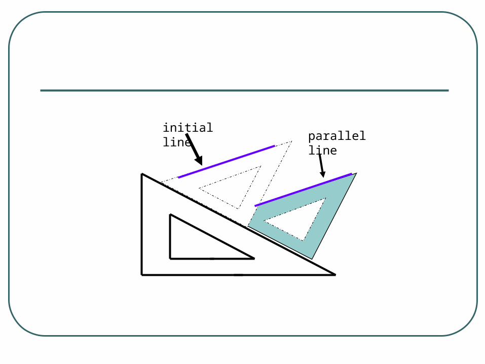
initial lineparallel line
Drawing Perpendicular Lines When two triangles are used, align the edge of one of the
triangles with the given line.• Do not use the hypotenuse (long edge) of the triangle.
Use the other triangle as a straightedge and hold it stationary.
Slide the aligned triangle along the edge of the stationary triangle.
After the moving triangle is in the new position, draw the line, using its perpendicular edge.

ENTC 1110
SCALES

Scales are used to measure distances on technical drawings.• Scales are six to twelve inches long.• Made from wood, plastic, or metal.
Scales are typically triangular allowing a combination of several scales on each side.
The most common scales are:• mechanical engineer’s• civil engineer’s• metric, and • archictectural
A combination scale has engineering, metric, and architectural scales on a single scale.
ENTC 1110
ARCHITECT’S SCALE

For this example, use the 3/4” per foot scale.• This scale has a 3/4 marked at the end.
• The feet are read to the right of the zero mark.
• Fractions of a foot are measured to the left of the zero mark.
• The large numbers (28, 26, 24, ...) near the left end of the scale represent two things:
• the number of feet for the 3/8 scale coming from the right end and
• the 6” marks for the 3/4 scale.
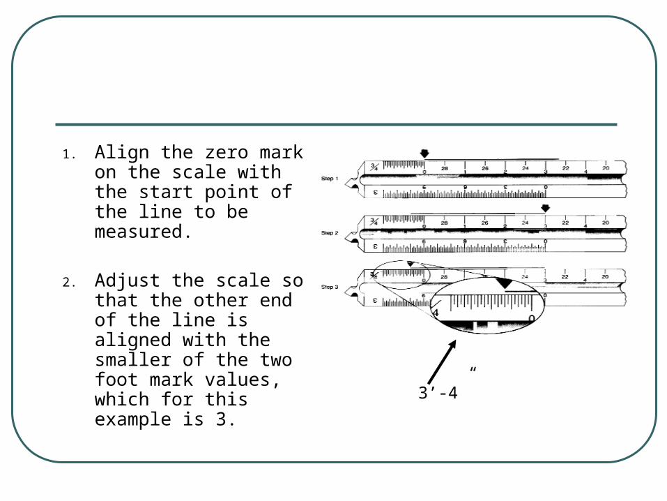
1. Align the zero mark on the scale with the start point of the line to be measured.
2. Adjust the scale so that the other end of the line is aligned with the smaller of the two foot mark values, which for this example is 3. 3’-4”

3. The fractions of a foot are read to the left of zero mark. To determine how many
parts a foot has been divided into count the number of
short marks long marks.
For the example, there are 24 marks to the left of the zero mark. Each mark equals 1/2”. The longer marks
represent inches.
4. For this example, the closest mark is the 8 The line is measured as 3’
4”.

ENTC 1110
CIVIL ENGINEER’S SCALE
The civil engineer’s scale is a decimal scale divided into multiple units of 10.• Commonly used to draw large structures and maps.
Each end of the scale is labeled 10, 20, 30, 40, 50, or 60.• Specifies the number of units per inch.
• The 30 scale has 30 units per inch.
• The 10 scale is often used as a decimal inch scale.
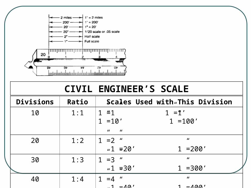
CIVIL ENGINEER’S SCALEDivisions Ratio Scales Used with This Division
10 1:1 1”=1” 1”=1’ 1”=10’ 1”=100’
20 1:2 1”=2” 1”=20’ 1”=200’
30 1:3 1”=3” 1”=30’ 1”=300’
40 1:4 1”=4” 1”=40’ 1”=400’
50 1:5 1”=5” 1”=50’ 1”=500’
60 1:6 1”=6” 1”=60’ 1”=600’

For the example, use the 20 scale.• twenty marks per inch.• each mark equals 1/20”
Align the zero mark on the 20 scale with the left end of the line to be measured.
Determine the closest mark on the 20 scale that corresponds to the right end of the line.• For a full-scale drawing
• the line is 24/20 or 1.2”
• For half-scale• the line is 2.4”
• For 1” equals 20’ (1” = 20’)• the line is 24’.

ENTC 1110
MECHANICAL ENGINEER’S SCALE
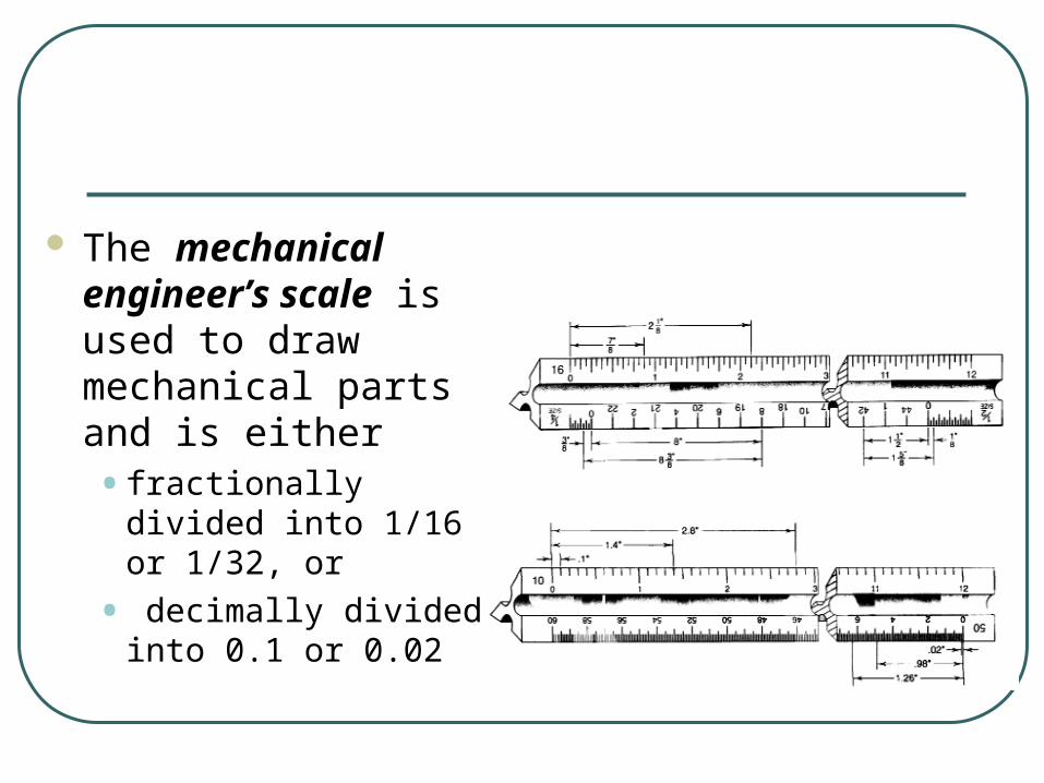
The mechanical engineer’s scale is used to draw mechanical parts and is either • fractionally divided into
1/16 or 1/32, or
• decimally divided into 0.1 or 0.02
Typically, the other sides of the scale are half size (1/2” = 1”), quarter size (1/4” = 1”), and eight size (1/8” = 1”).
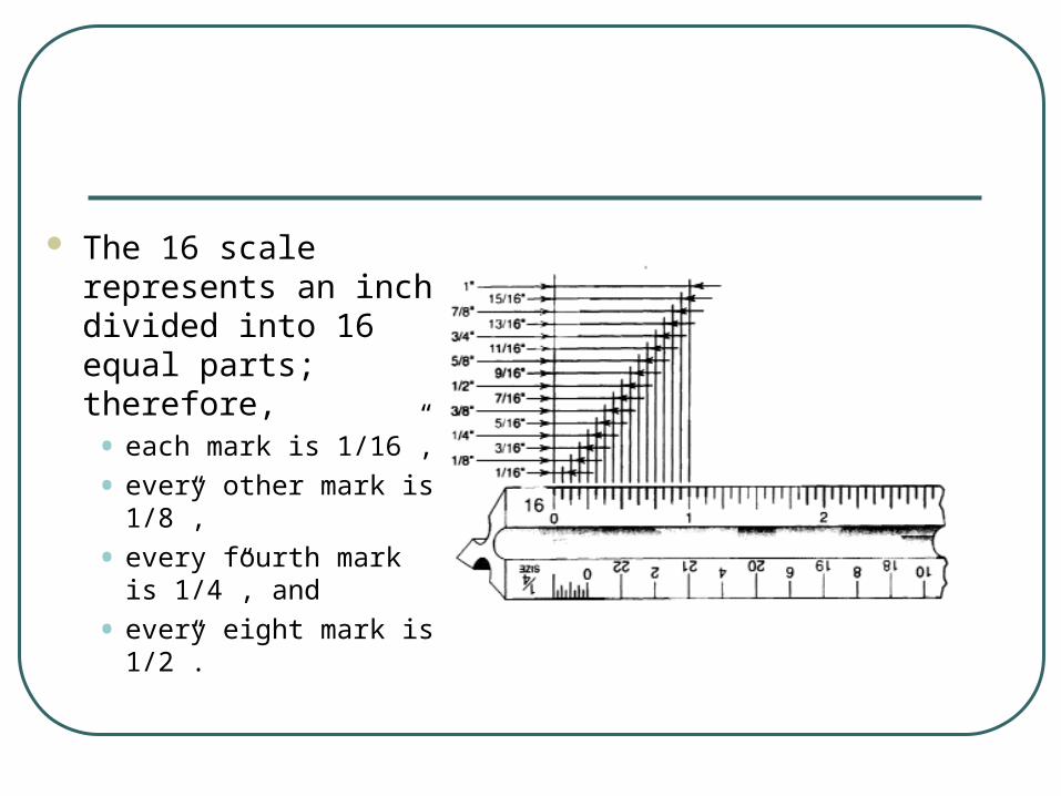
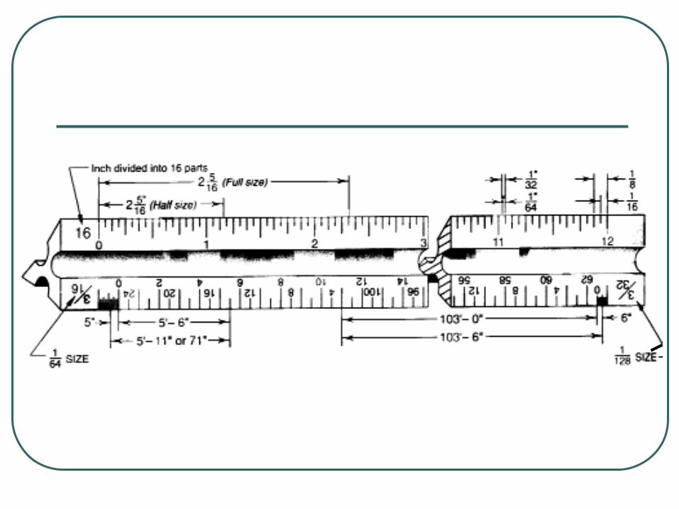
The 16 scale represents an inch divided into 16 equal parts; therefore, • each mark is 1/16”,
• every other mark is 1/8”,
• every fourth mark is 1/4”, and
• every eight mark is 1/2”.
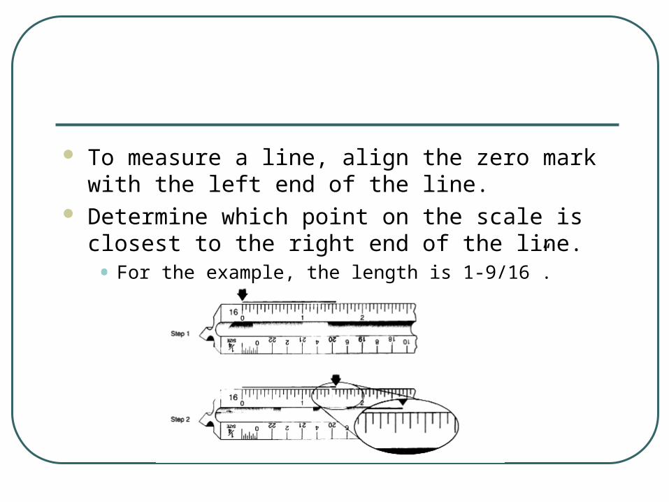
To measure a line, align the zero mark with the left end of the line.
Determine which point on the scale is closest to the right end of the line.• For the example, the length is 1-9/16”.

The 50 scale is commonly used for full-size mechanical engineering drawings because it provides two-decimal-place-accuracy• The ANSI standard calls for such accuracy on
all nontoleranced dimensions
• The 50 scale divides the inch into 50 parts• Each mark is 0.02”.

To measure a line, align the zero mark with the left end of the line.
Determine which point on the scale is closest to the right end of the line. For this example, assume a line for which the right end is aligned three marks to the left of the small number 12.
The length of the line is read as 2.46”.
Half-size scale
The half-size scale is labeled 1/2 at the end. • To the right of zero, each mark represents a full inch;
• to the left of zero, there is only one inch and it is marked off in fractions
• There are 16 marks in the inch to the left of zero, which means that each mark represents 1/16”.
• The longer marks represent 1/8”, 1/4”, and 1/2” increments.

To measure a line, position the scale such that the left end of the line is to the left of zero and is within the inch that is marked off. • (The exact position is not critical in this step.)
While making sure that the left end of the line stays within the marked-off inch to the left of zero, adjust the scale so that the right end of the line is exactly aligned with the closest full inch mark to the right of zero.
Read the full inch mark first;• then read the mark to the left end of the line
• The sample line is 3-5/16”.

ENTC 1110
METRIC SCALE

The international organization that establishes the metric standard if the International Standards Organization (ISO).• The system is called the International System of
Units, or Systeme Internationale (SI).
• The metric system is used to create scaled technical drawings using SI units.
• The meter is the base unit.
• 1000 millimeter = 1m
• 1000 m = 1 kilometer
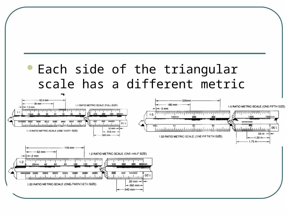
Each side of the triangular scale has a different metric scale.

1:1 Full size 1:2 Half size 1:5 Fifth size 1:10 Tenth size 1:20 Twentieth size 1:50 Fiftieth size

On the 1:1 metric scale, • each mark represents 1 mm and • every tenth mark represents 10 mm, or 1 cm .
To measure a line, align the zero mark with the left end of the line and read the mark on the scale aligned closest to the right end of the line. • For this example. assume a line for which the right end is closest to the sixth mark past the
number 20. • The length of this line would be read as 26 mm, or 2.6 cm.
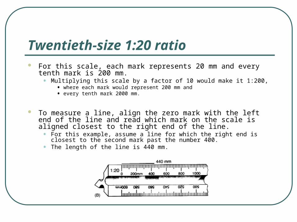
Twentieth-size 1:20 ratio For this scale, each mark represents 20 mm and every tenth mark is
200 mm.• Multiplying this scale by a factor of 10 would make it 1:200,
• where each mark would represent 200 mm and • every tenth mark 2000 mm.
To measure a line, align the zero mark with the left end of the line and read which mark on the scale is aligned closest to the right end of the line. • For this example, assume a line for which the right end is closest to the second
mark past the number 400. • The length of the line is 440 mm.

ENTC 1110
DRAWING INSTRUMENTS
A drawing instrument set typically consists of a compass and a set of dividers.• The compass is used to draw circles and arcs
of varying diameters.
• A divider is similar to the compass except that it has needle points on both ends.• The divider is used to transfer measurements on a
drawing or divide a line into equal parts by trial an error.

ENTC 1110
TECHNIQUES
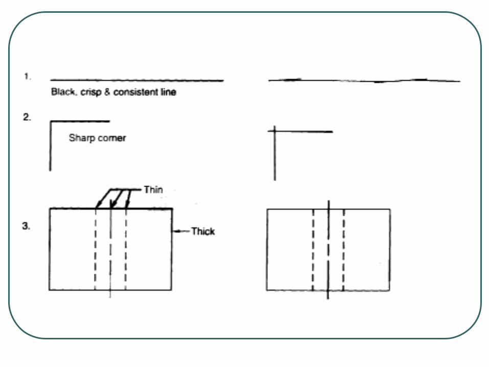
All lines except construction lines should be black, crisp, and consistent.• Black lines are drawn using soft lead
• Crisp lines do not have fuzzy edges
• A consistent line does not change in thickness from one end to the other.
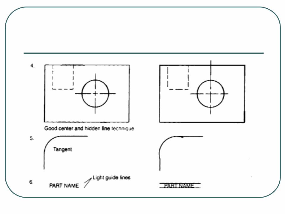
Corners should be sharp and without overlap.
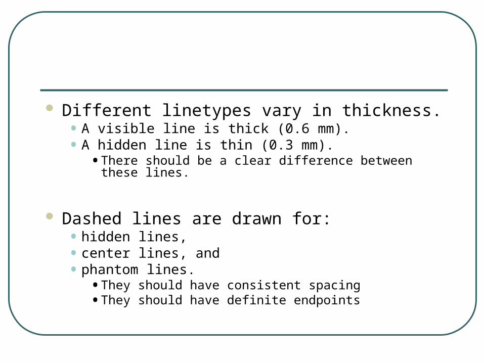
Different linetypes vary in thickness.• A visible line is thick (0.6 mm).• A hidden line is thin (0.3 mm).
• There should be a clear difference between these lines.
Dashed lines are drawn for:• hidden lines,• center lines, and• phantom lines.
• They should have consistent spacing• They should have definite endpoints
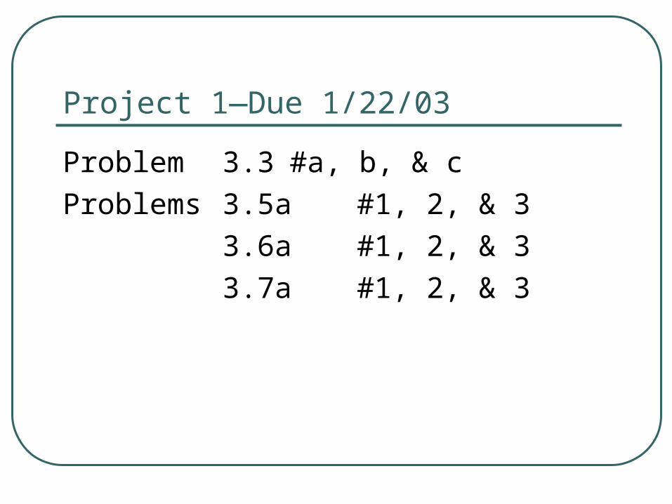
Project 1—Due 1/22/03
Problem 3.3 #a, b, & c
Problems 3.5a #1, 2, & 3
3.6a #1, 2, & 3
3.7a #1, 2, & 3