Embed Size (px)
Citation preview
GENERAL DESCRIPTION
LIST OF FEATURES Boundary Conditions and Loading• Five sets of boundary conditions are available to model the
pile head: free head, pinned head with sway, fixed head with sway, or elastically-restrained with a rotational spring. Depending on boundary conditions, pile-head loading may consist of a lateral load, a bending moment, a specific lateral displacement, or a specific pile-head rotation. The ability to specify both deflection and rotation at the pile head is an useful feature available in LPILE.
• Up to fifty different load cases may be applied at the pile head in a single analytical run. This is a helpful feature for the quick observation of pile behavior for a specified range of external loads.
• Users can specify any of the applied loads to be used for computations of pile-head deflection vs pile penetration to check critical pile length and produce efficient penetration designs.
• A set of distributed lateral loading may be applied anywhere along the length of the pile. Loading may be specified as constant or varying linearly with depth.
LPILE is a special-purpose program based on rational pro-cedures for analyzing a pile under lateral loading using the p-y method. LPILE solves the differential equation for a beam-column using nonlinear lateral load-transfer (p-y) curves. The program computes deflection, bending moment, shear force and soil response over the length of the pile. As an option, components of the stiffness matrix at the pile head may be computed internally by LPILE so users can incor-porate basic soil-structure interaction in their super-structure analyses. Another option from LPILE provides graphs of pile-head deflections for various pile lengths, to help users with optimum pile penetrations (for lateral response). Nonlinear lateral load-transfer from the foundation to the soil is modeled using p-y curves generated internally using published recommendations for various types of soils. Special procedures are programmed for computing p-y curves for layered soils and for rocks. Alternatively, the user can enter manually any other externally generated p-y curves. Five types of pile-head boundary conditions may be selected, and the structural properties of the pile can vary as a function of depth. LPILE has analytical features to compute the nonlinear moment-curvature relationships and nominal moment capacity of a pile’s section based on specified pile dimensions and nonlinear material properties. Optionally, the user may enter nonlinear moment-
LRFD Analyses• LPILE v6 introduces the capability of performing analyses for
Load and Resistance Factor Design (LRFD).• Up to fifty load-case combinations may be defined with up to
100 unfactored loads grouped in 13 pre-defined load types.• Load-case combinations are defined by entering the load
factors for each load type and the resistance factors for both flexure and shear. Optionally, the user may enter the load case combinations by reading external text files (previously created by the user).
• Unfactored loads are defined for: shear, moment, axial thrust, and distributed lateral load.
• Load types for unfactored loads are: dead load, live, earth-quake, impact, wind, water, ice, horizontal soil pressure, live roof, rain, snow, temperature plus two user-defined load types.
• Factored loads are computed for each load-case combination by multiplying the appropriate load factor by the sum of loads of the same type. Summary reports of the computed load-case combinations are generated by the program.
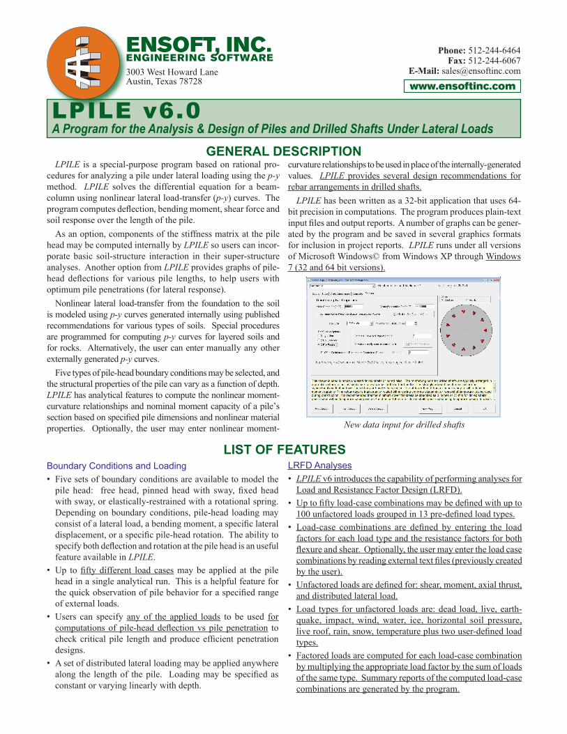
curvature relationships to be used in place of the internally-generated values. LPILE provides several design recommendations for rebar arrangements in drilled shafts. LPILE has been written as a 32-bit application that uses 64-bit precision in computations. The program produces plain-text input files and output reports. A number of graphs can be gener-ated by the program and be saved in several graphics formats for inclusion in project reports. LPILE runs under all versions of Microsoft Windows© from Windows XP through Windows 7 (32 and 64 bit versions).
New data input for drilled shafts
LPILE v6.0A Program for the Analysis & Design of Piles and Drilled Shafts Under Lateral Loads
www.ensoftinc.com
ENSOFT, INC.engineering software3003 West Howard LaneAustin, Texas 78728
Phone: 512-244-6464Fax: 512-244-6067
E-Mail: [email protected]

Custom charts for shear force and moment
LPILE v6.0
Generation of Lateral Load-Transfer (p-y) Curves• Soil-resistance (p-y) curves can be internally generated by the
program for the following soils: soft clay, stiff clay with or without free water, sand (Reese et al), sand (API), cemented c-φ soils (silt), liquefiable sand, strong rock, weak rock, stiff clay without free water using initial k, Piedmont Residual Soils, Loess Silt, and Elastic Subgrade. The p-y curves may be printed at any depth for reviews or reference.
• Users may optionally input their own lateral load-transfer (p-y) curves for specified soil layers.
• LPILE can adjust p-y curves for soil-layering effects (for example, where there may be layers of sand and clay).
• User-defined multipliers are provided to increase or reduce the soil resistance (p-y) curves at any points along the length of the pile. This feature is used in seismic conditions to reduce the response of liquefied layers or to account for Group Effects.
• Internal modification factors are automatically calculated to model pile batter and sloping ground surfaces.
• An user-specified curve may be used to model the additional shear resistance provided by the soil at the base of large-diameter drilled shafts and/or short piles.
• LPILE has the capability of analyzing the behavior of piles subjected to the free-field soil movement in the lateral direc-tion.
Structural Features • Linear interpolation of bending stiffness is possible for piles
with varying cross sections.• The user may optionally ask the program to generate and
take into account nonlinear values of flexural stiffness (EI). These values are generated internally by the program based on: cracked/uncracked concrete behavior, user-specified pile dimensions, and nonlinear material properties.
• Version 6 allows the user to define up to 10 sections with nonlinear bending properties. This permits the designer to cut off part of the reinforcing steel from the lower sections of a drilled shaft, as is common construction practice.
• Four values (K22, K23, K32, and K33) of a typical 6x6 matrix for foundation stiffness may be generated by the program for a range of loading. These values can be used to model nonlinear foundation springs in the analysis of the superstructure.
• LPILE has the capability to perform push-over analyses and can study the pile behavior after the development of plastic hinges (yielding).
• A new feature in Version 6 is the power to automatically gener-ate bundled bar arrangement for 2-bar and 3-bar bundles.
• Also new in Version 6 is the ability to offset the reinforcing steel from the centroid. This option was provided to allow analysis of drilled shafts where the reinforcement was placed (or accidentally moved) off-center.
Features for Optimization of Pile Designs • Several pile lengths can be automatically checked by the
LPILE program in order to help the user produce a design
with an optimum pile penetration. For this purpose, users can evaluate the curve of pile-head deflections vs pile length.
• Curves of flexural stiffness versus bending moment and/or moment versus curvature are provided to review the adequacy of the pile's section. In addition, the user may also observe the interaction diagram of the modeled pile section.
• The user may also observe the nonlinear values of the foun-dation stiffness matrix or the curve of pile-head deflections versus pile length.
Functional Features• Soil-layer data structures and input screens are improved to
help the user enter data conveniently with defaulted values provided. Hints and notes were also introduced on input windows to assist the user for data entry.
• Over 100 error-checking messages have been provided, mak-ing it simpler for occasional users to run the program and/or to debug run-time errors of more experienced users.
• The Graphics menu can produce quick displays of all results contained in the output file, including: pile deflection, bending moment, shear and soil resistance versus pile depth. A custom-control chart can be used to prepare various engineering plots in high quality for presentation and reporting.
• Standard Windows operations, such as dialog boxes, speed buttons, grid cells, clickable buttons, drop-down list of op-tions, and pull-down menu choices are all incorporated in the LPILE program.
• A well-documented Technical Manual is provided with rel-evant theoretical equations. The Technical and User's manuals are now distributed in electronic form with the LPILE pro-gram.
Software Support Free technical support and maintenance plus software upgrades are included for a period of one year from software purchase or upgrade.
LIST OF FEATURES (cont.)


![[FORM OF]€¦ · Web viewOther grammatical forms of defined words or phrases have ... a Unit at Base Load is 5% greater than the Guaranteed Heat Rate Point at Base Load unless](https://img.pdfslide.us/doc/110x75/5e6fd71838479950ea185330/form-of-web-view-other-grammatical-forms-of-defined-words-or-phrases-have-.jpg)