Embed Size (px)
Citation preview
ENPH 253 Robot Design Proposal
Team One
Runor Agbaire
Etienne Boivin
Bryan Pawlina
Eleanor Wong
Submitted to:
Randall Kerr
Andre Marziali
Jon Nakane
Bernhard Zender
June 17, 2014
Abstract
Over the course of several weeks an autonomous tape-following, IR-detecting, ziplining,artifact-collecting robot is to be designed and developed for the Engineering Physics 253 com-petition. The robot must be able to navigate an instructor-designed obstacle course by followinga path made of black tape, collecting and storing magnetic artifacts in a basket, using IR de-tectors to follow a beacon in the final stretch of the course, and finally using an extendable armto grab hold of a zipline and hoist itself up, all this in as short a time as possible. The robotsbehaviour is controlled by several electric circuits and software algorithms, and will receivemultiple inputs from its surroundings in order to guide it through the course.
The roughly 7kg robot will begin by receiving inputs from two tape sensors mounted in thefront which will be fed through a PID controller, which will in turn vary the power supply tothe right and left rear wheels in order to attempt to follow the tape path as closely as possible.As the robot moves through the course, it will detect any artifacts along the way by using anIR detector mounted on its side to monitor the status of an IR beacon mounted on the end ofan aluminum arm attached to the top of the robot. Passing by an artifact will block the beaconand prompt the robot to stop, and lower the arm which will pick up the artifact by way of amagnetic pad mounted on the end of the arm. The arm will then rotate, drop the artifact intoits top-mounted basket and continue on its way. When the tape gives way to a rocky path,the robot will then begin navigating using two IR detectors mounted on the front of its chassistowards a 10kHz beacon by utilizing the signal difference detected by the sensors. Once it hasreached the beacon, a final artifact (the Idol) will be collected and placed in the basket. Therobot will then extend a zipline arm mounted on the top of the chassis which will latch onto thezipline and allow the robot to slide all the way back to the beginning of the course.
Contents
Glossary i
List of Figures ii
List of Tables iii
1 Introduction and Overview of Basic Strategy 1
2 Chassis 22.1 Main Base . . . . . . . . . . . . . . . . . . . . . . . . . . . . . . . . . . . . . . . . 22.2 Basket . . . . . . . . . . . . . . . . . . . . . . . . . . . . . . . . . . . . . . . . . . 22.3 PCB and Tinah Storage . . . . . . . . . . . . . . . . . . . . . . . . . . . . . . . . 22.4 Materials and Method of Fabrication . . . . . . . . . . . . . . . . . . . . . . . . . 32.5 Design Specifications . . . . . . . . . . . . . . . . . . . . . . . . . . . . . . . . . . 42.6 Order of Assembly . . . . . . . . . . . . . . . . . . . . . . . . . . . . . . . . . . . 4
3 Drive and Actuator System 63.1 Steering . . . . . . . . . . . . . . . . . . . . . . . . . . . . . . . . . . . . . . . . . 63.2 Artifact Arm . . . . . . . . . . . . . . . . . . . . . . . . . . . . . . . . . . . . . . 63.3 Zipline Arm . . . . . . . . . . . . . . . . . . . . . . . . . . . . . . . . . . . . . . . 83.4 Transmission Calculations and Requirements . . . . . . . . . . . . . . . . . . . . 93.5 Motor Allocation and Purposes . . . . . . . . . . . . . . . . . . . . . . . . . . . . 10
4 Sensors and Feedback 114.1 Tape Sensors . . . . . . . . . . . . . . . . . . . . . . . . . . . . . . . . . . . . . . 124.2 Beacon Detectors . . . . . . . . . . . . . . . . . . . . . . . . . . . . . . . . . . . . 124.3 Magnet Pad Touch Sensor . . . . . . . . . . . . . . . . . . . . . . . . . . . . . . . 134.4 Artifact Detection Sensor . . . . . . . . . . . . . . . . . . . . . . . . . . . . . . . 134.5 Zipline Detection Sensor . . . . . . . . . . . . . . . . . . . . . . . . . . . . . . . . 134.6 Rear Wheel Drive Control . . . . . . . . . . . . . . . . . . . . . . . . . . . . . . . 134.7 Active Control of Front Wheels . . . . . . . . . . . . . . . . . . . . . . . . . . . . 144.8 Artifact Arm Servo . . . . . . . . . . . . . . . . . . . . . . . . . . . . . . . . . . . 144.9 Magnetic Pad Elevation Control . . . . . . . . . . . . . . . . . . . . . . . . . . . 144.10 Artifact Arm Up/Down Motor Control . . . . . . . . . . . . . . . . . . . . . . . . 14
5 Electrical Design 155.1 PCB0 - Power Rail Bar . . . . . . . . . . . . . . . . . . . . . . . . . . . . . . . . 155.2 PCB1 - QRD Sensors and Artifact Sensor . . . . . . . . . . . . . . . . . . . . . . 155.3 PCB2 - Magnetic Pad Sensor and Artifact Arm Control . . . . . . . . . . . . . . 165.4 PCB3 - 2 H Bridges (Wheels) . . . . . . . . . . . . . . . . . . . . . . . . . . . . . 175.5 PCB4 - 2 H Bridges (Zipline Arm) and Zipline Switch . . . . . . . . . . . . . . . 175.6 PCB5 - IR Sensors . . . . . . . . . . . . . . . . . . . . . . . . . . . . . . . . . . . 175.7 Physical Wiring . . . . . . . . . . . . . . . . . . . . . . . . . . . . . . . . . . . . . 19
6 Software Code and Algorithm 206.1 Overall Software and Function Flow . . . . . . . . . . . . . . . . . . . . . . . . . 206.2 Tape Following Algorithm . . . . . . . . . . . . . . . . . . . . . . . . . . . . . . . 216.3 Artifact Collection Processes . . . . . . . . . . . . . . . . . . . . . . . . . . . . . 226.4 IR Following Algorithm . . . . . . . . . . . . . . . . . . . . . . . . . . . . . . . . 226.5 Zipline Retrieval Processes . . . . . . . . . . . . . . . . . . . . . . . . . . . . . . . 236.6 Error Handling . . . . . . . . . . . . . . . . . . . . . . . . . . . . . . . . . . . . . 24
7 Risk Assessment and Contingency Planning 25
3

8 Task List, Major Milestones and Team Responsibilities 268.1 Major Milestones . . . . . . . . . . . . . . . . . . . . . . . . . . . . . . . . . . . . 278.2 Team Responsibilities . . . . . . . . . . . . . . . . . . . . . . . . . . . . . . . . . 27
9 Conclusion 28
A Appendix A 29
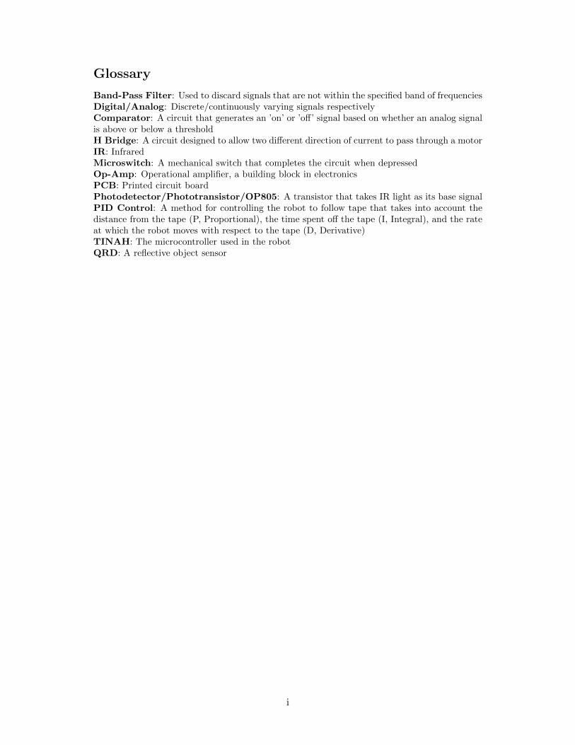
Glossary
Band-Pass Filter: Used to discard signals that are not within the specified band of frequenciesDigital/Analog: Discrete/continuously varying signals respectivelyComparator: A circuit that generates an ’on’ or ’off’ signal based on whether an analog signalis above or below a thresholdH Bridge: A circuit designed to allow two different direction of current to pass through a motorIR: InfraredMicroswitch: A mechanical switch that completes the circuit when depressedOp-Amp: Operational amplifier, a building block in electronicsPCB: Printed circuit boardPhotodetector/Phototransistor/OP805: A transistor that takes IR light as its base signalPID Control: A method for controlling the robot to follow tape that takes into account thedistance from the tape (P, Proportional), the time spent off the tape (I, Integral), and the rateat which the robot moves with respect to the tape (D, Derivative)TINAH: The microcontroller used in the robotQRD: A reflective object sensor
i
List of Figures
1 Main Base Chassis . . . . . . . . . . . . . . . . . . . . . . . . . . . . . . . . . . . 22 Basket Design . . . . . . . . . . . . . . . . . . . . . . . . . . . . . . . . . . . . . 33 PCB and Tinah Storage Box . . . . . . . . . . . . . . . . . . . . . . . . . . . . . 34 Assembled Chassis . . . . . . . . . . . . . . . . . . . . . . . . . . . . . . . . . . . 45 Active Steering Design . . . . . . . . . . . . . . . . . . . . . . . . . . . . . . . . 66 Artifact Arm Design . . . . . . . . . . . . . . . . . . . . . . . . . . . . . . . . . . 77 Zipline Arm Design . . . . . . . . . . . . . . . . . . . . . . . . . . . . . . . . . . 88 QRD1114 Reflective Object Sensors . . . . . . . . . . . . . . . . . . . . . . . . . 129 OP805 Phototransistor . . . . . . . . . . . . . . . . . . . . . . . . . . . . . . . . 1210 Magnet Pad Switches . . . . . . . . . . . . . . . . . . . . . . . . . . . . . . . . . 1311 Zipline Microswitch Detector . . . . . . . . . . . . . . . . . . . . . . . . . . . . . 1312 PCB0 Power Rail PCB . . . . . . . . . . . . . . . . . . . . . . . . . . . . . . . . 1513 PCB1 QRD Circuit . . . . . . . . . . . . . . . . . . . . . . . . . . . . . . . . . . 1514 PCB1 Artifact Optical Sensor Schematic . . . . . . . . . . . . . . . . . . . . . . 1615 PCB2 Pad Magnet Logic Schematic . . . . . . . . . . . . . . . . . . . . . . . . . 1616 PCB3/PCB4 H Bridge Circuit Schematic . . . . . . . . . . . . . . . . . . . . . . 1717 PCB5 IR Beacon Detector Schematic . . . . . . . . . . . . . . . . . . . . . . . . 1818 Flow Chart for Overall Robot Software . . . . . . . . . . . . . . . . . . . . . . . 2019 Flow Chart for Tape Following . . . . . . . . . . . . . . . . . . . . . . . . . . . . 2120 Flow Chart for getArtifact(); . . . . . . . . . . . . . . . . . . . . . . . . . . . . . 2221 Flow Chart for storeArtifact(); . . . . . . . . . . . . . . . . . . . . . . . . . . . . 2222 Flow Chart for retryArtifact(); . . . . . . . . . . . . . . . . . . . . . . . . . . . . 2323 Flow Chart for irFollow(); . . . . . . . . . . . . . . . . . . . . . . . . . . . . . . 2324 Flow Chart for Zipline Processes . . . . . . . . . . . . . . . . . . . . . . . . . . . 24
ii
List of Tables
1 Chassis Parts . . . . . . . . . . . . . . . . . . . . . . . . . . . . . . . . . . . . . . 52 Motor Resources . . . . . . . . . . . . . . . . . . . . . . . . . . . . . . . . . . . . 103 TINAH Analog I/O Allocation . . . . . . . . . . . . . . . . . . . . . . . . . . . . 114 TINAH Digital I/O Allocation . . . . . . . . . . . . . . . . . . . . . . . . . . . . 115 TINAH PWM I/O Allocation . . . . . . . . . . . . . . . . . . . . . . . . . . . . . 116 Table of Physical Wiring . . . . . . . . . . . . . . . . . . . . . . . . . . . . . . . . 197 Risk and Contingency Plan . . . . . . . . . . . . . . . . . . . . . . . . . . . . . . 258 Task List . . . . . . . . . . . . . . . . . . . . . . . . . . . . . . . . . . . . . . . . 269 Schedule and Task Distrubition . . . . . . . . . . . . . . . . . . . . . . . . . . . . 29
iii
1 Introduction and Overview of Basic Strategy
Welcome to Team One’s 2014 ENPH253 robot planning stage. We are planning on making arobot that will take the standard, but complete route through the playing field. That is, ourgoal is to produce a robot that will repeatedly follow the black tape, collect every artifact andthe idol, and take the zipline back to the starting point. Our strategy is such because taking thezipline, although a unique process that will have to be invented independently of other tasks,is logically simple and fastest, allowing us to allot more time to carefully pick up the artifacts,and navigate reliably. In our goal there exist many challenges. However, we are to solve theseproblems week by week, as listed in the timeline, and do so in a modular way, such that ourrobot can be constructed to first accomplish one task, and then another, and so on. Once thishas been accomplished, we will move on to a robot that can navigate through the rock bed andcollect the final idol. At this point, we must evaluate if a zipline route is still feasible, and if not,initiate building the robot that will find a way to return to the starting position alternatively.Building a robot that is reliable and durable for testing/tuning rests a lot on a solid chassis andwe will initially develop a chassis that provides optimal space usage in our 12x12x16 restriction.Beginning with the PD control we worked on previously we will first realize what coding/changesto gears/weight we need to control the robot.
Essential is the ability to pick up artifacts and store them. The entire team will spend a goodamount of time early on developing the magnetic pad sensor to accomplish this. We have decidedto utilize the fact that the artifacts are magnetic for moving them, but not for sensing them.Instead, we have followed recommendations to create a trip beam with IR light at 1”-2” aboveground to see when we have passed an artifact. At this point, the robot will stop and initiatethe process of retrieving the artifact. The pad sensor is magnetic and covered by a thin layersupported by microswitches. At the moment the artifact becomes stuck to the pad, the sensorswill be depressed and a signal sent to our robot’s TINAH board that gives more instructionson storing the artifact. This task must be repeatable. Our strategy for dealing with the rockbed is to have larger wheels in the front of the robot so that there is less rolling resistance.These wheels will begin on casters, should this be a simple solution. If in fact the wheels beginjamming in the rocks or causing other problems, we have a plan in place to implement activesteering on those wheels. Our detection of the 10kHz sine wave of infrared being emitted bythe robot’s destination will be done through phototransistors, although this signal will needboth filtering and amplification. Should the length of the rock bed be too great that we cannotkeep the output signal from these circuits within the range of what TINAH accepts (0-5V),we have a plan to implement gain-switching, although it has not been determined whether wewill run two concurrent circuits that differ in gain, read respectively when appropriate, or havea natural electronic system that switches the signal’s path based on a comparator-transistorcircuit if this is feasible. Implementing the ziplining procedure will depend on a reliable codingalgorithm that positions the robot within range to grab a hold of the zipline. By week five weare working on turning the robot in a way that the open face of the hook of the zipline willapproach the zipline and accept it before the robot attempts to lift itself up. Development ofthe zipline is planned but reliant on relatively on-pace progress in the rest of the robot, and isacknowledged as a rather final development. Nevertheless, the zipline arm will rely also greatlyon manufacturing quality, as several moving parts need to bear loads on their joints as greatas the robot’s weight. The ziplining phase is to be executed by means of a folding two-stagearm that extends via motor so that the tip (hook) of the arm remains almost exactly above therobot’s center of gravity, before a servo at the end controls a hook to grab the zipline. Lastly,a high-torque winch which was extended during the arms’s unfolding will pull the robot off theground in a straight line, freeing it to roll back down to the pad.
Our alternate plans include turning around on the rock pad and finding the tape again, withhelp from the “Beacon of Hope.”
Our strategy is completely centered on reliability and effectiveness, and we will generallywork only to accomplish the said tasks rather than finding a special solution to it. Granted;whatever solution achieves this will be novel enough.
1
2 Chassis
The chassis of the robot will consist of a basket, circuit tray, zipline arm and an artifact armmount on a two level main base. Majority of the robot chassis will be created in aluminum.
2.1 Main Base
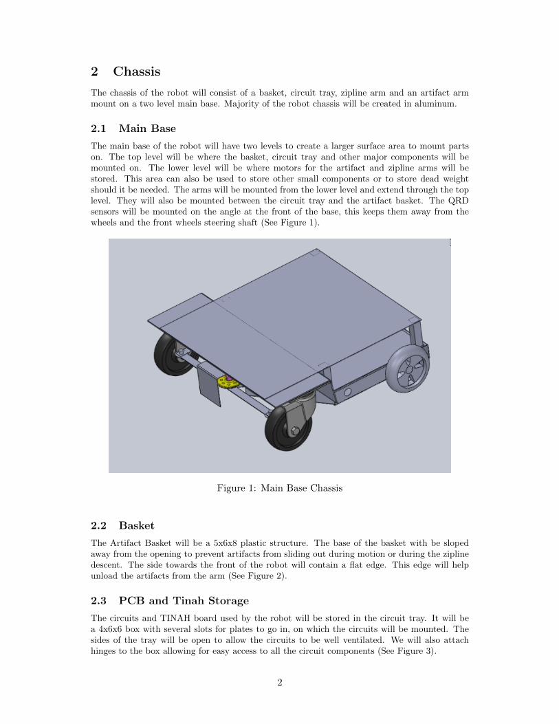
The main base of the robot will have two levels to create a larger surface area to mount partson. The top level will be where the basket, circuit tray and other major components will bemounted on. The lower level will be where motors for the artifact and zipline arms will bestored. This area can also be used to store other small components or to store dead weightshould it be needed. The arms will be mounted from the lower level and extend through the toplevel. They will also be mounted between the circuit tray and the artifact basket. The QRDsensors will be mounted on the angle at the front of the base, this keeps them away from thewheels and the front wheels steering shaft (See Figure 1).
Figure 1: Main Base Chassis
2.2 Basket
The Artifact Basket will be a 5x6x8 plastic structure. The base of the basket with be slopedaway from the opening to prevent artifacts from sliding out during motion or during the ziplinedescent. The side towards the front of the robot will contain a flat edge. This edge will helpunload the artifacts from the arm (See Figure 2).
2.3 PCB and Tinah Storage
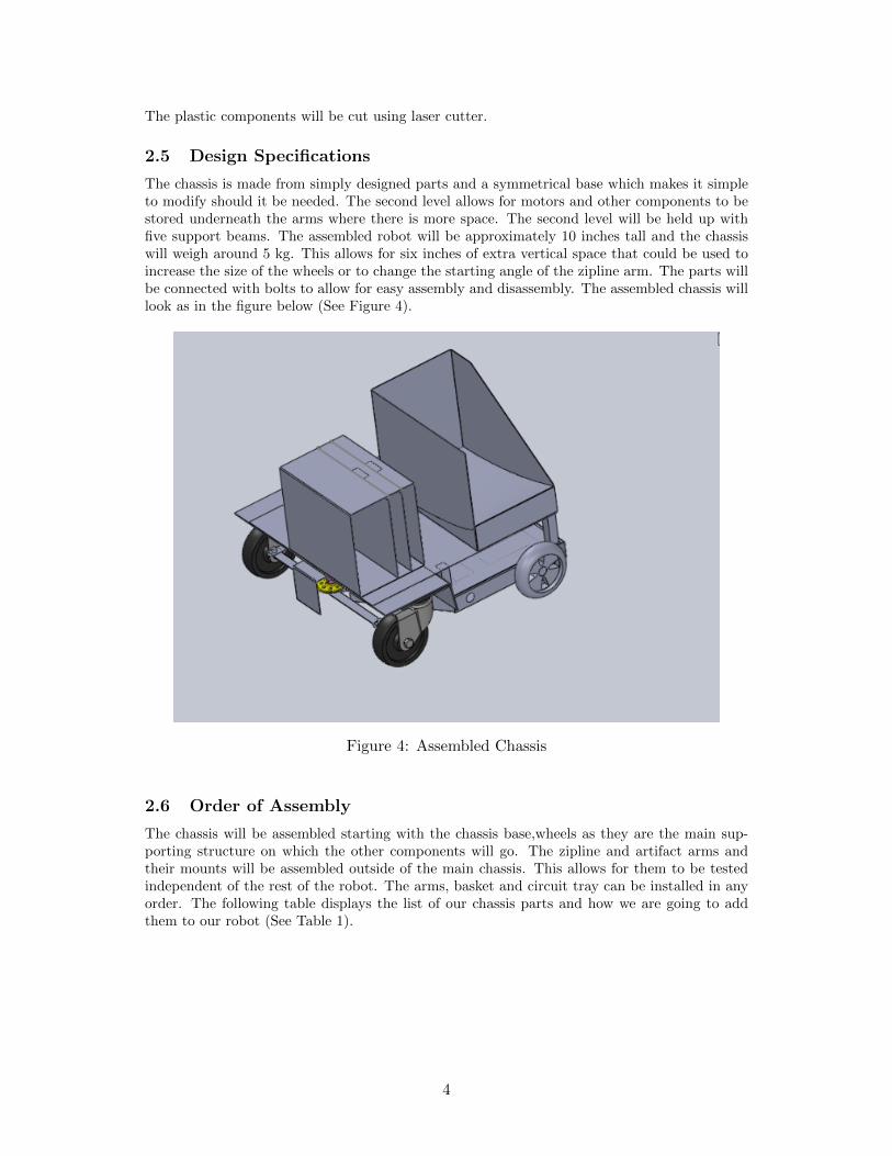
The circuits and TINAH board used by the robot will be stored in the circuit tray. It will bea 4x6x6 box with several slots for plates to go in, on which the circuits will be mounted. Thesides of the tray will be open to allow the circuits to be well ventilated. We will also attachhinges to the box allowing for easy access to all the circuit components (See Figure 3).
2
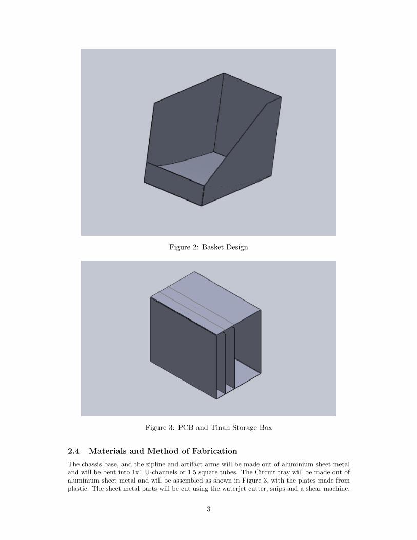
Figure 2: Basket Design
Figure 3: PCB and Tinah Storage Box
2.4 Materials and Method of Fabrication
The chassis base, and the zipline and artifact arms will be made out of aluminium sheet metaland will be bent into 1x1 U-channels or 1.5 square tubes. The Circuit tray will be made out ofaluminium sheet metal and will be assembled as shown in Figure 3, with the plates made fromplastic. The sheet metal parts will be cut using the waterjet cutter, snips and a shear machine.
3
The plastic components will be cut using laser cutter.
2.5 Design Specifications
The chassis is made from simply designed parts and a symmetrical base which makes it simpleto modify should it be needed. The second level allows for motors and other components to bestored underneath the arms where there is more space. The second level will be held up withfive support beams. The assembled robot will be approximately 10 inches tall and the chassiswill weigh around 5 kg. This allows for six inches of extra vertical space that could be used toincrease the size of the wheels or to change the starting angle of the zipline arm. The parts willbe connected with bolts to allow for easy assembly and disassembly. The assembled chassis willlook as in the figure below (See Figure 4).
Figure 4: Assembled Chassis
2.6 Order of Assembly
The chassis will be assembled starting with the chassis base,wheels as they are the main sup-porting structure on which the other components will go. The zipline and artifact arms andtheir mounts will be assembled outside of the main chassis. This allows for them to be testedindependent of the rest of the robot. The arms, basket and circuit tray can be installed in anyorder. The following table displays the list of our chassis parts and how we are going to addthem to our robot (See Table 1).
4
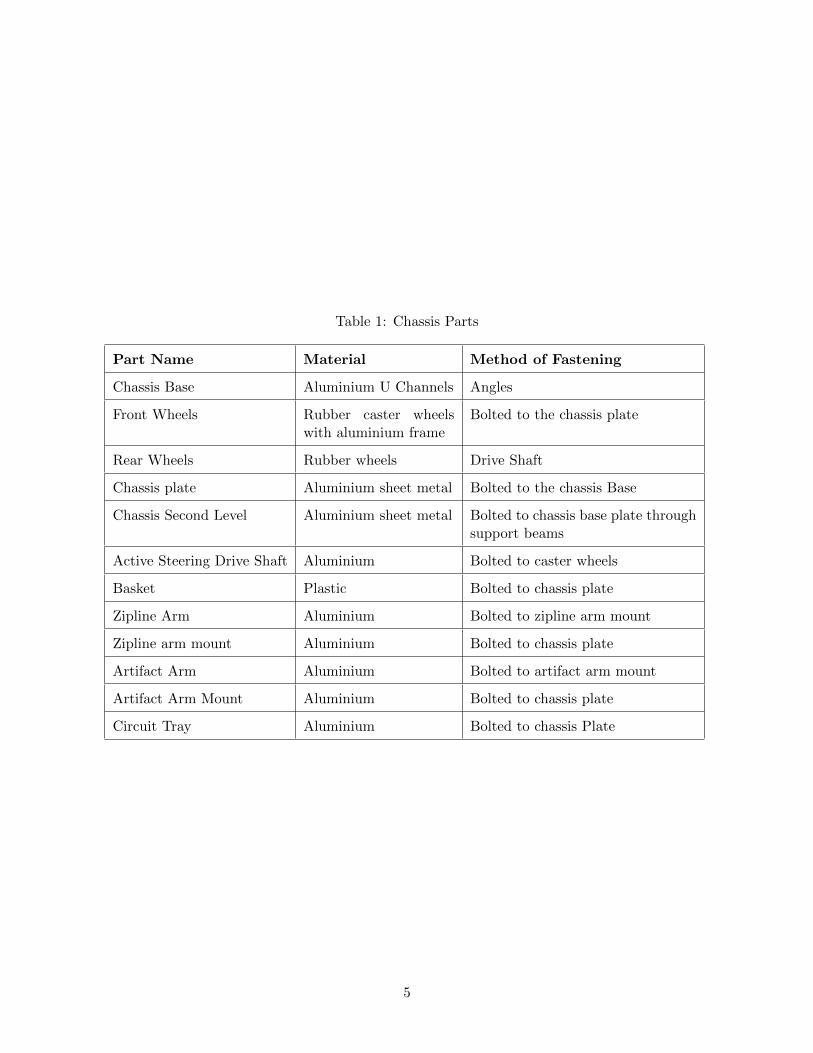
Table 1: Chassis Parts
Part Name Material Method of Fastening
Chassis Base Aluminium U Channels Angles
Front Wheels Rubber caster wheelswith aluminium frame
Bolted to the chassis plate
Rear Wheels Rubber wheels Drive Shaft
Chassis plate Aluminium sheet metal Bolted to the chassis Base
Chassis Second Level Aluminium sheet metal Bolted to chassis base plate throughsupport beams
Active Steering Drive Shaft Aluminium Bolted to caster wheels
Basket Plastic Bolted to chassis plate
Zipline Arm Aluminium Bolted to zipline arm mount
Zipline arm mount Aluminium Bolted to chassis plate
Artifact Arm Aluminium Bolted to artifact arm mount
Artifact Arm Mount Aluminium Bolted to chassis plate
Circuit Tray Aluminium Bolted to chassis Plate
5
3 Drive and Actuator System
An integral portion of the robot design consists of a wide variety of components that rotate,translate, lift, grab, and propel the robot in every conceivable direction in order to completethe various tasks that have been set out for us. Most of these actions are accomplished throughthe use of motors and servos, linked with gears pulleys, and rigid arms that will allow us totransform electrical signals into angular displacements, and electrical power into mechanicalpower.
3.1 Steering
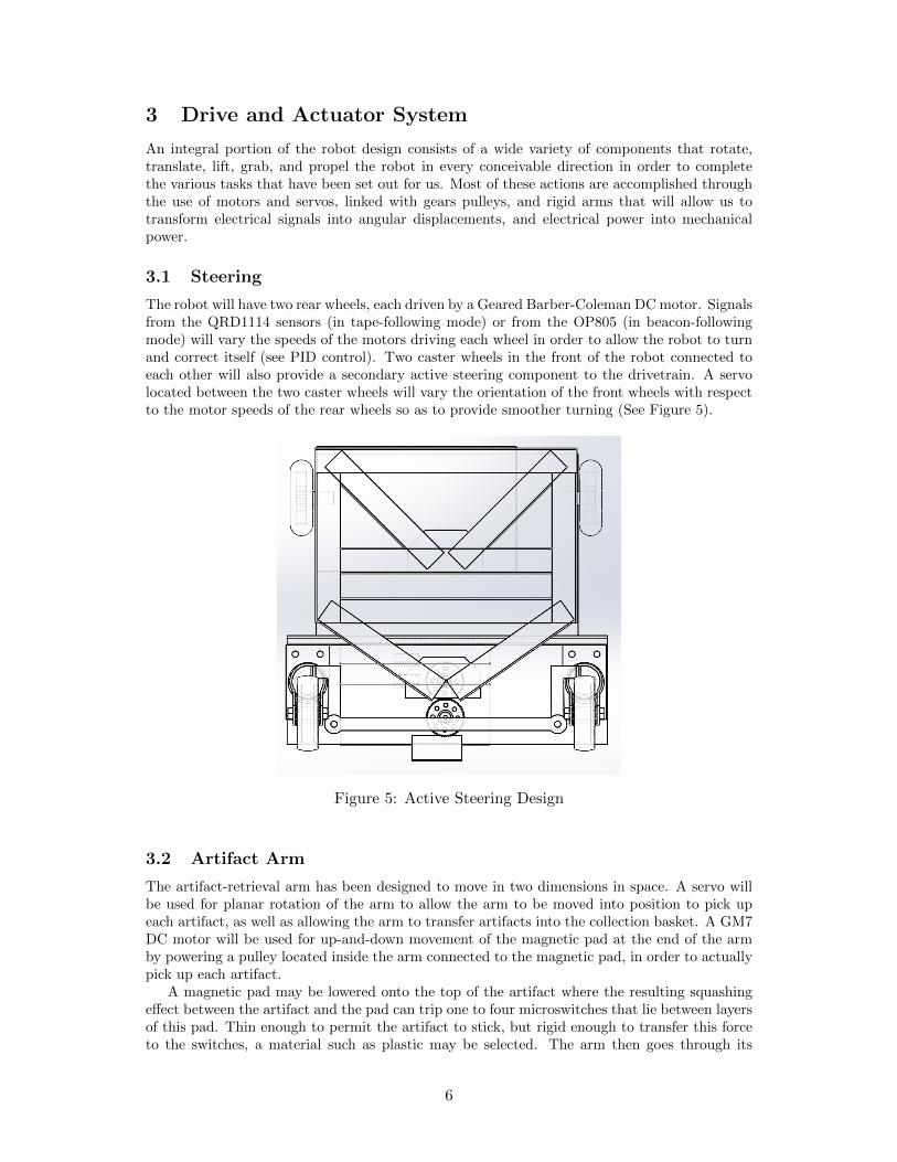
The robot will have two rear wheels, each driven by a Geared Barber-Coleman DC motor. Signalsfrom the QRD1114 sensors (in tape-following mode) or from the OP805 (in beacon-followingmode) will vary the speeds of the motors driving each wheel in order to allow the robot to turnand correct itself (see PID control). Two caster wheels in the front of the robot connected toeach other will also provide a secondary active steering component to the drivetrain. A servolocated between the two caster wheels will vary the orientation of the front wheels with respectto the motor speeds of the rear wheels so as to provide smoother turning (See Figure 5).
Figure 5: Active Steering Design
3.2 Artifact Arm
The artifact-retrieval arm has been designed to move in two dimensions in space. A servo willbe used for planar rotation of the arm to allow the arm to be moved into position to pick upeach artifact, as well as allowing the arm to transfer artifacts into the collection basket. A GM7DC motor will be used for up-and-down movement of the magnetic pad at the end of the armby powering a pulley located inside the arm connected to the magnetic pad, in order to actuallypick up each artifact.
A magnetic pad may be lowered onto the top of the artifact where the resulting squashingeffect between the artifact and the pad can trip one to four microswitches that lie between layersof this pad. Thin enough to permit the artifact to stick, but rigid enough to transfer this forceto the switches, a material such as plastic may be selected. The arm then goes through its
6
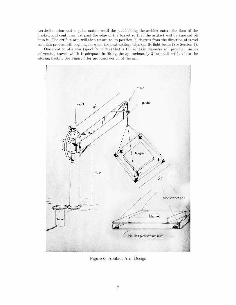
vertical motion and angular motion until the pad holding the artifact enters the door of thebasket, and continues just past the edge of the basket so that the artifact will be knocked offinto it. The artifact arm will then return to its position 90 degrees from the direction of traveland this process will begin again when the next artifact trips the IR light beam (See Section 4).
One rotation of a gear (spool for pulley) that is 1.6 inches in diameter will provide 5 inchesof vertical travel, which is adequate in lifting the approximately 3 inch tall artifact into thestoring basket. See Figure 6 for proposed design of the arm.
Figure 6: Artifact Arm Design
7
3.3 Zipline Arm
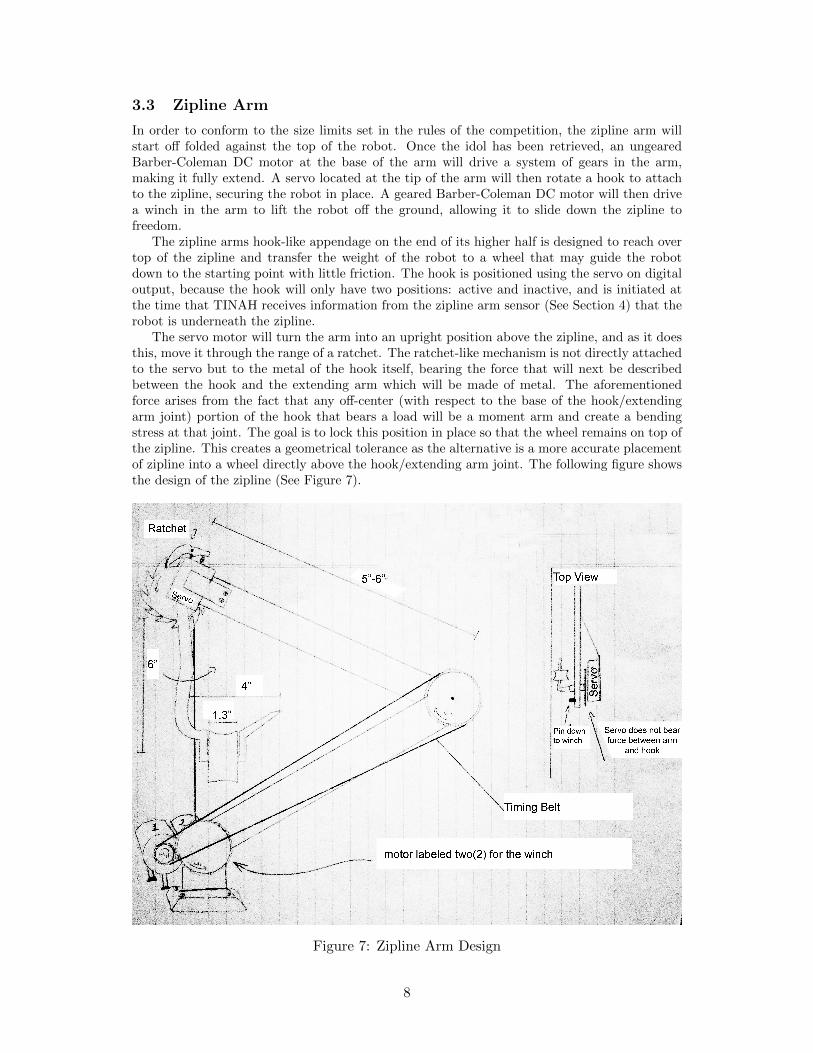
In order to conform to the size limits set in the rules of the competition, the zipline arm willstart off folded against the top of the robot. Once the idol has been retrieved, an ungearedBarber-Coleman DC motor at the base of the arm will drive a system of gears in the arm,making it fully extend. A servo located at the tip of the arm will then rotate a hook to attachto the zipline, securing the robot in place. A geared Barber-Coleman DC motor will then drivea winch in the arm to lift the robot off the ground, allowing it to slide down the zipline tofreedom.
The zipline arms hook-like appendage on the end of its higher half is designed to reach overtop of the zipline and transfer the weight of the robot to a wheel that may guide the robotdown to the starting point with little friction. The hook is positioned using the servo on digitaloutput, because the hook will only have two positions: active and inactive, and is initiated atthe time that TINAH receives information from the zipline arm sensor (See Section 4) that therobot is underneath the zipline.
The servo motor will turn the arm into an upright position above the zipline, and as it doesthis, move it through the range of a ratchet. The ratchet-like mechanism is not directly attachedto the servo but to the metal of the hook itself, bearing the force that will next be describedbetween the hook and the extending arm which will be made of metal. The aforementionedforce arises from the fact that any off-center (with respect to the base of the hook/extendingarm joint) portion of the hook that bears a load will be a moment arm and create a bendingstress at that joint. The goal is to lock this position in place so that the wheel remains on top ofthe zipline. This creates a geometrical tolerance as the alternative is a more accurate placementof zipline into a wheel directly above the hook/extending arm joint. The following figure showsthe design of the zipline (See Figure 7).
Figure 7: Zipline Arm Design
8
3.4 Transmission Calculations and Requirements
Assumptions:
• Weight distribution relatively uniform
• 8” curvature tape
• Rolling resistance neglibile
• Want to tranverse course in 1 min (without stopping)
Given that the course involves three 8 foot long sections, a ramp, we have approximated thisas four 8 foot sections.
P = ωτ
v = 32ft
s= 0.55− > 0.6
ft
s
The wheels of our robot will be approximately 3 inches in diameter.
3π = c
ω =v
c=
16ft/s
0.25πft= 0.76Hz
an =v2
r=
0.62
0.25= 1.44
ft
s2
QRDs are placed 10 inches from pivot thus,
α = 0.83 ∗ 1.44 = 1.2rad
s2
τ = Iαα
Iα =mL2
12= 1416 ∗ (0.43ft)2/12 = 0.81lbft2
τ0.81lbft2 ∗ 1.2rad
s2
τ = 0.972lbft2 = 1.296Nm
Using a correction factor of two to be safe as an estimate, τ = 2.6Nm and the power neededwill be 2.6 ∗ 0.6 = 1.6W .
For the zipline extender, the motor torque needed is accomplished by highly gearing downthe motor, which is okay because we need a small extension(approx 4-5 inches), and thus aslow one is permissible. The result is that our design already incorporates a slow moving, hightorque system that raises the two halves of the arm with only the weight of themselves as theimpeding force. On the other hand, the winch that will retract the entire weight of the robotsome distance needs to have tremendous torque, and likely the most powerful motor. The radiusof the spool can be found as follows:
7kg robot ∗ 9.81m
s2∗ cm
20N= 3.43cm
Hence, the max radius of the spool we will require is 3.43 cm. Numbers used are for aBarber Colman geared motor. We can do a lot better than this and at this stage in the racehave no rush, as this initiates the last part of the run. We can operate the motor based onadequate torque and let the speed be something reasonable for example the winch lifts therobot 8 centimeters in 5 seconds. 2cm radius of wheel guarantees adequate torque from above,while 8/(4π ∗ 5) rotations per sec must be met. A frequency of 0.13 Hz is certainly within thismotors power rating for P = τω.
9
3.5 Motor Allocation and Purposes
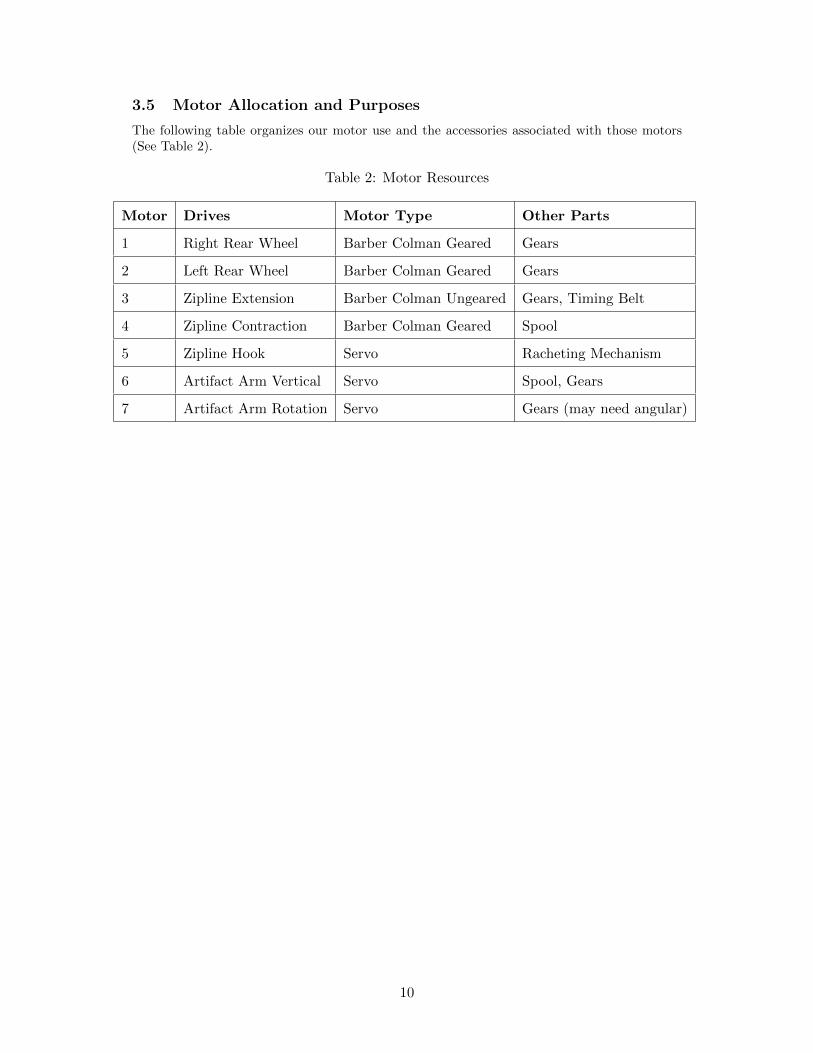
The following table organizes our motor use and the accessories associated with those motors(See Table 2).
Table 2: Motor Resources
Motor Drives Motor Type Other Parts
1 Right Rear Wheel Barber Colman Geared Gears
2 Left Rear Wheel Barber Colman Geared Gears
3 Zipline Extension Barber Colman Ungeared Gears, Timing Belt
4 Zipline Contraction Barber Colman Geared Spool
5 Zipline Hook Servo Racheting Mechanism
6 Artifact Arm Vertical Servo Spool, Gears
7 Artifact Arm Rotation Servo Gears (may need angular)
10
4 Sensors and Feedback
The control system of this robot is largely based on detecting and analyzing various infraredfrequencies. Touch sensors will also be utilized. Feedback from these sensors will be processedthrough various operational amplifier circuits and translated into mechanical actuation in variousparts of the robot. The rest of this section will have detailed descriptions of the other componentsthat have TINAH board resources allocated to them.
The specific connections are listed in the following tables (See Table 3, 4 and 5):
Table 3: TINAH Analog I/O Allocation
TINAH Analog Pin Number Device/Sensor
0 Right Tape Sensor
1 Left Tape Sensor
2 Right IR Beacon Detector
3 Left IR Beacon Detector
4 Artifact Arm Servo
5 Active Front Wheels Control Servo
Table 4: TINAH Digital I/O Allocation
TINAH Digital Pin Number Device/Sensor
0 Artifact Sensor
1 Pad Magnet Touch Sensor
2 Pad Elevation Control
3 Ziplne Detection Switch
4 Zipline Hook Control Servo
Table 5: TINAH PWM I/O Allocation
TINAH PWM Pin Number Device/Sensor
0 Right Rear Wheel Motor
1 Left Rear Wheel Motor
2 Zipline Arm Motor
3 Zipline Winch Motor
4 Artifact Arm Up/Down Motor
11
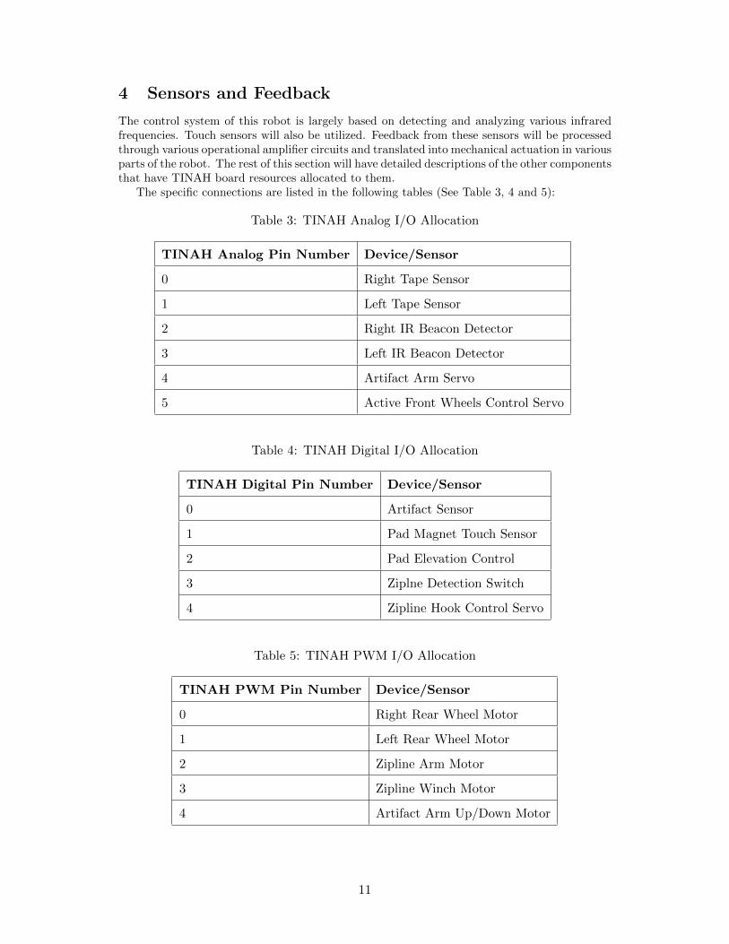
4.1 Tape Sensors
The two front tape sensors (QRD1114 Reflective Object Sensors, see Figure 8) are to be mountedin parallel between the two front wheels, pointing directly downwards. They will be providingfeedback on the robots alignment relative to the tape, and will be responsible for dictating itsdirection of movement. The presence of two sensors will allow the robot to more accuratelyfollow the tape path by comparing the readings of each sensor, and adjusting accordingly.
Figure 8: QRD1114 Reflective Object Sensors
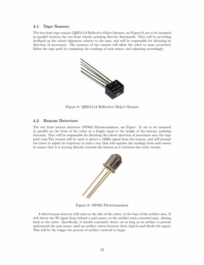
4.2 Beacon Detectors
The two front beacon detectors (OP805 Phototransistors, see Figure 9) are to be mountedin parallel on the front of the robot at a height equal to the height of the beacon, pointingforwards. They will be responsible for dictating the robots direction of movement once the tapepath ends.The sensors will be used to detect a 10kHz signal from the beacon, and will promptthe robot to adjust its trajectory in such a way that will equalize the readings from each sensorto ensure that it is moving directly towards the beacon as it traverses the rocky terrain.
Figure 9: OP805 Phototransistor
A third beacon detector will exist on the side of the robot, at the base of the artifact arm. Itwill detect the IR signal from behind a pad sensor on the artifact arms extended part, shiningback at the robot. Specifically, it should constantly detect on as long as no artifact is presentunderneath the pad sensor, until an artifact enters between these objects and blocks the signal.This will be the trigger for process of artifact retrieval to begin.
12
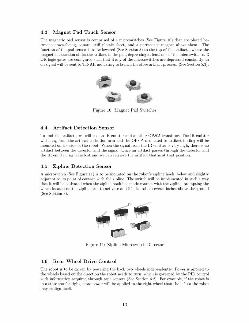
4.3 Magnet Pad Touch Sensor
The magnetic pad sensor is comprised of 4 microswitches (See Figure 10) that are placed be-tweena down-facing, square, stiff plastic sheet, and a permanent magnet above them. Thefunction of the pad sensor is to be lowered (See Section 3) to the top of the artifacts, where themagnetic attraction sticks the artifact to the pad, depressing at least one of the microswitches. 3OR logic gates are configured such that if any of the microswitches are depressed constantly anon signal will be sent to TINAH indicating to launch the store artifact process. (See Section 5.3).
Figure 10: Magnet Pad Switches
4.4 Artifact Detection Sensor
To find the artifacts, we will use an IR emitter and another OP805 transistor. The IR emitterwill hang from the artifact collection arm and the OP805 dedicated to artifact finding will bemounted on the side of the robot. When the signal from the IR emitter is very high, there is noartifact between the detector and the signal. Once an artifact passes through the detector andthe IR emitter, signal is lost and we can retrieve the artifact that is at that position.
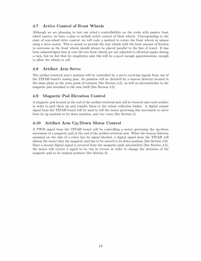
4.5 Zipline Detection Sensor
A microswitch (See Figure 11) is to be mounted on the robot’s zipline hook, below and slightlyadjacent to its point of contact with the zipline. The switch will be implemented in such a waythat it will be activated when the zipline hook has made contact with the zipline, prompting thewinch located on the zipline arm to activate and lift the robot several inches above the ground(See Section 3).
Figure 11: Zipline Microswitch Detector
4.6 Rear Wheel Drive Control
The robot is to be driven by powering the back two wheels independently. Power is applied tothe wheels based on the direction the robot needs to turn, which is governed by the PID controlwith information acquired through tape sensors (See Section 6.2). For example, if the robot isin a state too far right, more power will be applied to the right wheel than the left so the robotmay realign itself.
13
4.7 Active Control of Front Wheels
Although we are planning to test our robot’s controllability on the rocks with passive frontwheel casters, we have a plan to include active control of these wheels. Corresponding to thestate of rear-wheel drive control, we will code a method to rotate the front wheels in unisonusing a servo motor. This is meant to provide the rear wheels with the least amount of frictionto overcome as the front wheels should always be placed parallel to the line of travel. It hasbeen acknowledged that in cars the two front wheels are not adjusted to identical angles duringa turn, but we feel that for simplicitys sake this will be a good enough approximation; enoughto allow the wheels to roll.
4.8 Artifact Arm Servo
The artifact-retrieval arm’s position will be controlled by a servo receiving signals from one ofthe TINAH board’s analog pins. Its position will be dictated by a beacon detector located inthe same plane as the arms point of rotation (See Section 4.2), as well as microswitches in themagnetic pad attached to the arm itself (See Section 4.3).
4.9 Magnetic Pad Elevation Control
A magnetic pad located at the end of the artifact-retrieval arm will be lowered onto each artifactin order to pick them up and transfer them to the robots collection basket. A digital outputsignal from the TINAH board will be used to tell the motor governing this movement to movefrom its up position to its down position, and vice versa (See Section 3).
4.10 Artifact Arm Up/Down Motor Control
A PWM signal from the TINAH board will be controlling a motor governing the up/downmovement of a magnetic pad at the end of the artifact-retrieval arm. When the beacon detectormounted on the side of a robot has its signal blocked, a digital signal from the TINAH willinform the motor that the magnetic pad has to be moved to its down position (See Section 4.9).Once a second digital signal is received from the magnetic pads microswitch (See Section 4.3),the motor will receive a signal to be run in reverse in order to change the elevation of themagnetic pad to its original position (See Section 3).
14
5 Electrical Design
The proposed electrical design consists of six total PCBs mounted near the front of our robot.The PCBs will be fabricated out of circuit boards with components soldered onto them. All thePCBs will connect to a central PCB power hub titled PCB0 (See Section 5.1) through male andfemale headers. Many of the PCBs will also connect to the TINAH board I/O pins.
5.1 PCB0 - Power Rail Bar
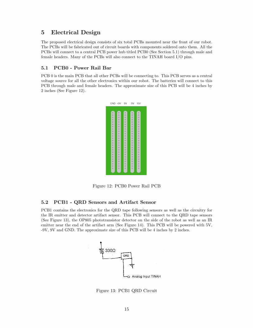
PCB 0 is the main PCB that all other PCBs will be connecting to. This PCB serves as a centralvoltage source for all the other electronics within our robot. The batteries will connect to thisPCB through male and female headers. The approximate size of this PCB will be 4 inches by2 inches (See Figure 12).
Figure 12: PCB0 Power Rail PCB
5.2 PCB1 - QRD Sensors and Artifact Sensor
PCB1 contains the electronics for the QRD tape following sensors as well as the circuitry forthe IR emitter and detector artifact sensor. This PCB will connect to the QRD tape sensors(See Figure 13), the OP805 phototransistor detector on the side of the robot as well as an IRemitter near the end of the artifact arm (See Figure 14). This PCB will be powered with 5V,-9V, 9V and GND. The approximate size of this PCB will be 4 inches by 2 inches.
Figure 13: PCB1 QRD Circuit
15
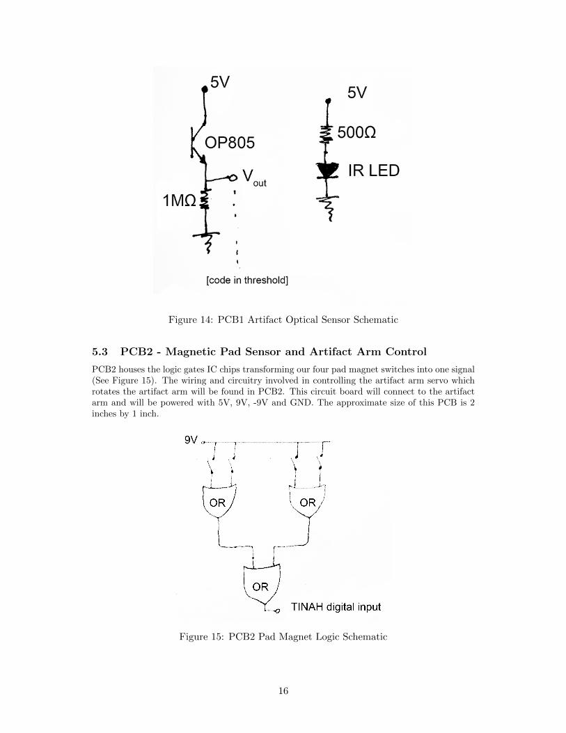
Figure 14: PCB1 Artifact Optical Sensor Schematic
5.3 PCB2 - Magnetic Pad Sensor and Artifact Arm Control
PCB2 houses the logic gates IC chips transforming our four pad magnet switches into one signal(See Figure 15). The wiring and circuitry involved in controlling the artifact arm servo whichrotates the artifact arm will be found in PCB2. This circuit board will connect to the artifactarm and will be powered with 5V, 9V, -9V and GND. The approximate size of this PCB is 2inches by 1 inch.
Figure 15: PCB2 Pad Magnet Logic Schematic
16
5.4 PCB3 - 2 H Bridges (Wheels)
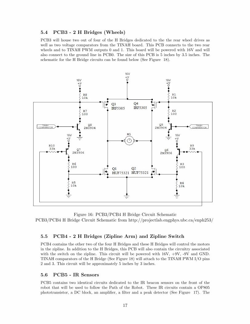
PCB3 will house two out of four of the H Bridges dedicated to the the rear wheel drives aswell as two voltage comparators from the TINAH board. This PCB connects to the two rearwheels and to TINAH PWM outputs 0 and 1. This board will be powered with 16V and willalso connect to the ground line in PCB0. The size of this PCB is 5 inches by 3.5 inches. Theschematic for the H Bridge circuits can be found below (See Figure 18).
Figure 16: PCB3/PCB4 H Bridge Circuit SchematicPCB3/PCB4 H Bridge Circuit Schematic from http://projectlab.engphys.ubc.ca/enph253/
5.5 PCB4 - 2 H Bridges (Zipline Arm) and Zipline Switch
PCB4 contains the other two of the four H Bridges and these H Bridges will control the motorsin the zipline. In addition to the H Bridges, this PCB will also contain the circuitry associatedwith the switch on the zipline. This circuit will be powered with 16V, +9V, -9V and GND.TINAH comparators of the H Bridge (See Figure 18) will attach to the TINAH PWM I/O pins2 and 3. This circuit will be approximately 5 inches by 3 inches.
5.6 PCB5 - IR Sensors
PCB5 contains two identical circuits dedicated to the IR beacon sensors on the front of therobot that will be used to follow the Path of the Robot. These IR circuits contain a OP805phototransistor, a DC block, an amplifier, a filter and a peak detector (See Figure 17). The
17
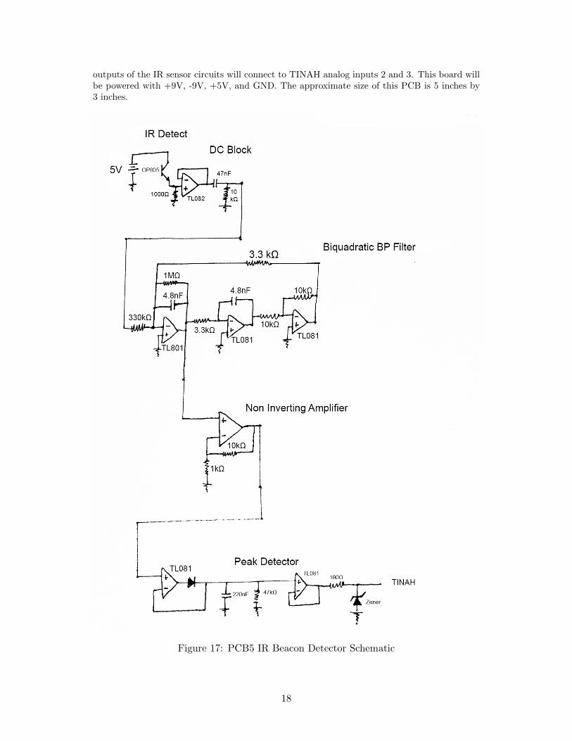
outputs of the IR sensor circuits will connect to TINAH analog inputs 2 and 3. This board willbe powered with +9V, -9V, +5V, and GND. The approximate size of this PCB is 5 inches by3 inches.
Figure 17: PCB5 IR Beacon Detector Schematic
18
5.7 Physical Wiring
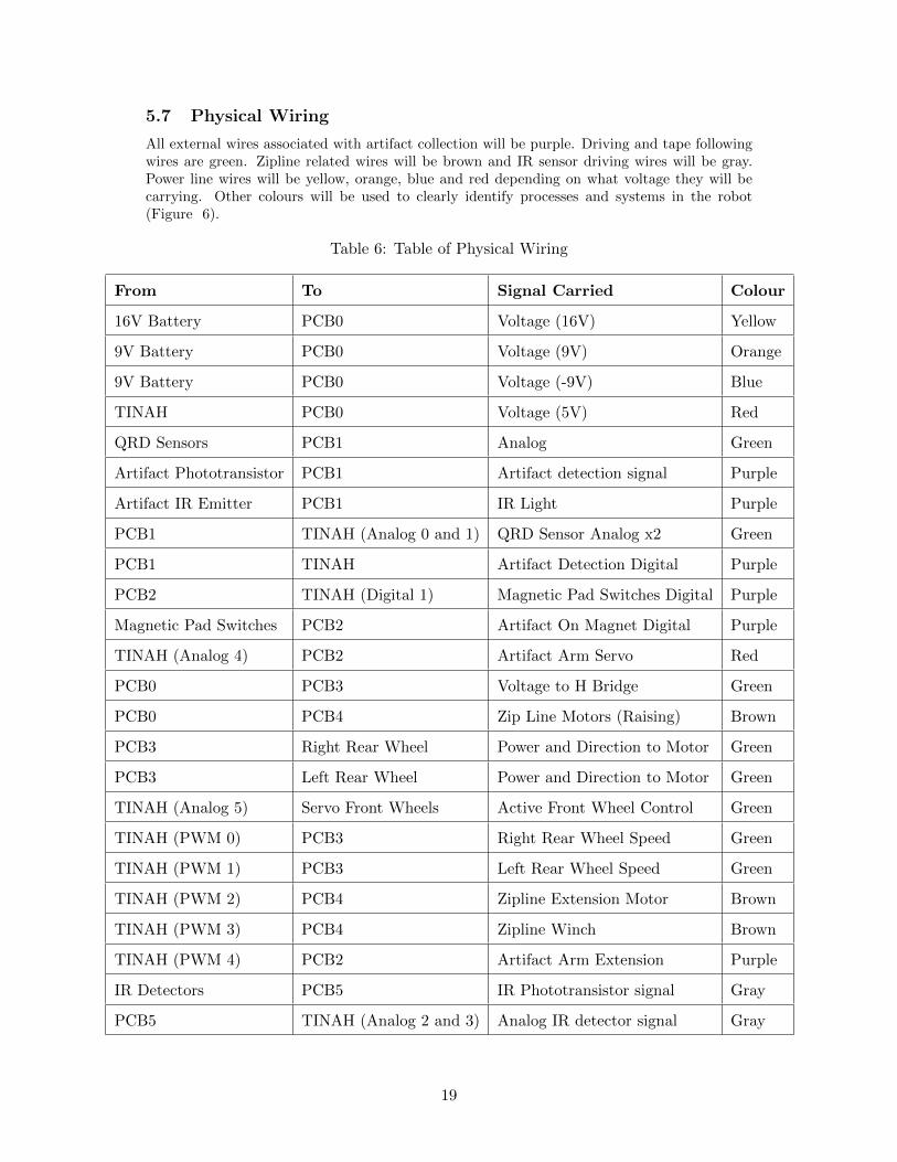
All external wires associated with artifact collection will be purple. Driving and tape followingwires are green. Zipline related wires will be brown and IR sensor driving wires will be gray.Power line wires will be yellow, orange, blue and red depending on what voltage they will becarrying. Other colours will be used to clearly identify processes and systems in the robot(Figure 6).
Table 6: Table of Physical Wiring
From To Signal Carried Colour
16V Battery PCB0 Voltage (16V) Yellow
9V Battery PCB0 Voltage (9V) Orange
9V Battery PCB0 Voltage (-9V) Blue
TINAH PCB0 Voltage (5V) Red
QRD Sensors PCB1 Analog Green
Artifact Phototransistor PCB1 Artifact detection signal Purple
Artifact IR Emitter PCB1 IR Light Purple
PCB1 TINAH (Analog 0 and 1) QRD Sensor Analog x2 Green
PCB1 TINAH Artifact Detection Digital Purple
PCB2 TINAH (Digital 1) Magnetic Pad Switches Digital Purple
Magnetic Pad Switches PCB2 Artifact On Magnet Digital Purple
TINAH (Analog 4) PCB2 Artifact Arm Servo Red
PCB0 PCB3 Voltage to H Bridge Green
PCB0 PCB4 Zip Line Motors (Raising) Brown
PCB3 Right Rear Wheel Power and Direction to Motor Green
PCB3 Left Rear Wheel Power and Direction to Motor Green
TINAH (Analog 5) Servo Front Wheels Active Front Wheel Control Green
TINAH (PWM 0) PCB3 Right Rear Wheel Speed Green
TINAH (PWM 1) PCB3 Left Rear Wheel Speed Green
TINAH (PWM 2) PCB4 Zipline Extension Motor Brown
TINAH (PWM 3) PCB4 Zipline Winch Brown
TINAH (PWM 4) PCB2 Artifact Arm Extension Purple
IR Detectors PCB5 IR Phototransistor signal Gray
PCB5 TINAH (Analog 2 and 3) Analog IR detector signal Gray
19
6 Software Code and Algorithm
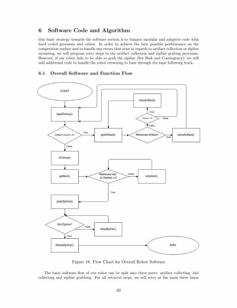
Our basic strategy towards the software section is to balance modular and adaptive code withhard coded processes and values. In order to achieve the best possible performance on thecompetition surface and to handle any errors that arise in regards to artifact collection or ziplinemounting, we will program retry steps to the artifact collection and zipline grabing processes.However, if our robot fails to be able to grab the zipline (See Risk and Contingency), we willadd additional code to handle the robot returning to base through the tape following track.
6.1 Overall Software and Function Flow
Figure 18: Flow Chart for Overall Robot Software
The basic software flow of our robot can be split into three parts: artifact collecting, idolcollecting and zipline grabbing. For all retrieval steps, we will retry at the most three times
20
before moving on with the the rest of the algorithm. If our robot fails to find the zipline, wewill turn around and take the risky and dangerous path back.
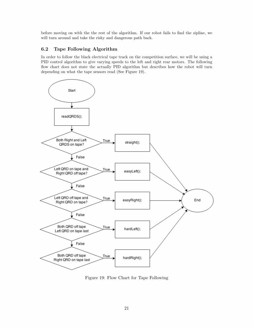
6.2 Tape Following Algorithm
In order to follow the black electrical tape track on the competition surface, we will be using aPID control algorithm to give varying speeds to the left and right rear motors. The followingflow chart does not state the actually PID algorithm but describes how the robot will turndepending on what the tape sensors read (See Figure 19).
Figure 19: Flow Chart for Tape Following
21
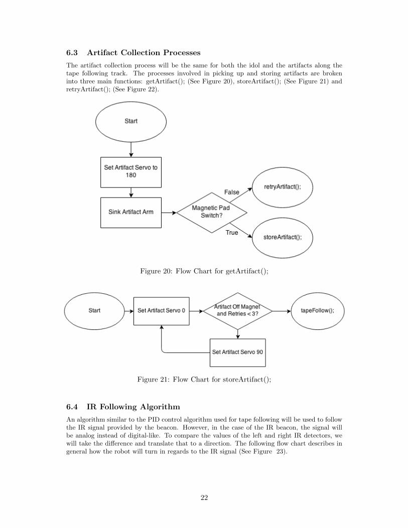
6.3 Artifact Collection Processes
The artifact collection process will be the same for both the idol and the artifacts along thetape following track. The processes involved in picking up and storing artifacts are brokeninto three main functions: getArtifact(); (See Figure 20), storeArtifact(); (See Figure 21) andretryArtifact(); (See Figure 22).
Figure 20: Flow Chart for getArtifact();
Figure 21: Flow Chart for storeArtifact();
6.4 IR Following Algorithm
An algorithm similar to the PID control algorithm used for tape following will be used to followthe IR signal provided by the beacon. However, in the case of the IR beacon, the signal willbe analog instead of digital-like. To compare the values of the left and right IR detectors, wewill take the difference and translate that to a direction. The following flow chart describes ingeneral how the robot will turn in regards to the IR signal (See Figure 23).
22
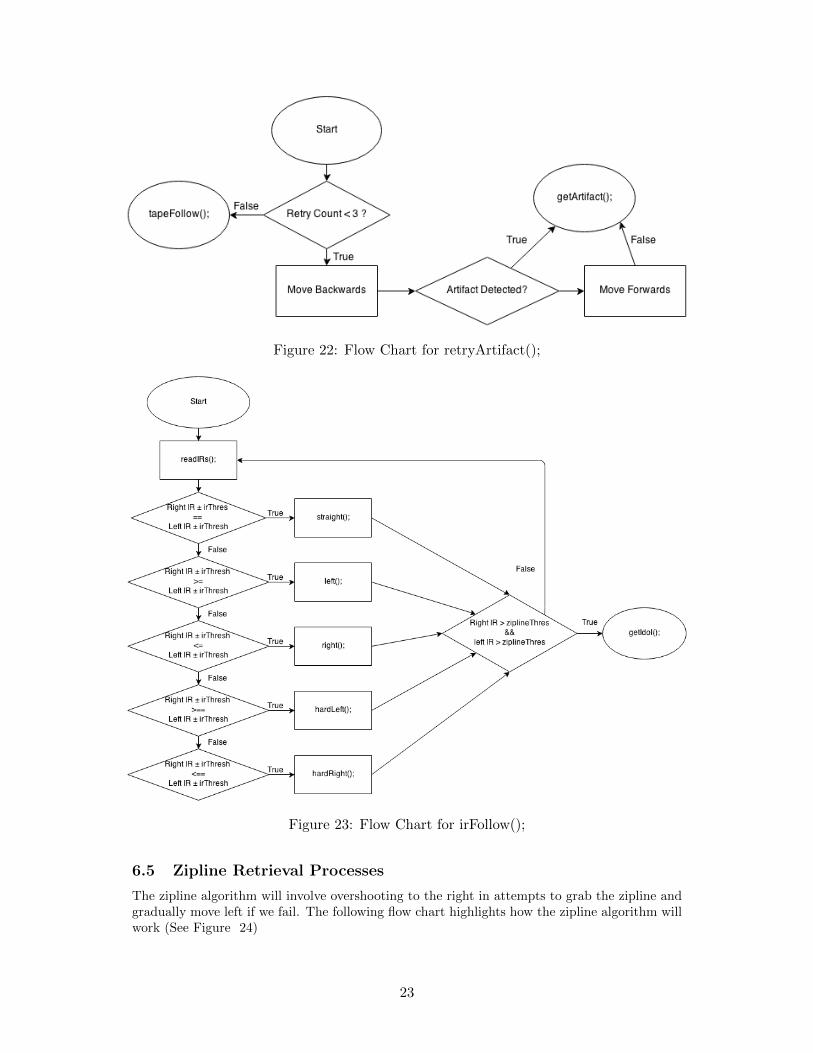
Figure 22: Flow Chart for retryArtifact();
Figure 23: Flow Chart for irFollow();
6.5 Zipline Retrieval Processes
The zipline algorithm will involve overshooting to the right in attempts to grab the zipline andgradually move left if we fail. The following flow chart highlights how the zipline algorithm willwork (See Figure 24)
23
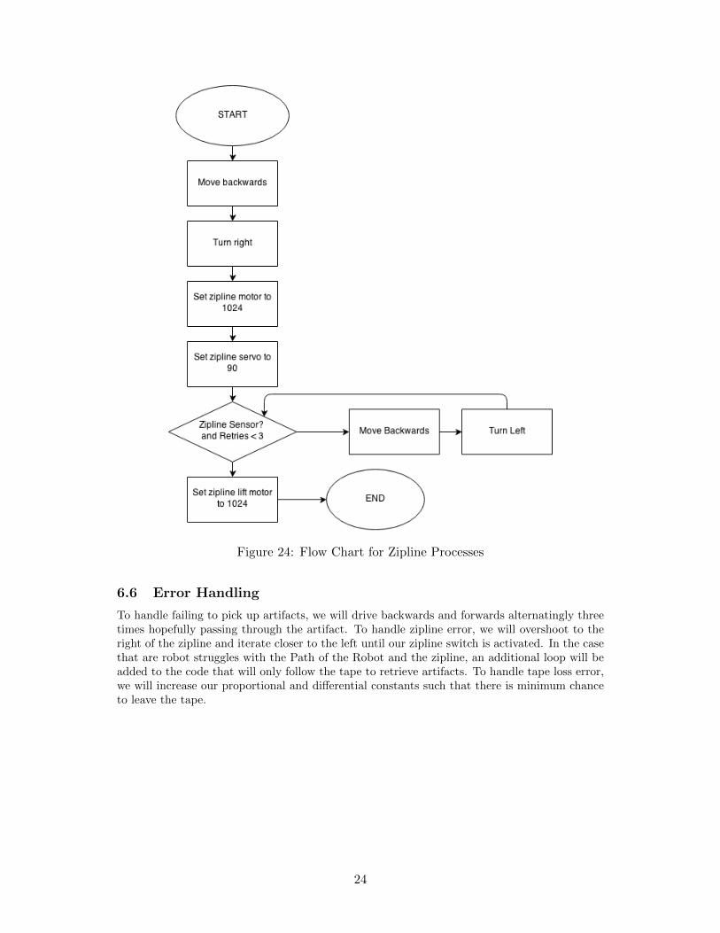
Figure 24: Flow Chart for Zipline Processes
6.6 Error Handling
To handle failing to pick up artifacts, we will drive backwards and forwards alternatingly threetimes hopefully passing through the artifact. To handle zipline error, we will overshoot to theright of the zipline and iterate closer to the left until our zipline switch is activated. In the casethat are robot struggles with the Path of the Robot and the zipline, an additional loop will beadded to the code that will only follow the tape to retrieve artifacts. To handle tape loss error,we will increase our proportional and differential constants such that there is minimum chanceto leave the tape.
24
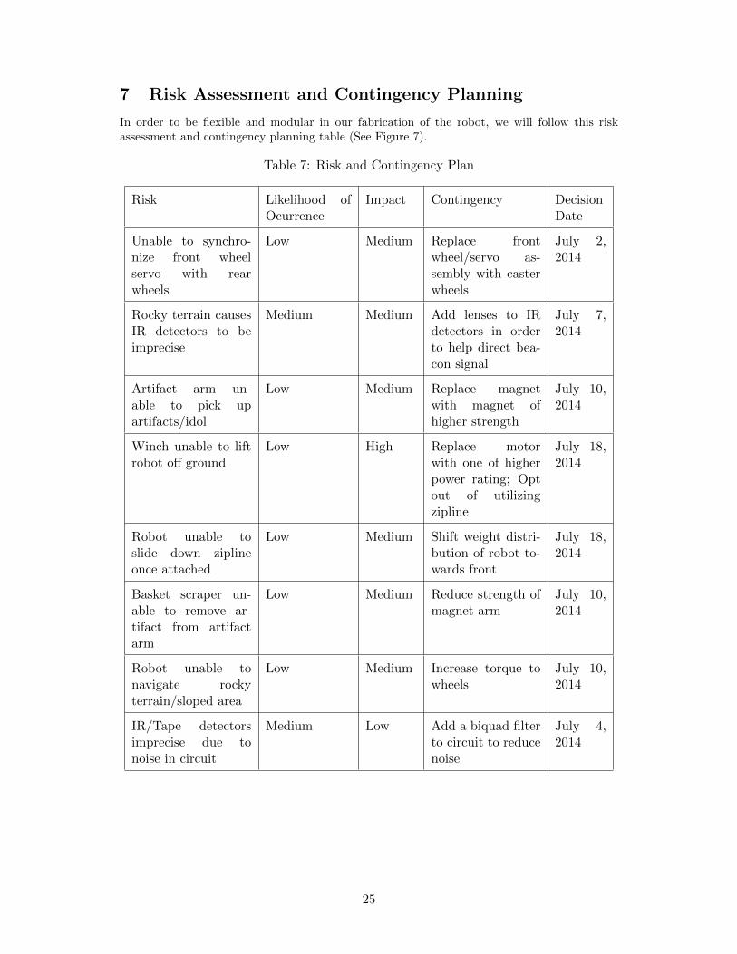
7 Risk Assessment and Contingency Planning
In order to be flexible and modular in our fabrication of the robot, we will follow this riskassessment and contingency planning table (See Figure 7).
Table 7: Risk and Contingency Plan
Risk Likelihood ofOcurrence
Impact Contingency DecisionDate
Unable to synchro-nize front wheelservo with rearwheels
Low Medium Replace frontwheel/servo as-sembly with casterwheels
July 2,2014
Rocky terrain causesIR detectors to beimprecise
Medium Medium Add lenses to IRdetectors in orderto help direct bea-con signal
July 7,2014
Artifact arm un-able to pick upartifacts/idol
Low Medium Replace magnetwith magnet ofhigher strength
July 10,2014
Winch unable to liftrobot off ground
Low High Replace motorwith one of higherpower rating; Optout of utilizingzipline
July 18,2014
Robot unable toslide down ziplineonce attached
Low Medium Shift weight distri-bution of robot to-wards front
July 18,2014
Basket scraper un-able to remove ar-tifact from artifactarm
Low Medium Reduce strength ofmagnet arm
July 10,2014
Robot unable tonavigate rockyterrain/sloped area
Low Medium Increase torque towheels
July 10,2014
IR/Tape detectorsimprecise due tonoise in circuit
Medium Low Add a biquad filterto circuit to reducenoise
July 4,2014
25
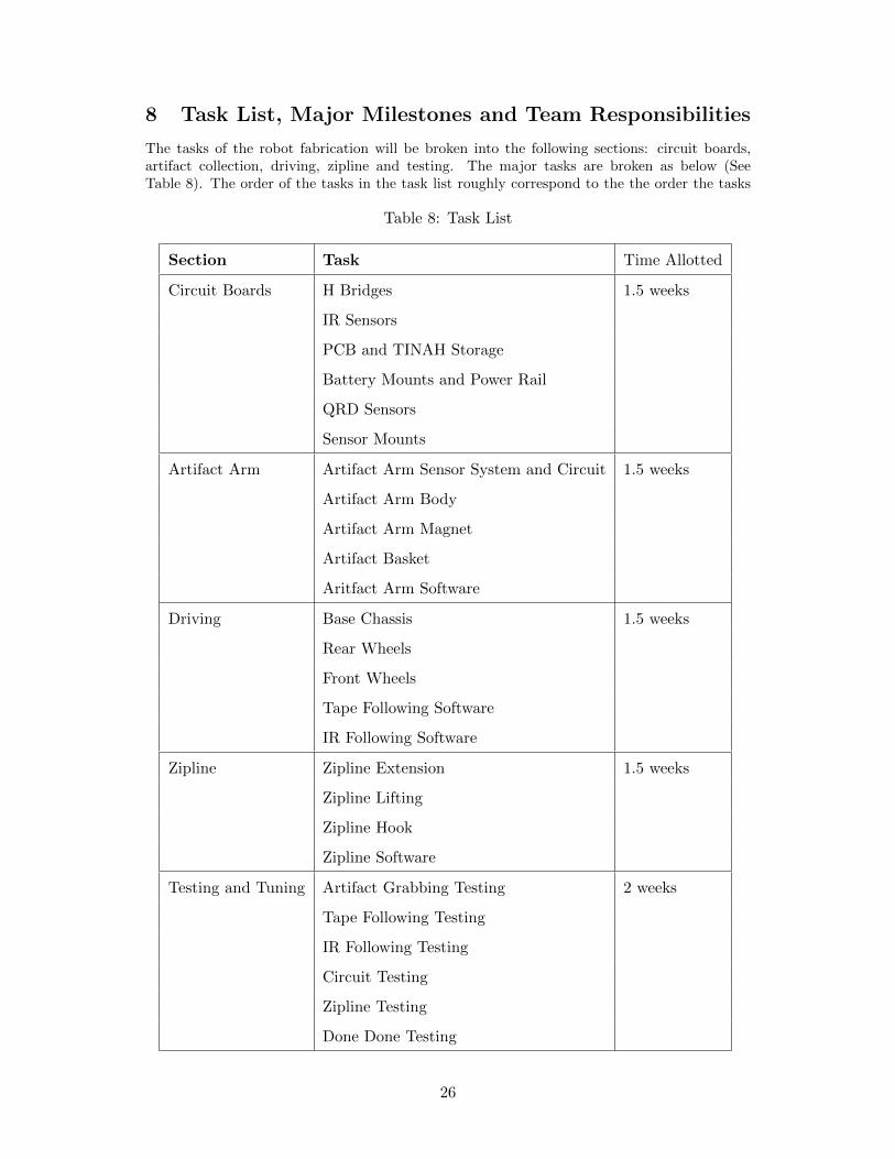
8 Task List, Major Milestones and Team Responsibilities
The tasks of the robot fabrication will be broken into the following sections: circuit boards,artifact collection, driving, zipline and testing. The major tasks are broken as below (SeeTable 8). The order of the tasks in the task list roughly correspond to the the order the tasks
Table 8: Task List
Section Task Time Allotted
Circuit Boards H Bridges 1.5 weeks
IR Sensors
PCB and TINAH Storage
Battery Mounts and Power Rail
QRD Sensors
Sensor Mounts
Artifact Arm Artifact Arm Sensor System and Circuit 1.5 weeks
Artifact Arm Body
Artifact Arm Magnet
Artifact Basket
Aritfact Arm Software
Driving Base Chassis 1.5 weeks
Rear Wheels
Front Wheels
Tape Following Software
IR Following Software
Zipline Zipline Extension 1.5 weeks
Zipline Lifting
Zipline Hook
Zipline Software
Testing and Tuning Artifact Grabbing Testing 2 weeks
Tape Following Testing
IR Following Testing
Circuit Testing
Zipline Testing
Done Done Testing
26
will be completed. The artifact collection section and the driving section will be developedsimultaneously because these two sections depend a lot on the status of each other.
8.1 Major Milestones
For July 7, the major milestones day, our goal is to be well in development for the followingtasks:
• H Bridge Circuits
• IR Sensor Circuits
• PCB and TINAH Storage
• Battery Mounts and Power Rail
• QRD Sensor Circuits
• Sensor Mounts
• Artifact Arm Sensor System and Circuit
• Artifact Arm Body
• Artifact Arm Magnet
• Artifact Arm Basket
• Artifact Arm Software Pseudocode
• Base Chassis
• Rear Wheels
• Front Wheels
• Tape Following Software
• IR Following Software
We will strive to finish creating majority of the PCBs and create the basic frame and mechanicsfor our robot. On this major milestone day, we will also decide whether or not to proceedforward with developing the zipline or to spend more time optimizing the artifact collection andtape following mechanisms.
8.2 Team Responsibilities
Each team member will have their own main focus and sub focus. The table in the appendixdescribes how each task will be sorted into the weeks of robot fabrication (See Appendix A).Runor will be focusing on the artifact arm with sub focus as software. Etienne will be focusingon drive with sub focus as circuits. Bryan will be focusing on the zipline with sub focus artifactarm. Eleanor will be focusing on software with sub focus drive.
27
9 Conclusion
The robot competition is to traverse an obstacle course and pick up four artifacts and returnto the start of the course. There are two ways to return to the start, drive down the track usedto get to the last artifact or use the zipline located at the last artifact. Overall, the robot willweigh 7 kg and will be able to pick up artifacts and use the zipline to return the start of thecourse.
There are several things to consider when designing a robot that can complete the challenge.The first is the drive system. This robot will have two driven rear wheels with active controlin the front wheels. The active control will use a servo motor to steer, this allows for reliablesteering and control of the robot. The robot will use an arm to pick up artifacts. Picked upartifacts will be stored in a basket near the rear wheels. The arm will rotate between the basketand artifacts on the course. To pick the artifacts, the artifact arm will have a magnetic padthat can move up and down to move closer to the artifacts.
Using the zipline to finish the course is advantageous because it is faster than driving back.The zipline arm will be at the centre of the robot, close to its centre of gravity. The armwill start folded and will extend to reach the zipline. When a switch at the end of the arm isactivated through its contact with the zipline, a servo motor will move the hook into place onthe zipline.
The electrical design for the robot will consist of several sensors, PCBs and a TINAH board.The QRDs will be used to follow the tape on the course. The artifact and zipline arms willboth have switches on them to determine if an artifact has been picked up and if the clamp ison the zipline, respectively. The PCBs and TINAH board will be stored vertically in a tray atthe front of the robot. There will be two IR sensors on the robot to direct it when it reachesthe end of the tape. The zipline arm and the rear wheels will have a pair of H-bridges to allowtheir motors to change direction.
Using a modular programming approach with a schedule that will complete the minimumviable product by early to mid July, Team One’s robot strives to complete the course, fromfollowing tape, to collecting artifacts, to riding the zipline out of the “Temple of Doom.”
28
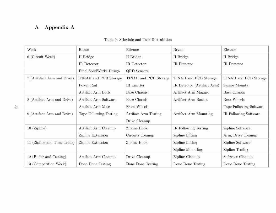
A Appendix A
Table 9: Schedule and Task Distrubition
Week Runor Etienne Bryan Eleanor
6 (Circuit Week) H Bridge H Bridge H Bridge H Bridge
IR Detector IR Detector IR Detector IR Detector
Final SolidWorks Design QRD Sensors
7 (Aritifact Arm and Drive) TINAH and PCB Storage TINAH and PCB Storage TINAH and PCB Storage TINAH and PCB Storage
Power Rail IR Emitter IR Detector (Artifact Arm) Sensor Mounts
Artifact Arm Body Base Chassis Artifact Arm Magnet Base Chassis
8 (Artifact Arm and Drive) Artifact Arm Software Base Chassis Artifact Arm Basket Rear Wheels
Artifact Arm Misc Front Wheels Tape Following Software
9 (Artifact Arm and Drive) Tape Following Testing Artifact Arm Testing Artifact Arm Mounting IR Following Software
Drive Cleanup
10 (Zipline) Artifact Arm Cleanup Zipline Hook IR Following Testing Zipline Software
Zipline Extension Circuits Cleanup Zipline Lifting Arm, Drive Cleanup
11 (Zipline and Time Trials) Zipline Extension Zipline Hook Zipline Lifting Zipline Software
Zipline Mounting Zipline Testing
12 (Buffer and Testing) Artifact Arm Cleanup Drive Cleanup Zipline Cleanup Software Cleanup
13 (Competition Week) Done Done Testing Done Done Testing Done Done Testing Done Done Testing
29