Embed Size (px)
Citation preview

The Allen-Bradley® Bulletins 193 and 592E1 Plus electronic overload relays are theindustry’s first modular self-powereddevices. Through the use of optional side-mount modules, functionality of the E1Plus overload relays can be cost effectivelyexpanded and machine operation andprotection enhanced.
AdvantagesCompact – Direct mounting to the left side of the current-sensing 193-EE and592-EE E1 Plus overload relays adds only18 mm is added to the width.
Simplified Control – The side-mountmodules electronically interface with theE1 Plus overload relay so that all controlcircuit connections are made at the E1 Plus overload relay terminals.
Flexibility – The modular design of the E1 Plus overload relays allowsexpanded functionality in only thoseapplications where it is required.
Enhanced ProtectionFlexibility - The E1 Plus side-mount modules provide adjustable levels ofprotection, tailored to your application.
Diagnostics – The E1 Plus side-mount module1 monitors the motor current byelectronically interfacing to the E1 Plus overload relay’s current-sensing circuit. As a result, the side-mount module is able to identify the cause of trip includingoverload, phase loss, or the added protection function the side-mount module provides.
To help minimize troubleshooting, a status LED on the front of each E1 Plus side-mount module2 provides diagnostic information about the cause of the trip.
Dynamic Inhibit on Start – The E1 Plus side-mount modules3 contain a uniquecircuit that monitors for motor starting inrush current. This circuit inhibits a jamor ground fault trip during the motor start period and then arms the jam and/orground fault trip function after the inrush current falls below 125% of the overload relay full-load current setting. This eliminates the need for additionalcomponents like timing relays, simplifying the control circuit.
Integrated Remote ResetEach E1 Plus side-mount module incorporates circuitry for resetting a tripped E1Plus overload relay. Actuation of a contact or PLC® output connected at themodule’s reset terminations will result in a reset signal being transmitted from themodule to the E1 Plus overload relay.1 Excluding the Remote Reset side-mount module (Cat. No. 193-ERR)2 Excluding the Series A Jam side-mount module (Cat. No. 193-EJM), the Series A Remote Reset side-mount module
(Cat. No. 193-ERR), and the DeviceNet™ side-mount module (Cat. No. 193-EDN)3 Excluding the Remote Reset side-mount module (Cat. No. 193-ERR) and the PTC side-mount module (Cat. No. 193-EPT)
ESSENTIAL COMPONENTSE1 Plus Side-Mount ModulesEnhancing Your Motor Protection
E1 Plus Profile.qxd:Product_app_profile5-18-05.qxd 4/11/07 2:14 PM Page 1
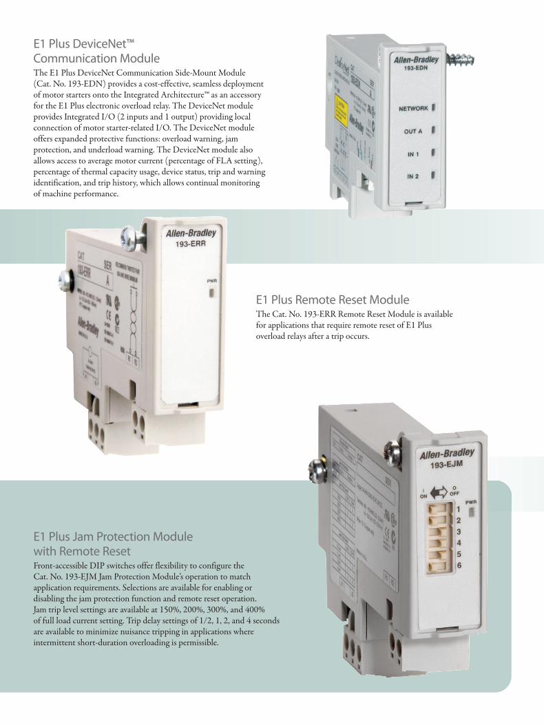
E1 Plus Jam Protection Module with Remote ResetFront-accessible DIP switches offer flexibility to configure the Cat. No. 193-EJM Jam Protection Module’s operation to matchapplication requirements. Selections are available for enabling ordisabling the jam protection function and remote reset operation. Jam trip level settings are available at 150%, 200%, 300%, and 400% of full load current setting. Trip delay settings of 1/2, 1, 2, and 4 seconds are available to minimize nuisance tripping in applications whereintermittent short-duration overloading is permissible.
E1 Plus Remote Reset ModuleThe Cat. No. 193-ERR Remote Reset Module is available for applications that require remote reset of E1 Plus overload relays after a trip occurs.
E1 Plus DeviceNet™ Communication ModuleThe E1 Plus DeviceNet Communication Side-Mount Module (Cat. No. 193-EDN) provides a cost-effective, seamless deploymentof motor starters onto the Integrated Architecture™ as an accessoryfor the E1 Plus electronic overload relay. The DeviceNet moduleprovides Integrated I/O (2 inputs and 1 output) providing localconnection of motor starter-related I/O. The DeviceNet moduleoffers expanded protective functions: overload warning, jamprotection, and underload warning. The DeviceNet module alsoallows access to average motor current (percentage of FLA setting),percentage of thermal capacity usage, device status, trip and warningidentification, and trip history, which allows continual monitoring of machine performance.
E1 Plus Profile.qxd:Product_app_profile5-18-05.qxd 4/11/07 2:14 PM Page 2
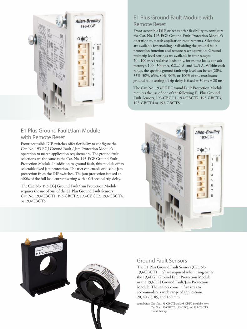
E1 Plus Ground Fault/Jam Module with Remote ResetFront-accessible DIP switches offer flexibility to configure the Cat. No. 193-EGJ Ground Fault / Jam Protection Module’soperation to match application requirements. The ground faultselections are the same as the Cat. No. 193-EGF Ground FaultProtection Module. In addition to ground fault, this module offersselectable fixed jam protection. The user can enable or disable jamprotection from the DIP switches. The jam protection is fixed at400% of the full load current setting with a 0.5 second trip delay.
The Cat. No. 193-EGJ Ground Fault/Jam Protection Modulerequires the use of one of the E1 Plus Ground Fault Sensors Cat. No. 193-CBCT1, 193-CBCT2, 193-CBCT3, 193-CBCT4, or 193-CBCT5.
E1 Plus Ground Fault Module with Remote ResetFront-accessible DIP switches offer flexibility to configurethe Cat. No. 193-EGF Ground Fault Protection Module’soperation to match application requirements. Selectionsare available for enabling or disabling the ground faultprotection function and remote reset operation. Groundfault trip level settings are available in four ranges: 20…100 mA (resistive loads only, for motor loads consultfactory), 100…500 mA, 0.2…1 A, and 1…5 A. Within eachrange, the specific ground fault trip level can be set (20%,35%, 50%, 65%, 80%, 90%, or 100% of the maximumground fault setting). Trip delay is fixed at 50 ms ± 20 ms.
The Cat. No. 193-EGF Ground Fault Protection Modulerequires the use of one of the following E1 Plus GroundFault Sensors, 193-CBCT1, 193-CBCT2, 193-CBCT3,193-CBCT4 or 193-CBCT5.
Ground Fault SensorsThe E1 Plus Ground Fault Sensors (Cat. No.193-CBCT1 … 5) are required when using eitherthe 193-EGF Ground Fault Protection Moduleor the 193-EGJ Ground Fault/Jam ProtectionModule. The sensors come in five sizes toaccommodate a wide range of applications, 20, 40, 65, 85, and 160 mm.Availability: Cat. Nos. 193-CBCTI and 193-CBTC2 available now.
Cat. Nos. 193-CBCT3, 193-CBCJ, and 193-CBCT5, consult factory.
E1 Plus Profile.qxd:Product_app_profile5-18-05.qxd 4/11/07 2:15 PM Page 3
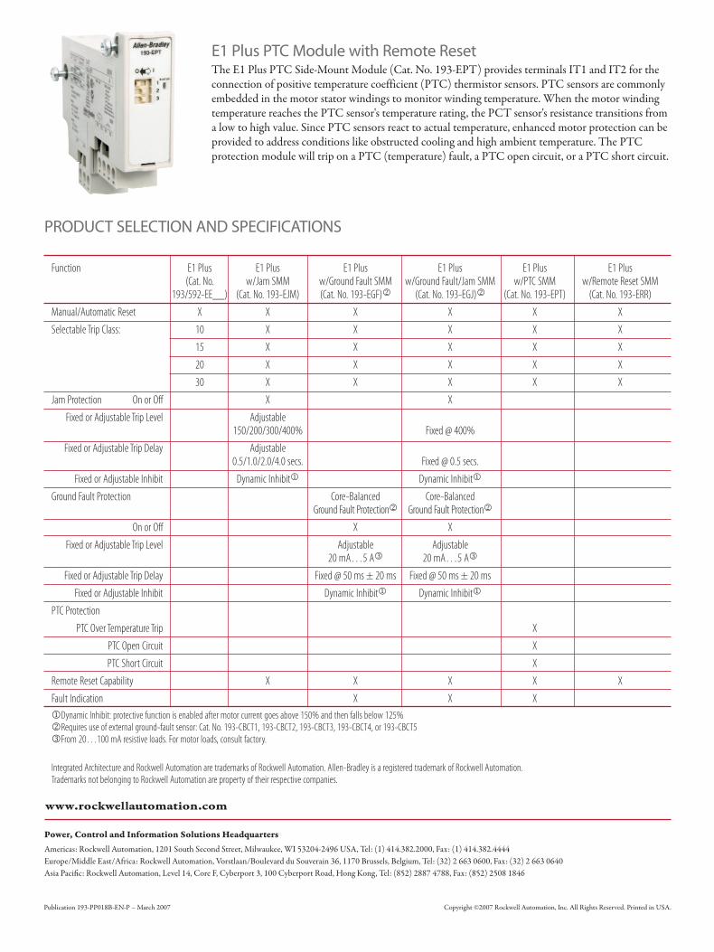
PRODUCT SELECTION AND SPECIFICATIONS
Publication 193-PP018B-EN-P – March 2007 Copyright ©2007 Rockwell Automation, Inc. All Rights Reserved. Printed in USA.
Function E1 Plus E1 Plus E1 Plus E1 Plus E1 Plus E1 Plus (Cat. No. w/Jam SMM w/Ground Fault SMM w/Ground Fault/Jam SMM w/PTC SMM w/Remote Reset SMM
193/592-EE__) (Cat. No. 193-EJM) (Cat. No. 193-EGF)2 (Cat. No. 193-EGJ)2 (Cat. No. 193-EPT) (Cat. No. 193-ERR)Manual/Automatic Reset X X X X X XSelectable Trip Class: 10 X X X X X
15 X X X X X20 X X X X X30 X X X X X
Jam Protection On or Off X XFixed or Adjustable Trip Level Adjustable
150/200/300/400% Fixed @ 400%Fixed or Adjustable Trip Delay Adjustable
0.5/1.0/2.0/4.0 secs. Fixed @ 0.5 secs.Fixed or Adjustable Inhibit Dynamic Inhibit1 Dynamic Inhibit1
Ground Fault Protection Core-Balanced Core-BalancedGround Fault Protection2 Ground Fault Protection2
On or Off X XFixed or Adjustable Trip Level Adjustable Adjustable
20 mA…5 A3 20 mA…5 A3
Fixed or Adjustable Trip Delay Fixed @ 50 ms ± 20 ms Fixed @ 50 ms ± 20 msFixed or Adjustable Inhibit Dynamic Inhibit1 Dynamic Inhibit1
PTC ProtectionPTC Over Temperature Trip X
PTC Open Circuit XPTC Short Circuit X
Remote Reset Capability X X X X XFault Indication X X X1Dynamic Inhibit: protective function is enabled after motor current goes above 150% and then falls below 125%2Requires use of external ground-fault sensor: Cat. No. 193-CBCT1, 193-CBCT2, 193-CBCT3, 193-CBCT4, or 193-CBCT53From 20…100 mA resistive loads. For motor loads, consult factory.
Integrated Architecture and Rockwell Automation are trademarks of Rockwell Automation. Allen-Bradley is a registered trademark of Rockwell Automation.Trademarks not belonging to Rockwell Automation are property of their respective companies.
E1 Plus PTC Module with Remote ResetThe E1 Plus PTC Side-Mount Module (Cat. No. 193-EPT) provides terminals IT1 and IT2 for theconnection of positive temperature coefficient (PTC) thermistor sensors. PTC sensors are commonlyembedded in the motor stator windings to monitor winding temperature. When the motor windingtemperature reaches the PTC sensor's temperature rating, the PCT sensor's resistance transitions froma low to high value. Since PTC sensors react to actual temperature, enhanced motor protection can beprovided to address conditions like obstructed cooling and high ambient temperature. The PTCprotection module will trip on a PTC (temperature) fault, a PTC open circuit, or a PTC short circuit.
E1 Plus Profile.qxd:Product_app_profile5-18-05.qxd 4/11/07 2:15 PM Page 4