Embed Size (px)
Citation preview
Enhancing the OK1DFC Square Septum Feed With a Choke Ring Paul Wade W1GHZ ©2007
[email protected] A previous investigation1 of the properties of the VE4MA feedhorn2, a circular waveguide horn with a single choke ring, led to the discovery of some combinations of dimensions that can provide significantly enhanced performance. One set of dimensions, which we called the “Super-VE4MA,” showed higher calculated dish efficiency than any other prime-focus feedhorn. These calculated results have been substantiated by sun noise measurements made independently by WD5AGO and others. It seems likely that the OK1DFC septum feed3,4 could also be enhanced by adding a choke ring, as shown in Figure 1, and optimizing the choke dimensions. The results suggest that there is a set of choke dimensions which can provide calculated efficiency for circular polarization nearly as high as the Super-VE4MA feed. However, the tolerance on dimensions for good performance is more limited than with the circular waveguide, making it more difficult to utilize available materials. The results for the enhanced OK1DFC septum feed have not yet been substantiated by measurement.
Figure 1 Septum feed with choke ring (from WA5WCP)
OK1DFC septum feed
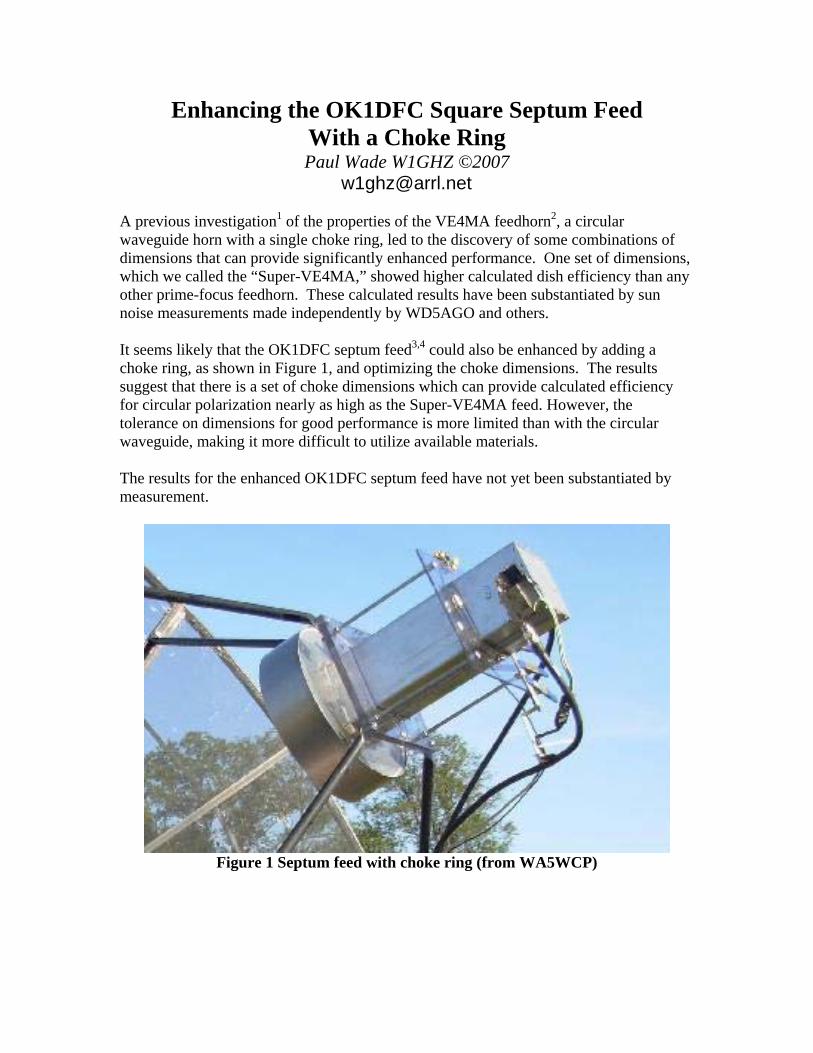
Figure 2 OK1DFC septum feed (from DL4MUP)
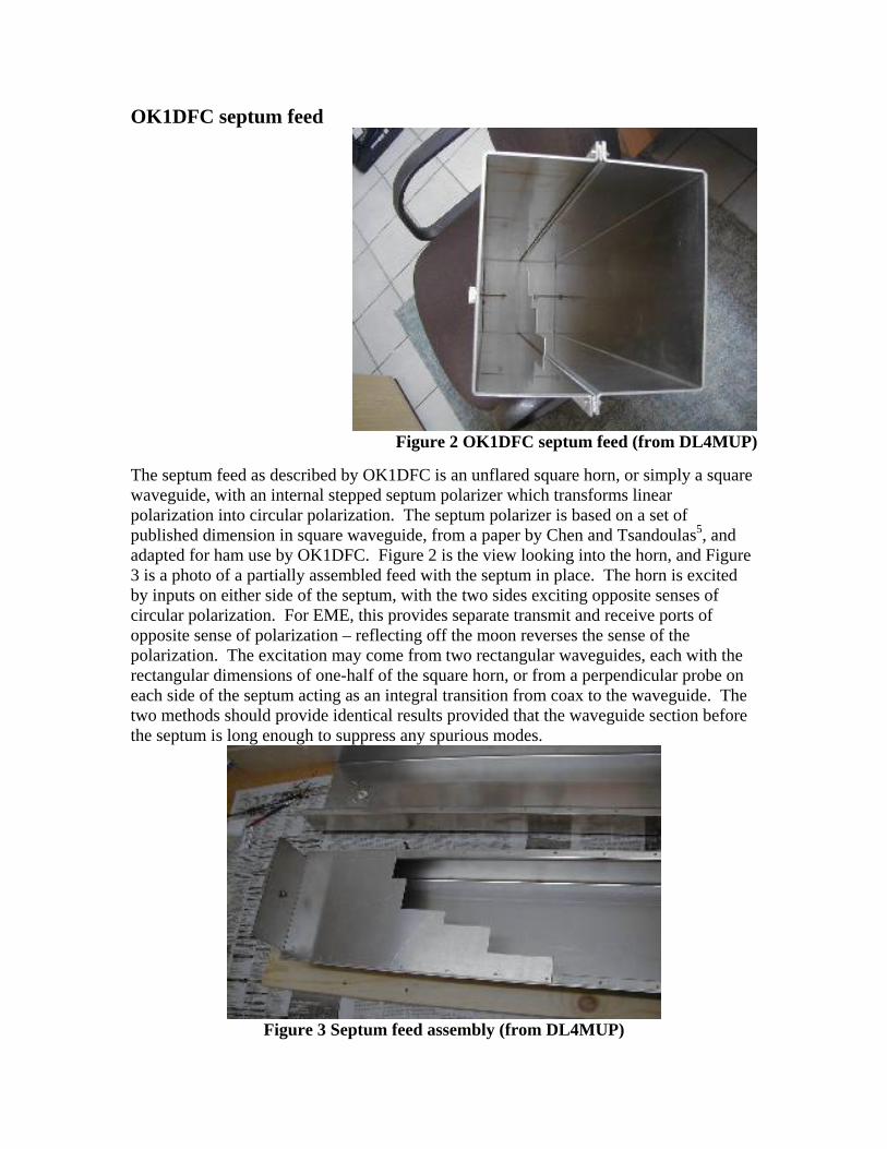
The septum feed as described by OK1DFC is an unflared square horn, or simply a square waveguide, with an internal stepped septum polarizer which transforms linear polarization into circular polarization. The septum polarizer is based on a set of published dimension in square waveguide, from a paper by Chen and Tsandoulas5, and adapted for ham use by OK1DFC. Figure 2 is the view looking into the horn, and Figure 3 is a photo of a partially assembled feed with the septum in place. The horn is excited by inputs on either side of the septum, with the two sides exciting opposite senses of circular polarization. For EME, this provides separate transmit and receive ports of opposite sense of polarization – reflecting off the moon reverses the sense of the polarization. The excitation may come from two rectangular waveguides, each with the rectangular dimensions of one-half of the square horn, or from a perpendicular probe on each side of the septum acting as an integral transition from coax to the waveguide. The two methods should provide identical results provided that the waveguide section before the septum is long enough to suppress any spurious modes.
Figure 3 Septum feed assembly (from DL4MUP)
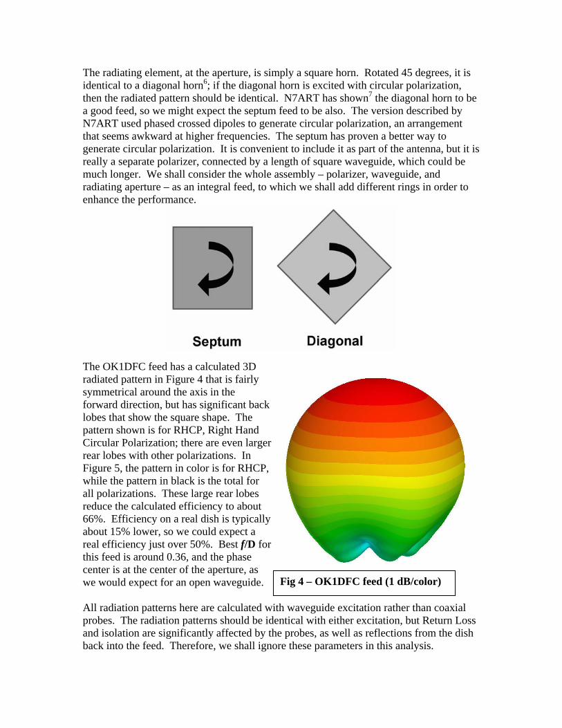
The radiating element, at the aperture, is simply a square horn. Rotated 45 degrees, it is identical to a diagonal horn6; if the diagonal horn is excited with circular polarization, then the radiated pattern should be identical. N7ART has shown7 the diagonal horn to be a good feed, so we might expect the septum feed to be also. The version described by N7ART used phased crossed dipoles to generate circular polarization, an arrangement that seems awkward at higher frequencies. The septum has proven a better way to generate circular polarization. It is convenient to include it as part of the antenna, but it is really a separate polarizer, connected by a length of square waveguide, which could be much longer. We shall consider the whole assembly – polarizer, waveguide, and radiating aperture – as an integral feed, to which we shall add different rings in order to enhance the performance.
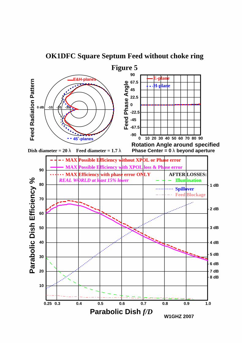
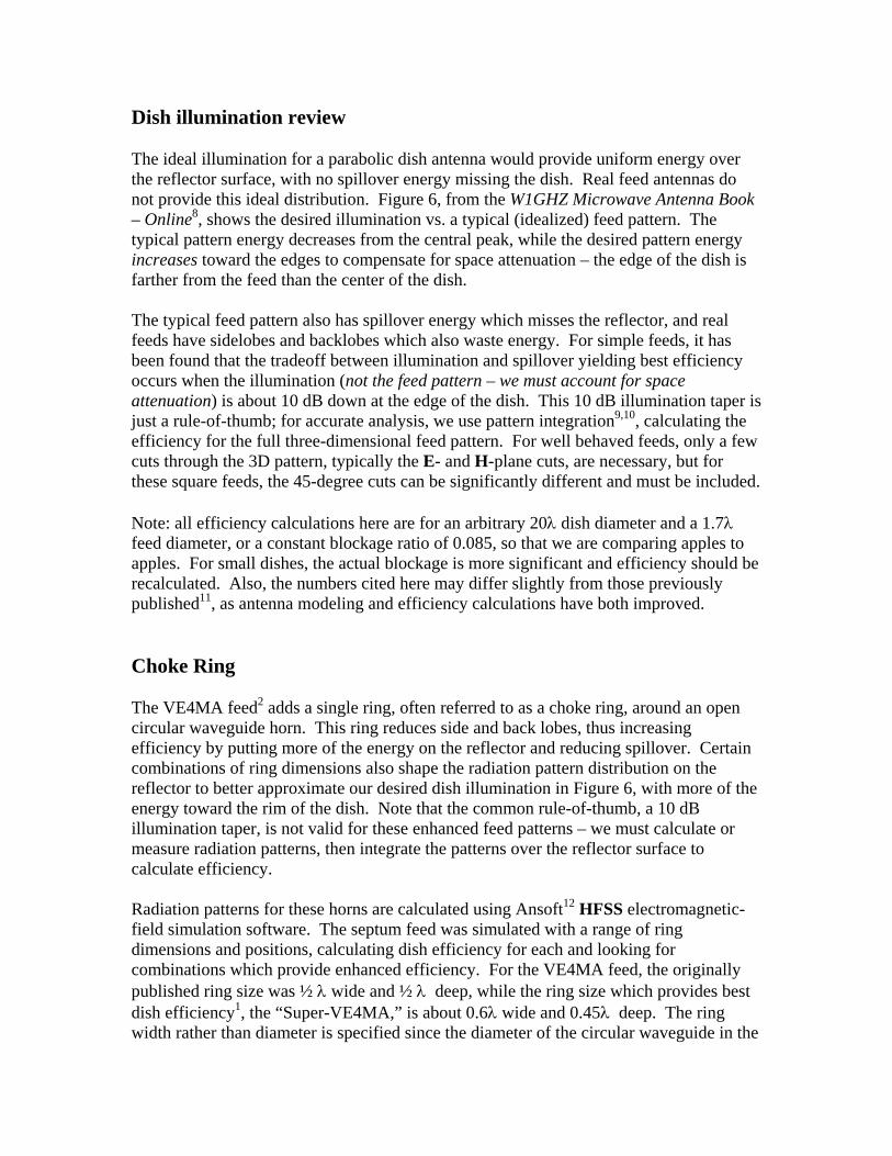
The OK1DFC feed has a calculated 3D radiated pattern in Figure 4 that is fairly symmetrical around the axis in the forward direction, but has significant back lobes that show the square shape. The pattern shown is for RHCP, Right Hand Circular Polarization; there are even larger rear lobes with other polarizations. In Figure 5, the pattern in color is for RHCP, while the pattern in black is the total for all polarizations. These large rear lobes reduce the calculated efficiency to about 66%. Efficiency on a real dish is typically about 15% lower, so we could expect a real efficiency just over 50%. Best f/D for this feed is around 0.36, and the phase center is at the center of the aperture, as we would expect for an open waveguide. Fig 4 – OK1DFC feed (1 dB/color) All radiation patterns here are calculated with waveguide excitation rather than coaxial probes. The radiation patterns should be identical with either excitation, but Return Loss and isolation are significantly affected by the probes, as well as reflections from the dish back into the feed. Therefore, we shall ignore these parameters in this analysis.
OK1DFC Square Septum Feed without choke ring
Figure 5
Dish diameter = 20 λ Feed diameter = 1.7 λ
E&H-planes
45˚-planes
0 dB -10 -20 -30
Fee
d R
adia
tio
n P
atte
rn
W1GHZ 2007
0 10 20 30 40 50 60 70 80 90-90
-67.5
-45
-22.5
0
22.5
45
67.5
90
Rotation Angle around
Fee
d P
has
e A
ng
le
E-plane
H-plane
specifiedPhase Center = 0 λ beyond aperture
0.3 0.4 0.5 0.6 0.7 0.8 0.90.25 1.0
10
20
30
40
50
60
70
80
90
1 dB
2 dB
3 dB
4 dB
5 dB
6 dB
7 dB8 dB
MAX Possible Efficiency with XPOL loss & Phase error
REAL WORLD at least 15% lower
MAX Possible Efficiency without XPOL or Phase error
MAX Efficiency with phase error ONLYIllumination
Spillover
AFTER LOSSES:
Feed Blockage
Parabolic Dish f/D
Par
abo
lic D
ish
Eff
icie
ncy
%
Dish illumination review The ideal illumination for a parabolic dish antenna would provide uniform energy over the reflector surface, with no spillover energy missing the dish. Real feed antennas do not provide this ideal distribution. Figure 6, from the W1GHZ Microwave Antenna Book – Online8, shows the desired illumination vs. a typical (idealized) feed pattern. The typical pattern energy decreases from the central peak, while the desired pattern energy increases toward the edges to compensate for space attenuation – the edge of the dish is farther from the feed than the center of the dish. The typical feed pattern also has spillover energy which misses the reflector, and real feeds have sidelobes and backlobes which also waste energy. For simple feeds, it has been found that the tradeoff between illumination and spillover yielding best efficiency occurs when the illumination (not the feed pattern – we must account for space attenuation) is about 10 dB down at the edge of the dish. This 10 dB illumination taper is just a rule-of-thumb; for accurate analysis, we use pattern integration9,10, calculating the efficiency for the full three-dimensional feed pattern. For well behaved feeds, only a few cuts through the 3D pattern, typically the E- and H-plane cuts, are necessary, but for these square feeds, the 45-degree cuts can be significantly different and must be included. Note: all efficiency calculations here are for an arbitrary 20λ dish diameter and a 1.7λ feed diameter, or a constant blockage ratio of 0.085, so that we are comparing apples to apples. For small dishes, the actual blockage is more significant and efficiency should be recalculated. Also, the numbers cited here may differ slightly from those previously published11, as antenna modeling and efficiency calculations have both improved. Choke Ring The VE4MA feed2 adds a single ring, often referred to as a choke ring, around an open circular waveguide horn. This ring reduces side and back lobes, thus increasing efficiency by putting more of the energy on the reflector and reducing spillover. Certain combinations of ring dimensions also shape the radiation pattern distribution on the reflector to better approximate our desired dish illumination in Figure 6, with more of the energy toward the rim of the dish. Note that the common rule-of-thumb, a 10 dB illumination taper, is not valid for these enhanced feed patterns – we must calculate or measure radiation patterns, then integrate the patterns over the reflector surface to calculate efficiency. Radiation patterns for these horns are calculated using Ansoft12 HFSS electromagnetic-field simulation software. The septum feed was simulated with a range of ring dimensions and positions, calculating dish efficiency for each and looking for combinations which provide enhanced efficiency. For the VE4MA feed, the originally published ring size was ½ λ wide and ½ λ deep, while the ring size which provides best dish efficiency1, the “Super-VE4MA,” is about 0.6λ wide and 0.45λ deep. The ring width rather than diameter is specified since the diameter of the circular waveguide in the
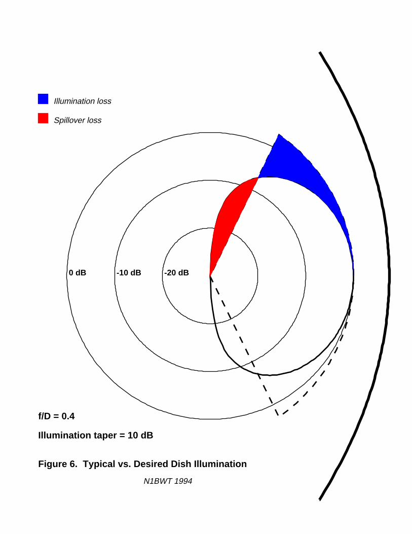
f/D = 0.4
Illumination taper = 10 dB
Figure 6. Typical vs. Desired Dish Illumination
N1BWT 1994
0 dB -10 dB -20 dB
Spillover loss
Illumination loss
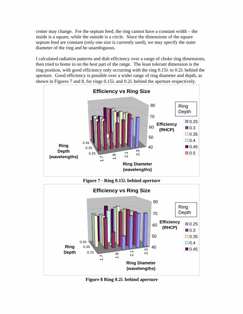
center may change. For the septum feed, the ring cannot have a constant width – the inside is a square, while the outside is a circle. Since the dimensions of the square septum feed are constant (only one size is currently used), we may specify the outer diameter of the ring and be unambiguous. I calculated radiation patterns and dish efficiency over a range of choke ring dimensions, then tried to home in on the best part of the range. The least tolerant dimension is the ring position, with good efficiency only occurring with the ring 0.15λ to 0.2λ behind the aperture. Good efficiency is possible over a wider range of ring diameter and depth, as shown in Figures 7 and 8, for rings 0.15λ and 0.2λ behind the aperture respectively.
1.7 1.9 2.1 2.3
0.250.35
0.4540
50
60
70
80
Efficiency (RHCP)
Ring Diameter(wavelengths)
Ring Depth
(wavelengths)
Efficiency vs Ring Size
0.250.30.350.40.450.5
Ring Depth
Figure 7 - Ring 0.15λ behind aperture
1.7 1.9 2.1 2.3
0.250.35
0.4540
50
60
70
80
Efficiency (RHCP)
Ring Diameter(wavelengths)
Ring Depth
Efficiency vs Ring Size
0.250.30.350.40.45
Ring Depth
Figure 8 Ring 0.2λ behind aperture
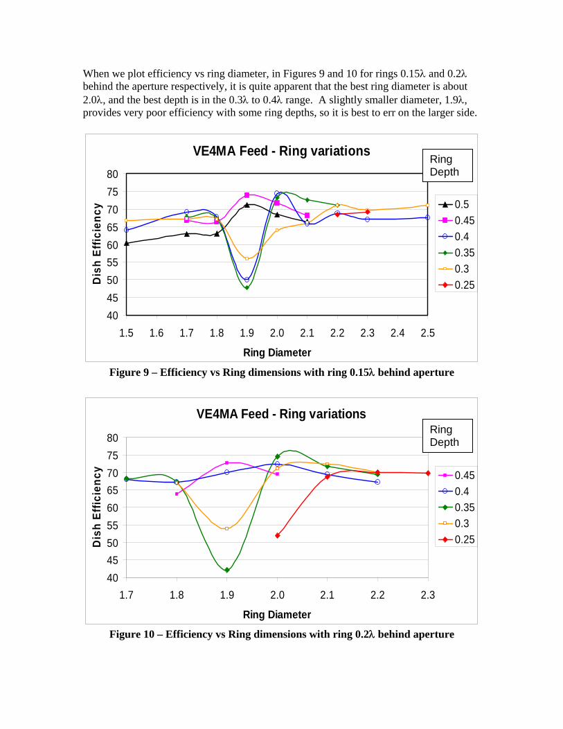
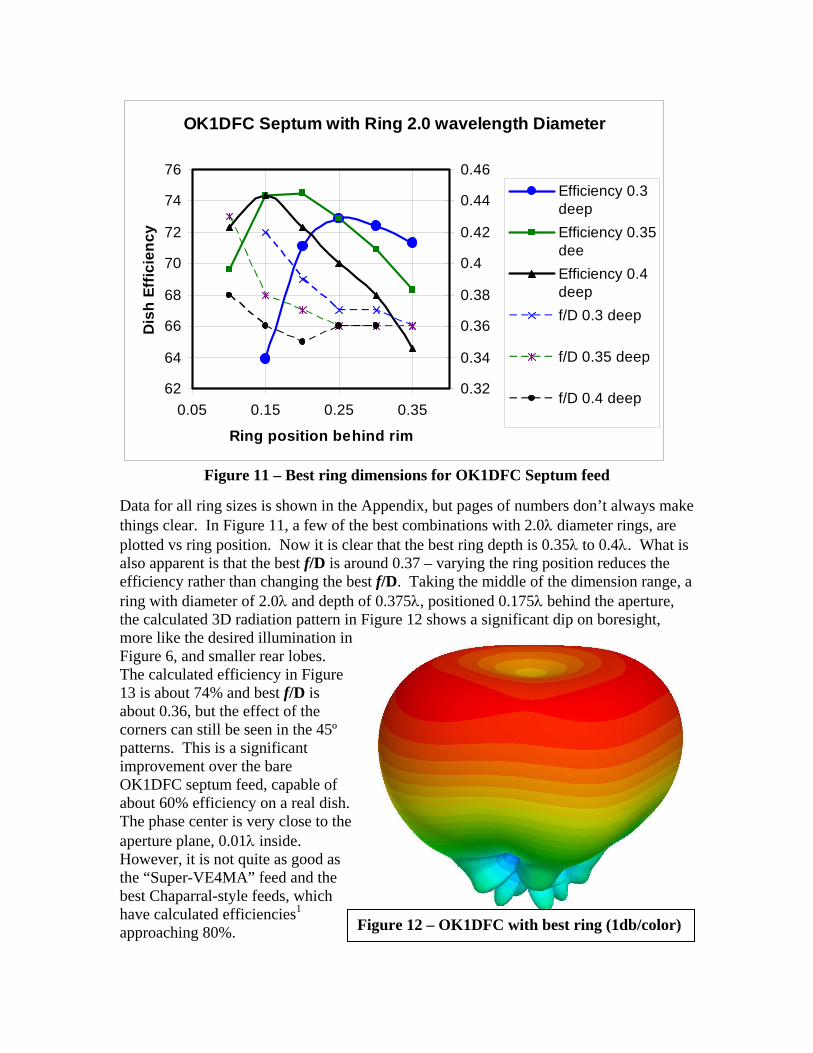
When we plot efficiency vs ring diameter, in Figures 9 and 10 for rings 0.15λ and 0.2λ behind the aperture respectively, it is quite apparent that the best ring diameter is about 2.0λ, and the best depth is in the 0.3λ to 0.4λ range. A slightly smaller diameter, 1.9λ, provides very poor efficiency with some ring depths, so it is best to err on the larger side.
VE4MA Feed - Ring variations
404550556065707580
1.5 1.6 1.7 1.8 1.9 2.0 2.1 2.2 2.3 2.4 2.5
Ring Diameter
Dis
h Ef
ficie
ncy 0.5
0.450.40.350.30.25
Ring Depth
Figure 9 – Efficiency vs Ring dimensions with ring 0.15λ behind aperture
VE4MA Feed - Ring variations
404550556065707580
1.7 1.8 1.9 2.0 2.1 2.2 2.3
Ring Diameter
Dis
h Ef
ficie
ncy 0.45
0.40.350.30.25
Ring Depth
Figure 10 – Efficiency vs Ring dimensions with ring 0.2λ behind aperture
OK1DFC Septum with Ring 2.0 wavelength Diameter
62
64
66
68
70
72
74
76
0.05 0.15 0.25 0.35
Ring position behind rim
Dis
h Ef
ficie
ncy
0.32
0.34
0.36
0.38
0.4
0.42
0.44
0.46Efficiency 0.3deepEfficiency 0.35deeEfficiency 0.4deepf/D 0.3 deep
f/D 0.35 deep
f/D 0.4 deep
Figure 11 – Best ring dimensions for OK1DFC Septum feed
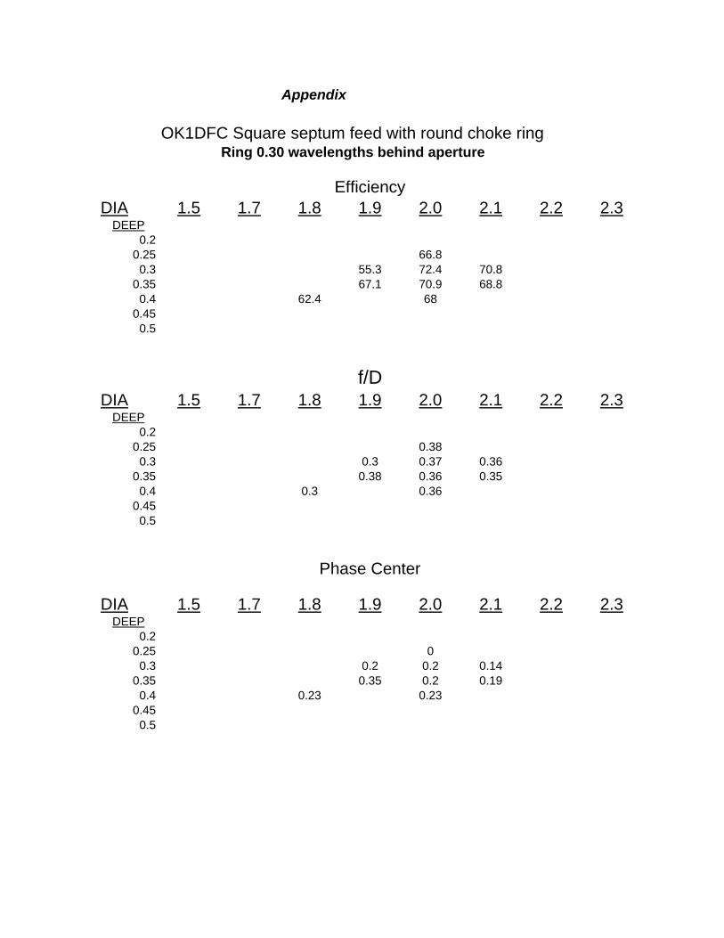
Data for all ring sizes is shown in the Appendix, but pages of numbers don’t always make things clear. In Figure 11, a few of the best combinations with 2.0λ diameter rings, are plotted vs ring position. Now it is clear that the best ring depth is 0.35λ to 0.4λ. What is also apparent is that the best f/D is around 0.37 – varying the ring position reduces the efficiency rather than changing the best f/D. Taking the middle of the dimension range, a ring with diameter of 2.0λ and depth of 0.375λ, positioned 0.175λ behind the aperture, the calculated 3D radiation pattern in Figure 12 shows a significant dip on boresight, more like the desired illumination in Figure 6, and smaller rear lobes. The calculated efficiency in Figure 13 is about 74% and best f/D is about 0.36, but the effect of the corners can still be seen in the 45º patterns. This is a significant improvement over the bare OK1DFC septum feed, capable of about 60% efficiency on a real dish. The phase center is very close to the aperture plane, 0.01λ inside. However, it is not quite as good as the “Super-VE4MA” feed and the best Chaparral-style feeds, which have calculated efficiencies1 approaching 80%. Figure 12 – OK1DFC with best ring (1db/color)
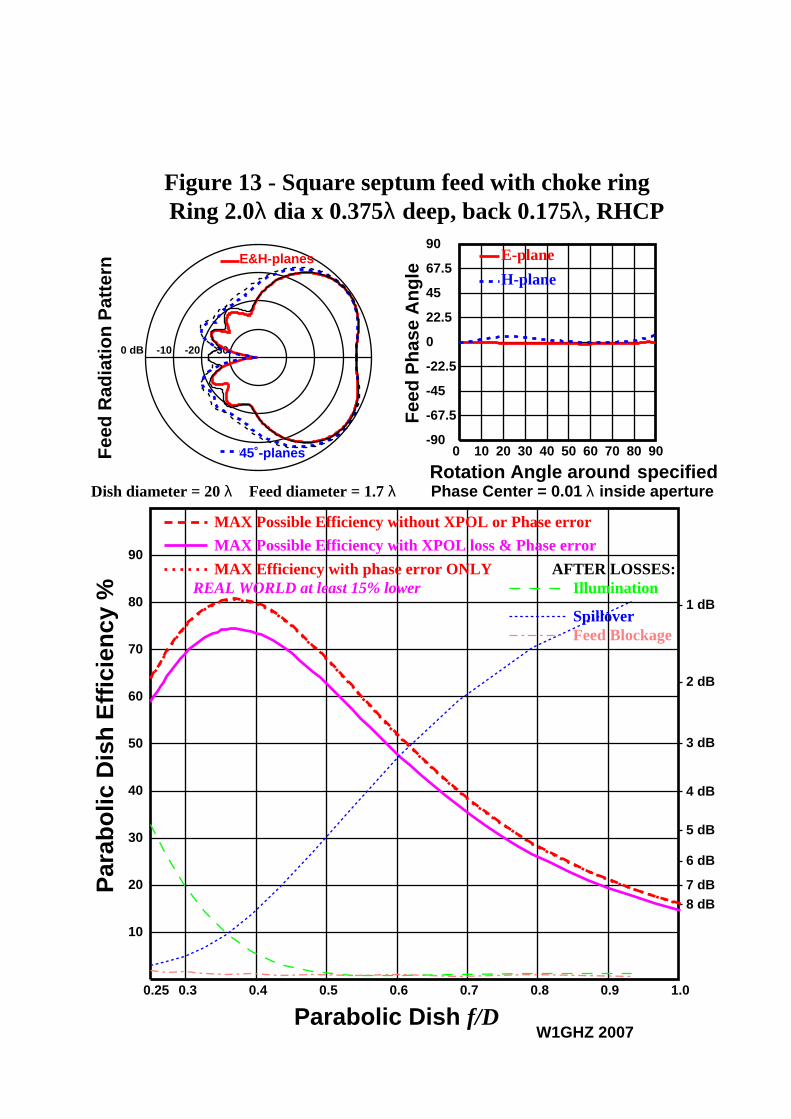
Figure 13 - Square septum feed with choke ring Ring 2.0λ dia x 0.375λ deep, back 0.175λ, RHCP
Dish diameter = 20 λ Feed diameter = 1.7 λ
E&H-planes
45˚-planes
0 dB -10 -20 -30
Fee
d R
adia
tio
n P
atte
rn
W1GHZ 2007
0 10 20 30 40 50 60 70 80 90-90
-67.5
-45
-22.5
0
22.5
45
67.5
90
Rotation Angle around
Fee
d P
has
e A
ng
le
E-plane
H-plane
specifiedPhase Center = 0.01 λ inside aperture
0.3 0.4 0.5 0.6 0.7 0.8 0.90.25 1.0
10
20
30
40
50
60
70
80
90
1 dB
2 dB
3 dB
4 dB
5 dB
6 dB
7 dB8 dB
MAX Possible Efficiency with XPOL loss & Phase error
REAL WORLD at least 15% lower
MAX Possible Efficiency without XPOL or Phase error
MAX Efficiency with phase error ONLYIllumination
Spillover
AFTER LOSSES:
Feed Blockage
Parabolic Dish f/D
Par
abo
lic D
ish
Eff
icie
ncy
%
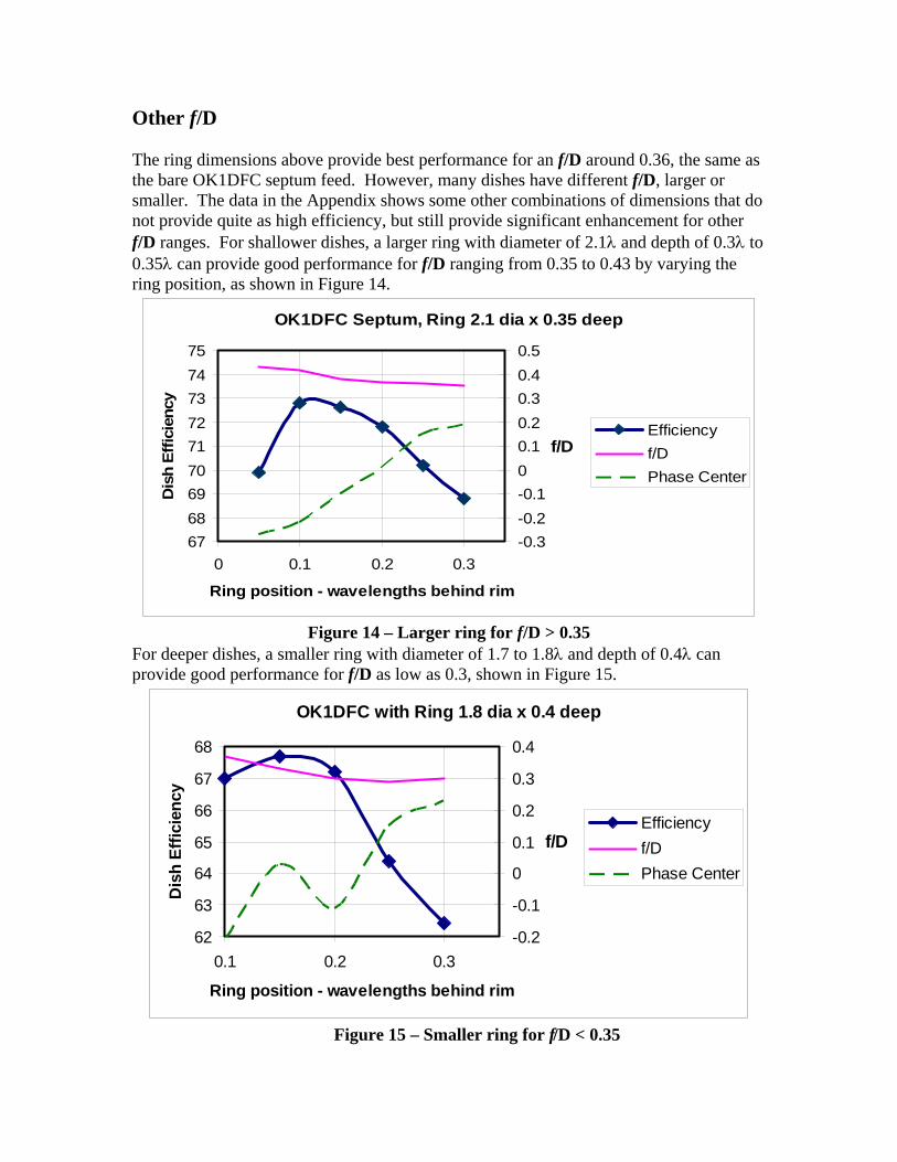
Other f/D The ring dimensions above provide best performance for an f/D around 0.36, the same as the bare OK1DFC septum feed. However, many dishes have different f/D, larger or smaller. The data in the Appendix shows some other combinations of dimensions that do not provide quite as high efficiency, but still provide significant enhancement for other f/D ranges. For shallower dishes, a larger ring with diameter of 2.1λ and depth of 0.3λ to 0.35λ can provide good performance for f/D ranging from 0.35 to 0.43 by varying the ring position, as shown in Figure 14.
OK1DFC Septum, Ring 2.1 dia x 0.35 deep
676869707172737475
0 0.1 0.2 0.3
Ring position - wavelengths behind rim
Dis
h Ef
ficie
ncy
-0.3-0.2-0.100.10.20.30.40.5
f/DEfficiencyf/DPhase Center
Figure 14 – Larger ring for f/D > 0.35
For deeper dishes, a smaller ring with diameter of 1.7 to 1.8λ and depth of 0.4λ can provide good performance for f/D as low as 0.3, shown in Figure 15.
OK1DFC with Ring 1.8 dia x 0.4 deep
62
63
64
65
66
67
68
0.1 0.2 0.3
Ring position - wavelengths behind rim
Dis
h Ef
ficie
ncy
-0.2
-0.1
0
0.1
0.2
0.3
0.4
f/DEfficiencyf/DPhase Center
Figure 15 – Smaller ring for f/D < 0.35
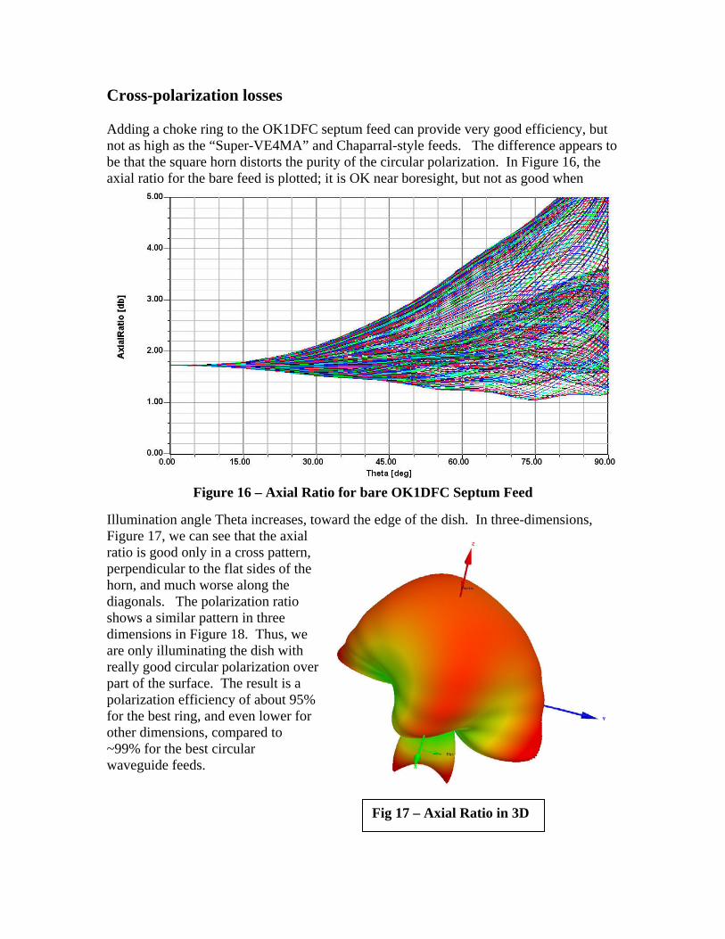
Cross-polarization losses Adding a choke ring to the OK1DFC septum feed can provide very good efficiency, but not as high as the “Super-VE4MA” and Chaparral-style feeds. The difference appears to be that the square horn distorts the purity of the circular polarization. In Figure 16, the axial ratio for the bare feed is plotted; it is OK near boresight, but not as good when
Figure 16 – Axial Ratio for bare OK1DFC Septum Feed
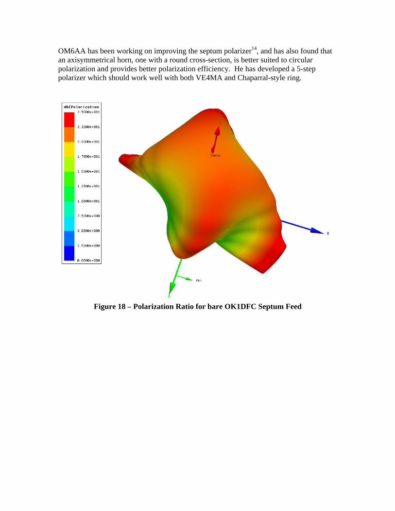
Illumination angle Theta increases, toward the edge of the dish. In three-dimensions, Figure 17, we can see that the axial ratio is good only in a cross pattern, perpendicular to the flat sides of the horn, and much worse along the diagonals. The polarization ratio shows a similar pattern in three dimensions in Figure 18. Thus, we are only illuminating the dish with really good circular polarization over part of the surface. The result is a polarization efficiency of about 95% for the best ring, and even lower for other dimensions, compared to ~99% for the best circular waveguide feeds.
Fig 17 – Axial Ratio in 3D
OM6AA has been working on improving the septum polarizer14, and has also found that an axisymmetrical horn, one with a round cross-section, is better suited to circular polarization and provides better polarization efficiency. He has developed a 5-step polarizer which should work well with both VE4MA and Chaparral-style ring.
Figure 18 – Polarization Ratio for bare OK1DFC Septum Feed
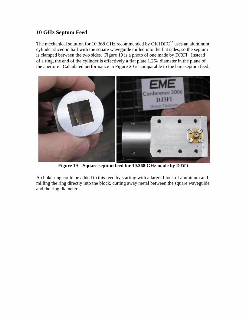
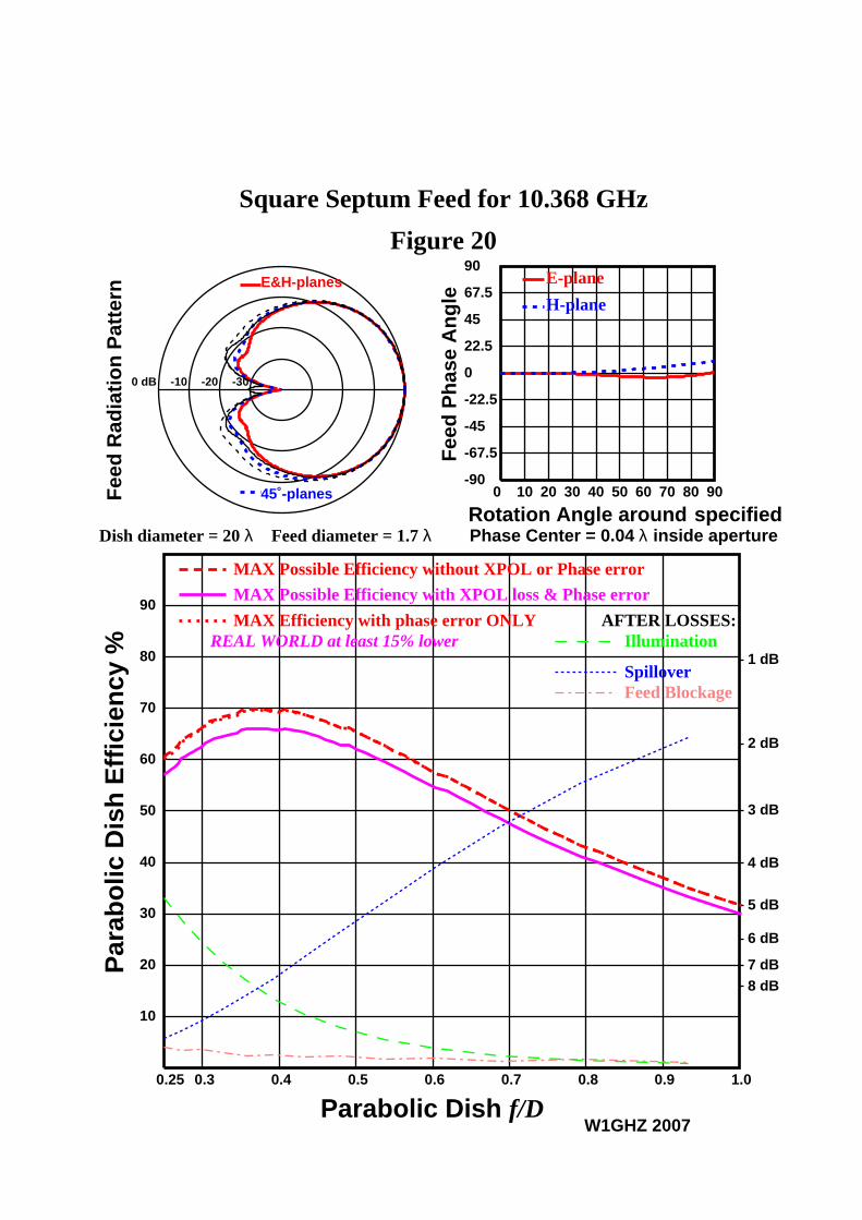
10 GHz Septum Feed The mechanical solution for 10.368 GHz recommended by OK1DFC13 uses an aluminum cylinder sliced in half with the square waveguide milled into the flat sides, so the septum is clamped between the two sides. Figure 19 is a photo of one made by DJ3FI. Instead of a ring, the end of the cylinder is effectively a flat plate 1.25λ diameter in the plane of the aperture. Calculated performance in Figure 20 is comparable to the bare septum feed.
Figure 19 – Square septum feed for 10.368 GHz made by DJ3FI
A choke ring could be added to this feed by starting with a larger block of aluminum and milling the ring directly into the block, cutting away metal between the square waveguide and the ring diameter.
Square Septum Feed for 10.368 GHz
Figure 20
Dish diameter = 20 λ Feed diameter = 1.7 λ
E&H-planes
45˚-planes
0 dB -10 -20 -30
Fee
d R
adia
tio
n P
atte
rn
W1GHZ 2007
0 10 20 30 40 50 60 70 80 90-90
-67.5
-45
-22.5
0
22.5
45
67.5
90
Rotation Angle around
Fee
d P
has
e A
ng
le
E-plane
H-plane
specifiedPhase Center = 0.04 λ inside aperture
0.3 0.4 0.5 0.6 0.7 0.8 0.90.25 1.0
10
20
30
40
50
60
70
80
90
1 dB
2 dB
3 dB
4 dB
5 dB
6 dB
7 dB8 dB
MAX Possible Efficiency with XPOL loss & Phase error
REAL WORLD at least 15% lower
MAX Possible Efficiency without XPOL or Phase error
MAX Efficiency with phase error ONLYIllumination
Spillover
AFTER LOSSES:
Feed Blockage
Parabolic Dish f/D
Par
abo
lic D
ish
Eff
icie
ncy
%
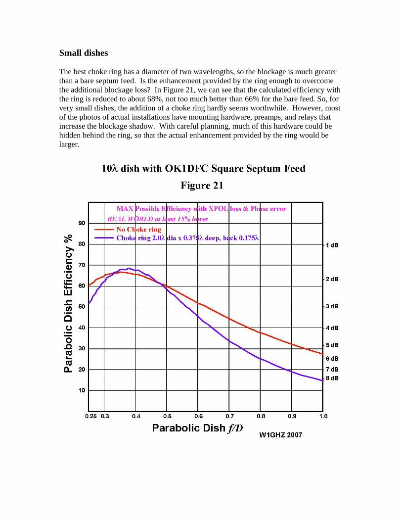
Small dishes The best choke ring has a diameter of two wavelengths, so the blockage is much greater than a bare septum feed. Is the enhancement provided by the ring enough to overcome the additional blockage loss? In Figure 21, we can see that the calculated efficiency with the ring is reduced to about 68%, not too much better than 66% for the bare feed. So, for very small dishes, the addition of a choke ring hardly seems worthwhile. However, most of the photos of actual installations have mounting hardware, preamps, and relays that increase the blockage shadow. With careful planning, much of this hardware could be hidden behind the ring, so that the actual enhancement provided by the ring would be larger.
Summary Addition of a choke ring to the popular OK1DFC square septum feed can improve dish efficiency significantly. Many copies of this feed are in use already, so adding a choke ring could enhance the performance of these EME stations – circular polarization is an advantage for EME, but not for most other communications. The feed performance is not quite as good as the “Super-VE4MA” feed and the best Chaparral-style feeds, so an operator considering the construction of a new feedhorn would do well to consider those horns as well as the septum feed. A final reminder is in order about the need for good contact between the choke ring and the horn. Both WD5AGO and OM6AA stress this point; Tommy states that at least six contact points are needed on a circular horn, while Rasto uses a spring contact. For the square horn, contacts at all four corners and all four sides are probably in order.
References
1. Paul Wade, W1GHZ, & Tommy Henderson, WD5AGO, “High-Efficiency Feeds for Prime-focus Dishes,” Proceedings of Microwave Update 2006, ARRL, 2006, pp. 102-155.
2. B.W. Malowanchuk,VE4MA, “Selection of an Optimum Dish Feed,” Proceedings of the 23rd Conference of the Central States VHF Society, ARRL, 1989, pp. 35-43.
3. Zdenek Samek, OK1DFC, “Feed for Parabolic Dish with Circular Polarization,” 10th International EME Conference 2002, Prague, 2002. www.qsl.net/ok1dfc
4. Zdenek Samek, OK1DFC , “Information and practical hints for the construction of a septum feed,” DUBUS, 1/2003, pp. 39-47.
5. Ming Hui Chen, G. N. Tsandoulas; A wide-band square-waveguide array polarizer, IEEE Transactions on Antennas and Propagation, vol. 21, pp. 389-391, May 1973.
6. A.W. Love, “The Diagonal Horn Antenna,” Microwave Journal, March 1962, pp. 117-122. (reprinted in A.W. Love, Electromagnetic Horn Antennas, IEEE, 1976, pp. 189-194.)
7. R. Miller, N7ART, “A 23cm Diagonal Waveguide Feed,” DUBUS, 2/1997, pp. 5-14.
8. P. Wade, W1GHZ, The W1GHZ Microwave Antenna Book – Online, Section 6.5.3, www.w1ghz.org
9. C.C. Cutler, “Parabolic-Antenna Design for Microwaves, Proceedings of the IRE, Nov. 1947, pp. 1284-1294. (reprinted in A.W. Love, Reflector Antennas, IEEE, 1978, pp. 16-26.)
10. B. Larkin, W7PUA, “Dipole-Reflector Parabolic Dish Feeds for f/D of 0.2-0.4,” QEX, February 1996, pp. 3-11.
11. P. Wade, W1GHZ, “Analysis of the OK1DFC Septum Feed,” DUBUS, 1/2003, pp. 22-38.
12. www.ansoft.com 13. www.ok1dfc.com/eme/Technic/septum/3cmsept.pdf 14. Rastislav Galuscak – OM6AA, & Pavel Hazdra, “Prime-focus circular waveguide
feed with septum polarization transformer,” DUBUS, 1/2007, pp. 8-32.
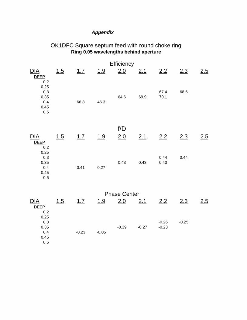
Appendix
OK1DFC Square septum feed with round choke ringRing 0.05 wavelengths behind aperture
EfficiencyDIA 1.5 1.7 1.9 2.0 2.1 2.2 2.3 2.5
DEEP0.2
0.250.3 67.4 68.6
0.35 64.6 69.9 70.10.4 66.8 46.3
0.450.5
f/DDIA 1.5 1.7 1.9 2.0 2.1 2.2 2.3 2.5
DEEP0.2
0.250.3 0.44 0.44
0.35 0.43 0.43 0.430.4 0.41 0.27
0.450.5
Phase CenterDIA 1.5 1.7 1.9 2.0 2.1 2.2 2.3 2.5
DEEP0.2
0.250.3 -0.26 -0.25
0.35 -0.39 -0.27 -0.230.4 -0.23 -0.05
0.450.5
Appendix
OK1DFC Square septum feed with round choke ringRing 0.10 wavelengths behind aperture
EfficiencyDIA 1.5 1.7 1.8 1.9 2.0 2.1 2.2 2.3
DEEP0.2
0.250.3 70.3
0.35 69.6 72.8 71 70.60.4 67 67 72.3
0.450.5
f/DDIA 1.5 1.7 1.8 1.9 2.0 2.1 2.2 2.3
DEEP0.2
0.250.3 0.42
0.35 0.43 0.42 0.41 0.420.4 0.38 0.37 0.38
0.450.5
Phase Center
DIA 1.5 1.7 1.8 1.9 2.0 2.1 2.2 2.3DEEP
0.20.25
0.3 -0.190.35 -0.37 -0.22 -0.16 -0.11
0.4 -0.21 -0.21 -0.270.45
0.5
Appendix
OK1DFC Square septum feed with round choke ringRing 0.15 wavelengths behind aperture
EfficiencyDIA 1.5 1.7 1.8 1.9 2.0 2.1 2.2 2.3 2.5
DEEP0.2
0.25 68.5 69.20.3 66.8 67.2 67 56 63.9 66.2 71.1 69.6 71
0.35 67.9 67.4 47.7 73.1 72.6 71 70.10.4 64 69.1 67.7 50.1 74.4 65.8 68.8 67.1 67.5
0.45 66.8 66.3 73.9 71.7 68.10.5 60.4 62.9 50.5 66.4 62.1
f/DDIA 1.5 1.7 1.8 1.9 2.0 2.1 2.2 2.3 2.5
DEEP0.2
0.25 0.43 0.430.3 0.41 0.36 0.37 0.36 0.42 0.42 0.41 0.42 0.42
0.35 0.37 0.36 0.27 0.38 0.38 0.42 0.410.4 0.35 0.35 0.33 0.38 0.36 0.36 0.38 0.41 0.41
0.45 0.32 0.31 0.35 0.36 0.370.5 0.3 0.32 0.36 0.36 0.38
Phase CenterDIA 1.5 1.7 1.8 1.9 2.0 2.1 2.2 2.3 2.5
DEEP0.2
0.25 -0.21 -0.190.3 -0.16 -0.18 -0.14 -0.13 -0.4 -0.23 -0.13 -0.1 0
0.35 -0.18 -0.18 -0.17 -0.22 -0.1 -0.06 00.4 -0.17 -0.18 0.03 -0.48 -0.05 0.13 0.05 0.13 0.13
0.45 -0.14 -0.16 0.11 0.2 0.270.5 -0.03 0.085 0.3 0.38 0.3
Appendix
OK1DFC Square septum feed with round choke ringRing 0.20 wavelengths behind aperture
EfficiencyDIA 1.5 1.7 1.8 1.9 2.0 2.1 2.2 2.3
DEEP
0.20.25 51.9 68.7 70.1 69.8
0.3 67 53.9 71.1 72.4 700.35 68.2 67.2 42.1 74.5 71.8 69.5
0.4 67.9 67.1 70 72.3 69.5 67.10.45 72.7 69.4
0.5
f/DDIA 1.5 1.7 1.8 1.9 2.0 2.1 2.2 2.3
DEEP0.2
0.25 0.42 0.42 0.41 0.420.3 0.35 0.3 0.39 0.38 0.41
0.35 0.36 0.32 0.32 0.37 0.37 0.380.4 0.32 0.3 0.37 0.35 0.36 0.37
0.45 0.36 0.350.5
Phase Center
DIA 1.5 1.7 1.8 1.9 2.0 2.1 2.2 2.3DEEP
0.20.25 -0.35 -0.21 -0.14 -0.13
0.3 -0.14 -0.15 -0.19 -0.07 -0.050.35 -0.16 -0.17 -0.37 0.01 0.05 0.05
0.4 -0.12 -0.11 0.26 0.19 0.18 0.180.45 0.27 0.3
0.5
Appendix
OK1DFC Square septum feed with round choke ringRing 0.25 wavelengths behind aperture
EfficiencyDIA 1.5 1.7 1.8 1.9 2.0 2.1 2.2 2.3
DEEP0.2 48 60.5
0.25 57.2 59.4 70.6 70.20.3 67.2 66.9 49.9 72.9 70.3 70.2 67.8
0.35 67.1 59.6 72.9 70.2 68.40.4 65.2 64.4 70.2 70 64.9 66 62.6
0.450.5 61.2 65.8 59.7 58.2
f/DDIA 1.5 1.7 1.9 2 2.1 2.2 2.3
DEEP0.2 0.36 0.42
0.25 0.3 0.41 0.4 0.390.3 0.32 0.32 0.27 0.37 0.36 0.36 0.38
0.35 0.3 0.36 0.36 0.36 0.360.4 0.3 0.29 0.37 0.36 0.36 0.35 0.35
0.450.5 0.35 0.35 0.37 0.35
Phase Center
DIA 1.5 1.7 1.9 2 2.1 2.2 2.3DEEP
0.2 -0.14 -0.19 -0.270.25 -0.3 -0.1 -0.070.3 -0.14 -0.14 -0.24 0.04 0.08 0.03 0.04
0.35 -0.09 0.34 0.17 0.15 0.120.4 0.1 0.15 0.3 0.22 0.27 0.2 0.21
0.450.5 0.18 0.26 0.27 0.16
Appendix
OK1DFC Square septum feed with round choke ringRing 0.30 wavelengths behind aperture
EfficiencyDIA 1.5 1.7 1.8 1.9 2.0 2.1 2.2 2.3
DEEP0.2
0.25 66.80.3 55.3 72.4 70.8
0.35 67.1 70.9 68.80.4 62.4 68
0.450.5
f/DDIA 1.5 1.7 1.8 1.9 2.0 2.1 2.2 2.3
DEEP0.2
0.25 0.380.3 0.3 0.37 0.36
0.35 0.38 0.36 0.350.4 0.3 0.36
0.450.5
Phase Center
DIA 1.5 1.7 1.8 1.9 2.0 2.1 2.2 2.3DEEP
0.20.25 0
0.3 0.2 0.2 0.140.35 0.35 0.2 0.19
0.4 0.23 0.230.45
0.5
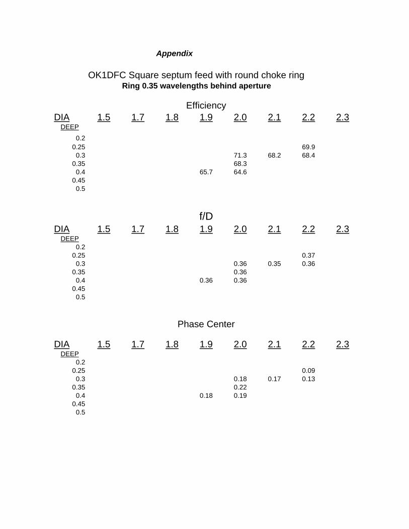
Appendix
OK1DFC Square septum feed with round choke ringRing 0.35 wavelengths behind aperture
EfficiencyDIA 1.5 1.7 1.8 1.9 2.0 2.1 2.2 2.3
DEEP
0.20.25 69.9
0.3 71.3 68.2 68.40.35 68.3
0.4 65.7 64.60.45
0.5
f/DDIA 1.5 1.7 1.8 1.9 2.0 2.1 2.2 2.3
DEEP0.2
0.25 0.370.3 0.36 0.35 0.36
0.35 0.360.4 0.36 0.36
0.450.5
Phase Center
DIA 1.5 1.7 1.8 1.9 2.0 2.1 2.2 2.3DEEP
0.20.25 0.09
0.3 0.18 0.17 0.130.35 0.22
0.4 0.18 0.190.45
0.5