Embed Size (px)
Citation preview
Seediscussions,stats,andauthorprofilesforthispublicationat:https://www.researchgate.net/publication/270293555
Enhancingthedesignofasuperconductingcoilformagneticenergystoragesystems
ArticleinPhysicaCSuperconductivity·January2015
ImpactFactor:0.94·DOI:10.1016/j.physc.2014.11.005
READS
42
3authors:
IndiraGomathinayagam
PrinceShriVenkateshwaraArtsandScienc…
1PUBLICATION0CITATIONS
SEEPROFILE
TheruUmamaheswararao
AnnaUniversity,Chennai
1PUBLICATION0CITATIONS
SEEPROFILE
SankaralingamChandramohan
AnnaUniversity,Chennai
13PUBLICATIONS55CITATIONS
SEEPROFILE
Allin-textreferencesunderlinedinbluearelinkedtopublicationsonResearchGate,
lettingyouaccessandreadthemimmediately.
Availablefrom:SankaralingamChandramohan
Retrievedon:13May2016
Physica C 508 (2015) 69–74
Contents lists available at ScienceDirect
Physica C
journal homepage: www.elsevier .com/locate /physc
Enhancing the design of a superconducting coil for magnetic energystorage systems
http://dx.doi.org/10.1016/j.physc.2014.11.0050921-4534/� 2014 Elsevier B.V. All rights reserved.
⇑ Corresponding author.E-mail addresses: [email protected] (G. Indira), [email protected] (T.
UmaMaheswaraRao), [email protected] (S. Chandramohan).
Gomathinayagam Indira a,⇑, Theru UmaMaheswaraRao b, Sankaralingam Chandramohan b
a EEE Department, Prince Shri Venkateshwara Padmavathy Engineering College, Chennai, Indiab Divison of Power Engineering and Management, Anna University, Chennai, India
a r t i c l e i n f o a b s t r a c t
Article history:Received 10 August 2014Received in revised form 2 November 2014Accepted 17 November 2014Available online 26 November 2014
Keywords:Critical current densityHigh temperature superconducting tapeOptimum designOptimum energy storage
Study and analysis of a coil for Superconducting Magnetic Energy Storage (SMES) system is presented inthis paper. Generally, high magnetic flux density is adapted in the design of superconducting coil of SMESto reduce the size of the coil and to increase its energy density. With high magnetic flux density, criticalcurrent density of the coil is degraded and so the coil is wound with High Temperature Superconductors(HTS) made of different materials. A comparative study is made to emphasize the relationship betweenthe energy storage and length of the coil wound by Bi2223, SF12100, SCS12100 and YBCO tapes. Recentlyfor the construction of HTS magnets, YBCO tapes have been used. Simulation models for various designshave been developed to analyze the magnetic field distribution for the optimum design of energy storage.The design which gives the maximum stored energy in the coil has been used with a certain length ofsecond-generation HTS. The performance analysis and the results of comparative study are done.
� 2014 Elsevier B.V. All rights reserved.
1. Introduction of reducing superconducting wire usage by considering the maxi-
Size and weight of the energy storage system are comparativelylesser in SMES than other energy storage systems [1]. SMES storesenergy in the form of magnetic field. The invention of HTS in 1986makes SMES as the hot research area. Recently for the constructionof HTS magnets, YBCO tapes have been used [2–6]. Compared toother energy storage methods, SMES exhibits a better performance.The current density of SMES coil is about 10–100 times larger thanthe common coil because it has virtually no resistive losses. Conse-quently, the Energy with a higher density can be stored in a persis-tent mode until required. SMES system has superior features suchas high efficiency, fast response and no performance degradationdue to repetition of charging and discharging of the coil. The SMESsystem is expected to be used for power system stabilization, loadfluctuation compensation and instantaneous voltage drop compen-sation [7]. A new advanced SMES consists of renewable energyresources, SMES coil and a hydrogen energy storage system. Thissystem uses the renewable energy effectively [8,9].Therefore, afocus on more researches has been performed for practical use ofSMES system [10–12].
The solenoid-type SMES coil is preferred due to its simple config-uration and high energy storage capacity [13]. An effective method
mum magnetic flux density within the SMES coil has not been inves-tigated effectively so far. In general, high magnetic flux density isadapted in the superconducting coil design to make the coil sizeto be smaller. However, critical current density of the superconduc-ting coil is degraded when high magnetic flux density is adapted tothe superconducting coil. High magnetic flux density is not only thecriteria for reducing superconducting coil size it also depends on theJC–B characteristics and the coil shape. In this paper, HTS solenoidcoil design, its analysis and simulation results are studied.
2. HTS solenoid coil design
In this section, four HTS solenoid coils with different materialtapes are designed and compared. Modeling has been carried outin MAGNET software package to design the coil. A common config-uration of HTS solenoid coil is shown in Fig. 1. In practice, Bi-2223or YBCO multifilament HTS tape conductor is chosen to design aHTS solenoid coil. Its main specifications are: width of 4.23 mm,thickness b of 0.23 mm, critical current IC of 100 A (at 77 K), thecritical current density JC of 10 kA/C.
2.1. Computation of energy storage of SMES coil
Inductance of a superconducting coil is computed as follows [14].
L ¼ 2pl0NC2R51Tðp; qÞ ð1Þ

Table 1Main geometries of Bi2223 and YBCO coils.
Material R1
(mm)R2
(mm)D(mm)
No ofturns
Length(m)
Volume(m3)
Bi2223 81 162 81 2186 1668 0.0005YBCO 81 162 81 2186 1668 0.0005
70 G. Indira et al. / Physica C 508 (2015) 69–74
wherel0 = 4p � 10�7,R1 – Inner radius of the coil
NC ¼ N=ðR2 � R1ÞD ð2Þ
whereR2 – Outer radius of the coilD – Depth of the coilN – Number of coil turnsT(p, q) – function of size ratio
p ¼ R2
R1
� �; q ¼ D
R1
� �
According to (1) and (2),
L ¼ 2pl0R51Tðp; qÞ N
ðR2 � R1ÞD
� �2
ð3Þ
Considering the filling factor K for practical design,
Nab ¼ ðR2� R1ÞD ð4Þ
The total length of conductors S is given by
S ¼ N 2p R1 þR2 � R1
2
� �� �ð5Þ
Energy storage of a coil is given by
E ¼ 12
LI2 ð6Þ
Table 2Comparison of Bi2223 and YBCO Coils.
Material Inductance (H) Energy storage (J)
Bi2223 1 5000YBCO 1.8 9000
2.2. Design of HTS solenoid coil
For the practical design of HTS solenoid coil, inner radius R1,outer radius R2 and cross sectional area (R2�R1) D are considered.
2.2.1. Comparison of Bi2223 and YBCO coilTable 1 gives the main geometries of Bi2223 and YBCO coil. The
computed value of size ratios (p,q) is (2,1) respectively. T(p,q) ofBi2223 is computed as 0.3290 [15]. A solenoid coil having the size
Fig. 1. Scheme of HTS solenoid coil.
ratios (2, 1) is called as Brooks Coil and this coil gives the maxi-mum inductance for a given length and volume of the conductor.
HTS coil should be wound with a certain insulating layer. Thetotal width and the thickness of Bi2223 HTS conductor withinsulating layer are 6 mm and 0.6 mm respectively. Therefore, areasonable filling factor is 32.2%. Using Eqs. (3) and (4), the induc-tance and the number of turns in Bi2223 coil are calculated as 1 Hand 2186 respectively. Total length of HTS coil is calculated as1668 m using Eq. (5) [16]. Critical current through the Bi2223 coilis100 A.
In the proposed YBCO coil, the same filling factor of 32.2% isconsidered. The inductance and the number of turns in YBCO coilare 1.8 H and 2186 respectively. Using Eq. (5), the total length ofYBCO coil is calculated as 1668 m. Table 2 gives the comparisonof Bi2223 and YBCO coil. Inductance, energy storage and fluxdensity are more in YBCO compared to Bi2223 coil.
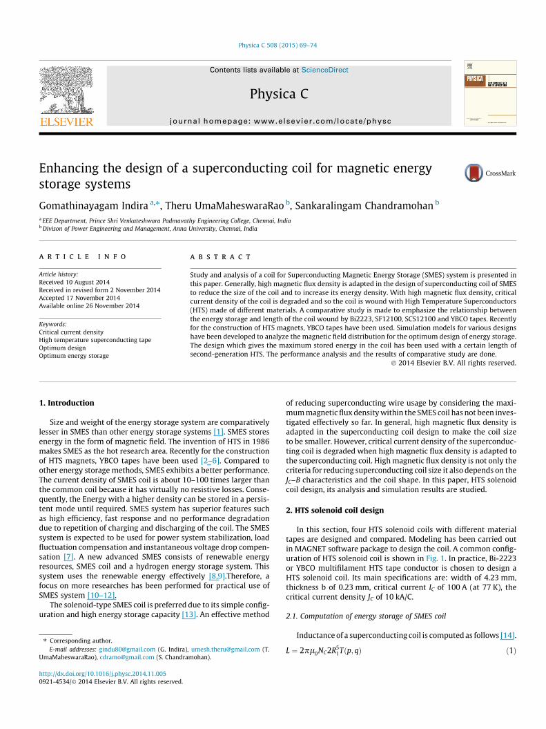
The design of YBCO coil and its energy storage are shown inFig. 2a. Assume that the center co-ordinate of magnetic distribu-tion is (0, 0) and the coil is symmetrically placed around it. A line‘a’ from (�100, �200) to (�100, 100) is added to analyze the fluxdensity pattern. The magnetic flux density pattern of YBCO andBi2223 coil are obtained as shown in Figs. 2b and 2c.
The usage of the superconducting wire is improved with themaximum magnetic flux density in YBCO. This means that the
Fig. 2a. Energy storage of YBCO coil.
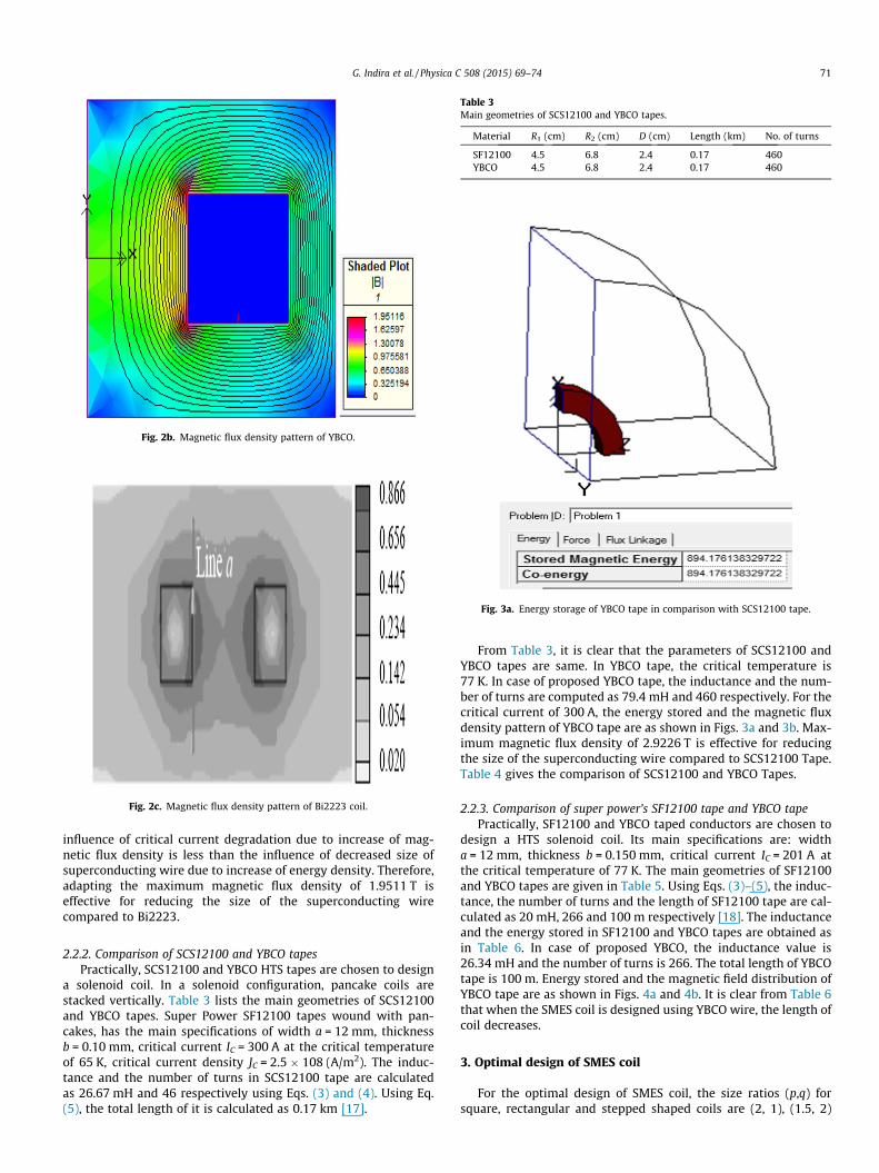
Fig. 2b. Magnetic flux density pattern of YBCO.
Fig. 2c. Magnetic flux density pattern of Bi2223 coil.
Table 3Main geometries of SCS12100 and YBCO tapes.
Material R1 (cm) R2 (cm) D (cm) Length (km) No. of turns
SF12100 4.5 6.8 2.4 0.17 460YBCO 4.5 6.8 2.4 0.17 460
Fig. 3a. Energy storage of YBCO tape in comparison with SCS12100 tape.
G. Indira et al. / Physica C 508 (2015) 69–74 71
influence of critical current degradation due to increase of mag-netic flux density is less than the influence of decreased size ofsuperconducting wire due to increase of energy density. Therefore,adapting the maximum magnetic flux density of 1.9511 T iseffective for reducing the size of the superconducting wirecompared to Bi2223.
2.2.2. Comparison of SCS12100 and YBCO tapesPractically, SCS12100 and YBCO HTS tapes are chosen to design
a solenoid coil. In a solenoid configuration, pancake coils arestacked vertically. Table 3 lists the main geometries of SCS12100and YBCO tapes. Super Power SF12100 tapes wound with pan-cakes, has the main specifications of width a = 12 mm, thicknessb = 0.10 mm, critical current IC = 300 A at the critical temperatureof 65 K, critical current density JC = 2.5 � 108 (A/m2). The induc-tance and the number of turns in SCS12100 tape are calculatedas 26.67 mH and 46 respectively using Eqs. (3) and (4). Using Eq.(5), the total length of it is calculated as 0.17 km [17].
From Table 3, it is clear that the parameters of SCS12100 andYBCO tapes are same. In YBCO tape, the critical temperature is77 K. In case of proposed YBCO tape, the inductance and the num-ber of turns are computed as 79.4 mH and 460 respectively. For thecritical current of 300 A, the energy stored and the magnetic fluxdensity pattern of YBCO tape are as shown in Figs. 3a and 3b. Max-imum magnetic flux density of 2.9226 T is effective for reducingthe size of the superconducting wire compared to SCS12100 Tape.Table 4 gives the comparison of SCS12100 and YBCO Tapes.
2.2.3. Comparison of super power’s SF12100 tape and YBCO tapePractically, SF12100 and YBCO taped conductors are chosen to
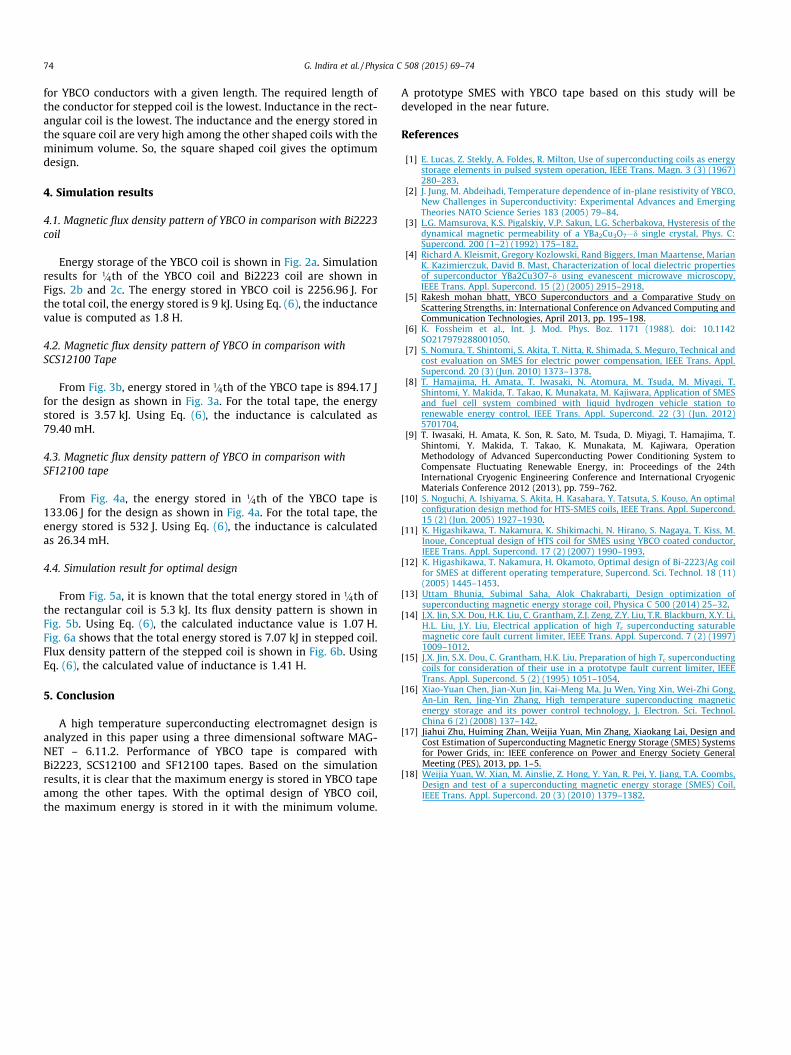
design a HTS solenoid coil. Its main specifications are: widtha = 12 mm, thickness b = 0.150 mm, critical current IC = 201 A atthe critical temperature of 77 K. The main geometries of SF12100and YBCO tapes are given in Table 5. Using Eqs. (3)–(5), the induc-tance, the number of turns and the length of SF12100 tape are cal-culated as 20 mH, 266 and 100 m respectively [18]. The inductanceand the energy stored in SF12100 and YBCO tapes are obtained asin Table 6. In case of proposed YBCO, the inductance value is26.34 mH and the number of turns is 266. The total length of YBCOtape is 100 m. Energy stored and the magnetic field distribution ofYBCO tape are as shown in Figs. 4a and 4b. It is clear from Table 6that when the SMES coil is designed using YBCO wire, the length ofcoil decreases.
3. Optimal design of SMES coil
For the optimal design of SMES coil, the size ratios (p,q) forsquare, rectangular and stepped shaped coils are (2, 1), (1.5, 2)
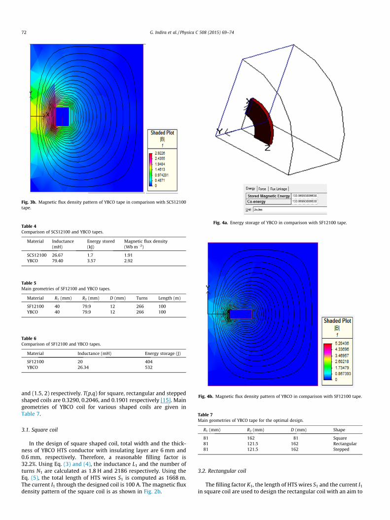
Fig. 3b. Magnetic flux density pattern of YBCO tape in comparison with SCS12100tape.
Table 4Comparison of SCS12100 and YBCO tapes.
Material Inductance(mH)
Energy stored(kJ)
Magnetic flux density(Wb m�2)
SCS12100 26.67 1.7 1.91YBCO 79.40 3.57 2.92
Table 5Main geometries of SF12100 and YBCO tapes.
Material R1 (mm) R2 (mm) D (mm) Turns Length (m)
SF12100 40 79.9 12 266 100YBCO 40 79.9 12 266 100
Table 6Comparison of SF12100 and YBCO tapes.
Material Inductance (mH) Energy storage (J)
SF12100 20 404YBCO 26.34 532
Fig. 4a. Energy storage of YBCO in comparison with SF12100 tape.
Fig. 4b. Magnetic flux density pattern of YBCO in comparison with SF12100 tape.
Table 7Main geometries of YBCO tape for the optimal design.
R1 (mm) R2 (mm) D (mm) Shape
81 162 81 Square81 121.5 162 Rectangular81 121.5 162 Stepped
72 G. Indira et al. / Physica C 508 (2015) 69–74
and (1.5, 2) respectively. T(p,q) for square, rectangular and steppedshaped coils are 0.3290, 0.2046, and 0.1901 respectively [15]. Maingeometries of YBCO coil for various shaped coils are given inTable 7.
3.1. Square coil
In the design of square shaped coil, total width and the thick-ness of YBCO HTS conductor with insulating layer are 6 mm and0.6 mm, respectively. Therefore, a reasonable filling factor is32.2%. Using Eq. (3) and (4), the inductance L1 and the number ofturns N1 are calculated as 1.8 H and 2186 respectively. Using theEq. (5), the total length of HTS wires S1 is computed as 1668 m.The current I1 through the designed coil is 100 A. The magnetic fluxdensity pattern of the square coil is as shown in Fig. 2b.
3.2. Rectangular coil
The filling factor K1, the length of HTS wires S1 and the current I1
in square coil are used to design the rectangular coil with an aim to

G. Indira et al. / Physica C 508 (2015) 69–74 73
optimize the design of Superconducting Coil. Using Eqs. (3) and (4),the inductance L2 and the length of YBCO conductors S2 in rectan-gular coil are calculated as 1.07 H and 1390 m respectively. Energystorage and the magnetic flux density pattern of the rectangularcoil are shown in Figs. 5a and 5b respectively.
3.3. Stepped coil
The filling factor K1, the length of HTS wires S1 and the current I1
in square coil are used to design stepped coil with an aim tooptimize the practical inductor design. Using Eqs. (3) and (4), the
Fig. 5a. Energy stored in rectangular coil.
Fig. 5b. Magnetic flux density pattern of rectangular coil.
inductance L3 and the length S3 of YBCO conductors in stepped coilare calculated as 1.41 H and 1250 m respectively. Energy storageand the magnetic flux density pattern of the stepped coil areshown in Figs. 6a and 6b respectively.
Table 8 gives the comparison of different shaped YBCO coils.Brooks coil is chosen to obtain the maximum value of inductance
Fig. 6a. Energy stored in stepped coil.
Fig. 6b. Magnetic flux density pattern of stepped coil.
Table 8Comparison of YBCO tape with different shapes.
Shape Volume(m)
Inductance(H)
Number ofturns
Length(m)
EnergyStored (kJ)
Square 0.0005 1.8 2186 1668 9Rectangular 0.0004 1.07 2186 1390 5.3Stepped 0.0036 1.41 2186 1250 7.07
74 G. Indira et al. / Physica C 508 (2015) 69–74
for YBCO conductors with a given length. The required length ofthe conductor for stepped coil is the lowest. Inductance in the rect-angular coil is the lowest. The inductance and the energy stored inthe square coil are very high among the other shaped coils with theminimum volume. So, the square shaped coil gives the optimumdesign.
4. Simulation results
4.1. Magnetic flux density pattern of YBCO in comparison with Bi2223coil
Energy storage of the YBCO coil is shown in Fig. 2a. Simulationresults for 1=4th of the YBCO coil and Bi2223 coil are shown inFigs. 2b and 2c. The energy stored in YBCO coil is 2256.96 J. Forthe total coil, the energy stored is 9 kJ. Using Eq. (6), the inductancevalue is computed as 1.8 H.
4.2. Magnetic flux density pattern of YBCO in comparison withSCS12100 Tape
From Fig. 3b, energy stored in 1=4th of the YBCO tape is 894.17 Jfor the design as shown in Fig. 3a. For the total tape, the energystored is 3.57 kJ. Using Eq. (6), the inductance is calculated as79.40 mH.
4.3. Magnetic flux density pattern of YBCO in comparison withSF12100 tape
From Fig. 4a, the energy stored in 1=4th of the YBCO tape is133.06 J for the design as shown in Fig. 4a. For the total tape, theenergy stored is 532 J. Using Eq. (6), the inductance is calculatedas 26.34 mH.
4.4. Simulation result for optimal design
From Fig. 5a, it is known that the total energy stored in 1=4th ofthe rectangular coil is 5.3 kJ. Its flux density pattern is shown inFig. 5b. Using Eq. (6), the calculated inductance value is 1.07 H.Fig. 6a shows that the total energy stored is 7.07 kJ in stepped coil.Flux density pattern of the stepped coil is shown in Fig. 6b. UsingEq. (6), the calculated value of inductance is 1.41 H.
5. Conclusion
A high temperature superconducting electromagnet design isanalyzed in this paper using a three dimensional software MAG-NET – 6.11.2. Performance of YBCO tape is compared withBi2223, SCS12100 and SF12100 tapes. Based on the simulationresults, it is clear that the maximum energy is stored in YBCO tapeamong the other tapes. With the optimal design of YBCO coil,the maximum energy is stored in it with the minimum volume.
A prototype SMES with YBCO tape based on this study will bedeveloped in the near future.
References
[1] E. Lucas, Z. Stekly, A. Foldes, R. Milton, Use of superconducting coils as energystorage elements in pulsed system operation, IEEE Trans. Magn. 3 (3) (1967)280–283.
[2] J. Jung, M. Abdeihadi, Temperature dependence of in-plane resistivity of YBCO,New Challenges in Superconductivity: Experimental Advances and EmergingTheories NATO Science Series 183 (2005) 79–84.
[3] L.G. Mamsurova, K.S. Pigalskiy, V.P. Sakun, L.G. Scherbakova, Hysteresis of thedynamical magnetic permeability of a YBa2Cu3O7�d single crystal, Phys. C:Supercond. 200 (1–2) (1992) 175–182.
[4] Richard A. Kleismit, Gregory Kozlowski, Rand Biggers, Iman Maartense, MarianK. Kazimierczuk, David B. Mast, Characterization of local dielectric propertiesof superconductor YBa2Cu3O7-d using evanescent microwave microscopy,IEEE Trans. Appl. Supercond. 15 (2) (2005) 2915–2918.
[5] Rakesh mohan bhatt, YBCO Superconductors and a Comparative Study onScattering Strengths, in: International Conference on Advanced Computing andCommunication Technologies, April 2013, pp. 195–198.
[6] K. Fossheim et al., Int. J. Mod. Phys. Boz. 1171 (1988). doi: 10.1142SO217979288001050.
[7] S. Nomura, T. Shintomi, S. Akita, T. Nitta, R. Shimada, S. Meguro, Technical andcost evaluation on SMES for electric power compensation, IEEE Trans. Appl.Supercond. 20 (3) (Jun. 2010) 1373–1378.
[8] T. Hamajima, H. Amata, T. Iwasaki, N. Atomura, M. Tsuda, M. Miyagi, T.Shintomi, Y. Makida, T. Takao, K. Munakata, M. Kajiwara, Application of SMESand fuel cell system combined with liquid hydrogen vehicle station torenewable energy control, IEEE Trans. Appl. Supercond. 22 (3) (Jun. 2012)5701704.
[9] T. Iwasaki, H. Amata, K. Son, R. Sato, M. Tsuda, D. Miyagi, T. Hamajima, T.Shintomi, Y. Makida, T. Takao, K. Munakata, M. Kajiwara, OperationMethodology of Advanced Superconducting Power Conditioning System toCompensate Fluctuating Renewable Energy, in: Proceedings of the 24thInternational Cryogenic Engineering Conference and International CryogenicMaterials Conference 2012 (2013), pp. 759–762.
[10] S. Noguchi, A. Ishiyama, S. Akita, H. Kasahara, Y. Tatsuta, S. Kouso, An optimalconfiguration design method for HTS-SMES coils, IEEE Trans. Appl. Supercond.15 (2) (Jun. 2005) 1927–1930.
[11] K. Higashikawa, T. Nakamura, K. Shikimachi, N. Hirano, S. Nagaya, T. Kiss, M.Inoue, Conceptual design of HTS coil for SMES using YBCO coated conductor,IEEE Trans. Appl. Supercond. 17 (2) (2007) 1990–1993.
[12] K. Higashikawa, T. Nakamura, H. Okamoto, Optimal design of Bi-2223/Ag coilfor SMES at different operating temperature, Supercond. Sci. Technol. 18 (11)(2005) 1445–1453.
[13] Uttam Bhunia, Subimal Saha, Alok Chakrabarti, Design optimization ofsuperconducting magnetic energy storage coil, Physica C 500 (2014) 25–32.
[14] J.X. Jin, S.X. Dou, H.K. Liu, C. Grantham, Z.J. Zeng, Z.Y. Liu, T.R. Blackburn, X.Y. Li,H.L. Liu, J.Y. Liu, Electrical application of high Tc superconducting saturablemagnetic core fault current limiter, IEEE Trans. Appl. Supercond. 7 (2) (1997)1009–1012.
[15] J.X. Jin, S.X. Dou, C. Grantham, H.K. Liu, Preparation of high Tc superconductingcoils for consideration of their use in a prototype fault current limiter, IEEETrans. Appl. Supercond. 5 (2) (1995) 1051–1054.
[16] Xiao-Yuan Chen, Jian-Xun Jin, Kai-Meng Ma, Ju Wen, Ying Xin, Wei-Zhi Gong,An-Lin Ren, Jing-Yin Zhang, High temperature superconducting magneticenergy storage and its power control technology, J. Electron. Sci. Technol.China 6 (2) (2008) 137–142.
[17] Jiahui Zhu, Huiming Zhan, Weijia Yuan, Min Zhang, Xiaokang Lai, Design andCost Estimation of Superconducting Magnetic Energy Storage (SMES) Systemsfor Power Grids, in: IEEE conference on Power and Energy Society GeneralMeeting (PES), 2013, pp. 1–5.
[18] Weijia Yuan, W. Xian, M. Ainslie, Z. Hong, Y. Yan, R. Pei, Y. Jiang, T.A. Coombs,Design and test of a superconducting magnetic energy storage (SMES) Coil,IEEE Trans. Appl. Supercond. 20 (3) (2010) 1379–1382.


![Stress Computation in the C400 Superconducting Coil Using ...accelconf.web.cern.ch/accelconf/PAC2009/papers/mo6pfp074.pdf · [2] M.N. Wilson, Superconducting Magnets , pub Oxford](https://img.pdfslide.us/doc/110x75/5ec37260d076c03bee637f0f/stress-computation-in-the-c400-superconducting-coil-using-2-mn-wilson-superconducting.jpg)