Embed Size (px)
Citation preview
© 2009-2012 Microchip Technology Inc. DS41385F
Enhanced mTouch™ CapacitiveTouch Evaluation Kit and
Accessory BoardsUser’s Guide
Note the following details of the code protection feature on Microchip devices:• Microchip products meet the specification contained in their particular Microchip Data Sheet.
• Microchip believes that its family of products is one of the most secure families of its kind on the market today, when used in the intended manner and under normal conditions.
• There are dishonest and possibly illegal methods used to breach the code protection feature. All of these methods, to our knowledge, require using the Microchip products in a manner outside the operating specifications contained in Microchip’s Data Sheets. Most likely, the person doing so is engaged in theft of intellectual property.
• Microchip is willing to work with the customer who is concerned about the integrity of their code.
• Neither Microchip nor any other semiconductor manufacturer can guarantee the security of their code. Code protection does not mean that we are guaranteeing the product as “unbreakable.”
Code protection is constantly evolving. We at Microchip are committed to continuously improving the code protection features of ourproducts. Attempts to break Microchip’s code protection feature may be a violation of the Digital Millennium Copyright Act. If such actsallow unauthorized access to your software or other copyrighted work, you may have a right to sue for relief under that Act.
Information contained in this publication regarding deviceapplications and the like is provided only for your convenienceand may be superseded by updates. It is your responsibility toensure that your application meets with your specifications.MICROCHIP MAKES NO REPRESENTATIONS ORWARRANTIES OF ANY KIND WHETHER EXPRESS ORIMPLIED, WRITTEN OR ORAL, STATUTORY OROTHERWISE, RELATED TO THE INFORMATION,INCLUDING BUT NOT LIMITED TO ITS CONDITION,QUALITY, PERFORMANCE, MERCHANTABILITY ORFITNESS FOR PURPOSE. Microchip disclaims all liabilityarising from this information and its use. Use of Microchipdevices in life support and/or safety applications is entirely atthe buyer’s risk, and the buyer agrees to defend, indemnify andhold harmless Microchip from any and all damages, claims,suits, or expenses resulting from such use. No licenses areconveyed, implicitly or otherwise, under any Microchipintellectual property rights.
DS41385F-page 2
QUALITY MANAGEMENT SYSTEM CERTIFIED BY DNV
== ISO/TS 16949 ==
Trademarks
The Microchip name and logo, the Microchip logo, dsPIC, KEELOQ, KEELOQ logo, MPLAB, PIC, PICmicro, PICSTART, PIC32 logo, rfPIC and UNI/O are registered trademarks of Microchip Technology Incorporated in the U.S.A. and other countries.
FilterLab, Hampshire, HI-TECH C, Linear Active Thermistor, MXDEV, MXLAB, SEEVAL and The Embedded Control Solutions Company are registered trademarks of Microchip Technology Incorporated in the U.S.A.
Analog-for-the-Digital Age, Application Maestro, chipKIT, chipKIT logo, CodeGuard, dsPICDEM, dsPICDEM.net, dsPICworks, dsSPEAK, ECAN, ECONOMONITOR, FanSense, HI-TIDE, In-Circuit Serial Programming, ICSP, Mindi, MiWi, MPASM, MPLAB Certified logo, MPLIB, MPLINK, mTouch, Omniscient Code Generation, PICC, PICC-18, PICDEM, PICDEM.net, PICkit, PICtail, REAL ICE, rfLAB, Select Mode, Total Endurance, TSHARC, UniWinDriver, WiperLock and ZENA are trademarks of Microchip Technology Incorporated in the U.S.A. and other countries.
SQTP is a service mark of Microchip Technology Incorporated in the U.S.A.
All other trademarks mentioned herein are property of their respective companies.
© 2009-2012, Microchip Technology Incorporated, Printed in the U.S.A., All Rights Reserved.
Printed on recycled paper.
ISBN: 978-1-62076-298-1
© 2009-2012 Microchip Technology Inc.
Microchip received ISO/TS-16949:2009 certification for its worldwide headquarters, design and wafer fabrication facilities in Chandler and Tempe, Arizona; Gresham, Oregon and design centers in California and India. The Company’s quality system processes and procedures are for its PIC® MCUs and dsPIC® DSCs, KEELOQ® code hopping devices, Serial EEPROMs, microperipherals, nonvolatile memory and analog products. In addition, Microchip’s quality system for the design and manufacture of development systems is ISO 9001:2000 certified.
ENHANCED mTouch™ CAPACITIVETOUCH EVALUATION KIT AND
ACCESSORY BOARDS USER’S GUIDE
Table of Contents
Preface ........................................................................................................................... 5Chapter 1. Introduction
1.1 Overview ...................................................................................................... 131.2 Operational Requirements ........................................................................... 171.3 Initial Board Setup ........................................................................................ 17
Chapter 2. Demonstration Application2.1 Introduction to the Touch Interface ............................................................... 192.2 Individual Touch Sense Demonstrations ...................................................... 21
Chapter 3. ProfiLab-Expert™ Graphical User Interface for Real-Time Debugging3.1 Overview ...................................................................................................... 253.2 GUI Setup ..................................................................................................... 253.3 mTouch GUI screens ................................................................................... 36
Chapter 4. Evaluation Board Hardware4.1 Application Functional Overview .................................................................. 434.2 Board Components ...................................................................................... 494.3 Interfacing to the Evaluation Boards ............................................................ 55
Chapter 5. Troubleshooting5.1 Common Issues ........................................................................................... 57
Appendix A. Evaluation Board SchematicsAppendix B. Adding Features to a ProfiLab-Expert™ GUI
B.1 mTouch Application Support ........................................................................ 69Index ............................................................................................................................. 73Worldwide Sales and Service .................................................................................... 74
© 2009-2012 Microchip Technology Inc. DS41385F-page 3

Enhanced mTouch™ Capacitive Touch Evaluation Kit and Accessory Boards User’s Guide
NOTES:
DS41385F-page 4 © 2009-2012 Microchip Technology Inc.
ENHANCED mTouch™ CAPACITIVETOUCH EVALUATION KIT AND
ACCESSORY BOARDS USER’S GUIDE
Preface
INTRODUCTIONThis chapter contains general information that will be useful to know before you use an Enhanced mTouch Capacitive Touch Evaluation Kit and Accessory Boards. Items discussed in this chapter include:• Document Layout• Conventions Used in this Guide• Warranty Registration• Recommended Reading• The Microchip Web Site• Development Systems Customer Change Notification Service• Customer Support• Document Revision History
DOCUMENT LAYOUTThis document describes how to use the Enhanced mTouch Capacitive Touch Evaluation Kit and Accessory Boards as a development and demonstration tool for PIC16F, PIC18F, PIC24F, PIC24H, and PIC32 MCU device capabilities and features. The document layout is as follows:• Chapter 1. Introduction – This chapter introduces the Enhanced mTouch
Capacitive Touch Evaluation Kit and Accessory Boards and provides an overview of their features.
• Chapter 2. Demonstration Application – This chapter describes the preprogrammed capacitive touch sense demonstration application.
• Chapter 3. ProfiLab-Expert™ Graphical User Interface for Real-Time Debugging – This chapter describes the diagnostic software and how to use it with the Enhanced mTouch Capacitive Touch Evaluation Kit and Accessory Boards.
• Chapter 4. Evaluation Board Hardware – This chapter provides a functional overview of the Enhanced mTouch Capacitive Touch Evaluation Kit and Accessory Boards and identifies the major hardware components.
NOTICE TO CUSTOMERS
All documentation becomes dated, and this manual is no exception. Microchip tools and documentation are constantly evolving to meet customer needs, so some actual dialogs and/or tool descriptions may differ from those in this document. Please refer to our web site (www.microchip.com) to obtain the latest documentation available.Documents are identified with a “DS” number. This number is located on the bottom of each page, in front of the page number. The numbering convention for the DS number is “DSXXXXXA”, where “XXXXX” is the document number and “A” is the revision level of the document.For the most up-to-date information on development tools, see the MPLAB® IDE online help. Select the Help menu, and then Topics to open a list of available online help files.
© 2009-2012 Microchip Technology Inc. DS41385F-page 5

Enhanced mTouch™ Capacitive Touch Evaluation Kit and Accessory Boards User’s Guide
• Chapter 5. Troubleshooting – This chapter provides troubleshooting tips for commonly encountered issues.
• Appendix A. “Evaluation Board Schematics” – This appendix provides detailed schematic diagrams of the evaluation boards.
• Appendix B. “Adding Features to a ProfiLab-Expert™ GUI” – This appendix provides for more information on ProfiLab-Expert and how to extend the GUI by adding new features.
CONVENTIONS USED IN THIS GUIDEThis manual uses the following documentation conventions:
DOCUMENTATION CONVENTIONSDescription Represents Examples
Arial font:Italic characters Referenced books MPLAB® IDE User’s Guide
Emphasized text ...is the only compiler...Initial caps A window the Output window
A dialog the Settings dialogA menu selection select Enable Programmer
Quotes A field name in a window or dialog
“Save project before build”
Underlined, italic text with right angle bracket
A menu path File>Save
Bold characters A dialog button Click OKA tab Click the Power tab
Text in angle brackets < > A key on the keyboard Press <Enter>, <F1>Courier New font:Plain Courier New Sample source code #define START
Filenames autoexec.bat
File paths c:\mcc18\h
Keywords _asm, _endasm, staticCommand-line options -Opa+, -Opa-
Bit values 0, 1
Constants 0xFF, ‘A’Italic Courier New A variable argument file.o, where file can be
any valid filenameSquare brackets [ ] Optional arguments mcc18 [options] file
[options]Curly brackets and pipe character: { | }
Choice of mutually exclusive arguments; an OR selection
errorlevel {0|1}
Ellipses... Replaces repeated text var_name [, var_name...]
Represents code supplied by user
void main (void){ ...}
DS41385F-page 6 © 2009-2012 Microchip Technology Inc.

Preface
WARRANTY REGISTRATIONPlease complete the enclosed Warranty Registration Card and mail it promptly. Sending in the Warranty Registration Card entitles you to receive new product updates. Interim software releases are available at the Microchip web site.
RECOMMENDED READINGThis user’s guide describes how to use the Enhanced mTouch Capacitive Touch Eval-uation Kit and Accessory Boards. Other useful documents are listed below. The follow-ing Microchip documents are available and recommended as supplemental reference resources. The latest documentation is available from the mTouch Sensing Solutions web page (www.microchip.com/mtouch).
Readme FilesFor the latest information on using other tools, read the tool-specific Readme files in the Readme subdirectory of the MPLAB® IDE installation directory. The Readme files contain update information and known issues that may not be included in this user’s guide.
Family Reference Manual SectionsFamily Reference Manual sections are available, which explain the operation of the PIC® microcontroller family architecture and peripheral modules. The specifics of each device family are discussed in the individual family’s device data sheet.Users are specifically directed to the “Charge Time Measurement Unit (CTMU)” Family Reference Manual sections for a detailed discussion of this module, which is at the heart of the capacitive touch sense demonstration. Please refer to the Microchip web site for the latest version of these documents.
Device Data Sheets and Flash Programming SpecificationsRefer to the appropriate device data sheet for device-specific information and specifications. Also, refer to the appropriate device Flash Programming Specification for information on instruction sets and firmware development. These documents may be obtained from the Microchip web site or your local sales office.
16-bit MCU and DSC Programmer’s Reference Manual (DS70157)This manual is a software developer’s reference for the 16-bit PIC24F and PIC24H MCU, and 16-bit dsPIC30F and dsPIC33F DSC families of devices. It describes the instruction set in detail and also provides general information to assist in developing software for these device families.
MPLAB® Assembler Linker and Utilities for PIC24 MCUs and dsPIC® DSCs User’s Guide (DS51317)This document details Microchip Technology’s language tools for dsPIC DSC devices based on GNU technology. The language tools discussed are:• MPLAB Assembler PIC24 MCUs and dsPIC DSCs• MPLAB Linker PIC24 MCUs and dsPIC DSCs• MPLAB Archiver/Librarian PIC24 MCUs and dsPIC DSCs• Other utilities
Note: Refer to “MIPS32® Architecture for Programmers Volume II: The MIPS32® Instruction Set” at www.mips.com for related information on PIC32 MCUs.
© 2009-2012 Microchip Technology Inc. DS41385F-page 7

Enhanced mTouch™ Capacitive Touch Evaluation Kit and Accessory Boards User’s Guide
MPLAB® Assembler Linker and Utilities for PIC32 MCUs User’s Guide (DS51833)This document details Microchip Technology’s language tools for PIC32 MCU devices based on GNU technology. The language tools discussed are:• MPLAB Assembler PIC32 MCUs• MPLAB Linker PIC32 MCUs• MPLAB Archiver/Librarian PIC32 MCUs• Other utilities
HI-TECH C® for PIC10/12/16 User’s Guide (DS51865)This document details the use of Microchip’s HI-TECH C Compiler for PIC10/12/16 MCUs, which is a free-standing, optimizing ANSI C compiler. It supports all PIC10, PIC12 and PIC16 series devices, as well as the PIC14000 device and the enhanced Mid-Range PIC® MCU architecture.
MPLAB® C Compiler for PIC18 MCUs User’s Guide (DS51288)
This document details the use of Microchip’s MPLAB C Compiler for PIC18 MCU devices to develop an application. The MPLAB C Compiler is a GNU-based language tool, based on source code from the Free Software Foundation (FSF). For more information about the FSF, see www.fsf.org.
MPLAB® C Compiler for PIC24 MCUs and dsPIC® DSCs User’s Guide (DS51284)This document details the use of Microchip’s MPLAB C Compiler for PIC24 MCUs and dsPIC DSC devices to develop an application. The MPLAB C Compiler is a GNU-based language tool, based on source code from the Free Software Foundation (FSF). For more information about the FSF, see www.fsf.org.
MPLAB® C Compiler for PIC32 MCUs User’s Guide (DS51686)This document details the use of Microchip’s MPLAB C Compiler for PIC32 MCU devices to develop an application. The MPLAB C Compiler is a GNU-based language tool, based on source code from the Free Software Foundation (FSF). For more information about the FSF, see www.fsf.org.
MPLAB® REAL ICE™ In-Circuit Emulator User’s Guide (DS51616)This document describes how to use the MPLAB REAL ICE in-circuit emulator as a development tool to emulate and debug firmware on a target board, as well as how to program devices.
MPLAB® IDE User’s Guide (DS51519)This document describes how to use the MPLAB IDE Integrated Development Environ-ment, as well as the MPLAB project manager, MPLAB editor and MPLAB SIM simulator. Use these development tools to help you develop and debug application code.
PICkit™ Serial Analyzer User’s Guide (DS51647)This document details the PICkit™ Serial Analyzer development system, which enables a personal computer (PC) to communicate with embedded development systems via serial protocols such as I2C™, SPI, and asynchronous and synchronous USART. The PC program uses a graphical interface to enter data and commands to communicate to the target device. Data and commands can be entered using basic or scripting com-mands. The PICkit Serial Analyzer connects to the embedded development system using a 6-pin header.
DS41385F-page 8 © 2009-2012 Microchip Technology Inc.

Preface
Application NotesThere are several Application Notes available from Microchip that help in understanding capacitive touch applications. These include:• AN1101 “Introduction to Capacitive Sensing”• AN1102 “Layout and Physical Design Guidelines for Capacitive Sensing”• AN1250 “Microchip CTMU for Capacitive Touch Applications”• AN1298 “Capacitive Touch Using Only an ADC (“CVD”)”• AN1317 “mTouch™ Conducted Noise Immunity Techniques for the CTMU”• AN1325 “mTouch™ Metal Over Cap Technology”• AN1334 “Techniques for Robust Touch Sensing Design”
Microchip mTouch™ Sensing Solutions WebinarsCurrently, there are three online Webinars available from the Microchip web site (www.microchip.com/mtouch) for mTouch Sensing Solutions:• Introduction to mTouch™ Capacitive Touch Sensing• Capacitive mTouch™ Sensing Solutions: Design Guidelines• Overview of Charge Time Measurement Unit (CTMU)
© 2009-2012 Microchip Technology Inc. DS41385F-page 9

Enhanced mTouch™ Capacitive Touch Evaluation Kit and Accessory Boards User’s Guide
THE MICROCHIP WEB SITEMicrochip provides online support through our web site at www.microchip.com. This web site is used as a means to make files and information easily available to customers. Accessible by using your favorite Internet browser, the web site contains the following information:• Product Support – Data sheets and errata, application notes and sample
programs, design resources, user’s guides and hardware support documents, latest software releases and archived software
• General Technical Support – Frequently Asked Questions (FAQs), technical support requests, online discussion groups, Microchip consultant program member listing
• Business of Microchip – Product selector and ordering guides, latest Microchip press releases, listing of seminars and events, listings of Microchip sales offices, distributors and factory representatives
DEVELOPMENT SYSTEMS CUSTOMER CHANGE NOTIFICATION SERVICEMicrochip’s customer notification service helps keep customers current on Microchip products. Subscribers will receive e-mail notification whenever there are changes, updates, revisions or errata related to a specified product family or development tool of interest.To register, access the Microchip web site at http://www.microchip.com, click Customer Change Notification and follow the registration instructions.The Development Systems product group categories are:• Compilers – The latest information on Microchip C compilers and other language
tools. These include the MPLAB® C compiler; MPASM™ and MPLAB 16-bit assemblers; MPLINK™ and MPLAB 16-bit object linkers; and MPLIB™ and MPLAB 16-bit object librarians.
• Emulators – The latest information on the Microchip MPLAB REAL ICE™ in-circuit emulator.
• In-Circuit Debuggers – The latest information on the Microchip in-circuit debugger, MPLAB ICD 3.
• MPLAB IDE – The latest information on Microchip MPLAB IDE, the Windows® Integrated Development Environment for development systems tools. This list is focused on the MPLAB IDE, MPLAB SIM simulator, MPLAB IDE Project Manager and general editing and debugging features.
• Programmers – The latest information on Microchip programmers. These include the MPLAB PM3 device programmer and the PICkit™ 3 development programmers.
CUSTOMER SUPPORTUsers of Microchip products can receive assistance through several channels:• Distributor or Representative• Local Sales Office• Field Application Engineer (FAE)• Technical SupportCustomers should contact their distributor, representative or FAE for support. Local sales offices are also available to help customers. A listing of sales offices and locations is included in the back of this document.Technical support is available through our web site at: http://support.microchip.com
DS41385F-page 10 © 2009-2012 Microchip Technology Inc.

Preface
DOCUMENT REVISION HISTORY
Revision A (April 2009)This is the initial released version of the document.
Revision B (September 2009)• Added reference to PIC18F MCU• Added PIC18F CTMU Evaluation Board Schematic• Added PIC18F Block Diagram for the CTMU Board• Modified the Kit Contents list
Revision C (June 2010)This version of the document includes the following updates:• Added references to PIC24H and PIC32 MCUs throughout the document• Modified the Kit Contents list• Added the PIC32 CVD Touch Evaluation Board• Added block diagrams for the PIC24H CVD and PIC32 CVD Evaluation Boards• Updated PIC16F CSM/CVD Evaluation Board schematic and layout
Revision D (August 2011)• Removed references to CSM• Added references to new PIC16F CVD Evaluation Board• Replaced “CVD/CSM schematic” with “CVD schematic”• Updated all references to CVD/CSM, to CVD only• Changed document’s title to “Enhanced mTouch™ Capacitive Touch Evaluation
Kit User’s Guide”
Revision E (February 2012)This revision of the document includes the following updates:• The document title has been updated to “Enhanced mTouch™ Capacitive Touch
Evaluation Kit and Accessory Boards User’s Guide”• Added the “PICkit™ Serial Analyzer User’s Guide” (DS51647) and AN1325
“mTouch™ Metal Over Cap Technology” to “Recommended Reading”• Updated the Enhanced mTouch™ Capacitive Touch Evaluation Kit Contents (see
Figure 1-1)• Updated Section 1.1.2.1 “PIC24H Capacitive Touch Evaluation Board”• Added Section 1.1.2.2 “PIC32 CTMU Capacitive Touch Evaluation Board”• Added Chapter 3. “ProfiLab-Expert™ Graphical User Interface for Real-Time
Debugging”• Added Section 4.1.6 “PIC32 CTMU Evaluation Board”• Updated the PIC16 CVD Evaluation Board Components (see Figure 4-7,
Table 4-1, and Section 4.2.1.1)• Added Section 4.1.6 “PIC32 CTMU Evaluation Board”• Added the PIC32 CTMU Evaluation Board to Section 4.2.2, Figure 4-8, Table 4-2,
and Section 4.2.2.1• Added the PIC32 CTMU Evaluation Board schematic (see Figure A-6)• Added Appendix B. “Adding Features to a ProfiLab-Expert™ GUI”• Formatting updates and minor typographical changes have been incorporated
throughout the document
© 2009-2012 Microchip Technology Inc. DS41385F-page 11

Enhanced mTouch™ Capacitive Touch Evaluation Kit and Accessory Boards User’s Guide
Revision F (May 2012)This revision of the document includes the following updates:• All references to VDDCORE were removed• Minor updates to text and formatting were incorporated throughout the document
DS41385F-page 12 © 2009-2012 Microchip Technology Inc.

ENHANCED mTouch™ CAPACITIVETOUCH EVALUATION KIT AND
ACCESSORY BOARDS USER’S GUIDE
Chapter 1. Introduction
Thank you for purchasing a Microchip Technology Enhanced mTouch Capacitive Touch Evaluation Kit and/or Accessory Board. Depending on your purchase, up to four individual evaluation boards are provided. These evaluation boards are intended to introduce and demonstrate the possibilities for capacitive touch sense applications on the PIC16F, PIC18F, PIC24F, PIC24H, and PIC32 microcontroller platforms.
This chapter introduces the evaluation kit and the separate accessory boards and provides an overview of their features. Topics covered include:• Overview• Operational Requirements• Initial Board Setup
1.1 OVERVIEWThe Enhanced mTouch Capacitive Touch Evaluation Kit and Accessory Boards provide a simple platform for developing a variety of capacitive touch sense applications. Depending on the kit or board purchased, up to four evaluation boards are included with PIC16F, PIC18F, PIC24F, PIC24H, and PIC32 microcontrollers, with four sensor daughter boards, as shown in Figure 1-1, Figure 1-2, and Figure 1-3.These evaluation boards are intended to be used to develop a capacitive touch sense application using Microchip’s mTouch Sensing Solution technologies. A board is used by first connecting a sensor daughter board, and then supplying power to the board via USB, a PICkit™ 3 In-Circuit Programmer/Debugger, or the PICkit Serial Analyzer. The J3/J4 connector, with numbers from 0 to 15, is the connector for the sensor channels. The numbers, from 0 to 13 for PIC16F, from 0 to 12 for PIC18F, and from 0 to 15 for PIC24F, PIC24H, and PIC32, represent the microcontroller’s sensor channels.When using an evaluation board out of the box, the default function of the LEDs is to illuminate on a key press. All functionalities may be reprogrammed by using a Microchip programmer and reprogramming the firmware in the device. The firmware supplied with the evaluation board has been optimized for use with the four sensor daughter boards. This firmware is also available for download from the Microchip web site.The USB connection supplies power to the board; no additional external power supply is needed. For independent operation, the evaluation board may be disconnected from the PC and powered at test points.
Note: This evaluation kit (and the accessory boards) are intended as a functional evaluation of Microchip’s mTouch™ Sensing Solutions. The kit and boards have not been designed for use in noisy or production-level testing environments. Please refer to the Microchip application notes listed in the Recommended Reading section of the Preface for guidelines when attempting to design a product to be used or deployed in such environments.
© 2009-2012 Microchip Technology Inc. DS41385F-page 13

Enhanced mTouch™ Capacitive Touch Evaluation Kit and Accessory Boards User’s Guide
A separate, 6-wire programming interface on connector J1 allows users to replace the preprogrammed demonstration firmware with their own applications using Microchip’s MPLAB Integrated Development Environment (IDE) and In-Circuit Serial Programming™ (ICSP™). This allows the board to also be used as a test platform for capacitive touch sense applications.Any of the in-circuit debugger/programmers listed in Section 1.2 “Operational Requirements” can be used to debug the application from MPLAB. Real-time diagnostic output on the J2 connector can be captured with the PICkit Serial Analyzer.
1.1.1 Enhanced mTouch Capacitive Touch Evaluation Kit ContentsThe Enhanced mTouch Capacitive Touch Evaluation Kit (DM183026-2), shown in Figure 1-1, contains the following items:• Four evaluation boards:
- PIC16F CVD Evaluation Board- PIC18F CTMU Evaluation Board- PIC24F CTMU Evaluation Board- PIC32 CVD Evaluation Board
• Four sensor daughter boards- 2-Channel Slider Sensor Daughter Board- 4-Channel Slider Sensor Daughter Board- 8-Key Direct Sensor Daughter Board- 12-Key Matrix Sensor Daughter Board
• PICkit Serial Analyzer• Two accessory cables (not shown in Figure 1-1):
- PICkit Serial Analyzer to evaluation board J2 adaptor cable (future upgrade)- USB cable
FIGURE 1-1: ENHANCED mTouch™ CAPACITIVE TOUCH EVALUATION KIT CONTENTS
DS41385F-page 14 © 2009-2012 Microchip Technology Inc.
Introduction
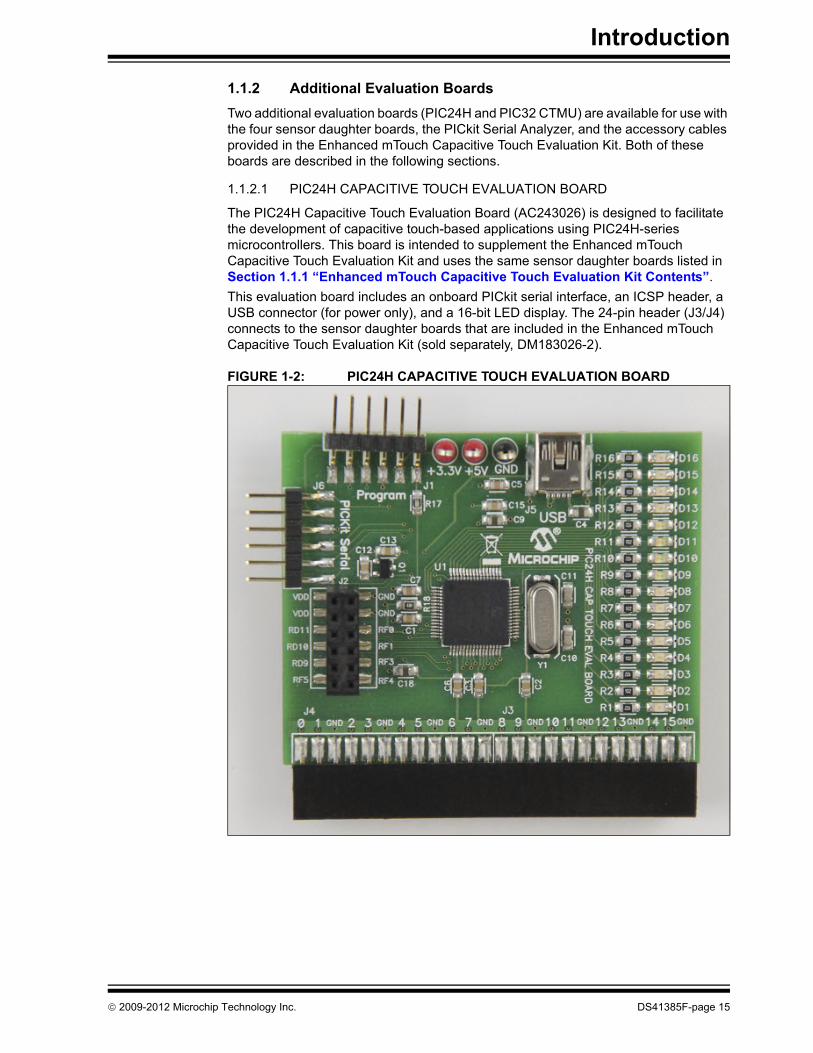
1.1.2 Additional Evaluation BoardsTwo additional evaluation boards (PIC24H and PIC32 CTMU) are available for use with the four sensor daughter boards, the PICkit Serial Analyzer, and the accessory cables provided in the Enhanced mTouch Capacitive Touch Evaluation Kit. Both of these boards are described in the following sections.
1.1.2.1 PIC24H CAPACITIVE TOUCH EVALUATION BOARD
The PIC24H Capacitive Touch Evaluation Board (AC243026) is designed to facilitate the development of capacitive touch-based applications using PIC24H-series microcontrollers. This board is intended to supplement the Enhanced mTouch Capacitive Touch Evaluation Kit and uses the same sensor daughter boards listed in Section 1.1.1 “Enhanced mTouch Capacitive Touch Evaluation Kit Contents”.This evaluation board includes an onboard PICkit serial interface, an ICSP header, a USB connector (for power only), and a 16-bit LED display. The 24-pin header (J3/J4) connects to the sensor daughter boards that are included in the Enhanced mTouch Capacitive Touch Evaluation Kit (sold separately, DM183026-2).
FIGURE 1-2: PIC24H CAPACITIVE TOUCH EVALUATION BOARD
© 2009-2012 Microchip Technology Inc. DS41385F-page 15

Enhanced mTouch™ Capacitive Touch Evaluation Kit and Accessory Boards User’s Guide
1.1.2.2 PIC32 CTMU CAPACITIVE TOUCH EVALUATION BOARD
The PIC32 CTMU Capacitive Touch Evaluation Board (AC323027) is designed to facilitate the development of capacitive touch-based applications using PIC32-series microcontrollers with a Charge Time Measurement Unit (CTMU) module. This board is intended to supplement the Enhanced mTouch Capacitive Touch Evaluation Kit and uses the same sensor daughter boards listed in Section 1.1.1 “Enhanced mTouch Capacitive Touch Evaluation Kit Contents”.This evaluation board includes an ICSP header, a USB connector (for power only), and a 16-bit LED display. The 24-pin header (J3/J4) connects to the sensor daughter boards that are included in the Enhanced mTouch Capacitive Touch Evaluation Kit (sold separately, DM183026-2).
FIGURE 1-3: PIC32 CTMU EVALUATION BOARD
DS41385F-page 16 © 2009-2012 Microchip Technology Inc.

Introduction
1.2 OPERATIONAL REQUIREMENTSTo communicate with, and to program an evaluation board, the following hardware and software are needed:• PC-compatible system with a CD-ROM drive• One available USB port on the PC or a powered USB hub• An additional USB port for the PICkit Serial Analyzer (optional)• Microsoft® Windows® XP SP2, Windows Vista (32-bit), or Windows 7• One of the following debugging/programming development tools:
- PICkit 3 In-Circuit Programmer/Debugger (PG164130), or- MPLAB ICD 3 In-Circuit Debugger (DV164035), or- MPLAB REAL ICE™ In-Circuit Emulator (DV244005) with the RJ-11 to
ICSP™ Adaptor (AC164110)
1.3 INITIAL BOARD SETUPWith its preinstalled demonstration application, an evaluation board is designed to be used right out of the box. Except for a single USB connection to a computer for power, no additional hardware or configuration is necessary.
1.3.1 Installing the SoftwareBefore you use the evaluation kit or an accessory board, it is important that you have installed the Microchip MPLAB Integrated Development Environment (IDE). MPLAB IDE provides the assembler tools you will use for development. You will also need a C compiler for the demonstration code. The MPLAB C Compiler seamlessly integrates into MPLAB IDE. Both the MPLAB IDE and C Compiler are free (see the note below) and are available for download from the Microchip web site at: www.microchip.com/MPLAB and www.microchip.com/compilers, respectively.
1.3.2 Connecting the HardwarePrior to connection, place the evaluation board on a flat surface near the computer. Check to make sure that there are no objects between the board and the surface upon which it is sitting. Once the evaluation kit software is installed, connect the provided USB cable (A to mini-B) to any available USB port on the PC or powered hub, and then to the board at the mini-B receptacle. The PC USB connection provides power to the board.The default code uses the 8-button board. Refer to Section 2.2.1 “8-Key Direct Plug-in Daughter Board” for more information on connecting this daughter board to an evaluation board.After connecting the daughter board to the evaluation board and applying power, the firmware application will illuminate all of the LEDs on the board at start-up. Any finger presses on the daughter board will cause the associate LED to illuminate. If this does not occur, refer to Chapter 5. “Troubleshooting”.
Note: The Standard Evaluation (Free) Version supports all optimization levels for 60 days, but then reverts to optimization level 0, or 1 only.
© 2009-2012 Microchip Technology Inc. DS41385F-page 17

Enhanced mTouch™ Capacitive Touch Evaluation Kit and Accessory Boards User’s Guide
NOTES:
DS41385F-page 18 © 2009-2012 Microchip Technology Inc.

ENHANCED mTouch™ CAPACITIVETOUCH EVALUATION KIT AND
ACCESSORY BOARDS USER’S GUIDE
Chapter 2. Demonstration Application
This chapter describes the touch sense application that is preprogrammed on the PIC16F, PIC18F, PIC24F, PIC24H and PIC32 microcontrollers, and its general principles of operation. Topics included in this chapter are:• Introduction to the Touch Interface• Individual Touch Sense Demonstrations
2.1 INTRODUCTION TO THE TOUCH INTERFACEMicrochip’s mTouch capacitive touch sensing techniques are voltage-based scanning methods that detect whether a key or button is pressed or not pressed (asserted/unas-serted) using the change in the capacitance of a key or button, which is caused by con-tact with the user’s finger. The change in capacitance creates a change in voltage that is measured by an on-chip Analog-to-Digital converter (ADC) module.PIC16F, PIC24H, and PIC32 microcontrollers without a CTMU module use the Sample and Hold (S&H) capacitor of an on-chip ADC to move the charge to or from each key or button. When two capacitors at different voltages are connected, a voltage divider is formed, which explains why the technique is known as Capacitive Voltage Divider (CVD).To charge a key or button, the ADC module is connected to an output pin that is pulled high, and is then switched to the pin of the key/button circuit. This process is repeated up to four times. The ADC module is then used to measure the resulting voltage.Discharging a key/button circuit with the ADC module also involves switching the ADC module between the key/button pin and an output pin; however, in this case, the output pin is low (i.e., grounded) and the key/button circuit has been previously charged. The key/button circuit is brought to VDD by converting the key/button pin on the device to an output pin that is pulled high before changing the pin back to an input pin. With the key/button circuit charged, the ADC module can then begin to discharge the circuit one S&H capacitor value at a time.Since the ADC module can source or sink a charge to or from the key/button circuit, it can be used to provide a differential touch measurement. If VPOS is the voltage mea-surement when the ADC module sources current, and VNEG is the voltage measure-ment when the ADC module sinks current, this would result in VDIF = VPOS – VNEG. Differential measurements provide greater noise immunity compared to just using VPOS or VNEG.
Note: Please refer to the Microchip application note AN1298 “Capacitive Touch Using Only an ADC (“CVD”)” for more details on capacitive touch measurements without a CTMU module.
© 2009-2012 Microchip Technology Inc. DS41385F-page 19
Enhanced mTouch™ Capacitive Touch Evaluation Kit and Accessory Boards User’s Guide
PIC18F, PIC24F, and some PIC32 microcontrollers use an on-chip Charge Time Mea-surement Unit (CTMU) module to charge each button and an on-chip ADC module to measure the resulting voltage. The CTMU consists of a constant current source that provides a highly repeatable charge to each key or button. When any additional capac-itance is added to the key/button circuit (from the touch of a fingertip, for example), this charge results in a lower voltage compared to the voltage seen on the circuit without the additional capacitance. This change in voltage is how the microcontroller with an on-chip ADC module detects a touch event.
For detailed information on the CTMU module, please refer to the related “Charge Time Measurement Unit (CTMU)” Family Reference Manual section, which is available from the Microchip web site.
Each evaluation board can be used with these sensor daughter boards:• 2-Channel Slider Plug-in Daughter Board• 4-Channel Slider Plug-in Daughter Board• 8-Key Direct Plug-in Daughter Board• 12-Key Matrix Plug-in Daughter BoardA more detailed description of evaluation board operation is provided in Chapter 4. “Evaluation Board Hardware”.The response of the sensor to fingertip touch is influenced by many factors, such as touch areas, voltage and current levels, ambient humidity, static buildup, and so on. The capacitive touch sensing is done by a relative shift in the capacitance due to the addition of the finger capacitance to the touch sensor. The demonstration code supplied takes most of the typical environmental factors into consideration. The demonstration application is very flexible in the sense that it can be modified by the user.
Note: Please refer to Microchip application note AN1250 “Microchip CTMU for Capacitive Touch Applications” for more details on how the CTMU and ADC modules work together to measure capacitive touch.
DS41385F-page 20 © 2009-2012 Microchip Technology Inc.

Demonstration Application
2.2 INDIVIDUAL TOUCH SENSE DEMONSTRATIONS
2.2.1 8-Key Direct Plug-in Daughter BoardThe 8-Key Direct Plug-in Daughter Board is an 8-channel plug-in board with each key directly mapped to a sensor channel. This board can be interfaced with eight channels out of the 16 channels provided in the Enhanced mTouch Capacitive Touch Evaluation Kit and Accessory Boards. Touching any one of the keys on the plug-in board will illuminate the corresponding LED on the evaluation board.Figure 2-1 shows the default plug-in channels of the 8-Key Direct Plug-in Daughter Board for the PIC24F CTMU, PIC24H CVD, and PIC32 CVD Evaluation Boards.
FIGURE 2-1: DEFAULT PLUG-IN CHANNELS FOR 8-KEY PLUG-IN BOARD (PIC24F CTMU, PIC24H CVD, AND PIC32 CVD)
The default firmware for all evaluation boards uses the 8-Key Direct Key Plug-in Daughter Board. Refer to Table 2-1 for the J3/J4 sensor channels that are used for the specific evaluation board.
TABLE 2-1: DEFAULT J3/J4 CONNECTOR PLUG-IN CHANNELS
Evaluation Board
Sensor Daughter Board
8-Key Direct 12-Key Matrix 4-Channel Slider
2-Channel Slider
PIC16F CVD 0-7 0-6 0-3 0-1PIC18F CTMU 0-7 6-12 0-3 0-1PIC24F CTMU 8-15 8-14 0-3 0-1PIC24H CVD 8-15 8-14 0-3 0-1PIC32 CTMU 0-7 0-6 0-3 0-1PIC32 CVD 8-15 8-14 0-3 0-1
© 2009-2012 Microchip Technology Inc. DS41385F-page 21

Enhanced mTouch™ Capacitive Touch Evaluation Kit and Accessory Boards User’s Guide
2.2.2 12-Key Matrix Plug-in Daughter BoardThe 12-Key Matrix Plug-in Daughter Board is an array of 12 touch-sensitive keys arranged in a 4x3 matrix (required 3 + 4 = 7 sensor inputs). Touching any one of the keys will illuminate one of the LEDs. The 12-Key Matrix Plug-in Daughter Board is numbered from 0 to 11, which corresponds to LEDs D1 to D12, respectively.Refer to Table 2-1 for the J3/J4 sensor channels that are used by each evaluation board when connected to the 12-Key Matrix Plug-in Daughter Board.
2.2.3 2-Channel and 4-Channel Slider Plug-in Daughter BoardsTouching anywhere along the length of the slider causes all the LEDs to illuminate as a bar graph that is representative to the position of the touch. The LED bar graph fol-lows the finger as it moves up and down along the length of the slider, and remains at the last position on the slider when the finger is removed.The default firmware loaded in the 2-Channel Slider Plug-in Daughter Board, is config-ured such that, channels 0 and 1 of connector J4/J3 in the evaluation kit are connected to the two channels in the 2-Channel Slider Plug-in Daughter Board.The default firmware for the 4-Channel Slider Plug-in Daughter Board, is configured such that, channels 0, 1, 2, and 3 of connector J4/J3 in the main evaluation board are connected to the four channels in the 4-Channel Slider Plug-in Daughter Board (see Figure 2-2).
FIGURE 2-2: DEFAULT PLUG-IN CHANNELS FOR 4-CHANNEL SLIDER PLUG-IN DAUGHTER BOARD
Note 1: The plug-in daughter boards can be interfaced to any of the channels in the evaluation kit by changing the configuration settings. The details of the configuration settings are explained in the Readme.txt file, which is distributed in each demonstration.
2: Plugging in a sensor board while an evaluation board is running, may require resetting the touch algorithm, most easily done by cycling power.
DS41385F-page 22 © 2009-2012 Microchip Technology Inc.
Demonstration Application
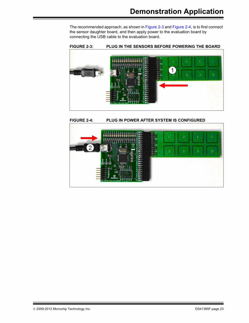
The recommended approach, as shown in Figure 2-3 and Figure 2-4, is to first connect the sensor daughter board, and then apply power to the evaluation board by connecting the USB cable to the evaluation board.
FIGURE 2-3: PLUG IN THE SENSORS BEFORE POWERING THE BOARD
FIGURE 2-4: PLUG IN POWER AFTER SYSTEM IS CONFIGURED
© 2009-2012 Microchip Technology Inc. DS41385F-page 23

Enhanced mTouch™ Capacitive Touch Evaluation Kit and Accessory Boards User’s Guide
NOTES:
DS41385F-page 24 © 2009-2012 Microchip Technology Inc.

ENHANCED mTouch™ CAPACITIVETOUCH EVALUATION KIT AND
ACCESSORY BOARDS USER’S GUIDE
Chapter 3. ProfiLab-Expert™ Graphical User Interface for Real-Time Debugging
This chapter describes the ProfiLab-Expert™ Graphical User Interface (GUI), which can be used for real-time debugging of the Enhanced mTouch Capacitive Touch Evaluation Kit and Accessory Boards.
3.1 OVERVIEWReal-time debugging support for mTouch software on the mTouch evaluation boards is supported by a stand-alone Windows® executable, mTouch GUI.exe, and an associated ProfiLab-Expert project, both of which are provided in the MPLAB mTouch projects for these boards. It is important to note that it is not necessary to purchase ProfiLab-Expert to make use of these project and executable files. ABACOM’s ProfiLab-Expert supports the development of Windows GUIs using a graphical programming paradigm. Optionally, users can purchase ProfiLab-Expert and adapt or extend the projects provided to support real-time debugging needs for most mTouch projects. For more information on ProfiLab-Expert, visit the ABACOM web site at: http://www.abacom-online.de/uk/html/profilab-expert.html
3.2 GUI SETUP
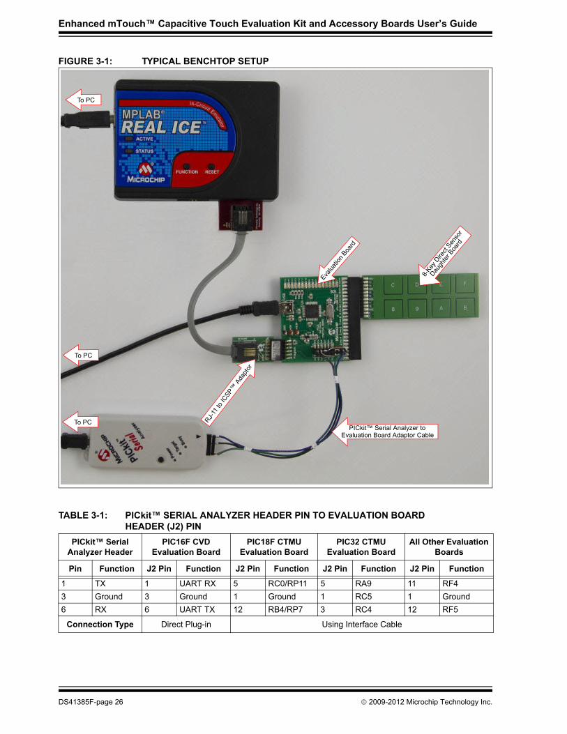
3.2.1 Operation Principles and Benchtop SetupThe basic principle of operation is for the mTouch application to format a text string of five-digit decimal numbers that are separated by commas, and output this data through the UART transmit (TX) pin on the device. Using a PICkit™ Serial Analyzer running special firmware, a ProfiLab-Expert GUI can display this data in real-time on a PC. The button status, button asserts, slider values, and button voltage measurements are displayed by the GUI, while the UART data can be captured in ASCII text files for later analysis.In fact, once the UART TX pin is active, the same data can be captured by a simple COM-port application, such as HyperTerminal (or equivalent) for later analysis using Excel® or Matlab®, or GNU Octave.A typical benchtop setup is shown in Figure 3-1. The UART receive (RX) pin of the PICkit Serial Analyzer is connected to a UART TX pin on connector J2. Refer to the ReadMe file (1st Read Me.txt) of each mTouch application to determine which pins of the J2 connector are used. A summary PICkit Serial Analyzer to evaluation board pin assignment is provided in Table 3-1.
Note: Refer to Appendix B. “Adding Features to a ProfiLab-Expert™ GUI” for more information on ProfiLab-Expert and how to extend the GUI by adding new features.
© 2009-2012 Microchip Technology Inc. DS41385F-page 25
Enhanced mTouch™ Capacitive Touch Evaluation Kit and Accessory Boards User’s Guide
FIGURE 3-1: TYPICAL BENCHTOP SETUP
TABLE 3-1: PICkit™ SERIAL ANALYZER HEADER PIN TO EVALUATION BOARD HEADER (J2) PIN
PICkit™ Serial Analyzer Header
PIC16F CVD Evaluation Board
PIC18F CTMU Evaluation Board
PIC32 CTMU Evaluation Board
All Other Evaluation Boards
Pin Function J2 Pin Function J2 Pin Function J2 Pin Function J2 Pin Function
1 TX 1 UART RX 5 RC0/RP11 5 RA9 11 RF43 Ground 3 Ground 1 Ground 1 RC5 1 Ground6 RX 6 UART TX 12 RB4/RP7 3 RC4 12 RF5
Connection Type Direct Plug-in Using Interface Cable
To PC
To PCPICkit™ Serial Analyzer to
Evaluation Board Adaptor Cable
Evalua
tion B
oard
RJ-11 t
o ICSP
™ A
dapto
r
8-Key
Dire
ct Sen
sor
Daugh
ter B
oard
To PC
DS41385F-page 26 © 2009-2012 Microchip Technology Inc.

ProfiLab-Expert™ Graphical User Interface for Real-Time Debugging
The PIC16F CVD Evaluation Board allows for a direct connection of the PICkit Serial Analyzer (DV164122), as shown in Figure 3-2.
FIGURE 3-2: PIC16F CVD EVALUATION BOARD CONNECTED TO A PICkit™ SERIAL ANALYZER
As shown in Figure 3-3, all mTouch Evaluation Boards can be directly connected to a PICkit 3 In-Circuit Programmer/Debugger (PG164130).
FIGURE 3-3: EVALUATION BOARD CONNECTED TO A PICkit™ 3 IN-CIRCUIT PROGRAMMER/DEBUGGER
8-Key
Dire
ct Se
nsor
Daugh
ter B
oard
To PCPI
C16F
CVD
Evalua
tion B
oard
To PC for Board Power
8-Key
Dire
ct Se
nsor
Daugh
ter B
oard
To PC
To PC
PIC16
F CVD
Evalu
ation
Boa
rd
To PC for Board Power
© 2009-2012 Microchip Technology Inc. DS41385F-page 27
Enhanced mTouch™ Capacitive Touch Evaluation Kit and Accessory Boards User’s Guide
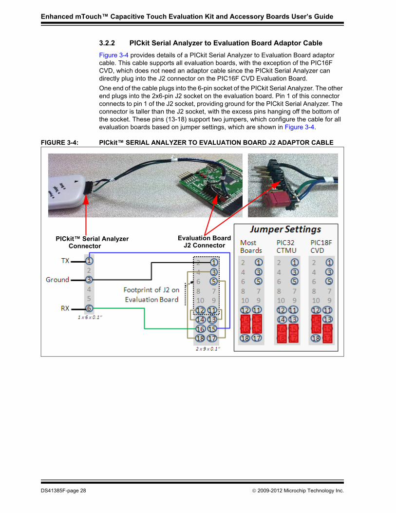
3.2.2 PICkit Serial Analyzer to Evaluation Board Adaptor CableFigure 3-4 provides details of a PICkit Serial Analyzer to Evaluation Board adaptor cable. This cable supports all evaluation boards, with the exception of the PIC16F CVD, which does not need an adaptor cable since the PICkit Serial Analyzer can directly plug into the J2 connector on the PIC16F CVD Evaluation Board.One end of the cable plugs into the 6-pin socket of the PICkit Serial Analyzer. The other end plugs into the 2x6-pin J2 socket on the evaluation board. Pin 1 of this connector connects to pin 1 of the J2 socket, providing ground for the PICkit Serial Analyzer. The connector is taller than the J2 socket, with the excess pins hanging off the bottom of the socket. These pins (13-18) support two jumpers, which configure the cable for all evaluation boards based on jumper settings, which are shown in Figure 3-4.
FIGURE 3-4: PICkit™ SERIAL ANALYZER TO EVALUATION BOARD J2 ADAPTOR CABLE
Evaluation BoardJ2 Connector
PICkit™ Serial AnalyzerConnector
DS41385F-page 28 © 2009-2012 Microchip Technology Inc.
ProfiLab-Expert™ Graphical User Interface for Real-Time Debugging
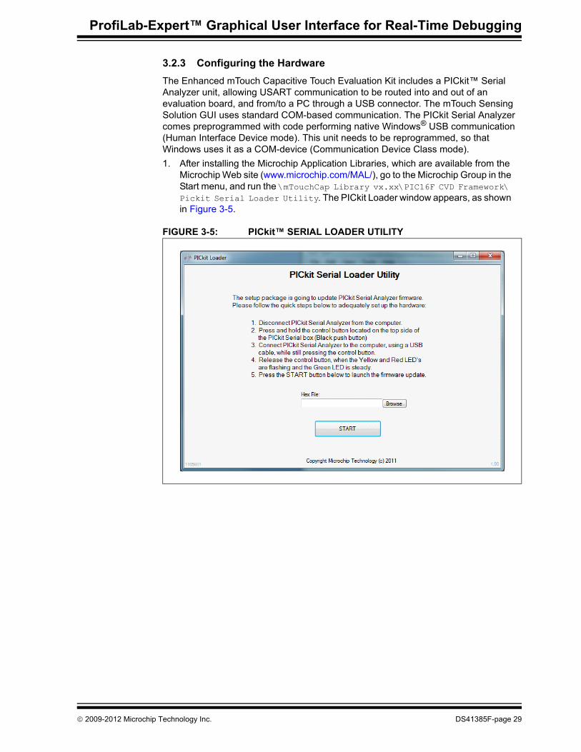
3.2.3 Configuring the HardwareThe Enhanced mTouch Capacitive Touch Evaluation Kit includes a PICkit™ Serial Analyzer unit, allowing USART communication to be routed into and out of an evaluation board, and from/to a PC through a USB connector. The mTouch Sensing Solution GUI uses standard COM-based communication. The PICkit Serial Analyzer comes preprogrammed with code performing native Windows® USB communication (Human Interface Device mode). This unit needs to be reprogrammed, so that Windows uses it as a COM-device (Communication Device Class mode).1. After installing the Microchip Application Libraries, which are available from the
Microchip Web site (www.microchip.com/MAL/), go to the Microchip Group in the Start menu, and run the \mTouchCap Library vx.xx\PIC16F CVD Framework\ Pickit Serial Loader Utility. The PICkit Loader window appears, as shown in Figure 3-5.
FIGURE 3-5: PICkit™ SERIAL LOADER UTILITY
© 2009-2012 Microchip Technology Inc. DS41385F-page 29

Enhanced mTouch™ Capacitive Touch Evaluation Kit and Accessory Boards User’s Guide
2. Follow the on-screen instructions to prepare the PICkit Serial Analyzer for programming, and then click Browse to select the code file, as shown in Figure 3-6.
FIGURE 3-6: LOADING THE FIRMWARE
3. Click Open. The following window appears, as shown in Figure 3-7.
FIGURE 3-7: STARTING PICkit™ SERIAL UPDATE
DS41385F-page 30 © 2009-2012 Microchip Technology Inc.

ProfiLab-Expert™ Graphical User Interface for Real-Time Debugging
4. Click START to begin the serial update. A programming status window appears indicating the operation may take a few minutes to complete, as shown in Figure 3-8. Once the update has completed, a notification window appears, as shown in Figure 3-9.
FIGURE 3-8: PROGRAMMING STATUS
FIGURE 3-9: SUCCESSFUL PROGRAMMING NOTIFICATION
© 2009-2012 Microchip Technology Inc. DS41385F-page 31

Enhanced mTouch™ Capacitive Touch Evaluation Kit and Accessory Boards User’s Guide
3.2.4 Connecting the PICkit Serial Analyzer to the Evaluation Board and the PC
For the PIC16F CVD Evaluation Board, connect the PICkit Serial Analyzer directly into the J2 connector on the board, which are the PICkit Serial pins. (The other set of six pins on the edge of the board, which are labeled J1 (PICkit 2) support an MPLAB debugger.)For all other boards, follow the connection setup shown in Table 3-1, or use the adaptor cable (see Figure 3-4) after setting the jumpers for the board you are using.Connect the PICkit Serial Analyzer to your PC using a USB A to mini-B cable.
3.2.5 Launching the mTouch GUILaunch the standalone GUI executable by the start menu:1. Select microchip mTouch GUI.2. Select mTouch GUI.If you have installed ProfiLab, you can launch ProfiLab and modify the GUI by selecting mTouch GUI project instead of the mTouch GUI.See Appendix B. “Adding Features to a ProfiLab-Expert™ GUI” for details on how to modify this project to add new features.
DS41385F-page 32 © 2009-2012 Microchip Technology Inc.

ProfiLab-Expert™ Graphical User Interface for Real-Time Debugging
3.2.6 Configuring the mTouch GUI with the Correct COM PortThe mTouch GUI uses standard asynchronous UART/USART communication. In the Windows environment, it uses a standard COM port. The GUI must know what COM port has been assigned to the PICkit Serial Analyzer when it is plugged into a PC USB port. You can use the Windows Device Manager to check which COM port has been assigned: 1. Open the Windows Device Manager.2. In Ports (COM & LPT), determine which COM port number is assigned to the
PICkit Serial Analyzer, as shown in Figure 3-10.
FIGURE 3-10: CHECKING THE COM PORT NUMBER
© 2009-2012 Microchip Technology Inc. DS41385F-page 33

Enhanced mTouch™ Capacitive Touch Evaluation Kit and Accessory Boards User’s Guide
Alternately, you can use a terminal emulator, such as RealTerm, which is available from http://realterm.sourceforge.net/. This terminal emulator allows you to not only identify which COM port the PICkit Serial Analyzer is using, but it also allows you to check the integrity of the data being received. Launch the terminal emulator, and then check which COM ports are available. Next, open this COM port with 115,200 Baud, 8 bits (Data), no Parity, and one Stop bit. You should see lines of 5-bit non-negative decimal integers, separated by commas.1. Once the COM port number is known, launch the GUI and click the red and white
screwdriver icon (located at the top right of the main GUI screen) to open the Configuration window, as shown in Figure 3-11.
2. Double click Serial Interface ($CR1), which opens the COM receive string dialog.
3. In the COM Receive string combo box, select the port assigned to the PICkit Serial Analyzer. Set all other options as shown in Figure 3-11, click OK, and then click Close.
FIGURE 3-11: COMMUNICATION SETTINGS
Click the screwdriver icon to open the Configuration window
Click Serial Interface ($CR1) to select the COM port
DS41385F-page 34 © 2009-2012 Microchip Technology Inc.

ProfiLab-Expert™ Graphical User Interface for Real-Time Debugging
If the mTouch application is properly connected, you should start receiving the button readings, which will immediately update the graphs on the plotter in the main window, as well as the raw readings, and the Min and Max for each channel or sensor. If you start touching the buttons, you should easily find the ones mapped to Buttons 1 to 4 and immediately see the corresponding LEDs on the display, reflecting any change to each button state. The graphs on the plotter should also reflect any change made to the corresponding four buttons.
© 2009-2012 Microchip Technology Inc. DS41385F-page 35

Enhanced mTouch™ Capacitive Touch Evaluation Kit and Accessory Boards User’s Guide
3.3 mTouch GUI SCREENSThe mTouch GUI has four tabbed screens: Channels 1-4, Channels 5-8, Channels 9-12, and Virtual Keypads. The first three screens show real-time button voltages for four buttons at a time. The last screen provides virtual keypads, reflecting the current state of the mTouch demonstration application, as reported by the UART to PICkit Serial Analyzer interface.
3.3.1 Voltage PlotsAs shown in Figure 3-12, the first tabbed screen provides normalized button voltage plots for the first four buttons/keys. If the mTouch communication parameters are properly set, the voltage should change as these buttons are pressed.
FIGURE 3-12: VOLTAGE PLOT FOR CHANNELS 1-4
Matrix Keys Channels 1-3 are columns 1-3
Matrix Keys Channel 4 is all ‘0’s
DS41385F-page 36 © 2009-2012 Microchip Technology Inc.

ProfiLab-Expert™ Graphical User Interface for Real-Time Debugging
Figure 3-13 shows the plot control interface, which is located at the bottom of the Channels 1-4 screen. Similarly, controls (minus the adjustment for Max Adjusted ADC Count and All Data Logger) are found on the two other voltage plot screens.
FIGURE 3-13: VOLTAGE PLOT CONTROLS
The QUIT button, located at the bottom left of the screen, stops data collection and terminates the GUI. To the right of the QUIT button, is the Reset Min/Max button that resets all of the maximum/minimum/delta values for all 12 input channels. These statistics allow measuring button assertion voltage swings for each sensor channel. The Reset Min/Max button allows you to reset the maximum/minimum/delta values so that new button assertions can be measured without restarting the GUI.Most 16-bit and 32-bit mTouch applications report measured button voltages as scaled and averaged ADC measurements, which are stored as unsigned 16-bit integers. Based on this, the Max Adjusted ADC Count is likely to be 65,535 (216 – 1). Button voltages are plotted normalized to this value, where 1.0 on the plot represents this maximum value. If the mTouch application uses a different normalization in reporting button voltages, the plots can be adjusted by changing the Max Adjusted ADC Count, which is just to the right of the Max, Raw, Min, and Delta fields.The REC/STOP button for the Plot Logger function starts and stops data recording into text files. Voltages from screens 1-3 are saved in the .\ProfiLabGUIs\mTouch GUI\Executable\Data\ folder as Record Page 1.txt through Record Page 3.txt. Data recorded using the REC/STOP button for the All Data Logger function is recorded in the .\ProfiLabGUIs\mTouch GUI\Executable\Data\ as All Data Dump.txt. The corresponding reset buttons clears the contents of the related ASCII file. All four ASCII text files are also cleared when the GUI is started. Therefore, it is recommended to move data files from a capture session out of the .\ProfiLabGUIs\mTouch GUI\Executable\Data\ folder before restarting the GUI.The format of voltage capture files (Record Page 1.txt, Record Page 2.txt, and Record Page 3.txt) is four columns of non-zero decimal numbers, one for each channel input. Each line in the file has four values, separated by semicolons. Example 3-1 shows a button assertion in the first column.
EXAMPLE 3-1:
Quit data collectionand exit the GUI
Reset Minimum andMaximum for all channels
MaximumADC Count
Delta = Max – Min
Save voltageplot data
to ASCII file
Save allUART datato ASCII file
Record/Stoprecording
Erase fileand start over
41519; 41581; 38021; 36995 38447; 41589; 37991; 37049 35375; 41589; 38003; 37047 32303; 41577; 37977; 37049 29231; 41557; 38001; 37035 26159; 41527; 37985; 37031 24263; 41381; 37997; 37033
© 2009-2012 Microchip Technology Inc. DS41385F-page 37

Enhanced mTouch™ Capacitive Touch Evaluation Kit and Accessory Boards User’s Guide
The All Data Dump.txt file has sixteen columns of non-zero decimal numbers, with the first three columns being button status, button asserts, and the slider value. The next twelve columns represent button voltages if the sixteenth (last) column is zero. A non-zero sixteenth column value represents a special record sent by the mTouch application and saved in the All Data Dump.txt file, but is otherwise ignored by the mTouch GUI. An example of All Data Dump.txt content is shown in Example 3-2.
EXAMPLE 3-2:
As seen in Figure 3-13, this first screen shows column voltages for a Matrix Key application. For a Matrix Key application the second screen, Channels 5 - 8, as shown in Figure 3-14, shows the voltages for all four key columns on the sensor daughter board.
FIGURE 3-14: VOLTAGE PLOT FOR CHANNELS 5-8
0; 0; 0; 24160; 41536; 37568; 36864; 39936; 38144; 37504; 36160; 0; 0; 0; 0; 290; 0; 0; 23648; 41440; 37984; 37024; 39904; 38080; 37152; 36128; 0; 0; 0; 0; 300; 0; 0; 23744; 41536; 37952; 36992; 39552; 37984; 37472; 36288; 0; 0; 0; 0; 310; 0; 0; 41519; 41519; 37975; 36985; 39911; 38087; 37481; 36213; 0; 0; 0; 0; 320; 0; 0; 41519; 41519; 37975; 36985; 39911; 38087; 37481; 36213; 0; 0; 0; 0; 0
Matrix Keys Channels 5-8 are rows 1-4
DS41385F-page 38 © 2009-2012 Microchip Technology Inc.

ProfiLab-Expert™ Graphical User Interface for Real-Time Debugging
3.3.2 Virtual KeypadsThe UART interface reports the current button status, as well as the current button voltages. Button status is shown on the fourth screen, Virtual Keypads, as shown in Figure 3-15. Some mTouch demonstration applications provide multiple interpretations of button status in the UART report, showing which buttons are pressed, which buttons have been asserted, and an equivalent slider value for the buttons that are pressed. These are all displayed on the Virtual Keypads screen.
FIGURE 3-15: VIRTUAL KEYPADS SCREEN
Prior Button Assert
Current Button Press Equivalent Slider Value
© 2009-2012 Microchip Technology Inc. DS41385F-page 39

Enhanced mTouch™ Capacitive Touch Evaluation Kit and Accessory Boards User’s Guide
3.3.3 Configuring Voltage PlotsA right mouse click in the middle of any voltage plot will bring up a menu of plotting options. Selecting Settings from the pop-up menu will enable editing of the plot format. Figure 3-16 shows how to increase the line width of the Channel 1 plot (represented by the thick red line) and the resulting change in the voltage plot.
FIGURE 3-16: CONFIGURING VOLTAGE PLOTS
Increasing Channel 1 Line Width
DS41385F-page 40 © 2009-2012 Microchip Technology Inc.

ProfiLab-Expert™ Graphical User Interface for Real-Time Debugging
Figure 3-17 shows an enlarged view of the visible plot controls on each plotting screen, which allow for various screen manipulations, including printing the plot or copying it to the clipboard.
FIGURE 3-17: PLOT CONTROLS
Y Zoom +
Y Zoom –
X Zoom +
X Zoom –
Zoom All
Reset Zoom
Delta timeCopy plotbetween samplesto ClipboardRecord
Stop
Print Plot
Plot Settings
Scroll TimeForward
Scroll TimeBack
© 2009-2012 Microchip Technology Inc. DS41385F-page 41

Enhanced mTouch™ Capacitive Touch Evaluation Kit and Accessory Boards User’s Guide
NOTES:
DS41385F-page 42 © 2009-2012 Microchip Technology Inc.

ENHANCED mTouch™ CAPACITIVETOUCH EVALUATION KIT AND
ACCESSORY BOARDS USER’S GUIDE
Chapter 4. Evaluation Board Hardware
This chapter provides a functional overview of the evaluation boards and identifies the major hardware components. Topics covered include:• Application Functional Overview• Board Components
4.1 APPLICATION FUNCTIONAL OVERVIEW
4.1.1 PIC16F CVD Evaluation BoardFor the PIC16F CVD Evaluation Board, ICSP lines are provided via the PICkit 3 header (J1). A mini-USB connector (J5) can provide power to the board. The PICkit Serial Analyzer may be used to communicate with the mTouch Sensing Solution GUI through asynchronous communication. For this board, do not use both the USB and PICkit tools to power the board at the same time (the USB connection has a 3.3V regulator used to regulate the USB power, while the PICkit tools have their own regulator straight to the device). ICSPCLK and ICSPDAT share pins with active-low LEDs (D6 and D7), which can cause problems when debugging. To use in-circuit serial debugging, remove jumper J4 to disconnect these two LEDs.
FIGURE 4-1: PIC16F CVD EVALUATION BOARD APPLICATION-SIDE BLOCK DIAGRAM
PIC16F1937
USB mini-BReceptacle
Matrix Key
ICSP™
VDD
ICSPDATICSPCLKMCLR
7-Channel
J1Programming
Header
CVDO:13
4-Channel
Slider Plug-in
Direct Key Slider8-Channel
J42-Channel
16 LEDs (D1-D16)
Sensor Boards
Board
Plug-in Board
Slider Plug-inBoard
BoardPlug-in
J5
PLUG-IN BOARDS PIC16F CVD EVALUATION BOARD
J2
Serial HeaderI2C PICkit™
I2C™
VDDVSS
GPIO
Vss
J3
© 2009-2012 Microchip Technology Inc. DS41385F-page 43

Enhanced mTouch™ Capacitive Touch Evaluation Kit and Accessory Boards User’s Guide
4.1.2 PIC18F CTMU Evaluation Board
The PIC18F CTMU Evaluation Board (see Figure 4-2) is similar to the PIC24F CTMU Evaluation Board except for the change in the number of ADC channels. The PIC18F46J50 microcontroller on the PIC18F CTMU Evaluation Board has 13 ADC channels, which are used by the touch sense application as the sensing channels.
The PIC18F microcontroller uses its on-chip USB engine and transceiver to communicate to the PC-side interface application, using the USB mini-B receptacle. The evaluation board also uses the USB receptacle for application power as a bus-powered device.Microcontroller and LED power are provided from the VBUS by Q1, an MCP1702 voltage regulator. Provisions on the board allow for the user to add components and create an externally powered application.
FIGURE 4-2: PIC18F CTMU EVALUATION BOARD APPLICATION-SIDE BLOCK DIAGRAM
Note: PIC18F CTMU Evaluation Board firmware uses only 13 channels for touch sense applications and channels 13 to 15 are unused in the PIC18F CTMU board.
Note: Unlike the PIC24F CTMU Evaluation Board, the ICD interface (PGC and PGD) on the PIC18F Evaluation Board is not shared with any of the CTMU channels.
PIC18F46J50
USB mini-BReceptacle
Key Plug-in
ICSP™
D+/D-
PGC/EMUCPGD/EMUDMCLR
7-Channel Matrix
J1Programming
Header
AN0:AN15
4-Channel
Slider Plug-in
Power SupplyQ1
RD0-RD7
Direct Key8-Channel
J42-Channel
16 LEDs (D1-D16)
D8-D15Direct Key Plug-in
D1-D12Matrix Key Plug-in
D1-D162-Channel and
4-Channel SliderPlug-in LEDsBoard
Board
Slider Plug-inBoard
Plug-in Board
Board LEDs
Board LEDs
(3.3V)
J5
PLUG-IN BOARDS PIC18F CTMU EVALUATION BOARD
J3
DS41385F-page 44 © 2009-2012 Microchip Technology Inc.
Evaluation Board Hardware
4.1.3 PIC24F CTMU Evaluation Board
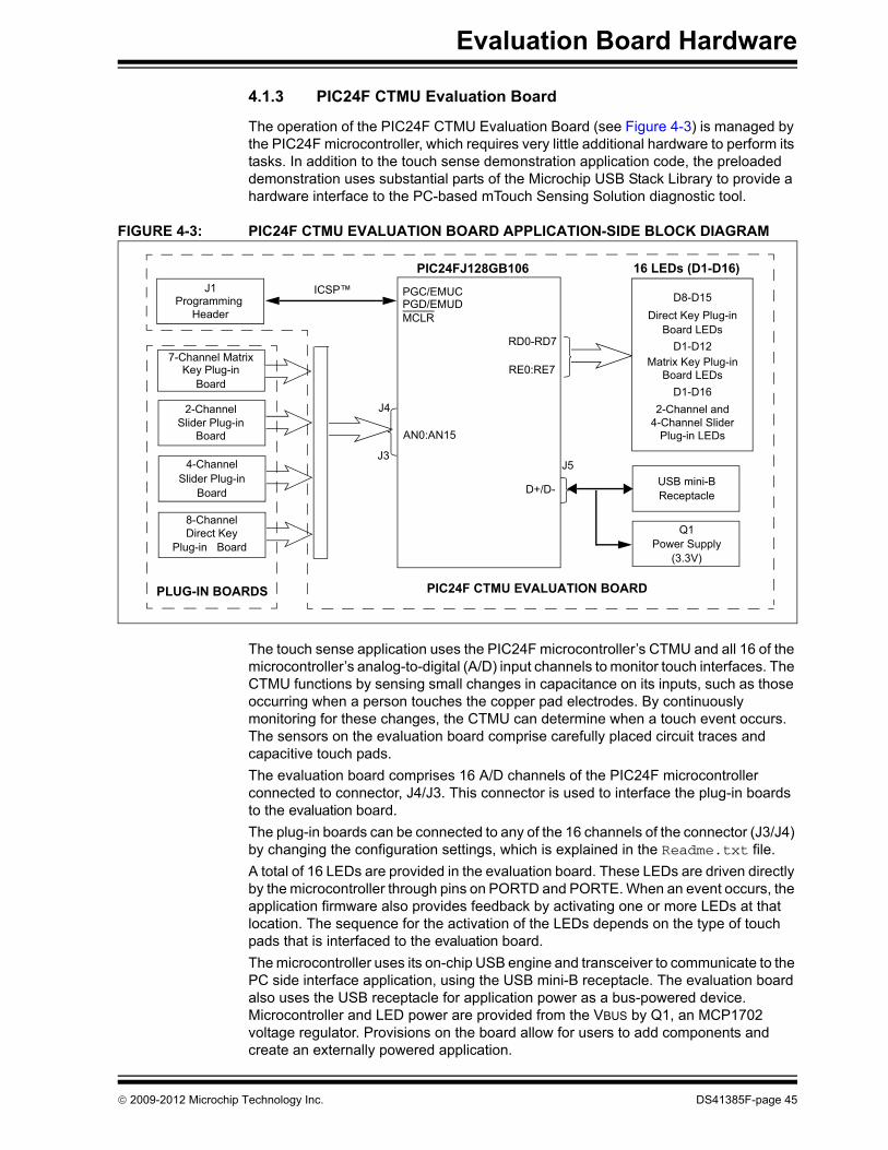
The operation of the PIC24F CTMU Evaluation Board (see Figure 4-3) is managed by the PIC24F microcontroller, which requires very little additional hardware to perform its tasks. In addition to the touch sense demonstration application code, the preloaded demonstration uses substantial parts of the Microchip USB Stack Library to provide a hardware interface to the PC-based mTouch Sensing Solution diagnostic tool.
FIGURE 4-3: PIC24F CTMU EVALUATION BOARD APPLICATION-SIDE BLOCK DIAGRAM
The touch sense application uses the PIC24F microcontroller’s CTMU and all 16 of the microcontroller’s analog-to-digital (A/D) input channels to monitor touch interfaces. The CTMU functions by sensing small changes in capacitance on its inputs, such as those occurring when a person touches the copper pad electrodes. By continuously monitoring for these changes, the CTMU can determine when a touch event occurs. The sensors on the evaluation board comprise carefully placed circuit traces and capacitive touch pads.The evaluation board comprises 16 A/D channels of the PIC24F microcontroller connected to connector, J4/J3. This connector is used to interface the plug-in boards to the evaluation board.The plug-in boards can be connected to any of the 16 channels of the connector (J3/J4) by changing the configuration settings, which is explained in the Readme.txt file.A total of 16 LEDs are provided in the evaluation board. These LEDs are driven directly by the microcontroller through pins on PORTD and PORTE. When an event occurs, the application firmware also provides feedback by activating one or more LEDs at that location. The sequence for the activation of the LEDs depends on the type of touch pads that is interfaced to the evaluation board. The microcontroller uses its on-chip USB engine and transceiver to communicate to the PC side interface application, using the USB mini-B receptacle. The evaluation board also uses the USB receptacle for application power as a bus-powered device. Microcontroller and LED power are provided from the VBUS by Q1, an MCP1702 voltage regulator. Provisions on the board allow for users to add components and create an externally powered application.
PIC24FJ128GB106
USB mini-BReceptacle
Key Plug-in
ICSP™
D+/D-
PGC/EMUCPGD/EMUDMCLR
7-Channel Matrix
J1Programming
Header
AN0:AN15
4-Channel
Slider Plug-in
Power SupplyQ1
RE0:RE7
RD0-RD7
Direct Key8-Channel
J42-Channel
16 LEDs (D1-D16)
D8-D15Direct Key Plug-in
D1-D12Matrix Key Plug-in
D1-D162-Channel and
4-Channel SliderPlug-in LEDsBoard
Board
Slider Plug-inBoard
BoardPlug-in
Board LEDs
Board LEDs
(3.3V)
J5
PLUG-IN BOARDS PIC24F CTMU EVALUATION BOARD
J3
© 2009-2012 Microchip Technology Inc. DS41385F-page 45

Enhanced mTouch™ Capacitive Touch Evaluation Kit and Accessory Boards User’s Guide
For users interested in using the evaluation board as an experimental platform, the microcontroller can be reprogrammed using the ICSP connector. A 6-pin header is provided for connecting the evaluation board to any programmer that is compatible with MPLAB ICD 3. Since the ICD interface (PGD and PGC) shares some input channels of the connector, J4/J3 (channel 6 and 7), necessary care should be taken when the debugger is enabled.The firmware in the evaluation board will have the default plug-in board channel configurations, which is explained in the Readme.txt file. The user can reconfigure the channels based on his application by referring to the Readme.txt file.
4.1.4 PIC24H CVD Evaluation BoardThe PIC24H CVD Evaluation Board (see Figure 4-4) is based on the same layout as the PIC24F CTMU and PIC32 CVD Evaluation Boards and has similar functional characteristics as the PIC16F CVD Evaluation Board (I2C interface with host).This board can be powered by the USB connector via a 3.3V regulator. Alternately, it can be powered by a PICkit 3 In-Circuit Programmer/Debugger; however, do not connect both devices at the same time.
FIGURE 4-4: PIC24H CVD EVALUATION BOARD APPLICATION-SIDE BLOCK DIAGRAM
PIC24HJ128GP506
USB mini-BReceptacle
Matrix Key
ICSP™
VDD
ICSPDATICSPCLKMCLR
7-Channel
J1Programming
Header
AN0-AN15
4-Channel
Slider Plug-in
Direct Key Slider8-Channel
J42-Channel
16 LEDs (D1-D16)
Sensor Boards
Board
Plug-in Board
Slider Plug-inBoard
BoardPlug-in
J5
PLUG-IN BOARDS PIC24H CVD EVALUATION BOARD
J2
Serial HeaderI2C PICkit™
I2C™
VDDVSS
GPIO
Vss
J3
DS41385F-page 46 © 2009-2012 Microchip Technology Inc.

Evaluation Board Hardware
4.1.5 PIC32 CVD Evaluation BoardThe PIC32 CVD Evaluation Board (see Figure 4-5) is similar to the PIC24F CTMU Evaluation Board. The evaluation board layout is almost identical due to the fact that the PIC32MX795F512H and PIC24FJ128GB106 devices are pin-to-pin compatible. The four daughter boards are connected to the J3/J4 connectors in the same manner. As for functionality, the PIC32 CVD evaluation board has 16 LEDs to indicate touch sensing while the USB interface is used for communicating with the host application for visualization and diagnostic.This board can be powered by the USB connector via a 3.3V regulator. Alternately, it can be powered by a PICkit 3 In-Circuit Programmer/Debugger; however, do not connect both devices at the same time.
FIGURE 4-5: PIC32 CVD EVALUATION BOARD APPLICATION-SIDE BLOCK DIAGRAM
PIC32MX795F512H
USB mini-BReceptacle
Key Plug-in
ICSP™
D+/D-
PGC/EMUCPGD/EMUDMCLR
7-Channel Matrix
J1Programming
Header
AN0:AN15
4-Channel
Slider Plug-in
Power SupplyQ1
RE0:RE7
RD0-RD7
Direct Key8-Channel
J42-Channel
16 LEDs (D1-D16)
D8-D15Direct Key Plug-in
D1-D12Matrix Key Plug-in
D1-D162-Channel and
4-Channel SliderPlug-in LEDsBoard
Board
Slider Plug-inBoard
BoardPlug-in
Board LEDs
Board LEDs
(3.3V)
J5
PLUG-IN BOARDS PIC32 CVD EVALUATION BOARD
J3
© 2009-2012 Microchip Technology Inc. DS41385F-page 47

Enhanced mTouch™ Capacitive Touch Evaluation Kit and Accessory Boards User’s Guide
4.1.6 PIC32 CTMU Evaluation Board
The PIC32 CTMU Evaluation Board (see Figure 4-6) is similar to the PIC24F CTMU Evaluation Board except for the change in the number of ADC channels. The PIC32MX220F032D microcontroller on the PIC32 CTMU Evaluation Board has 13 ADC channels, which are used by the touch sense application as the sensing channels.
This board can be powered by the USB connector via a 3.3V regulator. Alternately, it can be powered by a PICkit 3 In-Circuit Programmer/Debugger; however, do not connect both devices at the same time.
FIGURE 4-6: PIC32 CTMU EVALUATION BOARD APPLICATION-SIDE BLOCK DIAGRAM
Note: PIC32 CTMU Evaluation Board firmware uses only 13 channels for touch sense applications and channels 13 to 15 are unused in the PIC32 CTMU board.
Note: Unlike the PIC24F CTMU Evaluation Board, the ICD interface (PGC and PGD) on the PIC32 Evaluation Board is not shared with any of the CTMU channels.
PIC32220F032D
USB mini-BReceptacle
Key Plug-in
ICSP™
D+/D-
PGC/EMUCPGD/EMUDMCLR
7-Channel Matrix
J1Programming
Header
AN0:AN15
4-Channel
Slider Plug-in
Power SupplyQ1
RD0-RD7
Direct Key8-Channel
J42-Channel
16 LEDs (D1-D16)
D8-D15Direct Key Plug-in
D1-D12Matrix Key Plug-in
D1-D162-Channel and
4-Channel SliderPlug-in LEDsBoard
Board
Slider Plug-inBoard
Plug-in Board
Board LEDs
Board LEDs
(3.3V)
J5
PLUG-IN BOARDS PIC32 CTMU EVALUATION BOARD
J3
DS41385F-page 48 © 2009-2012 Microchip Technology Inc.

Evaluation Board Hardware
4.2 BOARD COMPONENTS
4.2.1 PIC16F CVD Evaluation BoardFigure 4-7 identifies the key hardware components that are common for the PIC16F CVD Evaluation Board. There is one evaluation board and four plug-in daughter boards. The four plug-in daughter boards are identified as direct keys, matrix keys, 2-channel slider and 4-channel slider.
FIGURE 4-7: PIC16F CVD EVALUATION BOARD COMPONENT LAYOUT (TOP SIDE)
TABLE 4-1: BOARD COMPONENTSReference Component
1 PIC16F1937 microcontroller (U1) for the PIC16F CVD Evaluation Board2 USB mini-B receptacle (J4)3 ICSP™ programming header (J1)4 Power supply (U3) to provide the VDD to the evaluation board5 Plug-in sensor LEDs (D1-D14)6 Plug-in interface connector (J3)7 PICkit™ Serial Analyzer connector (J2)
1
57
4
2
3
6
© 2009-2012 Microchip Technology Inc. DS41385F-page 49

Enhanced mTouch™ Capacitive Touch Evaluation Kit and Accessory Boards User’s Guide
4.2.1.1 COMPONENT DESCRIPTIONS
The components listed here (in order of their reference tags in Figure 4-7) are the key components of the application side of the PIC16F CVD Evaluation Board:1. PIC16F1937 Microcontroller (U1): This provides the processing power for the
touch sense applications in the PIC16F Evaluation Board. 2. USB mini-B Receptacle (J4): This provides power to the board via USB.3. ICSP™ Programming Header (J1): This provides a standard Microchip ICD
interface for programming and debugging applications on an evaluation board. It is designed to connect directly with Microchip's PICkit 3. Pin 1 is located on the right side of the interface, as viewed from the front of the board, and is marked with an arrow.
4. PICkit Serial Analyzer Connector (J2): This connector is used to exchange data to the Host PC through ASYNC using the PICkit Serial Analyzer.
5. Power Supply (U3): This converts the +5 VDC from VBUS to the regulated +3.3 VDC required by the evaluation board.
6. Plug-in Sensor LEDs (D1-D14): Fourteen LEDs (D1 through D14) are con-nected to one of the general purpose I/O ports of the PIC® microcontroller. These LEDs are illuminated based on the need of the application.
7. Plug-in Interface Connector (J3): This is a 40-pin connector, which is used to interface the different plug-in boards to the microcontroller. This connector is interfaced to 14 analog channels of the microcontroller and the remaining pins are connected to ground of the evaluation board.
DS41385F-page 50 © 2009-2012 Microchip Technology Inc.
Evaluation Board Hardware
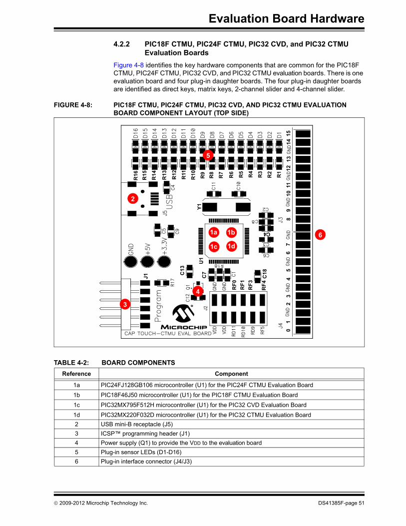
4.2.2 PIC18F CTMU, PIC24F CTMU, PIC32 CVD, and PIC32 CTMU Evaluation Boards
Figure 4-8 identifies the key hardware components that are common for the PIC18F CTMU, PIC24F CTMU, PIC32 CVD, and PIC32 CTMU evaluation boards. There is one evaluation board and four plug-in daughter boards. The four plug-in daughter boards are identified as direct keys, matrix keys, 2-channel slider and 4-channel slider.
FIGURE 4-8: PIC18F CTMU, PIC24F CTMU, PIC32 CVD, AND PIC32 CTMU EVALUATION BOARD COMPONENT LAYOUT (TOP SIDE)
TABLE 4-2: BOARD COMPONENTSReference Component
1a PIC24FJ128GB106 microcontroller (U1) for the PIC24F CTMU Evaluation Board
1b PIC18F46J50 microcontroller (U1) for the PIC18F CTMU Evaluation Board
1c PIC32MX795F512H microcontroller (U1) for the PIC32 CVD Evaluation Board
1d PIC32MX220F032D microcontroller (U1) for the PIC32 CTMU Evaluation Board2 USB mini-B receptacle (J5)3 ICSP™ programming header (J1)4 Power supply (Q1) to provide the VDD to the evaluation board5 Plug-in sensor LEDs (D1-D16)6 Plug-in interface connector (J4/J3)
J1
C13
C7
U1
R15
R16 R14 R10
R13 R12 R11 R8
R9 R7 R3
R6 R5 R4
R1
R2
Y1
C4
RF1
RF3
RF4
C18
RF0
01
23
45
67
89
1011
1213
1415
1c
2
5
6
4
3
1a
1d
1b
© 2009-2012 Microchip Technology Inc. DS41385F-page 51

Enhanced mTouch™ Capacitive Touch Evaluation Kit and Accessory Boards User’s Guide
4.2.2.1 COMPONENT DESCRIPTIONS
The components listed here (in order of their reference tags in Figure 4-8) are the key components of the application side of an evaluation board, which are common for both PIC18F and PIC24F CTMU evaluation boards except for the microcontroller used in the board:1a. PIC24FJ128GB106 Microcontroller (U1): This provides the processing power
for the touch sense demonstration applications. The microcontroller features 64 Kbytes of Flash program memory and 16 Kbytes RAM, allowing sufficient space for the development of more complex touch sense applications. The demonstration application uses an 8 MHz signal to create the 48 MHz USB clock, as well as the application’s 32 MHz clock. Crystal, Y1, and associated components are used by the microcontroller’s internal oscillator to maintain the frequency tolerances required by the USB specifications.
1b. PIC18F46J50 Microcontroller (U1): This provides the processing power for the touch sense applications in the PIC18F evaluation board. The microcontroller features 64 Kbytes of Flash program memory and 3.8 Kbytes RAM. The demon-stration application uses an 8 MHz signal to create the 48 MHz USB clock, as well as the application’s 32 MHz clock. Crystal, Y1, and associated components are used by the microcontroller’s internal oscillator to maintain the frequency tolerances required by the USB specifications.
1c. PIC32MX795F512H Microcontroller (U1): This provides the processing power for the touch sense applications in the PIC32 CVD evaluation board. The micro-controller features 512 Kbytes of Flash program memory and 128 Kbytes RAM. The demonstration application uses an 8 MHz signal to create the 48 MHz USB clock, as well as the application’s 40 MHz clock. Crystal, Y1, and associated components are used by the microcontroller’s internal oscillator to maintain the frequency tolerances required by the USB specifications.
1d. PIC32MX220F032D Microcontroller (U1): This provides the processing power for the touch sense demonstration applications. The microcontroller features 32 Kbytes of Flash program memory and 8 Kbytes RAM, allowing sufficient space for the development of more complex touch sense applications. The demonstration application uses an 8 MHz signal to create the 48 MHz USB clock, as well as the application’s 32 MHz clock. Crystal, Y1, and associated components are used by the microcontroller’s internal oscillator to maintain the frequency tolerances required by the USB specifications.
2. USB mini-B Receptacle (J5): This provides a convenient interface to the PC side of the demonstration application. As the evaluation board functions as a bus-powered device, this connection also provides power to the board.
3. ICSP™ Programming Header (J1): This provides a standard Microchip ICD interface for programming and debugging applications on an evaluation board. It is designed to connect directly with Microchip’s PICkit™ Starter Kit. Pin 1 (N/C) is located on the right side of the interface, as viewed from the front of the board, and is marked with an arrow.
4. Power Supply (Q1): This converts the +5 VDC from VBUS to the regulated +3.3 VDC required by the evaluation board.
5. Plug-in Sensor LEDs (D1-D16): Sixteen LEDs (D1 through D16) are connected to PORTD and PORTE of the PIC® microcontroller. These LEDs are illuminated based on the need of the application.
6. Plug-in Interface Connector (J4/J3): This is a 48-pin connector, which is used to interface the different plug-in boards to the microcontroller. This connector is interfaced to 16 analog channels of the microcontroller and the remaining pins are connected to ground of the evaluation board.
DS41385F-page 52 © 2009-2012 Microchip Technology Inc.
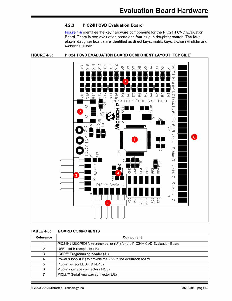
Evaluation Board Hardware
4.2.3 PIC24H CVD Evaluation BoardFigure 4-9 identifies the key hardware components for the PIC24H CVD Evaluation Board. There is one evaluation board and four plug-in daughter boards. The four plug-in daughter boards are identified as direct keys, matrix keys, 2-channel slider and 4-channel slider.
FIGURE 4-9: PIC24H CVD EVALUATION BOARD COMPONENT LAYOUT (TOP SIDE)
TABLE 4-3: BOARD COMPONENTSReference Component
1 PIC24HJ128GP506A microcontroller (U1) for the PIC24H CVD Evaluation Board2 USB mini-B receptacle (J5)3 ICSP™ Programming header (J1)4 Power supply (Q1) to provide the VDD to the evaluation board5 Plug-in sensor LEDs (D1-D16)6 Plug-in interface connector (J4/J3)7 PICkit™ Serial Analyzer connector (J2)
3
2
7
5
4
1 6
© 2009-2012 Microchip Technology Inc. DS41385F-page 53

Enhanced mTouch™ Capacitive Touch Evaluation Kit and Accessory Boards User’s Guide
4.2.3.1 COMPONENT DESCRIPTIONS
The components listed here (in order of their reference tags in Figure 4-9) are the key components of the application side of the PIC24H CVD Evaluation Board:1. PIC24HJ128GP506A Microcontroller (U1): This provides the processing
power for the touch sense applications in the PIC24H Evaluation Board.2. USB mini-B Receptacle (J5): This provides power to the board via USB.3. ICSP™ Programming Header (J1): This provides a standard Microchip ICD
interface for programming and debugging applications on an evaluation board. It is designed to connect directly with Microchip's PICkit 3, REAL ICE™ or ICD 3. Pin 1 is located on the right side of the interface, as viewed from the front of the board, and is marked with an arrow.
4. PICkit Serial Analyzer Connector (J2): This connector is used to exchange data to the Host PC through I2C using the PICkit Serial Analyzer.
5. Power Supply (Q1): This converts the +5 VDC from VBUS to the regulated+3.3 VDC required by the evaluation board.
6. Plug-in Sensor LEDs (D1-D16): Sixteen LEDs (D1 through D16) are connected to one general purpose I/O ports of the PIC microcontroller. These LEDs are illuminated based on the need of the application.
7. Plug-in Interface Connector (J4/J3): This is a 48-pin connector, which is used to interface the different plug-in boards to the microcontroller. This connector is interfaced to 16 analog channels of the microcontroller and the remaining pins are connected to ground of the evaluation board.
DS41385F-page 54 © 2009-2012 Microchip Technology Inc.
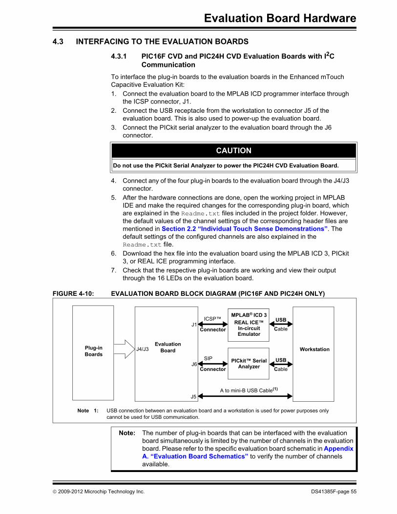
Evaluation Board Hardware
4.3 INTERFACING TO THE EVALUATION BOARDS
4.3.1 PIC16F CVD and PIC24H CVD Evaluation Boards with I2C Communication
To interface the plug-in boards to the evaluation boards in the Enhanced mTouch Capacitive Evaluation Kit:1. Connect the evaluation board to the MPLAB ICD programmer interface through
the ICSP connector, J1.2. Connect the USB receptacle from the workstation to connector J5 of the
evaluation board. This is also used to power-up the evaluation board. 3. Connect the PICkit serial analyzer to the evaluation board through the J6
connector.
4. Connect any of the four plug-in boards to the evaluation board through the J4/J3 connector.
5. After the hardware connections are done, open the working project in MPLAB IDE and make the required changes for the corresponding plug-in board, which are explained in the Readme.txt files included in the project folder. However, the default values of the channel settings of the corresponding header files are mentioned in Section 2.2 “Individual Touch Sense Demonstrations”. The default settings of the configured channels are also explained in the Readme.txt file.
6. Download the hex file into the evaluation board using the MPLAB ICD 3, PICkit 3, or REAL ICE programming interface.
7. Check that the respective plug-in boards are working and view their output through the 16 LEDs on the evaluation board.
FIGURE 4-10: EVALUATION BOARD BLOCK DIAGRAM (PIC16F AND PIC24H ONLY)
CAUTION
Do not use the PICkit Serial Analyzer to power the PIC24H CVD Evaluation Board.
Workstation
USB
Cable
MPLAB® ICD 3REAL ICE™
ICSP™
ConnectorJ1
EvaluationJ4/J3Plug-in
BoardsBoard
In-circuitEmulator
USB
Cable
SIP
ConnectorJ6
PICkit™ SerialAnalyzer
A to mini-B USB Cable(1)
J5
Note 1: USB connection between an evaluation board and a workstation is used for power purposes only cannot be used for USB communication.
Note: The number of plug-in boards that can be interfaced with the evaluation board simultaneously is limited by the number of channels in the evaluation board. Please refer to the specific evaluation board schematic in Appendix A. “Evaluation Board Schematics” to verify the number of channels available.
© 2009-2012 Microchip Technology Inc. DS41385F-page 55

Enhanced mTouch™ Capacitive Touch Evaluation Kit and Accessory Boards User’s Guide
4.3.2 PIC18F CTMU, PIC24F CTMU, and PIC32 CVD Evaluation Boards with USB Communications
To interface the plug-in boards to the evaluation boards in the Enhanced mTouch Capacitive Evaluation Kit:1. Connect the evaluation board to the MPLAB ICD programmer interface through
the ICSP connector, J1.2. Connect the USB receptacle from the workstation to connector J5 of the
evaluation board. This is also used to power-up the evaluation board. For the CTMU boards, it is also used to interface to the PC.
3. Connect any of the four plug-in boards to the evaluation board through the J4/J3 connector (48-pin).
4. After the hardware connections are done, open the working project in the MPLAB IDE and make the required changes for the corresponding plug-in board, which are explained in the Readme.txt file. However, the default values of the channel settings of the corresponding header files are mentioned in Section 2.2 “Individual Touch Sense Demonstrations”. The default settings of the configured channels are also explained in the Readme.txt file.
5. Download the hex file into the evaluation board using the MPLAB ICD 3 interface.6. Check that the respective plug-in boards are working and view their output
through the 16 LEDs on the evaluation board.
FIGURE 4-11: EVALUATION BOARD BLOCK DIAGRAM (PIC18F, PIC24F and PIC32 ONLY)
A to mini-B USB Cable
Workstation
USB
CableMPLAB® ICD 3REAL ICE™
ICSP™
ConnectorJ1
J5
EvaluationJ4/J3Plug-in
BoardsBoard
In-circuitEmulator
USB
Cable
PICkit™Serial
UART
Transmit/J2
AnalyzerReceive
Note: The number of plug-in boards that can be interfaced with the evaluation board simultaneously is limited by the number of channels in the evaluation board. In the case of the PIC24F CTMU Evaluation Board, the ICD interface (PGD and PGC) shares two of the input channels of the connector, J4/J3 (channel 6 and channel 7), the operation might fail if any of the plug-in boards is connected to these two channels when the Debugger mode is enabled in the MPLAB IDE.
DS41385F-page 56 © 2009-2012 Microchip Technology Inc.
ENHANCED mTouch™ CAPACITIVETOUCH EVALUATION KIT AND
ACCESSORY BOARDS USER’S GUIDE
Chapter 5. Troubleshooting
This chapter discusses common operational issues and methods to resolve them.
5.1 COMMON ISSUES
Issue 1: The evaluation board does not respond to inputs (i.e., no lights whena key plug-in or touch sensor is touched).
Solution: Check the evaluation board for power as follows:
• Verify that USB power (VUSB, +5 VDC) is present on the USB connection• If the evaluation board is connected to a computer through a USB hub,
verify that the hub is powered and capable of providing power to downstream devices
• If the evaluation board is directly connected to a computer, verify that the USB port used is active or try switching to another port
Issue 2: The touch sensors are abnormally sensitive or insensitive (generallyinsensitive) to inputs.
Solution: Check to make sure that the plug-in daughter boards are connected to thechannels that are mentioned in the Readme.txt file.
Check the bar graph settings for the sensors in the mTouch Sensing Solutionsoftware. The evaluation board’s trip point and other settings may have beenchanged to values that interfere with the default operation. Do the followingto correct this issue:• In the Settings dialog, verify that the Use Firmware Settings option is
selected• If the Use Saved Value option is selected instead, change the trip point
values for each affected channel to a value that produces an appropriate response
Issue 3: The evaluation board and the mTouch Sensing Solution diagnostictool are installed and operating properly, but are not communicatingwith each other.
Solution: The most prevalent problem is when the UART correctly transmits data butthe GUI does not see any data. To resolve this issue, ensure that the GUI isusing the correct COM port. It is recommended that a terminal application,such as RealTerm be used (available from http://realterm.sourceforge.net/).This application allows you to not only identify which COM port the PICkitSerial Analyzer is using, but it also allows you to check the integrity of thedata being received.
Be sure the red LED, labeled BUSY on the PICkit Serial Analyzer, isilluminated once your mTouch application is up and running after the initialLED display. If this does not occur, press the reset button on the PICkit SerialAnalyzer until all of the LEDs are illuminated. The BUSY LED should thenindicate that the PICkit Serial Analyzer is receiving data.
© 2009-2012 Microchip Technology Inc. DS41385F-page 57

Enhanced mTouch™ Capacitive Touch Evaluation Kit and Accessory Boards User’s Guide
More often than not, when the GUI is not seeing any data, there is actuallyno data to be seen. In other words, while there is a COM 8 or COM 15 portattached to the PICkit Serial Analyzer and the GUI is attached to the correctCOM port, nothing is getting up the USB cable from the PICkit SerialAnalyzer to the GUI, in spite of the fact that the BUSY LED on the PICkitSerial Analyzer is illuminated. In this case, the only recourse is to reboot thePC so that the USB driver for the PICkit Serial Analyzer is reinstalled.If the problem exists with a new mTouch application, you may want to try outan existing application that is known to work. If you are using a new board,try verifying the UART to GUI interface using a Microchip Enhanced mTouchCapacitive Touch evaluation board to verify that the PICkit Serial Analyzerand the GUI are working correctly before returning to debugging theinterface on your new board.
Issue 4: The board’s edge connector will add some additional parasiticcapacitance to the system.
Solution: Be sure to factor in this additional parasitic capacitance when using anevaluation board.
Issue 5: Touching the solder connections can create a very strong coupling tothe sensor and trigger buttons.
Solution: Avoid making contact with the solder connections.
DS41385F-page 58 © 2009-2012 Microchip Technology Inc.

ENHANCED mTouch™ CAPACITIVETOUCH EVALUATION KIT AND
ACCESSORY BOARDS USER’S GUIDE
Appendix A. Evaluation Board Schematics
This appendix includes the following schematics:• Figure A-1: “mTouch™ – PIC16F CVD Evaluation Board Schematic”• Figure A-2: “mTouch™ – PIC18F CTMU Evaluation Board Schematic”• Figure A-3: “mTouch™ – PIC24F CTMU Evaluation Board Schematic”• Figure A-4: “mTouch™ – PIC24H CVD Evaluation Board Schematic”• Figure A-5: “mTouch™ – PIC32 CVD Evaluation Board Schematic”• Figure A-6: “mTouch™ – PIC32 CTMU Evaluation Board Schematic”
© 2009-2012 Microchip Technology Inc. DS41385F-page 59

Enhanced mTouch™ Capacitive Touch Evaluation Kit and Accessory Boards User’s Guide
FIGURE A-1: mTouch™ – PIC16F CVD EVALUATION BOARD SCHEMATIC
PIC
kit™
Ser
ial
PIC
kit™
2
DS41385F-page 60 © 2009-2012 Microchip Technology Inc.

Evaluation Board Schematics
FIGURE A-2: mTouch™ – PIC18F CTMU EVALUATION BOARD SCHEMATIC
R25
J24.7K
VDDVDD
VDD
PGDPGC
RF5RF4
24681012
RC0RC1
RC6RC7
1357911
R244.7K
VBUS R23 56KR26 100K
J3:A 12
J3:D 78
J3:G 1314
J3:J 1920
J3:L BTN_82324
J3:K 2122
J3:I
RD4
1718
J3:H 1516
BTN_9
BTN_10
BTN_11
J4:F BTN_41112
J4:E 910
J4:C 56
J4:B 34
BTN_5
BTN_6
BTN_7
J4:L BTN_024
J4:K 2122
J4:I 1718
J4:H 1516
BTN_1
BTN_2
BTN_3
23
J4:A 2
J4:D 78
J4:G 1314
J4:J 1920
1
J3:F 2
J3:E 7
J3:C 13
J3:B 1920
BTN_12
8
14
R19RD0
VBUS
6
D-D+
12345
C44.7uF
C40.1
J5
VBUS
D-D+ USB
Shield +5V
VBUS
TP1
C13
0.1
MCP1702T–3302E/CB
3 IN OUTQ1
GND1
VDD
TP2
C18
1UF
C12
0.1
2
TP3
D11K
RD5
D2
RD6
D3
RD7
D4
R20RD1
D51K
D6 D7 D8
R21RD2
D91K
D10 D11 D12
R22RD3
D131K
D14 D15 D16
Green
Yellow
Orange
Red
RC7RX/DT1RD4/SPP42RD5/SPP53RD6/SPP64RD7SPP75VSS6VDD7RB08RB19RB210RB311
N/C 33RC0 32
OSC2 31OSC1 30
VSS 29VDD 28RE2 27RE1 26RE0 25RA5 24
VCAP 23
PIC18F4XJ50
N/C
12
N/C
13
RB4
14
RB5
15
RB6
16RB
717
MCL
R18 19 20 21 22
44 43 42 41 40 39 38 37 36 35 34
RC6
RC5/
D+RC
4/D- NC
RD3/
SPP3
RD2/
SPP2
RD1/
SPP1
RD
0/SP
P0V U
SBRC
2RC
1N/
C
U1
RA1
RA3
RA2
RA0
VDD
C1
0.1
RC7RD4
RD6RD5
RD7
RC0
VDD
BTN_5BTN_4
C96.8uF
C80.1
C1022pf
C1122pf
8 MHzY1
BTN
_3
BTN
_2B
TN_1
BTN
_0
VDD
MCLR
PG
D
PG
C
RB
4
RB
5123456
J1
MCLR
Program
R17 100+5V
R1810K
C70.1
D17
Note: The Channels 13,14 and 15 are not used, and are grounded in the PIC18F CTMU Evaluation Board.
BTN_7BTN_6
BTN_12
BTN_9
BTN_10
BTN_8
D-D+ RD
3R
D2
RD
0R
D1
VDD
C30.1
RC6
BTN
_11
RC
1
MBR0520L
© 2009-2012 Microchip Technology Inc. DS41385F-page 61

Enhanced mTouch™ Capacitive Touch Evaluation Kit and Accessory Boards User’s Guide
FIGURE A-3: mTouch™ – PIC24F CTMU EVALUATION BOARD SCHEMATIC
22 p
F22
pF
10
F
PIC24FJ128GB106I/PT
MCP1702T-3302E/CB
10
F
10
F
VCAP
DS41385F-page 62 © 2009-2012 Microchip Technology Inc.
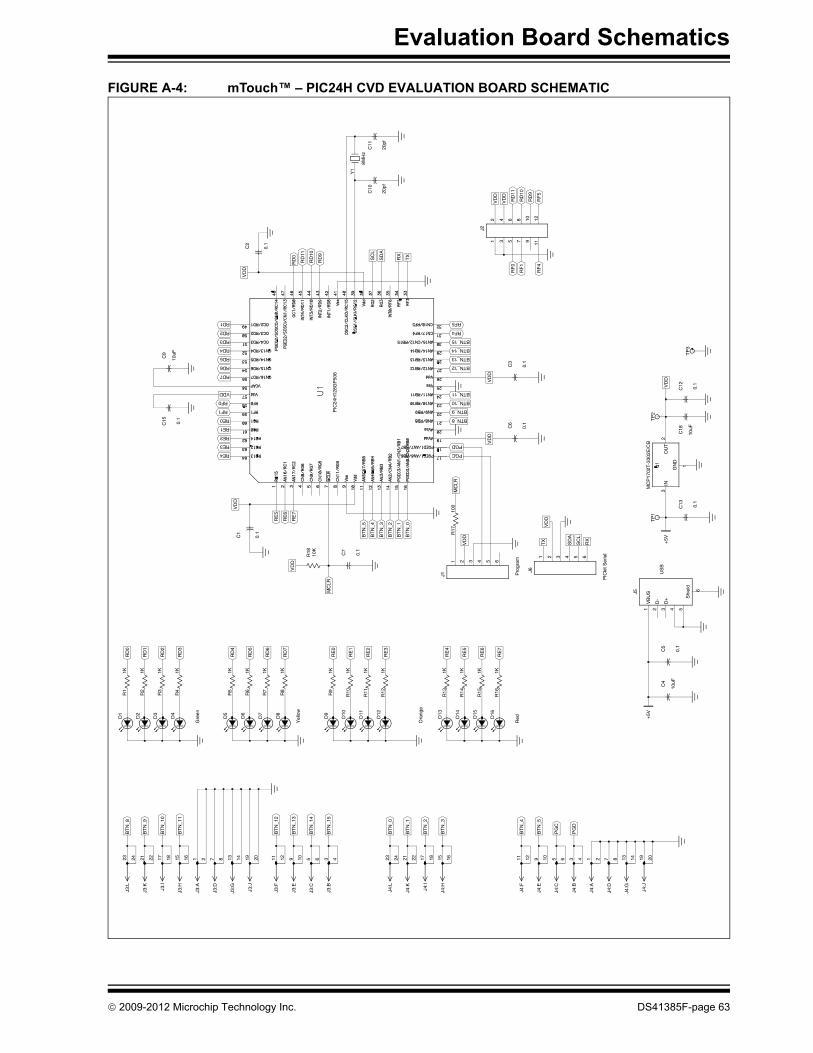
Evaluation Board Schematics
FIGURE A-4: mTouch™ – PIC24H CVD EVALUATION BOARD SCHEMATIC
RE4
RE2
RE1
RF1
RF0
RD7
RD5
RD4
RD2
RD1
PGC
BTN_9
BTN_10
BTN_13
BTN_14
RF4
RF5
Red
Yel
low
RE
6
RE
5
RE
3
RE
1
RE
0
RD
7
RD
6
RD
4
RD
3
RD
2
RD
0
RX
SD
A
TX
VD
D
MC
LR
VD
D
RF
1
+5V
Ora
nge
Gre
en
RE
7
RE
4
RE
2
RD
5
RD
1
MC
LR
SC
L
R18
10K
VD
D
VD
D
RE0
RE3
0.1
C12
VD
D
RD6
VDD
TP
3
RD3
RF
4
RF
0
C10
20pf
C11
20pf
C4
10uF
0.1
C5
3D
+4 51
VB
US
2D
-
6
Shi
eld
J5
+5V
0.1
C7
VD
D
0.1
C6
PGD
BTN_8
BTN_12
BTN_11
BTN_15
VD
D
910
34
1112
12
5 7
6 8
J2
PG
D
PG
C
BT
N_4
BT
N_3
BT
N_2
BT
N_0
BT
N_1
4
BT
N_1
3
BT
N_1
1
BT
N_1
0
BT
N_8
US
B
Pro
gram
R15
1K
R10
1K
R8
1K
R5
1K
R4
1K
R1
1K
R17
100
BT
N_1
BT
N_2
BT
N_4
BT
N_5
RE
7
RE
6
RD
9
RD
10
VD
D
VD
D
RX
SC
L
RD
9
RD
10
RD
0
13 14J4
:G
19 20J4
:J
3 4J4
:B
1 2J4
:A
11 12J4
:F
9 10J4
:EB
TN
_5
17 18J4
:I
15 16J4
:H
BT
N_1
23 24J4
:L
3 4J3
:B
5 6J3
:C
BT
N_1
5
11 12J3
:FB
TN
_12
13 14J3
:G
7 8J3
:D
15 16J3
:H
17 18J3
:I
BT
N_9
23 24J3
:L
PIC
kit S
eria
l
R14
1K
R16
1KD
16
D15
D14
R13
1KD
13
R12
1KD
12
R11
1KD
11
R9
1KD
9
R7
1KD
7
D8
R6
1K
D5
R3
1KD
3
D4
R2
1K
D1
0.1
C13
C18
10uF
TP
1T
P2
VD
D
BT
N_0
BT
N_3
RE
5
0.1
C15
C9
10uF
RF
5
RD
11
TX
SD
A
8MH
z
Y1
RD
11
0.1
C2
7 8J4
:D
5 6J4
:C
21 22J4
:K
9 10J3
:E
19 20J3
:J
1 2J3
:A
21 22J3
:K
D10
41 632 5
J1
D2
D6
1GN
D
3IN
2O
UT
MC
P17
02T
-330
2E/C
B
0.1
C3
0.1
C1
41 632 5
J6
PIC
24H
128G
P50
6
© 2009-2012 Microchip Technology Inc. DS41385F-page 63
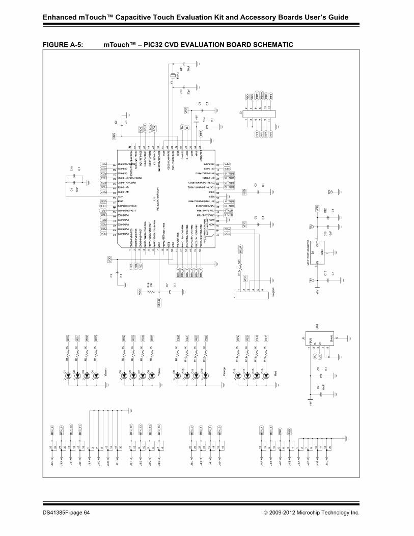
Enhanced mTouch™ Capacitive Touch Evaluation Kit and Accessory Boards User’s Guide
FIGURE A-5: mTouch™ – PIC32 CVD EVALUATION BOARD SCHEMATIC
RE4
RE2
RE1
RF1
RF0
RD7
RD5
RD4
RD2
RD1
PGC
BTN_9
BTN_10
BTN_13
BTN_14
RF4
RF5
D-
Red
Yel
low
US
B
RE
6
RE
5
RE
3
RE
1
RE
0
RD
7
RD
6
RD
4
RD
3
RD
2
RD
0
VD
D
MC
LR
RF
3
RF
1
C4
10uF
0.1
C5
D+
Ora
nge
Gre
en
RE
7
RE
4
RE
2
RD
5
RD
1
MC
LR
0.1
C13
+5V
R18
10K
VD
D
C18
10uF
VD
D
RE0
RE3
TP
3
VD
D
VDD
RD6
RD3
0.1
C15
RF
4
RF
0
RF
3
VD
D
C10
20pf
C11
20pf
+5V
TP
1
0.1
C7
VD
D
TP
2
0.1
C6
PGD
BTN_8
BTN_12
BTN_11
BTN_15
VD
D
+5V
0.1
C8
910
34
1112
12
5 7
6 8
J2
PG
D
PG
C
BT
N_4
BT
N_3
BT
N_2
BT
N_0
BT
N_1
4
BT
N_1
3
BT
N_1
1
BT
N_1
0
BT
N_8
Pro
gram
R15
1K
R10
1K
R8
1K
R5
1K
R4
1K
R1
1K
VD
D
R17
100
BT
N_1
BT
N_2
BT
N_4
BT
N_5
RE
7
RE
6
RD
9
RD
10
VD
D
VD
D
D+
RD
9
RD
10
RD
0
13 14J4
:G
19 20J4
:J
3 4J4
:B
1 2J4
:A
11 12J4
:F
9 10J4
:EB
TN
_5
17 18J4
:I
15 16J4
:H
BT
N_1
23 24J4
:L
3 4J3
:B
5 6J3
:C
BT
N_1
5
11 12J3
:FB
TN
_12
13 14J3
:G
7 8J3
:D
15 16J3
:H
17 18J3
:I
BT
N_9
23 24J3
:L
R14
1K
R16
1KD
16
D15
D14
R13
1KD
13
R12
1KD
12
R11
1KD
11
R9
1KD
9
R7
1KD
7
D8
R6
1K
D5
R3
1KD
3
D4
R2
1K
D1
0.1
C12
BT
N_0
BT
N_3
RE
5
C9
10uF
RF
5
RD
11
0.1
C14
D-
8MH
z
Y1
RD
11
0.1
C2
7 8J4
:D
5 6J4
:C
21 22J4
:K
9 10J3
:E
19 20J3
:J
1 2J3
:A
21 22J3
:K
3D
+4 51
VB
US
2D
-
6
Shi
eld
J5
D10
D2
D6
1GN
D
3IN
2O
UT
MC
P17
02T
-330
2E/C
B
0.1
C3
0.1
C1
41 632 5
J1
U1
PIC
32M
X79
5F51
2H
VCAP
DS41385F-page 64 © 2009-2012 Microchip Technology Inc.
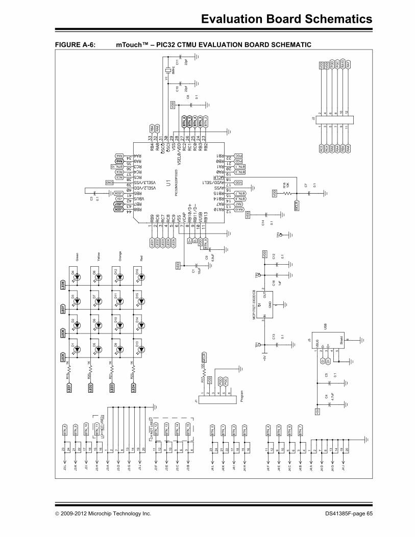
Evaluation Board Schematics
FIGURE A-6: mTouch™ – PIC32 CTMU EVALUATION BOARD SCHEMATIC
RA10LED6 LED6
RA7LED7 LED7
BTN_7LED8
RC5
BTN_0RC4
PGDRA9 RA9
PGCRA4
+5V
PG
D
LED
3LE
D3
LED
2LE
D2
D-MC
LR
US
B
Ora
nge
Yel
low
BTN
_9
VD
DD+
LED
5
LED
4
LED
2
LED
1
MC
LR
RB
4
RA
4
RC
4
RC
5
BTN
_2
BTN
_3BT
N_3
BTN
_5BT
N_5
BTN
_6BT
N_6
RA1
0
PG
C
VD
D
VD
D
C4
4.7u
F
Prog
ram
PG
C
VDD
LED
4LE
D4
LED
1LE
D1
0.1
C5
D+
D9
D5
LED
5LE
D5
D10
D6
LED
6LE
D6
D11
D7
LED
8LE
D8
0.1
C13
VDD
Red
Gre
en
D-
LED
3
C18
1uF
0.1
C14
BTN_8
VD
D
+5V
TP3
VDD
BTN_1BTN_10
GND
RA
8
RA
9
BTN
_4BT
N_4
VD
DC
10
22pf
C11
22pf
PG
D
RA
7
41 632 5
J1
D1
D13
D2
D14
D3
D15
TP1
C1
10uF
TP2
910
34
1112
12
5 7
6 8
J2
BTN
_7
BTN
_6
BTN
_4
BTN
_3
BTN
_2
BTN
_0
BTN
_14
BTN
_13
CH
NO
T U
SE
D
CH
NO
T U
SED
BTN
_11
BTN
_10
BTN
_8
R20
1K
VD
D
RA8
RB4
13 14J4
:G
19 20J4
:J
3 4J4
:B
1 2J4
:A
11 12J4
:F
9 10J4
:EB
TN_5
17 18J4
:I
15 16J4
:H
BTN
_1
23 24J4
:L
3 4J3
:B
5 6J3
:C
BTN
_15
11 12J3
:FBT
N_1
2
13 14J3
:G
7 8J3
:D
15 16J3
:H
17 18J3
:I
BTN
_9
23 24J3
:L
+5V
R17
100
D12
R22
1K
R21
1K
D8
R19
1KLE
D7
LED
7
0.1
C12
0.1
C7
VD
D
C9
6.8u
F
8MH
z
Y1
7 8J4
:D
5 6J4
:C
21 22J4
:K
9 10J3
:E
19 20J3
:J
1 2J3
:A
21 22J3
:K
3D
+4 51
VBU
S2
D-
6
Shie
ld
J5
D4
D16
1GN
D
3IN
2O
UT
MC
P17
02T-
3302
E/C
B
R18
10K
C3
0.1
0.1
C8
PIC
32M
X22
0F03
2D
VC
AP
© 2009-2012 Microchip Technology Inc. DS41385F-page 65

Enhanced mTouch™ Capacitive Touch Evaluation Kit and Accessory Boards User’s Guide
NOTES:
DS41385F-page 66 © 2009-2012 Microchip Technology Inc.
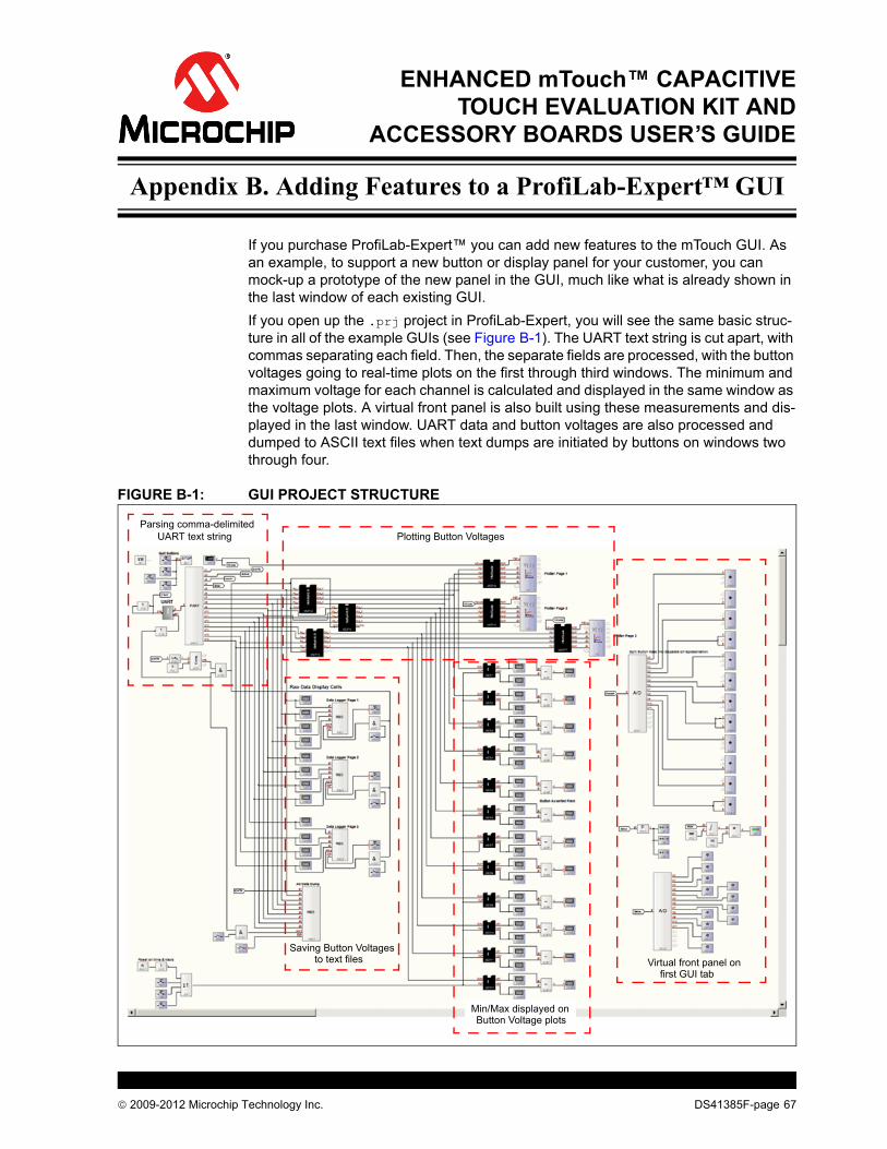
ENHANCED mTouch™ CAPACITIVETOUCH EVALUATION KIT AND
ACCESSORY BOARDS USER’S GUIDE
Appendix B. Adding Features to a ProfiLab-Expert™ GUI
If you purchase ProfiLab-Expert™ you can add new features to the mTouch GUI. As an example, to support a new button or display panel for your customer, you can mock-up a prototype of the new panel in the GUI, much like what is already shown in the last window of each existing GUI.If you open up the .prj project in ProfiLab-Expert, you will see the same basic struc-ture in all of the example GUIs (see Figure B-1). The UART text string is cut apart, with commas separating each field. Then, the separate fields are processed, with the button voltages going to real-time plots on the first through third windows. The minimum and maximum voltage for each channel is calculated and displayed in the same window as the voltage plots. A virtual front panel is also built using these measurements and dis-played in the last window. UART data and button voltages are also processed and dumped to ASCII text files when text dumps are initiated by buttons on windows two through four.
FIGURE B-1: GUI PROJECT STRUCTURE
Parsing comma-delimitedUART text string Plotting Button Voltages
Saving Button Voltagesto text files
Min/Max displayed onButton Voltage plots
Virtual front panel onfirst GUI tab
© 2009-2012 Microchip Technology Inc. DS41385F-page 67

Enhanced mTouch™ Capacitive Touch Evaluation Kit and Accessory Boards User’s Guide
The details of parsing the UART text string of comma-delimited five-digit integers are shown in Figure B-2.
FIGURE B-2: PARSING THE UART TEXT STRING
Voltage holds for plots
Volta
ges
This block decodes the comma-delimited UART string into status and voltages.
DS41385F-page 68 © 2009-2012 Microchip Technology Inc.

Adding Features to a ProfiLab-Expert™ GUI
Four channels of ADC counts are normalized and plotted in this part of the project, as shown in Figure B-3.
FIGURE B-3: PLOT DETAILS
As a suggestion, start with the GUIs provided and slowly and carefully add the new features you need. If you stop after each small step and test the GUI, you can easily revert to a prior working version once a bug appears. Attempts to make large scale modifications to the GUI’s structure all at once greatly increase the chances that the new GUI will not work, making debugging difficult. Fortunately, most of the work has already been completed in the GUI provided in the MPLAB projects, which provides you with a good starting point for creating your own custom features.
B.1 mTouch APPLICATION SUPPORT
B.1.1 Data Dump FormatEach mTouch application formats a string of comma-delimited five-digit non-negative numbers, and then outputs the text string using the UART module. The following is an example line of data taken from a Direct Key project:
00000,00128,00000,29687,18443,32159,30447,34727,34367,34783,32427
The first field shows whether any buttons are being pressed using a bit map where the Least Significant bit (LSb) corresponds to the first button. Therefore, this field can range from 00000 to 00255 for an 8-button sensor daughter board.The second field shows whether a button has been asserted. This field is latched and will not change until another button is asserted. The example above shows that button 7 (128 = 27) has been asserted.
Virtual front panel on first GUI tab
Min/Max displayed on Button Voltage plots
PlotScale macro scales the ADCcounts into normalized voltage.
© 2009-2012 Microchip Technology Inc. DS41385F-page 69

Enhanced mTouch™ Capacitive Touch Evaluation Kit and Accessory Boards User’s Guide
The third field reports the current slider value, with 00255 equal to full scale. Depending on the mTouch example being used, slider values are calculated using the 2, 4, or 8 buttons available. However, it is important to note that slider values are not available on the 12-key matrix sensor board, since this board uses a 3x4 button array that does not support a slider.The remaining fields, beginning with 29687, are the normalized ADC counts measuring the button voltages for all eight buttons, starting with the first button.The first channel screen (see Figure 3-12), supports changing the numerical value that represents full scale in ADC counts. By default, this value is 65,535, but it can be changed if ADC scaling changes in the mTouch application. Also seen in Figure 3-12 are buttons to START/STOP data dumps to an ASCII file. These buttons are provided to dump screen voltages or to dump all of the data that the mTouch application outputs through the UART transmit (TX) pin.
B.1.2 Supporting Application CodeExample B-1 provides a portion of PIC24H code that can be used to format and transmit data to ProfiLab-Expert.
EXAMPLE B-1:
Example B-2 provides a portion of PIC32 code that can be used to format and transmit data to ProfiLab-Expert.
EXAMPLE B-2:
sprintf(ButtonMeasString,"%05d,%05d,%05d,""%05d,%05d,%05d,%05d,""%05d,%05d,%05d,%05d""\r\n",CurrentButtonStatus, CurrentButtonAsserts, SliderValue,CurrentButtonMeasurements[0],CurrentButtonMeasurements[1],CurrentButtonMeasurements[2],CurrentButtonMeasurements[3],CurrentButtonMeasurements[4],CurrentButtonMeasurements[5],CurrentButtonMeasurements[6],CurrentButtonMeasurements[7]);
while(BusyUART2());putsUART2((unsigned int *)ButtonMeasString);
sprintf(ButtonMeasString,%05d,%05d,%05d,""%05d,%05d,%05d,%05d,""%05d,%05d,%05d,%05d""\r\n",CurrentButtonStatus, CurrentButtonAsserts, SliderValue,CurrentButtonMeasurements[0],CurrentButtonMeasurements[1],CurrentButtonMeasurements[2],CurrentButtonMeasurements[3],CurrentButtonMeasurements[4],CurrentButtonMeasurements[5],CurrentButtonMeasurements[6],CurrentButtonMeasurements[7]);
SendDataBuffer(ButtonMeasString, strlen(ButtonMeasString) );
DS41385F-page 70 © 2009-2012 Microchip Technology Inc.

Adding Features to a ProfiLab-Expert™ GUI
B.1.3 Modifying mTouch Application CodeProfiLab-Expert supports a UART data stream of up to 16 fields. The first three fields are used for status (button status, button asserts, and slider). The remaining thirteen fields are available for any other data of interest. Twelve fields are displayed on real-time plots of the first through third tabbed screens of the GUI. The last (sixteenth) field can be used to identify special output records that should not be plotted by the GUI, but can be captured and dumped to an ASCII text file using the All Data Logger buttons on the first screen. If the sixteenth value in the string is non-zero, the GUI will not plot the data record on the voltage plots.In many mTouch applications, 32 raw ADC measurements are averaged to produce the button voltage used by the detection algorithms and reported to the mTouch GUI.Example B-3 shows a portion of code that uses this special record feature to output the raw voltage measurements.
EXAMPLE B-3:
The mTouch software for the PIC24H and PIC32 families supports adaptive button detection, in which the current filtered button measurements are compared against long term averages. Sometimes it is useful to look at both the current button measurement and long term average on the same plot. Example B-4 shows a portion of code that formats the output text to look at both for the first six buttons.
EXAMPLE B-4:
# if defined( UART_DUMP_RAW_COUNTS )for ( iHF_Read = 0; iHF_Read < 32; iHF_Read++ ){
sprintf(ButtonMeasString,"%05d,%05d,%05d,""%05d,%05d,%05d,%05d,""%05d,%05d,%05d,%05d,""%05d,%05d,%05d,%05d,""%05d\r\n",CurrentButtonStatus, CurrentButtonAsserts, SliderValue,CurRawData[iHF_Read][0], CurRawData[iHF_Read][1],CurRawData[iHF_Read][2], CurRawData[iHF_Read][3],CurRawData[iHF_Read][4], CurRawData[iHF_Read][5],CurRawData[iHF_Read][6], CurRawData[iHF_Read][7],0,0,0,0,iHF_Read+1);
SendDataBuffer(ButtonMeasString, strlen(ButtonMeasString) );}
# endif
sprintf( ButtonMeasString,"%05d,%05d,%05d,""%05d,%05d,%05d,%05d,""%05d,%05d,%05d,%05d,""%05d,%05d,%05d,%05d""\r\n",CurrentButtonStatus, CurrentButtonAsserts, SliderValue,CurrentButtonMeasurements[0],CurrentAveragedMeasurements[0],CurrentButtonMeasurements[1],CurrentAveragedMeasurements[1],CurrentButtonMeasurements[2],CurrentAveragedMeasurements[2],CurrentButtonMeasurements[3],CurrentAveragedMeasurements[3],CurrentButtonMeasurements[4],CurrentAveragedMeasurements[4],CurrentButtonMeasurements[5],CurrentAveragedMeasurements[5]);
© 2009-2012 Microchip Technology Inc. DS41385F-page 71

Enhanced mTouch™ Capacitive Touch Evaluation Kit and Accessory Boards User’s Guide
NOTES:
DS41385F-page 72 © 2009-2012 Microchip Technology Inc.

ENHANCED mTOUCH™ CAPACITIVETOUCH EVALUATION KIT AND
ACCESSORY BOARDS USER’S GUIDE
Index
BBlock Diagrams
CVD Evaluation Layout (Top) ........................... 49PIC16F CVD Evaluation Board
Application Side.............................43, 46PIC18F CTMU Evaluation Board
Application Side.................................. 48PIC24F CTMU Evaluation Board
Application Side.............................45, 47PIC32 CTMU Evaluation Board
Application Side.................................. 48Board Components .......................................49, 51, 53Board H/W ............................................................... 43Board Setup ............................................................. 17
Connecting the H/W.......................................... 17Installing the S/W.............................................. 17Interfacing the Plug-in Boards .......................... 56
CCharge Time Measurement Unit (CTMU) ................ 45Components
External Plug-in Components ........................... 52ICSP Programming Header .............................. 52PIC18F46J50 Microcontroller ........................... 52PIC24FJ128GB106 Microcontroller .................. 52PIC32MX220F032D Microcontroller ................. 52PIC32MX795F512H Microcontroller ................. 52Plug-in Interface Connector .............................. 52Plug-in Sensor LEDs ........................................ 52Power Supply.................................................... 52USB mini-B Receptacle .................................... 52
Configuration SettingsReadme ............................................................ 22
Customer Notification Service.................................. 10Customer Support .................................................... 10
DDemonstration Application ....................................... 19Direct Key Plug-in .................................................... 21Documentation
Conventions........................................................ 6Layout ................................................................. 5
EEvaluation Board
CTMU and CVD Component Layout (Top Side)51
HHost Computer Requirements.................................. 17
IInitial Board Setup.................................................... 17Internet Address....................................................... 10
KKit Contents.............................................................. 14
MMatrix Key Plug-in .................................................... 22Microchip Internet Web Site ..................................... 10
OOperational Requirements ....................................... 17
PPIC16F1937 Microcontroller .............................. 43, 46PIC18F46J50 Microcontroller............................. 44, 48PIC24FJ128GB106 Microcontroller ......................... 45PIC32 CTMU Capacitive Touch Evaluation Board... 16PIC32MX795F512H Microcontroller ........................ 51Plug in Power ........................................................... 23Plug in the Sensors .................................................. 23
RReadme
Configuration Settings....................................... 22Recommended Reading ............................................ 7
SSchematics
PIC16F CVD Evaluation Board......................... 60PIC18F CTMU Evaluation Board ...................... 61PIC24F CTMU Evaluation Board ...................... 62PIC24H CVD Evaluation Board ........................ 63PIC32 CTMU Evaluation Board ........................ 65PIC32 CVD Evaluation Board ........................... 64
Slider Plug-in............................................................ 22
TTouch Interface ........................................................ 19Touch Sense Demonstrations.................................. 21
12-Key Matrix Plug-in Board ............................. 222-Channel Slider Plug-in Board ........................ 224-Channel Slider Plug-in ................................... 228-Key Direct Plug-in Board ............................... 21
Troubleshooting ....................................................... 57
UUsing the ProfiLab-Expert™ Graphical User Interface
for Real-Time Debugging ..................................... 25
WWarranty Registration ................................................ 7WWW Address......................................................... 10
© 2009-2012 Microchip Technology Inc. DS41385F-page 73

DS41385F-page 74 © 2009-2012 Microchip Technology Inc.
AMERICASCorporate Office2355 West Chandler Blvd.Chandler, AZ 85224-6199Tel: 480-792-7200 Fax: 480-792-7277Technical Support: http://www.microchip.com/supportWeb Address: www.microchip.comAtlantaDuluth, GA Tel: 678-957-9614 Fax: 678-957-1455BostonWestborough, MA Tel: 774-760-0087 Fax: 774-760-0088ChicagoItasca, IL Tel: 630-285-0071 Fax: 630-285-0075ClevelandIndependence, OH Tel: 216-447-0464 Fax: 216-447-0643DallasAddison, TX Tel: 972-818-7423 Fax: 972-818-2924DetroitFarmington Hills, MI Tel: 248-538-2250Fax: 248-538-2260IndianapolisNoblesville, IN Tel: 317-773-8323Fax: 317-773-5453Los AngelesMission Viejo, CA Tel: 949-462-9523 Fax: 949-462-9608Santa ClaraSanta Clara, CA Tel: 408-961-6444Fax: 408-961-6445TorontoMississauga, Ontario, CanadaTel: 905-673-0699 Fax: 905-673-6509
ASIA/PACIFICAsia Pacific OfficeSuites 3707-14, 37th FloorTower 6, The GatewayHarbour City, KowloonHong KongTel: 852-2401-1200Fax: 852-2401-3431Australia - SydneyTel: 61-2-9868-6733Fax: 61-2-9868-6755China - BeijingTel: 86-10-8569-7000 Fax: 86-10-8528-2104China - ChengduTel: 86-28-8665-5511Fax: 86-28-8665-7889China - ChongqingTel: 86-23-8980-9588Fax: 86-23-8980-9500China - HangzhouTel: 86-571-2819-3187 Fax: 86-571-2819-3189China - Hong Kong SARTel: 852-2401-1200 Fax: 852-2401-3431China - NanjingTel: 86-25-8473-2460Fax: 86-25-8473-2470China - QingdaoTel: 86-532-8502-7355Fax: 86-532-8502-7205China - ShanghaiTel: 86-21-5407-5533 Fax: 86-21-5407-5066China - ShenyangTel: 86-24-2334-2829Fax: 86-24-2334-2393China - ShenzhenTel: 86-755-8203-2660 Fax: 86-755-8203-1760China - WuhanTel: 86-27-5980-5300Fax: 86-27-5980-5118China - XianTel: 86-29-8833-7252Fax: 86-29-8833-7256China - XiamenTel: 86-592-2388138 Fax: 86-592-2388130China - ZhuhaiTel: 86-756-3210040 Fax: 86-756-3210049
ASIA/PACIFICIndia - BangaloreTel: 91-80-3090-4444 Fax: 91-80-3090-4123India - New DelhiTel: 91-11-4160-8631Fax: 91-11-4160-8632India - PuneTel: 91-20-2566-1512Fax: 91-20-2566-1513Japan - OsakaTel: 81-66-152-7160 Fax: 81-66-152-9310Japan - YokohamaTel: 81-45-471- 6166 Fax: 81-45-471-6122Korea - DaeguTel: 82-53-744-4301Fax: 82-53-744-4302Korea - SeoulTel: 82-2-554-7200Fax: 82-2-558-5932 or 82-2-558-5934Malaysia - Kuala LumpurTel: 60-3-6201-9857Fax: 60-3-6201-9859Malaysia - PenangTel: 60-4-227-8870Fax: 60-4-227-4068Philippines - ManilaTel: 63-2-634-9065Fax: 63-2-634-9069SingaporeTel: 65-6334-8870Fax: 65-6334-8850Taiwan - Hsin ChuTel: 886-3-5778-366Fax: 886-3-5770-955Taiwan - KaohsiungTel: 886-7-536-4818Fax: 886-7-330-9305Taiwan - TaipeiTel: 886-2-2500-6610 Fax: 886-2-2508-0102Thailand - BangkokTel: 66-2-694-1351Fax: 66-2-694-1350
EUROPEAustria - WelsTel: 43-7242-2244-39Fax: 43-7242-2244-393Denmark - CopenhagenTel: 45-4450-2828 Fax: 45-4485-2829France - ParisTel: 33-1-69-53-63-20 Fax: 33-1-69-30-90-79Germany - MunichTel: 49-89-627-144-0 Fax: 49-89-627-144-44Italy - Milan Tel: 39-0331-742611 Fax: 39-0331-466781Netherlands - DrunenTel: 31-416-690399 Fax: 31-416-690340Spain - MadridTel: 34-91-708-08-90Fax: 34-91-708-08-91UK - WokinghamTel: 44-118-921-5869Fax: 44-118-921-5820
Worldwide Sales and Service
11/29/11