Embed Size (px)
Citation preview
8/13/2019 ENHANCED GROUND PROXIMITY WARNING SYSTEME GPWS REV E
http://slidepdf.com/reader/full/enhanced-ground-proximity-warning-systeme-gpws-rev-e 1/95
8/13/2019 ENHANCED GROUND PROXIMITY WARNING SYSTEME GPWS REV E
http://slidepdf.com/reader/full/enhanced-ground-proximity-warning-systeme-gpws-rev-e 2/95
8/13/2019 ENHANCED GROUND PROXIMITY WARNING SYSTEME GPWS REV E
http://slidepdf.com/reader/full/enhanced-ground-proximity-warning-systeme-gpws-rev-e 3/95
8/13/2019 ENHANCED GROUND PROXIMITY WARNING SYSTEME GPWS REV E
http://slidepdf.com/reader/full/enhanced-ground-proximity-warning-systeme-gpws-rev-e 4/95
S TION This Pilot Guide describes the functions andoperation ofthe
MKV andMKVII Enhanced Ground ProximityWarning SystemINTRO U TION EGPWS
Thedocument is divided intofour sections: Section I is this
introduction andthe following briefdescription ofthe EGPWS
and its features ; Section 2 provides a functional description of
theEGPWS. This includes descriptions ofthevarious system
modes Built-In Test BIT and monitoring functions and
system features; Section 3 provides general operating
procedures to follow whenthesystem givesa caution or
warning alert; Section 4 provides definitions oftermsusedin
this manual.
This guide does not supercede FAA approved data
Flight Manuals individual Operations Manuals
requirements or procedures Pilots should be
thoroughly familiar with their own company policies
system configuration requirements and procedures
with respect to the operation of aircraft with the
EGPWS.
W T IS TH
GPWS
The information in thisdocument is intended as a general
explanation ofthe Honeywell EGPWS. It contains a general
description of system performance assuming identified options
are active and highlights deviations in system performance
resulting whena feature isdisabled.
TheEGPWS is a Terrain Awareness andAlerting system
providing terrainalerting anddisplay functions w t additional
features
TheEGPWS usesaircraft inputs including geographic position,
attitude altitude airspeed andglideslope deviation These are
usedw t internal terrain obstacles andairportdatabases to
predicta potential conflict between theaircraft flight pathand
terrainor an obstacle. Aterrainor obstacle conflict results in
the PWS providing a visual andaudio caution or warning alert
Additionally, theEGPWS provides alertsfor excessive glideslope
deviation, tooloww t flaps or gearnotin landingconfiguration and optionally provides bankangle and altitude
callouts basedon system programpinselection Detection of
severe windshear conditions isalsoprovided forselected
aircraft types whenenabled
060·4241·000 • Rcv E • December 2003
MKV MKVlI EGPWSPilot Guide
8/13/2019 ENHANCED GROUND PROXIMITY WARNING SYSTEME GPWS REV E
http://slidepdf.com/reader/full/enhanced-ground-proximity-warning-systeme-gpws-rev-e 5/95
WHAT IS THE
EGPW
CO N TI N U E D
TheEGPWS incorporates several enhanced features:
• Terrain Alerting and Display (TAD) provides a graphicdisplay ofthesurrounding terrain on theWeather d r
Indicator, EFIS, or a dedicated display. Based onthe
alrcralt s posi tion and Ole internal database, Oe terraintopography within thedisplay rangeselected thatis above
or within 2000feet below theaircraft altitude ispresented on
the system display. This feature is an option, enabled by
program pinsduring installation.
• Peaks isa T Dsupplemental feature providing dditlon l
terrain display features forenhanced . ituational awareness ,independent oftheaircraft s altitude . This includes digital
elevations forthehighest and lowest displayed terrain,
additional elevation (color)bands, anda unique representa
tionof0MSL elevation (sealevel anditscorresponding
shoreline) . This feature isanoption, enabled byprogram
pinsduring installation.
• Obstacles is a featureutilizing an obstacle database for
obstacle conflict alerting anddisplay EG PWS caution andwarning visual andaudioalerts areprovided whena conflict
is detected . Additionally, when T isenabled,Obstacles are
graphically disp layed similar to terrain. This feature isan
option, enabled byprogram pinsduring installation.
• Aprocessfeatu recalled EnvelopeModulation utilizes the
internal databa;e to tailor EGPWS alertsat certain geographic
locations toreducenuisance alerts andprovide addedprotection.
• ATerrain Clearance Floor feature addsanadditional
clement ofprotection byalerting thepilotofpossible
premature descent. This is intended fornon-precision
approaches andis based onthecurrentaircraft position
relative to thenearest runway Thi feature is enabled with
the T feature ,
• In -210-210 andlaterversions, aRunwayField ClearanceFloor (RFCF) feature is included. This is simllar to thereF
feature except th t RFCF is basedon thecurrentaircraftposition andheight above thedestination runway sed onGeometric Altitude (seenextpage). This provides im
proved protection at locations wherethedestination runway
isSignificantly higher thanthe surrounding terrain.
060-4241-000 · Rev E- December 2003MKV MKVII EGPWS PilotGuide
8/13/2019 ENHANCED GROUND PROXIMITY WARNING SYSTEME GPWS REV E
http://slidepdf.com/reader/full/enhanced-ground-proximity-warning-systeme-gpws-rev-e 6/95
W T IS THE
EGPWS
CONTINUED
PHYSIC L
DESCRIPTION
• AnAural Declutter feature reducesthe repetition ofwarningmessages. This feature isoptional, andmay be disabled
bysystem programpinsduringinstallation .
• Geometric Altitude, basedon GPS altitude, is a computed
pseudo-barometric altitude designed to reduceor eliminate
altitude errors resulting from temperature extremes, non
standardpressurealtitude conditions , and altimeter
miss-sets. This ensuresan optimal EGPWS alerting and dis
play capability.
• Runway Alerting Advisory System RAAS)
The EGPWS also providespositionawareness advisories
relative to runways during ground operations and
approach to land. This newfeature is knownas
Runway Awareness and Advisory System - RAAS only
available in -218-218 or later versions .
Some ofthesefeatures have beenaddedto theEGPWS as the
system evolved and are notpresentinall Enhanced Ground
ProximityWarning Computer EGPWC) partnumbers. Forspe
cific effeCtivity, refertoan applicable Airplane FlightManual AFM) or EGPWSAirplane FlightManual Supplement AFMS) or
contactHoneywell forassistance.
TIle EGPWC ispackaged i na2 VARINC 600-6rackmounted
enclosure weighing lessthan8lbs. No special vibration isolation
mounting or forced air-cooling isrequired.
115V 400HZ.) or 28VDe versions oftheEGPWe are avail
able. Units are alsoavailable with an internal GPS receiver for
requiredGPS datawhenanotherGPS sourceis notavailable.
Formoredetailed descriptions and information contact
Honeywell .
0604 241·000 • Rev. E · December 200.\
MKVa MK \11 EGPWSPilol Guide
8/13/2019 ENHANCED GROUND PROXIMITY WARNING SYSTEME GPWS REV E
http://slidepdf.com/reader/full/enhanced-ground-proximity-warning-systeme-gpws-rev-e 7/95
S TION SYSTEM ES RIPTION
nhancedGround ProximityWarning System 6
PWS Database 6
asic Functions
Mode 1 Excessive Descent Rate 8
Mode 2 Excessive Closure to Terrain 9
Mode 3 Altitude Loss After Takeoff 12
Mode 4 Unsafe Terrain Cle r n e 13
Mode 5 Excessive Deviation Below Glideslope 17
Mode 6 Advisory Callouts 19
Mode 7 Windshear Alerting 23
Enhanced Functions
Envelope Modulation 25
Terrain Clearance Floor 25
Runway Field Clearance Floor 27
Terrain LookAhe d Alerting 27
Terrain Alerting nd Display 29
Non PeaksDisplay 30
Pop Up nd Auto Range 32
Peaks Display 32
Geometric Altitude 36
Weather Radar Auto Tilt 37
Aural Message Priority 37System Inputs 39
System Outputs 41
ptions 41
060 4241 000 Rev E December 2003
MKV MKVIIEGPWSPilot Guide 5
8/13/2019 ENHANCED GROUND PROXIMITY WARNING SYSTEME GPWS REV E
http://slidepdf.com/reader/full/enhanced-ground-proximity-warning-systeme-gpws-rev-e 8/95
ENH N ED
GROUN
PROXIMITY
W RNING
SYSTEM
EGPWS
D T SE
6
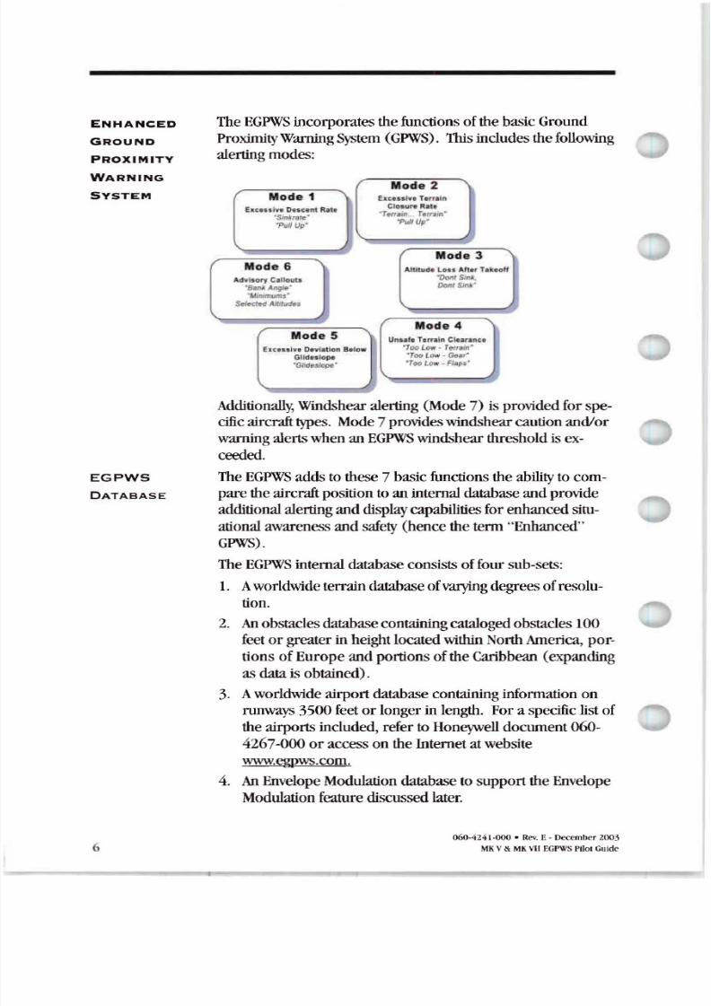
TheEGPWS incorporates the functions ofthebasicGround
ProximityWarningSystem GPWS . This includes the followingalertingmodes:
Mode 2Mode 1 Eat I . T , ln
EAtu , I Dn ce t Rat.
·Sinkriil e · T (l aJn.. Terr..n
'P II up · P i J n u p
Mode 3Mode 6 Atti1udl Lon AtI.f Tlkeoff
Advl lory Callouta onISin
. AngJp* Dont m ·· lltlmUl7ts·
SefKt Hl tdlldes
Mode 4Mode 5 ..,. Tllrraln ( Ilu ane l
Eltcen ve D t l. tlon S low T oo tew - r ~ l J iGll ulop.o °TooLtlw . GtI ·
llde lo p TooLow..Flaps'
Additionall Windshear alerting Mode 7) is provided forspe
cific aircrafttypes. Mode 7 provideswindshear caution and/or
warningalertswhen an EGPWS windshear threshold is ex
ceeded.
TheEGPWS addstothese7 basicfunctions theability to com
pare the aircraft position to an internal database andprovide
additionalalertinganddisplaycapabilities forenhancedsitu-
ational awarenessand safety hence the term Enhanced
GPWS).
TheEGPWS internal databaseconsists offoursub-sets:
1. Aworldwide terraindatabase ofvarying degrees ofresolu-
tion .
2. nobstacles database containing catalogedobstacles 100
feetor greaterin height located within NorthAmerica, por
tions ofEuropeand portions oftheCaribbean expanding
as datais obtained) .
3. Aworldwide airportdatabase containing information on
runways 3500feet or longerin length. Fora specific listofthe airportsincluded, refertoHoneywell document 060
4267-000 or access on theInternet atwebsite
www.egpws.com .
4. nEnvelopeModulation database to support theEnvelope
Modulation feature discussed later.
060- 424 1-000 • Rev. E - December 2003
MKV MKVIIEGPWSPilot Guide
8/13/2019 ENHANCED GROUND PROXIMITY WARNING SYSTEME GPWS REV E
http://slidepdf.com/reader/full/enhanced-ground-proximity-warning-systeme-gpws-rev-e 9/95
EGPWS
DATABASE
ONTINUE
Honeywell is constantlystriving to improve theEGPWS t
base in content, resolution, and accuracy. Notification ofa
Database update is accomplished byService Bulletin. Data-
baseupdates are distributed on PCMCIA t cardsanddownloadedvia a cardslotinthe front panelofeachEGPWC.
Contact Honeywell foradditional information.
Because theoverwhelming majority of Controlled Flight IntoTerrain CFIT accidents occurnearanairport andthefact
thataircraft operate in close proximity toterrain nearan air-
port and to address prevention ofairport runway/taxiway
incursions the terrain database contains higher resolutiongridsforairportareas. Lower resolution grids are usedout
sideairportareaswhere aircraft enroute altitude makecmaccidents lesslikely and terrain feature detail is lessimportant
totheflight crew.
With theuse ofaccurate GPS or FMS information theEGPWS
isprovided present position track, andgroundspeed. With
this information theEGPWSisabletopresenta graphical plan
viewoftheaircraft relative totheterrain andadvise theflightcrewofa potential conflict with the terrain or obstacle. Con
flicts are recognized andalertsprovided when terrainviolates
specific computed envelope boundaries onthe projectedflight
pathofthe aircraft. Alerts are provided intheform ofvisual
light annunciation ofa caution or warning audioenunciation
basedonthe type ofconflict andcolorenhanced visual display
ofthe terrain or obstacle relative totheforward lookoftheair-
craft. The terrain display isprovided ontheWeather Radar
Indicator EFIS display, or a dedicated EGPWSdisplay andmayor may notbedisplayed automaticall
Also available withhigh integrity GPS data is alerting advi-
sory information to help preventrunway/taxiway incursions
in the formofaudio advisory alerts.
The following sections provide functional descriptions ofthe
EGPWSbasic andenhanced functions and features, and system
inputand output requirements .
o6lH24 1-000. RevE- December 2003
MKV MKVIIEGPWS Pilot Guide 7
8/13/2019 ENHANCED GROUND PROXIMITY WARNING SYSTEME GPWS REV E
http://slidepdf.com/reader/full/enhanced-ground-proximity-warning-systeme-gpws-rev-e 10/95
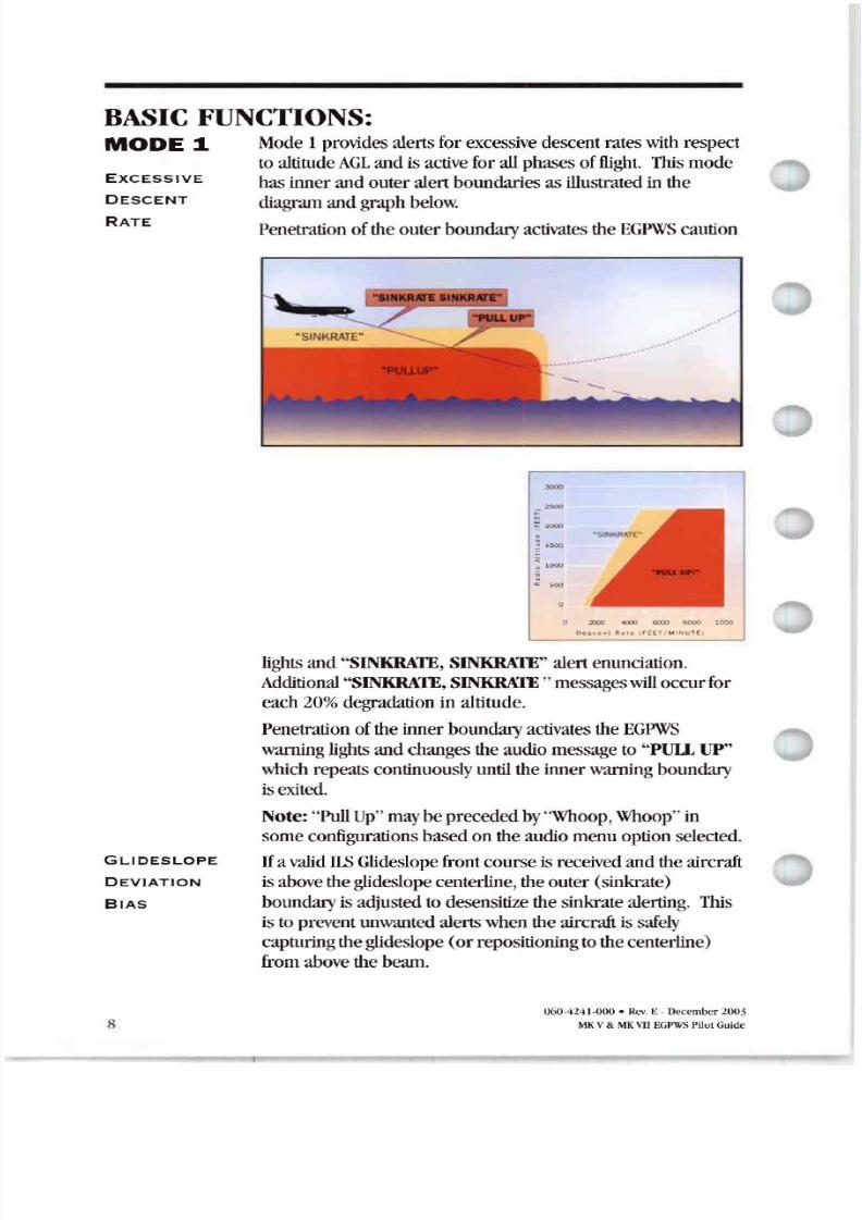
Mode 1provides alertsforexcessive descent rateswith respect
to altitude AGLand is active for allphases of flight. Th is mode
has inner and outer alert boundaries as illustratedin the
diagramandgraphbelo
Penetration ofthe outer boundary activates theEGPWScaution
EXCESSIVE
DESCENT
RATE
B SIC FUNCTIONS
MODE 1
o 2000 4UOO 6l:O:
Oe s c ,, ' ' h I e l ' EE T/ MI NUT
GLIDESLOPE
DEVIATION
BIAS
lights and SINKRATE, SINKRATE alertenunciation.
Additional SINKRATE,SINKRATE messages will occur for
each20 degradation in altitude.
Penetration ofthe inner boundary activates theEGPWS
warning lights and changes theaudiomessageto PUll UP
which repeats continuouslyuntil theinnerwarning boundaryisexited .
Note: PullUp maybeprecededby Whoop,Whoop ill
some configurations basedon theaudiomenuoption selected .
Ifavalid 11 Glideslopefrontcourseis received andtheaircraftisabove theglideslope centerline , theouter (sinkrate)
boundary is adjusted todesensitize thesinkrate alerting. This
istoprevent unwanted alertswhentheaircraft is safely
capturingtheglideslope(or repositioningtothecenterline)
fromabovethe beam.
060-424 J·000 • Rev. E - December 200 .)
V vnEGPWSIJi olGuide
8/13/2019 ENHANCED GROUND PROXIMITY WARNING SYSTEME GPWS REV E
http://slidepdf.com/reader/full/enhanced-ground-proximity-warning-systeme-gpws-rev-e 11/95
MODE
CONTINUED
S T EEP
pPRO CH
I S
MODE 2
EXCESSIVE
CLOSUR E TO
TERR IN
MODE
If the Aural Declutter feature isdisabled , the sinkrate alert
boundary remains fixed andtheauralmessage SINKRATE
repeats continuously until theouterboundary is exited.
TheEGPWS offers a Steep Approach option forgiven aircraft
types (typicallybizjets) thatdesensitizes thealertboundaries
to permitsteeper thannormal approaches without unwanted
alerts.
Mode 2 provides alerts tohelpprotect theaircraft from
impacting thegroundwhen rapidly rising terrain with respect
tothe aircraft isdetected. Mode 2 isbasedonRadio Altitude
andonhowrapidly Radio Altitude isdecreasing (closure rate).Mode 2 exists in two forms, 2A and2B.
Mode 2A isactive during climbout, cruise, and initial approach
(flaps notin thelanding configuration andtheaircraft noton
glideslope centerline). If theaircraft penetrates theMode 2A
caution envelope, theauralmessage TERRAIN, TERRAIN is
generated andcockpit EGPWScaution lights will illuminate. If
theaircraft continues to penetrate theenvelope, theEGPWS
warning lights will illuminate andtheauralwarning message PUll. UP is repeated continuously until thewarning
envelope isexited.
Note: PullUp may be precededby Whoop,Whoop in some
configurations basedontheaudiomenuoption selected.
Upon exiting thewarning envelope, if terrain clearance
continues todecrease, theauralmessage TERRAIN will be
given until theterrain clearance stops decreasing. In addition,
thevisual alertwill remain on until theaircraft hasgained 300feet ofbarometric altitude, 45 seconds haselapsed, or landing
flaps or the flap override switch isactivated.
060-4241-000 • Re\ E-December2003
MKV MKVIIEGPWS PilolGuide 9
8/13/2019 ENHANCED GROUND PROXIMITY WARNING SYSTEME GPWS REV E
http://slidepdf.com/reader/full/enhanced-ground-proximity-warning-systeme-gpws-rev-e 12/95
MODE
ONTINUE
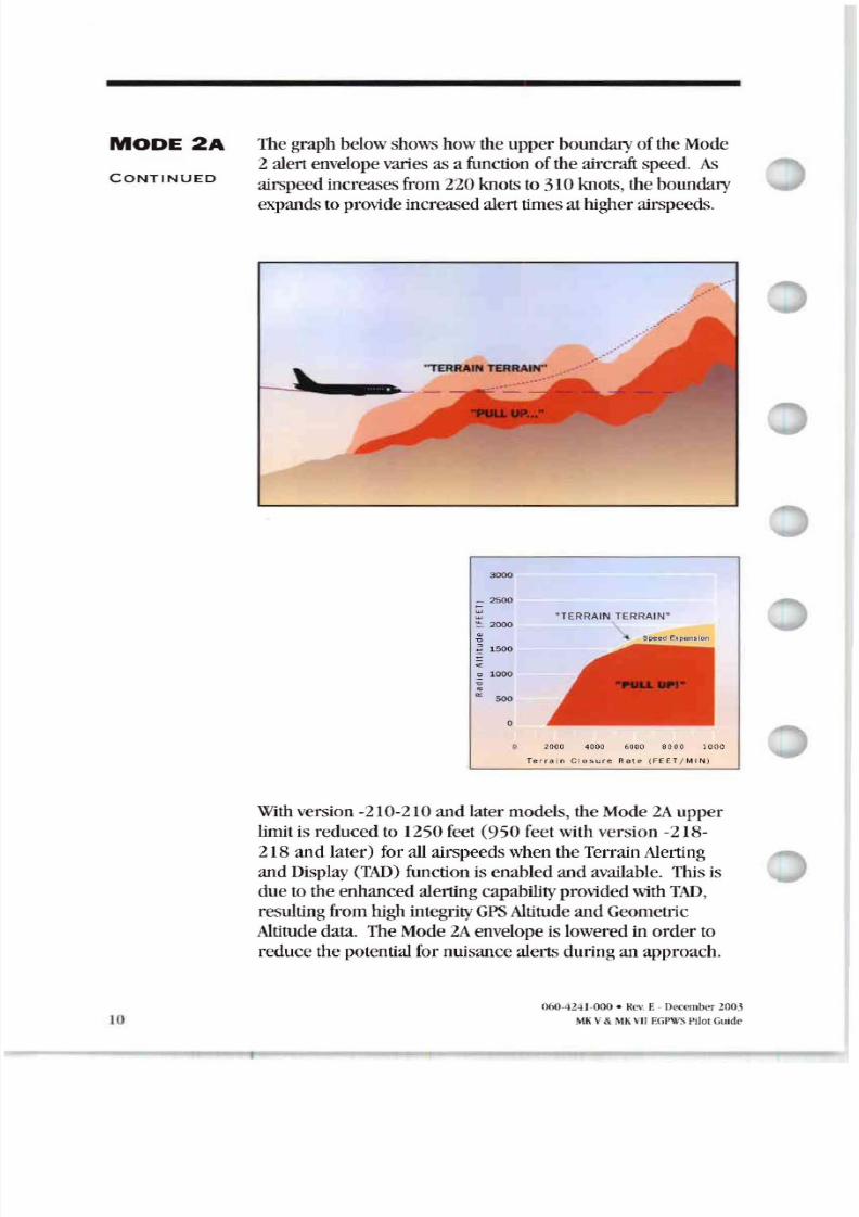
Thegraphbelowshows howthe upper boundary oftheMode
2 alert envelope varies as a function ofthe aircraft speed. As
airspeedincreases from220 knotsto 310knots, theboundaryexpandsto provide increasedalerttimesathigher airspeeds.
.....
3
5
TERRAIN TERRAN 2000
Speed Expiln s ion
1500
1000
500
J()
2000 4000 60 00 8 10 00
Terr a in Cl o s u r e Ra t e ( FEETI M I N)
With version -210-210and latermodels, theMode2A upper
limit is reduced to 1250 feet 950 feetwithversion -218
218 and later) for all airspeedswhentheTerrainAlerting
and Display TAD function is enabledand available. Thisisdue to theenhancedalerting capability provided with T D ,
resulting fromhighintegrity GPSAltitude andGeometric
Altitude data. TheMode2A envelope is loweredin order to
reduce thepotential fornuisancealertsduringan approach.
060··U41-000 • Rev E - December ZO H
M V M V EGPWS Pilot Guide
8/13/2019 ENHANCED GROUND PROXIMITY WARNING SYSTEME GPWS REV E
http://slidepdf.com/reader/full/enhanced-ground-proximity-warning-systeme-gpws-rev-e 13/95
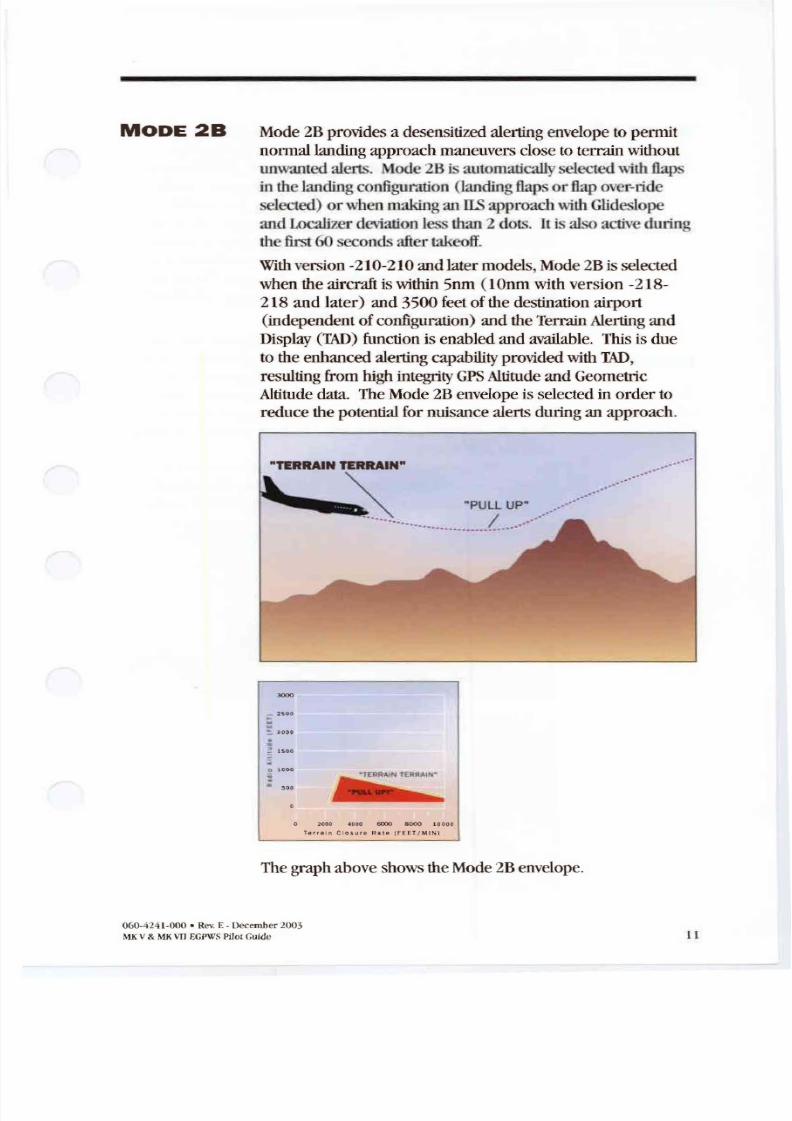
MO Mode 2Bprovides a desensitized alerting envelope to permit
nonnallandingapproach maneuvers close toterrainwithout
unwanted alerts. Mode 2Bisautomaticallyselected with flaps
in the landingconfigumtion landing flaps or flap over-ride
selected) or whenmakingan IL i approachwith G ideslopc
and Localizer deviatiouIcss than2 dots, It is also active during
the fi rst60 secondsafter takeoff
With version -210-210 andlatermodels,Mode 2Bis selected
whentheaircraft iswithin 5nm 1Onm withversion -218
218 and later) and 3500 feet ofthe destination airport
independent of configuration) andtheTerrain Alerting andDisplay TAD) function is enabledand available . Thisisdue
to theenhancedalerting capability provided with TAD ,
resulting fromhighintegrity GPS Altitude and Geometric
Altitude data. TheMode 2Benvelope isselectedinorder to
reducethe potential fornuisance alertsduringan approach.
TERR IN TERR IN
· LLup· .
.. . .. . . .. . . .
4 60Xl 10000
T ai n Clo s u re Ra il [ FEET / MINI
The graphaboveshows theMode 2Benvelope.
060·424 1·000 . Rev. E · December lOOS
MKV MK\ EGPWS Pilot Guide
8/13/2019 ENHANCED GROUND PROXIMITY WARNING SYSTEME GPWS REV E
http://slidepdf.com/reader/full/enhanced-ground-proximity-warning-systeme-gpws-rev-e 14/95
MO
CONTINUED
MODE 3
LTITUDE
s s FTER
T KEOFF
12
uringanapproach, if theaircraft penetrates theMode 2B
envelopewith either the gear or flaps notinthe landing
configuration, the auralmessage TERR IN, TERRAIN is
generated and the EGPWS caution light illuminate. Ifthe
aircraft continues topenetrate the envelope, theEGPWS
warning light illuminate and the aural rn ~ s a g e PULL UP is
repeated continuouslyuntil thewanting envelope is exited. If
the aircraft penetrates theMode 2Benvelopewith bothgear
and flaps in the landing configuration , the aural PU UP
messages are suppressedand theauralmessage TERRAIN
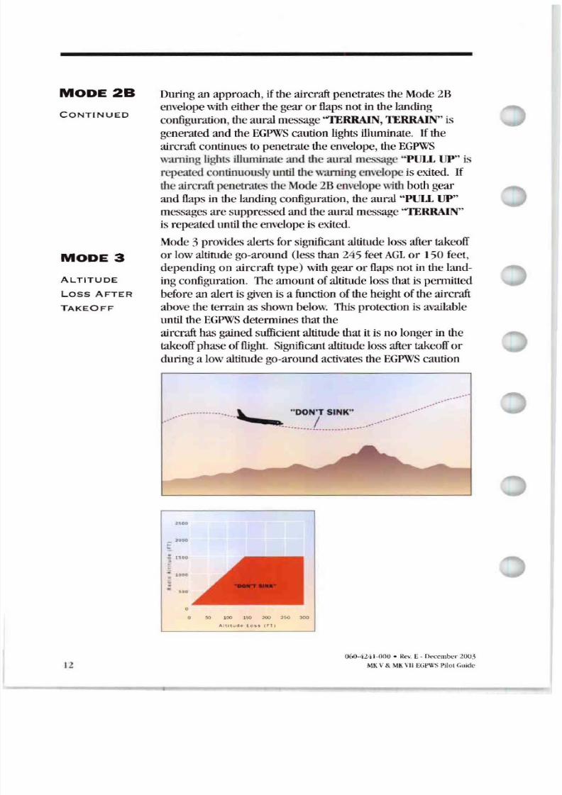
is repeateduntil theenvelope isexited.Mode 3 provides alertsfor significant altitude loss after takeoff
or lowaltitude go-around less than245 feetAGLor 150 feet,
depending on aircraft type) withgear or flaps notinthe land-
ingconfiguration . The amountof altitude lossthatis permitted
before analert is given is a function ofthe height oftheaircraft
above theterrainas shown below. This protection is available
until theEGPWS determ inesthatthe
aircraft hasgained sufficient altitude thatitis no longer in the
takeoff phase offlight Significant altitude loss aftertakeoff or
duringalowaltitude go-aroundactivates theEGPWS caution
DON'T SINK .•....•...•.•.•... . , / '
----0-._
U
50 tOO 150 200 250 aoo
t e 5 s i FT i
060-424 1-000 · Rev. E · December
MK V MI\ VII Pi lot Guide
8/13/2019 ENHANCED GROUND PROXIMITY WARNING SYSTEME GPWS REV E
http://slidepdf.com/reader/full/enhanced-ground-proximity-warning-systeme-gpws-rev-e 15/95
MODE 3
ONTINUED
MODE 4
UNS FE
TERR IN
LE R N E
MODE
lights andtheauralmessage DON T SINK, ON TSINK .
Theauralmessage
is enunciatedtwice
for each20 degradation in altitude. Upon establishinga positive rateofclimb ,
the EGPWScaution lights extinguish andtheauralalertwill
cease.
If the Ur MDeclutter feature is disabled , thewarning is
enunciated continuously until positive climb is established.
Mode 4 providesalertsforinsufficient terrain clearance with
respect tophaseofflight, configuration, andspeed. Mode 4exists inthreeforms , 4A, 4B, and c
• Mode 4A isactive during cruiseandapproachwith thegear
and flaps notinthelanding configuration.
• Mode 48 isactive during cruise andapproach with the gear
inthelanding configuration and flaps notinthe landing
configuration.
• Mode 4Cis active during the takeoff phaseofflight with
eitherthegearor flaps notinthe landing configuration.Mode 4 alerts activate the EGPWScaution lights andaural
messages.
Toreducenuisance alerts causedbyover-flying anotheraircraft, theupper limit oftheMode alerting curve canbe
reduced (from 1000)to800feet. This occursif theairplane isabove 250knotswith gearand flaps notin landing
configuration anda sudden change inRadio Altitude is
detected. This is intended toeliminate nuisance alerts whileflying a holding pattern andan aircraft over-flight occurs (with
1000foot separation) .
With version-210-210andlatermodels,Mode4 airspeed
expansion isdisabled upper limit heldatlowest airspeed
limit)when theTerrain Alerting andDisplay (TAD) function is
enabled and available. This isduetotheenhanced alerting
capability provided with T , resulting from high integrity GPS
Altitude andGeometric Altitude data. This change totheMode
4 envelopes reduces thepotential fornuisance alertswhen theaircraft isnotinthelanding configuration.
Mode 4A isactive duringcruise andapproach with gearandflaps up. This providesalerting during cruiseforinadvertent
flight intoterrain whereterrain isnot rising significantly, or the
060-4241-000 · Rev. E- December 2003
MKV MKvuEGPWSPiJo. Guide 3
8/13/2019 ENHANCED GROUND PROXIMITY WARNING SYSTEME GPWS REV E
http://slidepdf.com/reader/full/enhanced-ground-proximity-warning-systeme-gpws-rev-e 16/95
MODE
ONTINUED
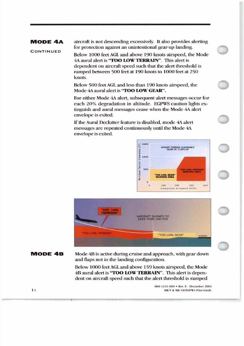
aircraftis notdescending excessively It alsoprovides alerting
forprotection against an unintentional gear-up landing .Below 1000feet L andabove190knots airspeed, the Mode
4A auralalertis TOOLOW TERRAIN . This alertis
dependenton aircraft speedsuch thatthe alertthreshold is
rampedbetween 500feetat 190knots to I000 feet at 250
knots.
Below 500 feet L and lessthan190knots airspeed, theMode 4Aauralalertis TOOLOW GEAR .
Foreither Mode 4A alert, subsequentalertmessages occurforeach 20%degradation in altitude. EGPWS caution light extinguish andaural messagesceasewhentheMode 4A alert
envelope isexited.
If theAural Declutter feature is disabled, mode4A alert
messages are repeated continuouslyuntil theMode 4A
envelopeisexited.
; 15 00
.e: 1 0 0 0<;
socEgci
o
•
UNSAFETERRAIN CLEARANCEGEARUP,FLAPS UP
1 00 LOW-QEAR
W RNIN AREA
100 190
omputed Ai r speed KTS
MODE
14
SI.OWm TOL SS THAN 190 IITS
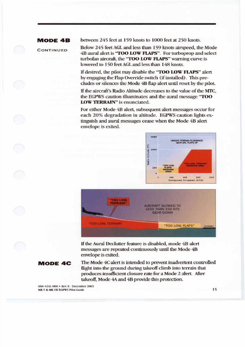
Mode 4Bis active duringcruiseandapproach,with geardown
and flaps notinthelanding configuration.
Below 1000feet L andabove 159knots airspeed theMode
4Bauralalertis ''TOO LOW TERRAIN . This alertisdepen-
denton aircraft speedsuchthatthealert threshold is ramped
06<J·4241-000 · Rev E- December 2003
MKV MKVII EGPWSPilot Guide
8/13/2019 ENHANCED GROUND PROXIMITY WARNING SYSTEME GPWS REV E
http://slidepdf.com/reader/full/enhanced-ground-proximity-warning-systeme-gpws-rev-e 17/95
MODE
ONTINUED
between 245 feetat 159knots to 1000feet at250 knots.
Below 245 feet L
and lessthan159knotsairspeed, theMode4Bauralalertis TOOLOW FLAPS . Forturbopropand select
turbofan aircraft, the TOOLOW FLAPS warning curve is
lowered to 150feet L andlessthan148knots.
If desired, thepilotmay disable the TOOLOW FLAPS alert
byengaging theFlap Override switch ifinstalled) . This pre
cludes or silences theMode 4Bflap alertuntil resetbythepilot.
If theaircraft s Radio Altitude decreases to thevalue oftheMTC,
theEGPWS caution illuminates and theauralmessage TOO
LOW TERRAIN is enunciated.
ForeitherMode 4Balert, subsequent alertmessages occurfor
each 20 degradationin altitude. EGPWS caution lights ex
tinguish andauralmessages ceasewhen theMode 4Balert
envelope is exited.
5
UNSAfETERR IN lE R N E
GEAR ON ftAPS UP
0
TOOLOW24S FUPS -
WARNING
MODE C
100 200
Compu t e d A.l rs peed (K TS)
If theAural Declutter feature is disabled, mode4Balert
messages are repeated continuously until theMode 4Benvelope isexited.
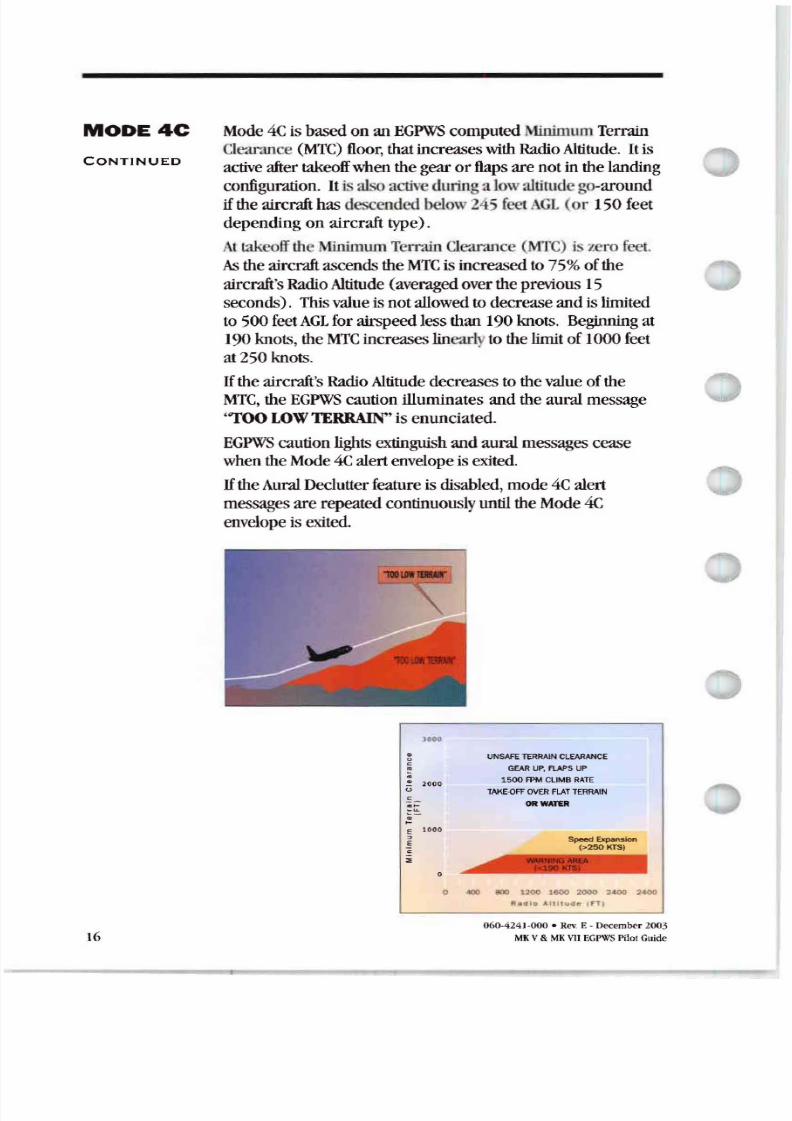
TheMode 4C alertis intended toprevent inadvertent controlled
flight intothegroundduringtakeoff climb intoterrainthat
producesinsufficient closurerateforaMode 2 alert. After
takeoff,Mode 4A and4Bprovide thisprotection.
060-4241·000 · Rev. E- December 2003
MKV MK\11EGI'Il'SPHo' Guide is
8/13/2019 ENHANCED GROUND PROXIMITY WARNING SYSTEME GPWS REV E
http://slidepdf.com/reader/full/enhanced-ground-proximity-warning-systeme-gpws-rev-e 18/95
MODE
CONTINUED
Mode 4Cis basedon anEGPWS computed Mnimum Terrain
Clearance MTC floor thatincreaseswith Radio Altitude . It is
active aftertakeoffwhenthe gearor flaps are notin the landing
configuration . It is also active duringa lowaliitude go-around
if theaircraft hasdescended below245 feet L(or 150feet
dependingon aircraft type).
t takeoffthe MinimumTerrainClearance ( rrC) iszero feel.
Astheaircraft ascendstheMTC is increased to75 ofthe
aircraft 's Radio Altitude (averaged overthe previous 15
seconds). This value isnotallowed todecreaseandis limited
to500 feet L forairspeed lessthan190knots. Beginning at190knots , theMTC increases linearlytothe limit of1000feet
at250 knots.
Iftheaircraft 's Radio Altitude deere eases to thevalue ofthe
MTC, theEGPWS caution illuminates and theauralmessage
''TOOLOW TERRAIN isenunciated.
EGPWS caution lights extinguish andauralmessages cease
when theMode 4C alertenvelope is exited.
If theAural Declutter feature isdisabled, mode4Calertmessages are repeated continuouslyuntil theMode 4C
envelope is exited.
1000
16
.
.U 2
e 1000
E
i
UNSAFETERRAINCLEARANCE
GEARUP RAPS UP
1500 FPMCLIMB R T
T K -oFFOV R FL T T RR IN
ORWATER
Speed ExpanSk> l(> 5 KTS)
o .4(l() lIXI 2 6 2 :1400 4
R_Ol e A11I1114& j
060·424J.()00 · Rev. E · December 2003
MKV MKVIIEGPWS PilotGuide
8/13/2019 ENHANCED GROUND PROXIMITY WARNING SYSTEME GPWS REV E
http://slidepdf.com/reader/full/enhanced-ground-proximity-warning-systeme-gpws-rev-e 19/95
MO ES
EXCESSIVE
DEVI TION
ELOW
GLIDESLOPE
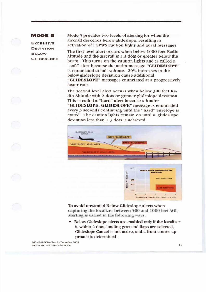
Mode 5 provides two levels of alerting for when the
air raft descends below glideslope, resultin g inactivation of EGPWS caution lights and aural messages.
The first level alert o urs when below 1000 feet Radio
Altitude and the aircraft is 1.3 dots or greater below the
beam. This turn s on the caution lights and is called a
soft alert because the audio message GLIDESLOPE
is enunciated at half volume. 20 increases in the
belowglideslope deviation cause additional
GLI DESLOPE messages enunciated at a progressively
faster rat e.
The second level alert occurs when below 300 feet Ra
dio Altitude with 2 dots or greater glideslope deviation .
This is called a hard alert because a louder
GLIDES LOPE, GLIDESLOPE message is enun ciated
every 3 seconds continuing until the hard envelope is
exited. The caution lights remain on until a glideslope
deviation less than 1.3 dots is achieved.
OlIl iLOP flf I\U
I mm.
1000MOO I now UOUlOf rAlU T
8 DOWIf
500
e
300
100
Gll des op e Dev Ol SFLV UP
Toavoid unwanted Below Glideslope alerts when
capturing the localizer between · and lOOO fect AGL,
alerting is varied in the following ways:
• BelowGlidcslope alerts are enabled only if the localizer
is within 2 dots, landing gear and flaps are selected,
Glideslope Cancel is not active, and a front course ap
proach is determined.
060-4241. · Rev E · December 2003
MKV MKHI EGI'WS I'ilotGuide 17
8/13/2019 ENHANCED GROUND PROXIMITY WARNING SYSTEME GPWS REV E
http://slidepdf.com/reader/full/enhanced-ground-proximity-warning-systeme-gpws-rev-e 20/95
MO S
ONTINUE
IX
• Theupper altitude limit forthealertis modulated with
vertical speed Fordescent ratesabove 500FPM theupperlimit issettothenormal1000 feet GL Fordescent rates
lowerthan500FPM theupper limit is desensitized
reduced) toaminimum of500 feet GL
Additionally bothalertlevels are desensitized below 150 feet
GL, to allow fornormalbeamvariations nearertheground,
andreducethepossibility ofnuisance alerts
If theAural Declutter feature isdisabled messages are repeated
continuously until theMode 5 envelope is exited.Mode 5alertscanbecanceled bypressing theGlideslope
Cancel switch ifinstalled). TheEGPWS will interpret this
switch oneof two ways depending on theinstallation
configuration
• Ast n r glideslope cancelswitch allows formanually
canceling Mode 5 alerting anytime below 2000feet GL
This isautomatically resetwhenthe aircraft descends below
30 feet or climbs above 2000feet GL 1000 feet GLfor
current Boeing production aircraft).
• An lt rn t glideslope cancelswitch allows formanually
canceling Mode 5 alerting atany time andanyaltitude The
cancelis resetbyagain pressing thecancelswitch, or
automatically if gearor napsare raised , or theaircraft ison
theground Dueto thenatureof thealternate cancel
switch, thismethod requires thattherebea cockpit
annunciation thatglideslope cancelis in effect this con-
figuration is currentlynot allowed on aircraft operatingunder F part 121 rules).
EGPWS Mode 5 alertsare inhibited duringbackcourse
approaches toprevent nuisance alertsdue tofalse fly uplobesfrom theGlideslope. TheEGPWC determines a backcourse
approach if either: 1) theaircraft smagnetic trackis greater
than90 degrees from the runways approachcourse, or 2) a
glideslope inhibit discreteis set
O ()· 4Z41-000 • evE - December 2003
V EGPWS Pilot Guide
8/13/2019 ENHANCED GROUND PROXIMITY WARNING SYSTEME GPWS REV E
http://slidepdf.com/reader/full/enhanced-ground-proximity-warning-systeme-gpws-rev-e 21/95
MODE 6
DV ISORY
C A L L OUTS
LTITUDE
LLOUTS
Mode 6 provides EGPWS advisorycallouts basedon the
menu-selected option established at installation (set byprogrampin configuration) . Thesecalloutsconsistof
predefined Radio Altitude basedvoicecalloutsor tones and an
excessivebankangle warning, There is no visual alerting
providedwith these callouts.
The following is a list ofeach of the possible altitudecallouts
or tones:
CAllOUT Occurs at (feetAGL)
R DIOAITIMl1ER 2500 ·IWEi\1Y FIVE HUNDRED 2500
ONE THOUSAND 1000a
FIVE HUNDRED 500 a
Five Hundred Tone (2 second 0 Hz) 500
FOUR HUNDRED 400
THREE HUNDRED 300
TWOHUNDRED 200
A PPRO HI 'GMhIM MS DH+80 b
APPROACHINGDECISION HEIGIIT 011+100 b
PLUSHUNDRfill DH+I00 b
FlYIT ABOVE DH+50 b
MI NIMUMS DH b
MINIMUMS- MLIIM lJMS DH b
DECISION HEIGHT DH b
DECIDE DH b
ONE HUNDRED 100
One Hundred Tone (2 second700Hz) 100 EIGH1Y 80
SX1Y 60
FlY 50
FOR1Y· 40
THIR1Y FIVE 35
ThirtyFive Tone second1400Hz) 35
THIR1Y ' 30
TWEN1Y ' 201\venty Tone (112second2800Hz) 20
TEN 10
FIVE 5
a. MaybeBarometricAltitudeabovethefield elevationforsomeaircraft types.
b. May beMD orDH forsome aircrafttypes.
060-4241·000 · Rev E-December2003
MKV .MKVIIEGPWS PilotGuide 19
8/13/2019 ENHANCED GROUND PROXIMITY WARNING SYSTEME GPWS REV E
http://slidepdf.com/reader/full/enhanced-ground-proximity-warning-systeme-gpws-rev-e 22/95
MODE
ONTINUED
SM RT
FOOT
LLOUT
20
In somecasesa callout is stated twice e.g. , ML\T£MUMS
MINIMUMS ) butin allcasesa given callout is only enunciatedonceperapproach.
Decision Height DH) basedcallouts Approaching Mini-
mums,Mininmms, etc.) requirethe landing geartobedown
andoccurwhen descending through theRadio Altitude
corresponding totheselected DB. These alsohave priority
overother altitude callouts whenoverlapping. Forexample , if
DH is setto 200andboth 1WO BUNDRED and MIM
MUMS are valid callouts , thenonly MINIMUMS will becalled outat200 feet AGL
DBplusbasedcallouts (e.g.,Approaching Minimums) are
only applicable foraircraft providing a Decision Height altitude
to theEGPWS. Consequently, notallEGPWS installations can
utilize thesecallout options.
Dueto thevariety ofaltitude callout choices available , it isnot
possible to identify every combination in thisguide. Refer toan
appropriateAirplane Flight Manual or EGPWS Airplane Flight
Manual Supplement forcallout identification in a specific
application or contactHoneywell.
Another feature available intheAltitude Callouts (options) isa
Smart 500 foot callout. When selected , t s callout assists
pilots duringa non-precision approachbyenunciating FIVE
HUN RE feet in addition to anyotheraltitude callout
discussed above. TheEGPWS determines a non-precision
approachwhenGlideslope is greater than 2 dots deviation
valid or not) or a back-courseapproach isdetected.This feature hasthedistinction ofadding the 500-foot callout
duringnon-precision approaches and removing the 500-foot
callout on precision approaches when partofthecallout
option .
060-4241-000 • Rev E- December 2003
MKV MKVIIEGP\\S Pilo Guide
8/13/2019 ENHANCED GROUND PROXIMITY WARNING SYSTEME GPWS REV E
http://slidepdf.com/reader/full/enhanced-ground-proximity-warning-systeme-gpws-rev-e 23/95
MODE 6
CONTINUED
NK NGLE
C LLOUT
US INESS
NK NGLE
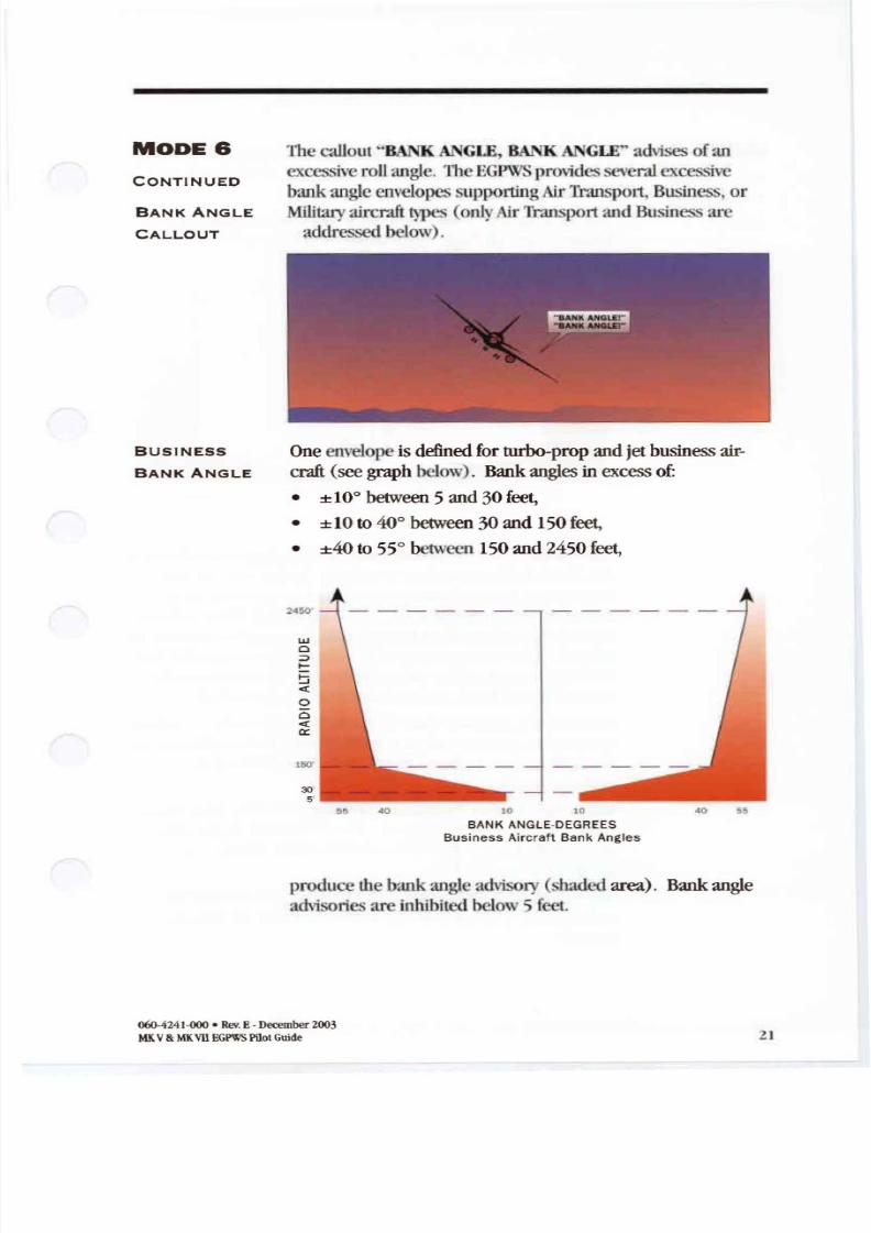
TIlc callout 8A K Gt E, BANK GLE advisesofan
excessive roll angle. The
I WS provides:everul excessiveIXU k angle envelopes supporting Air T l ~ u t S P I 1 Business, orlilitaryalrcrali types (onlyAir Transport andBusin ess arcaddressed below) .
One envelope is defined for turbo propandjetbusinessair-
craft(seegraphbelow). Bankangles in excessof:
• ±10° between 5 and30 feet
• ± 10 to 40° between 30and 150feet• ±4O to 55° between 150:md2450 feet
245
wCl ;
«
oCl«tt:
150
30
5
55 10
BANK ANGLE DEGREES
Busines s Airc raft Bank Angles
produce thebank angle advisory (shaded area). Bankangleadvisories are inhibited below5 feet ,
060-4241-000 . Rev.E· December 2003
v VIIEGPWS PilotGuide
8/13/2019 ENHANCED GROUND PROXIMITY WARNING SYSTEME GPWS REV E
http://slidepdf.com/reader/full/enhanced-ground-proximity-warning-systeme-gpws-rev-e 24/95
MODE 6
R TR NS-
PORT NK
NGLE
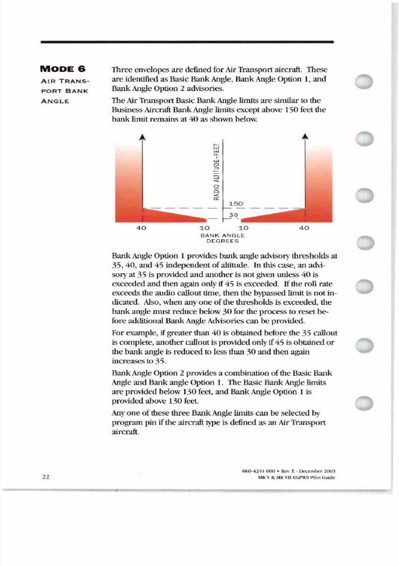
Three envelopes are defined forAir Transportaircraft. These
are identified asBasic Bank Angle BankAngle Option I andBank Angle Option 2 advisories
The Air Transport BasicBankAngle limits are similar to the
Business Aircraft BankAngle limits except above 150feet the
banklimit remains at40as shownbelow.
WWLL Wo=>
o
::
1 5 0
3 0
BAN K ANGLE
DEGREES
22
BankAngle Option I provides bankangle advisorythresholds at
35 40 and 45 independent ofaltitude . Inthiscase an advi
soryat 35 is provided and anotheris notgiven unless 40 is
exceeded and thenagainonly if 45 isexceeded. If therollrate
exceedstheaudio callout time then the bypassed limit is notin
dicated. Also when anyone ofthe thresholds is exceeded the
bankangle mustreducebelow 30 for the process to reset be
foreadditional BankAngle Advisoriescanbeprovided .Forexample ifgreater than 40 is obtained before the 35 callout
is complete anothercallout is provided onlyif 45 is obtained or
the bankangle is reduced to lessthan30 and thenagain
increases to35.
Bank Angle Option 2 provides a combination oftheBasic Bank
Angle andBank angle Option 1. TheBasic Bank Angle limits
are provided below 130feet andBankAngle Option 1 is
provided above 130feetAnyone ofthese threeBankAngle limits canbe selected by
program piniftheaircraft type is defined asan AirTransport
aircraft.
060-424 1-000 · Rev E - December 2005
V EGP\l S Pilot Guide
8/13/2019 ENHANCED GROUND PROXIMITY WARNING SYSTEME GPWS REV E
http://slidepdf.com/reader/full/enhanced-ground-proximity-warning-systeme-gpws-rev-e 25/95
MODE 7
WINDSHE R
LERTING
WINDSHE R
UTION
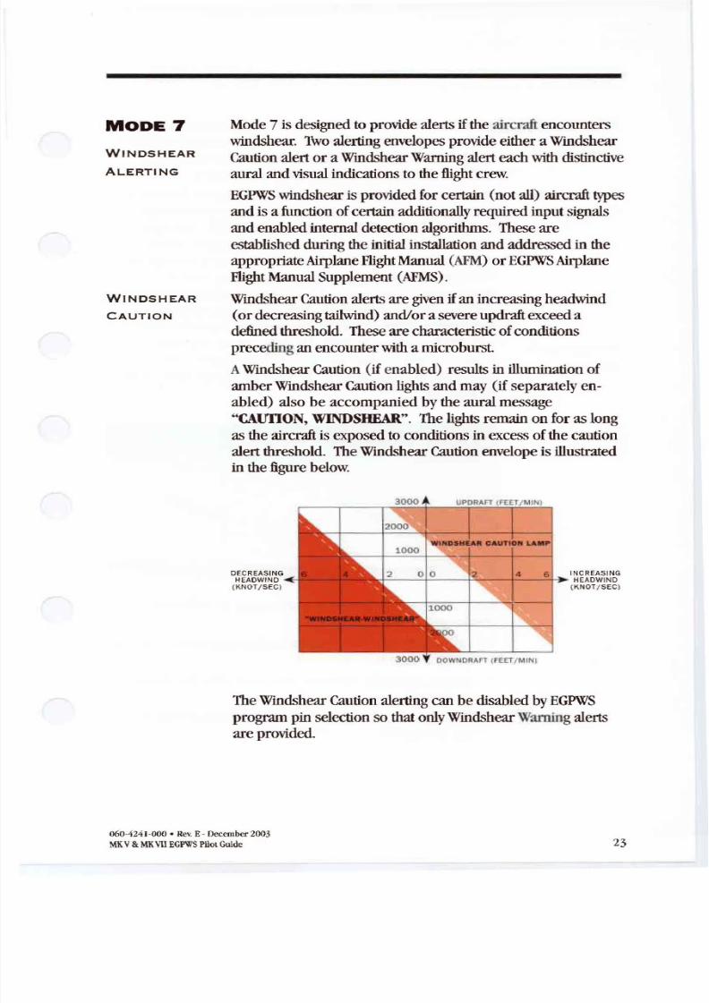
Mode 7 is designed toprovide alerts if the aircraltencounters
windshear. \\ alerting envelopes provide eithera WindshearCaution alertor a Wmdshear Warning alerteachwithdistinctive
auralandvisual indications totheflight crew.
EGPWS windshear isprovided for certain notall) aircraft types
andisa function ofcertain additionally required inputsignals
andenabled internal detection algorithms. These are
established during theinitial installation andaddressed in the
appropriate Airplane Flight Manual AFM) or EGPWSAirplane
Flight Manual Supplement AFMS).
Windshear Caution alerts are given if an increasing headwind
ordecreasing tailwind) and/ora severe updraft exceed adefined threshold. These arecharacteristic ofconditions
preceding an encounter with a microburst.
AWindshear Caution if enabled) results in illumination of
amberWindshear Caution lights and may if separately en
abled) also be accompanied bytheauralmessage
CAUI10N, WINDSHEAR . Thelights remain on foras long
astheaircraft is exposed to conditions in excess ofthe cautionalertthreshold . The Windshear Caution envelope is illustratedinthefigure below.
DECREASINGHEADWIND II
KNO SEC6
The Windshear Caution alerting canbe disabled byEGPWS
program pinselection so thatonlyWindshear \ amingalertsare provided.
060-4241-0 Rev. E - December 2003
V VI EGPWS Pilot Guide 23
8/13/2019 ENHANCED GROUND PROXIMITY WARNING SYSTEME GPWS REV E
http://slidepdf.com/reader/full/enhanced-ground-proximity-warning-systeme-gpws-rev-e 26/95
MODE 7
ONTINUED
WINDSHE R
W RNING
WINDSHE R
UTION
24
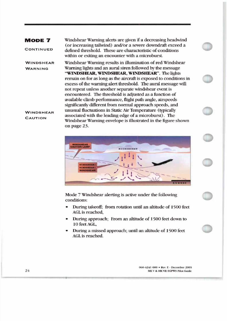
Windshear Warning alerts are given if a decreasing headwind
or increasing tailwind) and/ora severe downdraft exceed adefined threshold . These are characteristic ofconditions
within or exiting an encounter with a microburst.
Windshear Warning results in illumination ofredWindshear
Warning lights andan auralsirenfollowed bythemessage
WINDSHEAR, WINDSHEAR, WINDSHEAR . The lights
remain onforaslongastheaircraft isexposed to conditions in
excess ofthewarning alertthreshold. Theauralmessage will
notrepeatunless anotherseparate windshear event is
encountered. Thethreshold isadjusted as a function ofavailable climb performance , flight pathangle , airspeeds
significantlydifferent from normal approach speeds, and
unusual fluctuations in Static Air Temperature typically
associated with the leading edgeofa microburst) . The
Windshear Warning envelope is illustrated inthe figure shown
onpage23.
v
Mode 7Windshear alerting is active underthe following
conditions :
• During takeoff; from rotation until an altitude of1500feet
L is reached ,
• During approach; From an altitude of1500feet down to10 feetAGL,
• During a missed approach; until an altitude of 1500 feet L is reached.
060 424HJOO• Rev E December 2003
MKV MKvuEGPWSPilot Gude
8/13/2019 ENHANCED GROUND PROXIMITY WARNING SYSTEME GPWS REV E
http://slidepdf.com/reader/full/enhanced-ground-proximity-warning-systeme-gpws-rev-e 27/95
ENH NCED FUNCTIONS
ENVELOPE
MODULATION
TERR IN
CLE R NCE
FLOOR
Dueto terrain featuresat or nearcertainspecific airportsaround theworld, normaloperations have resulted in nuisance
or missed alertsatthese locations inthepast. With the
introduction ofaccurateposition infonnation anda terrain:U d
airportdatabase, it is possibleto identify these areasandadjust
the normal alerting process to compensateforthecondition.
TheEGPWS Envelope Modulation featureprovides improved
alertprotection andexpanded alerting margins at identified key
locations throughout theworld. This feature is automatic and
requires no flight crewaction.
Modes4, 5, and6areexpandedatcertain locations toprovide
alerting protection consistentwith normal approaches. Modes
1,2, and4 are desensitized atother locations to prevent
nuisance alerts thatresult from unusual terrainor approach
procedures. Inall cases, veryspecific infonnation is usedto
correlatethe alrcralt positionandphaseofflight priorto
modulating the envelopes.
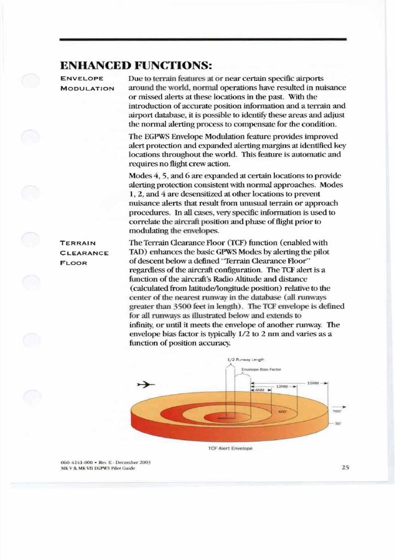
TheTerrain Clearance Floor TCF function (enabled withTAD ) enhances the basicGPWS Modes byalertingthe pilot
ofdescentbelow a defined Ierrain Clearance Floor
regardlessoftheaircraft configuration . The TCF alertisa
function ofthe aircraft sRadio Altitude and distance
(calculated from latitude/longitude position) relative tothe
center ofthe nearst runway in the database (all runways
greater thanr oofect in length). OIC TCF envelopeisdefined
for all runways as illustrated below: d extends to
infinity or until itmeets the envelope ofanotherrunway The
envelope biasfactor is typically 1/2 to2 omand varies as a
function ofposition accuracy.
1 2 Runway l ength
1
30
reF le Envelope
060-424 1-000 · Rev. E - December 2003
MKV MKVIIEGPWS Pilot Guide 25
8/13/2019 ENHANCED GROUND PROXIMITY WARNING SYSTEME GPWS REV E
http://slidepdf.com/reader/full/enhanced-ground-proximity-warning-systeme-gpws-rev-e 28/95
TERR IN
LE R N E
FLOOR
ONTINUED
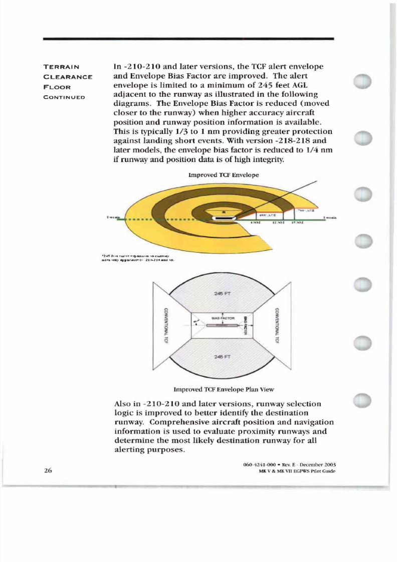
In -210-210 and later versions, the TeF alert envelope
and Envelope Bias Factor are improved. The alert
envelope is limited to a minimum of 245 feet GL
adjacent to the runway as illustrated in the following
diagrams. The Envelope Bias Factor is reduced (moved
closer to the runway) when higher accuracy aircraft
position and runway position information is available .
This is typically 1/3 to 1 nm providing greater protection
against landing short events. Withversion -218-218 and
later models, the envelope bias factor is reduced to 1/4 nm
if runwayand position data is of high integrity
ImprovedrCF Envelope
I r ,., . 1 N1 n ,n oft rw , .:- lul s t,na) apl hr . lll 1 , t n l l .n
45FT
1 l A I ~
q
45FT
ImprovedrCFEnvelope Plan View
Also in -210-210 and later versions, runway selectionlogic is improved to better identify the destination
runway. Comprehensive aircraft position and navigation
information is used to evaluate proximity runways and
determine the most likely destination runway for all
alerting purposes.
26060-4241-000• Rev. E . December 2005
MK I MK III PWS Pilot Guide
8/13/2019 ENHANCED GROUND PROXIMITY WARNING SYSTEME GPWS REV E
http://slidepdf.com/reader/full/enhanced-ground-proximity-warning-systeme-gpws-rev-e 29/95
RU W Y
FIELD
LE R N E
FLOOR
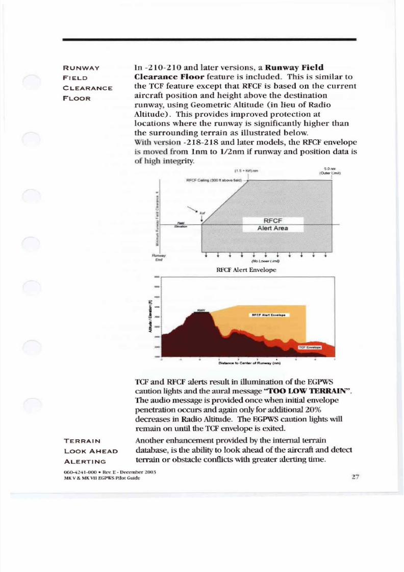
In -210-210 and later versions, a Runway Field
Clearance Floor feature is included. This is similar to
the TCF feature except that RFCF is based on the current
aircraft position and height above the destination
runway, using Geometric Altitude (in lieu of Radio
Altitude). Thisprovides improved protection at
locations where the runway is significantly higher than
the surrounding terrain as illustrated below.
With version -218-218and later models,the RFCF envelope
is moved from lnm to 2nm if runwayand positiondata is
of high integrity
j - O ow rLlftIll)
RFCFAlert Envelope
1 •
o nee lo centM of Runway rwn
5.0nm
1000er jUmllJ
TERR IN
LOOK HE D
LERTING
TCF and RFCF alertsresult in illumination oftheEGPWS
caution lights andtheauralmessage TOO OWTERRAIN .
Theaudiomessage isprovided oncewheninitial envelope
penetration occursandagain onlyforadditional 20 decreases in Radio Altitude. TheEGPWS caution lightswill
remainon until theTCF envelope is exited
Another enhancement provided bythe internal terrain
database , istheability to lookaheadoftheaircraft and detect
terrainor obstacle conflicts with greateralerting time
060-4241-000 ' Rev. E - December 200.\
V MK\11EGPWSPilotGuide 27
8/13/2019 ENHANCED GROUND PROXIMITY WARNING SYSTEME GPWS REV E
http://slidepdf.com/reader/full/enhanced-ground-proximity-warning-systeme-gpws-rev-e 30/95
TERR IN
LOOK
HE D
LERTING
ONTINUED
8
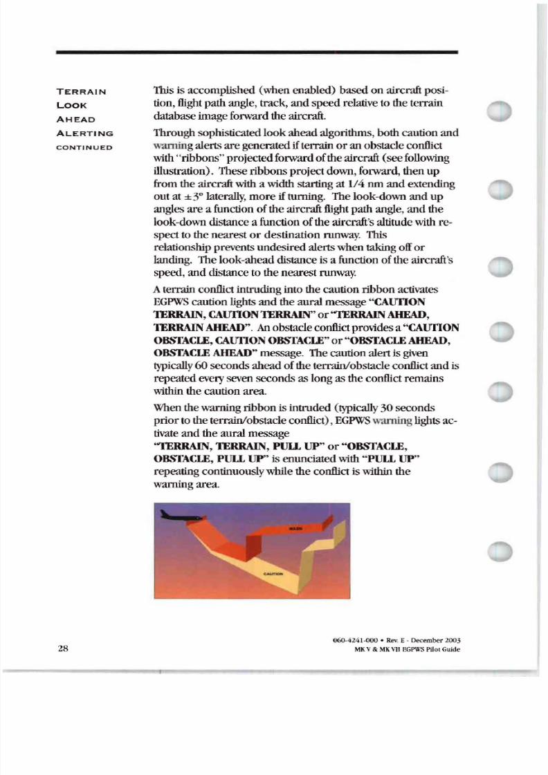
This is accomplished (when enabled) based on aircraft posi
tion, flight pathangle, track, andspeedrelative to theterrain
database image forward theaircraft.
Through sophisticated lookaheadalgorithms, bothcaution and
warningalerts aregenerated ifterrain oranobstacle conflict
with ribbons projected forward oftheaircraft (seefollowing
illustration) . These ribbons project down , forward , then up
from theaircraftwith a width starting at 1/4 nmand extendingoutat±3° laterally, moreiftuming. Thelook-down andup
angles area function oftheaircraft flight pathangle, andthe
look-down distance a function oftheaircraft s altitude with respect tothenearest or destination runway. This
relationshipprevents undesired alerts when takingofforlanding. Thelook-ahead distance is a function oftheaircraft s
speed, anddistance tothenearest runway.
A terrain conflict intruding intothecaution ribbon activatesEGPWS caution lights andtheauralmessage CAunON
TERRAIN, CAunON TERRAIN or TERRAIN AHEAD,
TERRAIN AHEAD . Anobstacle conflict provides a CAunONOBSTACLE, CAUfION OBSTACLE or OBSTACLE AHEAD ,
OBSTACLE AHEAD message. Thecaution alertisgiven
typically60seconds aheadoftheterrain/obstacle conflict andisrepeated every seven seconds as long astheconflict remains
within thecaution area.
When thewarning ribbon is intruded (typically30seconds
priortotheterrain/obstacle conflict), EGPWS warninglights ac
tivate andtheauralmessage
TERRAIN , TERRAIN , llUP or OBSTACLE,
OBSTACLE, llUP is enunciatedwith UllUP
repeating continuouslywhile the conflict iswithin the
warning area.
060-4241-000 · Rev E- December 2003
MK V MK VII PWSPilotGuide
8/13/2019 ENHANCED GROUND PROXIMITY WARNING SYSTEME GPWS REV E
http://slidepdf.com/reader/full/enhanced-ground-proximity-warning-systeme-gpws-rev-e 31/95
TERR IN
LOOK
HE D
LERTING
ONTINUED
TERR IN
LERTING
ND DISPL Y
In -210-210 andlaterversions, the look-ahead alerting
algorithms are improved at higherairspeeds (about300 knots
or greater). Thelook-ahead distance is designed toprovide a60-secondwarning alertforup to8 runlook-ahead (as
opposedto3D-secondsor up to 4 run).With version -218
218 and later, the look-aheaddistance is increased by
12.5 ,and the allowedterrain clearance heightis
increased for descents at high speeds to improvealerting
times.
Thespecific auralmessage provided is established duringthe
initial installation oftheEGPWS as a function ofwhetheror not
theterrainandobstacles features are enabledand theselected
audiomenu(viaprogrampinselection) .
Refer toan applicableAFMor EGPWSAFMS forspecific
application information or contact Honeywell foradditional
information.
When a compatible Weather Radar, EFIS, or otherdisplay is
available andenabled, theEGPWS Terrain Alerting andDisplay
11\1)) feature provides an image ofthesurrounding terrain
represented invarious colorsand intensities.
There arc two types ofT D displays depending onthe options
selected. TIleoriginal type provides a terrainimageonlywhen
the aircraftis 2000 feetor lessabove the t ain. Asecond type
called Peaks enhancesthe displaycharacteristicsto provide a
higher degree ofterrain awarenessindependentofthe
aircraft s altitude (available for selecteddisplay types in
version -206-206withadditionaldisplays added in laterversions). In eithercase,terrainandobstacles (ifenabled)
forward oftheaircraft are displayed. Obstacles arepresented
on the cockpitdisplayas terrain,employing the same
display-coloring scheme. TAD, peaksandObstacle functions
areenabledbyEGPWSprogrampinselection .
NOTE: With respecttoNon-Peaks or Peaksdisplay terrain
and or obstacle presentation is always basedon (andscaled
for) the geographic area available for display. Consequently,
terrainand/or obstacles outside ofthe selected display range
and defined display sweep do nothave anyeffect on the
displayed image.
060 4241·000 • Rev E December 2003
MKV MKVII E WS Pilot Guide 29
8/13/2019 ENHANCED GROUND PROXIMITY WARNING SYSTEME GPWS REV E
http://slidepdf.com/reader/full/enhanced-ground-proximity-warning-systeme-gpws-rev-e 32/95
NON PE KS
ISPL Y
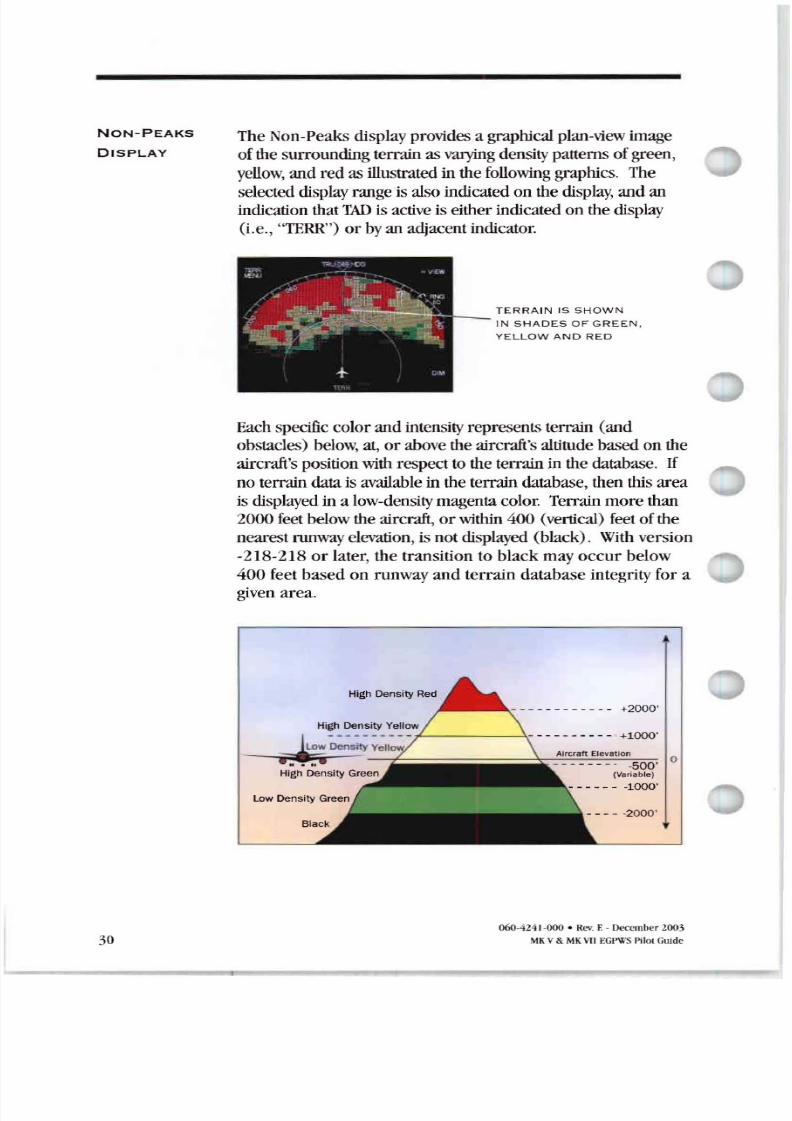
TheNon-Peaks display provides a graphical plan view image
ofthe surrounding terrainasvarying density patterns ofgreen,yellow and redas illustratedinthe following graphics The
selected display range isalso indicated on the display andan
indication thatThD is active is either indicated on thedisplay
(i.e., TERR ) or byan adjacent indicator.
TER R IN IS SHOW N
IN S HADES OF G REEN .
YEL LOW ND RED
Each specific colorand intensity represents terrain (and
obstacles) below, at, or above theaircraft s altitude basedon the
aircraft s position wiih respect to theterrainin thedatabase. If
no terraindatais available in the terraindatabase, thenthisareaisdisplayed in a low density magenta color. Terrainmore than
2000 feet below theaircraft or within 400 (vertical) feet ofthe
nearest runwayelevation , isnotdisplayed (black). With version
-218-218 or later, the transitionto black mayoccur below
400 feetbased on runway and terrain database integrity for a
given area.
- - - - -2000
- - - - - - - - - - - - +2000
- - - - - - - - -500 0 Variable
- - - - - - -1000
High Density Yellow - e - - - - - - - - - +1000
High Density Green
30060-4241-000 • Rev E- December Z 3
\IKV MK H I EGPWSPilol Guide
8/13/2019 ENHANCED GROUND PROXIMITY WARNING SYSTEME GPWS REV E
http://slidepdf.com/reader/full/enhanced-ground-proximity-warning-systeme-gpws-rev-e 33/95
NON PE KS
DISPLAY
CO N T I N U E D
When a caution alertis triggered,theterrain(or obstacle) that
created thealertischanged tosolidyellow (100 density) as
illustrated below
31
60 SE CONDS FR OM
PROJE CTED IMP CT
C A U T IO N TER RAIN
C UTION T ERR IN IS
SO LI D Y LLOW
llone ytrei l[FR s oum
\ \ 11en a warning alert is triggered, the terrain (or obstacle)
thatcreatedthealert is changed to solidred density as
illustrated below
3 0 SECONDS FR OM
PR OJECTED IMPACT
TE RR IN, TE RR IN,
-PULL U p
W RN IN G TERR IN
[S SOLID RED
Honeyll ell lfFR sbotou
NOTE When a T D caution or warningalert is active, the
display image cells surrounding the target are enlarged
(surroundingcellsare illunlinated . This allows a smaller
terrainor obstacle e.g., a single tower tobe betterseenon
the display.Thetransition between greenand yellow is below theaircraft in
order toaccountforaltimetryand/or terrain/obstacle height
errors. Also, the transition altitudes between colorsare biased
upwardproportional to thedescent ratewhengreaterthan
1000 feet per minute. This provides approximatelya 30
secondadvance displayofterrain.
060-4241-000 · Rev. E-December2003
MKV& MKVIIEGPWS PilotGuide
8/13/2019 ENHANCED GROUND PROXIMITY WARNING SYSTEME GPWS REV E
http://slidepdf.com/reader/full/enhanced-ground-proximity-warning-systeme-gpws-rev-e 34/95
NON PEAKS
DISPLAY
CONTINUED
P O P - U P AND
UTO-
RANGE
PE KS
ISPL Y
32
Essentially, pilotsshouldnote that anyyellow or red painted
terrain is at, or abovetheaircraft s altitude and appropriate
terrainclearanceneeds to be provided.
Basedon the display system used, theremaybe additional
terrain display features. Theseare definedas installation
optionsand allow for:
• Automatic display ofterrain on the cockpitdisplay ( TAD
pop-up ) in the event thata cautionorwarningalert is
triggered as describedinTerrain LookAhead Alerting. Insomecases, an active display modemustbe selectedfirst.
• Auto-range whenPop-upoccurs. Thisprovides fortheau
tomatic rangepresentation for terrain as definedfor the
display system configuration (typcally 10urn). In thiscase,
i the terrain auto-rangeis different than the display system
selectedrange, thedisplayed rangevalueon thecockpitdis
playis flashed or changescolor untilthe range ismanually
reselectedor terraindisplay isdeselected.
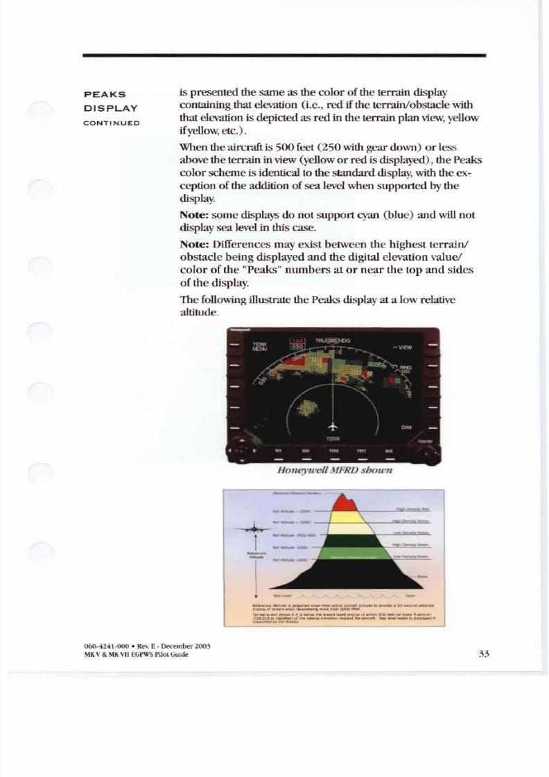
PeaksDisplayhasall thecharacteristics oftheNon-Peaks
Displaybutwithadditional terraindisplay features for
enhancedsituational awarenessindependentof the aircraft s
altitude. Theprincipleadditions are:
• Thedigital display ofthe highest and lowest terrain/obstacle
elevations currentlydisplayed ,
• Thedisplay ofadditional solidor lowerdensity colorbands,
including theadditionofthegraphicrepresentation ofsea
level (0 feetMSL .
With Terrain Display selectedon, digital values representing the
highest terrain/obstacle elevation and the elevation for the
bottomofthe lowest color bandare displayed . Theseare based
on the rangeselected(terrain inview .
Thelocation of thedigital values can v y somewhat for the
display used, but for thisguidewillbe shownin the lowerright
comer ofthe display. Theseelevations are expressedin
hundredsoffeetabove sea level (e.g., 125 is 12,500feetMSL
with the highest elevation on top and the lowest on the bottom.
However, in the event that there isno appreciabledifference in
the terrain/obstacle elevations (flatterrain), onlythe highest
value is displayed . Additionally, the color ofthe elevation value
060-4241-00 Rev. E - December 2003
MK V MKVII EGPWS PilotGuide
8/13/2019 ENHANCED GROUND PROXIMITY WARNING SYSTEME GPWS REV E
http://slidepdf.com/reader/full/enhanced-ground-proximity-warning-systeme-gpws-rev-e 35/95
PE KS
ISPL Y
ONTINUE
ispresentedthesameas thecolorofthe terraindisplaycontaining thatelevation (i.e., red i the terrain/obstacle with
thatelevation is depicted asred in theterrain planview, yellow
i yellow, etc.).
When theaircraft is500feet (250with geardown) or lessabove theterrainin view yellow or redisdisplayed), thePeaks
colorscheme is identical tothestandarddisplay with theexccption oftheaddition ofsea level whensupported bythedisplay.
Note: somedisplays do notsupport y n (blue) andwill notdisplaysea level in thiscase.
Note: Differences mayexistbetween the highestterrain/obstacle beingdisplayed and the digital elevation valuecolor of the Peaks numbers at or near the top and sides
ofthe display.
Thefollowing illustrate thePeaks display at a lowrelativealtitude.
o1/eYlI e MFNI sboum
l l M u d e p r c g e < d < > o o r l r o r n a c l ~ l 1 O O p r o v i O e . . . : : o r < ld i s p l a y n < l e s o e r > d J t l t ~ n l 0 0 0
T e a l n ; M , n i f i i $ b e I Q W ~ I O k < I s t b a n d a n d S W 1 t n r n 4 0 0 1 e e I I 0 t 1 0 V ' e 1 1 v e < s i o n218-2 16 IS ,$le lled)01tM runway e l(ln nM'e.tth 'r<;ral. . . . e l w ' p l a y e d ~
06ll-4241 00 • Rev E. December 2003
MKV MKVllEGPWSPilot Guide 33
8/13/2019 ENHANCED GROUND PROXIMITY WARNING SYSTEME GPWS REV E
http://slidepdf.com/reader/full/enhanced-ground-proximity-warning-systeme-gpws-rev-e 36/95
PE KS
ISPL Y
ONTINUE
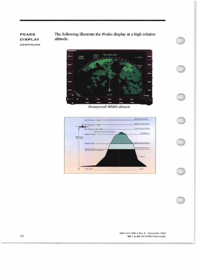
Thefollowing illustrate the eaksdisplay at a high relative
altitude
Houeyu ell MFNIJ SbOIl 1I
0 -
ieference lt itu e
6 424 J • Rev E Dec ember 2 3
MKV MKVII EGP\\SPilotGuide
8/13/2019 ENHANCED GROUND PROXIMITY WARNING SYSTEME GPWS REV E
http://slidepdf.com/reader/full/enhanced-ground-proximity-warning-systeme-gpws-rev-e 37/95
PE KS
DISPL Y
ONTINUED
Whenthe aircraft is greater than 500 feet 250 withgear
down above the terrain in view no yellowor red displayed ,additional green color bands are presented. These added
bands are computed and displayedas a function of the highest
and lowestelevations in view
The following table indicatesthe T D colors and elevations
Non-Peaks and Peaks .
Color Indic tion
Solid Red Terrain/Obstacle Threat Area - WarninR.
Solid Yellow Terrain/Obstacle Threat Area - Caution.
High Density Terrain/Obstacle that is more than 2000 feet
Red Fill above aircraft altitude.
High Density Terrain/Obstacle that is between 1000 and 2000
Yellow Fill feet above aircraft altitude.
LowDensity Terrain/Obstacle that is 500 250 with gear
Yellow Fill down feet below to 1000 feet above aircraft altitude.
Solid Green Shown only when no Red or Yellow terrain
Peaks only /Obstacle areas re within range on the display.
Highest terrain/Obstacle not within 500 250
with gear down feet of aircraft altitude.
High Density Terrain/Obstacle that is 500 250 with gear
Green Fill down feet below to 1000 below aircraft altitude. Peaks only Terrain/Obstacle that is the middle elevation
b nd when there is no Red orYellowterrain areas
within range on the display.
LowDensity Terrain/Obstacle that is 1000 to 2000 feet below
reen Fill aircraft altitude. Peaks only Terrain/Obstacle that is the lower elevation band
when there is no Red or Yellowterrain areas
within range on the display.
Black No significant terrain/Obstacle.
LowDensityCyan Water at sea level elevation 0 feet MSL .Fill Peaks only
Magenta Fill Unknown terrain. No terrain data in the data-
base for the magenta re shown .
Note: magenta may be displayed at or near the South and North Poles
dependent upon the airplane flight path and location .
060-4241-000 . Rev E- December 2003
MKV MKVII EGI WS1 il0l Guide : 5
8/13/2019 ENHANCED GROUND PROXIMITY WARNING SYSTEME GPWS REV E
http://slidepdf.com/reader/full/enhanced-ground-proximity-warning-systeme-gpws-rev-e 38/95
8/13/2019 ENHANCED GROUND PROXIMITY WARNING SYSTEME GPWS REV E
http://slidepdf.com/reader/full/enhanced-ground-proximity-warning-systeme-gpws-rev-e 39/95
GEOMETRI
LTITUDE
ONTINUED
WE THER
R D R
UTO TILT
UR L
MESS GE
PRIORITY
Altitude Calibrated Altitude determined during approach and
Barometric Altitude if available . Estimates oftheVFOM for
eachof these are determined and applied inorder todetermine
itsweight inthefinal altitude . Theblending algorithm gives the
mostweight to altitudeswith a higher estimated accuracy,
reducing theeffect oflessaccurate altitudes. Each component
altitude is alsochecked forreasonableness using awindow
monitor computed fromGPS Altitude anditsV OM . Altitudes
thatare invalid notavailable or fall outside thereasonableness
window arenot included inthe final Geometric Altitude value .
TheGeometric Altitude algorithm is designed to allow continuedoperation when oneor moreofthealtitude components
are notavailable. allcomponent altitudes are invalid or un
reasonable theGPS Altitude isuseddirectly GPS Altitude
fails or is notpresent thentheEGPWS reverts tousing Cor
rected Barometric Altitude alone.
The Geometric Altitude function is fully automatic andrequires
nopilotaction.
In -210-210 andlaterversions theEGPWC computes aoptimum Weather d r tilt angle basedon theaircraft altitude
ASL and theterrain elevation aheadofthe aircraft. This is
output and available toa compatible Weather d r system so
thatthe tilt angle maybe automaticallysetforoptimum
operation .
1\vo or moremessages maybe activated simultaneously, so a
message priority hasbeenestablished.Thefollowing table
reflects thepriority for these message callouts . Messagesatthe
topofthe list will startbefore or immediately override a lower
priority message even if it is alreadyin progress.
060·4241-000 . Rev E- December 2003
MKV MKVII EGPWSPilotGude 37
8/13/2019 ENHANCED GROUND PROXIMITY WARNING SYSTEME GPWS REV E
http://slidepdf.com/reader/full/enhanced-ground-proximity-warning-systeme-gpws-rev-e 40/95
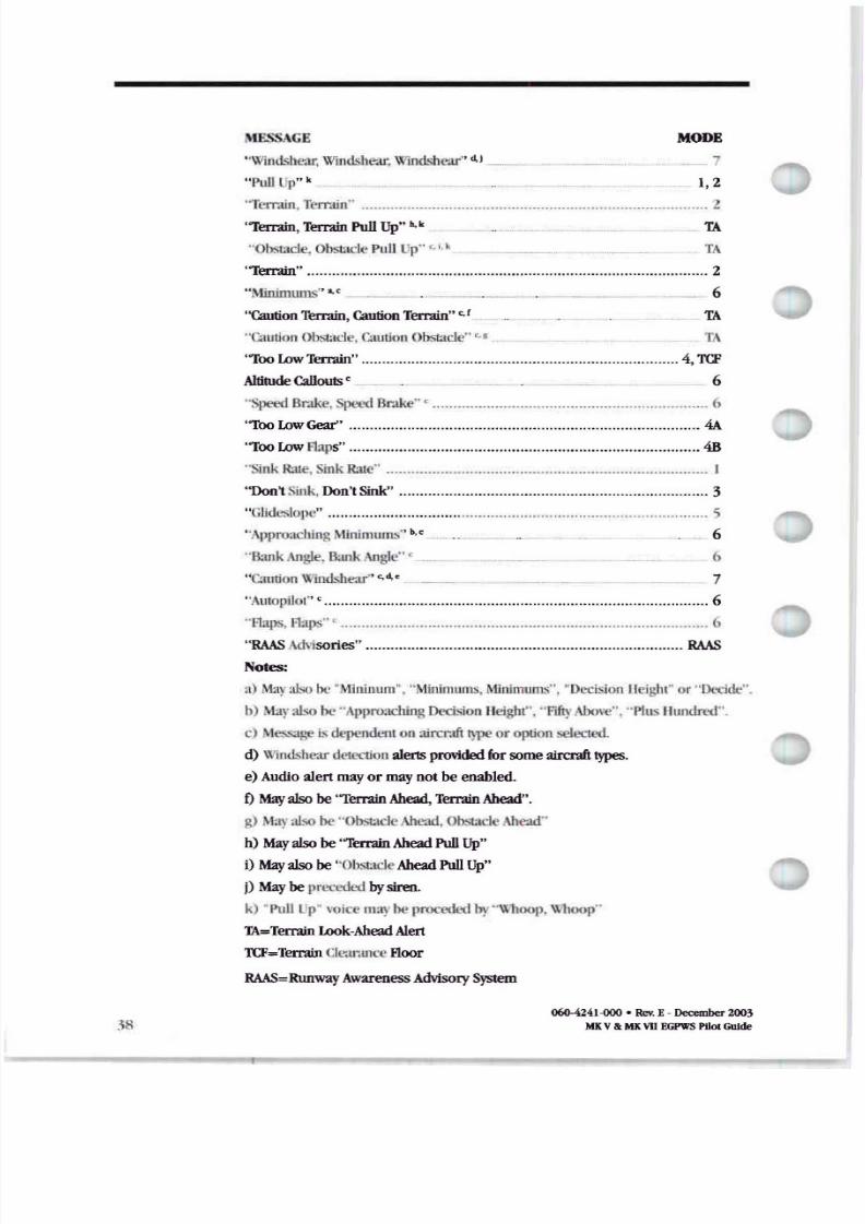
MESSAGE
' 'Willlh he rr,Wil1ll'hl'ar.Wind,hl'ar d,1_ ....._
MO
_ 7
I'ull Up k 1,2
Terrain, T ain
Terrain,Terrain PullUp h,k
Obstacle,Obstacle Pull Up r, ,. k Ii \
Terrain 2
Minimums _ 6
' Cauti onTerrain, Caution Terrain e r
Caution Obstacle, l t l l h s t : lTA
T
1 00LowTerrain 4, TCF
Altitude Callouts c __ _ 6
Speed Brake,Speed Brake.. c (,
Too LowGear 4A
'1'00 LowFlaps 4B
Sink Rare, SinkRate I
Don tSink.Don'tSink 3
Glldeslope
,\pproachingMinimulIls b, c _ 6
B ank Angle, II:Ulk Angle c __ (,
Caution Windshear 7
Autopilo c 6
Haps. Flaps (,
R S Advisories R S
Notes:
a) .\laya1so lx' M mlnum , Min imums,Minimullls . ' Decision Ileigh or Deide .
h) ,\t ryabo be ApproachingDec isinn Height , FftyAbove , Plus Hundred .
c) Ml ::> :lge Isdependenton aircraft typeor option selected,
d) \\ l lldshl tr detection alertsprovidedfor someaircrafttypes.
e)Audioalertmayor maynot be enabled.
oMay alsobe IerrainAhead, Terrain Ahead .
g) May:uso be Obsta cleAhead,ObstacleAhead
h) May alsobe IerrainAhead PullUp
I) May alsobe Obsta cleAhead PullUp
j) Maybepreceded bysiren.
k) Pull Up voice mayhe proceded hy 11f10p. \\11KIP
TA=TerrainLook-Ahead Alert
TCF=Terrain ClearanceFloor
R S Runway wareness Advisory System
060-4241-000 • Rev E · December 2003
MKVIt MKVII EGPWS PIIolGuide
8/13/2019 ENHANCED GROUND PROXIMITY WARNING SYSTEME GPWS REV E
http://slidepdf.com/reader/full/enhanced-ground-proximity-warning-systeme-gpws-rev-e 41/95
SYST M
NPUTS
IR T
R IO
LTITU E
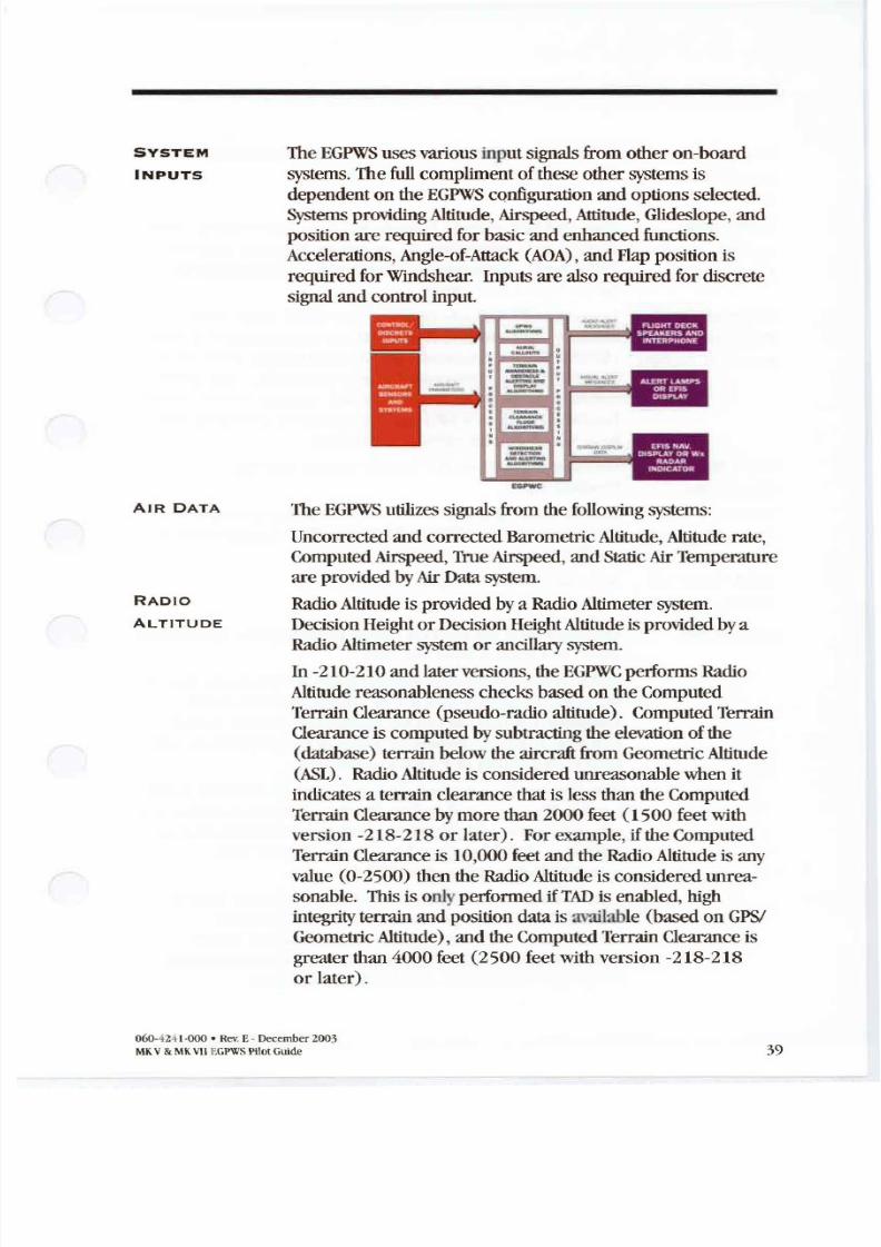
The EGPWSusesvarious inputsignals from otheron-board
systems. Thefull compliment ofthese othersystems isdependent on theEGPWSconfiguration andoptions selected .
Systems providingAltitude ,Airspeed,Attitude ,Glideslope, and
position are required forbasic and enhanced functions.
Accelerations,Angle-of-Attack AOA ,and Flap position is
required forWindshear. Inputs arealsorequiredfordiscrete
signal and control input.
TheEGPWS utilizes signalsfrom thefollowing systems:
Uncorrected and corrected Barometric Altitude, Altitude rate,Computed Airspeed,True Airspeed, andStatic ir Temperature
are provided by ir Data system.
Radio Altitude isprovided bya Radio Altimeter system.
Decision Height orDecision Height Altitude isprovided bya
Radio Altimeter systemor ancillary system.
In -210-210 andlaterversions, theEGPWC performs Radio
Altitude reasonableness checks basedon theComputed
Terrain Clearance pseudo-radio altitude . Computed TerrainClearance is computed bysubtracting theelevation ofthe
database terrain below theaircraft from Geometric Altitude
SL . Radio Altitude is consideredunreasonable when it
indicates a terrainclearance thatislessthantheComputed
Terrain Clearance bymorethan2000feet 1500 feetwith
version -218-218 or later . Forexample , if theComputed
TerrainClearance is 10,000 feetandtheRadio Altitude is any
value 0-2500 thentheRadio Altitude is considered unrea
sonable. This is onlyperformed if T is enabled , highintegrity terrain andposition datais available basedonGPSI
Geometric Altitude , andtheComputed Terrain Clearance is
greater than4000feet 2500 feetwithversion-218-218
or later .
060-4241-000 • Rev E- December 2003
MKV MK vuEGPWSPilot Guide 39
8/13/2019 ENHANCED GROUND PROXIMITY WARNING SYSTEME GPWS REV E
http://slidepdf.com/reader/full/enhanced-ground-proximity-warning-systeme-gpws-rev-e 42/95
R DIO
LTITUDE
CONTINUED
This feature reducesthepotential fornuisance alertscausedby
false tracking ofthe Radio Altimeter.
FMS , IRS, Pitch and Roll Attitude,Latitude and Longitude Position , Body
AHRS , CCEL Normal and Longitudinal Accelerations, Magnetic andTrue
EROM ETER TrackAngles, Magnetic andTrue Heading , Inertial Altitude,
Groundspeed, andmode.
GLOB L Latitude andLongitude Position,True Track Angle, GPS
POS I T ION ING Altitude ,Groundspeed, Horizontal andVertical Figure ofMerit
SYSTE M G PS VFOMIHFOM , Horizontal andVertical Dilution ofPrecision HDOPNDOP , Horizontal Integrity Limit I ilL , and sensor
status . Note: Runway Awareness and Alerting System RAAS
function requires a GPS source capable of providing lati
tude fine and Longitude fine data.
VHF N V Glideslope, Localizer, ILSTuned ,Selected Runway
RECIEVER Heading.
TERR IN t s Display range, and if available theHazard Bus from a Predictive
PL Y SYSTEM Windshear System PWS . IfEFIS, theEFIS display modeisusedinsomeconfigurations.
AOA V NE OR AOA,StickShakerMargin.
ST LL W RNING
DISCRETES
40
Discrete inputs are usedforsystem configuration , signal/status
input, andcontrolinputfunctions.
EGPWS programpinsare utilized to tell the system the type of
aircraft and interface thatitisin. These are defined andestablished duringtheEGPWS installation . EGPWS output
functions are consequently the resultofthe program pinstate
readeach time theEGPWS is powered on.
Signal/status discretes include signals suchas Decision Height,
Landing Flaps selected or Flap Position discretes , Landing Gear
selected ,Terrain Display Range , and status discretessuchas
Glideslope Valid, Localizer Valid, Radio Altitude Valid
associated with analog signal inputs.
Control discretes control EGPWS functions . These include
EGPWS Test, Glideslope Cancel, Glideslope Inhibit or
Glideslope Backcourse ,Terrain display select,Terrain
Inhibit, Flap Override,Audio Inhibit,Altitude Callout Enable ,
Steep Approach Enable, and ILSlimed discretes.
060-424J-000 • RevE - December 2003
MKV MKVII EGP\/S rHOlGuide
8/13/2019 ENHANCED GROUND PROXIMITY WARNING SYSTEME GPWS REV E
http://slidepdf.com/reader/full/enhanced-ground-proximity-warning-systeme-gpws-rev-e 43/95
SYST
OUTPUTS
OPT O S
TheEGPWS provides bothaudioand visual outputs.
Audio outputs are provided as specific alertphrases, andaltitude callouts or tonesprovided byan EGPWS speakerand
viathecockpit Interphone system for headset usage. Several
audiooutput levels are available. They are established during
the installation oftheEGPWS. These EGPWS audiooutputs c n
be inhibited byother systems having higherpriority i.e.,
windshear) or cockpit switches insomecases. TheEGPWS
alsohastheability to inhibit other system audiooutputs such
as TC AS.
Visual outputs provide discrete alertand status annunciations,
and display terrainvideo when a compatible display system is
available and enabled. Thediscrete visual alertscoincide with
audiocaution andwarning alertsto achieve an optimum
terrainalerting capability. Status annunciations provide
information tothe flight crewaboutthe status oftheEGPWS
e.g., GPWS It<\OP or activation ofselected functions. Terrain
video isgenerated bytheEGPWC basedon theaircraft s current
position relative tothesurrounding terrain. This video ispresented toa Weather d r indicator, EFIS display, or a
dedicated display unit.
TheEGPWC usesprogrampin discrete inputs or software
upgrade - RAAS only to define the installation configuration
and option selection. TheEGPWS hasbeendesigned for maxi-
mum flexibility while being tailored to specific aircraft
equipment, sensors, and displays . Thefollowing listsumma-
rizes available Operator options excludingsensorand
equipment configuration options :
• HAAS - Provides audio-only advisories of positiondur
ingground operations and approach to landing.
• FlashingLamps - When selected causesalertannuncia
torsto flash whenactive.
• T D andT F Disable - Suppresses allTA D and TCF
alerting and display functions.
• ltitude Callouts- Selects desiredaltitude callouts froma menuofoptions .
• udioOutput evel Selects desiredaudiooutputlevel
High, Medium, or Low.
• lternate Mode Volume - Selects reducedMode 6
volume -3 dB .
060-4241-000· Rev E- De<:ember2003MKV MKVIIEGPWS Pilot Guide 41
8/13/2019 ENHANCED GROUND PROXIMITY WARNING SYSTEME GPWS REV E
http://slidepdf.com/reader/full/enhanced-ground-proximity-warning-systeme-gpws-rev-e 44/95
OPTIONS
ONTINUE
• Obstacle Awareness Enabled - Enablesobstacle alerting
anddisplay.• TAD Alternate Pop Up- If TRUE , disables (or enables)
automaticterraindisplaywhen T or Obstacle alert is ac
tive, dependent on aircraft/displaytype.
• Mode 6 VolumeReduction - Selects reducedMode 6volume (-6 dB).
• Smart Callout Enable - Enables the SOD foot smart
callout. Five Hundred is called outat 500 feet Radio Alti-
tude duringnon-precisionapproaches. IfSO
is partofthealtitude callout option selected, this callout is notgiven on
precisionapproaches.
• BankAngleEnable - Enables BankAngle alerts
• Windshear CautionVoiceDisable - DisablesWindshear
Caution voice alertsproviding visual alertsonly.
• AudioDeclutter Disable - Disables theAudioDeclutter
function so that audioalertsare constant.
• AudioAlertingVoiceSelect-Selectsthe type(s) ofvoicethatare usedfor audioalerts.
• Lamp Format - Oneof two lampformats are available.
• Lamp Format 1provides onlyMode 5 Glideslope alertstothe caution (amber) lampoutputand allother alerts
(exceptWindshear andMode 6 callouts) to thewarning
(red) lampoutput.
• Lamp Format 2 providesall PullUp warning alertsto
thewanting (red) lampoutputandallcaution alertstothecaution (amber) lampoutput (F requirement for
newinstallations).
NOTE : Windshear annunciations are providedbyseparateout
putsand indications and are notaffected bylampformat Mode
6 advisories do noteffect anyannunciation and are notaffected
bylampformat.
• Peaks Enable - Adds additional densitypatterns and
level thresholds to the StandardDisplayMode, allowingdisplay ofhighest and lowest terrain/obstacle to increase
situational awarness.
060-4241 000 Rev E· December 200;
MK V MKVII EGPWS Pilot Guide
8/13/2019 ENHANCED GROUND PROXIMITY WARNING SYSTEME GPWS REV E
http://slidepdf.com/reader/full/enhanced-ground-proximity-warning-systeme-gpws-rev-e 45/95
OPTIONS
ONTINUE
Additional inputdiscretes are usedto control or define EGPWS
operations:
• EGPWS Self Test - Cockpit switch initiates EGPWS Self-Test on theground. Typically partofEGPWS warning red
lamp.
• Glideslope Cancel Cockpit switch cancels Mode 5
Glideslope alerting. Typically partofEGPWS caution am
ber lamp.
• Glideslope Inhibit- InhibitsMode 5Glideslope alerting .
Nonnally usedforbackcourseapproaches.• ltitude CalloutEnable - EnablesMode 6Callouts.
• Mode LowVolwne - ReducesMode 6volume an addi-
tional 6 dB. This is typically hardwired or connected toan
external switch.
• T D andT F Inhibit - Cockpit switch todisable allT D
andTCF functions. F requirement
• AudioInhibit - disables allEGPWS audiooutputs.
• Steep pproach Enab le - Enables Steep Approach Mode I Excessive Descent Rate alertsbiasing.
• Steep pproach Select - Selects activates Steep p-
proach Mode I Excessive Descent Rate alertsbiasing to
reducenuisance alerts.
• lapOver-Ride- Cockpit switch to select landing flaps
whennot in the landing llapconfiguration.
• earOver-Ride- Cockpit switch to selectgear down
when not in the gear downconfiguration.
• PU SelectlDeselect - Used fordisplaying or deselectingthedisplay ofEGPWS derived Pitch Limit Indicator PU
signals when aWindshear warning occurs.
Foradditional options infonnation contact Honeywell.
060-4241-000 • Rev E-December 2003
MKV MKVII GPWSPilot uide 43
8/13/2019 ENHANCED GROUND PROXIMITY WARNING SYSTEME GPWS REV E
http://slidepdf.com/reader/full/enhanced-ground-proximity-warning-systeme-gpws-rev-e 46/95
S TION
OPER TION L PRO EDURES
System Constraints 45
System Activation 6
EGP\VS Sell Test ........ ............................ 7
Normal ro edures 50
Caution Alcrts. 5 1
Warning Alerts 51
Glideslope Alerts ...................... ......... ............. ........ ... ............ ....... 51Advisory Callouts 52
Windshear Caution 52
Windshear \Varning 52
Abnormal ro edures 53
Emergency ro edures 54
611 4241 000• Rev E December 2003
MKV MKVII EGPWSPilot Guide
8/13/2019 ENHANCED GROUND PROXIMITY WARNING SYSTEME GPWS REV E
http://slidepdf.com/reader/full/enhanced-ground-proximity-warning-systeme-gpws-rev-e 47/95
SYSTEM System constraints forthe EGPWSare:
ONSTR INTS Ifterraindatais unavailable fora particular area, thenTerrainandObstacle alerting and displayisnotavailable for
thatareaand the affected display area iscoloredM GENT
normally onlydisplayed at or near North and South
Polesdependent upon airplane flight path and location) .
• Thedisplayofterrainand obstacle information is intended
to serve as a situational awareness tool. It doesnotprovide
theaccuracy and/or fidelity tobe thesolesourcefor
deciding terrainor obstacle avoidance. Navigation mustnot
bepredicated upon theuseoftheEGPWS terrain/Obstacledisplay
• If there isnosourceofaircraft position datameeting theaccuracy requirements for theT D andTCF functions, then
these enhanced functions are automatically inhibited with aresultant Terrain inoperative or unavailable indication .
• TAD/fCF function s should be manually inhibited within 15nm on approach to an airport or runway that is not in
the airport/runwaydatabase to avoidunwanted alerts.• TAD/fCF functions shouldbemanually inhibited during
QFE operations if GPS datais unavailable or inoperative .
• TAD/fCF functions should bemanually inhibited forditching or otherolI-airport landings .
• When theTADlfCt functions are inhibited andtheEGPWS isotherwise functional, theEGPWS reverts to providing
basic GPWS functions Modes 1 to andWindshear . In
thisstate, theEGPWS maygivelittle or no advance warning
time forflight intoprecipitous terrain where thereare few
or no preceding obstructions. This particularly applies if:
• Theaircraft isinthe landing configuration.
• Theaircraft is ina stabilized descent at anormal approachdescent rate.
• There isno II.5 GUdeslope signal being recievcd bytheEGPWS nottuned, notavailable, or inoperative .
• Terrain clearance or descent ratesthatare notcompatiblewith requiredminimum regulatory standards forGround
Proximity Warning equipment maycauseunwanted alerts.
• Ifenabled , theEGPWS usesonboardmeasurement ofairmassparameters andaircraft acceleration fordetection ofwindshear. This is a reactive system andcannotpredict
windshear,which may be aheadoftheaircraft.
060-4241-000• Rev E. December 2003
MKV MKVII EGPWS PilotGuide 45
8/13/2019 ENHANCED GROUND PROXIMITY WARNING SYSTEME GPWS REV E
http://slidepdf.com/reader/full/enhanced-ground-proximity-warning-systeme-gpws-rev-e 48/95
SYSTEM
TIV TION
SYSTEM • TheEGPWS terrain/obstacle database includes
ONSTR INTS cataloged human-made obstructions 100 feet high or
ONTINU ED greaterwithin North America and portions ofEuropeand
theCaribbean expanding) . Thedatabase isnotall-inclu
sive and newer, smalleror unknown obstruction s couldbe
encountered.
Refer to an appropriate AFM or EGPWS AFMS for specific
system limitations and procedures.
TheEGPWS is fullyactive whenthe following systems are
powered and functioning normally:• EGPWS
• Radio Altimeter
• AirData
• lIS orGlideslope Receiver
• IRS,AHRS,VG attitude)
• GPS,FMS, or IRS position)
• Landing gear
• Landing flaps
• Stall warning or O windshear only)
• Weather Radar EFIS, or a dedicated terraindisplay
if terrain/obstacle display enabled)
In the event thatrequireddatafor a particular function isnot
available, thenthatfunction is automatically inhibited and
annunciated e.g. ifposition dataisnotavailable or deter
minedunacceptable, T D andTCF is inhibited, anyactive
terrain
displayis removed, and TERR INOP , TERR UN V IL or
equivalent) is indicated) .
Some installations utilize redundant systems so thatif theprimary sourceofdatafails , theEGPWS continues on the
secondary source.
46060-4241 · RevE · December 2003
MK V MKVIIEGPWSPilotGuide
8/13/2019 ENHANCED GROUND PROXIMITY WARNING SYSTEME GPWS REV E
http://slidepdf.com/reader/full/enhanced-ground-proximity-warning-systeme-gpws-rev-e 49/95
SYSTEM
TIV TION
ONTINUE
PWS
S LF T ST
EGPWS status annunciations are provided forGPWS
inoperative mode1-6 functions ,Terrain inoperative T DI
TCF functions , andwindshear inoperative.
Refer to an appropriate M or EGPWS AFMS forspecific sys-
temand status requirements .
TheEGPWS provides a Self Test capability forverifyingand
indicating intended functions. This Self Test capability consists
ofsixlevels toaidin testing and troubleshooting theEGPWS.
These sixlevels are:
Levell- o No GoTest provides an overview ofthecurrentoperational functions andan indication oftheir
status.
Level 2 - urrentFaultsprovides a listofthe internal and
external faults currently detected bytheEGPWC.
Level 3 - PWS onfiguration indicates thecurrent
configuration bylisting theEGPWS hardware,
software, databases, and program pin inputs
detected bytheEGPWC.
Level 4 - ault istoryprovides an historical recordofthe
internal and external faults detected bytheEGPWC.
Level 5 - Warning istory provides an historical recordof
thealertsgiven bythe EGPWS.
Level 6 - iscrete Test provides audible indication ofany
change toa discrete inputstate.
Alevel 1Go/No Go Testis normally performed by flight crewsas
partofpreflight checks. ll other levels are typically usedforinsta11ation checkout andmaintenance operations.
060-4Z41·000 • Rev E. December ZOO3
MKV MK\11 EGPWSN otGuide 4;
8/13/2019 ENHANCED GROUND PROXIMITY WARNING SYSTEME GPWS REV E
http://slidepdf.com/reader/full/enhanced-ground-proximity-warning-systeme-gpws-rev-e 50/95
EGPWS
SELF TEST
CONTINUED
Level 1SelfTest is usedtoverify proper operation ofthe
EGPWS on thegroundas follows:1 Ensure thatadequate aircraft poweris available and the
EGPWSand associated systems are powered.
2. Ensure thatanyEGPWS inhibiting switches are in the
normal non-inhibiting) position.
Verify thatEGPWS inoperative annunciations are
extinguished. lfan inoperative annunciation is indicated ,perform theEGPWS Self-Test(below) andthenseek
corrective action iftheinoperative condition persists.
4. If a terraindisplayisenabled , selectterraintobedisplayed.
5. MomentarilydepresstheEGPWS Self-lest switch.
When a Self-Test is initiated, theEGPWC first checksforany
configuration (installation or database) errors. If anyare
detected itisaudiblyenunciated and the testis terminated. If
none detected, thetest continues through a sequence resulting
in turning onandoff
allsystemannunciators, enunciatingspecific audiomessages, andifenabled, displaying a video test
pattern on the terraindisplay (see illustration below) . Any
functions determined inoperative are alsoenunciated e.g.,
GLIDESLOPE INOP ). TheSelf-Test terminates automaticallyat itsconclusion .
Thefollowing is a description oftheexpected results ofatypi
callevel 1 Self-Test. Actual annunciation nomenclature and
sequencemaydiffer depending on the installation.
• GPWS INOp, W/S INOp, andTERR INOP annunciators tum
on.
• Amber caution ( BELOWGIS or GPWS ) annunciators
tum on.
• GIJDESLOPE is announced overspeaker.
• Amber annunciators tum off
• GIS N EL annunciators tum on if installed).
060-4241-000 • Rev. E - December 2003
MKV MKVII EG PWSPHo Gude
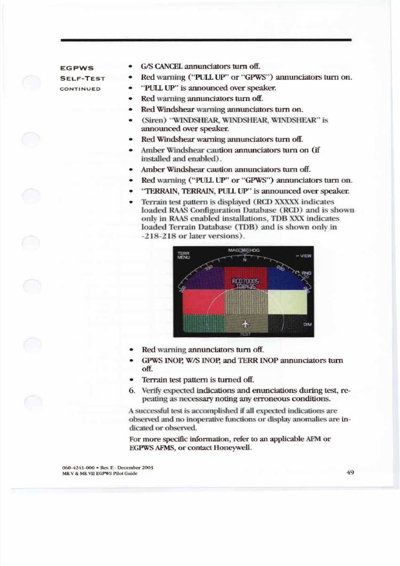
8/13/2019 ENHANCED GROUND PROXIMITY WARNING SYSTEME GPWS REV E
http://slidepdf.com/reader/full/enhanced-ground-proximity-warning-systeme-gpws-rev-e 51/95
EGPWS
SELF TEST
ONTINUED
• GIS C NCEL annunciatorstum off.
• Redwarning ( PULL
UP or GPWS ) annunciatorstum on.• PULL UP is announcedover speaker.
• Redwarningannunciatorstum off.
• RedWindshearwarningannunciators tum on.
• (Siren) WINDSlIEAR, \ l NDSlm·\R,WIl .USllEAR isannounced overspeaker.
• RedWindshear warningannunciatorstum off.
• Amber Windsh e-Jr caution annunciators tum on if
installed andenabled ).• Amber Windshear cautionannunciators tum off.
• Redwarning ( PULL UP or GPWS ) annunciatorstum on.
• TERRAIN, TERRAIN, PULL UP is announcedoverspeaker.
• Terrain testpattern is dispaye (RCD indicatesloaded HAASConfiguration Database (RCD) and i . shownonly in R S enabled installations, TIJB XXX indicates
loaded Terrain Database (TDB) : d is . hown only in
-2 18-2 I8 or later versions) .
• Redwarningannunciators tum off.
• GPWS WIS INOp,and TERR INOP annunciatorstumoff.
• Terrain testpatternis turned off.
6. V e r i ~ expected indications and enunciations duringtest,re-peatingas necessarynotinganyerroneous conditions.
Asuccessful lest is accomplished if all xpected indications arcobserved andno inopenuiv •functions or displayanomaliesarc in
dicatedor observed.
For morespecific information , refertoan applicable FMor
EGPWS FMS or contact Honeywell.
060·424 1·000 · Rev. E · December 2003
MKV MKVII EGPWS Pilot Guide 49
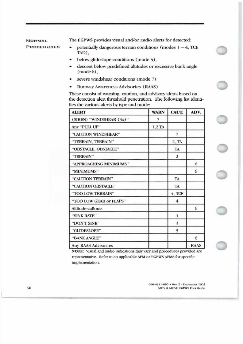
8/13/2019 ENHANCED GROUND PROXIMITY WARNING SYSTEME GPWS REV E
http://slidepdf.com/reader/full/enhanced-ground-proximity-warning-systeme-gpws-rev-e 52/95
NORM L
PRO EDURES
50
TheEGPWS providesvisualand/or audio alerts for detected:
• potentially dangerous terrainconditions (modes I - 4,TCFTAD) ,
• belowglideslope conditions(mode 5),
• descent belowpredefinedaltitudesor excessive bank angle
(mode6) ,
• severewindshear conditions (mode 7)
• RunwayAwareness Advisories (RAAS)
Theseconsistofwarning, caution, and advisory alerts based on
thedetectionalert thresholdpenetration. Thefollowing listidentifiesthevariousalerts bytypeand mode:
ALERT W R CAUf. ADV.
(SIREN) WlNDSIiEAR (3x) 7
ny PUll UP 1,2 T
C lITIONWINDSHEAR 7
TERIWN, TERRAIN 2,TA
OBSTACLE , OBST CLE T
TERRAIN 2
APPROACHINGMINIMUMS 6
MINIMUMS 6
C lITIONTERIWN T
C lITIONOBST CLE T
TOO LOWTERRALI 4, TCF
TOO LO W GE R or FlAPS
Altitude callouts 6
SL KR TE I
DON T SINK 3
GilDESLOPE 5
B NKANGLE 6
Any R S Advisories RAASNOTE: VISUal and audio tndicatlons mayvaryand procedures provided are
representative. Refer toan applicableAFM or EGPWS AFMS for specific
implementation .
060-4241-000 • Rev E - December 2003
MKV MK\ GPU SPHo Gude
8/13/2019 ENHANCED GROUND PROXIMITY WARNING SYSTEME GPWS REV E
http://slidepdf.com/reader/full/enhanced-ground-proximity-warning-systeme-gpws-rev-e 53/95
UTION
LERTS
W RNING
LERTS
GLi ESLOPE
LERTS
Recommended responseto EGPWS alertsare as follows:
1. Stop anydescent andclimbas necessary to
eliminate thealert. Analyze allavailable instruments and
information to determine bestcourseofaction.
2. Advise T ofsituation as necessary.
1. Aggressively position throttles formaximum rated thrust.
Apply maximum available poweras determinedby
emergencyneed. Thepilotnot flying (ifapplicable) shouldsetpowerandensurethatTO G powerandmodesare set.
2. f engaged , disengage theautopilot and smoothly but
aggressively increasepitchtoward stickshaker or Pitch
Limit Indicators PLI) to obtainmaximum climb
performance.
3. Continue climbing untilthewarning is eliminated and safe
flight is assured.
4. Advise T ofsituation .
NOTE: Climbing is the onlyrecommended response unless
operating in visual conditions and/or pilotdetermines, based
on allavailable information , thatturningin addition to the
climbing isthe safest courseofaction. Follow established
operatingprocedures.
NOTE: Navigation must notbebasedon theuse of theTer-
rainAwareness andAlerting Display TAD) .
Below Glideslope alertsconsistof soft and hard alerts
basedon thedegreeofg1ideslope deviation and altitude.
Respond to thesealertsas necessary to correct theaircraft s
flightpath backto theGlideslope centerline or performa
missedapproach.
060-4241-000 · Rev. E - December 2003
MK V MKVIIEGPWS PilotGuide 51
8/13/2019 ENHANCED GROUND PROXIMITY WARNING SYSTEME GPWS REV E
http://slidepdf.com/reader/full/enhanced-ground-proximity-warning-systeme-gpws-rev-e 54/95
DVISORY
LLOUTS
WINDSHE R
UTION
WINDSHE R
W RNING
52
Advisorycallouts being advisory innatureare usedto
announce an event or condition e.g. Minimums , RunwayXX - if S enabled).
Response to thesecallouts shouldbe in accordancewith
standardoperating procedures.
This alertgenerally occursdue to increasing performance
windshear conditions i.e., increasing headwind decreasing
tailwind , and/or updraft). This alertis generally considered
advisoryin thatthecrewresponse is tobealert tothe
possibility ofsubsequent significant airspeedlossand down
draft conditions. Coupled with otherweather factors , the
Windshear Caution shouldbeconsidered in determining the
advisabilityofperforming a go-around.
Wind andgustallowances shouldbeaddedtotheapproach
speed, increasing thrustifnecessary. It may be necessary to
disengage autopilot or auto-throttle. Avoid getting lowon the
approachg1idepath or reducing the throttles toidle.
When aWindshear warning occurs,the following procedures
shouldbe followed:
1. Immediately initiate theWindshear escapemaneuver in
accordancewith established Windshear procedures.
2. Aggressively apply maximum rated thrust disengage
autopilot and/or auto-throttle if necessary.
3. Rotate smoothlyto thego-around/take-off pitchattitude,
allowing airspeed todecrease if necessary Maintain wings
level. Donotretractflaps or landing gear.4. If theaircraft continues todescend, increase pitch attitude
smoothly and in smallincrements, bleeding air speedas
necessary tostopdescent. Use Stall Warning onset stick
shaker) as theupper limit ofpitchattitude.
5. Maintain escapeattitude and thrust anddelay retracting
flaps or landing gearuntil safeclimb-out is assured.
NOT Engine overboost shouldbe avoided unless the
airplane continues to descend and airplane safety isin doubt.
6 ~ 4 2 • Rev E • December 3
MKV MKVII Pilot Guide
8/13/2019 ENHANCED GROUND PROXIMITY WARNING SYSTEME GPWS REV E
http://slidepdf.com/reader/full/enhanced-ground-proximity-warning-systeme-gpws-rev-e 55/95
WINDSHE R
W RNING
CONTINUED
NORM L
PROCEDURES
MODE 1
EXCESSIVE
DESCENT
R TES
MODE 2
EXCESSIVE
CLOSURE TO
TERR IN
MODE 4
UNS FE
TERR IN
CLE R NCE
MODE 5
DESCENT
ELOW
GLIDESLOPE
If overboost is required, adjustthrottles backto maximum
ratedthrustas soonas safetyhasbeenassured.Overboosting engines while athighangle ofattacknC M
airplane stall maycauseengine stall, surge, or flameout.
Maintain escapeattitude andthrustand delay retracting flaps
or landing gearuntil safeclimb-out is assured.
Partial system deactivation or compensation canbe
accomplished forabnormal proceduresas follows:
If steep approaches are tobeperformed (40 orgreater)EGPWS
STEEP APPROACH shouldbeenabledand selected fortheseoperations. This may beaccomplished automatically by
on-hoardsystemsor manuallyselected bya cockpit switch,
When active, Mode I alertsare d . -nsitized to compensate for
normally higherdescent ratesforthese types ofoperation,
eliminating related unwanted alerts. If implemented with a
cockpitswitch , thisrequiresmanual deactivation .
When requiredto operatein closeproximity to terrain (less
than2500 above , Mode 2 alertscanbedesensitize oroverridden byactivating theHAP OVER-RIDE switch to
eliminate relatedunwanted alerts. This requiresmanual
deactivation.
Mode 4 alertscanbereducedbyactivation ofthe Jo P
OVER-RIDE switch , or GEAR OVER-RIDE . This is generally
recommendedwhenperforming approaches with less than
landing flaps selected, or landing gear not down. This re
quiresmanual deactivation .
Mode 5 Glideslope alertscan bemanuallycanceledwhen
below2000feetRadio Altitude (or 1000feetdependant on
aircraft type) bypressing theGIS Cancel switch (commonly
partoftheamber caution annunciators B LOWGIS or
GPWS ). This is typically selected whenan unreliable
Glideslope is expected orwhenmaneuvering is requireddur
ingHSfinal approach. TheGIS Cancel is automaticallyreset
following landing or if theaircraft climbs above the2000or
1000 feetdependant on aircraft type .
060-424 1-000 · Rev. E - December 2003
MK V M vu EGPWS 1'il0 Gude 53
8/13/2019 ENHANCED GROUND PROXIMITY WARNING SYSTEME GPWS REV E
http://slidepdf.com/reader/full/enhanced-ground-proximity-warning-systeme-gpws-rev-e 56/95
MODE
DESCENT
ELOW
GLIDESLOPE
CONTINUED
TERR IN
LERTING ND
CLE R NCE
FLOOR
EMERGENCY
PROCEDURES
54
n somecases, anAlternate S Cancel is available. This al
lows theMode 5 alerting tobecanceled at anytime andanyaltitude. In thisconfiguration ,which is defined only for certain
aircraft types or byprogrampin, pressing the S Cancel
switch in the cockpit hasthe effect of inhibiting Mode 5 alert
ing. t can bemanually resetby in pressingthe S Cancel
switch , or itisautomatically resetfollowing landing, if flap or
gear state changes i.e.,down to up), or whenthe aircraft
climbs above a predetermined altitude defined fortheaircraft
type . Because ofthenatureofthis type ofGIS Cancel, a cock
pit indication ofitsactivation is required.Some aircraft maybe configured with a S inhibit switch.
This switch isseparatefrom theone discussedabove butalso
results in inhibiting Mode 5 alerting. This switch is intended
forselection duringbackcourseapproaches toeliminate
unwanted alertsthatmay result. f a discrete backcourse
signal is available from anothersystem , this inputto the
EGPWC may beconnected to that system for automatic
Mode 5 inhibiting.
NOT Implementation oftheGlideslope Cancel and/or
Inhibit inputs tothe EGPWS varies. Verify a particular
application to determine the implementation used.
Pressing theTerrain Inhibit switch inhibits T andTCF
alerting anddisplay, including Obstacles and Peaks when
enabled. This isusedwhenposition accuracy isinadequateor
when operating at airportsor runways not in the terrain
database. Selection ofTerrain Inhibit doesnotcausetheTer
rain Inoperative annunciation unless theaircraft iswiredfor
thisto occur. Terrain Inhibit requiresmanual deactivation .
TIle EGPWS Flap or Gear Over-ride, TADIfCF Inhibit, or other
switches as installed maybeusedas requiredforan
emergency situation e.g., landing gearup).
Foradditional information refertoanapplicable FM or
EGPWS FMS or contact Honeywell.
060-4241-000 • Rev. E - December 200
V V GPWS PilotGutde
8/13/2019 ENHANCED GROUND PROXIMITY WARNING SYSTEME GPWS REV E
http://slidepdf.com/reader/full/enhanced-ground-proximity-warning-systeme-gpws-rev-e 57/95
S TION FINIT IONS Acronyms shall be interpreted as shown:
FM
FMS
GL
AHRS
AOA
SL
i T
BITCFIT
T
dB
DH
EFIS
EGPW lS
FMSFPM
FIW
GPS
GPWS
G/S
HDOP
HFOM
It
Hz
ICD
ILS
INOP
IRS
VS
MCP
V
Mf
MtS
MSL
MT
060-4241-000• RevE- December 2003
MKV MKVIIEGPWS Pilo Guide
Airplane Flight Manual
Airplane Flight Manual Supplement
Above Ground Level
AttitudelHeading Reference System
Angle of Attack
Above Sea Level
Air Traffic Control
Built In TestControlled Flight into Terrain
Computed Terrain Clearance
Decibels
Decision Height
Electronic Flight nstrument System
Enhanced round Proximity
Warning Computer/Systems
Federal Aviation Administration
Flight Management SystemFeet Per Minute
Fail Warning
Global Positioning System
Ground Proximity Warning System
Glideslope
Horizontal Dilution of Precision
Horizontal Figure of Merit
Horizontal Integrity LimitHertz cps)
Interface Control Document
nstrument Landing System
Inoperative
Inertial Reference System
Inertial Vertical Speed
Mode Control Panel
Modular Concept Unit
Multi Function DisplayMicrowave Landing System
Mean Sea Level
Minimum Terrain Clearance
55
8/13/2019 ENHANCED GROUND PROXIMITY WARNING SYSTEME GPWS REV E
http://slidepdf.com/reader/full/enhanced-ground-proximity-warning-systeme-gpws-rev-e 58/95
56
PCMCI
P1I
PPI
PWS
QFE
QNE
QNH
RMS
RAlM
RFCF
S T
T
T
TC S
TCF
TERR
TO G
VDOP
VFOM
VFR
VG
VHF
WS
Personal Computer Memory CardIndustry Association
Pitch Limit ndic tor
Plan Position ndic tor
Predictive Windshear System
A method of setting the altimeter to
compensate for changes in baro
metric pressure and runway
elevation. Pilot receives information
from airfield and adjusts his altimeter
accordingly and it will read zero alti
tude at touchdown on the runway.
The method of setting the altimeter
to the standard atmosphere datum
-29.92 inches of mercury 1,013.25
mb) . This setting is used in the
United States airspace by all aircraft
above FLl80.The more common method of setting
the altimeter to compensate for
changes in barometric pressure. Pilot
receives information from airfield,
adjusts his altimeter accordingly and
the altimeter will read airfield eleva
tion at touchdown.
Runway Awareness Advisory System
Receiver Autonomous IntegrityMonitoring
Runway Field Clearance Floor
Static Air Temperature
Terrain Awareness
Terrain Alerting nd Display
Traffic Collision Avoidance System
Terrain Clearance Floor
Terrain
TakeofVGo-Around
Vertical Dilution of Precision
Vertical Figure of Merit
Visual Flight Rules
Vertical Gyro
Very High Frequency
WindshearO OA241·000 • R \ E - December 20tH
MKV MK\ EGPWSPlot Guide
8/13/2019 ENHANCED GROUND PROXIMITY WARNING SYSTEME GPWS REV E
http://slidepdf.com/reader/full/enhanced-ground-proximity-warning-systeme-gpws-rev-e 59/95
8/13/2019 ENHANCED GROUND PROXIMITY WARNING SYSTEME GPWS REV E
http://slidepdf.com/reader/full/enhanced-ground-proximity-warning-systeme-gpws-rev-e 60/95
S TION INTRO U TION
WHY R S
58
This Pilot Guide describes thefunctions andoperation ofthe
MKV andMIMI EGPWS Runway Awareness andAdvisory System RAAS .
The document is divided into thefollowing sections:
• Section 1 introduction totheRAAS;
• Section 2 A uick eference guide totheoperation oftheRAAS;
• Section 3 Adetailed description oftheoperation ofRAAS;
• Section 4 Asummary oftheoptions available to operatorsto configure RAAS;
• Section 5 Overview ofthe three audio levels employed forRAAS;
• Section 6 Means fortheflight crew to check theoperationalavailability ofRAAS
• Section 7 Frequently Asked Questions
This guide does not supercede FAA approved data Flight
Manuals individual Operations Manuals requirementsor procedures. Pilots should be thoroughly familiar with
their own company policies system configuration
requirements and procedures with respect to the
operation of aircraft with the EGPWS and RAAS.
The information in this document is intended asa general expla
nation oftheHoneywell RAAS It contains a description ofsystem
performance assuming the identified options are active.
It iswell recognized that runway incursions andoverruns area
high-profile operational safety issue worldwide. Forexample, the
USA iscurrently experiencing at least one runway incursion per
day at towered airports alone. Safety data indicate that lackof
flight crew position awareness during ground operations andon
approach have contributed to such occurrences worldwide. Re
cent industry safety recommendations advocate theneed fornewflight deck runway incursion prevention systems. Honeywell has
developed theRAAS asa practical andlow-cost system with sig
nificant input from hundreds ofpilots. Extensive human factors
evaluations confirm thepositive operational safety benefits of
RAAS increased position awareness; enhanced crew decision
making; reduced crew workload; andsuperior detection of
position errors leading to runway incursions.060 4241 000 • Rev.E December 2003
MK V MKVIIEGPWS PilotGuide
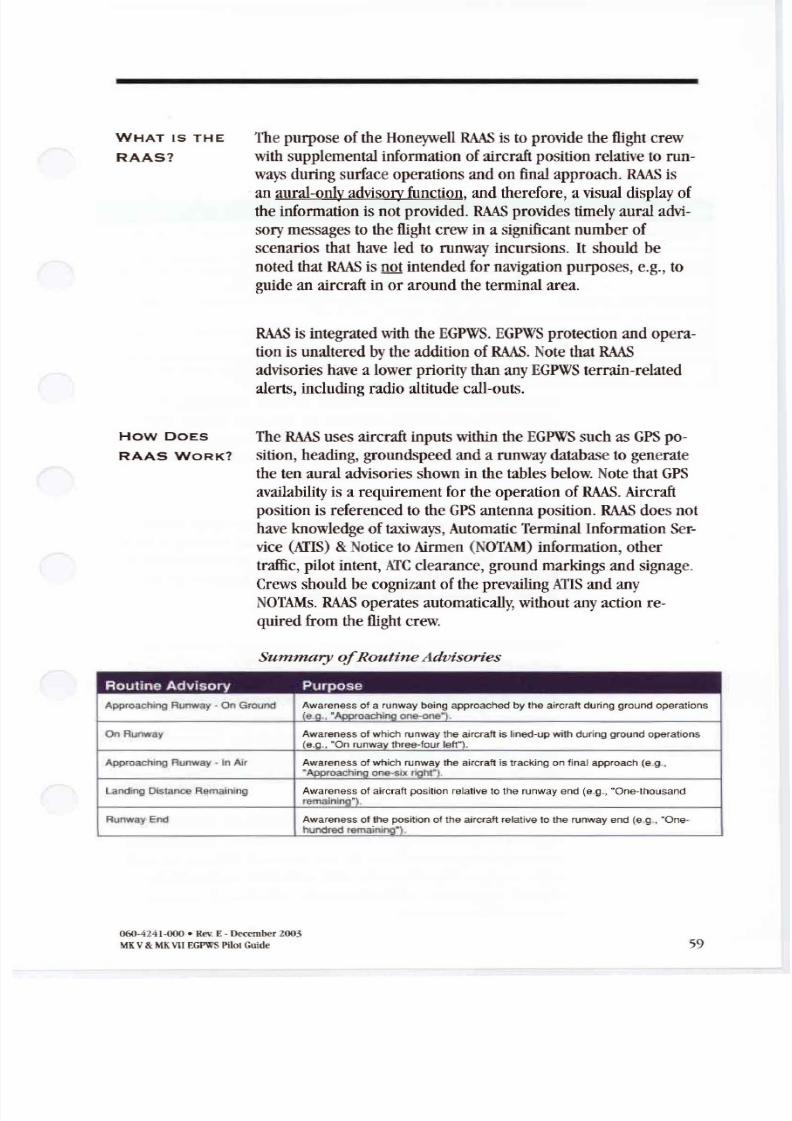
8/13/2019 ENHANCED GROUND PROXIMITY WARNING SYSTEME GPWS REV E
http://slidepdf.com/reader/full/enhanced-ground-proximity-warning-systeme-gpws-rev-e 61/95
WHAT IS THE
RAAS?
The purposeoftheHoneywell R S istoprovide theflight crew
with supplemental information ofaircraft position relative to runways during surfaceoperations andon final approach. R S is
anaural-only advisory function, andtherefore, a visual display of
theinformation isnotprovided . R S provides timely aural advi
sory messages totheflight crew ina significant number of
scenarios that have led to runway incursions . It should be
noted that R S isnot intended fornavigation purposes, e.g., to
guide anaircraft inor around theterminal area.
R S is integrated with theEGPWS EGPWSprotection andopera
tion is unaltered bythe addition ofR S . Note that R S
advisories have a lower priority than any EGPWS terrain-related
alerts, including radio altitude call-outs.
w DOES The R S uses aircraft inputs within theEGPWSsuch asGPS po-
RAAS WORK? sition , heading, groundspeed anda runwaydatabase togenerate
thetenaural advisories shown inthetables below. Note thatGPS
availability is a requirement for theoperation ofR S Aircraft
position is referenced totheGPS antenna position . R S does not
have knowledge oftaxiways, Automatic Terminal Information Ser-
vice AIlS Notice toAirmen NOT M information , other
traffic, pilot intent, TCclearance, ground markings andsignage.
Crews should becognizant oftheprevailing AIlSandany
NOTAMs. R S operates automatically, without anyaction re
quired from theflight crew.
ummary outin dvisories
Routine Adv isory Purpose
Approacl1lng Runway · On Ground Awareness of a runway being approached by the aircraft du ring ground operations
(e,o Approacl1inQone one; .
On Runway Awareness of which runway the aircraft is lined-up with during ground operat ions
(e.g On runway three- faur lett ).
Approach ing Runway · In Air Awareness of which runway the aircraft is tracking on tinal approach (e g .. Approacl1ing one-six flOht .
Landing Distance Remaining Awareness of aircraft position relative to the runway end (e.g., One-thousand
remai nina l.
Runway End Awareness 01the positio n of the aircraft relative to the runway end (e g., One-hundred remaining ) .
060-4241· J . Rev E - December2003
MKV MK VII EGPWS Pilat Gude 59
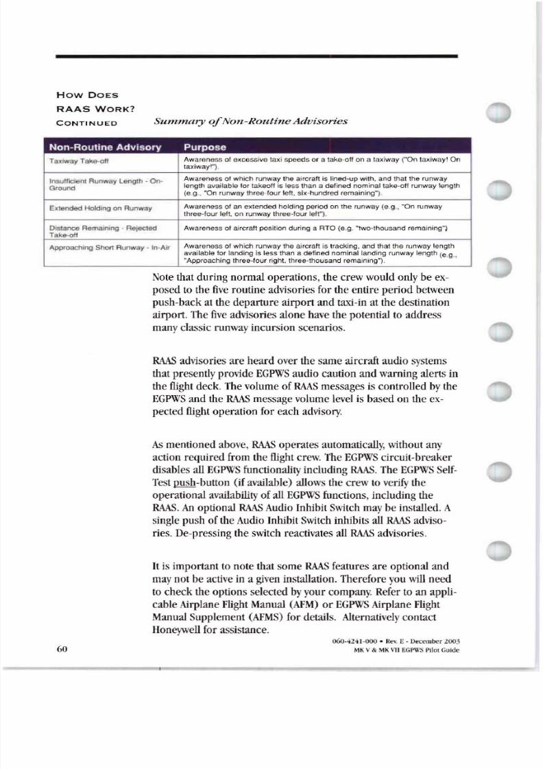
8/13/2019 ENHANCED GROUND PROXIMITY WARNING SYSTEME GPWS REV E
http://slidepdf.com/reader/full/enhanced-ground-proximity-warning-systeme-gpws-rev-e 62/95
w DOES
R S W R ?
CONTINUED umm ry Non Routine dvisories
Non-Roullne Advisory Purpose
Taxiway Take-oil Awareness of excessive taxi speeds or a take-off on a taxiway ( On taxiwayl On
taxiway ) .
Insurtlc ent Runway Length - On- Awareness 01which runway the aircraft is l ined-up with, and that the runway
Ground length available for takeoff is less than a def ined nominal take-off runway length
(e.g ., On runway three-four left, six-hundred rema ining )
E tended Holding on Runway Awarene ss of an extended ho lding perio d on the runway (e g .. On runway
three-four left. on runway three-four left ).
Distance Remaining - Rejected Awareness of aircraft posit ion during a RTO (e g. two-thousand remaining )
Take -off
Approecning Short Runwa y - In-Air Awareness of which runway the aircraft is tracking , and that the runway length
available for landing is less than a defin ed nominal landing runway length (e g . Approaching three-four right. three-thousand remaining ) .
Note thatduring normal operations , thecrew would only be ex-
posed tothe five routine advisories fortheentire period between
push back atthe departure airport andtaxi in at the destination
airport. The fiveadvisories alonehavethepotential toaddress
manyclassic runwayincursion scenarios.
R S advisories are heard over the sameaircraft audio systems
that presentlyprovide EGPWS audio caution and warning alerts in
theflight deck. The volume ofR S messages is controlled by the
EGPWS andtheR S message volume level is basedontheex
pected flight operation foreach advisory.
mentionedabove, R S operates automatically, without any
action required from theflight crew. The EGPWS circuit breaker
disables allEGPWS functionality including R S . The EGPWS SeIf
Testpush button ifavailable allows thecrew toverify the
operational availability ofallEGPWS functions, including theR S An optional R S Audio Inhibit Switch maybe installed . A
single pushoftheAudio Inhibit Switch inhibits allR S adviso
ries. De pressing theswitch reactivates allR S advisories.
It is importanttonote thatsomeR S features are optional and
maynotbe active ina given installation . Therefore youwill need
to check the options selected byyour company. Refer toan appli-
cable Airplane Flight Manual AFM or EGPWS irplane Flight
Manual Supplement FMS fordetails. lternativelycontact
Honeywellforassistance.
60060-4241-000 • Rev E- December
MK V & MK \11EGPWS Pilot Guide
8/13/2019 ENHANCED GROUND PROXIMITY WARNING SYSTEME GPWS REV E
http://slidepdf.com/reader/full/enhanced-ground-proximity-warning-systeme-gpws-rev-e 63/95
On Ground
How DOES
R S WORK
CONTINUED
The default setting for the advisories is a female voice.Advisories
that include runway lengthinthe annunciation may be annunci
ated in feetor metres. Thedefault settingforthese advisories isfeet.These options are discussedin detail inthe R S Options
sectionof this pilot Guide.
Appropriate flightcrewactions toR S advisories are:
If indoubt stop , VERIFY POSITION, and
contact T for assistance ifnecessary.Do nothesitate to requestprogressive
taxiinstructions.
In Air
Ifthe advisory is inconflict with expecta
tions , V RI Y POSITION contact T for
assistance if necessary. Consideration
should begiventoa go-around in accor
dance with company SOPs.
WHERE ND
WHEN DOES
R S WORK
Information contained herein or pro vided by a RAAS
advisory does not supercede any operator Standard
Operating Procedure SOP). Pilots should be thoroughly
familiar with regulatory, company, and other approved
operational procedures as required by their aircraft and
type of operation. Operators should also include RAAS
in th r training curriculum.
R S provides advisories during surface operations and
on final approach. R S is operationally available anytime
the EGPWSis poweredand the following conditions are
met:
• The software for the R S functionshave been loaded
and enabled into an EGPWS byyourcompany;
• The aircraft is on or approaching an airport in the R S
runway database; and• R S is functional e.g. all external signals are available
and not faulted , GPS position accuracy meetsminimum
R S requirements and there are no internal EGPWS
faults .
060-4241-000 • Rev E-December 2003
MKV MKVIIEGPWS PilotGuide 61
8/13/2019 ENHANCED GROUND PROXIMITY WARNING SYSTEME GPWS REV E
http://slidepdf.com/reader/full/enhanced-ground-proximity-warning-systeme-gpws-rev-e 64/95
8/13/2019 ENHANCED GROUND PROXIMITY WARNING SYSTEME GPWS REV E
http://slidepdf.com/reader/full/enhanced-ground-proximity-warning-systeme-gpws-rev-e 65/95
SE TION
UI K
R F R N
R S QUI K REFEREN E
6 4241 • evE December2 3
MKV MKVII PWSPilot uide 63
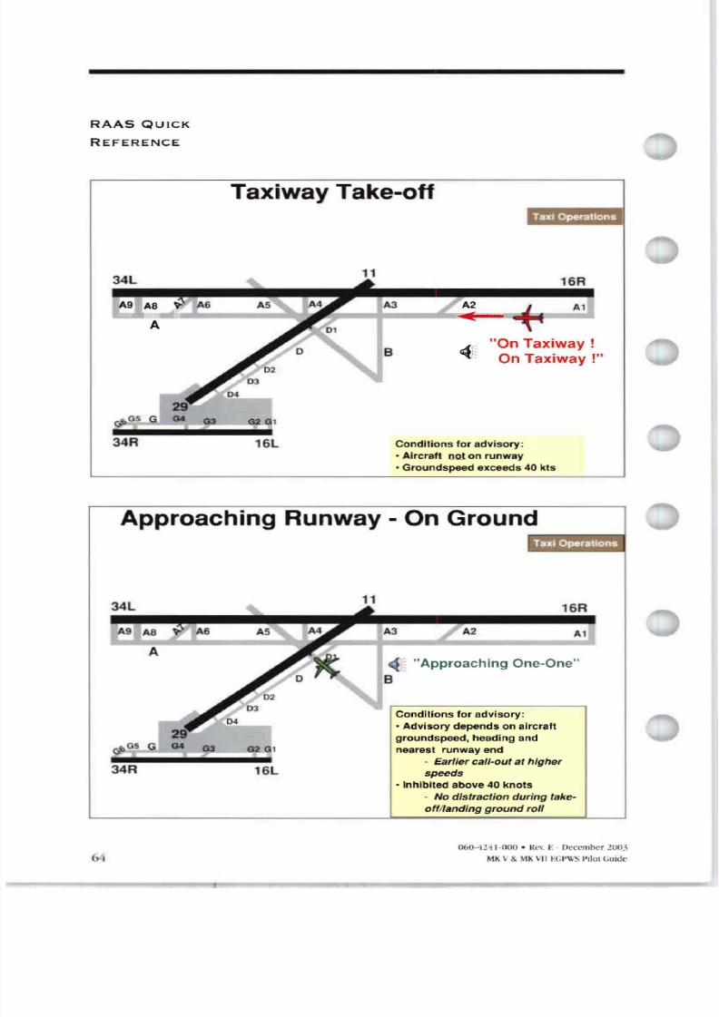
8/13/2019 ENHANCED GROUND PROXIMITY WARNING SYSTEME GPWS REV E
http://slidepdf.com/reader/full/enhanced-ground-proximity-warning-systeme-gpws-rev-e 66/95
S QUICK
REFERENCE
Taxiway Take off. ,' : .
cPG5 G
34R
G2 Gl
16L
16R
Al
OnTaxiwayOn Taxiway
Conditions lo r adv isory:
• Aircraft om on runway
• Groundspeed exceeds 4 kts
pproaching Runway On Ground
- Approaching One-One
Conditions lo r advisory :
- Advisory depends on aircraft
groundspeed, heading and
nearest runway end
Earlier celt outet h igher
speeds
• Inhibited above 4 knots
No distr tion during take-
off landing ground roll
34R
G3 G Gl
16L
11
B
A2
16R
Al
(,.j 6 424 1 • Rev E December l 5
MK v .MK VII Pilot Guid e
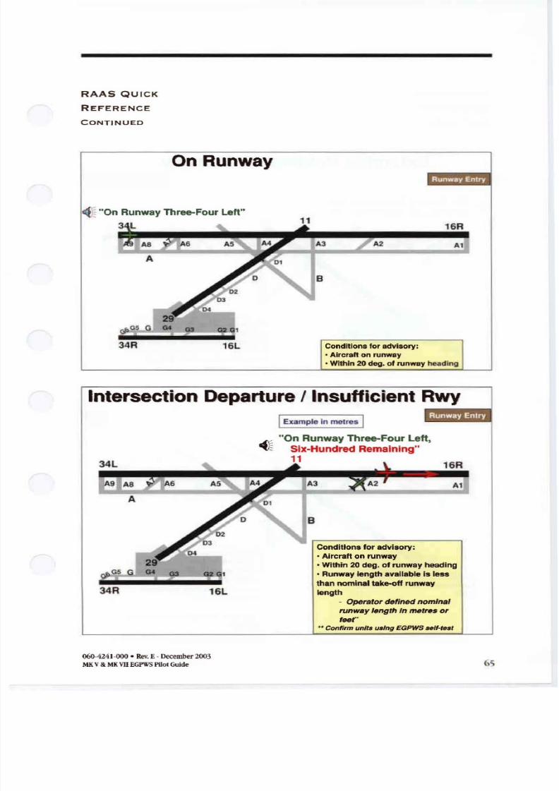
8/13/2019 ENHANCED GROUND PROXIMITY WARNING SYSTEME GPWS REV E
http://slidepdf.com/reader/full/enhanced-ground-proximity-warning-systeme-gpws-rev-e 67/95
S QUI K
REFEREN E
ONT INUE
On unw y
Al
16R
A2
Conditions for advisory:
• Aircraft on runway•Within 20deg. of runway heading
16L
cJ G
34R
: On Runway Three-Four Left
3 L
ntersection eparture I Insufficient Rwy
[ Example In metres I
34R 16L
On Runway Three-Four Left
Six-Hundred Remaining11
Conditions for advisory:
• Aircraft on runway
• Within 20 deg. of runway heading• Runway length available is less
than nominal take-off runway
length
Operator defined nominal
runway length In metres or
r •• onfirmunitsusingEGPWSself test
6 4241 000• Rev E Ilecember2003
MKV MKVII EGI \l SPilotGuide
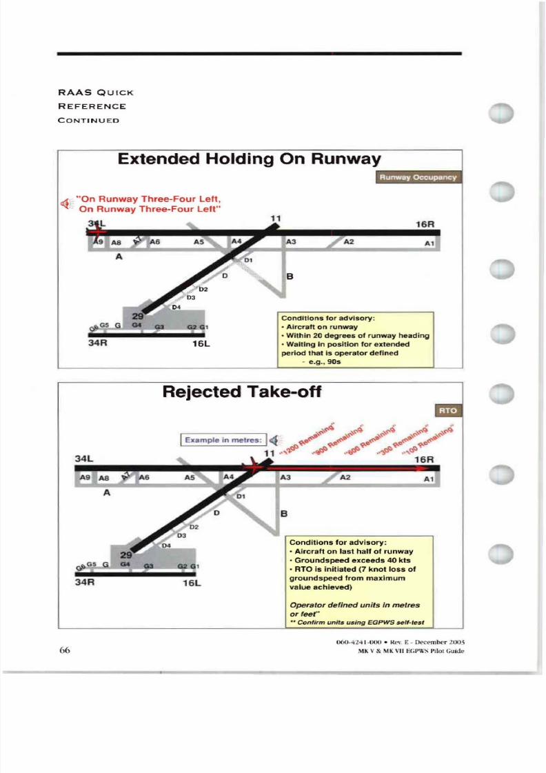
8/13/2019 ENHANCED GROUND PROXIMITY WARNING SYSTEME GPWS REV E
http://slidepdf.com/reader/full/enhanced-ground-proximity-warning-systeme-gpws-rev-e 68/95
R S QU ICK
R E F R N
CONT INUED
Extended Holding On Runway
On Runway Three-Four Left ,. On Runway Three-Four Left
Conditions for adv isory:
• Aircraft on runway• Within 20 degrees of runway heading
• Waiting in posit ion for extended
period thaI Is operalor defined
- e.g., 90s
34R 16L
A2
16R
Al
Rejected Take off. .
CI 05
34R 16L
A2
Conditions fo r adv isory :
• Aircraft on lasl half of runway
• Groundspeed exceeds 40 kls
• RTO is init iated 7 knolloss of
groundspeed from maximum
val ue ach ieved)
A1
66
per for defined un ifs in metres
or fe f
onfirm units using EGPWS self test
060 424 1 000 • Kt. \ E - December
MKV MKVII E :PWS Pilot Guide
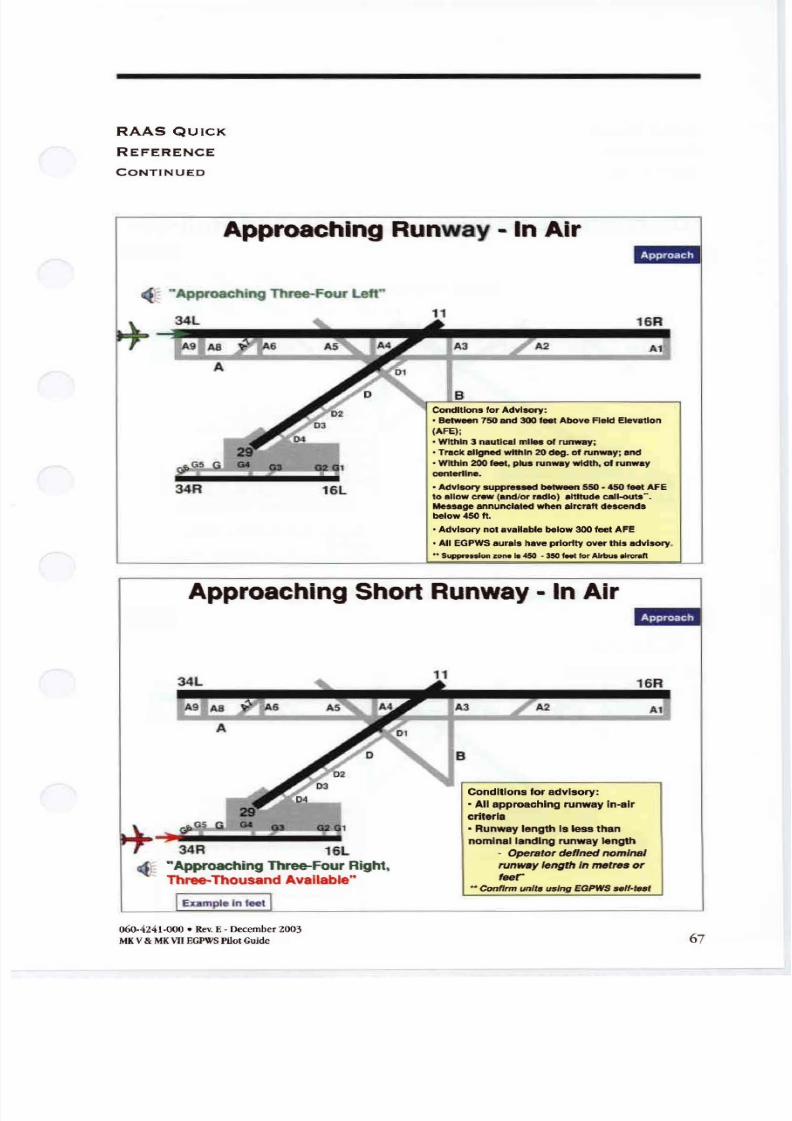
8/13/2019 ENHANCED GROUND PROXIMITY WARNING SYSTEME GPWS REV E
http://slidepdf.com/reader/full/enhanced-ground-proximity-warning-systeme-gpws-rev-e 69/95
R S QUI K
REFERENCE
ONT INUED
pproaching unway - In Air
Approaching Three-Four Left
ConditionsforAdvisory:
• Between750and 300feetAboveReid Elevation
IAFE ;
• Within3 nauticalmilesof runway;
• Treck alignedwithin20deg. of tnWaYi and
•Within 200feet, plus runwaywidth, 01runway
centertlne
• Advisory suppn s e 550 450 roel AFEto allowcrew and/or radio) altitudecall-outs .Messilgeannunciatedwhenaircraftdescendsbelow 450 It.
• Advisorynotavailablebelow300 feet AFE
• AllEGPWSauralshavepriorityoverthis advisory•
•• Suppressionzone.. 45 • 35 teet forAlrbut lrcraft
34R 16L
11
8
A2
16R
Al
pproaching Short unway - In Air
Conditions for advisory:
• All approaching runway In-air
criteria
• Runway length Isless than
nominal landing runway length
• Opera/or deffned nom n l
runw y leng h inm tr s or
fear Conti units us ing EGPWS 5 ·te8
34R 16L
Approaching Three-Four Right,Three-Thousand Available
060·4241 000 • RevE• December2003
MKV MKVII PWSPilotGuide
A2
16R
Al
67
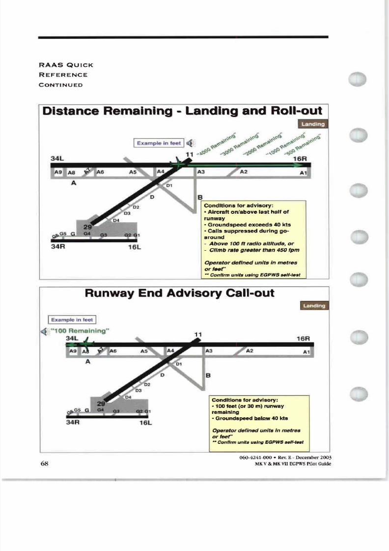
8/13/2019 ENHANCED GROUND PROXIMITY WARNING SYSTEME GPWS REV E
http://slidepdf.com/reader/full/enhanced-ground-proximity-warning-systeme-gpws-rev-e 70/95
R S QUI K
REFERENCE
CONTINUED
istanceRemaining Landing and Roll out
34R L
A2
Conditions for advisory:
• Aircraft on/above last half of
runway
• Groundspeed exceeds 40 kts
• Calls suppressed during go-
around
Above 100 ft radio altitude or
Climb rate greater than 450 fpm
Al
Operator defined units In metres
orf r
, t onfirmunitsusingEGPWSself test
Runway End dvisoryCall out
IExamplo in loet I
34R
11
A2
Conditions for advisory:
• 100 feet or 30m) runway
remaining
• Groundspeed below 40 Ids
16R
At
68
Operatordefined units In metresorf f
t onfirmunitsusingEGPWSsslMest
060 4241 000 Rev E December2003
MKV MK VII GPWSPilotGuide
8/13/2019 ENHANCED GROUND PROXIMITY WARNING SYSTEME GPWS REV E
http://slidepdf.com/reader/full/enhanced-ground-proximity-warning-systeme-gpws-rev-e 71/95
S TION
S YSTEM
OPER TION
DES R IPT ON
T XI
O PER TIONS
The R S uses aircraft inputs from the EGPWSsuch asGPS posi
tion heading groundspeedanda runway database togeneratetherunway awareness aural advisories.Note that GPS availability
isa requirement for the operation ofR S Aircraft position is
referenced totheGPS antenna position. R S does nothave
knowledge ofl:lxiwa} ATIS NOT Minformation other traffic,
pilot intent TC clearance ground markings andsignage. Crews
should be cognizant oftheprevailing TISandany NOT Ms.
Similarl data onnewlyconstructed runways or changesto
length ofexisting runway maynot necessarilyhe included in the
R S runway database . R S operates automatically without anyaction required from the flight crew.
The R S advisories arepresentedbelow for the relevant flight
phases.Note that allR S advisories have a lower priority than
any existing EGPWSalert, including radio altitude call-outs.
Taxiway Take-OffAdvisoryAHoneywell runway incursion study indicates that 7 oftake
offs andlandings were from/onto a t:lxiway The purpose oftheTaxiway Take-Off Advisory istoenhance crew awareness ofex
cessive taxi speeds or a take-off ona taxiway
This advisory isprovided foreach ofthe following conditions:
• inadvertent taxiwaytake-off or excessive taxi speeds; and
• approved take-off operations ona t x w y e.g., atairports
with a single runway that is closed for surface repairs .
060-4241-000 • RevE• December2003
MK V MKVII EGPWS PilotGuide 69
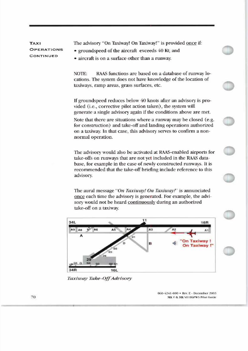
8/13/2019 ENHANCED GROUND PROXIMITY WARNING SYSTEME GPWS REV E
http://slidepdf.com/reader/full/enhanced-ground-proximity-warning-systeme-gpws-rev-e 72/95
T XI
OP R TIONS
ONTINUED
o
The advisory On Taxiway On Taxiway isprovided onceif
• groundspeed oftheaircraft exceeds 40Kt and
• aircraft isona surface otherthan a runway.
NOTE RAAS functions are based ona database ofrunway lo-
cations. The system does nothave knowledge ofthelocation of
taxiways, ramp areas, grass surfaces, etc.
If groundspeed reduces below 40knots after an advisory isprovided (i.e., corrective pilot action taken), thesystem will
generate a single advisory again iftheconditions above aremet.
Note thatthere are situations where a runway may be closed (e.g.
for construction) and take-off and landing operations authorized
ona taxiway. In that case, this advisory serves to confirm a non
normal operation.
The advisory would also be activated atRAAS-enabled airports for
take-offs on runways thatare notyet included in theRAAS data
base, for example inthecase ofnewly constructed runways. It is
recommended that the take-off briefing include reference to this
advisory.
The aural message n axiway n axiuayt is annunciated
once each time theadvisory is generated. For example, theadvi
sory would notbeheard continuously during an authorized
take-off ona taxiway.
16R
,. On Taxiway J
. On Taxiway
16L
Taxiway Take Off dvisory
060 4241 000 • Rev.E December 2003
MKV MKVIIEGPWS PilotGuide
8/13/2019 ENHANCED GROUND PROXIMITY WARNING SYSTEME GPWS REV E
http://slidepdf.com/reader/full/enhanced-ground-proximity-warning-systeme-gpws-rev-e 73/95
T XI
OPER TIONS
ONTINUED
pproaching Runway On Ground dvisory
Safety data show that lack ofposition awareness hasresulted inflight crews lining up with both thewrong runway anda taxiwayfor take off. Inaddition , insome casescrews failedtohold short
58 ofground operations occurrences) and/or inadverternfentered anactive runway. In many oftheselatter cases crews
were unaware oftheirposition relative toa proximate ru w y
edge.
The purpose oftheApproachingRunway On Ground vi sory istoprovide thecrew with awareness ofa proximate runway edgebeing approachedby theaircraft during taxi operations.
This advisory depends upon aircraft groundspeed current head-
ing andclosestrunway endandis provided if:
• aircraft groundspeedis less than 40 knots; and
• aircraft iswithin a specified distance from therunway edge.This distance depends onaircraft groundspeed andclosureangle with the runwa Approaching the runwayat relativelyhigher groundspeeds results inan earlier advisory. The advi-
sory isnot intended toguarantee stopping theaircraft short of
the runwayedge.
The annunciation is inhibitedabove groundspeeds inexcess of
40knots. For example, theadvisory would not beheard during
the high speed regime on take off or landing - this reduces po-
tential distraction intheflight deck. Arunway crossing canbeencountered below 40 knots, for example during an intersection
departure.Therefore it is recommended that crews reference ananticipated low speed b elow 40knots) Approaching Runway
Advisory inthe take off briefing.
060-4241-000 · Rev. E-December2003
MKV MKVIIEGPWS Pilot Guide 7
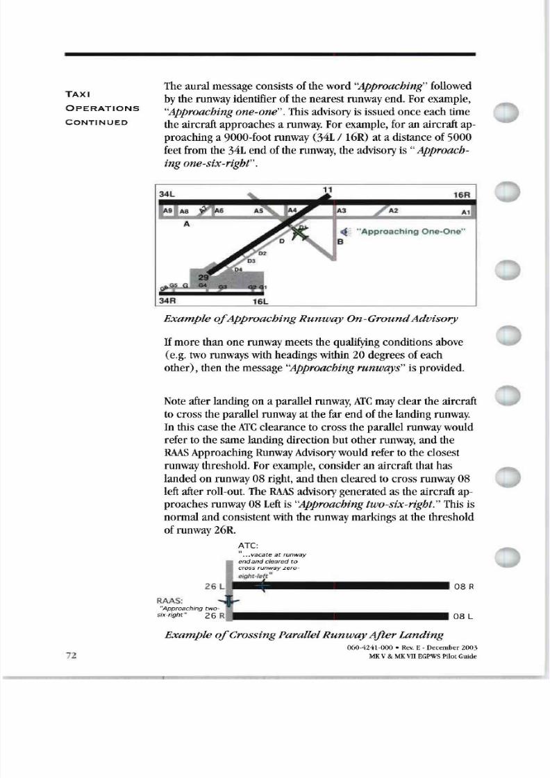
8/13/2019 ENHANCED GROUND PROXIMITY WARNING SYSTEME GPWS REV E
http://slidepdf.com/reader/full/enhanced-ground-proximity-warning-systeme-gpws-rev-e 74/95
T XI
OP R TIONS
ONTINUED
2
The aural message consists oftheword Approaching followed
by the runway identifier ofthenearest runway end. Forexample,
Approaching one one . This advisory is issued once each timetheaircraft approaches a runway. For example, foranaircraft ap-
proaching a 9000-foot runway 34L 16R at a distance of5000
feet from the34L endoftherunway, theadvisory is Approach-
ingone six right .
Example Approaching unway On GroundAdvisory
If more than onerunway meets thequalifying conditions above
e.g. two runways with headings within 20degrees ofeach
other , then themessage Approaching runways isprovided.
Note after landing ona parallel runway, T may clear theaircraft
tocross theparallel runway atthefarendofthelanding runway.
In this case the T clearance to cross theparallel runway would
refer tothesame landing direction butotherrunway, andtheR S Approaching Runway Advisory would refer totheclosest
runway threshold. For example, consider an aircraft that has
landed on runway 08 right, andthen cleared to cross runway 08
left after roll-out. The R S advisory generated astheaircraft ap-
proaches runway 08Left is Approaching two six right. This is
normal andconsistent with the runway markings atthe threshold
ofrunway 26R.
ATe:
... vacate at runway
end and cleared to
8 R
RAAS:
Approaching twosix right 26 R
L 8 L
Example Crossing Parallel unway fterLanding060 4241 000 • Rev. E December 2003
M V V EGPWS Pilot Guide
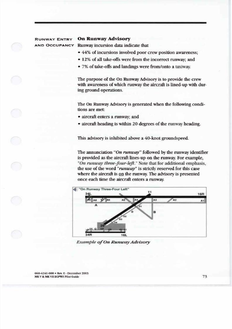
8/13/2019 ENHANCED GROUND PROXIMITY WARNING SYSTEME GPWS REV E
http://slidepdf.com/reader/full/enhanced-ground-proximity-warning-systeme-gpws-rev-e 75/95
RUNW Y ENTRY Runway Advisory
ND O UP N Y Runway incursion t indicate that• 44 ofincursions involved poorcrew position awareness;
• 12 ofalltake offs were from theincorrect runway; and
• 7 oftake offs andlandings were from/onto a t xiw y
The purpose oftheOn Runway Advisory istoprovide thecrew
with awareness ofwhich runway theaircraft is lined up with dur-
ing ground operations.
The On Runway Advisory isgenerated when thefollowing condi-tions aremet:
• aircraft enters a runway; and
• aircraft heading iswithin 20degrees oftherunwayheading.
This advisory is inhibited above a 40-knot groundspeed.
The annunciation On runuay followed bytherunwayidentifier
isprovided astheaircraft lines up ontherunway. For example,
rumo y three four left Note that for additional emphasis,the useofthe word runui y is strictly reserved forthis case
where theaircraft ison the runway. The advisory ispresented
once each time theaircraft enters a runway.
16L4R
- On Runway Three-Four La«
L
Bxample On unw y dvisory
060-4Z41-000• RI:_E- December z003
MKV MKVII EGPWS PilotGuide 73
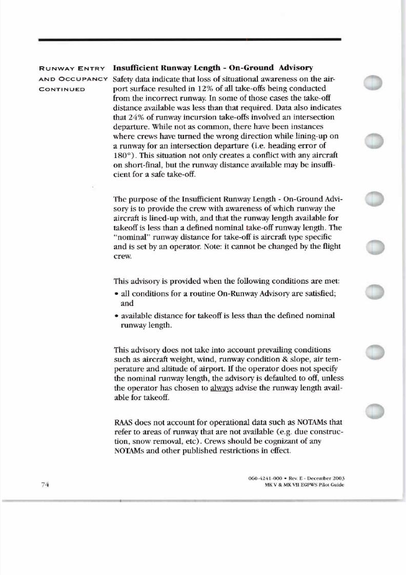
8/13/2019 ENHANCED GROUND PROXIMITY WARNING SYSTEME GPWS REV E
http://slidepdf.com/reader/full/enhanced-ground-proximity-warning-systeme-gpws-rev-e 76/95
R UNW Y N TRY InsufficientRunway Length - On-Ground Advisory
ND O UP N Y
Safety data indicate thatloss ofsituational awareness ontheair- ONTINUED portsurface resulted in 12 ofall take-offs being conducted
from theincorrect runway. In some of those cases the take-off
distance available was less than thatrequired. Data also indicates
that 24 ofrunway incursion take-offs involved an intersection
departure. While notas common, there have been instances
where crews have turned thewrong direction while lining-up on
a runway foran intersection departure i.e,heading error of
180°). This situation notonly creates a conflict with any aircraft
on short-final, butthe runway distance available may be insufficient fora safe take-off.
The purpose oftheInsufficient Runway Length - On-Ground Advi
sory istoprovide thecrew with awareness ofwhich runway the
aircraft is lined-up with, andthatthe runway length available for
takeoff is less than a defined nominal take-offrunway length. The
nominal runway distance for take-off is aircraft type specific
andissetbyanoperator. Note: it cannot be changed by theflightcrew.
This advisory is provided when thefollowing conditions aremet:
• allconditions fora routine On-RunwayAdvisory are satisfied;
and
• available distance for takeoff is less than thedefined nominal
runway length.
This advisory does nottake into account prevailing conditions
such asaircraft weight, wind, runway condition slope, air tem
perature andaltitude ofairport. If theoperator does notspecify
thenominal runway length, theadvisory is defaulted to off, unless
theoperator haschosen to always advise therunway length avail
able for takeoff.
R S does notaccount foroperational data such asNOT s that
refer toareasof runway that arenotavailable (e.g. dueconstruc
tion, snow removal, etc .Crews should be cognizant ofany
NOT s andotherpublished restrictions in effect.
7
060-4241-000 • Rev.E- December 2003
MKV MKVIIEGPWS PilotGuide
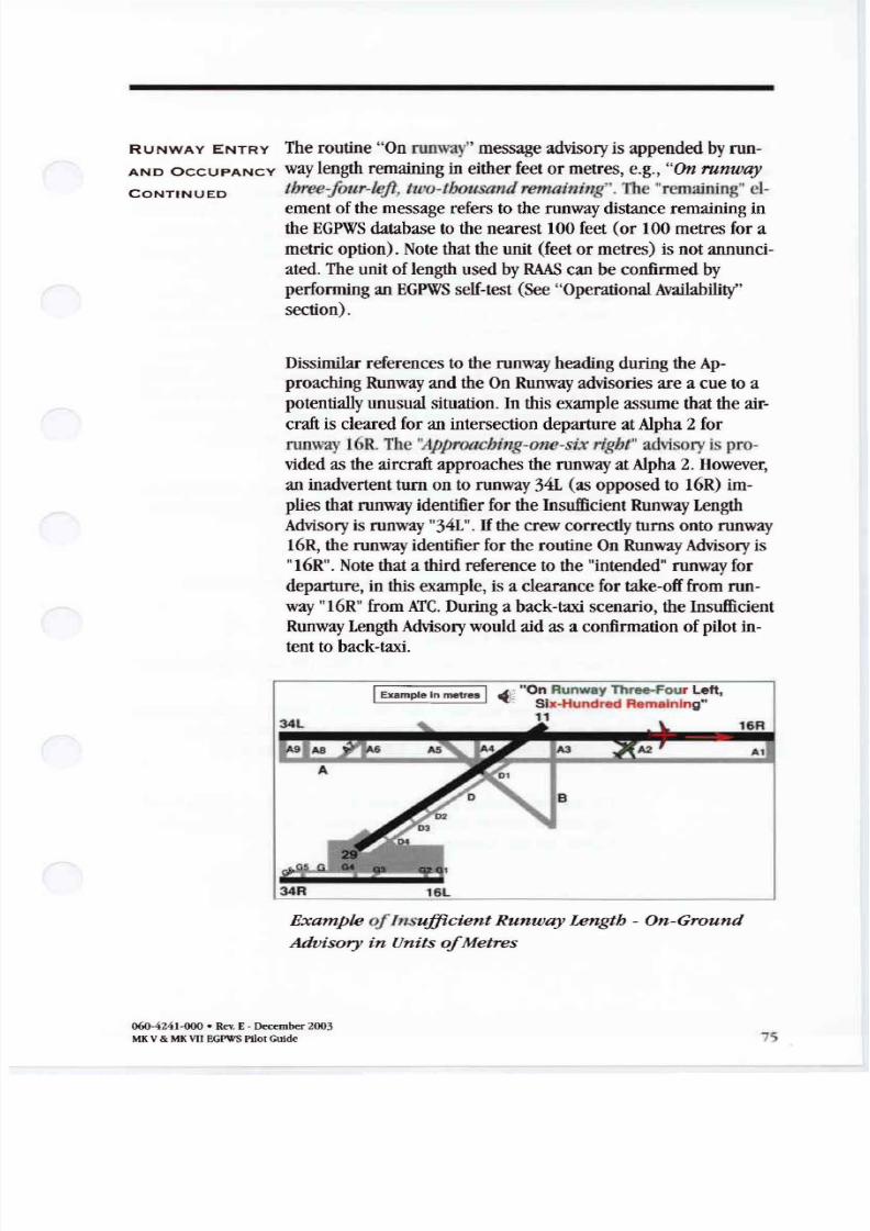
8/13/2019 ENHANCED GROUND PROXIMITY WARNING SYSTEME GPWS REV E
http://slidepdf.com/reader/full/enhanced-ground-proximity-warning-systeme-gpws-rev-e 77/95
RUNW Y ENTRY The routine On runway message advisory is appended by run
ND O UP N Y way length remaining in either feet ormetres, e.g., On runway ONTINUED three-four-left tuo tbousand remaining . The remaining cl
ement ofthemessage refers totherunway distance remaining intheEGPWS database to the nearest 100 feet (or 100 metres for a
metric option). Note that the unit feet or metres) isnotannunci
ated. The unit oflength used by R S canbeconfirmed by
performing an EGPWS self-test See OperationalAvailability
section) .
Dissimilar references totherunway heading during the p-
proaching Runway andtheOn Runway advisories area cuetoa
potentially unusual situation . In this example assume that theair
craft is cleared for an intersection departure atAlpha 2for
runway16R. The Approacbillg one six rigbt advisory ispro
vided astheaircraft approaches the runway atAlpha 2.However,
an inadvertent turn onto runway 34L (asopposed to 16R) im
plies that runway identifier fortheInsufficient Runway Length
Advisory is runway 34L . If thecrew correctly turns onto runway16R, the runway identifier for theroutine On Runway Advisory is
16R . Note that a third reference to the intended runway for
departure, in this example, isa clearance for take-off from run
way 16R from TC During a back-taxi scenario, theInsufficient
Runway Length Advisory would aidasa confirmation ofpilot in
tent toback-taxi.
34R
I Example In metr 1 . ,
On Runway Three-Four Left,o Six.Hundred RemaIning11
16L
Example o I II su cient Runway Length - On round
Advisory in Units o Metres
060-4241-000 • RevE- December2003
MK V MK VIIEGPWS PilotGuide 75
8/13/2019 ENHANCED GROUND PROXIMITY WARNING SYSTEME GPWS REV E
http://slidepdf.com/reader/full/enhanced-ground-proximity-warning-systeme-gpws-rev-e 78/95
RU W Y ENTRY xtended olding On Runway
ND O UP N Y Safety data show that 17 ofrunway incursions involved thepoor ONTINUED
76
useofa line-up-and-wait clearance or ataxi-into-position-and
hold clearance [TIPH] . The typical scenario involved Tower e
clearing an aircraft into position-and-hold ontothedeparture
runway. Factors such asdistractions in theTower, handling mul
tiple frequencies, high workload andmemory lapses have
resulted inthetower controller simultaneously clearing other
traffic tolandontheoccupied runway. In some cases crews is
suedwith theTIPH clearance were holding-in-position foran
unusually extended period. Industry safety recommendations
suggest that flight crews holding-in-position onan active runway
foranunexpected extended period should contact tower to con
firm theextended holding clearance. Timely crew intervention
could potentially reduce theriskofa runway incursion.
The purpose oftheExtended Holding On Runway Advisory isto
provide crew awareness ofan extended holding period onthe
runway.
The aural advisory isgiven ifthefollowing criteria aremet:
• aircraft enters a runway; and
• aircraft remains inposition fora time period considered tobe
an extended holding period.
Your company will select theextended holding period and it can
notbechanged by theflight crew. The time period canbe
configured for60,90, 120, 180,240,or 300seconds.
The aircraft heading must bewithin 20degrees of runway head
ing andtheaircraft must notmove more than 100 t along the
runway for this advisory tobe activated.
6 4241 · Rev.E - December 2003
MKV MKVII EGPWSPilo Guide
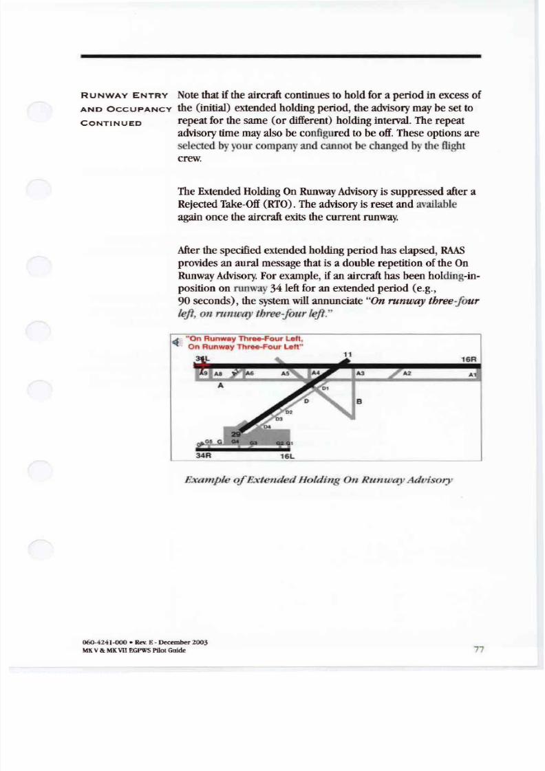
8/13/2019 ENHANCED GROUND PROXIMITY WARNING SYSTEME GPWS REV E
http://slidepdf.com/reader/full/enhanced-ground-proximity-warning-systeme-gpws-rev-e 79/95
RUNW Y ENTRY Note that if the aircraft continues tohold foraperiod in excess of
ND O UP N Y the initial extended holding period , theadvisory may besetto ONTINUED repeat forthesame (ordifferent holding interval. The repeat
advisory time may also becon gured tobeoff.These options are elected byyour company and cannot bechanged by theflight
crew.
The Extended Holding On Runway Advisory is suppressed after aRejected Take-Off RTO . The advisory is reset andavailable
again once the aircraft exits the current runway.
After thespecified extended holding period haselapsed, HAAS
provides anaural message that isa double repetition oftheOn
Runway Advisory. For example, if anaircraft has been holding-inposition on runway34 left for anextended period e.g.,
90 seconds , thesystem will annunciate Onrunw y three four
left runt y three-four left.
. On Runway Three-Four Lelt,On Runway Three-Four lett
l 16R
R 16l
A2 A
Example Extended Holding On untoay Aduisory
060-424J.( 00 Rev.E- December 2003
MK v MKVIIEGPWS PilotGuide 77
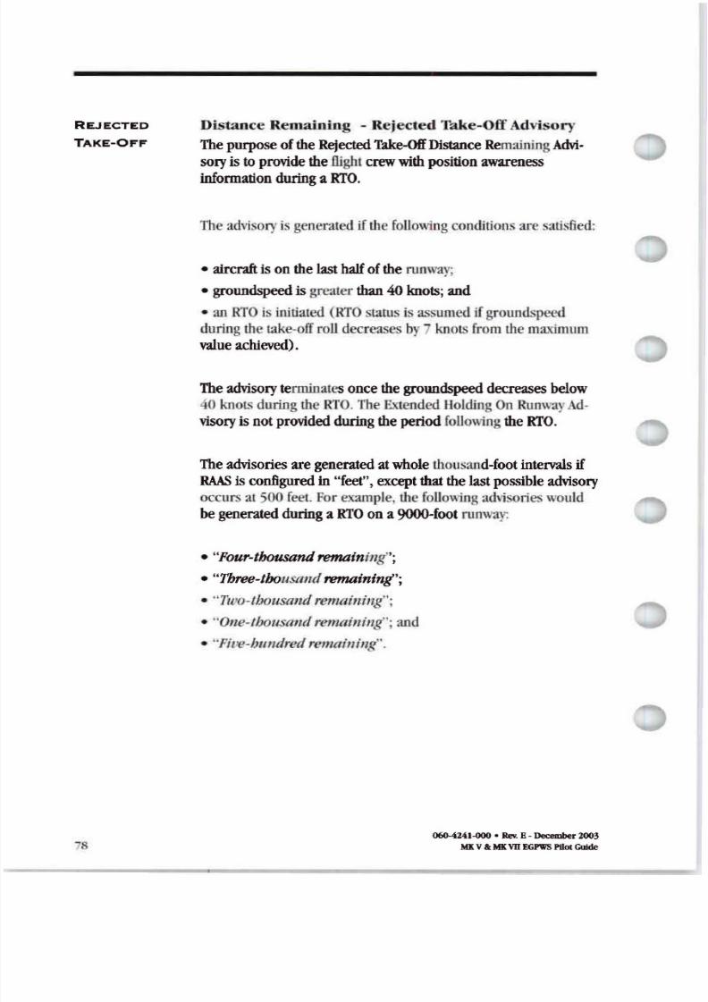
8/13/2019 ENHANCED GROUND PROXIMITY WARNING SYSTEME GPWS REV E
http://slidepdf.com/reader/full/enhanced-ground-proximity-warning-systeme-gpws-rev-e 80/95
REJECTED
T KE OFF
s
Distance Remaining - Rejected Take -Off Advisory
The purpose oftheRejected Take Off Distance Remaining dvisory is toprovide the/light crew with position awareness
infonnation during a RTO .
The advisory isgenera ted ifthe following conditionsaresatis ed:
• aircraft isonthelast half oftherunway;
• groundspeed is greater than 40knots;and
• an na i initiated RTO status isassumed ifground peed
during the lake off roll decreases by knots from the maximum
value achieved .
The advisory terminatesonce thegroundspeed decreases below
40 knots during the RTO .The Extended HoldingOn Runway d
visory is not provided during theperiod following theRTO .
The advisories aregenerated atwhole thousand-foot intervals ifR S is configured in feet , except that thelast possible advisory
occurs at ;00 feel. For example, thefollowing ad\isories would
begenerated during a RTO ona 9000 foot runway
• Four-thousandremainin ;
• Three thousand remaining ;
• Ttco-tbousaud remaining ;
• One-thousand remaining ;and
• Pite-bundred remaining .
060-4241-000• Rev. E-December 2003
MKV II MKV E PWS PIlot ulde
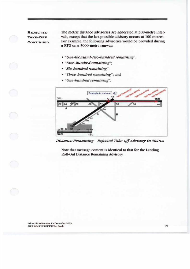
8/13/2019 ENHANCED GROUND PROXIMITY WARNING SYSTEME GPWS REV E
http://slidepdf.com/reader/full/enhanced-ground-proximity-warning-systeme-gpws-rev-e 81/95
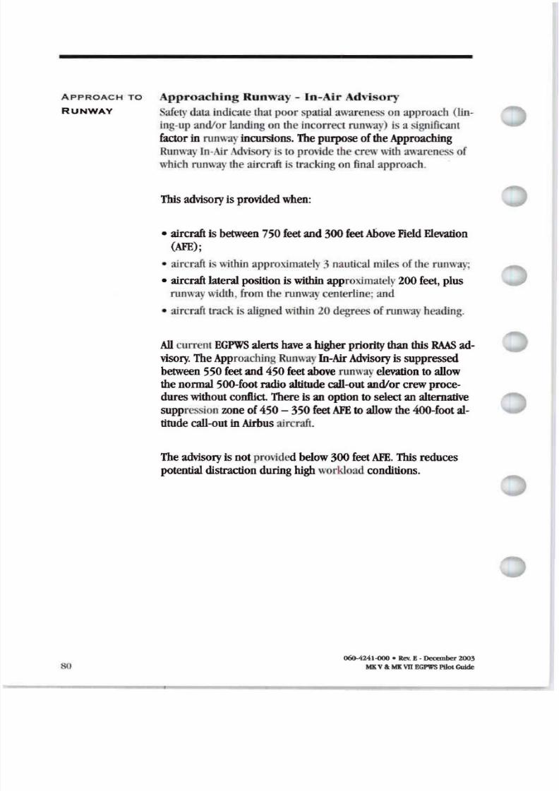
8/13/2019 ENHANCED GROUND PROXIMITY WARNING SYSTEME GPWS REV E
http://slidepdf.com/reader/full/enhanced-ground-proximity-warning-systeme-gpws-rev-e 82/95
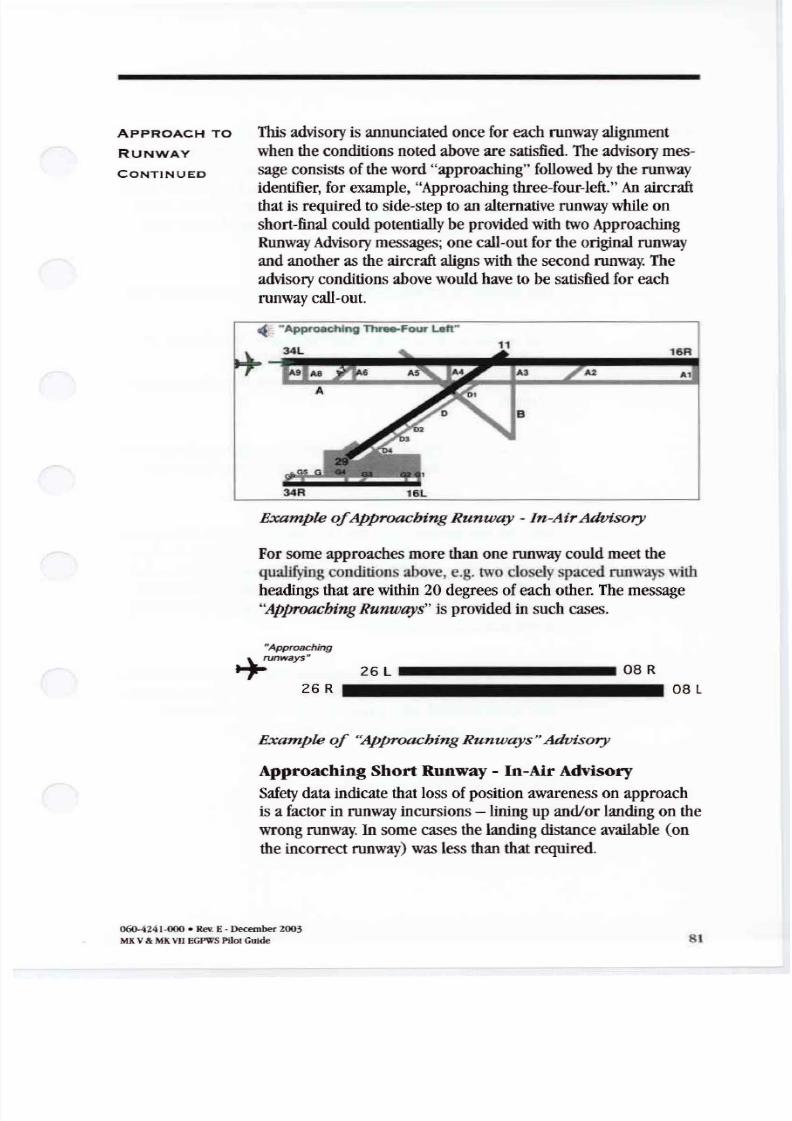
8/13/2019 ENHANCED GROUND PROXIMITY WARNING SYSTEME GPWS REV E
http://slidepdf.com/reader/full/enhanced-ground-proximity-warning-systeme-gpws-rev-e 83/95
pPRO H TO This advisory is annunciated once for each runwayalignment
RUNW Y
when the conditions noted above aresatisfied. The advisory mes- ONTINUE sage consists ofthe word approaching followed bytherunway
identifier for example Approaching three-four-left. An aircraft
that is required toside-step toanalternative runway while on
short-final could potentially beprovided with two Approaching
RunwayAdvisory messages; onecall-out fortheoriginal runway
andanother astheaircraft alignswith thesecond runwa The
advisory conditions above would have tobesatisfied foreach
runway call-out.
- Approaching Three-Four LaI1
Example ApproachingRumoay « In AirAdvisory
For some approaches more than one runwaycould meet the
qualifying condition above, e.g. two closelyspaced runwa with
headings that arewithin 20degrees ofeach other. The message
pproachingRunways isprovided insuch cases.
pproaching
,nways 26 L 08 R
R 8 l
Example Approaching Runways Advisory
ApproachingShort unw y In AirAdvisory
Safety data indicate that loss ofposition awareness onapproachisa factor in runway incursions -lining upand/or landing onthe
wrong runway. In some cases thelanding distance available on
theincorrect runway)was less than that required.
060-4241·000• RevE•December2003
MKV MKVIIEGPWSPilotGuide 81
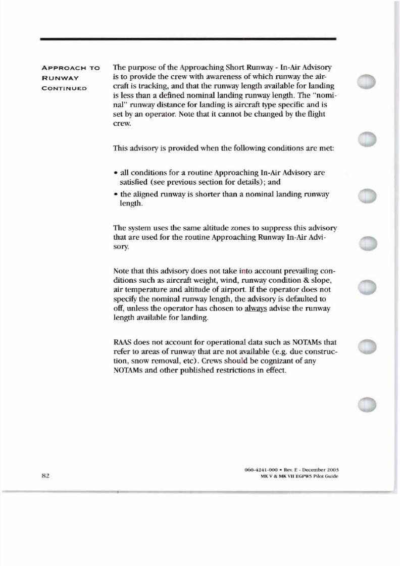
8/13/2019 ENHANCED GROUND PROXIMITY WARNING SYSTEME GPWS REV E
http://slidepdf.com/reader/full/enhanced-ground-proximity-warning-systeme-gpws-rev-e 84/95
pPRO H TO
RUNW Y ONTINUED
The purpose oftheApproachingShort Runway - In-Air Advisory
istoprovide thecrew with awareness ofwhich runway theaircraft is tracking, andthat therunway length available forlanding
is less than a defined nominal landing runway length. The nomi
nal runway distance forlanding is aircraft type specific andis
setby anoperator. Note that itcannot be changed bytheflight
crew.
This advisory isprovided when thefollowing conditions aremet:
• allconditions fora routine Approaching In-Air Advisory are
satisfied seeprevious section fordetails ; and
• thealigned runway is shorter than a nominal landing runway
length.
The system uses thesame altitude zones to suppress this advisory
that are used for theroutine Approaching Runway In-Air dvi-
sory.
Note that this advisory does nottake intoaccount prevailing con
ditions such asaircraft weight,wind, runway condition slope ,
air temperature andaltitude ofairport. Iftheoperator does not
specify thenominal runway length, theadvisory is defaulted to
off, unless theoperator haschosen to always advise the runway
length available for landing .
R S does not account foroperational datasuch asNOT s that
refer toareas ofrunway that are notavailable e.g. dueconstruc
tion , snow removal, etc . Crews should becognizant ofany
NOT s andother published restrictions in effect.
060-4 241-000 • Rev. E - December 2003
MKV MK VIIEGPWS Pilal Guide
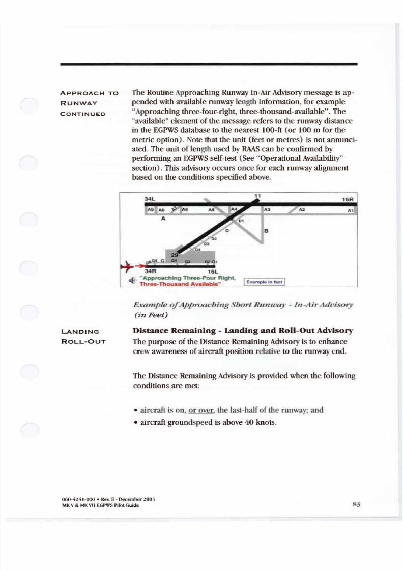
8/13/2019 ENHANCED GROUND PROXIMITY WARNING SYSTEME GPWS REV E
http://slidepdf.com/reader/full/enhanced-ground-proximity-warning-systeme-gpws-rev-e 85/95
pPRO H TO
RUNW Y
ONTINUED
TheRoutineApproachingRunway In-Air Advisory message is ap
pended with available runwaylength information, for example pproachingthree-four-right, three-thousand-available . The
available element ofthemessage refers tothe runway distance
in theEGPWSdatabase to the nearest 100-ft (or 100 mfor themetric option). Note that the unit (feet ormetres) isnot annunci
ated .The unit oflength usedby S can be confirmedby
performing anEGPWSself-test See OperationalAvailability section).This advisory occurs once for each runway alignment
based ontheconditions specifiedabove.
A1
16R
A2
34R 16L
- •Approaching Three-Four Right IEumple 0, 1- T h r e e T h o u s a n d •
L NDING
RO OUT
Example o /Jp roac Jillg Short IllIU { I - In-AirAdoisory
in Peet
Distance Remaining - Landing ndRoll-Out Advisory
Thepurpose oftheDistance Remaining Advisoryistoenhance
crewawareness ofaircraft position relative totherunway end,
TheDistance RemainingAdvisoryisprovided when the following
conditionsaremet:
• aircraft ison or over, the last-halfofthe runway; and
• aircraft groundspeed isabove 40 knots.
060-4241-000 • Rev E- ecember 2003
MKV MKVIIE PWSPilotGuide 83
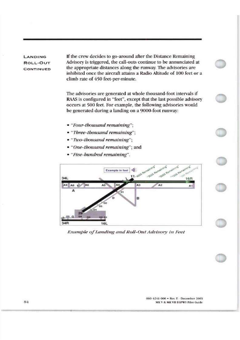
8/13/2019 ENHANCED GROUND PROXIMITY WARNING SYSTEME GPWS REV E
http://slidepdf.com/reader/full/enhanced-ground-proximity-warning-systeme-gpws-rev-e 86/95
L NDING
ROLL OUT
ONTINUE
IH
thecrew decides togo around after theDistance Remaining
Advisory is triggered, thecall outs continue tobeannunciated attheappropriate distances along therunway.The advisories are
inhibited once theaircraft attains a Radio Altitude of 100 feet or a
climb rateof450 feet per minute.
The advisories are generated atwhole thousand foot intervals if
S isconfigured in feet , except that thelast possible advisory
occurs at 500 feet. For example thefollowing advisorieswould
begenerated during a landing ona 9000 foot runway:
• Four-thousand remaining ;
• Three-thousand remaining ;
• Two-thousand remaining ;
• One-thousand remaining ; and
• Five-hundred remaining .
Example Landing n Roll OutAduisory in Feet
060-424H OO · Rev. F. December 2003
MKV MK\11EGPWSPilot Guide
8/13/2019 ENHANCED GROUND PROXIMITY WARNING SYSTEME GPWS REV E
http://slidepdf.com/reader/full/enhanced-ground-proximity-warning-systeme-gpws-rev-e 87/95
L NDING
RO OUT
ONTINUED
Themetric distance advisories aregeneratedat300-metre inter-
vals except that the last possible advisory occurs at 100 metres.For example, the following advisorieswould be generated during
a landing ona 3000-metre runway:
• One thousand two hundred remain ing ;
• Nine hundred remaining ;
• Six hundred remaining ;
• Three hundred remaini
ng ;and• One hundred remaining .
Note that message content is identical to that for theRejected
Take Off Distance Remaining Advisory.
Runway n Advisory
The purpose oftheRunway EndAdvisory istoimprove flightcrewawareness oftheposition ofthe aircraft relative totherun-
way endduring low visibility conditions. Note that theadvisory isnotintendedtoprevent a landing overrun.
The Runway EndAdvisory isprovided tothe flight crew when:
• aircraft isona runway andalignedwithin 20degrees ofrunway heading;
• aircraft approaches within 100 feet or 30metres for themetric option ofthe runway end;and
• aircraft groundspeedisbelow 40knots.
060-4241-000. Rev. E - December 2003
MK V MK EGPWS ilot Guide 85
8/13/2019 ENHANCED GROUND PROXIMITY WARNING SYSTEME GPWS REV E
http://slidepdf.com/reader/full/enhanced-ground-proximity-warning-systeme-gpws-rev-e 88/95
LANDING
ROLL OUT
CONTINUED
he aural message is One-hundred remaining for systems con-
figured in feet and Thirty remaining forametric configuration .
xample unway nd dvisory in feet
S TION
RAAS
OPTIONS
he options listed below areselected by your company andset
upduring the installation ofR S he flight crew cannot
configure them .
R SOptions
86
Con figurable Feature Opllon
Distance Unit 01Measurement Feel or Metres
Voice Gonder Female or Male
GPS Antenna LocatIonCustomer-selecled location based on
aircraftinstallation
Taxiway Takeoff Off or On
Insufficient Runway Length - On Ground Offoronusingcustomer selectednominal
Takeoff) runway length based ona ircrall type,or always on
Extended Holding - On Runway INITIAL: 60 90 120 1 80 2 40 300 Off
REPEAT: 30 60 90 120 180 2 40 300 Off
Dlst. nce Remain ing • Rejected Takeoff Off or On
Approaching Runway In Air OflorOn
Advisory suppression zone 550 - 450 leet AFE or 450 - 350 leet AFE
Approaching Short Runway • In Air Landing)Off
or on using customer selected nominal
runway length based on aircraft type,or always
Distance RemainIng Landing Off or On
Runway End C.Uout Ol for On
060 B4 1-000 • Rev E- Decernber Z j
MKV MK\ll EGP\\S Pilot Guide
8/13/2019 ENHANCED GROUND PROXIMITY WARNING SYSTEME GPWS REV E
http://slidepdf.com/reader/full/enhanced-ground-proximity-warning-systeme-gpws-rev-e 89/95
S TION
UDIO
LEVELS
R S advisoriesareheard over thesame aircraft audio systems
that presentlyprovide EGPWSaudio caution andwarning alertsinthe flight deck Thevolume ofR S advisories is controlled bythe EGPWS- the R S message volume level is basedontheex-
pected flight operation foreachadvisory. R S employs three
relative audio volume levels:
udio evels
Aud io Leve l Advis y
High The Taxiway Take-Off Advisory Is Issued at the EGPWS caution andwaminq alert volume level plus 3 dB.
Medium Distance Remaining Advisories are issued at the same volume level asEGPWS cautions and waminos.
Low All other in-air and on-ground advisories excludes Distance Remainingand Taxiway Takeoff Advisories) are issued at the same volume level asIhe EGPWS cautions and wamin os volume level minus 6 dB.
S TION
OPER T ION L
AV IL A ILI TY
R S isoperationallyavailable anytime the EGPWSispowered
andthe following conditions aremet:
• The software for theR S functions have been loadedand
enabled into anEGPWSby your company with software
version 218 218 or later anda minimum ofTerrain Data
base 435 ;
• The aircraft is onor approaching anairport intheR S
runwaydatabase ; and
• R S is functional e.g. allexternal signals are available and
notfaulted, PS position accuracy meets minimum R Srequirements, there areno internal EGPWSfaults .
060-4241-000 • Rev E- December2003
MKV MKVIIEGPWSPilotGuide 87
8/13/2019 ENHANCED GROUND PROXIMITY WARNING SYSTEME GPWS REV E
http://slidepdf.com/reader/full/enhanced-ground-proximity-warning-systeme-gpws-rev-e 90/95
OPER TION L
V IL ILITY
ONTINUE
R S operational availability is integrated into theexisting GPWS
fault monitoringandself-test functions. onsistent with approved GPWS self-test design thelossofR S functions is indicated
on ground onlyduringanEGPWSself-test. There is noautomatic
annunciation ofthe lossofR S functionality. The audio self-test
messages areas follows.
R S Self Test u o Messages
udio Message ond illons
AwarenessOKFeel RAAS software enabed functioning hasgood postioninformation and is at a validated airport. Fee willbe annunciatedinthegendervoiceoption (male or female)selectedfor RAAS,
Runway warenessOKMetres R S softwareenabled functioning hasgoodposition information and isat a validatedairport Metres w beannunciatedinthegender voiceoption (maleor female seiected for RAAS,
RunwayAwarenessNot vailableRAASsoftwareenabled but the system eitherhas nopositioninformation the accuracyoftheposition information is insufficienttoallowRAAS to function or theaircraftis at an airport thathas notbeenvalidated for RAASintheEGPWS TerrainDatabase
RunwayAwareness RAASsoftwareenabled butthe advisorieshavebeenmhibitedwiththeactivation ofanexternaldiscrete
Runway Awareness R T O RAASsoftwareenabledand functioning, but RAAS hasdetecteda RejecledTake-Offcondrtion. To dear Ihis message, theaecratmust be taxied he runwayarea
Runway w reness NOp· RAASsoftware enabledbut function is inoperative
88060-4241-000 RC\. Decembe 200.\
MKV MK\11EGPWSPilotGuide
8/13/2019 ENHANCED GROUND PROXIMITY WARNING SYSTEME GPWS REV E
http://slidepdf.com/reader/full/enhanced-ground-proximity-warning-systeme-gpws-rev-e 91/95
OPERATIONAL R S status can also bedisplayed ontheTerrain Display. This is
AVAILABILITY active onlywhen the aircraft ison the ground .The procedure re-CONTINUED quires the flight crew toselect the terrain display followed bya
change in the displayed range toa higher or lower range . R S
status is annunciated for two sweeps ofthe Terrain Display. This
feature isavailable onallaircraft but is primarilyintended for
those aircraft where the flight crew does notperform anEGPWS
self-test. The displayed status messages areas follows.
R S Self Test ispl y Messages
Audio Message Conditions
RAAS-OK ·FT green) RAAS software enabled. functioning, has good position information,and is at a validated airport Distances annunciated in teet.
RAAS-OK ·m g reen) RAAS software enabled, functioning, hasgood position information,and is at a validated airport Distances annunciated in metres
RAAS-K AVSl amber) RAASsoftwareenabled, but the system either has no positioninformation, the accuracy of the position information is insufficientto allow RAASto function, or the aircraft is at an airport thai has notbeen validated for RAAS in the EGPWS Terrain Database.
RAAS-INH lam , RAAS software enabled, but the advisories have been inhibitedwith lhe activation of an external discrete
RAA5-RTO green) RAAS software enabled and functioning, but RAAS has detected
a Rejected Take-Off condition To clear this message,the aircraft
must be taxiedoff the runway area
RAAS-INOP ,be<) RM S software enabled but function is inoperative.
S TION FREQUENTLY
ASKED
QUESTIONS
Q. How doI know that theR S is enabled?
Perform anEGPWS self-test or select theTerrain Display fol
lowed by a change inthedisplayed range toa higher or lower
range . R S status isannunciated for two sweeps ofthe Terrain
Di splay. These functions available onlywhen aircraft ison the
ground.
Q. How can theflight crew determine which R S database is
currentlyloaded intheEGPWS computer ?
The R S status message ontheTerrain Display during the
EGPWS self-test see last question also displays theversion of
the currently installed database.
060-4241-000 • Rev.E-December 2003
V MKVIIEGPWSPilotGuide 89
8/13/2019 ENHANCED GROUND PROXIMITY WARNING SYSTEME GPWS REV E
http://slidepdf.com/reader/full/enhanced-ground-proximity-warning-systeme-gpws-rev-e 92/95
FREQUENTLY
SKED
QUESTIONS
ONTINUED
90
Q. How cantheIlight crewdetermine if RAAS will workatthe
destination airportupon arrival?A RAAS status canbe displayed ontheTerrain Display only when
theaircraft isontheground . The crewshould checkin advance
ifthe destination airportis included intheRAAS database -see
answer tothenextquestion. Once ontheground atthedestina
tion airport, RAAS status canbe displayed ontheTerrain Display.
Q.How canthe Ilight crewdetermine what airports are enabled
for RAAS
A Details ofthe specific airports included intheRAAS database
andprocedures for operators to acquire the latest RAAS database
are provided ontheInternet atwww.egpws.com . Atelephone
number forvoice contact is included aswell.
Q.Who do I contact forhelp with a RAAS database issue suchas
adding anairportto theRAAS database , or a problem encoun
teredin theoperation ofRAAS at a particular airport?
A online form forRAAS discrepancies is provided onthe
Internet atwww.egpws .com. Atelephone number forvoice con
tact is included aswell.
877-436-2005 In U.S.
602-436-2005 Outside U S .
Q.How doI know what units are being usedfortheRAAS distance related advisories?
A. This information is provided during the EGPWS self-test audio
message or on theRAAS status message onthe terrain display
Q.How does RAAS account for temporary runway closures?
A RAAS doesnotinclude knowledge ofprevailing Notice toAir-
men NOTAM and therefore factors suchas closure of runways
isnot reflected byadvisories .Crews are assumed tobe cognizant
ofprevailing NOTAM andAutomatic Terminal Information Service
ATIS data. Similarly, dataon newlyconstructed runways or
changes to length ofexisting runways maynotnecessarily bein
cluded inthe RAAS runwaydatabase.
060-424 1-000 R ev. E - December 200,\
MK V MK VII EGPWSPilot Guide
8/13/2019 ENHANCED GROUND PROXIMITY WARNING SYSTEME GPWS REV E
http://slidepdf.com/reader/full/enhanced-ground-proximity-warning-systeme-gpws-rev-e 93/95
FREQUENTLY
SKED
QUESTIONS
CONTINUED
Q.Whydoes RAAS provide anOn Taxiwayadvisoryon some run-
waysA The runway isnotyet in the RAAS database Crews arealways
required touse conventional means toascertain andconfirm po-
sition of runways
Q.Whydoesn t RAAS always provide anapproaching runwayad
visory when I am at the hold short line?
A The Advisory isalways provided ata fix distance from the
runwayedge atgroundspeeds below 10knots andinsome cases
thehold-short lines arenotpainted atpositions that correspond
to lCAO standards . RAAS does nothave knowledge ofground
markings
REVI TIONS AFE
ATC
EGPWS
GPWS
NOTAM
RAAS
RTO
TIPH
060-4241-000· Rev E- December 2003
MKV MKVIIEGPWS Pilot Guide
Above Field Elevation [ftl
Air Traffic Control
Enhanced Ground Proximity Warning System
Ground Proximity Warning System
Notice toAirmen
RunwayAwareness andAdvisory System
Rejected Take Off
Taxi Into Position and Hold
l
8/13/2019 ENHANCED GROUND PROXIMITY WARNING SYSTEME GPWS REV E
http://slidepdf.com/reader/full/enhanced-ground-proximity-warning-systeme-gpws-rev-e 94/95
..J
..JIII
IIIZo
ll:
CZIIIIII
CZ0
x
IIIC
IIIIII0III..JD.
Dear Honeywell EGPWS Customer:
This form is a request for information that will allow Honeywell to notify you
of future updates to your Enhanced Ground Proximity Warn ing Sys tem. Please
complete the information below and fax the information sheet to Honeywell
at 4 5 885 87 or return via U.S.mail to:
Honeywell International Inc.
Attn: Sandra Slick
Technical Publications
p Box 97001Redmond W 98073-9701
CUSTOMER INFORM TION
Customer Contact: _
Company Name:
ShippingAddress: _
Phone Number: _
FaxNumber: _
E-mail Address: _
IRCR FT INFORM TION
Aircraft Model
EGPWSPart Number EGPWS Serial _
Aircraft Model
EGPWSPart Number EGPWS serial _
Aircraft Model
EGPWS Part Number EGPWS serial _
92
060-4241-000• Rev E- December2003
MKv MKVII PWSPllot uide
8/13/2019 ENHANCED GROUND PROXIMITY WARNING SYSTEME GPWS REV E
http://slidepdf.com/reader/full/enhanced-ground-proximity-warning-systeme-gpws-rev-e 95/95
Honeywell International Inc Honeywell International Inc