Embed Size (px)
Citation preview
EAGLE WORKBOOK MIL-STD-1388-2B
VERSION 15
14 February 2017
A Product of Raytheon Company 2017 Raytheon Company
ALL RIGHTS RESERVED U.S. Patents 4,847,795; 5,457,792; 5,493,679;
5,737,532; 7,930,052; 8,560,105
Made in the U.S.A
Enhanced
Automated
Graphical
Logistics
Environment

COPYRIGHT 2017 RAYTHEON COMPANY
UNPUBLISHED WORK - ALL RIGHTS RESERVED.
This document does not contain technology or Technical Data controlled under
either the U.S. International Traffic in Arms Regulations or the U.S. Export
Administration Regulations.
This document shall not be published, or disclosed to others, or duplicated in
whole or in part without written permission of Raytheon Company.
All other company and product names used herein may be the trademarks or
registered trademarks of their respective companies.
Information in this manual may change without notice and does not represent a
commitment on the part of Raytheon Company and its subsidiaries.
Excerpts from Logistics Product Data (ANSI/GEIA-STD-0007), Copyright ©
(2007), Government Electronics and Information Technology Association. All
Rights Reserved. Reprinted by Permission.
Revision History
Printed April 1997 First Edition
Printed February 2013 Eleventh Edition
Printed February 2014 Twelfth Edition
Printed February 2015 Thirteenth Edition
Printed February 2016 Fourteenth Edition
Printed February 2017 Fifteenth Edition
Printed February 2017
The EAGLE Software Package has become the best of its
kind thanks, in large part, to its clients. We would like to
take this opportunity to thank all of you for your
suggestions, insights and support. In addition, we want to
renew our commitment to you, our valued clients.

EAGLE Workbook 1388-2B Version 15
TABLE OF
CONTENTS


EAGLE WORKBOOK 1388-2B TABLE OF CONTENTS
v
TABLE OF CONTENTS
SECTION 1 THE EAGLE INTERFACE ................................................................... 1-3
1.0 INTRODUCTION ............................................................................................................... 1-3 1.1 CONVENTIONS USED IN DOCUMENTATION ............................................................. 1-3
1.1.1 General Conventions .................................................................................................... 1-3 1.1.2 Mouse Conventions ...................................................................................................... 1-4 1.1.3 Keyboard Conventions ................................................................................................. 1-4 1.1.4 Window Conventions ................................................................................................... 1-4 1.1.5 End Items and Student Ids ............................................................................................ 1-5
1.2 ADMINISTRATION ........................................................................................................... 1-5 1.2.1 Administrative User Ids and Passwords ....................................................................... 1-5
1.3 STANDARDS AND EAGLE LSAR DATA BASE CONFIGURATIONS ......................... 1-6 1.3.1 MIL-STD-1388 2B ....................................................................................................... 1-6
1.3.1.1 System Default Settings 2B ................................................................................... 1-6 1.3.1.2 End Item Default Settings 2B ................................................................................ 1-7
1.4 LOGGING IN TO EAGLE .................................................................................................. 1-7 1.5 THE NAVIGATOR ............................................................................................................. 1-8
1.5.1 Using Navigator Functions ......................................................................................... 1-10 1.5.2 Home Tab Functions .................................................................................................. 1-10
1.5.2.1Home Tab Filter ................................................................................................... 1-10 1.5.2.2 Basic Finder ......................................................................................................... 1-12
1.5.3 Favorites Tab Functions ............................................................................................. 1-14 1.5.4 Recent Tab Function................................................................................................... 1-16 1.5.5 Classic Navigator ....................................................................................................... 1-16
1.6 EAGLE MAIN SCREEN HEADER .................................................................................. 1-18 1.7 THE MENU BAR .............................................................................................................. 1-18 1.8 THE MAIN TOOLBAR .................................................................................................... 1-19
1.8.1 EAGLE Help .............................................................................................................. 1-19 1.8.2 Item Help .................................................................................................................... 1-20 1.8.3 DB Help ...................................................................................................................... 1-20 1.8.4 Graphical Functions ................................................................................................... 1-20
1.9 REPORTS/PROCESS MENU AND FUNCTION SPECIFIC TOOLBAR ....................... 1-20 1.9.1 Using the Reports Process Menu or Function Specific Toolbar ................................. 1-21
1.10 SELECTING END ITEM ................................................................................................ 1-22 1.11 DISCIPLINE OUTPUTS ................................................................................................. 1-23
SECTION 2 ENTERING CROSS FUNCTIONAL DATA ...................................... 2–3
2.0 INTRODUCTION ............................................................................................................... 2–3 2.1 ESTABLISHING AN END ITEM ACRONYM CODE ...................................................... 2–3 2.2 ASSIGNING LCNS ............................................................................................................. 2–6

EAGLE WORKBOOK 1388-2B TABLE OF CONTENTS
vi
2.3 ASSIGNING A PCCN AND UOC TO SYSTEM / END ITEM LEVEL LCN (PART
USAGE) .................................................................................................................................. 2–12 2.4 MAPPING LCNS TO SYSTEM/END ITEM UOCS ........................................................ 2–15 2.5 ASSIGNING SERIAL NUMBER UOCS TO SYSTEM/END ITEM LCNS ..................... 2–17 2.6 ASSIGNING SYSTEM/END ITEM SERIAL NUMBER UOCS TO LCNS..................... 2–19 2.7 ADDING CAGE CODES .................................................................................................. 2–21 2.8 ADDING REFERENCE NUMBER INFORMATION ..................................................... 2–23 2.9 APPLYING REFERENCE NUMBERS TO AN LCN (PART APPLICATION) .............. 2–25 2.10 MAPPING PART APPLICATIONS TO SYSTEM/END ITEM UOCS\ ........................ 2–27 2.11 ESTABLISHING TECHNICAL MANUAL CODES ..................................................... 2–31
SECTION 3 ENTERING OPERATIONS AND MAINTENANCE
REQUIREMENTS DATA .................................................................... 3–3
3.0 INTRODUCTION ............................................................................................................... 3–3 3.1 ADDING OPERATIONS AND MAINTENANCE DATA ................................................. 3–3
SECTION 4 ENTERING RELIABILITY, AVAILABILITY AND
MAINTAINABILITY DATA ............................................................... 4–3
4.0 INTRODUCTION ............................................................................................................... 4–3 4.1 ADDING RELIABILITY AND MAINTAINABILITY DATA .......................................... 4–3 4.2 ADDING RAM CHARACTERISTICS DATA ................................................................... 4–4 4.3 ADDING RAM CHARACTERISTICS NARRATIVE ....................................................... 4–6 4.4 ADDING RAM LOGISTICS CONSIDERATIONS NARRATIVE DATA ........................ 4–7 4.5 ADDING RAM INDICATOR CHARACTERISTICS DATA ............................................ 4–8 4.6 ADDING WAR/PEACE RAM INDICATOR CHARACTERISTICS DATA .................. 4–10 4.7 ADDING FAILURE MODE AND RCM ANALYSIS DATA .......................................... 4–11 4.8 ADDING FAILURE MODE AND RELIABILITY CENTERED MAINTENANCE
NARRATIVE .......................................................................................................................... 4–13 4.9 ADDING FAILURE MODE TASK DATA ...................................................................... 4–14 4.10 ADDING MISSION PHASE OPERATIONAL MODE DATA ...................................... 4–16 4.11 ADDING RAM CRITICALITY DATA & FAILURE MODE INDICATOR MISSION
PHASE CODE CHARACTERISTICS DATA ........................................................................ 4–17 4.12 ADDING RAM FAILURE MODE INDICATOR MISSION PHASE CODE
CHARACTERISTICS NARRATIVE DATA ......................................................................... 4–19
SECTION 5 ENTERING TASK ANALYSIS DATA ............................................... 5–3
5.0 INTRODUCTION ............................................................................................................... 5–3 5.1 CREATING TASKS............................................................................................................ 5–3
5.1.1 Adding a New Task ...................................................................................................... 5–5 5.1.1.1 Adding Original Tasks .......................................................................................... 5–5
EAGLE WORKBOOK 1388-2B TABLE OF CONTENTS
vii
5.1.1.1.1 Specifying Facilities Requirements in Task Analysis..................................... 5–9 5.1.1.2 Adding Reference Tasks ...................................................................................... 5–11
5.1.2 Cloning Tasks ............................................................................................................. 5–18 5.1.3 Sorting Task Codes .................................................................................................... 5–29
5.2 ADDING SUBTASKS TO TASKS ................................................................................... 5–31 5.2.1 Adding Original Subtasks ........................................................................................... 5–31 5.2.2 Adding Reference Subtasks ........................................................................................ 5–34 5.2.3 Breaking/Changing Subtask References..................................................................... 5–40
5.3 ADDING NARRATIVE DATA TO SUBTASKS ............................................................. 5–43 5.3.1 Adding Subtask Narrative .......................................................................................... 5–43 5.3.2 Subtask Narrative: Source Data Modified .................................................................. 5–46
5.4 ADDING SUPPORTING DATA FOR TASKS ................................................................ 5–50 5.4.1 Assigning Task Support Equipment ........................................................................... 5–51 5.4.2 Assigning Task Provisioned Items ............................................................................. 5–55 5.4.3 Assigning Subtask Personnel Requirements .............................................................. 5–58 5.4.4 Assigning Subtask Workload Requirements .............................................................. 5–60
5.5 ASSIGNING TASK NARRATIVE TO A TECH MANUAL ............................................ 5–62
SECTION 6 ENTERING FACILITIES CONSIDERATIONS DATA ................... 6–3
6.0 INTRODUCTION ............................................................................................................... 6–3 6.1 ADDING FACILITIES DATA ............................................................................................ 6–3
6.1.1 Adding New Facility Data ............................................................................................ 6–4 6.1.2 Linking Facilities Data to Task Requirements ............................................................. 6–6
SECTION 7 ENTERING PERSONNEL SKILL CONSIDERATIONS DATA .... 7–3
7.0 INTRODUCTION ............................................................................................................... 7–3 7.1 ADDING NEW SKILLS DATA ......................................................................................... 7–3 7.2 ASSIGNING PERSONNEL PHYSICAL & MENTAL REQUIREMENTS TO A TASK .. 7–6
SECTION 8 ENTERING TRANSPORTABILITY ENGINEERING ANALYSIS
DATA ...................................................................................................... 8–3
8.0 INTRODUCTION ............................................................................................................... 8–3 8.1 ADDING TRANSPORTATION DATA ............................................................................. 8–3
8.1.1 Adding Transportation Shipping Mode Data ............................................................... 8–5 8.1.2 Adding Transported End Item Data .............................................................................. 8–6 8.1.3 Adding Transported End Item Narrative ...................................................................... 8–7 8.1.4 Adding Transport by Fiscal Year Data ......................................................................... 8–9 8.1.5 Adding Transportation Narrative................................................................................ 8–10

EAGLE WORKBOOK 1388-2B TABLE OF CONTENTS
viii
SECTION 9 ENTERING SUPPORT EQUIPMENT AND TRAINING MATERIAL
REQUIREMENTS DATA .................................................................... 9–3
9.0 INTRODUCTION ............................................................................................................... 9–3 9.1 ADDING SUPPORT EQUIPMENT AND UNIT UNDER TEST INFORMATION .......... 9–3 9.2 ADDING SUPPORT EQUIPMENT ................................................................................... 9–4
9.2.1 Assigning SERD Numbers ........................................................................................... 9–6 9.2.2 Adding Support Equipment Data ................................................................................. 9–7
9.2.2.1 Support Equipment Data – Adding Narrative........................................................ 9–8 9.2.2.2 Support Equipment Data – Adding Administrative Data ...................................... 9–9
9.2.3 Running a SERD Report ............................................................................................ 9–10 9.3 SUPPORT EQUIPMENT AND UUT DATA .................................................................... 9–15
SECTION 10 ENTERING PACKAGING AND PROVISIONING
REQUIREMENTS DATA .................................................................. 10–3
10.0 INTRODUCTION ........................................................................................................... 10–3 10.1 ADDING REFERENCE NUMBER INFORMATION ................................................... 10–3
10.1.1 Adding CAGE Codes (XH) ...................................................................................... 10–4 10.1.2 Adding Reference Number Information (HA Records)............................................ 10–6 10.1.3 Adding Additional Reference Number Information (HB Records) .......................... 10–8
10.2 ADDING PART APPLICATIONS (HG RECORDS) ................................................... 10–10 10.3 MAINTAINING ADDITIONAL PROVISIONING DATA ELEMENTS USING THE
VIEW/EDIT PROVISIONING DATA WINDOW ............................................................... 10–14 10.3.1 Adding a PLISN to a Reference Number ............................................................... 10–16 10.3.2 Entering Provisioning Remarks .............................................................................. 10–17 10.3.3 Adding Provisioning UOC Data ............................................................................. 10–18 10.3.4 Adding Item Packaging Requirement Data ............................................................ 10–19 10.3.5 Adding Design Change Information ....................................................................... 10–21
10.4 MAPPING MULTIPLE PART APPLICATIONS TO A SYSTEM/END ITEM UOC .. 10–22 10.4.1 Mapping Multiple Part Applications to a UOC-PCCN Combination..................... 10–23
SECTION 11 AD HOC REPORTING..................................................................... 11–3
11.0 INTRODUCTION ........................................................................................................... 11–3 11.1 SQL TRANSACTION STATEMENTS .......................................................................... 11–3
11.1.1 New Query ............................................................................................................... 11–3 11.1.1.1Query Table Selection ........................................................................................ 11–4 11.1.1.2 Query Column Selection ................................................................................... 11–7 11.1.1.3 Generating the AdHoc Report ........................................................................... 11–8 11.1.1.4 Establishing Selection Criteria .......................................................................... 11–9 11.1.1.5 Multiple Tables in ADHOC Queries – Joining Tables .................................... 11–10 11.1.1.6 Where Criteria ................................................................................................. 11–18

EAGLE WORKBOOK 1388-2B TABLE OF CONTENTS
ix
11.1.1.7 Sort Criteria ..................................................................................................... 11–19 11.1.2 Adding Comments to Queries ................................................................................ 11–20 11.1.3 Saving Report Information ..................................................................................... 11–21
11.1.3.1 Saving Query Scripts ....................................................................................... 11–22 11.1.3.2 Saving Report Output ...................................................................................... 11–23
11.1.4 Recall Query ........................................................................................................... 11–24 11.1.4.1 Recalling Queries from the Database .............................................................. 11–24
11.1.5 Updating the Database with Query Results ............................................................ 11–28 11.1.5.1 Updating the Database (Query Results window) ............................................. 11–29 11.1.5.2 Updating the Database (Multi-Cell Cut, Copy, Paste Window) ...................... 11–32
11.1.6 Key Field Updates and Parent Table Deletes ......................................................... 11–37 11.1.7 Loading External Data ............................................................................................ 11–39
SECTION 12 INTERPRETING ERROR MESSAGES IN EAGLE .................... 12–3
12.0 INTRODUCTION ........................................................................................................... 12–3 12.1 ERROR MESSAGES IN EAGLE ................................................................................... 12–3
12.1.1 Security Violations ................................................................................................... 12–3 12.1.2 Unique Constraint Violation ..................................................................................... 12–5 12.1.3 Integrity Constraint – Parent Key Not Found ........................................................... 12–6 12.1.4 Integrity Constraint – Child Record Found .............................................................. 12–7 12.1.5 Cross Edit Violations ................................................................................................ 12–8 12.1.6 Rule Bound to a Column Violations ......................................................................... 12–9
APPENDIX A ASSIGN LCNS TO BOM ............................................................... A–3
APPENDIX B MIL-STD-1388-2B LSAR TABLES .............................................. B–3
APPENDIX C TABLE/DATA DEPENDENCIES ................................................ C–3
APPENDIX D STRUCTURED QUERY LANGUAGE ........................................ D-3
D.0 INTRODUCTION ............................................................................................................ D-3 D.1 CONVENTIONS USED IN THIS APPENDIX ................................................................ D-3 D.2 SQL AND RELATIONAL DATABASE MANAGEMENT ............................................ D-3
D.2.1 Tables, Columns, and Rows ...................................................................................... D-4 D.2.2 Data Elements ............................................................................................................ D-4
D.2.2.1 Key Fields ..................................................................................................... D-4 D.2.2.2 Data Types .................................................................................................... D-4
D.3 QUERYING DATABASES ............................................................................................. D-5 D.3.1 SELECT Syntax ........................................................................................................ D-5
D.3.1.1 Selecting All Columns From A Table .......................................................... D-5

EAGLE WORKBOOK 1388-2B TABLE OF CONTENTS
x
D.3.1.2 Eliminating Duplicates When Selecting ....................................................... D-6 D.3.1.3 Counting Rows ............................................................................................. D-6
D.3.2 WHERE Clause ......................................................................................................... D-6 D.3.2.1 Like and Wildcards ....................................................................................... D-7 D.3.2.2 Comparison Operators .................................................................................. D-8 D.3.2.3 Logical Operators ......................................................................................... D-8 D.3.2.4 Unknown Values: IS NULL and IS NOT NULL ......................................... D-9 D.3.2.5 Character Strings and Quotation Marks........................................................ D-9
D.3.3 Joining Two or More Tables.................................................................................... D-10 D.3.3.1 Inner Joins .................................................................................................. D-10 D.3.3.2 Outer Joins .................................................................................................. D-10
STUDENT NOTES ........................................................................................................... 3

EAGLE Workbook 1388-2B Version 15
LIST OF
ILLUSTRATIONS


EAGLE WORKBOOK 1388-2B LIST OF ILLUSTRATIONS
xv
LIST OF ILLUSTRATIONS
FIGURE PAGE Figure 1. System Defaults – MIL-STD-1388-2B ......................................................................... 1-6 Figure 2. End Item Defaults – Notice 1 ........................................................................................ 1-7 Figure 3. EAGLE Login Screen ................................................................................................... 1-8 Figure 4. The Navigator – Default Header Shown ....................................................................... 1-9 Figure 5. AdHoc Discipline – Visual Query Builder Function Selected .................................... 1-10 Figure 6. Navigator Home Tab – Filter Applied ........................................................................ 1-11 Figure 7. Navigator Home Tab – Clear Filter ............................................................................ 1-11 Figure 8. Navigator Home Tab – Provisioning Finder Selected ................................................. 1-12 Figure 9. Provisioning Finder ..................................................................................................... 1-13 Figure 10. Provisioning Finder – Records Returned C% Filter .................................................. 1-14 Figure 11. Favorites Tab – Provisioning Finder Selected .......................................................... 1-15 Figure 12. Manage Favorites – Add Button Selected ................................................................. 1-15 Figure 13. Navigator – Recent Tab Selected .............................................................................. 1-16 Figure 14. Main Toolbar – File Open ......................................................................................... 1-17 Figure 15. Classic Navigator Displayed ..................................................................................... 1-17 Figure 16. Tools>>Options – Behavior Tab ............................................................................... 1-18 Figure 17. Main Screen Header .................................................................................................. 1-18 Figure 18. Menu Bar .................................................................................................................. 1-19 Figure 19. Main Toolbar ............................................................................................................ 1-19 Figure 20. Main Toolbar – Drawing and Artwork Icons Activated ........................................... 1-20 Figure 21. Sample Function Specific Toolbar ............................................................................ 1-21 Figure 22. Main Toolbar – End Item Icon .................................................................................. 1-22 Figure 23. Select an End Item Window ...................................................................................... 1-22 Figure 24. LCN Maintenance – Table XB Query ‘ALC 01’ ...................................................... 1-23 Figure 25. Save Rows As Window ............................................................................................. 1-24 Figure 26. Navigator - End Item (XA) Maintenance ................................................................... 2–3 Figure 27. End Item Data Maintenance – End Item ‘BICYCLEXX’ .......................................... 2–4 Figure 28. Select End Item Window – TRAININGXX Selected ................................................ 2–4 Figure 29. End Item Data Maintenance Window - Adding End Item Acronym Code ................ 2–5 Figure 30. Navigator - LCN (XB) Maintenance .......................................................................... 2–6 Figure 31. LSA Control Number Maintenance window – No records Returned ........................ 2–7 Figure 32. LSA Control Number Maintenance Window – After Insert ...................................... 2–7 Figure 33. LSA Control Number Data Maintenance Window - Adding Top Level LCN ‘A’ .... 2–8 Figure 34. LSA Control Number Data Maintenance Window - Adding System/EI Identifier .... 2–9 Figure 35. Insert Record A01 – B Indenture Level ..................................................................... 2–9 Figure 36. LCN Maintenance – A03 Selected ........................................................................... 2–10 Figure 37. Data – Duplicate Record .......................................................................................... 2–10 Figure 38. LCN ‘A03’ – ALC ‘02’ ........................................................................................... 2–11 Figure 39. XB Records – ALC 02 ............................................................................................. 2–11 Figure 40. Navigator - System/EI (XC) Maintenance ............................................................... 2–13 Figure 41. XC Query – No Records .......................................................................................... 2–13

EAGLE WORKBOOK 1388-2B LIST OF ILLUSTRATIONS
xvi
Figure 42. System/End Item Maintenance window – ALC ‘2’ Selected ................................... 2–14 Figure 43. System/End Item Maintenance window – UOC ‘TR1’ ............................................ 2–14 Figure 44. Navigator - LCN to System/EI (XF) Maintenance .................................................. 2–15 Figure 45. LCN System/End Item Usable On Code Maintenance Window .............................. 2–16 Figure 46. LCN/System End Item UOC Mapped ...................................................................... 2–17 Figure 47. Navigator – System/EI SN (XD) Maintenance ........................................................ 2–18 Figure 48. System/End Item Serial Number Maintenance ........................................................ 2–19 Figure 49. Navigator - LCN to S/N UOC (XE) Maintenance ................................................... 2–20 Figure 50. Assignment of System/End Item Serial Number UOCs to LCNs ............................ 2–21 Figure 51. Navigator - CAGE Code (XH) Maintenance ........................................................... 2–22 Figure 52. CAGE Code Data Maintenance Window - Adding CAGE Code Information ........ 2–23 Figure 53. Navigator - Part (HA) Maintenance ......................................................................... 2–24 Figure 54. Part Number Data Maintenance - Adding Reference Number Information ............. 2–24 Figure 55. Navigator - Part App. (HG) Maintenance ................................................................ 2–25 Figure 56. Part Application Provisioning Data Maintenance – Record Entered ....................... 2–26 Figure 57. Part Application Provisioning Data Maintenance Window – Records Entered ....... 2–26 Figure 58. Part Application Provisioning Data Maintenance-Backfill ...................................... 2–27 Figure 59. Navigator - Prov. System/EI (HO) Maintenance ..................................................... 2–28 Figure 60. Provisioning System/End Item Usable On Code Maintenance Window ................. 2–29 Figure 61. Provisioning System /End Item Usable On Code Maintenance Window - Results . 2–29 Figure 62. LCN ‘A’ ALC ‘02’ Selected .................................................................................... 2–30 Figure 63. Part Application ‘A01’ Mapped to UOC ‘TR1’ ....................................................... 2–31 Figure 64. Navigator – Maintain Tech Manual Code ................................................................ 2–32 Figure 65. Maintain Tech Manual Codes Window ................................................................... 2–32 Figure 66. Maintain Tech Manual Codes .................................................................................. 2–32 Figure 67. Navigator - Operations Maintenance ......................................................................... 3–3 Figure 68. Operations and Maintenance Finder .......................................................................... 3–4 Figure 69. Operations and Maintenance Requirement ................................................................ 3–5 Figure 70. Operations Maintenance – War/Peace Requirements ................................................ 3–6 Figure 71. War and Peace Requirements ..................................................................................... 3–6 Figure 72. Operation and Maintenance Finder – ALC ‘00’ Selected .......................................... 3–7 Figure 73. Reliability Requirement - Annual Operating Requirements ...................................... 3–8 Figure 74. Navigator - Reliability & Maintainability .................................................................. 4–3 Figure 75. Reliability + Maintainability Finder ........................................................................... 4–4 Figure 76. Reliability + Maintainability Finder - RAM Ind. ....................................................... 4–5 Figure 77. Reliability & Maintenance - RAM Characteristics .................................................... 4–6 Figure 78. Reliability & Maintenance - RAM Characteristics Narrative .................................... 4–7 Figure 79. RAM Logistics Considerations Narrative Window ................................................... 4–8 Figure 80. RAM Indicator Characteristics Window .................................................................... 4–9 Figure 81. War/Peace RAM Window – LCN A01AK Selected ................................................ 4–10 Figure 82. Fail Mode (FM) and RCM Analysis Window – F001 Entered ................................ 4–12 Figure 83. RAM Failure Mode + RCM Narrative Window ...................................................... 4–13 Figure 84. Failure Mode Task Window..................................................................................... 4–14 Figure 85. Task Selection Window ........................................................................................... 4–15 Figure 86. Failure Mode Task-Assigned ................................................................................... 4–16 Figure 87. Mission Phase Operational Mode Window .............................................................. 4–17

EAGLE WORKBOOK 1388-2B LIST OF ILLUSTRATIONS
xvii
Figure 88. Failure Mode IMPCC Characteristics ...................................................................... 4–18 Figure 89. RAM FM IMPCC Narrative Window ...................................................................... 4–19 Figure 90. Navigator - Task Analysis Finder .............................................................................. 5–3 Figure 91. Task Analysis Finder – Records Returned ................................................................. 5–4 Figure 92. Task Analysis Finder – LCN ‘A’ ............................................................................... 5–5 Figure 93. Adding a New Task.................................................................................................... 5–6 Figure 94. Create/Modify Task Code .......................................................................................... 5–7 Figure 95. Annual Operating Requirement Finder ...................................................................... 5–8 Figure 96. Task Information Window – Task Code AGCOCAA Created .................................. 5–9 Figure 97. Task Information Window – Facilities Tab ............................................................. 5–10 Figure 98. Task Information Window - No Facilities Requirement Message ........................... 5–11 Figure 99. Task Information - Add Reference Task .................................................................. 5–12 Figure 100. Create/Modify Task Code - Task Code JGCOAAA .............................................. 5–13 Figure 101. Task Information Window – Reference an Existing Task ..................................... 5–14 Figure 102. Reference Task Finder ........................................................................................... 5–14 Figure 103. Reference Task Finder – REPAIR FLAT TIRE Selected ...................................... 5–15 Figure 104. Task Identification – REPAIR FLAT TIRE .......................................................... 5–16 Figure 105. Task Information Window – General Tab Selected ............................................... 5–16 Figure 106. Task Information - Viewing Referenced Task Information ................................... 5–17 Figure 107. ORIGINAL Task Information Displayed .............................................................. 5–18 Figure 108. Task Analysis Finder – Clone Task Button Selected ............................................. 5–19 Figure 109. Clone Tasks Window – Top Portion ...................................................................... 5–20 Figure 110. Clone Tasks Window – Bottom Portion ................................................................ 5–20 Figure 111. Clone Tasks Window – Create a Reference Task Selected .................................... 5–21 Figure 112. Clone Tasks Window – Copy Task ........................................................................ 5–21 Figure 113. Clone Tasks Window – Reference All Subtasks Selected ..................................... 5–21 Figure 114. Clone Tasks Window – Copy Second Task ........................................................... 5–22 Figure 115. Clone Tasks Window – Copy All Subtasks ........................................................... 5–22 Figure 116. Clone Tasks Window – Task Code DACOBAA ................................................... 5–23 Figure 117. Task Cloning Destination LCN Finder .................................................................. 5–24 Figure 118. LSA Control Number Data Maintenance Window – Query .................................. 5–25 Figure 119. LSA Control Number Data Maintenance Window – Adding ALC ‘03’ ................ 5–26 Figure 120. Task Cloning Destination LCN Finder Results ...................................................... 5–27 Figure 121. Clone Tasks Window – Cloning Destination ......................................................... 5–27 Figure 122. Task Cloning Results ............................................................................................. 5–28 Figure 123. Task Analysis Finder – Sorting Tasks.................................................................... 5–29 Figure 124. Task Information Window – Sort Tasks ................................................................ 5–30 Figure 125. Specify Sort Columns Window .............................................................................. 5–30 Figure 126. Task Analysis Finder – ALC ‘01’ .......................................................................... 5–31 Figure 127. Subtask Information Window – No Subtasks Found ............................................. 5–32 Figure 128. Subtask Information window - New Subtask ......................................................... 5–33 Figure 129. Subtask Information Window – Reference Subtask ............................................... 5–35 Figure 130. Reference Subtask Finder ...................................................................................... 5–36 Figure 131. Subtask Information Window – Reference Subtask Created ................................. 5–37 Figure 132. Subtask Information window – Subtask 10 ............................................................ 5–37 Figure 133. Subtask Information - Viewing Reference Subtask Information ............................ 5–38
EAGLE WORKBOOK 1388-2B LIST OF ILLUSTRATIONS
xviii
Figure 134. Subtask Information Window - Original ................................................................ 5–38 Figure 135. Original Subtask Information ................................................................................. 5–39 Figure 136. Subtask Information - Viewing Reference Data .................................................... 5–39 Figure 137. Subtask Information Window – Reference Information Tab ................................. 5–40 Figure 138. Reference Subtask Finder - Changing Subtask References ................................... 5–41 Figure 139. Subtask Information Window – Save Reference Changes ..................................... 5–42 Figure 140. EAGLE: Save Reference Subtask Changes – Dialog Box ..................................... 5–42 Figure 141. EAGLE Delete Subtask Selected! .......................................................................... 5–43 Figure 142. Task Analysis Finder – ALC ‘01’ Selected ........................................................... 5–44 Figure 143. Options Window – Publishing and Reports Tab .................................................... 5–45 Figure 144. Publishing and Reports Tab - Editor ...................................................................... 5–45 Figure 145. Task Analysis Narrative Editor - Subtask 1 – Element Code Checked .................. 5–46 Figure 146. Task Analysis Narrative Editor - Subtask 5 – Element Code Checked .................. 5–47 Figure 147. Source Data Modified – No Subtasks Selected ...................................................... 5–48 Figure 148. Source Data Modified –Subtask Selected .............................................................. 5–48 Figure 149. Source Data Modified – Change Only Selected Subtasks ...................................... 5–49 Figure 150. Source Data Modified – Select None ..................................................................... 5–50 Figure 151. Task Information - Support Equipment ................................................................. 5–52 Figure 152. Task Support Equipment Window – REPAIR STAND ......................................... 5–53 Figure 153. Task Information - Support Equipment Added ...................................................... 5–54 Figure 154. Task Information Task Info. Tab - Misc Tab ......................................................... 5–55 Figure 155. Task Information - Provisioned Items .................................................................... 5–56 Figure 156. Task Provisioned Items .......................................................................................... 5–57 Figure 157. Task Information - Provisioned Items Added ........................................................ 5–58 Figure 158. Subtask Information – Personnel Tab .................................................................... 5–59 Figure 159. Subtask Information Window - Workload Tab – Person ID Codes ....................... 5–60 Figure 160. Subtask Information Window - Workload Tab – Job Duty Codes ......................... 5–61 Figure 161. Subtask Information Window - Workload Tab – Workload Text .......................... 5–62 Figure 162. Task Information - Tech. Manuals ......................................................................... 5–63 Figure 163. Tech Manuals – TM Added ................................................................................... 5–64 Figure 164. Navigator – Facilities Discipline .............................................................................. 6–3 Figure 165. Facilities Finder ....................................................................................................... 6–4 Figure 166. Facilities Finder - Data Entry ................................................................................... 6–5 Figure 167. Facility Window ....................................................................................................... 6–6 Figure 168. Facilities Finder – Test Facility ................................................................................ 6–7 Figure 169. Operations + Maintenance Task Facility Requirements Window ............................ 6–7 Figure 170. Task Selection Window ........................................................................................... 6–8 Figure 171. Navigator - Personnel Skills Discipline ................................................................... 7–3 Figure 172. Personnel Skills Finder – Records Returned ............................................................ 7–4 Figure 173. Personnel Skills Finder - Skill Specialty Code Entered ........................................... 7–4 Figure 174. New or Modified Skill Finder .................................................................................. 7–5 Figure 175. Personnel Skills – Physical/Mental Req Finder (GE) .............................................. 7–6 Figure 176. Physical and Mental Requirements Narrative Finder (GE) ...................................... 7–7 Figure 177. New or Modified Skill Specialty Code Finder ......................................................... 7–8 Figure 178. Physical and Mental Requirements Narrative Finder – 23B Entered ....................... 7–8 Figure 179. Subtask Personnel Requirement Finder ................................................................... 7–9

EAGLE WORKBOOK 1388-2B LIST OF ILLUSTRATIONS
xix
Figure 180. Physical and Mental Requirements Narrative Finder - Data Selected ..................... 7–9 Figure 181. Personnel Skills - Physical and Mental Requirements Narrative Window ............ 7–10 Figure 182. Navigator - Transportation ....................................................................................... 8–3 Figure 183. Transportation Finder – Records Returned .............................................................. 8–4 Figure 184. Transportation Window ........................................................................................... 8–5 Figure 185. Transportation Ship Mode Window ......................................................................... 8–6 Figure 186. Transported End Item Window ................................................................................ 8–7 Figure 187. Transported End Item – Narrative Button ................................................................ 8–8 Figure 188. Transported End Item Narrative ............................................................................... 8–8 Figure 189. Transport by Fiscal Year Window ........................................................................... 8–9 Figure 190. Transportation Narrative Window ......................................................................... 8–10 Figure 191. Navigator - Support Equipment ............................................................................... 9–4 Figure 192. SERD Finder - Query Results .................................................................................. 9–5 Figure 193. Adding Support Equipment ..................................................................................... 9–6 Figure 194. SE Recommendation Data Window ......................................................................... 9–7 Figure 195. SERD Finder – TH-0001 ......................................................................................... 9–8 Figure 196. Support Equipment Data Window - Narrative Tab .................................................. 9–9 Figure 197. Support Equipment Data Window - Admin. Data Tab .......................................... 9–10 Figure 198. LSA-070 SERD - Standard Parameters Tab .......................................................... 9–11 Figure 199. LSA-070 SERD Specific Parameters Tab .............................................................. 9–12 Figure 200. Report Generator Completion Message ................................................................. 9–12 Figure 201. EAGLE: Report Availability Message ................................................................... 9–13 Figure 202. Document Imported ............................................................................................... 9–13 Figure 203. Navigator - Tech Manual>>Document Storage ..................................................... 9–14 Figure 204. Document Storage Finder ...................................................................................... 9–15 Figure 205. Navigator – Provisioning Discipline ...................................................................... 10–3 Figure 206. Provisioning Finder - Records Returned ................................................................ 10–4 Figure 207. New Part Information Window .............................................................................. 10–5 Figure 208. New Part Information Window - CAGE Code Data .............................................. 10–6 Figure 209. New Part Information Window – CAGE Code and Reference Number ................ 10–7 Figure 210. New Part Information Window – Bottom Shown .................................................. 10–7 Figure 211. Provisioning Finder – Record Selected .................................................................. 10–8 Figure 212. View/Edit Provisioning Data Window – Summary Tab Selected .......................... 10–9 Figure 213. View/Edit Provisioning Data Window – Table HB Tab Selected .......................... 10–9 Figure 214. View/Edit Provisioning Data Window – Table HB Data Entered ....................... 10–10 Figure 215. Part Application Information – HG ...................................................................... 10–11 Figure 216. LCN Finder – Records Returned .......................................................................... 10–11 Figure 217. LCN Finder Window – Blank Row Inserted ........................................................ 10–12 Figure 218. LCN Finder – Record Entered ............................................................................. 10–13 Figure 219. Part Application Information - HG (SMR Code) ................................................. 10–14 Figure 220. View/Edit Provisioning Data – Summary Tab ..................................................... 10–15 Figure 221. View/Edit Provisioning Data – PLISN Entered ................................................... 10–16 Figure 222. HG Tab – Repairable Items List Checkbox ......................................................... 10–17 Figure 223. View/Edit Provisioning Data – Adding Provisioning Remarks ........................... 10–18 Figure 224. View/Edit Provisioning Data – Adding Provisioning UOC Data ........................ 10–19 Figure 225. View/Edit Provisioning Data – HF Tab ............................................................... 10–20

EAGLE WORKBOOK 1388-2B LIST OF ILLUSTRATIONS
xx
Figure 226. Select Packaging Data – C Min. protect. Selected ............................................... 10–20 Figure 227. View/Edit Provisioning Data – Unit Pack Cube: Calculated ............................... 10–21 Figure 228. View/Edit Provisioning Data – HP Tab Selected ................................................. 10–22 Figure 229. Provisioning Discipline – UOC (HO) Maintenance Function Selected ............... 10–23 Figure 230. Usable On Code Maintenance Window – A03% Entered .................................... 10–23 Figure 231. Usable On Code Maintenance Window – TR1-H5T80B UOC-PCCN Displayed10–24 Figure 232. Map All Records to UOC-PCCN>> .................................................................... 10–24 Figure 233. EAGLE: UOC Mapping Popup Window ............................................................. 10–25 Figure 234. Usable On Code Maintenance Window – Records Mapped ................................ 10–25 Figure 235. EAGLE: Delete Table XF Records Too? Window .............................................. 10–26 Figure 236. Navigator – AdHoc>>New Query ......................................................................... 11–3 Figure 237. AdHoc New Query Main Screen ........................................................................... 11–4 Figure 238. AdHoc New Query Main Screen - Functional Area Highlighted .......................... 11–5 Figure 239. New Query Window – Table HG ........................................................................... 11–6 Figure 240. New Query Table Selection-Find Table HA .......................................................... 11–6 Figure 241. Table HA – Only Key/Mandatory .......................................................................... 11–7 Figure 242. New Query Table Column Selection ..................................................................... 11–8 Figure 243. AdHoc Report Results - Simple Query .................................................................. 11–9 Figure 244. Function Specific Toolbar – Where and Sort Active ........................................... 11–10 Figure 245. New Query-Adding Table HG ............................................................................. 11–11 Figure 246. Join Criteria – HA Joined to HG .......................................................................... 11–12 Figure 247. New Query-Adding Table HO ............................................................................. 11–13 Figure 248. Join Criteria - HG Joined to HO .......................................................................... 11–14 Figure 249. Adding Table XC ................................................................................................. 11–15 Figure 250. Join Criteria-HO and XC ..................................................................................... 11–16 Figure 251. Join Criteria – LCNTYP Selected ........................................................................ 11–17 Figure 252. New Query Window for Multi-Table Query ........................................................ 11–17 Figure 253. Where Criteria Window ....................................................................................... 11–18 Figure 254. Sort (Order By) Criteria Window......................................................................... 11–19 Figure 255. Sort Criteria - Query Results ................................................................................ 11–20 Figure 256. AdHoc Comments Window ................................................................................. 11–21 Figure 257. Query Location .................................................................................................... 11–22 Figure 258. Query Save Window ............................................................................................ 11–23 Figure 259. Navigator - Recall Query ..................................................................................... 11–24 Figure 260. Recall Query - Query Location Popup ................................................................. 11–25 Figure 261. Query Save Window – Provisioning Selected ..................................................... 11–25 Figure 262. Saved Queries Window – Recalling Saved Queries ............................................ 11–26 Figure 263. Recall Query Window .......................................................................................... 11–27 Figure 264. Recall Query Window – LH3 .............................................................................. 11–27 Figure 265. Query Results Window – 'LH3' Usable on Code ................................................. 11–28 Figure 266. Where Criteria Window – SMRCODHG Selected .............................................. 11–30 Figure 267. New Query Window – SMRCODHG Selected ................................................... 11–30 Figure 268. Editing Data in the Query Results Window ......................................................... 11–31 Figure 269. Where Criteria – REFNUMHA Selected ............................................................. 11–33 Figure 270. Sort (Order By) Criteria Window - REFNUMHA ............................................... 11–34 Figure 271. Query Results - Refnum MC% ............................................................................ 11–34

EAGLE WORKBOOK 1388-2B LIST OF ILLUSTRATIONS
xxi
Figure 272. Query Results for New Query – Alternate Editor ................................................ 11–35 Figure 273. Query Results with Multi-Cell Copy and Paste ................................................... 11–36 Figure 274. Where Criteria Window – A% ............................................................................. 11–38 Figure 275. Query Results for New Query Window – Key Field Changes ............................. 11–39 Figure 276. Query Results – NC% Records ............................................................................ 11–41 Figure 277. EAGLE Error Message - Security Violation .......................................................... 12–4 Figure 278. Security Violation Error Message – Show Details ................................................. 12–4 Figure 279. Unique Constraint Violation – Key Values Exist Details ...................................... 12–5 Figure 280. Integrity Constraint – Parent Key Not Found ........................................................ 12–6 Figure 281. Error Code Help for Integrity Constraint - Child Record Found ........................... 12–7 Figure 282. Cross Edit Violation Message ................................................................................ 12–8 Figure 283. Rule Bound to a Column Error Message ............................................................... 12–9 Figure 284. Navigator - Assign LCNs to BOM .......................................................................... A–3 Figure 285. Automatically Assign LCNs ................................................................................... A–4 Figure 286. EAGLE: Clipboard Format Popup .......................................................................... A–5 Figure 287. Automatically Assign LCNs – NEWBIKEXX ....................................................... A–6 Figure 288. EAGLE: Clipboard Format ..................................................................................... A–7 Figure 289. Automatically Assign LCNs-Paste Clipboard ......................................................... A–8 Figure 290. Automatically Assign HG Indenture Codes? .......................................................... A–9 Figure 291. Automatically Assign LCNs- Calculate LCNs ....................................................... A–9 Figure 292. Database Error Messages-View Results ................................................................A–10 Figure 293. Automatically Assign LCNs-Addl Parts/TM Data ................................................A–11 Figure 294. Automatically Assign LCNs – New LCNs ............................................................A–12 Figure 295. MIL-STD-1388-2B Table Structure (1 of 2) ............................................................ B–4 Figure 296. MIL-STD-1388-2B Table Structure (2 of 2) ............................................................ B–5 Figure 297. "A" Table Relationships ........................................................................................... B–7 Figure 298. "B" Table Relationships ........................................................................................... B–9 Figure 299. "C" Table Relationships ......................................................................................... B–11 Figure 300. "E" Table Relationships ......................................................................................... B–13 Figure 301. "F" Table Relationships ......................................................................................... B–14 Figure 302. "G" Table Relationships ......................................................................................... B–16 Figure 303. "H" Table Relationships ......................................................................................... B–18 Figure 304. "J" Table Relationships .......................................................................................... B–20 Figure 305. "U" Table Relationships ......................................................................................... B–22 Figure 306. "X" Table Relationships ......................................................................................... B–24

EAGLE WORKBOOK 1388-2B LIST OF ILLUSTRATIONS
xxii

EAGLE Workbook 1388-2B Version 15
LIST OF TABLES


EAGLE WORKBOOK 1388-2B LIST OF TABLES
xxv
LIST OF TABLES
Table 1. Support Equipment Data Tabs - Table and SERD Relationships ................................ 9–16 Table 2. Unit Under Test Data Tabs - Table and SERD Relationships ..................................... 9–17 Table 3. “A” Tables ...................................................................................................................... B–6 Table 4. “B” Tables ..................................................................................................................... B–8 Table 5. “C” Tables ................................................................................................................... B–10 Table 6. “E” Tables ................................................................................................................... B–12 Table 7. “F” Tables ................................................................................................................... B–14 Table 8. “G” Tables ................................................................................................................... B–15 Table 9. “H” Tables ................................................................................................................... B–17 Table 10. “J” Tables .................................................................................................................. B–19 Table 11. “U” Tables ................................................................................................................. B–21 Table 12. “X” Tables ................................................................................................................. B–23 Table 13. Cross Functional Requirement Dependencies - X Tables ........................................... C–4 Table 14. Operations and Maintenance Requirements Dependencies - A Tables ....................... C–5 Table 15. Operations and Maintenance Requirements Dependencies - A Tables (Continued) .. C–6 Table 16. Item Reliability, Availability, and Maintainability Characteristics - B Tables ........... C–7 Table 17. Task Inventory, Task Analysis, Personnel and Support Requirements Dependencies - C
Tables ................................................................................................................................... C–9 Table 18. Task Inventory, Task Analysis, Personnel and Support Requirements Dependencies - C
Tables (Continued) ............................................................................................................ C–10 Table 19. Support Equipment and Training Material Requirements - E Tables ........................ C–11 Table 20. Support Equipment and Training Material Requirements - E Tables (Continued) . C–12 Table 21. Facilities Considerations - F Tables .......................................................................... C–13 Table 22. Personnel Skills Considerations - G Tables .............................................................. C–13 Table 23. Packaging and Provisioning Requirement Dependencies - H Tables ........................ C–14 Table 24. Packaging and Provisioning Requirement Dependencies - H Tables (Continued)... C–15 Table 25. Packaging and Provisioning Requirement Dependencies - H Tables (Continued)... C–16 Table 26. Unit Under Test Requirements and Description Dependencies - U Tables ............... C–17 Table 27. Unit Under Test Requirements and Description Dependencies - U Tables (Continued)
............................................................................................................................................ C–18

EAGLE WORKBOOK 1388-2B LIST OF TABLES
xxvi

EAGLE Workbook 1388-2B Version 15
SECTION 1
THE EAGLE
INTERFACE


EAGLE WORKBOOK 1388-2B SECTION 1 THE EAGLE INTERFACE
1-3
SECTION 1 THE EAGLE INTERFACE
1.0 INTRODUCTION
This section provides a brief overview of the Enhanced Automated Graphical Logistics
Environment (EAGLE).
1.1 CONVENTIONS USED IN DOCUMENTATION
Before using EAGLE, it is important to understand the terms and notation conventions used in the
documentation.
1.1.1 General Conventions
The word ‘choose’ is used for carrying out a menu command or a command button
in a dialog box.
The word ‘select’ is used for highlighting the object that the next action is to affect,
and for selecting a specific dialog box option.
Commands that are chosen are given with the menu name preceding the command
name. For example, the phrase ‘choose File>>Save As ’ means choose the Save As
command from the File menu. This naming convention describes the sequence that
should be followed in choosing a command --- select the menu first, and then choose
the command.
Data fields that should be entered by the user into the application are enclosed in
single quotation marks preceded by the words ‘type in’ or ‘enter’.
The word ‘Discipline’ applies to a main area or application within EAGLE. For
example, the Provisioning Discipline or the Task Analysis Discipline.
The word ‘Function’ or ‘Discipline Function’ applies to the individual functions
within a discipline. For example, the Provisioning Discipline has a Provisioning
Finder Function, an Enter New Part Function, and a UOC Maintenance Function.
The word ‘STEP’ is used to indicate that the following instructions are steps that
should be performed by the user while taking the training class. Each step or user
action is preceded by a bullet symbol (•).
Button names, key stroke combinations, menu items and tabs are in bold print to help
emphasize what is being typed in or selected with the mouse.

EAGLE WORKBOOK 1388-2B SECTION 1 THE EAGLE INTERFACE
1-4
1.1.2 Mouse Conventions
The word ‘click’ means to press and immediately release the mouse button without
moving the mouse. For example, “Click on OK”.
The phrase ‘double-click’ means to click the mouse button twice in rapid succession.
For example, “Double-click the EAGLE icon to start EAGLE”.
The phrase ‘drag’ means to press and hold the mouse button while you move the
mouse; then, release the button.
1.1.3 Keyboard Conventions
Key names match the names shown on most keyboards and appear in bold caps. For
example the Shift key appears as SHIFT.
A plus (+) sign used between two key names indicates both keys must be pressed at
the same time. For example, ‘Press SHIFT+F1’ means press the Shift key and hold
it down while you press the F1 key.
A comma (,) between two key names indicates that those keys must be pressed
sequentially. For example, ‘Press ALT+F,O’ means press the Alt key and the F key
at the same time and release them, and then press the O key and release it.
1.1.4 Window Conventions
Initial windows for most Discipline Functions (applications) are Data Finders. The
menu and toolbars provide the primary methods of performing processes within the
Data Finders.
Editable items in a window have a white background while objects that can’t be
edited have a silver background.
Windows do not have close buttons on them. When the user is done with a window,
any data changes should be saved and the window should be closed by clicking the
appropriate icon in the window title bar.
Response windows cannot be closed using the normal window conventions. They
will have an Ok or Cancel button for response, and they will close upon completion.
Checkboxes are square objects on a window that allow selection of certain criteria.
They are designed so that more than one checkbox can be checked at a time.

EAGLE WORKBOOK 1388-2B SECTION 1 THE EAGLE INTERFACE
1-5
Radio buttons are circular objects on a window that allow selection of certain
criteria. They are designed so that only one radio button can be selected at a time.
Tabs exist on a window providing methods of accessing different areas of the
window. When a tab is clicked on, the window changes to reflect the tab
information.
When an item is deleted using the Delete button, the deletion doesn’t take place until
the Save button is chosen. The only exception to this rule is in the Drawing
Application since drawings may be stored in a different database than the LSAR
data.
1.1.5 End Items and Student Ids
The workbook makes reference to End Item ‘Bicyclexx’ and Ids such as ‘Studentxx’.
The ‘xx’ is used as a placeholder for specific assigned numbers like ‘01, 02, 03’ etc.
During training classes with a number of students present, specific numbers for the
‘xx’ placeholders will be provided. Always utilize the specific number assigned
when entering data for training purposes.
1.2 ADMINISTRATION
1.2.1 Administrative User Ids and Passwords
Database Administrator
The Database Administrator (EAGLE) is a special userid. Logging on with this
userid gives one the ability to create, modify, and/or delete database objects, act as
the Security Administrator and work with the data in the database regardless of
EAGLE Security or ORACLE standard security. The default password for the
database administrator can be obtained from the EAGLE help desk.
Security Administrator
The Security Administrator (EAGLESA) is another special userid. Using this id
allows one to create users on the system. It does not have DBA authority, cannot
manipulate any data in the LSAR tables and cannot use the EAGLE disciplines. The
security administrator has the responsibility to define users and resources to EAGLE
Security System. The default password for the security administrator can be obtained
from the EAGLE help desk.
EAGLE WORKBOOK 1388-2B SECTION 1 THE EAGLE INTERFACE
1-6
1.3 STANDARDS AND EAGLE LSAR DATA BASE CONFIGURATIONS
EAGLE LSAR is compliant with the following Standards:
MIL-STD-1388-2B
DEF STAN 00-60
GEIA-STD-0007
For your specific system to operate as designed, System and End Item settings must be made.
1.3.1 MIL-STD-1388 2B
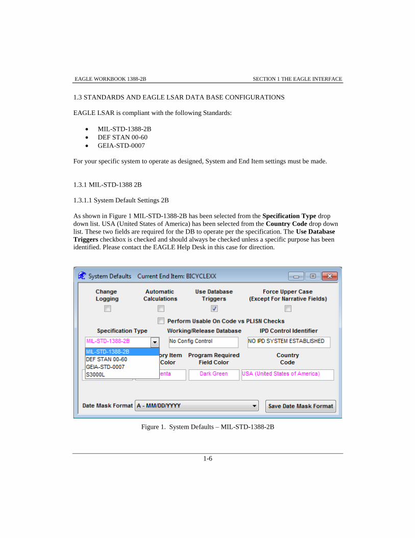
1.3.1.1 System Default Settings 2B
As shown in Figure 1 MIL-STD-1388-2B has been selected from the Specification Type drop
down list. USA (United States of America) has been selected from the Country Code drop down
list. These two fields are required for the DB to operate per the specification. The Use Database
Triggers checkbox is checked and should always be checked unless a specific purpose has been
identified. Please contact the EAGLE Help Desk in this case for direction.
Figure 1. System Defaults – MIL-STD-1388-2B

EAGLE WORKBOOK 1388-2B SECTION 1 THE EAGLE INTERFACE
1-7
1.3.1.2 End Item Default Settings 2B
No End Item Default record is required for 1388-2B operation but may be established if desired.
When the 2B System will be used in conjunction with EAGLE PUBLISHING SYSTEM an End
Item Default record is required. Please contact the EAGLE Help Desk in this case for direction or
consult the specific EPS Workbook for assistance.
Figure 2. End Item Defaults – Notice 1
1.4 LOGGING IN TO EAGLE
In order to access an EAGLE logistics database, a user must log in as shown in Figure 3. The
information required to log in includes a User Name, User Password, and a Database Server name.
After entering all the required information, choose OK to log on to the database.
To log in to EAGLE, enter the appropriate data in the EAGLE Login window as shown in Figure
3. This data will be used to log the user onto the LSAR database:
Enter the User Name:, User Password: and the Database Server: name provided
by the system administrator
Choose the button to log on to the database

EAGLE WORKBOOK 1388-2B SECTION 1 THE EAGLE INTERFACE
1-8
Figure 3. EAGLE Login Screen
1.5 THE NAVIGATOR
Once logged into EAGLE, the Navigator (Figure 4) is displayed within the Main Screen. From
Version 12 of EAGLE forward, the Navigator has been updated as shown. The Navigator has a
Home tab, a Favorites tab and a Recent tab as well as a Filter for ease of navigation to the desired
Discipline and Discipline(s) Functions.

EAGLE WORKBOOK 1388-2B SECTION 1 THE EAGLE INTERFACE
1-9
Figure 4. The Navigator – Default Header Shown
Utilizing the Expand Icon to the left of the Disciplines will display the various ‘Functions’ –
specific application programs contained within Disciplines – beneath the Disciplines as shown in
Figure 5.
In Figure 5 the Navigator is shown with the Adhoc Discipline expanded and the Visual Query
Builder function selected. The default header is displayed. This header is editable. Please contact
the EAGLE Help Desk for information regarding this feature.

EAGLE WORKBOOK 1388-2B SECTION 1 THE EAGLE INTERFACE
1-10
Figure 5. AdHoc Discipline – Visual Query Builder Function Selected
1.5.1 Using Navigator Functions
In EAGLE, data to be reviewed or maintained is usually located using a type of Navigator
Function known as a Data ‘Finder’. Finders consist of two basic parts; the Search Criteria input
boxes and the Record Retrieved window. Generally, retrieved records are not editable in the
Retrieved Record window. Other Functions in the Navigator allow records to be added, changed
or deleted.
1.5.2 Home Tab Functions
1.5.2.1Home Tab Filter
As shown in Figure 6, with the Home tab selected and entering the word ‘TASK’ in the Filter
box, the Navigator is filtered to return only Disciplines and Functions that contain the word
‘TASK’.

EAGLE WORKBOOK 1388-2B SECTION 1 THE EAGLE INTERFACE
1-11
Figure 6. Navigator Home Tab – Filter Applied
To clear the filtering, click the icon to the right of the Filter box (Figure 7).
Figure 7. Navigator Home Tab – Clear Filter
EAGLE WORKBOOK 1388-2B SECTION 1 THE EAGLE INTERFACE
1-12
1.5.2.2 Basic Finder
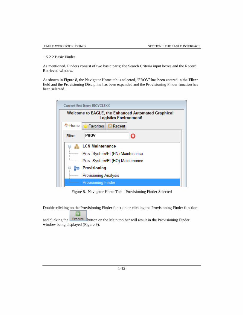
As mentioned. Finders consist of two basic parts; the Search Criteria input boxes and the Record
Retrieved window.
As shown in Figure 8, the Navigator Home tab is selected, ‘PROV’ has been entered in the Filter
field and the Provisioning Discipline has been expanded and the Provisioning Finder function has
been selected.
Figure 8. Navigator Home Tab – Provisioning Finder Selected
Double-clicking on the Provisioning Finder function or clicking the Provisioning Finder function
and clicking the button on the Main toolbar will result in the Provisioning Finder
window being displayed (Figure 9).
EAGLE WORKBOOK 1388-2B SECTION 1 THE EAGLE INTERFACE
1-13
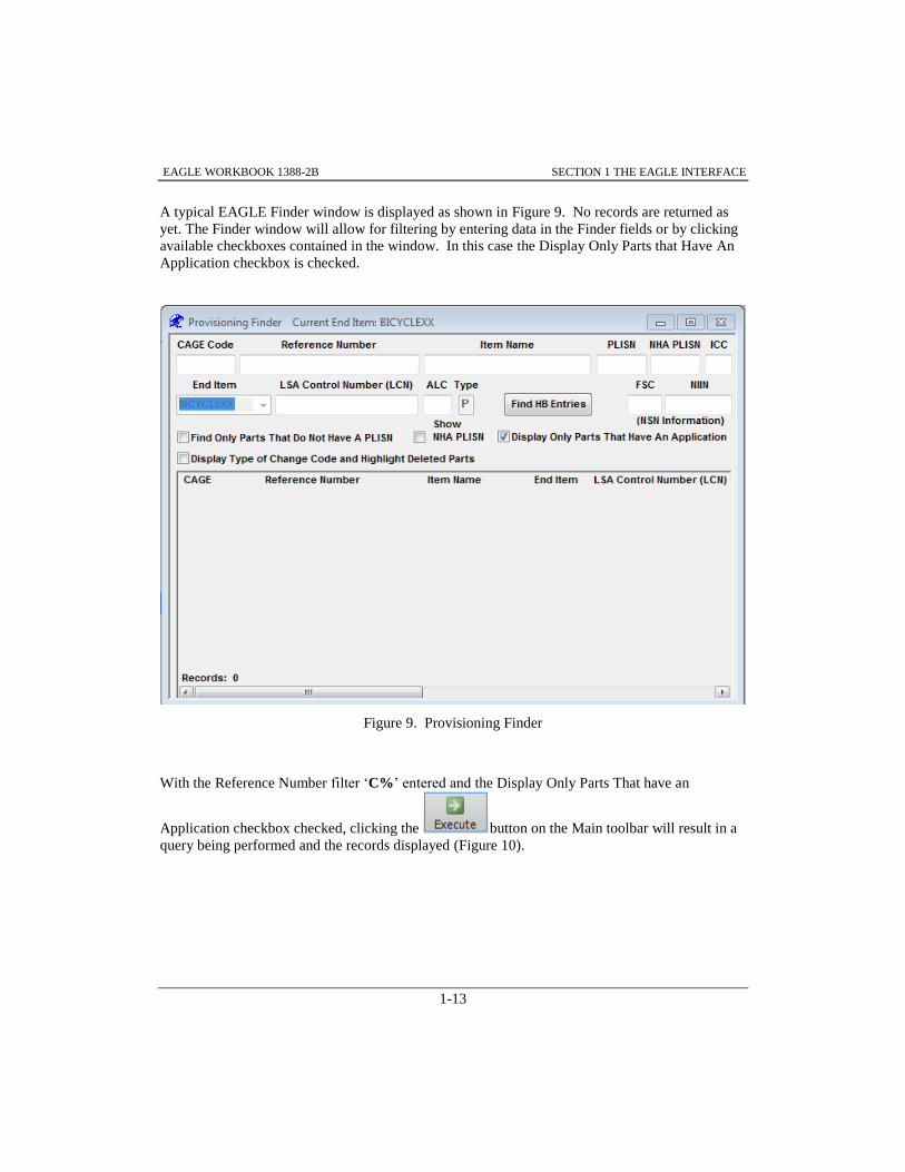
A typical EAGLE Finder window is displayed as shown in Figure 9. No records are returned as
yet. The Finder window will allow for filtering by entering data in the Finder fields or by clicking
available checkboxes contained in the window. In this case the Display Only Parts that Have An
Application checkbox is checked.
Figure 9. Provisioning Finder
With the Reference Number filter ‘C%’ entered and the Display Only Parts That have an
Application checkbox checked, clicking the button on the Main toolbar will result in a
query being performed and the records displayed (Figure 10).

EAGLE WORKBOOK 1388-2B SECTION 1 THE EAGLE INTERFACE
1-14
Figure 10. Provisioning Finder – Records Returned C% Filter
1.5.3 Favorites Tab Functions
As shown in Figure 11, the Favorites tab is selected in the Navigator and two Disciplines and
associated Functions are displayed. These records are available because they have been assigned
as favorites previously. Selecting the Provisioning Finder as shown and Double-clicking will
result in the Provisioning finder being displayed.
To Add or Remove Favorites, click the button located on the Function Specific toolbar.

EAGLE WORKBOOK 1388-2B SECTION 1 THE EAGLE INTERFACE
1-15
Figure 11. Favorites Tab – Provisioning Finder Selected
As shown in Figure 12, click on the Function desired, click the button and then
click the button on the Main toolbar to save a favorite.
Figure 12. Manage Favorites – Add Button Selected

EAGLE WORKBOOK 1388-2B SECTION 1 THE EAGLE INTERFACE
1-16
1.5.4 Recent Tab Function
As shown in Figure 13, the Recent tab is selected in the Navigator. The five most recent functions
having been utilized are displayed. You may access the desired functions finder by clicking the
record.
Figure 13. Navigator – Recent Tab Selected
1.5.5 Classic Navigator
If desired, the Classic Navigator is available for use. As shown in Figure 14, you may select
File>>Open from the Menu bar.

EAGLE WORKBOOK 1388-2B SECTION 1 THE EAGLE INTERFACE
1-17
Figure 14. Main Toolbar – File Open
This will result in the Classic Navigator being displayed for use (Figure 15).
Figure 15. Classic Navigator Displayed
The Discipline(s)/Function(s) available in the Classic Navigator will be as they were with the Tree
Navigator. At the time the User ‘Studentxx’ was created, if the Users Navigator was modified.
The Disciplines and Discipline Functions remain the same for user ‘Studentxx’ with either the
Classic or Tree Navigator selected.

EAGLE WORKBOOK 1388-2B SECTION 1 THE EAGLE INTERFACE
1-18
To return to the Tree Navigator once the Classic Navigator has been chosen, you may select
File>>Close from the Main toolbar.
Additionally, you may select either the CLASSIC or TREE Navigator by choosing
Tools>>Options from the Main Toolbar and selecting the Behavior Tab and utilize the drop down
list (Figure 16).
Figure 16. Tools>>Options – Behavior Tab
1.6 EAGLE MAIN SCREEN HEADER
At the top of the EAGLE Main screen is the Main screen header. The information provided on the
header is as shown in Figure 17. User would be the User ID you logged in with, Server is the
Database Server you are logged into and the EAGLE Client Version is displayed to show Version
and Build numbers of the EAGLE Client.
Figure 17. Main Screen Header
1.7 THE MENU BAR
Located just beneath the Header is the Menu bar (Figure 18).

EAGLE WORKBOOK 1388-2B SECTION 1 THE EAGLE INTERFACE
1-19
The EAGLE Menu bar is a similar to other graphical control elements which contain drop down
menus. The menu bar supplies a common area for window and application specific menus to
provide access to functions such as, copy, save edit and find/replace.
Figure 18. Menu Bar
1.8 THE MAIN TOOLBAR
The Main toolbar, illustrated in Figure 19, is displayed just under the Menu bar of the EAGLE
window. This toolbar contains buttons that perform generic functions used throughout EAGLE
and remains the same for all disciplines. Commonly used functions such as Print, Undo, Cut,
Copy, Paste, Clear, Execute, Save, Insert, Delete, Drawing, Artwork, Exit, Help and Item Help are
available here. The Main toolbar buttons are enabled and disabled depending on their
applicability to the discipline/function being used.
Figure 19. Main Toolbar
1.8.1 EAGLE Help
A Help button that retrieves a menu with indexed contents that can be searched on
keywords or strings is available from the Main Toolbar. Topics are logically linked and structured
to answer frequently asked questions. Bookmarks can be defined for quick reference to often-
visited topics and a History button logs the path of activity for easy retrieval of an earlier topic. In
addition to EAGLE help information, the Help button provides access to the on-line version of the
MIL-STD-1388-2B specification.

EAGLE WORKBOOK 1388-2B SECTION 1 THE EAGLE INTERFACE
1-20
1.8.2 Item Help
The Item Help button is used for context sensitive help. A single click toggles the
item help enabling the user to display specific Help for a window, database table or field. When
Item Help is enabled, a “?” shadowing the cursor indicates help is available. Clicking on the
window displays the Help topic for that area of the window. (This can be a help topic for the
window, a database table or a field). When the Item Help cursor is active, a single click of the
Item Help button will disable item help.
1.8.3 DB Help
The Database Schema Help function provides access to dynamic database schema
help. When selected, the Database Schema Help function will launch a Table Explorer window.
1.8.4 Graphical Functions
Artwork and Drawing buttons on the Main toolbar provide links to engineering drawings or
supporting illustrations. When cross references to engineering drawings or artwork have been
established for a CAGE Code/Reference Number combination selected in a Finder, the Artwork
and/or Drawing buttons are activated as shown in Figure 20. Clicking the Artwork or Drawing
button will display the graphical file in the EAGLE Viewer.
Figure 20. Main Toolbar – Drawing and Artwork Icons Activated
1.9 REPORTS/PROCESS MENU AND FUNCTION SPECIFIC TOOLBAR
The Reports/Process menu, accessed from the Menu bar, displays a list of topics for which more
information is available. It also displays a summarized list of applicable data reports.
The information displayed in this menu will vary depending on which Discipline/Function is
currently active. Once a topic is selected from the list, the data relating to that topic will be
displayed in a window for further manipulation. In addition, the Reports/Process menu provides
access to all standard LSAR reports applicable to the active discipline.

EAGLE WORKBOOK 1388-2B SECTION 1 THE EAGLE INTERFACE
1-21
The Function Specific toolbar is located left of the Navigator window. The buttons perform the
same functions as the options listed under the Reports/Process menu and provide a short cut to
using the menu. Figure 21 illustrates a sample Function Specific toolbar.
Figure 21. Sample Function Specific Toolbar
1.9.1 Using the Reports Process Menu or Function Specific Toolbar
To use the Reports/Process menu or Function Specific toolbar:
1. From the appropriate Data Finder, click on the desired record from the records retrieved
section.
2. Select the Reports/Process Menu (ALT+R) and click on the topic category of interest.
Or, click the equivalent button from the Function Specific toolbar. (In general, the topic
category of interest represents the various tables covered by the discipline.)
3. All data relating to the topic will be displayed in a window with the Data Finder’s key
fields displayed in gray at the top. From here the data for the retrieved record may be
changed, deleted or inserted in the provided data window.
4. Adding and deleting data in editable fields is done by selecting the information in the
data window and choosing Insert or Delete buttons from the toolbar or the Data Menu
(ALT+D). Data modifications may be made by typing the data into the data window
directly or by cutting and pasting like most Window applications.

EAGLE WORKBOOK 1388-2B SECTION 1 THE EAGLE INTERFACE
1-22
5. Once data entry is complete, the record must be saved to have it posted to the database by
pressing the Save button from the Main toolbar or ALT+D,S.
1.10 SELECTING END ITEM
EAGLE uses End Item to control access to the data in the database. Therefore, an End Item must
be selected prior to using EAGLE. As shown in Figure 22, the End Item button is
located at the far left of the Main toolbar. Clicking the Icon will bring up the Please Select an End
Item window (Figure 23).
Figure 22. Main Toolbar – End Item Icon
Figure 23. Select an End Item Window

EAGLE WORKBOOK 1388-2B SECTION 1 THE EAGLE INTERFACE
1-23
Once an End Item has been selected, it can be saved in the configuration setup so that the next
time EAGLE is run, the End Item will be defaulted. This End Item selection is used by all the
EAGLE disciplines, therefore eliminating the need for the user to select an End Item from End
Item drop down list boxes.
Only End Items for which the user has been assigned privileges are available. You may use the
Filter: box to limit the End Items to select from by entering the proper letter or number for an End
Item. Entering an ’X’ will return all three End Items displayed. Entering an ‘N’ will return only
the ‘NEWBIKEXX’ End Item
1.11 DISCIPLINE OUTPUTS
The majority of the Navigator Disciplines provide methods of saving data to external files. The
AdHoc Discipline has a unique way of saving the output of queries. For more information on
saving the output from the AdHoc Discipline, refer to Paragraph11.1.3. Most of the remaining
disciplines allow data displayed in a window to be saved to a file.
Data that is displayed in Maintenance Windows (windows that allow editing of data) may be
saved in most of the disciplines.
As shown in Figure 24, the Filter ALC ‘01’ has been used to return records in the data window
that are only ALC of ‘01’.
Figure 24. LCN Maintenance – Table XB Query ‘ALC 01’

EAGLE WORKBOOK 1388-2B SECTION 1 THE EAGLE INTERFACE
1-24
The Data is saved by using the File>>Save As menu item or ALT-F, A.
Note: When you utilize Filters, you must click your cursor in the data window on a row of data
to focus the File>>Save As on the window.
After the File>>Save As menu item has been chosen, the Save Rows As window, illustrated in
Figure 25, is displayed prompting the user for the File name: and Save as type: of file to save the
database rows in.
Figure 25. Save Rows As Window
Once the data has been saved to a file, it can be accessed whenever necessary using an appropriate
application. For example, if the data is saved in Excel Format (*.XLSX), Microsoft Excel should
be used to access the data for future use.

EAGLE Workbook 1388-2B Version 15
ENTERING CROSS
FUNCTIONAL DATA
SECTION 2

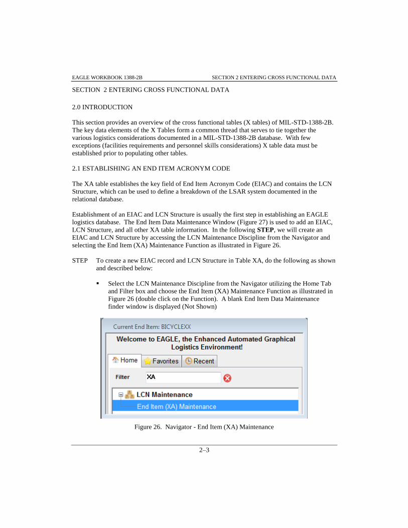
EAGLE WORKBOOK 1388-2B SECTION 2 ENTERING CROSS FUNCTIONAL DATA
2–3
SECTION 2 ENTERING CROSS FUNCTIONAL DATA
2.0 INTRODUCTION
This section provides an overview of the cross functional tables (X tables) of MIL-STD-1388-2B.
The key data elements of the X Tables form a common thread that serves to tie together the
various logistics considerations documented in a MIL-STD-1388-2B database. With few
exceptions (facilities requirements and personnel skills considerations) X table data must be
established prior to populating other tables.
2.1 ESTABLISHING AN END ITEM ACRONYM CODE
The XA table establishes the key field of End Item Acronym Code (EIAC) and contains the LCN
Structure, which can be used to define a breakdown of the LSAR system documented in the
relational database.
Establishment of an EIAC and LCN Structure is usually the first step in establishing an EAGLE
logistics database. The End Item Data Maintenance Window (Figure 27) is used to add an EIAC,
LCN Structure, and all other XA table information. In the following STEP, we will create an
EIAC and LCN Structure by accessing the LCN Maintenance Discipline from the Navigator and
selecting the End Item (XA) Maintenance Function as illustrated in Figure 26.
STEP To create a new EIAC record and LCN Structure in Table XA, do the following as shown
and described below:
Select the LCN Maintenance Discipline from the Navigator utilizing the Home Tab
and Filter box and choose the End Item (XA) Maintenance Function as illustrated in
Figure 26 (double click on the Function). A blank End Item Data Maintenance
finder window is displayed (Not Shown)
Figure 26. Navigator - End Item (XA) Maintenance

EAGLE WORKBOOK 1388-2B SECTION 2 ENTERING CROSS FUNCTIONAL DATA
2–4
Choose the Execute button. Figure 27 is displayed
Figure 27. End Item Data Maintenance – End Item ‘BICYCLEXX’
Click the button on the Main toolbar (far left). The End Item Select
window is displayed
Choose the correct ‘TRAININGXX’ End Item (Figure 28). You may use the Filter:
box to limit the End Items to select from by entering the proper letter or number for
an End Item. Entering an ’X’ will return all three End Items displayed. Entering an
‘N’ will return only the ‘NEWBIKEXX’ End Item
Figure 28. Select End Item Window – TRAININGXX Selected
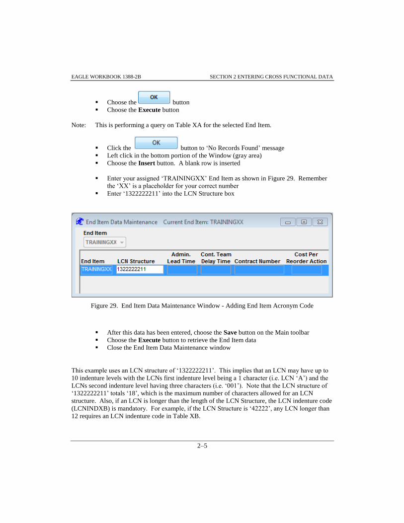
EAGLE WORKBOOK 1388-2B SECTION 2 ENTERING CROSS FUNCTIONAL DATA
2–5
Choose the button
Choose the Execute button
Note: This is performing a query on Table XA for the selected End Item.
Click the button to ‘No Records Found’ message
Left click in the bottom portion of the Window (gray area)
Choose the Insert button. A blank row is inserted
Enter your assigned ‘TRAININGXX’ End Item as shown in Figure 29. Remember
the ‘XX’ is a placeholder for your correct number
Enter ‘1322222211’ into the LCN Structure box
Figure 29. End Item Data Maintenance Window - Adding End Item Acronym Code
After this data has been entered, choose the Save button on the Main toolbar
Choose the Execute button to retrieve the End Item data
Close the End Item Data Maintenance window
This example uses an LCN structure of ‘1322222211’. This implies that an LCN may have up to
10 indenture levels with the LCNs first indenture level being a 1 character (i.e. LCN ‘A’) and the
LCNs second indenture level having three characters (i.e. ‘001’). Note that the LCN structure of
‘1322222211’ totals ‘18’, which is the maximum number of characters allowed for an LCN
structure. Also, if an LCN is longer than the length of the LCN Structure, the LCN indenture code
(LCNINDXB) is mandatory. For example, if the LCN Structure is ‘42222’, any LCN longer than
12 requires an LCN indenture code in Table XB.

EAGLE WORKBOOK 1388-2B SECTION 2 ENTERING CROSS FUNCTIONAL DATA
2–6
Note: The ‘TRAININGXX’ End Item was added in this step to illustrate how to add a new End
Item. For training purposes, an End Item containing ‘BICYCLEXX’ data has already
been established. For convenience, this End Item will be used for the remainder of the
exercises in this book. Make sure that you select your correct ‘BICYCLEXX’ End Item
in the next STEP.
2.2 ASSIGNING LCNS
Make sure that you have selected your correct ‘BICYCLEXX’ End Item. Note in the header
shown in Figure 30 that ‘Current End Item: BICYCLEXX’ is displayed. Remember again the
‘XX’ refers to your specific assigned number.
STEP To create an LCN do the following as shown and described:
Access the LCN Maintenance Discipline using the Navigator Home Tab and Filter
box, select and double-click LCN (XB) Maintenance as illustrated in Figure 30
Figure 30. Navigator - LCN (XB) Maintenance
The LSA Control Number Data Maintenance window is displayed
Make sure ‘BICYCLEXX’ is displayed in the End Item drop down list box (Figure
31)

EAGLE WORKBOOK 1388-2B SECTION 2 ENTERING CROSS FUNCTIONAL DATA
2–7
Figure 31. LSA Control Number Maintenance window – No records Returned
Choose the button on the Main toolbar (the End Item BICYCLEXX fills
automatically) (Figure 32)
Figure 32. LSA Control Number Maintenance Window – After Insert
Make sure ‘BICYCLEXX’ is displayed in the inserted row End Item box (Figure 33)
Enter ‘A’ into the LSA Control Number (LCN) box
Enter ‘02’ into the ALC (for alternate LCN of 2) box
Enter ‘P’ (for LCN type of Physical) into the Type box
Enter ‘TRAINING BICYCLE’ into the LCN Name box
Enter ‘A’ into the LCN Indenture Code box
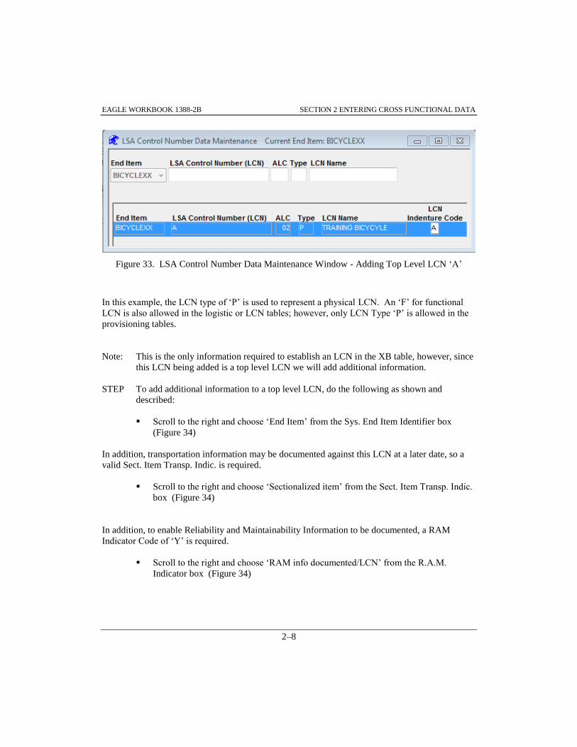
EAGLE WORKBOOK 1388-2B SECTION 2 ENTERING CROSS FUNCTIONAL DATA
2–8
Figure 33. LSA Control Number Data Maintenance Window - Adding Top Level LCN ‘A’
In this example, the LCN type of ‘P’ is used to represent a physical LCN. An ‘F’ for functional
LCN is also allowed in the logistic or LCN tables; however, only LCN Type ‘P’ is allowed in the
provisioning tables.
Note: This is the only information required to establish an LCN in the XB table, however, since
this LCN being added is a top level LCN we will add additional information.
STEP To add additional information to a top level LCN, do the following as shown and
described:
Scroll to the right and choose ‘End Item’ from the Sys. End Item Identifier box
(Figure 34)
In addition, transportation information may be documented against this LCN at a later date, so a
valid Sect. Item Transp. Indic. is required.
Scroll to the right and choose ‘Sectionalized item’ from the Sect. Item Transp. Indic.
box (Figure 34)
In addition, to enable Reliability and Maintainability Information to be documented, a RAM
Indicator Code of ‘Y’ is required.
Scroll to the right and choose ‘RAM info documented/LCN’ from the R.A.M.
Indicator box (Figure 34)

EAGLE WORKBOOK 1388-2B SECTION 2 ENTERING CROSS FUNCTIONAL DATA
2–9
Figure 34. LSA Control Number Data Maintenance Window - Adding System/EI Identifier
After this data has been entered, choose the button on the Main toolbar
STEP To illustrate adding a lower level LCN, do the following as shown and described:
Scroll back to the left in the Data window if necessary
Choose the Insert button
Enter ‘A01’ into the LSA Control Number (LCN) box (Figure 35)
Enter ‘02’ into the ALC (for alternate LCN of 02) box
Enter ‘P’ (for LCN type of Physical) into the Type box
Enter ‘FRAME ASSEMBLY’ into the LCN Name box
Enter ‘B’ into the LCN Indenture Code box
After this data has been entered, choose the Save button on the Main toolbar
Figure 35. Insert Record A01 – B Indenture Level
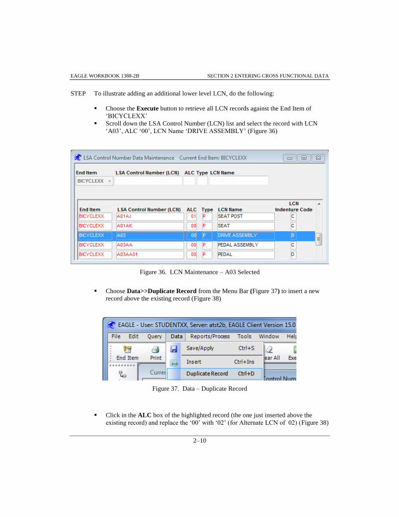
EAGLE WORKBOOK 1388-2B SECTION 2 ENTERING CROSS FUNCTIONAL DATA
2–10
STEP To illustrate adding an additional lower level LCN, do the following:
Choose the Execute button to retrieve all LCN records against the End Item of
‘BICYCLEXX’
Scroll down the LSA Control Number (LCN) list and select the record with LCN
‘A03’, ALC ‘00’, LCN Name ‘DRIVE ASSEMBLY’ (Figure 36)
Figure 36. LCN Maintenance – A03 Selected
Choose Data>>Duplicate Record from the Menu Bar (Figure 37) to insert a new
record above the existing record (Figure 38)
Figure 37. Data – Duplicate Record
Click in the ALC box of the highlighted record (the one just inserted above the
existing record) and replace the ‘00’ with ‘02’ (for Alternate LCN of 02) (Figure 38)

EAGLE WORKBOOK 1388-2B SECTION 2 ENTERING CROSS FUNCTIONAL DATA
2–11
Figure 38. LCN ‘A03’ – ALC ‘02’
After this data has been entered, choose the Save button on the Main toolbar
STEP To view the LCNs added in the previous paragraphs, do the following. Figure 39
illustrates the ‘BICYCLEXX’ LCNs with ALC ‘02’:
Enter ‘02’ into the ALC query box at the top of the window
Choose the Execute button to retrieve the data from the database
At this point your data should be as shown (Figure 39)
Figure 39. XB Records – ALC 02

EAGLE WORKBOOK 1388-2B SECTION 2 ENTERING CROSS FUNCTIONAL DATA
2–12
Close the LSA Control Number Data Maintenance window
Info: In these examples, the lower level LCNs entered were neither a System nor End Item;
therefore, the System/End Item Identifier box was left blank. In addition, transportation
information will not be added so the Sect. Item Trans. Indic. box was left as the default
‘Not Sectionalized’. RAM information will not be added so the R.A.M. Indicator box
was left as the default ‘RAM info. not documented/LCN’ for LCN ‘A01’, but because
‘Data Duplicate’ was used for LCN ‘A03’. The R.A.M. Indicator field indicates ‘RAM
info documented/LCN’.
At this point, a top level LCN of ‘A’ with lower level LCNs of ‘A01’ and ‘A03’, all with ALC
‘02’ have been added. If a Provisioning Contract Control Number (PCCN)/Usable On Code
(UOC) combination is available, it can be added at this time. The theory is that a PCCN is added
to LCNs representing a System/End item or an “A” indenture coded item. Lower level LCNs are
linked to a PCCN through its corresponding System/End item. In the next two Paragraphs (2.3
and 2.4) a PCCN will be added for the top level LCN ‘A’ ALC ‘02’ through table XC and then the
lower level LCNs ‘A01’ and ‘A03’ will be linked to a PCCN through LCN ‘A’.
2.3 ASSIGNING A PCCN AND UOC TO SYSTEM / END ITEM LEVEL LCN (PART USAGE)
Note: If the STEPs in Paragraph 2.2 were not completed, the LCN data needed for this
paragraph will not exist. Without this data, PCCNs and UOCs cannot be assigned.
STEP To illustrate adding a UOC and a PCCN to a System/End Item or LCN with an indenture
level of ‘A’ do the following as shown and described:
Access the System/EI (XC) Maintenance Function from the Navigator utilizing the
Home tab and Filter box (Figure 40)
Double-click the System/EI (XC) Maintenance Function
The System/End Item Maintenance window is displayed

EAGLE WORKBOOK 1388-2B SECTION 2 ENTERING CROSS FUNCTIONAL DATA
2–13
Figure 40. Navigator - System/EI (XC) Maintenance
In the System/End Item Maintenance window , make sure ‘BICYCLEXX’ is
displayed in the End Item drop down list box (Figure 41)
Make sure the Show only System/End Item LCNs checkbox is checked
Figure 41. XC Query – No Records
Choose the Execute button to query the database
After data is returned, select the record with LCN ‘A’ and ALC ‘02’ (Figure 42)
Note: If this record is not available, make sure that LCN ‘A’ ALC ‘02’ has been marked as
either ‘System’ or ‘End Item’ under the System/End Item dropdown list box in Table XB.

EAGLE WORKBOOK 1388-2B SECTION 2 ENTERING CROSS FUNCTIONAL DATA
2–14
Figure 42. System/End Item Maintenance window – ALC ‘2’ Selected
Scroll to the right so that the UOC and PCCN columns are displayed in the window
(Figure 43)
Enter ‘TR1’ into the UOC box
Enter ‘H5T80B’ into the PCCN box
Your screen should reflect Figure 43
Figure 43. System/End Item Maintenance window – UOC ‘TR1’
Choose the Save button on the Main toolbar
Close the System/End Item Maintenance window

EAGLE WORKBOOK 1388-2B SECTION 2 ENTERING CROSS FUNCTIONAL DATA
2–15
2.4 MAPPING LCNS TO SYSTEM/END ITEM UOCS
STEP To assign an LCN to a System/End Item level UOC, access LCN to System/EI (XF)
Maintenance from the LCN Maintenance Discipline using the Navigator and Filter: box
as shown in Figure 44:
Double-click the LCN to System/End Item (XF) Maintenance function
Figure 44. Navigator - LCN to System/EI (XF) Maintenance
The LCN System/End Item Usable On Code Maintenance window is displayed
STEP To illustrate mapping LCNs to a System/End Item UOC, do the following as shown in
Figure 45 and Figure 46. Figure 46 illustrates the window after the following STEP has
been completed:
Make sure ‘BICYCLEXX’ is displayed in the End Item drop down list box in the
LCN System/End Item Usable On Code Maintenance window as shown in Figure 45
Enter ‘2’ into the ALC finder box
Choose the Execute button to retrieve the data
Make sure that the record with LSA Control Number (LCN) = ‘A’, ALC=’02’, and
Type ‘P’ is selected in the upper portion of the window
Note: In Figure 45 the bottom left hand part of the screen displays the available UOCs for the
System/End Item configurations.

EAGLE WORKBOOK 1388-2B SECTION 2 ENTERING CROSS FUNCTIONAL DATA
2–16
Select the record with the LCN ‘A’, ALC ‘02’and UOC ‘TR1’ from the scrolling list
box in the bottom left of the window
Choose the button to map LCN ‘A’, ALC ‘02’ to the System/End Item
UOC
Figure 45. LCN System/End Item Usable On Code Maintenance Window
Choose the Save button on the Main toolbar
Select the record with the LCN ‘A01’, ALC ‘02’ in the upper portion of the window
(not shown)
Select the record with the LCN ‘A’, ALC ‘02’and UOC ‘TR1’ from the scrolling list
box in the bottom left of the window
Choose the button to map LCN ‘A01’, ALC ‘02’ to the System/ End
Item UOC
Choose the Save button on the Main toolbar
Select the record with the LCN ‘A03’, ALC ‘02’ in the upper portion of the window
(Figure 46)
Select the record with the LCN ‘A’, ALC ‘02’and UOC ‘TR1’ from the scrolling list
box in the bottom left of the window

EAGLE WORKBOOK 1388-2B SECTION 2 ENTERING CROSS FUNCTIONAL DATA
2–17
Choose the button to map LCN ‘A03’, ALC ‘02’ to the System/ End
Item UOC ‘TR1’(Figure 46)
Figure 46. LCN/System End Item UOC Mapped
Choose the Save button on the Main toolbar
Close the LCN System/End Item Usable On Code Maintenance window
Note: In this exercise three XF records were created. An XF record also will be generated
automatically when an HO record is added for physical LCN types.
2.5 ASSIGNING SERIAL NUMBER UOCS TO SYSTEM/END ITEM LCNS
When documenting complex systems where small quantities of a particular configuration may
exist (aircraft, ships, satellites, etc.), configuration is often documented by serial number. Serial
Number Range(s) that comprise a configuration and the corresponding System/End Item UOC are
stored in Table XD.

EAGLE WORKBOOK 1388-2B SECTION 2 ENTERING CROSS FUNCTIONAL DATA
2–18
STEP To assign a S/N UOC to a System/End Item level LCN, access System/EI SN (XD)
Maintenance from the LCN Maintenance Discipline using the Navigator and Filter: box
as shown in Figure 47
Double-click the System/EI SN (XD) Maintenance function
Figure 47. Navigator – System/EI SN (XD) Maintenance
The System/End Item Serial Number Maintenance window is displayed
Note: If Paragraph 2.3 was not completed, a top level LCN with an associated PCCN and UOC
will not exist. A top level LCN with an associated PCCN and UOC must exist to assign a
serial number UOC:
Make sure ‘BICYCLEXX’ is displayed in the End Item drop down list box (Figure
48)
Enter ‘A’ into the LSA Control Number Query (LCN) box
Choose the Execute button to retrieve the data
Select the record with LCN of ‘A’ and ALC of ‘02’
Activate the right portion of the screen (Serial Number Range:) by left-clicking in it
with the mouse. The blank data fields will not appear until Insert is chosen
Choose the Insert button
Enter ‘100’ into the From: box (see Figure 48)
Enter ‘200’ into the To: box
Enter ‘A’ into the S/N UOC: box

EAGLE WORKBOOK 1388-2B SECTION 2 ENTERING CROSS FUNCTIONAL DATA
2–19
Figure 48. System/End Item Serial Number Maintenance
After this data has been entered chose the Save button on the Main toolbar
Close the System/End Item Serial Number Maintenance window
2.6 ASSIGNING SYSTEM/END ITEM SERIAL NUMBER UOCS TO LCNS
When configuration control is managed by serial number, LCNs are mapped to the System/End
Item Serial Number range on which they are used by the System/End Item Serial Number UOC.
The cross-reference information between LCNs (from Table XB) and the System/End Item Serial
Number UOC (from Table XD) is established in Table XE.
Note: If Paragraph 2.5 was not completed, a system/end item serial number UOC will not exist.
A system/end item serial number UOC must exist for an LCN to be tied to a serial
number UOC:
STEP To assign a System/End Item serial number UOC to an LCN, access LCN to S/N UOC
(XE) Maintenance from the LCN Maintenance Discipline using the Navigator and Filter:
box as shown in Figure 49:
Double-click the LCN to S/N UOC (XE) Maintenance function

EAGLE WORKBOOK 1388-2B SECTION 2 ENTERING CROSS FUNCTIONAL DATA
2–20
Figure 49. Navigator - LCN to S/N UOC (XE) Maintenance
The LCN to Serial Number Usable On Code window is displayed
Make sure ‘BICYCLEXX’ is displayed in the End Item drop down list box (Figure
50)
Enter ‘2’ into the ALC Query box
Choose the Execute button to retrieve the data
Select the record with LCN of ‘A’, ALC of ‘02’ and Serial Number UOC of ’A’
from the box in the middle of the window
Select the record with LCN of ‘A01’ and ALC of ‘02’ from the scrolling list box on
the bottom left of the window
Choose the button to map LCN of ‘A01’, ALC of ‘02’ to the Serial
Number UOC of ‘A’ (serial numbers 100 to 200 of LCN ‘A’, ALC ‘02’)

EAGLE WORKBOOK 1388-2B SECTION 2 ENTERING CROSS FUNCTIONAL DATA
2–21
Figure 50. Assignment of System/End Item Serial Number UOCs to LCNs
Choose the Save button on the Main toolbar to save the data record to Table XE
Close the LCN to Serial Number Usable On Code window
2.7 ADDING CAGE CODES
CAGE Codes can be added through the LCN Maintenance Discipline or the Provisioning
Discipline. Paragraph 10.1.1 covers how to add a CAGE Code using the Provisioning Discipline.
This section will cover adding a CAGE Code using the LCN Maintenance Discipline. The best
method to add multiple CAGE Codes into the database is using the LCN Maintenance Discipline.
The Provisioning Discipline provides a method to add new CAGE codes when adding reference
numbers as a convenience for entering the data in one place.
STEP To add a new CAGE Code, access the LCN Maintenance Discipline using the Navigator
and Filter box as illustrated in Figure 51 and select CAGE Code (XH) Maintenance:
Double-click the CAGE Code (XH) Maintenance function

EAGLE WORKBOOK 1388-2B SECTION 2 ENTERING CROSS FUNCTIONAL DATA
2–22
Figure 51. Navigator - CAGE Code (XH) Maintenance
The CAGE Code Data Maintenance window is displayed
STEP To illustrate adding CAGE information, do the following as shown and described. Note:
The only required field is the CAGE:
With the CAGE Code Data Maintenance window displayed, choose the Insert
button
Enter ‘12345’ into the CAGE box (Figure 52)
Enter ‘BICYCLE PRO’ into the Name box
Enter ‘34 BEACH WALK DRIVE’ into the Street box
Enter ‘HUNTINGTON BEACH’ into the City box
Enter ‘CA’ into the State box
Enter ‘USA’ into the Nation box
Enter ‘92648-0623’ into the Postal Zone box
Info: Note the button at the top right of the window shown
in Figure 52; Clicking this button will allow for the entry of much additional info about
the supplier.
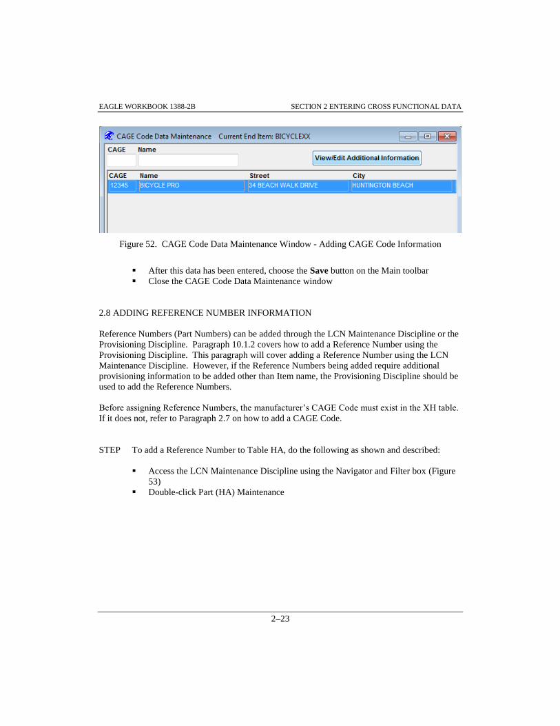
EAGLE WORKBOOK 1388-2B SECTION 2 ENTERING CROSS FUNCTIONAL DATA
2–23
Figure 52. CAGE Code Data Maintenance Window - Adding CAGE Code Information
After this data has been entered, choose the Save button on the Main toolbar
Close the CAGE Code Data Maintenance window
2.8 ADDING REFERENCE NUMBER INFORMATION
Reference Numbers (Part Numbers) can be added through the LCN Maintenance Discipline or the
Provisioning Discipline. Paragraph 10.1.2 covers how to add a Reference Number using the
Provisioning Discipline. This paragraph will cover adding a Reference Number using the LCN
Maintenance Discipline. However, if the Reference Numbers being added require additional
provisioning information to be added other than Item name, the Provisioning Discipline should be
used to add the Reference Numbers.
Before assigning Reference Numbers, the manufacturer’s CAGE Code must exist in the XH table.
If it does not, refer to Paragraph 2.7 on how to add a CAGE Code.
STEP To add a Reference Number to Table HA, do the following as shown and described:
Access the LCN Maintenance Discipline using the Navigator and Filter box (Figure
53)
Double-click Part (HA) Maintenance

EAGLE WORKBOOK 1388-2B SECTION 2 ENTERING CROSS FUNCTIONAL DATA
2–24
Figure 53. Navigator - Part (HA) Maintenance
The Part Number Data Maintenance window is displayed
Choose the Insert button, a blank row is entered
Enter ‘12345’ into the CAGE Code box (Figure 54)
Enter ‘MC-TBIKE’ into the Reference Number box
Enter ‘BICYCLE ASSEMBLY’ into the Item Name box
Figure 54. Part Number Data Maintenance - Adding Reference Number Information
After this data has been entered, choose the Save button

EAGLE WORKBOOK 1388-2B SECTION 2 ENTERING CROSS FUNCTIONAL DATA
2–25
STEP Do the following to add another reference number:
Choose the Insert button
Enter ‘12345’ into the CAGE Code box (not shown)
Enter ‘TFRAME’ into the Reference Number box
Enter ‘FRAME ASSEMBLY’ into the Item Name box
After this data has been entered, choose the Save button on the Main toolbar
Close the Part Number Data Maintenance window
2.9 APPLYING REFERENCE NUMBERS TO AN LCN (PART APPLICATION)
At this point in the exercises, a top level LCN of ‘A’ with lower level LCNs of ‘A01’ and ‘A03’
all ALC ‘02’ have been added. In addition, CAGE Code ‘12345’ has been entered along with
Reference Numbers ‘MC-TBIKE’ and ‘TFRAME’. The HG Table is used to associate a
Reference Number with the part indenture structure characterized through an LCN.
Note: If Paragraphs 2.2 and 2.8 were not completed, these Reference Number(s) cannot be
applied to an LCN in the database. The required fields for applying reference numbers to
an LCN are CAGE Code, Reference Number, End Item, LCN, ALC, and LCN Type.
STEP To apply a Reference Number to an LCN (Create an HG Record), do the following as
shown in Figure 55, Figure 56 and described:
Access the Part App. (HG) Maintenance Function from the LCN Maintenance
Discipline using the Navigator and Filter box as shown in Figure 55
Double-click the Part App. (HG) Maintenance function
Figure 55. Navigator - Part App. (HG) Maintenance
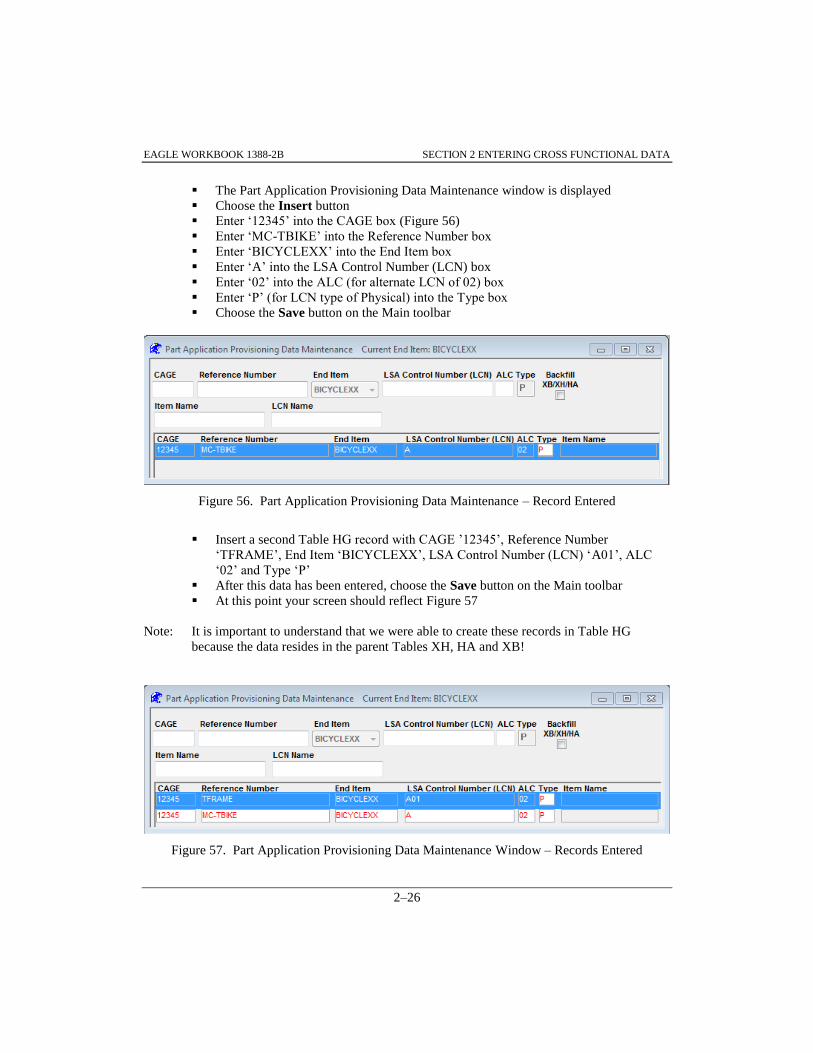
EAGLE WORKBOOK 1388-2B SECTION 2 ENTERING CROSS FUNCTIONAL DATA
2–26
The Part Application Provisioning Data Maintenance window is displayed
Choose the Insert button
Enter ‘12345’ into the CAGE box (Figure 56)
Enter ‘MC-TBIKE’ into the Reference Number box
Enter ‘BICYCLEXX’ into the End Item box
Enter ‘A’ into the LSA Control Number (LCN) box
Enter ‘02’ into the ALC (for alternate LCN of 02) box
Enter ‘P’ (for LCN type of Physical) into the Type box
Choose the Save button on the Main toolbar
Figure 56. Part Application Provisioning Data Maintenance – Record Entered
Insert a second Table HG record with CAGE ’12345’, Reference Number
‘TFRAME’, End Item ‘BICYCLEXX’, LSA Control Number (LCN) ‘A01’, ALC
‘02’ and Type ‘P’
After this data has been entered, choose the Save button on the Main toolbar
At this point your screen should reflect Figure 57
Note: It is important to understand that we were able to create these records in Table HG
because the data resides in the parent Tables XH, HA and XB!
Figure 57. Part Application Provisioning Data Maintenance Window – Records Entered

EAGLE WORKBOOK 1388-2B SECTION 2 ENTERING CROSS FUNCTIONAL DATA
2–27
In the previous STEP, we were able to create HG records by applying an existing HA (Ref Num)
record to an existing XB (LCN) record. In this next STEP, we will use a Backfill capability to
create the XH, HA, XB and HG records together. In order to illustrate this, we will enter the data
into the Part Application Provisioning Data Maintenance window (Figure 58).
STEP To create an HG record utilizing the Backfill capability, do the following as shown and
described:
Make sure ‘BICYCLEXX’ is displayed in the End Item drop down list box (Figure
58)
Choose the Insert button
Check the Backfill XB/XH/HA box. Note the Item Name and LCN Name columns
are now active
Enter ‘12346’ into the CAGE box
Enter ‘TFRAME-1’ into the Reference Number box
Make sure ‘BICYCLEXX’ is displayed I the End Item box
Enter ‘A01’ into the LSA Control Number (LCN) box
Enter ‘04’ into the ALC (for alternate LCN of 4) box
Enter ‘P’ (for LCN type of Physical) into the Type box
Enter ‘TEST FRAME 1’ into both the Item and LCN Name columns
Figure 58. Part Application Provisioning Data Maintenance-Backfill
After this data has been entered, choose the Save button on the Main toolbar
Close the Part Application Provisioning Data Maintenance window
2.10 MAPPING PART APPLICATIONS TO SYSTEM/END ITEM UOCS\
An HO record is required to link a LCN like ‘A’ or ‘A01’ to a UOC. However, an LCN must
have a part reference number applied to it (have a corresponding HG record) before an HO record
can be added. In Paragraph 2.9, part reference numbers (MC-TBIKE, TFRAME) were applied to
LCNs ‘A and A01’ so they can be linked to a UOC through a corresponding HO record.

EAGLE WORKBOOK 1388-2B SECTION 2 ENTERING CROSS FUNCTIONAL DATA
2–28
Note: If Paragraph 2.3 was not completed, the top level LCN with the PCCN and UOC will not
exist. A top level LCN must exist for a part LCN to be tied to a UOC.
STEP To illustrate the mapping of Part Application records to a System/End Item UOC, do the
following as shown and described:
Access the Prov. System/EI (HO) Maintenance Function from the LCN Maintenance
Discipline utilizing the Navigator Home tab and Filter box (Figure 59)
Double-click the Prov. System/EI (HO) Maintenance function
Figure 59. Navigator - Prov. System/EI (HO) Maintenance
The Provisioning System/End Item Usable On Code Maintenance window is
displayed
Make sure ‘BICYCLEXX’ is displayed in the End Item drop down list box (Figure
60)
Enter ‘2’ in the ALC Finder box

EAGLE WORKBOOK 1388-2B SECTION 2 ENTERING CROSS FUNCTIONAL DATA
2–29
Figure 60. Provisioning System/End Item Usable On Code Maintenance Window
Choose the Execute button to retrieve the records
Click on the record with CAGE ‘12345’, Reference Number ‘MC-TBIKE’ and LSA
Control Number (LCN) ‘A’ from the box in the middle of the window (Figure 61)
Select the record with the System/End Item LCN ‘A’, ALC ‘02’ and Usable On
Code (UOC) ‘TR1’ from the scrolling list box in the bottom left of the window
Figure 61. Provisioning System /End Item Usable On Code Maintenance Window - Results

EAGLE WORKBOOK 1388-2B SECTION 2 ENTERING CROSS FUNCTIONAL DATA
2–30
Choose the button to map the LSA Control Number (LCN) ‘A’ ALC
‘02’to Usable On Code (UOC) ‘TR1’ (Figure 62)
Figure 62. LCN ‘A’ ALC ‘02’ Selected
Choose the Save button on the Main toolbar. The window now indicates that LSA
Control Number (LCN) ‘A’ , ALC ‘02’ has been mapped to System/End Item LCN
‘A’ ALC ‘02’ (itself) which has a Usable On Code (UOC) of ‘TR1’
Click on the record with Reference Number ‘TFRAME’ from the box in the middle
of the window (Figure 63)
Select the record with the System/End Item LCN ‘A’, ALC ‘02’ and Usable On
Code (UOC) ‘TR1’ from the scrolling list box in the bottom left of the window
Choose the button to map the LSA Control Number (LCN) ‘A01’
ALC ‘02’to Usable On Code (UOC) ‘TR1’

EAGLE WORKBOOK 1388-2B SECTION 2 ENTERING CROSS FUNCTIONAL DATA
2–31
Figure 63. Part Application ‘A01’ Mapped to UOC ‘TR1’
Choose the Save button on the Main toolbar
At this point both records should be mapped to UOC ‘TR1’. Alternate between both ALC ‘02’
records in the middle of the window to make sure both are mapped correctly.
Close the Provisioning System /End Item Usable On Code Maintenance window
2.11 ESTABLISHING TECHNICAL MANUAL CODES
A Technical Manual Code must be established in order to produce technical publication output
products from EAGLE. The Maintain Tech Manual Code Function in the Tech Manual Discipline
is used to add Technical Manual codes to Table XI. Figure 64 illustrates the Maintain Tech
Manual Code option in the Navigator.
STEP To illustrate how to add data into the Technical Manual Code and Number Index Table
(Table XI) do the following as shown and described:
Access the Maintain Tech Manual Code Function from the Navigator by entering
‘TEC’ in the Filter box (Figure 64)
Double-click the Maintain Tech Manual Code function

EAGLE WORKBOOK 1388-2B SECTION 2 ENTERING CROSS FUNCTIONAL DATA
2–32
Figure 64. Navigator – Maintain Tech Manual Code
The Maintain Tech Manual Codes window is displayed
Figure 65. Maintain Tech Manual Codes Window
Choose the Insert button to create a blank row for entering a new record (Figure 66)
Enter ‘TMT’ in the TM Code box
Enter ‘TRAINING TM’ in the TM Number box
Figure 66. Maintain Tech Manual Codes
Choose the Save button on the Main toolbar
Close the Maintain Tech Manual Code window and return to the Navigator

EAGLE Workbook 1388-2B Version 15
ENTERING
OPERATIONS &
MAINTENANCE
REQUIREMENTS
DATA
SECTION 3


EAGLE WORKBOOK 1388-2B SECTION 3 ENTERING O & M REQUIREMENTS DATA
3–3
SECTION 3 ENTERING OPERATIONS AND MAINTENANCE REQUIREMENTS DATA
3.0 INTRODUCTION
This section provides an overview of the Operations and Maintenance Requirement tables (A
tables) of MIL-STD-1388-2B. The A tables are intended to consolidate information related to the
anticipated operation of systems, the environment in which these systems will be operated and
maintained, and the maintenance requirements that must be met. This information is documented
for an entire system and any subsystems for which maintenance requirements are imposed.
Information in the A tables is generally derived from contract specifications. Different Operations
and Maintenance (O&M) requirements can be documented for Wartime and Peacetime.
3.1 ADDING OPERATIONS AND MAINTENANCE DATA
Access the Operations Maintenance Discipline from the Navigator, select and double-click the O
& M Requirements (AA,AG,AH,AI) Function as illustrated in Figure 67.
Figure 67. Navigator - Operations Maintenance

EAGLE WORKBOOK 1388-2B SECTION 3 ENTERING O & M REQUIREMENTS DATA
3–4
STEP To add data into the Operation and Maintenance Requirement Tables (A Tables),
specifically the Operations and Maintenance Requirements (AA) Table, do the following
from the Operations and Maintenance Finder:
Make sure ‘BICYCLEXX’ is displayed in the End Item drop down list box in the
Operations and Maintenance Finder window (Figure 68)
Choose the Execute button or ALT+Q,E to retrieve the records
Select the record with LCN ‘A05’ and ALC ‘00’
Figure 68. Operations and Maintenance Finder
Choose the button at the left from the Function Specific toolbar
Click the button if the ‘No Records Found’ message box appears
The Operations and Maintenance Requirement window is displayed
Enter data in the data fields (Figure 69). Some of the fields are drop down list boxes.
When a field contains a drop down list box, the box appears and the user can select
the desired value
Note: A short cut to the drop down list box is to type the first letter or code of the desired value
and the rest of the value should fill in automatically when ENTER or TAB is pressed.
This will save users time once they are familiar with the application.
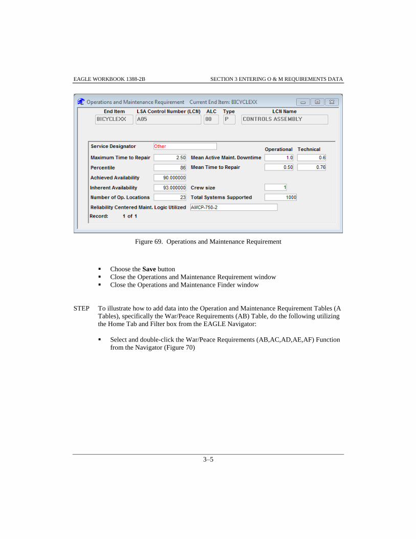
EAGLE WORKBOOK 1388-2B SECTION 3 ENTERING O & M REQUIREMENTS DATA
3–5
Figure 69. Operations and Maintenance Requirement
Choose the Save button
Close the Operations and Maintenance Requirement window
Close the Operations and Maintenance Finder window
STEP To illustrate how to add data into the Operation and Maintenance Requirement Tables (A
Tables), specifically the War/Peace Requirements (AB) Table, do the following utilizing
the Home Tab and Filter box from the EAGLE Navigator:
Select and double-click the War/Peace Requirements (AB,AC,AD,AE,AF) Function
from the Navigator (Figure 70)
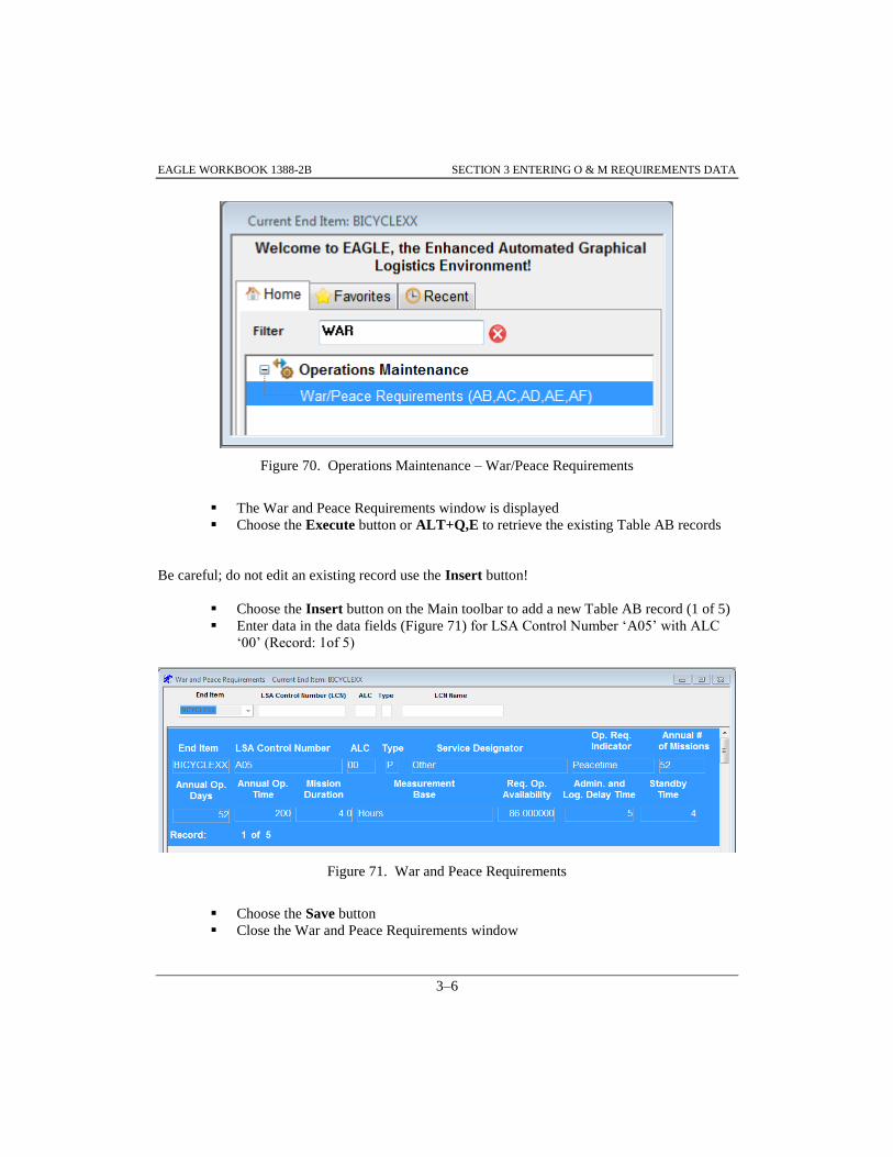
EAGLE WORKBOOK 1388-2B SECTION 3 ENTERING O & M REQUIREMENTS DATA
3–6
Figure 70. Operations Maintenance – War/Peace Requirements
The War and Peace Requirements window is displayed
Choose the Execute button or ALT+Q,E to retrieve the existing Table AB records
Be careful; do not edit an existing record use the Insert button!
Choose the Insert button on the Main toolbar to add a new Table AB record (1 of 5)
Enter data in the data fields (Figure 71) for LSA Control Number ‘A05’ with ALC
‘00’ (Record: 1of 5)
Figure 71. War and Peace Requirements
Choose the Save button
Close the War and Peace Requirements window

EAGLE WORKBOOK 1388-2B SECTION 3 ENTERING O & M REQUIREMENTS DATA
3–7
STEP To illustrate how to add data into the Operation and Maintenance Requirement Tables (A
Tables), specifically the Reliability Requirement Table or AG Table, do the following as
shown and described:
Select and double-click the O&M Requirements (AA,AG,AH,AI) Function from the
Navigator
The Operations and Maintenance Finder is displayed
Enter ‘A05’ into the LSA Control Number (LCN) Finder box (Figure 72)
Choose the Execute button or ALT+Q,E to retrieve the data
Select the record with LSA Control Number (LCN) ‘A05’ and ALC ‘00’
Figure 72. Operation and Maintenance Finder – ALC ‘00’ Selected
Choose the button from the Function Specific toolbar
Click the button when the ‘No Records Found’ message box
appears
The Reliability Requirement window is displayed
Enter data in the data fields (Figure 73)

EAGLE WORKBOOK 1388-2B SECTION 3 ENTERING O & M REQUIREMENTS DATA
3–8
Figure 73. Reliability Requirement - Annual Operating Requirements
Choose the Save button
Close the Reliability Requirement window
Close the Operations and Maintenance Finder

EAGLE Workbook 1388-2B Version 15
ENTERING
RELIABILITY,
AVAILABILITY &
MAINTAINABILITY
DATA
SECTION 4


EAGLE WORKBOOK 1388-2B SECTION 4 ENTERING RAM DATA
4–3
SECTION 4 ENTERING RELIABILITY, AVAILABILITY AND MAINTAINABILITY DATA
4.0 INTRODUCTION
The Reliability, Availability and Maintainability tables (B tables) in EAGLE are used to document
the function of each repairable item that comprises the system under analysis; outline the
maintenance concept to be utilized for design and support planning purposes; and identify any
design conditions such as fail safe requirements and environmental or nuclear hardness
considerations imposed on the system. Also documented in the B tables are item reliability,
maintainability, and related availability characteristics resulting from the failure modes and
effects, criticality, and maintainability analyses and accommodate a narrative description of any
analysis related to the potential redesign of an item.
4.1 ADDING RELIABILITY AND MAINTAINABILITY DATA
Access the Reliability & Maintainability Discipline from the Navigator by utilizing the Filter box,
select and double-click the RAM Finder Function as illustrated in Figure 74.
Figure 74. Navigator - Reliability & Maintainability
The Reliability + Maintainability Finder is displayed
STEP To illustrate how to use the Reliability + Maintainability Finder, do the following as
shown and described:

EAGLE WORKBOOK 1388-2B SECTION 4 ENTERING RAM DATA
4–4
Make sure the correct BICYCLEXX End Item is displayed in the End Item drop
down (Figure 75)
Make sure that ‘ALL’ is selected in the RAM Ind. drop down box and the Show all
LCNs radio button is selected
Choose the Execute button to retrieve the records
Figure 75. Reliability + Maintainability Finder
Note: When the Show all LCNs radio button is selected, all LCNs from Table XB meeting the
search criteria are returned. If the Only LCNs with RAM Data radio button is selected,
only LCNs with data in Table BA that meet the search criteria are returned.
4.2 ADDING RAM CHARACTERISTICS DATA
STEP To illustrate how to add data into the Reliability & Maintainability Tables, specifically
the RAM Characteristics or BA Table, do the following from the Reliability +
Maintainability Finder (Figure 76):

EAGLE WORKBOOK 1388-2B SECTION 4 ENTERING RAM DATA
4–5
Scroll down and select the record with LSA Control Number (LCN) ‘A01AK’ and
ALC ‘00’
Note: The RAM Ind. field (RAMINDXB) for the selected record must be set to 'Y' to allow
Reliability, Availability and Maintainability data in the B tables.
Select 'Y' from the RAM Ind. dropdown list for the record selected
Choose the Save button on the Main toolbar
Figure 76. Reliability + Maintainability Finder - RAM Ind.
Choose the button on the Function Specific toolbar
Note: If there is no data found for the given record selected, a message box will alert the user.
After responding by choosing the OK button, an empty window will appear allowing the
user to enter data.

EAGLE WORKBOOK 1388-2B SECTION 4 ENTERING RAM DATA
4–6
Click the button when the ‘No Records Found’ message box
appears
The RAM Characteristics window is displayed
Enter data in the data fields (Figure 77)
Figure 77. Reliability & Maintenance - RAM Characteristics
Choose the Save button
Close the RAM Characteristics window
You should be returned to the Reliability + Maintainability Finder
4.3 ADDING RAM CHARACTERISTICS NARRATIVE
STEP To illustrate how to add data into the Reliability & Maintainability Tables, specifically
the RAM Characteristics Narrative or BB Table, do the following from the Reliability +
Maintainability Finder:
Make sure the record with LSA Control Number (LCN) ‘A01AK’ and ALC ‘00’ is
selected

EAGLE WORKBOOK 1388-2B SECTION 4 ENTERING RAM DATA
4–7
Choose the button on the Function Specific Toolbar
The RAM Characteristics Narrative window is displayed
Select ‘A. RAM Item Function’ from the drop down (Figure 78)
Enter the following narrative ‘Provides support for the rider.’ To enter text for a
different narrative, select one of the other types of narrative from the drop down list
and enter the information
Figure 78. Reliability & Maintenance - RAM Characteristics Narrative
Choose the Save button
Close the RAM Characteristics Narrative window
You should be returned to the Reliability + Maintainability Finder
4.4 ADDING RAM LOGISTICS CONSIDERATIONS NARRATIVE DATA
STEP To illustrate how to add data into the Reliability & Maintainability Tables, specifically
the RAM Logistics Considerations Narrative or BC Table, do the following from the
Reliability + Maintainability Finder:
Make sure the record with LSA Control Number (LCN) ‘A01AK’ and ALC ‘00’ is
selected

EAGLE WORKBOOK 1388-2B SECTION 4 ENTERING RAM DATA
4–8
Choose the button on the Function Specific toolbar
The RAM Logistics Considerations Narrative window is displayed
Select D. SR (Safety) from the drop down list (Figure 79)
Enter the following narrative ‘Bicycle seat is safe when proper attire is worn.’ To
enter text for a different narrative, select one of the other types of narrative from the
drop down list box and enter the information
Figure 79. RAM Logistics Considerations Narrative Window
Choose the Save button on the Main toolbar
Close the RAM Logistics Considerations Narrative window
You should be returned to the Reliability + Maintainability Finder
4.5 ADDING RAM INDICATOR CHARACTERISTICS DATA
STEP To illustrate how to add data into the Reliability & Maintainability Tables, specifically
the RAM Indicator Characteristics or BD Table, do the following from the Reliability +
Maintainability Finder:
Make sure the record with LSA Control Number (LCN) ‘A01AK’ and ALC ‘00’ is
selected

EAGLE WORKBOOK 1388-2B SECTION 4 ENTERING RAM DATA
4–9
Choose the button on the Function Specific toolbar
Click the button when the ‘No Records Found’ message box
appears
The RAM Indicator Characteristics window is displayed
Select ‘Measured’ from the RAM Indicator Code drop down list (Figure 80)
Enter data in the data fields as shown
Figure 80. RAM Indicator Characteristics Window
Choose the Save button on the Main toolbar
Close the RAM Indicator Characteristics window
You should be returned to the Reliability + Maintainability Finder

EAGLE WORKBOOK 1388-2B SECTION 4 ENTERING RAM DATA
4–10
4.6 ADDING WAR/PEACE RAM INDICATOR CHARACTERISTICS DATA
STEP To illustrate how to add data into the Reliability & Maintainability Tables, specifically
the War/Peace RAM Indicator Characteristics or BE Table, do the following from the
Reliability + Maintainability Finder:
Make sure the record with LSA Control Number (LCN) ‘A01AK’ and ALC ‘00’ is
selected
Choose the button on the Function Specific toolbar
Click the button when the ‘No Records Found’ message box
appears
The War/Peace RAM window is displayed
Select ‘Measured’ from the RAM Indicator Code drop down list (Figure 81)
Select ‘Peacetime’ from the RAM Operational Requirement Indicator drop down list
Enter ‘20’ for Administrative and Logistic Delay Time
Enter ‘98’ for Operational Availability
Enter ‘5’ for Standby Time
Figure 81. War/Peace RAM Window – LCN A01AK Selected

EAGLE WORKBOOK 1388-2B SECTION 4 ENTERING RAM DATA
4–11
Choose the Save button on the Main toolbar
Close the War/Peace RAM window
You should be returned to the Reliability + Maintainability Finder
4.7 ADDING FAILURE MODE AND RCM ANALYSIS DATA
Results of Reliability Centered Maintenance (RCM) Analysis are documented in Table BF for
each failure mode defined. These results consist of a Y/N answer to each applicable question in
the RCM logic tree. The actual questions that comprise the RCM logic tree are generally
contained in specifications and not documented in the EAGLE database.
STEP To illustrate how to add data into the Reliability & Maintainability Tables, specifically
the Failure Mode and RCM Analysis Results or BF Table, do the following from the
Reliability + Maintainability Finder:
Make sure the record with LSA Control Number (LCN) ‘A01AK’ and ALC ‘00’ is
selected
Choose the button on the Function Specific toolbar
Click the button when the ‘No Records Found’ message box
appears
The Fail Mode (FM) and RCM Analysis window is displayed
Enter ‘F001’ for the Failure Mode Indicator (Figure 82)
Enter ‘.15’ for the Failure Mode Ratio
Select ‘Yes’ from the Reliability Centered Maintenance (RCM) Logic Results drop
down list box for questions 01, 04, and 06
Select ‘No’ from the Reliability Centered Maintenance (RCM) Logic Results drop
down list box for question 02
Enter ‘B’ in the RCM Disposition box for disposition A, enter ‘D’ for RCM
Disposition box B and enter ‘F’ for the RCM Disposition box D

EAGLE WORKBOOK 1388-2B SECTION 4 ENTERING RAM DATA
4–12
Figure 82. Fail Mode (FM) and RCM Analysis Window – F001 Entered
Choose the Save button on the Main toolbar
Note: To utilize the ‘Perform RCM Analysis’ functionality, the User must be assigned the
‘Common’ End Item established in the LSAR Database. Instructions regarding the
granting of permissions on the ‘Common’ End item are provided in the EAGLE Security
Manual, available by contacting the EAGLE Help Desk.
Close the Fail Mode (FM) and RCM Analysis window
You should be returned to the Reliability + Maintainability Finder

EAGLE WORKBOOK 1388-2B SECTION 4 ENTERING RAM DATA
4–13
4.8 ADDING FAILURE MODE AND RELIABILITY CENTERED MAINTENANCE
NARRATIVE
STEP To illustrate how to add data into the Reliability & Maintainability Tables, specifically
the Failure Mode and RCM Narrative or BG Table, do the following from the Reliability
+ Maintainability Finder:
Make sure the record with LSA Control Number (LCN) ‘A01AK’ and ALC ‘00’ is
selected
Choose the button from the Function Specific toolbar
The RAM Failure Mode + RCM Narrative window is displayed
Select ‘F001’ from the Select FM Indicator drop down list (Figure 83)
Select ‘D. Failure Cause’ from the Select Type of Narrative drop down list
Enter ‘Seat height set too high.’ in the narrative box. To enter text for a different
type of narrative, select one of the other types of narrative from the drop down list
and enter the information
Figure 83. RAM Failure Mode + RCM Narrative Window
Choose the Save button on the Main toolbar
Close the RAM Failure Mode + RCM Narrative window
You should be returned to the Reliability + Maintainability Finder
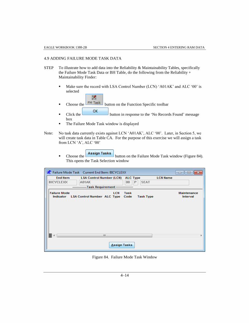
EAGLE WORKBOOK 1388-2B SECTION 4 ENTERING RAM DATA
4–14
4.9 ADDING FAILURE MODE TASK DATA
STEP To illustrate how to add data into the Reliability & Maintainability Tables, specifically
the Failure Mode Task Data or BH Table, do the following from the Reliability +
Maintainability Finder:
Make sure the record with LSA Control Number (LCN) ‘A01AK’ and ALC ‘00’ is
selected
Choose the button on the Function Specific toolbar
Click the button in response to the ‘No Records Found’ message
box
The Failure Mode Task window is displayed
Note: No task data currently exists against LCN ‘A01AK’, ALC ‘00’. Later, in Section 5, we
will create task data in Table CA. For the purpose of this exercise we will assign a task
from LCN ‘A’, ALC ‘00’
Choose the button on the Failure Mode Task window (Figure 84).
This opens the Task Selection window
Figure 84. Failure Mode Task Window

EAGLE WORKBOOK 1388-2B SECTION 4 ENTERING RAM DATA
4–15
Select ‘F001’ from the Failure Mode Indicator drop down list (Figure 85)
Enter ‘A’ in the LSA Control Number (LCN) box
Enter ‘D%’ in the Task Code box
Choose the button on the Task Selection window
Select the record with Task Code of ‘DACOBAA’
Choose the button on the Task Selection window
This will return you to the Failure Mode Task window
Info: Tasks can also be created from the Task Selection window by selecting the Create New
Task button.
Figure 85. Task Selection Window
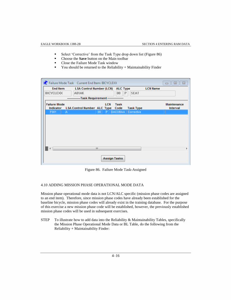
EAGLE WORKBOOK 1388-2B SECTION 4 ENTERING RAM DATA
4–16
Select ‘Corrective’ from the Task Type drop down list (Figure 86)
Choose the Save button on the Main toolbar
Close the Failure Mode Task window
You should be returned to the Reliability + Maintainability Finder
Figure 86. Failure Mode Task-Assigned
4.10 ADDING MISSION PHASE OPERATIONAL MODE DATA
Mission phase operational mode data is not LCN/ALC specific (mission phase codes are assigned
to an end item). Therefore, since mission phase codes have already been established for the
baseline bicycle, mission phase codes will already exist in the training database. For the purpose
of this exercise a new mission phase code will be established, however, the previously established
mission phase codes will be used in subsequent exercises.
STEP To illustrate how to add data into the Reliability & Maintainability Tables, specifically
the Mission Phase Operational Mode Data or BL Table, do the following from the
Reliability + Maintainability Finder:

EAGLE WORKBOOK 1388-2B SECTION 4 ENTERING RAM DATA
4–17
Make sure the record with LSA Control Number (LCN) ‘A01AK’ and ALC ‘00’ is
selected
Choose the button on the Function Specific toolbar
The Mission Phase Operational Mode window is displayed
Choose the Insert button from the Main toolbar
Select ‘D’ from the Code drop down list (Figure 87)
Enter ‘BICYCLE STORAGE’ for the Operational Mode
Figure 87. Mission Phase Operational Mode Window
Choose the Save button on the Main toolbar
Close the Mission Phase Operational Mode window
You should be returned to the Reliability + Maintainability Finder
4.11 ADDING RAM CRITICALITY DATA & FAILURE MODE INDICATOR MISSION
PHASE CODE CHARACTERISTICS DATA
STEP To illustrate how to add data into the Reliability & Maintainability Tables, specifically
the RAM Criticality or BK Table and the Failure Mode Indicator Mission Phase Code
Characteristics or BI Table, do the following from the Reliability + Maintainability
Finder:
Make sure the record with LSA Control Number (LCN) ‘A01AK’ and ALC ‘00’ is
selected

EAGLE WORKBOOK 1388-2B SECTION 4 ENTERING RAM DATA
4–18
Choose the button on the Function Specific toolbar
Click the button in response to the ‘No Records Found’ message
box
The Failure Mode IMPCC Characteristics window is displayed
Select ‘B’ from the Mission Phase Code drop down list (Figure 88)
Select ‘Minor’ from the Safety Hazard Severity Code drop down list
Select ‘F001’ from the Failure Mode Indicator drop down list
Enter ‘.5’ for the Failure Effect Probability
Select ‘Occasional’ from the Failure Probability Level drop down list
Enter ‘2’ for Operating Time
Select ‘Operating Hours’ for the Operating time Measurement Base
Figure 88. Failure Mode IMPCC Characteristics
Note: If Automatic Calculations are on, Failure Mode Criticality Number and RAM Item
Criticality Number will be calculated. They will not appear in Figure 88 until the RAM
Finder has been refreshed (the query re-executed) and the Failure Mode IMPCC
Characteristics window reopened.
Choose the Save button on the Main toolbar
Close the Failure Mode IMPCC Characteristics window
You should be returned to the Reliability + Maintainability Finder

EAGLE WORKBOOK 1388-2B SECTION 4 ENTERING RAM DATA
4–19
4.12 ADDING RAM FAILURE MODE INDICATOR MISSION PHASE CODE
CHARACTERISTICS NARRATIVE DATA
STEP To illustrate how to add data into the Reliability & Maintainability Tables, specifically
RAM Failure Mode Indicator Mission Phase Code Characteristics (MPCC) Narrative or
the BJ Table, do the following from the Reliability + Maintainability Finder:
Make sure the record with LSA Control Number (LCN) ‘A01AK’ and ALC ‘00’ is
selected
Choose the button on the Function Specific toolbar
Select ‘F001’ from the Select FM Indicator drop down list (Figure 89)
Select ‘B’ from the Select Mission Phase Code drop down list
Select ‘B. Compensating Operator Action Provisions’ from the Select Type of
Narrative drop down list
Input the following narrative: ‘Rider may ride without contacting seat.’
Figure 89. RAM FM IMPCC Narrative Window
Choose the Save button on the Main toolbar
Close the RAM FM IMPCC Narrative window
Close the Reliability + Maintainability Finder window

EAGLE WORKBOOK 1388-2B SECTION 4 ENTERING RAM DATA
4–20

EAGLE Workbook 1388-2B Version 15
SECTION 5
ENTERING TASK
ANALYSIS DATA


EAGLE WORKBOOK 1388-2B SECTION 5 ENTERING TASK ANALYSIS DATA
5–3
SECTION 5 ENTERING TASK ANALYSIS DATA
5.0 INTRODUCTION
The Task Analysis (C) Tables document maintenance task requirements for each repairable
assembly comprising the System/End Item. This includes maintenance procedures, task times and
frequencies, personnel skills, tools/support equipment, facilities, and supply support requirements.
Additionally, EAGLE LSAR Tables have been linked to the EAGLE Publishing System Tables to
provide and enable the re-use of the Task Data for Data Module use in ASD S1000D and Work
Packages in MIL-STD 40051.
5.1 CREATING TASKS
Access the Task Analysis Discipline from the Navigator by utilizing the Home tab and Filter box,
select and double-click the Task Analysis Finder function as illustrated in Figure 90.
Figure 90. Navigator - Task Analysis Finder

EAGLE WORKBOOK 1388-2B SECTION 5 ENTERING TASK ANALYSIS DATA
5–4
STEP To illustrate how to use the Task Analysis Finder, do the following as shown in Figure 91
and described below. Note that Figure 91 contains the results of the query after the
Execute button has been chosen and LCN ‘A’, ALC ‘01´has been selected:
With the Task Analysis Finder window displayed, choose the Execute button to
retrieve the records (Figure 91)
Figure 91. Task Analysis Finder – Records Returned
Info: If the Display Only LCNs With Tasks checkbox is checked and the LCNs radio button is
selected, only data for LCNs with task data that meet the search criteria will be returned.
If the Display Only LCNs With Tasks checkbox is checked and the LCNs and Task
Codes radio button is selected, records will be returned for each task that meets the search
criteria. If the Display Only LCNs With Tasks checkbox is not checked, all LCNs that
meet the search criteria will be returned.
Note: If the Display Only LCNs With Tasks checkbox is checked and the LCNs and Task
Codes radio button is selected, a large amount of data may be returned if specific search
criteria is not entered.

EAGLE WORKBOOK 1388-2B SECTION 5 ENTERING TASK ANALYSIS DATA
5–5
5.1.1 Adding a New Task
New tasks may be added to existing LCNs in the Task Analysis Discipline. If an LCN does not
already exist, the LCN should be added using the LCN Maintenance Discipline from the
Navigator.
Task Codes may be created as original or reference tasks. Original task codes are complete tasks,
whereas reference tasks are not. Reference tasks are used to avoid duplication of data. Once an
original task code’s information is complete, another task may reference it. Therefore, the second
task does not need to contain the same information as the first task. The only data the reference
task needs is the required keys for the Task Requirement (CA) Table. Reference tasks are used
when the data of the Task Requirement (CA) Table and the subordinate tables (tables CB through
CI) are the same for the referenced and referencing task.
5.1.1.1 Adding Original Tasks
STEP To illustrate how to add a new task code into the Task Analysis Tables, specifically the
Task Requirement or CA Table, do the following as shown and described:
Enter ‘1’ into the ALC Finder box (Figure 92
Choose the Execute button
Select the record with LCN ‘A’, ALC ‘01’
Figure 92. Task Analysis Finder – LCN ‘A’
Choose the button on the Function Specific toolbar
The Task Information window is displayed

EAGLE WORKBOOK 1388-2B SECTION 5 ENTERING TASK ANALYSIS DATA
5–6
Note in Figure 93 that for LCN ‘A’ with ALC ‘01’ there are no existing Tasks. This is indicated
by the ‘No Tasks Found’ information in the Task Code/Task Identification drop down list box:
Enter ‘INSPECT BICYCLE’ in the Task Identification box manually or initially fill
it by selecting one of the Recommended Action Verbs (INSPECT) and then using
the button and then enter ‘BICYCLE’ (Figure 93)
Info: The task code can be entered manually into the Task Code box on the New Task tab, but
the feature provided by the Create Task Code button is extremely helpful.
Choose the button to aid in entering the task code. The
Create/Modify Task Code window is displayed
Figure 93. Adding a New Task

EAGLE WORKBOOK 1388-2B SECTION 5 ENTERING TASK ANALYSIS DATA
5–7
STEP To illustrate how to create a new task code do the following from the Create/Modify Task
Code window (Figure 94):
Select or enter ‘A’ from the Step 1: Select FUNCTION drop down list
Select or enter ‘G’ from the Step 2: Select INTERVAL drop down list
Select or enter ‘C’ from the Step 3: Select O/M LEVEL drop down list
Select or enter ‘O’ from the Step 4: Select SERVICE drop down list
Select or enter ‘C’ from the Step 5: Select OPERABILITY drop down list
Choose the button to assign the sequence code for the sixth
and seventh positions of the task code. Notice the OK button is now enabled
indicating a complete task code
Choose the button to return to the Task Information window
Figure 94. Create/Modify Task Code
Choose the button

EAGLE WORKBOOK 1388-2B SECTION 5 ENTERING TASK ANALYSIS DATA
5–8
The Annual Operating Requirement Finder is displayed
Info: Since Task Code ‘AGCOCAA’ has a ‘G’ in the second position, it is an unscheduled task
and must have a measurement base entered which corresponds to the measurement base
for the annual operating requirements (AOR).
For this reason, the AOR LCN, AOR ALC, AOR LCN type, and the AOR measurement
base must match with a set of key values established in Table AG. Therefore, the
following window (Figure 95) is displayed when the Done button is chosen. At this
point, the AOR Requirements must be selected.
STEP To illustrate how to complete adding a task code by establishing the Annual Operating
Requirements, do the following from the Annual Operating Requirement Finder (Figure
95):
Select the desired Annual Operating Requirements by highlighting the row with
LCN ‘A’ and ALC ‘01’
Choose the button to return to the Task Information window
Figure 95. Annual Operating Requirement Finder
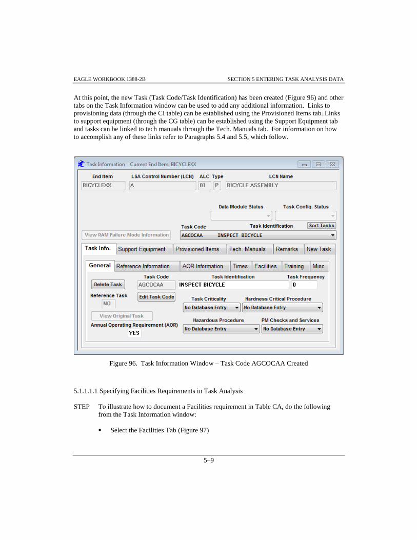
EAGLE WORKBOOK 1388-2B SECTION 5 ENTERING TASK ANALYSIS DATA
5–9
At this point, the new Task (Task Code/Task Identification) has been created (Figure 96) and other
tabs on the Task Information window can be used to add any additional information. Links to
provisioning data (through the CI table) can be established using the Provisioned Items tab. Links
to support equipment (through the CG table) can be established using the Support Equipment tab
and tasks can be linked to tech manuals through the Tech. Manuals tab. For information on how
to accomplish any of these links refer to Paragraphs 5.4 and 5.5, which follow.
Figure 96. Task Information Window – Task Code AGCOCAA Created
5.1.1.1.1 Specifying Facilities Requirements in Task Analysis
STEP To illustrate how to document a Facilities requirement in Table CA, do the following
from the Task Information window:
Select the Facilities Tab (Figure 97)

EAGLE WORKBOOK 1388-2B SECTION 5 ENTERING TASK ANALYSIS DATA
5–10
Click on 'BICYCLE REPAIR SHOP' from the Available Facilities list
Choose the button to link the BICYCLE REPAIR SHOP to the
INSPECT BICYCLE Task
Figure 97. Task Information Window – Facilities Tab
Choose the Save button on the Main toolbar
A ‘No Facilities Requirement’ message is displayed in the top portion of the Task
Information window (Figure 98)
Select ' ’ from the ‘Are facilities required for the
performance of this task?’ drop down list
Choose the Save button on the Main toolbar. The ‘No Facilities Requirement’
message should disappear

EAGLE WORKBOOK 1388-2B SECTION 5 ENTERING TASK ANALYSIS DATA
5–11
Figure 98. Task Information Window - No Facilities Requirement Message
5.1.1.2 Adding Reference Tasks
Reference tasks are created the same way original tasks are created; however, only key and
mandatory fields are required to be entered for reference tasks. These keys are the EIAC, LCN,
ALC, LCN type, task code, referenced EIAC, referenced LCN, referenced ALC, referenced LCN
type, and referenced task code. Mandatory fields are task ID and task frequency.
STEP To illustrate how to create a reference task, steps similar to those in Paragraph 5.1.1 are
used. Do the following from the Task Information window as shown (Figure 99). It is
assumed LCN ‘A’ ALC ‘01’ is selected:
Select the New Task tab
Enter ‘REPAIR FLAT’ in the Task Identification box and select the
button

EAGLE WORKBOOK 1388-2B SECTION 5 ENTERING TASK ANALYSIS DATA
5–12
Figure 99. Task Information - Add Reference Task
The Create/Modify Task Code window is displayed
Enter ‘JGCOAAA’ in the Task Code box on the right and notice the code and
description fill in on the left (Figure 100)
Choose the button
The Task Information window is displayed

EAGLE WORKBOOK 1388-2B SECTION 5 ENTERING TASK ANALYSIS DATA
5–13
Figure 100. Create/Modify Task Code - Task Code JGCOAAA
Note the Task Code ‘JGCOAAA’ is filled in (bottom middle of window Figure 101).
DO NOT complete the task (by clicking the Done button) until the task reference has
been established
This task is to be a reference task. Choose the button
from the Task Information window (Figure 101)
The Reference Task Finder is displayed

EAGLE WORKBOOK 1388-2B SECTION 5 ENTERING TASK ANALYSIS DATA
5–14
Figure 101. Task Information Window – Reference an Existing Task
Make sure ‘A’ is in the LCN query box (Figure 102)
Choose the button from the Reference Task Finder to extract a list of
available LCNs and Task Codes for referencing
Figure 102. Reference Task Finder

EAGLE WORKBOOK 1388-2B SECTION 5 ENTERING TASK ANALYSIS DATA
5–15
Scroll down the list and select the Task to reference by highlighting the ‘JGCOAAA’
Task for LCN ‘A’ and ALC ‘00’ with Task Identification ‘REPAIR FLAT TIRE’
(Figure 103)
Choose the button
Figure 103. Reference Task Finder – REPAIR FLAT TIRE Selected
The Task Information window is re-displayed
Notice in Figure 104 that the Task Identification box has been changed to reflect the
referenced task’s ID ('REPAIR FLAT' now reads 'REPAIR FLAT TIRE')
Choose the button

EAGLE WORKBOOK 1388-2B SECTION 5 ENTERING TASK ANALYSIS DATA
5–16
Figure 104. Task Identification – REPAIR FLAT TIRE
The Task Information window is refreshed
Click on the General Tab (Figure 105)
A reference task has now been added. Notice that once a task is a reference task, the title of the
Task Information window is changed to reflect that the task references another task (Figure 105).
This feature lets the user know that the task being displayed is not the original.
Figure 105. Task Information Window – General Tab Selected

EAGLE WORKBOOK 1388-2B SECTION 5 ENTERING TASK ANALYSIS DATA
5–17
As shown in Figure 106, 'YES' in the Reference Task box of the Task Information window and an
'R' after the Task Code in the Task Code/Task Identification drop down list box also indicate that
the task references another task.
STEP To illustrate how to view referenced and referencing task information, do the following
from the Task Information window as shown in Figure 106
Make sure Task Code 'JGCOAAA' is selected in the drop down box
Make sure the General tab is selected
Choose the button
Figure 106. Task Information - Viewing Referenced Task Information
The Task Information window now displays the ORIGINAL Task Information for
LSA Control Number (LCN) ‘A’ ALC ‘00’ (Figure 107)
Note: In order to edit data for a task, an original task must be selected. For example, once the
View Original Task button has been pressed, the Task Code/Task Identification drop
down box is disabled and the various tabs, (Support Equipment, Provisioned Items etc.)
are activated. At this point, support equipment, provisioned items etc. may be added to
the task. It is important to note that any changes made affect the original task data.

EAGLE WORKBOOK 1388-2B SECTION 5 ENTERING TASK ANALYSIS DATA
5–18
Figure 107. ORIGINAL Task Information Displayed
To return to the Referencing Task, click the button
Close the Task Information window
5.1.2 Cloning Tasks
Cloning task information is very useful when creating like or similar tasks. Not only does the
cloning save time, it keeps data consistent. There are two ways to perform cloning of task data
from one LCN to another LCN. Copying performs an actual copy of all task data (Table CA and
its subordinate tables CB through CK, except CJ) from the original LCN to a new LCN. When
copying is performed, data is duplicated. This method of cloning is suitable for a task that is
similar enough to an original task that the original task can be used as a ‘basis’ for creating the
new task. However, if the original task is identical to the new task, it is more efficient to create a
reference copy. A reference clone creates a new task that refers to an original task. The advantage
to this type of cloning is that the task data can be maintained in only one place. Therefore, if a
change needs to be made to a task, the original task is changed and the reference tasks are changed
as well.
The capability to clone tasks is provided through the Task Analysis Discipline using the Task
Analysis Finder.
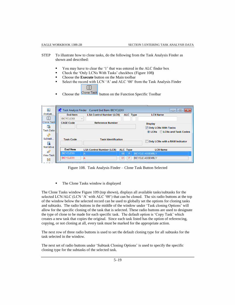
EAGLE WORKBOOK 1388-2B SECTION 5 ENTERING TASK ANALYSIS DATA
5–19
STEP To illustrate how to clone tasks, do the following from the Task Analysis Finder as
shown and described:
You may have to clear the ‘1’ that was entered in the ALC finder box
Check the ‘Only LCNs With Tasks’ checkbox (Figure 108)
Choose the Execute button on the Main toolbar
Select the record with LCN ‘A’ and ALC ‘00’ from the Task Analysis Finder
Choose the button on the Function Specific Toolbar
Figure 108. Task Analysis Finder – Clone Task Button Selected
The Clone Tasks window is displayed
The Clone Tasks window Figure 109 (top shown), displays all available tasks/subtasks for the
selected LCN/ALC (LCN ‘A’ with ALC ‘00’) that can be cloned. The six radio buttons at the top
of the window below the selected record can be used to globally set the options for cloning tasks
and subtasks. The radio buttons in the middle of the window under ‘Task cloning Options’ will
allow for the specific cloning of the task that is selected. These radio buttons are used to designate
the type of clone to be made for each specific task. The default option is ‘Copy Task’ which
creates a new task that copies the original. Since each task listed has the option of referencing,
copying, or not cloning at all, every task must be marked for the appropriate action.
The next row of three radio buttons is used to set the default cloning type for all subtasks for the
task selected in the window.
The next set of radio buttons under ‘Subtask Cloning Options’ is used to specify the specific
cloning type for the subtasks of the selected task.
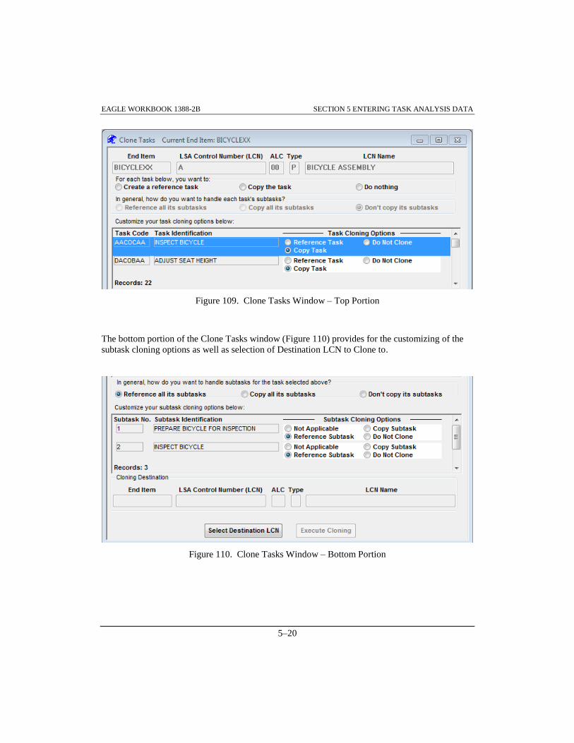
EAGLE WORKBOOK 1388-2B SECTION 5 ENTERING TASK ANALYSIS DATA
5–20
Figure 109. Clone Tasks Window – Top Portion
The bottom portion of the Clone Tasks window (Figure 110) provides for the customizing of the
subtask cloning options as well as selection of Destination LCN to Clone to.
Figure 110. Clone Tasks Window – Bottom Portion

EAGLE WORKBOOK 1388-2B SECTION 5 ENTERING TASK ANALYSIS DATA
5–21
STEP To continue with the cloning of LCN ‘A', ALC '00' tasks, do the following:
Select the Create a reference task radio button from the radio buttons listed at the top
of the window (Figure 111). This sets the Task Cloning Options for all tasks to
‘Reference Task’
Figure 111. Clone Tasks Window – Create a Reference Task Selected
Select Task Code ‘AACOCAA’ ‘INSPECT BICYCLE’ (Figure 112)
Choose the Copy Task radio button from the Task Cloning Options to the right of the
selected task
Figure 112. Clone Tasks Window – Copy Task
Click the Reference all its subtasks radio button (Figure 113). The subtasks in the
Subtask Cloning Options section are set to ‘Reference’
Figure 113. Clone Tasks Window – Reference All Subtasks Selected

EAGLE WORKBOOK 1388-2B SECTION 5 ENTERING TASK ANALYSIS DATA
5–22
Select Task Code 'DACOBAA' Task Identification ‘ADJUST SEAT HEIGHT’
(Figure 114)
Choose the Copy Task radio button from the Task Cloning Options to the right of the
selected task
Figure 114. Clone Tasks Window – Copy Second Task
Choose the Copy all its subtasks radio button (Figure 115)
All subtasks are defaulted to ‘Copy Subtask’
Figure 115. Clone Tasks Window – Copy All Subtasks
At this point your window should be as shown in Figure 116.
Choose the button to identify a destination LCN for
cloning (Figure 116)
The Task Cloning Destination LCN Finder window will be displayed

EAGLE WORKBOOK 1388-2B SECTION 5 ENTERING TASK ANALYSIS DATA
5–23
Figure 116. Clone Tasks Window – Task Code DACOBAA
Info: This window (Figure 117) is used to select the LCN to which the tasks will be cloned.
STEP To create a new LCN for the data to be cloned to, do the following as shown and
described:
Make sure ‘BICYCLEXX’ is displayed in the End Item drop down box (Figure 117)
Make sure ‘A’ is in the LSA Control Number (LCN) query box to retrieve only ‘A’
LCNs
Choose the button

EAGLE WORKBOOK 1388-2B SECTION 5 ENTERING TASK ANALYSIS DATA
5–24
At this point your window should be as shown in Figure 117.
Choose the button to create a new LCN for cloning
The LSA Control Number Data Maintenance window will be invoked
Figure 117. Task Cloning Destination LCN Finder
STEP To continue with creating the destination LCN for the clone, do the following as shown
and described:
Enter ‘A’ into the LSA Control Number (LCN) query box (Figure 118)
Choose the button

EAGLE WORKBOOK 1388-2B SECTION 5 ENTERING TASK ANALYSIS DATA
5–25
Figure 118. LSA Control Number Data Maintenance Window – Query
Insert a blank record by choosing the button
Enter ‘A’ into the LSA Control Number (LCN) field (Figure 119)
Enter ‘03’ into the ALC field
Enter ‘P’ into the Type field
Enter ‘CLONE BICYCLE’ into the LCN Name field
Enter ‘A’ into the LCN Indenture Code field
Choose the button to add the new LCN
Choose the button to return to the Task Cloning Destination LCN Finder

EAGLE WORKBOOK 1388-2B SECTION 5 ENTERING TASK ANALYSIS DATA
5–26
Figure 119. LSA Control Number Data Maintenance Window – Adding ALC ‘03’
STEP To finish selecting the destination LCN for the copy, do the following as shown and
described:
Choose the button to display the newly added LCN (Figure 120)
Select the record with LCN ‘A’ and ALC ‘03’ from the cloning destination list
Choose the button to return to the Clone Tasks window

EAGLE WORKBOOK 1388-2B SECTION 5 ENTERING TASK ANALYSIS DATA
5–27
Figure 120. Task Cloning Destination LCN Finder Results
Notice the Cloning Destination fields have been populated in the Clone Tasks
window (Figure 121)
Choose the button to perform the copy
The Task Cloning Status Screen will be displayed showing the Task/Subtask being
cloned
Figure 121. Clone Tasks Window – Cloning Destination

EAGLE WORKBOOK 1388-2B SECTION 5 ENTERING TASK ANALYSIS DATA
5–28
Close the Clone Tasks window. This takes you back to the Task Analysis Finder
STEP To verify the Clone Tasks was successful, do the following as described:
With the Task Analysis Finder displayed, choose the Execute button to query the
database
Select the record with LCN ‘A’ and ALC ‘03’
Choose the button on the Function Specific toolbar
The Task Information window is displayed
Choose the dropdown in the Task Code/Task Identification box (Just under the Sort
Tasks button) (Figure 122)
The resulting window should contain the tasks cloned. All tasks should be reference
tasks (R) except for Task Codes 'AACOCAA' and 'DACOBAA'
Figure 122. Task Cloning Results
Close the Task Information window

EAGLE WORKBOOK 1388-2B SECTION 5 ENTERING TASK ANALYSIS DATA
5–29
5.1.3 Sorting Task Codes
When a large number of tasks exist for an LCN/ALC, it is often useful to sort the tasks in an order
other than the default order (default is task code). In any of the functions available under the
Reports/Process menu from the Task Analysis Finder (except Clone Task), tasks may be sorted by
clicking the Sort Tasks button. Tasks may be sorted by positions 1 through 5 of the Task Code
(Task Function Code, Task Interval Code, Operations/Maintenance Level Code, Service
Designator Code, or Operability Code) or the Task Identification.
STEP To sort tasks do the following from the Task Analysis Finder as shown in Figure 123.
Note that Figure 123 contains the results of the query after the Execute button has been
chosen:
Make sure ‘BICYCLEXX’ is displayed in the End Item drop down list box
Check the Only LCNs With Tasks checkbox
Choose the Execute button or ALT+Q,E to retrieve the records
Select the record with LCN of ‘A’ and ALC of ‘00’
Figure 123. Task Analysis Finder – Sorting Tasks
Choose the button on the Function Specific toolbar

EAGLE WORKBOOK 1388-2B SECTION 5 ENTERING TASK ANALYSIS DATA
5–30
Click the button on the Task Information window (Figure 124)
Figure 124. Task Information Window – Sort Tasks
The Specify Sort Columns window is displayed
Drag and Drop task_code_interval from the Source Data list to Columns (Figure
125)
Drag and Drop task_code_om_level from the Source Data list to Columns
Choose the button
Figure 125. Specify Sort Columns Window
Verify that the tasks are now sorted alphabetically by Task Interval (2nd position of
Task Code) and then Task OM Level (3rd position of Task Code) by clicking the
Task Code/Task Identification drop down in the Task Information window
Close the Task Information window

EAGLE WORKBOOK 1388-2B SECTION 5 ENTERING TASK ANALYSIS DATA
5–31
5.2 ADDING SUBTASKS TO TASKS
New Subtasks may be added to existing LCN/Task Code combinations. If an LCN does not
already exist, the LCN should be added using the LCN Maintenance Discipline from the
Navigator. The process for adding a new subtask to a task is outlined below and illustrated in
Figure 128.
Subtasks may be created as original or reference subtasks. Original subtasks are subtasks that
contain applicable data in Table CB and its subordinate tables, whereas reference subtasks contain
“pointers” to other records in Table CB. Reference subtasks are used to avoid duplication of data.
The only data the reference subtask needs is the required keys for the Subtask Requirement (CB)
Table. Reference subtasks should only be used when the data of the Subtask Requirement (CB)
Table and its subordinate tables (tables CC and CD) are the same for the referenced and
referencing subtask.
5.2.1 Adding Original Subtasks
STEP To illustrate how to add a new subtask into the Task Analysis tables, specifically the
Subtask Requirement or CB Table, do the following from the Task Analysis Finder as
shown and described:
Make sure ‘BICYCLEXX’ is displayed in the End Item drop down list box (Figure
126)
Check the Only LCNs With Tasks checkbox
Choose the Execute button or ALT+Q,E to retrieve the records
Select the record with LCN ‘A’ and ALC ‘01’ from the Task Analysis Finder
Figure 126. Task Analysis Finder – ALC ‘01’

EAGLE WORKBOOK 1388-2B SECTION 5 ENTERING TASK ANALYSIS DATA
5–32
Choose the button on the Function Specific toolbar
The Subtask Information window is displayed
Info: For the ‘BICYCLEXX’ End Item and the ‘A’ LCN with ALC ‘01’ there are no subtasks
for Task Code ‘AGCOCAA’. This is indicated by the ‘No Subtasks Found’ information
in the Subtask/Subtask Identification drop down list box (Figure 127) and also indicated
by the fact that the New Subtask tab is defaulted.
Figure 127. Subtask Information Window – No Subtasks Found
STEP Cont’d:
Make sure Task Code ‘AGCOCAA’ is displayed in the Task Code/Task
Identification drop down list box (Figure 128)
Make sure the New Subtask tab is selected by clicking it

EAGLE WORKBOOK 1388-2B SECTION 5 ENTERING TASK ANALYSIS DATA
5–33
Enter ‘PREPARE BICYCLE FOR INSPECTION’ in the Subtask Identification box
manually or initially fill it by selecting one of the Recommended Action Verbs
(Prepare) and then using the button
Click the radio button for ‘Enter as FIRST Subtask’ under Subtask Numbering
(REQUIRED)
Choose the button to create the subtask
Figure 128. Subtask Information window - New Subtask
STEP Add another subtask by doing the following (not shown):
Make sure the New Subtask tab is selected by clicking on it
Enter ‘INSPECT BICYCLE’ in the Subtask Identification box
Enter ‘5’ in the New Subtask No. box
Choose the button to save the subtask

EAGLE WORKBOOK 1388-2B SECTION 5 ENTERING TASK ANALYSIS DATA
5–34
Note: Subtasks may be inserted as the first subtask, last subtask or between existing subtasks.
If a subtask is inserted as the first subtask, existing subtasks will be renumbered as
required. If a subtask is inserted as the last subtask, the next sequential subtask number
will be assigned to the subtask. If a subtask is inserted between existing subtasks, the
Renumber Subtask Window will be opened to allow the user to “place” the new subtask
in the desired sequence. A subtask number may be specified (as in the previous step),
provided the subtask number does not already exist in the task under analysis.
Tip: To avoid renumbering subtasks each time a new subtask is entered between existing
subtasks, maintain a ‘gap’ between existing subtasks whenever possible.
5.2.2 Adding Reference Subtasks
Reference subtasks are created the same way original subtasks are created; however, only key
fields are required to be entered for reference subtasks. These keys are the EIAC, LCN, ALC,
LCN type, task code, subtask number, referenced subtask EIAC, referenced subtask LCN,
referenced subtask ALC, referenced subtask LCN type, reference subtask task code and referenced
subtask number.
STEP To illustrate how to add a reference subtask, do the following from the Subtask
Information window as shown and described:
Select the New Subtask tab by clicking on it (Figure 129), and the window will
change reflecting information required for adding a new subtask
Enter ‘10’ for New Subtask No.
Enter ‘POST INSPECTION PROCEDURES’ in the Subtask Identification box
manually or initially fill it by selecting one of the Recommended Action Verbs and
then using the button
Click the button on the Subtask Information
Window (Figure 129)
This will take you to the Reference Subtask Finder
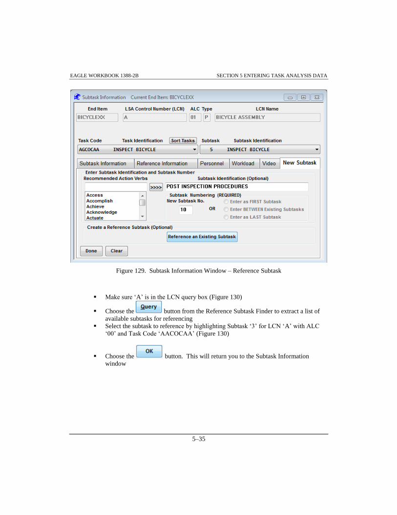
EAGLE WORKBOOK 1388-2B SECTION 5 ENTERING TASK ANALYSIS DATA
5–35
Figure 129. Subtask Information Window – Reference Subtask
Make sure ‘A’ is in the LCN query box (Figure 130)
Choose the button from the Reference Subtask Finder to extract a list of
available subtasks for referencing
Select the subtask to reference by highlighting Subtask ‘3’ for LCN ‘A’ with ALC
‘00’ and Task Code ‘AACOCAA’ (Figure 130)
Choose the button. This will return you to the Subtask Information
window

EAGLE WORKBOOK 1388-2B SECTION 5 ENTERING TASK ANALYSIS DATA
5–36
Figure 130. Reference Subtask Finder
Choose the button on the Subtask Information window to create the new
subtask
Choose the Save button on the Main toolbar
A reference subtask has now been added. Notice that once a subtask is a reference subtask, the
title of the Subtask Information window is changed to reflect ‘This subtask references another
subtask!!’(Figure 131)
This feature lets the user know that the subtask being edited is not the original. Note the ‘R’ after
the Subtask ‘10’ in the Subtask/Subtask Identification field. This also indicates the subtask
references another subtask.

EAGLE WORKBOOK 1388-2B SECTION 5 ENTERING TASK ANALYSIS DATA
5–37
Figure 131. Subtask Information Window – Reference Subtask Created
STEP To illustrate how to view reference and referencing subtask information, do the following
from the Subtask Information window as shown and described:
Make sure Task Code ‘AGCOCAA’ is selected (Figure 132)
Select the ‘POST INSPECTION PROCEDURES’ subtask from the Subtask
Identification drop down list. Note the (R) for Subtask ‘10’
Figure 132. Subtask Information window – Subtask 10
Make sure the Subtask Information tab is selected (Figure 133). Note the ‘YES’ in
the ‘Reference Subtask Used’ field
Choose the button

EAGLE WORKBOOK 1388-2B SECTION 5 ENTERING TASK ANALYSIS DATA
5–38
Figure 133. Subtask Information - Viewing Reference Subtask Information
Note that the title in the Subtask Information window header now states that the
information displayed is the ‘ORIGINAL Subtask Information’ (Figure 134)
Figure 134. Subtask Information Window - Original
Choose the button (Figure 135) to display the
reference subtask information

EAGLE WORKBOOK 1388-2B SECTION 5 ENTERING TASK ANALYSIS DATA
5–39
Figure 135. Original Subtask Information
As shown in Figure 136, an ‘R’ displayed next to the subtask number in the Subtask Identification
drop down list box indicates that a subtask is a reference subtask. When a subtask references
another subtask, the key fields of the referenced subtask are also displayed in the Subtask
Identification drop down list box.
Figure 136. Subtask Information - Viewing Reference Data
Close the Subtask Information window

EAGLE WORKBOOK 1388-2B SECTION 5 ENTERING TASK ANALYSIS DATA
5–40
5.2.3 Breaking/Changing Subtask References
Subtask references can be broken or changed using the Reference Information tab of the Subtask
Information window (Figure 137).
STEP To illustrate how to change a subtask reference, do the following as shown and described:
Select the record with LCN ‘A’ and ALC ‘03’ from the Task Analysis Finder
Choose the button on the Function Specific toolbar
Select Task Code ‘AACOCAA’ from the Task Code/Task Identification drop down
list (Figure 137)
Select Subtask ‘2 R’ ‘INSPECT BICYCLE’ from the Subtask/Subtask Identification
drop down list
Choose the Reference Information tab
Choose the button
The Reference Subtask Finder is displayed
Figure 137. Subtask Information Window – Reference Information Tab
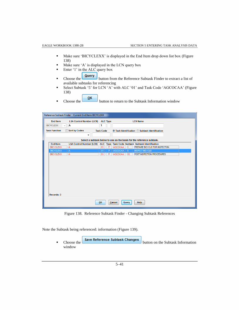
EAGLE WORKBOOK 1388-2B SECTION 5 ENTERING TASK ANALYSIS DATA
5–41
Make sure ‘BICYCLEXX’ is displayed in the End Item drop down list box (Figure
138)
Make sure ‘A’ is displayed in the LCN query box
Enter ‘1’ in the ALC query box
Choose the button from the Reference Subtask Finder to extract a list of
available subtasks for referencing
Select Subtask ‘5’ for LCN ‘A’ with ALC ‘01’ and Task Code ‘AGCOCAA’ (Figure
138)
Choose the button to return to the Subtask Information window
Figure 138. Reference Subtask Finder - Changing Subtask References
Note the Subtask being referenced: information (Figure 139).
Choose the button on the Subtask Information
window

EAGLE WORKBOOK 1388-2B SECTION 5 ENTERING TASK ANALYSIS DATA
5–42
Figure 139. Subtask Information Window – Save Reference Changes
The EAGLE: Save Reference Subtask Changes dialog box is displayed
Choose the button on the EAGLE: Save Reference Subtask
Changes dialog box (Figure 140)
Figure 140. EAGLE: Save Reference Subtask Changes – Dialog Box
The EAGLE: Delete Subtask Selected! dialog box is displayed

EAGLE WORKBOOK 1388-2B SECTION 5 ENTERING TASK ANALYSIS DATA
5–43
Choose the button on the EAGLE: Delete Subtask Selected! Dialog
box (Figure 141). (The old subtask reference is deleted and a new, referencing
subtask is created)
Figure 141. EAGLE Delete Subtask Selected!
Close the Subtask Information Window
5.3 ADDING NARRATIVE DATA TO SUBTASKS
5.3.1 Adding Subtask Narrative
Narrative Data for Subtasks can be added using the Task Analysis Discipline from the Navigator.
Access the Task Analysis Discipline from the Navigator and select the Task Analysis Finder.
STEP To Add Subtask Narrative, do the following as shown and described:
Make sure ‘BICYCLEXX’ is displayed in the End Item drop down box (Figure 142)
Check the Only LCNs With Tasks checkbox
Choose the Execute button or ALT+Q,E to retrieve the records
Select the record with LCN ‘A’ and ALC ‘01’ from the Task Analysis Finder

EAGLE WORKBOOK 1388-2B SECTION 5 ENTERING TASK ANALYSIS DATA
5–44
Figure 142. Task Analysis Finder – ALC ‘01’ Selected
Choose the button from the Function Specific toolbar. The Narrative
Editor is displayed
Info: Narrative data may be added to existing LCN/Task/Subtask combinations. However, to
edit narrative data, the Allow Editing checkbox must be checked. In addition, if an LCN
does not already exist, the LCN should be added using the LCN Maintenance Discipline
from the Navigator. If a Task does not already exist, the Task should be added using the
Task Analysis Discipline from the Navigator as outlined in Paragraph 5.1 above. Finally,
if a Subtask does not already exist, the Subtask should be added using the Task Analysis
Discipline from the Navigator as outlined in Paragraph 5.2 above.
Check: Do this to make sure we are using the correct Editor for this exercise:
From the Menu bar, select Tools>>Options to invoke the Options window
Click the Publishing and Reports tab (Figure 143)
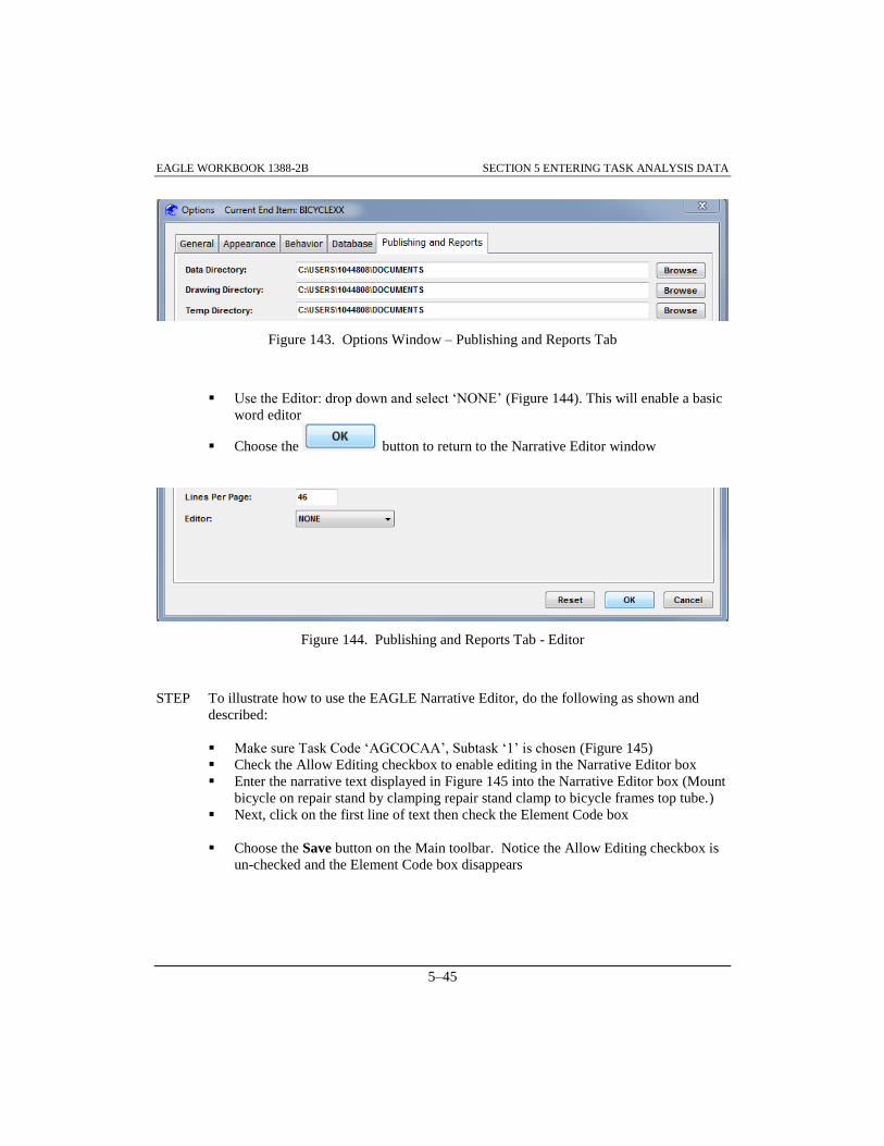
EAGLE WORKBOOK 1388-2B SECTION 5 ENTERING TASK ANALYSIS DATA
5–45
Figure 143. Options Window – Publishing and Reports Tab
Use the Editor: drop down and select ‘NONE’ (Figure 144). This will enable a basic
word editor
Choose the button to return to the Narrative Editor window
Figure 144. Publishing and Reports Tab - Editor
STEP To illustrate how to use the EAGLE Narrative Editor, do the following as shown and
described:
Make sure Task Code ‘AGCOCAA’, Subtask ‘1’ is chosen (Figure 145)
Check the Allow Editing checkbox to enable editing in the Narrative Editor box
Enter the narrative text displayed in Figure 145 into the Narrative Editor box (Mount
bicycle on repair stand by clamping repair stand clamp to bicycle frames top tube.)
Next, click on the first line of text then check the Element Code box
Choose the Save button on the Main toolbar. Notice the Allow Editing checkbox is
un-checked and the Element Code box disappears

EAGLE WORKBOOK 1388-2B SECTION 5 ENTERING TASK ANALYSIS DATA
5–46
Figure 145. Task Analysis Narrative Editor - Subtask 1 – Element Code Checked
Note: The procedural step above was identified with an Element Code to indicate the procedure
is the smallest logically and reasonably definable unit of behavior required to complete
the subtask action. In addition, since this subtask contained multiple lines of text, the
Element Code was associated with the first line.
5.3.2 Subtask Narrative: Source Data Modified
STEP Using the Narrative Editor, do the following as shown and described:
Make sure Task Code ‘AGCOCAA’ is selected (Figure 146)
Select Subtask ‘5’, ‘INSPECT BICYCLE’ from the Subtask/Subtask Identification
box
Check the Allow Editing checkbox to enable editing in the Narrative Editor box
Enter the narrative text ‘Physically inspect bicycle by looking for rust on spokes,
chain and frame.’ into the Narrative Editor box
Click on the first line of text then click on the Element Code box

EAGLE WORKBOOK 1388-2B SECTION 5 ENTERING TASK ANALYSIS DATA
5–47
Figure 146. Task Analysis Narrative Editor - Subtask 5 – Element Code Checked
Choose the Save button on the Main toolbar
The Source Data Modified-Reference Subtask Check window is displayed (Figure
147)
Since Subtask ‘5’ is referenced by another subtask, the Source Data Modified-Reference Subtask
Check window will be displayed to allow the user options for saving the narrative change. Three
options are available. These options consist of changing the original subtask only, changing the
original subtask and leaving all or some of the referencing tasks the same, or only changing the
referencing subtasks.
The first option for saving narrative changes to subtasks is to change the original subtask and all
references to it. This option is the default option and is shown in Figure 147. The “DO NOT
CHANGE the reference subtasks selected below” radio button is marked; however, no subtasks
are selected from the provided list so that all reference subtasks still point to the original subtask.
Therefore, the original subtask is changed and all reference subtasks are in effect changed since
they still reference the original subtask.

EAGLE WORKBOOK 1388-2B SECTION 5 ENTERING TASK ANALYSIS DATA
5–48
Figure 147. Source Data Modified – No Subtasks Selected
The second option for saving narrative changes to subtasks is to change the original subtask, but
leave some of the referencing tasks the same. For this option (Figure 148), the “DO NOT
CHANGE the reference subtask selected below” radio button is marked, and any referencing
subtasks that the user wishes to remain the same should be highlighted/selected from the list. The
original subtask will be changed, and any selected referencing subtasks will remain the same.
Therefore, the referencing subtasks remaining the same will become original tasks containing the
original narrative before the change was made.
Figure 148. Source Data Modified –Subtask Selected

EAGLE WORKBOOK 1388-2B SECTION 5 ENTERING TASK ANALYSIS DATA
5–49
The third option for saving narrative changes to subtasks is to change only the referencing
subtasks while leaving the original subtask alone. For this option (Figure 149), the ‘CHANGE
ONLY the referenced subtasks selected below (DO NOT change the Original)’ radio button is
marked. The original subtask will not contain the narrative change however any referenced
subtasks selected will be changed. Therefore, the selected referencing subtasks will become
original tasks containing the changed narrative, while the original task will remain unchanged.
Figure 149. Source Data Modified – Change Only Selected Subtasks
STEP Do the following as shown and described to ensure the modified source data will be
reflected in the referencing subtask(s):
Make sure the ‘DO NOT CHANGE the reference subtasks selected below’ radio
button is selected (Figure 150)
Choose the button to ensure that all of the referencing subtasks will
be affected (changed)
Choose the button
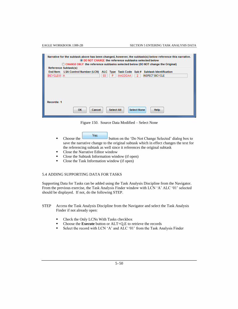
EAGLE WORKBOOK 1388-2B SECTION 5 ENTERING TASK ANALYSIS DATA
5–50
Figure 150. Source Data Modified – Select None
Choose the button on the ‘Do Not Change Selected’ dialog box to
save the narrative change to the original subtask which in effect changes the text for
the referencing subtask as well since it references the original subtask
Close the Narrative Editor window
Close the Subtask Information window (if open)
Close the Task Information window (if open)
5.4 ADDING SUPPORTING DATA FOR TASKS
Supporting Data for Tasks can be added using the Task Analysis Discipline from the Navigator.
From the previous exercise, the Task Analysis Finder window with LCN ‘A’ ALC ‘01’ selected
should be displayed. If not, do the following STEP.
STEP Access the Task Analysis Discipline from the Navigator and select the Task Analysis
Finder if not already open:
Check the Only LCNs With Tasks checkbox
Choose the Execute button or ALT+Q,E to retrieve the records
Select the record with LCN ‘A’ and ALC ‘01’ from the Task Analysis Finder

EAGLE WORKBOOK 1388-2B SECTION 5 ENTERING TASK ANALYSIS DATA
5–51
5.4.1 Assigning Task Support Equipment
In order to assign support equipment to a task, the support equipment (EA record) must already
exist. For instructions on how to create support equipment (EA) records, refer to Paragraph 9.2
about adding support equipment records. In order for a support equipment item to be available for
assignment to a task, it must have an item category code (SEICCDEA) of ‘7’, ‘8’, ‘M’, ‘D’, ‘1’,
‘H’, ‘4’, ‘5’, ‘6’, ‘2’, ‘G’, ‘N’, ‘P’, ‘R’, ‘3’, ‘S’, ‘T’, ‘E’, ‘F’, ‘J’, ‘U’, ‘V’, ‘AC’, ‘AD’, or ‘AF’.
The Support Equipment Discipline can be used to change the item category code if necessary.
It is presumed that LCN ‘A’ with ALC ‘01’ is selected in the Task Analysis Finder as described in
Paragraph 5.4 above. In order to assign support equipment to a task, a Task Support Equipment
(CG) record must be created. The CG record provides a link from the support equipment tables to
the task analysis tables. This allows documenting of support equipment required to complete a
task.
STEP To illustrate how to assign support equipment do the following as shown and described:
Choose the button on the Function Specific toolbar
Make sure Task Code ‘AGCOCAA’ is selected in the Task Information window
(Figure 151)
Click on the Support Equipment tab
Any support equipment assigned to the task will be displayed. In this case Records:
(0) is displayed
Choose the button. The Task Support Equipment window is
displayed

EAGLE WORKBOOK 1388-2B SECTION 5 ENTERING TASK ANALYSIS DATA
5–52
Figure 151. Task Information - Support Equipment
Choose the button (Figure 152) to search the database for all
Table EA records that exist for selection
Scroll down and select the Support Equipment with CAGE of ‘SE999’ and SE
Reference Number ‘RS-9’
Choose the button

EAGLE WORKBOOK 1388-2B SECTION 5 ENTERING TASK ANALYSIS DATA
5–53
Figure 152. Task Support Equipment Window – REPAIR STAND
The EAGLE:Task Support Equipment Add! Dialog box is displayed (not shown)
Choose the button
This will return the Task Information window
STEP To complete the addition of support equipment, do the following as shown and described:
Enter ‘1’ into the Qty field (Figure 153)
Select ‘EACH’ from the Unit of Measure drop down list
Choose the Save button
Note the ‘No Peculiar/Common Tool/SE Requirement’ message that appears in the
Task Information window

EAGLE WORKBOOK 1388-2B SECTION 5 ENTERING TASK ANALYSIS DATA
5–54
Figure 153. Task Information - Support Equipment Added
When the performance of a task requires tools or support equipment, a Tool/Support Equipment
Requirement Code should be documented in Table CA. (A code of ‘S’ indicates a Peculiar
tool/SE requirement, a code of ‘C’ indicates a Common tool/SE requirement, or a code of ‘B’
indicates both a Peculiar and Common tool/SE requirement.) Also, when test equipment is
required, the field Task Condition B in Table CA should contain a value of ‘Y’. Similarly, when
special tools are required, the field Task Condition C in Table CA should contain a value of ‘Y’.
The warning shown in the Task Information window is displayed when tool or support equipment
requirements are added to a task without these conditions satisfied.
The support equipment added in the previous exercise has an item category code of ‘8’ which
indicates that the part is a peculiar tool. Therefore, additional steps must be taken to correctly
identify the support equipment in this task.
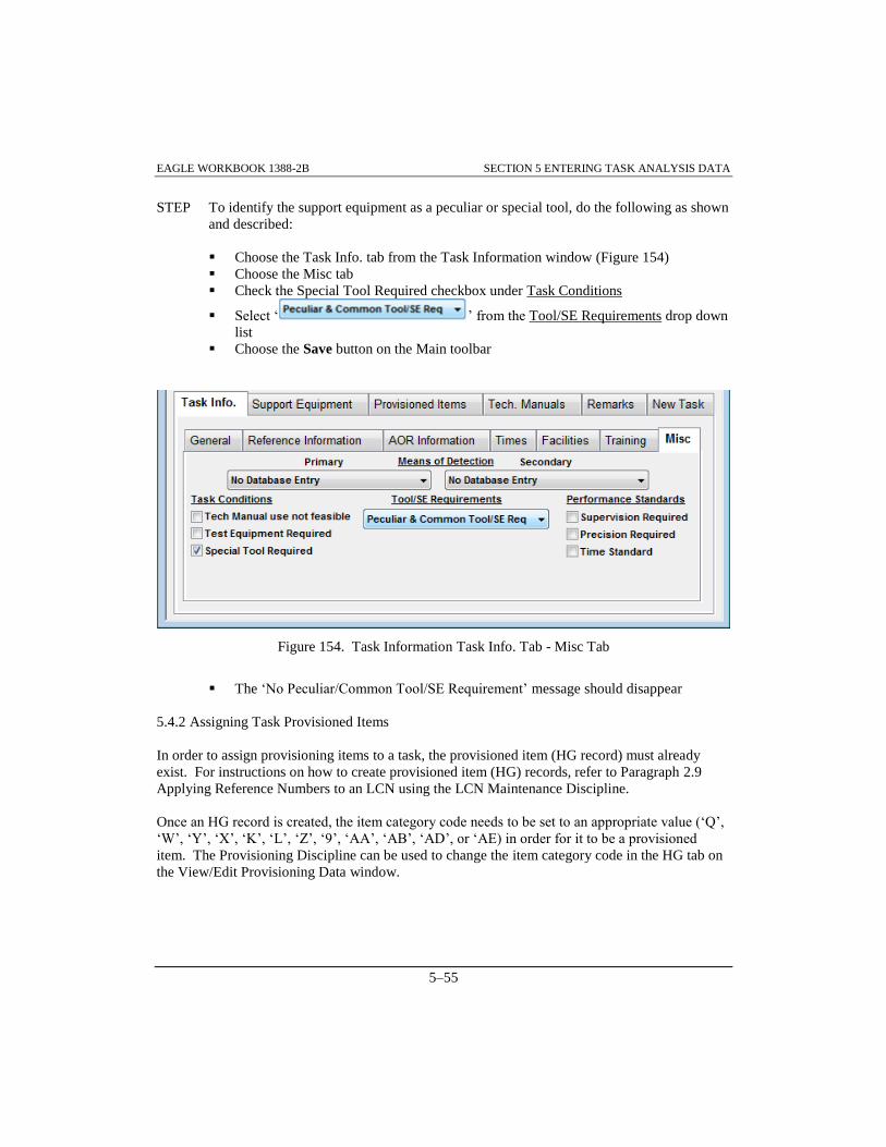
EAGLE WORKBOOK 1388-2B SECTION 5 ENTERING TASK ANALYSIS DATA
5–55
STEP To identify the support equipment as a peculiar or special tool, do the following as shown
and described:
Choose the Task Info. tab from the Task Information window (Figure 154)
Choose the Misc tab
Check the Special Tool Required checkbox under Task Conditions
Select ‘ ’ from the Tool/SE Requirements drop down
list
Choose the Save button on the Main toolbar
Figure 154. Task Information Task Info. Tab - Misc Tab
The ‘No Peculiar/Common Tool/SE Requirement’ message should disappear
5.4.2 Assigning Task Provisioned Items
In order to assign provisioning items to a task, the provisioned item (HG record) must already
exist. For instructions on how to create provisioned item (HG) records, refer to Paragraph 2.9
Applying Reference Numbers to an LCN using the LCN Maintenance Discipline.
Once an HG record is created, the item category code needs to be set to an appropriate value (‘Q’,
‘W’, ‘Y’, ‘X’, ‘K’, ‘L’, ‘Z’, ‘9’, ‘AA’, ‘AB’, ‘AD’, or ‘AE) in order for it to be a provisioned
item. The Provisioning Discipline can be used to change the item category code in the HG tab on
the View/Edit Provisioning Data window.

EAGLE WORKBOOK 1388-2B SECTION 5 ENTERING TASK ANALYSIS DATA
5–56
It is presumed that LCN ‘A’ ALC ‘01’ is still selected with the Task Identification ‘INSPECT
BICYCLE’ displayed in the Task Information window. In order to assign provisioning items to a
task, a Task Provisioned Item (CI) record must be created. The Table CI record provides a link
from the provisioning tables to the task analysis tables. This allows documenting of spare and
repair parts needed to support the task.
STEP To illustrate how to assign provisioned items, do the following as shown and described:
Select the Provisioned Items tab (Figure 155). Any provisioned items assigned to
the task will be displayed. In this case there are none (records: 0)
Make sure the Show All checkbox is checked so that all Item Category Codes (ICC
Elements) are selected
Click the button. The Task Provisioned Items window is displayed
Figure 155. Task Information - Provisioned Items

EAGLE WORKBOOK 1388-2B SECTION 5 ENTERING TASK ANALYSIS DATA
5–57
Choose the button to search the database for all HG records that
exist for the ‘BICYCLEXX’ end item (Figure 156)
Scroll down and select the record with CAGE ‘99999’ and Reference Number
‘ESL749ZF’ from the list of provisioned items
Choose the button
Figure 156. Task Provisioned Items
The EAGLE: Task Provisioning Items Add! Dialog box is displayed
Choose the button
The Task Information window is re-displayed
STEP To complete the addition of the provisioned item, do the following as shown and
described:
Enter ‘1’ into the Qty box (Figure 157)
Select ‘EACH’ from the Unit of Measure drop down list
Choose the Save button on the Main toolbar

EAGLE WORKBOOK 1388-2B SECTION 5 ENTERING TASK ANALYSIS DATA
5–58
Figure 157. Task Information - Provisioned Items Added
5.4.3 Assigning Subtask Personnel Requirements
In order to assign personnel to subtasks, a Subtask Personnel Requirement (CD) record must be
created. The CD record provides a link from the personnel skills tables to the task analysis tables.
This allows documenting of personnel skills required to complete a task.
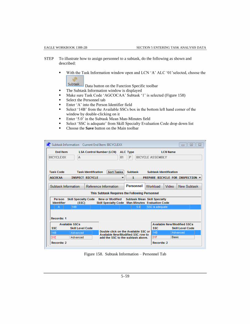
EAGLE WORKBOOK 1388-2B SECTION 5 ENTERING TASK ANALYSIS DATA
5–59
STEP To illustrate how to assign personnel to a subtask, do the following as shown and
described:
With the Task Information window open and LCN ‘A’ ALC ‘01’selected, choose the
Data button on the Function Specific toolbar
The Subtask Information window is displayed
Make sure Task Code ‘AGCOCAA’ Subtask ‘1’ is selected (Figure 158)
Select the Personnel tab
Enter ‘A’ into the Person Identifier field
Select ‘14B’ from the Available SSCs box in the bottom left hand corner of the
window by double-clicking on it
Enter ‘5.0’ in the Subtask Mean Man-Minutes field
Select ‘SSC is adequate’ from Skill Specialty Evaluation Code drop down list
Choose the Save button on the Main toolbar
Figure 158. Subtask Information – Personnel Tab

EAGLE WORKBOOK 1388-2B SECTION 5 ENTERING TASK ANALYSIS DATA
5–60
5.4.4 Assigning Subtask Workload Requirements
It is assumed that Paragraph 5.4.3 has been completed and personnel have been assigned to a
subtask. In order to assign workloads to subtasks, a Subtask Task Inventory (CK) record must be
created. The CK record provides a link from the personnel skills tables, the job and duty tables,
and the task analysis tables. This allows documenting of workload requirements to complete a
subtask.
STEP To illustrate how to assign workloads for a subtask, enter the following information as
shown and described:
Choose the Workload tab from the Subtask Information window (Figure 159)
Make sure the Person ID Codes tab is selected
Select the ‘A’ from the Available Person Identifiers records. In this case there is
only one record. ‘A’ is already selected
Choose the button to assign the Person Id Code: for the Workload
Assignment
Figure 159. Subtask Information Window - Workload Tab – Person ID Codes

EAGLE WORKBOOK 1388-2B SECTION 5 ENTERING TASK ANALYSIS DATA
5–61
Choose the Job/Duty Codes tab (Figure 160)
Scroll down the Job/Duty Codes list if necessary and choose the record with Job
Code ‘A1’ and Duty Code ‘1’
Choose the button to assign the Job/Duty Codes
Figure 160. Subtask Information Window - Workload Tab – Job Duty Codes
Choose the Workload Text tab (Figure 161)
Highlight the two rows of text. To get the From: and To: lines from the workload
text (click on the first line then click on the second line while holding down the Shift
key). You may have three lines of text
Choose the button to assign the Workload Text
Choose the Save button on the Main toolbar

EAGLE WORKBOOK 1388-2B SECTION 5 ENTERING TASK ANALYSIS DATA
5–62
Figure 161. Subtask Information Window - Workload Tab – Workload Text
Close the Subtask Information window
Note: If additional workload assignments need to be made the ‘New’ button on the bottom left
of the window is used to add another workload.
5.5 ASSIGNING TASK NARRATIVE TO A TECH MANUAL
Task narrative can be assigned to a Tech Manual by using the Task Analysis Discipline from the
Navigator. Before task narrative can be assigned to a tech manual, a tech manual code must
already exist. It is assumed that Paragraph 5.4.4 has been completed and the Task Analysis Finder
is displayed.
STEP To illustrate how to assign task narrative to a tech manual, do the following as shown and
described:
Make sure LCN ‘A’, ALC ‘01’ is selected in the Task Analysis Finder

EAGLE WORKBOOK 1388-2B SECTION 5 ENTERING TASK ANALYSIS DATA
5–63
Choose the button on the Function Specific toolbar
Select the Tech. Manuals Tab in the Task Information window (Figure 162)
Click if ‘No Records Found’ message is displayed
Select the record with TM Code ‘TMT’ and TM Number ‘TRAINING TM’
Choose the button
Figure 162. Task Information - Tech. Manuals
Choose the Save button on the Main toolbar
Your screen should reflect Figure 163

EAGLE WORKBOOK 1388-2B SECTION 5 ENTERING TASK ANALYSIS DATA
5–64
Figure 163. Tech Manuals – TM Added
Note: More than one technical manual code can be tied to a task’s narrative by adding multiple
technical manual codes. When a tech manual should no longer contain a task, click on
the tech manual record and choose the button to remove it.
Close the Task Information window
Close the Task Analysis Finder

EAGLE Workbook 1388-2B Version 15
ENTERING
FACILITIES
CONSIDERATIONS
DATA
SECTION 6


EAGLE WORKBOOK 1388-2B SECTION 6 ENTERING FACILITIES CONSIDERATIONS DATA
6–3
SECTION 6 ENTERING FACILITIES CONSIDERATIONS DATA
6.0 INTRODUCTION
This section provides an overview of the Facilities Considerations tables (F tables) of MIL-STD-
1388-2B. The F tables identify and justify all proposed special and additional facilities
requirements that are identified as a result of the operational/maintenance task analysis.
6.1 ADDING FACILITIES DATA
Access the Facilities Discipline from the Navigator, select and double-click the Facilities Finder
function as illustrated in Figure 164.
Figure 164. Navigator – Facilities Discipline
The Facilities Finder is used like other Data Finders (see paragraph 1.5.1). To familiarize the user
with how a Data Finder works the first step in this paragraph will walk through a simple query.
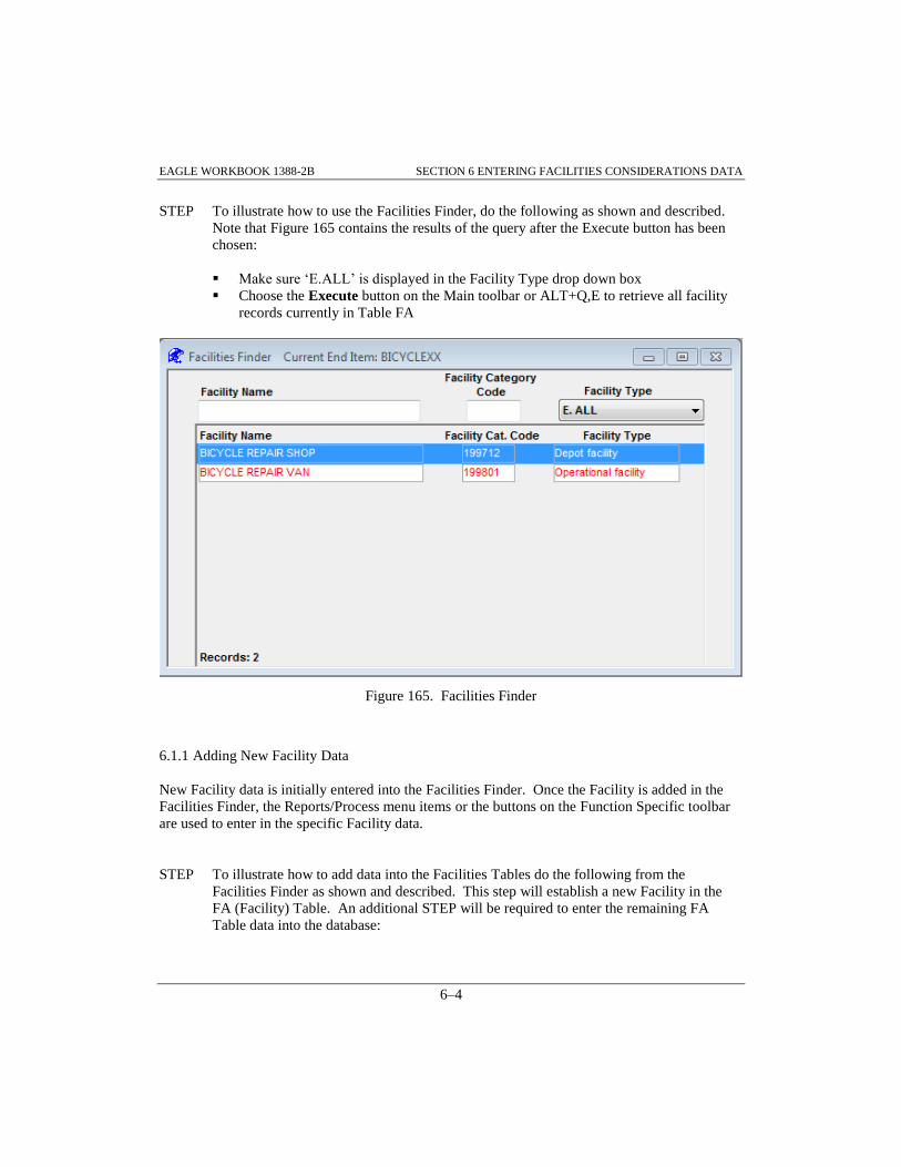
EAGLE WORKBOOK 1388-2B SECTION 6 ENTERING FACILITIES CONSIDERATIONS DATA
6–4
STEP To illustrate how to use the Facilities Finder, do the following as shown and described.
Note that Figure 165 contains the results of the query after the Execute button has been
chosen:
Make sure ‘E.ALL’ is displayed in the Facility Type drop down box
Choose the Execute button on the Main toolbar or ALT+Q,E to retrieve all facility
records currently in Table FA
Figure 165. Facilities Finder
6.1.1 Adding New Facility Data
New Facility data is initially entered into the Facilities Finder. Once the Facility is added in the
Facilities Finder, the Reports/Process menu items or the buttons on the Function Specific toolbar
are used to enter in the specific Facility data.
STEP To illustrate how to add data into the Facilities Tables do the following from the
Facilities Finder as shown and described. This step will establish a new Facility in the
FA (Facility) Table. An additional STEP will be required to enter the remaining FA
Table data into the database:

EAGLE WORKBOOK 1388-2B SECTION 6 ENTERING FACILITIES CONSIDERATIONS DATA
6–5
Choose the Insert button on the Main toolbar
Enter ‘BICYCLE SALES AND REPAIR SHOP’ into the empty Facility Name field
(Figure 166)
Enter ‘199345’ into the empty Facility Cat. Code field
Select ‘Test facility’ from the Facility Type drop down list
Choose the Save button on the Main toolbar
Figure 166. Facilities Finder - Data Entry
STEP To illustrate how to add additional data into the Facilities Tables, specifically the FA
Table, enter the following information as shown described. Note that Figure 167 displays
the result after the data has been saved to the database:
Select the just added ‘BICYCLE SALES AND REPAIR SHOP’ record from the
Facilities Finder
Choose the button on the Function Specific toolbar to add the remaining
facility data
Enter ‘WAREHOUSE’ into the Facility Class field (Figure 167)
Enter ‘H1N’ into the Dwg. Class field
Enter ‘ER23-00-1-12’ into the Drawing Number field
Enter ‘AA’ into the Rev. field
Enter ‘30’ into the Facility Area field
Select ‘SQUARE FOOT’ from the Unit Of Measure drop down list
Enter ‘1’ into the Constr. Unit Of Meas. Price field
Select ‘SQUARE FOOT’ from the Constr. Unit Of Meas. drop down list
Choose the Save button on the Main toolbar

EAGLE WORKBOOK 1388-2B SECTION 6 ENTERING FACILITIES CONSIDERATIONS DATA
6–6
Figure 167. Facility Window
Note: If the drawing exists in the EAGLE database, the Drawing Number and Rev. box can be
filled by using the Find Drawing button and selecting the drawing.
Close the Facility window and return to the Facilities Finder
6.1.2 Linking Facilities Data to Task Requirements
In order to link Facilities data to Task Requirements, The Facility data (Table FA) must already
exist in the database. Therefore, it is presumed that Paragraph 6.1.1 has been completed for the
‘BICYCLE SALES AND REPAIR SHOP’ Facility.
STEP To illustrate how to link data from the Facilities Tables (F tables) to the Task Tables
(CA), do the following as shown and described. Note: Facility Tables are linked to the
Task Tables through the Operations and Maintenance Task Facility Requirement (FE)
Table:
Make sure the ‘BICYCLE SALES AND REPAIR SHOP’ facility is selected in the
Facilities Finder (Figure 168)
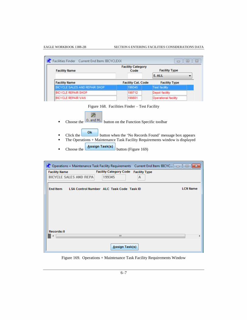
EAGLE WORKBOOK 1388-2B SECTION 6 ENTERING FACILITIES CONSIDERATIONS DATA
6–7
Figure 168. Facilities Finder – Test Facility
Choose the button on the Function Specific toolbar
Click the button when the ‘No Records Found’ message box appears
The Operations + Maintenance Task Facility Requirements window is displayed
Choose the button (Figure 169)
Figure 169. Operations + Maintenance Task Facility Requirements Window

EAGLE WORKBOOK 1388-2B SECTION 6 ENTERING FACILITIES CONSIDERATIONS DATA
6–8
The Task Selection window is displayed
STEP To continue linking data from the Facilities Tables (F tables) to the Task Tables (CA), do
the following from the Task Selection window as shown and described:
Enter ‘1’ into the ALC finder box (Figure 170)
Choose the button to retrieve the records
Select the record with LCN ‘A’ and Task Code ‘AGCOCAA’
Choose the button to return to the Operations + Maintenance Task
Facility Requirements window
Figure 170. Task Selection Window
Choose the Save button on the Main toolbar
Close the Operations & Maintenance Task Facility Requirements window
Close the Facilities Finder
Check: Do you now have two Facilities mapped to your ‘Inspect Bicycle’ Task for ALC ‘01’?

EAGLE Workbook 1388-2B Version 15
ENTERING
PERSONNEL SKILL
CONSIDERATIONS
DATA
SECTION 7


EAGLE WORKBOOK 1388-2B SECTION 7 ENTERING PERSONNEL SKILLS CONSIDERATIONS DATA
7–3
SECTION 7 ENTERING PERSONNEL SKILL CONSIDERATIONS DATA
7.0 INTRODUCTION
The Personnel Skill Considerations tables (G tables) describe and justify any new or modified
personnel skills required to support the system/equipment.
7.1 ADDING NEW SKILLS DATA
Access the Personnel Skills Discipline from the Navigator, utilizing the Home Tab and Filter box,
select and double-click the Skill Specialty Code Finder (GA) function as shown in Figure 171.
Figure 171. Navigator - Personnel Skills Discipline
Within the Personnel Skills Discipline, there are three Personnel Skills Finders that are used like
other Data Finders (see paragraph 1.5.1). To familiarize the user with how a Data Finder
functions, the first step in this paragraph will walk through a simple query.
STEP To illustrate how to use the Skill Specialty Code Finder (GA), do the following as shown
and described:
Choose the Execute button to retrieve all Skill Specialty Codes (Figure 172)

EAGLE WORKBOOK 1388-2B SECTION 7 ENTERING PERSONNEL SKILLS CONSIDERATIONS DATA
7–4
Figure 172. Personnel Skills Finder – Records Returned
Choose the Insert button
Enter ‘23A’ into the Skill Specialty Code field (Figure 173)
Select ‘Intermediate’ from the Skill Level drop down list
Enter ‘7.50’ into the Hourly Labor Rate field
Enter ‘20000’ into the Training Cost field
Choose the Save button on the Main toolbar
Figure 173. Personnel Skills Finder - Skill Specialty Code Entered
Close the Personnel Skills Finder (GA) window to return to the Navigator
STEP To illustrate how to add data into the Personnel Skill Consideration Tables, specifically
the New or Modified Skill Table or GB Table, do the following from the New or
Modified Skill Finder as shown and described:

EAGLE WORKBOOK 1388-2B SECTION 7 ENTERING PERSONNEL SKILLS CONSIDERATIONS DATA
7–5
Double-click the Personnel Skills Finder (GB,GC,GD) function from the Navigator
The New or Modified Skill Finder is displayed
Choose the Execute button to retrieve the skill specialty data
Choose the Insert button
Enter ‘23B’ in the New or Modified Skill Specialty Code field (Figure 174)
Select ‘Advanced’ from the New or Modified Skill Level field
Enter ‘23A’ into the Skill Specialty Code field
Enter ‘TRAINING’ into the Duty Position Requiring a New or Revised Skill field
Select ‘Unclassified’ from the Security Clearance (Required Information) drop down
list
Choose the Save button on the Main toolbar
Figure 174. New or Modified Skill Finder
Close the New or Modified Skill Finder
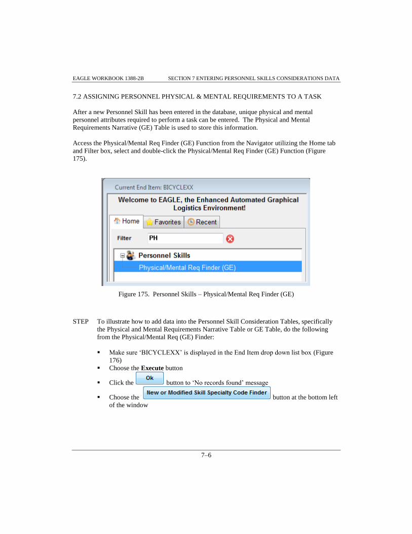
EAGLE WORKBOOK 1388-2B SECTION 7 ENTERING PERSONNEL SKILLS CONSIDERATIONS DATA
7–6
7.2 ASSIGNING PERSONNEL PHYSICAL & MENTAL REQUIREMENTS TO A TASK
After a new Personnel Skill has been entered in the database, unique physical and mental
personnel attributes required to perform a task can be entered. The Physical and Mental
Requirements Narrative (GE) Table is used to store this information.
Access the Physical/Mental Req Finder (GE) Function from the Navigator utilizing the Home tab
and Filter box, select and double-click the Physical/Mental Req Finder (GE) Function (Figure
175).
Figure 175. Personnel Skills – Physical/Mental Req Finder (GE)
STEP To illustrate how to add data into the Personnel Skill Consideration Tables, specifically
the Physical and Mental Requirements Narrative Table or GE Table, do the following
from the Physical/Mental Req (GE) Finder:
Make sure ‘BICYCLEXX’ is displayed in the End Item drop down list box (Figure
176)
Choose the Execute button
Click the button to ‘No records found’ message
Choose the button at the bottom left
of the window

EAGLE WORKBOOK 1388-2B SECTION 7 ENTERING PERSONNEL SKILLS CONSIDERATIONS DATA
7–7
Figure 176. Physical and Mental Requirements Narrative Finder (GE)
The New or Modified Skill Specialty Code Finder is displayed
Select the record with ‘23B’ in the New or Modified Skill Specialty Code field
(Figure 177)
Choose the button

EAGLE WORKBOOK 1388-2B SECTION 7 ENTERING PERSONNEL SKILLS CONSIDERATIONS DATA
7–8
Figure 177. New or Modified Skill Specialty Code Finder
You are returned to the Physical and Mental Requirements Narrative Finder
Choose the button at the bottom right of
the screen (Figure 178)
Figure 178. Physical and Mental Requirements Narrative Finder – 23B Entered
The Subtask Personnel Requirement Finder is displayed
Make sure ‘BICYCLEXX’ is displayed in the End Item drop down list box (Figure
179)
Choose the button

EAGLE WORKBOOK 1388-2B SECTION 7 ENTERING PERSONNEL SKILLS CONSIDERATIONS DATA
7–9
Choose the record with LCN ‘A’, ALC ‘00’, Task Code ‘AACOCAA’, and Subtask
‘1’
Choose the button
Figure 179. Subtask Personnel Requirement Finder
Figure 180 is displayed
Figure 180. Physical and Mental Requirements Narrative Finder - Data Selected

EAGLE WORKBOOK 1388-2B SECTION 7 ENTERING PERSONNEL SKILLS CONSIDERATIONS DATA
7–10
Choose the Save button on the Main toolbar
STEP Retrieve the window for adding the narrative data to the GE Table:
Choose the button from the Function Specific toolbar to retrieve the
Physical and Mental Requirements Narrative window
STEP To complete adding data into the Personnel Skill Consideration Tables, specifically the
Physical and Mental Requirements Narrative Table or GE Table, enter the following data
into the Personnel Physical and Mental Requirements Narrative window as shown and
described:
Select Subtask ‘1’ and Person ID ‘A’ from the drop down list (Figure 181)
Enter the narrative ‘Smart and aggressive individual needed.’ into the narrative box
Choose the Save button on the Main toolbar
Figure 181. Personnel Skills - Physical and Mental Requirements Narrative Window
Close the Physical and Mental Requirements Narrative window
Close the Physical and Mental Requirements Narrative Finder

EAGLE Workbook 1388-2B Version 15
ENTERING
TRANSPORTABILITY
ENGINEERING
ANALYSIS DATA
SECTION 8


EAGLE WORKBOOK 1388-2B SECTION 8 ENTERING TRANSPORT ENG ANALYSIS DATA
8–3
SECTION 8 ENTERING TRANSPORTABILITY ENGINEERING ANALYSIS DATA
8.0 INTRODUCTION
The Transportability Engineering Analysis tables (J tables) document transportability shipping
mode data for the end item. For end items that are sectionalized for transport, the J tables should
be completed for each section of the end item. Transportability data can only be documented for
items identified with a sectionalized item transportation indicator in table XB (SECITMXB) of
“Y” or a transportation end item indicator in table XC (TRASEIXC) of “Y”.
8.1 ADDING TRANSPORTATION DATA
Access the Transportation Discipline from the Navigator utilizing the Home tab and Filter box,
select and double-click the Transportation Finder Function as shown in Figure 182.
Figure 182. Navigator - Transportation
STEP To illustrate how to use the Transportation Finder, do the following as shown and
described:
Make sure the Transportation Finder is displayed

EAGLE WORKBOOK 1388-2B SECTION 8 ENTERING TRANSPORT ENG ANALYSIS DATA
8–4
Make sure ‘BICYCLEXX’ is displayed in the End Item drop down box (Figure 183)
Make sure the Show all LCNs radio button is selected
Choose the Execute button or ALT+Q,E to retrieve the records
Select the record with LCN ‘A’ and ALC ‘01’
Figure 183. Transportation Finder – Records Returned
Note: When the Show all LCNs radio button is selected, all LCNs from Table XB meeting the
search criteria are returned. If the Only LCNs with Transportation Data radio button is
selected, only LCNs with data in Table JA that meet the search criteria are returned. If
there is no data found for the given record selected, a message box will alert the user.
After responding by choosing the OK button, an empty window will appear allowing the
user to enter data.
STEP To illustrate how to add data into the Transportation Tables, specifically the
Transportation Table or JA Table, do the following as shown and described:

EAGLE WORKBOOK 1388-2B SECTION 8 ENTERING TRANSPORT ENG ANALYSIS DATA
8–5
Choose the button from the Function Specific toolbar
Click the button to ‘No Records Found’ message
The Transportation window is displayed
Select ‘Both Shipping Modes + Trans. E.I.’ from the Transportation Indicator drop
down list (Figure 184)
Select ‘Special considerations required’ from the Environmental Handling and
Transportation Indicator drop down list
Select 'Not Required' from the Delivery Schedule drop down list
Choose the Save button on the Main toolbar
Figure 184. Transportation Window
Close the Transportation window
8.1.1 Adding Transportation Shipping Mode Data
STEP To illustrate how to add shipping mode data, do the following from the Transportation
Finder as shown and described:
Select the record with LCN ‘A’ and ALC ‘01’ from the Transportation Finder
Choose the button from the Function Specific toolbar
Click the button to ‘No records found’ message
The Transportation Ship Mode window is displayed

EAGLE WORKBOOK 1388-2B SECTION 8 ENTERING TRANSPORT ENG ANALYSIS DATA
8–6
Enter ‘1’ for the Transportation Character Number in the Transportation Ship Mode
Window (Figure 185)
Select ‘Rail’ from the Transportation Character Mode Type drop down list
Select ‘Crate’ from the Shipping Configuration drop down list
Choose the Save button on the Main toolbar
Figure 185. Transportation Ship Mode Window
Close the Transportation Ship Mode window
8.1.2 Adding Transported End Item Data
STEP To illustrate how to add Transported End Item data, do the following from the
Transportation Finder as shown and described:
Select the record with LCN ‘A’ and ALC ‘01’ from the Transportation Finder
Choose the button from the Function Specific toolbar
Click the button to ‘No records found’ message
The Transported End Item window is displayed
Enter ‘1’ for the Transported Conf. Number (Figure 186)
Select ‘Skid’ from the Mobility Type drop down list
Enter ‘1’ for Skid Number of Skids
Enter ‘25’ for Skid Area
Select ‘FOOT’ from the Skid Area Unit of Measure drop down list
Choose the Save button on the Main toolbar

EAGLE WORKBOOK 1388-2B SECTION 8 ENTERING TRANSPORT ENG ANALYSIS DATA
8–7
Figure 186. Transported End Item Window
Close the Transported End Item window
8.1.3 Adding Transported End Item Narrative
STEP To illustrate how to add Transported End Item Narrative data, do the following from the
Transportation Finder as shown and described:
Select the record with LCN ‘A’ and ALC ‘01’ from the Transportation Finder
Choose the button from the Function Specific Toolbar
Select the record with Transportation Conf. Number of ‘1’ in the Transported End
Item Window (Figure 187)

EAGLE WORKBOOK 1388-2B SECTION 8 ENTERING TRANSPORT ENG ANALYSIS DATA
8–8
Click the button in the upper right corner of the Transported End Item
window (Figure 187)
Figure 187. Transported End Item – Narrative Button
The Transported End Item Narrative window is displayed
Select ‘1’ from the Select Transported Configuration Number drop down list (Figure
188)
Select ‘A. Skid’ from the Select Mobility Type drop down list
Select ‘B. Skid remarks’ from the Select Type of Narrative drop down list
Enter ‘The bicycle is transported on a skid 6 inches wide by 5 feet long.’ as shown
Choose the button
Figure 188. Transported End Item Narrative
Choose the button to save changes
Close the Transported End Item window
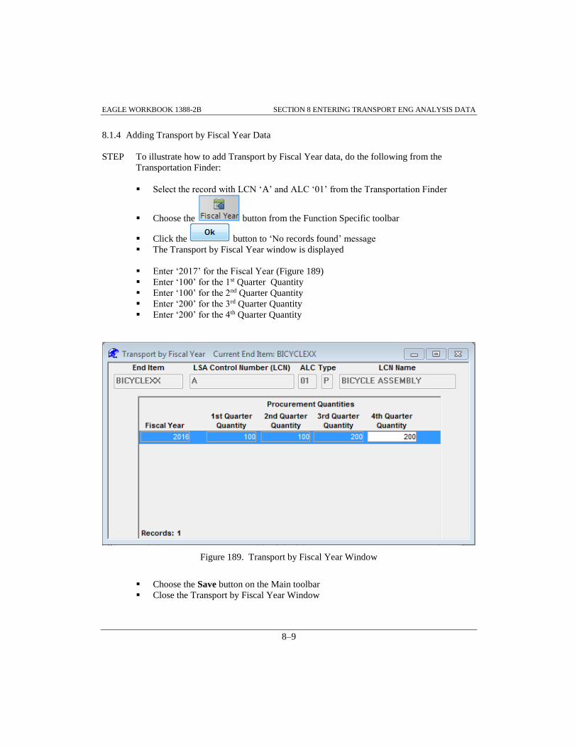
EAGLE WORKBOOK 1388-2B SECTION 8 ENTERING TRANSPORT ENG ANALYSIS DATA
8–9
8.1.4 Adding Transport by Fiscal Year Data
STEP To illustrate how to add Transport by Fiscal Year data, do the following from the
Transportation Finder:
Select the record with LCN ‘A’ and ALC ‘01’ from the Transportation Finder
Choose the button from the Function Specific toolbar
Click the button to ‘No records found’ message
The Transport by Fiscal Year window is displayed
Enter ‘2017’ for the Fiscal Year (Figure 189)
Enter ‘100’ for the 1st Quarter Quantity
Enter ‘100’ for the 2nd Quarter Quantity
Enter ‘200’ for the 3rd Quarter Quantity
Enter ‘200’ for the 4th Quarter Quantity
Figure 189. Transport by Fiscal Year Window
Choose the Save button on the Main toolbar
Close the Transport by Fiscal Year Window

EAGLE WORKBOOK 1388-2B SECTION 8 ENTERING TRANSPORT ENG ANALYSIS DATA
8–10
8.1.5 Adding Transportation Narrative
STEP To illustrate how to add Transportation Narrative data, do the following from the
Transportation Finder as shown and described:
Select the record with LCN ‘A’ and ALC ‘01’ from the Transportation Finder
Choose the button from the Function Specific Toolbar
The Transportation Narrative window is displayed
Select ‘D. Regulatory requirements’ from the Select Type of Narrative drop down
list (Figure 190)
Enter the following narrative: ‘Bicycle must be transported with an ungreased chain
in environmentally sensitive areas.’
Choose the Save button on the Main toolbar
Figure 190. Transportation Narrative Window
Close the Transportation Narrative window
Close the Transportation Finder

EAGLE Workbook 1388-2B Version 15
ENTERING SUPPORT
EQUIPMENT AND
TRAINING MATERIAL
REQUIREMENTS DATA
SECTION 9


EAGLE WORKBOOK 1388-2B SECTION 9 ENTERING SE AND TRAINING MATERIAL REQ DATA
9–3
SECTION 9 ENTERING SUPPORT EQUIPMENT AND TRAINING MATERIAL
REQUIREMENTS DATA
9.0 INTRODUCTION
This section provides an overview of the Support Equipment and Training Material Requirements
tables (E tables) and the Unit Under Test (UUT) Requirements and Description Tables (U Tables)
of MIL-STD-1388-2B. The E Tables document information pertaining to existing or new support,
test, or training equipment required to operate or maintain the system/end item. The U tables
identify the UUT and those hardware and software elements required to test the UUT with off-line
support/test equipment. The unique combination of these elements required for a specific UUT
and support/test equipment configuration is a Test Program Set (TPS). In addition to defining the
TPS elements, this information provides the configuration identification of the UUT (i.e., the UUT
and the support/test equipment to be used in the test). This information is established for each
UUT that has a requirement to be tested by the support/test equipment documented. Additionally,
Calibration and Measurement Requirement Summary (CMRS) information is captured in these
tables.
Info: The Support Equipment Discipline is based on the SERD Report Specification. The
support equipment data is mainly stored in the Support Equipment and Training Material
Requirements (E) Tables and the unit under test data is stored in the Unit Under Test
Requirements and Description (U) Tables. Since the Support Equipment Discipline is
designed after the SERD Report (LSA-070), data is not necessarily edited by tables as in
the other disciplines. Data is entered following the structure or main paragraphs of the
SERD Report.
9.1 ADDING SUPPORT EQUIPMENT AND UNIT UNDER TEST INFORMATION
Note: In order to add support equipment to the Support Equipment tables, reference number
data for the support equipment item must exist in the parent table HA.
STEP To access the SERD Finder, do the following as shown and described:
Access the Support Equipment Discipline and SERD Finder Function from the
Navigator by utilizing the Home tab and Filter box (Figure 191)
Double-click the SERD Finder Function. The SERD Finder is displayed

EAGLE WORKBOOK 1388-2B SECTION 9 ENTERING SE AND TRAINING MATERIAL REQ DATA
9–4
Figure 191. Navigator - Support Equipment
STEP To illustrate how to use the SERD Finder, do the following as shown and described:
Choose the Execute button or ALT+Q,E to retrieve all support equipment currently
in table EA
9.2 ADDING SUPPORT EQUIPMENT
STEP To illustrate how to add data into the Support Equipment Tables, specifically the
Support Equipment or EA Table, do the following as shown and described:
With the SERD Finder open and displayed (Figure 192)
Choose the button on the Function Specific toolbar

EAGLE WORKBOOK 1388-2B SECTION 9 ENTERING SE AND TRAINING MATERIAL REQ DATA
9–5
Figure 192. SERD Finder - Query Results
The Support Equipment window is displayed
Enter ‘SE%’ into the CAGE Code query box (Figure 193)
Choose the Execute button to retrieve all records from Table HA that have a CAGE
Code of ‘SE%’
Select the record with CAGE Code ‘SE999’ and Reference Number ‘TH-1001’ from
the Item Identification box
Choose the button to add the part to the Support Equipment list

EAGLE WORKBOOK 1388-2B SECTION 9 ENTERING SE AND TRAINING MATERIAL REQ DATA
9–6
Figure 193. Adding Support Equipment
Choose the Save button on the Main toolbar
Close the Support Equipment window and return to the SERD Finder
9.2.1 Assigning SERD Numbers
STEP To illustrate how to assign a SERD number, do the following as shown and described:
With the SERD Finder displayed, choose the Execute button on the Main toolbar to
re-query for the record added in the previous STEP
Select the record with the CAGE ‘SE999’ and Reference Number ‘TH-1001’
Choose the button on the Function Specific toolbar
Click to the ‘No Records Found’ message box
The Support Equipment Recommendation Data window is displayed (Figure 194)
Enter ‘0000001234’ into the SERD Number box
Enter ‘ A’ into the SERD Revision box
Enter ‘20170317’ into the SERD Date of Initial Submission box

EAGLE WORKBOOK 1388-2B SECTION 9 ENTERING SE AND TRAINING MATERIAL REQ DATA
9–7
Enter ‘20171113’ into the SERD Date of Revision Submission box
Select ‘Approved’ for SERD Status
Figure 194. SE Recommendation Data Window
Choose the Save button on the Main toolbar
Close the Support Equipment Recommendation Data window and return to the
SERD Finder
9.2.2 Adding Support Equipment Data
Support Equipment information is added through the Reports/Process>>Support Equipment
Data menu item or the button on the Function Specific toolbar from the SERD
Finder. Once the menu item is chosen, the reference number highlighted in the SERD Finder will
be displayed for maintenance in the Support Equipment Data Window (Figure 196).

EAGLE WORKBOOK 1388-2B SECTION 9 ENTERING SE AND TRAINING MATERIAL REQ DATA
9–8
Info: The Support Equipment Data window consists of many tabs representing the various
types of data areas pertaining to the SERD report. Since there are multiple rows of tabs
in the Support Equipment Data Window, each row of tabs is brought to the front of the
window when it is clicked on. Therefore, it appears that the tabs are changing positions
when in fact they are just being brought to the front of the window to allow the data to be
maintained. The following paragraphs will describe a few of the support equipment tabs.
9.2.2.1 Support Equipment Data – Adding Narrative
Support Equipment Narrative is added through the Narrative tab on the Support Equipment Data
window.
STEP To illustrate how to add narrative for a piece of support equipment, do the following as
shown and described:
Make sure the record with the SE Reference Number of ‘TH-1001’ is selected in the
SERD Finder (Figure 195)
Choose the button on the Function Specific toolbar
Figure 195. SERD Finder – TH-0001
The Support Equipment Data window is displayed
Choose the Narrative tab (Figure 196)
Select ‘B. Description + function of SE’ from the Select Type of Narrative drop
down list
Enter the text ‘The THANDLE provides a support mount for inspecting the Bicycle
Assembly.’ as shown in Figure 196

EAGLE WORKBOOK 1388-2B SECTION 9 ENTERING SE AND TRAINING MATERIAL REQ DATA
9–9
Figure 196. Support Equipment Data Window - Narrative Tab
Choose the Save button on the Main toolbar
9.2.2.2 Support Equipment Data – Adding Administrative Data
A Support Equipment Name and Item Category Code are added through the Admin. Data tab on
the Support Equipment Data window.
STEP To illustrate how to add a SE Name and SE ICC to a piece of support equipment, do the
following as shown and described:
With the Support Equipment Data window open
Choose the Admin. Data tab
Enter ‘BICYCLEXX’ into the End Article Designator box (Figure 197)
Enter ‘TEMPORARY HANDLE’ into the SE Full Item Name box
Select ‘Yes’ from the Sketch box drop down list
Enter ‘N000XX-17-C-1234’ into the Contract Number box
Select ‘Contractor Furnished’ from the Cont. Furn. EQ. Govt Furn. EQ. drop down
list box
Select ‘Peculiar tools’ from the SE Item Category Code Drop Down list

EAGLE WORKBOOK 1388-2B SECTION 9 ENTERING SE AND TRAINING MATERIAL REQ DATA
9–10
Figure 197. Support Equipment Data Window - Admin. Data Tab
Choose the Save button on the Main toolbar
Close the Support Equipment Data window
9.2.3 Running a SERD Report
The SERD Discipline provides the convenience of running an LSA-070 report from the SERD
Finder.
STEP To illustrate how to run an LSA-070 report from the SERD Discipline, do the following
as shown and described:
Select the record with CAGE ‘SE999’ and Reference Number ‘TH-1001’ from the
SERD Finder
Choose Reports/Process>>Reports>>LSA-070 - Support Equipment
Recommendation Data from the Menu bar
The LSA-070 SERD parameter window is displayed

EAGLE WORKBOOK 1388-2B SECTION 9 ENTERING SE AND TRAINING MATERIAL REQ DATA
9–11
STEP To enter the standard parameters for the SERD report, do the following as shown and
described:
Select the Standard Parameters tab (Figure 198)
Enter the appropriate file name and directory for the Parameter File (third one down)
by selecting it with the Browse button or entering it manually
Enter the appropriate file name and directory for the Report File by selecting it with
the Browse button or entering it manually
Enter the appropriate file name and directory for the Message File by selecting it
with the Browse button or entering it manually
Make sure the Requester: field is filled in
Figure 198. LSA-070 SERD - Standard Parameters Tab
STEP To enter the specific parameters for the SERD report, do the following as shown and
described:
Select the Specific Parameters tab (Figure 199)
Make sure "BICYCLEXX" is displayed in the End Item: drop down box
Make sure ‘TH-1001’ is displayed in the Reference: box
Make sure ‘SE999’ is displayed in the Cage: box

EAGLE WORKBOOK 1388-2B SECTION 9 ENTERING SE AND TRAINING MATERIAL REQ DATA
9–12
Figure 199. LSA-070 SERD Specific Parameters Tab
Choose the Execute button to generate the SERD report
Choose the button if prompted to overwrite the existing report
and/or message file. This just means the report has been run previously and these
files exist
The EAGLE: Report Generator Completion Message window is displayed (Figure
200). Note that the report may be partially complete due to missing data. This
indicates that the report ran correctly, but may be incomplete
Select the ‘ button to Display/Print the SERD Report
Figure 200. Report Generator Completion Message

EAGLE WORKBOOK 1388-2B SECTION 9 ENTERING SE AND TRAINING MATERIAL REQ DATA
9–13
The EAGLE: Report Availability Message window is displayed (Figure 201)
Selecting the button in the EAGLE: Report Availability Message
window will store the report in the EAGLE ZD Table (document storage Table)
Figure 201. EAGLE: Report Availability Message
Click the button in response to ‘Document successfully Imported!’
(Figure 202) (if imported)
Figure 202. Document Imported
After viewing the report, close the Report Display window
Close the LSA-070 SERD window
Close the SERD Finder
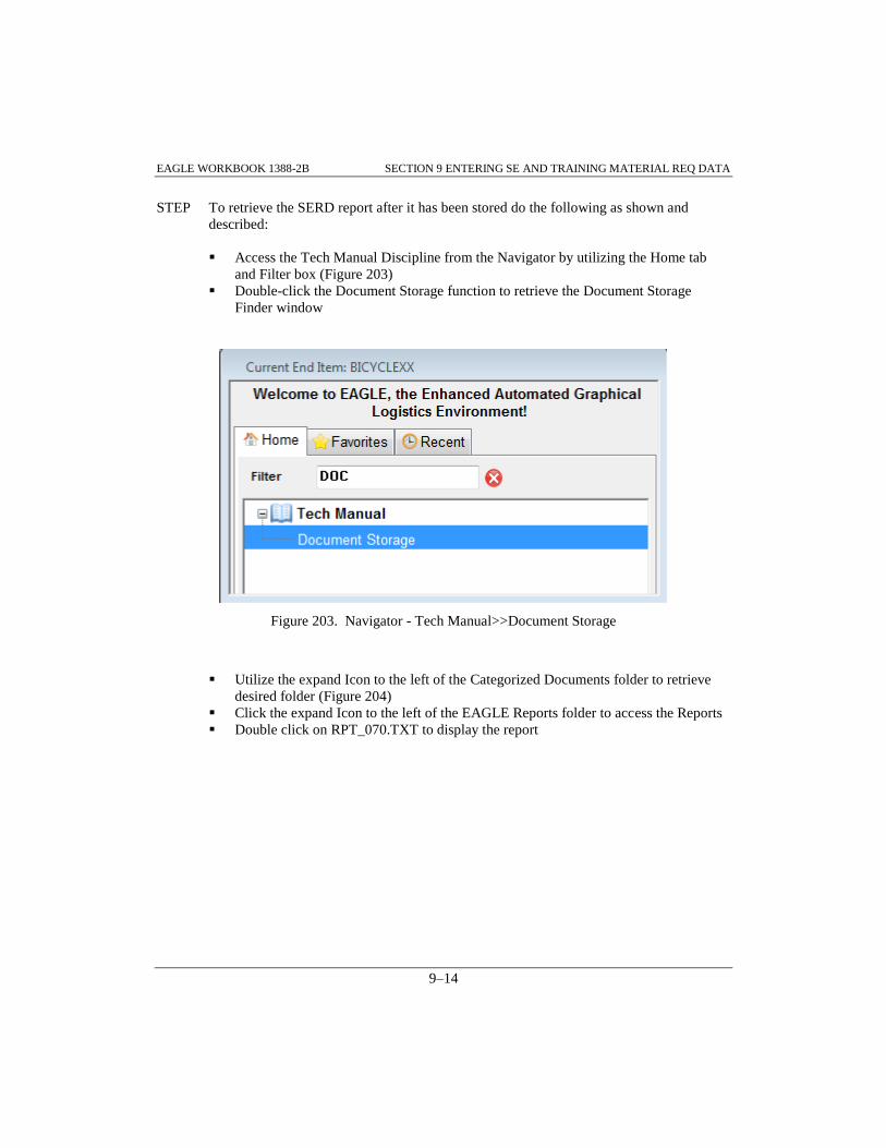
EAGLE WORKBOOK 1388-2B SECTION 9 ENTERING SE AND TRAINING MATERIAL REQ DATA
9–14
STEP To retrieve the SERD report after it has been stored do the following as shown and
described:
Access the Tech Manual Discipline from the Navigator by utilizing the Home tab
and Filter box (Figure 203)
Double-click the Document Storage function to retrieve the Document Storage
Finder window
Figure 203. Navigator - Tech Manual>>Document Storage
Utilize the expand Icon to the left of the Categorized Documents folder to retrieve
desired folder (Figure 204)
Click the expand Icon to the left of the EAGLE Reports folder to access the Reports
Double click on RPT_070.TXT to display the report

EAGLE WORKBOOK 1388-2B SECTION 9 ENTERING SE AND TRAINING MATERIAL REQ DATA
9–15
Figure 204. Document Storage Finder
Close the 070 Report window
Close the Document Storage Finder
9.3 SUPPORT EQUIPMENT AND UUT DATA
In Paragraph 9.2.2 Support Equipment Data was added utilizing the multiple tabs provided in the
Support Equipment Data window. The UUT data can be added in a similar method via the Unit
Under test Data window. These multi-tab windows can be accessed through the Reports/Process
menu selections or by choosing either the button or the button both of
which are located on the Function Specific toolbar.
Instead of covering each of the tabs in detail, the following tables are supplied to show which part
of the SERD report the data is displayed in and what LSAR tables are affected by each tab. The
first table contains the Support Equipment Data tabs and the second table contains the Unit Under
Test Data tabs.

EAGLE WORKBOOK 1388-2B SECTION 9 ENTERING SE AND TRAINING MATERIAL REQ DATA
9–16
Table 1. Support Equipment Data Tabs - Table and SERD Relationships
Support Equipment Data
Tabs
Support
Equipment
Tables Affected
SERD Report Section
Narrative EE Section 1. Description of RQMTS
(HEADER)
Admin. Data EA, EF, EH Section 2 Administrative Data (HEADER)
and Price Data Section
Physical Data EA Section 2 Administrative Data - Physical
Data Section
GFAE (System Equipment
Required)
EM Section 2 Administrative Data - System
Equipment Required (GFAE)
Articles Requiring Support UB, UA Section 2 Administrative Data - Articles
Requiring Support (ARS)
Rev. Remarks EG Section 2 Administrative Data (HEADER)
- Revision Remarks
Supercedure EK Section 3
Supercedure/Deletion/Distribution Data
(HEADER)
Allocation Data EA, EB Section 3.
Supercedure/Deletion/Distribution Data -
Allocation Data (HEADER)
Authorizations ED Section 3
Supercedure/Deletion/Distribution Data -
Specific Authorizations (HEADER)
Design Data EJ Section 4 Design Data (HEADER)
ILS Data EL Section 5 ILS Data (HEADER)
Parameters EC Section 6 SE Parameters and UUT Related
Information (HEADER)
Supplement EA N/A
UUT Data UM, UN N/A
Input Power Source EI N/A

EAGLE WORKBOOK 1388-2B SECTION 9 ENTERING SE AND TRAINING MATERIAL REQ DATA
9–17
Table 2. Unit Under Test Data Tabs - Table and SERD Relationships
Unit Under Test Data
Tabs
Support
Equipment
Tables Affected
SERD Report Section
UUT Information UA, UB Section 6 SE Parameters and UUT Related
Information (HEADER) - UUT Related
Information (HEADER)
UUT Parameters UG Section 6 SE Parameters and UUT Related
Information (HEADER) - UUT Parameters
(HEADER)
Fault Isolation UH Section 6 SE Parameters and UUT Related
Information (HEADER) - Fault Isolated
Replaceable Units (HEADER)
Operational Test Programs UC, UD Section 6 SE Parameters and UUT Related
Information (HEADER) - Operational
ATE/TMDE Test Program (HEADER)
Test Position Instructions UD, UE Section 6 SE Parameters and UUT Related
Information (HEADER) - Test Program
Instruction (HEADER)
Test Adapters/Cables UI, UJ Section 6 SE Parameters and UUT Related
Information (HEADER) - Adapter/Cable
Set/Interconnecting Device (HEADER)
ATE UK, UL Section 6 SE Parameters and UUT Related
Information (HEADER) - ATE Test Station
(HEADER)
UUT Remarks UF Section 6 SE Parameters and UUT Related
Information (HEADER) - UUT Related
Remarks (HEADER)

EAGLE WORKBOOK 1388-2B SECTION 9 ENTERING SE AND TRAINING MATERIAL REQ DATA
9–18

EAGLE Workbook 1388-2B Version 15
ENTERING
PACKAGING
AND PROVISIONING
REQUIREMENTS DATA
SECTION 10


EAGLE WORKBOOK 1388-2B SECTION 10 ENTERING PROVISIONING DATA
10–3
SECTION 10 ENTERING PACKAGING AND PROVISIONING REQUIREMENTS DATA
10.0 INTRODUCTION
The Packaging and Provisioning Requirements (H tables) document packaging and provisioning
requirements including non-application dependent part data related to provisioning screening and
cataloging, packaging, and common maintenance data. Also documented in the H tables are data
items used to document data requirements for initial support requirements determination, repair
parts manual, and design change information. This section of the EAGLE workbook provides an
overview of the creation and maintenance of H table data using the EAGLE Provisioning
Discipline.
10.1 ADDING REFERENCE NUMBER INFORMATION
When creating a logistics database, provisioning or parts data must be entered into the system.
The keys required to add part data in the database are the CAGE code and the reference number.
The reference number information is stored in Table HA (Item Identification Table) and CAGE
code information is stored in Table XH (Commercial and Government Entity Table). The specific
Cage code must exist in Table XH before a part can be added to Table HA.
STEP To navigate to the Provisioning Finder do the following as shown and described:
Make sure ‘BICYCLEXX’ is displayed in the Navigator Header (Figure 205)
Access the Provisioning Discipline from the Navigator utilizing the Home tab and
Filter box, select and double click the Provisioning Finder function
Figure 205. Navigator – Provisioning Discipline

EAGLE WORKBOOK 1388-2B SECTION 10 ENTERING PROVISIONING DATA
10–4
The Provisioning Finder is displayed
STEP To illustrate how to use the Provisioning Finder do the following as shown and described:
Make sure ‘BICYCLEXX’ is displayed in the End Item drop down box (Figure 206)
Uncheck the ‘Display Only Parts That Have an Application’ checkbox
Choose the Execute button to retrieve the records
Note: The first three records have not been associated with and LCN (part application) as yet.
Figure 206. Provisioning Finder - Records Returned
10.1.1 Adding CAGE Codes (XH)
CAGE code information may be entered in various ways. The method chosen to add CAGE codes
depends on the user’s intent. Two methods are summarized below.

EAGLE WORKBOOK 1388-2B SECTION 10 ENTERING PROVISIONING DATA
10–5
One method of adding new CAGE codes is using the LCN Maintenance Discipline. This method
should be used if new CAGE codes need to be entered without reference number information.
The LCN Maintenance Discipline is also used to add multiple CAGE codes. For instructions on
how to use this method, refer to Paragraph 2.7.
A second method of adding new CAGE codes may be used if a reference number is to be added
with a CAGE code that doesn’t already exist. Normally, when entering reference number
information into the database, the Provisioning Discipline is used. Therefore, new CAGE codes
can be entered for reference numbers from the Provisioning Discipline utilizing the Provisioning
finder as outlined below or, by selecting the ‘Enter New Part’ Function from the Navigator.
It is presumed that the Provisioning Finder has been executed as described in the previous STEP.
STEP To illustrate adding a new CAGE code, do the following from the Provisioning Finder:
Choose the button on the Function Specific toolbar
The New Part Information window is displayed
Info: Once the New Part Information is displayed CAGE Codes may be retrieved or created
and reference number information may be added. The reference number information
includes CAGE Codes; therefore, an Enter New CAGE button has been added to the New
Part Information window for ease in adding new CAGE Codes while entering reference
number information.
Figure 207. New Part Information Window

EAGLE WORKBOOK 1388-2B SECTION 10 ENTERING PROVISIONING DATA
10–6
STEP To illustrate adding a CAGE code into the EAGLE database, do the following from the
New Part Information window as shown and described:
Choose the button (Figure 208). This inserts a blank row
Enter ‘TCAGE’ into the blank CAGE Code field
Enter ‘BIKES PLUS’ into the blank Name field
Figure 208. New Part Information Window - CAGE Code Data
Choose the Save button on the Main toolbar
10.1.2 Adding Reference Number Information (HA Records)
This paragraph continues from the last STEP. The New Part Information window should be
displayed to complete the following.
STEP Do the following to add a new Reference Number with the new CAGE Code and
additional information from the New Part Information window as shown and described:
Locate ‘TCAGE’ from the CAGE Code list (Figure 209)
Note: TCAGE appears alphabetically towards the bottom of the list so scroll down
to find it or enter ‘T’ in the Find: window
Click on the ‘TCAGE’ CAGE Code record
The window should now display empty data fields under Item Identification!
Enter ‘BS-HANDLE-B’ into the Reference Number (Required Data) field
Enter ‘TR HANDLE BAR’ into the Item Name: field
Enter ‘1234’ into the FSC portion of the National Stock Number
Enter ‘456789123’ into the NIIN portion of the National Stock Number
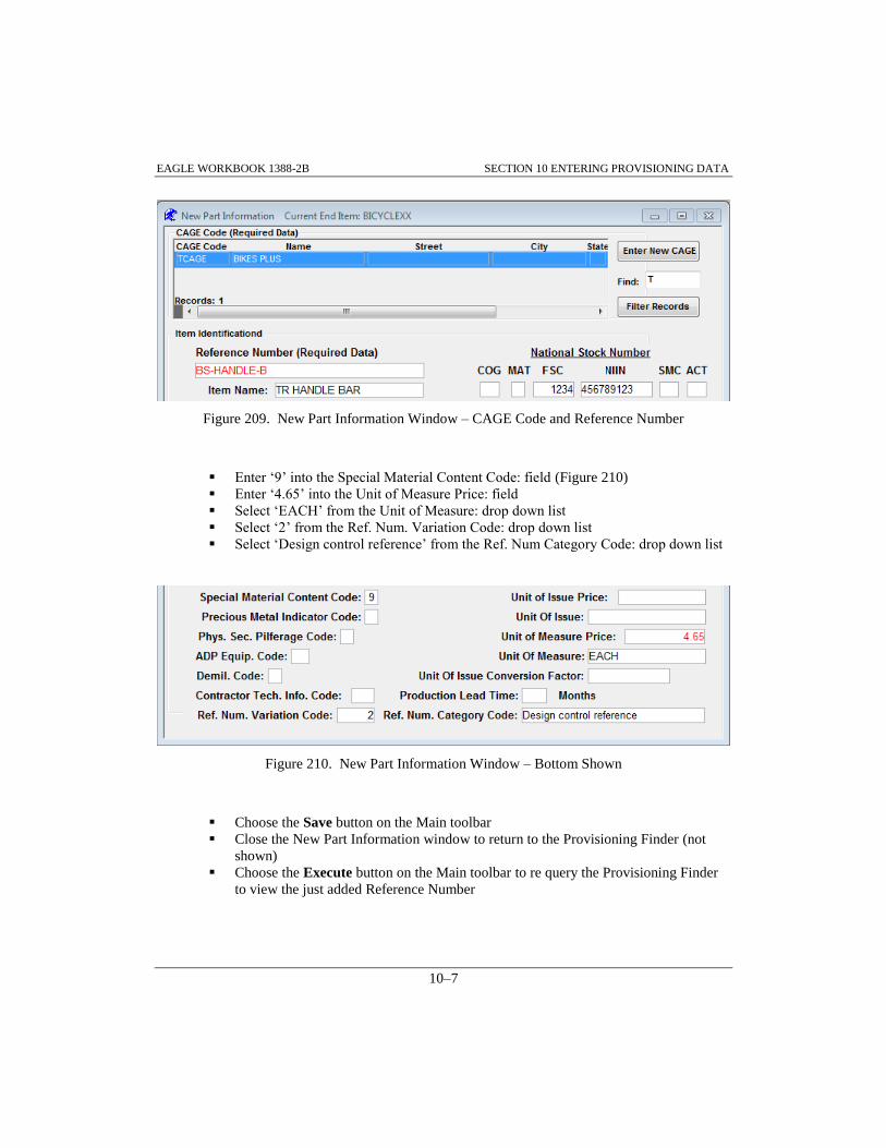
EAGLE WORKBOOK 1388-2B SECTION 10 ENTERING PROVISIONING DATA
10–7
Figure 209. New Part Information Window – CAGE Code and Reference Number
Enter ‘9’ into the Special Material Content Code: field (Figure 210)
Enter ‘4.65’ into the Unit of Measure Price: field
Select ‘EACH’ from the Unit of Measure: drop down list
Select ‘2’ from the Ref. Num. Variation Code: drop down list
Select ‘Design control reference’ from the Ref. Num Category Code: drop down list
Figure 210. New Part Information Window – Bottom Shown
Choose the Save button on the Main toolbar
Close the New Part Information window to return to the Provisioning Finder (not
shown)
Choose the Execute button on the Main toolbar to re query the Provisioning Finder
to view the just added Reference Number

EAGLE WORKBOOK 1388-2B SECTION 10 ENTERING PROVISIONING DATA
10–8
10.1.3 Adding Additional Reference Number Information (HB Records)
An Additional Reference Number and information may be a supplier part number or manufacturer
part number(s) and information different that the basic used as a replacement.
It is presumed that the Provisioning Finder has been queried per the previous STEP.
STEP To illustrate adding an Additional reference number, do the following as shown and
described:
Make sure the record with CAGE ‘TCAGE’ and Reference Number ‘BS-HANDLE-
B’ is selected in the Provisioning Finder (Figure 211)
Note: The additional reference number CAGE code must exist in table XH before it can be used
with the additional reference number.
Choose the from the Function Specific toolbar
Figure 211. Provisioning Finder – Record Selected

EAGLE WORKBOOK 1388-2B SECTION 10 ENTERING PROVISIONING DATA
10–9
The View/Edit Provisioning Data window (top shown) is displayed with the
Summary tab selected (Figure 212). This allows for easy selection of specific tables
for data entry
Figure 212. View/Edit Provisioning Data Window – Summary Tab Selected
STEP Cont’d:
Click on the HB tab (Figure 213)
Normally the Insert button would be chosen at this point, but since there are no
additional reference numbers established for ‘BS-HANDLE-B’, insert mode is
already activated
Figure 213. View/Edit Provisioning Data Window – Table HB Tab Selected
Enter ‘TCAGE’ into the ARN Cage Code field (Figure 214)
Enter ‘TBAR’ into the Additional Reference Number field
Choose the Save button on the Main toolbar

EAGLE WORKBOOK 1388-2B SECTION 10 ENTERING PROVISIONING DATA
10–10
Figure 214. View/Edit Provisioning Data Window – Table HB Data Entered
Close the View/Edit Provisioning Data window
10.2 ADDING PART APPLICATIONS (HG RECORDS)
It is presumed that the Provisioning Finder is displayed and that the previous STEPs have been
completed.
STEP To illustrate adding an HG record, do the following as shown and described:
Select the record where the CAGE is ‘TCAGE’ and the Reference Number is ‘BS-
HANDLE-B’ from the Provisioning Finder
Choose the button on the Function Specific toolbar
The Part Application Information – HG window is displayed
STEP Search for an existing LCN to link the Reference Number information to by doing the
following as shown and described:
Click the button on the Part Application Information - HG window
(Figure 215)

EAGLE WORKBOOK 1388-2B SECTION 10 ENTERING PROVISIONING DATA
10–11
Figure 215. Part Application Information – HG
The LCN Finder window is displayed
Choose the button at the bottom of the LCN Finder window(Figure 216)
Figure 216. LCN Finder – Records Returned
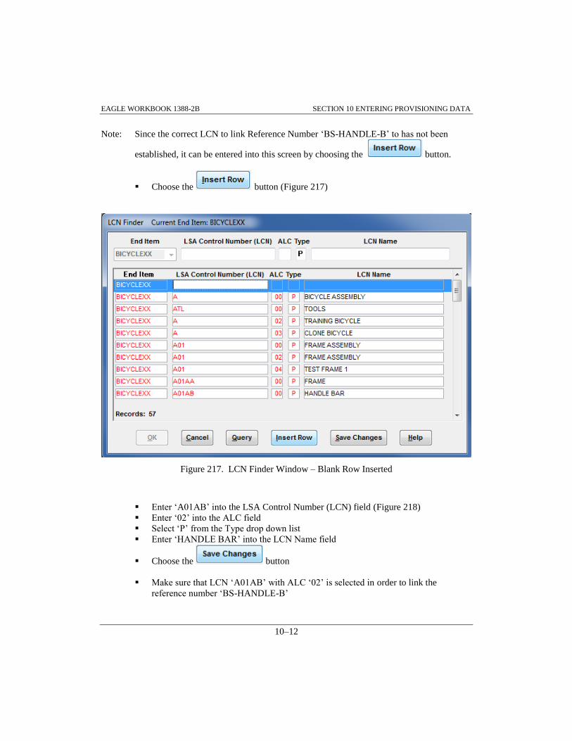
EAGLE WORKBOOK 1388-2B SECTION 10 ENTERING PROVISIONING DATA
10–12
Note: Since the correct LCN to link Reference Number ‘BS-HANDLE-B’ to has not been
established, it can be entered into this screen by choosing the button.
Choose the button (Figure 217)
Figure 217. LCN Finder Window – Blank Row Inserted
Enter ‘A01AB’ into the LSA Control Number (LCN) field (Figure 218)
Enter ‘02’ into the ALC field
Select ‘P’ from the Type drop down list
Enter ‘HANDLE BAR’ into the LCN Name field
Choose the button
Make sure that LCN ‘A01AB’ with ALC ‘02’ is selected in order to link the
reference number ‘BS-HANDLE-B’

EAGLE WORKBOOK 1388-2B SECTION 10 ENTERING PROVISIONING DATA
10–13
Choose the button
Figure 218. LCN Finder – Record Entered
Choose the button to ‘save the HG changes?’
The Part Application Information - HG window is re-displayed
STEP To Enter Part Usage Information into the Part Application Information - HG window do
the following as shown and described:
Enter ‘PAOZZ’ in the Source, Maintenance, and Recoverability (SM & R) Code:
field (Figure 219)
Select ‘Bulk items’ from the Item Category Code: drop down list
Choose the Save button on the Main toolbar
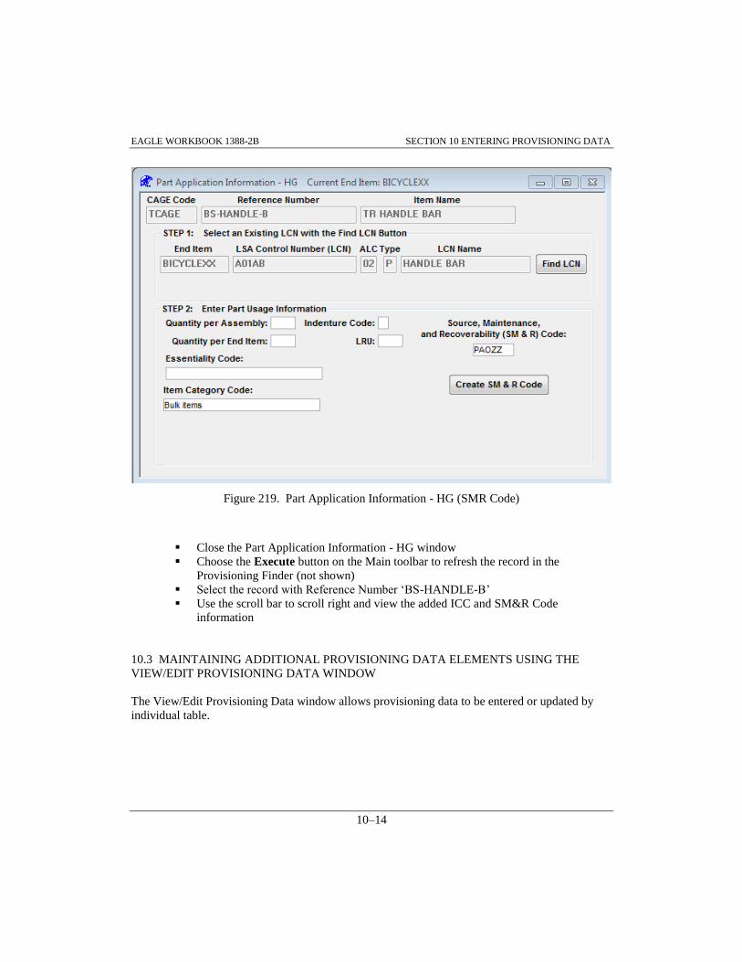
EAGLE WORKBOOK 1388-2B SECTION 10 ENTERING PROVISIONING DATA
10–14
Figure 219. Part Application Information - HG (SMR Code)
Close the Part Application Information - HG window
Choose the Execute button on the Main toolbar to refresh the record in the
Provisioning Finder (not shown)
Select the record with Reference Number ‘BS-HANDLE-B’
Use the scroll bar to scroll right and view the added ICC and SM&R Code
information
10.3 MAINTAINING ADDITIONAL PROVISIONING DATA ELEMENTS USING THE
VIEW/EDIT PROVISIONING DATA WINDOW
The View/Edit Provisioning Data window allows provisioning data to be entered or updated by
individual table.

EAGLE WORKBOOK 1388-2B SECTION 10 ENTERING PROVISIONING DATA
10–15
When a record is selected from the Provisioning Finder and the button is selected from
the Function Specific toolbar, the View/Edit Provisioning Data window is displayed with the
Summary Tab selected displaying information from tables HA, HB and HH (Figure 220). Also
available are tabs for each of the provisioning tables (HA-HR). To review, maintain or establish
data in any of these tables for the record selected in the Provisioning Finder, click on the tab for
the desired table.
Figure 220. View/Edit Provisioning Data – Summary Tab
Note: When performing the following STEPs in Paragraph(s) 10.3.1 - 10.3.5 it is not necessary
to close the View/Edit Provisioning Data window as instructed at the end of each STEP.
After you Save the data entered in each paragraph, just click on the Table Tab instructed
in each new paragraph and continue!

EAGLE WORKBOOK 1388-2B SECTION 10 ENTERING PROVISIONING DATA
10–16
10.3.1 Adding a PLISN to a Reference Number
It is presumed that the Provisioning Finder is displayed with records returned and that Paragraph
10.2 has been completed.
STEP To illustrate adding a PLISN to a reference number, do the following from the
Provisioning Finder as described:
Select the record where the CAGE is ‘TCAGE’ and the Reference Number is ‘BS-
HANDLE-B’
Choose the button from the Function Specific toolbar
The View/Edit Provisioning Data window is displayed
Choose the HG tab (Figure 221)
Enter ‘AAAE’ into the PLISN: field
Figure 221. View/Edit Provisioning Data – PLISN Entered

EAGLE WORKBOOK 1388-2B SECTION 10 ENTERING PROVISIONING DATA
10–17
Scroll down and check the ‘Repairable Items List:’ checkbox (Figure 222)
Figure 222. HG Tab – Repairable Items List Checkbox
Choose the Save button on the Main toolbar
Close the View/Edit Provisioning Data window
10.3.2 Entering Provisioning Remarks
It is presumed that the Provisioning Finder has been selected from the Provisioning Discipline
using the Navigator (Figure 206) and that Paragraph 10.2 has been completed.
STEP To illustrate adding provisioning remarks, do the following as shown and described:
Select the record where the CAGE is ‘TCAGE’ and the Reference Number is ‘BS-
HANDLE-B’

EAGLE WORKBOOK 1388-2B SECTION 10 ENTERING PROVISIONING DATA
10–18
Choose the button from the Function Specific toolbar
Choose the HI tab (Figure 223)
Enter the following Provisioning Remark narrative: ‘TR HANDLE BAR, P/N BS-
HANDLE-B, will no longer be available from BIKES PLUS effective 11/01/2018.’
Choose the Save button on the Main toolbar
Close the View/Edit Provisioning Data window
Figure 223. View/Edit Provisioning Data – Adding Provisioning Remarks
10.3.3 Adding Provisioning UOC Data
It is presumed that the Provisioning Finder has been selected from the Provisioning Discipline
using the Navigator (Figure 206) and that Paragraph 10.2 has been completed.
STEP To illustrate adding provisioning UOC data, do the following as shown and described:
Select the record where the CAGE is ‘TCAGE’ and the Reference Number is ‘BS-
HANDLE-B’
Choose the button from the Function Specific toolbar
Choose the HO tab (Figure 224)
Select the record with UOC of 'LX2' from the list of XC records (box on lower left
corner)
Choose the button to add an HO record. This maps the new HG record
to the baseline configuration Bicycle (UOC LX2)! We did this also for another
record utilizing the LCN Maintenance discipline

EAGLE WORKBOOK 1388-2B SECTION 10 ENTERING PROVISIONING DATA
10–19
Map the ‘TR HANDLE BAR’ to the ‘TR1’ UOC also
Choose the Save button on the Main toolbar
Close the View/Edit Provisioning Data window
Figure 224. View/Edit Provisioning Data – Adding Provisioning UOC Data
10.3.4 Adding Item Packaging Requirement Data
It is presumed that the Provisioning Finder has been selected from the Provisioning Discipline
using the Navigator (Figure 206) and that Paragraph 10.2 has been completed.
STEP To illustrate adding item packaging requirement data, do the following as shown and
described:
Select the record where the CAGE is ‘TCAGE’ and the Reference Number is ‘BS-
HANDLE-B’
Choose the button from the Function Specific toolbar
Choose the HF tab (Figure 225)

EAGLE WORKBOOK 1388-2B SECTION 10 ENTERING PROVISIONING DATA
10–20
Click the button
The Select Packaging Data window is displayed
Figure 225. View/Edit Provisioning Data – HF Tab
Select 'C Min. protect.' (Figure 226)
Figure 226. Select Packaging Data – C Min. protect. Selected
Choose the button to return to the View/Edit Provisioning Data window
Note the ‘C’ has been filled in the in the Degree of Protection Code: field (Not
Shown)
Scroll to the right and enter '5.0' in the Unit Pack Weight: field (Figure 227)
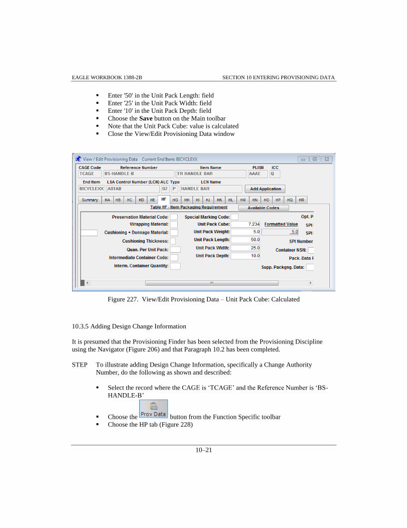
EAGLE WORKBOOK 1388-2B SECTION 10 ENTERING PROVISIONING DATA
10–21
Enter '50' in the Unit Pack Length: field
Enter '25' in the Unit Pack Width: field
Enter '10' in the Unit Pack Depth: field
Choose the Save button on the Main toolbar
Note that the Unit Pack Cube: value is calculated
Close the View/Edit Provisioning Data window
Figure 227. View/Edit Provisioning Data – Unit Pack Cube: Calculated
10.3.5 Adding Design Change Information
It is presumed that the Provisioning Finder has been selected from the Provisioning Discipline
using the Navigator (Figure 206) and that Paragraph 10.2 has been completed.
STEP To illustrate adding Design Change Information, specifically a Change Authority
Number, do the following as shown and described:
Select the record where the CAGE is ‘TCAGE’ and the Reference Number is ‘BS-
HANDLE-B’
Choose the button from the Function Specific toolbar
Choose the HP tab (Figure 228)

EAGLE WORKBOOK 1388-2B SECTION 10 ENTERING PROVISIONING DATA
10–22
Enter ‘ECP-0001-2017’ for Change Authority Number:
Click the Save button on the Main toolbar
Close the View/Edit Provisioning Data window (go ahead this time)
Close the Provisioning Finder
Figure 228. View/Edit Provisioning Data – HP Tab Selected
10.4 MAPPING MULTIPLE PART APPLICATIONS TO A SYSTEM/END ITEM UOC
In SECTION 2 we utilized the LCN Maintenance Discipline to access the Prov. System/EI (HO)
Maintenance Function to map individual Part Applications to System/End Item UOCs (2.10).
In this Paragraph, we will access the UOC (HO) Maintenance Function from the Provisioning
Discipline which will enable us to map multiple Part Applications to a UOC-PCCN combination
for example, a subassembly used in an existing configuration that will be used in a different
configuration.

EAGLE WORKBOOK 1388-2B SECTION 10 ENTERING PROVISIONING DATA
10–23
10.4.1 Mapping Multiple Part Applications to a UOC-PCCN Combination
STEP To map a subassembly (multiple part applications) to a System/End Item UOC-PCCN do
the following as shown and described:
Access the UOC (HO) Maintenance Function from the Navigator by utilizing the
Home tab and Filter box (Figure 229)
The Usable On Code Maintenance window will be displayed
Figure 229. Provisioning Discipline – UOC (HO) Maintenance Function Selected
Enter ‘A03%’ into the LSA Control Number (LCN) finder field (Figure 230)
Choose the Execute button
Figure 230. Usable On Code Maintenance Window – A03% Entered

EAGLE WORKBOOK 1388-2B SECTION 10 ENTERING PROVISIONING DATA
10–24
Manipulate your window to display the TR1-H5T80B UOC-PCCN combination as
shown in Figure 231 by expanding the window and using the grey-bar split window
capability
Figure 231. Usable On Code Maintenance Window – TR1-H5T80B UOC-PCCN Displayed
Select ‘TR1-H5T80B’ from the Map All Records to UOC-PCCN>> drop down list
(Figure 232)
Figure 232. Map All Records to UOC-PCCN>>
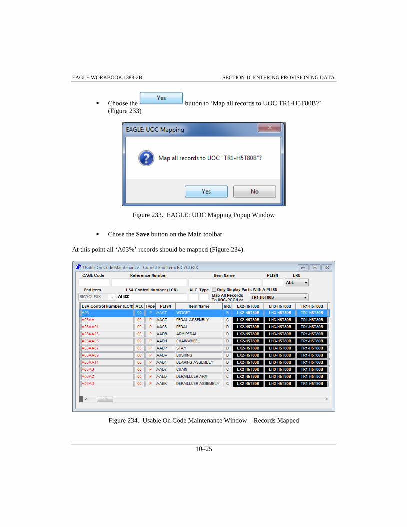
EAGLE WORKBOOK 1388-2B SECTION 10 ENTERING PROVISIONING DATA
10–25
Choose the button to ‘Map all records to UOC TR1-H5T80B?’
(Figure 233)
Figure 233. EAGLE: UOC Mapping Popup Window
Chose the Save button on the Main toolbar
At this point all ‘A03%’ records should be mapped (Figure 234).
Figure 234. Usable On Code Maintenance Window – Records Mapped
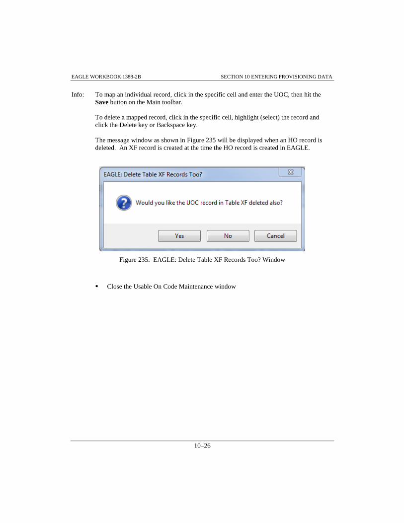
EAGLE WORKBOOK 1388-2B SECTION 10 ENTERING PROVISIONING DATA
10–26
Info: To map an individual record, click in the specific cell and enter the UOC, then hit the
Save button on the Main toolbar.
To delete a mapped record, click in the specific cell, highlight (select) the record and
click the Delete key or Backspace key.
The message window as shown in Figure 235 will be displayed when an HO record is
deleted. An XF record is created at the time the HO record is created in EAGLE.
Figure 235. EAGLE: Delete Table XF Records Too? Window
Close the Usable On Code Maintenance window

EAGLE Workbook 1388-2B Version 15
AD HOC REPORTING
SECTION 11


EAGLE WORKBOOK 1388-2B SECTION 11 AD HOC REPORTING
11–3
SECTION 11 AD HOC REPORTING
11.0 INTRODUCTION
The AdHoc Discipline allows the user to define and generate unique or one-shot reports based on
a particular instance, or ad hoc need, rather than the generation of standard reports. If certain ad
hoc reports are required to be run periodically, or complex reports are developed, they can be
stored in the database or to disk as a file.
User-friendly screens are provided to assist the user in constructing the transaction statements
necessary to produce the desired report. These screens generate the actual SQL statements that
operate on the relational database to assemble the desired data.
Once a query is created and executed, the resulting data is displayed. These results can be saved,
printed or updated. Updates performed on the AdHoc results data are posted back to the database
when the data is saved. Editing permissions on tables are set by the database administrator.
11.1 SQL TRANSACTION STATEMENTS
The constructs involved in an SQL transaction are familiar to anyone with some programming
experience in a high-level language (BASIC, Pascal, C, etc.). Although this familiarity is not
absolutely necessary, it will help in understanding the concepts and principals involved in the
underlying SQL transaction. Appendix D provides an overview of SQL.
11.1.1 New Query
Access the AdHoc Discipline from the Navigator and double-click the New Query Function as
illustrated in Figure 236.
Figure 236. Navigator – AdHoc>>New Query

EAGLE WORKBOOK 1388-2B SECTION 11 AD HOC REPORTING
11–4
The above selection will display the AdHoc New Query Main screen (Figure 237). Figure 237 is
shown after Table AA has been selected by clicking on it.
11.1.1.1Query Table Selection
The database table for the query must be selected first. The listings shown in the DATABASE
TABLES box on the left side of the screen display the different database tables available.
The TABLE NAME column displays the table name that will be used in the query. Tables that are
to be used in the query should be highlighted. Once a table is selected for a query, the Database
Columns box is updated to reflect the current column information. Each time a table is selected,
the Database Columns are updated to reflect the correct COLUMN NAME/DESCRIPTION.
To select a database table from the DATABASE TABLES box, single click on the database table.
Figure 237. AdHoc New Query Main Screen

EAGLE WORKBOOK 1388-2B SECTION 11 AD HOC REPORTING
11–5
Since there are hundreds of tables used in the EAGLE database, the DATABASE TABLES list
can take time to scroll through to find the table needed. Two methods have been provided to make
selecting a table more efficient. The first is a FUNCTIONAL AREAS drop down box located
below the DATABASE TABLES Header as shown in Figure 238. As you move the cursor up and
down the list each FUNCTIONAL AREA is highlighted. In this example, the PROVISIONING
(H Tables) option is highlighted.
Figure 238. AdHoc New Query Main Screen - Functional Area Highlighted
The second method is the Find Table: Query box located beneath the FUNCTIONAL AREAS
drop down list. Typing the desired table into the Query box returns that record to the top of the
window.
STEP To illustrate how to select a table to be used in the query, do the following from the
AdHoc New Query window as shown and described:
Enter ‘HG’ in the Find Table: Query field (Figure 239)
Select Table HG by clicking on it and notice that the DATABASE COLUMNS
COLUMN NAME/DESCRIPTION data is filled in

EAGLE WORKBOOK 1388-2B SECTION 11 AD HOC REPORTING
11–6
Figure 239. New Query Window – Table HG
Choose the button on the Main toolbar
Enter ‘H’ in the Find Table: Query field and select Table HA from the Table
Selections by clicking on it and notice that the COLUMN NAME/DESCRIPTION
data changes to the HA Table data fields (Figure 240)
Figure 240. New Query Table Selection-Find Table HA

EAGLE WORKBOOK 1388-2B SECTION 11 AD HOC REPORTING
11–7
We now have Table HA selected. We will use this as a beginning to generate a Top down
Breakdown Query of our baseline ‘BICYCLEXX’ End Item as outlined in the following
paragraphs.
11.1.1.2 Query Column Selection
The DATABASE COLUMNS box on the right hand side of the window allows selection of the
various columns from a table for queries. As table columns or fields are selected, they are
displayed in the query area at the bottom of the window (Figure 242). These fields will be used in
the generation of the final query on the database.
In order to select database columns or fields, single click on the database column. If a selected
column is no longer desired, double-click on the database column and it will be deselected. The
radio buttons at the top of the column list allow the user to select different columns for different
types of queries. For example, the ALL (NAMES) radio button selects all the columns in the
table and puts their name in the query.
STEP To illustrate how to select the table columns to be used in the query, do the following
from the AdHoc New Query window as shown and described. It is presumed that Table
HA has already been selected as shown:
Choose the ONLY KEY/MANDATORY radio button under DATABASE
COLUMNS to select columns from the table that are key fields (Figure 242)
Figure 241. Table HA – Only Key/Mandatory

EAGLE WORKBOOK 1388-2B SECTION 11 AD HOC REPORTING
11–8
Choose the ITNAMEHA field by clicking on it in the COLUMN NAME list (Figure
242)
Notice that the query statement is being built at the bottom of the screen
Figure 242. New Query Table Column Selection
11.1.1.3 Generating the AdHoc Report
STEP The Execute button on the Main toolbar or ALT+Q, E is used to generate the report.
Figure 243 illustrates the AdHoc Query results. To generate the AdHoc Report do the
following:
Choose the Execute button on the Main toolbar
The Query Results for New Query window is displayed (Query Results window)
Choose the button (Figure 243)

EAGLE WORKBOOK 1388-2B SECTION 11 AD HOC REPORTING
11–9
Figure 243. AdHoc Report Results - Simple Query
Notice that the Query Results window title bar contains the time the query was executed so that
the user knows when the query was run. In addition, the New Query window title bar is also
updated with the execute time. This allows the user to identify which query script goes with
which results in the case that more than one query or results window is open.
Tip: Columns may be rearranged in the Query Results window by dragging a column header
to the desired location.
STEP Return to the New Query window by closing the Query Results Window:
Close the Query Results window, leaving the New Query window open
11.1.1.4 Establishing Selection Criteria
A query without selection criteria returns all rows in a table. This could be a large amount of data.
To narrow down the amount of data returned to a more precise set, selection criteria can be
established. The Select Criteria buttons on the New Query Window Function Specific toolbar
(Figure 244) are used to create selection criteria for the query.

EAGLE WORKBOOK 1388-2B SECTION 11 AD HOC REPORTING
11–10
The Select Criteria buttons allow Where, Sort, and Join conditions to be set for queries. These
conditions are used in queries to control which data should be selected, how the data should be
sorted, and what join requirements exist between tables. When a Select Criteria button is selected,
a window appears displaying a dialog edit box with options for creating the desired condition.
The Where and Sort buttons are always available after a table and its columns are selected.
However, the Join button is only available if two or more tables are selected.
Figure 244. Function Specific Toolbar – Where and Sort Active
11.1.1.5 Multiple Tables in ADHOC Queries – Joining Tables
In the following STEP(s), multiple tables will be added to the query from the previous STEP.
Whenever multiple tables are included in a query, data in the tables must be related or ‘joined’.
This insures that valid data will be returned.
STEP Table HA should still be selected from the previous query. Add additional information
from table HG to the query by doing the following as shown and described:
Scroll down and click on Table ‘HG’ from the Table Selections (Figure 245) and
notice that the Table HG columns are automatically filled in on the right hand side of
the screen under DATABASE COLUMNS
Choose the following fields from the DATABASE COLUMNS list by clicking on
them: ‘LSACONXB’, ‘ALTLCNXB’, ‘QTYASYHG’, ‘SMRCODHG’ (scroll down
about halfway)

EAGLE WORKBOOK 1388-2B SECTION 11 AD HOC REPORTING
11–11
Figure 245. New Query-Adding Table HG
STEP Join tables HA and HG by doing the following:
Choose the button from the Function Specific toolbar
The Join Criteria window is displayed
Note the Matching Join Radio button is selected (Figure 246)
Choose the button
Choose the button to add the join criteria (WHERE) to the New Query
Window

EAGLE WORKBOOK 1388-2B SECTION 11 AD HOC REPORTING
11–12
Figure 246. Join Criteria – HA Joined to HG
Info: Next two STEP(s).
The HO table links part applications in the HG table to a System/End Item UOC in table XC. So
that we may query for a single BICYCLE configuration by UOC, we will add table HO to the
query.
STEP Add UOC cross reference data from table HO to the query by doing the following as
shown and described:
Scroll down and select Table HO from the Table Selections and notice that the Table
HO columns are automatically filled in on the right hand side of the screen under
DATABASE COLUMNS (Figure 247)
Choose the following fields from the DATABASE COLUMNS list by clicking on
them: ‘LCNSEIHO’, ‘ALCSEIHO’
Note: Also available for selection in Table HO are columns ‘LSACONHO’ and ‘ALTLCNHO’.
At this point in the Query, these are not the Columns we want to select. Be careful.

EAGLE WORKBOOK 1388-2B SECTION 11 AD HOC REPORTING
11–13
Figure 247. New Query-Adding Table HO
STEP Join tables HG and HO by doing the following:
Choose the button from the Function Specific toolbar
The Join Criteria window is displayed
Select the ‘HG’ table from the TABLE 1 drop down list (Figure 248)
Select the ‘HO’ table from the TABLE 2 drop down list
Choose the button
Choose the button to add the join criteria to the New Query window

EAGLE WORKBOOK 1388-2B SECTION 11 AD HOC REPORTING
11–14
Figure 248. Join Criteria - HG Joined to HO
STEP Add UOC from Table XC to the query by doing the following as shown and described:
Enter XC in the Find Table: Query field (Figure 249)
Select Table XC from the Table Selections and notice that the columns are
automatically filled in on the right hand side of the screen under DATABASE
COLUMNS
Choose ‘UOCSEIXC’ from the DATABASE COLUMNS list by clicking on it
Note: This is a good time to verify that your New Query window is as shown in Figure 249.

EAGLE WORKBOOK 1388-2B SECTION 11 AD HOC REPORTING
11–15
Figure 249. Adding Table XC
STEP Join tables HO and XC by doing the following as shown and described. We will not use
the Create Join button for this Join:
Choose the button from the Function Specific toolbar. The Join Criteria
window is displayed
Select the ‘HO’ table from the TABLE 1 drop down list (Figure 250)
Select the ‘XC’ table from the TABLE 2 drop down list
Note: The Create Join button IS NOT used when joining table HO to table XC because two sets
of LCN/ALC data exists in Table HO. Use of the Join Common Fields Matching Join in
this case would cause erroneous results.

EAGLE WORKBOOK 1388-2B SECTION 11 AD HOC REPORTING
11–16
Select ‘EIACODXA’ from the TABLE 1 list by clicking on it
Select ‘EIACODXA’ from the TABLE 2 list
Notice the join criteria are generated in the white space (Figure 250)
Note: Be sure to click the field from the TABLE 1 list then the field from the TABLE 2 list
(NOT two fields from the TABLE 1 list then two fields from the TABLE 2 list!).
Figure 250. Join Criteria-HO and XC
CAREFUL!!
Continue joining tables HO and XC
Click ‘LCNSEIHO’ (TABLE 1 scroll down) then ‘LSACONXB’ from TABLE 2
Click ‘ALCSEIHO’ (TABLE 1) then ‘ALTLCNXB’ (TABLE 2)
Click ‘LCNTYPXB’ (TABLE 1 up) then ‘LCNTYPXB’ (TABLE 2) (Figure 251)
Choose the button to add the join criteria to the New Query window

EAGLE WORKBOOK 1388-2B SECTION 11 AD HOC REPORTING
11–17
Figure 251. Join Criteria – LCNTYP Selected
At this point, your query should match the New Query window (Figure 252).
Figure 252. New Query Window for Multi-Table Query

EAGLE WORKBOOK 1388-2B SECTION 11 AD HOC REPORTING
11–18
11.1.1.6 Where Criteria
The Where criteria restricts which data is included in the query results. A ‘Where’ clause may be
created by typing it at the end of the SQL statement in the bottom of the window, or by using the
Where button to create it; Whenever a database column is compared to a character string, the
character string must be enclosed in single quotes (Figure 253). Double quotes should never be
used.
STEP To illustrate how to create selection criteria to be used in the query, do the following
from the Where Criteria window as shown and described:
Choose the button from the Function Specific toolbar
The Where Criteria window is displayed
Select table ‘XC’ from the TABLE/COLUMNS drop down list (Figure 253)
Select COLUMN NAME ‘UOCSEIXC’ and it should appear in the Where Criteria
window
Select the ‘=‘ Operator followed by a single quote to start the search string
Enter ‘LX2’ in the Where Criteria window as shown followed by a single quote
Choose the button to return to the New Query window
Figure 253. Where Criteria Window

EAGLE WORKBOOK 1388-2B SECTION 11 AD HOC REPORTING
11–19
11.1.1.7 Sort Criteria
The Sort Criteria allows selection of which column or field to sort on and what order they should
be sorted. The sort choices are ascending (ASC) or descending (DESC) order. Appropriate
operators are inserted into the Order By window when multiple columns or fields are required.
STEP Enter the Sort Criteria as shown and described:
Choose the button from the Function Specific toolbar to bring up the Sort
(Order By) Criteria window
Select 'HG' from the TABLE NAME/DESCRIPTION list in the lower left side of the
Sort (Order By) Criteria window (Figure 254)
Click the ‘LSACONXB’ column
Click the ‘ALTLCNXB’ column
Choose the button to return to the New Query window
Figure 254. Sort (Order By) Criteria Window

EAGLE WORKBOOK 1388-2B SECTION 11 AD HOC REPORTING
11–20
Execute the Query using the Execute button on the Main toolbar or ALT+Q, E
The resulting Query Results for New Query window should reflect Figure 255. The
button allows for more columns to be viewed. Notice that the results returned
contain the data in sorted order. This query has returned a Top down breakdown of the baseline
BICYCLEXX (UOC LX2).
Figure 255. Sort Criteria - Query Results
Close the Query Results for New Query window
Leave the New Query window open for the next STEP
11.1.2 Adding Comments to Queries
STEP To illustrate adding comments or documentation to queries, do the following as shown
and described:
In the New Query window, make sure the cursor is placed at the end of the query
developed in the previous exercise
Choose the button on the Function Specific toolbar to retrieve the AdHoc
Comments window

EAGLE WORKBOOK 1388-2B SECTION 11 AD HOC REPORTING
11–21
Enter the following comment ‘This query was developed for the EAGLE Training
Class by STUDENTXX aka (Your Name)’.
Choose the button
Figure 256. AdHoc Comments Window
Execute the Query again, using the Execute button on the Toolbar or ALT+Q, E
Close the Query Results window
Note: The Comment narrative has been added at the top of the query, bracketed by ‘/*’ and ‘*/’.
/*
11.1.3 Saving Report Information
Once a report has been created using the New Query Function, the data can be saved to a file. In
addition, the SQL query statement that was used to create the report can be saved to the database
as a file for future use. It is helpful to save the SQL query statement for queries that are used
often. This saves time by providing the ability to recall an existing query instead of having to
create it every time. For more information on recalling queries, refer to Paragraph 11.1.4.

EAGLE WORKBOOK 1388-2B SECTION 11 AD HOC REPORTING
11–22
11.1.3.1 Saving Query Scripts
The ability to save the SQL query statement that produced the AdHoc report results is a very
powerful tool. Once an SQL query statement has been saved into the database or a script file, it
can be re-used at any time by recalling the query as shown in Paragraph 11.1.4. When queries are
saved to disk, the process is similar to opening a file in the Windows operating system and will not
be performed here.
STEP To save the SQL query statement from paragraph 11.1.2 do the following as shown and
described:
It is assumed the New Query window is open from the previous STEP
Choose the button on the Function Specific toolbar
The Query Location pop up is displayed
Choose the button on the Query Location dialogue box (Figure 257)
Figure 257. Query Location
The Saved Queries window is displayed
Careful Be sure to select the Query Type from the data portion in the middle of the window as
shown. The Query Type, Created By, Sequence, Query and Comment finder fields at the
top of the window are search criteria boxes for locating saved queries
Select ‘Provisioning’ from the Query Type drop down list (Figure 258)
Enter ‘Query to Generate Top down Breakdown’ in the Comments: field
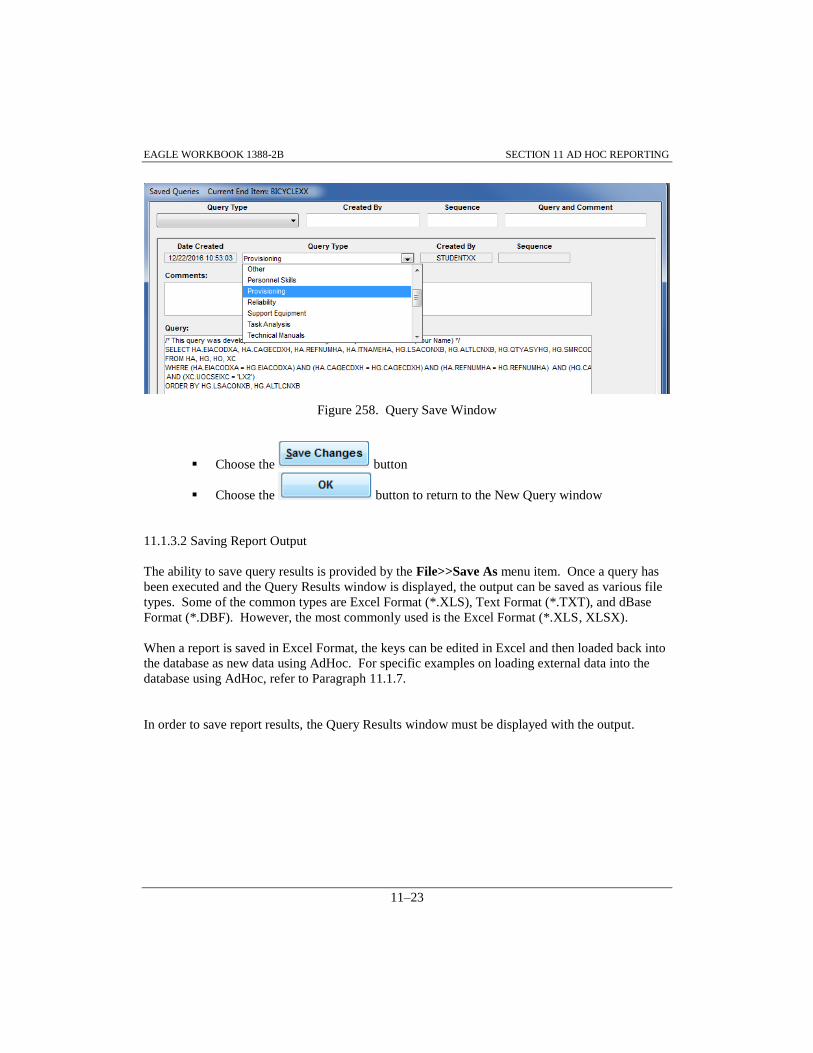
EAGLE WORKBOOK 1388-2B SECTION 11 AD HOC REPORTING
11–23
Figure 258. Query Save Window
Choose the button
Choose the button to return to the New Query window
11.1.3.2 Saving Report Output
The ability to save query results is provided by the File>>Save As menu item. Once a query has
been executed and the Query Results window is displayed, the output can be saved as various file
types. Some of the common types are Excel Format (*.XLS), Text Format (*.TXT), and dBase
Format (*.DBF). However, the most commonly used is the Excel Format (*.XLS, XLSX).
When a report is saved in Excel Format, the keys can be edited in Excel and then loaded back into
the database as new data using AdHoc. For specific examples on loading external data into the
database using AdHoc, refer to Paragraph 11.1.7.
In order to save report results, the Query Results window must be displayed with the output.

EAGLE WORKBOOK 1388-2B SECTION 11 AD HOC REPORTING
11–24
STEP To save the SQL query results shown in the Query Results window do the following (not
shown). You may use MS Excel to view, edit, or format the report output:
Execute the Query (topdown breakdown with comments added) using the Execute
button on the toolbar
Choose the File>>Save As menu item
Choose ‘Desktop’ from the Save In: dropdown list
Enter ‘Training 1’ for the File name:
Make sure the file type is Excel Format (*.XLS)
Choose the button
Close the Query Results window
Close the New Query window
11.1.4 Recall Query
The Recall Query function allows queries to be recalled from either the database or a file. In the
exercise below, the query saved to the database in paragraph 0 will be recalled, edited and
executed. When queries are recalled from disk, the process is similar to opening a file in the
Windows operating system and will not be performed here.
11.1.4.1 Recalling Queries from the Database
STEP To recall the query saved to the database in paragraph 11.1.3, do the following:
Access the AdHoc Discipline from the Navigator and double-click the Recall Query
Function (Figure 259)
Figure 259. Navigator - Recall Query

EAGLE WORKBOOK 1388-2B SECTION 11 AD HOC REPORTING
11–25
The Query Location pop up is displayed (Figure 260)
Choose the button on the Query Location dialogue box
Figure 260. Recall Query - Query Location Popup
The Saved Queries window is displayed
Select ‘Provisioning’ from the Query Type drop down list (Figure 261)
Enter ‘STUDENTXX’ in the Created By finder field
Figure 261. Query Save Window – Provisioning Selected
Choose the button on the Saved Queries window. Figure 262 is
displayed
Note: If multiple Provisioning Query Type records exist, a scroll bar will appear on the
window, enabling the user to scroll through the returned records. (Look in the Created
By field for your Id or your name in the Comment line).
Select the query titled ‘Query to Generate Top down Breakdown’ in the Comments:
field

EAGLE WORKBOOK 1388-2B SECTION 11 AD HOC REPORTING
11–26
Choose the button to open the saved query
Figure 262. Saved Queries Window – Recalling Saved Queries
The Recall Query window is displayed
If you notice that some of the text displayed goes off the edge of the window, check the FIT
TEXT LINE IN WINDOW checkbox at the bottom of the Recall Query window (Figure 263)

EAGLE WORKBOOK 1388-2B SECTION 11 AD HOC REPORTING
11–27
Figure 263. Recall Query Window
STEP At this point the query may be edited in the text window. The original query produced a
Top down breakdown of the baseline BICYCLE. To edit the query to produce a Top
down breakdown of an alternate BICYCLE configuration, do the following:
In the ‘AND (XC.UOCSEIXC = ‘LX2’)’ entry, change ‘LX2’ to ‘LH3’ in the Recall
Query window (Figure 264)
Figure 264. Recall Query Window – LH3
Choose the Execute button on the Main toolbar or ALT+Q, E
Choose the ‘Yes” butoon to Save changes? message
The Query Results for Recall Query window is displayed

EAGLE WORKBOOK 1388-2B SECTION 11 AD HOC REPORTING
11–28
Click the button and scroll over to the right
Note ‘LH3’ in the xc.uocseixc column. This represents the ALC ‘01’ configuration
bicycle
Figure 265. Query Results Window – 'LH3' Usable on Code
Close the Query Results for Recall Query window
Close the Recall Query window to return to the Navigator
11.1.5 Updating the Database with Query Results
After a query has been executed and the Query Results window is displayed, the data can be
updated. However, the only time data can be updated in this window is when all keys fields of a
table are displayed. There are two ways to update the data results. The first method is using the
Query Results window and the second method is using the “Multi-Cell Cut, Copy, Paste” option.
The Multi-Cell Cut, Copy, Paste option should only be used to update blocks of data (multiple
cells in multiple rows) from blocks (matching size) of data on the Windows clipboard. The Multi-
Cell Cut, Copy, Paste option should not be used to load new records or to update single fields.

EAGLE WORKBOOK 1388-2B SECTION 11 AD HOC REPORTING
11–29
11.1.5.1 Updating the Database (Query Results window)
To change the data using the first method simply type in the new information in the Query Results
window over the old data. When all changes are complete, choose the Save button or ALT-D, S
to save the data to the database. If there is any problem with the data, a message box will appear
with an error message.
STEP To illustrate editing query results using the Query Results window, do the following as
shown and described:
From the Navigator open the New Query window by double clicking on the New
Query function of the AdHoc Discipline
Select the HG table from the DATABASE TABLES list
Select the ONLY KEY/MANDATORY radio button under DATABASE
COLUMNS
Select the SMRCODHG field from the DATABASE COLUMNS list
Select the button on the Function Specific toolbar
The Where Criteria window is displayed
From the TABLE/COLUMNS list, select the SMRCODHG column (Figure 266)
From the OPERATORS list, select is null. (The “is null” operator will find records
for which data has not been established for the column)
Choose the button to return to the New Query window

EAGLE WORKBOOK 1388-2B SECTION 11 AD HOC REPORTING
11–30
Figure 266. Where Criteria Window – SMRCODHG Selected
At this point your SQL Query should reflect Figure 267!
Figure 267. New Query Window – SMRCODHG Selected
Choose the Execute button or ALT+Q, E
The Query Results for New Query window will be displayed
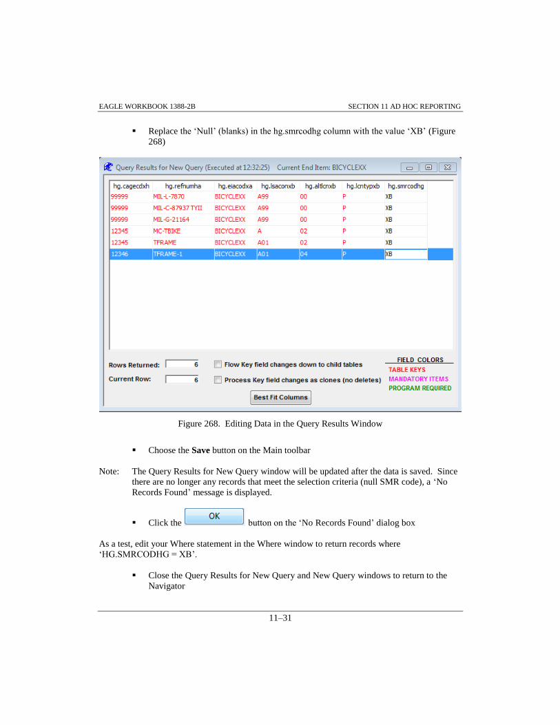
EAGLE WORKBOOK 1388-2B SECTION 11 AD HOC REPORTING
11–31
Replace the ‘Null’ (blanks) in the hg.smrcodhg column with the value ‘XB’ (Figure
268)
Figure 268. Editing Data in the Query Results Window
Choose the Save button on the Main toolbar
Note: The Query Results for New Query window will be updated after the data is saved. Since
there are no longer any records that meet the selection criteria (null SMR code), a ‘No
Records Found’ message is displayed.
Click the button on the ‘No Records Found’ dialog box
As a test, edit your Where statement in the Where window to return records where
‘HG.SMRCODHG = XB’.
Close the Query Results for New Query and New Query windows to return to the
Navigator

EAGLE WORKBOOK 1388-2B SECTION 11 AD HOC REPORTING
11–32
11.1.5.2 Updating the Database (Multi-Cell Cut, Copy, Paste Window)
The second method for updating data in the AdHoc Discipline is the ‘Multi-Cell Cut, Copy, Paste’
option. By choosing the button from the Function Specific toolbar, the user is taken
into a spreadsheet environment that allows them to perform multi-cell cut, copy, and paste
functions.
STEP To illustrate the Multi-Cell Cut, Copy, Paste function, do the following as shown and
described:
From the Navigator open the New Query window by double clicking on the New
Query function of the AdHoc Discipline
Select the HA table from the DATABASE TABLES list (not shown)
Select the ‘ALL (NAMES)’ radio button from under DATABASE COLUMNS
Select the button on the Function Specific toolbar
The Where Criteria window is displayed
From the TABLE/COLUMNS list, select the ‘REFNUMHA’ column (Figure 269)
From the OPERATORS list, select ‘like’ (The ‘like’ enables wild card queries).
Since REFNUMHA is an alphanumeric field, a single quote is placed after the like
operator (For fields defined as alphanumeric or character data, search criteria must
be enclosed in single quotes)
After the single quote, type ‘MC%’ (The % wildcard character will return any
characters, any length string).
Close the search criteria string with a single quote ( ' )
Choose the button to return to the New Query window

EAGLE WORKBOOK 1388-2B SECTION 11 AD HOC REPORTING
11–33
Figure 269. Where Criteria – REFNUMHA Selected
Choose the button on the Function Specific toolbar
Select 'REFNUMHA' from the COLUMN NAME list (Figure 270)
Choose the button to return to the New Query window
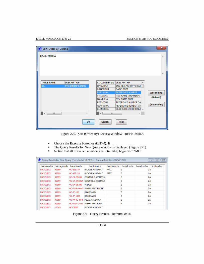
EAGLE WORKBOOK 1388-2B SECTION 11 AD HOC REPORTING
11–34
Figure 270. Sort (Order By) Criteria Window - REFNUMHA
Choose the Execute button or ALT+Q, E
The Query Results for New Query window is displayed (Figure 271)
Notice that all reference numbers (ha.refnumha) begin with ‘MC’
Figure 271. Query Results - Refnum MC%
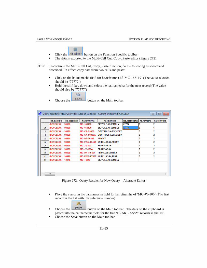
EAGLE WORKBOOK 1388-2B SECTION 11 AD HOC REPORTING
11–35
Click the button on the Function Specific toolbar
The data is exported to the Multi-Cell Cut, Copy, Paste editor (Figure 272)
STEP To continue the Multi-Cell Cut, Copy, Paste function, do the following as shown and
described. In effect, copy data from two cells and paste:
Click on the ha.inamecha field for ha.refnumha of ‘MC-168119’ (The value selected
should be ‘77777’)
Hold the shift key down and select the ha.inamecha for the next record (The value
should also be ‘77777’)
Choose the button on the Main toolbar
Figure 272. Query Results for New Query – Alternate Editor
Place the cursor in the ha.inamecha field for ha.refnumha of ‘MC-JY-100’ (The first
record in the list with this reference number)
Choose the button on the Main toolbar. The data on the clipboard is
pasted into the ha.inamecha field for the two ‘BRAKE ASSY’ records in the list
Choose the Save button on the Main toolbar

EAGLE WORKBOOK 1388-2B SECTION 11 AD HOC REPORTING
11–36
Your window should reflect Figure 273
Figure 273. Query Results with Multi-Cell Copy and Paste
Close the Query Results for New Query window
Note: To do the upcoming exercise in paragraph 11.1.7, an excel spreadsheet containing Table
HA data will be required. At this time we will create such a spreadsheet by saving the
data used in this exercise (11 HA records with ha.refnum = ‘MC%’).
With the New Query window open from the previous STEP, choose the Execute
button or ALT+Q, E
Choose the File >> Save As menu option (for ease of retrieval, save to desktop)
Enter ‘Training 2’ in the File name: box and ‘Excel Format(*.XLS)’ in the Save as
type: box
Choose the Save button on the Save Rows As window
Close the Query Results window
Close the New Query window

EAGLE WORKBOOK 1388-2B SECTION 11 AD HOC REPORTING
11–37
11.1.6 Key Field Updates and Parent Table Deletes
When changes are made to key fields, the change must be applied to all child tables of the table
changed. In EAGLE, this is accomplished through stored procedures, collections of SQL
statements for which execution plans have already been figured out. When selected, the "Flow
key field changes down to child tables" checkbox executes the appropriate stored procedure for
the table selected when changes are saved. Changes can be edits to key fields or parent table
record deletes. When an edit is made to a key field, an update stored procedure is executed.
Similarly, when a record with dependent data is deleted, a delete stored procedure is executed.
STEP To illustrate key field updates, do the following as shown and described:
From the Navigator open the New Query window by double-clicking on the New
Query function of the AdHoc Discipline
Select the ‘CA’ table from the DATABASE TABLES list (not shown)
Select the ‘ONLY KEY/MANDATORY’ radio button
Select the button from the Function Specific toolbar
From the COLUMN NAME list select ‘TASKCDCA’ (Figure 274)
From the OPERATORS list, select ‘like’ (The ‘like’ enables wild card queries).
Since TASKCDCA is an alphanumeric field, a single quote is placed after the like
operator (For fields defined as alphanumeric or character data, search criteria must
be enclosed in single quotes)
After the single quote, type ‘A%’ (The % wildcard character will return any
characters, any length string).
Close the search criteria string with a single quote ( ' )
Choose the button to return to the New Query window

EAGLE WORKBOOK 1388-2B SECTION 11 AD HOC REPORTING
11–38
Figure 274. Where Criteria Window – A%
Choose the Execute button or ALT+Q, E
The Query Results for New Query window is displayed
Select the record with ca.lsaconxb of 'A', ca.altlcnxb of '00', and ca.taskcdca of
'AACOCAA (Figure 275)
Edit the third position of the task code (ca.taskcdca column) from a 'C' to a 'D'. (This
changes the maintenance level for the task from operator/crew to depot.)
Check the Flow Key field changes down to child tables checkbox
Choose the Save button on the Main toolbar
The change is applied to the CA table and all of its child tables

EAGLE WORKBOOK 1388-2B SECTION 11 AD HOC REPORTING
11–39
Figure 275. Query Results for New Query Window – Key Field Changes
Close the Query Results window
Close the New Query window
11.1.7 Loading External Data
Data can be loaded from external files into the database using AdHoc. AdHoc performs its
external data loading using the Windows concept of copying and pasting to the Clipboard. Data is
most commonly loaded from an Excel Spreadsheet, so the AdHoc Discipline has a Paste
Spreadsheet option. The data is actually copied out of the spreadsheet and inserted into the
AdHoc Query Results Window. In order to insert data from a spreadsheet, all columns in the
selected table must exist in the Query Results Window.
STEP Load the spreadsheet data created in Paragraph 11.1.5 into the database using AdHoc by
doing the following as shown and described:
From the Navigator open the New Query window by double-clicking on the New
Query function of the AdHoc Discipline
Select the ‘HA’ table from the DATABASE TABLES list (not shown)
Select the ‘ALL (NAMES)’ radio button
Select button from the Function Specific toolbar
From the TABLE/COLUMNS list, select the ‘REFNUMHA’ column
From the OPERATORS list, select ‘like’ (The ‘like’ enables wild card queries).
Since REFNUMHA is an alphanumeric field, a single quote is placed after the like
operator (For fields defined as alphanumeric or character data, search criteria must
be enclosed in single quotes)
After the single quote, type ‘MC%’ (The % wildcard character will return any
characters, any length string)

EAGLE WORKBOOK 1388-2B SECTION 11 AD HOC REPORTING
11–40
Close the search criteria string with a single quote (‘).
Choose the button to return to the New Query window
Choose the Execute button or ALT+Q, E.
Open ‘Training 2.XLS’ saved on the Desktop in Paragraph 11.1.5
Note: Because the data in the spreadsheet already exists in the database, a key field must be
changed in order to establish new records. To do this, use MS Excel to change the ‘MCs’
in the REFNUMHA column to ‘NCs’.
Change the ‘MC’s to ‘NC’s in the TRAINING2.XLS spreadsheet
Select the entire spreadsheet data (11 records), not the header row, and copy it to the
clipboard (CTRL-C)
Return to the Query Results for New Query window
Click in the window
Choose Edit>>Paste Spreadsheet from the menu or the button on the
Function Specific toolbar and the data will be inserted into the Query Results
window
Click the button to acknowledge the ‘11 Rows Added’ message
Choose the Save button on the Main toolbar
Note: The new records will not be displayed when the query results are refreshed because the
‘NC’ part numbers do not meet the search criteria in the original query (Refnum like
MC%).
Return to the New Query window by closing the Query Results for New Query
window
Click the button on the Function Specific toolbar
In the Where Criteria window, change the ‘MC%’ to ‘NC%’
Choose the button to return to the New Query window
Choose the Execute button or ALT+Q, E
Notice that all reference numbers (ha.refnumha) begin with ‘NC’ (Figure 276)

EAGLE WORKBOOK 1388-2B SECTION 11 AD HOC REPORTING
11–41
Figure 276. Query Results – NC% Records
Close the Query Results for New Query window
Test your skills:
Change your Where statement to return both MC% and NC% records.
Close the Query Results window
Close the New Query window

EAGLE WORKBOOK 1388-2B SECTION 11 AD HOC REPORTING
11–42

EAGLE Workbook 1388-2B Version 15
INTERPRETING
ERROR MESSAGES
IN EAGLE
SECTION 12


EAGLE WORKBOOK 1388-2B INTERPRETING ERROR MESSAGES IN EAGLE
12–3
SECTION 12 INTERPRETING ERROR MESSAGES IN EAGLE
12.0 INTRODUCTION
This section provides information on common types of error messages in EAGLE and provides a
methodology for interpreting their meanings. The error messages displayed in EAGLE vary
depending on the database system in use. For Oracle systems, there are six common types of error
messages that can occur. In many cases, the EAGLE Help function can be used to aid in
interpreting error messages.
12.1 ERROR MESSAGES IN EAGLE
For EAGLE databases the six common error types are:
1) Security Violations
2) Unique Constraint Violations
3) Integrity Constraint Violation – Parent Key Not Found
4) Integrity Constraint Violation – Child Record Found
5) Data Element Cross Edit Violation
6) Violation of a Rule Bound to a Column
12.1.1 Security Violations
Security violations in EAGLE result when a user attempts to access, add, modify or delete data
without having the appropriate permissions. On Oracle versions of EAGLE, users must have a set
of permissions established. These permissions are based on End Item and ownership codes. In
order to access a data record, a user must have permission on the End Item and have a select
ownership associated with their userid that matches the ownership code of the record being
accessed. To modify or delete existing data, a user must have permission on the End Item and
have an ownership code associated with their userid matching the ownership code of the record
being modified or deleted. To add a new record, a user must have permission on the End Item. If
this is the case, the ownership code associated with the user's userid will be attached to the record.
Figure 277 is an example of an error message displayed when a security violation occurs. By
clicking the button, the Structured Query Language (SQL) for the failed
transaction can be reviewed (Figure 278).
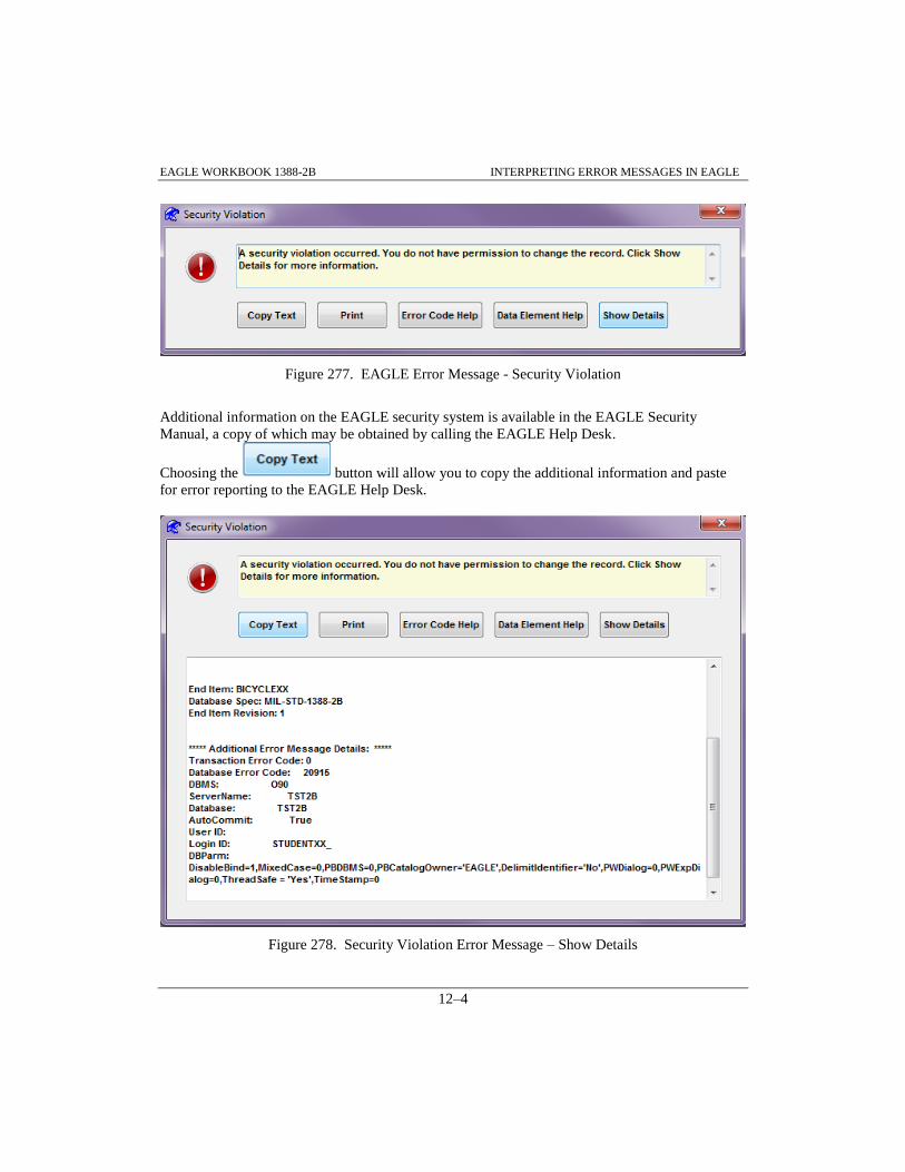
EAGLE WORKBOOK 1388-2B INTERPRETING ERROR MESSAGES IN EAGLE
12–4
Figure 277. EAGLE Error Message - Security Violation
Additional information on the EAGLE security system is available in the EAGLE Security
Manual, a copy of which may be obtained by calling the EAGLE Help Desk.
Choosing the button will allow you to copy the additional information and paste
for error reporting to the EAGLE Help Desk.
Figure 278. Security Violation Error Message – Show Details

EAGLE WORKBOOK 1388-2B INTERPRETING ERROR MESSAGES IN EAGLE
12–5
12.1.2 Unique Constraint Violation
In relational databases, rows of data in a table are defined by key fields. In order to establish a
new record in a table, the key fields defining the record must be unique to existing records.
Whenever a new record is inserted or an existing record is modified so that the key fields defining
the record are the same as an existing record, a unique constraint violation occurs. Figure 279 is
an example of a unique constraint error message. In most cases, the ‘Key Values Exist’ header
section of the EAGLE error messages provides enough information for the user to interpret the
error message. Additional information as shown in Figure 279 can be obtained by clicking the
button and scrolling down the error message to display the SQL for the failed
transaction.
Figure 279. Unique Constraint Violation – Key Values Exist Details

EAGLE WORKBOOK 1388-2B INTERPRETING ERROR MESSAGES IN EAGLE
12–6
12.1.3 Integrity Constraint – Parent Key Not Found
In relational databases, rows of data in a table are defined by key fields. Key fields ‘flow down’
from higher level tables to ‘child tables’ as ‘Foreign Keys’ which relate the data in the child table
to its ‘parent table’. Whenever a record is inserted or modified in a child table, the foreign key
fields must match the key fields of its parent table(s).
If an attempt is made to insert or modify a record in a child table so that its foreign keys do not
match the key fields of its parent tables, an Integrity Constraint Violation – Parent Key Not Found
error results. Figure 280 is an example of a Missing Parent Table Information error message. By
clicking the button, information to interpret the error message is provided. In this
case, the "integrity constraint (EAGLE.HA_XH_FOREIGN) violated – parent key not found"
message indicates that the foreign keys inserted in the HA table do not match a set of key fields in
the parent table, XH.
Figure 280. Integrity Constraint – Parent Key Not Found

EAGLE WORKBOOK 1388-2B INTERPRETING ERROR MESSAGES IN EAGLE
12–7
12.1.4 Integrity Constraint – Child Record Found
In relational databases, rows of data in a table are defined by key fields. Key fields ‘flow down’
from higher level tables to ‘child tables’ as ‘Foreign Keys’ which relate the data in the child table
to its ‘parent table’. Key fields cannot be modified or records deleted in parent tables if data in
child tables is dependent on the existence of the parent keys. Whenever records are deleted or
keys modified in parent tables for which child data exists in lower level tables, an Integrity
Constraint - Child Record Found results. Figure 281 is an example of an Integrity Constraint
Violation – Parent Key Not Found error message. By clicking the button, additional
information is provided to interpret the error message. In this case the
(EAGLE.EM_HA_FOREIGN) violated – child record found is provided.
Figure 281. Error Code Help for Integrity Constraint - Child Record Found

EAGLE WORKBOOK 1388-2B INTERPRETING ERROR MESSAGES IN EAGLE
12–8
12.1.5 Cross Edit Violations
The cross edits defined in each table definition in MIL-STD-1388-2B place restrictions on data
that can be entered. Figure 282 is an example of a cross edit violation. In most cases, the
Top portion of the error message provides enough information to interpret the error. In this case,
the ‘Table JA not loaded. Either XC.TRASEIXC OR XB.SECITMXB Must Be Y. – JA.a
‘message indicates cross edit paragraph ‘a’ of the JA table cross edits has been violated. (This
cross edit states: ‘The transportability area can only be used if an item has been identified by a
Sectionalized Item Transportation Indicator (SECITMXB) table XB, or by a Transportation End
Item Indicator (TRASEIXC) table XC’.) By clicking the button additional
information displayed for cross edit violations can be displayed. These messages are unique to the
specific cross edit violated.
Figure 282. Cross Edit Violation Message
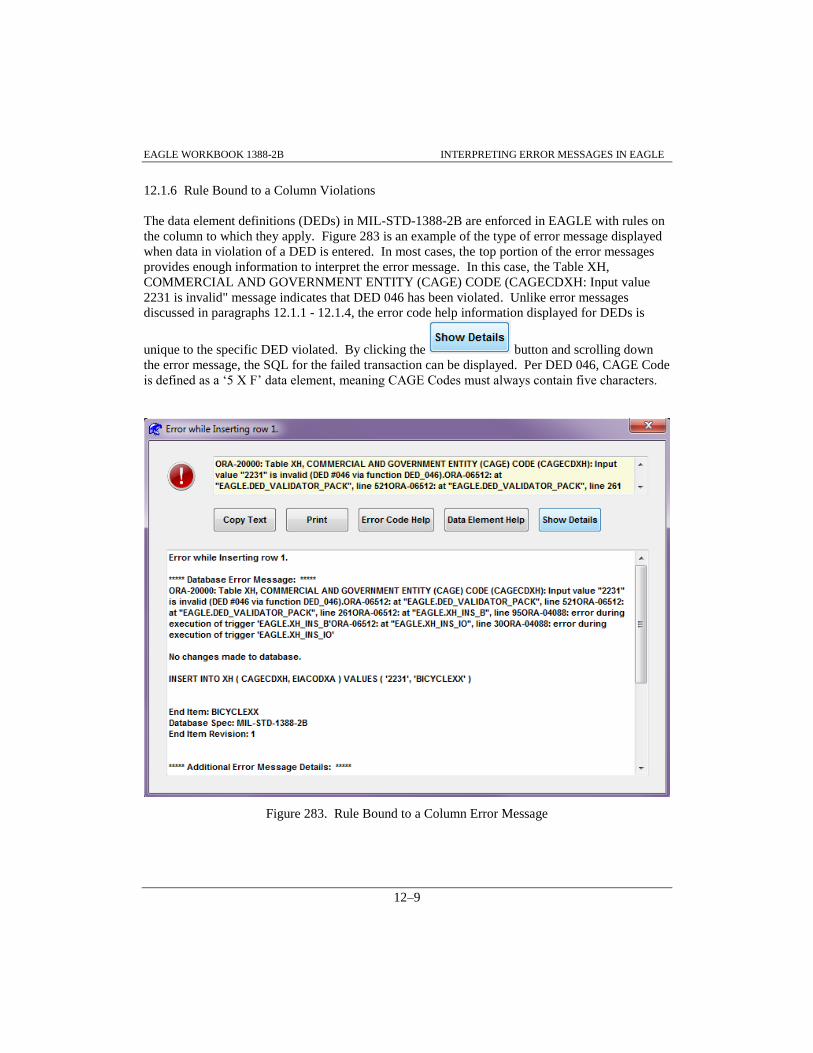
EAGLE WORKBOOK 1388-2B INTERPRETING ERROR MESSAGES IN EAGLE
12–9
12.1.6 Rule Bound to a Column Violations
The data element definitions (DEDs) in MIL-STD-1388-2B are enforced in EAGLE with rules on
the column to which they apply. Figure 283 is an example of the type of error message displayed
when data in violation of a DED is entered. In most cases, the top portion of the error messages
provides enough information to interpret the error message. In this case, the Table XH,
COMMERCIAL AND GOVERNMENT ENTITY (CAGE) CODE (CAGECDXH: Input value
2231 is invalid" message indicates that DED 046 has been violated. Unlike error messages
discussed in paragraphs 12.1.1 - 12.1.4, the error code help information displayed for DEDs is
unique to the specific DED violated. By clicking the button and scrolling down
the error message, the SQL for the failed transaction can be displayed. Per DED 046, CAGE Code
is defined as a ‘5 X F’ data element, meaning CAGE Codes must always contain five characters.
Figure 283. Rule Bound to a Column Error Message

EAGLE WORKBOOK 1388-2B INTERPRETING ERROR MESSAGES IN EAGLE
12–10

EAGLE Workbook 1388-2B Version 15
ASSIGN LCNs TO
BILL OF MATERIALS
APPENDIX A


EAGLE WORKBOOK 1388-2B APPENDIX A ASSIGN LCNs TO BOM
A–3
APPENDIX A ASSIGN LCNs TO BOM
EAGLE provides a method for automatically generating LCNs using the Assign LCNs to BOM
Function of the LCN Maintenance Discipline. The input file is a file that is commonly referred to
as a Bill of Materials (BOM) file. It must contain the indenture code, CAGE code, reference
number, and reference number description. In addition, this file must be in top down break down
sequence with indenture codes assigned. The easiest way to use the BOM file with EAGLE is to
have it in an Excel Spreadsheet. For this exercise, a BOM Excel Spreadsheet has been created for
training and will be used in the following paragraphs.
In order to do this as an exercise, the TRAINBOM.XLS file must be open in Excel and all the data
selected for copying.
Access the TRAINBOM.XLS file located in the EAGLE root directory
Copy the records in Excel to the clipboard
Access the Assign LCNs to BOM Function from the LCN Maintenance discipline using
the Navigator Home tab and Filter (Figure 284)
Double-click the Assign LCNs to BOM Function
Figure 284. Navigator - Assign LCNs to BOM
The Automatically Assign LCNs Window is displayed (Figure 285)

EAGLE WORKBOOK 1388-2B APPENDIX A ASSIGN LCNs TO BOM
A–4
Because the TRAINBOM.XLS file contains data that already exists in our BICYCLEXX End
Item, we have selected the NEWBIKEXX End Item. This End Item must be selected before
Assign LCNs to BOM is executed from the Navigator or entered manually.
STEP Do the following to Automatically Assign LCNs to a BOM and import the Data:
Make sure ‘NEWBIKEXX’ is selected as End Item
Choose the button
Figure 285. Automatically Assign LCNs
The EAGLE: Clipboard Format popup window is displayed (Figure 286)
The data in your spreadsheet must be in this format
Click the button

EAGLE WORKBOOK 1388-2B APPENDIX A ASSIGN LCNs TO BOM
A–5
Figure 286. EAGLE: Clipboard Format Popup
Enter ‘AA’ in the Start LCN data box (Figure 287)
Enter ‘2232222111’ for LCN Structure: Note that the ‘2’at the beginning of the LCN
Structure corresponds to the ‘AA’ in the Start LCN data field. If you were to choose ‘A’
as your Start LCN, the first indenture level in the LCN Structure: data field would have to
be a ‘1’. As an example, the BICYCLEXX End Item used for our training has an LCN
structure of ‘1222222221’ and a corresponding Start LCN of ‘A’
Choose the radio button for AlphaNumeric under LCN Data Type. AlphaNumeric allows
for the most Indenture Levels and the most items at each level
Check the Skip I’s and O’s checkbox to exclude the use of I’s and O’s in the LCN’s
Make sure the six checkboxes in the Tables to Fill area are checked
Enter ‘1’ for LCN Gap:

EAGLE WORKBOOK 1388-2B APPENDIX A ASSIGN LCNs TO BOM
A–6
At this point our window should reflect Figure 287.
Choose the button
Figure 287. Automatically Assign LCNs – NEWBIKEXX
The EAGLE: Clipboard Format window is displayed

EAGLE WORKBOOK 1388-2B APPENDIX A ASSIGN LCNs TO BOM
A–7
Choose the button to ‘Is the Clipboard data in this order?’ message
(Figure 288)
Figure 288. EAGLE: Clipboard Format
The records are added to the Automatically Assign LCNs window (Figure 289)
Choose the button

EAGLE WORKBOOK 1388-2B APPENDIX A ASSIGN LCNs TO BOM
A–8
Figure 289. Automatically Assign LCNs-Paste Clipboard
The Automatically Assign HG Indenture Codes? window is displayed (Figure 290)
At this time our spreadsheet does not contain HG Indenture Codes, so choose the
button to ‘Would you like the Table HG Indenture Codes to be
assigned/calculated?

EAGLE WORKBOOK 1388-2B APPENDIX A ASSIGN LCNs TO BOM
A–9
Figure 290. Automatically Assign HG Indenture Codes?
The LCNs are added to the LCN column (Figure 291)
This gives you the opportunity to view the LCNs as they will appear in your structure
Choose the button
Figure 291. Automatically Assign LCNs- Calculate LCNs

EAGLE WORKBOOK 1388-2B APPENDIX A ASSIGN LCNs TO BOM
A–10
Note the View Results button becomes active
Choose the button
The Assign LCNs to BOM – Populate Database Results window is displayed (Figure
292)
Close the Assign LCNs to BOM – Populate Database Results window
Figure 292. Database Error Messages-View Results
In the Tables to Fill portion of the window, note the additional checkboxes available (Figure 293).
This capability is provided in the event your BOM contains additional parts information/TM data.
There is another BOM File located in the EAGLE Root directory (trainbom-new.xls) to utilize for
this exercise if you so choose.
At some point the Calculate LCNs Function may not allow for your specific needs. This next step
offers a method to change/add LCNs and populate the Database.
STEP Do the following to Assign LCNs to a BOM and import the Data:
With the Automatically Assign LCNs window open as shown in Figure 293, click on a
record as shown and choose Edit >> Copy Datawindow from the Main toolbar
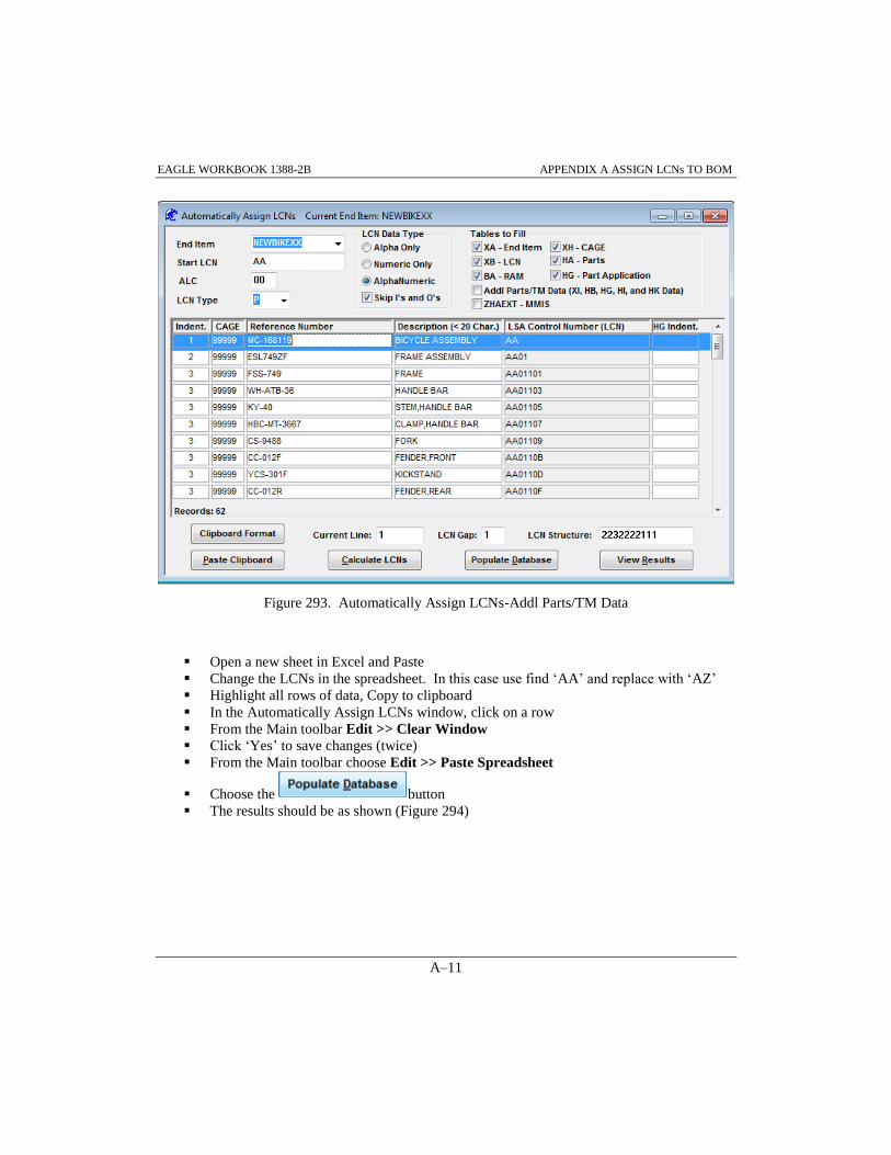
EAGLE WORKBOOK 1388-2B APPENDIX A ASSIGN LCNs TO BOM
A–11
Figure 293. Automatically Assign LCNs-Addl Parts/TM Data
Open a new sheet in Excel and Paste
Change the LCNs in the spreadsheet. In this case use find ‘AA’ and replace with ‘AZ’
Highlight all rows of data, Copy to clipboard
In the Automatically Assign LCNs window, click on a row
From the Main toolbar Edit >> Clear Window
Click ‘Yes’ to save changes (twice)
From the Main toolbar choose Edit >> Paste Spreadsheet
Choose the button
The results should be as shown (Figure 294)

EAGLE WORKBOOK 1388-2B APPENDIX A ASSIGN LCNs TO BOM
A–12
Figure 294. Automatically Assign LCNs – New LCNs

EAGLE Workbook 1388-2B Version 15
MIL-STD-1388-2B
LSAR RELATIONAL
TABLES
APPENDIX B


EAGLE WORKBOOK 1388-2B APPENDIX B MIL-STD-1388-2B LSAR TABLES
B–3
APPENDIX B MIL-STD-1388-2B LSAR TABLES
Military Standard 1388-2B defines the DoD requirements for a Logistic Support Analysis Record.
The standard is based on joint efforts of the military services and the Federal Aviation
Administration with assistance from private industry. The goal of the standard is to establish
uniform requirements for development and delivery of LSAR data. The LSA documentation,
including LSAR data, is generated as a result of performing any or all of the analysis specified in
MIL-STD-1388-1, Logistic Support Analysis (LSA).
The LSAR is structured to accommodate the maximum range of data potentially required by all
services and all ILS element functional areas. This approach establishes "one face to industry" for
government required LSAR data, and facilitates improving cost effectiveness of the generation,
maintenance, acquisition, and use of the technical data required to support an ILS program.
The LSAR documents data across all ILS functional areas. The relational design of LSAR data is
intended to facilitate integration of engineering design, manufacturing, and product support
elements for complete life-cycle management of a system.
EAGLE allows for remote on-line access to LSAR databases. This capability provides the user
with a powerful tool for accessing the logistics data for their program. AdHoc queries, generation
of required data reports, access to engineering drawings with markup capability, and automated
generation of technical data are a few of the salient features of EAGLE.
EAGLE engineers have expanded the core structure of the LSAR as defined in MIL-STD-1388-
2B to accommodate these advanced features. As an example, new tables have been created,
within the database that allow linking of engineering drawings and artwork to technical
publications. The automated generation of technical publications process uses these customized
tables to automatically pull in required artwork.

EAGLE WORKBOOK 1388-2B APPENDIX B MIL-STD-1388-2B LSAR TABLES
B–4
LSAR Table Structure
Figure 295. and Figure 296 are a schematic representation of the MIL-STD-1388-2B LSAR table
structure.
Figure 295. MIL-STD-1388-2B Table Structure (1 of 2)
XC
XG
ABOPRQIN
AGMEASBS
AHIONAME
IOINTY
ACOMLVLC
AD
BDRAMIND
BEOPRQIN
BFFAMOIN
BGFMNCNA
TEXSEQ
HHNHAPLI
HITEXSEQ
HJREFDES
HAREFNUM
HDUIPRIC
HEUMPRIC
HFDEGPRO
XA XC
HA
CI
HG
HG
XB
CA
XDFRSNUM
TOSNUM
XE
AFTEXSEQ
AISERDES
OMLVLC
XC
AJOMLVLF
OMLVLT
GA
AE
AKSEINCD
TEXSEQ
BJFMMPCN
TEXSEQ
BI
BH
BBRAMCNA
TEXSEQ
BCLOCOCO
TEXSEQ
CETSKRRC
CF
XA
CH
XI
CCTEXSEQ
CDSUBPID
CJJOBCOD
DUTYCD
CK
CBSUBNUM
AASERDES
CG
EDACTNAM
EETEXSEQ
SENARC
EFSERDNO
SRDREV
EBALDCNM
ECPARGPC
EHALTFSC
ALTNII
EGTEXSEQ
EM
HA
EIIPSOPN
EK
EJDSNDAT
ELIRCCOD
XI
HKFIGNUM
ITEMNO
HLTEXSEQ
HPCANUM
HQFRSRNO
TOSRNO
HO
HBADDREF
XHCAGECD
HC
HRHNREFNUM
XD
EA
HMBOICTR
XF
BA
BKFMSHSC
BLMISSPC
CATASKCD
XAEIACOD
XBLSACON
ALTLCN
LCNTYP
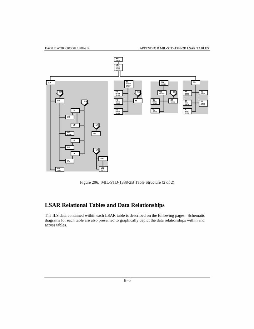
EAGLE WORKBOOK 1388-2B APPENDIX B MIL-STD-1388-2B LSAR TABLES
B–5
Figure 296. MIL-STD-1388-2B Table Structure (2 of 2)
LSAR Relational Tables and Data Relationships
The ILS data contained within each LSAR table is described on the following pages. Schematic
diagrams for each table are also presented to graphically depict the data relationships within and
across tables.
UA
UD
UFTEXSEQ
UGUUTPGC
UC
UH
UK
UM
CI
EA
UB
UL
EA
UNSEUPGC
UE
UI
UJ
HA
FAFACNAM
FACCCD
FACTYP
FCFBNACD
TEXSEQ
FBFNCODE
TEXSEQ
FDNMFNCD
TEXSEQ
FE
CA
GASKSPCD
GBMDCSSC
GCNMSMCD
TEXSEQ
GDASVAPE
GETEXSEQ
CD
JA
JBTRANCN
TRCHMT
JCTRCON
MOBTYP
JDTREINC
TEXSEQ
JETRAFYR
JFTRANCD
TEXSEQ
XAEIACOD
XBLSACON
ALTLCN
LCNTYP
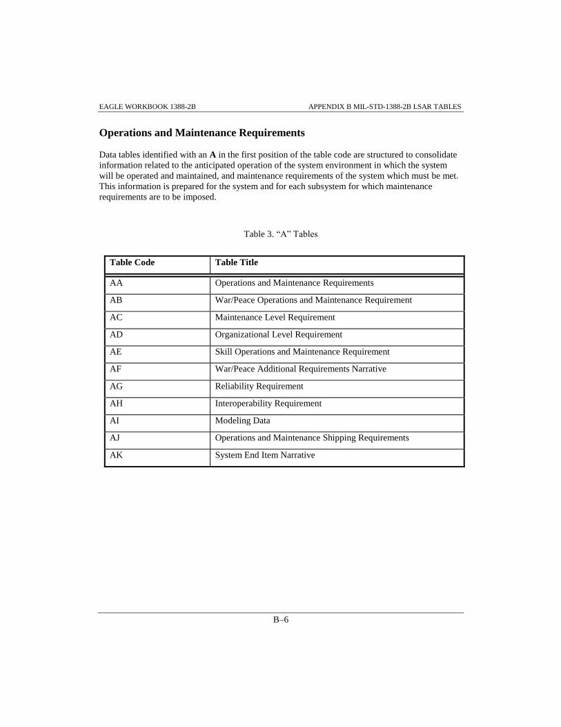
EAGLE WORKBOOK 1388-2B APPENDIX B MIL-STD-1388-2B LSAR TABLES
B–6
Operations and Maintenance Requirements
Data tables identified with an A in the first position of the table code are structured to consolidate
information related to the anticipated operation of the system environment in which the system
will be operated and maintained, and maintenance requirements of the system which must be met.
This information is prepared for the system and for each subsystem for which maintenance
requirements are to be imposed.
Table 3. “A” Tables
Table Code Table Title
AA Operations and Maintenance Requirements
AB War/Peace Operations and Maintenance Requirement
AC Maintenance Level Requirement
AD Organizational Level Requirement
AE Skill Operations and Maintenance Requirement
AF War/Peace Additional Requirements Narrative
AG Reliability Requirement
AH Interoperability Requirement
AI Modeling Data
AJ Operations and Maintenance Shipping Requirements
AK System End Item Narrative

EAGLE WORKBOOK 1388-2B APPENDIX B MIL-STD-1388-2B LSAR TABLES
B–7
Figure 297. "A" Table Relationships
End Item Acronym
End Item Acronym Code
XA
Modeling Data
Modeling Service
Designator Code
Modeling Operations and
Maintenance Level Code
AI
Interoperability
Requirement
Interoperable Item Name
Interoperable Item Number
Type
AH Operations and
Maintenance Rqmts
Service Designator
Code
AA
System End Item Narrative
System End Item Narrative
Code
System/End Item Text
Sequencing Code
AKOperations andMaintenance ShippingRequirements
Operations Maintenance
Level From
Operations Maintenance
Level To
AJ
Skill Specialty
Skill Specialty Code
GA
Maintenance Level
Requirement
Operations and
Maintenance Level Code
AC
Organizational Level
Requirment
AD
Skill Operations and
Maintenance Rqmt
Operational Requirement
Indicator
AE
War / Peace Additional
Requirement Narrative
Additional Requirements
Text Sequencing Code
AF
War / Peace Operations
and Maintenance Rqmt
AB
Operational Requirement
Indicator
AB
Reliability Requirement
Annual Operating
Requirement Measurement
Base
AG
LCN Indentured Item
LSA Control Number (LCN)
Alternate LCN Code
LCN Type
X8
System End Item
XC

EAGLE WORKBOOK 1388-2B APPENDIX B MIL-STD-1388-2B LSAR TABLES
B–8
Item Reliability, Availability and Maintainability Characteristics; Failure
Modes Effects and Criticality Analysis; and Maintainability Analysis
Data tables beginning with an B in the first position of the table code are structured to provide a
description of the function of each item of the end item; outline the maintenance concept to be
utilized for design and support planning purposes; and, identify and design conditions such as fail
safe requirements/environmental or nuclear hardness considerations imposed upon the system.
The tables summarize the item reliability, maintainability, and related availability characteristics
of the item resulting from the failure modes and effects, criticality, and maintainability analysis,
and accommodate a narrative description of any analysis related to the potential redesign of an
item.
Table 4. “B” Tables
Table Code Table Title
BA Reliability, Availability, and Maintainability Characteristics
BB Reliability, Availability, and Maintainability Characteristics
Narrative
BC Reliability, Availability, and Maintainability Logistics
Consideration
BD Reliability, Availability, and Maintainability Indicator
Characteristics
BE War/Peace Reliability, Availability, and Maintainability Indicator
Characteristics
BF Failure Mode and Reliability Centered Maintenance Analysis
BG Failure Mode and Reliability Centered Maintenance Narrative
BH Failure Mode Task
BI Failure Mode Indicator Mission Phase Code Characteristics
BJ Failure Mode Indicator Mission Phase Code Characteristics
Narrative
BK Reliability, Availability, and Maintainability Criticality
BL Mission Phase Operational Mode

EAGLE WORKBOOK 1388-2B APPENDIX B MIL-STD-1388-2B LSAR TABLES
B–9
Figure 298. "B" Table Relationships
End Item Acronym
End Item Acronym Code
XA
LCN Indentured Item
LSA Control Number
(LCN)
Alternate LCN Code
LCN Type
XB
Reliability, Availability,
and Maintainability
Characteristic
BA
Reliability, Availability,and MaintainabilityIndicator Characteristics
RAM Indicator Code
BD
Reliability, Availability,and MaintainabilityLogisticsConsiderations
Logistics
Considerations Code
RAM Logistics
Considerations Text
Sequencing Code
BC
War / Peace Reliability,Availability, andMaintainability IndicatorCharacteristics
Operational
Requirement Indicator
BE
Reliability, Availability,and MaintainabilityCharacteristics Narrative
RAM Characteristics
Narrative Code
RAM Characteristics
Narrative Text
Sequencing Code
BB
Failure Mode and
Reliability Centered
Maintenance Narrative
Failure Mode and RCM
Narrative Code
Failure Mode Narrative
Text Sequencing Code
BG
Failure Mode and
Reliability Centered
Maintenance Analysis
Failure Mode Indicator
BF
Failure Mode Task
BH
Failure Mode Indicator
Mission Phase Code
Characteristics
BI
Reliability, Availability,
and Maintainability
Criticality
RAM Safety Hazard
Severity Code
BK
Mission Phase
Operational Mode
Mission Phase Code
BL
Task Requirement
End Item Acronym Code
LSA Control Number(LCN)
Alternate LCN Code
LCN Type
Task Code
CA
Failure Mode IndicatorMission Phase CodeCharacteristicsNarrativeFailure Mode IndicatorMission PhaseCharacteristicsNarrative Code
Failure Mode IndicatorMission PhaseCharacteristicsNarrative TextSequencing Code BJ
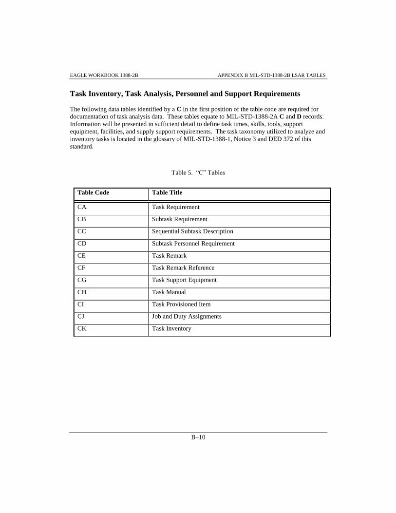
EAGLE WORKBOOK 1388-2B APPENDIX B MIL-STD-1388-2B LSAR TABLES
B–10
Task Inventory, Task Analysis, Personnel and Support Requirements
The following data tables identified by a C in the first position of the table code are required for
documentation of task analysis data. These tables equate to MIL-STD-1388-2A C and D records.
Information will be presented in sufficient detail to define task times, skills, tools, support
equipment, facilities, and supply support requirements. The task taxonomy utilized to analyze and
inventory tasks is located in the glossary of MIL-STD-1388-1, Notice 3 and DED 372 of this
standard.
Table 5. “C” Tables
Table Code Table Title
CA Task Requirement
CB Subtask Requirement
CC Sequential Subtask Description
CD Subtask Personnel Requirement
CE Task Remark
CF Task Remark Reference
CG Task Support Equipment
CH Task Manual
CI Task Provisioned Item
CJ Job and Duty Assignments
CK Task Inventory

EAGLE WORKBOOK 1388-2B APPENDIX B MIL-STD-1388-2B LSAR TABLES
B–11
Figure 299. "C" Table Relationships
LCN
ALC
LCN Type
LCN Indentured Item
XB
Item Identification
Reference No.
CAGE
HA
Provisioning Item
Reference No.
CAGE
EIAC
LCN
ALC
LCN Type HG
Task Support Equipment
CG
Task Provision Item
CI
Subtask Requirement
Subtask No.
CB
Technical Manual
TM Code
XI
Task Remark
Task Remark
Referencing Code
CE
End Item Acronym Code
EIAC
XA
Task Requirement
Task Code
CA
Task Manual
CH
Task Remark Reference
CF
Job and Duty
Assignments
Job Code
Duty Code
CJ
Subtask Personnel
Requirement
CD
Sequential Subtask
Description
Test Sequencing Code
CC
Task Inventory
CK

EAGLE WORKBOOK 1388-2B APPENDIX B MIL-STD-1388-2B LSAR TABLES
B–12
Support Equipment and Training Materiel Requirements
Data tables identified with an E in the first position of the table code are structured to consolidate
the pertinent information related to existing or new support/test equipment or training equipment.
These tables contain most of the data that was captured on the old E and EI records. Much of this
information serves as administrative type data for the Support Equipment Recommendation Data
(SERD) report. This information also serves as identification of hardware and software elements
required to conduct off line tests.
Table 6. “E” Tables
Table Code Table Title
EA Support Equipment
EB Allocation Data
EC Support Equipment Parameters
ED Support Equipment Authorization
EE Support Equipment Narrative
EF Support Equipment Recommendation Data
EG Support Equipment Recommendation Data Revision Remarks
EH Alternate National Stock Numbers
EI Input Power Source
EJ Support Equipment Design Data
EK Supercedure Data
EL Support Equipment Integrated Logistic Support Requirement
Category Code
EM System Equipment

EAGLE WORKBOOK 1388-2B APPENDIX B MIL-STD-1388-2B LSAR TABLES
B–13
Figure 300. "E" Table Relationships
Support Equipment
EA
Support Equipment ILSRequirement CategoryCode
Support Equipment
IRCC
EL
Supercedure Data
Supercedure Reference
Number
Supercedure CAGE
EKSupport EquipmentDesign Data
Design Data Category
Code
EJ
Item Identification
Reference No.
CAGE
HA
System Equipment
EM
Revision Remarks
EG
Alternate NSN
Alternate FSC
Alternate NSN
EH
Support EquipmentRecommendation Data
SERD Number
SERD Revision
EF
Input Power Source
Source Option Number
EI
Support EquipmentNarrative
Test Sequencing Code
SE Narrative Code
EE
Support EquipmentAuthorization
Activity Name Location
ED
Support EquipmentParameters
Parameter Group Code
EC
Allocation Date
Allowance Document
Number
EB

EAGLE WORKBOOK 1388-2B APPENDIX B MIL-STD-1388-2B LSAR TABLES
B–14
Facilities Considerations
Data tables beginning with an F in the first position of the table code are structured to describe and
justify all proposed special and additional facilities requirements, which are indicated as a result of
the operational/maintenance task analysis.
Table 7. “F” Tables
Table Code Table Title
FA Facility
FB Facility Narrative
FC Baseline Facility Narrative
FD New or Modified Facility Narrative
FE Operations and Maintenance Task Facility Requirement
Figure 301. "F" Table Relationships
Operations and
Maintenance Task Facility
Requirements
FE
Baseline Facility Narrative
Baseline Facility Narrative
Code
Baseline Facility Narrative
Text Sequencing Code
FC
Facility Narrative
Facility Narrative Code
Facility Narrative Text
Sequencing Code
FB
New or Modified Facility
Narrative
New or Modified Facility
Narrative Code
New or Modified Facility
Narrative Text Sequencing
Code
FD
Facility
Facility Name
Facility Category Code
FA
Task Requirement
End Item Acronym Code
LSA Control Number
Alternate LCN Code
LCN Type
Task Code CA

EAGLE WORKBOOK 1388-2B APPENDIX B MIL-STD-1388-2B LSAR TABLES
B–15
Personnel Skill Considerations
Data tables beginning with a G in the first position of the table code are structured to describe and
justify any new or modified personnel skills required to support the system/equipment.
Table 8. “G” Tables
Table Code Table Title
GA Skill Specialty
GB New or Modified Skill
GC New or Modified Skill Narrative
GD Skill Aptitude Data
GE Physical and Mental Requirements Narrative

EAGLE WORKBOOK 1388-2B APPENDIX B MIL-STD-1388-2B LSAR TABLES
B–16
Figure 302. "G" Table Relationships
Skill Specialty
Skill Specialty Code
GA
Skill Aptitude Data
ASVAB Aptitude Element
GD
New or Modified Skill
Narrative
New or Modified Skill
Narrative Code
New or Modified Skill
Narrative Text Sequencing
Code
GC
Physical and Mental
Requirements Narrative
Physical and Mental
Requirements Narrative
Text Sequencing Code
GE
New or Modified Skill
New or Modified Skill
Specialty Code
GB
Subtask Requirement
End Item Acronym Code
LSA Control Number (LCN)
Alternate LCN Code
LCN Type
Task Code
Subtask Number
Subtask Person ID CD

EAGLE WORKBOOK 1388-2B APPENDIX B MIL-STD-1388-2B LSAR TABLES
B–17
Packaging and Provisioning Requirement
The following H data tables are used to document packaging/provisioning data requirements.
Included in these tables are static parts data (non-application dependent) related to provisioning
screening and cataloging, packaging, and common maintenance data. Also included under these
data tables are application data of items used to document the data required for initial support
requirements determination, repair parts manuals, and design change information.
Table 9. “H” Tables
Table Code Table Title
HA Item Identification
HB Additional Reference Number
HC Contractor Technical Information Code CAGE
HD Unit Of Issue Price
HE Unit Of Measure Price
HF Item Packaging Requirement
HG Part Application Provisioning
HH Overhaul-Kit Next Higher Assembly PLISN
HI Provisioning Remark
HJ Provisioning Reference Designation
HK Parts Manual Description
HL Parts Manual Provisioning Nomenclature
HM Basis Of Issue
HN Provisioning Serial Number Usable On Code
HO Provisioning System/End Item Usable On Code
HP Design Change Information
HQ Serial Number Effectivity
HR Design Change Usable On Code
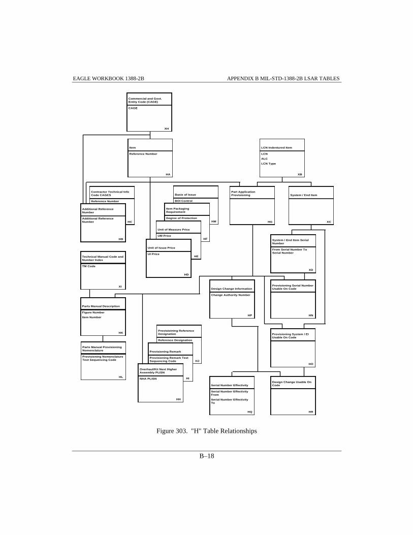
EAGLE WORKBOOK 1388-2B APPENDIX B MIL-STD-1388-2B LSAR TABLES
B–18
Figure 303. "H" Table Relationships
Commercial and Govt.
Entity Code (CAGE)
CAGE
XH
Item
Reference Number
HA
Contractor Technical Info
Code CAGES
Reference Number
HC
Basis of Issue
BOI Control
HM
Item Packaging
Requirement
Degree of Protection
HF
Unit of Measure Price
UM Price
HE
Unit of Issue Price
UI Price
HD
Additional Reference
Number
HB
Additional Reference
Number
LCN Indentured Item
LCN
ALC
LCN Type
XB
HG
Part Application
Provisioning
XC
System / End Item
Technical Manual Code and
Number Index
TM Code
XI
Parts Manual Description
Figure Number
Item Number
HK
Parts Manual Provisioning
Nomenclature
Provisioning Nomenclature
Text Sequencing Code
HL
Provisioining Reference
Designation
Reference Designation
HJ
Provisioning Remark
Provisioning Remark Text
Sequencing Code
HI
Overhaul/Kit Next Higher
Assembly PLISN
NHA PLISN
HH
System / End Item Serial
Number
From Serial Number To
Serial Number
XD
Provisioning Serial Number
Usable On Code
HN
Design Change Usable On
Code
HR
Serial Number Effectivity
Serial Number Effectivity
From
Serial Number Effectivity
To
HQ
Design Change Information
Change Authority Number
HP
Provisioning System / EI
Usable On Code
HO

EAGLE WORKBOOK 1388-2B APPENDIX B MIL-STD-1388-2B LSAR TABLES
B–19
Transportability Engineering Analysis
Data tables beginning with a J in the first position of the table code are structured to capture the
information pertaining to the transportability shipping modes and to the transported end item. In
the event that the end item is sectionalized for transport, the information shall be completed for
each section of the end item.
Table 10. “J” Tables
Table Code Table Title
JA Transportation
JB Transportation Shipping Mode
JC Transported End Item
JD Transported End Item Narrative
JE Transport by Fiscal Year
JF Transportation Narrative

EAGLE WORKBOOK 1388-2B APPENDIX B MIL-STD-1388-2B LSAR TABLES
B–20
Figure 304. "J" Table Relationships
LSA Control Number
(LCN)
Alternate LCN Code
LCN Type
LCN Indentured Item
XB
Transport by Fiscal Year
Transport Fiscal Year
JE
Transported End Item
Transported
Configuration
Mobility Type
JC
Transported End ItemNarrative
Transported End Item
Narrative Code
Transported End Item
Narrative Text
Sequencing Code
JD
Transportation Narrative
Transportation Narrative
Code
Transportation Narrative
Text Sequencing Code
JF
Transportation Shipping
Modes
Transportation
Character Number
Transportation
Character Mode Type
JB
End Item Acronym Code
End Item Acronym Code
XA
Transportation
JA

EAGLE WORKBOOK 1388-2B APPENDIX B MIL-STD-1388-2B LSAR TABLES
B–21
Unit Under Test Requirements and Description
Data tables beginning with a U in the first position of the table code are structured to identify the
UUT and those hardware and software elements required to test the UUT with off-line support/test
equipment. The unique combination of these elements required for a specific UUT and support
test equipment configuration is a Test Program Set (TPS). In addition to defining the TPS
elements, this information provides the configuration identification of the UUT (i.e., the UUT and
the support/test equipment to be used in the test). This information is established for each UUT
that has a requirement to be tested by the support/test equipment documented. Additionally,
Calibration and Measurement Requirement Summary (CMRS) information is captured in these
tables.
Table 11. “U” Tables
Table Code Table Title
UA Article Requiring Support/Unit Under Test
UB Unit Under Test Support Equipment
UC Operational Test Program
UD Unit Under Test Support Equipment Operational Test Program
UE Test Program Instruction
UF Unit Under Test Explanation
UG Unit Under Test Parameter Group
UH Unit Under Test Fault Isolated Replaceable Unit
UI Adapter-Interconnector Device
UJ Unit Under Test Support Equipment Adapter-Interconnector
Device
UK Automatic Test Equipment Test Station
UL Unit Under Test Support Equipment Automatic Test Equipment
UM Support Equipment Item Unit Under Test
UN Support Equipment Unit Under Test Parameter Group

EAGLE WORKBOOK 1388-2B APPENDIX B MIL-STD-1388-2B LSAR TABLES
B–22
Figure 305. "U" Table Relationships
Support Equipment
EA
LSA Control Number
(LCN)
Alternate LCN Code
LCN Type
LCN Indentured Item
XB
Unit Under Test
UA
Unit Under Test Support
Equipment
UB
Text Sequencing Code
Unit Under Test
Explanation
UF
UUT Parameter Group
Code
UUT Parameter Group
UG
Automatic Test Equip.
Test Station
UK
Adapter Interconnector
Device
UI
UUT Support Equipment
AID
UJ
UUT Support Equipment
OTP
UD
UUT Support Equipment
ATE
UL
Support Equipment UUT
Parameter Group Code
Support Equipment UUT
Support Equipment
UN
UUT Fault Isolated
Replacable Unit
UH
EIAC
Task LCN
Task LCN Type
Task ALC
Task Provision TaskCode
Task Provision LCN
Task Provision ALC
Task Provision LCNType
Task ProvisionReference No.
Task Provision CAGE
Task Provision Item
CI
Test Program
Instruction
UE
Operational Test
Program
UC
Item Identification
Reference No.
CAGE
HA
Support Equipment Unit
Under Test
UM

EAGLE WORKBOOK 1388-2B APPENDIX B MIL-STD-1388-2B LSAR TABLES
B–23
Cross Functional Requirement
The following X data tables have attributes which cross multiple functional areas or are used as a
link to various functional data tables. Included under these tables is the functional and physical
breakdown LCN, assignment and application of UOCs, technical manual numbers, and
government provided Level Of Repair Analysis (LORA) modeling information.
Table 12. “X” Tables
Table Code Table Title
XA End Item Acronym Code
XB LCN Indentured Item
XC System/End Item
XD System/End Item Serial Number
XE LCN to Serial Number Usable On Code
XF LCN to System/End Item Usable On Code
XG Functional/Physical LCN Mapping
XH Commercial and Government Entity
XI Technical Manual Code and Number Index

EAGLE WORKBOOK 1388-2B APPENDIX B MIL-STD-1388-2B LSAR TABLES
B–24
Figure 306. "X" Table Relationships
End Item Acronym
EIAC
XA
LCN Indentured Item
LCN
ALC
LCN Type
XB
Functional / Physical LCN
Mapping
XG
System / End Item
XC
System / End Item Serial
Number
From Serial Number
To Serial Number
XD
LCN To System / End Item
Usable On Code
XF
Commercial and
Government Entity Code
CAGE
XH
LCN To Serial Number
Usable On Code
XE
Item
Reference Number
HA
Technical Manual Code and
Number Index
TM Code
XI
Task Manual
EIAC
LCN
ALC
LCN Type
Task Code CH
Parts Manual Description
CAGE
Reference Number
EIAC
LCN
ALC
LCN Type
Figure Number
Item Number HK

EAGLE Workbook 1388-2B Version 15
TABLE/DATA
DEPENDENCIES
APPENDIX C


EAGLE WORKBOOK 1388-2B APPENDIX C TABLE DATA DEPENDENCIES
C–3
APPENDIX C TABLE/DATA DEPENDENCIES
The following Tables provide a list of dependencies for entering data into the LSAR Tables.
These tables are extremely useful when a user wants to enter data into a table, but doesn’t know
what prerequisite data needs to be entered. For example an LCN can be entered using the LCN
Maintenance Discipline; however, an EIAC must exist before an LCN can be entered. Therefore,
LCN has the EIAC dependency. The dependencies listed are immediate (parent) dependencies
only. For example, PCCN requires that an LCN be added first, but it also requires an EIAC before
the LCN. The immediate (parent) dependency for PCCN is the LCN, so it is the only one listed.
The ( ) after the information in the ‘Data to be Added’ column and the ‘Dependencies’ column
represents the table that the data is stored in. Although not shown in the following tables for
tables without an EIAC dependency in MIL-STD-1388-2B, all tables have an EIAC dependency
in the Oracle version of EAGLE.
The ‘Discipline / Function to Add Data’ column shows the Discipline and the appropriate
Function to add the designated data. In the event that the Report Menu is used to add the data, it is
listed under the ‘Report Menu Option to Add Data’ column. If there are any data or table
dependencies, they are listed in the ‘Dependencies’ column. For example, to add facility narrative
(FB) data, the Facility Discipline and Facility Data Finder are used with the Report
Menu>>Facility Narrative option. However, if the corresponding dependent data (Facility (FA))
doesn’t exist, it must be added first. If the user is not familiar with how to add the Facility (FA)
data, they should look up Facility (FA) under the Data to be added column.
Although the AdHoc Discipline can be used to enter any data into any table, the following tables
show the preferred discipline that should be used to enter the required data.

EAGLE WORKBOOK 1388-2B APPENDIX C TABLE DATA DEPENDENCIES
C–4
Table 13. Cross Functional Requirement Dependencies - X Tables
Data to be
Added
Discipline / Function to
Add Data
Report Menu
Option to Add Data
Dependencies
End Item
Acronym
Code (XA)
LCN Maintenance / End Item
(XA) Maintenance
LCN
Indentured
Item (XB)
LCN Maintenance / LCN
(XB) Maintenance
End Item Acronym
Code (XA)
System/End
Item (XC)
LCN Maintenance /
System/EI (XC) Maintenance
LCN Indentured
Item (XB)
System/End
Item Serial
Number (XD)
LCN Maintenance /
System/EI SN (XD)
Maintenance
System/End Item
(XC)
LCN to Serial
Number
Usable On
Code (XE)
LCN Maintenance / LCN to
SN/UOC (XE) Maintenance
System/End Item
Serial Number (XD)
LCN to
System/End
Item Usable
On Code (XF)
LCN Maintenance / LCN to
System/EI (XF) Maintenance
System/End Item
(XC)
Functional /
Physical LCN
Mapping (XG)
LCN Maintenance / LCN
(XG) F to P Mapping
LCN Indentured
Item (XB)
Commercial
and
Government
Entity (XH)
LCN Maintenance / CAGE
(XH) Code Maintenance
Technical
Manual Code
and Number
Index (XI)
Tech Manual / Maintain Tech
Manual Code

EAGLE WORKBOOK 1388-2B APPENDIX C TABLE DATA DEPENDENCIES
C–5
Table 14. Operations and Maintenance Requirements Dependencies - A Tables
Data to be
Added
Discipline / Function to
Add Data
Report Menu
Option to Add Data
Dependencies
Operations and
Maintenance
Requirements
(AA)
Operations Maintenance /
O&M Requirements
(AA,AG,AH,AI)
>>Operations and
Maintenance
Requirement
LCN (XB)
War/Peace
Operations and
Maintenance
Requirement
(AB)
Operations Maintenance /
War/Peace Requirements
(AB,AC,AD,AE,AF)
>>War/Peace
Additional
Requirements
Narrative
Operations and
Maintenance
Requirements (AA)
Maintenance
Level
Requirement
(AC)
Operations Maintenance /
War/Peace Requirements
(AB,AC,AD,AE,AF)
>>Maintenance /
Organizational / Skill
Level Requirement
War Peace
Operations and
Maintenance
Requirement (AB)
Organizational
Level
Requirement
(AD)
Operations Maintenance /
War/Peace Requirements
(AB,AC,AD,AE,AF)
>>Maintenance /
Organizational / Skill
Level Requirement
Maintenance Level
Requirement (AC)
Skill Operations
and Maintenance
Requirement
(AE)
Operations Maintenance /
War/Peace Requirements
(AB,AC,AD,AE,AF)
>>Maintenance /
Organizational / Skill
Level Requirement
Maintenance Level
Requirement (AC)
Skill Specialty
(GA)
War/Peace
Additional
Requirements
Narrative (AF)
Operations Maintenance /
War/Peace Requirements
(AB,AC,AD,AE,AF)
>>War/Peace
Additional
Requirements
Narrative
War/Peace
Operations and
Maintenance
Requirement (AB)
Reliability
Requirement
(AG)
Operations Maintenance /
O&M Requirements
(AA,AG,AH,AI)
>>Reliability
Requirement
LCN (XB)
War Peace
Operations
Maintenance
Requirement (AB)
Interoperability
Requirement
(AH)
Operations Maintenance /
O&M Requirements
(AA,AG,AH,AI)
>>Interoperability
Requirement
LCN (XB)

EAGLE WORKBOOK 1388-2B APPENDIX C TABLE DATA DEPENDENCIES
C–6
Table 15. Operations and Maintenance Requirements Dependencies - A Tables (Continued)
Data to be
Added
Discipline / Function to
Add Data
Report Menu Option
to Add Data
Dependencies
Modeling
Data (AI)
Operations Maintenance /
O&M Requirements
(AA,AG,AH,AI)
>>Modeling Data EIACODXA (XA)
Operations
and
Maintenance
Shipping
Requirements
(AJ)
Operations Maintenance /
System/End Item O&M
(AJ,AK)
>>Operations
Maintenance
Shipping
Requirement
System/End Item
PCCN/UOC Link
(XC)
System End
Item
Narrative
(AK)
Operations Maintenance /
System/End Item O&M
(AJ,AK)
>>System/End Item
Narrative
System/End Item
PCCN/UOC Link
(XC)
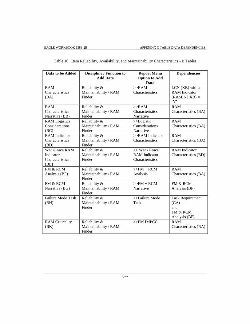
EAGLE WORKBOOK 1388-2B APPENDIX C TABLE DATA DEPENDENCIES
C–7
Table 16. Item Reliability, Availability, and Maintainability Characteristics - B Tables
Data to be Added Discipline / Function to
Add Data
Report Menu
Option to Add
Data
Dependencies
RAM
Characteristics
(BA)
Reliability &
Maintainability / RAM
Finder
>>RAM
Characteristics
LCN (XB) with a
RAM Indicator
(RAMINDXB) =
‘Y’
RAM
Characteristics
Narrative (BB)
Reliability &
Maintainability / RAM
Finder
>>RAM
Characteristics
Narrative
RAM
Characteristics (BA)
RAM Logistics
Considerations
(BC)
Reliability &
Maintainability / RAM
Finder
>>Logistic
Considerations
Narrative
RAM
Characteristics (BA)
RAM Indicator
Characteristics
(BD)
Reliability &
Maintainability / RAM
Finder
>>RAM Indicator
Characteristics
RAM
Characteristics (BA)
War /Peace RAM
Indicator
Characteristics
(BE)
Reliability &
Maintainability / RAM
Finder
>> War / Peace
RAM Indicator
Characteristics
RAM Indicator
Characteristics (BD)
FM & RCM
Analysis (BF)
Reliability &
Maintainability / RAM
Finder
>>FM + RCM
Analysis
RAM
Characteristics (BA)
FM & RCM
Narrative (BG)
Reliability &
Maintainability / RAM
Finder
>>FM + RCM
Narrative
FM & RCM
Analysis (BF)
Failure Mode Task
(BH)
Reliability &
Maintainability / RAM
Finder
>>Failure Mode
Task
Task Requirement
(CA)
and
FM & RCM
Analysis (BF)
RAM Criticality
(BK)
Reliability &
Maintainability / RAM
Finder
>>FM IMPCC RAM
Characteristics (BA)

EAGLE WORKBOOK 1388-2B APPENDIX C TABLE DATA DEPENDENCIES
C–8
Table 16. Item Reliability, Availability, and Maintainability Characteristics - B Tables
(Continued)
FM IMPCC (BI) Reliability &
Maintainability / RAM
Finder
>>FM IMPCC
Narrative
FM & RCM
Analysis (BF)
and
RAM Criticality
(BK)
FM IMPCC
Narrative (BJ)
Reliability &
Maintainability / RAM
Finder
>>FM IMPCC
Narrative
FM IMPCC (BI)
Mission Phase
Operational
Mode (BL)
Reliability &
Maintainability / RAM
Finder
>>Mission Phase
Operational Mode
End Item Acronym
Code (XA)

EAGLE WORKBOOK 1388-2B APPENDIX C TABLE DATA DEPENDENCIES
C–9
Table 17. Task Inventory, Task Analysis, Personnel and Support Requirements Dependencies - C
Tables
Data to be added Discipline / Function to
Add Data
Report Menu Option
to Add Data
Dependencies
Task Requirement
(CA)
Task Analysis / Task
Analysis Finder
>>View/Edit Task
Information (use the
New Task tab)
LCN (XB)
and potentially
Reliability
Requirement (AG)
for AOR
Subtask
Requirement (CB)
Task Analysis / Task
Analysis Finder
>>View/Edit Subtask
Information (use the
New Subtask tab)
Task Requirement
(CA)
Sequential Subtask
Description (CC)
Task Analysis / Task
Analysis Finder
>>View/Edit
Narrative Information
Subtask
Requirement (CB)
Subtask Personnel
Requirement (CD)
Task Analysis / Task
Analysis Finder
>>View/Edit Subtask
Information (use the
Personnel tab)
Subtask
Requirement (CB)
Task Remark (CE) Task Analysis / Task
Analysis Finder
>>View/Edit Task
Information (use the
Remarks tab)
End Item
Acronym Code
(XA)
Task Remark
Reference (CF)
Task Analysis / Task
Analysis Finder
>>View/Edit Task
Information (use the
Remarks tab)
Task Requirement
(CA)
and
Task Remark (CE)
Task Support
Equipment (CG)
Task Analysis / Task
Analysis Finder
>>View/Edit Task
Information (use the
Support Equipment
tab)
Task Requirement
(CA)
and
Support
Equipment (EA)
Task Manual (CH) Task Analysis / Task
Analysis Finder
>>View/Edit Task
Information (use the
Tech. Manuals tab)
Task Requirement
(CA)
and
Technical Manual
Code and Number
Index (XI)

EAGLE WORKBOOK 1388-2B APPENDIX C TABLE DATA DEPENDENCIES
C–10
Table 18. Task Inventory, Task Analysis, Personnel and Support Requirements Dependencies - C
Tables (Continued)
Data to be
added
Discipline / Function to Add
Data
Report Menu Option
to Add Data
Dependencies
Task
Provisioned
Item (CI)
Task Analysis / Task Analysis
Finder
>>View/Edit Task
Information (use the
Provisioned Items
tab)
Task Requirement
(CA)
and
Part Application
Provisioning (HG)
Job and Duty
Assignments
(CJ)
Task Analysis / Task Analysis
Finder
>>View/Edit Subtask
Information (use the
Workload tab)
Task Inventory
(CK)
Task
Inventory
(CK)
Task Analysis / Task Analysis
Finder
>>View/Edit Subtask
Information (use the
Workload tab)
Sequential Subtask
Description (CC)
and
Subtask Personnel
Requirement (CD)

EAGLE WORKBOOK 1388-2B APPENDIX C TABLE DATA DEPENDENCIES
C–11
Table 19. Support Equipment and Training Material Requirements - E Tables
Data to be Added Discipline / Function to
Add Data
Report Menu Option
to Add Data
Dependencies
Support Equipment
(EA)
Support Equipment /
SERD Finder
>>Add/Delete
Support Equipment
and
>>Support Equipment
Data (use the Admin
Data tab)
and
>>Support Equipment
Data (use the Physical
Data tab)
and
>>Support Equipment
Data (use the
Allocation Data tab)
and
>>Support Equipment
Data (use the Ad
Supplement tab)
Reference Number
(HA)
Allocation Data
(EB)
Support Equipment /
SERD Finder
>>Support Equipment
Data (use the
Allocation Data tab)
Support Equipment
(EA)
Support Equipment
Parameters (EC)
Support Equipment /
SERD Finder
>>Support Equipment
Data (use the
Parameters tab)
Support Equipment
(EA)
Support Equipment
Authorization (ED)
Support Equipment /
SERD Finder
>>Support Equipment
Data (use the
Authorizations tab)
Support Equipment
(EA)
Support Equipment
Narrative (EE)
Support Equipment /
SERD Finder
>>Support Equipment
Data (use the
Narrative tab)
Support Equipment
(EA)

EAGLE WORKBOOK 1388-2B APPENDIX C TABLE DATA DEPENDENCIES
C–12
Table 20. Support Equipment and Training Material Requirements - E Tables (Continued)
Data to be Added Discipline / Function to
Add Data
Report Menu Option
to Add Data
Dependencies
Support Equipment
Recommendation
Data (EF)
Support Equipment /
SERD Finder
>>SERD #
Recommendation
Data
Support Equipment
(EA)
Support Equipment
Recommendation
Data Revision
Remarks (EG)
Support Equipment /
SERD Finder
>>Support Equipment
Data (use the Rev.
Remarks tab)
Support Equipment
Recommendation
Data (EF)
Alternate National
Stock Numbers
(EH)
Support Equipment /
SERD Finder
>>Alternate NSN Support Equipment
Recommendation
Data (EF)
Input Power
Source (EI)
Support Equipment /
SERD Finder
>>Support Equipment
Data (use the Input
Power Source tab)
Support Equipment
(EA)
Support Equipment
Design Data (EJ)
Support Equipment /
SERD Finder
>>Support Equipment
Data (use the Design
Data tab)
Support Equipment
(EA)
Supercedure Data
(EK)
Support Equipment /
SERD Finder
>>Support Equipment
Data (use the
Supercedure tab)
Support Equipment
(EA)
and
Reference Number
(HA)
Support Equipment
Integrated Logistic
Support
Requirement
Category Code
(EL)
Support Equipment /
SERD Finder
>>Support Equipment
Data (use the ILS
Data tab)
Support Equipment
(EA)
System Equipment
(EM)
Support Equipment /
SERD Finder
>>Support Equipment
Data (use the GFAE
tab)
Support Equipment
(EA)
and
Reference Number
(HA)

EAGLE WORKBOOK 1388-2B APPENDIX C TABLE DATA DEPENDENCIES
C–13
Table 21. Facilities Considerations - F Tables
Data to be
Added
Discipline / Function to
Add Data
Report Menu Option
to Add Data
Dependencies
Facility (FA) Facilities / Facilities
Finder
>>Facility
Facility Narrative
(FB)
Facilities / Facilities
Finder
>>Facility Narrative Facility (FA)
Baseline Facility
Narrative (FC)
Facilities / Facilities
Finder
>>Baseline Facility
Narrative
Facility (FA)
New or Modified
Facility Narrative
(FD)
Facilities / Facilities
Finder
>>New or Modified
Facility Narrative
Facility (FA)
Operations and
Maintenance Task
Facility
Requirements
(FE)
Facilities / Facilities
Finder
>>Operations and
Maintenance Task
Facility Requirement
Facility (FA)
and
Task Requirement
(CA)
Table 22. Personnel Skills Considerations - G Tables
Data to be
Added
Discipline / Function to
Add Data
Report Menu Option
to Add Data
Dependencies
Skill Specialty
(GA)
Personnel Skills / Skill
Specialty Code Finder
(GA)
New or Modified
Skill (GB)
Personnel Skills / Personnel
Skills Finder (GB,GC,GD)
>>New or Modified
Skill Narrative
New or Modified
Skill Narrative
(GC)
Personnel Skills / Personnel
Skills Finder (GB,GC,GD)
>>New or Modified
Skill Narrative
New or Modified
Skill (GB)
Skill Aptitude
Data (GD)
Personnel Skills / Personnel
Skills Finder (GB,GC,GD)
>>Skill Aptitude Data New or Modified
Skill (GB)
Physical and
Mental
Requirements
Narrative (GE)
Personnel Skills /
Physical/Mental Req Finder
(GE)
>>Physical and
Mental Req. Narrative
New or Modified
Skill (GB)and
Subtask Personnel
Requirement (CD)
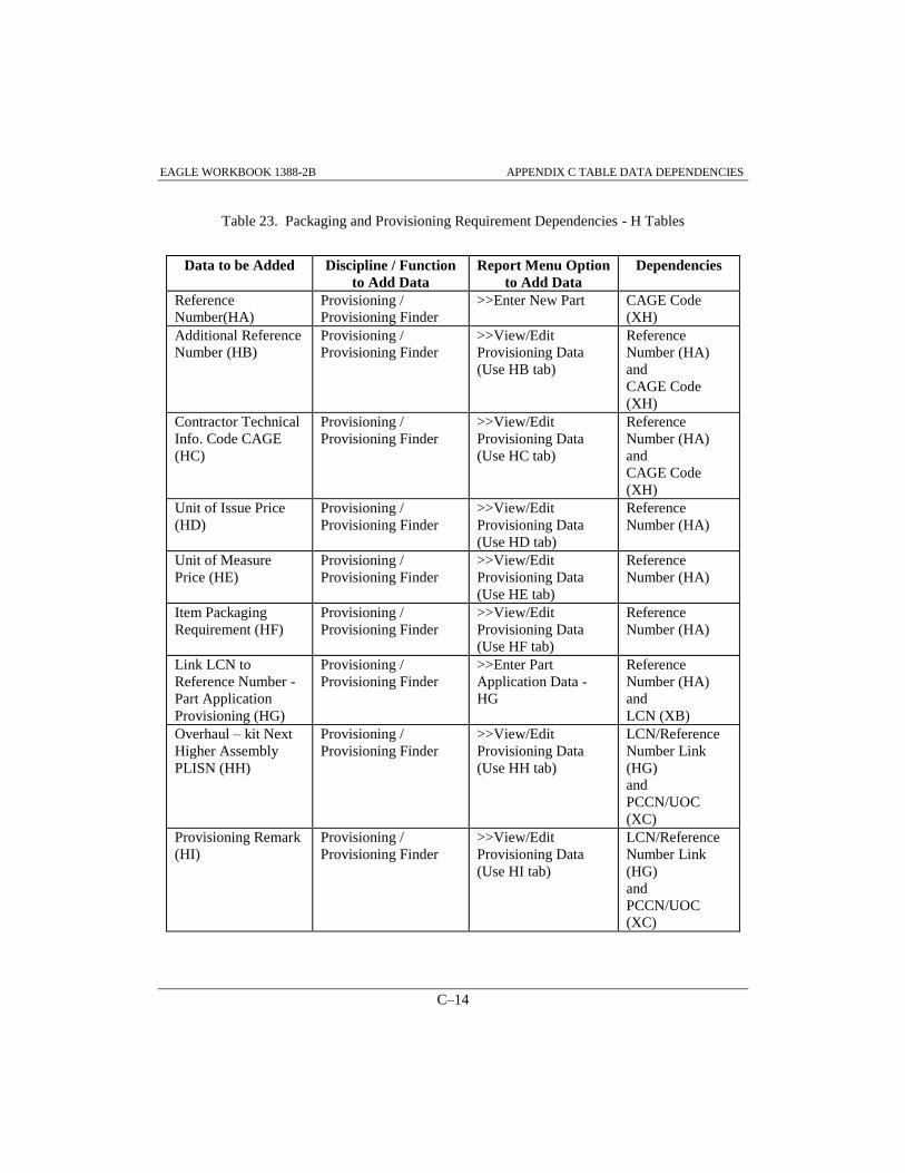
EAGLE WORKBOOK 1388-2B APPENDIX C TABLE DATA DEPENDENCIES
C–14
Table 23. Packaging and Provisioning Requirement Dependencies - H Tables
Data to be Added Discipline / Function
to Add Data
Report Menu Option
to Add Data
Dependencies
Reference
Number(HA)
Provisioning /
Provisioning Finder
>>Enter New Part CAGE Code
(XH)
Additional Reference
Number (HB)
Provisioning /
Provisioning Finder
>>View/Edit
Provisioning Data
(Use HB tab)
Reference
Number (HA)
and
CAGE Code
(XH)
Contractor Technical
Info. Code CAGE
(HC)
Provisioning /
Provisioning Finder
>>View/Edit
Provisioning Data
(Use HC tab)
Reference
Number (HA)
and
CAGE Code
(XH)
Unit of Issue Price
(HD)
Provisioning /
Provisioning Finder
>>View/Edit
Provisioning Data
(Use HD tab)
Reference
Number (HA)
Unit of Measure
Price (HE)
Provisioning /
Provisioning Finder
>>View/Edit
Provisioning Data
(Use HE tab)
Reference
Number (HA)
Item Packaging
Requirement (HF)
Provisioning /
Provisioning Finder
>>View/Edit
Provisioning Data
(Use HF tab)
Reference
Number (HA)
Link LCN to
Reference Number -
Part Application
Provisioning (HG)
Provisioning /
Provisioning Finder
>>Enter Part
Application Data -
HG
Reference
Number (HA)
and
LCN (XB)
Overhaul – kit Next
Higher Assembly
PLISN (HH)
Provisioning /
Provisioning Finder
>>View/Edit
Provisioning Data
(Use HH tab)
LCN/Reference
Number Link
(HG)
and
PCCN/UOC
(XC)
Provisioning Remark
(HI)
Provisioning /
Provisioning Finder
>>View/Edit
Provisioning Data
(Use HI tab)
LCN/Reference
Number Link
(HG)
and
PCCN/UOC
(XC)

EAGLE WORKBOOK 1388-2B APPENDIX C TABLE DATA DEPENDENCIES
C–15
Table 24. Packaging and Provisioning Requirement Dependencies - H Tables (Continued)
Data to be
Added
Discipline / Function to Add
Data
Report Menu Option
to Add Data
Dependencies
Provisioning
Reference
Designation
(HJ)
Provisioning / Provisioning
Finder
>>View/Edit
Provisioning Data
(Use HJ tab)
LCN/Reference
Number Link (HG)
and
PCCN/UOC (XC)
and
potentially Parts
Manual (HK)
Parts Manual
Description
(HK)
Provisioning / Provisioning
Finder
>>View/Edit
Provisioning Data
(Use HK tab)
LCN/Reference
Number Link (HG)
and
PCCN/UOC (XC)
Parts Manual
Provisioning.
Nomenclatur
e (HL)
Provisioning / Provisioning
Finder
>>View/Edit
Provisioning Data
(Use HL tab)
LCN/Reference
Number Link (HG)
and
PCCN/UOC (XC)
and
Parts Manual (HK)
Basis of
Issue (HM)
Provisioning / Provisioning
Finder
>>View/Edit
Provisioning Data
(Use HM tab)
Reference Number
(HA)
Provisioning
Serial
Number
Useable On
Code (HN)
Provisioning / Provisioning
Finder
>>View/Edit
Provisioning Data
(Use HN tab)
LCN/Reference
Number Link (HG)
and
System/End Item
Serial Number (XD)
Provisioning
System/End
Item Usable
On Code
(HO)
Provisioning / Provisioning
Finder
>>Enter Part Usage
Data - HO
LCN/Reference
Number Link (HG)
and
PCCN/UOC (XC)
Design
Change
Information
(HP)
Provisioning / Provisioning
Finder
>>View/Edit
Provisioning Data
(Use HP tab)
LCN/Reference
Number Link (HG)
Serial
Number
Effectivity
(HQ)
Provisioning / Provisioning
Finder
>>View/Edit
Provisioning Data
(Use HQ tab)
Design Change
Information (HP)

EAGLE WORKBOOK 1388-2B APPENDIX C TABLE DATA DEPENDENCIES
C–16
Table 25. Packaging and Provisioning Requirement Dependencies - H Tables (Continued)
Data to be
Added
Discipline / Function to Add
Data
Report Menu Option
to Add Data
Dependencies
Design
Change
Usable On
Code (HR)
Provisioning / Provisioning
Finder
>>View/Edit
Provisioning Data
(Use HR tab)
Design Change
Information (HP)
and
Link PCCN to Part
Application (HO)
Table 26. Transportability Engineering Analysis Dependencies - J Tables
Data to be
Added
Discipline / Function to Add
Data
Report Menu Option
to Add Data
Dependencies
Transportatio
n (JA)
Transportation /
Transportation Finder
>>Transportation LCN (XB)
Transportatio
n Shipping
Mode (JB)
Transportation /
Transportation Finder
>>Transportation
Shipping Modes
Transportation (JA)
Transported
End Item
(JC)
Transportation /
Transportation Finder
>>Transported End
Item
Transportation (JA)
Transported
End Item
Narrative
(JD)
Transportation /
Transportation Finder
>>Transported End
Item Narrative
Transported End
Item (JC)
Transport by
Fiscal Year
(JE)
Transportation /
Transportation Finder
>>Transport by Fiscal
Year
Transportation (JA)
Transportatio
n Narrative
(JF)
Transportation /
Transportation Finder
>>Transportation
Narrative
Transportation (JA)

EAGLE WORKBOOK 1388-2B APPENDIX C TABLE DATA DEPENDENCIES
C–17
Table 26. Unit Under Test Requirements and Description Dependencies - U Tables
Data to be
Added
Discipline / Function to
Add Data
Report Menu Option
to Add Data
Dependencies
Articles
Requiring
Support / Unit
Under Test (UA)
Support Equipment / SERD
Finder
>>Unit Under Test
Data (use the UUT
Information tab)
LCN (XB)
and
Task Requirement
(CA)
Unit Under Test
Support
Equipment (UB)
Support Equipment / SERD
Finder
>>Support Equipment
Data (use the Articles
Requiring Support
tab)
and
>>Unit Under Test
Data (use the UUT
Information tab)
Articles Requiring
Support / UUT
(UA)
and
Support Equipment
(EA)
Operational Test
Program (UC)
Support Equipment / SERD
Finder
>>Unit Under Test
Data (use the
Operational Test
Programs tab)
Unit Under Test
Support Equipment
(UB)
UUT Support
Equipment
Operational Test
Program (UD)
Support Equipment / SERD
Finder
>>Unit Under Test
Data (use the
Operational Test
Programs tab)
and
>>Unit Under Test
Data (use the Test
Position Instructions
tab)
Unit Under Test
Support Equipment
(UB)
and
Operational Test
Program (UC)
Test Program
Instruction (UE)
Support Equipment / SERD
Finder
>>Unit Under Test
Data (use the Test
Position Instructions
tab)
Operational Test
Program (UC)
and
Reference Number
(HA)
UUT
Explanation (UF)
Support Equipment / SERD
Finder
>>Unit Under Test
Data (use the UUT
Remarks tab)
Articles Requiring
Support / Unit
Under Test (UA)

EAGLE WORKBOOK 1388-2B APPENDIX C TABLE DATA DEPENDENCIES
C–18
Table 27. Unit Under Test Requirements and Description Dependencies - U Tables (Continued)
Data to be
Added
Discipline / Function to Add
Data
Report Menu Option
to Add Data
Dependencies
UUT
Parameter
Group (UG)
Support Equipment / SERD
Finder
>>Unit Under Test
Data (use the UUT
Parameters tab)
Unit Under Test
Support Equipment
(UB)
UUT Fault
Isolated
Replaceable
Unit (UH)
Support Equipment / SERD
Finder
>>Unit Under Test
Data (use the Fault
Isolation tab)
Task Provisioned
Item (CI)
Adapter-
Interconnect
or Device
(UI)
Support Equipment / SERD
Finder
>>Unit Under Test
Data (use the Test
Adapters/Cables tab)
Reference Number
(HA)
UUT
Support
Equipment
Adapter-
Interconnect
or Device
(UJ)
Support Equipment / SERD
Finder
>>Unit Under Test
Data (use the Test
Adapters/Cables tab)
Adapter-
Interconnector
Device (UI)
Automatic
Test
Equipment
Station (UK)
Support Equipment / SERD
Finder
>>Unit Under Test
Data (use the ATE
tab)
Reference Number
(HA)
UUT
Support
Equipment
Automatic
Test
Equipment
(UL)
Support Equipment / SERD
Finder
>>Unit Under Test
Data (use the ATE
tab)
Automatic Test
Equipment Station
(UK)
Support
Equipment
Item UUT
(UM)
Support Equipment / SERD
Finder
>>Support Equipment
Data (use the UUT
Data tab)
Support Equipment
(EA)
Support
Equipment
UUT Test
Parameter
Group (UN)
Support Equipment / SERD
Finder
>>Support Equipment
Data (use the UUT
Data tab)
Support Equipment
(EA)
and
Support Equipment
Item UUT (UM)

EAGLE Workbook 1388-2B Version 15
STRUCTURED QUERY
LANGUAGE
APPENDIX D

EAGLE WORKBOOK 1388-2B APPENDIX D STRUCTURED QUERY LANGUAGE
D-3
APPENDIX D STRUCTURED QUERY LANGUAGE
D.0 INTRODUCTION
This appendix contains a brief overview of the most commonly used SQL commands. It is not
intended to be a comprehensive document on SQL syntax. A good reference guide would be one
of the following.
Microsoft SQL Server
Transact-SQL User’s Guide
Document No. SY27439-0192
The Guide To SQL Server
Aloke Nath
Addison-Wesley Publishing
D.1 CONVENTIONS USED IN THIS APPENDIX
CONVENTION PURPOSE
UPPERCASE Transact-SQL statements, and any other portions of syntax
that must appear exactly as shown.
italic Represents table names and columns names.
[brackets] Enclose optional items. Type only the information within the
braces, not the braces themselves.
| (vertical bar) Separates items inside a set of braces or brackets. The vertical
bar means you can choose only one of the items.
D.2 SQL AND RELATIONAL DATABASE MANAGEMENT
SQL, originally an acronym for ‘Structured Query Language’, is a unified language for defining,
querying, modifying, and controlling the data in a relational database. Its name is officially
pronounced ‘ess-cue-el’”, but many people say ‘sequel’. With SQL you can query, insert, update
and delete data in a database. SQL works on database systems like SYBASE, Oracle, and
Microsoft Access.
EAGLE WORKBOOK 1388-2B APPENDIX D STRUCTURED QUERY LANGUAGE
D-4
D.2.1 Tables, Columns, and Rows
In a relational database system, users see data as tables or relations. Each row, or record, of a
table describes one occurrence of an entity – a System Code, a Part Number, Serial Number
combination. Each Column describes one characteristic of the entity. Below is an example of a
table titled defect:
sys_cd part_no serial_no
-------- ------------------- ------------
A3 12345678-104 100
A3 12345678-130 200
A3 12345678-130 210
A5 12345678-130 300
A5 12345680-100 100
D.2.2 Data Elements
D.2.2.1 Key Fields
Keys uniquely define a row of data in a table.
D.2.2.2 Data Types
Each column in a database has a datatype. It specifies data characteristics of the column. Below
are a few examples:
Character: Hold letters, numbers, and special characters. The two general types are fixed-
length character (char) and variable-length character (varchar).
Whole-number: Integers only, no fractions or decimals. These are often known by such
names as number, integer, int, smallint, and tinyint.
Decimal: Numbers with fractions. Exact decimal numbers are known as decimal or numeric.
Approximate decimal numbers have names like real, double, and float.
Date and Time: Record date, time, and combinations of date and time.

EAGLE WORKBOOK 1388-2B APPENDIX D STRUCTURED QUERY LANGUAGE
D-5
D.3 QUERYING DATABASES
D.3.1 SELECT Syntax
The SELECT statement specifies the columns you want to retrieve. The FROM clause specifies
the tables where the columns are located. The Where clause specifies the rows in the tables you
want to see. The ORDER BY clause specifies the sort order of the data.
The basic SELECT syntax is:
SELECT select_list
FROM table_list
WHERE search_conditions
ORDER BY column name
The following SELECT statement retrieves the part number and serial number of failed parts in
the defect table. This SELECT statement will return three rows of data with records sorted by
part number and serial number:
select part_no, serial_no
from defect
where sys_cd = ‘A3’
order by part_no, serial_no
The complete syntax of the SELECT statement include the following phrases and keywords:
SELECT [ALL | DISTINCT] select_list
FROM table_name
WHERE search_conditions
GROUP BY [table_name].column_name
HAVING search_conditions
ORDER BY [table_name].column_name [ASC | DESC]
D.3.1.1 Selecting All Columns From A Table
To select all columns use the * wildcard. The following SELECT statement selects all columns
from the defect table:
select *
from defect
where sys_cd = ‘A3’ order by part_no, serial_no

EAGLE WORKBOOK 1388-2B APPENDIX D STRUCTURED QUERY LANGUAGE
D-6
D.3.1.2 Eliminating Duplicates When Selecting
The DISTINCT keyword will eliminate all duplicates for the selected columns. The following
SELECT statement selects only unique part numbers from the defect table. This SELECT
statement will return two rows of data:
select distinct part_no
from defect
where sys_cd = ‘A3’ order by part_no
D.3.1.3 Counting Rows
To count the rows in a tables use the COUNT() function. The following SELECT counts the total
number of failed parts. This SELECT statement would return the number ‘3’:
select count(*)
from defect
where sys_cd = ‘A3’
D.3.2 WHERE Clause
The WHERE clause in a SELECT statement specifies the criteria for which rows to retrieve; the
Search conditions in the WHERE clause include;
Comparison operators (such as =, <>, < and >)
where serial_no > 200
Ranges (BETWEEN and NOT BETWEEN)
where serial_no between 100 and 500
Lists (IN, NOT IN)
where part_no in (‘12345678-104’, ‘12345678-106’, ‘12345678-130’)
Pattern Matches (LIKE and NOT LIKE)
where part_no like ‘12345678%’ where part_no like ‘12345678____’
Combination of these conditions (AND, OR)
where serial_no > 200 and part_no like ‘12345678%’

EAGLE WORKBOOK 1388-2B APPENDIX D STRUCTURED QUERY LANGUAGE
D-7
D.3.2.1 Like and Wildcards
The LIKE keyword selects rows containing fields that match specified portions of character
strings.
SYMBOL MEANING
LIKE ‘5%’ 5 followed by any string of 0 or more characters
LIKE ‘_n’ an, in, on (and so on)
This query finds all part numbers that begin with 12345678. This SELECT statement will return
four records:
select part_no
from defect
where part_no like ‘12345678%’
Wildcards are special characters that expand and perform as a substitute for specific information
within an argument. Wildcards shown below, act as jokers do in a deck of cards:
WILDCARD MEANING
% Any string of zero or more characters
_ Any single character
Wildcards used without LIKE are interpreted as literals rather than as a pattern; they represent
only their own values. The following query attempts to find all part numbers that begin with
12345678, however, since LIKE is not used, only part numbers that equal 12345678% will be
found. This query will return no records:
select part_no
from defect
where part_no = ‘12345678%’

EAGLE WORKBOOK 1388-2B APPENDIX D STRUCTURED QUERY LANGUAGE
D-8
Queries can also be written to search for the wildcard characters themselves. To use the wildcards
as characters in a LIKE match string rather than as wildcards, use special characters and
‘ESCAPE’ to search for the specific character.
SYMBOL MEANING
LIKE ‘5$%’ escape‘$’ 5%
LIKE ‘&_n’ escape ‘&’ _n
Example Query: select Refnumha
from HA
where Refnumha like ‘%$_%’ escape ‘$’
Example Result: 3819_500-102
T6_5544AA
D.3.2.2 Comparison Operators
OPERATOR MEANING
= equal to
> greater than
< less than
>= greater than or equal to
<= less than or equal to
<>,!= not equal to
!> not greater than
!< not less than
D.3.2.3 Logical Operators
The logical operators AND and OR are used to connect search conditions in WHERE clauses.
When more than one logical operator is used in a statement, NOT is evaluated first, then AND
finally OR.
This select statement retrieves all of the 12345678 and 12345680 part numbers (five rows):
select *
from defect
where part_no like ‘12345678%’ and part_no like ‘12345680%’ order by part_no
EAGLE WORKBOOK 1388-2B APPENDIX D STRUCTURED QUERY LANGUAGE
D-9
D.3.2.4 Unknown Values: IS NULL and IS NOT NULL
When you see NULL in a column, it means that the user or application has made no entry in that
column. A data value for the column is unknown or not available. NULL is not the same as zero
or blank. The following select statement selects all the records from the DEFECT table where the
serial_no is null.
select *
from defect
where serial_no IS NULL
order by part_no
D.3.2.5 Character Strings and Quotation Marks
Character strings and dates must be enclosed in single quotation marks when you enter or search
for them. Although double quotation marks are allowed, single quotation marks are preferred for
compliance with Industry standards. To specify literal single quotation marks (or apostrophes)
within a character entry, use two consecutive single quotation marks, as shown in the following
example:
select *
from faildesc
where fail_desc like ‘%DON’’T KNOW%‘

EAGLE WORKBOOK 1388-2B APPENDIX D STRUCTURED QUERY LANGUAGE
D-10
D.3.3 Joining Two or More Tables
D.3.3.1 Inner Joins
An inner join would be used when a data match from one table to another is desired. The
following query will match all of the failure narrative with the failure data.
select evaluation.part_no, evaluation.serial_no,
evaluation.basic_failure_no,
evaluation.failure_dash_no,
faildesc.line_no, faildesc.fail_desc
from evaluation, faildesc
where evaluation.basic_failure_no =
faildesc.basic_failure_no and
evaluation.failure_dash_no =
faildesc.failure_dash_no
order by evaluation.part_no, evaluation.serial_no,
evaluation.basic_failure_no,
evaluation.failure_dash_no,
faildesc.line_no
D.3.3.2 Outer Joins
In inner joins, only matching rows are include in the results. If non matching rows are desired in
the results of a join, an outer join should be used. The Oracle equivalent for an outer join uses the
(+) operators as shown below. The example queries below will retrieve all part information and
their defect code, if the part failed testing. An outer join is required in this case since not all parts
fail testing.
Oracle: select evaluation.part_no, evaluation.serial_no,
evaluation_qty, defect_cd
from evaluation, defect
where evaluation.sys_cd = defect.sys_cd(+) and
evaluation.part_no = defect.part_no(+) and
evaluation.serial_no = defect.serial_no(+)

EAGLE Workbook 1388-2B Version 15
INDEX

INDEX
INDEX 3
INDEX A Table, 3–4
data dependencies, C–5, C–6
ADDING PART APPLICATIONS (HG
RECORDS), 10–10
Adding Subtask Narrative
Source Data Modified, 5–46
Additional Reference Number
adding, 10–8
Adhoc
key field updates and parent table deletes, 11–
37
AdHoc, 11–3
adding comments to queries, 11–20
generating reports, 11–8
loading external data, 11–39
New Query, 11–3
query, 11–3
Recall Query, 11–24
saving reports, 11–19, 11–21, 11–23
updating database, 11–28
Administration
Administrative User Ids and Passwords, 1-5
Database Administrator, 1-5
Security Administrator, 1-5
ASSIGNING SERIAL NUMBER UOCS TO
SYSTEM/END ITEM LCNS, 2–17
ASSIGNING SYSTEM/END ITEM SERIAL
NUMBER UOCS TO LCNS, 2–19
B Table
data dependencies, C–7
C Table
data dependencies, C–9, C–10
CAGE Code
adding, 10–4
methods of adding, 10–4
CAGE CODE
ADDING, 2–21
Character Strings, D-9
Columns, D-4
Comparison Operators, D-8
Conventions, 1-3
general, 1-3
keyboard, 1-4
mouse, 1-4
window, 1-4
Copying Tasks, 5–18
Data Elements, D-4
Data Types, D-4
Default Settings
End Item Default Settings 2B, 1-7
System Default Settings 2B, 1-6
Discipline, 1-3
Facilities, 6–3
Operations Maintenance, 3–3
Reliability & Maintainability, 4–3
Task Analysis, 5–3
DISCIPLINE OUTPUTS
File Save As, 1-23
E Table
data dependencies, C–11, C–12
EAGLE
login, 1-7
End Item (XA) Maintenance, 2–3
End Items and Student Ids, 1-5
ERROR MESSAGES
Oracle, 12–3
Data Element Cross Edit Violations, 12–8
Integrity Constraint – Child Record Found,
12–7
Integrity Constraint - Parent Key Not
Found, 12–6
Rule Bound to a Column Violations, 12–9
Security Violations, 12–3
Unique Constraint Violation, 12–5
F Table
data dependencies, C–13
Facilities
adding, 6–4
linking to task, 6–6
Facilities Discipline
Facilities Finder, 6–3
Facilities Finder, 6–3
Finder
data, 1-10
G Table
data dependencies, C–13
H Table
data dependencies, C–14, C–15, C–16
Home tab
Provisioning Finder, 1-12
Home Tab
Home Tab Filter, 1-10
J Table
data dependencies, C–16
JOIN
inner join, D-10
outer join, D-10
Joining Tables, 11–10

INDEX
INDEX 4
Key Fields, D-4
LCN
ASSIGNING, 2–6
lower level, 2–9
Lower level, 2–12
top level, 2–12
LCN (XB) Maintenance, 2–6
LCN to System/EI (XF) Maintenance, 2–15
LOGGING IN TO EAGLE, 1-7
Logical Operators, D-8
Main Screen
Navigator, 1-8
MAINTAINING ADDITIONAL
PROVISIONING DATA ELEMENTS
USING THE VIEW/EDIT PROVISIONING
DATA WINDOW, 10–14
MAPPING MULTIPLE PART APPLICATIONS
TO A SYSTEM/END ITEM UOC, 10–22
Mapping Multiple Part Applications to a UOC-
PCCN Combination, 10–23
Navigator
Basic Finder, 1-12
Favorites tab, 1-8
Favorites Tab Functions, 1-14
Filter, 1-8
Home tab, 1-8
Home Tab Functions, 1-10
Legacy Navigator, 1-16
Recent tab, 1-8
Recent Tab Function, 1-16
Using the, 1-10
NULL, D-9
O&M Requirements
Reliability, AOR, 3–7
Operations Maintenance Discipline, 3–3
PCCN
ASSIGNING SYSTEM. SEE REFERENCE
NUMBER:PART USAGE
Personnel Skills Discipline, 7–3
adding skills, 7–4
Skill Specialty Code Finder (GA), 7–3
PERSONNEL SKILLS DISCIPLINE
PERSONNEL PHYSICAL AND MENTAL
REQUIREMENTS, 7–6
PLISN
assigning, 10–16
Provisioning
Adding Design Change Information, 10–21
Adding Item Packaging Requirement Data,
10–19
Adding UOC Data, 10–18
Entering Provisioning Remarks, 10–17
Query
saving scripts, 11–22
selecting column(s), 11–7
selecting table(s), 11–4
selection criteria, 11–9
Sort, 11–19
Where, 11–18
Reference Number
adding, 10–3
adding information, 10–6
additional. See Additional Reference Number
assigning PLISN. See PLISN:assigning
methods of adding, 10–5
REFERENCE NUMBER
ADDING, 2–23
PART APPLICATION, 2–25
PART USAGE, 2–12
Relational Database, D-3
Reliability & Maintainability Discipline, 4–3
Adding Failure Mode Indicator Mission Phase
Code Characteristics Data, 4–17
Adding RAM Criticality Data, 4–17
RAM Finder, 4–3
RELIABILITY & MAINTAINABILITY
DISCIPLINE
ADDING FAILURE MODE AND RCM
ANALYSIS DATA, 4–11
ADDING FAILURE MODE AND RCM
NARRATIVE, 4–13
ADDING FAILURE MODE TASK DATA,
4–14
ADDING MISSION PHASE
OPERATIONAL MODE DATA, 4–16
ADDING RAM CHARACTERISTICS
DATA, 4–4
ADDING RAM CHARACTERISTICS
NARRATIVE, 4–6
ADDING RAM FAILURE MODE
INDICATOR MISSION PHASE
CODECHARACTERISTICS
NARRATIVE, 4–19
ADDING RAM INDICATOR CODE DATA,
4–8
ADDING RAM LOGISTICS
CONSIDERATIONS NARRATIVE
DATA, 4–7
ADDING WAR/PEACE RAM INDICATOR
CHARACTERISTICS DATA, 4–10
Reports/Process Menu, 1-20–1-22
using, 1-21

INDEX
INDEX 5
Rows, D-4
SELECT, D-5
SERD Numbers
assigning, 9–6
SERD Report
running, 9–10
Skills
adding, 7–4
SKILLS
PERSONNEL PHYSICAL AND MENTAL
REQUIREMENTS, 7–6
Sorting Task Codes, 5–29
Specifying Facilities Requirements in Task
Analysis, 5–9
SQL, 11–3, D-3
Standards
MIL-STD-1388 2B, 1-6
Subtask
adding as original, 5–31
adding as reference, 5–34
adding narrative, 5–43
adding to task, 5–31
assign personnel, 5–58
assign workload, 5–60
reference, 5–31
view reference, 5–37
Subtask References
Changing and Breaking, 5–40
Support Equipment
adding, 9–4
adding SE data, 9–7
adding SE narrative, 9–8, 9–9
administrative data, 9–9
SERD name, 9–9
Support Equipment Data Tabs
Table and SERD Relationships, 9–16
Support Equipment Discipline
support equipment data, 9–3
unit under test data, 9–3
Tables, D-4
Task
adding as original, 5–5
adding as reference, 5–11
adding narrative. See Subtask : adding
narrative
adding subtasks, 5–31
adding to LCN, 5–5
AOR, 5–8
assigning provisioning items, 5–55
assigning support equipment, 5–51
copying. See Copying Tasks
create task code, 5–6
original, 5–5
reference, 5–5
tech manual narrative, 5–62
view reference, 5–17
Task Analysis Discipline, 5–3
Task Analysis Finder, 5–3
Technical Manual Code, 2–31
Technical Support, 5
Toolbar
Graphical Functions, 1-20
Help, 1-19
Item Help, 1-20
main, 1-19
Selecting an End Item (Oracle only), 1-22
Transportation Discipline, 8–3
adding data, 8–4
Adding Shipping Mode Data, 8–5
Adding Transport by Fiscal Year Data, 8–9
Adding Transportation Narrative, 8–10
Adding Transported End Item Data, 8–6
Adding Transported End Item Narrative, 8–7
Transportation Finder, 8–3
Transportation Finder, 8–3
U Table
data dependencies, C–17, C–18
Unit Under Test Data
tab/table relationships, 9–17
UOC
assigning part, 2–12, See Prov. System/EI
(HO) Maintenance
ASSIGNING SYSTEM. SEE REFERENCE
NUMBER:PART USAGE
WHERE, D-6
Wildcards, D-7
X Table
data dependencies, C–4

INDEX
INDEX 6

EAGLE Workbook Version 15
STUDENT
NOTES


SN - 3
STUDENT NOTES
_______________________________________________________
_______________________________________________________
_______________________________________________________
_______________________________________________________
_______________________________________________________
_______________________________________________________
_______________________________________________________
_______________________________________________________
_______________________________________________________
_______________________________________________________
_______________________________________________________
_______________________________________________________
_______________________________________________________
_______________________________________________________
_______________________________________________________
_______________________________________________________
_______________________________________________________
_______________________________________________________
_______________________________________________________
_______________________________________________________
_______________________________________________________
_______________________________________________________
_______________________________________________________
_______________________________________________________
_______________________________________________________
_______________________________________________________
_______________________________________________________

SN - 4
STUDENT NOTES
_______________________________________________________
_______________________________________________________
_______________________________________________________
_______________________________________________________
_______________________________________________________
_______________________________________________________
_______________________________________________________
_______________________________________________________
_______________________________________________________
_______________________________________________________
_______________________________________________________
_______________________________________________________
_______________________________________________________
_______________________________________________________
_______________________________________________________
_______________________________________________________
_______________________________________________________
_______________________________________________________
_______________________________________________________
_______________________________________________________
_______________________________________________________
_______________________________________________________
_______________________________________________________
_______________________________________________________
_______________________________________________________
_______________________________________________________
_______________________________________________________
_______________________________________________________
_______________________________________________________
_______________________________________________________

Technical support is provided by the EAGLE Team of Raytheon Company. Telephone support is
available Monday through Friday from 8:00 a.m. to 4:30 p.m. Mountain Standard Time. EAGLE
technical support personnel can be reached at (520) 663-6673. Training on the EAGLE product is
available.
Are you ready for EAGLE? Join Team EAGLE and find out what it’s like to soar. Give your
logistics software product the EAGLE advantage. For more information on becoming part of
Team EAGLE, contact:
Raytheon Company
Team EAGLE
(520) 663-6673
Email: [email protected]
Enhanced
Automated
Graphical
Logistics
Environment