Embed Size (px)
Citation preview
ENGR0135 - Statics and Mechanics of Materials 1 (2161)Homework #2
Solution Set
1. Summing forces in the y-direction allows one to determine the magnitude of F2:∑Fy = 1000 sin 60◦ − 800 sin 37◦ − F2 sin 45◦ = 0 =⇒ F2 = 543.8689 N
Then, summing forces in the x-direction and using the value of F2 allows one to deter-mine the magnitude of F1:∑
Fx = F1 + F2 cos 45◦ − 1000 cos 60◦ − 800 cos 37◦ = 0 =⇒ F1 = 754.3350 N
Thus,F1 = 754 N , F2 = 544 N
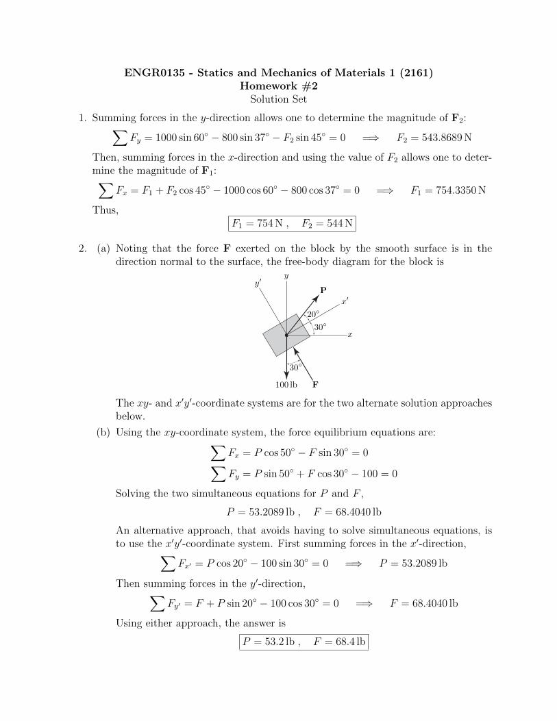
2. (a) Noting that the force F exerted on the block by the smooth surface is in thedirection normal to the surface, the free-body diagram for the block is
20◦
30◦
30◦
P
x
y
F
x′
y′
100 lb
The xy- and x′y′-coordinate systems are for the two alternate solution approachesbelow.
(b) Using the xy-coordinate system, the force equilibrium equations are:∑
Fx = P cos 50◦ − F sin 30◦ = 0∑
Fy = P sin 50◦ + F cos 30◦ − 100 = 0
Solving the two simultaneous equations for P and F ,
P = 53.2089 lb , F = 68.4040 lb
An alternative approach, that avoids having to solve simultaneous equations, isto use the x′y′-coordinate system. First summing forces in the x′-direction,
∑Fx′ = P cos 20◦ − 100 sin 30◦ = 0 =⇒ P = 53.2089 lb
Then summing forces in the y′-direction,∑
Fy′ = F + P sin 20◦ − 100 cos 30◦ = 0 =⇒ F = 68.4040 lb
Using either approach, the answer is
P = 53.2 lb , F = 68.4 lb
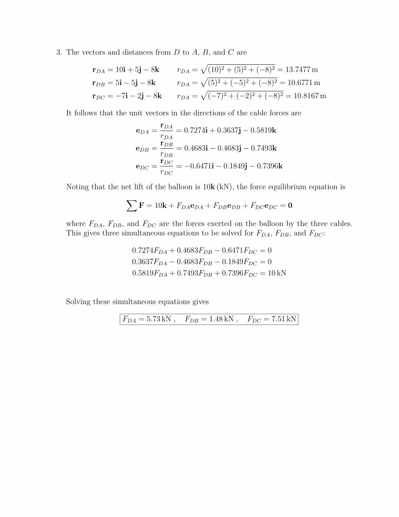
3. The vectors and distances from D to A, B, and C are
rDA = 10i + 5j− 8k rDA =√
(10)2 + (5)2 + (−8)2 = 13.7477 m
rDB = 5i− 5j− 8k rDA =√
(5)2 + (−5)2 + (−8)2 = 10.6771 m
rDC = −7i− 2j− 8k rDA =√
(−7)2 + (−2)2 + (−8)2 = 10.8167 m
It follows that the unit vectors in the directions of the cable forces are
eDA =rDArDA
= 0.7274i + 0.3637j− 0.5819k
eDB =rDBrDB
= 0.4683i− 0.4683j− 0.7493k
eDC =rDCrDC
= −0.6471i− 0.1849j− 0.7396k
Noting that the net lift of the balloon is 10k (kN), the force equilibrium equation is
∑F = 10k + FDAeDA + FDBeDB + FDCeDC = 0
where FDA, FDB, and FDC are the forces exerted on the balloon by the three cables.This gives three simultaneous equations to be solved for FDA, FDB, and FDC :
0.7274FDA + 0.4683FDB − 0.6471FDC = 0
0.3637FDA − 0.4683FDB − 0.1849FDC = 0
0.5819FDA + 0.7493FDB + 0.7396FDC = 10 kN
Solving these simultaneous equations gives
FDA = 5.73 kN , FDB = 1.48 kN , FDC = 7.51 kN
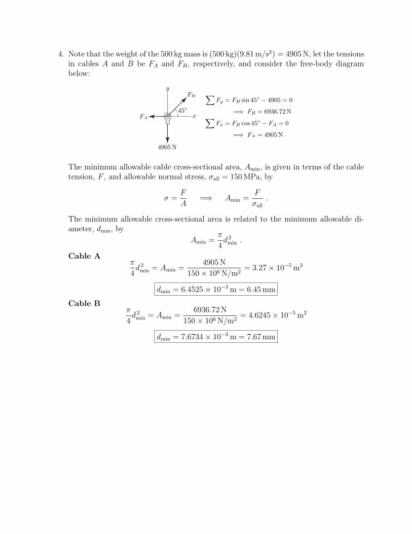
4. Note that the weight of the 500 kg mass is (500 kg)(9.81 m/s2) = 4905 N, let the tensionsin cables A and B be FA and FB, respectively, and consider the free-body diagrambelow:
45◦x
y
FA
FB
4905N
∑Fy = FB sin 45◦ − 4905 = 0
=⇒ FB = 6936.72N∑
Fx = FB cos 45◦ − FA = 0
=⇒ FA = 4905N
The minimum allowable cable cross-sectional area, Amin, is given in terms of the cabletension, F , and allowable normal stress, σall = 150 MPa, by
σ =F
A=⇒ Amin =
F
σall.
The minimum allowable cross-sectional area is related to the minimum allowable di-ameter, dmin, by
Amin =π
4d 2min .
Cable Aπ
4d 2min = Amin =
4905 N
150× 106 N/m2= 3.27× 10⁻⁵ m2
dmin = 6.4525× 10⁻³ m = 6.45 mm
Cable Bπ
4d 2min = Amin =
6936.72 N
150× 106 N/m2= 4.6245× 10⁻⁵ m2
dmin = 7.6734× 10⁻³ m = 7.67 mm
5. Note: In a problem, like this one, where an allowable normal stress is given with-out mentioning tension or compression, the allowable normal stress is assumed to bethe same in both tension and compression. This may not be entirely clear from thetextbook.
Use appropriate free-body diagrams, as shown below, to determine the axial force, andsubsequently the minimum allowable cross-sectional area, for each pipe section.
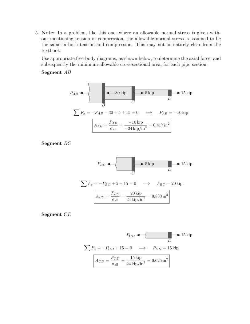
Segment AB
BC
D
30 kip 5 kip 15 kipPAB
∑Fx = −PAB − 30 + 5 + 15 = 0 =⇒ PAB = −10 kip
AAB =PAB
σall=
−10 kip
−24 kip/in2= 0.417 in2
Segment BC
CD
5 kip 15 kipPBC
∑Fx = −PBC + 5 + 15 = 0 =⇒ PBC = 20 kip
ABC =PBC
σall=
20 kip
24 kip/in2= 0.833 in2
Segment CD
D
15 kipPCD
∑Fx = −PCD + 15 = 0 =⇒ PCD = 15 kip
ACD =PCD
σall=
15 kip
24 kip/in2= 0.625 in2
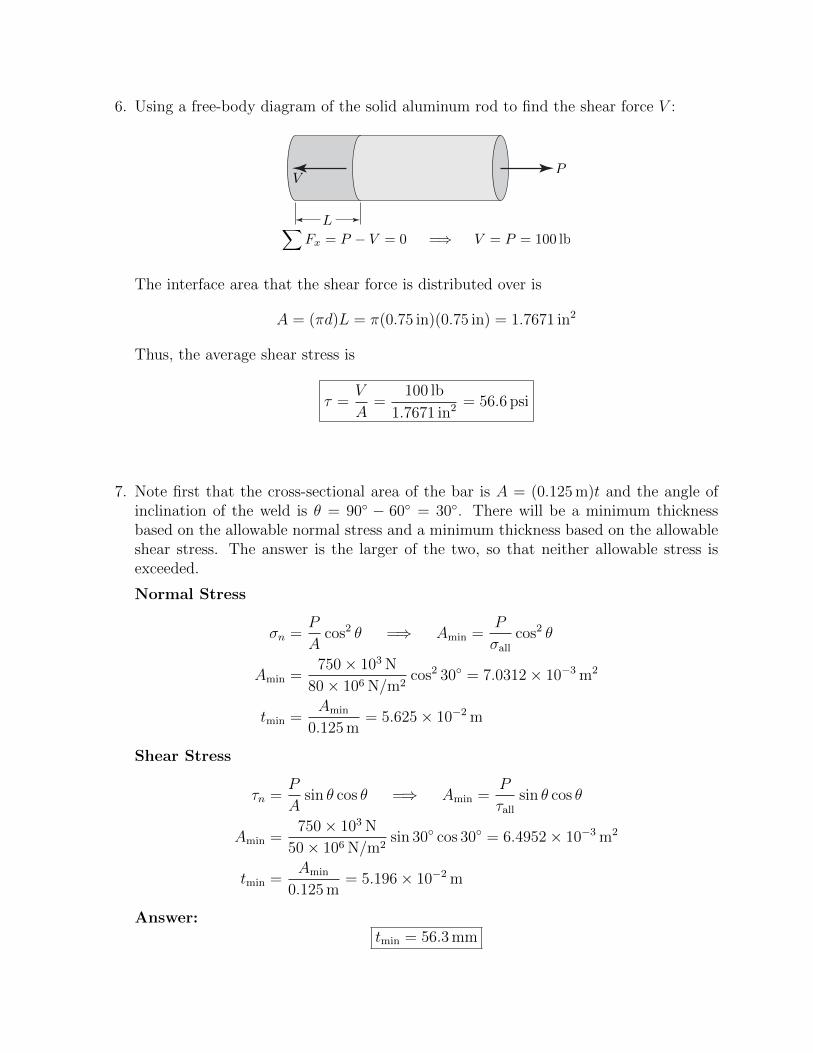
6. Using a free-body diagram of the solid aluminum rod to find the shear force V :
P
L
V
∑Fx = P − V = 0 =⇒ V = P = 100 lb
The interface area that the shear force is distributed over is
A = (πd)L = π(0.75 in)(0.75 in) = 1.7671 in2
Thus, the average shear stress is
τ =V
A=
100 lb
1.7671 in2 = 56.6 psi
7. Note first that the cross-sectional area of the bar is A = (0.125 m)t and the angle ofinclination of the weld is θ = 90◦ − 60◦ = 30◦. There will be a minimum thicknessbased on the allowable normal stress and a minimum thickness based on the allowableshear stress. The answer is the larger of the two, so that neither allowable stress isexceeded.
Normal Stress
σn =P
Acos2 θ =⇒ Amin =
P
σallcos2 θ
Amin =750× 103 N
80× 106 N/m2cos2 30◦ = 7.0312× 10⁻³ m2
tmin =Amin
0.125 m= 5.625× 10⁻² m
Shear Stress
τn =P
Asin θ cos θ =⇒ Amin =
P
τallsin θ cos θ
Amin =750× 103 N
50× 106 N/m2sin 30◦ cos 30◦ = 6.4952× 10⁻³ m2
tmin =Amin
0.125 m= 5.196× 10⁻² m
Answer:tmin = 56.3 mm
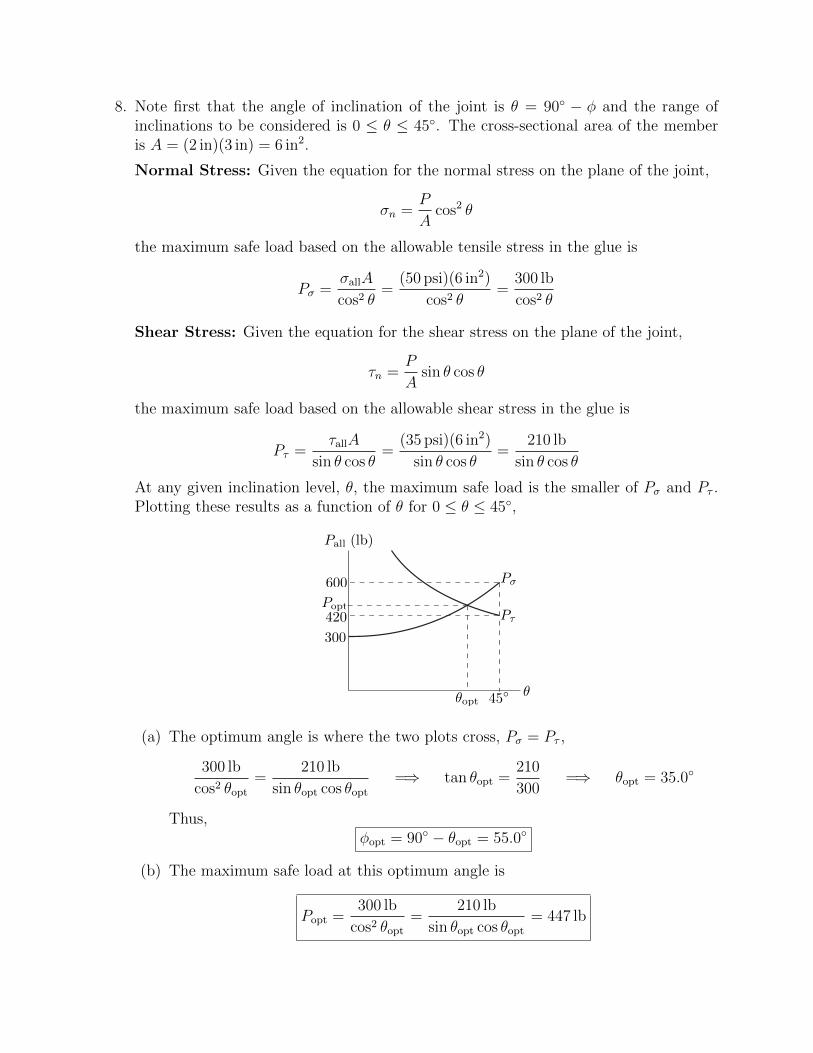
8. Note first that the angle of inclination of the joint is θ = 90◦ − φ and the range ofinclinations to be considered is 0 ≤ θ ≤ 45◦. The cross-sectional area of the memberis A = (2 in)(3 in) = 6 in2.
Normal Stress: Given the equation for the normal stress on the plane of the joint,
σn =P
Acos2 θ
the maximum safe load based on the allowable tensile stress in the glue is
Pσ =σallA
cos2 θ=
(50 psi)(6 in2)
cos2 θ=
300 lb
cos2 θ
Shear Stress: Given the equation for the shear stress on the plane of the joint,
τn =P
Asin θ cos θ
the maximum safe load based on the allowable shear stress in the glue is
Pτ =τallA
sin θ cos θ=
(35 psi)(6 in2)
sin θ cos θ=
210 lb
sin θ cos θ
At any given inclination level, θ, the maximum safe load is the smaller of Pσ and Pτ .Plotting these results as a function of θ for 0 ≤ θ ≤ 45◦,
θ
Pall (lb)
θopt 45◦
300
420
600
Popt
Pσ
Pτ
(a) The optimum angle is where the two plots cross, Pσ = Pτ ,
300 lb
cos2 θopt=
210 lb
sin θopt cos θopt=⇒ tan θopt =
210
300=⇒ θopt = 35.0◦
Thus,φopt = 90◦ − θopt = 55.0◦
(b) The maximum safe load at this optimum angle is
Popt =300 lb
cos2 θopt=
210 lb
sin θopt cos θopt= 447 lb