Embed Size (px)
Citation preview
ENGR-2300 Quiz 3 Spring 2015
1 K. A. Connor
ENGR-2300
Electronic Instrumentation
Quiz 3
Spring 2015
On all questions: SHOW ALL WORK. BEGIN WITH FORMULAS, THEN SUBSTITUTE VALUES AND UNITS. No credit will be given for answers that appear without justification. Also, if there is a small flaw in your reasoning, we will not know and not be able to give you credit for what you have correct if you do not provide information on how you solved the problem. Read the entire quiz before answering any questions. Also it may be easier to answer parts of questions out of order.
ENGR-2300 Quiz 3 Spring 2015
2 K. A. Connor
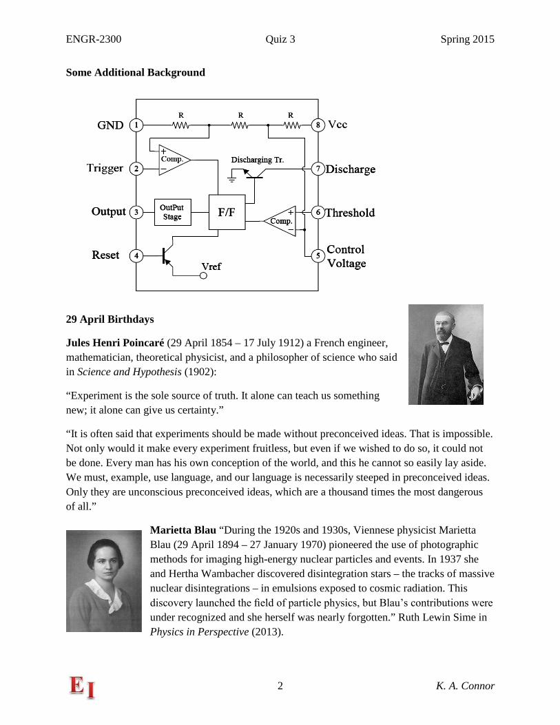
Some Additional Background
29 April Birthdays
Jules Henri Poincaré (29 April 1854 – 17 July 1912) a French engineer, mathematician, theoretical physicist, and a philosopher of science who said in Science and Hypothesis (1902):
“Experiment is the sole source of truth. It alone can teach us something new; it alone can give us certainty.”
“It is often said that experiments should be made without preconceived ideas. That is impossible. Not only would it make every experiment fruitless, but even if we wished to do so, it could not be done. Every man has his own conception of the world, and this he cannot so easily lay aside. We must, example, use language, and our language is necessarily steeped in preconceived ideas. Only they are unconscious preconceived ideas, which are a thousand times the most dangerous of all.”
Marietta Blau “During the 1920s and 1930s, Viennese physicist Marietta Blau (29 April 1894 – 27 January 1970) pioneered the use of photographic methods for imaging high-energy nuclear particles and events. In 1937 she and Hertha Wambacher discovered disintegration stars – the tracks of massive nuclear disintegrations – in emulsions exposed to cosmic radiation. This discovery launched the field of particle physics, but Blau’s contributions were under recognized and she herself was nearly forgotten.” Ruth Lewin Sime in Physics in Perspective (2013).
ENGR-2300 Quiz 3 Spring 2015
3 K. A. Connor
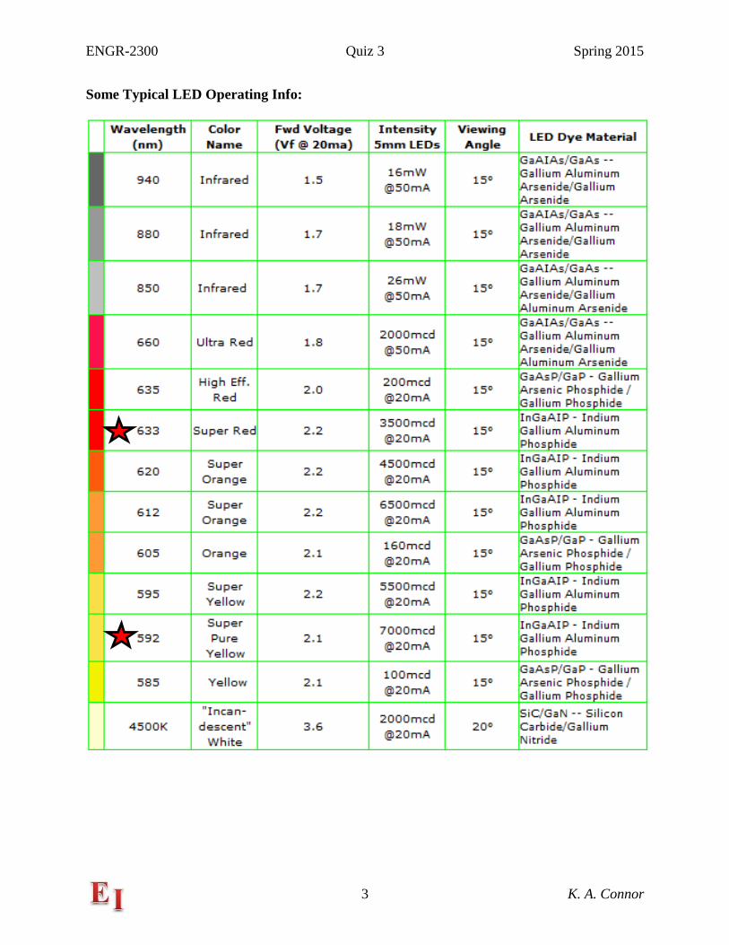
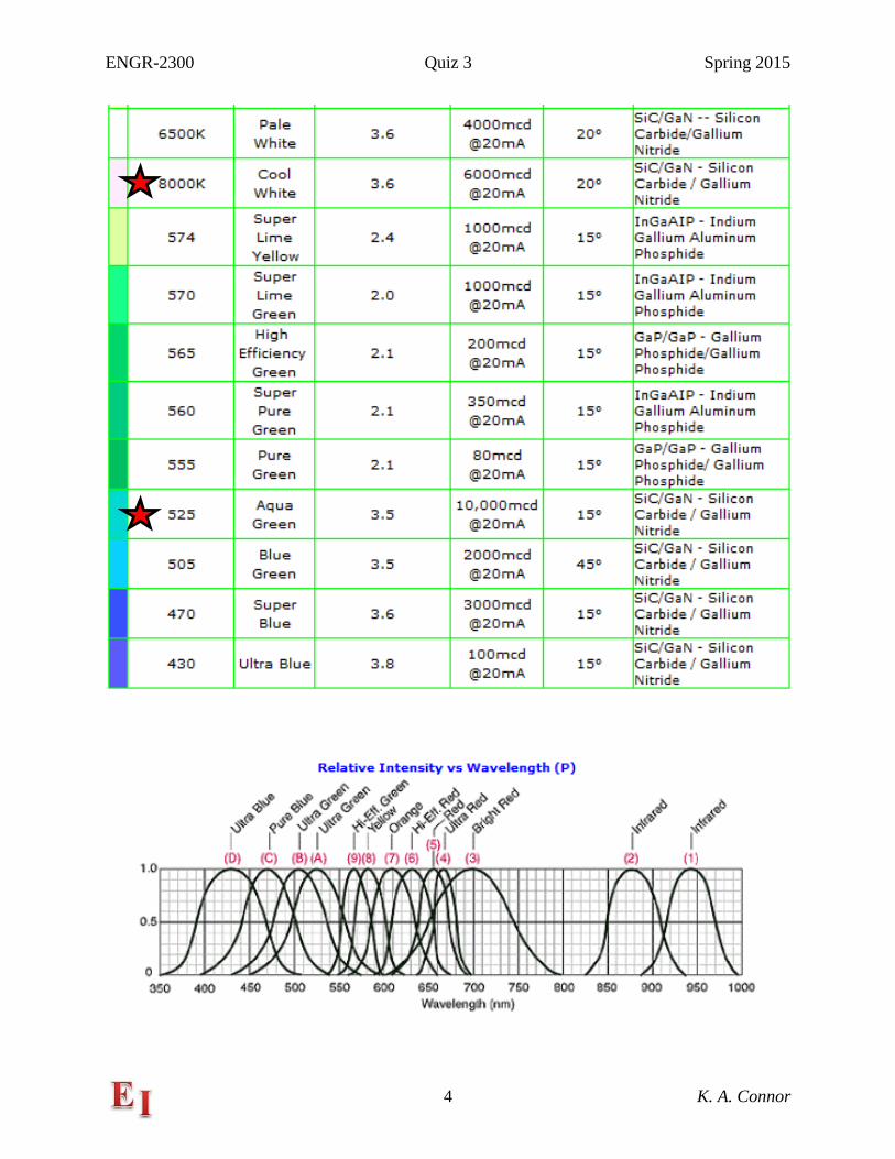
Some Typical LED Operating Info:
ENGR-2300 Quiz 3 Spring 2015
4 K. A. Connor
ENGR-2300 Quiz 3 Spring 2015
5 K. A. Connor
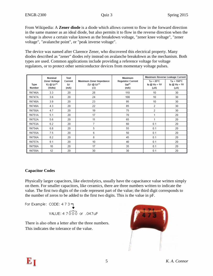
From Wikipedia: A Zener diode is a diode which allows current to flow in the forward direction in the same manner as an ideal diode, but also permits it to flow in the reverse direction when the voltage is above a certain value known as the breakdown voltage, "zener knee voltage", "zener voltage", "avalanche point", or "peak inverse voltage".
The device was named after Clarence Zener, who discovered this electrical property. Many diodes described as "zener" diodes rely instead on avalanche breakdown as the mechanism. Both types are used. Common applications include providing a reference voltage for voltage regulators, or to protect other semiconductor devices from momentary voltage pulses.
Capacitor Codes
Physically larger capacitors, like electrolytics, usually have the capacitance value written simply on them. For smaller capacitors, like ceramics, there are three numbers written to indicate the value. The first two digits of the code represent part of the value; the third digit corresponds to the number of zeros to be added to the first two digits. This is the value in pF.
There is also often a letter after the three numbers. This indicates the tolerance of the value.
ENGR-2300 Quiz 3 Spring 2015
6 K. A. Connor
Question 1 (20 Points) A Little Thevenin & Voltage Divider Background
The following configurations behave like parts of circuits encountered in Experiments 6 and 7.
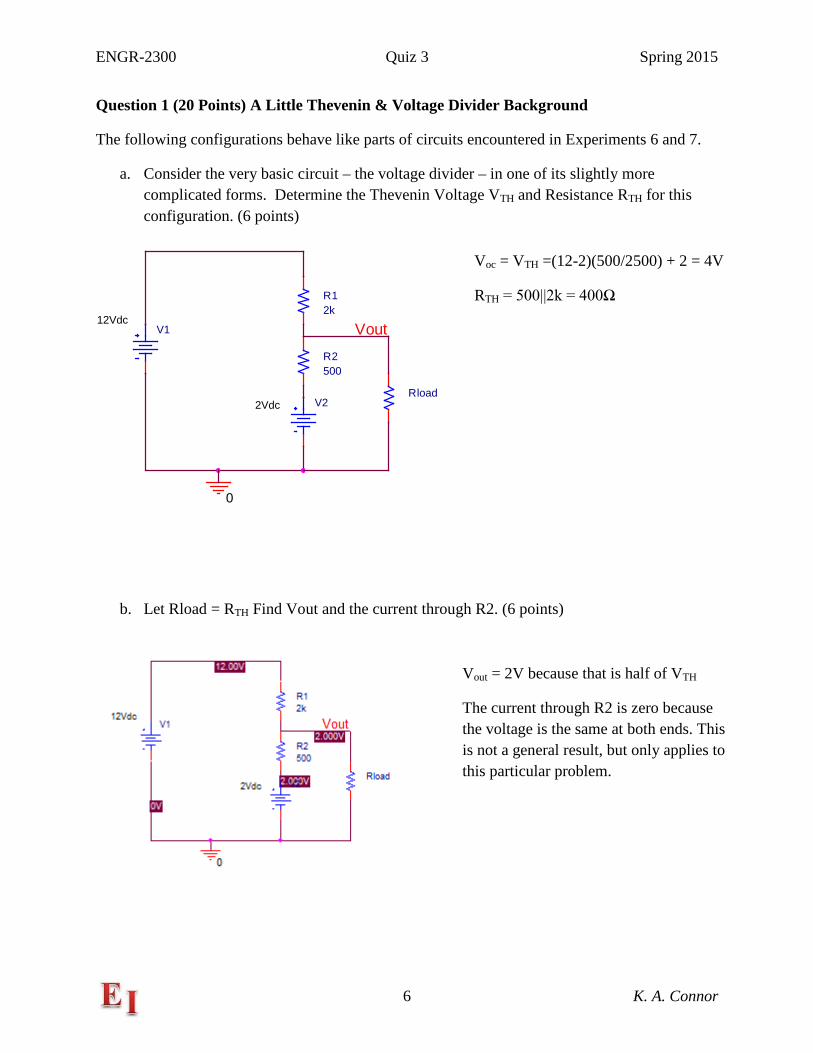
a. Consider the very basic circuit – the voltage divider – in one of its slightly more complicated forms. Determine the Thevenin Voltage VTH and Resistance RTH for this configuration. (6 points)
b. Let Rload = RTH Find Vout and the current through R2. (6 points)
V112Vdc
V22Vdc
R2500
R12k
0
Vout
Rload
Voc = VTH =(12-2)(500/2500) + 2 = 4V
RTH = 500||2k = 400Ω
Vout = 2V because that is half of VTH
The current through R2 is zero because the voltage is the same at both ends. This is not a general result, but only applies to this particular problem.
ENGR-2300 Quiz 3 Spring 2015
7 K. A. Connor
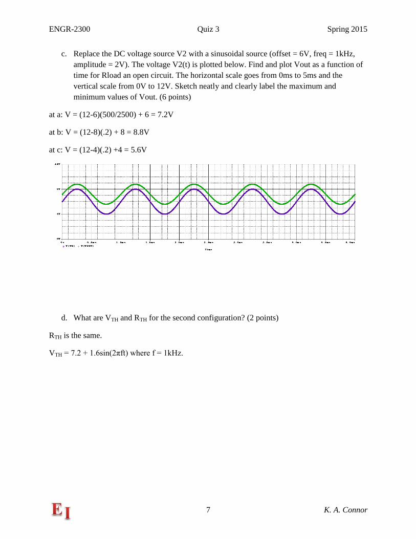
c. Replace the DC voltage source V2 with a sinusoidal source (offset = 6V, freq = 1kHz, amplitude = 2V). The voltage V2(t) is plotted below. Find and plot Vout as a function of time for Rload an open circuit. The horizontal scale goes from 0ms to 5ms and the vertical scale from 0V to 12V. Sketch neatly and clearly label the maximum and minimum values of Vout. (6 points)
at a: V = (12-6)(500/2500) + 6 = 7.2V
at b: V = (12-8)(.2) + 8 = 8.8V
at c: V = (12-4)(.2) +4 = 5.6V
d. What are VTH and RTH for the second configuration? (2 points)
RTH is the same.
VTH = 7.2 + 1.6sin(2πft) where f = 1kHz.
ENGR-2300 Quiz 3 Spring 2015
8 K. A. Connor
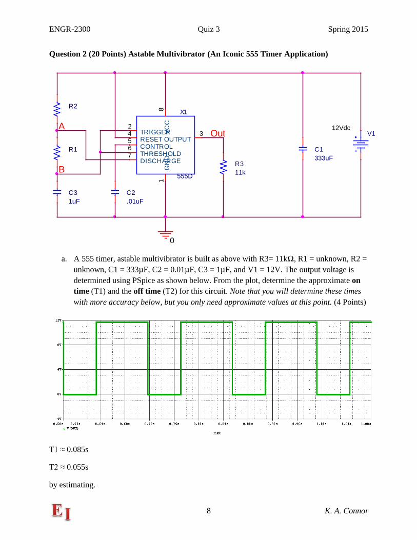
Question 2 (20 Points) Astable Multivibrator (An Iconic 555 Timer Application)
a. A 555 timer, astable multivibrator is built as above with R3= 11kΩ, R1 = unknown, R2 = unknown, C1 = 333µF, C2 = 0.01µF, C3 = 1µF, and V1 = 12V. The output voltage is determined using PSpice as shown below. From the plot, determine the approximate on time (T1) and the off time (T2) for this circuit. Note that you will determine these times with more accuracy below, but you only need approximate values at this point. (4 Points)
T1 ≈ 0.085s
T2 ≈ 0.055s
by estimating.
X1
555DG
ND
1
TRIGGER2
OUTPUT3
RESET4
CONTROL5
THRESHOLD6
DISCHARGE7
VCC
8
V112Vdc
C1333uF
C2.01uF
C31uF
R1
R2
R311k
0
OutA
B
ENGR-2300 Quiz 3 Spring 2015
9 K. A. Connor
b. Assume that the circuit was built using resistors from a box where they were all equal to multiples of 11kΩ (i.e. 11kΩ, 22kΩ, 33kΩ, 44kΩ, 55kΩ, 66kΩ, 77kΩ, 88kΩ or 99kΩ). Determine the values of R1 and R2 (4 points)
R1 = 77kΩ
R2 = 44kΩ
Just try the values until they work. Start with R1 because only it is involved in T2.
c. Using your answers to part b, find T1 and T2 again, but with more accuracy this time. (4 points)
T1 = 0.083s
T2 = 0.053s)
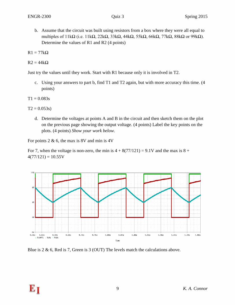
d. Determine the voltages at points A and B in the circuit and then sketch them on the plot on the previous page showing the output voltage. (4 points) Label the key points on the plots. (4 points) Show your work below.
For points 2 & 6, the max is 8V and min is 4V
For 7, when the voltage is non-zero, the min is 4 + 8(77/121) = 9.1V and the max is 8 + 4(77/121) = 10.55V
Blue is 2 & 6, Red is 7, Green is 3 (OUT) The levels match the calculations above.
ENGR-2300 Quiz 3 Spring 2015
10 K. A. Connor
Question 3 (20 Points) Combinational & Sequential Logic Circuits
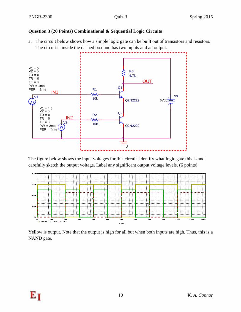
a. The circuit below shows how a simple logic gate can be built out of transistors and resistors. The circuit is inside the dashed box and has two inputs and an output.
The figure below shows the input voltages for this circuit. Identify what logic gate this is and carefully sketch the output voltage. Label any significant output voltage levels. (6 points)
Yellow is output. Note that the output is high for all but when both inputs are high. Thus, this is a NAND gate.
Q1
Q2N2222
Q2
Q2N2222
R1
10k
R2
10k
R34.7k
Vs6Vdc
0
V1
TD = 0
TF = 0PW = 1msPER = 2ms
V1 = 0
TR = 0
V2 = 5
V2
TD = 0
TF = 0PW = 2msPER = 4ms
V1 = 4.5
TR = 0
V2 = 0
IN1
IN2
OUT
ENGR-2300 Quiz 3 Spring 2015
11 K. A. Connor
It is possible to configure any standard logic gate out of either just NOR gates or NAND gates or simple combinations. Hint: Determine the states of the other points in each circuit as you fill out the tables.
b. What logic gate can be realized with either the NAND or NOR configuration shown below? (2 Pts)
NOT
NOT
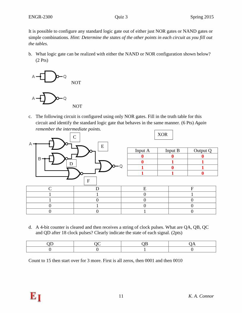
c. The following circuit is configured using only NOR gates. Fill in the truth table for this circuit and identify the standard logic gate that behaves in the same manner. (6 Pts) Again remember the intermediate points.
C D E F 1 1 0 1 1 0 0 0 0 1 0 0 0 0 1 0
d. A 4-bit counter is cleared and then receives a string of clock pulses. What are QA, QB, QC and QD after 18 clock pulses? Clearly indicate the state of each signal. (2pts)
QD QC QB QA 0 0 1 0
Count to 15 then start over for 3 more. First is all zeros, then 0001 and then 0010
Input A Input B Output Q 0 0 0 0 1 1 1 0 1 1 1 0
C
D
E
F
XOR
ENGR-2300 Quiz 3 Spring 2015
12 K. A. Connor
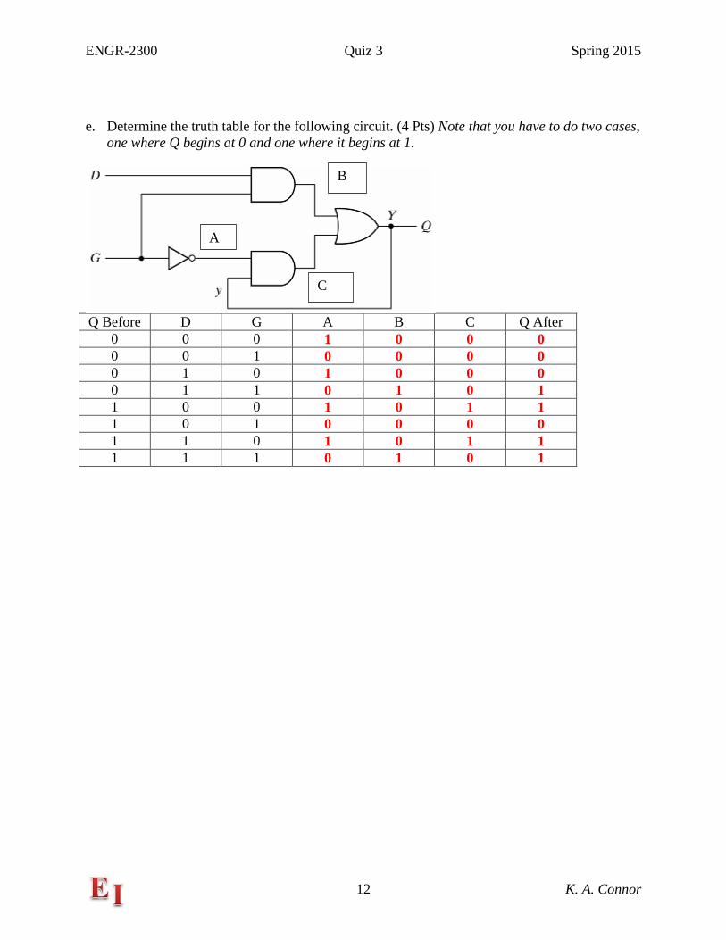
e. Determine the truth table for the following circuit. (4 Pts) Note that you have to do two cases,
one where Q begins at 0 and one where it begins at 1.
Q Before D G A B C Q After
0 0 0 1 0 0 0 0 0 1 0 0 0 0 0 1 0 1 0 0 0 0 1 1 0 1 0 1 1 0 0 1 0 1 1 1 0 1 0 0 0 0 1 1 0 1 0 1 1 1 1 1 0 1 0 1
B
C
A
ENGR-2300 Quiz 3 Spring 2015
13 K. A. Connor
Question 4 (20 Points) Schmitt Trigger
In this problem, we investigate the same properties of Schmitt Triggers we did in Experiment 6, but in a different order. First we look at how a commercial device works and then see if we can reproduce its properties using the Schmitt Trigger we can make with an op-amp.
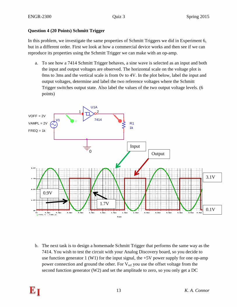
a. To see how a 7414 Schmitt Trigger behaves, a sine wave is selected as an input and both the input and output voltages are observed. The horizontal scale on the voltage plot is 0ms to 3ms and the vertical scale is from 0v to 4V. In the plot below, label the input and output voltages, determine and label the two reference voltages where the Schmitt Trigger switches output state. Also label the values of the two output voltage levels. (6 points)
b. The next task is to design a homemade Schmitt Trigger that performs the same way as the 7414. You wish to test the circuit with your Analog Discovery board, so you decide to use function generator 1 (W1) for the input signal, the +5V power supply for one op-amp power connection and ground the other. For Vref you use the offset voltage from the second function generator (W2) and set the amplitude to zero, so you only get a DC
U1A
7414
1 2
R11k
V1
FREQ = 1k
VAMPL = 2V
VOFF = 2V
0
VV
Input Output
0.9V
1.7V
3.1V
0.1V
ENGR-2300 Quiz 3 Spring 2015
14 K. A. Connor
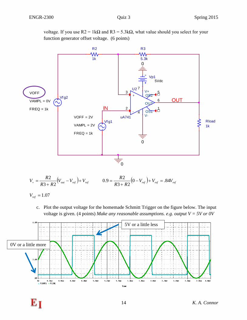
voltage. If you use R2 = 1kΩ and R3 = 5.3kΩ, what value should you select for your function generator offset voltage. (6 points)
( ) refrefout VVVRR
RV +−+
=+ 232 ( ) refrefref VVV
RRR 84.0
2329.0 =+−+
=
07.1=refV
c. Plot the output voltage for the homemade Schmitt Trigger on the figure below. The input voltage is given. (4 points) Make any reasonable assumptions. e.g. output V = 5V or 0V
U2
uA741
+3
-2
V+7
V-4
OUT6
OS11
OS25
R2
1k
R3
5.3k
Rload1k
Vp15Vdc
Vf g1
FREQ = 1k
VAMPL = 2V
VOFF = 2V
0
0
0
OUTIN
Vf g2
FREQ = 1k
VAMPL = 0V
VOFF
5V or a little less
0V or a little more
ENGR-2300 Quiz 3 Spring 2015
15 K. A. Connor
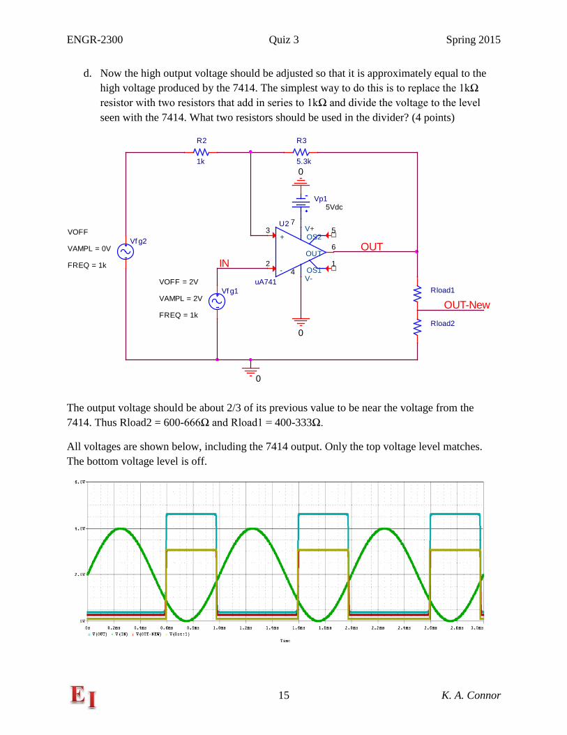
d. Now the high output voltage should be adjusted so that it is approximately equal to the high voltage produced by the 7414. The simplest way to do this is to replace the 1kΩ resistor with two resistors that add in series to 1kΩ and divide the voltage to the level seen with the 7414. What two resistors should be used in the divider? (4 points)
The output voltage should be about 2/3 of its previous value to be near the voltage from the 7414. Thus Rload2 = 600-666Ω and Rload1 = 400-333Ω.
All voltages are shown below, including the 7414 output. Only the top voltage level matches. The bottom voltage level is off.
U2
uA741
+3
-2
V+7
V-4
OUT6
OS11
OS25
R2
1k
R3
5.3k
Rload1
Vp15Vdc
Vf g1
FREQ = 1k
VAMPL = 2V
VOFF = 2V
0
0
0
OUTIN
Vf g2
FREQ = 1k
VAMPL = 0V
VOFF
Rload2
OUT-New
ENGR-2300 Quiz 3 Spring 2015
16 K. A. Connor
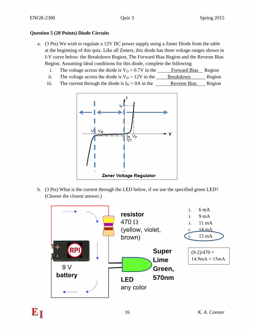
Question 5 (20 Points) Diode Circuits
a. (3 Pts) We wish to regulate a 12V DC power supply using a Zener Diode from the table at the beginning of this quiz. Like all Zeners, this diode has three voltage ranges shown in I-V curve below: the Breakdown Region, The Forward Bias Region and the Reverse Bias Region. Assuming ideal conditions for this diode, complete the following
i. The voltage across the diode is VD ≈ 0.7V in the Forward Bias Region ii. The voltage across the diode is VD ≈ 12V in the Breakdown Region
iii. The current through the diode is ID ≈ 0A in the Reverse Bias Region
b. (3 Pts) What is the current through the LED below, if we use the specified green LED? (Choose the closest answer.)
Super Lime Green, 570nm
i. 6 mA ii. 9 mA ii. 11 mA v. 14 mA v. 15 mA
(9-2)/470 = 14.9mA ≈ 15mA
ENGR-2300 Quiz 3 Spring 2015
17 K. A. Connor
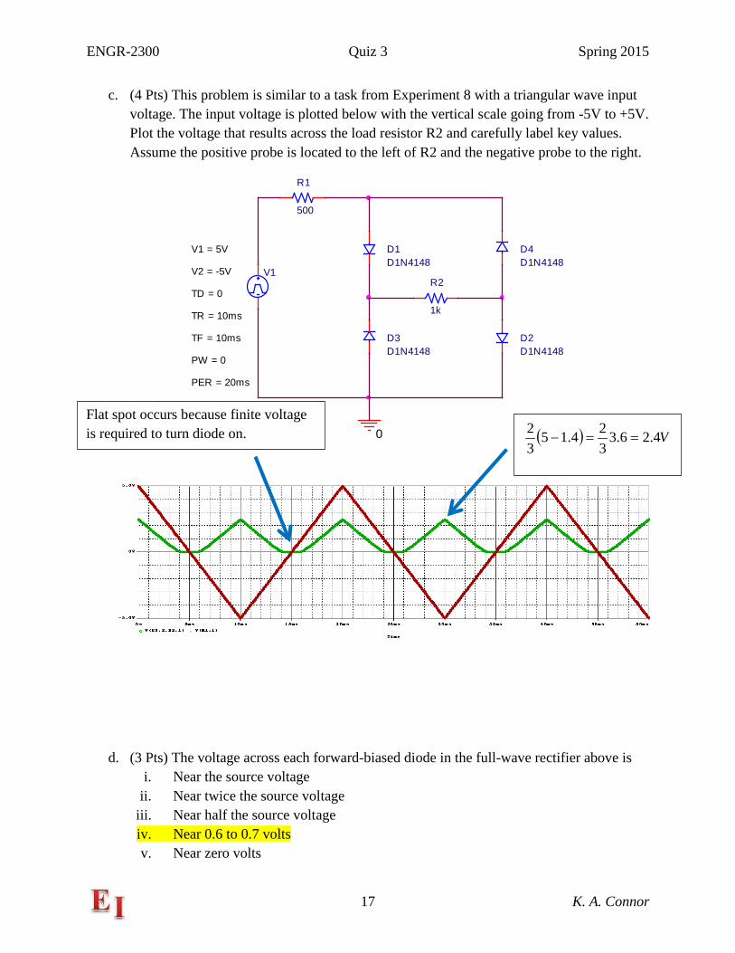
c. (4 Pts) This problem is similar to a task from Experiment 8 with a triangular wave input voltage. The input voltage is plotted below with the vertical scale going from -5V to +5V. Plot the voltage that results across the load resistor R2 and carefully label key values. Assume the positive probe is located to the left of R2 and the negative probe to the right.
d. (3 Pts) The voltage across each forward-biased diode in the full-wave rectifier above is i. Near the source voltage
ii. Near twice the source voltage iii. Near half the source voltage iv. Near 0.6 to 0.7 volts v. Near zero volts
V1
TD = 0
TF = 10ms
PW = 0
PER = 20ms
V1 = 5V
TR = 10ms
V2 = -5V
D1D1N4148
D2D1N4148
D3D1N4148
D4D1N4148
R1
500
R2
1k
0 ( ) V4.26.3324.15
32
==− Flat spot occurs because finite voltage is required to turn diode on.
ENGR-2300 Quiz 3 Spring 2015
18 K. A. Connor
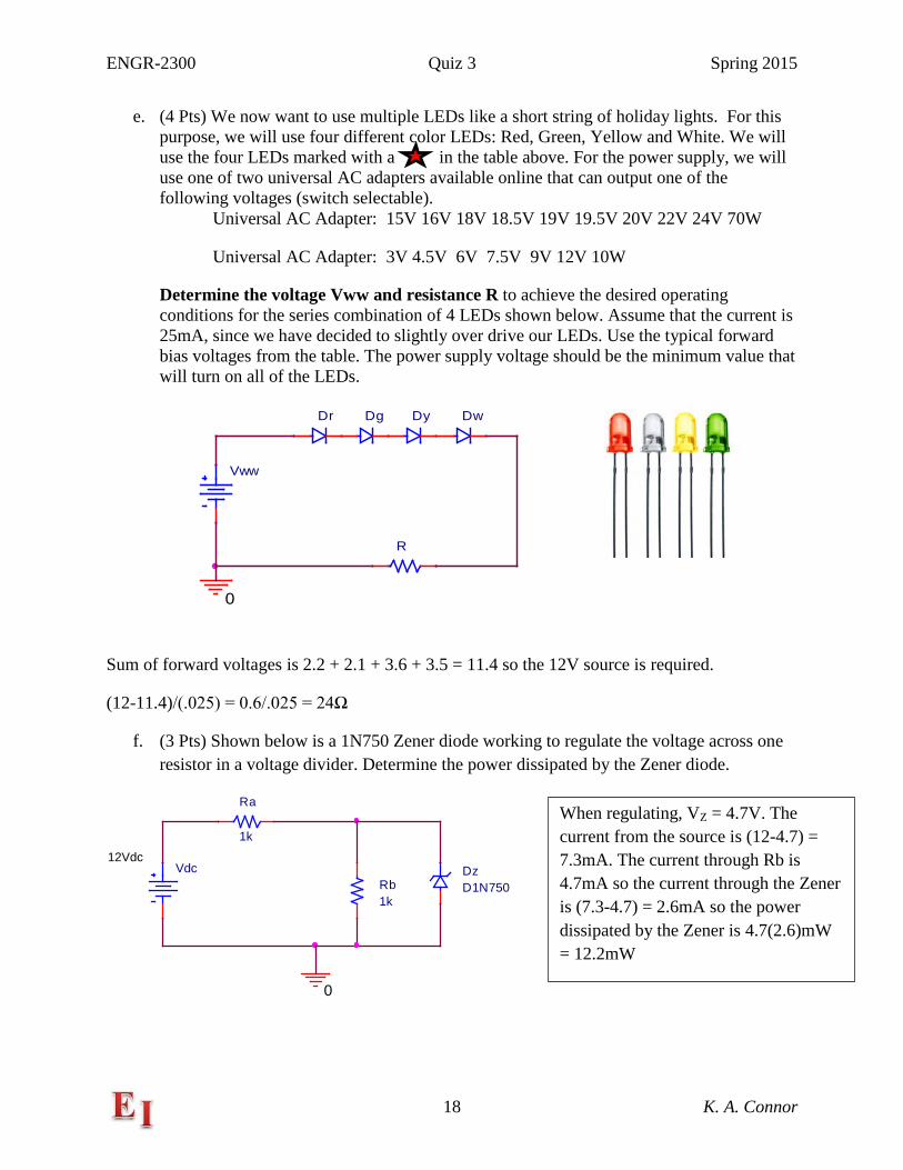
e. (4 Pts) We now want to use multiple LEDs like a short string of holiday lights. For this purpose, we will use four different color LEDs: Red, Green, Yellow and White. We will use the four LEDs marked with a in the table above. For the power supply, we will use one of two universal AC adapters available online that can output one of the following voltages (switch selectable).
Universal AC Adapter: 15V 16V 18V 18.5V 19V 19.5V 20V 22V 24V 70W
Universal AC Adapter: 3V 4.5V 6V 7.5V 9V 12V 10W
Determine the voltage Vww and resistance R to achieve the desired operating conditions for the series combination of 4 LEDs shown below. Assume that the current is 25mA, since we have decided to slightly over drive our LEDs. Use the typical forward bias voltages from the table. The power supply voltage should be the minimum value that will turn on all of the LEDs.
Sum of forward voltages is 2.2 + 2.1 + 3.6 + 3.5 = 11.4 so the 12V source is required.
(12-11.4)/(.025) = 0.6/.025 = 24Ω
f. (3 Pts) Shown below is a 1N750 Zener diode working to regulate the voltage across one resistor in a voltage divider. Determine the power dissipated by the Zener diode.
Vdc12Vdc
Ra
1k
Rb1k
DzD1N750
0
Dw
Vww
R
1k
Dr Dg Dy
0
When regulating, VZ = 4.7V. The current from the source is (12-4.7) = 7.3mA. The current through Rb is 4.7mA so the current through the Zener is (7.3-4.7) = 2.6mA so the power dissipated by the Zener is 4.7(2.6)mW = 12.2mW


![[XLS] - Mar15/District Reasi new proforma... · Web view2035 2300 2036 2300 2037 2300 2038 2300 2039 2300 2040 2300 2041 2300 2042 2300 2043 2300 2044 2300 2045 2300 2046 2300 2047](https://img.pdfslide.us/doc/110x75/5aa68dbc7f8b9a517d8ea409/xls-mar15district-reasi-new-proformaweb-view2035-2300-2036-2300-2037-2300.jpg)