Embed Size (px)
Citation preview
ENG
LISH
1
TECHCONNECT TILT OWNERS MANUALTECHCONNECT TILT GUIdE dE L’UTILISATEURTECHCONNECT TILT MANUAL dE USUARIO
TECHCONNECT TILT GEBRUIKERSHANdLEIdINGBESITZERHANdBUCH TECHCONNECT TILT
TECHCONNECT TILT MANUALE dEL PROPRIETARIOTILT TECHCONNECT: INSTRUKCJA OBSŁUGI
MANUAL dE UTILIZAdOR dO TECHCONNECT TILT
installation:innovation

ENG
LISH
3
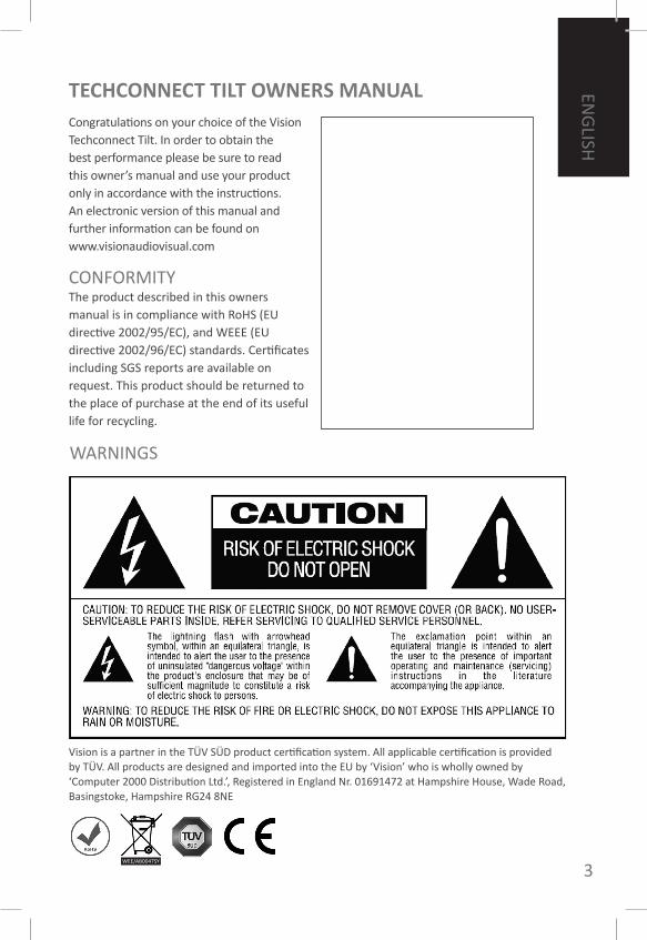
TechconnecT TILT oWneRS MAnUALCongratulations on your choice of the Vision Techconnect Tilt. In order to obtain the best performance please be sure to read this owner’s manual and use your product only in accordance with the instructions. An electronic version of this manual and further information can be found on www.visionaudiovisual.com
WARNINGS
CONFORMITYThe product described in this owners manual is in compliance with RoHS (EU directive 2002/95/EC), and WEEE (EU directive 2002/96/EC) standards. Certificates including SGS reports are available on request. This product should be returned to the place of purchase at the end of its useful life for recycling.
Vision is a partner in the TÜV SÜD product certification system. All applicable certification is provided by TÜV. All products are designed and imported into the EU by ‘Vision’ who is wholly owned by ‘Computer 2000 Distribution Ltd.’, Registered in England Nr. 01691472 at Hampshire House, Wade Road, Basingstoke, Hampshire RG24 8NE
WEE/AB0047SY
4
ENG
LISH
USE oNLY DomESTIC AC oUTLETS Connecting the unit to an outlet supplying a higher voltage may create a fire hazard.
HANDLE THE PoWER CoRD WITH CAREDo not disconnect the plug from the AC outlet by pulling the cord; always pull the plug itself. Pulling the cord may damage it. If you do not intend to use your unit for any considerable length of time, unplug the unit. Do not place furniture or other heavy objects on the cord, and try to avoid dropping heavy objects on it. Do not tie a knot in the power cord. Not only could the cord be damaged, but a short circuit could also be caused with a consequent fire hazard.
PLACE of INSTALLATIoNAvoid installing this product under the following conditions:• moist or humid places• Places exposed to direct sunlight or close to heating equipment• Extremely cold locations• Places subject to excessive vibration or dust• Poorly ventilated places
Do not expose this product to dripping or splashing. Do NoT PLACE oBJECTS fILLED WITH LIQUIDS oN oR NEAR THIS PRoDUCT!
moVING THE UNITBefore moving the unit, be sure to pull out the power cord from the AC outlet and disconnect the interconnection cords with other units.
WARNING SIGNSIf you detect an abnormal smell or smoke, turn this product off immediately and unplug the power cord. Contact your reseller or Vision.
PACkAGINGSave all packing material. It is essential for shipping in the event the unit ever needs repair.
If oRIGINAL PACkAGING IS NoT USED To RETURN THE UNIT To THE SERVICE CENTRE, DAmAGE IN TRANSIT WILL NoT BE CoVERED BY WARRANTY.

ENG
LISH
5
1. Cable management Clip2. motor Control Socket3. 220V AC Power output Socket
(provides loop-through power to the module on the faceplate)
4. 220V AC Power Input socket5. UP/DoWN Touch-sensitive Button6. faceplate
CHASSIS LAYoUT
6
ENG
LISH
INSTALLATIoN INSTRUCTIoNS
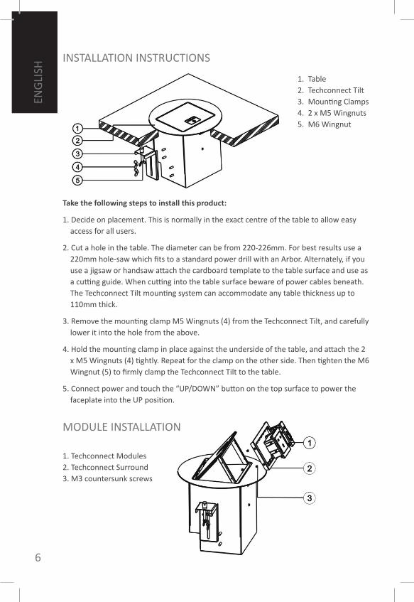
Take the following steps to install this product:
1. Decide on placement. This is normally in the exact centre of the table to allow easy access for all users.
2. Cut a hole in the table. The diameter can be from 220-226mm. for best results use a 220mm hole-saw which fits to a standard power drill with an Arbor. Alternately, if you use a jigsaw or handsaw attach the cardboard template to the table surface and use as a cutting guide. When cutting into the table surface beware of power cables beneath. The Techconnect Tilt mounting system can accommodate any table thickness up to 110mm thick.
3. Remove the mounting clamp m5 Wingnuts (4) from the Techconnect Tilt, and carefully lower it into the hole from the above.
4. Hold the mounting clamp in place against the underside of the table, and attach the 2 x m5 Wingnuts (4) tightly. Repeat for the clamp on the other side. Then tighten the m6 Wingnut (5) to firmly clamp the Techconnect Tilt to the table.
5. Connect power and touch the “UP/DoWN” button on the top surface to power the faceplate into the UP position.
1. Table2. Techconnect Tilt3. mounting Clamps4. 2 x m5 Wingnuts5. m6 Wingnut
1. Techconnect modules2. Techconnect Surround3. m3 countersunk screws
moDULE INSTALLATIoN
ENG
LISH
7
Follow the following steps to assemble the faceplate:
1. feed the cables up though the aperture in the faceplate.
2. Terminate the cables to each module as required. The VGA module has an integrated cable management clamp. After you’ve terminated the cable you should attach the clamp with a screwdriver. This will remove stress on the join.
3. Clip each module into the surround.
To eject modules from the surround the m3 screws on each side of the surround must be removed. The surround can then be removed and each module ejected from the rear.
The Techconnect Tilt is ready for use. Touch the “UP/DoWN” button on the top surface to power the faceplate into the DoWN position. The motor has a safety switch which prevents the faceplate from closing if fingers or cables present the motor with resistance. Likewise, if anything heavy is sitting on the faceplate, the motor will sense the weight and will not open the faceplate, HoWEVER this should not be relied on to prevent spillages.
SERIoUS RISk of ELECTRIC SHoCk: Do NoT PLACE oBJECTS fILLED WITH LIQUIDS oN oR NEAR THIS PRoDUCT!
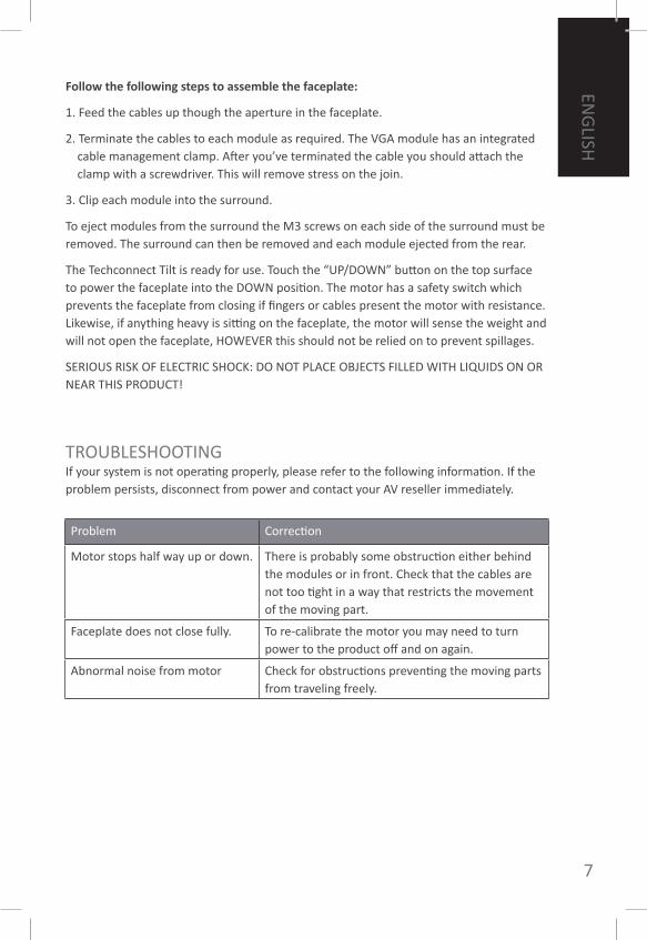
TRoUBLESHooTINGIf your system is not operating properly, please refer to the following information. If the problem persists, disconnect from power and contact your AV reseller immediately.
1. Table2. Techconnect Tilt3. mounting Clamps4. 2 x m5 Wingnuts5. m6 Wingnut
Problem Correction
motor stops half way up or down. There is probably some obstruction either behind the modules or in front. Check that the cables are not too tight in a way that restricts the movement of the moving part.
faceplate does not close fully. To re-calibrate the motor you may need to turn power to the product off and on again.
Abnormal noise from motor Check for obstructions preventing the moving parts from traveling freely.
8
ENG
LISH
WARRANTYThis product comes with a 2-year return to base warranty, effective from the date of purchase. This warranty applies only to the original purchaser and is not transferable. for the avoidance of doubt, this will be taken from the information held by the appointed national distributor at the point of sale. If the product is DoA (dead on arrival), you have 21 days from purchase date to notify the national distributor via your AV reseller. The liability of the manufacturer and its appointed service company is limited to the cost of repair and/or replacement of the faulty unit under warranty, except for death or injury (EU85/374/EEC). This warranty protects you against the following:• failure of any components, including the power supply.• Damage when the product is first removed from its packaging if reported within 24
hours of purchase.If you find you do have a problem with this product, you should contact the AV reseller you purchased this product from. The original purchaser is responsible for shipment of the product to the manufacturer’s appointed service centre for repair. We will endeavour to return repaired units within 5 working days, however this may not always be possible, in which case it will be returned as soon as practicably possible. In line with our WEEE commitments, the manufacturer endeavours to replace the faulty parts of the product rather than replacing the whole unit. This warranty does not protect this product against faults caused by abuse, misuse, incorrect installation, unstable or faulty power input, which might be caused by ignoring the guidelines set out in this manual.
SPECIfICATIoNSPower Supply: 100-240V, output 12VDC, • 1000mA, 12Wmotor current and torque: going up: 0.7A, • 30n / going down: 0.45A, 20nTop Surface material: Polished Black • AluminiumCutout Diameter Range: 220-226mm• outer Diameter: 240mm• Product Dimensions: 164 x 145 x 200 (side • x side x height)Product Weight: 3.7kg• Colour: Black•
note: Because we are committed to improving our products, the details above may change without prior warning.
ACCESSoRIES INCLUDED1 x Euro IEC Power cable 1.8m long• 1 x Uk IEC Power cable 1.8m long• 1 x Cutout Template• 2 x mounting Ears• 1 x Uk Power module with IEC power • cable1 x EU Power module with IEC power • cable2 x VGAf3.5mm module• 1 x RJ45 Ethernet module• 1 x Twin-RJ45 module• 1 x Blank module•
ENG
LISH
9
FRAN
ÇAIS
CONFORMITELe produit décrit dans ce guide est en conformité avec les exigences RoHS (directive de l’UE 2002/95/EC), et la WEEE (directive UE 2002/96/EC). Les certifi cats de validation, rapports SGS y compris, sont disponibles sur demande. Le produit devra être retourné sur le lieu d’achat dès la fi n de son utliisation à but de recyclage.
TechconnecT TILT GUIde de L’UTILISATeURfélicitations, vous venez d’acquérir le Techconnect Tilt Vision. Afin d’obtenir la meilleure performance possible, assurez-vous de vous conformer aux instructions fournies dans le guide de l’utilisateur. Une version électronique du guide et des informations complémentaires sont disponibles sur notre site: www.visionaudiovisual.com
ATTENTION : POUR RÉDUIRE LES RISQUES D’ÉLECTROCUTION, N’OUVREZ PAS LE PANNEAU ARRIÈRE OU LE CAPOTDE L’APPAREIL. IL NE CONTIENT AUCUN COMPOSANT QUI PUISSE ÊTRE ENTRETENU PAR L’UTILISATEUR.REPORTEZ-VOUS AUPRÈS D’UN SERVICE DE MAINTENANCE QUALIFIÉ.
L’éclair fléché au centre d’un triangle équilatéral prévient l’utilisateur de la présence de courants élevés dans l’appareil, pouvant constituer un risque d’électrocution en cas de mise en contact avec les composants internes.
Le point d’exclamation au centre d’un triangle équilatéral prévient l’utilisateur de la présence d’instructions importantes dans le mode d’emploi concernant la mise en oeuvre et l’entretien de l’appareil.
ATTENTION
RISQUE DE CHOC ÉLECTRIQUE NE PAS OUVRIR
AVERTISSEmENTS
Vision est l’un des partenaires du système de certification produit TÜV SÜD. Toutes les certifications pertinentes sont fournies par TÜV. Tous les produits sont conçus et importés dans l’UE par Vision, qui est une propriété exclusive de Computer 2000 Distribution Ltd., enregistrée au Royaume-Uni n° 01691472 Hampshire House, Wade Road, Basingstoke, Hampshire RG24 8NE
WEE/AB0047SY
ATTENTION : POUR RÉDUIRE LES RISQUES D’ÉLECTROCUTION, N’EXPOSEZ PAS CET APPAREIL À LA PLUIE OU À L’HUMIDITÉ.

10
ENG
LISH
FRA
NÇA
IS
La connection de l’unité à une prise de puissance supérieure peut entraîner des risques d’incendie.
mANIEz LE CoRDoN D’ALImENTATIoN AVEC PRUDENCENe déconnectez pas la prise en tirant sur le cordon, toujours tirer sur la prise elle-même, sinon vous risquez de l’endommager. Si vous n’avez pas l’intention d’utiliser votre unité pendant un certain moment, débranchez la. Ne placez pas d’objets lourds sur le cordon. Ne faîtes pas de noeuds dans le cordon, cela l’endommagerait et risquerait de provoquer un court-circuit avec risque d’incendie.
LIEU D’INSTALLATIoNNe pas installer le produit dans les cas suivants :• Un endroit humide.• Un endroit exposé à la lumière directe ou près de sources de chaleur.• Un endroit extrêmement froid.• Un endroit fortement ventilé ou poussiereux.• Un endroit faiblement ventilé.
Éviter toute fuite ou projection de liquide sur le produit. NE PAS PLACER D’oBJETS CoNTENANT DES LIQUIDES SUR oU À PRoXImITÉ DU PRoDUIT !
DÉPLACEmENT DE L’UNITÉAvant de déplacer l’unité, veillez à bien débrancher la prise et déconnectez les cables la reliant aux autres unités.
SIGNES D’AVERTISSEmENTEn cas d’odeur ou de fumée anormale, éteindre immédiatement le produit et débrancher le cordon d’alimentation. Contacter le concessionnaire ou Vision.
L’EmBALLAGEConservez tout emballage, il vous sera utile en cas de renvoi de l’unité pour réparation éventuelle. SI L’UNITE EST ENDommAGEE LoRS DU RENVoI, LA GARANTIE NE SERA PAS VALIDE.
UTILISEz UNIQUEmENT LES PRISES DE TENSIoN ALTERNATIVE

ENG
LISH
11
FRAN
ÇAIS
UTILISEz UNIQUEmENT LES PRISES DE TENSIoN ALTERNATIVE SCHÉmA D’ENSEmBLE CHÂSSIS
1. Serre-câbles2. Prise d’alimentation moteur3. Prise de sortie CA 220 V
(fournit l’alimentation en boucle du module sur la plaque frontale)
4. Prise d’entrée CA 220 V5. Bouton tactile UP/DoWN6. Plaque frontale
12
ENG
LISH
FRA
NÇA
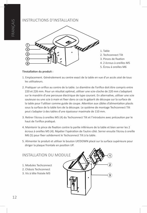
IS INSTRUCTIoNS D’INSTALLATIoN
TInstallation du produit :
1. Emplacement. Généralement au centre exact de la table en vue d’un accès aisé de tous les utilisateurs.
2. Pratiquer un orifice au centre de la table. Le diamètre de l’orifice doit être compris entre 220 et 226 mm. Pour un résultat optimal, utiliser une scie-cloche de 220 mm s’adaptant sur le mandrin d’une perceuse électrique de type courant. En alternative, utiliser une scie sauteuse ou une scie à main et fixer dans ce cas le gabarit de découpe sur la surface de la table pour l’utiliser comme guide de coupe. Attention aux câbles d’alimentation placés sous la surface de la table lors de la découpe. Le système de montage Techconnect Tilt peut s’adapter à des tables d’une épaisseur maximale de 110 mm.
3. Retirer l’écrou à oreilles m5 (4) du Techconnect Tilt et l’introduire avec précaution par le haut de l’orifice pratiqué.
4. maintenir la pince de fixation contre la partie inférieure de la table et bien serrer les 2 écrous à oreilles m5 (4). Répéter l’opération de l’autre côté. Serrer ensuite l’écrou à oreille m6 (5) pour fixer solidement le Techconnect Tilt à la table.
5. Alimenter le produit et utiliser le bouton UP/DoWN placé sur la surface supérieure pour diriger la plaque frontale en position UP.
1. Table2. Techconnect Tilt3. Pinces de fixation4. 2 écrous à oreilles m55. Écrou à oreilles m6
1. modules Techconnect 2. Châssis Techconnect3. Vis à tête fraisée m3
INSTALLATIoN DU moDULE
ENG
LISH
13
FRAN
ÇAIS
Pour le montage de la plaque frontale, procéder comme suit :
1. faire monter les câbles à travers l’orifice de la plaque frontale.
2. Raccorder les câbles à chaque module. Le module VGA est équipé d’un serre-câble intégré. Après avoir raccordé le câble, fixer la pince au moyen d’un tournevis. Cette précaution évitera toute contrainte sur la jointure.
3. fixer tous les modules sur le châssis.
Pour éjecter les modules, ôter les vis m3 de chaque côté du châssis. Retirer ensuite le châssis pour permettre l’éjection des modules à l’arrière.
Le Techconnect Tilt est prêt à l’utilisation. 5. Alimenter le produit et utiliser le bouton UP/DoWN installé sur la surface supérieure pour orienter la plaque frontale en position DoWN. Le moteur est équipé d’un interrupteur de sécurité empêchant toute fermeture de la plaque frontale en cas de pression des doigts ou de câbles sur le moteur. De même, si un objet lourd est posé sur la plaque frontale, le moteur le détecte et ne procède pas à son ouverture. ATTENTIoN, ce système ne permet pas d’éviter les déversements.
RISQUES ImPoRTANTS DE CHoC ÉLECTRIQUE : NE PLACER AUCUN oBJET CoNTENANT UN LIQUIDE SUR oU À PRoXImITÉ DU PRoDUIT !
PRoBLEmES EVENTUELSSi votre système ne fonctionne pas correctement, référez vous aux informations suivantes. Si le problème persiste, coupez l’alimentation et contactez le service après vente.
Problème Solution
Le moteur s’arrête à mi-chemin ou ne monte pas.
obstruction probable derrière ou devant les modules. Vérifier que les câbles ne sont pas trop tendus et ne gênent pas les mouvements des composants.
La plaque frontale ne se ferme pas complètement.
Pour réétalonner le moteur, sectionner et rétablir l’alimentation du produit.
Le moteur émet un bruit anormal Vérifier qu’aucune obstruction n’empêche le déplacement des composants mobiles.
14
ENG
LISH
FRA
NÇA
IS
GARANTIECe produit a une garantie de 2 ans qui prend effet le jour de l’achat. Cette garantie concerne uniquement l’acheteur initial et n’est pas transférable. Afin d’éviter tout doute, l’information référante sera celle du revendeur du lieu d’achat.Si le produit est défectueux à l’arrivée, vous avez 21 jours à partir de la date d’achat pour en avertir le grossiste via votre service audio visuel. La responsabilité du fabricant et du revendeur est limitée au coût de reparation et du remplacement de l’unité sous garantie, excepté la mort ou des dommages (EU85/374/EEC). La garantie vous protège contre : • Pièces défectueuses, alimentation comprise.• Dommages à la première sortie d’emballage si vous nous en notifiez en moins de 24
heures suivant l’’achat.Si vous avez un problème avec ce produit, vous devez contacter le revendeur. L’acheteur d’origine est responsable de la livraison du produit au centre de service de réparation.Nous ferons de notre possible pour vous retourner les unités réparées sous 5 jours ouvrables. Cependant, ceci n’est pas toujours possible auquel cas nous nous engageons à vous la faire parvenir le plus rapidement possible. Conformément à nos engagements WEEE, le fabricant s’engage à, dans la mesure du possible, remplacer la pièce défectueuse plutôt que l’unité dans son intégralité. Cette garantie ne protège pas l’unité contre des défauts causés par abus, mauvaise utilisation, installation incorrecte ou alimentation défectueuse, issus d’un mauvais suivi des conseils dans ce guide.
PRoPRIETESAlimentation : 100-240 V, Sortie 12 VCC, • 1 000 mA, 12 WCourant et couple moteur : en montée : • 0,7 A, 30 n / en descente : 0,45 A, 20 nmatériau surface supérieure : • aluminium noir poliDécoupe Diamètre Plage : 220-226 mm• Diamètre externe : 240 mm• Dimensions produit : • 164 x 145 x 200 (côté x côté x hauteur)Poids produit : 3,7 kg• Couleur : Noir•
Remarque : Nous procédons à des perfectionnements constants de nos produits et pouvons modifier les informations ci-dessus sans préavis.
ACCESSoIRES INCLUS1 câble d’alimentation IEC Euro • longueur 1,8 m1 câble d’alimentation IEC Uk • longueur 1,8 m1 gabarit de découpe• 2 oreilles de montage• 1 module d’alimentation Royaume-Uni • avec câble d’alimentation IEC1 module d’alimentation UE avec câble • d’alimentation IEC2 modules VGAf 3,5 mm• 1 module Ethernet RJ45• 1 module Twin-RJ45• 1 module vierge•
ENG
LISH
15
ESPAñ
oL
CoNfoRmIDADEl producto descrito en este manual es conforme a los estándares de la Directiva RoHS (EU 2002/95/EC) y WEEE (EU 2002/96/EC). Los certificados de validación están disponibles bajo petición. Este producto deber ser devuelto al lugar de compra al final de su vida útil, para ser reciclado.
TechconnecT TILT MAnUAL de USUARIofelicidades por escoger su Vision Techconnect Tilt. Para obtener mejores resultados, por favor, lea este manual, y use este producto sólo de acuerdo con las instrucciones. Una version electrónica de este manual y mas información se podrá encontrar en www.visionaudiovisual.com
ADVERTENCIAS
Vision participa en el sistema de certificación de productos TÜV SÜD. TÜV proporciona todas las certificaciones aplicables. Vision, sociedad participada al 100% por Computer 2000 Distribution Ltd., registrada en Inglaterra con el número 01691472 en Hampshire House, Wade Road, Basingstoke, Hampshire RG24 8NE, diseña e importa todos los productos a la UE.
WEE/AB0047SY
16
ENG
LISH
ESPA
ño
L UTILIzAR SoLAmENTE CoN ENCHUfES DomESTICoSConectar esta unidad a un enchufe con mayor voltaje podrá crear un riesgo de incendio
mANEJE EL CABLE ELECTRICo CoN CUIDADoNo desconecte la clavija del enchufe por su cordon; siempre saque la clavija entera. Tirar del cordon puede dañarlo. Si no piensa utilizar su unidad por un tiempo indefinido, desconecte la unidad. No ponga muebles ni otros objetos pesados encima del cordon, y evite tirar objectos pesados encima. No haga un nudo con el cordon, porque no solo lo podrá dañar sino que tambien puede causar un cortocircuito y riesgo de incendio.
LUGARES DE INSTALACIóNNo instale este producto en las circunstancias siguientes:1. Lugares húmedos o mojados2. Lugares expuestos al sol o cerca de equipo de calentamiento3. Lugares extremadamente fríos4. Lugares sujetos a vibraciones excesivas o al polvo5. Lugares mal ventilados
No exponga este producto a goteos ni salpicaduras. No CoLoQUE oBJEToS QUE CoNTENGAN LÍQUIDoS SoBRE EL PRoDUCTo NI CERCA DE ÉL.
moVIENDo LA UNIDAD Antes de mover la unidad, asegurese de sacar la clavija del enchufe y desconectar todos los cables interconectados con otras unidades.
SEñALES DE PELIGRoSi percibe humo o un olor inusual, apague este producto inmediatamente y desenchufe el cable de alimentación. Póngase en contacto con su distribuidor o con Vision.
EmBALAJEGuarde todo el material de embalaje. Esto es esencial para su envío en caso de que alguna vez necesite repararse. SI LA UNIDAD SE DAñA CAmINo DEL CENTRo DE SERVICIo, LA GARANTIA SERA INVALIDA.

ENG
LISH
17
ESPAñ
oL
1. Pinza de sujeción del cableado2. Enchufe de control del motor3. Terminal de salida de corriente CA de
220 V (proporciona corriente mediante una conexión derivada al módulo de la placa frontal)
4. Terminal de entrada de corriente CA de 220 V
5. Botón sensible al tacto ARRIBA/ABAJo6. Placa frontal
DISEño DEL BASTIDoR
18
ENG
LISH
ESPA
ño
L INSTRUCCIoNES DE INSTALACIóN
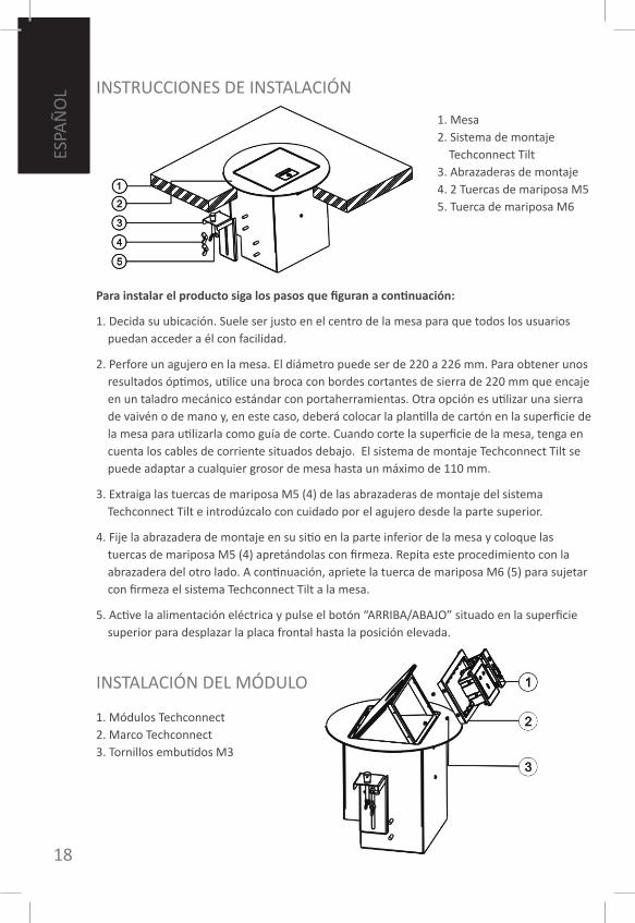
Para instalar el producto siga los pasos que figuran a continuación:
1. Decida su ubicación. Suele ser justo en el centro de la mesa para que todos los usuarios puedan acceder a él con facilidad.
2. Perfore un agujero en la mesa. El diámetro puede ser de 220 a 226 mm. Para obtener unos resultados óptimos, utilice una broca con bordes cortantes de sierra de 220 mm que encaje en un taladro mecánico estándar con portaherramientas. otra opción es utilizar una sierra de vaivén o de mano y, en este caso, deberá colocar la plantilla de cartón en la superficie de la mesa para utilizarla como guía de corte. Cuando corte la superficie de la mesa, tenga en cuenta los cables de corriente situados debajo. El sistema de montaje Techconnect Tilt se puede adaptar a cualquier grosor de mesa hasta un máximo de 110 mm.
3. Extraiga las tuercas de mariposa m5 (4) de las abrazaderas de montaje del sistema Techconnect Tilt e introdúzcalo con cuidado por el agujero desde la parte superior.
4. fije la abrazadera de montaje en su sitio en la parte inferior de la mesa y coloque las tuercas de mariposa m5 (4) apretándolas con firmeza. Repita este procedimiento con la abrazadera del otro lado. A continuación, apriete la tuerca de mariposa m6 (5) para sujetar con firmeza el sistema Techconnect Tilt a la mesa.
5. Active la alimentación eléctrica y pulse el botón “ARRIBA/ABAJo” situado en la superficie superior para desplazar la placa frontal hasta la posición elevada.
1. mesa2. Sistema de montaje
Techconnect Tilt3. Abrazaderas de montaje4. 2 Tuercas de mariposa m55. Tuerca de mariposa m6
1. módulos Techconnect2. marco Techconnect3. Tornillos embutidos m3
INSTALACIóN DEL móDULo
ENG
LISH
19
ESPAñ
oL
Para instalar el producto siga los pasos que figuran a continuación:
1. Decida su ubicación. Suele ser justo en el centro de la mesa para que todos los usuarios puedan acceder a él con facilidad.
2. Perfore un agujero en la mesa. El diámetro puede ser de 220 a 226 mm. Para obtener unos resultados óptimos, utilice una broca con bordes cortantes de sierra de 220 mm que encaje en un taladro mecánico estándar con portaherramientas. otra opción es utilizar una sierra de vaivén o de mano y, en este caso, deberá colocar la plantilla de cartón en la superficie de la mesa para utilizarla como guía de corte. Cuando corte la superficie de la mesa, tenga en cuenta los cables de corriente situados debajo. El sistema de montaje Techconnect Tilt se puede adaptar a cualquier grosor de mesa hasta un máximo de 110 mm.
3. Extraiga las tuercas de mariposa m5 (4) de las abrazaderas de montaje del sistema Techconnect Tilt e introdúzcalo con cuidado por el agujero desde la parte superior.
4. fije la abrazadera de montaje en su sitio en la parte inferior de la mesa y coloque las tuercas de mariposa m5 (4) apretándolas con firmeza. Repita este procedimiento con la abrazadera del otro lado. A continuación, apriete la tuerca de mariposa m6 (5) para sujetar con firmeza el sistema Techconnect Tilt a la mesa.
5. Active la alimentación eléctrica y pulse el botón “ARRIBA/ABAJo” situado en la superficie superior para desplazar la placa frontal hasta la posición elevada.
Para montar la placa frontal siga los pasos que figuran a continuación:
1. Pase los cables hacia arriba por la abertura de la placa frontal.
2. Conecte los cables a cada módulo según sea necesario. El módulo VGA dispone de una pinza integrada de sujeción de cables. Una vez que haya conectado el cable, debe colocar la pinza con un destornillador. De este modo se elimina tensión en las uniones.
3. Sujete todos los módulos al marco.
Para separar los módulos del marco, se deben extraer los tornillos m3 de cada lado del marco. A continuación, se podrá retirar el marco y extraer cada módulo por la parte posterior.
El sistema Techconnect Tilt ya está preparado para comenzar a utilizarlo. Pulse el botón “ARRIBA/ABAJo” situado en la superficie superior para desplazar la placa frontal hasta ABAJo. El motor dispone de un interruptor de seguridad que impide que la placa frontal se cierre si los dedos o los cables ofrecen resistencia al motor. De igual modo, si cualquier objeto pesado se coloca sobre la placa frontal, el motor detectará el peso y no abrirá la placa frontal. No oBSTANTE, no se debe confiar en este mecanismo para evitar que se derramen líquidos.
RIESGo GRAVE DE DESCARGA ELÉCTRICA: No CoLoQUE oBJEToS CoN LÍQUIDo EN SU INTERIoR SoBRE ESTE PRoDUCTo NI CERCA DE ÉL.
RESoLUCIóN DE PRoBLEmASSi su sistema no esta funcionando bien, favor de referirse a la siguiente información. Si el problema persiste, desconecte del poder y contacte su comerciante inmediatamente.
1. mesa2. Sistema de montaje
Techconnect Tilt3. Abrazaderas de montaje4. 2 Tuercas de mariposa m55. Tuerca de mariposa m6
Problema Solución
El motor se detiene a medio recorrido hacia arriba o hacia abajo.
Probablemente haya alguna obstrucción detrás de los módulos o en la parte frontal. Compruebe que los cables no están demasiado tirantes de forma que limiten el desplazamiento de las piezas móviles.
La placa frontal no se cierra completamente.
Para volver a calibrar el motor es necesario apagar y volver a encender la alimentación eléctrica del producto.
Ruido inusual del motor. Compruebe que no haya obstrucciones que impidan que las piezas móviles se desplacen libremente.
20
ENG
LISH
ESPA
ño
L
GARANTÍAEste producto viene con una garantía de 2 años regreso a base, efectivo desde la fecha de compra. La garantía se aplica solamente al comprador original y no es transferible. Para evitar cualquier duda, esto se tomará de la información guardada por el distribuidor nacional al punto de venta. Si el producto no funciona cuando lo recibió, tiene 21 dias desde la fecha de compra para notificar al distribuidor nacional a través de su vendedor. La responsabilidad del fabricante y su compañía apuntada está limitada al costo de reparación o el reemplazo del producto defectuoso bajo garantía, a excepción de muerte o de lesion (EU85/374/EEC). Esta garantía lo proteje contra lo siguiente:• Defecto de cualquiera de los componentes, incluyendo el suministro electrico• Daño cuando el producto es extraído de su embalaje por primera vez, pero solo si es
reportado dentro de 24 despues de compra. Si encuentra que tiene algún problema con este producto, por favor contacte con el punto de venta audiovisual donde lo compró. El comprador original es responsable por el envío del producto al centro de servicio del fabricante para reparación. Nosotros procuraremos retornar las unidades reparadas dentro de 5 dias laborales, pero esto no siempre será posible, en cual caso será retornado lo antes posible. En línea con nuestros compromisos WEEE, el fabricante procurará reemplazar las partes defectuosas en vez de la unidad completa. La garantía no proteje a este producto contra averias causadas por abuso, mal uso, instalación incorrecta, alimentación eléctrica inestable o defectuosa, lo cual puede ser causado por ignorar las indicaciones explicadas en este manual.
ESPECIfICACIoNESAlimentación eléctrica: 100-240 V, • salida 12 V de CC, 1000 mA, 12 WPar y corriente del motor: ascenso: • 0,7 A, 30 n / descenso: 0,45 A, 20 nmaterial de la parte superior: • aluminio negro pulidoRango de corte del diámetro: • 220-226 mmDiámetro exterior: 240 mm• Dimensiones del producto: • 164 x 145 x 200 (lateral x lateral x altura)Peso del producto: 3,7 kg• Color: negro•
nota: dado nuestro compromiso con la mejora constante, los datos anteriores se pueden modificar sin advertencia previa.
ACCESoRIoS INCLUIDoS1 x cable de corriente Euro CEI de 1,8 m • de largo1 x cable de corriente GB CEI de 1,8 m • de largo1 x plantilla de corte• 2 x pestañas de montaje• 1 x módulo de potencia GB con cable de • corriente CEI1 x módulo de potencia EU con cable de • corriente CEI2 x módulo VGAf 3,5 mm• 1 x módulo RJ45 Ethernet• 1 x módulo Twin-RJ45 Ethernet• 1 x módulo hueco•
ENG
LISH
21
NED
ERLAN
DS
TechconnecT TILT GeBRUIKeRShAndLeIdInGGefeliciteerd met uw koop van Vision Techconnect Tilt. Lees deze gebruikershandleiding en gebruik uw product alleen in overeenstemming met de aanwijzingen voor een optimale prestatie. U vindt een elektronische versie en verdere informatie op: www.visionaudiovisual.com
WAARSCHUWINGEN
De bliksemschicht met pijlpunt aan de onderkant binnen een gelijkzijdige driehoek is bedoeld om de gebruiker te waarschuwen voor de aanwezigheid van “gevaarlijke spanning” binnen de afgesloten producten omdat deze groot genoeg kan zijn om mensen een elektrische schok toe te brengen.
Het uitroepteken binnen een gelijkzijdige driehoek is bedoeld om de lezer te wijzen op een belangrijke aanwijzing in de handleiding behorende bij het apparaat over de werking en het onderhoud.
VOOrzIchTIg
RISICO OP ELEkTRISCHE SCHOk NIET OPENEN
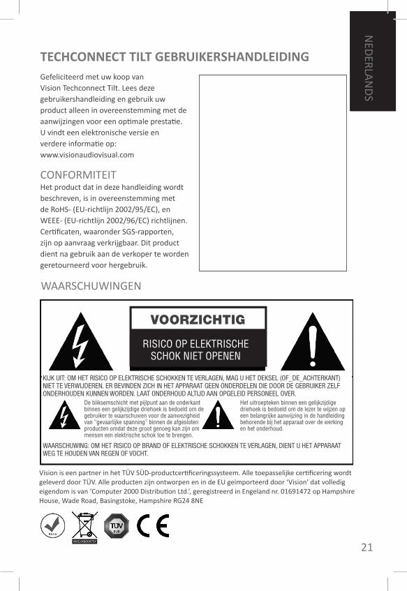
CONFORMITEITHet product dat in deze handleiding wordt beschreven, is in overeenstemming met de RoHS- (EU-richtlijn 2002/95/EC), en WEEE- (EU-richtlijn 2002/96/EC) richtlijnen. Certificaten, waaronder SGS-rapporten, zijn op aanvraag verkrijgbaar. Dit product dient na gebruik aan de verkoper te worden geretourneerd voor hergebruik.
Vision is een partner in het TÜV SÜD-productcertificeringssysteem. Alle toepasselijke certificering wordt geleverd door TÜV. Alle producten zijn ontworpen en in de EU geïmporteerd door ‘Vision’ dat volledig eigendom is van ‘Computer 2000 Distribution Ltd.’, geregistreerd in Engeland nr. 01691472 op Hampshire House, Wade Road, Basingstoke, Hampshire RG24 8NE
WEE/AB0047SY
KIJK UIT: OM HET RISICO OP ELEKTRISCHE SCHOKKEN TE VERLAGEN, MAG U HET DEKSEL (OF_DE_ACHTERKANT) NIET TE VERWIJDEREN. ER BEVINDEN ZICH IN HET APPARAAT GEEN ONDERDELEN DIE DOOR DE GEBRUIKER ZELF ONDERHOUDEN KUNNEN WORDEN. LAAT ONDERHOUD ALTIJD AAN OPGELEID PERSONEEL OVER.
WAARSCHUWING: OM HET RISICO OP BRAND OF ELEKTRISCHE SCHOKKEN TE VERLAGEN, DIENT U HET APPARAAT WEG TE HOUDEN VAN REGEN OF VOCHT.
22
ENG
LISH
NED
ERLA
ND
S
GEBRUIk ALLEEN AC-SToPCoNTACTEN DIE STANDAARD zIJN VooR UW LANDHet aansluiten van het apparaat op een stopcontact van een hoger voltage kan brand veroorzaken.
GA zoRGVULDIG om mET DE STRoomkABELTrek de stekker niet via het snoer uit het stopcontact. Trek altijd alleen aan de stekker zelf. Trekken aan het snoer kan schade veroorzaken. Als u uw apparaat een tijdje niet gebruikt, is het beter om het apparaat los te koppelen. Plaats geen meubels of andere zware voorwerpen op het snoer en probeer er geen zware voorwerpen op te laten vallen. Leg geen knoop in de stroomkabel. Dit kan niet alleen uw snoer beschadigen, maar ook kortsluiting en dientengevolge brand veroorzaken.
HET PLAATSEN VAN DE INSTALLATIEInstalleer het product niet onder de volgende omstandigheden:• nat of vochtig zijn• aan direct zonlicht zijn blootgesteld of te dicht bij de verwarming zijn• extreem koud zijn• blootgesteld zijn aan veel trillingen of stof• slecht geventileerd zijn
Stel het product niet bloot aan drup- of spatwater. PLAATS GEEN VooRWERPEN GEVULD mET WATER oP of IN DE BUURT VAN DIT PRoDUCT!
HET APPARAAT VERPLAATSENVoordat u het apparaat verplaatst, dient u het snoer uit het stopcontact te trekken en alle tussenkabels met andere apparaten los te koppelen.
WAARSCHUWINGSTEkENSRuikt u een vreemde geur of ziet u rook, schakel dit product dan onmiddellijk uit en trek de stekker uit het stopcontact. Neem contact op met de distributeur of met Vision.
VERPAkkINGBewaar al het verpakkingsmateriaal. Dit is belangrijk wanneer u het apparaat ter reparatie moet vervoeren. ALS HET APPARAAT NIET IN DE oRIGINELE VERPAkkING AAN HET SERVICECENTRE WoRDT GEREToURNEERD, VALT EVENTUELE TIJDENS HET VERVoER oNTSTANE SCHADE BUITEN DE GARANTIE.

ENG
LISH
23
NED
ERLAN
DS
1. kabelclip2. Contact motorbesturing3. 220V AC uitgangscontact
(voor loopthrough-spanning naar de module op de frontplaat)
4. 220V AC ingangscontact5. omHooG/omLAAG-tiptoets6. frontplaat
CHASSIS-SCHEmA
24
ENG
LISH
NED
ERLA
ND
S
INSTALLATIE-INSTRUCTIES
neem de volgende stappen om dit product te installeren:
1. Bepaal de plaats. Normaliter is dit exact in het midden van de tafel, zodat gebruikers gemakkelijk bereik hebben.
2. zaag een gat in de tafel. Er is een diameter van 220 tot 226 mm mogelijk. Gebruik voor het beste resultaat een 220 mm-gatenzaag, die past op een standaard elektrische boormachine met opsteekdoorn. Bevestig het kartonnen sjabloon op de tafel als leidraad wanneer u een steek- of handzaag gebruikt. Let bij het zagen op kabels onder de tafel. Het Techconnect Tilt-montagesysteem kan elke tafeldikte tot 110 mm aan.
3. Verwijder de montageklem m5-vleugelmoeren (4) van de Techconnect Tilt, en laat deze voorzichtig van bovenuit in het gat zakken.
4. Houd de montageklem op zijn plaats tegen de onderkant van de tafel en draai de 2 x m5-vleugelmoeren (4) stevig aan. Herhaal dit voor de klem aan de andere kant. Draai vervolgens de m6-vleugelmoer aan (5) om zo de Techconnect Tilt stevig op de tafel te klemmen.
5. Steek de stekker in het stopcontact en raak de “omHooG/omLAAG”-knop aan om de frontplaat in de omHooG-positie te brengen.
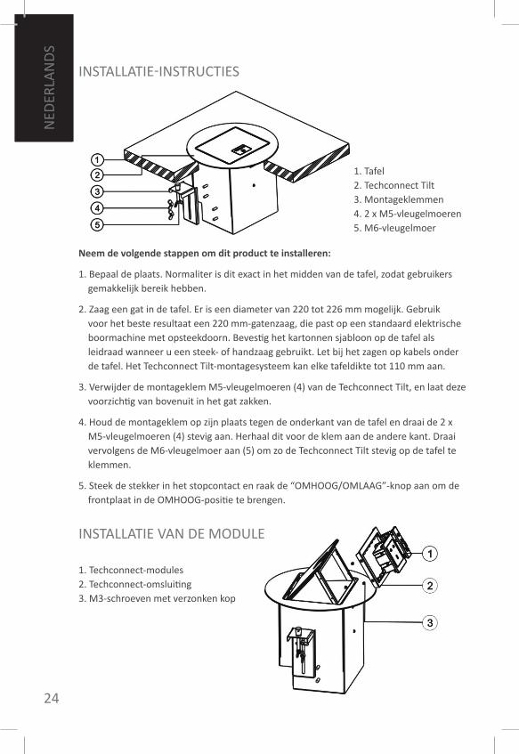
1. Tafel2. Techconnect Tilt3. montageklemmen4. 2 x m5-vleugelmoeren5. m6-vleugelmoer
1. Techconnect-modules2. Techconnect-omsluiting3. m3-schroeven met verzonken kop
INSTALLATIE VAN DE moDULE
ENG
LISH
25
NED
ERLAN
DS
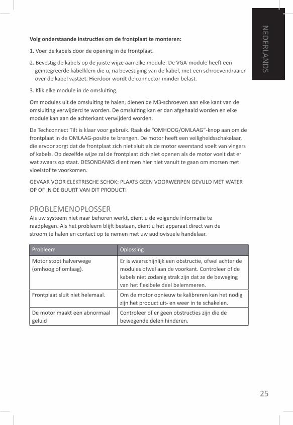
Volg onderstaande instructies om de frontplaat te monteren:
1. Voer de kabels door de opening in de frontplaat.
2. Bevestig de kabels op de juiste wijze aan elke module. De VGA-module heeft een geïntegreerde kabelklem die u, na bevestiging van de kabel, met een schroevendraaier over de kabel vastzet. Hierdoor wordt de connector minder belast.
3. klik elke module in de omsluiting.
om modules uit de omsluiting te halen, dienen de m3-schroeven aan elke kant van de omsluiting verwijderd te worden. De omsluiting kan er dan afgehaald worden en elke module kan aan de achterkant verwijderd worden.
De Techconnect Tilt is klaar voor gebruik. Raak de “omHooG/omLAAG”-knop aan om de frontplaat in de omLAAG-positie te brengen. De motor heeft een veiligheidsschakelaar, die ervoor zorgt dat de frontplaat zich niet sluit als de motor weerstand voelt van vingers of kabels. op dezelfde wijze zal de frontplaat zich niet openen als de motor voelt dat er wat zwaars op staat. DESoNDANkS dient men hier niet vanuit te gaan om morsen met vloeistof te voorkomen.
GEVAAR VooR ELEkTRISCHE SCHok: PLAATS GEEN VooRWERPEN GEVULD mET WATER oP of IN DE BUURT VAN DIT PRoDUCT!
PRoBLEmENoPLoSSERAls uw systeem niet naar behoren werkt, dient u de volgende informatie te raadplegen. Als het probleem blijft bestaan, dient u het apparaat direct van de stroom te halen en contact op te nemen met uw audiovisuele handelaar.
Probleem oplossing
motor stopt halverwege (omhoog of omlaag).
Er is waarschijnlijk een obstructie, ofwel achter de modules ofwel aan de voorkant. Controleer of de kabels niet zodanig strak zijn dat ze de beweging van het flexibele deel belemmeren.
frontplaat sluit niet helemaal. om de motor opnieuw te kalibreren kan het nodig zijn het product uit- en weer in te schakelen.
De motor maakt een abnormaal geluid
Controleer of er geen obstructies zijn die de bewegende delen hinderen.
26
ENG
LISH
NED
ERLA
ND
S
GARANTIEDit product heeft een teruggeefgarantie van 2 jaar beginnend op de dag van aankoop.Deze garantie is alleen geldig voor de koper en kan niet worden overgedragen. om enige twijfel te voorkomen, zal deze informatie niet voorkomen op de informatie van de aangewezen nationale distributeur op het verkooppunt. Als het product kapot blijkt te zijn en niet meer gerepareerd kan worden, heeft u 21 dagen vanaf de dag van aankoop de tijd om de nationale distributeur via uw audiovisuele handelaar op de hoogte te stellen.De aansprakelijkheid van de fabrikant en diens aangewezen servicebedrijf is beperkt tot de reparatiekosten en/of vervanging van het gebreken vertonende deel waarvoor deze garantie geldt, behalve in geval van overlijden of letsel (EU85/374/EEC).Deze garantie beschermt u tegen:• fouten in de onderdelen, waaronder de stroomtoevoer.• Wanneer het product beschadigd uit de verpakking komt, dient dit binnen 24 uur na
aankoop te worden gemeld.Indien u toch een probleem met dit product ondervindt, dient u contact op te nemen met de audiovisuele verkoper bij wie u dit product kocht. De koper is verantwoordelijk voor het transport van het product naar het reparerende servic centre aangewezen door de fabrikant.We proberen de gerepareerde onderdelen binnen 5 werkdagen terug te sturen. Dit is echter niet altijd mogelijk. In zo’n geval sturen wij het gerepareerde onderdeel zo snel als de praktijk dat toelaat terug. overeenkomstig onze WEEE-verplichtingen probeert de fabrikant foutieve onderdelen van het product in plaats van het hele product te vervangen.Deze garantie is ongeldig bij gebreken veroorzaakt door misbruik, verkeerd gebruik of incorrecte installatie die veroorzaakt kunnen zijn door het niet nakomen van de richtlijnen in deze handleiding.
SPECIfICATIESVoeding: 100-240V, output 12VDC, • 1000mA, 12Wmotorstroom en draaimoment: omhoog: • 0,7A, 30n / omlaag: 0,45A, 20nmateriaal frontplaat: gepolijst zwart • aluminiumUitsnijding diameter bereik: 220-226 mm• Buitendiameter: 240 mm• Afmetingen: 164 x 145 x 200 (lengte x • breedte x hoogte)Gewicht: 3,7 kg• kleur: zwart•
• Afmetingen: 71 x 42 x 40mm• Gewicht: 63g• kleur: Wit
Let op: omdat we onze producten continu willen verbeteren, kan bovenstaande informatie zich zonder voorafgaande waarschuwing wijzigen.
BIJGESLoTEN ACCESSoIRES1 x Euro IEC-kabel 1,8 m lang• 1 x Uk IEC-kabel 1,8 m lang• 1 x zaagsjabloon• 2 x montageoren• 1 x Uk powermodule met IEC-kabel• 1 x EU powermodule met IEC-kabel• 2 x VGAf3.5mm-module• 1 x RJ45-ethernetmodule• 1 x Twin-RJ45-module• 1 x blanco module•
ENG
LISH
27
DEU
TSCHE
koNfoRmITÄT Das in diesem Besitzerhandbuch beschriebene Produkt stimmt mit den Normen zur Beschränkung der Verwendung bestimmter gefährlicher Stoffe in Elektro- und Elektronikgeräten (RoHS) (EU-Richtlinie 2002/95/EC) und den WEEE (EU-Richtlinie 2002/96/EC) überein. zertifikate sowie SGS-Berichte sind auf Anfrage erhältlich. Dieses Produkt sollte am Ende seiner Gebrauchsdauer an den ort des kaufs zur Wiederverwertung zurückgebracht werden.
BeSITZeRhAndBUch TechconnecT TILTHerzlichen Glückwunsch zu Ihrer Wahl der Vision Techconnect Tilt. Um die beste Leistung zu erzielen, sollten Sie diese Bedienungsanleitung lesen und das Produkt nur entsprechend den Anweisungen verwenden. Eine elektronische Ausgabe dieses Handbuchs sowie weitere Informationen finden Sie unter www.visionaudiovisual.com.
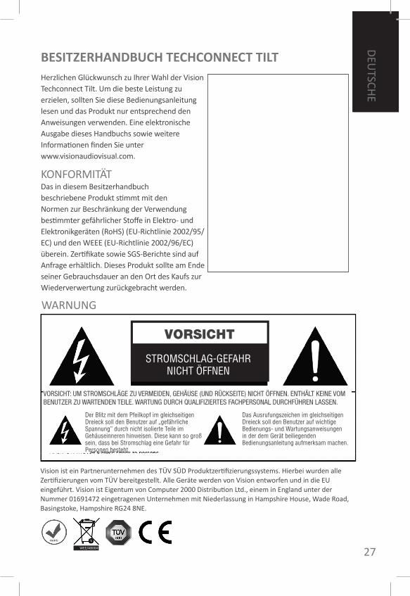
Der Blitz mit dem Pfeilkopf im gleichseitigen Dreieck soll den Benutzer auf „gefährliche Spannung” durch nicht isolierte Teile im Gehäuseinneren hinweisen. Diese kann so groß sein, dass bei Stromschlag eine Gefahr für Personen besteht.
Das Ausrufungszeichen im gleichseitigen Dreieck soll den Benutzer auf wichtige Bedienungs- und Wartungsanweisungen in der dem Gerät beiliegenden Bedienungsanleitung aufmerksam machen.
VOrsIchT
STROmSCHLAG-GEfAHRNICHT öffNEN
Vision ist ein Partnerunternehmen des TÜV SÜD Produktzertifizierungssystems. Hierbei wurden alle zertifizierungen vom TÜV bereitgestellt. Alle Geräte werden von Vision entworfen und in die EU eingeführt. Vision ist Eigentum von Computer 2000 Distribution Ltd., einem in England unter der Nummer 01691472 eingetragenen Unternehmen mit Niederlassung in Hampshire House, Wade Road, Basingstoke, Hampshire RG24 8NE.
WEE/AB0047SY
VORSICHT: UM STROMSCHLÄGE ZU VERMEIDEN, GEHÄUSE (UND RÜCKSEITE) NICHT ÖFFNEN. ENTHÄLT KEINE VOM BENUTZER ZU WARTENDEN TEILE. WARTUNG DURCH QUALIFIZIERTES FACHPERSONAL DURCHFÜHREN LASSEN.
WARNUNG
28
ENG
LISH
DEU
TSCH
E AUSSCHLIESSLICH HAUSHALTSÜBLICHE STECkDoSEN BENUTzENBeim Anschließen des Gerätes an einen Stromanschluss mit höherer Spannung besteht feuergefahr.
SoRGSAmER UmGANG mIT DEm NETzkABELziehen Sie den Netzstecker nicht aus der Steckdose, indem Sie am Netzkabel ziehen! Immer den Stecker selbst ziehen. Durch das ziehen am kabel kann selbiges beschädigt werden. falls Sie beabsichtigen, das Gerät für längere zeit nicht zu betreiben, ziehen Sie den Netzstecker aus der Steckdose. Stellen Sie keine möbelstücke oder andere schwere Gegenstände auf das Netzkabel und vermeiden Sie nach möglichkeit, schwere Gegenstände darauf fallen zu lassen. machen Sie keine knoten in das Netzkabel. Dies könnte nicht nur eine Beschädigung des kabels zur folge haben, sondern auch zu einem kurzschluss und somit feuer führen.
AUfSTELLUNGSoRTVermeiden Sie eine Installation des Geräts unter folgenden Bedingungen:• feuchte oder nasse orte• orte, die direktem Sonnenlicht ausgesetzt sind oder sich in der Nähe von Heizkörpern
befinden• Extrem kalte orte• Staubige orte oder solche, die starken Vibrationen ausgesetzt sind• Schlecht belüftete orte
Setzen Sie das Gerät keinen tropfenden oder spritzenden flüssigkeiten aus. STELLEN SIE kEINERLEI mIT fLÜSSIGkEITEN GEfÜLLTE GEGENSTÄNDE AUf oDER NAHE DEm GERÄT AB!
TRANSPoRTIEREN DES GERÄTESStellen Sie vor dem Transportieren des Gerätes sicher, dass Sie den Netzstecker aus der Steckdose gezogen und die Verbindung mit anderen Geräten gelöst haben.
WARNSIGNALEWenn Sie einen ungewöhnlichen Geruch oder Rauchentwicklung bemerken, schalten Sie das Gerät umgehend aus und ziehen Sie den Netzstecker. Setzen Sie sich mit Ihrem Händler oder Vision in Verbindung.
VERPACkUNGHeben Sie alle Verpackungsmaterialien auf. Sie werden zum Versand des Gerätes im Reparaturfall gebraucht. fALLS zUR RÜCkSENDUNG DES GERÄTES AN DEN kUNDENDIENST NICHT DIE oRIGINALVERPACkUNG VERWENDET WIRD, SIND ETWAIGE TRANSPoRTSCHÄDEN NICHT DURCH DIE GARANTIE ABGEDECkT

ENG
LISH
29
DEU
TSCHE
1. kabel-management-klemme2. motorsteuerungsbuchse3. 220 V AC Steckdose (versorgt das
modul auf der Abdeckung mit Durchschleifstrom)
4. 220 V AC Eingangssteckdose5. NACH oBEN/UNTEN -
berührungsempfindliche Taste6. Abdeckung
ABBILDUNG: DAS GEHÄUSE
30
ENG
LISH
DEU
TSCH
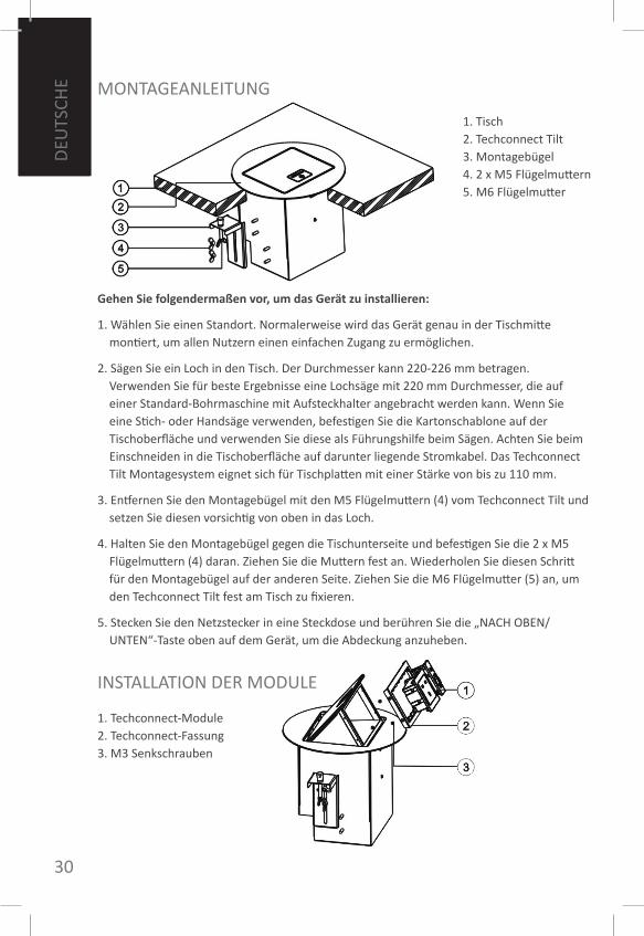
E moNTAGEANLEITUNG
Gehen Sie folgendermaßen vor, um das Gerät zu installieren:
1. Wählen Sie einen Standort. Normalerweise wird das Gerät genau in der Tischmitte montiert, um allen Nutzern einen einfachen zugang zu ermöglichen.
2. Sägen Sie ein Loch in den Tisch. Der Durchmesser kann 220-226 mm betragen. Verwenden Sie für beste Ergebnisse eine Lochsäge mit 220 mm Durchmesser, die auf einer Standard-Bohrmaschine mit Aufsteckhalter angebracht werden kann. Wenn Sie eine Stich- oder Handsäge verwenden, befestigen Sie die kartonschablone auf der Tischoberfläche und verwenden Sie diese als führungshilfe beim Sägen. Achten Sie beim Einschneiden in die Tischoberfläche auf darunter liegende Stromkabel. Das Techconnect Tilt montagesystem eignet sich für Tischplatten mit einer Stärke von bis zu 110 mm.
3. Entfernen Sie den montagebügel mit den m5 flügelmuttern (4) vom Techconnect Tilt und setzen Sie diesen vorsichtig von oben in das Loch.
4. Halten Sie den montagebügel gegen die Tischunterseite und befestigen Sie die 2 x m5 flügelmuttern (4) daran. ziehen Sie die muttern fest an. Wiederholen Sie diesen Schritt für den montagebügel auf der anderen Seite. ziehen Sie die m6 flügelmutter (5) an, um den Techconnect Tilt fest am Tisch zu fixieren.
5. Stecken Sie den Netzstecker in eine Steckdose und berühren Sie die „NACH oBEN/UNTEN“-Taste oben auf dem Gerät, um die Abdeckung anzuheben.
1. Tisch2. Techconnect Tilt3. montagebügel4. 2 x m5 flügelmuttern5. m6 flügelmutter
1. Techconnect-module2. Techconnect-fassung3. m3 Senkschrauben
INSTALLATIoN DER moDULE
ENG
LISH
31
DEU
TSCHE
Gehen Sie folgendermaßen vor, um die Abdeckung zu montieren:
1. ziehen Sie die kabel durch die Öffnung in der Abdeckung nach oben.
2. Schließen Sie die kabel nach Wunsch an den einzelnen modulen an. Das VGA-modul hat eine integrierte kabel-management-klemme. Befestigen Sie nach dem Anschließen die klemme mit einem Schraubenzieher auf dem kabel. Auf diese Weise werden Belastungen an den Phoenix-Anschlussstellen reduziert.
3. Stecken Sie alle module in die fassung.
Um die module aus der fassung zu nehmen, müssen die m3 Schrauben auf beiden Seiten der fassung entfernt werden. Dann können die fassung entnommen und alle module von hinten herausgedrückt werden.
Der Techconnect Tilt ist jetzt betriebsbereit. Berühren Sie die „NACH oBEN/UNTEN“-Taste oben auf dem Gerät, um die Abdeckung zu senken. Der motor verfügt über einen Sicherheitsschalter, der das Herabsenken der Abdeckung verhindert, wenn finger oder kabel einen Widerstand für den motor darstellen. Befindet sich ein schwerer Gegenstand auf der Abdeckung, erkennt der motor das Gewicht und verhindert ein Anheben der Abdeckung. Dieser mechanismus sollte allerdings nicht zum Schutz gegen auslaufende flüssigkeiten verwendet werden.
ERNSTHAfTE STRomSCHLAGGEfAHR: STELLEN SIE kEINE mIT fLÜSSIGkEITEN GEfÜLLTEN GEGENSTÄNDE AUf oDER NAHE DEm GERÄT AB!
fEHLERBEHEBUNGfalls Ihre Anlage nicht ordnungsgemäß funktioniert, nehmen Sie bitte die folgenden Informationen zu Hilfe. falls das Problem sich nicht beheben lässt, Stromstecker ziehen und unverzüglich den AV-Vertragshändler, bei dem der Verstärker gekauft wurde, kontaktieren.
1. Tisch2. Techconnect Tilt3. montagebügel4. 2 x m5 flügelmuttern5. m6 flügelmutter
Problem Behebung
Der motor bleibt auf halbem Weg stehen.
Wahrscheinlich befindet sich hinter oder vor den modulen ein Hindernis. Stellen Sie sicher, dass die kabel nicht zu stark gestrafft sind und die Bewegung des beweglichen Teils einschränken.
Die Abdeckung schließt sich nicht vollständig.
Um den motor neu zu kalibrieren, müssen Sie gegebenenfalls die Stromzufuhr des Geräts aus- und wieder einschalten.
Der motor macht ungewöhnliche Geräusche.
Stellen Sie sicher, dass die Bewegung der beweglichen Teile nicht durch Hindernisse eingeschränkt wird.
32
ENG
LISH
DEU
TSCH
E
GARANTIEDieses Produkt wird mit einer 2-jährigen Werksgarantie geliefert, die ab dem kaufdatum gültig ist. Diese Garantie gilt nur für den ursprünglichen käufer und ist nicht übertragbar. Um zweifel zu beseitigen, ist dies den Informationen seitens des autorisierten nationalen Händlers am Verkaufsort zu entnehmen. falls das Produkt bereits beim kauf defekt ist, ist innerhalb von 21 Tagen ab kaufdatum der nationale Vertragshändler über Ihren AV-Händler in kenntnis zu setzen. Die Haftung des Herstellers und seiner autorisierten Dienstleistungsgesellschaft ist auf die kosten für die Reparatur und den Austausch des fehlerhaften Geräts, für das Garantie besteht, beschränkt, mit Ausnahme des Todes oder einer Verletzung (EU85/374/EEC).Diese Haftung schützt Sie gegen folgendes: • Ausfall jeglicher Bauteile, einschließlich des Netzteils.• Beschädigung, wenn das Gerät erstmalig der Verpackung entnommen wird,
vorausgesetzt, dies wird innerhalb von 24 Stunden nach dem kauf gemeldet.falls Probleme mit diesem Produkt vorliegen, sollten Sie sich an den Gerätehändler, bei welchem Sie dieses Produkt erstanden haben, wenden. Der ursprüngliche käufer ist für die Versendung des Produktes an den vom Hersteller genannten Reparaturdienst zuständig. Wir streben an, Reparatur und Versand der Geräte innerhalb von 5 Arbeitstagen abzuwickeln. Dies ist jedoch nicht immer möglich. In solchen fällen wird das Gerät so schnell wie möglich zurückgesandt. In Übereinstimmung mit den WEEE-Verpflichtungen strebt der Hersteller an, die fehlerhaften Teile des Produkts auszutauschen, anstatt das gesamte Gerät zu ersetzen. Diese Garantie schützt das Produkt nicht bei fehlern durch missbrauch, falsche Installation bzw. unregelmäßige oder fehlerhafte Stromzufuhr, welche auf Nichtbeachten der Richtlinien dieser Anleitung zurückzuführen sein könnten.
SPEzIfIkATIoNENStromversorgung: 100-240 V, Ausgang 12 • V DC, 1000 mA, 12 WStrom- und Drehmoment des motors: • beim Anheben: 0,7 A, 30 n / beim Absenken: 0,45 A, 20 noberflächenmaterial: Poliertes schwarzes • AluminiumDurchmesserbereich des Ausschnitts: • 220-226 mmÄußerer Durchmesser: 240 mm• Abmessungen: 164 x 145 x 200 (Länge x • Breite x Höhe)Gewicht: 3,7 kg• farbe: Schwarz•
hinweis: Da wir ständig an der Verbesserung unserer Geräte arbeiten, können diese Angaben ohne vorherige Benachrichtigung geändert werden.
mITGELIEfERTES zUBEHÖR1 x EU IEC-Stromkabel mit 1,8 m Länge• 1 x Uk IEC-Stromkabel mit 1,8 m Länge• 1 x Sägeschablone• 2 x Befestigungsklammern• 1 x Uk-Netzteil mit IEC-Stromkabel• 1 x EU-Netzteil mit IEC-Stromkabel• 2 x VGA f3.5mm module• 1 x RJ45 Ethernet-modul• 1 x Twin-RJ45 modul• 1 x Leeres modul•
ENG
LISH
33
ITALIA
NO
AVVERTENzE
TechconnecT TILT MAnUALe deL PRoPRIeTARIoCongratulazioni per aver scelto Techconnect Tilt di Vision. Per ottenere la migliore prestazione, leggere questo manuale e usare il prodotto secondo le istruzioni.E’ possibile trovare una versione elettronica di questo manuale e ulteriori informazioni su www.visionaudiovisual.com
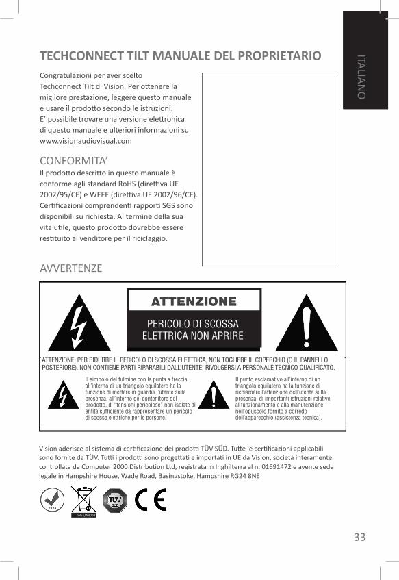
Il simbolo del fulmine con la punta a freccia all’interno di un triangolo equilatero ha la funzione di mettere in guardia l’utente sulla presenza, all’interno del contenitore del prodotto, di “tensioni pericolose” non isolate di entità sufficiente da rappresentare un pericolo di scosse elettriche per le persone.
Il punto esclamativo all’interno di un triangolo equilatero ha la funzione di richiamare l’attenzione dell’utente sulla presenza di importanti istruzioni relative al funzionamento e alla manutenzione nell’opuscolo fornito a corredo dell’apparecchio (assistenza tecnica).
ATTENzIONE
PERICOLO DI SCOSSA ELETTRICA NON APRIRE
CoNfoRmITA’Il prodotto descritto in questo manuale è conforme agli standard RoHS (direttiva UE 2002/95/CE) e WEEE (direttiva UE 2002/96/CE). Certificazioni comprendenti rapporti SGS sono disponibili su richiesta. Al termine della sua vita utile, questo prodotto dovrebbe essere restituito al venditore per il riciclaggio.
Vision aderisce al sistema di certificazione dei prodotti TÜV SÜD. Tutte le certificazioni applicabili sono fornite da TÜV. Tutti i prodotti sono progettati e importati in UE da Vision, società interamente controllata da Computer 2000 Distribution Ltd, registrata in Inghilterra al n. 01691472 e avente sede legale in Hampshire House, Wade Road, Basingstoke, Hampshire RG24 8NE
WEE/AB0047SY
ATTENZIONE: PER RIDURRE IL PERICOLO DI SCOSSA ELETTRICA, NON TOGLIERE IL COPERCHIO (O IL PANNELLO POSTERIORE). NON CONTIENE PARTI RIPARABILI DALL’UTENTE; RIVOLGERSI A PERSONALE TECNICO QUALIFICATO.
34
ENG
LISH
ITA
LIA
NO USARE SoLo PRESE AC DomESTICHE
Collegare l’unità a una presa di corrente con un voltaggio superiore potrebbe provocare incendi.
mANEGGIARE CoN CURA IL CAVo DI ALImENTAzIoNENon staccare la spina dalla presa AC tirando il cavo; tirare sempre la spina stessa.Tirare il cavo potrebbe danneggiarlo. In caso di inutilizzo prolungato dell’unità, staccare la spina. Non collocare mobili o altri oggetti pesanti sul cavo ed evitare di farvi cadere oggetti pesanti. Non annodare il cavo di alimentazione. Non solo potrebbe danneggiarsi il cavo, ma potrebbe anche essere provocato un cortocircuito con conseguente rischio di incendio.
LUoGo DI INSTALLAzIoNEInstallare l’apparecchio rispettando le seguenti raccomandazioni:• Luoghi bagnati o umidi• Luoghi esposti alla luce solare diretta o vicino a fonti di calore• Luoghi estremamente freddi• Luoghi soggetti a vibrazioni eccessive o polvere• Luoghi poco ventilati
Evitare luoghi soggetti a formazione di condensa o in cui l’apparecchio possa venire a contatto con schizzi di liquidi. NoN CoLLoCARE SULL’APPARECCHIo o NELLE ImmEDIATE VICINANzE oGGETTI CoNTENENTI LIQUIDI!
SPoSTARE L’UNITA’Prima di spostare l’unità, assicurarsi di togliere il cavo di alimentazione dalla presa AC e di scollegare i cavi di interconnessione con altri apparecchi.
SEGNALI DI PERICoLoIn presenza di odori anomali o fumo, spegnere immediatamente l’apparecchio e staccare il cavo di alimentazione. Contattare il proprio rivenditore o Vision.
IMBALLAGGIOConservare tutto il materiale di imballaggio. E’ fondamentale per la spedizione in caso di riparazione dell’unità.IN CASo DI mANCATo UTILIzzo DELL’ImBALLAGGIo oRIGINALE PER LA RESTITUzIoNE DELL’UNITA’ AL CENTRo ASSISTENzA, I DANNI VERIfICATISI DURANTE IL VIAGGIo NoN SARANNo CoPERTI DA GARANzIA.
ENG
LISH
35
ITALIA
NO
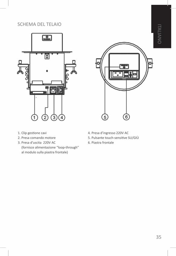
1. Clip gestione cavi2. Presa comando motore3. Presa d’uscita 220V AC
(fornisce alimentazione “loop-through” al modulo sulla piastra frontale)
4. Presa d’ingresso 220V AC5. Pulsante touch-sensitive SU/GIÙ6. Piastra frontale
SCHEmA DEL TELAIo
36
ENG
LISH
ITA
LIA
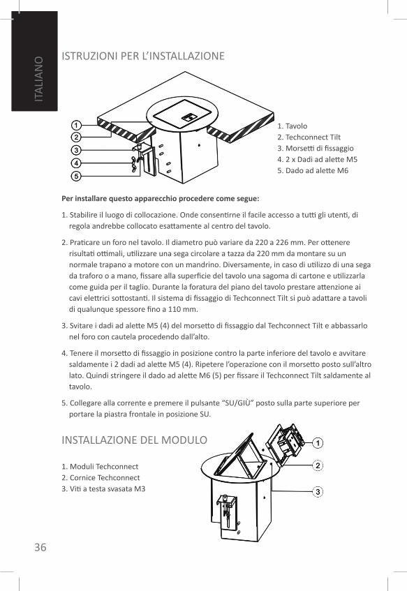
NO ISTRUzIoNI PER L’INSTALLAzIoNE
Per installare questo apparecchio procedere come segue:
1. Stabilire il luogo di collocazione. onde consentirne il facile accesso a tutti gli utenti, di regola andrebbe collocato esattamente al centro del tavolo.
2. Praticare un foro nel tavolo. Il diametro può variare da 220 a 226 mm. Per ottenere risultati ottimali, utilizzare una sega circolare a tazza da 220 mm da montare su un normale trapano a motore con un mandrino. Diversamente, in caso di utilizzo di una sega da traforo o a mano, fissare alla superficie del tavolo una sagoma di cartone e utilizzarla come guida per il taglio. Durante la foratura del piano del tavolo prestare attenzione ai cavi elettrici sottostanti. Il sistema di fissaggio di Techconnect Tilt si può adattare a tavoli di qualunque spessore fino a 110 mm.
3. Svitare i dadi ad alette m5 (4) del morsetto di fissaggio dal Techconnect Tilt e abbassarlo nel foro con cautela procedendo dall’alto.
4. Tenere il morsetto di fissaggio in posizione contro la parte inferiore del tavolo e avvitare saldamente i 2 dadi ad alette m5 (4). Ripetere l’operazione con il morsetto posto sull’altro lato. Quindi stringere il dado ad alette m6 (5) per fissare il Techconnect Tilt saldamente al tavolo.
5. Collegare alla corrente e premere il pulsante “SU/GIÙ” posto sulla parte superiore per portare la piastra frontale in posizione SU.
1. Tavolo2. Techconnect Tilt3. morsetti di fissaggio4. 2 x Dadi ad alette m55. Dado ad alette m6
1. moduli Techconnect2. Cornice Techconnect3. Viti a testa svasata m3
INSTALLAzIoNE DEL moDULo
ENG
LISH
37
ITALIA
NO
Per montare la piastra frontale procedere come segue:
1. far scorrere i cavi verso l’alto attraverso l’apertura nella piastra frontale.
2. Collegare i cavi a ciascun modulo come da necessità. Il modulo VGA dispone di un sistema per la gestione dei cavi integrato da fissare, dopo aver collegato il cavo, con un cacciavite. In questo modo si eliminano le sollecitazioni nei punti di giunzione.
3. fissare ogni modulo nella cornice.
Per separare i moduli dalla cornice, svitare le viti m3 poste su ciascun lato della cornice stessa. In questo modo la cornice può essere rimossa e ogni modulo separato agendo dal retro.
Il Techconnect Tilt è pronto per l’uso. Premere il pulsante “SU/GIÙ” posto sulla parte superiore per portare la piastra frontale in posizione GIÙ. Il motore dispone di un interruttore di sicurezza che impedisce la chiusura della piastra nel caso il motore incontri la resistenza di dita o cavi. Allo stesso modo, in presenza di un oggetto pesante sulla piastra frontale, il motore ne avverte il peso e non la apre. IN oGNI CASo non fare affidamento su tale funzione per evitare il rovesciamento di liquidi.
SERIo PERICoLo DI SCoSSA ELETTRICA: NoN CoLLoCARE SULL’APPARECCHIo o NELLE ImmEDIATE VICINANzE oGGETTI CoNTENENTI LIQUIDI!
RICERCA ED_ELImINAzIoNE GUASTIIn caso di malfunzionamento del sistema, consultare le seguenti informazioni.Se il problema persiste, staccare dalla presa di corrente e contattare immediatamente il proprio rivenditore di AV.
Problema Cosa fare
Il motore si ferma a metà strada verso l’alto o il basso.
Probabile ostacolo sotto i moduli o davanti agli stessi. Verificare che i cavi non siano eccessivamente tesi impedendo i movimenti della parte mobile.
La piastra frontale non si chiude completamente.
Per ricalibrare il motore potrebbe essere necessario staccare e riattaccare la corrente all'apparecchio.
Il motore emette un rumore anomalo.
Controllare che non vi siano ostacoli che impediscono il libero movimento delle parti mobili.
38
ENG
LISH
ITA
LIA
NO
GARANZIAQuesto prodotto è dotato di una garanzia return to base di 2 anni, valida dalla data di acquisto. Questa garanzia è valida solo per il primo acquirente e non è trasferibile. Allo scopo di evitare qualsiasi dubbio, questi è colui che risulta dalle informazioni raccolte presso il punto vendita dal distributore nazionale assegnato.Se il prodotto è DoA (dead on arrival: non funzionante alla consegna), l’acquirente ha a disposizione 21 giorni dalla data di acquisto per informare il distributore nazionale tramite il proprio rivenditore di AV. La responsabilità del produttore e della società di assistenza assegnata è limitata al costo della riparazione e/o della sostituzione dell’unità difettosa in garanzia, salvo i casi di morte o lesione (UE 85/374/CEE).Questa garanzia tutela l’utente contro quanto segue:• Il guasto di qualsiasi componente, compreso l’alimentatore.• I danni riscontrati quando il prodotto è disimballato per la prima volta, se segnalati entro
24 ore dall’acquisto.Qualora si ritenga di avere un problema con questo prodotto, contattare il rivenditore di AV presso cui è stato effettuato l’acquisto. Il primo acquirente è responsabile della spedizione del prodotto al centro assistenza del produttore per la riparazione.Sarà compiuto ogni sforzo per restituire le unità riparate entro 5 giorni lavorativi, se ciò non fosse possibile la restituzione avverrà al più presto. In conformità con gli obblighi imposti dalla direttiva WEEE, il produttore farà il possibile per sostituire le parti difettose del prodotto invece di sostituire l’intera unità. Questa garanzia non protegge il prodotto contro i guasti provocati da abuso, uso improprio, installazione non corretta o alimentazione di corrente instabile o difettosa, che possano essere causati dalla mancata conoscenza delle linee guida riportate in questo manuale.
SPECIfICHEAlimentazione: • 100-240V, Uscita 12VDC, 1000mA, 12WCorrente e coppia del motore: in salita: • 0,7A, 30n / in discesa: 0,45A, 20nmateriale della parte superiore: • alluminio nero lucidoRange diametro sagoma: 220-226 mm• Diametro esterno: 240 mm• Dimensioni dell’apparecchio: • 164 x 145 x 200 (lato x lato x altezza)Peso dell’apparecchio: 3,7kg• Colore: nero•
nB: Siamo costantemente impegnati a migliorare i nostri prodotti, pertanto i dati suindicati potrebbero subire variazioni senza preavviso.
ACCESSoRI IN DoTAzIoNE1 x Cavo di alimentazione IEC Euro, • lunghezza 1,8 m1 x Cavo di alimentazione IEC Uk , • lunghezza 1,8 m1 x Sagoma modello• 2 x Alette di fissaggio• 1 x modulo di alimentazione per il Regno • Unito con cavo di alimentazione IEC1 x modulo di alimentazione per l’UE con • cavo di alimentazione IEC2 x moduli VGAf3.5mm• 1 x modulo Ethernet RJ45• 1 x modulo Twin-RJ45• 1 x modulo vuoto•
ENG
LISH
39
PoLSkI
TILT TECHCONNECT: INSTRUKCJA OBSŁUGIGratulujemy wyboru Tilt Vision Techconnect. Aby móc w pełni wykorzystać możliwości tego produktu, należy koniecznie przeczytać niniejszą instrukcję obsługi i używać go wyłącznie zgodnie z zawartymi w niej zaleceniami. Elektroniczna wersja tej instrukcji i inne informacje są dostępne pod adresem www.visionaudiovisual.com
oSTRzEŻENIA
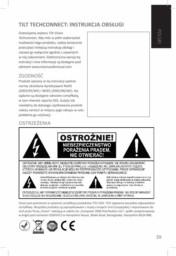
zGoDNoŚĆProdukt opisany w tej instrukcji spełnia normy określone dyrektywami RoHS (2002/95/WE) i WEEE (2002/96/WE). Na żądanie są dostępne odnośne certyfikaty, w tym również raporty SGS. zużyty lub niezdatny do dalszego użytkowania produkt należy zwrócić w miejscu jego zakupu w celu poddania go utylizacji.
Vision jest partnerem w systemie certyfikacji produktów TÜV SÜD. TÜV zapewnia wszystkie odpowiednie certyfikaty. Wszystkie produkty są zaprojektowane z myślą o krajach Unii Europejskiej i importowane do nich przez firmę „Vision” należącą w całości do „Computer 2000 Distribution Ltd.”, spółki zarejestrowanej w Anglii pod numerem 01691472 w Hampshire House, Wade Road, Basingstoke, Hampshire RG24 8NE.
WEE/AB0047SY

40
ENG
LISH
PoLS
kI
PRoDUkT PoDŁĄCzAJ WYŁĄCzNIE Do DomoWYCH GNIAz-DEk zASILAJĄCYCH Podłączenie urządzenia do gniazda zasilającego o wyższym napięciu grozi pożarem.
oSTRoŻNIE oBCHoDŹ SIĘ z PRzEWoDEm zASILAJĄCYmNie wolno odłączać urządzenia od gniazdka, ciągnąc za przewód: należy chwycić i pociągnąć za wtyczkę. Ciągnięcie za przewód grozi jego uszkodzeniem. Jeżeli urządzenie ma nie być używane przez dłuższy czas, należy wyjąć wtyczkę przewodu zasilającego z gniazdka. Nie wolno ustawiać na przewodzie zasilającym mebli ani żadnych innych, ciężkich przedmiotów. Należy też uważać, aby nie upuścić takiego przedmiotu na przewód. Nie wolno wiązać przewodu zasilającego. Grozi to nie tylko jego uszkodzeniem, ale także zwarciem i — w efekcie — pożarem.
WYBóR mIEJSCA INSTALACJINależy unikać montażu tego urządzenia w następujących warunkach:• w miejscach mokrych lub wilgotnych,• w miejscach wystawionych na bezpośrednie działanie promieni słonecznych ani w pobliżu urządzeń grzewczych,• w miejscach o bardzo niskiej temperaturze,• w miejscach, w których byłoby poddawane nadmiernym wibracjom lub silnemu zapyleniu,• w miejscach mało przewiewnych.
Nie wolno narażać urządzenia na działanie kapiących lub rozpryskujących się substancji. NIE UmIESzCzAĆ PRzEDmIoTóW WYPEŁNIoNYCH PŁYNEm NA URzĄDzENIU ANI W JEGo PoBLIŻU!
PRzEmIESzCzANIE URzĄDzENIAPrzed przeniesieniem urządzenia w inne miejsce, należy koniecznie odłączyć przewód zasilający od gniazdka elektrycznego oraz odłączyć od niego przewody łączące go z innymi urządzeniami.
SYmPTomY oSTRzEGAWCzEW przypadku stwierdzenia nienaturalnego zapachu lub dymu należy natychmiast wyłączyć urządzenie i wyjąć przewód elektryczny z gniazda. Skontaktować się ze sprzedawcą lub firmą Vision.
oPAkoWANIENależy zachować wszystkie materiały, jakie zostały fabrycznie użyte do opakowania produktu. Będą one potrzebne w przypadku, gdyby wymagał on kiedykolwiek przesłania do naprawyGWARANCJA NIE oBEJmUJE USzkoDzEŃ PRoDUkTU PoWSTAŁYCH W TRANSPoRCIE, JEŻELI W CELU JEGo PRzESŁANIA Do CENTRUm SERWISoWEGo UŻYTo INNEGo oPAkoWANIA NIŻ oRYGINALNE.

ENG
LISH
41
PoLSkI
1. zacisk kablowy2. Gniazdo sterowania silnika3. Gniazdo wyjściowe prądu zmiennego 220 V
(zapewnia bezpośrednie zasilanie modułu na płycie czołowej)
4. Gniazdo wejściowe prądu zmiennego 220V5. Przycisk dotykowy UP/DoWN (GóRA/DóŁ)6. Płyta czołowa
SCHEmAT PoDSTAWY moNTAŻoWEJ
42
ENG
LISH
INSTRUkCJA moNTAŻU
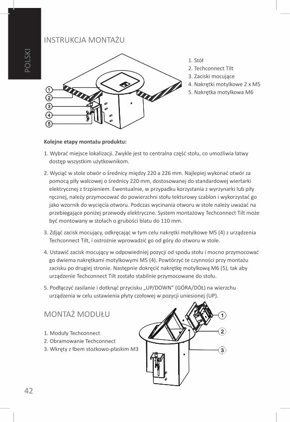
Kolejne etapy montażu produktu:
1. Wybrać miejsce lokalizacji. zwykle jest to centralna część stołu, co umożliwia łatwy dostęp wszystkim użytkownikom.
2. Wyciąć w stole otwór o średnicy między 220 a 226 mm. Najlepiej wykonać otwór za pomocą piły walcowej o średnicy 220 mm, dostosowanej do standardowej wiertarki elektrycznej z trzpieniem. Ewentualnie, w przypadku korzystania z wyrzynarki lub piły ręcznej, należy przymocować do powierzchni stołu tekturowy szablon i wykorzystać go jako wzornik do wycięcia otworu. Podczas wycinania otworu w stole należy uważać na przebiegające poniżej przewody elektryczne. System montażowy Techconnect Tilt może być montowany w stołach o grubości blatu do 110 mm.
3. zdjąć zacisk mocujący, odkręcając w tym celu nakrętki motylkowe m5 (4) z urządzenia Techconnect Tilt, i ostrożnie wprowadzić go od góry do otworu w stole.
4. Ustawić zacisk mocujący w odpowiedniej pozycji od spodu stołu i mocno przymocować go dwiema nakrętkami motylkowymi m5 (4). Powtórzyć te czynności przy montażu zacisku po drugiej stronie. Następnie dokręcić nakrętkę motylkową m6 (5), tak aby urządzenie Techconnect Tilt zostało stabilnie przymocowane do stołu.
5. Podłączyć zasilanie i dotknąć przycisku „UP/DoWN” (GóRA/DóŁ) na wierzchu urządzenia w celu ustawienia płyty czołowej w pozycji uniesionej (UP).
1. Stół2. Techconnect Tilt3. zaciski mocujące4. Nakrętki motylkowe 2 x m55. Nakrętka motylkowa m6
1. moduły Techconnect2. obramowanie Techconnect3. Wkręty z łbem stożkowo-płaskim m3
moNTAŻ moDUŁU
PoLS
kI
ENG
LISH
43
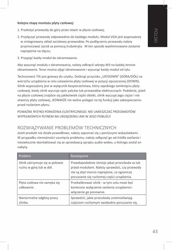
Kolejne etapy montażu płyty czołowej:
1. Przełożyć przewody do góry przez otwór w płycie czołowej.
2. Przyłączyć przewody odpowiednio do każdego modułu. moduł VGA jest wyposażony w zintegrowany układ zaciskowy przewodów. Po podłączeniu przewodu należy przymocować zacisk za pomocą śrubokręta. W ten sposób wyeliminowane zostanie naprężenie na złączu.
3. Przypiąć każdy moduł do obramowania.
Aby wysunąć moduły z obramowania, należy odkręcić wkręty m3 na każdej stronie obramowania. Teraz można zdjąć obramowanie i wysunąć każdy moduł od tyłu.
Techconnect Tilt jest gotowy do użytku. Dotknąć przycisku „UP/DoWN” (GóRA/DóŁ) na wierzchu urządzenia w celu ustawienia płyty czołowej w pozycji opuszczonej (DoWN). Silnik wyposażony jest w wyłącznik bezpieczeństwa, który zapobiega zamknięciu płyty czołowej, kiedy silnik wyczuje opór palców lub przewodów elektrycznych. Podobnie, jeżeli na płycie czołowej znajdzie się jakikolwiek ciężki obiekt, silnik wyczuje jego ciężar i nie otworzy płyty czołowej, JEDNAkŻE nie wolno polegać na tej funkcji jako zabezpieczeniu przed rozlaniem płynu.
PoWAŻNE RYzYko PoRAŻENIA ELEkTRYCzNEGo: NIE UmIESzCzAĆ PRzEDmIoTóW WYPEŁNIoNYCH PŁYNEm NA URzĄDzENIU ANI W JEGo PoBLIŻU!
RozWIĄzYWANIE PRoBLEmóW TECHNICzNYCHJeżeli produkt nie działa prawidłowo, należy zapoznać się z poniższymi wskazówkami. W przypadku niemożności usunięcia problemu, należy odłączyć go od źródła zasilania i niezwłocznie skontaktować się ze sprzedawcą sprzętu audio-wideo, u którego został on nabyty.
Problem Rozwiązanie
Silnik zatrzymuje się w połowie ruchu w górę lub w dół.
Prawdopodobnie istnieje jakaś przeszkoda za lub przed modułami. Należy sprawdzić, czy przewody nie są zbyt mocno naprężone, co ogranicza poruszanie się ruchomej części urządzenia.
Płyta czołowa nie zamyka się całkowicie.
Przekalibrować silnik - w tym celu może być konieczne wyłączenie zasilania urządzenia i włączenie go ponownie.
Nienormalne odgłosy pracy silnika.
Sprawdzić, jakie przeszkody uniemożliwiają częściom ruchomym swobodne poruszanie się.
PoLSkI
44
ENG
LISH
PoLS
kI
GWARANCJANiniejszy produkt jest objęty 2-letnią gwarancją typu Return to Base (naprawa w punkcie serwisowym), o okresie biegnącym od daty zakupu. Gwarancja ta przysługuje tylko pierwszemu nabywcy i jest nieprzenośna. W celu uniknięcia nieporozumień, tożsamość pierwszego nabywcy jest określana na podstawie ewidencji prowadzonej przez wyznaczonego dystrybutora w kraju zakupu produktu. W przypadku nabycia niesprawnego produktu, nabywca jest zobowiązany w ciągu 21 dni od daty zakupu powiadomić o tym fakcie dystrybutora krajowego za pośrednictwem sprzedawcy detalicznego. odpowiedzialność producenta i wyznaczonego przez niego dostawcy usług serwisowych jest ograniczona do wysokości kosztu naprawy lub wymiany wadliwego produktu na podstawie niniejszej gwarancji, za wyjątkiem przypadków poniesionej przez konsumenta śmierci lub obrażeń (dyrektywa 85/374/EWG). Niniejsza gwarancja chroni nabywcę w zakresie:• awarii dowolnego z elementów urządzenia, w tym zasilacza,• uszkodzeń stwierdzonych przy pierwszym rozpakowaniu produktu, o ile zostaną one
zgłoszone w ciągu 24 godzin od zakupu.W przypadku jakichkolwiek problemów z produktem należy skontaktować się ze sprzedawcą sprzętu audio-wideo, u którego został on nabyty. Pierwszy nabywca jest odpowiedzialny za przesłanie produktu do autoryzowanego przez producenta punktu serwisowego w celu dokonania naprawy.Producent dołoży starań, aby naprawiony produkt został zwrócony w ciągu 5 dni roboczych, może to jednak w niektórych przypadkach nie być wykonalne i jego zwrot nastąpi później, w najwcześniejszym możliwym terminie. Dążąc do realizacji wytycznych dyrektywy WEEE, producent preferuje naprawę przez wymianę wadliwych części produktu od wymiany całego urządzenia na nowe. Niniejsza gwarancja nie chroni konsumenta przed wadami produktu, spowodowanymi świadomym lub nieświadomym użyciem produktu niezgodnie z przeznaczeniem, bądź nieprawidłowo przeprowadzoną instalacją. Wady takie mogą wyniknąć z niezastosowania się do wytycznych zawartych w tej instrukcji.
DANE TECHNICzNEzasilanie: 100-240 V, wyjście prądu • stałego 12 V, 1000 mA, 12 WNatężenie prądu i moment obrotowy • silnika: podczas ruchu w górę - 0,7 A, 30 n / podczas ruchu w dół - 0,45 A, 20nmateriał powierzchni górnej: • polerowane czarne aluminiumzakres średnic wycięcia: 220-226 mm• Średnica zewnętrzna: 240 mm• Wymiary urządzenia: 164 x 145 x 200 • (bok x bok x wysokość)masa urządzenia: 3,7 kg• kolor: czarny•
Uwaga: w związku z nieustannym udoskonalaniem naszych produktów podane powyżej parametry mogą ulec zmianie bez uprzedzenia.
AkCESoRIA W zESTAWIE1 x kabel Euro IEC o długości 1,8 m• 1 x kabel Uk IEC o długości 1,8 m • 1 x szablon do wycinania otworu• 2 x zaczepy mocujące• 1 x moduł zasilania dla Wlk. Brytanii z • przewodem elektrycznym IEC1 x moduł zasilania dla krajów UE z • przewodem IEC2 x moduł VGAf3.5mm• 1 x moduł ethernet RJ45• 1 x moduł Twin-RJ45• 1 x pusty moduł•
ENG
LISH
45
PoRTU
GU
êS
MAnUAL de UTILIZAdoR do TechconnecT TILTParabéns por ter escolhido o Vision Techconnect Tilt. Para obter o melhor desempenho, leia este manual e utilize o seu produto apenas de acordo com as instruções apresentadas. Pode obter uma versão digital deste manual, assim como informações adicionais, em www.visionaudiovisual.com
AVISoS
CoNfoRmIDADEo produto descrito neste manual encontra-se em conformidade com as normas RoHS (Directiva UE 2002/95/CE) e WEEE(Directiva UE 2002/96/CE). os respectivos certificados, assim como os relatórios SGS, estão disponíveis mediante pedido. Este produto deve ser devolvido ao local de compra no fim da sua vida útil, para ser reciclado.
A Vision é um dos parceiros do sistema de certificação de produtos TÜV SÜD. Todas as certificações aplicáveis são fornecidas pela TÜV. Todos os produtos são concebidos e importados para a União Europeia pela ‘Vision’, propriedade integral da ‘Computer 2000 Distribution Ltd.’, registada em Inglaterra com o nº. 01691472 em Hampshire House, Wade Road, Basingstoke, Hampshire RG24 8NE
46
ENG
LISH
PoRT
UG
UêS
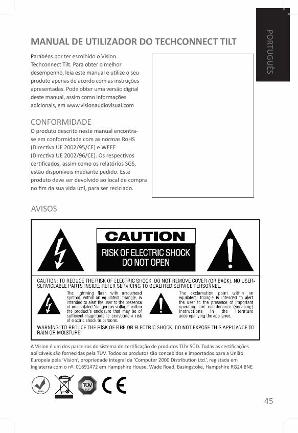
UTILIzAR APENAS TomADAS CA DomÉSTICAS Ligar a unidade a uma tomada com tensão superior pode criar o risco de incêndio.
mANUSEIE o CABo DE ALImENTAÇÃo Com CUIDADoNão desligue a ficha da tomada CA puxando o cabo. Puxe sempre a ficha. Puxar o cabo pode danificá-lo. Caso não pretenda utilizar a sua unidade durante um período considerável de tempo, desligue-a da tomada. Não coloque mobília ou outros objectos pesados sobre o cabo e evite que objectos pesados caiam sobre o mesmo. Não dê nós no cabo de alimentação. Não só pode danificar o cabo, como pode também provocar um curto-circuito, criando risco de incêndio.
LoCAL DE INSTALAÇÃoEvite instalar este produto nas seguintes condições:• Locais húmidos• Locais directamente expostos à luz solar ou junto a equipamento de aquecimento• Locais extremamente frios• Locais sujeitos a vibração ou pó excessivos• Locais com má ventilação
Não exponha este produto a pingos ou derrame de líquidos. NÃo CoLoQUE oBJECToS Com LÍQUIDoS SoBRE oU JUNTo A ESTE PRoDUTo!
moVER A UNIDADEAntes de mover a unidade, desligue o cabo de alimentação da tomada CA e desligue os cabos de ligação a outras unidades.
SINAIS DE AVISoSe detectar um cheiro anormal ou fumo, desligue imediatamente o botão de corrente deste produto e desligue o cabo de alimentação da tomada. Contacte o seu revendedor ou a Vision.
EMBALAGEMGuarde todo o material de embalagem. Este é essencial para expedir a unidade caso este necessite de reparação.
CASo NÃo SEJA UTILIzADA A EmBALAGEm oRIGINAL PARA DEVoLVER A UNIDADE Ao CENTRo DE ASSISTêNCIA, oS DANoS CAUSADoS Em TRANSPoRTE NÃo SERÃo ABRANGIDoS PELA GARANTIA.
ENG
LISH
47
PoRTU
GU
êS
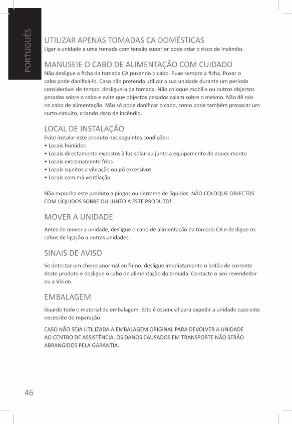
1. Abraçadeira de gestão de cabos2. Tomada de controlo do motor3. Tomada de saída de alimentação
de 220 V CA (fornece alimentação em “loop-through”
ao módulo no painel dianteiro)
4. Tomada de alimentação de 220 V CA5. Botão táctil PARA CImA/BAIXo6. Painel
DISPoSIÇÃo Do CHASSIS
48
ENG
LISH
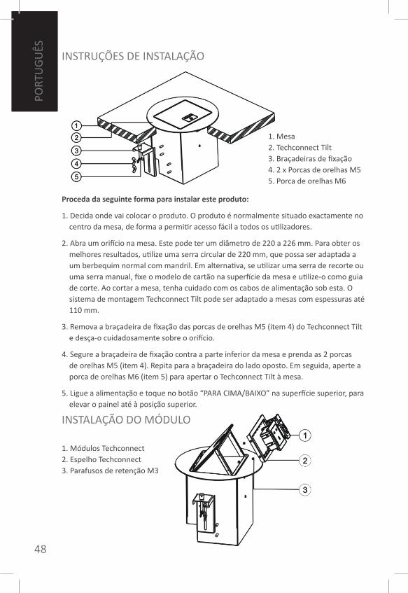
INSTRUÇÕES DE INSTALAÇÃo
Proceda da seguinte forma para instalar este produto:
1. Decida onde vai colocar o produto. o produto é normalmente situado exactamente no centro da mesa, de forma a permitir acesso fácil a todos os utilizadores.
2. Abra um orifício na mesa. Este pode ter um diâmetro de 220 a 226 mm. Para obter os melhores resultados, utilize uma serra circular de 220 mm, que possa ser adaptada a um berbequim normal com mandril. Em alternativa, se utilizar uma serra de recorte ou uma serra manual, fixe o modelo de cartão na superfície da mesa e utilize-o como guia de corte. Ao cortar a mesa, tenha cuidado com os cabos de alimentação sob esta. o sistema de montagem Techconnect Tilt pode ser adaptado a mesas com espessuras até 110 mm.
3. Remova a braçadeira de fixação das porcas de orelhas m5 (item 4) do Techconnect Tilt e desça-o cuidadosamente sobre o orifício.
4. Segure a braçadeira de fixação contra a parte inferior da mesa e prenda as 2 porcas de orelhas m5 (item 4). Repita para a braçadeira do lado oposto. Em seguida, aperte a porca de orelhas m6 (item 5) para apertar o Techconnect Tilt à mesa.
5. Ligue a alimentação e toque no botão “PARA CImA/BAIXo” na superfície superior, para elevar o painel até à posição superior.
1. mesa2. Techconnect Tilt3. Braçadeiras de fixação4. 2 x Porcas de orelhas m55. Porca de orelhas m6
1. módulos Techconnect2. Espelho Techconnect3. Parafusos de retenção m3
INSTALAÇÃo Do móDULo
PoRT
UG
UêS
ENG
LISH
49
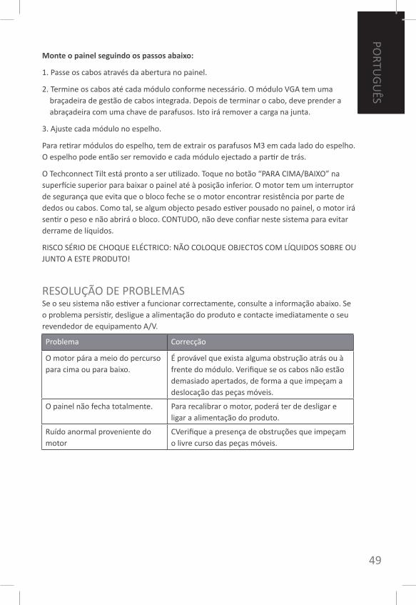
Monte o painel seguindo os passos abaixo:
1. Passe os cabos através da abertura no painel.
2. Termine os cabos até cada módulo conforme necessário. o módulo VGA tem uma braçadeira de gestão de cabos integrada. Depois de terminar o cabo, deve prender a abraçadeira com uma chave de parafusos. Isto irá remover a carga na junta.
3. Ajuste cada módulo no espelho.
Para retirar módulos do espelho, tem de extrair os parafusos m3 em cada lado do espelho. o espelho pode então ser removido e cada módulo ejectado a partir de trás.
o Techconnect Tilt está pronto a ser utilizado. Toque no botão “PARA CImA/BAIXo” na superfície superior para baixar o painel até à posição inferior. o motor tem um interruptor de segurança que evita que o bloco feche se o motor encontrar resistência por parte de dedos ou cabos. Como tal, se algum objecto pesado estiver pousado no painel, o motor irá sentir o peso e não abrirá o bloco. CoNTUDo, não deve confiar neste sistema para evitar derrame de líquidos.
RISCo SÉRIo DE CHoQUE ELÉCTRICo: NÃo CoLoQUE oBJECToS Com LÍQUIDoS SoBRE oU JUNTo A ESTE PRoDUTo!
RESoLUÇÃo DE PRoBLEmASSe o seu sistema não estiver a funcionar correctamente, consulte a informação abaixo. Se o problema persistir, desligue a alimentação do produto e contacte imediatamente o seu revendedor de equipamento A/V.
Problema Correcção
o motor pára a meio do percurso para cima ou para baixo.
É provável que exista alguma obstrução atrás ou à frente do módulo. Verifique se os cabos não estão demasiado apertados, de forma a que impeçam a deslocação das peças móveis.
o painel não fecha totalmente. Para recalibrar o motor, poderá ter de desligar e ligar a alimentação do produto.
Ruído anormal proveniente do motor
CVerifique a presença de obstruções que impeçam o livre curso das peças móveis.
PoRTU
GU
êS
50
ENG
LISH
GARANTIAEste produto tem uma garantia de 2 anos, com efeito a partir da data de compra. Esta garantia aplica-se apenas ao comprador original e não é transferível. Para evitar dúvidas, a garantia será aplicada à informação retida pelo distribuidor nacional designado no ponto de venda. Se o produto for entregue avariado, tem 21 dias a partir da data de compra para notificar o distribuidor nacional através do seu revendedor de equipamento A/V. A responsabilidade do fabricante e da empresa de assistência designada limita-se ao custo de reparação e/ou substituição da unidade avariada ao abrigo da garantia, excepto por morte ou ferimentos (EU85/374/CEE).Esta garantia protege-o nas seguintes situações:• Avaria de qualquer componente, incluindo a fonte de alimentação.• Danos aquando da primeira remoção do produto da respectiva embalagem, caso
comunicados dentro de 24 horas após a compra.
Se encontrar qualquer problema neste produto, deve contactar o revendedor de equipamento A/V ao qual adquiriu o produto. o comprador original é responsável pelo envio do produto para reparação para o centro de assistência designado pelo fabricante. faremos o nosso melhor para devolver unidades reparadas dentro de 5 úteis. Contudo, isso pode não ser sempre possível, sendo que a unidade será devolvida o mais rapidamente possível. De acordo com os nossos compromissos WEEE, o fabricante fará todos os esforços para substituir as peças avariadas do produto, em vez de substituir toda a unidade. A garantia não protege este produto contra avarias provocadas por abuso, utilização incorrecta, instalação incorrecta, alimentação instável ou defeituosa, que possam ser provocadas pelo desrespeito das linhas de orientação definidas neste manual.
ESPECIfICAÇÕESAlimentação: 100-240 V, saída 12 V CC, • 1000 mA, 12 WCorrente do motor e binário: elevação: • 0,7 A, 30 n / descida: 0,45 A, 20 nmaterial da superfície superior: alumínio • preto polidoGama de diâmetro de corte: 220-226 mm• Diâmetro exterior: 240 mm• Dimensões do produto: 164 x 145 x 200 • (lado x lado x altura)Peso do produto: 3,7 kg• Cor: Preto•
nota: Devido ao nosso empenho no melhoramento dos nossos produtos, os detalhes acima mencionados podem ser alterados sem aviso prévio.
ACESSóRIoS INCLUÍDoS1 x Cabo de alimentação IEC (Europa) • com 1,8 m de comprimento1 x Cabo de alimentação IEC (Reino • Unido) com 1,8 m de comprimento1 x modelo de corte• 2 x Abas de fixação• 1 x módulo de alimentação IEC (Reino • Unido) com cabo de alimentação1 x módulo de alimentação IEC (Europa) • com cabo de alimentação2 x módulos VGAf 3,5 mm• 1 x módulo Ethernet RJ45• 1 x módulo RJ45 duplo• 1 x módulo vazio•
PoRT
UG
UêS