Embed Size (px)
Citation preview
Copyright © 2009 Lorex Technology Inc.
www.lorexcctv.com
www.lorexcctv.com
INSTRUCTION MANUALEnglish Version 1.0
LOREX LinkH.264, INTERNET REMOTE VIEWING, LIGHT TOUCH
LH400 LINK SERIESMODEL:
DIGITAL VIDEO SURVEILLANCE RECORDER
Thank you for purchasing this product. Lorex is committed to providing our customers with a high quality, reliable security solution.
This manual refers to the following model(s):
• LH400 Series (4/8/16 channel configurations)
For more information on this product, firmware updates, and accessory products, please visit us at:
www.lorexcctv.com
CAUTION
RISK OF ELECTRIC SHOCKDO NOT OPEN
CAUTION: TO REDUCE THE RISK OF ELECTRIC SHOCK DO NOT REMOVE COVER. NO USER SERVICABLE PARTS INSIDE.
REFER SERVICING TO QUALIFIED SERVICE PERSONNEL.
The lightning flash with arrowhead symbol, within an equilateral triangle, is intended to alert the user to the presence of uninsulated "dangerous voltage" within the products ' enclosure that may be of sufficient magnitude to constitute a risk of electric shock.The exclamation point within an equilateral triangle is intended to alert the user to the presence of important operating and maintenance (servicing) instructions in the literature accompanying the appliance.
WARNING: TO PREVENT FIRE OR SHOCK HAZARD, DO NOT EXPOSE THIS UNIT TO RAIN OR MOISTURE.
CAUTION: TO PREVENT ELECTRIC SHOCK, MATCH WIDE BLADE OF THE PLUG TO THE WIDE SLOT AND FULLY INSERT.

www.lorexcctv.com
LOREX IS COMMITTED TO FULFILLING YOUR SECURITY NEEDS
BEFORE YOU STARTTHIS PRODUCT MAY REQUIRE PROFESSIONAL INSTALLATION
• We have developed user friendly products and documentation.
Please read the Quick Start Guide and User Manual before you
install this product.
• Consumer Guides and Video Tutorials are available on our web
site at www.lorexcctv.com/support
• If you require further installation assistance, please visit
www.lorexcctv.com/installation or contact a professional
installer.
• Please refer to the “Need Help” insert for technical support and
customer care information.
• Please note that once the components of this product have been
unsealed, you cannot return this product directly to the store
without the original packaging.
w w w . l o r e x c c t v . c o m
AVANT DE COMMENCER
ANTES DE EMPEZAR
LOREX SE COMPROMETE A SATISFACER SUS NECESIDADES EN SEGURIDAD
LOREX S’ENGAGE À SATISFAIRE VOS BESOINS SÉCURITAIRES
ESTE PRODUCTO PUEDE EXIGIR UNA INSTALACIÓN PROFESIONAL
CE PRODUIT POURRAIT EXIGER UNE INSTALLATION PROFESSIONNELLE
• Veuillez lire le guide de démarrage rapide et le mode d’emploi avant d’installer ce produit.
• Les guides du consommateur et les séances de tutorat vidéo sont disponibles sur l’Internet en visitant www.lorexcctv.com/support
• Si vous avez besoin de l’aide pour l’installation, veuillez visiter www.lorexcctv.com/installation ou contactez un spécialiste en installation
• Veuillez référer à l’insert “Need Help” pour ob¬tenir de l’information sur le service à la cli-entèle et le support technique
• Veuillez constater qu’une fois que les com¬posantes de ce produit ont été retirées de l’emballage, vous ne pourrez plus retourner ce produit directement au magasin.
• Favor de leer la guía de instalación rápida y la guía del usuario antes de instalar este producto.
• Puede conseguir las guías del consumidor y los cursos en enseñanza video sobre el Internet visitando www.lorexcctv.com/support
• Si necesita ayuda para la instalación, visite www.lorexcctv.com/installation o contacte un especialista en instalaciones
• Favor de referir al documento “Need Help” para obtener información acerca del servicio al cliente y al soporte técnico
• Favor de notar que una vez que los compo-nentes de este producto han sido removidos del embalaje, no podrá devolver este producto di-rectamente a la tienda

Vers ion 7 - Nov 26 2009
NORTH AMERICA:CUSTOMER SERVICE: 1-888-425-6739 (1-888-42-LOREX)TECH SUPPORT: 1-877-755-6739 (1-877-75-LOREX)MEXICO: 1-800-514-6739
INTERNATIONAL: +800-425-6739-0
(Example: From the UK, d ia l 00 instead of +)
By Phone:
Techn ica l Suppor t ( f o r techn ica l / ins ta l l a t i on i ssues )
By Email:
Customer Care ( f o r war ran ty and accessor y sa les )
customerserv [email protected]
Customer Feedback
Produc t Suppor t i s ava i l ab le 24/7 inc lud ing p roduc t
in fo rmat ion , user manua ls , qu ick s ta r t up gu ides and FAQ’s
a t www.lorexcctv.com/support
Online:
To o rder accessor ies , v i s i t
www.lorexcctv.com
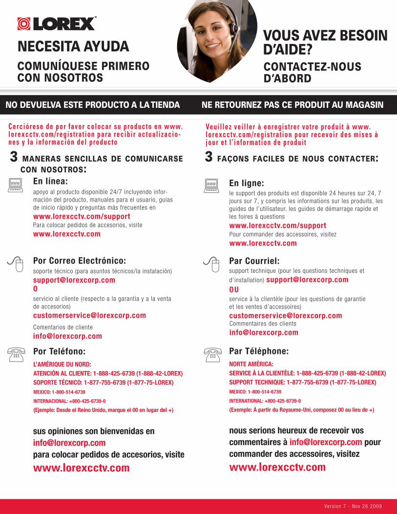
DO NOT RETURN THIS PRODUCT TO THE STORE
NEED HELP?CONTACT US FIRST
3 EASY WAYS TO CONTACT US:
Please make sure to register your product at www.lorexcctv.com to receive product updates and information
Vers ion 7 - Nov 26 2009
NO DEVUELVA ESTE PRODUCTO A LA TIENDA
3 maneras sencillas de comunicarse con nosotros:
NE RETOURNEZ PAS CE PRODUIT AU MAGASIN
3 façons faciles de nous contacter:
L’AMÉRIQUE DU NORD:ATENCIÓN AL CLIENTE: 1-888-425-6739 (1-888-42-LOREX)SOPORTE TÉCNICO: 1-877-755-6739 (1-877-75-LOREX)MEXICO: 1-800-514-6739
INTERNACIONAL: +800-425-6739-0
(Ejemplo: Desde el Reino Unido, marque el 00 en lugar del +)
Por Teléfono:
sus opiniones son bienvenidas en [email protected] colocar pedidos de accesorios, visite
www.lorexcctv.com
apoyo al producto disponible 24/7 incluyendo infor-mación del producto, manuales para el usuario, guías de inicio rápido y preguntas más frecuentes en
www.lorexcctv.com/support
En línea:www
NORTE AMÉRICA:SERVICE À LA CLIENTÈLE: 1-888-425-6739 (1-888-42-LOREX)SUPPORT TECHNIQUE: 1-877-755-6739 (1-877-75-LOREX)MEXICO: 1-800-514-6739
INTERNATIONAL: +800-425-6739-0
(Exemple: À partir du Royaume-Uni, composez 00 au lieu de +)
Par Téléphone:
nous serions heureux de recevoir vos commentaires à [email protected] pour commander des accessoires, visitez
www.lorexcctv.com
Veuil lez vei l ler à enregistrer votre produi t à www.lorexcctv.com/registrat ion pour recevoir des mises à jour et l ’ in formation de produi t
Cerciórese de por favor colocar su producto en www.lorexcctv.com/registrat ion para recibir actual izacio-nes y la información del producto
NECESITA AYUDACOMUNÍQUESE PRIMERO CON NOSOTROS
VOUS AVEZ BESOIN D’AIDE?CONTACTEZ-NOUS D’ABORD
Pour commander des accessoires, visitez
www.lorexcctv.com
le support des produits est disponible 24 heures sur 24, 7 jours sur 7, y compris les informations sur les produits, les guides de l’utilisateur, les guides de démarrage rapide et les foires à questions
www.lorexcctv.com/support
En ligne:www
Para colocar pedidos de accesorios, visite
www.lorexcctv.com
Commentaires des clients
support technique (pour les questions techniques et
d’installation) [email protected]
Par Courriel:
service à la clientèle (pour les questions de garantie et les ventes d’accessoires)
OU
soporte técnico (para asuntos técnicos/la instalación)
[email protected] Por Correo Electrónico:
servicio al cliente (respecto a la garantía y a la venta de accesorios)
O
Comentarios de cliente
Important Safeguards
In addition to the careful attention devoted to quality standards in the manufacturing process of your video product, safety is a major factor in the design of every instrument. However, safety is your responsibility too. This sheet lists important information that will help to assure your enjoyment and proper use of the video product and accessory equipment. Please read them carefully before operating and using your video product.
Installation1. Read and Follow Instructions - All the safety and
operating instructions should be read before the video product is operated. Follow all operating instructions.
2. Retain Instructions - The safety and operating instructions should be retained for future reference.
3. Heed Warnings - Comply with all warnings on the video product and in the operating instructions.
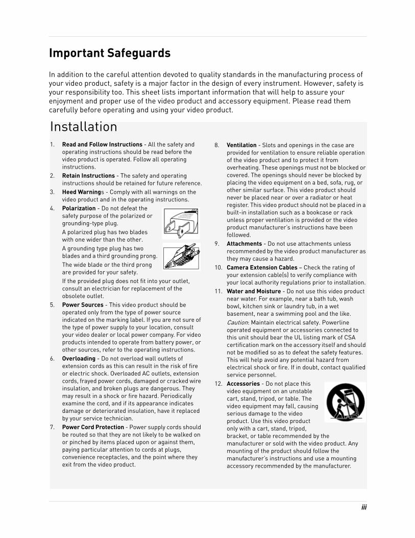
4. Polarization - Do not defeat the safety purpose of the polarized or grounding-type plug.A polarized plug has two blades with one wider than the other.A grounding type plug has two blades and a third grounding prong.The wide blade or the third prong are provided for your safety.If the provided plug does not fit into your outlet, consult an electrician for replacement of the obsolete outlet.
5. Power Sources - This video product should be operated only from the type of power source indicated on the marking label. If you are not sure of the type of power supply to your location, consult your video dealer or local power company. For video products intended to operate from battery power, or other sources, refer to the operating instructions.
6. Overloading - Do not overload wall outlets of extension cords as this can result in the risk of fire or electric shock. Overloaded AC outlets, extension cords, frayed power cords, damaged or cracked wire insulation, and broken plugs are dangerous. They may result in a shock or fire hazard. Periodically examine the cord, and if its appearance indicates damage or deteriorated insulation, have it replaced by your service technician.
7. Power Cord Protection - Power supply cords should be routed so that they are not likely to be walked on or pinched by items placed upon or against them, paying particular attention to cords at plugs, convenience receptacles, and the point where they exit from the video product.
8. Ventilation - Slots and openings in the case are provided for ventilation to ensure reliable operation of the video product and to protect it from overheating. These openings must not be blocked or covered. The openings should never be blocked by placing the video equipment on a bed, sofa, rug, or other similar surface. This video product should never be placed near or over a radiator or heat register. This video product should not be placed in a built-in installation such as a bookcase or rack unless proper ventilation is provided or the video product manufacturer’s instructions have been followed.
9. Attachments - Do not use attachments unless recommended by the video product manufacturer as they may cause a hazard.
10. Camera Extension Cables – Check the rating of your extension cable(s) to verify compliance with your local authority regulations prior to installation.
11. Water and Moisture - Do not use this video product near water. For example, near a bath tub, wash bowl, kitchen sink or laundry tub, in a wet basement, near a swimming pool and the like. Caution: Maintain electrical safety. Powerline operated equipment or accessories connected to this unit should bear the UL listing mark of CSA certification mark on the accessory itself and should not be modified so as to defeat the safety features. This will help avoid any potential hazard from electrical shock or fire. If in doubt, contact qualified service personnel.
12. Accessories - Do not place this video equipment on an unstable cart, stand, tripod, or table. The video equipment may fall, causing serious damage to the video product. Use this video product only with a cart, stand, tripod, bracket, or table recommended by the manufacturer or sold with the video product. Any mounting of the product should follow the manufacturer’s instructions and use a mounting accessory recommended by the manufacturer.
iii
General Precautions
Service13. Servicing - Do not attempt to service this video
equipment yourself as opening or removing covers may expose you to dangerous voltage or other hazards. Refer all servicing to qualified service personnel.
14. Conditions Requiring Service - Unplug this video product from the wall outlet and refer servicing to qualified service personnel under the following conditions:• When the power supply cord or plug is damaged.
• If liquid has been spilled or objects have fallen into the video product.
• If the video product has been exposed to rain or water.
• If the video product does not operate normally by following the operating instructions. Adjust only those controls that are covered by the operating instructions. Improper adjustment of other controls may result in damage and will often require extensive work by a qualified technician to restore the video product to its normal operation.
• If the video product has been dropped or the cabinet has been damaged.
• When the video product exhibits a distinct change in performance. This indicates a need for service.
15. Replacement Parts - When replacement parts are required, have the service technician verify that the replacements used have the same safety characteristics as the original parts. Use of replacements specified by the video product manufacturer can prevent fire, electric shock or other hazards.
16. Safety Check - Upon completion of any service or repairs to this video product, ask the service technician to perform safety checks recommended by the manufacturer to determine that the video product is in safe operating condition.
17. Wall or Ceiling Mounting - The cameras provided with this system should be mounted to a wall or ceiling only as instructed in this guide, using the provided mounting brackets.
18. Heat - The product should be situated away from heat sources such as radiators, heat registers, stoves, or other products (including amplifiers) that produce heat.
Use19. Cleaning - Unplug the video product from the wall
outlet before cleaning. Do not use liquid cleaners or aerosol cleaners. Use a damp cloth for cleaning.
20. Product and Cart Combination - Video and cart combination should be moved with care. Quick stops, excessive force, and uneven surfaces may cause the video product and car combination to overturn.
21. Object and Liquid Entry - Never push objects for any kind into this video product through openings as they may touch dangerous voltage points or “short-out” parts that could result in a fire or electric shock. Never spill liquid of any kind on the video product.
22. Lightning - For added protection for this video product during a lightning storm, or when it is left unattended and unused for long periods of time, unplug it from the wall outlet and disconnect the antenna or cable system. This will prevent damage to the video product due to lightning and power line surges.
iv
General Precautions1. All warnings and instructions in this manual should be followed.2. Remove the plug from the outlet before cleaning. Do not use liquid aerosol detergents. Use a
water dampened cloth for cleaning.3. Do not use this unit in humid or wet places.4. Keep enough space around the unit for ventilation. Slots and openings in the storage cabinet
should not be blocked.5. During lightning storms, or when the unit is not used for a long time, disconnect the power
supply, antenna, and cables to protect the unit from electrical surge.
This equipment has been certified and found to comply with the limits regulated by FCC, EMC, and LVD. Therefore, it is designated to provide reasonable protection against interference and will not cause interference with other appliance usage.
However, it is imperative that the user follows the guidelines in this manual to avoid improper usage which may result in damage to the unit, electrical shock and fire hazard injury.
In order to improve the feature functions and quality of this product, the specifications are subject to change without notice from time to time.
FCC CLASS B NOTICE
NOTE
This equipment has been tested and found to comply with the limits for a Class B digital device, pursuant to Part 15 of the FCC Rules. These limits are designed to provide reasonable protection against harmful interference in a residential installation. This equipment generates, uses, and can radiate radio frequency energy and, if not in-stalled and used in accordance with the instruction, may cause harmful interference to radio communications.
However, there is no guarantee that interference will not occur in a particular installation. If this equipment does cause harmful interference to radio or television reception (which can be determined by turning the equipment on and off), the user is encouraged to try to correct the interference by one or more of the following measures:
• Reorient or relocate the receiving antenna• Increase the separation between the equipment and receiver• Connect the equipment into an outlet on a circuit different from that to which the receiver is
connected• Consult the dealer or an experienced radio or television technician for assistance
www.lorexcctv.com
v
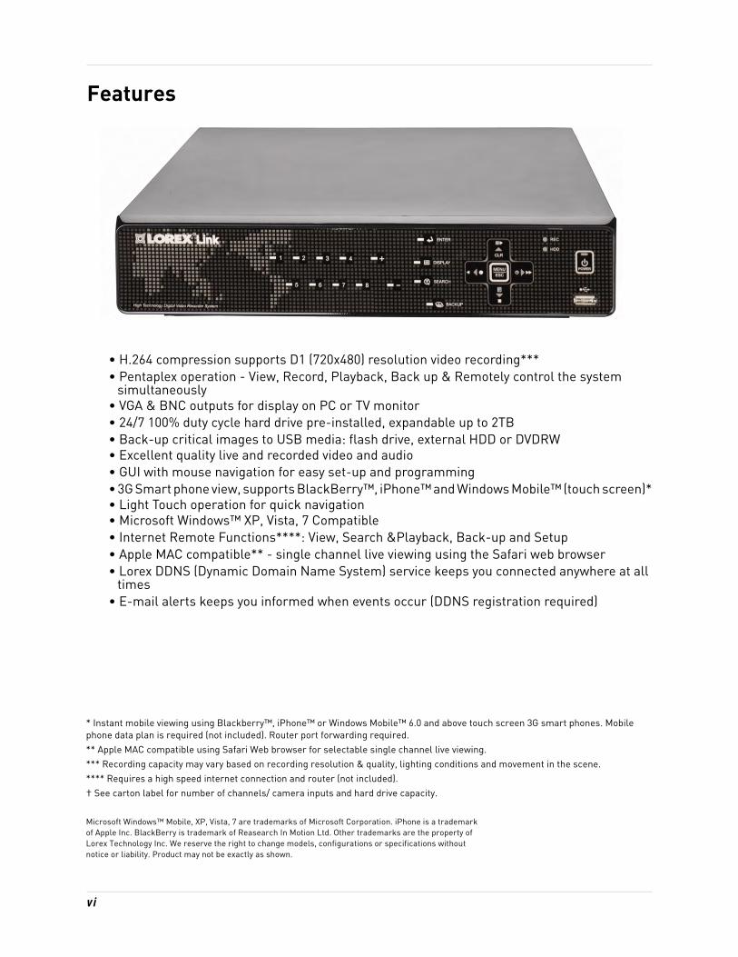
Features
• H.264 compression supports D1 (720x480) resolution video recording***• Pentaplex operation - View, Record, Playback, Back up & Remotely control the system
simultaneously• VGA & BNC outputs for display on PC or TV monitor• 24/7 100% duty cycle hard drive pre-installed, expandable up to 2TB• Back-up critical images to USB media: flash drive, external HDD or DVDRW• Excellent quality live and recorded video and audio• GUI with mouse navigation for easy set-up and programming• 3G Smart phone view, supports BlackBerry™, iPhone™ and Windows Mobile™ (touch screen)*• Light Touch operation for quick navigation• Microsoft Windows™ XP, Vista, 7 Compatible• Internet Remote Functions****: View, Search &Playback, Back-up and Setup• Apple MAC compatible** - single channel live viewing using the Safari web browser• Lorex DDNS (Dynamic Domain Name System) service keeps you connected anywhere at all
times• E-mail alerts keeps you informed when events occur (DDNS registration required)
* Instant mobile viewing using Blackberry™, iPhone™ or Windows Mobile™ 6.0 and above touch screen 3G smart phones. Mobile phone data plan is required (not included). Router port forwarding required.** Apple MAC compatible using Safari Web browser for selectable single channel live viewing.*** Recording capacity may vary based on recording resolution & quality, lighting conditions and movement in the scene.**** Requires a high speed internet connection and router (not included).† See carton label for number of channels/ camera inputs and hard drive capacity.
Microsoft Windows™ Mobile, XP, Vista, 7 are trademarks of Microsoft Corporation. iPhone is a trademarkof Apple Inc. BlackBerry is trademark of Reasearch In Motion Ltd. Other trademarks are the property ofLorex Technology Inc. We reserve the right to change models, configurations or specifications withoutnotice or liability. Product may not be exactly as shown.
vi
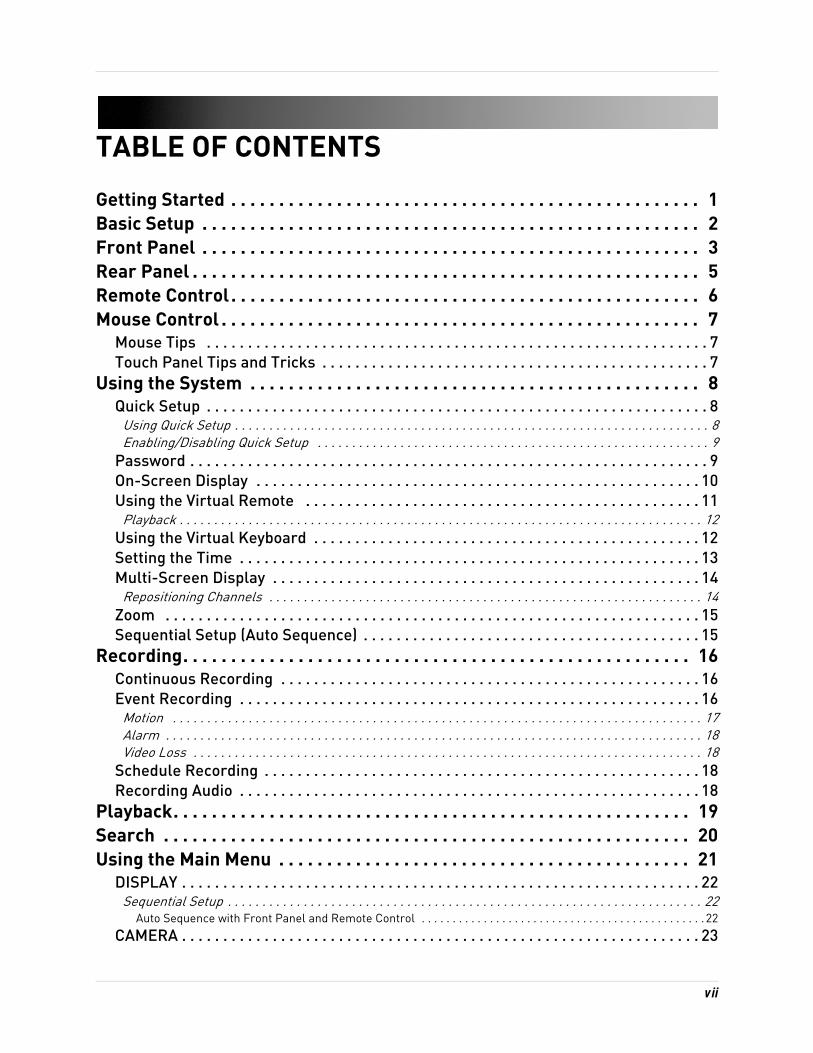
TABLE OF CONTENTS
Getting Started . . . . . . . . . . . . . . . . . . . . . . . . . . . . . . . . . . . . . . . . . . . . . . . . . 1Basic Setup . . . . . . . . . . . . . . . . . . . . . . . . . . . . . . . . . . . . . . . . . . . . . . . . . . . . 2Front Panel . . . . . . . . . . . . . . . . . . . . . . . . . . . . . . . . . . . . . . . . . . . . . . . . . . . . 3Rear Panel . . . . . . . . . . . . . . . . . . . . . . . . . . . . . . . . . . . . . . . . . . . . . . . . . . . . . 5Remote Control. . . . . . . . . . . . . . . . . . . . . . . . . . . . . . . . . . . . . . . . . . . . . . . . . 6Mouse Control . . . . . . . . . . . . . . . . . . . . . . . . . . . . . . . . . . . . . . . . . . . . . . . . . . 7
Mouse Tips . . . . . . . . . . . . . . . . . . . . . . . . . . . . . . . . . . . . . . . . . . . . . . . . . . . . . . . . . . . . . 7Touch Panel Tips and Tricks . . . . . . . . . . . . . . . . . . . . . . . . . . . . . . . . . . . . . . . . . . . . . . . 7
Using the System . . . . . . . . . . . . . . . . . . . . . . . . . . . . . . . . . . . . . . . . . . . . . . . 8Quick Setup . . . . . . . . . . . . . . . . . . . . . . . . . . . . . . . . . . . . . . . . . . . . . . . . . . . . . . . . . . . . . 8
Using Quick Setup . . . . . . . . . . . . . . . . . . . . . . . . . . . . . . . . . . . . . . . . . . . . . . . . . . . . . . . . . . . . . . . . . . . . . 8Enabling/Disabling Quick Setup . . . . . . . . . . . . . . . . . . . . . . . . . . . . . . . . . . . . . . . . . . . . . . . . . . . . . . . . . 9
Password . . . . . . . . . . . . . . . . . . . . . . . . . . . . . . . . . . . . . . . . . . . . . . . . . . . . . . . . . . . . . . . 9On-Screen Display . . . . . . . . . . . . . . . . . . . . . . . . . . . . . . . . . . . . . . . . . . . . . . . . . . . . . . 10Using the Virtual Remote . . . . . . . . . . . . . . . . . . . . . . . . . . . . . . . . . . . . . . . . . . . . . . . . 11
Playback . . . . . . . . . . . . . . . . . . . . . . . . . . . . . . . . . . . . . . . . . . . . . . . . . . . . . . . . . . . . . . . . . . . . . . . . . . . . 12Using the Virtual Keyboard . . . . . . . . . . . . . . . . . . . . . . . . . . . . . . . . . . . . . . . . . . . . . . . 12Setting the Time . . . . . . . . . . . . . . . . . . . . . . . . . . . . . . . . . . . . . . . . . . . . . . . . . . . . . . . . 13Multi-Screen Display . . . . . . . . . . . . . . . . . . . . . . . . . . . . . . . . . . . . . . . . . . . . . . . . . . . . 14
Repositioning Channels . . . . . . . . . . . . . . . . . . . . . . . . . . . . . . . . . . . . . . . . . . . . . . . . . . . . . . . . . . . . . . . 14Zoom . . . . . . . . . . . . . . . . . . . . . . . . . . . . . . . . . . . . . . . . . . . . . . . . . . . . . . . . . . . . . . . . . 15Sequential Setup (Auto Sequence) . . . . . . . . . . . . . . . . . . . . . . . . . . . . . . . . . . . . . . . . . 15
Recording. . . . . . . . . . . . . . . . . . . . . . . . . . . . . . . . . . . . . . . . . . . . . . . . . . . . . 16Continuous Recording . . . . . . . . . . . . . . . . . . . . . . . . . . . . . . . . . . . . . . . . . . . . . . . . . . . 16Event Recording . . . . . . . . . . . . . . . . . . . . . . . . . . . . . . . . . . . . . . . . . . . . . . . . . . . . . . . . 16
Motion . . . . . . . . . . . . . . . . . . . . . . . . . . . . . . . . . . . . . . . . . . . . . . . . . . . . . . . . . . . . . . . . . . . . . . . . . . . . . 17Alarm . . . . . . . . . . . . . . . . . . . . . . . . . . . . . . . . . . . . . . . . . . . . . . . . . . . . . . . . . . . . . . . . . . . . . . . . . . . . . . 18Video Loss . . . . . . . . . . . . . . . . . . . . . . . . . . . . . . . . . . . . . . . . . . . . . . . . . . . . . . . . . . . . . . . . . . . . . . . . . . 18
Schedule Recording . . . . . . . . . . . . . . . . . . . . . . . . . . . . . . . . . . . . . . . . . . . . . . . . . . . . . 18Recording Audio . . . . . . . . . . . . . . . . . . . . . . . . . . . . . . . . . . . . . . . . . . . . . . . . . . . . . . . . 18
Playback. . . . . . . . . . . . . . . . . . . . . . . . . . . . . . . . . . . . . . . . . . . . . . . . . . . . . . 19Search . . . . . . . . . . . . . . . . . . . . . . . . . . . . . . . . . . . . . . . . . . . . . . . . . . . . . . . 20Using the Main Menu . . . . . . . . . . . . . . . . . . . . . . . . . . . . . . . . . . . . . . . . . . . 21
DISPLAY . . . . . . . . . . . . . . . . . . . . . . . . . . . . . . . . . . . . . . . . . . . . . . . . . . . . . . . . . . . . . . . 22Sequential Setup . . . . . . . . . . . . . . . . . . . . . . . . . . . . . . . . . . . . . . . . . . . . . . . . . . . . . . . . . . . . . . . . . . . . . 22
Auto Sequence with Front Panel and Remote Control . . . . . . . . . . . . . . . . . . . . . . . . . . . . . . . . . . . . . . . . . . . . . . 22
CAMERA . . . . . . . . . . . . . . . . . . . . . . . . . . . . . . . . . . . . . . . . . . . . . . . . . . . . . . . . . . . . . . . 23
vii
MOTION . . . . . . . . . . . . . . . . . . . . . . . . . . . . . . . . . . . . . . . . . . . . . . . . . . . . . . . . . . . . . . . 23RECORD . . . . . . . . . . . . . . . . . . . . . . . . . . . . . . . . . . . . . . . . . . . . . . . . . . . . . . . . . . . . . . . 24ALARM . . . . . . . . . . . . . . . . . . . . . . . . . . . . . . . . . . . . . . . . . . . . . . . . . . . . . . . . . . . . . . . . 24SCHEDULE . . . . . . . . . . . . . . . . . . . . . . . . . . . . . . . . . . . . . . . . . . . . . . . . . . . . . . . . . . . . 25
Stopping Scheduled Recording . . . . . . . . . . . . . . . . . . . . . . . . . . . . . . . . . . . . . . . . . . . . . . . . . . . . . . . . . 26Overnight Recording . . . . . . . . . . . . . . . . . . . . . . . . . . . . . . . . . . . . . . . . . . . . . . . . . . . . . . . . . . . . . . . . . . 26
Example . . . . . . . . . . . . . . . . . . . . . . . . . . . . . . . . . . . . . . . . . . . . . . . . . . . . . . . . . . . . . . . . . . . . . . . . . . . . . . . . . . . . 26
NETWORK . . . . . . . . . . . . . . . . . . . . . . . . . . . . . . . . . . . . . . . . . . . . . . . . . . . . . . . . . . . . . 27EMAIL . . . . . . . . . . . . . . . . . . . . . . . . . . . . . . . . . . . . . . . . . . . . . . . . . . . . . . . . . . . . . . . . . . . . . . . . . . . . . . 27DDNS . . . . . . . . . . . . . . . . . . . . . . . . . . . . . . . . . . . . . . . . . . . . . . . . . . . . . . . . . . . . . . . . . . . . . . . . . . . . . . 28EASY CONNECT . . . . . . . . . . . . . . . . . . . . . . . . . . . . . . . . . . . . . . . . . . . . . . . . . . . . . . . . . . . . . . . . . . . . . . 28MISC . . . . . . . . . . . . . . . . . . . . . . . . . . . . . . . . . . . . . . . . . . . . . . . . . . . . . . . . . . . . . . . . . . . . . . . . . . . . . . . 28
SYSTEM . . . . . . . . . . . . . . . . . . . . . . . . . . . . . . . . . . . . . . . . . . . . . . . . . . . . . . . . . . . . . . . 29GENERAL . . . . . . . . . . . . . . . . . . . . . . . . . . . . . . . . . . . . . . . . . . . . . . . . . . . . . . . . . . . . . . . . . . . . . . . . . . . 29TIME . . . . . . . . . . . . . . . . . . . . . . . . . . . . . . . . . . . . . . . . . . . . . . . . . . . . . . . . . . . . . . . . . . . . . . . . . . . . . . . 29ACCOUNT . . . . . . . . . . . . . . . . . . . . . . . . . . . . . . . . . . . . . . . . . . . . . . . . . . . . . . . . . . . . . . . . . . . . . . . . . . . 29DISK . . . . . . . . . . . . . . . . . . . . . . . . . . . . . . . . . . . . . . . . . . . . . . . . . . . . . . . . . . . . . . . . . . . . . . . . . . . . . . . 30
Formatting Disks . . . . . . . . . . . . . . . . . . . . . . . . . . . . . . . . . . . . . . . . . . . . . . . . . . . . . . . . . . . . . . . . . . . . . . . . . . . . 30Overwrite . . . . . . . . . . . . . . . . . . . . . . . . . . . . . . . . . . . . . . . . . . . . . . . . . . . . . . . . . . . . . . . . . . . . . . . . . . . . . . . . . . .30Disk Monitor . . . . . . . . . . . . . . . . . . . . . . . . . . . . . . . . . . . . . . . . . . . . . . . . . . . . . . . . . . . . . . . . . . . . . . . . . . . . . . . . 30
UPDATE . . . . . . . . . . . . . . . . . . . . . . . . . . . . . . . . . . . . . . . . . . . . . . . . . . . . . . . . . . . . . . . . . . . . . . . . . . . . 31INFO . . . . . . . . . . . . . . . . . . . . . . . . . . . . . . . . . . . . . . . . . . . . . . . . . . . . . . . . . . . . . . . . . . . . . . . . . . . . . . . 31
Backup . . . . . . . . . . . . . . . . . . . . . . . . . . . . . . . . . . . . . . . . . . . . . . . . . . . . . . . 32USB Flash Drive . . . . . . . . . . . . . . . . . . . . . . . . . . . . . . . . . . . . . . . . . . . . . . . . . . . . . . . . 32External USB HDD . . . . . . . . . . . . . . . . . . . . . . . . . . . . . . . . . . . . . . . . . . . . . . . . . . . . . . 33USB CD/DVD-RW . . . . . . . . . . . . . . . . . . . . . . . . . . . . . . . . . . . . . . . . . . . . . . . . . . . . . . . 33Time Search and Backup . . . . . . . . . . . . . . . . . . . . . . . . . . . . . . . . . . . . . . . . . . . . . . . . . 34Viewing Backup Video . . . . . . . . . . . . . . . . . . . . . . . . . . . . . . . . . . . . . . . . . . . . . . . . . . . 35Using MCD Player . . . . . . . . . . . . . . . . . . . . . . . . . . . . . . . . . . . . . . . . . . . . . . . . . . . . . . . 36
Lorex Client 8.0. . . . . . . . . . . . . . . . . . . . . . . . . . . . . . . . . . . . . . . . . . . . . . . . 37System Requirements . . . . . . . . . . . . . . . . . . . . . . . . . . . . . . . . . . . . . . . . . . . . . . . . . . . . . . . . . . . . . . . . 37
Installing Lorex Client 8.0 . . . . . . . . . . . . . . . . . . . . . . . . . . . . . . . . . . . . . . . 38Using Lorex Client 8.0 . . . . . . . . . . . . . . . . . . . . . . . . . . . . . . . . . . . . . . . . . . 39
Adding a DVR . . . . . . . . . . . . . . . . . . . . . . . . . . . . . . . . . . . . . . . . . . . . . . . . . . . . . . . . . . . 40Editing a DVR . . . . . . . . . . . . . . . . . . . . . . . . . . . . . . . . . . . . . . . . . . . . . . . . . . . . . . . . . . . . . . . . . . . . . . . . 40Deleting a DVR . . . . . . . . . . . . . . . . . . . . . . . . . . . . . . . . . . . . . . . . . . . . . . . . . . . . . . . . . . . . . . . . . . . . . . 40
Lorex Client 8.0 Main Screen . . . . . . . . . . . . . . . . . . . . . . . . . . . . . . . . . . . . . . . . . . . . . 41Lorex Client 8.0 Setup . . . . . . . . . . . . . . . . . . . . . . . . . . . . . . . . . . . . . . . . . . . . . . . . . . . 42
Live Mode. . . . . . . . . . . . . . . . . . . . . . . . . . . . . . . . . . . . . . . . . . . . . . . . . . . . . 43DVR Indicators . . . . . . . . . . . . . . . . . . . . . . . . . . . . . . . . . . . . . . . . . . . . . . . . . . . . . . . . . 43Camera Indicators . . . . . . . . . . . . . . . . . . . . . . . . . . . . . . . . . . . . . . . . . . . . . . . . . . . . . . 44Display Views . . . . . . . . . . . . . . . . . . . . . . . . . . . . . . . . . . . . . . . . . . . . . . . . . . . . . . . . . . 44Changing Channels . . . . . . . . . . . . . . . . . . . . . . . . . . . . . . . . . . . . . . . . . . . . . . . . . . . . . 44Onscreen Display . . . . . . . . . . . . . . . . . . . . . . . . . . . . . . . . . . . . . . . . . . . . . . . . . . . . . . . 44Sub-Menu . . . . . . . . . . . . . . . . . . . . . . . . . . . . . . . . . . . . . . . . . . . . . . . . . . . . . . . . . . . . . 45
viii
Health . . . . . . . . . . . . . . . . . . . . . . . . . . . . . . . . . . . . . . . . . . . . . . . . . . . . . . . . . . . . . . . . 46Clearing Health Status . . . . . . . . . . . . . . . . . . . . . . . . . . . . . . . . . . . . . . . . . . . . . . . . . . . . . . . . . . . . . . . . 46Health Report . . . . . . . . . . . . . . . . . . . . . . . . . . . . . . . . . . . . . . . . . . . . . . . . . . . . . . . . . . . . . . . . . . . . . . . 46
Health Report Conditions . . . . . . . . . . . . . . . . . . . . . . . . . . . . . . . . . . . . . . . . . . . . . . . . . . . . . . . . . . . . . . . . . . . . . . 47
PTZ . . . . . . . . . . . . . . . . . . . . . . . . . . . . . . . . . . . . . . . . . . . . . . . . . . . . . . . . . . . . . . . . . . . 48Recording. . . . . . . . . . . . . . . . . . . . . . . . . . . . . . . . . . . . . . . . . . . . . . . . . . . . . 49
Remote Recording . . . . . . . . . . . . . . . . . . . . . . . . . . . . . . . . . . . . . . . . . . . . . . . . . . . . . . 49Playback. . . . . . . . . . . . . . . . . . . . . . . . . . . . . . . . . . . . . . . . . . . . . . . . . . . . . . 50
Remote Playback . . . . . . . . . . . . . . . . . . . . . . . . . . . . . . . . . . . . . . . . . . . . . . . . . . . . . . . 51Playback Controls . . . . . . . . . . . . . . . . . . . . . . . . . . . . . . . . . . . . . . . . . . . . . . . . . . . . . . . . . . . . . . . . . . . . 51
Remote Download . . . . . . . . . . . . . . . . . . . . . . . . . . . . . . . . . . . . . . . . . . . . . . . . . . . . . . 52Local Playback . . . . . . . . . . . . . . . . . . . . . . . . . . . . . . . . . . . . . . . . . . . . . . . . . . . . . . . . . 53
File Naming Conventions . . . . . . . . . . . . . . . . . . . . . . . . . . . . . . . . . . . . . . . . . . . . . . . . . . . . . . . . . . . . . . 53Playing Backup Files . . . . . . . . . . . . . . . . . . . . . . . . . . . . . . . . . . . . . . . . . . . . . . . . . . . . . . . . . . . . . . . . . 54
Virtual DVR . . . . . . . . . . . . . . . . . . . . . . . . . . . . . . . . . . . . . . . . . . . . . . . . . . . 55Creating a Virtual DVR . . . . . . . . . . . . . . . . . . . . . . . . . . . . . . . . . . . . . . . . . . . . . . . . . . . 55Editing a Virtual DVR . . . . . . . . . . . . . . . . . . . . . . . . . . . . . . . . . . . . . . . . . . . . . . . . . . . . 56Deleting a Virtual DVR . . . . . . . . . . . . . . . . . . . . . . . . . . . . . . . . . . . . . . . . . . . . . . . . . . . 56Virtual DVR Properties . . . . . . . . . . . . . . . . . . . . . . . . . . . . . . . . . . . . . . . . . . . . . . . . . . . 56Configuring a Virtual DVR . . . . . . . . . . . . . . . . . . . . . . . . . . . . . . . . . . . . . . . . . . . . . . . . 57Deleting Cameras from a Virtual DVR . . . . . . . . . . . . . . . . . . . . . . . . . . . . . . . . . . . . . . 58
Remote Setup . . . . . . . . . . . . . . . . . . . . . . . . . . . . . . . . . . . . . . . . . . . . . . . . . 59DISPLAY . . . . . . . . . . . . . . . . . . . . . . . . . . . . . . . . . . . . . . . . . . . . . . . . . . . . . . . . . . . . . . . 60
Sequential Setup (Auto Sequence) . . . . . . . . . . . . . . . . . . . . . . . . . . . . . . . . . . . . . . . . . . . . . . . . . . . . . . 60CAMERA . . . . . . . . . . . . . . . . . . . . . . . . . . . . . . . . . . . . . . . . . . . . . . . . . . . . . . . . . . . . . . . 61MOTION . . . . . . . . . . . . . . . . . . . . . . . . . . . . . . . . . . . . . . . . . . . . . . . . . . . . . . . . . . . . . . . 61RECORD . . . . . . . . . . . . . . . . . . . . . . . . . . . . . . . . . . . . . . . . . . . . . . . . . . . . . . . . . . . . . . . 62ALARM . . . . . . . . . . . . . . . . . . . . . . . . . . . . . . . . . . . . . . . . . . . . . . . . . . . . . . . . . . . . . . . . 62SCHEDULE . . . . . . . . . . . . . . . . . . . . . . . . . . . . . . . . . . . . . . . . . . . . . . . . . . . . . . . . . . . . 63NETWORK . . . . . . . . . . . . . . . . . . . . . . . . . . . . . . . . . . . . . . . . . . . . . . . . . . . . . . . . . . . . . 64
EMAIL . . . . . . . . . . . . . . . . . . . . . . . . . . . . . . . . . . . . . . . . . . . . . . . . . . . . . . . . . . . . . . . . . . . . . . . . . . . . . . 64DDNS . . . . . . . . . . . . . . . . . . . . . . . . . . . . . . . . . . . . . . . . . . . . . . . . . . . . . . . . . . . . . . . . . . . . . . . . . . . . . . 65
SYSTEM . . . . . . . . . . . . . . . . . . . . . . . . . . . . . . . . . . . . . . . . . . . . . . . . . . . . . . . . . . . . . . . 65TIME . . . . . . . . . . . . . . . . . . . . . . . . . . . . . . . . . . . . . . . . . . . . . . . . . . . . . . . . . . . . . . . . . . . . . . . . . . . . . . . 66PASSWORD . . . . . . . . . . . . . . . . . . . . . . . . . . . . . . . . . . . . . . . . . . . . . . . . . . . . . . . . . . . . . . . . . . . . . . . . . 66CONTROL . . . . . . . . . . . . . . . . . . . . . . . . . . . . . . . . . . . . . . . . . . . . . . . . . . . . . . . . . . . . . . . . . . . . . . . . . . . 66
Appendix A: System Specifications . . . . . . . . . . . . . . . . . . . . . . . . . . . . . . . 67DVR SPECIFICATIONS . . . . . . . . . . . . . . . . . . . . . . . . . . . . . . . . . . . . . . . . . . . . . . . . . . . 67
Appendix B: Setting up Remote Viewing . . . . . . . . . . . . . . . . . . . . . . . . . . . 68What Do I Need? . . . . . . . . . . . . . . . . . . . . . . . . . . . . . . . . . . . . . . . . . . . . . . . . . . . . . . . . 68
Network Setup / Remote Access Overview . . . . . . . . . . . . . . . . . . . . . . . . . . . . . . . . . . . . . . . . . . . . . . . . . . . . . . . 68
How Do I Find My IP and MAC addresses? . . . . . . . . . . . . . . . . . . . . . . . . . . . . . . . . . . . 69Finding Your External IP Address . . . . . . . . . . . . . . . . . . . . . . . . . . . . . . . . . . . . . . . . . . . . . . . . . . . . . . . 69
How Do I Enable Port Forwarding? . . . . . . . . . . . . . . . . . . . . . . . . . . . . . . . . . . . . . . . . 70
ix
Appendix C: Setting Up DDNS Service . . . . . . . . . . . . . . . . . . . . . . . . . . . . . 71How Do I Enable DDNS On My System? . . . . . . . . . . . . . . . . . . . . . . . . . . . . . . . . . . . . . 72
Appendix D: Connecting PTZ Cameras. . . . . . . . . . . . . . . . . . . . . . . . . . . . . 73Using a PTZ Camera . . . . . . . . . . . . . . . . . . . . . . . . . . . . . . . . . . . . . . . . . . . . . . . . . . . . . 74Compatible PTZ Cameras . . . . . . . . . . . . . . . . . . . . . . . . . . . . . . . . . . . . . . . . . . . . . . . . 76
Appendix E: Connecting Additional External Monitors . . . . . . . . . . . . . . . 77Appendix F: Connecting Motion / Alarm Devices . . . . . . . . . . . . . . . . . . . . 78Appendix G: Full Connectivity Diagram . . . . . . . . . . . . . . . . . . . . . . . . . . . . 79Appendix H: Replacing the Hard Drive. . . . . . . . . . . . . . . . . . . . . . . . . . . . . 80
Removing the Hard Drive . . . . . . . . . . . . . . . . . . . . . . . . . . . . . . . . . . . . . . . . . . . . . . . . 80Replacing the Hard Drive . . . . . . . . . . . . . . . . . . . . . . . . . . . . . . . . . . . . . . . . . . . . . . . . 81Formatting the Hard Drive . . . . . . . . . . . . . . . . . . . . . . . . . . . . . . . . . . . . . . . . . . . . . . . 82
Appendix I: Using Listen-in Audio . . . . . . . . . . . . . . . . . . . . . . . . . . . . . . . . 83Appendix J: Converting Video Files to AVI. . . . . . . . . . . . . . . . . . . . . . . . . . 84
Playing AVI Files . . . . . . . . . . . . . . . . . . . . . . . . . . . . . . . . . . . . . . . . . . . . . . . . . . . . . . . . 85Appendix K: Remote Viewing using Internet Explorer . . . . . . . . . . . . . . . 86
Using Live Viewer . . . . . . . . . . . . . . . . . . . . . . . . . . . . . . . . . . . . . . . . . . . . . . . . . . . . . . . 87Appendix L: DVR Properties and Log Files . . . . . . . . . . . . . . . . . . . . . . . . . 88
DVR Properties . . . . . . . . . . . . . . . . . . . . . . . . . . . . . . . . . . . . . . . . . . . . . . . . . . . . . . . . . 88Virtual DVR Properties . . . . . . . . . . . . . . . . . . . . . . . . . . . . . . . . . . . . . . . . . . . . . . . . . . . 88CMS Log List . . . . . . . . . . . . . . . . . . . . . . . . . . . . . . . . . . . . . . . . . . . . . . . . . . . . . . . . . . . 88DVR Log List . . . . . . . . . . . . . . . . . . . . . . . . . . . . . . . . . . . . . . . . . . . . . . . . . . . . . . . . . . . 89
Advanced Search . . . . . . . . . . . . . . . . . . . . . . . . . . . . . . . . . . . . . . . . . . . . . . . . . . . . . . . . . . . . . . . . . . . . . 89Appendix M: Lorex Easy Connect Internet Remote Viewing . . . . . . . . . . . 90
What is Easy Connect? . . . . . . . . . . . . . . . . . . . . . . . . . . . . . . . . . . . . . . . . . . . . . . . . . . . . . . . . . . . . . . . . 90Before Getting Started . . . . . . . . . . . . . . . . . . . . . . . . . . . . . . . . . . . . . . . . . . . . . . . . . . . . . . . . . . . . . . . . 90Software Compatibility . . . . . . . . . . . . . . . . . . . . . . . . . . . . . . . . . . . . . . . . . . . . . . . . . . . . . . . . . . . . . . . . 90
Before You Begin . . . . . . . . . . . . . . . . . . . . . . . . . . . . . . . . . . . . . . . . . . . . . . . . . . . . . . . 91Creating A Yoics Account . . . . . . . . . . . . . . . . . . . . . . . . . . . . . . . . . . . . . . . . . . . . . . . . . . . . . . . . . . . . . . . . . . . . . . 91Starting Remote Viewing . . . . . . . . . . . . . . . . . . . . . . . . . . . . . . . . . . . . . . . . . . . . . . . . . . . . . . . . . . . . . . . . . . . . . . 93
Appendix N: Remote Viewing Using Your Mobile Device. . . . . . . . . . . . . . 95Registering your LH400 Link For Mobile Access . . . . . . . . . . . . . . . . . . . . . . . . . . . . . . . . . . . . . . . . . . . 95
Viewing Video From Your Mobile Device . . . . . . . . . . . . . . . . . . . . . . . . . . . . . . . . . . . . . . . . . . . . . . . . . . . . . . . . . . 97
Appendix O: Remote Connectivity Options . . . . . . . . . . . . . . . . . . . . . . . . . 98Connectivity Table . . . . . . . . . . . . . . . . . . . . . . . . . . . . . . . . . . . . . . . . . . . . . . . . . . . . . . 99
Troubleshooting . . . . . . . . . . . . . . . . . . . . . . . . . . . . . . . . . . . . . . . . . . . . . . 100
x
1
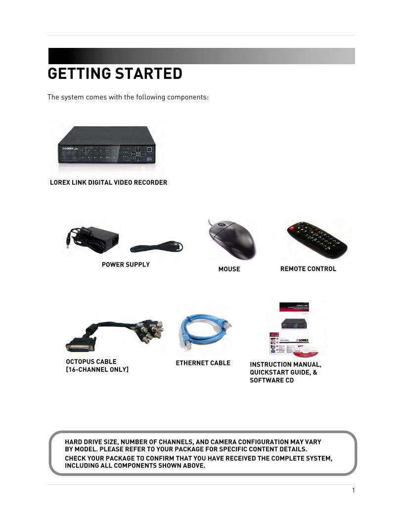
GETTING STARTEDThe system comes with the following components:
LOREX LINK DIGITAL VIDEO RECORDER
POWER SUPPLY
INSTRUCTION MANUAL, QUICKSTART GUIDE, & SOFTWARE CD
REMOTE CONTROL
ETHERNET CABLE
MOUSE
OCTOPUS CABLE [16-CHANNEL ONLY]
HARD DRIVE SIZE, NUMBER OF CHANNELS, AND CAMERA CONFIGURATION MAY VARYBY MODEL. PLEASE REFER TO YOUR PACKAGE FOR SPECIFIC CONTENT DETAILS.CHECK YOUR PACKAGE TO CONFIRM THAT YOU HAVE RECEIVED THE COMPLETE SYSTEM, INCLUDING ALL COMPONENTS SHOWN ABOVE.
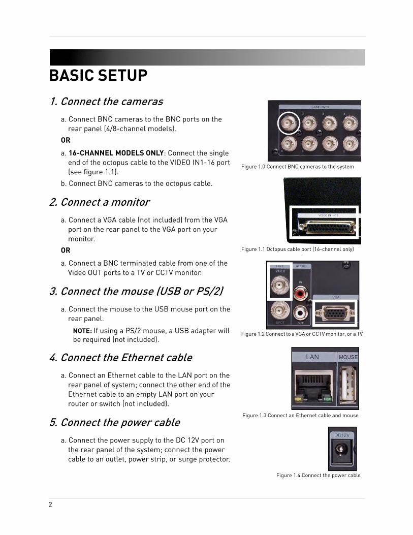
BASIC SETUP1. Connect the cameras
a. Connect BNC cameras to the BNC ports on the rear panel (4/8-channel models).
OR
a. 16-CHANNEL MODELS ONLY: Connect the single end of the octopus cable to the VIDEO IN1-16 port (see figure 1.1).
b. Connect BNC cameras to the octopus cable.
2. Connect a monitora. Connect a VGA cable (not included) from the VGA
port on the rear panel to the VGA port on your monitor.
OR
a. Connect a BNC terminated cable from one of the Video OUT ports to a TV or CCTV monitor.
3. Connect the mouse (USB or PS/2)a. Connect the mouse to the USB mouse port on the
rear panel.
NOTE: If using a PS/2 mouse, a USB adapter will be required (not included).
4. Connect the Ethernet cablea. Connect an Ethernet cable to the LAN port on the
rear panel of system; connect the other end of the Ethernet cable to an empty LAN port on your router or switch (not included).
5. Connect the power cablea. Connect the power supply to the DC 12V port on
the rear panel of the system; connect the power cable to an outlet, power strip, or surge protector.
Figure 1.0 Connect BNC cameras to the system
Figure 1.2 Connect to a VGA or CCTV monitor, or a TV
Figure 1.3 Connect an Ethernet cable and mouse
Figure 1.4 Connect the power cable
Figure 1.1 Octopus cable port (16-channel only)
2
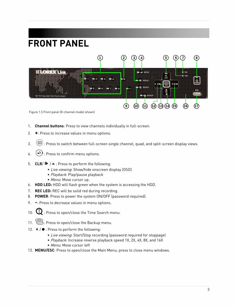
FRONT PANEL
1. Channel buttons: Press to view channels individually in full-screen.
2. +: Press to increase values in menu options.
3. : Press to switch between full-screen single channel, quad, and split-screen display views.
4. : Press to confirm menu options.
5. CLR/ / : Press to perform the following:• Live viewing: Show/hide onscreen display (OSD)• Playback: Play/pause playback• Menu: Move cursor up.
6. HDD LED: HDD will flash green when the system is accessing the HDD.
7. REC LED: REC will be solid red during recording.8. POWER: Press to power the system ON/OFF (password required).
9. -: Press to decrease values in menu options.
10. : Press to open/close the Time Search menu.
11. : Press to open/close the Backup menu.
12. / : Press to perform the following:• Live viewing: Start/Stop recording (password required for stoppage)• Playback: Increase reverse playback speed 1X, 2X, 4X, 8X, and 16X• Menu: Move cursor left
13. MENU/ESC: Press to open/close the Main Menu; press to close menu windows.
1 2 6 7
10
Figure 1.5 Front panel (8-channel model shown)
3 54 8
1716151413129 11
3
Front Panel
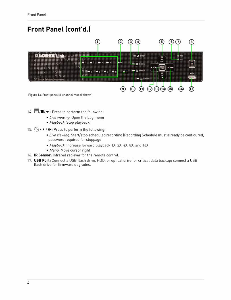
Front Panel (cont’d.)
14. / / : Press to perform the following:• Live viewing: Open the Log menu• Playback: Stop playback
15. / / : Press to perform the following:• Live viewing: Start/stop scheduled recording (Recording Schedule must already be configured;
password required for stoppage)• Playback: Increase forward playback 1X, 2X, 4X, 8X, and 16X• Menu: Move cursor right
16. IR Sensor: Infrared reciever for the remote control.17. USB Port: Connect a USB flash drive, HDD, or optical drive for critical data backup; connect a USB
flash drive for firmware upgrades.
Figure 1.6 Front panel (8-channel model shown)
1 2 6 7
10
3 54 8
1716151413129 11
4
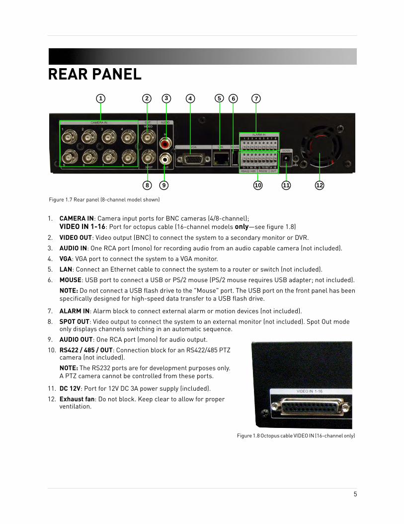
REAR PANEL
1. CAMERA IN: Camera input ports for BNC cameras (4/8-channel); VIDEO IN 1-16: Port for octopus cable (16-channel models only—see figure 1.8)
2. VIDEO OUT: Video output (BNC) to connect the system to a secondary monitor or DVR.
3. AUDIO IN: One RCA port (mono) for recording audio from an audio capable camera (not included).
4. VGA: VGA port to connect the system to a VGA monitor.
5. LAN: Connect an Ethernet cable to connect the system to a router or switch (not included).
6. MOUSE: USB port to connect a USB or PS/2 mouse (PS/2 mouse requires USB adapter; not included).
NOTE: Do not connect a USB flash drive to the "Mouse" port. The USB port on the front panel has been specifically designed for high-speed data transfer to a USB flash drive.
7. ALARM IN: Alarm block to connect external alarm or motion devices (not included).
8. SPOT OUT: Video output to connect the system to an external monitor (not included). Spot Out mode only displays channels switching in an automatic sequence.
9. AUDIO OUT: One RCA port (mono) for audio output.
10. RS422 / 485 / OUT: Connection block for an RS422/485 PTZ camera (not included).
NOTE: The RS232 ports are for development purposes only. A PTZ camera cannot be controlled from these ports.
11. DC 12V: Port for 12V DC 3A power supply (included).
12. Exhaust fan: Do not block. Keep clear to allow for proper ventilation.
4 5 61 2 3
8 9 10 11 12
Figure 1.7 Rear panel (8-channel model shown)
7
Figure 1.8 Octopus cable VIDEO IN (16-channel only)
5
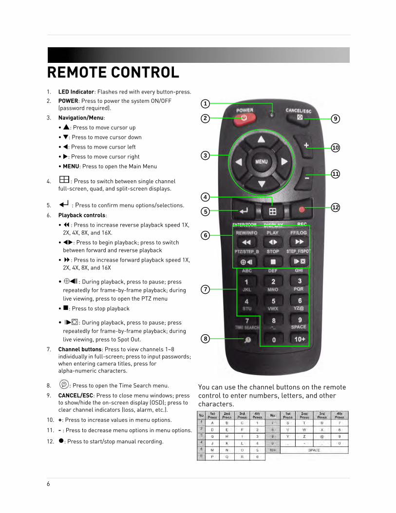
REMOTE CONTROL1. LED Indicator: Flashes red with every button-press.
2. POWER: Press to power the system ON/OFF (password required).
3. Navigation/Menu:
• : Press to move cursor up
• : Press to move cursor down
• : Press to move cursor left
• : Press to move cursor right
• MENU: Press to open the Main Menu
4. : Press to switch between single channel full-screen, quad, and split-screen displays.
5. : Press to confirm menu options/selections.
6. Playback controls:
• : Press to increase reverse playback speed 1X, 2X, 4X, 8X, and 16X.
• : Press to begin playback; press to switch between forward and reverse playback
• : Press to increase forward playback speed 1X, 2X, 4X, 8X, and 16X
• : During playback, press to pause; press repeatedly for frame-by-frame playback; during live viewing, press to open the PTZ menu
• : Press to stop playback
• : During playback, press to pause; press repeatedly for frame-by-frame playback; during live viewing, press to Spot Out.
7. Channel buttons: Press to view channels 1~8 individually in full-screen; press to input passwords; when entering camera titles, press for alpha-numeric characters.
8. : Press to open the Time Search menu.
9. CANCEL/ESC: Press to close menu windows; press to show/hide the on-screen display (OSD); press to clear channel indicators (loss, alarm, etc.).
10. +: Press to increase values in menu options.
11. - : Press to decrease menu options in menu options.
12. : Press to start/stop manual recording.
9
10
1
4
3
5
6
7
8
11
12
You can use the channel buttons on the remote control to enter numbers, letters, and other characters.
2
6
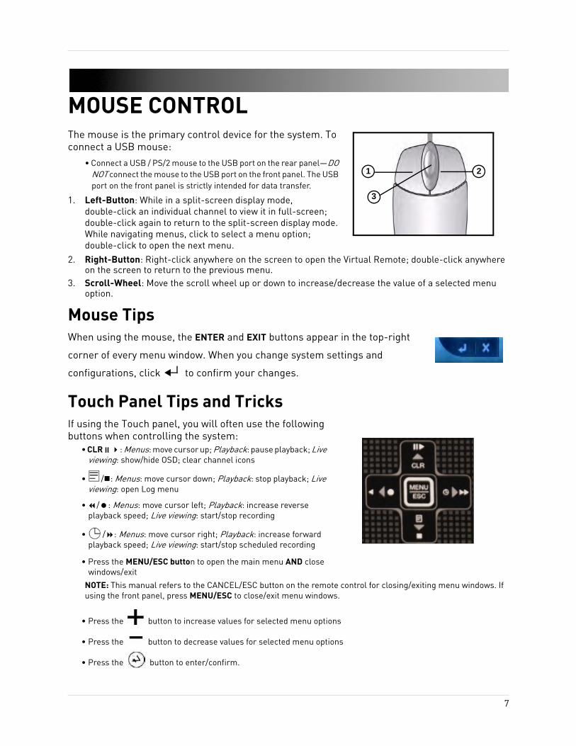
MOUSE CONTROLThe mouse is the primary control device for the system. To connect a USB mouse:
• Connect a USB / PS/2 mouse to the USB port on the rear panel—DO NOT connect the mouse to the USB port on the front panel. The USB port on the front panel is strictly intended for data transfer.
1. Left-Button: While in a split-screen display mode, double-click an individual channel to view it in full-screen; double-click again to return to the split-screen display mode. While navigating menus, click to select a menu option; double-click to open the next menu.
2. Right-Button: Right-click anywhere on the screen to open the Virtual Remote; double-click anywhere on the screen to return to the previous menu.
3. Scroll-Wheel: Move the scroll wheel up or down to increase/decrease the value of a selected menu option.
Mouse TipsWhen using the mouse, the ENTER and EXIT buttons appear in the top-right
corner of every menu window. When you change system settings and
configurations, click to confirm your changes.
Touch Panel Tips and TricksIf using the Touch panel, you will often use the following buttons when controlling the system:
• CLR : Menus: move cursor up; Playback: pause playback; Live viewing: show/hide OSD; clear channel icons
• / : Menus: move cursor down; Playback: stop playback; Live viewing: open Log menu
• / : Menus: move cursor left; Playback: increase reverse playback speed; Live viewing: start/stop recording
• / : Menus: move cursor right; Playback: increase forward playback speed; Live viewing: start/stop scheduled recording
• Press the MENU/ESC button to open the main menu AND close windows/exit
NOTE: This manual refers to the CANCEL/ESC button on the remote control for closing/exiting menu windows. If using the front panel, press MENU/ESC to close/exit menu windows.
• Press the button to increase values for selected menu options
• Press the button to decrease values for selected menu options
• Press the button to enter/confirm.
1 2
3
7
USING THE SYSTEMTo power the system ON/OFF:1. Connect the power cable to the port on the rear panel.2. Press the POWER button on the front panel or remote control.
NOTE: You need to press the Power button for initial startup only. The system will load the live viewing screen on subsequent resets.
NOTE: You will need to input your system password (by default, 000000) to power off the system. Use the mouse or remote control to enter the password. You can also use the front panel to enter in the 0’s by pressing + and simultaneously.
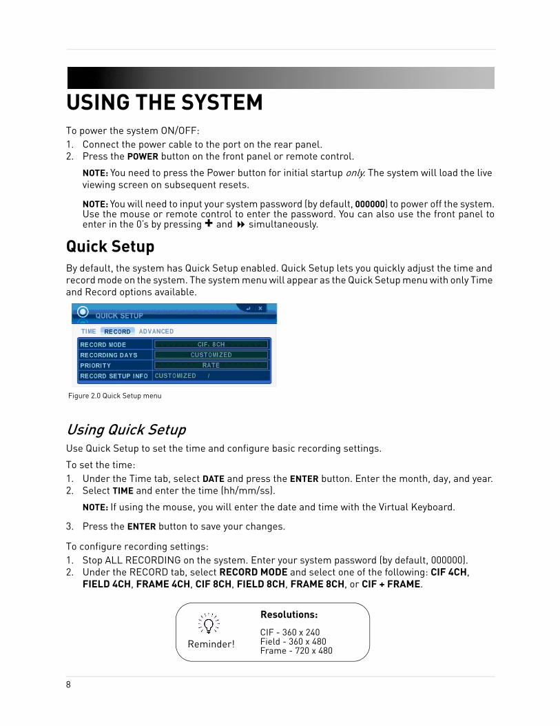
Quick SetupBy default, the system has Quick Setup enabled. Quick Setup lets you quickly adjust the time and record mode on the system. The system menu will appear as the Quick Setup menu with only Time and Record options available.
Using Quick SetupUse Quick Setup to set the time and configure basic recording settings.
To set the time:1. Under the Time tab, select DATE and press the ENTER button. Enter the month, day, and year.2. Select TIME and enter the time (hh/mm/ss).
NOTE: If using the mouse, you will enter the date and time with the Virtual Keyboard.
3. Press the ENTER button to save your changes.
To configure recording settings:1. Stop ALL RECORDING on the system. Enter your system password (by default, 000000).2. Under the RECORD tab, select RECORD MODE and select one of the following: CIF 4CH,
FIELD 4CH, FRAME 4CH, CIF 8CH, FIELD 8CH, FRAME 8CH, or CIF + FRAME.
Figure 2.0 Quick Setup menu
CIF - 360 x 240Field - 360 x 480Frame - 720 x 480
Reminder!
Resolutions:
8
Using the System
Using Quick Setup (cont’d.)NOTE: If "CIF + FRAME" recording mode is selected, only channel 1 will record in frame—the remaining channels will record in CIF.
3. Under the RECORD tab, select RECORDING DAYS. Press the +/ - buttons and select 12 HOURS, 1~6 DAYS, 1~20 WEEKS, or NONE.
4. Under PRIORITY, select QUALITY (the quality of the video) or RATE (frames per second). If you select RATE, the video quality and frames per second will be at the lowest possible setting. This will reduce overall video quality, but will maximize the available hard drive space. Adjust this setting to best suit your recording environment and security needs. For details on configuring recording options, see “RECORD” on page 24.
NOTE: The necessary recording parameters will appear under RECORD SETUP INFO at the bottom of the Quick Setup window.
5. Press the ENTER button to save your settings.
Enabling/Disabling Quick SetupYou must disable Quick Setup in order to access the full system main menu.
To disable Quick Setup:1. Under the ADVANCED tab, select RUN ADVANCED.2. Select ON and press the ENTER button. The window closes. Quick Setup has been disabled.
The full main menu will appear when you press the MENU button.
To enable Quick Setup:1. Press the MENU button. The Main menu opens.2. Select DISPLAY and press the ENTER button.3. Under the DISPLAY SETUP tab, move the cursor to QUICK SETUP, select ON and press the
ENTER button.4. Press the CANCEL/ESC button to exit.5. Press the MENU button again to open the Quick Setup menu.
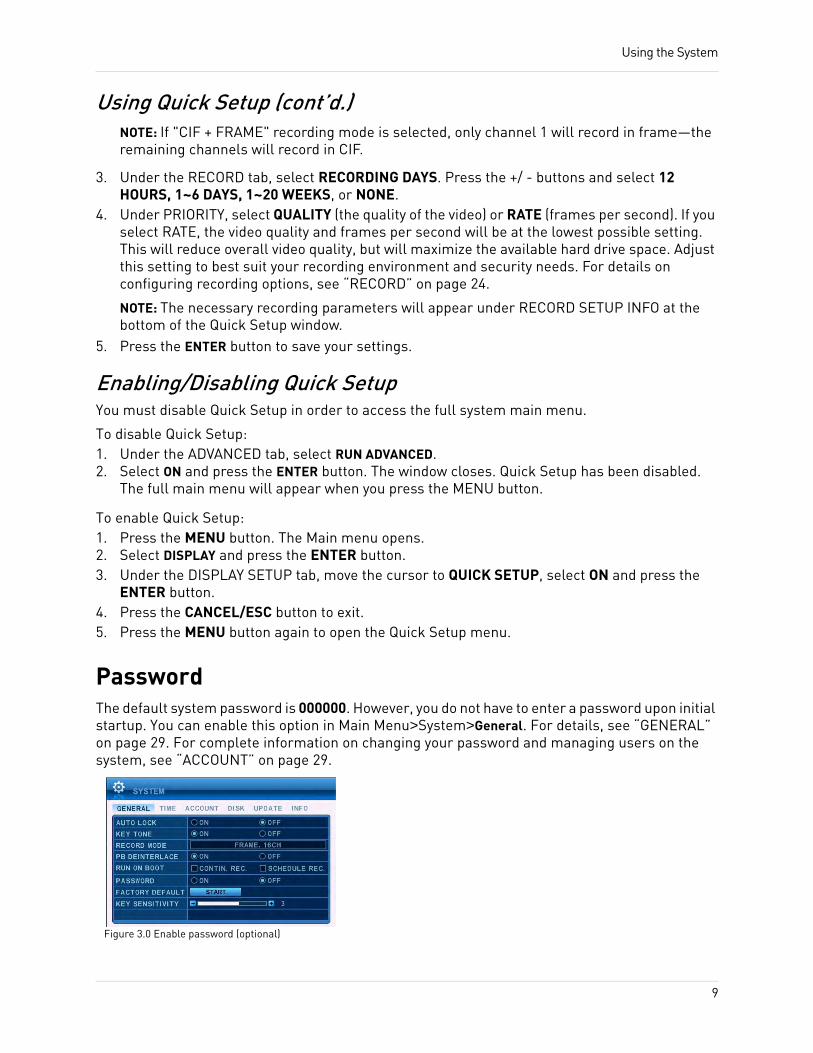
PasswordThe default system password is 000000. However, you do not have to enter a password upon initial startup. You can enable this option in Main Menu>System>General. For details, see “GENERAL” on page 29. For complete information on changing your password and managing users on the system, see “ACCOUNT” on page 29.
Figure 3.0 Enable password (optional)
9
Using the System
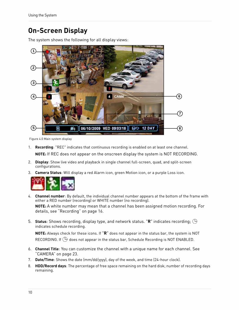
On-Screen DisplayThe system shows the following for all display views:
1. Recording: "REC" indicates that continuous recording is enabled on at least one channel.
NOTE: If REC does not appear on the onscreen display the system is NOT RECORDING.
2. Display: Show live video and playback in single channel full-screen, quad, and split-screen configurations.
3. Camera Status: Will display a red Alarm icon, green Motion icon, or a purple Loss icon.
4. Channel number: By default, the individual channel number appears at the bottom of the frame with either a RED number (recording) or WHITE number (no recording).NOTE: A white number may mean that a channel has been assigned motion recording. For details, see “Recording” on page 16.
5. Status: Shows recording, display type, and network status. "R" indicates recording; indicates schedule recording.
NOTE: Always check for these icons. If "R" does not appear in the status bar, the system is NOT
RECORDING. If does not appear in the status bar, Schedule Recording is NOT ENABLED.
6. Channel Title: You can customize the channel with a unique name for each channel. See “CAMERA” on page 23.
7. Date/Time: Shows the date (mm/dd/yyyy), day of the week, and time (24-hour clock).
8. HDD/Record days: The percentage of free space remaining on the hard disk; number of recording days remaining.
Figure 4.0 Main system display
1
2
7
8
3
4
5
6
10
Using the System
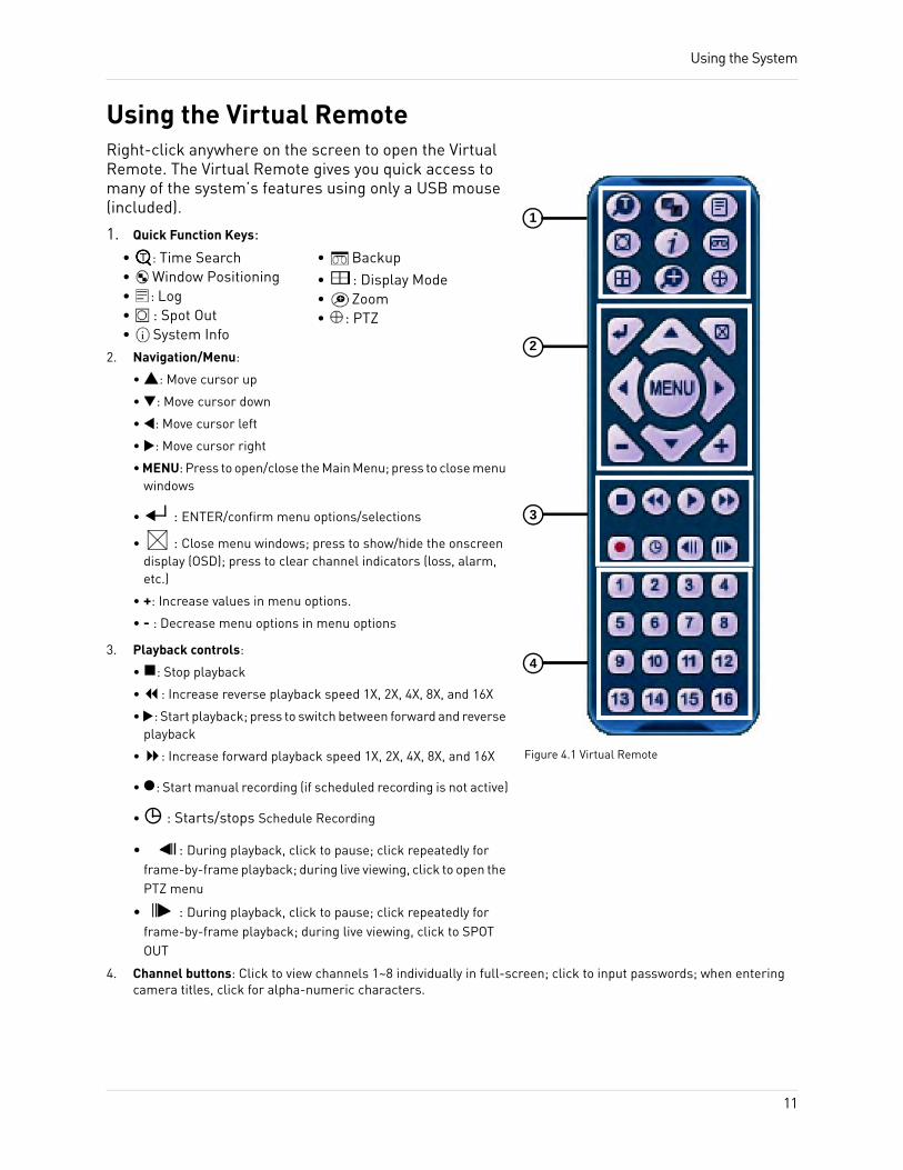
Using the Virtual RemoteRight-click anywhere on the screen to open the Virtual Remote. The Virtual Remote gives you quick access to many of the system’s features using only a USB mouse (included).
1. Quick Function Keys:
2. Navigation/Menu:
• : Move cursor up
• : Move cursor down
• : Move cursor left
• : Move cursor right
• MENU: Press to open/close the Main Menu; press to close menu windows
• : ENTER/confirm menu options/selections
• : Close menu windows; press to show/hide the onscreen display (OSD); press to clear channel indicators (loss, alarm, etc.)
• +: Increase values in menu options.
• - : Decrease menu options in menu options
3. Playback controls:
• : Stop playback
• : Increase reverse playback speed 1X, 2X, 4X, 8X, and 16X
• : Start playback; press to switch between forward and reverse playback
• : Increase forward playback speed 1X, 2X, 4X, 8X, and 16X
• : Start manual recording (if scheduled recording is not active)
• : Starts/stops Schedule Recording
• : During playback, click to pause; click repeatedly for frame-by-frame playback; during live viewing, click to open the PTZ menu
• : During playback, click to pause; click repeatedly for frame-by-frame playback; during live viewing, click to SPOT OUT
4. Channel buttons: Click to view channels 1~8 individually in full-screen; click to input passwords; when entering camera titles, click for alpha-numeric characters.
2
3
1
Figure 4.1 Virtual Remote
4
• : Time Search• Window Positioning• : Log• : Spot Out• System Info
• Backup• : Display Mode• Zoom• : PTZ
11
Using the System
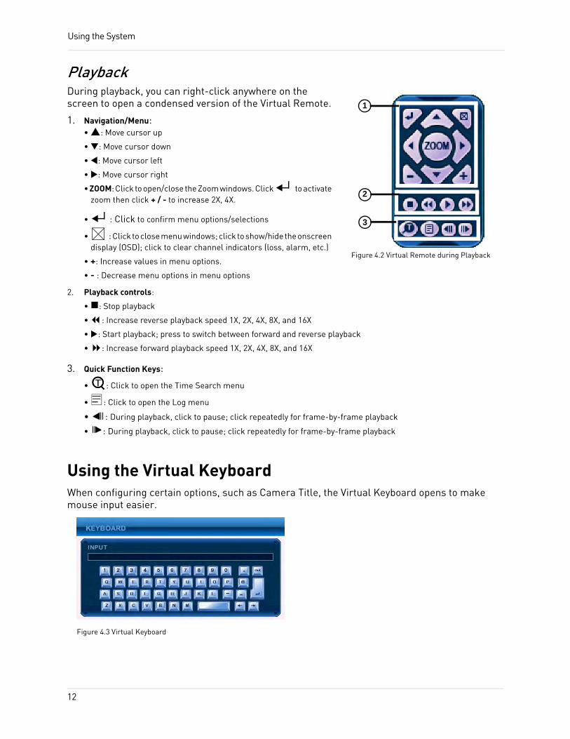
PlaybackDuring playback, you can right-click anywhere on the screen to open a condensed version of the Virtual Remote.
1. Navigation/Menu: • : Move cursor up
• : Move cursor down
• : Move cursor left
• : Move cursor right
• ZOOM: Click to open/close the Zoom windows. Click to activate zoom then click + / - to increase 2X, 4X.
• : Click to confirm menu options/selections
• : Click to close menu windows; click to show/hide the onscreen display (OSD); click to clear channel indicators (loss, alarm, etc.)
• +: Increase values in menu options.
• - : Decrease menu options in menu options
2. Playback controls:
• : Stop playback
• : Increase reverse playback speed 1X, 2X, 4X, 8X, and 16X
• : Start playback; press to switch between forward and reverse playback
• : Increase forward playback speed 1X, 2X, 4X, 8X, and 16X
3. Quick Function Keys:
• : Click to open the Time Search menu
• : Click to open the Log menu
• : During playback, click to pause; click repeatedly for frame-by-frame playback
• : During playback, click to pause; click repeatedly for frame-by-frame playback
Using the Virtual KeyboardWhen configuring certain options, such as Camera Title, the Virtual Keyboard opens to make mouse input easier.
2
3
1
Figure 4.2 Virtual Remote during Playback
Figure 4.3 Virtual Keyboard
12
Using the System
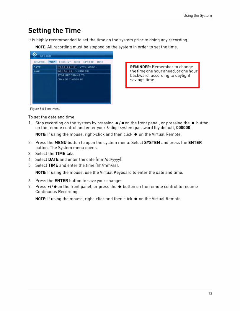
Setting the TimeIt is highly recommended to set the time on the system prior to doing any recording.
NOTE: All recording must be stopped on the system in order to set the time.
To set the date and time:1. Stop recording on the system by pressing / on the front panel, or pressing the button
on the remote control and enter your 6-digit system password (by default, 000000).
NOTE: If using the mouse, right-click and then click on the Virtual Remote.
2. Press the MENU button to open the system menu. Select SYSTEM and press the ENTER button. The System menu opens.
3. Select the TIME tab.4. Select DATE and enter the date (mm/dd/yyyy).5. Select TIME and enter the time (hh/mm/ss).
NOTE: If using the mouse, use the Virtual Keyboard to enter the date and time.
6. Press the ENTER button to save your changes.7. Press / on the front panel, or press the button on the remote control to resume
Continuous Recording.
NOTE: If using the mouse, right-click and then click on the Virtual Remote.
Figure 5.0 Time menu
REMINDER: Remember to change the time one hour ahead, or one hour backward, according to daylight savings time.
13
Using the System
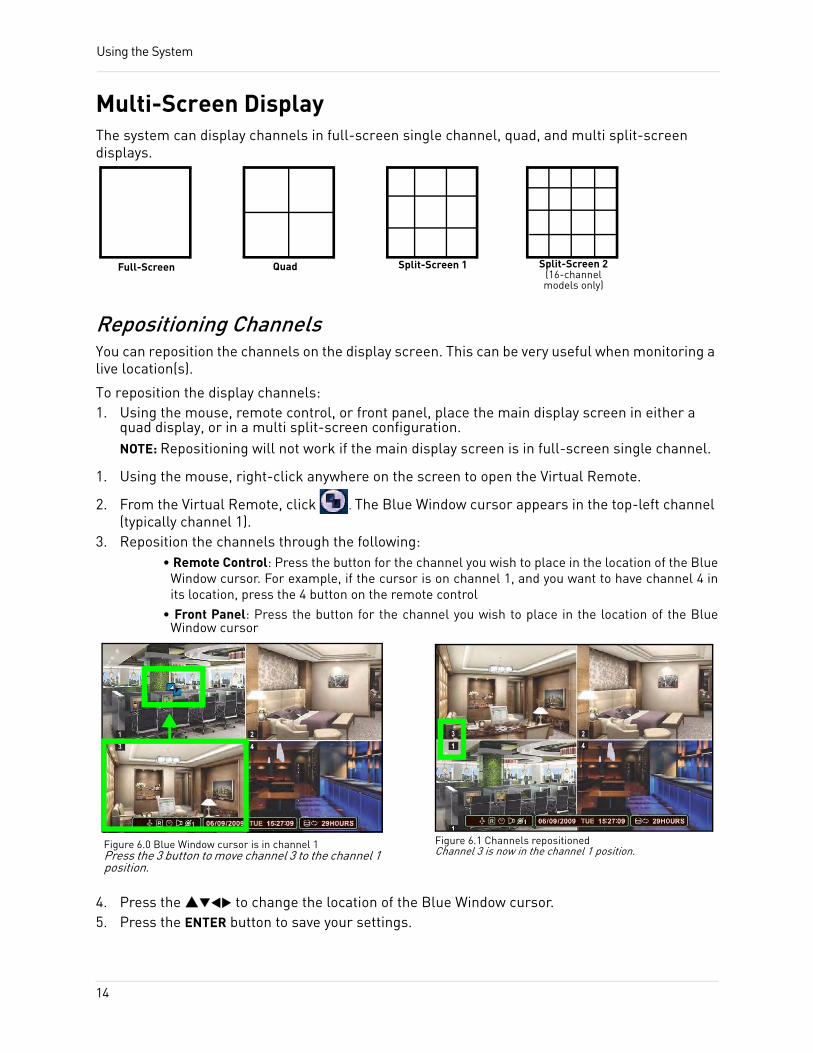
Multi-Screen DisplayThe system can display channels in full-screen single channel, quad, and multi split-screen displays.
Repositioning ChannelsYou can reposition the channels on the display screen. This can be very useful when monitoring a live location(s).
To reposition the display channels:1. Using the mouse, remote control, or front panel, place the main display screen in either a
quad display, or in a multi split-screen configuration.NOTE: Repositioning will not work if the main display screen is in full-screen single channel.
1. Using the mouse, right-click anywhere on the screen to open the Virtual Remote.
2. From the Virtual Remote, click . The Blue Window cursor appears in the top-left channel (typically channel 1).
3. Reposition the channels through the following:• Remote Control: Press the button for the channel you wish to place in the location of the Blue
Window cursor. For example, if the cursor is on channel 1, and you want to have channel 4 in its location, press the 4 button on the remote control
• Front Panel: Press the button for the channel you wish to place in the location of the Blue Window cursor
4. Press the to change the location of the Blue Window cursor.5. Press the ENTER button to save your settings.
Full-Screen Quad Split-Screen 1 Split-Screen 2 (16-channel models only)
Figure 6.0 Blue Window cursor is in channel 1Press the 3 button to move channel 3 to the channel 1 position.
Figure 6.1 Channels repositioned Channel 3 is now in the channel 1 position.
14
Using the System
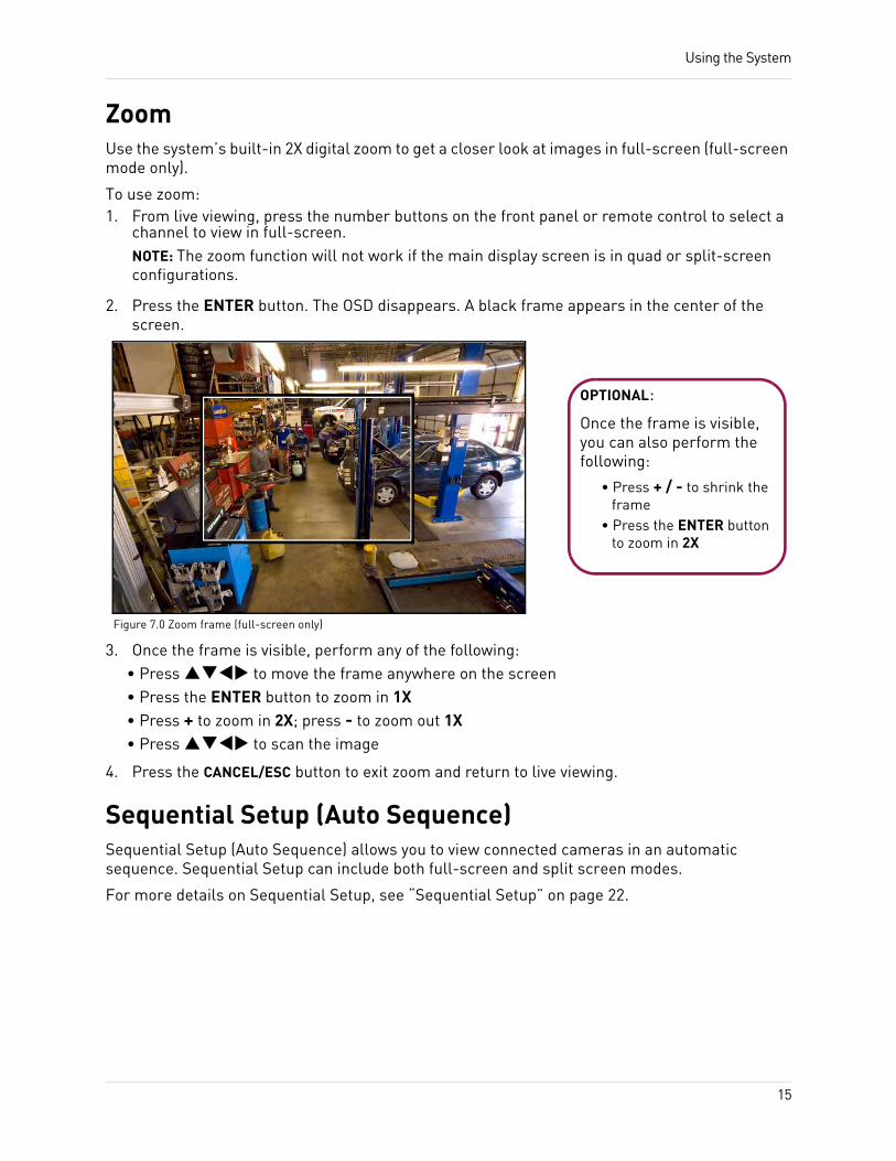
ZoomUse the system’s built-in 2X digital zoom to get a closer look at images in full-screen (full-screen mode only).
To use zoom:1. From live viewing, press the number buttons on the front panel or remote control to select a
channel to view in full-screen.NOTE: The zoom function will not work if the main display screen is in quad or split-screen configurations.
2. Press the ENTER button. The OSD disappears. A black frame appears in the center of the screen.
3. Once the frame is visible, perform any of the following:• Press to move the frame anywhere on the screen• Press the ENTER button to zoom in 1X• Press + to zoom in 2X; press - to zoom out 1X• Press to scan the image
4. Press the CANCEL/ESC button to exit zoom and return to live viewing.
Sequential Setup (Auto Sequence)Sequential Setup (Auto Sequence) allows you to view connected cameras in an automatic sequence. Sequential Setup can include both full-screen and split screen modes.
For more details on Sequential Setup, see “Sequential Setup” on page 22.
OPTIONAL:
Once the frame is visible, you can also perform the following:
• Press + / - to shrink the frame
• Press the ENTER button to zoom in 2X
Figure 7.0 Zoom frame (full-screen only)
15
RECORDINGBy default, the system is set to immediately record at startup from connected cameras—continuous recording. It is highly recommended to keep continuous recording on at all times.
The system can perform Continuous Recording, Event Recording, and Schedule Recording. However, the system can only perform one type of recording at a given time.
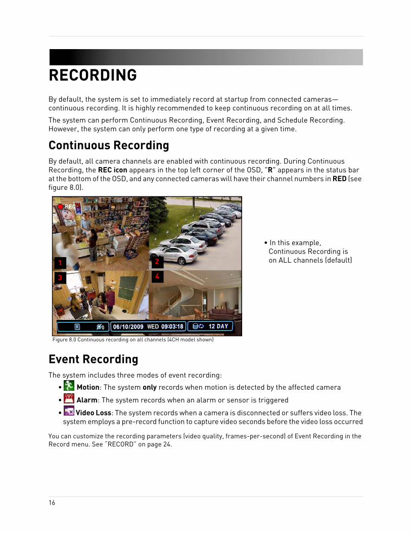
Continuous RecordingBy default, all camera channels are enabled with continuous recording. During Continuous Recording, the REC icon appears in the top left corner of the OSD, "R" appears in the status bar at the bottom of the OSD, and any connected cameras will have their channel numbers in RED (see figure 8.0).
Event RecordingThe system includes three modes of event recording:
• Motion: The system only records when motion is detected by the affected camera
• Alarm: The system records when an alarm or sensor is triggered
• Video Loss: The system records when a camera is disconnected or suffers video loss. The system employs a pre-record function to capture video seconds before the video loss occurred
You can customize the recording parameters (video quality, frames-per-second) of Event Recording in the Record menu. See “RECORD” on page 24.
1 2
3 4
Figure 8.0 Continuous recording on all channels (4CH model shown)
• In this example, Continuous Recording is on ALL channels (default)
16
Recording
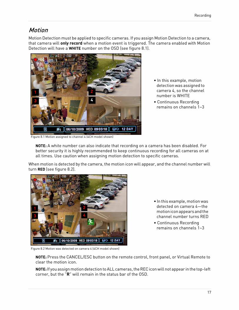
MotionMotion Detection must be applied to specific cameras. If you assign Motion Detection to a camera, that camera will only record when a motion event is triggered. The camera enabled with Motion Detection will have a WHITE number on the OSD (see figure 8.1).
NOTE: A white number can also indicate that recording on a camera has been disabled. For better security it is highly recommended to keep continuous recording for all cameras on at all times. Use caution when assigning motion detection to specific cameras.
When motion is detected by the camera, the motion icon will appear, and the channel number will turn RED (see figure 8.2).
NOTE: Press the CANCEL/ESC button on the remote control, front panel, or Virtual Remote to clear the motion icon.
NOTE: If you assign motion detection to ALL cameras, the REC icon will not appear in the top-left corner, but the "R" will remain in the status bar of the OSD.
1 2
3 4
Figure 8.1 Motion assigned to channel 4 (4CH model shown)
• In this example, motion detection was assigned to camera 4, so the channel number is WHITE
• Continuous Recording remains on channels 1~3
1 2
3 4
Figure 8.2 Motion was detected on camera 4 (4CH model shown)
• In this example, motion was detected on camera 4—the motion icon appears and the channel number turns RED
• Continuous Recording remains on channels 1~3
17
Recording
AlarmWhen an alarm is triggered, the system will continue to record, but can apply unique recording parameters that you can set in the Alarm menu (Main Menu>Alarm). For details, see “ALARM” on page 24.
NOTE: Press the CANCEL/ESC button on the remote control, front panel, or Virtual Remote to clear the alarm icon.
Video LossIf a camera is disconnected or is damaged, the video loss icon will appear for the affected channel. The channel number will turn WHITE.
NOTE: Once video has been restored, press the CANCEL/ESC button on the remote control, front panel, or Virtual Remote to clear the video loss icon.
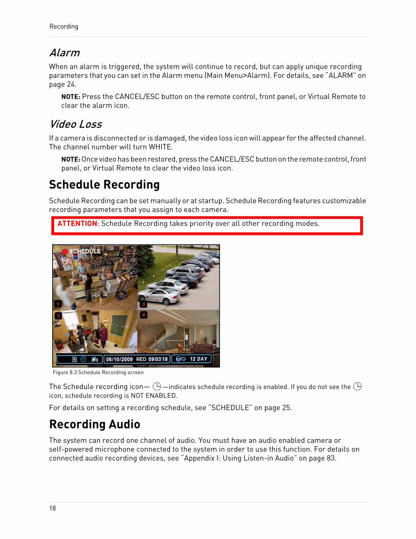
Schedule RecordingSchedule Recording can be set manually or at startup. Schedule Recording features customizable recording parameters that you assign to each camera.
The Schedule recording icon— —indicates schedule recording is enabled. If you do not see the icon, schedule recording is NOT ENABLED.
For details on setting a recording schedule, see “SCHEDULE” on page 25.
Recording AudioThe system can record one channel of audio. You must have an audio enabled camera or self-powered microphone connected to the system in order to use this function. For details on connected audio recording devices, see “Appendix I: Using Listen-in Audio” on page 83.
Figure 8.3 Schedule Recording screen
ATTENTION: Schedule Recording takes priority over all other recording modes.
18
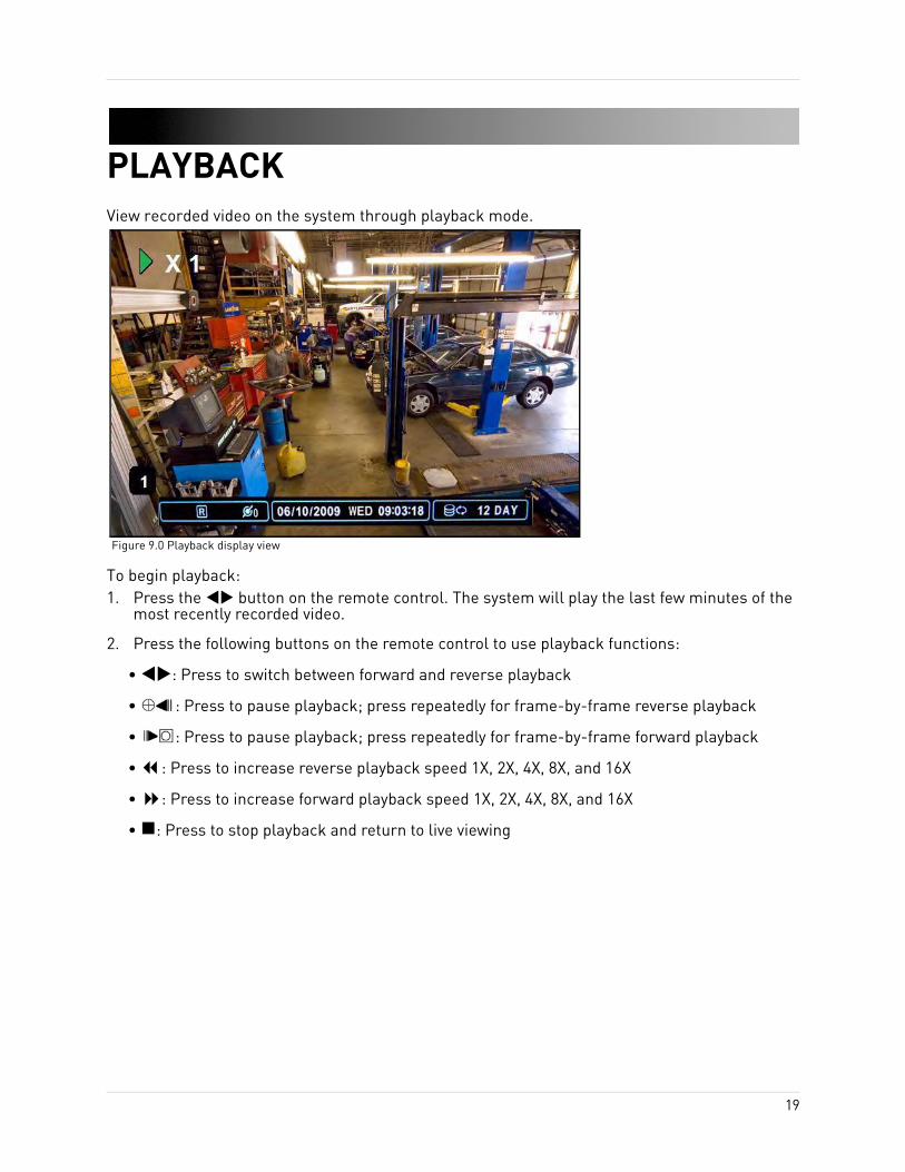
PLAYBACKView recorded video on the system through playback mode.
To begin playback:1. Press the button on the remote control. The system will play the last few minutes of the
most recently recorded video.
2. Press the following buttons on the remote control to use playback functions:
• : Press to switch between forward and reverse playback
• : Press to pause playback; press repeatedly for frame-by-frame reverse playback
• : Press to pause playback; press repeatedly for frame-by-frame forward playback
• : Press to increase reverse playback speed 1X, 2X, 4X, 8X, and 16X
• : Press to increase forward playback speed 1X, 2X, 4X, 8X, and 16X
• : Press to stop playback and return to live viewing
Figure 9.0 Playback display view
19
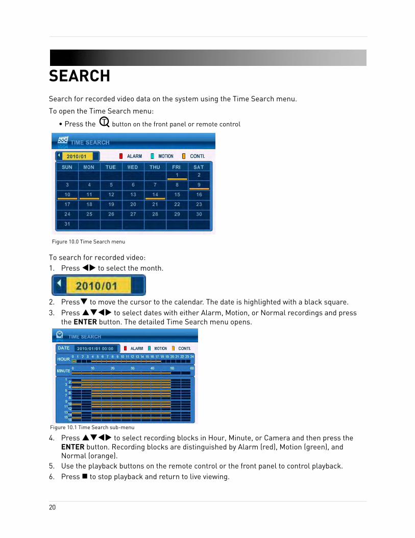
SEARCHSearch for recorded video data on the system using the Time Search menu.
To open the Time Search menu:
• Press the button on the front panel or remote control
To search for recorded video:1. Press to select the month.
2. Press to move the cursor to the calendar. The date is highlighted with a black square.3. Press to select dates with either Alarm, Motion, or Normal recordings and press
the ENTER button. The detailed Time Search menu opens.
4. Press to select recording blocks in Hour, Minute, or Camera and then press the ENTER button. Recording blocks are distinguished by Alarm (red), Motion (green), and Normal (orange).
5. Use the playback buttons on the remote control or the front panel to control playback.6. Press to stop playback and return to live viewing.
Figure 10.0 Time Search menu
Figure 10.1 Time Search sub-menu
20
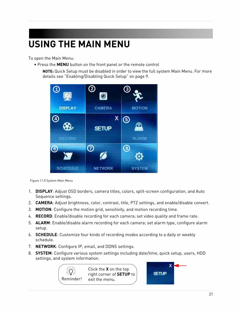
USING THE MAIN MENUTo open the Main Menu:
• Press the MENU button on the front panel or the remote control
NOTE: Quick Setup must be disabled in order to view the full system Main Menu. For more details see “Enabling/Disabling Quick Setup” on page 9.
1. DISPLAY: Adjust OSD borders, camera titles, colors, split-screen configuration, and Auto Sequence settings.
2. CAMERA: Adjust brightness, color, contrast, title, PTZ settings, and enable/disable convert.
3. MOTION: Configure the motion grid, sensitivity, and motion recording time.
4. RECORD: Enable/disable recording for each camera; set video quality and frame rate.
5. ALARM: Enable/disable alarm recording for each camera; set alarm type, configure alarm setup.
6. SCHEDULE: Customize four kinds of recording modes according to a daily or weekly schedule.
7. NETWORK: Configure IP, email, and DDNS settings.
8. SYSTEM: Configure various system settings including date/time, quick setup, users, HDD settings, and system information.
Figure 11.0 System Main Menu
1 2 3
4 5
6 7 8
Reminder!
Click the X on the top right corner of SETUP to exit the menu.
21
Using the Main Menu
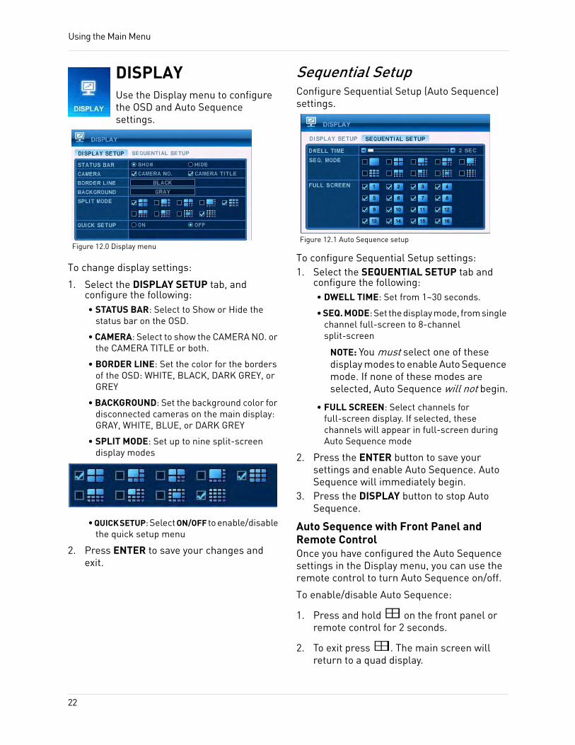
DISPLAYUse the Display menu to configure the OSD and Auto Sequence settings.
To change display settings:
1. Select the DISPLAY SETUP tab, and configure the following:• STATUS BAR: Select to Show or Hide the
status bar on the OSD.
• CAMERA: Select to show the CAMERA NO. or the CAMERA TITLE or both.
• BORDER LINE: Set the color for the borders of the OSD: WHITE, BLACK, DARK GREY, or GREY
• BACKGROUND: Set the background color for disconnected cameras on the main display: GRAY, WHITE, BLUE, or DARK GREY
• SPLIT MODE: Set up to nine split-screen display modes
• QUICK SETUP: Select ON/OFF to enable/disable the quick setup menu
2. Press ENTER to save your changes and exit.
Sequential SetupConfigure Sequential Setup (Auto Sequence) settings.
To configure Sequential Setup settings:1. Select the SEQUENTIAL SETUP tab and
configure the following:• DWELL TIME: Set from 1~30 seconds.
• SEQ. MODE: Set the display mode, from single channel full-screen to 8-channel split-screen
NOTE: You must select one of these display modes to enable Auto Sequence mode. If none of these modes are selected, Auto Sequence will not begin.
• FULL SCREEN: Select channels for full-screen display. If selected, these channels will appear in full-screen during Auto Sequence mode
2. Press the ENTER button to save your settings and enable Auto Sequence. Auto Sequence will immediately begin.
3. Press the DISPLAY button to stop Auto Sequence.
Auto Sequence with Front Panel and Remote ControlOnce you have configured the Auto Sequence settings in the Display menu, you can use the remote control to turn Auto Sequence on/off.
To enable/disable Auto Sequence:
1. Press and hold on the front panel or remote control for 2 seconds.
2. To exit press . The main screen will return to a quad display.
Figure 12.0 Display menuFigure 12.1 Auto Sequence setup
22
Using the Main Menu
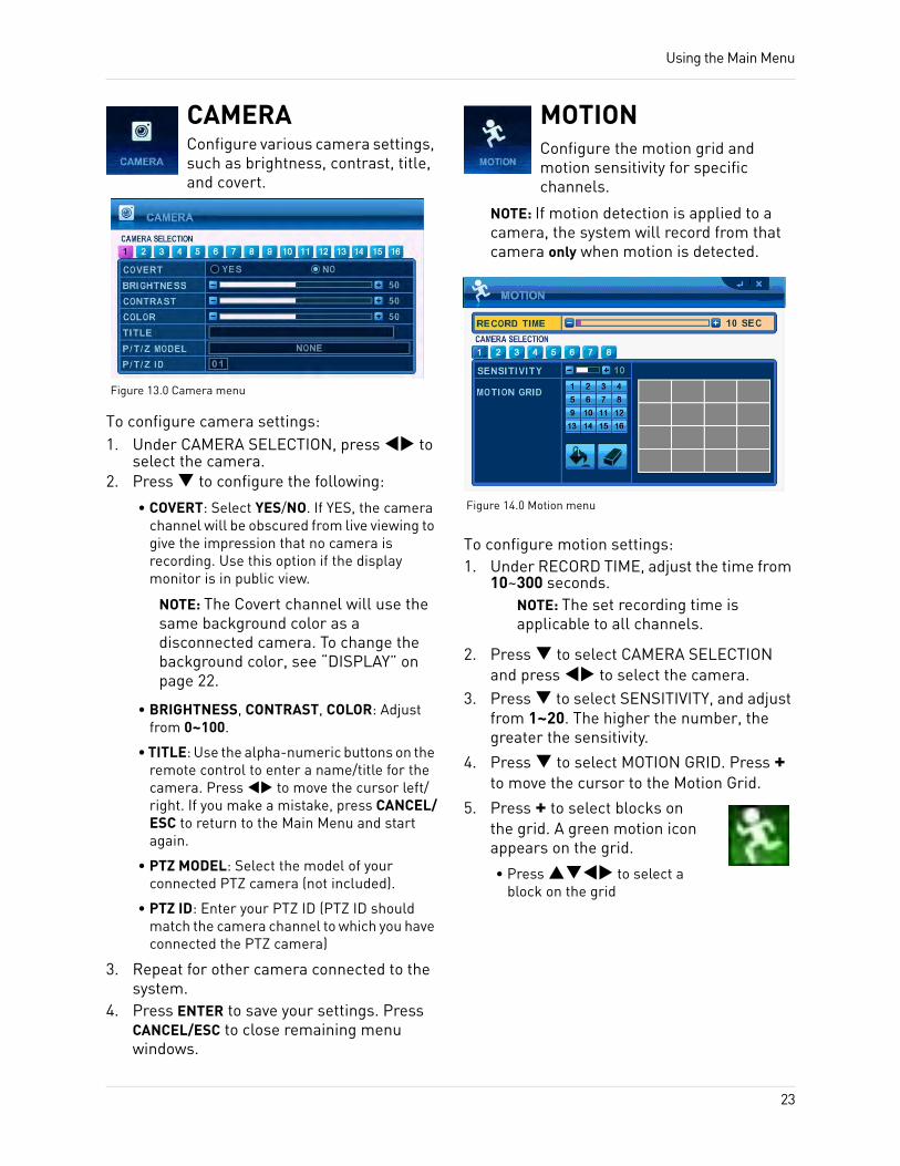
CAMERAConfigure various camera settings, such as brightness, contrast, title, and covert.
To configure camera settings:1. Under CAMERA SELECTION, press to
select the camera.2. Press to configure the following:
• COVERT: Select YES/NO. If YES, the camera channel will be obscured from live viewing to give the impression that no camera is recording. Use this option if the display monitor is in public view.
NOTE: The Covert channel will use the same background color as a disconnected camera. To change the background color, see “DISPLAY” on page 22.
• BRIGHTNESS, CONTRAST, COLOR: Adjust from 0~100.
• TITLE: Use the alpha-numeric buttons on the remote control to enter a name/title for the camera. Press to move the cursor left/right. If you make a mistake, press CANCEL/ESC to return to the Main Menu and start again.
• PTZ MODEL: Select the model of your connected PTZ camera (not included).
• PTZ ID: Enter your PTZ ID (PTZ ID should match the camera channel to which you have connected the PTZ camera)
3. Repeat for other camera connected to the system.
4. Press ENTER to save your settings. Press CANCEL/ESC to close remaining menu windows.
MOTIONConfigure the motion grid and motion sensitivity for specific channels.
NOTE: If motion detection is applied to a camera, the system will record from that camera only when motion is detected.
To configure motion settings:1. Under RECORD TIME, adjust the time from
10~300 seconds.NOTE: The set recording time is applicable to all channels.
2. Press to select CAMERA SELECTION and press to select the camera.
3. Press to select SENSITIVITY, and adjust from 1~20. The higher the number, the greater the sensitivity.
4. Press to select MOTION GRID. Press + to move the cursor to the Motion Grid.
5. Press + to select blocks on the grid. A green motion icon appears on the grid.
• Press to select a block on the grid
Figure 13.0 Camera menu
Figure 14.0 Motion menu
23
Using the Main Menu
• Press + enable/disable motion sensitivity. Disabled blocks are colored grey. Active blocks will be turquoise-colored when motion is detected. Move an object in front of the selected camera to test sensitivity and enable/disable the appropriate blocks
• Press - to exit the grid
• Press to select All/Clear and then press +.
6. Press ENTER to save your settings. Press CANCEL/ESC to close remaining menu windows.
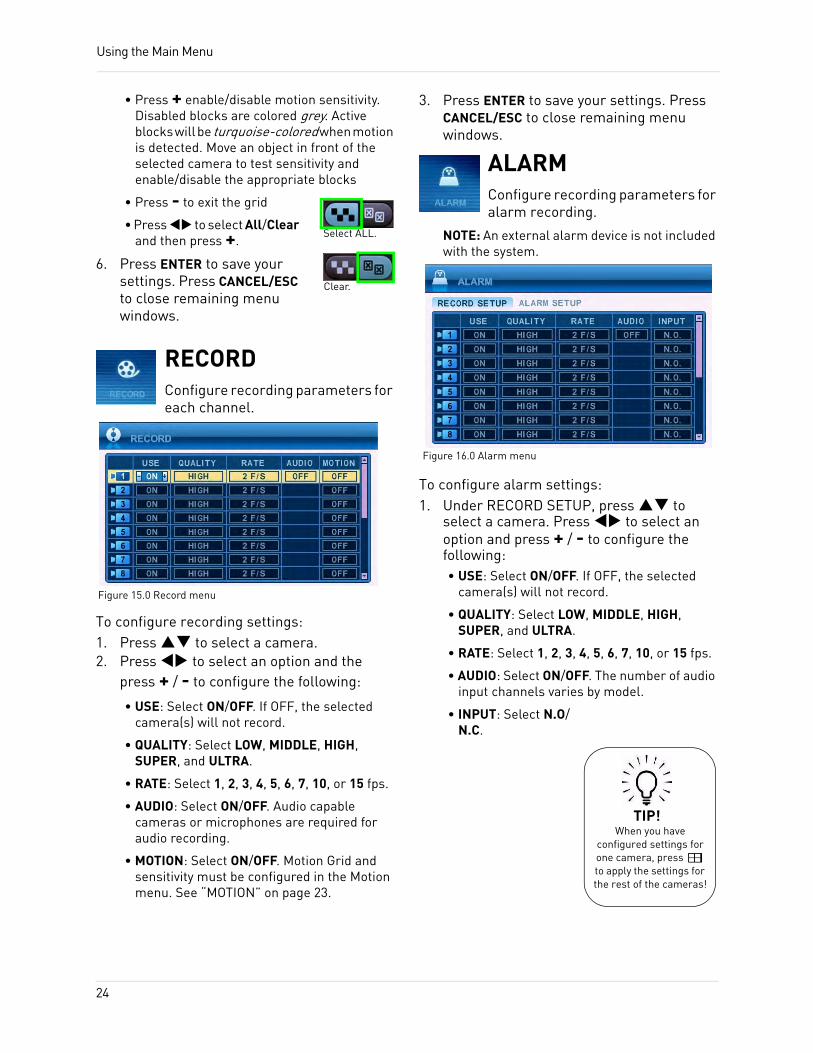
RECORDConfigure recording parameters for each channel.
To configure recording settings:1. Press to select a camera.2. Press to select an option and the
press + / - to configure the following:
• USE: Select ON/OFF. If OFF, the selected camera(s) will not record.
• QUALITY: Select LOW, MIDDLE, HIGH, SUPER, and ULTRA.
• RATE: Select 1, 2, 3, 4, 5, 6, 7, 10, or 15 fps.
• AUDIO: Select ON/OFF. Audio capable cameras or microphones are required for audio recording.
• MOTION: Select ON/OFF. Motion Grid and sensitivity must be configured in the Motion menu. See “MOTION” on page 23.
3. Press ENTER to save your settings. Press CANCEL/ESC to close remaining menu windows.
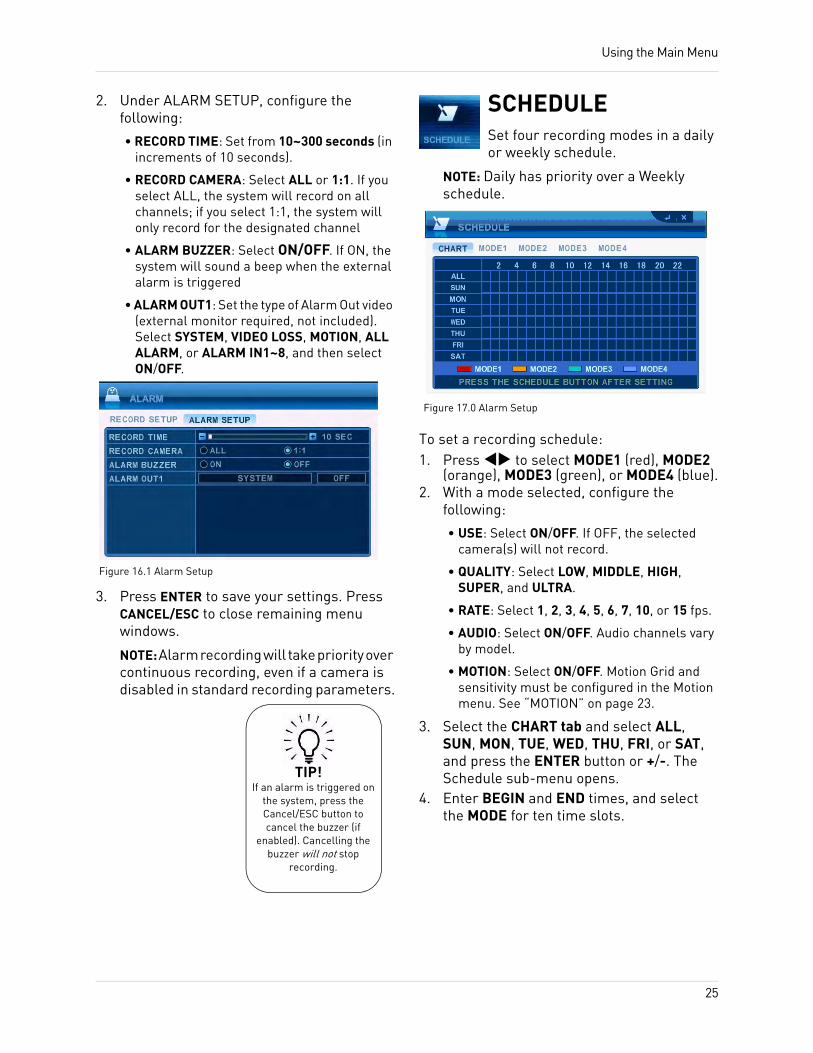
ALARMConfigure recording parameters for alarm recording.
NOTE: An external alarm device is not included with the system.
To configure alarm settings:1. Under RECORD SETUP, press to
select a camera. Press to select an option and press + / - to configure the following:• USE: Select ON/OFF. If OFF, the selected
camera(s) will not record.
• QUALITY: Select LOW, MIDDLE, HIGH, SUPER, and ULTRA.
• RATE: Select 1, 2, 3, 4, 5, 6, 7, 10, or 15 fps.
• AUDIO: Select ON/OFF. The number of audio input channels varies by model.
• INPUT: Select N.O/N.C.
Select ALL.
Clear.
Figure 15.0 Record menu
Figure 16.0 Alarm menu
TIP!When you have
configured settings for one camera, press to apply the settings for the rest of the cameras!
24
Using the Main Menu
2. Under ALARM SETUP, configure the following:
• RECORD TIME: Set from 10~300 seconds (in increments of 10 seconds).
• RECORD CAMERA: Select ALL or 1:1. If you select ALL, the system will record on all channels; if you select 1:1, the system will only record for the designated channel
• ALARM BUZZER: Select ON/OFF. If ON, the system will sound a beep when the external alarm is triggered
• ALARM OUT1: Set the type of Alarm Out video (external monitor required, not included). Select SYSTEM, VIDEO LOSS, MOTION, ALL ALARM, or ALARM IN1~8, and then select ON/OFF.
3. Press ENTER to save your settings. Press CANCEL/ESC to close remaining menu windows.
NOTE: Alarm recording will take priority over continuous recording, even if a camera is disabled in standard recording parameters.
SCHEDULESet four recording modes in a daily or weekly schedule.
NOTE: Daily has priority over a Weekly schedule.
To set a recording schedule:1. Press to select MODE1 (red), MODE2
(orange), MODE3 (green), or MODE4 (blue).2. With a mode selected, configure the
following:
• USE: Select ON/OFF. If OFF, the selected camera(s) will not record.
• QUALITY: Select LOW, MIDDLE, HIGH, SUPER, and ULTRA.
• RATE: Select 1, 2, 3, 4, 5, 6, 7, 10, or 15 fps.
• AUDIO: Select ON/OFF. Audio channels vary by model.
• MOTION: Select ON/OFF. Motion Grid and sensitivity must be configured in the Motion menu. See “MOTION” on page 23.
3. Select the CHART tab and select ALL, SUN, MON, TUE, WED, THU, FRI, or SAT, and press the ENTER button or +/-. The Schedule sub-menu opens.
4. Enter BEGIN and END times, and select the MODE for ten time slots.
Figure 16.1 Alarm Setup
TIP!If an alarm is triggered on
the system, press the Cancel/ESC button to cancel the buzzer (if
enabled). Cancelling the buzzer will not stop
recording.
Figure 17.0 Alarm Setup
25
Using the Main Menu
5. Press the ENTER button to save your settings. The Schedule sub-menu closes. The assigned mode appears in the main Schedule window.
6. Press CANCEL/ESC to close remaining menu windows.
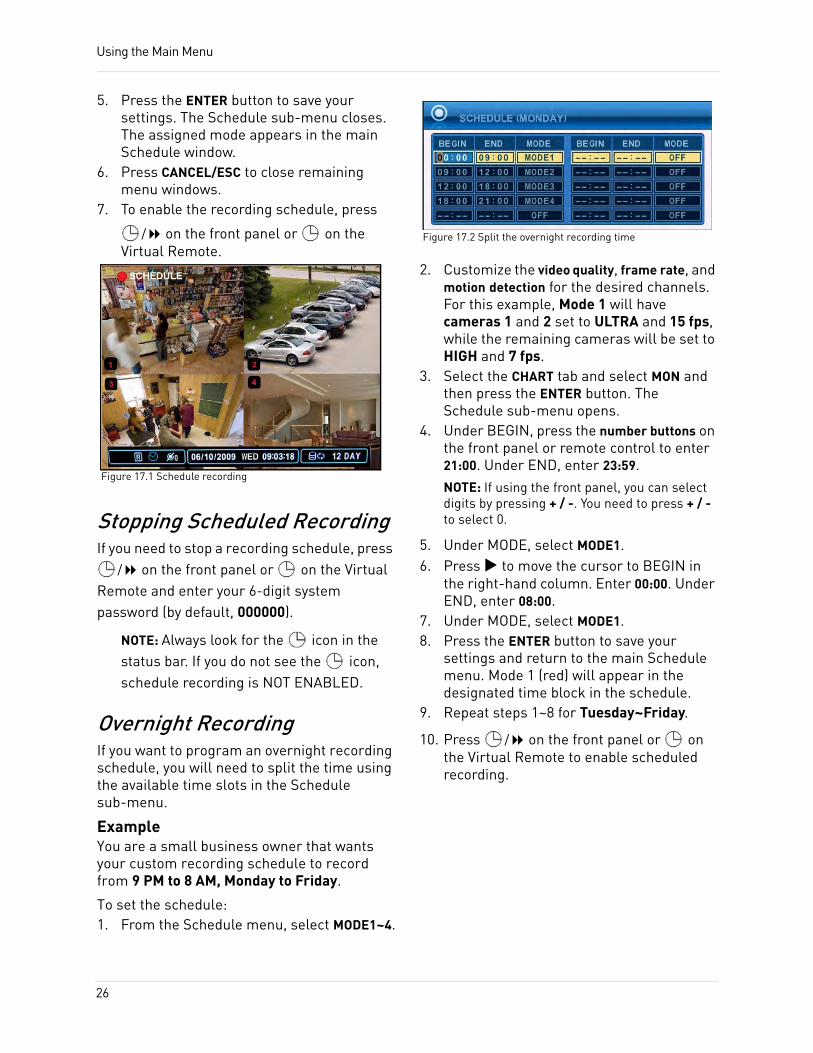
7. To enable the recording schedule, press
/ on the front panel or on the Virtual Remote.
Stopping Scheduled RecordingIf you need to stop a recording schedule, press
/ on the front panel or on the Virtual Remote and enter your 6-digit system password (by default, 000000).
NOTE: Always look for the icon in the status bar. If you do not see the icon, schedule recording is NOT ENABLED.
Overnight RecordingIf you want to program an overnight recording schedule, you will need to split the time using the available time slots in the Schedule sub-menu.
ExampleYou are a small business owner that wants your custom recording schedule to record from 9 PM to 8 AM, Monday to Friday.
To set the schedule:1. From the Schedule menu, select MODE1~4.
2. Customize the video quality, frame rate, and motion detection for the desired channels. For this example, Mode 1 will have cameras 1 and 2 set to ULTRA and 15 fps, while the remaining cameras will be set to HIGH and 7 fps.
3. Select the CHART tab and select MON and then press the ENTER button. The Schedule sub-menu opens.
4. Under BEGIN, press the number buttons on the front panel or remote control to enter 21:00. Under END, enter 23:59.NOTE: If using the front panel, you can select digits by pressing + / -. You need to press + / - to select 0.
5. Under MODE, select MODE1.6. Press to move the cursor to BEGIN in
the right-hand column. Enter 00:00. Under END, enter 08:00.
7. Under MODE, select MODE1.8. Press the ENTER button to save your
settings and return to the main Schedule menu. Mode 1 (red) will appear in the designated time block in the schedule.
9. Repeat steps 1~8 for Tuesday~Friday.
10. Press / on the front panel or on the Virtual Remote to enable scheduled recording.
Figure 17.1 Schedule recording
Figure 17.2 Split the overnight recording time
26

Using the Main Menu
NETWORKConfigure network and DDNS options.
To configure IP Setup:1. Connect an Ethernet cable to the LAN port
on the rear panel of the system.2. Disconnect the power cable and let the
system power down for a few moments. Reconnect the power cable. The system automatically powers on.
3. Under CONFIG, select STATIC or DHCP. DHCP allows you to instantly obtain an IP address when first networking your system. STATIC IP lets you manually enter a fixed IP address. If you select STATIC, go to step 4.NOTE: DCHP allows you to quickly connect to your network by obtaining an IP address from the router. After the initial setup, we recommend that you disable DHCP and set the IP address between 1~100. For example, if your IP address is 192.168.0.107, change the last digits to 90 (i.e. 192.163.0.90). This ensures that port forwarding will not change in the event of power failure or resetting of your network.
4. Press ENTER to save your settings. Press CANCEL/ESC to close remaining menu windows.
EMAILConfigure settings for email notification of events on the system.
To configure email settings:1. Under USE, select DEFAULT or SMTP (your
own email server). If you select DEFAULT, go to step 7. If you select SMTP, go to step 2.
2. Under SMTP SERVER, enter your SMTP email server.
3. Under SMTP PORT, enter your SMTP port.4. Under SMTP AUTH, select ON.5. Under SMTP USER ID, enter your SMTP
user name.6. Under SMTP PASSWORD, enter your SMTP
password.7. Under EMAIL ADDRESS, enter the
recipient email address for the email notification. You can add up to five email addresses.
8. Press ENTER to save your settings. Press CANCEL/ESC to close remaining windows.
NOTE: When an event is triggered, you will receive an email alert. If no events occur in the next 5 minutes, you will not receive another email. If a new event is triggered during that minutes, you will only receive the new email 5 minutes after the first email.
Figure 18.0 Network menu (IP setup)
Figure 18.1 Email menu
27
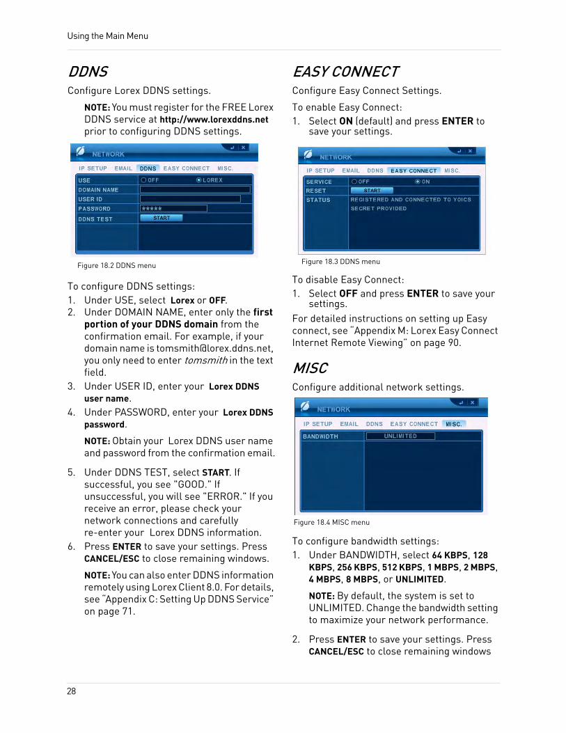
Using the Main Menu
DDNSConfigure Lorex DDNS settings.
NOTE: You must register for the FREE Lorex DDNS service at http://www.lorexddns.net prior to configuring DDNS settings.
To configure DDNS settings:1. Under USE, select Lorex or OFF.2. Under DOMAIN NAME, enter only the first
portion of your DDNS domain from the confirmation email. For example, if your domain name is [email protected], you only need to enter tomsmith in the text field.
3. Under USER ID, enter your Lorex DDNS user name.
4. Under PASSWORD, enter your Lorex DDNS password.
NOTE: Obtain your Lorex DDNS user name and password from the confirmation email.
5. Under DDNS TEST, select START. If successful, you see "GOOD." If unsuccessful, you will see "ERROR." If you receive an error, please check your network connections and carefully re-enter your Lorex DDNS information.
6. Press ENTER to save your settings. Press CANCEL/ESC to close remaining windows.
NOTE: You can also enter DDNS information remotely using Lorex Client 8.0. For details, see “Appendix C: Setting Up DDNS Service” on page 71.
EASY CONNECTConfigure Easy Connect Settings.
To enable Easy Connect:1. Select ON (default) and press ENTER to
save your settings.
To disable Easy Connect:1. Select OFF and press ENTER to save your
settings.For detailed instructions on setting up Easy connect, see “Appendix M: Lorex Easy Connect Internet Remote Viewing” on page 90.
MISCConfigure additional network settings.
To configure bandwidth settings:1. Under BANDWIDTH, select 64 KBPS, 128
KBPS, 256 KBPS, 512 KBPS, 1 MBPS, 2 MBPS, 4 MBPS, 8 MBPS, or UNLIMITED.
NOTE: By default, the system is set to UNLIMITED. Change the bandwidth setting to maximize your network performance.
2. Press ENTER to save your settings. Press CANCEL/ESC to close remaining windows
Figure 18.2 DDNS menu Figure 18.3 DDNS menu
Figure 18.4 MISC menu
28
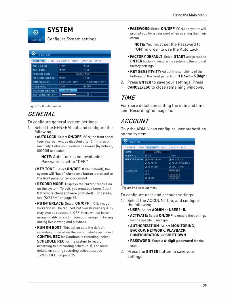
Using the Main Menu
SYSTEMConfigure System settings.
GENERALTo configure general system settings:1. Select the GENERAL tab and configure the
following:• AUTO LOCK: Select ON/OFF. If ON, the front panel
touch-screen will be disabled after 3 minutes of inactivity. Enter your system password (by default, 000000) to disable.
NOTE: Auto Lock is not available if Password is set to "OFF."
• KEY TONE: Select ON/OFF. If ON (default), the system will "beep" whenever a button is pressed on the front panel or remote control
• RECORD MODE: Displays the current resolution on the system. To edit, you must use Lorex Client 8.0 remote client software (included). For details, see “SYSTEM” on page 65.
• PB INTERLACE: Select ON/OFF. If ON, image flickering will be reduced, but overall image quality may also be reduced. If OFF, there will be better image quality on still images, but image flickering during live viewing and playback.
• RUN ON BOOT: This option sets the default recording mode when the system starts up. Select CONTIN. REC for Continuous recording; select SCHEDULE REC for the system to record according to a recording schedule(s). For more details on setting recording schedules, see “SCHEDULE” on page 25.
• PASSWORD: Select ON/OFF. If ON, the system will prompt you for a password when opening the main menu
NOTE: You must set the Password to "ON" in order to use the Auto Lock.
• FACTORY DEFAULT: Select START and press the ENTER button to restore the system to the original factory settings
• KEY SENSITIVITY: Adjust the sensitivity of the buttons on the front panel from 1 (low) ~ 5 (high)
2. Press ENTER to save your settings. Press CANCEL/ESC to close remaining windows.
TIMEFor more details on setting the date and time, see “Recording” on page 16.
ACCOUNTOnly the ADMIN can configure user authorities on the system.
To configure user and account settings:1. Select the ACCOUNT tab, and configure
the following:• USER: Select ADMIN or USER1~5.• ACTIVATE: Select ON/OFF to enable the settings
for the specific user type
• AUTHORIZATION: Select MONITORING, BACKUP, NETWORK, PLAYBACK, CONFIGURATION, or SHUTDOWN
• PASSWORD: Enter a 6-digit password for the user
2. Press the ENTER button to save your settings.
Figure 19.0 Setup menu
Figure 19.1 Account menu
29
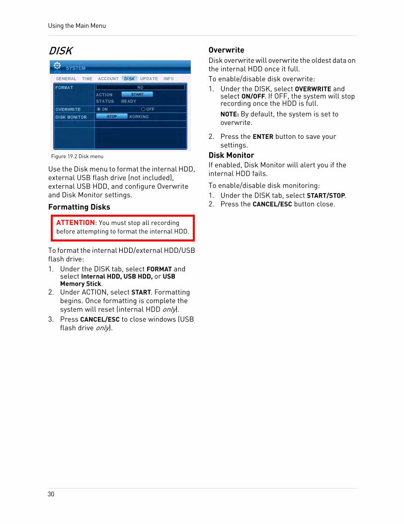
Using the Main Menu
DISK
Use the Disk menu to format the internal HDD, external USB flash drive (not included), external USB HDD, and configure Overwrite and Disk Monitor settings.
Formatting Disks
To format the internal HDD/external HDD/USB flash drive:1. Under the DISK tab, select FORMAT and
select Internal HDD, USB HDD, or USB Memory Stick.
2. Under ACTION, select START. Formatting begins. Once formatting is complete the system will reset (internal HDD only).
3. Press CANCEL/ESC to close windows (USB flash drive only).
OverwriteDisk overwrite will overwrite the oldest data on the internal HDD once it full.To enable/disable disk overwrite:1. Under the DISK, select OVERWRITE and
select ON/OFF. If OFF, the system will stop recording once the HDD is full.NOTE: By default, the system is set to overwrite.
2. Press the ENTER button to save your settings.
Disk MonitorIf enabled, Disk Monitor will alert you if the internal HDD fails.
To enable/disable disk monitoring:1. Under the DISK tab, select START/STOP.2. Press the CANCEL/ESC button close.
Figure 19.2 Disk menu
ATTENTION: You must stop all recording before attempting to format the internal HDD.
30
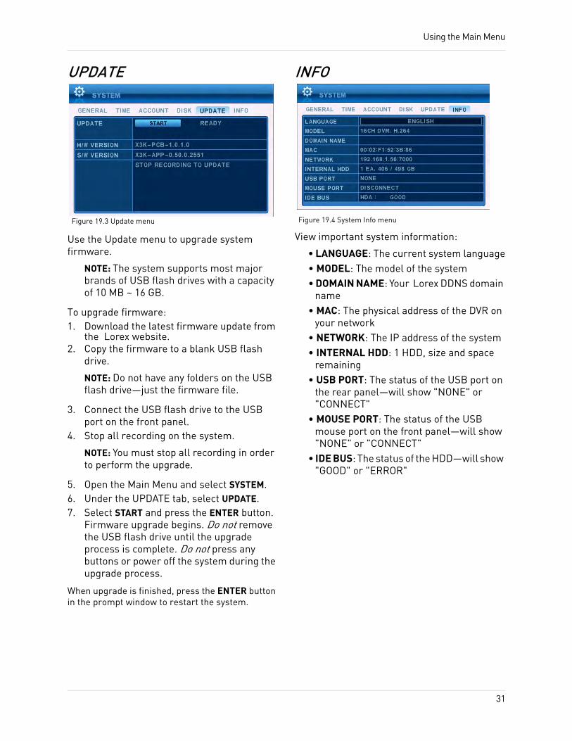
Using the Main Menu
UPDATE
Use the Update menu to upgrade system firmware.
NOTE: The system supports most major brands of USB flash drives with a capacity of 10 MB ~ 16 GB.
To upgrade firmware:1. Download the latest firmware update from
the Lorex website.2. Copy the firmware to a blank USB flash
drive.
NOTE: Do not have any folders on the USB flash drive—just the firmware file.
3. Connect the USB flash drive to the USB port on the front panel.
4. Stop all recording on the system.
NOTE: You must stop all recording in order to perform the upgrade.
5. Open the Main Menu and select SYSTEM.6. Under the UPDATE tab, select UPDATE.7. Select START and press the ENTER button.
Firmware upgrade begins. Do not remove the USB flash drive until the upgrade process is complete. Do not press any buttons or power off the system during the upgrade process.
When upgrade is finished, press the ENTER button in the prompt window to restart the system.
INFO
View important system information:
• LANGUAGE: The current system language• MODEL: The model of the system• DOMAIN NAME: Your Lorex DDNS domain
name• MAC: The physical address of the DVR on
your network• NETWORK: The IP address of the system• INTERNAL HDD: 1 HDD, size and space
remaining• USB PORT: The status of the USB port on
the rear panel—will show "NONE" or "CONNECT"
• MOUSE PORT: The status of the USB mouse port on the front panel—will show "NONE" or "CONNECT"
• IDE BUS: The status of the HDD—will show "GOOD" or "ERROR"
Figure 19.3 Update menu Figure 19.4 System Info menu
31
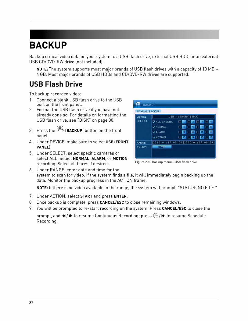
BACKUPBackup critical video data on your system to a USB flash drive, external USB HDD, or an external USB CD/DVD-RW drive (not included).
NOTE: The system supports most major brands of USB flash drives with a capacity of 10 MB ~ 4 GB. Most major brands of USB HDDs and CD/DVD-RW drives are supported.
USB Flash DriveTo backup recorded video:1. Connect a blank USB flash drive to the USB
port on the front panel.2. Format the USB flash drive if you have not
already done so. For details on formatting the USB flash drive, see “DISK” on page 30.
3. Press the (BACKUP) button on the front panel.
4. Under DEVICE, make sure to select USB (FRONT PANEL).
5. Under SELECT, select specific cameras or select ALL. Select NORMAL, ALARM, or MOTION recording. Select all boxes if desired.
6. Under RANGE, enter date and time for the system to scan for video. If the system finds a file, it will immediately begin backing up the data. Monitor the backup progress in the ACTION frame.
NOTE: If there is no video available in the range, the system will prompt, "STATUS: NO FILE."
7. Under ACTION, select START and press ENTER.8. Once backup is complete, press CANCEL/ESC to close remaining windows.9. You will be prompted to re-start recording on the system. Press CANCEL/ESC to close the
prompt, and / to resume Continuous Recording; press / to resume Schedule Recording.
Figure 20.0 Backup menu—USB flash drive
32
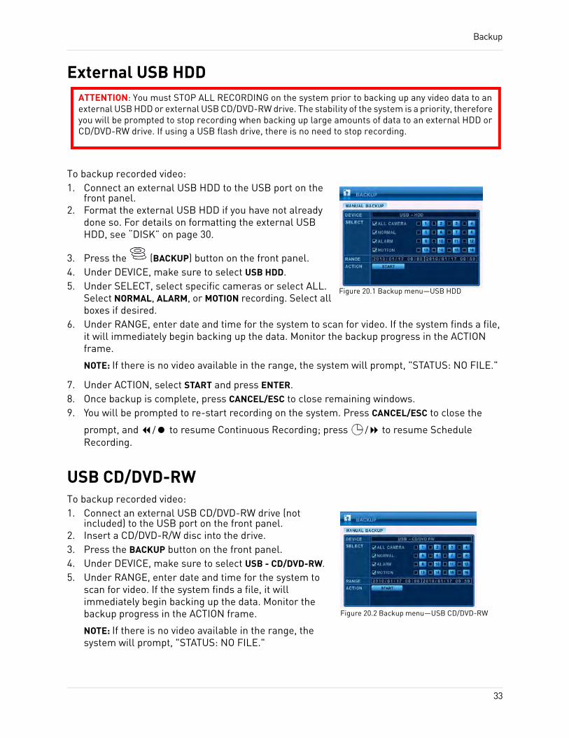
Backup
External USB HDD
To backup recorded video:1. Connect an external USB HDD to the USB port on the
front panel.2. Format the external USB HDD if you have not already
done so. For details on formatting the external USB HDD, see “DISK” on page 30.
3. Press the (BACKUP) button on the front panel.4. Under DEVICE, make sure to select USB HDD.5. Under SELECT, select specific cameras or select ALL.
Select NORMAL, ALARM, or MOTION recording. Select all boxes if desired.
6. Under RANGE, enter date and time for the system to scan for video. If the system finds a file, it will immediately begin backing up the data. Monitor the backup progress in the ACTION frame.
NOTE: If there is no video available in the range, the system will prompt, "STATUS: NO FILE."
7. Under ACTION, select START and press ENTER.8. Once backup is complete, press CANCEL/ESC to close remaining windows.9. You will be prompted to re-start recording on the system. Press CANCEL/ESC to close the
prompt, and / to resume Continuous Recording; press / to resume Schedule Recording.
USB CD/DVD-RWTo backup recorded video:1. Connect an external USB CD/DVD-RW drive (not
included) to the USB port on the front panel.2. Insert a CD/DVD-R/W disc into the drive.3. Press the BACKUP button on the front panel.4. Under DEVICE, make sure to select USB - CD/DVD-RW.5. Under RANGE, enter date and time for the system to
scan for video. If the system finds a file, it will immediately begin backing up the data. Monitor the backup progress in the ACTION frame.
NOTE: If there is no video available in the range, the system will prompt, "STATUS: NO FILE."
ATTENTION: You must STOP ALL RECORDING on the system prior to backing up any video data to an external USB HDD or external USB CD/DVD-RW drive. The stability of the system is a priority, therefore you will be prompted to stop recording when backing up large amounts of data to an external HDD or CD/DVD-RW drive. If using a USB flash drive, there is no need to stop recording.
Figure 20.1 Backup menu—USB HDD
Figure 20.2 Backup menu—USB CD/DVD-RW
33
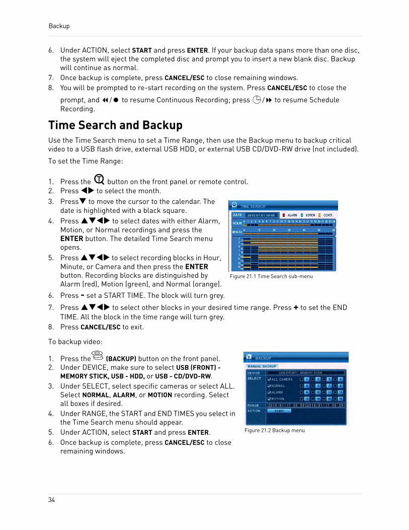
Backup
6. Under ACTION, select START and press ENTER. If your backup data spans more than one disc, the system will eject the completed disc and prompt you to insert a new blank disc. Backup will continue as normal.
7. Once backup is complete, press CANCEL/ESC to close remaining windows.8. You will be prompted to re-start recording on the system. Press CANCEL/ESC to close the
prompt, and / to resume Continuous Recording; press / to resume Schedule Recording.
Time Search and BackupUse the Time Search menu to set a Time Range, then use the Backup menu to backup critical video to a USB flash drive, external USB HDD, or external USB CD/DVD-RW drive (not included).
To set the Time Range:
1. Press the button on the front panel or remote control.2. Press to select the month.3. Press to move the cursor to the calendar. The
date is highlighted with a black square.4. Press to select dates with either Alarm,
Motion, or Normal recordings and press the ENTER button. The detailed Time Search menu opens.
5. Press to select recording blocks in Hour, Minute, or Camera and then press the ENTER button. Recording blocks are distinguished by Alarm (red), Motion (green), and Normal (orange).
6. Press - set a START TIME. The block will turn grey.
7. Press to select other blocks in your desired time range. Press + to set the END TIME. All the block in the time range will turn grey.
8. Press CANCEL/ESC to exit.
To backup video:
1. Press the (BACKUP) button on the front panel.2. Under DEVICE, make sure to select USB (FRONT) -
MEMORY STICK, USB - HDD, or USB - CD/DVD-RW.3. Under SELECT, select specific cameras or select ALL.
Select NORMAL, ALARM, or MOTION recording. Select all boxes if desired.
4. Under RANGE, the START and END TIMES you select in the Time Search menu should appear.
5. Under ACTION, select START and press ENTER.6. Once backup is complete, press CANCEL/ESC to close
remaining windows.
Figure 21.1 Time Search sub-menu
Figure 21.2 Backup menu
34
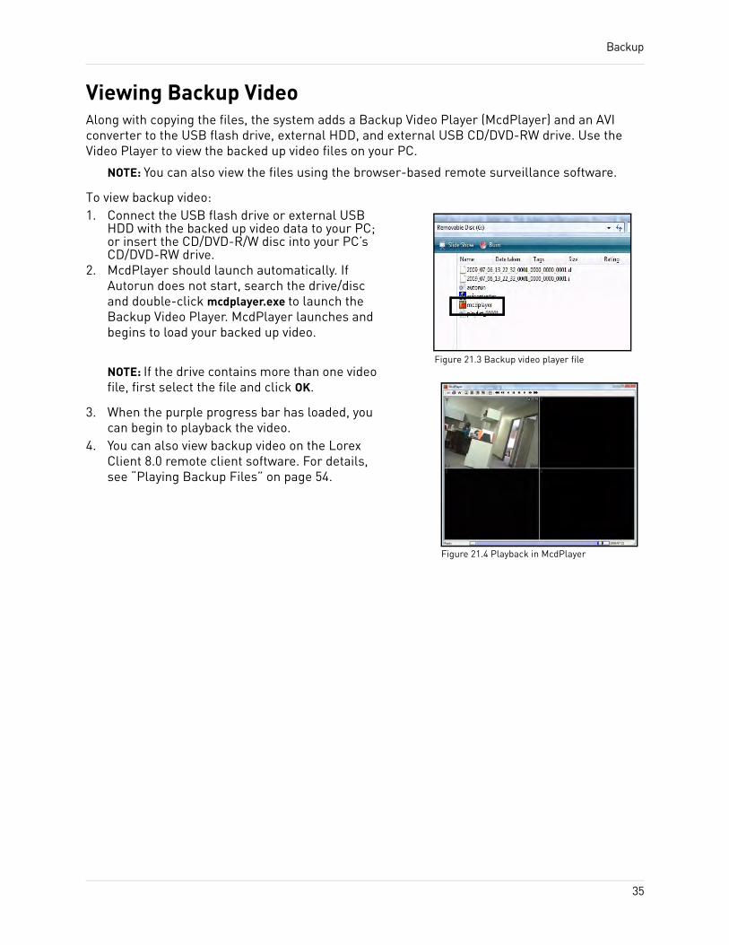
Backup
Viewing Backup VideoAlong with copying the files, the system adds a Backup Video Player (McdPlayer) and an AVI converter to the USB flash drive, external HDD, and external USB CD/DVD-RW drive. Use the Video Player to view the backed up video files on your PC.
NOTE: You can also view the files using the browser-based remote surveillance software.
To view backup video:1. Connect the USB flash drive or external USB
HDD with the backed up video data to your PC; or insert the CD/DVD-R/W disc into your PC’s CD/DVD-RW drive.
2. McdPlayer should launch automatically. If Autorun does not start, search the drive/disc and double-click mcdplayer.exe to launch the Backup Video Player. McdPlayer launches and begins to load your backed up video.
NOTE: If the drive contains more than one video file, first select the file and click OK.
3. When the purple progress bar has loaded, you can begin to playback the video.
4. You can also view backup video on the Lorex Client 8.0 remote client software. For details, see “Playing Backup Files” on page 54.
Figure 21.3 Backup video player file
Figure 21.4 Playback in McdPlayer
35
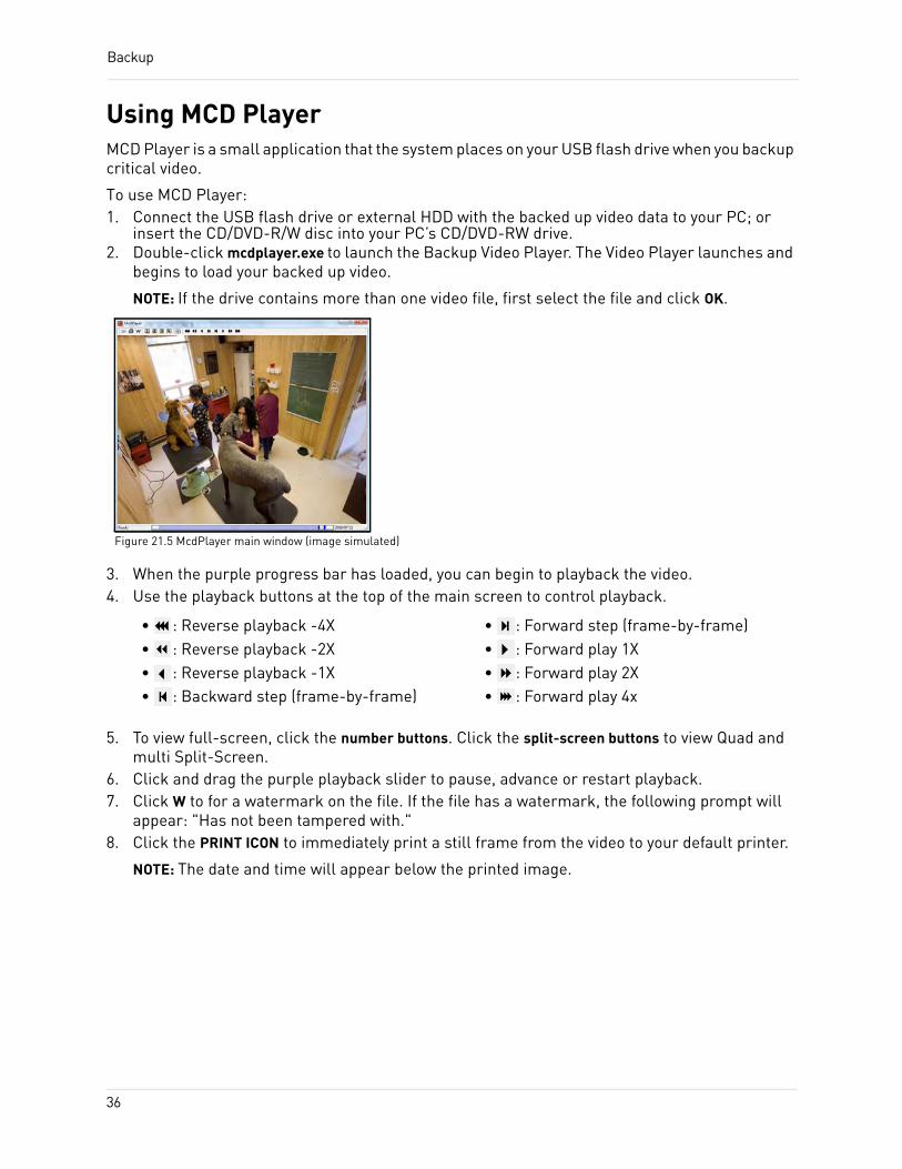
Backup
Using MCD PlayerMCD Player is a small application that the system places on your USB flash drive when you backup critical video.
To use MCD Player:1. Connect the USB flash drive or external HDD with the backed up video data to your PC; or
insert the CD/DVD-R/W disc into your PC’s CD/DVD-RW drive.2. Double-click mcdplayer.exe to launch the Backup Video Player. The Video Player launches and
begins to load your backed up video.
NOTE: If the drive contains more than one video file, first select the file and click OK.
3. When the purple progress bar has loaded, you can begin to playback the video.4. Use the playback buttons at the top of the main screen to control playback.
5. To view full-screen, click the number buttons. Click the split-screen buttons to view Quad and multi Split-Screen.
6. Click and drag the purple playback slider to pause, advance or restart playback.7. Click W to for a watermark on the file. If the file has a watermark, the following prompt will
appear: "Has not been tampered with."8. Click the PRINT ICON to immediately print a still frame from the video to your default printer.
NOTE: The date and time will appear below the printed image.
Figure 21.5 McdPlayer main window (image simulated)
• : Reverse playback -4X• : Reverse playback -2X• : Reverse playback -1X• : Backward step (frame-by-frame)
• : Forward step (frame-by-frame)• : Forward play 1X• : Forward play 2X• : Forward play 4x
36

LOREX CLIENT 8.0Lorex Client 8.0 is an advanced remote viewing software that allows remote live viewing, playback, and control of the DVR.
System RequirementsPrior to using Lorex Client 8.0, make sure your system meets or exceeds the following system requirements:
*High-speed Internet connection recommended
Description Requirement
CPU 2.4 GHz Pentium® 4 or above
Operating System
Windows XP/Vista/7 , 32 & 64 bit versions
Browser Internet Explorer 6 or greater
Memory 1 GB RAM (more than 1 GB recommended)
Video 16 MB of video memory
HDD 2 GB of free space
Network (LAN) 10/100 Base-T Network
Network (WAN)
384 Kbps upstream*
37
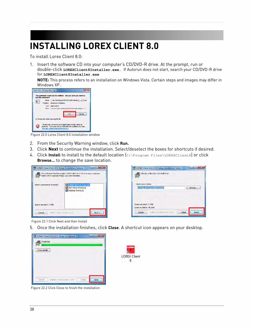
INSTALLING LOREX CLIENT 8.0To install Lorex Client 8.0:
1. Insert the software CD into your computer’s CD/DVD-R drive. At the prompt, run or double-click LOREXClient8Installer.exe. If Autorun does not start, search your CD/DVD-R drive for LOREXClient8Installer.exe
NOTE: This process refers to an installation on Windows Vista. Certain steps and images may differ in Windows XP.
2. From the Security Warning window, click Run. 3. Click Next to continue the installation. Select/deselect the boxes for shortcuts if desired.4. Click Install to install to the default location (C:\Program Files\LOREXClient8) or click
Browse... to change the save location.
5. Once the installation finishes, click Close. A shortcut icon appears on your desktop.
Figure 22.0 Lorex Client 8.0 installation window
Figure 22.1 Click Next and then Install
Figure 22.2 Click Close to finish the installation
38
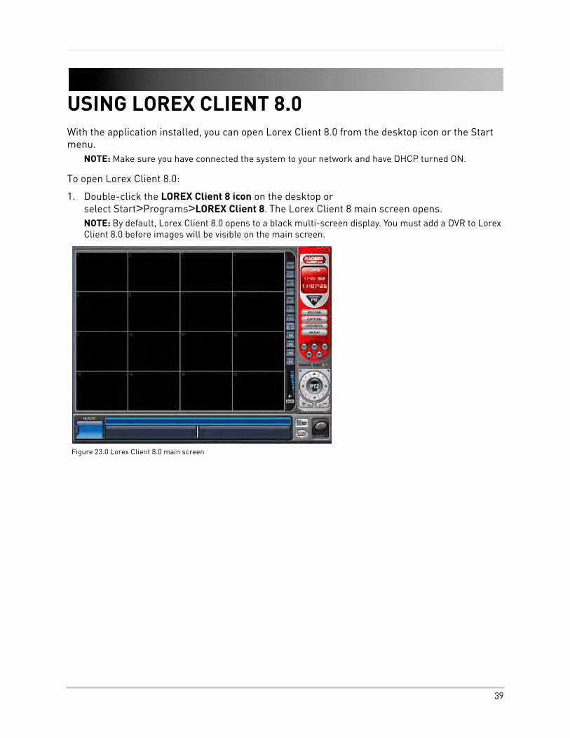
USING LOREX CLIENT 8.0With the application installed, you can open Lorex Client 8.0 from the desktop icon or the Start menu.
NOTE: Make sure you have connected the system to your network and have DHCP turned ON.
To open Lorex Client 8.0:
1. Double-click the LOREX Client 8 icon on the desktop or select Start>Programs>LOREX Client 8. The Lorex Client 8 main screen opens.NOTE: By default, Lorex Client 8.0 opens to a black multi-screen display. You must add a DVR to Lorex Client 8.0 before images will be visible on the main screen.
Figure 23.0 Lorex Client 8.0 main screen
39
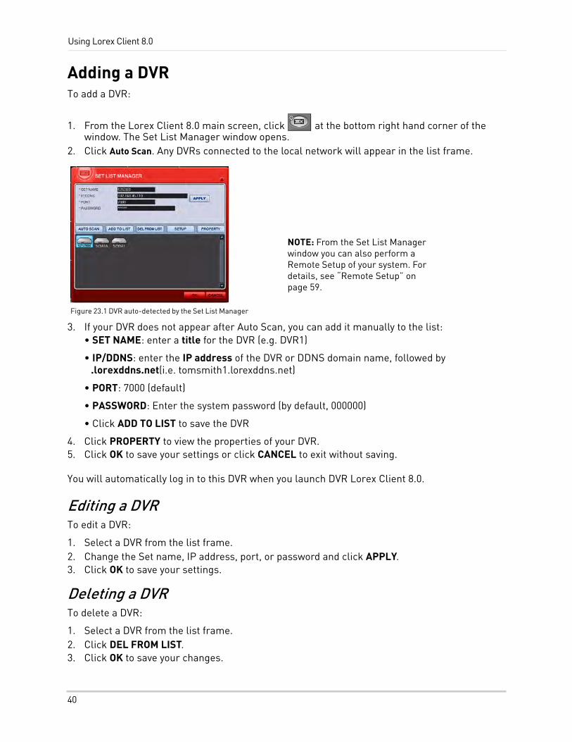
Using Lorex Client 8.0
Adding a DVRTo add a DVR:
1. From the Lorex Client 8.0 main screen, click at the bottom right hand corner of the window. The Set List Manager window opens.
2. Click Auto Scan. Any DVRs connected to the local network will appear in the list frame.
3. If your DVR does not appear after Auto Scan, you can add it manually to the list:• SET NAME: enter a title for the DVR (e.g. DVR1)
• IP/DDNS: enter the IP address of the DVR or DDNS domain name, followed by .lorexddns.net(i.e. tomsmith1.lorexddns.net)
• PORT: 7000 (default)
• PASSWORD: Enter the system password (by default, 000000)
• Click ADD TO LIST to save the DVR
4. Click PROPERTY to view the properties of your DVR.5. Click OK to save your settings or click CANCEL to exit without saving.
You will automatically log in to this DVR when you launch DVR Lorex Client 8.0.
Editing a DVRTo edit a DVR:
1. Select a DVR from the list frame.2. Change the Set name, IP address, port, or password and click APPLY.3. Click OK to save your settings.
Deleting a DVRTo delete a DVR:
1. Select a DVR from the list frame.2. Click DEL FROM LIST.3. Click OK to save your changes.
Figure 23.1 DVR auto-detected by the Set List Manager
NOTE: From the Set List Manager window you can also perform a Remote Setup of your system. For details, see “Remote Setup” on page 59.
40
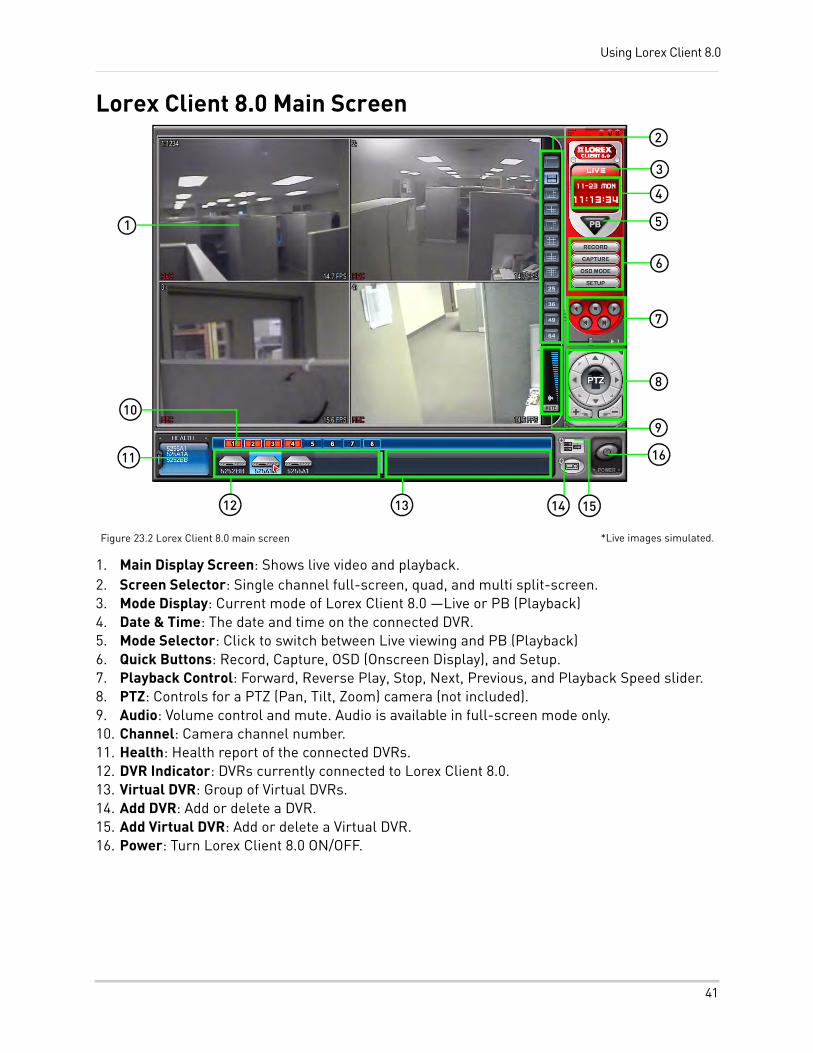
Using Lorex Client 8.0
Lorex Client 8.0 Main Screen
1. Main Display Screen: Shows live video and playback.2. Screen Selector: Single channel full-screen, quad, and multi split-screen.3. Mode Display: Current mode of Lorex Client 8.0 —Live or PB (Playback)4. Date & Time: The date and time on the connected DVR.5. Mode Selector: Click to switch between Live viewing and PB (Playback)6. Quick Buttons: Record, Capture, OSD (Onscreen Display), and Setup.7. Playback Control: Forward, Reverse Play, Stop, Next, Previous, and Playback Speed slider.8. PTZ: Controls for a PTZ (Pan, Tilt, Zoom) camera (not included).9. Audio: Volume control and mute. Audio is available in full-screen mode only.10. Channel: Camera channel number.11. Health: Health report of the connected DVRs.12. DVR Indicator: DVRs currently connected to Lorex Client 8.0.13. Virtual DVR: Group of Virtual DVRs.14. Add DVR: Add or delete a DVR.15. Add Virtual DVR: Add or delete a Virtual DVR.16. Power: Turn Lorex Client 8.0 ON/OFF.
Figure 23.2 Lorex Client 8.0 main screen
1
3
4
5
6
7
2
8
9
11
10
12 13 14 15
16
*Live images simulated.
41
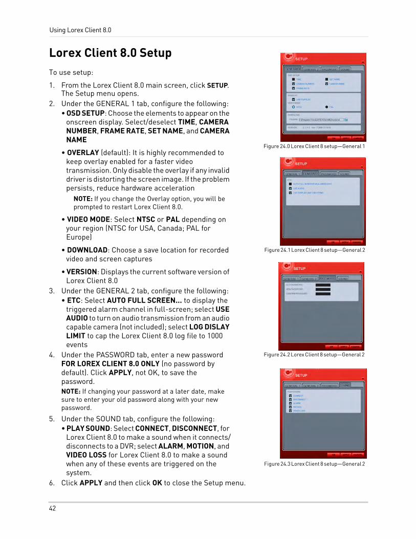
Using Lorex Client 8.0
Lorex Client 8.0 SetupTo use setup:
1. From the Lorex Client 8.0 main screen, click SETUP. The Setup menu opens.
2. Under the GENERAL 1 tab, configure the following:• OSD SETUP: Choose the elements to appear on the
onscreen display. Select/deselect TIME, CAMERA NUMBER, FRAME RATE, SET NAME, and CAMERA NAME
• OVERLAY (default): It is highly recommended to keep overlay enabled for a faster video transmission. Only disable the overlay if any invalid driver is distorting the screen image. If the problem persists, reduce hardware acceleration
NOTE: If you change the Overlay option, you will be prompted to restart Lorex Client 8.0.
• VIDEO MODE: Select NTSC or PAL depending on your region (NTSC for USA, Canada; PAL for Europe)
• DOWNLOAD: Choose a save location for recorded video and screen captures
• VERSION: Displays the current software version of Lorex Client 8.0
3. Under the GENERAL 2 tab, configure the following:• ETC: Select AUTO FULL SCREEN... to display the
triggered alarm channel in full-screen; select USE AUDIO to turn on audio transmission from an audio capable camera (not included); select LOG DISLAY LIMIT to cap the Lorex Client 8.0 log file to 1000 events
4. Under the PASSWORD tab, enter a new password FOR LOREX CLIENT 8.0 ONLY (no password by default). Click APPLY, not OK, to save the password.NOTE: If changing your password at a later date, make sure to enter your old password along with your new password.
5. Under the SOUND tab, configure the following:• PLAY SOUND: Select CONNECT, DISCONNECT, for
Lorex Client 8.0 to make a sound when it connects/disconnects to a DVR; select ALARM, MOTION, and VIDEO LOSS for Lorex Client 8.0 to make a sound when any of these events are triggered on the system.
6. Click APPLY and then click OK to close the Setup menu.
Figure 24.0 Lorex Client 8 setup—General 1
Figure 24.1 Lorex Client 8 setup—General 2
Figure 24.2 Lorex Client 8 setup—General 2
Figure 24.3 Lorex Client 8 setup—General 2
42
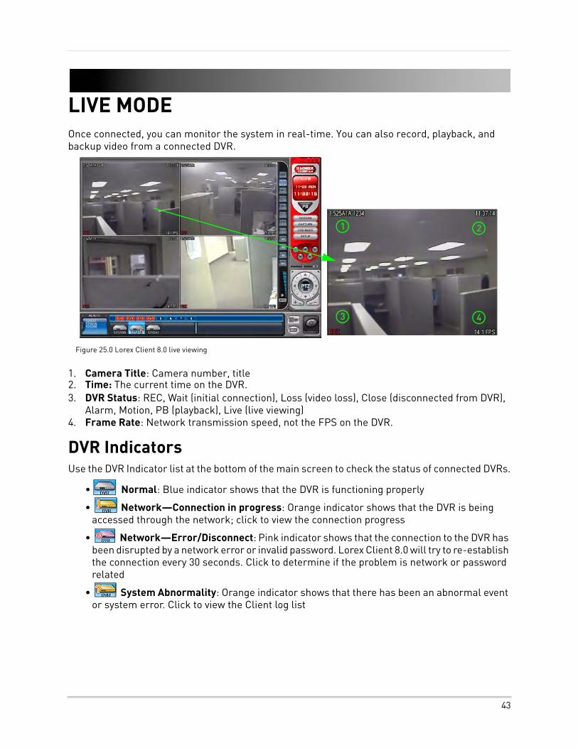
LIVE MODEOnce connected, you can monitor the system in real-time. You can also record, playback, and backup video from a connected DVR.
1. Camera Title: Camera number, title2. Time: The current time on the DVR.3. DVR Status: REC, Wait (initial connection), Loss (video loss), Close (disconnected from DVR),
Alarm, Motion, PB (playback), Live (live viewing)4. Frame Rate: Network transmission speed, not the FPS on the DVR.
DVR IndicatorsUse the DVR Indicator list at the bottom of the main screen to check the status of connected DVRs.
• Normal: Blue indicator shows that the DVR is functioning properly
• Network—Connection in progress: Orange indicator shows that the DVR is being accessed through the network; click to view the connection progress
• Network—Error/Disconnect: Pink indicator shows that the connection to the DVR has been disrupted by a network error or invalid password. Lorex Client 8.0 will try to re-establish the connection every 30 seconds. Click to determine if the problem is network or password related
• System Abnormality: Orange indicator shows that there has been an abnormal event or system error. Click to view the Client log list
1
Figure 25.0 Lorex Client 8.0 live viewing
2
3 4
43
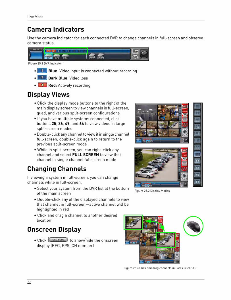
Live Mode
Camera IndicatorsUse the camera indicator for each connected DVR to change channels in full-screen and observe camera status.
• Blue: Video input is connected without recording
• Dark Blue: Video loss
• Red: Actively recording
Display Views• Click the display mode buttons to the right of the
main display screen to view channels in full-screen, quad, and various split-screen configurations
• If you have multiple systems connected, click buttons 25, 36, 49, and 64 to view videos in large split-screen modes
• Double-click any channel to view it in single channel full-screen; double-click again to return to the previous split-screen mode
• While in split-screen, you can right-click any channel and select FULL SCREEN to view that channel in single channel full-screen mode
Changing ChannelsIf viewing a system in full-screen, you can change channels while in full-screen.
• Select your system from the DVR list at the bottom of the main screen
• Double-click any of the displayed channels to view that channel in full-screen—active channel will be highlighted in red
• Click and drag a channel to another desired location
Onscreen Display• Click to show/hide the onscreen
display (REC, FPS, CH number)
Figure 25.1 DVR Indicator
Figure 25.2 Display modes
Figure 25.3 Click and drag channels in Lorex Client 8.0
44
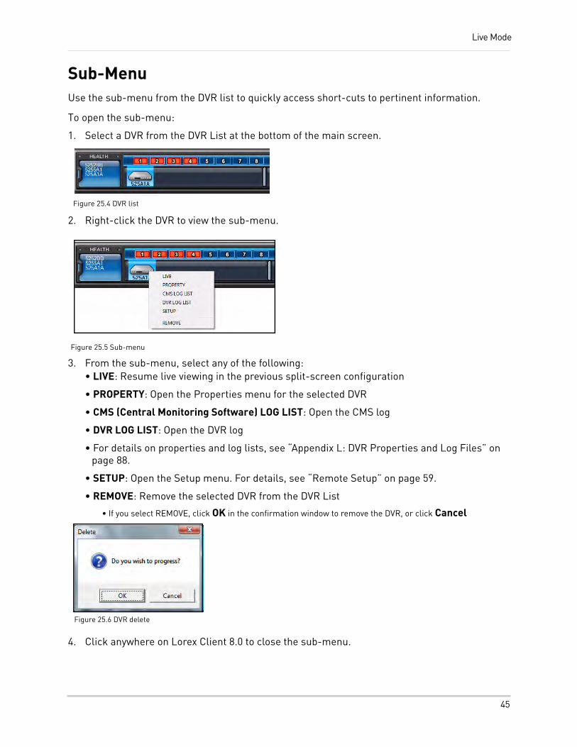
Live Mode
Sub-MenuUse the sub-menu from the DVR list to quickly access short-cuts to pertinent information.
To open the sub-menu:
1. Select a DVR from the DVR List at the bottom of the main screen.
2. Right-click the DVR to view the sub-menu.
3. From the sub-menu, select any of the following:• LIVE: Resume live viewing in the previous split-screen configuration
• PROPERTY: Open the Properties menu for the selected DVR
• CMS (Central Monitoring Software) LOG LIST: Open the CMS log
• DVR LOG LIST: Open the DVR log
• For details on properties and log lists, see “Appendix L: DVR Properties and Log Files” on page 88.
• SETUP: Open the Setup menu. For details, see “Remote Setup” on page 59.
• REMOVE: Remove the selected DVR from the DVR List
• If you select REMOVE, click OK in the confirmation window to remove the DVR, or click Cancel
4. Click anywhere on Lorex Client 8.0 to close the sub-menu.
Figure 25.4 DVR list
Figure 25.5 Sub-menu
Figure 25.6 DVR delete
45
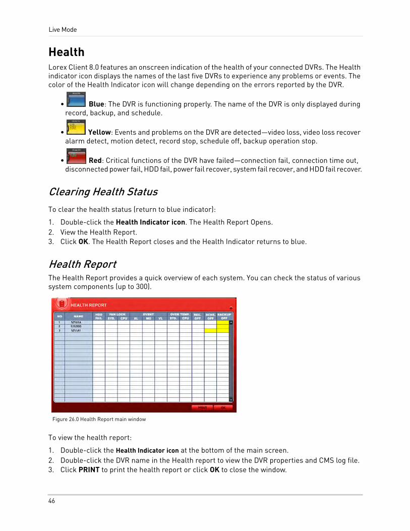
Live Mode
HealthLorex Client 8.0 features an onscreen indication of the health of your connected DVRs. The Health indicator icon displays the names of the last five DVRs to experience any problems or events. The color of the Health Indicator icon will change depending on the errors reported by the DVR.
• Blue: The DVR is functioning properly. The name of the DVR is only displayed during record, backup, and schedule.
• Yellow: Events and problems on the DVR are detected—video loss, video loss recover alarm detect, motion detect, record stop, schedule off, backup operation stop.
• Red: Critical functions of the DVR have failed—connection fail, connection time out, disconnected power fail, HDD fail, power fail recover, system fail recover, and HDD fail recover.
Clearing Health StatusTo clear the health status (return to blue indicator):
1. Double-click the Health Indicator icon. The Health Report Opens.2. View the Health Report.3. Click OK. The Health Report closes and the Health Indicator returns to blue.
Health ReportThe Health Report provides a quick overview of each system. You can check the status of various system components (up to 300).
To view the health report:
1. Double-click the Health Indicator icon at the bottom of the main screen.2. Double-click the DVR name in the Health report to view the DVR properties and CMS log file.3. Click PRINT to print the health report or click OK to close the window.
Figure 26.0 Health Report main window
46
Live Mode
Health Report Color Codes
Health Report Conditions• HDD FAIL: HDD failure.
• EVENT: AL=alarm, MO=motion, VL=video loss
• OVER TEMP: NOT SUPPORTED IN THIS MODEL.
• REC. OFF: Indicates REC LED ON/OFF on the DVR.
• SCHE. OFF: Indicates SCHEDULE LED ON/OFF on the DVR.
• BACKUP OFF: Indicates the Backup status of the DVR.
Block Color Condition
Solid RED An event or a problem had occurred.
Blinking RED A current event or problem.
Solid YELLOW Current status of the DVR.
47
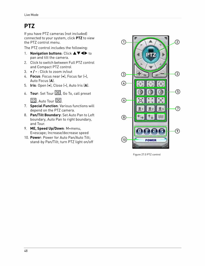
Live Mode
PTZIf you have PTZ cameras (not included) connected to your system, click PTZ to view the PTZ control menu.The PTZ control includes the following:
1. Navigation buttons: Click to pan and tilt the camera.
2. Click to switch between Full PTZ control and Compact PTZ control
3. + / - : Click to zoom in/out4. Focus: Focus near (+), Focus far (-),
Auto Focus (A).5. Iris: Open (+), Close (-), Auto Iris (A).
6. Tour: Set Tour , Go To, call preset
, Auto Tour .7. Special Function: Various functions will
depend on the PTZ camera.8. Pan/Tilt Boundary: Set Auto Pan to Left
boundary, Auto Pan to right boundary, and Tour.
9. ME, Speed Up/Down: M=menu, E=escape; Increase/decrease speed
10. Power: Power for Auto Pan/Auto Tilt; stand-by Pan/Tilt; turn PTZ light on/off
Figure 27.0 PTZ control
1 2
3 3
4
5
6
7
8
9
10
48
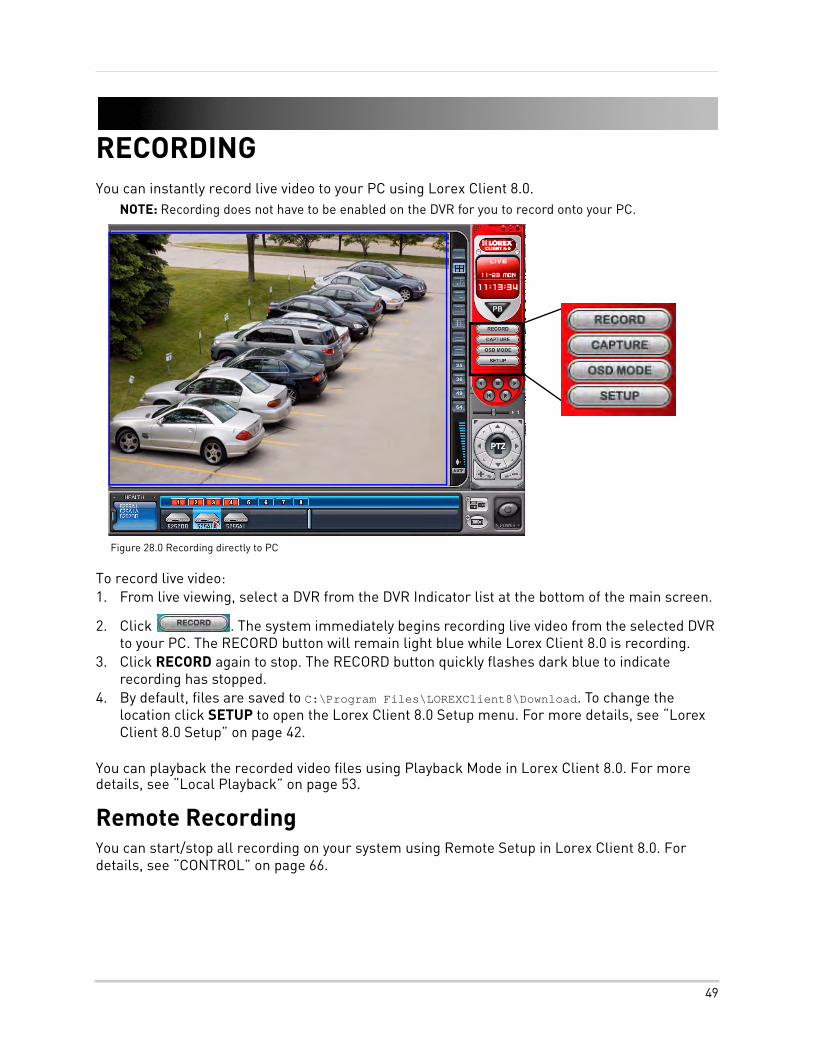
RECORDINGYou can instantly record live video to your PC using Lorex Client 8.0.
NOTE: Recording does not have to be enabled on the DVR for you to record onto your PC.
To record live video:1. From live viewing, select a DVR from the DVR Indicator list at the bottom of the main screen.
2. Click . The system immediately begins recording live video from the selected DVR to your PC. The RECORD button will remain light blue while Lorex Client 8.0 is recording.
3. Click RECORD again to stop. The RECORD button quickly flashes dark blue to indicate recording has stopped.
4. By default, files are saved to C:\Program Files\LOREXClient8\Download. To change the location click SETUP to open the Lorex Client 8.0 Setup menu. For more details, see “Lorex Client 8.0 Setup” on page 42.
You can playback the recorded video files using Playback Mode in Lorex Client 8.0. For more details, see “Local Playback” on page 53.
Remote RecordingYou can start/stop all recording on your system using Remote Setup in Lorex Client 8.0. For details, see “CONTROL” on page 66.
Figure 28.0 Recording directly to PC
49
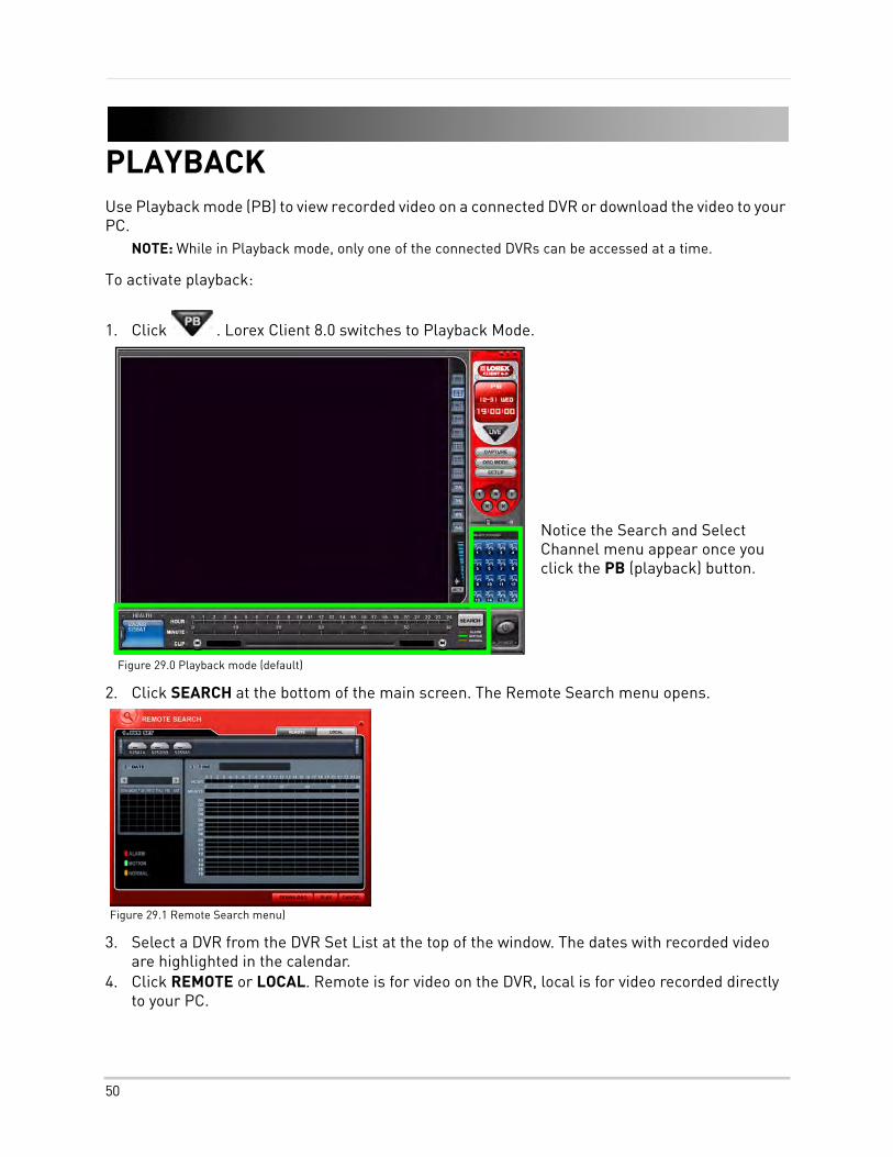
PLAYBACKUse Playback mode (PB) to view recorded video on a connected DVR or download the video to your PC.
NOTE: While in Playback mode, only one of the connected DVRs can be accessed at a time.
To activate playback:
1. Click . Lorex Client 8.0 switches to Playback Mode.
2. Click SEARCH at the bottom of the main screen. The Remote Search menu opens.
3. Select a DVR from the DVR Set List at the top of the window. The dates with recorded video are highlighted in the calendar.
4. Click REMOTE or LOCAL. Remote is for video on the DVR, local is for video recorded directly to your PC.
Figure 29.0 Playback mode (default)
Notice the Search and Select Channel menu appear once you click the PB (playback) button.
Figure 29.1 Remote Search menu)
50
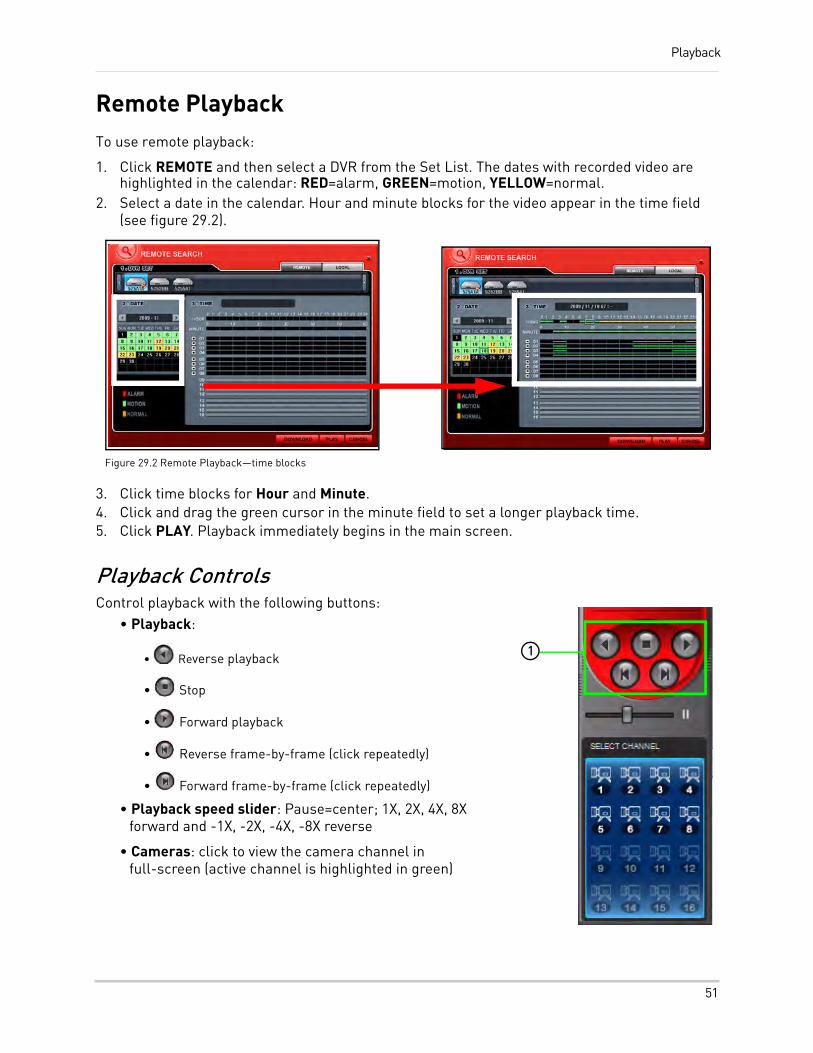
Playback
Remote PlaybackTo use remote playback:
1. Click REMOTE and then select a DVR from the Set List. The dates with recorded video are highlighted in the calendar: RED=alarm, GREEN=motion, YELLOW=normal.
2. Select a date in the calendar. Hour and minute blocks for the video appear in the time field (see figure 29.2).
3. Click time blocks for Hour and Minute.4. Click and drag the green cursor in the minute field to set a longer playback time.5. Click PLAY. Playback immediately begins in the main screen.
Playback ControlsControl playback with the following buttons:
• Playback:
• Reverse playback
• Stop
• Forward playback
• Reverse frame-by-frame (click repeatedly)
• Forward frame-by-frame (click repeatedly)
• Playback speed slider: Pause=center; 1X, 2X, 4X, 8X forward and -1X, -2X, -4X, -8X reverse
• Cameras: click to view the camera channel in full-screen (active channel is highlighted in green)
Figure 29.2 Remote Playback—time blocks
1
51
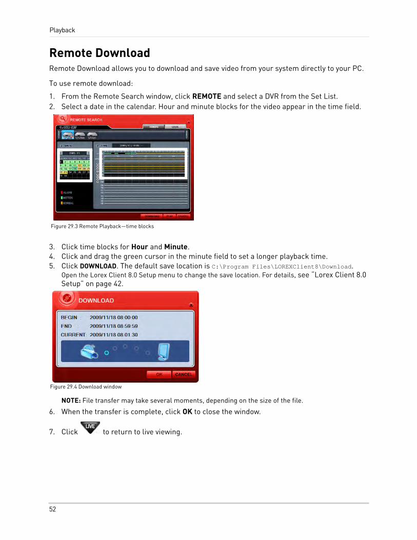
Playback
Remote DownloadRemote Download allows you to download and save video from your system directly to your PC.
To use remote download:
1. From the Remote Search window, click REMOTE and select a DVR from the Set List.2. Select a date in the calendar. Hour and minute blocks for the video appear in the time field.
3. Click time blocks for Hour and Minute.4. Click and drag the green cursor in the minute field to set a longer playback time.5. Click DOWNLOAD. The default save location is C:\Program Files\LOREXClient8\Download.
Open the Lorex Client 8.0 Setup menu to change the save location. For details, see “Lorex Client 8.0 Setup” on page 42.
NOTE: File transfer may take several moments, depending on the size of the file.
6. When the transfer is complete, click OK to close the window.
7. Click to return to live viewing.
Figure 29.3 Remote Playback—time blocks
Figure 29.4 Download window
52
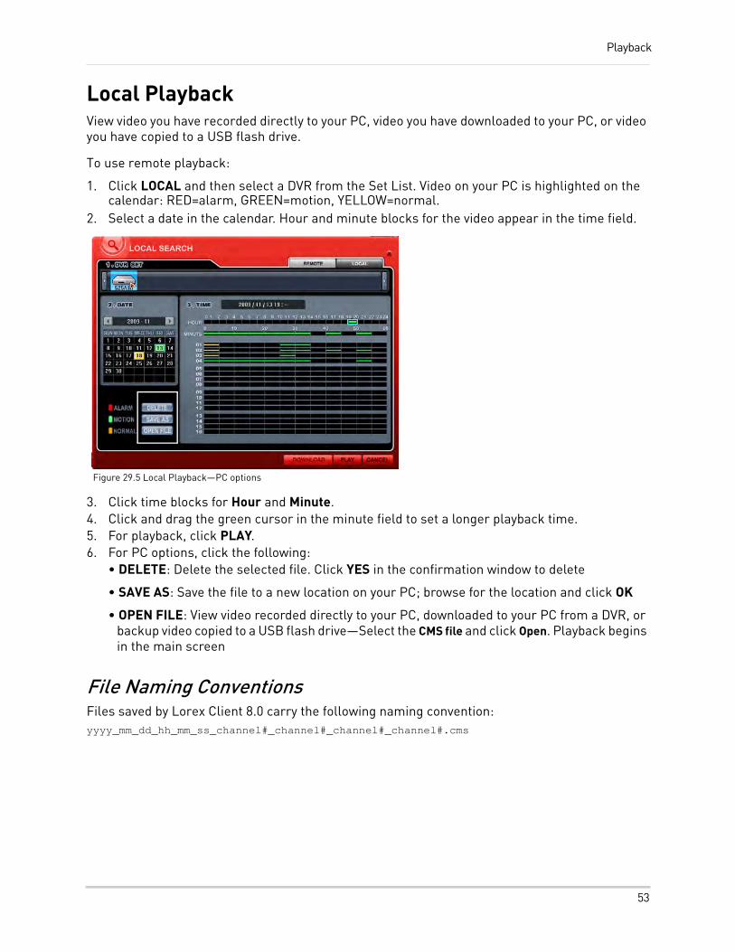
Playback
Local PlaybackView video you have recorded directly to your PC, video you have downloaded to your PC, or video you have copied to a USB flash drive.
To use remote playback:
1. Click LOCAL and then select a DVR from the Set List. Video on your PC is highlighted on the calendar: RED=alarm, GREEN=motion, YELLOW=normal.
2. Select a date in the calendar. Hour and minute blocks for the video appear in the time field.
3. Click time blocks for Hour and Minute.4. Click and drag the green cursor in the minute field to set a longer playback time.5. For playback, click PLAY.6. For PC options, click the following:
• DELETE: Delete the selected file. Click YES in the confirmation window to delete
• SAVE AS: Save the file to a new location on your PC; browse for the location and click OK
• OPEN FILE: View video recorded directly to your PC, downloaded to your PC from a DVR, or backup video copied to a USB flash drive—Select the CMS file and click Open. Playback begins in the main screen
File Naming ConventionsFiles saved by Lorex Client 8.0 carry the following naming convention:yyyy_mm_dd_hh_mm_ss_channel#_channel#_channel#_channel#.cms
Figure 29.5 Local Playback—PC options
53
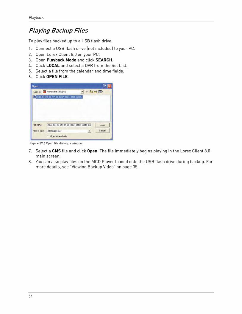
Playback
Playing Backup FilesTo play files backed up to a USB flash drive:
1. Connect a USB flash drive (not included) to your PC.2. Open Lorex Client 8.0 on your PC.3. Open Playback Mode and click SEARCH.4. Click LOCAL and select a DVR from the Set List.5. Select a file from the calendar and time fields.6. Click OPEN FILE.
7. Select a CMS file and click Open. The file immediately begins playing in the Lorex Client 8.0 main screen.
8. You can also play files on the MCD Player loaded onto the USB flash drive during backup. For more details, see “Viewing Backup Video” on page 35.
Figure 29.6 Open file dialogue window
54
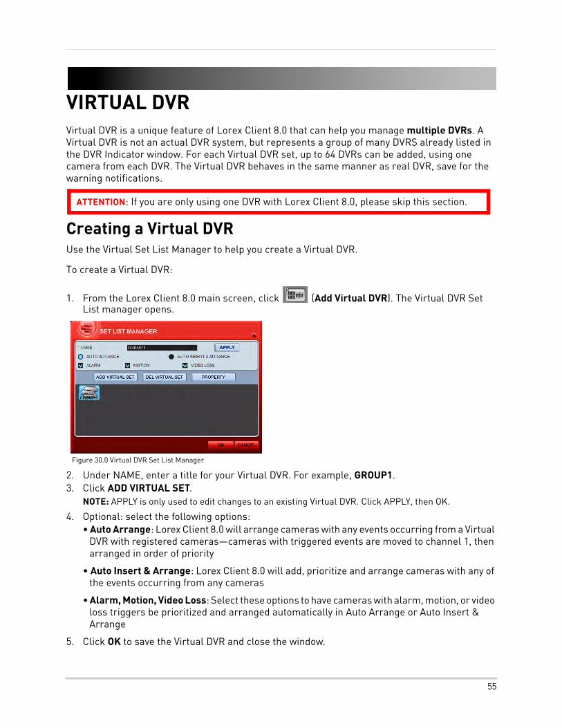
VIRTUAL DVRVirtual DVR is a unique feature of Lorex Client 8.0 that can help you manage multiple DVRs. A Virtual DVR is not an actual DVR system, but represents a group of many DVRS already listed in the DVR Indicator window. For each Virtual DVR set, up to 64 DVRs can be added, using one camera from each DVR. The Virtual DVR behaves in the same manner as real DVR, save for the warning notifications.
Creating a Virtual DVRUse the Virtual Set List Manager to help you create a Virtual DVR.
To create a Virtual DVR:
1. From the Lorex Client 8.0 main screen, click (Add Virtual DVR). The Virtual DVR Set List manager opens.
2. Under NAME, enter a title for your Virtual DVR. For example, GROUP1.3. Click ADD VIRTUAL SET.
NOTE: APPLY is only used to edit changes to an existing Virtual DVR. Click APPLY, then OK.
4. Optional: select the following options:• Auto Arrange: Lorex Client 8.0 will arrange cameras with any events occurring from a Virtual
DVR with registered cameras—cameras with triggered events are moved to channel 1, then arranged in order of priority
• Auto Insert & Arrange: Lorex Client 8.0 will add, prioritize and arrange cameras with any of the events occurring from any cameras
• Alarm, Motion, Video Loss: Select these options to have cameras with alarm, motion, or video loss triggers be prioritized and arranged automatically in Auto Arrange or Auto Insert & Arrange
5. Click OK to save the Virtual DVR and close the window.
ATTENTION: If you are only using one DVR with Lorex Client 8.0, please skip this section.
Figure 30.0 Virtual DVR Set List Manager
55
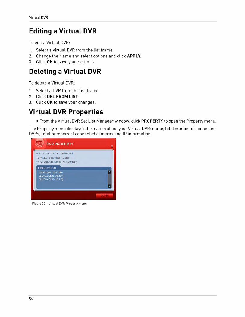
Virtual DVR
Editing a Virtual DVRTo edit a Virtual DVR:
1. Select a Virtual DVR from the list frame.2. Change the Name and select options and click APPLY.3. Click OK to save your settings.
Deleting a Virtual DVRTo delete a Virtual DVR:
1. Select a DVR from the list frame.2. Click DEL FROM LIST.3. Click OK to save your changes.
Virtual DVR Properties• From the Virtual DVR Set List Manager window, click PROPERTY to open the Property menu.
The Property menu displays information about your Virtual DVR: name, total number of connected DVRs, total numbers of connected cameras and IP information.
Figure 30.1 Virtual DVR Property menu
56
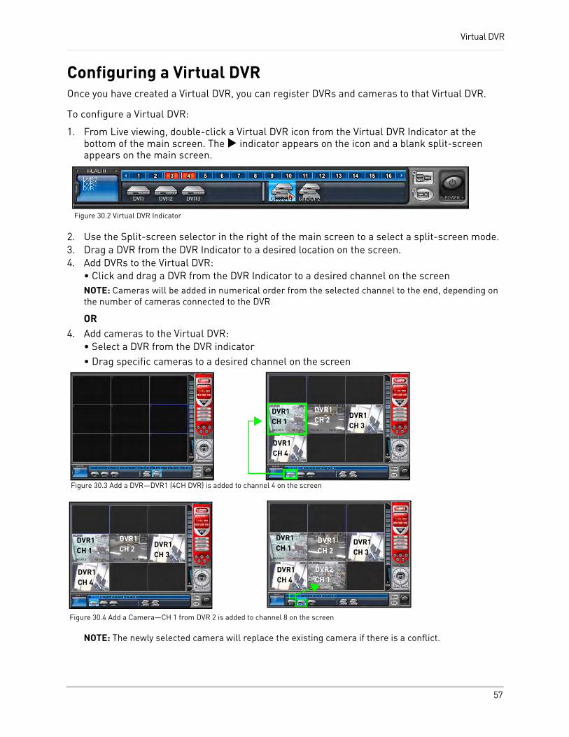
Virtual DVR
Configuring a Virtual DVROnce you have created a Virtual DVR, you can register DVRs and cameras to that Virtual DVR.
To configure a Virtual DVR:
1. From Live viewing, double-click a Virtual DVR icon from the Virtual DVR Indicator at the bottom of the main screen. The indicator appears on the icon and a blank split-screen appears on the main screen.
2. Use the Split-screen selector in the right of the main screen to a select a split-screen mode.3. Drag a DVR from the DVR Indicator to a desired location on the screen.4. Add DVRs to the Virtual DVR:
• Click and drag a DVR from the DVR Indicator to a desired channel on the screenNOTE: Cameras will be added in numerical order from the selected channel to the end, depending on the number of cameras connected to the DVR
OR4. Add cameras to the Virtual DVR:
• Select a DVR from the DVR indicator• Drag specific cameras to a desired channel on the screen
NOTE: The newly selected camera will replace the existing camera if there is a conflict.
Figure 30.2 Virtual DVR Indicator
Figure 30.3 Add a DVR—DVR1 (4CH DVR) is added to channel 4 on the screen
DVR1CH 1
DVR1CH 2 DVR1
CH 3
DVR1CH 4
DVR1CH 1
DVR1CH 2
DVR1CH 3
DVR1CH 4
Figure 30.4 Add a Camera—CH 1 from DVR 2 is added to channel 8 on the screen
DVR1CH 1
DVR1CH 2
DVR1CH 3
DVR1CH 4
DVR2CH 1
57
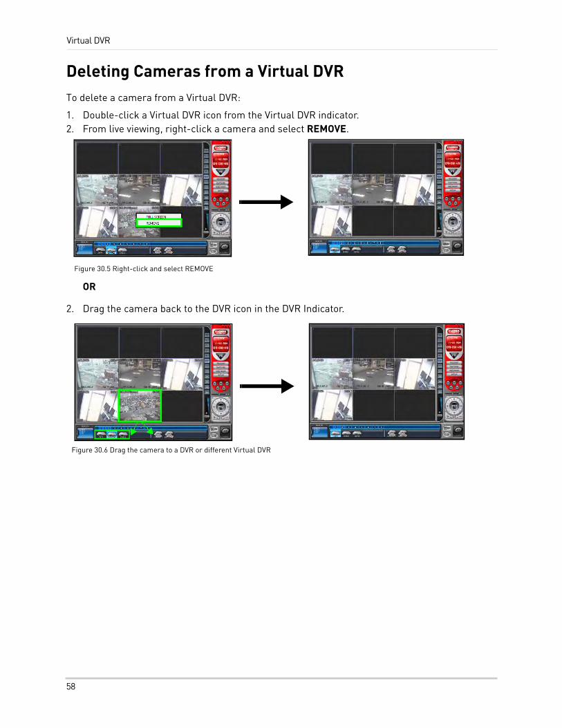
Virtual DVR
Deleting Cameras from a Virtual DVRTo delete a camera from a Virtual DVR:
1. Double-click a Virtual DVR icon from the Virtual DVR indicator.2. From live viewing, right-click a camera and select REMOVE.
OR
2. Drag the camera back to the DVR icon in the DVR Indicator.
Figure 30.5 Right-click and select REMOVE
Figure 30.6 Drag the camera to a DVR or different Virtual DVR
58
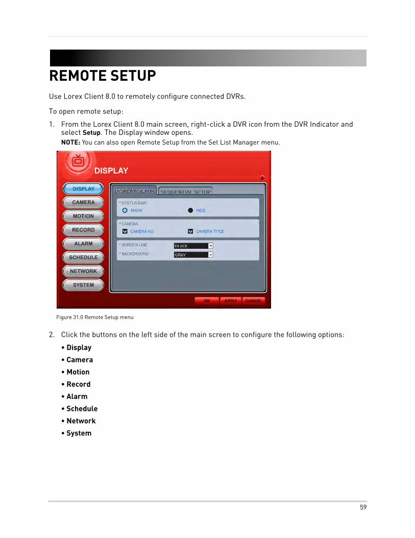
REMOTE SETUPUse Lorex Client 8.0 to remotely configure connected DVRs.
To open remote setup:
1. From the Lorex Client 8.0 main screen, right-click a DVR icon from the DVR Indicator and select Setup. The Display window opens.NOTE: You can also open Remote Setup from the Set List Manager menu.
2. Click the buttons on the left side of the main screen to configure the following options:
• Display
• Camera
• Motion
• Record
• Alarm
• Schedule
• Network
• System
Figure 31.0 Remote Setup menu
59
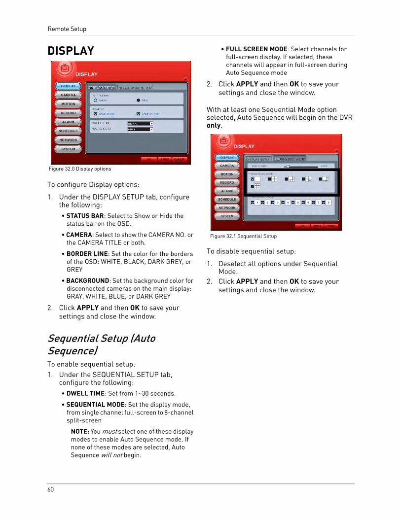
Remote Setup
DISPLAY
To configure Display options:
1. Under the DISPLAY SETUP tab, configure the following:• STATUS BAR: Select to Show or Hide the
status bar on the OSD.
• CAMERA: Select to show the CAMERA NO. or the CAMERA TITLE or both.
• BORDER LINE: Set the color for the borders of the OSD: WHITE, BLACK, DARK GREY, or GREY
• BACKGROUND: Set the background color for disconnected cameras on the main display: GRAY, WHITE, BLUE, or DARK GREY
2. Click APPLY and then OK to save your settings and close the window.
Sequential Setup (Auto Sequence)To enable sequential setup:1. Under the SEQUENTIAL SETUP tab,
configure the following:• DWELL TIME: Set from 1~30 seconds.
• SEQUENTIAL MODE: Set the display mode, from single channel full-screen to 8-channel split-screen
NOTE: You must select one of these display modes to enable Auto Sequence mode. If none of these modes are selected, Auto Sequence will not begin.
• FULL SCREEN MODE: Select channels for full-screen display. If selected, these channels will appear in full-screen during Auto Sequence mode
2. Click APPLY and then OK to save your settings and close the window.
With at least one Sequential Mode option selected, Auto Sequence will begin on the DVR only.
To disable sequential setup:
1. Deselect all options under Sequential Mode.
2. Click APPLY and then OK to save your settings and close the window.
Figure 32.0 Display options
Figure 32.1 Sequential Setup
60
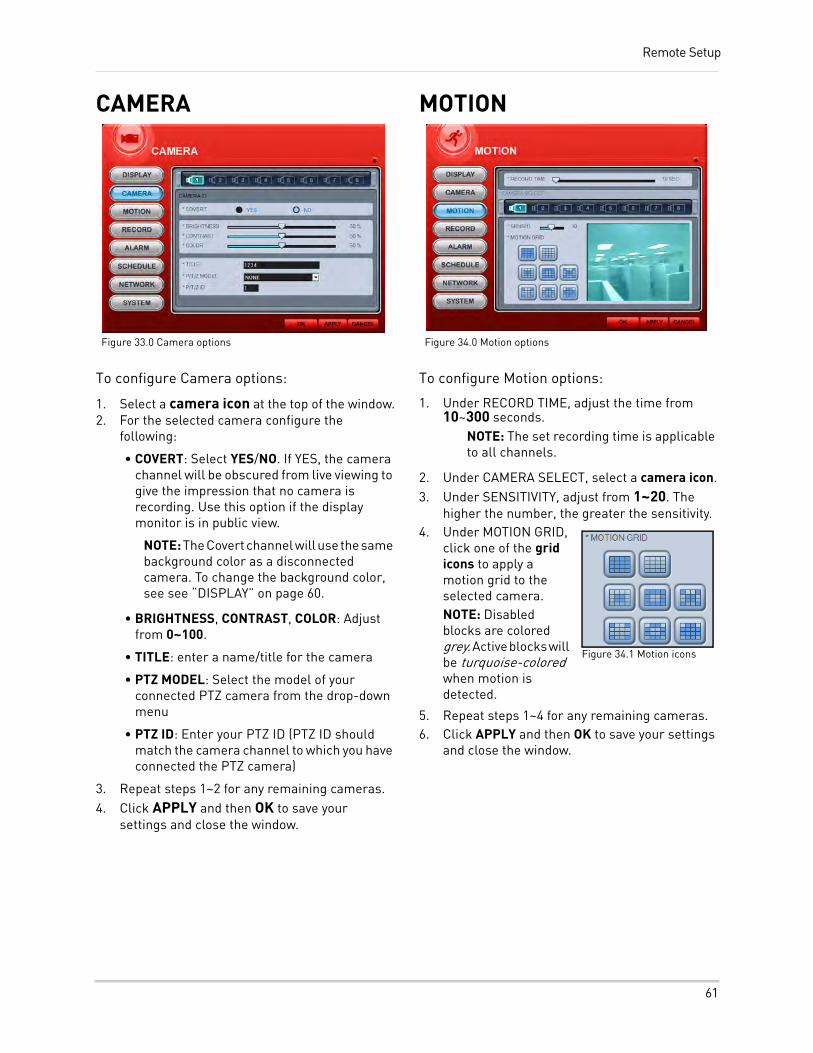
Remote Setup
CAMERA
To configure Camera options:
1. Select a camera icon at the top of the window.2. For the selected camera configure the
following:
• COVERT: Select YES/NO. If YES, the camera channel will be obscured from live viewing to give the impression that no camera is recording. Use this option if the display monitor is in public view.
NOTE: The Covert channel will use the same background color as a disconnected camera. To change the background color, see see “DISPLAY” on page 60.
• BRIGHTNESS, CONTRAST, COLOR: Adjust from 0~100.
• TITLE: enter a name/title for the camera
• PTZ MODEL: Select the model of your connected PTZ camera from the drop-down menu
• PTZ ID: Enter your PTZ ID (PTZ ID should match the camera channel to which you have connected the PTZ camera)
3. Repeat steps 1~2 for any remaining cameras.4. Click APPLY and then OK to save your
settings and close the window.
MOTION
To configure Motion options:
1. Under RECORD TIME, adjust the time from 10~300 seconds.
NOTE: The set recording time is applicable to all channels.
2. Under CAMERA SELECT, select a camera icon.3. Under SENSITIVITY, adjust from 1~20. The
higher the number, the greater the sensitivity.4. Under MOTION GRID,
click one of the grid icons to apply a motion grid to the selected camera.NOTE: Disabled blocks are colored grey. Active blocks will be turquoise-colored when motion is detected.
5. Repeat steps 1~4 for any remaining cameras.6. Click APPLY and then OK to save your settings
and close the window.
Figure 33.0 Camera options Figure 34.0 Motion options
Figure 34.1 Motion icons
61
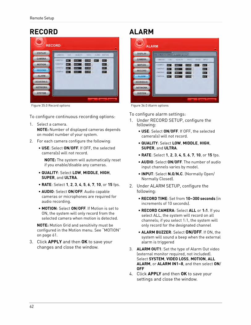
Remote Setup
RECORD
To configure continuous recording options:
1. Select a camera.NOTE: Number of displayed cameras depends on model number of your system.
2. For each camera configure the following:
• USE: Select ON/OFF. If OFF, the selected camera(s) will not record.
NOTE: The system will automatically reset if you enable/disable any cameras.
• QUALITY: Select LOW, MIDDLE, HIGH, SUPER, and ULTRA.
• RATE: Select 1, 2, 3, 4, 5, 6, 7, 10, or 15 fps.
• AUDIO: Select ON/OFF. Audio capable cameras or microphones are required for audio recording.
• MOTION: Select ON/OFF. If Motion is set to ON, the system will only record from the selected camera when motion is detected.
NOTE: Motion Grid and sensitivity must be configured in the Motion menu. See “MOTION” on page 61.
3. Click APPLY and then OK to save your changes and close the window.
ALARM
To configure alarm settings:1. Under RECORD SETUP, configure the
following:• USE: Select ON/OFF. If OFF, the selected
camera(s) will not record.
• QUALITY: Select LOW, MIDDLE, HIGH, SUPER, and ULTRA.
• RATE: Select 1, 2, 3, 4, 5, 6, 7, 10, or 15 fps.
• AUDIO: Select ON/OFF. The number of audio input channels varies by model.
• INPUT: Select N.O/N.C. (Normally Open/ Normally Closed).
2. Under ALARM SETUP, configure the following:
• RECORD TIME: Set from 10~300 seconds (in increments of 10 seconds).
• RECORD CAMERA: Select ALL or 1:1. If you select ALL, the system will record on all channels; if you select 1:1, the system will only record for the designated channel
• ALARM BUZZER: Select ON/OFF. If ON, the system will sound a beep when the external alarm is triggered
3. ALARM OUT1: Set the type of Alarm Out video (external monitor required, not included). Select SYSTEM, VIDEO LOSS, MOTION, ALL ALARM, or ALARM IN1~8, and then select ON/OFF
4. Click APPLY and then OK to save your settings and close the window.
Figure 35.0 Record options Figure 36.0 Alarm options
62
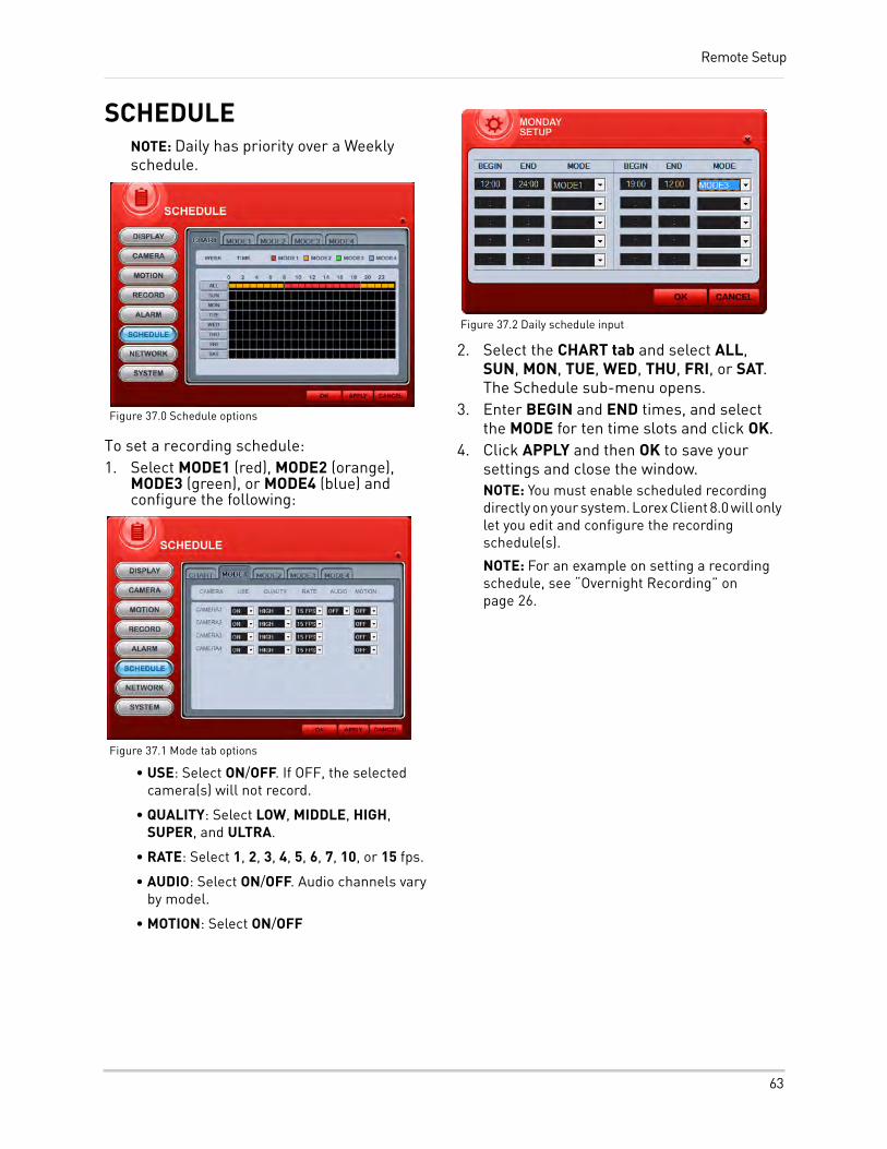
Remote Setup
SCHEDULENOTE: Daily has priority over a Weekly schedule.
To set a recording schedule:1. Select MODE1 (red), MODE2 (orange),
MODE3 (green), or MODE4 (blue) and configure the following:
• USE: Select ON/OFF. If OFF, the selected camera(s) will not record.
• QUALITY: Select LOW, MIDDLE, HIGH, SUPER, and ULTRA.
• RATE: Select 1, 2, 3, 4, 5, 6, 7, 10, or 15 fps.
• AUDIO: Select ON/OFF. Audio channels vary by model.
• MOTION: Select ON/OFF
2. Select the CHART tab and select ALL, SUN, MON, TUE, WED, THU, FRI, or SAT. The Schedule sub-menu opens.
3. Enter BEGIN and END times, and select the MODE for ten time slots and click OK.
4. Click APPLY and then OK to save your settings and close the window.NOTE: You must enable scheduled recording directly on your system. Lorex Client 8.0 will only let you edit and configure the recording schedule(s).
NOTE: For an example on setting a recording schedule, see “Overnight Recording” on page 26.
Figure 37.0 Schedule options
Figure 37.1 Mode tab options
Figure 37.2 Daily schedule input
63
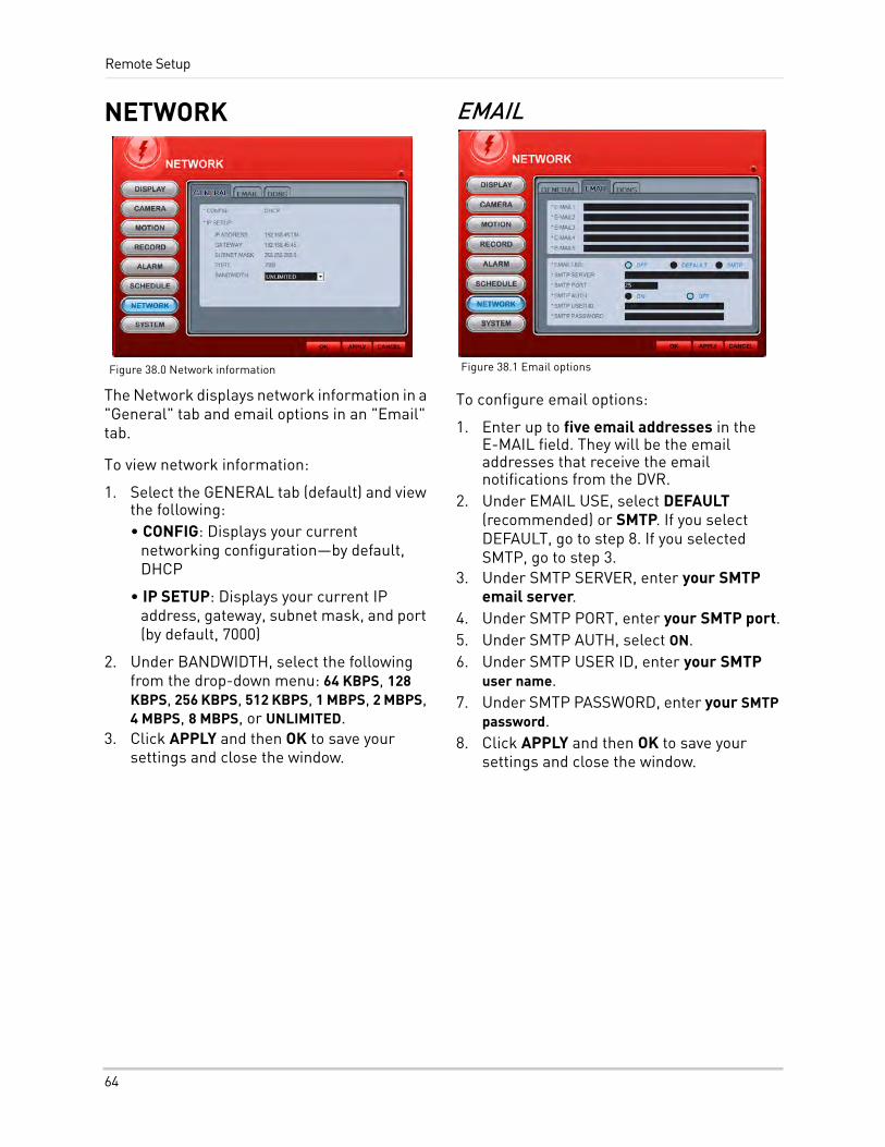
Remote Setup
NETWORK
The Network displays network information in a "General" tab and email options in an "Email" tab.
To view network information:
1. Select the GENERAL tab (default) and view the following:• CONFIG: Displays your current
networking configuration—by default, DHCP
• IP SETUP: Displays your current IP address, gateway, subnet mask, and port (by default, 7000)
2. Under BANDWIDTH, select the following from the drop-down menu: 64 KBPS, 128 KBPS, 256 KBPS, 512 KBPS, 1 MBPS, 2 MBPS, 4 MBPS, 8 MBPS, or UNLIMITED.
3. Click APPLY and then OK to save your settings and close the window.
To configure email options:
1. Enter up to five email addresses in the E-MAIL field. They will be the email addresses that receive the email notifications from the DVR.
2. Under EMAIL USE, select DEFAULT (recommended) or SMTP. If you select DEFAULT, go to step 8. If you selected SMTP, go to step 3.
3. Under SMTP SERVER, enter your SMTP email server.
4. Under SMTP PORT, enter your SMTP port.5. Under SMTP AUTH, select ON.6. Under SMTP USER ID, enter your SMTP
user name.7. Under SMTP PASSWORD, enter your SMTP
password.8. Click APPLY and then OK to save your
settings and close the window.
Figure 38.0 Network information Figure 38.1 Email options
64
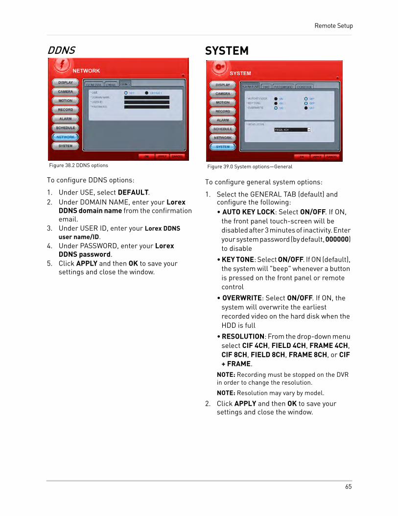
Remote Setup
DDNS
To configure DDNS options:
1. Under USE, select DEFAULT.2. Under DOMAIN NAME, enter your Lorex
DDNS domain name from the confirmation email.
3. Under USER ID, enter your Lorex DDNS user name/ID.
4. Under PASSWORD, enter your Lorex DDNS password.
5. Click APPLY and then OK to save your settings and close the window.
SYSTEM
To configure general system options:
1. Select the GENERAL TAB (default) and configure the following:• AUTO KEY LOCK: Select ON/OFF. If ON,
the front panel touch-screen will be disabled after 3 minutes of inactivity. Enter your system password (by default, 000000) to disable
• KEY TONE: Select ON/OFF. If ON (default), the system will "beep" whenever a button is pressed on the front panel or remote control
• OVERWRITE: Select ON/OFF. If ON, the system will overwrite the earliest recorded video on the hard disk when the HDD is full
• RESOLUTION: From the drop-down menu select CIF 4CH, FIELD 4CH, FRAME 4CH, CIF 8CH, FIELD 8CH, FRAME 8CH, or CIF + FRAME.
NOTE: Recording must be stopped on the DVR in order to change the resolution.
NOTE: Resolution may vary by model.
2. Click APPLY and then OK to save your settings and close the window.
Figure 38.2 DDNS options Figure 39.0 System options—General
65
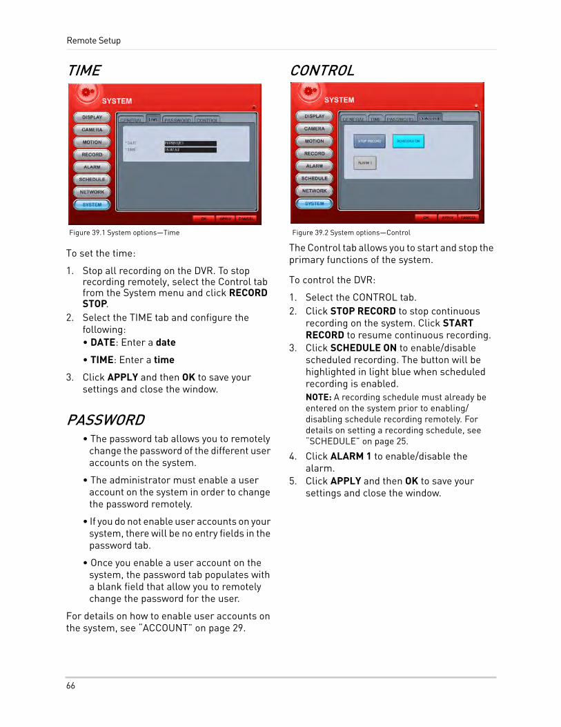
Remote Setup
TIME
To set the time:
1. Stop all recording on the DVR. To stop recording remotely, select the Control tab from the System menu and click RECORD STOP.
2. Select the TIME tab and configure the following:• DATE: Enter a date
• TIME: Enter a time
3. Click APPLY and then OK to save your settings and close the window.
PASSWORD• The password tab allows you to remotely
change the password of the different user accounts on the system.
• The administrator must enable a user account on the system in order to change the password remotely.
• If you do not enable user accounts on your system, there will be no entry fields in the password tab.
• Once you enable a user account on the system, the password tab populates with a blank field that allow you to remotely change the password for the user.
For details on how to enable user accounts on the system, see “ACCOUNT” on page 29.
CONTROL
The Control tab allows you to start and stop the primary functions of the system.
To control the DVR:
1. Select the CONTROL tab.2. Click STOP RECORD to stop continuous
recording on the system. Click START RECORD to resume continuous recording.
3. Click SCHEDULE ON to enable/disable scheduled recording. The button will be highlighted in light blue when scheduled recording is enabled.NOTE: A recording schedule must already be entered on the system prior to enabling/disabling schedule recording remotely. For details on setting a recording schedule, see “SCHEDULE” on page 25.
4. Click ALARM 1 to enable/disable the alarm.
5. Click APPLY and then OK to save your settings and close the window.
Figure 39.1 System options—Time Figure 39.2 System options—Control
66
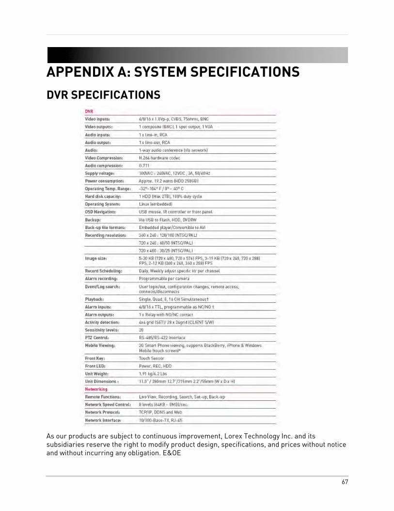
APPENDIX A: SYSTEM SPECIFICATIONS
DVR SPECIFICATIONS
As our products are subject to continuous improvement, Lorex Technology Inc. and its subsidiaries reserve the right to modify product design, specifications, and prices without notice and without incurring any obligation. E&OE
67
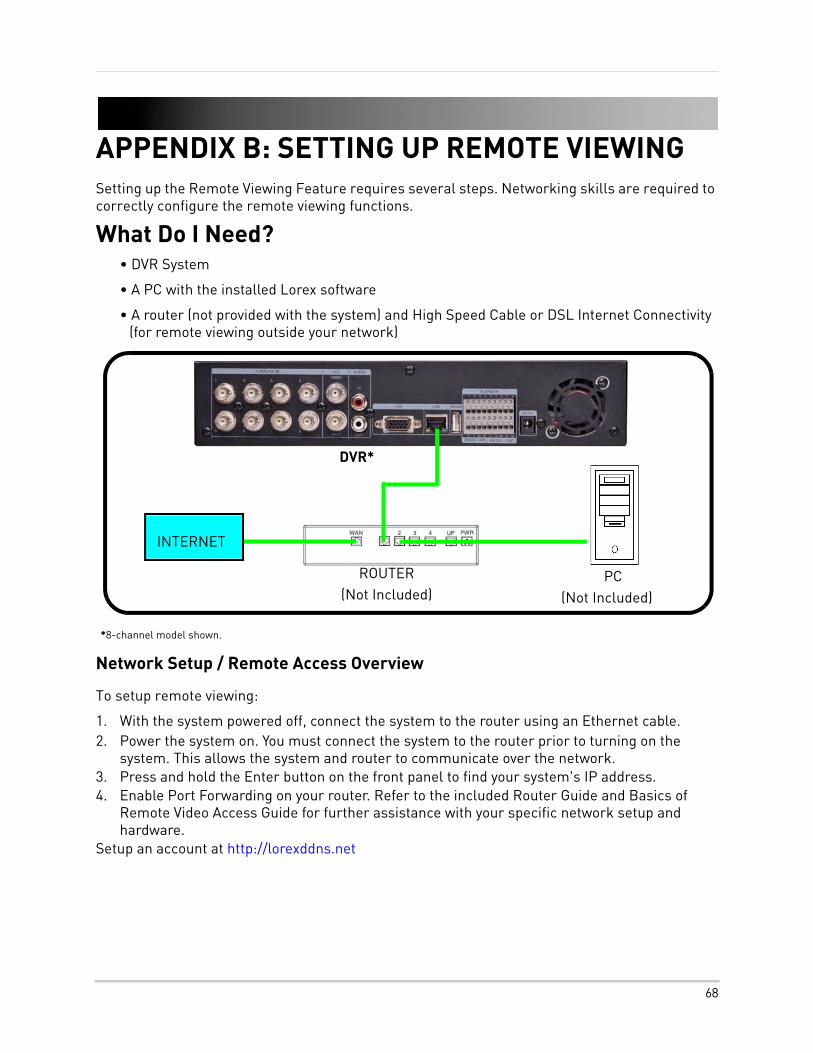
APPENDIX B: SETTING UP REMOTE VIEWINGSetting up the Remote Viewing Feature requires several steps. Networking skills are required to correctly configure the remote viewing functions.
What Do I Need?• DVR System
• A PC with the installed Lorex software
• A router (not provided with the system) and High Speed Cable or DSL Internet Connectivity (for remote viewing outside your network)
Network Setup / Remote Access Overview
To setup remote viewing:
1. With the system powered off, connect the system to the router using an Ethernet cable.2. Power the system on. You must connect the system to the router prior to turning on the
system. This allows the system and router to communicate over the network.3. Press and hold the Enter button on the front panel to find your system's IP address.4. Enable Port Forwarding on your router. Refer to the included Router Guide and Basics of
Remote Video Access Guide for further assistance with your specific network setup and hardware.
Setup an account at http://lorexddns.net
ROUTER(Not Included)
INTERNET
PC(Not Included)
DVR*
*8-channel model shown.
68
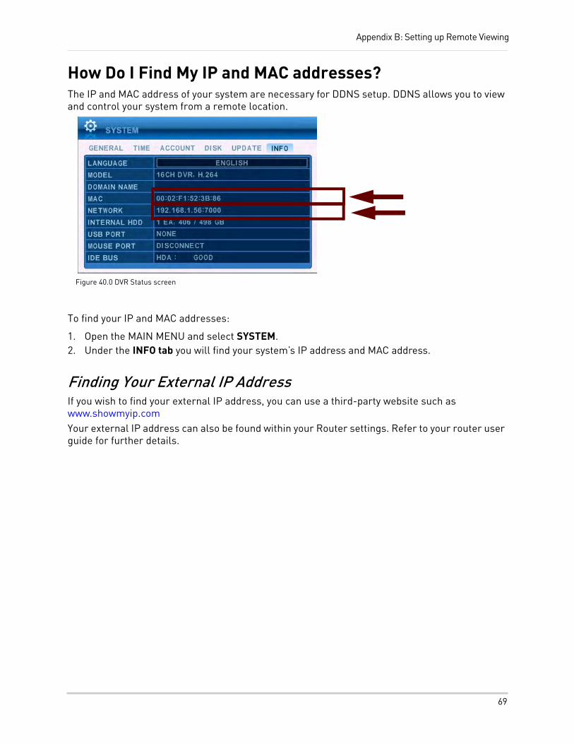
Appendix B: Setting up Remote Viewing
How Do I Find My IP and MAC addresses?The IP and MAC address of your system are necessary for DDNS setup. DDNS allows you to view and control your system from a remote location.
To find your IP and MAC addresses:
1. Open the MAIN MENU and select SYSTEM.2. Under the INFO tab you will find your system’s IP address and MAC address.
Finding Your External IP AddressIf you wish to find your external IP address, you can use a third-party website such as www.showmyip.comYour external IP address can also be found within your Router settings. Refer to your router user guide for further details.
Figure 40.0 DVR Status screen
69
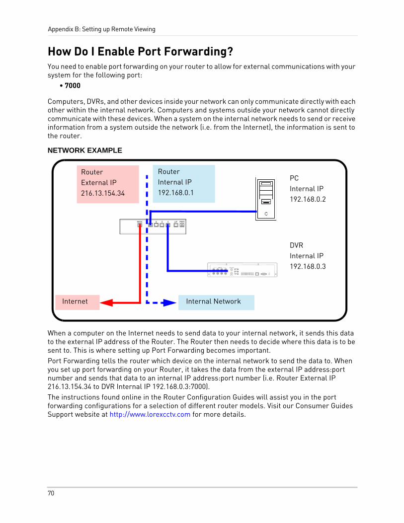
Appendix B: Setting up Remote Viewing
How Do I Enable Port Forwarding?You need to enable port forwarding on your router to allow for external communications with your system for the following port:
• 7000
Computers, DVRs, and other devices inside your network can only communicate directly with each other within the internal network. Computers and systems outside your network cannot directly communicate with these devices. When a system on the internal network needs to send or receive information from a system outside the network (i.e. from the Internet), the information is sent to the router.
NETWORK EXAMPLE
When a computer on the Internet needs to send data to your internal network, it sends this data to the external IP address of the Router. The Router then needs to decide where this data is to be sent to. This is where setting up Port Forwarding becomes important.Port Forwarding tells the router which device on the internal network to send the data to. When you set up port forwarding on your Router, it takes the data from the external IP address:port number and sends that data to an internal IP address:port number (i.e. Router External IP 216.13.154.34 to DVR Internal IP 192.168.0.3:7000).The instructions found online in the Router Configuration Guides will assist you in the port forwarding configurations for a selection of different router models. Visit our Consumer Guides Support website at http://www.lorexcctv.com for more details.
PCInternal IP192.168.0.2
DVRInternal IP192.168.0.3
RouterInternal IP192.168.0.1
RouterExternal IP216.13.154.34
Internal NetworkInternet
70
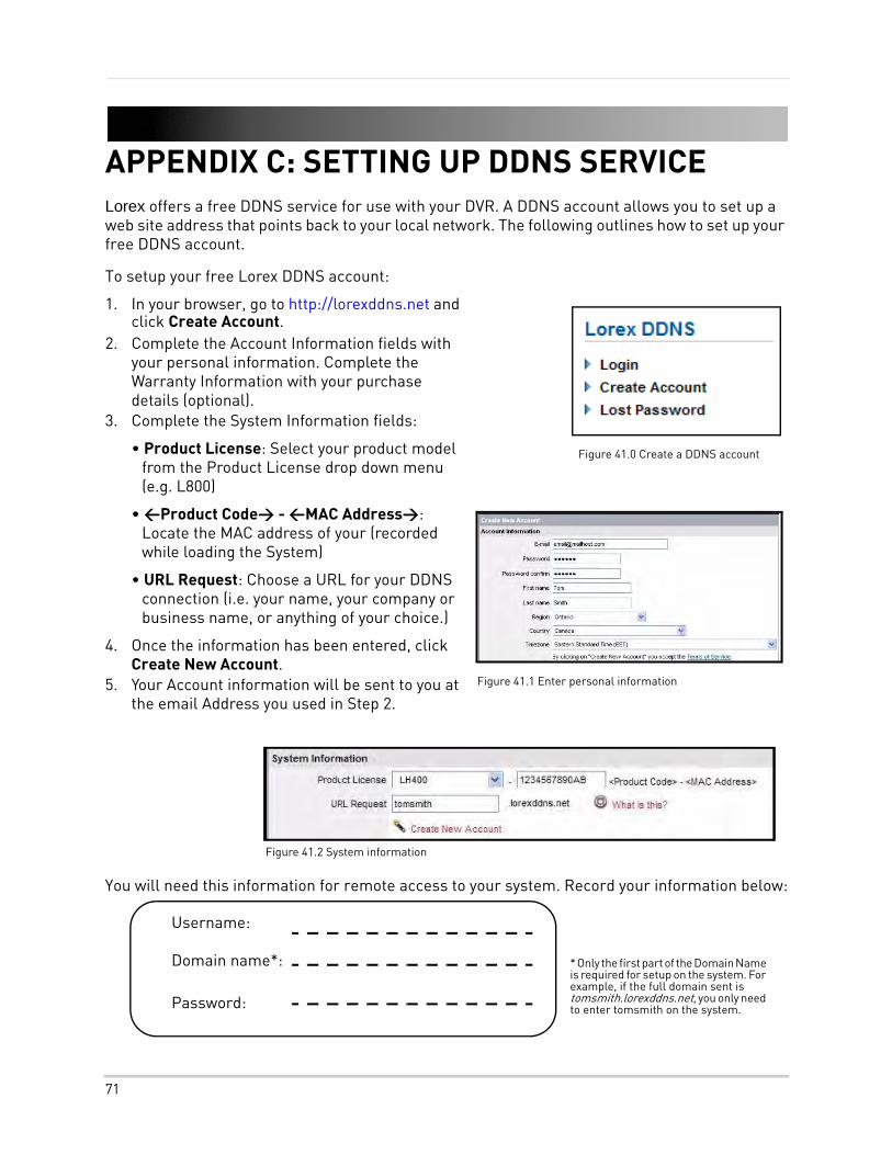
APPENDIX C: SETTING UP DDNS SERVICELorex offers a free DDNS service for use with your DVR. A DDNS account allows you to set up a web site address that points back to your local network. The following outlines how to set up your free DDNS account.
To setup your free Lorex DDNS account:
1. In your browser, go to http://lorexddns.net and click Create Account.
2. Complete the Account Information fields with your personal information. Complete the Warranty Information with your purchase details (optional).
3. Complete the System Information fields:
• Product License: Select your product model from the Product License drop down menu (e.g. L800)
• <Product Code> - <MAC Address>: Locate the MAC address of your (recorded while loading the System)
• URL Request: Choose a URL for your DDNS connection (i.e. your name, your company or business name, or anything of your choice.)
4. Once the information has been entered, click Create New Account.
5. Your Account information will be sent to you at the email Address you used in Step 2.
You will need this information for remote access to your system. Record your information below:
Figure 41.0 Create a DDNS account
Figure 41.1 Enter personal information
Figure 41.2 System information
Username: Domain name*: Password:
* Only the first part of the Domain Name is required for setup on the system. For example, if the full domain sent is tomsmith.lorexddns.net, you only need to enter tomsmith on the system.
71
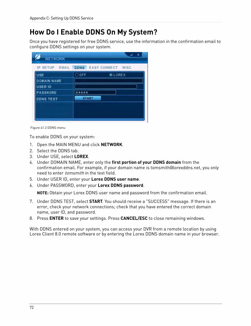
Appendix C: Setting Up DDNS Service
How Do I Enable DDNS On My System?Once you have registered for free DDNS service, use the information in the confirmation email to configure DDNS settings on your system.
To enable DDNS on your system:
1. Open the MAIN MENU and click NETWORK.2. Select the DDNS tab.3. Under USE, select LOREX.4. Under DOMAIN NAME, enter only the first portion of your DDNS domain from the
confirmation email. For example, if your domain name is [email protected], you only need to enter tomsmith in the text field.
5. Under USER ID, enter your Lorex DDNS user name.6. Under PASSWORD, enter your Lorex DDNS password.
NOTE: Obtain your Lorex DDNS user name and password from the confirmation email.
7. Under DDNS TEST, select START. You should receive a "SUCCESS" message. If there is an error, check your network connections; check that you have entered the correct domain name, user ID, and password.
8. Press ENTER to save your settings. Press CANCEL/ESC to close remaining windows.
With DDNS entered on your system, you can access your DVR from a remote location by using Lorex Client 8.0 remote software or by entering the Lorex DDNS domain name in your browser.
Figure 41.3 DDNS menu
72
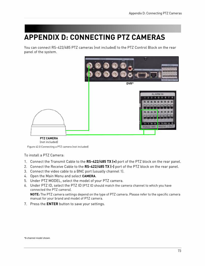
Appendix D: Connecting PTZ Cameras
APPENDIX D: CONNECTING PTZ CAMERASYou can connect RS-422/485 PTZ cameras (not included) to the PTZ Control Block on the rear panel of the system.
To install a PTZ Camera:
1. Connect the Transmit Cable to the RS-422/485 TX (+) port of the PTZ block on the rear panel.2. Connect the Receive Cable to the RS-422/485 TX (-) port of the PTZ block on the rear panel.3. Connect the video cable to a BNC port (usually channel 1).4. Open the Main Menu and select CAMERA.5. Under PTZ MODEL, select the model of your PTZ camera.6. Under PTZ ID, select the PTZ ID (PTZ ID should match the camera channel to which you have
connected the PTZ camera).NOTE: The PTZ camera settings depend on the type of PTZ camera. Please refer to the specific camera manual for your brand and model of PTZ camera.
7. Press the ENTER button to save your settings.
*8-channel model shown.
DVR*
PTZ CAMERA(not included)
Figure 42.0 Connecting a PTZ camera (not included)
73
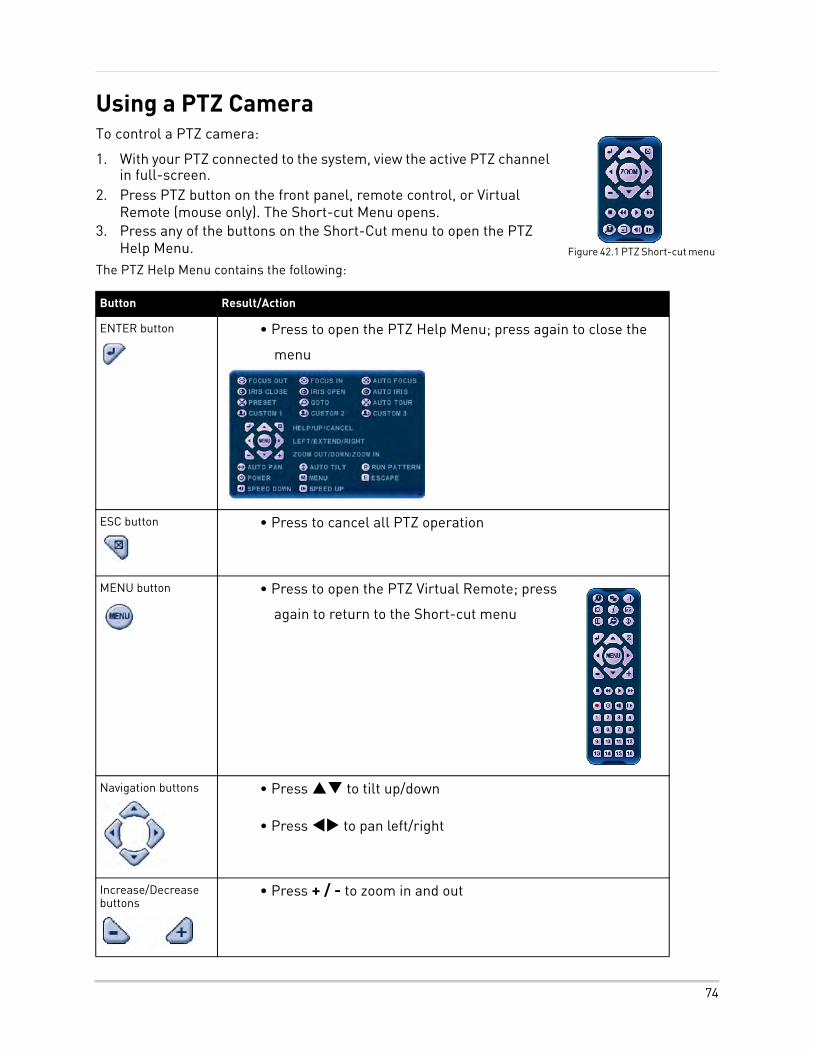
Using a PTZ CameraTo control a PTZ camera:
1. With your PTZ connected to the system, view the active PTZ channel in full-screen.
2. Press PTZ button on the front panel, remote control, or Virtual Remote (mouse only). The Short-cut Menu opens.
3. Press any of the buttons on the Short-Cut menu to open the PTZ Help Menu.
The PTZ Help Menu contains the following:
Button Result/Action
ENTER button • Press to open the PTZ Help Menu; press again to close the
menu
ESC button • Press to cancel all PTZ operation
MENU button • Press to open the PTZ Virtual Remote; press
again to return to the Short-cut menu
Navigation buttons • Press to tilt up/down
• Press to pan left/right
Increase/Decrease buttons
• Press + / - to zoom in and out
Figure 42.1 PTZ Short-cut menu
74
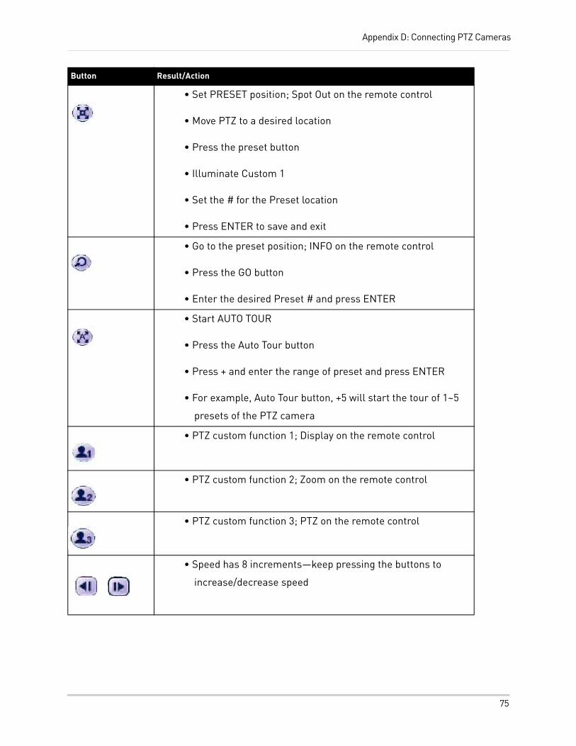
Appendix D: Connecting PTZ Cameras
Button Result/Action
• Set PRESET position; Spot Out on the remote control
• Move PTZ to a desired location
• Press the preset button
• Illuminate Custom 1
• Set the # for the Preset location
• Press ENTER to save and exit
• Go to the preset position; INFO on the remote control
• Press the GO button
• Enter the desired Preset # and press ENTER
• Start AUTO TOUR
• Press the Auto Tour button
• Press + and enter the range of preset and press ENTER
• For example, Auto Tour button, +5 will start the tour of 1~5
presets of the PTZ camera
• PTZ custom function 1; Display on the remote control
• PTZ custom function 2; Zoom on the remote control
• PTZ custom function 3; PTZ on the remote control
• Speed has 8 increments—keep pressing the buttons to
increase/decrease speed
75
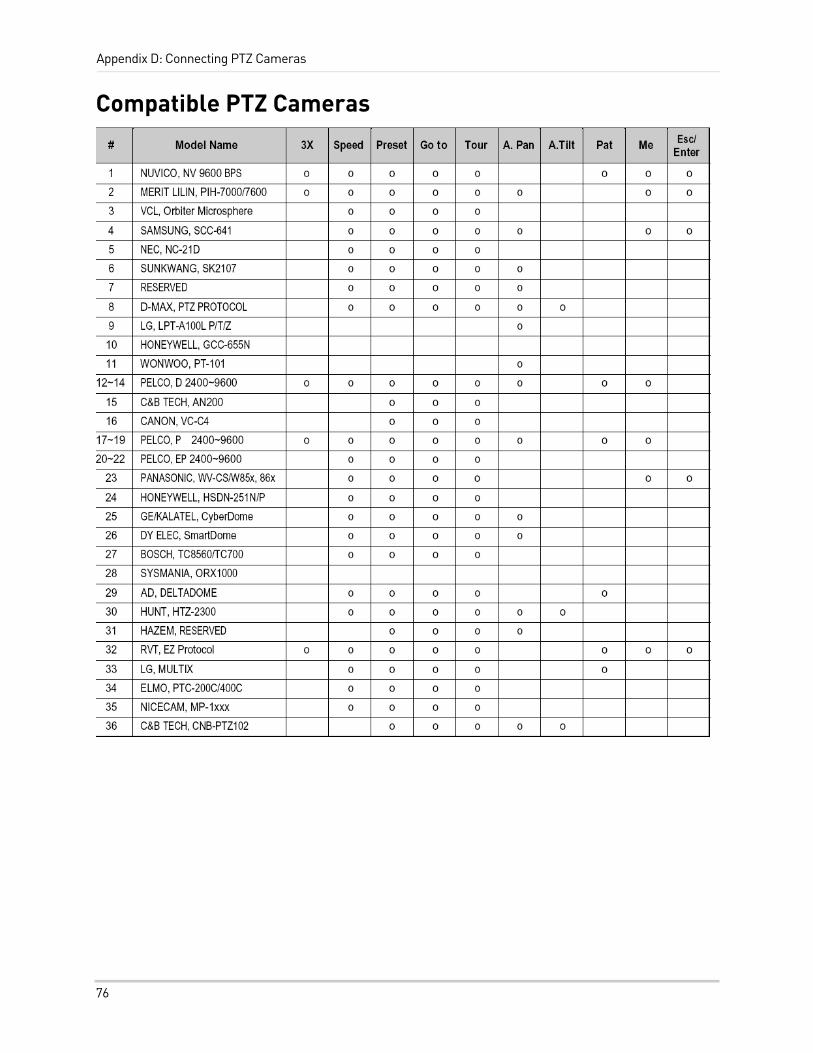
Appendix D: Connecting PTZ Cameras
Compatible PTZ Cameras
76
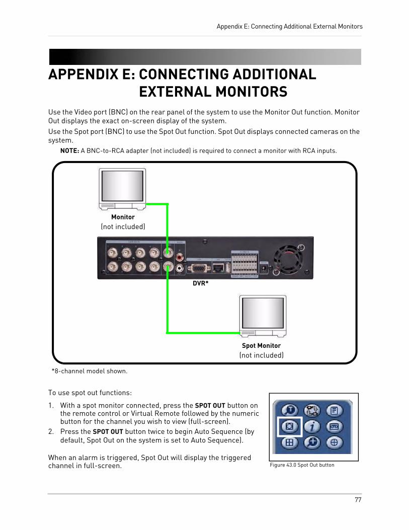
Appendix E: Connecting Additional External Monitors
APPENDIX E: CONNECTING ADDITIONAL EXTERNAL MONITORS
Use the Video port (BNC) on the rear panel of the system to use the Monitor Out function. Monitor Out displays the exact on-screen display of the system.Use the Spot port (BNC) to use the Spot Out function. Spot Out displays connected cameras on the system.
NOTE: A BNC-to-RCA adapter (not included) is required to connect a monitor with RCA inputs.
To use spot out functions:
1. With a spot monitor connected, press the SPOT OUT button on the remote control or Virtual Remote followed by the numeric button for the channel you wish to view (full-screen).
2. Press the SPOT OUT button twice to begin Auto Sequence (by default, Spot Out on the system is set to Auto Sequence).
When an alarm is triggered, Spot Out will display the triggered channel in full-screen.
DVR*
Monitor(not included)
Spot Monitor(not included)
*8-channel model shown.
Figure 43.0 Spot Out button
77
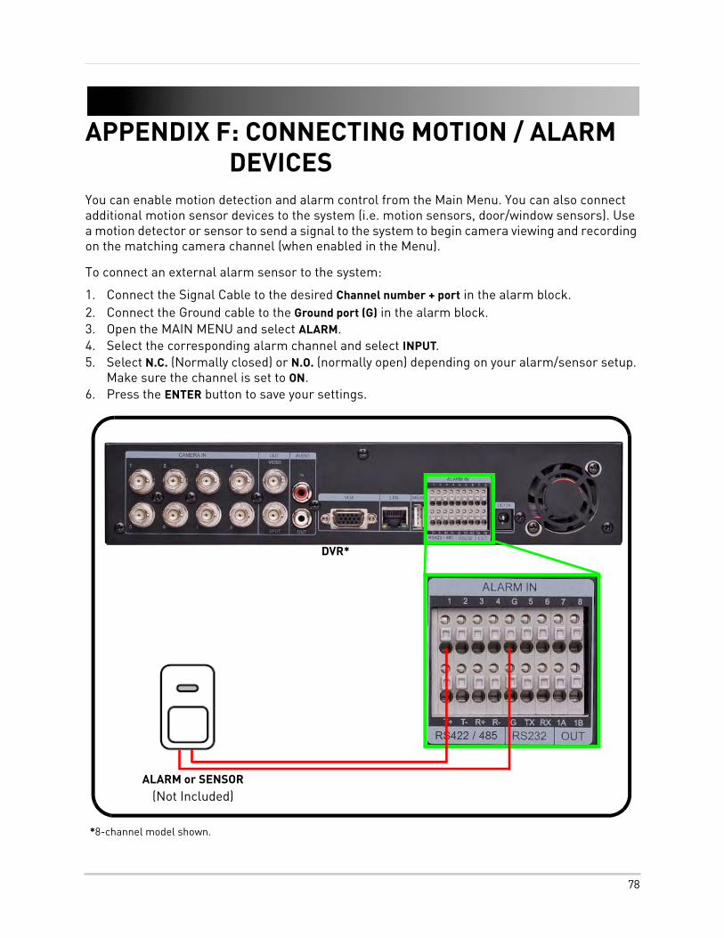
APPENDIX F: CONNECTING MOTION / ALARM DEVICES
You can enable motion detection and alarm control from the Main Menu. You can also connect additional motion sensor devices to the system (i.e. motion sensors, door/window sensors). Use a motion detector or sensor to send a signal to the system to begin camera viewing and recording on the matching camera channel (when enabled in the Menu).
To connect an external alarm sensor to the system:
1. Connect the Signal Cable to the desired Channel number + port in the alarm block.2. Connect the Ground cable to the Ground port (G) in the alarm block.3. Open the MAIN MENU and select ALARM.4. Select the corresponding alarm channel and select INPUT.5. Select N.C. (Normally closed) or N.O. (normally open) depending on your alarm/sensor setup.
Make sure the channel is set to ON.6. Press the ENTER button to save your settings.
ALARM or SENSOR(Not Included)
DVR*
*8-channel model shown.
78
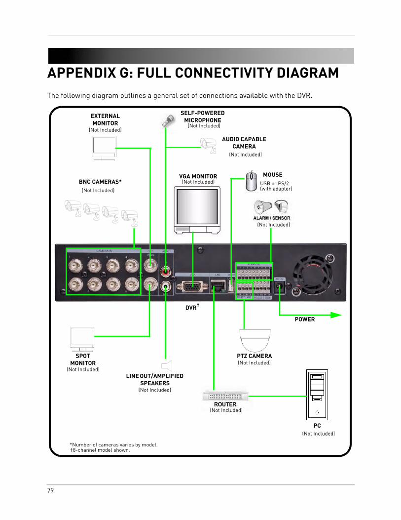
APPENDIX G: FULL CONNECTIVITY DIAGRAMThe following diagram outlines a general set of connections available with the DVR.
*Number of cameras varies by model.†8-channel model shown.
SPOT MONITOR
(Not Included)
POWER
BNC CAMERAS*VGA MONITOR
(Not Included)
(Not Included)
DVR†
EXTERNAL MONITOR
(Not Included)
(Not Included)LINE OUT/AMPLIFIED
SPEAKERS(Not Included)
AUDIO CAPABLE CAMERA
(Not Included)
SELF-POWERED MICROPHONE
(Not Included)
(Not Included)
PC(Not Included)
PTZ CAMERA(Not Included)
USB or PS/2 (with adapter)
MOUSE
79
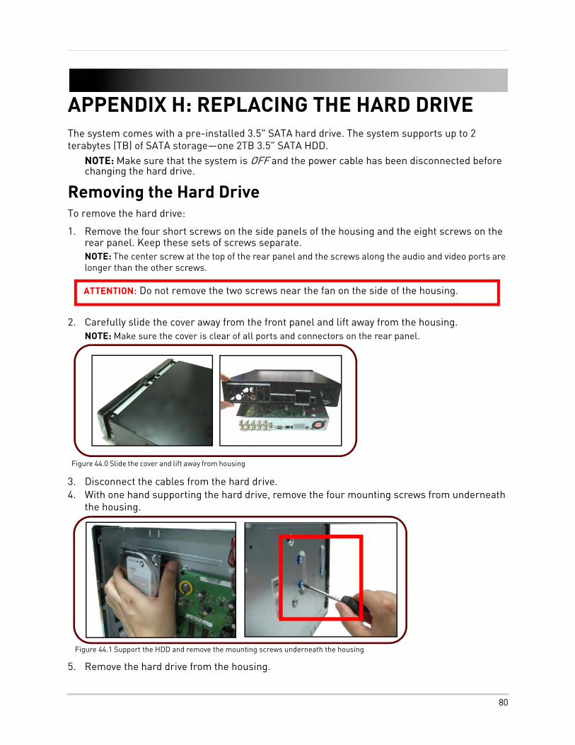
APPENDIX H: REPLACING THE HARD DRIVEThe system comes with a pre-installed 3.5" SATA hard drive. The system supports up to 2 terabytes (TB) of SATA storage—one 2TB 3.5" SATA HDD.
NOTE: Make sure that the system is OFF and the power cable has been disconnected before changing the hard drive.
Removing the Hard DriveTo remove the hard drive:
1. Remove the four short screws on the side panels of the housing and the eight screws on the rear panel. Keep these sets of screws separate.NOTE: The center screw at the top of the rear panel and the screws along the audio and video ports are longer than the other screws.
2. Carefully slide the cover away from the front panel and lift away from the housing.NOTE: Make sure the cover is clear of all ports and connectors on the rear panel.
3. Disconnect the cables from the hard drive.4. With one hand supporting the hard drive, remove the four mounting screws from underneath
the housing.
5. Remove the hard drive from the housing.
ATTENTION: Do not remove the two screws near the fan on the side of the housing.
Figure 44.0 Slide the cover and lift away from housing
Figure 44.1 Support the HDD and remove the mounting screws underneath the housing
80
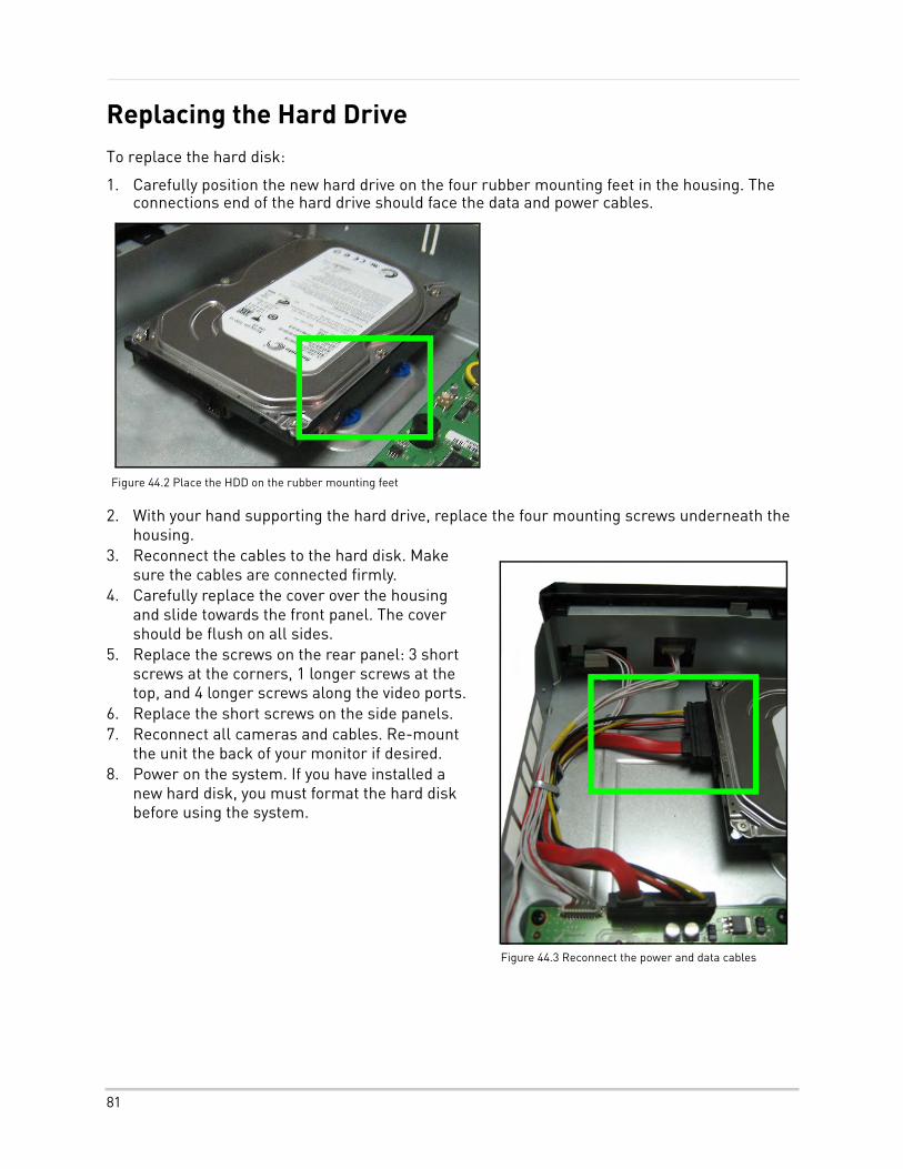
Replacing the Hard DriveTo replace the hard disk:
1. Carefully position the new hard drive on the four rubber mounting feet in the housing. The connections end of the hard drive should face the data and power cables.
2. With your hand supporting the hard drive, replace the four mounting screws underneath the housing.
3. Reconnect the cables to the hard disk. Make sure the cables are connected firmly.
4. Carefully replace the cover over the housing and slide towards the front panel. The cover should be flush on all sides.
5. Replace the screws on the rear panel: 3 short screws at the corners, 1 longer screws at the top, and 4 longer screws along the video ports.
6. Replace the short screws on the side panels.7. Reconnect all cameras and cables. Re-mount
the unit the back of your monitor if desired.8. Power on the system. If you have installed a
new hard disk, you must format the hard disk before using the system.
Figure 44.2 Place the HDD on the rubber mounting feet
Figure 44.3 Reconnect the power and data cables
81
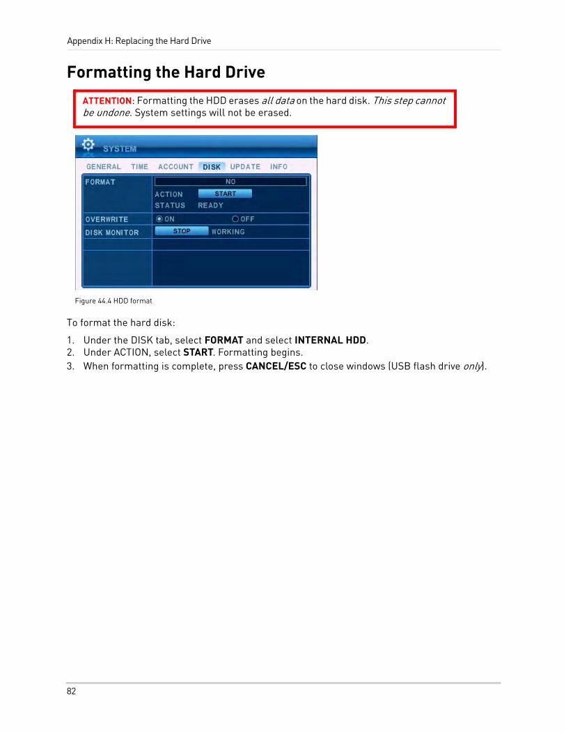
Appendix H: Replacing the Hard Drive
Formatting the Hard Drive
To format the hard disk:
1. Under the DISK tab, select FORMAT and select INTERNAL HDD.2. Under ACTION, select START. Formatting begins. 3. When formatting is complete, press CANCEL/ESC to close windows (USB flash drive only).
ATTENTION: Formatting the HDD erases all data on the hard disk. This step cannot be undone. System settings will not be erased.
Figure 44.4 HDD format
82
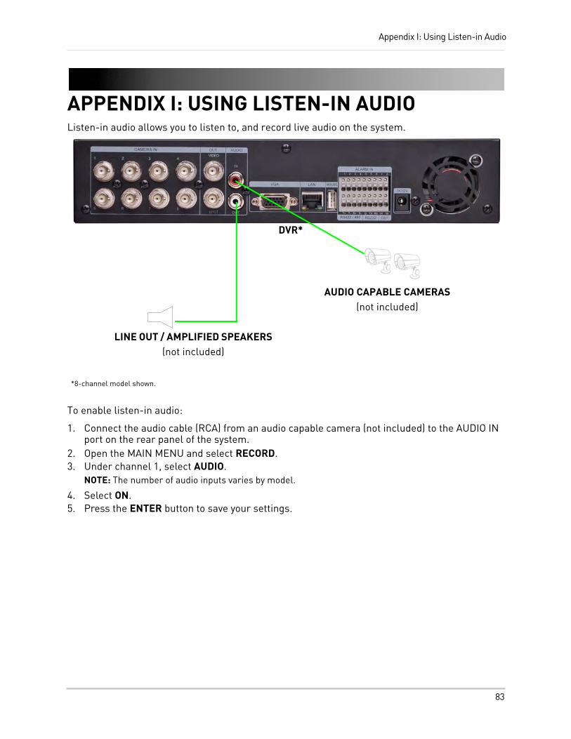
Appendix I: Using Listen-in Audio
APPENDIX I: USING LISTEN-IN AUDIOListen-in audio allows you to listen to, and record live audio on the system.
To enable listen-in audio:
1. Connect the audio cable (RCA) from an audio capable camera (not included) to the AUDIO IN port on the rear panel of the system.
2. Open the MAIN MENU and select RECORD.3. Under channel 1, select AUDIO.
NOTE: The number of audio inputs varies by model.
4. Select ON.5. Press the ENTER button to save your settings.
LINE OUT / AMPLIFIED SPEAKERS(not included)
DVR*
AUDIO CAPABLE CAMERAS(not included)
*8-channel model shown.
83
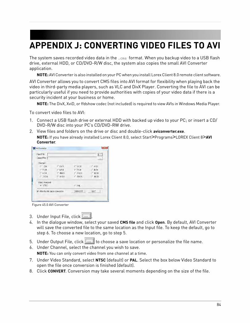
APPENDIX J: CONVERTING VIDEO FILES TO AVIThe system saves recorded video data in the .cms format. When you backup video to a USB flash drive, external HDD, or CD/DVD-R/W disc, the system also copies the small AVI Converter application.
NOTE: AVI Converter is also installed on your PC when you install Lorex Client 8.0 remote client software.
AVI Converter allows you to convert CMS files into AVI format for flexibility when playing back the video in third-party media players, such as VLC and DivX Player. Converting the file to AVI can be particularly useful if you need to provide authorities with copies of your video data if there is a security incident at your business or home.
NOTE: The DivX, XviD, or ffdshow codec (not included) is required to view AVIs in Windows Media Player.
To convert video files to AVI:
1. Connect a USB flash drive or external HDD with backed up video to your PC; or insert a CD/DVD-R/W disc into your PC’s CD/DVD-RW drive.
2. View files and folders on the drive or disc and double-click aviconverter.exe.NOTE: If you have already installed Lorex Client 8.0, select Start>Programs>LOREX Client 8>AVI Converter.
3. Under Input File, click .4. In the dialogue window, select your saved CMS file and click Open. By default, AVI Converter
will save the converted file to the same location as the Input file. To keep the default, go to step 6. To choose a new location, go to step 5.
5. Under Output File, click to choose a save location or personalize the file name. 6. Under Channel, select the channel you wish to save.
NOTE: You can only convert video from one channel at a time.
7. Under Video Standard, select NTSC (default) or PAL. Select the box below Video Standard to open the file once conversion is finished (default).
8. Click CONVERT. Conversion may take several moments depending on the size of the file.
Figure 45.0 AVI Converter
84
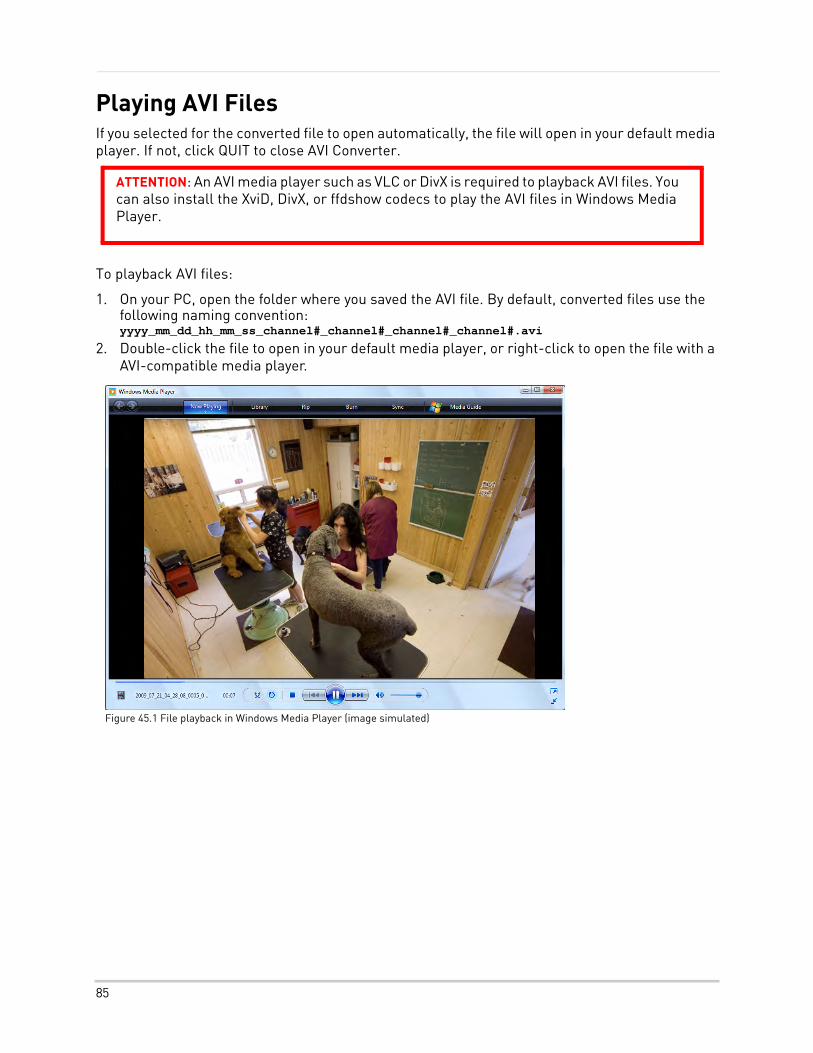
Playing AVI FilesIf you selected for the converted file to open automatically, the file will open in your default media player. If not, click QUIT to close AVI Converter.
To playback AVI files:
1. On your PC, open the folder where you saved the AVI file. By default, converted files use the following naming convention: yyyy_mm_dd_hh_mm_ss_channel#_channel#_channel#_channel#.avi
2. Double-click the file to open in your default media player, or right-click to open the file with a AVI-compatible media player.
ATTENTION: An AVI media player such as VLC or DivX is required to playback AVI files. You can also install the XviD, DivX, or ffdshow codecs to play the AVI files in Windows Media Player.
Figure 45.1 File playback in Windows Media Player (image simulated)
85
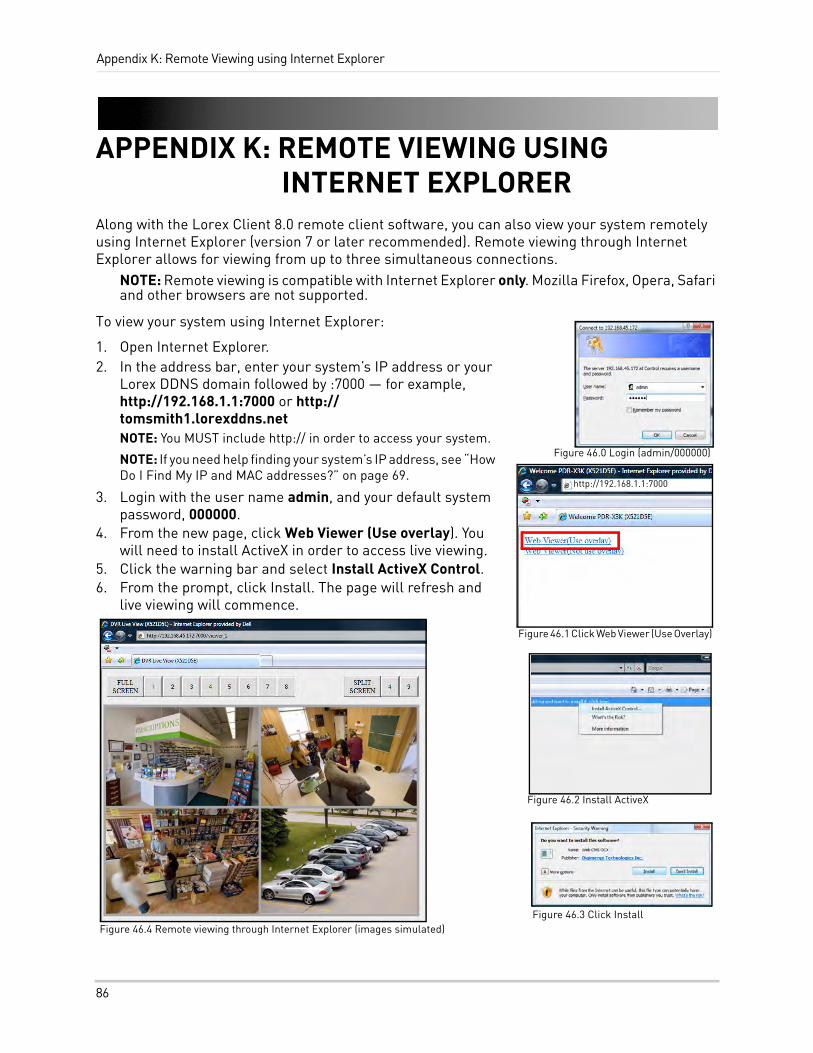
Appendix K: Remote Viewing using Internet Explorer
APPENDIX K: REMOTE VIEWING USING INTERNET EXPLORER
Along with the Lorex Client 8.0 remote client software, you can also view your system remotely using Internet Explorer (version 7 or later recommended). Remote viewing through Internet Explorer allows for viewing from up to three simultaneous connections.
NOTE: Remote viewing is compatible with Internet Explorer only. Mozilla Firefox, Opera, Safari and other browsers are not supported.
To view your system using Internet Explorer:
1. Open Internet Explorer.2. In the address bar, enter your system’s IP address or your
Lorex DDNS domain followed by :7000 — for example, http://192.168.1.1:7000 or http://tomsmith1.lorexddns.netNOTE: You MUST include http:// in order to access your system.
NOTE: If you need help finding your system’s IP address, see “How Do I Find My IP and MAC addresses?” on page 69.
3. Login with the user name admin, and your default system password, 000000.
4. From the new page, click Web Viewer (Use overlay). You will need to install ActiveX in order to access live viewing.
5. Click the warning bar and select Install ActiveX Control.6. From the prompt, click Install. The page will refresh and
live viewing will commence.
http://192.168.1.1:7000
Figure 46.0 Login (admin/000000)
Figure 46.1 Click Web Viewer (Use Overlay)
Figure 46.2 Install ActiveX
Figure 46.3 Click InstallFigure 46.4 Remote viewing through Internet Explorer (images simulated)
86
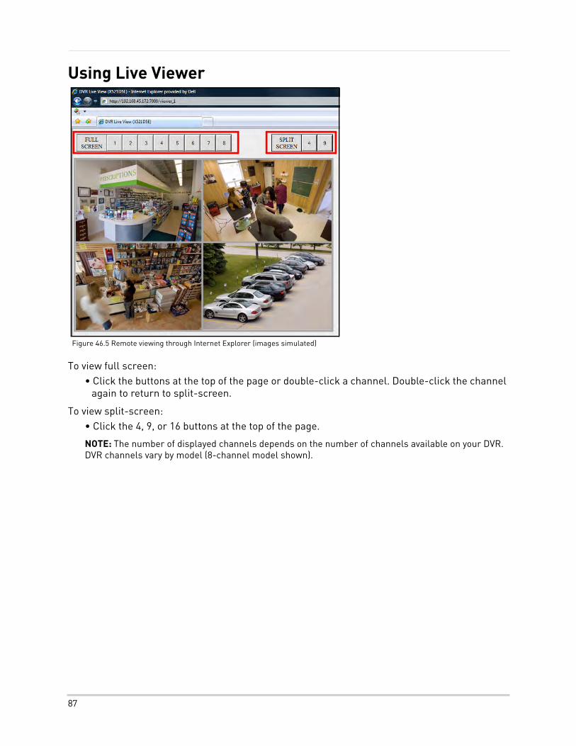
Using Live Viewer
To view full screen:• Click the buttons at the top of the page or double-click a channel. Double-click the channel
again to return to split-screen.
To view split-screen:• Click the 4, 9, or 16 buttons at the top of the page.
NOTE: The number of displayed channels depends on the number of channels available on your DVR. DVR channels vary by model (8-channel model shown).
Figure 46.5 Remote viewing through Internet Explorer (images simulated)
87
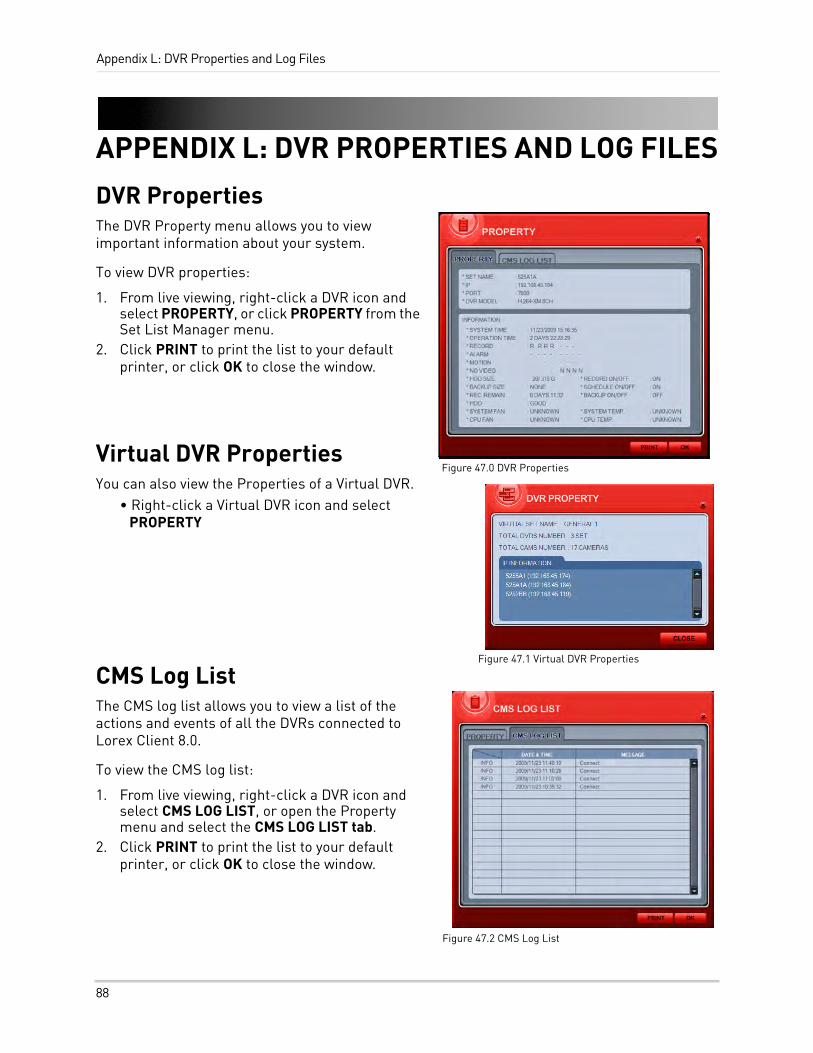
Appendix L: DVR Properties and Log Files
APPENDIX L: DVR PROPERTIES AND LOG FILES
DVR PropertiesThe DVR Property menu allows you to view important information about your system.
To view DVR properties:
1. From live viewing, right-click a DVR icon and select PROPERTY, or click PROPERTY from the Set List Manager menu.
2. Click PRINT to print the list to your default printer, or click OK to close the window.
Virtual DVR PropertiesYou can also view the Properties of a Virtual DVR.
• Right-click a Virtual DVR icon and select PROPERTY
CMS Log ListThe CMS log list allows you to view a list of the actions and events of all the DVRs connected to Lorex Client 8.0.
To view the CMS log list:
1. From live viewing, right-click a DVR icon and select CMS LOG LIST, or open the Property menu and select the CMS LOG LIST tab.
2. Click PRINT to print the list to your default printer, or click OK to close the window.
Figure 47.0 DVR Properties
Figure 47.2 CMS Log List
Figure 47.1 Virtual DVR Properties
88
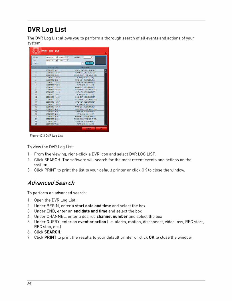
DVR Log ListThe DVR Log List allows you to perform a thorough search of all events and actions of your system.
To view the DVR Log List:
1. From live viewing, right-click a DVR icon and select DVR LOG LIST.2. Click SEARCH. The software will search for the most recent events and actions on the
system.3. Click PRINT to print the list to your default printer or click OK to close the window.
Advanced SearchTo perform an advanced search:
1. Open the DVR Log List.2. Under BEGIN, enter a start date and time and select the box3. Under END, enter an end date and time and select the box4. Under CHANNEL, enter a desired channel number and select the box5. Under QUERY, enter an event or action (i.e. alarm, motion, disconnect, video loss, REC start,
REC stop, etc.)6. Click SEARCH.7. Click PRINT to print the results to your default printer or click OK to close the window.
Figure 47.3 DVR Log List
89
Appendix M: Lorex Easy Connect Internet Remote Viewing
APPENDIX M: LOREX EASY CONNECT INTERNET REMOTE VIEWING
What is Easy Connect?Easy Connect is an innovative technological solution enabling internet remote connectivity to your system without configuring your router for port forwarding. Easy Connect utilizes Yoics online service to make this possible. Yoics is an online service that allows you to connect and manage your Lorex devices online without router configuration. Register with Yoics to remotely view your cameras anywhere in the world.
Before Getting StartedWhile Yoics is one of the most advanced networking solution available in the market, it may not address all circumstances. Lorex is providing the Yoics service free of charge to the consumer to ease the network configuration process. Yoics is designed for Instant Remote Viewing. Yoics times out after 15-30 minutes to conserve your bandwidth.
Intended UseMost people connect remotely to their system for viewing purposes only, for short periods of time. The Lorex Easy Connect solution is ideal for this scenerio. For more advanced remote features (eg. playback, backup and configuration), Lorex Client 8.0 should be used, and the appropriate network setup (router port forwarding, DDNS) should be completed. For a detailed list of connectivity options, see “Appendix O: Remote Connectivity Options” on page 98.
Easy Connect is designed for homes and small businesses that do not have corporate network infrastructure. If for any reason the Easy Connect solution is not compatible with the environment of the end user, please use the included instructions for internet remote viewing using the remote viewing software (included), free Lorex DDNS service, and configure your router for port forwarding.
Software Compatibility
System Requirements• Microsoft Windows XP, Vista, Windows 7 operating systems
• Internet Explorer 6 or later only
• Firefox, Safari and browsers other than Internet Explorer are not supported
NOTE: In certain corporate environments, network firewall and security settings may block the Yoics service.
90
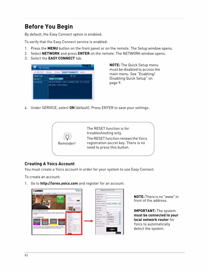
Before You BeginBy default, the Easy Connect option is enabled.
To verify that the Easy Connect service is enabled:
1. Press the MENU button on the front panel or on the remote. The Setup window opens.2. Select NETWORK and press ENTER on the remote. The NETWORK window opens.3. Select the EASY CONNECT tab.
4. Under SERVICE, select ON (default). Press ENTER to save your settings.
Creating A Yoics AccountYou must create a Yoics account in order for your system to use Easy Connect.
To create an account:
1. Go to http://lorex.yoics.com and register for an account.
NOTE: The Quick Setup menu must be disabled to access the main menu. See “Enabling/Disabling Quick Setup” on page 9.
NOTE: There is no "www" in front of the address.
IMPORTANT: The system must be connected to your local network router for Yoics to automatically detect the system.
Reminder!
The RESET function is for troubleshooting only. The RESET function renews the Yoics registration secret key. There is no need to press this button.
91
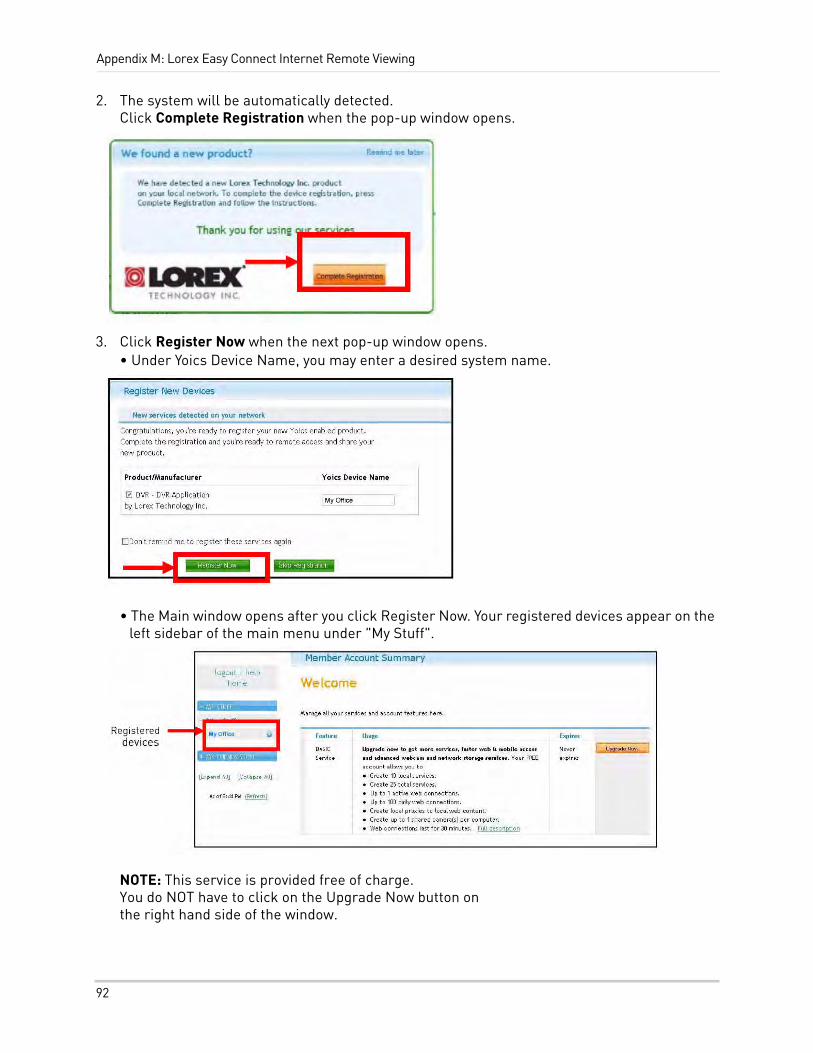
Appendix M: Lorex Easy Connect Internet Remote Viewing
2. The system will be automatically detected. Click Complete Registration when the pop-up window opens.
3. Click Register Now when the next pop-up window opens. • Under Yoics Device Name, you may enter a desired system name.
• The Main window opens after you click Register Now. Your registered devices appear on the left sidebar of the main menu under "My Stuff".
NOTE: This service is provided free of charge. You do NOT have to click on the Upgrade Now button on the right hand side of the window.
92
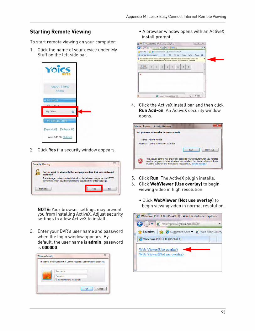
Appendix M: Lorex Easy Connect Internet Remote Viewing
Starting Remote Viewing
To start remote viewing on your computer:
1. Click the name of your device under My Stuff on the left side bar.
2. Click Yes if a security window appears.
NOTE: Your browser settings may prevent you from installing ActiveX. Adjust security settings to allow ActiveX to install.
3. Enter your DVR’s user name and password when the login window appears. By default, the user name is admin; password is 000000.
• A browser window opens with an ActiveX install prompt.
4. Click the ActiveX install bar and then click Run Add-on. An ActiveX security window opens.
5. Click Run. The ActiveX plugin installs.6. Click WebViewer (Use overlay) to begin
viewing video in high resolution.
• Click WebViewer (Not use overlay) to begin viewing video in normal resolution.
93
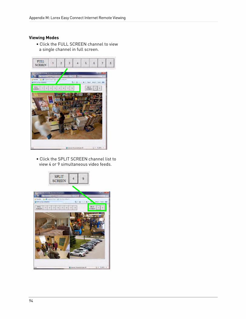
Appendix M: Lorex Easy Connect Internet Remote Viewing
Viewing Modes• Click the FULL SCREEN channel to view
a single channel in full screen.
• Click the SPLIT SCREEN channel list to view 4 or 9 simultaneous video feeds.
94
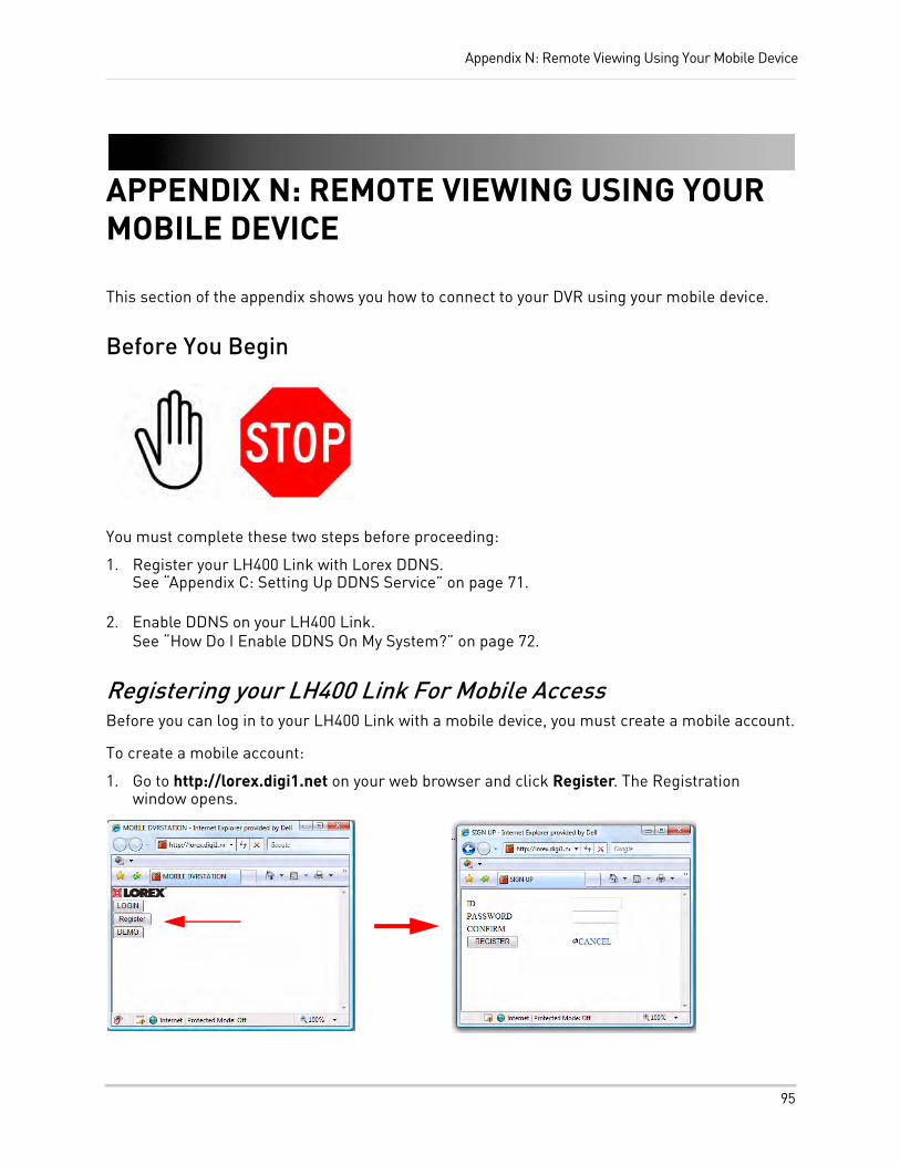
Appendix N: Remote Viewing Using Your Mobile Device
APPENDIX N: REMOTE VIEWING USING YOUR MOBILE DEVICE
This section of the appendix shows you how to connect to your DVR using your mobile device.
Before You Begin
You must complete these two steps before proceeding:
1. Register your LH400 Link with Lorex DDNS. See “Appendix C: Setting Up DDNS Service” on page 71.
2. Enable DDNS on your LH400 Link. See “How Do I Enable DDNS On My System?” on page 72.
Registering your LH400 Link For Mobile AccessBefore you can log in to your LH400 Link with a mobile device, you must create a mobile account.
To create a mobile account:
1. Go to http://lorex.digi1.net on your web browser and click Register. The Registration window opens.
95
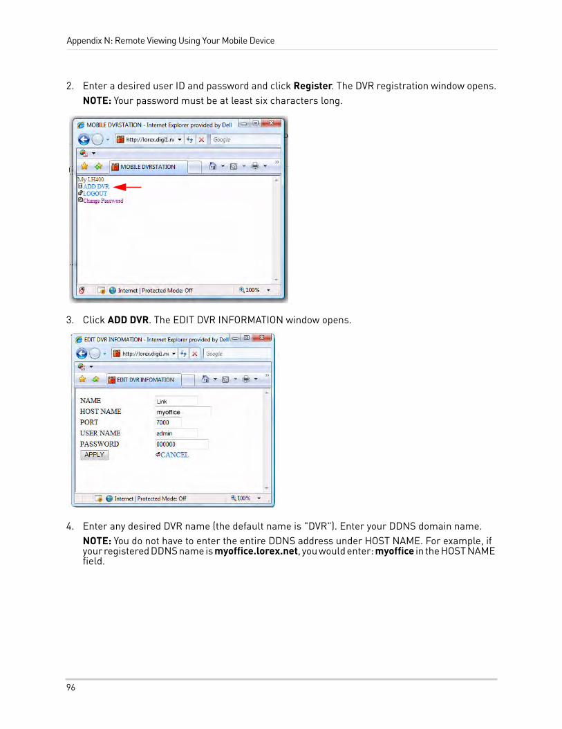
Appendix N: Remote Viewing Using Your Mobile Device
2. Enter a desired user ID and password and click Register. The DVR registration window opens.NOTE: Your password must be at least six characters long.
3. Click ADD DVR. The EDIT DVR INFORMATION window opens.
4. Enter any desired DVR name (the default name is "DVR"). Enter your DDNS domain name.NOTE: You do not have to enter the entire DDNS address under HOST NAME. For example, if your registered DDNS name is myoffice.lorex.net, you would enter: myoffice in the HOST NAME field.
96
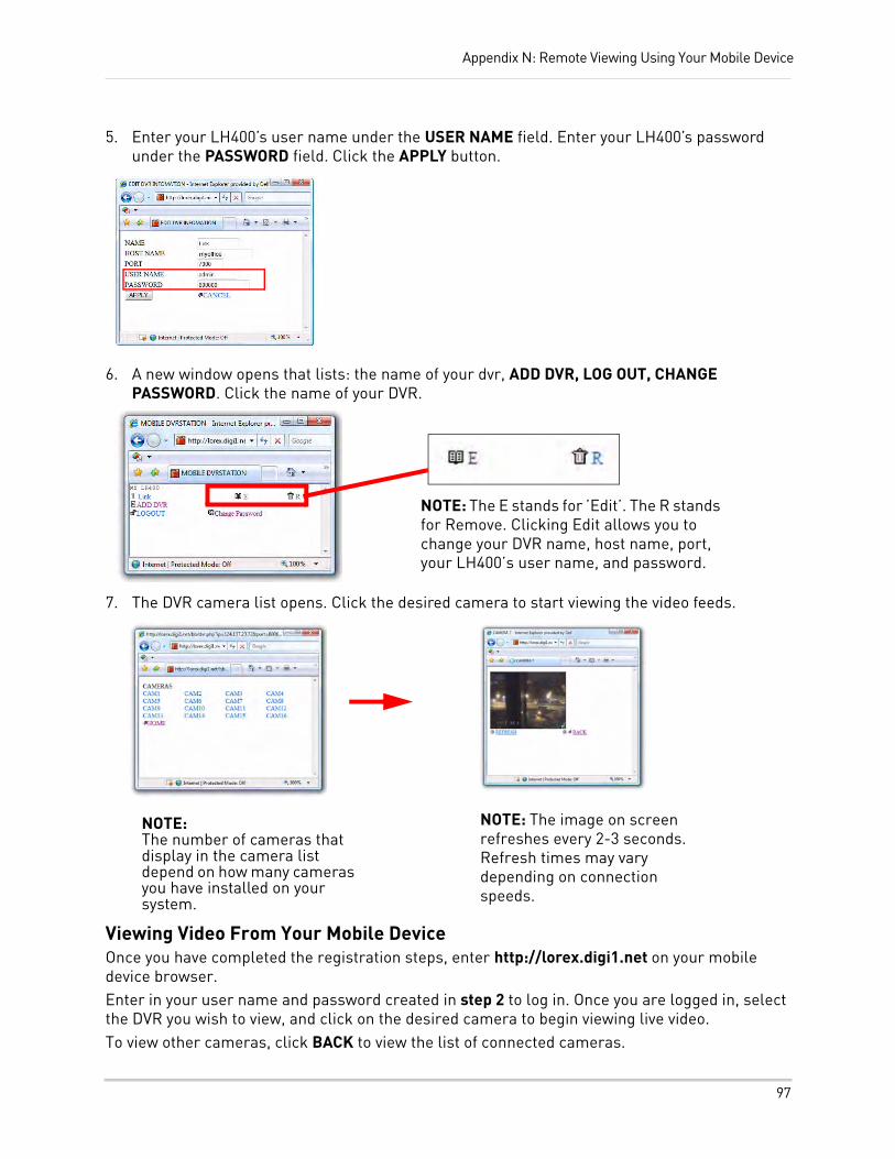
Appendix N: Remote Viewing Using Your Mobile Device
5. Enter your LH400’s user name under the USER NAME field. Enter your LH400’s password under the PASSWORD field. Click the APPLY button.
6. A new window opens that lists: the name of your dvr, ADD DVR, LOG OUT, CHANGE PASSWORD. Click the name of your DVR.
7. The DVR camera list opens. Click the desired camera to start viewing the video feeds.
Viewing Video From Your Mobile DeviceOnce you have completed the registration steps, enter http://lorex.digi1.net on your mobile device browser. Enter in your user name and password created in step 2 to log in. Once you are logged in, select the DVR you wish to view, and click on the desired camera to begin viewing live video.To view other cameras, click BACK to view the list of connected cameras.
NOTE: The E stands for ’Edit’. The R stands for Remove. Clicking Edit allows you to change your DVR name, host name, port, your LH400’s user name, and password.
NOTE: The number of cameras that display in the camera list depend on how many cameras you have installed on your system.
NOTE: The image on screen refreshes every 2-3 seconds. Refresh times may vary depending on connection speeds.
97
Appendix O: Remote Connectivity Options
APPENDIX O: REMOTE CONNECTIVITY OPTIONSThe Lorex LINK DVR offers extensive connectivity and compatibility with many devices in the market.
Multiple variables determine the method of connectivity:
• The installation environment - where are you planning to connect from :
• Local Area Network (e.g. within an office or a home network)
• Over the Internet (e.g. Connecting from home to view your business):
• Using a Dynamic IP Address (most popular in homes and small businesses). Lorex provides a free DDNS service.
• Using static IP Address (required a higher monthly cost and a specific arrangement with your internet service provider)
• The device used for connecting:
• Computer (PC vs. Apple Mac)
• Mobile Smart-phone
• Intended use - the purpose you have for connecting to your system remotely
• Viewing only
• Advanced control (e.g. playback, backup, configuration)
• Ease of installation
• Lorex Easy connect (no router port forwarding required)
• Advanced ( router port forwarding required)
Depending on the installation environment, the device and the intended application there are multiple connectivity options. Lorex strives to provide a user friend and easy consumer experience. However, certain setup steps are required depending on the chosen scenario. The table on the next page depicts the most common scenarios.
98
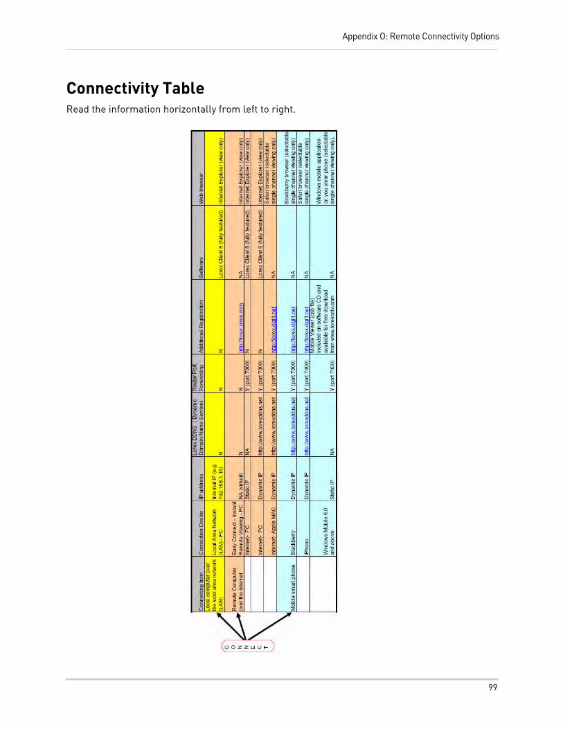
Appendix O: Remote Connectivity Options
Connectivity TableRead the information horizontally from left to right.
99
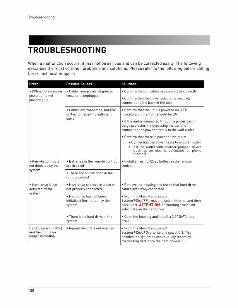
Troubleshooting
TROUBLESHOOTINGWhen a malfunction occurs, it may not be serious and can be corrected easily. The following describes the most common problems and solutions. Please refer to the following before calling Lorex Technical Support:
Error Possible Causes Solutions
• DVR is not receiving power, or is not powering up
• Cable from power adapter is loose or is unplugged
• Confirm that all cables are connected correctly
• Confirm that the power adapter is securely connected to the back of the unit
• Cables are connected, but DVR unit is not receiving sufficient power
• Confirm that the unit is powered on (LED indicators on the front should be ON)
• If the unit is connected through a power bar or surge protector, try bypassing the bar and connecting the power directly to the wall outlet
• Confirm that there is power at the outlet:
• Connecting the power cable to another outlet• Test the outlet with another plugged device
(such as an electric calculator or phone charger)
• Remote control is not detected by the system
• Batteries in the remote control are drained
• Install a fresh CR2025 battery in the remote control
• There are no batteries in the remote control
• Hard drive is not detected by the system
• Hard drive cables are loose or not properly connected
• Remove the housing and check that hard drive cables are firmly connected
• Hard drive has not been initialized (formatted) by the system
• From the Main Menu, select System>Disk>Format and select Internal and then click Start. ATTENTION: Formatting erases all video data on the hard drive
• There is no hard drive in the system
• Open the housing and install a 3.5" SATA hard drive
Hard drive is full (0%) and the unit is no longer recording
• Repeat Record is not enabled • From the Main Menu, select System>Disk>Overwrite and select ON. This enables the system to continuously record by overwriting data once the hard drive is full
100
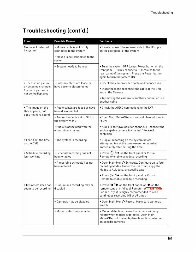
Troubleshooting
Troubleshooting (cont’d.)
Error Possible Causes Solutions
Mouse not detected by system
• Mouse cable is not firmly connected to the system
• Firmly connect the mouse cable to the USB port on the rear panel of the system
• Mouse is not connected to the system
• System needs to be reset • Turn the system OFF (press Power button on the front panel). Firmly connect a USB mouse to the rear panel of the system. Press the Power button again to turn the system ON
• There is no picture on selected channels / camera picture is not being displayed
• Camera cables are loose or have become disconnected
• Check the camera video cable and connections
• Disconnect and reconnect the cable at the DVR and at the Camera
• Try moving the camera to another channel or use another cable
• The image on the DVR appears, but does not have sound
• Audio cables are loose or have been disconnected
• Check the AUDIO connections to the DVR
• Audio channel is set to OFF in the system menu
• Open Main Menu>Record and set channel 1 audio to ON
• Audio is associated with the wrong video channel
• Audio is only available for channel 1—connect the audio capable camera to channel 1 to avoid confusion
• I can’t set the time on the DVR
• The system is recording • Stop all recording on the system before attempting to set the time—resume recording immediately after setting the time
• Schedule recording isn’t working
• Schedule recording has not been enabled
• Press / on the front panel or Virtual Remote to enable schedule recording
• A recording schedule has not been entered
• Open Main Menu>Schedule. Configure up to four recording Modes. Under the Chart tab, apply the Modes to ALL days, or specific days
• Press / on the front panel or Virtual Remote to enable schedule recording
• My system does not seem to be recording
• Continuous recording may be disabled
• Press / on the front panel, or on the remote control or Virtual Remote—ATTENTION: For security, it is highly recommended to keep continuous recording ON at all times
• Cameras may be disabled • Open Main Menu>Record. Make sure cameras are ON
• Motion detection is enabled • Motion detection means the camera will only record when motion is detected. Open Main Menu>Record to enable/disable motion detection on specific cameras
101
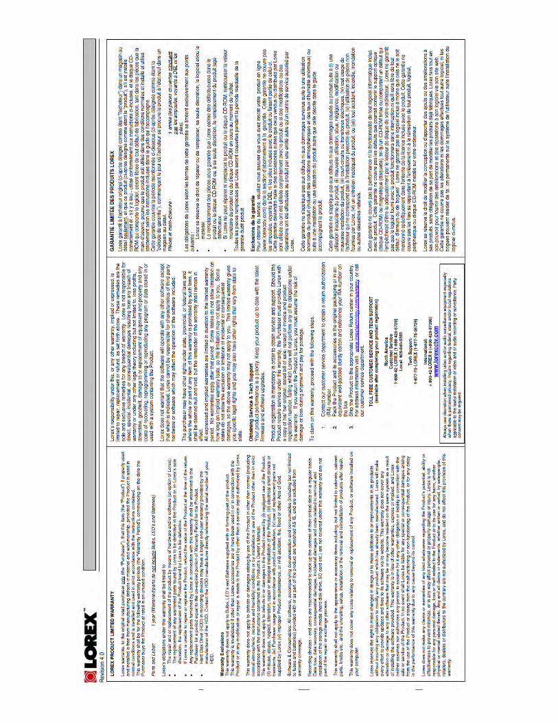
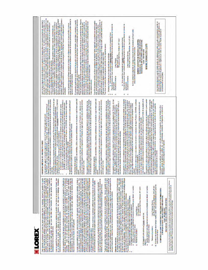

Enhance your security with genuine Lorex Cameras, Digital Video Recorders, Integrated Systems and Accessories. Order whatever you need at
www.lorexcctv.com or call 1-888-42-LOREX (1-888-425-6739)
11262009-R10
SEE HEAR PROTECT
PROTECT EVERYTHING THAT MATTERS
Warehouse
CVC6998HR
Office
CVC6993R
Kitchen
LW2702
Convenience Store
LW2100VQ1536HR
Restaurant
Home Office
LW2002B
Add wired or wireless cameras to expand the “Envelope of Protection” for your business,
your home and your family
Drive Way
SG7540
Front Door
LW2301
Nursery
LW2002W
Backyard
LW2201