Embed Size (px)
Citation preview

P/NO : MFL63285302 www.lg.com
INSTALLATION MANUAL
AIR CONDITIONER • Please read this installation manual completely before installing the product.• Installation work must be performed in accordance with the national wiring standards by authorized personnel only.• Please retain this installation manual for future reference after reading it thoroughly.
TYPE : Air-to-Water Heat Pump
ITALIA
NO
ESPAÑ
OL
FRA
NÇ
AIS
DEU
TSCH
PORTU
GU
ÊSEN
GLISH
Air-to-Water Heat Pump Installation Manual
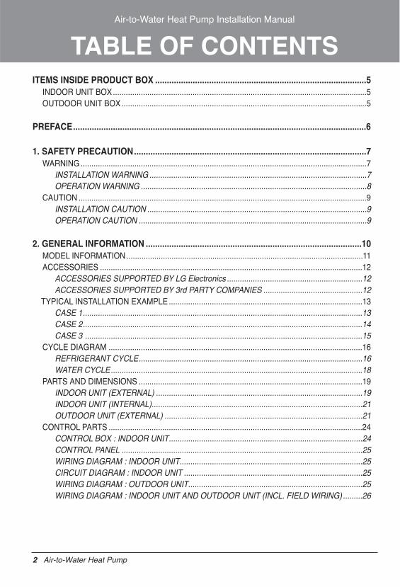
TABLE OF CONTENTSITEMS INSIDE PRODUCT BOX ..........................................................................................5
INDOOR UNIT BOX......................................................................................................................5OUTDOOR UNIT BOX..................................................................................................................5
PREFACE.............................................................................................................................6
1. SAFETY PRECAUTION...................................................................................................7WARNING .....................................................................................................................................7
INSTALLATION WARNING .....................................................................................................7OPERATION WARNING .........................................................................................................8
CAUTION ......................................................................................................................................9INSTALLATION CAUTION ......................................................................................................9OPERATION CAUTION ..........................................................................................................9
2. GENERAL INFORMATION ............................................................................................10MODEL INFORMATION..............................................................................................................11ACCESSORIES ..........................................................................................................................12
ACCESSORIES SUPPORTED BY LG Electronics ...............................................................12ACCESSORIES SUPPORTED BY 3rd PARTY COMPANIES ..............................................12
TYPICAL INSTALLATION EXAMPLE..........................................................................................13CASE 1..................................................................................................................................13CASE 2..................................................................................................................................14CASE 3 .................................................................................................................................15
CYCLE DIAGRAM ......................................................................................................................16REFRIGERANT CYCLE........................................................................................................16WATER CYCLE.....................................................................................................................18
PARTS AND DIMENSIONS ........................................................................................................19INDOOR UNIT (EXTERNAL) ................................................................................................19INDOOR UNIT (INTERNAL)..................................................................................................21OUTDOOR UNIT (EXTERNAL) ............................................................................................21
CONTROL PARTS ......................................................................................................................24CONTROL BOX : INDOOR UNIT..........................................................................................24CONTROL PANEL ................................................................................................................25WIRING DIAGRAM : INDOOR UNIT.....................................................................................25CIRCUIT DIAGRAM : INDOOR UNIT ...................................................................................25WIRING DIAGRAM : OUTDOOR UNIT.................................................................................25WIRING DIAGRAM : INDOOR UNIT AND OUTDOOR UNIT (INCL. FIELD WIRING) .........26
2 Air-to-Water Heat Pump
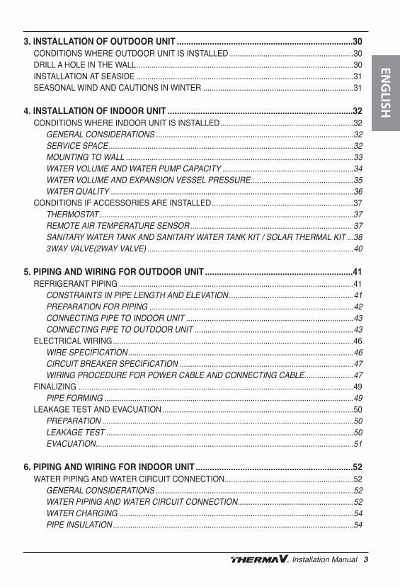
3. INSTALLATION OF OUTDOOR UNIT ...........................................................................30CONDITIONS WHERE OUTDOOR UNIT IS INSTALLED..........................................................30DRILL A HOLE IN THE WALL.....................................................................................................30INSTALLATION AT SEASIDE .....................................................................................................31SEASONAL WIND AND CAUTIONS IN WINTER ......................................................................31
4. INSTALLATION OF INDOOR UNIT ...............................................................................32CONDITIONS WHERE INDOOR UNIT IS INSTALLED..............................................................32
GENERAL CONSIDERATIONS ............................................................................................32SERVICE SPACE..................................................................................................................32MOUNTING TO WALL ..........................................................................................................33WATER VOLUME AND WATER PUMP CAPACITY .............................................................34WATER VOLUME AND EXPANSION VESSEL PRESSURE................................................35WATER QUALITY .................................................................................................................36
CONDITIONS IF ACCESSORIES ARE INSTALLED..................................................................37THERMOSTAT ......................................................................................................................37REMOTE AIR TEMPERATURE SENSOR........................................................................... 37SANITARY WATER TANK AND SANITARY WATER TANK KIT / SOLAR THERMAL KIT ...383WAY VALVE(2WAY VALVE) ................................................................................................40
5. PIPING AND WIRING FOR OUTDOOR UNIT ...............................................................41REFRIGERANT PIPING .............................................................................................................41
CONSTRAINTS IN PIPE LENGTH AND ELEVATION..........................................................41PREPARATION FOR PIPING ...............................................................................................42CONNECTING PIPE TO INDOOR UNIT ..............................................................................43 CONNECTING PIPE TO OUTDOOR UNIT ..........................................................................43
ELECTRICAL WIRING................................................................................................................46WIRE SPECIFICATION.........................................................................................................46CIRCUIT BREAKER SPECIFICATION .................................................................................47WIRING PROCEDURE FOR POWER CABLE AND CONNECTING CABLE.......................47
FINALIZING ................................................................................................................................49PIPE FORMING ....................................................................................................................49
LEAKAGE TEST AND EVACUATION.........................................................................................50PREPARATION .....................................................................................................................50LEAKAGE TEST ...................................................................................................................50EVACUATION........................................................................................................................51
6. PIPING AND WIRING FOR INDOOR UNIT ...................................................................52WATER PIPING AND WATER CIRCUIT CONNECTION............................................................52
GENERAL CONSIDERATIONS ............................................................................................52WATER PIPING AND WATER CIRCUIT CONNECTION......................................................52WATER CHARGING .............................................................................................................54PIPE INSULATION................................................................................................................54
ENG
LISH
Installation Manual 3
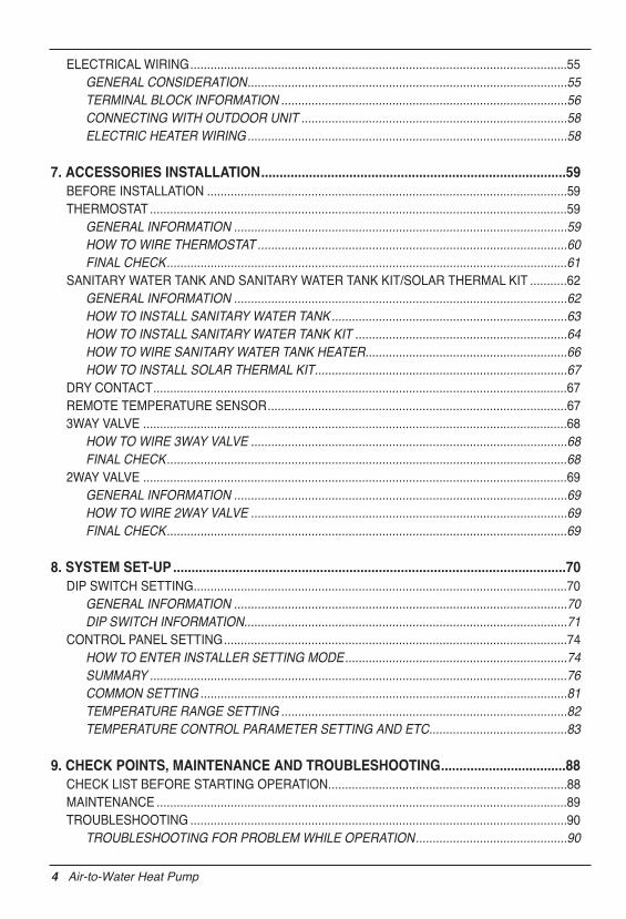
ELECTRICAL WIRING................................................................................................................55GENERAL CONSIDERATION...............................................................................................55TERMINAL BLOCK INFORMATION .....................................................................................56CONNECTING WITH OUTDOOR UNIT ...............................................................................58ELECTRIC HEATER WIRING...............................................................................................58
7. ACCESSORIES INSTALLATION...................................................................................59BEFORE INSTALLATION ...........................................................................................................59THERMOSTAT ............................................................................................................................59
GENERAL INFORMATION ...................................................................................................59HOW TO WIRE THERMOSTAT ............................................................................................60FINAL CHECK.......................................................................................................................61
SANITARY WATER TANK AND SANITARY WATER TANK KIT/SOLAR THERMAL KIT ...........62GENERAL INFORMATION ...................................................................................................62HOW TO INSTALL SANITARY WATER TANK......................................................................63HOW TO INSTALL SANITARY WATER TANK KIT ...............................................................64HOW TO WIRE SANITARY WATER TANK HEATER............................................................66HOW TO INSTALL SOLAR THERMAL KIT...........................................................................67
DRY CONTACT...........................................................................................................................67REMOTE TEMPERATURE SENSOR.........................................................................................673WAY VALVE ..............................................................................................................................68
HOW TO WIRE 3WAY VALVE ..............................................................................................68FINAL CHECK.......................................................................................................................68
2WAY VALVE ..............................................................................................................................69GENERAL INFORMATION ...................................................................................................69HOW TO WIRE 2WAY VALVE ..............................................................................................69FINAL CHECK.......................................................................................................................69
8. SYSTEM SET-UP ...........................................................................................................70DIP SWITCH SETTING...............................................................................................................70
GENERAL INFORMATION ...................................................................................................70DIP SWITCH INFORMATION................................................................................................71
CONTROL PANEL SETTING......................................................................................................74HOW TO ENTER INSTALLER SETTING MODE..................................................................74SUMMARY ............................................................................................................................76COMMON SETTING .............................................................................................................81TEMPERATURE RANGE SETTING .....................................................................................82TEMPERATURE CONTROL PARAMETER SETTING AND ETC.........................................83
9. CHECK POINTS, MAINTENANCE AND TROUBLESHOOTING..................................88CHECK LIST BEFORE STARTING OPERATION.......................................................................88MAINTENANCE ..........................................................................................................................89TROUBLESHOOTING ................................................................................................................90
TROUBLESHOOTING FOR PROBLEM WHILE OPERATION.............................................90
4 Air-to-Water Heat Pump
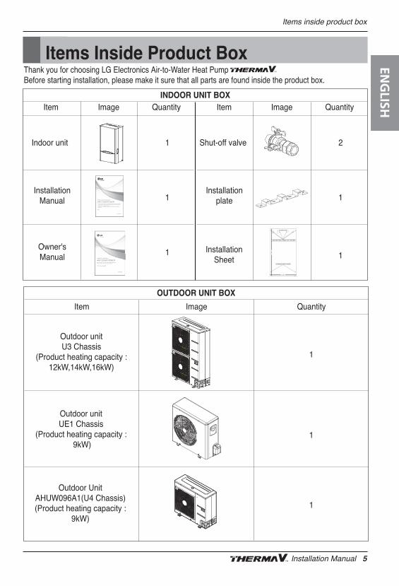
Items Inside Product BoxThank you for choosing LG Electronics Air-to-Water Heat Pump Before starting installation, please make it sure that all parts are found inside the product box.
INDOOR UNIT BOX
Indoor unit 1
1
1
Shut-off valve 2
1
1
Item Image Quantity Item Image Quantity
InstallationManual
Installationplate
Owner'sManual
InstallationSheet
www.lg.com
INSTALLATION MANUAL
AIR CONDITIONER • Please read this installation manual completely before installing the product.• Installation work must be performed in accordance with the national wiring standards by authorized personnel only.• Please retain this installation manual for future reference after reading it thoroughly.
TYPE :
www.lg.com
OWNER’S MANUAL
AIR CONDITIONER Please read this manual carefully before operatingyour set and retain it for future reference.
TYPE : WALL MOUNTED
Outdoor unitUE1 Chassis
(Product heating capacity :9kW)
OUTDOOR UNIT BOX
Item Image Quantity
1
1
1
Outdoor UnitAHUW096A1(U4 Chassis)(Product heating capacity :
9kW)
Outdoor unitU3 Chassis
(Product heating capacity :12kW,14kW,16kW)
Items inside product boxEN
GLISH
Installation Manual 5
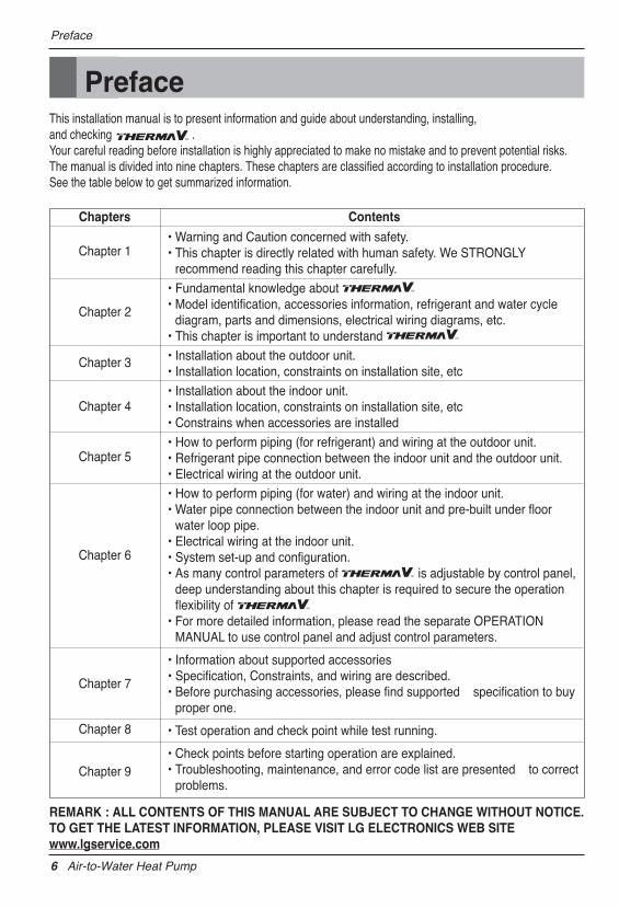
PrefaceThis installation manual is to present information and guide about understanding, installing, and checking .Your careful reading before installation is highly appreciated to make no mistake and to prevent potential risks.The manual is divided into nine chapters. These chapters are classified according to installation procedure.See the table below to get summarized information.
• Warning and Caution concerned with safety.• This chapter is directly related with human safety. We STRONGLY
recommend reading this chapter carefully.
• Fundamental knowledge about • Model identification, accessories information, refrigerant and water cycle
diagram, parts and dimensions, electrical wiring diagrams, etc.• This chapter is important to understand
• Installation about the outdoor unit.• Installation location, constraints on installation site, etc
• Installation about the indoor unit.• Installation location, constraints on installation site, etc• Constrains when accessories are installed
• How to perform piping (for refrigerant) and wiring at the outdoor unit.• Refrigerant pipe connection between the indoor unit and the outdoor unit. • Electrical wiring at the outdoor unit.
• How to perform piping (for water) and wiring at the indoor unit.• Water pipe connection between the indoor unit and pre-built under floor
water loop pipe.• Electrical wiring at the indoor unit.• System set-up and configuration.• As many control parameters of is adjustable by control panel,
deep understanding about this chapter is required to secure the operationflexibility of
• For more detailed information, please read the separate OPERATIONMANUAL to use control panel and adjust control parameters.
• Information about supported accessories • Specification, Constraints, and wiring are described.• Before purchasing accessories, please find supported specification to buy
proper one.
• Test operation and check point while test running.
• Check points before starting operation are explained.• Troubleshooting, maintenance, and error code list are presented to correct
problems.
Chapters Contents
Chapter 1
Chapter 2
Chapter 3
Chapter 4
Chapter 5
Chapter 6
Chapter 7
Chapter 8
Chapter 9
REMARK : ALL CONTENTS OF THIS MANUAL ARE SUBJECT TO CHANGE WITHOUT NOTICE.TO GET THE LATEST INFORMATION, PLEASE VISIT LG ELECTRONICS WEB SITEwww.lgservice.com
Preface
6 Air-to-Water Heat Pump
Safety PrecautionsEN
GLISH
Installation Manual 7
Do not modify or extend thepower cable.
• There is risk of fire or electricshock.
Do not install, remove, orreinstall the unit by yourself(customer).
• There is risk of fire, electricshock, explosion, or injury
Be cautious whenunpacking and installing theproduct.
• Sharp edges could cause injury.Especially careful on the productedges and the fins on the heatexchanger.
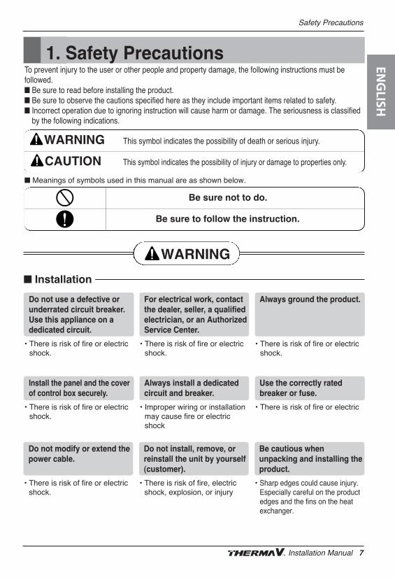
1. Safety PrecautionsTo prevent injury to the user or other people and property damage, the following instructions must befollowed.n Be sure to read before installing the product.n Be sure to observe the cautions specified here as they include important items related to safety.n Incorrect operation due to ignoring instruction will cause harm or damage. The seriousness is classified
by the following indications.
n Meanings of symbols used in this manual are as shown below.
This symbol indicates the possibility of death or serious injury.
This symbol indicates the possibility of injury or damage to properties only.
n Installation
Be sure not to do.
Be sure to follow the instruction.
Do not use a defective orunderrated circuit breaker.Use this appliance on adedicated circuit.
• There is risk of fire or electricshock.
For electrical work, contactthe dealer, seller, a qualifiedelectrician, or an AuthorizedService Center.
• There is risk of fire or electricshock.
Always ground the product.
• There is risk of fire or electricshock.
Install the panel and the coverof control box securely.
• There is risk of fire or electricshock.
Always install a dedicatedcircuit and breaker.
• Improper wiring or installationmay cause fire or electricshock
Use the correctly ratedbreaker or fuse.
• There is risk of fire or electric
8 Air-to-Water Heat Pump
n Operation
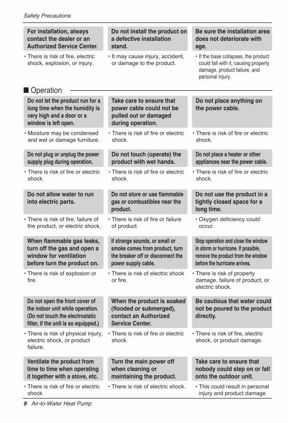
For installation, alwayscontact the dealer or anAuthorized Service Center.
• There is risk of fire, electricshock, explosion, or injury.
Do not install the product ona defective installationstand.
• It may cause injury, accident,or damage to the product.
Be sure the installation areadoes not deteriorate withage.
• If the base collapses, the productcould fall with it, causing propertydamage, product failure, andpersonal injury.
Do not let the product run for along time when the humidity isvery high and a door or awindow is left open.
• Moisture may be condensedand wet or damage furniture.
Take care to ensure thatpower cable could not bepulled out or damagedduring operation.
• There is risk of fire or electricshock.
Do not place anything onthe power cable.
• There is risk of fire or electricshock.
Do not plug or unplug the powersupply plug during operation.
• There is risk of fire or electricshock.
Do not touch (operate) theproduct with wet hands.
• There is risk of fire or electricshock.
Do not place a heater or otherappliances near the power cable.
• There is risk of fire or electricshock.
Safety Precautions
Ventilate the product fromtime to time when operatingit together with a stove, etc.
• There is risk of fire or electricshock.
Turn the main power offwhen cleaning ormaintaining the product.
• There is risk of electric shock.
Take care to ensure thatnobody could step on or fallonto the outdoor unit.
• This could result in personalinjury and product damage.
Do not allow water to runinto electric parts.
• There is risk of fire, failure ofthe product, or electric shock.
Do not store or use flammablegas or combustibles near theproduct.
• There is risk of fire or failureof product.
Do not use the product in atightly closed space for along time.
• Oxygen deficiency couldoccur.
When flammable gas leaks,turn off the gas and open awindow for ventilationbefore turn the product on.
• There is risk of explosion orfire.
If strange sounds, or small orsmoke comes from product, turnthe breaker off or disconnect thepower supply cable.
• There is risk of electric shockor fire.
Stop operation and close the windowin storm or hurricane. If possible,remove the product from the windowbefore the hurricane arrives.
• There is risk of propertydamage, failure of product, orelectric shock.
Do not open the front cover ofthe indoor unit while operation.(Do not touch the electrostaticfilter, if the unit is so equipped.)
• There is risk of physical injury,electric shock, or productfailure.
When the product is soaked(flooded or submerged),contact an AuthorizedService Center.
• There is risk of fire or electricshock.
Be cautious that water couldnot be poured to the productdirectly.
• There is risk of fire, electricshock, or product damage.
ENG
LISH
Installation Manual 9
Safety Precautions
n InstallationAlways check for gas(refrigerant) leakage afterinstallation or repair ofproduct.
• Low refrigerant levels may causefailure of product.
Do not install the productwhere it will be exposed tosea wind (salt spray)directly.
• It may cause corrosion on theproduct. Corrosion, particularly onthe condenser and evaporator fins,could cause product malfunction orinefficient operation.
Keep level even wheninstalling the product.
• To avoid vibration or waterleakage.
Do not install the product where the noiseor hot air from the outdoor unit coulddamage the neighborhoods.
• It may cause a problem for your neighbors.
Use two or more people to lift and transportthe product.
• Avoid personal injury.
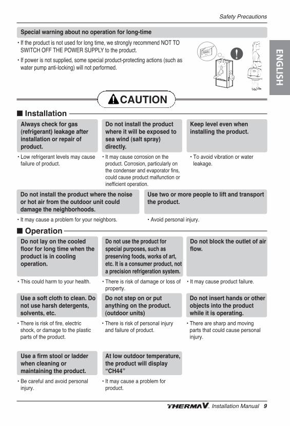
Special warning about no operation for long-time
• If the product is not used for long time, we strongly recommend NOT TOSWITCH OFF THE POWER SUPPLY to the product.
• If power is not supplied, some special product-protecting actions (such aswater pump anti-locking) will not performed.
n OperationDo not lay on the cooledfloor for long time when theproduct is in coolingoperation.
• This could harm to your health.
Do not use the product forspecial purposes, such aspreserving foods, works of art,etc. It is a consumer product, nota precision refrigeration system.
• There is risk of damage or loss ofproperty.
Do not block the outlet of airflow.
• It may cause product failure.
Use a soft cloth to clean. Donot use harsh detergents,solvents, etc.
• There is risk of fire, electricshock, or damage to the plasticparts of the product.
Do not step on or putanything on the product.(outdoor units)
• There is risk of personal injuryand failure of product.
Do not insert hands or otherobjects into the productwhile it is operating.
• There are sharp and movingparts that could cause personalinjury.
Use a firm stool or ladderwhen cleaning ormaintaining the product.
• Be careful and avoid personalinjury.
At low outdoor temperature,the product will display“CH44”
• It may cause a problem forproduct.
2. General Information
Model Information
With advanced inverter technology, is suitable for applications like under floor heating,under floor cooling, and hot water generation. By Interfacing to various accessories user cancustomize the range of the application.
In this chapter, general information of is presented to identify the installationprocedure. Before beginning installation, read this chapter carefully and find helpful information oninstallation.
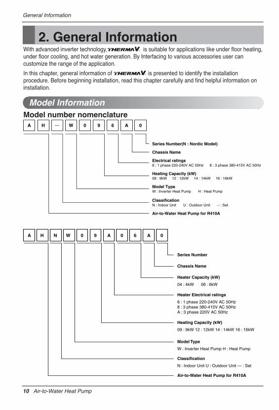
Model number nomenclatureA H — W 0 9 6 A 0
Series Number(N : Nordic Model)
Chassis Name
Electrical ratings6 : 1 phase 220-240V AC 50Hz 8 : 3 phase 380-415V AC 50Hz
Heating Capacity (kW)09 : 9kW 12 : 12kW 14 : 14kW 16 : 16kW
Model TypeW : Inverter Heat Pump H : Heat Pump
ClassificationN : Indoor Unit U : Outdoor Unit – : Set
Air-to-Water Heat Pump for R410A
A H N W 0 9 A 0 6 A 0
Series Number
Chassis Name
Heater Electrical ratings
6 : 1 phase 220-240V AC 50Hz 8 : 3 phase 380-415V AC 50Hz A : 3 phase 220V AC 50Hz
Heating Capacity (kW)
09 : 9kW 12 : 12kW 14 : 14kW 16 : 16kW
Heater Capacity (kW)
04 : 4kW 06 : 6kW
Model Type
W : Inverter Heat Pump H : Heat Pump
Classification
N : Indoor Unit U : Outdoor Unit — : Set
Air-to-Water Heat Pump for R410A
10 Air-to-Water Heat Pump
General Information
General InformationEN
GLISH
Installation Manual 11
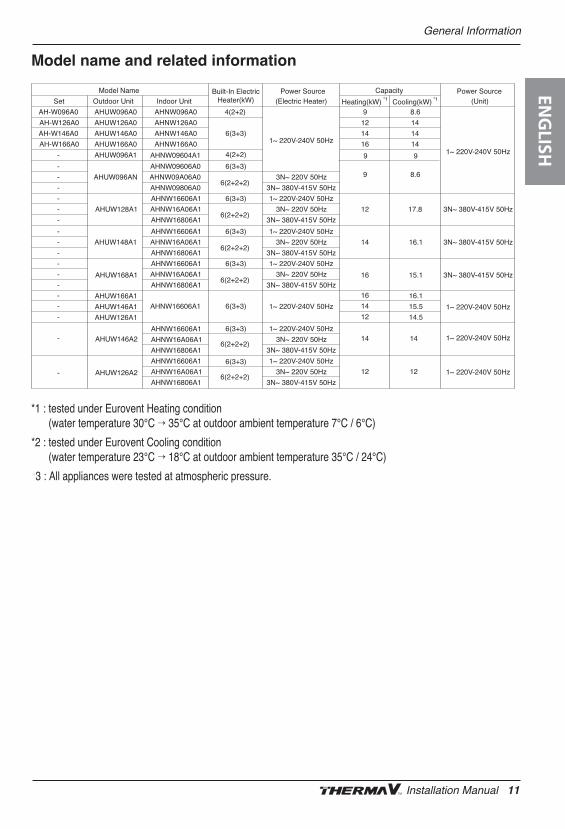
*1 : tested under Eurovent Heating condition (water temperature 30°C ’ 35°C at outdoor ambient temperature 7°C / 6°C)
*2 : tested under Eurovent Cooling condition (water temperature 23°C ’ 18°C at outdoor ambient temperature 35°C / 24°C)
**3 : All appliances were tested at atmospheric pressure.
Model name and related information
Set Outdoor Unit Indoor Unit Heating(kW) *1 Cooling(kW) *1
AH-W096A0 AHUW096A0 AHNW096A0 4(2+2) 9 8.6
AH-W126A0 AHUW126A0 AHNW126A0 12 14
AH-W146A0 AHUW146A0 AHNW146A0 14 14
AH-W166A0 AHUW166A0
AHUW096A1
AHNW166A0
AHNW09604A1
16 14
-
-
AHNW09606A0 6(3+3)
- AHNW09A06A0
- AHNW09806A0
- AHNW16606A1 6(3+3)
- AHNW16A06A1
- AHNW16806A1
- AHNW16606A1 6(3+3)
- AHNW16A06A1
- AHNW16806A1
- AHNW16606A1 6(3+3)
- AHNW16A06A1
- AHNW16806A1
AHUW128A1
AHUW148A1
AHUW168A1
AHUW146A2
AHUW126A2
Model Name Built-In ElectricHeater(kW)
6(3+3)
4(2+2)
6(2+2+2)AHUW096AN
6(2+2+2)
6(2+2+2)
6(2+2+2)
6(3+3)
6(2+2+2)
6(3+3)
6(2+2+2)
Capacity
9 8.6
99
12 17.8
14 16.1
Power Source(Electric Heater)
Power Source(Unit)
16 15.1
3N~ 220V 50Hz
3N~ 380V-415V 50Hz
1~ 220V-240V 50Hz
3N~ 220V 50Hz
3N~ 380V-415V 50Hz
1~ 220V-240V 50Hz
3N~ 220V 50Hz
3N~ 380V-415V 50Hz
1~ 220V-240V 50Hz
3N~ 220V 50Hz
3N~ 380V-415V 50Hz
1~ 220V-240V 50Hz
3N~ 220V 50Hz
3N~ 380V-415V 50Hz
1~ 220V-240V 50Hz
3N~ 220V 50Hz
3N~ 380V-415V 50Hz
1~ 220V-240V 50Hz
1~ 220V-240V 50Hz
3N~ 380V-415V 50Hz
3N~ 380V-415V 50Hz
3N~ 380V-415V 50Hz
-
6(3+3)- AHNW16606A1
-
-
-
16
14
12
14
12
14
12
16.1
15.5
14.5
1~ 220V-240V 50Hz 1~ 220V-240V 50Hz
1~ 220V-240V 50Hz
1~ 220V-240V 50Hz
AHNW16606A1
AHNW16A06A1
AHNW16806A1
AHNW16606A1
AHNW16A06A1
AHNW16806A1
AHUW166A1
AHUW146A1
AHUW126A1
Accessories
Accessories supported by LG Electronics
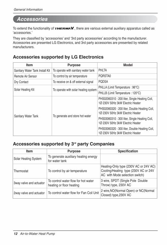
To extend the functionality of , there are various external auxiliary apparatus called asʻaccessories.ʼ
They are classified by ʻaccessoriesʼ and ʻ3rd party accessoriesʼ according to the manufacturer.Accessories are presented LG Electronics, and 3rd party accessories are presented by relatedmanufacturers.
Accessories supported by 3rd party Companies
Item Purpose Specification
Solar Heating System
Thermostat
3way valve and actuator
2way valve and actuator
To generate auxiliary heating energyfor water tank
To control by air temperature
To control water flow for hot waterheating or floor heating
To control water flow for Fan Coil Unit
Heating-Only type (230V AC or 24V AC)Cooling/Heating type (230V AC or 24VAC with Mode selection switch)
3 wire, SPDT (Single Pole DoubleThrow) type, 230V AC
2 wire,NO(Normal Open) or NC(NormalClosed) type,230V AC
Item Purpose Model
Sanitary Water Tank Install Kit
Remote Air Sensor
Dry Contact
Solar Heating Kit
Sanitary Water Tank
To operate with sanitary water tank
To control by air temperature
To receive on & off external signal
To operate with solar heating system
To generate and store hot water
PHLTA
PQRSTA0
PQDSA
PHLLA (Limit Temperature : 96℃)
PHLLB (Limit Temperature : 120℃)
PHS02060310 : 200 liter, Single Heating Coil,1Ø 230V 50Hz 3kW Electric Heater
PHS02060320 : 200 liter, Double Heating Coil,1Ø 230V 50Hz 3kW Electric Heater
PHS03060310 : 300 liter, Single Heating Coil,1Ø 230V 50Hz 3kW Electric Heater
PHS03060320 : 300 liter, Double Heating Coil,1Ø 230V 50Hz 3kW Electric Heater
General Information
12 Air-to-Water Heat Pump
General InformationEN
GLISH
Installation Manual 13
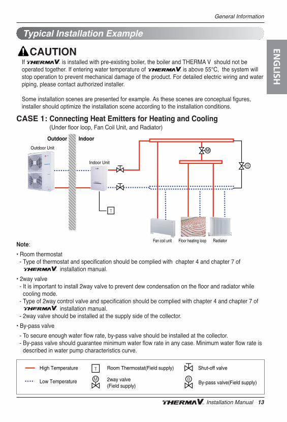
If is installed with pre-existing boiler, the boiler and THERMA V should not beoperated together. If entering water temperature of is above 55°C, the system willstop operation to prevent mechanical damage of the product. For detailed electric wiring and waterpiping, please contact authorized installer.
Some installation scenes are presented for example. As these scenes are conceptual figures,installer should optimize the installation scene according to the installation conditions.
CASE 1: Connecting Heat Emitters for Heating and Cooling (Under floor loop, Fan Coil Unit, and Radiator)
Outdoor Indoor
Outdoor Unit
Indoor Unit
Floor heating loopFan coil unit Radiator
High Temperature Room Thermostat(Field supply)
2way valve(Field supply)
By-pass valve(Field supply)Low Temperature
Shut-off valve
Typical Installation Example
Note:
• Room thermostat - Type of thermostat and specification should be complied with chapter 4 and chapter 7 of
installation manual.
• 2way valve- It is important to install 2way valve to prevent dew condensation on the floor and radiator while
cooling mode.- Type of 2way control valve and specification should be complied with chapter 4 and chapter 7 of
installation manual.- 2way valve should be installed at the supply side of the collector.
• By-pass valve
- To secure enough water flow rate, by-pass valve should be installed at the collector.- By-pass valve should guarantee minimum water flow rate in any case. Minimum water flow rate is
described in water pump characteristics curve.
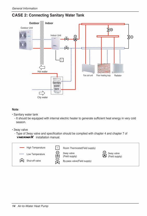
CASE 2: Connecting Sanitary Water Tank
Outdoor Indoor
Outdoor Unit
Indoor Unit
Floor heating loopFan coil unit
Sanitarywatertank
Hot water
City water
Radiator
High Temperature Room Thermostat(Field supply)
2way valve(Field supply)
3way valve(Field supply)
By-pass valve(Field supply)
Low Temperature
Shut-off valve
Note:
• Sanitary water tank- It should be equipped with internal electric heater to generate sufficient heat energy in very cold
season.
• 3way valve- Type of 3way valve and specification should be complied with chapter 4 and chapter 7 of
installation manual.
General Information
14 Air-to-Water Heat Pump
General Information
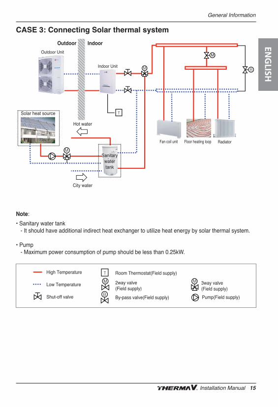
CASE 3: Connecting Solar thermal system
Solar heat source
Outdoor Indoor
Outdoor Unit
Indoor Unit
Floor heating loopFan coil unit
Sanitarywatertank
Hot water
City water
Radiator
High Temperature Room Thermostat(Field supply)
2way valve(Field supply)
3way valve(Field supply)
By-pass valve(Field supply)
Low Temperature
Shut-off valve Pump(Field supply)
Note:
• Sanitary water tank- It should have additional indirect heat exchanger to utilize heat energy by solar thermal system.
• Pump- Maximum power consumption of pump should be less than 0.25kW.
ENG
LISH
Installation Manual 15
16 Air-to-Water Heat Pump
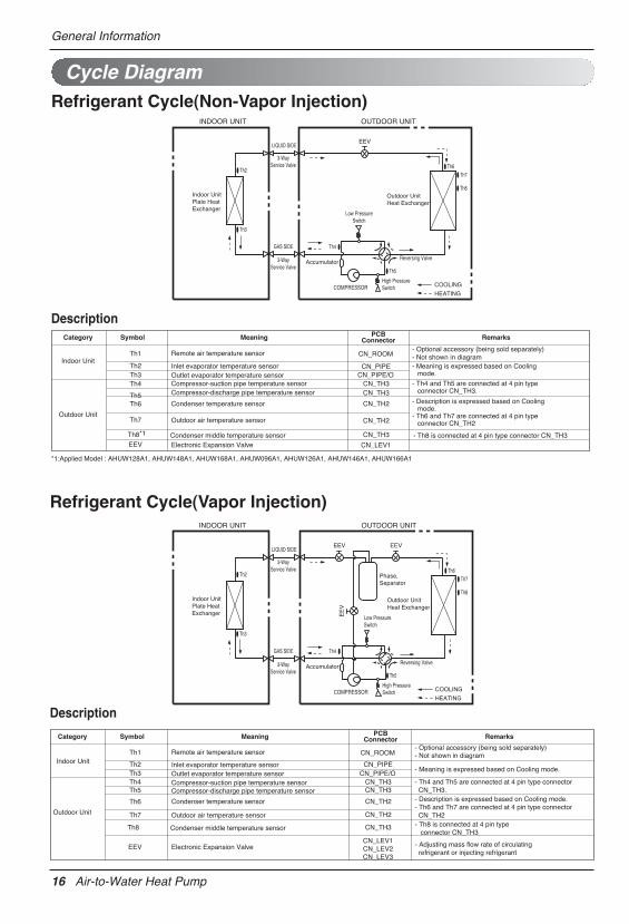
Cycle DiagramRefrigerant Cycle(Non-Vapor Injection)
Description
INDOOR UNIT OUTDOOR UNIT
Indoor UnitPlate HeatExchanger
Outdoor Unit
EEV
Heat Exchanger
COMPRESSOR
Accumulator
GAS SIDE
LIQUID SIDE
3-Way Service Valve
3-Way Service Valve
COOLING
HEATING
Reversing Valve
High PressureSwitch
Low PressureSwitch
Th3
Th2Th6
Th7
Th8
Th5
Th4
- Optional accessory (being sold separately)- Not shown in diagram- Meaning is expressed based on Cooling
mode.
- Th4 and Th5 are connected at 4 pin typeconnector CN_TH3.
- Description is expressed based on Coolingmode.
- Th6 and Th7 are connected at 4 pin typeconnector CN_TH2
- Th8 is connected at 4 pin type connector CN_TH3
CN_ROOM
CN_PIPECN_PIPE/O
CN_TH3CN_TH3
CN_TH2
CN_TH2
CN_TH3
CN_LEV1
Remote air temperature sensor
Inlet evaporator temperature sensorOutlet evaporator temperature sensorCompressor-suction pipe temperature sensorCompressor-discharge pipe temperature sensor
Condenser temperature sensor
Outdoor air temperature sensor
Condenser middle temperature sensor Electronic Expansion Valve
Th1
Th2Th3Th4
Th5Th6
Th7
EEV
Category Symbol Meaning PCBConnector Remarks
Indoor Unit
Outdoor Unit
Th8*1
*1:Applied Model : AHUW128A1, AHUW148A1, AHUW168A1, AHUW096A1, AHUW126A1, AHUW146A1, AHUW166A1
General Information
Refrigerant Cycle(Vapor Injection)INDOOR UNIT OUTDOOR UNIT
Indoor UnitPlate HeatExchanger
Outdoor Unit
Phase,Separator
EEV
Heat Exchanger
COMPRESSOR
Accumulator
GAS SIDE
LIQUID SIDE
3-Way Service Valve
3-Way Service Valve
COOLING
HEATING
Reversing Valve
High PressureSwitch
Low PressureSwitch
Th3
Th2Th6
Th7
Th8
Th5
Th4
EEV
EE
V
- Optional accessory (being sold separately)- Not shown in diagram
- Meaning is expressed based on Cooling mode.
- Th4 and Th5 are connected at 4 pin type connector CN_TH3.- Description is expressed based on Cooling mode.- Th6 and Th7 are connected at 4 pin type connector CN_TH2- Th8 is connected at 4 pin type connector CN_TH3
- Adjusting mass flow rate of circulating refrigerant or injecting refrigerant
CN_ROOM
CN_PIPECN_PIPE/O
CN_TH3CN_TH3
CN_TH2
CN_TH2
CN_TH3
CN_LEV1CN_LEV2CN_LEV3
Remote air temperature sensor
Inlet evaporator temperature sensorOutlet evaporator temperature sensorCompressor-suction pipe temperature sensorCompressor-discharge pipe temperature sensor
Condenser temperature sensor
Outdoor air temperature sensor
Condenser middle temperature sensor
Electronic Expansion Valve
Th1
Th2Th3Th4Th5
Th6
Th7
EEV
Category Symbol Meaning PCBConnector Remarks
Indoor Unit
Outdoor Unit
Th8
Description
General Information
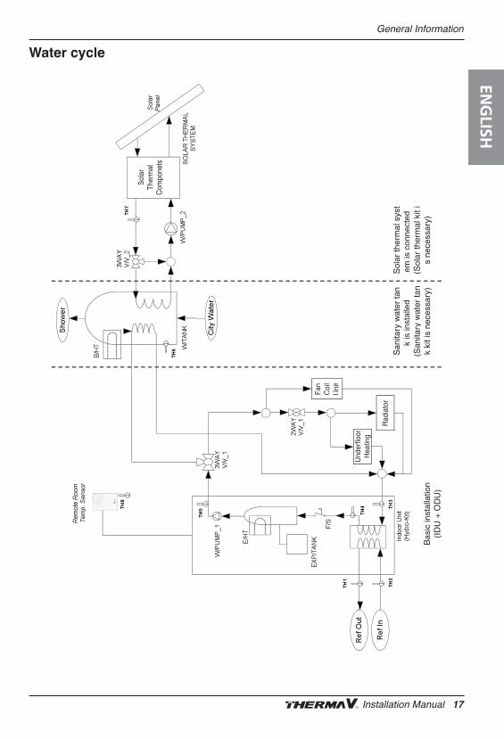
Water cycle
San
itary
wat
er ta
nk
isin
stal
led
(San
itary
wat
er ta
nk
kit i
s ne
cess
ary)
Sol
ar th
erm
al s
yst
em is
conn
ecte
d(S
olar
ther
mal
kit
is
nece
ssar
y)B
asic
inst
alla
tion
()
(ID
U +
OD
U)
Sol
arTh
erm
alC
ompo
nets
Fan
Coi
lU
nit
Und
erflo
orH
eatin
g
Rad
iato
r
ENG
LISH
Installation Manual 17
General Information
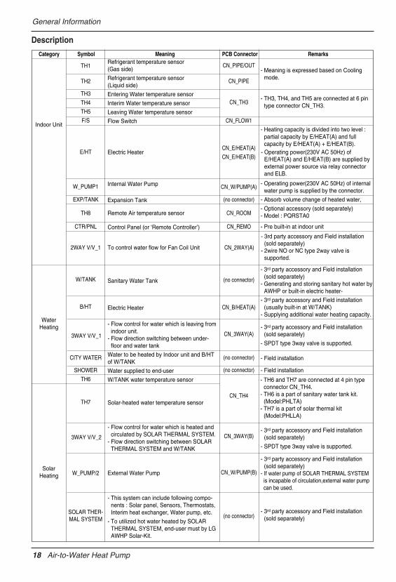
Description
- Meaning is expressed based on Coolingmode.
- TH3, TH4, and TH5 are connected at 6 pintype connector CN_TH3.
- Heating capacity is divided into two level :partial capacity by E/HEAT(A) and fullcapacity by E/HEAT(A) + E/HEAT(B).
- Operating power(230V AC 50Hz) of internalwater pump is supplied by the connector.
- Absorb volume change of heated water,
- Optional accessory (sold separately)- Model : PQRSTA0
- Pre built-in at indoor unit
- 3rd party accessory and Field installation(sold separately)
- Generating and storing sanitary hot water byAWHP or built-in electric heater-
- 3rd party accessory and Field installation(usually built-in at W/TANK)
- Supplying additional water heating capacity.
- 3rd party accessory and Field installation(sold separately)
- SPDT type 3way valve is supported.
- Field installation
- Field installation
- 3rd party accessory and Field installation(sold separately)
- SPDT type 3way valve is supported.
- 3rd party accessory and Field installation(sold separately)
- If water pump of SOLAR THERMAL SYSTEM is incapable of circulation,external water pump can be used.
- 3rd party accessory and Field installation(sold separately)
CN_PIPE/OUT
CN_PIPE
CN_TH3
CN_FLOW1
CN_E/HEAT(A)
CN_E/HEAT(B)
CN_W/PUMP(A)
(no connector)
CN_ROOM
CN_REMO
CN_2WAY(A)
(no connector)
CN_B/HEAT(A)
CN_3WAY(A)
(no connector)
(no connector)
CN_TH4
CN_3WAY(B)
CN_W/PUMP(B)
(no connector)
Refrigerant temperature sensor(Gas side)
Refrigerant temperature sensor(Liquid side)
Entering Water temperature sensor
Interim Water temperature sensor
Leaving Water temperature sensor
Flow Switch
Electric Heater
Internal Water Pump
Expansion Tank
Remote Air temperature sensor
Control Panel (or
To control water flow for Fan Coil Unit
‘Remote Controller’)
Sanitary Water Tank
Electric Heater
- Flow control for water which is leaving fromindoor unit.
- Flow direction switching between under-floor and water tank
Water to be heated by Indoor unit and B/HTof W/TANK
Water supplied to end-user
W/TANK water temperature sensor
Solar-heated water temperature sensor
- Flow control for water which is heated andcirculated by SOLAR THERMAL SYSTEM.
- Flow direction switching between SOLARTHERMAL SYSTEM and W/TANK
External Water Pump
- This system can include following compo-nents : Solar panel, Sensors, Thermostats,Interim heat exchanger, Water pump, etc.
- To utilized hot water heated by SOLARTHERMAL SYSTEM, end-user must by LGAWHP Solar-Kit.
TH1
TH2
TH3
TH4
TH5
F/S
E/HT
W_PUMP1
EXP/TANK
TH8
CTR/PNL
2WAY V/V_1
W/TANK
B/HT
3WAY V/V_1
CITY WATER
SHOWER
TH6
TH7
3WAY V/V_2
W_PUMP/2
SOLAR THER-MAL SYSTEM
Category Symbol Meaning PCB Connector Remarks
Indoor Unit
WaterHeating
SolarHeating
- Operating power(230V AC 50Hz) of E/HEAT(A) and E/HEAT(B) are supplied by external power source via relay connector and ELB.
- 3rd party accessory and Field installation (sold separately)
- 2wire NO or NC type 2way valve is supported.
- TH6 and TH7 are connected at 4 pin type connector CN_TH4.
- TH6 is a part of sanitary water tank kit. (Model:PHLTA)
- TH7 is a part of solar thermal kit (Model:PHLLA)
18 Air-to-Water Heat Pump
General Information
Parts and Dimensions
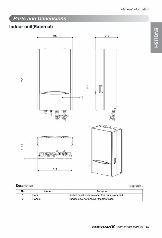
Indoor unit(External)
315490
850
315.
3
474
Description
No Name Remarks1 Door Control panel is shown after this door is opened.2 Handle Used to cover or uncover the front case
(unit:mm)
ENG
LISH
Installation Manual 19
General Information
Description
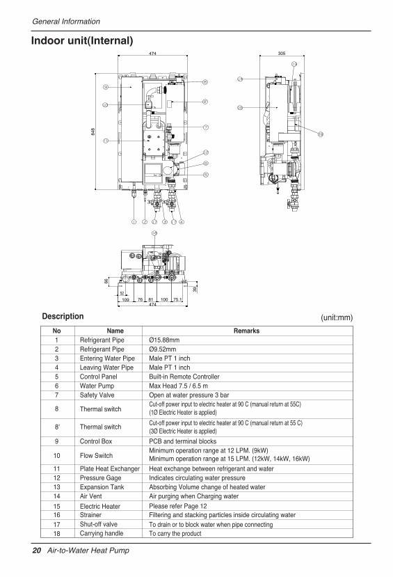
Indoor unit(Internal)474
848
305
66
39
75.11008176109
52
474
No Name Remarks1 Refrigerant Pipe Ø15.88mm2 Refrigerant Pipe Ø9.52mm3 Entering Water Pipe Male PT 1 inch4 Leaving Water Pipe Male PT 1 inch5 Control Panel Built-in Remote Controller6 Water Pump Max Head 7.5 / 6.5 m7 Safety Valve Open at water pressure 3 bar
8
8'
T
Thermal switch
hermal switchCut-off power input to electric heater at 90 C (manual return at 55C)(1Ø Electric Heater is applied)
Cut-off power input to electric heater at 90 C (manual return at 55 C)(3Ø Electric Heater is applied)
9 Control Box PCB and terminal blocks
10 Flow SwitchMinimum operation range at 12 LPM. (9kW)Minimum operation range at 15 LPM. (12kW, 14kW, 16kW)
11 Plate Heat Exchanger Heat exchange between refrigerant and water12 Pressure Gage Indicates circulating water pressure13 Expansion Tank Absorbing Volume change of heated water14 Air Vent Air purging when Charging water
15 Electric Heater Please refer Page 121617
StrainerShut-off valve
18 Carrying handle
Filtering and stacking particles inside circulating waterTo drain or to block water when pipe connectingTo carry the product
(unit:mm)
20 Air-to-Water Heat Pump
General Information
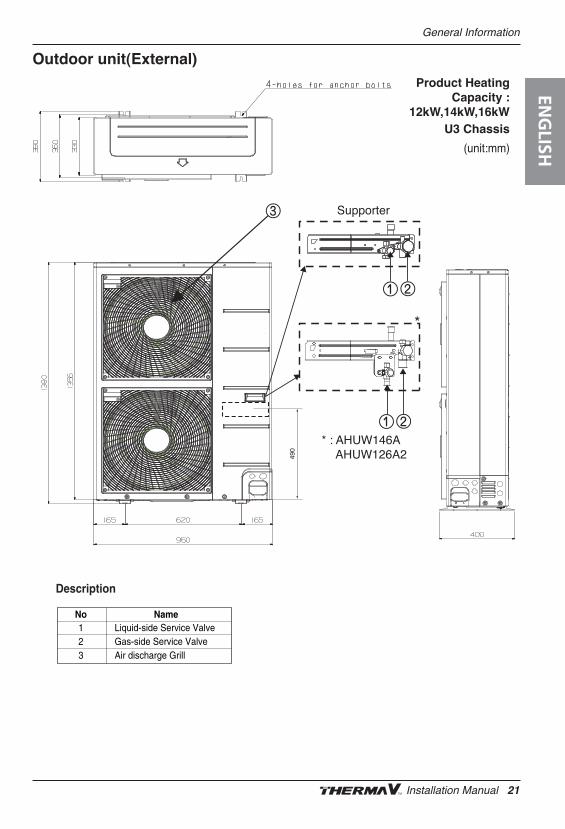
Outdoor unit(External)
Supporter
* : AHUW146A AHUW126A2
*
490
Description
No Name123
Liquid-side Service ValveGas-side Service ValveAir discharge Grill
Product HeatingCapacity :
12kW,14kW,16kWU3 Chassis
(unit:mm)
ENG
LISH
Installation Manual 21
General Information
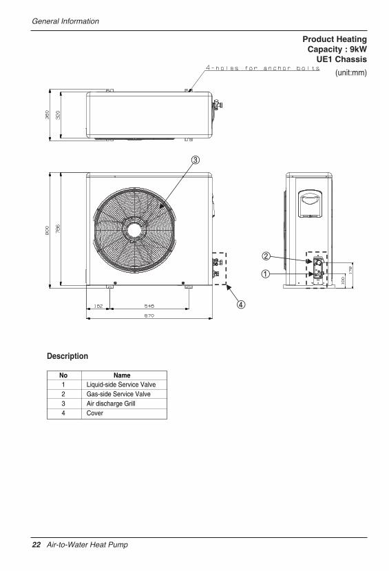
Description
No Name1234
Liquid-side Service ValveGas-side Service ValveAir discharge GrillCover
Product HeatingCapacity : 9kW
UE1 Chassis
(unit:mm)
22 Air-to-Water Heat Pump
General Information
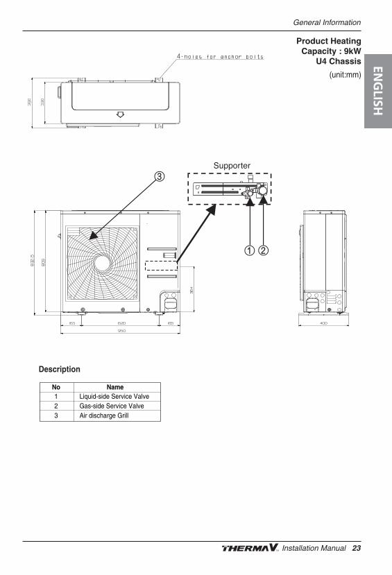
Supporter
.
Description
No Name123
Liquid-side Service ValveGas-side Service ValveAir discharge Grill
Product HeatingCapacity : 9kW
U4 Chassis
(unit:mm)
ENG
LISH
Installation Manual 23
General Information
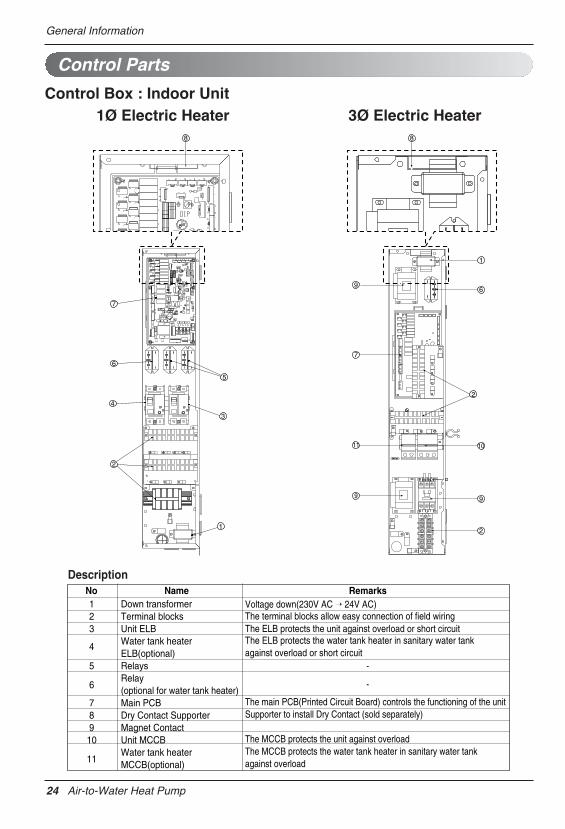
Control Parts
Control Box : Indoor Unit
7
6
4
2
1
3
5
8 8
1
96
7
11
9
10
9
2
2
DescriptionNo Name Remarks123
4
5
6
789
10
11
Down transformerTerminal blocksUnit ELBWater tank heater ELB(optional)RelaysRelay(optional for water tank heater)Main PCBDry Contact SupporterMagnet ContactUnit MCCBWater tank heaterMCCB(optional)
The terminal blocks allow easy connection of field wiringVoltage down(230V AC → 24V AC)
The ELB protects the unit against overload or short circuit
The main PCB(Printed Circuit Board) controls the functioning of the unitSupporter to install Dry Contact (sold separately)
The MCCB protects the unit against overloadThe MCCB protects the water tank heater in sanitary water tank against overload
The ELB protects the water tank heater in sanitary water tankagainst overload or short circuit
-
-
1Ø Electric Heater 3Ø Electric Heater
24 Air-to-Water Heat Pump
General Information
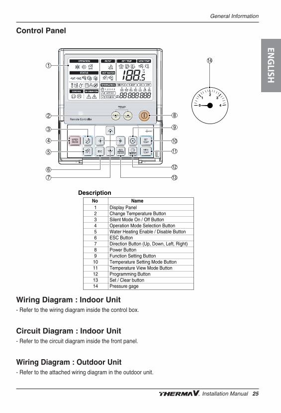
Control Panel
1
0
23
4
1
2
3
4
5
6
7
8
9
10
11
12
13
14
No Name123456789
1011121314
Display PanelChange Temperature ButtonSilent Mode On / Off ButtonOperation Mode Selection ButtonWater Heating Enable / Disable ButtonESC ButtonDirection Button (Up, Down, Left, Right)Power ButtonFunction Setting ButtonTemperature Setting Mode ButtonTemperature View Mode ButtonProgramming ButtonSet / Clear buttonPressure gage
Description
Wiring Diagram : Indoor Unit- Refer to the wiring diagram inside the control box.
Circuit Diagram : Indoor Unit- Refer to the circuit diagram inside the front panel.
Wiring Diagram : Outdoor Unit- Refer to the attached wiring diagram in the outdoor unit.
ENG
LISH
Installation Manual 25
General Information
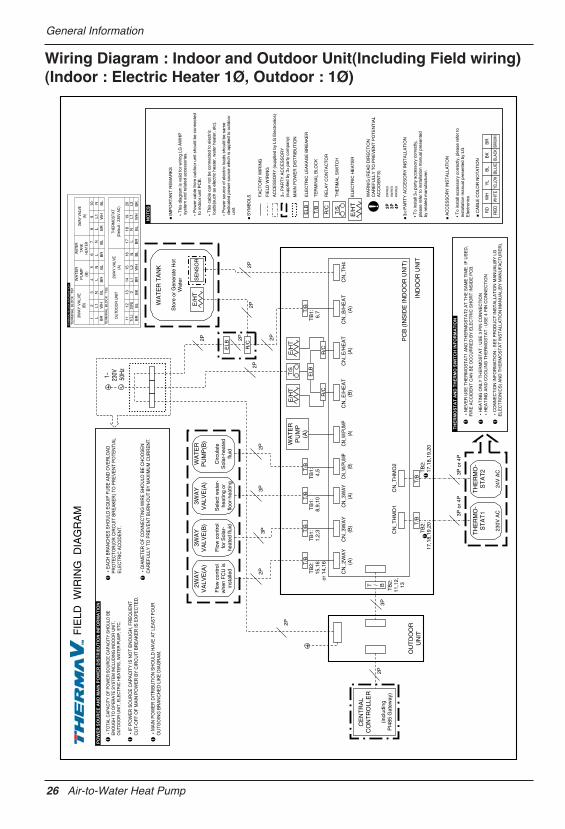
Wiring Diagram : Indoor and Outdoor Unit(Including Field wiring)(Indoor : Electric Heater 1Ø, Outdoor : 1Ø)
1~
230V
50
Hz
26 Air-to-Water Heat Pump
General Information
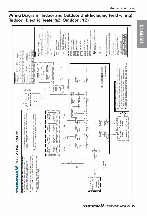
Wiring Diagram : Indoor and Outdoor Unit(Including Field wiring)(Indoor : Electric Heater 3Ø, Outdoor : 1Ø)
1~ 230V
50Hz
3~ 220V
50H
zor
3~
380
V 50
Hz
3
MC
CB
MC
CB
M/C
M/C
M/C
ENG
LISH
Installation Manual 27
General Information
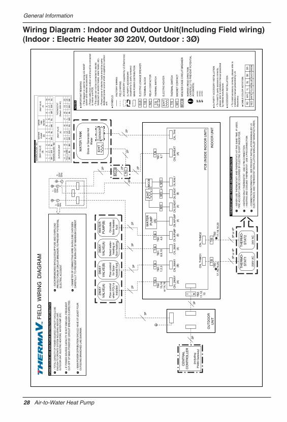
Wiring Diagram : Indoor and Outdoor Unit(Including Field wiring)(Indoor : Electric Heater 3Ø 220V, Outdoor : 3Ø)
3~ 380V
50Hz
3~ 220V
50H
z
1~ 2
20V
50H
z
3
MC
CB
MC
CB
M/C
M/C
M/C
28 Air-to-Water Heat Pump
General Information
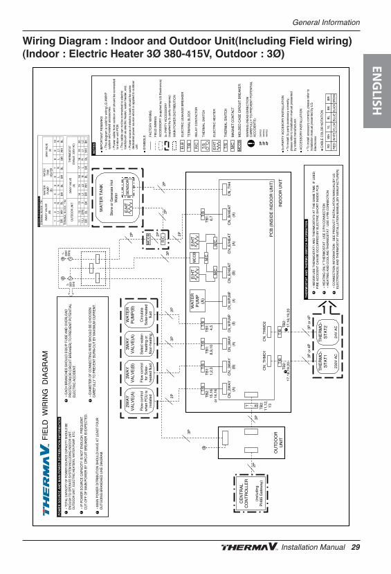
Wiring Diagram : Indoor and Outdoor Unit(Including Field wiring)(Indoor : Electric Heater 3Ø 380-415V, Outdoor : 3Ø)
3~ 380V
50Hz
1~ 220V
50H
z
3
MC
CB
MC
CB
M/C
M/C
M/C
ENG
LISH
Installation Manual 29
Installation of Outdoor Unit
3. Installation of Outdoor UnitThe outdoor unit of is installed outside to exchange heat with ambient air. Therefore, itis important to secure proper space around the outdoor unit and care for specific external conditions.
This chapter presents a guide to install the outdoor unit, make a route to connect with the indoor, andwhat to do when installed around seaside.
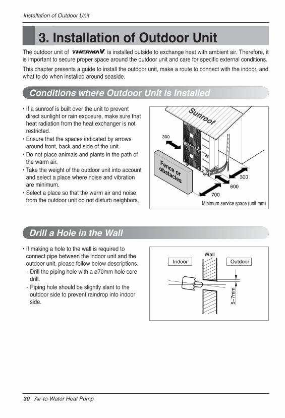
• If a sunroof is built over the unit to preventdirect sunlight or rain exposure, make sure thatheat radiation from the heat exchanger is notrestricted.
• Ensure that the spaces indicated by arrowsaround front, back and side of the unit.
• Do not place animals and plants in the path ofthe warm air.
• Take the weight of the outdoor unit into accountand select a place where noise and vibrationare minimum.
• Select a place so that the warm air and noisefrom the outdoor unit do not disturb neighbors.
Conditions where Outdoor Unit is Installed
300
Fence orobstacles
700
300
600
Sunroof
• If making a hole to the wall is required toconnect pipe between the indoor unit and theoutdoor unit, please follow below descriptions.- Drill the piping hole with a ø70mm hole core
drill.- Piping hole should be slightly slant to the
outdoor side to prevent raindrop into indoorside.
Drill a Hole in the Wall
Wall
5~7m
m
Indoor Outdoor
Minimum service space (unit:mm)
30 Air-to-Water Heat Pump
Installation of Outdoor Unit
Installation at Seaside
Seasonal wind and cautions in winter
1. Air conditioners should not be installed in areas where corrosive gases, such as acid or alkaline gas, are produced.2. Do not install the product where it could be exposed to sea wind (salty wind) directly. It can result corrosion
on the product. Corrosion, particularly on the condenser and evaporator fins, could cause product malfunc-tion or inefficient performance.
3. If outdoor unit is installed close to the seaside, it should avoid direct exposure to the sea wind. Otherwise itneeds additional anticorrosion treatment on the heat exchanger.
1. If you can’t meet above guide line in the seaside installation, please contact LG Electronics for the additional anticorrosion treatment.2. Periodic ( more than once/year ) cleaning of the dust or salt particles stuck on the heat exchanger by using water
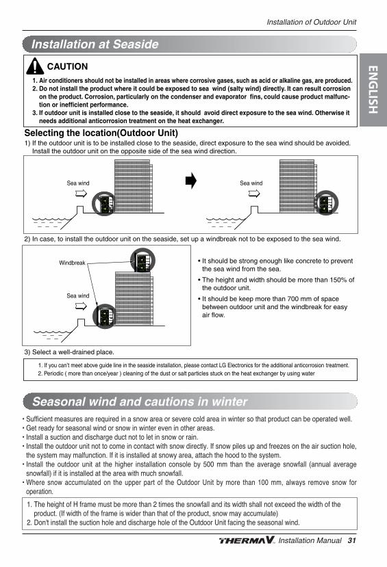
Selecting the location(Outdoor Unit)1) If the outdoor unit is to be installed close to the seaside, direct exposure to the sea wind should be avoided.
Install the outdoor unit on the opposite side of the sea wind direction.
2) In case, to install the outdoor unit on the seaside, set up a windbreak not to be exposed to the sea wind.
3) Select a well-drained place.
• It should be strong enough like concrete to preventthe sea wind from the sea.
• The height and width should be more than 150% ofthe outdoor unit.
• It should be keep more than 700 mm of spacebetween outdoor unit and the windbreak for easyair flow.
CAUTION
Sea wind Sea wind
Sea wind
Windbreak
• Sufficient measures are required in a snow area or severe cold area in winter so that product can be operated well.• Get ready for seasonal wind or snow in winter even in other areas.• Install a suction and discharge duct not to let in snow or rain.• Install the outdoor unit not to come in contact with snow directly. If snow piles up and freezes on the air suction hole,
the system may malfunction. If it is installed at snowy area, attach the hood to the system.• Install the outdoor unit at the higher installation console by 500 mm than the average snowfall (annual average
snowfall) if it is installed at the area with much snowfall.• Where snow accumulated on the upper part of the Outdoor Unit by more than 100 mm, always remove snow for
operation.
1. The height of H frame must be more than 2 times the snowfall and its width shall not exceed the width of theproduct. (If width of the frame is wider than that of the product, snow may accumulate)
2. Don't install the suction hole and discharge hole of the Outdoor Unit facing the seasonal wind.
ENG
LISH
Installation Manual 31
Installation of Indoor Unit
4. Installation of Indoor UnitThe indoor unit of is installed inside where terminal of under floor water pipe cycle andrefrigerant pipe from the outdoor unit are accessible at the same time.
In this chapter conditions for installation place is described. In addition, considerations wheninstalling accessories or 3rd party accessories are described, too.
Conditions where Indoor Unit is InstalledSpecific conditions are required for installation place such as service space, wall mounting, waterpipe length and height, total volume of water, adjusting expansion vessel, and water quality.
General ConsiderationsFollowings are should be considered before the installation of the indoor unit.
- The installation place should be free from outdoor weather conditions such as rain, snow, wind,frost, etc.
- Choose the place where is water-resistant or good drainage.
- Service space should be secured.
- No flammable materials around the indoor unit.
- Mice can not be appeared to prevent entering the indoor unit or attacking wires.
- Do not place anything in front of the indoor unit to ensure air circulation around the indoor unit.
- Do not locate anything under the indoor unit to be free from unexpected water out.
- In case of water pressure increasing to 3 bar, water drainage should be treated when water isdrained by safety valve.
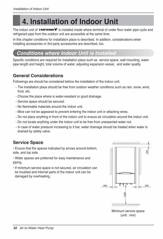
Service Space• Ensure that the spaces indicated by arrows around bottom,side, and top side.
• Wider spaces are preferred for easy maintenance andpiping.
• If minimum service space is not secured, air circulation canbe troubled and internal parts of the indoor unit can bedamaged by overheating.
200
250
200
1300
Minimum service space(unit : mm)
32 Air-to-Water Heat Pump
Installation of Indoor Unit
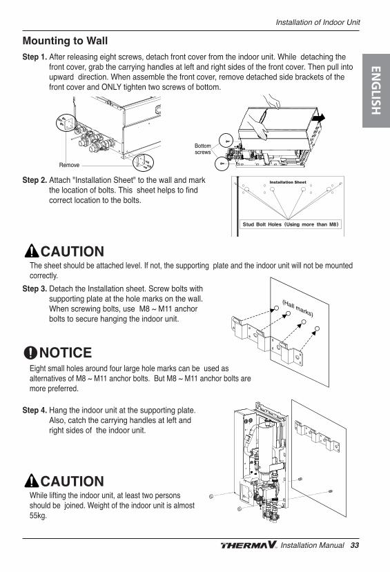
Mounting to WallStep 1. After releasing eight screws, detach front cover from the indoor unit. While detaching the
front cover, grab the carrying handles at left and right sides of the front cover. Then pull intoupward direction. When assemble the front cover, remove detached side brackets of thefront cover and ONLY tighten two screws of bottom.
Step 2. Attach "Installation Sheet" to the wall and mark the location of bolts. This sheet helps to find correct location to the bolts.
Step 3. Detach the Installation sheet. Screw bolts withsupporting plate at the hole marks on the wall.When screwing bolts, use M8 ~ M11 anchorbolts to secure hanging the indoor unit.
Bottomscrews
Remove
(Hall marks)
The sheet should be attached level. If not, the supporting plate and the indoor unit will not be mountedcorrectly.
Eight small holes around four large hole marks can be used asalternatives of M8 ~ M11 anchor bolts. But M8 ~ M11 anchor bolts aremore preferred.
Step 4. Hang the indoor unit at the supporting plate.Also, catch the carrying handles at left andright sides of the indoor unit.
While lifting the indoor unit, at least two personsshould be joined. Weight of the indoor unit is almost55kg.
ENG
LISH
Installation Manual 33
Installation of Indoor Unit
Water Volume and Pump Capacity
Product Heating Capacity : 9kW
Product Heating Capacity : 12kW,14kW,16kW
0.0
0.5
1.0
1.5
2.0
2.5
3.0
3.5
4.0
4.5
5.0
5.5
6.0
6.5
7.0
7.5
8.0
0 10 20 30 40 50 60 70 80 90 100 110
15
Hyd
raul
ic H
ead
Loss
(mH
2O)
aulic
Hea
d Lo
ss(m
H2O
)
Water Flowrate(l/min)
Water Flowrate(l/min)
Max.
Med.
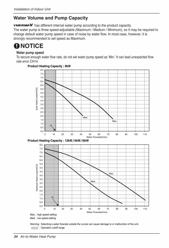
Max. : high speed setting Med. : low speed setting
Warning : Selecting a water flowrate outside the curves can cause damage to or malfunction of the unit. : Operation cutoff range
Max.
Med.
0.0
0.5
1.0
1.5
2.0
2.5
3.0
3.5
4.0
4.5
5.0
5.5
6.0
6.5
7.0
7.5
8.0
0 10 20 30 40 50 60 70 80 90 100 110
12
has different internal water pump according to the product capacity.The water pump is three speed-adjustable (Maximum / Medium / Minimum), so it may be required tochange default water pump speed in case of noise by water flow. In most case, however, it isstrongly recommended to set speed as Maximum.
Water pump speedTo secure enough water flow rate, do not set water pump speed as ʻMin.ʼ It can lead unexpected flowrate error CH14.
34 Air-to-Water Heat Pump
Installation of Indoor Unit
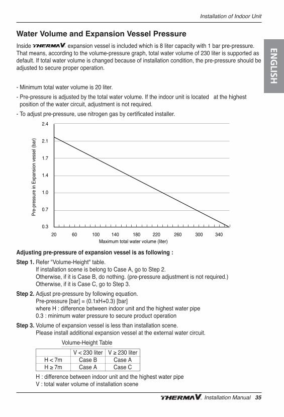
Water Volume and Expansion Vessel PressureInside expansion vessel is included which is 8 liter capacity with 1 bar pre-pressure.That means, according to the volume-pressure graph, total water volume of 230 liter is supported asdefault. If total water volume is changed because of installation condition, the pre-pressure should beadjusted to secure proper operation.
- Minimum total water volume is 20 liter.
- Pre-pressure is adjusted by the total water volume. If the indoor unit is located at the highestposition of the water circuit, adjustment is not required.
- To adjust pre-pressure, use nitrogen gas by certificated installer.
Maximum total water volume (liter)
Pre
-pre
ssur
e in
Exp
ansi
on v
esse
l (ba
r)
20 60 100 140 180 220 260 300 340
2.4
2.1
1.7
1.4
1.0
0.7
0.3
Adjusting pre-pressure of expansion vessel is as following :
Step 1. Refer "Volume-Height" table.If installation scene is belong to Case A, go to Step 2.Otherwise, if it is Case B, do nothing. (pre-pressure adjustment is not required.) Otherwise, if it is Case C, go to Step 3.
Step 2. Adjust pre-pressure by following equation.Pre-pressure [bar] = (0.1xH+0.3) [bar] where H : difference between indoor unit and the highest water pipe0.3 : minimum water pressure to secure product operation
Step 3. Volume of expansion vessel is less than installation scene.Please install additional expansion vessel at the external water circuit.
H : difference between indoor unit and the highest water pipe V : total water volume of installation scene
V < 230 liter V ≥ 230 literH < 7m Case B Case AH ≥ 7m Case A Case C
Volume-Height Table
ENG
LISH
Installation Manual 35
Installation of Indoor Unit
Water Quality
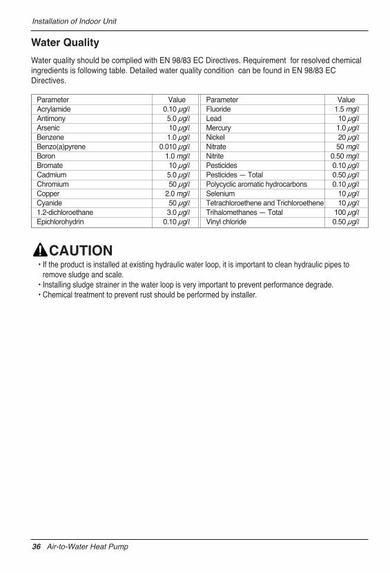
Water quality should be complied with EN 98/83 EC Directives. Requirement for resolved chemicalingredients is following table. Detailed water quality condition can be found in EN 98/83 ECDirectives.
Parameter ValueAcrylamide 0.10 μg/lAntimony 5.0 μg/lArsenic 10 μg/lBenzene 1.0 μg/lBenzo(a)pyrene 0.010 μg/lBoron 1.0 mg/lBromate 10 μg/lCadmium 5.0 μg/lChromium 50 μg/lCopper 2.0 mg/lCyanide 50 μg/l1.2-dichloroethane 3.0 μg/lEpichlorohydrin 0.10 μg/l
Parameter ValueFluoride 1.5 mg/lLead 10 μg/lMercury 1.0 μg/lNickel 20 μg/lNitrate 50 mg/lNitrite 0.50 mg/lPesticides 0.10 μg/lPesticides — Total 0.50 μg/lPolycyclic aromatic hydrocarbons 0.10 μg/lSelenium 10 μg/lTetrachloroethene and Trichloroethene 10 μg/lTrihalomethanes — Total 100 μg/lVinyl chloride 0.50 μg/l
• If the product is installed at existing hydraulic water loop, it is important to clean hydraulic pipes toremove sludge and scale.
• Installing sludge strainer in the water loop is very important to prevent performance degrade.• Chemical treatment to prevent rust should be performed by installer.
36 Air-to-Water Heat Pump
Installation of Indoor Unit
Thermostat
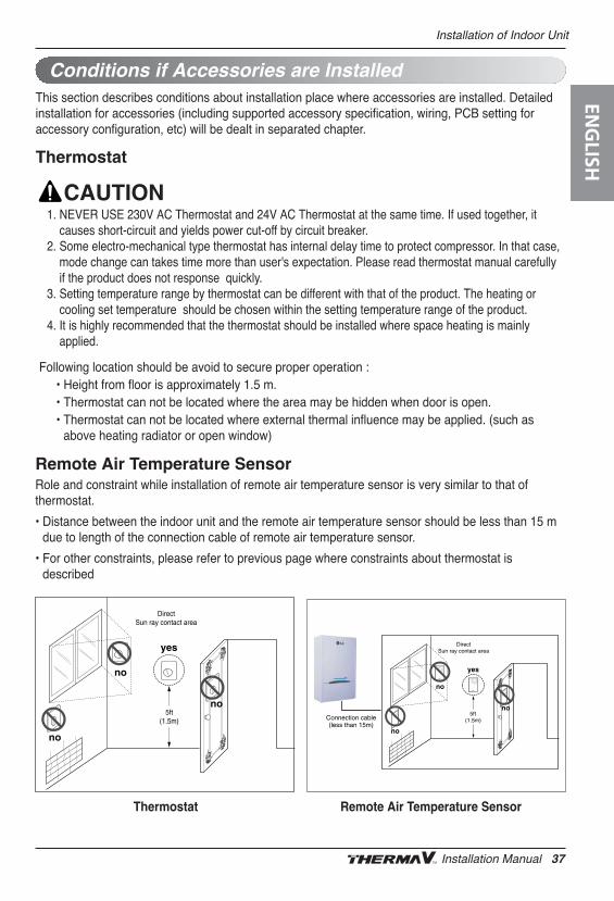
Conditions if Accessories are InstalledThis section describes conditions about installation place where accessories are installed. Detailedinstallation for accessories (including supported accessory specification, wiring, PCB setting foraccessory configuration, etc) will be dealt in separated chapter.
Following location should be avoid to secure proper operation :• Height from floor is approximately 1.5 m.• Thermostat can not be located where the area may be hidden when door is open.• Thermostat can not be located where external thermal influence may be applied. (such as
above heating radiator or open window)
1. NEVER USE 230V AC Thermostat and 24V AC Thermostat at the same time. If used together, itcauses short-circuit and yields power cut-off by circuit breaker.
2. Some electro-mechanical type thermostat has internal delay time to protect compressor. In that case,mode change can takes time more than user's expectation. Please read thermostat manual carefullyif the product does not response quickly.
3. Setting temperature range by thermostat can be different with that of the product. The heating orcooling set temperature should be chosen within the setting temperature range of the product.
4. It is highly recommended that the thermostat should be installed where space heating is mainlyapplied.
5ft(1.5m)
DirectSun ray contact area
no
no
no
yes
5ft(1.5m)
DirectSun ray contact area
no
no
no
yes
Connection cable(less than 15m)
Remote Air Temperature SensorRole and constraint while installation of remote air temperature sensor is very similar to that ofthermostat.
• Distance between the indoor unit and the remote air temperature sensor should be less than 15 mdue to length of the connection cable of remote air temperature sensor.
• For other constraints, please refer to previous page where constraints about thermostat isdescribed
Thermostat Remote Air Temperature Sensor
ENG
LISH
Installation Manual 37
Installation of Indoor Unit
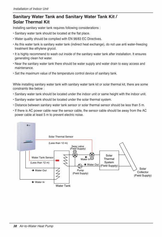
Sanitary Water Tank and Sanitary Water Tank Kit /Solar Thermal KitInstalling sanitary water tank requires following considerations :
• Sanitary water tank should be located at the flat place.
• Water quality should be complied with EN 98/83 EC Directives.
• As this water tank is sanitary water tank (indirect heat exchange), do not use anti water-freezingtreatment like ethylene grycol.
• It is highly recommend to wash out inside of the sanitary water tank after installation. It ensuresgenerating clean hot water.
• Near the sanitary water tank there should be water supply and water drain to easy access andmaintenance.
• Set the maximum value of the temperature control device of sanitary tank.
While installing sanitary water tank with sanitary water tank kit or solar thermal kit, there are someconstraints like below :
• Sanitary water tank should be located under the indoor unit or same height with the indoor unit.
• Sanitary water tank should be located under the solar thermal system.
• Distance between sanitary water tank sensor or solar thermal sensor should be less than 5 m.
• If there is AC power cable near the sensor cable, the sensor cable should be away from the ACpower cable at least 5 m to prevent electric noise.
SolarThermalSystem
(Field Supply)Solar
Collector(Field Supply)
Water Tank
Water Tank Sensor
(Less than 12 m)
Solar Thermal Sensor
(Less than 12 m)
Water In
Water Out
Water Out
Water In
3way valve(Field Supply)
Pump(Field Supply)
38 Air-to-Water Heat Pump
Installation of Indoor Unit
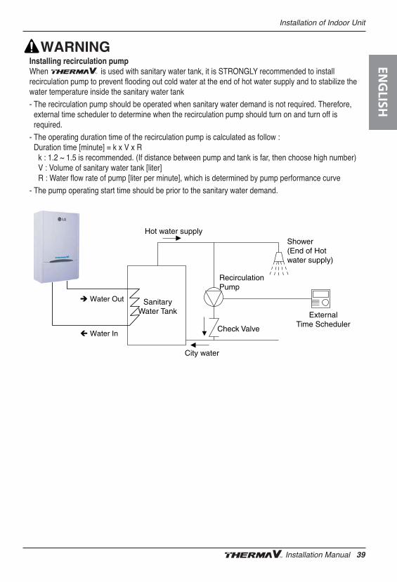
Installing recirculation pumpWhen is used with sanitary water tank, it is STRONGLY recommended to installrecirculation pump to prevent flooding out cold water at the end of hot water supply and to stabilize thewater temperature inside the sanitary water tank
- The recirculation pump should be operated when sanitary water demand is not required. Therefore,external time scheduler to determine when the recirculation pump should turn on and turn off isrequired.
- The operating duration time of the recirculation pump is calculated as follow :Duration time [minute] = k x V x R
k : 1.2 ~ 1.5 is recommended. (If distance between pump and tank is far, then choose high number)V : Volume of sanitary water tank [liter]R : Water flow rate of pump [liter per minute], which is determined by pump performance curve
- The pump operating start time should be prior to the sanitary water demand.
SanitaryWater Tank
RecirculationPump
ExternalTime Scheduler
Check Valve
Shower(End of Hot water supply)
Hot water supply
City water
Water In
Water Out
ENG
LISH
Installation Manual 39
Installation of Indoor Unit
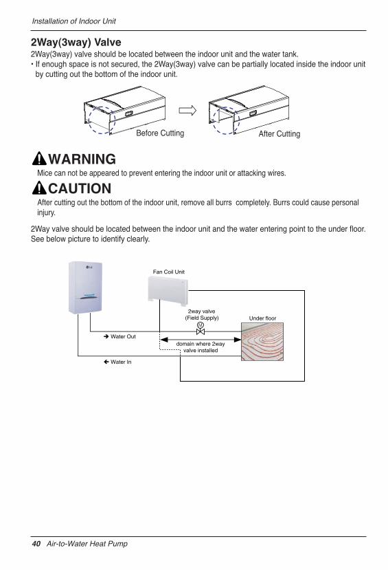
2Way(3way) Valve2Way(3way) valve should be located between the indoor unit and the water tank.• If enough space is not secured, the 2Way(3way) valve can be partially located inside the indoor unit
by cutting out the bottom of the indoor unit.
Mice can not be appeared to prevent entering the indoor unit or attacking wires.
After cutting out the bottom of the indoor unit, remove all burrs completely. Burrs could cause personalinjury.
2Way valve should be located between the indoor unit and the water entering point to the under floor.See below picture to identify clearly.
Water In
Water Out
2way valve(Field Supply)
domain where 2wayvalve installed
Fan Coil Unit
Under floor
Before Cutting After Cutting
40 Air-to-Water Heat Pump
Piping and Wiring for Outdoor Unit
5. Piping and Wiring for Outdoor UnitProcedures about refrigerant piping and electric wiring at the outdoor are described in this chapter. Most ofprocedures are similar to those of LG Air Conditioner.
Before starting refrigerant piping, constraints in pipe length and elevation should be examined. Afterresolving all constraints, some preparations are required to proceed. Then connecting pipe to the outdoorand the indoor unit is beginning.
Refrigerant Piping
Constraints in Pipe Length and Elevation
Outdoor unit
Indoor unit
A
B
Outdoor unit
Indoor unit
A
B
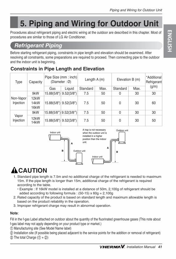
A trap is not necessary when the outdoor unit is installed in a higher position than the indoor unit.
1. Standard pipe length is 7.5m and no additional charge of the refrigerant is needed to maximum15m. If the pipe length is longer than 15m, additional charge of the refrigerant is requiredaccording to the table. • Example : If 16kW model is installed at a distance of 50m, 2,100g of refrigerant should be
added according to following formula : (50-15) x 60g = 2,100g2. Rated capacity of the product is based on standard length and maximum allowable length is
based on the product reliability in the operation.3. Improper refrigerant charge may result in abnormal operation.
Note:
Fill in the f-gas Label attached on outdoor about the quantity of the fluorinated greenhouse gases (This note aboutf-gas label may not apply depending on your product type or market.)① Manufacturing site (See Model Name label)② Installation site (If possible being placed adjacent to the service points for the addition or removal of refrigerant)③ The total Charge (① + ②)
Type CapacityPipe Size (mm : inch)
(Diameter : Ø)Length A (m) Elevation B (m) *Additional
Refrigerant(g/m)Gas Liquid Standard Max. Standard Max.
Non-VaporInjection
9kW 15.88(5/8") 9.52(3/8") 7.5 50 0 30 3012kW14kW16kW
15.88(5/8") 9.52(3/8") 7.5 50 0 30 60
VaporInjection
9kW 15.88(5/8″) 9.52(3/8″) 7.5 50 0 30 30
12kW14kW 15.88(5/8") 9.52(3/8") 7.5 50 0 30 50
ENG
LISH
Installation Manual 41
Piping and Wiring for Outdoor Unit
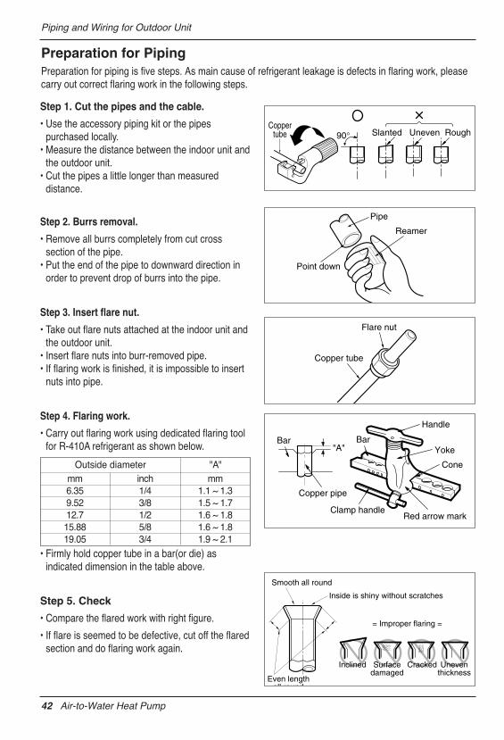
Step 1. Cut the pipes and the cable.
• Use the accessory piping kit or the pipespurchased locally.
• Measure the distance between the indoor unit andthe outdoor unit.
• Cut the pipes a little longer than measureddistance.
Step 2. Burrs removal.
• Remove all burrs completely from cut crosssection of the pipe.
• Put the end of the pipe to downward direction inorder to prevent drop of burrs into the pipe.
Step 3. Insert flare nut.
• Take out flare nuts attached at the indoor unit andthe outdoor unit.
• Insert flare nuts into burr-removed pipe.• If flaring work is finished, it is impossible to insert
nuts into pipe.
Step 4. Flaring work.
• Carry out flaring work using dedicated flaring toolfor R-410A refrigerant as shown below.
• Firmly hold copper tube in a bar(or die) asindicated dimension in the table above.
Step 5. Check
• Compare the flared work with right figure.
• If flare is seemed to be defective, cut off the flaredsection and do flaring work again.
Preparation for PipingPreparation for piping is five steps. As main cause of refrigerant leakage is defects in flaring work, pleasecarry out correct flaring work in the following steps.
Coppertube 90° Slanted Uneven Rough
Pipe
Reamer
Point down
Flare nut
Copper tube
Bar
Copper pipe
Clamp handleRed arrow mark
Cone
Yoke
Handle
Bar"A"
Inclined
Inside is shiny without scratches
Smooth all round
Even lengthall round
Surfacedamaged
Cracked Uneventhickness
= Improper flaring =
mm inch mm6.35 1/4 1.1 ~ 1.39.52 3/8 1.5 ~ 1.712.7 1/2 1.6 ~ 1.815.88 5/8 1.6 ~ 1.819.05 3/4 1.9 ~ 2.1
Outside diameter "A"
42 Air-to-Water Heat Pump
Piping and Wiring for Outdoor Unit
Connecting Pipe to Indoor UnitConnecting pipe to the indoor unit is two steps. Read following directions carefully.
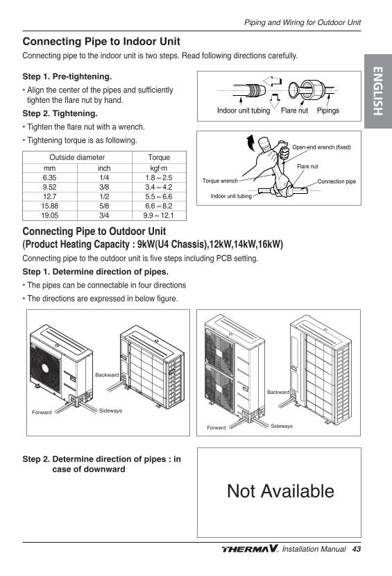
Connecting Pipe to Outdoor Unit (Product Heating Capacity : 9kW(U4 Chassis),12kW,14kW,16kW)Connecting pipe to the outdoor unit is five steps including PCB setting.
Step 1. Pre-tightening.
• Align the center of the pipes and sufficientlytighten the flare nut by hand.
Step 2. Tightening.
• Tighten the flare nut with a wrench.
• Tightening torque is as following.
Step 1. Determine direction of pipes.
• The pipes can be connectable in four directions
• The directions are expressed in below figure.
Step 2. Determine direction of pipes : incase of downward
Torque wrench
Indoor unit tubing
Open-end wrench (fixed)
Connection pipe
Flare nut
Indoor unit tubing Flare nut Pipings
mm inch kgf·m6.35 1/4 1.8 ~ 2.59.52 3/8 3.4 ~ 4.212.7 1/2 5.5 ~ 6.615.88 5/8 6.6 ~ 8.219.05 3/4 9.9 ~ 12.1
Outside diameter Torque
Forward Sideways
Backward
Forward Sideways
Backward
Not Available
ENG
LISH
Installation Manual 43
Piping and Wiring for Outdoor Unit
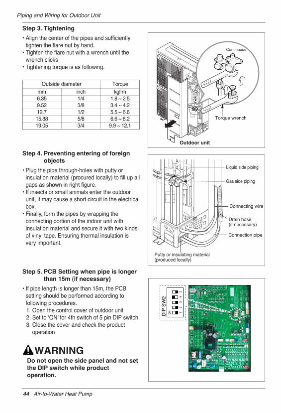
Step 3. Tightening
• Align the center of the pipes and sufficientlytighten the flare nut by hand.
• Tighten the flare nut with a wrench until thewrench clicks
• Tightening torque is as following.
Step 4. Preventing entering of foreignobjects
• Plug the pipe through-holes with putty orinsulation material (procured locally) to fill up allgaps as shown in right figure.
• If insects or small animals enter the outdoorunit, it may cause a short circuit in the electricalbox.
• Finally, form the pipes by wrapping theconnecting portion of the indoor unit withinsulation material and secure it with two kindsof vinyl tape. Ensuring thermal insulation isvery important.
Step 5. PCB Setting when pipe is longerthan 15m (if necessary)
• If pipe length is longer than 15m, the PCBsetting should be performed according tofollowing procedures.1. Open the control cover of outdoor unit2. Set to ʻONʼ for 4th switch of 5 pin DIP switch3. Close the cover and check the product
operation
Do not open the side panel and not setthe DIP switch while productoperation.
mm inch kgf·m6.35 1/4 1.8 ~ 2.59.52 3/8 3.4 ~ 4.212.7 1/2 5.5 ~ 6.615.88 5/8 6.6 ~ 8.219.05 3/4 9.9 ~ 12.1
Outside diameter Torque
Outdoor unit
Continuous
Torque wrench
Gas side piping
Liquid side piping
Putty or insulating material(produced locally)
Drain hose(if necessary)
Connecting wire
Connection pipe
ON 1
23
45
DIP
SW
2
44 Air-to-Water Heat Pump
Piping and Wiring for Outdoor Unit
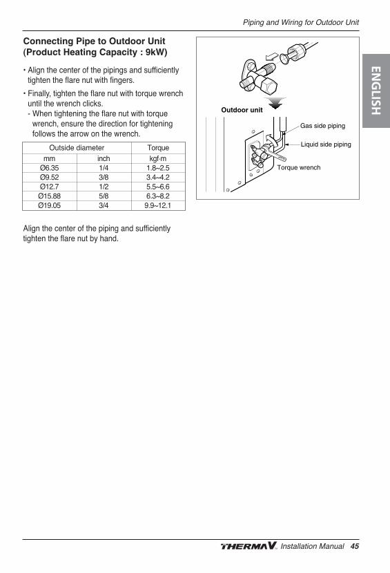
Connecting Pipe to Outdoor Unit(Product Heating Capacity : 9kW)
• Align the center of the pipings and sufficientlytighten the flare nut with fingers.
• Finally, tighten the flare nut with torque wrenchuntil the wrench clicks. - When tightening the flare nut with torque
wrench, ensure the direction for tighteningfollows the arrow on the wrench.
Align the center of the piping and sufficientlytighten the flare nut by hand.
mm inch kgf.mØ6.35 1/4 1.8~2.5Ø9.52 3/8 3.4~4.2Ø12.7 1/2 5.5~6.6Ø15.88 5/8 6.3~8.2Ø19.05 3/4 9.9~12.1
Outside diameter Torque
Torque wrench
Outdoor unit
Gas side piping
Liquid side piping
ENG
LISH
Installation Manual 45
Piping and Wiring for Outdoor Unit
Two kind of cables should be connected to the outdoor unit : One is ʻPower cableʼ, the other one is ʻConnecting cableʼ.Power cable is a cable which is used to supply external electricity to the outdoor unit. This cable is generally connectedbetween external power source (such as main electric power distribution panel of userʼs house) and the outdoor unit.Connecting cable is, on the other hand, used to connect between the outdoor unit and the indoor unit to supply electricpower to the indoor unit and to establish the communication between the outdoor unit and the indoor unit.
Procedure for wiring to the outdoor unit is four steps. Before starting wiring, check if wire specification is suitable andread following directions and cautions VERY carefully.
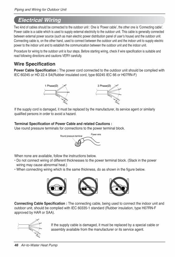
Wire SpecificationPower Cable Specification : The power cord connected to the outdoor unit should be complied withIEC 60245 or HD 22.4 S4(Rubber insulated cord, type 60245 IEC 66 or H07RN-F)
Electrical Wiring
Round pressure terminalPower wire
Terminal Specification of Power Cable and related Cautions :Use round pressure terminals for connections to the power terminal block.
Connecting Cable Specification : The connecting cable, being used to connect the indoor unit andoutdoor unit, should be complied with IEC 60335-1 standard (Rubber insulation, type H07RN-Fapproved by HAR or SAA).
If the supply cord is damaged, it must be replaced by the manufacturer, its service agent or similarlyqualified persons in order to avoid a hazard.
When none are available, follow the instructions below.• Do not connect wiring of different thicknesses to the power terminal block. (Slack in the power
wiring may cause abnormal heat.)• When connecting wiring which is the same thickness, do as shown in the figure below.
If the supply cable is damaged, it must be replaced by a special cable orassembly available from the manufacturer or its service agent.
20mm
GN/YL
1 Phase(Ø) 3 Phase(Ø)
20mm
GN/YL
20mm
GN/YL
46 Air-to-Water Heat Pump
Piping and Wiring for Outdoor Unit
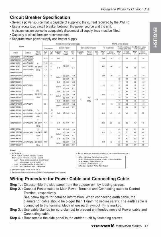
Wiring Procedure for Power Cable and Connecting CableStep 1. : Disassemble the side panel from the outdoor unit by loosing screws.Step 2. : Connect Power cable to Main Power Terminal and Connecting cable to Control
Terminal, respectively. See below figure for detailed information. When connecting earth cable, thediameter of cable should be bigger than 1.6mm2 to secure safety. The earth cable isconnected to the terminal block where earth symbol is marked.
Step 3. : Use cable clamps (or cord clamps) to prevent unintended move of Power cable andConnecting cable.
Step 4. : Reassemble the side panel to the outdoor unit by fastening screws.
Circuit Breaker Specification• Select a power source that is capable of supplying the current required by the AWHP.• Use a recognized circuit breaker between the power source and the unit.
A disconnection device to adequately disconnect all supply lines must be fitted.• Capacity of circuit breaker recommended.• Separate main power supply and heater supply.
Notes:
1. MCA / MOPMCA = (1.25 x Load1) + Load2 + Load3 MOP = (2.25 x Load1) + Load2 + Load3 - Load1 : Rated running current of largest motor
(compressor or other motor) - Load2 : sum of current for all other motors- Load3 : any other load rated 1.0A or more
2. Select wire spec. based on the MCA
3. Recommended circuit breaker is ELCB (Earth Leakage Circuit breaker)
4. RLA is measured during each individual compressor test condition.
MCA : Minimum Circuit Amperes (A)MOP : Maximum rating Over current Protective deviceRLA : Rated Load Amperes (A)FLA : Full Load Amperes (A)S/Heater: Sanitary Water Tan Heater
CircuitBreaker(A)
MOP(A)
CircuitBreaker(A)
MOP(A)
CircuitBreaker(A)
MOP(A)
FLA(A)
Capacity(kW)
RLA(A)
Capacity(kW)Outdoor Power
SupplyPowerSupply
PowerSupply
Indoor
For Electric Heater(with S/Heater)
For Electric Heater(without S/Heater)For Heat PumpSanitary Tank HeaterElectric HeaterCompressor
RLA(A)
FLA(A)
MOP & Circuit BreakerCore Component Electrical Spec.Model
3 12.51Ø
230V
AHUW096A0
AHUW096A1
AHUW126A0
AHUW146A0
AHUW166A0
AHUW096AN
AHUW168A1
AHUW148A1
AHUW128A1
9.7
17.0
17.0
17.0
9.7
5.3
5.0
4.0
15
25
27
27
15
9.9
2+2
3+3
2+2+2
3+3
2+2+2
3+3
2+2+2
3+3
2+2+2
1Ø 230V
3Ø 220V
3Ø 400V
1Ø 230V
3Ø 220V
3Ø 400V
1Ø 230V
3Ø 220V
3Ø 400V
1Ø 230V
3Ø 220V
3Ø 400V
8.3
12.5
15.8
8.7
12.5
15.8
8.7
12.5
15.8
8.7
12.5
15.8
8.7
23.9
40.3
23.9
14.0
13.3
11.1
20
40
20
13
13
10
27
41
37
22
41
37
22
41
37
22
41
37
22
30
40
30
20
40
30
20
40
30
20
40
30
20
45
53
49
38
53
49
38
53
49
38
53
49
38
40
50
40
30
50
40
30
50
40
30
50
40
30
1~
220-240V
50Hz
3N~
380-415V
50Hz
1~
220-240V
50Hz
1~
220-240V
50Hz
25
27
27
17.0
9.7 15
3+3
2+2
1Ø 230V
1Ø 230V 8.3
12.5 40.3
23.9
40
20
41
27 30 45 40
40 53 50
AHNW096A0
AHNW09604A1
AHNW126A0
AHNW146A0
AHNW166A0
AHNW09606A0
AHNW09A06A0
AHNW09806A0
AHNW16606A1
AHNW16A06A1
AHNW16806A1
AHNW16606A1
AHNW16A06A1
AHNW16806A1
AHNW16606A1
AHNW16A06A1
AHNW16806A1
AHNW16606A1
AHNW16606A1
AHNW16606A1
AHNW09604A1
AHNW16606A1
AHNW16A06A1
AHNW16806A1
AHNW16606A1
AHNW16A06A1
AHNW16806A1
AHUW126A1
AHUW146A1
AHUW166A1
AHUW096A2
1~
220-240V
50Hz
1~
220-240V
50Hz
29
14.5
16.9
3+3
2+2+2
3+3
2+2+2
1Ø 230V
3Ø 220V
3Ø 400V
1Ø 230V
3Ø 220V
3Ø 400V
12.5
15.8
8.7
12.5
15.8
8.7
34.7
40.1 40
30
41
37
22
41
37
22
40
30
20
40
30
20
53
49
38
53
49
38
50
40
30
50
40
30
AHUW126A2
AHUW146A2
ENG
LISH
Installation Manual 47
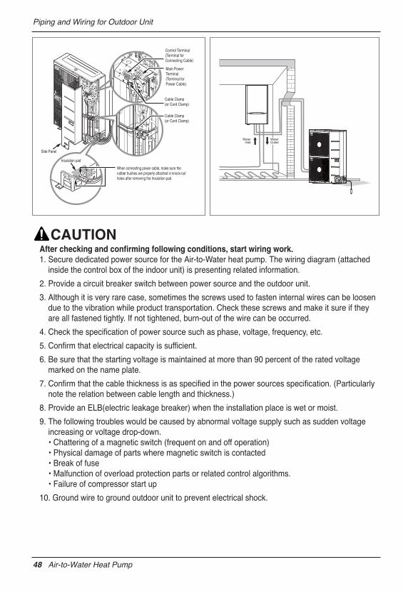
Piping and Wiring for Outdoor Unit
After checking and confirming following conditions, start wiring work.1. Secure dedicated power source for the Air-to-Water heat pump. The wiring diagram (attached
inside the control box of the indoor unit) is presenting related information.
2. Provide a circuit breaker switch between power source and the outdoor unit.
3. Although it is very rare case, sometimes the screws used to fasten internal wires can be loosendue to the vibration while product transportation. Check these screws and make it sure if theyare all fastened tightly. If not tightened, burn-out of the wire can be occurred.
4. Check the specification of power source such as phase, voltage, frequency, etc.
5. Confirm that electrical capacity is sufficient.
6. Be sure that the starting voltage is maintained at more than 90 percent of the rated voltagemarked on the name plate.
7. Confirm that the cable thickness is as specified in the power sources specification. (Particularlynote the relation between cable length and thickness.)
8. Provide an ELB(electric leakage breaker) when the installation place is wet or moist.
9. The following troubles would be caused by abnormal voltage supply such as sudden voltageincreasing or voltage drop-down.• Chattering of a magnetic switch (frequent on and off operation)• Physical damage of parts where magnetic switch is contacted• Break of fuse• Malfunction of overload protection parts or related control algorithms.• Failure of compressor start up
10. Ground wire to ground outdoor unit to prevent electrical shock.
When connecting power cable, make sure the rubber bushes are properly attached in knock-out holes after removing the Insulation pad.
Control Terminal(Terminal for Connecting Cable)
Main Power Terminal(Terminal for Power Cable)
Cable Clamp(or Cord Clamp)
Cable Clamp(or Cord Clamp)
Insulation pad
Side Panel
WaterInlet
WaterOutlet
48 Air-to-Water Heat Pump
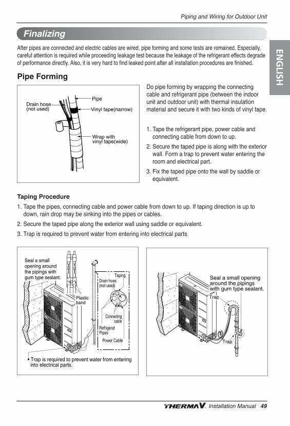
Piping and Wiring for Outdoor Unit
After pipes are connected and electric cables are wired, pipe forming and some tests are remained. Especially,careful attention is required while proceeding leakage test because the leakage of the refrigerant effects degradeof performance directly. Also, it is very hard to find leaked point after all installation procedures are finished.
Pipe FormingDo pipe forming by wrapping the connectingcable and refrigerant pipe (between the indoorunit and outdoor unit) with thermal insulationmaterial and secure it with two kinds of vinyl tape.
1. Tape the refrigerant pipe, power cable andconnecting cable from down to up.
2. Secure the taped pipe is along with the exteriorwall. Form a trap to prevent water entering theroom and electrical part.
3. Fix the taped pipe onto the wall by saddle orequivalent.
Drain hose(not used) Vinyl tape(narrow)
Pipe
Wrap with vinyl tape(wide)
Taping Procedure
1. Tape the pipes, connecting cable and power cable from down to up. If taping direction is up todown, rain drop may be sinking into the pipes or cables.
2. Secure the taped pipe along the exterior wall using saddle or equivalent.
3. Trap is required to prevent water from entering into electrical parts.
• Trap is required to prevent water from enteringinto electrical parts.
TapingDrain hose(not used)
RefrigeratPipes
Connectingcable
Power Cable
PlasticPlasticbandbandPlasticband
Seal a small Seal a small opening around opening around the pipings with the pipings with gum type sealer.gum type sealer.
Seal a small opening around the pipings with gum type sealant.
Trap
Seal a small opening around the pipings with gum type sealer.
Trap
Plasticband
Seal a small opening around the pipings with gum type sealer.
TrapTrapTrap
Seal a small opening Seal a small opening around the pipings around the pipings with gum type sealer.with gum type sealer.
Seal a small opening around the pipings with gum type sealant.
Finalizing
ENG
LISH
Installation Manual 49
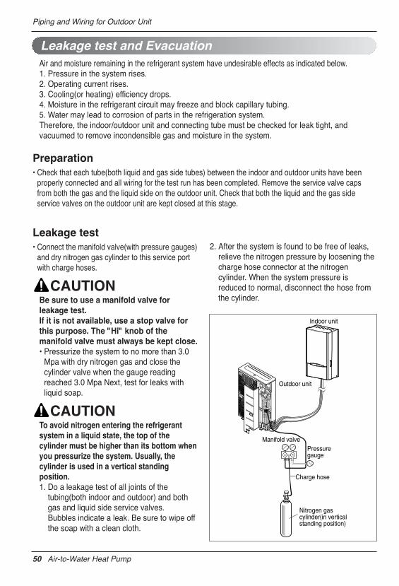
Piping and Wiring for Outdoor Unit
Air and moisture remaining in the refrigerant system have undesirable effects as indicated below.1. Pressure in the system rises.2. Operating current rises.3. Cooling(or heating) efficiency drops.4. Moisture in the refrigerant circuit may freeze and block capillary tubing.5. Water may lead to corrosion of parts in the refrigeration system.Therefore, the indoor/outdoor unit and connecting tube must be checked for leak tight, andvacuumed to remove incondensible gas and moisture in the system.
Preparation• Check that each tube(both liquid and gas side tubes) between the indoor and outdoor units have been
properly connected and all wiring for the test run has been completed. Remove the service valve capsfrom both the gas and the liquid side on the outdoor unit. Check that both the liquid and the gas sideservice valves on the outdoor unit are kept closed at this stage.
Leakage test• Connect the manifold valve(with pressure gauges)
and dry nitrogen gas cylinder to this service portwith charge hoses.
Be sure to use a manifold valve forleakage test. If it is not available, use a stop valve forthis purpose. The "Hi" knob of themanifold valve must always be kept close.• Pressurize the system to no more than 3.0
Mpa with dry nitrogen gas and close thecylinder valve when the gauge readingreached 3.0 Mpa Next, test for leaks withliquid soap.
To avoid nitrogen entering the refrigerantsystem in a liquid state, the top of thecylinder must be higher than its bottom whenyou pressurize the system. Usually, thecylinder is used in a vertical standingposition.1. Do a leakage test of all joints of the
tubing(both indoor and outdoor) and bothgas and liquid side service valves.Bubbles indicate a leak. Be sure to wipe offthe soap with a clean cloth.
2. After the system is found to be free of leaks,relieve the nitrogen pressure by loosening thecharge hose connector at the nitrogencylinder. When the system pressure isreduced to normal, disconnect the hose fromthe cylinder.
Leakage test and Evacuation
Charge hose
Indoor unit
Outdoor unit
Manifold valve
Lo Hi
Pressure gauge
Nitrogen gascylinder(in verticalstanding position)
50 Air-to-Water Heat Pump
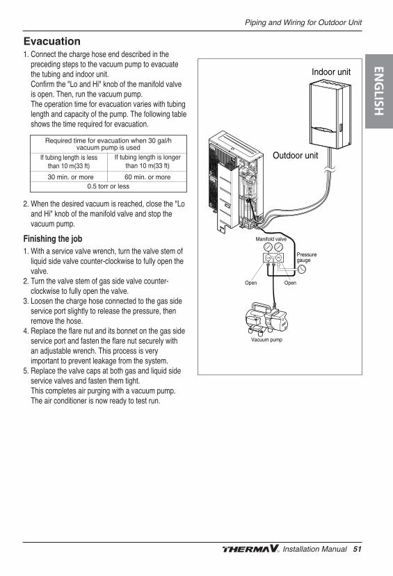
Piping and Wiring for Outdoor Unit
Evacuation1. Connect the charge hose end described in the
preceding steps to the vacuum pump to evacuatethe tubing and indoor unit.Confirm the "Lo and Hi" knob of the manifold valveis open. Then, run the vacuum pump.The operation time for evacuation varies with tubinglength and capacity of the pump. The following tableshows the time required for evacuation.
2. When the desired vacuum is reached, close the "Loand Hi" knob of the manifold valve and stop thevacuum pump.
Finishing the job1. With a service valve wrench, turn the valve stem of
liquid side valve counter-clockwise to fully open thevalve.
2. Turn the valve stem of gas side valve counter-clockwise to fully open the valve.
3. Loosen the charge hose connected to the gas sideservice port slightly to release the pressure, thenremove the hose.
4. Replace the flare nut and its bonnet on the gas sideservice port and fasten the flare nut securely withan adjustable wrench. This process is veryimportant to prevent leakage from the system.
5. Replace the valve caps at both gas and liquid sideservice valves and fasten them tight.This completes air purging with a vacuum pump. The air conditioner is now ready to test run.
Indoor unit
Outdoor unit
Lo Hi
Manifold valve
Vacuum pump
Open Open
Pressure gauge
Required time for evacuation when 30 gal/h vacuum pump is used
30 min. or more 60 min. or more0.5 torr or less
If tubing length is lessthan 10 m(33 ft)
If tubing length is longerthan 10 m(33 ft)
ENG
LISH
Installation Manual 51
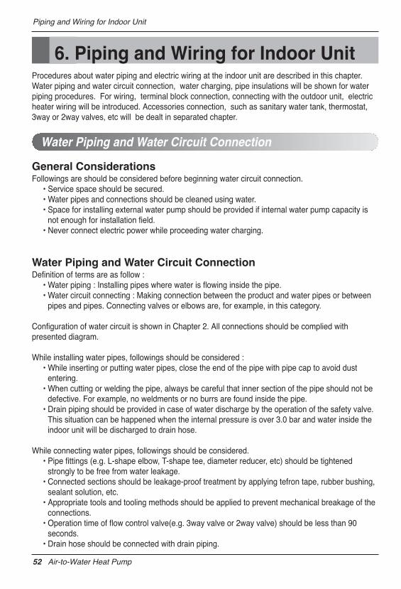
Piping and Wiring for Indoor Unit
6. Piping and Wiring for Indoor UnitProcedures about water piping and electric wiring at the indoor unit are described in this chapter.Water piping and water circuit connection, water charging, pipe insulations will be shown for waterpiping procedures. For wiring, terminal block connection, connecting with the outdoor unit, electricheater wiring will be introduced. Accessories connection, such as sanitary water tank, thermostat,3way or 2way valves, etc will be dealt in separated chapter.
General ConsiderationsFollowings are should be considered before beginning water circuit connection.
• Service space should be secured. • Water pipes and connections should be cleaned using water.• Space for installing external water pump should be provided if internal water pump capacity is
not enough for installation field. • Never connect electric power while proceeding water charging.
Water Piping and Water Circuit ConnectionDefinition of terms are as follow :
• Water piping : Installing pipes where water is flowing inside the pipe.• Water circuit connecting : Making connection between the product and water pipes or between
pipes and pipes. Connecting valves or elbows are, for example, in this category.
Configuration of water circuit is shown in Chapter 2. All connections should be complied withpresented diagram.
While installing water pipes, followings should be considered :• While inserting or putting water pipes, close the end of the pipe with pipe cap to avoid dust
entering.• When cutting or welding the pipe, always be careful that inner section of the pipe should not be
defective. For example, no weldments or no burrs are found inside the pipe.• Drain piping should be provided in case of water discharge by the operation of the safety valve.
This situation can be happened when the internal pressure is over 3.0 bar and water inside theindoor unit will be discharged to drain hose.
While connecting water pipes, followings should be considered.• Pipe fittings (e.g. L-shape elbow, T-shape tee, diameter reducer, etc) should be tightened
strongly to be free from water leakage. • Connected sections should be leakage-proof treatment by applying tefron tape, rubber bushing,
sealant solution, etc. • Appropriate tools and tooling methods should be applied to prevent mechanical breakage of the
connections.• Operation time of flow control valve(e.g. 3way valve or 2way valve) should be less than 90
seconds.• Drain hose should be connected with drain piping.
Water Piping and Water Circuit Connection
52 Air-to-Water Heat Pump
Piping and Wiring for Indoor Unit
Installing shut-off valve • While assembling two shut-off valves, that are found inside ʻAWHP Installation Kit
(AET69364401)ʼ, pop sound will be heard when valve is open or close by rotating handles. It isnormal condition because the sound is due to leakage of charged nitrogen gas inside the valve.The nitrogen gas is applied to secure quality assurance.
• Before starting water charging, these two shut-off valves should be assembled with water inletand outlet pipe of the indoor unit.
Water condensation on the floorWhile cooling operation, it is very important to keep leaving water temperature higher than 16°C.Otherwise, dew condensation can be occurred on the floor.If floor is in humid environment, do not set leaving water temperature below 18 °C.
Water condensation on the radiatorWhile cooling operation, cold water may not flow to the radiator. If cold water enters to the radiator,dew generation on the surface of the radiator can be occurred.
Drainage treatmentWhile cooling operation, condensed dew can drop down to the bottom of the indoor unit. In thiscase, prepare drainage treatment (for example, vessel to contain condensed dew) to avoid waterdrop.
ENG
LISH
Installation Manual 53
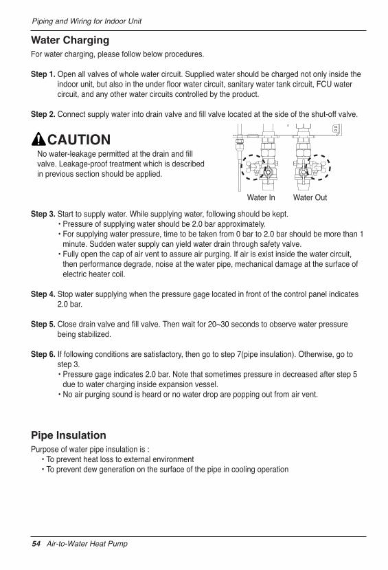
Piping and Wiring for Indoor Unit
Water ChargingFor water charging, please follow below procedures.
Step 1. Open all valves of whole water circuit. Supplied water should be charged not only inside theindoor unit, but also in the under floor water circuit, sanitary water tank circuit, FCU watercircuit, and any other water circuits controlled by the product.
Step 2. Connect supply water into drain valve and fill valve located at the side of the shut-off valve.
No water-leakage permitted at the drain and fillvalve. Leakage-proof treatment which is describedin previous section should be applied.
Step 3. Start to supply water. While supplying water, following should be kept.• Pressure of supplying water should be 2.0 bar approximately.• For supplying water pressure, time to be taken from 0 bar to 2.0 bar should be more than 1
minute. Sudden water supply can yield water drain through safety valve.• Fully open the cap of air vent to assure air purging. If air is exist inside the water circuit,
then performance degrade, noise at the water pipe, mechanical damage at the surface ofelectric heater coil.
Step 4. Stop water supplying when the pressure gage located in front of the control panel indicates2.0 bar.
Step 5. Close drain valve and fill valve. Then wait for 20~30 seconds to observe water pressurebeing stabilized.
Step 6. If following conditions are satisfactory, then go to step 7(pipe insulation). Otherwise, go tostep 3.• Pressure gage indicates 2.0 bar. Note that sometimes pressure in decreased after step 5
due to water charging inside expansion vessel.• No air purging sound is heard or no water drop are popping out from air vent.
Pipe InsulationPurpose of water pipe insulation is :
• To prevent heat loss to external environment• To prevent dew generation on the surface of the pipe in cooling operation
Water In Water Out
54 Air-to-Water Heat Pump
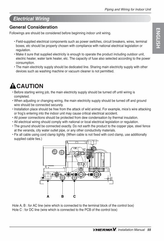
Piping and Wiring for Indoor Unit
General ConsiderationFollowings are should be considered before beginning indoor unit wiring.
• Field-supplied electrical components such as power switches, circuit breakers, wires, terminalboxes, etc should be properly chosen with compliance with national electrical legislation orregulation.
• Make it sure that supplied electricity is enough to operate the product including outdoor unit,electric heater, water tank heater, etc. The capacity of fuse also selected according to the powerconsumption.
• The main electricity supply should be dedicated line. Sharing main electricity supply with otherdevices such as washing machine or vacuum cleaner is not permitted.
• Before starting wiring job, the main electricity supply should be turned off until wiring iscompleted.
• When adjusting or changing wiring, the main electricity supply should be turned off and groundwire should be connected securely.
• Installation place should be free from the attack of wild animal. For example, miceʼs wire attackingor frogʼs entering into the indoor unit may cause critical electrical accident.
• All power connections should be protected from dew condensation by thermal insulation.• All electrical wiring should comply with national or local electrical legislation or regulation.• The ground should be connected exactly. Do not earth the product to the copper pipe, steel fence
at the veranda, city water outlet pipe, or any other conductivity materials.• Fix all cable using cord clamp tightly. (When cable is not fixed with cord clamp, use additionally
supplied cable ties.)
Hole A, B : for AC line (wire which is connected to the terminal block of the control box)Hole C : for DC line (wire which is connected to the PCB of the control box)
Electrical Wiring
A B C
ENG
LISH
Installation Manual 55
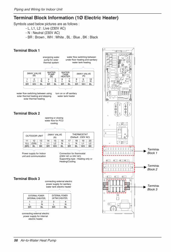
Piping and Wiring for Indoor Unit
Terminal Block Information (1Ø Electric Heater)Symbols used below pictures are as follows :
- L, L1, L2 : Live (230V AC) - N : Neutral (230V AC)- BR : Brown , WH : White , BL : Blue , BK : Black
Terminal Block 1
Terminal Block 2
Terminal Block 3
energizing waterpump for solarthermal system
water flow switching betweenunder floor heating and sanitary
water tank heating
water flow switching between usingsolar thermal heating and skipping
solar thermal heating
turn on or off sanitarywater tank heater
3WAY VALVE(B)
WATERPUMP
(B)
WATERTANK
HEATER3WAY VALVE
(A)
1L
BR WH BL BR BL BR BR WHBL BL
2L1
3N
4L
5N
6L
7N
8L
9L1
10N
Power supply for Indoorunit and communication
Connection for thermostat(230V AC or 24V AC)Supporting type : Heating only or Heating/Cooling
opening or closingwater flow for FCU
cooling
OUTDOOR UNIT 2WAY VALVE(A)
THERMOSTAT(Default : 230V AC)
111(L)(BR)
12(2(N)BL
133
BK
14L1BR
15L2WH
16NBL
17L
BR
18NBL
19L1WH
20L2BK
connecting external electricpower supply for internal
electric heater
connecting external electricpower supply for sanitarywater tank electric heater
EXTERNAL POWER(W/TNK E/HEATER)
EXTERNAL POWER(INTERNAL E/HEATER)
1L
BR
2NBL
3L
BR
4NBL
TerminalBlock 1
TerminalBlock 2
TerminalBlock 3
56 Air-to-Water Heat Pump
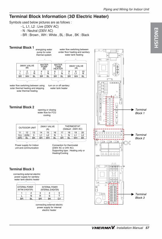
Piping and Wiring for Indoor Unit
Terminal Block Information (3Ø Electric Heater)Symbols used below pictures are as follows :
- L, L1, L2 : Live (230V AC) - N : Neutral (230V AC)- BR : Brown , WH : White , BL : Blue , BK : Black
Terminal Block 1
Terminal Block 2
Terminal Block 3
energizing waterpump for solarthermal system
water flow switching betweenunder floor heating and sanitary
water tank heating
water flow switching between usingsolar thermal heating and skipping
solar thermal heating
turn on or off sanitarywater tank heater
3WAY VALVE(B)
WATERPUMP
(B)
WATERTANK
HEATER3WAY VALVE
(A)
1L
BR WH BL BR BL BR BR WHBL BL
2L1
3N
4L
5N
6L
7N
8L
9L1
10N
Power supply for Indoorunit and communication
Connection for thermostat(230V AC or 24V AC)Supporting type : Heating only or Heating/Cooling
opening or closingwater flow for FCU
cooling
OUTDOOR UNIT 2WAY VALVE(A)
THERMOSTAT(Default : 230V AC)
111(L)(BR)
12(2(N)BL
133
BK
14L1BR
15L2WH
16NBL
17L
BR
18NBL
19L1WH
20L2BK
connecting external electricpower supply for internal
electric heater
connecting external electricpower supply for sanitarywater tank electric heater
EXTERNAL POWER(W/TNK E/HEATER)
EXTERNAL POWER(INTERNAL E/HEATER)
3R
BR
1L
BR
2NBL
4S
BK
5T
GY
Terminal Block 1
Terminal Block 2
Terminal Block 3
ENG
LISH
Installation Manual 57
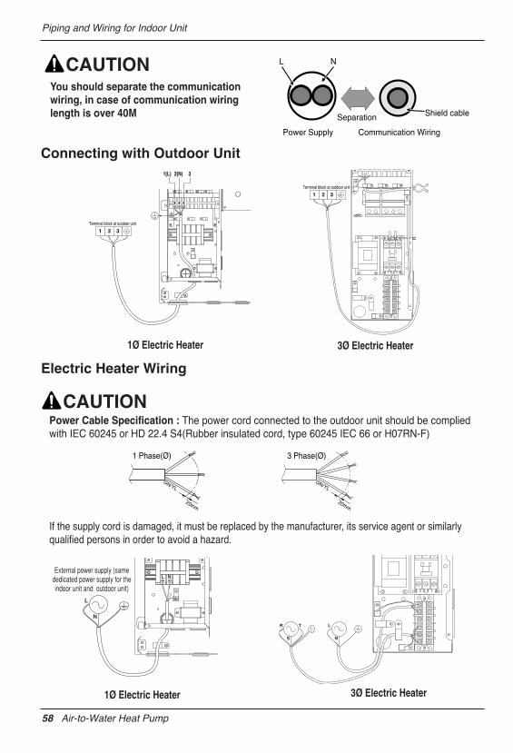
Piping and Wiring for Indoor Unit
Connecting with Outdoor Unit
Electric Heater Wiring
1(L) 2(N) 3
1 2 3Terminal block at outdoor unit
1 2 3Terminal block at outdoor unit
N
L
S
R T
NL
N
L
External power supply (same dedicated power supply for the indoor unit and outdoor unit)
Power Cable Specification : The power cord connected to the outdoor unit should be compliedwith IEC 60245 or HD 22.4 S4(Rubber insulated cord, type 60245 IEC 66 or H07RN-F)
If the supply cord is damaged, it must be replaced by the manufacturer, its service agent or similarlyqualified persons in order to avoid a hazard.
20mm
GN/YL
1 Phase(Ø) 3 Phase(Ø)
20mm
GN/YL
1Ø Electric Heater
1Ø Electric Heater 3Ø Electric Heater
3Ø Electric Heater
L N
Separation
Power Supply Communication Wiring
Shield cable
You should separate the communicationwiring, in case of communication wiringlength is over 40M
58 Air-to-Water Heat Pump
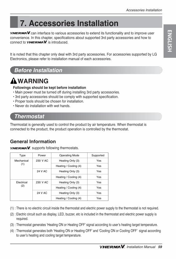
Accessories Installation
7. Accessories Installationcan interface to various accessories to extend its functionality and to improve user
convenience. In this chapter, specifications about supported 3rd party accessories and how toconnect to is introduced.
It is noted that this chapter only deal with 3rd party accessories. For accessories supported by LGElectronics, please refer to installation manual of each accessories.
Thermostat is generally used to control the product by air temperature. When thermostat isconnected to the product, the product operation is controlled by the thermostat.
General Informationsupports following thermostats.
(1) : There is no electric circuit inside the thermostat and electric power supply to the thermostat is not required.
(2) : Electric circuit such as display, LED, buzzer, etc is included in the thermostat and electric power supply isrequired.
(3) : Thermostat generates ʻHeating ON or Heating OFFʼ signal according to userʼs heating target temperature.
(4) : Thermostat generates both ʻHeating ON or Heating OFFʼ and ʻCooling ON or Cooling OFFʼ signal accordingto userʼs heating and cooling target temperature.
Before Installation
Thermostat
Followings should be kept before installation• Main power must be turned off during installing 3rd party accessories.• 3rd party accessories should be comply with supported specification.• Proper tools should be chosen for installation.• Never do installation with wet hands.
YesHeating / Cooling (4)
YesHeating / Cooling (4)
YesHeating / Cooling (4)
YesHeating / Cooling (4)
YesHeating Only (3)24 V AC
YesHeating Only (3)24 V AC
YesHeating Only (3)230 V ACElectrical(2)
YesHeating Only (3)230 V ACMechanical(1)
SupportedOperating ModePowerType
ENG
LISH
Installation Manual 59
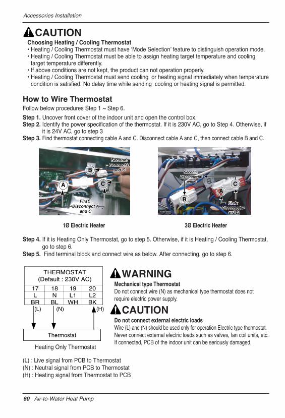
Accessories Installation
Choosing Heating / Cooling Thermostat• Heating / Cooling Thermostat must have ʻMode Selectionʼ feature to distinguish operation mode. • Heating / Cooling Thermostat must be able to assign heating target temperature and cooling
target temperature differently.• If above conditions are not kept, the product can not operation properly.• Heating / Cooling Thermostat must send cooling or heating signal immediately when temperature
condition is satisfied. No delay time while sending cooling or heating signal is permitted.
How to Wire ThermostatFollow below procedures Step 1 ~ Step 6.
Step 1. Uncover front cover of the indoor unit and open the control box.Step 2. Identify the power specification of the thermostat. If it is 230V AC, go to Step 4. Otherwise, if
it is 24V AC, go to step 3 Step 3. Find thermostat connecting cable A and C. Disconnect cable A and C, then connect cable B and C.
Mechanical type ThermostatDo not connect wire (N) as mechanical type thermostat does notrequire electric power supply.
Do not connect external electric loadsWire (L) and (N) should be used only for operation Electric type thermostat.Never connect external electric loads such as valves, fan coil units, etc.If connected, PCB of the indoor unit can be seriously damaged.
(L) : Live signal from PCB to Thermostat(N) : Neutral signal from PCB to Thermostat(H) : Heating signal from Thermostat to PCB
Heating Only Thermostat
Step 4. If it is Heating Only Thermostat, go to step 5. Otherwise, if it is Heating / Cooling Thermostat,go to step 6.
Step 5. Find terminal block and connect wire as below. After connecting, go to step 6.
Second:Second:Connect BConnect B
and Cand C
Second:Connect B
and C
First: First: Disconnect ADisconnect A
and Cand C
First: Disconnect A
and C
AB
CA
B
C
First :First :Disconnect ADisconnect A
and Cand C
Secont : Secont : Disconnect BDisconnect B
and C and C
First :First :Disconnect ADisconnect A
and Cand C
Secont : Secont : Disconnect BDisconnect B
and C and C
First :Disconnect A
and C
Secont : Disconnect B
and CAA
BB
CC
Thermostat
(L) (N) (H)
THERMOSTAT(Default : 230V AC)
17L
BR
18NBL
19L1WH
20L2BK
1Ø Electric Heater 3Ø Electric Heater
60 Air-to-Water Heat Pump
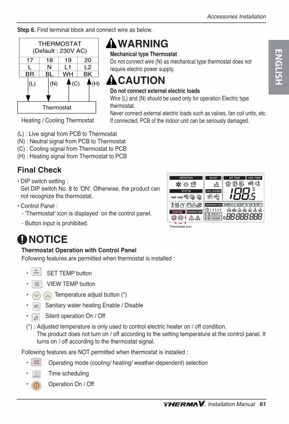
Accessories Installation
Heating / Cooling Thermostat
Final Check• DIP switch setting :
Set DIP switch No. 8 to 'ON'. Otherwise, the product cannot recognize the thermostat.
• Control Panel :- 'Thermostat' icon is displayed on the control panel.
- Button input is prohibited.
(L) : Live signal from PCB to Thermostat(N) : Neutral signal from PCB to Thermostat(C) : Cooling signal from Thermostat to PCB(H) : Heating signal from Thermostat to PCB
Step 6. Find terminal block and connect wire as below.
Mechanical type ThermostatDo not connect wire (N) as mechanical type thermostat does notrequire electric power supply.
Do not connect external electric loadsWire (L) and (N) should be used only for operation Electric typethermostat.Never connect external electric loads such as valves, fan coil units, etc.If connected, PCB of the indoor unit can be seriously damaged.
Thermostat
(L) (N) (C) (H)
THERMOSTAT(Default : 230V AC)
17L
BR
18NBL
19L1WH
20L2BK
Thermostat Icon
Thermostat Operation with Control PanelFollowing features are permitted when thermostat is installed :
• SET TEMP button
• VIEW TEMP button
• Temperature adjust button (*)
• Sanitary water heating Enable / Disable
• Silent operation On / Off
(*) : Adjusted temperature is only used to control electric heater on / off condition.The product does not turn on / off according to the setting temperature at the control panel. Itturns on / off according to the thermostat signal.
Following features are NOT permitted when thermostat is installed :
• Operating mode (cooling/ heating/ weather-dependent) selection
• Time scheduling
• Operation On / Off
ENG
LISH
Installation Manual 61
Accessories Installation
To establish sanitary water circuit, 3way valve and sanitary water tank kit is required. If solar thermalsystem is pre-installed at the installation field, solar thermal kit is required to interface solar thermalsystem – to – sanitary water tank – to –
General Informationsupports following 3way valve.
(1) : SPDT = Single Pole Double Throw. Three wires consist of Live1 (for selecting Flow A), Live 2(for selecting Flow B), and Neutral (for common).
(2) : 'Flow A' means water flow from the indoor unit to under floor water circuit.
(3) : 'Flow B' means water flow from the indoor unit to sanitary water tank.
Sanitary Water Tank and Sanitary Water Tank Kit/Solar Thermal Kit
YesSelecting “ Flow B” between“ Flow A” and “ Flow B” (3)
YesSelecting “ Flow A” between“ Flow A” and “ Flow B” (2)
230V ACSPDT3-wire
(1)
SupportedOperating ModePowerType
62 Air-to-Water Heat Pump
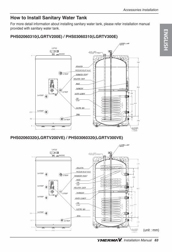
Accessories Installation
How to Install Sanitary Water TankFor more detail information about installing sanitary water tank, please refer installation manualprovided with sanitary water tank.
PHS02060310(LGRTV200E) / PHS03060310(LGRTV300E)
PHS02060320(LGRTV200VE) / PHS03060320(LGRTV300VE)
(unit : mm)
ENG
LISH
Installation Manual 63
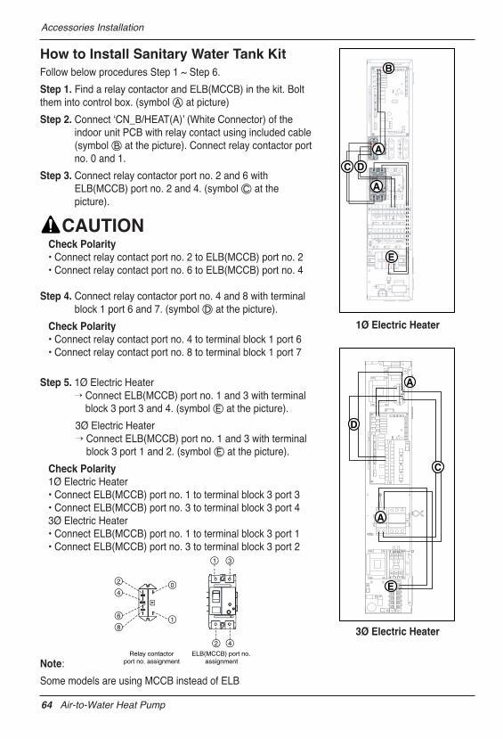
Accessories Installation
A
E
C
A
B
C D
A
E
A
D
Relay contactorport no. assignment
ELB(MCCB) port no.assignment
0
1
2
6
4
8
1 3
2 4
How to Install Sanitary Water Tank KitFollow below procedures Step 1 ~ Step 6.
Step 1. Find a relay contactor and ELB(MCCB) in the kit. Boltthem into control box. (symbol Ⓐ at picture)
Step 2. Connect ʻCN_B/HEAT(A)ʼ (White Connector) of theindoor unit PCB with relay contact using included cable(symbol Ⓑ at the picture). Connect relay contactor portno. 0 and 1.
Step 3. Connect relay contactor port no. 2 and 6 withELB(MCCB) port no. 2 and 4. (symbol Ⓒ at thepicture).
Check Polarity• Connect relay contact port no. 2 to ELB(MCCB) port no. 2• Connect relay contact port no. 6 to ELB(MCCB) port no. 4
Step 4. Connect relay contactor port no. 4 and 8 with terminalblock 1 port 6 and 7. (symbol Ⓓ at the picture).
Check Polarity• Connect relay contact port no. 4 to terminal block 1 port 6• Connect relay contact port no. 8 to terminal block 1 port 7
Step 5. 1Ø Electric Heater’ Connect ELB(MCCB) port no. 1 and 3 with terminal
block 3 port 3 and 4. (symbol Ⓔ at the picture).
3Ø Electric Heater’ Connect ELB(MCCB) port no. 1 and 3 with terminal
block 3 port 1 and 2. (symbol Ⓔ at the picture).
Check Polarity1Ø Electric Heater• Connect ELB(MCCB) port no. 1 to terminal block 3 port 3• Connect ELB(MCCB) port no. 3 to terminal block 3 port 43Ø Electric Heater• Connect ELB(MCCB) port no. 1 to terminal block 3 port 1• Connect ELB(MCCB) port no. 3 to terminal block 3 port 2
Note:
Some models are using MCCB instead of ELB
1Ø Electric Heater
3Ø Electric Heater
64 Air-to-Water Heat Pump
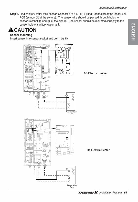
Accessories Installation
Step 6. Find sanitary water tank sensor. Connect it to ʻCN_TH4ʼ (Red Connector) of the indoor unitPCB (symbol Ⓐ at the picture). The sensor wire should be passed through holes forsensor (symbol Ⓑ and Ⓒ at the picture). The sensor should be mounted correctly to thesensor hole of sanitary water tank.
Sensor mountingInsert sensor into sensor socket and bolt it tightly.
Sanitary WaterTank
D
A B
C
Sanitary WaterTank
D
A B
C
1Ø Electric Heater
3Ø Electric Heater
ENG
LISH
Installation Manual 65
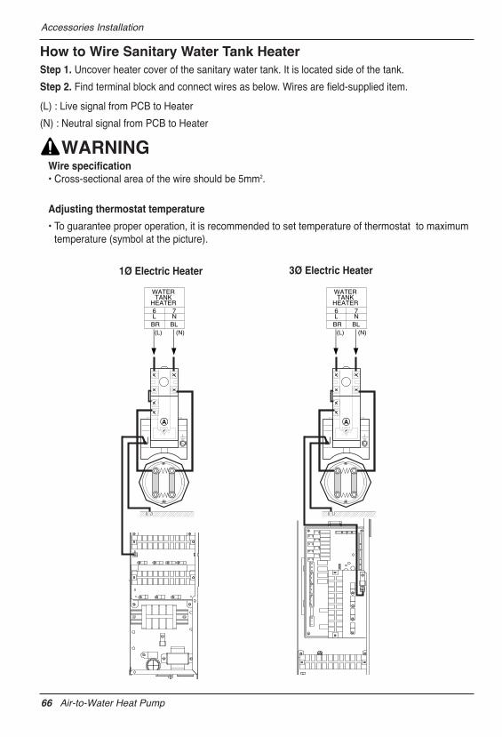
Accessories Installation
How to Wire Sanitary Water Tank HeaterStep 1. Uncover heater cover of the sanitary water tank. It is located side of the tank.
Step 2. Find terminal block and connect wires as below. Wires are field-supplied item.
(L) : Live signal from PCB to Heater
(N) : Neutral signal from PCB to Heater
Wire specification• Cross-sectional area of the wire should be 5mm2.
Adjusting thermostat temperature
• To guarantee proper operation, it is recommended to set temperature of thermostat to maximumtemperature (symbol at the picture).
(L) (N)
A
WATERTANK
HEATER
BR BL
6L
7N
(L) (N)
A
WATERTANK
HEATER
BR BL
6L
7N
1Ø Electric Heater 3Ø Electric Heater
66 Air-to-Water Heat Pump
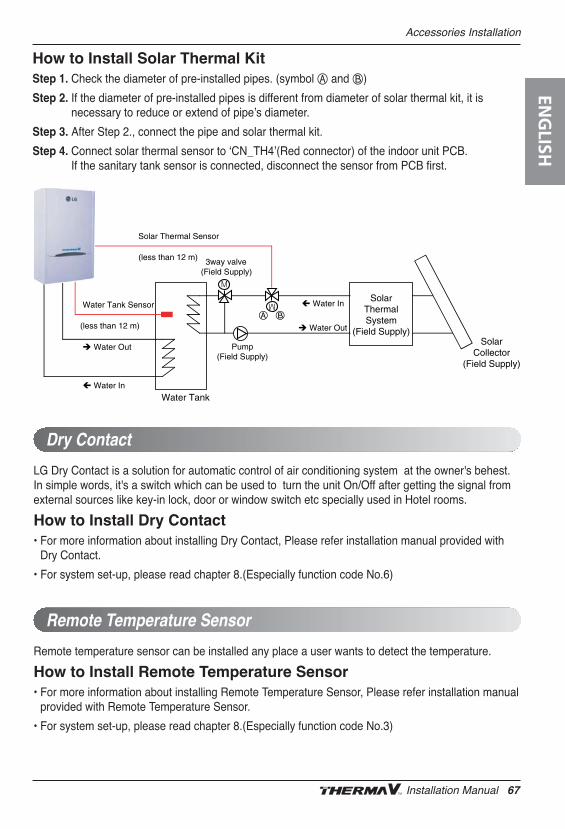
Accessories Installation
How to Install Solar Thermal KitStep 1. Check the diameter of pre-installed pipes. (symbol Ⓐ and Ⓑ)
Step 2. If the diameter of pre-installed pipes is different from diameter of solar thermal kit, it isnecessary to reduce or extend of pipeʼs diameter.
Step 3. After Step 2., connect the pipe and solar thermal kit.
Step 4. Connect solar thermal sensor to ʻCN_TH4ʼ(Red connector) of the indoor unit PCB.If the sanitary tank sensor is connected, disconnect the sensor from PCB first.
SolarThermalSystem
(Field Supply)Solar
Collector(Field Supply)
Water Tank
Water Tank Sensor
(less than 12 m)
Solar Thermal Sensor
(less than 12 m)
Water In
Water Out
Water Out
Water In
3way valve(Field Supply)
Pump(Field Supply)
LG Dry Contact is a solution for automatic control of air conditioning system at the owner's behest.In simple words, it's a switch which can be used to turn the unit On/Off after getting the signal fromexternal sources like key-in lock, door or window switch etc specially used in Hotel rooms.
How to Install Dry Contact• For more information about installing Dry Contact, Please refer installation manual provided with
Dry Contact.
• For system set-up, please read chapter 8.(Especially function code No.6)
Dry Contact
Remote temperature sensor can be installed any place a user wants to detect the temperature.
How to Install Remote Temperature Sensor• For more information about installing Remote Temperature Sensor, Please refer installation manual
provided with Remote Temperature Sensor.
• For system set-up, please read chapter 8.(Especially function code No.3)
Remote Temperature Sensor
ENG
LISH
Installation Manual 67
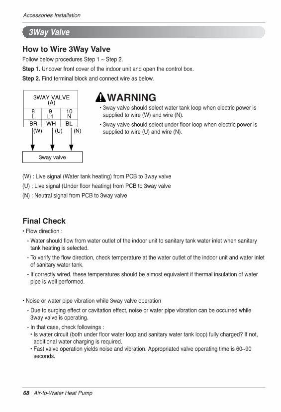
Accessories Installation
Final Check• Flow direction :
- Water should flow from water outlet of the indoor unit to sanitary tank water inlet when sanitarytank heating is selected.
- To verify the flow direction, check temperature at the water outlet of the indoor unit and water inletof sanitary water tank.
- If correctly wired, these temperatures should be almost equivalent if thermal insulation of waterpipe is well performed.
• Noise or water pipe vibration while 3way valve operation
- Due to surging effect or cavitation effect, noise or water pipe vibration can be occurred while3way valve is operating.
- In that case, check followings :• Is water circuit (both under floor water loop and sanitary water tank loop) fully charged? If not,
additional water charging is required.• Fast valve operation yields noise and vibration. Appropriated valve operating time is 60~90
seconds.
• 3way valve should select water tank loop when electric power issupplied to wire (W) and wire (N).
• 3way valve should select under floor loop when electric power issupplied to wire (U) and wire (N).
How to Wire 3Way ValveFollow below procedures Step 1 ~ Step 2.
Step 1. Uncover front cover of the indoor unit and open the control box.
Step 2. Find terminal block and connect wire as below.
(W) : Live signal (Water tank heating) from PCB to 3way valve
(U) : Live signal (Under floor heating) from PCB to 3way valve
(N) : Neutral signal from PCB to 3way valve
3Way Valve
3way valve
(W) (U) (N)
3WAY VALVE(A)
BR WH BL
8L
9L1
10N
68 Air-to-Water Heat Pump
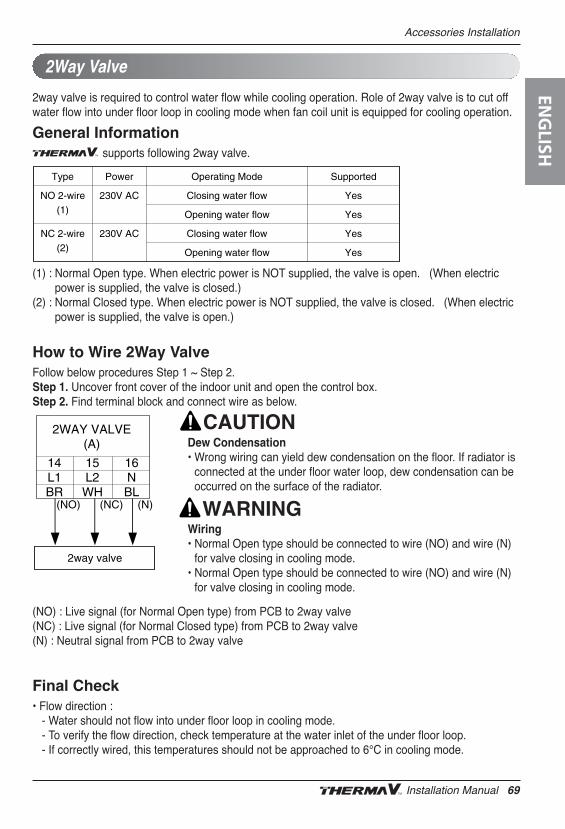
Accessories Installation
Dew Condensation• Wrong wiring can yield dew condensation on the floor. If radiator is
connected at the under floor water loop, dew condensation can beoccurred on the surface of the radiator.
Wiring• Normal Open type should be connected to wire (NO) and wire (N)
for valve closing in cooling mode.• Normal Open type should be connected to wire (NO) and wire (N)
for valve closing in cooling mode.
2way valve is required to control water flow while cooling operation. Role of 2way valve is to cut offwater flow into under floor loop in cooling mode when fan coil unit is equipped for cooling operation.
General Informationsupports following 2way valve.
(1) : Normal Open type. When electric power is NOT supplied, the valve is open. (When electricpower is supplied, the valve is closed.)
(2) : Normal Closed type. When electric power is NOT supplied, the valve is closed. (When electricpower is supplied, the valve is open.)
How to Wire 2Way ValveFollow below procedures Step 1 ~ Step 2.Step 1. Uncover front cover of the indoor unit and open the control box.Step 2. Find terminal block and connect wire as below.
(NO) : Live signal (for Normal Open type) from PCB to 2way valve(NC) : Live signal (for Normal Closed type) from PCB to 2way valve(N) : Neutral signal from PCB to 2way valve
Final Check• Flow direction :
- Water should not flow into under floor loop in cooling mode.- To verify the flow direction, check temperature at the water inlet of the under floor loop. - If correctly wired, this temperatures should not be approached to 6°C in cooling mode.
2Way Valve
YesClosing water flow230V ACNC 2-wire(2) YesOpening water flow
YesOpening water flow
YesClosing water flow230V ACNO 2-wire(1)
SupportedOperating ModePowerType
2way valve
(NO) (NC) (N)
2WAY VALVE(A)
14L1BR
15L2WH
16NBL
ENG
LISH
Installation Manual 69
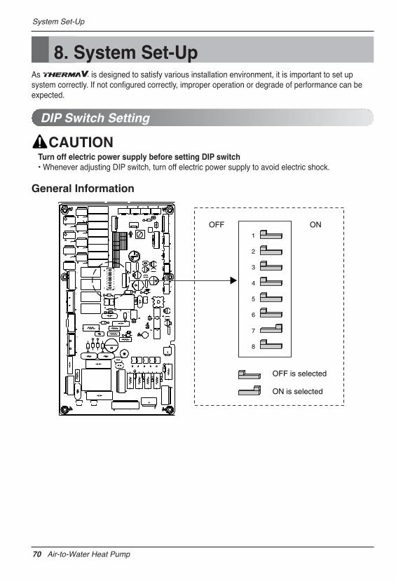
System Set-Up
8. System Set-UpAs is designed to satisfy various installation environment, it is important to set upsystem correctly. If not configured correctly, improper operation or degrade of performance can beexpected.
DIP Switch Setting
Turn off electric power supply before setting DIP switch • Whenever adjusting DIP switch, turn off electric power supply to avoid electric shock.
General Information
OFF ON 1
2
3
4
5
6
7
8
OFF is selected
ON is selected
70 Air-to-Water Heat Pump
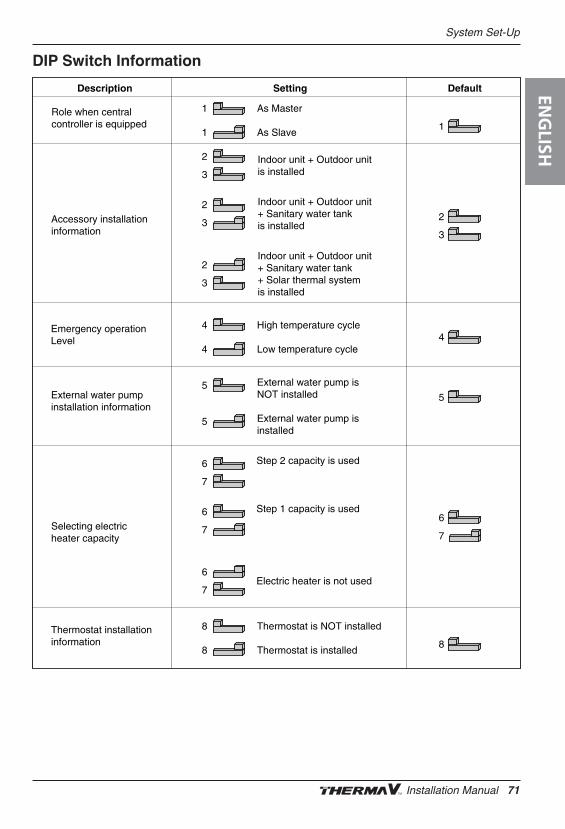
System Set-Up
DIP Switch Information
Role when centralcontroller is equipped
1
1
As Master
As Slave
Description Setting Default
Accessory installationinformation
2
3
Indoor unit + Outdoor unitis installed
2
3
Indoor unit + Outdoor unit+ Sanitary water tankis installed
2
3
Indoor unit + Outdoor unit+ Sanitary water tank+ Solar thermal systemis installed
Emergency operationLevel
4
4
High temperature cycle
Low temperature cycle
External water pumpinstallation information
5 External water pump isNOT installed
5 External water pump isinstalled
Selecting electricheater capacity
6
7
Step 2 capacity is used
Electric heater is not used
6
7
6
7
Step 1 capacity is used
Thermostat installationinformation
8
8
Thermostat is NOT installed
Thermostat is installed
1
2
3
4
5
6
7
8
ENG
LISH
Installation Manual 71
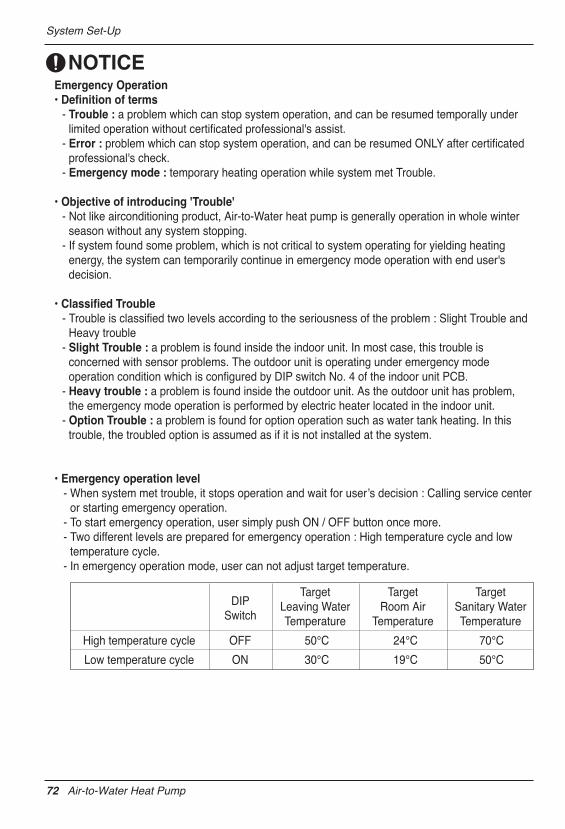
System Set-Up
Emergency Operation• Definition of terms
- Trouble : a problem which can stop system operation, and can be resumed temporally underlimited operation without certificated professional's assist.
- Error : problem which can stop system operation, and can be resumed ONLY after certificatedprofessional's check.
- Emergency mode : temporary heating operation while system met Trouble.
• Objective of introducing 'Trouble'- Not like airconditioning product, Air-to-Water heat pump is generally operation in whole winter
season without any system stopping.- If system found some problem, which is not critical to system operating for yielding heating
energy, the system can temporarily continue in emergency mode operation with end user'sdecision.
• Classified Trouble- Trouble is classified two levels according to the seriousness of the problem : Slight Trouble and
Heavy trouble- Slight Trouble : a problem is found inside the indoor unit. In most case, this trouble is
concerned with sensor problems. The outdoor unit is operating under emergency modeoperation condition which is configured by DIP switch No. 4 of the indoor unit PCB.
- Heavy trouble : a problem is found inside the outdoor unit. As the outdoor unit has problem,the emergency mode operation is performed by electric heater located in the indoor unit.
- Option Trouble : a problem is found for option operation such as water tank heating. In thistrouble, the troubled option is assumed as if it is not installed at the system.
• Emergency operation level- When system met trouble, it stops operation and wait for userʼs decision : Calling service center
or starting emergency operation. - To start emergency operation, user simply push ON / OFF button once more.- Two different levels are prepared for emergency operation : High temperature cycle and low
temperature cycle.- In emergency operation mode, user can not adjust target temperature.
High temperature cycle OFF 50°C 24°C 70°C
Low temperature cycle ON 30°C 19°C 50°C
DIPSwitch
TargetLeaving WaterTemperature
TargetRoom Air
Temperature
TargetSanitary WaterTemperature
72 Air-to-Water Heat Pump
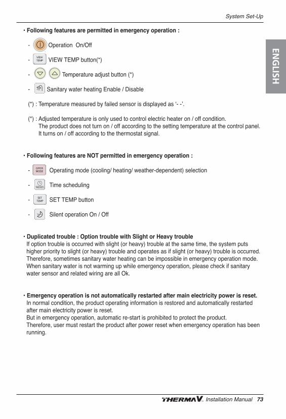
System Set-Up
• Following features are permitted in emergency operation :
- Operation On/Off
- VIEW TEMP button(*)
- Temperature adjust button (*)
- Sanitary water heating Enable / Disable
(*) : Temperature measured by failed sensor is displayed as ʻ- -ʼ.
(*) : Adjusted temperature is only used to control electric heater on / off condition.The product does not turn on / off according to the setting temperature at the control panel.It turns on / off according to the thermostat signal.
• Following features are NOT permitted in emergency operation :
- Operating mode (cooling/ heating/ weather-dependent) selection
- Time scheduling
- SET TEMP button
- Silent operation On / Off
• Duplicated trouble : Option trouble with Slight or Heavy troubleIf option trouble is occurred with slight (or heavy) trouble at the same time, the system putshigher priority to slight (or heavy) trouble and operates as if slight (or heavy) trouble is occurred.Therefore, sometimes sanitary water heating can be impossible in emergency operation mode.When sanitary water is not warming up while emergency operation, please check if sanitarywater sensor and related wiring are all Ok.
• Emergency operation is not automatically restarted after main electricity power is reset.In normal condition, the product operating information is restored and automatically restartedafter main electricity power is reset.But in emergency operation, automatic re-start is prohibited to protect the product.Therefore, user must restart the product after power reset when emergency operation has beenrunning.
ENG
LISH
Installation Manual 73
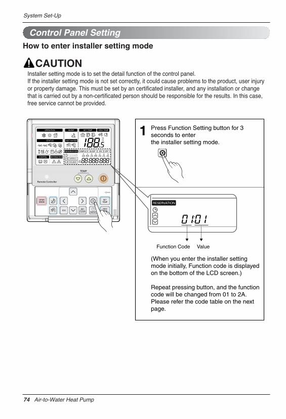
System Set-Up
Control Panel SettingHow to enter installer setting mode
Installer setting mode is to set the detail function of the control panel.If the installer setting mode is not set correctly, it could cause problems to the product, user injuryor property damage. This must be set by an certificated installer, and any installation or changethat is carried out by a non-certificated person should be responsible for the results. In this case,free service cannot be provided.
Press Function Setting button for 3 seconds to enterthe installer setting mode.
(When you enter the installer setting mode initially, Function code is displayed on the bottom of the LCD screen.)
Repeat pressing button, and the function code will be changed from 01 to 2A. Please refer the code table on the next page.
1
Function Code Value
74 Air-to-Water Heat Pump
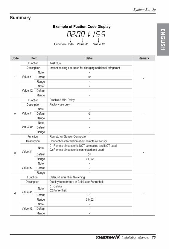
System Set-Up
Summary
Example of Fuction Code Display
Function Code Value #1 Value #2
Code Item Detail Remark
1 Value #1Note -
Default 01Range -
-
-
-
-
Value #2Note -
Default -Range -
2 Value #1Note -
Default 01Range -
Value #2Note -
Default -Range -
3
FunctionDescription
FunctionDescription
FunctionDescription
Value #1Note
Default 01Range 01~02
Value #2Note -
Default -Range -
4
FunctionDescription
Value #1Note
Default 01Range 01~02
Value #2Note -
Default -Range -
Test RunInstant cooling operation for charging additional refrigerant
Disable 3 Min. DelayFactory use only
Remote Air Sensor ConnectionConnection information about remote air sensor01:Remote air sensor is NOT connected and NOT used02:Remote air sensor is connected and used
Celsius/Fahrenheit SwitchingDisplay temperature in Celsius or Fahrenheit01:Celsius02:Fahrenheit
ENG
LISH
Installation Manual 75
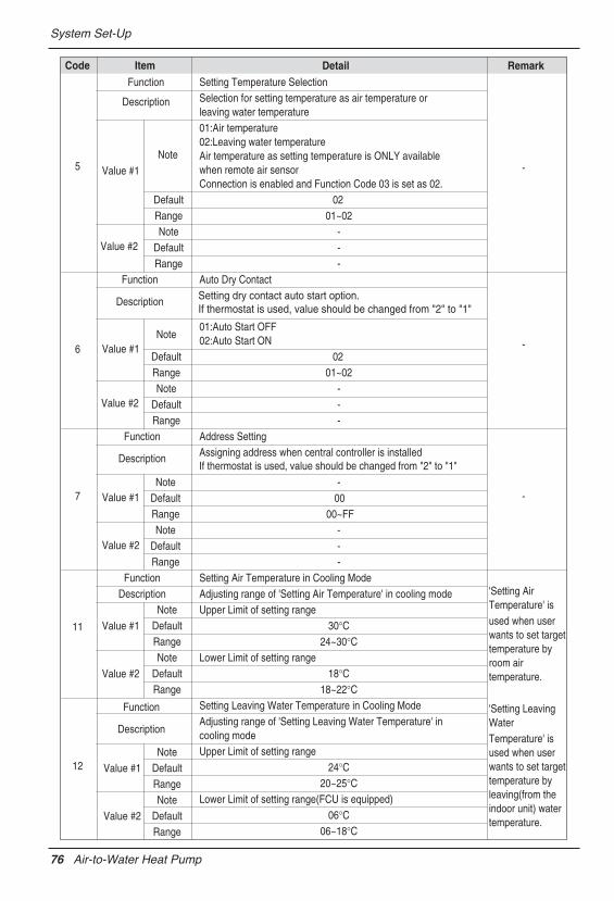
System Set-Up
5
Function
Description
Value #1Note
Default 02Range 01~02
Value #2Note -
-
-
-
Default -Range -
6
Function
Description
Value #1Note
Default 02Range 01~02
Value #2Note -
Default -Range -
7
Function
Description
Value #1Note -
Default 00Range 00~FF
Value #2Note -
Default -Range -
11
FunctionDescription
Value #1Note
Default 30°CRange 24~30°C
Value #2Note
Default 18°CRange 18~22°C
12
Function
Description
Value #1Note
Default 24°CRange 20~25°C
Value #2Note
Default 06°CRange 06~18°C
Code ItemSetting Temperature SelectionSelection for setting temperature as air temperature orleaving water temperature01:Air temperature02:Leaving water temperature Air temperature as setting temperature is ONLY availablewhen remote air sensorConnection is enabled and Function Code 03 is set as 02.
Auto Dry ContactSetting dry contact auto start option. If thermostat is used, value should be changed from "2" to "1"
01:Auto Start OFF02:Auto Start ON
Address SettingAssigning address when central controller is installedIf thermostat is used, value should be changed from "2" to "1"
Setting Air Temperature in Cooling ModeAdjusting range of 'Setting Air Temperature' in cooling modeUpper Limit of setting range
Lower Limit of setting range
Setting Leaving Water Temperature in Cooling ModeAdjusting range of 'Setting Leaving Water Temperature' in cooling modeUpper Limit of setting range
Lower Limit of setting range(FCU is equipped)
'Setting AirTemperature' is used when userwants to set targettemperature byroom airtemperature.
'Setting LeavingWater Temperature' isused when userwants to set targettemperature byleaving(from theindoor unit) watertemperature.
Detail Remark
76 Air-to-Water Heat Pump
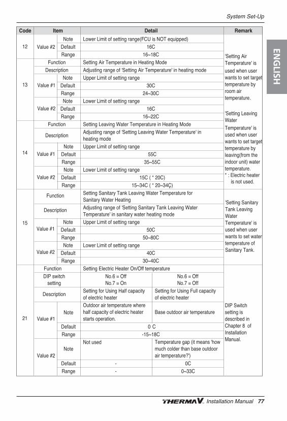
System Set-Up
12 Value #2
NoteDefault 16CRange 16~18C
13
FunctionDescription
Value #1Note
Default 30CRange 24~30C
Value #2Note
Default 16CRange 16~22C
14
Function
Description
Value #1Note
Default 55CRange 35~55C
Value #2Note
Default 15C ( * 20C)Range 15~34C ( * 20~34Ç)
15
Function
Description
Value #1Note
Default 50CRange 50~80C
Value #2Note
Default 40CRange 30~40C
21
FunctionDIP switch No.6 = Off No.6 = Off
setting No.7 = On No.7 = Off
Description
Value #1Note
Default 0 CRange -15~18C
Value #2Note
Default - 0CRange - 0~33C
Code Item
DIP Switch setting isdescribed inChapter 8 ofInstallationManual.
'Setting SanitaryTank LeavingWaterTemperature' isused when userwants to set watertemperature ofSanitary Tank.
'Setting LeavingWater Temperature' isused when userwants to set targettemperature byleaving(from theindoor unit) watertemperature.* : Electric heater is not used.
'Setting AirTemperature' is used when userwants to set targettemperature byroom airtemperature.
Lower Limit of setting range(FCU is NOT equipped)
Setting Air Temperature in Heating ModeAdjusting range of 'Setting Air Temperature' in heating modeUpper Limit of setting range
Lower Limit of setting range
Setting Leaving Water Temperature in Heating ModeAdjusting range of 'Setting Leaving Water Temperature' inheating modeUpper Limit of setting range
Lower Limit of setting range
Setting Sanitary Tank Leaving Water Temperature for Sanitary Water HeatingAdjusting range of 'Setting Sanitary Tank Leaving Water Temperature' in sanitary water heating modeUpper Limit of setting range
Lower Limit of setting range
Setting Electric Heater On/Off temperature
Setting for Using Half capacity of electric heater
Not used
Outdoor air temperature wherehalf capacity of electric heaterstarts operation.
Setting for Using Full capacity of electric heater
Base outdoor air temperature
Temperature gap (it means 'howmuch colder than base outdoorair temperature?')
Detail Remark
ENG
LISH
Installation Manual 77
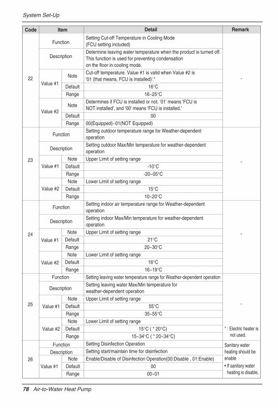
System Set-Up
22
Function
Description
Value #1
Note -
-
-
-
Default 16°CRange 16~25°C
Value #2Note
Default 00Range
23
Function
Description
Function
Description
Value #1Note
Default -10°CRange -20~05°C
Value #2Note
Default 15°CRange 10~20°C
24Value #1
NoteDefault 21°CRange 20~30°C
Value #2
NoteDefault 16°CRange 16~19°C
25
Function
Description
Value #1
NoteDefault 55°CRange 35~55°C
Value #2
NoteDefault 15°C ( * 20°C)Range 15~34°C ( * 20~34°C)
26
FunctionDescription
Value #1
NoteDefault 00Range 00~01
Sanitary waterheating should be
* : Electric heater is not used.
enable• If sanitary water
heating is disable,
Code Item
Setting Cut-off Temperature in Cooling Mode(FCU setting included)Determine leaving water temperature when the product is turned off.This function is used for preventing condensation on the floor in cooling mode.Cut-off temperature. Value #1 is valid when Value #2 is '01 (that means, FCU is installed)'."
Determines if FCU is installed or not. '01' means 'FCU is NOT installed', and '00' means 'FCU is installed.'
00(Equipped)~01(NOT Equipped)Setting outdoor temperature range for Weather-dependent operationSetting outdoor Max/Min temperature for weather-dependentoperationUpper Limit of setting range
Lower Limit of setting range
Setting indoor air temperature range for Weather-dependentoperationSetting indoor Max/Min temperature for weather-dependentoperationUpper Limit of setting range
Lower Limit of setting range
Setting leaving water temperature range for Weather-dependent operationSetting leaving water Max/Min temperature forweather-dependent operationUpper Limit of setting range
Lower Limit of setting range
Setting Disinfection OperationSetting start/maintain time for disinfectionEnable/Disable of Disinfection Operation(00:Disable , 01:Enable)
Detail Remark
78 Air-to-Water Heat Pump
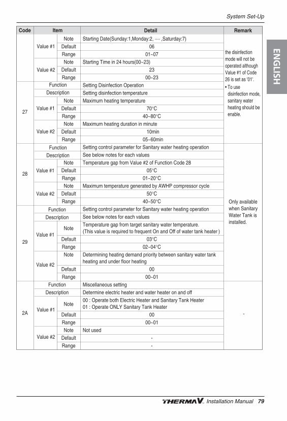
System Set-Up
NoteDefault 06Range 01~07
Value #2
Value #1
NoteDefault 23Range 00~23
27Value #1
NoteDefault 70°CRange 40~80°C
Value #2Note
Default 10minRange 05~60min
28Value #1
NoteDefault 05°CRange 01~20°C
Value #2
NoteDefault 50°CRange 40~50°C
29Value #1
Note)
Default 03°CRange 02~04°C
Value #2
Note
Default 00Range 00~01
2A
FunctionDescription
FunctionDescription
FunctionDescription
FunctionDescription
Value #1Note
Default 00Range 00~01
Value #2Note
Default -
-
Range -
the disinfectionmode will not beoperated althoughValue #1 of Code26 is set as '01'.• To use
disinfection mode,sanitary waterheating should beenable.
Code Item
Only availablewhen SanitaryWater Tank isinstalled.
Starting Date(Sunday:1,Monday:2, ···· ,Saturday:7)
Starting Time in 24 hours(00~23)
Setting Disinfection OperationSetting disinfection temperatureMaximum heating temperature
Maximum heating duration in minute
Setting control parameter for Sanitary water heating operationSee below notes for each valuesTemperature gap from Value #2 of Function Code 28
Maximum temperature generated by AWHP compressor cycle
Setting control parameter for Sanitary water heating operationSee below notes for each valuesTemperature gap from target sanitary water temperature.(This value is required to frequent On and Off of water tank heater
Determining heating demand priority between sanitary water tank heating and under floor heating
Miscellaneous settingDetermine electric heater and water heater on and off00 : Operate both Electric Heater and Sanitary Tank Heater01 : Operate ONLY Sanitary Tank Heater
Not used
Detail Remark
ENG
LISH
Installation Manual 79
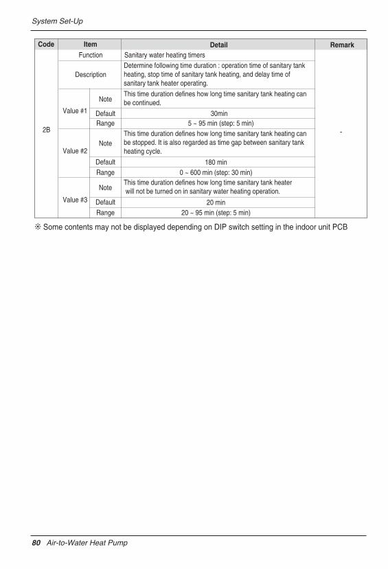
System Set-Up
Code Item
2B
Function Sanitary water heating timers
Description
Value #1
Note
DefaultRange 5 ~ 95 min (step: 5 min)
Value #2Note
Default
30min
-
Range 0 ~ 600 min (step: 30 min)180 min
Some contents may not be displayed depending on DIP switch setting in the indoor unit PCB
Determine following time duration : operation time of sanitary tank heating, stop time of sanitary tank heating, and delay time of sanitary tank heater operating.
This time duration defines how long time sanitary tank heating can be stopped. It is also regarded as time gap between sanitary tank heating cycle.
Value #3
Note
DefaultRange 20 ~ 95 min (step: 5 min)
20 min
This time duration defines how long time sanitary tank heater will not be turned on in sanitary water heating operation.
This time duration defines how long time sanitary tank heating can be continued.
Detail Remark
80 Air-to-Water Heat Pump
System Set-Up
Common Setting• Function Code 01 : Test Run
Test run should be performed when additional refrigerant charging is required. To charge therefrigerant, the product must run in Cooling mode. Test run instantly makes the product working inCooling mode for 18 minutes.
Note: • If you press any kind of button during this mode, Test Run mode will be finished.• After running 18 minutes under test run mode, system will automatically turn OFF.
• Function Code 02 : Disable 3 minute DelayFactory use only.
• Function Code 03 : Remote Air Sensor ConnectionIf user connects remote air sensor to control the product by room air temperature, the connectioninformation should be notified to the product.
Note : If remote air sensor is connected but this function code is not set correctly, the product cannot be controlled by room air temperature.
• Function Code 04 : Celsius/Fahrenheit SwitchingTemperature is displayed in Celsius or Fahrenheit.
• Function Code 05 : Setting Temperature SelectionThe product can be operated according to air temperature or leaving water temperature. Theselection for setting temperature as air temperature or leaving water temperature is determined.
Note : Air temperature as setting temperature is ONLY available when Remote Air SensorConnection is enabled and Function Code 03 is set as 02.
• Function Code 06 : Auto Dry ContactThis function allows the Dry contact-indoor unit operate under Auto Run mode or Manual modewith remote control panel.
If thermostat is used, value should be changed from "2" to "1"
• Function Code 07 : Address SettingWhen Central Controller is installed, address assigning is set by this function.
ENG
LISH
Installation Manual 81
System Set-Up
Temperature Range Setting• Function Code 11 : Setting Air Temperature in Cooling Mode
Determine cooling setting temperature range when air temperature is selected as settingtemperature.
Only available when remote air temperature sensor is connected• Accessory PQRSTA0 should be installed.• Also, Function Code 03 should be set properly.
• Function Code 12 : Setting Leaving Water Temperature in Cooling ModeDetermine cooling setting temperature range when leaving water temperature is selected as settingtemperature.
Water condensation on the floor• While cooling operation, it is very important to keep leaving water temperature higher than 16°C.
Otherwise, dew condensation can be occurred on the floor.• If floor is in humid environment, do not set leaving water temperature below 18 °C.
Water condensation on the radiator• While cooling operation, cold water may not flow to the radiator. If cold water enters to the
radiator, dew generation on the surface of the radiator can be occurred.
• Function Code 13 : Setting Air Temperature in Heating ModeDetermine heating setting temperature range when air temperature is selected as settingtemperature.
Only available when remote air temperature sensor is connected• Accessory PQRSTA0 should be installed.• Also, Function Code 03 should be set properly.
• Function Code 14 : Setting Leaving Water Temperature in Heating ModeDetermine heating setting temperature range when leaving water temperature is selected as settingtemperature.
• Function Code 15 : Setting Sanitary Tank Leaving Water TemperatureDetermine heating setting temperature range of water tank leaving water.
Only available when sanitary water tank feature is installed• Sanitary water tank and sanitary water tank kit should be installed.• DIP switch No. 2 and 3 should be set properly.
82 Air-to-Water Heat Pump
System Set-Up
Temperature Control Parameter Setting • Function Code 21 : Setting Electric Heater On/Off temperature
Using Half capacity of electric heater : when DIP Switch No. 6 and 7 is set as ʻOFF-ONʼ :- Value #1 : outdoor air temperature where half capacity of electric heater starts operation.- Value #2 : not used.- Example : If Value #1 is set as ʻ-1ʼ and DIP Switch No 6. and 7 is set as ʻOFF-ONʼ, then half
capacity of electric heater will start operation when outdoor air temperature is below -1°C andcurrent leaving water temperature or room air temperature is much belower than target leavingwater temperature or target room air temperature.
Using Full capacity of electric heater : when DIP Switch No. 6 and 7 is set as ʻOFF-OFFʼ :- Value #1 : base outdoor air temperature. - Value #2 : temperature gap (it means ʻhow much colder than base outdoor air temperature?ʼ)- Example : If Value #1 is set as ʻ-1ʼ and Value #2 is set as ʻ3ʼ and DIP Switch No 6. and 7 is set as
ʻOFF-OFFʼ, then full capacity of electric heater will start operation when outdoor air temperature isbelow -4°C (-4 = Value #1 – Value #2) and current leaving water temperature or room airtemperature is far much belower than target leaving water temperature or target room airtemperature.
• Function Code 22 : Setting Cut-off Temperature in Cooling Mode (FCU setting included)Determine leaving water temperature when the product is turned off. This function is used frpreventing condensation on the floor in cooling mode.- Value #1 : cut-off temperature. Value #1 is valid when Value #2 is ʼ01 (that means, FCU is
installed)ʼ.- Value #2 : determines if FCU is installed or not. ʼ01ʼ means ʻFCU is NOT installedʼ, and ʼ00ʼ means
ʻFCU is installed.ʼ- Example : If Value #1 is set as ʻ10ʼ and Value #2 is ʼ01ʼ and actually FCU is NOT installed in the
water loop, the product stop operation in cooling mode when the leaving water temperature isbelow 10 °C.
- Example : If Value #1 is set as ʻ10ʼ and Value #2 is ʼ00ʼ and actually FCU is installed in the waterloop, the Value #1 is not used and the product do NOT stop operation in cooling mode when theleaving water temperature is below 10 °C.
FCU Installation• If FCU is used, related 2way valve should be installed and connected to the indoor unit PCB.• If Value #2 is set as ʼ00ʼ but FCU or 2way valve is NOT installed, the product can abnormal
operation.
Function Code 23 and 24 : Setting Weather-dependent operation Mode
ENG
LISH
Installation Manual 83
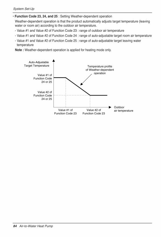
System Set-Up
• Function Code 23, 24, and 25 : Setting Weather-dependent operation
Weather-dependent operation is that the product automatically adjusts target temperature (leavingwater or room air) according to the outdoor air temperature.
- Value #1 and Value #2 of Function Code 23 : range of outdoor air temperature
- Value #1 and Value #2 of Function Code 24 : range of auto-adjustable target room air temperature
- Value #1 and Value #2 of Function Code 25 : range of auto-adjustable target leaving watertemperature
Note : Weather-dependent operation is applied for heating mode only.
Value #1 ofFunction Code 23
Auto-AdjustableTarget Temperature
Outdoorair temperature
Temperature profileof Weather-dependent
operation
Value #2 ofFunction Code 23
Value #1 ofFunction Code
24 or 25
Value #2 ofFunction Code
24 or 25
84 Air-to-Water Heat Pump
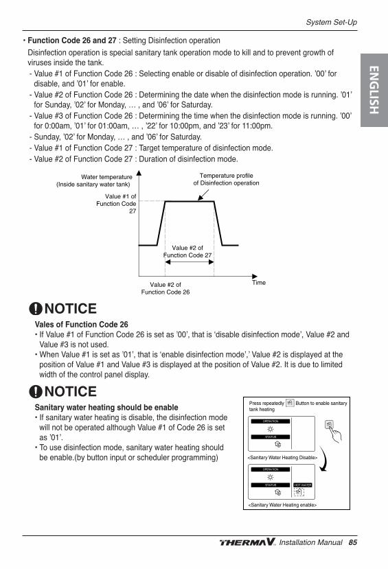
System Set-Up
• Function Code 26 and 27 : Setting Disinfection operation
Disinfection operation is special sanitary tank operation mode to kill and to prevent growth ofviruses inside the tank. - Value #1 of Function Code 26 : Selecting enable or disable of disinfection operation. ʼ00ʼ for
disable, and ʼ01ʼ for enable.- Value #2 of Function Code 26 : Determining the date when the disinfection mode is running. ʼ01ʼ
for Sunday, ʼ02ʼ for Monday, … , and ʼ06ʼ for Saturday.- Value #3 of Function Code 26 : Determining the time when the disinfection mode is running. ʼ00ʼ
for 0:00am, ʼ01ʼ for 01:00am, … , ʼ22ʼ for 10:00pm, and ʼ23ʼ for 11:00pm.- Sunday, ʼ02ʼ for Monday, … , and ʼ06ʼ for Saturday.- Value #1 of Function Code 27 : Target temperature of disinfection mode.- Value #2 of Function Code 27 : Duration of disinfection mode.
Vales of Function Code 26• If Value #1 of Function Code 26 is set as ʼ00ʼ, that is ʻdisable disinfection modeʼ, Value #2 and
Value #3 is not used. • When Value #1 is set as ʼ01ʼ, that is ʻenable disinfection modeʼ,ʼ Value #2 is displayed at the
position of Value #1 and Value #3 is displayed at the position of Value #2. It is due to limitedwidth of the control panel display.
Sanitary water heating should be enable• If sanitary water heating is disable, the disinfection mode
will not be operated although Value #1 of Code 26 is setas ʼ01ʼ.
• To use disinfection mode, sanitary water heating shouldbe enable.(by button input or scheduler programming)
TimeValue #2 ofFunction Code 26
Value #1 ofFunction Code
27
Value #2 ofFunction Code 27
Water temperature(Inside sanitary water tank)
Temperature profileof Disinfection operation
Press repeatedly Button to enable sanitary tank heating
<Sanitary Water Heating Disable>
<Sanitary Water Heating enable>
ENG
LISH
Installation Manual 85
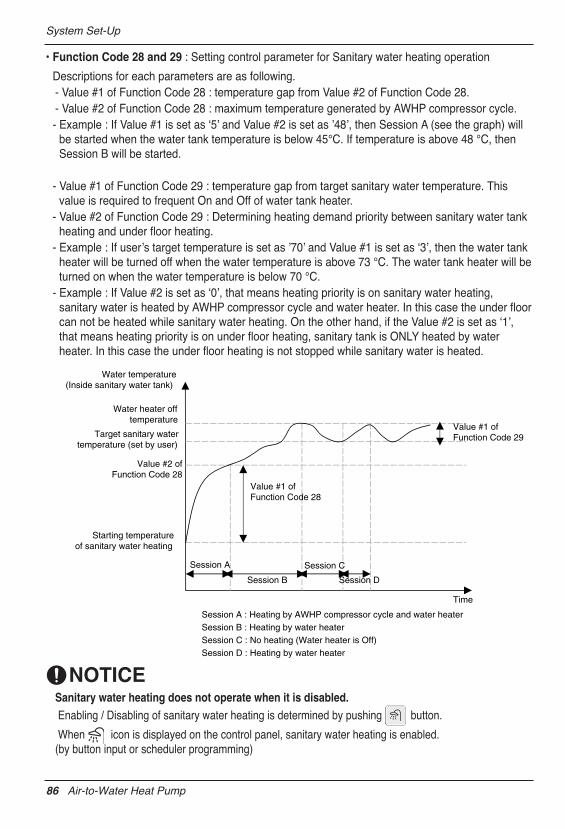
System Set-Up
• Function Code 28 and 29 : Setting control parameter for Sanitary water heating operation
Descriptions for each parameters are as following.- Value #1 of Function Code 28 : temperature gap from Value #2 of Function Code 28.- Value #2 of Function Code 28 : maximum temperature generated by AWHP compressor cycle.- Example : If Value #1 is set as ʻ5ʼ and Value #2 is set as ʼ48ʼ, then Session A (see the graph) will
be started when the water tank temperature is below 45°C. If temperature is above 48 °C, thenSession B will be started.
- Value #1 of Function Code 29 : temperature gap from target sanitary water temperature. Thisvalue is required to frequent On and Off of water tank heater.
- Value #2 of Function Code 29 : Determining heating demand priority between sanitary water tankheating and under floor heating.
- Example : If userʼs target temperature is set as ʼ70ʼ and Value #1 is set as ʻ3ʼ, then the water tankheater will be turned off when the water temperature is above 73 °C. The water tank heater will beturned on when the water temperature is below 70 °C.
- Example : If Value #2 is set as ʻ0ʼ, that means heating priority is on sanitary water heating,sanitary water is heated by AWHP compressor cycle and water heater. In this case the under floorcan not be heated while sanitary water heating. On the other hand, if the Value #2 is set as ʻ1ʼ,that means heating priority is on under floor heating, sanitary tank is ONLY heated by waterheater. In this case the under floor heating is not stopped while sanitary water is heated.
Water heater offtemperature
Time
Session A
Session B
Session C
Session D
Target sanitary watertemperature (set by user)
Starting temperatureof sanitary water heating
Session A : Heating by AWHP compressor cycle and water heaterSession B : Heating by water heaterSession C : No heating (Water heater is Off)Session D : Heating by water heater
Water temperature(Inside sanitary water tank)
Value #1 ofFunction Code 28
Value #2 ofFunction Code 28
Value #1 ofFunction Code 29
Sanitary water heating does not operate when it is disabled.Enabling / Disabling of sanitary water heating is determined by pushing button.
When icon is displayed on the control panel, sanitary water heating is enabled.(by button input or scheduler programming)
86 Air-to-Water Heat Pump
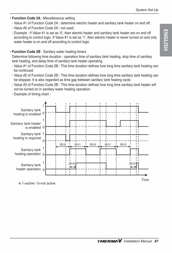
System Set-Up
• Function Code 2A : Miscellaneous setting- Value #1 of Function Code 2A : determine electric heater and sanitary tank heater on and off.- Value #2 of Function Code 2A : not used. - Example : If Value #1 is set as ʻ0ʼ, then electric heater and sanitary tank heater are on and off
according to control logic. If Value #1 is set as ʻ1ʼ, then electric heater is never turned on and onlywater heater is on and off according to control logic.
• Function Code 2B : Sanitary water heating timersDetermine following time duration : operation time of sanitary tank heating, stop time of sanitarytank heating, and delay time of sanitary tank heater operating. - Value #1 of Function Code 2B : This time duration defines how long time sanitary tank heating can
be continued.- Value #2 of Function Code 2B : This time duration defines how long time sanitary tank heating can
be stopped. It is also regarded as time gap between sanitary tank heating cycle.- Value #3 of Function Code 2B : This time duration defines how long time sanitary tank heater will
not be turned on in sanitary water heating operation.- Example of timing chart :
Sanitary tankheating is enabled
Sanitary tank heateris enabled
Sanitary tankheating is required
Sanitary tankheating operation
Sanitary tankheater operation
1=active / 0=not activeTime
2B.03 2B.03
2B.01 2B.012B.02 2B.022B.02
1
0
1
0
1
0
1
0
1
0
❈
ENG
LISH
Installation Manual 87
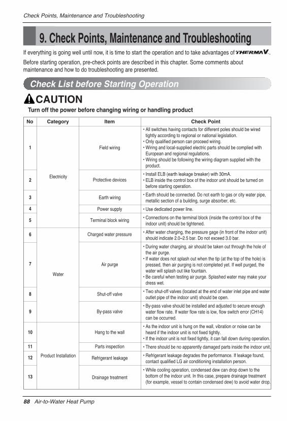
Check Points, Maintenance and Troubleshooting
9. Check Points, Maintenance and TroubleshootingIf everything is going well until now, it is time to start the operation and to take advantages of .
Before starting operation, pre-check points are described in this chapter. Some comments aboutmaintenance and how to do troubleshooting are presented.
Check List before Starting Operation
Turn off the power before changing wiring or handling product
• All switches having contacts for different poles should be wiredtightly according to regional or national legislation.
• Only qualified person can proceed wiring.• Wiring and local-supplied electric parts should be complied with
European and regional regulations.• Wiring should be following the wiring diagram supplied with the
product.
• Install ELB (earth leakage breaker) with 30mA.• ELB inside the control box of the indoor unit should be turned on
before starting operation.
• Earth should be connected. Do not earth to gas or city water pipe,metallic section of a building, surge absorber, etc.
• Use dedicated power line.
• Connections on the terminal block (inside the control box of theindoor unit) should be tightened.
• After water charging, the pressure gage (in front of the indoor unit)should indicate 2.0~2.5 bar. Do not exceed 3.0 bar.
• During water charging, air should be taken out through the hole ofthe air purge.
• If water does not splash out when the tip (at the top of the hole) ispressed, then air purging is not completed yet. If well purged, thewater will splash out like fountain.
• Be careful when testing air purge. Splashed water may make yourdress wet.
• Two shut-off valves (located at the end of water inlet pipe and wateroutlet pipe of the indoor unit) should be open.
• By-pass valve should be installed and adjusted to secure enoughwater flow rate. If water flow rate is low, flow switch error (CH14)can be occurred.
• As the indoor unit is hung on the wall, vibration or noise can beheard if the indoor unit is not fixed tightly.
• If the indoor unit is not fixed tightly, it can fall down during operation.
• There should be no apparently damaged parts inside the indoor unit.
• Refrigerant leakage degrades the performance. If leakage found,contact qualified LG air conditioning installation person.
• While cooling operation, condensed dew can drop down to thebottom of the indoor unit. In this case, prepare drainage treatment(for example, vessel to contain condensed dew) to avoid water drop.
No Category Item Check Point
1
Electricity
Field wiring
Protective devices
Earth wiring
Power supply
Terminal block wiring
Charged water pressure
Air purge
Shut-off valve
By-pass valve
Hang to the wall
Parts inspection
Refrigerant leakage
Drainage treatment
Water
Product Installation
2
3
4
5
6
7
8
9
10
11
12
13
88 Air-to-Water Heat Pump
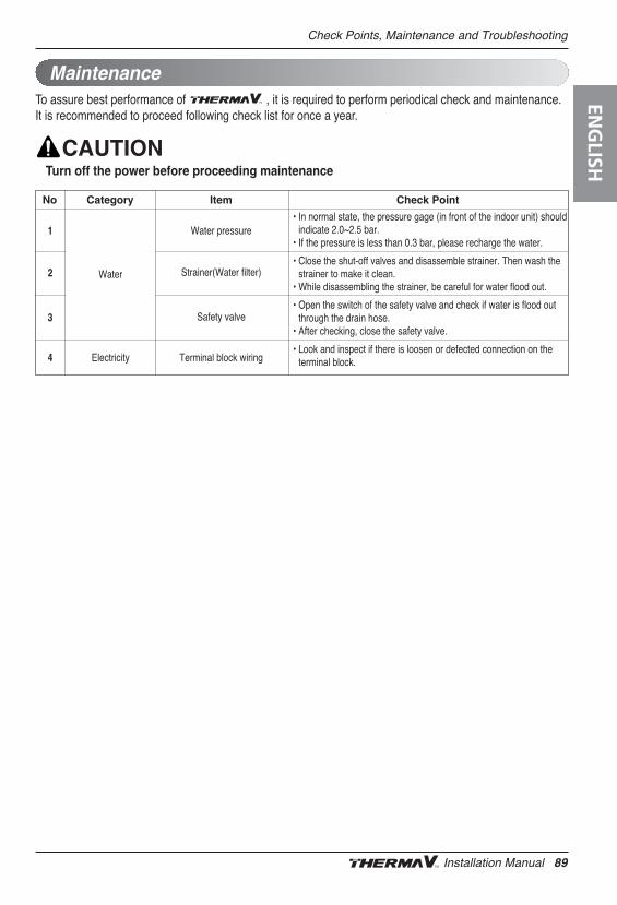
Check Points, Maintenance and Troubleshooting
To assure best performance of , it is required to perform periodical check and maintenance.It is recommended to proceed following check list for once a year.
Maintenance
Turn off the power before proceeding maintenance
• In normal state, the pressure gage (in front of the indoor unit) shouldindicate 2.0~2.5 bar.
• If the pressure is less than 0.3 bar, please recharge the water.
• Close the shut-off valves and disassemble strainer. Then wash thestrainer to make it clean.
• While disassembling the strainer, be careful for water flood out.
• Open the switch of the safety valve and check if water is flood outthrough the drain hose.
• After checking, close the safety valve.
• Look and inspect if there is loosen or defected connection on theterminal block.
No Category Item Check Point
Water
Electricity
Water pressure
Strainer(Water filter)
Safety valve
Terminal block wiring
1
2
3
4
ENG
LISH
Installation Manual 89
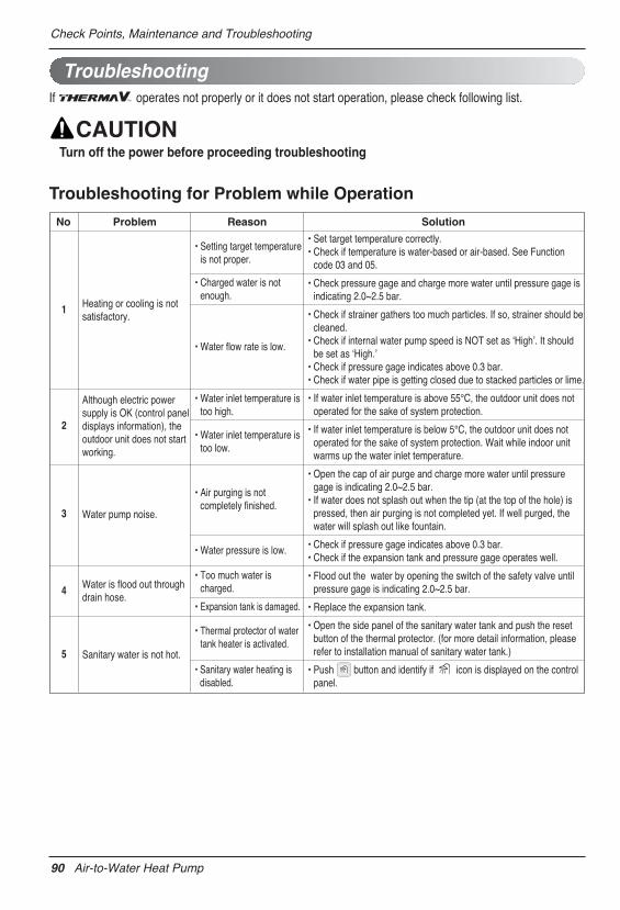
Check Points, Maintenance and Troubleshooting
If operates not properly or it does not start operation, please check following list.
Troubleshooting
Turn off the power before proceeding troubleshooting
Troubleshooting for Problem while Operation
• Set target temperature correctly.• Check if temperature is water-based or air-based. See Function
code 03 and 05.
• Check pressure gage and charge more water until pressure gage isindicating 2.0~2.5 bar.
• Check if strainer gathers too much particles. If so, strainer should becleaned.
• Check if internal water pump speed is NOT set as ʻHighʼ. It shouldbe set as ʻHigh.ʼ
• Check if pressure gage indicates above 0.3 bar.• Check if water pipe is getting closed due to stacked particles or lime.
• If water inlet temperature is above 55°C, the outdoor unit does notoperated for the sake of system protection.
• If water inlet temperature is below 5°C, the outdoor unit does notoperated for the sake of system protection. Wait while indoor unitwarms up the water inlet temperature.
• Open the cap of air purge and charge more water until pressuregage is indicating 2.0~2.5 bar.
• If water does not splash out when the tip (at the top of the hole) ispressed, then air purging is not completed yet. If well purged, thewater will splash out like fountain.
• Check if pressure gage indicates above 0.3 bar.• Check if the expansion tank and pressure gage operates well.
• Flood out the water by opening the switch of the safety valve untilpressure gage is indicating 2.0~2.5 bar.
• Replace the expansion tank.
• Open the side panel of the sanitary water tank and push the resetbutton of the thermal protector. (for more detail information, pleaserefer to installation manual of sanitary water tank.)
• Push button and identify if icon is displayed on the controlpanel.
No Problem Reason Solution
Heating or cooling is notsatisfactory.
Although electric powersupply is OK (control paneldisplays information), theoutdoor unit does not startworking.
Water pump noise.
Water is flood out throughdrain hose.
Sanitary water is not hot.
• Setting target temperatureis not proper.
• Charged water is notenough.
• Water inlet temperature istoo high.
• Water inlet temperature istoo low.
• Air purging is notcompletely finished.
• Water pressure is low.
• Too much water ischarged.
• Expansion tank is damaged.
• Thermal protector of watertank heater is activated.
• Sanitary water heating isdisabled.
• Water flow rate is low.
1
2
3
4
5
90 Air-to-Water Heat Pump
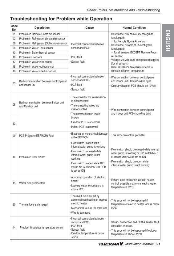
Check Points, Maintenance and Troubleshooting
Troubleshooting for Problem while Operation
01 Problem in Remote Room Air sensor
02 Problem in Refrigerant (Inlet side) sensor
06 Problem in Refrigerant (Outlet side) sensor
08 Problem in Water Tank sensor
13 Problem in Solar-thermal sensor
16 Problems in sensors
17 Problem in Water-inlet sensor
18 Problem in Water-outlet sensor
19 Problem in Water-interlim sensor
03Bad communication between control panel and indoor uni
05Bad communication between Indoor unit and Outdoor unit
53
09 PCB Program (EEPROM) Fault
14 Problem in Flow Switch
15 Water pipe overheated
20 Thermal fuse is damaged
44 Problem in outdoor temperature sensor.
• Incorrect connection betweensensor and PCB
• PCB fault
• Sensor fault
• Incorrect connection betweensensor and PCB
• PCB fault
• Sensor fault
• The connector for transmissionis disconnected
• The connecting wires aremisconnected
• The communication line isbroken
• Outdoor PCB is abnormal
• Indoor PCB is abnormal
• Electrical or mechanical damagea the EEPROM
• Flow switch is open whileinternal water pump is working
• Flow switch is closed whileinternal water pump is notworking
• Flow switch is open while DIPswitch No. 5 of indoor unit PCBis set as ON
• Abnormal operation of electricheater
• Leaving water temperature isabove 72°C
• Thermal fuse is cut off byabnormal overheating of internalelectric heater
• Mechanical fault at the rmal fuse
• Wire is damaged
• Incorrect connection betweensensor and PCB
• PCB fault• Sensor fault• Outdoor temperature is below
-25℃.
• If there is no problem in electric heatercontrol, possible maximum leaving watertemperature is 62°C.
• This error will not be happened iftemperature of electric heater tank is below90°C.
• Sensor connection and PCB & sensor faultshould be checked.
• This error will not be happened if outdoortemperature is above -25℃.
• Resistance: 10k ohm at 25 centigrade(unplugged)’ for Remote Room Air sensor
• Resistance: 5k ohm at 25 centigrade(unplugged) ’ for all sensors EXCEPT Remote RoomAir sensor
• Voltage: 2.5Vdc at 25 centigrade (plugged)(for all sensors)
• Refer resistance-temperature table tocheck in different temperature
• Wire connection between control paneland indoor unit PCB should be tight
• Output voltage of PCB should be 12Vdc
• Wire connection between control paneland indoor unit PCB should be tight
• This error can not be permitted
• Flow switch should be closed while internalwater pump is working or DIP switch No. 5of indoor unit PCB is set as ON
• Flow switch should be open whileinternal water pump is not working
Code Description Cause Normal ConditionNo. EN
GLISH
Installation Manual 91

92 Air-to-Water Heat Pump