Embed Size (px)
Citation preview

Engineers India Limited
Design Aspects of CTL Process With High Ash Indian Coal: An Efforts Towards Development of
CTL Technology
GASIFICATION INDIA 2017, NEW DELHI6 - 7 December 2017

11 December 2017 2
CTL process: aspects of technology components
CTL Technology developments efforts Methodology Experimental facilities/pilot plants Demonstration plant Operating results/observations
Summary
Overview of Coal to Liquids

11 December 2017 3
Coal to liquids (Transportation liquids)
3
Direct coal liquefaction
• High efficiency potential• No aromatics, high-octane gasoline,
low-cetane diesel • Products w/ higher energy density• Water & air emissions issues • Higher operating expenses• Suitable with low ash coal
• Mature & established but complex, less efficient
• Low-octane gasoline, ultra-clean diesel • CO2 capture & power co-production • Use existing refining technologies• Meet all current & projected
specifications for sulfur & aromatic
Indirect coal liquefaction

11 December 2017 4
Incentives of CTL Technology Developments
Coal is relatively more abundant than oil and gas Technologically Feasible Significant advancements made over the years and undergoing major
improvements currently
Economics At present not encouraging but Capital and operating costs – downward trends Expected to be more profitable in the rising prices of oil & gas scenario
CTL is an umbrella term for a group of technologies Varieties of feeds stock > syngas > polygeneration Energy security/ expanding energy basket

11 December 2017 5
PRODUCT FLEXIBILITY OF SYNGAS

11 December 2017 6
CHEMICALS
Chemical CO/H2 Atom selectivity
Methanol 1 / 2 100Acetic acid 1 / 1 100Ethylene glycol
2 / 3 100
Acetic anhydride
1 / 1 85
Propionic acid
3 / 4 80
Methacrylic acid
4 / 5 73
Ethanol 1 / 2 72Acetaldehyde 2 / 3 71Ethyl acetate 2 / 3 71Vinyl acetate 4 / 5 70Ethene 1 / 2 44
Fuels from syngas- combustion energy content of a product per unit volume is an important economic parameter
Chemicals from syngas- generally sold by weight
for their chemical performance., atom is an important first factor to discriminate between the various chemicals to be produced from syngas

11 December 2017 7
REPORTED COMMECIAL USE OF SYNGAS
Largest - Manufacture of H2, more than half of which is used in the synthesis of ammonia.
The second largest - in the synthesis of methanol.
The third largest- conversion to paraffins, olefins and oxygenates via the Fischer-Tropsch reaction.
The fourth largest- the hydroformylation OXO reaction.
The use of syn gas in the generation of electricity via IGCC has the potential for considerable growth.

11 December 2017 8
CTL through ICLFour Major Steps Gasification: Coal preparation, Coal Gasification, Syngas Cooling, Particulate
Control Syngas Purification: Ammonia Scrubbing, Mercury Removal, Acid Gas Removal,
CO2 Management FT synthesis: Catalysts, Reactors (LTFT/HTFT), Water Separations/Product
Recovery Product upgradation: Hydrocracking, Hydrotreating, Isomerisation, etc.
11 December 2017 9
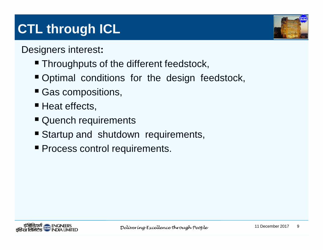
CTL through ICLDesigners interest: Throughputs of the different feedstock,Optimal conditions for the design feedstock,Gas compositions, Heat effects,Quench requirements Startup and shutdown requirements, Process control requirements.

11 December 2017 10
Problem due to high ash coals
• Erosions of equipment and boiler parts
• Difficulty in pulverization,
• Poor emissivity, poor flame temperature. Low irradiative transfer, more unburnt carbons.
• Excessive amount of fly ash and bottom ash,
• Lower combustion efficiency,
• Increase ash resistivity due to higher amounts of silica and alumina, reduction in ESP efficiency,
• Increased emissions
11 December 2017 11
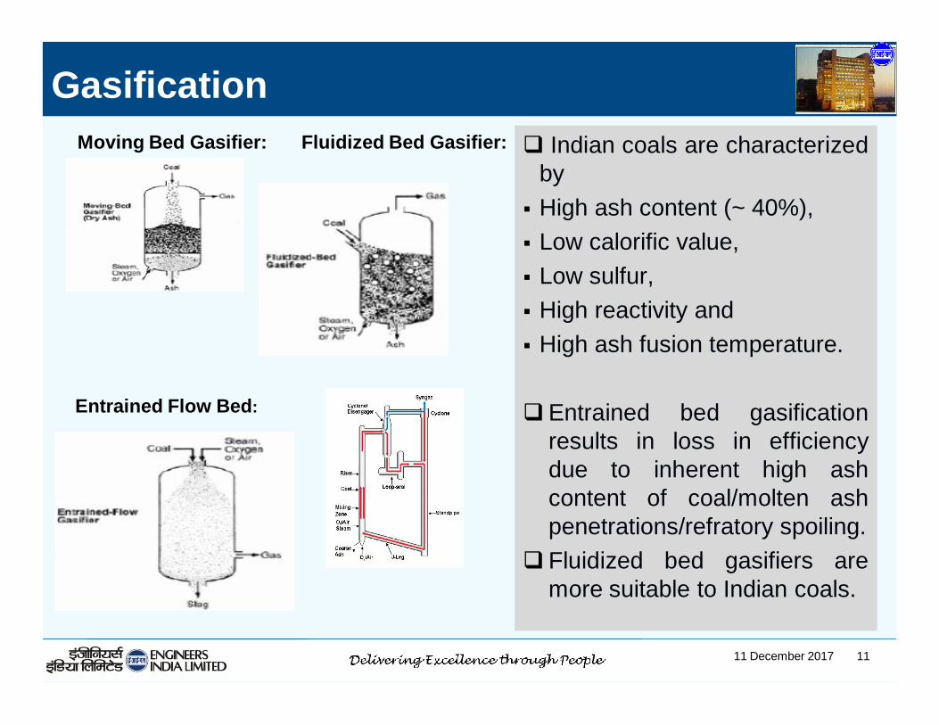
Moving Bed Gasifier:
Entrained Flow Bed:
Fluidized Bed Gasifier:
Gasification Indian coals are characterized
by High ash content (~ 40%), Low calorific value, Low sulfur, High reactivity and High ash fusion temperature.
Entrained bed gasificationresults in loss in efficiencydue to inherent high ashcontent of coal/molten ashpenetrations/refratory spoiling.
Fluidized bed gasifiers aremore suitable to Indian coals.

11 December 2017 12
Key Issues with Gasifiers Kinetics (shrinking core?) Kinetic/equilibrium
controlled? Operating P, Temp Coal/gas contact Syn gas compositions Sizing of the gasifier Effects of feed variations Material of construction Engineering Aspects Scale-up
GasificationExothermic:
• Partial Combustion of CarbonC + 0.5O2 ↔ CO; ΔH0
298 = -110.5 kJ/mol
• Complete Combustion of CarbonC + O2 ↔ CO2, ΔH0 298 = -393.5 kJ/mol
• Water Gas Shift ReactionCO + H2O ↔ CO2 + H2, ΔH0 298 = -283.0 kJ/mol
• MethanationC + 2H2 ↔ CH4
ΔH0 298 = -74.5 kJ/molCO + 3H2 ↔ CH4 + H2O, ΔH0 298 = -205.8 kJ/mol
Endothermic:• Boudard ReactionC + CO2 ↔ 2CO, ΔH0 298 = +172.5 kJ/mol
• Steam Reforming ReactionC + H2O ↔ CO + H2, ΔH0 298 = +131.3 kJ/mol
• Liberation of Bound Hydrogen2H ↔ H2 , ΔH0 298 = +431.0 kJ/mol
Gasifier GasComposition
(Vol %)
H2 25 - 30CO 30 - 60CO2 5 - 15H2O 2 - 30CH4 0 – 5H2S 0.2 - 1COS 0 - 0.1N2 0.5 - 4Ar 0.2 - 1
NH3 + HCN 0 -0.3
Ash/Slag/PM
CoalO2/AirSteam

11 December 2017 13
Contaminants in Syngas/Allowable ConcElement Conc in Coal Species Conc in Syngas
S 0.3 – 3.6 wt% H₂S, COS, CS₂ 750-7000 ppmv as H₂S and 25-200 ppmv as COS
N 1.1 – 1.6 wt% NH₃, HCN 50-800 ppmv as NH₃Cl 0.003 – 0.37 wt% HCl, metal chlorides 170-830 ppmv as HClHg 0.02 – 1 μg/g Hg (g) , Hg(CH3)2 1.3-63 ppbv
As 0.5 – 80 μg/g As2 (g) As4 (g) , AsH3 (g)AsS (g)
84-1300 ppbv
Se 0.2 – 1.6 μg/g H₂Se (g) 32-2600 ppbv
Cd 0.1 – 3 μg/g Cd (g) , CdS(condensed), CdCl2 (g)
11-340 ppbv
Application Catalyst/Constraint S CO2 Other PoisonPower Environmental/Engineering ≤ 40 ppmHydrogen Cr/Fe; Zn/Cu; Co/Mo ≤ 0.1 ppm ClAmmonia Ni; Cr/Fe; Zn/Cu ≤ 0.1 ppm ≤ 10 ppm Cl, Hg, As
SNG Cr/Fe; Zn/Cu; Ni ≤ 0.1 ppm Cl, Hg, As
Fischer-Tropsch Co; Fe ≤ 0.1 ppm

11 December 2017 14
F-T Synthesis
F-T Reactor(Cat: Co/Fe)
Available Technology: Fixed bed/Fluidized bed/Slurry bed
Synthesis Gas
CO hydrogenation nCO + 2nH2
Water gas shift CO + H2O
Methanation CO + 3H2
Syncrude (Long chain aliphatic HC, mainly n-paraffins)
(-CH2-)n + nH2O -152 kJ/mol
H2 + CO2 - 41 kJ/mol
H2O + CH4 -206 kJ/mol
xH2+yCO(-CH2-)n
180-350oC20-35 bar

11 December 2017 15
Slurry Reactor Very high heat transfer rate High conversion per pass Higher catalyst activity with better
selectivity Catalyst regeneration by continuous purge
and feed Uniform temperature distribution Difficult to separate catalyst and Product
FT Reactor Types
Fixed Bed Reactor (FB) Multitubular design Diameter limited by slow heat
removal Good for heavy liquid & waxes conversion per pass is limited,
difficult to replace deactivated catalyst

11 December 2017 16
Product Refining
ProductRefining
Long chain waxy HC Naphtha, Kero, Diesel, Waxes(-CH2-)n
Hydroprocessing Section Hydroisomerisation / hydrocracking of n-paraffins to iso-paraffins
of desired length & boiling range Mild hydrocracking at 300-350 deg C & 30-50 bar Reactivity increases with increasing number of paraffins Maximum yield of middle distillates Minimum yield of C4 & lighters
Distillation Section Conventional distillation for product fractionation
Gas Processing & Wax Finishing as necessary

11 December 2017 17
CTL Technology Development Efforts
EIL-BPCL-THERMAX-CHT

11 December 2017 18
CTL Technology Development Approach
GASIFIER SECTION
TGAPILOT GASIFIEROPERATING DATAGASIFIER MODELDESIGN METHOD
GAS CLEAN INGSECTION
PILOT PLANTOPERATING DATANOVEL SCHEMEDESIGN METHOD
FT SECTION
CATALYST DEVMICRO REACTORKINETIC DATACOLD FLOW/CFD MODELREACTOR MODELDESIGN METHOD
DEMO PLANT
INTEGRATE A+B+CFOR LARGE CAPACITYPROCESS PACKAGEENGINNERINGPROCUMENTCOMMISIONING

11 December 2017 19
Pilot plants and mathematical tools
HPTGA Gasifier unit Syngas cleaning unit Cold stand Slurry column Facilities for catalyst formulations/testing Batch reactor/fixed bed/continuous for catalyst testing/FT
kinetics
Mathematical model Gasifier Slurry bubble FT reactor CFD model of SBCR

11 December 2017 20
Gasification Studies: Kinetics Using HPTGA
HPTGA along with MS for gas analysis have been installedat EIL-R&D complex Design pressure: 50 bar Design temp: 11000C
Various type of coal viz. high ash coal, lignite, petcoke are being studied
Objectives: Investigations of coal gasification reactions at high
pressure, high temperature, high ash coal Insights to Coal gasification ‘reactivity’

11 December 2017 21
HPTGA + MS Expt. Setup at EIL, R&D Lab
GAS DOSING SYSTEM
P, T CONTROL &
SAFETY SYSTEMMICROBALANCE
SYSTEM
MS FOR ONLINEANALYSIS

11 December 2017 22
Mathematical Modeling of Gasifier
Issues of FBG at High Pressure Complex hydrodynamics
Complex reaction kinetics (impact of ash
layer not known)
Kinetics at high pressure
Multiphase, multi-component reactor
modeling- solution is a challenge

11 December 2017 23
Model Predictions

11 December 2017 24
A coal gasification fluidized bed plant is designed and installed at EIL-R&D center Capacity: 150 kg/h O2 purity: 93% by volume
The plant consists of Coal crushing & feeding system High pressure gasifier with ash removal system Cyclones Syngas cooling systems Ash disposal system Air separation unit, etc.
Gasifier Pilot Plant (FB Type)

11 December 2017 25
Gasifier: 200mm ID, 11000mm heightCapacity: 150 kg/h high ash coal, 25 m Structural height
Syn gas clean up21m structural height
Enclosed ground flare, 35 m
Gasifier And Syngas cleanup at EIL-R&D Gurgaon complex:

11 December 2017 2626
Pilot Gasifier: Issues being addressed Process Design Coal Characterization and kinetics Estimation of process parameters (T,P,C/O2, C/Steam, Flux etc) Gasifier sizing (dia, height) Quench System Cyclone Deep leg/j leg
Mechanical Design Coal preparation unit Feed injection system Ash/Solid removal Loop seal Distributor Exchangers

11 December 2017 27
Operation was planned stepwise Combustion Gasification
Air mode Gradual rise of pressure
Enriched O2 Gradual rise of pressure
O2& Steam Gradual rise of pressure
Gasifier operation Strategy

11 December 2017 28
SYN GAS FLARED IN GROUND FLARE WITH BLUE FLAME
Gasification experiments(Air mode)

11 December 2017 29
Gas Cleaning: Removal of H2S, COS, HCN, CO2, NH3, Particulates.
Basis: Adoption of Conventional Technologies & Novel Processes
Pilot facilities created for syngas clean up Water scrubber with EIL’s proprietary structured packing HCN/COS Converter AGR unit
Syngas Cleaning

11 December 2017 30
Syngas Cleaning Pilot Plant Capacity: 350 Nm3/hOperating pressure: 30 bar

11 December 2017 31
Catalysts & Kinetics (Iron/Cobalt based)
Hydrodynamics of SBCR (Pilot plant/CFD studies)
Development of mathematical model for SBCR
Conversion/Yield and selectivity/Sizing of reactors
FT Technology Development Approach

11 December 2017 32
Flow Regime/scale up issues

11 December 2017 33
SBCR Pilot Plant at EIL, R&D

11 December 2017 34
Gas holdup & distribution of small and large bubbles affectedby various parameters
Superficial gas velocity Pressure Gas density Physical properties of liquid Solid concentration Reactor size Types of gas distributors
Effects of Various Parameters on Gas Holdup

11 December 2017 35
SBCR FT Reactor Modeling
Reactions:Paraffins: nCO + (2n+1)H2 → CnH2n+2 + nH2O
Olefins: nCO + 2nH2 → CnH2n+ nH2O
Water gas shift : H2O + CO ↔ CO2 + H2
Kinetics ( in-house with Co/Fe)
Hydrodynamics (pilot plant, CFD)
Target: The model can be used for • Design reactor• Optimization & scale up• Trouble shooting• Control

11 December 2017 36
FT Reactor Model : Syngas Conversion
Comparison of Model OutputLit Model
Reactor details
Reactor diameter (DT), m 7 7
Dispersion height (H), m 30 30
Vertical cooling tube dia, mm 50 50
No of tubes 6000 5300
Operating conditions
Temp, 0C 240 240
Pressure (P), bar 30 30

11 December 2017 37
BDEP of a Demonstration UnitBroad aim Reasonably large size/integrating all the components. Locate near to a refinery site In long term demonstration of key components and
carrying out wider range of experiments
BDEP/ capacity 1700 TPD high ash coal being prepared alongwith costing to demonstrate the technology and to understandthe missing links if any

11 December 2017 38
CTL is an option for clean transport fuels will be attractivethrough technological advancement and reducedavailability of oil and gas.
Although CTL is known, still there several issues of designwith high ash coal need to be assessed in Indian context.
There are various technical components in CTL Processviz. coal gasification , syngas cleaning, FT synthesis andproduct upgradation.
Experience of CTL with high ash coal is emerging. Thereare various issues to be experienced or to be assessedexperimentally specially with gasification.
EIL, BPCL, Thermax Ltd and CHT are engaged indeveloping CTL Technology based on high ash Indian coal.
Summary

11 December 2017 39
Various sizes of experimental facilities have been createdfor gasification, syngas clean up, FT synthesis at EIL,R&Dand BPCL,R&D to address various issues of design.
Based on both experimental and Mathematical models it isplanned to develop the complete CTL technology.
Setting up a demonstration plant of capacity ~1700 TPDhigh ash coal is being assessed towards demonstrationand commercialization of CTL unit
It is hoped that numbers of offshoots technology will beuseful and also will open several research front.
Moreover syngas (an umbrella feed) will remain an answerto the chemicals, power, H2, SNG in crisis of gas/oilavailability and will add flexibility in energy basket
Conclusions…

11 December 2017 40
www.engineersindia.com
Thank You

11 December 2017 41
DCL Vs ICL

11 December 2017 42
Syngas Cleaning & Conditioning
42

11 December 2017 43
CTL Technology Components/Development Approach
CoalC, H, N, S, O,
Metals (Fe,Ni,Na etc)Ash
GASIFIERC + 1/2 O2 = COC + O2 = CO2C + 2H2 = CH4
CO + H2O = H2 + CO2
GASIFIER SECTION
TGAPILOT GASIFIEROPERATING DATAGASIFIER MODELDESIGN METHOD
SYN GASH2COCO2H2OCH4
H2SCOS N2Ar
NH3 + HCN Ash/Slag/PM
Gas Cooling& Cleaning
FISCHER-TROPSCH REACTOR
CO+2H2->-(CH2)- +H2OCO+3H2->CH4 +H2OH2 + CO = CO2 + H2
PRODUCT UPGRAD/SEPPHYCAL SEP
Air/O2
STEAMPowerMP/LP
LPGNAPTHADIESEL
FGC2/C3
GAS CLEAN SECTIONPILOT PLANTOPERATING DATANOVEL SCHEMEDESIGN METHOD
FT SECTION
CATALYST DEVMICRO REACTORKINETIC DATACOLD FLOW/CFD MODELREACTOR MODELDESIGN METHOD
DEMOPLANT
INTEGRATE A+B+CFOR LARGE CAPACITYPROCESS PACKAGEENGINNERINGPROCUMENTCOMMISIONING
COMPETITIVETECHNOLOGY
LOOK BACK FOR UPGRADATION
CO2H2OH2S
COS NH3 + HCN Ash/Slag/PM