Embed Size (px)
Citation preview
Engineers Australia
Engineering Heritage Victoria
Nomination
Engineering Heritage Australia Heritage Recognition Program
for the
INTERSCAN Microwave Landing
System, Melbourne, Victoria
February 2013

2
Front Cover Photograph Caption
This photo shows two of the different INTERSCAN MLS Elevation Antennas1
which were components of the prototype INTERSCAN landing system located
at Melbourne International Airport in Tullamarine. This photograph was taken
in 1977.
Image: Civil Aviation Historical Society’s collection.
1 The plural of antenna adopted in this document is antennas. Both Collins and Oxford Dictionaries suggest
that antennas is the correct plural expression for radio aerials whereas antennae is correct for botanical
applications.

3
TABLE OF CONTENTS
PAGE
Table of Contents 3
1 Introduction 5
2 Heritage Nomination Letter 6
3 Heritage Assessment 7
3.1 Item Name 7
3.2 Other/Former Names 7
3.3 Location of Prototype 7
3.4 Address of Prototype 7
3.5 Suburb/Nearest Town of Prototype Installation 7
3.6 State 7
3.7 Local Govt. Area of Prototype Installation 7
3.8 Location of Interpretation Panel 7
3.9 Owner 7
3.10 Current Use 7
3.11 Former Use 7
3.12 Designer 7
3.13 Maker/Builder 8
3.14 Year Started 8
3.15 Year Completed 8
3.16 Physical Description 8
3.17 Physical Condition 8
3.18 Historical Notes 8
3.19 INTERSCAN Currently 11
3.20 Heritage Listings 13
3.20.1 Commonwealth Heritage List 13
4 Assessment of Significance 14
4.1 Historical significance 14
4.2 Historic Individuals or Association 15
4.3 Creative or Technical Achievement 15
4.4 Research Potential 16
4.5 Social 16
4.6 Rarity 17
4.7 Representativeness 17
4.8 Integrity/Intactness 17
5 Statement of Significance 18
5.1 INTERSCAN Historical Significance 18
4
5.2 Civil Aviation Historical Society 18
6 Area of Significance 19
7 Interpretation Plan 20
7.1 General Approach 20
7.2 General Attributes of the Possible Interpretation Panel 22
7.3 The Interpretation Panel 23
7.4 Preliminary Text Blocks for Interpretation Panel 24
8 References 25
Acknowledgements 26
Appendix 1: Location of the INTERSCAN System 27 Appendix 2: Timeline for Air Services Responsibility in Australia 31
Appendix 3: Historic Individuals or Associations 32
Appendix 4: An Introduction to Microwave Landing Systems (MLS) 50
Appendix 5: Glossary of Terms 52
Appendix 6: Press release from Thales 55
Appendix 7: Additional Photographs 57
5
1 Introduction
The INTERSCAN, which is short for Time INTERval SCANning) Microwave
Landing System (MLS) was an Australian-developed technology created in
response to a competition devised by the International Civil Aviation Organisation
(ICAO) and administered by the All Weather Operational Panel (AWOP) to find a
replacement for the then current Instrument Landing System (ILS). The INTERSCAN
system through superior design and technological diplomacy was accepted as the
world standard technology for assisted landing in 1978 and is still being installed and
used in airports around the world such as Heathrow Airport.
Despite the success of the technology on the international stage, in relatively recent
history little has been done to acknowledge the significance of the system. The
technology has mostly fallen out of the public’s interest and the prototype equipment,
at Melbourne International Airport has been left exposed to the elements with little
care for its historical value.
This Nomination for Engineers Heritage listing should lead to greater public
awareness and possible recognition with other heritage recognising bodies, allowing
this Australian achievement to be remembered for posterity.
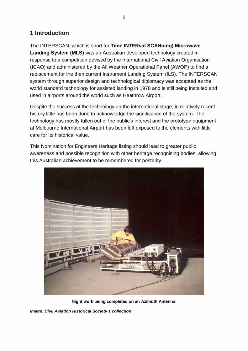
Night work being completed on an Azimuth Antenna.
Image: Civil Aviation Historical Society’s collection

6
2 Heritage Award Nomination Letter
The Administrator
Engineering Heritage Australia
Engineers Australia
Engineering House
11 National Circuit
BARTON ACT 2600
Name of work: INTERSCAN Microwave Landing System
The above-mentioned work is nominated to be awarded recognition under the
Engineering Heritage Recognition Program.
Location, including address and map grid reference if a fixed work: The INTERSCAN
system is located at three sites along the East-West runway (Runway 09/27) at
Melbourne International Airport, Victoria.
Interpretation Panel Location (Location): The interpretation panel for the INTERSCAN
installation at Melbourne International Airport will be installed within the
Civil Aviation Historical Society and Airways Museum at Essendon Airport, upon the
museum’s approval.
The owner has been advised of this nomination and a letter of agreement is attached.
Access to site: The location of the INTERSCAN prototype installation is restricted,
and is not accessible to the public. This is due to the location being close to the East-
West runway and various taxiways at Melbourne International Airport.
Nominating Body: Engineering Heritage Victoria
Owen Peake
Chair, Engineering Heritage Victoria
Date: 24 June 2013
7
3 Heritage Assessment
3.1 Item Name: INTERSCAN Microwave Landing System
3.2 Other/Former Names: Nil
3.3 Location of Prototype: East-West Runway, Melbourne International Airport
3.4 Address of Prototype: Melbourne International Airport
3.5 Suburb/Nearest Town of Prototype Installation: Tullamarine
3.6 State: Victoria
3.7 Local Govt. Area of Prototype Installation: Federal Government of Australia
3.8 Location of Interpretation Panel: Civil Aviation Historical Society and
Airways Museum, Essendon Airport, Victoria
3.9 Owner: This is currently undetermined; at the time of construction the airport was
owned by the Federal Airports Corporation but at the time the radio navigation
equipment was installed the parcels of land belonged to the Civil Aviation Authority.
Since then the airport has changed hands to Australia Pacific Airports Melbourne Pty
Ltd who is the likely owner of the site by default but this cannot be confirmed as the
parcels of land may still remain in the ownership of the Civil Aviation Authority which
is now known as Airservices Australia.
Contact with both parties has not cleared up the ownership issue for this site.
For the purpose of the Interpretation panel, the panel will be placed within the
Civil Aviation Historical Society and Airways Museum at Essendon airport. This is
due to the INTERSCAN installation at Melbourne airport being in a restricted location
along the East–West Runway of the airport, as well as the INTERSCAN installation’s
owner being currently unknown.
3.10 Current Use: Prototype is no longer in use
3.11 Former Use: As a working demonstration and prototype of the INTERSCAN
Microwave Landing System Technology for the International Civil Aviation
Organisation (ICAO) as the future standard precision approach and landing system
for international civil aviation.
3.12 Designer: Commonwealth Scientific and Industrial Research Organisation
(CSIRO), Australia
8
3.13 Maker/Builder: Amalgamated Wireless (Australasia) Ltd (AWA) in association
with the CSIRO, Sydney. The antenna structures were designed by Gutteridge
Haskins and Davey.
3.14 Year Started: INTERSCAN Project began in 1971, Prototype built and installed
in three separate sites within Melbourne International Airport in 1973.
3.15 Year Completed: INTERSCAN was made the standard signal by the
International Civil Aviation Organisation (ICAO) in 1978, after all flight testing was
complete in 1975.
3.16 Physical Description: The INTERSCAN MLS consists of three different sites
along the East–West runway of Melbourne International Airport. The INTERSCAN
system includes a number of different antennas (see appendix 1 for all element
locations) and receivers in different positions along the length of the runway. On the
approach, on the eastern part of the runway there is an antenna to detect the
aircraft’s missed approach, two Flare Antennas to the left on the eastern approach to
determine the elevation and final guidance signal for landing on the runway. On the
far end of the western side of the runway is the Azimuth Antenna to determine the
glide angle the aircraft should take, and two antennas either side of the runway to
determine the position of the aircraft for the Azimuth Antenna to determine the
aircraft’s position relative to the runway’s centre line. The Azimuth information and
the Elevation Flare information are combined into the guidance system to safely and
accurately guide and aid the pilot to land the aircraft. The INTERSCAN system does
not contain moving parts, it is stationary during operation.
3.17 Physical Condition: Currently the system is partially intact at Melbourne
International Airport; however the remnants of the system are in poor condition as
the antennas are open to the elements. All buildings and some equipment have been
removed and concrete slabs remain where they once stood.
3.18 Historical Notes:2
In the early 1960s the Australian Department of Civil Aviation (DCA) and various
aviation administrations in Australia came to the conclusion after various upgrades
were conducted on the existing Instrument Landing Systems (ILS), that an entire
new system with higher accuracy was required for landing aircraft. This new system
became known as the Microwave Landing System as it operated in the radio
frequencies of 5000 MHz and higher, in comparison to the existing ILS system which
used frequencies in the 110 to 330 MHz region during operation.
During the 1960s the United States and the United Kingdom had commenced
studying alternative landing systems, each with their own objectives and were
independently developed in each country. The DCA believed that the International
2 Refer to Appendix 2 for a timeline of Air Services Responsibilities in Australia.
9
Civil Aviation Organisation (ICAO) should coordinate the development of the
Microwave Landing System, rather than have separate countries developing
separate systems in an uncoordinated method with each other, with non-universal
systems.
In April 1967 during the meeting of the All Weather Operational Panel (AWOP), a
proposal was made for the ICAO to begin studies on a new system to replace the
older existing ILS landing system. Two years later ICAO finally agreed to commence
the study for an alternative landing system, and gave the AWOP the task of
producing an Operational Requirement (OR) for the system to be developed.
Consequently the DoT actively participated in the task given to AWOP. In 1972 the
recommendations made in the Operational Requirement were agreed to
internationally by the ICAO.
In the early 1970s after the ICAO agreement with the AWOP, a worldwide
competition began with the United States of America, United Kingdom, France and
Germany, to study and develop a new, more accurate alternative landing system.
Australia entered into this competition in 1973, to develop a submission for the
ICAO.
In 1971, Dr John Paul Wild was appointed the chief of the Division of Radio Physics
at the Commonwealth Scientific and Industrial Research Organisation (CSIRO) in
Australia. He held discussions with the DCA in regards to applied research projects
in the aviation field. As a result of these discussions the developments for the
Microwave Landing System were reviewed, and in particular that the United States
had reluctantly ceased development of a superior system due the lack of a suitable
antenna being available for use.
Shortly after, Wild assembled a small team, which was very quick to conceptualise
and develop a possible solution to the Microwave Landing System project. This
solution was called ‘INTERSCAN’ due to its operational nature. In 1972 Wild
appointed Harry Minnett as the Engineering Director for the ‘INTERSCAN’ Project.
Wild and Harry had complementary expertise and both had enthusiasm for the
project. Harry’s knowledge and expertise of antennas was crucial in the conceptual
and design phases; one of the antennas was an electronically scanned Torus
Reflector. The technology for the Torus Reflector was earlier developed for the
surface of the Parkes Radio Telescope; it was directly applicable for use in the
INTERSCAN system.
In 1973 two Australian companies called Amalgamated Wireless Australasia (AWA)
and Hawker de Havilland were awarded a contract from the Department of Transport
(DoT) to manufacture the prototype INTERSCAN system. The prototype system
installed at Melbourne International Airport was called MITAN by the two
manufacturing companies, and was used for flight trials.
The operational testing of the system was undertaken by DCA and DoT.
10
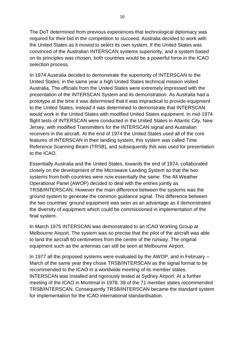
The DoT determined from previous experiences that technological diplomacy was
required for their bid in the competition to succeed. Australia decided to work with
the United States as it moved to select its own system. If the United States was
convinced of the Australian INTERSCAN systems superiority, and a system based
on its principles was chosen, both countries would be a powerful force in the ICAO
selection process.
In 1974 Australia decided to demonstrate the superiority of INTERSCAN to the
United States; in the same year a high United States technical mission visited
Australia. The officials from the United States were extremely impressed with the
presentation of the INTERSCAN System and its demonstration. As Australia had a
prototype at the time it was determined that it was impractical to provide equipment
to the United States, instead it was determined to demonstrate that INTERSCAN
would work in the United States with modified United States equipment. In mid-1974
flight tests of INTERSCAN were conducted in the United States in Atlantic City, New
Jersey, with modified Transmitters for the INTERSCAN signal and Australian
receivers in the aircraft. At the end of 1974 the United States used all of the core
features of INTERSCAN in their landing system, this system was called Time
Reference Scanning Beam (TRSB), and subsequently this was used for presentation
to the ICAO.
Essentially Australia and the United States, towards the end of 1974, collaborated
closely on the development of the Microwave Landing System so that the two
systems from both countries were now essentially the same. The All Weather
Operational Panel (AWOP) decided to deal with the entries jointly as
TRSB/INTERSCAN. However the main difference between the systems was the
ground system to generate the common guidance signal. This difference between
the two countries’ ground equipment was seen as an advantage as it demonstrated
the diversity of equipment which could be commissioned in implementation of the
final system.
In March 1975 INTERSCAN was demonstrated to an ICAO Working Group at
Melbourne Airport. The system was so precise that the pilot of the aircraft was able
to land the aircraft 60 centimetres from the centre of the runway. The original
equipment such as the antennas can still be seen at Melbourne Airport.
In 1977 all the proposed systems were evaluated by the AWOP, and in February –
March of the same year they chose TRSB/INTERSCAN as the signal format to be
recommended to the ICAO in a worldwide meeting of its member states.
INTERSCAN was installed and rigorously tested at Sydney Airport. At a further
meeting of the ICAO in Montreal in 1978, 39 of the 71 member states recommended
TRSB/INTERSCAN. Consequently TRSB/INTERSCAN became the standard system
for implementation for the ICAO international standardisation.
11
The Microwave Landing System became the replacement for the older Instrument
Landing System in Europe. However in the United States, the Federal Aviation
Administration in 1994 halted further development of the MLS system, in favour of
technology based upon the Global Positioning System (GPS). After the competition
had ceased an Australian company called INTERSCAN (Australia) Pty Ltd was
formed to commercialise aspects of the INTERSCAN Microwave Landing System.
The company was renamed INTERSCAN International to promote the sale of its
products on the international market.
3.19 INTERSCAN Currently
Unfortunately INTERSCAN MLS branding is no longer being used by the
government constructed vehicle for development and commercialisation
INTERSCAN Pty Ltd. INTERSCAN Pty Ltd no longer constructs MLS systems as
part of its product base. However as the INTERSCAN/TRSB MLS design was
chosen as the world standard for Microwave Landing Systems by the ICAO, all
current MLS should incorporate the principles of design which were pioneered by
the CSIRO in the construction of the INTERSCAN system. MLS systems are being
installed at Heathrow airport in England by an engineering company called Thales,
on all of its main runways
Thales manufactures various electronic and electrical systems relating to aviation
and the company produces MLS receivers and transmitters. MLS System
installations under the same contract by Thales are being considered for installation
at several other major airports in the United Kingdom.
In France’s main international Charles De Gaulle airport in Paris and other airports in
Europe, MLS systems are being considered for installation as they provide a far
more efficient landing service for aircraft, especially in areas of poor visibility. As
MLS Systems are still being considered for installation around Europe, it is currently
unknown on how many airports have the systems currently installed. MLS systems
are favoured over GPS guidance, as the satellites which make up the GPS global
network are controlled by the United States military and could be deactivated or
jammed at any given time. Hence MLS as a navigational aid for aircraft is favoured
as each system is independent of each other and only concerns the particular
runway at which they are installed.
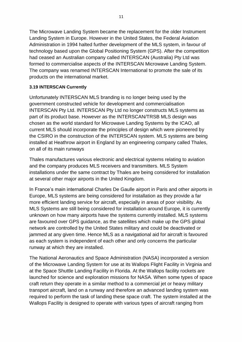
The National Aeronautics and Space Administration (NASA) incorporated a version
of the Microwave Landing System for use at its Wallops Flight Facility in Virginia and
at the Space Shuttle Landing Facility in Florida. At the Wallops facility rockets are
launched for science and exploration missions for NASA. When some types of space
craft return they operate in a similar method to a commercial jet or heavy military
transport aircraft, land on a runway and therefore an advanced landing system was
required to perform the task of landing these space craft. The system installed at the
Wallops Facility is designed to operate with various types of aircraft ranging from
12
commercial and military aircraft to different types of scientific related and
experimental aircraft.
The system installed at the Wallops facility, and the Shuttle Landing Facility in
Florida, is called Microwave Scanning Beam Landing System. This system is similar
to the original ICAO approved INTERSCAN/TRSB system, however it is slightly
different so as to accommodate the space shuttle’s descent rate being 20 times
higher and 7 times steeper upon approach in comparison to regular commercial
aircraft.
On the 21st of August 2007, the space shuttle mission STS-118 to the International
Space Station utilised the Microwave Landing System installed at the Shuttle
Landing Facility at the John F Kennedy Space Center, Florida, to land the Space
Shuttle Endeavour.3
Unfortunately due to the United States Federal Aviation Administration’s decision to
develop GPS guidance systems for aircraft, Microwave Landing System
development was halted in 1994. However a small number of airports including Los
Angeles International (LAX) have Microwave Landing Systems installed from the era
when the TRSB/INTERSCAN was accepted as the international standard for MLS
systems.
The United States Air Force is the largest user in the world of Microwave Landing
Systems4, with more ground systems implemented than all other civil and military
applications in the world combined. In Afghanistan, the USAF is employing six of its
37 mobile MLS systems to transmit landing guidance to Lockheed C-130 “Hercules”
and Boeing C-17 “Globemaster III” transports providing support to U.S. and allied
forces.
Approximately 500 Hercules of the USAF are reported to be equipped with MLS
receivers5, and MLS avionics are standard on the Globemaster III, both types of
aircraft are large heavy transport aircraft.
3 NASA has released a video showing the Space Shuttle Endeavour landing after mission STS-118 at the Shuttle
Landing Center at the John F Kennedy Space Center in Florida. The Video is very descriptive about the nature
of Space Shuttle landings. The link to the video is: http://www.youtube.com/watch?v=r15QlpFchbQ
4 The USAF decision to implement MMLS as a rapidly-deployable precision approach system was based upon
the crash of a US military transport in Bosnia on the 3rd
of April 1996. The crash occurred whilst performing a
non-precision approach in adverse weather resulting in the death of 35 passengers including the then US
Secretary of Commerce Ron Brown.
5 Johnathon Schembri has been able to confirm from a source at the Avalon Airshow that USAF C-130s
definitely have the MLS systems installed. This source had flown H model Hercules in the late 1980s and early
1990s for the USAF.
13
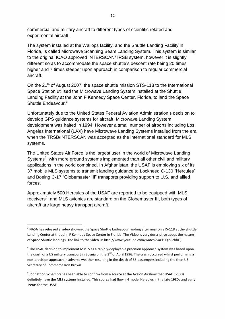
Currently testing is in progress to implement GPS based precision approach and
landing system. The USAF currently has no operational GPS landing guidance
equipment, as GPS is currently considered vulnerable to enemy jamming.
The Royal Australian Air Force operates Lockheed C-130H and J model aircraft, and
also operates Boeing C-17 Globemaster III aircraft. Since the Hercules would require
the MLS receivers to be installed for use, it is undetermined whether the RAAF
Hercules do have the MLS receivers installed6. However since it is standard on the
Globemaster III, the RAAF aircraft should be able to utilise the MLS systems for
Assisted or Auto landing with any runway with MLS installed. The use of MLS
ensures both the safety of the aircraft and the personnel on board, as in areas such
as Afghanistan there is often poor visibility due to weather conditions or terrain,
which increases the difficulty of landing aircraft.
Due to the characteristics of the MLS system, military aircraft landing in dangerous
locations are able to make sudden sharp turns upon approach to the path of the
runway so as to avoid potential enemy ground-to-air missiles, with the guidance of
MLS. Each time an aircraft lands at the same runway the approach angle and
direction is altered to make each flight different from the last and not predictable to
avoid potential missile threats.
3.20 Heritage Listings (information for all listings)
3.20.1 Commonwealth Heritage List
Name: Microwave Landing System Antennas at Melbourne Airport
Nominator: Civil Aviation Historical Society Inc.
Place ID: 106235
File No: 2/13/007/0028
Legal Status: Nominated Place
Admin Status: Not Assessed
Date: N/A
6 Johnathon Schembri spoke to a RAAF C-130 J pilot at the Avalon Airshow who confirmed that the RAAF
C-130s are not equipped with MLS.
14
4 Assessment of Significance
4.1 Historical significance:
See section 3.18 and 3.19 above for details of the history of INTERSCAN.
The historical significance of this system is due to the evolution of aircraft landing
systems made possible through INTERSCAN’s construction and the advancements
made in Australia’s ability to use diplomacy to further its technological agenda.
The basis for the INTERSCAN landing system was the Time Reference Scanning
Beam system, a US Technology which was claimed at the time to be superior to
other scanning beam methods; the technology was dropped by the US, however,
due to the lack of a suitable antenna. In short order the CSIRO, Department of
Transport and AWA Ltd were able to design and create a system using this superior
method, a prototype of which was built at Tullamarine Airport which was used to
demonstrate the effectiveness of the technology which lead to its acceptance as the
preferred system of the US over four other competing designs.7
Several tests were performed in the US using modified Australian/US equipment
until it was agreed by the US that all the essential components of the INTERSCAN
system would be incorporated into the TRSB system and the two system proposals
were merged into one proposal to the ICAO. The proposal competed against several
of the world’s most technologically advanced nations such as the UK, France and
Germany with the member states of the AWOP selecting INTERSCAN as the civil
aviation’s world standard for landing systems to replace the older, less capable ILS.
7 These systems were based on beam technology and Doppler technology.
15
4.2 Historic Individuals or Association:
See Appendix 3 for biographical information on:
1. Dr. John Paul Wild
2. Harry Clive Minnett
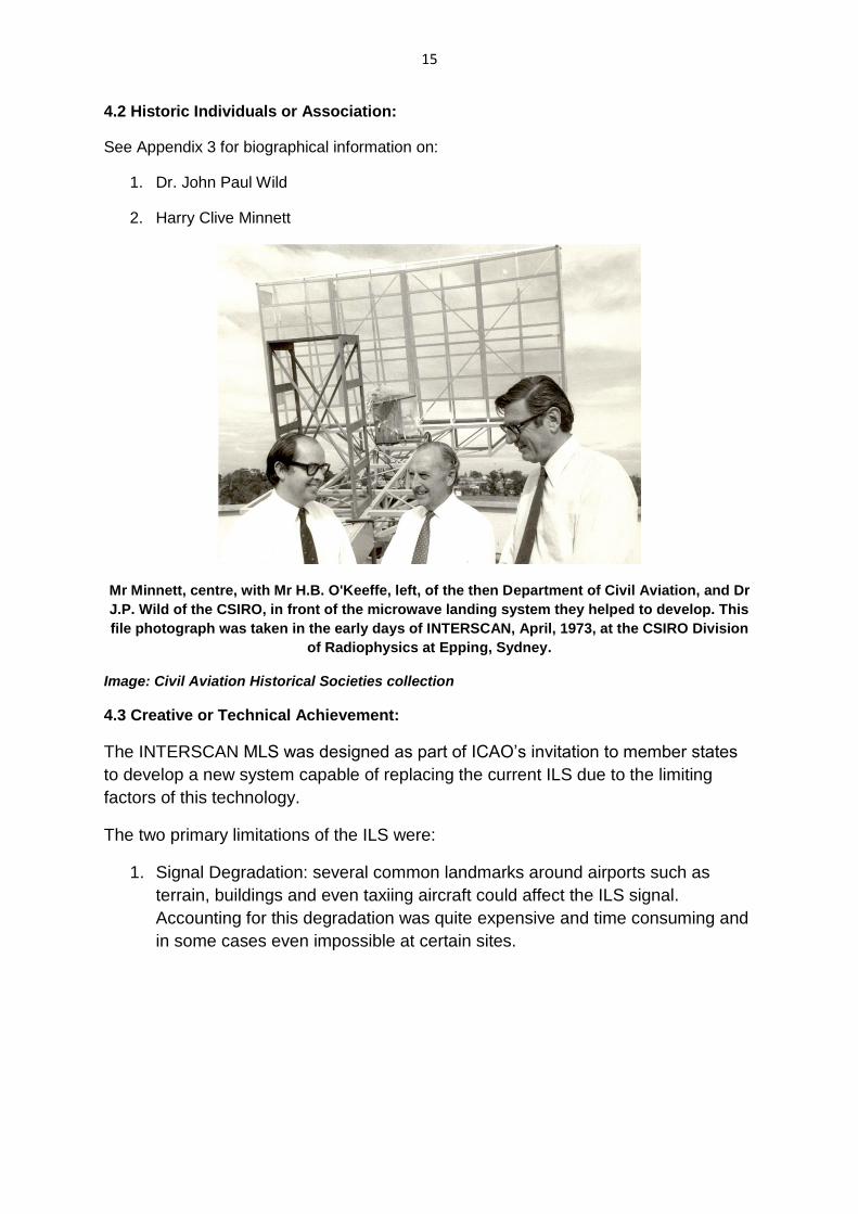
Mr Minnett, centre, with Mr H.B. O'Keeffe, left, of the then Department of Civil Aviation, and Dr
J.P. Wild of the CSIRO, in front of the microwave landing system they helped to develop. This
file photograph was taken in the early days of INTERSCAN, April, 1973, at the CSIRO Division
of Radiophysics at Epping, Sydney.
Image: Civil Aviation Historical Societies collection
4.3 Creative or Technical Achievement:
The INTERSCAN MLS was designed as part of ICAO’s invitation to member states
to develop a new system capable of replacing the current ILS due to the limiting
factors of this technology.
The two primary limitations of the ILS were:
1. Signal Degradation: several common landmarks around airports such as
terrain, buildings and even taxiing aircraft could affect the ILS signal.
Accounting for this degradation was quite expensive and time consuming and
in some cases even impossible at certain sites.
16
2. Single approach path: The ILS provided only a single landing path directly on
the centre line of the runway and at a fixed descent angle requiring the plane
to be on the correct landing approach well before the airport.8
The INTERSCAN system was capable of solving both problems with the ground
based equipment being comparable in cost. The primary benefits of the system
were:
1. Multiple approach paths: The INTERSCAN MLS allowed planes to approach
the runway from several paths including curved paths; by doing so aircraft
could be diverted around noise sensitive areas and lead to simpler air traffic
management as all aircraft did not need to be on the same approach path to
land using the system.
2. Greater and variable descent angle: The INTERSCAN system accommodated
descent angles up to 15 degrees well in excess of the 3 degrees possible with
the ILS; this allowed the system to accommodate VTOL (vertical take-off and
landing) and STOL (short take-off and landing) aircraft.
3. More resilient signal: the INTERSCAN MLS was not affected by terrain,
buildings and aircraft in the vicinity of the airport; this made the system able to
be used in more locations than the ILS and also prevented the need for costly
earthworks and building considerations to make the system workable.
4.4 Research Potential:
As the device was created relatively recently by the CSIRO and was subjected to
heavy scrutiny as part of its adoption as the international standard to replace the
aging Instrumental Landing System, ample documentation of the devices’
construction and function does exists and as such no particular areas of research
appear to be pressing at this time.
4.5 Social:
Prior to the introduction of MLS technologies the single approach path offered by the
then current ILS had great impacts on how airports operated and their relationships
with people who lived in the vicinity of the airport.
The single flight path offered by the ILS was often responsible for the bulk of airports’
traffic being sent over noise sensitive areas such as homes; the path could be
changed but in the best case scenario it required realignment of the runways and at
worst was impossible due to the ILS’s weaknesses associated with buildings and
terrain. This often lead to airports being subjected to curfews which presented
8 O’Keeffe, H.B. “INTERSCAN – The development and international acceptance of a new microwave landing
system for civil aviation” as featured in Transactions of the Institution of Engineers, Australia, Electrical
Engineering, Vol. EE 16, No 2, June 1980, page78.
17
serious problems trying to arrange international flights around local curfews at take-
off and landing.
The introduction of MLS systems allowed air traffic control to divert traffic to paths
that did not pass over noise sensitive areas allowing airports to operate at expanded
hours and new airports to be constructed in areas closer to population centres
without being affected by curfews.
It also allowed airports to integrate better into the local environment as expensive
earthworks along the approach path were no longer required and local buildings did
not affect the MLS’s ability to operate which allowed approach paths to be better
calculated to avoid populated areas
4.6 Rarity:
Whilst the INTERSCAN MLS was chosen as the international standard by the ICAO,
the installation at Tullamarine represents the very first INTERSCAN MLS in the world
making the installation unique.
Due to the unique nature of the installation coupled with its lack of heritage
recognition, effort should be taken to preserve the site.
4.7 Representativeness:
The TRSB/INTERSCAN microwave landing systems were accepted by the ICAO as
the international standard for landing systems; as such, MLS devices implemented
worldwide should follow the essential standards demonstrated in the prototype
system making the device a perfect representation of the system’s origin.
4.8 Integrity/Intactness:
Quite a few of the components of the device are still in place at Melbourne airport
with their exact locations available in Appendix 1. According to anecdotal evidence
the remaining antennas have been left exposed to the elements without
maintenance and are in a poor condition although components may be able to be
restored if necessary. In addition to the antenna components, a transmitter used for
the guidance signal is currently being held at the Airways Museum in Victoria which
has been well preserved.
18
5 Statement of Significance:
5.1 INTERSCAN Historical Significance
The INTERSCAN Microwave Landing System installation at Melbourne International
Airport was used as a prototype in March 1975 to conduct a demonstration of its
operation for the ICAO. The INTERSCAN prototype installation was proven to be
extremely precise in that it aided the pilot to land the aircraft within 60 centimetres of
the centre of the runway.
Initially, in 1971 to early 1974, the INTERSCAN system was developed by the
CSIRO, as a potential alternative to the aging Instrument Landing System. The
INTERSCAN Microwave Landing System is very significant to Australia nationally
and internationally, as the guidance signal used by INTERSCAN became the
international standard for this type of landing system in 1978. The significance of the
INTERSCAN System is that it was initially completely designed in Australia and a
working prototype was installed and successfully tested locally at Melbourne
International Airport, as well as at Sydney Airport.
Internationally the INTERSCAN system is significant in that the United States and
Australia jointly developed a Microwave Landing System based on the principles of
INTERSCAN and certain components of the American Time Reference Scanning
Beam (TRSB); consequently in 1978 the system was recommended by 39 of 71
member states of the ICAO, and the combination of the Australian INTERSCAN
system and the United states TRSB became the international standard for the
Microwave Landing Systems.
5.2 Civil Aviation Historical Society
The INTERSCAN project was Australia’s response to the ICAO’s challenge for
member states to develop a microwave landing system to replace the many non-
standard ILS installations at civil airports around the world. INTERSCAN was the
Australian name patented for its version of the MLS. The name is a neologism,
derived from the words Time INTERval SCANning system. It was the result of
collaboration between science (The Commonwealth Scientific and Industrial
Research Organisation – CSIRO), design and precision manufacturing
(Amalgamated Wireless (Australasia) Ltd (AWA) and civil aviation navigation aids
engineering (Department of Civil Aviation until 1973, and then the Department of
Transport Air Transport Group [DCA/DoT]). The signal format and antenna design
were based on CSIRO Radio Astronomy research work. As a result of the success of
the project a company, INTERSCAN Navigation Systems Pty Ltd, was created to
manufacture and market INTERSCAN and other radio navigation aids. For example,
Distance Measuring Equipment (DME) was also a joint venture between the Council
for Scientific and Industrial Research (CSIR) – the forerunner of today’s CSIRO,
AWA and DCA between 1948 and 1965. The optical tracker, used in the flight testing

19
of INTERSCAN was also an Australian development. Several elements of the
development of INTERSCAN resulted in Australian patents being granted.
6 Area of Significance:
National and International
20
7 Interpretation Plan
7.1 General Approach
The ceremony should be held on Saturday 9th of November 2013. As the
Civil Aviation Historical Society and Airways Museum Essendon are holding an Open
Day with the theme of Melbourne International Airport history; it would be most
appropriate to hold the ceremony at the museum on this date.
Preliminary discussions have been held with Roger Meyer of the museum. We are
thinking of a ceremony at 10 AM with speakers at least from the Civil Aviation
Historical Society and Engineers Australia. Roger thinks we might be able to get one
of the people involved in the development of INTERSCAN to speak. There might
also be merit in asking a VIP from Melbourne Airport to speak as a part of the
process of getting their support for a sustainable future for the INTERSCAN relics at
Melbourne Airport.
The ceremony could be held in the room where the INTERSCAN exhibit is located.
This space would comfortably hold 30 - 50 people. Morning tea and nibbles can be
provided. The museum has suitable kitchen facilities.
The interpretation panel and marker can be located within the Airways Museum at
Essendon Airport in the INTERSCAN display already in place in the museum. The
museum is planning to rearrange the INTERSCAN display to better integrate the
elements and have agreed that an Engineering Heritage Australia marker and “mini”
panel could be included.
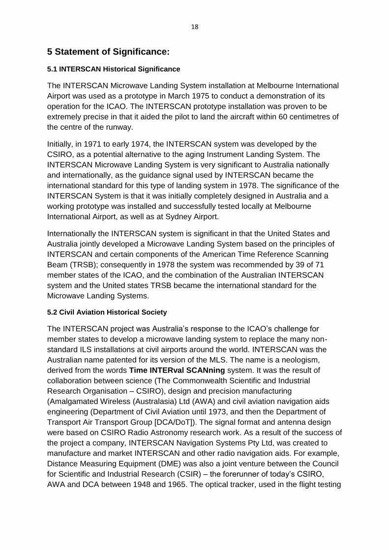
This exhibit currently includes:
An interpretation panel with the story of INTERSCAN/MLS (see image below).
This panel is of good quality and well illustrated. Because of this there is no
need for a full EHA standard interpretation panel, which, in any case,
would be difficult to accommodate.
21
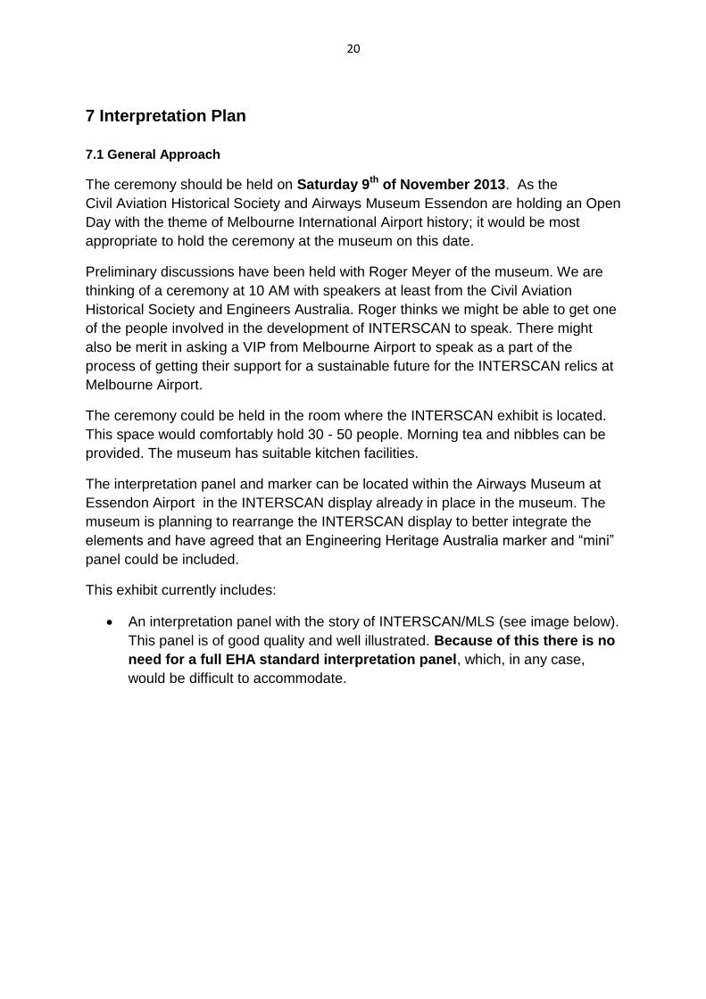
A 19” rack of INTERSCAN electronic equipment (see image below).
22
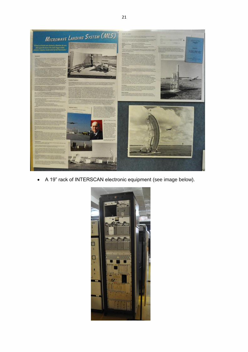
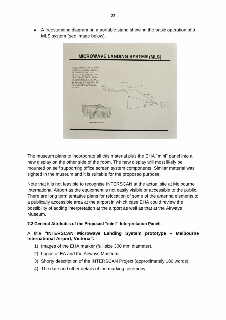
A freestanding diagram on a portable stand showing the basic operation of a
MLS system (see image below).
The museum plans to incorporate all this material plus the EHA “mini” panel into a
new display on the other side of the room. The new display will most likely be
mounted on self supporting office screen system components. Similar material was
sighted in the museum and it is suitable for the proposed purpose.
Note that it is not feasible to recognise INTERSCAN at the actual site at Melbourne
International Airport as the equipment is not easily visible or accessible to the public.
There are long term tentative plans for relocation of some of the antenna elements to
a publically accessible area at the airport in which case EHA could review the
possibility of adding interpretation at the airport as well as that at the Airways
Museum.
7.2 General Attributes of the Proposed “mini" Interpretation Panel:
A title “INTERSCAN Microwave Landing System prototype – Melbourne International Airport, Victoria”.
1) Images of the EHA marker (full size 300 mm diameter).
2) Logos of EA and the Airways Museum.
3) Shorty description of the INTERSCAN Project (approximately 180 words).
4) The date and other details of the marking ceremony.
23
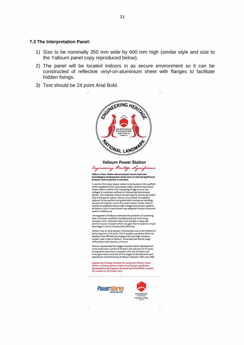
7.3 The Interpretation Panel:
1) Size to be nominally 350 mm wide by 600 mm high (similar style and size to the Yallourn panel copy reproduced below).
2) The panel will be located indoors in as secure environment so it can be constructed of reflective vinyl-on-aluminium sheet with flanges to facilitate hidden fixings.
3) Text should be 24 point Arial Bold.
24
7.4 Text Block for the Interpretation Panel:
“The INTERSCAN Microwave Landing System (MLS) was an Australian developed technology created in response to a competition devised by the International Civil Aviation Organisation (ICAO) to find a replacement for the then current Instrument Landing System (ILS). The INTERSCAN installation at Melbourne International Airport was used as a
prototype in March 1975 to conduct a demonstration of its operation for the
International Civil Aviation Organisation (ICAO). The INTERSCAN prototype
installation was proven to be extremely precise in that it aided the pilot to land the
aircraft within 60 centimetres of the centre of the runway. The system was adopted
as an international standard by ICAO.
The system was designed by the Commonwealth Scientific and Industrial Research
Organisation (CSIRO) and built by Amalgamated Wireless (Australasia) Ltd (AWA) in
close collaboration with the CSIRO.
Whilst MLS did not replace ILS universally as planned in the 1970s the technology
which grew out of INTERSCAN is now being used at busy airports in Europe and by
the US Air Force at front line airfields such as in Afghanistan. The technology was
never adopted in Australia”.
(181 words)
Aim for 180 words
25
8 References:
1. CSIRO 2012, INTERSCAN aircraft Landing System, Australia, Viewed: 10 December 2012,
<www.csiropedia.csiro.au/display/CSIROpedia/INTERSCAN+aircraft+Landing+System>
2. Airways Museum, 2012, The INTERSCAN Microwave Landing System, Egon Stern, Australia,
Viewed: 10 December 2012,
<www.airwaysmuseum.com/MLS%20INTERSCAN%20article%20Stern%2078.htm>
3. Avionics Today, 3 April 2003, MLS Back to The Future?, United States of America, Viewed: 9
January 2013 <http://www.aviationtoday.com/av/issue/feature/807.html#.UO44229QH4Z>
4. Thomas, B & Robinson, B 2005, ‘Harry Clive Minnett 1917-2003’, Historical Records of
Australian Science, vol. 16, no. 2, pp. 199-220
5. Bollard, J.R 1989, ‘Introduction of Microwave Landing Systems to Australia’, Civil Aviation
Authority.
6. Edwards, Ekers & Frater 2011 ‘JOHN PAUL WILD’, Proceedings of the American
Philosophical Society vol. 155, no. 3, pp. 377-381
7. O’Keeffe, H.B 1980, ‘INTERSCAN – The Development and International Acceptance of a
New Microwave Landing System for Civil Aviation’, Transactions of the Institution of
Engineers, Australia, vol. EE 16, no. 2, pp. 78-81
8. CSIRO 2012, Harry Clive Minnett [1917-2003], CSIRO, Viewed: 28 January 2013,
<http://www.csiropedia.csiro.au/display/CSIROpedia/Minnett,+Harry+Clive>
9. AINonline 2013, by: John Sheridan, May 15, 2008, Viewed: 12 February 2013,
<http://www.ainonline.com/aviation-news/aviation-international-news/2008-05-15/european-
airports-choice-mls-doesnt-mean-ils-dead>
10. Wikipedia 2013, Microwave Landing System, Viewed: 10 December 2012,
<http://en.wikipedia.org/wiki/Microwave_landing_system>
11. Armada International, June 2002, Landing aids for bare bases, Viewed: 20 February 2013,
<http://www.thefreelibrary.com/Landing+aids+for+bare+bases%3A+the+war+in+Afghanistan+
has+seen+US...-a090256992>
26
Acknowledgements
The authors of this nomination would like to take the opportunity to express our
warmest appreciation for the assistance provided by the Civil Aviation Historical
Society and in particular Roger Meyer. Their assistance has proven invaluable in the
drafting of this nomination.
Nomination prepared by:
Johnathon Schembri Victoria University, Bachelor of Electrical and Electronic Engineering, Student 115 Market Street Essendon, Victoria 3040 Phone: +61 03 93510954 Mobile: 0407208410 Email: [email protected] Anthony Slattery Victoria University, Bachelor of Electrical and Electronic Engineering, Student 3 Strang Street Hoppers Crossing, Victoria 3029 Phone: +61 03 97347844 Mobile: 0466065834 Email: [email protected]
27
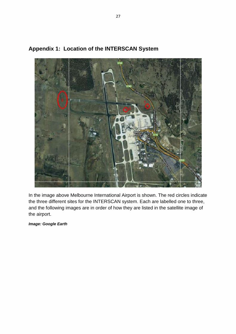
Appendix 1: Location of the INTERSCAN System
In the image above Melbourne International Airport is shown. The red circles indicate
the three different sites for the INTERSCAN system. Each are labelled one to three,
and the following images are in order of how they are listed in the satellite image of
the airport.
Image: Google Earth
28
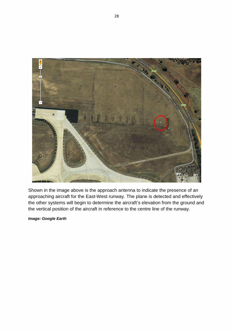
Shown in the image above is the approach antenna to indicate the presence of an
approaching aircraft for the East-West runway. The plane is detected and effectively
the other systems will begin to determine the aircraft’s elevation from the ground and
the vertical position of the aircraft in reference to the centre line of the runway.
Image: Google Earth
29
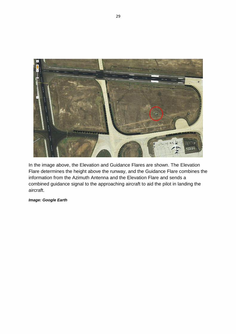
In the image above, the Elevation and Guidance Flares are shown. The Elevation
Flare determines the height above the runway, and the Guidance Flare combines the
information from the Azimuth Antenna and the Elevation Flare and sends a
combined guidance signal to the approaching aircraft to aid the pilot in landing the
aircraft.
Image: Google Earth
30
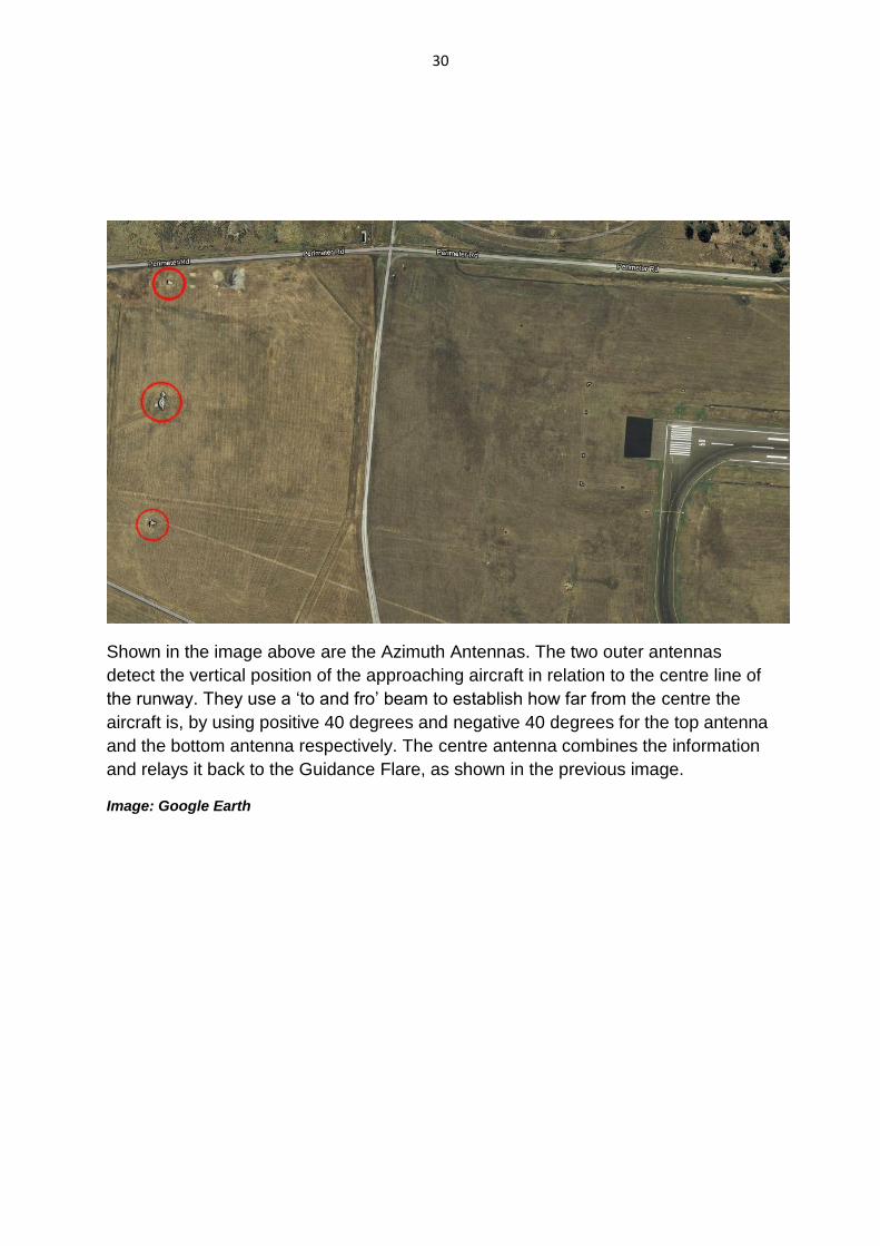
Shown in the image above are the Azimuth Antennas. The two outer antennas
detect the vertical position of the approaching aircraft in relation to the centre line of
the runway. They use a ‘to and fro’ beam to establish how far from the centre the
aircraft is, by using positive 40 degrees and negative 40 degrees for the top antenna
and the bottom antenna respectively. The centre antenna combines the information
and relays it back to the Guidance Flare, as shown in the previous image.
Image: Google Earth
31
Appendix 2: Timeline for Air Services Responsibilities in Australia9
2 December 1920 The Air Navigation Act, which established the Civil Aviation
Branch in the Department of Defence, was passed.
28 March 1921 The Civil Aviation Branch began to function, with the
appointment of Superintendents of Aerodromes, Flying
Operations and Aircraft.
8 April 1936 The Civil Aviation Board established within the Department of
Defence.
14 November 1938 The Department of Civil Aviation (DCA) was created.
30 November 1973 The Department of Civil Aviation was amalgamated with the
Department of Shipping and Transport to form the Department
of Transport (DoT), Air Transport Group.
7 May 1982 The Department of Aviation was created.
24 July 1987 The Department of Aviation was amalgamated with the
Department of Transport and Communications.
1 January 1988 The Federal Airports Corporation was created.
1 July 1988 The Civil Aviation Authority was established.
6 July 1995 Airservices Australia was created.
1 July 1995 The Civil Aviation Safety Authority was created.
The functions performed by the Department of Civil Aviation since its creation in
1938 continue to be performed by Airservices Australia, The Civil Aviation Safety
Authority and the Federal Airports Corporation. The only exception is that the
responsibility for Domestic and International Policy reverted to the Department of
Transport and Communications from July 1988.
9 Sourced from the Civil Aviation Historical Society, November 1995.

32
Appendix 3: Historic Individuals or Associations
Dr. John Paul Wild (1923 - 2008)
Dr. John Paul Wild
John Paul Wild10 was born in Sheffield, England, the son of a cutlery manufacturer
who lost everything in the Great Depression. Paul’s father went to the U.S. when
Paul was three months old and Paul did not see him for the next thirty-three years.
Paul had an early love of mathematics that he attributed to the enthusiasm and
encouragement of his school mathematics teachers. He went to Cambridge
University in 1942 and studied mathematics and physics before joining the navy in
July 1943. This two year period was to be his only period of university study.
Paul served as a radar officer on the flagship HMS King George V in the British
Pacific Fleet for two and a half years. On one of the many visits the fleet made to
Sydney, Australia, Paul met Elaine Hull, and their friendship grew with subsequent
visits. Paul returned to England after the war and taught radar to naval officers,
corresponding frequently with Elaine. In 1947, he obtained a job at the Radiophysics
Laboratory of Australia’s Council for Scientific and Industrial Research (CSIR) and
moved to Sydney, his proposal of marriage by mail having already been accepted.
Paul’s first role was the relatively mundane maintenance and development of test
equipment, but after a year he was able to join Joe Pawsey’s radioastronomy group.
Paul was a great admirer of Pawsey, who provided “an ideal environment to allow
everyone to use their own initiative.” CSIR became the Commonwealth Scientific and
Industrial Research Organisation (CSIRO) in 1949.
Paul worked with Lindsay McCready to build, at Pawsey’s suggestion, the first
spectrograph to study the frequency dependence of solar bursts. This instrument
10
Known as Paul Wild for short.
33
provided a display of frequency versus time covering a swept frequency range from
40 to 70 MHz. Paul travelled to Penrith, 50 km west of Sydney, by train each day
with a technician and a hand-cranked movie camera to record the cathode ray
screen showing the variation of intensity with frequency of the solar radio emission.
Paul recalled, “Every now and then a great burst would come from the sun and we
were very excited and we photographed everything that went on. … After four
months we got so much data that we just closed everything down and came back
and I analysed the data at very great length; the results were spectacular.”
Three types of bursts were identified—which they named Types I, II, and III —
distinguished by the way the frequency changed with time. In a series of papers
published in 1950, they presented their data and the conclusion that Type II bursts
were associated with shock waves coming out through the solar atmosphere at
1,000 km/sec that were associated, about a day later, with aurorae visible near the
Earth’s poles. The more frequent Type III bursts were associated with streams of
electrons being ejected one hundred times faster—at a third the speed of light—and
taking only an hour to reach the earth. This was one of the first realisations that
astrophysical phenomena could result in the production of particles travelling at
relativistic speeds. The interpretations proved to be correct, and their naming of the
burst types became the standard.
The success of these observations led to the construction of three rhombic
spectrograph antennas at Dapto, 100 km south of Sydney, to conduct further studies
of the sun at frequencies between 40 and 240 MHz, which confirmed and extended
the Penrith work. Paul likened this research to the study of taxonomy that preceded
Darwin’s Origin of Species. His analysis of the anatomy of the solar flares and his
development of the physical interpretation culminated in a unified model that
integrated the apparently complex radio flare phenomena in the solar chromosphere,
in the solar corona, and in the interplanetary space.
In the course of this solar work, Paul became interested in the radio spectrum of
hydrogen and wrote up an internal report related to the potential for spectral lines in
the solar bursts. When Ewen and Purcell in the USA first observed the 1420 MHz
hyperfine transition of hydrogen in 1951, Paul went back to his report, generalized it
to include the interstellar medium, and six months later published the first detailed
theoretical paper on the microwave spectral lines from the hydrogen atom—a classic
in the field. After ten years of research, Paul’s collected papers gained him a doctor
of science degree from Cambridge. The group was the pre-eminent group in the
world for solar radioastronomy and would continue its work for three decades.
All these results had been inferred from spectral observations, and there was a
growing desire to be able to image the sun at the same range of frequencies with an
angular resolution comparable to the human eye. This dictated the need for an
instrument more than a million times the size of the aperture of the human eye. With
Pawsey’s help, a grant of US$500,000 (later increased to $630,000) was received
34
from the U.S. Ford Foundation to build a radio-heliograph at Culgoora, near the town
of Narrabri, in northern New South Wales. Paul acknowledged his friend Kevin
Sheridan, chief electronics engineer, as the key figure in this development.
The radio-heliograph consisted of 96 steerable parabolic antennas, each 13.7 m in
diameter, and spaced at 100 m intervals around a circle of diameter 3 km. More than
320 km of copper wire was used to form open transmission lines to transport the
signals to the central control building. Operating initially at 80 MHz (a wavelength of
3.75 m), the radio-heliograph was able to produce a detailed image of the sun each
second, and to record both senses of polarization of the radio waves. This
unprecedented capability yielded its first surprise in its first days of operation: a
series of bursts, previously assumed to all be originating from the same part of the
sun, were found to be coming from two locations separated by more than 800,000
km but connected, it was subsequently realised, by solar magnetic field lines.
The radio-heliograph, which was later extended to frequencies of 40, 160, and 327
MHz, stayed in operation for seventeen years from 1967, providing a tremendous
amount of data and insight into the way the solar corona works and the relationship
between solar and terrestrial phenomena. Paul published more than seventy papers
in this area, and his achievements brought him the Balthasar van der Pol Gold Medal
of the International Union of Radio Science for contributions to radioastronomy
“including completion of a notable high-resolution radio-heliograph” in 1968; the
Hendryck Arctowski Gold Medal of the U.S. National Academy of Sciences in 1969;
the Herschel Medal of the Royal Astronomical Society in 1974; and the Hale Prize of
the American Astronomical Society for Solar Astronomy in 1980.
In 1971, Paul took over from E. G. (“Taffy”) Bowen as chief of CSIRO’s Division of
Radiophysics. While continuing his interest in solar studies, he also looked for
opportunities to use the skills gained from the radioastronomy work and to provide a
balance of pure and applied work in the division. Discussions with the Department of
Civil Aviation identified a replacement for the existing commercial aircraft all-weather
Instrument Landing System as a key opportunity, which was taken up with great
enthusiasm by Paul. This work led to the INTERSCAN microwave landing system,
which was accepted as the new global standard in 1978, and was used until cheaper
GPS-based systems became available. Paul was awarded the Royal Medal of the
Royal Society in 1980, “In recognition of his conception of the basic principles of the
INTERSCAN instrument landing system and the guidance of its development to a
successful conclusion.”
Paul was appointed chairman and chief executive of CSIRO in 1978. As chairman of
CSIRO from 1978 to 1985, he was Australia’s national science leader. He led the
organisation through a restructuring to modernise it and bring it closer to the
industries and community it serves. Recognising that CSIRO needed to adapt and
provide scientific and technological leadership in a changing world, he wrote in 1984,
“Yet, whatever the changes, one characteristic must remain inviolate: a high
35
standard of excellence and originality. Without excellence and originality, research
achieves nothing.” During this period he was instrumental in securing funding for
major national research facilities including Australia’s National Oceanographic
Research Vessel, the Australian Animal Health Laboratory, and the Australia
Telescope, and he established a new Division of Information Technology. The
Australia Telescope Compact Array was built on the site of the radio-heliograph.
Another project that started in this era was his Very Fast Train (VFT) project. He
envisaged a fast train linking Sydney, Canberra, and Melbourne, noting, “We’re
trying to take Australian railways out of the 19th century and into the 21st in one
leap.” He became chairman of the VFT consortium, but the project collapsed in 1991
when the government rejected proposals to provide tax benefits for infrastructure
projects.
Progress in science requires “big-picture” people who can see their way through the
complexity to set the path forward. In this arena, as illustrated from his earliest work,
Paul was absolutely first class. He clearly had an exceptional intellect, wide
knowledge, appreciation of technical issues, and unquenchable interest in new
projects and ideas.
Paul’s work was recognized by many awards: he was made a fellow of the American
Academy of Arts and Sciences in 1961, a foreign member of the American
Philosophical Society in 1962, a fellow of the Australian Academy of Science in
1964, and a fellow of the Royal Society in 1970. He was made a Commander of the
Order of the British Empire (CBE) in 1978 and a Companion of the Order of Australia
in 1986.
Paul died a week before his eighty-fifth birthday. At his funeral service the casket
was covered in red, orange, yellow, green, blue, and indigo flowers—the colours of
the sun’s spectrum. Some of Paul’s ashes were sealed into a memorial sundial near
the Visitor Centre at Culgoora, which is now known as the Paul Wild Observatory.
Paul outlived Elaine and his second wife, Margaret, and is survived by his children,
Peter, Penny, and Tim.

36
Harry Clive Minnett (1917-2003)11
Harry Clive Minnett
Harry Minnett was born at Hurstville in Sydney on 12 June 1917 and lived there until
he married in 1955, just prior to being posted to London in 1956. His parents were
Frederick Harry Brook Minnett, a nurseryman (born in Paddington, September 1887)
and Elsie May Garnsey (born in Dubbo, July 1891). Following their marriage, they
established a delicatessen business at a time when Hurstville was expanding.
Harry attended Hurstville Primary School and was Dux in his final year in 1929. He
then attended Sydney Boys' High School, 1930-34. Harry had a brother Bruce who
was nine years younger. At an early age Harry was captivated by technology, and at
around the age of 15 built a short-wave radio set to listen to overseas stations. This
more than anything is seen to have sparked the passion that marked out his future
career and dominated so much of his life.
He studied science and engineering at the University of Sydney, where the Professor
of Electrical Engineering was the far-seeing JPV Madsen. Harry graduated in
Science (Mathematics and Physics) in 1939 and in Engineering (Mechanical and
Electrical) with First-Class Honours in 1940.
At CSIR/CSIRO 1940-81
In April 1940, Harry Minnett joined the Council for Scientific and Industrial Research
(CSIR, renamed CSIRO in May 1949), soon after the establishment of the
11 Thomas BM, Robinson BJ, 2005, Biographical memoirs: Harry Clive Minnett 1917-2003, Australian Academy
of Science.
37
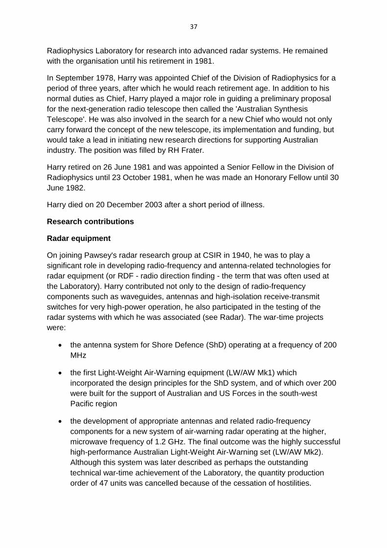
Radiophysics Laboratory for research into advanced radar systems. He remained
with the organisation until his retirement in 1981.
In September 1978, Harry was appointed Chief of the Division of Radiophysics for a
period of three years, after which he would reach retirement age. In addition to his
normal duties as Chief, Harry played a major role in guiding a preliminary proposal
for the next-generation radio telescope then called the 'Australian Synthesis
Telescope'. He was also involved in the search for a new Chief who would not only
carry forward the concept of the new telescope, its implementation and funding, but
would take a lead in initiating new research directions for supporting Australian
industry. The position was filled by RH Frater.
Harry retired on 26 June 1981 and was appointed a Senior Fellow in the Division of
Radiophysics until 23 October 1981, when he was made an Honorary Fellow until 30
June 1982.
Harry died on 20 December 2003 after a short period of illness.
Research contributions
Radar equipment
On joining Pawsey's radar research group at CSIR in 1940, he was to play a
significant role in developing radio-frequency and antenna-related technologies for
radar equipment (or RDF - radio direction finding - the term that was often used at
the Laboratory). Harry contributed not only to the design of radio-frequency
components such as waveguides, antennas and high-isolation receive-transmit
switches for very high-power operation, he also participated in the testing of the
radar systems with which he was associated (see Radar). The war-time projects
were:
the antenna system for Shore Defence (ShD) operating at a frequency of 200
MHz
the first Light-Weight Air-Warning equipment (LW/AW Mk1) which
incorporated the design principles for the ShD system, and of which over 200
were built for the support of Australian and US Forces in the south-west
Pacific region
the development of appropriate antennas and related radio-frequency
components for a new system of air-warning radar operating at the higher,
microwave frequency of 1.2 GHz. The final outcome was the highly successful
high-performance Australian Light-Weight Air-Warning set (LW/AW Mk2).
Although this system was later described as perhaps the outstanding
technical war-time achievement of the Laboratory, the quantity production
order of 47 units was cancelled because of the cessation of hostilities.
38
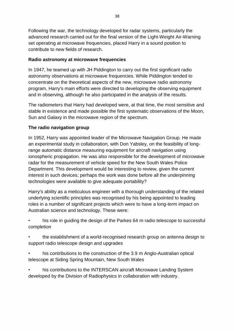
Following the war, the technology developed for radar systems, particularly the
advanced research carried out for the final version of the Light-Weight Air-Warning
set operating at microwave frequencies, placed Harry in a sound position to
contribute to new fields of research.
Radio astronomy at microwave frequencies
In 1947, he teamed up with JH Piddington to carry out the first significant radio
astronomy observations at microwave frequencies. While Piddington tended to
concentrate on the theoretical aspects of the new, microwave radio astronomy
program, Harry's main efforts were directed to developing the observing equipment
and in observing, although he also participated in the analysis of the results.
The radiometers that Harry had developed were, at that time, the most sensitive and
stable in existence and made possible the first systematic observations of the Moon,
Sun and Galaxy in the microwave region of the spectrum.
The radio navigation group
In 1952, Harry was appointed leader of the Microwave Navigation Group. He made
an experimental study in collaboration, with Don Yabsley, on the feasibility of long-
range automatic distance measuring equipment for aircraft navigation using
ionospheric propagation. He was also responsible for the development of microwave
radar for the measurement of vehicle speed for the New South Wales Police
Department. This development would be interesting to review, given the current
interest in such devices; perhaps the work was done before all the underpinning
technologies were available to give adequate portability?
Harry's ability as a meticulous engineer with a thorough understanding of the related
underlying scientific principles was recognised by his being appointed to leading
roles in a number of significant projects which were to have a long-term impact on
Australian science and technology. These were:
• his role in guiding the design of the Parkes 64 m radio telescope to successful
completion
• the establishment of a world-recognised research group on antenna design to
support radio telescope design and upgrades
• his contributions to the construction of the 3.9 m Anglo-Australian optical
telescope at Siding Spring Mountain, New South Wales
• his contributions to the INTERSCAN aircraft Microwave Landing System
developed by the Division of Radiophysics in collaboration with industry.
39
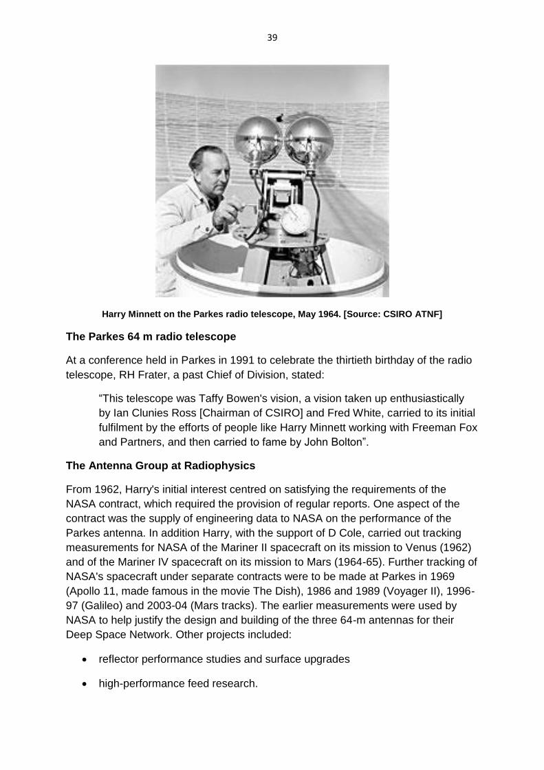
Harry Minnett on the Parkes radio telescope, May 1964. [Source: CSIRO ATNF]
The Parkes 64 m radio telescope
At a conference held in Parkes in 1991 to celebrate the thirtieth birthday of the radio
telescope, RH Frater, a past Chief of Division, stated:
“This telescope was Taffy Bowen's vision, a vision taken up enthusiastically
by Ian Clunies Ross [Chairman of CSIRO] and Fred White, carried to its initial
fulfilment by the efforts of people like Harry Minnett working with Freeman Fox
and Partners, and then carried to fame by John Bolton”.
The Antenna Group at Radiophysics
From 1962, Harry's initial interest centred on satisfying the requirements of the
NASA contract, which required the provision of regular reports. One aspect of the
contract was the supply of engineering data to NASA on the performance of the
Parkes antenna. In addition Harry, with the support of D Cole, carried out tracking
measurements for NASA of the Mariner II spacecraft on its mission to Venus (1962)
and of the Mariner IV spacecraft on its mission to Mars (1964-65). Further tracking of
NASA's spacecraft under separate contracts were to be made at Parkes in 1969
(Apollo 11, made famous in the movie The Dish), 1986 and 1989 (Voyager II), 1996-
97 (Galileo) and 2003-04 (Mars tracks). The earlier measurements were used by
NASA to help justify the design and building of the three 64-m antennas for their
Deep Space Network. Other projects included:
reflector performance studies and surface upgrades
high-performance feed research.
40
The Anglo-Australian optical telescope project
An Anglo-Australian Joint Policy Committee (JPC) recommended that the UK and
Australia jointly fund the construction of a 3.9 m optical telescope in Australia, to be
called the Anglo-Australian Telescope (AAT). The project office for the AAT was
established in Canberra in 1967.
In November 1967 Harry, having gained extensive experience with the design of the
Parkes radio telescope, became a consultant, together with RL Ford of the Royal
Radar Establishment (Malvern), for the design of the drive and control system for the
AAT. It was initially intended to follow well-established design concepts for the
telescope, but Harry found that the requirements for the drive and control system
were initially lacking. He also considered that optical telescope design had not kept
pace with the opportunities that could be provided by technological advances. As
Harry related:
“Together we visited the major astronomy centres in Britain and listened to the
conflicting and often discouraging requirements of the optical observers. I
persuaded the Science Research Council that Ford should accompany me to
Kitt Peak where we found a proposal for a digital servo drive to the traditional
worm gear system”.
Harry became convinced that the only way to make a major advance in optical
telescope drive systems was to eliminate the inefficient worm gears from the servo
loop, together with the reverse-torque spur gear system that had gradually evolved
for anti-backlash purposes. His proposal was to replace these with a precision spur-
gear driven by a balanced pair of motors and pinions in the push-pull anti-backlash
arrangement that had become common in radio telescopes. Harry's experience with
the design of the Parkes servo system also suggested that the struts connecting the
horseshoe structure to the north-end bearing were too flexible and would lead to a
low-resonant frequency. The AAT strut structure was completely redesigned for
greater rigidity by consultants in Canada.
Harry and Ford recommended to the JPC that the AAT should use a photo-electric
guiding system integral with the telescope to relieve the astronomer of this traditional
chore. They also recommended a modified digital on-line computer for automatic
setting, correction of systematic errors, monitoring and data logging. As Harry stated:
“All these changes represented a major rethink in optical telescope drive and
control practice and in such a large project could only be advocated after a
good deal of anxious soul searching. A great amount of effort by myself and
ultimately by many others was needed with the gearing manufacturers and
the Japanese drive and control contractors to achieve the high precision
required.”
41
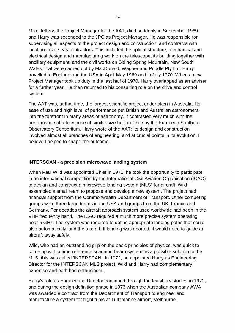
Mike Jeffery, the Project Manager for the AAT, died suddenly in September 1969
and Harry was seconded to the JPC as Project Manager. He was responsible for
supervising all aspects of the project design and construction, and contracts with
local and overseas contractors. This included the optical structure, mechanical and
electrical design and manufacturing work on the telescope, its building together with
ancillary equipment, and the civil works on Siding Spring Mountain, New South
Wales, that were carried out by MacDonald, Wagner and Priddle Pty Ltd. Harry
travelled to England and the USA in April-May 1969 and in July 1970. When a new
Project Manager took up duty in the last half of 1970, Harry overlapped as an adviser
for a further year. He then returned to his consulting role on the drive and control
system.
The AAT was, at that time, the largest scientific project undertaken in Australia. Its
ease of use and high level of performance put British and Australian astronomers
into the forefront in many areas of astronomy. It contrasted very much with the
performance of a telescope of similar size built in Chile by the European Southern
Observatory Consortium. Harry wrote of the AAT: Its design and construction
involved almost all branches of engineering, and at crucial points in its evolution, I
believe I helped to shape the outcome.
INTERSCAN - a precision microwave landing system
When Paul Wild was appointed Chief in 1971, he took the opportunity to participate
in an international competition by the International Civil Aviation Organisation (ICAO)
to design and construct a microwave landing system (MLS) for aircraft. Wild
assembled a small team to propose and develop a new system. The project had
financial support from the Commonwealth Department of Transport. Other competing
groups were three large teams in the USA and groups from the UK, France and
Germany. For decades the aircraft approach system used worldwide had been in the
VHF frequency band. The ICAO required a much more precise system operating
near 5 GHz. The system was required to define appropriate landing paths that could
also automatically land the aircraft. If landing was aborted, it would need to guide an
aircraft away safely.
Wild, who had an outstanding grip on the basic principles of physics, was quick to
come up with a time-reference scanning-beam system as a possible solution to the
MLS; this was called 'INTERSCAN'. In 1972, he appointed Harry as Engineering
Director for the INTERSCAN MLS project. Wild and Harry had complementary
expertise and both had enthusiasm.
Harry's role as Engineering Director continued through the feasibility studies in 1972,
and during the design definition phase in 1973 when the Australian company AWA
was awarded a contract from the Department of Transport to engineer and
manufacture a system for flight trials at Tullamarine airport, Melbourne.
42
Harry's antenna expertise was called on particularly for the conceptual and design
phases. One of the antennas was an electronically scanned Torus Reflector. He
wrote: The vertical profile of an azimuth reflector was shaped by synthesis
techniques to produce a very sharp cut-off along the ground and an optimum shape
at other vertical angles. The technology developed for the new surface of the Parkes
radio telescope was directly applicable to all the reflector antennas for INTERSCAN.
During 1974, Harry travelled widely to advocate the INTERSCAN MLS system. At
the end of that year, the US Government conducted a four-month evaluation of the
British Doppler system and the Australian INTERSCAN system. Through negotiation,
the US would collaborate with the country that they saw as having the best system.
This would then undergo further development prior to submission to ICAO. The US
decided in favour of the Australian time-reference scanning-beam technique, giving
the US and Australia a common technical platform in preparation for the final
submissions to ICAO.
As part of the program to improve the INTERSCAN system, Harry proposed a
concept for correcting the cylindrical aberration of the Torus Reflector. The correction
was implemented in the electronic modulation and switching system that produced
the quasi-continuous beam scan. This reduced the overall size of the antenna by
almost one-half.
The Department of Transport entered the INTERSCAN MLS system into the
international competition conducted by ICAO, and in 1976 it was selected as the
winning entry. Unfortunately international politics was later to plague the project,
resulting in a reduced role for Australia.
One significant spin-off was the formation of a company to commercialise aspects of
the INTERSCAN MLS system. This Australian company was called INTERSCAN
(Australia) Pty Ltd but was later renamed INTERSCAN International to promote the
sale of its products, including phased-array antennas, on the international market.
In retirement
In 1982, Harry became consultant to INTERSCAN (Australia) Pty Ltd at the invitation
of the Managing Director (J Drennan). The INTERSCAN (Australia) engineering
team had just spent two years in Kansas City, USA, working with Wilcox Electric
developing an MLS using phased-array antennas, which had displaced the original
CSIRO reflector antennas. This joint effort was aimed at satisfying the Federal
Aviation Administration (FAA) specifications followed by submission of a formal
response to the FAA's Request for Tender. It was then a matter of urgent
commercial necessity for INTERSCAN to obtain other engineering work to support
the team while the tender was being evaluated. As it later transpired, INTERSCAN
(Australia) was unsuccessful in being awarded a contract and the need for new
contracts became more pressing. Although INTERSCAN (Australia) was
43
unsuccessful in its bid to the FAA for MLS, it was successful in selling the systems in
Spain, China and Taiwan, and in the USA to non-FAA customers.
Harry's task was to search for suitable opportunities. His first success came with a
proposal for a long-range VOR (Very-high-frequency Omni-Range) antenna. This
was the first task outside MLS to be undertaken by INTERSCAN (Australia). Some
twenty systems were subsequently sold to the DCA.
An additional task undertaken by Harry was the design of a precision ground-
reflection antenna range using the old landing strip at Fleurs, Badgery's Creek, New
South Wales.
This range was intended to be used for production testing of MLS antennas. The
units were tested on the range to a precision of 0.001 degrees in guidance accuracy.
Another project in which Harry was involved, this time in association with BB Jones,
was the conceptual design of an electronically scanned TACAN (Tactical Air
Navigation) antenna for use by the Royal Australian Air Force. This antenna
consisted of a cylindrical array fed from a 36-way Butler Matrix using electronic
phase shifters. It was a very successful project both commercially and technically.
Harry became Deputy Chief Executive of INTERSCAN International in 1985 and
retired from that position in July 1986 at age 69.
Tribute
In their biographical memoir of Harry Minnett, former CSIRO colleagues Bruce
Thomas and Brian Robinson wrote:
“... Harry was very thorough in every task that he undertook and was
analytically precise. He would invariably follow the subject through with
extreme attention to detail, often to the frustration of those working around
him. Of course, this was to stand him in good stead when the need arose”.
Harry was a person of the highest integrity, had professional competence of a high
order in many different fields of engineering and science, and made outstanding
contributions to science through engineering. Harry was never the 'centre of
attention' at staff parties, preferring to discuss engineering in the corner of the room
with colleagues. He had very little time for 'small talk'.
Honours and awards
Fellowships:
1980 Fellow, Institution of Engineers Australia
1979 Fellow, Australian Academy of Technological Sciences and Engineering

44
1976 Fellow, Australian Academy of Science
Awards:
2001 Centenary Medal - for service to Australian society and to the science of
radiophysics
1982 Australian Medal of the Guild of Air Pilots and Air Navigators
1972 Officer (Civil), Order of the British Empire (OBE) - for services to science
45
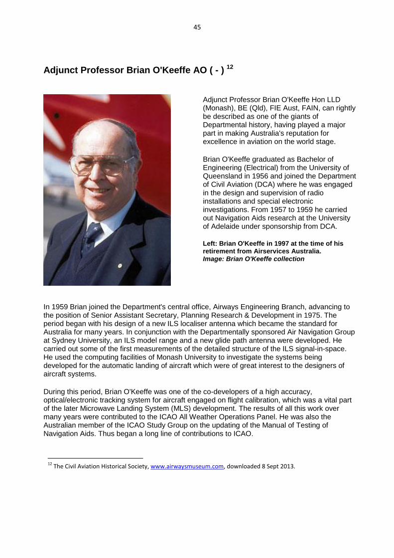
Adjunct Professor Brian O'Keeffe AO ( - ) 12
Adjunct Professor Brian O'Keeffe Hon LLD (Monash), BE (Qld), FIE Aust, FAIN, can rightly be described as one of the giants of Departmental history, having played a major part in making Australia's reputation for excellence in aviation on the world stage.
Brian O'Keeffe graduated as Bachelor of Engineering (Electrical) from the University of Queensland in 1956 and joined the Department of Civil Aviation (DCA) where he was engaged in the design and supervision of radio installations and special electronic investigations. From 1957 to 1959 he carried out Navigation Aids research at the University of Adelaide under sponsorship from DCA.
Left: Brian O'Keeffe in 1997 at the time of his retirement from Airservices Australia. Image: Brian O'Keeffe collection
In 1959 Brian joined the Department's central office, Airways Engineering Branch, advancing to the position of Senior Assistant Secretary, Planning Research & Development in 1975. The period began with his design of a new ILS localiser antenna which became the standard for Australia for many years. In conjunction with the Departmentally sponsored Air Navigation Group at Sydney University, an ILS model range and a new glide path antenna were developed. He carried out some of the first measurements of the detailed structure of the ILS signal-in-space. He used the computing facilities of Monash University to investigate the systems being developed for the automatic landing of aircraft which were of great interest to the designers of aircraft systems.
During this period, Brian O'Keeffe was one of the co-developers of a high accuracy, optical/electronic tracking system for aircraft engaged on flight calibration, which was a vital part of the later Microwave Landing System (MLS) development. The results of all this work over many years were contributed to the ICAO All Weather Operations Panel. He was also the Australian member of the ICAO Study Group on the updating of the Manual of Testing of Navigation Aids. Thus began a long line of contributions to ICAO.
12
The Civil Aviation Historical Society, www.airwaysmuseum.com, downloaded 8 Sept 2013.
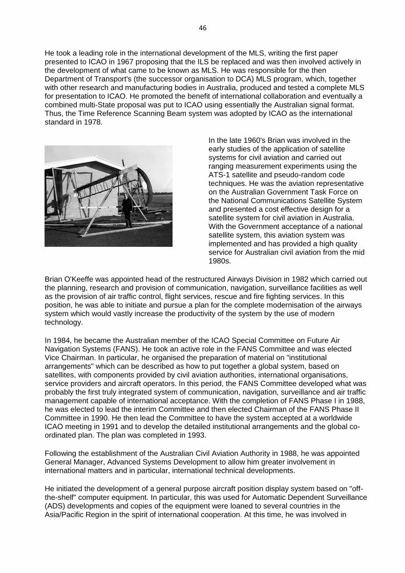
46
He took a leading role in the international development of the MLS, writing the first paper presented to ICAO in 1967 proposing that the ILS be replaced and was then involved actively in the development of what came to be known as MLS. He was responsible for the then Department of Transport's (the successor organisation to DCA) MLS program, which, together with other research and manufacturing bodies in Australia, produced and tested a complete MLS for presentation to ICAO. He promoted the benefit of international collaboration and eventually a combined multi-State proposal was put to ICAO using essentially the Australian signal format. Thus, the Time Reference Scanning Beam system was adopted by ICAO as the international standard in 1978.
In the late 1960's Brian was involved in the early studies of the application of satellite systems for civil aviation and carried out ranging measurement experiments using the ATS-1 satellite and pseudo-random code techniques. He was the aviation representative on the Australian Government Task Force on the National Communications Satellite System and presented a cost effective design for a satellite system for civil aviation in Australia. With the Government acceptance of a national satellite system, this aviation system was implemented and has provided a high quality service for Australian civil aviation from the mid 1980s.
Brian O'Keeffe was appointed head of the restructured Airways Division in 1982 which carried out the planning, research and provision of communication, navigation, surveillance facilities as well as the provision of air traffic control, flight services, rescue and fire fighting services. In this position, he was able to initiate and pursue a plan for the complete modernisation of the airways system which would vastly increase the productivity of the system by the use of modern technology.
In 1984, he became the Australian member of the ICAO Special Committee on Future Air Navigation Systems (FANS). He took an active role in the FANS Committee and was elected Vice Chairman. In particular, he organised the preparation of material on "institutional arrangements" which can be described as how to put together a global system, based on satellites, with components provided by civil aviation authorities, international organisations, service providers and aircraft operators. In this period, the FANS Committee developed what was probably the first truly integrated system of communication, navigation, surveillance and air traffic management capable of international acceptance. With the completion of FANS Phase I in 1988, he was elected to lead the interim Committee and then elected Chairman of the FANS Phase II Committee in 1990. He then lead the Committee to have the system accepted at a worldwide ICAO meeting in 1991 and to develop the detailed institutional arrangements and the global co-ordinated plan. The plan was completed in 1993.
Following the establishment of the Australian Civil Aviation Authority in 1988, he was appointed General Manager, Advanced Systems Development to allow him greater involvement in international matters and in particular, international technical developments.
He initiated the development of a general purpose aircraft position display system based on "off-the-shelf" computer equipment. In particular, this was used for Automatic Dependent Surveillance (ADS) developments and copies of the equipment were loaned to several countries in the Asia/Pacific Region in the spirit of international cooperation. At this time, he was involved in
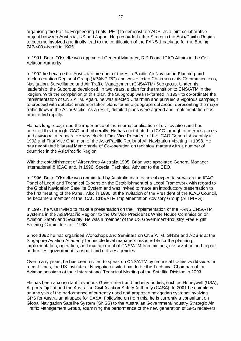
47
organising the Pacific Engineering Trials (PET) to demonstrate ADS, as a joint collaborative project between Australia, US and Japan. He persuaded other States in the Asia/Pacific Region to become involved and finally lead to the certification of the FANS 1 package for the Boeing 747-400 aircraft in 1995.
In 1991, Brian O'Keeffe was appointed General Manager, R & D and ICAO Affairs in the Civil Aviation Authority.
In 1992 he became the Australian member of the Asia Pacific Air Navigation Planning and Implementation Regional Group (APANPIRG) and was elected Chairman of its Communications, Navigation, Surveillance and Air Traffic Management (CNS/ATM) Sub group. Under his leadership, the Subgroup developed, in two years, a plan for the transition to CNS/ATM in the Region. With the completion of this plan, the Subgroup was re-formed in 1994 to co-ordinate the implementation of CNS/ATM. Again, he was elected Chairman and pursued a vigorous campaign to proceed with detailed implementation plans for nine geographical areas representing the major traffic flows in the Asia/Pacific. As a result, detailed plans were agreed and implementation has proceeded rapidly.
He has long recognised the importance of the internationalisation of civil aviation and has pursued this through ICAO and bilaterally. He has contributed to ICAO through numerous panels and divisional meetings. He was elected First Vice President of the ICAO General Assembly in 1992 and First Vice Chairman of the Asia/Pacific Regional Air Navigation Meeting in 1993. He has negotiated bilateral Memoranda of Co-operation on technical matters with a number of countries in the Asia/Pacific Region.
With the establishment of Airservices Australia 1995, Brian was appointed General Manager International & ICAO and, in 1996, Special Technical Adviser to the CEO.
In 1996, Brian O'Keeffe was nominated by Australia as a technical expert to serve on the ICAO Panel of Legal and Technical Experts on the Establishment of a Legal Framework with regard to the Global Navigation Satellite System and was invited to make an introductory presentation to the first meeting of the Panel. Also in 1996, at the invitation of the President of the ICAO Council, he became a member of the ICAO CNS/ATM Implementation Advisory Group (ALLPIRG).
In 1997, he was invited to make a presentation on the "Implementation of the FANS CNS/ATM Systems in the Asia/Pacific Region" to the US Vice President's White House Commission on Aviation Safety and Security. He was a member of the US Government-Industry Free Flight Steering Committee until 1998.
Since 1992 he has organised Workshops and Seminars on CNS/ATM, GNSS and ADS-B at the Singapore Aviation Academy for middle level managers responsible for the planning, implementation, operation, and management of CNS/ATM from airlines, civil aviation and airport authorities, government transport and military agencies.
Over many years, he has been invited to speak on CNS/ATM by technical bodies world-wide. In recent times, the US Institute of Navigation invited him to be the Technical Chairman of the Aviation sessions at their International Technical Meeting of the Satellite Division in 2003.
He has been a consultant to various Government and Industry bodies, such as Honeywell (USA), Airports Fiji Ltd and the Australian Civil Aviation Safety Authority (CASA). In 2001 he completed an analysis of the performance of currently used and proposed navigation systems involving GPS for Australian airspace for CASA. Following on from this, he is currently a consultant on Global Navigation Satellite System (GNSS) to the Australian Government/Industry Strategic Air Traffic Management Group, examining the performance of the new generation of GPS receivers
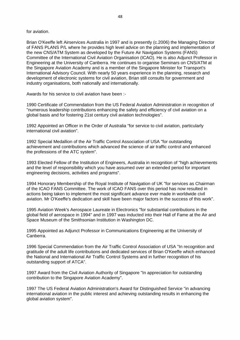
48
for aviation.
Brian O'Keeffe left Airservices Australia in 1997 and is presently (c.2006) the Managing Director of FANS PLANS P/L where he provides high level advice on the planning and implementation of the new CNS/ATM System as developed by the Future Air Navigation Systems (FANS) Committee of the International Civil Aviation Organisation (ICAO). He is also Adjunct Professor in Engineering at the University of Canberra. He continues to organise Seminars on CNS/ATM at the Singapore Aviation Academy and is a member of the Singapore Minister for Transport's International Advisory Council. With nearly 50 years experience in the planning, research and development of electronic systems for civil aviation, Brian still consults for government and industry organisations, both nationally and internationally.
Awards for his service to civil aviation have been :-
1990 Certificate of Commendation from the US Federal Aviation Administration in recognition of "numerous leadership contributions enhancing the safety and efficiency of civil aviation on a global basis and for fostering 21st century civil aviation technologies".
1992 Appointed an Officer in the Order of Australia "for service to civil aviation, particularly international civil aviation".
1992 Special Medallion of the Air Traffic Control Association of USA "for outstanding achievement and contributions which advanced the science of air traffic control and enhanced the professions of the ATC system".
1993 Elected Fellow of the Institution of Engineers, Australia in recognition of "high achievements and the level of responsibility which you have assumed over an extended period for important engineering decisions, activities and programs".
1994 Honorary Membership of the Royal Institute of Navigation of UK "for services as Chairman of the ICAO FANS Committee. The work of ICAO FANS over this period has now resulted in actions being taken to implement the most significant advance ever made in worldwide civil aviation. Mr O'Keeffe's dedication and skill have been major factors in the success of this work".
1995 Aviation Week's Aerospace Laureate in Electronics "for substantial contributions in the global field of aerospace in 1994" and in 1997 was inducted into their Hall of Fame at the Air and Space Museum of the Smithsonian Institution in Washington DC.
1995 Appointed as Adjunct Professor in Communications Engineering at the University of Canberra.
1996 Special Commendation from the Air Traffic Control Association of USA "In recognition and gratitude of the adult life contributions and dedicated services of Brian O'Keeffe which enhanced the National and International Air Traffic Control Systems and in further recognition of his outstanding support of ATCA".
1997 Award from the Civil Aviation Authority of Singapore "In appreciation for outstanding contribution to the Singapore Aviation Academy".
1997 The US Federal Aviation Administration's Award for Distinguished Service "in advancing international aviation in the public interest and achieving outstanding results in enhancing the global aviation system".
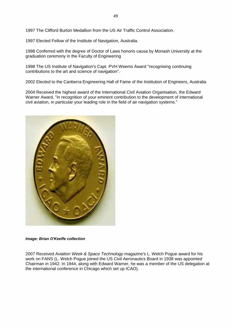
49
1997 The Clifford Burton Medallion from the US Air Traffic Control Association.
1997 Elected Fellow of the Institute of Navigation, Australia.
1998 Conferred with the degree of Doctor of Laws honoris causa by Monash University at the graduation ceremony in the Faculty of Engineering
1998 The US Institute of Navigation's Capt. PVH Weems Award "recognising continuing contributions to the art and science of navigation".
2002 Elected to the Canberra Engineering Hall of Fame of the Institution of Engineers, Australia
2004 Received the highest award of the International Civil Aviation Organisation, the Edward Warner Award, "in recognition of your eminent contribution to the development of international civil aviation, in particular your leading role in the field of air navigation systems."
Image: Brian O'Keeffe collection
2007 Received Aviation Week & Space Technology magazine's L. Welch Pogue award for his work on FANS (L. Welch Pogue joined the US Civil Aeronautics Board in 1938 was appointed Chairman in 1942. In 1944, along with Edward Warner, he was a member of the US delegation at the international conference in Chicago which set up ICAO).
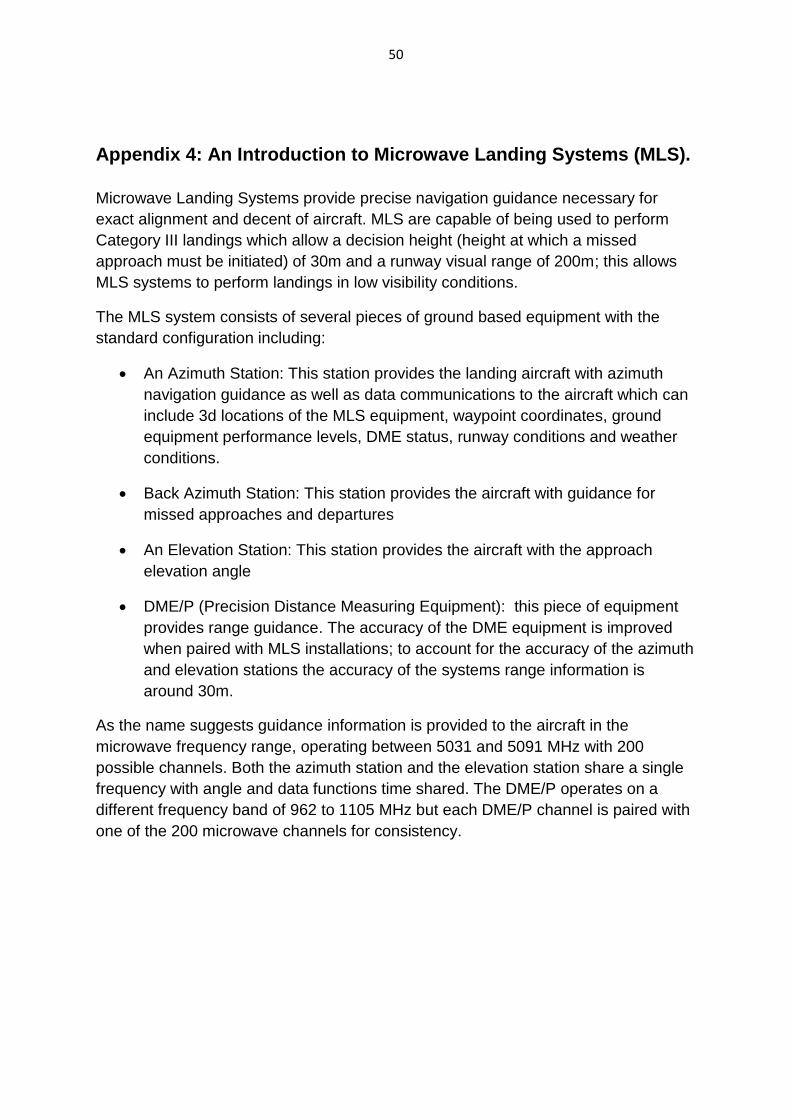
50
Appendix 4: An Introduction to Microwave Landing Systems (MLS).
Microwave Landing Systems provide precise navigation guidance necessary for
exact alignment and decent of aircraft. MLS are capable of being used to perform
Category III landings which allow a decision height (height at which a missed
approach must be initiated) of 30m and a runway visual range of 200m; this allows
MLS systems to perform landings in low visibility conditions.
The MLS system consists of several pieces of ground based equipment with the
standard configuration including:
An Azimuth Station: This station provides the landing aircraft with azimuth
navigation guidance as well as data communications to the aircraft which can
include 3d locations of the MLS equipment, waypoint coordinates, ground
equipment performance levels, DME status, runway conditions and weather
conditions.
Back Azimuth Station: This station provides the aircraft with guidance for
missed approaches and departures
An Elevation Station: This station provides the aircraft with the approach
elevation angle
DME/P (Precision Distance Measuring Equipment): this piece of equipment
provides range guidance. The accuracy of the DME equipment is improved
when paired with MLS installations; to account for the accuracy of the azimuth
and elevation stations the accuracy of the systems range information is
around 30m.
As the name suggests guidance information is provided to the aircraft in the
microwave frequency range, operating between 5031 and 5091 MHz with 200
possible channels. Both the azimuth station and the elevation station share a single
frequency with angle and data functions time shared. The DME/P operates on a
different frequency band of 962 to 1105 MHz but each DME/P channel is paired with
one of the 200 microwave channels for consistency.
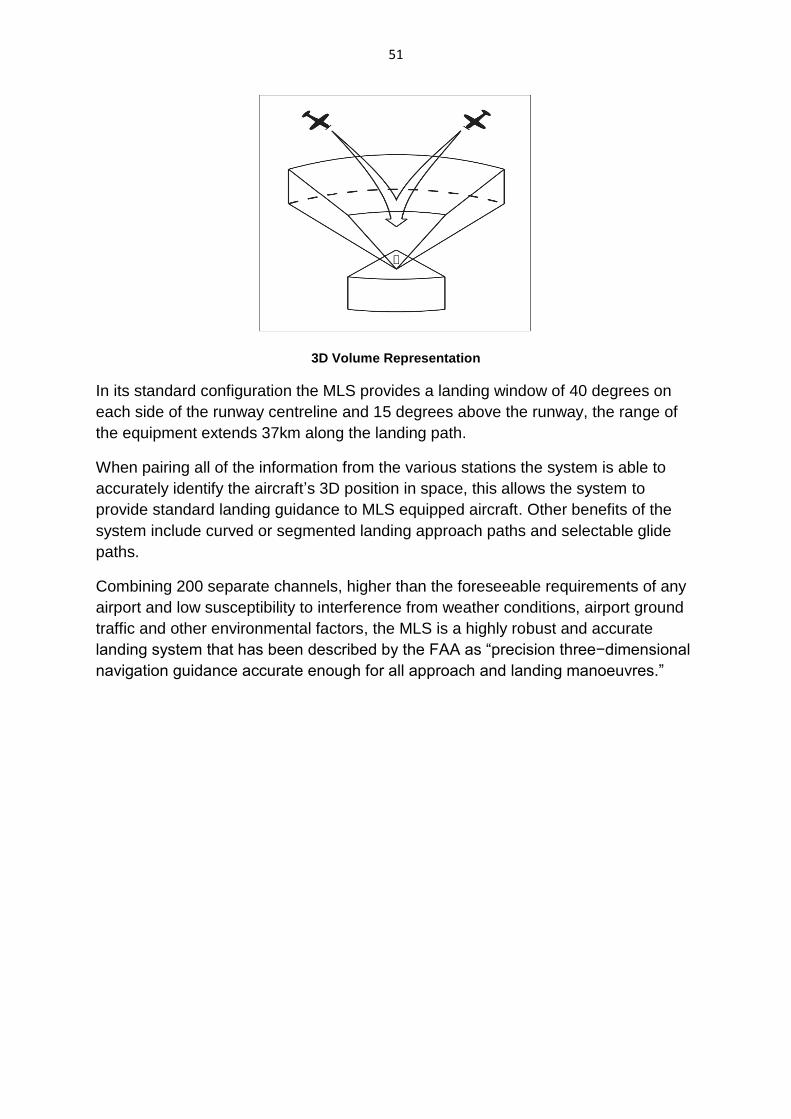
51
3D Volume Representation
In its standard configuration the MLS provides a landing window of 40 degrees on
each side of the runway centreline and 15 degrees above the runway, the range of
the equipment extends 37km along the landing path.
When pairing all of the information from the various stations the system is able to
accurately identify the aircraft’s 3D position in space, this allows the system to
provide standard landing guidance to MLS equipped aircraft. Other benefits of the
system include curved or segmented landing approach paths and selectable glide
paths.
Combining 200 separate channels, higher than the foreseeable requirements of any
airport and low susceptibility to interference from weather conditions, airport ground
traffic and other environmental factors, the MLS is a highly robust and accurate
landing system that has been described by the FAA as “precision three−dimensional
navigation guidance accurate enough for all approach and landing manoeuvres.”
52
Appendix 5: Glossary of Terms
A Technology
MLS: An acronym for Microwave Landing System: these systems use Microwave
beams to determine an aircraft’s location in space relative to the runway and provide
navigation information necessary to land in low visibility conditions. The technology
was developed to supplement or replace the then current Instrument Landing
Systems providing several benefits over the older system.
ILS: An acronym for Instrument Landing Systems: prior to the acceptance of
INTERSCAN/TRSB as the world standard of ICAO, ILS was the preferred low
visibility precision landing aid; the system provided aircraft with navigation
information required to align the aircraft with a single pre-set landing path directly
down the centre line of a runway on a glide path of 3 degrees. Despite being
replaced as the world standard for all weather landing systems ILS is still used
heavily today and is capable of performing a Cat III landing.
DME: An acronym for Distance Measuring Equipment: this is another Australian
developed technology and is used to provide aircraft with their distance from the
device.
TRSB: An acronym for Time Reference Scanning Beam: this was the name selected
by the US for the technology behind the combined bid for the INTERSCAN/TRSB
landing systems.
GPS: An acronym for Global Positioning System: this is a spaced based navigation
system that uses a series of satellites. When the ground based system has line of
sight with at least 4 satellites a pulse is sent from each which contains the exact time
it was sent; by comparing the time the pulse is received with the time it was sent the
distance from each satellite can be determined and from this the user’s exact
position.
VTOL/STOL: An acronym for Vertical Take Off and Landing/Short Take Off and
Landing: these aircraft differ from common aircraft due to the much higher angle at
which they land and take off. In the case of VTOL this is all the way up to an
elevation angle of 90 degrees due to the fact that they land vertically down instead of
gliding into a runway on a low descent angle like traditional aircraft.
53
B Organisations
ICAO: an acronym for the International Civil Aviation Organisation
AWOP: an acronym for ALL Weather Operations Panel, AWOP is a Part of the ICAO
CSIR/CSIRO: Acronyms for the Commonwealth Scientific and Industrial Research/
Commonwealth Scientific and Industrial Research Organisation, currently the
organisation goes by the name CSIRO
AWA: an acronym for Amalgamated Wireless (Australasia) Ltd
Concepts
Azimuth: this is an angular measurement used in spherical coordinate systems and
represents the angle between a reference point and an object on a reference plane.
In the case of INTERSCAN, the object of interest would be the landing aircraft, the
reference plane would be the horizon and the reference point would be the centre
line of the runway.
Microwave: these are waves in the electromagnetic spectrum with wavelengths
varying from 1mm to 1m and a frequency range from 300 MHz (0.3 GHz) to 300
GHz. The term microwave comes from the smaller wavelength in comparison to
radio waves.
Categories of Precision Approach and Landing Operations: These are guidelines set
down by civil aviation organisations around the world as minimum safe landing
conditions; the various landing aids are rated by their performance through rigorous
testing and are assigned a category based on their performance to the guidelines
below which come from Australia’s Civil Aviation Safety Authority:
Category I (CAT I) operation. A precision instrument approach and landing with a
decision height not lower than 200 feet and a visibility not less than 800 meters, or a
runway visual range not less than 550 meters.
Category II (CAT II) operation: A precision instrument approach and landing with a
decision height lower than 200 feet but not lower than 100 feet, and a runway visual
range not less than 300 meters.
(iii) Category IIIA (CAT IIIA) operation: A precision instrument approach and landing
with a decision height lower than 100 feet, or no decision height and a runway visual
range not less than 175 meters.

54
(iv) Category IIIB (CAT IIIB) operation: A precision instrument approach and landing
with either a decision height lower than 50 feet, or with no decision height and a
runway visual range less than 175 meters but not less than 50 meters.
(v) Category IIIC (CAT IIIC) operation: A precision instrument approach and landing
with no decision height and no runway visual range limitations.
Decision Height: depending on the landing category this is the minimum height at
which a missed approach must be initiated.
Australian Government Agencies responsible for Civil Aviation: Refer to Appendix 2.
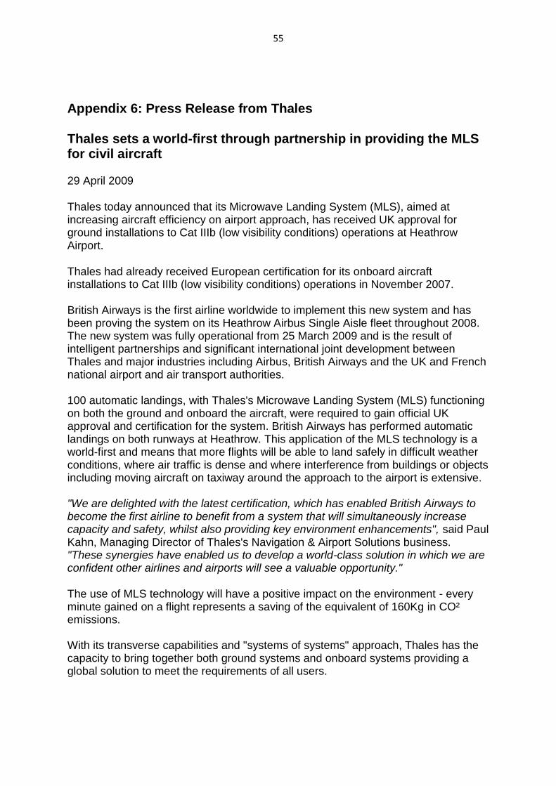
55
Appendix 6: Press Release from Thales
Thales sets a world-first through partnership in providing the MLS for civil aircraft
29 April 2009
Thales today announced that its Microwave Landing System (MLS), aimed at increasing aircraft efficiency on airport approach, has received UK approval for ground installations to Cat IIIb (low visibility conditions) operations at Heathrow Airport.
Thales had already received European certification for its onboard aircraft installations to Cat IIIb (low visibility conditions) operations in November 2007. British Airways is the first airline worldwide to implement this new system and has been proving the system on its Heathrow Airbus Single Aisle fleet throughout 2008. The new system was fully operational from 25 March 2009 and is the result of intelligent partnerships and significant international joint development between Thales and major industries including Airbus, British Airways and the UK and French national airport and air transport authorities. 100 automatic landings, with Thales's Microwave Landing System (MLS) functioning on both the ground and onboard the aircraft, were required to gain official UK approval and certification for the system. British Airways has performed automatic landings on both runways at Heathrow. This application of the MLS technology is a world-first and means that more flights will be able to land safely in difficult weather conditions, where air traffic is dense and where interference from buildings or objects including moving aircraft on taxiway around the approach to the airport is extensive. "We are delighted with the latest certification, which has enabled British Airways to become the first airline to benefit from a system that will simultaneously increase capacity and safety, whilst also providing key environment enhancements", said Paul Kahn, Managing Director of Thales's Navigation & Airport Solutions business. "These synergies have enabled us to develop a world-class solution in which we are confident other airlines and airports will see a valuable opportunity." The use of MLS technology will have a positive impact on the environment - every minute gained on a flight represents a saving of the equivalent of 160Kg in CO² emissions. With its transverse capabilities and "systems of systems" approach, Thales has the capacity to bring together both ground systems and onboard systems providing a global solution to meet the requirements of all users.
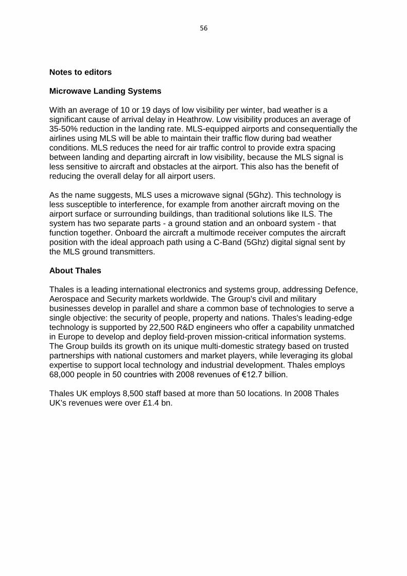
56
Notes to editors Microwave Landing Systems With an average of 10 or 19 days of low visibility per winter, bad weather is a significant cause of arrival delay in Heathrow. Low visibility produces an average of 35-50% reduction in the landing rate. MLS-equipped airports and consequentially the airlines using MLS will be able to maintain their traffic flow during bad weather conditions. MLS reduces the need for air traffic control to provide extra spacing between landing and departing aircraft in low visibility, because the MLS signal is less sensitive to aircraft and obstacles at the airport. This also has the benefit of reducing the overall delay for all airport users. As the name suggests, MLS uses a microwave signal (5Ghz). This technology is less susceptible to interference, for example from another aircraft moving on the airport surface or surrounding buildings, than traditional solutions like ILS. The system has two separate parts - a ground station and an onboard system - that function together. Onboard the aircraft a multimode receiver computes the aircraft position with the ideal approach path using a C-Band (5Ghz) digital signal sent by the MLS ground transmitters. About Thales Thales is a leading international electronics and systems group, addressing Defence, Aerospace and Security markets worldwide. The Group's civil and military businesses develop in parallel and share a common base of technologies to serve a single objective: the security of people, property and nations. Thales's leading-edge technology is supported by 22,500 R&D engineers who offer a capability unmatched in Europe to develop and deploy field-proven mission-critical information systems. The Group builds its growth on its unique multi-domestic strategy based on trusted partnerships with national customers and market players, while leveraging its global expertise to support local technology and industrial development. Thales employs 68,000 people in 50 countries with 2008 revenues of €12.7 billion. Thales UK employs 8,500 staff based at more than 50 locations. In 2008 Thales UK's revenues were over £1.4 bn.
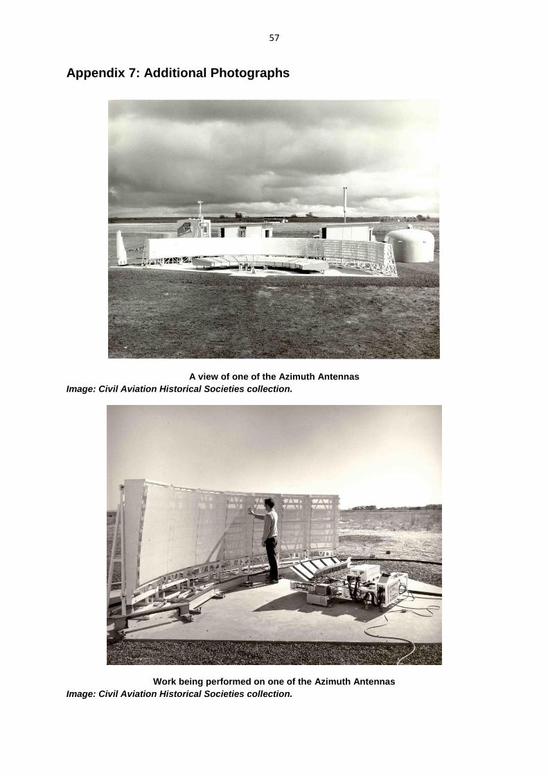
57
Appendix 7: Additional Photographs
A view of one of the Azimuth Antennas
Image: Civil Aviation Historical Societies collection.
Work being performed on one of the Azimuth Antennas
Image: Civil Aviation Historical Societies collection.
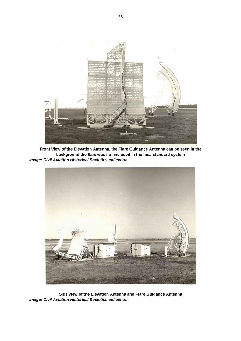
58
Front View of the Elevation Antenna, the Flare Guidance Antenna can be seen in the
background the flare was not included in the final standard system
Image: Civil Aviation Historical Societies collection.
Side view of the Elevation Antenna and Flare Guidance Antenna
Image: Civil Aviation Historical Societies collection.
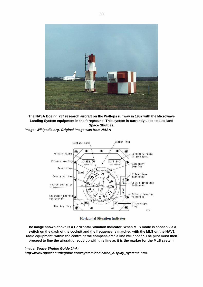
59
The NASA Boeing 737 research aircraft on the Wallops runway in 1987 with the Microwave
Landing System equipment in the foreground. This system is currently used to also land
Space Shuttles.
Image: Wikipedia.org, Original Image was from NASA
The image shown above is a Horizontal Situation Indicator. When MLS mode is chosen via a
switch on the dash of the cockpit and the frequency is matched with the MLS on the NAV1
radio equipment, within the centre of the compass area a line will appear. The pilot must then
proceed to line the aircraft directly up with this line as it is the marker for the MLS system.
Image: Space Shuttle Guide Link:
http://www.spaceshuttleguide.com/system/dedicated_display_systems.htm.
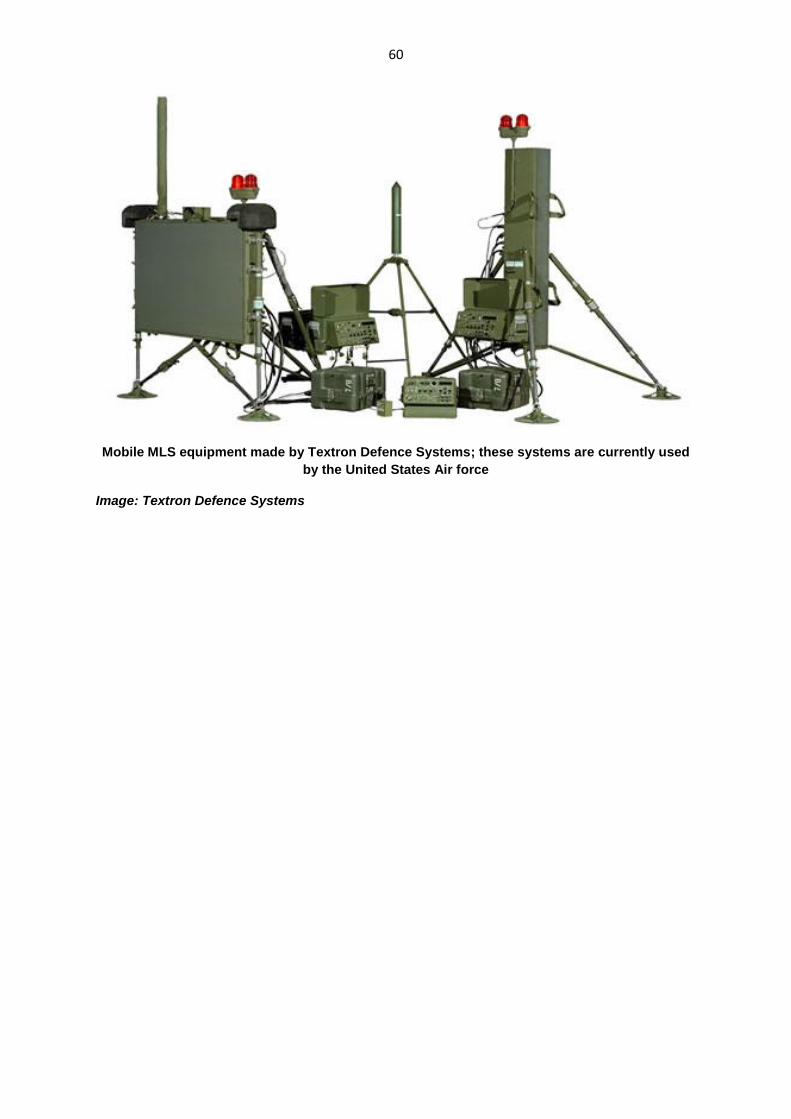
60
Mobile MLS equipment made by Textron Defence Systems; these systems are currently used
by the United States Air force
Image: Textron Defence Systems
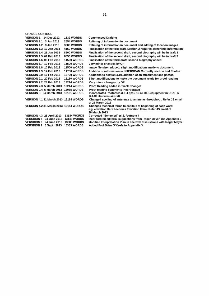
61
CHANGE CONTROL
VERSION 1 14 Dec 2012 1132 WORDS Commenced Drafting
VERSION 1.1 3 Jan 2013 2554 WORDS Refining of information in document
VERSION 1.2 9 Jan 2013 3680 WORDS Refining of information in document and adding of location images
VERSION 1.3 10 Jan 2013 4150 WORDS Finalisation of the first draft, Section 2 requires ownership information
VERSION 1.4 25 Jan 2013 8500 WORDS Finalisation of the second draft, second biography will be in draft 3
VERSION 1.5 01 Feb 2013 8550 WORDS Finalisation of the second draft, second biography will be in draft 3
VERSION 1.6 08 Feb 2013 11500 WORDS Finalisation of the third draft, second biography added
VERSION 1.7 10 Feb 2013 11500 WORDS Very minor changes by OP
VERSION 1.8 10 Feb 2013 11500 WORDS Image file size reduced, slight modifications made to document. VERSION 1.9 14 Feb 2013 11750 WORDS Addition of information in INTERSCAN Currently section and Photos VERSION 2.0 16 Feb 2013 12700 WORDS Additions to section 3.19, addition of an attachment and photos
VERSION 2.1 20 Feb 2013 13150 WORDS Slight modifications to make the document ready for proof reading VERSION 2.2 28 Feb 2013 13214 WORDS Very minor changes by OP VERSION 2.3 5 March 2013 13214 WORDS Proof Reading added in Track Changes VERSION 2.4 5 March 2013 13085 WORDS Proof reading comments incorporated VERSION 3 24 March 2013 13151 WORDS Incorporated footnotes 3 & 4 pp12-13 re MLS equipment in USAF &
RAAF Hercules aircraft VERSION 4.1 31 March 2013 13184 WORDS Changed spelling of antennae to antennas throughout. Refer JS email of 28 March 2013 VERSION 4.2 31 March 2013 13184 WORDS Changes technical terms to capitals at beginning of each word
e.g. elevation flare becomes Elevation Flare. Refer JS email of 28 March 2013 VERSION 4.3 28 April 2013 13184 WORDS Corrected “Schembri” p12, footnote 4 VERSDION 5 24 June 2013 13143 WORDS Incorporated editorial suggestions from Roger Meyer inc Appendix 2 VERSDION 6 24 June 2013 13385 WORDS Modified Interpretation Plan in line with discussions with Roger Meyer VERSDION 7 8 Sept 2013 13385 WORDS Added Prof Brian O’Keefe to Appendix 3