Embed Size (px)
Citation preview
Engineering Thermodynamics
Fourth Semester
Dr. Ramesh Ch. Nayak
(Associate Professor, Mechanical Engineering Department)
Synergy Institute of Technology, Bhubaneswar
At: Bhimpur, Near Phulnakhara, PO: Pahala,
Bhubaneswar, Odisha-752101, INDIA.
ENGINEERING THERMODYNAMICS 1
SIT, BBSR, DR. R. C. Nayak, ETD, 4th Sem, Mech.
THEORYPARAMETERS :
P - Pressure (bar)
1 bar = 25 /101 mN
2/1 mN = 1 Pascal
610MicroM
310millim
310kilok
610Mega
910GigaG
)( 3mvolumeV
)/( smvelocityV
)/(int kgJenergyernalU
)//( kgkgorkJJEnthalpyh
)/( kgKkJEntropyS
STATE POINT RELATION :
mRcTPV
tconsgassticCharacteriRc tan
kgKJC pair /10005.1 3
kgKJC vair /10718.0 3
kgKJR cair /10287.0 3
4.1air
J
RCC c
vp & v
p
C
C
Where, J = mechanical equivalent of heat [ J= 1(SI)]
Process Relation :
T
PV= Constant
2
22
1
11
` T
VP
T
VP
nCompressio Pressure increases &
volume decreases
Expainsion Pressure decreases & vol-ume in creases.
For P = Constant :
CPPP 21
1
2
1
2
V
V
T
T
For Volume constant :
21 VV
1
2
1
2
P
P
T
T
For t = Constant (Isothermal) :
21 TT
2211 VPVP
For t = Constant (Isothermal) :
CVP n
1
2
1
1
1
2
1
2
nn
n
V
V
P
P
T
T
2
SIT, BBSR, DR. R. C. Nayak, ETD, 4th Sem, Mech.
ENGINEERING THERMODYNAMICSAdiabatic :
1
2
1
1
1
2
1
2
V
V
P
P
T
T
2211 VPVP
GAS CYCLE :
cycleOtto constat heat addition volumecycle
cycleDiesel constant pressure cycle
cycleDual Both Pressure & volume re-mains constant
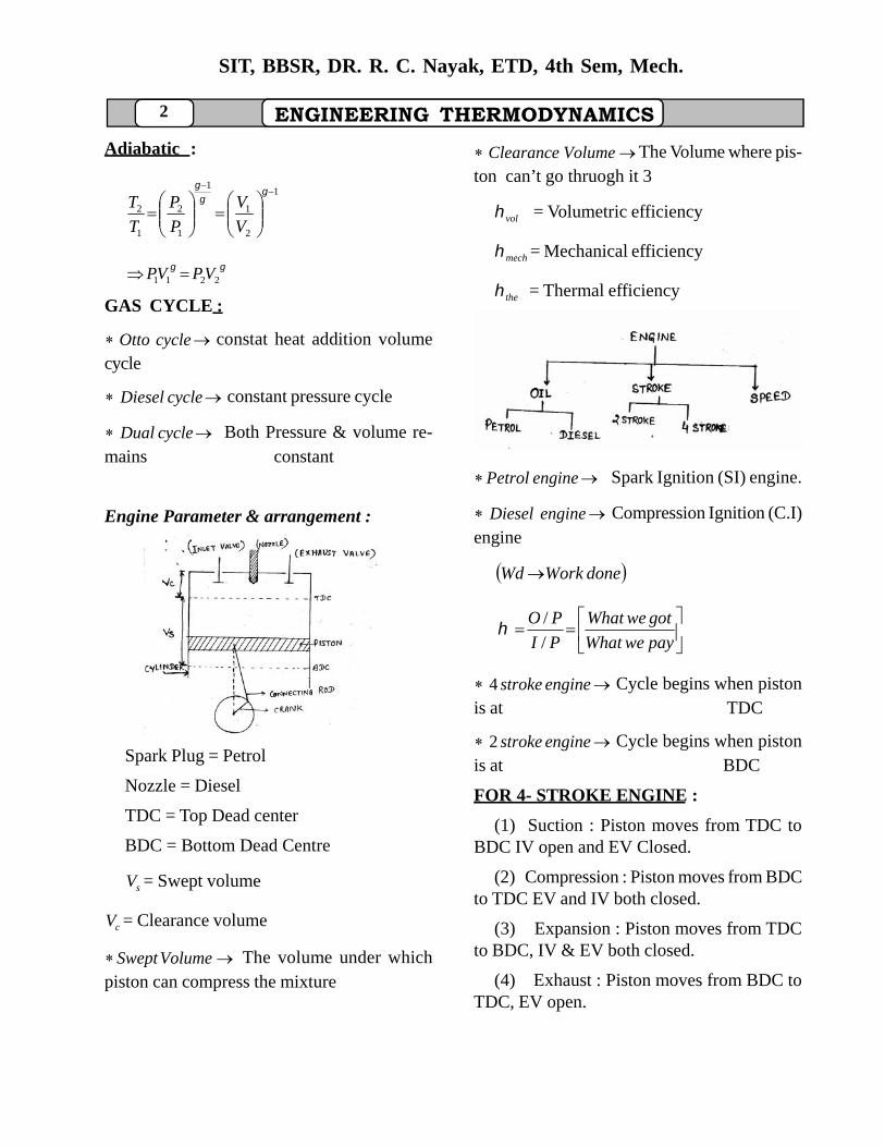
Engine Parameter & arrangement :
Fig-1
Spark Plug = Petrol
Nozzle = Diesel
TDC = Top Dead center
BDC = Bottom Dead Centre
sV = Swept volume
cV = Clearance volume
VolumeSwept The volume under whichpiston can compress the mixture
VolumeClearance The Volume where pis-ton can’t go thruogh it 3
vol = Volumetric efficiency
mech = Mechanical efficiency
the = Thermal efficiency
Fig-2
enginePetrol Spark Ignition (SI) engine.
engineDiesel Compression Ignition (C.I)engine
doneWorkWd
payweWhat
gotweWhat
PI
PO
/
/
enginestroke4 Cycle begins when pistonis at TDC
enginestroke2 Cycle begins when pistonis at BDC
FOR 4- STROKE ENGINE :
(1) Suction : Piston moves from TDC toBDC IV open and EV Closed.
(2) Compression : Piston moves from BDCto TDC EV and IV both closed.
(3) Expansion : Piston moves from TDCto BDC, IV & EV both closed.
(4) Exhaust : Piston moves from BDC toTDC, EV open.
ENGINEERING THERMODYNAMICS 3
SIT, BBSR, DR. R. C. Nayak, ETD, 4th Sem, Mech.
IC. Through nozzle fine spray of fuelis injected & mixed with compressed air whichis at high temp & pressure.
IS. By using of spark plug air fuel mix-ture is ignited.
PARAMETER :
D = d = Bore dia / cylinder dia / piston dia :
L = Stroke length
= Length of connecting rod.
cV = Clearance volume
sV = Swept volume
r = Compression ratio
volsmall
volbig
= Cut off ratio.
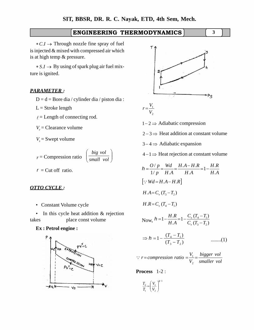
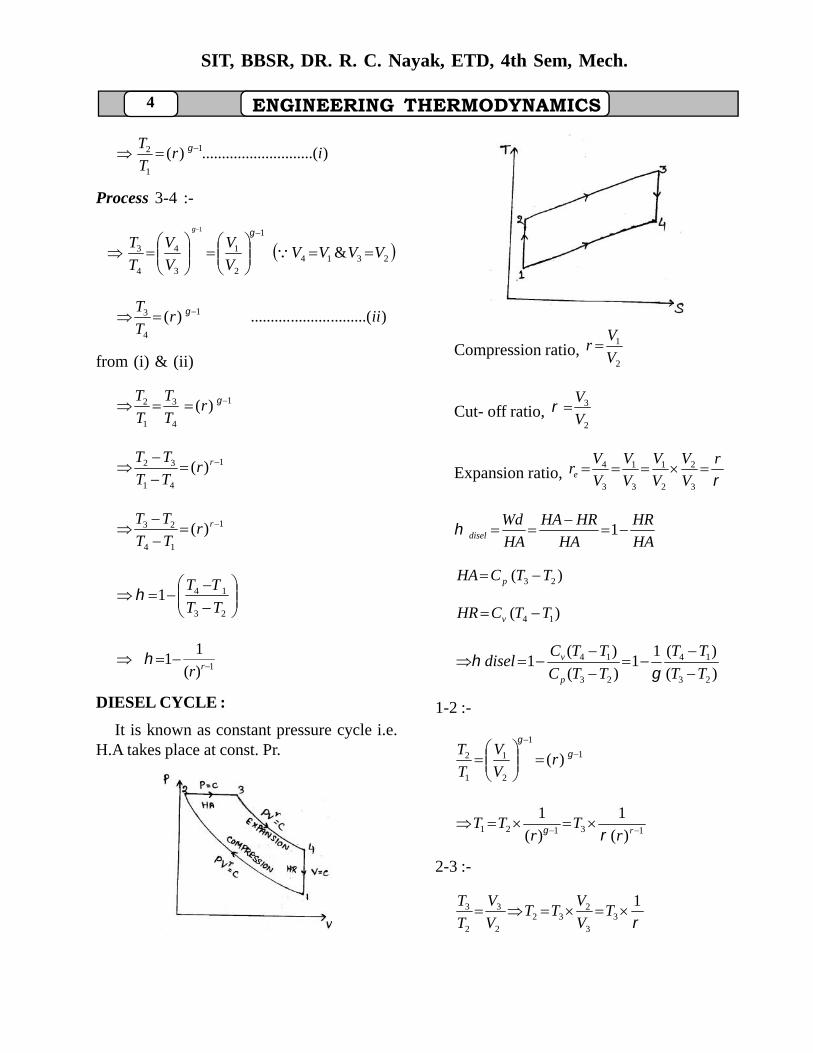
OTTO CYCLE :
• Constant Volume cycle
• In this cycle heat addition & rejectiontakes place const volume
Ex : Petrol engine :
Fig-3
2
1
V
Vr
21 Adiabatic compression
32 Heat addition at constant volume
43 Adiabatic expansion
14 Heat rejection at constant volume
AH
RH
AH
RHAH
AH
Wd
p
pO
.
.1
.
..
./1
/
RHAHWd ..
)(. 23 TTCAH v
)(. 14 TTCRH v
Now, )(
)(1
.
.1
23
14
TTC
TTC
AH
RH
v
v
)(
)(1
23
14
TT
TT
........(1)
volsmaller
volbigger
V
Vrationcompressior
2
1
Process 1-2 :
1
2
1
1
2
V
V
T
T
4
SIT, BBSR, DR. R. C. Nayak, ETD, 4th Sem, Mech.
ENGINEERING THERMODYNAMICS
)........(....................)( 1
1
2 irT
T
Process 3-4 :-
2314
1
2
1
3
4
4
3 &
1
VVVVV
V
V
V
T
T
).........(....................)( 1
4
3 iirT
T
from (i) & (ii)
1
4
3
1
2 )( rT
T
T
T
1
41
32 )(
rrTT
TT
1
14
23 )(
rrTT
TT
23
141TT
TT
1)(
11
rr
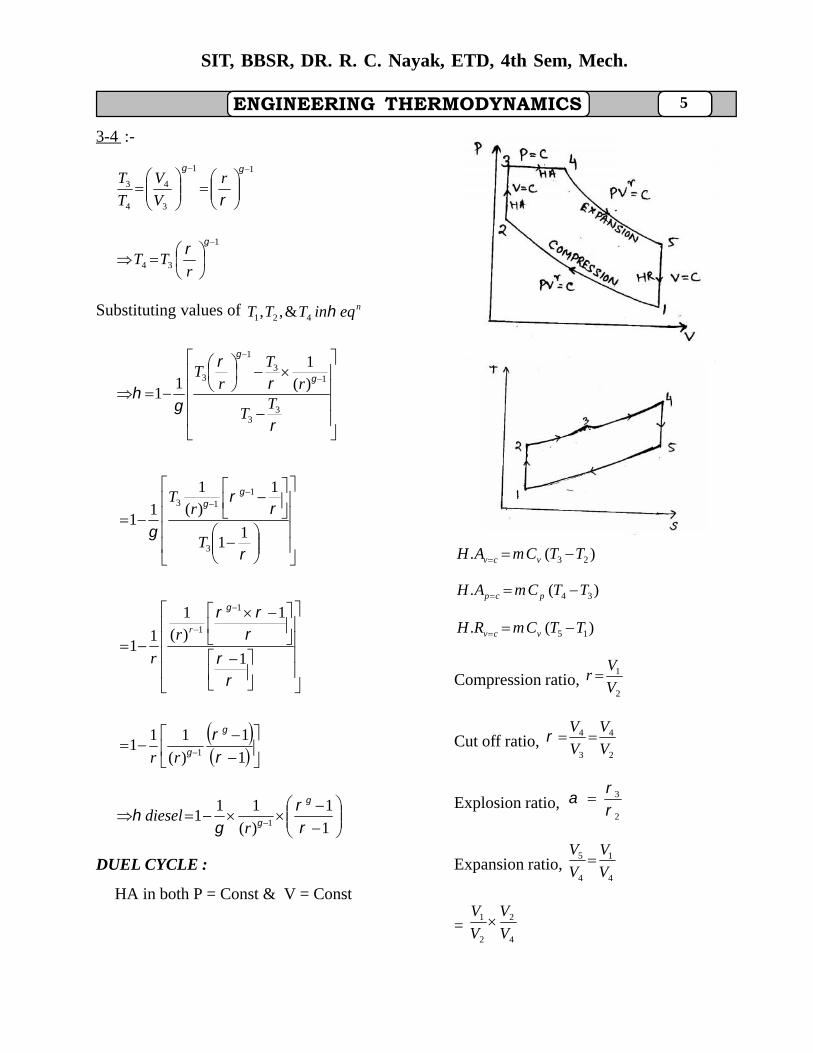
DIESEL CYCLE :
It is known as constant pressure cycle i.e.H.A takes place at const. Pr.
Fig-4
Compression ratio,2
1
V
Vr
Cut- off ratio,2
3
V
V
Expansion ratio, r
V
V
V
V
V
V
V
Vre
3
2
2
1
3
1
3
4
HA
HR
HA
HRHA
HA
Wddisel
1
)( 23 TTCHA p
)( 14 TTCHR v
)(
)(11
)(
)(1
23
14
23
14
TT
TT
TTC
TTCdisel
p
v
1-2 :-
1
1
2
1
1
2 )(
rV
V
T
T
13121 )(
1
)(
1
rrT
rTT
2-3 :-
1
33
232
2
3
2
3 TV
VTT
V
V
T
T
ENGINEERING THERMODYNAMICS 5
SIT, BBSR, DR. R. C. Nayak, ETD, 4th Sem, Mech.
3-4 :-
11
3
4
4
3
r
V
V
T
T
1
34
r
TT
Substituting values of neqinTTT 421 &,,
33
13
1
3 )(1
11
TT
r
T
rT
11
1)(1
11
3
113
T
rT
1
1)(1
11
1
1rr
r
1
1
)(
111
1
rr
1
1
)(
111
1
rdiesel
DUEL CYCLE :
HA in both P = Const & V = Const
Fig-5
)(. 23 TTCmAH vcv
)(. 34 TTCmAH pcp
)(. 15 TTCmRH vcv
Compression ratio,2
1
V
Vr
Cut off ratio,2
4
3
4
V
V
V
V
Explosion ratio,2
3
Expansion ratio,4
1
4
5
V
V
V
V
=4
2
2
1
V
V
V
V
6
SIT, BBSR, DR. R. C. Nayak, ETD, 4th Sem, Mech.
ENGINEERING THERMODYNAMICS
= r
r 1
AH
RH
AH
HRHA
AH
dW
.
.1
..
.
= )()(
)(1
3423
15
TTmCTTCm
TTCm
pv
v
)()(
)(1
3423
15
TTTT
TT
(Divide Cv on numerator & denomi-nator)
Process 4-5 :-
1
5
4
4
5
V
V
T
T 1
45
r
TT
Process 3-4 :-
4
3
4
3
V
V
T
T
1
43 TT
Process 2-3 :-
3
2
3
2
P
P
T
T
1
32 TT
14
2 T
T
Process 1-2 :-
1
1
2
2
1
V
V
T
T
121 )(
1 r
TT
14
1 )(
11 r
TT
44
44
14
1
4 )(1
1T
TTT
r
T
rT
11
11
1)(1
1
44
114
TT
rT
111
1)(1
1
1
1r
1
11
1
1
r
1
11
1
1
r
)1(1
11
1
1
rdual
Procedure for sloving problem :
1. Read the question & confirm (Medium :
ENGINEERING THERMODYNAMICS 7
SIT, BBSR, DR. R. C. Nayak, ETD, 4th Sem, Mech.
air, Cycle : otto, diesel, dualword is there)
2. Then check above cycle.
3. Draw P-V & T-S diagram
4. Write the data given
5. If medium is air then assume pC air, vC
air, cR & Vair
.
6. If cut off ratio word is there.
[Ex. cut off takes place at 5% of stroke]
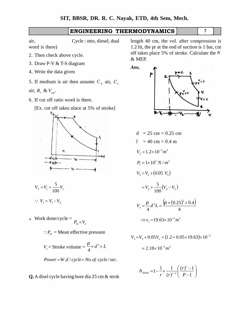
Fig-6
sc VVV100
53
21 VVVs
Work done/cycle =sm VP
mP = Mean effective pressure
sV = Stroke volume = Ld 2
4
.sec/./. cycleofNocycledWPower
Q.A disel cycle having bore dia 25 cm & strok
length 40 cm, the vol. after compression is1.2 lit, the pr at the end of suction is 1 bar, cutoff takes place 5% of stroke. Calculate the & MEP.
Ans.
Fig-7
d = 25 cm = 0.25 cm
l = 40 cm = 0.4 m
332 102.1 mV
251 /101 mNP
323 05.0 VVV
242 100
5VVV
4
4.025.0
4
22
LdVs
331063.19 mvs
333 1063.1905.02.105.0 sVVV
331018.2 m
1
1)(
)(
111
1 P
r
rr
r
rdielel
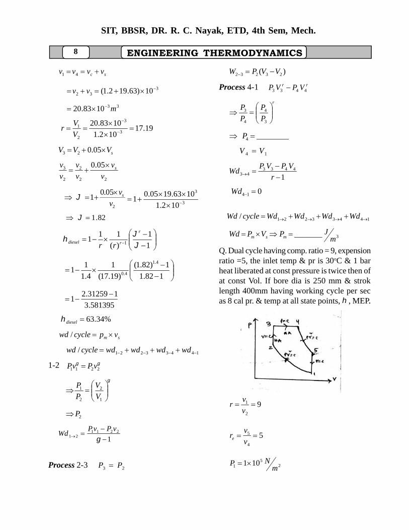
8
SIT, BBSR, DR. R. C. Nayak, ETD, 4th Sem, Mech.
ENGINEERING THERMODYNAMICS
sc vvvv 41
332 10)63.192.1( vv
331083.20 m
19.17102.1
1083.203
3
2
1
V
Vr
sVVV 05.023
22
2
2
3 05.0
v
v
v
v
v
v s
2
05.01
v
vs 3
3
102.1
1063.1905.01
82.1
1
1
)(
111
1
r
rdiesel rr
182.1
1)82.1(
)19.17(
1
4.1
11
4.1
4.0
581395.3
131259.21
%34.63diesel
sm vpcyclewd /
14433221/ wdwdwdwdcyclewd
1-2 2211 vPvP
1
2
2
1
V
V
P
P
2P
12211
21
vPvP
Wd
Process 2-3 23 PP
)( 23232 VVPW
Process 4-1 rr VPVP 4433
r
P
P
P
P
3
4
4
3
________4 P
14 VV
14433
43
r
VPVPWd
014 Wd
14433221/ WdWdWdWdcycleWd
3_______m
JPVPWd msm
Q. Dual cycle having comp. ratio = 9, expensionratio =5, the inlet temp & pr is 30oC & 1 barheat liberated at const pressure is twice then ofat const Vol. If bore dia is 250 mm & stroklength 400mm having working cycle per secas 8 cal pr. & temp at all state points, , MEP..
FIG-8
92
1 v
vr
54
5 v
vre
25
1 101m
NP
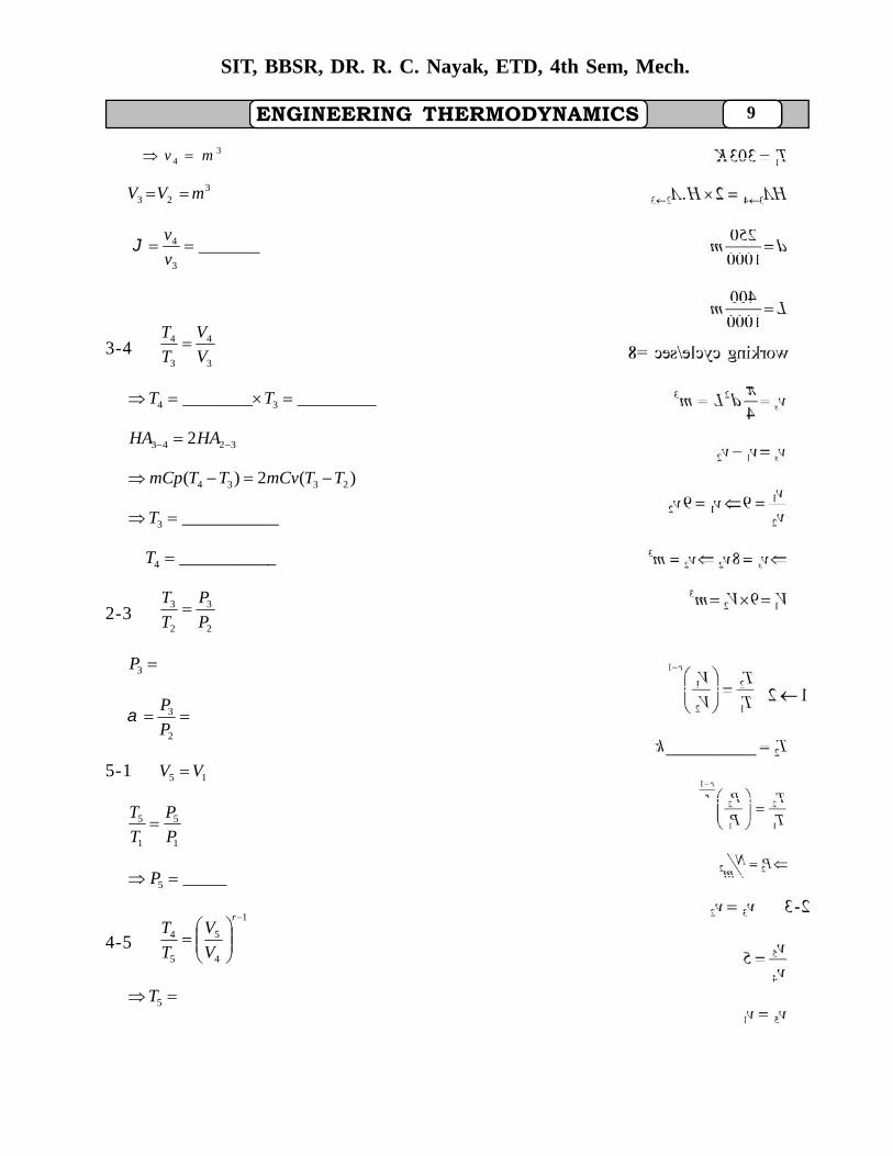
ENGINEERING THERMODYNAMICS 9
SIT, BBSR, DR. R. C. Nayak, ETD, 4th Sem, Mech.
34 mv
323 mVV
_______3
4 v
v
3-43
4
3
4
V
V
T
T
_________________ 34 TT
3243 2 HAHA
)(2)( 2334 TTmCvTTmCp
___________3 T
___________4 T
2-32
3
2
3
P
P
T
T
3P
2
3
P
P
5-1 15 VV
1
5
1
5
P
P
T
T
_____5 P
4-5
1
4
5
5
4
r
V
V
T
T
5T
10
SIT, BBSR, DR. R. C. Nayak, ETD, 4th Sem, Mech.
ENGINEERING THERMODYNAMICS
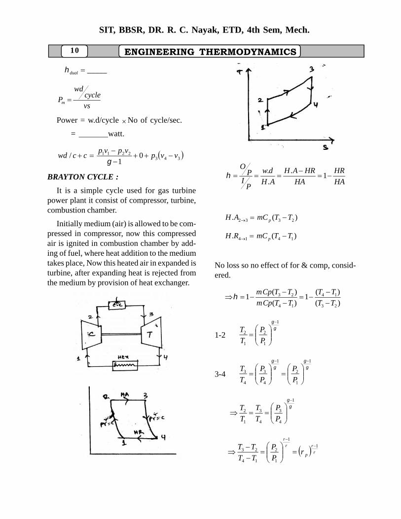
_____dual
vs
cyclewd
Pm
Power = w.d/cycle No of cycle/sec.
= _______watt.
3432211 0
1/ vvp
vpvpccwd
BRAYTON CYCLE :
It is a simple cycle used for gas turbinepower plant it consist of compressor, turbine,combustion chamber.
Initially medium (air) is allowed to be com-pressed in compressor, now this compressedair is ignited in combustion chamber by add-ing of fuel, where heat addition to the mediumtakes place, Now this heated air in expanded isturbine, after expanding heat is rejected fromthe medium by provision of heat exchanger.
Fig-9
Fig-10
HA
HR
HA
HRAH
AH
dw
PI
PO
1.
.
.
)(. 2332 TTmCAH p
)(. 1414 TTmCRH p
No loss so no effect of for & comp, consid-ered.
)(
)(1
)(
)(1
23
14
14
23
TT
TT
TTCpm
TTCpm
1-2
1
1
2
1
2
P
P
T
T
3-4
1
1
2
1
4
3
4
3
P
P
P
P
T
T
1
4
3
4
3
1
2
P
P
T
T
T
T
r
r
p
r
r
rP
P
TT
TT 1
1
1
2
14
23
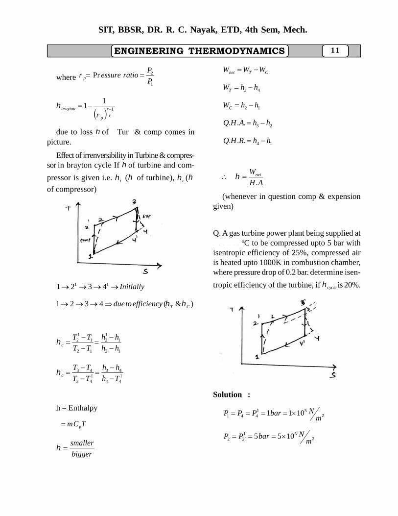
ENGINEERING THERMODYNAMICS 11
SIT, BBSR, DR. R. C. Nayak, ETD, 4th Sem, Mech.
where1
2PrP
Pratioessurer p
r
r
p
brayton
r1
11
due to loss of Tur & comp comes inpicture.
Effect of irrenversibility in Turbine & compres-sor in brayton cycle If of turbine and com-
pressor is given i.e. t ( of turbine), c (
of compressor)
Fig-11
Initially 11 4321
)&(4321 CTefficiencytodue
12
112
12
11
2
hh
hh
TT
TTc
143
431
43
43
Th
hh
TT
TTc
h = Enthalpy
TCm p
bigger
smaller
CTnet WWW
43 hhWT
12 hhWC
23... hhAHQ
14... hhRHQ
AH
Wnet
.
(whenever in question comp & expensiongiven)
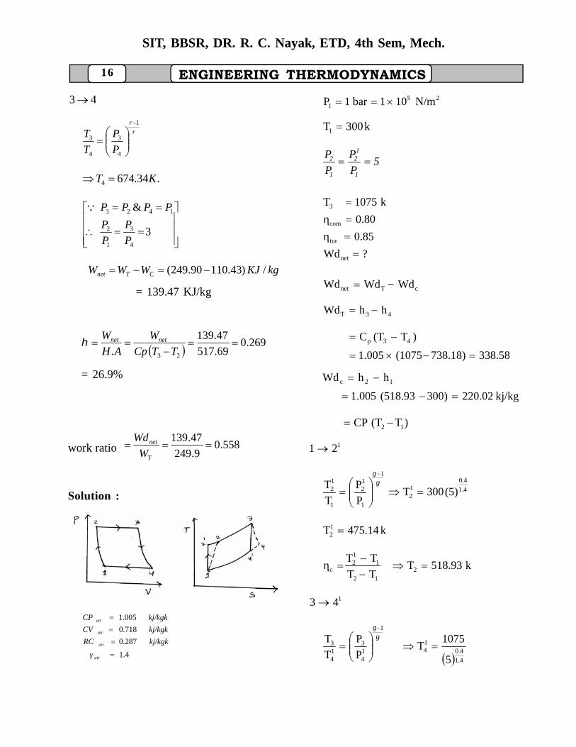
Q. A gas turbine power plant being supplied at1 b a r , 2 7
oC to be compressed upto 5 bar withisentropic efficiency of 25%, compressed airis heated upto 1000K in combustion chamber,where pressure drop of 0.2 bar. determine isen-
tropic efficiency of the turbine, if cycle is 20%.
Fig-12
Solution :
251
441 1011m
NbarPPP
251
`22 1055m
NbarPP
12
SIT, BBSR, DR. R. C. Nayak, ETD, 4th Sem, Mech.
ENGINEERING THERMODYNAMICS
kT 300273271
,25.0c kT 10003
(as pressure drop of 0.2 bar)
?T
2.0%20 Brayton
for 1-21 process
1
1
12
1
12
P
P
T
T
kT 14.47512
12
11
2
TT
TTc
KT 7.11752
for 3-a1 process
1
3
14
3
14
P
P
T
T
kT 79.63814
Now 143
43
TT
TTT
AH
dw netBrayton .
).(
32.
AH
WW CT
)(
)()(
23
1243
hh
hhhh
)(
)()(
23
1243
TT
TTTTtonBary
4T =950.23 k
136.01
43
43
TT
TTT
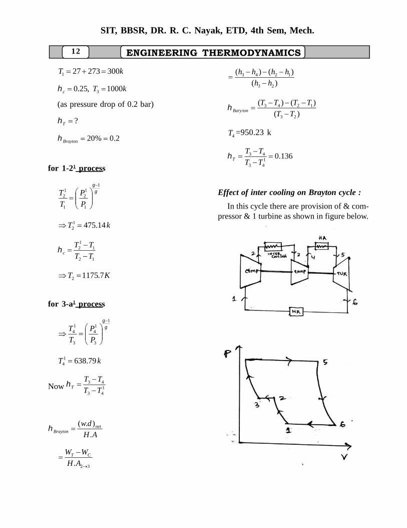
Effect of inter cooling on Brayton cycle :
In this cycle there are provision of & com-pressor & 1 turbine as shown in figure below.
Fig-13
Fig-14
ENGINEERING THERMODYNAMICS 13
SIT, BBSR, DR. R. C. Nayak, ETD, 4th Sem, Mech.
45. hhAH
],[],[ 3213 PPTT
16 hhHR
56 hhWT
14 hhWC
HA
HR1
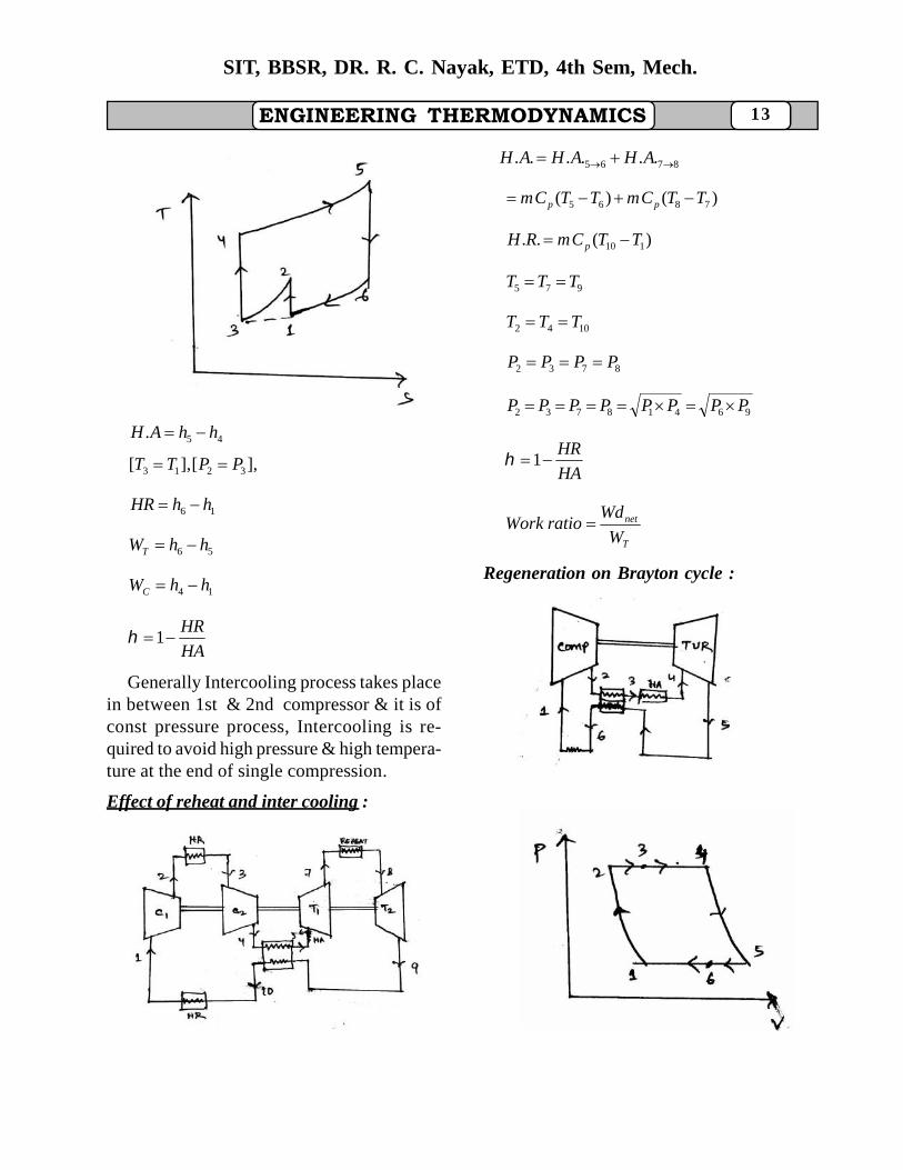
Generally Intercooling process takes placein between 1st & 2nd compressor & it is ofconst pressure process, Intercooling is re-quired to avoid high pressure & high tempera-ture at the end of single compression.
Effect of reheat and inter cooling :
Fig-15
8765 ...... AHAHAH
)()( 7865 TTCmTTCm pp
)(.. 110 TTCmRH p
975 TTT
1042 TTT
8732 PPPP
96418732 PPPPPPPP
HA
HR1
T
net
W
WdratioWork
Regeneration on Brayton cycle :
Fig-17
Fig-18
14
SIT, BBSR, DR. R. C. Nayak, ETD, 4th Sem, Mech.
ENGINEERING THERMODYNAMICS
1616.. TThhRH
3434.. TThhAH
62 TT
53 TT
34
1611TT
TT
HA
HR
54
121TT
TT
53
62
TT
TT
4
54
1
21
1
1
1
T
TT
T
TT
4
5
2
1
1
2
4
1
1
1
1
T
T
T
T
T
T
T
T
For 21 process
1
11
1
1
2
1
2
prP
P
T
T
pr = pressure ratio
1
2
P
P
For 54 process
1
11
1
1
21
1
5
4
5
4
r
p
rr
rP
P
P
P
T
T
4
5
2
1
4
2
1
1
1
T
T
T
T
T
T
1
1
1
1
4
2
11
11
1
p
p
r
r
T
T
4
21T
T
4
24
T
TT
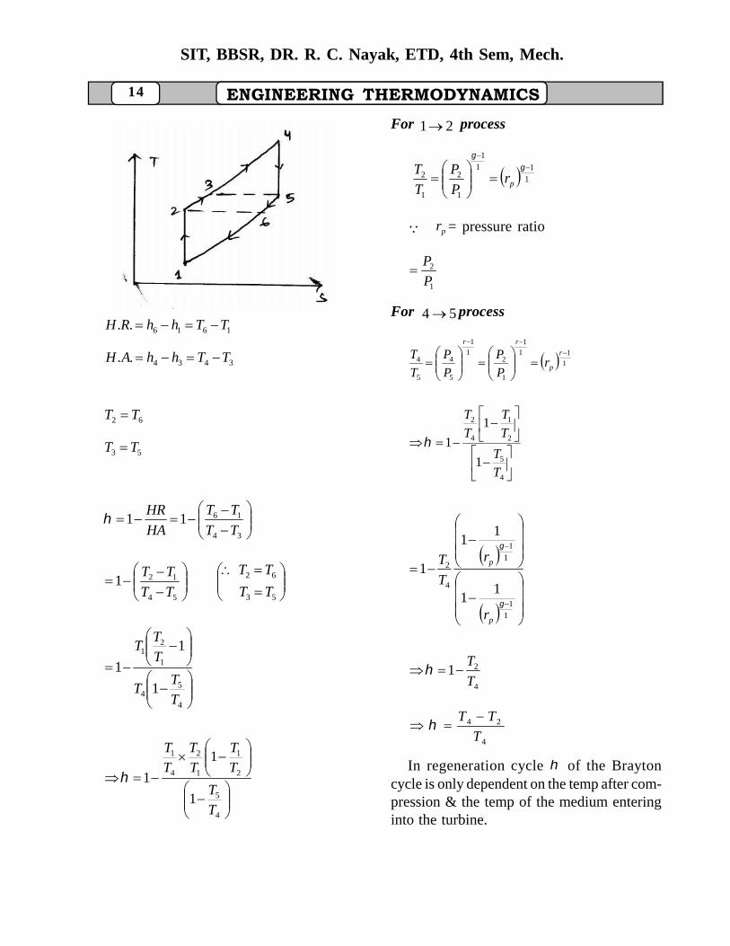
In regeneration cycle of the Braytoncycle is only dependent on the temp after com-pression & the temp of the medium enteringinto the turbine.
ENGINEERING THERMODYNAMICS 15
SIT, BBSR, DR. R. C. Nayak, ETD, 4th Sem, Mech.
Procedure for solving problem :
1) Read the question & confirm (cycle usedin power plant, H.A & H.R. at cont pr.)
2) Then check about of compressor & Tur--bine is given or not is given.
AH
Wnet
.
CTnet WWWd
3) Then check about the conditions (Re-heat, inter coooling)
4) Draw T-S diagram
5) Write the formula & then solve theproblem.
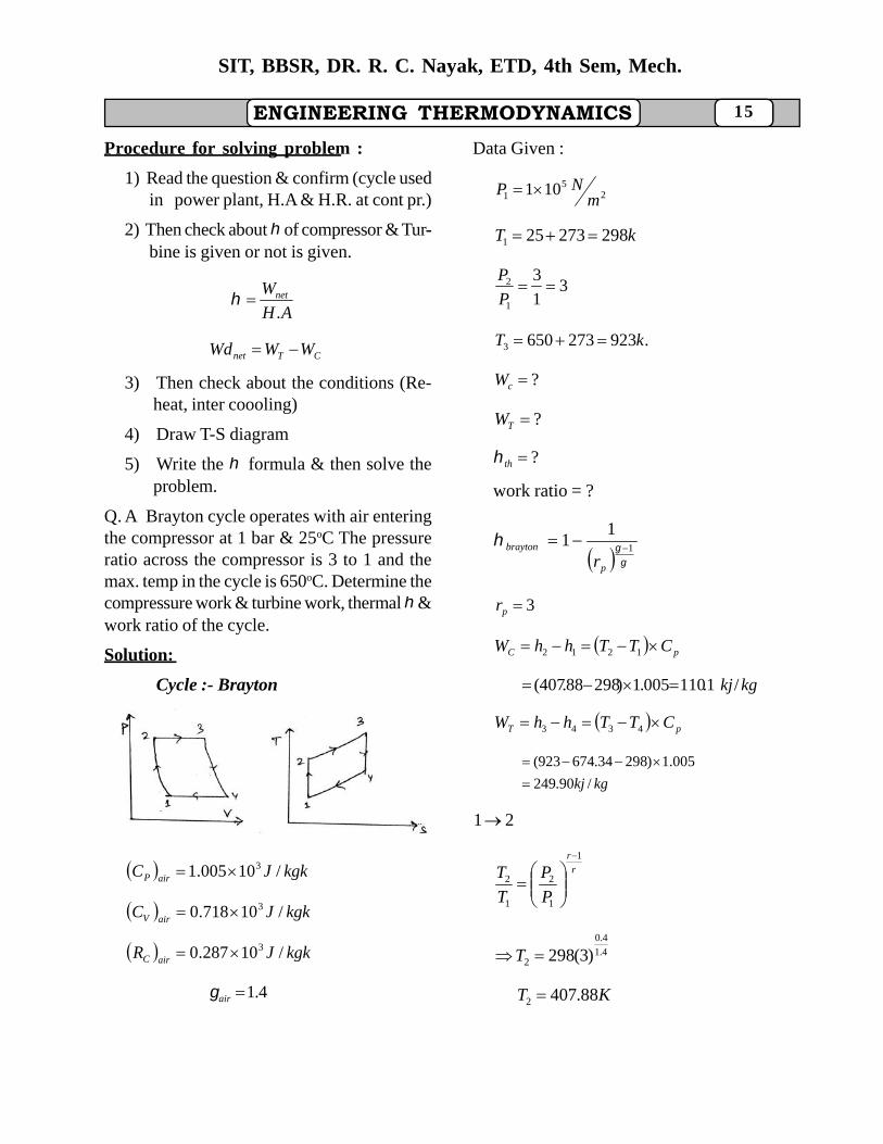
Q. A Brayton cycle operates with air enteringthe compressor at 1 bar & 25oC The pressureratio across the compressor is 3 to 1 and themax. temp in the cycle is 650oC. Determine thecompressure work & turbine work, thermal &work ratio of the cycle.
Solution:
Cycle :- Brayton
FIG-19
kgkJC airP /10005.1 3
kgkJC airV /10718.0 3
kgkJR airC /10287.0 3
4.1air
Data Given :
25
1 101m
NP
kT 298273251
31
3
1
2 P
P
.9232736503 kT
?cW
?TW
?th
work ratio = ?
1
11
p
brayton
r
3pr
pC CTThhW 1212
kgkj/1.110005.1)29888.407(
pT CTThhW 4343
kgkj /90.249
005.1)29834.674923(
21
r
r
P
P
T
T1
1
2
1
2
4.1
4.0
2 )3(298T
KT 88.4072
16
SIT, BBSR, DR. R. C. Nayak, ETD, 4th Sem, Mech.
ENGINEERING THERMODYNAMICS
43
r
r
P
P
T
T1
4
3
4
3
.34.6744 KT
3
&
4
3
1
2
1423
P
P
P
P
PPPP
kgKJWWW CTnet /)43.11090.249(
= 139.47 KJ/kg
269.069.517
47.139
. 23
TTCp
W
AH
W netnet
= 26.9%
work ratio 558.09.249
47.139
T
net
W
Wd
Solution :
Fig -A
1.4
0.287
0.718
1.005
air
air
air
air
γkj/kgkRC
kj/kgkCV
kj/kgkCP
251 N/m101bar1P
k300T1
5P
P
P
P
1
12
1
2
?Wd
0.85η0.80η
k1075T
net
tur
com
3
cTnet WdWdWd
43T hhWd
338.58738.18)(10751.005
)T(TC 43p
kj/kg220.02300)(518.931.005
hhWd 12c
)T(TCP 12
121
1.4
0.412
1
1
12
1
12 (5)300T
P
P
T
T
k475.14T12
k518.93TTT
TTη 212
112
c
143
1.4
0.414
1
14
314
3
5
1075T
P
P
T
T
ENGINEERING THERMODYNAMICS 17
SIT, BBSR, DR. R. C. Nayak, ETD, 4th Sem, Mech.
k678.74T14
143
43T TT
TTη
k738.18T4
kj/kg118.48WdWdWd
kj/kg220.02Wd
kj/kg338.5Wd
cTnet
c
T
%21.20.212558.85
118.48
)T(TCp
Wd
HA
Wdη23
netnet
0.35338.6
118.48RatioWork
Tur
net
W
Wd
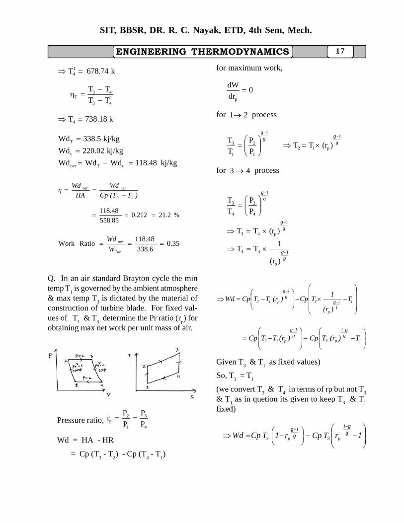
Q. In an air standard Brayton cycle the mintemp T
1 is governed by the ambient atmosphere
& max temp T3 is dictated by the material of
construction of turbine blade. For fixed val-ues of T
1 & T
3 determine the Pr ratio (r
p) for
obtaining max net work per unit mass of air.
Fig-B
Pressure ratio,4
3
1
2p P
P
P
Pr
Wd = HA - HR
= Cp (T3 - T
2) - Cp (T
4 - T
1)
for maximum work,
0dr
dW
p
for 21 process
1
p12
1
1
2
1
3 )(rTTP
P
T
T
for 43 process
1
p
34
1
p43
1
4
3
4
3
)(r
1TT
)(rTT
P
P
T
T
11
p
3
1
p13 T
)(r
1TCp)(rTTCpWd
1
1
1
p3
1
p13 T)(rTCp)(rTTCp
Given T3 & T
1 as fixed values)
So, T3 = T
1
(we convert T2 & T
4 in terms of rp but not T
3
& T1 as in quetion its given to keep T
3 & T
1
fixed)
1rTCpr1TCpWd1
p3
1
p3
18
SIT, BBSR, DR. R. C. Nayak, ETD, 4th Sem, Mech.
ENGINEERING THERMODYNAMICS (T
3 = T
1 as given fixed value)
Now, 0dr
dW
p
11
p33 )(r1
TCp0TCp
00TCp)(r1
TCp 3
11
p3
21
p
1
p
21
p
1
p
r
1
p
1
p
)(r)(r
)(r1
)(r1
0)(r1
)(r1
0
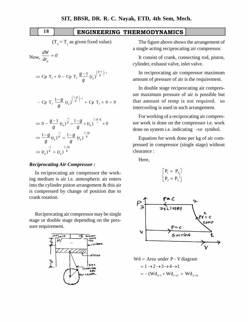
Reciprocating Air Compressor :
In reciprocating air compressor the work-ing medium is air i.e. atmospheric air entersinto the cylinder piston arrangement & this airis compressed by change of position due tocrank rotation.
Reciprocating air compressor may be singlestage or double stage depending on the pres-sure requirement.
Fig-C
The figure above shows the arrangement ofa single acting reciprocating air compressor.
It consist of crank, connecting rod, piston,cylinder, exhaust valve, inlet valve.
In reciprocating air compressor maximumamount of pressure of air is the requirement.
In double stage reciprocating air compres-sor maximum pressure of air is possible butthat amount of temp is not required. sointercooling is used in such arrangement.
For working of a reciprocating air compres-sor work is done on the compressor i.e. workdone on system i.e. indicating -ve symbol.
Equation for work done per kg of air com-pressed in compressor (single stage) withoutclearance :
Here,
23
41
PP
PP
Fig-D
322114 WdWd(Wd
14321
diagramVPunderAreaWd
ENGINEERING THERMODYNAMICS 19
SIT, BBSR, DR. R. C. Nayak, ETD, 4th Sem, Mech.
)V(VP1
VPVP)V(VP 232
2211411 n
)VP(1
VPVPVP 22
221111 n
1
VPVP)VPVP( 2211
2211 n
1
VPVPVPVP 2211
2211 n
1
VPVPVPVP 1122
1122 n
1
11VPVP 1122 n
1
11VPVP 1122 n
n
12
1122
TmRcTmRc1n
n
1n
nVPVP
TRcmPV
Rc1n
nWd
12 TT
kg1m
etemperaturncompressio&'2''1'oftermsIn
Again,
1122 VPVP1n
nWd
1
VP
VPVP
1n
n
11
2211
1T
TTRcm
1n
n
1TRcm
TRcmTRcm
1n
n
1
21
1
21
1P
PTRc
1n
nWd n
1n
1
21
unnit of Wd = J/kg.
kgm 1
Equation for work per kg of air conpressedin conpressor (single state) with clearance :
Fig-E
Here, 2341 PP&PP
56435underAreaWd
16521underAreaWd
WdWdWd
e
c
expansionncompressio
20
SIT, BBSR, DR. R. C. Nayak, ETD, 4th Sem, Mech.
ENGINEERING THERMODYNAMICS
1P
PVP
1n
n1
P
PVP
1n
nWd
n
1n
4
344
n
1n
1
211
11
1
1
2411
n
n
P
PVVP
n
n
as P1 = P
4 & P
2 = P
3
Let V1 - V
4 = V
a
where, Va = Actual Vol. of air delivered.
11
11
1
1
21
1
1
21
n
n
n
n
a
P
PTRcm
n
n
P
PVP
n
nWd
kg1m1P
PTRc
1n
nWd
n
1n
1
21clearance
Hence it is concluded that for work per kgof air compressed in air compressor (singlestage) without clearance and with clearance hasnot efect i.e. same value of Wd.
Volumetric Efficiency :
It is ratio of actual free air delivered to thedisplacement of the compressor. displacementof the compressor = (Vs)
s
a
31
41v V
V
VV
VV
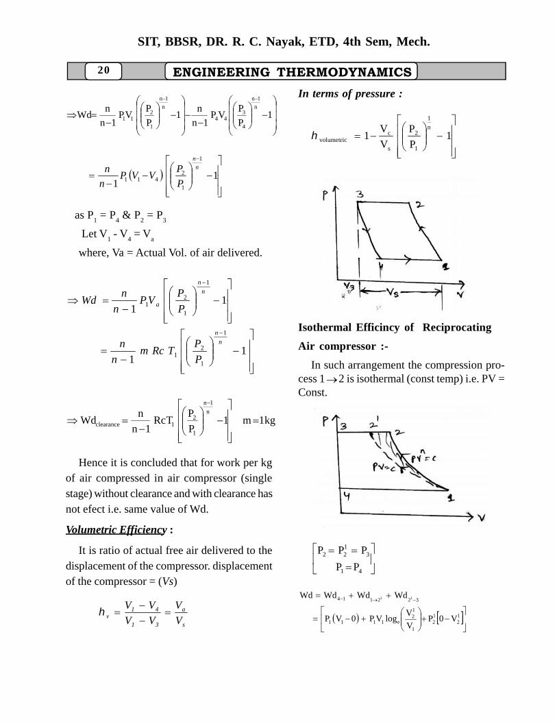
In terms of pressure :
1
P
P
V
V1
n
1
1
2
s
cvolumetric
Fig-F
Isothermal Efficincy of Reciprocating
Air compressor :-
In such arrangement the compression pro-cess 12 is isothermal (const temp) i.e. PV =Const.
Fig -G
41
3122
PP
PPP
12
12
1
12
e1111
322114
V0PV
VlogVP0VP
WdWdWdWd 11
ENGINEERING THERMODYNAMICS 21
SIT, BBSR, DR. R. C. Nayak, ETD, 4th Sem, Mech.
(-ve sign as we give work on the system)
1112
121
2
1e11 VPVP
V
VlogVP
But, 12
1211 VPVP
12
1e11 V
VlogVPWd
12
1e1isothermal V
VlogTRcmWd
kg1mfor
12
1e1isothermal V
VlogTRcWd
Isothermal Efficiency :
It is the ratio between isothermal work tothe actual work.
11
log
1
1
21
12
11
iso
n
n
c
e
P
PTR
n
n
V
VTRc
11
log
1
1
2
1
12
n
n
e
P
P
n
n
P
P
12
1
1
12
V
V
P
P
Procedure for solving problem :
1. Read the question & confirm stage.
2. Check about single or double stage.
3. Then check about compression process (ifit given a law (PVn = const., n= any val-ues) then con sider it as actual work done
(or Wdactual
or Wdpolytropic
)).
4. Write the data given :
Pistom Speed = 2 LN
Where, L = Stroke length
N = Speed in rpm
LD4
πV 2
s
Input of the compressor :
Input of the compressor
1000
compressorondonework
Sometimes the indicated power of a com-
pressor (IP) is calculated in terms of mean Ef-
fective Pressure(Pn).
IP kwNALPm 100
where, N = revolution per sec of compressor
Pm = MEP in 2m
N
L = Length of the stroke in m.
A = Area of the piston in m2.
Related Formula :
Single acting single stage :
Fig-H
22
SIT, BBSR, DR. R. C. Nayak, ETD, 4th Sem, Mech.
ENGINEERING THERMODYNAMICS
11
1
1
1
21
n
VP
P
P
n
nWd a
41a VVV
11
1
1
211
n
n
P
PVP
n
n
31s VVV
11
1
1
21
n
n
s P
PVP
n
nwithout clear--
ance
( I.P. = Indicated Power)
Fig-I
kw1000
RPS1
P
PnVP
1n
n
kw1000
RPS1
P
P
1n
nIP
1
1n
1
2vs1
n
1n
1
21
aVP
kw1000
11
P
PVP
1n
n n
1n
1
211
Volumetric volη
sV
4V
1V
sV
aV
sV
cV
k1P
Pk1η
n
1
1
2v
Mean Effective pressure -
11
1
1
21
n
n
m P
PP
n
nP
* F r e e a i r d e l i v e r e d ( Va)per min = sv VN
( N in RPM )
* deliveredAirFreeaV = sv V
* Piston speed (rpm) = 2 LN
* LdVs 2
4
SINGLE ACTING WITH TWO STAGE :
Q. Determine the size of the cylinder of adouble acting air compressor of 32 kw inputpower in which air is drawn at 1 bar & com-pressed to 16 bar according to law PV1.25 = c,
RPM = 300, piston speed 180 m/min, v = 0.8
(volumetric m)
Solution :
Indicated Power, IP= 32 kw = watt1032 3
ENGINEERING THERMODYNAMICS 23
SIT, BBSR, DR. R. C. Nayak, ETD, 4th Sem, Mech.
60
300RPSrpm300N
1.25)(nConstantPV
N/m1016PP
N/m101PP
1.25
2523
2514
0.8
m/min180speedPiston
v
21000
RPS1
P
PVP
1n
nIP
n
1n
1
2a1
(as given double action)
31032
1000
2
6
3001
1
16101
25.0
25.1 25.1
25.0
5
aV
3s
s
41
s
av
3a
m10.8V
64.8
V
VV
V
Vm
m8.64V
sV
m6.77d
Ld4
πV
n0.3L
LN2speedPiston
2s
Q.A single stage single acting compressordellvers 15 m3 of the free air per minute from1 bar to 8 bar, that compression & expansionfollow the law PV1.3= C and clearance is 1/
16th of teh swept vol. Find the dia & stroke ofthe compressor.
Take 1.5D
L .
Solution : 1.5D
L
sc
1.3
252
251
3a
V16
1V
1.3)(nCPV
rpm300N
N/m108P
N/m101P
min/m15V
Find D = ?
L = ?
11
1
1
2n
S
CV P
P
V
V
753.01
8
16
11
3.1
1.1
%3.75
Free air delivered / min (Va) =
SSV VVN 753.0300
066.0SV
5.1
42
D
LLDVS
24
SIT, BBSR, DR. R. C. Nayak, ETD, 4th Sem, Mech.
ENGINEERING THERMODYNAMICS
,383.0 mD
mL 574.0383.05.1
60
1
1000
11
1.
1
1
21
n
n
a P
PVP
n
nPI
= 66.4 kw.
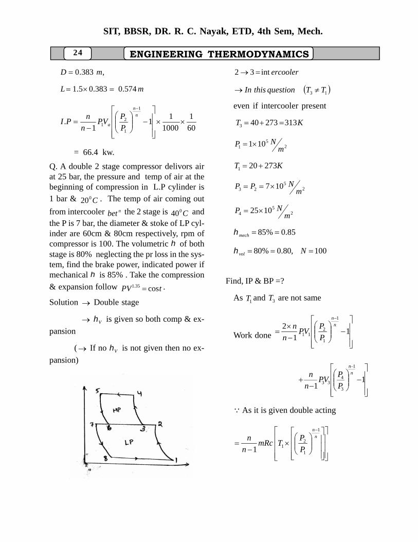
Q. A double 2 stage compressor delivors airat 25 bar, the pressure and temp of air at thebeginning of compression in L.P cylinder is1 bar & C020 . The temp of air coming out
from intercooler nbet the 2 stage is C040 andthe P is 7 bar, the diameter & stoke of LP cyl-inder are 60cm & 80cm respectively, rpm ofcompressor is 100. The volumetric of bothstage is 80% neglecting the pr loss in the sys-tem, find the brake power, indicated power ifmechanical is 85% . Take the compression
& expansion follow tPV cos35.1 .
Solution Double stage
V is given so both comp & ex-
pansion
( If no V is not given then no ex-
pansion)
Fig-J
ercoolerint32
13 TTquestionthisIn
even if intercooler present
KT 313273403
25
1 101m
NP
KT 273201
25
23 107m
NPP
25
4 1025m
NP
85.0%85 mech
100,80.0%80 Nvol
Find, IP & BP =?
As 1T and 3T are not same
Work done
11
21
1
211
n
n
P
PVP
n
n
11
1
3
433
n
n
P
PVP
n
n
As it is given double acting
n
n
P
PTmRc
n
n1
1
211
ENGINEERING THERMODYNAMICS 25
SIT, BBSR, DR. R. C. Nayak, ETD, 4th Sem, Mech.
1
1
3
43
n
n
P
PT
11 TMRCVP a
NVV Sa
VLd
2
4
= 0.181m3
11 TmRcVP a
kgm 215.0293287
181.0101 5
1000.
speedWdPI
kw244
PI
PBmech .
.
kwPI
PBmech
287..
..
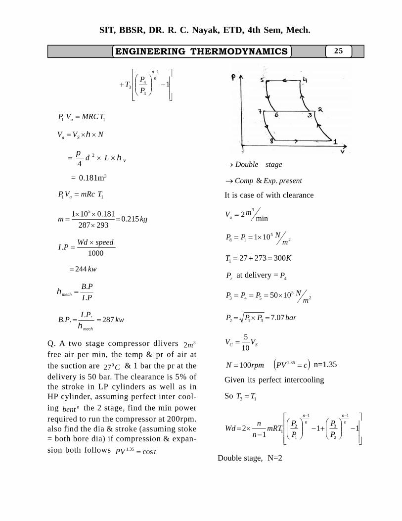
Q. A two stage compressor dlivers 32mfree air per min, the temp & pr of air atthe suction are C027 & 1 bar the pr at thedelivery is 50 bar. The clearance is 5% ofthe stroke in LP cylinders as well as inHP cylinder, assuming perfect inter cool-ing nbent the 2 stage, find the min powerrequired to run the compressor at 200rpm.also find the dia & stroke (assuming stoke= both bore dia) if compression & expan-sion both follows tPV cos35.1
Fig-K
stageDouble
presentExpComp .&
It is case of with clearance
min23mVa
25
18 101m
NPP
KT 300273271
rP at delivery = 4P
25
543 1050m
NPPP
barPPP 07.7312
SC VV10
5
cPVrpmN 35.1100 n=1.35
Given its perfect intercooling
So 13 TT
111
2
1
2
3
1
1
21
n
n
n
n
P
P
P
PmRT
n
nWd
Double stage, N=2
26
SIT, BBSR, DR. R. C. Nayak, ETD, 4th Sem, Mech.
ENGINEERING THERMODYNAMICS
1
1
RT
VPm a
= 2.32 kg/min = 0.038 kg/sec
kwWd
PI 965.161000
.
Free air delivered = NV VS 11
3011.01
mVs
11
1
1
21
n
S
CV P
P
V
V
= 83.75
LdVS 21 4
dd 2
4
cmd 8.24
cmLd 8.24
Refrigeration Cycle
(Vapur Compression cycle)
Fig-L
Parameters : -
* P Pressure (bar)
* T Temp (K)
* t Temp ( C0 )
* v Specific volume
kgm3
* h Enthalpy (kJ/kg)
* SEntropy (kJ/kg K)
* U Internal energy (kJ/kg)
* x Dryness fraction
* Dry Steam
* Wet Water
Steam
wet steam
saturated steam
superheated steam
WET STEAM Denoted by ‘X’
Where X : Dryness fraction
If given condition of steam of less thansatoration condition (Found from steamtable) then that steam is wet steam.
wetwetwetwet VUSh ,,,
gwet
fgfwet
fgfwet
XVV
XSSS
Xhhh
Satorated Steam :
If given condition of steam is equal tosturation nCond then given steam becomessatrated steam.
ENGINEERING THERMODYNAMICS 27
SIT, BBSR, DR. R. C. Nayak, ETD, 4th Sem, Mech.
gfgfgf VVSShh ,,,,, (directly found
from steam table)
Superheated Steam :
If given condition of steam is greater thansaturation condition.
supsupsupsup ,,, UVSh
* satPsteamg TTChh supsup
*
satPsteamg T
TeCSS sup
sup log
*
satV
sat
g
T
V
T
V
sup
sup
foundbecanV sup
kgKkJCPsteam 1.2
kgKkJCPwater 2.4
wpwwater TCh
Fig-M
Fig-N
Fig-O
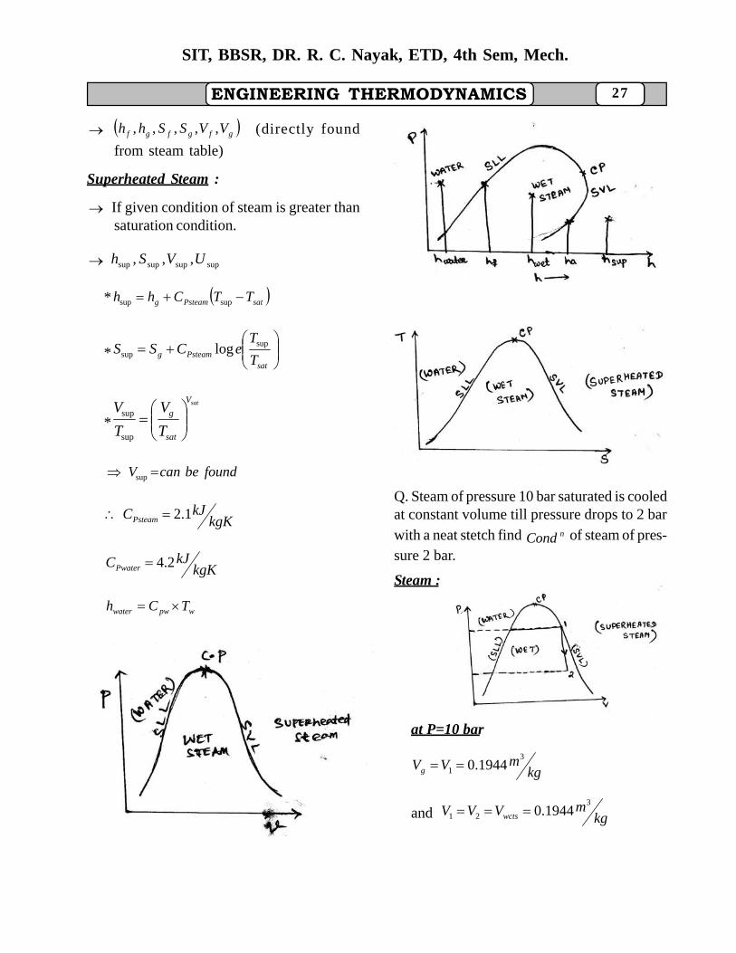
Q. Steam of pressure 10 bar saturated is cooledat constant volume till pressure drops to 2 barwith a neat stetch find nCond of steam of pres-sure 2 bar.
Steam :
Fig-P
at P=10 bar
kgmVVg
3
1 1944.0
and kgmVVV wcts
3
21 1944.0
28
SIT, BBSR, DR. R. C. Nayak, ETD, 4th Sem, Mech.
ENGINEERING THERMODYNAMICS
Now, gswct VXV 2
at P = 2bar
kgmVg
38857.0
8857.01944.0 X
22.02 XX
22222 fgfwct hXhhh
9.220122.07.504
kgkJ91.986
22222 fgfwct SXSSS
5970.52.25301.1
kgKkJ7558.2
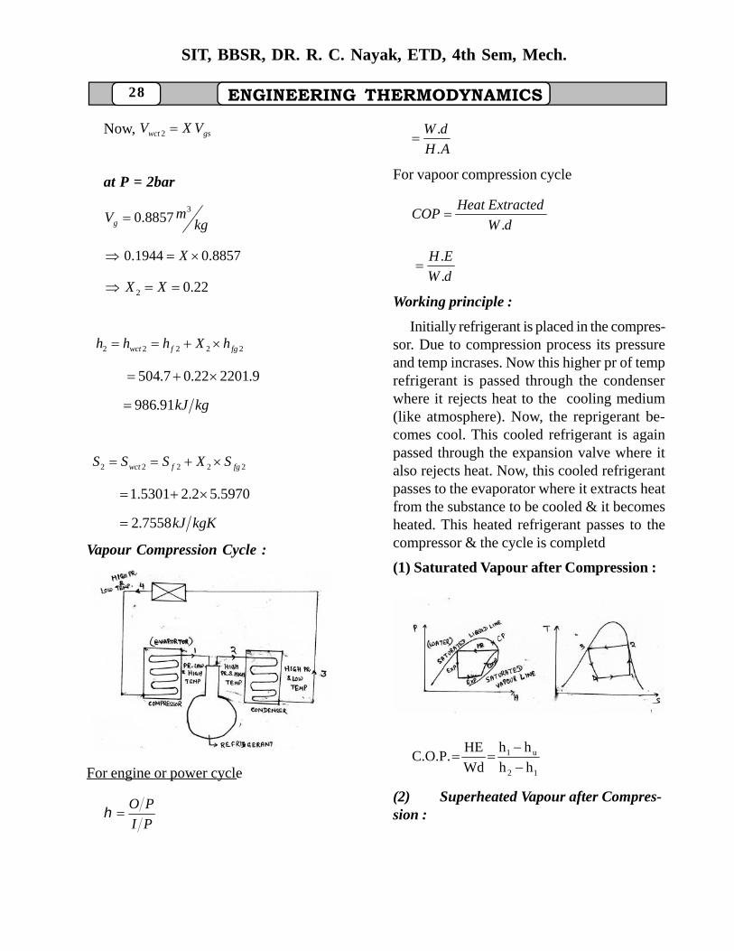
Vapour Compression Cycle :
Fig-Q
For engine or power cycle
PI
PO
AH
dW
.
.
For vapoor compression cycle
dW
ExtractedHeatCOP
.
dW
EH
.
.
Working principle :
Initially refrigerant is placed in the compres-sor. Due to compression process its pressureand temp incrases. Now this higher pr of temprefrigerant is passed through the condenserwhere it rejects heat to the cooling medium(like atmosphere). Now, the reprigerant be-comes cool. This cooled refrigerant is againpassed through the expansion valve where italso rejects heat. Now, this cooled refrigerantpasses to the evaporator where it extracts heatfrom the substance to be cooled & it becomesheated. This heated refrigerant passes to thecompressor & the cycle is completd
(1) Saturated Vapour after Compression :
Fig-R
12
u1
hh
hh
Wd
HEC.O.P.
(2) Superheated Vapour after Compres-sion :
ENGINEERING THERMODYNAMICS 29
SIT, BBSR, DR. R. C. Nayak, ETD, 4th Sem, Mech.
Fig-S
(3) Superheated Vapour before and afterCompression :
Fig-T
(4) Wet steam before and after Compression:
Fig-U
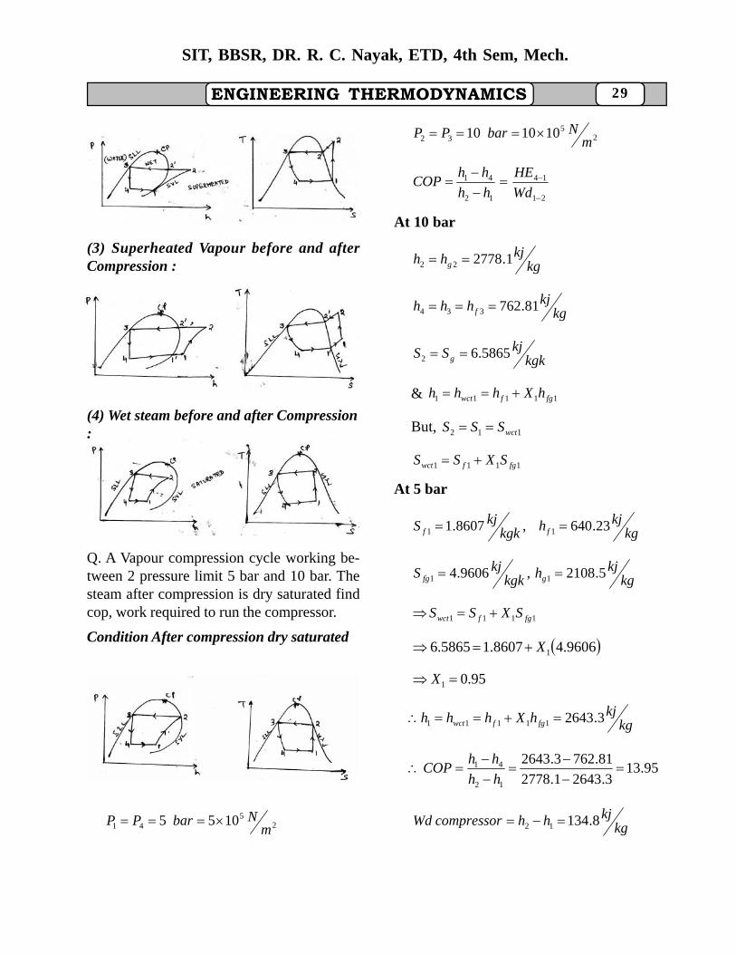
Q. A Vapour compression cycle working be-tween 2 pressure limit 5 bar and 10 bar. Thesteam after compression is dry saturated findcop, work required to run the compressor.
Condition After compression dry saturated
Fig-V
25
41 1055m
NbarPP
25
32 101010m
NbarPP
21
14
12
41
Wd
HE
hh
hhCOP
At 10 bar
kgkjhh g 1.277822
kgkjhhh f 81.762334
kgkkjSS g 5865.62
& 11111 fgfwct hXhhh
But, 112 wctSSS
1111 fgfwct SXSS
At 5 bar
kgkjhkgk
kjS ff 23.640,8607.1 11
kgkjhkgk
kjS gfg 5.2108,9606.4 11
1111 fgfwct SXSS
9606.48607.15865.6 1X
95.01 X
kgkjhXhhh fgfwct 3.264311111
95.133.26431.2778
81.7623.2643
12
41
hh
hhCOP
kgkjhhcompressorWd 8.13412
30
SIT, BBSR, DR. R. C. Nayak, ETD, 4th Sem, Mech.
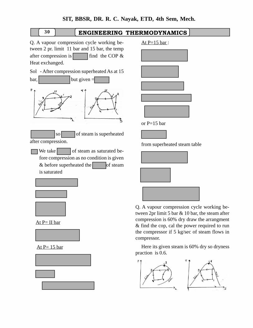
ENGINEERING THERMODYNAMICSQ. A vapour compression cycle working be-tween 2 pr. limit 11 bar and 15 bar, the tempafter compression is find the COP &Heat exchanged.
Sol - After compression superheated As at 15
bar, but given =
Fig-W
so of steam is superheated
after compression.
We take of steam as saturated be-fore compression as no condition is given& before superheated the of steamis saturated
At P= II bar
At P= 15 bar
At P=15 bar :
or P=15 bar
from superheated steam table
Q. A vapour compression cycle working be-tween 2pr limit 5 bar & 10 bar, the steam aftercompression is 60% dry draw the arrangment& find the cop, cal the power required to runthe compressor if 5 kg/sec of steam flows incompressor.
Here its given steam is 60% dry so drynesspraction is 0.6.
Fig-X
ENGINEERING THERMODYNAMICS 31
SIT, BBSR, DR. R. C. Nayak, ETD, 4th Sem, Mech.
barPP 541
barPP 1032
6.0%602 X
12
41
hh
hhcop
At P= 10bar
2334 81.762 ff hkgkjhhh
kgkkjSkg
kjh ff 1387.2,81.762 22
kgkkjSkg
kjh fgfg 4478.4,3.2015 22
kgkjhXhhh fgfwct 99.197122222
kgkkjSXSSS fgfwct 80738.422222
kgkkjSSS wct 80738.4112
1111 fgfwct SXSS
P=5bar
kgkjhkgk
kjS ff 23.640,8607.1 11
kgkjhkgk
kjS fgfg 5.2108,9606.4 11
59.01111 fgfwc SXSS
25.188411111 fgfwct hXhhh
25.188499.1971
81.76225.1884
12
41
hh
hhCop
78.1274.87
44.1121
Power of compressor mhh 12
kwS 87.4374.87
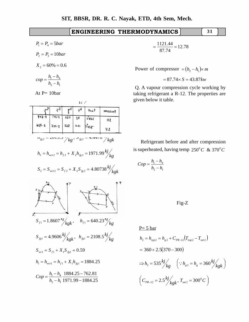
Q. A vapour compression cycle working bytaking refrigerant a R-12. The properties aregiven below it table.
Fig-Y
Refrigerant before and after compression
is superheated, having temp CC 00 370&250
12
41
hh
hhCop
Fig-Z
P= 5 bar
22sup12222 satPRgsyp TTChhh
3003705.2360
kgk
kjhhkgkjh gg 360535 22
CTkgk
kjC satPR0
212 300,5.2
32
SIT, BBSR, DR. R. C. Nayak, ETD, 4th Sem, Mech.
ENGINEERING THERMODYNAMICS
11sup1211 satPRg TTChh
P=10 bar
CT 01sup 250
CTsat0200
kgkjhg 2601
200205.22601 h
kgkj385
P= 15 bar
kgkjhhh f 110334
833.1150
275
385535
110385
12
41
hh
hhCop
Steam Power Cycle :
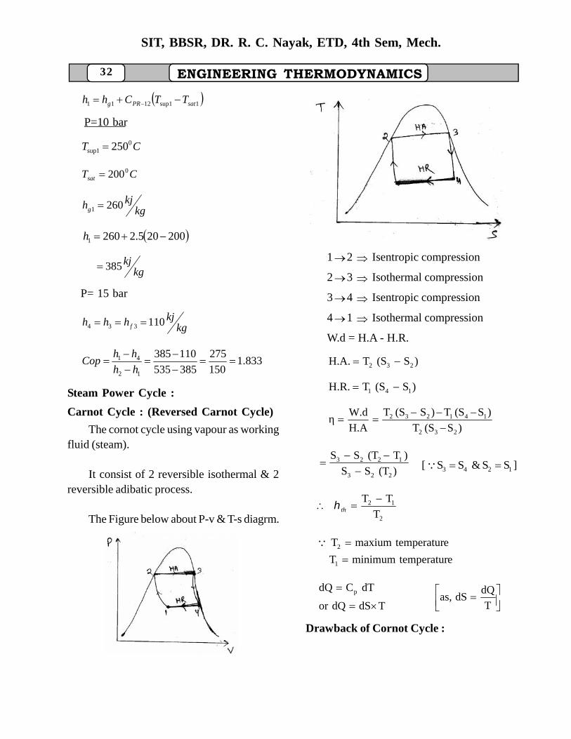
Carnot Cycle : (Reversed Carnot Cycle)
The cornot cycle using vapour as workingfluid (steam).
It consist of 2 reversible isothermal & 2reversible adibatic process.
The Figure below about P-v & T-s diagrm.
Fig-1 Fig-2
12 Isentropic compression
23 Isothermal compression
34 Isentropic compression
41 Isothermal compression
W.d = H.A - H.R.
)S(STH.A. 232
)S(STH.R. 141
)S(ST
)S(ST)S(ST
H.A
W.dη232
141232
)(TSS
)T(TSS
223
1223
]SS&SS[ 1243
2
12
T
TT th
etemperaturminimumT
etemperaturmaxiumT
1
2
TdSdQor
dTCdQ p
T
dQdSas,
Drawback of Cornot Cycle :
ENGINEERING THERMODYNAMICS 33
SIT, BBSR, DR. R. C. Nayak, ETD, 4th Sem, Mech.
(1) During Isothermal condensation process,the condensation is stopped at point 1 i.e. beforesaturated liquid condition is reached.
(2) Heat addition & Heat rejection take placeat const. temperature.
(3) of the carnot vapour cycle is 100% whichis practically impossible.
(4) As non-homogeneous mixture(water+steam) enter into the compressor socompressor size must be increased & workinput have to be large.
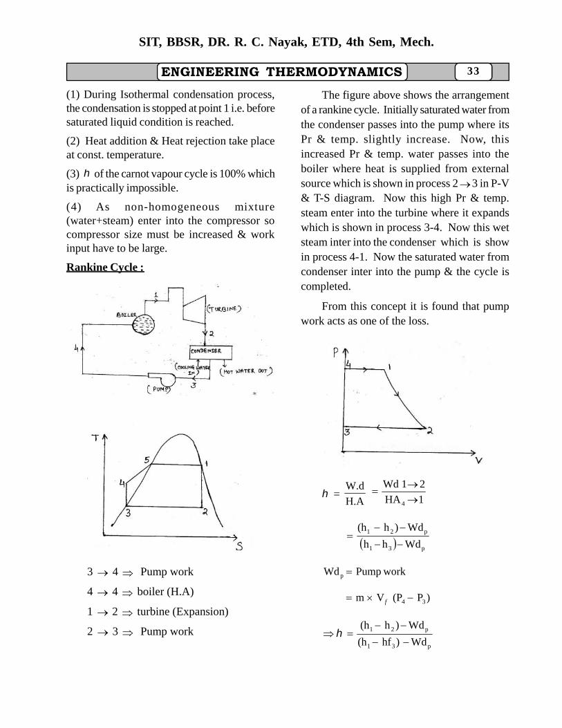
Rankine Cycle :
Fig- 3
Fig 4
3 4 Pump work
4 4 boiler (H.A)
1 2 turbine (Expansion)
2 3 Pump work
The figure above shows the arrangementof a rankine cycle. Initially saturated water fromthe condenser passes into the pump where itsPr & temp. slightly increase. Now, thisincreased Pr & temp. water passes into theboiler where heat is supplied from externalsource which is shown in process 23 in P-V& T-S diagram. Now this high Pr & temp.steam enter into the turbine where it expandswhich is shown in process 3-4. Now this wetsteam inter into the condenser which is showin process 4-1. Now the saturated water fromcondenser inter into the pump & the cycle iscompleted.
From this concept it is found that pumpwork acts as one of the loss.
Fig -5
=H.A
W.d1HA
21Wd
4
p31
p21
Wdhh
Wd)h(h
workPumpWd p
)P(PVm 34 f
p31
p21
Wd)hf(h
Wd)h(h
34
SIT, BBSR, DR. R. C. Nayak, ETD, 4th Sem, Mech.
ENGINEERING THERMODYNAMICSV
f = Saturated water Sp volume.
Steam Consumption =TurbineWd
3600
Work ratio =T
pT
T
net
Wd
WdWd
Wd
Wd
Efficiency ratio =Rankine
ith
Where ith is the indicated thermal
efficiency.
)hf(hm
3600
31sith
Where ms is the mass of steam.
Hint : If in quest it is not asked about workratio then we can neglect pump work.
Q. A rankine cycle works between 2 pr. limit12 bar & 0.01 bar. The steam that exits fromboiler is dry saturated. Find the rankine η .
Solution : Rankine cycle : since work ratio isnot given so we can neglect pump work.
Fig - 6
Now, P4 = P
1 = 12 bar
P2 = P
3 = 0.01 bar
η rankine = ?
η rankine =31
21
hh
hh
P = 12 bar.
h1 = hg
1 2784.8 kj/kg
S1 = S
g1 = 6.5233 kj/kgk
P = 0.01 bar
hf3 = h
3= 29.3 kj/kg
S1=S
2 =Swet
2 =6.5233 kj/kgk
Swet2 = Sf
2 + X
2 Sfg
2
P = 0.01 bar
Sf2 = 0.1059 kj/kgk,
hf2 = 29.3 kj/kg
Sfg2 = 8.8697 kj/kgk,
kgkjhgf /9.2484
2
kj/kg1818.43
2484.90.7229.3
hfgxhfh
0.72x
8.8697x0.10596.5233
2222
2
2
rankineη31
21
hfh
hh
3.298.2784
43.18188.2784
5.2755
37.966 .3507.0
ENGINEERING THERMODYNAMICS 35
SIT, BBSR, DR. R. C. Nayak, ETD, 4th Sem, Mech.
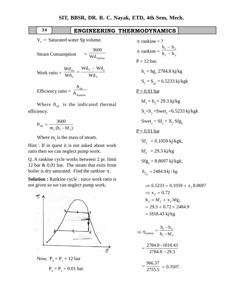
Q : A rankine cycle working between 2 pr. limit10 bar & 0.2 bar, find the η neglecting pumpwork if the steam after boiler has 90% drynesspraction.
Fig-7
Solution :
P4 = P1 = 10 bar.
P2 = P3 = 0.2 bar
rankineη = ?
31
21
frankine hh
hh
9.01 x
hf1 = 762.81 kj/kg Sf
1 = 2.1387 kj/kgk
hfg1 = 2015.3 kj/kg Sfg
1=4.4478 kj/kgk
h1 = 52576.58 kj/kg.
Now, S1 = Swet
1 = Sf
1 + x
1 Sfg
1
= 6.1417 kj/kgk
At 0.2 bar,
h3 = hf
3 = 251.40 kj/kg
hf2 = 251.40 kj/kg
Sf2=0.8320 kj/kgk
hfg2 = 2358.3 kj/kg
Sfg2 = 7.0766 kj/kgk
S2 = S
1 = Sf
2 + x
2 Sfg
2
6.1417 = 0.8320 + x2 7.0766
x2 = 0.75
h2 = hf
2 + x
2 hfg
2
= 2020.12 kj/kg.
η =31
21
hfh
hh
251.40-2576.58
2020.12-2576.58
2393.018.2325
46.556
Q. A rankine cyle working between 2 pr limit10 bar and 0.1 bar Temp after the boiler is 4000Cfind the work ratio steam consumption and alsofind rankine η and draw the total arrangementin T-S dia.
Fig-8
Solution :
Pump work is considered.
P4 = P
1 = 10 bar
P2=P
3 = 0.1 bar
tsat
= 179.910C
tgiven
= 4000C
tgiven
> tsat
, condition of
36
SIT, BBSR, DR. R. C. Nayak, ETD, 4th Sem, Mech.
ENGINEERING THERMODYNAMICSsteam is superheated so
point 1 is in superheated region.
P = 10 bar,
tsup
= 4000C
in superheated steam table
h1 = h
sup1 = 3263.9 kj/kg
S1 = S
sup1 = 7.4651 kj/kgk
P = 0.1 bar
hf3 = h
3 = 29.30 kj/kg
vf = vf3 = 0.001000 m3/kg
S2= S
1 = 7.4651 kj/kgk
S2 = S
wet2= Sf
2 + x
2 Sfg
2
P = 0.1 bar
Sf2 = 0.1059 kj/kgk
hf2 = 29.3 kj/kg
Sfg2= 8.8697
x2 = 0.83
h2 = hf
2 + x
2 hfg
2
kj/kg2089.28
2484.9)(0.8329.3
p31
p21
Wd)hp(h
Wd)h(hη
0.9929.3)(3263.9
0.992089.28)(3263.9
= 0.36
kj0.99
100.1)(100.0011
)P(PVmWd2
34fpump
0.991174.62
0.991174.62
Wd
WdWdRatioWork
T
pT
kj/kg1174.62
hhWd 21T
Stem consumption = kg/kj3.064Wd
3600
T
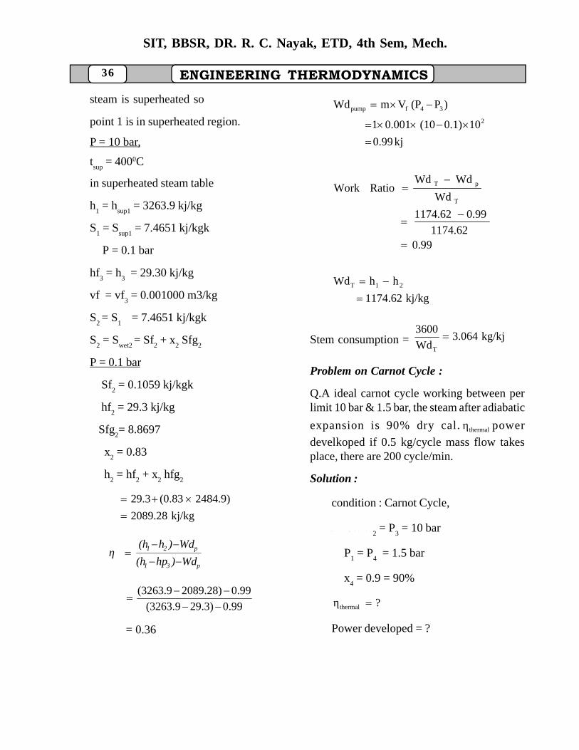
Problem on Carnot Cycle :
Q.A ideal carnot cycle working between perlimit 10 bar & 1.5 bar, the steam after adiabatic
expansion is 90% dry cal. thermalη power
develkoped if 0.5 kg/cycle mass flow takesplace, there are 200 cycle/min.
Solution :
condition : Carnot Cycle,
G i v e n , P
2 = P
3 = 10 bar
P1 = P
4 = 1.5 bar
x4 = 0.9 = 90%
?η thermal
Power developed = ?
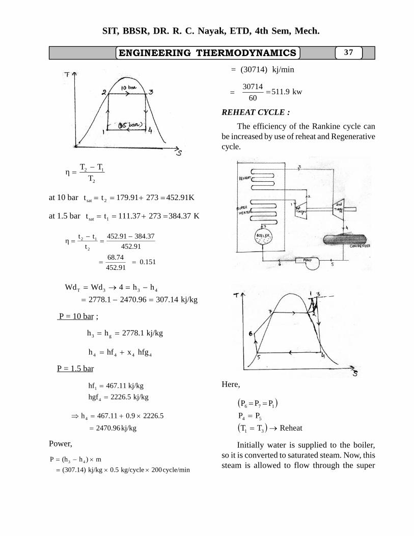
ENGINEERING THERMODYNAMICS 37
SIT, BBSR, DR. R. C. Nayak, ETD, 4th Sem, Mech.
Fig - 9
2
12
T
TTη
at 10 bar 452.91K273179.91tt 2sat
at 1.5 bar K37.84327337.111tt 1sat
0.151452.91
68.74
452.91
384.37452.91
t
ttη2
12
kj/kg307.142470.962778.1
hh4WdWd 433T
P = 10 bar ;
kj/kg2778.1hh g3
4444 hfgxhfh
P = 1.5 bar
kj/kg2226.5hgf
kj/kg467.11hf
4
1
kj/kg2470.96
2226.50.9467.11h4
Power,
cycle/min200kg/cycle0.5kj/kg(307.14)
m)h(hP 43
= (30714) kj/min
= kw511.960
30714
REHEAT CYCLE :
The efficiency of the Rankine cycle canbe increased by use of reheat and Regenerativecycle.
Fig - 10
Fig - 11
Here,
ReheatTT
PP
PPP
31
54
176
Initially water is supplied to the boiler,so it is converted to saturated steam. Now, thissteam is allowed to flow through the super
38
SIT, BBSR, DR. R. C. Nayak, ETD, 4th Sem, Mech.
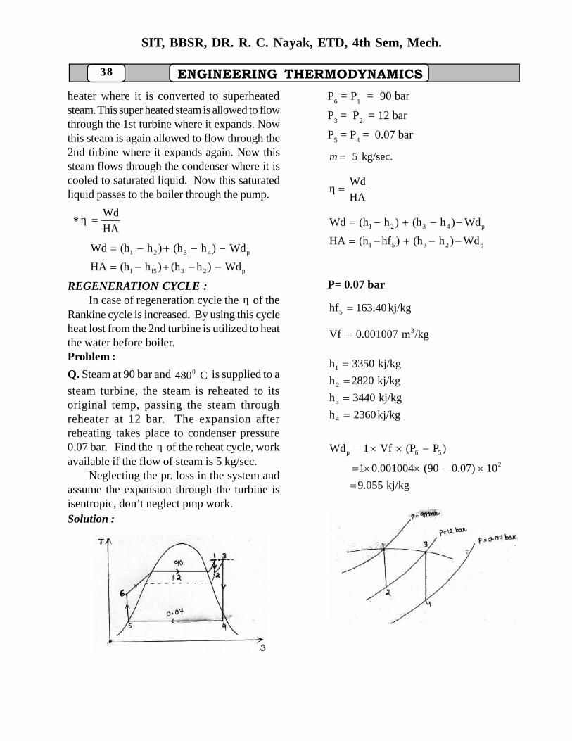
ENGINEERING THERMODYNAMICSheater where it is converted to superheatedsteam. This super heated steam is allowed to flowthrough the 1st turbine where it expands. Nowthis steam is again allowed to flow through the2nd tirbine where it expands again. Now thissteam flows through the condenser where it iscooled to saturated liquid. Now this saturatedliquid passes to the boiler through the pump.
*HA
Wdη
p23f51
p4321
Wd)h(h)h(hHA
Wd)h(h)h(hWd
REGENERATION CYCLE :In case of regeneration cycle the η of the
Rankine cycle is increased. By using this cycleheat lost from the 2nd turbine is utilized to heatthe water before boiler.Problem :
Q. Steam at 90 bar and C4800 is supplied to a
steam turbine, the steam is reheated to itsoriginal temp, passing the steam throughreheater at 12 bar. The expansion afterreheating takes place to condenser pressure0.07 bar. Find the η of the reheat cycle, workavailable if the flow of steam is 5 kg/sec.
Neglecting the pr. loss in the system andassume the expansion through the turbine isisentropic, don’t neglect pmp work.Solution :
Fig -12
P6 = P
1 = 90 bar
P3 = P
2 = 12 bar
P5 = P
4 = 0.07 bar
kg/sec.5m
HA
Wdη
p2351
p4321
Wd)h(h)hf(hHA
Wd)h(h)h(hWd
P= 0.07 bar
kj/kg163.40hf5
/kgm0.001007Vf 3
kj/kg2360h
kj/kg3440h
kj/kg2820h
kj/kg3350h
4
3
2
1
kj/kg9.055
100.07)(900.0010041
)P(PVf1Wd2
56p
Fig- 13
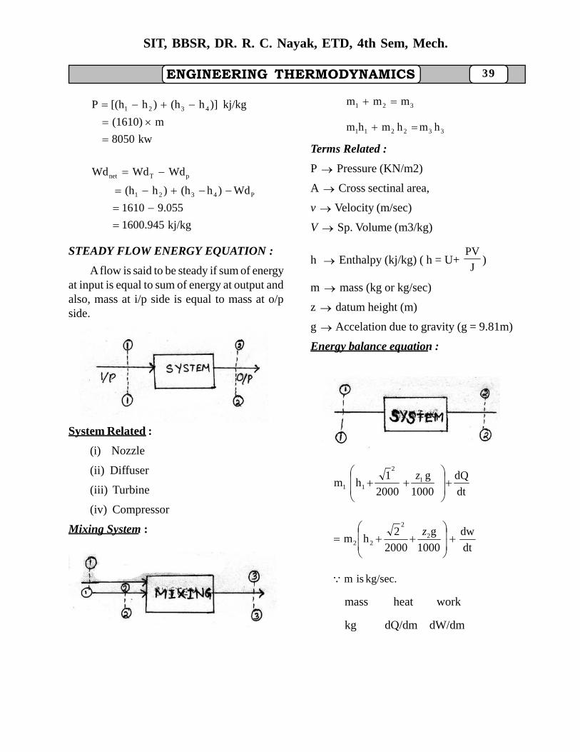
ENGINEERING THERMODYNAMICS 39
SIT, BBSR, DR. R. C. Nayak, ETD, 4th Sem, Mech.
kw8050
m(1610)
kj/kg)]h(h)h[(hP 4321
kj/kg1600.945
9.0551610
Wd)h(h)h(h
WdWdWd
P4321
pTnet
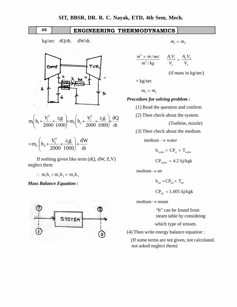
STEADY FLOW ENERGY EQUATION :
A flow is said to be steady if sum of energyat input is equal to sum of energy at output andalso, mass at i/p side is equal to mass at o/pside.
Fig -14
System Related :
(i) Nozzle
(ii) Diffuser
(iii) Turbine
(iv) Compressor
Mixing System :
Fig-15
321 mmm
332211 hmhmhm
Terms Related :
P Pressure (KN/m2)
A Cross sectinal area,
v Velocity (m/sec)
V Sp. Volume (m3/kg)
h Enthalpy (kj/kg) ( h = U+J
PV)
m mass (kg or kg/sec)
z datum height (m)
g Accelation due to gravity (g = 9.81m)
Energy balance equation :
dt
dQ
1000
g
2000
1hm 1
2
11
z
dt
dw
1000
g
2000
2hm 2
2
22
z
kg/sec.ism
mass heat work
kg dQ/dm dW/dm
40
SIT, BBSR, DR. R. C. Nayak, ETD, 4th Sem, Mech.
ENGINEERING THERMODYNAMICS
kg/sec dQ/dt. dW/dt.
Fig-17
dt
dQ
1000
g
2000hm
1000
g
2000hm 2
22
221
21
11
zVzV
dt
dW
1000
g
2000hm 3
23
33
zV
If nothing given like term (dQ, dW, Z,V)neglect them
332211 hmhmhm
Mass Balance Equation :
Fig-18
21 mm
2
22
1
113
2
/
sec/
V
VA
V
VA
kgm
mm
(if mass in kg/sec)
= kg/sec
21 mm
Procedure for solving problem :
(1) Read the question and confirm
(2) Then check about the system.
(Tuebine, nozzle)
(3) Then check about the medium
watermedium
waterwwater TCPh
kj/kgk4.2CPwater
airmedium
airairair TCPh
kj/kgk1.005CPair
steammedium
“h” can be found from steam table by consideing
which type of srteam.
(4) Then write energy balance equation :
(If some terms are not given, not calculated, not asked neglect them)
ENGINEERING THERMODYNAMICS 41
SIT, BBSR, DR. R. C. Nayak, ETD, 4th Sem, Mech.
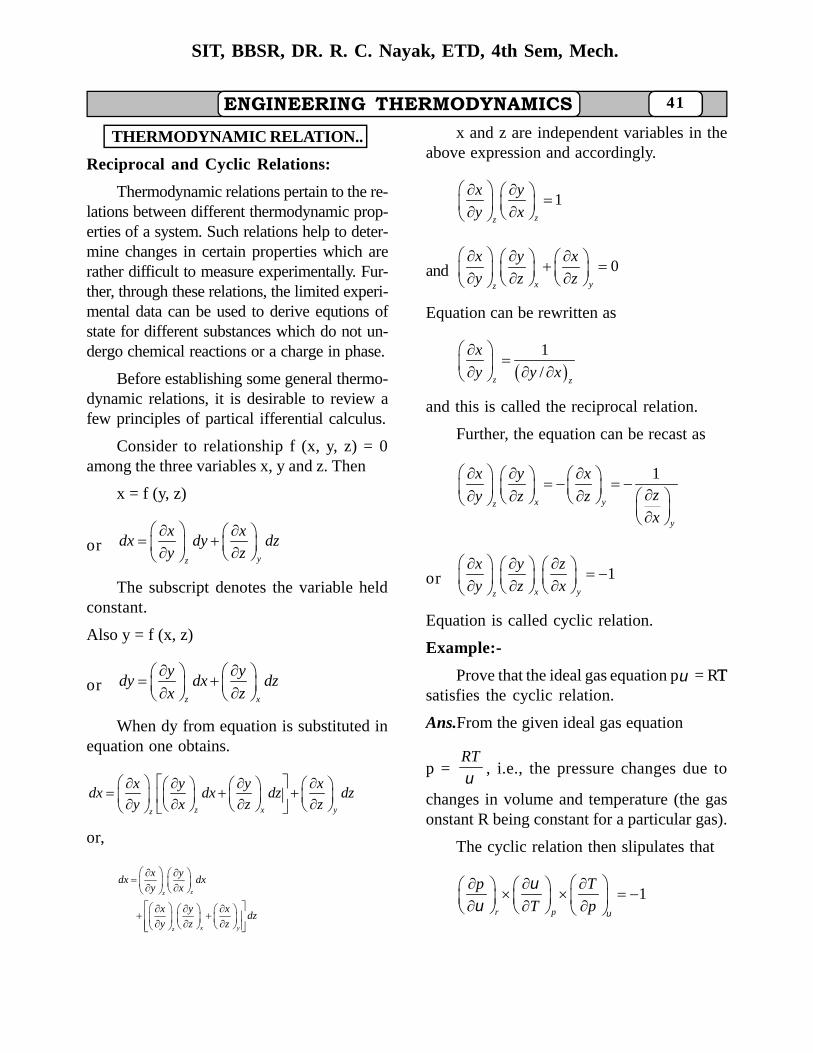
THERMODYNAMIC RELATION..
Reciprocal and Cyclic Relations:
Thermodynamic relations pertain to the re-lations between different thermodynamic prop-erties of a system. Such relations help to deter-mine changes in certain properties which arerather difficult to measure experimentally. Fur-ther, through these relations, the limited experi-mental data can be used to derive equtions ofstate for different substances which do not un-dergo chemical reactions or a charge in phase.
Before establishing some general thermo-dynamic relations, it is desirable to review afew principles of partical ifferential calculus.
Consider to relationship f (x, y, z) = 0among the three variables x, y and z. Then
x = f (y, z)
oryz
x xdx dy dz
y z
The subscript denotes the variable heldconstant.
Also y = f (x, z)
orz x
y ydy dx dz
x z
When dy from equation is substituted inequation one obtains.
z x yz
x y y xdx dx dz dz
y x z z
or,
zz
x yz
x ydx dx
y x
x y xdz
y z z
x and z are independent variables in theabove expression and accordingly.
1zz
x y
y x
and 0x yz
x y x
y z z
Equation can be rewritten as
1
/z z
x
y y x
and this is called the reciprocal relation.
Further, the equation can be recast as
1
x yz
y
x y xzy z zx
or 1x yz
x y z
y z x
Equation is called cyclic relation.
Example:-
Prove that the ideal gas equation p = RTTsatisfies the cyclic relation.
Ans.From the given ideal gas equation
p =RT
, i.e., the pressure changes due to
changes in volume and temperature (the gasonstant R being constant for a particular gas).
The cyclic relation then slipulates that
1r p
p T
T p
42 ENGINEERING THERMODYNAMICS
SIT, BBSR, DR. R. C. Nayak, ETD, 4th Sem, Mech.
The three partial derivates can be deter-mined separately and we get
2
1
r
p RTRT
v v
P
R RT
T p T p
Tp
p R p R
Substituting these values in left hand sideof the cyclic relation, we obtain
21
RT R RT
p R p
p RT
and it equals the right hand side. Thatproves that the given gas equation satisfies thecyclic relation.
Property relations:
For a unit mass of the system, the firstand second law of thermodynamics are pre-scribed by the relations.
q w du p du du
and q T ds
T ds = p du + du
or du = T ds - p du
The enthalpy is defined as the sum of in-ternal energy and the flow work (i.e., pressurevolume product). Thus for a unit mass,
h = u + pu
or dh = du + p du + u dp
= (T ds - p du) + p du + u dp
= T ds + u dp
The Helmholtz free energy is defined asthe difference between the internal energy andthe product to temperature and entropy. Thusfor a unit mass,
f = u - Ts
or df = du - t ds - s dT
= (T ds - p dv) - T ds - s dT
= - p dv - s dT
The Gibbs free energy is defined as thedifference between enthalpy and the productof temperature and entropy. Thus for a unitmass
g = h - Ts
or dg = dh - T ds - s dT
= (T ds + v dp) - T ds - s dT
= v dp - s dT
Since u, h, f and g are properties of thesystem, the relations are often referred to asthe property relations (also called the Gibbsrelations). These relations are applicable toall processes whether reversible orirreversible, and whether in a closed systemor in an open system.
Check for a property:
Consider z to be a function of twoindependent variables x and y. Mathematically
z = f(x, y)
ory x
z zdz dx dy
x y
where z is an exact differential, i.e., itrepresents a thermodynamic property. Letthe partial derivative in the above identity
ENGINEERING THERMODYNAMICS 43
SIT, BBSR, DR. R. C. Nayak, ETD, 4th Sem, Mech.
be written as
y x
z zM and N
x y
Equation may then be written as
dz = M dx + N dy
Further:2
y
M z z
y y x x y
and2
x
N z z
x x y x y
Thusyx
M N
y x
This leads us to conclude that consideringthe expression: dz = M dx + N dy
If z represents thermodynamic propertyof the system, then
yx
M N
y x
Maxwell Relations:
Consider the expression: du = T ds - p dv
Here internal energy u is athermodynamic property and the expressionindicates that internal energy varies withentropy s and volume v. That is
u = f(s, v)
orv s
u udu ds dv
s v
Equating the coefficients of ds and dv, wemay write
v s
u uT and p
s v
When differentiated, we obtain
2 2
s v
T u p uand
v v s s v s
s v
T p
v s
Alternatively: Comparing the givenidentity with dz = M dx + N dy
M = T N = -p
x = s y = v
Since z corresponds to u which is athermodynamic property, the followingidentity must hold good:
, . .,y s vx
M N T pi e
y x v s
Consider the expression:
dh = T ds + v dp
Here enthalpy h is a thermodynamicproperty and the expression indicates thatenthalpy is a function of entropy and pressure.That is
h = f(s, p)
orp s
h hdh ds dp
s p
Equating the coefficients of ds and dv, wemay write
p s
h hT and v
s p
When differentiated, we obtain
44 ENGINEERING THERMODYNAMICS
SIT, BBSR, DR. R. C. Nayak, ETD, 4th Sem, Mech.
2 2
ps
T h v hand
p s p s s p
ps
T v
p s
Alternatively: Comparing the givenidentity with dz = M dx + N dy
M = T N = v
x = s y = p
Since z corresponds to h which is athermodynamic property, the followingidentity must hold good,
, . .,y px s
M N T vi e
y x p s
T-ds Equations( , )u f T v
orv T
du udu dT dv
T v
vT
uc dT dv
v
... (a)
Invoking property relation :
du T ds p dv ... (b)
Comparing identities (a) and (b), andequating the coefficients
vv
sc T
T
Introducing total differential of ds interms of ( , )s f T v
v T
s sds dT dv
T v
vT
dT sc dv
T v
From Maxwell relation :
v T
p s
T v
vv
dT pds c dv
T T
The term v
dTc
T gives change in entropy
at constant volume and the term
v
pdv
T
represents change in entropy
at constant temperature.
Equation is known as first T ds equationand is often recast as
....vv
pT ds c dT T dv
T
(ii) Consider variation of enthalpy h withtemperature T and pressure p. Then
( , )h f T p
orp T
h hdh dT dp
T p
... ( )pT
hc dT dv c
v
Invoking property relation :
... ( )dh T ds v dp d
ENGINEERING THERMODYNAMICS 45
SIT, BBSR, DR. R. C. Nayak, ETD, 4th Sem, Mech.
Comparing identities (c) and (d), andequating the coefficients,
pp
sc T
T
Introducing total differential of ds interms of ( , )s f T p
p T
s sds dT dp
T p
p
T
dT sc dp
T p
From Maxwell relation :
pT
s v
p T
pp
dT vds c dp
T T
The term p
dTc
T gives change in entropy
at constant pressure and the termp
vdp
T
represents change in entropy at constanttemperature.
Equation is known as second T dsequation and is often recast is
pp
vT ds c dT T dp
T
HEAT CAPACITY RELATIONS
Equating the first and second T dsequations, we get
vv
pc dT T dv
T
pp
vc dT T dp
T
( )p vor c c dT
v p
p vT dv T dp
T T
pv
p v p v
vp T dpT dvTT
or dTc c c c
From the fundamental relation ( , )T f p v
pv
T TdT dp dv
p v
Comparing identities (i) and (ii), and equatingthe coefficients
v
pp v
pT
TT
c c v
p vv p
p vc c T ... (iii)
T T
Following cyclic relationship holdsgood among the thermodynamic variables p,T and v
v p T
p T v1 .... (iv)
T v p
From identities (iii) and (iv), we have
p vp
p T
1 vc c T
TT vv p
46 ENGINEERING THERMODYNAMICS
SIT, BBSR, DR. R. C. Nayak, ETD, 4th Sem, Mech.
2
p T
v pT
T v
The following important conclusions canbe drawn from the above thermodynamicrelation :
(i) For any substanceT
p
v
is negative,
and the term
2
p
v
T
is always positive.
Obviously p v(c c ) is positive and
accordingly cp is always greater than c
v.
(ii) p vc c as T 0. Apparently cp
equals cv at zero absolute temperature.
(iii) For solids and liquids, the volumechange with temperature is negligible underconstant pressure conditions. That is
p
v0.
T
That gives p vc c 0, i.e.,
p vc c . For water, such a situation exists at
04 C where specific volume is minimum or
density is maximum.(iv) For an ideal gas: pv = RT
p
v R v
T p T
2T p
p RT RT
v v v v
2
p v 2
v RTc c T R
T v
(v) Quite often, it is considered worthwhile to express equation in terms of volume
expansivity and isothermal compressibility
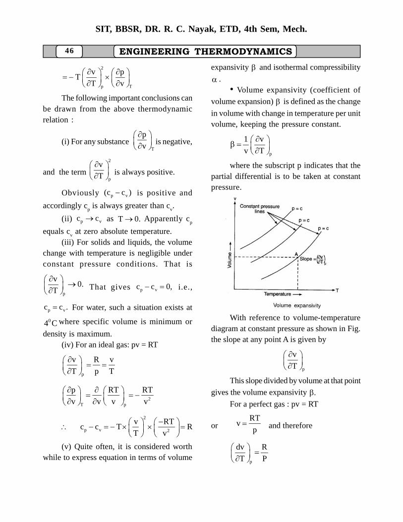
.• Volume expansivity (coefficient of
volume expansion) is defined as the change
in volume with change in temperature per unitvolume, keeping the pressure constant.
p
1 v
v T
where the subscript p indicates that thepartial differential is to be taken at constantpressure.
PAGE – 284 FIGURE
With reference to volume-temperaturediagram at constant pressure as shown in Fig.the slope at any point A is given by
p
v
T
This slope divided by volume at that point
gives the volume expansivity .For a perfect gas : pv = RT
orRT
vp
and therefore
p
dv R
T P
ENGINEERING THERMODYNAMICS 47
SIT, BBSR, DR. R. C. Nayak, ETD, 4th Sem, Mech.
1 R 1 v 1That gives :
v P v T T
Apparently, the volume expansivity of aperfect gas is a function of temperature only.It varies inversely with absolute temperatureand is independent of both pressure andvolume.
* Isothermal compressibility
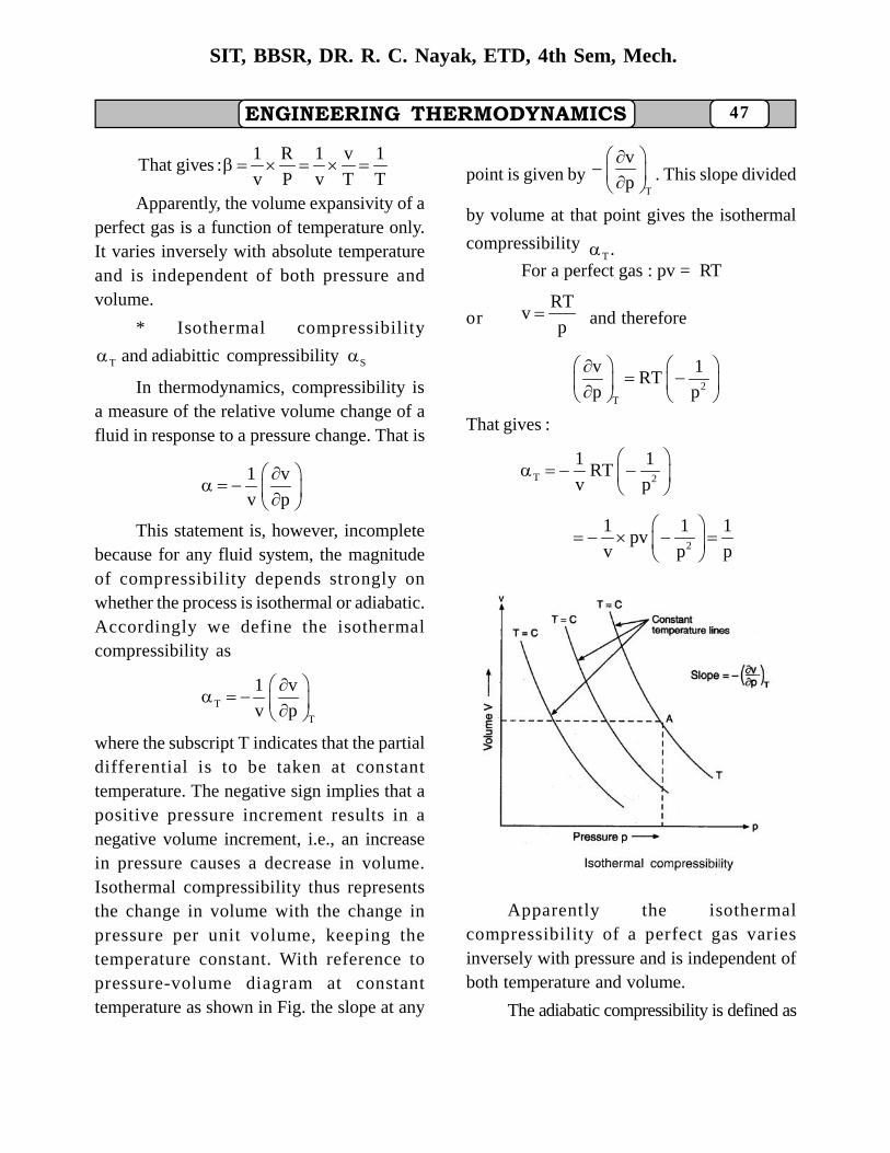
T and adiabittic compressibility S
In thermodynamics, compressibility isa measure of the relative volume change of afluid in response to a pressure change. That is
1 v
v p
This statement is, however, incompletebecause for any fluid system, the magnitudeof compressibility depends strongly onwhether the process is isothermal or adiabatic.Accordingly we define the isothermalcompressibility as
T
T
1 v
v p
where the subscript T indicates that the partialdifferential is to be taken at constanttemperature. The negative sign implies that apositive pressure increment results in anegative volume increment, i.e., an increasein pressure causes a decrease in volume.Isothermal compressibility thus representsthe change in volume with the change inpressure per unit volume, keeping thetemperature constant. With reference topressure-volume diagram at constanttemperature as shown in Fig. the slope at any
point is given byT
v
p
. This slope divided
by volume at that point gives the isothermal
compressibilityT .
For a perfect gas : pv = RT
orRT
vp
and therefore
2T
v 1RT
p p
That gives :
T 2
1 1RT
v p
2
1 1 1pv
v p p
FIGURE – 285
Apparently the isothermalcompressibility of a perfect gas variesinversely with pressure and is independent ofboth temperature and volume.
The adiabatic compressibility is defined as
48 ENGINEERING THERMODYNAMICS
SIT, BBSR, DR. R. C. Nayak, ETD, 4th Sem, Mech.
S
S
1 v
v p
where the subscript s indicates that the partialdifferential is to be taken at constant entropy.The adiabatic compressibility thus representsthe change in volume with change in pressureper unit volume when entropy is kept constant.
Considering changes in volume due tochanges in pressure and temperature,
v f (p, T)
orP T
v vdv dT dp
T p
p T
v 1 v 1 vdT dp
v v T v p
dT dp
The above correlation expresses volumechange in terms of volume expansivity andisothermal compressibility.
Equation can be rewritten as
2
2p
p v
T
1 vv T
c c Tv Tv1 vv p
The above identity is called the Mayerrelation.
Ration of specific heats : The ratio of
p vc and c is given as
p p p
v
v v
s sT
c T T
s sc TT T
From the cyclic correlations
p Ts
s T p1
T p s
v s T
s T vand 1,
T v s
p s T
s p s
T T v
s sT
s T T
p s pT p vv s pT v v
Since is greater than 1,
s T
p p
v v
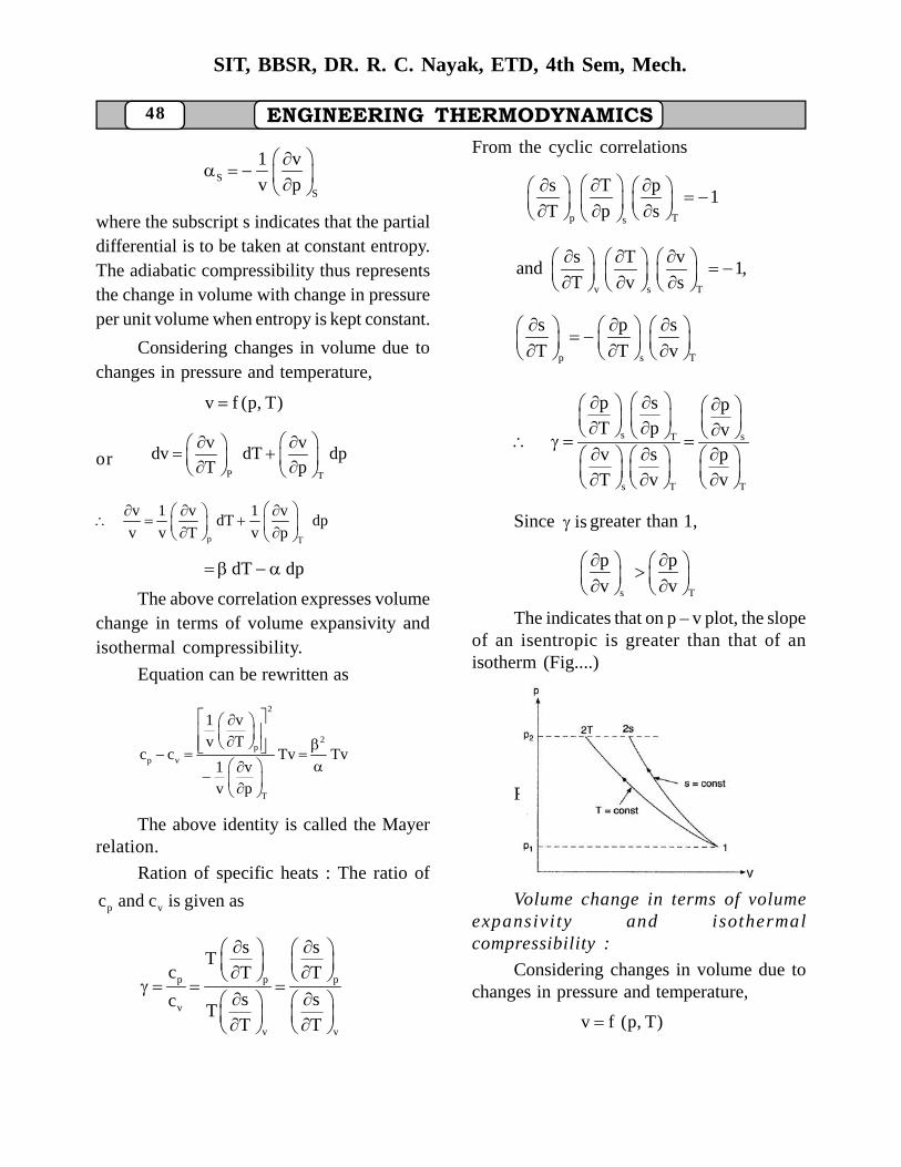
The indicates that on p – v plot, the slopeof an isentropic is greater than that of anisotherm (Fig....)
FIGURE – 286
Volume change in terms of volumeexpansivi ty and isothermalcompressibility :
Considering changes in volume due tochanges in pressure and temperature,
v f (p, T)
ENGINEERING THERMODYNAMICS 49
SIT, BBSR, DR. R. C. Nayak, ETD, 4th Sem, Mech.
p T
v vor dv dT dp
T p
p T
dv 1 v 1 vdT dp
v v T v p
Since v
T T
1 v vor
v p p
... (i)
T T
T T
1 v vor v
v p p
...(ii)
T
dv 1 1v dT ( v) dp
v v v
TdT dp Frome cyclic property of differentials,
v p T
p T v1
T v p
Substituting the values ofp
vand
T
T
v
p
from identities (i) and (ii), we obtain
Tv
p 1( v) 1
T v
v T T
p vor
T v
That is, the ratio of coefficient of volume
expansion and isothermal compressibility
T represents the change in pressure withtemperature when volume is kept constant.
Further, from expression
s T
ST
p / v v / p
p / v ( v / p)
T T
S S
1/ v ( v / p)
( 1 / v) ( v / dp)
Apparently the adiabatic exponent (the
ratio of specific heats p vc / c ) is equal to the
ratio of isothermal compressibility and
adiabatic compressibility. Since is always
greater than unity, the above expression
indicates that T is always greater than SRELATIONS FOR INTERNAL ENERGYAND ENTHALPY
(a) When a system undergoes aninfinitesimal reversible process, the changein internal energy between two equilibriumstates is given by
du T ds p dv The first T ds equation gives
vv
pT ds c dT T dv
T
vv
pdu c dT T dv p dv
T
vv
pc dT T p dv .... (i)
T
Considering the functional relationship
u f (T, v) which expresses internal energy
u as a function of temperature T and volume v.
u f (T, v)
v T
u uor du dT dv .... (ii)
T v
The equivalence between (i) and (ii)gives
vv
uc
T
T V
u pand T p
v T
50 ENGINEERING THERMODYNAMICS
SIT, BBSR, DR. R. C. Nayak, ETD, 4th Sem, Mech.
The above identity is called the energyequation.
(b) When a system undergoes aninfinitesimal reversible process, the changein enthalpy between two equilibrium states isgiven by
dh T ds v dp The second T ds equation gives
pp
vT ds c dT T dp
T
pp
vdh c dT T dp vdp
T
pp
vc dT v T dp ... (iii)
T
Considering the functional relationship
h = f(T, p) which expresses enthalpy as afunction of temperature T and pressure p.
h f (T, p)
p T
h hor dh dT dp ... (iv)
T p
The equivalence between (iii) and (iv)gives
pp
hc
T
pT
h vand v T
p T
EXAMPLESet up the following expression for the
specific heats at constant volume and atconstant pressure :
2v
2T v
c pT
v T
2p
2
T p
c vand T
p T
Further, proceed to show that for aperfect gas obeying pv = RT, the specific heats
p vc and c are function of temperature alone.
Solution : The specific heat at constantvolume is
vv
sc T
T
2v
T
c sor T
v T v
From Maxwell relation :
T v
s p
v T
2 2
2
v
s por
v T T
2v
2T v
c pT
v T
which is the required result.
For the perfect gas :RT
pv
2
2
p R por and 0
T v T
v
T
cHence 0
v
vc is independent of volume and is a
function of temperature alone.(b) The specific heat at constant
pressure is
pp
sc T
T
ENGINEERING THERMODYNAMICS 51
SIT, BBSR, DR. R. C. Nayak, ETD, 4th Sem, Mech.
2p
T
c sor T
p T p
From Maxwell relation :
pT
s v
p T
2 2
2
p
s vor
p T T
2p
2
T p
c v
p T
which is the required result.
RT For a perfect gas,RT
vp
2
2
v R vor and 0
T P T
p
T
cHence 0
p
pc is independent of pressure and is
a function of temperature alone.EXAMPLE
Determine the difference in
p vc and c for water at 300 K for which
coefficient of volume exp ansion 4 12 10 K
isothermal compressibility a4 14.85 10 MPa and
specific volume 3v 0.001003 m / kg(b) What would be the value of
p v(c c ) for an ideal gas.
Solution : The difference in specificheats for any substance is given by
2
p vc c T v
Therefore, for liquid water
4 2
p v 4 6
(2 10 )c c
4.85 10 10
300 0.001003
24.816 J / kg K
0.0248 kJ / kg K(b) For an ideal gas : pv = RT
p
1 v p RT
v T RT T p
p R 1
RT p T
T
1 v
v p
T
p RT
RT p p
2
p RT 1
RT p p
2
p v 2
p pvc c T v Tv R
T R
EXAMPLE
Show that for a perfect gas, thedifference between the specific heats
p v(c c ) can be expressed as
p vT p
u vc c p
v T
T
upv v
v
52 ENGINEERING THERMODYNAMICS
SIT, BBSR, DR. R. C. Nayak, ETD, 4th Sem, Mech.
where is the coefficient of volume
expansion.Solution : The property relations for
internal energy u and enthalpy h areT ds = du + p dv
and T ds = dh – v dp du + p dv = dh – v dp ...(i)From the functional relations u = (T, v)
and h = f (T, p), we have
v T
u udu dT
T v
vT
udv c dT dv
v
p T
h hand dh dT
T p
p
T
hdp c dT dp
p
Substituting the values of du and dh inexpression (i), we get
vT
uc dT dv p dv
v
p
T
hc dT dp v dp
p
vT
uor c dT p dv
dv
p
T
hc dT v dp
p
The above equation is valid for anyprocess. Writing it for the case when dp = 0,we have
p v p pT
u(c c ) (dT) p (dv)
v
p vT p
u vor c c p
v T
which is the required result.(b) The coefficient of volume expansion
p is defined as
p
1 v
v T
and accordingly, we can write
p vT
uc c p v
v
T
upv v
v
EXAMPLE 11.5
Set up a T ds relation in the followingform :
v
TT ds c dT dv
where is the coefficient of volume
expansion, a is the isothermal compressibility,and the other symbols have their usualmeanings.
Solution : The given relation expressesentropy s as a function of temperature T andvolume v. That is
s f (T, v)
v T
s sor ds dT dv
T v
It is known that:
T v
s p
v T
.... Maxwell relation
vv
sand T c
T
ENGINEERING THERMODYNAMICS 53
SIT, BBSR, DR. R. C. Nayak, ETD, 4th Sem, Mech.
Making these substitutions, we get
vv
pT ds c dT T dv
T
The parameters and are defined as
p
1 v
v T
T
1 vand
v p
p T
1 v v
v T ( v / p)
p T
v p.... (ii)
T v
The cyclic relation between p, v and Tgives
T p v
p v T1
v T p
p T v
v p 1or
T v ( T / p)
v
p... (iii)
T
From relations (ii) and (iii),
v
p
T
When the value ofv
p
T
as obtained
above is substituted in expression (i), weget
v
TT ds c dT dv
which is the required relation.EXAMPLE
Set up a T ds relation in the followingform
pT ds c dT v T dp
where is the coefficient of volume
expansion. The other symbols have their usualmeanings.
Solution : The given relation expressesentropy s as a function of temperature T andpressure p. That is
s f (T, p)
p T
s sor ds dT dp
T p
It is known that :
pT
s v
p T
.... Maxwell relation
pp
sand T c
T
Making these substitutions, we get
pp
vT ds c dT T dp ... (i)
T
The coefficient of volume expansion isdefined as
p p
1 v vor v
v T T
When this value ofp
v
T
is substituted
in expression (i), we get
p pT ds c dT v T d
which is the required relation.
54 ENGINEERING THERMODYNAMICS
SIT, BBSR, DR. R. C. Nayak, ETD, 4th Sem, Mech.
EXAMPLESet up the following relation for the
change in internal energy of a substance fromthe measured values of temperature andvolume
v
Tdu c dT p dv
where is the coefficient of volume
expansion, a is the isothermal compressibility,and the other symbols have their usualmeanings.
Proceed therefrom to show that internalenergy of an ideal gas is independent ofpressure and volume and is a function oftemperature only.
Solution : The given relation expressesinternal energy u as a function of temperatureT and volume v. That is
u f (T, v)
v T
u uor du dT dv
T v
Since vv
udefines c ,
T
we can write
vT
udu c dT dv ... (i)
v
Consider the property relation :
du T ds p dv Keeping T constant, let this relation be
divided by dv. That gives
T T
u sT p
v v
Substituting the Maxwell relation
T v
s p, we get
v T
T v
u pT p ... (ii)
v T
The cyclic relation between p, v and T gives
T p v
p v T1
v T p
v T p
p p vor ... (iii)
T v T
The parameters P and a are defined as
p
1 v
v T
T
1 vand
v p
p T
1 v v
v T ( v / p)
p T
v p... (iv)
T v
Relations (iii) and (iv) are then combinedto give
v
p
T
When the value ofv
p
T
as obtained
above is substituted in expression (ii), we get
T
u Tp
v
The above correlation is then substituted
in expression (i) and we obtain
v
Tdu c dT p dv
ENGINEERING THERMODYNAMICS 55
SIT, BBSR, DR. R. C. Nayak, ETD, 4th Sem, Mech.
which is the required relation.(b) For an ideal gas pv = RT
p
1 v
v T
p
p RT
RT T p
p R 1
RT p T
T
1 v
v p
T
p RT
RT p p
2
p RT 1
RT p p
v v
Tpdu c dT p dv c T
T
Thus the internal energy of an ideal gasis independent of pressure and volume and isa function of temperature only.EXAMPLE
Set up the following relation for thechange in enthalpy of a substance from themeasured values of temperature and pressure
pdh c dT v (1 T) dp
where is is the coefficient of volumeexpansion. The other symbols have their usualmeanings.
Proceed therefrom to show thatenthalpy of an ideal gas is independent ofpressure and volume and depends only ontemperature.Solution : The given relation expressesenthalpy h as a function of temperature T and
pressure p. That is
h f (T, p)
p T
h hor dh dT dp
T p
pp
hSince defines c ,
T
we can write
p
T
hdh c dT dp ... (i)
p
From the property relation :dh = T ds + v dp
Keeping T constant, let this relation bedivided by dp. That gives
T T
h sT v
p p
Substituting the Maxwell relation , we get
pT
s v
p T
, we get
pT
h vT v
p T
The coefficient of volume expansion isdefined as
p
1 v
v T
T
hv t v
p
v (1 T) ...(ii)
When the value ofT
h
p
as obtained
above is substituted in expression (i), we get
pdh c dT v (1 T) dp
56 ENGINEERING THERMODYNAMICS
SIT, BBSR, DR. R. C. Nayak, ETD, 4th Sem, Mech.
which is the required expression.(b) For an ideal gas pv = RT
p
1 v
v T
p
p RT
RT T p
p R 1
RT p T
p p
1dh c dT v 1 T c dT
T
Thus the enthalpy of an ideal gas isindependent of pressure and volume and is afunction of temperature only.EXAMPLE
Over a certain range of pressures andtemperatures, the equation of state of a certaingas is prescribed by the relation
3
RT Cv
p T where C is a constant
Set up expressions for a change inenthalpy and entropy of the gas. Consider thechange to occur under isothermal conditions.Solution : From the relations
dh = T ds + v dp
pp
vand T ds c dT T
T
dp; we have
pp
vdh c dT T dp v dp
T
For an isothermal process (T = constant)
Tp
v(dh) v T dp ... (i)
T
From the given equation of state :
3
RT Cv
p T
4p
v R 3C
T p T
p
vand v T dp
T
3 3
RT C RT 3Cdp
p T p T
3
4Cdp
T
The identity (i) may then be written as
T 3
4C(dh) dp
T
Upon integration between the state point1 and state point 2, we have
2 1 2 1 T3
4Ch h (p p )
T
1 2 T3
4C(p p )
T
(b) From the T ds relation :
pp
vT ds c dT T dp,
T
we have
pp
dT vds c dp
T T
For an isothermal (constant temperatureprocess),
Tp
v(ds) dp
T
From the given equation of state:
3
RT Cv
p T
4p
v R 3C
T p T
ENGINEERING THERMODYNAMICS 57
SIT, BBSR, DR. R. C. Nayak, ETD, 4th Sem, Mech.
T 4
R 3C(ds) dp
p T
Upon integration between the state point
1 and state point 2,
22 1 T e 2 1 T4
1
p 3C(s s ) R log (p p )
p T
1e 1 2 T4
2
p 3CR log (p p )
p T
EXAMPLESet up the T ds equation in the form
v ppv
T TT ds c dp c dv
p v
Further, proceed to show that this rela-tion can be recast as
pv
v
cT ds c dp dv
where is the coefficient of volume ex-
pansion and a is the isothermal compressibil-ity factor.
Solution : Consider variation of entropys with pressure p and specific volume v.
Then s f (p, v)
pv
s sor ds dp dv
p v
v v
s Tdp
T p
p p
s Tdv
T v
Substituting the relations:
pv
v p
ccs sand ,
T T T T
we can write
pv
pv
cc T Tds dp dv
T p T v
v ppv
T Tor T ds c dp c dv ... (i)
p v
which is the required expression.This identity is often known as Third T
ds equation.(b) The parameters (3 and a are defined
as
p
1 v
v T
T
1 vand
v p
p p
v T 1Then : v or
T v v
From the cyclic relationship
T pv
T p v1
p v T
v
T p
T 1or
p vpv T
T
p
vp
vT
Making the substitution forv
T
p
and
p
T
v
in expression (/), we get
58 ENGINEERING THERMODYNAMICS
SIT, BBSR, DR. R. C. Nayak, ETD, 4th Sem, Mech.
v p
1T ds c dp c dv
pv
cc dp dv
which is the required result.EXAMPLE
Set up ffe following relations for a gaswhich conforms to the van der Waal’s equa-tion of state.
(a) p v 2 3
Rc c
1 2a (v b) RT v
(b) v
RcT(v b) constant for an isen-
tropic process where the symbols have theirusual meanings.
Solution : From generalised relation
for p vc and c , we have
p vv p
p vc c T
T T
The van der Waals equation of state is
2
ap (v b) RT
v
2
RT aor p
v b v
Differentiating p with respect to T atconstant volume, we get
v
p R
T v b
p vp
RT vc c
v b T
Again when volume v in the van derWaal’s equation is differentiated with respectto temperature T treating pressure p as con-stant, we get
2 3p p
a v 2a vp (v b) R
v T v T
3p p
RT v 2a vor (v b) R
v b T v T
p2 3
v Ror
T RT 2a[v b]
(v b) v
3
3 2
R(v b) v
RT v 2a (v b)
3
p v 3 2
RT R(v b) vc c
v b RTv 2a (v b)
3
3 2 3
R vRT
RT v [1 2a (v b) / RT v ]]
2 3
R
1 2a (v b) / RT v
(b) Consider the first T ds equation
vv
pT ds c dT T dv
T
The van der Waal’s equation of state is
2
ap (v b) RT
v
2
RT aor p
v b v
Differentiating p with respect to T treat-ing v as constant, we get
v
p R
T v b
ENGINEERING THERMODYNAMICS 59
SIT, BBSR, DR. R. C. Nayak, ETD, 4th Sem, Mech.
v
RTThen T ds c dT dv
v b
v
dT Ror ds c dv
T v b
At constant entropy ds = 0 and, there-
fore v
dT Rc dv 0
T v b
v
dT R dvor 0
T c v b
By integration:
e e ev
Rlog T log (v b) log
c constant
R / Ce eor log T (v b) log constant
vR / cor T(v b) cons tan t EXAMPLE
Set up the expressions for changes in in-ternal energy, enthalpy and entropy for a gaswhich obeys the van der Waal’s equation
2
ap (v b) RT
v Solution : When a system undergoes an
infinitesimal reversible process, the changein internal energy between two equilibriumstates is given by
vv
pdu c dT T p dv
T
From the given van der Waal’s equation
2
RT ap
v b v
v
p R Rand 0
T v b v b
2
2 1
1
u u du
2 2
v
1 1
RTc dT p dv
v b
2
v
1
c dT 2
21
RT RT adv
v b v b v
2 2 2
v 21 1
ac dT dv
v
v 2 11 2
1 1c (T T ) a
v v
which is the desired expression for
change in internal energy.Under constant temperature conditions,
v 2 1c (T T ) 0 and accordingly
2 1 T1 2
1 1(u u ) a
v v
(b) When a system undergoes an
infinitesimal reversible process, the changein enthalpy between two equilibrium states is
pp
vdh c dT v T dp
T
Under constant temperature conditions,
dT = 0 and then
T Tp
dv(dh) v T (dp) ... (a)
dt
Considering the functional relation
p f (v, T)
T v
p pdp dv dT
v T
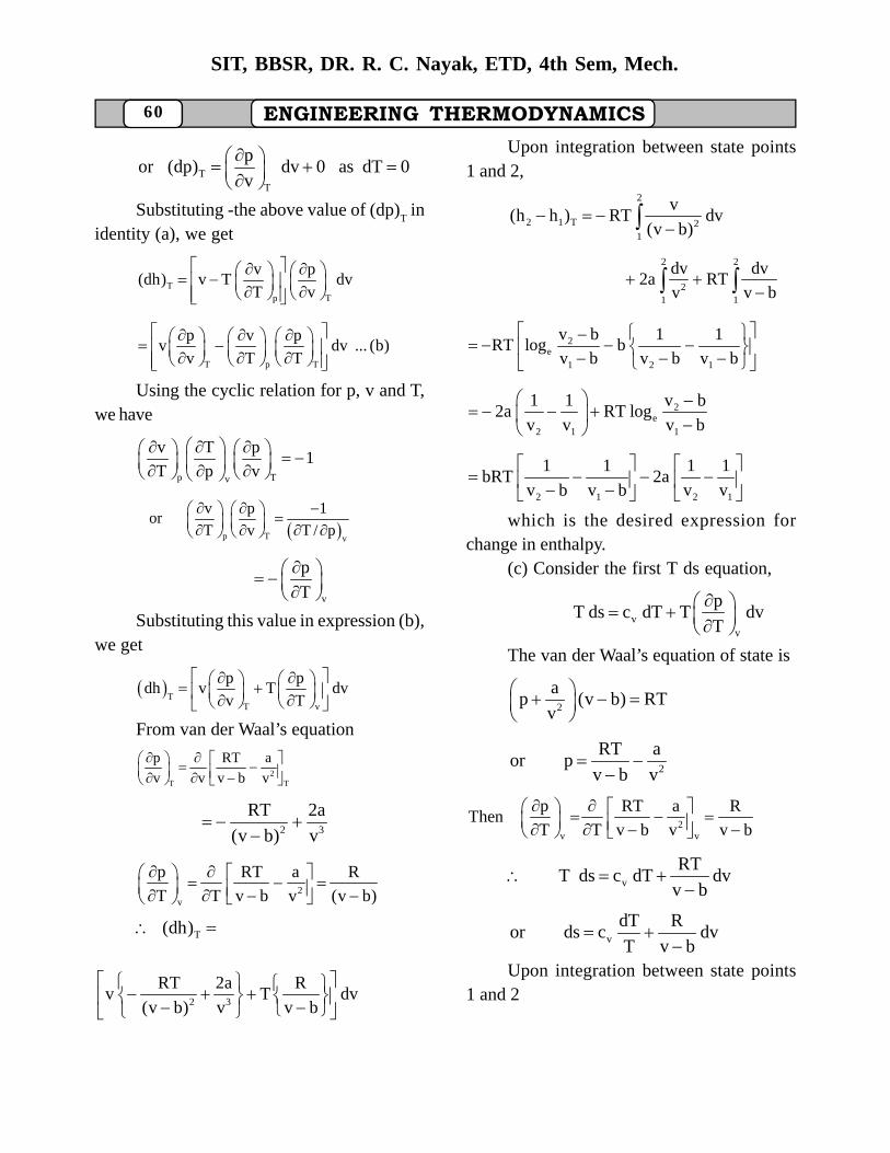
60 ENGINEERING THERMODYNAMICS
SIT, BBSR, DR. R. C. Nayak, ETD, 4th Sem, Mech.
TT
por (dp) dv 0 as dT 0
v
Substituting -the above value of (dp)
T in
identity (a), we get
Tp T
v p(dh) v T dv
T v
T p T
p v pv dv ... (b)
v T T
Using the cyclic relation for p, v and T,we have
p Tv
v T p1
T p v
p T v
v p 1or
T v T / p
v
p
T
Substituting this value in expression (b),
we get
T
T v
p pdh v T dv
v T
From van der Waal’s equation
2T T
p RT a
v v v b v
2 3
RT 2a
(v b) v
2v
p RT a R
T T v b v (v b)
T(dh)
2 3
RT 2a Rv T dv
(v b) v v b
Upon integration between state points1 and 2,
2
2 1 T 21
v(h h ) RT dv
(v b)
2 2
21 1
dv dv2a RT
v v b
2e
1 2 1
v b 1 1RT log b
v b v b v b
2e
2 1 1
1 1 v b2a RT log
v v v b
2 1 2 1
1 1 1 1bRT 2a
v b v b v v
which is the desired expression forchange in enthalpy.
(c) Consider the first T ds equation,
vv
pT ds c dT T dv
T
The van der Waal’s equation of state is
2
ap (v b) RT
v
2
RT aor p
v b v
2v v
p RT a RThen
T T v b v v b
v
RTT ds c dT dv
v b
v
dT Ror ds c dv
T v b
Upon integration between state points
1 and 2
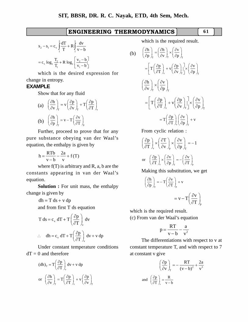
ENGINEERING THERMODYNAMICS 61
SIT, BBSR, DR. R. C. Nayak, ETD, 4th Sem, Mech.
2 2
2 1 v
1 1
dT dvs s c R
T v b
2 2v e e
1 1
T v bc log R log
T v b
which is the desired expression forchange in entropy.EXAMPLE
Show that for any fluid
(a)T T v
h p pv T
v v T
(b)pT
h vv T
p T
Further, proceed to prove that for anypure substance obeying van der Waal’sequation, the enthalpy is given by
RTb 2ah f (T)
v b v
where f(T) is arbitrary and R, a, b are theconstants appearing in van der Waal’sequation.
Solution : For unit mass, the enthalpychange is given by
dh T ds v dp and from first T ds equation
vv
pT ds c dT T dv
T
vv
pdh c dT T dv v dp
T
Under constant temperature conditionsdT = 0 and therefore
Tv
p(dh) T dv v dp
T
T v T
h p por T v
v T v
which is the required result.
(b)TT T
h h v
p v p
v T T
p p vT v
T v p
T T
h v
v p
v T T
p p vT v
T v p
v T
p vT v
T p
From cyclic relation :
v p T
p T v1
T v p
v pT
p v vor
T p T
Making this substitution, we get
pT
h vT v
p T
p
vv T
T
which is the required result.(c) From van der Waal’s equation
2
RT ap
v b v
The differentiations with respect to v atconstant temperature T, and with respect to 7at constant v give
2 3T
p RT 2a
v (v b) v
v
p Rand
T v b
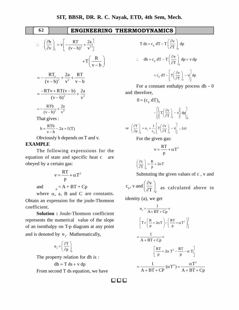
62 ENGINEERING THERMODYNAMICS
SIT, BBSR, DR. R. C. Nayak, ETD, 4th Sem, Mech.
2 3T
h RT 2av
v (v b) v
RT
v b
v2 2
RT 2a RT
(v b) v v b
2 2
RTv RT(v b) 2a
(v b) v
2 2
RTb 2a
(v b) v
That gives :
RTbh 2a f (T)
v b
Obviously h depends on T and v.EXAMPLE
The following expressions for theequation of state and specific heat c areobeyed by a certain gas:
2RTv T
p
and c
p = A + BT + Cp
where , a, B and C are constants.
Obtain an expression for the joule-Thomsoncoefficient.
Solution : Joule-Thomson coefficientrepresents the numerical value of the slopeof an isenthalpy on T-p diagram at any point
and is denoted by ju . Mathematically,,
j
h
Tu
p
The property relation for dh is :
dh T ds v dp From second T ds equation, we have
pp
vT ds c dT T dp
T
pp
vdh c dT T dp v dp
T
pp
vc dT T v dp
T
For a constant enthalpy process dh - 0and therefore,
p h0 (c dT)
ph
vT v dp
T
jpph
T 1 vor u T v ... (a)
p c T
For the given gas:
2RTv T
p
p
v R2 T
T p
Substuting the given values of c , v and
pp
vc , v and
T
as calculated above in
identity (a), we get
j
1u
A BT Cp
2R RTT 2 T T
p p
1
A BT Cp
2RT RT2 T T
p p
221 T
( T )A BT CP A BT Cp


![Untitled-1 [m2.lmcdn.fr]](https://img.pdfslide.us/doc/110x75/61a6b49d7e45db3ba4760d96/untitled-1-m2lmcdnfr.jpg)