Embed Size (px)
Citation preview

ENGINEERING SYMBOLOGY, PRINTS,
AND DRAWINGS
Module 3
Electrical Diagrams and Schematics

Module 3: Electrical Diagrams and Schematics
i
TABLE OF CONTENTS
LIST OF FIGURES ......................................................................................................... ii
LIST OF TABLES .......................................................................................................... iii
REFERENCES .............................................................................................................. iv
OBJECTIVES ................................................................................................................ v
ELECTRICAL DIAGRAMS AND SCHEMATICS ............................................................ 1
Symbology ........................................................................................................... 2
Transformers ....................................................................................................... 2
Switches ............................................................................................................. 3
Fuses and Breakers ........................................................................................... 5
Relays, Contacts, Connectors, Lines, Resistors, and Miscellaneous Electrical Components ....................................................................................................... 6
Large Components ............................................................................................. 7
Types of Electrical Diagrams or Schematics ...................................................... 9
Reading Electrical Diagrams and Schematics .................................................. 14
Summary .......................................................................................................... 17
ELECTRICAL WIRING AND SCHEMATIC DIAGRAM READING EXAMPLES ................................................................................................. 18
Examples .......................................................................................................... 18
Summary .......................................................................................................... 23

Module 3: Electrical Diagrams and Schematics
ii
LIST OF FIGURES
Figure 1 Basic Transformer Symbols ............................................................................ 2
Figure 2 Transformer Polarity ........................................................................................ 2
Figure 3 Switches and Switch Symbols ......................................................................... 3
Figure 4 Switch and Switch Status Symbology ............................................................. 4
Figure 5 Fuse and Circuit Breaker Symbols .................................................................. 5
Figure 6 3-phase and Removable Breaker Symbols ..................................................... 6
Figure 7 Common Electrical Component Symbols ........................................................ 7
Figure 8 Large Common Electrical Components ........................................................... 8
Figure 9 Comparison of an Electrical Schematic and a Pictorial Diagram ..................... 9
Figure 10 Comparison of an Electrical Schematic and a Wiring Diagram .................... 10
Figure 11 Wiring Diagram of a Car's Electrical Circuit .................................................. 11
Figure 12 Schematic of a Car's Electrical Circuit .......................................................... 12
Figure 13 Example Electrical Single Line ..................................................................... 13
Figure 14 Examples of Relays and Relay Contacts ..................................................... 14
Figure 15 Ganged Switch Symbology .......................................................................... 15
Figure 16 Three-Phase Symbols .................................................................................. 16
Figure 17 Example 1 .................................................................................................... 19
Figure 18 Example 2 .................................................................................................... 20

Module 3: Electrical Diagrams and Schematics
iii
LIST OF TABLES
Table 1 Comparison Between Wiring and Schematic Diagrams ............................. 9

Module 3: Electrical Diagrams and Schematics
iv
REFERENCES
ASME Y14.5-2009, Dimensioning and Tolerancing.
IEEE Std 315-1975 (Reaffirmed 1993), Graphic Symbols for Electrical and
Electronic Diagrams.
Gasperini, Richard E., Digital Troubleshooting, Movonics Company; Los Altos,
California, 1976.
Jensen - Helsel, Engineering Drawing and Design, 7th Ed., McGraw-Hill Book
Company, New York, (August 15, 2007).
Lenk, John D., Handbook of Logic Circuits, Reston Publishing Company, Reston,
Virginia, 1972.
Wickes, William E., Logic Design with Integrated Circuits, John Wiley & Sons,
Inc, 1968.
Naval Auxiliary Machinery, United States Naval Institute, Annapolis, Maryland,
1951.
TPC Training Systems, Reading Schematics and Symbols, Technical Publishing
Company, Barrington, Illinois, 1974.
Arnell, Alvin, Standard Graphical Symbols, McGraw-Hill Book Company, 1963.
George Masche, Systems Summary of a Westinghouse Pressurized Water
Reactor, Westinghouse Electric Corporation, 1971.
Smith-Zappe, Valve Selection Handbook, 5th Ed., Gulf Publishing Company,
Houston, Texas, December 2003.

Module 3: Electrical Diagrams and Schematics
v
TERMINAL OBJECTIVE
1.0 Given an electrical print, READ and INTERPRET facility electrical diagrams and
schematics.
ENABLING OBJECTIVES
1.1 IDENTIFY the symbols used on engineering electrical drawings for the following
components:
a. Single-phase circuit breaker m. Electric motor
(open/closed) n. Meters
b. Three-phase circuit breaker o. Junctions
(open/closed) p. In-line fuses
c. Thermal overload q. Single switch
d. "a" contact r. Multiple-position switch
e. "b" contact s. Pushbutton switch
f. Time-delay contacts t. Limit switches
g. Relay u. Turbine-driven generator
h. Potential transformer v. Motor-generator set
i. Current transformer w. Generator (wye or delta)
j. Single-phase transformer x. Diesel-driven generator
k. Delta-wound transformer y. Battery
l. Wye-wound transformer
1.2 Given an electrical drawing of a circuit containing a transformer, DETERMINE
the direction of current flow, as shown by the transformer's symbol.
1.3 IDENTIFY the symbols and/or codes used on engineering electrical drawings to
depict the relationship between the following components:
a. Relay and its contacts
b. Switch and its contacts
c. Interlocking device and its interlocked equipment

Module 3: Electrical Diagrams and Schematics
vi
ENABLING OBJECTIVES (Cont.)
1.4 STATE the condition in which all electrical devices are shown, unless otherwise
noted on the diagram or schematic.
1.5 Given a simple electrical schematic and initial conditions, DETERMINE the
condition of the specified component (i.e., energized/de-energized, open/closed).
1.6 Given a simple electrical schematic and initial conditions, IDENTIFY the power
sources and/or loads and their status (i.e., energized or de-energized).

Module 3: Electrical Diagrams and Schematics
1
ELECTRICAL DIAGRAMS AND SCHEMATICS
To read and interpret electrical diagrams and schematics, the basic
symbols and conventions used in the drawing must be understood. This
chapter concentrates on how electrical components are represented on
diagrams and schematics. The function of the individual electrical
components and the theory behind their operation is covered in more
detail in the Electrical Science Handbook.
EO 1.1 IDENTIFY the symbols used on engineering electrical drawings for the
following components:
a. Single-phase circuit breaker m. Electric motor
(open/closed) n. Meters
b. Three-phase circuit breaker o. Junctions
(open/closed) p. In-line fuses
c. Thermal overload q. Single switch
d. "a" contact r. Multiple-position switch
e. "b" contact s. Pushbutton switch
f. Time-delay contacts t. Limit switches
g. Relay u. Turbine-driven generator
h. Potential transformer v. Motor-generator set
i. Current transformer w. Generator (wye or delta)
j. Single-phase transformer x. Diesel-driven generator
k. Delta-wound transformer y. Battery
l. Wye-wound transformer
EO 1.2 Given an electrical drawing of a circuit containing a transformer, DETERMINE
the direction of current flow, as shown by the transformer's symbol.
EO 1.3 IDENTIFY the symbols and/or codes used on engineering electrical drawings
to depict the relationship between the following components:
a. Relay and its contacts
b. Switch and its contacts
c. Interlocking device and its interlocked equipment
EO 1.4 STATE the condition in which all electrical devices are shown, unless
otherwise noted on the diagram or schematic.
EO 1.5 Given a simple electrical schematic and initial conditions, DETERMINE the
condition of the specified component (i.e., energized/de-energized,
open/closed).

Module 3: Electrical Diagrams and Schematics
2
Figure 1 Basic Transformer Symbols
Symbology
To read and interpret electrical diagrams and schematics, the reader must first be well versed in what the many symbols represent. This chapter discusses the common symbols used to depict the many components in electrical systems. Once mastered, this knowledge should enable the reader to successfully understand most electrical diagrams and schematics.
The information that follows provides details on the basic symbols used to represent components in electrical transmission, switching, control, and protection diagrams and schematics.
Transformers
The basic symbols for the various types of transformers are shown in Figure 1 (A). Figure 1 (B) shows how the basic symbol for the transformer is modified to represent specific types and transformer applications.
In addition to the transformer symbol itself, polarity marks are sometimes used to indicate current flow in the circuit. This information can be used to determine the phase relationship (polarity) between the input and output terminals of a transformer. The marks usually appear as dots on a transformer symbol, as shown in Figure 2.
Figure 2 Transformer Polarity

Module 3: Electrical Diagrams and Schematics
3
On the primary side of the transformer the dot indicates current in; on the secondary
side the dot indicates current out.
If at a given instant the current is flowing into the transformer at the dotted end of the
primary coil, it will be flowing out of the transformer at the dotted end of the secondary
coil. The current flow for a transformer using the dot symbology is illustrated in Figure 2.
Switches
Figure 3 shows the most common types of switches and their symbols. The term "pole,"
as used to describe the switches in Figure 3, refers to the number of points at which
current can enter a switch. Single pole and double pole switches are shown, but a
switch may have as many poles as it requires to perform its function. The term "throw"
used in Figure 3 refers to the number of circuits that each pole of a switch can complete
or control.
Figure 3 Switches and Switch Symbols

Module 3: Electrical Diagrams and Schematics
4
Figure 4 provides the common symbols that are used to denote automatic switches and
explains how the symbol indicates switch status or actuation.
Figure 4 Switch and Switch Status Symbology

Module 3: Electrical Diagrams and Schematics
5
Fuses and Breakers
Figure 5 depicts basic fuse and circuit breaker symbols for single-phase applications. In
addition to the graphic symbol, most drawings will also provide the rating of the fuse
next to the symbol. The rating is usually in amps.
Figure 5 Fuse and Circuit Breaker Symbols

Module 3: Electrical Diagrams and Schematics
6
When fuses, breakers, or switches are used in three-phase systems, the three-phase
symbol combines the single-phase symbol in triplicate as shown in Figure 6. Also
shown is the symbol for a removable breaker, which is a standard breaker symbol
placed between a set of chevrons. The chevrons represent the point at which the
breaker disconnects from the circuit when removed.
Figure 6 Three-phase and Removable Breaker Symbols
Relays, Contacts, Connectors, Lines, Resistors,
and Miscellaneous Electrical Components
Figure 7 shows the common symbols for relays, contacts, connectors, lines, resistors,
and other miscellaneous electrical components.

Module 3: Electrical Diagrams and Schematics
7
Figure 7 Common Electrical Component Symbols
Large Components
The symbols in Figure 8 are used to identify the larger components that may be found in
an electrical diagram or schematic. The detail used for these symbols will vary when
used in system diagrams. Usually the amount of detail will reflect the relative
importance of a component to the particular diagram.

Module 3: Electrical Diagrams and Schematics
8
Figure 8 Large Common Electrical Components

Module 3: Electrical Diagrams and Schematics
9
Types of Electrical Diagrams or Schematics
There are three ways to show electrical circuits. They are wiring, schematic, and
pictorial diagrams. The two most commonly used are the wiring diagram and the
schematic diagram. The uses of these two types of diagrams are compared in Table 1.
TABLE 1
Comparison Between Wiring and Schematic Diagrams
Wiring Diagrams Schematic Diagrams
1. Emphasize connections between elements of a circuit or system
1. Emphasize "flow" of system
2. Use horizontal and vertical lines to represent the wires
2. Use horizontal and vertical lines to show system flow
3. Use simplified pictorials that clearly resemble circuit/system components
3. Use symbols that indicate function of equipment, but the symbols do not look like the actual equipment
4. Place equipment and wiring on drawing to approximate actual physical location in real circuit
4. Drawing layout is done to show the "flow" of the system as it functions, not the physical layout of the equipment
The pictorial diagram is usually
not found in engineering
applications for the reasons
shown in the following
example. Figure 9 provides a
simple example of how a
schematic diagram compares
to a pictorial equivalent. As can
be seen, the pictorial version is
not nearly as useful as the
schematic, especially if you
were trying to obtain enough
information to repair a circuit or
determine how it operates.
Figure 9 Comparison of an Electrical Schematic and a
Pictorial Diagram

Module 3: Electrical Diagrams and Schematics
10
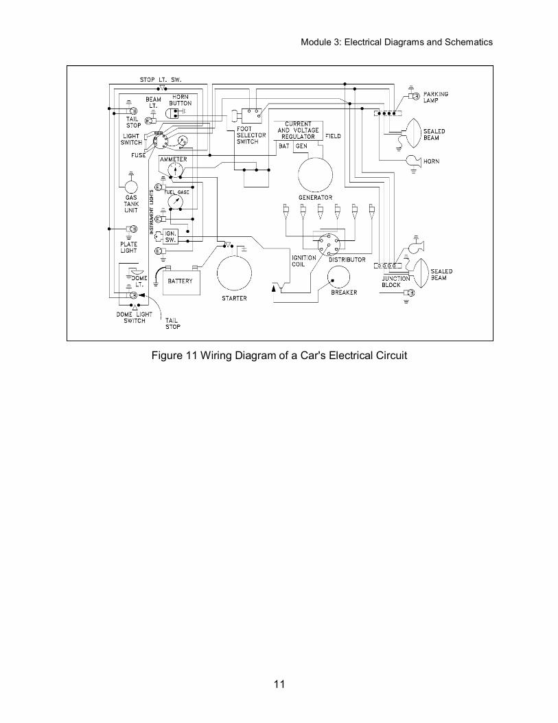
Figure 10 provides an example of the relationship between a schematic diagram (Figure
10A) and a wiring diagram (Figure 10B) for an air drying unit. A more complex example,
the electrical circuit of an automobile, is shown in wiring diagram format in Figure 11
and in schematic format in Figure 12. Notice that the wiring diagram (Figure 11) uses
both pictorial representations and schematic symbols. The schematic (Figure 12) drops
all pictorial representations and depicts the electrical system only in symbols.
Figure 10 Comparison of an Electrical Schematic and a Wiring Diagram
Module 3: Electrical Diagrams and Schematics
11
Figure 11 Wiring Diagram of a Car's Electrical Circuit

Module 3: Electrical Diagrams and Schematics
12
Figure 12 Schematic of a Car's Electrical Circuit
When dealing with a large power distribution system, a special type of schematic
diagram called an electrical single line is used to show all or part of the system. This
type of diagram depicts the major power sources, breakers, loads, and protective
devices, thereby providing a useful overall view of the flow of power in a large electrical
power distribution system.
On power distribution single lines, even if it is a 3-phase system, each load is commonly
represented by only a simple circle with a description of the load and its power rating
(running power consumption). Unless otherwise stated, the common units are kilowatts
(kW). Figure 13 shows a portion of an electrical distribution system at a nuclear power
plant.

Module 3: Electrical Diagrams and Schematics
13
Figure 13 Example Electrical Single Line

Module 3: Electrical Diagrams and Schematics
14
Figure 14 Examples of Relays and Relay Contacts
Reading Electrical Diagrams and Schematics
To read electrical system diagrams and schematics properly, the condition or state of
each component must first be understood. For electrical schematics that detail
individual relays and contacts, the components are always shown in the de-energized
condition (also called the shelf-state).
To associate the proper relay with the contact(s) that it operates, each relay is assigned
a specific number and/or letter combination. The number/letter code for each relay is
carried by all associated contacts. Figure 14 (A) shows a simple schematic containing a
coil (M1) and its contact. If space permits, the relationship may be emphasized by
drawing a dashed line (symbolizing a mechanical connection) between the relay and its
contact(s) or a dashed box around them as shown in Figure 14 (B). Figure 14 (C)
illustrates a switch and a second set of contacts that are operated by the switch.

Module 3: Electrical Diagrams and Schematics
15
When a switch is used in a circuit, it may contain several sets of contacts or small
switches internal to it. The internal switches are shown individually on a schematic. In
many cases, the position of one internal switch will affect the position of another. Such
switches are called ganged switches and are symbolized by connecting them with a
dashed line as shown in Figure 15 (A). In that example, closing Switch 1 also closes
Switch 2. The dashed line is also used to indicate a mechanical interlock between two
circuit components. Figure 15 (B) shows two breakers with an interlock between them.
Figure 15 Ganged Switch Symbology
In system single line diagrams, transformers are often represented by the symbol for a
single-phase air core transformer; however, that does not necessarily mean that the
transformer has an air core or that it is single phase. Single line system diagrams are
intended to convey only general functional information, similar to the type of information
presented on a P&ID for a piping system. The reader must investigate further if more
detail is required. In diagrams depicting three-phase systems, a small symbol may be

Module 3: Electrical Diagrams and Schematics
16
placed to the side of the transformer primary and secondary to indicate the type of
transformer windings that are used.
Figure 16 (A) shows the most commonly used symbols to indicate how the phases are
connected in three-phase windings. Figure 16 (B) illustrates examples of how these
symbols appear in a three-phase single line diagram.
Figure 16 Three-Phase Symbols

Module 3: Electrical Diagrams and Schematics
17
Summary
The important information in this chapter is summarized below.
Electrical Diagrams and Schematics Summary
This chapter covered the common symbols used on electrical diagrams and
schematics to represent the basic electrical components.
Polarity on a transformer is defined by dots placed on the primary and
secondary windings. On the primary side, the dot indicates current in; on the
secondary, the dot indicates current out.
Switches, relays, and interlocked equipment commonly use dashed lines or
boxes to indicate the relationship between them and other components.
Electrical components, such as relays, are drawn in the de-energized state
unless otherwise noted on the diagram.

Module 3: Electrical Diagrams and Schematics
18
ELECTRICAL WIRING AND SCHEMATIC DIAGRAM
READING EXAMPLES
This chapter contains several examples that will help to build, through
practice, on the knowledge gained in reading electrical wiring and
schematic diagrams.
1.6 Given a simple electrical schematic and initial conditions, IDENTIFY the
power sources and/or loads and their status (i.e., energized or de-
energized).
Examples
To aid in understanding the symbology and diagrams discussed in this module refer to
Figure 17 and Figure 18. Then answer the questions asked about each. The answers
for each example are given on the page following the questions.
Referring to Figure 17:
1. What type of diagram is it?
2. What is the rating on the fuses protecting the motor controller circuit?
Refer to the number at the far left to locate the following lines.
3. What is the component labeled ITDR in line 13?
4. Which lines contain limit switches?
5. Which lines contain pushbutton switches?
6. How many contacts are operated from relay 8CR?
7. What component is represented by the symbol on the far right of line 4?

Module 3: Electrical Diagrams and Schematics
19
Figure 17 Example 1

Module 3: Electrical Diagrams and Schematics
20
Answers to questions on Figure 17.
1. Schematic
2. 10 amps
3. A time delay closing switch
4. Lines 7, 9, 11, 12, 14, and 15
5. Lines 3, 4, 5, 6, and 18
6. 4.
7. A green lamp
Figure 18 Example 2

Module 3: Electrical Diagrams and Schematics
21
Referring to Figure 18.
1. What type of diagram is Figure 18?
2. How many current transformers are in the diagram?
3. What type of circuit breakers are shown?
4. What is the voltage on the main bus?
5. What is the voltage entering the transformer in the lower left corner?
6. Classify the transformer in the upper left corner.
7. What is the component in the lower left corner?

Module 3: Electrical Diagrams and Schematics
22
Answers to questions on Figure 18.
1. System diagram
2. 3. If you said 4, the one in the upper right is a potential transformer.
3. Drawout type.
4. 4.16 kV or 4160 V.
5. 480 V.
6. Delta primary, grounded wye secondary.
7. (Emergency) diesel generator

Module 3: Electrical Diagrams and Schematics
23
Summary
The important information in this chapter is summarized below.
Electrical Wiring and Schematic Diagram Reading Example Summary
This chapter reviewed the material presented in this module through the practice
reading examples.