Embed Size (px)
Citation preview

ADVANCED ENGINEERING SOLUTIONS Inc.Innovative Steps to Excellence…
1AES Property/Confidential 1
Engineering Solutions
Through CAD / CAE / CFD
AES FEA Capabilities & Case Studies

ADVANCED ENGINEERING SOLUTIONS Inc.Innovative Steps to Excellence…
AES Property/Confidential 2
FEA Capability
• Finite Element Analysis for Static & Dynamic
• Linear and Non-linear Analysis
• Steady state/ Transient Analysis
• Stress Analysis, Structural and Thermal analysis
• Crash and Impact analysis
• Fatigue and Durability analysis
• Plastic Deformation
• Creep Analysis
• Rotor Dynamics
• Vibration
• Fluid Flow Impact & Large Deflection
• Electro-Magnetic
• Impact Analysis
• Harmonic, Spectrum & Random analysis
• Transient Dynamic
• Coupled-physics involving acoustic, piezoelectric,
thermo-structural
• Sub-model analysis and
• Design Optimization studies
AES FEA Competencies
• ANSYS for FE analysis
• ABAQUS for Non-linear Structural FEA
• Nastran
• LS-DYNA for Impact analysis
• HYPERMESH & ICEM CFD for meshing
• PRO/E, AUTOCAD, CATIA and
UNIGRAPHICS for Design and Model

ADVANCED ENGINEERING SOLUTIONS Inc.Innovative Steps to Excellence…
AES Property/Confidential 3
Punch Design for Cold Forming Process
Project goal
Simulate forward and backward non-linear metal forming simulation
Design extrusion punch – Nose Design
Back-extrude
punch Generic Nose
Design
Carbide punches can withstand very high compressive stress
but are very poor under tensile stresses
Punch nose design criteria's
Less wall friction to reduce forward compressive stress
Avoid material build up behind nose to reduce tensile
stress while punch backing up
Hole making process
Initial
shapePreform Extrusion Pierce
Challenges

ADVANCED ENGINEERING SOLUTIONS Inc.Innovative Steps to Excellence…
AES Property/Confidential 4
Forward Extrude Simulation Backward Extrude Simulation
Punch
Deformed
Material
Deformed
Material
Deformed
Material
Deformed
MaterialDeformed
Material
Tension
Compression
Punch
Nose
Successfully designed
punch nose that has lower
tensile stress during
backward extrude
Results – Punch Nose Design

ADVANCED ENGINEERING SOLUTIONS Inc.Innovative Steps to Excellence…
AES Property/Confidential 5
Multi-Physics Electro Thermal Analysis
Project goal Simulate Smelting Process – Electrolysis process for Aluminum Production
Find best process variables that produce desired temperature distribution
Cathode
ElectrolyteLedge
Anode
Temperature profiles showing temp. isotherms
Heat produced = Elec. Resistance x I2 x time
Wall

ADVANCED ENGINEERING SOLUTIONS Inc.Innovative Steps to Excellence…
AES Property/Confidential 6
Electrolyte below 840°C remains in a solid state protecting the walls of the “POT” from the highly
corrosive electrolyte that is in liquid state
Results – Ledge Design
ADVANCED ENGINEERING SOLUTIONS Inc.Innovative Steps to Excellence…
AES Property/Confidential 7
Design Optimization Capabilities
P
P
r

ADVANCED ENGINEERING SOLUTIONS Inc.Innovative Steps to Excellence…
AES Property/Confidential 8
Background
Tier-IV Engine - additional 4” of overhang
Modify bracket or Change frame
Objective
Optimize the Tier-IV Engine bracket
Minimize mass while improving performance
Constraints
Stress in Tier-IV bracket <= Tier-III bracket
Stiffness of Tier-IV bracket >= Tier-III bracket
Bolted Joint Performance of Tier-IV bracket >= Tier-III bracket
24.3 mm
120.8 mm105 mm
Tier 3 – Bracket
103 mm
198 mm105 mm
Tier 4 – Concept Bracket
Engine
Block
Mounting
Bracket
x
zy
x
z
y
Engine Front Mount Casting Design

ADVANCED ENGINEERING SOLUTIONS Inc.Innovative Steps to Excellence…
AES Property/Confidential 9
Captured Major Load paths
- address the 4” overhang
Topology Optimization Design Interpretation
Fine Tune Design for PerformanceInertial loads in X, Y and Z directions – Stress Comparison
Stiffness of the bracket to meet Iso-Mounting requirements – Stiffness Ratio
Bolted Joint Analysis to evaluate integrity with 4” Overhang – Shear Capacity
Design Process
Tier III Tier IV - 4 Bolts Tier IV - 5 Bolts

ADVANCED ENGINEERING SOLUTIONS Inc.Innovative Steps to Excellence…
AES Property/Confidential 10
80 MPa128 MPa
250 MPa
Tier III Tier IV - 4 Bolts Tier IV - 5 Bolts
Deformed ShapeDeformed Shape
Shear Force Shear Force Shear Force
Deformed Shape
Prime Path
Stress
Tier-IV Bracket <= Tier-III
Stiffness
Tier-IV Bracket <= Tier-III
Bolted Joint
Tier-IV Bracket <= Tier-III
5th bolt is sharing some of the
shear force with the 4th bolt
and increasing the overall
shear capacity of the joint
X Y Z
Baseline - Tier 3 170 3.7 262 5.9
Tier IV - 4 Bolt 279 7.2 121 9.2
Tier IV - 5 Bolt 180 6.3 99 9.5
Bracket / Iso Mount Stiffness RatioBracket Mass (Kg)
Structural Performance of Optimized Bracket

ADVANCED ENGINEERING SOLUTIONS Inc.Innovative Steps to Excellence…
11
Tilt Lever Topology Optimization
Problem Statement: Complete an Optimization process to achieve 10,000 hours of life with minimum mass of the Tilt Lever.
Maximum Design Space for the Tilt Lever is provided in PRO/E part file format and NASTRAN input file.
Nine load cases and loading sequences for fatigue calculation is provided.
Symmetry is required with respect to Base_XY plane.
Fatigue curve for material is provided.
Material property is provided in NASTRAN/Optistruct input file.
Use 40% or less weight.
AES Property/Confidential 11

ADVANCED ENGINEERING SOLUTIONS Inc.Innovative Steps to Excellence…
12
Topology Optimization Set-Up
Define the maximum design space for the tilt
lever as design variable in Optistruct.
Define optimization responses: Weighted Compliance, strain energy type of
response for multiple load cases
Volumefrac, regional volume fraction response
Define optimization constraint. Volumefrac < 0.4
Define optimization objective. Minimize weighted compliance
Define manufacturing constraint: Split Draw
constraint in z-direction.
AES Property/Confidential 12

ADVANCED ENGINEERING SOLUTIONS Inc.Innovative Steps to Excellence…
13
Topology Optimization Results
Optimized Material
Distribution
Interpreted Design
New Minimum life area, around 9900 Hrs
AES Property/Confidential 13

ADVANCED ENGINEERING SOLUTIONS Inc.Innovative Steps to Excellence…
14
Casting Design – Size and Shape Optimization
Project goal
Replace multiple overlaying welded sheet metal with a single casting
Reduce parent material stresses and weld stresses
Minimize weight of the casting
Multiple sheet metals Single casting
Model was provided in Pro-E format.
Meshing was done in Hypermesh and Abaqus was used for the dynamic impact
analysis
Automation, Design trade off studies and Optimization was done in I-Sight
AES Property/Confidential 14

ADVANCED ENGINEERING SOLUTIONS Inc.Innovative Steps to Excellence…
15
Shape and Size Design Variables
Variable 1: Radius Shape
(Fore Aft-Cross tube)
Variable 2: Lower Cross Tube
Diameter
Fix
this edge
Variable 3: Fore Aft
width
Fix
this edge
Variable 4: Fore Aft width
Variable 5: Casting Side
Wall ThicknessVariable 6: Casting
top/bottom
Wall Thickness
Variable 7: Casting
Lower Cross Tube
Thickness
Variable 8: Casting
Lower Cross Tube
Length
Variable 9 - Fore Aft Top Bottom Cover Plates
Variable 10 - Fore Aft Side Cover Plates
Variable 11 - Lower Cross Tube Thickness
AES Property/Confidential 15

ADVANCED ENGINEERING SOLUTIONS Inc.Innovative Steps to Excellence…
16
Optimization Setup
Objective
Minimize Weight of entire frame
Subject to
Stress at weld location < 200 Mpa
Stress on Casting < 500 MPa
AES Property/Confidential 16

ADVANCED ENGINEERING SOLUTIONS Inc.Innovative Steps to Excellence…
17
Optimized Results11.27 mm (plate) thck
13.82 mm
(plate) thck 12.00 mm (wall) thck
12.00 mm
(wall) thck
12.00 mm (wall) thck
Include Radius
Increase Diameter
by 4%
10.00 mm
(plate) thck
FIX
VariablesConcept 1
Baseline(mm)Optimized (mm)
Casting Side Wall Thickness 12.70 12.00
Casting Top-Bottom Wall Thickness 12.70 12.00
ForeAft-Crosstube Radius (shape) 0.00 9.09
Casting Cross tube thickness 12.70 12.00
Castin Lower Cross tube Length 887.00 910.16
Casting ForeAft width 151.00 159.18
ForeAft Side Plate Thickness 12.00 13.82
ForeAft Top-Bottom Plate Thickness 5.00 11.27
Lower Cross Tube Thickness 12.70 10.00
Lower Cross Tube Diameter 163.50 171.74
Response Original Optimized
Mass (of frame) (Tons) 3.737 4.01957
Response Original Optimized
element 211 (Mpa) 205 204
element 212 (Mpa) 361 188
element 213 (Mpa) 87 73
element 214 (Mpa) 205 123
Response Original Optimized
element 257 (Mpa) 417 273
element 266 (Mpa) 408 424
element 267 (Mpa) 447 396
element 468 (Mpa) 473 385
Stress at Weld LocationsStress on Cast part
Interpretation
(Pro-E Model)
AES Property/Confidential 17

ADVANCED ENGINEERING SOLUTIONS Inc.Innovative Steps to Excellence…
18
Modified Concept Performance Evaluation
518 MPa
362 MPa
498 MPa
266 MPa
547 MPa
627 MPa
620 Mpa
475 MPa
629 MPa
308 MPa
Current Production Concept 2
With Wrapper Plate
Without Wrapper Plate
467 MPa
• All stresses are the max stress during the entire time history
AES Property/Confidential 18

ADVANCED ENGINEERING SOLUTIONS Inc.Innovative Steps to Excellence…
AES Property/Confidential 19
Oil and Gas structures
- Finite Element Analysis - Capabilities on
Static Structural FEA Simulations Dynamic FEA Simulations
* Oil pipe Pressure application
analysis.
* Oil and Gas, Offshore
structures Nonlinear Contact
Simulation.
* Fatigue life estimation analysis.
* Fracture Simulations of Offshore
structure base and pipes.
* Offshore structures Thermal and
Thermo structural simulations.
* Oil pipes and Offshore
structures frequency analysis.
* Random Vibration analysis of Oil
and Gas structures.
* Dynamic Explicit simulations of
oil and gas structures.
* Impact simulations.
Few Case Studies on problems related to oil and gas
structures FEA is presented in oncoming slides.
* Seismic analysis.
ADVANCED ENGINEERING SOLUTIONS Inc.Innovative Steps to Excellence…
AES Property/Confidential 20
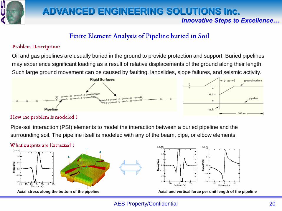
Oil and gas pipelines are usually buried in the ground to provide protection and support. Buried pipelines
may experience significant loading as a result of relative displacements of the ground along their length.
Such large ground movement can be caused by faulting, landslides, slope failures, and seismic activity.
Pipe-soil interaction (PSI) elements to model the interaction between a buried pipeline and the
surrounding soil. The pipeline itself is modeled with any of the beam, pipe, or elbow elements.
Axial stress along the bottom of the pipeline Axial and vertical force per unit length of the pipeline

ADVANCED ENGINEERING SOLUTIONS Inc.Innovative Steps to Excellence…
AES Property/Confidential 21
Pipelines extending from the sea floor to the ocean surface (risers) are subject to many types
of load: self-weight, buoyancy, internal and external pressure, tensile forces arising from
surface moorings, current drag, and oscillatory loads resulting from wave motion. The
response of a riser to these loads is complex, and the difficulty of such analysis is heightened
by the relative length of such pipelines (deep water risers).
Displacement plot Vs riser position
The riser has a weight and is loaded by a top tension . Drag loading is applied by a steady
current flowing by the riser with a velocity distribution varying linearly. Wave motion effect
modeled with the Airy wave theory. The analysis is done in two steps. The first is the static step,
in which the top tension is applied and the riser is moved from the vertical to its offset position
by specifying the necessary horizontal displacement at the top of the pipeline. The second step,
is a dynamic step, where deformation is applied with respect to time.
Bending stress
Vs
Riser Normalised position
Offshore Riser Pipe
specifications
Horizontal displacement
No
rmali
sed
po
sit
ion
Bending stress
No
rmali
sed
po
sit
ion

ADVANCED ENGINEERING SOLUTIONS Inc.Innovative Steps to Excellence…
AES Property/Confidential 22
Threaded connectors are commonly used components in the piping and offshore industry. They must
withstand a variety of loading conditions: thread engagement, torque, bending, axial pullout, internal
pressure under operating and overload conditions, and potential fluid leakage through threaded
connections.
Stress Plots after Interference fit
A three-dimensional cut-away view of the threaded connection
assembly analyzed. Although the actual threads are helical, they are
represented with an axis symmetric geometry. Three steps adopted
for problem solving. Step-1: Resolving Interference fit between
threads of pin and box, Step-2: the assembly is held fixed while the
friction coefficient is changed from 0 to 0.1. Step-3: An internal gauge
pressure of 0.689 MPa is applied.
Pressure Plots Penetration pressure Vs distance along box

ADVANCED ENGINEERING SOLUTIONS Inc.Innovative Steps to Excellence…
AES Property/Confidential 23
While lifting a one million pound section of space frame roof structure
at a construction site, a crane failed and overturned. During the
ensuing failure investigation, the strength of the crane‟s king pin, a 12″
diameter, 11′ long steel shaft about which the front crawler body
rotates, was a key issue along with any changes in king pin strength
that may occur with various king pin connection details.
King pin
stress plots
Finite element model
of Kingpin
Heavy lift craneKingpin connection
details
A quarter symmetry solid element model of the king pin is assumed
for analysis. The model included multiple 3D deformable body-to-
deformable body contact surfaces and material nonlinearities.
The analysis showed the variation of king pin strength with differing king
pin connection details and this information was used as part of the multi-
disciplinary investigation to determine a probable cause for the failure of
the crane.
Thrust bearing
stress plots

ADVANCED ENGINEERING SOLUTIONS Inc.Innovative Steps to Excellence…
AES Property/Confidential 24
Finite element model of the
foundation
When the oil storage tank is filled with oil, the maximal additional pressure
on the foundation is assumed up to 250 KN/m2. In fact, the contact status
of soil and tank foundation is between viscous contact and slick contact,
but if the tank foundation only supports vertical force and the soil of
foundation is cohesive soil, the contact status of soil and tank foundation
tends to viscous contact. Also, dynamic effect and horizontal lateral force of
tank foundation are ignored in this work. A one-quarter model of the
foundation is assumed for this study.
The maximal stress does not appear at the center of tank foundation, but
appears at the areas between 15 and 25 meters away from the center, and it is
also higher than the pressure that the foundation is loaded when the tank is
filled with oil. For the areas that appear to have a concentration of stress, the
soil moves into plastic status from elastic status. Moreover, the soil mass suffers
from upward force if the soil is very far from the center of tank foundation.
Settlement contour line of
homogenous soil
Methods on how to deal with foundation and minimum compound modulus of
elasticity and Poisson‟s ratio that are required in order to control the settlement in
some magnitude are concluded by using finite element analysis to simulate the
extra stress distribution of the single oil storage tank.

ADVANCED ENGINEERING SOLUTIONS Inc.Innovative Steps to Excellence…
AES Property/Confidential 25
Free body diagram of the loads
taken by the support structure
Foundation stress plots
Vibrating, rotating, reciprocating and impacting equipment create machine-induced
vibration and/or shock, which is transmitted into their support systems. Rotating machines
and equipment that are not properly balanced produce centrifugal forces creating steady
state and random vibration. A finite element study conducted on the foundation with
different combinations including soil and other dampening effects will reduce this problem.
A foundation or any support structure must provide a reliable structural configuration that also meets the
static and dynamic criteria for the structure. Deflections in the foundation caused by static loads or by
dynamic forces/inputs should be within acceptable limits. This design approach sometimes requires modeling
of the foundation as seen in the above figure, so that the real structure behavior is predetermined and errors
are minimized.
The calculations for the stiffness of a foundation yield the static and
dynamic behavior and stress concentration points that occur.
Mode shapes (stiffness of a structure in each axis) identify the
physical direction of each frequency mode and any deformations,
such as bending or twisting.
Examining mode shapes in a vibrating structure is a valuable
step in adjusting vibration amplitudes at critical points by
varying the stiffness, mass and damping in a structure. Mode shapes of the structure

ADVANCED ENGINEERING SOLUTIONS Inc.Innovative Steps to Excellence…
AES Property/Confidential 26
Case Study – FE analysis of Decking structureObjective :
• To perform a 3D static, and seismic load analysis of the decking structure.
• To Predict reaction loads and reaction moments at all Anchor bolts.
FEA Modeling :
• Material properties, gravity and seismic loads, and CAD model as input. Several load-cases analyzed.
• Lumped mass formulation used for heavy equipments and assemblies supported by decking structure.
• Anchor bolts were modeled with appropriate contact s with the columns fixed to the ground.
Task Executed:
• The model cleaned using Unigraphics. Hex-dominant meshing carried out using Ansys Workbench. Model set-up and
Analysis carried out in Ansys.
• Stress and displacements plots were plotted along with detailed tabular results for reaction loads and moments at all bolts.
Conclusion & Reliability :
• CAE analysis was carried out to make required changes in the decking structure design and bolts‟ design.
Cost Savings :
• Installation was done in IBC zone-4 seismic regions. Decking structure design was iteratively modified.

ADVANCED ENGINEERING SOLUTIONS Inc.Innovative Steps to Excellence…
AES Property/Confidential 27
Case Study – NVH on PC BoardObjective
• To perform Dynamic Analysis on a PC Board under bolt pretension load.
• Modal analysis, Harmonic analysis and Random analysis on PC Board assembly.
FEA Modeling
• 3D FE model created using Hypermesh. Model set up done using Ansys Workbench
• Bolt pretension analysis followed by Modal, harmonic and random analysis. Input PSD available from
customer for Random analysis‟
• Detailed response charts post-processed.
Task Executed
• The model is created in Unigraphics. Hexahedral meshing is carried out using Hypermesh. Model set-up
done in Ansys Workbench and Analysis is carried out in Ansys classic.
Conclusion & Reliability
• Components with high resonance identified.
• Required vibration isolation and correct bolt pretension was determined later in the design cycle.
Cost Savings
• Simulation results validated with test data used for further design changes.

ADVANCED ENGINEERING SOLUTIONS Inc.Innovative Steps to Excellence…
AES Property/Confidential 28
Case Study – CreepObjective
• To predict creep deformation in the backing plate (of process chamber) after 10,000 hrs of operation.
• Repeat the analysis with the steel support structure, and predict reaction forces (at different locations).
FEA Modeling
• Quarter symmetric model analyzed. T=Creep constants for time hardening curve fit, available from the customer.
• Different sizes of backing plate with different thicknesses analyzed.
• Different sub-models, such as steel bolt fitment to the Aluminum plate, welds between transfer chamber and
process chamber, etc were studied.
Task Executed
• 3D CAD model was created in Unigraphics. Meshing is carried out using Ansys Workbench. Model set-up was
done in Ansys Workbench.
• Analysis and Post-processing was carried out in Ansys classics. Many other important factors, such as low-
thickness BP lift at the corners, stresses in the lid-welds, etc, were studied.
Conclusion & Reliability
• Creep constants were validated by comparing results on 40 K without support structure with the real life field
data.
• Steel support structure with modified fitment became standard solution for creep for all future projects.
Cost Savings
• Huge cost savings on part of material cost cutting (by using thinner backing plates) have been achieved..

ADVANCED ENGINEERING SOLUTIONS Inc.Innovative Steps to Excellence…
AES Property/Confidential 29
Case Study – TSSL chamber crack propagationObjective :
• To perform a 3D weld propagation in the TSSL chambers. Existing cracks in the field.
• To check vacuum leak as worst case scenario.
• Design retrofit.
FEA Modeling :
• 3D FE model created using Ansys Workbench. All welds modeled as parts. Appropriate bonded and standard contacts
assigned. Number of parts is very high.
• Linear static analysis to identify regions above fatigue yield limit.
• Crack created later to study crack propagation characteristics.
Task Executed:
• The model is created in Unigraphics. Meshing is carried out using Ansys Workbench. Model set-up and Analysis carried out
in Ansys Workbench.
• Crack propagation parameters calculated and analyzed. Suitable design changes analyzed to check vacuum leak.
Conclusion & Reliability :
• Crack direction of propagation, growth rate identified.
• All equipments installed in field were later worked on over with suggested retrofit.
Cost Savings :
• Cracks appearing in field identified and retrofit made well in time before vacuum leaks.

ADVANCED ENGINEERING SOLUTIONS Inc.Innovative Steps to Excellence…
AES Property/Confidential 30
Case Study – Hoist-bracket structural analysisObjective :
• To perform a 3D stress analysis hoist bracket assembly.
• Identify regions of low safety factor or failure as the case may be.
FEA Modeling :
• 3D FE model created using Ansys classic. Welds analyzed as parts with appropriate contacts.
• Post-yield Non-linear material properties were used.
Task Executed:
• The model is created in Unigraphics. Hexahedral meshing carried out using Hypermesh. Model set-up and Analysis carried
out in Ansys Classic.
• Welds were particularly meshed with a good quality, being the main focus area.
Conclusion & Reliability :
• Some of the welds were actually failing in some of the load-cases. This was consistent with the testing.
Cost Savings :
• The problem was identified and rectified before entire product was shipped.

ADVANCED ENGINEERING SOLUTIONS Inc.Innovative Steps to Excellence…
AES Property/Confidential 31
Case Study – FE analysis of PSU spacer panelObjective :
• To perform a 3D stress analysis on 6” spacer panels used in aircraft interior.
• Analyze model against different gravity load-cases, and against rail motion envelope as specified by the aircraft manufacturer.
FEA Modeling :
• Linear material properties used initially, to avoid added complexity due to highly non-linear contacts. A total of 21 cases
analyzed including inboard rail motion envelope.
• Worst case scenarios re-analyzed with proposed design changes.
Task Executed:
• The model is created in Unigraphics. Hex-dominant meshing carried out using Workbench. Model set-up and Analysis carried
out in Ansys Workbench
• Design changes made based on high stress gradients and high strains.
Conclusion & Reliability :
• Project is currently on, and results will be validated by testing.
Cost Savings :
• Client is a tier-1 supplier to Boeing. New designs „ conformation to the specifications will open up new opportunities in PSU
market.

ADVANCED ENGINEERING SOLUTIONS Inc.Innovative Steps to Excellence…
AES Property/Confidential 32
Case Study – FE analysis of O-ring compressionObjective :
• To perform a 3D stress analysis on O-ring used in the antenna assembly.
• To analyze the performance at various temperatures.
• To predict the deformation of plastic housing due to O-ring compression
FEA Modeling :
• Input all material non-linearities, including the hyper-relastic O-ring and non-linear stress strain curve for the plastic material,
at different temperatures.
• Appropriate contact control parameters and time-step control used..
Task Executed:
• The model is created in Unigraphics. Hex-dominant meshing carried out using Hypermesh. Model set-up and Analysis
carried out in Ansys.
• Stress and displacements plots were plotted along with a detailed analysis of performance.
Conclusion & Reliability :
• Results were validated with testing at room temperature.
Cost Savings :
• Antenna is installed in severe weather conditions. These conditions were simulated using the FE A tool.

ADVANCED ENGINEERING SOLUTIONS Inc.Innovative Steps to Excellence…
AES Property/Confidential 33
AES Oil & Gas Case Studies
CFD Analysis of
1. Catalyst (Monolith Modeling)
2. Mixing Tank
3. Reservoir
4. Continuous stirred-tank reactor
5. Porous Modeling with Fluid Injection
6. Nozzle Analysis

ADVANCED ENGINEERING SOLUTIONS Inc.Innovative Steps to Excellence…
AES Property/Confidential 34
Case Study
on
Catalyst (Monolith Modeling)

ADVANCED ENGINEERING SOLUTIONS Inc.Innovative Steps to Excellence…
AES Property/Confidential 35
Objectives
CFD Analysis of Catalyst
Geometry Modeling & Meshing
Honeycomb
CFD analysis to predict the flow pattern in Catalyst.
To predict the Surface reactions in porous media, Pressure drop, static pressure &
total pressure distribution, Accounts for fluid acceleration effects, temperature and mass
fraction in the Catalyst.
Honeycomb Model as porous domain
ADVANCED ENGINEERING SOLUTIONS Inc.Innovative Steps to Excellence…
AES Property/Confidential 36
Analysis Methodology
Model:
• Turbulent and unsteady steady incompressible flow in 2D Axisymmetric Domain is
solved in Ansys FLUENT parallel solver.
Boundary conditions
• Inlet velocity: 0.8 m/s
• Inlet temperature: 300K
• Adiabatic walls
• Inlet hydrogen volumetric fraction 6%
• Inlet methane concentration is 1.5%
• The operating reference pressure for the mixing tank is 1 atm.
Monitoring
• Residuals to keep track of convergence
• User defined expressions for tracking the Reaction.

ADVANCED ENGINEERING SOLUTIONS Inc.Innovative Steps to Excellence…
AES Property/Confidential 37
Task Executed
The model is created in Unigraphics. Hexahedral meshing is carried out using ICEM-Hexa. Analysis
is carried out in FLUENT after applying the material properties and different boundary conditions.
Different plots are provided in the technical report using FLUENT- Post-processing.
Conclusion1. Reacting zone is a catalyst and modeled as porous domain.
2. Methane concentration & temperature contour and were plotted.
Final Results
From the Analysis, Pressure drop , static pressure, total pressure, static temperature, mass fractions
of fluids at different location and velocity components are plotted. Based on the analysis,
performance are optimized for the given design as per the SOW.
Typical contour plots
Result & Discussion
INLET
INLET
OUTLET
OUTLET
Methane concentration contours Temperature contours

ADVANCED ENGINEERING SOLUTIONS Inc.Innovative Steps to Excellence…
AES Property/Confidential 38
Case Study
on
Mixing Tank

ADVANCED ENGINEERING SOLUTIONS Inc.Innovative Steps to Excellence…
AES Property/Confidential 39
Objectives
CFD Analysis of Mixing Tank
Geometry Modeling & Meshing
Impeller Model
CFD analysis to predict the flow pattern in the mixing tank.
To predict the static pressure & total pressure distribution , velocity and mass fraction
in the mixing tank.
To optimise the design base on series of runs for different flow rates of jet.

ADVANCED ENGINEERING SOLUTIONS Inc.Innovative Steps to Excellence…
AES Property/Confidential 40
Analysis Methodology
Model
• Turbulent and unsteady steady incompressible flow in 3D Domain is solved in Ansys
CFX 11 parallel solver.
Boundary conditions
• The jet was placed theoretically next to the impeller and its effect on reducing the
mixing time was investigated
• Liquid (surface tension 0.02 N/m & density 900 kg/m^3) is inside the mixing tank of
19,000 m3 Outlet is section is maintained at gauge pressure of 0 Pa .
• The operating reference pressure for the mixing tank is 1 atm.
Monitoring
• Residuals to keep track of convergence
• User defined expressions for tracking the flow stability.

ADVANCED ENGINEERING SOLUTIONS Inc.Innovative Steps to Excellence…
AES Property/Confidential 41
Task Executed
The model is created in Unigraphics. Hexahedral meshing is carried out using ICEM-Hexa. Analysis
is carried out in CFX after applying the material properties and different boundary conditions.
Different plots are provided in the technical report using CFX- Post-processing.
Conclusion
Various jet outflow rates including: 33, 66, 132 and 264 m3 h−1 were examined and the effect of the
angle between the jet and the impeller on the mixing time for four setups was investigated.
Final Results
From the Analysis, the static pressure, total pressure, mach number, static temperature, mass
fractions of fluids at different location and velocity components are plotted. Based on the analysis,
performance are optimized for the given design as per the SOW.
Typical contour plots
Result & Discussion

ADVANCED ENGINEERING SOLUTIONS Inc.Innovative Steps to Excellence…
AES Property/Confidential 42
Case Study
on
Reservoir
ADVANCED ENGINEERING SOLUTIONS Inc.Innovative Steps to Excellence…
AES Property/Confidential 43
Objectives
CFD Analysis of Reservoir
Geometry Modeling & Meshing
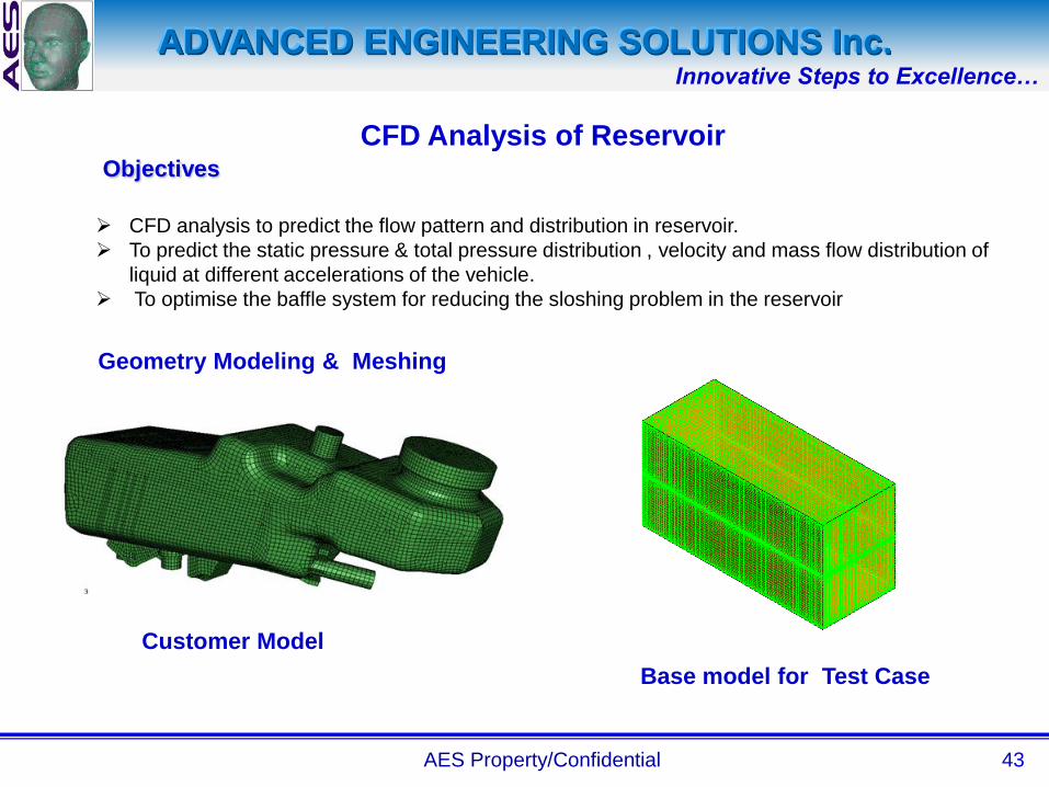
Customer Model
Base model for Test Case
CFD analysis to predict the flow pattern and distribution in reservoir.
To predict the static pressure & total pressure distribution , velocity and mass flow distribution of
liquid at different accelerations of the vehicle.
To optimise the baffle system for reducing the sloshing problem in the reservoir

ADVANCED ENGINEERING SOLUTIONS Inc.Innovative Steps to Excellence…
AES Property/Confidential 44
Analysis Methodology
Model
• Isothermal, Turbulent, Multiphase and unsteady incompressible flow in 3D Domain is solved in
Ansys CFX 11 parallel solver.
Boundary conditions
• Completely closed geometry filled with brake fluid and the above is atmospheric air.
• Fluid (surface tension 0.04 N/m & density 1700 kg/m^3) free surface is separating the both fluids.
• The operating reference pressure for reservoir chamber is 1 atm.
Monitoring
• Residuals to keep track of convergence
• User defined expressions for tracking the flow stability.
• Free surface and pressure data has been captured for every millisecond.

ADVANCED ENGINEERING SOLUTIONS Inc.Innovative Steps to Excellence…
AES Property/Confidential 45
Task Executed
The model is created in Unigraphics. Hexahedral meshing is carried out using ICEM-Hexa. Analysis
is carried out in CFX after applying the material properties and different boundary conditions.
Different plots are provided in the technical report using CFX- Post-processing.
Conclusion
Best insight of fluid behavior for each design of baffles made us to judge the design of few baffle systems
without any simulations and client could finish the design in less number of simulations than expected.
Final Results
From the Analysis, the static pressure, total pressure, fluid level at different accelerations of the
vehicle. Based on the analysis, good baffle design has achieved through few simulations.
Typical contour plots
Result & Discussion

ADVANCED ENGINEERING SOLUTIONS Inc.Innovative Steps to Excellence…
AES Property/Confidential 46
Case Study
on
Continuous stirred-tank reactor

ADVANCED ENGINEERING SOLUTIONS Inc.Innovative Steps to Excellence…
AES Property/Confidential 47
Objectives
CFD Analysis of Continuous stirred-tank reactor
Reactor Tank
Stirred Model
CFD analysis to predict the flow pattern in the tank.
To predict the static pressure & total pressure distribution , velocity and mass fraction in the mixing tank.
To optimise the design base on series of runs for different flow rates of jet.

ADVANCED ENGINEERING SOLUTIONS Inc.Innovative Steps to Excellence…
AES Property/Confidential 48
Analysis Methodology
Model
• Turbulent and unsteady incompressible flow in 3D Domain is solved in Ansys CFX 11 parallel solver.
Boundary conditions
• The jets were placed theoretically on top of the tank and its effect on reducing the mixing time was
investigated
• Outlet is section is maintained at gauge pressure of 0 Pa .
• The operating reference pressure for the tank is 48.3 bar and operating temperature is 300 deg C.
Monitoring
• Residuals to keep track of convergence
• User defined expressions for tracking the flow stability.

ADVANCED ENGINEERING SOLUTIONS Inc.Innovative Steps to Excellence…
AES Property/Confidential 49
Task Executed
The model is created in Unigraphics. Hexahedral meshing is carried out using ICEM-Hexa. Analysis
is carried out in CFX after applying the material properties and different boundary conditions.
Different plots are provided in the technical report using CFX- Post-processing.
Final Results
From the Analysis, the static pressure, total pressure static temperature, mass fractions of fluids at
different location and velocity components are plotted. Based on the analysis, performance are
optimized for the given design as per the SOW.
Typical Transient data plot
Result & Discussion
E(t)
Time

ADVANCED ENGINEERING SOLUTIONS Inc.Innovative Steps to Excellence…
AES Property/Confidential 50
Conclusion
Various jet outflow rates including: 3, 7, 14 and 21 m3 h−1 were examined. The visual contours and
tracking along with the transient reported data for parametric flows has added value to the design
changes. Residence time is 7.28 times the mixing time.
Typical contour plots

ADVANCED ENGINEERING SOLUTIONS Inc.Innovative Steps to Excellence…
11/14/07
Pre
sent
ed
to
Case Study
on
Porous Modeling with Fluid Injection

ADVANCED ENGINEERING SOLUTIONS Inc.Innovative Steps to Excellence…
11/14/07
Objectives
CFD Analysis of Porous Modeling with Fluid Injection
Geometry Modelling & Meshing
Model
Mesh
CFD analysis to predict injected fluid concentration
To predict the velocity, injected fluid concentration, static pressure & total pressure distribution at
different location.
To optimise the design.

ADVANCED ENGINEERING SOLUTIONS Inc.Innovative Steps to Excellence…
11/14/07
a. Boundary Condition
b. Methodology & Convergence
• The flow is Incompressible
• Gases as defined in RFQ are used as the Fluid Medium, Density of individual gas is
considered.
• Solver used in the analysis is CFX.
• k-ε Turbulence Model is considered with Standard log law wall function near wall treatment
with Inlet turbulence Intensity= 5%.
• The convergence criteria from CFX is taken where the scaled residuals decrease to 10e-4
for all equations.
Inlet : Mass Flow Rate
Outlet : Static Pressure
Porosity Model
Ammonia Injection rate : Defined
Volume Porosity = 0.5
Analysis Methodology

ADVANCED ENGINEERING SOLUTIONS Inc.Innovative Steps to Excellence…
11/14/07
Task Executed
The model is created in Unigraphics. Hexahedral meshing is carried out using ICEM-Hexa. Analysis
is carried out in CFX after applying the material properties and different boundary conditions.
Different plots are provided in the technical report using CFX- Post-processing.
Conclusion
Initially Customer verified the result with the experimental results and optimized other designs based on
CFD analysis.
Final Results
From the Analysis, the static pressure, total pressure, mach number, static temperature, NH3 injection
concentration at different location and velocity components are plotted. Based on the analysis, the
perforated plate and fluid injection rate is optimized for the required design.
Typical contour plots
Result & Discussion

ADVANCED ENGINEERING SOLUTIONS Inc.Innovative Steps to Excellence…
AES Property/Confidential 55
Case Study
on
Nozzle Analysis

ADVANCED ENGINEERING SOLUTIONS Inc.Innovative Steps to Excellence…
AES Property/Confidential 56
Objectives
CFD Analysis of Nozzle
Geometry Modeling & Meshing
Model Mesh
CFD analysis to predict the flow pattern in the nozzle system.
To predict the static pressure & total pressure distribution , velocity and mass flow distribution of
liquid in the nozzle system.
To optimise the design.

ADVANCED ENGINEERING SOLUTIONS Inc.Innovative Steps to Excellence…
AES Property/Confidential 57
Analysis Methodology
Model
• Isothermal, Turbulent and steady incompressible flow in 3D Domain is solved in Ansys CFX 11
parallel solver.
Boundary conditions
• Gas is entering through the gas inlet section with mass flow rate of 10 Liter /minute
• Liquid (surface tension 0.02 N/m & density 900 kg/m^3) is entering through the liquid inlet section
with a flow rate of 10 milliliters /hour
• Outlet is section is maintained at gauge pressure of 6 psi .
• The operating reference pressure for the nozzle chamber is 1 atm.
Monitoring
• Residuals to keep track of convergence
• User defined expressions for tracking the flow stability.

ADVANCED ENGINEERING SOLUTIONS Inc.Innovative Steps to Excellence…
AES Property/Confidential 58
Task Executed
The model is created in Unigraphics. Hexahedral meshing is carried out using ICEM-Hexa. Analysis
is carried out in CFX after applying the material properties and different boundary conditions.
Different plots are provided in the technical report using CFX- Post-processing.
Conclusion
Customer verified the initial results as well as optimized results obtained by CFD analysis with the
experimental data.
Final Results
From the Analysis, the static pressure, total pressure, mach number, static temperature, mass
fractions of fluids at different location and velocity components are plotted. Based on the analysis,
the liquid gas ratio and performance are optimized for the given design as per the SOW.
Typical contour plots
Result & Discussion


![[CAD CAM CAE] Ansys - Userguide](https://img.pdfslide.us/doc/110x75/543e0826b1af9f1f2b8b45c7/cad-cam-cae-ansys-userguide.jpg)