Embed Size (px)
Citation preview
Engineering Sketching Engineering Sketching TechniquesTechniques
“A picture says a thousand words”
Allyson WhiteSTEM Lab 2011
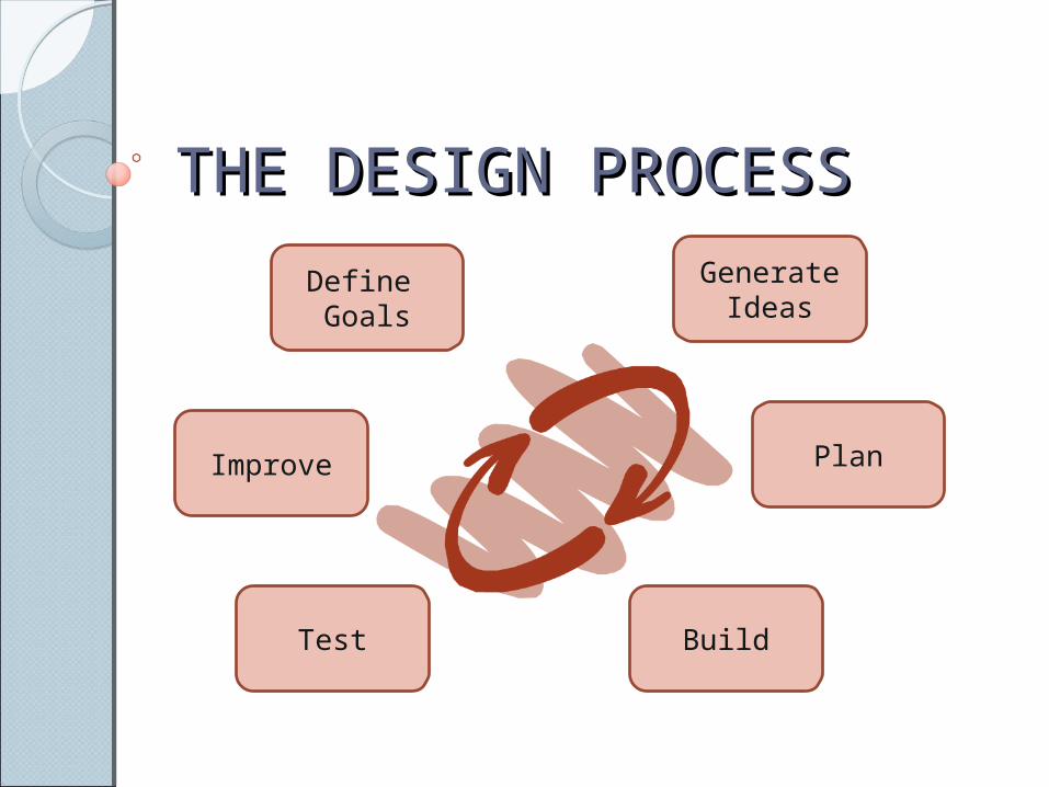
THE DESIGN PROCESSTHE DESIGN PROCESS
Define Goals
Test
Plan
Build
Improve
Generate Ideas
Learning GoalsLearning GoalsRecognize the three basic styles
of engineering sketches.Understand why a detailed
sketch is a powerful communication tool.
Be able to accurately sketch an object using isometric, orthographic, and oblique design methods.
Why?Why?Troubleshooting:
◦Sketches allow engineers to see each part of a product before a prototype is developed
Communication:◦Sketches reveal details of a product;
size shape, and features, quickly and accurately.
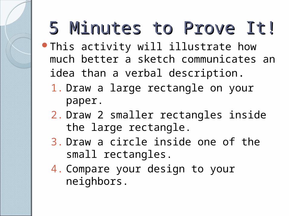
5 Minutes to Prove It!5 Minutes to Prove It!This activity will illustrate how much
better a sketch communicates an idea than a verbal description.1. Draw a large rectangle on your paper.2. Draw 2 smaller rectangles inside the
large rectangle.3. Draw a circle inside one of the small
rectangles.4. Compare your design to your
neighbors.
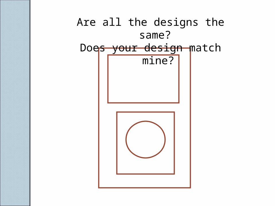
Are all the designs the same? Does your design match mine?

Isometric ProjectionIsometric ProjectionIsometric projections show three
sides of an item in proportional dimensions.◦All vertical lines are vertical◦All horizontal lines are drawn at a
30° angle.
Picture Source: Total Fabrication, Retrieved from: http://tle.tafevc.com.au/toolbox/items/2915349d-458b-d355-6733-a2388c8eb190/1/905_draw_t3.zip/2_draw/draw_t3/htm/draw3_2_2.htm
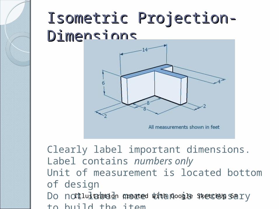
Isometric Projection- Isometric Projection- DimensionsDimensions
Clearly label important dimensions. Label contains numbers onlyUnit of measurement is located bottom of designDo not label more than is necessary to build the item.
Illustration created with Google SketchUp 6®
Orthographic ProjectionOrthographic ProjectionOrthographic sketches represent
3D items in multiple 2D drawings.Top, front, bottom, and side
views may be used.The general rule is to use only
the views necessary to show the details of the item.
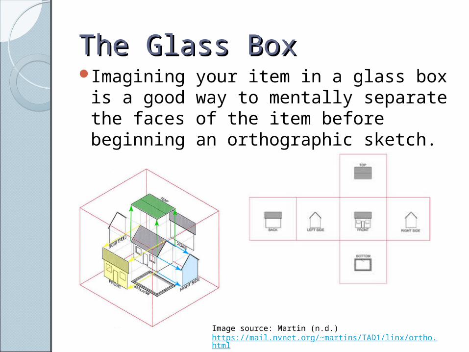
The Glass BoxThe Glass BoxImagining your item in a glass box
is a good way to mentally separate the faces of the item before beginning an orthographic sketch.
Image source: Martin (n.d.) https://mail.nvnet.org/~martins/TAD1/linx/ortho.html
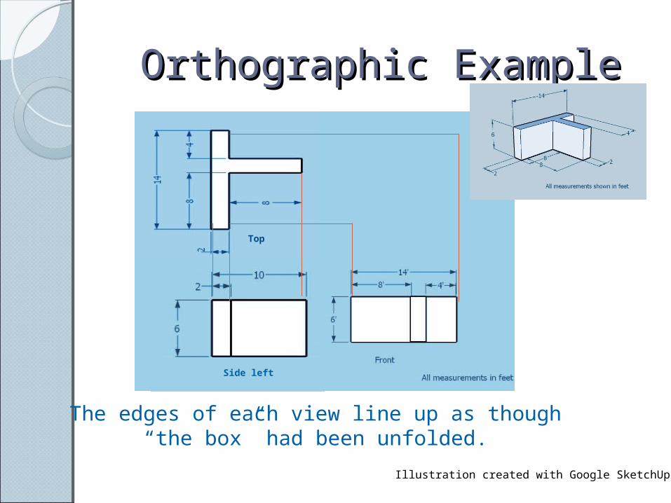
Orthographic ExampleOrthographic Example
Illustration created with Google SketchUp 6®
Top
Side left
The edges of each view line up as though “the box” had been unfolded.
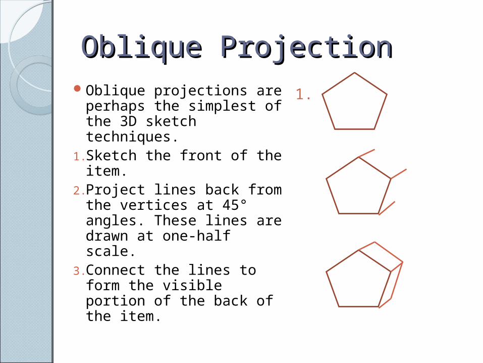
Oblique ProjectionOblique ProjectionOblique projections are
perhaps the simplest of the 3D sketch techniques.
1.Sketch the front of the item.
2.Project lines back from the vertices at 45° angles. These lines are drawn at one-half scale.
3.Connect the lines to form the visible portion of the back of the item.
1.
Computer Aided Design Computer Aided Design (CAD)(CAD)Software
packages range from the simple such as the ModelSmart program we use, Google SketchUp (free to download) to the very complex.
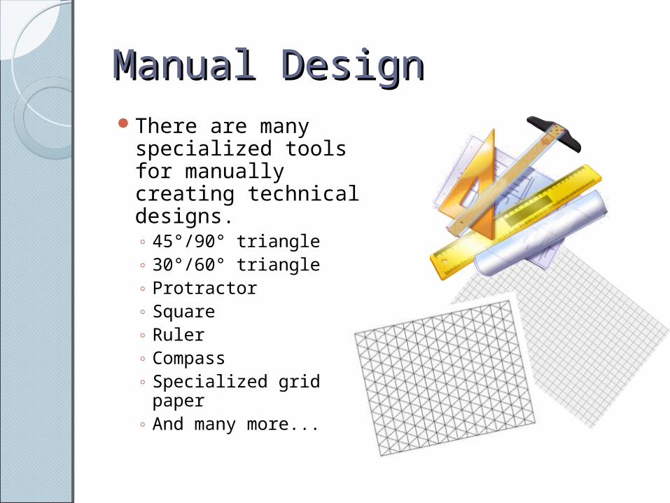
Manual DesignManual DesignThere are many
specialized tools for manually creating technical designs. ◦ 45°/90° triangle◦ 30°/60° triangle◦ Protractor◦ Square◦ Ruler◦ Compass ◦ Specialized grid
paper◦ And many more...
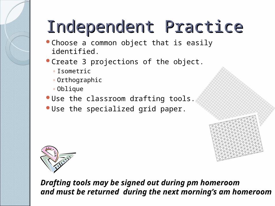
Independent PracticeIndependent PracticeChoose a common object that is easily identified. Create 3 projections of the object.
◦ Isometric◦ Orthographic◦ Oblique
Use the classroom drafting tools.Use the specialized grid paper.
Drafting tools may be signed out during pm homeroom and must be returned during the next morning’s am homeroom
Resources for StudentsResources for StudentsSokolowski, G. (2004) Orthographic
Projection #1, Wisc-Online. http://www.wisc-online.com/objects/ViewObject.aspx?ID=ENG19204
Ryan, V. (2011) Oblique projections: http://www.technologystudent.com/despro2/obli1.htm
Ryan, V. (2011) Isometric projections: http://www.technologystudent.com/prddes1/drawtec2.html
Standards AlignmentStandards AlignmentStandard 11: Students will develop abilities to
apply the design process.◦ [H] Apply a design process to solve problems in and
beyond the laboratory-classroom.
◦ [J] Make two-dimensional and three-dimensional representations of the designed solution.
Standard 17: Students will develop an understanding of and be able to select and use information and communication technologies.◦ [K] The use of symbols, measurements, and drawings promotes
clear communication by providing a common language to express ideas.
Resources Resources EST Foundations (2006), Topic 3- Engineering Sketching. Retrieved from:
http://www.estfoundations.com/index.html Google Inc., (2007) Google SketchUp Version 6.4.112. Retrieved from:
http://sketchup.google.com/ Martin Suzette (n.d.) Technical and architectural design one, Orthographic
projection. Retrieved from: https://mail.nvnet.org/~martins/TAD1/linx/ortho.html
Ryan, V. (2011) Isometric projections: technologystudent.com. Retrieved from: http://www.technologystudent.com/prddes1/drawtec2.html
Ryan, V. (2011) Oblique projections:, technologystudent.com. Retrieved from: http://www.technologystudent.com/despro2/obli1.htm
Sokolowski, G. (2004) Orthographic Projection #1, Wisc-Online. Retrieved from: http://www.wisc-online.com/objects/ViewObject.aspx?ID=ENG19204
Total Fabrication, (n.d.) What is isometric drawing?. Retrieved from: http://tle.tafevc.com.au/toolbox/items/2915349d-458b-d355-6733-a2388c8eb190/1/905_draw_t3.zip/2_draw/draw_t3/htm/draw3_2_2.htm