Embed Size (px)
Citation preview
Engineering SafetyManagement
Issue 3
Yellow Book 3
Volume 1Fundamentals
Disclaimer
Railtrack has taken trouble to make sure that thisdocument is accurate and useful, but it is only a guide. Thecompany does not give any form of guarantee thatfollowing the recommendations in this document will beenough to ensure safety. Railtrack will not be liable to paycompensation to anyone who uses this guide.
The Crystal Mark applies to volume 1 only.
Published by Railtrack on behalf of the UK rail industry
Published in January 2000 by:Railtrack PLCRailtrack HouseEuston SquareLondon NW1 2EE.Phone: 020 7557 8000www.railtrack.co.uk
Distributed by:Praxis Critical Systems Limited20 Manvers StreetBath BA1 1PX.Phone: 01225 466991www.praxis-cs.co.uk
Copyright © Railtrack PLC 2000
You can order further copies from the ESM administrator at Praxis Critical Systems.
Foreword
Railtrack published issue 1 of the Yellow Book in 1996 as a single volume. It containedcertain group standards, line standards and departmental work instructions. Togetherthese provided a basis for carrying out Engineering Safety Management and supportedour customers and suppliers by giving details of some of our internal procedures forEngineering Safety Management.
We published Issue 2 of the Yellow Book in 1997 in four volumes. This issue addedmore basic safety information, written specifically for those managing safetyengineering.
After publishing issue 2, we set up a steering group to direct further development of theYellow Book. We also set up a user group, bringing together people with responsibilityfor safety from the railway and other industries, to support the steering group.
We wrote issue 3 of the Yellow Book, under the direction of the steering group, withinput from users, through the user group and other channels. We now publish materialthat is specific to Railtrack separately, and the Yellow Book has been aligned withrelevant international standards. The guidance in the Yellow Book is no longer specificto Railtrack and may be useful in connection with other railways.
We are continuing to try and improve the format and content of the Yellow Book. Pleaseuse the suggestion form at the end of this volume if you want to comment on this issue.
Acknowledgements
We have prepared this document with the guidance of the following steering groupmembers. All of these people provided their time and expertise as professionalscommitted to improving railway safety. Their opinions do not necessarily reflect those oftheir employers. We gratefully acknowledge their contribution.
Roger Aylward Brian ClementsonAlan Cooksey John D CorrieRobert A Davis Andy DohertyBruce Elliott Terry GeorgeEddie Goddard Colin HallAli G Hessami Jim IrwinRoderick I Muttram Dee RazdanChris Thompson
The members were drawn from the following organisations:
DaimlerChrysler Rail Systems (UK) Limited Her Majesty’s Railway InspectorateHSBC Rail (UK) Limited London Underground LimitedMott MacDonald Limited Praxis Critical Systems LimitedRailtrack PLC Virgin TrainsWestinghouse Signals Limited WS Atkins Rail Limited
We are also grateful to Plain English Campaign for their help in writing this document.
Volume structure
Volume 1 Engineering Safety Management Fundamentals
1 Introduction2 Obligations and liabilities3 Engineering safety management fundamentals4 Putting the fundamentals into practice
Volume 2 Engineering Safety Management Guidance
Part 1: Introductory material1 Introduction
Part 2: Organisational fundamentals2 Safety responsibilities3 Safety culture4 Competence and training5 Working with suppliers6 Communicating and co-ordinating
Part 3: Change fundamentals7 Defining changes8 Identifying hazards and assessing and reducing risk9 Safety requirements10 Safety evidence and authorising change
Part 4: Project fundamentals11 ESM from start to finish12 Safety planning and good practice13 Configuration management, documentation and records14 Independent professional review
AppendicesA GlossaryB Document outlinesC ChecklistsD ExamplesE TechniquesF Referenced documents
Volume 1 Engineering Safety Management Fundamentals
Page
1 INTRODUCTION 11.1 Purpose 11.2 Definitions 11.3 The structure of the Yellow Book 2
2 OBLIGATIONS AND LIABILITIES 42.1 UK law 42.2 Railways (Safety Case) Regulations 52.3 ‘Reasonable practicability’ 52.4 Good practice 6
3 ENGINEERING SAFETY MANAGEMENT FUNDAMENTALS 83.1 Organisations 93.2 Changes 113.3 Projects 14
4 PUTTING THE FUNDAMENTALS INTO PRACTICE 16
5 OTHER REFERENCES 16
Introduction Section 1
Issue 3 Page 1
1 INTRODUCTION
1.1 Purpose
Safety has always been the first concern for the railway. It is due to theprofessionalism and vigilance of its workers that railway transport is so safe,compared to other forms of transport.
Railtrack has written Engineering Safety Management (or the Yellow Book as it ismore commonly known) to help people who are involved in changes to the railway(such as new trains and signalling) make sure that these changes contribute toimproved safety. Please do not be misled by the title. The Yellow Book is not just forengineers and you can use it for changes that involve more than just engineering.We considered other titles but felt that it was least confusing to keep the title peoplewere familiar with.
We originally published the Yellow Book for our own purposes. However, in ourNetwork Management Statement and our Railway Safety Case, we have committedourselves to taking a central role in Britain’s railways. We have therefore sponsoredissue 3 on behalf of the whole industry, under the direction of a steering group withmembers from across the industry.
We have improved the Yellow Book over time. This issue is in two volumes. Thisvolume gives the basic legal background to Engineering Safety Management and thefundamentals of carrying it out. It is relevant to anyone working in the railwayindustry involved in, or accountable for, changing the railway. Volume 2 gives morespecialised guidance as described on the next page.
1.2 Definitions
In general we have written this volume in plain language but we use a fewspecialised terms. In this volume they have the following meanings.
Hazard – any situation that could contribute to an accident. Hazards should beeliminated wherever ‘practicable’, but this is not always the case. Where a hazardcannot be completely eliminated then there will be some risk.
Risk – the likelihood that an accident will happen and the harm that could arise. Inmany cases, risk cannot be eliminated entirely. We must accept this if we are tocontinually improve safety.
We say that something is safe when the risk associated with it is reduced to anacceptable level. This level may reduce as technological advances make it possibleto reduce risk even further.
System – any collection of equipment, people and procedures which work togetherto achieve a common goal. We can treat any change to the railway as introducing anew system or changing an existing one.
Engineering Safety Management (ESM) – managing the safety of changes whichmay affect railway safety. This involves considering the safety of the railwaythroughout the life of the change but is mostly done before the change is made. Wecannot separate engineering from the other factors that affect safety, particularlyhuman factors. ESM involves considering all relevant factors.
Volume 1 Engineering Safety Management Fundamentals
Page 2 Issue 3
Engineering safety case – this presents the justification for the safety of a changeto the railway. (Like ESM, an engineering safety case covers more than justengineering.) This is different from a railway safety case which is a document thatdescribes an organisation’s arrangements for safety management. Where we usesafety case on its own, we mean an engineering safety case.
1.3 The structure of the Yellow Book
Issue 3 of the Yellow Book is in two volumes:
1 Engineering Safety Management Fundamentals
2 Engineering Safety Management Guidance
Volume 1 describes some of the safety obligations on people involved in changingthe railway. It also describes the fundamentals of a systematic approach to meetingthese obligations.
There are many effective ways of putting these fundamentals into practice. Volume 2gives advice on ways that have proved effective.
Volume 2 is in three main parts, corresponding to the three groups of fundamentalswe describe in this volume. We give guidance on each fundamental in a separatesection. There is also a CD-ROM which provides information that supports volume 2.
Volumes 1 and 2 are relevant to you if you are involved in railway ESM, whether ornot you are looking to gain our safety acceptance. If you are looking to gain oursafety acceptance, you should also read our industry guidance on our acceptanceprocedures. This describes how we grant safety acceptance and gives guidance onhow to get it.
Other organisations, such as Her Majesty’s Railway Inspectorate (HMRI) and LondonUnderground Limited, also publish guidance on their safety acceptance procedures.However, these publications are not directly associated with the Yellow Book.
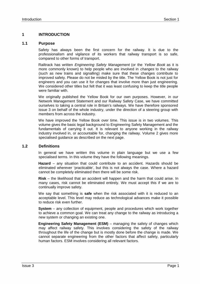
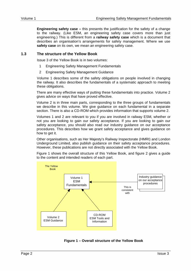
Figure 1 shows the overall structure of this Yellow Book, and figure 2 gives a guideto the content and intended readers of each part.
our
CD-ROMESM Tools and
Information
The YellowBook
Industry guidanceon our acceptance
proceduresThis is
consistentwith
Volume 2ESM Guidance
Volume 1ESM
Fundamentals
Figure 1 – Overall structure of the Yellow Book
Introduction Section 1
Issue 3 Page 3
Part Content Intended readers
Volume 1 –Engineering SafetyManagementFundamentals
• The essentialfeatures of aneffectiveapproach toESM
• Senior executives in therailway industry
• Anyone whose workcontributes to railway change
Volume 2 –Engineering SafetyManagement Guidance
• Guidance onone proven wayof putting thefundamentalsinto practice
• Anyone whose workcontributes to railway change
• Anyone assessing or auditingthis kind of work
CD ROM – EngineeringSafety ManagementTools and Information
• Practicalsupport toassess risk
• Anyone carrying out a riskassessment
Industry guidance onour acceptanceprocedures
• Railtrack policyand guidanceon gainingRailtrack safetyacceptance
• Anyone seeking our safetyacceptance
• Anyone assessing or auditingprojects for which Railtracksafety acceptance isrequested
Figure 2 – Content and intended readers of the Yellow Book, and associatedpublications
Volume 1 Engineering Safety Management Fundamentals
Page 4 Issue 3
2 OBLIGATIONS AND LIABILITIES
The main purpose of the Yellow Book is to help you set up a process that protectsyou and others from mistakes and gives documented evidence (the engineeringsafety case) that risk is at an acceptable level. The Yellow Book also helps you tokeep within the law and relevant standards.
This section describes some of the obligations that the Yellow Book helps you tocarry out. It also describes some of the legal liabilities that you face and some waysof reducing them.
We discuss UK law, but the discussion is no substitute for detailed legal advice.
2.1 UK law
The Government reviewed the arrangements for regulating railway safety beforeprivatising the British main line railway. It followed recommendations in the report‘Ensuring Safety on Britain’s Railways’ and confirmed that the Health and SafetyExecutive (HSE) would be the safety regulator for the whole railway network. In factHMRI, which is part of HSE, does the regulating.
More generally, the ‘Health and Safety at Work etc Act 1974’ places duties onemployers and employees. Employers must ensure, ‘so far as is reasonablypracticable’, the health, safety and welfare of their employees and of other peoplethey affect. In the case of railways, this includes passengers and other members ofthe public. Section 2.3 discusses the phrase, ‘so far as is reasonably practicable’.
The act applies to those who supply products, such as trains and signalling systems,as well as those who run and maintain the railways. These responsibilities can beshared under a contract but cannot be completely transferred.
The act contains powers to make regulations. Regulations made under the act havethe force of law. HSE publishes guidance notes on regulations, which you shouldread if they are relevant to you.
The ‘Management of Health and Safety at Work Regulations 1992’ says employersmust assess the risk to employees and others affected by their work. Employers whoshare a workplace must also co-operate to achieve safety and share safetyinformation.
The ‘Construction (Design and Management) Regulations 1994’ place duties onthose involved in some construction projects. They must plan, co-operate, shareinformation and keep certain records. This will control the risk to the health andsafety of people affected by the project. The people involved must be able to showHSE that they have done this.
The ‘Railways (Safety Critical Work) Regulations 1994’ place a duty on those whoemploy people doing defined ‘safety-critical’ work on the railway to assess that theyare competent and fit to do the work. The assessment must be recorded.
The ‘Railways (Safety Case) Regulations 1994’ say that train and station operatorsand railway infrastructure controllers must prepare a railway safety case. The railwaysafety case must be accepted before they start operations and they must follow it.We discuss railway safety cases in the next section.
As well as the railway’s own acceptance processes, statutory approval is needed fornew and changed railways. The ‘Railways and Other Transport Systems (Approval ofWorks, Plant and Equipment) Regulations 1994’, made under the ‘Transport andWorks Work Act 1992’, confirm the powers given to HMRI by earlier laws. They alsoextend them, in particular, to include the general power to approve trains.
Obligations and Liabilities Section 2
Issue 3 Page 5
HMRI publishes guidance on how the regulations apply and how to get approval. Theapproval process is similar to the railway’s own acceptance process. In many cases,the work done to get railway acceptance will help to get HMRI approval as well.
There are other relevant acts and regulations, which we do not discuss.
2.2 Railways (Safety Case) Regulations
Any train or station operator must write a railway safety case and have it acceptedbefore starting operations. The operator must then follow their safety case.
HSE accepts railway safety cases from the infrastructure controller, who owns andruns the infrastructure. The infrastructure controller may accept railway safety casesfrom train and station operators.
The Railway Group is made up of us and those organisations whose railway safetycases we accept.
Among other things, the railway safety case must describe:
• the operator’s safety policy and arrangements for safety management;
• the operator’s assessment of the risk;
• how it will monitor safety;
• how it organises itself to carry out its safety policy; and
• how it makes sure that its staff are competent to do safety-related work.
A railway safety case must also show a systematic approach to managing technicalchange in general. An engineering safety case shows a systematic approach tomanaging the safety of one change to the railway. The two are different but relatedand an engineering safety case can support a railway safety case.
2.3 ‘Reasonable practicability’
We have seen that the ‘Health and Safety at Work etc Act 1974’ places duties onemployers to ensure health, safety and welfare ‘so far as is reasonably practicable’.This section gives more guidance on this test. We have taken account of the HSEdiscussion document, ‘Reducing Risks, Protecting People’.
If you are working on a change to the railway, you should first identify the hazardsassociated with the change. You should make sure that you have precautions inplace against each hazard within your control (unless you can show that the riskarising from the hazard is so small that it is not worth considering).
You should make sure that your precautions reflect good practice, as set out in thelaw, government guidance and standards. If the risk is low and completely coveredby good practice, published by a recognised authority, showing that you havefollowed this good practice may be enough to show that the risk is acceptable. Forinstance the electrical safety of ordinary office equipment is normally shown bycertifying it against electrical standards. However, before you decide that justreferring to standards is enough, make sure that:
• the equipment is being used as intended;
• all of the risk is covered by the standards; and
• the standards cover your situation.
We discuss good practice further in the next section.
Volume 1 Engineering Safety Management Fundamentals
Page 6 Issue 3
If following good practice is not enough to show that the risk is acceptable, youshould also assess the total risk that will be produced by the part of the railway beingchanged. You then need to compare it with two extreme regions.
• An intolerable region where risk can never be accepted.
• A broadly acceptable region where risk can always be accepted.
To decide whether or not to accept a risk:
1 check if the risk is in the intolerable region – if it is, do not accept it;
2 check if the risk is in the broadly acceptable region – if it is, you will not need toreduce it further, unless you can do so at reasonable cost, but you mustmonitor it to make sure that it stays in that region; and
3 if the risk lies between these two regions, accept it only after you have taken all‘reasonably practicable’ steps to reduce the risk.
You should consider ways of making the change less likely to contribute to anaccident. You should also consider ways of making the change more likely to preventan accident. You do not have to consider steps that are outside your control.
You will generally expect the risk to be lower after the change than it wasbeforehand. If it is higher, it is unlikely that you have reduced the risk as low asreasonably practicable.
If you are not certain about the risk, you should choose to be cautious – uncertaintydoes not justify not taking action.
To decide whether a step that would reduce risk is reasonably practicable, you mustbalance the reduction in risk against other factors. These include cost and anyincrease in complexity.
In ‘Reducing Risks, Protecting People’, HSE suggest that you can use a figure ofslightly under £1 million (at 1998 prices) as a ‘benchmark’ – an indication of what it isreasonably practicable to spend to reduce risk by one fatality. However, you shoulduse a higher figure for risks for which there is high public concern. As risks of majorrailway accidents fall into this category, the benchmarks used in railway decisionmaking are often higher.
All benchmarks are only rough reflections of the values held by society. If there issignificant public concern about a hazard, you should take this into account in yourdecision making and it may justify precautions that would not be justified otherwise.
Following this guidance will help you make objective decisions and show how youreach those decisions. It also helps you make sure that you are using limitedresources in the best way.
2.4 Good practice
The main reason for using good practice is to reduce risk. However, if you face a civilaction for damages after an accident, you may want to show that you used goodpractice and met relevant standards. This could help your defence against a chargeof negligence and reduce other legal liabilities.
The standards that are relevant to you will depend upon what you are doing but thefollowing generally apply.
Our Safety and Standards Directorate maintains a series of ‘Railway GroupStandards’, which cover aspects of the UK main line railway and members of theRailway Group must meet these.
Obligations and Liabilities Section 2
Issue 3 Page 7
HMRI’s ‘Railway Safety Principles and Guidance’ (the ‘Blue Book’) gives advice ondesigning, constructing and altering works, plant and equipment, while maintainingrailway safety. It sets out safety principles and the factors affecting how to put theminto practice. It also gives advice on detailed aspects of railway construction. It dealswith the end result of design and construction rather then the processes themselves.
The Engineering Council’s ‘Guidelines on Risk Issues’ give practical and ethicalguidance to engineers and managers on how to meet their social responsibilities bycontrolling risk. They discuss:
• the legal and professional restrictions on the engineer;
• the concepts behind managing risk; and
• implications for education and public awareness.
The Hazard Forum’s document ‘Safety-related Systems – Guidance for Engineers’gives professional engineers an overview of the professional, practical and legalaspects of working on safety-related systems. It applies particularly to computer-based systems.
Also, if your work involves electronic systems then the following will generally apply:
• IEC Standard 61508, ‘Functional safety of electrical/electronic/programmableelectronic safety-related systems’. This is an international standard that appliesto all sectors of industry. It describes a general safety lifecycle, which includesanalysing hazards and risks, and setting safety requirements.
• CENELEC have published European standards for railway applications and areworking on others.
The Yellow Book is generally in line with these standards and following the YellowBook guidance will help you meet these other standards. However the Yellow Booktakes a wide view of good practice and does not say that you have to follow any onestandard.
Volume 1 Engineering Safety Management Fundamentals
Page 8 Issue 3
3 ENGINEERING SAFETY MANAGEMENT FUNDAMENTALS
To make sure that a change to the railway is safe and to show this, you must follow asystematic approach to Engineering Safety Management.
You do not need to carry out a full programme of ESM activities if you can show thatthe change involves only a ‘broadly acceptable’ level of risk, or no risk. However, youmust monitor the risk to check that it stays low.
If the risk comes completely within accepted standards that define agreed ways ofcontrolling it, showing that you have met these standards may be enough to showthat the risk is acceptable. For instance the electrical safety of ordinary officeequipment is normally shown by certifying it against electrical standards. However,before you decide that just referring to standards is enough, make sure that:
• the equipment is being used as intended;
• all of the risk is covered by the standards; and
• the standards cover your situation.
If you need to carry out an ESM programme, it must have some fundamentalfeatures. We can look at these under three headings. These are:
• the organisation, including the people who work within it, that will carry outthe work;
• the proposed change to the railway; and
• the project, in other words the collection of activities which will make thechange happen.
We use ‘organisation’ to mean a company, government agency or other corporategroup.
Any change to the railway should be managed as a project.
The fundamentals do not just apply to the railway. When we refer to a ‘change’, thiscould be a change to any complicated system. In our case, this system will alwaysbe the railway, including not just physical parts like the track and trains, but peopleand procedures as well.
Each fundamental is shown in a box, followed by an explanation and justification.
ESM Fundamentals Section 3
Issue 3 Page 9
3.1 Organisations
3.1.1 Safety responsibility
Your organisation must identify safety responsibilities and put them in writing. It mustkeep records of the transfer of safety responsibilities and must make sure thatanyone taking on safety responsibilities understands and accepts theseresponsibilities. It must make sure that anyone who is transferring responsibility forsafety passes on any known assumptions and conditions that safety depends on.
You need a structured organisation with good communications to carry outsuccessful ESM. Everyone should have clear responsibilities and understand them.
In particular, anyone whose work creates a risk should be responsible for managingit. They should have the knowledge they need to understand the implications of thatrisk and to put controls in place.
Your organisation should identify who is accountable for the safety of work. They willstay accountable even if they pass on responsibility, for parts of the work, to others.
The organisation that takes the lead in introducing a change should make sure thatthe other organisations are clear on their safety responsibilities. If you hand overinfrastructure changes to an infrastructure controller or hand over rolling stock to atrain operator, you may also transfer some safety responsibility.
3.1.2 Safety culture
Your organisation must have safety as a primary goal.
The most important factor in achieving safety is creating a safety culture. This meansrunning an organisation so that safety is seen as a primary goal and consideredappropriately in every activity. Everyone should understand that achieving safety willhelp to meet business goals. Setting up safety procedures is not enough. All staffshould understand why these procedures are necessary and use them.
3.1.3 Competence and training
Your organisation must make sure that all staff who are responsible for ESMactivities are competent to carry them out. Your organisation must give them enoughresources and authority to carry out their responsibilities. Your organisation mustmonitor their performance.
Staff should have the proper training, technical knowledge, skills, experience andqualifications for their job.
Volume 1 Engineering Safety Management Fundamentals
Page 10 Issue 3
3.1.4 Working with suppliers
Whenever your organisation contracts out the performance of ESM activities, it mustmake sure that the supplier is competent to do the work and can put thesefundamentals (including this one) into practice. It must check that they do put theminto practice.
A supplier is anyone who supplies your organisation with goods or services. You canshare safety responsibilities with your suppliers but you can never transfer themcompletely.
This fundamental is needed to make sure that the other fundamentals do not get lostin contractual relationships. Your organisation will set specific requirements fromthese fundamentals, which are relevant to the work being done, before passing therequirements on to the supplier. You do not have to pass them on by writing theminto the contract, though this is normally a good idea.
3.1.5 Communicating safety-related information
If your organisation has information that someone else needs to reduce risk, yourorganisation must pass it on.
This information may include problems you find in someone else’s work, orassumptions about someone else’s work which are important to safety. Yourorganisation should pass on any relevant information about hazards and safetyrequirements to its suppliers.
3.1.6 Co-ordination
Whenever your organisation is working with others on one change, they mustco-ordinate their ESM activities.
There are specific legal obligations in this area, for instance regulation 9 of the‘Management of Health and Safety at Work Regulations 1992’.
ESM Fundamentals Section 3
Issue 3 Page 11
3.2 Changes
3.2.1 Defining changes
Before starting work on a change, your organisation must define the aims, extentand context of the change.
This is often done in a requirements specification.
If you are in doubt about the aim, extent or context of the change, you will also be indoubt about claims for its safety.
When you define a change you should also find out which authorities will have toapprove your safety case.
3.2.2 Identifying hazards
When your organisation considers change, it must make a systematic and vigorousattempt to identify any possible hazards. Your organisation must consider hazardswhich could contribute to an accident at any time, from introducing the change intothe railway to removing it.
Identifying hazards is the foundation of ESM. If you do not identify a hazard, you cantake no specific action to get rid of it or reduce the risk relating to it. However, youmay be able to take general actions, such as introducing safety margins.
You should not just consider accidents which might happen during normal operation,but others which might happen at other times, such as installation, track-testing,commissioning, maintenance, emergencies, decommissioning and disposal.
You should consider the people who the change will affect, and design it to helpthem avoid mistakes.
When identifying hazards, you should consider all the effects of the change on therest of the railway and its neighbours.
You may identify a possible hazard which you believe is so unlikely to happen thatyou do not need to do anything to control it. You should not ignore this type ofhazard; you should record it together with the grounds for your belief that it is sounlikely to happen.
3.2.3 Assessing risk
Your organisation must assess the effect of any proposed change on overall systemrisk.
There are legal duties to assess risk.
Risk measures the likelihood that an accident will happen and the harm that couldarise. You should consider both factors. Your organisation should also consider whois affected.
Some changes are made specifically to make the railway safer, that is to reduce risk,at least in the long run. You should still assess them in case they introduce otherrisks.
Volume 1 Engineering Safety Management Fundamentals
Page 12 Issue 3
3.2.4 Reducing risk
Your organisation must carry out a thorough search for measures which reduceoverall system risk, within its area of responsibility. It must decide whether eachmeasure is reasonably practicable and, if so, must take it.
If your organisation finds that risk is still intolerable, it must not accept it.
If the risk is in the broadly acceptable region, you need only consider measureswhich are clearly reasonably practicable.
There are legal duties to do this.
You should look for:
• ways to get rid of hazards or to reduce their likelihood;
• ways to contain the effects of hazards, if they happen; and
• contingency measures to reduce harm if there is an accident.
You should look for ways of controlling both hazards introduced by the change itselfand hazards that are already present in the railway. Even if a change is designed tomake the railway safer then you should still see if there are ways that you couldmake the railway even safer.
3.2.5 Safety requirements
Your organisation must set safety requirements for any change, to reduce the riskassociated with the change to an acceptable level.
Safety requirements are requirements that should be met to make sure that thesafety risk presented by a change is reduced to an acceptable level. Safetyrequirements may specify:
• features or functions of the change, including any which help people avoiddangerous mistakes;
• what the change must not do to ensure safety;
• environmental conditions under which the change must operate to stay safe;
• targets for carrying out a function reliably, or reliably avoiding a dangerousstate;
• features of the design and build processes; and
• operational procedures and restrictions.
You will set some safety requirements to meet regulations or standards. Others mayarise when you identify hazards and assess and reduce risk.
ESM Fundamentals Section 3
Issue 3 Page 13
3.2.6 Evidence of safety
Your organisation must convince itself that risk associated with a change has beenreduced to an acceptable level. It must support its arguments with objectiveevidence, including evidence that it has met all safety requirements.
You should normally put these arguments together in a safety case to show that:
• you have adequately assessed the risk;
• you have set adequate safety requirements and met them;
• you have carried out the safety plan; and
• all safety-related work has been done by people with the proper skills andexperience.
If other people must take action before a change is safe, the safety case shoulddescribe these actions and show that the other people have accepted responsibilityfor carrying out these actions.
You may include relevant in-service experience and safety approvals as supportingevidence.
If you are working on signalling systems or equipment, CENELEC standardENV 50129:1998, ‘Railway Applications – Safety Related Electronic Systems forSignalling’ is relevant. It places requirements on safety cases.
3.2.7 Authorising changes
No change can be authorised until all necessary safety approvals have been given.
You must get safety approval from the necessary safety authorities. You will usuallyneed approval from both the railway authority (such as Railtrack and LondonUnderground Limited) and the regulatory authority (HMRI in the UK). Safety approvalwill normally be based on accepting the safety case.
The approving authority will normally produce a certificate, setting out anyrestrictions on how the work is used.
The approving authority will usually give safety approval at the end of a project, whenthe change is about to go into service. Some projects make staged changes to therailway in which case each stage will need safety approval. Large or complicatedprojects may need additional approval before they change the railway, for examplefor a safety plan or for safety requirements.
Volume 1 Engineering Safety Management Fundamentals
Page 14 Issue 3
3.3 Projects
3.3.1 ESM from start to finish
Your organisation must start ESM activities as soon as possible. It must review theresults of these activities, and any assumptions made throughout the project. It mustreview and extend ESM activities whenever new information makes this necessary. Itmust monitor information on performance that relates to safety.
You should start early while it is easiest to build safety in. However, you may havelittle design information early in the project, so you should repeat the hazard analysisand risk assessment activities throughout the project, as the design becomes moredetailed.
New information also includes design changes and information on faults.
3.3.2 Safety planning
Your organisation must plan all ESM activities before carrying them out.
You will normally write a safety plan, which should describe how you will put all theseESM fundamentals into practice on your project.
You do not have to write one plan for the whole programme beforehand, but youshould plan each ESM activity before you do it.
You should adjust the extent of the safety plan and the ESM activities you carry outaccording to the extent of the risk.
3.3.3 Systematic processes and good practice
Your organisation must carry out safety-related projects following systematicprocesses which use good engineering practices. It must write down the processesbeforehand.
You should use good systems engineering practice to develop safety-relatedsystems.
Engineering needs a safety culture as much as any other activity. It is true that safetydepends on the people who do the work, but it also depends on the way they do theirwork and the tools they use.
When choosing methods, you should take account of relevant standards. What isand is not good practice will depend upon the requirements.
ESM Fundamentals Section 3
Issue 3 Page 15
3.3.4 Configuration management
Your organisation must have configuration management arrangements that covereverything which is important to achieve safety or to demonstrate safety.
You should keep track of the items that the project produces and the relationshipsbetween them. This is known as configuration management. Your configurationmanagement arrangements should let you:
• uniquely identify each version of each item;
• record the history and status of each version;
• record the parts of each item (if it has any); and
• record the relationships between the items.
If you are in doubt about any of the above, you cannot be certain that all risk hasbeen controlled.
3.3.5 Records
Your organisation must keep full and auditable records of all project ESM activities.
You should keep records to show that you have followed the safety plan. Theserecords may include the results of design activity, analyses, tests, reviews andmeetings. You should keep a hazard log which records all the possible hazardsidentified and describes the action to be taken to get rid of them, or reduce theirlikelihood or severity to an acceptable level.
The amount and type of records that you keep will depend on the extent of the risk.
You should keep records until you are sure that nobody will need them to makefurther changes or to investigate an incident. Often you will have to keep recordsuntil the change has been removed from the railway.
3.3.6 Independent professional review
ESM activities you carry out must be reviewed by professionals who are not involvedin the activities concerned.
These reviews are normally structured as a series of safety audits and safetyassessments. They assure that the work has been carried out safely and provideevidence to support the safety case. How often and how thoroughly each type ofreview is carried out, and the degree of independence of the reviewer, will depend onthe project. They will depend on the amount of risk and novelty and on howcomplicated the project is.
Volume 1 Engineering Safety Management Fundamentals
Page 16 Issue 3
4 PUTTING THE FUNDAMENTALS INTO PRACTICE
If your organisation has a systematic approach to ESM, you should check that it putsall the fundamentals into practice. If you do not, or if your approach does not put allthe fundamentals into practice, you may find volume 2 useful. You do not have touse the approach described there and it is not the only effective approach, but it hasbeen proven in practice.
You may also find the following further reading helpful:
1 HMRI, Railway Safety Principles and Guidance (‘Blue Book’), ISBN 0 71760712 7
(Advice on designing, constructing and altering works, plant and equipment,while maintaining railway safety.)
2 Investigation into the Clapham Junction Railway Accident, Anthony HiddenQC, HMSO, ISBN 0 10 108202 9
(Analysis of weaknesses in management at the root of one of the worst recentBritish railway accidents.)
3 The Engineering Council, Guidelines on Risk Issues, February 1993,ISBN 0-9516611-7-5
(Practical and ethical guidance to engineers and managers on their safetyresponsibilities.)
4 Hazards Forum, Safety-related Systems – Guidance for Engineers,March 1995, ISBN 0 9525103 0 8
(An overview of the professional, practical and legal aspects of working onsafety-related systems, particularly computer-based systems.)
5 Construction Industry Advisory Committee, A Guide to Managing Health andSafety in Construction, 1995, ISBN 0 7176 0755 0
(Thorough guidance on the duties imposed by the Construction (Design andMaintenance) Regulations 1994.)
5 OTHER REFERENCES
This section provides full descriptions of other documents, except acts andregulations, we have referred to in the text.
1 HSE, Ensuring Safety on Britain’s Railways, published by the Department ofTransport, 1993
2 HSE discussion document, Reducing Risks, Protecting People, 1999
3 IEC Standard 61508, Functional safety of electrical/electronic/programmableelectronic safety-related systems, IEC Publication 61508-1 (First edition -1998)
4 CENELEC Standard ENV 50129:1998, Railway Applications – Safety RelatedElectronic Systems for Signalling
Engineering Safety Management
Issue 3
Yellow Book 3
Volume 2 Guidance
Disclaimer
Railtrack has taken trouble to make sure that thisdocument is accurate and useful, but it is only aguide. The company does not give any form ofguarantee that following the recommendations in thisdocument will be enough to ensure safety. Railtrackwill not be liable to pay compensation to anyone whouses this guide.
Published by Railtrack on behalf of the UK rail industry
Published in January 2000 by: Railtrack PLC Railtrack House Euston Square London NW1 2EE. Phone: 020 7557 8000 www.railtrack.co.uk Distributed by: Praxis Critical Systems Limited 20 Manvers Street Bath BA1 1PX. Phone: 01225 466991 www.praxis-cs.co.uk ISBN 0 9537595 0 4 Copyright © Railtrack PLC 2000
You can order further copies from the ESM administrator at Praxis CriticalSystems.
Yellow Book Editorial Committee
This document was prepared with the guidance of the following Editorial Committeemembers. All provided their expertise as professionals committed to improving railwaysafety. Their opinions do not necessarily reflect those of their employers. Theircontribution is gratefully acknowledged.
Brian Alston Craig CheekPaul Cheeseman Brian ClementsonRobert A Davis John DownesPeter Duggan Dick DumoloBruce Elliott Keith EnnisColin Hall Ali G HessamiAlan Lawton Andy MallenderBill Robinson Ian ShannonAndrew Sharpe
The members were drawn from the following organisations:
Her Majesty’s Railway Inspectorate HSBC Rail (UK) LimitedLondon Underground Limited Michael Hamlyn Associates LimitedMott MacDonald Limited Praxis Critical Systems LimitedRailtrack PLC Virgin TrainsWestinghouse Signals Limited WS Atkins Rail Limited
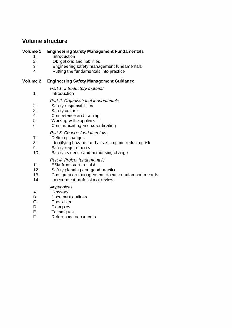
Volume structure
Volume 1 Engineering Safety Management Fundamentals1 Introduction2 Obligations and liabilities3 Engineering safety management fundamentals4 Putting the fundamentals into practice
Volume 2 Engineering Safety Management Guidance
Part 1: Introductory material1 Introduction
Part 2: Organisational fundamentals2 Safety responsibilities3 Safety culture4 Competence and training5 Working with suppliers6 Communicating and co-ordinating
Part 3: Change fundamentals7 Defining changes8 Identifying hazards and assessing and reducing risk9 Safety requirements10 Safety evidence and authorising change
Part 4: Project fundamentals11 ESM from start to finish12 Safety planning and good practice13 Configuration management, documentation and records14 Independent professional review
AppendicesA GlossaryB Document outlinesC ChecklistsD ExamplesE TechniquesF Referenced documents

Part 1
Introductory Material
Introduction Chapter 1
Issue 3 Page 1 - 1
Chapter 1
Introduction1.1 Purpose and scope of this volume
Issue 2 of the Yellow Book described one proven and effective approach to managingthe safety of railway change. Other approaches are being developed in the UK and therest of Europe, and, although the differences are generally minor, there is increasingpotential for confusion. In issue 3 we have tried to distil the fundamentals behind theseapproaches and then present them in volume 1.
This volume provides guidance on implementing the ESM fundamentals presented involume 1. None of the content of this volume should be regarded as prescriptive – thereare other effective ways of implementing the fundamentals – but the guidance isrepresentative of good practice.
ESM is the process of making sure that the risk associated with changes to the railway(such as new trains and signalling) is reduced to an acceptable level. ESM is not just forengineers and can be used for changes that involve more than just engineering. ESM,and this publication, are however scoped to:
• controlling safety risk, that is the risk of harming people, rather than the risk ofenvironmental or commercial damage;
• changes to the railway rather than day-to-day operational safety; and
• system safety rather than occupational health and safety.
The Yellow Book does not provide a complete framework for making decisions aboutrailway changes. It is concerned with safety and does not consider non-safety benefits.Even as regards safety, the Yellow Book does not dictate the values which underliedecisions to accept or reject risk. However, it does provide a rational framework formaking sure that such decisions stay within the law and reflect your organisation’svalues and those of society at large and for demonstrating that they do so.
This guidance has been written with significant changes in mind. You may find it usefulfor smaller changes but you should consider scaling the activities described in order toimplement the fundamentals of volume 1 cost-effectively.
1.2 How this volume is written
After this introduction, each chapter provides guidance on one or more of thefundamentals from volume 1. The fundamentals are reproduced in a box at thebeginning and the summary guidance from volume 1 is reproduced afterwards.
The chapters of volume 2 are in the same order as the fundamentals of volume 1. Thefundamentals in volume 1 are arranged under three headings:
• the organisation, including the people who work within it, that will carry out thework;
Volume 2 Engineering Safety Management Guidance
Page 1 - 2 Issue 3
• the proposed change to the railway; and
• the project, that is the collection of activities which will realise the change.
The chapters of this volume are grouped into three parts corresponding to theseheadings.
The chapters refer to each other and these cross-references are summarised in ‘RelatedGuidance’ sections at the end of each chapter.
Supporting material is supplied in appendices which provide:
• a glossary of terms,
• document outlines,
• checklists,
• examples,
• brief descriptions of relevant specialist techniques, and
• a list of referenced documents.
Specialist terms are printed in bold when introduced (but note that bold text is also usedto highlight key words in lists). The most specialist terms, such as ‘Safety Case’ arewritten with initial capitals. All of these are defined in appendix A, the glossary.
There is a list of referenced documents in appendix F and references are indicated inthe text in the form ‘[F.1]’.
1.3 ESM overview
This volume takes the view that:
• any change to the railway can be regarded as introducing a new system orchanging an existing one; and
• any change to the railway should be managed as a project.
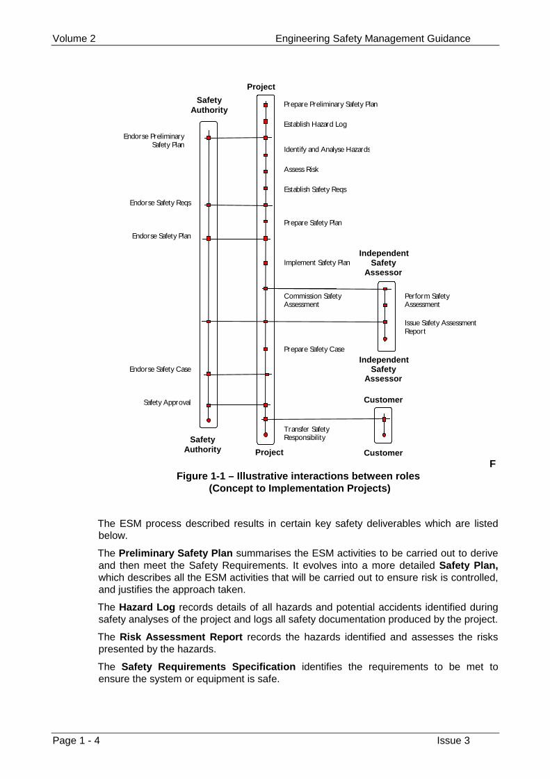
Figure 1-1 presents a simplified view of a possible sequence of ESM activities that maybe carried out during a project and the interactions between the parties involved. Thefigure is not a full definition of the process, but an illustration of its main features. It issimplified in that iteration, change, multiple safety assessment and rework are naturalways of working on projects but none of these are shown. Nonetheless it provides anoverview of the main activities and their relationship.
Refer to section 1.4 below for a description of the notation. The diagram describes thefollowing sequence of activities.
The Safety Lifecycle begins with the production of Preliminary Safety Plan by theproject. The Preliminary Safety Plan is typically submitted to the Safety Authority, theperson or organisation ultimately responsible for approving the change, forendorsement.
The project then establishes a Hazard Log. The Hazard Log is used for recordingdetails of accidents and hazards, and details of safety documentation, and is used toprovide evidence of the management of safety by the project.
The Hazard Log is at the centre of effective ESM and it should be established early,even though there may be little information to put in it at first.
Hazard Identification and Analysis and Risk Assessment are then carried out.
Introduction Chapter 1
Issue 3 Page 1 - 3
On the basis of the Risk Assessment, Safety Requirements are prepared. Theserequirements are typically endorsed by the Safety Authority.
Once the Safety Requirements have been determined, a Safety Plan is prepared andsubmitted to the Safety Authority for endorsement. Safety activities defined by theSafety Plan are then carried out.
At various times, Independent Safety Audits and Assessments may be commissioned.Typically, these will be commissioned in the early stages of a project to ensure anappropriate approach is being taken, and at the later stages of a project to provideevidence for use in the Safety Case. (Note that Figure 1-1, for illustrative purposes,shows only one assessment.)
When the development is complete (that is when the ESM activities have finished) aSafety Case is prepared. Endorsement of the Safety Case is required before SafetyApproval can be given
After the safety approval, safety responsibility for the system may be transferred to auser, for example an infrastructure manager. There is an ongoing responsibility tomanage safety during operation, through to, and including, decommissioning ordisposal, but this is outside the scope of this book.
Volume 2 Engineering Safety Management Guidance
Page 1 - 4 Issue 3
Prepare Preliminary Safety Plan
Project
SafetyAuthority
SafetyAuthority Project
Establish Hazard Log
Identify and Analyse Hazards
Establish Safety Reqs
Prepare Safety Plan
Implement Safety Plan
Commission SafetyAssessment
Customer
Customer
IndependentSafety
Assessor
IndependentSafety
Assessor
Perform SafetyAssessment
Issue Safety AssessmentReport
Prepare Safety Case
T ransfer SafetyResponsibility
Endorse PreliminarySafety Plan
Endorse Safety Reqs
Endorse Safety Plan
Endorse Safety Case
Safety Approval
Assess Risk
FFigure 1-1 – Illustrative interactions between roles
(Concept to Implementation Projects)
The ESM process described results in certain key safety deliverables which are listedbelow.
The Preliminary Safety Plan summarises the ESM activities to be carried out to deriveand then meet the Safety Requirements. It evolves into a more detailed Safety Plan,which describes all the ESM activities that will be carried out to ensure risk is controlled,and justifies the approach taken.
The Hazard Log records details of all hazards and potential accidents identified duringsafety analyses of the project and logs all safety documentation produced by the project.
The Risk Assessment Report records the hazards identified and assesses the riskspresented by the hazards.
The Safety Requirements Specification identifies the requirements to be met toensure the system or equipment is safe.
Introduction Chapter 1
Issue 3 Page 1 - 5
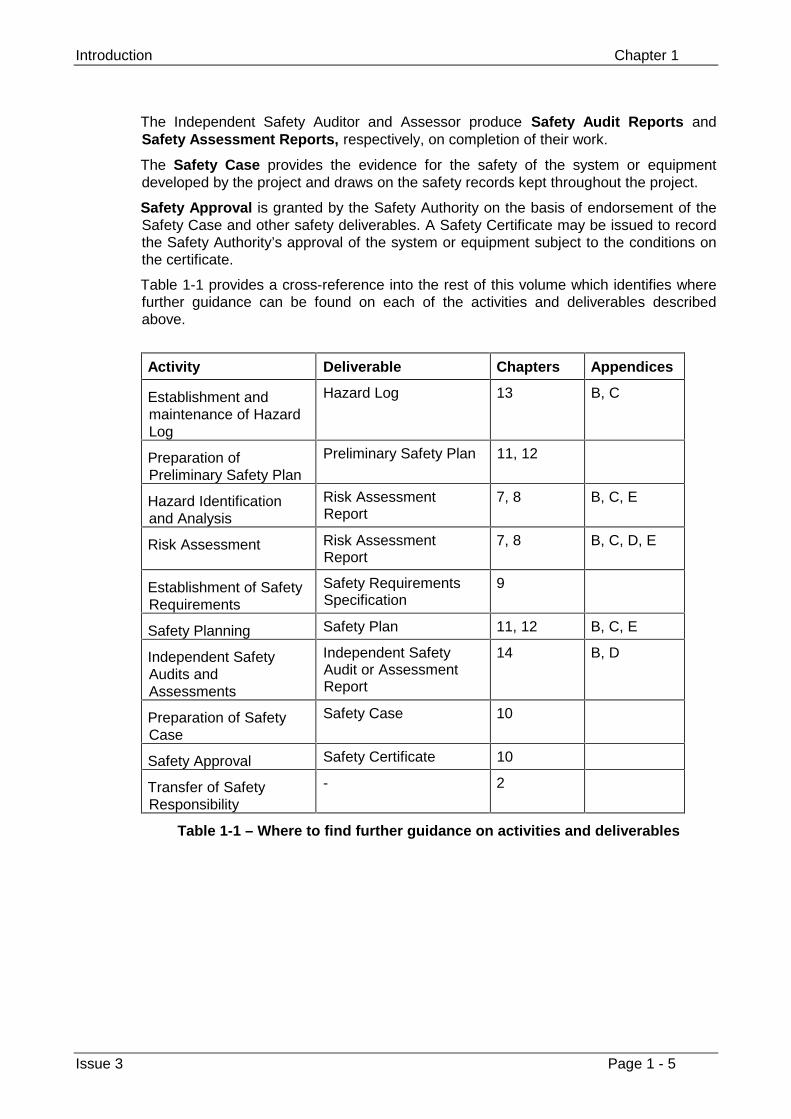
The Independent Safety Auditor and Assessor produce Safety Audit Reports andSafety Assessment Reports, respectively, on completion of their work.
The Safety Case provides the evidence for the safety of the system or equipmentdeveloped by the project and draws on the safety records kept throughout the project.
Safety Approval is granted by the Safety Authority on the basis of endorsement of theSafety Case and other safety deliverables. A Safety Certificate may be issued to recordthe Safety Authority’s approval of the system or equipment subject to the conditions onthe certificate.
Table 1-1 provides a cross-reference into the rest of this volume which identifies wherefurther guidance can be found on each of the activities and deliverables describedabove.
Activity Deliverable Chapters Appendices
Establishment andmaintenance of HazardLog
Hazard Log 13 B, C
Preparation ofPreliminary Safety Plan
Preliminary Safety Plan 11, 12
Hazard Identificationand Analysis
Risk AssessmentReport
7, 8 B, C, E
Risk Assessment Risk AssessmentReport
7, 8 B, C, D, E
Establishment of SafetyRequirements
Safety RequirementsSpecification
9
Safety Planning Safety Plan 11, 12 B, C, E
Independent SafetyAudits andAssessments
Independent SafetyAudit or AssessmentReport
14 B, D
Preparation of SafetyCase
Safety Case 10
Safety Approval Safety Certificate 10
Transfer of SafetyResponsibility
- 2
Table 1-1 – Where to find further guidance on activities and deliverables
Volume 2 Engineering Safety Management Guidance
Page 1 - 6 Issue 3
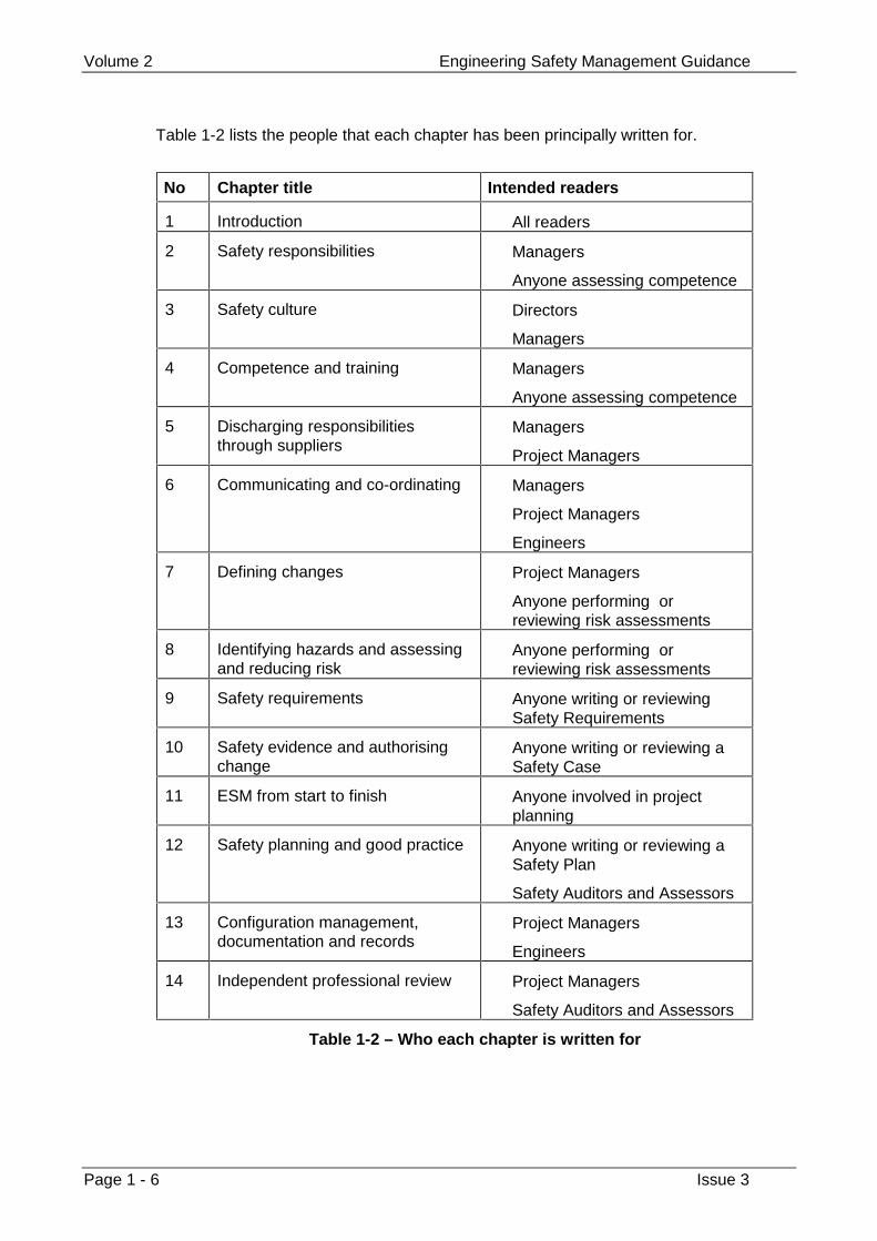
Table 1-2 lists the people that each chapter has been principally written for.
No Chapter title Intended readers
1 Introduction All readers
2 Safety responsibilities Managers
Anyone assessing competence
3 Safety culture Directors
Managers
4 Competence and training Managers
Anyone assessing competence
5 Discharging responsibilitiesthrough suppliers
Managers
Project Managers
6 Communicating and co-ordinating Managers
Project Managers
Engineers
7 Defining changes Project Managers
Anyone performing orreviewing risk assessments
8 Identifying hazards and assessingand reducing risk
Anyone performing orreviewing risk assessments
9 Safety requirements Anyone writing or reviewingSafety Requirements
10 Safety evidence and authorisingchange
Anyone writing or reviewing aSafety Case
11 ESM from start to finish Anyone involved in projectplanning
12 Safety planning and good practice Anyone writing or reviewing aSafety Plan
Safety Auditors and Assessors
13 Configuration management,documentation and records
Project Managers
Engineers
14 Independent professional review Project Managers
Safety Auditors and Assessors
Table 1-2 – Who each chapter is written for
Introduction Chapter 1
Issue 3 Page 1 - 7
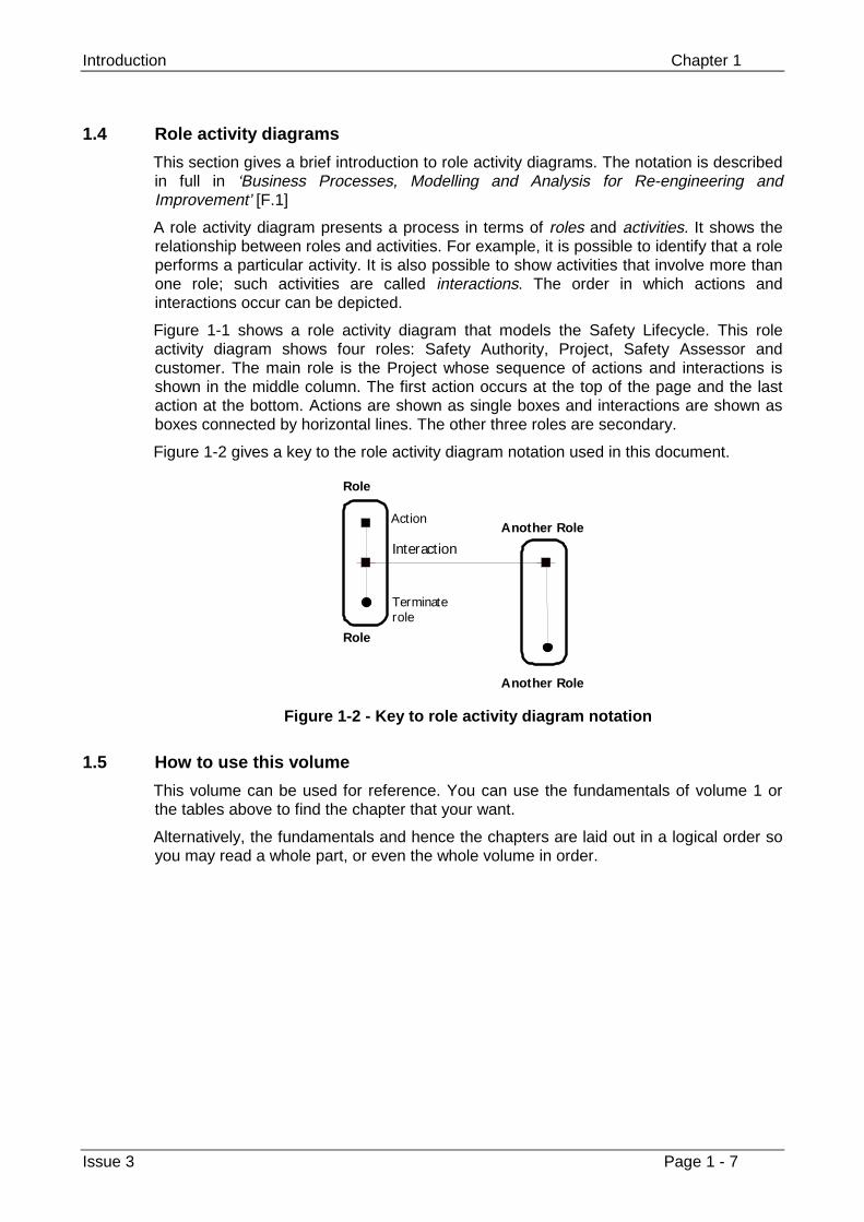
1.4 Role activity diagrams
This section gives a brief introduction to role activity diagrams. The notation is describedin full in ‘Business Processes, Modelling and Analysis for Re-engineering andImprovement’ [F.1]
A role activity diagram presents a process in terms of roles and activities. It shows therelationship between roles and activities. For example, it is possible to identify that a roleperforms a particular activity. It is also possible to show activities that involve more thanone role; such activities are called interactions. The order in which actions andinteractions occur can be depicted.
Figure 1-1 shows a role activity diagram that models the Safety Lifecycle. This roleactivity diagram shows four roles: Safety Authority, Project, Safety Assessor andcustomer. The main role is the Project whose sequence of actions and interactions isshown in the middle column. The first action occurs at the top of the page and the lastaction at the bottom. Actions are shown as single boxes and interactions are shown asboxes connected by horizontal lines. The other three roles are secondary.
Figure 1-2 gives a key to the role activity diagram notation used in this document.
Role
Role
T erminaterole
Action
Interaction
Another Role
Another Role
Figure 1-2 - Key to role activity diagram notation
1.5 How to use this volume
This volume can be used for reference. You can use the fundamentals of volume 1 orthe tables above to find the chapter that your want.
Alternatively, the fundamentals and hence the chapters are laid out in a logical order soyou may read a whole part, or even the whole volume in order.

Volume 2 Engineering Safety Management Guidance
Page 1 - 8 Issue 3
This page left intentionally blank
Part 2
Organisational Fundamentals
Safety Responsibilities Chapter 2
Issue 3 Page 2 - 1
Chapter 2
Safety Responsibilities
Your organisation must identify safety responsibilities and put them in writing. It mustkeep records of the transfer of safety responsibilities and must make sure that anyonetaking on safety responsibilities understands and accepts these responsibilities. It mustmake sure that anyone who is transferring responsibility for safety passes on any knownassumptions and conditions that safety depends on.
2.1 Guidance from volume 1
You need a structured organisation with good communications to carry out successfulESM. Everyone should have clear responsibilities and understand them.
In particular, anyone whose work creates a risk should be responsible for managing it.They should have the knowledge they need to understand the implications of that riskand to put controls in place.
Your organisation should identify who is accountable for the safety of work. They willstay accountable even if they pass on responsibility, for parts of the work, to others.
The organisation that takes the lead in introducing a change should make sure that theother organisations are clear on their safety responsibilities. If you hand overinfrastructure changes to an infrastructure controller or hand over rolling stock to a trainoperator, you may also transfer some safety responsibility.
2.2 Introduction
ESM is a team activity, involving people with different backgrounds from across theorganisation and outside it. Therefore, an important part of ESM is the allocation ofsafety roles with clearly defined safety responsibilities.
These safety roles may be separated into fixed, organisation-related roles and those thatare specific to a particular project.
This chapter describes some common safety roles and the related responsibilities, andexplains how they can be allocated and transferred, both within an organisation andbetween organisations.
Volume 2 Engineering Safety Management Guidance
Page 2 - 2 Issue 3
Responsibility is not necessarily the same as accountability. You are responsible forsomething if you are entrusted with making sure that it happens. To be accountable forsomething means that you can be called to account if it does not happen. Generally,managers remain accountable for ESM performance even though they delegateresponsibility for ESM activities.
There are certain legal obligations placed on employers and employees with regard todefining responsibilities. See volume 1 for further details.
This chapter is written for:
• managers responsible for the appointment of staff to safety-related tasks or fordetermining organisational structure, and
• anyone performing an assessment of personnel competence.
2.3 Different types of safety responsibility
A basic principle of ESM is that those whose activities create a risk should beresponsible for managing and reducing that risk.
These activities may be related to a particular system or piece of equipment (such asdevelopment, operation, maintenance, or modification), or to the provision of resourcesor information. The safety responsibilities related to these activities may includereducing the risk of component failure, providing accurate technical manuals, ensuringthat maintenance is performed in a timely and efficient manner, and so on.
Whatever the activity may be, it is important to:
• clearly define the safety roles and responsibilities;
• gain agreement from all parties on their allocation; and
• pass on any relevant safety-related information.
When responsibility for the system’s operation is handed over to another party, risk maythen be created by the organisation accepting the system, and therefore some safetyresponsibilities are also transferred. However, the Project Manager will retainaccountability for the development work.
An organisation also needs certain ESM roles that are independent of any particularproject. Their responsibilities will include setting safety policy and safety goals, definingother safety responsibilities, granting authority and approval, providing resources, andestablishing communication channels.
The following sections therefore suggest two types of safety role: organisation-relatedroles (Safety Authority, Line Manager); and project-related roles (Project Manager,Project Safety Manager).
Safety roles and their responsibilities should be regularly reviewed to ensure that theyare still relevant.
2.3.1 Safety Authority
An organisation performing safety-related work will commonly appoint a senior personas a Safety Authority, responsible for dealing with general safety issues throughout theorganisation. They will typically have a high level of authority within the organisation andconsiderable operational experience and technical knowledge. Train OperatingCompanies, in particular, will usually appoint an officer with such responsibilities in orderto meet railway safety case requirements.
Safety Responsibilities Chapter 2
Issue 3 Page 2 - 3
Their role is to promote ESM within the organisation, and to ensure that the workproduced by the organisation meets the required safety standards. They will also reporton any shortcomings in safety, and provide independent advice on safety issues.
The Safety Authority’s responsibilities may include:
• setting, maintaining and monitoring safety policy;
• ensuring that an Engineering Safety Management System is effectivelyimplemented and maintained;
• agreeing the safety classification of projects;
• endorsing key safety documentation for a project;
• monitoring the ESM performed on a project; and
• appointing Independent Safety Auditors and Assessors for projects.
For larger organisations, there may need to be multiple Safety Authorities, withknowledge and experience in different areas.
2.3.2 Line Manager
An organisation may assign a Line Manager to a group of staff and/or a group ofprojects, to ensure that their activities are run effectively and safely. The Line Managershould assure himself or herself that ESM is performed correctly by the staff and on theprojects that they manage. The Line Manager should be familiar with the safety issuesrelating to these projects.
The Line Manager’s safety responsibilities may include:
• assigning sufficient ESM resources (both personnel and other) to the projectmanager, according to the intended integrity of the project;
• ensuring that the staff allocated to the project have the skills necessary for thetasks to which they are assigned (providing training if needed); and
• ensuring that the ESM performed on a project is monitored.
2.3.3 Project Manager
Some of an organisation’s work may be grouped into projects, with Project Managerstaking overall responsibility for the work. The Project Manager’s safety role is to ensurethe safety of the work done under their direction.
The Project Manager’s safety responsibilities may include:
• ensuring that the project conforms to all relevant ESM standards and procedures;
• ensuring that all safety activities are carried out and documented in accordancewith good engineering practice; and
• ensuring that the risk associated with all project deliverables is reduced ‘As Low AsReasonably Practicable’.
The Project Manager will generally report to the Safety Authority on all safety issues andto the Line Manager on all management issues.
Volume 2 Engineering Safety Management Guidance
Page 2 - 4 Issue 3
2.3.4 Project Safety Manager
For larger projects, there may be a need for a Project Safety Manager, who will take thesafety responsibilities from the Project Manager. However, the Project Manager willtypically retain overall accountability for the safety of the project.
2.3.5 Other roles
There may also be a requirement for Independent Safety Auditors and Assessors.These roles and their responsibilities are described fully in chapter 14.
2.4 Allocating safety responsibilities
Responsibilities for ESM should be allocated from the top of the organisationdownwards. The senior manager in an organisation or department appoints the SafetyAuthority and assigns responsibilities to them. The senior manager should also assignsafety responsibilities to the Line Managers. In turn, the Line Managers should assign aProject Manager to a particular project. The Project Manager may then delegate safetyresponsibilities to a Project Safety Manager (if one is to be appointed).
It is essential that safety roles and responsibilities are clearly defined and documented.The responsibilities assigned to individuals should be explicit and understood byeveryone in the organisation. In this respect, they should be documented and madefreely available within the organisation.
The documentation should identify:
• the various organisational positions;
• the associated responsibilities and authorities for ESM; and
• the communication and reporting channels.
Safety roles and responsibilities should be put in writing.
When someone is proposed for safety-related work, they should be given a taskdescription, detailing their specific responsibilities, the authority that they will carry, andtheir lines of reporting. They should confirm that they understand and accept the taskdescription before their assignment is confirmed.
There should be some form of organisational structure chart available to all employees,containing details of the organisation’s safety roles.
The definition of safety responsibilities should be periodically reviewed.
2.5 Transferring safety responsibilities within an organisation
Transfer of safety responsibilities may occur within an organisation in a number ofcircumstances including, the following:
• one Project Manager replaces another;
• (within a product organisation) a Project Manager hands over a completeddevelopment to a manager with a product support role; and
• (within a railway operator) a Project Manager hands over a completed project tothe operating function.
Typically the manager accepting responsibility will take on all the safety responsibilitiesthat the relinquishing manager had, although the relinquishing manager will remainaccountable for his or her past actions.
Safety Responsibilities Chapter 2
Issue 3 Page 2 - 5
Many different situations may occur but two fundamental points should be observed:
• No responsibility should be transferred until the accepting manager confirms inwriting that he or she is prepared to accept it.
• The relinquishing manager should make sure that all relevant safety information isrecorded and that the records are up-to-date (see 2.7 below).
Typically, the relinquishing manager will do this by assuring himself or herself thatthe Hazard Log for the project is up-to-date and comprehensive, and, in particular,that it records all assumptions and unresolved issues and then by endorsing theHazard Log (see chapter 13 for more details on the Hazard Log).
2.6 Transferring safety responsibilities between organisations
Typically this occurs when a supplier completes a contract for the supply of a safety-related system. Exactly which areas of safety responsibility are transferred to thecustomer and which remain with the supplier will be determined by the law and thecontract. The contract may leave the supplier with responsibility for maintenance, forinstance, in which case associated safety responsibilities will also remain with thesupplier.
In any case, the supplier will remain accountable for their past actions.
Many different situations may occur but two fundamental points should be observed:
• No responsibility should be transferred until the accepting organisation confirms inwriting that it accepts the responsibility.
• The supplier should make sure that all relevant safety information is recorded andthat the records are up-to-date (see 2.7 below).
Typically, the supplier will do this by delivering a Safety Case. The Safety Caseshould include a comprehensive list of assumptions, limitations on use and anyother caveats on which the conclusions of the Safety Case are based (see chapter10).
ESM is concerned with controlling the risk associated with changes to the railway. Oncethe change has been made, there is still a need to control risk but this falls outside thescope of this book.
2.7 Passing on information
When a system is handed over, all information relevant to the safe operation of thesystem should be passed on to the organisation accepting the system. This is theresponsibility of the Project Manager. There is a legal obligation in the ‘Health andSafety at Work etc Act 1974’ for suppliers of safety-related articles to ensure that thereis adequate information for the articles to be put into safe use.
The information handed over will typically include the following:
• system description, including details of interfaces and environmental requirements;
• hazards, precautions and safety features of the system;
• safety information for operators of the equipment or system;
• detailed instructions for the operation, servicing and maintenance of theequipment, including operating and technical handbooks, parts and sparesidentification lists, drawings, and so on;
Volume 2 Engineering Safety Management Guidance
Page 2 - 6 Issue 3
• installation details, including calibration, verification testing, training requirements,inspection schedule, and decommissioning requirements;
• details of responsibilities to be transferred, including hazard log maintenance,training, system maintenance, and so on;
• details of items to be transferred, including hardware, software, anddocumentation;
• procedures for fault reporting and change control, including approval;
• details of training requirements, including routine operation, emergencyprocedures, maintenance, and so on.
The Hazard Log and the Safety Case are often the most important documents. Theydescribe the risks and how they are controlled. The system suppliers usually retain acopy and some agreement may be needed on who will hold the master document.
2.8 Related guidance
Competency and training requirements for the roles outlined in this chapter are dealtwith in chapter 4.
Safety Cases and Safety Approval are discussed in chapter 10.
Hazard Logs are discussed in chapter 13.
The roles of the Independent Safety Auditors and Assessors and their responsibilitiesare described fully in chapter 14.
Safety Culture Chapter 3
Issue 3 Page 3 - 1
Chapter 3
Safety Culture
Your organisation must have safety as a primary goal.
3.1 Guidance from volume 1
The most important factor in achieving safety is creating a safety culture. This meansrunning an organisation so that safety is seen as a primary goal and consideredappropriately in every activity. Everyone should understand that achieving safety willhelp to meet business goals. Setting up safety procedures is not enough. All staff shouldunderstand why these procedures are necessary and use them.
3.2 Background
An organisation’s safety culture is its general approach and attitude towards safety.
In a good safety culture, safety always comes first, and this will be apparent in the workthat the organisation produces. Safety is built into the organisation’s products, and itssafety procedures support what is already being achieved.
A good safety culture may be achieved through a combination of sound safety policy setby management, awareness on everyone’s part of the importance of safety in allactivities, and motivation to put safety policy into practice.
This chapter provides guidance on fostering a good safety culture and explains the keyrole of an explicit safety policy in doing this. It describes the content of safety policystatements and how an organisation may implement them.
There are certain legal obligations on employers, relating to their safety policy. Seevolume 1 for further details.
This chapter is written for:
• directors and managers wishing to establish or improve the safety culture withintheir organisation.
Volume 2 Engineering Safety Management Guidance
Page 3 - 2 Issue 3
3.3 The benefits of a safety culture
In an organisation with a good safety culture, everyone:
• is aware of the importance of safety;
• makes safety the highest priority in all that they do;
• continually strives to improve safety; and
• understands the parts of the law and other regulations that are relevant to them.
The benefits of nurturing a good safety culture are that:
• safety is built into the organisation’s products and services;
• potential hazards and failures are detected and eliminated or controlled early;
• the organisation’s products are safe and visibly so;
• the organisation realises efficiencies and cost savings; and
• the risk of not conforming to legal obligations is reduced.
A good safety culture will enhance an organisation’s reputation, whereas a single majorincident can ruin it. Indeed a major incident can mar the reputation of the industry as awhole, and cause harm to many of the interdependent organisations that contribute toand rely on the industry’s success.
Richard Profit, in his book ‘Systematic Safety Management in the Air Traffic Services’[F.2], specifies other significant benefits to an organisation’s business of creating a goodsafety culture (page 19). This book is recommended for further reading on ESM.
3.4 Safety policy
The starting point for a good safety culture is a commitment on the part of management.This is best expressed by the setting of a safety policy, endorsed by the board ofdirectors. A safety policy should state the organisation’s aims for achieving safety.
The safety policy statements should define the fundamental approach to managingsafety within the organisation. They should encompass both process and product safetyissues. It is up to each individual organisation to define their own set of safety policystatements, according to the nature of their business. However, the safety policystatements should cover the following issues:
• confirmation that safety is a primary goal for the organisation;
• definition of management’s responsibility and accountability for safetyperformance;
• the responsibility of everyone in the organisation for ensuring safety;
• the provision of assurance that products meet safety requirements;
• the continual improvement in safety within the organisation;
• compliance with regulations and standards; and
• the reduction of risk ‘so far as is reasonably practicable’.
These last two points are linked, since the ‘Health and Safety at Work etc Act, 1974’requires the reduction of risk ‘so far as is reasonably practicable’. However, this shouldbe explicitly confirmed in the organisation’s safety policy.
Safety Culture Chapter 3
Issue 3 Page 3 - 3
Absolute safety cannot be guaranteed and attempting to achieve it can distort theallocation of resources, so safety should be balanced against other factors.
This means that:
• although safety should be a primary goal, it is not the only goal;
• pursuit of safety at all costs is not advisable; and
• judgement is required to know when to stop trying to reduce risk.
Some examples of other organisations’ safety policy statements are given in appendixD.
By defining the safety policy statements, ensuring that they are effectively implemented,and monitoring their effect on safety and on the organisation, it is possible to encourageand develop a good safety culture. Setting safety policy statements alone is not enough.Management should nurture and encourage good safety practices, monitor safety, andprovide the necessary resources.
3.5 People’s responsibilities within a safety culture
A Safety Authority is commonly appointed to take on the role of initiating, implementing,and maintaining an organisation’s safety culture and its safety policy.
Everyone within an organisation, from the board of directors down, is responsible forunderstanding the importance of safety, following the safety policy, and incorporating itinto their everyday activities.
Roles and responsibilities for specific activities within ESM are described in chapter 2.
3.6 Putting safety policy into practice
The board of directors of an organisation should ensure that:
• there is management commitment to following the safety policy;
• everyone in the organisation is aware of the importance of following the safetypolicy;
• the necessary training and resources are provided;
• the way that the organisation performs ESM is monitored and improved;
• the safety of the organisation’s products is monitored and improved;
• the organisation is regularly audited to assess its performance with regard tosafety.
Awareness is a key factor in the successful implementation of safety policy. Everyone inthe organisation should be aware of the importance of safety and of the organisation’ssafety policy. The methods for achieving this will vary according to the size and type ofthe organisation. It may be possible with smaller organisations to provide direct briefingof the safety policy. With larger organisations, cascade briefing may be more practical.
Management should put in place procedures to implement the key components of safetypolicy. Resources for ensuring successful implementation of safety policy should bemade available. This will include personnel with suitable background and training, aswell as equipment.
Management should provide the opportunity and motivation to all staff to improve thesafety of their work.
Volume 2 Engineering Safety Management Guidance
Page 3 - 4 Issue 3
3.7 How to monitor safety policy
Management should check that the safety policy is being implemented. Typically this willbe done with a rolling program which ensures that every aspect of the policy ismonitored over a period of a few years.
Typically an aspect of the safety policy is monitored on a random selection from all therelevant activities of the organisation. In some cases it may be sufficient to carry out asimple inspection of these activities. In other cases it may be appropriate to commissiona formal audit. The guidance on safety auditing in chapter 14 may be used as a basis forsuch an audit.
Management should check that the findings of inspections and audits are acted upon.
The way in which the safety policy is implemented should be regularly reviewed to checkthat it is consistent with good practice which evolves over time.
Management should provide an environment in which staff feel able to bring safetyshortcomings to management attention without fear of recriminations.
3.8 Related guidance
Roles and responsibilities for specific activities within ESM are described in chapter 2.
Guidance on safety auditing is provided in chapter 14.
Some example safety policies are presented in Appendix D.
Competence and Training Chapter 4
Issue 3 Page 4 - 1
Chapter 4
Competence and Training
Your organisation must make sure that all staff who are responsible for ESM activitiesare competent to carry them out. Your organisation must give them enough resourcesand authority to carry out their responsibilities. Your organisation must monitor theirperformance.
4.1 Guidance from volume 1
Staff should have the proper training, technical knowledge, skills, experience andqualifications for their job.
4.2 Background
Anyone doing safety-related work should be competent to do the work.
To be competent, you must have the necessary training, technical knowledge, skills,experience and qualifications to do a specific task properly. Competence is not ageneral reflection on someone’s overall abilities. Just because you are not yetcompetent for a specific task does not mean that you are an incompetent person. Andconversely, being competent at one task will imply little about your competence foranother, unless the two tasks are very similar.
There are two primary obligations on you if you are assigning or accepting a safety-related task:
1 You should know your limitations and not go beyond them.
2 If you are assigning people to safety-related work, then you should ensure thatthey are competent for that work.
The first obligation is a requirement of the codes of practice of several professionalinstitutions. For instance the British Computer Society Code of Conduct requires that‘Members shall only offer to do work or provide service which is within their professionalcompetence.’
The second obligation is a legal duty in certain circumstances. See volume 1 for furtherdetails.
Volume 2 Engineering Safety Management Guidance
Page 4 - 2 Issue 3
This chapter of the Yellow Book is concerned with the competence of individuals(chapter 5 talks about suppliers). It provides some general guidance on the followingaspects of assuring the competence of staff:
1 specifying requirements for staff competence,
2 assessing personnel,
3 training,
4 monitoring.
This chapter is written for:
• those responsible for assigning safety-related tasks to staff, and
• anyone otherwise assessing the competence of staff.
4.3 Specifying competence requirements
Chapter 2 described how to allocate and document the responsibilities for safety-relatedwork. From these responsibilities, you should derive and document criteria forknowledge, skills, experience and qualifications that are necessary to carry out the work.
Consider setting requirements on:
• education (for instance, relevant degrees or attendance at specific courses),
• professional status (for instance, Chartered Engineer), and
• experience (for instance, three years involvement in safety or quality auditing).
However do not restrict yourselves to requirements, like those above, which are easilyassessed, but try and set criteria for the minimum fundamental skills and knowledge thatare required to perform the task.
Many tasks require more skills and knowledge than any one person possesses. In thatcase they will have to be tackled by a team and you should specify the requiredcollective competence of the team as a whole.
In addition to project-specific and non-safety criteria, Project Managers on safety-relatedprojects and Project Safety Managers should generally:
• have received training in ESM; and
• be a Chartered Engineer or full member of another professional organisation.
Anyone taking a leading role in the design or operation of a safety-related systemshould be familiar with:
• the applicable law and standards, and
• current good practice.
Some tasks may also require certain personal attributes such as the resolve to resistany pressure to compromise safety,
Competence and Training Chapter 4
Issue 3 Page 4 - 3
4.4 Assessing competence
Before someone is assigned a safety-related task, they should be assessed to decidewhether or not they meet the criteria set for that task. This initial assessment should bedocumented and kept, along with any supporting evidence. This evidence may berequired for the following reasons:
• as part of a Safety Case,
• for an independent safety assessment, or
• in investigating an incident.
The assessment is usually done by the individual’s manager or a third person but it isusually most effective to work with the individual.
Assessment of education, experience and professional status can be checked by directreference to CVs, which should be kept on file. Examinations or other tests may be usedto assess general skills and knowledge, but it is generally more useful to refer toevaluated performance on similar tasks.
It is sometimes useful, or even necessary, to assign a safety-related task to someonewho does not yet fulfil the requirements to perform it, but who is likely to gain thenecessary qualifications (perhaps through performing the task). This is acceptable,provided that they work under the supervision of an experienced mentor who does fulfilthe requirements. The mentor should be accessible to the person being supervised andshould take overall responsibility for the work.
All of this guidance applies as much to individual contract personnel as to employees(although the selection of suppliers to take on specified tasks is covered in chapter 5).
4.5 Developing competence
Those responsible for staff training should make sure that staff skills and knowledge arekept up-to-date. It may be necessary to arrange specific training for the work that theyneed to do.
Training does not just include formal courses but also distance learning packages (suchas those provided by the Open University), computer-based training and on-the-jobcoaching from senior staff.
Several professional organisations (including the IEE, IMechE and BCS) providecontinuing professional development schemes which can help in selecting appropriatetraining. Professional engineers are expected to maintain their professional competencethrough self-managed continuing professional development but the concept is of valueto other professionals as well. The schemes generally provide individuals with mentorswho periodically assist the individual to sets plans for their learning needs and to monitorprogress against previous plans. Each individual maintains a log book in which he orshe records planned and actual professional development. Some schemes also provideguidance on the sort of training and experience which should be acquired for differenttypes of work and levels of seniority.
Volume 2 Engineering Safety Management Guidance
Page 4 - 4 Issue 3
If your organisation is arranging its own training then providing certificates of attendanceor of passing a final test can make it easier to assess people later (see section 4.4).Certificates should have a limited life.
4.6 Monitoring
Most organisations have periodic evaluations of staff performance for business reasons.These evaluations are particularly important for staff performing safety-related work, tore-assess their level of competence for this work. This re-assessment providesinformation on any additional training that they may need, or whether the person is notsuited to this role and should be transferred. Feedback on performance may also comefrom audits and assessments and from incident evaluations.
In the case where a person performing a safety-related task needs to be replaced orretrained, it is necessary to act quickly but with sensitivity.
4.7 Transitional arrangements
When introducing a more formal approach to assessing competence, it may be foundthat the most experienced and capable personnel have not been through the trainingprogramme that would be required for someone new taking on their job. This does notmean that they should not continue in their roles, and in fact they may be required tocoach more junior staff.
A proven track record in a job is the most direct evidence of competence. It is normalunder these circumstances to write some transitional arrangements into the trainingcriteria, which exempt some existing staff from the formal criteria for their current job.However, it is necessary to show not just that the individuals have held the post for aperiod of time, but also that their performance has been satisfactory during that period.
4.8 Review and audit
Management should arrange to periodically review and/or audit the competencyarrangements to check that they are being put into action as planned and that they areeffective. If necessary, improvement actions should be defined and implemented.
4.9 Related guidance
Chapter 2 provides guidance on defining responsibilities
Chapter 5 provides guidance on selecting contract organisations to carry out safety-related work.
At the time of writing two organisations had issued draft guidance in this area which maybe valuable further reading.
• HMRI had issued draft guidance on competence management and assurancewhich describes principles and factors to consider when setting up a system tomanage competence.
• The Institution of Electrical Engineers, in collaboration with the British ComputerSociety, had issued a set of competency statements for safety-related functionsand tasks.
Working with Suppliers Chapter 5
Issue 3 Page 5 - 1
Chapter 5
Working with Suppliers
Whenever your organisation contracts out the performance of ESM activities, it mustmake sure that the supplier is competent to do the work and can put these fundamentals(including this one) into practice. It must check that they do put them into practice.
5.1 Guidance from volume 1
A supplier is anyone who supplies your organisation with goods or services. You canshare safety responsibilities with your suppliers but you can never transfer themcompletely.
This fundamental is needed to make sure that the other fundamentals do not get lost incontractual relationships. Your organisation will set specific requirements from thesefundamentals, which are relevant to the work being done, before passing therequirements on to the supplier. You do not have to pass them on by writing them intothe contract, though this is normally a good idea.
5.2 Background
This chapter is concerned with the situation where safety-related tasks are contractedout to another organisation. It is not concerned with contract personnel who work underyour organisation’s supervision (chapter 4 is relevant to that case).
Contracting out a safety-related task does not relieve your organisation of allresponsibilities for that task. It is your responsibility to make sure that the supplier iscompetent to do the work. This responsibility is made clear in the Engineering Council’s‘Guidelines on Risk Issues’ [F.3] and is a legal duty in some circumstances. See volume1 for further details.
The contractor should also be required to adopt good ESM practice and they should bemonitored to ensure that they do.
Your organisation should also inform the supplier about hazards, risks and safetyrequirements which are relevant to their work. This obligation is considered further in thenext section.
This chapter is written for:
• senior management or Project Managers, who are considering contracting otherorganisations to perform safety-related work.
Volume 2 Engineering Safety Management Guidance
Page 5 - 2 Issue 3
5.3 Assessing suppliers
In the language of the ‘Construction (Design and Management) Regulations 1994’, asupplier assessment should be ‘proportional and appropriate’ to the risks involved in thework. It need not be extensive where the requirements are straightforward but it shouldbe written down and put on file.
Criteria should be set for the capabilities that a supplier should have to perform the taskssatisfactorily. Typically these will include requirements that the supplier has:
• a suitable organisation with competent personnel;
• the necessary equipment which is properly maintained;
• a suitable health and safety policy appropriate to the work;
• an ability and commitment to undertake suitable and sufficient risk assessments;
• an effective Engineering Safety Management System to control the risks identified;
• the competence to deliver the contract.
Evidence should then be collected that the supplier meets these criteria. The followingevidence may be required:
• a pre-tender safety plan;
• responses to a questionnaire;
• a copy of their safety policy and procedures;
• details of their accident and incident records;
• training records;
• CVs for the staff who will be performing the work;
• QA procedures;
• project review and monitoring documents;
• details of previous experience;
• references from other customers.
For complex tenders, a pre-selection procedure might be appropriate, with a detailedassessment of those who are short-listed.
Where your business involves contracting out the same sort of work repeatedly, it maysave time to have a list of pre-assessed approved suppliers. If this is done, the list ofapproved suppliers should detail the type of work that each supplier has been approvedfor.
The safety performance of suppliers should be recorded and taken into account if thesupplier bids for further, safety-related work.
5.4 Specifying and monitoring work
You should produce written specifications of all safety-related work to be done bysuppliers and check that the suppliers meet these specifications.
Working with Suppliers Chapter 5
Issue 3 Page 5 - 3
For simple requirements it may be sufficient to directly inspect the work being done orthe deliverables being produced. Additional deliverables may also be specified such asaudit and assessment reports, which may be used to check compliance. In other casesa direct audit or assessment of the work may be needed, either by your organisation, orby contracting a third party to do this. If a direct audit or assessment is required, thenthe necessary access to the supplier’s information, people and premises should bespecified in the contract.
You should check that the supplier acts on the findings of any inspection or audit.
5.5 Related guidance
Chapter 4 provides guidance on assessing the competence of contract personnel whowork under your supervision.
Volume 2 Engineering Safety Management Guidance
Page 5 - 4 Issue 3
This page left intentionally blank
Communicating and Co-ordinating Chapter 6
Issue 3 Page 6 - 1
Chapter 6
Communicating and Co-ordinating
If your organisation has information that someone else needs to reduce risk, yourorganisation must pass it on.
Whenever your organisation is working with others on one change, they mustco-ordinate their ESM activities.
6.1 Guidance from volume 1
Safety-related information may include problems you find in someone else’s work, orassumptions about someone else’s work which are important to safety. Yourorganisation should pass on any relevant information about hazards and safetyrequirements to its suppliers.
There are specific legal obligations in the area of co-ordinating activities, for instanceregulation 9 of the ‘Management of Health and Safety at Work Regulations 1992’.
6.2 Background
Safety issues do not respect organisational boundaries. Effective communications andco-ordination are often needed to resolve them.
The responsibility to pass on information or to co-ordinate activities with others is a legalduty in certain circumstances. See volume 1 for further details.
Railway Group Standards bring obligations on those involved in the UK mainline railwayto share information:
• Group Standard GM/RT2250, ‘Safety Performance Monitoring and DefectReporting of Rail Vehicles and Plant and Machinery’ requires Railway Groupmembers to submit reports of safety-related defects to a centralised repository,managed by Railtrack, and to share details of safety-related defects with of othermembers of the Railway Group.
Volume 2 Engineering Safety Management Guidance
Page 6 - 2 Issue 3
The Engineering Council ‘Code of Professional Practice on Risk Issues’ also places aprofessional obligation on all engineers to:
‘Communicate effectively with colleagues, both up and down the chain ofresponsibility, to help ensure that risk management activities are sufficientlycomprehensive and understood.
‘Endeavour to raise awareness of potential hazards and risk issues among yourcolleagues.
‘Seek to ensure that all those involved with a project are aware of any risks to whichthey may be exposed, of any relevant limitations inherent in the design or operatingprocedures, and of any implications for their conduct.
‘Discuss the reasons for incidents and near misses with your colleagues, so thatlessons can be learned.’
This chapter is written for:
• managers and engineers who have safety-related information that is required bysomeone else or who need to work or liaise with others in the interest of safety.
6.3 What to communicate
Your organisation should make arrangements to pass on the following sorts of safety-related information to people who need it to reduce risk:
• hazards, risk and arrangements to control them;
• limitations on the products and systems that your organisation makes and anyimplications for users and maintainers;
• lessons learned, relating to safety; and
• safety-related information about your products, principally to your customers.
In particular, you should make sure that any of your suppliers who are doing safety-related work have all relevant information regarding:
• hazard identification and risk assessments that you have carried out;
• strategies that you have defined to control risk; and
• safety requirements that you have established.
If any of this information changes, then you should make sure that you inform yoursuppliers of the change promptly.
If one of your suppliers tells you about a safety issue that other suppliers should beaware of then you should pass the information on.
Your organisation should put in place arrangements to capture and record this sort ofinformation, to decide who should receive it, and to make sure that they do receive it.
Communicating and Co-ordinating Chapter 6
Issue 3 Page 6 - 3
6.4 Communication within your organisation
There will probably need to be several different processes for communicating differentsorts of information. Do not feel restricted to using formal documents (such asmemoranda, user manuals, Safety Case, Hazard Log). You may find it effective tocommunicate information by:
• face-to-face briefings,
• informal documents (such as newsletters, bulletins, electronic mail),
• audio-visual packages,
• training.
Whatever method you choose, you should make sure that it is auditable.
6.5 Communication between organisations
Initially it is usually a good idea to pass information on verbally, so thatmisunderstandings can be quickly resolved. However communication of safety-relatedinformation should be done auditably, so it should be confirmed in writing afterwards.
Considerations of commercial confidence and the expense of providing certain classesof information can make passing necessary information around slow and expensive. Toavoid this happening, it is often a good idea to enter into non-disclosure agreements andto agree who will pay for what at the outset of any partnership.
6.6 Co-ordinating under normal conditions
Cross-organisation working groups with a focus on safety are commonly set up inmilitary projects (see DEF-STAN 00-56 [F.4] and MIL-STD 882C [F.5]).
If several organisations are involved in a project then the lead organisation should set upsuch a working group and involve all other interested parties including users,maintainers and suppliers.
The working group should be given clear terms of reference. It should have the authorityto resolve straightforward issues directly, but will need to escalate issues which have acomplexity outside its scope, or which are outside its authority (often where significant,unplanned resources need to be expended).
It can be useful to maintain a database of safety issues and to track their resolution.
All co-ordination arrangements should be put in writing so that they can be audited.
Volume 2 Engineering Safety Management Guidance
Page 6 - 4 Issue 3
6.7 Co-ordinating under emergency conditions
If your organisation potentially has to deal with an accident or emergency, then it shouldhave contingency plans in place to co-ordinate responses with others to do this:
• your organisation will need to have arranged, in advance, lines of communicationand control and have set up dedicated communications facilities (such as landlines or radio communications);
• your organisation should have agreed arrangements in place for dealing withemergency services and for communicating with the general public and the media;and
• your organisation may wish to set up joint exercises with the people you will haveto deal with, if there is the realistic possibility that you may have to deal with acatastrophic incident.
6.8 Related guidance
Chapter 2 provides guidance on the transfer of responsibilities. There are requirementsfor making sure that whoever takes on responsibility is properly informed.

Part 3
Change Fundamentals
Defining Changes Chapter 7
Issue 3 Page 7 - 1
Chapter 7
Defining Changes
Before starting work on a change, your organisation must define the aims, extent andcontext of the change.
7.1 Guidance from volume 1
This is often done in a requirements specification.
If you are in doubt about the aim, extent or context of the change, you will also be indoubt about claims for its safety.
When you define a change you should also find out which authorities will have toapprove your safety case.
7.2 General
Understanding the aims, extent and context of a change is fundamental to successfulESM. Any change to the railway can be regarded as introducing a new system, orchanging an existing one. Understanding the boundary between this system and itsenvironment is a pre-requisite to understanding how the system might contribute to anaccident (that is understanding what its hazards are).
Figure 7-1 illustrates the relationship between the system boundary, hazards andaccidents.
The system or equipment may consist of software, hardware, people and procedures.
The environment consists of any anything that could influence, or be influenced by, thesystem or equipment. This will include anything to which the system connectsmechanically, electrically or by radio but may also include other parts of the railway thatcan interact through electromagnetic interference, or thermal interchange. Theenvironment will also include people and procedures that can affect, or be affected by,the operation of the system or equipment.
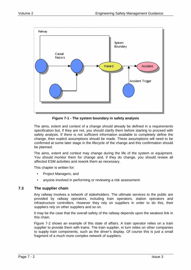
Volume 2 Engineering Safety Management Guidance
Page 7 - 2 Issue 3
Railway
AccidentHazard
CausalFactors
SystemBoundary
Accident T r igger
Figure 7-1 - The system boundary in safety analysis
The aims, extent and context of a change should already be defined in a requirementsspecification but, if they are not, you should clarify them before starting to proceed withsafety analysis. If there is not sufficient information available to completely define thechange, then explicit assumptions should be made. These assumptions will need to beconfirmed at some later stage in the lifecycle of the change and this confirmation shouldbe planned.
The aims, extent and context may change during the life of the system or equipment.You should monitor them for change and, if they do change, you should review allaffected ESM activities and rework them as necessary.
This chapter is written for:
• Project Managers, and
• anyone involved in performing or reviewing a risk assessment.
7.3 The supplier chain
Any railway involves a network of stakeholders. The ultimate services to the public areprovided by railway operators, including train operators, station operators andinfrastructure controllers. However they rely on suppliers in order to do this, theirsuppliers rely on other suppliers and so on.
It may be the case that the overall safety of the railway depends upon the weakest link inthis chain.
Figure 7-2 shows an example of this state of affairs. A train operator relies on a trainsupplier to provide them with trains. The train supplier, in turn relies on other companiesto supply train components, such as the driver’s display. Of course this is just a smallfragment of a much more complex network of suppliers.
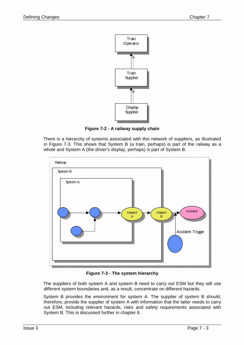
Defining Changes Chapter 7
Issue 3 Page 7 - 3
T rainOperator
T rain Supplier
Display Supplier
Figure 7-2 - A railway supply chain
There is a hierarchy of systems associated with this network of suppliers, as illustratedin Figure 7-3. This shows that System B (a train, perhaps) is part of the railway as awhole and System A (the driver’s display, perhaps) is part of System B.
HazardA
HazardB
Accident
System A
System B
Railway
Accident T r igger
Figure 7-3 - The system hierarchy
The suppliers of both system A and system B need to carry out ESM but they will usedifferent system boundaries and, as a result, concentrate on different hazards.
System B provides the environment for system A. The supplier of system B should,therefore, provide the supplier of system A with information that the latter needs to carryout ESM, including relevant hazards, risks and safety requirements associated withSystem B. This is discussed further in chapter 6.
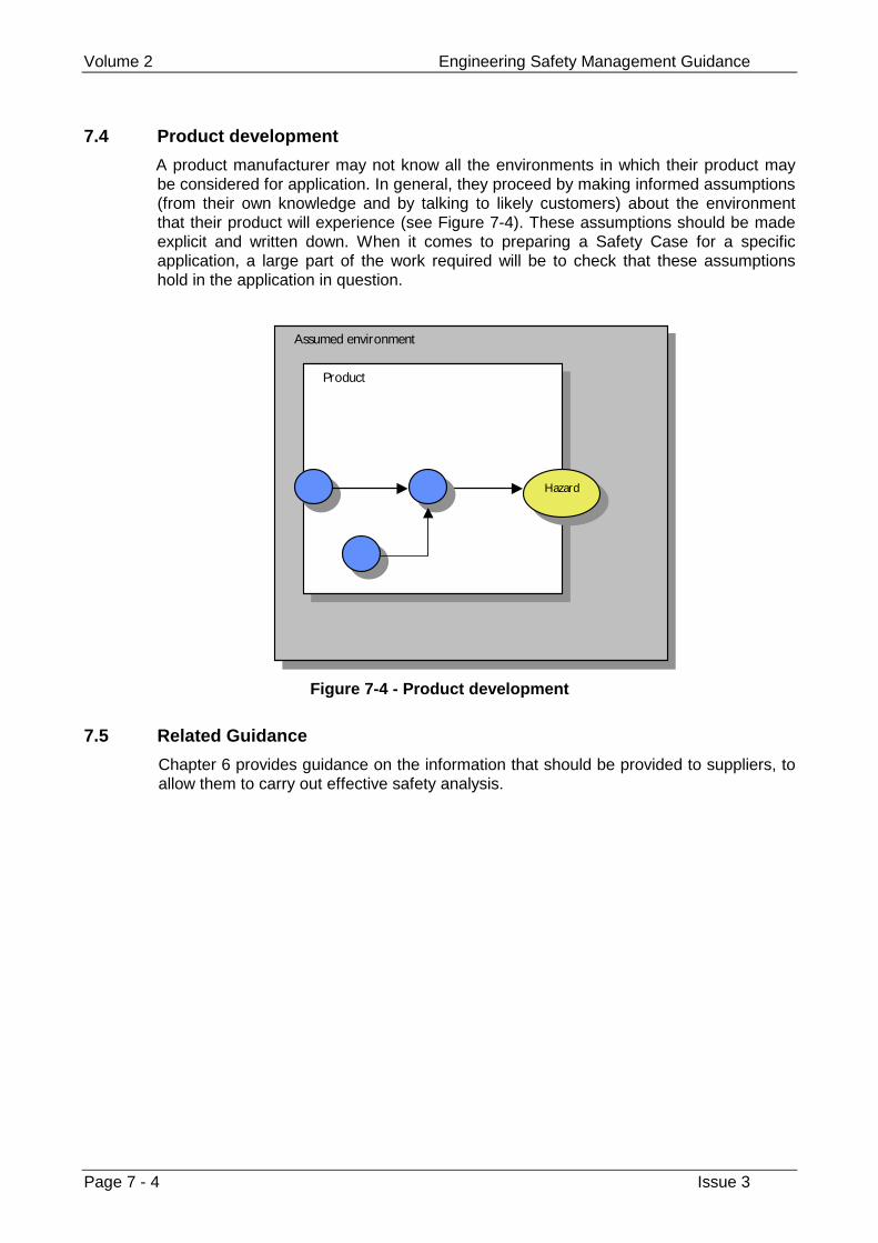
Volume 2 Engineering Safety Management Guidance
Page 7 - 4 Issue 3
7.4 Product development
A product manufacturer may not know all the environments in which their product maybe considered for application. In general, they proceed by making informed assumptions(from their own knowledge and by talking to likely customers) about the environmentthat their product will experience (see Figure 7-4). These assumptions should be madeexplicit and written down. When it comes to preparing a Safety Case for a specificapplication, a large part of the work required will be to check that these assumptionshold in the application in question.
Hazard
Product
Assumed environment
Figure 7-4 - Product development
7.5 Related Guidance
Chapter 6 provides guidance on the information that should be provided to suppliers, toallow them to carry out effective safety analysis.
Identifying Hazards and Assessing and Reducing Risk Chapter 8
Issue 3 Page 8 - 1
Chapter 8
Identifying Hazards and Assessing andReducing Risk
When your organisation considers change, it must make a systematic and vigorousattempt to identify any possible hazards. Your organisation must consider hazards whichcould contribute to an accident at any time, from introducing the change into the railwayto removing it.
Your organisation must assess the effect of any proposed change on overall systemrisk.
Your organisation must carry out a thorough search for measures which reduce overallsystem risk, within its area of responsibility. It must decide whether each measure isreasonably practicable and, if so, must take it.
If your organisation finds that risk is still intolerable, it must not accept it.
8.1 Guidance from volume 1
8.1.1 Identifying hazards
Identifying hazards is the foundation of ESM. If you do not identify a hazard, you cantake no specific action to get rid of it or reduce the risk relating to it. However, you maybe able to take general actions, such as introducing safety margins.
You should not just consider accidents which might happen during normal operation, butothers which might happen at other times, such as installation, track-testing,commissioning, maintenance, emergencies, decommissioning and disposal.
You should consider the people who the change will affect, and design it to help themavoid mistakes.
When identifying hazards, you should consider all the effects of the change on the restof the railway and its neighbours.
You may identify a possible hazard which you believe is so unlikely to happen that youdo not need to do anything to control it. You should not ignore this type of hazard; youshould record it together with the grounds for your belief that it is so unlikely to happen.
Volume 2 Engineering Safety Management Guidance
Page 8 - 2 Issue 3
8.1.2 Assessing Risk
There are legal duties to assess risk.
Risk measures the likelihood that an accident will happen and the harm that could arise.You should consider both factors. Your organisation should also consider who isaffected.
Some changes are made specifically to make the railway safer, that is to reduce risk, atleast in the long run. You should still assess them in case they introduce other risks.
8.1.3 Reducing Risk
If the risk is in the broadly acceptable region, you need only consider measures whichare clearly reasonably practicable.
There are legal duties to do this.
You should look for:
• ways to get rid of hazards or to reduce their likelihood;
• ways to contain the effects of hazards, if they happen; and
• contingency measures to reduce harm if there is an accident.
You should look for ways of controlling both hazards introduced by the change itself andhazards that are already present in the railway. Even if a change is designed to makethe railway safer then you should still see if there are ways that you could make therailway even safer.
8.2 Background
Most railway changes are associated with risk, that is the potential for harm to people.The risk associated with a change can vary from negligible to totally unacceptable.
Risk can generally be reduced, although usually at a cost.
Risk assessment entails a systematic analysis of the potential losses associated with achange and of the measures for reducing the likelihood or severity of loss. It enableslosses to be aggregated and compared against the cost of measures.
Risk assessment is tightly coupled with hazard identification and risk reduction. Thehazards of a system have to be identified before an accurate assessment of risk can bemade. Risk assessment provides, throughout the lifecycle of a system or equipment,both input to risk reduction and feedback on its success.
This chapter presents a single, systematic framework for:
• identifying hazards,
• assessing risk, and
• reducing risk.
The next section provides some further background.
The following sections describe a seven-stage process for hazard identification, riskassessment and risk reduction.
This chapter is written for:
• anyone involved in performing or reviewing a risk assessment.
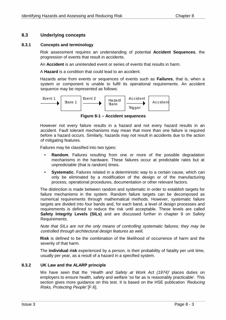
Identifying Hazards and Assessing and Reducing Risk Chapter 8
Issue 3 Page 8 - 3
8.3 Underlying concepts
8.3.1 Concepts and terminology
Risk assessment requires an understanding of potential Accident Sequences, theprogression of events that result in accidents.
An Accident is an unintended event or series of events that results in harm.
A Hazard is a condition that could lead to an accident.
Hazards arise from events or sequences of events such as Failures, that is, when asystem or component is unable to fulfil its operational requirements. An accidentsequence may be represented as follows:
Event 1State 1
Event 2 HazardState Accident
Accident
Trigger
Figure 8-1 – Accident sequences
However not every failure results in a hazard and not every hazard results in anaccident. Fault tolerant mechanisms may mean that more than one failure is requiredbefore a hazard occurs. Similarly, hazards may not result in accidents due to the actionof mitigating features.
Failures may be classified into two types:
• Random . Failures resulting from one or more of the possible degradationmechanisms in the hardware. These failures occur at predictable rates but atunpredictable (that is random) times.
• Systematic . Failures related in a deterministic way to a certain cause, which canonly be eliminated by a modification of the design or of the manufacturingprocess, operational procedures, documentation or other relevant factors.
The distinction is made between random and systematic in order to establish targets forfailure mechanisms in the system. Random failure targets can be decomposed asnumerical requirements through mathematical methods. However, systematic failuretargets are divided into four bands and, for each band, a level of design processes andrequirements is defined to reduce the risk until acceptable. These levels are calledSafety Integrity Levels (SILs) and are discussed further in chapter 9 on SafetyRequirements.
Note that SILs are not the only means of controlling systematic failures; they may becontrolled through architectural design features as well.
Risk is defined to be the combination of the likelihood of occurrence of harm and theseverity of that harm.
The individual risk experienced by a person, is their probability of fatality per unit time,usually per year, as a result of a hazard in a specified system.
8.3.2 UK Law and the ALARP principle
We have seen that the ‘Health and Safety at Work Act (1974)’ places duties onemployers to ensure health, safety and welfare ‘so far as is reasonably practicable’. Thissection gives more guidance on this test. It is based on the HSE publication ‘ReducingRisks, Protecting People’ [F.6].
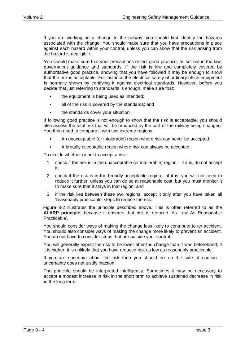
Volume 2 Engineering Safety Management Guidance
Page 8 - 4 Issue 3
If you are working on a change to the railway, you should first identify the hazardsassociated with the change. You should make sure that you have precautions in placeagainst each hazard within your control, unless you can show that the risk arising fromthe hazard is negligible.
You should make sure that your precautions reflect good practice, as set out in the law,government guidance and standards. If the risk is low and completely covered byauthoritative good practice, showing that you have followed it may be enough to showthat the risk is acceptable. For instance the electrical safety of ordinary office equipmentis normally shown by certifying it against electrical standards. However, before youdecide that just referring to standards is enough, make sure that:
• the equipment is being used as intended;
• all of the risk is covered by the standards; and
• the standards cover your situation.
If following good practice is not enough to show that the risk is acceptable, you shouldalso assess the total risk that will be produced by the part of the railway being changed.You then need to compare it with two extreme regions.
• An unacceptable (or intolerable) region where risk can never be accepted.
• A broadly acceptable region where risk can always be accepted.
To decide whether or not to accept a risk:
1 check if the risk is in the unacceptable (or intolerable) region – if it is, do not acceptit;
2 check if the risk is in the broadly acceptable region – if it is, you will not need toreduce it further, unless you can do so at reasonable cost, but you must monitor itto make sure that it stays in that region; and
3 if the risk lies between these two regions, accept it only after you have taken all‘reasonably practicable’ steps to reduce the risk.
Figure 8-2 illustrates the principle described above. This is often referred to as theALARP principle, because it ensures that risk is reduced ‘As Low As ReasonablePracticable’.
You should consider ways of making the change less likely to contribute to an accident.You should also consider ways of making the change more likely to prevent an accident.You do not have to consider steps that are outside your control.
You will generally expect the risk to be lower after the change than it was beforehand; ifit is higher, it is unlikely that you have reduced risk as low as reasonably practicable.
If you are uncertain about the risk then you should err on the side of caution –uncertainty does not justify inaction.
The principle should be interpreted intelligently. Sometimes it may be necessary toaccept a modest increase in risk in the short term to achieve sustained decrease in riskin the long term.
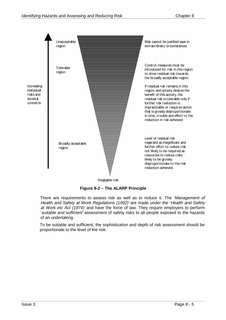
Identifying Hazards and Assessing and Reducing Risk Chapter 8
Issue 3 Page 8 - 5
Risk cannot be justified save inextraordinary circumstances
Control measures must beintroduced for r isk in this regionto dr ive residual r isk towardsthe broadly acceptable region.
If residual r isk remains in thisregion, and society desires thebenefit of this activity, theresidual r isk is tolerable only iffurther r isk reduction isimpracticable or requires actionthat is grossly disproportionatein time, trouble and effort to thereduction in r isk achieved
Level of residual r iskregarded as insignificant andfurther effort to reduce r isknot likely to be required asresources to reduce r iskslikely to be grosslydisproportionate to the r iskreduction achieved.
Broadly acceptableregion
T olerableregion
Unacceptableregion
Negligible r isk
Increasingindividualr isks andsocietalconcerns
Figure 8-2 – The ALARP Principle
There are requirements to assess risk as well as to reduce it. The ‘Management ofHealth and Safety at Work Regulations (1992)’ are made under the ‘Health and Safetyat Work etc Act (1974)’ and have the force of law. They require employers to perform‘suitable and sufficient’ assessment of safety risks to all people exposed to the hazardsof an undertaking.
To be suitable and sufficient, the sophistication and depth of risk assessment should beproportionate to the level of the risk.
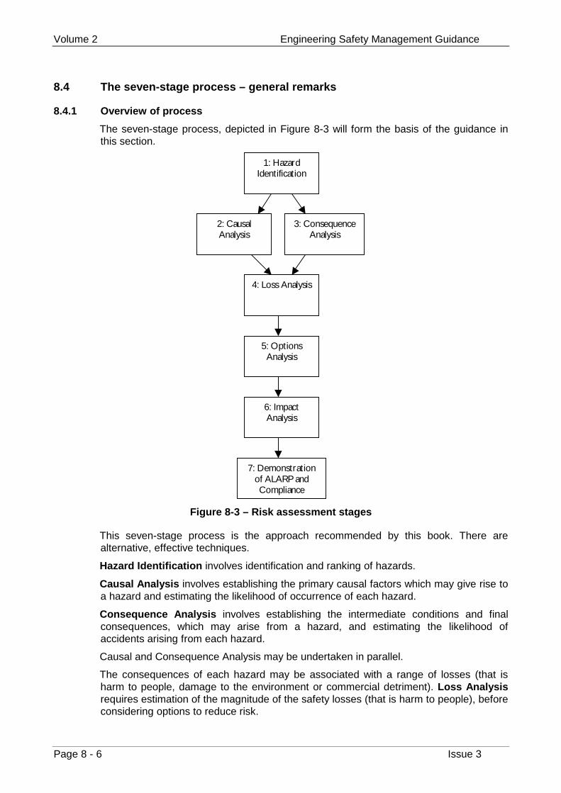
Volume 2 Engineering Safety Management Guidance
Page 8 - 6 Issue 3
8.4 The seven-stage process – general remarks
8.4.1 Overview of process
The seven-stage process, depicted in Figure 8-3 will form the basis of the guidance inthis section.
1: HazardIdentification
2: CausalAnalysis
3: ConsequenceAnalysis
7: Demonstrationof ALARP andCompliance
6: ImpactAnalysis
5: OptionsAnalysis
4: Loss Analysis
Figure 8-3 – Risk assessment stages
This seven-stage process is the approach recommended by this book. There arealternative, effective techniques.
Hazard Identification involves identification and ranking of hazards.
Causal Analysis involves establishing the primary causal factors which may give rise toa hazard and estimating the likelihood of occurrence of each hazard.
Consequence Analysis involves establishing the intermediate conditions and finalconsequences, which may arise from a hazard, and estimating the likelihood ofaccidents arising from each hazard.
Causal and Consequence Analysis may be undertaken in parallel.
The consequences of each hazard may be associated with a range of losses (that isharm to people, damage to the environment or commercial detriment). Loss Analysisrequires estimation of the magnitude of the safety losses (that is harm to people), beforeconsidering options to reduce risk.
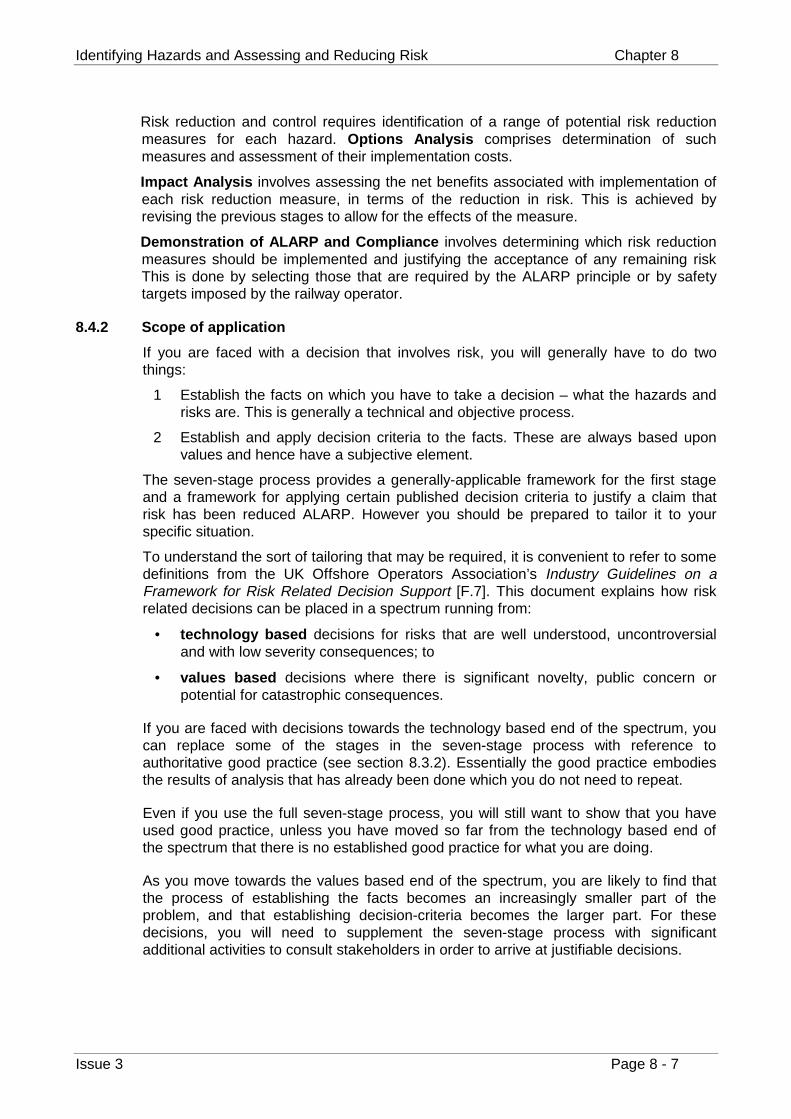
Identifying Hazards and Assessing and Reducing Risk Chapter 8
Issue 3 Page 8 - 7
Risk reduction and control requires identification of a range of potential risk reductionmeasures for each hazard. Options Analysis comprises determination of suchmeasures and assessment of their implementation costs.
Impact Analysis involves assessing the net benefits associated with implementation ofeach risk reduction measure, in terms of the reduction in risk. This is achieved byrevising the previous stages to allow for the effects of the measure.
Demonstration of ALARP and Compliance involves determining which risk reductionmeasures should be implemented and justifying the acceptance of any remaining riskThis is done by selecting those that are required by the ALARP principle or by safetytargets imposed by the railway operator.
8.4.2 Scope of application
If you are faced with a decision that involves risk, you will generally have to do twothings:
1 Establish the facts on which you have to take a decision – what the hazards andrisks are. This is generally a technical and objective process.
2 Establish and apply decision criteria to the facts. These are always based uponvalues and hence have a subjective element.
The seven-stage process provides a generally-applicable framework for the first stageand a framework for applying certain published decision criteria to justify a claim thatrisk has been reduced ALARP. However you should be prepared to tailor it to yourspecific situation.
To understand the sort of tailoring that may be required, it is convenient to refer to somedefinitions from the UK Offshore Operators Association’s Industry Guidelines on aFramework for Risk Related Decision Support [F.7]. This document explains how riskrelated decisions can be placed in a spectrum running from:
• technology based decisions for risks that are well understood, uncontroversialand with low severity consequences; to
• values based decisions where there is significant novelty, public concern orpotential for catastrophic consequences.
If you are faced with decisions towards the technology based end of the spectrum, youcan replace some of the stages in the seven-stage process with reference toauthoritative good practice (see section 8.3.2). Essentially the good practice embodiesthe results of analysis that has already been done which you do not need to repeat.
Even if you use the full seven-stage process, you will still want to show that you haveused good practice, unless you have moved so far from the technology based end ofthe spectrum that there is no established good practice for what you are doing.
As you move towards the values based end of the spectrum, you are likely to find thatthe process of establishing the facts becomes an increasingly smaller part of theproblem, and that establishing decision-criteria becomes the larger part. For thesedecisions, you will need to supplement the seven-stage process with significantadditional activities to consult stakeholders in order to arrive at justifiable decisions.
Volume 2 Engineering Safety Management Guidance
Page 8 - 8 Issue 3
Figure 8-4 illustrates the parts that good practice, the seven-stage process andstakeholder consultative processes might play in different sorts of decisions. The widthof each band gives a rough indication of the relative significance of each type of activity.
Technology Based
Values Based
Consultativeprocesses
Seven-stageprocess
Goodpractice
Figure 8-4 – Approaches to different risk decisions
8.4.3 Quantitative and qualitative analysis
The seven-stage process presents a uniform framework for assessment of the full rangeof risks associated with any given undertaking. Within this framework, the analysis maybe performed to different depths. Qualitative risk assessment is appropriate for thesmaller risks and quantitative risk assessment for the larger risks. It is also possible toadopt hybrid approaches.
It is acceptable, in both approaches, to adopt approximations provided that they areconservative, that is that they do not under-estimate risk.
Qualitative risk assessment relies mainly upon domain expert judgement and pastexperience. It addresses the risks of an undertaking in a subjective and coarse manner.There is not a complete lack of quantification but order of magnitude estimates aregenerally used. Its advantages are that:
• it does not require detailed quantification, data collection or analytical work,
• it is relatively simple, and
• it is less expensive than quantitative risk assessment.
Its disadvantages are that:
• the assumptions require thorough documentation, and
Identifying Hazards and Assessing and Reducing Risk Chapter 8
Issue 3 Page 8 - 9
• it is inadequate as the sole basis for assessment of major risks, including thosearising from low loss incidents of high frequency, as well as from low frequencyincidents associated with high losses.
Quantitative risk assessment employs rigorous analytical processes. Whilst based uponthe same fundamental principles as qualitative risk assessment, quantitative riskassessment will typically employ modelling, using objective and validated data; explicittreatment of the uncertainty associated with input data; and explicit treatment of thedependencies between significant factors contributing to risk.
Its advantages are that:
• it is more accurate than qualitative risk assessment,
• it helps identify hidden assumptions, and
• it provides a better understanding of the potential causes and consequences of ahazard.
Its disadvantages are that:
• it is complex,
• it requires expertise,
• it requires a lot of objective data,
• it is difficult to quantify the probability of systematic failures,
• it is more expensive than qualitative risk assessment, and
• it can require significant computing resource.
Qualitative risk assessment is likely to suffice for most hazards. However, hazards, withthe potential to lead to major or catastrophic consequences, may require quantitativerisk assessment. A quantitative approach may also be justified for novel systems wherethere is insufficient experience to support an empirical, qualitative approach.
Quantitative risk assessment is more expensive than its qualitative counterpart andshould only be applied if it is justified by the increased confidence achieved.
8.4.4 Iteration and preliminary hazard analysis
Safety analysis is iterative: as the design progresses, the analysis should be repeated totake account of change and extended to cover the extra detail. The design can then bemodified to avoid hazards or reduce risks as soon as they are identified. The processshould start as soon as a high-level description of the system is available.
A preliminary hazard analysis should be carried out at the start of a project todetermine a measure of the scope and extent of the risk presented by the change.
Preliminary hazard analysis is a first-pass hazard identification and risk assessmentintended to determine:
a) the scope and extent of risk presented by a change, so that ESM may be applied toan appropriate depth;
b) a list of potential hazards that may be eliminated or controlled during initial designactivity.
Volume 2 Engineering Safety Management Guidance
Page 8 - 10 Issue 3
At the start of a project, design detail will almost always be limited, so the results ofpreliminary hazard analysis (in particular the depth of application of ESM) should bebacked up and re-assessed by carrying out a full analysis and risk assessment as soonas detail is available.
Preliminary hazard analysis should be carried out before any significant design activitybegins. It requires a full high-level description of the system’s function and constructionand its interfaces to people and other systems.
The risk assessment activity carried out during preliminary hazard analysis shouldconsist of annotating identified hazards with an initial appraisal of their severity andlikelihood. Ideally, the preliminary hazard analysis should support the process of initialsafety requirements setting and, therefore, should provide targets for the likelihood ofeach of the identified hazards.
The results of the preliminary hazard analysis should be used to decide where furtherquantified analysis is required.
The findings of preliminary hazard analysis and the decisions that result should bedocumented in a report.
8.4.5 Use of historical data
Risk assessment always relies on some form of extrapolation from the past to the future.Historical data is used at many stages but it should be used with care. The reasons forthis include the following:
• Insufficient information may be available to determine whether historical figuresare relevant to the circumstances of concern, particularly regarding rare major orcatastrophic accidents and the circumstances surrounding previous incidents.
• Secondary effects arising from an incident are likely to be difficult to reliablydetermine (for example fires, derailment or exposure to harmful substances).
Inappropriate use of historical data can undermine the analysis, and significantly reducethe accuracy of risk assessment.
Where historical data is employed in an assessment, a clear argument should bepresented that its use provides an accurate forecast of the losses associated with theparticular circumstances under study.
8.4.6 Documenting the process
Typically, the results of a risk assessment study will be compiled into a risk assessmentreport so that they can be subject to review and endorsement.
Once risk assessment results have been reviewed and endorsed they should beimmediately incorporated into the Hazard Log which is described in chapter 13.
8.4.7 Division of work
The seven-stage process provides an overall framework for controlling risk anddemonstrating compliance with legal obligations. In practical application it is often thecase that different parts of the process are performed by different organisations.
Any change to the railway can be regarded as introducing a new system or changing anexisting one.
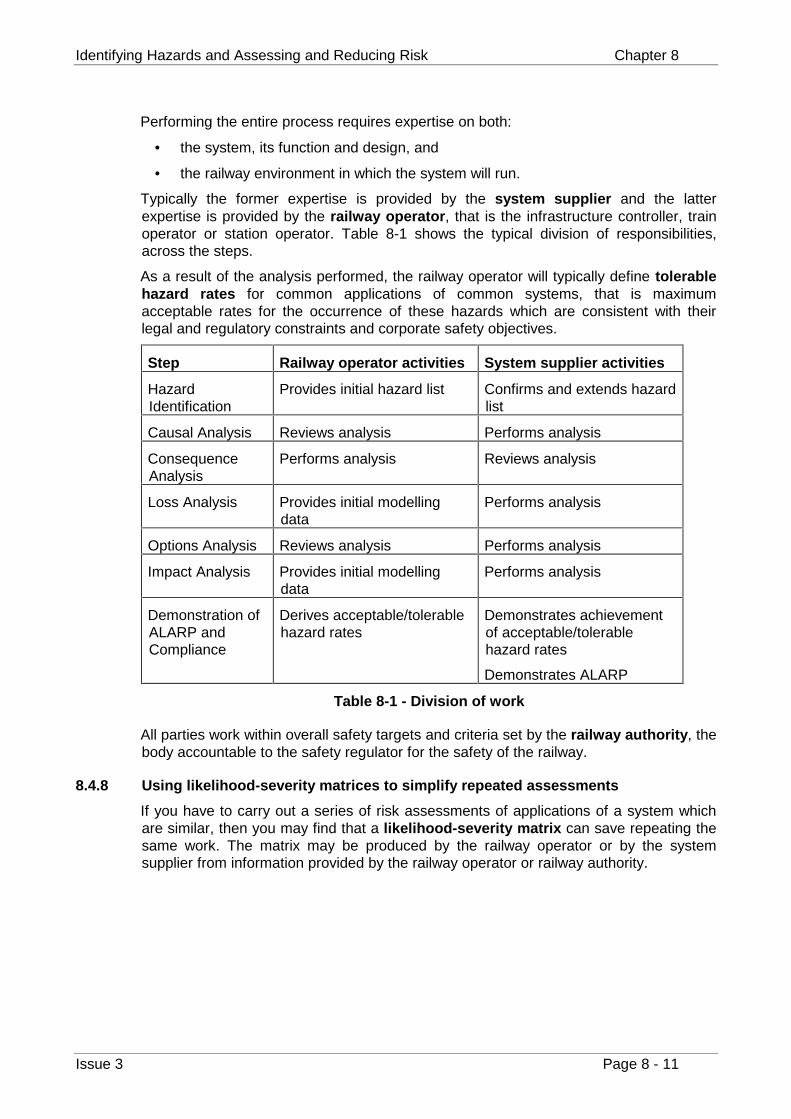
Identifying Hazards and Assessing and Reducing Risk Chapter 8
Issue 3 Page 8 - 11
Performing the entire process requires expertise on both:
• the system, its function and design, and
• the railway environment in which the system will run.
Typically the former expertise is provided by the system supplier and the latterexpertise is provided by the railway operator, that is the infrastructure controller, trainoperator or station operator. Table 8-1 shows the typical division of responsibilities,across the steps.
As a result of the analysis performed, the railway operator will typically define tolerablehazard rates for common applications of common systems, that is maximumacceptable rates for the occurrence of these hazards which are consistent with theirlegal and regulatory constraints and corporate safety objectives.
Step Railway operator activities System supplier activities
HazardIdentification
Provides initial hazard list Confirms and extends hazardlist
Causal Analysis Reviews analysis Performs analysis
ConsequenceAnalysis
Performs analysis Reviews analysis
Loss Analysis Provides initial modellingdata
Performs analysis
Options Analysis Reviews analysis Performs analysis
Impact Analysis Provides initial modellingdata
Performs analysis
Demonstration ofALARP andCompliance
Derives acceptable/tolerablehazard rates
Demonstrates achievementof acceptable/tolerablehazard rates
Demonstrates ALARP
Table 8-1 - Division of work
All parties work within overall safety targets and criteria set by the railway authority, thebody accountable to the safety regulator for the safety of the railway.
8.4.8 Using likelihood-severity matrices to simplify repeated assessments
If you have to carry out a series of risk assessments of applications of a system whichare similar, then you may find that a likelihood-severity matrix can save repeating thesame work. The matrix may be produced by the railway operator or by the systemsupplier from information provided by the railway operator or railway authority.
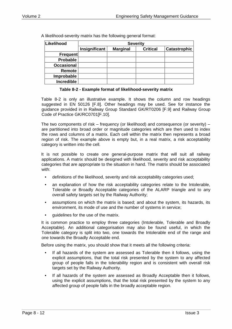
Volume 2 Engineering Safety Management Guidance
Page 8 - 12 Issue 3
A likelihood-severity matrix has the following general format:
SeverityLikelihoodInsignificant Marginal Critical Catastrophic
FrequentProbable
OccasionalRemote
ImprobableIncredible
Table 8-2 - Example format of likelihood-severity matrix
Table 8-2 is only an illustrative example. It shows the column and row headingssuggested in EN 50126 [F.8]. Other headings may be used. See for instance theguidance provided in in Railway Group Standard GK/RT0206 [F.9] and Railway GroupCode of Practice GK/RC0701[F.10].
The two components of risk – frequency (or likelihood) and consequence (or severity) –are partitioned into broad order or magnitude categories which are then used to indexthe rows and columns of a matrix. Each cell within the matrix then represents a broadregion of risk. The example above is empty but, in a real matrix, a risk acceptabilitycategory is written into the cell.
It is not possible to create one general-purpose matrix that will suit all railwayapplications. A matrix should be designed with likelihood, severity and risk acceptabilitycategories that are appropriate to the situation in hand. The matrix should be associatedwith:
• definitions of the likelihood, severity and risk acceptability categories used;
• an explanation of how the risk acceptability categories relate to the Intolerable,Tolerable or Broadly Acceptable categories of the ALARP triangle and to anyoverall safety targets set by the Railway Authority;
• assumptions on which the matrix is based; and about the system, its hazards, itsenvironment, its mode of use and the number of systems in service;
• guidelines for the use of the matrix.
It is common practice to employ three categories (Intolerable, Tolerable and BroadlyAcceptable). An additional categorisation may also be found useful, in which theTolerable category is split into two, one towards the Intolerable end of the range andone towards the Broadly Acceptable end.
Before using the matrix, you should show that it meets all the following criteria:
• If all hazards of the system are assessed as Tolerable then it follows, using theexplicit assumptions, that the total risk presented by the system to any affectedgroup of people falls in the tolerability region and is consistent with overall risktargets set by the Railway Authority.
• If all hazards of the system are assessed as Broadly Acceptable then it follows,using the explicit assumptions, that the total risk presented by the system to anyaffected group of people falls in the broadly acceptable region.
Identifying Hazards and Assessing and Reducing Risk Chapter 8
Issue 3 Page 8 - 13
• The matrices can be used to support a justification that risk has been reducedALARP. The guidelines should emphasise that the final judgement on ALARPrelates to the total risk arising from the system as a whole, and, in particularshould advise that:
• Partitioning the risk across hazards and evaluating each hazard against achosen matrix alone may lead to each hazard being considered as BroadlyAcceptable or Tolerable, whereas the total system risk may be in a highercategory.
• The total risk should be reduced so far as is reasonably practicable. So, if thetotal risk is in the Tolerable region but the classification from one particularhazard is Broadly Acceptable, the risk from this hazard should still be reducedfurther if it is reasonably practicable to do so.
When using the matrix, you should provide justification of the likelihood and severitycategories assigned to each hazard.
To avoid possible later problems with use of the matrices, you should submit the matrixwith your justification that it meets these criteria for endorsement by any Safety Authoritywhom you may later ask to endorse a safety argument using the matrix.
8.4.9 Risk assessment and broader decision making
Risk assessment is focussed on demonstrating compliance with legal safety obligationsand these are phrased in terms of harm to people. These obligations place constraintson the alternatives that may be followed. The seven-stage process will assist you ineliminating alternatives which do not comply with your obligations. The seven-stageprocess can be extended to help control non-safety losses (such as environmental andcommercial losses) but that is beyond the scope of this book.
In broader decision making, it is appropriate to consider non-safety losses, such asenvironmental and commercial harm as well as the opportunities for reaping benefits ofmany different sorts. Techniques such as Weighted Factor Analysis [F.11] provide abasis for balancing the factors in such decision making.
Volume 2 Engineering Safety Management Guidance
Page 8 - 14 Issue 3
8.5 The seven-stage process – stage by stage
8.5.1 Stage 1: Hazard Identification
8.5.1.1 Introduction
Before conducting hazard identification, you need to understand the boundary of thesystem concerned and its interactions with its environment. This is discussed in chapter7. When performing hazard identification, you should always look out for interactionsthat have not been identified and which have the potential to be implicated in hazards.
Hazard Identification is fundamental to the risk assessment process. Absence of asystematic and comprehensive Hazard Identification phase can severely undermine therisk assessment process. In the worst case this can create an illusion of safety and afalse sense of confidence.
When identifying hazards, you should not restrict yourself to the steady-state operationphase but consider all aspects of the systems lifecycle from the point at which it isinstalled on the railway to its final decommissioning, including maintenance andupgrade.
Systematic identification of hazards may be performed empirically or creatively.
8.5.1.2 Empirical hazard identification
Empirical hazard identification relies largely upon knowledge and experience of the pastto identify potential hazards. Whilst it is sometimes sufficient for routine undertakings,novel or modified undertakings will generally also require a more creative form of hazardidentification.
Empirical hazard identification methods include:
• checklists (see appendix C), and
• structured walkthroughs.
The following more rigorous empirical methods may also be used:
• Failure Mode and Effects Analysis (FMEA) for equipment and systems (seeappendix E), and
• Task Analysis for man-machine interfaces (see [F.12]).
These latter techniques identify particular component failures or human errors, whichmay lead to hazardous circumstances. They do, however, require a detailed knowledgeof the failure modes of components and sub-systems, including human actions andlikely errors.
8.5.1.3 Creative hazard identification
Creative hazard identification methods provide systematic techniques to encouragelateral and imaginative creative thought. Ideally they should employ a team-basedapproach to exploit the diverse and complementary backgrounds of a range ofindividuals. They include:
• brainstorming,
• Hazard and Operability Studies (HAZOP) (see appendix E).
Empirical and creative hazard identification complement one another, increasingconfidence that all significant hazards have been identified.
Identifying Hazards and Assessing and Reducing Risk Chapter 8
Issue 3 Page 8 - 15
8.5.1.4 General remarks
Once identified the hazards should be listed. The record of hazards is usuallymaintained in a Hazard Log (see chapter 13).
Each hazard is usually associated with several causes. If you have identified a largenumber of hazards, you should check to see that you have not separately identifiedmultiple causes of a single hazard.
To focus risk assessment effort upon the most significant hazards, the hazards shouldbe ranked. The subsequent stages of risk assessment, as detailed in this document,should be applied on a prioritised basis, beginning with the highest ranking hazards. Therelative rank of each hazard should be used to guide the breadth and depth of its furtheranalysis. A simple matrix should be employed. A sample ranking matrix is presented inAppendix D.
Volume 2 Engineering Safety Management Guidance
Page 8 - 16 Issue 3
8.5.2 Stage 2: Causal Analysis
8.5.2.1 Introduction
Once you have identified and ranked the hazards you should determine those factorscontributing to the occurrence of each hazard, in order to:
• enable accurate assessment of the likelihood of occurrence of each hazard; and
• help identify measures to reduce the likelihood of its occurrence.
Causal Analysis requires domain knowledge of the system or equipment. CausalAnalysis generally assumes that the design material is organised as a functionalhierarchy which shows how the overall system is broken down into ever smallercomponents.
Before the Causal Analysis can be completed, the analyst should have seen a completeset of design material, normally including but not limited to:
• physical drawings of the system,
• component lists, and
• operating and maintenance instructions.
The key factors to consider in the analysis process are:
• identification and modelling of common cause failures,
• interdependency of some errors and failures, and
• the correct logical relationships.
Most Causal Analysis techniques employ a diagrammatic representation of the errorsand failures leading to a hazard. This helps to understand and communicate therelationships between the causes of a hazard and is therefore recommended.
Causal Analysis may be done qualitatively or quantitatively.
8.5.2.2 Qualitative analysis
Qualitative Causal Analysis should be done to a depth sufficient to enable a realisticsubjective estimate to be made of the likelihood of the hazard. It may not be necessaryto go to the level of detail of failures in basic system elements in order to do this.
8.5.2.3 Quantitative analysis
Quantitative Causal Analysis of a hazard should continue until all the fundamentalcausal factors have been identified, or until there is insufficient reliable data to gofurther. Fundamental causal factors include basic component failures and human errors.
Accurate quantification of causal models requires an objective assessment of thefrequency or probability of occurrence of fundamental causal factors. These are thencombined in accordance with the rules of probability calculus to estimate the probabilityof occurrence of the hazard.
Key issues are:
• obtaining reliable and accurate data;
• appropriate treatment of uncertainty in the data;
• sensitivity analysis; and
Identifying Hazards and Assessing and Reducing Risk Chapter 8
Issue 3 Page 8 - 17
• ensuring that different causal factors are combined appropriately to yieldconsistent results (for example ensuring that two frequencies are not multiplied toyield units in terms of per time squared).
The depth of treatment of uncertainty in data sources should vary according to thenature of the hazard being assessed. For example, consider a hazard with potentiallysignificant consequences. Suppose that a causal factor is identified whose occurrenceleads to a high likelihood of realisation of the hazard. Significant uncertainty in estimatesof the frequency of the causal factor are likely to result in significant uncertainty in thefrequency determined for the associated hazard (and may, in turn, lead to significantunderestimates of potential losses). In such cases, further analysis of the likelyfrequency of the causal factor is warranted.
Quantitative analysis should aim to minimise the significance of uncertainties. Thenature and implications of all uncertainties should be carefully documented.
Where the frequencies of causal factors are specified with confidence intervals,accurate estimation of the likely mean and distribution of the frequency of occurrence ofa hazard requires use of statistical simulation techniques.
Quantitative Causal Analysis techniques are generally based upon formal mathematicalfoundations and are supported by computer based tools. However, they cannotgenerally handle variation in the frequencies of causal factors over time.
Since the causal models are usually generated with the assistance of individual domainexperts, they should be subject to peer review in order to enhance confidence in theirintegrity and correctness.
If a particular hazard occurs frequently, and reliable statistics are available concerningthe probability of its occurrence, detailed quantitative Causal Analysis may not benecessary, but it may still be useful in determining the causes of the hazard and helpingto identify potential hazard prevention measures.
8.5.2.4 General remarks
Fault Tree Analysis and FMEA are techniques which may be used to perform CausalAnalysis, see section appendix E. ENV 50129:1998 [F.13] provides guidance onidentifying the failure modes of hardware items which may support these or othertechniques.
Volume 2 Engineering Safety Management Guidance
Page 8 - 18 Issue 3
8.5.3 Stage 3: Consequence Analysis
8.5.3.1 Introduction
In contrast to Causal Analysis, which is aimed at determining the factors which lead tothe occurrence of a hazard, Consequence Analysis involves determining the possibleeffects of each hazard. The results of Consequence Analysis should provide anestimate of the likelihood of occurrence of each incident following realisation of thehazard in order to:
• support accurate assessment of the likely losses associated with a hazard; and
• help identify control measures for the hazard.
Like Causal Analysis, Consequence Analysis is mainly empirical, requiring domainknowledge of the system’s environment. It is generally applied to each hazard in abottom-up manner until all potential consequences (incidents and accidents) have beendetermined. This leads to identification of several other intermediate states andconsequences.
Key issues are:
• developing a clear understanding of the hazard; and
• determining existing physical, procedural and circumstantial barriers to theescalation of the hazard.
Most Consequence Analysis techniques employ a diagrammatic representation of thelines of cause and effect and this is encouraged.
Consequence Analysis may be done qualitatively or quantitatively.
8.5.3.2 Qualitative analysis
Qualitative Consequence Analysis should be conducted to a depth sufficient to enable arealistic subjective estimate to be made of the likelihood of occurrence of an incident oraccident. As a general rule, the analysis should be continued until all potential incidentsand accidents arising from a hazard have been identified.
Note that identifying all barriers to escalation of a hazard may sometimes be used toprovide only an understanding of how each incident can arise. It may not be necessaryto quantify the probability of success of each individual barrier in order to estimate thelikelihood of occurrence of each incident. Rather, it may be possible to make a simpleconservative estimate of the likelihood of each incident based upon the understandinggained by consequence modelling.
8.5.3.3 Quantitative analysis
Consequence Analysis techniques typically present the results of analysis in the form ofa logic tree structure. Such trees lend themselves to quantification in order to obtain anassessment of the likely frequency of predicted incidents and accidents. Event TreeAnalysis and Cause Consequence Diagramming are such techniques. The latter isdescribed in appendix E.
Quantification of consequence trees requires an objective assessment of the probabilityof success of each barrier to escalation of a hazard (that is an assessment of the barrier‘strength’). Such assessment may be based upon historical data, the results of specificcausal analysis or, where no objective data can be obtained, on the basis of expertopinion.
Identifying Hazards and Assessing and Reducing Risk Chapter 8
Issue 3 Page 8 - 19
Key issues are:
• obtaining reliable and objective data sources for the assessment of barrierstrengths;
• appropriate treatment of uncertainty in the data sources; and
• sensitivity analysis of barrier strengths.
The depth of treatment of uncertainty in data sources should vary according to thenature of the hazard being assessed. For example, consider a high frequency hazardwith potentially significant consequences (major incidents or accidents). Uncertainty inthe estimate of the strength of a barrier may lead to uncertainty in the likelihood ofoccurrence of a major incident. In such cases, further analysis of the barrier strength iswarranted.
Sensitivity analysis performed upon the barriers to escalation of a hazard can be used todetermine those barriers with the greatest effect upon the likelihood of occurrence ofincidents. The uncertainty associated with estimates of the strength of such barriersshould be reduced where possible. The nature and implications of any uncertaintiesshould be carefully documented.
Where barrier strengths are specified with confidence intervals, accurate estimation ofthe likely mean and distribution of the frequency of occurrence of adverse incidentsrequires use of statistical simulation techniques.
In order to meet the above requirements, quantitative Consequence Analysis techniquesare generally based upon formal mathematical foundations and are supported by a suiteof computer based tools.
The typical disadvantages of such techniques should be noted:
• they are generally incapable of addressing temporal variations in data, applyingonly if barrier strengths remain constant over time; and
• they are generally incapable of addressing interdependencies between barriers.
Since the consequence models are usually generated with the assistance of individualdomain experts, they should be subject to peer review in order to enhance confidence intheir integrity and correctness.
8.5.3.4 General remarks
It is important in Consequence Analysis to consider the full range of consequences. Donot assume that because a failure is termed a ‘Right Side Failure’ that it cannotcontribute to an accident. Typically, even right side failures lead to alternative, temporarymethods of working which increase risks.
Volume 2 Engineering Safety Management Guidance
Page 8 - 20 Issue 3
8.5.4 Stage 4: Loss Analysis
8.5.4.1 Introduction
Loss Analysis comprises a systematic investigation of the safety losses associated withall incidents and accidents identified through Consequence Analysis.
Loss Analysis involves assessment of the losses associated with the hazards of anundertaking before considering risk reduction measures, leaving the consideration of theeffect of these measures to later stages.
The losses associated with a system should be aggregated for all hazards of thesystem. The safety losses experienced by different groups of people (for instancepassenger and trackside workers) should be aggregated separately for each group.
Loss Analysis may be carried out qualitatively or quantitatively.
8.5.4.2 Qualitative analysis
Safety losses should be estimated in terms of Potential Equivalent Fatalities perannum. In other words, all safety losses should be converted into an equivalent annualfatality figure. The current convention is as follows:
• 1 fatality = 10 major injuries
• 1 major injury = 20 minor injuries
For example, if 1 major injury is estimated as arising from a hazard (over a year), thisequates to 0.1 Potential Equivalent Fatalities.
8.5.4.3 Quantitative analysis
In order to convert safety losses into monetary values an indication of what it isreasonably practicable to spend to reduce risk by one fatality is required. Such a figureis often referred to as a Value of Preventing a Fatality (VPF). The VPF is a parameterintended for supporting ALARP decisions only. It is not an estimation of the commercialloss that might follow from such a fatality and so cannot be used for purposes such asarranging insurance cover.
The total Potential Equivalent Fatalities per annum is multiplied by the VPF to yield amonetary loss per annum, for decision making purposes.
VPFs are generally set by railway operators. In ‘Reducing Risks, Protecting People’,HSE suggests that a benchmark of slightly under £1M (at 1998 prices) can be used insome cases. However, a higher figure should be used for risks for which there is highaversion. As risks of major railway accidents fall into this category, the VPFs used inrailway decision making are often higher.
Be aware that all benchmarks are only rough reflections of the values held by society atlarge. If there is significant public concern about a hazard then you should take this intoaccount in your decision making and it may justify precautions that would not be justifiedotherwise.
Identifying Hazards and Assessing and Reducing Risk Chapter 8
Issue 3 Page 8 - 21
8.5.5 Stage 5: Options Analysis
Options Analysis determines options to reduce the associated losses determined duringLoss Analysis. These options can typically be divided into:
• those aimed at reducing the rate of occurrence of a hazard;
• those aimed at limiting the consequences of a hazard once it has occurred.
For each option, the costs associated with its implementation should be assessed andrecorded. Only costs associated directly with implementation of the option should beestimated. The impact of potential benefits realised by the option should not be included(this will be determined in the next stage).
Demonstration of compliance with the ALARP principle requires that all significantpotential risk reduction measure are identified and considered. Unless a comprehensiveOptions Analysis has been undertaken, therefore, it is not possible to demonstrate thatthe risk has been reduced ALARP.
Options Analysis is therefore best conducted:
• using empirical and creative processes (for example checklists and brainstormingrespectively) in a manner similar to that used in Hazard Identification; it should benoted that a thorough Hazard Identification process may also have identified somepotential options;
• through analysis of the results of Causal and Consequence Analysis to guideidentification of potential options.
Volume 2 Engineering Safety Management Guidance
Page 8 - 22 Issue 3
8.5.6 Stage 6: Impact Analysis
Impact Analysis determines the likely effects of each option identified in OptionsAnalysis upon the losses.
Impact Analysis revisits the previous stages, this time allowing for the effects of theoption. For each option identified, the following process should be adopted:
1. Determine the impact of the option upon occurrence or escalation of a hazard.
2. On the basis of the revised Causal or Consequence Analysis, revisit the LossAnalysis of the associated hazard to determine the losses to be realisedassuming implementation of the option.
3. Calculate the difference between safety losses with and without theimplementation of the option. This is the safety value of the change.
In some cases, an option may have the potential to mitigate hazards in other railwaysystems. In that case, you may increase the safety value of the change by the reductionin losses associated with the other system as a result of this option.
Safety values should be determined individually for each affected population, in thesame way as for Loss Analysis.
Where more than one risk reduction option has been identified, care should be taken toensure that the dependencies between these options are properly addressed.
If the previous stages were originally done qualitatively then they should be revisitedqualitatively. If they were originally done quantitatively then they should be revisitedquantitatively.
Where quantitative analysis is employed, sensitivity parameters may be derived for eachof the options through appropriate analysis of the corresponding causal or consequencemodels. This helps determine the most effective measures for loss reduction.
Identifying Hazards and Assessing and Reducing Risk Chapter 8
Issue 3 Page 8 - 23
8.5.7 Stage 7: Demonstration of ALARP and compliance
As explained in section 8.3.2, demonstrating compliance with the ALARP principleinvolves demonstrating two separate facts:
1 that the overall risk is in the tolerability region, that is below the upper limit oftolerability, and
2 that risk has been reduced ALARP.
This stage can be divided into two steps, each demonstrating one of these facts.
8.5.7.1 Demonstration of compliance with upper limit of tolerability
The upper limit of tolerability will be defined for any given railway by the railway authorityfor that railway. Typically, it is defined in terms of the individual risk experienced by amember of an affected group of people.
Upper limits of tolerability may be set for more than one group of people. For instance,Railtrack’s Railway Safety Case sets limits for three groups: employees, passengersand the public.
Note that completing this step is not enough to show that you have reduced risk ALARP;to do this you still need to perform the next step – Demonstration of ALARP.
8.5.7.2 Demonstration of compliance (qualitative)
A qualitative argument for compliance with the upper limit of tolerability may be made,on the basis of order of magnitude calculations by showing that the changed railwaypresents significantly less risk than before, provided that:
• the risk was below the upper limit of tolerability before the change was made;
• the upper limit of tolerability has not since been reduced by a larger factor than theimprovement in safety; and
• there has been no significant adjustment of safety targets between railwaysystems.
Justification should be made that all the above provisos are met.
In general, a qualitative argument of this form can be made by the system supplieralone, using limited, and often publicly available, information on safety performance andpolicy from the railway authority.
Alternatively, if a likelihood-severity matrix has been constructed for this application, aqualitative argument for compliance with the upper limit of tolerability may be made byshowing that:
• the risk of each hazard falls into a Tolerable or Broadly Acceptable category;
• the guidelines associated with the matrix have been followed; and
• the assumptions associated with the matrix hold for application in question.
8.5.7.3 Demonstration of compliance (quantitative)
The quantitative approach to demonstrating compliance with the upper limit of tolerabilityrequires three steps:
1 to apportion the upper limit of tolerability between railway systems;
2 to derive tolerable hazard rates for the system in question;
3 to show that the actual system hazard rates are below the derived upper limits.
Volume 2 Engineering Safety Management Guidance
Page 8 - 24 Issue 3
The third step is performed by direct comparison with the results of quantitative CausalAnalysis.
If the railway authority has already defined tolerable hazard rates for the system (seesection 8.4.7), the first two steps can be omitted. Otherwise they may be performed asfollows.
To apportion the limit, you will normally employ an existing model of the contribution ofsafety risk from different railway systems. Typically you will estimate an initialapportionment in line with historical data as follows:
• estimate what fraction of total annual risk of safety loss is attributable to thesystem;
• multiply the upper limit of tolerability by this fraction.
If upper limits of tolerability are set for multiple groups, then this calculation will becarried out for each group.
The initial apportionment may be adjusted to meet strategic objectives for safetyimprovement.
Tolerable hazard rates for the system are then set so that the exposed members of eachgroup experience an individual risk from the system below this limit. To confirm that thisis the case, you will need to do the following for each group:
• add up the statistical average number of fatalities (F) that would occur for thisgroup if all hazards occurred at their tolerable hazard rates;
• estimate the number of people (n) within this group exposed to the risk; and
• estimate the individual risk (F/n) experienced by an average person who isexposed to the risk and show that this is below the apportioned upper limit oftolerability.
8.5.7.4 Demonstration of ALARP
To show that risk has been reduced ALARP, you have to show that no reasonablypracticable options exist which have not been implemented.
A qualitative demonstration may be made relying on informed consensus from a groupof experts reviewing the results of Options Analysis that all rejected options are notreasonably practicable. The reasons for this judgement should be articulated anddocumented.
If a quantitative approach is being followed, Impact Analysis will have calculated, usingVPFs supplied by the railway authority, a safety value, that is a monetary value for theimprovement in safety arising from each option. Options Analysis will have estimated thenet cost of implementing the option. An option may be rejected as not reasonablypracticable if the safety value is significantly less than the cost.
Note, that this conclusion can only be made robustly if the difference between the twovalues is more than the total uncertainty in both of them.
Identifying Hazards and Assessing and Reducing Risk Chapter 8
Issue 3 Page 8 - 25
8.6 Related guidance
Chapter 7 provides guidance on defining the boundaries of a system as a pre-requisiteto risk assessment.
Chapter 9 explains how risk assessment is used to set safety requirements in generaland safety integrity levels in particular.
Chapter 13 describes the maintenance of a Hazard Log, which will act as a repositoryfor risk assessment data.
Appendix C provides supporting checklists.
Appendix E describes some relevant techniques.
Volume 2 Engineering Safety Management Guidance
Page 8 - 26 Issue 3
This page left intentionally blank
Safety Requirements Chapter 9
Issue 3 Page 9 - 1
Chapter 9
Safety Requirements
Your organisation must set safety requirements for any change, to reduce the riskassociated with the change to an acceptable level.
9.1 Guidance from volume 1
Safety requirements are requirements that should be met to make sure that the safetyrisk presented by a change is reduced to an acceptable level. Safety requirements mayspecify:
• features or functions of the change, including any which help people avoiddangerous mistakes,
• what the change must not do to ensure safety,
• environmental conditions under which the change must operate to stay safe,
• targets for carrying out a function reliably, or reliably avoiding a dangerous state,
• features of the design and build processes, and
• operational procedures and restrictions.
You will set some safety requirements to meet regulations or standards. Others mayarise when you identify hazards and assess and reduce risk.
9.2 Background
A project carrying out safety-related work should identify the hazards and accidents thatmay result from the work, assess the risk associated with these, reduce the risk ALARPand set Safety Requirements to ensure this level of risk is met. There is a legalrequirement to assess the risks involved in safety-related work. Safety Requirementsshould also be consistent with the operator’s stated targets.
Safety Requirements may be quantitative or qualitative. Good engineering practice formeeting integrity requirements for components susceptible to systematic failure is to useSafety Integrity Levels (SILs). SILs are described in section 9.6 below.
The activity of establishing safety requirements follows and builds on the work describedin the previous chapter. If you have not already done so, you should read theBackground section of the previous chapter as it also provides important background forthis chapter.
Volume 2 Engineering Safety Management Guidance
Page 9 - 2 Issue 3
The Safety Requirements Specification consolidates information provided by theseactivities into specific requirements, which form the basis against which the safety of thesystem is tested and assessed.
The activity of establishing Safety Requirements is iterative to reflect the iterative natureof safety analysis.
This chapter is written for people writing or reviewing Safety Requirements.
9.3 Reducing risk
The following is a widely accepted order of precedence for reducing risk
1 Respecify or redesign to eliminate hazards or reduce their likelihood.
2 Reduce risk in the design, by adding safety features.
3 Reduce risk by adding warning devices.
4 Reduce risk through procedures and training.
5 Reduce risk by adding warning signs and notices
For any given hazard you should first seek to set Safety Requirements to eliminate it.Only where this is not possible should you proceed to set Safety Requirements on thedesign of the system. And only when all reasonably practicable risk reduction has beenaccomplished on the design should you consider procedures and training as riskreduction options.
9.4 Overview of process
Setting safety targets is normally done by working from a fault tree (or similarrepresentation of cause and effect logic) and the event probabilities to:
a) derive numerical accident targets which conform to the ALARP principle, that iseither they are tolerable and further risk reduction is not reasonably practicable orthey are negligible;
b) derive hazard occurrence rate and/or unavailability targets which are consistentwith (a);
c) (if systematic failure modes exist) relate hazards to system functions and deriveSILs for the system functions that are consistent with (b).
The requirements may be apportioned further to sub-systems of the hierarchy andaligned with the system design. In general, systematic targets should not be set belowsub-system function level. Refer to IEC 61508 [F.14] or ENV 50129:1998 [F.13] forfurther guidance on this decomposition.
Any functional requirements on the system or equipment that are necessary to reducerisk to an acceptable level should be incorporated as qualitative safety requirements.
The analyst may set other qualitative safety requirements such as conformance toexternal standards and should do so whenever:
• such conformance is assumed in the calculation of safety targets; or
• such conformance is otherwise required to reduce risks as low as reasonablypracticable.
If the seven-step process described in chapter 8 is being used, then some requirementswill arise from the fifth step, Options Analysis. However requirements may also arisefrom relevant regulations, standards and codes of practice.
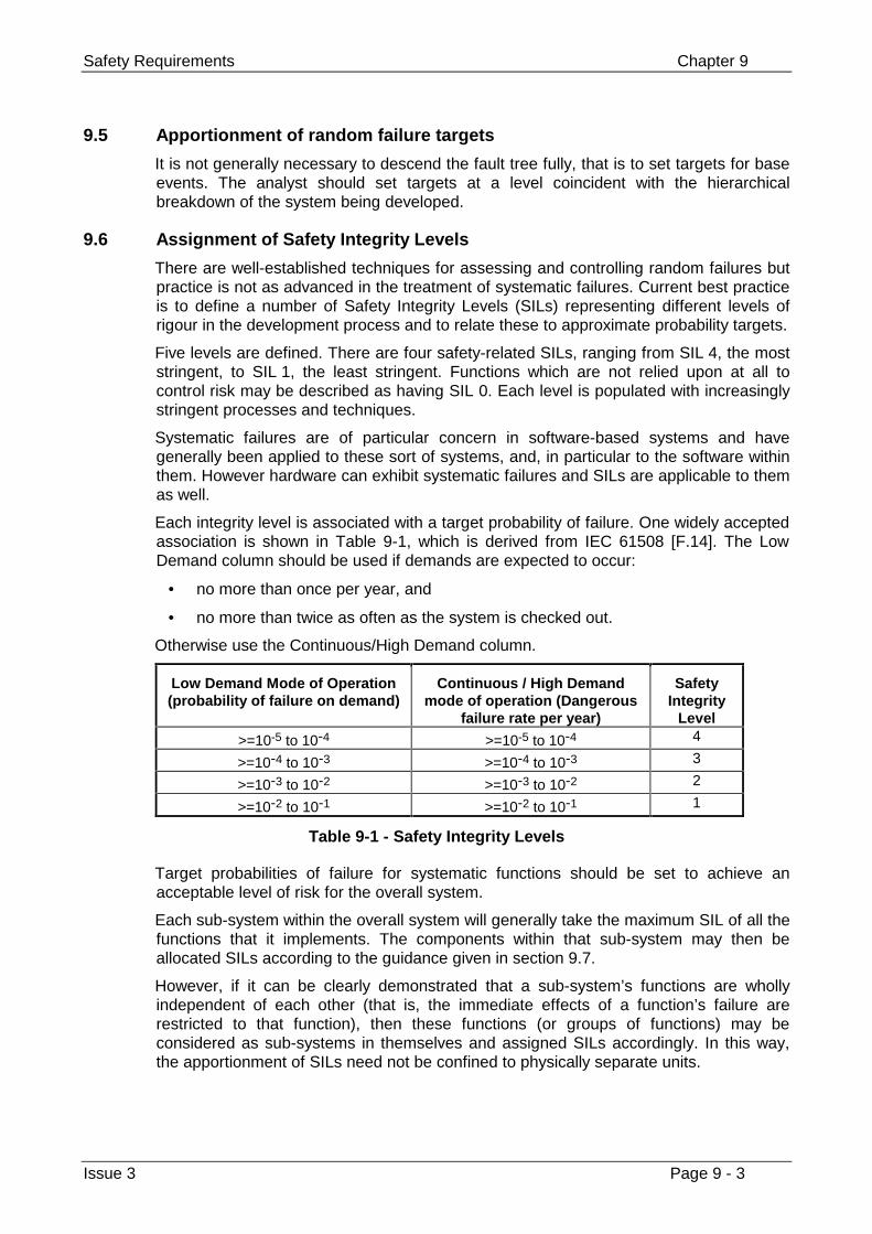
Safety Requirements Chapter 9
Issue 3 Page 9 - 3
9.5 Apportionment of random failure targets
It is not generally necessary to descend the fault tree fully, that is to set targets for baseevents. The analyst should set targets at a level coincident with the hierarchicalbreakdown of the system being developed.
9.6 Assignment of Safety Integrity Levels
There are well-established techniques for assessing and controlling random failures butpractice is not as advanced in the treatment of systematic failures. Current best practiceis to define a number of Safety Integrity Levels (SILs) representing different levels ofrigour in the development process and to relate these to approximate probability targets.
Five levels are defined. There are four safety-related SILs, ranging from SIL 4, the moststringent, to SIL 1, the least stringent. Functions which are not relied upon at all tocontrol risk may be described as having SIL 0. Each level is populated with increasinglystringent processes and techniques.
Systematic failures are of particular concern in software-based systems and havegenerally been applied to these sort of systems, and, in particular to the software withinthem. However hardware can exhibit systematic failures and SILs are applicable to themas well.
Each integrity level is associated with a target probability of failure. One widely acceptedassociation is shown in Table 9-1, which is derived from IEC 61508 [F.14]. The LowDemand column should be used if demands are expected to occur:
• no more than once per year, and
• no more than twice as often as the system is checked out.
Otherwise use the Continuous/High Demand column.
Low Demand Mode of Operation(probability of failure on demand)
Continuous / High Demandmode of operation (Dangerous
failure rate per year)
SafetyIntegrity
Level
>=10-5 to 10-4 >=10-5 to 10-4 4
>=10-4 to 10-3 >=10-4 to 10-3 3
>=10-3 to 10-2 >=10-3 to 10-2 2
>=10-2 to 10-1 >=10-2 to 10-1 1
Table 9-1 - Safety Integrity Levels
Target probabilities of failure for systematic functions should be set to achieve anacceptable level of risk for the overall system.
Each sub-system within the overall system will generally take the maximum SIL of all thefunctions that it implements. The components within that sub-system may then beallocated SILs according to the guidance given in section 9.7.
However, if it can be clearly demonstrated that a sub-system’s functions are whollyindependent of each other (that is, the immediate effects of a function’s failure arerestricted to that function), then these functions (or groups of functions) may beconsidered as sub-systems in themselves and assigned SILs accordingly. In this way,the apportionment of SILs need not be confined to physically separate units.
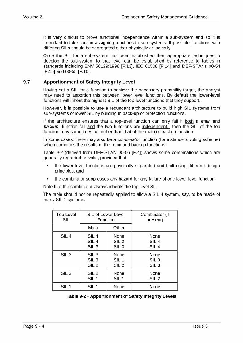
Volume 2 Engineering Safety Management Guidance
Page 9 - 4 Issue 3
It is very difficult to prove functional independence within a sub-system and so it isimportant to take care in assigning functions to sub-systems. If possible, functions withdiffering SILs should be segregated either physically or logically.
Once the SIL for a sub-system has been established then appropriate techniques todevelop the sub-system to that level can be established by reference to tables instandards including ENV 50129:1998 [F.13], IEC 61508 [F.14] and DEF-STANs 00-54[F.15] and 00-55 [F.16].
9.7 Apportionment of Safety Integrity Level
Having set a SIL for a function to achieve the necessary probability target, the analystmay need to apportion this between lower level functions. By default the lower-levelfunctions will inherit the highest SIL of the top-level functions that they support.
However, it is possible to use a redundant architecture to build high SIL systems fromsub-systems of lower SIL by building in back-up or protection functions.
If the architecture ensures that a top-level function can only fail if both a main andbackup function fail and the two functions are independent, then the SIL of the topfunction may sometimes be higher than that of the main or backup function.
In some cases, there may also be a combinator function (for instance a voting scheme)which combines the results of the main and backup functions.
Table 9-2 (derived from DEF-STAN 00-56 [F.4]) shows some combinations which aregenerally regarded as valid, provided that:
• the lower level functions are physically separated and built using different designprinciples, and
• the combinator suppresses any hazard for any failure of one lower level function.
Note that the combinator always inherits the top level SIL.
The table should not be repeatedly applied to allow a SIL 4 system, say, to be made ofmany SIL 1 systems.
Top LevelSIL
SIL of Lower LevelFunction
Combinator (ifpresent)
Main Other
SIL 4 SIL 4SIL 4SIL 3
NoneSIL 2SIL 3
NoneSIL 4SIL 4
SIL 3 SIL 3SIL 3SIL 2
NoneSIL 1SIL 2
NoneSIL 3SIL 3
SIL 2 SIL 2SIL 1
NoneSIL 1
NoneSIL 2
SIL 1 SIL 1 None None
Table 9-2 - Apportionment of Safety Integrity Levels
Safety Requirements Chapter 9
Issue 3 Page 9 - 5
9.8 Software Safety Requirements
This guidance is applicable to any railway system containing software, includingembedded systems such as programmable logic controllers.
For programmable systems, it is normal to derive a Software Requirements Specification(although other titles may be used). This should define the functions that the softwaremust perform which, taken together with the capabilities of the hardware components,will allow the overall system to meet its requirements.
In just the same way as safety requirements are set at the system level and form part ofthe overall system requirements, it is usual to establish a Software Safety RequirementsSpecification, either as a subset of the Software Requirements Specification or as aseparate document.
The software safety requirements will normally include requirements for features whichcan tolerate faults as well as requirements for dependability of the software.
prEN 50128 provides guidance on fault-tolerant features.
Dependability should be treated by specifying the SIL of the software. This will be thesame as the SIL for the system unless it has been explicitly apportioned as described inthe previous section.
Guidance on the development of software for safety-related railway applications can befound in prEN 50128 [F.17] which also describes techniques appropriate to each SIL.
Evidence of validation of the software against its requirements should be produced. IfprEN 50128 is used then this is documented in a software assessment report and asoftware validation report. This evidence will form an important part of the overall systemSafety Case.
9.9 The Safety Requirements Specification
The following structure is recommended for a Safety Requirements Specification:
• Introduction.
• Background. A summary of the system and project, including configurationinformation where appropriate.
• Statement of Safety Requirements. A list of all Safety Requirements.
• Justification of Safety Requirements. The assumptions and calculations supportingthe statement of Safety Requirements, including a record of the techniquesemployed, the manner in which they were applied.
• Reference to safety documentation. References to all documents used togetherwith version numbers.
Other effective formats are in common use. The Safety Requirements Specificationdoes not need to be a separate document. and is sometimes combined with otherdocuments. A Safety Requirements Specification will, however, normally include at leastas much information as provided in the structure above.
The Safety Requirements Specification should be submitted to the Safety Authority forendorsement.
Volume 2 Engineering Safety Management Guidance
Page 9 - 6 Issue 3
9.10 Related Guidance
Chapter 8 provides guidance on the safety analysis processes which should be carriedout before setting safety requirements.
Safety Evidence and Authorising Change Chapter 10
Issue 3 Page 10 - 1
Chapter 10
Safety Evidence and Authorising Change
Your organisation must convince itself that risk associated with a change has beenreduced to an acceptable level. It must support its arguments with objective evidence,including evidence that it has met all safety requirements.
No change can be authorised until all necessary safety approvals have been given.
10.1 Guidance from volume 1
10.1.1 Evidence of safety
You should normally put these arguments together in a safety case to show that:
• you have adequately assessed the risk;
• you have set adequate safety requirements and met them;
• you have carried out the safety plan; and
• all safety-related work has been done by people with the proper skills andexperience.
If other people must take action before a change is safe, the safety case shoulddescribe these actions and show that the other people have accepted responsibility forcarrying out these actions.
You may include relevant in-service experience and safety approvals as supportingevidence.
If you are working on signalling systems or equipment, CENELEC standardENV 50129:1998, ‘Railway Applications – Safety Related Electronic Systems forSignalling’ [F.13] is relevant. It places requirements on safety cases.
10.1.2 Safety approval
You must get safety approval from the necessary safety authorities. You will usuallyneed approval from both the railway authority (such as Railtrack and LondonUnderground Limited) and the regulatory authority (HMRI in the UK). Safety approval willnormally be based on accepting the safety case.
The approving authority will normally produce a certificate, setting out any restrictions onhow the work is used.
Volume 2 Engineering Safety Management Guidance
Page 10 - 2 Issue 3
The approving authority will usually give safety approval at the end of a project, whenthe change is about to go into service. Some projects make staged changes to therailway in which case each stage will need safety approval. Large or complicatedprojects may need additional approval before they change the railway, for example for asafety plan or for safety requirements.
10.2 Background
The Safety Case is a document that provides an argument for the safety of a change tothe railway. It provides assurance that risk has been reduced to an acceptable level tothe project itself and to the Safety Authorities who will approve the change to therailway.
The main sources of evidence called up by the Safety Case are the records that havebeen kept and the checks that have been made by independent engineers.
The Safety Case can also be presented as an incremental document which will includeESM data as it becomes available.
The Safety Case required by ESM is an engineering Safety Case and should not beconfused with the railway safety case which the ‘Railways (Safety Case) Regulations1994’ require all train and station operators to produce. The two are linked however: anoperator’s railway safety case may rely in part on the engineering safety cases for theoperator’s major systems.
The Safety Case provides much of the evidence for safety that the Safety Authorityrequires in order to grant safety approval for the change to proceed.
Note that the phrase ‘safety approval’ is used by some people to describe a processduring which the safety authority accepts liability for the railway change. The phrase‘safety acceptance’ is used to describe an endorsement without acceptance of liability.In this volume ‘safety approval’ is used to describe any process by which a SafetyAuthority grants its approval for a proposed change to the railway to proceed, regardlessof the implications for legal liability.
This chapter is written for:
• anyone preparing a Safety Case, and
• anyone reviewing a Safety Case.
10.3 Application
The size of the Safety Case will depend on the risks and complexity of the project. Forexample, the Safety Case for a simple and low-risk project should be a concisedocument with brief arguments justifying that the risk is acceptable. A Safety Case for ahigh-risk or complex project will require a comprehensive Safety Case withcomprehensive safety arguments.
10.4 Responsibilities
The Project Manager is responsible for ensuring that a Safety Case is prepared,maintained, and submitted to the Safety Authorities. He may delegate the preparation toa Project Safety Manager but should retain overall responsibility.
The relevant Safety Authorities are responsible for endorsing the Safety Case.
Safety Evidence and Authorising Change Chapter 10
Issue 3 Page 10 - 3
10.5 Submission
The Safety Case should be submitted to the relevant Safety Authorities forendorsement.
In the UK, the Safety Case may need to be submitted to HMRI as part of type approvalas required by the ‘Railways and Other Transport Systems (Approval of Works, Plantand Equipment) Regulations 1994’.
Interim versions of the Safety Case may be submitted as the project proceeds. Forinstance, for the introduction of rolling stock onto the Railtrack railway network it is usualto make safety submissions after design, before track test, before interim operationsand before full fleet operation.
The points at which versions of the Safety Case will be submitted should be agreed withthe Safety Authorities and documented in the Safety Plan.
A complete version of the Safety Case should be submitted and endorsed before anychange is introduced to the railway. If the project is making staged changes then severalversions may need to be submitted and endorsed, each covering one or more stages.
The Safety Case should be modified during operation if the system is changed or iffurther safety-related information is obtained.
Note: The Safety Case forms part of the evidence of safety, submitted to the SafetyAuthority. It will typically be accompanied by other documents, including an IndependentSafety Assessor’s report. Also, other ESM documents such as the Safety Plan andSafety Requirements Specification may have been submitted for endorsementbeforehand. The Safety Authority’s review of these documents can constitute a SafetyReview in the terminology used by prEN 50126 [F.8].
10.6 General guidance
The Safety Case should demonstrate that the system complies with its SafetyRequirements and that risk has been reduced to an acceptable level.
The Safety Case should identify and justify any unresolved hazards and any non-conformances with the Safety Requirements Specification and Safety Plan.
The Safety Case should consider safety relating to the entire system as it consists of acombination of hardware, software, procedures and people interacting to achieve thedefined objective.
The Safety Case should present information at a high-level and reference detail in otherproject documentation, such as the Hazard Log. Any referenced documentation shouldbe uniquely identified and traceable. References should be accurate andcomprehensive.
The Safety Case should present or reference evidence to support its reasoning.Evidence may come from many sources, although the Safety Case is likely to dependheavily on entries in the Hazard Log and the results of Safety Assessments and SafetyAudits.
The Safety Case should accurately reflect information obtained from other projectdocumentation.
Although the Safety Case is primarily used to satisfy the project and Safety Authoritiesof the safety of the system or equipment, the Safety Case may have a wider readership,including Safety Auditors and Assessors, and this should be taken into account whenpreparing the Safety Case.
Volume 2 Engineering Safety Management Guidance
Page 10 - 4 Issue 3
10.7 CENELEC standard ENV 50129:1998
This pre-standard defines the conditions which should be met to accept a safety-relatedelectronic railway signalling system.
The principal normative contents of the standard are:
• requirements on Safety Case structure and content (clauses 5.1 through 5.4 andappendix B);
• requirements on safety acceptance and approval (including types of safety cases)(clause 5.5);
• requirements on the establishment of Safety Integrity Levels (appendix A); and
• requirements on the identification of hardware component failure modes (appendixC).
Note though that this standard is not intended to provide comprehensive guidance onwriting a Safety Case. It provides a structured framework for demonstrating safety butrequires interpretation to deliver a convincing demonstration of safety for a railwaychange.
Volume 2 of the Yellow Book in general, and this chapter in particular, have been writtento allow the reader to comply with ENV 50129:1998 [F.13] while following the guidanceprovided, and to help with interpreting this standard effectively.
10.8 Types of Safety Case
Three different types of Safety Case can be considered, see ENV 50129:1998 [F.13]
• A generic product Safety Case provides evidence that a generic product is safe ina variety of applications.
• A generic application Safety Case provides evidence that a generic product is safein a specific class of applications.
• A specific application Safety Case is relevant to one specific application.
These may be used to allow efficient re-use of safety evidence. For instance a specificapplication Safety Case for a resignalling scheme may refer to a generic applicationSafety Case for the use of a points machine in a particular type of junction which may inturn refer to a generic product Safety Case for that points machine.
NB ENV 50129:1998 [F.13] requires that a specific application Safety Case be split intotwo Safety Cases: application design and physical implementation. This publicationhowever does not recommend splitting the Safety Case in that way for all applications.
10.9 Content of the Safety Case
The structure described in Figure 10-1, which is consistent with ENV 50129:1998 [F.13],is recommended for a Safety Case.
Alternative structures may be appropriate in some cases but they should cover the sametopics as this structure.
Note though that above all, a Safety Case should deliver a convincing andcomprehensive argument for safety. This cannot be provided just by complying with anygiven structure but should arise from an effective programme of ESM activities.
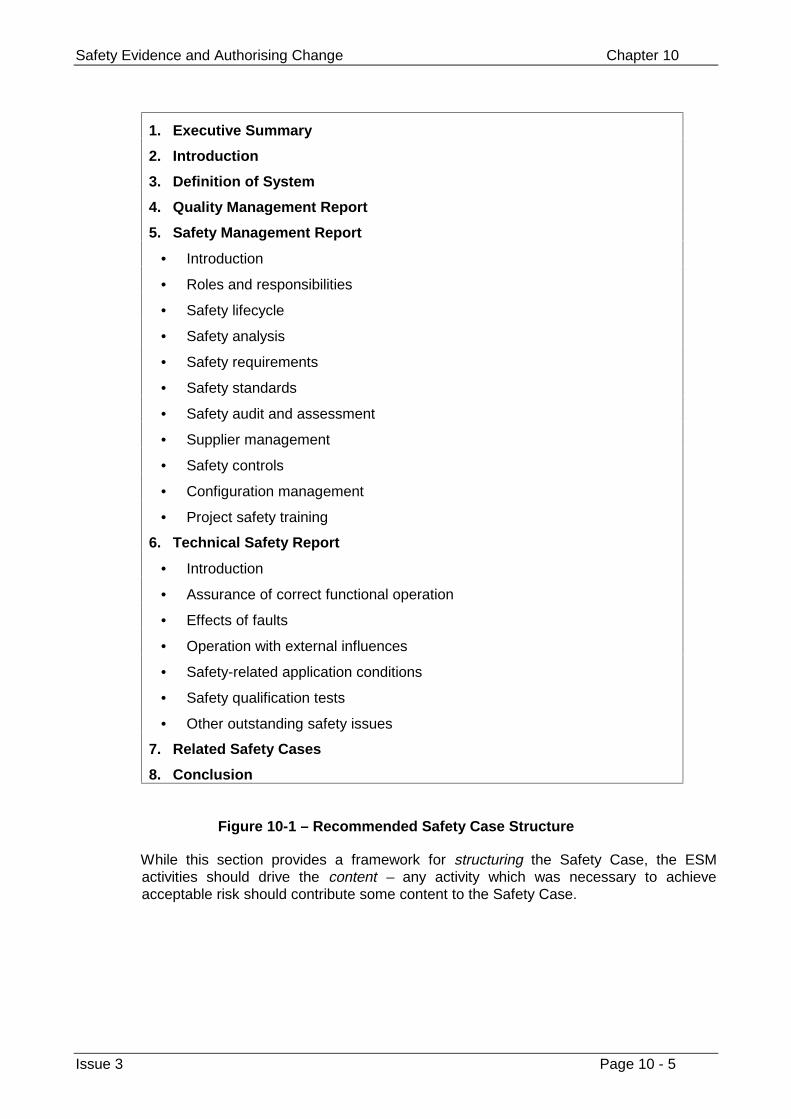
Safety Evidence and Authorising Change Chapter 10
Issue 3 Page 10 - 5
1. Executive Summary
2. Introduction
3. Definition of System
4. Quality Management Report
5. Safety Management Report
• Introduction
• Roles and responsibilities
• Safety lifecycle
• Safety analysis
• Safety requirements
• Safety standards
• Safety audit and assessment
• Supplier management
• Safety controls
• Configuration management
• Project safety training
6. Technical Safety Report
• Introduction
• Assurance of correct functional operation
• Effects of faults
• Operation with external influences
• Safety-related application conditions
• Safety qualification tests
• Other outstanding safety issues
7. Related Safety Cases
8. Conclusion
Figure 10-1 – Recommended Safety Case Structure
While this section provides a framework for structuring the Safety Case, the ESMactivities should drive the content – any activity which was necessary to achieveacceptable risk should contribute some content to the Safety Case.
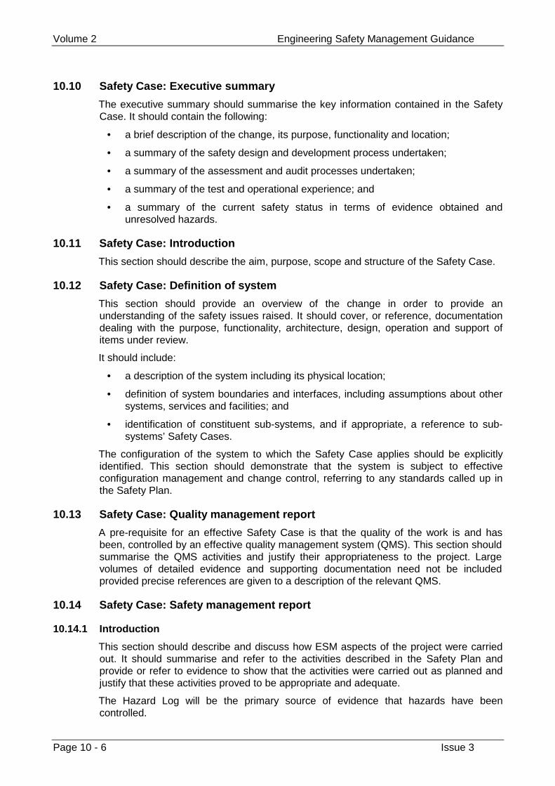
Volume 2 Engineering Safety Management Guidance
Page 10 - 6 Issue 3
10.10 Safety Case: Executive summary
The executive summary should summarise the key information contained in the SafetyCase. It should contain the following:
• a brief description of the change, its purpose, functionality and location;
• a summary of the safety design and development process undertaken;
• a summary of the assessment and audit processes undertaken;
• a summary of the test and operational experience; and
• a summary of the current safety status in terms of evidence obtained andunresolved hazards.
10.11 Safety Case: Introduction
This section should describe the aim, purpose, scope and structure of the Safety Case.
10.12 Safety Case: Definition of system
This section should provide an overview of the change in order to provide anunderstanding of the safety issues raised. It should cover, or reference, documentationdealing with the purpose, functionality, architecture, design, operation and support ofitems under review.
It should include:
• a description of the system including its physical location;
• definition of system boundaries and interfaces, including assumptions about othersystems, services and facilities; and
• identification of constituent sub-systems, and if appropriate, a reference to sub-systems’ Safety Cases.
The configuration of the system to which the Safety Case applies should be explicitlyidentified. This section should demonstrate that the system is subject to effectiveconfiguration management and change control, referring to any standards called up inthe Safety Plan.
10.13 Safety Case: Quality management report
A pre-requisite for an effective Safety Case is that the quality of the work is and hasbeen, controlled by an effective quality management system (QMS). This section shouldsummarise the QMS activities and justify their appropriateness to the project. Largevolumes of detailed evidence and supporting documentation need not be includedprovided precise references are given to a description of the relevant QMS.
10.14 Safety Case: Safety management report
10.14.1 Introduction
This section should describe and discuss how ESM aspects of the project were carriedout. It should summarise and refer to the activities described in the Safety Plan andprovide or refer to evidence to show that the activities were carried out as planned andjustify that these activities proved to be appropriate and adequate.
The Hazard Log will be the primary source of evidence that hazards have beencontrolled.
Safety Evidence and Authorising Change Chapter 10
Issue 3 Page 10 - 7
The following ESM issues should be addressed:
• Roles and responsibilities;
• Safety lifecycle;
• Safety analysis
• Safety requirements;
• Safety standards;
• Safety audit and assessment;
• Supplier management;
• Safety controls;
• Configuration management; and
• Project safety training.
Each issue is treated in a separate section, below.
10.14.2 Roles and responsibilities
This section should provide evidence to show that the key safety personnel on theproject carried out the roles defined in the Safety Plan.
It should justify the appointment of the key safety personnel by referring to competenceand experience.
10.14.3 Safety lifecycle
This section should justify the project and safety lifecycles followed during the project,particularly if they differed significantly from those defined in the Safety Plan.
10.14.4 Safety analysis
This section should present a detailed discussion of the safety analysis process used onproject. It should provide assurance that all foreseeable hazards have been identified,that intolerable risks have been eliminated and that other risks have been reducedALARP.
This section should show that the safety analyses have taken into account the scope ofthe system and its normal and abnormal operation. System and component failure andmalfunction, procedural failures, human error and environmental conditions should beconsidered.
The following should be provided:
• A list of the analysis methods used and their application on the project.
• Identification of the design documents referenced during the analysis work, clearlyindicating the configuration and status of the design for each analysis.
• Evidence that the safety analysis process is capable of addressing the safety offuture system changes.
This section should review all the incidents that have occurred. It should state the cause,potential and actual effects, and the actions required to prevent the re-occurrence of allincidents that have occurred during operational experience which could havecompromised safety during operation in-service. The review should refer to the HazardLog.
Volume 2 Engineering Safety Management Guidance
Page 10 - 8 Issue 3
This section should also present a review of reliability data based on data obtained fromoperating experience, including the Hazard Log. The data should be used to quantifyand justify the safety analysis evidence.
This section should discuss the approach used to demonstrate that risk has beenreduced ALARP and demonstrate that the approach follows good practice.
This section should record any elements of the safety policy set by the railway authoritywhich are relevant to the analysis. These may include safety targets set by the railwayauthority and latitude allowed to their contractors and suppliers to change aspects of therailway environment in which the system or equipment will run.
10.14.5 Safety requirements
This section may either restate the safety requirements for the system or equipment orsummarise them and refer to the Safety Requirements Specification.
A discussion of the safety implications of the requirements, indicating how eachrequirement affected the project, should be included.
Any assumptions made should be stated and justified.
Evidence for compliance with the Safety Requirements is addressed in section 10.15.3below.
10.14.6 Safety standards
This section should provide evidence that the procedures and standards called up by theSafety Plan were followed, and justify any non-conformances.
10.14.7 Safety audits and safety assessments
Evidence for the implementation of the Safety Audit and Assessment programme is akey element of the Safety Case. The findings of these audits and assessments arenormally presented in separate documents. This section should present the following:
• a description and justification of timing of the audits and assessments should bedescribed;
• a justification that the auditors and assessors had sufficient competence andindependence;
• a justification of any decision not to take action in response to a finding orrecommendation.
10.14.8 Supplier management
This section should show that the work of contractors and suppliers has been carried outto the safety standards expected for the SIL applicable, and as specified in thesupplier’s Safety Plan.
10.14.9 Safety controls
This section should provide evidence that the safety controls identified in the Safety Planhave been applied.
10.14.10 Configuration management
This section should justify the configuration management system employed and showthat it has been implemented correctly.
Safety Evidence and Authorising Change Chapter 10
Issue 3 Page 10 - 9
Evidence that all safety-related project items are under configuration managementshould be provided.
10.14.11 Project safety training
This section should show that the personnel carrying out the safety-related activitieswere adequately trained by providing evidence for the implementation of defined trainingplans.
10.15 Safety Case: Technical safety report
The Technical Safety Report should explain the technical principles which assure thesafety of the design including (or giving references to) all supporting evidence (forexample, design principles and calculations, test specifications and results, and safetyanalyses). Large volumes of detailed evidence and supporting documentation need notbe included, provided precise references are given to such documents. The followinggives a guideline for the structure of the Technical Safety Report,
1 Introduction;
2 Assurance of correct functional operation;
3 Effects of faults;
4 Operation with external influences;
5 Safety-related application conditions;
6 Safety qualification tests;
7 Other outstanding safety issues.
Items 2 to 7 inclusive are each treated in the sections below.
10.15.1 Assurance of correct functional operation, effects of faults, operation withexternal influences
These three sections should describe and discuss the activities carried out in eachphase of the project in order to satisfy the Safety Requirements. They shouldsummarise and refer to the activities described in the Safety Plan and provide or refer toevidence to show that the activities were carried out and that these activities proved tobe appropriate and adequate for the defined SIL.
These activities should be provided under three headings:
• Assurance of correct functional operation
Demonstrating that the system will contribute acceptable risk in the absence offaults and external influences. Routine maintenance should be considered as wellas normal operation.
• Effects of faults
Demonstrating that the system will contribute acceptable risk in the presence offoreseeable internal faults. Relevant safety features, fall-back modes andalternative operating procedures should be described.
Volume 2 Engineering Safety Management Guidance
Page 10 - 10 Issue 3
• Operation with external influences
Demonstrating that the system will contribute acceptable risk in the presence offoreseeable external influences, such as weather, electromagnetic interferenceand vandalism, Relevant safety features, fall-back modes and alternativeoperating procedures should be described.
The Hazard Log should be used as the primary source of evidence.
These sections should show that the approach adopted reduced risk ALARP.
These sections should show that the Safety Requirements have been met. They shouldinclude the following, where relevant:
a) Evidence that the Safety Requirements were defined according to good practice(see chapter 12);
b) Identification and justification of major changes made to the Safety Requirementsthroughout the project;
c) A summary and reference to all analyses carried out during requirements definition;
d) Evidence that high-level allocation of safety requirements to sub-systems has beencarried out;
e) An explanation and justification of all use of sub-systems, pre-fabricated sections,dependencies on other systems and so on, which have been produced outside thedirect control of the project;
f) Safety evidence acquired from verification and validation of the systemsummarised, including the strategy and method employed and the results andevidence obtained;
g) Evidence that further work or improvements identified as a result of validation andverification activities have been carried out;
h) Evidence that the system has been integrated with existing systems andprocedures in a safe and controlled manner;
i) Evidence that commissioning activities have been examined for commissioning-specific hazards;
j) Evidence that, for systems with extensive or complex hardware, software or human-factors considerations, a formal hazard identification and analysis activity has beencarried out;
k) Practical experience of operating the system, including testing, integration,commissioning and any in-service experience summarised;
l) Evidence that the hazards associated with system operation will be adequatelycontrolled under both normal and abnormal conditions and for all modes ofoperation;
m) Evidence that all aspects effecting safe operation and maintenance, includingstaffing levels, training requirements, operational management and interfaces toother systems, have been addressed;
n) Evidence that response time requirements and other analogue issues, such as non-overlapping tolerances have been considered.
Safety Evidence and Authorising Change Chapter 10
Issue 3 Page 10 - 11
10.15.2 Safety-related application conditions
This section should specify (or reference) the rules, conditions and constraints whichshould be observed in the application of the system. This should include the applicationconditions contained in the Safety Case of any related sub-system or item of equipment.
10.15.3 Safety qualification tests
This section should provide evidence of test activities which demonstrate that eachSafety Requirement has been met.
If this evidence is not available or sufficient, this section should present analyticalevidence that each Safety Requirement has been met, or adequately justify any thathave not been met. Such a justification should include an assessment of the residualrisk presented by the non-compliance.
This section should review the fault history and status of the system or equipment asrecorded in the Data Recording And Corrective Action System (DRACAS) and justify theconclusion that risk has been reduced to an acceptable level in the light of this evidence.
10.15.4 Other outstanding safety issues
All outstanding safety issues not covered by documented Safety Requirements shouldbe discussed here, whenever they would have a bearing on operational safety.
10.16 Safety Case: Related safety cases
This section should contain references to any other Safety Cases upon which this SafetyCase depends, together with a demonstration that any assumptions, limitations orrestrictions in the related Safety Cases are either fulfilled or carried forward into thisSafety Case.
10.17 Safety Case: Conclusion
This section should make a statement on the acceptability of the system in terms of thesafety requirements. This statement should include:
• a list of assumptions made in the safety case especially those made about thesafety requirements;
• a statement of the residual risk presented by the system;
• a statement of system deficiencies;
• identification of all unresolved hazards and other outstanding issues;
• operating restrictions or procedures imposed for safety reasons; and
• recommendations for or identification of further work to be carried out.
The conclusions section should document any caveats on which the conclusion is basedincluding assumptions and limitations and restrictions on use. The Safety Authority maycarry these forward as conditions of safety approval.
10.18 Related guidance
Chapter 12 provides guidance on establishing safety requirements.

Volume 2 Engineering Safety Management Guidance
Page 10 - 12 Issue 3
This page left intentionally blank

Part 4
Project Fundamentals
ESM from Start to Finish Chapter 11
Issue 3 Page 11 - 1
Chapter 11
ESM from Start to Finish
Your organisation must start ESM activities as soon as possible. It must review theresults of these activities, and any assumptions made throughout the project. It mustreview and extend ESM activities whenever new information makes this necessary. Itmust monitor information on performance that relates to safety.
11.1 Guidance from volume 1
You should start early while it is easiest to build safety in. However, you may have littledesign information early in the project, so you should repeat the hazard analysis and riskassessment activities throughout the project, as the design becomes more detailed.
New information also includes design changes and information on faults.
11.2 Background
It is always more effective to build safety in than to try to retrofit it later. Decisions on theform and structure of systems start to be taken at the beginning of projects and safetyanalysis should therefore start at the beginning so that safety considerations caninfluence the earliest decisions.
At the beginning of a project there is insufficient information to perform a detailed hazardanalysis or risk assessment and the analysis is usually limited to a preliminaryidentification of hazards. This is sufficient to support early discussions on the approachto controlling each hazard, to ensure that each hazard is taken into account.
As decisions on the scope, functionality and design of the system are taken it is possibleto improve the identification of hazards, to analyse their causes and consequences and,eventually, to assess the risks. In each phase of the project, the analysis should betaken as far as the available information permits, in order to provide the best support fordecisions taken during that phase.
An iterative approach to analysis should therefore be taken, and the analysis will beimproved and extended in step with the specification and design, with constantinteraction between the two.
Other ESM activities also need to be performed during these phases. This chapterprovides guidance on what should be done when. This chapter is written for:
• anyone involved in starting up a project and planning the later stages.
See also chapter 12 which provides guidance on safety planning.
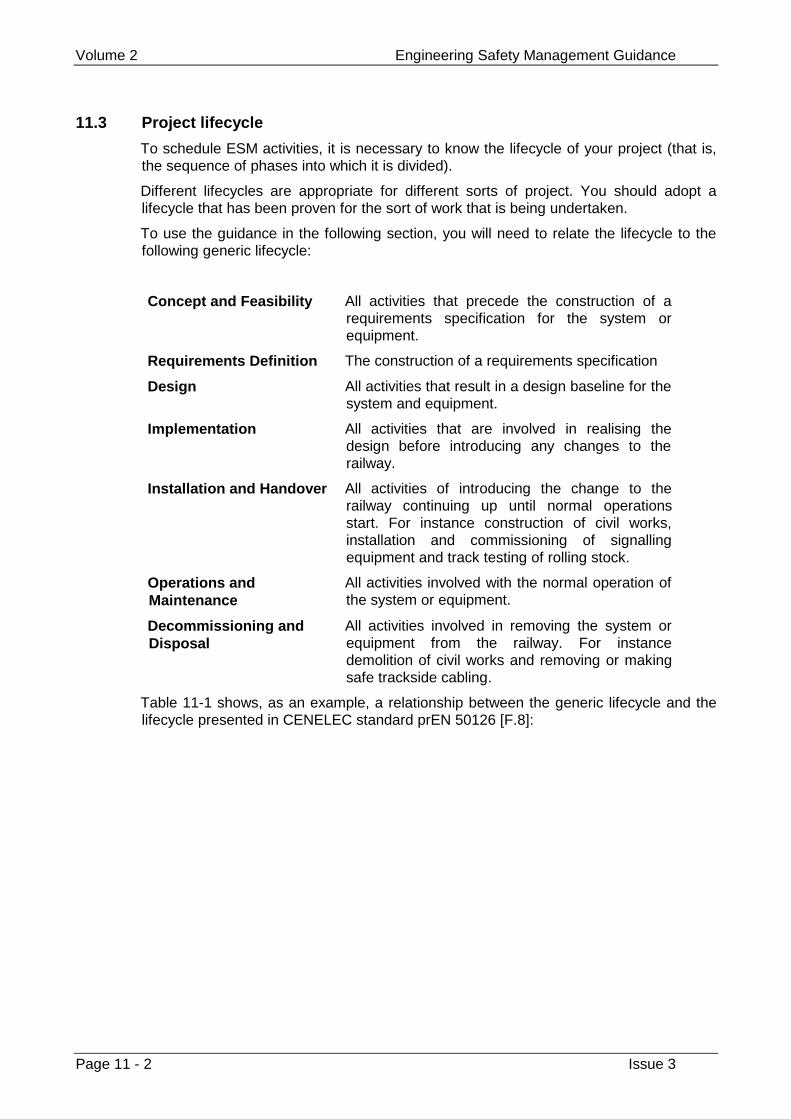
Volume 2 Engineering Safety Management Guidance
Page 11 - 2 Issue 3
11.3 Project lifecycle
To schedule ESM activities, it is necessary to know the lifecycle of your project (that is,the sequence of phases into which it is divided).
Different lifecycles are appropriate for different sorts of project. You should adopt alifecycle that has been proven for the sort of work that is being undertaken.
To use the guidance in the following section, you will need to relate the lifecycle to thefollowing generic lifecycle:
Concept and Feasibility All activities that precede the construction of arequirements specification for the system orequipment.
Requirements Definition The construction of a requirements specification
Design All activities that result in a design baseline for thesystem and equipment.
Implementation All activities that are involved in realising thedesign before introducing any changes to therailway.
Installation and Handover All activities of introducing the change to therailway continuing up until normal operationsstart. For instance construction of civil works,installation and commissioning of signallingequipment and track testing of rolling stock.
Operations andMaintenance
All activities involved with the normal operation ofthe system or equipment.
Decommissioning andDisposal
All activities involved in removing the system orequipment from the railway. For instancedemolition of civil works and removing or makingsafe trackside cabling.
Table 11-1 shows, as an example, a relationship between the generic lifecycle and thelifecycle presented in CENELEC standard prEN 50126 [F.8]:
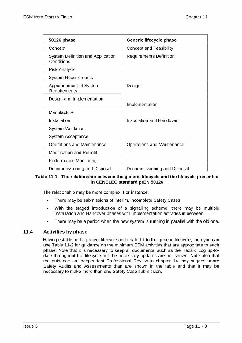
ESM from Start to Finish Chapter 11
Issue 3 Page 11 - 3
50126 phase Generic lifecycle phase
Concept Concept and Feasibility
System Definition and ApplicationConditions
Risk Analysis
System Requirements
Requirements Definition
Apportionment of SystemRequirements
Design
Design and Implementation
Manufacture
Implementation
Installation
System Validation
System Acceptance
Installation and Handover
Operations and Maintenance
Modification and Retrofit
Performance Monitoring
Operations and Maintenance
Decommissioning and Disposal Decommissioning and Disposal
Table 11-1 - The relationship between the generic lifecycle and the lifecycle presentedin CENELEC standard prEN 50126
The relationship may be more complex. For instance:
• There may be submissions of interim, incomplete Safety Cases.
• With the staged introduction of a signalling scheme, there may be multipleInstallation and Handover phases with Implementation activities in between.
• There may be a period when the new system is running in parallel with the old one.
11.4 Activities by phase
Having established a project lifecycle and related it to the generic lifecycle, then you canuse Table 11-2 for guidance on the minimum ESM activities that are appropriate to eachphase. Note that it is necessary to keep all documents, such as the Hazard Log up-to-date throughout the lifecycle but the necessary updates are not shown. Note also thatthe guidance on Independent Professional Review in chapter 14 may suggest moreSafety Audits and Assessments than are shown in the table and that it may benecessary to make more than one Safety Case submission.
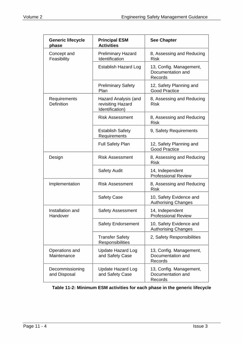
Volume 2 Engineering Safety Management Guidance
Page 11 - 4 Issue 3
Generic lifecyclephase
Principal ESMActivities
See Chapter
Preliminary HazardIdentification
8, Assessing and ReducingRisk
Establish Hazard Log 13, Config. Management,Documentation andRecords
Concept andFeasibility
Preliminary SafetyPlan
12, Safety Planning andGood Practice
Hazard Analysis (andrevisiting HazardIdentification)
8, Assessing and ReducingRisk
Risk Assessment 8, Assessing and ReducingRisk
Establish SafetyRequirements
9, Safety Requirements
RequirementsDefinition
Full Safety Plan 12, Safety Planning andGood Practice
Risk Assessment 8, Assessing and ReducingRisk
Design
Safety Audit 14, IndependentProfessional Review
Risk Assessment 8, Assessing and ReducingRisk
Implementation
Safety Case 10, Safety Evidence andAuthorising Changes
Safety Assessment 14, IndependentProfessional Review
Safety Endorsement 10, Safety Evidence andAuthorising Changes
Installation andHandover
Transfer SafetyResponsibilities
2, Safety Responsibilities
Operations andMaintenance
Update Hazard Logand Safety Case
13, Config. Management,Documentation andRecords
Decommissioningand Disposal
Update Hazard Logand Safety Case
13, Config. Management,Documentation andRecords
Table 11-2: Minimum ESM activities for each phase in the generic lifecycle
ESM from Start to Finish Chapter 11
Issue 3 Page 11 - 5
11.5 Reacting to modifications and new information
Your configuration management arrangements (see chapter 13) should establishbaselines and then provide a procedure for assessing, authorising and tracking changesto these baselines. This procedure should assess the affect on safety of any proposedchange and should ensure that, when a change is authorised, any necessary changesto ESM documents, including the Hazard Log, are made.
Your configuration management arrangements should provide a procedure forassessing faults discovered in baselines, defining any corrective action and thenfollowing this through. This procedure should include assessing whether any faults showthe need to amend any ESM documents, including the Hazard Log, and if so ensure thatthe amendments are made. These procedures should make use of a Data RecordingAnd Corrective Action System (see appendix E).
When the system or equipment is introduced to the railway, your management of theHazard Log (see chapter 13) should include a procedure for logging any incidents thatoccur, assessing them and defining any corrective action that is necessary to preventthem from recurring. This procedure should also assess the need to change any ESMdocuments.
11.6 Related guidance
Guidance on writing a Safety Plan is provided in chapter 12.
Guidance on maintaining a Hazard Log provided in chapter 13.
Guidance on establishing a Data Recording And Corrective Action System is provided inappendix E.
Volume 2 Engineering Safety Management Guidance
Page 11 - 6 Issue 3
This page left intentionally blank
Safety Planning and Good Practice Chapter 12
Issue 3 Page 12 - 1
Chapter 12
Safety Planning and Good Practice
Your organisation must plan all project ESM activities before carrying them out.
Your organisation must carry out safety-related projects following systematic processeswhich use good engineering practices. It must write down the processes beforehand.
12.1 Guidance from volume 1
12.1.1 Safety planning
You will normally write a safety plan, which should describe how you will put all theseESM fundamentals into practice on your project.
You do not have to write one plan for the whole programme beforehand, but you shouldplan each ESM activity before you do it.
You should adjust the extent of the safety plan and the ESM activities you carry outaccording to the extent of the risk.
12.1.2 Systematic processes and good practice
You should use good systems engineering practice to develop safety-related systems.
Engineering needs a safety culture as much as any other activity. It is true that safetydepends on the people who do the work, but it also depends on the way they do theirwork and the tools they use.
When choosing methods, you should take account of relevant standards. What is and isnot good practice may depend upon the requirements.
12.2 Background
The Yellow Book recommends that any significant change to the railway should be runas a project. A Safety Plan should be produced for each safety-related project.
The Safety Plan performs two main functions:
1 it provides a detailed schedule of how safety risks will be reduced to an acceptablelevel (or shown already to be at an acceptable level); and
2 it provides a means of demonstrating that this has been done.
Volume 2 Engineering Safety Management Guidance
Page 12 - 2 Issue 3
The Safety Plan should describe a programme of work which will ensure the SafetyRequirements are identified and met. It should also state and justify the allocation of keystaff and resources to carry out this programme.
The Safety Plan is an evolutionary document. For example, early in the project aPreliminary Safety Plan will describe the safety analysis activities needed to deriveSafety Requirements. As the project progresses, a Safety Plan will describe activities tomeet these Safety Requirements.
This chapter describes the different types of Safety Plan that may be required during aproject, the process for preparing a Safety Plan, and its content.
The other chapters of this volume describe good practice in ESM activities, such assafety analysis and preparing a Safety Case. However, you should also use goodpractice if you are carrying out mainstream engineering work, such as civil, electronicand software engineering.
What constitutes good practice is relative and depends on:
• the type of work that you are doing;
• the Safety Integrity Level (SIL) of the system or equipment; and
• the current standard of good practice, which will change with time.
This chapter does not attempt to define what is and is not good practice for a wide rangeof engineering disciplines, but it does provide guidance on researching good practiceand documenting and justifying your choices.
This chapter is written for:
• anyone responsible for preparing a Safety Plan,
• anyone who will need to endorse a Safety Plan, and
• anyone involved in performing, auditing or assessing ESM activities.
12.3 Relevant Safety Authorities
When planning or implementing a change to the railway, it is necessary to gain approvalfor the change from certain Safety Authorities. Approval may be needed from thefollowing organisations:
• your own organisation,
• the railway authority (for instance, Railtrack or London Underground Ltd),
• the regulatory authority (HMRI in the UK).
To find out if the change needs approval from these organisations, you should in thefirst instance:
• Check your own organisation’s requirements.
• Consult the railway authority’s procedures (for example, Railway GroupStandards).
• Consult the guidance provided by the regulatory authority (for example, HMRI’sdocument ‘Guide to the Approval of Railway Works, Plant, and Equipment’ [F.18]).
Unless you know definitely that you do not require approval from any of the aboveorganisations, then you should seek advice from them.
Safety Planning and Good Practice Chapter 12
Issue 3 Page 12 - 3
In the rest of this chapter, ‘relevant Safety Authority’ means any organisation from whichapproval is required.
12.4 The depth of safety planning
The size and depth of the Safety Plan will depend on the complexity and level of riskpresented by the project. For simple and low-risk projects a brief Safety Plan definingthe project personnel and justifying a simple approach may be sufficient. Note that, ifyou assume a project is low-risk, you should make this assumption explicit and takeaction to confirm it. The Safety Plan should be endorsed by the relevant SafetyAuthorities, regardless of the level of complexity or risk.
The Safety Plan may permit reliance on previous work to demonstrate acceptable risks.You would not normally do this unless:
• the previous work used good practice, and
• it covered all of the project risk, and
• there is no novelty in development, application or use.
The last condition may be relaxed slightly, to allow limited novelty for low-risk projects.
12.5 The safety planning process
The Project Manager is responsible for preparing the Preliminary and full Safety Plans.The Project Manager may delegate the preparation of these documents to suitablyqualified and competent personnel but should retain overall responsibility.
The relevant Safety Authorities are responsible for endorsing Safety Plans.
A typical approach to the safety planning process is as follows:
1 Develop a Preliminary Safety Plan to set out an overall approach to managingsafety on the project. In particular, the Preliminary Safety Plan should describe theapproach for carrying out a full Safety Analysis and justify the competencies of keystaff allocated to undertake these activities.
2 Seek endorsement of the Preliminary Safety Plan from the relevant SafetyAuthorities.
3 Carry out the Safety Analysis and produce a set of Safety Requirements.
4 Prepare a Safety Plan to describe how the Safety Requirements are to be met.
5 Seek endorsement of the Safety Plan from the relevant Safety Authorities.
6 Update this version of the Safety Plan as appropriate and seek re-endorsement
Note: it may save time to seek comments from the Safety Auditor before submitting astrategy or plan to the Safety Authority.
The Safety Plan should be scoped according to the information available and theorganisation of the project. It may be split into smaller plans that cover particular stagesof the lifecycle, activities to be carried out by particular disciplines or the entire project.However, every project safety activity should be covered by a Safety Plan.
The Safety Plan should be updated throughout the project to reflect any changes to theplanned activities that arise as a result of undertaking safety activities. Followingsignificant updates, the Safety Plan should be re-submitted for endorsement.
Volume 2 Engineering Safety Management Guidance
Page 12 - 4 Issue 3
The Safety Plan should state and justify the ESM approach to be applied to the project,so that it may be considered and endorsed.
The Safety Plan may be combined with reliability, maintainability and availability plansinto a System Assurance Plan. However, it is usually kept separate so that it may besubmitted to the relevant Safety Authorities, who will want to focus on the safety aspectsof the project and do not need to see other plans.
12.6 Content of a Preliminary Safety Plan
This section describes the information that should be contained within a PreliminarySafety Plan.
The Preliminary Safety Plan will be a short, high-level version of the Safety Plan,produced as early in the project as possible, and describing the overall strategy andapproach to reducing safety risks.
The following structure is recommended:
1 Introduction and background;
2 Safety analysis;
3 Key staff;
4 Safety audit and assessment;
5 Safety documentation;
6 Safety engineering.
Each section should be brief; detailed planning will be carried out after SafetyRequirements have been set, and documented in the Safety Plan.
The Introduction and background should describe the aims, extent and context (seechapter 7) of the change to be made to the railway.
The Safety analysis section should describe the techniques to be adopted to determinethe risk presented by the system or equipment and to establish Safety Requirements.This section should detail the competencies of key staff allocated to carry out hazardidentification and analysis activities.
The Key staff section should identify those members of staff proposed for key safetyroles and justify their competence.
The Safety audit and assessment section should identify the competence andindependence requirements for auditors and or assessors. If they are known, theyshould be identified and shown to meet the requirements.
The Safety documentation section should detail the documentation that will beproduced. The list should include Hazard Log, Safety Plan and the Safety Analysisdocumentation and also state whether an incremental or non-incremental Safety Case isto be used.
The Safety engineering section should describe, at a high-level, mainstreamengineering steps that are being taken to reduce risk (such as redundancy, protectionsystems, fail-safe design principles).
Safety Planning and Good Practice Chapter 12
Issue 3 Page 12 - 5
12.7 Content of a Safety Plan
This section describes the information that should be contained within a full Safety Plan.The following structure is recommended:
1 Introduction;
2 Background and requirements;
3 ESM activities;
4 Safety controls;
5 Safety documentation;
6 Safety engineering;
7 Validation of external items.
A more detailed suggested outline for the Safety Plan is provided in appendix B. Ifanother structure is used, it should cover the information described for each of thesections listed above.
For large or complex projects it may be appropriate to prepare separate plans coveringone or more of these sections.
12.7.1 Introduction
This should describe the aim, purpose, scope and structure of the Safety Plan.
12.7.2 Background and requirements
This section should:
a) justify the approach taken, with reference to ESM guidance such as this bookand safety policy;
b) describe or reference a description of any safety principles underpinning theapproach to safety;
c) describe the aims, extent and context (see chapter 7) of the change to be madeto the railway and provide or refer to a summary of the system or equipment,including interfaces to other systems or projects;
d) state or provide a reference to the Safety Requirements Specification;
e) briefly describe the risk assessment criteria that will be used to derive targetsfor risk tolerability;
f) describe or reference the process for assigning safety functions to systemelements; and
g) list any assumptions or constraints on the project or system.
Items c) and d) may be omitted from early issues, but should be included when theappropriate activities have been carried out.
Volume 2 Engineering Safety Management Guidance
Page 12 - 6 Issue 3
12.7.3 ESM Activities
This section should address the following ESM issues, to the extent necessary:
1 Safety roles and responsibilities,
2 Safety lifecycle,
3 Safety analysis,
4 Safety deliverables,
5 Safety standards,
6 Safety assessment,
7 Safety audit,
8 Safety case and safety approval,
9 Supplier management,
10 Configuration management,
11 Project safety training,
12 System operation, modification and maintenance,
13 Decommissioning and disposal
The following sections describe what the Safety Plan should say about these issues.
12.7.3.1 Safety roles and responsibilities
This section should identify the key safety personnel of the project, their roles,responsibilities, qualifications and experience and the reporting lines between them.
Note: the Project Manager retains overall accountability for safety even if he or shedelegates responsibilities for ESM activities.
In particular, this section should identify the personnel allocated to manage and performthe following safety activities:
• defining safety requirements;
• leading the design, implementation or validation activities;
• performing safety analysis;
• liaising with regulatory bodies such as HMRI.
Note: suppliers will normally liase with HMRI via the railway operator.
The Project Manager should be responsible for:
• producing a Safety Plan;
• submitting the Safety Plan to the relevant Safety Authorities;
• where necessary, attending the safety endorsement meeting;
• ensuring safety documentation is produced as planned;
• commissioning Safety Audits and Assessments as planned;
• initiating ESM activities, as planned;
• ensuring that all project staff have read and understood the Safety Plan;
• obtaining and allocating sufficient resources to implement the Safety Plan;
Safety Planning and Good Practice Chapter 12
Issue 3 Page 12 - 7
• ensuring competence of key staff; and
• co-ordinating safety activities with other parts of the organisation, and with theclient.
If there is a Project Safety Manager, they will typically be delegated responsibility for:
• producing a Safety Plan;
• submitting the Safety Plan to the relevant Safety Authorities;
• where necessary, attending the endorsement meeting;
• ensuring safety documentation is produced as planned;
• commissioning Safety Audits and Assessments as planned; and
• initiating ESM activities, as planned.
This section should define the specific safety responsibilities of the Safety Auditor andSafety Assessor.
The Safety Auditor should audit the project to check for adequacy of the Safety Plan andcompliance with the Safety Plan and any referenced standards or procedures.
The Safety Assessor should assess the project to check the adequacy of the SafetyRequirements and that the Safety Requirements are being met.
Chapter 2 provides guidance on safety roles and responsibilities and chapter 14provides guidance on carrying out Safety Audits and Assessments.
12.7.3.2 Safety lifecycle
This section should define a project lifecycle that describes the major phases of theproject, and a safety lifecycle that specifies the order in which the safety tasks are to becarried out. The safety lifecycle should be derived from the guidance given in chapter 11on scheduling ESM activities, and should be tailored to the specific requirements of theproject. The relationship between the project and safety lifecycles should be specified(that is, at what points in the project the safety activities will be performed).
12.7.3.3 Safety analysis
This section should define the process of safety analysis to be used to determine theSafety Requirements for the project. The process should be tailored to each individualproject.
Guidance on performing safety analysis is provided in chapter 8 of this handbook.
For each safety analysis activity, this section should provide details of responsibilities,documentation and timing of deliverables. This section should also state the criteriaused to establish the tolerability for the identified risks.
12.7.3.4 Safety deliverables
This section should detail the safety-related items (other than Safety Documentation,see section 12.7.5) that are to be delivered during the project. They should includesafety-related hardware and software, but may also include other items such asmaintenance procedures.
12.7.3.5 Safety standards
Any safety-related work should be performed within a defined Quality ManagementSystem (QMS), which is compliant with an ISO-9000 series standard.
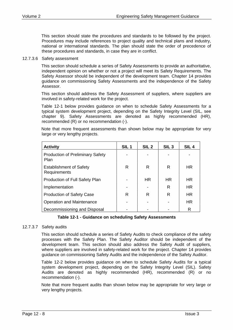
Volume 2 Engineering Safety Management Guidance
Page 12 - 8 Issue 3
This section should state the procedures and standards to be followed by the project.Procedures may include references to project quality and technical plans and industry,national or international standards. The plan should state the order of precedence ofthese procedures and standards, in case they are in conflict.
12.7.3.6 Safety assessment
This section should schedule a series of Safety Assessments to provide an authoritative,independent opinion on whether or not a project will meet its Safety Requirements. TheSafety Assessor should be independent of the development team. Chapter 14 providesguidance on commissioning Safety Assessments and the independence of the SafetyAssessor.
This section should address the Safety Assessment of suppliers, where suppliers areinvolved in safety-related work for the project.
Table 12-1 below provides guidance on when to schedule Safety Assessments for atypical system development project, depending on the Safety Integrity Level (SIL, seechapter 9). Safety Assessments are denoted as highly recommended (HR),recommended (R) or no recommendation (-).
Note that more frequent assessments than shown below may be appropriate for verylarge or very lengthy projects.
Activity SIL 1 SIL 2 SIL 3 SIL 4
Production of Preliminary SafetyPlan
- - - -
Establishment of SafetyRequirements
R R R HR
Production of Full Safety Plan - HR HR HR
Implementation - - R HR
Production of Safety Case R R R HR
Operation and Maintenance - - - HR
Decommissioning and Disposal - - - R
Table 12-1 - Guidance on scheduling Safety Assessments
12.7.3.7 Safety audits
This section should schedule a series of Safety Audits to check compliance of the safetyprocesses with the Safety Plan. The Safety Auditor should be independent of thedevelopment team. This section should also address the Safety Audit of suppliers,where suppliers are involved in safety-related work for the project. Chapter 14 providesguidance on commissioning Safety Audits and the independence of the Safety Auditor.
Table 12-2 below provides guidance on when to schedule Safety Audits for a typicalsystem development project, depending on the Safety Integrity Level (SIL). SafetyAudits are denoted as highly recommended (HR), recommended (R) or norecommendation (-).
Note that more frequent audits than shown below may be appropriate for very large orvery lengthy projects.
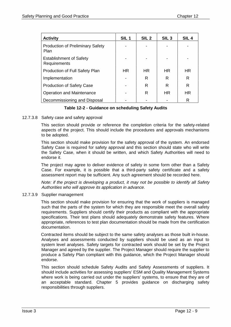
Safety Planning and Good Practice Chapter 12
Issue 3 Page 12 - 9
Activity SIL 1 SIL 2 SIL 3 SIL 4
Production of Preliminary SafetyPlan
- - - -
Establishment of SafetyRequirements
- - - -
Production of Full Safety Plan HR HR HR HR
Implementation - R R R
Production of Safety Case - R R R
Operation and Maintenance - R HR HR
Decommissioning and Disposal - - - R
Table 12-2 - Guidance on scheduling Safety Audits
12.7.3.8 Safety case and safety approval
This section should provide or reference the completion criteria for the safety-relatedaspects of the project. This should include the procedures and approvals mechanismsto be adopted.
This section should make provision for the safety approval of the system. An endorsedSafety Case is required for safety approval and this section should state who will writethe Safety Case, when it should be written, and which Safety Authorities will need toendorse it.
The project may agree to deliver evidence of safety in some form other than a SafetyCase. For example, it is possible that a third-party safety certificate and a safetyassessment report may be sufficient. Any such agreement should be recorded here.
Note: if the project is developing a product, it may not be possible to identify all SafetyAuthorities who will approve its application in advance.
12.7.3.9 Supplier management
This section should make provision for ensuring that the work of suppliers is managedsuch that the parts of the system for which they are responsible meet the overall safetyrequirements. Suppliers should certify their products as compliant with the appropriatespecifications. Their test plans should adequately demonstrate safety features. Whereappropriate, references to test plan documentation should be made from the certificationdocumentation.
Contracted items should be subject to the same safety analyses as those built in-house.Analyses and assessments conducted by suppliers should be used as an input tosystem level analyses. Safety targets for contracted work should be set by the ProjectManager and agreed by the supplier. The Project Manager should require the supplier toproduce a Safety Plan compliant with this guidance, which the Project Manager shouldendorse.
This section should schedule Safety Audits and Safety Assessments of suppliers. Itshould include activities for assessing suppliers’ ESM and Quality Management Systemswhere work is being carried out under the suppliers’ systems, to ensure that they are ofan acceptable standard. Chapter 5 provides guidance on discharging safetyresponsibilities through suppliers.
Volume 2 Engineering Safety Management Guidance
Page 12 - 10 Issue 3
12.7.3.10 Configuration management
This section should specify how configuration of system deliverables will be managed,normally referring to a separate configuration management plan for detail. This sectionshould specify how systems, components and other equipment will be labelled to ensurethat safety is not compromised by the use of faulty or untested equipment. Chapter 13provides guidance on configuration management.
12.7.3.11 Project safety training
This section should define any training requirements of personnel scheduled to performsafety-related activities and provide a plan or programme of training that meets therequirements.
12.7.3.12 System operation, modification and maintenance
This section should outline processes for analysing system operation to ensurecompliance with requirements. It should also describe the process and approvalmechanisms for system modification and maintenance. A checklist of items to consideris provided in appendix C.
12.7.3.13 Decommissioning and disposal
This section should outline plans for safely decommissioning the system at the end of itslife and disposing of it. A checklist of items to consider is provided in appendix C.
12.7.4 Safety controls
This section should specify all aspects of quality controls that contribute to safety,normally referring to a separate quality plan for detail. It should identify anyrequirements for the use of equipment in restricted areas or restrictions to be imposedon the use of equipment in open areas. These requirements may cover training, securityclearance or the use of specific safety-related procedures or controls.
This section should also record the signatories for each safety deliverable produced bythe project. The signatories should include:
• the originator of the deliverable;
• the approver (that is, the person who professionally accepts the technical work inthe deliverable); and
• the authoriser (that is, the person who is managerially responsible, normally theProject Manager).
12.7.5 Safety documentation
This section should specify whether an incremental or non-incremental Safety Case is tobe used and list the safety documentation to be produced. It should also specify when itis to be produced and the personnel to be responsible for producing it. This sectionshould provide or reference a specification of the form, content, distribution and requiredendorsement for each document.
12.7.6 Safety engineering
This section should specify mainstream engineering steps that are being taken toreduce risk (such as redundancy, protection systems, fail-safe design principles). Theengineering activities specified should be appropriate to the Safety Integrity Level of thesystem.
Safety Planning and Good Practice Chapter 12
Issue 3 Page 12 - 11
For each phase of the project, this section should identify the methods to be used,describe how traceability, verification and validation will be addressed and identify thedocumentation to be produced. Each phase should be concluded with a plannedverification activity (for example a programme of testing, a review or an inspection).Appendix C provides checklists for further guidance.
If the details above are specified in a spearate quality plan, then this section should justrefer to that plan.
The provision of specific engineering guidance is beyond the scope of this guidance.The Project Manager should draw on his engineering experience and competence todetermine the appropriate engineering tasks for a particular project, and on bestpractice engineering as defined in the relevant standards.
This section should describe how a Data Reporting Analysis and Corrective ActionSystem (DRACAS) will be implemented. This is a system for reporting, collecting,recording, analysing, investigating and taking timely corrective action on all incidents. Itshould be applied from the point at which a version of the system approximating to thefinal, operational version is available until the system is decommissioned. It should beused by suppliers, although the supplier may implement their own DRACAS. Appendix Edescribes a DRACAS.
12.7.7 Validation of external items
This section should specify adequate controls to ensure that the risk arising from safety-related external items (such as tools, equipment and components that have beenpreviously developed or purchased) has been reduced to an acceptable level.
This section should specify an approval procedure for the use of external items. Theprocedure should include the following steps:
1 determine the extent to which the item in question will be used in a safety-relatedmanner;
2 obtain all documentation relevant to the item;
3 assess the documentation;
Note: Railway Group Code of Practice GK/RC/0701 [F.10] has an examplechecklist in figure E1 which may be of value in guiding this assessment.;
4 identify the item’s capabilities and limitations with respect to the project’srequirements;
5 test the item’s safety-related features both with, and independent to, the newsystem;
6 perform a risk assessment of the use of the item;
7 perform a Safety Assessment of the supplier of the item.
The use of external items not subject to such an approval procedure should be justifiedin the Safety Plan. Non-approval may be justified in the following cases:
• non-safety-related items justified as such by the reference to the Hazard Log;
• items for which there is extensive operational experience under the sameconditions as the current system or equipment; or
• items for which the relevant railway authority has granted safety approval in theapplication in question.
Volume 2 Engineering Safety Management Guidance
Page 12 - 12 Issue 3
A similar procedure should apply to approving the upgrade or modification of previouslyapproved external items already in use on the project.
This section should describe the means for ensuring that any tools and equipment, onwhich safety relies, have been approved. It should specify any analyses, tests ordemonstrations by the supplier of any external items that are carried out to satisfy theapproval procedure requirements listed above. It should also identify personnelresponsible for approving the specified approach to evaluating previously developed orpurchased components.
12.8 Related guidance
Chapter 2 provides further guidance on safety roles and responsibilities.
Chapter 3 discusses the topic of a Safety Culture.
Guidance on performing the safety analysis activities described by the Safety Plan isprovided in chapters 7 through 10.
Chapter 9 provides guidance on Safety Integrity Levels.
Chapter 11 provides guidance on the safety lifecycle.
Chapter 13 provides guidance on Safety Documentation.
Chapter 14 deals with the independent professional review of the Safety Plan.
Configuration Management, Documentation and Records Chapter 13
Issue 3 Page 13 - 1
Chapter 13
Configuration Management, Documentation andRecords
Your organisation must have configuration management arrangements that covereverything which is important to achieve safety or to demonstrate safety.
Your organisation must keep full and auditable records of all project ESM activities.
13.1 Guidance from volume 1
13.1.1 Configuration management
You should keep track of the items that the project produces and the relationshipsbetween them. This is known as configuration management. Your configurationmanagement arrangements should let you:
• uniquely identify each version of each item;
• record the history and status of each version;
• record the parts of each item (if it has any); and
• record the relationships between the items.
If you are in doubt about any of the above, you cannot be certain that all risk has beencontrolled.
13.1.2 Documentation and records
You should keep records to show that you have followed the safety plan. These recordsmay include the results of design activity, analyses, tests, reviews and meetings. Youshould keep a hazard log which records all the possible hazards identified and describesthe action to be taken to get rid of them, or reduce their likelihood or severity to anacceptable level.
The amount and type of records that you keep will depend on the extent of the risk.
You should keep records until you are sure that nobody will need them to make furtherchanges or to investigate an incident. Often you will have to keep records until thechange has been removed from the railway.
Volume 2 Engineering Safety Management Guidance
Page 13 - 2 Issue 3
13.2 Background
A convincing demonstration of safety rests on good housekeeping.
Certain items within a system need to be accurately identified and changes to themneed to be assessed for any safety implications and then monitored and tracked. Thisprovides information on the different versions that may exist for that item, its relationshipwith other items, and the history of how it has developed and changed.
This chapter describes how to identify items whose configuration should be recordedand kept under control. It explains why configuration management should be applied tosafety-related system items and documents and how it may be monitored.
There are three main reasons for keeping records of safety-related activities:
1 to show others that you have reduced risk to an acceptable level;
2 to explain to people making future changes why decisions were taken, so that theydo not undo the work that you have done; and
3 to support the hand-over of safety responsibilities to other people.
Project managers are responsible for keeping adequate records of ESM activity (safetyrecords), to provide evidence that these activities have been carried out and to recordthe results of these activities.
A log of all safety records and documentation and all identified hazards and potentialaccidents should be maintained; this log is termed the Hazard Log.
This chapter describes the Hazard Log and other safety records that should beproduced and kept. It also describes how they may be managed and controlled so thatthe most up-to-date versions are available.
This chapter is written for:
• Project Managers who are responsible for controlling the configuration of safety-related projects,
• engineering staff who make changes to any safety-related item, and
• managers and engineers who are responsible for preparing or updating safetyrecords.
13.3 Roles and responsibilities
The Project Manager is responsible for the configuration management of all itemsrelating to the project. The Project Manager should write a configuration managementplan detailing how this will be achieved, and should ensure that it is followed. Theseresponsibilities may be delegated but the Project Manager normally retains overallaccountability.
The Project Manager will normally be responsible for setting configuration managementpolicy and defining processes for configuration control.
The Project Manager is responsible for the creation and maintenance of the Hazard Logand other safety records until the transfer of overall safety responsibility to anotherparty.
The Project Manager may delegate this role to a Project Safety Manager but shouldretain overall responsibility. Guidance on transferring safety responsibility is provided inchapter 2.
Configuration Management, Documentation and Records Chapter 13
Issue 3 Page 13 - 3
13.4 Identification of configuration items
The identification of configuration items should be started during the early stages ofproject definition. There may be a number of hierarchical levels of items underconfiguration control, reflecting the system structure (though it may not be necessary tocontrol all system items). The relationship between configuration items should bedocumented to provide traceability information. For example, there may be compositeitems consisting of smaller items; items may be derived from other items (such asdesign items derived from the requirements).
You should place all items which will support the Safety Case under configurationmanagement. You should consider placing the following items under configurationmanagement:
• safety-related items;
• items interfacing to other systems;
• items identified as deliverables;
• documentation of enduring value, such as:
specifications,
designs,
drawings,
test specifications,
user and maintenance manuals,
other technical manuals;
• items particularly susceptible to change (for example, software);
• items supplied by other suppliers.
The following information should be maintained for each item
• unique identifier;
• item name and description;
• version number;
• modification status.
All items placed under configuration management control should be indexed, and theindex itself should be placed under configuration management.
Section 13.5.4 details considerations specific to software items.
13.5 Configuration management plan
Configuration management on a project should be planned and documented in aconfiguration management plan or a configuration management section of the projectplan. This plan should define:
a) a list of the types of configuration items;
b) responsibilities for configuration management within the project, including theperson responsible for approving updates to configuration items;
c) the baselines that will be produced;
Volume 2 Engineering Safety Management Guidance
Page 13 - 4 Issue 3
d) the version control arrangements;
e) the change control process;
f) software configuration management arrangements (if required); and
g) any configuration management tools used.
Items c) to g) inclusive are expanded on below.
13.5.1 Baselines
A baseline is a consistent and complete set of configuration item versions. It shouldspecify:
• an issue of the requirements specification;
• all of the configuration items that are derived from these requirements; and
• all the component items and their versions that the configuration items are builtfrom.
Baselines are established at major points in the system lifecycle as a departure point forthe control of future changes.
13.5.2 Version control
Different versions of the same item may be needed as the system develops, to allow fordifferent applications both during the project (such as testing and debugging) and whilein operation (such as different processors, or increased functionality).
Versions may be controlled by assigning a unique reference number, a meaningfulname and a status to each version, and by monitoring changes to the versions.
Changes made to different versions should be tracked to provide and maintain a changehistory. In addition, superseded versions of documentation and software should bearchived to allow for reference.
It should be possible to readily establish the status of a version, to tell if it has beenapproved for use or not. Items known to be faulty should be clearly marked as such sothat they are not used by mistake.
13.5.3 Change control process
Any changes to a baselined item should be assessed to identify the safety implicationsof the change (such as the introduction of a new hazard). Changes should bedocumented and should follow a process for requesting change, assessing the changeand the effect that it may have on other configuration items, and reviewing the change.
Configuration Management, Documentation and Records Chapter 13
Issue 3 Page 13 - 5
13.5.4 Software configuration management
All software programs that are deliverable, or affect the delivered product, should beheld under change control, including:
• application programs,
• test programs,
• support programs,
• sub-programs used in more than one higher-level program,
• firmware components,
• programs for operation in different models,
• sub-programs from separate sources to be used in one higher-level program.
13.5.5 Configuration management tools
Configuration management requires a means of storing and controlling the configurationitems. Some form of electronic database may be the best option and there are manytools available to perform this function. However, it is possible to perform configurationmanagement without using electronic tools.
It is not necessary to contain all items under the same system. In fact it is often moreefficient to separate the items into logical groups, such as software items,documentation, physical items, and so on and to choose the best tool for each group.
You should consider whether there is any plausible way in which a configurationmanagement tool could contribute to a system hazard. If there is then you should regardthe tool as safety-related and collect evidence of its dependability for inclusion in theSafety Case for the system.
13.6 Safety records
All safety-related projects should produce at least the following safety records:
• Hazard Log,
• Safety Plan,
• Safety Case.
Further records may be required for many projects. The extent of the safety recordsmaintained by a project will depend on the complexity and level of risk presented by theproject. Simple and low-risk projects will carry out only a small number of safety-relatedactivities and the records required of these will be small. High-risk and complex projectswill produce more safety records.
Safety records are valuable and difficult to replace. Appropriate security and backupsafeguards should be employed to ensure their integrity.
The Hazard Log is the key safety record. Its functions include:
• detailing hazards and potential accidents;
• maintaining a list of safety records and a chronological journal of entries;
• providing traceability to all other safety records; and
• collating evidence for the Safety Case.
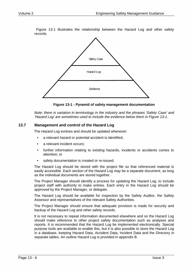
Volume 2 Engineering Safety Management Guidance
Page 13 - 6 Issue 3
Figure 13-1 illustrates the relationship between the Hazard Log and other safetyrecords.
Safety Case
Evidence
Hazard Log
Figure 13-1 - Pyramid of safety management documentation
Note: there is variation in terminology in the industry and the phrases ‘Safety Case’ and‘Hazard Log’ are sometimes used to include the evidence below them in Figure 13-1.
13.7 Management and control of the Hazard Log
The Hazard Log evolves and should be updated whenever:
• a relevant hazard or potential accident is identified;
• a relevant incident occurs;
• further information relating to existing hazards, incidents or accidents comes toattention; or
• safety documentation is created or re-issued.
The Hazard Log should be stored with the project file so that referenced material iseasily accessible. Each section of the Hazard Log may be a separate document, as longas the individual documents are stored together.
The Project Manager should identify a process for updating the Hazard Log, to includeproject staff with authority to make entries. Each entry in the Hazard Log should beapproved by the Project Manager, or delegate.
The Hazard Log should be available for inspection by the Safety Auditor, the SafetyAssessor and representatives of the relevant Safety Authorities.
The Project Manager should ensure that adequate provision is made for security andbackup of the Hazard Log and other safety records.
It is not necessary to repeat information documented elsewhere and so the Hazard Logshould make reference to other project safety documentation such as analyses andreports. It is recommended that the Hazard Log be implemented electronically. Specialpurpose tools are available to enable this, but it is also possible to store the Hazard Login a database, keeping Hazard Data, Accident Data, Incident Data and the Directory inseparate tables. An outline Hazard Log is provided in appendix B.
Configuration Management, Documentation and Records Chapter 13
Issue 3 Page 13 - 7
13.8 Related guidance
Chapter 8 provides guidance on assessing and mitigating any safety implications ofchanges.
Safety Audits and Assessments of safety documentation are described in chapter 14.
Appendix B provides an outline Hazard Log.
Appendix C provides checklists for updating the Hazard Log.

Volume 2 Engineering Safety Management Guidance
Page 13 - 8 Issue 3
This page left intentionally blank
Independent Professional Review Chapter 14
Issue 3 Page 14 - 1
Chapter 14
Independent Professional Review
ESM activities you carry out must be reviewed by professionals who are not involved inthe activities concerned.
14.1 Guidance from volume 1
These reviews are normally structured as a series of safety audits and safetyassessments. They assure that the work has been carried out safely and provideevidence to support the safety case. How often and how thoroughly each type of reviewis carried out, and the degree of independence of the reviewer, will depend on theproject. They will depend on the amount of risk and novelty and on how complicated theproject is.
14.2 Background
Review of safety-related projects by professionals independent of the work is animportant contribution to the confidence in the safety of the change being made to therailway.
We divide independent professional review into two activities:
• Safety Audits focus on the ESM processes being used and check that they areadequate and are being followed.
• Safety Assessments focus on the product of the project and check that the riskassociated with the system being developed is (or will be) reduced to an adequatelevel.
In practice there is overlap between the two.
There is variation in terminology and practice in this area. Some practitioners divide thetopic of independent professional review up differently and use the phrases ‘SafetyAudit’ and ‘Safety Assessment’ with different meanings. For example, a distinction issometimes drawn between technical assessment of engineering design and processassessment of safety management activities. You may need to refer to the guidanceunder both the audit and assessment headings even if the activity that you are asked tocommission or perform is described as one or the other type of review.
This chapter describes these two types of review and the documentation that is requiredby them. It also discusses how to go about commissioning a review, what the reviewsshould be checking for, and how the results should be used. Outlines and checklists areprovided in appendices B and C, respectively.
Volume 2 Engineering Safety Management Guidance
Page 14 - 2 Issue 3
This chapter is written for Project Managers who will need to commission reviews andinterpret the results, and the auditors and assessors who will be performing them.
14.3 Safety Audits and Assessments
14.3.1 Safety Audits
Safety Audits are intended to check that the ESM of a project is adequate and has beencarried out in conformance with the Safety Plan. If there is no Safety Plan, one shouldbe written before a Safety Audit is carried out.
The primary output of an audit is a Safety Audit Report. This report should include: ajudgement on the extent of the project’s compliance with the Safety Plan; a judgementon the adequacy of the Safety Plan; and recommendations for action to comply with thePlan or to improve it.
A Safety Audit should consider:
• work since the previous audit (all work so far if first audit);
• plans for the next stage;
• recommendations of the previous audit.
14.3.2 Safety Assessments
Safety Assessment is the process of forming a judgement as to whether or not the riskassociated with the system being developed is (or will be) reduced to an adequate level.
The safety requirements for the system are central to a Safety Assessment. Theassessor should review the Safety Requirements Specification to assess whether it issufficient to control risk and review the system to assess whether or not it meets or willmeet the Safety Requirements Specification.
Safety Assessment involves the use of design analysis, auditing techniques andpractical assessment by competent and experienced persons.
The assessor should also review the processes and organisation employed on theproject. This aspect of the assessment is easier if the results of a recent Safety Auditare available. If a Safety Audit has not been carried out on the project recently enoughthat its conclusions are still valid, then one should be commissioned before a SafetyAssessment, to ensure that the documentation to be assessed has been producedunder a correctly applied Safety Plan. If the audit results are unsatisfactory then theassessment may be postponed until corrective action has been taken.
The result of a Safety Assessment is a Safety Assessment Report. This report shouldinclude an assessment on whether or not the risk associated with the system beingdeveloped is (or will be) reduced to an adequate level and recommendations forcorrective action if necessary.
If the risk is not assessed as acceptable then the system may need to be re-assessedafter corrective action is taken.
14.4 Commissioning a Safety Audit or Assessment
In general the frequency and depth of each type of review and the level of independenceof the reviewer (the Safety Auditor or Safety Assessor) will depend on the complexityand level of risk presented by the project.
Independent Professional Review Chapter 14
Issue 3 Page 14 - 3
Typically, Safety Audits and Assessments of the simplest and lowest risk projects shouldnot take more than about a day of effort from a single auditor or assessor. Safety Auditsof the most complex and highest risk projects may involve much more effort from anindependent organisation.
Audits and assessments should be commissioned at the points defined in the SafetyPlan (see chapter 12). The Project Manager or Safety Authority may commissionadditional audits or assessments.
Whoever commissions an audit or assessment should write a Safety Audit/AssessmentRemit. This should record the requirements of the Audit or Assessment and all therelevant details, including:
1 the project title and reference;
2 the name of the Safety Auditor/Assessor, their qualifications and experience, andtheir level of independence;
3 references to previous audits and assessments;
4 audit or assessment requirements defining:
a) the scope of the audit/assessment which may be limited in extent (forinstance, to a part of the system) or in time (for instance, to changes since thelast release);
b) the purpose of the audit/assessment (for instance, to support a submission forsafety approval);
c) the basis of the audit/assessment. For an audit this will define the documentsthat the project will be audited against (normally the Safety Plan and thedocuments that it references). For an assessment this should specify the legalframework (for instance, the ALARP principle in the UK) and the ESMframework (for instance, the Yellow Book) within which the project is beingrun; and
d) any previous assessments or audits whose results may be assumed in theperformance of the current audit/assessment.
The remit should be agreed and signed by the Project Manager and the SafetyAuditor/Assessor. An outline for a Safety Audit/Assessment remit is provided inappendix B and an example generic Safety Assessment remit is provided in appendix D.
14.4.1 Independence
The Safety Auditor/Assessor should be independent of the project. Whoevercommissions an audit or assessment should decide the level of independence. Thefollowing paragraphs provide guidance only.
The level of independence should be dependent primarily on the level of risk presentedby the project (for electronic systems this is indicated by the Safety Integrity Level (SIL)of the system or equipment being developed. SILs are discussed in chapter 9.)
Table 14-1 provides guidance (derived from IEC 61508 [F.14]) on the level ofindependence appropriate at each SIL. Note that ‘HR’ indicates Highly Recommended,‘NR’ indicates Not Recommended, and ‘-’ indicates no recommendation for or against;however, a lower level of independence may be chosen by agreement with the SafetyAuthority. For the highest risk projects the Safety Auditor or Assessor should work for anindependent organisation. For the lowest risk projects they may be organisationallyclose to the project, but should not be working on the project.
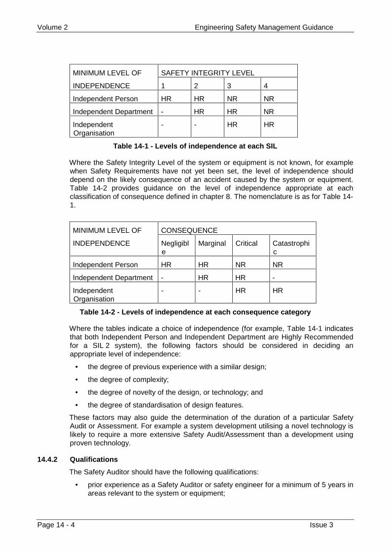
Volume 2 Engineering Safety Management Guidance
Page 14 - 4 Issue 3
MINIMUM LEVEL OF SAFETY INTEGRITY LEVEL
INDEPENDENCE 1 2 3 4
Independent Person HR HR NR NR
Independent Department - HR HR NR
IndependentOrganisation
- - HR HR
Table 14-1 - Levels of independence at each SIL
Where the Safety Integrity Level of the system or equipment is not known, for examplewhen Safety Requirements have not yet been set, the level of independence shoulddepend on the likely consequence of an accident caused by the system or equipment.Table 14-2 provides guidance on the level of independence appropriate at eachclassification of consequence defined in chapter 8. The nomenclature is as for Table 14-1.
MINIMUM LEVEL OF CONSEQUENCE
INDEPENDENCE Negligible
Marginal Critical Catastrophic
Independent Person HR HR NR NR
Independent Department - HR HR -
IndependentOrganisation
- - HR HR
Table 14-2 - Levels of independence at each consequence category
Where the tables indicate a choice of independence (for example, Table 14-1 indicatesthat both Independent Person and Independent Department are Highly Recommendedfor a SIL 2 system), the following factors should be considered in deciding anappropriate level of independence:
• the degree of previous experience with a similar design;
• the degree of complexity;
• the degree of novelty of the design, or technology; and
• the degree of standardisation of design features.
These factors may also guide the determination of the duration of a particular SafetyAudit or Assessment. For example a system development utilising a novel technology islikely to require a more extensive Safety Audit/Assessment than a development usingproven technology.
14.4.2 Qualifications
The Safety Auditor should have the following qualifications:
• prior experience as a Safety Auditor or safety engineer for a minimum of 5 years inareas relevant to the system or equipment;
Independent Professional Review Chapter 14
Issue 3 Page 14 - 5
• experience of process assurance (for instance quality or safety audits);
• familiarity with external safety standards and procedures;
• familiarity with the legal and safety regulatory framework within which UK railwaysoperate;
• training in ESM.
The Safety Assessor should have the following qualifications:
• Chartered Engineer status in an engineering or scientific discipline relevant to thesystem or equipment;
• prior experience as a Safety Assessor or safety engineer for a minimum of 5 yearsin areas relevant to the system or equipment;
• demonstrable application domain experience;
• experience of process assurance (for instance quality or safety audits);
• familiarity with external safety standards and procedures;
• familiarity with the legal and safety regulatory framework within which UK railwaysoperate;
• training in ESM.
The following factors should be taken into account in establishing the relevance ofexperience:
• purpose of the project;
• technology and methods used;
• Safety Integrity Level and accident potential.
Where a Safety Assessment is carried out by a team, the team as a whole shouldexhibit the necessary domain and process assurance experience and the lead assessoras an individual should possess the other qualifications.
It is a good idea to retain the same Safety Auditor and Assessor throughout the project.
14.4.3 Depth of review
Engineering judgement should be applied to determine the degree to which theguidance above need be applied on a particular project. For the simplest and lowest riskprojects, for example:
• The requirements for Safety Auditor or Assessor qualifications may be relaxed.
• Audit or Assessment activities listed in section 14.5 may be limited to interviewingpersonnel and reviewing documentation.
• The detail of the audit checklist or assessment checklist may be reduced.
• The Safety Audit or Assessment Report described in appendix B shouldconcentrate on the findings and recommendations of the Safety Audit; therequirements and audit details sections should be brief.
The Safety Audit or Assessment Report should record and justify significant changes tothe processes defined in section 14.5.
Volume 2 Engineering Safety Management Guidance
Page 14 - 6 Issue 3
The Safety Assessment Report should concentrate on the findings andrecommendations of the Safety Assessment; the requirements and assessment detailssections should be brief.
14.4.4 Roles and responsibilities
The Project Manager is responsible for:
• initiating Safety Audits or Assessments when scheduled in the Safety Plan;
• preparing the Safety Audit/Assessment requirements;
• appointing an auditor or assessor acceptable to the Safety Authority;
• ensuring the auditor/assessor has appropriate access to personnel, the HazardLog and other documents;
• commenting on the Safety Audit or Assessment Report;
• formulating any necessary improvement actions in response to the report’srecommendations;
• passing on any parts of the report which materially affect the Safety Assessmentprocess to the Safety Authority; and
• implementing the improvement actions.
The Safety Auditor is responsible for:
• planning the Safety Audit;
• carrying out the Safety Audit; and
• preparing a Safety Audit Report.
The Safety Assessor is responsible for:
• planning the Safety Assessment;
• carrying out the Safety Assessment; and
• preparing a Safety Assessment Report.
14.5 The Safety Audit and Assessment processes
14.5.1 Performing a Safety Audit
The Safety Audit process consists of three activities:
1 Planning the Safety Audit and producing an audit schedule;
2 Executing the audit schedule;
3 Preparing the Safety Audit Report.
The audit schedule should be produced by the Safety Auditor and endorsed by theProject Manager. Planned activities may be modified to reflect any required change ofemphasis based on information gathered during the audit, although it is not alwaysnecessary for the audit schedule to be re-issued.
The schedule should be brief and should include:
• A statement of the audit requirements, according to the Audit Remit, but takinginto account any agreed amendments;
• Identification of audit activities to be undertaken;
Independent Professional Review Chapter 14
Issue 3 Page 14 - 7
• Identification of individuals to be interviewed;
• Identification of documentation to be examined;
• Audit time-scales;
• Safety Audit Report distribution and the expected date of issue.
During audit planning the Safety Auditor should become familiar with:
• The Safety Plan;
• The findings and recommendations of any previous Safety Audits;
• Details of progress since the last Safety Audit (if any);
• Details of the next stage of work;
• Details of project staffing.
This familiarisation should be achieved through a briefing with the Project Manager, andpreliminary inspection of project documents.
The audit activities should include:
• Interviews with project personnel;
• Examination of project documents;
• Observation of normal working practices, project activities and conditions;
• Demonstrations arranged at the auditor’s request.
The evidence for compliance or non-compliance with the Safety Plan that arises fromthese activities should be noted for inclusion in the Safety Audit Report.
14.5.2 What to look for in a Safety Audit
The Safety Audit is a check for adequacy of the Safety Plan and compliance against theSafety Plan. The audit should check therefore, that the planned project activities arebeing or have been carried out and in the manner and to the standards prescribed in theSafety Plan.
The Safety Auditor should derive an audit checklist for the investigation, to guide theenquiries and to record results and evidence. An outline for the checklist and anexample are included in appendix D. The format of the checklist should mirror that of theSafety Plan and associated ESM activities such that each aspect of these is directlyaddressed by a question in the checklist. It should be in the form of a checklist withquestions that may be answered ‘Yes’ or ‘No’.
The checklist should be drawn up to meet the audit requirements, using the documentsreferenced in the Remit. The auditor should note anything that he or she finds that isobjectively wrong, whether or not it relates to a checklist item. Note that the checklist isan aid for the Safety Auditor – it should not be completed by the project personnel.
The audit should check that any standards or procedures called up by the Safety Planhave been correctly applied. It should also check that there is traceability from theSafety Plan to project activities that implement it.
The audit should look for documentary evidence that every safety activity has beencarried out. The answer to each question on the audit checklist should be supported bydocumentary evidence.
Volume 2 Engineering Safety Management Guidance
Page 14 - 8 Issue 3
All instances where there is no evidence of compliance should be documented in theSafety Audit Report along with a recommendation for remedial action. Each non-compliance should be identified in terms of the specific requirements of the Safety Plan.The auditor should classify each finding. A suggested classification is shown in section14.6.
Audit findings should be documented on the checklist. Where evidence of compliance islacking, further in-depth examination should be carried out.
Information gathered through interviews should, where possible, be verified by acquiringthe same information from other independent sources.
14.5.3 Performing a Safety Assessment
The Safety Assessor should become familiar with:
• The Hazard Log;
• The Safety Plan;
• The Safety Requirements Specification;
• The findings and recommendations of any previous Safety Assessments or SafetyAudits;
• Details of progress since the last Safety Assessment;
• Details of the next stage of work.
This familiarisation should be achieved through a briefing with the Project Manager, andpreliminary inspection of project documents.
The Safety Assessor should prepare an assessment plan. The plan should be brief andshould include:
• A statement of the assessment requirements, according to the assessment remit,but taking into account any agreed amendments;
• Identification of any dependencies on the project or others, such as access toproject personnel or documents;
• Identification of the assessor or assessment team, including qualifications,experience and level of independence;
• Identification of individuals to be interviewed;
• Management arrangements for reporting findings and reviewing, endorsing anddistributing the Safety Assessment Report;
• Assessment time-scales, including the expected date of issue of the SafetyAssessment Report.
The assessment activities should include:
• Interviews with project personnel;
• Examination of project documents;
• Observation of normal working practices, project activities and conditions;
• Re-work of parts of the safety analysis work to check accuracy, concentrating onparticularly critical areas or where the assessor has reason to suspect a problem;
• Demonstrations arranged at the assessor’s request.
Independent Professional Review Chapter 14
Issue 3 Page 14 - 9
14.5.4 What to look for in a Safety Assessment
The primary objective in planning and carrying out a Safety Assessment is to make surethat you collect enough information to support a judgement on the acceptability of therisk. The following guidance may help in planning the assessment but you should alsoemploy your professional judgement and experience to tailor the guidance to theapplication in hand.
The assessment should examine the development or application process, review thedesign decisions taken by the project staff which have safety implications and verify thatthat risk has been reduced As Low As Reasonably Practicable (ALARP) and inaccordance with the Safety Requirements.
The Safety Assessor should derive an assessment checklist to guide the enquiries andto record results and evidence. Example checklists are presented in appendix D. Thechecklist should be drawn up to meet the assessment requirements, using thedocuments referenced in the remit. The assessor should note anything that he or shefinds that is objectively wrong, whether or not it relates to a checklist item. Note thatthese checklists are an aid for the Safety Assessor – they should not be completed bythe project personnel.
The assessment should not just focus on documents but should look at the processesand organisation behind them. The assessor should look for any shortcomings in theapproach to safety and make recommendations.
The assessment should pay particular attention to the Hazard Log, which should providetraceability from the Safety Requirements to documentation supporting engineeringactivities on the project.
The assessment should check that there is documentary evidence for every safetyactivity carried out. The answer to each question on the assessment checklist should besupported by documentary evidence.
If operational data is available, the assessor should analyse it for evidence of:
• hazards not previously identified;
• risks incorrectly classified;
• Safety Requirements not met;
• changes in the pattern of operational use.
The Safety Assessor may call for the repetition of any formal tests and the ProjectManager should arrange for these to be run under the Safety Assessor’s supervision.
If a previous assessment has been carried out and has not been invalidated by changesto the design or new knowledge then the assessor need not repeat the analyses carriedout there and should concentrate instead on analysing new and changed material.
If the assessment detects a flaw in the ESM programme then the assessor shouldreview the ESM documentation to establish the most likely root cause. The assessorshould consider whether this throws doubt on any other aspects of the ESM, and theassessment recommendations should include measures to restore confidence inaffected areas as well as addressing the defects detected.
Information gathered through interviews should, where possible, be verified by checkingthe same information from other independent sources.
Volume 2 Engineering Safety Management Guidance
Page 14 - 10 Issue 3
14.5.5 Findings
Findings should be communicated to the Project Manager and project team as soon aspossible. You should not wait until the Safety Audit/Assessment Report is prepared anddistributed.
This may conveniently be done with a simple three-part form:
• Part 1: Finding
• Part 2: Project response
• Part 3: Assessor’s/auditor’s comments on project response.
14.6 Audit/assessment findings
All auditor’s and assessor’s findings should be uniquely numbered and classified. Thefollowing classification scheme is widely used and is recommended. Categories 1 to 3should be used when the audit/assessment is supporting a request for safety approval.
Category 1 - Issue is sufficiently important to require (substantial) resolution, prior torecommending that the change may become operational. (Alternatively a specific controlmeasure may be implemented to control the risk in the short term.)
Category 2 - Issue is sufficiently important to require resolution within 3-6 months, butthe change may become operational in the interim (possibly with a protective controlmeasure.)
Category 3 - Issue is highlighted for incorporation into the Safety Case at the nextperiodic review, but no action is required separately.
Where there are a large number of lower category issues, the auditor/assessor shouldconsider whether, in totality, they represent sufficient residual risk that they in effectequate to one or more higher category issues (that is, that they would warrant theimposition of any additional mitigating control measures). In these circumstances, itshould be considered whether these outstanding issues relate to an overall lack of rigouror quality in the document that has been reviewed.
The Project Manager should review and endorse the Safety Audit/Assessment Report,and formulate improvement actions in response to the Safety Auditor’s/Assessor’sfindings. It may be appropriate to record any faults discovered in the system itself in theData Recording and Corrective Actions System (see chapter 12). The Project Managershould implement these improvement actions.
The Safety Assessment Report may include recommendations for action by the relevantSafety Authorities, for example reviewing the approval of systems or equipment inservice. If the report contains any such recommendations the Project Manager shouldpass that part of the report to the relevant Safety Authorities, who should then considerany such recommendations and implement promptly any necessary actions.
Independent Professional Review Chapter 14
Issue 3 Page 14 - 11
14.7 Related guidance
Chapter 8 provides guidance on risk assessment
Chapter 9 provides guidance on the safety requirements specification and SafetyIntegrity Levels.
Chapter 12 provides guidance on safety planning.
Appendix B provides outline audit and assessment remits and reports.
Appendix D provides an example assessment remit and example audit and assessmentchecklists.
Volume 2 Engineering Safety Management Guidance
Page 14 - 12 Issue 3
This page left intentionally blank

Appendices
Glossary Appendix A
Issue 3 Page A - 1
Appendix A
Glossary
This glossary defines the specialised terms used in this volume. Volume 1 uses simplerand more restricted terminology which is introduced in the volume itself.
We have tried to minimise inconsistencies between the terminology used in this volumeand that used in other principal sources of information for railway ESM. However it is notpossible to eliminate inconsistency entirely because there is variation in usage betweenthese other sources.
accident An unintended event or series of events thatresults in harm.
Note: this broadly corresponds to a ‘hazardousevent’ in the Railtrack S&SD Safety Risk Model.
accident likelihood The likelihood of an accident occurring. May beexpressed as numeric probability or frequencyor as a category.
accident sequence A potential progression of events that result inan accident.
Accident Sequence Analysis Derivation of the sequence of events which leadfrom hazard to accident.
accident severity A measure of amount of harm. May beexpressed as a financial value or as a category.
accident trigger A condition or event which is required for ahazard to give rise to an accident.
Note: this broadly corresponds to a ‘precursor(consequence)’ in the Railtrack S&SD SafetyRisk Model.
ALARP principle The principle that no risk in the tolerability regioncan be accepted unless reduced ‘As Low AsReasonably Practicable’.
See chapter 8.
apportioned risk benchmark A target for the average individual probability offatality per annum experienced by a group,arising from a given aspect of the railway’soperations
Volume 2 Engineering Safety Management Guidance
Page A - 2 Issue 3
authorisation The formal permission to introduce a system,product or other change into the railway withinspecified application constraints.
barrier (In the context of risk assessment) anythingwhich may act to prevent a hazard giving rise toan accident. Barriers may be physical,procedural or circumstantial
broadly acceptable risk A risk which is generally acceptable withoutfurther reduction.
causal factor Any event, state or other factor which mightcontribute to the occurrence of a hazard.
code of practice A statement of best practice whose use is notmandated by the issuing authority.
compliance A demonstration that a characteristic or propertyof a system, product or other change satisfiesthe stated requirements.
consequence The results arising from the addition of energy,or exposure, to a hazard. These may rangefrom benign results to accidents. Severalconsequences may be associated with ahazard.
Data Recording andCorrective Action System(DRACAS)
A closed-loop system for ensuring that failuresand other incidents are thoroughly analysed andthat any necessary corrective action, particularlyif it affects safety, is identified and carriedthrough.
See appendix E.
endorse Approve a document, piece of equipment, etc,as being fit for purpose.
Engineering SafetyManagement (ESM)
The activities involved in making a system,product or other change safe and showing that itis safe.
Note: despite the name, ESM is not performedby engineers alone and is applicable to changesthat involve more than just engineering.
Engineering SafetyManagement System
A systematic and documented approach toESM.
error A deviation from the intended design whichcould result in unintended system behaviour orfailure.
event A significant happening that may originate in thesystem, product or other change or its domain.
Event Tree Analysis A method of illustrating the intermediate andfinal outcomes which may arise after theoccurrence of a selected initial event.
failure A deviation from the specified performance of asystem, product or other change. A failure is theconsequence of a fault or error.
Glossary Appendix A
Issue 3 Page A - 3
fault A fault is a defect in a system, product or otherchange which may cause an error.
Fault Tree Analysis A method for representing the logicalcombinations of various states which lead to aparticular outcome (top event).
See appendix E.
FMEA Failure Mode and Effects Analysis. A processfor hazard identification where all known failuremodes of components or features of a system,are considered in turn and undesired outcomesare noted.
See appendix E.
FMECA Failure Mode, Effects and Criticality Analysis. Anextension to FMEA in which the criticality of theeffects is also assessed.
See appendix E.
group Group of people exposed to railway operations.Such as: employees (trackside staff),passengers and the public.
handover Used to mean the process of handing over partof the railway to the infrastructure controller sothat it can put into or back into service.
Note: this process is referred to as ‘Handback’within Railtrack.
hazard A condition that could lead to an accident. Apotential source of harm. A hazard should bereferred to a system or product.
Note: this broadly corresponds to a ‘precursor(cause)’ in the Railtrack S&SD Safety RiskModel
Hazard Analysis Report A document identifying the potential hazardsand accidents of a system, product or otherchange and analysing the causal factors of thehazards.
Hazard Log A document which records details of hazardsand potential accidents identified during safetyanalyses of a system, product or other changeand logs safety documentation produced.
HAZOP Hazard and Operability Study. A study carriedout by application of guide words to identify alldeviations from the design intent with undesiredeffects for safety or operability.
See DEF STAN 00-58 [F.19]
incident Unplanned, uncontrolled event, which underdifferent circumstances could have resulted inan accident.
Volume 2 Engineering Safety Management Guidance
Page A - 4 Issue 3
individual risk The individual risk experienced by a person, istheir probability of fatality per unit time, usuallyper year, as a result of a hazard in a specifiedsystem.
intolerable risk A risk which cannot be accepted and must bereduced.
loss A measure of harm to people.
potential equivalent fatality A convention for aggregating harm to people byregarding major and minor injuries as beingequivalent to a certain fraction of a fatality.
Project Manager The person in overall control of a project. Alsoresponsible for the safety of the productsproduced during the project, although maydelegate this role to a Project Safety Manager(but remains accountable).
Project Safety Manager The person responsible for safety on a projectand for producing all safety-relateddocumentation.
railway operator An infrastructure controller, train operator orstation operator
random hardware failure Failures resulting from one or more of thepossible degradation mechanisms in thehardware. These failures occur at predictablerates but at unpredictable (that is random)times.
reliability The probability that an item can perform arequired function under given conditions for agiven time interval.
remit Terms of reference, in particular for a SafetyAudit or Safety Assessment
risk Combination of the likelihood of occurrence ofharm and the severity of that harm.
risk analysis A structured process which identifies both thelikelihood and extent of adverse consequencesarising from a given activity of facility.
risk assessment The combination of risk analysis and riskevaluation.
risk assessment report A document containing an analysis of the risksof accidents occurring.
risk benchmark A target for the average individual probability offatality per annum experienced by a group, forall the railway’s operations
risk classification A scheme to classify risk according to likelihoodof harm occurring and the severity of the harm.
risk evaluation The appraisal of the significance of a givenquantitative (or, where applicable, qualitative)measure of risk.
Glossary Appendix A
Issue 3 Page A - 5
safety Freedom from unacceptable risk.
Criteria for accepting risk are described inchapter 8.
safety analysis A general term encompassing identifyinghazards, analysing hazards and assessing risk.
safety approval The process by which a Safety Authority grantsits approval for a proposed change to therailway to proceed.
Safety Assessment The process of analysis to determine whether asystem, product or other change to the railwayhas met its Safety Requirements and that theSafety Requirements are adequate.
Safety Assessment Remit A form capturing a request for a SafetyAssessment and the terms of reference.
Safety Assessment Report A report on the activity carried out to check thatthe Safety Requirements are being met on aproject.
Safety Assessor The person who carries out SafetyAssessments.
Safety Audit An activity to check and ensure that a project isbeing run according to its Safety Plan. It will alsoaddress the adequacy of the Safety Plan.
Safety Audit Remit A form capturing a request for a Safety Auditand the terms of reference.
Safety Audit Report A report on the activity carried out to check thatthe Safety Plan and safety managementprocedures are being carried out on a project.
Safety Auditor The person appointed to carry out Safety Auditson a project.
Safety Authority The body responsible for certifying that thesafety-related system, product or other changeis safe, fit for service and complies with allstatutory and regulatory requirements.
Safety Case A formal presentation of evidence, argumentsand assumptions aimed at providing assurancethat a system, product or other change to therailway has met its Safety Requirements andthat the Safety Requirements are adequate.
Early issues may present analysis andassessment information, plans andrequirements.
Safety Certificate A certificate authorising system, product orother change for use. Usually refers to third-party equipment.
safety control A quality control with the potential to revealhazardous faults.
Volume 2 Engineering Safety Management Guidance
Page A - 6 Issue 3
Safety Engineering The application of technical methods to ensureachievement of the Safety Requirements.
Safety Integrity The likelihood of a system, product or otherchange satisfactorily performing the requiredsafety functions under all the stated conditionswithin a stated period of time.
Safety Integrity Level (SIL) Discrete level (1 out of a possible 5) forspecifying the safety integrity requirements ofthe safety functions to be allocated to a system,product or component, where safety integritylevel 4 has the highest level of safety integrityand safety integrity level 0 is reserved forfunctions which are not relied upon at all tocontrol risk.
safety lifecycle The additional series of ESM activities carriedout in conjunction with the system lifecycle forsafety-related systems.
Safety Plan A document detailing the activities to be carriedout, and responsibilities of people to ensure thesafety of work being carried out.
Safety Planning An activity to define the activities to be carriedout and the staff responsibilities to be assignedto ensure the safety of work to be carried out.Results in the preparation of a Safety Plan.
Safety Records Log A reference to every safety document producedand used by a project.
safety-related An item is safety-related if any of its features orcapabilities have the potential to contribute to orprevent an accident.
Safety RequirementsSpecification
Specification of the requirements that a product,system or change to the railway must satisfy inorder to be judged safe.
safety standard A document which establishes criteria orrequirements by which the safety of products orprocesses may be assessed objectively.
safety value The monetary value of reductions in safetylosses likely to be achieved by implementationof a risk mitigation option.
severity See accident severity
standard An authorised document, including specification,procedure, instruction, directive, rule orregulation, which sets mandatory requirementsfor use in service.
system supplier Any organisation supplying systems or productsto be used on the railway.
Glossary Appendix A
Issue 3 Page A - 7
systematic failure Failure related in a deterministic way to a certaincause, which can only be eliminated by amodification of the design or of themanufacturing process, operational procedures,documentation or other relevant factors.
tolerability region A region of risk which is neither high enough tobe unacceptable nor low enough to be broadlyacceptable. Risks in this region must bereduced ALARP (see ALARP principle)
upper limit of tolerability A measure of the average individual risk offatality per annum, defined for each group, andrepresenting the boundary between tolerableand intolerable risk for the group.
Value of Preventing aFatality (VPF)
A defined monetary figure which is used toindicate what it is regarded as reasonablypracticable to spend in the expectation ofpreventing a single fatality.
Volume 2 Engineering Safety Management Guidance
Page A - 8 Issue 3
This page left intentionally blank
Document Outlines Appendix B
Issue 3 Page B - 1
Appendix B
Document Outlines
This appendix provides suggested document outlines for the following ESM documents:
1 Safety Plan (see chapter 12)
2 Hazard Log (see chapter 13)
3 Safety Assessment and Audit Remits (see chapter 14)
4 Safety Assessment and Audit Reports (see chapter 14)
The outlines do not show administrative document sections such as change history,terminology and referenced documents sections which should be added according toyour own document standards.
Volume 2 Engineering Safety Management Guidance
Page B - 2 Issue 3
B.1 Outline Safety Plan
The scope and coverage of this outline is designed to be consistent with the CENELECstandard prEN 50126 [F.8]. This is one of a group of European standards for safetywithin the rail industry. prEN 50126 defines a process for the management of Reliability,Availability, Maintainability, and Safety (RAMS). The letters in square brackets refer tothe CENELEC requirement detailed in clause 6.2.3.4 of prEN 50126.
The recommended structure for the Safety Plan is as follows:
Introduction Aims and objectives
(describe the aims and objectives of this Safety Plan forreaders unfamiliar with ESM or this project)
Scope [b]
(include the lifecycle phases this Safety Plan addresses)
Structure
(describe the structure of the plan)
Backgroundandrequirements
Summary of system [c, m]
(include, or refer to, a description of the system, includinginterfaces to other related programmes)
Outline of project [a]
(a brief description of the conduct of the project, to include astatement of compliance with the organisation’s safety policy,or a justification of an alternative approach)
Safety requirements [f]
(a summary of the safety requirements or a reference tothem and a description of the process by which the safetyrequirements were established and maintained; where noneare available the Safety Plan should indicate how and whenthe Safety Requirements are to be determined)
Risk assessment criteria [f]
(a brief description of the criteria used to derive risktolerability targets for the system)
Assumptions and constraints [n]
(list any assumptions or constraints on the system or theproject)
(cont.)
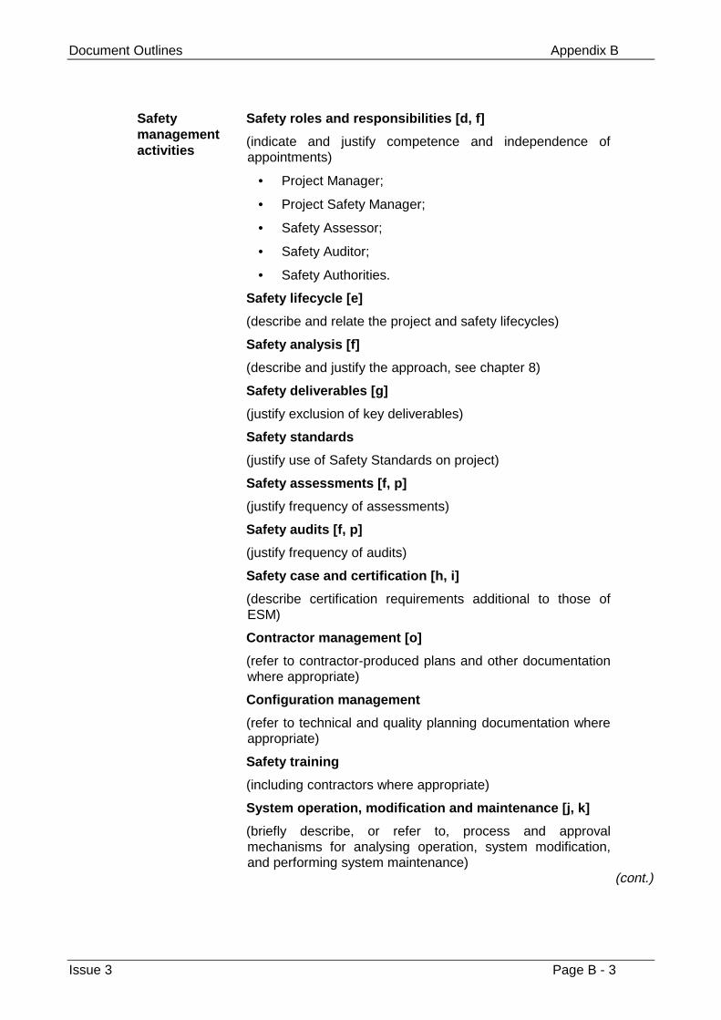
Document Outlines Appendix B
Issue 3 Page B - 3
Safetymanagementactivities
Safety roles and responsibilities [d, f]
(indicate and justify competence and independence ofappointments)
• Project Manager;
• Project Safety Manager;
• Safety Assessor;
• Safety Auditor;
• Safety Authorities.
Safety lifecycle [e]
(describe and relate the project and safety lifecycles)
Safety analysis [f]
(describe and justify the approach, see chapter 8)
Safety deliverables [g]
(justify exclusion of key deliverables)
Safety standards
(justify use of Safety Standards on project)
Safety assessments [f, p]
(justify frequency of assessments)
Safety audits [f, p]
(justify frequency of audits)
Safety case and certification [h, i]
(describe certification requirements additional to those ofESM)
Contractor management [o]
(refer to contractor-produced plans and other documentationwhere appropriate)
Configuration management
(refer to technical and quality planning documentation whereappropriate)
Safety training
(including contractors where appropriate)
System operation, modification and maintenance [j, k]
(briefly describe, or refer to, process and approvalmechanisms for analysing operation, system modification,and performing system maintenance)
(cont.)
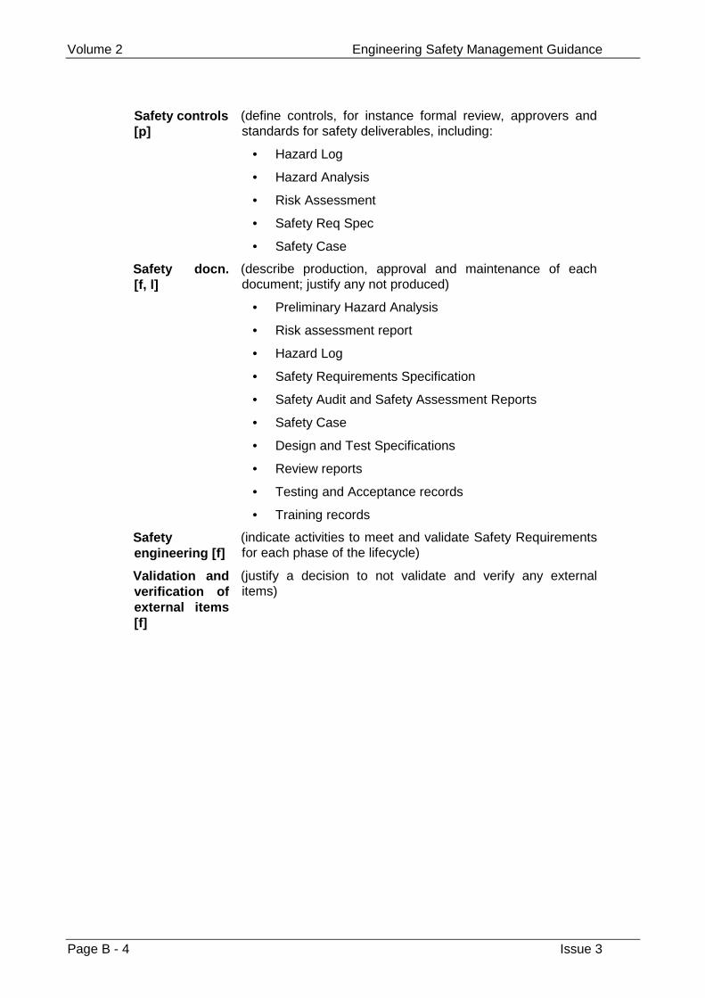
Volume 2 Engineering Safety Management Guidance
Page B - 4 Issue 3
Safety controls[p]
(define controls, for instance formal review, approvers andstandards for safety deliverables, including:
• Hazard Log
• Hazard Analysis
• Risk Assessment
• Safety Req Spec
• Safety Case
Safety docn.[f, l]
(describe production, approval and maintenance of eachdocument; justify any not produced)
• Preliminary Hazard Analysis
• Risk assessment report
• Hazard Log
• Safety Requirements Specification
• Safety Audit and Safety Assessment Reports
• Safety Case
• Design and Test Specifications
• Review reports
• Testing and Acceptance records
• Training records
Safetyengineering [f]
(indicate activities to meet and validate Safety Requirementsfor each phase of the lifecycle)
Validation andverification ofexternal items[f]
(justify a decision to not validate and verify any externalitems)
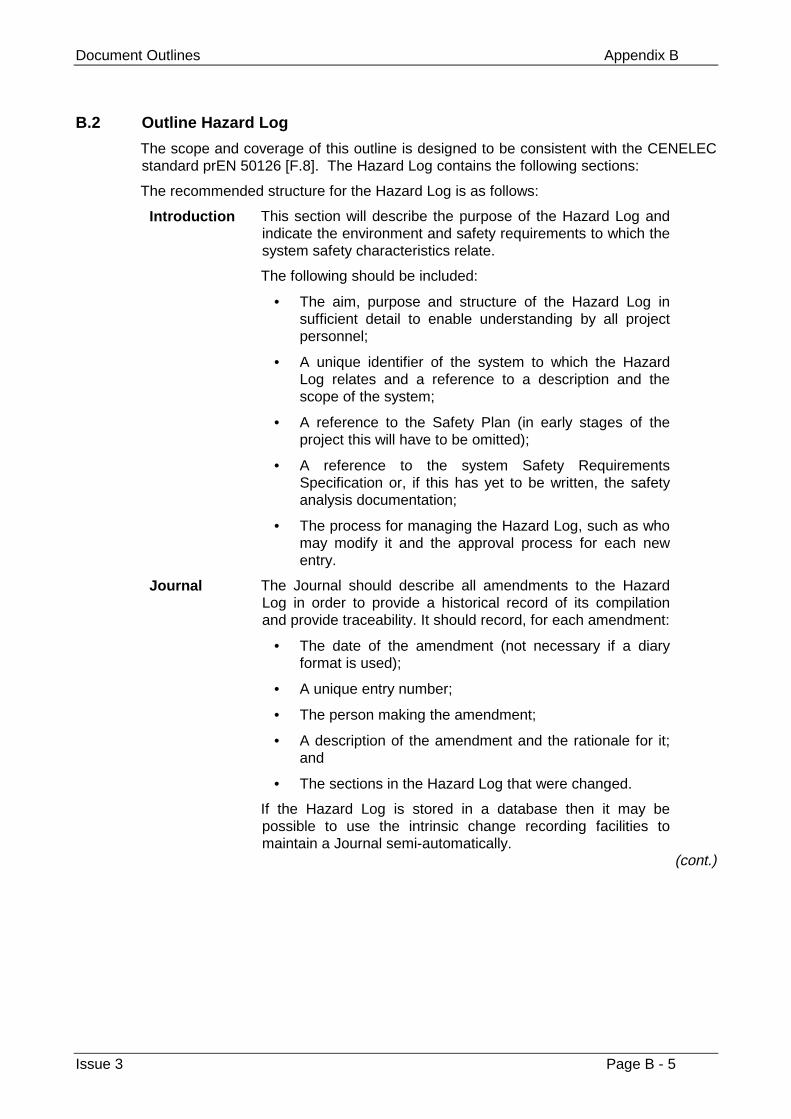
Document Outlines Appendix B
Issue 3 Page B - 5
B.2 Outline Hazard Log
The scope and coverage of this outline is designed to be consistent with the CENELECstandard prEN 50126 [F.8]. The Hazard Log contains the following sections:
The recommended structure for the Hazard Log is as follows:
Introduction This section will describe the purpose of the Hazard Log andindicate the environment and safety requirements to which thesystem safety characteristics relate.
The following should be included:
• The aim, purpose and structure of the Hazard Log insufficient detail to enable understanding by all projectpersonnel;
• A unique identifier of the system to which the HazardLog relates and a reference to a description and thescope of the system;
• A reference to the Safety Plan (in early stages of theproject this will have to be omitted);
• A reference to the system Safety RequirementsSpecification or, if this has yet to be written, the safetyanalysis documentation;
• The process for managing the Hazard Log, such as whomay modify it and the approval process for each newentry.
Journal The Journal should describe all amendments to the HazardLog in order to provide a historical record of its compilationand provide traceability. It should record, for each amendment:
• The date of the amendment (not necessary if a diaryformat is used);
• A unique entry number;
• The person making the amendment;
• A description of the amendment and the rationale for it;and
• The sections in the Hazard Log that were changed.
If the Hazard Log is stored in a database then it may bepossible to use the intrinsic change recording facilities tomaintain a Journal semi-automatically.
(cont.)
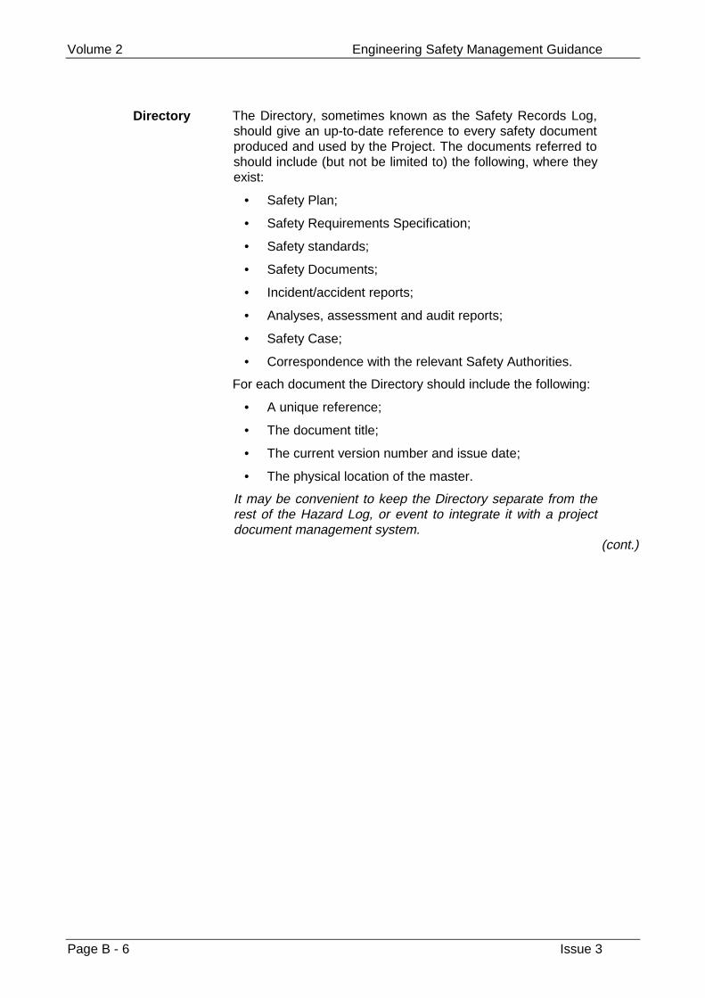
Volume 2 Engineering Safety Management Guidance
Page B - 6 Issue 3
Directory The Directory, sometimes known as the Safety Records Log,should give an up-to-date reference to every safety documentproduced and used by the Project. The documents referred toshould include (but not be limited to) the following, where theyexist:
• Safety Plan;
• Safety Requirements Specification;
• Safety standards;
• Safety Documents;
• Incident/accident reports;
• Analyses, assessment and audit reports;
• Safety Case;
• Correspondence with the relevant Safety Authorities.
For each document the Directory should include the following:
• A unique reference;
• The document title;
• The current version number and issue date;
• The physical location of the master.
It may be convenient to keep the Directory separate from therest of the Hazard Log, or event to integrate it with a projectdocument management system.
(cont.)
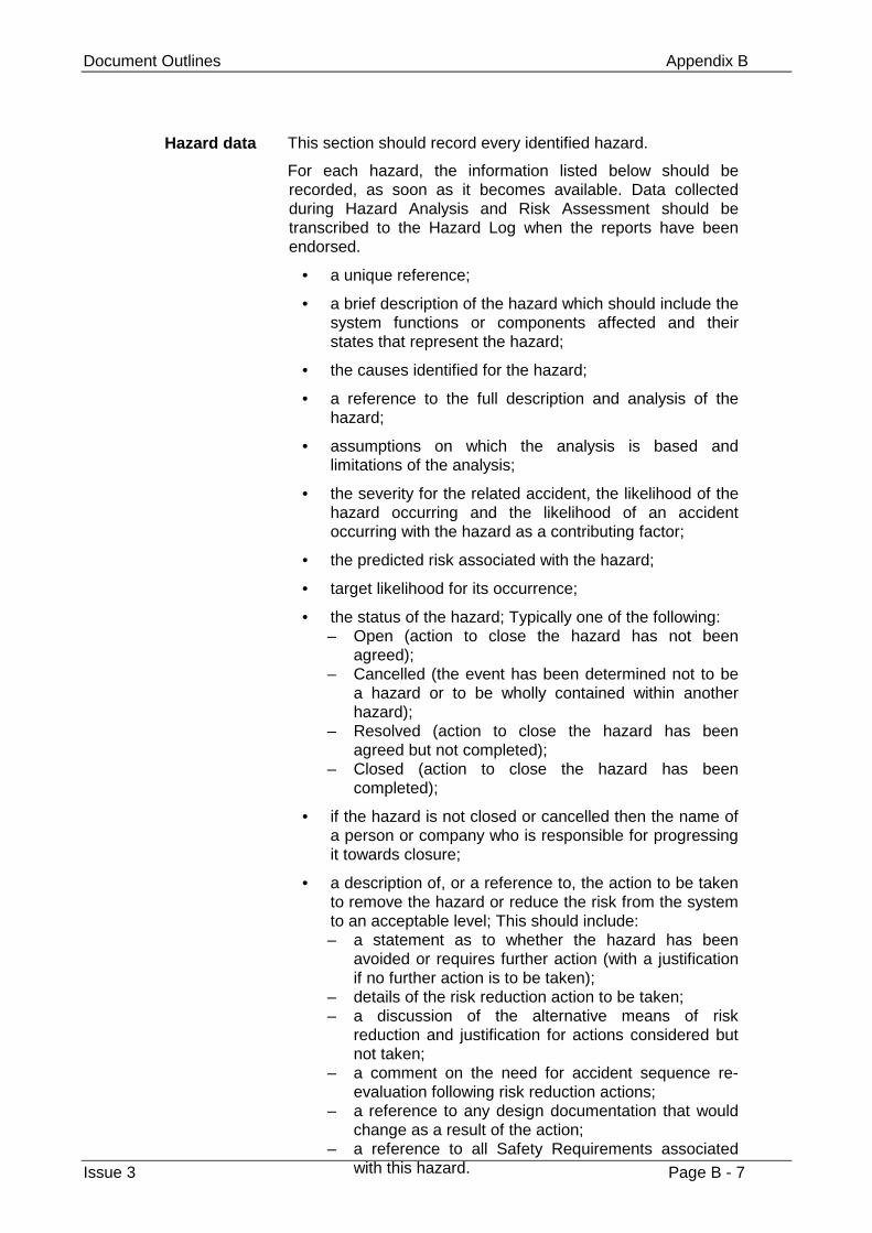
Document Outlines Appendix B
Issue 3 Page B - 7
Hazard data This section should record every identified hazard.
For each hazard, the information listed below should berecorded, as soon as it becomes available. Data collectedduring Hazard Analysis and Risk Assessment should betranscribed to the Hazard Log when the reports have beenendorsed.
• a unique reference;
• a brief description of the hazard which should include thesystem functions or components affected and theirstates that represent the hazard;
• the causes identified for the hazard;
• a reference to the full description and analysis of thehazard;
• assumptions on which the analysis is based andlimitations of the analysis;
• the severity for the related accident, the likelihood of thehazard occurring and the likelihood of an accidentoccurring with the hazard as a contributing factor;
• the predicted risk associated with the hazard;
• target likelihood for its occurrence;
• the status of the hazard; Typically one of the following:– Open (action to close the hazard has not been
agreed);– Cancelled (the event has been determined not to be
a hazard or to be wholly contained within anotherhazard);
– Resolved (action to close the hazard has beenagreed but not completed);
– Closed (action to close the hazard has beencompleted);
• if the hazard is not closed or cancelled then the name ofa person or company who is responsible for progressingit towards closure;
• a description of, or a reference to, the action to be takento remove the hazard or reduce the risk from the systemto an acceptable level; This should include:– a statement as to whether the hazard has been
avoided or requires further action (with a justificationif no further action is to be taken);
– details of the risk reduction action to be taken;– a discussion of the alternative means of risk
reduction and justification for actions considered butnot taken;
– a comment on the need for accident sequence re-evaluation following risk reduction actions;
– a reference to any design documentation that wouldchange as a result of the action;
– a reference to all Safety Requirements associatedwith this hazard.
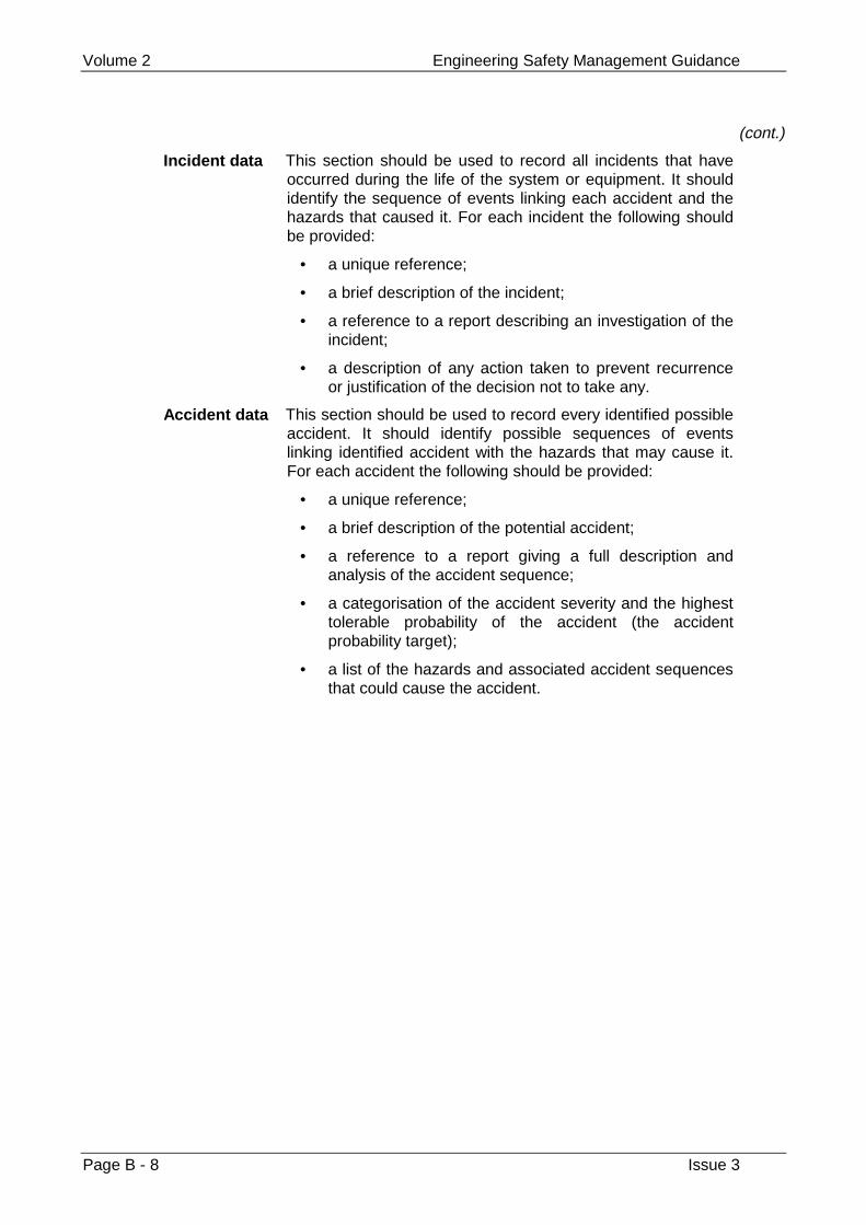
Volume 2 Engineering Safety Management Guidance
Page B - 8 Issue 3
(cont.)
Incident data This section should be used to record all incidents that haveoccurred during the life of the system or equipment. It shouldidentify the sequence of events linking each accident and thehazards that caused it. For each incident the following shouldbe provided:
• a unique reference;
• a brief description of the incident;
• a reference to a report describing an investigation of theincident;
• a description of any action taken to prevent recurrenceor justification of the decision not to take any.
Accident data This section should be used to record every identified possibleaccident. It should identify possible sequences of eventslinking identified accident with the hazards that may cause it.For each accident the following should be provided:
• a unique reference;
• a brief description of the potential accident;
• a reference to a report giving a full description andanalysis of the accident sequence;
• a categorisation of the accident severity and the highesttolerable probability of the accident (the accidentprobability target);
• a list of the hazards and associated accident sequencesthat could cause the accident.
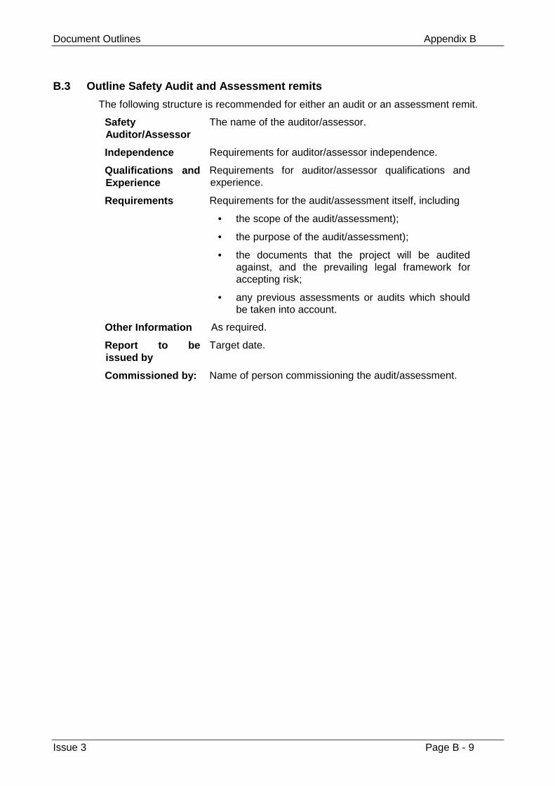
Document Outlines Appendix B
Issue 3 Page B - 9
B.3 Outline Safety Audit and Assessment remits
The following structure is recommended for either an audit or an assessment remit.
SafetyAuditor/Assessor
The name of the auditor/assessor.
Independence Requirements for auditor/assessor independence.
Qualifications andExperience
Requirements for auditor/assessor qualifications andexperience.
Requirements Requirements for the audit/assessment itself, including
• the scope of the audit/assessment);
• the purpose of the audit/assessment);
• the documents that the project will be auditedagainst, and the prevailing legal framework foraccepting risk;
• any previous assessments or audits which shouldbe taken into account.
Other Information As required.
Report to beissued by
Target date.
Commissioned by: Name of person commissioning the audit/assessment.
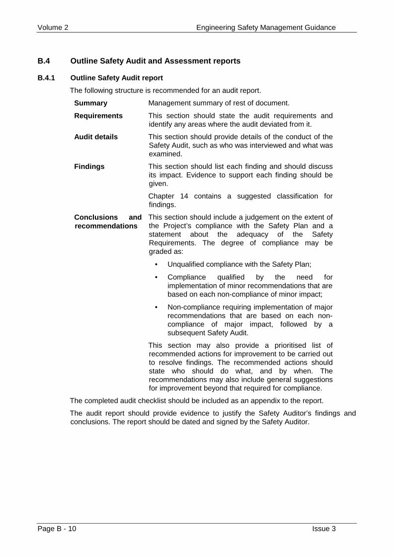
Volume 2 Engineering Safety Management Guidance
Page B - 10 Issue 3
B.4 Outline Safety Audit and Assessment reports
B.4.1 Outline Safety Audit report
The following structure is recommended for an audit report.
Summary Management summary of rest of document.
Requirements This section should state the audit requirements andidentify any areas where the audit deviated from it.
Audit details This section should provide details of the conduct of theSafety Audit, such as who was interviewed and what wasexamined.
Findings This section should list each finding and should discussits impact. Evidence to support each finding should begiven.
Chapter 14 contains a suggested classification forfindings.
Conclusions andrecommendations
This section should include a judgement on the extent ofthe Project’s compliance with the Safety Plan and astatement about the adequacy of the SafetyRequirements. The degree of compliance may begraded as:
• Unqualified compliance with the Safety Plan;
• Compliance qualified by the need forimplementation of minor recommendations that arebased on each non-compliance of minor impact;
• Non-compliance requiring implementation of majorrecommendations that are based on each non-compliance of major impact, followed by asubsequent Safety Audit.
This section may also provide a prioritised list ofrecommended actions for improvement to be carried outto resolve findings. The recommended actions shouldstate who should do what, and by when. Therecommendations may also include general suggestionsfor improvement beyond that required for compliance.
The completed audit checklist should be included as an appendix to the report.
The audit report should provide evidence to justify the Safety Auditor’s findings andconclusions. The report should be dated and signed by the Safety Auditor.
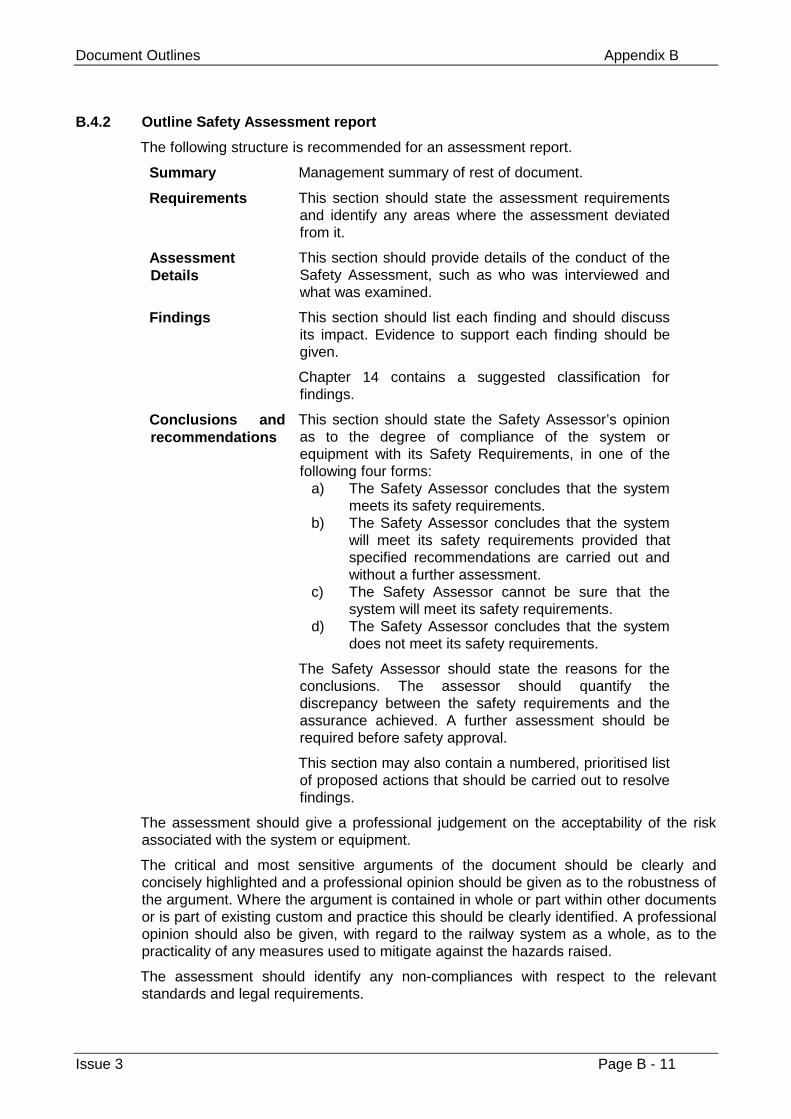
Document Outlines Appendix B
Issue 3 Page B - 11
B.4.2 Outline Safety Assessment report
The following structure is recommended for an assessment report.
Summary Management summary of rest of document.
Requirements This section should state the assessment requirementsand identify any areas where the assessment deviatedfrom it.
AssessmentDetails
This section should provide details of the conduct of theSafety Assessment, such as who was interviewed andwhat was examined.
Findings This section should list each finding and should discussits impact. Evidence to support each finding should begiven.
Chapter 14 contains a suggested classification forfindings.
Conclusions andrecommendations
This section should state the Safety Assessor’s opinionas to the degree of compliance of the system orequipment with its Safety Requirements, in one of thefollowing four forms:
a) The Safety Assessor concludes that the systemmeets its safety requirements.
b) The Safety Assessor concludes that the systemwill meet its safety requirements provided thatspecified recommendations are carried out andwithout a further assessment.
c) The Safety Assessor cannot be sure that thesystem will meet its safety requirements.
d) The Safety Assessor concludes that the systemdoes not meet its safety requirements.
The Safety Assessor should state the reasons for theconclusions. The assessor should quantify thediscrepancy between the safety requirements and theassurance achieved. A further assessment should berequired before safety approval.
This section may also contain a numbered, prioritised listof proposed actions that should be carried out to resolvefindings.
The assessment should give a professional judgement on the acceptability of the riskassociated with the system or equipment.
The critical and most sensitive arguments of the document should be clearly andconcisely highlighted and a professional opinion should be given as to the robustness ofthe argument. Where the argument is contained in whole or part within other documentsor is part of existing custom and practice this should be clearly identified. A professionalopinion should also be given, with regard to the railway system as a whole, as to thepracticality of any measures used to mitigate against the hazards raised.
The assessment should identify any non-compliances with respect to the relevantstandards and legal requirements.

Volume 2 Engineering Safety Management Guidance
Page B - 12 Issue 3
This page left intentionally blank
Checklists Appendix C
Issue 3 Page C - 1
Appendix C
Checklists
This appendix provides checklists to support the following activities:
1 Hazard Identification and Risk Assessment (see chapter 8)
2 Safety Planning (see chapter 12)
3 Updating the Hazard Log (see chapter 13)
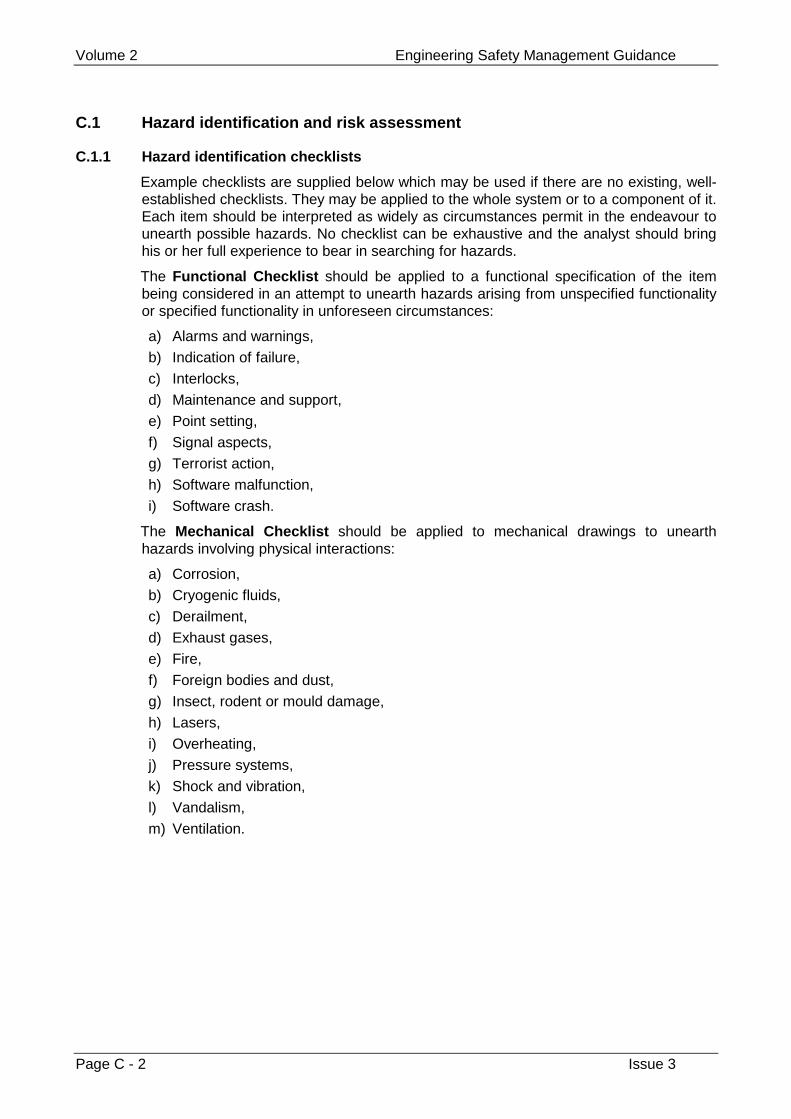
Volume 2 Engineering Safety Management Guidance
Page C - 2 Issue 3
C.1 Hazard identification and risk assessment
C.1.1 Hazard identification checklists
Example checklists are supplied below which may be used if there are no existing, well-established checklists. They may be applied to the whole system or to a component of it.Each item should be interpreted as widely as circumstances permit in the endeavour tounearth possible hazards. No checklist can be exhaustive and the analyst should bringhis or her full experience to bear in searching for hazards.
The Functional Checklist should be applied to a functional specification of the itembeing considered in an attempt to unearth hazards arising from unspecified functionalityor specified functionality in unforeseen circumstances:
a) Alarms and warnings,
b) Indication of failure,
c) Interlocks,
d) Maintenance and support,
e) Point setting,
f) Signal aspects,
g) Terrorist action,
h) Software malfunction,
i) Software crash.
The Mechanical Checklist should be applied to mechanical drawings to unearthhazards involving physical interactions:
a) Corrosion,
b) Cryogenic fluids,
c) Derailment,
d) Exhaust gases,
e) Fire,
f) Foreign bodies and dust,
g) Insect, rodent or mould damage,
h) Lasers,
i) Overheating,
j) Pressure systems,
k) Shock and vibration,
l) Vandalism,
m) Ventilation.
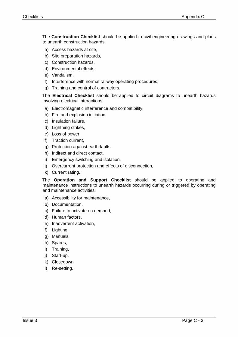
Checklists Appendix C
Issue 3 Page C - 3
The Construction Checklist should be applied to civil engineering drawings and plansto unearth construction hazards:
a) Access hazards at site,
b) Site preparation hazards,
c) Construction hazards,
d) Environmental effects,
e) Vandalism,
f) Interference with normal railway operating procedures,
g) Training and control of contractors.
The Electrical Checklist should be applied to circuit diagrams to unearth hazardsinvolving electrical interactions:
a) Electromagnetic interference and compatibility,
b) Fire and explosion initiation,
c) Insulation failure,
d) Lightning strikes,
e) Loss of power,
f) Traction current,
g) Protection against earth faults,
h) Indirect and direct contact,
i) Emergency switching and isolation,
j) Overcurrent protection and effects of disconnection,
k) Current rating.
The Operation and Support Checklist should be applied to operating andmaintenance instructions to unearth hazards occurring during or triggered by operatingand maintenance activities:
a) Accessibility for maintenance,
b) Documentation,
c) Failure to activate on demand,
d) Human factors,
e) Inadvertent activation,
f) Lighting,
g) Manuals,
h) Spares,
i) Training,
j) Start-up,
k) Closedown,
l) Re-setting.
Volume 2 Engineering Safety Management Guidance
Page C - 4 Issue 3
The Occupational Health Checklists should be applied to a general description tounearth hazards to personnel installing, operating, maintaining or disposing of the item:
a) Asbestos,
b) Asphyxiates,
c) CFCs,
d) Corrosive materials,
e) Cryogenic fluids,
f) Electrocution,
g) Exhaust gases,
h) Fire,
i) High temperatures,
j) Injury from moving parts,
k) Lasers,
l) Noise,
m) Pressure systems,
n) Radioactive materials,
o) Toxicity,
p) Electrical overheating.
Checklists Appendix C
Issue 3 Page C - 5
C.1.2 Operation and maintenance responsibilities checklist
This checklist may be used to assist in thorough control of risks related to operation andmaintenance.
Actions to be taken by the Project Manager:
a) Define responsibilities for operation and support in project requirements;
b) Establish communications on operation and support with users.
Operating Information and Documentation checklist:
c) Provide operating instructions prior to commissioning, emphasising safety aspectsand precautions as appropriate;
d) Consider need to alter current operating instructions and advise Users accordingly;
e) Include instructions to be followed in event of system or equipment failure;
f) Include instructions to be followed to render system safe and to maintainoperational capabilities where possible;
g) Include instructions to be followed in the event of an accident resulting from asystem or equipment failure;
h) Define requirements for review and exercising of the safety aspects of operatinginstructions.
Operator interface design checklist:
i) Consider safety aspects of man-machine interface in system or equipment;
j) Check that required operating tasks are within intended operators’ physical andmental capabilities;
k) Ensure that implications of emergency actions are clearly defined in operatinginstructions.
Operational safety features checklist:
l) Check that operator safeguards have been considered;
m) Check clarity of instructions for operator safety systems;
n) Consider requirements for periodical safety checks, by operating and maintenancepersonnel.
Operational Record checklist:
o) Determine requirements for failure reporting;
p) Issue instructions for the recording and analysis of failures;
q) Define procedures for the incorporation of alterations to systems and equipment forsafety reasons.
Operator Training and Competence checklist:
r) Determine requirements for operator safety training;
s) Consider need for training aids and facilities;
t) Define skill levels and calibre of operators and maintainers.
Volume 2 Engineering Safety Management Guidance
Page C - 6 Issue 3
Maintenance Instructions checklist
u) Provide maintenance specifications and identify safety-related requirements;
v) Define fault-diagnosis, condition monitoring and test equipment;
w) Provide maintenance task instructions;
x) Define skill levels required;
y) Provide maintenance schedules;
z) Provide a maintenance recording system;
aa) Provide a defect reporting system;
bb) Provide a system for the incorporation of changes to a design.
System Definition and Spares Identification checklist
cc) Create a database of system and equipment support information;
dd) Identify safety aspects of spares and support equipment;
ee) Define safety requirements for packaging, handling, storage and transport ofspares.
Maintenance Specifications and Mandatory Items checklist
ff) Identify mandatory preventive maintenance;
gg) Define data reporting, analysis and corrective action system;
hh) Designate team of specialists for monitoring data reports.
Safe Maintenance Practices and Accessibility checklist
ii) Provide instructions for gaining safe access to systems for repairs;
jj) Provide instructions for the promulgation of safety precautions;
kk) Provide instructions for a ‘permit-to-work’ procedure.
Change Control checklist
ll) Establish procedures for the safe management of changes and alterations tosystems;
mm) Define requirements for testing and commissioning after changes have beenincorporated.
Checklist of Regulations on Safety in Operation and Support
nn) HSE Guidance Note GS27. Protection against electric shock;
oo) IEC publication 479. Effects of current passing through the human body (1984 orlater edition);
pp) IEC Guide 105. Principles concerning the safety of equipment electricallyconnected to a telecommunications network;
qq) IEE Wiring Regulations (15th edition);
rr) Control of Substances Hazardous to Health Regulations 1988.
Checklists Appendix C
Issue 3 Page C - 7
C.1.3 Checklist of decommissioning/disposal considerations
This checklist may be used to assist in thorough control of risks related todecommissioning and disposal.
Checklist of actions to be completed
a) Has the hazard listing identified possible hazards in decommissioning, dismantlingand disposal?
b) Has the hazard analysis classified the severity or consequences of any potentialaccidents in decommissioning or disposing of a system or equipment at the end ofits life?
c) Has the system been designed to eliminate potential hazards of disposal?
d) Has guidance for the safe disposal of systems and equipment been included in theHazard Log and the Safety Case?
e) Does the Safety Plan cover the decommissioning of systems and equipment?
f) Is there any risk due to interaction between a decommissioned system and anyremaining systems?
g) If any parts of systems have been designated for salvage on decommissioning,have instructions for re-certification been prepared?
h) Are all decommissioning and disposal procedures defined along with any specialtesting requirements they imply?
Checklist of hazardous components (not exhaustive)
i) Flammable substances,
j) Explosives,
k) Asphyxiates, toxic, corrosive or penetrating substances,
l) Allergenic substances,
m) Pressurised systems,
n) Electrical sources or batteries,
o) Radiation sources,
p) Rotational machinery, moving parts,
q) Hazardous surfaces,
r) Cutting edges and sharp projections,
s) Heavy weights.
Volume 2 Engineering Safety Management Guidance
Page C - 8 Issue 3
C.1.4 Checklists of installation and handover considerations
This checklist is intended to be used to check whether or not all required safetymanagement activities have taken place prior to safety approval.
a) Have any incidents with safety implications been reported during the site trial?
b) Has the Safety Case been updated to reflect the validation activities?
c) Has the Safety Case been reviewed by the Safety Assessor and issued forapproval?
d) Have these incidents involved changes to the information on which the Safety Casewas based (thereby requiring a reworking of the Safety Case)?
e) Have all changes to the Safety Case been approved by the Safety Authority?
f) Has all operational support documentation with safety connotations been reviewedduring this phase?
g) Have these reviews caused changes to the information on which the Safety Casewas based (thereby requiring a reworking of the Safety Case)?
h) Has all safety-related documentation necessary for the use of the operationalsupport team been handed over?
i) Has all training documentation in safety aspects been reviewed and approved?
j) Have all Procedures, Work Instructions and method statements required beendefined and approved, including any variations to existing standards?
k) Have all required as-built diagrams, drawings, photographs and otherdocumentation been supplied?
l) Has all required training for the operational team been carried out?
m) Has a formal channel of communication been established between the operationalsupport team and the development team to ensure that data about operationalsafety is fed back into the future developments?
Checklists Appendix C
Issue 3 Page C - 9
C.2 Safety planning
These checklists have been produced to assist the creation and evaluation of the ESMActivities section of the Safety Plan. They provide guidance on safety planning for safetyactivities throughout the system lifecycle.
The Safety Plan should define responsibilities and time-scales for each ESM activityscheduled.
C.2.1 General considerations
The safety-related activities listed below should be considered throughout the lifecycle.
a) Maintain Hazard Log;
b) Revisit Safety Plan and update and re-issue where appropriate;
c) Revisit Safety Analysis work and re-issue all affected documentation asappropriate;
d) Establish criteria for risk tolerability;
e) Carry-out Safety Audits and Safety Assessments as scheduled in the Safety Plan.
C.2.2 Concept and feasibility
a) Preliminary Hazard Analysis scheduled;
b) Analysis of safety implications of each proposed technical approach scheduled;
c) Production of report on this analysis scheduled;
d) Guidance provided on safety analysis (chapter 8) considered.
C.2.3 Requirements definition
a) Guidance provided on establishing Safety Requirements (chapter 9) considered;
b) Production of acceptance test plan scheduled.
C.2.4 Design
a) Design techniques and procedures specified;
b) Standards for the production of design documentation specified;
c) Allocation of safety requirements to top-level sub-systems scheduled;
d) Allocation of random and systematic elements of the hazard probability targets tohigh-level sub-systems scheduled;
e) Diagrammatic method of allocation referred to in item d) above described;
f) Guidance provided on Risk Assessment (chapter 8) considered;
g) Re-use of sub-systems and/or components clearly identified and justified;
h) Plans for the review and testing of built components and documentation scheduled;
i) System integration plan production scheduled;
j) Occupational Health and Safety issues, related to operation and maintenance,considered;
k) Production of validation and verification plan scheduled;
Volume 2 Engineering Safety Management Guidance
Page C - 10 Issue 3
l) Independent formal reviews of design and its associated design documentationagainst safety requirements scheduled.
C.2.5 Implementation
a) Implementation techniques specified;
b) Procedures, standards and working practices specified;
c) Automatic testing tools and integrated development tools specified;
d) Occupational Health and Safety issues, related to operation and maintenance,considered;
e) Review of validation and verification plan scheduled;
f) Implementation of reviewed verification plan scheduled.
C.2.6 Installation and handover
a) Strategy for installation and handover defined;
b) States for start-up, steady-state (normal operation), shut-down, maintenance andabnormal operation addressed;
c) Required approvals of acceptance plan specified (should include client);
d) Requirement for client attendance at acceptance testing specified;
e) Independence of acceptance testing team defined;
f) Requirements for acceptance testing documentation defined;
g) Means of safe and controlled integration of the system with existing systems andprocedures defined;
h) Start-up of the system addressed;
i) Parallel operation of the replacement system and the existing system addressed;
j) Sub-system versus full system switch-overs addressed;
k) Cross validation of results between existing and replacement systems addressed;
l) Fallback to the existing system if the replacement system fails addressed;
m) Safety training required for operators, users, maintainers and managers of thesystem identified;
n) Means of ensuring system integrity following installation defined;
o) Inspections and Safety Assessments scheduled where appropriate;
p) Guidance provided on transfer of safety responsibility (chapter 3) considered;
q) All documentation or manuals that provide operational or maintenance support toensure safe operation of the system identified;
r) Occupational Health and Safety issues, related to operation and maintenance,considered;
s) Approval authorities for support material identified;
t) Reviews of support material scheduled.
Checklists Appendix C
Issue 3 Page C - 11
C.2.7 Operations and maintenance
a) Maintenance plan included or referred to;
b) Plan agreed by Project Manager and Operations Manager;
c) Testing and auditing of the system scheduled;
d) Routine actions which need to be carried out to maintain the ‘as designed’functional safety of the system or equipment identified;
e) Actions and constraints required during start-up, normal operation, foreseeabledisturbances, faults or failures, and shutdown to ensure safety identified;
f) Records which need to be maintained showing results of maintenance, audits, testsand inspections identified;
g) Records which need to be maintained on hazardous incidents (or incidents with thepotential to create hazards), system failure and availability rates identified;
h) Actions to be taken in the event of hazards, incidents or accidents occurringidentified;
i) Comparisons of system performance with design assumptions scheduled;
j) Procedure for assessing deviations for safety implications and for proposingmodifications defined;
k) Procedures for modifying the system in-service defined;
l) System performance below tolerable risk addressed;
m) Identification of systematic faults addressed;
n) New or amended safety legislation identified and taken into account;
o) Modifications to the safety requirements addressed;
p) Need for analysis of the effect of a proposed modification on system safetyaddressed;
q) Approval of modification implementation plan defined;
r) Need for maintenance of documentation effected by modifications highlighted;
s) Inspection, testing and/or analysis of modifications addressed;
t) Occupational Health and Safety issues, related to operation and maintenance,considered;
u) Criteria for withdrawal of the system from service identified.
C.2.8 Decommissioning and disposal
a) Safety-related considerations for decommissioning the system or equipmentidentified;
b) How the system or equipment is to be removed, including the safe disposal of anyhazardous material addressed;
c) The phasing in of any replacement system or equipment addressed;
d) Any gaps in the level of service provided by removing the system or equipmentaddressed.
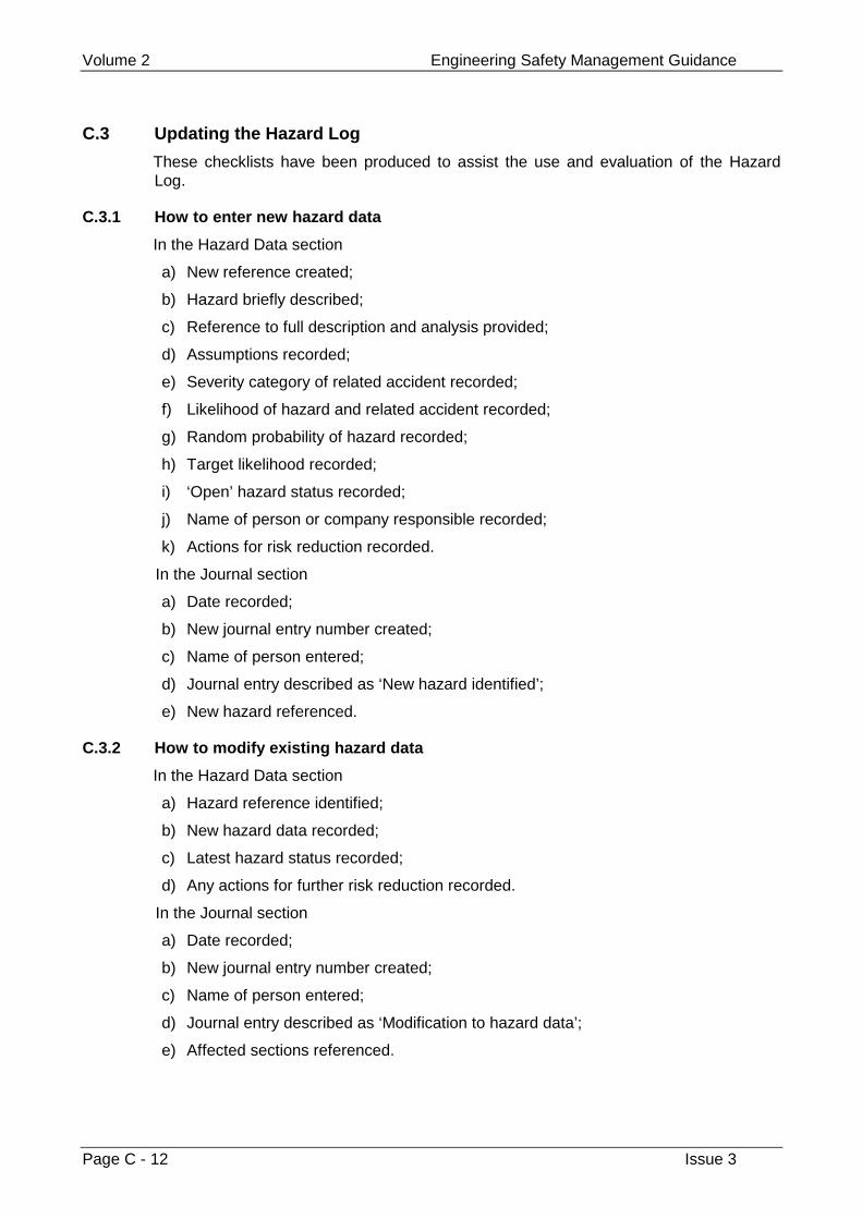
Volume 2 Engineering Safety Management Guidance
Page C - 12 Issue 3
C.3 Updating the Hazard Log
These checklists have been produced to assist the use and evaluation of the HazardLog.
C.3.1 How to enter new hazard data
In the Hazard Data section
a) New reference created;
b) Hazard briefly described;
c) Reference to full description and analysis provided;
d) Assumptions recorded;
e) Severity category of related accident recorded;
f) Likelihood of hazard and related accident recorded;
g) Random probability of hazard recorded;
h) Target likelihood recorded;
i) ‘Open’ hazard status recorded;
j) Name of person or company responsible recorded;
k) Actions for risk reduction recorded.
In the Journal section
a) Date recorded;
b) New journal entry number created;
c) Name of person entered;
d) Journal entry described as ‘New hazard identified’;
e) New hazard referenced.
C.3.2 How to modify existing hazard data
In the Hazard Data section
a) Hazard reference identified;
b) New hazard data recorded;
c) Latest hazard status recorded;
d) Any actions for further risk reduction recorded.
In the Journal section
a) Date recorded;
b) New journal entry number created;
c) Name of person entered;
d) Journal entry described as ‘Modification to hazard data’;
e) Affected sections referenced.
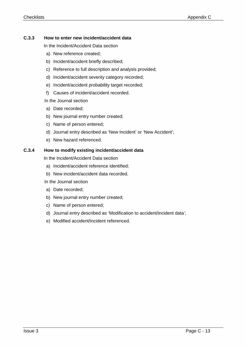
Checklists Appendix C
Issue 3 Page C - 13
C.3.3 How to enter new incident/accident data
In the Incident/Accident Data section
a) New reference created;
b) Incident/accident briefly described;
c) Reference to full description and analysis provided;
d) Incident/accident severity category recorded;
e) Incident/accident probability target recorded;
f) Causes of incident/accident recorded.
In the Journal section
a) Date recorded;
b) New journal entry number created;
c) Name of person entered;
d) Journal entry described as ‘New Incident’ or ‘New Accident’;
e) New hazard referenced.
C.3.4 How to modify existing incident/accident data
In the Incident/Accident Data section
a) Incident/accident reference identified;
b) New incident/accident data recorded.
In the Journal section
a) Date recorded;
b) New journal entry number created;
c) Name of person entered;
d) Journal entry described as ‘Modification to accident/incident data’;
e) Modified accident/incident referenced.
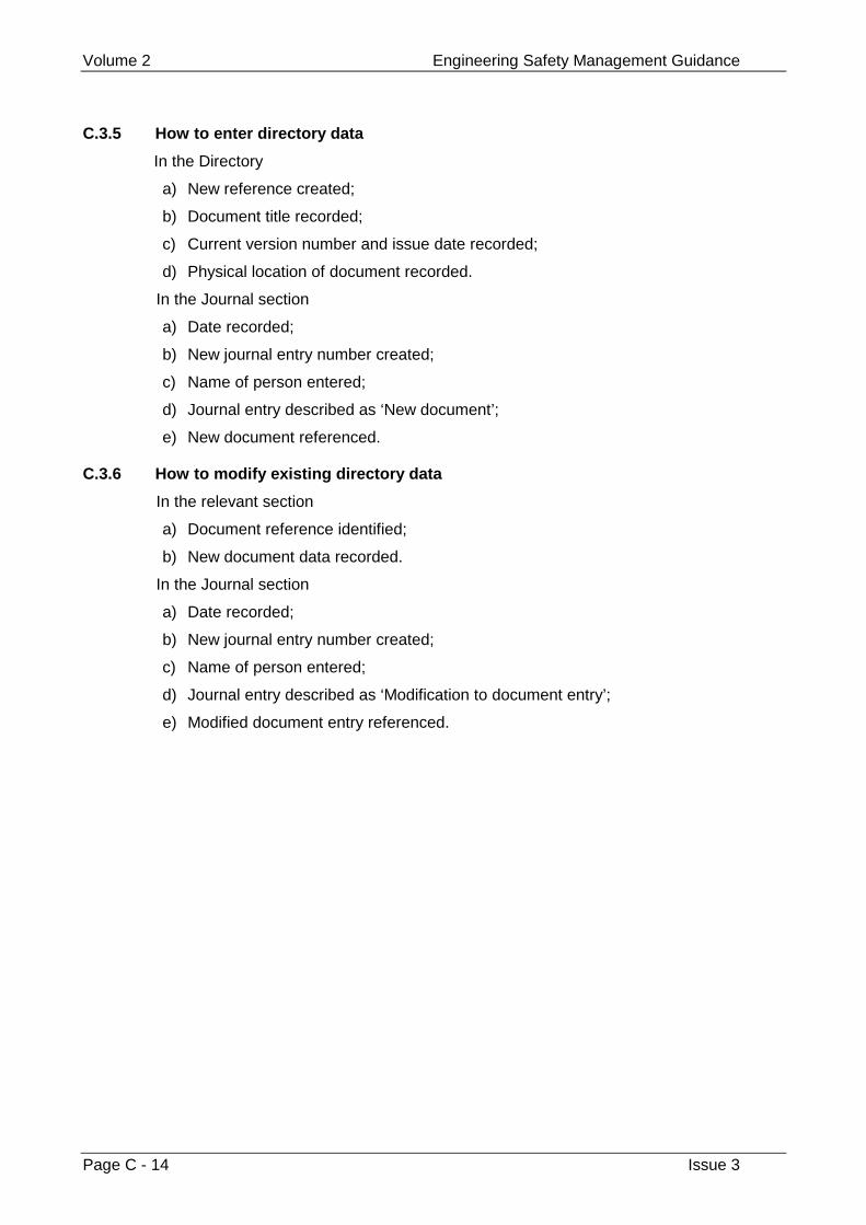
Volume 2 Engineering Safety Management Guidance
Page C - 14 Issue 3
C.3.5 How to enter directory data
In the Directory
a) New reference created;
b) Document title recorded;
c) Current version number and issue date recorded;
d) Physical location of document recorded.
In the Journal section
a) Date recorded;
b) New journal entry number created;
c) Name of person entered;
d) Journal entry described as ‘New document’;
e) New document referenced.
C.3.6 How to modify existing directory data
In the relevant section
a) Document reference identified;
b) New document data recorded.
In the Journal section
a) Date recorded;
b) New journal entry number created;
c) Name of person entered;
d) Journal entry described as ‘Modification to document entry’;
e) Modified document entry referenced.
Examples Appendix D
Issue 3 Page D - 1
Appendix D
Examples
This appendix provides examples of the following:
1 Safety policies (see chapter 3)
2 Hazard ranking matrix (see chapter 8)
3 Risk assessment (see chapter 8)
4 Safety Assessment remit (see chapter 14)
5 Safety Audit checklist (see chapter 14)
6 Safety Assessment checklist (see chapter 14)
Volume 2 Engineering Safety Management Guidance
Page D - 2 Issue 3
D.1 Example safety policies
This section contains extracts from the safety policies of three different rail companies:
• Railtrack plc, the infrastructure controller for the UK mainline railway,
• Virgin Trains, a UK mainline train operator,
• WS Atkins Rail Limited, a UK rail engineering and consultancy firm.
The organisations concerned have given permission for their safety policies to beincluded in the Yellow Book as a public demonstration of their commitment to safety.They are provided in the hope that they may prove useful to other organisations wishingto formulate safety policies. Please bear in mind that these policy statements are subjectto revision. You should contact the organisations concerned directly if you wish to makesure that you have an up-to-date statement.
Examples Appendix D
Issue 3 Page D - 3
D.1.1 Railtrack plc
Railtrack plc have issued the following Safety Policy Statement.
Railtrack PLC has prime responsibility for the safety and security of the railway itcontrols and for the health and safety of those who may be affected by the company’sactivities. As the Infrastructure Controller, our responsibility extends to ensuring safetywithin the entire Railway Group, through our own efforts and through the co-operationand compliance of our suppliers and the train and station operating companies that useour system. We seek and welcome recommendations for continuous improvement fromboth our staff and from theirs.
We view safety in the widest context - for us, it means protection from the risk of death,injury and poor health arising from our activities. It also means the avoidance of damageto property and the environment from whatever cause - accident, fire, explosion or lossof security. We will adopt a robust and cost-effective loss control policy in all that we do,recognising that good safety performance is good business - for us and our customers.
We accept that our responsibility extends to all who are involved in any way in ourindustry - our travellers, our workforce and those contracted to work for us, or on ourproperty, the general public when on our property, and our neighbours.
Our commitment to a safe railway comprises:
• Improving safety through the setting of goals and targets and adherence todefined standards of excellence for all those involved in the provision of railtransport.
• The development of access and contract agreements designed to maintain a saferailway for all.
• Robust monitoring and investigation systems to enable us thoroughly to evaluateand manage risk.
• The maintenance of effective communication and systems to manage theinterfaces between parties.
• A continuing policy of safety awareness for those working for our railway and allwho use it.
• An intolerance of failures to establish safe methods of work or to comply withlegislation, formal procedures and commitments.
Safety is fundamental to all contract and trading agreements between all parties whoseactivities impact on the railway. Evidence of professional safety management practice is,and will remain, a condition of access to our railway.
We will, through our operationally independent Safety and Standards Directorate,provide strategic leadership to secure the continuous improvement in safetyperformance necessary to deliver the ten year vision contained within the Railway GroupSafety Plan.
I, as your Chairman, and the Railtrack Board, commit ourselves to uphold theseprinciples in the efficient and effective conduct of our business and will provide adequateresources for this purpose.
Our approach to safety is dynamic and we will revise this policy to take account of anyand all improvements to safety. Our policy will be reviewed at least annually.
SIR PHILIP BECK Chairman, Railtrack PLCAugust 1999
Volume 2 Engineering Safety Management Guidance
Page D - 4 Issue 3
D.1.2 Virgin Trains
Virgin Trains issue a Health and Safety Policy as a small booklet. The policy starts withthe following Chief Executive’s Statement.
Nothing is more important than Safety
Safety is the responsibility of all of us, all of the time and in everything we do. Whateverour job we each have a constant duty to ensure that there is no harm to our customers,
colleagues, contractors, the general public or the environment.
Working safely is a condition of our employment and anyone who aborts work on thegrounds of Health and Safety will be given my full support and that of my managers.
I am committed to:-
Continuous improvement in the Health, Safety & Welfare of all our people and all thoseaffected by our operations, including customers, contractors and visitors.
Co-operating fully with Railtrack, other operators, and rail industry suppliers to ensurethat risks to our customers, colleagues, contractors, the general public, and risks to ouroperations and assets, are identified and eliminated or controlled.
Setting safety performance objectives and implementing improvement actions, which willbe published in our annual Safety Improvement Plan, and reviewed by Safety Council.
Ensuring adequate resources and funding are prioritised to meet our Safetycommitments.
I need and acknowledge your help in eliminating hazards, which may result in personalinjury, illness, fire and damage to property, harm to the environment or loss due tobreaches in security.
Chris GreenVIRGIN TRAINS June 1999
Examples Appendix D
Issue 3 Page D - 5
D.1.3 WS Atkins Rail Limited
WS Atkins Rail Limited have issued the following Safety Policy Statement.
WS Atkins Rail is committed to implementing policies for health, safety, security andwelfare and encouraging positive attitudes and behaviour. Through the WS Atkins RailLimited Safety Policy we seek continuous improvement, compliance with legislation andstandards, giving proper regard to protection of people, premises, property, processesand the environment.
All WS Atkins Rail Limited staff have a responsibility to ensure the safety of clients,colleagues, contractors and the general public. As Chairman I accept the ultimateresponsibility for the safety of the organisation and I shall seek to promote a climate inwhich we are aware of risks and proper safeguards are taken, in line with the WS Atkinscorporate Health and Safety Policy.
Suggestions from the staff on how safety arrangements can be improved and unsafeacts prevented will always be welcomed and actively encouraged within WS Atkins RailLimited.
As head of WS Atkins Rail Limited, my Directors and I are totally committed to theimplementation of these policies by personal involvement.
Safety is everyone’s responsibility and a condition of our employment. We look for thesupport and professionalism of our employees at all levels at making this policy trulyeffective not only for their personal Health and Safety, but also for others whom theiracts or omissions could affect.
J DoyleChairman
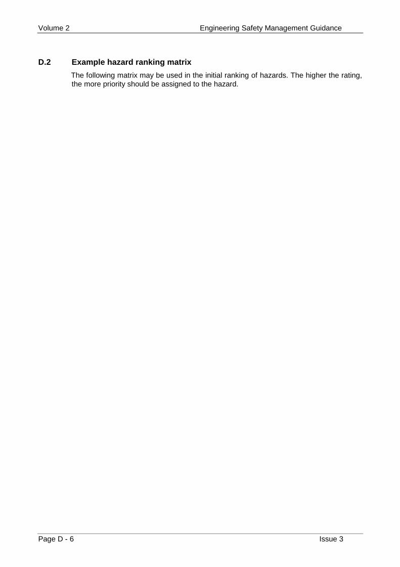
Volume 2 Engineering Safety Management Guidance
Page D - 6 Issue 3
D.2 Example hazard ranking matrix
The following matrix may be used in the initial ranking of hazards. The higher the rating,the more priority should be assigned to the hazard.
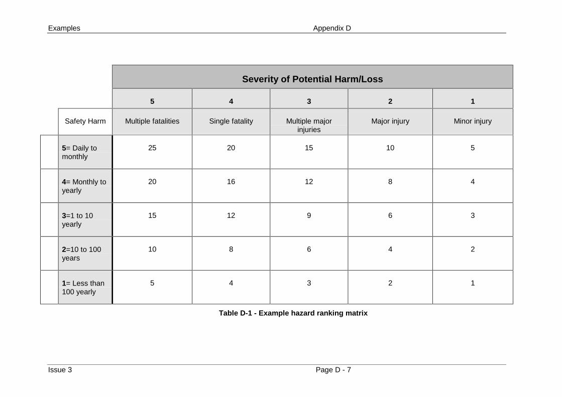
Examples Appendix D
Issue 3 Page D - 7
Severity of Potential Harm/Loss
5 4 3 2 1
Safety Harm Multiple fatalities Single fatality Multiple majorinjuries
Major injury Minor injury
5= Daily tomonthly
25 20 15 10 5
4= Monthly toyearly
20 16 12 8 4
3=1 to 10yearly
15 12 9 6 3
2=10 to 100years
10 8 6 4 2
1= Less than100 yearly
5 4 3 2 1
Table D-1 - Example hazard ranking matrix
Volume 2 Engineering Safety Management Guidance
Page D - 8 Issue 3
D.3 Risk assessment
D.3.1 Introduction
The example presented in this appendix is provided to illustrate application of therisk assessment framework detailed in this document. The example does notnecessarily relate to actual operational circumstances and the data used withinthe example is provided for the purposes of illustration only. In order tosimplify the example, some crude assumptions have been made that are unlikelyto apply in practice.
D.3.2 Background to example
The undertaking subject to analysis is the operation of an Automatic Half Barrierlevel crossing in a particular location. There is scope for making improvements tothe operation and use of this system. The aim of this risk assessment is thereforeto determine whether changes are required in order to reduce the risk presentedby the particular Automatic Half Barrier to a level that is compliant with theprinciple of ALARP.
It should be noted that the Automatic Half Barrier concerned has, to date, been inoperation for a period of 20 years. There is, therefore, some considerableoperational experience of its use.
D.3.3 Hazard Identification
The operation of an Automatic Half Barrier level crossing is not a novel process.Hence the hazards associated with this undertaking were predominantly identifiedfrom a checklist.
The likely frequency and severity of each hazard has been estimated using thecategorisation detailed in Table D-2 and Table D-3.
For each hazard, its estimated frequency and severity have been multiplied toobtain the hazard’s ‘rank’. Table D-4 presents the results of hazard identificationand ranking.
Examples Appendix D
Issue 3 Page D - 9
Frequencycategory
Definition
1 Less than 100 yearly
2 10 to 100 years
3 1 to 10 yearly
4 Monthly to yearly
5 Daily to monthly
Table D-2 - Categorisation for estimated hazard frequency
Severitycategory
Definition
1 Minor injury
2 Major injury
3 Multiple major injuries
4 Single fatality
5 Multiple fatalities
Table D-3 - Categorisation for estimated hazard severity
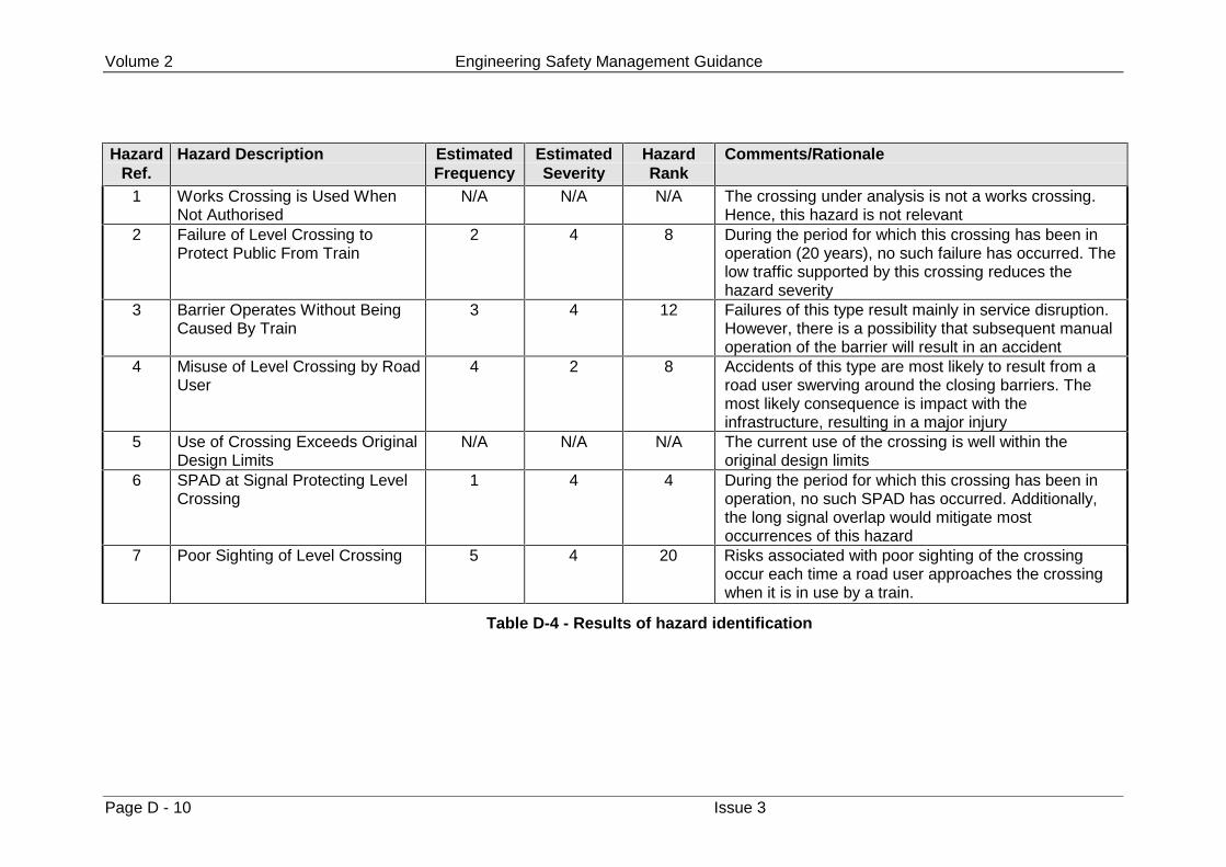
Volume 2 Engineering Safety Management Guidance
Page D - 10 Issue 3
HazardRef.
Hazard Description EstimatedFrequency
EstimatedSeverity
HazardRank
Comments/Rationale
1 Works Crossing is Used WhenNot Authorised
N/A N/A N/A The crossing under analysis is not a works crossing.Hence, this hazard is not relevant
2 Failure of Level Crossing toProtect Public From Train
2 4 8 During the period for which this crossing has been inoperation (20 years), no such failure has occurred. Thelow traffic supported by this crossing reduces thehazard severity
3 Barrier Operates Without BeingCaused By Train
3 4 12 Failures of this type result mainly in service disruption.However, there is a possibility that subsequent manualoperation of the barrier will result in an accident
4 Misuse of Level Crossing by RoadUser
4 2 8 Accidents of this type are most likely to result from aroad user swerving around the closing barriers. Themost likely consequence is impact with theinfrastructure, resulting in a major injury
5 Use of Crossing Exceeds OriginalDesign Limits
N/A N/A N/A The current use of the crossing is well within theoriginal design limits
6 SPAD at Signal Protecting LevelCrossing
1 4 4 During the period for which this crossing has been inoperation, no such SPAD has occurred. Additionally,the long signal overlap would mitigate mostoccurrences of this hazard
7 Poor Sighting of Level Crossing 5 4 20 Risks associated with poor sighting of the crossingoccur each time a road user approaches the crossingwhen it is in use by a train.
Table D-4 - Results of hazard identification
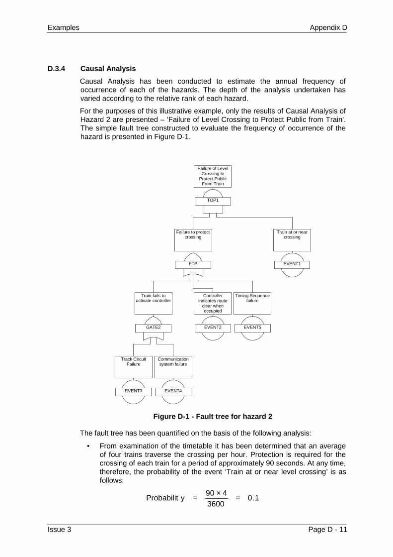
Examples Appendix D
Issue 3 Page D - 11
D.3.4 Causal Analysis
Causal Analysis has been conducted to estimate the annual frequency ofoccurrence of each of the hazards. The depth of the analysis undertaken hasvaried according to the relative rank of each hazard.
For the purposes of this illustrative example, only the results of Causal Analysis ofHazard 2 are presented – ‘Failure of Level Crossing to Protect Public from Train'.The simple fault tree constructed to evaluate the frequency of occurrence of thehazard is presented in Figure D-1.
TOP1
Failure of LevelCrossing to
Protect PublicFrom Train
FTP
Failure to protectcrossing
EVENT1
Train at or nearcrossing
GATE2
Train fails toactivate controller
EVENT2
Controllerindicates route
clear whenoccupied
EVENT5
Timing Sequencefailure
EVENT3
Track CircuitFailure
EVENT4
Communicationsystem failure
Figure D-1 - Fault tree for hazard 2
The fault tree has been quantified on the basis of the following analysis:
• From examination of the timetable it has been determined that an averageof four trains traverse the crossing per hour. Protection is required for thecrossing of each train for a period of approximately 90 seconds. At any time,therefore, the probability of the event ‘Train at or near level crossing’ is asfollows:
1.03600
490yProbabilit =×=
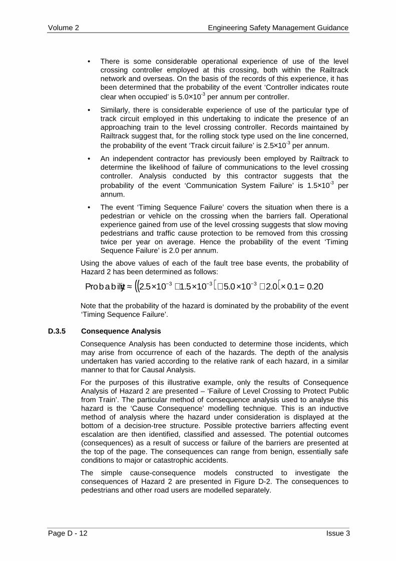
Volume 2 Engineering Safety Management Guidance
Page D - 12 Issue 3
• There is some considerable operational experience of use of the levelcrossing controller employed at this crossing, both within the Railtracknetwork and overseas. On the basis of the records of this experience, it hasbeen determined that the probability of the event ‘Controller indicates routeclear when occupied’ is 5.0×10⁻³ per annum per controller.
• Similarly, there is considerable experience of use of the particular type oftrack circuit employed in this undertaking to indicate the presence of anapproaching train to the level crossing controller. Records maintained byRailtrack suggest that, for the rolling stock type used on the line concerned,the probability of the event ‘Track circuit failure’ is 2.5×10⁻³ per annum.
• An independent contractor has previously been employed by Railtrack todetermine the likelihood of failure of communications to the level crossingcontroller. Analysis conducted by this contractor suggests that theprobability of the event ‘Communication System Failure’ is 1.5×10⁻³ perannum.
• The event ‘Timing Sequence Failure’ covers the situation when there is apedestrian or vehicle on the crossing when the barriers fall. Operationalexperience gained from use of the level crossing suggests that slow movingpedestrians and traffic cause protection to be removed from this crossingtwice per year on average. Hence the probability of the event ‘TimingSequence Failure’ is 2.0 per annum.
Using the above values of each of the fault tree base events, the probability ofHazard 2 has been determined as follows:
( )( ) 20.01.00.2100.5105.1105.2y Probabilit 333 =×+×+×+×≈ −−−
Note that the probability of the hazard is dominated by the probability of the event‘Timing Sequence Failure’.
D.3.5 Consequence Analysis
Consequence Analysis has been conducted to determine those incidents, whichmay arise from occurrence of each of the hazards. The depth of the analysisundertaken has varied according to the relative rank of each hazard, in a similarmanner to that for Causal Analysis.
For the purposes of this illustrative example, only the results of ConsequenceAnalysis of Hazard 2 are presented – ‘Failure of Level Crossing to Protect Publicfrom Train’. The particular method of consequence analysis used to analyse thishazard is the ‘Cause Consequence’ modelling technique. This is an inductivemethod of analysis where the hazard under consideration is displayed at thebottom of a decision-tree structure. Possible protective barriers affecting eventescalation are then identified, classified and assessed. The potential outcomes(consequences) as a result of success or failure of the barriers are presented atthe top of the page. The consequences can range from benign, essentially safeconditions to major or catastrophic accidents.
The simple cause-consequence models constructed to investigate theconsequences of Hazard 2 are presented in Figure D-2. The consequences topedestrians and other road users are modelled separately.
Examples Appendix D
Issue 3 Page D - 13
For the purposes of this analysis it has been estimated that, on average, 500pedestrians use the crossing per day, taking 9 seconds each to traverse thecrossing. Since trains run for 15 hours per day on this line, this leads to thefollowing probability of a pedestrian being present at the crossing at any giventime whilst trains are running:
2103.81536009500
y Probabilit −×=××=
Similarly, to estimate the probability of a road user being present at the crossing ithas been estimated that, on average, 1000 vehicles use the crossing per day,taking 5 seconds to traverse the crossing.
It can be seen from the analysis, that most occurrences of the hazard do not leadto an accident, due to mitigating factors such as the vigilance of pedestrians andother road users and other, circumstantial factors, such as there being no traffic atthe crossing when the hazard occurs.
Note: The estimates of the probability with which a vehicle or pedestrian takessuccessful emergency action have to take account of the fact that, in most caseswhere the hazard occurs, it is as a result of a slow moving vehicle or pedestrian inthe first place.
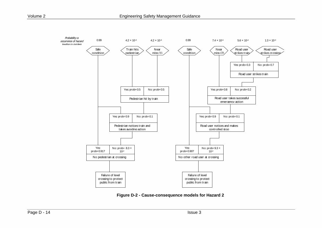
Volume 2 Engineering Safety Management Guidance
Page D - 14 Issue 3
Safecondition
T rain hitspedestr ian
Nearmiss (1)
Safecondition
Nearmiss (2)
Road userstr ikes train
Road userstr ikes crossing
Yes: prob=0.3 No: prob=0.7
Road user str ikes train
Yes: prob=0.8 No: prob=0.2
Road user takes successfulemergency action
Yes: prob=0.9 No: prob=0.1
Road user notices and makescontrolled stop
Yes:prob=0.907
No: prob=9.3 ×10⁻²
No other road user at crossing
Yes: prob=0.5 No: prob=0.5
Pedestr ian hit by train
Yes: prob=0.9 No: prob=0.1
Pedestr ian notices train andtakes avoiding action
Yes:prob=0.917
No: prob= 8.3 ×10⁻²
No pedestr ian at crossing
Failure of levelcrossing to protectpublic from train
Failure of levelcrossing to protectpublic from train
Probability ofoccurrence of hazard
leading to incident0.99 4.2 × 10⁻³ 4.2 × 10⁻³ 0.99 7.4 × 10⁻³ 5.6 × 10⁻⁴ 1.3 × 10⁻³
Figure D-2 - Cause-consequence models for Hazard 2
Examples Appendix D
Issue 3 Page D - 15
D.3.6 Loss Analysis
Loss Analysis has been conducted to determine the magnitude of potential safety lossesassociated with each hazard.
For the purposes of this illustrative example, only the results of Loss Analysis of Hazard2 are provided – ‘Failure of Level Crossing to Protect Public from Train'. Table D-5presents details of the loss modelling conducted. The incidents (consequences) havebeen taken from the cause consequence diagram presented earlier. The followingincidents were identified:
• Safe Condition,
• Near Miss,
• Train Hits Pedestrian,
• Road User Strikes Train,
• Road User Strikes Crossing.
It has been assumed that no losses arise from a Safe Condition. A Near Miss is judgednot to result in safety losses, although it can result in significant train delays. Theremaining consequences all result in both safety and commercial losses.
Following analysis of Railtrack accident statistics, for circumstances similar to the levelcrossing under study, it has been assumed that:
• the incident ‘Train Hits Pedestrian’ results in no injuries to passengers, but 1fatality to a member of the public;
• the incident ‘Road User Strikes Train’ results in 2 minor injuries to passengers anda single major injury to a member of the public;
• the incident ‘Road User Strikes Crossing’ results in 1 minor injury to passengersand 1 major injury to a member of the public.
The injuries associated with each incident have been converted to a correspondingPotential Equivalent Fatality (PEF) figure using the following currently accepted Railtrackconvention:
• 1 fatality = 10 major injuries
• 1 major injury = 20 minor injuries
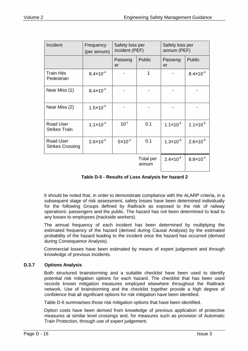
Volume 2 Engineering Safety Management Guidance
Page D - 16 Issue 3
Incident Frequency (per annum)
Safety loss perincident (PEF)
Safety loss perannum (PEF)
Passenger
Public Passenger
Public
Train HitsPedestrian
8.4×10⁻⁴ - 1 - 8.4×10⁻⁴
Near Miss (1) 8.4×10⁻⁴ - - - -
Near Miss (2) 1.5×10⁻³ - - - -
Road UserStrikes Train
1.1×10⁻⁴ 10-2 0.1 1.1×10⁻⁶ 1.1×10⁻⁵
Road UserStrikes Crossing
2.6×10⁻⁴ 5×10⁻³ 0.1 1.3×10⁻⁶ 2.6×10⁻⁵
Total perannum
2.4×10⁻⁶ 8.8×10⁻⁴
Table D-5 - Results of Loss Analysis for hazard 2
It should be noted that, in order to demonstrate compliance with the ALARP criteria, in asubsequent stage of risk assessment, safety losses have been determined individuallyfor the following Groups defined by Railtrack as exposed to the risk of railwayoperations: passengers and the public. The hazard has not been determined to lead toany losses to employees (trackside workers).
The annual frequency of each incident has been determined by multiplying theestimated frequency of the hazard (derived during Causal Analysis) by the estimatedprobability of the hazard leading to the incident once the hazard has occurred (derivedduring Consequence Analysis).
Commercial losses have been estimated by means of expert judgement and throughknowledge of previous incidents.
D.3.7 Options Analysis
Both structured brainstorming and a suitable checklist have been used to identifypotential risk mitigation options for each hazard. The checklist that has been usedrecords known mitigation measures employed elsewhere throughout the Railtracknetwork. Use of brainstorming and the checklist together provide a high degree ofconfidence that all significant options for risk mitigation have been identified.
Table D-6 summarises those risk mitigation options that have been identified.
Option costs have been derived from knowledge of previous application of protectivemeasures at similar level crossings and, for measures such as provision of AutomaticTrain Protection, through use of expert judgement.
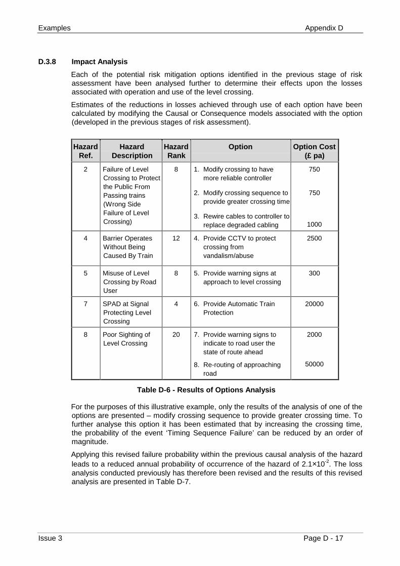
Examples Appendix D
Issue 3 Page D - 17
D.3.8 Impact Analysis
Each of the potential risk mitigation options identified in the previous stage of riskassessment have been analysed further to determine their effects upon the lossesassociated with operation and use of the level crossing.
Estimates of the reductions in losses achieved through use of each option have beencalculated by modifying the Causal or Consequence models associated with the option(developed in the previous stages of risk assessment).
HazardRef.
HazardDescription
HazardRank
Option Option Cost(£ pa)
2 Failure of LevelCrossing to Protectthe Public FromPassing trains(Wrong SideFailure of LevelCrossing)
8 1. Modify crossing to havemore reliable controller
2. Modify crossing sequence toprovide greater crossing time
3. Rewire cables to controller toreplace degraded cabling
750
750
1000
4 Barrier OperatesWithout BeingCaused By Train
12 4. Provide CCTV to protectcrossing fromvandalism/abuse
2500
5 Misuse of LevelCrossing by RoadUser
8 5. Provide warning signs atapproach to level crossing
300
7 SPAD at SignalProtecting LevelCrossing
4 6. Provide Automatic TrainProtection
20000
8 Poor Sighting ofLevel Crossing
20 7. Provide warning signs toindicate to road user thestate of route ahead
8. Re-routing of approachingroad
2000
50000
Table D-6 - Results of Options Analysis
For the purposes of this illustrative example, only the results of the analysis of one of theoptions are presented – modify crossing sequence to provide greater crossing time. Tofurther analyse this option it has been estimated that by increasing the crossing time,the probability of the event ‘Timing Sequence Failure’ can be reduced by an order ofmagnitude.
Applying this revised failure probability within the previous causal analysis of the hazardleads to a reduced annual probability of occurrence of the hazard of 2.1×10⁻². The lossanalysis conducted previously has therefore been revised and the results of this revisedanalysis are presented in Table D-7.
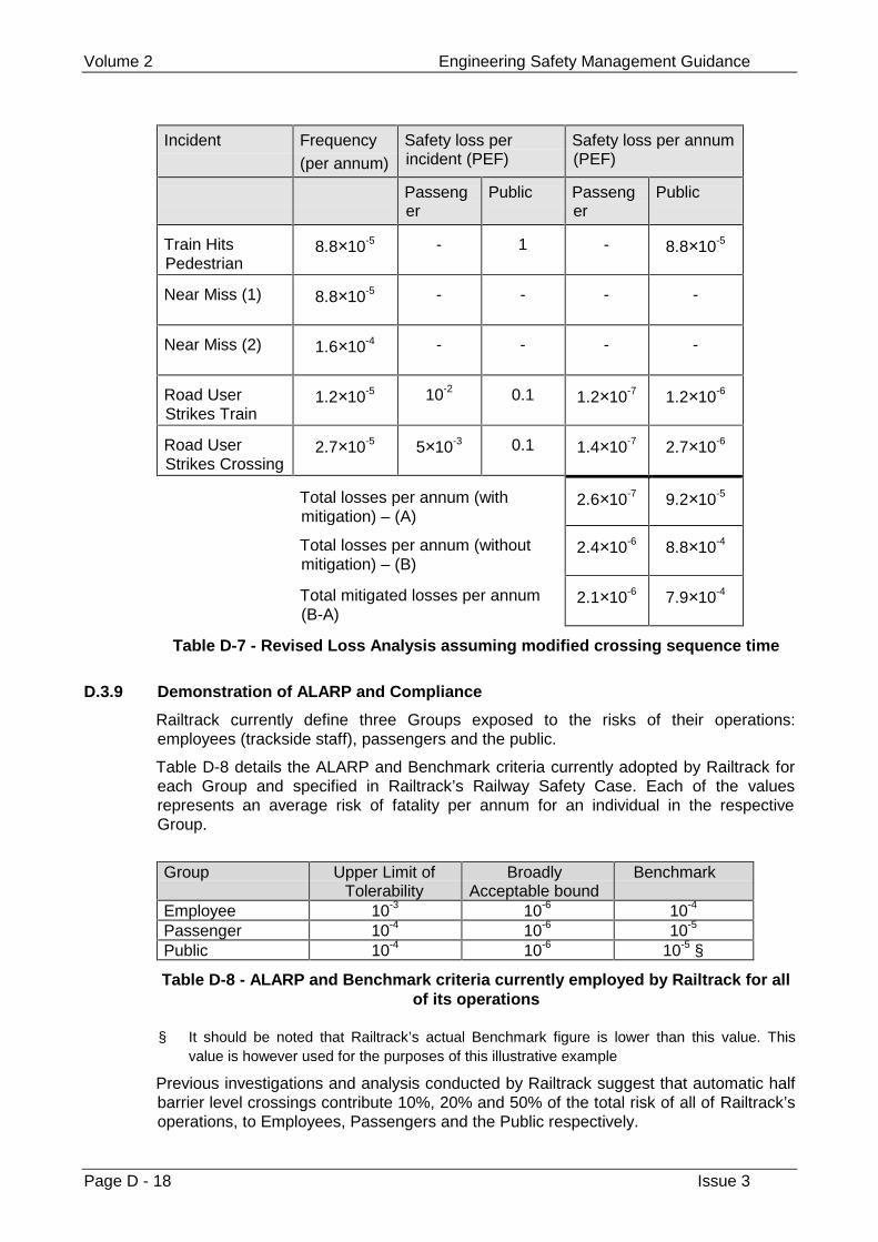
Volume 2 Engineering Safety Management Guidance
Page D - 18 Issue 3
Incident Frequency (per annum)
Safety loss perincident (PEF)
Safety loss per annum(PEF)
Passenger
Public Passenger
Public
Train HitsPedestrian
8.8×10⁻⁵ - 1 - 8.8×10⁻⁵
Near Miss (1) 8.8×10⁻⁵ - - - -
Near Miss (2) 1.6×10⁻⁴ - - - -
Road UserStrikes Train
1.2×10⁻⁵ 10-2 0.1 1.2×10⁻⁷ 1.2×10⁻⁶
Road UserStrikes Crossing
2.7×10⁻⁵ 5×10⁻³ 0.1 1.4×10⁻⁷ 2.7×10⁻⁶
Total losses per annum (withmitigation) – (A)
2.6×10⁻⁷ 9.2×10⁻⁵
Total losses per annum (withoutmitigation) – (B)
2.4×10⁻⁶ 8.8×10⁻⁴
Total mitigated losses per annum(B-A)
2.1×10⁻⁶ 7.9×10⁻⁴
Table D-7 - Revised Loss Analysis assuming modified crossing sequence time
D.3.9 Demonstration of ALARP and Compliance
Railtrack currently define three Groups exposed to the risks of their operations:employees (trackside staff), passengers and the public.
Table D-8 details the ALARP and Benchmark criteria currently adopted by Railtrack foreach Group and specified in Railtrack’s Railway Safety Case. Each of the valuesrepresents an average risk of fatality per annum for an individual in the respectiveGroup.
Group Upper Limit of
TolerabilityBroadly
Acceptable boundBenchmark
Employee 10-3 10-6 10-4
Passenger 10-4 10-6 10-5
Public 10-4 10-6 10-5 §
Table D-8 - ALARP and Benchmark criteria currently employed by Railtrack for allof its operations
§ It should be noted that Railtrack’s actual Benchmark figure is lower than this value. Thisvalue is however used for the purposes of this illustrative example
Previous investigations and analysis conducted by Railtrack suggest that automatic halfbarrier level crossings contribute 10%, 20% and 50% of the total risk of all of Railtrack’soperations, to Employees, Passengers and the Public respectively.
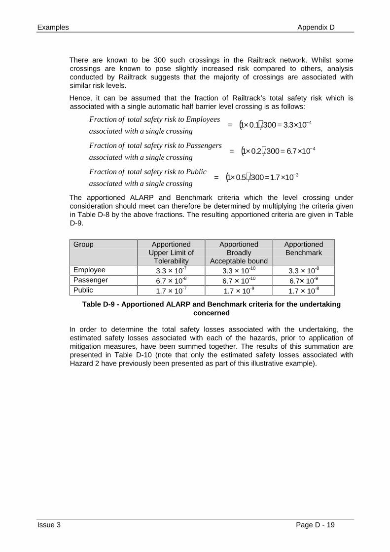
Examples Appendix D
Issue 3 Page D - 19
There are known to be 300 such crossings in the Railtrack network. Whilst somecrossings are known to pose slightly increased risk compared to others, analysisconducted by Railtrack suggests that the majority of crossings are associated withsimilar risk levels.
Hence, it can be assumed that the fraction of Railtrack’s total safety risk which isassociated with a single automatic half barrier level crossing is as follows:
( ) 4103.33001.01 −×=×=crossing singlea withassociated
Employees to risk safety total of Fraction
( ) 4107.63002.01 −×=×=crossing singlea withassociated
Passengers to risk safety total of Fraction
( ) 3107.13005.01 −×=×=crossing singlea withassociated
Public to risk safety total of Fraction
The apportioned ALARP and Benchmark criteria which the level crossing underconsideration should meet can therefore be determined by multiplying the criteria givenin Table D-8 by the above fractions. The resulting apportioned criteria are given in TableD-9.
Group Apportioned
Upper Limit ofTolerability
ApportionedBroadly
Acceptable bound
ApportionedBenchmark
Employee 3.3 × 10⁻⁷ 3.3 × 10⁻¹⁰ 3.3 × 10⁻⁸
Passenger 6.7 × 10⁻⁸ 6.7 × 10⁻¹⁰ 6.7× 10⁻⁹
Public 1.7 × 10⁻⁷ 1.7 × 10⁻⁹ 1.7 × 10⁻⁸
Table D-9 - Apportioned ALARP and Benchmark criteria for the undertakingconcerned
In order to determine the total safety losses associated with the undertaking, theestimated safety losses associated with each of the hazards, prior to application ofmitigation measures, have been summed together. The results of this summation arepresented in Table D-10 (note that only the estimated safety losses associated withHazard 2 have previously been presented as part of this illustrative example).
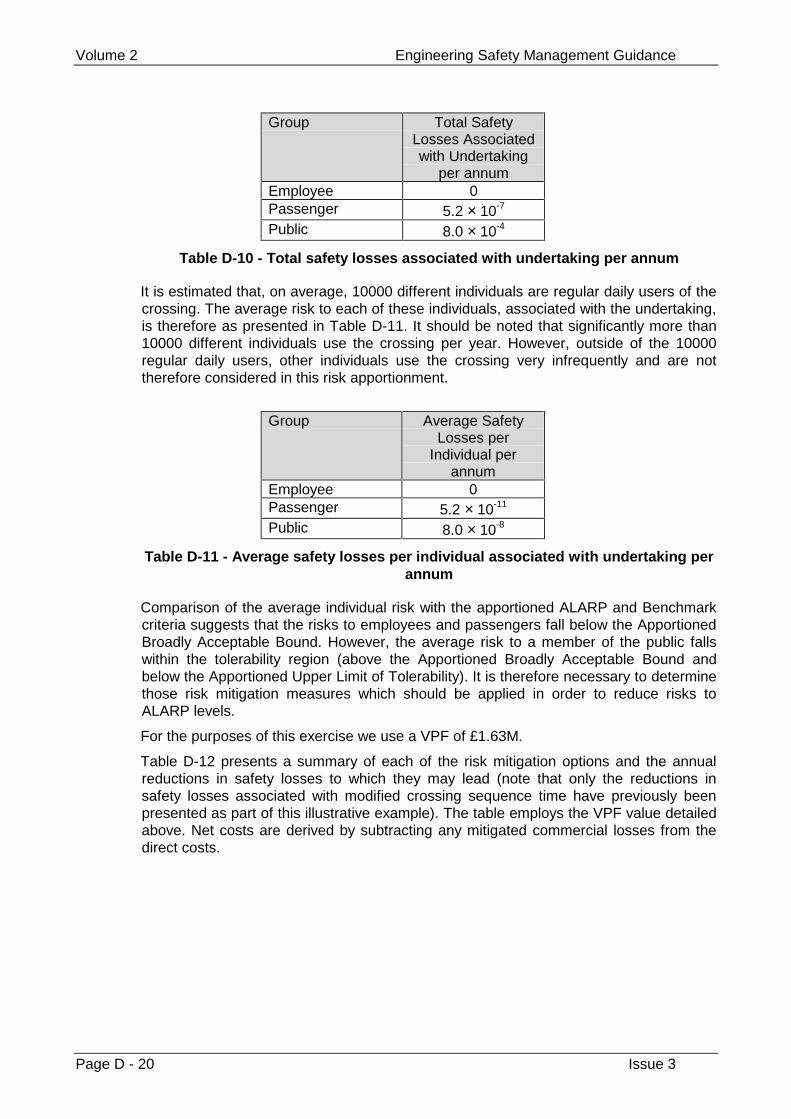
Volume 2 Engineering Safety Management Guidance
Page D - 20 Issue 3
Group Total SafetyLosses Associatedwith Undertaking
per annumEmployee 0Passenger 5.2 × 10⁻⁷
Public 8.0 × 10⁻⁴
Table D-10 - Total safety losses associated with undertaking per annum
It is estimated that, on average, 10000 different individuals are regular daily users of thecrossing. The average risk to each of these individuals, associated with the undertaking,is therefore as presented in Table D-11. It should be noted that significantly more than10000 different individuals use the crossing per year. However, outside of the 10000regular daily users, other individuals use the crossing very infrequently and are nottherefore considered in this risk apportionment.
Group Average Safety
Losses perIndividual per
annumEmployee 0Passenger 5.2 × 10⁻¹¹
Public 8.0 × 10⁻⁸
Table D-11 - Average safety losses per individual associated with undertaking perannum
Comparison of the average individual risk with the apportioned ALARP and Benchmarkcriteria suggests that the risks to employees and passengers fall below the ApportionedBroadly Acceptable Bound. However, the average risk to a member of the public fallswithin the tolerability region (above the Apportioned Broadly Acceptable Bound andbelow the Apportioned Upper Limit of Tolerability). It is therefore necessary to determinethose risk mitigation measures which should be applied in order to reduce risks toALARP levels.
For the purposes of this exercise we use a VPF of £1.63M.
Table D-12 presents a summary of each of the risk mitigation options and the annualreductions in safety losses to which they may lead (note that only the reductions insafety losses associated with modified crossing sequence time have previously beenpresented as part of this illustrative example). The table employs the VPF value detailedabove. Net costs are derived by subtracting any mitigated commercial losses from thedirect costs.
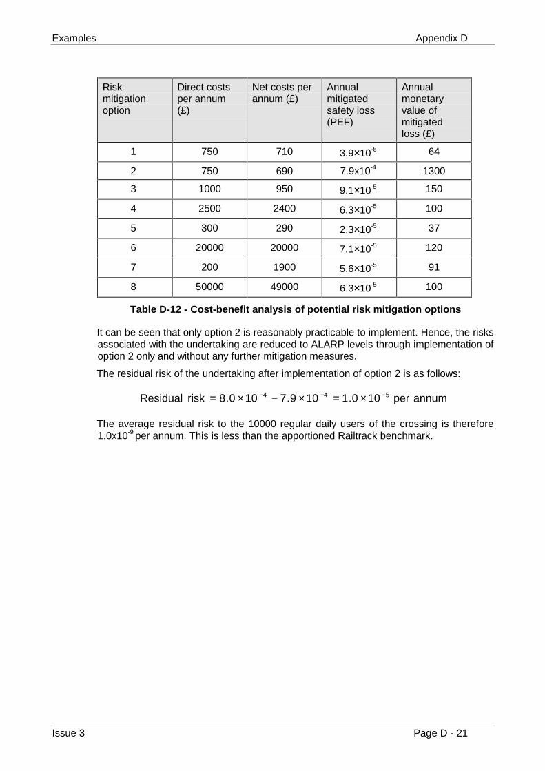
Examples Appendix D
Issue 3 Page D - 21
Riskmitigationoption
Direct costsper annum(£)
Net costs perannum (£)
Annualmitigatedsafety loss(PEF)
Annualmonetaryvalue ofmitigatedloss (£)
1 750 710 3.9×10⁻⁵ 64
2 750 690 7.9x10⁻⁴ 1300
3 1000 950 9.1×10⁻⁵ 150
4 2500 2400 6.3×10⁻⁵ 100
5 300 290 2.3×10⁻⁵ 37
6 20000 20000 7.1×10⁻⁵ 120
7 200 1900 5.6×10⁻⁵ 91
8 50000 49000 6.3×10⁻⁵ 100
Table D-12 - Cost-benefit analysis of potential risk mitigation options
It can be seen that only option 2 is reasonably practicable to implement. Hence, the risksassociated with the undertaking are reduced to ALARP levels through implementation ofoption 2 only and without any further mitigation measures.
The residual risk of the undertaking after implementation of option 2 is as follows:
annum per 100.1109.7100.8risk Residual 544 −−− ×=×−×=
The average residual risk to the 10000 regular daily users of the crossing is therefore1.0x10-9 per annum. This is less than the apportioned Railtrack benchmark.
Volume 2 Engineering Safety Management Guidance
Page D - 22 Issue 3
D.4 Safety Assessment remit
The following generic wording is used and recommended by the Railtrack SystemReview Panels as a starting point for writing remits for safety assessments:
The assessment shall:
• State the safety targets which have been used in carrying out theassessment.
• Give a professional recommendation on the suitability and acceptabilityof the document with regard to its stated purpose.
The critical and most sensitive arguments of the documents should beclearly and concisely highlighted and a professional opinion shall begiven as to the robustness of the argument. Where the argument ofcontained in whole or part within other documents or is part of existingcustom and practice this should be clearly identified.
A professional opinion should also be given, with regard to the railwaysystem as a whole, as to the practicality of any measures used tomitigate against the hazards raised.
• Identify any non-compliances to Railway Group or Railtrack LineStandards and legal requirements.
• Supply related technical advice as required by the Client, or asperceived necessary by the advisor.
All assessor observations are to be uniquely numbered and classified intoone of the following three Classes, categories 1 to 3 should be used whereoperational use is being sought and categories A to C where otherdocuments are under review (additional subclasses are permitted to aidclarity):
Documents seeking Operational Authority
Category 1 Issue is sufficiently important to require (substantial) resolution,prior to recommending that the train/equipment may becomeoperational. (Alternatively a specific control measure may beimplemented to control the risk in the short term).
Category 2 Issue is sufficiently important to require resolution within 3-6months, but the train/equipment may become operational in theinterim (possibly with a protective control measure).
Category 3 Issue is highlighted for incorporation into the Safety Case at thenext periodic review, but no action is required separately.
Examples Appendix D
Issue 3 Page D - 23
Other Documents
Category A Concerns, errors, omissions or questions that have a directbearing on the acceptability of the document, which it isnecessary to resolve prior to the consideration of downstream oroffspring documents.
Category B Requires satisfactory resolution prior to acceptance of completesafety submission, or within a defined time period (not normally toexceed 6 months).
Category C Minor errors, e.g. syntax, spelling, minor technical matters whichhave no direct significant safety implications. For clarity, theserequire to be recorded and correcting if the document is re-issued, but are not in themselves sufficiently significant to warrantre-issue on their own.
For either the numerical or alphabetical categories, where there are a largenumber of lower category issues, the reviewer is to consider whether intotality they represent sufficient residual risk that they in effect equate to oneor more higher category issues (e.g. that they would warrant the impositionof any additional mitigating control measures). In these circumstances, Itshould be considered whether these outstanding issues relate to an overalllack of rigour or quality in the document which has been reviewed.
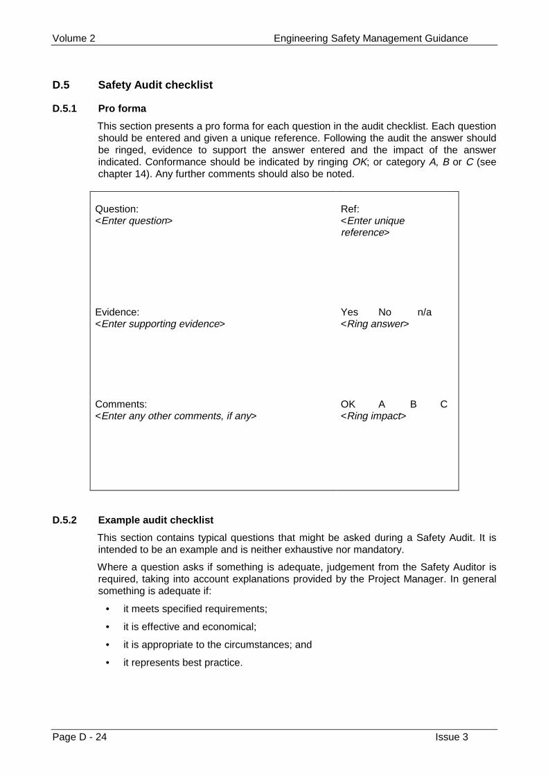
Volume 2 Engineering Safety Management Guidance
Page D - 24 Issue 3
D.5 Safety Audit checklist
D.5.1 Pro forma
This section presents a pro forma for each question in the audit checklist. Each questionshould be entered and given a unique reference. Following the audit the answer shouldbe ringed, evidence to support the answer entered and the impact of the answerindicated. Conformance should be indicated by ringing OK; or category A, B or C (seechapter 14). Any further comments should also be noted.
Question:<Enter question>
Ref:<Enter uniquereference>
Evidence:<Enter supporting evidence>
Yes No n/a<Ring answer>
Comments:<Enter any other comments, if any>
OK A B C<Ring impact>
D.5.2 Example audit checklist
This section contains typical questions that might be asked during a Safety Audit. It isintended to be an example and is neither exhaustive nor mandatory.
Where a question asks if something is adequate, judgement from the Safety Auditor isrequired, taking into account explanations provided by the Project Manager. In generalsomething is adequate if:
• it meets specified requirements;
• it is effective and economical;
• it is appropriate to the circumstances; and
• it represents best practice.
Examples Appendix D
Issue 3 Page D - 25
D.5.2.1 Safety planning
a) Is there an adequate Safety Plan (see chapter 12)?
b) Are the responsibilities for safety and the competencies of staff clearly defined?
c) Is the Safety Plan clear, easily obtained and accessible to the project?
d) Have appropriate safety requirements been defined for each deliverable?
e) Have suitable controls been devised to verify the safety requirements?
f) Has an appropriate approach to safety been chosen?
D.5.2.2 Safety documentation
a) Has the Safety Documentation required for the project been identified?
b) Has the identified documentation been produced?
c) Is the plan for safety documentation adequate?
d) Have the responsibilities for producing safety documentation been identified?
e) Has the documentation been produced by the staff identified for the task?
f) Has an appropriate standard for documentation been specified?
g) Has the standard been consistently applied?
D.5.2.3 Subcontract management
a) Has an adequate method of evaluating subcontractor capability been identified?
b) Has this method been rigorously applied to all subcontractors?
c) Has each subcontractor been set safety targets or requirements?
d) Has each subcontractor produced a Safety Plan?
e) Have these plans been reviewed and approved as defined in the project SafetyPlan?
f) Is there any evidence of subcontractor non-compliance?
g) Have all subcontractor-identified hazards been entered in the Hazard Log?
D.5.2.4 Testing
a) Has testing called for in the Safety Plan been carried out?
b) Is the test team independent of the development team?
c) Have incidents arising from testing activities been entered in the Hazard Log?
d) Does the testing programme adequately demonstrate the safety of the system?
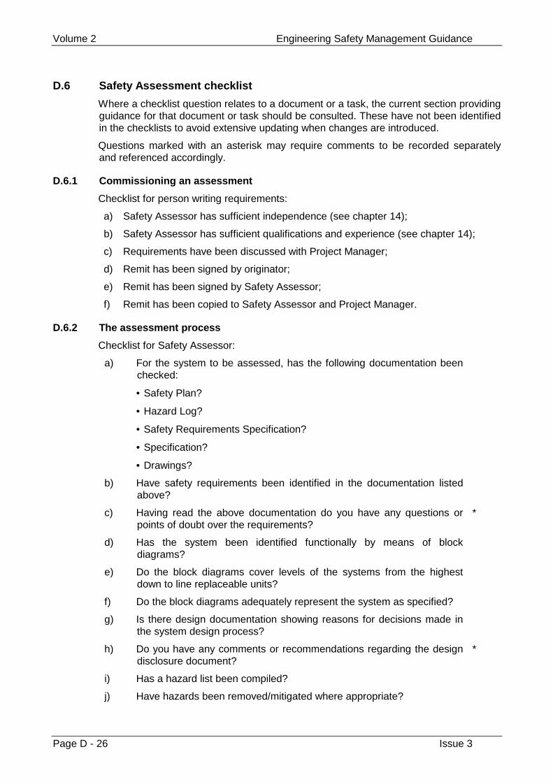
Volume 2 Engineering Safety Management Guidance
Page D - 26 Issue 3
D.6 Safety Assessment checklist
Where a checklist question relates to a document or a task, the current section providingguidance for that document or task should be consulted. These have not been identifiedin the checklists to avoid extensive updating when changes are introduced.
Questions marked with an asterisk may require comments to be recorded separatelyand referenced accordingly.
D.6.1 Commissioning an assessment
Checklist for person writing requirements:
a) Safety Assessor has sufficient independence (see chapter 14);
b) Safety Assessor has sufficient qualifications and experience (see chapter 14);
c) Requirements have been discussed with Project Manager;
d) Remit has been signed by originator;
e) Remit has been signed by Safety Assessor;
f) Remit has been copied to Safety Assessor and Project Manager.
D.6.2 The assessment process
Checklist for Safety Assessor:
a) For the system to be assessed, has the following documentation beenchecked:
• Safety Plan?
• Hazard Log?
• Safety Requirements Specification?
• Specification?
• Drawings?
b) Have safety requirements been identified in the documentation listedabove?
c) Having read the above documentation do you have any questions orpoints of doubt over the requirements?
*
d) Has the system been identified functionally by means of blockdiagrams?
e) Do the block diagrams cover levels of the systems from the highestdown to line replaceable units?
f) Do the block diagrams adequately represent the system as specified?
g) Is there design documentation showing reasons for decisions made inthe system design process?
h) Do you have any comments or recommendations regarding the designdisclosure document?
*
i) Has a hazard list been compiled?
j) Have hazards been removed/mitigated where appropriate?
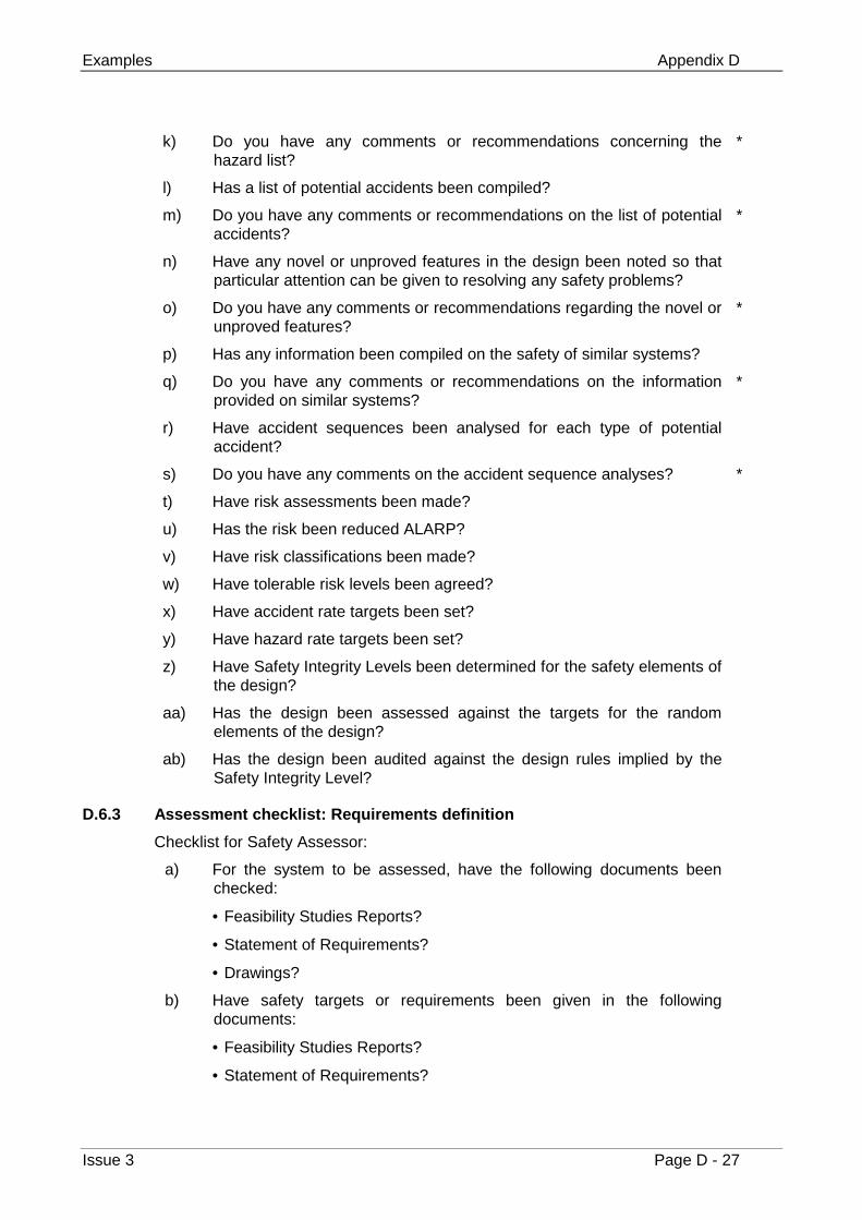
Examples Appendix D
Issue 3 Page D - 27
k) Do you have any comments or recommendations concerning thehazard list?
*
l) Has a list of potential accidents been compiled?
m) Do you have any comments or recommendations on the list of potentialaccidents?
*
n) Have any novel or unproved features in the design been noted so thatparticular attention can be given to resolving any safety problems?
o) Do you have any comments or recommendations regarding the novel orunproved features?
*
p) Has any information been compiled on the safety of similar systems?
q) Do you have any comments or recommendations on the informationprovided on similar systems?
*
r) Have accident sequences been analysed for each type of potentialaccident?
s) Do you have any comments on the accident sequence analyses? *
t) Have risk assessments been made?
u) Has the risk been reduced ALARP?
v) Have risk classifications been made?
w) Have tolerable risk levels been agreed?
x) Have accident rate targets been set?
y) Have hazard rate targets been set?
z) Have Safety Integrity Levels been determined for the safety elements ofthe design?
aa) Has the design been assessed against the targets for the randomelements of the design?
ab) Has the design been audited against the design rules implied by theSafety Integrity Level?
D.6.3 Assessment checklist: Requirements definition
Checklist for Safety Assessor:
a) For the system to be assessed, have the following documents beenchecked:
• Feasibility Studies Reports?
• Statement of Requirements?
• Drawings?
b) Have safety targets or requirements been given in the followingdocuments:
• Feasibility Studies Reports?
• Statement of Requirements?
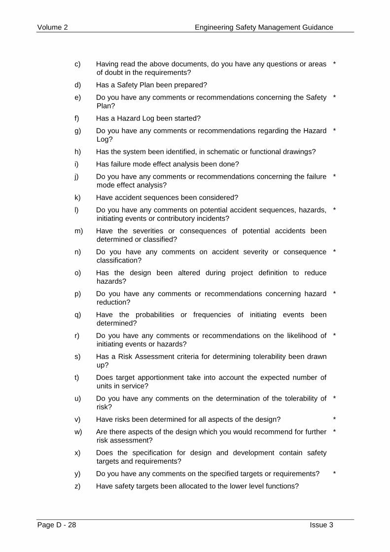
Volume 2 Engineering Safety Management Guidance
Page D - 28 Issue 3
c) Having read the above documents, do you have any questions or areasof doubt in the requirements?
*
d) Has a Safety Plan been prepared?
e) Do you have any comments or recommendations concerning the SafetyPlan?
*
f) Has a Hazard Log been started?
g) Do you have any comments or recommendations regarding the HazardLog?
*
h) Has the system been identified, in schematic or functional drawings?
i) Has failure mode effect analysis been done?
j) Do you have any comments or recommendations concerning the failuremode effect analysis?
*
k) Have accident sequences been considered?
l) Do you have any comments on potential accident sequences, hazards,initiating events or contributory incidents?
*
m) Have the severities or consequences of potential accidents beendetermined or classified?
n) Do you have any comments on accident severity or consequenceclassification?
*
o) Has the design been altered during project definition to reducehazards?
p) Do you have any comments or recommendations concerning hazardreduction?
*
q) Have the probabilities or frequencies of initiating events beendetermined?
r) Do you have any comments or recommendations on the likelihood ofinitiating events or hazards?
*
s) Has a Risk Assessment criteria for determining tolerability been drawnup?
t) Does target apportionment take into account the expected number ofunits in service?
u) Do you have any comments on the determination of the tolerability ofrisk?
*
v) Have risks been determined for all aspects of the design? *
w) Are there aspects of the design which you would recommend for furtherrisk assessment?
*
x) Does the specification for design and development contain safetytargets and requirements?
y) Do you have any comments on the specified targets or requirements? *
z) Have safety targets been allocated to the lower level functions?
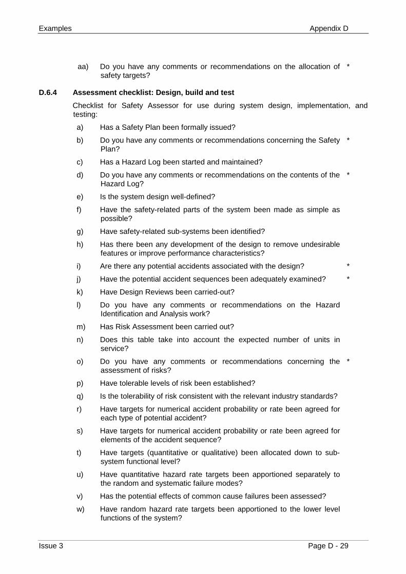
Examples Appendix D
Issue 3 Page D - 29
aa) Do you have any comments or recommendations on the allocation ofsafety targets?
*
D.6.4 Assessment checklist: Design, build and test
Checklist for Safety Assessor for use during system design, implementation, andtesting:
a) Has a Safety Plan been formally issued?
b) Do you have any comments or recommendations concerning the SafetyPlan?
*
c) Has a Hazard Log been started and maintained?
d) Do you have any comments or recommendations on the contents of theHazard Log?
*
e) Is the system design well-defined?
f) Have the safety-related parts of the system been made as simple aspossible?
g) Have safety-related sub-systems been identified?
h) Has there been any development of the design to remove undesirablefeatures or improve performance characteristics?
i) Are there any potential accidents associated with the design? *
j) Have the potential accident sequences been adequately examined? *
k) Have Design Reviews been carried-out?
l) Do you have any comments or recommendations on the HazardIdentification and Analysis work?
m) Has Risk Assessment been carried out?
n) Does this table take into account the expected number of units inservice?
o) Do you have any comments or recommendations concerning theassessment of risks?
*
p) Have tolerable levels of risk been established?
q) Is the tolerability of risk consistent with the relevant industry standards?
r) Have targets for numerical accident probability or rate been agreed foreach type of potential accident?
s) Have targets for numerical accident probability or rate been agreed forelements of the accident sequence?
t) Have targets (quantitative or qualitative) been allocated down to sub-system functional level?
u) Have quantitative hazard rate targets been apportioned separately tothe random and systematic failure modes?
v) Has the potential effects of common cause failures been assessed?
w) Have random hazard rate targets been apportioned to the lower levelfunctions of the system?
Volume 2 Engineering Safety Management Guidance
Page D - 30 Issue 3
x) Have Safety Integrity Levels been defined for the systematic elements?
y) Have Safety Integrity Levels been apportioned to lower level functionsaccording to agreed rules (see Chapter 9)?
z) Have the targets and criteria developed from the above beenadequately recorded and reported in the Hazard Log?
*
aa) In carrying out the Safety Assessment, it is necessary to compare therandom targets with those predicted for the random elements. Is thecomparison satisfactory?
*
ab) For the Safety Assessment of the systematic elements, it is necessaryto audit the design against the tolerable levels of risk, the agreed rulesfor Safety Integrity Levels and the design techniques. Is the designacceptable?
*
D.6.5 Assessment checklist: Customer acceptance and validation
Checklist for Safety Assessor:
a) Does the Safety Plan contain an element relating to a test andacceptance programme?
b) Are the safety features of the design identified for acceptance tests?
c) Do you have any comments or recommendations concerning theadequacy of the test programme?
*
d) Have the results of the safety test and acceptance programme beenrecorded and reported in the Hazard Log?
e) Are the results satisfactory? *
f) Are there any shortcomings or outstanding items? *
g) Is the level of test coverage adequate?
D.6.6 Assessment checklist: Site trial/pilot scheme
Checklist for Safety Assessor:
a) Does the Safety Plan contain requirements for the conduct of SiteTrial?
b) Does the Safety Plan contain requirements for the conduct of a PilotScheme?
c) Are the safety features of the system design identified for Site Trialpurposes?
d) Are the safety features of the system design identified for Pilot Schemepurposes?
e) Do you have any comments regarding the adequacy of the Site Trial todemonstrate the safety features?
*
f) Do you have any comments regarding the adequacy of the PilotScheme to demonstrate the safety features?
*
g) Has an incident or defect reporting system been set up for the SiteTrial?
h) Is the trial covered by a Safety Certificate?
Examples Appendix D
Issue 3 Page D - 31
i) Is the system being used with the constraints of the Safety Certificate?
j) Are all necessary support arrangements in place?
D.6.7 Assessment checklist: In-service support
Checklist for Safety Assessor:
a) Has support of the system in service been addressed duringRequirements Definition?
b) Has support of the system in service been addressed duringDesign and Development?

Volume 2 Engineering Safety Management Guidance
Page D - 32 Issue 3
This page left intentionally blank
Techniques Appendix E
Issue 3 Page E - 1
Appendix E
Techniques
This appendix provides additional guidance on the execution of the following techniques
1 Failure Mode and Effects Analysis (FMEA) (see chapter 8)
2 Hazard and Operability Studies (HAZOP) (see chapter 8)
3 Fault Tree Analysis (see chapter 8)
4 Cause Consequence Diagramming (see chapter 8)
5 Data Recording and Corrective Action System (DRACAS) (see chapter 12)
Volume 2 Engineering Safety Management Guidance
Page E - 2 Issue 3
E.1 Failure Mode and Effects Analysis (FMEA)
FMEA should be carried out in compliance with established standards such as BS 5760[F.20].
Note that users of this standard should ensure that they use a common set of units, ifthey wish their risk ratings to be comparable
The analyst should consider components at a detailed level of indenture and record theirfailure modes along with causes and effects. The failure effects of these sub-components then become failure modes of components at the next higher level ofindenture. The process is repeated up the functional hierarchy to yield the individualfailure modes of the whole system.
The depth of the analysis should be adjusted according to the preliminary appraisal ofthe hazards. The components which contribute to more severe hazards should beanalysed in greater detail.
Checklists, HAZOP or other techniques may be used to identify basic failure modes.
The analysis is recorded on a worksheet which has at least the following columns:
Item Ref The unique identifier of the sub-component beingconsidered.
Description A description of this sub-component.
Failure Ref A unique identifier for the failure mode entered.
Mode A description of the failure mode.
Causes For this failure.
Effect Of this failure (local and system-wide).
CompensatingProvisions
Which may cause the effects of this failure not to bepromulgated.
How detected The means by which the failure may be detected.
Remarks Any other notes made by the analyst.
This conforms to the British Standard for FMECA [F.20 §2.2.3] except that there is nocolumn for ‘Severity of effects’. Criticality is considered instead during the later stages ofRisk Assessment although note that FMECA may be more appropriate for someapplications.
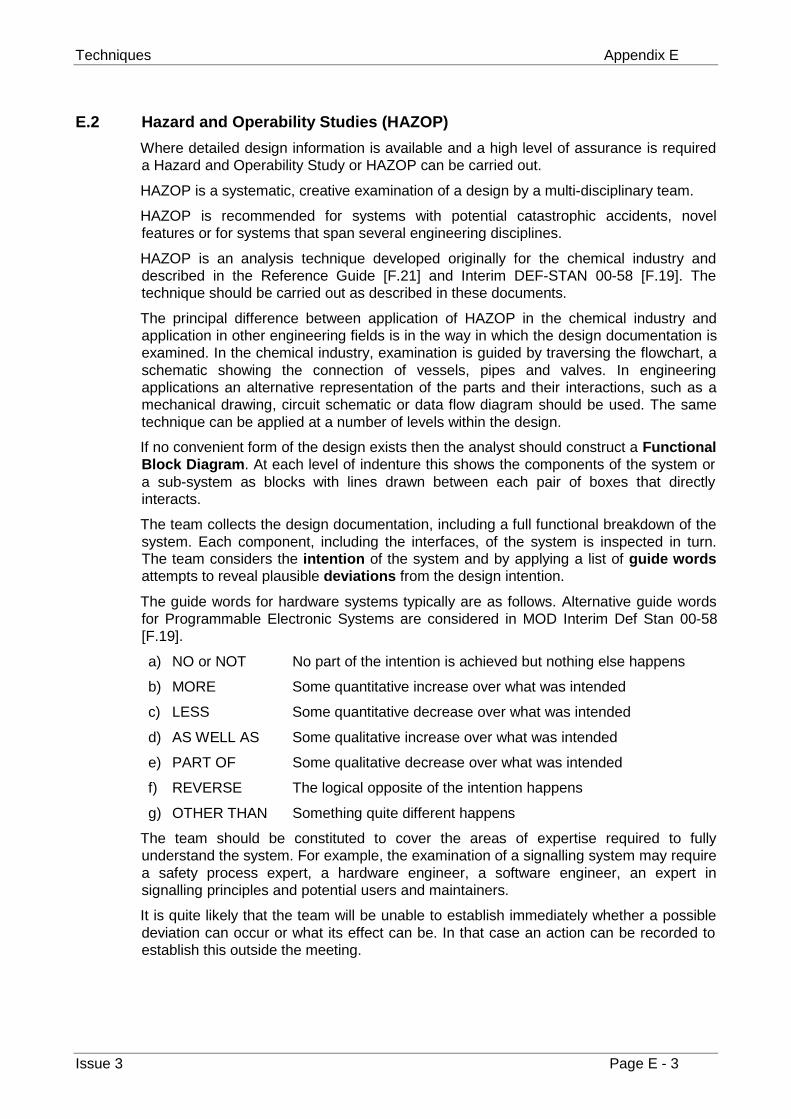
Techniques Appendix E
Issue 3 Page E - 3
E.2 Hazard and Operability Studies (HAZOP)
Where detailed design information is available and a high level of assurance is requireda Hazard and Operability Study or HAZOP can be carried out.
HAZOP is a systematic, creative examination of a design by a multi-disciplinary team.
HAZOP is recommended for systems with potential catastrophic accidents, novelfeatures or for systems that span several engineering disciplines.
HAZOP is an analysis technique developed originally for the chemical industry anddescribed in the Reference Guide [F.21] and Interim DEF-STAN 00-58 [F.19]. Thetechnique should be carried out as described in these documents.
The principal difference between application of HAZOP in the chemical industry andapplication in other engineering fields is in the way in which the design documentation isexamined. In the chemical industry, examination is guided by traversing the flowchart, aschematic showing the connection of vessels, pipes and valves. In engineeringapplications an alternative representation of the parts and their interactions, such as amechanical drawing, circuit schematic or data flow diagram should be used. The sametechnique can be applied at a number of levels within the design.
If no convenient form of the design exists then the analyst should construct a FunctionalBlock Diagram. At each level of indenture this shows the components of the system ora sub-system as blocks with lines drawn between each pair of boxes that directlyinteracts.
The team collects the design documentation, including a full functional breakdown of thesystem. Each component, including the interfaces, of the system is inspected in turn.The team considers the intention of the system and by applying a list of guide wordsattempts to reveal plausible deviations from the design intention.
The guide words for hardware systems typically are as follows. Alternative guide wordsfor Programmable Electronic Systems are considered in MOD Interim Def Stan 00-58[F.19].
a) NO or NOT No part of the intention is achieved but nothing else happens
b) MORE Some quantitative increase over what was intended
c) LESS Some quantitative decrease over what was intended
d) AS WELL AS Some qualitative increase over what was intended
e) PART OF Some qualitative decrease over what was intended
f) REVERSE The logical opposite of the intention happens
g) OTHER THAN Something quite different happens
The team should be constituted to cover the areas of expertise required to fullyunderstand the system. For example, the examination of a signalling system may requirea safety process expert, a hardware engineer, a software engineer, an expert insignalling principles and potential users and maintainers.
It is quite likely that the team will be unable to establish immediately whether a possibledeviation can occur or what its effect can be. In that case an action can be recorded toestablish this outside the meeting.
Volume 2 Engineering Safety Management Guidance
Page E - 4 Issue 3
E.3 Fault Tree Analysis
Fault Tree Analysis (FTA) is a widely known and accepted top-down or deductive systemfailure analysis technique. The Fault Tree Handbook, NUREG-0492 [F.22], is acomprehensive reference document for FTA, and may be used in conjunction with otherFTA standards.
FTA begins with a single undesired top event and provides a method for determining allthe possible causes of that event.
A correctly constructed Fault Tree is a graphical and logical model of the various paralleland sequential combinations of events that will result in the occurrence of the Top Event.
FTA can be used for both qualitative as well as quantitative analysis. The graphicalnature of the technique aids the qualitative identification of potential sources of single-point failures and safety critical failure combinations.
The precise definition of the top event is critical to the success of the analysis, since anincorrect top event will, in most cases, invalidate the whole analysis.
The system is analysed, from the identified top events, in the context of its environment,and modes of operation, to find all credible causal events.
The fault tree is made up of gates, which serve to permit or inhibit the flow of fault logicup the tree. The gates show the relationship of lower events - the inputs to the gate -needed for the occurrence of a higher event - the output of the gate. The gate symboldenotes the relationship of the input events required for the output event.
The fault tree is used to produce the minimal cut sets - the minimum combination ofindependent base events which, if they occur or exist at the same time, will cause thetop-event to occur. The minimal cut sets provide the basis for both the qualitative andquantitative analysis of the system.
Fault Trees are relatively simple in concept, but can be very difficult in practice. This isparticularly true when quantitative analysis is required. Chapter V of NUREG-0492 [F.22]provides a detailed explanation of the technique. The following key concepts and rulesfrom that document are given here to guide the analyst in the approach required to theconstruction of the tree.
In determining the causes of an event in a fault tree, the analyst should identify theimmediate, necessary and sufficient causes for the occurrence of that event. Thetemptation to jump directly to the basic causes should be resisted, even if these mayappear obvious.
The dependence between base events within a minimal cut set should be identifiedduring FTA. This is achieved by performing Common Cause Failure Analysis on theMinimal Cut Sets to identify potential dependencies.
The following basic rules should be applied when constructing a fault tree:
a) Write the statements that are entered into the event boxes as faults: state preciselywhat the fault is and when it occurs.
b) If the answer to the question ‘Can this fault consist of a component failure?’ is ‘Yes’,classify the event as a ‘State of Component Fault’. If the answer is ‘No’, classifythe event as a ‘State of System Fault’. If an event is classified as ‘State ofComponent Fault’, add an OR-gate below the event and look for primary, secondaryand command faults that may cause the event. If an event is classified as a ‘State ofSystem Fault’, an AND-gate, OR-gate, INHIBIT-gate, or possibly no gate at all may
Techniques Appendix E
Issue 3 Page E - 5
be required, and the minimum, necessary and sufficient causes should bedetermined.
c) If the normal functioning of a component propagates a fault sequence, then it isassumed that the component functions normally.
d) All inputs to a particular gate should be completely defined before further analysis ofany one of them is undertaken.
e) Gate inputs are to be properly defined fault events. Gates are not to be connecteddirectly to other gates.
f) Identify fixed probabilities ie non-failure conditions, with inhibit gates.
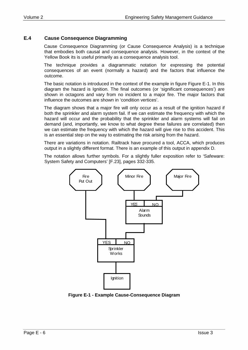
Volume 2 Engineering Safety Management Guidance
Page E - 6 Issue 3
E.4 Cause Consequence Diagramming
Cause Consequence Diagramming (or Cause Consequence Analysis) is a techniquethat embodies both causal and consequence analysis. However, in the context of theYellow Book its is useful primarily as a consequence analysis tool.
The technique provides a diagrammatic notation for expressing the potentialconsequences of an event (normally a hazard) and the factors that influence theoutcome.
The basic notation is introduced in the context of the example in figure Figure E-1. In thisdiagram the hazard is Ignition. The final outcomes (or ‘significant consequences’) areshown in octagons and vary from no incident to a major fire. The major factors thatinfluence the outcomes are shown in ‘condition vertices’.
The diagram shows that a major fire will only occur as a result of the ignition hazard ifboth the sprinkler and alarm system fail. If we can estimate the frequency with which thehazard will occur and the probability that the sprinkler and alarm systems will fail ondemand (and, importantly, we know to what degree these failures are correlated) thenwe can estimate the frequency with which the hazard will give rise to this accident. Thisis an essential step on the way to estimating the risk arising from the hazard.
There are variations in notation. Railtrack have procured a tool, ACCA, which producesoutput in a slightly different format. There is an example of this output in appendix D.
The notation allows further symbols. For a slightly fuller exposition refer to ‘Safeware:System Safety and Computers’ [F.23], pages 332-335.
Ignition
SprinklerWorks
YES NO
AlarmSounds
YES NO
FirePut Out
Minor Fire Major Fire
Figure E-1 - Example Cause-Consequence Diagram
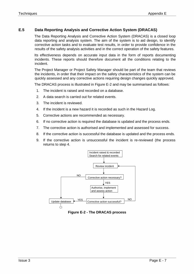
Techniques Appendix E
Issue 3 Page E - 7
E.5 Data Reporting Analysis and Corrective Action System (DRACAS)
The Data Reporting Analysis and Corrective Action System (DRACAS) is a closed loopdata reporting and analysis system. The aim of the system is to aid design, to identifycorrective action tasks and to evaluate test results, in order to provide confidence in theresults of the safety analysis activities and in the correct operation of the safety features.
Its effectiveness depends on accurate input data in the form of reports documentingincidents. These reports should therefore document all the conditions relating to theincident.
The Project Manager or Project Safety Manager should be part of the team that reviewsthe incidents, in order that their impact on the safety characteristics of the system can bequickly assessed and any corrective actions requiring design changes quickly approved.
The DRACAS process is illustrated in Figure E-2 and may be summarised as follows:
1. The incident is raised and recorded on a database.
2. A data search is carried out for related events.
3. The incident is reviewed.
4. If the incident is a new hazard it is recorded as such in the Hazard Log.
5. Corrective actions are recommended as necessary.
6. If no corrective action is required the database is updated and the process ends.
7. The corrective action is authorised and implemented and assessed for success.
8. If the corrective action is successful the database is updated and the process ends.
9. If the corrective action is unsuccessful the incident is re-reviewed (the processreturns to step 4.
Figure E-2 - The DRACAS process
Incident raised & recordedSearch for related events
Review incident
Corrective action necessary?
Update database
Authorise, implementand assess action
Corrective action successful?YES
YES
NO
NO

Volume 2 Engineering Safety Management Guidance
Page E - 8 Issue 3
This page left intentionally blank
Referenced Documents Appendix F
Issue 3 Page F - 1
Appendix F
Referenced Documents
This appendix provides full references to the documents referred to in the body ofvolume 2.
F.1 Ould M. A., Business Processes: Modelling and Analysis for Re-engineering andImprovement, Wiley 1995, ISBN 0-471-95352-0
F.2 Profit R., Systematic Safety Management in the Air Traffic Services, EuromoneyBooks 1995, ISBN 1 85564 470 2
F.3 Guidelines on Risk Issues, The Engineering Council, February 1993,ISBN 0-9516611-7-5
F.4 Ministry of Defence, DEF-STAN 00-56, Safety Management Requirements forDefence Systems, Issue 2, December 1996
F.5 DoD MIL-STD-882C, System Safety Program Requirements, 19 January 1993.
F.6 Health and Safety Executive discussion document, Reducing Risk, ProtectingPeople, 1999
F.7 UK Offshore Operators Association, Industry Guidelines on a Framework forRisk Related Decision Support, issue 1, May 1999, ISBN 1 903003 00 8.
F.8 CENELEC Draft prEN50126, Railway applications – The specification anddemonstration of dependability, reliability, availability, maintainability and safety(RAMS)
F.9 Railway Group Standard GK/RT0206, Signalling and OperationalTelecommunications Design: Safety Requirements, Issue 1, February 1998
F.10 Railway Group Code of Practice GK/RC0701, Signalling Design: ProductionGuidance, Issue 1, October 1998
F.11 Hessami A., Risk – A Missed Opportunity?, Risk and Continuity, volume 2, issue2, June 1999, pages 17-26
F.12 Preece J., Rogers Y., Sharp H., Benyon D., Holland S. and Carey T., Human-Computer Interaction., Addison Wesley. 1994, ISBN 0-521-36570-8
F.13 CENELEC ENV50129: 1998, Railway applications – Safety related electronicsystems for signalling, May 1998
F.14 International Electrotechnical Commission, IEC 61508, Functional safety ofelectrical/electronic/programmable electronic safety-related systems.
F.15 Ministry of Defence, Interim DEF-STAN 00-54, Requirements for Safety RelatedElectronic Hardware in Defence Equipment, Issue 1, 19 March 1999
Volume 2 Engineering Safety Management Guidance
Page F - 2 Issue 3
F.16 Ministry of Defence, DEF-STAN 00-55, Requirements for Safety-RelatedSoftware in Defence Equipment, Issue 2, 1997
F.17 CENELEC Draft prEN50128: 1998, Railway applications – Software for railwaycontrol and protection systems
F.18 HMRI, Guide to the Approval of Railway Works, Plant and Equipment, Healthand Safety Executive, 1994
F.19 Ministry of Defence, Interim Defence Standard 00-58, HAZOP Studies onSystems Containing Programmable Electronics, Issue 1, August 1996
F.20 BS5760: Part 5 1991, Reliability of systems, equipment and components: Part 5Guide to failure modes, effects and criticality analysis
F.21 Chemical Industries Association, A Guide to Hazard and Operability Studies,Kings Buildings, Smith Square, London SW1P 3JJ, 1992
F.22 NUREG 0492, The Fault Tree Handbook, 1981
F.23 Leveson N., Safeware: System Safety and Computers, Addison-Wesley 1995,ISBN 0-201-11972-2
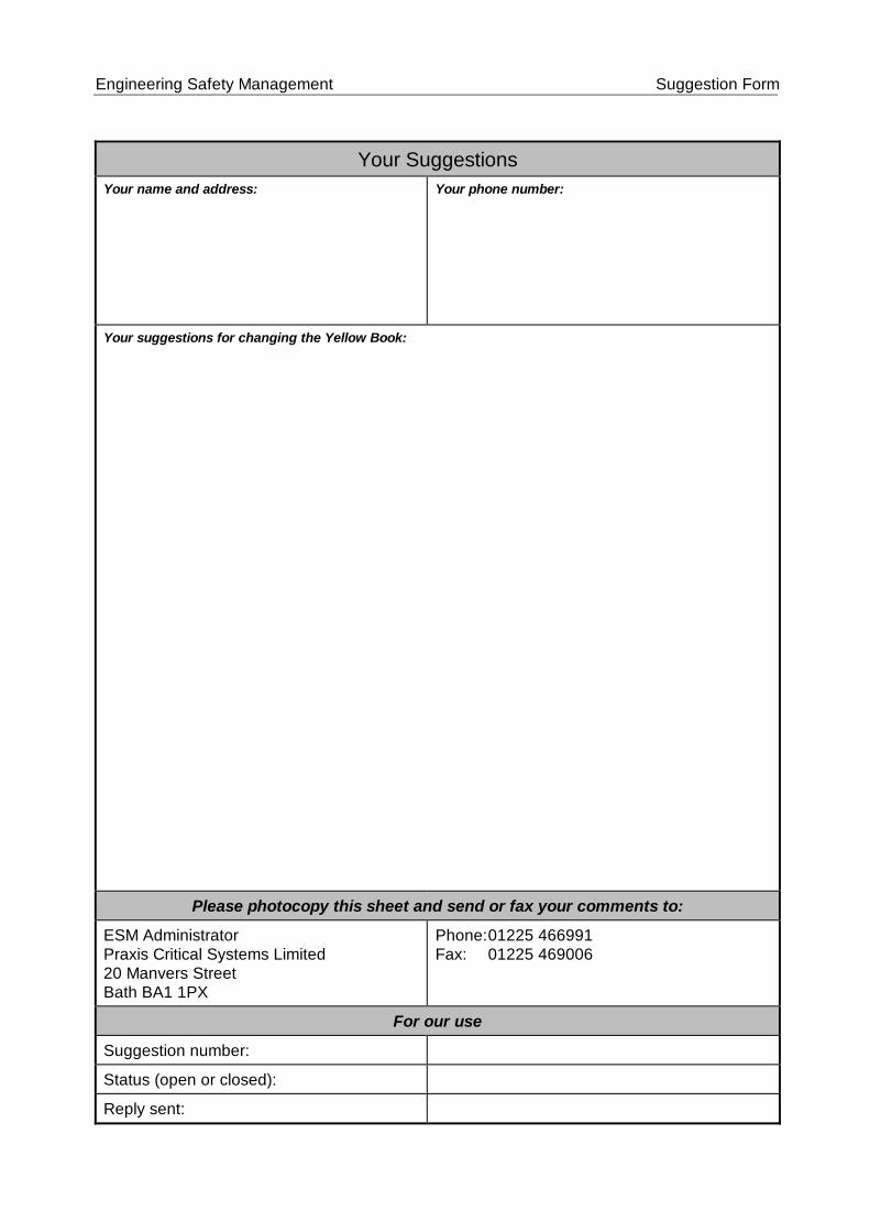
Engineering Safety Management Suggestion Form
Your SuggestionsYour name and address: Your phone number:
Your suggestions for changing the Yellow Book:
Please photocopy this sheet and send or fax your comments to:
ESM AdministratorPraxis Critical Systems Limited20 Manvers StreetBath BA1 1PX
Phone:01225 466991Fax: 01225 469006
For our use
Suggestion number:
Status (open or closed):
Reply sent: