Embed Size (px)
Citation preview

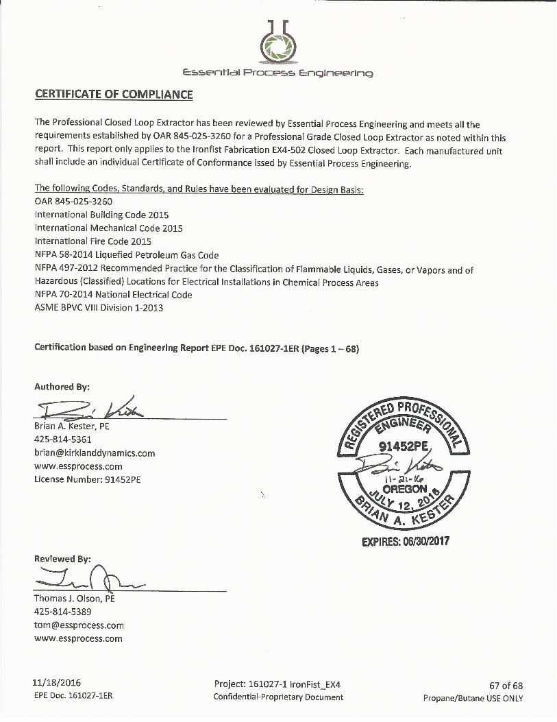
ENGINEERING REPORTProfessional Grade Closed Loop Extractor
Ironfist Fabrication EX4-502 Extractor
Kirkland, WA 98034
11731 120th Avenue NE, Suite B
Essential Process Engineering
Reviewed By:
11/18/2016 EPE Doc. 161027-1ER
Project: 161027-1 IronFist_EX4 Confidential-Proprietary Document
1 of 68 Propane/Butane USE ONLY

INDEX
1. SUMMARY 3
2. SOLVENT DATA 4
3. STANDARD OPERATING PROCEDURE 6
4. EXTRACTOR SYSTEM OVERVIEW 10
5. PRESSURE VESSEL CALCULATIONS 13
6. GENERAL COMPONENT SPECIFICATIONS 39
7. CHEMICAL COMPATIBILITY 55
8. WARNING SIGNS & PLACARDS 59
9. STATE SPECIFIC REQUIREMENTS 60
10. CERTIFICATE OF COMPLIANCE 67
11. PRESSURE VESSEL DRAWINGS APPENDIX A
11/18/2016 EPE Doc. 161027-1ER
Project: 161027-1 IronFist_EX4 Confidential-Proprietary Document
2 of 68 Propane/Butane USE ONLY

SUMMARY
EXTRACTOR MANUFACTURER: Ironfist Fabrication ALLOWABLE WORKING PRESSURE: 250 PSI
EXTRACTOR TITLE: EX4-502 OPERATING TEMPERATURE RANGE: -20 TO 110 ͦF
Figure 1.1 - Ironfist Fabrication EX4-502 Extractor
An engineering analysis has been performed on a Professional Grade Closed Loop Extraction system used in the
extraction of essential oils from a botanical substance by use of a Propane/Butane solvent. The Extraction system
analyzed within this report is classified as the Ironfist Fabrication EX4-502 Extractor. This system is composed of an
assembly of food grade piping and pressure vessels. The system identified within this report is based on
configurations for use as processing equipment. The Closed Loop Extraction system has been analyzed using the
American Society of Mechanical Engineers (ASME) standards B36.19M-2004, B36.10M-2004, ASME BPVC Section VIII
Division 1-2013, and NFPA-58 LP Gas Code as a BASIS FOR DESIGN ONLY. As no such standard exists for the
specification and control of Closed-Loop Extraction, a Performance based design has been completed. This report
and certificate of conformance shall demonstrate that the use of the Ironfist Fabrication EX4-502 extractor model
shown in Figure 3.1 in conjunction with those facility fire protection and safety features identified, meets all
requirements for this type of system in design and manufacturing. This report identifies minimum installation
requirements of the processing lab for safe operation per the International Building Code (IBC) 2015, International
Fire Code 2015 (IFC), International Mechanical Code 2015 (IMC), NFPA 54-2015, NFPA 497-2012, and NFPA 70-2014.
11/18/2016 EPE Doc. 161027-1ER
Project: 161027-1 IronFist_EX4 Confidential-Proprietary Document
3 of 68 Propane/Butane USE ONLY

SOLVENT DATA
Maximum Operating Temperature for this extraction system = 110 ͦF
VP Butane at 110 ͦF = 45 psig
VP Propane at 110 ͦF = 220 psig
**Considerations must be made for varying altitudes.
The Ironfist Fabrication EX4-502 extractor system reviewed in this report is certified for the use of either Propane or
Butane as the solvent medium. Vapor Pressures and corresponding Maximum Allowable Working Pressures
(MAWP) for these solvents are shown below.
Table 2.1 - Propane and Butane Vapor Pressures(Fisher Controls LP-Gas Serviceman's Handbook, 2001)
11/18/2016 EPE Doc. 161027-1ER
Project: 161027-1 IronFist_EX4 Confidential-Proprietary Document
4 of 68 Propane/Butane USE ONLY
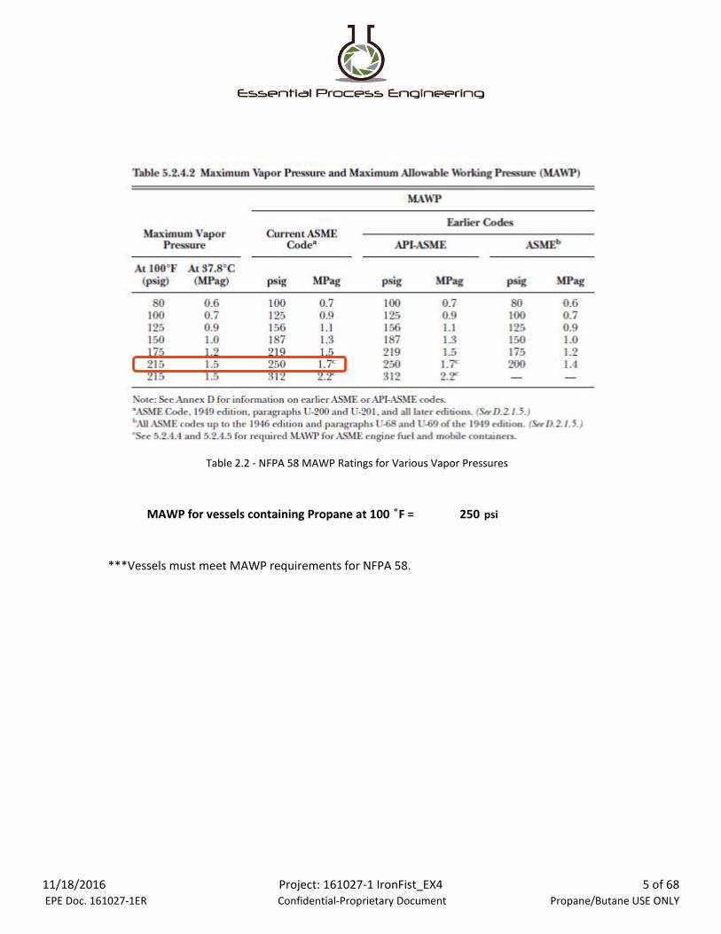
MAWP for vessels containing Propane at 100 ͦF = 250 psi
***Vessels must meet MAWP requirements for NFPA 58.
Table 2.2 - NFPA 58 MAWP Ratings for Various Vapor Pressures
11/18/2016 EPE Doc. 161027-1ER
Project: 161027-1 IronFist_EX4 Confidential-Proprietary Document
5 of 68 Propane/Butane USE ONLY

STANDARD OPERATING PROCEDURE
GENERAL EXTRACTION SYSTEM COMPONENTS
The following is a general overview of the extraction process. Operating procedures may vary for specific extractor
models.
MATERIAL VESSEL - HOLDS TRIM BEING PROCESSED.
*SOME EXTRACTION SYSTEMS MAY USE MULTIPLE MATERIAL VESSELS.
SOLVENT TANK - CONTAINS REQUIRED AMOUNT OF
BUTANE/PROPANE
COLLECTION VESSEL - USED TO COLLECT EXTRACTED OIL AND SOLVENT AT THE END OF THE
EXTRACTION PROCESS.
PUMP - USED TO CREATE A VACUUM IN THE
SYSTEM AND TO RECOVER SOLVENT GAS FROM THE
COLLECTION VESSEL.
11/18/2016 EPE Doc. 161027-1ER
Project: 161027-1 IronFist_EX4 Confidential-Proprietary Document
6 of 68 Propane/Butane USE ONLY

LOAD TRIM INTO MATERIAL VESSEL(S)
*DO NOT EXCEED RATED MATERIAL CAPACITIES
PUMP OXYGEN OUT OF COLLECTION AND MATERIAL VESSELS
ENSURE THE CORRECT FILTERS HAVE BEEN INSTALLED IN THE BOTTOM OF THE
MATERIAL VESSEL(S)
LOAD TRIM INTO MATERIAL VESSEL(S)
CLOSE OUTPUT VALVE ON SOLVENT TANK
USE PUMP TO PUMP AIR OUT OF COLLECTION AND
MATERIAL VESSELS.
*PUMP(S) MUST BE RATED FOR USE IN AN EXPLOSIVE ENVIRONMENT AND WITH THE LISTED SOLVENTS
11/18/2016 EPE Doc. 161027-1ER
Project: 161027-1 IronFist_EX4 Confidential-Proprietary Document
7 of 68 Propane/Butane USE ONLY
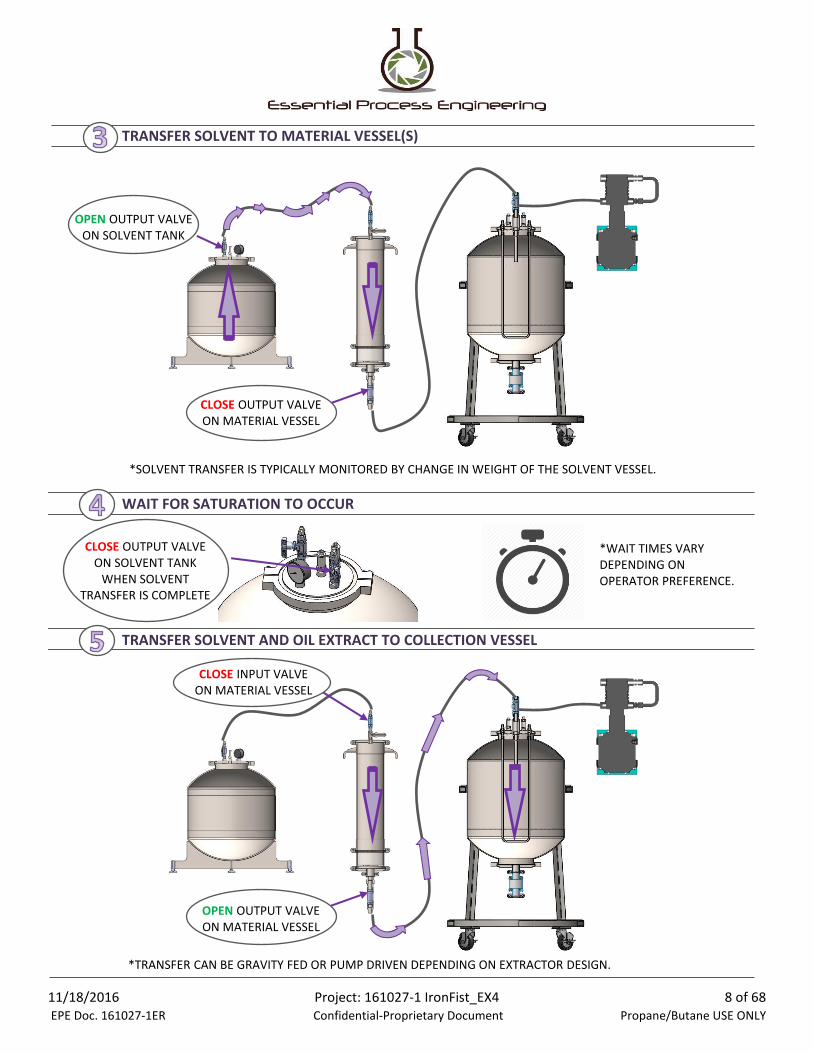
TRANSFER SOLVENT TO MATERIAL VESSEL(S)
WAIT FOR SATURATION TO OCCUR
TRANSFER SOLVENT AND OIL EXTRACT TO COLLECTION VESSEL
CLOSE OUTPUT VALVE ON SOLVENT TANK
WHEN SOLVENT TRANSFER IS COMPLETE
OPEN OUTPUT VALVE ON MATERIAL VESSEL
CLOSE INPUT VALVE ON MATERIAL VESSEL
*SOLVENT TRANSFER IS TYPICALLY MONITORED BY CHANGE IN WEIGHT OF THE SOLVENT VESSEL.
OPEN OUTPUT VALVE ON SOLVENT TANK
CLOSE OUTPUT VALVE ON MATERIAL VESSEL
*TRANSFER CAN BE GRAVITY FED OR PUMP DRIVEN DEPENDING ON EXTRACTOR DESIGN.
*WAIT TIMES VARY DEPENDING ON OPERATOR PREFERENCE.
11/18/2016 EPE Doc. 161027-1ER
Project: 161027-1 IronFist_EX4 Confidential-Proprietary Document
8 of 68 Propane/Butane USE ONLY

RECOVER SOLVENT
REMOVE OIL EXTRACT FROM COLLECTION VESSEL
OPEN INPUT VALVE ON SOLVENT TANK
CLOSE OUTPUT VALVE ON
SOLVENT TANK
CLOSE INPUT VALVE AND OPEN OUTPUT
VALVE ON COLLECTION VESSEL
*SOLVENT TANK SHOULD BE 99% OF ORIGINAL WEIGHT WHEN SOLVENT TRANSFER IS COMPLETE.
USE RECOVERY PUMP TO TRANSFER
VAPORIZEDSOLVENT GAS TO SOLVENT TANK
OPEN VALVE ON THE BOTTOM OF THE
COLLECTION VESSEL AND DRAIN OIL EXTRACT TO EXTERNAL CONTAINER
11/18/2016 EPE Doc. 161027-1ER
Project: 161027-1 IronFist_EX4 Confidential-Proprietary Document
9 of 68 Propane/Butane USE ONLY

EXTRACTOR SYSTEM OVERVIEW
SYSTEM DIAGRAM - PASSIVE RECOVERY
Figure 4.1 - Ironfist Fabrication EX4-502 Extractor - In Passive Configuration
11/18/2016 EPE Doc. 161027-1ER
Project: 161027-1 IronFist_EX4 Confidential-Proprietary Document
10 of 68 Propane/Butane USE ONLY

SYSTEM DIAGRAM - ACTIVE RECOVERY
Figure 4.2 - Ironfist Fabrication EX4-502 Extractor Configuration for use in Active Recovery
Passive Recovery system does not include the Recovery pump. Recovery is driven by the use of the warming coil at
the collection vessel base and the cooling of the Solvent recovery tank. Care shall be taken to monitor temperatures
and pressures to assure the system is maintained within operating parameters. Solvent recovery is complete when
99% of solvent is acurately weighed at the Solvent vessel. Recovery by weight method shall always be used. Solvent
shall not remain within the solution.
11/18/2016 EPE Doc. 161027-1ER
Project: 161027-1 IronFist_EX4 Confidential-Proprietary Document
11 of 68 Propane/Butane USE ONLY
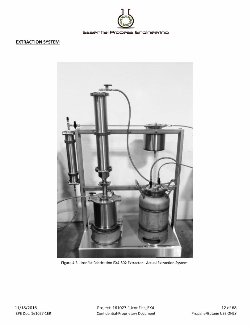
EXTRACTION SYSTEM
Figure 4.3 - Ironfist Fabrication EX4-502 Extractor - Actual Extraction System
11/18/2016 EPE Doc. 161027-1ER
Project: 161027-1 IronFist_EX4 Confidential-Proprietary Document
12 of 68 Propane/Butane USE ONLY

PRESSURE VESSEL CALCULATIONS
VESSEL CALCULATIONS INDEX
SOLVENT VESSEL:
Mid Section - Minimum Shell Thickness Calculation
End Caps - Ellipsoidal Head Thickness Calculation (Top and Bottom)
- Reinforcement Calculation for Top Riser Opening
- Flat Head Cover Thickness Calculation for Top Cover
- Reinforcement Calculation for Weld Bung Openings
COLLECTION VESSEL:
Mid Section - Minimum Shell Thickness Calculation
End Caps - Flat Head Cover Thickness Calculation for Top Cover
- Reinforcement Criteria for Openings in Flat Heads
- Reinforcement Calculation for Openings in Flat Head
MATERIAL VESSEL:
Mid Section - Minimum Shell Thickness Calculation
End Caps - Flat Head Cover Thickness Calculation for Top Cover
- Reinforcement Criteria for Openings in Flat Heads
- Conical Head Thickness Calculation (Bottom)
SEPARATOR VESSEL:
Mid Section - Minimum Shell Thickness Calculation
End Caps - Flat Head Cover Thickness Calculation for Top and Bottom Covers
11/18/2016 EPE Doc. 161027-1ER
Project: 161027-1 IronFist_EX4 Confidential-Proprietary Document
13 of 68 Propane/Butane USE ONLY

SOLVENT VESSEL
Figure 5.1 - Ironfist Fabrication EX4-502 Extractor - SOLVENT VESSEL
GENERANT 6000 PSIGSTEEL BALL VALVES
PRESSURE RELIEF VALVES
PRESSURE GAUGE
6" TRI-CLAMP
11/18/2016 EPE Doc. 161027-1ER
Project: 161027-1 IronFist_EX4 Confidential-Proprietary Document
14 of 68 Propane/Butane USE ONLY

SOLVENT VESSEL
- GENERAL DATA
RATED CAPACITY: 30 LBS OF SOLVENT
DIMENSIONS: 10 in. DIAMETER
29 in. TALL (APPROX)
0.365 in. WALL THICKNESS
OUTSIDE AREA (A): 944 in2 (APPROX)
- PRESSURE RELIEF VALVE REQUIREMENT
PRV SET PRESSURE: 1.00 X MAWP = 250 PSI - NFPA 58, 5.7.2.5
MIN PRV FLOW RATE: QMIN = 53.632 x A0.82- NFPA 58, 5.7.2.6
QMIN = 250.64 CFM
PRV RATED FLOW RATE: 272.7 CFM (SEE PRV DATA)
QTY PRVs REQUIRED: 1
- VESSEL PRESSURE RATING
MAX CERTIFIED PRESSURE: 294.9 PSI - PER ASME BPVC VIII DIVISION I (SEE CALCS ON FOLLOWING SHEETS)
*DO NOT EXCEED MAWP OF 250 PSI PER NFPA 58.
RESULT: The SOLVENT VESSEL meets ASME BPVC VIII Division I requirements for pressure vessels at 250 psi.
*VESSELS LARGER THAN 6" DIAMETER MUST BE
MARKED WITH ASME U-STAMP PER ASME BVPC VIII.
11/18/2016 EPE Doc. 161027-1ER
Project: 161027-1 IronFist_EX4 Confidential-Proprietary Document
15 of 68 Propane/Butane USE ONLY

SOLVENT VESSEL
UG-27 PRESSURE RATING BASED ON SHELL THICKNESS
MATERIAL:
t = 0.365 in
Actual wall thickness of vessel
E = 0.6 - Welded Joints
Joint Efficiency (UW-12, ASME BPVC VIII Division I)
R = 4.64 in
Inside radius of shell
S = 20000 PSI
Maximum allowable stress value
(1) Circumferential Stress:
P = (S x E x t) / (R + 0.6 x t) - UG-27, Equation 1
Maximum Allowable Pressure
P = 902.3 PSI
(2) Longitudinal Stress:
P = (2 x S x E x t) / (R - 0.4 x t) - UG-27, Equation 2
Maximum Allowable Pressure
P = 1951.4 PSI
Result
316 Stainless Steel
The Maximum Allowable Pressure for the SOLVENT VESSEL with a wall thickness of 0.365 inches is 902.3
psi, based on the ASME BPVC VIII Division I UG-27 Shell Thickness Calculation.
11/18/2016 EPE Doc. 161027-1ER
Project: 161027-1 IronFist_EX4 Confidential-Proprietary Document
16 of 68 Propane/Butane USE ONLY
SOLVENT VESSEL
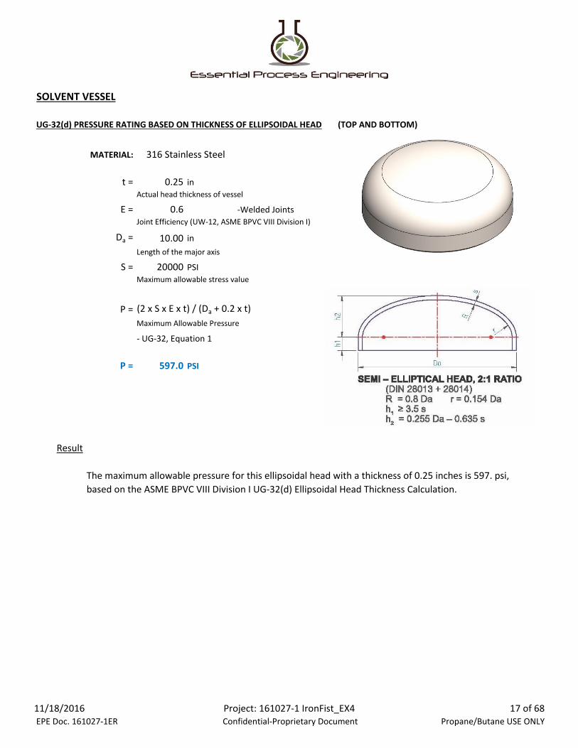
UG-32(d) PRESSURE RATING BASED ON THICKNESS OF ELLIPSOIDAL HEAD (TOP AND BOTTOM)
MATERIAL:
t = 0.25 in
Actual head thickness of vessel
E = 0.6 -Welded Joints
Joint Efficiency (UW-12, ASME BPVC VIII Division I)
Da = 10.00 in
Length of the major axis
S = 20000 PSI
Maximum allowable stress value
P = (2 x S x E x t) / (Da + 0.2 x t)
Maximum Allowable Pressure
- UG-32, Equation 1
P = 597.0 PSI
Result
316 Stainless Steel
The maximum allowable pressure for this ellipsoidal head with a thickness of 0.25 inches is 597. psi,
based on the ASME BPVC VIII Division I UG-32(d) Ellipsoidal Head Thickness Calculation.
11/18/2016 EPE Doc. 161027-1ER
Project: 161027-1 IronFist_EX4 Confidential-Proprietary Document
17 of 68 Propane/Butane USE ONLY

SOLVENT VESSEL
1-10 ALTERNATE REINFORCEMENT CALCULATION FOR OPENINGS IN SHELLS AND FORMED HEADS
dn = 5.50 in
Finished diameter of opening (internal diameter)
tn = 0.11 in
Actual wall thickness of nozzle
Lpr1 = 1.50 in
Nozzle projection from outside of vessel wall
En = 0.6 - Welded Joints
Joint Efficiency (UW-12, ASME BPVC VIII Division I)
WL = 0.25 in
Weld size (Length of Leg)
PA = 597 PSI
Maximum Allowable Pressure (Not to exceed Max Allowable Pressure for End Cap)
teff = 1 in
Effective thickness of nozzle
LR = 8 x t = 2 in
Limit of Reinforcement along vessel wall
LH = 0.679 in
Effective length of nozzle wall outside of vessel
A1 = λ = min[(dn + tn)/((Di + teff) x teff)0.5, 10] = 1.731
Area contributed by shell
A1 = 0.500 in2
A2 = tn x LH = 0.075 in2
Area contributed by nozzle projecting outward
A3 = tn x LI = 0 in2
Area contributed by nozzle projecting inward
A4 = WL2 = 0.0625 in2
Area contributed by weld
AT = 0.637 in2
Total Area Contributed
t + 0.78 x (Rn x tn)0.5 =
t x LR x max (λ/4, 1)
A1 + A2 + A3 + A4 =
11/18/2016 EPE Doc. 161027-1ER
Project: 161027-1 IronFist_EX4 Confidential-Proprietary Document
18 of 68 Propane/Butane USE ONLY
SOLVENT VESSEL
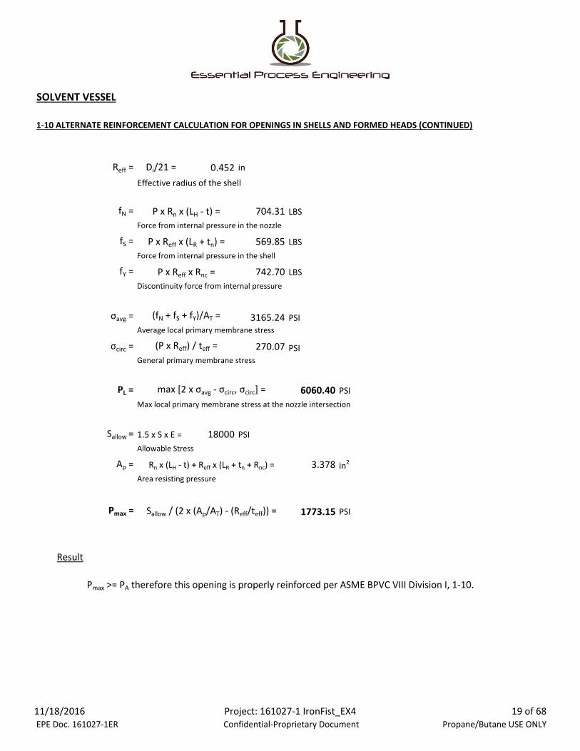
1-10 ALTERNATE REINFORCEMENT CALCULATION FOR OPENINGS IN SHELLS AND FORMED HEADS (CONTINUED)
Reff = Di/21 = 0.452 in
Effective radius of the shell
fN = 704.31 LBS
Force from internal pressure in the nozzle
fS = 569.85 LBS
Force from internal pressure in the shell
fY = 742.70 LBS
Discontinuity force from internal pressure
σavg = 3165.24 PSI
Average local primary membrane stress
σcirc = 270.07 PSI
General primary membrane stress
PL = 6060.40 PSI
Max local primary membrane stress at the nozzle intersection
Sallow = 1.5 x S x E = 18000 PSI
Allowable Stress
Ap = 3.378 in2
Area resisting pressure
Pmax = 1773.15 PSI
Result
P x Rn x (LH - t) =
P x Reff x (LR + tn) =
P x Reff x Rnc =
(fN + fS + fY)/AT =
(P x Reff) / teff =
max [2 x σavg - σcirc, σcirc] =
Rn x (LH - t) + Reff x (LR + tn + Rnc) =
Sallow / (2 x (Ap/AT) - (Reff/teff)) =
Pmax >= PA therefore this opening is properly reinforced per ASME BPVC VIII Division I, 1-10.
11/18/2016 EPE Doc. 161027-1ER
Project: 161027-1 IronFist_EX4 Confidential-Proprietary Document
19 of 68 Propane/Butane USE ONLY

SOLVENT VESSEL
UG-34(c)(2) PRESSURE RATING BASED ON UNSTAYED FLAT HEAD THICKNESS (CLAMPED)
MATERIAL:
t = 0.437 in
Actual thickness of cap
C = 0.30
d = 6.57 in
Diameter
E = 1.0 -Clamped Joint
Joint Efficiency (UW-12, ASME BPVC VIII Division I)
S = 20000 PSI
Maximum Allowable Stress Value
P = [S x E x (t / d)2] / C - UG-34, Equation 1
Maximum Allowable Pressure
P = 294.9 in
Result
316 Stainless Steel
Factor dependent on method of attachment from Figure
UG-34, ASME BPVC VIII Div. I
The maximum allowable pressure for this flat cover with a thickness of 0.437 inches is 294.9 psi, based
on the ASME BPVC VIII Division I UG-34(c)(2) Unstayed Flat Heads and Covers Calculation.
11/18/2016 EPE Doc. 161027-1ER
Project: 161027-1 IronFist_EX4 Confidential-Proprietary Document
20 of 68 Propane/Butane USE ONLY
SOLVENT VESSEL
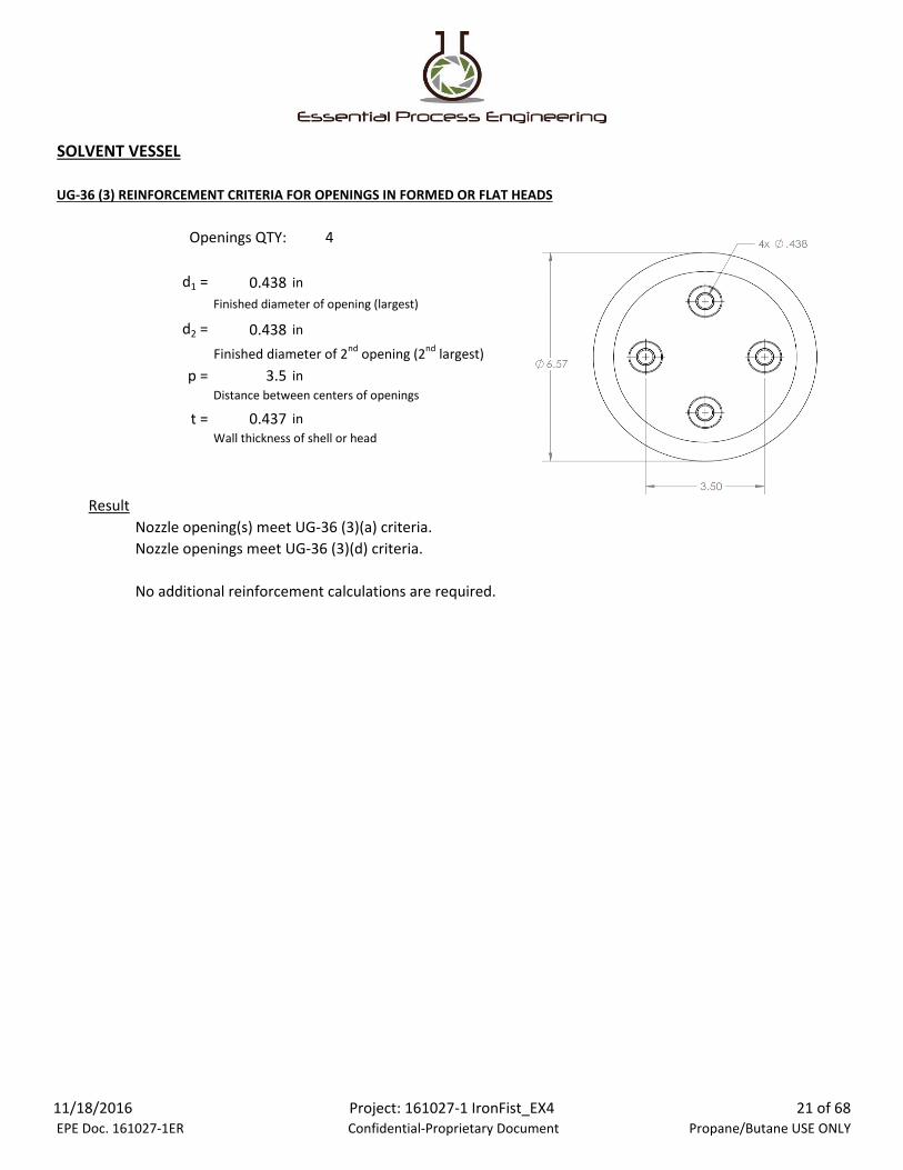
UG-36 (3) REINFORCEMENT CRITERIA FOR OPENINGS IN FORMED OR FLAT HEADS
Openings QTY: 4
d1 = 0.438 in
Finished diameter of opening (largest)
d2 = 0.438 in
Finished diameter of 2nd opening (2nd largest)
p = 3.5 in
Distance between centers of openings
t = 0.437 in
Wall thickness of shell or head
Result
Nozzle opening(s) meet UG-36 (3)(a) criteria.
Nozzle openings meet UG-36 (3)(d) criteria.
No additional reinforcement calculations are required.
11/18/2016 EPE Doc. 161027-1ER
Project: 161027-1 IronFist_EX4 Confidential-Proprietary Document
21 of 68 Propane/Butane USE ONLY
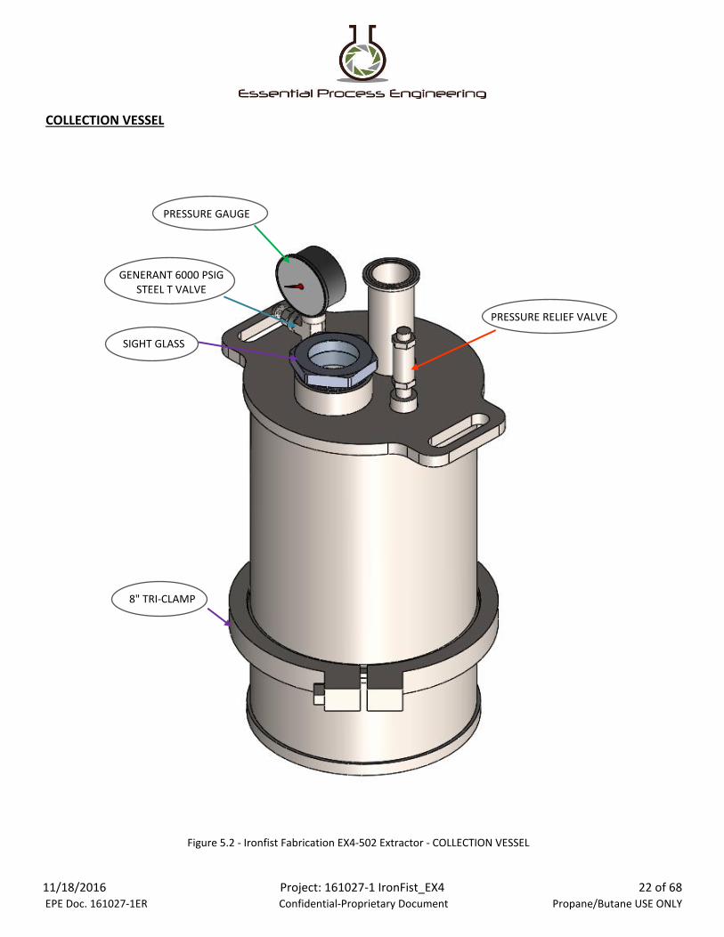
COLLECTION VESSEL
Figure 5.2 - Ironfist Fabrication EX4-502 Extractor - COLLECTION VESSEL
GENERANT 6000 PSIGSTEEL T VALVE
PRESSURE RELIEF VALVE
PRESSURE GAUGE
8" TRI-CLAMP
SIGHT GLASS
11/18/2016 EPE Doc. 161027-1ER
Project: 161027-1 IronFist_EX4 Confidential-Proprietary Document
22 of 68 Propane/Butane USE ONLY

COLLECTION VESSEL
- GENERAL DATA
RATED CAPACITY: 120 LBS OF SOLVENT
DIMENSIONS: 8 in. DIAMETER
15 in. TALL (APPROX)
0.25 in. WALL THICKNESS
OUTSIDE AREA (A): 460 in2 (APPROX)
- PRESSURE RELIEF VALVE REQUIREMENT
PRV SET PRESSURE: 1.00 X MAWP = 250 PSI - NFPA 58, 5.7.2.5
MIN PRV FLOW RATE: QMIN = 53.632 x A0.82- NFPA 58, 5.7.2.6
QMIN = 139.00 CFM
PRV RATED FLOW RATE: 272.7 CFM (SEE PRV DATA)
QTY PRVs REQUIRED: 1
- VESSEL PRESSURE RATING
MAX CERTIFIED PRESSURE: 257.1 PSI - PER ASME BPVC VIII DIVISION I (SEE CALCS ON FOLLOWING SHEETS)
*DO NOT EXCEED MAWP OF 250 PSI PER NFPA 58.
RESULT:
*VESSELS LARGER THAN 6" DIAMETER MUST BE
MARKED WITH ASME U-STAMP PER ASME BVPC VIII.
The COLLECTION VESSEL meets ASME BPVC VIII Division I requirements for pressure vessels at 250 psi.
11/18/2016 EPE Doc. 161027-1ER
Project: 161027-1 IronFist_EX4 Confidential-Proprietary Document
23 of 68 Propane/Butane USE ONLY

COLLECTION VESSEL
UG-27 PRESSURE RATING BASED ON SHELL THICKNESS
MATERIAL:
t = 0.25 in
Actual wall thickness of vessel
E = 0.6 - Welded Joints
Joint Efficiency (UW-12, ASME BPVC VIII Division I)
R = 3.75 in
Inside radius of shell
S = 20000 PSI
Maximum allowable stress value
(1) Circumferential Stress:
P = (S x E x t) / (R + 0.6 x t) - UG-27, Equation 1
Maximum Allowable Pressure
P = 769.2 PSI
(2) Longitudinal Stress:
P = (2 x S x E x t) / (R - 0.4 x t) - UG-27, Equation 2
Maximum Allowable Pressure
P = 1643.8 PSI
Result
316L Stainless Steel
The Maximum Allowable Pressure for the COLLECTION VESSEL with a wall thickness of 0.25 inches is
769.2 psi, based on the ASME BPVC VIII Division I UG-27 Shell Thickness Calculation.
11/18/2016 EPE Doc. 161027-1ER
Project: 161027-1 IronFist_EX4 Confidential-Proprietary Document
24 of 68 Propane/Butane USE ONLY
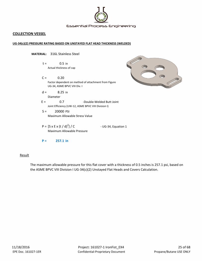
COLLECTION VESSEL
UG-34(c)(2) PRESSURE RATING BASED ON UNSTAYED FLAT HEAD THICKNESS (WELDED)
MATERIAL:
t = 0.5 in
Actual thickness of cap
C = 0.20
d = 8.25 in
Diameter
E = 0.7 -Double-Welded Butt Joint
Joint Efficiency (UW-12, ASME BPVC VIII Division I)
S = 20000 PSI
Maximum Allowable Stress Value
P = [S x E x (t / d)2] / C - UG-34, Equation 1
Maximum Allowable Pressure
P = 257.1 in
Result
316L Stainless Steel
Factor dependent on method of attachment from Figure
UG-34, ASME BPVC VIII Div. I
The maximum allowable pressure for this flat cover with a thickness of 0.5 inches is 257.1 psi, based on
the ASME BPVC VIII Division I UG-34(c)(2) Unstayed Flat Heads and Covers Calculation.
11/18/2016 EPE Doc. 161027-1ER
Project: 161027-1 IronFist_EX4 Confidential-Proprietary Document
25 of 68 Propane/Butane USE ONLY

COLLECTION VESSEL
UG-36 (3) REINFORCEMENT CRITERIA FOR OPENINGS IN FORMED OR FLAT HEADS
Openings QTY: 4
d1 = 1.540 in
Finished diameter of opening (largest)
d2 = 1.250 in
Finished diameter of 2nd opening (2nd largest)
p = 2.88 in
Distance between centers of openings
t = 0.500 in
Wall thickness of shell or head
Result
Nozzle opening(s) meet UG-36 (3)(a) criteria.
Nozzle openings do NOT meet UG-36 (3)(d) criteria.
Reinforcement calculations ARE required.
11/18/2016 EPE Doc. 161027-1ER
Project: 161027-1 IronFist_EX4 Confidential-Proprietary Document
26 of 68 Propane/Butane USE ONLY

COLLECTION VESSEL
UG-39(2) REINFORCEMENT CALCULATION FOR OPENINGS IN FLAT HEADS - MULTIPLE OPENINGS
dn1 = 1.54 in
Finished diameter of opening (nozzle 1)
tn1 = 0.35 in
Actual wall thickness (nozzle 1)
dn2 = 1.25 in
Finished diameter of opening (nozzle 2)
tn2 = 0.19 in
Actual wall thickness of (nozzle 2)
p = 2.88 in
Distance between centers of openings
h1 = 0.00 in
Distance of inward projection (nozzle 1)
h2 = 0.53 in
Distance of inward projection (nozzle 2)
En = 0.6 - Welded Joints
Joint Efficiency (UW-12, ASME BPVC VIII Division I)
WL1 = 0.188 in WL2 = 0.188 in
Weld size (Length of Leg) - Nozzle 1 Weld size (Length of Leg) - Nozzle 2
PA = 257.1 PSI
Maximum Allowable Pressure (Not to exceed Max Allowable Pressure for Cover)
tr = 0.500 in - UG-34, Equation 1
Minimum required thickness
tr n1= 0.017 in
Required nozzle thickness for MAWP (nozzle 1)
tr n2= 0.014 in
Required nozzle thickness for MAWP (nozzle 2)
CRITERIA CHECK:
AREQ1 = 0.385 in2
Required reinforcement area for opening 1
AREQ2 = 0.312 in2
Required reinforcement area for opening 2
AS1 = 0.000 in2
Area available in shell (nozzle 1)
AS2 = 0.000 in2
Area available in shell (nozzle 2)
dn2 x (t - tr) =
(dn2 x tr)/2 =
dn1 x (t - tr) =
(dn1 x tr)/2 =
d x [(C x PA) / (S x E)]0.5 =
(PA x (dn1/2)) / (S x En - 0.6 x PA) =
(PA x (dn2/2)) / (S x En - 0.6 x PA) =
Each nozzle opening shall meet the reinforement area requirment shown below per UG-
39(b)(2).
11/18/2016 EPE Doc. 161027-1ER
Project: 161027-1 IronFist_EX4 Confidential-Proprietary Document
27 of 68 Propane/Butane USE ONLY

AN1-1 = 0.583 in2
AN1-2 = 0.163 in2
AN2-1 = 0 in2
AN2-2 = 0.176 in2
AW1 = 0.071 in2
Area available in weld (nozzle 1)
AW2 = 0.071 in2
Area available in weld (nozzle 2)
AAVAIL 1 = 0.654 in2
AAVAIL 2 = 0.410 in2
Result
Per UG-37 of ASME BPVC VIII Division I, these nozzle openings are rated for a maximum pressure of
257.1 psi, without additional reinforcements being added.
2 x (Weld Leg Length)2 =
AS1 + AN1-1 + AN2-2 + AW1 =
AS2 + AN1-2 + AN2-2 + AW2 =
5 x tn22 =
Area available in nozzle projecting inward (nozzle 2)
2 x (Weld Leg Length)2 =
Area available in nozzle projecting outward (nozzle 2)
2 x h x tn1 =
Area available in nozzle projecting inward (nozzle 1)
5 x (tn1 - tr n1) x tn1 =
Area available in nozzle projecting outward (nozzle 1)
5 x (tn2 - tr n2) x tn2 =
11/18/2016 EPE Doc. 161027-1ER
Project: 161027-1 IronFist_EX4 Confidential-Proprietary Document
28 of 68 Propane/Butane USE ONLY

MATERIAL VESSEL
Figure 5.3 - Ironfist Fabrication EX4-502 Extractor - MATERIAL VESSEL
GENERANT 6000 PSIGSTEEL BALL VALVE
PRESSURE RELIEF VALVEPRESSURE GAUGE
4" TRI-CLAMP
4" TRI-CLAMP
11/18/2016 EPE Doc. 161027-1ER
Project: 161027-1 IronFist_EX4 Confidential-Proprietary Document
29 of 68 Propane/Butane USE ONLY

MATERIAL VESSEL
- GENERAL DATA
RATED CAPACITY: 4 LBS OF TRIM
DIMENSIONS: 4.125 in. DIAMETER
50 in. TALL (APPROX)
0.13 in. WALL THICKNESS
OUTSIDE AREA (A): 670 in2 (APPROX)
OPERATING TEMPERATURE: 110 ͦF
- PRESSURE RELIEF VALVE REQUIREMENT
PRV SET PRESSURE: 1.00 X MAWP = 250 PSI - NFPA 58, 5.7.2.5
MIN PRV FLOW RATE: QMIN = 53.632 x A0.82- NFPA 58, 5.7.2.6
QMIN = 189.21 CFM
PRV RATED FLOW RATE: 272.7 CFM (SEE PRV DATA)
QTY PRVs REQUIRED: 1
- VESSEL PRESSURE RATING
MAX CERTIFIED PRESSURE: 684.4 PSI - PER ASME BPVC VIII DIVISION I (SEE CALCS ON FOLLOWING SHEETS)
*DO NOT EXCEED MAWP OF 250 PSI PER NFPA 58.
RESULT:
The MATERIAL VESSEL meets ASME BPVC VIII Division I requirements for pressure vessels at 250 psi.
11/18/2016 EPE Doc. 161027-1ER
Project: 161027-1 IronFist_EX4 Confidential-Proprietary Document
30 of 68 Propane/Butane USE ONLY
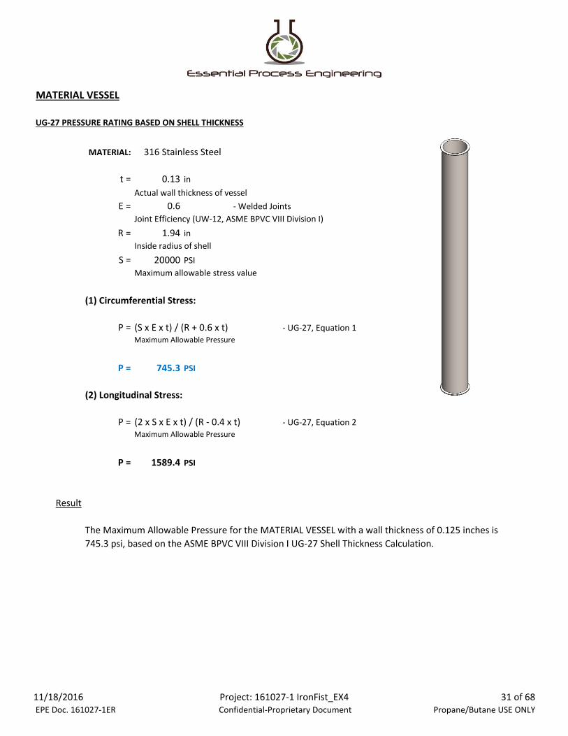
MATERIAL VESSEL
UG-27 PRESSURE RATING BASED ON SHELL THICKNESS
MATERIAL:
t = 0.13 in
Actual wall thickness of vessel
E = 0.6 - Welded Joints
Joint Efficiency (UW-12, ASME BPVC VIII Division I)
R = 1.94 in
Inside radius of shell
S = 20000 PSI
Maximum allowable stress value
(1) Circumferential Stress:
P = (S x E x t) / (R + 0.6 x t) - UG-27, Equation 1
Maximum Allowable Pressure
P = 745.3 PSI
(2) Longitudinal Stress:
P = (2 x S x E x t) / (R - 0.4 x t) - UG-27, Equation 2
Maximum Allowable Pressure
P = 1589.4 PSI
Result
316 Stainless Steel
The Maximum Allowable Pressure for the MATERIAL VESSEL with a wall thickness of 0.125 inches is
745.3 psi, based on the ASME BPVC VIII Division I UG-27 Shell Thickness Calculation.
11/18/2016 EPE Doc. 161027-1ER
Project: 161027-1 IronFist_EX4 Confidential-Proprietary Document
31 of 68 Propane/Butane USE ONLY

MATERIAL VESSEL
UG-34(c)(2) PRESSURE RATING BASED ON UNSTAYED FLAT HEAD THICKNESS (CLAMPED)
MATERIAL:
t = 0.625 in
Actual thickness of cap
C = 0.33
d = 4 in
Diameter
E = 1.0 -Clamped Joint
Joint Efficiency (UW-12, ASME BPVC VIII Division I)
S = 20000 PSI
Maximum Allowable Stress Value
P = [S x E x (t / d)2] / C - UG-34, Equation 1
Maximum Allowable Pressure
P = 1479.6 PSI
Result
Factor dependent on method of attachment from Figure
UG-34, ASME BPVC VIII Div. I
The maximum allowable pressure for this flat cover with a thickness of 0.625 inches is 1479.6 psi, based
on the ASME BPVC VIII Division I UG-34(c)(2) Unstayed Flat Heads and Covers Calculation.
316 Stainless Steel
11/18/2016 EPE Doc. 161027-1ER
Project: 161027-1 IronFist_EX4 Confidential-Proprietary Document
32 of 68 Propane/Butane USE ONLY

MATERIAL VESSEL
UG-36 (3) REINFORCEMENT CRITERIA FOR OPENINGS IN FORMED OR FLAT HEADS
Openings QTY: 1
d1 = 0.600 in
Finished diameter of opening (largest)
d2 = 0.000 in
Finished diameter of 2nd opening (2nd largest)
p = 0 in
Distance between centers of openings
t = 0.625 in
Wall thickness of shell or head
Result
Nozzle opening(s) meet UG-36 (3)(a) criteria.
No additional reinforcement calculations are required.
11/18/2016 EPE Doc. 161027-1ER
Project: 161027-1 IronFist_EX4 Confidential-Proprietary Document
33 of 68 Propane/Butane USE ONLY
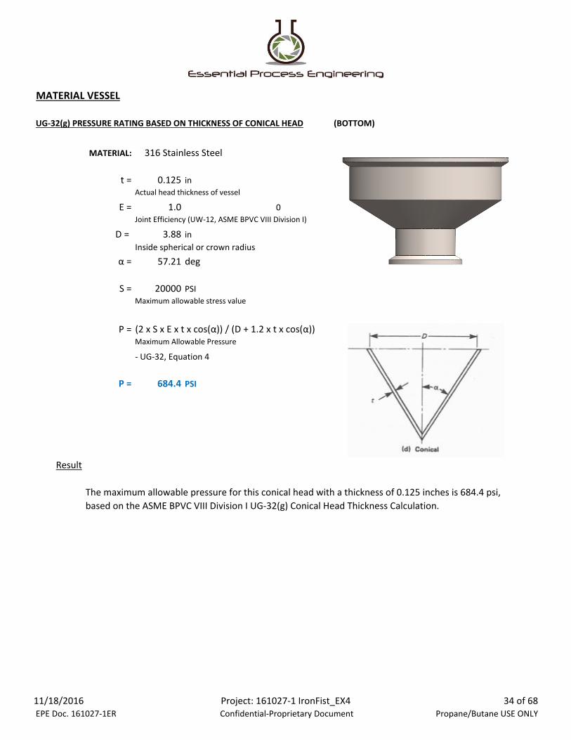
MATERIAL VESSEL
UG-32(g) PRESSURE RATING BASED ON THICKNESS OF CONICAL HEAD (BOTTOM)
MATERIAL:
t = 0.125 in
Actual head thickness of vessel
E = 1.0 0
Joint Efficiency (UW-12, ASME BPVC VIII Division I)
D = 3.88 in
Inside spherical or crown radius
α = 57.21 deg
S = 20000 PSI
Maximum allowable stress value
P = (2 x S x E x t x cos(α)) / (D + 1.2 x t x cos(α))Maximum Allowable Pressure
- UG-32, Equation 4
P = 684.4 PSI
Result
The maximum allowable pressure for this conical head with a thickness of 0.125 inches is 684.4 psi,
based on the ASME BPVC VIII Division I UG-32(g) Conical Head Thickness Calculation.
316 Stainless Steel
11/18/2016 EPE Doc. 161027-1ER
Project: 161027-1 IronFist_EX4 Confidential-Proprietary Document
34 of 68 Propane/Butane USE ONLY

SEPARATOR VESSEL
Figure 5.4 - Ironfist Fabrication EX4-502 Extractor - SEPARATOR VESSEL
3" TRI-CLAMP
3" TRI-CLAMP
11/18/2016 EPE Doc. 161027-1ER
Project: 161027-1 IronFist_EX4 Confidential-Proprietary Document
35 of 68 Propane/Butane USE ONLY
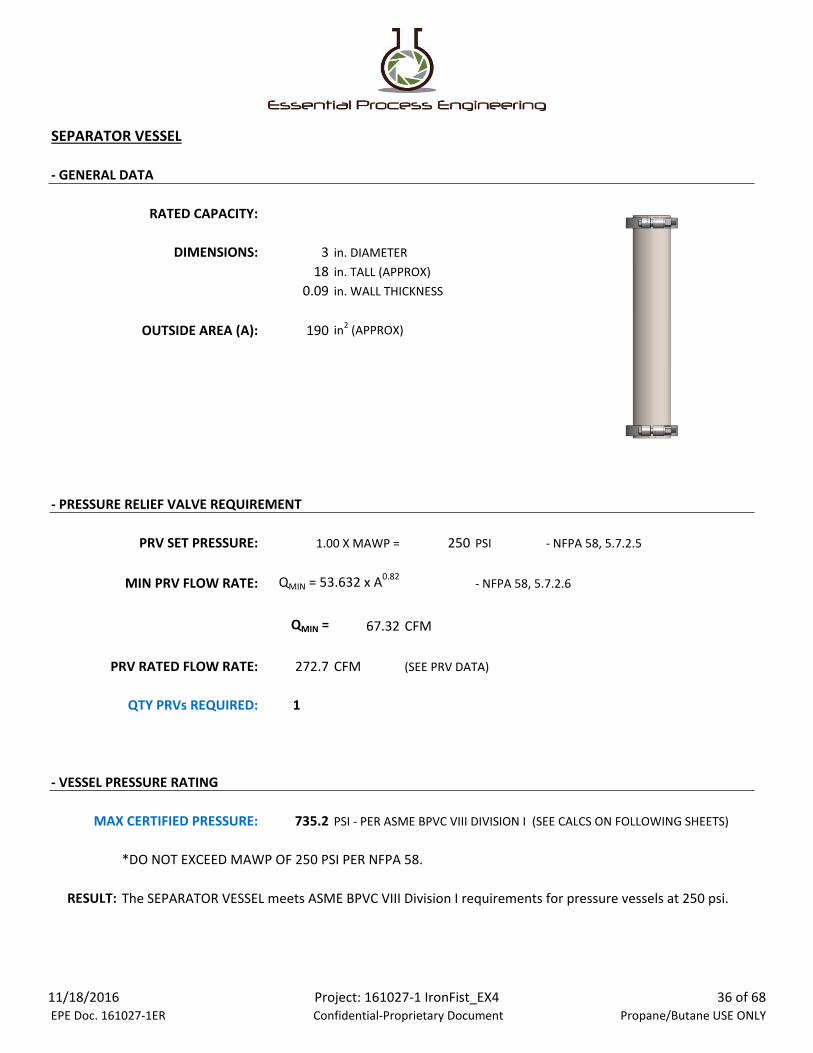
SEPARATOR VESSEL
- GENERAL DATA
RATED CAPACITY:
DIMENSIONS: 3 in. DIAMETER
18 in. TALL (APPROX)
0.09 in. WALL THICKNESS
OUTSIDE AREA (A): 190 in2 (APPROX)
- PRESSURE RELIEF VALVE REQUIREMENT
PRV SET PRESSURE: 1.00 X MAWP = 250 PSI - NFPA 58, 5.7.2.5
MIN PRV FLOW RATE: QMIN = 53.632 x A0.82- NFPA 58, 5.7.2.6
QMIN = 67.32 CFM
PRV RATED FLOW RATE: 272.7 CFM (SEE PRV DATA)
QTY PRVs REQUIRED: 1
- VESSEL PRESSURE RATING
MAX CERTIFIED PRESSURE: 735.2 PSI - PER ASME BPVC VIII DIVISION I (SEE CALCS ON FOLLOWING SHEETS)
*DO NOT EXCEED MAWP OF 250 PSI PER NFPA 58.
RESULT:
The SEPARATOR VESSEL meets ASME BPVC VIII Division I requirements for pressure vessels at 250 psi.
11/18/2016 EPE Doc. 161027-1ER
Project: 161027-1 IronFist_EX4 Confidential-Proprietary Document
36 of 68 Propane/Butane USE ONLY

SEPARATOR VESSEL
UG-27 PRESSURE RATING BASED ON SHELL THICKNESS
MATERIAL:
t = 0.09 in
Actual wall thickness of vessel
E = 0.6 - Welded Joints
Joint Efficiency (UW-12, ASME BPVC VIII Division I)
R = 1.42 in
Inside radius of shell
S = 20000 PSI
Maximum allowable stress value
(1) Circumferential Stress:
P = (S x E x t) / (R + 0.6 x t) - UG-27, Equation 1
Maximum Allowable Pressure
P = 735.2 PSI
(2) Longitudinal Stress:
P = (2 x S x E x t) / (R - 0.4 x t) - UG-27, Equation 2
Maximum Allowable Pressure
P = 1566.4 PSI
Result
316 Stainless Steel
The Maximum Allowable Pressure for the SEPARATOR VESSEL with a wall thickness of 0.09 inches is
735.2 psi, based on the ASME BPVC VIII Division I UG-27 Shell Thickness Calculation.
11/18/2016 EPE Doc. 161027-1ER
Project: 161027-1 IronFist_EX4 Confidential-Proprietary Document
37 of 68 Propane/Butane USE ONLY
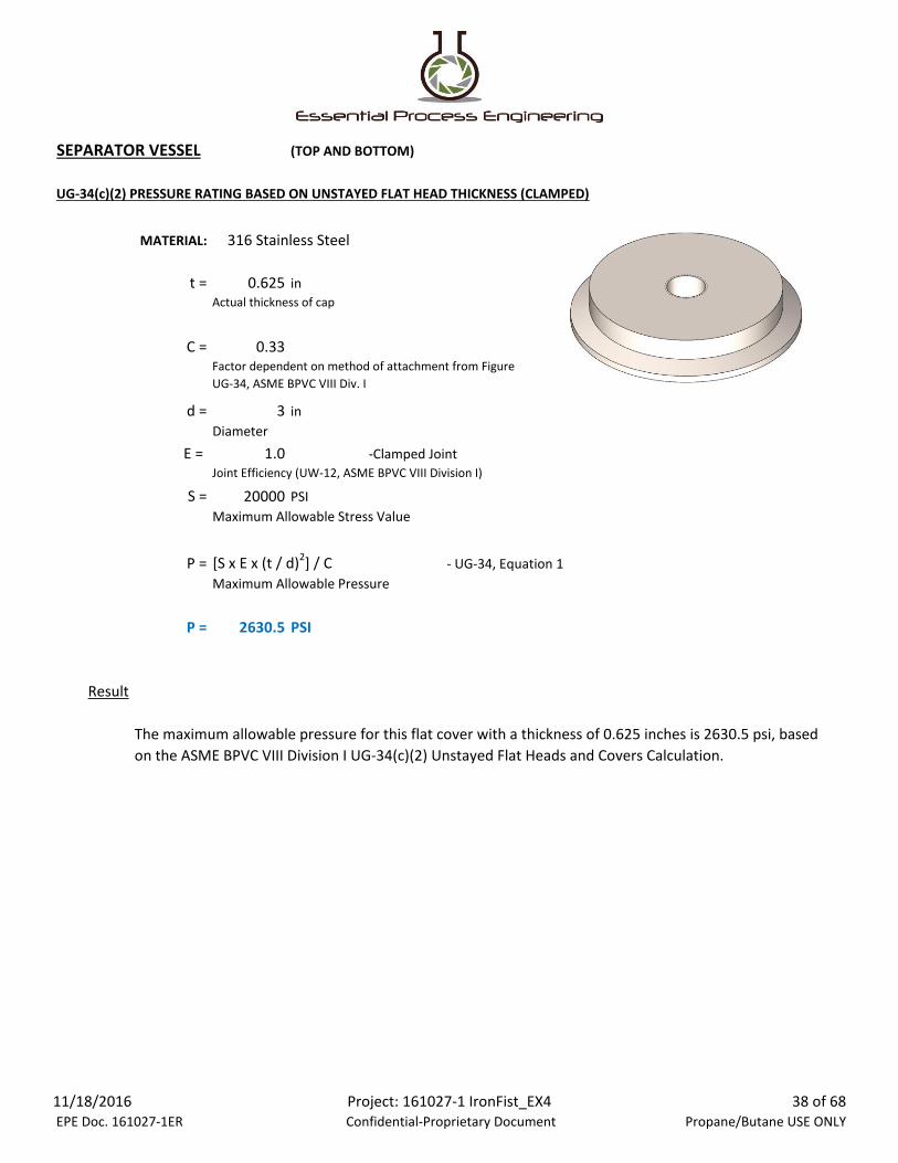
SEPARATOR VESSEL (TOP AND BOTTOM)
UG-34(c)(2) PRESSURE RATING BASED ON UNSTAYED FLAT HEAD THICKNESS (CLAMPED)
MATERIAL:
t = 0.625 in
Actual thickness of cap
C = 0.33
d = 3 in
Diameter
E = 1.0 -Clamped Joint
Joint Efficiency (UW-12, ASME BPVC VIII Division I)
S = 20000 PSI
Maximum Allowable Stress Value
P = [S x E x (t / d)2] / C - UG-34, Equation 1
Maximum Allowable Pressure
P = 2630.5 PSI
Result
Factor dependent on method of attachment from Figure
UG-34, ASME BPVC VIII Div. I
The maximum allowable pressure for this flat cover with a thickness of 0.625 inches is 2630.5 psi, based
on the ASME BPVC VIII Division I UG-34(c)(2) Unstayed Flat Heads and Covers Calculation.
316 Stainless Steel
11/18/2016 EPE Doc. 161027-1ER
Project: 161027-1 IronFist_EX4 Confidential-Proprietary Document
38 of 68 Propane/Butane USE ONLY

PUMP SPECIFICATIONS
Recovery pumps are used with Active Recovery Systems only and are not requird for Passive Configurations.
Figure 6.1 - Indicator Panel for Caresaver Type Recovery Pump
The Iron Fist Extractor identified within this report may utilize the following types of recovery pumps rated for use
with Butane (R600/ R600a refrigerants) and Propane (R290 refrigerant). The Iron Fist Extractor may come with the
following recovery pump as well based on model requested by the customer:
11/18/2016 EPE Doc. 161027-1ER
Project: 161027-1 IronFist_EX4 Confidential-Proprietary Document
39 of 68 Propane/Butane USE ONLY

PUMP SPECIFICATIONS (CONTINUED)
CM-EP / Nanjing Wonfulay Precision Machinery Co. Ltd, China
ChunMu Refrigeration
Refrigerants: R290/ R600A/ R1234YF/ R134A/ R404A/ R410A/ R22/ R23/ R431A/ R417A/ R502/ R407C
For Explosion proof rating the system must be wired per Article 500 and Article 501 of NFPA 70-2014.
Figure 6.2 - CMEP-OL Recovery Pump (Optional Recovery Pump System)
The recovery pump includes High pressure/ low pressure protection and overcurrent protection. Internal oil
separator / filtration on recovery process. Inlet filtration.
Designed to meet ARI-740 Standard (AHRI-740, Standard for Refrigerant Recovery Equipment), Plastic enclosure with
an Oil-less operation. System indicates that it is an “Anti-explosive refrigerant recovery machine”.
11/18/2016 EPE Doc. 161027-1ER
Project: 161027-1 IronFist_EX4 Confidential-Proprietary Document
40 of 68 Propane/Butane USE ONLY
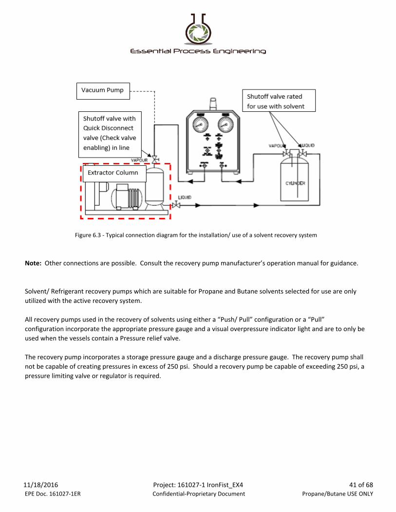
IMAGE #:
Figure 6.3 - Typical connection diagram for the installation/ use of a solvent recovery system
Solvent/ Refrigerant recovery pumps which are suitable for Propane and Butane solvents selected for use are only
utilized with the active recovery system.
All recovery pumps used in the recovery of solvents using either a “Push/ Pull” configuration or a “Pull”
configuration incorporate the appropriate pressure gauge and a visual overpressure indicator light and are to only be
used when the vessels contain a Pressure relief valve.
The recovery pump incorporates a storage pressure gauge and a discharge pressure gauge. The recovery pump shall
not be capable of creating pressures in excess of 250 psi. Should a recovery pump be capable of exceeding 250 psi, a
pressure limiting valve or regulator is required.
Note: Other connections are possible. Consult the recovery pump manufacturer’s operation manual for guidance.
11/18/2016 EPE Doc. 161027-1ER
Project: 161027-1 IronFist_EX4 Confidential-Proprietary Document
41 of 68 Propane/Butane USE ONLY
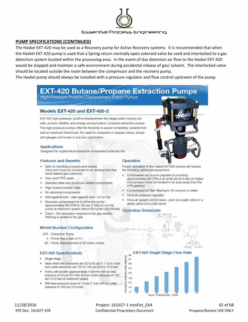
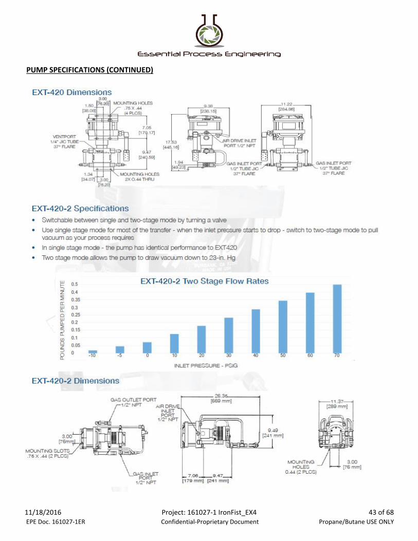
PUMP SPECIFICATIONS (CONTINUED)The Haskel EXT-420 may be used as a Recovery pump for Active Recovery systems. It is recommended that when
the Haskel EXT-420 pump is used that a Spring return normally open solenoid valve be used and interlocked to a gas
detection system located within the processing area. In the event of Gas detection air flow to the Haskel EXT-420
would be stopped and maintain a safe environment during accidental release of gas/ solvent. The interlocked valve
should be located outside the room between the compressor and the recovery pump.
The Haskel pump should always be installed with a pressure regulator and flow control upstream of the pump.
11/18/2016 EPE Doc. 161027-1ER
Project: 161027-1 IronFist_EX4 Confidential-Proprietary Document
42 of 68 Propane/Butane USE ONLY
PUMP SPECIFICATIONS (CONTINUED)
11/18/2016 EPE Doc. 161027-1ER
Project: 161027-1 IronFist_EX4 Confidential-Proprietary Document
43 of 68 Propane/Butane USE ONLY

PUMP SPECIFICATIONS (CONTINUED)
Vacuum Pump (Used to purge normal atmospheric air from the closed system):
Guidelines for incorporation of the vacuum pump:
1) The vacuum pump includes a visible vacuum gauge.
Figure 6.4 - Vacuum pump for use with Closed Loop Extraction System, EX4-502
2) Food grade mineral oil is recommended for proper lubrication of the vacuum pump system. Means
should be taken to ensure that oils used as lubrication for the vacuum pump can never contaminate the
vacuum system where contact with the Closed Loop Extractor is possible.
Figure 6.5 - Yellow Jacket Type vacuum pump specifications
11/18/2016 EPE Doc. 161027-1ER
Project: 161027-1 IronFist_EX4 Confidential-Proprietary Document
44 of 68 Propane/Butane USE ONLY

PRESSURE RELIEF VALVE SPECIFICATIONS
IMAGE #:
The Ironfist Fabrication EX4-502 Extractor vessels use Generant Series stainless steel cryogenic relief valves with 1/4
NPT port sizes. See product specifications below.
Figure 6.6 - Generant PRV Maximum Flow Rate Calculation
(SIMILAR TO PROPANE/BUTANE)
11/18/2016 EPE Doc. 161027-1ER
Project: 161027-1 IronFist_EX4 Confidential-Proprietary Document
45 of 68 Propane/Butane USE ONLY

PRESSURE RELIEF VALVE SPECIFICATIONS (CONTINUED)
11/18/2016 EPE Doc. 161027-1ER
Project: 161027-1 IronFist_EX4 Confidential-Proprietary Document
46 of 68 Propane/Butane USE ONLY

BALL VALVES
The Ironfist Fabrication EX4-502 Extractor uses a Swagelok SS-43GS6 3/8 inch ball valve and a Bradford 2 inch
stainless steel ball valve. Product specifications for these ball valves are shown below.
Figure 6.7 - Swagelok Ball Valve Specifications
Figure 6.8 - Bradford Ball Valve Specifications
11/18/2016 EPE Doc. 161027-1ER
Project: 161027-1 IronFist_EX4 Confidential-Proprietary Document
47 of 68 Propane/Butane USE ONLY

GAUGES
Figure 6.9 - Swagelok Gauge Specifications
The Ironfist Fabrication EX4-502 Extractor uses Swagelok PGI-63C stainless steel pressure gauges. Specifications for
this gauge are shown below.
11/18/2016 EPE Doc. 161027-1ER
Project: 161027-1 IronFist_EX4 Confidential-Proprietary Document
48 of 68 Propane/Butane USE ONLY
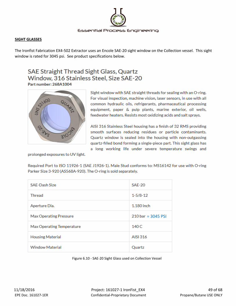
SIGHT GLASSES
The Ironfist Fabrication EX4-502 Extractor uses an Encole SAE-20 sight window on the Collection vessel. This sight
window is rated for 3045 psi. See product specifications below.
Figure 6.10 - SAE-20 Sight Glass used on Collection Vessel
= 3045 PSI
11/18/2016 EPE Doc. 161027-1ER
Project: 161027-1 IronFist_EX4 Confidential-Proprietary Document
49 of 68 Propane/Butane USE ONLY

HOSES
Figure 6.11 - SwageLOK T Series PFTE Hoses (3000 PSI rated, 3/8 inch Diameter)
All hoses used on the Ironfist Fabrication EX4-502 Extractor are PTFE lined with braided stainless steel reinforcing
jacketing. All hoses and fittings are approved for use with Butane and rated for temperatures of -65 ͦF to 450 ͦF.
Hoses are SwageLOK T and W Series type or equivalent and static dissipative. See product specifications below.
*All hoses are T Series except where noted in Appendix B.
11/18/2016 EPE Doc. 161027-1ER
Project: 161027-1 IronFist_EX4 Confidential-Proprietary Document
50 of 68 Propane/Butane USE ONLY

QUICK DISCONNECTS
Figure 6.13 - Parker Quick Disconnect, FS-372-6FP, Hose Connection (May be used)
The Ironfist Fabrication EX4-502 Extractor uses Parker Quick Disconnect fittings. The product specifications for these
fittings are shown below.
Figure 6.12 - SwageLOK SAF 2507 Tubing Specifications
11/18/2016 EPE Doc. 161027-1ER
Project: 161027-1 IronFist_EX4 Confidential-Proprietary Document
51 of 68 Propane/Butane USE ONLY

HIGH PRESSURE TRI-CLAMPS
Figure 6.14 - Parker Quick Disconnect, FS-371-6FP, Hose Connection (May be used)
**SwageLok Brand Quick Disconnect fittings rated for the Pressure and Temperatures identified within this report
are suitable for use as replacements for Parker FS type.
**An automatic Pressure Relief Valve is installed to the Solvent Vessel (any closed section where pressure is
trapped) the Solvent Vessel, Material vessels and the Collection Vessel.
Figure 6.15 - Pressure Ratings for High Pressure Clamps, 13MHP Type
The Ironfist Fabrication EX4-502 Extractor utilizes 1.5 inch, 3 inch, 4 inch, and 6 inch High Pressure stainless steel Tri-
Clamps. Product specifications for these clamps are listed below.
11/18/2016 EPE Doc. 161027-1ER
Project: 161027-1 IronFist_EX4 Confidential-Proprietary Document
52 of 68 Propane/Butane USE ONLY
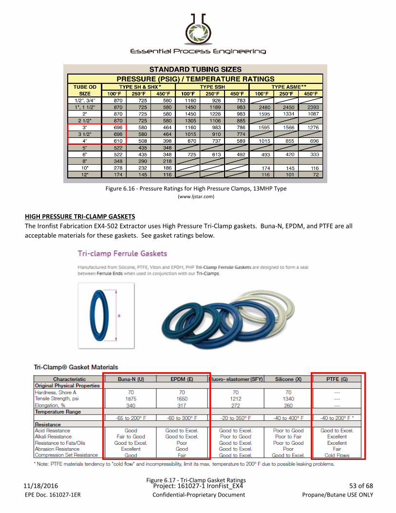
HIGH PRESSURE TRI-CLAMP GASKETS
(www.ljstar.com)
Figure 6.16 - Pressure Ratings for High Pressure Clamps, 13MHP Type
The Ironfist Fabrication EX4-502 Extractor uses High Pressure Tri-Clamp gaskets. Buna-N, EPDM, and PTFE are all
acceptable materials for these gaskets. See gasket ratings below.
Figure 6.17 - Tri-Clamp Gasket Ratings11/18/2016 EPE Doc. 161027-1ER
Project: 161027-1 IronFist_EX4 Confidential-Proprietary Document
53 of 68 Propane/Butane USE ONLY

FASTENER TORQUE REQUIREMENTS
FASTENER DIAMETER TORQUE VALUE
5/16" 10 ft-lbs
3/8" 17.5 ft-lbs
1/2" 38 ft-lbs
Table 6.18 - Tri-Clamp Torque Specifications
Table 6.19 - Stainless Steel Fastener Maximum Torque Specifications
Table 6.20 - Summary of Torque Specifications for Common Fastener Sizes
Fastener torque specifications for sanitary Tri-Clamp fittings are shown in Table 6.18 below. When manufacturer
specifications are not available, fasteners shall be tightened to 85% of their maximum rated torque value. See Table
6.19 for stainless steel maximum torque specifications. Operators are required to maintain a torque wrench and
utilize the torque wrench when tightening or assembling any vessel. Torque wrenches shall be calibrated and in
good working condition.
11/18/2016 EPE Doc. 161027-1ER
Project: 161027-1 IronFist_EX4 Confidential-Proprietary Document
54 of 68 Propane/Butane USE ONLY

CHEMICAL COMPATIBILITY
The following charts indicate compatibility of the primary components to the Propane solvent used for extraction.
Figure 7.1 - Propane and 316 Stainless Steel Compatibility
(Cole-Parmer Chemical Compatibility Database)
www.coleparmer.com/Chemical-Resistance
11/18/2016 EPE Doc. 161027-1ER
Project: 161027-1 IronFist_EX4 Confidential-Proprietary Document
55 of 68 Propane/Butane USE ONLY

CHEMICAL COMPATIBILITY
Figure 7.2 - Propane and PTFE Compatibility
(Cole-Parmer Chemical Compatibility Database)
www.coleparmer.com/Chemical-Resistance
11/18/2016 EPE Doc. 161027-1ER
Project: 161027-1 IronFist_EX4 Confidential-Proprietary Document
56 of 68 Propane/Butane USE ONLY
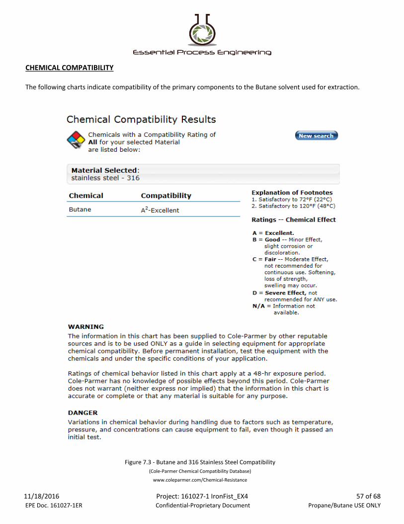
CHEMICAL COMPATIBILITY
The following charts indicate compatibility of the primary components to the Butane solvent used for extraction.
Figure 7.3 - Butane and 316 Stainless Steel Compatibility
(Cole-Parmer Chemical Compatibility Database)
www.coleparmer.com/Chemical-Resistance
11/18/2016 EPE Doc. 161027-1ER
Project: 161027-1 IronFist_EX4 Confidential-Proprietary Document
57 of 68 Propane/Butane USE ONLY
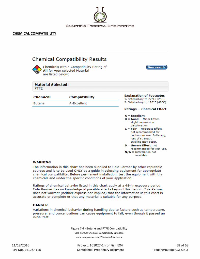
CHEMICAL COMPATIBILITY
www.coleparmer.com/Chemical-Resistance
Figure 7.4 - Butane and PTFE Compatibility
(Cole-Parmer Chemical Compatibility Database)
11/18/2016 EPE Doc. 161027-1ER
Project: 161027-1 IronFist_EX4 Confidential-Proprietary Document
58 of 68 Propane/Butane USE ONLY

WARNING SIGNS/LABELS/PLACARDS
The Ironfist Fabrication EX4-502 Extractor shall have the appropriate warning labels for the use of propane and/or
butane visibly affixed. See Figures 8.1 and 8.2 for examples.
Figure 8.1 - Warning Label Example
Figure 8.2 - Required Warning Label for Propane, Butane, and other Solvents in use
11/18/2016 EPE Doc. 161027-1ER
Project: 161027-1 IronFist_EX4 Confidential-Proprietary Document
59 of 68 Propane/Butane USE ONLY

STATE SPECIFIC REQUIREMENTS
CODE PATH ANALYSIS
APPLICABLE CODES
OAR 845-025-3260Cannabinoid Concentrate and Extract Processor Requirements Effective September 20, 2016
(b) Must:
(A) Only use a hydrocarbon-based solvent that is at least 99 percent purity.
(B) Only use a non-hydrocarbon-based solvent that is food-grade.
(D) Use only potable water and ice made from potable water in processing.
The Ironfist Fabrication EX4-502 Extractor has been reviewed per the following Oregon State Codes/Standards:
(1) Cannabinoid Concentrates or Extracts. A processor with a cannabinoid concentrate or extract endorsement:
(a) May not use Class I solvents as those are classified in the Federal Drug Administration Guidance, Table I,
published in the Federal Register on December 24, 1997 (62 FR 67377).
(C) Work in an environment with proper ventilation, controlling all sources of ignition where a
flammable atmosphere is or may be present.
(E) If making a concentrate or extract that will be used in a cannabinoid edible, be endorsed as a
cannabinoid edible processor and comply with OAR 845-025-3250.
11/18/2016 EPE Doc. 161027-1ER
Project: 161027-1 IronFist_EX4 Confidential-Proprietary Document
60 of 68 Propane/Butane USE ONLY

APPLICABLE CODES (CONTINUED)
OAR 845-025-3260 (CONTINUED)
(2) Cannabinoid Extracts. A processor with an endorsement to make cannabinoid extracts:
(b) Must:
(A) Process in a:
(i) American National Standards Institute (ANSI);
(ii) Underwriters Laboratories (UL); or
(iii) The American Society for Testing and Materials (ASTM).
(D) Have equipment and facilities used in processing approved for use by the local fire code official.
(F) Have an emergency eye-wash station in any room in which cannabinoid extract is being processed.
(G) Have all applicable material safety data sheets readily available to personnel working for the
processor.
(a) May not use pressurized canned flammable fuel, including but not limited to butane and other fuels intended for
use in camp stoves, handheld torch devices, refillable cigarette lighters and similar consumer products.
(i) Fully enclosed room clearly designated on the current diagram of the licensed premises.
(ii) Room and with equipment, including all electrical installations that meet the
requirements of the Oregon Structural Specialty Code, related Oregon Specialty Codes
and the Oregon Fire Code.
(B) Use a professional grade closed loop extraction system designed to recover the solvents and built to
codes of recognized and generally accepted good engineering standards, such as those of:
(C) If using carbon dioxide in processing, use a professional grade closed loop carbon dioxide gas
extraction system where every vessel is rated to a minimum of six hundred pounds per square inch.
(E) For extraction system engineering services, including but not limited to consultation on and design
of extraction systems or components of extraction systems, use the services of a professional engineer
registered with the Oregon State Board of Examiners for Engineering and Land Surveying, unless an
exemption under ORS 672.060 applies.
11/18/2016 EPE Doc. 161027-1ER
Project: 161027-1 IronFist_EX4 Confidential-Proprietary Document
61 of 68 Propane/Butane USE ONLY

APPLICABLE CODES (CONTINUED)
OAR 845-025-3260 (CONTINUED)
(3) Cannabinoid Concentrates. A processor with an endorsement to make cannabinoid concentrates:
(a) May not:
(A) Use denatured alcohol.
(B) If using carbon dioxide, apply high heat or pressure.
(c) May use:
(A) A mechanical extraction process;
Stat. Auth.: ORS 475B.025 & 475B.090
Stats. Implemented: ORS 475B.090
NFPA 58-2014
(b) Must only use or store dry ice in a well-ventilated room to prevent against the accumulation of dangerous levels
of carbon dioxide.
(B) A chemical extraction process using a nonhydrocarbon-based or other solvent, such as water,
vegetable glycerin, vegetable oils, animal fats, isopropyl alcohol or ethanol; or
(C) A chemical extraction process using the hydrocarbon-based solvent carbon dioxide, provided that
the process does not involve the use heat over 180 degrees or pressure.
4.1.1 Systems or Components assembled to make up systems shall be approved. Cylinders less than 120 gallons. Container
Valves, connection manifold valve assemblies, regulators, and pressure relief valves.
4.2.2 Odorization is not required as the R600/a is delivered from the manufacturer or distributor. The addition of Odorization
damages the processed materials and shall increase the risk of the process by requiring persons untrained in odorization to
perform this task. Odorization is not required and is not to be performed by processors for the purpose of oil extraction by a
Professional Grade Closed Loop Extractor. A gas monitoring system is used to detect and monitor levels of the LP-Gas used.
5.2.3.1 DOT and ASME Designed containers are used for the storage of Solvents. No other containers are used for this process.
The Extraction equipment is designed to the rules of ASME BPVC VIII Division 1, and the Butane tank (container) is a DOT
approved container with a 20 lb quantity of Butane (R600/a)
11/18/2016 EPE Doc. 161027-1ER
Project: 161027-1 IronFist_EX4 Confidential-Proprietary Document
62 of 68 Propane/Butane USE ONLY

APPLICABLE CODES (CONTINUED)
NFPA 58-2014 (CONTINUED)
5.2.8.1 (A) The Solvent vessel is marked according to the section, “Flammable” and “Butane”
5.7.6 Pressure Gauges. Compatible pressure gauges are installed.
5.7.7 Other Container Connections. The process requires bi-directional ball valves.
5.9.4 Fittings for Metallic Pipe and Tubing
6.7.2 Installation of Pressure Relief Devices (See 5.7.2, page 41 of code)
6.18.3 Compressor Installation (Refrigerant Recovery Pump)
6.20.6 Buildings Housing Industrial Occupancies
7.3 Venting LP-Gas to Atmosphere has been evaluated. Only emergency venting would occur.
5.9.3 Pipe and Tubing. All piping and tubing have been sized and selected to meet the pressure requirements and compatibility
requirements of this process and the chemical.
5.2.4.2 The Maximum Allowable Working Pressure (MAWP) has been calculated to the current ASME Boiler and Pressure Vessel
Code VIII Division 1. The MAWP has been identified and listed within this report. The process pressure never exceeds the MAWP.
5.2.8.4 Warning Labels that contain unodorized LP-Gas products shall be marked “NOT ODORIZED”, Letter height 3/8”, Border
Width 1/16”. The equipment and the room have the appropriate warning labels affixed.
5.7.1 Materials. All processing equipment such as the recovery pump, valves, fittings, seals and extracting piping meet the
compatibility requirements for this process and solvent.
5.7.2 Pressure Relief Devices. Pressure relief valves have been installed at each vessel that can be closed. There are three (3)
pressure relief valves installed.
5.7.3 Overfilling Prevention Devices. The DOT certified container is never filled beyond it’s original supplied capacity. Butane is
recycled to its original container and weighed to determine the amount of Butane recovered.
6.20.3 Installation Requirements for Cylinders, Equipment, Piping and appliances in Buildings, Building Roofs, and Exterior
Balconies
11/18/2016 EPE Doc. 161027-1ER
Project: 161027-1 IronFist_EX4 Confidential-Proprietary Document
63 of 68 Propane/Butane USE ONLY

APPLICABLE CODES (CONTINUED)
NFPA 497 2012
This standard has been evaluated.
INTERNATIONAL FIRE CODE 2015
5003.9 General safety precautions.
5003.9.1 Personnel training and written procedures.
5003.9.1.1 Fire department liaison.
5003.9.4 Electrical wiring and equipment.
Electrical wiring and equipment shall be installed and maintained in accordance with NFPA 70.
5003.9.5 Static accumulation.
5005.2.2 Closed systems.
5005.2.2.1 Ventilation. Where closed systems are designed to be opened as part of normal operations, ventilation shall be provided in accordance with
Section 5005.2.1.1.
General precautions for the safe storage, handling or care of hazardous materials shall be in accordance with Sections 5003.9.1
through 5003.9.10.
Persons responsible for the operation of areas in which hazardous materials are stored, dispensed, handled or used shall be
familiar with the chemical nature of the materials and the appropriate mitigating actions necessary in the event of fire, leak or
spill.
Responsible persons shall be designated and trained to be liaison personnel to the fire department. These persons shall aid the
fire department in preplanning emergency responses and identifying the locations where hazardous materials are located, and
shall have access to Material Safety Data Sheets and be knowledgeable in the site’s emergency response procedures.
When processes or conditions exist where a flammable mixture could be ignited by static electricity, means shall be provided to
prevent the accumulation of a static charge. Floors are Anti-Static. Operators wear lab coats and gloves. The floor is a non-static
floor. Process does not involve repeated motion of hoses which reduce risk of static accumulation.
Use of hazardous materials in closed containers or systems shall be in accordance with Sections 5005.2.2.1 through 5005.2.2.4.
11/18/2016 EPE Doc. 161027-1ER
Project: 161027-1 IronFist_EX4 Confidential-Proprietary Document
64 of 68 Propane/Butane USE ONLY

APPLICABLE CODES (CONTINUED)
NFPA 70 - NATIONAL ELECTRICAL CODE
Article 500 Hazardous (Classified) Locations, Classes I, II, and III, Divisions 1 and 2
Article 500.7(K) Combustible Gas Detection System Protection method utilized in processing room.
ASME BPVC VIII DIVISION I
Article 500.5(2)(1) Class I, Divison 2 location –Protection Technique K is to be used to allow for normal wiring and remove
requirement for Explosion Proof Devices.
Sections UG (General Requirements), UW (Requirements pertaining to methods of fabrication of pressure vessels), and UHA
(Requirements for pressure vessels constructed of High Alloy steel). Used in the determination of the construction and
performance of the Extractor.
Appendices 1 (Supplementary Design Formulas), 2 (Rules for bolted flange connections with ring type gaskets), 11 (Capacity
conversions for safety valves), 24 (Design rules for clamp connections). Used to calculate the performance requirements for the
Pressure relief valves, and sanitary tri-clamps.
11/18/2016 EPE Doc. 161027-1ER
Project: 161027-1 IronFist_EX4 Confidential-Proprietary Document
65 of 68 Propane/Butane USE ONLY

PROCESSING FACILITY BUILDING REQUIREMENTS
Occupancy:
Extraction Equipment Models: Ironfist Fabrication EX4-502
Solvents Used:
Solvent Quantity:
Lab Construction: IBC/ IFC Control Area Design or H-2 Type
*Processing Lab design/approval not included in this report
F-1 minimum required / Processing within an identified
Control Area designed to OAR 845-025-3260.
Flammable Gas (IsoButane/ nButane/ Propane) –
Liquified/ Gas
Not to exceed 150 lbs (30 Gallons) Per Control Area (See
local codes)
-For inclusion of non-explosion proof rated equipment,
see NFPA 70, Section 500.7(k)
11/18/2016 EPE Doc. 161027-1ER
Project: 161027-1 IronFist_EX4 Confidential-Proprietary Document
66 of 68 Propane/Butane USE ONLY

ESSENTIAL PROCESS ENGINEERING11731 120TH Avenue NE, Suite B
Kirkland, WA 98034
425-814-5389
11/18/2016 EPE Doc. 161027-1ER
Project: 161027-1 IronFist_EX4 Confidential-Proprietary Document
68 of 68 Propane/Butane USE ONLY

APPENDIX A
IRONFIST EX-4 PRESSURE VESSEL DRAWINGS

Configuration Information:
Item 8 – Material Vessel, SA-249 Grade 316 Stainless Steel
Figure 21.1 – Material Vessel Dimensional Drawing, SA-240 Stainless Steel
Figure 21.2 –Collection Vessel Top Section Assembly, SA-240 Stainless Steel
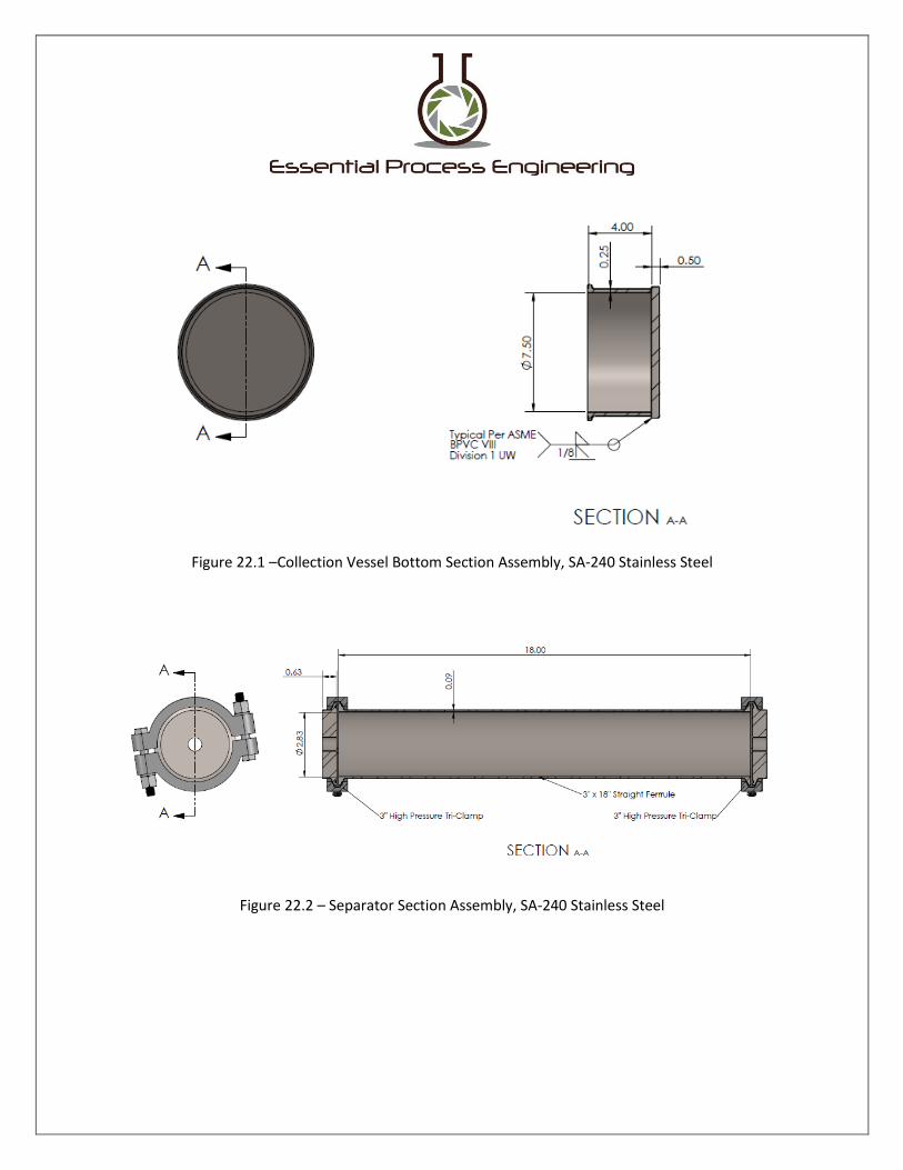
Figure 22.1 –Collection Vessel Bottom Section Assembly, SA-240 Stainless Steel
Figure 22.2 – Separator Section Assembly, SA-240 Stainless Steel

Figure 23.1 – ASME B36.19 Standard for Stainless Steel Pipe

Figure 24.1 – Solvent Vessel Assembly
Vessels are hydrostatically or pneumatically pressure tested per ASME BPVC VIII Division 1 prior to
operational use.
Other items within the configuration not described above – Weight Scale. A digital scale is used to measure the dry and full weight of the Solvent recovery tank to indicate the quantity of solvent transferred.
*The Collection Vessel includes a Pressure Gauge rated for use with Propane or Butane.