Embed Size (px)
Citation preview
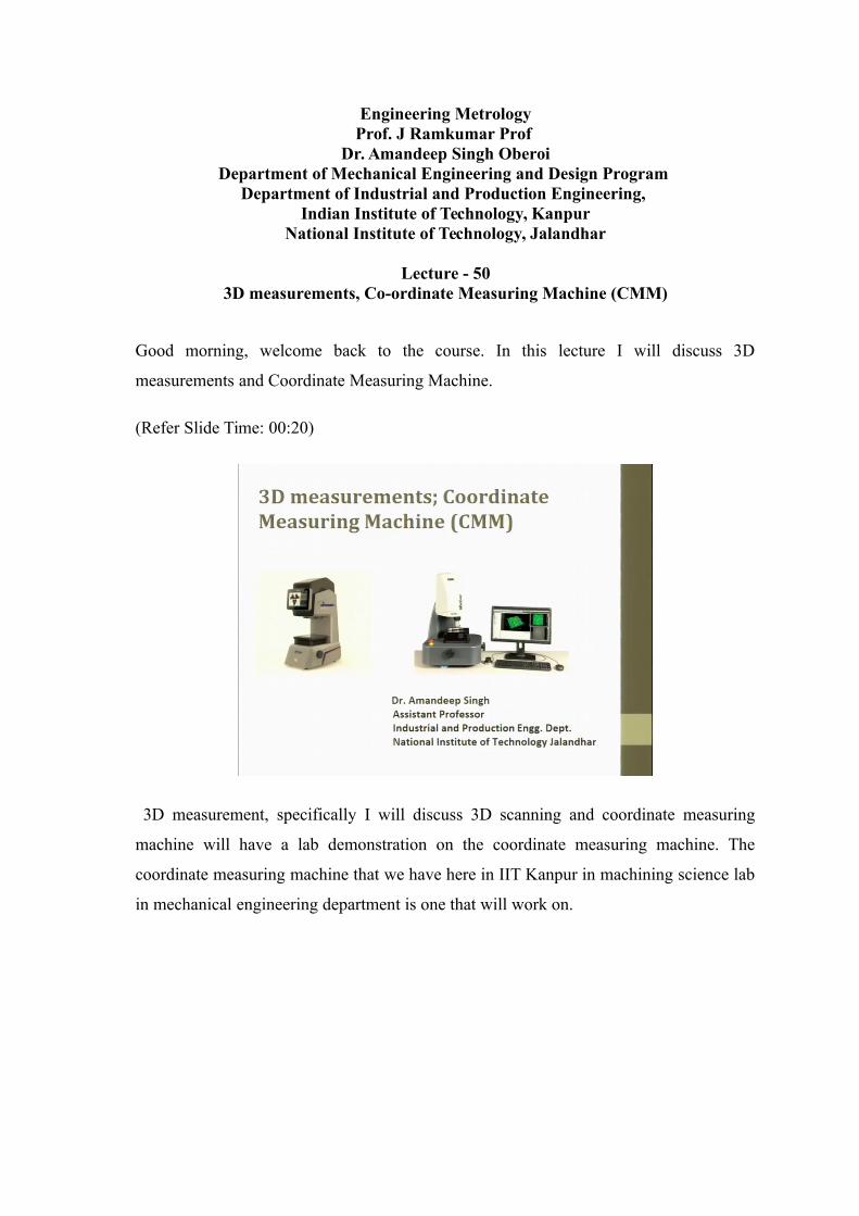
Engineering MetrologyProf. J Ramkumar Prof
Dr. Amandeep Singh OberoiDepartment of Mechanical Engineering and Design Program
Department of Industrial and Production Engineering, Indian Institute of Technology, Kanpur
National Institute of Technology, Jalandhar
Lecture - 503D measurements, Co-ordinate Measuring Machine (CMM)
Good morning, welcome back to the course. In this lecture I will discuss 3D
measurements and Coordinate Measuring Machine.
(Refer Slide Time: 00:20)
3D measurement, specifically I will discuss 3D scanning and coordinate measuring
machine will have a lab demonstration on the coordinate measuring machine. The
coordinate measuring machine that we have here in IIT Kanpur in machining science lab
in mechanical engineering department is one that will work on.
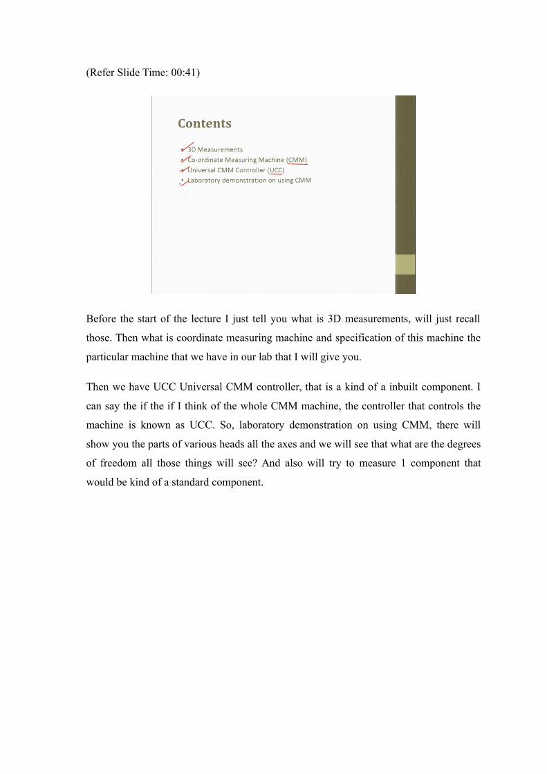
(Refer Slide Time: 00:41)
Before the start of the lecture I just tell you what is 3D measurements, will just recall
those. Then what is coordinate measuring machine and specification of this machine the
particular machine that we have in our lab that I will give you.
Then we have UCC Universal CMM controller, that is a kind of a inbuilt component. I
can say the if the if I think of the whole CMM machine, the controller that controls the
machine is known as UCC. So, laboratory demonstration on using CMM, there will
show you the parts of various heads all the axes and we will see that what are the degrees
of freedom all those things will see? And also will try to measure 1 component that
would be kind of a standard component.
(Refer Slide Time: 01:29)
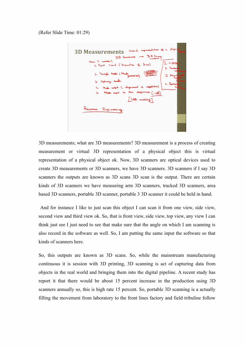
3D measurements; what are 3D measurements? 3D measurement is a process of creating
measurement or virtual 3D representation of a physical object this is virtual
representation of a physical object ok. Now, 3D scanners are optical devices used to
create 3D measurements or 3D scanners, we have 3D scanners. 3D scanners if I say 3D
scanners the outputs are known as 3D scans 3D scan is the output. There are certain
kinds of 3D scanners we have measuring arm 3D scanners, tracked 3D scanners, area
based 3D scanners, portable 3D scanner, portable 3 3D scanner it could be held in hand.
And for instance I like to just scan this object I can scan it from one view, side view,
second view and third view ok. So, that is front view, side view, top view, any view I can
think just see I just need to see that make sure that the angle on which I am scanning is
also record in the software as well. So, I am putting the same input the software so that
kinds of scanners here.
So, this outputs are known as 3D scans. So, while the mainstream manufacturing
continuous it is session with 3D printing, 3D scanning is act of capturing data from
objects in the real world and bringing them into the digital pipeline. A recent study has
report it that there would be about 15 percent increase in the production using 3D
scanners annually so, this is high rate 15 percent. So, portable 3D scanning is a actually
filling the movement from laboratory to the front lines factory and field tribuline follow
by key factors and because there are low cost. So, better accuracy is there, simplicity is
there, convenience and flexibility is there.
So, 3D scanner can scan the real object and produced a virtual image of that ok, it can
produce this object, how it what are the steps for that I will just give a brief introduction
to them as well. So, before that the 3 or 4 types of 3D scanners, number 1 that I am going
discuss here is CMM. This I will discuss in detail coordinate measuring machine so, in
this arms can be equipped with either fixed probe or touched figure probe has it is also
possible to mount a 3D scanning head on the CMM.
So, we will discuss this a many advantages that many different tools can be mounted on
a on the portable CMM s and making it possible to easily integrate scanning and probing.
So, limitations also there, portable CMM you know need to be fixed on the surface so,
use of physical link. So, we do not have a portable machine, we have a full fledged 3D
scanner not a very big industrial size, but for research it is quite capable of producing the
outputs that has required.
So, also getting some industry consultancy here as well so, 2nd type of 3D scanner is
tracked 3D scanner; tracked 3D scanner A tracked 3D scanner, (Refer Time: 04:59)
optical tracking devices can track various types of measurement tools including
positioning of a 3D scanner. So, positioning method may be external optical tracking
devices this can a use an external optical tracking device to establish positioning. So,
they usually use markers such as passive or active targets that optically bind the tracking
device to the scanner.
So, another kind of a scanner is structured light scanner; structured light scanner. So, by
structural lighter means that this can be project a pattern of light on to a part or a process
when it is happening and how the pattern is started when the light hits the object is then
and LCD projector or scanned or defective laser beams projects the light pattern 1 or 2 or
sometimes more sensors records the projective patterns. So, if just put the light and the
structured light scanner with patterns in a change of a light tells us the various profiles or
the curve of the object so, this is another way.
So, one more type of scanner is portable, portable 3D scanner. Portable 3D scanner can
be either CMM or the meant as a portable 3D scanner anything that can be helping hand
taken to the machine or the component that will like to measure is would be called as
portable. So, these are the major kinds of scanners, I am just introducing, I am not
getting into detail for details will share you the notes and you can read them.
So, how does 3D scanning works? What happens when it scans, when it try to scan,
when we use CMM machine it will try to touch the points ok. The first step it produce is
the point cloud., I will write it, how it works? The first step is the point cloud. So, point
cloud I can even better put at this is actually acquisition of the data, the data or the shape
whatever we like to we trying to just this is the first input I am getting from my surface.
So, it is this is I can say acquisition of scan. If I need to produce this surface the points
would be produced first, this kind of curve the point would be produced first. So, this
kind of points will be produced, the curve let me say this is one surface ok, the points are
produced, these are the points, this is point cloud. So, these scanning results are
representing using free form. Though this is free form or unstructured form, sometimes
structure components are like we have a circle, a cone, a plane, a rectangle or when these
things are known that known are shapes are there, those are known as structured forms.
This is a kind of freeform ok however, if we know about; if you know about the curves
the Bezier curve, b spline curve those are also there, but nowadays those are also not
very significant. Even the freeform any curvature that we need is quite possible to be
scan using the 3D scanners.
So, 1st point is the point cloud, using the point cloud, we created triangle mesh. What is
triangle mesh? Now, this is a point cloud, will make triangle out of this ok, joining a
point with other point we are trying into make it triangles. Similarly, whole that the
whole surface would be in the form of a triangle, this is known as triangle mesh. So, this
is actually I would just call it mesh generation.
The 3rd step could be when the mesh is generated will to optimize the mesh. Optimize
mesh means the number of triangles you know when we conduct the analysis or when we
to conduct the strength analysis or heat analysis this is the mesh, the number of triangles
makes when more the number of triangles are moved be the computational part. So, it
depends upon what type of competition we need to do. So, optimization of mesh to
reduce the time of computation and to get the optimum shape as well that is also
important when instance if there steep angles here, the steep angles here the triangle
mesh can be the smaller triangle. Here, if it is kind of a plane surface, if it is a kind of a
plane surface here so whether triangle can be of bigger size.
So, we need to optimize the mesh to obtain the near possible shape here ok. So,
optimization of mesh is required then. After that fourth point here could be the output of
the mesh. So, images and scans are brought into common reference system where data is
merged into a complete model ok, a complete model data is merged and the complete
model is formed this process is called alignment or registration or we can call as mesh
output. This is alignment or registration ok. So, we have scan from different views, when
we are aligning those surfaces to get this specific shape the solid shape this is known as
complete mesh output.
So, after it, so mesh input to the engineers; mesh input in the engineer workflows. So,
this output goes, I will put mesh input to the engineers. So, this mesh input go to the
engineers they can create a surface if they like after that so, they can create a solid model
if they like. So, these things can be created using this so, this is the next step. So, this
mesh input goes to the engineers. How does it go to them? It is generally produced in the
stl format, throughout stl format ok.
So, the computer softwares can be used to clean up this scan data, filling holes,
correcting errors, then improving data quality. So, the resulting triangle mesh is typically
exported in this format, stl format and we can bought into the known form like, we can
converted into the Bezier scan or Bezier curve if it is possible. If not then also the things
are which is things can go ok so, CAD modeling can be produced out of this ok.
So, this was a brief introduction about 3D scanning. Next, where does 3D scanning
apply? The major application is in reverse engineering. So, what happens in reverse
engineering? So, in mechanical engineering this process reverse engineering aims to
create virtual 3D model from an existing physical object in order to duplicate or in to
enhance it.
So, the procedure is again very similar in reverse engineering. We create 3D scan mesh,
then extract the information, then cad modeling, then verify the data, then other things
feedback, then exporting to the model. So, what is reverse engineering actually, what is
general engineering we have an idea, from the idea we have certain plans for the certain
plans of certain model we have.
Finally, we get the final product after getting through various analyses technical,
financial, availability of material, manufacturability all those things we get the final
product. Reverse engineering is if I got this final product, I like to scan this product then
move reverse I will create a model out of that and just to trying to create replicate of this
product, this is reverse engineering ok.
(Refer Slide Time: 13:49)
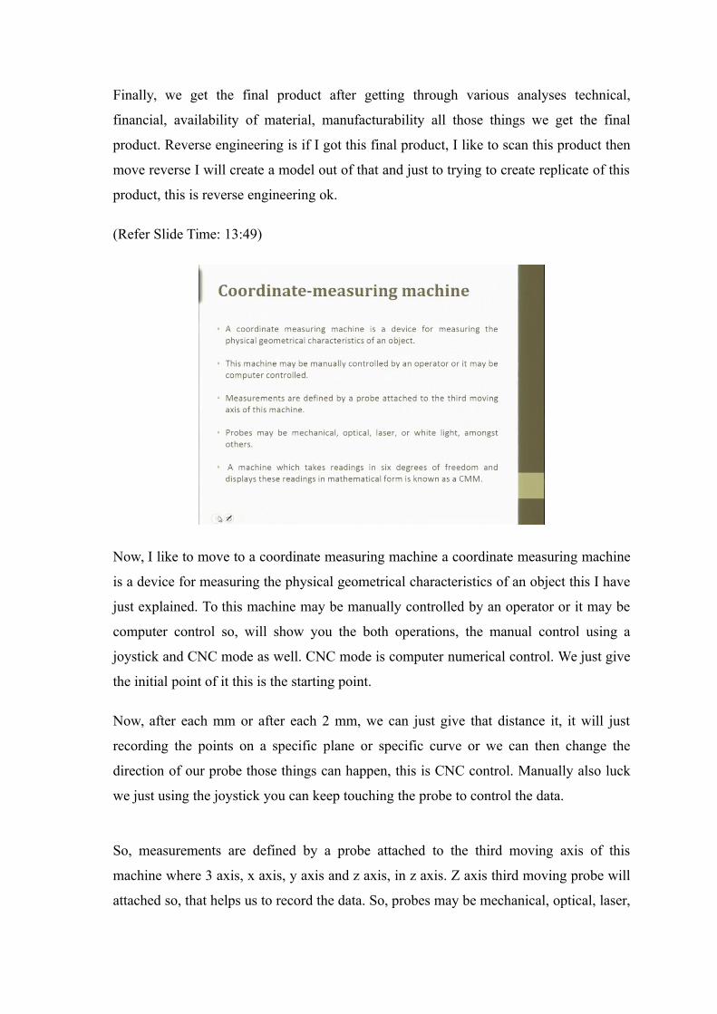
Now, I like to move to a coordinate measuring machine a coordinate measuring machine
is a device for measuring the physical geometrical characteristics of an object this I have
just explained. To this machine may be manually controlled by an operator or it may be
computer control so, will show you the both operations, the manual control using a
joystick and CNC mode as well. CNC mode is computer numerical control. We just give
the initial point of it this is the starting point.
Now, after each mm or after each 2 mm, we can just give that distance it, it will just
recording the points on a specific plane or specific curve or we can then change the
direction of our probe those things can happen, this is CNC control. Manually also luck
we just using the joystick you can keep touching the probe to control the data.
So, measurements are defined by a probe attached to the third moving axis of this
machine where 3 axis, x axis, y axis and z axis, in z axis. Z axis third moving probe will
attached so, that helps us to record the data. So, probes may be mechanical, optical, laser,
white light and many such. Mechanical optical is like you know laser white light all
those in a, but so, we have here in our machine is the mechanical probe ok. It will
physically touch the component that we are trying to measure, it will touch and it will
produce a beep sound and also an indicator would blink. So, whenever it touches here so,
this probe will use here.
The machine which take readings in 6 degrees of freedom and displays these readings in
mathematical form is known as coordinate measuring machine, this if it is of freedom
that is all the dimensions are taken into account and displays these reading is in
mathematical form. When mathematical form that that is can be obtained like the
distance between the object and the shape of the object.
If it is a freeform it will create a freeform if we know that the there is a structured form
we can select it before and only that this is a circle that we are going to measure of a
circle 3 points are minimum to are required to measure for a plane, 3 points are required
to define the plane, for a cylinder 8 points are required, for a cone 8 points are required.
So, I will come to them when I will actually show you the lab demonstrations.
(Refer Slide Time: 16:14)
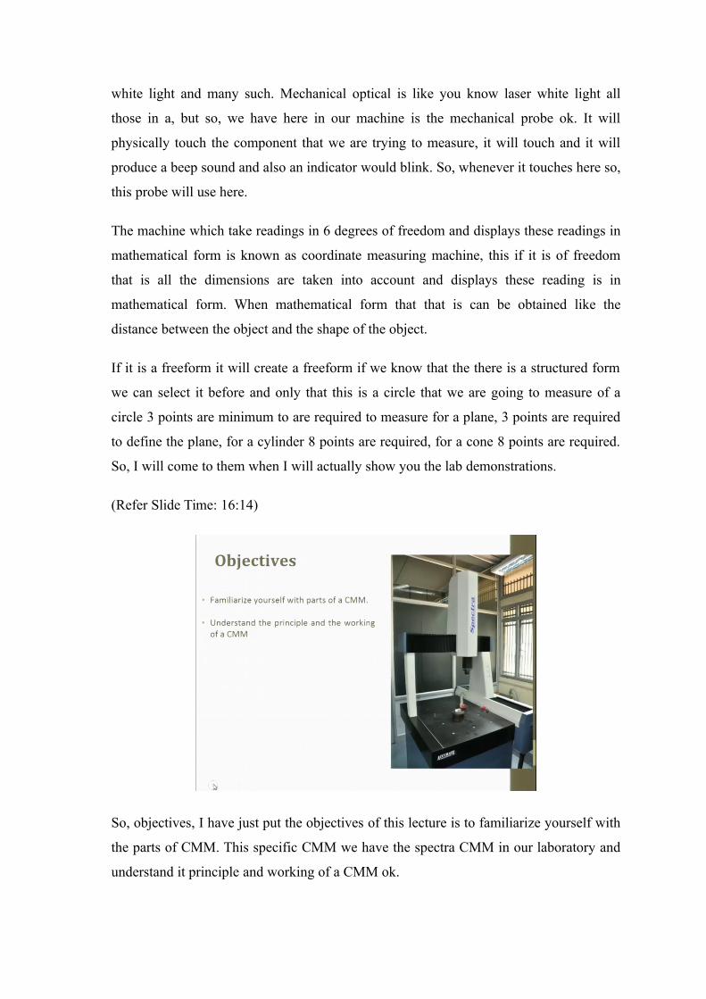
So, objectives, I have just put the objectives of this lecture is to familiarize yourself with
the parts of CMM. This specific CMM we have the spectra CMM in our laboratory and
understand it principle and working of a CMM ok.
(Refer Slide Time: 16:31)
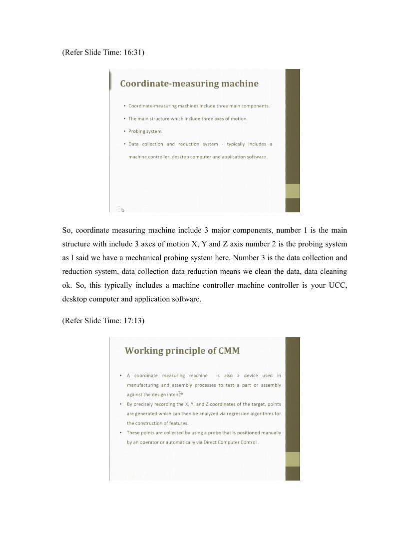
So, coordinate measuring machine include 3 major components, number 1 is the main
structure with include 3 axes of motion X, Y and Z axis number 2 is the probing system
as I said we have a mechanical probing system here. Number 3 is the data collection and
reduction system, data collection data reduction means we clean the data, data cleaning
ok. So, this typically includes a machine controller machine controller is your UCC,
desktop computer and application software.
(Refer Slide Time: 17:13)
Now, working principle of CMM; a coordinate measuring machine is also a device used
in manufacturing and assembly processes to test a part or assembly against the design
intent, what is over intent for design against that with test whether our part or assembly is
trying to meet that or not. So, by precisely recording the X, Y and Z coordinates of the
target, points are generated which can then be analyzed via regression algorithms
because we might we can have the mathematical relation, mathematical equation which
are regression algorithms as well.
So, this via regression algorithms, the points can be analyzed for construction of the
features that we finally need them above product. So, these points are collected by using
the probe that is position manually by an operator or automatically via direct computer
control.
(Refer Slide Time: 18:10)
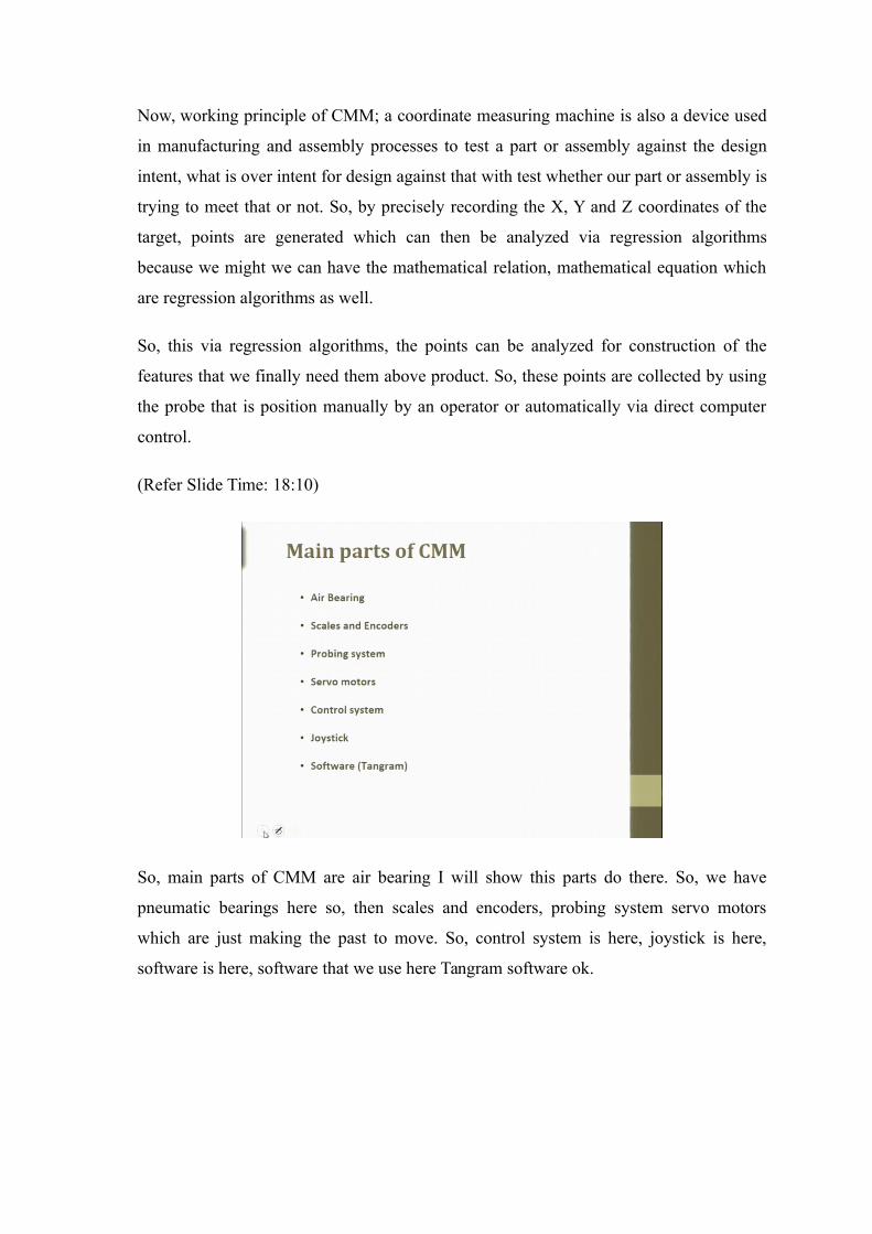
So, main parts of CMM are air bearing I will show this parts do there. So, we have
pneumatic bearings here so, then scales and encoders, probing system servo motors
which are just making the past to move. So, control system is here, joystick is here,
software is here, software that we use here Tangram software ok.
(Refer Slide Time: 18:32)
.
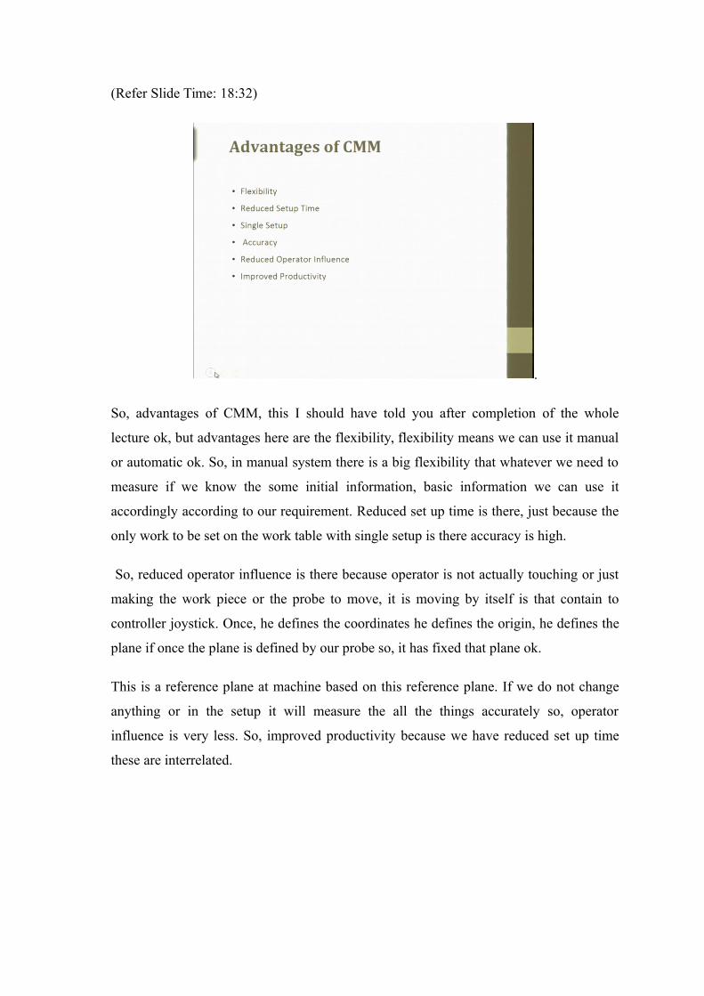
So, advantages of CMM, this I should have told you after completion of the whole
lecture ok, but advantages here are the flexibility, flexibility means we can use it manual
or automatic ok. So, in manual system there is a big flexibility that whatever we need to
measure if we know the some initial information, basic information we can use it
accordingly according to our requirement. Reduced set up time is there, just because the
only work to be set on the work table with single setup is there accuracy is high.
So, reduced operator influence is there because operator is not actually touching or just
making the work piece or the probe to move, it is moving by itself is that contain to
controller joystick. Once, he defines the coordinates he defines the origin, he defines the
plane if once the plane is defined by our probe so, it has fixed that plane ok.
This is a reference plane at machine based on this reference plane. If we do not change
anything or in the setup it will measure the all the things accurately so, operator
influence is very less. So, improved productivity because we have reduced set up time
these are interrelated.
(Refer Slide Time: 19:50)
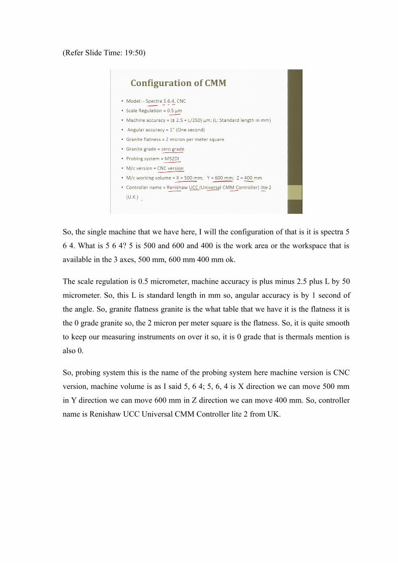
So, the single machine that we have here, I will the configuration of that is it is spectra 5
6 4. What is 5 6 4? 5 is 500 and 600 and 400 is the work area or the workspace that is
available in the 3 axes, 500 mm, 600 mm 400 mm ok.
The scale regulation is 0.5 micrometer, machine accuracy is plus minus 2.5 plus L by 50
micrometer. So, this L is standard length in mm so, angular accuracy is by 1 second of
the angle. So, granite flatness granite is the what table that we have it is the flatness it is
the 0 grade granite so, the 2 micron per meter square is the flatness. So, it is quite smooth
to keep our measuring instruments on over it so, it is 0 grade that is thermals mention is
also 0.
So, probing system this is the name of the probing system here machine version is CNC
version, machine volume is as I said 5, 6 4; 5, 6, 4 is X direction we can move 500 mm
in Y direction we can move 600 mm in Z direction we can move 400 mm. So, controller
name is Renishaw UCC Universal CMM Controller lite 2 from UK.
(Refer Slide Time: 21:05)
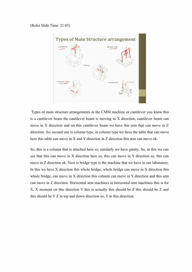
Types of main structure arrangements in the CMM machine or cantilever you know this
is a cantilever beam the cantilever beam is moving in X direction, cantilever beam can
move in X direction and on this cantilever beam we have this arm that can move in Z
direction. So, second one is column type, in column type we have the table that can move
here this table can move in X and Y direction in Z direction this arm can move ok.
So, this is a column that is attached here so, similarly we have gantry. So, in this we can
see that this can move in X direction here so, this can move in Y direction so, this can
move in Z direction ok. Next is bridge type is the machine that we have in our laboratory.
In this we have X direction this whole bridge, whole bridge can move in X direction this
whole bridge, can move in X direction this column can move in Y direction and this arm
can move in Z direction. Horizontal arm machines in horizontal arm machines this is for
X, X moment on this direction Y this is actually this should be Z this should be Z and
this should be Y Z in top and down direction so, Y in this direction.
(Refer Slide Time: 22:30)
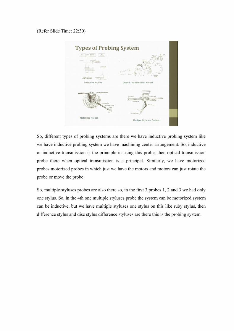
So, different types of probing systems are there we have inductive probing system like
we have inductive probing system we have machining center arrangement. So, inductive
or inductive transmission is the principle in using this probe, then optical transmission
probe there when optical transmission is a principal. Similarly, we have motorized
probes motorized probes in which just we have the motors and motors can just rotate the
probe or move the probe.
So, multiple styluses probes are also there so, in the first 3 probes 1, 2 and 3 we had only
one stylus. So, in the 4th one multiple styluses probe the system can be motorized system
can be inductive, but we have multiple styluses one stylus on this like ruby stylus, then
difference stylus and disc stylus difference styluses are there this is the probing system.
(Refer Slide Time: 23:23)
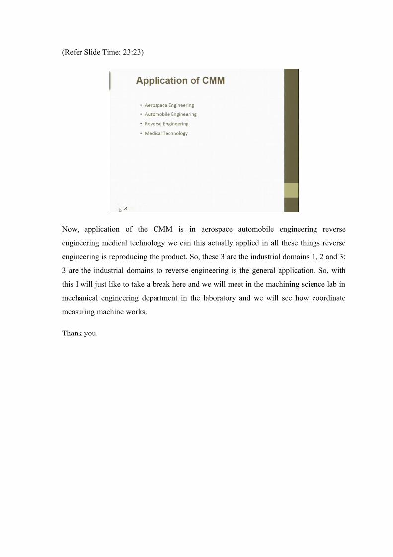
Now, application of the CMM is in aerospace automobile engineering reverse
engineering medical technology we can this actually applied in all these things reverse
engineering is reproducing the product. So, these 3 are the industrial domains 1, 2 and 3;
3 are the industrial domains to reverse engineering is the general application. So, with
this I will just like to take a break here and we will meet in the machining science lab in
mechanical engineering department in the laboratory and we will see how coordinate
measuring machine works.
Thank you.