Embed Size (px)
Citation preview

Engineering Letters, 20:1, EL_20_1_01
(Advance online publication: 27 February 2012)
______________________________________________________________________________________

Symbolically, the above equation can be written in terms of four linear differential operators as
04321 UDDDD (4)
xs
ykD kk
)4,3,2,1( ,
Where, )4,3,2,1( ksk are the roots of the
characteristic equation
02
)2(2
2226
26612
316
411
asa
saasasa (5)
The roots of equation (5) can be written as
111 is
222 is
113 is
224 is (6)
On integrating equation (3), the Airy’s stress function ),( yxU can be represented as
)()(
)()(),(
4433
2211
ysxFysxF
ysxFysxFyxU
)()(
)()(),(
2211
2211
zFzF
zFzFyxU (7)
The analytic functions Φ (z1), ψ (z2) and their conjugates are given by
)( 11
1 zdz
dF ; )( 2
2
2 zdz
dF ;
)( 1
1
1 zzd
Fd ; )( 2
1
2 zzd
Fd (8)
By substituting analytic functions from equation (8) into equation (7), and finally equation (7) into equation (2), the
stress components in terms of )( 1z and )( 2z can be
represented as
)()(Re2
)()(Re2
)()(Re2
2'
21'
1
2'
1'
2'2
21'2
1
zszs
zz
zszs
xy
y
x
(9)
The stresses in Cartesian coordinates given in equation (9) can be written in orthogonal curvilinear coordinate system by means of the following relations
xy
y
x
nmmnmn
mnmn
mnnm
22
22
22
2
2
(10)
m and n are the direction cosines.
III. MAPPING FUNCTION
The area external to a given hole (here, circular, elliptical
or triangular), in Z-plane is mapped conformably to the area
outside the unit circle in ζ plane using following mapping function.
N
kkkm
Rz1
)(
(11)
R =Hole size constant
ie (Here, =1 for unit circle)
0km , for circular hole
ba
bamk k,1 , for elliptical hole, where, a and b
are the semi major and semi minor axis of the ellipse,
respectively
...17,14,11,8,5,3k and 3/13 m ; 45/15 m ;
162/18 m ; 2673/711 m ; 729/114 m ;
111537/9117 m , for triangular hole.
For anisotropic materials, the deformations undergo affine transformation. Hence, the mapping function (Equation
(11)) is modified by introducing complex parameters js .
N
kkk
j
N
k
kkjjj
mbma
Rz
11
1
2)(
,1 jj isa jj isb 1 ; j=1,2. (12)
IV. ARBITRARY BIAXIAL LOADING CONDITIONS
In order to consider several cases of in-plane loads, the
arbitrary biaxial loading condition is introduced into the boundary conditions. This condition has been adopted from Gao’s [10] solution for elliptical hole in isotropic plate. By means of this condition solutions for biaxial loading can be obtained without the need of superposition of the solutions of the uni-axial loading. This is achieved by introducing the biaxial loading factor λ and the orientation angle β into the boundary conditions at infinity.
The boundary conditions for in-plane biaxial loading conditions are as follows:
;' x
;' y
0' xy
at z
Where, 'x
and 'y
are stresses applied about x`, y` axes at
infinity (Refer Fig. (1)). By applying stress invariance into above boundary conditions, boundary conditions about XOY can be written explicitly as:
]2cos)1()1[(2
p
x
]2cos)1()1[(2
p
y
]2sin)1[(2
p
xy (13)
Engineering Letters, 20:1, EL_20_1_01
(Advance online publication: 27 February 2012)
______________________________________________________________________________________
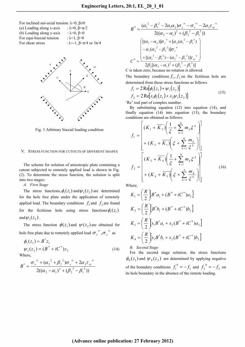
For inclined uni-axial tension: λ=0, β≠0 (a) Loading along x-axis : λ=0, β=π/2 (b) Loading along y-axis : λ=0, β=0 For equi-biaxial tension : λ=1, β=0 For shear stress : λ=-1, β=π/4 or 3π/4
Fig. 1 Arbitrary biaxial loading condition
V. STRESS FUNCTION FOR CUTOUTS OF DIFFERENT SHAPES
The scheme for solution of anisotropic plate containing a cutout subjected to remotely applied load is shown in Fig. (2). To determine the stress function, the solution is split into two stages:
A. First Stage
The stress functions, )( 11 z and )( 21 z are determined
for the hole free plate under the application of remotely
applied load. The boundary conditions 1f and 2f are found
for the fictitious hole using stress functions )( 11 z
and )( 21 z .
The stress function )( 1z and )( 2z are obtained for
hole free plate due to remotely applied load
yx , as
1*
11 )( zBz
2'*'*
21 )()( ziCBz (14)
Where,
))()((2
2)(2
12
22
12
22
22
2*
xyyxB
))()((2
2)2(2
12
22
12
2212
12
1'*
xyxyB
)]()[(2
)]()[(
)](
)([)][(
21
22
2122
22
22
21
21
22
221
21
21221
'*
xy
y
x
C
C is taken zero, because no rotation is allowed.
The boundary conditions 21 , ff on the fictitious hole are
determined from these stress functions as follows
2121112
21111
Re2
Re2
zszsf
zzf
(15)
‘Re’ real part of complex number. By substituting equation (12) into equation (14), and
finally equation (14) into equation (15), the boundary conditions are obtained as follows:
N
kkk
N
k
kk
mKK
mKK
f
112
121
1
)(
1)(
N
kkk
N
k
kk
mKK
mKK
f
134
143
2
)(
1)(
(16)
Where,
2'*'*
1*
1 )(2
aiCBaBR
K
2'*'*
1*
2 )(2
biCBbBR
K
2'*'*
21*
13 )(2
aiCBsaBsR
K
2'*'*
21*
14 )(2
biCBsbBsR
K
B. Second Stage For the second stage solution, the stress functions
)( 10 z and )( 20 z are determined by applying negative
of the boundary conditions 10
1 ff and 20
2 ff on
its hole boundary in the absence of the remote loading.
Engineering Letters, 20:1, EL_20_1_01
(Advance online publication: 27 February 2012)
______________________________________________________________________________________

The stress functions of second stage solution are obtained
using these new boundary conditions ),( 02
01 ff into
Schwarz formula:
1
02
012
210 )(
)(4)(
t
dt
t
tffs
ss
i
(17)
2
02
011
210 )(
)(4)(
t
dt
t
tffs
ss
i
(18)
Where γ is the boundary of the unit circle in ζ-plane, t is the value of ζ on hole boundary, λ1 and λ2 are imaginary constants which will have no contribution towards stress field.
By evaluating the integral the stress functions are obtained as
N
kkkm
ba
13
30 )(
N
kkkm
ba
14
40 )(
(19)
Where,
)()(1
4321221
3 KKKKsss
a
)()(1
3412221
3 KKKKsss
b
)()(1
4321121
4 KKKKsss
a
)()(1
3412121
4 KKKKsss
b
C. Final Solution
The stress function )( 1z and )( 2z for single hole
problem, can be obtained by adding the stress functions of first and second stage.
)()()( 10111 zzz
)()()( 20212 zzz (20)
VI. RESULTS AND DISCUSSION
The numerical results are obtained for Graphite/epoxy
(E1=181GPa, E2=10.3GPa, G12=7.17GPa and ν12=0.28) and Glass/epoxy (E1=47.4GPa, E2=16.2GPa, G12=7.0GPa and ν12=0.26). Some of the results are obtained for isotropic plate (E=200GPa, G=80GPa and ν=0.25) also for sake of comparison. The steps followed in computer implementation are as under:
1. Choose the value of biaxial load factor, λ and load angle, β for the type of loading.
2. Calculate the compliance co-efficient, aij from generalized Hooke’s Law
3. Calculate the value of complex parameters of anisotropy s1 and s2 from the characteristic equation (Equation 1). Some of the constants of anisotropy s1 and s2 are presented in Table 1.
4. Calculate the constants: a1, b1, a2, b2, B, B’, C’, K1, K2, K3, K4 etc.
5. Evaluate the stress functions and their derivatives. 6. Evaluate stresses. The stress functions obtained above are the generalized
solutions. Using these functions, stress distribution for
A. The stress functions (1(z1) and 1(z2)) for the hole free plate under the application of remotely applied load. The boundary conditions at the hole circumference is f1 and f2
B. The second stage stress functions (0(z1) and 0(z2)) for plate with hole, without load at infinity (f0
1 =-f1 and f0
2 =- f2)
C. The stress function ((z1) and (z2)) for plate with hole, subjected to remotely applied load.
Fig.2. Problem configuration with scheme of solution
Engineering Letters, 20:1, EL_20_1_01
(Advance online publication: 27 February 2012)
______________________________________________________________________________________

different loading conditions and material parameters can be obtained.
The following loading cases have been considered. 1. Plate subjected to uni-axial tension at infinite
distance. 2. Plate subjected to biaxial tension at infinite
distance. The stress concentration around elliptical hole varies as
ratio of lengths of major axis (2a) to minor axis (2a) varies. The circle (a/b=1) and crack (a/b=) are the special case of
ellipse. As )()( baba approaches unity, the stress
concentration at the end of major axis of the ellipse tends to be infinite for all materials under consideration (Refer Fig.(3)). For isotropic material the stress concentration is found higher when uni-axial load is applied compared to equi-biaxial loading.
Table 1 Constants of anisotropy
Fiber angle
Graphite/epoxy Glass/epoxy s1 s2 s1 s2
0 -0.0000 + .8936i
0 + 0.8566i
0.0000 + 2.3960i
-0.00 + 0.7139i
90 -0.000 + 1.1674i
0.000 + 0.2043i
-0.000 + 1.4007i
0.000 + 0.4174i
0/90 -0.000 + 3.6403i
0.000 + 0.2747i
-0.000 + 2.0142i
0.000 + 0.4965i
45/-45
-0.8597 + 0.511i
0.8597 + 0.511i
-0.6045 + 0.7966i
0.6045 + 0.7966i
The Fig.(4) shows distribution of normalized tangential
stress (σ/σ) around circular hole in infinite plate subjected to uniaxial (=0) loading at infinity. For all material under consideration (Graphite/epoxy (0/90), Graphite/epoxy (45/-45) and Isotropic Steel) compressive zone is evident at around 900 and 2700. The maximum value of σ/σ for Graphite/epoxy (45/-45) is not found at 00 and 1800 but at 350, 1450, 2150 and 3250. Also the maximum value for Graphite/epoxy (45/-45) is found smaller in comparison to other material in consideration.
The stress distribution around circular hole in composite/isotropic plate subjected to equi-biaxial loading can be seen in Fig. (5). As expected, isotropic material shows equal intensity of stress concentration around hole under hydrostatic state of stress (=1). The anisotropy brings in change in magnitude of stress concentration and also location of it.
The normalized tangential stress (σ/σ) around elliptical hole (semi major axis (a)/semi minor axis (b)=2.0) in infinite plate subjected to uni-axial (=0) and equi-biaxial (=1) loading at infinity is shown in Fig. (6) and Fig. (7), respectively. In all cases under consideration, uni-axial loading produces higher stress concentration compared to equi-bixial loading.
Fig. 3: Change in maximum stress concentration factor for elliptical hole as ratio )()( baba varies from 0(crack) to
1.0(circle).
Fig. 4: The normalized tangential stress around circular hole in infinite plate subjected to uniaxial loading at infinity (=0)
Fig. 5: The normalized tangential stress around circular hole in infinite plate subjected to equi-biaxial loading at infinity (=1)
Engineering Letters, 20:1, EL_20_1_01
(Advance online publication: 27 February 2012)
______________________________________________________________________________________

Fig. 6: The normalized tangential stress (σ/σ) around elliptical hole (a/b=2.0) in infinite plate subjected to uni-axial loading at infinity (=0)
Fig. 7: The normalized tangential stress (σ/σ) around elliptical hole (a/b=2.0) in infinite plate subjected to equi-biaxial loading at infinity (=1)
The mapping function having 7 terms is used for triangular hole. As number of terms increases the hole shape converges to equilateral triangle and corner radius decreases (Refer Fig. (8)). With the 7-term mapping function the corner radius is found 0.0031 with side length 2.3676.
Stress is a point function and varies as we go around the hole boundary. Fig. (9) shows the stress distribution around triangular hole for different materials (corner radius, r=0.0476). The hole geometry and material parameters are taken same as Ukadgaonker and Rao [5] and Daoust and Hoa [8]. Fig. (9) can be compared with Fig. (3) (pp. 178) of Ukadgaonker and Rao [5] and Fig. (6) (pp. 127) of Daoust and Hoa [8].
Fig. 8: Effect of number of terms on triangular hole shape
Fig. 9: Normalized tangential stress around the triangular hole (corner radius=0.0457, load angle, β=00, fiber orientation angle, Φ =00).
The Graphite/epoxy and Glass/epoxy lamina are considered to understand the effect of fiber orientation angle on normalized tangential stress. The maximum (σ/σ) on the boundary of hole corresponding to fiber orientation angle ranging from 00 to 900 are shown in Fig. (10), (11) and (12). For plates with circular and elliptical hole the maximum tensile stress (σ/σ) increases as fiber orientation angle increases, whereas maximum compressive stress (σ/σ) decreases (Refer Fig. (10) and (11)). For the plate containing triangular hole the effect of fiber orientation angle (Φ) on normalized tangential stress (σ/σ) for Graphite/epoxy and Glass/epoxy material is studied for load angle β=00 and β=900. The Graphite/epoxy plate subjected to uni-axial loading (=0, β=00) experience highest stress concentration when fiber orientation angle is Φ=900. (Refer Fig. (12))
Engineering Letters, 20:1, EL_20_1_01
(Advance online publication: 27 February 2012)
______________________________________________________________________________________

Fig. 10: Effect of fiber orientation angle (Φ) on normalized tangential stress (σ/σ) for Graphite/epoxy and Glass/epoxy plate with circular hole
Fig. 11: Effect of fiber orientation angle (Φ) on normalized tangential stress (σ/σ) for Graphite/epoxy and Glass/epoxy plate with elliptical hole having a/b=2.0
The load angle (β) is varied from 00 to 900 and corresponding maximum normalized tangential stress is found. The effect of load angle (β) on maximum normalized tangential stress (σ/σ) for Graphite/epoxy and isotropic plate with circular, elliptical and triangular hole is presented in Fig. (13), (14) and (15), respectively. The maximum and minimum values of maximum normalized tangential stress corresponding to some load angle are tabulated in Table (2).
A comparison of von-Mises stresses for triangular hole having corner radius r=0.0031 unit for isotropic steel can be seen in Fig. (16). The results from present method (σvon/σ=34.75) are in close confirmation with results obtained from finite element software (ANSYS) (σvon/σ=34.09).
Fig. 12: Effect of fiber orientation angle (Φ) on normalized tangential stress (σ/σ) for Graphite/epoxy and Glass/epoxy plate with triangular hole with corner radius=0.0031
Fig. 13: Effect of load angle (β) on maximum normalized tangential stress (σ/σ) for Graphite/epoxy and isotropic plate with circular hole Table 2. The stress concentration factors for various load angles.
Graphite/ epoxy (0/90)
Graphite/ epoxy (45/-45)
Isotropic Material
Circular hole
4.915 at β=00, 900
4.9150 at β=450
3.0(For all load angle)
2.9578 at β=450
2.9578 at β=00, 900
Elliptical hole (a/b=2)
8.8301 at β=900
5.8502 at β=630
5.0 at β=900
2.7621at β=330
1.7798 at β= 00 2.0 at β=00
Triangular hole (r=0.0031)
67.0607 at β=900
39.6906 at β=290
34.7472 at β=300, 900
28.6624 at β= 410
22.7871 at β=900
25.8104 at β=00, 600
Engineering Letters, 20:1, EL_20_1_01
(Advance online publication: 27 February 2012)
______________________________________________________________________________________

Fig. 14: Effect of load angle (β) on maximum normalized tangential stress (σ/σ) for Graphite/epoxy and isotropic plate with elliptical hole having a/b=2.0
Fig. 15: Effect of load angle (β) on maximum normalized tangential stress (σ/σ) for Graphite/epoxy and isotropic plate with triangular having corner radius r=0.0031
Fig. 16: von-Mises stress distribution around triangular hole (r=0.0031)
Table 2. The stress concentration factors for various load angles.
Graphite/ epoxy (0/90)
Graphite/ epoxy (45/-45)
Isotropic Material
Circular hole
4.9150 at β=00, 900
4.9150 at β=450
3.0(For all load angle)
2.9578 at β=450
2.9578 at β=00, 900
Elliptical hole (a/b=2)
8.8301 at β=900
5.8502 at β=630
5.0 at β=900
2.7621at β=330
1.7798 at β= 00 2.0 at β=00
Triangular hole (corner radius, r=0.0031)
67.0607 at β=900
39.6906 at β=290
34.7472 at β=300, 900
28.6624 at β= 410
22.7871 at β=900
25.8104 at β=00, 600
VII. CONCLUSION The general stress functions for determining the stress
concentration around circular, elliptical and triangular cutouts in laminated composite plate subjected to arbitrary biaxial loading at infinity are obtained using Muskhelishvili’s complex variable method. The solution presented here can be a handy tool for the designers. From the numerical results following points can be concluded:
1. The principle of superposition can be avoided by introducing biaxial loading factor.
2. As the ratio of minor to major axis in elliptical hole decreases from 1.0 to 0, the stress concentration approaches infinity. The stress concentration factor for isotropic material under biaxial loading is always smaller than that obtained when uniaxial loading is applied.
3. The stress field around hole is greatly affected by fiber orientation and stacking sequence of lamina. The magnitude and location of maximum stress around the hole periphery is highly dependent on fiber orientation and stacking sequence, for the given material and loading condition.
4. The stress concentration factor is greatly affected by material parameters and loading angle.
5. The bluntness of the corner radius has significant effect on stress concentration.
REFERENCES
[1] N. I. Muskhelishvili, Some basic problems of the mathematical theory of elasticity. Groningen-P.Noordhooff Ltd, 1963.
[2] G. N. Savin, Stress concentration around holes. New York-Pergamon Press, 1961.
[3] S. G. Lekhnitskii, Theory of elasticity of an anisotropic elastic body. San Francisco- Holden-Day Inc, 1963.
Engineering Letters, 20:1, EL_20_1_01
(Advance online publication: 27 February 2012)
______________________________________________________________________________________

[4] V. G. Ukadgaonker and D. K. N. Rao, “A general solution for stresses around holes in symmetric laminates under in-plane loading,” Composite Structure, vol. 49, pp. 339-354, 2000.
[5] V. G. Ukadgaonker and D. K. N. Rao, “Stress distribution around triangular holes in anisotropic plates,” Composite Structure, vol. 45, pp. 171-183, 1999.
[6] V.G. Ukadgaonker and V. Kakhandki, “Stress analysis for an orthotropic plate with an irregular shaped hole for different in-plane loading conditions-part-I.” Composite Structure, vol. 70, pp. 255-274, 2005.
[7] D. K. Nageswara Rao, M. Ramesh Babu, K. Raja Narender Reddy and D. Sunil, “Stress around square and rectangular cutouts in symmetric laminates,” Composite Structure, vol. 92, pp. 2845-2859, 2010.
[8] J. Daoust and S. V. Hoa, “An analytical solution for anisotropic plates containing triangular holes,” Composite Structure, vol.19, pp. 107-130, 1991.
[9] J. Rezaeepazhand and M. Jafari, “Stress concentration in metallic plates with special shaped cutout,” International Journal of Mechanical Sciences, vol.52, pp. 96–102, 2010.
[10] D. S. Sharma, “Stress concentration around circular/ elliptical/triangular cutouts in infinite composite plate, ” Lecture Notes in Engineering and Computer Science: Proceedings of the World Congress on Engineering 2011, WCE 2011, 6-8 July, 2011, London, U.K., pp. 2626-2631.
[11] X. L. Gao, “A general solution of an infinite elastic plate with an elliptic hole under biaxial loading,” International Journal of Pressure Vessel and Piping, vol. 67, pp.95–104, 1996.
Engineering Letters, 20:1, EL_20_1_01
(Advance online publication: 27 February 2012)
______________________________________________________________________________________


![Business letters presentation[1]](https://img.pdfslide.us/doc/110x75/555c5a62d8b42af3448b500c/business-letters-presentation1.jpg)

![Letters and sounds_phase_2_words[1]](https://img.pdfslide.us/doc/110x75/55644c35d8b42a9f128b5211/letters-and-soundsphase2words1.jpg)