Embed Size (px)
Citation preview
A03 ~1a HUMAN ENGINEERING LAB ABERDEEN PROVING GROUND MD F/S 19/5 -‘
— SIMPLIFIED PROCEDURES FOR ENGAGING MOVING TARG ETS WITH THE M72A—ETC(U)NOV 76 D J GIORDANO
UNCLASSIFIED ICL—TM—25—76 Pt.
c m _a
H _ _ _
H
~~
Technical Memorandum 28-76
SIMPLIFIED PROCEDURES FOR ENGAGING MOVING TARGETS
WITH THE M72A2 LAW
Dominick J. Giordano
November 1976AMCMS Code 672716. 11 .H7000
0 0 0L1~) ~~Approved for public relcue;
distribution unlimited. ~T
U. S. ARMY HUMAN ENGINEERING LABORATORY
Aberdeen Proving Ground, Maryland
COPY AYAH ADLE TO DOC I~ES NOT 5PERMiT FULLY [E~18LE PROQUCTWW— ~~~~~~~~~~~~ ~~~L’~~~ ’ K~z~~._i c~~
r~~~~ ~~ IT~ ~~~~~~~~~~~~~~~~~~~~~~~~~~~~
t- . -‘
Destroy this report when no longer needed.Do not return it to the originator.
The findings in this report are not to be construed as an official Departmentof the Army position unless so designated by other authorized documents.
Use of trade names in this report does not constitute an official endorsement -~~~
or approval of the use of such commercial products.
—
SECURITY CLASSIF ICATION OF THiS PAGE IThw Pass Eni.,. d)
,~ ~~~~~ READ INSTRUCTIONSREPORT i’uCUMENTA rluN ‘-mu BEFORE COMPLET IN G FORMI. REPORT NUMB ER 2. GOVT A CCESSION NO. 3. RE CIPIENT S C A T A L O G NUMBER
Technical Memorandum 28-764.~ T~t.i.A~(~~d 5ii6Wla,~
- ‘ . - S Pé OF REPORT & PERIOD COVERED
~JMPL!FIEDPROCEDURES FOR~~NGAGING MOVING‘TARGETS WITH THE M72A2 LAW • Final 7’
6.~-~ w o * ’~~ e. WEP6W1~ NUMB ER
T AUTHQR(.) 8 CONTRA CT OR GRANT NUNBER(.)
Dominick J . Giordano
9. PERFORMING ORGANIZATION NAM E AN D ADDRESS ID. PROGRAM E L E M E N T . PROJECr . TAS K
U.S. Army Human Engineering LaboratoryAberdeen Proving Ground, MD 21005 / AMCMS Code 672716. 1 1.H7000
I I . CO NTROLLINGOF FICE NAME AND ADDRESS IL REPORT DATE
/ Nove~~~~ 1~976
! / .- -- -
— ~~~~~ .~~~~
, :~ ~~.? ,
14 . MONITO~~WG AGENC’f 14-*M€-ê AODR~ 6B(U dj lM,,ndk. - GenfrelUa4 Office) IS. SECURI1~~’~~LA
UnclassifiedISa, OECLASS IFICAT IONJ OOWNGRA DING
SCHEDULE
16. OISTRI8UTION STAT EMENT (of this R.pori)
Approved for public release; distribution unlimited.
17. GISTRI B UTION STATEMENT (of lb. ab.l,.ct ..nt.r.din Block 20, if dItf.rant from R.port)
lB . SUPPLEMENTARY NOTES
19. KEY WORDS (ConIinu. on r.v.r.. aid. if n.c.a..~y id idsnt ify by block numbs?)
Antitank Weapons Human PerformanceShoulder-Fired Antitank Weapons InfantrymenHuman Factors Engineering M72 LAWAntitank Gunnery Procedures Lead LinesSighting
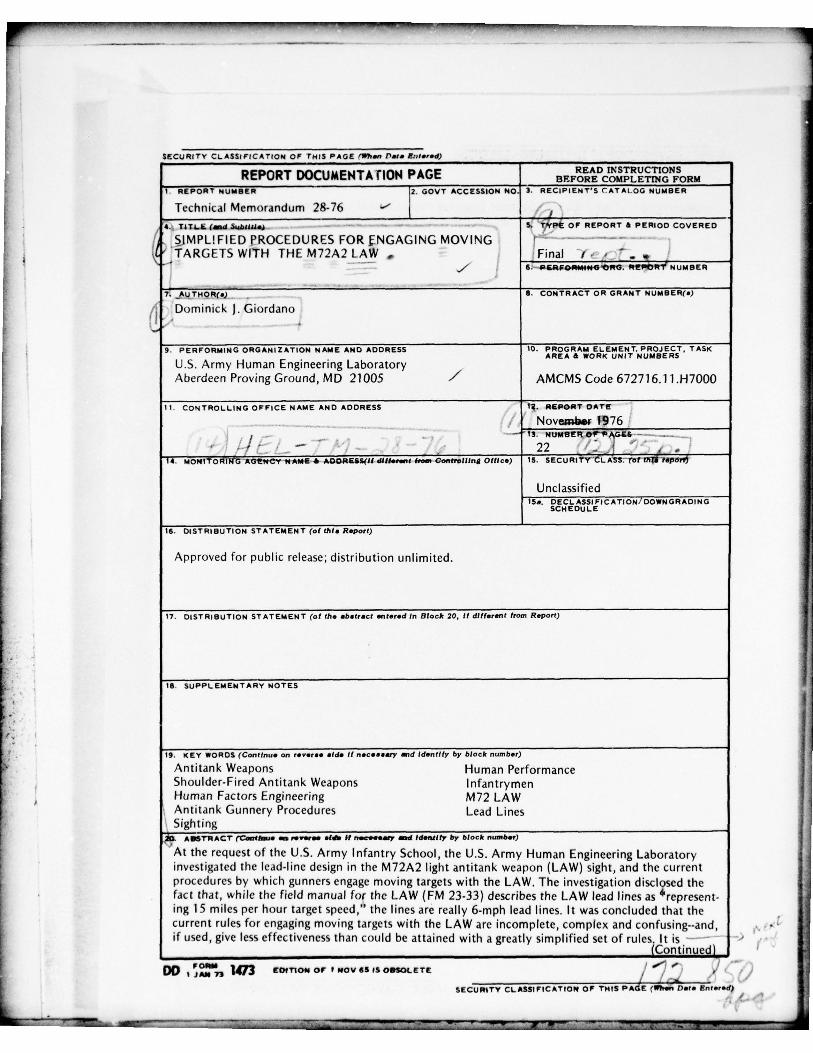
ABSTRAC’r ~~~~~~~~ ~~ evsr~~ .f~~ if n.c..Sas v ~~d id.nflfr by block numb.?)
‘At the request of the U.S. Army Infantry School , the U.S. Army Human Engineering Laboratoryinvestigated the lead-line design in the M72A2 light antitank weapon (LAW) sight , and the currentprocedures by which gunners engage moving targets with the LAW. The investigation discl9se d thefact that , while the field manual for the LAW (FM 23-33) describes the LAW lead lines as represent-ing 15 miles per hour targe t speed ,” the lines are really 6-mph lead lines. It was concluded that thecurrent rules for engaging moving targets w ith the LAW are incomplete , complex and confusing--and ,if used, give less effectiveness than could be attained wit h a greatly simp lified set of rules It is —
iContinued)DO lJA ~~fl ~473 EOIT1ON OF 1 NOV68 IS OBSOLETE “2~
)SECURITY CLAS SI F ICATIO N OF THIS PAdE (WMi5ilsi. EnIs?.d~ /
1~ ~~~~~~~~~~~~~~~~~~ ~~~~ —
~~~~-.--
~— —- --
~~~- -
~~~-~~
—~~~~
- - - ~~~~~~~~~~~~~ ~~~~~~~~~~~ ~~~ ..‘—-- S- .
SEf URITY CLASSIFICATION OF THIS PAOE(WII., Dais Ani.,. d)
120. Abstract (Continued)
• recommended that the Infantry adopt the proposed new rules that can increase the LAW gunner’seffectiveness and reduce the training time for potential LAW gunners.
• p
SECURITY CLASSIFICATION OF THIS PAGE(*~,s n D.ia Entsrsd)
~~~~~~~~~~~~~~~~~~~~~~~~ -5-
I
-• 5-5-5, ,
AMCMS Code 672716.11 .H7000 Technical Memorandum 28-76
SIMPLIFIED PROCEDURES FOR ENGAGING MOVING TARGETS
WITH THE M72A2 LAW
Dominick J . Giordano
Technical AssistanceDavid J. Ursin
November 1976
~ iAPP ~~~~~~~~~~~~~~~~~~~~~~~~~~
: irectorU. S. Army Human Engineer ing Laboratory
--‘ - S. .--
U. S. ARMY HUMAN ENGINEERING LABORATORY ‘ ‘ ‘ ‘ CAberdeen Proving Ground, Mary land 21005 ‘ 0
H ~~~,
-•~~~~~~~~~~~~~~~~~
Approved (or public reles e; - • i• , ,
distribut ion unlimited.1 -
-. -
~~~~-- •-i~ ~~. -•~~~~~~~—- -~~ —~
—____-~c~~~~~~ ~~~~~~-5 • ~~~•
- ~~~~-- ~~~~~~~~~~~~~~~~~~ ~~~~~~~~~~~~~~~~~~~~~~~~~~~~~~~~~~~~~~~~~~ _ _ 1
CONTENTS
INTRODUCTION 3
TRAINING IMPLICATIONS 19
CONCLUSIONS 19
RECOMMENDATION 19
REFERENCES 21
FIGURES
1. LAW Sighting Procedures for Engaging Moving Targets (From FM 23-33 ,July 1970) 5
2. The “Common-Lead” Rule As Applied to the LAW (from USAIS LAWTraining Aid) 7
3. Lead Required to Hit a Moving Target with the M72A2 LAW 9
4. LAW Round Point-of-Impact On a Twenty-Foot-Long Target Moving Perpendicularlyto he Gunner ’s Line of Sight--Three Speeds and Two Types of Lead . . . . 11
5. LAW Round Point-of-Impact On a Twenty-Foot-Long Target Moving Perpendicularlyto the Gunner ’s Line of Sight--Lead Line On Leading Edge of 2-5 mph Target . 12
6. LAW Round Point-of-Impact On a Twenty-Foot-Long Target Moving Perpendicularlyto the Gunner ’s Line of Sight--Lead Line On Leading Edge of 6-9 mph Target . 13
7. LAW Round Point-of-Impact On a Twenty-Foot-Long Target Moving Perpendicularlyto the Gunner ’s Line of Sight--Lead Line On Center of 6-9 mph Target . . . . 14
8. LAW Round Point-of-Impact On a Twenty-Foot-Long Target Moving Perpendicularlyto the Gunner ’s Line of Sight--Aiming Point At the Target ’s Center 15
9. LAW Round Point-of-Impact On a Twenty-Foot-Long Target Moving Perpendicularly - •
to the Gunner ’s Line of Sight--Centerline and Interpolated Point On Target ’sLeading Edge 16
10. LAW Round Poirit-of.Impact On a Twenty-Foot-Long Target Moving Perpendicularlyto the Gunner ’s Line of Sight--One-Half Lead On Target ’s Leading Edge . . . . 17
11. Simplified Procedures for Engaging Moving Targets with the LAW 20
-a ,
1
t- — S 5-SS~~5~5- ~~~~~~~~~~~~~~~~~~~~~~~~~~~~~~ --5-5--5-~ 5~~~~~ 1~~ S.S~~~ jS~~~~
• .~~ 5S 5- = ._~

SIMPLIFIED PROCEDURES FOR ENGAGING MOVING TARGETS
WITH THE M72A2 LAW
INTRODUCTION
Background
The U.S. Army Human Engineering Laboratory (HEL) undertook this investigat ion as aconsequence of telephone discussions initiated by U.S. Army Infantry Center (USAIC) personnel,to determine why the LAW hit probabilities against moving targets that were recorded in a fieldexperiment (10) were lower than those predicted from theoreticaI performance curves. Theinvestigation revealed these facts: (a) the lead lines in the LAW sight differed from those inprevious antitank weapon sights ; (b) contrary to FM 23-33 (2), the lead lines were designed for atarget speed of 6 mph, not 15 mph; and (c) the procedures for engaging moving targets werecomp lex and confusing. Simplified procedure s were developed for engaging moving targets withthe LAW out to the maximum range on the sight (350 meters), and they were forwarded to theUSAIC (8). When discussions with USAIC personnel indicated that future LAW gunners would betrained to engage moving targets only at ranges of 200 meters or closer, the procedures weresimplified further and again forwarded to the USAIC (9). The re-simplified procedures were alsosent to the U.S. Army Training and Doctrine Command (TRADOC) headquarters in response totheir message (12) about adopting the new procedures for training future LAW gunners, and forinc lusion in a training bulletin.
Subsequently, in a presentation to the Army War College (6), the Deputy Chief of Staff forTraining at TRADOC, Major General Gorman, briefly described the problem in the LAW’ slead-line design. This resulted in inquiries from U.S. Army Materiel Development and ReadinessCommand Laboratories (Picatinny Arsenal and Rock Island A rsenal) to obtain further detailsabout what appeared to be an error in the sight design.a
A recently released TRADOC bulletin (7) incorporates a modification of the HELprocedures for engaging moving targets with the LAW , but merely alludes to the lead-linesdesign—it mere ly states that the lead lines are for a 6-mile-per-hour target speed .
• Undoubtedly, t here will be further inquiries regarding: (a) whether there was an error indesigning the LAW sight; (b) why the procedures for engaging moving targets with the LAWdiffer from those for previous antitank weapons; and (c) what rationaIe was used in developingthe simp lified procedures. Therefore, although the findings of this investigation have already beenadopted, this report is necessary in order to answer these inquiries. Also , by disseminating theresu lts of this investigation , we hope to avoid a similar sight design problem with futureLAW-type weapons (e.g., V iPER).
aAlthough, as is pointed out later , the lead lines were not designed incorrectly, the stadia lineswere designed incorrectly (3 , 5). Also , it is well known that the plastic sight reticle has pooroptica l qualities (images near the edge of the reticle are distorted). In addition, the spacing
F7 ~~~~~~~~~~~—~~~~~~~~~~~~~~~~~~~~~~~~~~~~~~~~~~~~~~~~~~~~~~~ 7~~~~~~~~~~~~~~~~~ _ S-- ~~ S.5 - 5 - S .~~~~~~~ - - —~~~~~~~~~~~~~~~~5-
~~~~~~~~~5-
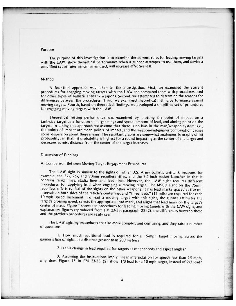
Purpose
The purpose of this investigation is to examine the current rules for leading moving targetswith the LAW , show theoretical performance when a gunner attempts to use them, and devise a
• simplified set of rules which, when used , will increase effectiveness.
Method
A four-fold approach was taken in the investigation. First, we examined the currentprocedures for engaging moving targets with the LAW and compared them with procedures usedfor other types of ballistic antitank weapons. Second , we attempted to determine the reasons fordifferences between the procedures. Third, we exam ined theoretical hitting performance againstmov ing targets. Fourth , based on theoretical findings, we developed a simplified set of proceduresfor engaging moving targets with the LAW.
Theoretical hitting performance was examined by plctting the point of impact on atank-size target as a funct ion of ta~get range and speed , amount of lead , and aiming point on thetarget. In taking this approach we assume that there is no bias in the man/weapon system; i.e.,the points of impact are mean points of impact , and the weapon-and-gunner combination causessome dispersion about these means. The resultant graphs are somewhat analogous to graphs of hitprobability, in that hit probability is highest for a round impacting at the center of the target anddecreases as miss distance from the center of the targe t increases.
Discussion of Findings
A. Comparison Between Moving-Target Engagement Procedures
The LAW sight is similar to the sights on other U.S. Army ballistic antitank weapons--fo rexamp le, the 57- , 75-, and 90mm recoilless rifles , and the 3.5-inch rocket launcher--in that itcontains range lines , stad ia lines and lead lines. However , the LAW sight requires differentprocedures for app ly ing lead when engaging a moving target. The M9OD sight on the 75mmreco illess rifle is typical of the sights on the other weapons; it has lead marks spaced at five-muinterva ls on both sides of the reticle ’s center line , and “three leads” (15 mils) are required for each10-mph speed increment. To lead a moving target with this sight , the gunner estimates thetarget ’s cross ing speed , se lects the appropriate lead mark , and aligns that lead mark on the target ’scenter of mass. Figure 1 shows the procedures for leading moving targets with the LAW sight , andexplanatory figures reproduced from FM 23-33 , paragrap h 25 (2); the differences between theseand the previous procedures are easily seen.
The LAW sighting procedures are also more complex and confusing, and they raise a numberof questions:
1. How much additional lead is required for a 15-mph target moving across thegunner ’s line of sight, at a distance greater than 200 meters ?
2. Is this change in lead required for targets at other speeds and aspect angles? •
3. Assuming the instructions imply linear interpolation for speeds less than 15 mph ,wh y does Figure 15 in FM 23-33 (2) show 1/3 lead for a 10-mph target , instead of 2/3 lead?
4
• ~~~~~~~~~~~~~~ ~~~~~~~~~~~
5-
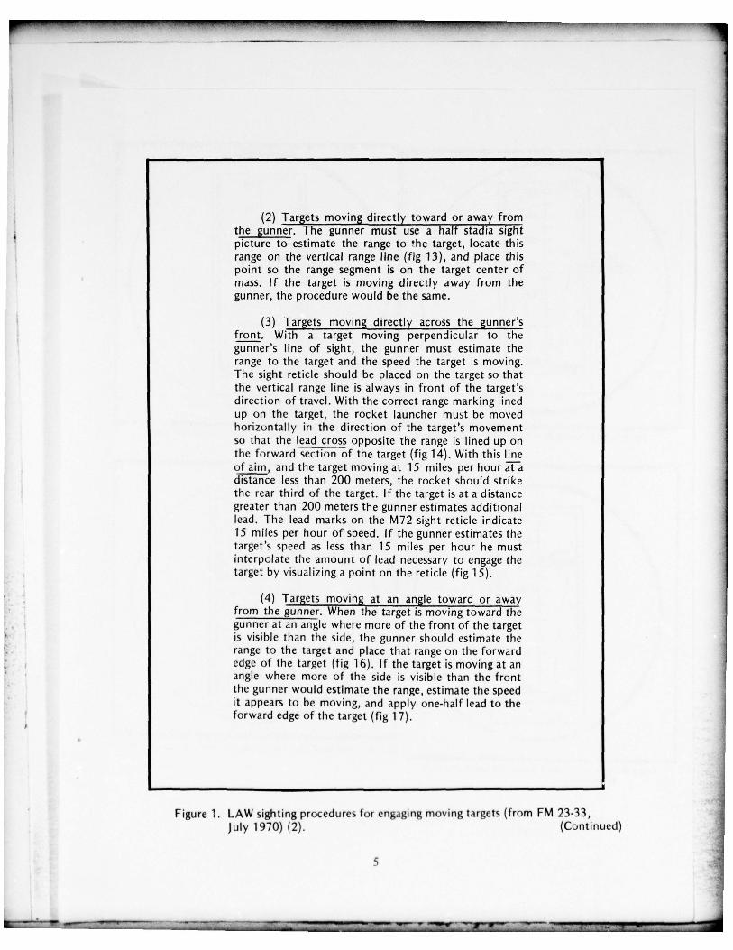
(2) Targets moving directl y toward or away fromthe gunner. The gunner must use a half stadia sightpicture to estimate the range to the target , locate thisrange on the vertical range line (fig 13), and place thispoint so the range segment is on the target center ofmass. If the target is moving directly away from thegunner, the procedure would be the same.
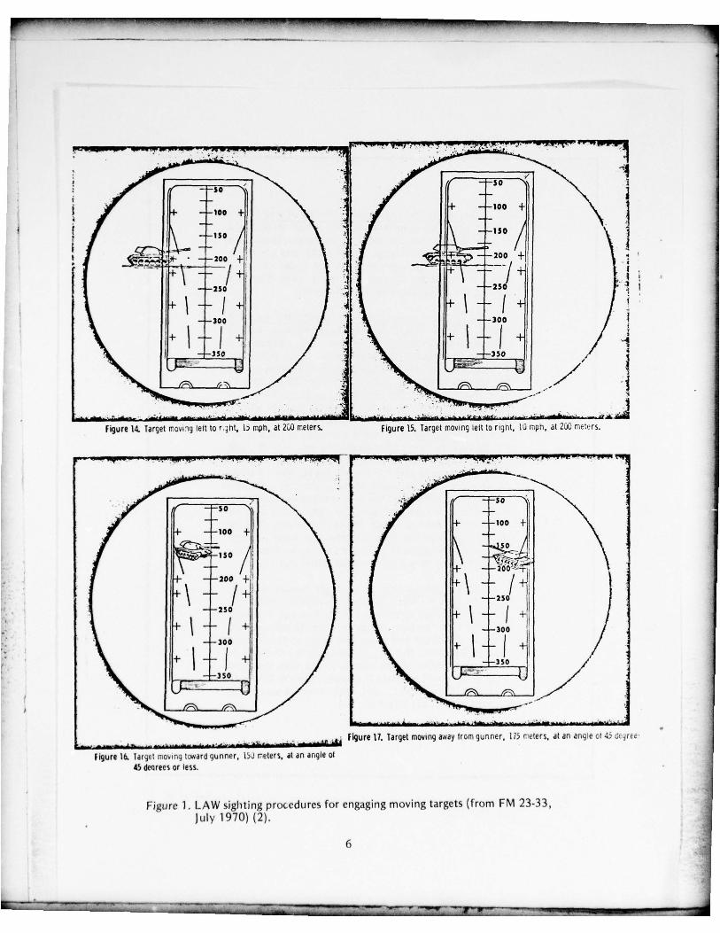
(3) Targets moving directl y across the gunner ’sfront. Wit h a target moving perpendicular to thegunner ’s line of sight , the gunner must estimate therange to the target and the speed the target is moving.The sight reticle should be placed on the target so thatthe vertical range line is always in front of the target ’sdirection of travel. With the correct range marking linedup on the target , the rocket launcher must be movedhorizonta lly in the direction of the target ’s movementso that the lead cross opposite the range is lined up onthe forward section of the target (fig 14). With this lineof a im, and the target moving at 15 miles per hour ~tàdistance less than 200 meters , the rocket should strikethe rear third of the target. If the target is at a distancegreater than 200 meters the gunner estimates additionallead . The lead marks on the M72 sight reticle indicate15 miles per hour of speed. If the gunner estimates thetarge t ’s speed as less than 15 miles per hour he mustinterpolate the amount of lead necessary to engage thetarget by visua lizing a point on the reticle (fig 15).
(4) Targçts moving at an angle toward or awayfrom the gunner. When the target is moving toward thegunner at an angle w here more of the front of the targetis vis ible than the side , the gunner should estimate therange to the target and place that range on the forwardedge of the target (fig 16). If the target is moving at anangle where more of the side is visible than the frontthe gunner would estimate the range, est imate the speedit appears to be moving, and app ly one-half lead to theforward edge of t he target (fig 17).
Figure 1. LAW sighting procedures for engaging moving targets (from FM 23-33 ,July 1970) (2). (Continued)
5 ~•
.7 .
~r .. . : • — ~~7 1 ~~~~~~~~~~ _—~~v ~~~~~~~~~~~~~~~~~~~~~~~~~~~~~~~~~~~~~~ .~_:-________
~TTIT ~5-T
~~TIIiT ~ TI _ _
‘S - ~~~~~~~~~~~~~~~~~~~~~~~ -a —‘ ~~~~~~~~~~~~~~~~
~~~~~~~~~~~~ r r - .-~ ~~~~~~~~~~~~~~~~~~~~~~~~~~~~~~~ —
~~—
- 7 . .
~— so
t /“ : ÷~ “\ •
, - F ~~Ioo +
I I = -150 \ -• - ~~~~~ I
~~~~~~~~~~~~~‘ = 200 ’~
, • _ _
~~~~- - .
~
-
- -250 1 - —250
- 1 - - J -+ / ~ f. f ~- - 300 1 • - — — 300
+ ~~~~
- - I -f I -
~ ÷
~~~~
- - I -~ / :
- -350 I / - • - ~~~~ /
-
- / : • ~ ~~~~~~~~~~~
-
//
~~~~~~~~ • • -
~ ..
- .5 -~ •~-:-• - .
5-.
_ .__;.~~_a~~~. —..--. ~~~--~~ -—~-.~~~~~ —-- -~ -—~~~— ~~~~~~~~~~~~~~~~~ —~——~ -—-~- ~~~~~~~~~~~ ~~~~~~~~~~~~~~~~~~~~~~~~~~~~~~~~ ~~~~~~~~~~~~~ —
Figure 14. Target mov; ig left to r,~ht, b mph, at 200 meters. Figure 15. Target moving le it to right , 10 mph, at 200 meters.
— ‘~~ . — ~~~~~~~~~~~~ —!— —.-
~~-.
~~~ ‘~~~~~~~~ .!“ ~~~~~~~~~~ ~~~~~~~~~~~~~~~~~~~~~~~ S.~~~’p~~~~•
~~~~~~~~ ~~~~~~~~ ~~~~~~~~~~~~~~~~~~~~~~
~~~~~~~
.iS0
/ \ IH - —200 4-
~~
- - / ~IJ - -
~~~~~
+
.5 . - -300— -300 + t - - I ~
- —~~~~~~ ---- ~~~~~~--- . .
• -
~~~~~ — - ~~~~~~~~~ A . ~~~~~...
, _ ~~~ ~~ FIgure Ti. Target moving away from gunner , i75 r ete rs , at an angle ci 4 C .jre .~
Figure l& Target moving t~~ard gunner . 15) n~eter s, at an angie of45 dearees or less.
Figure 1. LAW sight ing procedures for engaging moving targets (from FM 23-33 ,July 1970) (2).
6
L~ T 1Ti J~~~~~~~ _ . . 2 . ~~~~~~~~~~~~~~~~~~~~~~ . •~~~~~~ . ,~~~~
5-S.’ ~~~~~~~~~~~~~ —•..---7--- -~~ 5S.~~~~~~~7— 5 - - 7~~~_ _ _ _ _ _ _r - ~~~~ .
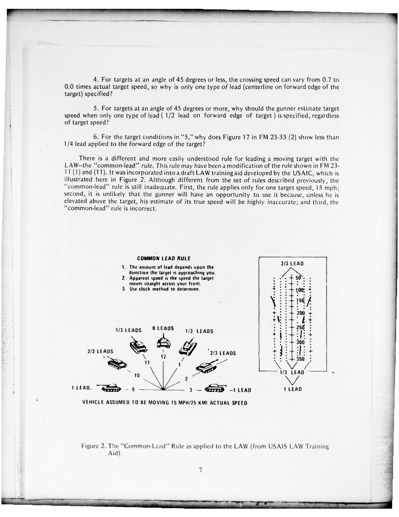
4. For targets at an angle of 45 degrees or less , the crossing speed can vary from 0.7 to0.0 times actual target speed , so w hy is only one type of lead (centerline on forward edge of thetarget) specified ?
5. For targets at an angle of 45 degrees or more, w hy should the gunner estimate targetspeed when on ly one type of lead (1/ 2 lead on forward edge of target ) is specified , regardlessof target speed?
6. For the target conditions in “5 ,” why does Figure 17 in FM 23-33 (2) show less than1/4 lead applied to the forward edge of the target?
There is a different and more easil y understood rule for leading a moving target with theLAW--t he “common-lead ” ru le. This rule may have been a modi fication of the rule shown in FM 23-1 1(1) and (11). It was incorporated into a draft LAW training aid developed by the USAIC , which isillustrated here in Figure 2. A lthough different from the set of rules described previousl y, the‘ common-lead ” ru le is still inadequate. First , the rule app lies only for one target speed , 15 mph;second , it is un likely that the gunner will have an opportunity to use it because , unless he iselevated above the target , his estimate of its true speed will be highly inaccurate : and third, the“common- lead” ru le is incorrect.
COMMON LEAD RULE1. The amount of lead depends upon the 2/3
,~~AD
direction the target is approaching you. ,/‘ “N2. A pparent speed is the spee d the target :
moves straight across your front .3. Use clock method to determine . ‘
~~ : - 100 t
1/3 LEADS 0 LEADS 1/3 LEADS -
~~~~~ ~~~~2/3 LEADS ~~~~ ‘2/3 LEADS t - :1.s•~
‘\ 12 / : :
1/3 LEAD
I L EAD - _____ -
2
~ -— — 1 LEAD
VEHICLE ASSUMED TO BE MOVi NG 15 MPH/25 KM) ACTUAL SPEED
Figure 2 . The “Common- Le.id” Rule as app lied to the LAW (from IJSAIS L \W Ti ainingAid )
7
-I
~~~~~~~~~~~~~~~~~~~~~~~~~~~~~~~~~~~~~~~~~~~~~~~~~~~~~~~~~ ~~~~~~~~~~~~~~~~~~~~~~~~~~~~~~~~~~~~~ ~~~~~~~~~~~~~~~~~~~~~~~~~~~~~~~~~~~~~~~~~~~~~~~~~~~~~~~~~~~~~~~~~~~~~~~ 5-
~~~~~~~~~~~~~~~~~~~~~~~
Apparent target speed is proportional to the sine of the target ’s aspect angle. For a60-degree targe t aspect (10 o’c lock and 2 o’c lock), apparent speed is about 0.9 times its truespeed ; and for a 30-degree target aspect (11 o’clock and 1 o’clock), it is 0.5 times true speed.Therefore , where the “common-lea d” rule calls for 2/3 lead, a fu ll lead would be more correct;and where 1/3 lead is specified , 1/2 lead should be applied. However , the fact that the“common- lead” rule is incorrect is only of academic interest , because it is unlikely that the targetwill be so obliging as to trave l only at a 15-mph speed.
B. Causes of the Difference Between Sighting Procedures
Procedures for engaging moving targets with the other weapons are optimum b because , ifused correctly, they direct rounds toward the target’s cente r, thus maximizing hit probability. Byspecif y ing some other aiming point, rat her than the target ’s center , the LAW sighting proceduresgive less effectiveness than the optimum procedures. However , it was necessary to use a differentand less effective set of procedures for the LAW because of an incompatibility between infantryrequirements for lead and the maximum allowable size of the sight.
Although there appears to be no written history of the development of the LAW sight ,informa l conversations with people who worked on the program disclose that , at the start of thedeve lopment cycle for the M72 LAW , the sight contained only range lines. During testing, leadlines were added so the weapon could be used e ffectively against moving targets. c The infantryrequired a weapon capable of leading a 15-mph target. However , a true 1 S-mp h lead line wouldhave required a reticle about 66mm wide , whic h would not fit on the weapon. Therefore leadlines were place d near the edges of the existing reticle , and the sighting procedures weremodified.
Figure 3 shows the relationship between the angular lead designed into the LAW sight andthe true lead required for target speeds of 5, 10 , and 15 mph. Although FM 23-33 (2) describesthe LAW lead lines as “representing 15 miles per hour target speed,” interpo lation in Figure 3shows that they are approximatel y 6-mph lead lines.
Making a device do someth ing beyond its intended purpose often requires a new and morecomplicated set of rules than those for using the device as origina lly intended. For the LAW leadlines- -assuming the lead requirements were realistic--t his was an engineering n ecessity.Nevertheless , the rules that evolved leave much to be desired in terms of clari ty and correctness.
• bAithough the sighting procedures are optimum, the sight design is no:. The lead lines are spacedat a fixed-m u distance from the centerline at all ranges. Thus, they assume a constant-velocityround. But velocity decreases w ith range and , as a result , a small lead error is designed into thesight. However , t his error is negligible compared to gunner errors (e.g., range estimation , speedestimation , and aiming errors ), and to the fact that the target may not be moving in a straightline , or at a constant velocity, or at a constant range.
c Stadia lines were added later in the mistaken belief they would help the gunner measure targetrange (3 , 5 , 10).
8
~~~~~ .i ,ii 5 ,. . : r~ : - j ~~~~~~~~~~~~ ~~~~~ 1L~~~S ~~~~~~~ -~~ f—
.- ~~‘ -~~~~~~~~~~~~~~~~~~~~
-~~~~~ : --~~~~~~~~~~~
Lum
LUf r i
~L~_J e-i
EL
I
I I 1 1 1 1 $ I I I I I I t I I 4 4 1 1N —
( SJJ~ 93Q ) QJdJf l~ J~ QbJl
‘9

5- _
C. Hitting Per l i i n.tr~~~ ‘~ e rsus - \ r ’ unt ,t Lead and Target Speed
The h ri’~ i i.~ i l lusi ,ttes the ‘ iced f i r a simp ler and more complete set of rules for engaging
mu~ ing t a rge t ’ -. v. i t h the L .\\~~. \~ a starting point toward this goal , a LAW round’s theoret icalimpact p i i i i t ~s JS d~ t~~i n ined grap hic .ilk for ta nk-size targets with var ious speeds and ranges ,amounts of c R 1 , and a impoints on the targe ts.
These granh\ . shown in Figures 4 t h u ugh 10 , assume a 20-foot-long target moving from leftto right and perpe ndiLu larl\ to the gunner ’s line of sight. These figures can also be used to obtainimpact points I ui other target sizes , or fo r targets not mov ing perpendicularl y to the gunner ’s lineof sight. To make such con\ersions , construct a new target of the appropr iate size and start fromthe ti ,r~~ard edge i 1 the ta r c~et shown in the figures when lead is applied there , or center the newtarget on the mid point of the target shown in the fi gures w hen lead is app lied there. However , thee t t e C t of a c hange in range w i th a target that is moving at some angle other than 90 degrees-- whichis a second-order effect- -cannot be accounted for in using the f igures.
In Figure 4 , curve 1 shows that placing t he lead mark on the cente r of a 5-mph target resultsin a hit c lose to the center over the entire target range. Curve 2 shows the effect of app ly ing thesame lead to a target mov ing at 10 mph; the point of impact shifts towards the target ’s rear asrange increases and lies behind the targe t at ranges beyond about 220 meters. This curve pointsout the fact that , in order to hit a target moving faster than the speed the single-lead line wasdesigned for , the gunner must position the lead line forward of the target ’s center. Curve 3 Sh OW Sthat placing the lead line on the leading edge of a 10-mp h target resu lts in a hit somc~c hcre on thetarget out to a range of about 350 meters. For a target speed of 15 mph , as seen in c u r ~e 4 , extralead equal to the target ’s ful l length is required for ranges between 200 and 350 meters.
Figures 5 through 10 show target-impact points for other met h J s of .lpp !’i inglead—including no lead , lead ing with the centerline , and one-half , one-third , and t~’. - t h i t d ~lead--and the effect of errors in the gunner ’s estimate of target speed.
Figure 5 shows that placing the lead line on the target ’s forward edge results in a miss infront of the targe t for speeds of 5 mph or less. With the same lead and speeds up t about 8mph (Fi gure 6), a round impacts further from the target center than if the lead line had beenpositioned on the target ’s mid-point (Figure 7).
Figure 7 shows the effect of underestimating target speed when the gunner uses the correct- - procedure for app lying lead (i.e., positions the proper lead line on the target ’ s center ). Curves 3
through 5 in Figure 8 show a similar effect for overestimating speed. For speeds of 0 and 2 mph ,the round lands in front of the targe t at ranges greater than about 150 and 225 meters ,
F. respectively. Similar ly, for a speed of 9 mp h, the round lands behind t he target at ranges beyond275 meters.
Curves 1 and 2 of Figure 8 show impact points resulting from positioning the sight ’scenterline (range line) on the center of the target. Curves 1 and 2 of Figure 9 show similar resultsfor positioning the centerline on the target ’s forward edge. For a 5-mph target speed , bothmethods for leading a target cause the round to land further from the target ’s midpoint--andlower the hit probability--than placing the lead line on the targe t ’s center. On t he other hand , for10-mph target speeds , leading the target by placing t he lead li;ie on the forward edge of the tat -getyields the higher hit probability.
10
5— -
.
• S5.• _ 7 .~~~~~~~~~~~~~ .: _~~~~~~~~~~~~ ’S5- -~~~~~ - 5 5- - --.— —~~~~ S-75-~ — - ---—’5-- --7—---- --_~~~~~~~~~~~ .:

(1+) (2)
H I I
u1~~~~~~LaJF- ILU I I
F-LUL9
F-
E~~ ~~~~~~~~~~~~ I IF- ‘~~~~~~~
La_I (1) Lead l ine on centerL~ of 5-mph target
irm~~ ~~~ (2) Lead line on center
of 10-mph target I(3) Lead line on leading I
edge of 10-mph target
(4) Lead l ine on leadingedge of 15-mph target I
I ’— ~ ~~~~~~~~~~~~~~~~ L~~ding ~
ROUND I MPACT PO I NT (METERs )
Figu re 4. LAW round point-of-impact on a twenty-foot-long target moving perpendicularly to thegunner ’s line of sight--Three speeds and two types of lead.
11
~
-~~ - ~ — -.~ - - -‘S ~~~~~~ -‘ I .:~ . ~~~~~~~~~
I
(4) (3) (2) (1)
- : I II I
-~~~ I II I
I
l/
I
(1) Lead line on l eading edge I~ I ~~~~ - of 2—mph target.
(2) Lead line on leading edge- of 3—mph target. - I I(3) Lead line on l eading edge I
- - of 4-mph target.
(4) Lead line on leading edge- - of 5—mp h target. I
~ L- ‘ Trail— Ta’rget Leading
-
‘ I ~~ .—~~~~~ ing Center Ed ge i ~~Edge
RDUN~’ I MPACT POINT ( METERs )
Figure 5. LAW round point-of-impact on a twenty-foot-long target moving perpendicularly to thegunner ’s l ine of sight--Lead line on leading edge of 2-5 mph target.
12
~
~~~~~~~~~~~~~~~~~~~~~~~~~~~~~~~~~~~~~~~~~~~~~~~~~~~~~~~~~~~~~~~~~~~~~~~~~~~~~~~~~~~~~~~~~~~~~~~~~~~~~~~~~~~~~~~~~~~~~~~~~~~~~~~~ -~~~~
_ _ _ _ _ _
~~~~~~~~ —S’-5- 1~~~~~
L~~~Ø i~
’
~
~) (ç) (1)
\ \I \ \ I
- I II_j.i I IH F-
-
w
F- I
w ILii ~~~~~~~
F-
1=2 f i - r ~I— ‘~~~~~~~~~~
‘ IU
~~- I 1
~~~~~~ - - (1) Lead line on l eading edgeof 6-rrph target. I
- - (2) Lead Pne on lead,ing edgeof 7—mph target.
(3) Lead line on leading edgeof 8-mph target. I
- (4) Lead line on leadin g edgeof 9-mph target.
Tra il — Tar~et Lea ing I
— I ~~ ~~~~~
Center Edge I ~ROUND IMPACT PO I NT ( METERS )
Figure 6. LAW round point-of-impact on a twenty-foot-long target moving perpendicularly to the u’ - -
gunner ’s line of sight—Lead tine on leading edge of 6-9 mph target. -
-
13
— . - - 5 -~~ ‘~~~~~~~~ - ‘~~~~~‘~~~~ - -~~~~- ~~-~~~~~-
5- - •- -~~~~~ ~~~~~~~~~~~
- ~~~~~~~~~~~~~~~~~~~~~~~~~~~~~~~~~
_ _ _
-: uIi IT~
- 5 - - - - - -~~- ---- ~~-- - --~~~~~~“5~~ —~~~~-~~~~~~~~~~~~~~~~~~~ —- -
(4) ~~
I I
1 1
Lfl (1) Lead line on center of I I~ I ~~~~ 6 mph target.
(2) Lead l ine on center of7-mph target.
M (3) Lead line on center of I I[~
-. 8-mph target.
(4) Lead line on center of9—mp h target. I
a I I 1- ‘ Trail— Ta qet Leading
— 1 ~~ S ~~~ Center Edge
ROUND iMPACT PO I NT ( METERS )
SV
Figure 7. LAW round point-of-impact on a twenty-foot-long target moving perpendicularl y to thegunner ’s line of sight-- Lead line on center of 6-9 mph target. -~~
~~
14
--U I~~~~-~rw .” ~ - - w ’swc~~~.- .- ~~~~~~~~~ — 5
~~~~~~~~~~~~~~~~~~~~ - ~~~~~~~~
u~~~~
(1) (5 ) (4) (3)~ \ ( ~) \ i i I
5’
\ I
\ I
\ II 1 /
in3~~ \ I 1/ /H \ /
I , ,
\\ I f ,\ / i l / I
I—
~~ L~~~~~• \\ ~\
/ 1 / i- (1) Cen terline on cen ter of ~~~ 1
-
ROUND I MPACT POINT (METERS )
Figure 8. LAW round point-of-impact on a twenty -foot-long target moving perpendicularly to the• gunner ’s line of sight—Aiming point at the target ’s center.
~~~~~~~~~~~~~~~~~~~~~~~~~~~~~~~~ ~~~~~~~~~~~~~~~ ~— ~~ - ~~~~~~~~~~ ‘~~ _
- - ---- - - - - ~~~~ — -
(2) (4) (I) (3)
I I
Lfl~~~~~~~(1) Centerline on lead ing
I— edge of 5-mph target.
1=1 I M (2) Center line on l eading I1— ~~~~ edge of 10—mph target. 1U~1 (3) One—third lead on leading
_____
edge of 5-mph target.
~~ I ~~~ (4) Two-thirds lead on leading1i.’.-’~~~edge of 10-mph target.
I II
Trailing T~rget Leading~ I
— I ~ —~~~~~ Edge Center Edge
~ I ~~~ -
-
ROUND IMPACT PO iNT (METERS )
Figure 9. LAW round point-of-impact on a twenty-foot-long target moving perpendicularly to thegunner ’s l ine of sight--Centerline and interpolated point on targets leading edge.
16
—- . ,.- —~~~~~~~~~ —~~~~ -~~~-.- ~~~~~~~ _ - L- 1~~~ ~~~~~~~~~~~~~~~~~~~~~~~~~~~~~~ -5=--.—- .
~~~~~— ~~~~~ ---——-~~~~~~ -‘~~~~. ~~~~~~ -5- -
(2) (1)
\I
’
\ I\F—. \U \ IL:l -
F-
1 - (1) One—half lead on leading ___________
edge of 5-mph target .
LU - - I ILO (2) One-half lead on leading
________
2’ edge of 10-mph target.
(3) One—half lead on leading __L_ .~ Iedge of 15-mp h target. I
-
~ Tr~ i 1i n g Ta~get Leading F
— I ~ ._.
~~~~~ Edge Center Edge ~ I ~
ROUND I MPA CT POINT (METERS )
Figure 10. LAW round point-of-impact on a twenty-foot-long target moving perpendic ularly to thegunner ’s l ine cf sight—One-half lead on target’s leading edge.
17
— -— 5- 5- -—
- -
Curves 3 and 4 in Figure 9 show the effect of interpolating lead by splitting the distancebetween the cen terl ine and the sight’s lead line into thirds, then applying one-third andtwo-thirds lead to targets moving at apparent speeds of 5 mph and 10 mph , respectivel y (in amanner somewhat like the “common-lead ” rule). The effect of applying one-half lead is shown inFigure 10. Once again, these methods for app lying lead give lower hi t probabilities than leading a5-mph target with the lead line positioned on the target’s center , or leading 10-mph and 15-mphtargets with the lead line positioned on the target’s forward edge.
D. Simplified Procedures for Engaging Moving Targets with LAW
The two most important relationships the graphs in Figures 4 through 10 convey are:
1. Performance against moving targets is optimum only when angular lead correspondsto target speed and the gunner positions the lead line on the target’s midpoint.
2. There is no single combination of type of lead and aiming point which will producegood performance out to ranges of 350 meters with target speeds up to 15 mph.
These relationships , plus the limitation that the sight cannot be enlarged to incorporate largerlead angles , make i t difficult to provide good performance and satisfy infantry requirements. As aresult , the rules for lead ing moving targets with the LAW must necessarily be more complicatedthan those used with the antitank weapons described prev iously.
These problems can be minimized by imposing the following constraints:
(a) The gunner should only have to estimate the target’s crossing speed.
(b) He should only have to estimate approximate levels of speed : for example , slow ,medium , and fast (equivalent to 5, 10, and 15 mph, respect ively).
(c) There should be only a small number of combinations of lead and aimpoint onthe target.
Figures 4 through 10 show that leading the target using the lead line and varying the aimingpoint on the target produces greater effectiveness than leading the target using either thecenterline or a point the gunner interpolates between the centerline and the lead line. For targetspeeds of about 5 mph , positioning the lead line on the target’s center produces the h ighest h itprob abr lity . For faster target speeds the highest hit probabilit y would be obtained if the gunnercould lead , using “hold-off” from the target’s center that increases with target speed; but th istask is far too difficult.
Requiri ng the gunner to positi on the lead line on the target’s forward edge offers acompromise between ef fect iveness and complexity for the faster target speeds. However , for a15-mph speed, this procedure can be used only for ranges closer than 200 meters (Figure 4, curve4). Assuming that targets will be engaged out to 350 meters, a compromise procedure for 15-mph —
speed and 200- to 350-meter range is requiring the gunner to appl y add itional lead (i.e., hold-off)equ al to the length of the target.
18
-- -—-5-- ~~~~~~~~~~~~~~~~~~~~~~~~~~~~~ -
~~~~~~~~~~~ - -
~--- -- - -
-5
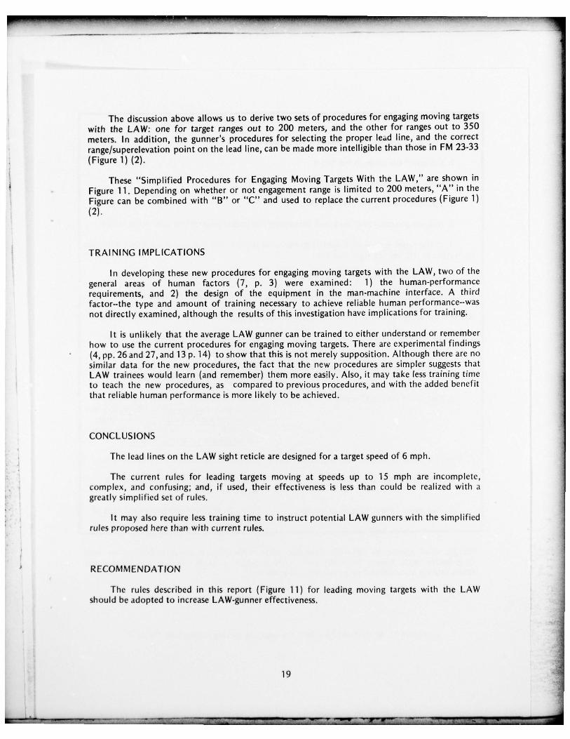
The discussion above allows us to derive two sets of procedures for engaging moving targetswith the LAW: one for target ranges out to 200 meters, and the other for ranges out to 350meters. In addition , the gunner ’s procedures for selecting the proper lead line , and the correc trange/superelevation point on the lead line , can be made more intelligib le than those in FM 23-33(Fi gure 1) (2).
These “Simplified Procedures for Engaging Moving Targets With the LAW ,” are shown inFigure 11 . Depending on whether or not engagement range is limited to 200 meters, “A” in theFigure can be combined with “B” or “C” and used to replace the current procedures (Figure 1)(2).
TRAINING IMPLICATIONS
I n developing these new procedures for engaging moving targets with the LAW, two of thegeneral areas of human factors (7, p. 3) were examined : 1) the human-performancerequirements, and 2) the design of the equipment in the man-machine inte rface. A thirdfactor—the type and amount of training necessary to achieve reliable human performance--wasnot directly examined , although the resul ts of this investigation have imp lications for training.
I t is unlikely that the average LAW gunner can be trained to either understand or rememberhow to use the current procedures for engaging moving targets. There are experimental findings(4, pp. 26 and 27, and 13 p. 14) to show that this is not merely supposition. Although there are nosimilar data for the new procedures , the fact that the new procedures are simpler suggests thatLAW trainees would learn (and remember) them more easily. Also, it may take less training timeto teach the new procedures , as compared to previous procedures , and with the added benefitthat reliable human performance is more likely to be achieved.
CONC L US IONS
The l ead lines on the LAW sight reticle are designed for a target speed of 6 mph.
The curren t rules for leading targets moving at speeds up to 15 mph are incomplete ,comp lex , and confusing; and , i f used, their effectiveness is less than could be realized with agreatl y s i mp l ified set of rules.
I t may also require less training time to instruct potential LAW gunners with the simplifiedrules proposed here than with current rules.
RECOMMENDATiON
The rules described in this report (Figure 11 ) for leading moving targets with the LAWshould be adopted to increase LAW-gunner effectiveness.
19
_________________ - - - - - ~~~~~~~~~~~~~~~~~~~~~~~ ~~--~~~ - ~~~~~~~~~~~~~~~~~~~~~~~~~~~~~~~~~~~~~~~~~~~ _5-I~~~~~~ 5- — -
-
~~~~~~~~~~~~~~~~~~~~~~~~~~~~~~~~~~~~~~~~~~~~~~~~~~~~~~~~~~~~~~~~~~~~~~~~~~~~~~~~~~~~~~~~~~~~~~~~~~~~~~~~~~~~~~~~~~
--
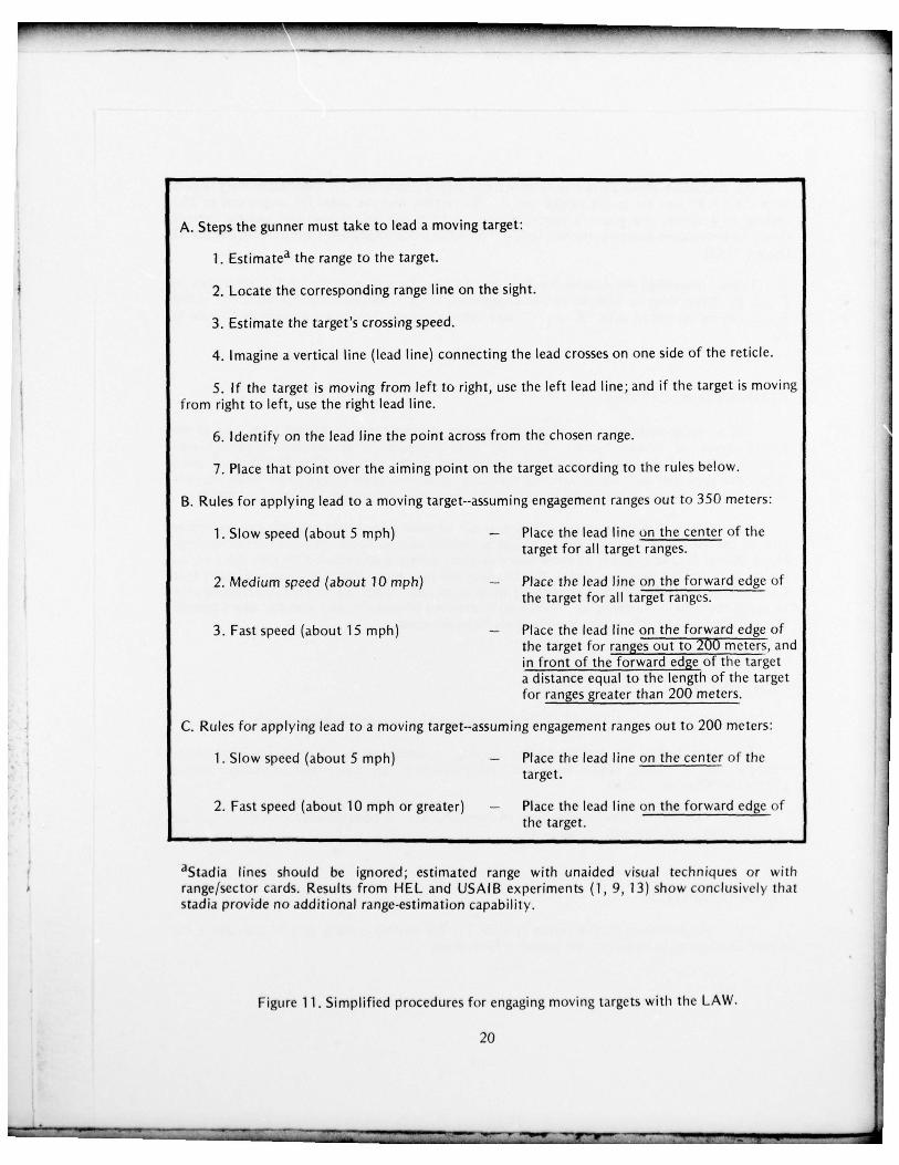
A. Steps the gunner must take to lead a moving target:
1. Estimate a the range to the target.
2. Locate the corresponding range line on the sight.
3. Estimate the target’s crossing speed.
4. Imagine a vertical line (lead line) connecting the lead crosses on one side of the reticle.
5. If the target is moving from left to right, use the left lead line; and if the target is movingfrom right to left , use the right lead line.
6. Identify on the lead line the point across from the chosen range.
7. Place that point over the aiming point on the target according to the rules below .
B. Rules for apply ing lead to a moving target--assuming engagement ranges out to 350 meters:
1. Slow speed (about 5 mph) — Place the lead line on the center of thetarget for all target ranges.
2. Medium speed (about 10mph) — Place the lead line on the fo rward edge ofthe target for all target ranges.
3. Fast speed (about 15 mph) — Place the lead line on the forward edge ofthe target for ranges out to 200 meters , andin front of t he forward edge of the targeta distance equa l to the length of the targetfor ranges greater than 200 meters.
C. Rules for app lying lead to a moving target--assuming engagement ranges out to 200 meters :
1. Slow speed (about 5 mph ) — Place the lead line on the center of thetarget.
2. Fast speed (about 10 mph or greater) — Place the lead line on the forward edge ofthe target.
aStadia lines should be ignored ; estimate d range with unaided visual techniques or withrange/sector cards. Results from HEL and USAIB experiments (1 , 9, 13 ) show conclusively thatstad ia provide no additional range-estimation capability.
Figure 11 . Simplified procedures for engaging moving targets with the LAW.
20 -
-
L~~~~~~~~~L -:::I:: ~~~~~~
.~~~~~~ —~~-- - ~~~~‘— .~~~~~~
— - -— -
--- - -- ~~~~~~~~~~~~~~~~~~~~~~~~~~~~~~~~~~~~~~~~~~~~
-~
REFERENCES
1. Department of the Army. 90mm Recoil less Rifle, M67. FM 23-1 1, Washington , DC, July1965.
2. Department of the Army. 66mm Heat Rocket M72A1 , M72AE1 , and M72. FM 23-33,Washington, DC, June 1970.
3. Giordano, D.J. Sources of range underestimation in the M72 LAW and other stadiametricsights. Letter Report No. 156, U.S. Army Human Eng ineering Laboratory, AberdeenProving Ground, MD, June 1973.
4. Giordano, D.J . Gunner errors when using the M72A2 LAW sight. Technical Memorandum19-75, U.S. Army Human Engineering Laboratory, Aberdeen Proving Ground, MD, August1975.
5. Giordano , D.J . Sights for light antitank weapons. Technical Memorandum 11-76, U.S. ArmyHuman Eng ineer ing Laboratory, Aberdeen Proving Ground, MD, A pril 1976.
6. Gorman, MG P.F. Official presentation to the Army War College of 1976, Subject: TrainingManagement in the U.S. Army. Carlisle Barracks , Carlisle , PA, 5 March 1976 (FOUO).
7. Miles , J.L., Jr. An interim method for improving predictions of system reliability. TechnicalNote 2-74, U.S. Army Hu m a n Eng ineer ing Laborato~y, Aberdeen Proving Ground , MD,January 1974.
8. U.S. Army Human Engineering Laboratory. Letter , AMXHE , Subjec t: S i mp lif ied Rules forEngaging Moving Targets with the LAW. U.S. Army Human Engineering Laboratory,Aberdeen Proving Ground, MD, 23 Dec 1975.
9. U.S. Army Human Engineering Laboratory. Letter , AMXHE , Subj ect: Simp lified Rules forEngag ing Moving Targets with the LAW. U.S. Army Human Engineering Laboratory,Aberdeen Proving Ground, MD, 8 Jan 1976.
10. U.S. Army Infantry Board. Force development test and experimentation of M72A2 LAW- : training effectiveness anal ysis. TECOM Project No. 8-MU-014-072-046 , Ft. Benning, GA ,
December 1975.
11. U.S. Army Infantry School. Unit antiarmor training program. IC 23-20 Draft , U.S. ArmyInfantry School , Ft. Benning, GA , August 1975.
12. U.S. Army Training and Doctrine Command. Message , TRADOC , Subject: TRADOCBulletin No. 5 , Tra ining with LAW. U.S. Army Training and Doctrine Command , Ft.Monroe , VA , 6 Jan 1976.
13. U.S. Army Training and Doctrine Command. TRADOC Bulletin No. 5, Tra ining with LAW ,U.S . Army Training and Doctrine Command , June 1976.
21
~~~~~~~ -
~~~~~~~~~~~~
-—-.-
~~~~~ —5- - ~~~~~~~~~~~~~~~~~~~~~~~~~~~~~~~~~