Embed Size (px)
Citation preview

January 2019
ENGINEERING
INSTRUCTION EI
19-001
Title: NYSDOT LRFD BRIDGE DESIGN SPECIFICATIONS - 2019
Approved:
Original Signed by Richard Marchione Richard Marchione, PE
Deputy Chief Engineer (Structures)
01-14-2019 Date
ADMINISTRATIVE INFORMATION:
This Engineering Instruction (EI) is effective beginning with projects submitted for the letting of May 1, 2019
This EI supersedes EI 16-016 “NYSDOT LRFD BRIDGE DESIGN SPECIFICATIONS”
Disposition of Issued Materials: The technical information transmitted by this EI will be incorporated into the next revision of the NYSDOT Bridge Manual
PURPOSE: This EI officially adopts the NYSDOT LRFD Bridge Design Specifications – 2019 for use in New York State and announces the availability of “NYSDOT LRFD Blue Pages” dated January 2019. TECHNICAL INFORMATION: The AASHTO LRFD Bridge Design Specifications - 8th Edition, 2017, together with the AASHTO Errata Changes for LRFD-8, May 2018 and the “NYSDOT LRFD Blue Pages” dated January 2019 constitute the NYSDOT LRFD Bridge Design Specifications.
The LRFD specifications will continue to be used for the design of all new and replacement bridges for NYSDOT. This includes both superstructure designs and substructure designs. This EI does not discontinue use of the NYSDOT Standard Specifications for Highway Bridges – 2003. Both specifications will continue to be used until further notice. The existing NYSDOT Standard Specifications for Highway Bridges - 2003 will be used when necessary for the repair and rehabilitation of structures. The NYSDOT Standard Specifications for Highway Bridges – 2003 consists of the AASHTO Standard Specifications for Highway Bridges - 17th Edition plus the “NYSDOT Blue Pages”, issued by EB 02-038 and EB 03-016.
Currently, NYSDOT overload permitting and bridge posting policies require that new and replacement bridges be load rated using the Load Factor Design (LFD)
January 2019
or Allowable Stress Design (ASD) methods. For this reason, load ratings will continue to be computed by the LFD or ASD method and shown on the contract plans. Also, load rating factors for all new and replacement bridges will be computed by the Load and Resistance Factor Rating (LRFR) method and shown on the contract plans. LRFR ratings shall be shown at the Inventory and Operating levels as rating factors of the AASHTO HL-93 live load. Once overload permitting and bridge posting policies are revised to accommodate LRFR, load ratings using the LFD and ASD methods will be discontinued.
The NYSDOT Bridge Manual supplements both the LRFD Specifications and the Standard Specifications for Highway Bridges. Designers are required to consult the Bridge Manual for additional policies, guidance, details and interpretations of the design specifications.
The “NYSDOT LRFD Blue Pages” dated January 2019 do not replace any existing “NYSDOT LRFD Blue Pages” for the AASHTO LRFD Bridge Design Specifications – 8th Edition, 2017, including the AASHTO Errata Changes for LRFD-8, May 2018.
IMPLEMENTATION: This Engineering Instruction (EI) is effective immediately for all structural design projects in New York State unless immediate implementation will result in undue delay to projects currently under design as determined by the Regional Director and the Deputy Chief Engineer (Structures). TRANSMITTED MATERIALS: The NYSDOT LRFD Blue Pages dated January 2019 can be found at the following web address:
https://www.dot.ny.gov/divisions/engineering/structures/manuals CONTACT: Direct questions regarding this EI to Harry White of the Office of Structures at (518) 485-6634 or via e-mail at [email protected].

January 2019
2019 NYSDOT Blue Pages
Article No. Proposed vs.
Current Comments
1.1 No changes
1.3.5 No changes
3.4.1 No changes
3.6.1.2.1 No changes
3.6.1.2.4a Modified Minor editorial changes.
3.6.1.2.6a No changes
3.6.1.6 Modified Minor editorial changes.
3.6.5.1 Modified Minor editorial changes.
3.7.5 Modified Minor editorial changes.
C3.7.5 No changes
3.8.1.1.2 New Defining wind speed in special wind region.
3.8.1.2.1 New
Modified Table to account for
sound barriers mounted on
structures.
3.9.2.1 No changes
C3.9.2.2 No changes
3.9.3 Modified Minor editorial changes.
C3.9.3 Modified Minor editorial changes.
3.10.1 Modified Minor editorial changes.
C3.10.2.1 Modified Minor editorial changes.
3.10.2.2 Modified Minor editorial changes.
3.10.5 Modified Minor editorial changes.
3.10.7.1 Modified Minor editorial changes.
3.10.9 New
Removed requirement for
minimum seismic connection
force and replaced with requiring minimum support
length.
3.10.11.1 Modified Minor editorial changes.
C3.10.11.1 Modified Minor editorial changes.
3.10.11.2 Modified Minor editorial changes.
A3.10 Modified
To improve readability,
removed redundant tables
and corrected minor
typographical, spelling, and
grammar errors – There
January 2019
were no changes in
substance.
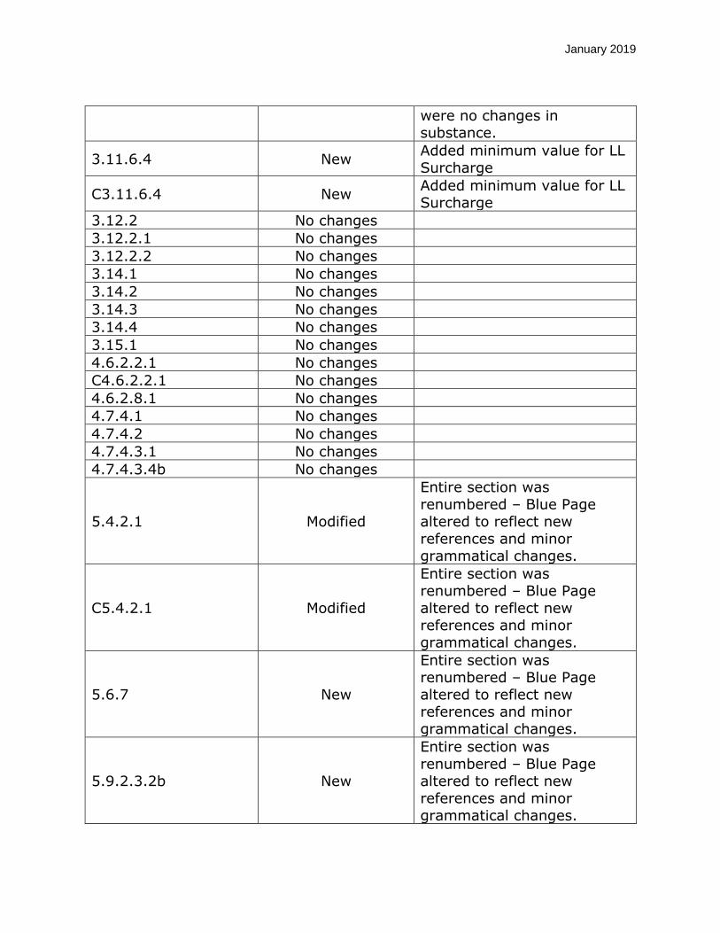
3.11.6.4 New Added minimum value for LL
Surcharge
C3.11.6.4 New Added minimum value for LL Surcharge
3.12.2 No changes
3.12.2.1 No changes
3.12.2.2 No changes
3.14.1 No changes
3.14.2 No changes
3.14.3 No changes
3.14.4 No changes
3.15.1 No changes
4.6.2.2.1 No changes
C4.6.2.2.1 No changes
4.6.2.8.1 No changes
4.7.4.1 No changes
4.7.4.2 No changes
4.7.4.3.1 No changes
4.7.4.3.4b No changes
5.4.2.1 Modified
Entire section was
renumbered – Blue Page
altered to reflect new references and minor
grammatical changes.
C5.4.2.1 Modified
Entire section was renumbered – Blue Page
altered to reflect new
references and minor
grammatical changes.
5.6.7 New
Entire section was
renumbered – Blue Page altered to reflect new
references and minor
grammatical changes.
5.9.2.3.2b New
Entire section was renumbered – Blue Page
altered to reflect new
references and minor
grammatical changes.

January 2019
5.10.6 New
Entire section was
renumbered – Blue Page
altered to reflect new
references and minor
grammatical changes.
5.11.4.1.4 New
Entire section was
renumbered – Blue Page altered to reflect new
references and minor
grammatical changes.
5.11.4.1.5 New
Entire section was
renumbered – Blue Page altered to reflect new
references and minor
grammatical changes.
5.11.4.1.6 New
Entire section was renumbered – Blue Page
altered to reflect new
references and minor
grammatical changes.
5.11.4.2 New
Entire section was renumbered – Blue Page
altered to reflect new references and minor
grammatical changes.
6.6.1.2.3 No changes
6.7.3 Modified Minor editorial changes.
6.7.4.1 Modified Minor editorial changes.
C 6.7.4.1 Modified Minor editorial changes.
6.7.4.2 No changes
6.7.5.3 No changes
6.10.3.1a Modified Minor editorial changes.
6.13.2.4.1b No changes
6.13.2.4.1c No changes
6.13.2.4.1d No changes
6.13.2.6.1 No changes
6.13.2.8 No changes
6.13.3.1 No changes
6.13.6.1.1 Modified Made specific for tension
members.
6.13.6.1.2 New Made specific for compression members.

January 2019
6.13.6.2 No changes
6.16.4.1 No changes
9.7.1.3 No changes
C9.7.1.3 Modified Minor editorial changes.
9.7.2 No changes
10.5.5.2.3 No changes
C10.5.5.2.3 No changes
10.7.2.4 No changes
10.7.3.6 No changes
10.7.3.8.6f No changes
10.7.9 No changes
11.5.4.1 No changes
11.10.6.2.1 New Modified Figure 11.10.6.2.1-
1
11.10.6.3.2 New Modified requirements for soil reinforcement pullout
design
11.10.10.1 Removed This Blue Page is Deleted
12.6.2.1a Modified Clarify when the deflection
requirement is applicable.
12.11.2.1 Modified Minor editorial changes.
12.14.5.3 Modified Minor editorial changes.
A13.4.3.1 New
Correcting typographical
error in specification formula.
14.4.2.2.1 No changes
14.4.2.2.2 Modified
Making uncertainty
requirement consistent between pot and disc
bearings.

January 2019
NEW YORK STATE DEPARTMENT OF TRANSPORTATION
LRFD BLUE PAGES
TABLE OF CONTENTS
Article Article Article
1.1 3.12.2.2 6.13.2.4.1b
1.3.5 3.14.1 6.13.2.4.1c
3.4.1 3.14.2 6.13.2.4.1d
3.6.1.2.1 3.14.3 6.13.2.6.1
3.6.1.2.4a 3.14.4 6.13.2.8
3.6.1.2.6a 3.15.1 6.13.3.1
3.6.1.6 4.6.2.2.1 6.13.6.1.1
3.6.5.1 C4.6.2.2.1 6.13.6.1.2 (New)
3.7.5 4.6.2.8.1 6.13.6.2
C3.7.5 4.7.4.1 6.16.4.1
3.8.1.2 (New) 4.7.4.2 9.7.1.3
3.8.1.2.1 (New) 4.7.4.3.1 C9.7.1.3
3.9.2.1 4.7.4.3.4b 9.7.2
C3.9.2.2 5.4.2.1 10.5.5.2.3
3.9.3 C5.4.2.1 C10.5.5.2.3
C3.9.3 5.6.7 (New) 10.7.2.4
3.10.1 5.9.2.3.2b (New) 10.7.3.6
C3.10.2.1 5.10.6 (New) 10.7.3.8.6f
3.10.2.2 5.11.4.1.4 (New) 10.7.9
3.10.5 5.11.4.1.5 (New) 11.5.4.1
3.10.7.1 5.11.4.1.6 (New) 11.10.6.2.1 (New)
3.10.11.1 (New) 5.11.4.2 (New) 11.10.6.3.2 (New)
C3.10.11.1 (New) 6.6.1.2.3 12.6.2.1a
3.10.11.2 6.7.3 12.11.2.1
App. A3.10 6.7.4.1 12.14.5.3
3.11.6.4 (New) C6.7.4.1 A13.4.3.1 (New)
C3.11.6.4 (New) 6.7.4.2 14.4.2.2.1
3.12.2 6.7.5.3 14.4.2.2.2
3.12.2.1 6.10.3.1a

January 2019
[This Page Intentionally Left Blank]

January 2019
1.1 SCOPE OF THE SPECIFICATION
Delete the sixth paragraph of Article 1.1 and replace it with the
following:
Seismic design shall be in accordance with the provisions in these
specifications. Seismic design in accordance with the provisions
given in the AASHTO Guide Specifications for LRFD Seismic Bridge
Design can be used with the approval of Deputy Chief Engineer (Structures).

January 2019
1.3 DESIGN PHILOSOPHY
1.3.5 Operational Importance
Delete the third paragraph and replace it with the following:
For the strength limit state:
η I =1.05 for critical bridges* =1.00 for essential and other bridges
For all other limit states:
η I =1.00
*For definition of critical bridges, see Blue Page 3.10.5.
January 2019
3.4 LOAD FACTORS AND COMBINATIONS
3.4.1 Load Factors and Load Combinations
Delete the sixth bullet of the second paragraph and replace it with the following:
EXTREME EVENT I - Load combination including earthquake.
The load factor for live load γEQ, shall be 0.50 for bridges with Average Daily Truck Traffic (ADTT) greater than 5,000 and 0.00
for all other bridges.
January 2019
3.4 LOAD FACTORS AND COMBINATIONS
3.4.1 Load Factors and Load Combinations
Add the following note to the end of Table 3.4.1-2:
For horizontal reinforcement design of a cantilevered wingwall
rigidly attached to an integral abutment, a passive lateral earth
pressure load factor of 1.5 shall be used.

January 2019
3.4 LOAD FACTORS AND COMBINATIONS
3.4.1 Load Factors and Load Combinations
Delete the second to last paragraph of Article 3.4.1.

January 2019
3.6 LIVE LOADS
3.6.1 Gravity Loads: LL and PL
3.6.1.2 Design Vehicular Live Load
3.6.1.2.1 General
Add the following paragraph to the end of Article 3.6.1.2.1:
NY State owned bridges (including state owned bridges carrying
parkways), all bridges on the National Highway System and all bridges on the state touring routes shall also be designed for the
NYSDOT Design Permit Vehicle in accordance with Article
3.6.1.2.4a, unless otherwise approved by Deputy Chief Engineer (Structures).

January 2019
3.6 LIVE LOADS
3.6.1 Gravity Loads: LL and PL
3.6.1.2 Design Vehicular Live Load
Add a new Article 3.6.1.2.4a:
3.6.1.2.4a NYSDOT Design Permit Vehicle The NYSDOT Design Permit Vehicle is a design vehicular load to
be applied to the “Strength II” limit state. For pre-stressed concrete bridges, the NYSDOT Design Permit Vehicle shall also be
used for the “Service III” limit state as a design load case in
addition to the AASHTO HL93 live load (see Article 5.9.4.2.2 for Service III resistance limits). All ratable elements (such as beams,
girders, steel cap beams and steel columns) of new and replacement bridges shall satisfy these limit states using NYSDOT Design Permit Vehicle.
The design permit vehicle loading shall be used for all State-owned
bridges (including State-owned bridges carrying parkways), all
bridges on the National Highway System and all bridges on the
state touring routes unless otherwise approved by Deputy Chief
Engineer (Structures). Other bridges may be designed for NYSDOT Design Permit Vehicle at the option of the owner. Bridge rehabilitation designs where the primary structural members are
being retained may also use the design permit vehicle.
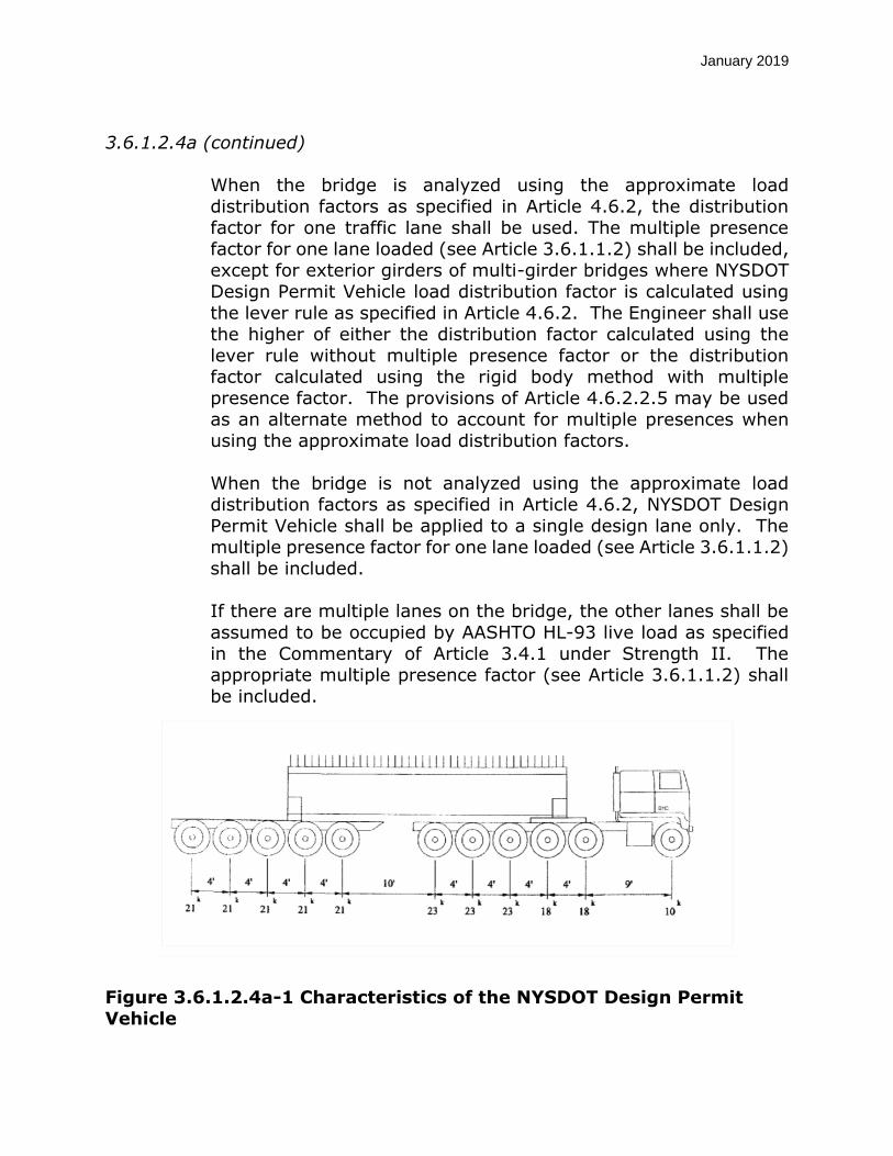
The weights and spacing of axles for NYSDOT design permit vehicle shall be as specified in Figure 3.6.1.2.4a-1. The transverse
spacing of wheels shall be taken as 6.0 ft. The dynamic load
allowance shall be applied as specified in Article 3.6.2.
January 2019
3.6.1.2.4a (continued) When the bridge is analyzed using the approximate load
distribution factors as specified in Article 4.6.2, the distribution
factor for one traffic lane shall be used. The multiple presence factor for one lane loaded (see Article 3.6.1.1.2) shall be included,
except for exterior girders of multi-girder bridges where NYSDOT
Design Permit Vehicle load distribution factor is calculated using
the lever rule as specified in Article 4.6.2. The Engineer shall use the higher of either the distribution factor calculated using the
lever rule without multiple presence factor or the distribution
factor calculated using the rigid body method with multiple presence factor. The provisions of Article 4.6.2.2.5 may be used
as an alternate method to account for multiple presences when
using the approximate load distribution factors.
When the bridge is not analyzed using the approximate load distribution factors as specified in Article 4.6.2, NYSDOT Design Permit Vehicle shall be applied to a single design lane only. The
multiple presence factor for one lane loaded (see Article 3.6.1.1.2) shall be included.
If there are multiple lanes on the bridge, the other lanes shall be
assumed to be occupied by AASHTO HL-93 live load as specified
in the Commentary of Article 3.4.1 under Strength II. The appropriate multiple presence factor (see Article 3.6.1.1.2) shall be included.
Figure 3.6.1.2.4a-1 Characteristics of the NYSDOT Design Permit
Vehicle

January 2019
3.6 LIVE LOADS
3.6.1 Gravity Loads: LL and PL
3.6.1.2 Design Vehicular Live Load
3.6.1.2.6 Distribution of Wheel Loads through Earth Fills
3.6.1.2.6a General
In the first sentence of the second and third paragraphs, add ‘box
or,’ just before the words ‘flat top three-sided’.

January 2019
3.6 LIVE LOADS
3.6.1 Gravity Loads: LL and PL
3.6.1.6 Pedestrian Loads
Delete the first paragraph of Article 3.6.1.6 and replace it with the
following:
Pedestrian load shall be neglected if the sidewalk width is less than
or equal to 10.0 ft., and no physical barrier exists between
vehicular traffic and sidewalk.
If the pedestrian load is neglected, then the HL 93 live load shall
be assumed to mount the sidewalk, and shall be applied at 1.0 ft. from the face of the bridge railing for the design of the overhang,
and 2.0 ft. from the face of the bridge railing for the design of all other components. The NYSDOT Design Permit Vehicle shall be applied 2.0 ft. from the edge of curb for the design of all
components.
When the sidewalk is greater than 10.0 ft., or when a physical
barrier exists between vehicular traffic and the sidewalk, a
pedestrian load of 0.075 ksf shall be applied to all sidewalk areas,
and shall be considered simultaneously with the vehicular design live load applied 2.0 ft. from the edge of curb. The NYSDOT Design Permit Vehicle shall be applied 2.0 ft. from the edge of curb for
the design of all components.
All bridges shall be checked for the live load case where the sidewalk is removed in the future.
The Load Rating shall be for the case where the HL 93 live load is applied 2.0 ft. from the edge of curb and no pedestrian load on
the sidewalk.

January 2019
3.6 LIVE LOADS
3.6.5 Vehicular Collision Force: CT
3.6.5.1 Protection of Structures
Add the following to the end of second paragraph.
For hammerhead and multi-column piers, the preferred design choice is to redirect or absorb the collision load wherever it is
feasible.
Add the following paragraph to the end of Article 3.6.5.1:
Structures crossing railroad tracks with crash walls designed in
accordance with the American Railway Engineering and maintenance of Way Association (AREMA) specifications are exempt from the provisions of Article 3.6.5.1. Abutments that are
at least 2.50 ft. thick and at least 12.0 ft. long are also exempt from these provisions.

January 2019
3.7 WATER LOADS: WA
3.7.5 Change in Foundations Due to Limit State for Scour
Add the following paragraphs to the end of this article.
The following changes in foundation condition shall be considered
for the service, strength, and extreme event limit states for typical
foundations supported on piles and drilled shafts.
For piles and drilled shafts at all scour depths, the surrounding soil
above the scour elevation provides no lateral support.
For abutments and independent wingwalls with a minimum of two
rows of piles, with at least one row battered, the reduced lateral soil resistance and increased displacement caused by the scour is
counteracted by the battered piles and negates the need for a scour case lateral analysis. The structural resistance of the piles for the scour case shall be determined based on applied vertical
loads without lateral loads, using an unbraced length set equal to the scour depth. This applies to integral abutments with vertical
piles as well, except the lateral stability comes from the abutments
fixed connection with the superstructure rather than the battered
piles. This does not apply to independent wingwalls with a single
row of piles, even if those piles are battered. For piers, the structural resistance of the pile or drilled shaft for
the scour case shall be determined based on applied vertical and horizontal loads, using an unbraced length set equal to the scour
depth.
If the calculated displacement of the pile or drilled shaft, based on
group analysis, under the applied lateral loads is less than 4.0 in., no further checks are necessary.
If the pile or drilled shaft displacement is greater than 4.0 in. or when the displacement is unknown, the superstructure to
substructure connection shall be designed for the applicable limit
state.
In all cases, the axial geotechnical resistance of the piles and
drilled shafts shall account for scour as stated in articles 10.7.3.6
or 10.8.3.3, as applicable.
January 2019
3.7 WATER LOADS: WA
3.7.5 Change in Foundations Due to Limit State for Scour
C3.7.5 Delete the Commentary to Article 3.7.5 and replace it with the following:
Designing for large scour depths is impractical for pile foundations
at abutments given the conservatism of the current state of practice. Based on NYSDOT’s experience and design methodology,
the excess resistance of the abutment battered piles sufficiently
counter balances the decrease in lateral resistance and the theoretical increase in displacement that the design models
predict for a scour event.
Therefore, because of the inherent conservatism in NYSDOT’s
current state of practice combined with NYSDOT’s inspection program, a rigorous lateral analysis for scour events is unnecessary for typical pile abutment foundations. Large, critical,
signature structures, or other economically significant structures exposed to unusual scour risk may warrant a rigorous lateral
analysis.
January 2019
3.8 WIND LOAD: WL AND WS
3.8.1 Horizontal Wind Loading
3.8.1.1 Exposure Conditions
3.8.1.1.2 Wind Speed
Delete the second sentence in Article 3.8.1.1.2 and replace it with the following:
In the absence of more precise information, the 3-second gust wind speed for areas designated as a Special Wind Region in
Figure 3.8.1.1.2-1 may be taken as 115 MPH.

January 2019
3.8 WIND LOAD: WL AND WS
3.8.1 Horizontal Wind Load
3.8.1.2 Wind Load on Structures: WS
3.8.1.2.1 General
Delete Table 3.8.1.2.1-1 Gust Effect Factor, G and replace it with the following:
Structure Type Gust Effect
Factor, G
Sound Barriers Mounted on the Ground 0.85
Sound Barriers Mounted on a Structure 1.00
All other Structures 1.00
January 2019
3.9 ICE LOADS: IC
3.9.2 Dynamic Ice Forces on Piers
3.9.2.1 Effective Ice Strength
Delete Article 3.9.2.1 and replace it with the following:
In the absence of more precise information, a value of 24.0 ksf may be used for the effective ice crushing strength.
The height of action of the Dynamic Ice Load shall be the Ordinary High Water elevation.

January 2019
3.9 ICE LOADS: IC
3.9.2 Dynamic Ice Forces on Piers
3.9.2.2 Crushing and Flexing
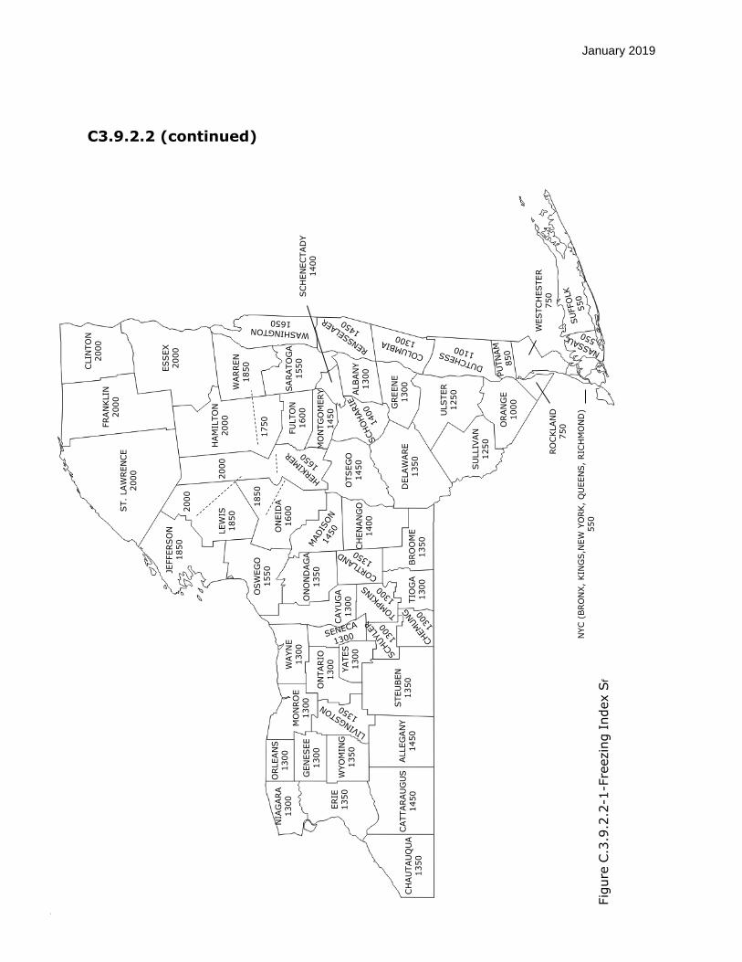
C3.9.2.2 Delete the following definition:
“Sf = freezing index, being the algebraic sum, Σ(32 – T), summed
from the date of freeze-up to the date of interest, in degree days.”
and replace with:
Sf = freezing index. Values for each county of New York are given
in Fig. C3.9.2.2-1. For a bridge crossing a county line or a line separating areas with different values of Sf, the smaller value of Sf should be used.
Delete the following:
“As a guide, Neill (1981) indicates the following values for α:
windy lakes without snow 0.8
average lake with snow 0.5-0.7 average river with snow 0.4-0.5 sheltered small river with snow 0.2-0.4”
and replace with:
In the absence of more precise information, the following values may be used for α:
All lakes 0.70
All rivers 0.50
January 2019
C3.9.2.2 (continued) ST.
LAW
REN
CE
2000
FRAN
KLIN
2000
ESSEX
2000
CLIN
TO
N2000
WARREN
1850
SARATO
GA
1550
ALBAN
Y1300
GREEN
E1300
ULSTER
1250
ORAN
GE
1000
SU
LLIV
AN
1250
DELAW
ARE
1350
MO
NTG
OM
ERY
1450
FU
LTO
N1600
HAM
ILTO
N2000
ON
EID
A16002000
JEFFERSO
N1850
OSW
EG
O1550
ON
ON
DAG
A1350
OTSEG
O1450
BRO
OM
E1350
CH
EN
AN
GO
1400
TIO
GA
1300
STEU
BEN
1350
ALLEG
AN
Y1450
CATTARAU
GU
S1450
CH
AU
TAU
QU
A1350
ERIE
1350
NIA
GARA
1300
ORLEAN
S1300
GEN
ESEE
1300
WYO
MIN
G1350
ON
TARIO
1300
MO
NRO
E1300
WAYN
E1300
CAYU
GA
1300
YATES
1300
WESTC
HESTER
750
NYC
(BRO
NX,
KIN
GS,N
EW
YO
RK,
QU
EEN
S,
RIC
HM
ON
D)
550
RO
CKLAN
D750
SC
HEN
EC
TAD
Y1400
Fig
ure
C.3
.9.2
.2-1
-Fre
ezin
g I
ndex S
f
2000
1750
1850
LEW
IS1850

January 2019
3.9 ICE LOADS: IC
3.9.3 Static Ice Loads on Piers
Add the following at the end of the article:
When the designer determines that static ice loads should be
considered in the design of a member, the Static Ice Force may
be assumed to be the product of a 7.5 ksf pressure applied over a depth equal to the thickness of the ice, not to exceed 2.0 ft.
The height of action of the Static Ice Load shall be the Ordinary Water elevation.
Static Ice Loads shall not be combined with Dynamic Ice Forces.
C.3.9.3 Add the following at the end of the commentary:
In the absence of more precise information, the thickness of ice can be estimated using the procedure in C3.9.2.
The maximum ice pressure developed in the static condition is
known to have an upper limiting value of 7.5 ksf due to cracking
and creep relaxation of ice pressures. For an ice sheet having a thickness greater than 2.0 ft., the force
per unit width does not depend on ice thickness, because the ice layer below the 2.0 ft. depth does not undergo a change in
temperature.

January 2019
3.10 EARTHQUAKE EFFECTS: EQ
3.10.1 General
Delete the first paragraph of Article 3.10.1 and replace it with the following:
Bridge Operational Categories are defined in Article 3.10.5.
Bridges defined as “other” shall be designed to have a low probability of collapse but may suffer significant damage and
disruption to service when subject to earthquake ground motions
that have a 7% probability of exceedance in 75 years. Partial or complete replacement may be required. Higher levels of
performance may be used with the authorization of the bridge
owner.
Add the following after the last paragraph:
For bridges located in the counties of Bronx, Kings, New York, Queens, Richmond, Nassau, Rockland, and Westchester (defined
as the Downstate Zone), delete Section 3.10, including all
subsequent articles, and replace it with Blue Page A3.10. For
seismic analysis and design procedures, all remaining sections of
the LRFD Bridge Design Specifications along with the NYS Blue Pages shall be followed.

January 2019
3.10 EARTHQUAKE EFFECTS: EQ
3.10.2 Seismic Hazard
3.10.2.1 General Procedure
C3.10.2.1 Delete the fourth and fifth paragraphs of the Commentary to
Article 3.10.2.1.

January 2019
3.10 EARTHQUAKE EFFECTS: EQ
3.10.2 Seismic Hazard
3.10.2.2 Site Specific Procedure
Delete Article 3.10.2.2 and replace it with the following:
A site-specific procedure to develop design response spectra of earthquake ground motions shall be performed when required by
Article 3.10.2 and may be performed for any site. The objective
of the site-specific procedure should be to generate a response spectrum for the 1,000 year return period earthquake for spectral
values over the entire period range of interest. An additional
response spectrum for a 2,500 year return period earthquake is required for critical bridges. The uniform-hazard acceleration
response spectrum for rock below soil at the bridge site shall be based on the 2009 AASHTO spectra for the 1,000 year earthquake and shall be based on the 2009 NEHRP spectra for the 2,500 year
earthquake.
Where analyses to determine site soil response effects are
required by Article 3.10.3.1 for Site Class F soils, the influence of
the local soil conditions shall be determined based on site-specific
geotechnical investigations and dynamic site response analyses using appropriate rock spectra.
Where response spectra are determined from a site-specific study, the spectra shall not be lower than two thirds of the response
spectra determined using the general procedure of Article 3.10.2.1 in the region of 0.5TF to 2.0TF of the spectrum where TF
is the bridge fundamental period.

January 2019
3.10 EARTHQUAKE EFFECTS: EQ
3.10.5 Operational Classification
Add the following after the last paragraph:
Seismic Performance Criteria
Critical Bridge: A critical bridge must provide immediate access after the lower level (functional) event and limited access after the upper
level (safety) event and continue to function as a part of the lifeline,
social/survival network and serve as an important link for civil defense, police, fire department and/or public health agencies to
respond to a disaster situation after the event, providing a continuous
route. Any bridge on a critical route shall be classified as critical if there is no readily accessible detour, and shall at a minimum be
classified as essential if there is such a detour. Any bridge that crosses a critical route, whose collapse would block
the critical route, shall at a minimum be classified as essential if there is no readily accessible detour for the critical route. However, the
bridge owner may classify such bridges as critical with the
concurrence of the DCES.
The designated detour for the critical route shall also be treated as a critical route.
It is expected that relatively few bridges will be classified as critical. Critical bridges would generally be limited to those on life safety
routes in an urban area or on the approaches to an urban area. Critical bridges would also be located on routes to a defense facility that has
limited access. Bridges on limited access highways in rural areas
would generally not be classified as critical unless they are major structures. The designation of a bridge as critical is at the discretion
of the Regional Director/Bridge Owner and it is to be documented in
the Design Report and included in the Site Data Package.
January 2019
3.10.5 (continued)
Critical bridges shall be analyzed for two earthquake hazard design
levels: a lower level event (functional evaluation/design level) having
a 7% probability of being exceeded in 75 years (1,000 year return period), and an upper level event (safety evaluation/design level)
having a 3% probability of being exceeded in 75 years (2,500 year
return period). These analysis requirements shall apply to critical
bridges located within Seismic Zone 1 as well. A site specific analysis is required for critical bridges, except for single-span bridges located
on non-liquefiable soil sites. In the case of long span bridges, the
effects of spatial variation on the seismic ground motions must also be considered.
Critical bridges shall survive the upper level event (2,500 year return period) with repairable damage (see definition of damage levels).
Traffic access following this event may be limited; within 48 hours for emergency/defense vehicles and within months for general traffic. After the lower level event (1,000 year return period) the bridge shall
suffer no damage to primary structural elements and minimal damage to other components (see definition of damage levels). Access after
this event shall be immediate to all traffic with an allowance of a few
hours for inspection.
Essential Bridge: An essential bridge must provide at least limited access after a lower level event and serve as an important link for civil defense, police, fire department and/or public disaster situation
after the event, providing a continuous route. A bridge that crosses an essential route, whose collapse would block the essential route,
shall also be classified as essential if there is no readily accessible detour for the essential route. The designated detour for the essential
route shall also be treated as an essential route.
Essential bridges should include those on interstate highways and
others of importance as determined by the Regional Director/Bridge
Owner. The designation of a bridge as essential is to be documented in the Design Report and included in the Site Data Package.

January 2019
3.10.5 (continued)
Essential bridges shall be analyzed for a single earthquake hazard
design level event having a 7% probability of being exceeded in 75
years (1,000 year return period). Essential bridges shall survive the design event with repairable damage (see definition of damage
levels). Access following the seismic event may be limited: one or two
lanes shall be available within 72 hours for emergency vehicles, full
service within months.
Other Bridges: All bridges not classified as critical or essential shall
be classified as Other Bridges. Other bridges shall be analyzed for a single earthquake hazard design level event having a 7% probability
of being exceeded in 75 years (1,000 year return period). Other
bridges may suffer significant damage (see definition of damage levels) although collapse shall not occur. The designation of a bridge
as Other is to be documented in the design report and included in the Site Data Package.
Damage Levels – Definitions
Minimal Damage: The Bridge should essentially behave
elastically during the earthquake, although minor inelastic
response could take place. Post-earthquake damage should be
limited to narrow flexural cracking in concrete and masonry elements. There should be no permanent deformations to structural members. Only minor damage or permanent
deformations to non-structural members should take place.
Repairable Damage: The extent of damage should be limited so that the structure can be restored to its pre-earthquake condition
without replacement of structural members. Inelastic response
may occur resulting in: concrete cracking, minor cover spalling and reinforcement yielding; minor yielding of structural steel
members; some damage to secondary members and non-
structural components; some damage to masonry. Repair should not require complete closure of the bridge. Permanent offsets
should be small and there should be no collapse.

January 2019
3.10.5 (continued)
Significant Damage: There is no collapse, but permanent offsets
may occur. Extensive cracking, major spalling of concrete and
reinforcement yielding, cracking of deck slab at the shear studs, may force closure for repair. Similar consequences could result
from yielding or local buckling of steel members. There could be
yielding of member connections, fracture of limited number of
bolts/rivets, serious damage to secondary structural members and non-structural components, as well as to masonry. In sites with
significant ground lateral spreading due to liquefaction, large
inelastic deformations might be induced to piles. Liquefaction could also result in excessive differential settlements. Partial or
complete replacement may be required in some cases.

January 2019
3.10 EARTHQUAKE EFFECTS: EQ
3.10.7 Response Modification Factors
3.10.7.1 General
Add to Article 3.10.7.1 the following:
The response modification factors given in Table 3.10.7.1-1 shall be applied, where applicable, to the seismic design forces that
result from a 1,000 year return period event. In the case of a
critical bridge where a 2,500 year return period event is being evaluated, the response modification factors for an essential
bridge shall be applied, as shown in the table below.
Response Modification Factors – Critical Bridges

January 2019
3.10.9 Calculation of Design Forces
3.10.9.1 General
Delete the first paragraph of the article and replace with the following:
For single-span bridges, regardless of seismic zone, there shall
be no required seismic design connection force in the restrained
direction between the superstructure and the substructure. Minimum support lengths at both expansion and fixed bearings
shall be provided as given in Article 4.7.4.4.

January 2019
Insert Article 3.10.11 and Appendix A3.10 in between Article 3.10.10 and
Article 3.11
3.10.11 Criteria for Seismic Retrofitting of Bridges Programmed for Rehabilitation
3.10.11.1 General
For evaluating and upgrading the seismic resistance of existing
highway bridges, FHWA’s “Seismic Retrofitting Manual for
Highway Structures: Part 1 – Bridges” (January 2006, Publication No. FHWA-HRT-06-032) is referenced. The provisions of this
manual shall apply to highway bridges of conventional steel and
concrete construction with spans not exceeding 500 ft. The Owner shall specify and/or approve appropriate provisions for
nonconventional construction and for bridges with spans exceeding 500 ft.
C3.10.11.1 Conventional bridges include those with slab, beam, box girder,
or truss superstructures, and single or multiple-column piers,
wall-type piers, or pile-bent substructures. In addition,
conventional bridges are founded on shallow or piled footings or
shafts. Nonconventional bridges include suspension bridges, cable-stayed bridges, arches, movable bridges, and bridges with truss towers or hollow piers for substructures.

January 2019
3.10.11.2 Seismic Performance Criteria
Refer to the FHWA Seismic Retrofitting Manual and the NYSDOT
Bridge Manual for guidance on the appropriate extent of seismic
retrofitting.
The following changes to the FHWA Seismic Retrofitting Manual
shall be applied:
FHWA’s seismic retrofitting manual recommends evaluation of
bridges for lower level earthquake event of 100 years and an
upper level event of 1,000 years. Bridges shall be evaluated only for the upper level earthquake ground motions with a 7%
probability of exceedance in 75 years corresponding to a 1,000
year return period. Critical and essential bridges shall be combined in one category
and will be evaluated under “essential” bridges as defined in the Retrofit Manual.
Other bridges shall be considered the same as “standard”
bridges as defined in the Retrofit Manual. Design Response Spectrum shall be constructed as per Article
3.10.4.1 incorporating site factors as per Article 3.10.3.2.
Minimum support length requirements are to be calculated as
per Article 4.7.4.4.

January 2019
A3.10 SEISMIC DESIGN CRITERIA FOR THE DOWNSTATE ZONE
Downstate Zone: The counties of Bronx, Kings, New York, Queens, Richmond,
Nassau, Rockland and Westchester as shown in Figure A3.10-1.
A3.10.1 General
The Seismic Design Criteria for the Downstate Zone provides criteria for the analysis, evaluation,
design and retrofit of bridges in the Downstate Zone. For additional information regarding these
provisions refer to the 2016 New York City Department of Transportation Seismic Design
Guidelines for Bridges in Downstate Region (NYCDOT SDGBDZ 2016).
The design earthquake ground motion levels specified herein could result in both structural and
non-structural damage. For most bridge systems designed and constructed or retrofitted according
to these criteria, structural damage from the design earthquake ground motion would be repairable.
It is expected that the damage from the design earthquake ground motions would not be so severe
as to preclude continued function of the bridge. The actual ability to accomplish these goals
depends upon a number of factors including site conditions, the structural type and configuration
of the bridge, construction materials, and as-built details of construction.
The following criteria identify minimum requirements for seismic design. Each bridge presents a
unique set of design challenges. The designer must determine the appropriate methods and level
of refinement necessary to design and analyze each bridge on a case-by-case basis. The designer
must exercise judgment in the application of these criteria.

January 2019
Situations may arise that warrant detailed attention beyond what is provided in the Guidelines. It
is the prerogative of each bridge owner to decide under which cases these Guidelines would need
to be modified to suit specific circumstances.
The NYCDOT SDGBDZ 2016 includes requirements related to the following:
Bridge Classification and Performance Criteria
Very Hard Rock Spectra and Time History Records
Classification of a Site as a Rock or Soil Site
Rock Classes and Rock Generic Horizontal Design Spectra
Soil Site Characterization and Soil Generic Horizontal Design Spectra
Vertical Motions and Generic Design Spectra for Rock and Soil Sites
Site Liquefaction
Site Specific Studies
A3.10.2 Seismic Hazard
The seismic hazard at a bridge site shall be characterized by the acceleration response spectrum
for the relevant site class. The acceleration spectrum shall be determined using either the General
Procedure specified in Article A3.10.2.1 or the Site Specific Procedure specified in Article
A3.10.2.2.
The Seismic Hazard for the Downstate Zone (see Figure A3.10-1) has been quantified in the form
of 5% damped Uniform Hazard Spectra (UHS) for three earthquake return periods, 1,000, 1,500,
and 2,500 years, corresponding to probabilities of exceedance in 75 years of 7%, 5%, and 3%,
respectively. The horizontal UHS are presented in Table A3.10.2-1 and Figure A.3.10.2-1 as
coefficients corresponding to spectral accelerations in terms of g, the acceleration of gravity. The
vertical UHS are presented in Table A3.10.2-2 and Figure A.3.10.2-2 as coefficients corresponding
to spectral accelerations in terms of g, the acceleration of gravity. The spectra in Table A3.10.2-1
and A3.10.2-2, and in Figures A3.10.2-1 and A.3.10.2-2, represent an 85th percentile (median plus
one standard deviation level) of ground motions corresponding to each one of the three return
periods of 1,000 years, 1,500 years, and 2,500 years. The motions are for Very Hard Rock (VHR)
in NYC, typical of the eastern United States (US), with a shear wave velocity of at least 2.83
km/sec (approximately 9,000 ft/sec). This 2.83 km/sec shear wave velocity is an average of eastern
US continental crust. UHS in the horizontal direction for softer rock conditions and soil site
conditions are given in Article A3.10.4.
Vertical UHS for Very Hard Rock, softer rock conditions, as well as for soil site conditions, are
also presented in Article A3.10.4 and shall be used according to Article A3.10.2.1.
Very Hard Rock ground motion time history records have been developed to match the spectral
accelerations in Tables A3.10.2-1 and A3.10.2-2 and are available in digital form from the
NYSDOT Office of Structures website for the 1,000 years, 1,500 years, and 2,500 years earthquake
return periods.
( https://www.dot.ny.gov/divisions/engineering/structures/manuals/seismic-references )

January 2019
Three sets of multiple support ground motion time-histories, for 1,000 year, 1,500 year, and 2,500
year earthquake return periods, were derived for use as inputs to seismic analyses, (as input to the
bridge dynamic analysis in the time domain or as input to the soil dynamic site response analyses)
for each of the three earthquake return periods (1,000 year, 1,500 year, and 2,500 year).
Providing three sets of time histories for each of the three return periods allows for accounting of
uncertainties in the earthquake excitation and variations in the non-linear response of bridge
components. In addition, each one of these three sets incorporates the effects of spatial variation
along 21 hypothetical piers on Very Hard Rock spaced at 100 m (328 ft.), and extended over a
straight line having a total length of 2 km (1.24 mile). These sets are to be used as the basis for
spatial variation analyses of long-span bridges as required and described in article 4.7.4.3.4b.
These Very Hard Rock response spectra and time history records may be used either for the
structural dynamic analysis of the bridge (design of the bridge) in the case of a bridge at a rock
site, or as rock input to the soil in dynamic site response analyses. Whether used as input to the
bridge analysis or as input to the soil site response analyses, these spectra and time histories shall
be assumed to be located at the surface of an outcrop of Very Hard Rock (VHR).
Design Acceleration Response Spectra (5% damped) and associated acceleration time histories for
Rock Classes A and B (see Article A3.10.3.2 for rock site classifications), shall be obtained by
one of the following approaches:
1) Modifying the corresponding available UHS spectra and records on Very Hard Rock.
2) Site-specific ground response analysis if the depth and properties of softer rock over VHR are
known.
The procedures for the modification of the Very Hard Rock motions are as follows:
Design Acceleration Response Spectrum and associated acceleration time histories for Rock
Class A: Multiply UHS on Very Hard Rock (see Tables A3.10.2-1 and A3.10.2-2) by a factor
of 1.15; multiply the acceleration time histories on Very Hard Rock by a factor of 1.15.
Design Acceleration Response Spectrum and associated acceleration time histories for Rock
Class B: Multiply UHS on Very Hard Rock (see Tables A3.10.2-1 and A3.10.2-2) by a factor
of 1.65; multiply the acceleration time histories on Very Hard Rock by a factor of 1.65.
Coefficients for horizontal spectra on Rock Classes A and B, already multiplied by 1.15 and 1.65,
respectively, are included in Table A3.10.2-3 (1,000 years), Table A3.10.2-4 (1,500 years), and
Table A3.10.2-5 (2,500 years). Plots of these horizontal spectra for 1,000 years, 1,500 years, and
2,500 years earthquakes are presented in Figures A.3.10.2-3, A.3.10.2-4, and A.3.10.2-5,
respectively.
Coefficients for vertical spectra on Rock Classes A and B, already multiplied by 1.15 and 1.65,
respectively, are included in Table A3.10.2-6 (1,000 years), Table A3.10.2-7 (1,500 years), and
Table A3.10.2-8 (2,500 years). Plots of these vertical spectra for 1,000 years, 1,500 years, and
2,500 years earthquakes are presented in Figures A.3.10.2-6, A.3.10.2-7, and A.3.10.2-8,
respectively.

January 2019
These design spectra and time histories on Rock Class A or B, may be used either for the structural
dynamic analysis of the bridge (design of the bridge) in the case of a bridge at a rock site, or as
rock input to the soil in dynamic site response analyses. Whether used for design of the bridge or
as input to the soil site response analyses, these spectra and time histories shall be assumed to be
located at the surface of an outcrop of Rock Class A or B (see Figure A3.10.3.1-1).
Vertical design spectra are for reference only and shouldn’t be used for the response spectrum
analysis (general procedure in Article A3.10.4). Vertical ground motion time-histories on Rock
Class A or B may be used for the structural dynamic analysis of the bridge (design of the bridge)
in the case of a bridge at a rock site. Vertical motions for a bridge founded at a soil site shall be
obtained using site specific procedure in Article A3.10.2.2.
A3.10.2.1 General Procedure
For design values, the spectra in Article A3.10.4 based on Site Classification of Article A3.10.3
shall be used for both longitudinal and transverse direction of a structure.
A3.10.2.2 Site Specific Procedure
Within the Downstate Zone, a site-specific procedure to develop design response spectra of
earthquake ground motions shall be performed for the following conditions.
When required by Article 3.10.2 of AASHTO LRFD Bridge Design Specifications.
All bridge categories with Site Class F.
All “Critical” bridges with Soil Sites or Rock under Soil Sites as defined in Articles A.3.10.3.2
and A.3.10.3.3.
A site-specific procedure may be performed for any bridge site at the discretion of the Bridge
Owner and shall be documented in the design report.
Site specific studies shall be performed using acceleration time histories (available at NYSDOT
Office of Structures website) described in Article A3.10.2 and satisfying procedures and
requirements in this section. General provisions of Article 3.10.2.2 of AASHTO LRFD Bridge
Design Specifications are also applicable.
The development of site-specific design response spectra, and, when needed, site-specific
acceleration time-histories, shall account for the effects of the local subsurface site conditions, and,
in the case of long-span bridges, also for the spatial variation of the motions (see article 4.7.4.3.4b).
The influence of the local site conditions on the free field ground motions shall be based on site-
specific geotechnical investigations and dynamic site response analyses.
1) Site-Specific Studies and Depth of Rock Surface, Hr
Site-specific analyses shall account for the local site conditions, by incorporating parameters
based on the data collected through subsurface investigations performed at the site (drilling
soil borings, taking samples, laboratory testing, geophysical testing), in order to obtain the
necessary information regarding local geology, establishing soil types and layering, depth to
rock and dynamic properties of the soils and rock at the site. The subsurface investigation shall
include in-situ seismic measurements to provide accurate seismic shear wave and
compressional wave velocity values for the soil and rock.

January 2019
Wave velocity measurements are required to a minimum depth of Hr + 20 ft. if Hr ≤ 100 ft., or
to a minimum depth of 100 ft. if Hr > 100 ft.; where rH is the depth of the rock surface defined
in Article A3.10.3.1. In the case of Hr > 100 ft., while wave velocity measurements are not
required below 100 ft., they are strongly recommended if possible to a depth of Hr + 20 ft., in
order to reduce the uncertainty of the site-specific calculated spectra and corresponding time-
histories.
For sites where the value of Hr is known and the Rock Class under the soil is also known, the
horizontal and vertical ground motions at the soil surface will be determined as follows:
Horizontal soil ground motions (spectra and corresponding time-histories) will be obtained
from dynamic site response analyses of the soil profile, with the corresponding rock motion
input placed on a rock outcrop. If needed for time-history analysis of the bridge, in addition
to the time-histories calculated in the dynamic site analyses, it may also be necessary to
generate time-histories to match the horizontal design spectrum on soil, as discussed in
article 4.7.4.3.4b.
Vertical soil ground motions (spectra) will be obtained by multiplying the corresponding
final horizontal soil spectra by the appropriate period dependent V/H design ratios. These
V/H ratios are listed in Tables A3.10.2.2-1, A3.10.2.2-2 and A3.10.2.2-3 for return periods
of 1,000 years, 1,500 years and 2500 years, respectively, as a function of Hr, Rock Class
under the soil, and Soil Site Class. These spectra can be used for the generation of vertical
time-histories on soil if needed for use in time-history analysis of the bridge, see article
4.7.4.3.4b.
For bridge soil sites where the depth to rock, Hr > 100 ft. and the value of Hr is unknown, the
site response analyses for horizontal ground motions shall proceed by assuming two or more
values of the depth to rock Hr . As a minimum, the following two values of Hr should be used:
(i) the depth of the deepest measured Vs; and (ii) a best estimate of the depth to the rock surface
based on the geological and geotechnical information available to the engineer, including
depths to rock in nearby sites. For these cases of estimated Hr, Rock Class B shall be assumed
to exist under the soil. In addition, a conservative approach shall be taken in the selection of
the horizontal design spectrum on top of the soil, including selecting an envelope of the soil
spectra calculated with the various assumed Hr.
If the depth and properties of softer rock over VHR are known, the softer rock layer may be
included in the site-specific analysis. In this case, the rock input shall use the VHR motions.

January 2019
2) Parametric Variations of VS
To account for uncertainties in the soil properties (including parameters such as Vs, nonlinear
G/Gmax modulus reduction curve versus strain, Plasticity Index of clays, etc.), “Best Estimate”
values, as well as lower range and upper range values of the soil shear wave velocities, shall
be considered in the dynamic site response analyses. Therefore, three or more site response
analyses must be conducted for every soil profile selected. As a minimum, the following three
analyses shall be conducted: (i) analyses using the “Best Estimate” sV for all soil layers; (ii)
analyses using the “Best Estimate” Vs minus 20% for all soil layers; and (iii) analyses using
the “Best Estimate” Vs plus 20% for all soil layers. The envelope spectra shall be used for
design, and can be obtained by picking the maximum spectral acceleration for each period.
3) Minimum Two-Thirds Rule for Selected Horizontal Design Spectrum and PGA
If no peer review of the site-specific study is performed, final design horizontal spectrum and
PGA shall not be less than two-thirds of the corresponding site “generic” spectrum and PGA.
This requirement applies to both Critical and Non-Critical Bridges. For the purpose of applying
the two-thirds rule, the following shall apply:
Soil Class F due to soil liquefaction: the site shall be re-classified as Soil Class C, D or E
following the procedures in Article A3.10.3.3 and ignoring liquefaction.
Soil Class F due to reasons other than liquefaction: the generic spectra and PGA will be
selected for the appropriate combination of Hr, Rock Class under the soil, and Soil Class
D.
4) Soil-Structure Interaction Studies
Soil-structure interaction effects must be included whenever necessary at a Soil or Rock Site.
5) Critical Bridges
For critical bridges, site-specific soil effects, including the possible effect of soil liquefaction,
shall be incorporated through dynamic site response analyses. Spatial variation effects shall
also be evaluated in the case of long-span bridges. Selection of rock design spectra for bridges
at rock sites, dynamic site response analyses at soil sites, and spatial variation analyses, shall
comply with the pertinent sections of these specifications.
Design Acceleration Response Spectra (5% damped) for the 2,500 year earthquake on soil and,
when needed, associated time-histories obtained from site-specific dynamic site response
analyses, will be selected as follows:
Horizontal ground motions for design and liquefaction evaluation: Site-specific dynamic
site response analyses shall be conducted using the rock input in accordance with Articles
A.3.10.2 and 4.7.4.3.4b. The horizontal design spectrum and design peak ground
acceleration (PGA) will be selected at the soil surface from the results of these analyses.
The potential for liquefaction during the 2,500 year earthquake shall be evaluated in
accordance with Article A.3.10.2.2(7), assuming an earthquake of magnitude M = 6.25.

January 2019
If it is determined that liquefaction will occur, the effect of both liquefied and non-liquefied
configurations must be considered on the design horizontal spectrum and PGA. After
selection of the final design horizontal spectrum and design horizontal PGA, if needed for
time-history analyses, acceleration time-histories calculated as part of the dynamic
response analyses may be used, or modified as needed, to match the final design horizontal
spectrum. If this is not possible, acceleration time-histories shall be obtained that match
the final design horizontal spectrum using appropriate commercially available software
(see article 4.7.4.3.4b).
Vertical ground motions for design: The vertical design spectrum for the 2,500 year
earthquake will be obtained by multiplying the site-specific final design horizontal
spectrum and PGA by the appropriate period dependent V/H ratios in Table A.3.10.2.2-3.
If needed for time-history analyses of the bridge, acceleration time-histories may be
obtained from matching the design vertical spectrum, using appropriate commercially
available software.
The design criteria for the 1,000 year earthquake provides for minimal damage and normal
service following a post-earthquake inspection. Thus, the engineer shall evaluate the response
of the bridge to this event for compliance to the serviceability requirements. Only one analysis
may be necessary to assess the performance requirements associated with this event. Design
Acceleration Response Spectra (5% damped) for the 1,000 year earthquake for soil, and when
needed, also associated time-histories obtained from site-specific dynamic site response
analyses will be selected as follows:
Horizontal ground motions for design: Site-specific dynamic site response analyses will be
conducted using the rock input in accordance with Articles A.3.10.2 and 4.7.4.3.4b. The
horizontal design spectrum and PGA will be selected at the soil surface from the results of
these analyses. If needed for time-history analyses of the bridge, acceleration time-histories
calculated as part of the dynamic response analyses may be used, or modified as needed,
to match the final design horizontal spectrum. If this is not possible, acceleration time-
histories shall be obtained that match the final design horizontal spectrum, using
appropriate commercially available software.
Vertical ground motions for design: The vertical design spectrum for the 1,000 year
earthquake will be obtained by multiplying the site-specific final design horizontal
spectrum and PGA by the appropriate period dependent V/H ratios in Article A.3.10.2.2-
1. If needed for time-history analyses of the bridge, acceleration time-histories shall be
obtained by matching the final design vertical spectrum using appropriate commercially
available software.
Peer review of site specific spectra shall be carried out as per the requirements in Article
A.3.10.2.3.

January 2019
6) Non-Critical Bridges (Essential and Others)
Non-critical Bridges shall be analyzed for a single earthquake hazard level, corresponding to
a 7% probability of being exceeded in 75 years (1,000 year return period). The owner has the
option to use a single earthquake hazard level, corresponding to a 5% probability of being
exceeded in 75 years (1,500 year return period) instead. Site-specific soil effects, including the
possible effect of soil liquefaction, shall be incorporated through dynamic site response
analyses, and spatial variation effects shall also be evaluated in the case of long-span bridges.
Selection of rock design spectra for bridges at rock sites, as well as dynamic site response
analyses at soil sites, and spatial variation analyses, shall comply with the specifications in
Articles A.3.10.2 and 4.7.4.3.4b.
Design Acceleration Response Spectra (5% damped) for the design earthquake on soil and,
when needed, associated time-histories obtained from site-specific dynamic site response
analyses, will be selected as follows:
Horizontal ground motions for design and liquefaction evaluation: Site-specific dynamic
site response analyses will be conducted using the rock input in accordance with Articles
A.3.10.2 and 4.7.4.3.4b. The horizontal design spectrum and design peak ground horizontal
acceleration (PGA) will be selected at the soil surface from the results of these analyses.
The potential for liquefaction during the design earthquake shall be evaluated in
accordance with Article A.3.10.2.2(7), and assuming if necessary, an earthquake of
magnitude M = 6. If it is determined that liquefaction will occur, the effect of both liquefied
and non-liquefied configurations must be considered on the design horizontal spectrum and
PGA (see Article A.3.10.2.2(7)). If the liquefaction evaluation indicates no liquefaction,
the liquefaction evaluations shall be repeated using the procedures in Article A3.10.3.4
using surface horizontal peak ground acceleration (PGA) equal to either the site-specific
value, or two thirds of the corresponding PGA in Table A3.10.3-1, whichever is greater.
An earthquake magnitude, M = 6 will be used in this liquefaction re-evaluation. If this re-
evaluation indicates that liquefaction will occur, the occurrence of liquefaction will be
considered in the design of the bridge, including its effects on the response spectra (see
Article A.3.10.2.2(7)).
A final design horizontal spectrum and PGA will be selected that is at all periods equal or
greater than two thirds of the corresponding generic spectrum and PGA. After selection of
the horizontal design spectrum and design horizontal PGA, if needed for time-history
analyses, acceleration time-histories calculated as part of the dynamic response analyses
may be used, or modified as needed, to match the final design horizontal spectrum. If this
is not possible, acceleration time-histories shall be obtained that match the final design
horizontal spectrum, using appropriate commercially available software (Article
4.7.4.3.4b).
If the engineer determines that liquefaction will occur for a site that was originally
classified as Soil Class C, the generic spectra used as a basis for the two thirds rule in the
range of periods greater than 0.5 sec will be recalculated based on the appropriate
combination of Hr, Rock Class under the soil, and Soil Class D. The spectrum in the range
of periods below 0.5 sec, including the PGA, and computed using Soil Class C, shall not
be affected by this recalculation.

January 2019
Vertical ground motions for design: The design vertical spectrum for the 1,000 year or
1,500 year earthquake will be obtained by multiplying the site-specific final design soil
horizontal spectrum and PGA by the appropriate period dependent V/H ratios in Table
A3.10.2.2-1 (for 1,000 year) and Table A3.10.2.2-2 (for 1,500 year). The final design
horizontal spectrum to be used for the calculations should be that already adjusted by the
two thirds rule. If needed for time-history analyses of the bridge, acceleration time-histories
shall be obtained by matching the final design vertical spectrum using appropriate
commercially available software.
Peer review of site specific spectra shall be carried out as per the requirements in Article
A.3.10.2.3.
7) Liquefaction Evaluation and Effect on Ground Motions
If liquefiable layers are present at a soil site for any bridge, one of the objectives of the site-
specific study is to conduct the corresponding liquefaction evaluation. The liquefaction
evaluation shall be performed after performing site response analyses, assuming that
liquefaction does not occur. The liquefaction assessment may use either the PGA or other
parameters from the site response analyses (e.g., shear stresses or strains) selected by the
engineer to quantify the earthquake demand. Liquefaction assessment may be carried out
following the procedures in Article A3.10.3.4 or by a more advanced approach selected by the
engineer. If it is determined that liquefaction will occur at the bridge site for the given
earthquake level, and if the site response analyses do not already incorporate the effect of
excess pore water pressures on the soil ground motions, then additional site response analyses
may have to be performed to consider the effect of liquefaction on the soil ground motions. If
it is determined that liquefaction will occur, the bridge site shall be analyzed for two
configurations: (i) non-liquefied configuration, where the site is analyzed assuming no pore
pressure buildup and no liquefaction; and (ii) liquefied configuration, where the site is
reanalyzed assuming that liquefaction occurs in the liquefiable soil layers.
The ground motion spectra shall be the envelope of the results calculated with both non-
liquefied and liquefied configurations. If time-history analyses are needed, the provisions of
Article 4.7.4.3b shall be followed.
A3.10.2.3 Peer Review of Site Specific Studies
1) Critical Bridges
A peer review of a site-specific study shall be performed by an owner-approved independent
engineer, who has experience in performing site specific seismic analyses. The engineer or
engineering panel performing the peer review shall submit a final written report that
summarizes the conclusions and recommendations.
If the owner decides to waive the requirement of a peer review for the site-specific study of a
Critical Bridge, the selected 2,500 year and 1,000 year horizontal design spectra must comply
with the minimum two thirds rule in Article A3.10.2.2(3) using the generic spectra for 2,500
year and 1,000 year return periods in Article A.3.10.4 as the baseline for the two-thirds
requirement.

January 2019
If no peer review is performed, and the liquefaction evaluation conducted as part of the site-
specific study following Article A3.10.2.2(7) indicates no liquefaction, the liquefaction
evaluation shall be repeated with the procedures in Article A3.10.3.4 using a surface horizontal
peak ground acceleration (PGA) equal to either that calculated in the site-specific study, or
two-thirds of the corresponding PGA for 2,500 years in Table A3.10.3-1, whichever is greater.
An earthquake magnitude M = 6.25 will be used in this liquefaction re-evaluation. If this re-
evaluation indicates that liquefaction will occur, the occurrence of liquefaction shall be
considered in the design of the bridge, including its effects on the response spectra (see Article
A3.10.2.2(7)). The final design soil vertical spectra will be computed using the corresponding
V/H ratios from the final design soil horizontal spectra after the horizontal spectra have been
adjusted to comply with the two thirds rule.
If no peer review is performed, and the engineer determines that liquefaction will occur for a
site that was originally classified as Soil Class C, the generic spectra used as a basis for the
two thirds rule in the range of periods greater than 0.5 sec will be recalculated based on the
appropriate combination of Hr, Rock Class under the soil, and Soil Class D. The spectrum in
the range of periods below 0.5 sec, including the PGA, and computed using Soil Class C, shall
not be affected by this recalculation.
2) Non-Critical Bridges
The owner has the option to require a peer review of a site-specific study. This review shall be
performed by an owner-approved independent engineer who has experience in performing site
specific seismic analyses. The engineer or engineering panel performing the peer review shall
submit a final written report that summarizes the conclusions and recommendations.
If a peer review is performed, and the site-specific liquefaction evaluation as per Article
A3.10.2.2(7) indicates no liquefaction, the requirement for a liquefaction re-evaluation using
the procedure in Article A3.10.3.4 is waived. That is, the conclusion of no liquefaction
obtained from the site-specific study may stand, provided that the engineer or engineering
panel performing the review approves this in the final written report.
If a peer review is performed for a Non-Critical Bridge, requirements of Article A3.10.2.2(3)
related to the two thirds rule are waived. That is, the final design soil horizontal and vertical
spectra and PGA selected for the 1,000 year earthquake from the site-specific study may be
lower than that required by the two-thirds rule, provided that the engineer or engineering panel
performing the review approves this in the final written report.

January 2019
A3.10.3 Site Effects
Site classes specified herein shall be used in the General Procedure for Seismic Hazard (Design
Response) Spectrum specified in Article A3.10.4.
A site is classified as a soil site if there is more than 10.0 ft. of soil between the bottom of spread
footing or pile cap and the rock surface; otherwise it is classified as a rock site. The specific
definitions for rock surface determination are shown in Article A3.10.3.1. Rock sites are classified
as Rock Site Class VHR, A, or B, as described in Article A3.10.3.2. Soil sites are classified as Soil
Site Class C, D, E or F, as described in Article A3.10.3.3. Article A3.10.3.4 describes the site
liquefaction assessment procedure.
A3.10.3.1 Rock Surface Determination
The depth of the rock surface below the ground surface of the site is labeled Hr in these Guidelines
(see Figure A3.10.3.1-1).
The “rock surface” is defined as the shallowest depth for which the following three conditions are
concurrently satisfied:
1. The geotechnical material in the 20.0 ft. immediately below the rock surface is either rock
material or cemented or very dense soil with an average shear wave velocity 500,2V 20 s
ft./sec (see Table A3.10.3.1-1 and Figure A3.10.3.1-1). The average shear wave velocity 20Vs
is defined later in this Article.
In the case of cemented or very dense material, determination that the rock surface has been
reached, for the purposes of these provisions, shall be based only on the actual measured
500,2V 20 s ft./sec in the 20.0 ft. below the assumed rock surface. In the absence of shear
wave velocity measurements, the cemented or very dense material shall be considered to be a
soil layer above the rock surface. In the case of rock material, determination that the rock
surface has been reached shall be based preferably on shear wave velocity measurements in
the 20 ft. below the assumed rock surface. However, for competent rock with moderate
fracturing and weathering, estimation of this shear wave velocity shall be permitted. For more
highly fractured and weathered rock, the shear wave velocity shall be directly measured;
otherwise, it shall be assumed that the rock surface has not yet been reached and the highly
fractured and weathered rock shall be considered to be a soil layer above the rock surface.
2. The value of sV at each individual sublayer within the 20 ft. below the rock surface is at least
2,000 ft/sec.
3. Based on the geotechnical characteristics at the site, the Engineer can reasonably assume that
the sV profile below the rock surface will not decrease below ft/sec, 500,2V 20 s with sV
eventually increasing with depth until the very hard rock elevation ( 000,9V s ft/sec) is
reached.

January 2019
Determining that the rock surface has been reached requires calculating 20Vs , which is defined as
follows (see Figure A3.10.3.1-1):
n
i si
i
n
i
i
s d
d
1
120
V
V where
n
i
id1
= 20.0 ft.
The symbol i refers to any one of the sublayers within the 20.0 ft. immediately below the rock
surface, with measured shear wave velocity siV and thickness id , from 1 to n (where n is the total
number of sublayers). Each siV must be at least 2,000 ft./sec.
A3.10.3.2 Rock Site & Rock Under Soil Site Classification
1) Rock Site
For a Rock Site, the Rock Class shall be defined as follows (see Table A3.10.3.1-1):
VHR: Very Hard Rock with measured averaged shear wave velocity, 000,9V 20 s ft./sec.
Rock Class A: Hard Rock with measured averaged shear wave velocity,
000,9V000,5 20 s ft./sec.
Rock Class B: Rock material or cemented or very dense soil with averaged shear wave
velocity 000,5V500,2 20 s ft./sec.
In the case of cemented or very dense material (e.g., very dense glacial till), classification as
Rock Class B shall be based only on shear wave velocity measurements. In the absence of
shear wave velocity measurements, the cemented or very dense material shall be considered to
be a soil layer above the rock surface, as defined in Article A3.10.3.3.
In the case of rock material, classification as Rock Class B shall be based preferably on shear
wave velocity measurements. However, for competent rock with moderate fracturing and
weathering, estimation of this shear wave velocity shall be permitted. For more highly
fractured and weathered rock, the shear wave velocity shall be directly measured or the highly
fractured and weathered rock shall be considered a soil layer above the rock surface.
Assignment of either Rock Class A or VHR shall be based on either in-situ shear wave velocity
measurements, or shear wave velocity measurements on profiles of the same rock type in the
same formation with an equal or greater degree of weathering and fracturing.
If the measured shear wave velocities indicate Rock Class B, but Rock Class A (or VHR) is
found by drilling at a depth below the rock surface not greater than 40 ft, the Engineer shall
have the option to classify the site as Rock Site Class A (or VHR) instead of Rock Site Class
B, for the purpose of selecting the generic spectra in Article A3.10.4 (see Figure A3.10.3.2-1).
The decision to drill deeper than 20 ft. below the rock surface is optional (see Article
A3.10.3.1).
January 2019
2) Rock Under Soil Site
For a Soil Site with Hr < 100 ft., the selection of design spectra in Article A3.10.4 and the
selection of Peak Ground Acceleration (PGA) for liquefaction evaluation (see Article
A3.10.2.2), require classification of the rock under the site as either Rock Class A/VHR or B.
The same definition of 20Vs (see Figure A3.10.3.1-1), and the same ranges of 20Vs given for
Rock Sites in Article A3.10.3.2(1), shall be used. Classification of Rock under Soil Sites is as
follows (see Table A3.10.3.1-1):
Rock Class A/VHR: Hard to Very Hard Rock with measured shear wave velocity 20Vs >
5,000 ft./sec.
Rock Class B: Rock material or cemented or very dense soil with shear wave velocity
000,5V500,2 20 s ft./sec.
In the case of cemented or very dense material (e.g., very dense glacial till), classification as
Rock Class B shall be based only on shear wave velocity measurements. In the absence of
shear wave velocity measurements, the cemented or very dense material shall be considered to
be a soil layer above the rock surface.
In the case of rock material, classification as Rock Class B shall be based preferably on shear
wave velocity measurements. However, for competent rock with moderate fracturing and
weathering, estimation of this shear wave velocity shall be permitted. For more highly
fractured and weathered rock, the shear wave velocity shall be directly measured or the highly
fractured and weathered rock shall be considered a soil layer above the rock surface.
Assignment of Rock Class A/VHR shall be based on either in-situ shear wave velocity
measurements, or shear wave velocity measurements on profiles of the same rock type in the
same formation with an equal or greater degree of weathering and fracturing.
If Hr ≤ 100 ft. and the measured averaged shear wave velocity 20Vs indicates Rock Class B
directly beneath the soil, but Rock Class A/VHR is found by drilling at a depth below the rock
surface not greater than 40.0 ft., the Engineer shall have the option to specify that the soil
profile is on top of Rock Class A/VHR instead of Rock Class B (see Figure A3.10.3.2-1), for
the purpose of selecting the generic spectral accelerations (see Article A3.10.4), and the Peak
Ground Acceleration (PGA) for liquefaction evaluation (see Article A3.10.2.2). To exercise
this option, drilling must continue at least 20.0 ft. below the Rock Class A/VHR surface shown
in Figure A3.10.3.2-1.
January 2019
A3.10.3.3 Soil Sites Classification
1) Soil Site Classes C, D, E, F
A soil site is defined as one where the distance between the rock surface and the bottom of
spread footing or pile cap is greater than 10.0 ft.
Soil Site Classes shall be characterized on the basis of average soil properties. The sites of
Critical Bridges shall only be classified using the measured soil shear wave velocity Vs. The
preferred soil property used for the Non-Critical Bridges is also the soil shear wave velocity.
Other alternative soil properties that may be used for Non-critical bridges are the Standard
Penetration Test (SPT) resistance N ( chN for cohesionless soils) and the undrained shear
strength su for cohesive soils. The corresponding average soil properties sV , N , chN , and us
are specifically defined in Table A3.10.3.3-1. Definitions of these average soil properties are
provided in subsection 2). The Soil Classes used to classify a Soil Site are defined as follows:
Soil Class C: Very dense soil with shear wave velocity, 500,2V200,1 s ft./sec or with
either standard blow count 50)or ( chNN , or undrained shear strength 000,2us psf.
Soil above the rock surface which has a 500,2Vs ft./sec due to the presence of cemented
or very dense soil layers, but does not meet the requirements of a rock site, as specified in
Articles A3.10.3.1 and A3.10.3.2, shall be classified as Soil Class C.
Soil Class D: Stiff soil with ft/sec 200,1V600 s or with 50)or (15 chNN or
000,2000,1 us psf.
Soil Class E: A soil profile with 600Vs ft./sec, or any profile at a soil site with more
than 10 feet of soft clay defined as soil with plasticity index PI > 20, water content
%40w , and 500us psf, or any profile with N or 15chN , or 000,1us psf.
Soil Class F: Soils requiring site-specific evaluations:
1. Soils vulnerable to potential failure or collapse under seismic loading such as
liquefiable soils, quick and highly sensitive clays, and collapsible weakly cemented
soils. The site of a Critical Bridge will be classified as Soil Class F if it will liquefy
during the 2,500 year earthquake, as determined according to Article A3.10.2.2. The
site of an Essential or Other Bridge will be classified as Soil Class F if it will liquefy
during the 1,000 year earthquake (or 1,500 year earthquake, optionally), as determined
according to Article A3.10.2.2.
2. Peats and/or highly organic clays (H > 10.0 ft. of peat and/or highly organic clay, where
H = total thickness of soil layers with those characteristics).
3. Very high plasticity clays (H > 25.0 ft. with PI > 75).
4. Very thick soft/medium stiff clays (H > 120.0 ft.) with 000,1us psf.
January 2019
Table A3.10.3.3-1 summarizes the classification of Soil Sites.
2) Definitions of Soil Class Parameters
The definitions presented in this Article apply to soil profiles where the rock surface, as defined
in Article A3.10.3.1, is located more than 10.0 ft. below the bottom of a spread footing or pile
cap. If the depth of rock surface Hr ≤ 100 ft., only the properties of the soil between the ground
surface and the rock surface are used. If Hr > 100 ft., only the properties of the soil between
the ground surface and a depth of 100 ft. are used. Therefore, definition of the Soil Class at a
soil site does not require subsurface exploration deeper than 100 ft. (see Figure A3.10.3.3-1),
except in cases of very thick soft/medium stiff clays (i.e. Site Class F). Profiles containing
distinctly different soil layers shall be subdivided into those layers designated by a number that
ranges from 1 to n at the bottom, where there are a total of n distinct layers down to the depth
Hr or down to a depth of 100 ft., depending on the case. The symbol i refers to any one of the
layers between 1 and n.
The average shear velocity sV is calculated as
n
i si
i
n
i
i
sd
d
1
1
V
V
where siV is the shear wave velocity of a layer in ft/sec, id is the thickness of any layer between
0.0 ft. and 100 ft. and
n
i
id1
shall not be greater than 100 ft. If the depth to rock rH is less than
100 ft., then r
n
i
i Hd 1
.
The average standard penetration resistance N is calculated as
n
i i
i
n
i
i
N
d
d
N
1
1
where Ni is the Standard Penetration Resistance determined in accordance with ASTM D1586,
as directly measured in the field without corrections, and shall not be taken greater than 100
blows/ft. In the equation above, iN and id are for cohesionless and cohesive soil layers (i.e.
rock shall not be included) within a total depth not exceeding 100 ft. If the depth to rock Hr is
less than 100 ft., thenr
n
i
i Hd 1
.

January 2019
For cohesionless soils, chN is calculated as:
chN
m
i i
i
m
i
i
N
d
d
1
1
where
m
i
si dd1
is the total thickness of cohesionless soil layers. Use id and iN only for
cohesionless soils within a total depth not exceeding 100 ft. for layers from 1 to m.
Average undrained shear strength us is calculated as:
us
k
i ui
i
c
s
d
d
1
where uis is the undrained shear strength in psf, and shall be determined in accordance to
ASTM D2166 or ASTM D2850. It shall not exceed 5,000 psf.
k
i
ic dd1
is the total thickness
of cohesive soil top layers within a total depth not exceeding 100 ft., from 1 to k, and
100 cs dd ft.
Plasticity Index (PI) is determined in accordance to ASTM D4318.
Moisture content (w), in percent, is determined in accordance to ASTM D2216.
3) Steps for Classifying Soil Site as Class C, D, E or F
The steps described below are to be taken after establishing that the site is a Soil Site rather
than a Rock Site (see Articles A3.10.3.1 and A3.10.3.2). The definitions of sV , ,N chN and
us , used below, are given in the previous subsection.
Step 1: Check in Part 1 of Article A3.10.3.3 for the four categories of Soil Class F requiring
site-specific evaluation. If the site corresponds to any of these categories, classify the site as
Soil Class F.
Step 2: Check for the existence of a total thickness of soft clay > 10 ft. where a soft clay layer
is defined by: 500us psf, %40w , and PI > 20. If these criteria are satisfied, classify the
Site as Class E.
Step 3: Categorize the site using one of the following three methods with sV , ,N or chN and
us computed in all cases as specified in subsection A3.10.3.3(2):
January 2019
i. sV for the soil layers, computed from the ground surface down to a depth of Hr, with a
maximum depth of 100 ft. if Hr > 100 ft. ( sV method). Classify the site as Soil Class C,
even if sV > 2,500 ft/sec, when this is due to the presence of high shear wave velocity
cemented or very dense intermediate soil sub-layers above the rock surface (see Article
A3.10.3.1).
ii. N for the soil layers computed from the ground surface down to a depth of rH , with a
maximum depth of 100 ft. if Hr > 100 ft. ( N method).
iii. chN for cohesionless soil layers (PI < 20), and us for cohesive soil layers (PI > 20), with
both chN and us computed from the ground surface down to a depth of rH with a
maximum depth of 100 ft. if Hr > 100 ft. ( us method).
sV data are required for site classification of Critical Bridges. For Non-critical bridges, where
reliable sV data (i.e. based on field measured sV data) are available for the site, sV shall be
used to classify the site. If ,Vs,N chN and us criteria listed above are used and two different
Soil Classes are obtained for the site, both Soil Classes shall be used in Article A3.10.4 to
select the soil horizontal and vertical spectra and the Peak Ground Acceleration (PGA) for
liquefaction evaluation (see Article A3.10.3.4). In such a case, the envelope of both curves in
the horizontal and vertical directions shall be used for design. The envelope spectra shall be
used for design, and can be obtained by picking the maximum spectral acceleration for each
period. For example, when selecting the spectral acceleration values for a Non-Critical bridge,
if a site of Hr > 100 ft. can be classified either as Soil Class C or Soil Class D, then the Soil
Class C spectral accelerations shall be used for periods lower than T = 0.5 sec, and the Soil
Class D spectral accelerations shall be used for periods higher than T = 0.5 sec.
A3.10.3.4 Site Liquefaction
Liquefaction design requirements of AASHTO LRFD Article 10.5.4.2 shall be used in conjunction
with “Downstate Zone” provisions below. The provisions below shall govern over any
requirements of AASHTO LRFD Article 10.5.4.2. Specifically, the evaluations of liquefaction
potential of these Guidelines shall be performed irrespective of the Seismic Performance Zone
assigned to the bridge.
Soil liquefaction assessment shall be required for those “Downstate Zone” bridges where the
geotechnical investigation indicates the presence of potentially liquefiable saturated soils and
following the specific requirements for Critical and Non-Critical bridges. This assessment shall
include:
1. Possible occurrence of liquefaction.
2. Effect of liquefaction on the dynamic ground motions and spectra used for design.
3. Effects of liquefaction-induced soil deformations and decreases in the stiffness and strength of
the soil on the performance and capacity of the foundations and structure of the bridge.

January 2019
For items 1 and 2, the evaluation of liquefaction potential at bridge sites, as a minimum, shall
follow the procedures of the updated Seed and Idriss “Simplified Procedure” summarized in the
paper by Youd, T.L. et al. (2001), “Liquefaction resistance of soils: Summary report from the 1996
NCEER and 1998 NCEER/NSF workshops on evaluation of liquefaction resistance of soils,”
Journal of Geotechnical & Geo-environmental Engineering, ASCE, 127(10): 817-833, but the
liquefaction susceptibility of soils with plastic fines in Youd et al. (2001) shall not be used. It
should be replaced by either the one in Bray and Sancio (2006), “Assessment of the liquefaction
susceptibility of fine- grained soils,” Journal of Geotechnical and Geoenvironmental engineering,
ASCE, 132(9): 1165–1177, or the one in Boulanger and Idriss (2006), “Liquefaction susceptibility
criteria for silts and clays,” Journal of Geotechnical and Geoenvironmental Engineering, ASCE,
132(11): 1413-1426.
It is recommended that Item 3 should follow, as much as possible, the recommendations contained
in the Liquefaction Study Report MCEER/ATC-49-1 (prepared under NCHRP Project 12-49,
2003), with such assessment including, as needed, soil-foundation and soil-structure interaction
analyses, in order to evaluate the effects of liquefaction and large ground deformations on the
performance of the bridge. Item 3 may also be addressed using a more updated state of the practice
as approved by the Bridge Owner. The methodology adopted for item 3 shall be documented in
the design report.
The following provides specific requirements for the evaluation of liquefaction potential for
Critical and Non-Critical Bridges.
Critical Bridges: a site-specific study to select the design spectra is required, regardless of Soil
Class. Liquefaction assessment shall be performed including items 1, 2, and 3 mentioned above.
Non-Critical Bridges: The Soil Class, depth to the rock surface, and Rock Class under the soil,
shall be determined in accordance with Articles A3.10.3.1 and A3.10.3.2. When determining the
Soil Class, the potential for liquefaction should be initially ignored. If the site is classified as Soil
Class F for reasons other than liquefaction (see Article A3.10.3.3), then generic spectra may not
be used for design, and a site-specific study needs to be conducted with liquefaction potential being
evaluated as part of the site response analyses.
For Non-Critical Bridges (Essential and Others) that do not include a site-specific study, an
evaluation of liquefaction potential shall be performed for the 1,000 year earthquake using the
generic PGA values listed in Table A3.10.3-1 and an earthquake magnitude M = 6.0. The owner
may instead require an evaluation of liquefaction potential for the 1,500 year earthquake, using the
generic PGA values listed in Table A3.10.3-1 and an earthquake magnitude M = 6.0.
Possible outcomes of this liquefaction evaluation may be:
No liquefaction will occur during the design earthquake. In this case, the effects of liquefaction
do not have to be considered in the design.
Liquefaction will occur during the design earthquake. In this case, the site classification shall
be switched to Soil Class F and a site-specific study shall be conducted. The potential for
liquefaction shall be reevaluated using the site specific results. If liquefaction is estimated to
occur in the site-specific study, site response analyses taking into account the effect of
liquefaction must be performed according to Articles A3.10.2.2(6) and A3.10.2.2(7)
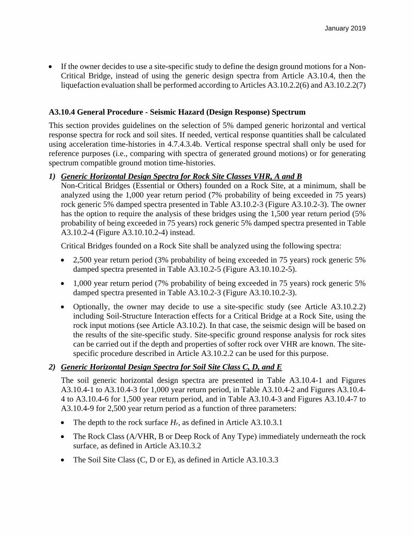
January 2019
If the owner decides to use a site-specific study to define the design ground motions for a Non-
Critical Bridge, instead of using the generic design spectra from Article A3.10.4, then the
liquefaction evaluation shall be performed according to Articles A3.10.2.2(6) and A3.10.2.2(7)
A3.10.4 General Procedure - Seismic Hazard (Design Response) Spectrum
This section provides guidelines on the selection of 5% damped generic horizontal and vertical
response spectra for rock and soil sites. If needed, vertical response quantities shall be calculated
using acceleration time-histories in 4.7.4.3.4b. Vertical response spectral shall only be used for
reference purposes (i.e., comparing with spectra of generated ground motions) or for generating
spectrum compatible ground motion time-histories.
1) Generic Horizontal Design Spectra for Rock Site Classes VHR, A and B
Non-Critical Bridges (Essential or Others) founded on a Rock Site, at a minimum, shall be
analyzed using the 1,000 year return period (7% probability of being exceeded in 75 years)
rock generic 5% damped spectra presented in Table A3.10.2-3 (Figure A3.10.2-3). The owner
has the option to require the analysis of these bridges using the 1,500 year return period (5%
probability of being exceeded in 75 years) rock generic 5% damped spectra presented in Table
A3.10.2-4 (Figure A3.10.10.2-4) instead.
Critical Bridges founded on a Rock Site shall be analyzed using the following spectra:
2,500 year return period (3% probability of being exceeded in 75 years) rock generic 5%
damped spectra presented in Table A3.10.2-5 (Figure A3.10.10.2-5).
1,000 year return period (7% probability of being exceeded in 75 years) rock generic 5%
damped spectra presented in Table A3.10.2-3 (Figure A3.10.10.2-3).
Optionally, the owner may decide to use a site-specific study (see Article A3.10.2.2)
including Soil-Structure Interaction effects for a Critical Bridge at a Rock Site, using the
rock input motions (see Article A3.10.2). In that case, the seismic design will be based on
the results of the site-specific study. Site-specific ground response analysis for rock sites
can be carried out if the depth and properties of softer rock over VHR are known. The site-
specific procedure described in Article A3.10.2.2 can be used for this purpose.
2) Generic Horizontal Design Spectra for Soil Site Class C, D, and E
The soil generic horizontal design spectra are presented in Table A3.10.4-1 and Figures
A3.10.4-1 to A3.10.4-3 for 1,000 year return period, in Table A3.10.4-2 and Figures A3.10.4-
4 to A3.10.4-6 for 1,500 year return period, and in Table A3.10.4-3 and Figures A3.10.4-7 to
A3.10.4-9 for 2,500 year return period as a function of three parameters:
The depth to the rock surface Hr, as defined in Article A3.10.3.1
The Rock Class (A/VHR, B or Deep Rock of Any Type) immediately underneath the rock
surface, as defined in Article A3.10.3.2
The Soil Site Class (C, D or E), as defined in Article A3.10.3.3

January 2019
Non-Critical Bridges (Essential or Others) founded on a Soil Site Class C, D or E, at a
minimum, shall be analyzed using the 1,000 year return period (7% probability of being
exceeded in 75 years) soil generic 5% damped horizontal spectra presented in Table A3.10.4-
1 and Figures A3.10.4-1 to A3.10.4-3. The owner has the option to require the analysis of these
bridges using the 1,500 year return period (5% probability of being exceeded in 75 years) soil
generic 5% damped horizontal spectra presented in Table A3.10.4-2 and Figures A3.10.4-4 to
A3.10.4-6, instead.
If insufficient data are available to classify a soil profile under a non-critical bridge, Soil Site
Class D shall be assumed. For periods less than 0.5 seconds, spectral accelerations for “Soil
Class D on top of Rock Class B, Hr ≤ 100 ft. shall be used. For periods larger than 0.5 seconds,
spectral accelerations for “Soil Class D on top of Deep Rock of Any Type” shall be used.
3) Generic Vertical Design Spectra for Rock Site Classes VHR, A and B
When necessary, Non-Critical Bridges (Essential or Others) founded on a Rock Site, at a
minimum, shall be analyzed using the 1,000 year return period (7% probability of being
exceeded in 75 years) rock vertical generic 5% damped spectra presented in Table A3.10.2-6.
The owner has the option to require the analysis of these bridges using the 1,500 year return
period (5% probability of being exceeded in 75 years) rock vertical generic 5% damped spectra
in Table A3.10.2-7, instead.
Unless the bridge owner decides that a site specific and/or soil-structure interaction study is
justified, Critical Bridges founded on a Rock Site, shall be analyzed using the following spectra
when necessary:
2,500 year return period (3% probability of being exceeded in 75 years) rock vertical
generic 5% damped spectra presented in Table A3.10.2-8.
1,000 year return period (7% probability of being exceeded in 75 years) rock vertical
generic 5% damped spectra presented in Table A3.10.2-6.
Optionally, the engineer may decide to conduct a site-specific study, see 1) above, including
Soil-Structure Interaction effects for a Critical Bridge at a Rock Site, using the rock input
motions listed see Article A3.10.2. In that case, the seismic design will be based on the results
of the site-specific study following the specifications of see Article A3.10.2.2.
4) Generic Vertical Design Spectra for Soil Site Class C, D, and E
The soil generic vertical design spectra for Non-critical and Critical Bridges are presented in
Tables A3.10.4-4 to A3.10.4-6 as a function of three parameters:
The depth to the rock surface (Hr), as defined in A3.10.3.1.
The Rock Class (A/VHR or B) immediately underneath the rock surface, as defined in
A3.10.3.2.
The Soil Site Class (C, D or E), as defined in A3.10.3.3.

January 2019
When necessary, non-critical Bridges (Essential or Others) founded on a Soil Site Class C, D
or E, at a minimum, shall be analyzed using the 1,000 year return period (7% probability of
being exceeded in 75 years) soil vertical generic 5% damped spectra presented in Table
A3.10.4-4 (Figures A3.10.4-10 to A3.10.4-12). The owner also has the option to require the
analysis of these bridges using the 1,500 year return period (5% probability of being exceeded
in 75 years) soil vertical generic 5% damped spectra presented in A3.10.4-5 (Figures A3.10.4-
13 to A3.10.4-15), instead.
A non-critical bridge founded on a Soil Site with a known depth to the rock surface, Hr ≤ 100
ft., shall be analyzed using the corresponding spectrum for Hr ≤ 100 ft., Soil Site Class C, D
or E, on top of Rock Class A/VHR or Rock Class B in Table A3.10.4-4 (Figures A3.10.4-10
or A3.10.4-11) for 1,000 year return period or in Table A3.10.4-5 (Figures A3.10.4-13 or
A3.10.4-14) for 1,500 year return period.
A non-critical bridge founded on a Soil Site with depth to the rock surface, rH > 100 ft.,
whether Hr is known or unknown, shall be analyzed using the corresponding spectrum for Soil
Site Class C, D or E, labeled “Soil on Top of Deep Rock of Any Type” in Table A3.10.4-4
(Figure A3.10.4-12) for 1,000 year return period or in Table A3.10.4-5 (Figure A3.10.4-15)
for 1,500 year return period.
If insufficient data are available to classify a soil profile under a non-critical bridge, Soil Site
Class D shall be assumed. For periods less than 0.5 seconds, spectral accelerations for Soil
Class D, Hr ≤ 100 ft. and soil on top of Rock Class B shall be used. For periods larger than 0.5
seconds, spectral accelerations for Soil Class D on top of Deep Rock of Any Type shall be
used.
Critical Bridges at Soil Sites shall be analyzed based on the results of a site-specific study
following the procedures specified in A3.10.2.2. The generic vertical spectra in Table A3.10.4-
5 (Figures A3.10.4-16 to A3.10.4-18) are used as references during the site-specific studies.
A3.10.5 Operational Categories and Seismic Performance Criteria within Downstate Zone
A3.10.5.1 Performance Criteria and Seismic Hazard
Bridges in the Downstate Zone shall be designed to meet the performance criteria outlined in Table
A3.10.5-1. This Table summarizes the relationship between bridge importance and performance
requirements. In all cases, collapse is not permitted. More rigorous analysis as recommended
herein and satisfying the minimum requirements of Article 4.7.4.3.1 shall be performed unless
otherwise required by the Bridge Owner. Seismic Performance criteria given herein address the
safety and functional performance of a bridge during and after an earthquake. They are defined in
terms of the bridge’s post seismic service level and the extent of damage. Bridges shall be
classified by the agency having jurisdiction, as “critical”, “essential” or “other” meeting the
following requirements:

January 2019
Critical Bridge: A Critical Bridge must provide immediate access after the lower level
(functional) event and limited access after the upper level (safety) event and continue to function
as a part of the lifeline, social/survival network and serve as an important link for civil defense,
police, fire department and/or public health agencies to respond to a disaster situation after the
event, providing a continuous route. Any bridge on a critical route shall be classified as critical if
there is no readily accessible detour, and shall at a minimum be classified as essential if there is
such a detour.
Any bridge that crosses a critical route whose collapse would block the critical route shall at a
minimum be classified as essential if there is no readily accessible detour for the critical route.
However, the bridge owner may classify such bridges as critical with the concurrence of the DCES.
The designated detour for the critical route shall also be treated as a critical route.
It is expected that relatively few bridges will be classified as critical. Critical bridges would
generally be limited to those on life safety routes in an urban area or on the approaches to an urban
area. Critical Bridges would also be located on routes to a defense facility that has limited access.
Bridges on limited access highways in rural areas would generally not be classified as critical
unless they are major structures. The designation of a bridge as critical is at the discretion of the
Regional Director/Bridge Owner and it is to be documented in the Design Report and included in
the Site Data Package.
Critical bridges shall be analyzed for two earthquake hazard design levels: a lower level event
(functional evaluation/design level) having a 7% probability of being exceeded in 75 years (1,000
year return period), and an upper level event (safety evaluation/design level) having a 3%
probability of being exceeded in 75 years (2,500 year return period).
A multimode spectral analysis or time history analysis must be used to establish vulnerability for
both events. The seismic analysis for the upper level event must be confirmed by either a
multimodal spectral analysis augmented by non-linear static (pushover) analysis, or by nonlinear
time history analysis. In the case of long-span bridges, the effects of spatial variation on the seismic
ground motions must also be considered in accordance to the requirements of Article 4.7.4.3.4b.
For Critical bridges at Soil Sites (see Article A3.10.3), site-specific soil effects and, if necessary,
soil-structure interaction must be considered. The required site-specific soils study shall comply
with Article A3.10.2.2.
For Critical bridges at Rock Sites (see Article A3.10.3), the generic spectra specified in section (1)
of Article A3.10.4 may be used for design; alternatively, the engineers shall have the option of
conducting a site-specific study including Soil-Structure Interaction effects, using the rock input
motions according to Article A3.10.2.2.
Critical Bridges shall survive the upper level event (2,500 year return period) with repairable
damage (see definition of damage levels in Article A3.10.5.2). Traffic access following this event
may be limited; within 48 hours for emergency/defense vehicles and within months for general
traffic. After the lower level event (1,000 year return period), the bridge shall suffer no damage to
primary structural elements and minimal damage to other components (see definition of damage
levels in Article A3.10.5.2). Access after this event shall be immediate to all traffic with an
allowance of a few hours for inspection.

January 2019
Essential Bridge: An Essential Bridge must provide at least limited access after the lower level
event and serve as an important link for civil defense, police, fire department and/or public
disaster situation after the event, providing a continuous route. A bridge that crosses an essential
route whose collapse would block the essential route shall also be classified as essential, if there
is no readily accessible detour for the essential route. The designated detour for the essential
route shall also be treated as an essential route.
Essential bridges should include those on interstate highways and others of importance as
designated by the Regional Director/Bridge Owner. The designation of a bridge as critical is to be
documented in the design report and included in the Site Data Package.
Essential bridges shall survive the design event with repairable damage (see definition of damage
levels in Article A3.10.5.2). Access following the seismic event may be limited: one or two lanes
shall be available within 72 hours for emergency vehicles, and full service within months.
Other Bridges: Other bridges are those not classified as Critical or Essential. Bridges classified
as Other may suffer significant damage (see definition of damage levels in Article A3.10.5.2)
although collapse shall not occur. Extended closures are acceptable.
Non-Critical Bridges: Essential and Other bridges (also labeled together Non-critical Bridges),
at a minimum, shall be analyzed for a single earthquake hazard design level event having a 7%
probability of being exceeded in 75 years (1,000 year return period). The owner has the option to
use a single earthquake hazard design level event having a 5% probability of being exceeded in 75
years (1,500 year return period) instead.
The seismic ground motions specified in these guidelines are defined in terms of generic design
spectra described in Article A3.10.4. For a Rock Site, the generic design spectra are specified in
section (1) of Article A3.10.4. For a Soil Site, the generic design spectra are specified in section
(2) of Article A3.10.4. If the Essential and Other bridge is on a Soil Site classified as Soil Class C,
D, or E (see Article A3.10.3.3), the Engineer shall have the option of conducting a site specific
study accounting for the local subsurface conditions, to produce site-specific acceleration ground
surface spectra and corresponding time histories, for use in the design instead of the generic
spectra. A site-specific study accounting for the local subsurface site conditions shall be required
for a Soil Site classified as Soil Class F (see Article A3.10.3.3). For an Essential bridge at a Rock
Site, the Engineer shall have the option of conducting a site-specific study including the effects of
Soil-Structure Interaction. Any required or optional site-specific study at a Soil or Rock Site shall
comply with Article A3.10.2.2. In the case of long-span bridges, the effects of spatial variation on
the seismic ground motions must be considered in accordance with Articles A3.10.2 and A4.7.3b.
A3.10.5.2 Damage Levels – Definitions
Bridge component detailing or retrofit shall be such that the damage caused by an earthquake
would be in a controlled pattern in order to allow for a desired post event service level.
Minimal Damage: The Bridge should essentially behave elastically during the earthquake,
although minor inelastic response could take place. Post-earthquake damage should be limited
to narrow flexural cracking in concrete and masonry elements. There should be no permanent
deformations to structural members. Only minor damage or permanent deformations to non-
structural members should take place.

January 2019
Repairable Damage: The extent of damage should be limited so that the structure can be
restored to its pre-earthquake condition without replacement of structural members. Inelastic
response may occur resulting in: concrete cracking, minor cover spalling and reinforcement
yielding; minor yielding of structural steel members; some damage to secondary members and
non-structural components; some damage to masonry. Repair should not require complete
closure of the bridge. Permanent offsets should be small and there should be no collapse.
Significant Damage: There should be no collapse, but permanent offsets may occur. Extensive
cracking, major spalling of concrete and reinforcement yielding, cracking of deck slab at the
shear studs, may force closure for repair. Similar consequences could result from yielding or
local buckling of steel members. There could be yielding of member connections, fracture of
limited number of bolts/rivets, serious damage to secondary structural members and non-
structural components, as well as to masonry. In sites with significant ground lateral spreading
due to liquefaction, large inelastic deformations might be induced to piles. Liquefaction could
also result in excessive differential settlements. Partial or complete replacement may be
required in some cases.
A3.10.6 Seismic Performance Zones
Each bridge shall be assigned to one of the three Seismic Performance Zones (2, 3 or 4),
determined by the One Second Period Spectral Acceleration, SD1, of the horizontal design
spectrum, in accordance with Table A3.10.6-1 below (Seismic Performance Zone 1 is not
applicable to Downstate Zone).
Table A3.10.6-1 Downstate Seismic Performance Zones
Acceleration Coefficient, 1DS Seismic Performance Zone
Seismic Performance Zone 1 Not applicable to NYC
1DS 0.30g 2
0.30g < 1DS 0.50g 3
0.50g < 1DS 4
The One Second Period Acceleration SD1 shall be obtained as the spectral acceleration at the period
T = 1.0 second. The horizontal design spectra of Critical Bridges shall be obtained from site-
specific study, except for all rock sites (see Article A3.10.3.2) where site specific study is optional.
The horizontal design spectra of Non-Critical Bridges may use the generic ones specified in Article
A3.10.4 depending on the site class.
A3.10.7 Seismic Rehabilitation of Bridges
As in the case of any rehabilitation project, judgment should be exercised in assessing options and
costs of seismic retrofit measures, and to incorporate into the rehabilitation plans those retrofit
measures deemed warranted for eliminating or mitigating such seismic vulnerabilities. Seismic
rehabilitation in the downstate region shall be based on applicable provisions of NYSDOT LRFD
Bridge Design Specifications.

September 2018
Table A3.10.2-1
Very Hard Rock-VHR - Horizontal Uniform Hazard Spectra for the Downstate Zone
Spectral Acceleration (g)
Period (sec) 1,000 year 1,500 year 2,500 year
0.01 9.98E-02 1.40E-01 2.02E-01
0.04 2.33E-01 3.36E-01 5.27E-01
0.1 1.87E-01 2.60E-01 3.64E-01
0.2 1.16E-01 1.58E-01 2.31E-01
0.5 4.47E-02 6.21E-02 9.15E-02
1 2.16E-02 2.98E-02 4.35E-02
2 1.13E-02 1.55E-02 2.24E-02
4 4.13E-03 5.90E-03 9.05E-03
5 2.94E-03 4.27E-03 6.92E-03
8 1.37E-03 2.01E-03 3.23E-03
10 1.05E-03 1.54E-03 2.49E-03

September 2018
Table A3.10.2-2
Very Hard Rock-VHR - Vertical Uniform Hazard Spectra for the Downstate Zone.
Spectral Acceleration (g)
Period (sec) 1,000 year 1,500 year 2,500 year
0.01 7.76E-02 1.09E-01 1.58E-01
0.04 1.75E-01 2.52E-01 3.95E-01
0.1 1.25E-01 1.74E-01 2.44E-01
0.2 7.77E-02 1.06E-01 1.55E-01
0.5 3.00E-02 4.16E-02 6.13E-02
1 1.45E-02 2.00E-02 2.91E-02
2 7.60E-03 1.04E-02 1.50E-02
4 2.76E-03 3.95E-03 6.06E-03
5 1.97E-03 2.86E-03 4.64E-03
8 9.21E-04 1.35E-03 2.16E-03
10 6.99E-04 1.03E-03 1.67E-03

September 2018
Table A3.10.2-3
1,000 year Return Period – Downstate Zone – Horizontal Design Spectra
Spectral Acceleration (g)
Period (sec) Very Hard Rock-VHR Rock Class A Rock Class B
0.01 9.98E-02 1.15E-01 1.65E-01
0.04 2.33E-01 2.68E-01 3.84E-01
0.1 1.87E-01 2.15E-01 3.09E-01
0.2 1.16E-01 1.33E-01 1.91E-01
0.5 4.47E-02 5.15E-02 7.35E-02
1 2.16E-02 2.49E-02 3.57E-02
2 1.13E-02 1.30E-02 1.87E-02
4 4.13E-03 4.75E-03 6.82E-03
5 2.94E-03 3.38E-03 4.86E-03
8 1.37E-03 1.58E-03 2.26E-03
10 1.05E-03 1.20E-03 1.72E-03

September 2018
Table A3.10.2-4
1,500 year Return Period – Downstate Zone – Horizontal Design Spectra
Spectral Acceleration (g)
Period (sec) Very Hard Rock-VHR Rock Class A Rock Class B
0.01 1.40E-01 1.61E-01 2.31E-01
0.04 3.36E-01 3.86E-01 5.54E-01
0.1 2.60E-01 2.99E-01 4.29E-01
0.2 1.58E-01 1.82E-01 2.61E-01
0.5 6.21E-02 7.14E-02 1.02E-01
1 2.98E-02 3.43E-02 4.92E-02
2 1.55E-02 1.78E-02 2.56E-02
4 5.90E-03 6.79E-03 9.74E-03
5 4.27E-03 4.91E-03 7.05E-03
8 2.01E-03 2.31E-03 3.32E-03
10 1.54E-03 1.77E-03 2.54E-03
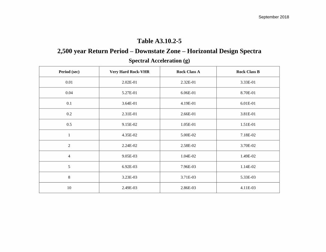
September 2018
Table A3.10.2-5
2,500 year Return Period – Downstate Zone – Horizontal Design Spectra
Spectral Acceleration (g)
Period (sec) Very Hard Rock-VHR Rock Class A Rock Class B
0.01 2.02E-01 2.32E-01 3.33E-01
0.04 5.27E-01 6.06E-01 8.70E-01
0.1 3.64E-01 4.19E-01 6.01E-01
0.2 2.31E-01 2.66E-01 3.81E-01
0.5 9.15E-02 1.05E-01 1.51E-01
1 4.35E-02 5.00E-02 7.18E-02
2 2.24E-02 2.58E-02 3.70E-02
4 9.05E-03 1.04E-02 1.49E-02
5 6.92E-03 7.96E-03 1.14E-02
8 3.23E-03 3.71E-03 5.33E-03
10 2.49E-03 2.86E-03 4.11E-03
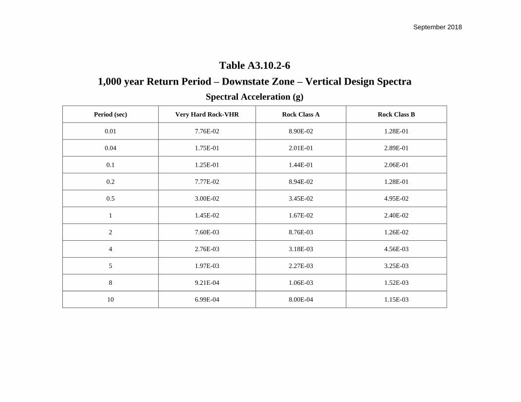
September 2018
Table A3.10.2-6
1,000 year Return Period – Downstate Zone – Vertical Design Spectra
Spectral Acceleration (g)
Period (sec) Very Hard Rock-VHR Rock Class A Rock Class B
0.01 7.76E-02 8.90E-02 1.28E-01
0.04 1.75E-01 2.01E-01 2.89E-01
0.1 1.25E-01 1.44E-01 2.06E-01
0.2 7.77E-02 8.94E-02 1.28E-01
0.5 3.00E-02 3.45E-02 4.95E-02
1 1.45E-02 1.67E-02 2.40E-02
2 7.60E-03 8.76E-03 1.26E-02
4 2.76E-03 3.18E-03 4.56E-03
5 1.97E-03 2.27E-03 3.25E-03
8 9.21E-04 1.06E-03 1.52E-03
10 6.99E-04 8.00E-04 1.15E-03

September 2018
Table A3.10.2-7
1,500 year Return Period – Downstate Zone – Vertical Design Spectra
Spectral Acceleration (g)
Period (sec) Very Hard Rock-VHR Rock Class A Rock Class B
0.01 1.09E-01 1.25E-01 1.80E-01
0.04 2.52E-01 2.90E-01 4.16E-01
0.1 1.74E-01 2.00E-01 2.87E-01
0.2 1.06E-01 1.22E-01 1.75E-01
0.5 4.16E-02 4.78E-02 6.86E-02
1 2.00E-02 2.30E-02 3.30E-02
2 1.04E-02 1.20E-02 1.72E-02
4 3.95E-03 4.54E-03 6.52E-03
5 2.86E-03 3.29E-03 4.72E-03
8 1.35E-03 1.55E-03 2.23E-03
10 1.03E-03 1.18E-03 1.70E-03

September 2018
Table A3.10.2-8
2,500 year Return Period – Downstate Zone – Vertical Design Spectra
Spectral Acceleration (g)
Period (sec) Very Hard Rock-VHR Rock Class A Rock Class B
0.01 1.58E-01 1.82E-01 2.61E-01
0.04 3.95E-01 4.54E-01 6.52E-01
0.1 2.44E-01 2.81E-01 4.03E-01
0.2 1.55E-01 1.78E-01 2.56E-01
0.5 6.13E-02 7.05E-02 1.01E-01
1 2.91E-02 3.35E-02 4.80E-02
2 1.50E-02 1.73E-02 2.48E-02
4 6.06E-03 6.97E-03 1.00E-02
5 4.64E-03 5.34E-03 7.66E-03
8 2.16E-03 2.48E-03 3.56E-03
10 1.67E-03 1.92E-03 2.76E-03

September 2018
Table A3.10.2.2-1
1,000 yr. Return Period - Downstate Zone Soil Sites V/H Design Ratio for Site-Specific Studies
Soil on Top of Rock Class A /VHR - Hr<100 ft.
Period(sec) Soil Class C Soil Class D Soil Class E PGA 0.65 0.65 0.90
0.02 0.80 0.80 1.10
0.04 0.80 0.80 1.10
0.10 0.60 0.60 0.70
0.20 0.50 0.50 0.50
0.50 0.50 0.50 0.50
1.00 0.50 0.50 0.50
2.00 0.50 0.50 0.50
4.00 0.50 0.50 0.50
Soil on Top of Rock Class B - Hr<100 ft.
Period(sec) Soil Class C Soil Class D Soil Class E PGA 0.65 0.65 0.90
0.02 1.05 1.05 1.30
0.04 1.05 1.05 1.30
0.10 0.70 0.70 0.80
0.20 0.50 0.50 0.50
0.50 0.50 0.50 0.50
1.00 0.50 0.50 0.50
2.00 0.50 0.50 0.50
4.00 0.50 0.50 0.50
Soil on Top of Deep Rock of Any Type - Hr>100 ft.
Period(sec) Soil Class C Soil Class D Soil Class E PGA 0.73 0.80 1.20
0.02 1.15 1.30 1.75
0.04 1.15 1.30 1.75
0.10 0.75 0.80 1.00
0.20 0.60 0.60 0.75
0.50 0.50 0.50 0.50
1.00 0.50 0.50 0.50
2.00 0.50 0.50 0.50
4.00 0.50 0.50 0.50

September 2018
Table A3.10.2.2-2
1,500 yr. Return Period - Downstate Zone Soil Sites V/H Design Ratio for Site-Specific Studies
Period (sec) Soil Class C Soil Class D Soil Class E
PGA 0.65 0.65 0.90
0.02 0.80 0.80 1.10
0.04 0.80 0.80 1.10
0.10 0.60 0.60 0.70
0.20 0.50 0.50 0.50
0.50 0.50 0.50 0.50
1.00 0.50 0.50 0.50
2.00 0.50 0.50 0.50
4.00 0.50 0.50 0.50
Period (sec) Soil Class C Soil Class D Soil Class E
PGA 0.65 0.65 0.90
0.02 1.05 1.05 1.30
0.04 1.05 1.05 1.30
0.10 0.70 0.70 0.80
0.20 0.50 0.50 0.50
0.50 0.50 0.50 0.50
1.00 0.50 0.50 0.50
2.00 0.50 0.50 0.50
4.00 0.50 0.50 0.50
Period (sec) Soil Class C Soil Class D Soil Class E
PGA 0.80 0.80 1.20
0.02 1.30 1.30 1.75
0.04 1.30 1.30 1.75
0.10 0.80 0.80 1.00
0.20 0.60 0.60 0.75
0.50 0.50 0.50 0.50
1.00 0.50 0.50 0.50
2.00 0.50 0.50 0.50
4.00 0.50 0.50 0.50
1500 yr Return Period - NYC Soil Sites
V/H Design Ratio for Site-Specific Studies (Section 9)
Soil on Top of Rock Class A / VHR - Hr<100 ft
Soil on Top of Rock Class B - Hr<100 ft
Soil on Top of Deep Rock of Any Type - Hr>100 ft
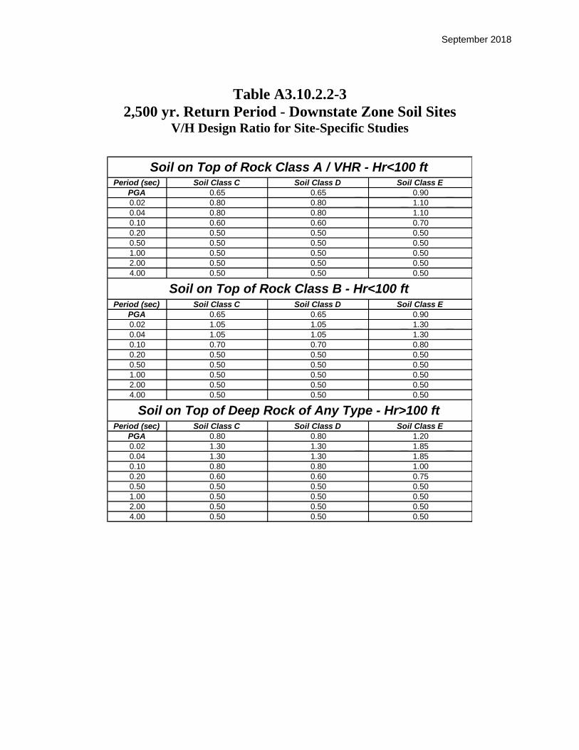
September 2018
Table A3.10.2.2-3
2,500 yr. Return Period - Downstate Zone Soil Sites V/H Design Ratio for Site-Specific Studies
Period (sec) Soil Class C Soil Class D Soil Class E
PGA 0.65 0.65 0.90
0.02 0.80 0.80 1.10
0.04 0.80 0.80 1.10
0.10 0.60 0.60 0.70
0.20 0.50 0.50 0.50
0.50 0.50 0.50 0.50
1.00 0.50 0.50 0.50
2.00 0.50 0.50 0.50
4.00 0.50 0.50 0.50
Period (sec) Soil Class C Soil Class D Soil Class E
PGA 0.65 0.65 0.90
0.02 1.05 1.05 1.30
0.04 1.05 1.05 1.30
0.10 0.70 0.70 0.80
0.20 0.50 0.50 0.50
0.50 0.50 0.50 0.50
1.00 0.50 0.50 0.50
2.00 0.50 0.50 0.50
4.00 0.50 0.50 0.50
Period (sec) Soil Class C Soil Class D Soil Class E
PGA 0.80 0.80 1.20
0.02 1.30 1.30 1.85
0.04 1.30 1.30 1.85
0.10 0.80 0.80 1.00
0.20 0.60 0.60 0.75
0.50 0.50 0.50 0.50
1.00 0.50 0.50 0.50
2.00 0.50 0.50 0.50
4.00 0.50 0.50 0.50
2500 yr Return Period - NYC Soil Sites
V/H Design Ratio for Site-Specific Studies (Section 9)
Soil on Top of Rock Class A / VHR - Hr<100 ft
Soil on Top of Rock Class B - Hr<100 ft
Soil on Top of Deep Rock of Any Type - Hr>100 ft

September 2018
A3.10.3.1-1: Rock Classification
Rock Sites
Rock
Class Name
Average
Shear-Wave Velocity
20Vs ft./sec.
Remarks
VHR Very Hard Rock 000,9V 20 s Very Hard Rock shall be established
only by measured .Vs
A Hard Rock 000,9V5,000 20 s Rock Class A shall be established only
by measured .Vs
B
Rock
(or Cemented or Very
Dense Soil) 000,5V2,500 20 s
Assignment of Rock Class B for
cemented or very dense soil shall be
based on shear wave velocity
measurements. Rock Class B may be
assigned for moderately fractured and
weathered rock.
Rock Under Soil Sites
Rock
Class Name
Average
Shear-Wave Velocity
20Vs ft/sec.
Remarks
A / VHR Hard Rock 000,5V 20 s Rock Class A / VHR shall be
established only by measured .Vs
B
Rock
(or Cemented or Very
Dense Soil) 000,5V2,500 20 s
Assignment of Rock Class B for
cemented or very dense soil shall be
based on shear wave velocity
measurements. Rock Class B may be
assigned for moderately fractured and
weathered rock.
Notes:
1) The Rock Class shall be established through properly substantiated geotechnical data.
2) For the definition of 20Vs see Article A3.10.3.1.
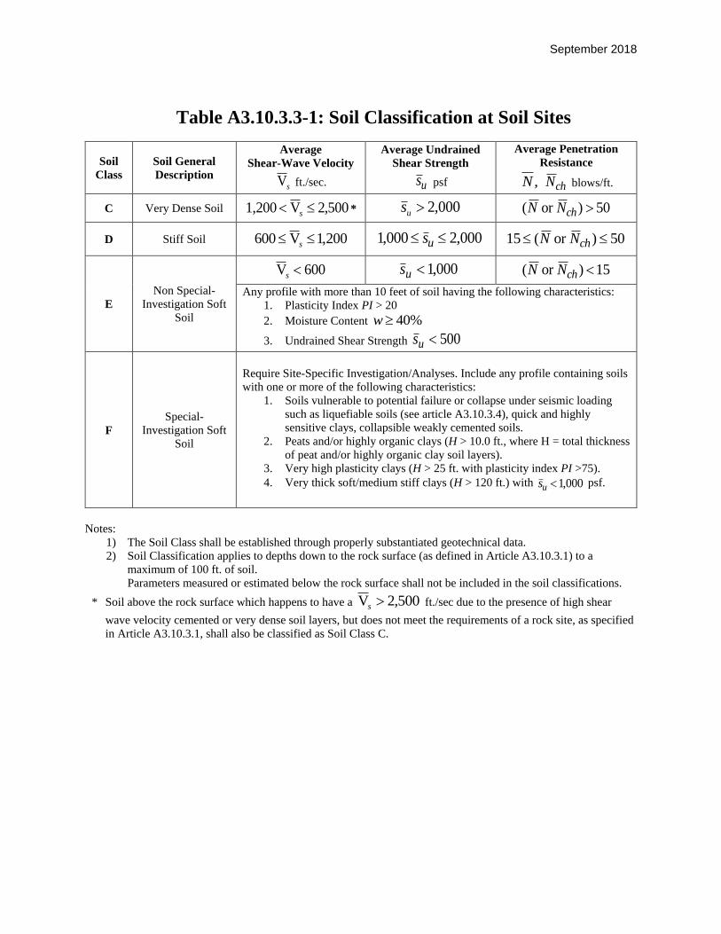
September 2018
Table A3.10.3.3-1: Soil Classification at Soil Sites
Soil
Class
Soil General
Description
Average
Shear-Wave Velocity
sV ft./sec.
Average Undrained
Shear Strength
us psf
Average Penetration
Resistance
,N chN blows/ft.
C Very Dense Soil 500,2V1,200 s * 000,2us 50)or ( chNN
D Stiff Soil 200,1V006 s 000,2000,1 us 50)or (15 chNN
E
Non Special-
Investigation Soft
Soil
600V s 000,1us 15)or ( chNN
Any profile with more than 10 feet of soil having the following characteristics:
1. Plasticity Index PI > 20
2. Moisture Content %40w
3. Undrained Shear Strength 500us
F
Special-
Investigation Soft
Soil
Require Site-Specific Investigation/Analyses. Include any profile containing soils
with one or more of the following characteristics:
1. Soils vulnerable to potential failure or collapse under seismic loading
such as liquefiable soils (see article A3.10.3.4), quick and highly
sensitive clays, collapsible weakly cemented soils.
2. Peats and/or highly organic clays (H > 10.0 ft., where H = total thickness
of peat and/or highly organic clay soil layers).
3. Very high plasticity clays (H > 25 ft. with plasticity index PI >75).
4. Very thick soft/medium stiff clays (H > 120 ft.) with 000,1us psf.
Notes:
1) The Soil Class shall be established through properly substantiated geotechnical data.
2) Soil Classification applies to depths down to the rock surface (as defined in Article A3.10.3.1) to a
maximum of 100 ft. of soil.
Parameters measured or estimated below the rock surface shall not be included in the soil classifications.
* Soil above the rock surface which happens to have a 500,2V s ft./sec due to the presence of high shear
wave velocity cemented or very dense soil layers, but does not meet the requirements of a rock site, as specified
in Article A3.10.3.1, shall also be classified as Soil Class C.
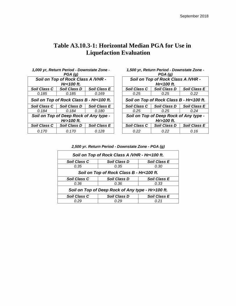
September 2018
Table A3.10.3-1: Horizontal Median PGA for Use in
Liquefaction Evaluation
1,000 yr, Return Period - Downstate Zone - PGA (g)
1,500 yr, Return Period - Downstate Zone -
PGA (g)
Soil on Top of Rock Class A /VHR - Hr<100 ft.
Soil on Top of Rock Class A /VHR -
Hr<100 ft. Soil Class C Soil Class D Soil Class E Soil Class C Soil Class D Soil Class E
0.185 0.185 0.169 0.25 0.25 0.22
Soil on Top of Rock Class B - Hr<100 ft. Soil on Top of Rock Class B - Hr<100 ft.
Soil Class C Soil Class D Soil Class E Soil Class C Soil Class D Soil Class E
0.184 0.184 0.180 0.25 0.25 0.24
Soil on Top of Deep Rock of Any type - Hr>100 ft.
Soil on Top of Deep Rock of Any type -
Hr>100 ft. Soil Class C Soil Class D Soil Class E Soil Class C Soil Class D Soil Class E
0.170 0.170 0.128 0.22 0.22 0.16
2,500 yr. Return Period - Downstate Zone - PGA (g)
Soil on Top of Rock Class A /VHR - Hr<100 ft.
Soil Class C Soil Class D Soil Class E
0.35 0.35 0.30
Soil on Top of Rock Class B - Hr<100 ft.
Soil Class C Soil Class D Soil Class E
0.36 0.36 0.33
Soil on Top of Deep Rock of Any type - Hr>100 ft.
Soil Class C Soil Class D Soil Class E
0.29 0.29 0.21

September 2018
Table A3.10.3-2
Seismic Hazard and Time Histories for Rock
to be used in Site-Specific Studies of Downstate Zone
Importance Category
Seismic Hazard Return Period (Probability of Exceedance)
Site–Specific Study Mandatory
or Optional
Horizontal Rock Spectra
and Time Histories
Critical Bridges
2,500-year (3% in 75 years.)
Mandatory unless waived by the owner
Very Hard Rock (VHR): Spectra and Time Histories
described in Tables A3.10.2-1 and A.3.10.2-2
Rock Class A: Multiply Very Hard Rock Spectra and Time Histories by a Factor
1.15 (Tables A3.10.2-3 to A3.10.2-8)
Rock Class B: Multiply Very Hard Rock Spectra and Time Histories by a Factor
1.65 (Tables A3.10.2-3 to A3.10.2-8)
1,000-year (7% in 75 years.)
Mandatory unless waived by the owner
Essential and
Other Bridges
1,000-year (7% in 75 yrs)
or
1,500-year (5% in 75 yrs)
(optional)
Mandatory for Soil Site Class F and for
Long-Span Bridges (Spatial Variation)
Optional for Other Rock and Soil Site Classes
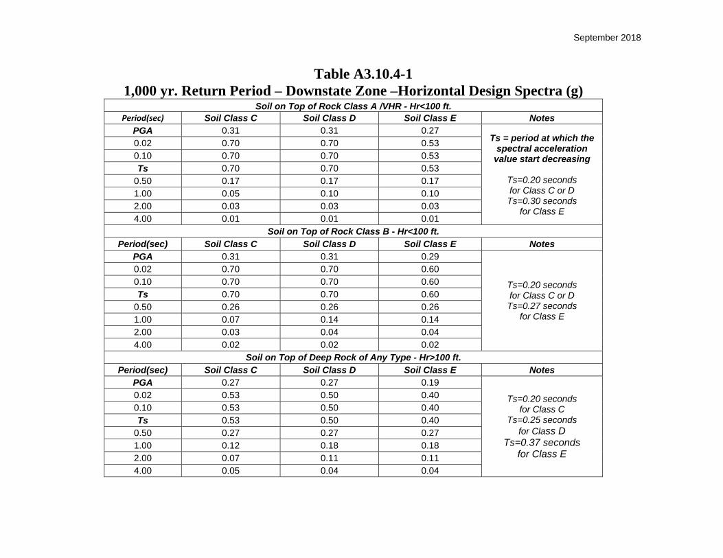
September 2018
Table A3.10.4-1
1,000 yr. Return Period – Downstate Zone –Horizontal Design Spectra (g) Soil on Top of Rock Class A /VHR - Hr<100 ft.
Period(sec) Soil Class C Soil Class D Soil Class E Notes
PGA 0.31 0.31 0.27 Ts = period at which the
spectral acceleration value start decreasing
Ts=0.20 seconds for Class C or D Ts=0.30 seconds
for Class E
0.02 0.70 0.70 0.53
0.10 0.70 0.70 0.53
Ts 0.70 0.70 0.53
0.50 0.17 0.17 0.17
1.00 0.05 0.10 0.10
2.00 0.03 0.03 0.03
4.00 0.01 0.01 0.01
Soil on Top of Rock Class B - Hr<100 ft.
Period(sec) Soil Class C Soil Class D Soil Class E Notes
PGA 0.31 0.31 0.29
Ts=0.20 seconds for Class C or D Ts=0.27 seconds
for Class E
0.02 0.70 0.70 0.60
0.10 0.70 0.70 0.60
Ts 0.70 0.70 0.60
0.50 0.26 0.26 0.26
1.00 0.07 0.14 0.14
2.00 0.03 0.04 0.04
4.00 0.02 0.02 0.02
Soil on Top of Deep Rock of Any Type - Hr>100 ft.
Period(sec) Soil Class C Soil Class D Soil Class E Notes
PGA 0.27 0.27 0.19
Ts=0.20 seconds for Class C
Ts=0.25 seconds
for Class D Ts=0.37 seconds
for Class E
0.02 0.53 0.50 0.40
0.10 0.53 0.50 0.40
Ts 0.53 0.50 0.40
0.50 0.27 0.27 0.27
1.00 0.12 0.18 0.18
2.00 0.07 0.11 0.11
4.00 0.05 0.04 0.04

September 2018
Table A3.10.4-2
1,500 yr. Return Period – NYC Soil Sites –Horizontal Design Spectra (g)
Period (sec) Soil Class C Soil Class D Soil Class E Notes PGA 0.42 0.42 0.34 Ts= period at which the 0.02 0.95 0.95 0.70 spectral acceleration 0.10 0.95 0.95 0.70 values start decreasing Ts 0.95 0.95 0.70
0.50 0.23 0.23 0.23 Ts= 0.20 seconds
1.00 0.06 0.13 0.13 for Class C or D 2.00 0.04 0.04 0.04 Ts= 0.30 seconds
4.00 0.01 0.01 0.01 for Class E
Period (sec) Soil Class C Soil Class D Soil Class E Notes PGA 0.42 0.42 0.38 0.02 0.95 0.95 0.82 Ts= 0.20 seconds
0.10 0.95 0.95 0.82 for Class C or D Ts 0.95 0.95 0.82 Ts= 0.27 seconds
0.50 0.35 0.35 0.35 for Class E 1.00 0.08 0.19 0.19 2.00 0.04 0.06 0.06 4.00 0.02 0.02 0.02
Period (sec) Soil Class C Soil Class D Soil Class E Notes PGA 0.34 0.34 0.24 0.02 0.72 0.66 0.51 Ts= 0.20 seconds
0.10 0.72 0.66 0.51 for Class C Ts 0.72 0.66 0.51 Ts= 0.25 seconds
0.50 0.35 0.35 0.35 for Class D 1.00 0.16 0.24 0.24 Ts= 0.37 seconds
2.00 0.09 0.15 0.15 for Class E 4.00 0.06 0.06 0.06
Soil on Top of Rock Class A / VHR - Hr<100 ft.
Soil on Top of Rock Class B - Hr<100 ft.
Soil on Top of Deep Rock of Any Type - Hr>100 ft.

September 2018
Table A3.10.4-3
2,500 yr. Return Period – Downstate Zone –Horizontal Design Spectra (g)
Period (sec) Soil Class C Soil Class D Soil Class E Notes PGA 0.58 0.58 0.46 Ts= period at which the 0.02 1.34 1.34 0.97 spectral acceleration 0.10 1.34 1.34 0.97 values start decreasing Ts 1.34 1.34 0.97
0.50 0.33 0.33 0.33 Ts= 0.20 seconds
1.00 0.08 0.18 0.18 for Class C or D 2.00 0.04 0.06 0.06 Ts= 0.31 seconds
4.00 0.02 0.02 0.02 for Class E
Period (sec) Soil Class C Soil Class D Soil Class E Notes PGA 0.58 0.58 0.51 0.02 1.34 1.34 1.15 Ts= 0.20 seconds
0.10 1.34 1.34 1.15 for Class C or D Ts 1.34 1.34 1.15 Ts= 0.27 seconds
0.50 0.48 0.48 0.48 for Class E 1.00 0.11 0.27 0.27 2.00 0.06 0.10 0.10 4.00 0.02 0.03 0.03
Period (sec) Soil Class C Soil Class D Soil Class E Notes PGA 0.46 0.46 0.31 0.02 0.98 0.89 0.67 Ts= 0.25 seconds
0.10 0.98 0.89 0.67 for Class C Ts 0.98 0.89 0.67 Ts= 0.26 seconds
0.50 0.49 0.49 0.49 for Class D 1.00 0.24 0.34 0.34 Ts= 0.39 seconds
2.00 0.14 0.23 0.23 for Class E 4.00 0.06 0.09 0.09
Soil on Top of Rock Class A / VHR - Hr<100 ft.
Soil on Top of Rock Class B - Hr<100 ft.
Soil on Top of Deep Rock of Any Type - Hr>100 ft.

September 2018
Table A3.10.4-4
1,000 yr Return Period – Downstate Zone Soil Sites Vertical Design Spectra (g)
Soil on Top of Rock Class A /VHR - Hr<100 ft.
Period(sec) Soil Class C Soil Class D Soil Class E
PGA 0.24 0.24 0.24
0.02 0.58 0.58 0.58
0.04 0.58 0.58 0.58
0.10 0.43 0.43 0.43
0.20 0.28 0.28 0.28
0.50 0.12 0.12 0.12
1.00 0.03 0.04 0.04
2.00 0.02 0.02 0.02
4.00 0.01 0.01 0.01
Soil on Top of Rock Class B - Hr<100 ft.
Period(sec) Soil Class C Soil Class D Soil Class E
PGA 0.29 0.30 0.30
0.02 0.76 0.79 0.79
0.04 0.76 0.79 0.79
0.10 0.56 0.59 0.59
0.20 0.36 0.36 0.36
0.50 0.15 0.15 0.15
1.00 0.05 0.07 0.07
2.00 0.02 0.02 0.02
4.00 0.01 0.01 0.01
Soil on Top of Deep Rock of Any Type - Hr>100 ft.
Period(sec) Soil Class C Soil Class D Soil Class E
PGA 0.30 0.31 0.31
0.02 0.74 0.79 0.79
0.04 0.74 0.79 0.79
0.10 0.56 0.60 0.60
0.20 0.35 0.35 0.35
0.50 0.15 0.15 0.15
1.00 0.08 0.10 0.10
2.00 0.04 0.06 0.06
4.00 0.02 0.02 0.02

September 2018
Table A3.10.4-5
1,500 yr. Return Period – Downstate Zone Soil Sites Vertical Design Spectra (g)
Period (sec) Soil Class C Soil Class D Soil Class E
PGA 0.30 0.30 0.30
0.02 0.75 0.75 0.75
0.04 0.75 0.75 0.75
0.10 0.55 0.55 0.55
0.20 0.35 0.35 0.35
0.50 0.15 0.15 0.15
1.00 0.04 0.06 0.06
2.00 0.02 0.02 0.02
4.00 0.01 0.01 0.01
Period (sec) Soil Class C Soil Class D Soil Class E
PGA 0.40 0.40 0.40
0.02 1.05 1.05 1.05
0.04 1.05 1.05 1.05
0.10 0.75 0.75 0.75
0.20 0.45 0.45 0.45
0.50 0.20 0.20 0.20
1.00 0.06 0.10 0.10
2.00 0.02 0.03 0.03
4.00 0.01 0.01 0.01
Period (sec) Soil Class C Soil Class D Soil Class E
PGA 0.40 0.40 0.40
0.02 1.00 1.00 1.00
0.04 1.00 1.00 1.00
0.10 0.75 0.75 0.75
0.20 0.45 0.45 0.45
0.50 0.21 0.21 0.21
1.00 0.10 0.13 0.13
2.00 0.05 0.08 0.08
4.00 0.03 0.03 0.03
1500 yr Return Period - NYC Soil Sites
Vertical Design Spectra (g)
Soil on Top of Rock Class A / VHR - Hr<100 ft
Soil on Top of Rock Class B - Hr<100 ft
Soil on Top of Deep Rock of Any Type - Hr>100 ft

September 2018
Table A3.10.4-6
2,500 yr Return Period – Downstate Zone Soil Sites Vertical Design Spectra (g)
Table A3.10.5-1
Period (sec) Soil Class C Soil Class D Soil Class E
PGA 0.40 0.40 0.40
0.02 1.05 1.05 1.05
0.04 1.05 1.05 1.05
0.10 0.75 0.75 0.75
0.20 0.45 0.45 0.45
0.50 0.18 0.18 0.18
1.00 0.06 0.10 0.10
2.00 0.02 0.03 0.03
4.00 0.01 0.01 0.01
Period (sec) Soil Class C Soil Class D Soil Class E
PGA 0.60 0.60 0.60
0.02 1.45 1.45 1.45
0.04 1.45 1.45 1.45
0.10 1.00 1.00 1.00
0.20 0.60 0.60 0.60
0.50 0.25 0.25 0.25
1.00 0.08 0.15 0.15
2.00 0.03 0.06 0.06
4.00 0.01 0.02 0.02
Period (sec) Soil Class C Soil Class D Soil Class E
PGA 0.55 0.55 0.55
0.02 1.30 1.30 1.30
0.04 1.30 1.30 1.30
0.10 0.90 0.90 0.90
0.20 0.60 0.60 0.60
0.50 0.35 0.35 0.35
1.00 0.14 0.20 0.20
2.00 0.07 0.12 0.12
4.00 0.03 0.05 0.05
2500 yr Return Period - NYC Soil Sites
Vertical Design Spectra (g)
Soil on Top of Rock Class A / VHR - Hr<100 ft
Soil on Top of Rock Class B - Hr<100 ft
Soil on Top of Deep Rock of Any Type - Hr>100 ft

September 2018
Performance Criteria and Seismic Hazard Level for Design and Evaluation of Bridges
Importance
Category
Seismic Hazard
Level
Return
Period Event Performance Criteria
Critical
Bridges
Upper Hazard
Level-Safety 2,500 years
3% in 75 years
Probability of Exceedance
No collapse, repairable damage, limited access for
emergency traffic within 48 hours, full service within
month(s).
Lower Hazard
Level-Functional 1,000 years
7% in 75 years
Probability of Exceedance
No collapse, no damage to primary structural elements,
minimal repairable damage to other components, full access
to normal traffic available immediately (allow a few hours
for inspection).
Essential
Bridges
Single Hazard
Level-Safety 1,000 years
or
1,500 years
(optional)
7% in 75 years
Probability of Exceedance
or
5% in 75 years
Probability of Exceedance
(optional)
No collapse, repairable damage, limited access for
emergency vehicles, one or two lanes available within 72
hours, full service within month(s).
Other
Bridges
Single Hazard
Level-Safety
No collapse, significant damage in visible and controlled
areas. Traffic interruption acceptable.
Critical
Bridges
A bridge that must provide immediate access after the lower level (functional) event and at least limited access after the upper level
(safety) event and continue to function as part of the lifeline, social/survival and serve as important link for civil defense, police, fire
department or/and public health agencies to respond to a disaster situation after the event, providing a continuous route. Any bridge on
a critical route shall be classified as critical if there is no readily accessible detour, and shall at a minimum be classified as essential if
there is such a detour. Any bridge that crosses a critical route, whose collapse would block the critical route, shall at a minimum be
classified as essential if there is no readily accessible detour for the critical route. The designated detour for the critical route shall
also be treated as a critical route.
Essential
Bridges
A bridge that must provide at least limited access after the single-level safety event and serve as important link for civil defense,
police, fire department or/and public health agencies to respond to a disaster situation after the event, providing a continuous route. A
bridge that crosses an essential route whose collapse would block the essential route shall also be classified as essential, if there is no
readily accessible detour for the essential route. The designated detour for the essential route shall also be treated as an essential route.
Other
Bridges A bridge not qualifying as critical or essential.

September 2018
a) Site Definition
b) Vs20 Definition
Figure A3.10.3.1-1. Downstate Zone Guidelines Rock and Soil Sites
Rock Outcrop
Soil
Rock
20ft
Rock Under Soil Site
Soil
Rock
20ft
Hr > 0.0 Ft
Hr = 0.0 Ft
Vs20 = Average Vs in 20 ft of Rock
Rock Outcrop
Soil
Rock
20ft
Rock Under Soil Site
Soil
Rock
20ft
Hr > 0.0 Ft
Hr = 0.0 Ft
Vs20 = Average Vs in 20 ft of Rock
Hr = Depth to Rock Surface
Soil
20ft Rock or Cemented or Very Dense Soil of Vs20 > 2500 ft/sec
Hr < Hr >
Ground Surface
Rock Surface Hr = Depth to Rock Surface
Soil
20ft Rock or Cemented or Very Dense Soil of Vs20 > 2500 ft/sec
Hr < Hr >
Hr < Hr >
Ground Surface
Rock Surface
10ft Soil Site 10ft Rock Site

September 2018
Figure A3.10.3.2-1. Downstate Zone Guidelines Option for Soil Site on Rock Class B
Followed Within 40 ft. by Rock Class A/VHR
V s in - situ measurements
< 40ft
Soil Rock Surface
20ft
20ft
2500 ft/sec < V s20 < 5000 ft/sec ( Rock Class B)
V s20 > 5000 ft/sec ( Rock Class A/VHR)
V s = ?
Rock V s Profile
Hr 15ft
Rock Class A/VHR Surface
V s in - situ measurements
< 40ft
Soil Rock Surface
20ft
20ft
2500 ft/sec < V s20 < 5000 ft/sec ( Rock Class B)
V s20 > 5000 ft/sec ( Rock Class A/VHR)
V s = ?
Rock V s Profile
Hr >10ft
Rock Class A/VHR Surface

September 2018
Figure A3.10.3.3-1. Downstate Zone Guidelines Soil Classification

January 2019
3.11 EARTH PRESSURE: EH, ES, LS, AND DD
3.11.6 Surcharge Loads: ES AND LS
3.11.6.4 Live Load Surcharge (LS)
Add the following at the end of this Article:
All retaining walls shall be designed for a live load surcharge with a minimum equivalent soil height of 2.0 ft., regardless of their
height or the distance to traffic.
C3.11.6.4 Add the following at the end of the commentary:
The minimum live load surcharge requirement for retaining walls is to account for loads experienced during construction.
January 2019
3.12 FORCE EFFECTS DUE TO SUPERIMPOSED
DEFORMATIONS: TU, TG, SH, CR, SE
3.12.2 Uniform Temperature
Delete Article 3.12.2 and replace it with the following:
The design thermal movement associated with uniform
temperature change shall be calculated using Procedure B for concrete deck bridges having concrete or steel girders and
Procedure A for all other bridge types.
January 2019
3.12 FORCE EFFECTS DUE TO SUPERIMPOSED
DEFORMATIONS: TU, TG, SH, CR, SE
3.12.2 Uniform Temperature
3.12.2.1 Temperature Range for Procedure A
Add the following after Table 3.12.2.1-1:
Areas of New York State designated by NYSDOT as Region 10 and
Region 11 shall be considered to have a Moderate Climate. All
other areas of the State shall be considered to have a Cold Climate.
3.12.2.2 Temperature Range for Procedure B
Add the following after Article 3.12.2.2:
For pile design of integral abutments, the setting temperature shall be the average of the maximum and minimum design
temperatures.

January 2019
3.14 VESSEL COLLISION: CV
3.14.1 General
Replace the third paragraph of Article 3.14.1 with the following:
For typical and essential bridges, the minimum design impact load
for substructure design shall be determined using an empty
hopper barge drifting at a velocity equal to the yearly mean current for the waterway location.
For critical bridges, the minimum design impact load for substructure design shall be determined using an empty hopper
barge drifting at a velocity equal to the design flood event (100
year flood event).
The design barge shall be a single 35.0 ft. x 195ft. barge, with an empty displacement of 200 ton, unless approved otherwise by the
Owner. For critical bridges, the minimum design impact load (drifting
empty barge) shall be combined with one-half of the predicted
long-term scour plus one-half of the predicted short-term scour.
The flow rate, water level, and short-term scour depth are those
associated with the design flood for bridge scour (100-year flood event).

January 2019
3.14 VESSEL COLLISION: CV
3.14.2 Owner’s Responsibility
Replace Article 3.14.2 with the following:
The Owner shall establish and/or approve the bridge operational
classification, the vessel traffic density in the waterway, and the
design velocity of vessels for the bridge.
Critical bridges shall behave elastically during the application of
the vessel collision force (CV) as per the Extreme Event II load combination. Post event damage should be limited to narrow
flexural cracking in concrete and masonry elements. There shall
be no permanent deformation to steel structural members.
Essential and typical bridges shall not collapse but may have inelastic behavior during application of the vessel collision force
(CV) as per the Extreme Event II load combination. Permanent deformation shall be small and repairable. Acceptable damage includes concrete cracking, cover spalling and reinforcement
yielding; minor yielding of structural steel members, damage to
secondary members and nonstructural components; and some
damage to masonry. Repair shall not require complete closure of
the bridge. The collapse of protection systems is acceptable from the vessel
collision force (CV) Extreme Event II load combination provided that:
If the ultimate strength of the protection system is less than
the impact load caused by the minimum design impact load (drifting empty barge), any damage to the protected
component caused by the residual impact load shall meet the
limits described above.
If the ultimate strength of the protection system is less than
the impact load caused by a vessel used for design vessel analysis, the residual impact load shall be included in the
annual frequency of collapse calculation.
Certain protective systems could transfer load to the protected element regardless of damage to the system. If protective
systems of these types are used, those loads shall similarly be accounted for in design.

January 2019
3.14 VESSEL COLLISION: CV
3.14.3 Operational Classification
Add the following paragraph to 3.14.3:
For the purpose of Article 3.14, an operational bridge
classification, either “Critical”, “Essential”, or “Typical”
(alternatively stated as “Other”) shall be determined by the Regional Director/Owner.
3.14.4 Design Vessel
Add the following paragraph to 3.14.4:
Design Vessel Load occurs under typical waterway conditions. The flow rate and water level shall be taken as yearly mean conditions.
For critical bridges, the impact loads shall be combined with the effects of one-half of the long-term scour and no short term scour.

January 2019
3.15 BLAST LOADING
3.15.1 Introduction
Add the following paragraph to the end of Article 3.15.1:
Consult Deputy Chief Engineer (Structures) for determining the
application of this Article.

January 2019
4.6 STATIC ANALYSIS
4.6.2 Approximate Methods of Analysis
4.6.2.2 Beam–Slab Bridges
4.6.2.2.1 Application
Add the following before the next to last paragraph:
Interior beams of multi-beam bridges shall not have less
resistance than an exterior beam except possibly in the cases of:
Horizontally curved girders Exterior girders that support other girders Exterior girders that have other girders framed into them Special loading conditions on the exterior girder where a
refined analysis is necessary C4.6.2.2.1 Add the following after the last paragraph:
Without this provision, it is possible to design interior beams with
less resistance than exterior beams when using these
specifications for bridges with normal dimensions and cross sections. This provision prevents the undesirable condition of interior beams having less load carrying capacity than exterior
beams. Having all beams in a bridge cross section with relatively equal
stiffness helps assure that predicted deflections occur during
construction. Bridge cross sections consisting of beams of unequal stiffness require refined analyses to reliably predict such
deflections.

January 2019
4.6 STATIC ANALYSIS
4.6.2 Approximate Methods of Analysis
4.6.2.8 Seismic Lateral Load Distribution
4.6.2.8.1 Applicability
Delete the existing paragraph and replace it with the following:
These provisions shall apply to diaphragms, cross-frames, and lateral bracing, which are part of the seismic lateral force resisting
system in common slab-on-girder bridges in Seismic Zones 2, 3,
and 4. These provisions shall also apply to critical bridges in Seismic Zone 1. The provisions of Article 3.10.9.2 shall apply to
all non-critical bridges in Seismic Zone 1.

January 2019
4.7 DYNAMIC ANALYSIS
4.7.4 Analysis for Earthquake Loads
4.7.4.1 General
Delete the third paragraph and replace it with the following:
Non-critical bridges in Seismic Zone 1 need not be analyzed for seismic loads, regardless of their geometry. However, the
minimum requirements, as specified in Articles 4.7.4.4 and
3.10.9, shall apply.

January 2019
4.7 DYNAMIC ANALYSIS
4.7.4 Analysis for Earthquake Loads
4.7.4.2 Single-Span Bridges
Delete the first paragraph and replace it with the following:
Seismic analysis is not required for single-span bridges, except for critical bridges on a liquefiable soil site.
4.7.4.3 Multispan Bridges
4.7.4.3.1 Selection of Method
Modify Table 4.7.4.3.1-1, as shown below, to require a multimode elastic method as a minimum analysis for critical bridges in
Seismic Zone 1. Table 4.7.4.3.1-1 – Minimum Analysis Requirements for Seismic Effects
Seismic Zone
Single-Span
Bridges
Multispan Bridges
Other bridges Essential bridges Critical bridges
regular irregular regular irregular regular irregular
1 No seismic
analysis required†
* * * * MM MM
2 SM/UL SM SM/UL MM MM MM
3 SM/UL MM MM MM MM TH
4 SM/UL MM MM MM TH TH
†Except for bridges on a liquefiable soil site
January 2019
This Blue Page applies only to bridges located in the Downstate Zone, as
defined on Blue Page A3.10.
4.7 DYNAMIC ANALYSIS
4.7.4 Analysis for Earthquake Loads
4.7.4.3 Multispan Bridges
4.7.4.3.4 Time-History Method
4.7.4.3.4b Acceleration Time Histories
Delete Article 4.7.4.3.4b and replace it with the following:
When conducting Time History Analyses of a bridge, at least three acceleration time histories, compatible with the horizontal and
vertical design spectra selected shall be used for each of the three orthogonal components of the design seismic motions (two horizontals and one vertical). All three orthogonal components
shall be input simultaneously. The selection of these input
acceleration time histories and actual number of analyses to be
conducted shall be such that the response of the bridge accounts
conservatively for:
The effect of uncertainty in the earthquake excitation, which may be especially significant for the non-linear response of
bridge components. At least three site-response analyses shall
be conducted; using three different input excitations (see Blue Page A3.10.2).
The effect of uncertainty in the soil properties (which requires at least three site-response analyses, sV best estimate ±20%
(see Blue Page A3.10.2.2).
When applicable, the effect of unknown depth to the rock
surface, rH , which requires at least two site-response analyses
(see Blue Page A3.10.3.1).
When applicable, the effects of liquefaction as described below.
When applicable, the effects of spatial variation as described
below.

January 2019
4.7.4.3.4b (continued)
All effects mentioned above shall be treated according to Article
A3.10. If needed for time-history analysis of the bridge, in addition
to the horizontal time histories calculated in the dynamic site-response analyses, it may also be necessary to generate
acceleration time histories by matching the selected design
horizontal spectrum on soil. This might result in particular from
the requirement to comply with the two thirds rule, or due to the need to envelope response spectra corresponding to non-liquefied
and liquefied soil configurations. In such cases, horizontal
acceleration time histories may be obtained from matching the final design soil horizontal spectrum, using appropriate
commercially available software as approved by the Owner. If
needed for time-history analyses of the bridge, acceleration time histories may be obtained from matching the design soil vertical
spectrum, using appropriate commercially available software as approved by the Owner.
The vertical design spectrum for the design earthquake will be obtained by multiplying the site-specific final design soil horizontal
spectrum and PGA by the appropriate period dependent V/H ratios
tabulated in tables A3.10.2.2-1, A3.10.2.2-2 and A3.10.2.2-3.
If it is determined that liquefaction occurs (see Blue Page A3.10.2.2), the bridge site shall be analyzed for two configurations: (i) non-liquefied configuration, where the site is
analyzed assuming no pore pressure buildup and no liquefaction; and (ii) liquefied configuration, where the site is reanalyzed assuming that liquefaction occurs in the liquefiable soil layers.

January 2019
4.7.4.3.4b (continued)
The ground motions, spectra and corresponding time histories,
calculated with both non-liquefied and liquefied configurations,
may be considered conservatively when developing the design ground motions, by enveloping the spectra calculated with both
configurations. This simpler conservative option shall be
considered carefully as it may have significant consequences on
the design of the bridge and shall be approved by the Owner. If needed for time-history analysis of the bridge, in addition to the
time histories calculated in the site response analyses, it may also
be necessary to generate time histories by matching the final design horizontal spectrum on soil as applicable in this Article.
When establishing the rock motions for a long-span bridge, be it critical, essential or other, the spatial variation of ground motions
along the length of the bridge shall be considered. Three sets of time history records for each return period are available in digital
form from NYSDOT Office of Structures website (see Blue Page A3.10.2). Each set incorporates the effects of spatial variation of the seismic waves travelling though the rock medium, along 21
hypothetical piers/stations on Very Hard Rock spaced at 328 ft.
(100 m), and extended over a straight line having a total length
of 1.24 mi (2 km).
https://www.dot.ny.gov/divisions/engineering/structures/manuals/seismic-references
The engineer shall establish the ground motions for any long-span
bridge length (up to 1.24 miles/2 km), by selecting an appropriate subset of piers/stations time histories whose locations match
those of the bridge foundations. It is recommended to include
pier/station #11 (the reference one) in the subset of ground motions selected.
In site-specific analyses with non-uniform site foundation
conditions, the local rock and soil conditions should be incorporated pier by pier by appropriate modification of the Very
Hard Rock horizontal and vertical time histories, as per section
A3.10

January 2019
5.4 MATERIAL PROPERTIES
5.4.2 Normal Weight and Lightweight Concrete
5.4.2.1 Compressive Strength
Delete the second and third paragraphs of Article 5.4.2.1 and
replace with the following:
Normal weight concrete with a design compressive strength above
10.0 ksi shall only be used when approved by the DCES.
The design compressive strength for prestressed concrete shall
not be less than 4.0 ksi
The design compressive strength for cast-in-place decks shall not
be less than 3.0 ksi.
Concrete with a design compressive strength less than 2.4 ksi shall not be used in structural applications.
Delete the fifth and sixth paragraphs in Article 5.4.2.1.
C5.4.2.1 Delete Article C5.4.2.1 and replace it with the following:
For concrete mix characteristics, refer to Section 501, Portland
Cement Concrete – General, of the NYSDOT Standard Specifications.

January 2019
5.6 DESIGN FOR FLEXURAL AND AXIAL FORCE EFFECTS – B
REGIONS
5.6.7 Control of Cracking by Distribution of Reinforcement
Delete the first paragraph of Article 5.6.7 and replace it with the
following:
Except for footings and deck slabs designed in accordance with Article 9.7.2, the provisions specified herein shall apply to the
reinforcement of all concrete components in which tension in the
cross-section exceeds 80% of the modulus of rupture, specified in Article 5.4.2.6, at applicable service limit state load combination
specified in Table 3.4.1-1.

January 2019
5.9 PRESTRESSING
5.9.2 Stress Limitations
5.9.2.3 Stress Limits for Concrete
5.9.2.3.2 For Stresses at Service Limit State after Losses
5.9.2.3.2b Tensile Stresses
Delete the second paragraph of Article 5.9.2.3.2b and replace it
with following:
The limits in Table 5.9.2.3.2b-1 shall apply when AASHTO HL-93
live loading is used. When the NYSDOT design permit vehicle is used, the stress limit for bridge types other than segmentally
constructed bridges, and using components with bonded prestressing tendons or reinforcement, shall be taken as 0.14λ√f’c
≤ 0.45 ksi, regardless of corrosive condition.
Add the following directly below Table 5.9.2.3.2b-1:
Due to the extensive use of deicing salts, all bridges in New York
State shall be considered to be subjected to severe corrosive conditions.

January 2019
5.10 REINFORCEMENT
5.10.6 Shrinkage and Temperature Reinforcement
Add to Article 5.10.6 the following:
Non-exposed faces of walls, abutment stems and footings are
exempt from Article 5.10.6 except minimum reinforcement as
shown on NYSDOT Bridge Detail Sheets shall be provided.

January 2019
5.11 SEISMIC DESIGN AND DETAILS
5.11.4 Seismic Zones 3 and 4
5.11.4.1 Column Requirements
5.11.4.1.4 Transverse Reinforcement for Confinement at Plastic Hinges
After Equation 5.11.4.1.4-3, replace the definitions of ‘s’ and hc with the following:
s = vertical spacing of hoops, not exceeding 6.0 in. for Seismic Zones 1 and 2, and not exceeding 4.0 in. for Seismic Zones 3
and 4.
hc = core dimension of tied column in the direction under
consideration, measured to the outside of the hoop (in.). For solid piers in Seismic Zone 1, a reduced effective width may be
used for hc, according to the ‘reduced effective area’ method outlined in Article 5.6.4.2.

January 2019
5.11 SEISMIC DESIGN AND DETAILS
5.11.4 Seismic Zones 3 and 4
5.11.4.1 Column Requirements
5.11.4.1.5 Spacing of Transverse Reinforcement for Confinement
Replace the last bullet with the following:
Spaced not to exceed the lesser of the following:
o one-quarter of the minimum member dimension
o 6.0 in. center-to-center, for Seismic Zones 1 and 2
o 4.0 in. center-to-center, for Seismic Zones 3 and 4
5.11.4.1.6 Splices
Delete the 2nd paragraph of Article 5.11.4.1.6 and replace with
the following:
Lap splices in longitudinal reinforcement shall not be used in the plastic hinge zones of columns.
Delete the 3rd paragraph of Article 5.11.4.1.6 and replace with the following:
For Seismic Zones 3 and 4 only, the spacing of the transverse reinforcement over the length of the splice shall not exceed the
lesser of the following:
one-quarter of the minimum member dimension 4.0 in.

January 2019
5.11 SEISMIC DESIGN AND DETAILS
5.11.4 Seismic Zones 3 and 4
5.11.4.2 Requirements for Wall-Type Piers
Add the following after the last paragraph:
For Wall-Type Piers in Seismic Zones 1 and 2, in lieu of the
above minimum requirements for the horizontal and vertical
reinforcement ratio, the more critical of the following shall be used:
a) For the horizontal and vertical reinforcement, the requirements of Shrinkage and Temperature Reinforcement
as per Article 5.10.6.
b) Design of vertical reinforcement with reduced effective area approach as per Article 5.6.4.2.
c) Horizontal (Transverse) reinforcement as per Articles 5.10.4
and 5.11.4.1.4.

January 2019
6.6 FATIGUE AND FRACTURE CONSIDERATIONS
6.6.1 Fatigue
6.6.1.2 Load-Induced Fatigue
6.6.1.2.3 Detail Categories
Delete the second sentence of the first paragraph and replace it with the following:
Where connector holes are depicted in Table 6.6.1.2.3-1, their fabrication shall conform to the provisions of NYSDOT Steel
Construction Manual.

January 2019
6.7 GENERAL DIMENSION AND DETAIL REQUIREMENTS
6.7.3 Minimum Thickness of Steel
Delete the first and second paragraphs and replace it with the following:
Structural steel, including bracing, cross-frames, and all types of
gusset and splice plates, shall not be less than 0.375 in. in thickness. Excluded from this requirement are webs of rolled
shapes, closed ribs in orthotropic decks, fillers, and railings.
The web thickness of rolled beams or channels shall not be less
than 0.25 inches. For orthotropic decks, the deck plate thickness
shall not be less than 0.625 inches or 4% of the larger spacing of the ribs, and the thickness of closed ribs shall not be less than
0.25 inches.
6.7.4 Diaphragms and Cross-Frames
6.7.4.1 General
Delete the first paragraph of Article 6.7.4.1 and replace it with the
following:
Diaphragms or cross-frames shall be placed at the end of the
structure, and intermittently along the span at intervals not to exceed 25 ft. Intermittent diaphragms shall also be placed, such that, at least one diaphragm line passes through an interior
support. The need for diaphragms or cross-frames shall be
investigated for all stages of assumed construction procedures and the final condition.
C6.7.4.1 Delete the first paragraph in C6.7.4.1 and replace it with the
following:
The requirement for maximum diaphragm spacing has been
retained to ensure adequate bracing during construction and redundancy in the final condition.

January 2019
6.7 GENERAL DIMENSION AND DETAIL REQUIREMENTS
6.7.4 Diaphragms and Cross-Frames
6.7.4.2 I-Section Members
Delete the fourth paragraph of Article 6.7.4.2 and replace it with
the following:
Where support lines are not skewed more than 20˚ from normal,
intermediate diaphragms or cross-frames shall be placed in
contiguous skewed lines, parallel to the skewed supports.
Delete the fifth paragraph of Article 6.7.4.2 and replace it with the following:
Where support lines are skewed more than 20˚ from normal,
intermediate diaphragms or cross-frames shall be placed in contiguous lines, normal to the girders.

January 2019
6.7 GENERAL DIMENSION AND DETAIL REQUIREMENTS
6.7.5 Lateral Bracing
6.7.5.3 Tub Section Members
Delete the 1st and 3rd paragraphs of Article 6.7.5.3 and replace
them with the following:
Open top box girders (also referred to as tub girders or trough
girders), where the composite concrete deck completes the box
girder enclosure, shall include a full-length lateral bracing system in the form of a horizontal truss between the top flanges of the
box girder. The lateral bracing in the horizontal truss shall be
proportioned to resist torsional shear and lateral deformations caused by all anticipated loads on the non-composite, open box
section, including construction loads and load eccentricities encountered during placement of the concrete deck.
For straight girders, an equivalent top lateral bracing system or a partial-length top lateral bracing system may be considered
adequate if it is demonstrated by a full analysis to be effective,
submitted to and approved by the Deputy Chief Engineer
(Structures).

January 2019
6.10 I-SECTION FLEXURAL MEMBERS
6.10.3 Constructability
Add a new Article 6.10.3.1a
6.10.3.1a Stability During Erection
The designer shall check all girders for stability during erection. To make this check, the designer shall specify and design splice
locations when girders need to be erected in multiple segments.
The maximum shipping length of steel girder segments is ordinarily limited to 140 ft. The maximum shipping width of steel
girder segments is ordinarily limited to 16 ft., however any width
greater than 12 ft. will require an escort. Shipping widths instead of lengths may control the location of splices for steel curved
girders. Further guidance on splice locations and shipping lengths can be found in Section 8 of NYSDOT Bridge Manual.
Girder segments shall be checked for all conditions where they are simply supported. The fully assembled girder shall also be checked
for stability for its full length under dead load only. This condition
will exist when the first fully assembled girder is erected in one
piece without the use of any falsework and before any bracing is
in place. If the girder segment or fully assembled girder meets the
provisions of Article 6.10.6.2.3 for web slenderness, the check shall be made according to Article A6.3.3 Lateral Torsional Buckling Resistance. If it does not meet these provisions, the
check will be made according to Article 6.10.8.2.3.
In making the stability check, the load factor for the weight of the
girder shall be taken as 1.25 in accordance with Article 3.4.2, Load
Factors for Construction Loads.
If the girder segment or fully assembled girder does not meet the stability check, the designer shall either:
a. Increase the girder size to meet the stability check. OR
b. Place Steel Erection Note #A1 on the plans.

January 2019
6.10.3.1a (continued)
This choice shall be based on an economic analysis comparing the
cost of providing additional steel versus the cost of providing
additional bracing, falsework, or holding cranes. Site conditions will need to be investigated to determine the feasibility of various
erection methods.
Steel Erection Notes
A1. The Contractor shall provide for the stability of structural
steel during all phases of erection and construction, as provided in Subsection 204 of the New York State Steel
Construction Manual (SCM). The girders on this bridge shall
be stabilized during erection by use of falsework, temporary bracing, compression flange stiffening trusses, choosing
alternate picking points, or by use of a holding crane until a sufficient number of girders have been erected and cross
frames installed. The methods used by the contractor shall be documented on the erection drawings with all supporting stability calculations submitted and stamped by a licensed
New York State Professional Engineer and submitted to the
DCES in accordance with the SCM.
If the girder segments and fully assembled girders meet the stability check, then Steel Erection Note #A2 shall be placed on the plans.
A2. The contractor shall provide for the stability of structural
steel during all phases of erection and construction, as
provided in Subsection 204 of the New York State Steel
Construction Manual (SCM). The methods used by the contractor shall be documented on the erection drawings
with all supporting stability calculations submitted and
stamped by a licensed New York State Professional Engineer
and submitted to the DCES in accordance with the SCM.

January 2019
6.13 CONNECTIONS AND SPLICES
6.13.2 Bolted Connections
6.13.2.4 Holes
6.13.2.4.1 Type
6.13.2.4.1b Oversize Holes
Delete Article 6.13.2.4.1b and replace it with the following:
Oversize holes may be used on diaphragms (primary and
secondary members) and all other secondary members. When
oversize holes are used they shall be in accordance with the “New York State Steel Construction Manual.”
6.13.2.4.1c Short-Slotted Holes Delete Article 6.13.2.4.1c
6.13.2.4.1d Long-Slotted Holes
Delete Article 6.13.2.4.1d

January 2019
6.13 CONNECTIONS AND SPLICES
6.13.2 Bolted Connections
6.13.2.6 Spacing of Bolts
6.13.2.6.1 Minimum Spacing and Clear Distance
Delete the first sentence of Article 6.13.2.6.1 and replace it with the following:
The minimum spacing between centers of bolts shall be as specified in the “New York State Steel Construction Manual.”

January 2019
6.13 CONNECTIONS AND SPLICES
6.13.2 Bolted Connections
6.13.2.8 Slip Resistance
Add the following immediately after Table 6.13.2.8-3:
All slip-critical connections shall be designed for Class A surface conditions unless otherwise approved by the Deputy Chief
Engineer (Structures).

January 2019
6.13 CONNECTIONS AND SPLICES
6.13.3 Welded Connections
6.13.3.1 General
Delete Article 6.13.3.1 and its Commentary C6.13.3.1 and replace
it with the following:
Steel base metal to be welded, weld metal, welding design details,
and fabrication shall conform to the provisions of the “New York
State Steel Construction Manual.”
January 2019
6.13 CONNECTIONS AND SPLICES
6.13.6 Splices
6.13.6.1 Bolted Splices
6.13.6.1.1 Tension Members
Delete the second sentence in Article 6.13.6.1.1 and replace it with the following:
The following design rules shall be followed:
There shall be no section changes at a splice location unless
approved by the DCES. Where a section changes at the splice, the smaller of the two connected sections shall be used in the
design.
The minimum splice plate thickness shall be 3/8 in. for webs, and 1/2 in. for flanges.
The minimum area of the splice plates shall be equal to the
section area of each component spliced.

January 2019
6.13 CONNECTIONS AND SPLICES
6.13.6 Splices
6.13.6.1 Bolted Splices
6.13.6.1.2 Compression Members
Delete the second sentence in Article 6.13.6.1.2 and replace it
with the following:
The following design rules shall be followed:
There shall be no section changes at a splice location unless approved by the DCES. Where a section changes at the splice,
the smaller of the two connected sections shall be used in the design.
The minimum splice plate thickness shall be 3/8 in. for webs, and 1/2 in. for flanges.
The minimum area of the splice plates shall be equal to the
section area of each component spliced.

January 2019
6.13 CONNECTIONS AND SPLICES
6.13.6 Splices
6.13.6.2 Welded Splices
At the end of the second paragraph, replace the word “should”
with “shall”.

January 2019
6.16 PROVISIONS FOR SEISMIC DESIGN
6.16.4 Design Requirements for Seismic Zones 2, 3, or 4
6.16.4.1 General
Delete the first paragraph and replace it with the following:
Components of slab-on-steel girder bridges located in Seismic Zones 3 or 4, defined as specified in Article 3.10.6, and all critical
bridges, shall be designed using one of the two types of response
strategies specified in this article. Single span bridges are exempt from this requirement.

January 2019
9.7 CONCRETE DECK SLABS
9.7.1 General
9.7.1.3 Skewed Decks
Delete Article 9.7.1.3 and replace it with the following:
If the skew angle of the deck does not exceed 30˚, the primary reinforcement may be placed in the direction of the skew;
otherwise, it shall be placed perpendicular to the main supporting
components.
C9.7.1.3 Delete the second sentence in the commentary for Article 9.7.1.3 and replace it with the following:
The 30˚ limit could affect the area of steel by as much as 15%.

January 2019
9.7 CONCRETE DECK SLABS
9.7.2 Empirical Design
Delete Article 9.7.2 along with its associated commentaries and refer to the subsection entitled “Isotropic Decks” in Section 5 of
the NYSDOT Bridge Manual.

January 2019
10.5 LIMIT STATES AND RESISTANCE FACTORS
10.5.5 Resistance Factors
10.5.5.2 Strength Limit States
10.5.5.2.3 Driven Piles
Replace Table 10.5.5.2.3-1 with the following Table.
Table 10.5.5.2.3-1 - Resistance Factors for Driven Piles
Condition/Resistance Determination Method
Resistance Factor
Nominal Bearing
Resistance of Single Pile – in Axial Compression –
Dynamic Analysis and Static Load Test Methods
(φdyn)
Driving criteria established by successful static load test of at least one pile per site condition and dynamic testing* of at least two piles per site condition, but no less than 2% of the production piles
0.80
Driving criteria established by successful static load test of at least one pile per site condition without dynamic testing
0.75
Driving criteria established by dynamic testing* conducted on 100% of production piles
0.75
Driving criteria established by dynamic testing,* quality control by dynamic testing* of at least two piles per site condition, but no less than 2% of the production piles
0.65
Wave equation analysis, without pile dynamic measurements or load test but with field confirmation of hammer performance
0.50
Wave equation analysis for CIP piles in cohesionless soil, without pile dynamic measurements or load test but with field confirmation of hammer performance, at end of drive or begin of re-drive conditions (NYSDOT GEB, 2012)
0.60
FHWA-modified Gates dynamic pile formula (End of Drive condition only)
0.40
Engineering News (as defined in Article 10.7.3.8.5) dynamic pile formula (End of Drive condition only)
0.10
* Dynamic testing requires signal matching, and best estimates of nominal resistance are made from a restrike. Dynamic tests are calibrated to the static load test, when available.

January 2019
10.5.5.2.3 (continued)
Table 10.5.5.2.3-1 - Resistance Factors for Driven Piles (continued)
Condition/Resistance Determination Method
Resistance Factor
Nominal Bearing Resistance of Single Pile in Axial Compression – Static Analysis Methods, φstat
Side Resistance and End Bearing: Clay and Mixed Soils α – method (Tominson, 1987; Skempton, 1951) β – method (Esrig & Kirby, 1979; Skempton, 1951) λ – method (Vijayvergiya & Focht, 1972; Skempton,1951) Side Resistance and End Bearing: Sand Soils Nordlund/Thurman Method (Hannigan et al., 2005) Nordlund Method – CIP piles (NYSDOT GEB, 2012) SPT – method (Meyerhof) CPT – method (Schmertmann) End bearing in rock (Canadian Geotech. Society, 1985)
0.35 0.25
0.40
0.45 0.60 0.30
0.50
0.45
Block Failure, φb1 Clay 0.60
Uplift Resistance Of Single Piles φup
Nordlund Method α – method β - method λ – method SPT – method CPT – method Static load test Dynamic test with signal matching
0.35 0.25 0.20 0.30 0.25 0.40 0.60 0.50
Group Uplift Resistance, φug
All soils 0.50
Lateral Geotechnical Resistance of Single Pile or Pile Group
All soils and rock 1.00
Structural Limit State Steel piles See the provisions of Article 6.5.4.2 Concrete piles See the provisions of Article 5.5.4.2.1 Timber piles See the provisions of Article 8.5.2.2 and 8.5.2.3
Pile Drivability Analysis, φda
Steel piles See the provisions of Article 6.5.4.2 Concrete piles See the provisions of Article 5.5.4.2.1 Timber piles See the provisions of Article 8.5.2.2 In all three Articles identified above, use φ identified as “resistance during pile driving”

January 2019
10.5 LIMIT STATES AND RESISTANCE FACTORS
10.5.5 Resistance Factors
10.5.5.2 Strength Limit States
10.5.5.2.3 Driven Piles
C10.5.5.2.3 Add the following at the end of the commentary:
NYSDOT Geotechnical Engineering Bureau (GEB) conducted a
study to analyze dynamic pile load test data with signal matching (CAPWAP) acquired on cast-in-place (CIP) piles driven in
primarily cohesionless soils at NYSDOT projects from 1990-2010.
This data was compared to pile resistance estimates using the Nordlund static analysis method and the Wave Equation Analysis
of Pile Driving (WEAP) dynamic method. As a result of the study, resistance factors were revised for both analysis methods.

January 2019
10.7 DRIVEN PILES
10.7.2 Service Limit State Design
10.7.2.4 Horizontal Pile Foundation Movement
Replace Table 10.7.2.4-1 with the following:
Table 10.7.2.4-1, Pile P-Multipliers, Pm, for Multiple Row Shading (Rollins et al., 2006)1.
Pile CTC spacing
(in the direction
of loading)
P-Multipliers, Pm
Row 1 Row 2
Row 3
and
higher 2.5 B 0.738 0.476 0.300
3.0 B 0.786 0.571 0.409
3.5 B 0.826 0.651 0.502
4.0 B 0.860 0.721 0.582
4.5 B 0.891 0.782 0.652
5.0 B 0.918 0.837 0.716
5.5 B 0.943 0.886 0.773
6.0 B 0.966 0.932 0.825
6.5 B 0.987 0.973 0.873
7.0 B 1.000 1.000 0.918
7.5 B 1.000 1.000 0.959
8.0 B 1.000 1.000 0.998
8.5 B 1.000 1.000 1.000
Replace the seventh paragraph of Article 10.7.2.4 with the following:
Loading direction and spacing shall be taken as defined in Figure 10.7.2.4-1. If the loading direction is perpendicular to the row
(bottom detail in the figure), a group reduction factor of less than
1.0 should only be used if the pile spacing is 7B or less, i.e., a Pm of 0.786 for a spacing of 3B, as shown in Figure 10.7.2.4-1.
In the bottom detail of Figure 10.7.2.4-1, replace the spacing designated “5B or less” with “7B or less”.
1 Rollins, Kyle M, Kimball G. Olsen, Derek H. Jensen, Brian H. Garrett, Ryan J. Olsen, and Jeffery J. Egbert. 2006, “Pile Spacing Effects on Lateral Group Pile Behavior: Analysis.”
ASCE Journal of Geotechnical and Geoenvironmental Engineering, American Society of Civil Engineers, Reston, VA, Vol. 132, No. 10, pp. 1272-1283

January 2019
10.7 DRIVEN PILES
10.7.3 Strength Limit State Design
10.7.3.6 Scour
Add the following to the end of the first paragraph:
Except for critical bridges, piles for any abutment with the front row of piles battered and piles for integral abutments can be
considered to meet the nominal lateral resistance requirement as
per Article 3.7.5.

January 2019
10.7 DRIVEN PILES
10.7.3 Strength Limit State Design
10.7.3.8 Determination of Nominal Axial Pile Resistance in Compression
10.7.3.8.6 Static Analysis
10.7.3.8.6f Nordlund/Thurman Method in Cohesionless Soils
Replace equation 10.7.3.8.6f-2 with the following: qp = t N’q ’v

January 2019
10.7 DRIVEN PILES
10.7.9 Probe Piles
Delete the first sentence of the first paragraph of Article 10.7.9 and replace it with the following:
Probe or Test piles should be included where piles that are difficult
or expensive to splice, such as precast concrete piles and timber piles, are used.
January 2019
11.5 LIMIT STATES AND RESISTANCE FACTORS
11.5.4 Extreme Event Limit State
11.5.4.1 General Requirements
Add the following sentences at the end of the Article.
Abutments for single span non-critical bridges need not be investigated for Extreme Event I limit state. Also, refer to Articles
3.10.9.1 and C3.10.9.1.

January 2019
11.10 MECHANICALLY STABILIZED EARTH WALLS
11.10.6 Safety Against Structural Failure (Internal Stability)
11.10.6.2 Loading
11.10.6.2.1 Maximum Reinforcement Loads
In Figure 11.10.6.2.1-1, delete “Assumed for reinforcement and connection rupture calculations, not for pullout calculations.” and replace it with
“Assumed for reinforcement and connection rupture calculations. Also
assumed for pullout calculations unless the live loads will only be on the resistant zone.”
Delete the pullout formula and replace it with:
Pullout (when live load is on the active zone): σv = γrZ + q + Δ σv
Pullout (when live load is only on the resistant zone): σv = γrZ + Δ σv

January 2019
11.10 MECHANICALLY STABILIZED EARTH WALLS
11.10.6 Safety Against Structural Failure (Internal Stability)
11.10.6.3 Reinforcement Pullout
11.10.6.3.2 Reinforcement Pullout Design
Delete the second paragraph and replace it with:
Note that the traffic live load can be neglected if it can be shown that the
live load will only be on the resistant zone. Otherwise, compute Tmax with live loads and exclude live loads from the pullout resistance (see Figure
11.10.6.2.1-1).

January 2019
12.6 GENERAL DESIGN FEATURES
12.6.2 Service Limit State
12.6.2.1 Tolerable Movement
Add a new Article 12.6.2.1a
12.6.2.1a Tolerable Movement of a Stem Wall Supporting a Precast Reinforced Concrete Three-Sided Structure
A stem wall may be used as a pedestal for the leg of a precast reinforced concrete three-sided structure in situations when the
leg of the precast unit cannot be fabricated long enough for the
design requirements. Stem walls may be placed on rock, piles, or soil depending on the design requirements.
Once the precast reinforced concrete three-sided structure is
placed on the stem wall, the tolerable subsequent lateral movement at the top of the stem wall due to flexure of the stem wall shall be limited to 1/16 inch.

January 2019
12.11 REINFORCED CONCRETE CAST-IN-PLACE AND PRECAST
BOX CULVERTS AND REINFORCED CAST-IN-PLACE
ARCHES
12.11.2 Loads and Live Load Distribution
12.11.2.1 General
Add the following at the end of the first paragraph:
For wheel loads on box culverts skewed 15˚ or less the effect of
skew may be neglected by using the provisions as given for culverts with main reinforcement parallel to traffic. For box
culverts with skews greater than 15˚, the effect of skew shall be
considered in the analysis using the provisions as given for culverts with main reinforcement perpendicular to traffic.
Traffic traveling perpendicular to the span can have two or more
trucks on the same design strip at the same time. This along with multiple presence shall be accounted for in design. For the Strength II limit state only one lane loaded with multiple presence
shall be considered.
January 2019
12.14 PRECAST REINFORCED CONCRETE THREE-SIDED
STRUCTURES
12.14.5 Design
12.14.5.3 Distribution of Concentrated Loads in Skewed Culverts
Delete the last sentence of the first paragraph and replace it with
the following sentences:
For culvert elements with skews greater than 15˚, the effect of
skew shall be considered in the analysis using the provisions as given for culverts with main reinforcement perpendicular to traffic.
Traffic traveling perpendicular to the span can have two or more
trucks on the same design strip at the same time. This along with
multiple presence shall be accounted for in design. For the
Strength II limit state only one lane loaded with multiple presence
shall be considered.

January 2019
A13.4 DECK OVERHANG DESIGN
A13.4.3 Decks Supporting Post-and Beam Railings
A13.4.3.1 Overhang Design
In Figure A13.4.3.1-1 – Effective Length of Cantilever for Carrying
Concentrated Post Loads, Transverse or Vertical, replace the dimension
equation “2X + Wb = b” with “b”.

January 2019
14.4 MOVEMENTS AND LOADS
14.4.2 Design Requirements
14.4.2.2 High Load Multirotational (HLMR) Bearings
14.4.2.2.1 Pot Bearings and Curved Sliding Surface Bearings
Delete the first and third bullets after the first paragraph and replace them with the following:
The rotations due to applicable factored loads. (Rotation due to dead loads need not be considered and rotation due to roadway
grade may be effectively eliminated with the use of a tapered
sole plate); An allowance for uncertainties which shall be taken as 0.005
rad.
14.4.2.2.2 Disc Bearings
Delete the first and second bullet after the first paragraph and
replace it with the following:
The rotations due to applicable factored loads. (Rotation due to
dead loads need not be considered and rotation due to roadway
grade may be effectively eliminated with the use of a tapered sole plate);
An allowance for uncertainties which shall be taken as 0.005
rad.