Embed Size (px)
Citation preview
MRC Bearing Services
MRC Bearing ServicesCall Toll Free1 (800) MRC-7000
Headquarters1510 Gehman RoadKulpsville, PA 19443USA
® MRC is a registered trademark of SKF USA Inc. The contents of this publication are the copyright of the publisher and may not be reproduced (even extracts) unless prior written permission is granted. Every care has been taken to ensure the accuracy of the information contained in this publication but no liability can be accepted for any loss or damage whether direct, indirect or consequential arising out of use of the information contained herein.© 2005 SKF USA Inc. Publication M190-730 (7.5M/CW 6/2005) Fifth Edition Version 6/2005 Printed in U.S.A.
Engineering HandbookEngineering Handbook

Engineering Handbook
1
Section I – IntroductionMRC History . . . . . . . . . . . . . . . . . . . . . . . . . . . . . . . . . . . . . . . . . . . . . . . . . . . . . . . . . . . . . . . . . . . . . . . . . 6Catalog and speed rating disclaimer. . . . . . . . . . . . . . . . . . . . . . . . . . . . . . . . . . . . . . . . . . . . . . . . . . . . . . 7Warranty statement. . . . . . . . . . . . . . . . . . . . . . . . . . . . . . . . . . . . . . . . . . . . . . . . . . . . . . . . . . . . . . . . . . . . 7Identification system. . . . . . . . . . . . . . . . . . . . . . . . . . . . . . . . . . . . . . . . . . . . . . . . . . . . . . . . . . . . . . . . . . . 8Bearing symbols . . . . . . . . . . . . . . . . . . . . . . . . . . . . . . . . . . . . . . . . . . . . . . . . . . . . . . . . . . . . . . . . . . . . . . 9Identification of non-standard variants . . . . . . . . . . . . . . . . . . . . . . . . . . . . . . . . . . . . . . . . . . . . . . . . . . . . 26Descriptive manufacturing suffixes . . . . . . . . . . . . . . . . . . . . . . . . . . . . . . . . . . . . . . . . . . . . . . . . . . . . . . 29Telephone and fax numbers . . . . . . . . . . . . . . . . . . . . . . . . . . . . . . . . . . . . . . . . . . . . . . . . . . . . . . . . . . . . 31
Section II – Bearing Specification TablesMRC Bearing Series . . . . . . . . . . . . . . . . . . . . . . . . . . . . . . . . . . . . . . . . . . . . . . . . . . . . . . . . . . . . . . . . . . 35Bearing Types Summary Chart. . . . . . . . . . . . . . . . . . . . . . . . . . . . . . . . . . . . . . . . . . . . . . . . . . . . . . . . . . 36Single-row deep groove, type S . . . . . . . . . . . . . . . . . . . . . . . . . . . . . . . . . . . . . . . . . . . . . . . . . . . . . . . . . 41Single-row deep groove cartridge type SFFC . . . . . . . . . . . . . . . . . . . . . . . . . . . . . . . . . . . . . . . . . . . . . . 51Single-row deep groove, type S hybrid . . . . . . . . . . . . . . . . . . . . . . . . . . . . . . . . . . . . . . . . . . . . . . . . . . . 54Single-row maximum capacity, filling notch, type M . . . . . . . . . . . . . . . . . . . . . . . . . . . . . . . . . . . . . . . . . 57Self-aligning ball bearings . . . . . . . . . . . . . . . . . . . . . . . . . . . . . . . . . . . . . . . . . . . . . . . . . . . . . . . . . . . . . 65Double-row angular contact, 5000 series . . . . . . . . . . . . . . . . . . . . . . . . . . . . . . . . . . . . . . . . . . . . . . . . . 83Single-row 15° angular contact, type R . . . . . . . . . . . . . . . . . . . . . . . . . . . . . . . . . . . . . . . . . . . . . . . . . . 103Single-row 15° angular contact, type XLS . . . . . . . . . . . . . . . . . . . . . . . . . . . . . . . . . . . . . . . . . . . . . . . . 114Single-row 29° angular contact, 7000 series . . . . . . . . . . . . . . . . . . . . . . . . . . . . . . . . . . . . . . . . . . . . . . 121Single-row 40° angular contact, 7000 P series . . . . . . . . . . . . . . . . . . . . . . . . . . . . . . . . . . . . . . . . . . . . 135Single-row 40° angular contact, 7000 PJ series . . . . . . . . . . . . . . . . . . . . . . . . . . . . . . . . . . . . . . . . . . . 147PumPac 8000, 8000 BB and 8000 AAB series . . . . . . . . . . . . . . . . . . . . . . . . . . . . . . . . . . . . . . . . . . . . 157Single-row 29° angular contact, split ring, 9000 U series . . . . . . . . . . . . . . . . . . . . . . . . . . . . . . . . . . . . 167Single-row 40° angular contact, split ring, 9000 UP series . . . . . . . . . . . . . . . . . . . . . . . . . . . . . . . . . . . 171Duplex 29° angular contact 97000 U series . . . . . . . . . . . . . . . . . . . . . . . . . . . . . . . . . . . . . . . . . . . . . . 177Duplex 40° angular contact 97000UP series . . . . . . . . . . . . . . . . . . . . . . . . . . . . . . . . . . . . . . . . . . . . . . 180Precision ABEC-5 and ABEC-7 bearings. . . . . . . . . . . . . . . . . . . . . . . . . . . . . . . . . . . . . . . . . . . . . . . . . 187
Single-row 15° angular contact, type R . . . . . . . . . . . . . . . . . . . . . . . . . . . . . . . . . . . . . . . . . . . . . . . 188Single-row deep groove, type S, Woodworking Bearings . . . . . . . . . . . . . . . . . . . . . . . . . . . . . . . . . 196Ball screw support bearings . . . . . . . . . . . . . . . . . . . . . . . . . . . . . . . . . . . . . . . . . . . . . . . . . . . . . . . 197Excello bearings. . . . . . . . . . . . . . . . . . . . . . . . . . . . . . . . . . . . . . . . . . . . . . . . . . . . . . . . . . . . . . . . . 199
Specialty bearings . . . . . . . . . . . . . . . . . . . . . . . . . . . . . . . . . . . . . . . . . . . . . . . . . . . . . . . . . . . . . . . . . . 203Adapter type . . . . . . . . . . . . . . . . . . . . . . . . . . . . . . . . . . . . . . . . . . . . . . . . . . . . . . . . . . . . . . . . . . . 204Conveyor roll . . . . . . . . . . . . . . . . . . . . . . . . . . . . . . . . . . . . . . . . . . . . . . . . . . . . . . . . . . . . . . . . . . . 205Dynamometer . . . . . . . . . . . . . . . . . . . . . . . . . . . . . . . . . . . . . . . . . . . . . . . . . . . . . . . . . . . . . . . . . . . 207Electric motor quality / ABMA cross reference . . . . . . . . . . . . . . . . . . . . . . . . . . . . . . . . . . . . . . . . . 209Felt seal replacement. . . . . . . . . . . . . . . . . . . . . . . . . . . . . . . . . . . . . . . . . . . . . . . . . . . . . . . . . . . . . 224Mast guide . . . . . . . . . . . . . . . . . . . . . . . . . . . . . . . . . . . . . . . . . . . . . . . . . . . . . . . . . . . . . . . . . . . . . 228Wide inner ring . . . . . . . . . . . . . . . . . . . . . . . . . . . . . . . . . . . . . . . . . . . . . . . . . . . . . . . . . . . . . . . . . . 231
Table of Contents Page
Introduction
BEARINGSPECIFICATION TABLES
INTRODUCTION ENGINEERING DATA MARATHON SERIES MADE-TO-ORDER

MRC Bearing Services
2
Section III – Engineering DataDuplex bearings . . . . . . . . . . . . . . . . . . . . . . . . . . . . . . . . . . . . . . . . . . . . . . . . . . . . . . . . . . . . . . . . . . . . 234
97000 Series . . . . . . . . . . . . . . . . . . . . . . . . . . . . . . . . . . . . . . . . . . . . . . . . . . . . . . . . . . . . . . . . . . . 237ABEC tolerances. . . . . . . . . . . . . . . . . . . . . . . . . . . . . . . . . . . . . . . . . . . . . . . . . . . . . . . . . . . . . . . . . . . . 239Shaft and housing fits . . . . . . . . . . . . . . . . . . . . . . . . . . . . . . . . . . . . . . . . . . . . . . . . . . . . . . . . . . . . . . . . 245Internal radial clearance. . . . . . . . . . . . . . . . . . . . . . . . . . . . . . . . . . . . . . . . . . . . . . . . . . . . . . . . . . . . . . 270Dynamic and static load ratings. . . . . . . . . . . . . . . . . . . . . . . . . . . . . . . . . . . . . . . . . . . . . . . . . . . . . . . . 271Bearing life . . . . . . . . . . . . . . . . . . . . . . . . . . . . . . . . . . . . . . . . . . . . . . . . . . . . . . . . . . . . . . . . . . . . . . . . 272Speed factors . . . . . . . . . . . . . . . . . . . . . . . . . . . . . . . . . . . . . . . . . . . . . . . . . . . . . . . . . . . . . . . . . . . . . . 273Speed ratings . . . . . . . . . . . . . . . . . . . . . . . . . . . . . . . . . . . . . . . . . . . . . . . . . . . . . . . . . . . . . . . . . . . . . . 274Materials and limitations . . . . . . . . . . . . . . . . . . . . . . . . . . . . . . . . . . . . . . . . . . . . . . . . . . . . . . . . . . . . . . 277Lubrication . . . . . . . . . . . . . . . . . . . . . . . . . . . . . . . . . . . . . . . . . . . . . . . . . . . . . . . . . . . . . . . . . . . . . . . . 281Vibration data . . . . . . . . . . . . . . . . . . . . . . . . . . . . . . . . . . . . . . . . . . . . . . . . . . . . . . . . . . . . . . . . . . . . . . 299Snap ring data . . . . . . . . . . . . . . . . . . . . . . . . . . . . . . . . . . . . . . . . . . . . . . . . . . . . . . . . . . . . . . . . . . . . . 321Locknuts and lockwashers . . . . . . . . . . . . . . . . . . . . . . . . . . . . . . . . . . . . . . . . . . . . . . . . . . . . . . . . . . . . 325Locknut torque and clamping force . . . . . . . . . . . . . . . . . . . . . . . . . . . . . . . . . . . . . . . . . . . . . . . . . . . . . 328Installation procedures . . . . . . . . . . . . . . . . . . . . . . . . . . . . . . . . . . . . . . . . . . . . . . . . . . . . . . . . . . . . . . . 329Shaft and housing shoulder diameters . . . . . . . . . . . . . . . . . . . . . . . . . . . . . . . . . . . . . . . . . . . . . . . . . . 336Bearing weights . . . . . . . . . . . . . . . . . . . . . . . . . . . . . . . . . . . . . . . . . . . . . . . . . . . . . . . . . . . . . . . . . . . . 340Millimeter-inch equivalents . . . . . . . . . . . . . . . . . . . . . . . . . . . . . . . . . . . . . . . . . . . . . . . . . . . . . . . . . . . . 342Fraction-decimal equivalents . . . . . . . . . . . . . . . . . . . . . . . . . . . . . . . . . . . . . . . . . . . . . . . . . . . . . . . . . . 344Conversion factors . . . . . . . . . . . . . . . . . . . . . . . . . . . . . . . . . . . . . . . . . . . . . . . . . . . . . . . . . . . . . . . . . . 345Useful formulae. . . . . . . . . . . . . . . . . . . . . . . . . . . . . . . . . . . . . . . . . . . . . . . . . . . . . . . . . . . . . . . . . . . . . 348Product index . . . . . . . . . . . . . . . . . . . . . . . . . . . . . . . . . . . . . . . . . . . . . . . . . . . . . . . . . . . . . . . . . . . . . . 371
Section IV – Marathon® Corrosion-Resistant Housings and Bearings . . . . . . . . . . . . . . . . . . . . . . . . . . 385
Section V – Made-To-Order Program . . . . . . . . . . . . . . . . . . . . . . . . . . . . . . . . . . . . . . . . . . . . . . . . . . . . . . 389
Table of Contents Page
Engineering Handbook
3
Section I Bearing Symbols
Non-Standard Variants
Section II Single-Row Deep Groove, Type S
Single-Row Maximum Capacity, Filling Notch, Type M
Self-Aligning Ball Bearings
Double-Row Angular Contact, 5000 Series
Single-Row 15° Angular Contact, Type R
Single-Row Angular Contact, 7000, 7000P and 7000PJ Series
PumPac 8000, 8000BB and 8000AAB Series
Single-Row Angular Contact, Split Ring, 9000U, 9000UP, 97000U and 97000UP Series
Precision ABEC-5 and ABEC-7 Bearings
Specialty Bearings
Section III Duplex Bearings
ABEC Tolerances
Shaft and Housing Fits
Lubrication
Vibration Data
Section IV Marathon® Corrosion-Resistant Housings and Bearings
Section V Made-To-Order Program

4
Section IIntroduction
MRC History . . . . . . . . . . . . . . . . . . . . . . . . . . . . . . . . . . . . . . . . . . . . . . . . . . . . . . . . . . . . . . . . . . . . . . . . . 6Catalog and speed rating disclaimer. . . . . . . . . . . . . . . . . . . . . . . . . . . . . . . . . . . . . . . . . . . . . . . . . . . . . . 7Warranty statement. . . . . . . . . . . . . . . . . . . . . . . . . . . . . . . . . . . . . . . . . . . . . . . . . . . . . . . . . . . . . . . . . . . . 7Identification system. . . . . . . . . . . . . . . . . . . . . . . . . . . . . . . . . . . . . . . . . . . . . . . . . . . . . . . . . . . . . . . . . . . 8Bearing symbols . . . . . . . . . . . . . . . . . . . . . . . . . . . . . . . . . . . . . . . . . . . . . . . . . . . . . . . . . . . . . . . . . . . . . . 9Identification of non-standard variants . . . . . . . . . . . . . . . . . . . . . . . . . . . . . . . . . . . . . . . . . . . . . . . . . . . . 26Descriptive manufacturing suffixes . . . . . . . . . . . . . . . . . . . . . . . . . . . . . . . . . . . . . . . . . . . . . . . . . . . . . . 29Telephone and fax numbers . . . . . . . . . . . . . . . . . . . . . . . . . . . . . . . . . . . . . . . . . . . . . . . . . . . . . . . . . . . . 31
Table of Contents Page
5

MRC Bearing ServicesMRC History
6
The Historical Perspective of MRC Bearing ServicesMRC Bearing Services is the outgrowth of three ofAmerica’s oldest bearing companies—Standard Roller Bearing Company, Gurney Ball BearingCompany, and Strom Bearing Company.
The Standard Roller Bearing Company was formedwhen a Philadelphia industrialist, S. S. Eveland, mergedthe Ball Bearing Company of Boston with seven othermajor ball bearing and ball-making equipmentmanufacturers. The company used the SRB Diamondtrademark. SRB made many contributions to theadvancement of anti-friction bearings; most notably, thedevelopment of 52100 steel, a high carbon, highchrome alloy steel that greatly improved bearing life.
In 1902, Frederick W. Gurney started the manufacture of ball bearing machinery in Jamestown, New York. He originated the Gurney “radial-thrust angular-contact”bearing (today’s 7000 Series) in 1905, and the Gurney“radial-Type R” bearing (same designation today) in1909. Gurney also developed duplex bearings—amatched pair of counterbored bearings—which were amajor contribution to the accuracy of high speedmachine tool spindles.
Stephen Snyder began manufacturing filling slot radialball bearings in a small Chicago shop in 1908. Hisbusiness was incorporated in 1909 as the U.S. BallBearing Manufacturing Company. Axel Strom becamesole owner and changed the name to Strom BallBearing Manufacturing Company. The companyestablished itself as a major supplier of precision ballbearings to the automotive and machinery industries. A major innovation by Strom was engineering service,provided to customers, “to aid in proper choice of ballbearings, their use, and guidance for mounting andmaintenance.”
Prior to World War I, Albert F. Rockwell, one of twobrothers who founded New Departure Company,formed the Rockwell-Drake Corporation to manufactureball bearings in Plainville, Connecticut. During the war,Rockwell combined Rockwell-Drake Corporation withseveral other corporations including the Standard RollerBearing Company of Philadelphia.
After World War I, some of the manufacturing units wereliquidated and the company was reorganized asStandard Steel and Bearing, Inc., Division of MarlinRockwell Corporation. In 1923, the bearing
manufacturing plants were consolidated at Plainville,Connecticut. The following year, Gurney Ball BearingCompany merged with Marlin Rockwell Corporation.MRC purchased Strom Ball Bearing ManufacturingCorporation in 1925 and its assets were moved toJamestown, New York, in 1931.
The manufacturing experience, technical background,and managerial skills of these antecedent companiesprovided Marlin Rockwell with a firm base out of whichto develop and grow. In 1953, a new state-of-the-artplant was built at Falconer, New York, and an additionto the plant was completed in 1966. The plant wasdevoted to the manufacture of high-precision ball androller bearings.
In 1964, Marlin Rockwell Corporation was merged with TRW, Incorporated, and renamed TRW BearingsDivision in 1979. With the technological backgroundand facilities of the parent company at its disposal,TRW Bearings Division entered a new period of growth.A ball manufacturing plant was acquired in 1964 atWinstead, Connecticut. In 1976, the Division built a newfacility at Gainesville, Georgia, to specialize in high-volume bearing production.
In 1986, the Bearing Division was acquired by the SKF Group, which is an international manufacturing andmarketing organization composing approximately 200companies with 85 factories, together operating in morethan 130 countries. SKF sales units are backed up bynearly 200 sales offices and over 10,000 distributors anretailers.
Shortly after the consolidation of major executive andmanagement functions at the Jamestown, New Yorkfacilities in the early 1930’s, the need for a functionwithin the organization to identify and meet the specialneeds of our bearing distributor customers wasrecognized. To provide these services, the forerunner oftoday’s MRC Bearing Services was initiated. From theinception of MRC Bearing Services, the list of servicesprovided to our customers and the quality of theservices continued to increase. As the result of over 50years of experience servicing bearing distributorcustomers, MRC Bearing Services now provides animpressive list of services designed to help our bearingdistributor customers respond to the needs of theaftermarket.
Catalog and Speed RatingDisclaimer and Warranty
7
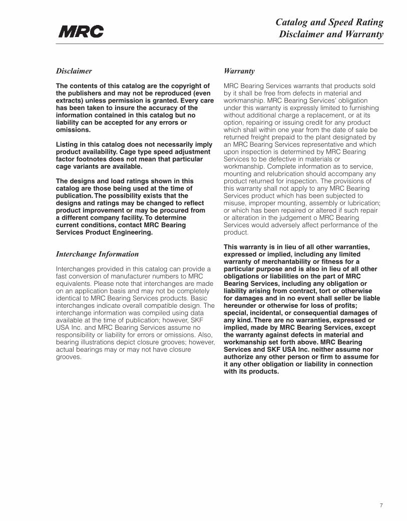
Disclaimer
The contents of this catalog are the copyright ofthe publishers and may not be reproduced (evenextracts) unless permission is granted. Every carehas been taken to insure the accuracy of theinformation contained in this catalog but noliability can be accepted for any errors oromissions.
Listing in this catalog does not necessarily implyproduct availability. Cage type speed adjustmentfactor footnotes does not mean that particularcage variants are available.
The designs and load ratings shown in thiscatalog are those being used at the time ofpublication. The possibility exists that the designs and ratings may be changed to reflectproduct improvement or may be procured from a different company facility. To determine current conditions, contact MRC Bearing Services Product Engineering.
Interchange Information
Interchanges provided in this catalog can provide afast conversion of manufacturer numbers to MRCequivalents. Please note that interchanges are madeon an application basis and may not be completelyidentical to MRC Bearing Services products. Basicinterchanges indicate overall compatible design. Theinterchange information was compiled using dataavailable at the time of publication; however, SKFUSA Inc. and MRC Bearing Services assume noresponsibility or liability for errors or omissions. Also,bearing illustrations depict closure grooves; however,actual bearings may or may not have closuregrooves.
Warranty
MRC Bearing Services warrants that products soldby it shall be free from defects in material andworkmanship. MRC Bearing Services’ obligationunder this warranty is expressly limited to furnishingwithout additional charge a replacement, or at itsoption, repairing or issuing credit for any productwhich shall within one year from the date of sale bereturned freight prepaid to the plant designated byan MRC Bearing Services representative and whichupon inspection is determined by MRC BearingServices to be defective in materials orworkmanship. Complete information as to service,mounting and relubrication should accompany anyproduct returned for inspection. The provisions ofthis warranty shall not apply to any MRC BearingServices product which has been subjected tomisuse, improper mounting, assembly or lubrication;or which has been repaired or altered if such repairor alteration in the judgement o MRC BearingServices would adversely affect performance of theproduct.
This warranty is in lieu of all other warranties,expressed or implied, including any limitedwarranty of merchantability or fitness for aparticular purpose and is also in lieu of all otherobligations or liabilities on the part of MRCBearing Services, including any obligation orliability arising from contract, tort or otherwise for damages and in no event shall seller be liablehereunder or otherwise for loss of profits;special, incidental, or consequential damages ofany kind. There are no warranties, expressed orimplied, made by MRC Bearing Services, exceptthe warranty against defects in material andworkmanship set forth above. MRC BearingServices and SKF USA Inc. neither assume norauthorize any other person or firm to assume forit any other obligation or liability in connectionwith its products.
MRC Bearing Services
8
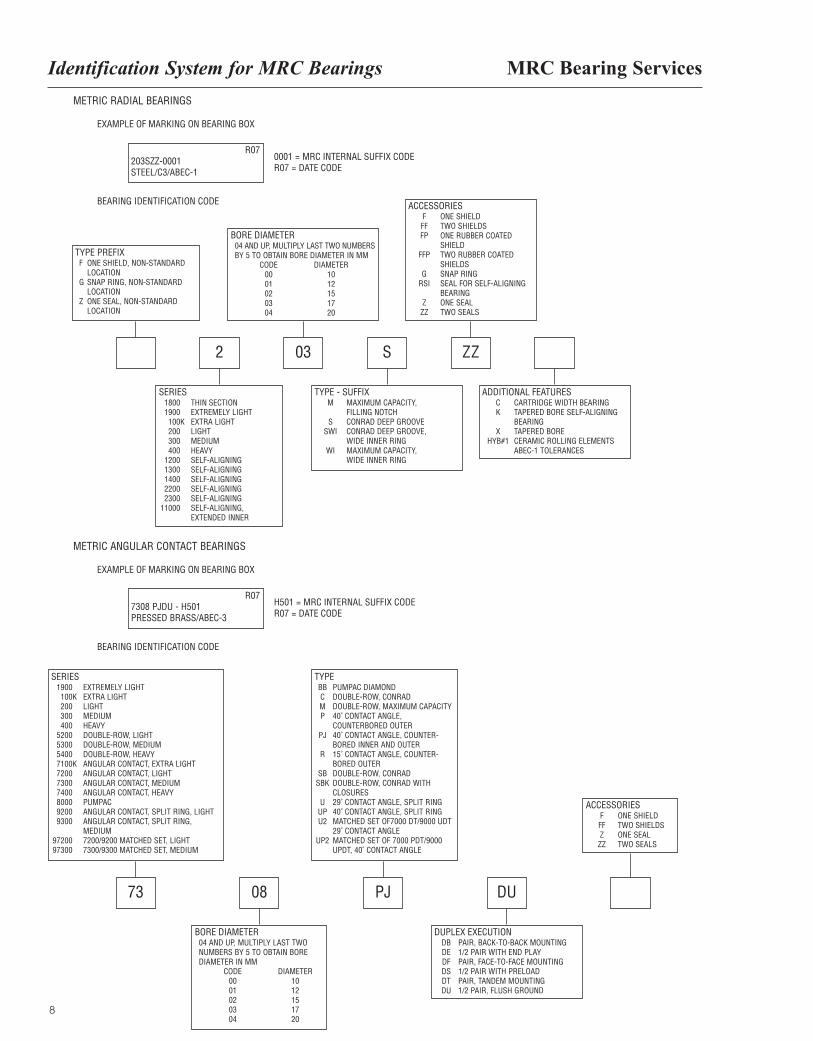
METRIC RADIAL BEARINGS
TYPE PREFIXF ONE SHIELD, NON-STANDARD
LOCATIONG SNAP RING, NON-STANDARD
LOCATIONZ ONE SEAL, NON-STANDARD
LOCATION
BORE DIAMETER04 AND UP, MULTIPLY LAST TWO NUMBERSBY 5 TO OBTAIN BORE DIAMETER IN MM
CODE DIAMETER00 1001 1202 1503 1704 20
ACCESSORIESF ONE SHIELDFF TWO SHIELDSFP ONE RUBBER COATED
SHIELDFFP TWO RUBBER COATED
SHIELDSG SNAP RING
RSI SEAL FOR SELF-ALIGNINGBEARING
Z ONE SEALZZ TWO SEALS
EXAMPLE OF MARKING ON BEARING BOX
BEARING IDENTIFICATION CODE
R07203SZZ-0001STEEL/C3/ABEC-1
0001 = MRC INTERNAL SUFFIX CODER07 = DATE CODE
SERIES1800 THIN SECTION1900 EXTREMELY LIGHT100K EXTRA LIGHT200 LIGHT300 MEDIUM400 HEAVY
1200 SELF-ALIGNING1300 SELF-ALIGNING1400 SELF-ALIGNING2200 SELF-ALIGNING2300 SELF-ALIGNING
11000 SELF-ALIGNING, EXTENDED INNER
TYPE - SUFFIXM MAXIMUM CAPACITY,
FILLING NOTCHS CONRAD DEEP GROOVE
SWI CONRAD DEEP GROOVE, WIDE INNER RING
WI MAXIMUM CAPACITY,WIDE INNER RING
ADDITIONAL FEATURESC CARTRIDGE WIDTH BEARINGK TAPERED BORE SELF-ALIGNING
BEARINGX TAPERED BORE
HYB#1 CERAMIC ROLLING ELEMENTSABEC-1 TOLERANCES
METRIC ANGULAR CONTACT BEARINGS
SERIES1900 EXTREMELY LIGHT100K EXTRA LIGHT200 LIGHT300 MEDIUM400 HEAVY
5200 DOUBLE-ROW, LIGHT5300 DOUBLE-ROW, MEDIUM5400 DOUBLE-ROW, HEAVY7100K ANGULAR CONTACT, EXTRA LIGHT7200 ANGULAR CONTACT, LIGHT7300 ANGULAR CONTACT, MEDIUM7400 ANGULAR CONTACT, HEAVY8000 PUMPAC9200 ANGULAR CONTACT, SPLIT RING, LIGHT9300 ANGULAR CONTACT, SPLIT RING,
MEDIUM97200 7200/9200 MATCHED SET, LIGHT97300 7300/9300 MATCHED SET, MEDIUM
TYPEBB PUMPAC DIAMONDC DOUBLE-ROW, CONRADM DOUBLE-ROW, MAXIMUM CAPACITYP 40˚ CONTACT ANGLE,
COUNTERBORED OUTERPJ 40˚ CONTACT ANGLE, COUNTER-
BORED INNER AND OUTERR 15˚ CONTACT ANGLE, COUNTER-
BORED OUTERSB DOUBLE-ROW, CONRAD
SBK DOUBLE-ROW, CONRAD WITH CLOSURES
U 29˚ CONTACT ANGLE, SPLIT RINGUP 40˚ CONTACT ANGLE, SPLIT RINGU2 MATCHED SET OF7000 DT/9000 UDT
29˚ CONTACT ANGLEUP2 MATCHED SET OF 7000 PDT/9000
UPDT, 40˚ CONTACT ANGLE
EXAMPLE OF MARKING ON BEARING BOX
BEARING IDENTIFICATION CODE
R077308 PJDU - H501PRESSED BRASS/ABEC-3
H501 = MRC INTERNAL SUFFIX CODER07 = DATE CODE
ACCESSORIESF ONE SHIELDFF TWO SHIELDSZ ONE SEALZZ TWO SEALS
BORE DIAMETER04 AND UP, MULTIPLY LAST TWONUMBERS BY 5 TO OBTAIN BOREDIAMETER IN MM
CODE DIAMETER00 1001 1202 1503 1704 20
DUPLEX EXECUTIONDB PAIR, BACK-TO-BACK MOUNTINGDE 1/2 PAIR WITH END PLAYDF PAIR, FACE-TO-FACE MOUNTINGDS 1/2 PAIR WITH PRELOADDT PAIR, TANDEM MOUNTINGDU 1/2 PAIR, FLUSH GROUND
Identification System for MRC Bearings
73 08 PJ
2 03 S ZZ
DU
Bearing Symbols
9
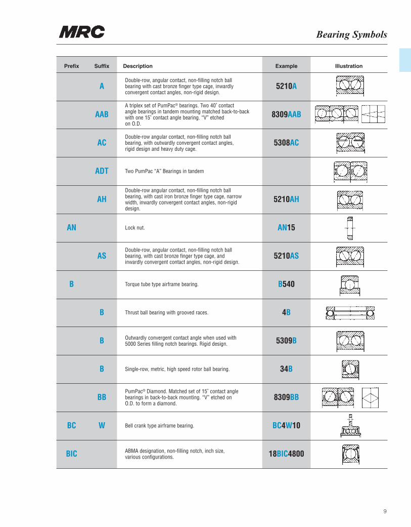
IllustrationPrefix Suffix Description Example
AN
B
BC
BIC
ADouble-row, angular contact, non-filling notch ball bearing with cast bronze finger type cage, inwardlyconvergent contact angles, non-rigid design.
A triplex set of PumPac® bearings. Two 40˚ contactangle bearings in tandem mounting matched back-to-backwith one 15˚ contact angle bearing. “V” etchedon O.D.
Double-row angular contact, non-filling notch ballbearing, with outwardly convergent contact angles, rigid design and heavy duty cage.
Two PumPac “A” Bearings in tandem
Double-row angular contact, non-filling notch ballbearing, with cast iron bronze finger type cage, narrowwidth, inwardly convergent contact angles, non-rigid design.
Lock nut.
Double-row, angular contact, non-filling notch ball bearing, with cast bronze finger type cage, andinwardly convergent contact angles, non-rigid design.
Torque tube type airframe bearing.
Thrust ball bearing with grooved races.
Outwardly convergent contact angle when used with5000 Series filling notch bearings. Rigid design.
Single-row, metric, high speed rotor ball bearing.
PumPac® Diamond. Matched set of 15˚ contact anglebearings in back-to-back mounting. “V” etched on O.D. to form a diamond.
Bell crank type airframe bearing.
ABMA designation, non-filling notch, inch size, various configurations.
5210A
8309AAB
5308AC
5210AH
AN15
5210AS
B540
4B
5309B
34B
8309BB
BC4W10
18BIC4800
AAB
AC
ADT
AH
AS
B
B
B
BB
W
MRC Bearing ServicesBearing Symbols
10
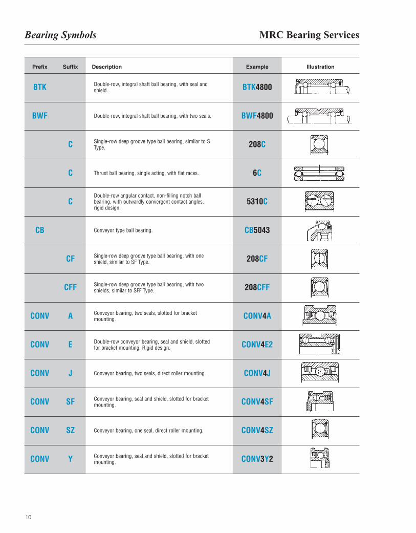
IllustrationPrefix Suffix Description Example
BTK
BWF
CB
CONV
CONV
CONV
CONV
CONV
CONV
Double-row, integral shaft ball bearing, with seal andshield.
Double-row, integral shaft ball bearing, with two seals.
Single-row deep groove type ball bearing, similar to SType.
Thrust ball bearing, single acting, with flat races.
Double-row angular contact, non-filling notch ballbearing, with outwardly convergent contact angles,rigid design.
Conveyor type ball bearing.
Single-row deep groove type ball bearing, with oneshield, similar to SF Type.
Single-row deep groove type ball bearing, with twoshields, similar to SFF Type.
Conveyor bearing, two seals, slotted for bracketmounting.
Double-row conveyor bearing, seal and shield, slottedfor bracket mounting, Rigid design.
Conveyor bearing, two seals, direct roller mounting.
Conveyor bearing, seal and shield, slotted for bracketmounting.
Conveyor bearing, one seal, direct roller mounting.
Conveyor bearing, seal and shield, slotted for bracketmounting.
BTK4800
BWF4800
208C
6C
5310C
CB5043
208CF
208CFF
CONV4A
CONV4E2
CONV4J
CONV4SF
CONV4SZ
CONV3Y2
C
C
C
CF
CFF
A
E
J
SF
SZ
Y
Bearing Symbols
11
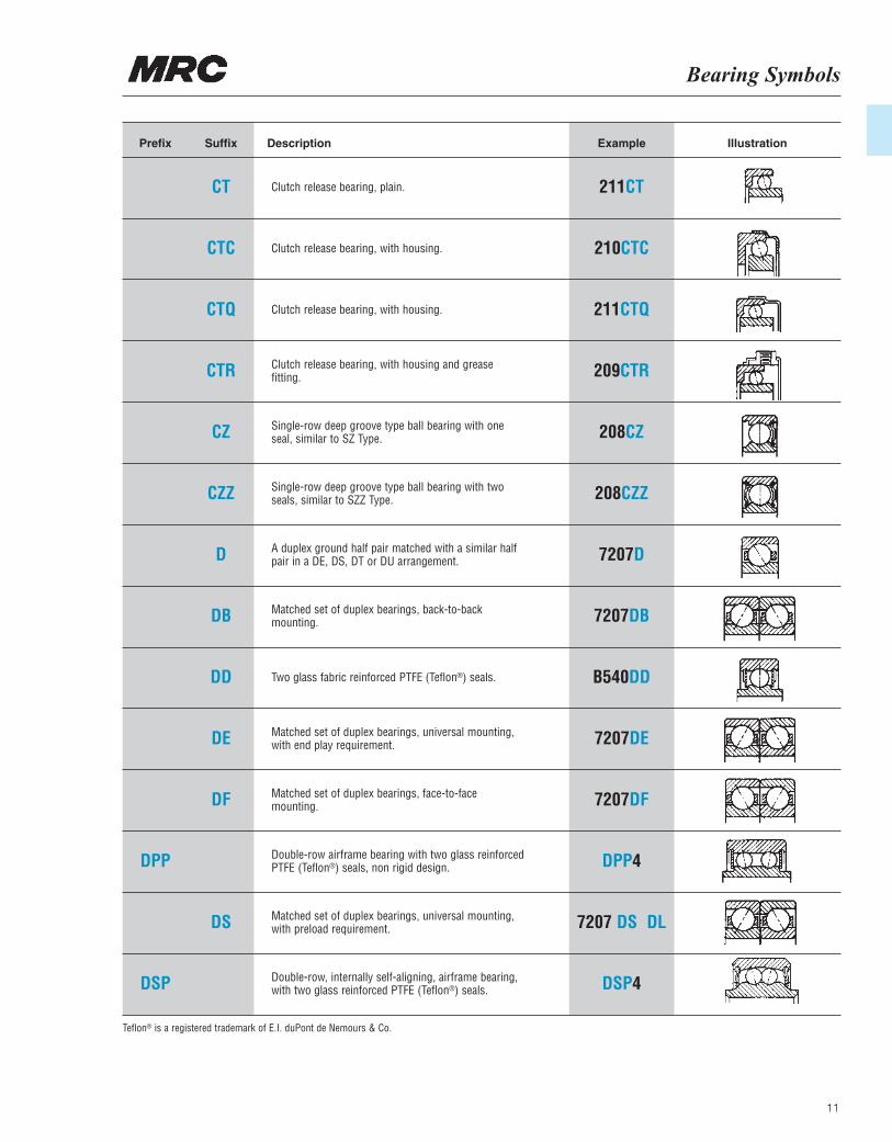
IllustrationPrefix Suffix Description Example
DPP
DSP
CT Clutch release bearing, plain.
Clutch release bearing, with housing.
Clutch release bearing, with housing.
Clutch release bearing, with housing and greasefitting.
Single-row deep groove type ball bearing with oneseal, similar to SZ Type.
Single-row deep groove type ball bearing with twoseals, similar to SZZ Type.
A duplex ground half pair matched with a similar halfpair in a DE, DS, DT or DU arrangement.
Matched set of duplex bearings, back-to-backmounting.
Two glass fabric reinforced PTFE (Teflon®) seals.
Matched set of duplex bearings, universal mounting,with end play requirement.
Matched set of duplex bearings, face-to-facemounting.
Double-row airframe bearing with two glass reinforcedPTFE (Teflon®) seals, non rigid design.
Matched set of duplex bearings, universal mounting,with preload requirement.
Double-row, internally self-aligning, airframe bearing,with two glass reinforced PTFE (Teflon®) seals.
211CT
210CTC
211CTQ
209CTR
208CZ
208CZZ
7207D
7207DB
B540DD
7207DE
7207DF
DPP4
7207 DS DL
DSP4
CTC
CTQ
CTR
CZ
CZZ
D
DB
DD
DE
DF
DS
Teflon® is a registered trademark of E.I. duPont de Nemours & Co.
MRC Bearing ServicesBearing Symbols
12
IllustrationPrefix Suffix Description Example
DW
DW
E
ER
E
FB
FB
FB
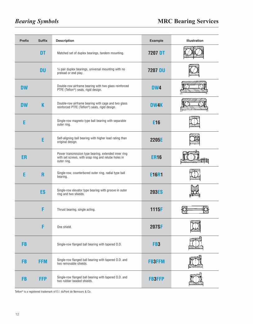
DT Matched set of duplex bearings, tandem mounting.
¹|₂ pair duplex bearings, universal mounting with nopreload or end play.
Double-row airframe bearing with two glass reinforcedPTFE (Teflon®) seals, rigid design.
Double-row airframe bearing with cage and two glassreinforced PTFE (Teflon®) seals, rigid design.
Single-row magneto type ball bearing with separableouter ring.
Self-aligning ball bearing with higher load rating thanoriginal design.
Power transmission type bearing, extended inner ringwith set screws, with snap ring and relube holes inouter ring.
Single-row, counterbored outer ring, radial type ballbearing.
Single-row elevator type bearing with groove in outerring and two shields.
Thrust bearing, single acting.
One shield.
Single-row flanged ball bearing with tapered O.D.
Single-row flanged ball bearing with tapered O.D. andtwo removable shields.
Single-row flanged ball bearing with tapered O.D. andtwo rubber beaded shields.
7207 DT
7207 DU
DW4
DW4K
E16
2205E
ER16
E16R1
203ES
1115F
207SF
FB3
FB3FFM
FB3FFP
DU
K
E
R
ES
F
F
FFM
FFP
Teflon® is a registered trademark of E.I. duPont de Nemours & Co.
Bearing Symbols
13
IllustrationPrefix Suffix Description Example
FB
FC
FC
FC
FC
FG
FG
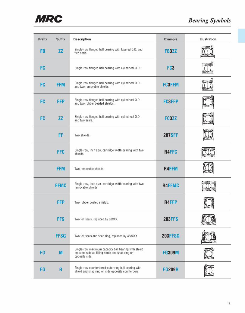
ZZ Single-row flanged ball bearing with tapered O.D. andtwo seals.
Single-row flanged ball bearing with cylindrical O.D.
Single-row flanged ball bearing with cylindrical O.D.and two removable shields.
Single-row flanged ball bearing with cylindrical O.D.and two rubber beaded shields.
Single-row flanged ball bearing with cylindrical O.D.and two seals.
Two shields.
Single-row, inch size, cartridge width bearing with twoshields.
Two removable shields.
Single-row, inch size, cartridge width bearing with tworemovable shields
Two rubber coated shields.
Two felt seals, replaced by 88XXX.
Two felt seals and snap ring, replaced by 488XXX.
Single-row maximum capacity ball bearing with shieldon same side as filling notch and snap ring on opposite side.
Single-row counterbored outer ring ball bearing withshield and snap ring on side opposite counterbore.
FB3ZZ
FC3
FC3FFM
FC3FFP
FC3ZZ
207SFF
R4FFC
R4FFM
R4FFMC
R4FFP
203FFS
203FFSG
FG309M
FG209R
FFM
FFP
ZZ
FF
FFC
FFM
FFMC
FFP
FFS
FFSG
M
R
MRC Bearing ServicesBearing Symbols
14
IllustrationPrefix Suffix Description Example
F
F
F
F
FZG
FZ
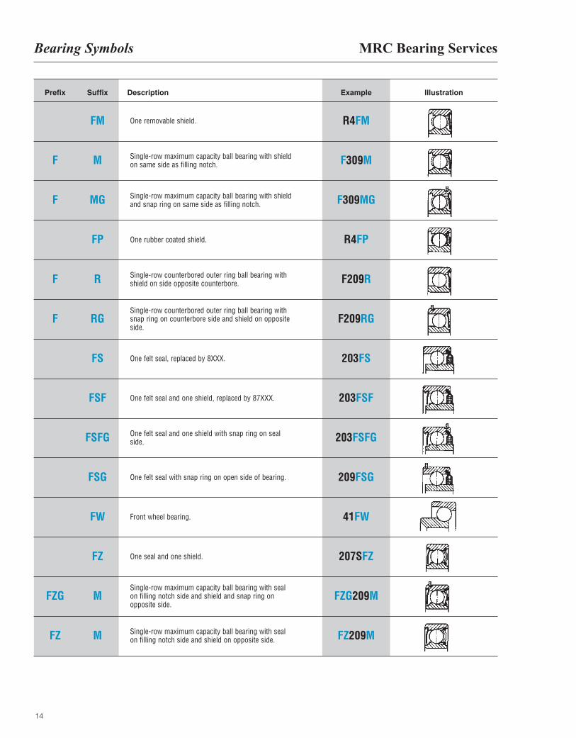
FM One removable shield.
Single-row maximum capacity ball bearing with shield on same side as filling notch.
Single-row maximum capacity ball bearing with shieldand snap ring on same side as filling notch.
One rubber coated shield.
Single-row counterbored outer ring ball bearing withshield on side opposite counterbore.
Single-row counterbored outer ring ball bearing withsnap ring on counterbore side and shield on oppositeside.
One felt seal, replaced by 8XXX.
One felt seal and one shield, replaced by 87XXX.
One felt seal and one shield with snap ring on seal side.
One felt seal with snap ring on open side of bearing.
Front wheel bearing.
One seal and one shield.
Single-row maximum capacity ball bearing with sealon filling notch side and shield and snap ring onopposite side.
Single-row maximum capacity ball bearing with sealon filling notch side and shield on opposite side.
R4FM
F309M
F309MG
R4FP
F209R
F209RG
203FS
203FSF
203FSFG
209FSG
41FW
207SFZ
FZG209M
FZ209M
M
MG
FP
R
RG
FS
FSF
FSFG
FSG
FW
FZ
M
M
Bearing Symbols
15
IllustrationPrefix Suffix Description Example
FZ
G
G
G
G
G
GR
G
G
G
GT
H
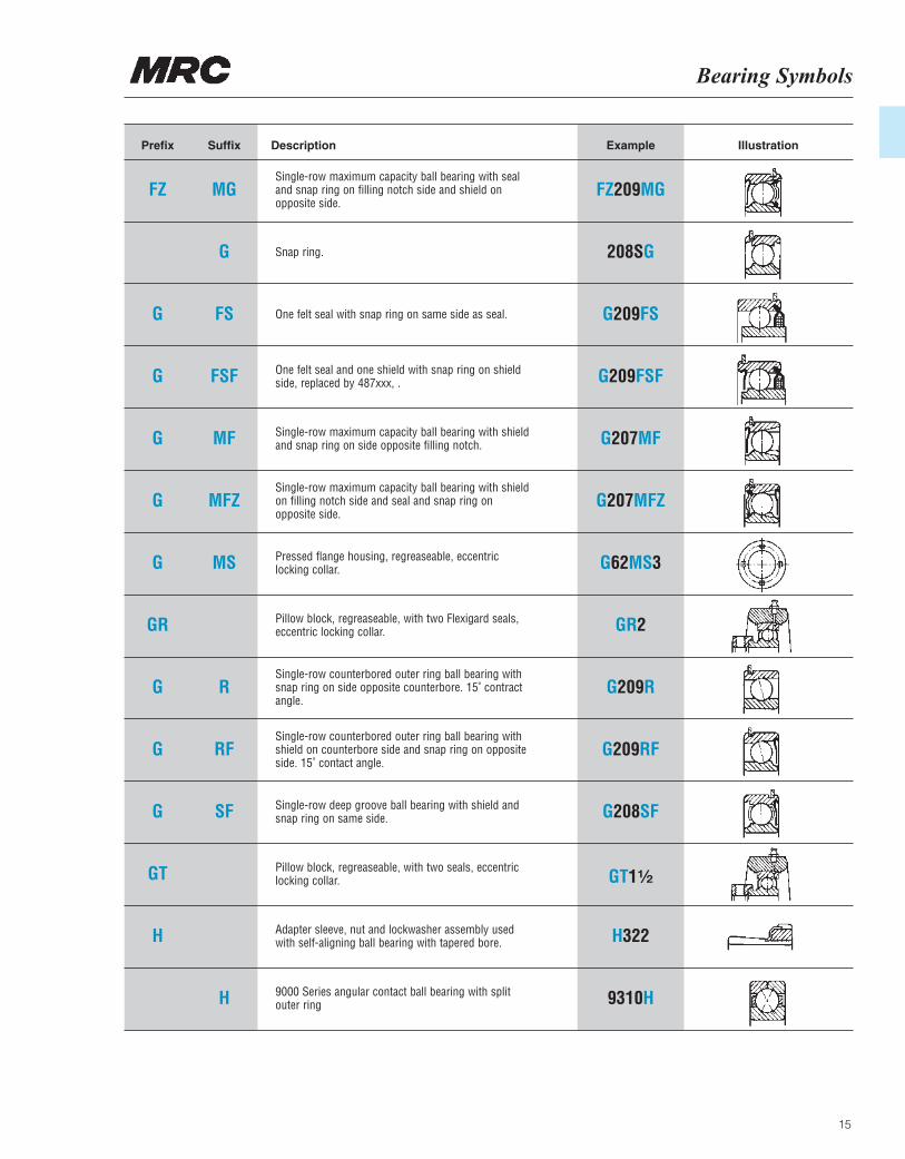
MGSingle-row maximum capacity ball bearing with sealand snap ring on filling notch side and shield onopposite side.
Snap ring.
One felt seal with snap ring on same side as seal.
One felt seal and one shield with snap ring on shieldside, replaced by 487xxx, .
Single-row maximum capacity ball bearing with shieldand snap ring on side opposite filling notch.
Single-row maximum capacity ball bearing with shieldon filling notch side and seal and snap ring onopposite side.
Pressed flange housing, regreaseable, eccentriclocking collar.
Pillow block, regreaseable, with two Flexigard seals,eccentric locking collar.
Single-row counterbored outer ring ball bearing withsnap ring on side opposite counterbore. 15˚ contractangle.
Single-row counterbored outer ring ball bearing withshield on counterbore side and snap ring on oppositeside. 15˚ contact angle.
Single-row deep groove ball bearing with shield andsnap ring on same side.
Pillow block, regreaseable, with two seals, eccentriclocking collar.
Adapter sleeve, nut and lockwasher assembly used with self-aligning ball bearing with tapered bore.
9000 Series angular contact ball bearing with split outer ring
FZ209MG
208SG
G209FS
G209FSF
G207MF
G207MFZ
G62MS3
GR2
G209R
G209RF
G208SF
GT1¹|₂
H322
9310H
G
FS
FSF
MF
MFZ
MS
R
RF
SF
H
MRC Bearing ServicesBearing Symbols
16
IllustrationPrefix Suffix Description Example
HH
J
J
K
KP
KP
KP
KP
KP
KP
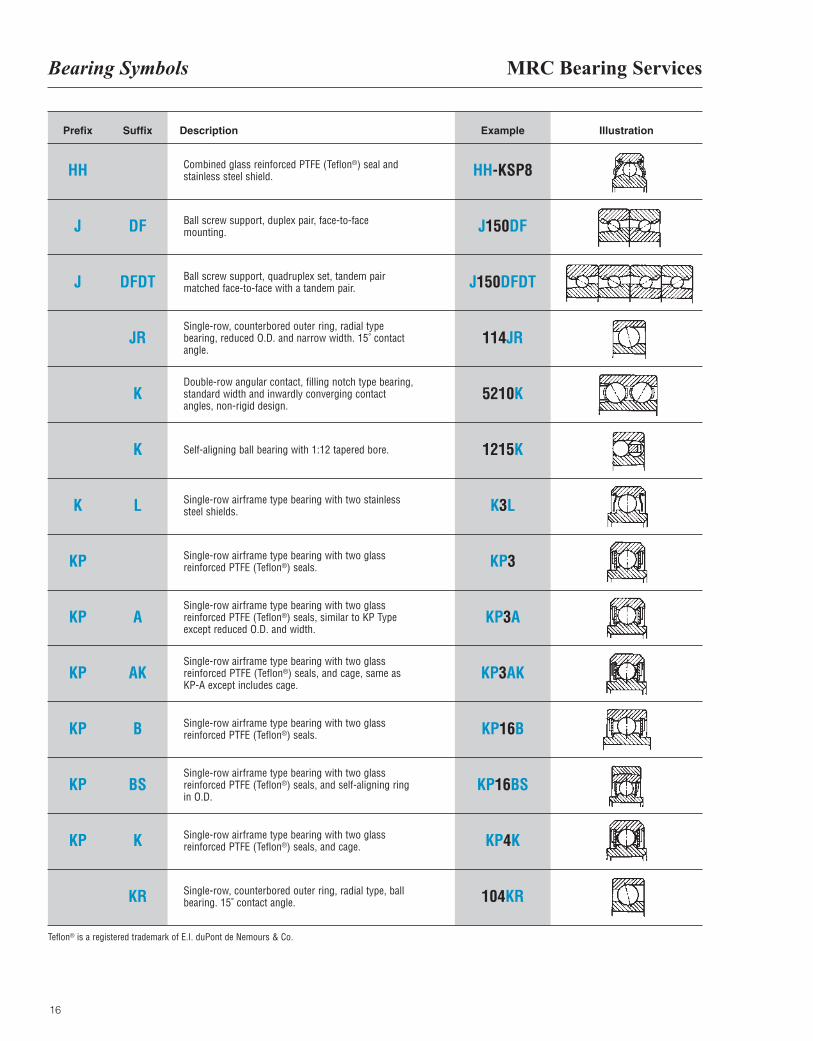
Combined glass reinforced PTFE (Teflon®) seal andstainless steel shield.
Ball screw support, duplex pair, face-to-face mounting.
Ball screw support, quadruplex set, tandem pairmatched face-to-face with a tandem pair.
Single-row, counterbored outer ring, radial type bearing, reduced O.D. and narrow width. 15˚ contactangle.
Double-row angular contact, filling notch type bearing,standard width and inwardly converging contact angles, non-rigid design.
Self-aligning ball bearing with 1:12 tapered bore.
Single-row airframe type bearing with two stainlesssteel shields.
Single-row airframe type bearing with two glassreinforced PTFE (Teflon®) seals.
Single-row airframe type bearing with two glassreinforced PTFE (Teflon®) seals, similar to KP Typeexcept reduced O.D. and width.
Single-row airframe type bearing with two glassreinforced PTFE (Teflon®) seals, and cage, same asKP-A except includes cage.
Single-row airframe type bearing with two glassreinforced PTFE (Teflon®) seals.
Single-row airframe type bearing with two glassreinforced PTFE (Teflon®) seals, and self-aligning ring in O.D.
Single-row airframe type bearing with two glassreinforced PTFE (Teflon®) seals, and cage.
Single-row, counterbored outer ring, radial type, ballbearing. 15˚ contact angle.
HH-KSP8
J150DF
J150DFDT
114JR
5210K
1215K
K3L
KP3
KP3A
KP3AK
KP16B
KP16BS
KP4K
104KR
DF
DFDT
JR
K
K
L
A
AK
B
BS
K
KR
Teflon® is a registered trademark of E.I. duPont de Nemours & Co.
Bearing Symbols
17
IllustrationPrefix Suffix Description Example
KSP
KSP
KSP
L
LB
LL
LZ
M
M
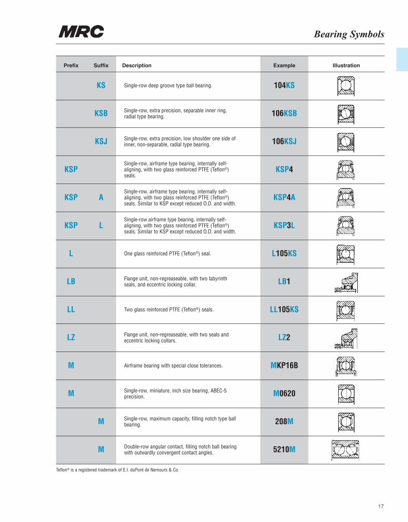
KS Single-row deep groove type ball bearing.
Single-row, extra precision, separable inner ring, radial type bearing.
Single-row, extra precision, low shoulder one side ofinner, non-separable, radial type bearing.
Single-row, airframe type bearing, internally self-aligning, with two glass reinforced PTFE (Teflon®)seals.
Single-row, airframe type bearing, internally self-aligning, with two glass reinforced PTFE (Teflon®)seals. Similar to KSP except reduced O.D. and width.
Single-row airframe type bearing, internally self-aligning, with two glass reinforced PTFE (Teflon®)seals. Similar to KSP except reduced O.D. and width.
One glass reinforced PTFE (Teflon®) seal.
Flange unit, non-regreaseable, with two labyrinthseals, and eccentric locking collar.
Two glass reinforced PTFE (Teflon®) seals.
Flange unit, non-regreaseable, with two seals andeccentric locking collars.
Airframe bearing with special close tolerances.
Single-row, miniature, inch size bearing, ABEC-5precision.
Single-row, maximum capacity, filling notch type ballbearing.
Double-row angular contact, filling notch ball bearingwith outwardly convergent contact angles.
104KS
106KSB
106KSJ
KSP4
KSP4A
KSP3L
L105KS
LB1
LL105KS
LZ2
MKP16B
M0620
208M
5210M
KSB
KSJ
A
L
M
M
Teflon® is a registered trademark of E.I. duPont de Nemours & Co.
MRC Bearing ServicesBearing Symbols
18
IllustrationPrefix Suffix Description Example
MR
MR
MR
MR
MR
MR
MR
MR
MR
N
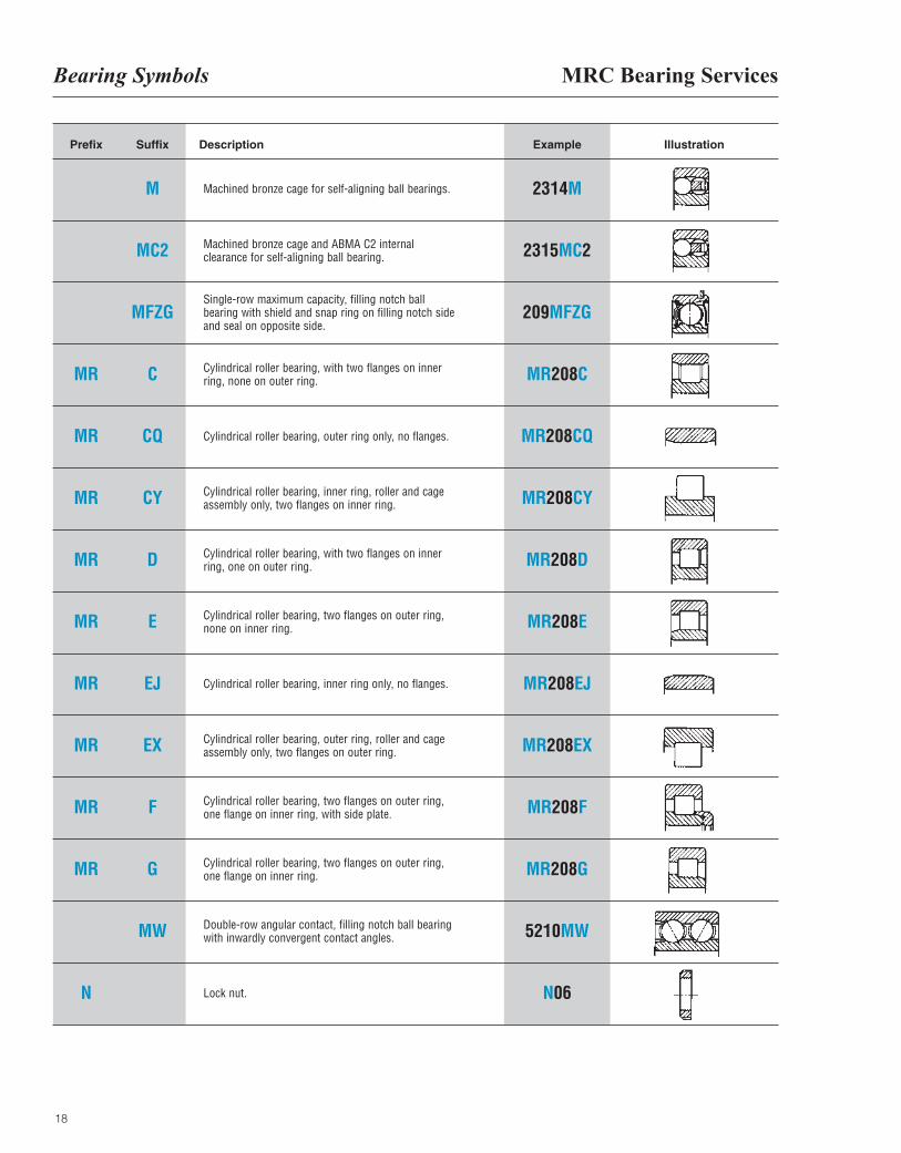
M Machined bronze cage for self-aligning ball bearings.
Machined bronze cage and ABMA C2 internalclearance for self-aligning ball bearing.
Single-row maximum capacity, filling notch ballbearing with shield and snap ring on filling notch sideand seal on opposite side.
Cylindrical roller bearing, with two flanges on innerring, none on outer ring.
Cylindrical roller bearing, outer ring only, no flanges.
Cylindrical roller bearing, inner ring, roller and cageassembly only, two flanges on inner ring.
Cylindrical roller bearing, with two flanges on innerring, one on outer ring.
Cylindrical roller bearing, two flanges on outer ring,none on inner ring.
Cylindrical roller bearing, inner ring only, no flanges.
Cylindrical roller bearing, outer ring, roller and cageassembly only, two flanges on outer ring.
Cylindrical roller bearing, two flanges on outer ring,one flange on inner ring, with side plate.
Cylindrical roller bearing, two flanges on outer ring,one flange on inner ring.
Double-row angular contact, filling notch ball bearingwith inwardly convergent contact angles.
Lock nut.
2314M
2315MC2
209MFZG
MR208C
MR208CQ
MR208CY
MR208D
MR208E
MR208EJ
MR208EX
MR208F
MR208G
5210MW
N06
MC2
MFZG
C
CQ
CY
D
E
EJ
EX
F
G
MW
Bearing Symbols
19
IllustrationPrefix Suffix Description Example
O
OR
P
PB
PD
P
PZ
R
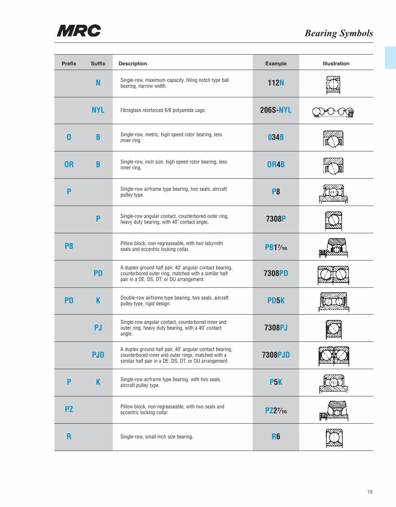
N Single-row, maximum capacity, filling notch type ballbearing, narrow width.
Fibreglass reinforced 6/6 polyamide cage.
Single-row, metric, high speed rotor bearing, lessinner ring.
Single-row, inch size, high speed rotor bearing, lessinner ring.
Single-row airframe type bearing, two seals, aircraftpulley type.
Single-row angular contact, counterbored outer ring,heavy duty bearing, with 40˚ contact angle.
Pillow block, non-regreaseable, with two labyrinthseals and eccentric locking collar.
A duplex ground half pair, 40˚ angular contact bearing,counterbored outer ring, matched with a similar halfpair in a DE, DS, DT, or DU arrangement.
Double-row airframe type bearing, two seals, aircraftpulley type, rigid design.
Single-row angular contact, counterbored inner andouter ring, heavy duty bearing, with a 40˚ contactangle.
A duplex ground half pair, 40˚ angular contact bearing,counterbored inner and outer rings, matched with asimilar half pair in a DE, DS, DT, or DU arrangement.
Single-row airframe type bearing, with two seals,aircraft pulley type.
Pillow block, non-regreaseable, with two seals andeccentric locking collar.
Single-row, small inch size bearing.
112N
206S-NYL
034B
OR4B
P8
7308P
PB1⁷|₁₆
7308PD
PD5K
7308PJ
7308PJD
P5K
PZ2⁷|₁₆
R6
NYL
B
B
P
PD
K
PJ
PJD
K
MRC Bearing ServicesBearing Symbols
20
IllustrationPrefix Suffix Description Example
R
RA
RA
RA
RA
RAP
R
R
R
R
R
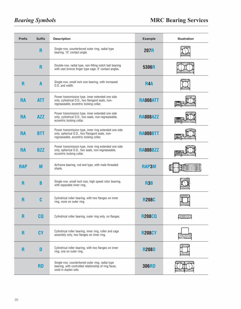
R Single-row, counterbored outer ring, radial typebearing, 15˚ contact angle.
Double-row, radial type, non-filling notch ball bearingwith cast bronze finger type cage. 0˚ contact angles.
Single-row, small inch size bearing, with increasedO.D. and width.
Power transmission type, inner extended one sideonly, cylindrical O.D., two flexigard seals, non-regreaseable, eccentric locking collar.
Power transmission type, inner extended one sideonly, cylindrical O.D., two seals, non-regreaseable,eccentric locking collar.
Power transmission type, inner ring extended one sideonly, spherical O.D., two Flexigard seals, non-regreaseable, eccentric locking collar.
Power transmission type, inner ring extended one sideonly, spherical O.D., two seals, non-regreaseable,eccentric locking collar.
Airframe bearing, rod end type, with male threadedshank.
Single-row, small inch size, high speed rotor bearing,with separable inner ring.
Cylindrical roller bearing, with two flanges on innerring, none on outer ring.
Cylindrical roller bearing, outer ring only, no flanges.
Cylindrical roller bearing, inner ring, roller and cageassembly only, two flanges on inner ring.
Cylindrical roller bearing, with two flanges on innerring, one on outer ring.
Single-row, counterbored outer ring, radial typebearing, with controlled relationship of ring faces,used in duplex sets.
207R
5306R
R4A
RA008ATT
RA008AZZ
RA008BTT
RA008BZZ
RAP3M
R3B
R208C
R208CQ
R208CY
R208D
306RD
R
A
ATT
AZZ
BTT
BZZ
M
B
C
CQ
CY
D
RD
Bearing Symbols
21
IllustrationPrefix Suffix Description Example
R
R
R
REPB
REP
REP
REP
REP
R
R
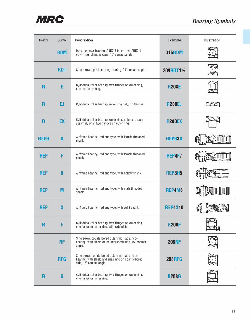
RDM Dynamometer bearing, ABEC-5 inner ring, ABEC-1outer ring, phenolic cage, 15˚ contact angle.
Single-row, split inner ring bearing, 20˚ contact angle.
Cylindrical roller bearing, two flanges on outer ring,none on inner ring.
Cylindrical roller bearing, inner ring only, no flanges.
Cylindrical roller bearing, outer ring, roller and cageassembly only, two flanges on outer ring.
Airframe bearing, rod end type, with female threadedshank.
Airframe bearing, rod end type, with female threadedshank.
Airframe bearing, rod end type, with hollow shank.
Airframe bearing, rod end type, with male threadedshank.
Airframe bearing, rod end type, with solid shank.
Cylindrical roller bearing, two flanges on outer ring,one flange on inner ring, with side plate.
Single-row, counterbored outer ring, radial typebearing, with shield on counterbored side, 15˚ contactangle.
Single-row, counterbored outer ring, radial typebearing, with shield and snap ring on counterboredside, 15˚ contact angle.
Cylindrical roller bearing, two flanges on outer ring,one flange on inner ring.
316RDM
309RDT1¹|₂
R208E
R208EJ
R208EX
REPB3N
REP4F7
REP3H5
REP4M6
REP4S10
R208F
208RF
208RFG
R208G
RDT
E
EJ
EX
N
F
H
M
S
F
RF
RFG
G
MRC Bearing ServicesBearing Symbols
22
IllustrationPrefix Suffix Description Example
RRA
RRA
RT
RW
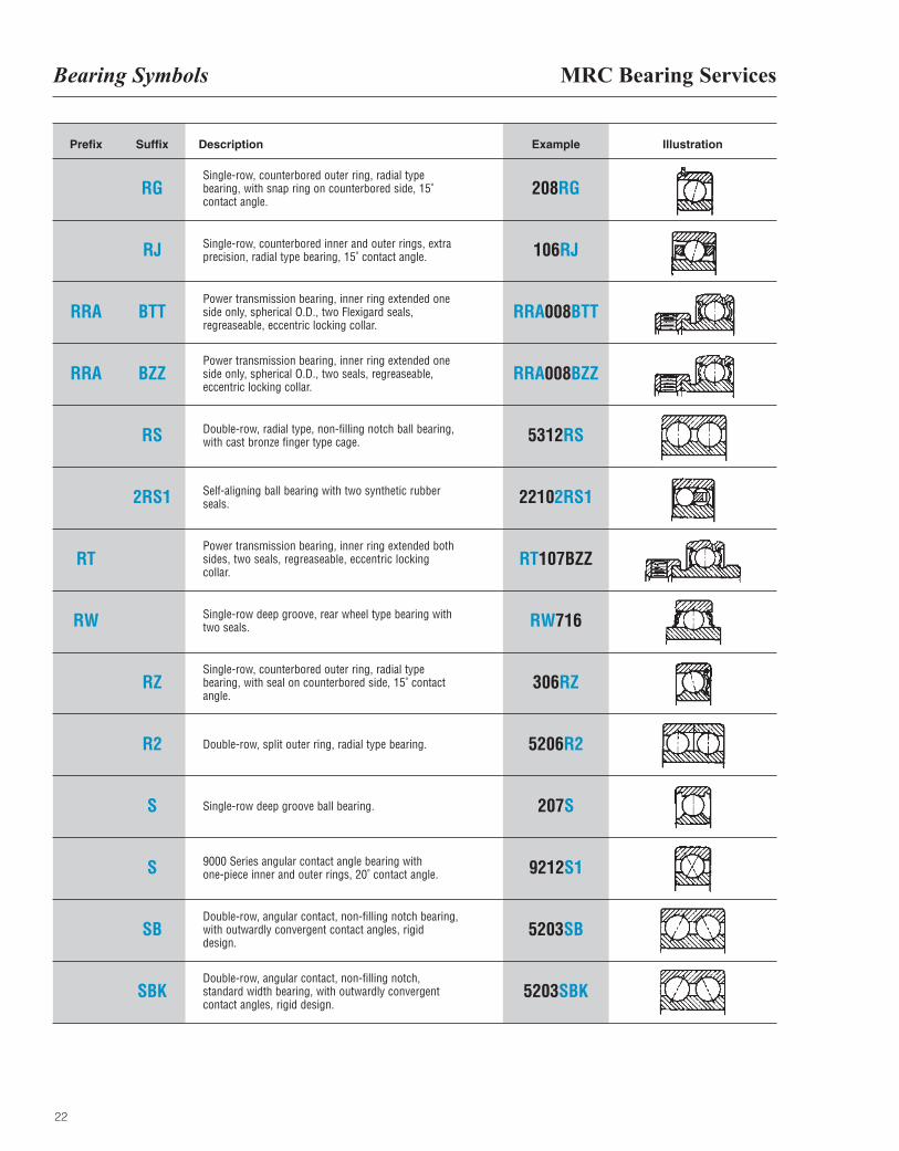
RGSingle-row, counterbored outer ring, radial typebearing, with snap ring on counterbored side, 15˚contact angle.
Single-row, counterbored inner and outer rings, extraprecision, radial type bearing, 15˚ contact angle.
Power transmission bearing, inner ring extended oneside only, spherical O.D., two Flexigard seals,regreaseable, eccentric locking collar.
Power transmission bearing, inner ring extended oneside only, spherical O.D., two seals, regreaseable,eccentric locking collar.
Double-row, radial type, non-filling notch ball bearing,with cast bronze finger type cage.
Self-aligning ball bearing with two synthetic rubberseals.
Power transmission bearing, inner ring extended bothsides, two seals, regreaseable, eccentric lockingcollar.
Single-row deep groove, rear wheel type bearing withtwo seals.
Single-row, counterbored outer ring, radial typebearing, with seal on counterbored side, 15˚ contactangle.
Double-row, split outer ring, radial type bearing.
Single-row deep groove ball bearing.
9000 Series angular contact angle bearing withone-piece inner and outer rings, 20˚ contact angle.
Double-row, angular contact, non-filling notch bearing,with outwardly convergent contact angles, rigiddesign.
Double-row, angular contact, non-filling notch,standard width bearing, with outwardly convergentcontact angles, rigid design.
208RG
106RJ
RRA008BTT
RRA008BZZ
5312RS
22102RS1
RT107BZZ
RW716
306RZ
5206R2
207S
9212S1
5203SB
5203SBK
RJ
BTT
BZZ
RS
2RS1
RZ
R2
S
S
SB
SBK
Bearing Symbols
23
IllustrationPrefix Suffix Description Example
S
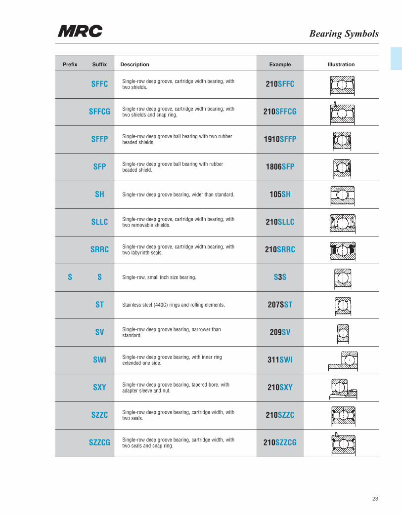
SFFC Single-row deep groove, cartridge width bearing, withtwo shields.
Single-row deep groove, cartridge width bearing, withtwo shields and snap ring.
Single-row deep groove ball bearing with two rubberbeaded shields.
Single-row deep groove ball bearing with rubberbeaded shield.
Single-row deep groove bearing, wider than standard.
Single-row deep groove, cartridge width bearing, withtwo removable shields.
Single-row deep groove, cartridge width bearing, withtwo labyrinth seals.
Single-row, small inch size bearing.
Stainless steel (440C) rings and rolling elements.
Single-row deep groove bearing, narrower thanstandard.
Single-row deep groove bearing, with inner ringextended one side.
Single-row deep groove bearing, tapered bore, withadapter sleeve and nut.
Single-row deep groove bearing, cartridge width, withtwo seals.
Single-row deep groove bearing, cartridge width, withtwo seals and snap ring.
210SFFC
210SFFCG
1910SFFP
1806SFP
105SH
210SLLC
210SRRC
S3S
207SST
209SV
311SWI
210SXY
210SZZC
210SZZCG
SFFCG
SFFP
SFP
SH
SLLC
SRRC
S
ST
SV
SWI
SXY
SZZC
SZZCG
MRC Bearing ServicesBearing Symbols
24
IllustrationPrefix Suffix Description Example
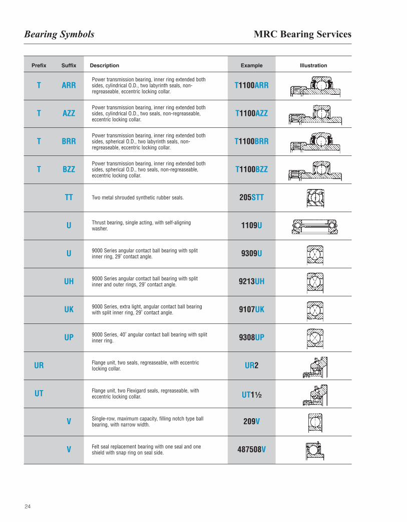
T
T
T
T
UR
UT
ARRPower transmission bearing, inner ring extended bothsides, cylindrical O.D., two labyrinth seals, non-regreaseable, eccentric locking collar.
Power transmission bearing, inner ring extended bothsides, cylindrical O.D., two seals, non-regreaseable,eccentric locking collar.
Power transmission bearing, inner ring extended bothsides, spherical O.D., two labyrinth seals, non-regreaseable, eccentric locking collar.
Power transmission bearing, inner ring extended bothsides, spherical O.D., two seals, non-regreaseable,eccentric locking collar.
Two metal shrouded synthetic rubber seals.
Thrust bearing, single acting, with self-aligningwasher.
9000 Series angular contact ball bearing with splitinner ring, 29˚ contact angle.
9000 Series angular contact ball bearing with splitinner and outer rings, 29˚ contact angle.
9000 Series, extra light, angular contact ball bearingwith split inner ring, 29˚ contact angle.
9000 Series, 40˚ angular contact ball bearing with splitinner ring.
Flange unit, two seals, regreaseable, with eccentriclocking collar.
Flange unit, two Flexigard seals, regreaseable, witheccentric locking collar.
Single-row, maximum capacity, filling notch type ballbearing, with narrow width.
Felt seal replacement bearing with one seal and oneshield with snap ring on seal side.
T1100ARR
T1100AZZ
T1100BRR
T1100BZZ
205STT
1109U
9309U
9213UH
9107UK
9308UP
UR2
UT1¹|₂
209V
487508V
AZZ
BRR
BZZ
TT
U
U
UH
UK
UP
V
V
Bearing Symbols
25
IllustrationPrefix Suffix Description Example
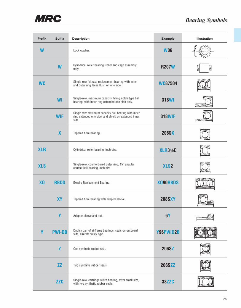
W
WC
XLR
XLS
XO
Y
Lock washer.
Cylindrical roller bearing, roller and cage assemblyonly.
Single-row felt seal replacement bearing with innerand outer ring faces flush on one side.
Single-row, maximum capacity, filling notch type ballbearing, with inner ring extended one side only.
Single row maximum capacity ball bearing with innerring extended one side, and shield on extended innerside.
Tapered bore bearing.
Cylindrical roller bearing, inch size.
Single-row, counterbored outer ring, 15° angularcontact ball bearing, inch size.
Excello Replacement Bearing.
Tapered bore bearing with adapter sleeve.
Adapter sleeve and nut.
Duplex pair of airframe bearings, seals on outboardside, aircraft pulley type.
One synthetic rubber seal.
Two synthetic rubber seals.
Single-row, cartridge width bearing, extra small size,with two synthetic rubber seals.
W06
R207W
WC87504
318WI
318WIF
206SX
XLR3¹|₂E
XLS2
XO90RBDS
208SXY
6Y
Y96PWID2B
206SZ
206SZZ
38ZZC
W
WI
WIF
X
RBDS
XY
Y
PWI-DB
Z
ZZ
ZZC
MRC Bearing ServicesPrefix/Suffix Symbols for Single-RowBearing Non-Standard Variants
26
Prefix–Suffix Illustration
MF
MG
MFG
G–M
F–M
F–MG
G–MF
FG–M
MX
Prefix–Suffix Illustration
X–M
MXF
X–MF
MFX
F–MX
MFZ
FZ–M
MFZG
FZ–MG
Prefix–Suffix Illustration
G–MFZ
FZG–M
MXFZ
XFZ–M
X–MFZ
FZ–MX
SFG
G–SF
SFX
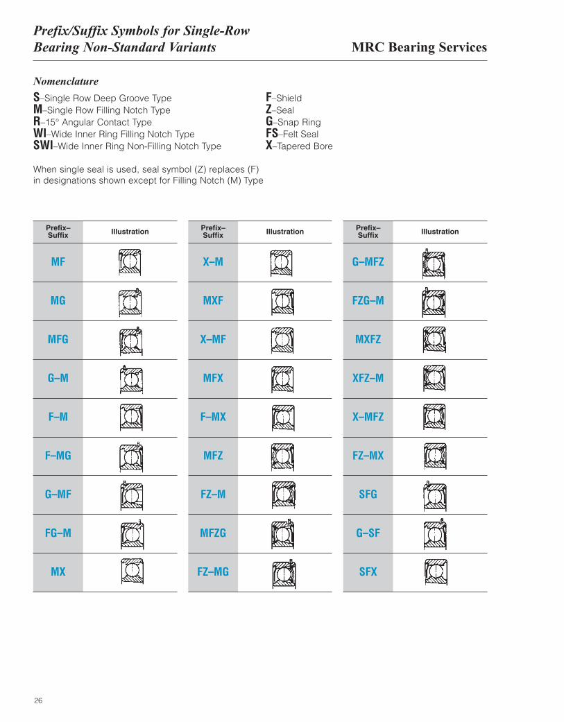
Nomenclature
S–Single Row Deep Groove TypeM–Single Row Filling Notch TypeR–15° Angular Contact TypeWI–Wide Inner Ring Filling Notch TypeSWI–Wide Inner Ring Non-Filling Notch Type
F–ShieldZ–SealG–Snap RingFS–Felt SealX–Tapered Bore
When single seal is used, seal symbol (Z) replaces (F)in designations shown except for Filling Notch (M) Type
Prefix/Suffix Symbols for Single-RowBearing Non-Standard Variants
27
Prefix–Suffix Illustration
SXF
SWIF
F–SWI
WIF
F–WI
FSG
G–FS
FSFG
Prefix–Suffix Illustration
G–FSF
RF
RG
RFG
F–R
G–R
FG–R
G–RF
Prefix–Suffix Illustration
F–RG
RX
X–R
RFX
X–RF
F–RX
FX–R
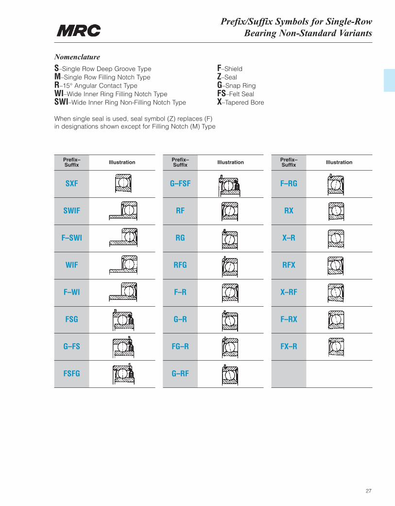
Nomenclature
S–Single Row Deep Groove TypeM–Single Row Filling Notch TypeR–15° Angular Contact TypeWI–Wide Inner Ring Filling Notch TypeSWI–Wide Inner Ring Non-Filling Notch Type
F–ShieldZ–SealG–Snap RingFS–Felt SealX–Tapered Bore
When single seal is used, seal symbol (Z) replaces (F)in designations shown except for Filling Notch (M) Type
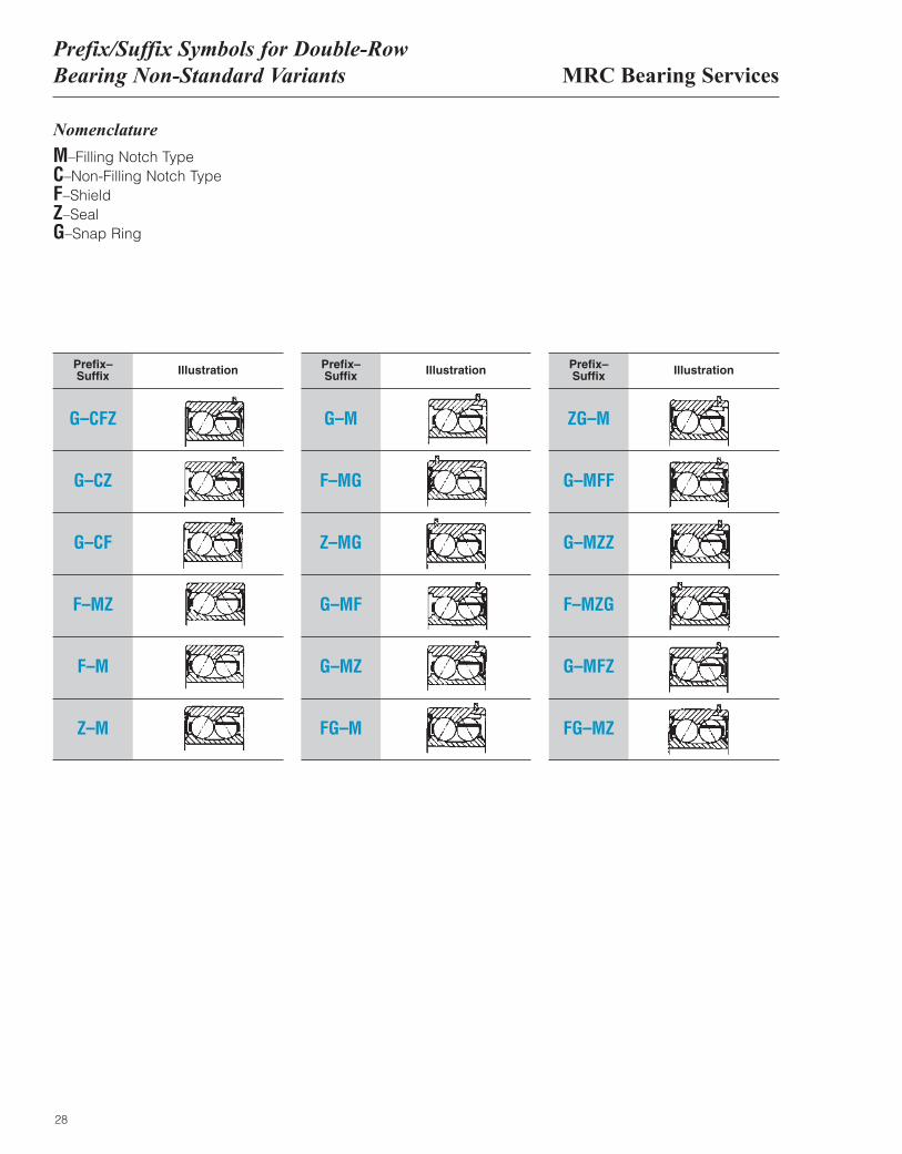
MRC Bearing ServicesPrefix/Suffix Symbols for Double-RowBearing Non-Standard Variants
28
Prefix–Suffix Illustration
G–CFZ
G–CZ
G–CF
F–MZ
F–M
Z–M
Prefix–Suffix Illustration
G–M
F–MG
Z–MG
G–MF
G–MZ
FG–M
Prefix–Suffix Illustration
ZG–M
G–MFF
G–MZZ
F–MZG
G–MFZ
FG–MZ
Nomenclature
M–Filling Notch TypeC–Non-Filling Notch TypeF–ShieldZ–SealG–Snap Ring
MRC Manufacturing Suffixes
29
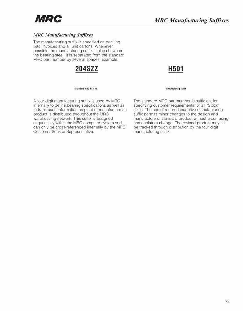
MRC Manufacturing Suffixes
The manufacturing suffix is specified on packinglists, invoices and all unit cartons. Wheneverpossible the manufacturing suffix is also shown onthe bearing steel. It is separated from the standardMRC part number by several spaces. Example:
204SZZ
Standard MRC Part No.
H501
Manufacturing Suffix
A four digit manufacturing suffix is used by MRCinternally to define bearing specifications as well asto track such information as plant-of-manufacture asproduct is distributed throughout the MRCwarehousing network. This suffix is assignedsequentially within the MRC computer system andcan only be cross-referenced internally by the MRCCustomer Service Representative.
The standard MRC part number is sufficient forspecifying customer requirements for all “Stock” sizes. The use of a non-descriptive manufacturingsuffix permits minor changes to the design andmanufacture of standard product without a confusingnomenclature change. The revised product may stillbe tracked through distribution by the four digitmanufacturing suffix.
MRC Bearing ServicesMRC Descriptive Part Suffixes
30
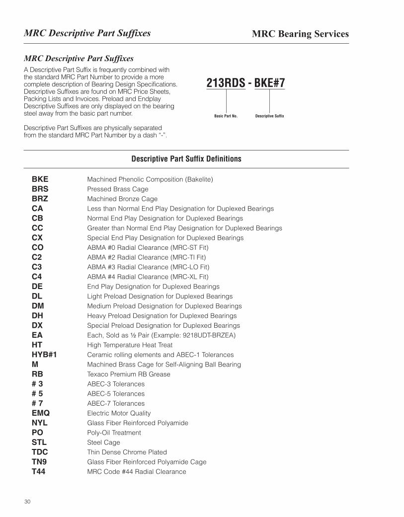
MRC Descriptive Part SuffixesA Descriptive Part Suffix is frequently combined with the standard MRC Part Number to provide a morecomplete description of Bearing Design Specifications.Descriptive Suffixes are found on MRC Price Sheets,Packing Lists and Invoices. Preload and EndplayDescriptive Suffixes are only displayed on the bearingsteel away from the basic part number.
Descriptive Part Suffixes are physically separatedfrom the standard MRC Part Number by a dash “-”.
213RDS
Basic Part No.
BKE#7
Descriptive Suffix
-
Descriptive Part Suffix Definitions
BKEBRSBRZCACBCCCXCOC2C3C4DEDLDMDHDXEAHTHYB#1MRB# 3# 5# 7EMQNYLPOSTLTDCTN9T44
Machined Phenolic Composition (Bakelite)Pressed Brass CageMachined Bronze CageLess than Normal End Play Designation for Duplexed BearingsNormal End Play Designation for Duplexed BearingsGreater than Normal End Play Designation for Duplexed BearingsSpecial End Play Designation for Duplexed BearingsABMA #0 Radial Clearance (MRC-ST Fit)ABMA #2 Radial Clearance (MRC-Tl Fit)ABMA #3 Radial Clearance (MRC-LO Fit)ABMA #4 Radial Clearance (MRC-XL Fit)End Play Designation for Duplexed BearingsLight Preload Designation for Duplexed BearingsMedium Preload Designation for Duplexed BearingsHeavy Preload Designation for Duplexed BearingsSpecial Preload Designation for Duplexed BearingsEach, Sold as ¹|₂ Pair (Example: 9218UDT-BRZEA)High Temperature Heat TreatCeramic rolling elements and ABEC-1 TolerancesMachined Brass Cage for Self-Aligning Ball BearingTexaco Premium RB GreaseABEC-3 TolerancesABEC-5 TolerancesABEC-7 TolerancesElectric Motor QualityGlass Fiber Reinforced Polyamide Poly-Oil TreatmentSteel CageThin Dense Chrome PlatedGlass Fiber Reinforced Polyamide CageMRC Code #44 Radial Clearance
The six primary features of the servicesprovided to our customers are listed below:
31
• MRC is always one 1-800-MRC-7000 phone callaway—saving time in response to your customer.
• Fax number toll-free at 888-322-4672
• Immediate attention is given to technical questions byour in-house engineering department, (215) 513-4700.
• MRC Technical Services experts are able to addressbearing problems in the field and offer solutions.
• MRC provides bearing failure analysis in problemapplications.
• Friendly, knowledgeable customer service people are able to take important action on your requests.
• Many servicing warehouses assure inventoryaccessibility in all parts of the country.

32
BEARINGSPECIFICATION TABLES
INTRODUCTION ENGINEERING DATA MARATHON SERIES MADE-TO-ORDER
BearingSpecificationTables

Section IIBearing Specification Tables
33
MRC Bearing Series . . . . . . . . . . . . . . . . . . . . . . . . . . . . . . . . . . . . . . . . . . . . . . . . . . . . . . . . . . . . . . . . . . 35Bearing Types Summary Chart. . . . . . . . . . . . . . . . . . . . . . . . . . . . . . . . . . . . . . . . . . . . . . . . . . . . . . . . . . 36Single-row deep groove, type S . . . . . . . . . . . . . . . . . . . . . . . . . . . . . . . . . . . . . . . . . . . . . . . . . . . . . . . . . 41Single-row deep groove cartridge type SFFC . . . . . . . . . . . . . . . . . . . . . . . . . . . . . . . . . . . . . . . . . . . . . . 51Single-row deep groove, type S hybrid . . . . . . . . . . . . . . . . . . . . . . . . . . . . . . . . . . . . . . . . . . . . . . . . . . . 54Single-row maximum capacity, filling notch, type M . . . . . . . . . . . . . . . . . . . . . . . . . . . . . . . . . . . . . . . . . 57Self-aligning ball bearings . . . . . . . . . . . . . . . . . . . . . . . . . . . . . . . . . . . . . . . . . . . . . . . . . . . . . . . . . . . . . 65Double-row angular contact, 5000 series . . . . . . . . . . . . . . . . . . . . . . . . . . . . . . . . . . . . . . . . . . . . . . . . . 83Single-row 15° angular contact, type R . . . . . . . . . . . . . . . . . . . . . . . . . . . . . . . . . . . . . . . . . . . . . . . . . . 103Single-row 15° angular contact, type XLS . . . . . . . . . . . . . . . . . . . . . . . . . . . . . . . . . . . . . . . . . . . . . . . . 114Single-row 29° angular contact, 7000 series . . . . . . . . . . . . . . . . . . . . . . . . . . . . . . . . . . . . . . . . . . . . . . 121Single-row 40° angular contact, 7000 P series . . . . . . . . . . . . . . . . . . . . . . . . . . . . . . . . . . . . . . . . . . . . 135Single-row 40° angular contact, 7000 PJ series . . . . . . . . . . . . . . . . . . . . . . . . . . . . . . . . . . . . . . . . . . . 147PumPac 8000, 8000 BB and 8000 AAB series . . . . . . . . . . . . . . . . . . . . . . . . . . . . . . . . . . . . . . . . . . . . 157Single-row 29° angular contact, split ring, 9000 U series . . . . . . . . . . . . . . . . . . . . . . . . . . . . . . . . . . . . 167Single-row 40° angular contact, split ring, 9000 UP series . . . . . . . . . . . . . . . . . . . . . . . . . . . . . . . . . . . 171Duplex 29° angular contact 97000 U series . . . . . . . . . . . . . . . . . . . . . . . . . . . . . . . . . . . . . . . . . . . . . . 177Duplex 40° angular contact 97000UP series . . . . . . . . . . . . . . . . . . . . . . . . . . . . . . . . . . . . . . . . . . . . . . 180Precision ABEC-5 and ABEC-7 bearings. . . . . . . . . . . . . . . . . . . . . . . . . . . . . . . . . . . . . . . . . . . . . . . . . 187
Single-row 15° angular contact, type R . . . . . . . . . . . . . . . . . . . . . . . . . . . . . . . . . . . . . . . . . . . . . . . 188Single-row deep groove, type S, Woodworking Bearings . . . . . . . . . . . . . . . . . . . . . . . . . . . . . . . . . 196Ball screw support bearings . . . . . . . . . . . . . . . . . . . . . . . . . . . . . . . . . . . . . . . . . . . . . . . . . . . . . . . 197Excello bearings. . . . . . . . . . . . . . . . . . . . . . . . . . . . . . . . . . . . . . . . . . . . . . . . . . . . . . . . . . . . . . . . . 199
Specialty bearings . . . . . . . . . . . . . . . . . . . . . . . . . . . . . . . . . . . . . . . . . . . . . . . . . . . . . . . . . . . . . . . . . . 203Adapter type . . . . . . . . . . . . . . . . . . . . . . . . . . . . . . . . . . . . . . . . . . . . . . . . . . . . . . . . . . . . . . . . . . . 204Conveyor roll . . . . . . . . . . . . . . . . . . . . . . . . . . . . . . . . . . . . . . . . . . . . . . . . . . . . . . . . . . . . . . . . . . . 205Dynamometer . . . . . . . . . . . . . . . . . . . . . . . . . . . . . . . . . . . . . . . . . . . . . . . . . . . . . . . . . . . . . . . . . . . 207Electric motor quality / ABMA cross reference . . . . . . . . . . . . . . . . . . . . . . . . . . . . . . . . . . . . . . . . . 209Felt seal replacement. . . . . . . . . . . . . . . . . . . . . . . . . . . . . . . . . . . . . . . . . . . . . . . . . . . . . . . . . . . . . 224Mast guide . . . . . . . . . . . . . . . . . . . . . . . . . . . . . . . . . . . . . . . . . . . . . . . . . . . . . . . . . . . . . . . . . . . . . 228Wide inner ring . . . . . . . . . . . . . . . . . . . . . . . . . . . . . . . . . . . . . . . . . . . . . . . . . . . . . . . . . . . . . . . . . . 231
Table of Contents Page

34
MRC Bearing Series
35
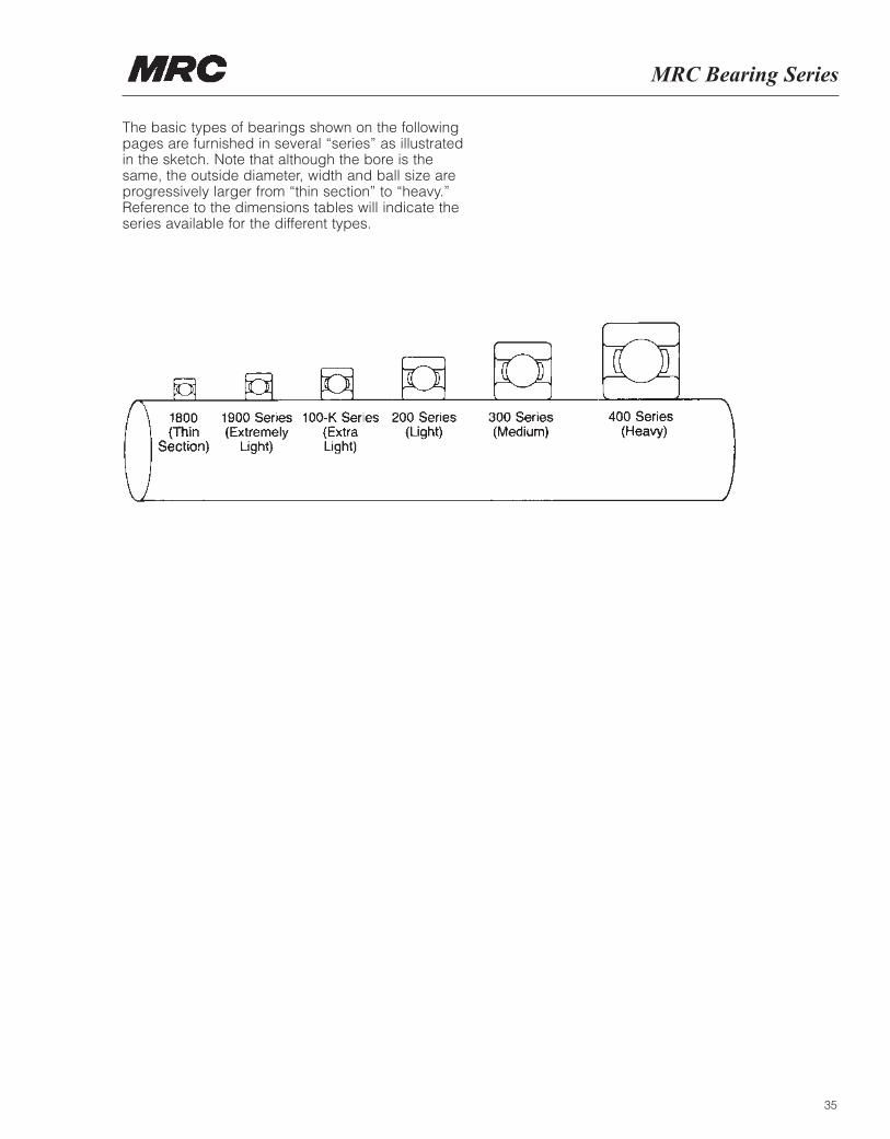
The basic types of bearings shown on the followingpages are furnished in several “series” as illustratedin the sketch. Note that although the bore is thesame, the outside diameter, width and ball size areprogressively larger from “thin section” to “heavy.”Reference to the dimensions tables will indicate theseries available for the different types.
36
Bearing Type Cage Contact Performance Characteristics DescriptionAngle Level Speed Radial Axial
Capacity Capacity
Extremely HighVery HighHighModerate
Extremely HighVery HighHighModerate
Extremely HighVery HighHighModerate
Extremely HighVery HighHighModerate
Extremely HighVery HighHighModerate
Extremely HighVery HighHighModerate
Extremely HighVery HighHighModerate
Extremely HighVery HighHighModerate
Extremely HighVery HighHighModerate
Extremely HighVery HighHighModerate
�
Type “S” Conrad Pressed 0°Deep Groove Steel
“R” Inch Series Pressed 0°Conrad Deep Groove Steel
Type “M” Maximum Pressed 0°Capacity Filling Notch Steel
Type “R” 15° Pressed 15°Angular Contact Steel
5000 Series Pressed 30°Double Row Steel“C” Type Conrad,“M” TypeMaximumCapacity
7000 Series 29° Pressed 29°Angular Contact Steel
7000P Series 40° Machined 40°Angular Contact and Pressed
Brass
“XLS” Inch Series Bakelite 15°Angular Contact
5300 UPG Series Machined 40°Split Inner Ring BrassDouble Row
8000 PumPac® Series Machined 40° & 15°Angular Contact BrassAssembly
37
Bearing Types Summary Chart
Description
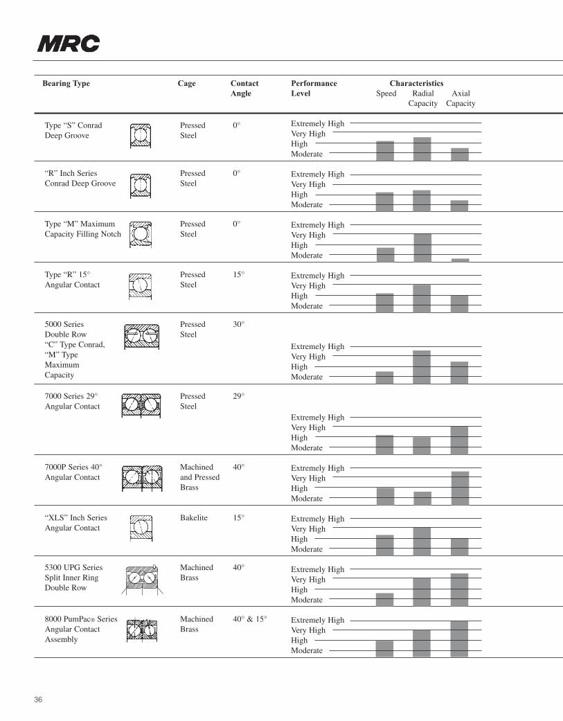
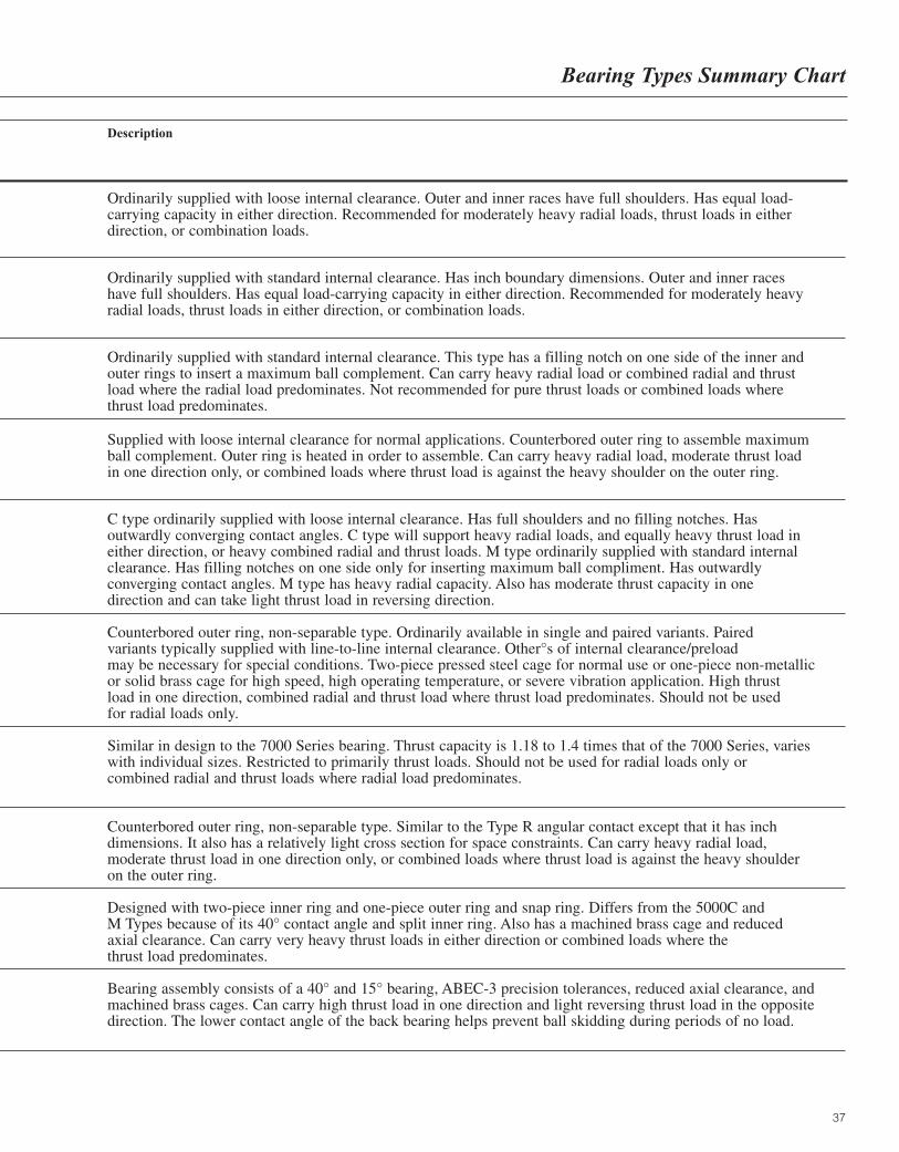
Ordinarily supplied with loose internal clearance. Outer and inner races have full shoulders. Has equal load-carrying capacity in either direction. Recommended for moderately heavy radial loads, thrust loads in either direction, or combination loads.
Ordinarily supplied with standard internal clearance. Has inch boundary dimensions. Outer and inner races have full shoulders. Has equal load-carrying capacity in either direction. Recommended for moderately heavy radial loads, thrust loads in either direction, or combination loads.
Ordinarily supplied with standard internal clearance. This type has a filling notch on one side of the inner and outer rings to insert a maximum ball complement. Can carry heavy radial load or combined radial and thrust load where the radial load predominates. Not recommended for pure thrust loads or combined loads where thrust load predominates.
Supplied with loose internal clearance for normal applications. Counterbored outer ring to assemble maximum ball complement. Outer ring is heated in order to assemble. Can carry heavy radial load, moderate thrust load in one direction only, or combined loads where thrust load is against the heavy shoulder on the outer ring.
C type ordinarily supplied with loose internal clearance. Has full shoulders and no filling notches. Has outwardly converging contact angles. C type will support heavy radial loads, and equally heavy thrust load in either direction, or heavy combined radial and thrust loads. M type ordinarily supplied with standard internal clearance. Has filling notches on one side only for inserting maximum ball compliment. Has outwardly converging contact angles. M type has heavy radial capacity. Also has moderate thrust capacity in onedirection and can take light thrust load in reversing direction.
Counterbored outer ring, non-separable type. Ordinarily available in single and paired variants. Paired variants typically supplied with line-to-line internal clearance. Other°s of internal clearance/preloadmay be necessary for special conditions. Two-piece pressed steel cage for normal use or one-piece non-metallicor solid brass cage for high speed, high operating temperature, or severe vibration application. High thrust load in one direction, combined radial and thrust load where thrust load predominates. Should not be used for radial loads only.
Similar in design to the 7000 Series bearing. Thrust capacity is 1.18 to 1.4 times that of the 7000 Series, varies with individual sizes. Restricted to primarily thrust loads. Should not be used for radial loads only or combined radial and thrust loads where radial load predominates.
Counterbored outer ring, non-separable type. Similar to the Type R angular contact except that it has inch dimensions. It also has a relatively light cross section for space constraints. Can carry heavy radial load, moderate thrust load in one direction only, or combined loads where thrust load is against the heavy shoulder on the outer ring.
Designed with two-piece inner ring and one-piece outer ring and snap ring. Differs from the 5000C and M Types because of its 40° contact angle and split inner ring. Also has a machined brass cage and reduced axial clearance. Can carry very heavy thrust loads in either direction or combined loads where the thrust load predominates.
Bearing assembly consists of a 40° and 15° bearing, ABEC-3 precision tolerances, reduced axial clearance, and machined brass cages. Can carry high thrust load in one direction and light reversing thrust load in the opposite direction. The lower contact angle of the back bearing helps prevent ball skidding during periods of no load.
38
Bearing Type Cage Contact Performance Characteristics DescriptionAngle Level Speed Radial Axial
Capacity Capacity
Extremely HighVery HighHighModerate
Extremely HighVery HighHighModerate
Extremely HighVery HighHighModerate
Extremely HighVery HighHighModerate
Extremely HighVery HighHighModerate
Extremely HighVery HighHighModerate
Extremely HighVery HighHighModerate
Extremely HighVery HighHighModerate
Extremely HighVery HighHighModerate
Extremely HighVery HighHighModerate
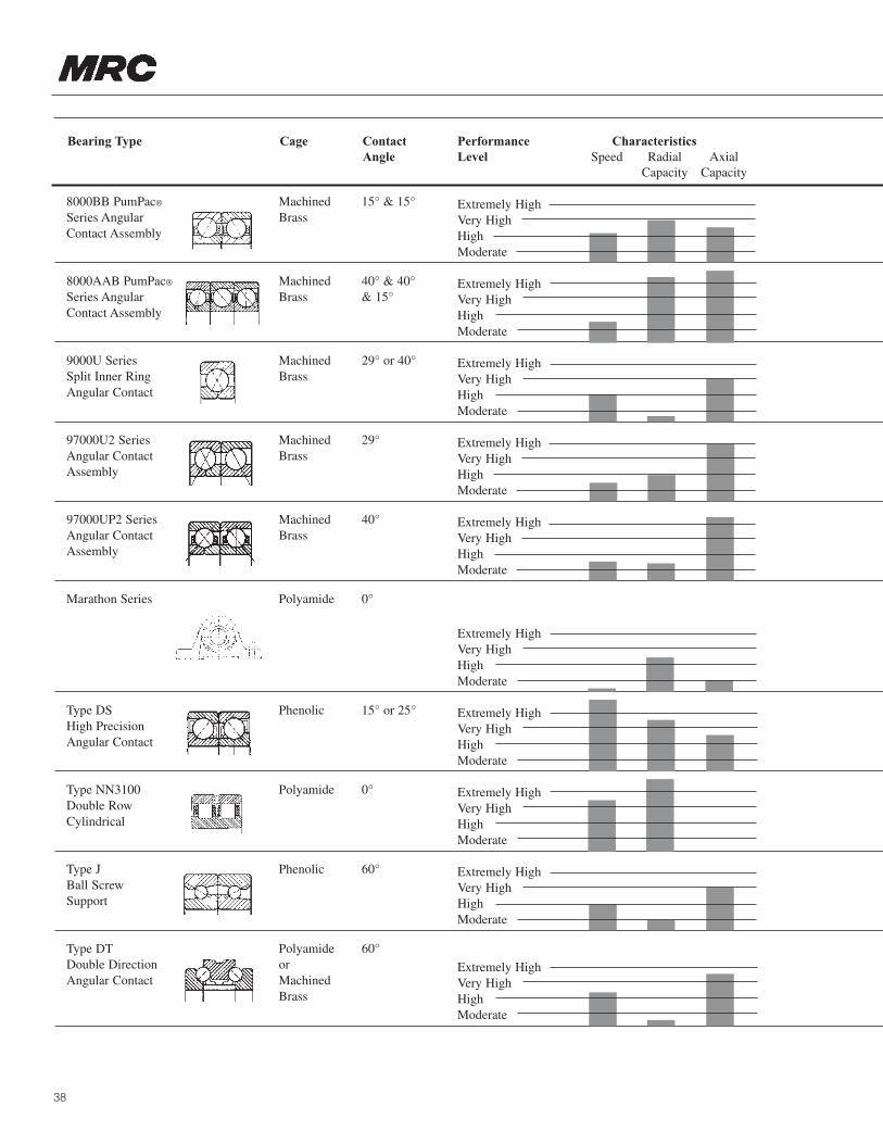
8000BB PumPac® Machined 15° & 15°Series Angular BrassContact Assembly
8000AAB PumPac® Machined 40° & 40°Series Angular Brass & 15°Contact Assembly
9000U Series Machined 29° or 40°Split Inner Ring BrassAngular Contact
97000U2 Series Machined 29°Angular Contact BrassAssembly
97000UP2 Series Machined 40°Angular Contact BrassAssembly
Marathon Series Polyamide 0°
Type DS Phenolic 15° or 25°High PrecisionAngular Contact
Type NN3100 Polyamide 0°Double RowCylindrical
Type J Phenolic 60°Ball ScrewSupport
Type DT Polyamide 60°Double Direction or Angular Contact Machined
Brass
39
Bearing Types Summary Chart
Description
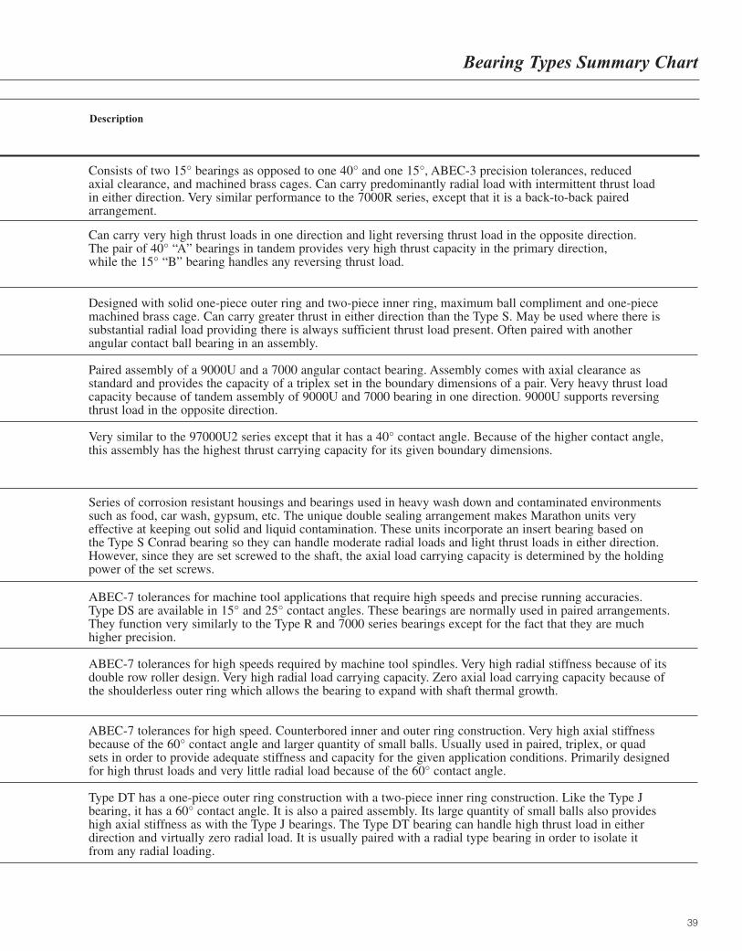
Consists of two 15° bearings as opposed to one 40° and one 15°, ABEC-3 precision tolerances, reduced axial clearance, and machined brass cages. Can carry predominantly radial load with intermittent thrust load in either direction. Very similar performance to the 7000R series, except that it is a back-to-back pairedarrangement.
Can carry very high thrust loads in one direction and light reversing thrust load in the opposite direction. The pair of 40° “A” bearings in tandem provides very high thrust capacity in the primary direction,while the 15° “B” bearing handles any reversing thrust load.
Designed with solid one-piece outer ring and two-piece inner ring, maximum ball compliment and one-piece machined brass cage. Can carry greater thrust in either direction than the Type S. May be used where there is substantial radial load providing there is always sufficient thrust load present. Often paired with another angular contact ball bearing in an assembly.
Paired assembly of a 9000U and a 7000 angular contact bearing. Assembly comes with axial clearance as standard and provides the capacity of a triplex set in the boundary dimensions of a pair. Very heavy thrust loadcapacity because of tandem assembly of 9000U and 7000 bearing in one direction. 9000U supports reversing thrust load in the opposite direction.
Very similar to the 97000U2 series except that it has a 40° contact angle. Because of the higher contact angle,this assembly has the highest thrust carrying capacity for its given boundary dimensions.
Series of corrosion resistant housings and bearings used in heavy wash down and contaminated environments such as food, car wash, gypsum, etc. The unique double sealing arrangement makes Marathon units very effective at keeping out solid and liquid contamination. These units incorporate an insert bearing based on the Type S Conrad bearing so they can handle moderate radial loads and light thrust loads in either direction.However, since they are set screwed to the shaft, the axial load carrying capacity is determined by the holdingpower of the set screws.
ABEC-7 tolerances for machine tool applications that require high speeds and precise running accuracies.Type DS are available in 15° and 25° contact angles. These bearings are normally used in paired arrangements. They function very similarly to the Type R and 7000 series bearings except for the fact that they are much higher precision.
ABEC-7 tolerances for high speeds required by machine tool spindles. Very high radial stiffness because of itsdouble row roller design. Very high radial load carrying capacity. Zero axial load carrying capacity because of the shoulderless outer ring which allows the bearing to expand with shaft thermal growth.
ABEC-7 tolerances for high speed. Counterbored inner and outer ring construction. Very high axial stiffness because of the 60° contact angle and larger quantity of small balls. Usually used in paired, triplex, or quad sets in order to provide adequate stiffness and capacity for the given application conditions. Primarily designed for high thrust loads and very little radial load because of the 60° contact angle.
Type DT has a one-piece outer ring construction with a two-piece inner ring construction. Like the Type J bearing, it has a 60° contact angle. It is also a paired assembly. Its large quantity of small balls also provides high axial stiffness as with the Type J bearings. The Type DT bearing can handle high thrust load in eitherdirection and virtually zero radial load. It is usually paired with a radial type bearing in order to isolate it from any radial loading.

40
Single-Row Deep GrooveBall Bearings, S-Type
41
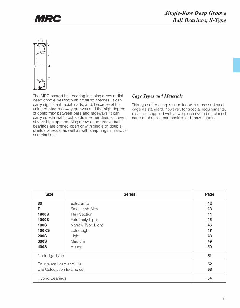
The MRC conrad ball bearing is a single-row radialdeep groove bearing with no filling notches. It cancarry significant radial loads, and, because of the uninterrupted raceway grooves and the high degree of conformity between balls and raceways, it cancarry substantial thrust loads in either direction, evenat very high speeds. Single-row deep groove ballbearings are offered open or with single or doubleshields or seals, as well as with snap rings in variouscombinations.
Cage Types and Materials
This type of bearing is supplied with a pressed steelcage as standard; however, for special requirements, it can be supplied with a two-piece riveted machinedcage of phenolic composition or bronze material.
Size
30R1800S1900S100S100KS200S300S400S
Extra SmallSmall Inch-SizeThin SectionExtremely LightNarrow-Type LightExtra LightLightMediumHeavy
424344454647484950
Series Page
Cartridge Type
Equivalent Load and LifeLife Calculation Examples
51
5253
Hybrid Bearings 54
343536
373839
456
789
161919
222226
566
778
.30
.30
.30
.30
.30
.64
459696
110110161
1 4702 2102 210
3 2503 2504 620
600950950
1 3601 3601 960
43 00036 00036 000
36 00036 00028 000
50 00043 00043 000
43 00043 00034 000
30 00026 00026 000
23 00023 00020 000
MRC Bearing Services30 SeriesExtra Small Size
42
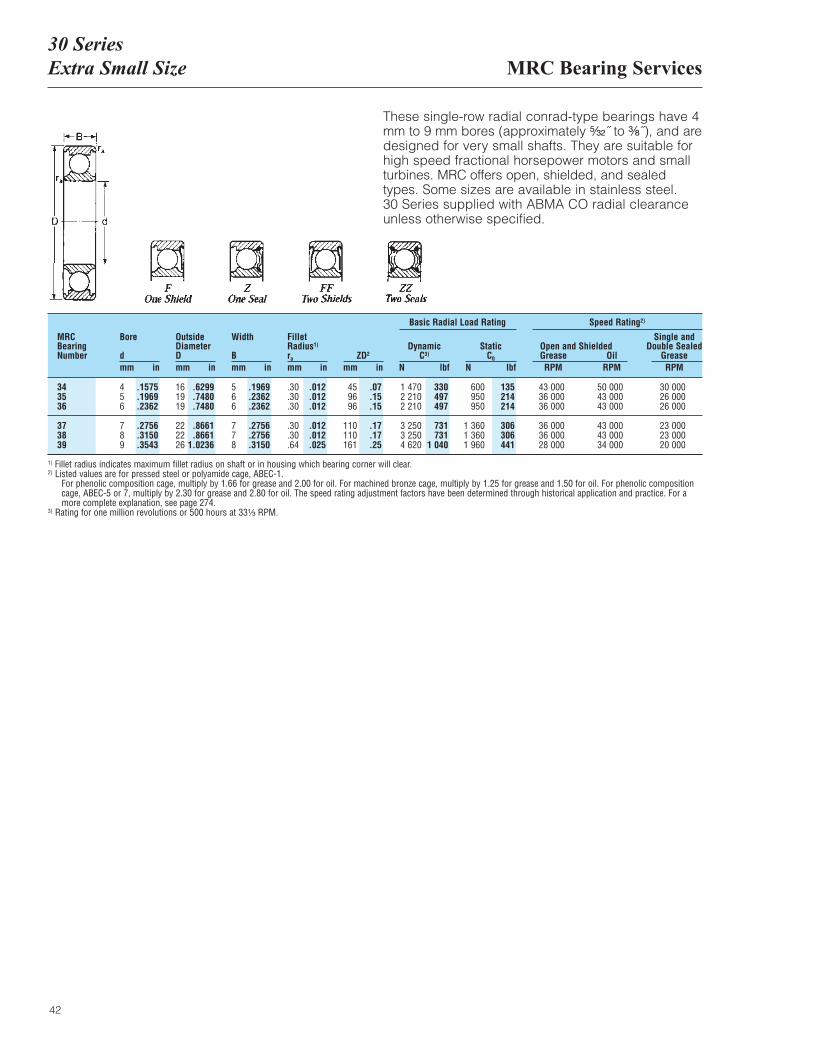
These single-row radial conrad-type bearings have 4mm to 9 mm bores (approximately ⁵|₃₂˝ to ³|₈˝), and aredesigned for very small shafts. They are suitable forhigh speed fractional horsepower motors and smallturbines. MRC offers open, shielded, and sealedtypes. Some sizes are available in stainless steel.30 Series supplied with ABMA CO radial clearanceunless otherwise specified.
MRCBearingNumber
Bore
dmm in
OutsideDiameterDmm in
Width
Bmm in
FilletRadius1)
ra
mm inZD2
mm in
DynamicC3)
N lbf
Basic Radial Load Rating Speed Rating2)
StaticC0
N lbf
Open and ShieldedGrease OilRPM RPM
Single andDouble Sealed
GreaseRPM
.1575
.1969
.2362
.2756
.3150
.3543
.6299
.7480
.7480
.8661
.86611.0236
.1969
.2362
.2362
.2756
.2756
.3150
.012
.012
.012
.012
.012
.025
.07
.15
.15
.17
.17
.25
330497497
731731
1 040
135214214
306306441
1) Fillet radius indicates maximum fillet radius on shaft or in housing which bearing corner will clear.2) Listed values are for pressed steel or polyamide cage, ABEC-1.
For phenolic composition cage, multiply by 1.66 for grease and 2.00 for oil. For machined bronze cage, multiply by 1.25 for grease and 1.50 for oil. For phenolic compositioncage, ABEC-5 or 7, multiply by 2.30 for grease and 2.80 for oil. The speed rating adjustment factors have been determined through historical application and practice. For amore complete explanation, see page 274.
3) Rating for one million revolutions or 500 hours at 33¹|₃ RPM.
MRCBearingNumber
Bore
dmm in
OutsideDiameterDmm in
Shielded orSealedmm in
FilletRadius1)
ra
mm inZD2
mm in
DynamicC3)
N lbf
Basic Radial Load Rating
StaticC0
N lbf
Open and ShieldedGrease OilRPM RPM
Single andDouble Sealed
GreaseRPM
Plain
mm inZD2
mm in
Speed Rating2)
R-2R-2-AR-3
R-4R-4-AR-6
R-8R-10R-12
R-14R-16R-18
R-20R-24
3.23.24.8
6.46.49.5
12.715.919.1
22.225.428.6
31.838.1
9.512.712.7
15.919.122.2
28.634.941.3
47.650.854.0
57.266.7
4.04.44.0
5.05.65.6
6.47.17.9
9.59.59.5
9.511.1
4.04.45.0
5.07.17.1
7.98.7
11.1
12.712.712.7
12.714.3
.30
.30
.30
.30
.41
.41
.41
.79
.79
.79
.79
.79
.79
.79
191939
4571
110
181226361
406406510
613755
312312956
1 4802 8103 320
5 0706 0509 360
10 10010 10012 500
14 00016 800
120120490
6201 1601 340
2 4003 2505 100
5 8506 0007 500
9 30011 800
75 00075 00057 000
44 00039 00031 000
24 00018 00016 000
14 00013 00011 000
11 0009 000
91 00091 00069 000
54 00048 00038 000
29 00022 00019 000
17 00016 00014 000
13 00011 000
52 000 52 00040 000
31 00027 00021 000
16 00013 00011 000
9 6009 0007 900
7 5006 200
.1250
.1250
.1875
.2500
.2500
.3750
.5000
.6250
.7500
.87501.00001.1250
1.25001.5000
.3750
.5000
.5000
.6250
.7500
.8750
1.12501.37501.6250
1.87502.00002.1250
2.25002.6250
.1562
.1719
.1562
.1960
.2188
.2188
.2500
.2812
.3125
.3750
.3750
.3750
.3750
.4375
.1562
.1719
.1960
.1960
.2812
.2812
.3125
.3438
.4375
.5000
.5000
.5000
.5000
.5625
.012
.012
.012
.012
.016
.016
.016
.031
.031
.031
.031
.031
.031
.031
.03
.03
.06
.07
.11
.17
.28
.35
.56
.63
.63
.79
.951.17
7070
215
332632746
1 1401 3602 100
2 2702 2702 810
3 1503 780
2727
110
139261301
540731
1 150
1 3201 3501 690
2 0902 650
R Series Small Inch-Size
43
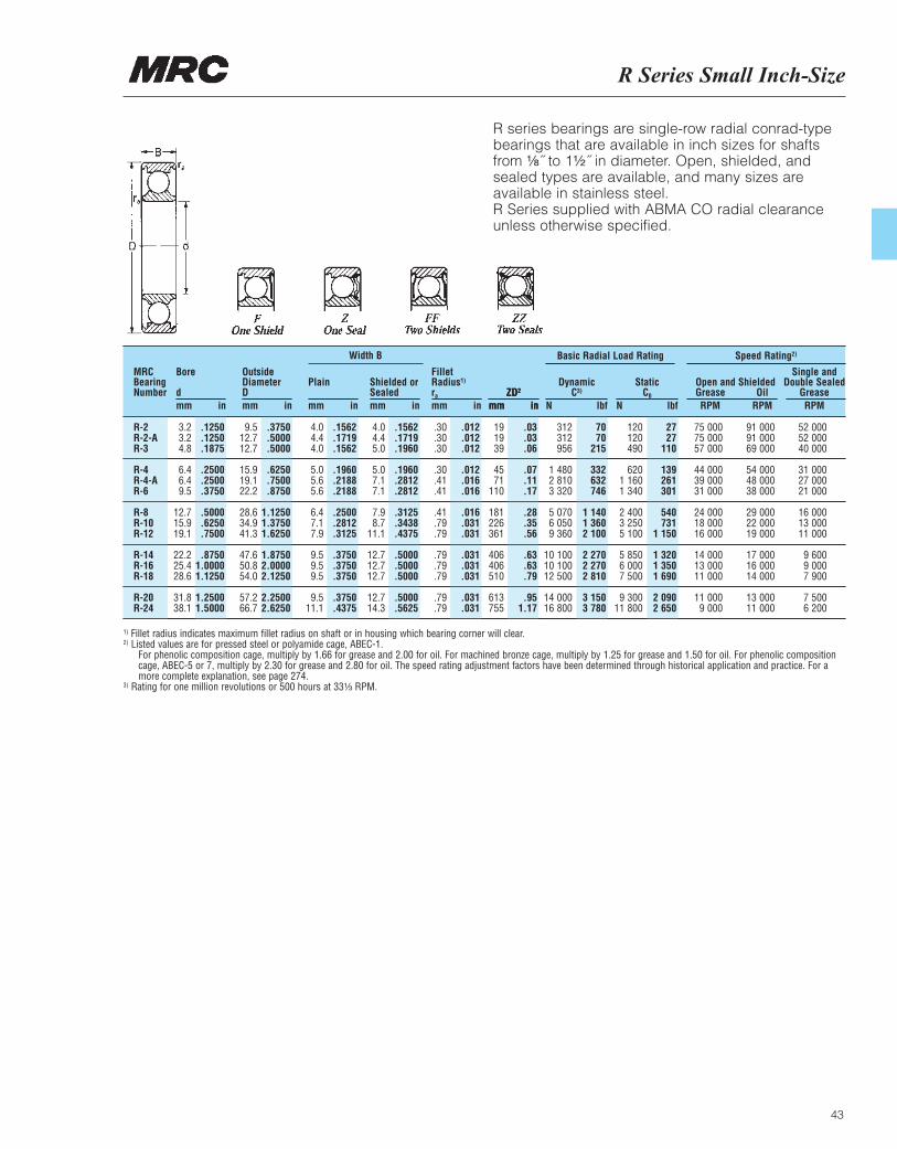
R series bearings are single-row radial conrad-typebearings that are available in inch sizes for shaftsfrom ¹|₈˝ to 1¹|₂˝ in diameter. Open, shielded, andsealed types are available, and many sizes areavailable in stainless steel.R Series supplied with ABMA CO radial clearanceunless otherwise specified.
1) Fillet radius indicates maximum fillet radius on shaft or in housing which bearing corner will clear.2) Listed values are for pressed steel or polyamide cage, ABEC-1.
For phenolic composition cage, multiply by 1.66 for grease and 2.00 for oil. For machined bronze cage, multiply by 1.25 for grease and 1.50 for oil. For phenolic compositioncage, ABEC-5 or 7, multiply by 2.30 for grease and 2.80 for oil. The speed rating adjustment factors have been determined through historical application and practice. For amore complete explanation, see page 274.
3) Rating for one million revolutions or 500 hours at 33¹|₃ RPM.
Width B
MRC Bearing Services1800-S Thin Section Series
44
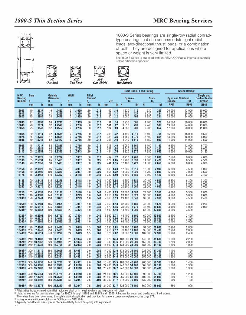
1800-S Series bearings are single-row radial conrad-type bearings that can accommodate light radialloads, two-directional thrust loads, or a combinationof both. They are designed for applications wherespace or weight is very limited.The 1800-S Series is supplied with an ABMA CO Radial internal clearanceunless otherwise specified.
MRCBearingNumber
Bore
dmm in
OutsideDiameterDmm in
Width
Bmm in
FilletRadius1)
ra
mm inZD2
mm in
DynamicC3)
N lbf
Basic Radial Load Rating Speed Rating2)
StaticC0
N lbf
Open and ShieldedGrease OilRPM RPM
Single andDouble Sealed
GreaseRPM
1800S1801S1802S
1803S1804S1805S
1806S1807S1808S
1809S1810S1811S
1812S1813S1814S
1815S1816S1817S
1818S1819S1820S
1821S1822S1824S4)
1826S4)
1828S4)
1830S4)
1832S4)
1834S4)
1836S4)
1838S4)
1840S4)
1844S4)
1848S4)
1852S4)
1856S4)
1860S4)
1864S4)
1868S4)
1872S4)
1876S4)
1880S4)
1884S4)
1888S4)
1892S4)
1896S4)
101215
172025
303540
455055
606570
758085
9095
100
105110120
130140150
160170180
190200220
240260280
300320340
360380400
420440460
480
192124
263237
424752
586572
788590
95100110
115120125
130140150
165175190
200215225
240250270
300320350
380400420
440480500
520540580
600
555
577
777
779
101010
101013
131313
131616
181820
202222
242424
282833
383838
384646
464656
56
.30
.30
.30
.30
.30
.30
.30
.30
.30
.30
.30
.30
.30
.60
.60
.60
.601.0
1.01.01.0
1.01.01.0
1.01.01.0
1.01.01.0
1.51.51.5
2.02.02.0
2.02.02.0
2.02.02.0
2.02.02.5
2.5
626880
91141184
208233257
315347454
499679741
803864
1 230
1 2801 3301 380
1 4801 9102 060
2 6602 8703 540
3 6904 5504 730
5 6905 9106 370
8 6709 330
11 500
14 20014 70015 900
16 40022 70023 700
24 60025 50033 300
34 700
1 8201 9002 080
2 2503 5104 360
4 4904 7504 940
6 0506 2408 320
8 71011 70012 100
12 50013 00019 500
19 50019 900 20 300
20 80028 10029 100
37 70039 00048 800
49 40061 80062 400
74 10076 10078 000
108 000111 000138 000
172 000172 000178 000
182 000242 000247 000
251 000255 000312 000
325 000
9301 0401 250
1 4602 2402 900
3 4003 8004 150
5 1005 5007 350
8 00011 00011 800
12 90013 70019 600
20 40021 20022 000
23 60030 50032 500
43 00046 50057 000
60 00073 50076 500
91 50095 000
102 000
140 000150 000183 000
228 000236 000255 000
260 000365 000380 000
390 000405 000530 000
560 000
36 000 32 00028 000
24 00019 00017 000
15 00013 00011 000
9 5009 0008 500
7 5007 0006 700
6 3006 0005 300
5 3005 0004 800
4 5004 3003 800
3 6003 4003 000
2 8002 6002 400
2 2002 2001 900
1 8001 7001 600
1 4001 3001 200
1 1001 0001 000
950900900
850
43 00038 00034 000
30 00024 00020 000
18 00016 00014 000
12 00011 00010 000
9 0008 5008 000
7 5007 0006 300
6 3006 0005 600
5 3005 0004 500
4 3004 0003 600
3 4003 2003 000
2 8002 8002 400
2 2002 0001 900
1 7001 6001 500
1 4001 3001 300
1 2001 1001 100
1 000
20 00019 00017 000
16 00013 00011 000
9 5008 0007 500
6 7006 0005 180
4 8004 5004 300
4 0003 6003 400
3 2003 0003 000
2 8002 6002 400
2 2002 000
.3937
.4724
.5906
.6693
.7874
.9843
1.18111.37801.5748
1.77171.96852.1654
2.36222.55912.7559
2.95283.14963.3465
3.54333.74023.9370
4.13394.33074.7244
5.11815.51185.9055
6.29926.69297.0866
7.48037.87408.6614
9.448810.236211.0236
11.811012.598413.3858
14.173214.960615.7480
16.535417.322818.1102
18.8976
.7480
.8268
.9449
1.02361.25981.4567
1.65351.85042.0472
2.28352.55912.8346
3.07093.34653.5433
3.74023.93704.3307
4.52764.72444.9213
5.11815.51185.9055
6.49616.88987.4803
7.87408.46468.8583
9.44889.8425
10.6299
11.811012.598413.7795
14.960615.748016.5354
17.322818.897619.6850
20.472421.259822.8346
23.6220
.1969
.1969
.1969
.1969
.2756
.2756
.2756
.2756
.2756
.2756
.2756
.3543
.3937
.3937
.3937
.3937
.3937
.5118
.5118
.5118
.5118
.5118
.6299
.6299
.7087
.7087
.7874
.7874
.8661
.8661
.9449
.9449
.9449
1.10241.10241.2992
1.49611.49611.4961
1.49611.81101.8110
1.81101.81102.2047
2.2047
.012
.012
.012
.012
.012
.012
.012
.012
.012
.012
.012
.012
.012
.025
.025
.025
.025
.040
.040
.040
.040
.040
.040
.040
.040
.040
.040
.040
.040
.040
.060
.060
.060
.080
.080
.080
.080
.080
.080
.080
.080
.080
.080
.080
.100
.100
.10
.11
.12
.14
.22
.28
.32
.36
.40
.49
.54
.70
.771.051.15
1.241.321.90
1.982.062.14
2.292.953.19
4.134.465.49
5.717.067.34
8.819.179.87
13.414.517.8
22.022.924.6
25.535.336.7
38.139.551.7
53.7
410427468
505790980
1 0101 0701 110
1 3601 4001 870
1 9602 6302 720
2 8102 9204 380
4 3804 4704 560
4 6806 3206 540
8 4808 770
11 000
11 10013 90014 000
16 70017 10017 500
24 30025 00031 000
38 70038 70040 000
40 90054 40055 500
56 40057 30070 100
73 100
209234281
328504652
764854933
1 1501 2401 650
1 8002 4702 650
2 9003 0804 410
4 5904 7704 950
5 3106 8607 310
9 67010 50012 800
13 50016 50017 200
20 60021 40022 900
31 50033 70041 100
51 30053 10057 300
58 50082 10085 400
87 70091 000
119 000
126 0001) Fillet radius indicates maximum fillet radius on shaft or in housing which bearing corner will clear.2) Listed values are for pressed steel cage for 1800S through 1828S and 1834S and 1856S. All others for outer land guided machined bronze.
The values have been determined through historical application and practice. For a more complete explanation, see page 274.3) Rating for one million revolutions or 500 hours at 33¹|₃ RPM.4) Typically non-stocked sizes, please check availability before designing into equipment.
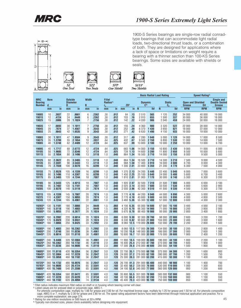
1900-S Series Extremely Light Series
45
1900-S Series bearings are single-row radial conrad-type bearings that can accommodate light radialloads, two-directional thrust loads, or a combinationof both. They are designed for applications where a lack of space or limitations on weight require abearing with a thinner section than 100-KS Seriesbearings. Some sizes are available with shields orseals.
MRCBearingNumber
Bore
dmm in
OutsideDiameterDmm in
Width
Bmm in
FilletRadius1)
ra
mm inZD2
mm in
DynamicC3)
N lbf
Basic Radial Load Rating Speed Rating2)
StaticC0
N lbf
Open and ShieldedGrease OilRPM RPM
Single andDouble Sealed
GreaseRPM
1900S1901S1902S
1903S1904S1905S
1906S1907S1908S
1909S1910S1911S
1912S1913S1914S
1915S1916S1917S
1918S1919S1920S
1921S1922S1924S
1926S4)
1928S4)
1930S4)
1932S4)
1934S4)
1936S4)
1938S4)
1940S4)
1944S4)
1948S4)
1952S4)
1956S4)
1960S4)
1964S4)
1968S4)
1972S4)
1976S4)
1980S4)
1984S4)
1988S4)
1992S4)
101215
172025
303540
455055
606570
758085
9095
100
105110120
130140150
160170180
190200220
240260280
300320340
360380400
420440460
222428
303742
475562
687280
8590
100
105110120
125130140
145150165
180190210
220230250
260280300
320360380
420440460
480520540
560600620
667
799
91012
121213
131316
161618
181820
202022
242428
282833
333838
384646
565656
566565
657474
.30
.30
.30
.30
.30
.30
.30
.64
.64
.64
.641.0
1.01.01.0
1.01.01.0
1.01.01.0
1.01.01.0
1.51.52.0
2.02.02.0
2.02.02.0
2.02.02.0
3.03.03.0
3.04.04.0
4.04.04.0
84103142
155252271
317432637
683728864
864968
1 300
1 3701 4501 810
1 9202 0252 550
2 7702 7703 460
4 1004 3205 670
6 0006 3308 060
8 06010 20010 800
11 90016 40017 300
22 70024 00025 300
26 70032 40034 100
35 80043 10045 400
2 5102 9104 030
4 360 6 3706 630
7 2809 560
13 800
14 00014 60016 500
16 50017 40023 800
24 20025 10031 900
32 50033 80042 300
44 20043 60055 300
65 00066 30088 400
92 30093 600
119 000
117 000148 000151 000
159 000212 000216 000
270 000276 000281 000
291 000338 000345 000
351 000410 000423 000
1 1201 5002 040
2 3203 6504 150
5 0006 800
10 000
10 80011 80014 000
14 30016 00021 200
22 40024 00030 000
31 50033 50041 500
44 00044 00057 000
67 00071 00093 000
98 000104 000132 000
134 000166 000176 000
196 000270 000285 000
375 000390 000415 000
440 000530 000560 000
585 000710 000750 000
34 00030 00024 000
22 00018 00016 000
14 00011 00010 000
9 0008 5008 000
7 5006 7006 300
6 0005 6005 300
5 0004 8004 500
4 3004 0003 600
3 4003 2002 800
2 6002 4002 200
2 2002 0001 900
1 8001 6001 500
1 3001 2001 100
1 1001 000
950
900900850
40 00036 00030 000
28 00022 00019 000
17 00014 00013 000
11 00010 0009 500
9 0008 0007 500
7 0006 7006 300
6 0005 6005 300
5 0004 8004 300
4 0003 8003 400
3 2003 0002 800
2 8002 6002 400
2 2001 9001 800
1 6001 5001 400
1 4001 3001 200
1 1001 1001 000
19 00018 00016 000
14 00012 00010 000
8 5007 5006 700
6 0005 6005 000
4 5004 3004 000
3 6003 4003 200
3 1002 9002 700
2 6002 5002 300
2 1002 0001 800
1 7001 6001 500
1 4001 3001 200
1 1001 000
950
800750700
700650600
550550550
.3937
.4724
.5906
.6693
.7874
.9843
1.18111.37801.5748
1.77171.96852.1654
2.36222.55912.7559
2.95283.14963.3465
3.54333.74023.9370
4.13394.33074.7244
5.11815.51185.9055
6.29926.69297.0866
7.48037.87408.6614
9.448810.236211.0236
11.811012.598413.3858
14.173214.960615.7480
16.535417.322818.1102
.8661
.94491.1024
1.18111.45671.6535
1.85042.16542.4409
2.67722.83463.1496
3.34653.54333.9370
4.13394.33074.7244
4.92135.11815.5118
5.70875.90556.4961
7.08667.48038.2677
8.66149.05519.8425
10.236211.023611.8110
12.598414.173214.9606
16.535417.322818.1102
18.897620.472421.2598
22.047223.622024.4094
.2362
.2362
.2756
.2756
.3543
.3543
.3543
.3937
.4724
.4724
.4724
.5118
.5118
.5118
.6299
.6299
.6299
.7087
.7087
.7087
.7874
.7874
.7874
.8661
.9449
.94491.1024
1.10241.10241.2992
1.29921.49611.4961
1.49611.81101.8110
2.20472.20472.2047
2.20472.55912.5591
2.55912.91342.9134
.012
.012
.012
.012
.012
.012
.012
.025
.025
.025
.025
.040
.040
.040
.040
.040
.040
.040
.040
.040
.040
.040
.040
.040
.060
.060
.080
.080
.080
.080
.080
.080
.080
.080
.080
.080
.120
.120
.120
.120
.160
.160
.160
.160
.160
.13
.16
.22
.24
.39
.42
.49
.67
.99
1.061.131.34
1.341.502.01
2.132.252.81
2.973.143.96
4.184.185.36
6.356.708.78
9.309.8212.5
12.515.816.7
18.525.426.8
35.137.239.3
41.350.252.8
55.566.870.3
565655906
9801 4301 490
1 6402 1503 100
3 1503 2803 710
3 7103 9105 350
5 4405 6407 170
7 3107 6009 510
9 9409 800
12 400
14 60014 90019 900
20 70021 00026 800
26 30033 30033 900
35 80047 70048 600
60 70062 10063 200
65 40076 00077 000
78 90092 20095 100
252337459
522821933
1 1201 5302 250
2 4302 6503 150
3 2103 6004 770
5 0405 4006 740
7 0807 5309 330
9 8909 890
12 800
15 10016 00020 900
22 00023 40029 700
30 10037 30039 600
44 10060 70064 100
84 30087 70093 300
98 900119 000126 000
132 000160 000169 000
1) Fillet radius indicates maximum fillet radius on shaft or in housing which bearing corner will clear.2) Listed values are for pressed steel or polyamide cage, ABEC-1.
For phenolic composition cage, multiply by 1.66 for grease and 2.00 for oil. For machined bronze cage, multiply by 1.25 for grease and 1.50 for oil. For phenolic compositioncage, ABEC-5 or 7, multiply by 2.30 for grease and 2.80 for oil. The speed rating adjustment factors have been determined through historical application and practice. For amore complete explanation, see page 274.
3) Rating for one million revolutions or 500 hours at 33¹|₃ RPM.4) Typically non-stocked sizes, please check availability before designing into equipment.
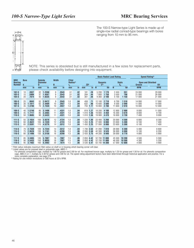
MRC Bearing Services100-S Narrow-Type Light Series
46
The 100-S Narrow-type Light Series is made up of single-row radial conrad-type bearings with bores ranging from 10 mm to 95 mm.
MRCBearingNumber
Bore
dmm in
OutsideDiameterDmm in
Width
Bmm in
FilletRadius1)
ra
mm inZD2
mm in
DynamicC3)
N lbf
Basic Radial Load Rating Speed Rating2)
StaticC0
N lbf
Open and ShieldedGrease Oil
RPM RPM
102-S103-S104-S
105-S106-S107-S
108-S109-S110-S
111-S112-S113-S
114-S115-S116-S
117-S118-S119-S
101520
253035
404550
556065
707580
859095
323742
526270
808590
100105115
120130135
145150160
999
91010
111111
121214
141616
181820
.51
.51
.51
1.01.01.0
1.01.01.0
1.01.01.0
1.01.51.5
1.51.51.5
181284361
458632755
8191 0101 010
1 2201 4501 450
1 7002 2602 420
2 8502 8503 530
5 2007 8009 360
12 10015 60016 800
18 20019 80019 900
23 40027 00027 000
31 20042 30044 200
52 70052 70063 700
2 4503 5505 100
6 7009 300
11 600
12 90016 30016 600
20 00023 60023 600
28 00036 00039 000
45 50046 50057 000
24 00021 00017 000
14 00011 00010 000
9 0008 0007 400
6 8006 1006 100
5 4005 1004 800
4 5004 3004 000
29 00026 00021 000
17 00014 00012 000
11 0009 7009 000
8 3007 4007 400
6 6006 2005 900
5 5005 2004 900
.3937
.5906
.7874
.98431.18111.3780
1.57481.77171.9685
2.16542.36222.5591
2.75592.95283.1496
3.34653.54333.7402
1.25981.45671.6535
2.04722.44092.7559
3.14963.34653.5433
3.93704.13394.5276
4.72445.11815.3150
5.70875.90556.2992
.3543
.3543
.3543
.3543
.3937
.3937
.4331
.4331
.4331
.4724
.4724
.5512
.5512
.6299
.6299
.7087
.7087
.7874
.02
.02
.02
.04
.04
.04
.04
.04
.04
.04
.04
.04
.04
.06
.06
.06
.06
.06
.28
.44
.56
.71
.981.17
1.271.561.56
1.892.252.25
2.643.503.75
4.424.425.47
1 1701 7502 100
2 7103 5003 780
4 1004 4504 470
5 2606 0806 080
7 0109 5209 940
11 80011 80014 300
551798
1 150
1 5102 0902 610
2 9003 6703 730
4 5005 3005 300
6 3008 0908 770
10 20010 50012 800
1) Fillet radius indicates maximum fillet radius on shaft or in housing which bearing corner will clear.2) Listed values are for pressed steel or polyamide cage, ABEC-1.
For phenolic composition cage, multiply by 1.66 for grease and 2.00 for oil. For machined bronze cage, multiply by 1.25 for grease and 1.50 for oil. For phenolic compositioncage, ABEC-5 or 7, multiply by 2.30 for grease and 2.80 for oil. The speed rating adjustment factors have been determined through historical application and practice. For amore complete explanation, see page 274.
3) Rating for one million revolutions or 500 hours at 33¹|₃ RPM.
NOTE: This series is obsoleted but is still manufactured in a few sizes for replacement parts, please check availability before designing into equipment.
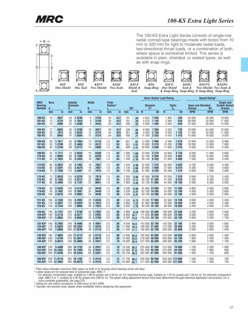
100-KS Extra Light Series
47
The 100-KS Extra Light Series consists of single-rowradial conrad-type bearings made with bores from 10mm to 320 mm for light to moderate radial loads, two-directional thrust loads, or a combination of both,where space is somewhat limited. This series isavailable in plain, shielded, or sealed types, as wellas with snap-rings.
MRCBearingNumber
Bore
dmm in
OutsideDiameterDmm in
Width
Bmm in
FilletRadius1)
ra
mm inZD2
mm in
DynamicC3)
N lbf
Basic Radial Load Rating Speed Rating2)
StaticC0
N lbf
Open and ShieldedGrease OilRPM RPM
Single andDouble Sealed
GreaseRPM
100-KS101-KS102-KS
103-KS104-KS105-KS
106-KS107-KS108-KS
109-KS110-KS111-KS
112-KS113-KS114-KS
115-KS116-KS117-KS
118-KS119-KS120-KS
121-KS122-KS124-KS
126-KS128-KS4)
130-KS4)
132-KS4)
134-KS4)
136-KS4)
138-KS4)
140-KS4)
144-KS4)
148-KS4)
152-KS4)
156-KS4)
160-KS4)
164-KS4)
101215
172025
303540
455055
606570
758085
9095
100
105110120
130140150
160170180
190200220
240260280
300320
262832
354247
556268
758090
95100110
115125130
140145150
160170180
200210225
240260280
290310340
360400420
460480
889
101212
131415
161618
181820
202222
242424
262828
333335
384246
465156
566565
7474
.30
.30
.30
.30
.64
.64
1.01.01.0
1.01.01.0
1.01.01.0
1.01.01.0
1.51.51.5
2.02.02.0
2.02.02.0
2.02.02.0
2.02.02.5
2.53.03.0
3.03.0
181181206
226361458
561691909
1 0901 1801 390
1 6101 7302 100
2 2602 6502 860
3 2803 5303 530
4 3304 6605 000
5 9606 9008 385
9 03011 80011 400
13 40015 90018 600
19 50023 90025 700
31 70034 000
4 6205 0705 590
6 0509 360
11 200
13 30015 80020 800
23 40024 70028 100
32 50033 80041 000
42 30050 70052 700
61 80063 70063 700
79 30081 80085 200
106 000111 000125 000
143 000168 000190 000
195 000216 000247 000
255 000291 000302 000
358 000371 000
1 9602 3602 850
3 2505 0006 550
8 30010 20011 600
16 60018 00021 600
25 00027 00032 500
35 50041 50045 000
51 00054 00054 000
65 50073 50080 000
100 000108 000125 000
143 000173 000200 000
216 000245 000290 000
315 000375 000405 000
500 000540 000
30 00026 00022 000
19 00017 00015 000
12 00010 0009 500
9 0008 5007 500
6 7006 3006 000
5 6005 3005 000
4 8004 5004 300
4 0003 8003 400
3 2003 0002 600
2 4002 2002 000
2 0001 9001 800
1 7001 5001 400
1 2001 100
36 00032 00028 000
24 00020 00018 000
15 00013 00012 000
11 00010 0009 000
8 0007 5007 000
6 7006 3006 000
5 6005 3005 000
4 8004 5004 000
3 8003 6003 200
3 0002 8002 600
2 6002 4002 200
2 0001 8001 700
1 5001 400
19 00017 00014 000
13 00011 0009 500
8 0007 0006 300
5 6005 0004 500
4 3004 0003 600
3 4003 2003 000
2 8002 8002 600
2 4002 4002 200
2 0001 8001 700
1 6001 5001 400
1 4001 3001 100
1 000940890
780730
.3937
.4724
.5906
.6693
.7874
.9843
1.18111.37801.5748
1.77171.96852.1654
2.36222.55912.7559
2.95283.14963.3465
3.54333.74023.9370
4.13394.33074.7244
5.11815.51185.9055
6.29926.69297.0866
7.48037.87408.6614
9.448810.236211.0236
11.811012.5984
1.02361.10241.2598
1.37801.65351.8504
2.16542.44092.6772
2.95283.14963.5433
3.74023.93704.3307
4.52764.92135.1181
5.51185.70875.9055
6.29926.69297.0866
7.87408.26778.8583
9.448810.236211.0236
11.417312.204713.3868
14.173215.748016.5354
18.110218.8976
.3150
.3150
.3543
.3937
.4724
.4724
.5118
.5512
.5906
.6299
.6299
.7087
.7087
.7087
.7874
.7874
.8661
.8661
.9449
.9449
.9449
1.02361.10241.1024
1.29921.29921.3780
1.49611.65351.8110
1.81102.00792.2047
2.20472.55912.5591
2.91342.9134
.012
.012
.012
.012
.025
.025
.04
.04
.04
.04
.04
.04
.04
.04
.04
.04
.04
.04
.06
.06
.06
.08
.08
.08
.08
.08
.08
.08
.08
.08
.08
.08
.10
.10
.12
.12
.12
.12
.28
.28
.32
.35
.56
.71
.871.071.41
1.691.832.16
2.492.683.25
3.504.114.43
5.085.475.47
6.727.237.75
9.2410.713.0
14.018.317.7
20.824.628.9
30.237.039.9
49.252.7
1 0401 1401 260
1 3602 1002 520
2 9903 5704 680
5 2705 5606 320
7 3107 6009 220
9 51011 40011 800
13 90014 30014 300
17 80018 40019 100
23 80025 00028 100
32 10037 80042 700
43 80048 60055 500
57 30065 40067 900
80 50083 400
440530640
7301 1201 470
1 8702 2902 610
3 7304 0504 880
5 6206 0707 310
7 9709 330
10 100
11 50012 10012 100
14 70016 50018 000
22 50024 30028 100
32 10038 90045 000
48 60055 10065 200
70 80084 30091 000
112 000121 000
1) Fillet radius indicates maximum fillet radius on shaft or in housing which bearing corner will clear.2) Listed values are for pressed steel or polyamide cage, ABEC-1.
For phenolic composition cage, multiply by 1.66 for grease and 2.00 for oil. For machined bronze cage, multiply by 1.25 for grease and 1.50 for oil. For phenolic compositioncage, ABEC-5 or 7, multiply by 2.30 for grease and 2.80 for oil. The speed rating adjustment factors have been determined through historical application and practice. For amore complete explanation, see page 274.
3) Rating for one million revolutions or 500 hours at 33¹|₃ RPM.4) Typically non-stocked sizes, please check availability before designing into equipment.
KSFOne Shield
KSZOne Seal
KSFFTwo Shields
KSZZTwo Seals
KSFZShield &
Seal
KSGSnap-Ring
KSFGOne Shield
& Snap-Ring
KSZGSeal &
Snap-Ring
KSFFGTwo Shields& Snap-Ring
KSZZGTwo Seals &Snap-Ring
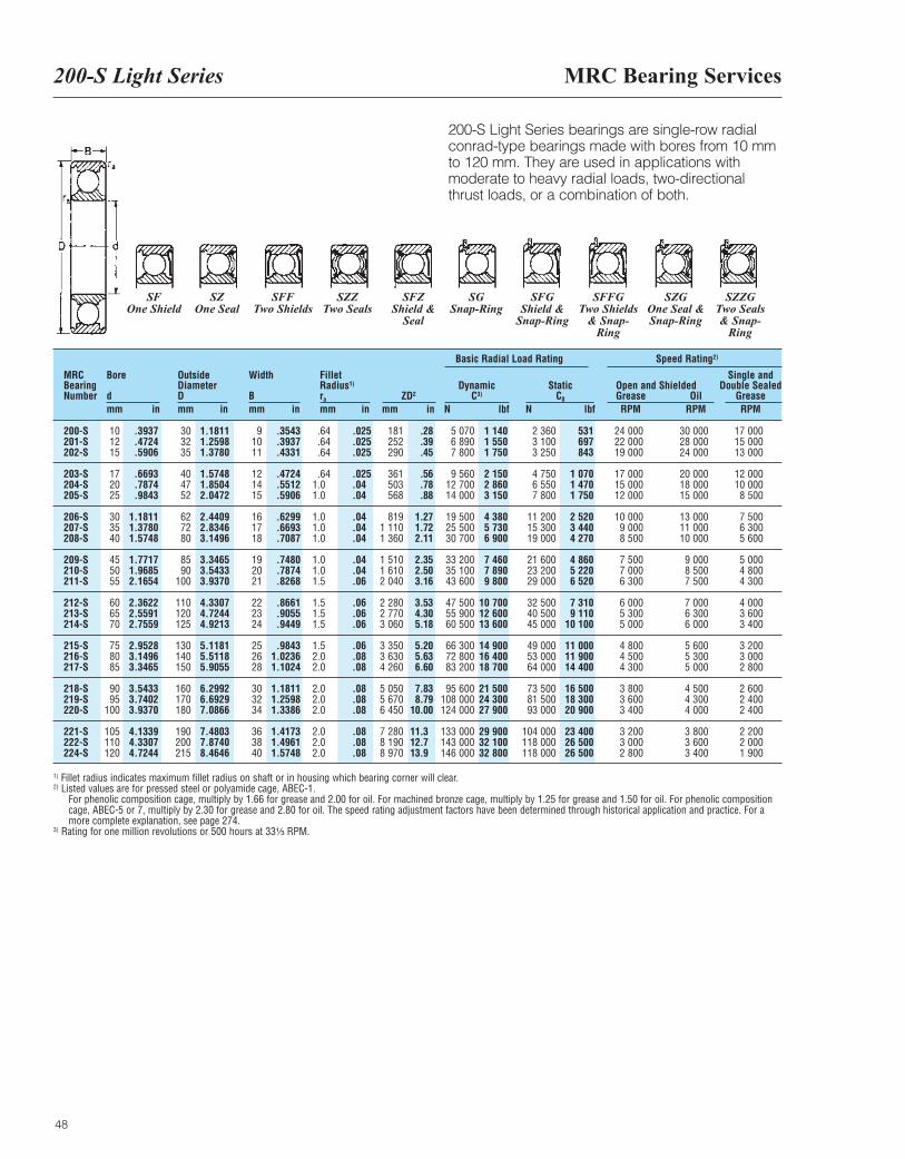
MRC Bearing Services200-S Light Series
48
200-S Light Series bearings are single-row radial conrad-type bearings made with bores from 10 mm to 120 mm. They are used in applications with moderate to heavy radial loads, two-directional thrust loads, or a combination of both.
MRCBearingNumber
Bore
dmm in
OutsideDiameterDmm in
Width
Bmm in
FilletRadius1)
ra
mm inZD2
mm in
DynamicC3)
N lbf
Basic Radial Load Rating Speed Rating2)
StaticC0
N lbf
Open and ShieldedGrease OilRPM RPM
Single andDouble Sealed
GreaseRPM
200-S201-S202-S
203-S204-S205-S
206-S207-S208-S
209-S210-S211-S
212-S213-S214-S
215-S216-S217-S
218-S219-S220-S
221-S222-S224-S
101215
172025
303540
455055
606570
758085
9095
100
105110120
303235
404752
627280
8590
100
110120125
130140150
160170180
190200215
91011
121415
161718
192021
222324
252628
303234
363840
.64
.64
.64
.641.01.0
1.01.01.0
1.01.01.5
1.51.51.5
1.52.02.0
2.02.02.0
2.02.02.0
181252290
361503568
8191 1101 360
1 5101 6102 040
2 2802 7703 060
3 3503 6304 260
5 0505 6706 450
7 2808 1908 970
5 0706 8907 800
9 56012 70014 000
19 50025 50030 700
33 20035 10043 600
47 50055 90060 500
66 30072 80083 200
95 600108 000124 000
133 000143 000146 000
2 3603 1003 250
4 7506 5507 800
11 20015 30019 000
21 60023 20029 000
32 50040 50045 000
49 00053 00064 000
73 50081 50093 000
104 000118 000118 000
24 00022 00019 000
17 00015 00012 000
10 0009 0008 500
7 5007 0006 300
6 0005 3005 000
4 8004 5004 300
3 8003 6003 400
3 2003 0002 800
30 00028 00024 000
20 00018 00015 000
13 00011 00010 000
9 0008 5007 500
7 0006 3006 000
5 6005 3005 000
4 5004 3004 000
3 8003 6003 400
17 00015 00013 000
12 00010 0008 500
7 5006 3005 600
5 0004 8004 300
4 0003 6003 400
3 2003 0002 800
2 6002 4002 400
2 2002 0001 900
.3937
.4724
.5906
.6693
.7874
.9843
1.18111.37801.5748
1.77171.96852.1654
2.36222.55912.7559
2.95283.14963.3465
3.54333.74023.9370
4.13394.33074.7244
1.18111.25981.3780
1.57481.85042.0472
2.44092.83463.1496
3.34653.54333.9370
4.33074.72444.9213
5.11815.51185.9055
6.29926.69297.0866
7.48037.87408.4646
.3543
.3937
.4331
.4724
.5512
.5906
.6299
.6693
.7087
.7480
.7874
.8268
.8661
.9055
.9449
.98431.02361.1024
1.18111.25981.3386
1.41731.49611.5748
.025
.025
.025
.025
.04
.04
.04
.04
.04
.04
.04
.06
.06
.06
.06
.06
.08
.08
.08
.08
.08
.08
.08
.08
.28
.39
.45
.56
.78
.88
1.271.722.11
2.352.503.16
3.534.305.18
5.205.636.60
7.838.79
10.00
11.312.713.9
1 1401 5501 750
2 1502 8603 150
4 3805 7306 900
7 4607 8909 800
10 70012 60013 600
14 90016 40018 700
21 50024 30027 900
29 90032 10032 800
531697843
1 0701 4701 750
2 5203 4404 270
4 8605 2206 520
7 3109 110
10 100
11 00011 90014 400
16 50018 30020 900
23 40026 50026 500
1) Fillet radius indicates maximum fillet radius on shaft or in housing which bearing corner will clear.2) Listed values are for pressed steel or polyamide cage, ABEC-1.
For phenolic composition cage, multiply by 1.66 for grease and 2.00 for oil. For machined bronze cage, multiply by 1.25 for grease and 1.50 for oil. For phenolic compositioncage, ABEC-5 or 7, multiply by 2.30 for grease and 2.80 for oil. The speed rating adjustment factors have been determined through historical application and practice. For amore complete explanation, see page 274.
3) Rating for one million revolutions or 500 hours at 33¹|₃ RPM.
SFOne Shield
SZOne Seal
SFFTwo Shields
SZZTwo Seals
SFZShield &
Seal
SGSnap-Ring
SFGShield &
Snap-Ring
SFFGTwo Shields
& Snap-Ring
SZGOne Seal &Snap-Ring
SZZGTwo Seals & Snap-
Ring
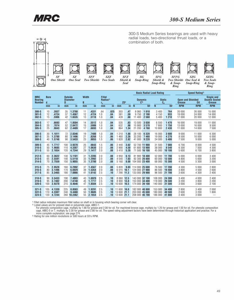
300-S Medium Series
49
300-S Medium Series bearings are used with heavyradial loads, two-directional thrust loads, or acombination of both.
SFOne Shield
SZOne Seal
SFFTwo Shields
SZZTwo Seals
SFZShield &
Seal
SGSnap-Ring
SFGShield &
Snap-Ring
SFFGTwo Shields
& Snap-Ring
SZGOne Seal &Snap-Ring
SZZGTwo Seals & Snap-
Ring
300-S301-S302-S
303-S304-S305-S
306-S307-S308-S
309-S310-S311-S
312-S313-S314-S
315-S316-S317-S
318-S319-S320-S
321-S322-S324-S
101215
172025
303540
455055
606570
758085
9095
100
105110120
.3937
.4724
.5906
.6693
.7874
.9843
1.18111.37801.5748
1.77171.96852.1654
2.36222.55912.7559
2.95283.14963.3465
3.54333.74023.9370
4.13394.33074.7244
353742
475262
728090
100110120
130140150
160170180
190200215
225240260
1.37801.45671.6535
1.85042.04722.4409
2.83463.14963.5433
3.93704.33074.7244
5.11815.51185.9055
6.29926.69297.0866
7.48037.87408.4646
8.85839.4488
10.2362
111213
141517
192123
252729
313335
373941
434547
495055
.4331
.4724
.5118
.5512
.5906
.6693
.7480
.8268
.9055
.98431.06301.1417
1.22051.29921.3780
1.45671.53541.6142
1.69291.77171.8504
1.92911.96852.1654
.641.01.0
1.01.01.0
1.01.51.5
1.52.02.0
2.02.02.0
2.02.02.5
2.52.52.5
2.52.52.5
.025
.04
.04
.04
.04
.04
.04
.06
.06
.06
.08
.08
.08
.08
.08
.08
.08
.10
.10
.10
.10
.10
.10
.10
303381439
535632864
1 2101 4601 820
2 4402 9003 410
3 9504 5405 160
5 8206 5157 290
8 0608 900
10 600
11 60013 60013 600
.47
.59
.68
.83
.981.34
1.882.262.82
3.624.505.28
6.137.038.00
9.0310.111.3
12.513.816.5
18.021.121.1
8 0609 750
11 400
13 50015 90021 200
28 10033 20041 000
52 70061 80071 500
81 90092 300
104 000
114 000124 000133 000
143 000153 000174 000
182 000203 000208 000
1 8102 1902 560
3 0303 5704 760
6 3207 4609 220
11 90013 90016 100
18 40020 80023 400
25 60027 90029 900
32 10034 40039 100
40 80045 60046 700
3 4004 1505 400
6 5507 800
10 800
16 00019 00024 000
31 50038 00045 000
52 00060 00068 000
76 50086 50096 500
108 000118 000140 000
153 000180 000186 000
764933
1 210
1 4701 7502 430
3 6004 2705 400
7 0808 540
10 100
11 70013 50015 300
17 20019 40021 700
24 30026 50031 500
34 40040 50041 800
20 00019 00017 000
16 00013 00011 000
9 0008 5007 500
6 7006 3005 600
5 0004 8004 500
4 3003 8003 600
3 4003 2003 000
2 8002 6002 400
26 00024 00020 000
19 00016 00014 000
11 00010 0009 000
8 0007 5006 700
6 0005 6005 300
5 0004 5004 300
4 0003 8003 600
3 4003 2003 000
15 00014 00012 000
11 0009 5007 500
6 3006 0005 000
4 5004 3003 800
3 4003 2003 000
2 8002 6002 400
2 4002 2002 100
2 0001 800
—
MRCBearingNumber
Bore
dmm in
OutsideDiameterDmm in
Width
Bmm in
FilletRadius1)
ra
mm inZD2
mm in
DynamicC3)
N lbf
StaticC0
N lbf
Open and ShieldedGrease OilRPM RPM
Single andDouble Sealed
GreaseRPM
Basic Radial Load Rating Speed Rating2)
1) Fillet radius indicates maximum fillet radius on shaft or in housing which bearing corner will clear.2) Listed values are for pressed steel or polyamide cage, ABEC-1.
For phenolic composition cage, multiply by 1.66 for grease and 2.00 for oil. For machined bronze cage, multiply by 1.25 for grease and 1.50 for oil. For phenolic compositioncage, ABEC-5 or 7, multiply by 2.30 for grease and 2.80 for oil. The speed rating adjustment factors have been determined through historical application and practice. For amore complete explanation, see page 274.
3) Rating for one million revolutions or 500 hours at 33¹|₃ RPM.
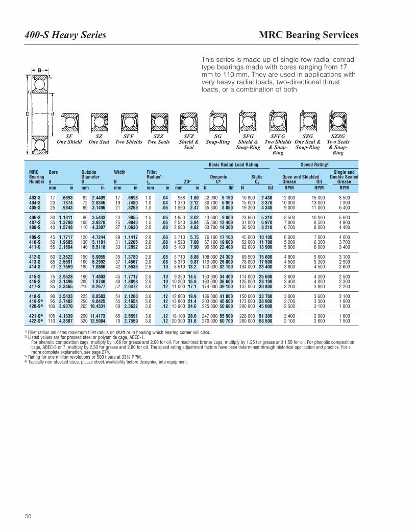
MRC Bearing Services400-S Heavy Series
50
This series is made up of single-row radial conrad-type bearings made with bores ranging from 17mm to 110 mm. They are used in applications withvery heavy radial loads, two-directional thrustloads, or a combination of both.
MRCBearingNumber
Bore
dmm in
OutsideDiameterDmm in
Width
Bmm in
FilletRadius1)
ra
mm inZD2
mm in
DynamicC3)
N lbf
Basic Radial Load Rating Speed Rating2)
StaticC0
N lbf
Open and ShieldedGrease OilRPM RPM
Single andDouble Sealed
GreaseRPM
403-S404-S405-S
406-S407-S408-S
409-S410-S411-S
412-S413-S414-S
415-S416-S417-S
418-S419-S4)
420-S4)
421-S4)
422-S4)
172025
303540
455055
606570
758085
9095
100
105110
627280
90100110
120130140
150160180
190200210
225250265
290320
171921
232527
293133
353742
454852
545560
6570
1.01.01.5
1.51.52.0
2.02.02.0
2.02.02.5
2.52.53.0
3.03.03.0
3.03.0
9681 3701 590
1 9502 5402 980
3 7104 5205 100
5 7106 3708 510
9 35010 20011 000
12 80013 80015 900
18 10020 300
22 90030 70035 800
43 60055 30063 700
76 10087 10099 500
108 000119 000143 000
153 000163 000174 000
186 000203 000225 000
247 000270 000
10 80015 00019 300
23 60031 00036 500
45 00052 00062 000
69 50078 000
104 000
114 000125 000137 000
150 000173 000200 000
228 000260 000
12 00010 0009 000
8 5007 0006 700
6 0005 2005 000
4 8004 5003 800
3 6003 4003 200
3 0002 7002 500
2 4002 100
15 00013 00011 000
10 0008 5008 000
7 0006 3006 000
5 6005 3004 500
4 3004 0003 800
3 6003 3003 100
2 9002 600
8 5007 3006 400
5 6004 9004 400
4 0003 7003 400
3 1002 9002 600
2 5002 3002 200
2 1001 9001 800
1 6001 500
.6693
.7874
.9843
1.18111.37801.5748
1.77171.96852.1654
2.36222.55912.7559
2.95283.14963.3465
3.54333.74023.9370
4.13394.3307
2.44092.83463.1496
3.54333.93704.3307
4.72445.11815.5118
5.90556.29927.0866
7.48037.87408.2677
8.85839.8425
10.4331
11.417312.5984
.6693
.7480
.8268
.9055
.98431.0630
1.14171.22051.2992
1.37801.45671.6535
1.77171.88982.0472
2.12602.16542.3622
2.55912.7559
.04
.04
.06
.06
.06
.08
.08
.08
.08
.08
.08
.10
.10
.10
.12
.12
.12
.12
.12
.12
1.502.122.47
3.023.944.62
5.757.007.90
8.869.87
13.2
14.515.817.1
19.921.424.6
28.031.6
5 1506 9008 050
9 80012 40014 300
17 10019 60022 400
24 30026 80032 100
34 40036 60039 100
41 80045 60050 600
55 50060 700
2 4303 3704 340
5 3106 9708 210
10 10011 70013 900
15 60017 50023 400
25 60028 10030 800
33 70038 90045 000
51 30058 500
1) Fillet radius indicates maximum fillet radius on shaft or in housing which bearing corner will clear.2) Listed values are for pressed steel or polyamide cage, ABEC-1.
For phenolic composition cage, multiply by 1.66 for grease and 2.00 for oil. For machined bronze cage, multiply by 1.25 for grease and 1.50 for oil. For phenolic compositioncage, ABEC-5 or 7, multiply by 2.30 for grease and 2.80 for oil. The speed rating adjustment factors have been determined through historical application and practice. For amore complete explanation, see page 274.
3) Rating for one million revolutions or 500 hours at 33¹|₃ RPM.4) Typically non-stocked sizes, please check availability before designing into equipment.
SFOne Shield
SZOne Seal
SFFTwo Shields
SZZTwo Seals
SFZShield &
Seal
SGSnap-Ring
SFGShield &
Snap-Ring
SFFGTwo Shields
& Snap-Ring
SZGOne Seal &Snap-Ring
SZZGTwo Seals & Snap-
Ring
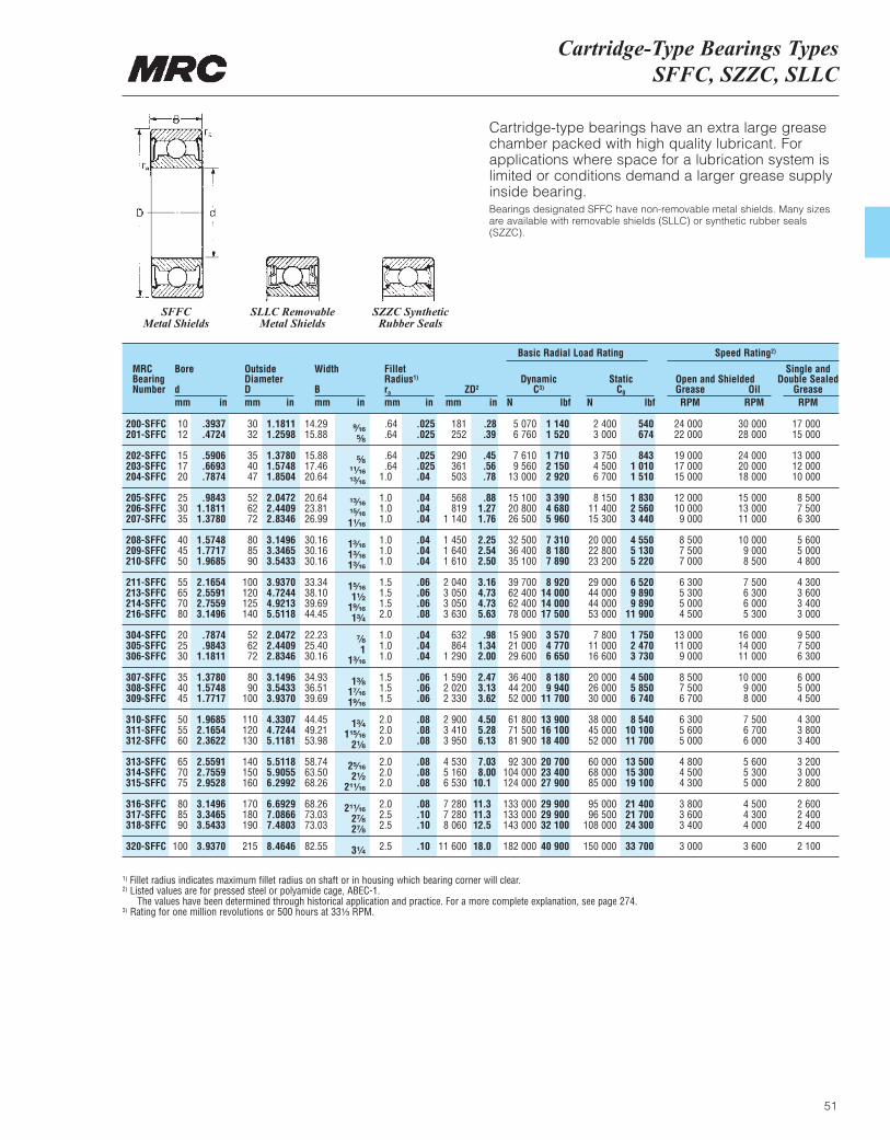
Cartridge-Type Bearings TypesSFFC, SZZC, SLLC
51
Cartridge-type bearings have an extra large greasechamber packed with high quality lubricant. Forapplications where space for a lubrication system islimited or conditions demand a larger grease supplyinside bearing.Bearings designated SFFC have non-removable metal shields. Many sizesare available with removable shields (SLLC) or synthetic rubber seals(SZZC).
MRCBearingNumber
Bore
dmm in
OutsideDiameterDmm in
Width
Bmm in
FilletRadius1)
ra
mm inZD2
mm in
DynamicC3)
N lbf
Basic Radial Load Rating Speed Rating2)
StaticC0
N lbf
Open and ShieldedGrease OilRPM RPM
Single andDouble Sealed
GreaseRPM
200-SFFC201-SFFC
202-SFFC203-SFFC204-SFFC
205-SFFC206-SFFC207-SFFC
208-SFFC209-SFFC210-SFFC
211-SFFC213-SFFC214-SFFC216-SFFC
304-SFFC305-SFFC306-SFFC
307-SFFC308-SFFC309-SFFC
310-SFFC311-SFFC312-SFFC
313-SFFC314-SFFC315-SFFC
316-SFFC317-SFFC318-SFFC
320-SFFC
1012
151720
253035
404550
55657080
202530
354045
505560
657075
808590
100
3032
354047
526272
808590
100120125140
526272
8090
100
110120130
140150160
170180190
215
14.2915.88
15.8817.4620.64
20.6423.8126.99
30.1630.1630.16
33.3438.1039.6944.45
22.2325.4030.16
34.9336.5139.69
44.4549.2153.98
58.7463.5068.26
68.2673.0373.03
82.55
.64
.64
.64
.641.0
1.01.01.0
1.01.01.0
1.51.51.52.0
1.01.01.0
1.51.51.5
2.02.02.0
2.02.02.0
2.02.52.5
2.5
181252
290361503
568819
1 140
1 4501 6401 610
2 0403 0503 0503 630
632864
1 290
1 5902 0202 330
2 9003 4103 950
4 5305 1606 530
7 2807 2808 060
11 600
5 0706 760
7 6109 560
13 000
15 10020 80026 500
32 50036 40035 100
39 70062 40062 40078 000
15 90021 00029 600
36 40044 20052 000
61 80071 50081 900
92 300104 000124 000
133 000133 000143 000
182 000
2 4003 000
3 7504 5006 700
8 15011 40015 300
20 00022 80023 200
29 00044 00044 00053 000
7 80011 00016 600
20 00026 00030 000
38 00045 00052 000
60 00068 00085 000
95 00096 500
108 000
150 000
24 00022 000
19 00017 00015 000
12 00010 0009 000
8 5007 5007 000
6 3005 3005 0004 500
13 00011 0009 000
8 5007 5006 700
6 3005 6005 000
4 8004 5004 300
3 8003 6003 400
3 000
30 00028 000
24 00020 00018 000
15 00013 00011 000
10 0009 0008 500
7 5006 3006 0005 300
16 00014 00011 000
10 0009 0008 000
7 5006 7006 000
5 6005 3005 000
4 5004 3004 000
3 600
17 00015 000
13 00012 00010 000
8 5007 5006 300
5 6005 0004 800
4 3003 6003 4003 000
9 5007 5006 300
6 0005 0004 500
4 3003 8003 400
3 2003 0002 800
2 6002 4002 400
2 100
.3937
.4724
.5906
.6693
.7874
.98431.18111.3780
1.57481.77171.9685
2.16542.55912.75593.1496
.7874
.98431.1811
1.37801.57481.7717
1.96852.16542.3622
2.55912.75592.9528
3.14963.34653.5433
3.9370
1.18111.2598
1.37801.57481.8504
2.04722.44092.8346
3.14963.34653.5433
3.93704.72444.92135.5118
2.04722.44092.8346
3.14963.54333.9370
4.33074.72445.1181
5.51185.90556.2992
6.69297.08667.4803
8.4646
⁹|₁₆⁵|₈
⁵|₈¹¹|₁₆¹³|₁₆
¹³|₁₆¹⁵|₁₆1¹|₁₆
1³|₁₆1³|₁₆1³|₁₆
1⁵|₁₆1¹|₂
1⁹|₁₆1³|₄
⁷|₈1
1³|₁₆
1³|₈1⁷|₁₆1⁹|₁₆
1³|₄1¹⁵|₁₆
2¹|₈
2⁵|₁₆2¹|₂
2¹¹|₁₆
2¹¹|₁₆2⁷|₈2⁷|₈
3¹|₄
.025
.025
.025
.025
.04
.04
.04
.04
.04
.04
.04
.06
.06
.06
.08
.04
.04
.04
.06
.06
.06
.08
.08
.08
.08
.08
.08
.08
.10
.10
.10
.28
.39
.45
.56
.78
.881.271.76
2.252.542.50
3.164.734.735.63
.981.342.00
2.473.133.62
4.505.286.13
7.038.00
10.1
11.311.312.5
18.0
1 1401 520
1 7102 1502 920
3 3904 6805 960
7 3108 1807 890
8 92014 00014 00017 500
3 5704 7706 650
8 1809 940
11 700
13 90016 10018 400
20 70023 40027 900
29 90029 90032 100
40 900
540674
8431 0101 510
1 8302 5603 440
4 5505 1305 220
6 5209 8909 890
11 900
1 7502 4703 730
4 5005 8506 740
8 54010 10011 700
13 50015 30019 100
21 40021 70024 300
33 700
1) Fillet radius indicates maximum fillet radius on shaft or in housing which bearing corner will clear.2) Listed values are for pressed steel or polyamide cage, ABEC-1.
The values have been determined through historical application and practice. For a more complete explanation, see page 274.3) Rating for one million revolutions or 500 hours at 33¹|₃ RPM.
SFFCMetal Shields
SLLC RemovableMetal Shields
SZZC SyntheticRubber Seals
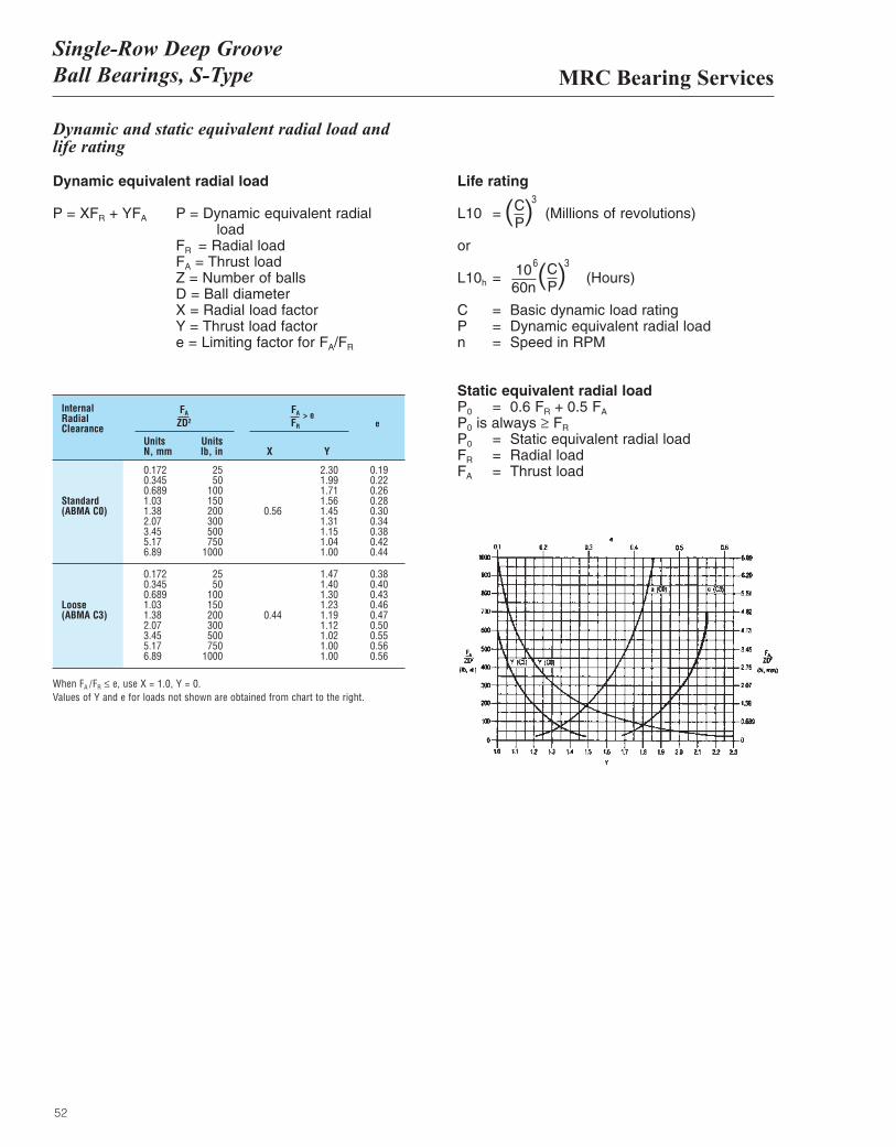
MRC Bearing ServicesSingle-Row Deep GrooveBall Bearings, S-Type
52
InternalRadialClearance
0.172 25 2.30 0.190.345 50 1.99 0.220.689 100 1.71 0.26
Standard 1.03 150 1.56 0.28(ABMA C0) 1.38 200 0.56 1.45 0.30
2.07 300 1.31 0.343.45 500 1.15 0.385.17 750 1.04 0.426.89 1000 1.00 0.44
0.172 25 1.47 0.380.345 50 1.40 0.400.689 100 1.30 0.43
Loose 1.03 150 1.23 0.46(ABMA C3) 1.38 200 0.44 1.19 0.47
2.07 300 1.12 0.503.45 500 1.02 0.555.17 750 1.00 0.566.89 1000 1.00 0.56
Units UnitsN, mm lb, in X Y
FA FA
ZD2 FR
> ee
When FA /FR ≤ e, use X = 1.0, Y = 0.Values of Y and e for loads not shown are obtained from chart to the right.
Dynamic and static equivalent radial load andlife rating
Dynamic equivalent radial load
P = XFR + YFA P = Dynamic equivalent radial load
FR = Radial loadFA = Thrust loadZ = Number of ballsD = Ball diameterX = Radial load factorY = Thrust load factore = Limiting factor for FA/FR
Life rating
L10 = (Millions of revolutions)
or
L10h = (Hours)
C = Basic dynamic load ratingP = Dynamic equivalent radial loadn = Speed in RPM
Static equivalent radial loadP0 = 0.6 FR + 0.5 FA
P0 is always ≥ FR
P0 = Static equivalent radial loadFR = Radial loadFA = Thrust load
( )CP
3
( )CP
1060n
36
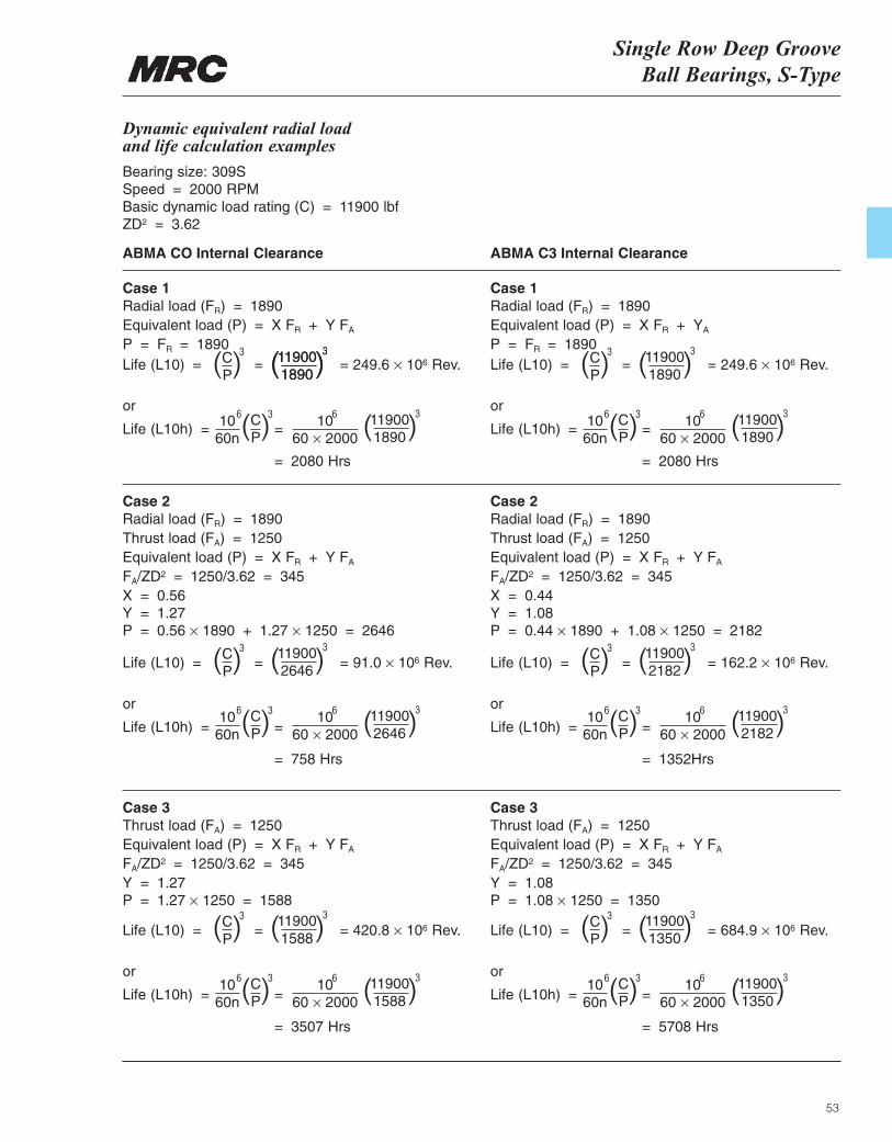
Single Row Deep GrooveBall Bearings, S-Type
53
Life (L10) = = = 420.8 × 10⁶ Rev.
or
Life (L10h) = =
= 3507 Hrs
Life (L10) = = = 684.9 × 10⁶ Rev.
or
Life (L10h) = =
= 5708 Hrs
Life (L10) = = = 91.0 × 10⁶ Rev.
or
Life (L10h) = =
= 758 Hrs
Dynamic equivalent radial load and life calculation examples
Bearing size: 309SSpeed = 2000 RPMBasic dynamic load rating (C) = 11900 lbfZD2 = 3.62
ABMA CO Internal Clearance ABMA C3 Internal Clearance
Case 1Radial load (FR) = 1890Equivalent load (P) = X FR + Y FA
P = FR = 1890
Case 2Radial load (FR) = 1890Thrust load (FA) = 1250Equivalent load (P) = X FR + Y FA
FA/ZD2 = 1250/3.62 = 345X = 0.56Y = 1.27P = 0.56 × 1890 + 1.27 × 1250 = 2646
Case 3Thrust load (FA) = 1250Equivalent load (P) = X FR + Y FA
FA/ZD2 = 1250/3.62 = 345Y = 1.27P = 1.27 × 1250 = 1588
Case 3Thrust load (FA) = 1250Equivalent load (P) = X FR + Y FA
FA/ZD2 = 1250/3.62 = 345Y = 1.08P = 1.08 × 1250 = 1350
Case 2Radial load (FR) = 1890Thrust load (FA) = 1250Equivalent load (P) = X FR + Y FA
FA/ZD2 = 1250/3.62 = 345X = 0.44Y = 1.08P = 0.44 × 1890 + 1.08 × 1250 = 2182
Case 1Radial load (FR) = 1890Equivalent load (P) = X FR + YA
P = FR = 1890Life (L10) = = = 249.6 × 10⁶ Rev.
or
Life (L10h) = =
= 2080 Hrs
Life (L10) = = = 249.6 × 10⁶ Rev.
or
Life (L10h) = =
= 2080 Hrs
( )CP
3
( )CP
3
( )CP
3
( )CP
3
( )CP
3
( )CP
3
( )119001890
3
( )CP
1060n
3
( )CP
3
( )CP
3
( )CP
3
( )CP
3
( )CP
36
1060n
6
1060n
6 1060n
6
1060n
6
1060n
61060 × 2000
6
1060 × 2000
6
1060 × 2000
6 1060 × 2000
6
1060 × 2000
6
1060 × 2000
6
( )119001890
3
( )119002646
3
( )119001588
3
( )119001350
3
( )119002182
3
( )119001890
3
( )119001890
3
( )119002646
3
( )119001588
3
( )119001350
3
( )119002182
3
( )119001890
3
Life (L10) = = = 162.2 × 10⁶ Rev.
or
Life (L10h) = =
= 1352Hrs
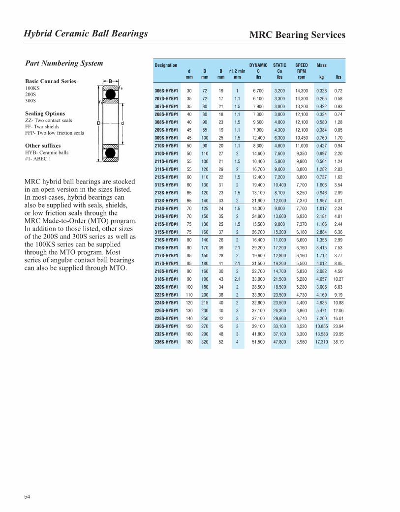
54
Part Numbering System
Basic Conrad Series100KS200S300S
Sealing OptionsZZ- Two contact sealsFF- Two shieldsFFP- Two low friction seals
Other suffixesHYB- Ceramic balls#1- ABEC 1
MRC hybrid ball bearings are stockedin an open version in the sizes listed.In most cases, hybrid bearings can also be supplied with seals, shields, or low friction seals through the MRC Made-to-Order (MTO) program.In addition to those listed, other sizesof the 200S and 300S series as well asthe 100KS series can be suppliedthrough the MTO program. Mostseries of angular contact ball bearingscan also be supplied through MTO.
Designation DYNAMIC STATIC SPEED Massd D B r1,2 min C Co RPM
mm mm mm mm lbs lbs rpm kg lbs
306S-HYB#1 30 72 19 1 6,700 3,200 14,300 0.328 0.72
207S-HYB#1 35 72 17 1.1 6,100 3,300 14,300 0.265 0.58
307S-HYB#1 35 80 21 1.5 7,900 3,800 13,200 0.422 0.93
208S-HYB#1 40 80 18 1.1 7,300 3,800 12,100 0.334 0.74
308S-HYB#1 40 90 23 1.5 9,500 4,800 12,100 0.580 1.28
209S-HYB#1 45 85 19 1.1 7,900 4,300 12,100 0.384 0.85
309S-HYB#1 45 100 25 1.5 12,400 6,300 10,450 0.769 1.70
210S-HYB#1 50 90 20 1.1 8,300 4,600 11,000 0.427 0.94
310S-HYB#1 50 110 27 2 14,600 7,600 9,350 0.997 2.20
211S-HYB#1 55 100 21 1.5 10,400 5,800 9,900 0.564 1.24
311S-HYB#1 55 120 29 2 16,700 9,000 8,800 1.282 2.83
212S-HYB#1 60 110 22 1.5 12,400 7,200 8,800 0.737 1.62
312S-HYB#1 60 130 31 2 19,400 10,400 7,700 1.606 3.54
213S-HYB#1 65 120 23 1.5 13,100 8,100 8,250 0.946 2.09
313S-HYB#1 65 140 33 2 21,900 12,000 7,370 1.957 4.31
214S-HYB#1 70 125 24 1.5 14,300 9,000 7,700 1.017 2.24
314S-HYB#1 70 150 35 2 24,900 13,600 6,930 2.181 4.81
215S-HYB#1 75 130 25 1.5 15,500 9,800 7,370 1.106 2.44
315S-HYB#1 75 160 37 2 26,700 15,200 6,160 2.884 6.36
216S-HYB#1 80 140 26 2 16,400 11,000 6,600 1.358 2.99
316S-HYB#1 80 170 39 2.1 29,200 17,200 6,160 3.415 7.53
217S-HYB#1 85 150 28 2 19,600 12,800 6,160 1.712 3.77
317S-HYB#1 85 180 41 2.1 31,500 19,200 5,500 4.012 8.85
218S-HYB#1 90 160 30 2 22,700 14,700 5,830 2.082 4.59
318S-HYB#1 90 190 43 2.1 33,900 21,500 5,280 4.657 10.27
220S-HYB#1 100 180 34 2 28,500 18,500 5,280 3.006 6.63
222S-HYB#1 110 200 38 2 33,900 23,500 4,730 4.169 9.19
224S-HYB#1 120 215 40 2 32,800 23,500 4,400 4.935 10.88
226S-HYB#1 130 230 40 3 37,100 26,300 3,960 5.471 12.06
228S-HYB#1 140 250 42 3 37,100 29,900 3,740 7.260 16.01
230S-HYB#1 150 270 45 3 39,100 33,100 3,520 10.855 23.94
232S-HYB#1 160 290 48 3 41,800 37,100 3,300 13.583 29.95
236S-HYB#1 180 320 52 4 51,500 47,800 3,960 17.319 38.19
MRC Bearing ServicesHybrid Ceramic Ball Bearings
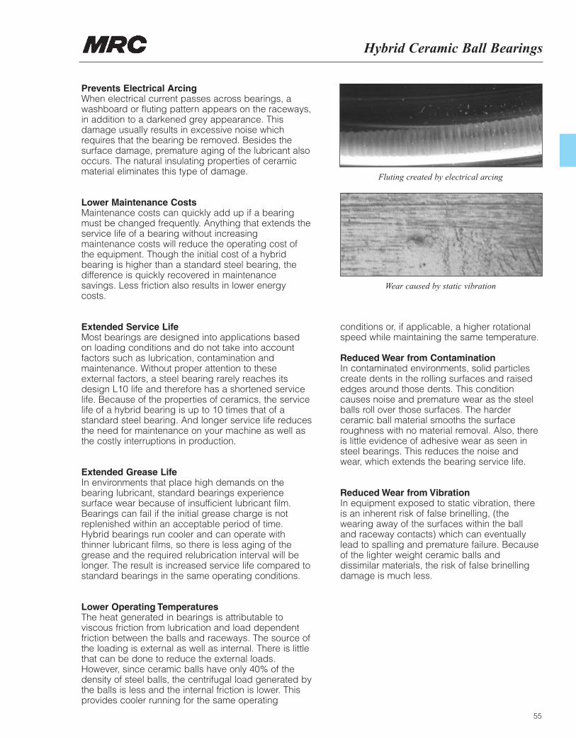
55
Hybrid Ceramic Ball Bearings
Prevents Electrical ArcingWhen electrical current passes across bearings, awashboard or fluting pattern appears on the raceways,in addition to a darkened grey appearance. Thisdamage usually results in excessive noise whichrequires that the bearing be removed. Besides thesurface damage, premature aging of the lubricant alsooccurs. The natural insulating properties of ceramicmaterial eliminates this type of damage.
Lower Maintenance CostsMaintenance costs can quickly add up if a bearingmust be changed frequently. Anything that extends theservice life of a bearing without increasingmaintenance costs will reduce the operating cost ofthe equipment. Though the initial cost of a hybridbearing is higher than a standard steel bearing, thedifference is quickly recovered in maintenancesavings. Less friction also results in lower energycosts.
Extended Service LifeMost bearings are designed into applications basedon loading conditions and do not take into accountfactors such as lubrication, contamination andmaintenance. Without proper attention to theseexternal factors, a steel bearing rarely reaches itsdesign L10 life and therefore has a shortened servicelife. Because of the properties of ceramics, the servicelife of a hybrid bearing is up to 10 times that of astandard steel bearing. And longer service life reducesthe need for maintenance on your machine as well asthe costly interruptions in production.
Extended Grease LifeIn environments that place high demands on thebearing lubricant, standard bearings experiencesurface wear because of insufficient lubricant film.Bearings can fail if the initial grease charge is notreplenished within an acceptable period of time.Hybrid bearings run cooler and can operate withthinner lubricant films, so there is less aging of thegrease and the required relubrication interval will belonger. The result is increased service life compared tostandard bearings in the same operating conditions.
Lower Operating TemperaturesThe heat generated in bearings is attributable toviscous friction from lubrication and load dependentfriction between the balls and raceways. The source ofthe loading is external as well as internal. There is littlethat can be done to reduce the external loads.However, since ceramic balls have only 40% of thedensity of steel balls, the centrifugal load generated bythe balls is less and the internal friction is lower. Thisprovides cooler running for the same operating
conditions or, if applicable, a higher rotationalspeed while maintaining the same temperature.
Reduced Wear from ContaminationIn contaminated environments, solid particlescreate dents in the rolling surfaces and raisededges around those dents. This conditioncauses noise and premature wear as the steelballs roll over those surfaces. The harderceramic ball material smooths the surfaceroughness with no material removal. Also, thereis little evidence of adhesive wear as seen insteel bearings. This reduces the noise andwear, which extends the bearing service life.
Reduced Wear from VibrationIn equipment exposed to static vibration, thereis an inherent risk of false brinelling, (thewearing away of the surfaces within the balland raceway contacts) which can eventuallylead to spalling and premature failure. Becauseof the lighter weight ceramic balls anddissimilar materials, the risk of false brinellingdamage is much less.
Fluting created by electrical arcing
Wear caused by static vibration
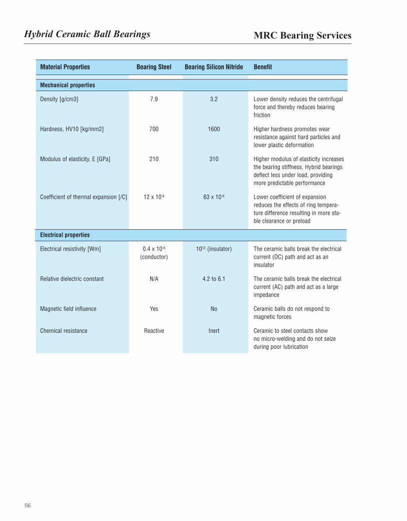
56
MRC Bearing ServicesHybrid Ceramic Ball Bearings
Material Properties Bearing Steel Bearing Silicon Nitride Benefit
Mechanical properties
Density [g/cm3] 7.9 3.2 Lower density reduces the centrifugalforce and thereby reduces bearingfriction
Hardness, HV10 [kg/mm2] 700 1600 Higher hardness promotes wearresistance against hard particles andlower plastic deformation
Modulus of elasticity, E [GPa] 210 310 Higher modulus of elasticity increasesthe bearing stiffness. Hybrid bearingsdeflect less under load, providingmore predictable performance
Coefficient of thermal expansion [/C] 12 x 10-6 63 x 10-6 Lower coefficient of expansionreduces the effects of ring tempera-ture difference resulting in more sta-ble clearance or preload
Electrical properties
Electrical resistivity [Wm] 0.4 x 10⁻⁶ 1012 (insulator) The ceramic balls break the electrical (conductor) current (DC) path and act as an
insulator
Relative dielectric constant N/A 4.2 to 6.1 The ceramic balls break the electricalcurrent (AC) path and act as a largeimpedance
Magnetic field influence Yes No Ceramic balls do not respond to magnetic forces
Chemical resistance Reactive Inert Ceramic to steel contacts show no micro-welding and do not seize during poor lubrication
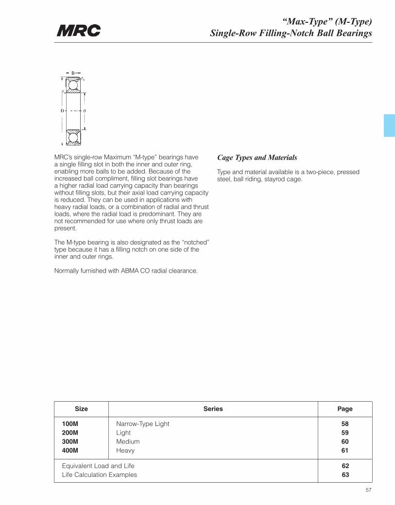
“Max-Type” (M-Type)Single-Row Filling-Notch Ball Bearings
57
MRC’s single-row Maximum “M-type” bearings have a single filling slot in both the inner and outer ring,enabling more balls to be added. Because of theincreased ball compliment, filling slot bearings have a higher radial load carrying capacity than bearingswithout filling slots, but their axial load carrying capacityis reduced. They can be used in applications withheavy radial loads, or a combination of radial and thrustloads, where the radial load is predominant. They arenot recommended for use where only thrust loads arepresent.
The M-type bearing is also designated as the “notched”type because it has a filling notch on one side of theinner and outer rings.
Normally furnished with ABMA CO radial clearance.
Cage Types and Materials
Type and material available is a two-piece, pressedsteel, ball riding, stayrod cage.
Size
100M200M300M400M
Narrow-Type LightLightMediumHeavy
58596061
Series Page
Equivalent Load and LifeLife Calculation Examples
6263
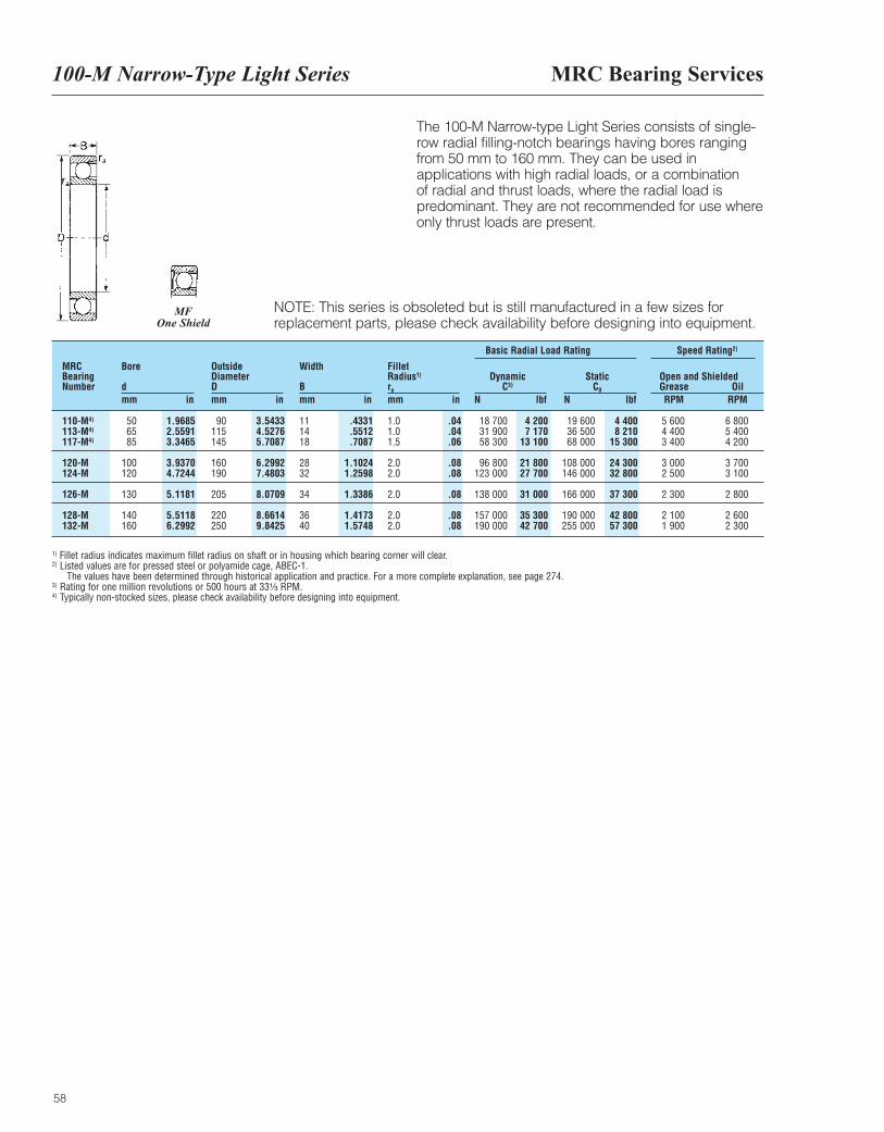
MRC Bearing Services100-M Narrow-Type Light Series
58
The 100-M Narrow-type Light Series consists of single-row radial filling-notch bearings having bores rangingfrom 50 mm to 160 mm. They can be used inapplications with high radial loads, or a combination of radial and thrust loads, where the radial load ispredominant. They are not recommended for use whereonly thrust loads are present.
NOTE: This series is obsoleted but is still manufactured in a few sizes forreplacement parts, please check availability before designing into equipment.
MRCBearingNumber
Bore
dmm in
OutsideDiameterDmm in
Width
Bmm in
FilletRadius1)
ra
mm in
DynamicC3)
N lbf
Basic Radial Load Rating Speed Rating2)
StaticC0
N lbf
Open and ShieldedGrease OilRPM RPM
110-M4)
113-M4)
117-M4)
120-M124-M
126-M
128-M132-M
506585
100120
130
140160
90115145
160190
205
220250
111418
2832
34
3640
1.01.01.5
2.02.0
2.0
2.02.0
18 70031 90058 300
96 800123 000
138 000
157 000190 000
19 60036 50068 000
108 000146 000
166 000
190 000255 000
5 6004 4003 400
3 0002 500
2 300
2 1001 900
6 8005 4004 200
3 7003 100
2 800
2 6002 300
1.96852.55913.3465
3.93704.7244
5.1181
5.51186.2992
3.54334.52765.7087
6.29927.4803
8.0709
8.66149.8425
.4331
.5512
.7087
1.10241.2598
1.3386
1.41731.5748
.04
.04
.06
.08
.08
.08
.08
.08
4 2007 170
13 100
21 80027 700
31 000
35 30042 700
4 4008 210
15 300
24 30032 800
37 300
42 80057 300
1) Fillet radius indicates maximum fillet radius on shaft or in housing which bearing corner will clear.2) Listed values are for pressed steel or polyamide cage, ABEC-1.
The values have been determined through historical application and practice. For a more complete explanation, see page 274.3) Rating for one million revolutions or 500 hours at 33¹|₃ RPM.4) Typically non-stocked sizes, please check availability before designing into equipment.
MFOne Shield
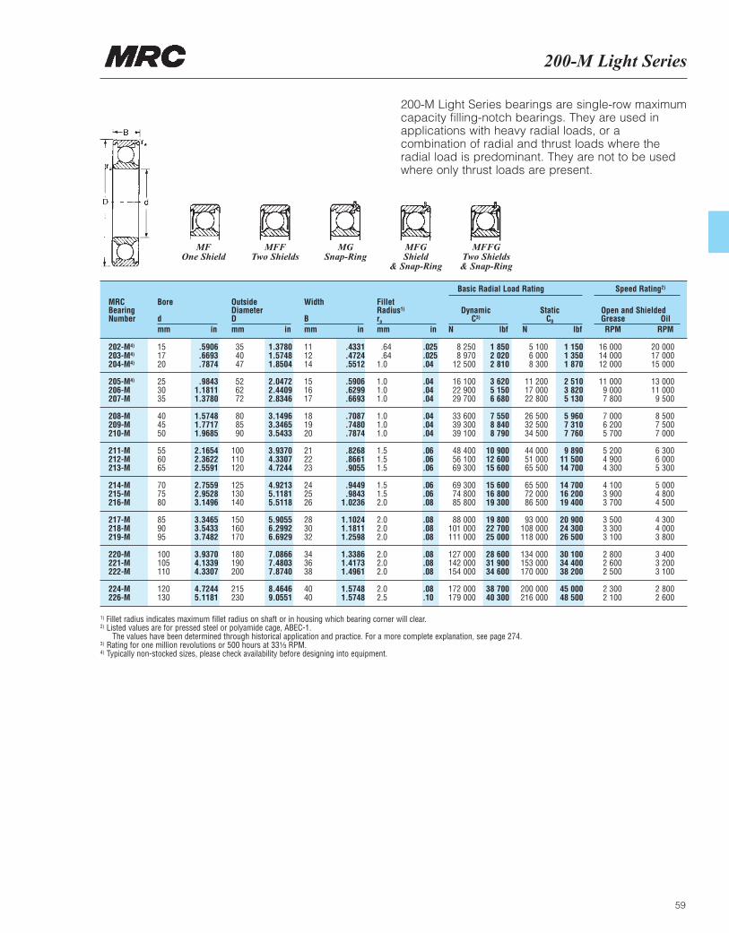
200-M Light Series
59
200-M Light Series bearings are single-row maximumcapacity filling-notch bearings. They are used inapplications with heavy radial loads, or acombination of radial and thrust loads where theradial load is predominant. They are not to be usedwhere only thrust loads are present.
MRCBearingNumber
Bore
dmm in
OutsideDiameterDmm in
Width
Bmm in
FilletRadius1)
ra
mm in
DynamicC3)
N lbf
Basic Radial Load Rating Speed Rating2)
StaticC0
N lbf
Open and ShieldedGrease OilRPM RPM
202-M4)
203-M4)
204-M4)
205-M4)
206-M207-M
208-M209-M210-M
211-M212-M213-M
214-M215-M216-M
217-M218-M219-M
220-M221-M222-M
224-M226-M
151720
253035
404550
556065
707580
859095
100105110
120130
354047
526272
808590
100110120
125130140
150160170
180190200
215230
111214
151617
181920
212223
242526
283032
343638
4040
.64
.641.0
1.01.01.0
1.01.01.0
1.51.51.5
1.51.52.0
2.02.02.0
2.02.02.0
2.02.5
8 2508 970
12 500
16 10022 90029 700
33 60039 30039 100
48 40056 10069 300
69 30074 80085 800
88 000101 000111 000
127 000142 000154 000
172 000179 000
5 1006 0008 300
11 20017 00022 800
26 50032 50034 500
44 00051 00065 500
65 50072 00086 500
93 000108 000118 000
134 000153 000170 000
200 000216 000
16 00014 00012 000
11 0009 0007 800
7 0006 2005 700
5 2004 9004 300
4 1003 9003 700
3 5003 3003 100
2 8002 6002 500
2 3002 100
20 00017 00015 000
13 00011 0009 500
8 5007 5007 000
6 3006 0005 300
5 0004 8004 500
4 3004 0003 800
3 4003 2003 100
2 8002 600
.5906
.6693
.7874
.98431.18111.3780
1.57481.77171.9685
2.16542.36222.5591
2.75592.95283.1496
3.34653.54333.7482
3.93704.13394.3307
4.72445.1181
1.37801.57481.8504
2.04722.44092.8346
3.14963.34653.5433
3.93704.33074.7244
4.92135.11815.5118
5.90556.29926.6929
7.08667.48037.8740
8.46469.0551
.4331
.4724
.5512
.5906
.6299
.6693
.7087
.7480
.7874
.8268
.8661
.9055
.9449
.98431.0236
1.10241.18111.2598
1.33861.41731.4961
1.57481.5748
.025
.025
.04
.04
.04
.04
.04
.04
.04
.06
.06
.06
.06
.06
.08
.08
.08
.08
.08
.08
.08
.08
.10
1 8502 0202 810
3 6205 1506 680
7 5508 8408 790
10 90012 60015 600
15 60016 80019 300
19 80022 70025 000
28 60031 90034 600
38 70040 300
1 1501 3501 870
2 5103 8205 130
5 9607 3107 760
9 89011 50014 700
14 70016 20019 400
20 90024 30026 500
30 10034 40038 200
45 00048 500
1) Fillet radius indicates maximum fillet radius on shaft or in housing which bearing corner will clear.2) Listed values are for pressed steel or polyamide cage, ABEC-1.
The values have been determined through historical application and practice. For a more complete explanation, see page 274.3) Rating for one million revolutions or 500 hours at 33¹|₃ RPM.4) Typically non-stocked sizes, please check availability before designing into equipment.
MFOne Shield
MFFTwo Shields
MGSnap-Ring
MFGShield
& Snap-Ring
MFFGTwo Shields& Snap-Ring
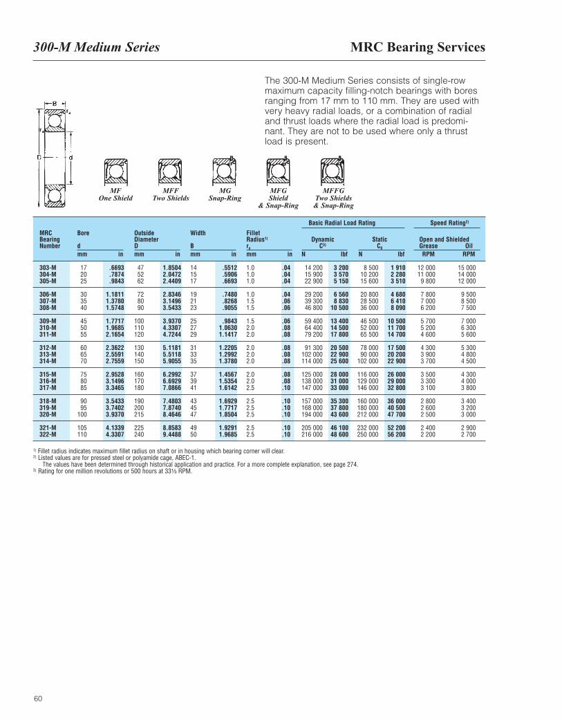
MRC Bearing Services300-M Medium Series
60
The 300-M Medium Series consists of single-rowmaximum capacity filling-notch bearings with boresranging from 17 mm to 110 mm. They are used withvery heavy radial loads, or a combination of radialand thrust loads where the radial load is predomi-nant. They are not to be used where only a thrustload is present.
MRCBearingNumber
Bore
dmm in
OutsideDiameterDmm in
Width
Bmm in
FilletRadius1)
ra
mm in
DynamicC3)
N lbf
Basic Radial Load Rating Speed Rating2)
StaticC0
N lbf
Open and ShieldedGrease OilRPM RPM
303-M304-M305-M
306-M307-M308-M
309-M310-M311-M
312-M313-M314-M
315-M316-M317-M
318-M319-M320-M
321-M322-M
172025
303540
455055
606570
758085
9095
100
105110
475262
728090
100110120
130140150
160170180
190200215
225240
141517
192123
252729
313335
373941
434547
4950
1.01.01.0
1.01.51.5
1.52.02.0
2.02.02.0
2.02.02.5
2.52.52.5
2.52.5
14 20015 90022 900
29 20039 30046 800
59 40064 40079 200
91 300102 000114 000
125 000138 000147 000
157 000168 000194 000
205 000216 000
8 50010 20015 600
20 80028 50036 000
46 50052 00065 500
78 00090 000
102 000
116 000129 000146 000
160 000180 000212 000
232 000250 000
12 00011 0009 800
7 8007 0006 200
5 7005 2004 600
4 3003 9003 700
3 5003 3003 100
2 8002 6002 500
2 4002 200
15 00014 00012 000
9 5008 5007 500
7 0006 3005 600
5 3004 8004 500
4 3004 0003 800
3 4003 2003 000
2 9002 700
.6693
.7874
.9843
1.18111.37801.5748
1.77171.96852.1654
2.36222.55912.7559
2.95283.14963.3465
3.54333.74023.9370
4.13394.3307
1.85042.04722.4409
2.83463.14963.5433
3.93704.33074.7244
5.11815.51185.9055
6.29926.69297.0866
7.48037.87408.4646
8.85839.4488
.5512
.5906
.6693
.7480
.8268
.9055
.98431.06301.1417
1.22051.29921.3780
1.45671.53541.6142
1.69291.77171.8504
1.92911.9685
.04
.04
.04
.04
.06
.06
.06
.08
.08
.08
.08
.08
.08
.08
.10
.10
.10
.10
.10
.10
3 2003 5705 150
6 5608 830
10 500
13 40014 50017 800
20 50022 90025 600
28 00031 00033 000
35 30037 80043 600
46 10048 600
1 9102 2803 510
4 6806 4108 090
10 50011 70014 700
17 50020 20022 900
26 00029 00032 800
36 00040 50047 700
52 20056 200
1) Fillet radius indicates maximum fillet radius on shaft or in housing which bearing corner will clear.2) Listed values are for pressed steel or polyamide cage, ABEC-1.
The values have been determined through historical application and practice. For a more complete explanation, see page 274.3) Rating for one million revolutions or 500 hours at 33¹|₃ RPM.
MFOne Shield
MFFTwo Shields
MGSnap-Ring
MFGShield
& Snap-Ring
MFFGTwo Shields& Snap-Ring
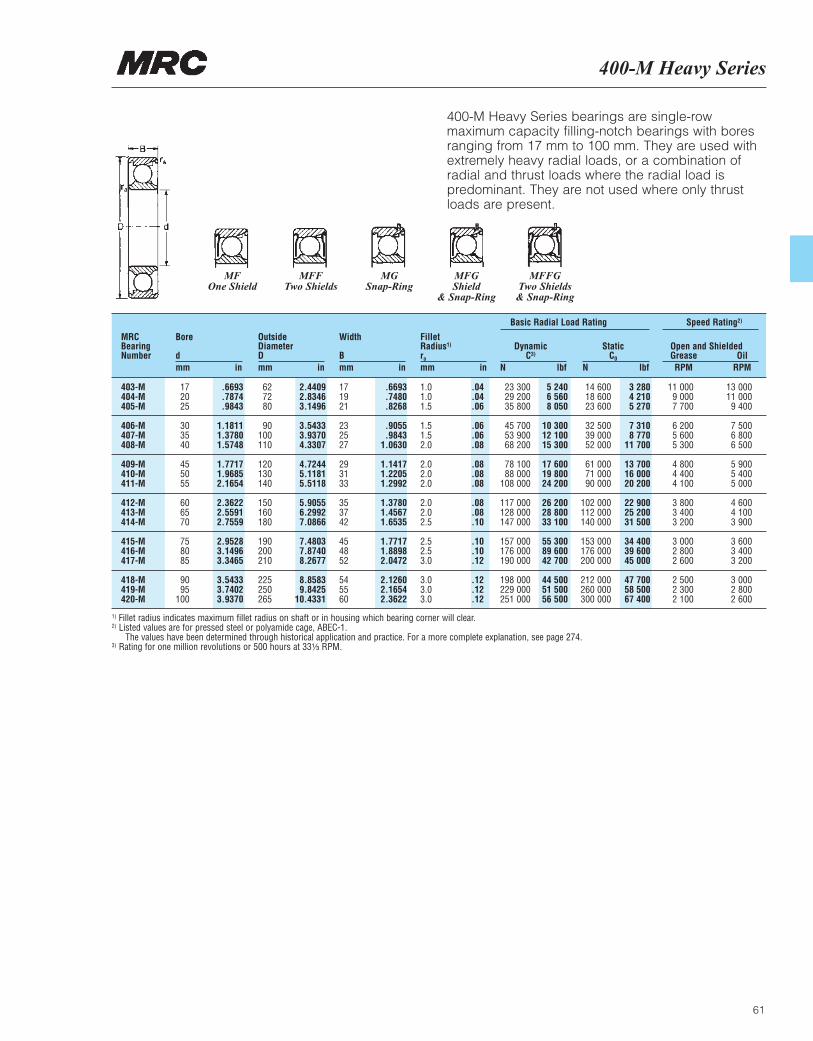
400-M Heavy Series
61
400-M Heavy Series bearings are single-rowmaximum capacity filling-notch bearings with boresranging from 17 mm to 100 mm. They are used withextremely heavy radial loads, or a combination ofradial and thrust loads where the radial load ispredominant. They are not used where only thrustloads are present.
MRCBearingNumber
Bore
dmm in
OutsideDiameterDmm in
Width
Bmm in
FilletRadius1)
ra
mm in
DynamicC3)
N lbf
Basic Radial Load Rating Speed Rating2)
StaticC0
N lbf
Open and ShieldedGrease OilRPM RPM
403-M404-M405-M
406-M407-M408-M
409-M410-M411-M
412-M413-M414-M
415-M416-M417-M
418-M419-M420-M
172025
303540
455055
606570
758085
9095
100
627280
90100110
120130140
150160180
190200210
225250265
171921
232527
293133
353742
454852
545560
1.01.01.5
1.51.52.0
2.02.02.0
2.02.02.5
2.52.53.0
3.03.03.0
23 30029 20035 800
45 70053 90068 200
78 10088 000
108 000
117 000128 000147 000
157 000176 000190 000
198 000229 000251 000
14 60018 60023 600
32 50039 00052 000
61 00071 00090 000
102 000112 000140 000
153 000176 000200 000
212 000260 000300 000
11 0009 0007 700
6 2005 6005 300
4 8004 4004 100
3 8003 4003 200
3 0002 8002 600
2 5002 3002 100
13 00011 0009 400
7 5006 8006 500
5 9005 4005 000
4 6004 1003 900
3 6003 4003 200
3 0002 8002 600
.6693
.7874
.9843
1.18111.37801.5748
1.77171.96852.1654
2.36222.55912.7559
2.95283.14963.3465
3.54333.74023.9370
2.44092.83463.1496
3.54333.93704.3307
4.72445.11815.5118
5.90556.29927.0866
7.48037.87408.2677
8.85839.8425
10.4331
.6693
.7480
.8268
.9055
.98431.0630
1.14171.22051.2992
1.37801.45671.6535
1.77171.88982.0472
2.12602.16542.3622
.04
.04
.06
.06
.06
.08
.08
.08
.08
.08
.08
.10
.10
.10
.12
.12
.12
.12
5 2406 5608 050
10 30012 10015 300
17 60019 80024 200
26 20028 80033 100
55 30089 60042 700
44 50051 50056 500
3 2804 2105 270
7 3108 770
11 700
13 70016 00020 200
22 90025 20031 500
34 40039 60045 000
47 70058 50067 400
1) Fillet radius indicates maximum fillet radius on shaft or in housing which bearing corner will clear.2) Listed values are for pressed steel or polyamide cage, ABEC-1.
The values have been determined through historical application and practice. For a more complete explanation, see page 274.3) Rating for one million revolutions or 500 hours at 33¹|₃ RPM.
MFOne Shield
MFFTwo Shields
MGSnap-Ring
MFGShield
& Snap-Ring
MFFGTwo Shields& Snap-Ring
MRC Bearing ServicesSingle-RowFilling-Notch Ball Bearings, M-Type
62
Dynamic and static equivalent radial load andlife rating
Dynamic equivalent radial load
P = FR + FA P = Dynamic equivalent radial loadFR = Radial loadFA = Thrust load
when FA/FR > 0.6 or P > 0.5 Co, a non-filling notchbearing is suggested.C0 = Basic static radial load rating
Life rating
L10 = (millions of revolutions)
or
L10h = (Hours)
C = Basic dynamic radial load ratingP = Dynamic equivalent radial loadn = Speed in rpm
Static equivalent radial loadP0 = FR + 0.5 FA
Provided FA/FR ≤ 0.6P0 = Static equivalent radial loadFR = Radial loadFA = Thrust load
( )CP
3
( )CP
1060n
36
Single-RowFilling-Notch Ball Bearings, M-Type
63
Dynamic equivalent radial load and life calculation examples
Life (L10) = = = 105 × 106 Rev.
or
Life (L10h) = =
= 875 Hrs
Bearing size: 309MSpeed = 2000 RPMBasic dynamic load rating (C) = 13400 lbf
ABMA CO Internal Clearance
Case 1Radial load (FR) = 1890Equivalent load (P) = FR + FA
P = FR = 1890
Case 2Radial load (FR) = 1890Thrust load (FA) = 950
FA/FR = 950/1890 = 0.50
Since FA/FR < 0.60P = FR + FA = 1890 + 950 = 2840
Case 3Radial load (FR) = 1890Thrust load (FA) = 1250FA/FR = 1250/1890 = 0.66
Since FA/FR > 0.60, use a non-filling notch bearing
Life (L10) = = = 356 × 106 Rev.
or
Life (L10h) = =
= 2967 Hrs
( )CP
3
( )CP
3
( )3
( )CP
1060n
36
1060n
6
1060 × 2000
6
1060 × 2000
6
( )134001890
3
( )134002840
3
( )134002840
3
( )134001890
3
( )134002840
3

64
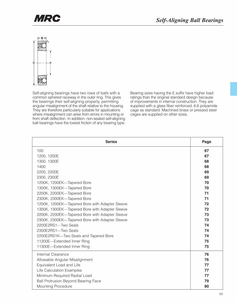
Self-Aligning Ball Bearings
65
Internal Clearance 76Allowable Angular Misalignment 76Equivalent Load and Life 77Life Calculation Examples 77Minimum Required Radial Load 77Ball Protrusion Beyond Bearing Face 79Mounting Procedure 80
Self-aligning bearings have two rows of balls with acommon sphered raceway in the outer ring. This givesthe bearings their self-aligning property, permittingangular misalignment of the shaft relative to the housing.They are therefore particularly suitable for applicationswhere misalignment can arise from errors in mounting orfrom shaft deflection. In addiiton, non-sealed self-aligningball bearings have the lowest friction of any bearing type.
Bearing sizes having the E suffix have higher loadratings than the original standard design because of improvements in internal construction. They aresupplied with a glass fiber reinforced, 6.6 polyamidecage as standard. Machined brass or pressed steelcages are supplied on other sizes.
100 671200, 1200E 671300, 1300E 681400 682200, 2200E 692300, 2300E 691200K, 1200EK—Tapered Bore 701300K, 1300EK—Tapered Bore 702200K, 2200EK—Tapered Bore 712300K, 2300EK—Tapered Bore 711200K, 1200EK—Tapered Bore with Adapter Sleeve 721300K, 1300EK—Tapered Bore with Adapter Sleeve 722200K, 2200EK—Tapered Bore with Adapter Sleeve 732300K, 2300EK—Tapered Bore with Adapter Sleeve 732200E2RS1—Two Seals 742300E2RS1—Two Seals 742200E2RS1K—Two Seals and Tapered Bore 7411200E—Extended Inner Ring 7511300E—Extended Inner Ring 75
Series Page
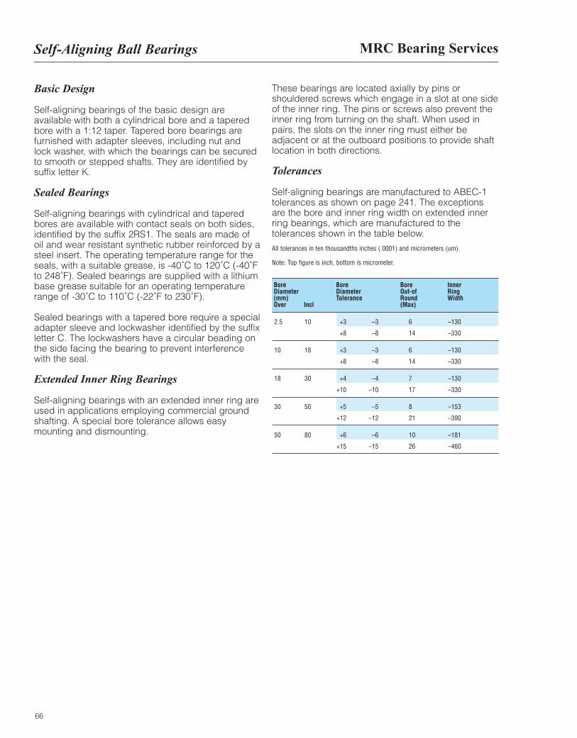
MRC Bearing ServicesSelf-Aligning Ball Bearings
66
Basic Design
Self-aligning bearings of the basic design areavailable with both a cylindrical bore and a taperedbore with a 1:12 taper. Tapered bore bearings arefurnished with adapter sleeves, including nut andlock washer, with which the bearings can be securedto smooth or stepped shafts. They are identified bysuffix letter K.
Sealed Bearings
Self-aligning bearings with cylindrical and taperedbores are available with contact seals on both sides,identified by the suffix 2RS1. The seals are made ofoil and wear resistant synthetic rubber reinforced by asteel insert. The operating temperature range for theseals, with a suitable grease, is -40˚C to 120˚C (-40˚Fto 248˚F). Sealed bearings are supplied with a lithiumbase grease suitable for an operating temperaturerange of -30˚C to 110˚C (-22˚F to 230˚F).
Sealed bearings with a tapered bore require a specialadapter sleeve and lockwasher identified by the suffixletter C. The lockwashers have a circular beading onthe side facing the bearing to prevent interferencewith the seal.
Extended Inner Ring Bearings
Self-aligning bearings with an extended inner ring areused in applications employing commercial groundshafting. A special bore tolerance allows easymounting and dismounting.
These bearings are located axially by pins orshouldered screws which engage in a slot at one sideof the inner ring. The pins or screws also prevent theinner ring from turning on the shaft. When used inpairs, the slots on the inner ring must either beadjacent or at the outboard positions to provide shaftlocation in both directions.
Tolerances
Self-aligning bearings are manufactured to ABEC-1tolerances as shown on page 241. The exceptionsare the bore and inner ring width on extended innerring bearings, which are manufactured to thetolerances shown in the table below.
All tolerances in ten thousandths inches (.0001) and micrometers (um).
Note: Top figure is inch, bottom is micrometer.
Bore Bore Bore Inner Diameter Diameter Out-of Ring (mm) Tolerance Round Width Over Incl (Max)
2.5 10 +3 –3 6 –130
+8 –8 14 –330
10 18 +3 –3 6 –130
+8 –8 14 –330
18 30 +4 –4 7 –130
+10 –10 17 –330
30 50 +5 –5 8 –153
+12 –12 21 –390
50 80 +6 –6 10 –181
+15 –15 26 –460
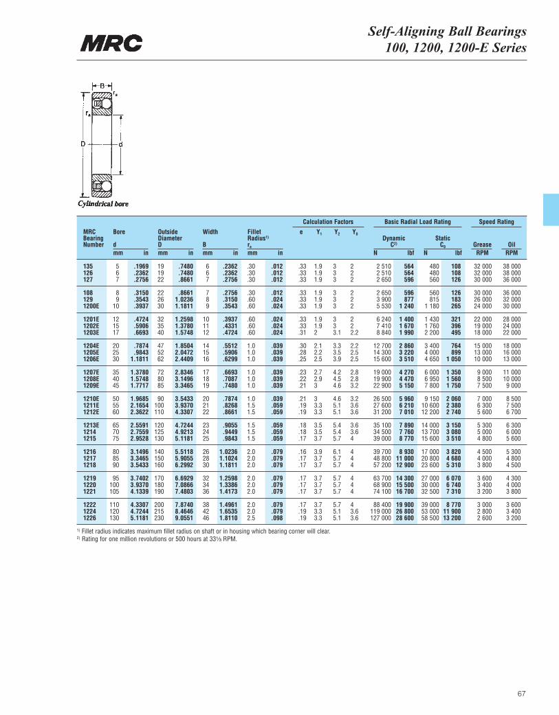
Self-Aligning Ball Bearings100, 1200, 1200-E Series
67
MRCBearingNumber
Bore
dmm in
OutsideDiameterDmm in
Width
Bmm in
ra
mm in
DynamicC2)
N lbf
Basic Radial Load RatingCalculation Factors Speed Rating
StaticC0
N lbfGrease OilRPM RPM
Fillet Radius1)
e Y1 Y2 Y0
135 5 .1969 19 .7480 6 .2362 .30 .012 .33 1.9 3 2 2 510 564 480 108 32 000 38 000126 6 .2362 19 .7480 6 .2362 .30 .012 .33 1.9 3 2 2 510 564 480 108 32 000 38 000127 7 .2756 22 .8661 7 .2756 .30 .012 .33 1.9 3 2 2 650 596 560 126 30 000 36 000
108 8 .3150 22 .8661 7 .2756 .30 .012 .33 1.9 3 2 2 650 596 560 126 30 000 36 000129 9 .3543 26 1.0236 8 .3150 .60 .024 .33 1.9 3 2 3 900 877 815 183 26 000 32 0001200E 10 .3937 30 1.1811 9 .3543 .60 .024 .33 1.9 3 2 5 530 1 240 1 180 265 24 000 30 000
1201E 12 .4724 32 1.2598 10 .3937 .60 .024 .33 1.9 3 2 6 240 1 400 1 430 321 22 000 28 0001202E 15 .5906 35 1.3780 11 .4331 .60 .024 .33 1.9 3 2 7 410 1 670 1 760 396 19 000 24 0001203E 17 .6693 40 1.5748 12 .4724 .60 .024 .31 2 3.1 2.2 8 840 1 990 2 200 495 18 000 22 000
1204E 20 .7874 47 1.8504 14 .5512 1.0 .039 .30 2.1 3.3 2.2 12 700 2 860 3 400 764 15 000 18 0001205E 25 .9843 52 2.0472 15 .5906 1.0 .039 .28 2.2 3.5 2.5 14 300 3 220 4 000 899 13 000 16 0001206E 30 1.1811 62 2.4409 16 .6299 1.0 .039 .25 2.5 3.9 2.5 15 600 3 510 4 650 1 050 10 000 13 000
1207E 35 1.3780 72 2.8346 17 .6693 1.0 .039 .23 2.7 4.2 2.8 19 000 4 270 6 000 1 350 9 000 11 0001208E 40 1.5748 80 3.1496 18 .7087 1.0 .039 .22 2.9 4.5 2.8 19 900 4 470 6 950 1 560 8 500 10 0001209E 45 1.7717 85 3.3465 19 .7480 1.0 .039 .21 3 4.6 3.2 22 900 5 150 7 800 1 750 7 500 9 000
1210E 50 1.9685 90 3.5433 20 .7874 1.0 .039 .21 3 4.6 3.2 26 500 5 960 9 150 2 060 7 000 8 5001211E 55 2.1654 100 3.9370 21 .8268 1.5 .059 .19 3.3 5.1 3.6 27 600 6 210 10 600 2 380 6 300 7 5001212E 60 2.3622 110 4.3307 22 .8661 1.5 .059 .19 3.3 5.1 3.6 31 200 7 010 12 200 2 740 5 600 6 700
1213E 65 2.5591 120 4.7244 23 .9055 1.5 .059 .18 3.5 5.4 3.6 35 100 7 890 14 000 3 150 5 300 6 3001214 70 2.7559 125 4.9213 24 .9449 1.5 .059 .18 3.5 5.4 3.6 34 500 7 760 13 700 3 080 5 000 6 0001215 75 2.9528 130 5.1181 25 .9843 1.5 .059 .17 3.7 5.7 4 39 000 8 770 15 600 3 510 4 800 5 600
1216 80 3.1496 140 5.5118 26 1.0236 2.0 .079 .16 3.9 6.1 4 39 700 8 930 17 000 3 820 4 500 5 3001217 85 3.3465 150 5.9055 28 1.1024 2.0 .079 .17 3.7 5.7 4 48 800 11 000 20 800 4 680 4 000 4 8001218 90 3.5433 160 6.2992 30 1.1811 2.0 .079 .17 3.7 5.7 4 57 200 12 900 23 600 5 310 3 800 4 500
1219 95 3.7402 170 6.6929 32 1.2598 2.0 .079 .17 3.7 5.7 4 63 700 14 300 27 000 6 070 3 600 4 3001220 100 3.9370 180 7.0866 34 1.3386 2.0 .079 .17 3.7 5.7 4 68 900 15 500 30 000 6 740 3 400 4 0001221 105 4.1339 190 7.4803 36 1.4173 2.0 .079 .17 3.7 5.7 4 74 100 16 700 32 500 7 310 3 200 3 800
1222 110 4.3307 200 7.8740 38 1.4961 2.0 .079 .17 3.7 5.7 4 88 400 19 900 39 000 8 770 3 000 3 6001224 120 4.7244 215 8.4646 42 1.6535 2.0 .079 .19 3.3 5.1 3.6 119 000 26 800 53 000 11 900 2 800 3 4001226 130 5.1181 230 9.0551 46 1.8110 2.5 .098 .19 3.3 5.1 3.6 127 000 28 600 58 500 13 200 2 600 3 200
1) Fillet radius indicates maximum fillet radius on shaft or in housing which bearing corner will clear.2) Rating for one million revolutions or 500 hours at 33¹|₃ RPM.
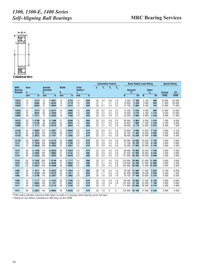
MRC Bearing Services1300, 1300-E, 1400 Series Self-Aligning Ball Bearings
68
MRCBearingNumber
Bore
dmm in
OutsideDiameterDmm in
Width
Bmm in
ra
mm in
DynamicC2)
N lbf
Basic Radial Load Rating Speed Rating
StaticC0
N lbfGrease OilRPM RPM
Fillet Radius1)
1301E 12 .4724 37 1.4567 12 .4724 1.0 .039 .35 1.8 2.8 1.8 9 360 2 100 2 160 486 18 000 22 0001302E 15 .5906 42 1.6535 13 .5118 1.0 .039 .31 2 3.1 2.2 10 800 2 430 2 600 585 17 000 20 0001303E 17 .6693 47 1.8504 14 .5512 1.0 .039 .30 2.1 3.3 2.2 12 700 2 860 3 400 764 14 000 17 000
1304E 20 .7874 52 2.0472 15 .5906 1.0 .039 .28 2.2 3.5 2.5 14 300 3 220 4 000 899 12 000 15 0001305E 25 .9843 62 2.4409 17 .6693 1.0 .039 .28 2.2 3.5 2.5 19 000 4 270 5 400 1 210 9 500 12 0001306E 30 1.1811 72 2.8346 19 .7480 1.0 .039 .25 2.5 3.9 2.5 22 500 5 060 6 800 1 530 9 000 11 000
1307E 35 1.3780 80 3.1496 21 .8268 1.5 .059 .25 2.5 3.9 2.5 26 500 5 960 8 500 1 910 7 500 9 0001308E 40 1.5748 90 3.5433 23 .9055 1.5 .059 .23 2.7 4.2 2.8 33 800 7 600 11 200 2 520 6 700 8 0001309E 45 1.7717 100 3.9370 25 .9843 1.5 .059 .23 2.7 4.2 2.8 39 000 8 770 13 400 3 010 6 300 7 500
1310E 50 1.9685 110 4.3307 27 1.0630 2.0 .079 .24 2.6 4.1 2.8 43 600 9 800 14 000 3 150 5 600 6 7001311E 55 2.1654 120 4.7244 29 1.1417 2.0 .079 .23 2.7 4.2 2.8 50 700 11 400 18 000 4 050 5 000 6 0001312E 60 2.3622 130 5.1181 31 1.2205 2.0 .079 .23 2.7 4.2 2.8 58 500 13 200 22 000 4 950 4 500 5 300
1313E 65 2.5591 140 5.5118 33 1.2992 2.0 .079 .22 2.9 4.5 2.8 65 000 14 600 25 500 5 730 4 300 5 0001314 70 2.7559 150 5.9055 35 1.3780 2.0 .079 .22 2.9 4.5 2.8 74 100 16 700 27 500 6 180 4 000 4 8001315 75 2.9528 160 6.2992 37 1.4567 2.0 .079 .22 2.9 4.5 2.8 79 300 17 800 30 000 6 740 3 800 4 500
1316 80 3.1496 170 6.6929 39 1.5354 2.0 .079 .22 2.9 4.5 2.8 88 400 19 900 33 500 7 530 3 600 4 3001317 85 3.3465 180 7.0866 41 1.6142 2.5 .098 .22 2.9 4.5 2.8 97 500 21 900 38 000 8 540 3 400 4 0001318 90 3.5433 190 7.4803 43 1.6929 2.5 .098 .22 2.9 4.5 2.8 117 000 26 300 44 000 9 890 3 200 3 800
1319 95 3.7402 200 7.8740 45 1.7717 2.5 .098 .23 2.7 4.2 2.8 133 000 29 900 51 000 11 500 3 000 3 6001320 100 3.9370 215 8.4646 47 1.8504 2.5 .098 .23 2.7 4.2 2.8 143 000 32 200 57 000 12 800 2 800 3 4001322 110 4.3307 240 9.4488 50 1.9685 2.5 .098 .22 2.9 4.5 2.8 163 000 36 600 72 000 16 200 2 400 3 000
1406 30 1.1811 90 3.5433 28 1.1024 1.5 .059 .40 1.6 2.4 1.6 59 200 13 300 17 000 3 820 6 700 8 0001407 35 1.3780 100 3.9370 30 1.1811 1.5 .059 .37 1.7 2.6 1.8 62 400 14 000 18 000 4 050 6 300 7 5001408 40 1.5748 110 4.3307 33 1.2992 2.0 .079 .35 1.8 2.8 1.8 76 100 17 100 23 600 5 310 5 300 6 300
1409 45 1.7717 120 4.7244 35 1.3780 2.0 .079 .35 1.8 2.8 1.8 88 400 19 900 27 500 6 180 5 000 6 0001410 50 1.9685 130 5.1181 37 1.4567 2.0 .079 .35 1.8 2.8 1.8 101 000 22 700 32 000 7 190 4 800 5 6001411 55 2.1654 140 5.5118 40 1.5748 2.0 .079 .33 1.9 3 2 111 000 25 000 36 500 8 210 4 300 5 000
1412 60 2.3622 150 5.9055 42 1.6535 2.0 .079 .33 1.9 3 2 125 000 28 100 41 500 9 330 3 800 4 500
Calculation Factors
e Y1 Y2 Y0
1) Fillet radius indicates maximum fillet radius on shaft or in housing which bearing corner will clear.2) Rating for one million revolutions or 500 hours at 33¹|₃ RPM.
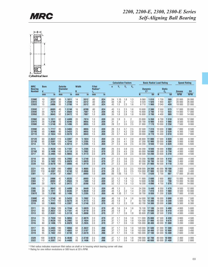
2200, 2200-E, 2300, 2300-E Series Self-Aligning Ball Bearing
69
MRCBearingNumber
Bore
dmm in
OutsideDiameterDmm in
Width
Bmm in
ra
mm in
DynamicC2)
N lbf
Basic Radial Load Rating Speed Rating
StaticC0
N lbfGrease OilRPM RPM
Fillet Radius1)
2200E 10 .3937 30 1.1811 14 .5512 .60 .024 .54 1.15 1.8 1.3 8 060 1 810 1 730 389 22 000 28 0002201E 12 .4724 32 1.2598 14 .5512 .60 .024 .50 1.25 2 1.3 8 520 1 920 1 900 427 20 000 26 0002202E 15 .5906 35 1.3780 14 .5512 .60 .024 .43 1.5 2.3 1.6 8 710 1 960 2 040 459 18 000 22 000
2203E 17 .6693 40 1.5748 16 .6299 .60 .024 .43 1.5 2.3 1.6 10 600 2 380 2 550 573 17 000 20 0002204E 20 .7874 47 1.8504 18 .7087 1.0 .039 .40 1.6 2.4 1.6 16 800 3 780 4 150 933 14 000 17 0002205E 25 .9843 52 2.0472 18 .7087 1.0 .039 .35 1.8 2.8 1.8 16 800 3 780 4 400 989 11 000 14 000
2206E 30 1.1811 62 2.4409 20 .7874 1.0 .039 .33 1.9 3 2 23 800 5 350 6 700 1 510 9 500 12 0002207E 35 1.3780 72 2.8346 23 .9055 1.0 .039 .31 2 3.1 2.2 30 700 6 900 8 800 1 980 8 500 10 0002208E 40 1.5748 80 3.1496 23 .9055 1.0 .039 .28 2.2 3.5 2.5 31 900 7 170 10 000 2 250 7 500 9 000
2209E 45 1.7717 85 3.3465 23 .9055 1.0 .039 .26 2.4 3.7 2.5 32 500 7 310 10 600 2 380 7 000 8 5002210E 50 1.9685 90 3.5433 23 .9055 1.0 .039 .23 2.7 4.2 2.8 33 800 7 600 11 200 2 520 6 300 7 5002211E 55 2.1654 100 3.9370 25 .9843 1.5 .059 .23 2.7 4.2 2.8 39 000 8 770 13 400 3 010 6 000 7 000
2212E 60 2.3622 110 4.3307 28 1.1024 1.5 .059 .24 2.6 4.1 2.8 48 800 11 000 17 000 3 820 5 300 6 3002213E 65 2.5591 120 4.7244 31 1.2205 1.5 .059 .24 2.6 4.1 2.8 57 200 12 900 20 000 4 500 5 000 6 0002214 70 2.7559 125 4.9213 31 1.2205 1.5 .059 .27 2.3 3.6 2.5 44 200 9 940 17 000 3 820 4 800 5 600
2215 75 2.9528 130 5.1181 31 1.2205 1.5 .059 .25 2.5 3.9 2.5 44 200 9 940 18 000 4 050 4 500 5 3002216E 80 3.1496 140 5.5118 33 1.2992 2.0 .079 .22 2.9 4.5 2.8 65 000 14 600 25 500 5 730 4 000 4 8002217 85 3.3465 150 5.9055 36 1.4173 2.0 .079 .25 2.5 3.9 2.5 58 500 13 200 23 600 5 310 3 800 4 500
2218 90 3.5433 160 6.2992 40 1.5748 2.0 .079 .27 2.3 3.6 2.5 70 200 15 800 28 500 6 410 3 600 4 3002219 95 3.7402 170 6.6929 43 1.6929 2.0 .079 .27 2.3 3.6 2.5 83 200 18 700 34 500 7 760 3 400 4 0002220 100 3.9370 180 7.0866 46 1.8110 2.0 .079 .27 2.3 3.6 2.5 97 500 21 900 40 500 9 110 3 200 3 800
2221 105 4.1339 190 7.4803 50 1.9685 2.0 .079 .28 2.2 3.5 2.5 108 000 24 300 45 000 10 100 3 000 3 6002222 110 4.3307 200 7.8740 53 2.0866 2.0 .079 .28 2.2 3.5 2.5 124 000 27 900 52 000 11 700 2 800 3 4002301 12 .4724 37 1.4567 17 .6693 1.0 .039 .60 1.05 1.6 1.1 11 700 2 630 2 700 607 17 000 20 000
2302 15 .5906 42 1.6535 17 .6693 1.0 .039 .52 1.2 1.9 1.3 11 900 2 680 2 900 652 15 000 18 0002303 17 .6693 47 1.8504 19 .7480 1.0 .039 .52 1.2 1.9 1.3 14 600 3 280 3 550 798 13 000 16 0002304 20 .7874 52 2.0472 21 .8268 1.0 .039 .52 1.2 1.9 1.3 18 200 4 090 4 750 1 070 11 000 14 000
2305 25 .9843 62 2.4409 24 .9449 1.0 .039 .48 1.3 2 1.4 24 200 5 440 6 550 1 470 9 500 12 0002306 30 1.1811 72 2.8346 27 1.0630 1.0 .039 .44 1.4 2.2 1.4 31 200 7 010 8 800 1 980 8 500 10 0002307E 35 1.3780 80 3.1496 31 1.2205 1.5 .059 .46 1.35 2.1 1.4 39 700 8 930 11 200 2 520 7 000 8 500
2308E 40 1.5748 90 3.5433 33 1.2992 1.5 .059 .40 1.6 2.4 1.6 54 000 12 100 16 000 3 600 6 300 7 5002309E 45 1.7717 100 3.9370 36 1.4173 1.5 .059 .33 1.9 3 2 63 700 14 300 19 300 4 340 5 600 6 7002310 50 1.9685 110 4.3307 40 1.5748 2.0 .079 .43 1.5 2.3 1.6 63 700 14 300 20 000 4 500 5 300 6 300
2311 55 2.1654 120 4.7244 43 1.6929 2.0 .079 .40 1.6 2.4 1.6 76 100 17 100 24 000 5 400 4 800 5 6002312 60 2.3622 130 5.1181 46 1.8110 2.0 .079 .33 1.9 3 2 87 100 19 600 28 500 6 410 4 500 5 3002313 65 2.5591 140 5.5118 48 1.8898 2.0 .079 .37 1.7 2.6 1.8 95 600 21 500 32 500 7 310 4 000 4 800
2314 70 2.7559 150 5.9055 51 2.0079 2.0 .079 .37 1.7 2.6 1.8 111 000 25 000 37 500 8 430 3 800 4 5002315 75 2.9528 160 6.2992 55 2.1654 2.0 .079 .37 1.7 2.6 1.8 124 000 27 900 43 000 9 670 3 400 4 0002316 80 3.1496 170 6.6929 58 2.2835 2.0 .079 .37 1.7 2.6 1.8 135 000 30 400 49 000 11 000 3 200 3 800
2317 85 3.3465 180 7.0866 60 2.3622 2.5 .098 .37 1.7 2.6 1.8 140 000 31 500 51 000 11 500 3 000 3 6002318 90 3.5433 190 7.4803 64 2.5197 2.5 .098 .37 1.7 2.6 1.8 153 000 34 400 57 000 12 800 2 800 3 4002319 95 3.7402 200 7.8740 67 2.6378 2.5 .098 .37 1.7 2.6 1.8 165 000 37 100 64 000 14 400 2 600 3 200
2320 100 3.9370 215 8.4646 73 2.8740 2.5 .098 .37 1.7 2.6 1.8 190 000 42 700 80 000 18 000 2 400 3 0002322 110 4.3307 240 9.4488 80 3.1496 2.5 .098 .37 1.7 2.6 1.8 216 000 48 600 95 000 21 400 2 200 2 800
Calculation Factors
e Y1 Y2 Y0
1) Fillet radius indicates maximum fillet radius on shaft or in housing which bearing corner will clear.2) Rating for one million revolutions or 500 hours at 33¹|₃ RPM.
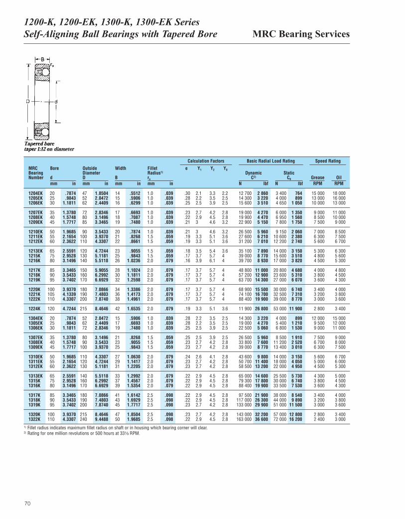
MRC Bearing Services1200-K, 1200-EK, 1300-K, 1300-EK Series Self-Aligning Ball Bearings with Tapered Bore
70
MRCBearingNumber
Bore
dmm in
OutsideDiameterDmm in
Width
Bmm in
ra
mm in
DynamicC2)
N lbf
Basic Radial Load Rating Speed Rating
StaticC0
N lbfGrease OilRPM RPM
Fillet Radius1)
1204EK 20 .7874 47 1.8504 14 .5512 1.0 .039 .30 2.1 3.3 2.2 12 700 2 860 3 400 764 15 000 18 0001205EK 25 .9843 52 2.0472 15 .5906 1.0 .039 .28 2.2 3.5 2.5 14 300 3 220 4 000 899 13 000 16 0001206EK 30 1.1811 62 2.4409 16 .6299 1.0 .039 .25 2.5 3.9 2.5 15 600 3 510 4 650 1 050 10 000 13 000
1207EK 35 1.3780 72 2.8346 17 .6693 1.0 .039 .23 2.7 4.2 2.8 19 000 4 270 6 000 1 350 9 000 11 0001208EK 40 1.5748 80 3.1496 18 .7087 1.0 .039 .22 2.9 4.5 2.8 19 900 4 470 6 950 1 560 8 500 10 0001209EK 45 1.7717 85 3.3465 19 .7480 1.0 .039 .21 3 4.6 3.2 22 900 5 150 7 800 1 750 7 500 9 000
1210EK 50 1.9685 90 3.5433 20 .7874 1.0 .039 .21 3 4.6 3.2 26 500 5 960 9 150 2 060 7 000 8 5001211EK 55 2.1654 100 3.9370 21 .8268 1.5 .059 .19 3.3 5.1 3.6 27 600 6 210 10 600 2 380 6 300 7 5001212EK 60 2.3622 110 4.3307 22 .8661 1.5 .059 .19 3.3 5.1 3.6 31 200 7 010 12 200 2 740 5 600 6 700
1213EK 65 2.5591 120 4.7244 23 .9055 1.5 .059 .18 3.5 5.4 3.6 35 100 7 890 14 000 3 150 5 300 6 3001215K 75 2.9528 130 5.1181 25 .9843 1.5 .059 .17 3.7 5.7 4 39 000 8 770 15 600 3 510 4 800 5 6001216K 80 3.1496 140 5.5118 26 1.0236 2.0 .079 .16 3.9 6.1 4 39 700 8 930 17 000 3 820 4 500 5 300
1217K 85 3.3465 150 5.9055 28 1.1024 2.0 .079 .17 3.7 5.7 4 48 800 11 000 20 800 4 680 4 000 4 8001218K 90 3.5433 160 6.2992 30 1.1811 2.0 .079 .17 3.7 5.7 4 57 200 12 900 23 600 5 310 3 800 4 5001219K 95 3.7402 170 6.6929 32 1.2598 2.0 .079 .17 3.7 5.7 4 63 700 14 300 27 000 6 070 3 600 4 300
1220K 100 3.9370 180 7.0866 34 1.3386 2.0 .079 .17 3.7 5.7 4 68 900 15 500 30 000 6 740 3 400 4 0001221K 105 4.1339 190 7.4803 36 1.4173 2.0 .079 .17 3.7 5.7 4 74 100 16 700 32 500 7 310 3 200 3 8001222K 110 4.3307 200 7.8740 38 1.4961 2.0 .079 .17 3.7 5.7 4 88 400 19 900 39 000 8 770 3 000 3 600
1224K 120 4.7244 215 8.4646 42 1.6535 2.0 .079 .19 3.3 5.1 3.6 11 900 26 800 53 000 11 900 2 800 3 400
1304EK 20 .7874 52 2.0472 15 .5906 1.0 .039 .28 2.2 3.5 2.5 14 300 3 220 4 000 899 12 000 15 0001305EK 25 .9843 62 2.4409 17 .6693 1.0 .039 .28 2.2 3.5 2.5 19 000 4 270 5 400 1 210 9 500 12 0001306EK 30 1.1811 72 2.8346 19 .7480 1.0 .039 .25 2.5 3.9 2.5 22 500 5 060 6 800 1 530 9 000 11 000
1307EK 35 1.3780 80 3.1496 21 .8268 1.5 .059 .25 2.5 3.9 2.5 26 500 5 960 8 500 1 910 7 500 9 0001308EK 40 1.5748 90 3.5433 23 .9055 1.5 .059 .23 2.7 4.2 2.8 33 800 7 600 11 200 2 520 6 700 8 0001309EK 45 1.7717 100 3.9370 25 .9843 1.5 .059 .23 2.7 4.2 2.8 39 000 8 770 13 400 3 010 6 300 7 500
1310EK 50 1.9685 110 4.3307 27 1.0630 2.0 .079 .24 2.6 4.1 2.8 43 600 9 800 14 000 3 150 5 600 6 7001311EK 55 2.1654 120 4.7244 29 1.1417 2.0 .079 .23 2.7 4.2 2.8 50 700 11 400 18 000 4 050 5 000 6 0001312EK 60 2.3622 130 5.1181 31 1.2205 2.0 .079 .23 2.7 4.2 2.8 58 500 13 200 22 000 4 950 4 500 5 300
1313EK 65 2.5591 140 5.5118 33 1.2992 2.0 .079 .22 2.9 4.5 2.8 65 000 14 600 25 500 5 730 4 300 5 0001315K 75 2.9528 160 6.2992 37 1.4567 2.0 .079 .22 2.9 4.5 2.8 79 300 17 800 30 000 6 740 3 800 4 5001316K 80 3.1496 170 6.6929 39 1.5354 2.0 .079 .22 2.9 4.5 2.8 88 400 19 900 33 500 7 530 3 600 4 300
1317K 85 3.3465 180 7.0866 41 1.6142 2.5 .098 .22 2.9 4.5 2.8 97 500 21 900 38 000 8 540 3 400 4 0001318K 90 3.5433 190 7.4803 43 1.6929 2.5 .098 .22 2.9 4.5 2.8 117 000 26 300 44 000 9 890 3 200 3 8001319K 95 3.7402 200 7.8740 45 1.7717 2.5 .098 .23 2.7 4.2 2.8 133 000 29 900 51 000 11 500 3 000 3 600
1320K 100 3.9370 215 8.4646 47 1.8504 2.5 .098 .23 2.7 4.2 2.8 143 000 32 200 57 000 12 800 2 800 3 4001322K 110 4.3307 240 9.4488 50 1.9685 2.5 .098 .22 2.9 4.5 2.8 163 000 36 600 72 000 16 200 2 400 3 000
Calculation Factors
e Y1 Y2 Y0
1) Fillet radius indicates maximum fillet radius on shaft or in housing which bearing corner will clear.2) Rating for one million revolutions or 500 hours at 33¹|₃ RPM.
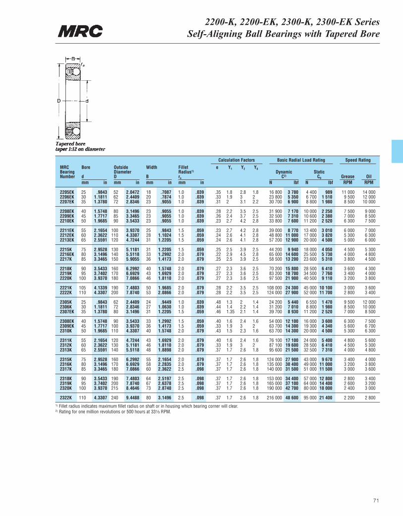
2200-K, 2200-EK, 2300-K, 2300-EK Series Self-Aligning Ball Bearings with Tapered Bore
71
MRCBearingNumber
Bore
dmm in
OutsideDiameterDmm in
Width
Bmm in
ra
mm in
DynamicC2)
N lbf
Basic Radial Load Rating Speed Rating
StaticC0
N lbfGrease OilRPM RPM
Fillet Radius1)
2205EK 25 .9843 52 2.0472 18 .7087 1.0 .039 .35 1.8 2.8 1.8 16 800 3 780 4 400 989 11 000 14 0002206EK 30 1.1811 62 2.4409 20 .7874 1.0 .039 .33 1.9 3 2 23 800 5 350 6 700 1 510 9 500 12 0002207EK 35 1.3780 72 2.8346 23 .9055 1.0 .039 .31 2 3.1 2.2 30 700 6 900 8 800 1 980 8 500 10 000
2208EK 40 1.5748 80 3.1496 23 .9055 1.0 .039 .28 2.2 3.5 2.5 31 900 7 170 10 000 2 250 7 500 9 0002209EK 45 1.7717 85 3.3465 23 .9055 1.0 .039 .26 2.4 3.7 2.5 32 500 7 310 10 600 2 380 7 000 8 5002210EK 50 1.9685 90 3.5433 23 .9055 1.0 .039 .23 2.7 4.2 2.8 33 800 7 600 11 200 2 520 6 300 7 500
2211EK 55 2.1654 100 3.9370 25 .9843 1.5 .059 .23 2.7 4.2 2.8 39 000 8 770 13 400 3 010 6 000 7 0002212EK 60 2.3622 110 4.3307 28 1.1024 1.5 .059 .24 2.6 4.1 2.8 48 800 11 000 17 000 3 820 5 300 6 3002213EK 65 2.5591 120 4.7244 31 1.2205 1.5 .059 .24 2.6 4.1 2.8 57 200 12 900 20 000 4 500 5 000 6 000
2215K 75 2.9528 130 5.1181 31 1.2205 1.5 .059 .25 2.5 3.9 2.5 44 200 9 940 18 000 4 050 4 500 5 3002216EK 80 3.1496 140 5.5118 33 1.2992 2.0 .079 .22 2.9 4.5 2.8 65 000 14 600 25 500 5 730 4 000 4 8002217K 85 3.3465 150 5.9055 36 1.4173 2.0 .079 .25 2.5 3.9 2.5 58 500 13 200 23 600 5 310 3 800 4 500
2218K 90 3.5433 160 6.2992 40 1.5748 2.0 .079 .27 2.3 3.6 2.5 70 200 15 800 28 500 6 410 3 600 4 3002219K 95 3.7402 170 6.6929 43 1.6929 2.0 .079 .27 2.3 3.6 2.5 83 200 18 700 34 500 7 760 3 400 4 0002220K 100 3.9370 180 7.0866 46 1.8110 2.0 .079 .27 2.3 3.6 2.5 97 500 21 900 40 500 9 110 3 200 3 800
2221K 105 4.1339 190 7.4803 50 1.9685 2.0 .079 .28 2.2 3.5 2.5 108 000 24 300 45 000 10 100 3 000 3 6002222K 110 4.3307 200 7.8740 53 2.0866 2.0 .079 .28 2.2 3.5 2.5 124 000 27 900 52 000 11 700 2 800 3 400
2305K 25 .9843 62 2.4409 24 .9449 1.0 .039 .48 1.3 2 1.4 24 200 5 440 6 550 1 470 9 500 12 0002306K 30 1.1811 72 2.8346 27 1.0630 1.0 .039 .44 1.4 2.2 1.4 31 200 7 010 8 800 1 980 8 500 10 0002307EK 35 1.3780 80 3.1496 31 1.2205 1.5 .059 .46 1.35 2.1 1.4 39 700 8 930 11 200 2 520 7 000 8 500
2308EK 40 1.5748 90 3.5433 33 1.2992 1.5 .059 .40 1.6 2.4 1.6 54 000 12 100 16 000 3 600 6 300 7 5002309EK 45 1.7717 100 3.9370 36 1.4173 1.5 .059 .33 1.9 3 2 63 700 14 300 19 300 4 340 5 600 6 7002310K 50 1.9685 110 4.3307 40 1.5748 2.0 .079 .43 1.5 2.3 1.6 63 700 14 300 20 000 4 500 5 300 6 300
2311K 55 2.1654 120 4.7244 43 1.6929 2.0 .079 .40 1.6 2.4 1.6 76 100 17 100 24 000 5 400 4 800 5 6002312K 60 2.3622 130 5.1181 46 1.8110 2.0 .079 .33 1.9 3 2 87 100 19 600 28 500 6 410 4 500 5 3002313K 65 2.5591 140 5.5118 48 1.8898 2.0 .079 .37 1.7 2.6 1.8 95 600 21 500 32 500 7 310 4 000 4 800
2315K 75 2.9528 160 6.2992 55 2.1654 2.0 .079 .37 1.7 2.6 1.8 124 000 27 900 43 000 9 670 3 400 4 0002316K 80 3.1496 170 6.6929 58 2.2835 2.0 .079 .37 1.7 2.6 1.8 135 000 30 400 49 000 11 000 3 200 3 8002317K 85 3.3465 180 7.0866 60 2.3622 2.5 .098 .37 1.7 2.6 1.8 140 000 31 500 51 000 11 500 3 000 3 600
2318K 90 3.5433 190 7.4803 64 2.5197 2.5 .098 .37 1.7 2.6 1.8 153 000 34 400 57 000 12 800 2 800 3 4002319K 95 3.7402 200 7.8740 67 2.6378 2.5 .098 .37 1.7 2.6 1.8 165 000 37 100 64 000 14 400 2 600 3 2002320K 100 3.9370 215 8.4646 73 2.8740 2.5 .098 .37 1.7 2.6 1.8 190 000 42 700 80 000 18 000 2 400 3 000
2322K 110 4.3307 240 9.4488 80 3.1496 2.5 .098 .37 1.7 2.6 1.8 216 000 48 600 95 000 21 400 2 200 2 800
Calculation Factors
e Y1 Y2 Y0
1) Fillet radius indicates maximum fillet radius on shaft or in housing which bearing corner will clear.2) Rating for one million revolutions or 500 hours at 33¹|₃ RPM.
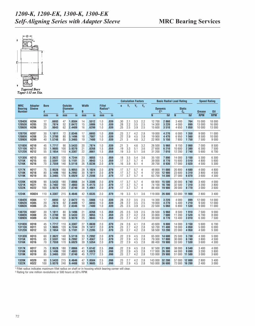
MRC Bearing Services1200-K, 1200-EK, 1300-K, 1300-EK Self-Aligning Series with Adapter Sleeve
72
MRCBearingNumber
AdapterSleeve
Bore
dmm in
OutsideDiameterDmm in
Width
Bmm in
ra
mm in
DynamicC2)
N lbf
Basic Radial Load Rating Speed Rating
StaticC0
N lbfGrease OilRPM RPM
Fillet Radius1)
1204EK H204 17 .6693 47 1.8504 14 .5512 1.0 .039 .30 2.1 3.3 2.2 12 700 2 860 3 400 764 15 000 18 0001205EK H205 20 .7874 52 2.0472 15 .5906 1.0 .039 .28 2.2 3.5 2.5 14 300 3 220 4 000 899 13 000 16 0001206EK H206 25 .9843 62 2.4409 16 .6299 1.0 .039 .25 2.5 3.9 2.5 15 600 3 510 4 650 1 050 10 000 13 000
1207EK H207 30 1.1811 72 2.8346 17 .6693 1.0 .039 .23 2.7 4.2 2.8 19 000 4 270 6 000 1 350 9 000 11 0001208EK H208 35 1.3780 80 3.1496 18 .7087 1.0 .039 .22 2.9 4.5 2.8 19 900 4 470 6 950 1 560 8 500 10 0001209EK H209 40 1.5748 85 3.3465 19 .7480 1.0 .039 .21 3 4.6 3.2 22 900 5 150 7 800 1 750 7 500 9 000
1210EK H210 45 1.7717 90 3.5433 20 .7874 1.0 .039 .21 3 4.6 3.2 26 500 5 960 9 150 2 060 7 000 8 5001211EK H211 50 1.9685 100 3.9370 21 .8268 1.5 .059 .19 3.3 5.1 3.6 27 600 6 210 10 600 2 380 6 300 7 5001212EK H212 55 2.1654 110 4.3307 22 .8661 1.5 .059 .19 3.3 5.1 3.6 31 200 7 010 12 200 2 740 5 600 6 700
1213EK H213 60 2.3622 120 4.7244 23 .9055 1.5 .059 .18 3.5 5.4 3.6 35 100 7 890 14 000 3 150 5 300 6 3001215K H215 65 2.5591 130 5.1181 25 .9843 1.5 .059 .17 3.7 5.7 4 39 000 8 770 15 600 3 510 4 800 5 6001216K H216 70 2.7559 140 5.5118 26 1.0236 2.0 .079 .16 3.9 6.1 4 39 700 8 930 17 000 3 820 4 500 5 300
1217K H217 75 2.9528 150 5.9055 28 1.1024 2.0 .079 .17 3.7 5.7 4 48 800 11 000 20 800 4 680 4 000 4 8001218K H218 80 3.1496 160 6.2992 30 1.1811 2.0 .079 .17 3.7 5.7 4 57 200 12 900 23 600 5 310 3 800 4 5001219K H219 85 3.3465 170 6.6929 32 1.2598 2.0 .079 .17 3.7 5.7 4 63 700 14 300 27 000 6 070 3 600 4 300
1220K H220 90 3.5433 180 7.0866 34 1.3386 2.0 .079 .17 3.7 5.7 4 68 900 15 500 30 000 6 740 3 400 4 0001221K H221 95 3.7402 190 7.4803 36 1.4173 2.0 .079 .17 3.7 5.7 4 74 100 16 700 32 500 7 310 3 200 3 8001222K H222 100 3.9370 200 7.8740 38 1.4961 2.0 .079 .17 3.7 5.7 4 88 400 19 900 39 000 8 770 3 000 3 600
1224K H3024 110 4.3307 215 8.4646 42 1.6535 2.0 .079 .19 3.3 5.1 3.6 119 000 26 800 53 000 11 900 2 800 3 400
1304EK H304 17 .6693 52 2.0472 15 .5906 1.0 .039 .28 2.2 3.5 2.5 14 300 3 220 4 000 899 12 000 14 0001305EK H305 20 .7874 62 2.4409 17 .6693 1.0 .039 .28 2.2 3.5 2.5 19 000 4 270 5 400 1 210 9 500 12 0001306EK H306 25 .9843 72 2.8346 19 .7480 1.0 .039 .25 2.5 3.9 2.5 22 500 5 060 6 800 1 530 9 000 11 000
1307EK H307 30 1.1811 80 3.1496 21 .8268 1.5 .059 .25 2.5 3.9 2.5 26 500 5 960 8 500 1 910 7 500 9 0001308EK H308 35 1.3780 90 3.5433 23 .9055 1.5 .059 .23 2.7 4.2 2.8 33 800 7 600 11 200 2 520 6 700 8 0001309EK H309 40 1.5748 100 3.9370 25 .9843 1.5 .059 .23 2.7 4.2 2.8 39 000 8 770 13 400 3 010 6 300 7 500
1310EK H310 45 1.7717 110 4.3307 27 1.0630 2.0 .079 .24 2.6 4.1 2.8 43 600 9 800 14 000 3 150 5 600 6 7001311EK H311 50 1.9685 120 4.7244 29 1.1417 2.0 .079 .23 2.7 4.2 2.8 50 700 11 400 18 000 4 050 5 000 6 0001312EK H312 55 2.1654 130 5.1181 31 1.2205 2.0 .079 .23 2.7 4.2 2.8 58 500 13 200 22 000 4 950 4 500 5 300
1313EK H313 60 2.3622 140 5.5118 33 1.2992 2.0 .079 .22 2.9 4.5 2.8 65 000 14 600 25 500 5 730 4 300 5 0001315K H315 65 2.5591 160 6.2992 37 1.4567 2.0 .079 .22 2.9 4.5 2.8 79 300 17 800 30 000 6 740 3 800 4 5001316K H316 70 2.7559 170 6.6929 39 1.5354 2.0 .079 .22 2.9 4.5 2.8 88 400 19 900 33 500 7 530 3 600 4 300
1317K H317 75 2.9528 180 7.0866 41 1.6142 2.5 .098 .22 2.9 4.5 2.8 97 500 21 900 38 000 8 540 3 400 4 0001318K H318 80 3.1496 190 7.4803 43 1.6929 2.5 .098 .22 2.9 4.5 2.8 117 000 26 300 44 000 9 890 3 200 3 8001319K H319 85 3.3465 200 7.8740 45 1.7717 2.5 .098 .23 2.7 4.2 2.8 133 000 29 900 51 000 11 500 3 000 3 600
1320K H320 90 3.5433 215 8.4646 47 1.8504 2.5 .098 .23 2.7 4.2 2.8 143 000 32 200 57 000 12 800 2 800 3 4001322K H322 100 3.9370 240 9.4488 50 1.9685 2.5 .098 .22 2.9 4.5 2.8 163 000 36 600 72 000 16 200 2 400 3 000
Calculation Factors
e Y1 Y2 Y0
1) Fillet radius indicates maximum fillet radius on shaft or in housing which bearing corner will clear.2) Rating for one million revolutions or 500 hours at 33¹|₃ RPM.
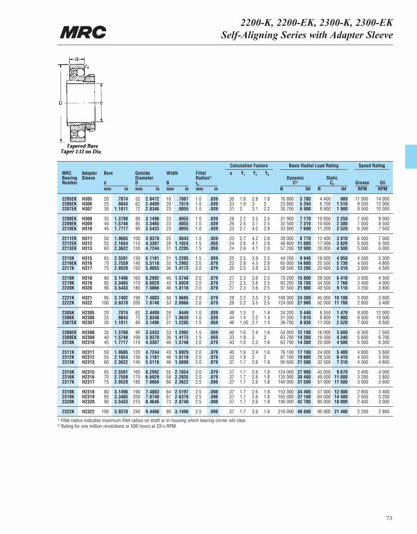
2200-K, 2200-EK, 2300-K, 2300-EKSelf-Aligning Series with Adapter Sleeve
73
MRCBearingNumber
Bore
dmm in
OutsideDiameterDmm in
Width
Bmm in
ra
mm in
DynamicC2)
N lbf
Basic Radial Load Rating Speed Rating
StaticC0
N lbfGrease OilRPM RPM
Fillet Radius1)
2205EK H305 20 .7874 52 2.0472 18 .7087 1.0 .039 .35 1.8 2.8 1.8 16 800 3 780 4 400 989 11 000 14 0002206EK H306 25 .9843 62 2.4409 20 .7874 1.0 .039 .33 1.9 3 2 23 800 5 350 6 700 1 510 9 500 12 0002207EK H307 30 1.1811 72 2.8346 23 .9055 1.0 .039 .31 2 3.1 2.2 30 700 6 900 8 800 1 980 8 500 10 000
2208EK H308 35 1.3780 80 3.1496 23 .9055 1.0 .039 .28 2.2 3.5 2.5 31 900 7 170 10 000 2 250 7 500 9 0002209EK H309 40 1.5748 85 3.3465 23 .9055 1.0 .039 .26 2.4 3.7 2.5 32 500 7 310 10 600 2 380 7 000 8 5002210EK H310 45 1.7717 90 3.5433 23 .9055 1.0 .039 .23 2.7 4.2 2.8 33 800 7 600 11 200 2 520 6 300 7 500
2211EK H311 50 1.9685 100 3.9370 25 .9843 1.5 .059 .23 2.7 4.2 2.8 39 000 8 770 13 400 3 010 6 000 7 0002212EK H312 55 2.1654 110 4.3307 28 1.1024 1.5 .059 .24 2.6 4.1 2.8 48 800 11 000 17 000 3 820 5 300 6 3002213EK H313 60 2.3622 120 4.7244 31 1.2205 1.5 .059 .24 2.6 4.1 2.8 57 200 12 900 20 000 4 500 5 000 6 000
2215K H315 65 2.5591 130 5.1181 31 1.2205 1.5 .059 .25 2.5 3.9 2.5 44 200 9 940 18 000 4 050 4 500 5 3002216EK H316 70 2.7559 140 5.5118 33 1.2992 2.0 .079 .22 2.9 4.5 2.8 65 000 14 600 25 500 5 730 4 000 4 8002217K H317 75 2.9528 150 5.9055 36 1.4173 2.0 .079 .25 2.5 3.9 2.5 58 500 13 200 23 600 5 310 3 800 4 500
2218K H318 80 3.1496 160 6.2992 40 1.5748 2.0 .079 .27 2.3 3.6 2.5 70 200 15 800 28 500 6 410 3 600 4 3002219K H319 85 3.3465 170 6.6929 43 1.6929 2.0 .079 .27 2.3 3.6 2.5 83 200 18 700 34 500 7 760 3 400 4 0002220K H320 90 3.5433 180 7.0866 46 1.8110 2.0 .079 .27 2.3 3.6 2.5 97 500 21 900 40 500 9 110 3 200 3 800
2221K H321 95 3.7402 190 7.4803 50 1.9685 2.0 .079 .28 2.2 3.5 2.5 108 000 24 300 45 000 10 100 3 000 3 6002222K H322 100 3.9370 200 7.8740 53 2.0866 2.0 .079 .28 2.2 3.5 2.5 124 000 27 900 52 000 11 700 2 800 3 400
2305K H2305 20 .7874 62 2.4409 24 .9449 1.0 .039 .48 1.3 2 1.4 24 200 5 440 6 550 1 470 9 500 12 0002306K H2306 25 .9843 72 2.8346 27 1.0630 1.0 .039 .44 1.4 2.2 1.4 31 200 7 010 8 800 1 980 8 500 10 0002307EK H2307 30 1.1811 80 3.1496 31 1.2205 1.5 .059 .46 1.35 2.1 1.4 39 700 8 930 11 200 2 520 7 000 8 500
2308EK H2308 35 1.3780 90 3.5433 33 1.2992 1.5 .059 .40 1.6 2.4 1.6 54 000 12 100 16 000 3 600 6 300 7 5002309EK H2309 40 1.5748 100 3.9370 36 1.4173 1.5 .059 .33 1.9 3 2 63 700 14 300 19 300 4 340 5 600 6 7002310K H2310 45 1.7717 110 4.3307 40 1.5748 2.0 .079 .43 1.5 2.3 1.6 63 700 14 300 20 000 4 500 5 300 6 300
2311K H2311 50 1.9685 120 4.7244 43 1.6929 2.0 .079 .40 1.6 2.4 1.6 76 100 17 100 24 000 5 400 4 800 5 6002312K H2312 55 2.1654 130 5.1181 46 1.8110 2.0 .079 .33 1.9 3 2 87 100 19 600 28 500 6 410 4 500 5 3002313K H2313 60 2.3622 140 5.5118 48 1.8898 2.0 .079 .37 1.7 2.6 1.8 95 600 21 500 32 500 7 310 4 000 4 800
2315K H2315 65 2.5591 160 6.2992 55 2.1654 2.0 .079 .37 1.7 2.6 1.8 124 000 27 900 43 000 9 670 3 400 4 0002316K H2316 70 2.7559 170 6.6929 58 2.2835 2.0 .079 .37 1.7 2.6 1.8 135 000 30 400 49 000 11 000 3 200 3 8002317K H2317 75 2.9528 180 7.0866 60 2.3622 2.5 .098 .37 1.7 2.6 1.8 140 000 31 500 51 000 11 500 3 000 3 600
2318K H2318 80 3.1496 190 7.4803 64 2.5197 2.5 .098 .37 1.7 2.6 1.8 153 000 34 400 57 000 12 800 2 800 3 4002319K H2319 85 3.3465 200 7.8740 67 2.6378 2.5 .098 .37 1.7 2.6 1.8 165 000 37 100 64 000 14 400 2 600 3 2002320K H2320 90 3.5433 215 8.4646 73 2.8740 2.5 .098 .37 1.7 2.6 1.8 190 000 42 700 80 000 18 000 2 400 3 000
2322K H2322 100 3.9370 240 9.4488 80 3.1496 2.5 .098 .37 1.7 2.6 1.8 216 000 48 600 95 000 21 400 2 200 2 800
Calculation Factors
e Y1 Y2 Y0
1) Fillet radius indicates maximum fillet radius on shaft or in housing which bearing corner will clear.2) Rating for one million revolutions or 500 hours at 33¹|₃ RPM.
AdapterSleeve
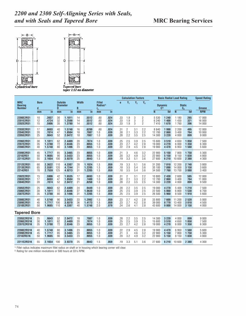
MRC Bearing Services2200 and 2300 Self-Aligning Series with Seals,and with Seals and Tapered Bore
74
MRCBearingNumber
Bore
dmm in
OutsideDiameterDmm in
Width
Bmm in
ra
mm in
DynamicC2)
N lbf
Basic Radial Load Rating Speed Rating
StaticC0
N lbfGreaseRPM
Fillet Radius1)
2200E2RS1 10 .3937 30 1.1811 14 .5512 .60 .024 .33 1.9 3 2 5 530 1 240 1 180 265 17 0002201E2RS1 12 .4724 32 1.2598 14 .5512 .60 .024 .33 1.9 3 2 6 240 1 400 1 430 321 16 0002202E2RS1 15 .5906 35 1.3780 14 .5512 .60 .024 .33 1.9 3 2 7 410 1 670 1 760 396 14 000
2203E2RS1 17 .6693 40 1.5748 16 .6299 .60 .024 .31 2 3.1 2.2 8 840 1 990 2 200 495 12 0002204E2RS1 20 .7874 47 1.8504 18 .7087 1.0 .039 .30 2.1 3.3 2.2 12 700 2 860 3 400 764 10 0002205E2RS1 25 .9843 52 2.0472 18 .7087 1.0 .039 .28 2.2 3.5 2.5 14 300 3 220 4 000 899 9 000
2206E2RS1 30 1.1811 62 2.4409 20 .7874 1.0 .039 .25 2.5 3.9 2.5 15 600 3 510 4 650 1 050 7 5002207E2RS1 35 1.3780 72 2.8346 23 .9055 1.0 .039 .23 2.7 4.2 2.8 19 000 4 270 6 000 1 350 6 3002208E2RS1 40 1.5748 80 3.1496 23 .9055 1.0 .039 .22 2.9 4.5 2.8 19 900 4 470 6 950 1 560 5 600
2209E2RS1 45 1.7717 85 3.3465 23 .9055 1.0 .039 .21 3 4.6 3.2 22 900 5 150 7 800 1 750 5 30022102RS1 50 1.9685 90 3.5433 23 .9055 1.0 .039 .20 3.2 4.9 3.2 22 900 5 150 8 150 1 830 4 8002211E2RS1 55 2.1654 100 3.9370 25 .9843 1.5 .059 .19 3.3 5.1 3.6 27 600 6 210 10 600 2 380 4 300
2212E2RS1 60 2.3622 110 4.3307 28 1.1024 1.5 .059 .19 3.3 5.1 3.6 31 200 7 010 12 200 2 740 3 8002213E2RS1 65 2.5591 120 4.7244 31 1.2205 1.5 .059 .18 3.5 5.4 3.6 35 100 7 890 14 000 3 150 3 60022142RS1 70 2.7559 125 4.9213 31 1.2205 1.5 .059 .18 3.5 5.4 3.6 34 500 7 760 13 700 3 080 3 400
2302E2RS1 15 .5906 42 1.6535 17 .6693 1.0 .039 .31 2 3.1 2.2 10 800 2 430 2 600 585 12 0002303E2RS1 17 .6693 47 1.8504 19 .7480 1.0 .039 .30 2.1 3.3 2.2 12 700 2 860 3 400 764 11 0002304E2RS1 20 .7874 52 2.0472 21 .8268 1.0 .039 .28 2.2 3.5 2.5 14 300 3 220 4 000 899 9 500
2305E2RS1 25 .9843 62 2.4409 24 .9449 1.0 .039 .28 2.2 3.5 2.5 19 000 4 270 5 400 1 210 7 5002306E2RS1 30 1.1811 72 2.8346 27 1.0630 1.0 .039 .25 2.5 3.9 2.5 22 500 5 060 6 800 1 530 6 7002307E2RS1 35 1.3780 80 3.1496 31 1.2205 1.5 .059 .25 2.5 3.9 2.5 26 500 5 960 8 500 1 910 5 600
2308E2RS1 40 1.5748 90 3.5433 33 1.2992 1.5 .059 .23 2.7 4.2 2.8 33 800 7 600 11 200 2 520 5 0002309E2RS1 45 1.7717 100 3.9370 36 1.4173 1.5 .059 .23 2.7 4.2 2.8 39 000 8 770 13 400 3 010 4 5002310E2RS1 50 1.9685 110 4.3307 40 1.5748 2.0 .079 .24 2.6 4.1 2.8 43 600 9 800 14 000 3 150 4 000
2205E2RS1K 25 .9843 52 2.0472 18 .7087 1.0 .039 .28 2.2 3.5 2.5 14 300 3 220 4 000 899 9 0002206E2RS1K 30 1.1811 62 2.4409 20 .7874 1.0 .039 .25 2.5 3.9 2.5 15 600 3 510 4 650 1 050 7 5002207E2RS1K 35 1.3780 72 2.8346 23 .9055 1.0 .039 .23 2.7 4.2 2.8 19 000 4 270 6 000 1 350 6 300
2208E2RS1K 40 1.5748 80 3.1496 23 .9055 1.0 .039 .22 2.9 4.5 2.8 19 900 4 470 6 950 1 560 5 6002209E2RS1K 45 1.7717 85 3.3465 23 .9055 1.0 .039 .21 3 4.6 3.2 22 900 5 150 7 800 1 750 5 30022102RS1K 50 1.9685 90 3.5433 23 .9055 1.0 .039 .20 3.2 4.9 3.2 22 900 5 150 8 150 1 830 4 800
2211E2RS1K 55 2.1654 100 3.9370 25 .9843 1.5 .059 .19 3.3 5.1 3.6 27 600 6 210 10 600 2 380 4 300
Calculation Factors
e Y1 Y2 Y0
Tapered Bore
1) Fillet radius indicates maximum fillet radius on shaft or in housing which bearing corner will clear.2) Rating for one million revolutions or 500 hours at 33¹|₃ RPM.
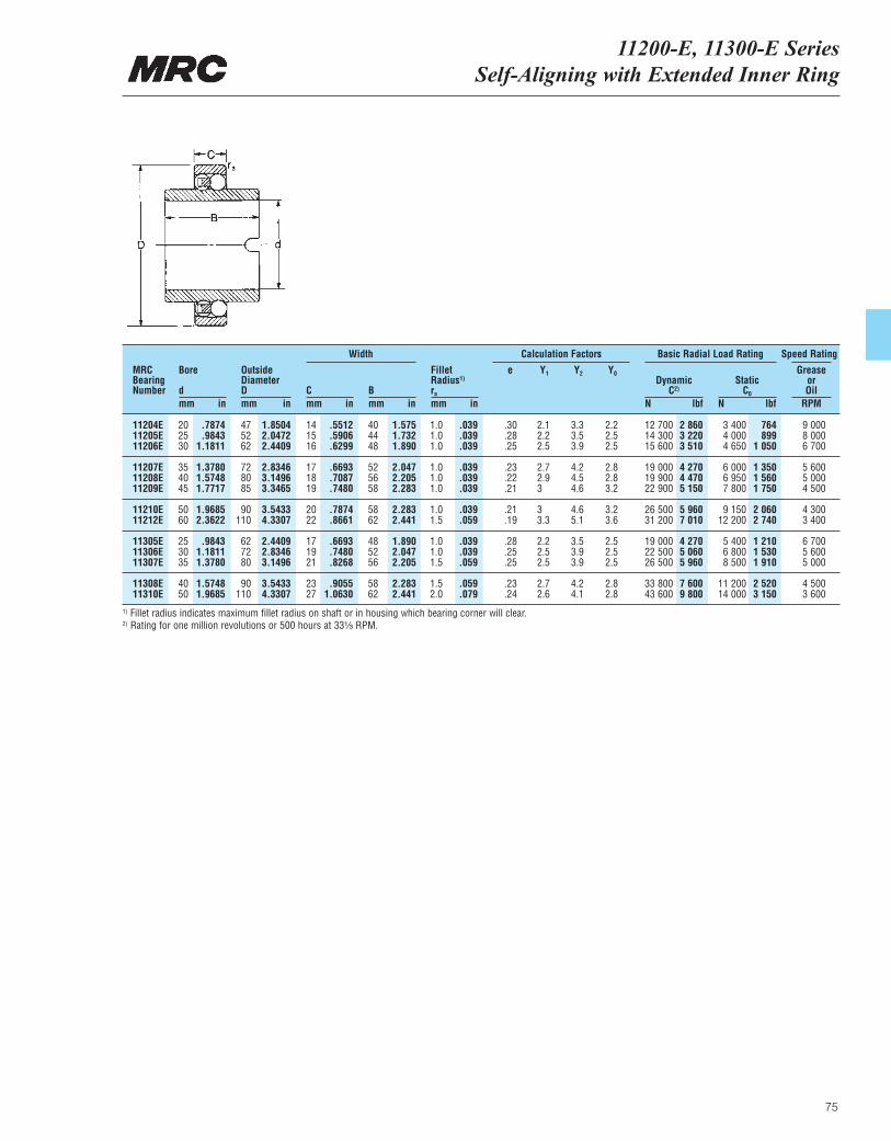
11200-E, 11300-E Series Self-Aligning with Extended Inner Ring
75
MRCBearingNumber
Bore
dmm in
OutsideDiameterDmm in
Cmm in
Bmm in
ra
mm in
DynamicC2)
N lbf
Basic Radial Load Rating Speed Rating
StaticC0
N lbf
GreaseorOil
RPM
Fillet Radius1)
11204E 20 .7874 47 1.8504 14 .5512 40 1.575 1.0 .039 .30 2.1 3.3 2.2 12 700 2 860 3 400 764 9 00011205E 25 .9843 52 2.0472 15 .5906 44 1.732 1.0 .039 .28 2.2 3.5 2.5 14 300 3 220 4 000 899 8 00011206E 30 1.1811 62 2.4409 16 .6299 48 1.890 1.0 .039 .25 2.5 3.9 2.5 15 600 3 510 4 650 1 050 6 700
11207E 35 1.3780 72 2.8346 17 .6693 52 2.047 1.0 .039 .23 2.7 4.2 2.8 19 000 4 270 6 000 1 350 5 60011208E 40 1.5748 80 3.1496 18 .7087 56 2.205 1.0 .039 .22 2.9 4.5 2.8 19 900 4 470 6 950 1 560 5 00011209E 45 1.7717 85 3.3465 19 .7480 58 2.283 1.0 .039 .21 3 4.6 3.2 22 900 5 150 7 800 1 750 4 500
11210E 50 1.9685 90 3.5433 20 .7874 58 2.283 1.0 .039 .21 3 4.6 3.2 26 500 5 960 9 150 2 060 4 30011212E 60 2.3622 110 4.3307 22 .8661 62 2.441 1.5 .059 .19 3.3 5.1 3.6 31 200 7 010 12 200 2 740 3 400
11305E 25 .9843 62 2.4409 17 .6693 48 1.890 1.0 .039 .28 2.2 3.5 2.5 19 000 4 270 5 400 1 210 6 70011306E 30 1.1811 72 2.8346 19 .7480 52 2.047 1.0 .039 .25 2.5 3.9 2.5 22 500 5 060 6 800 1 530 5 60011307E 35 1.3780 80 3.1496 21 .8268 56 2.205 1.5 .059 .25 2.5 3.9 2.5 26 500 5 960 8 500 1 910 5 000
11308E 40 1.5748 90 3.5433 23 .9055 58 2.283 1.5 .059 .23 2.7 4.2 2.8 33 800 7 600 11 200 2 520 4 50011310E 50 1.9685 110 4.3307 27 1.0630 62 2.441 2.0 .079 .24 2.6 4.1 2.8 43 600 9 800 14 000 3 150 3 600
Calculation FactorsWidth
e Y1 Y2 Y0
1) Fillet radius indicates maximum fillet radius on shaft or in housing which bearing corner will clear.2) Rating for one million revolutions or 500 hours at 33¹|₃ RPM.
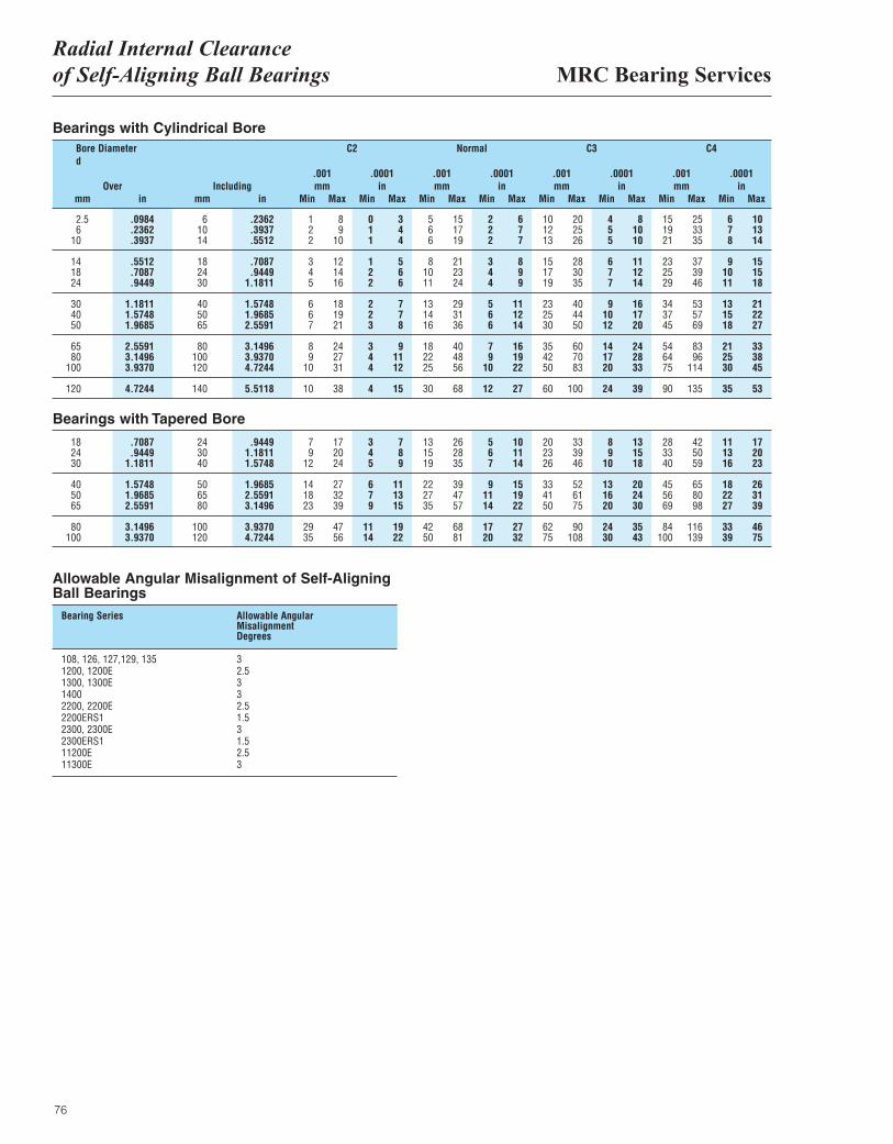
MRC Bearing ServicesRadial Internal Clearance of Self-Aligning Ball Bearings
76
Bore Diameterd
Overmm mmin in Min Min Min Min Min Min Min Min
mm in in in inmm mm mm.001 .0001 .0001 .0001 .0001.001 .001 .001
Max Max Max Max Max Max Max MaxIncluding
C2 Normal C3 C4
2.5 .0984 6 .2362 1 8 0 3 5 15 2 6 10 20 4 8 15 25 6 106 .2362 10 .3937 2 9 1 4 6 17 2 7 12 25 5 10 19 33 7 13
10 .3937 14 .5512 2 10 1 4 6 19 2 7 13 26 5 10 21 35 8 14
14 .5512 18 .7087 3 12 1 5 8 21 3 8 15 28 6 11 23 37 9 1518 .7087 24 .9449 4 14 2 6 10 23 4 9 17 30 7 12 25 39 10 1524 .9449 30 1.1811 5 16 2 6 11 24 4 9 19 35 7 14 29 46 11 18
30 1.1811 40 1.5748 6 18 2 7 13 29 5 11 23 40 9 16 34 53 13 2140 1.5748 50 1.9685 6 19 2 7 14 31 6 12 25 44 10 17 37 57 15 2250 1.9685 65 2.5591 7 21 3 8 16 36 6 14 30 50 12 20 45 69 18 27
65 2.5591 80 3.1496 8 24 3 9 18 40 7 16 35 60 14 24 54 83 21 3380 3.1496 100 3.9370 9 27 4 11 22 48 9 19 42 70 17 28 64 96 25 38
100 3.9370 120 4.7244 10 31 4 12 25 56 10 22 50 83 20 33 75 114 30 45
120 4.7244 140 5.5118 10 38 4 15 30 68 12 27 60 100 24 39 90 135 35 53
18 .7087 24 .9449 7 17 3 7 13 26 5 10 20 33 8 13 28 42 11 1724 .9449 30 1.1811 9 20 4 8 15 28 6 11 23 39 9 15 33 50 13 2030 1.1811 40 1.5748 12 24 5 9 19 35 7 14 26 46 10 18 40 59 16 23
40 1.5748 50 1.9685 14 27 6 11 22 39 9 15 33 52 13 20 45 65 18 2650 1.9685 65 2.5591 18 32 7 13 27 47 11 19 41 61 16 24 56 80 22 3165 2.5591 80 3.1496 23 39 9 15 35 57 14 22 50 75 20 30 69 98 27 39
80 3.1496 100 3.9370 29 47 11 19 42 68 17 27 62 90 24 35 84 116 33 46100 3.9370 120 4.7244 35 56 14 22 50 81 20 32 75 108 30 43 100 139 39 75
Bearings with Cylindrical Bore
Bearings with Tapered Bore
Allowable Angular Misalignment of Self-AligningBall Bearings
Bearing Series Allowable AngularMisalignmentDegrees
108, 126, 127,129, 135 31200, 1200E 2.51300, 1300E 31400 32200, 2200E 2.52200ERS1 1.52300, 2300E 32300ERS1 1.511200E 2.511300E 3
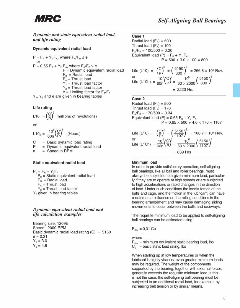
Self-Aligning Ball Bearings
77
Dynamic and static equivalent radial loadand life rating
Dynamic equivalent radial load
P = FR + Y1 FA, where FA/FR ≤ eor
P = 0.65 FR + Y2 FA, where FA/FR > eP = Dynamic equivalent radial loadFR = Radial loadFA = Thrust loadY1 = Thrust load factorY2 = Thrust load factore = Limiting factor for FA/FR
Y1, Y2 and e are given in bearing tables
Life rating
L10 = (millions of revolutions)
or
L10h = (Hours)
C = Basic dynamic load ratingP = Dynamic equivalent radial loadn = Speed in RPM
Static equivalent radial load
P0 = FR + Y0FA
P0 = Static equivalent radial loadFR = Radial loadFA = Thrust loadY0 = Thrust load factor
Y0 given in bearing tables
( )CP
3
( )CP
1060n
36
Dynamic equivalent radial load and life calculation examples
Bearing size: 1209ESpeed: 2000 RPMBasic dynamic radial load rating (C) = 5150e = 0.21Y1 = 3.0Y2 = 4.6
Case 1Radial load (FR) = 500Thrust load (FA) = 100FA/FR = 100/500 = 0.20Equivalent load (P) = FR + Y1 FA
P = 500 + 3.0 × 100 = 800
Life (L10) = = = 266.8 × 10⁶ Rev.
orLife (L10h) = =
= 2223 Hrs
( )CP
3
( )CP
1060n
36 1060 × 2000
6
( )5150800
3
( )5150800
3
Case 2Radial load (FR) = 500Thrust load (FA) = 170FA/FR = 170/500 = 0.34Equivalent load (P) = 0.65 FR + Y2 FA
P = 0.65 × 500 + 4.6 × 170 = 1107
Life (L10) = = = 100.7 × 10⁶ Rev.
orLife (L10h) = =
= 839 Hrs
( )CP
3
( )CP
1060n
36 1060 × 2000
6
( )51501107
3
( )51501107
3
Minimum loadIn order to provide satisfactory operation, self-aligningball bearings, like all ball and roller bearings, mustalways be subjected to a given minimum load, particular-ly if they are to operate at high speeds or are subjectedto high accelerations or rapid changes in the direction of load. Under such conditions the inertia forces of the balls and cage, and the friction in the lubricant, can have a detrimental influence on the rolling conditions in the bearing arrangement and may cause damaging slidingmovements to occur between the balls and raceways.
The requisite minimum load to be applied to self-aligningball bearings can be estimated using
P0m = 0,01 Co
whereP0m = minimum equivalent static bearing load, lbsC0 = basic static load rating, lbs
When starting up at low temperatures or when the lubricant is highly viscous, even greater minimum loadsmay be required. The weight of the components supported by the bearing, together with external forces,generally exceeds the requisite minimum load. If thisis not the case, the self-aligning ball bearing must besubjected to an additional radial load, for example, byincreasing belt tension or by similar means.

78
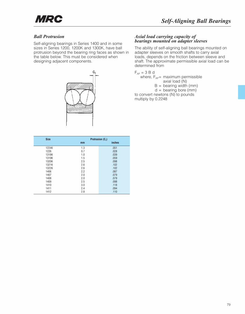
Self-Aligning Ball Bearings
79
Ball Protrusion
Self-aligning bearings in Series 1400 and in somesizes in Series 1200, 1200K and 1300K, have ballprotrusion beyond the bearing ring faces as shown inthe table below. This must be considered whendesigning adjacent components.
Axial load carrying capacity of bearings mounted on adapter sleeves
The ability of self-aligning ball bearings mounted onadapter sleeves on smooth shafts to carry axialloads, depends on the friction between sleeve andshaft. The approximate permissible axial load can bedetermined from
FAP = 3 B dwhere, FAP= maximum permissible
axial load (N) B = bearing width (mm) d = bearing bore (mm)
to convert newtons (N) to pounds multiply by 0.2248
Size Protrusion (C1)mm inches
1224K 1.3 .0511226 0.7 .0281318K 1.0 .0391319K 1.5 .0591320K 2.5 .0981321K 2.6 .1021322K 2.6 .1021406 2.2 .0871407 2.0 .0791408 2.0 .0791409 2.5 .0981410 3.0 .1181411 2.4 .0941412 2.8 .110
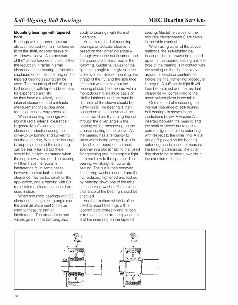
MRC Bearing ServicesSelf-Aligning Ball Bearings
80
Mounting bearings with taperedbore Bearings with a tapered bore arealways mounted with an interferencefit on the shaft, adapter sleeve orwithdrawal sleeve. As a measure of the° of interference of the fit, eitherthe reduction in radial internalclearance of the bearing or the axialdisplacement of the inner ring on thetapered bearing seating can beused. The mounting of self-aligningball bearings with tapered bore callsfor experience and skill as they have a relatively smallinternal clearance, and a reliablemeasurement of the clearancereduction is not always possible.
When mounting bearings withNormal radial internal clearance it is generally sufficient to checkclearance reduction during thedrive-up by turning and swivellingout the outer ring. When the bearingis properly mounted the outer ringcan be easily turned but thereshould be a slight resistance whenthe ring is swivelled out. The bearingwill then have the requisiteinterference fit. In some cases,however, the residual internalclearance may be too small for theapplication, and a bearing with C3radial internal clearance should beused instead.
When mounting bearings with C3clearance, the tightening angle α orthe axial displacement S can beused to measure the° ofinterference. The procedures andvalues given in the following also
apply to bearings with Normalclearance.
An easy method of mountingbearings on adapter sleeves isbased on the tightening angle αthrough which the nut is turned andthe procedure is described in thefollowing. Guideline values for thetightening angle α are given in thetable overleaf. Before mounting, thethread of the nut and the side face of the nut which is to abut thebearing should be smeared with amolybdenum disulphide paste orsimilar lubricant, and the outsidediameter of the sleeve should belightly oiled. The bearing is thenpushed on to the sleeve and the nut screwed on. By turning the nutthrough the given angle α thebearing will be pressed up on thetapered seating of the sleeve. As the bearing has a tendency to skew when being pressed up it isadvisable to reposition the hookspanner in a slot at 180˚ to that usedfor tightening and then apply a lighthammer blow to the spanner. Thebearing will straighten up on itsseating. The nut is then removed, the locking washer inserted and thenut replaced, tightened and lockedby bending down one of the tabs of the locking washer. The residualclearance of the bearing should bechecked.
Another method which is oftenused to mount bearings with atapered bore correctly and reliably is to measure the axial displacementS of the inner ring on the tapered
seating. Guideline values for therequisite displacement S are given in the table overleaf.
When using either of the abovemethods, the self-aligning ballbearings should always be pushedup on to the tapered seating until thebore of the bearing is in contact withthe seating on the shaft or sleevearound its whole circumference,before the final tightening procedureis begun. A sufficiently tight fit willthen be obtained and the residual clearance will correspond to themean values given in the table.
One method of measuring theinternal clearance of self-aligning ball bearings is shown in theillustrations below. A washer A isinserted between the bearing andthe shaft or sleeve nut to ensurecorrect alignment of the outer ringwith respect to the inner ring. A dialgauge B placed on the bearingouter ring can be used to measurethe bearing clearance. The outerring should be pushed upwards inthe direction of the shaft.
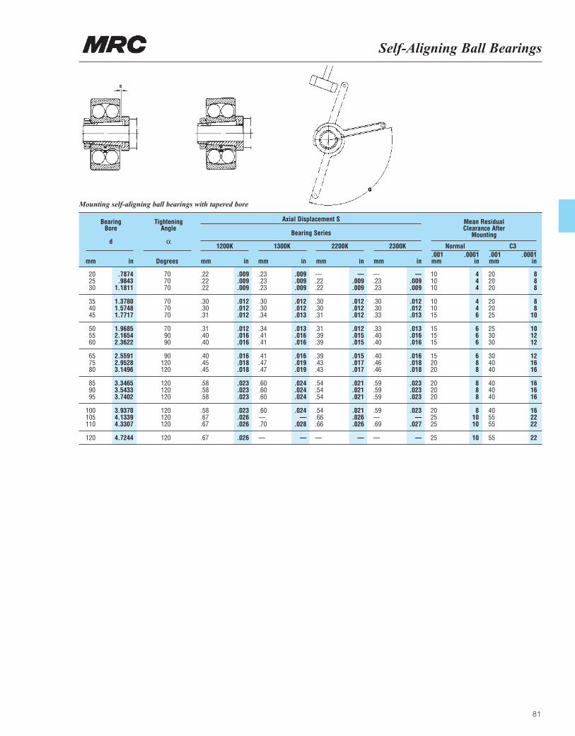
Self-Aligning Ball Bearings
81
BearingBore
d
mm in
TighteningAngle
α
Degrees mm in mm in mm in mm in.001 .0001mm in
.001 .0001mm in
20 .7874 70 .22 .009 .23 .009 — — — — 10 4 20 825 .9843 70 .22 .009 .23 .009 .22 .009 .23 .009 10 4 20 830 1.1811 70 .22 .009 .23 .009 .22 .009 .23 .009 10 4 20 8
35 1.3780 70 .30 .012 .30 .012 .30 .012 .30 .012 10 4 20 840 1.5748 70 .30 .012 .30 .012 .30 .012 .30 .012 10 4 20 845 1.7717 70 .31 .012 .34 .013 .31 .012 .33 .013 15 6 25 10
50 1.9685 70 .31 .012 .34 .013 .31 .012 .33 .013 15 6 25 1055 2.1654 90 .40 .016 .41 .016 .39 .015 .40 .016 15 6 30 1260 2.3622 90 .40 .016 .41 .016 .39 .015 .40 .016 15 6 30 12
65 2.5591 90 .40 .016 .41 .016 .39 .015 .40 .016 15 6 30 1275 2.9528 120 .45 .018 .47 .019 .43 .017 .46 .018 20 8 40 1680 3.1496 120 .45 .018 .47 .019 .43 .017 .46 .018 20 8 40 16
85 3.3465 120 .58 .023 .60 .024 .54 .021 .59 .023 20 8 40 1690 3.5433 120 .58 .023 .60 .024 .54 .021 .59 .023 20 8 40 1695 3.7402 120 .58 .023 .60 .024 .54 .021 .59 .023 20 8 40 16
100 3.9370 120 .58 .023 .60 .024 .54 .021 .59 .023 20 8 40 16105 4.1339 120 .67 .026 — — .66 .026 — — 25 10 55 22110 4.3307 120 .67 .026 .70 .028 .66 .026 .69 .027 25 10 55 22
120 4.7244 120 .67 .026 — — — — — — 25 10 55 22
1200K
Bearing Series
Axial Displacement S Mean ResidualClearance After
Mounting
1300K 2200K 2300K Normal C3
Mounting self-aligning ball bearings with tapered bore

82
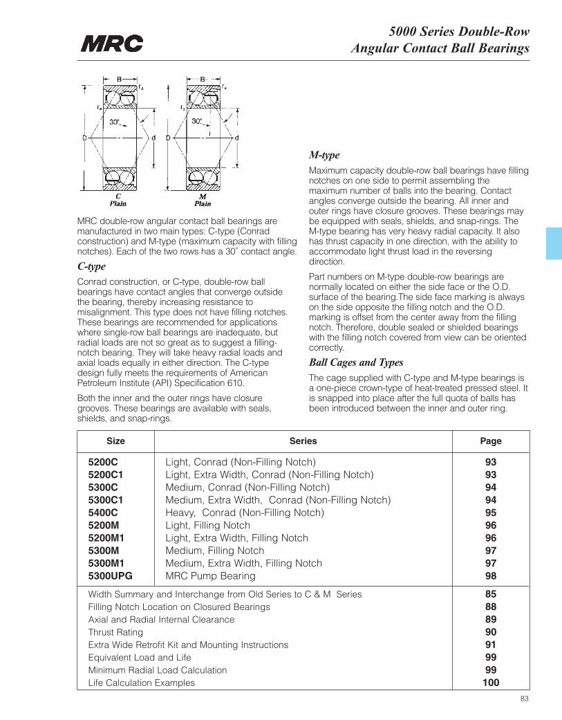
Width Summary and Interchange from Old Series to C & M Series 85Filling Notch Location on Closured Bearings 88Axial and Radial Internal Clearance 89Thrust Rating 90Extra Wide Retrofit Kit and Mounting Instructions 91Equivalent Load and Life 99Minimum Radial Load Calculation 99Life Calculation Examples 100
5000 Series Double-RowAngular Contact Ball Bearings
83
MRC double-row angular contact ball bearings aremanufactured in two main types: C-type (Conradconstruction) and M-type (maximum capacity with fillingnotches). Each of the two rows has a 30˚ contact angle.
C-typeConrad construction, or C-type, double-row ballbearings have contact angles that converge outside the bearing, thereby increasing resistance tomisalignment. This type does not have filling notches.These bearings are recommended for applicationswhere single-row ball bearings are inadequate, butradial loads are not so great as to suggest a filling-notch bearing. They will take heavy radial loads andaxial loads equally in either direction. The C-typedesign fully meets the requirements of AmericanPetroleum Institute (API) Specification 610.
Both the inner and the outer rings have closuregrooves. These bearings are available with seals,shields, and snap-rings.
M-typeMaximum capacity double-row ball bearings have fillingnotches on one side to permit assembling themaximum number of balls into the bearing. Contactangles converge outside the bearing. All inner andouter rings have closure grooves. These bearings maybe equipped with seals, shields, and snap-rings. TheM-type bearing has very heavy radial capacity. It alsohas thrust capacity in one direction, with the ability toaccommodate light thrust load in the reversingdirection.
Part numbers on M-type double-row bearings arenormally located on either the side face or the O.D.surface of the bearing.The side face marking is alwayson the side opposite the filling notch and the O.D.marking is offset from the center away from the fillingnotch. Therefore, double sealed or shielded bearingswith the filling notch covered from view can be orientedcorrectly.
Ball Cages and TypesThe cage supplied with C-type and M-type bearings isa one-piece crown-type of heat-treated pressed steel. Itis snapped into place after the full quota of balls hasbeen introduced between the inner and outer ring.
Size
5200C Light, Conrad (Non-Filling Notch) 935200C1 Light, Extra Width, Conrad (Non-Filling Notch) 935300C Medium, Conrad (Non-Filling Notch) 945300C1 Medium, Extra Width, Conrad (Non-Filling Notch) 945400C Heavy, Conrad (Non-Filling Notch) 955200M Light, Filling Notch 965200M1 Light, Extra Width, Filling Notch 965300M Medium, Filling Notch 975300M1 Medium, Extra Width, Filling Notch 975300UPG MRC Pump Bearing 98
Series Page
MRC Bearing Services5000 Series Bearings Suffix and Width Summary
84
The older MRC 5000 series double-row ballbearings were made in three series — 5200 Light,5300 Medium, and 5400 Heavy — each withprogressively larger cross sections. These old-style5000 type double-rows were available in the SBConrad and maximum capacity configurations. The SB Conrad version had contact angles whichdiverged inwardly, thereby increasing resistance to misalignment. The maximum capacity versionhad contact angles which converged inwardly,giving it the capability of handling small amounts of misalignment. It also had filling notches on both sides, for the introduction of a maximumcomplement of balls.
Our double-row ball bearings are available in the C-type (Conrad construction) and M-type (withfilling notches on one side only). Both types featureinwardly diverging contact angles, which provide
greater rigidity than found in the previous double-row filling-notch type bearings. A uniquemanufacturing system utilizing “common parts” isemployed in the manufacture of these bearings.Using a minimum number of components, thesystem provides greater flexibility for producingeither Conrad or maximum capacity types as openbearings or with a variety of closures. Twenty-fourvariations of a single bearing size can bemanufactured to solve your application problems.
The chart on pages 85-86 outlines the suffixes andwidths of MRC 5000 series bearings. The data on the chart do not represent actual availability ofdouble-row products. These data are intended tobe used as references for interchanging. Currentstyle double-rows appear next to their old-stylecounterparts that are the same width.
B Rigid construction, maximum capacity. BK Rigid construction, maximum capacity,
standard width. C Conrad, rigid construction, standard width. C1 ¹|₈˝ additional width from standard.
5205C1 & 5212C1 are ¹|₁₆˝ wider than standard.
F One shield FF Two shields G Snap-ring K Standard width M Maximum capacity, rigid construction,
standard width.
M1 ¹|₈˝ additional width from standard. 5205M1 & 5212M1 are ¹|₁₆˝ wider than standard.
Plain Maximum capacity, nonrigid construction.Narrow width in 5200 series, extra width isrequired with closures.
S Conrad construction (Note: always combined with additional suffix letters)
SB Conrad, rigid construction, narrow width.Extra width is required with closures.
SBK Conrad, rigid construction, standard width. Z One seal ZZ Two seals
MRC Double-Row Suffix Identification SummarySuffix Description Suffix Description
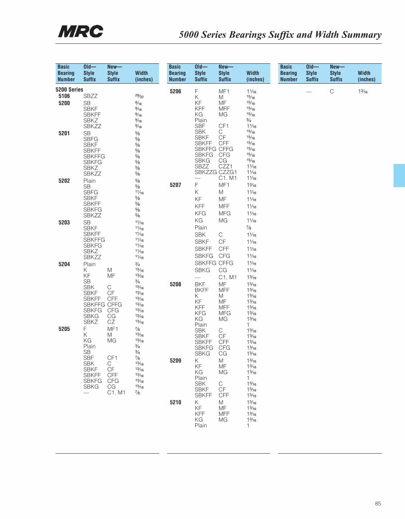
5000 Series Bearings Suffix and Width Summary
85
Basic Old— New— Bearing Style Style Width Number Suffix Suffix (inches)
Basic Old— New— Bearing Style Style Width Number Suffix Suffix (inches)
Basic Old— New— Bearing Style Style Width Number Suffix Suffix (inches)
5200 Series5106 SBZZ ²⁹|₃₂
5200 SB ⁹|₁₆SBKF ⁹|₁₆SBKFF ⁹|₁₆SBKZ ⁹|₁₆SBKZZ ⁹|₁₆
5201 SB ⁵|₈SBFG ⁵|₈SBKF ⁵|₈SBKFF ⁵|₈SBKFFG ⁵|₈SBKFG ⁵|₈SBKZ ⁵|₈SBKZZ ⁵|₈
5202 Plain ⁵|₈SB ⁵|₈SBFG ¹¹|₁₆SBKF ⁵|₈SBKFF ⁵|₈SBKFG ⁵|₈SBKZZ ⁵|₈
5203 SB ¹¹|₁₆SBKF ¹¹|₁₆SBKFF ¹¹|₁₆SBKFFG ¹¹|₁₆SBKFG ¹¹|₁₆SBKZ ¹¹|₁₆SBKZZ ¹¹|₁₆
5204 Plain ³|₄K M ¹³|₁₆KF MF ¹³|₁₆SB ³|₄SBK C ¹³|₁₆SBKF CF ¹³|₁₆SBKFF CFF ¹³|₁₆SBKFFG CFFG ¹³|₁₆SBKFG CFG ¹³|₁₆SBKG CG ¹³|₁₆SBKZ CZ ¹³|₁₆
5205 F MF1 ⁷|₈K M ¹³|₁₆KG MG ¹³|₁₆Plain ³|₄SB ³|₄SBF CF1 ⁷|₈SBK C ¹³|₁₆SBKF CF ¹³|₁₆SBKFF CFF ¹³|₁₆SBKFG CFG ¹³|₁₆SBKG CG ¹³|₁₆— C1, M1 ⁷|₈
5206 F MF1 1¹|₁₆K M ¹⁵|₁₆KF MF ¹⁵|₁₆KFF MFF ¹⁵|₁₆KG MG ¹⁵|₁₆Plain ³|₄SBF CF1 1¹|₁₆SBK C ¹⁵|₁₆SBKF CF ¹⁵|₁₆SBKFF CFF ¹⁵|₁₆SBKFFG CFFG ¹⁵|₁₆SBKFG CFG ¹⁵|₁₆SBKG CG ¹⁵|₁₆SBZZ CZZ1 1¹|₁₆SBKZZG CZZG1 1¹|₁₆— C1, M1 1¹|₁₆
5207 F MF1 1³|₁₆
K M 1¹|₁₆
KF MF 1¹|₁₆
KFF MFF 1¹|₁₆
KFG MFG 1¹|₁₆
KG MG 1¹|₁₆
Plain ⁷|₈
SBK C 1¹|₁₆
SBKF CF 1¹|₁₆
SBKFF CFF 1¹|₁₆
SBKFG CFG 1¹|₁₆
SBKFFG CFFG 1¹|₁₆
SBKG CG 1¹|₁₆
— C1, M1 1³|₁₆
5208 BKF MF 1³|₁₆BKFF MFF 1³|₁₆K M 1³|₁₆KF MF 1³|₁₆KFF MFF 1³|₁₆KFG MFG 1³|₁₆KG MG 1³|₁₆Plain 1SBK C 1³|₁₆SBKF CF 1³|₁₆SBKFF CFF 1³|₁₆SBKFG CFG 1³|₁₆SBKG CG 1³|₁₆
5209 K M 1³|₁₆KF MF 1³|₁₆KG MG 1³|₁₆Plain 1SBK C 1³|₁₆SBKF CF 1³|₁₆SBKFF CFF 1³|₁₆
5210 K M 1³|₁₆KF MF 1³|₁₆KFF MFF 1³|₁₆KG MG 1³|₁₆Plain 1
— C 1³|₁₆
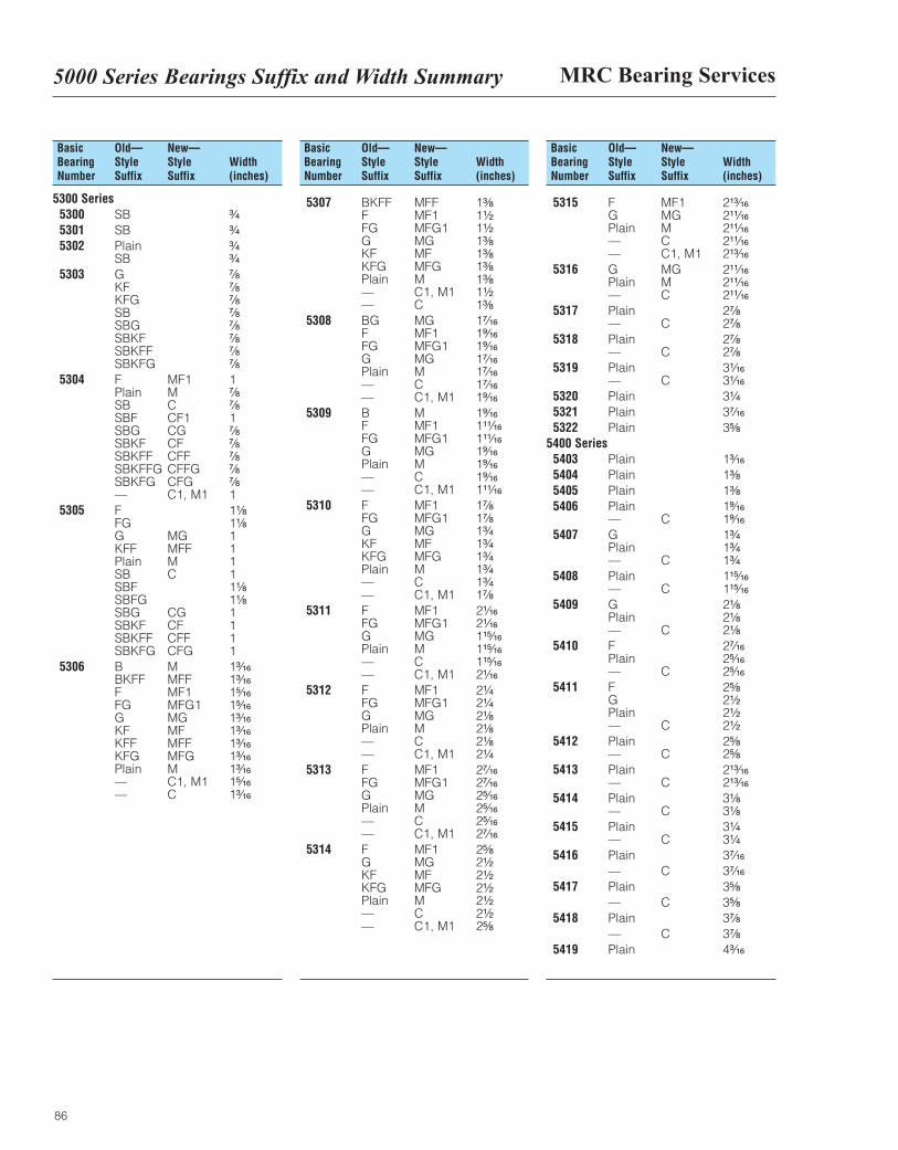
MRC Bearing Services5000 Series Bearings Suffix and Width Summary
86
Basic Old— New— Bearing Style Style Width Number Suffix Suffix (inches)
5300 Series 5300 SB ³|₄
5301 SB ³|₄
5302 Plain ³|₄SB ³|₄
5303 G ⁷|₈KF ⁷|₈KFG ⁷|₈SB ⁷|₈SBG ⁷|₈SBKF ⁷|₈SBKFF ⁷|₈SBKFG ⁷|₈
5304 F MF1 1Plain M ⁷|₈SB C ⁷|₈SBF CF1 1SBG CG ⁷|₈SBKF CF ⁷|₈SBKFF CFF ⁷|₈SBKFFG CFFG ⁷|₈SBKFG CFG ⁷|₈— C1, M1 1
5305 F 1¹|₈FG 1¹|₈G MG 1KFF MFF 1Plain M 1SB C 1SBF 1¹|₈SBFG 1¹|₈SBG CG 1SBKF CF 1SBKFF CFF 1SBKFG CFG 1
5306 B M 1³|₁₆BKFF MFF 1³|₁₆F MF1 1⁵|₁₆FG MFG1 1⁵|₁₆G MG 1³|₁₆KF MF 1³|₁₆KFF MFF 1³|₁₆KFG MFG 1³|₁₆Plain M 1³|₁₆— C1, M1 1⁵|₁₆— C 1³|₁₆
Basic Old— New— Bearing Style Style Width Number Suffix Suffix (inches)
5307 BKFF MFF 1³|₈F MF1 1¹|₂FG MFG1 1¹|₂G MG 1³|₈KF MF 1³|₈KFG MFG 1³|₈Plain M 1³|₈— C1, M1 1¹|₂— C 1³|₈
5308 BG MG 1⁷|₁₆F MF1 1⁹|₁₆FG MFG1 1⁹|₁₆G MG 1⁷|₁₆Plain M 1⁷|₁₆— C 1⁷|₁₆— C1, M1 1⁹|₁₆
5309 B M 1⁹|₁₆F MF1 1¹¹|₁₆FG MFG1 1¹¹|₁₆G MG 1⁹|₁₆Plain M 1⁹|₁₆— C 1⁹|₁₆— C1, M1 1¹¹|₁₆
5310 F MF1 1⁷|₈FG MFG1 1⁷|₈G MG 1³|₄KF MF 1³|₄KFG MFG 1³|₄Plain M 1³|₄— C 1³|₄— C1, M1 1⁷|₈
5311 F MF1 2¹|₁₆FG MFG1 2¹|₁₆G MG 1¹⁵|₁₆Plain M 1¹⁵|₁₆— C 1¹⁵|₁₆— C1, M1 2¹|₁₆
5312 F MF1 2¹|₄FG MFG1 2¹|₄G MG 2¹|₈Plain M 2¹|₈— C 2¹|₈— C1, M1 2¹|₄
5313 F MF1 2⁷|₁₆FG MFG1 2⁷|₁₆G MG 2⁵|₁₆Plain M 2⁵|₁₆— C 2⁵|₁₆— C1, M1 2⁷|₁₆
5314 F MF1 2⁵|₈G MG 2¹|₂KF MF 2¹|₂KFG MFG 2¹|₂Plain M 2¹|₂— C 2¹|₂— C1, M1 2⁵|₈
Basic Old— New— Bearing Style Style Width Number Suffix Suffix (inches)
5315 F MF1 2¹³|₁₆G MG 2¹¹|₁₆Plain M 2¹¹|₁₆— C 2¹¹|₁₆— C1, M1 2¹³|₁₆
5316 G MG 2¹¹|₁₆Plain M 2¹¹|₁₆— C 2¹¹|₁₆
5317 Plain 2⁷|₈— C 2⁷|₈
5318 Plain 2⁷|₈— C 2⁷|₈
5319 Plain 3¹|₁₆— C 3¹|₁₆
5320 Plain 3¹|₄
5321 Plain 3⁷|₁₆
5322 Plain 3⁵|₈
5400 Series5403 Plain 1³|₁₆
5404 Plain 1³|₈
5405 Plain 1³|₈
5406 Plain 1⁹|₁₆— C 1⁹|₁₆
5407 G 1³|₄Plain 1³|₄— C 1³|₄
5408 Plain 1¹⁵|₁₆— C 1¹⁵|₁₆
5409 G 2¹|₈Plain 2¹|₈— C 2¹|₈
5410 F 2⁷|₁₆Plain 2⁵|₁₆— C 2⁵|₁₆
5411 F 2⁵|₈G 2¹|₂Plain 2¹|₂— C 2¹|₂
5412 Plain 2⁵|₈— C 2⁵|₈
5413 Plain 2¹³|₁₆— C 2¹³|₁₆
5414 Plain 3¹|₈— C 3¹|₈
5415 Plain 3¹|₄— C 3¹|₄
5416 Plain 3⁷|₁₆
— C 3⁷|₁₆
5417 Plain 3⁵|₈
— C 3⁵|₈
5418 Plain 3⁷|₈
— C 3⁷|₈
5419 Plain 4³|₁₆
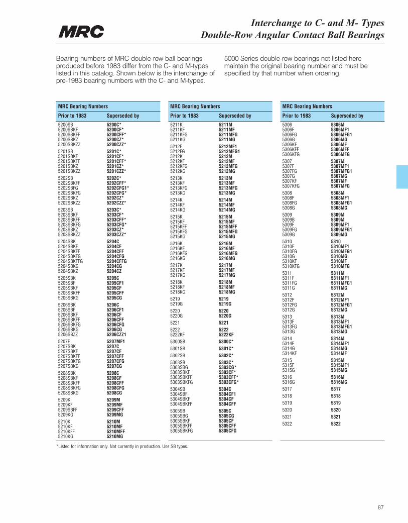
Interchange to C- and M- Types Double-Row Angular Contact Ball Bearings
87
MRC Bearing Numbers
Prior to 1983 Superseded by
Bearing numbers of MRC double-row ball bearingsproduced before 1983 differ from the C- and M-typeslisted in this catalog. Shown below is the interchange ofpre-1983 bearing numbers with the C- and M-types.
5000 Series double-row bearings not listed heremaintain the original bearing number and must bespecified by that number when ordering.
MRC Bearing Numbers
Prior to 1983 Superseded by
MRC Bearing Numbers
Prior to 1983 Superseded by
5200SB 5200C*5200SBKF 5200CF*5200SBKFF 5200CFF*5200SBKZ 5200CZ*5200SBKZZ 5200CZZ*5201SB 5201C*5201SBKF 5201CF*5201SBKFF 5201CFF*5201SBKZ 5201CZ*5201SBKZZ 5201CZZ*5202SB 5202C*5202SBKFF 5202CFF*5202SBFG 5202CFG1*5202SBKFG 5202CFG*5202SBKZ 5202CZ*5202SBKZZ 5202CZZ*5203SB 5203C*5203SBKF 5203CF*5203SBKFF 5203CFF*5203SBKFG 5203CFG*5203SBKZ 5203CZ*5203SBKZZ 5203CZZ*5204SBK 5204C5204SBKF 5204CF5204SBKFF 5204CFF5204SBKFG 5204CFG5204SBKFFG 5204CFFG5204SBKG 5204CG5204SBKZ 5204CZ5205SBK 5205C5205SBF 5205CF15205SBKF 5205CF5205SBKFF 5205CFF5205SBKG 5205CG5206SBK 5206C5206SBF 5206CF15206SBKF 5206CF5206SBKFF 5206CFF5206SBKFG 5206CFG5206SBKG 5206CG5206SBZZ 5206CZZ15207F 5207MF15207SBK 5207C5207SBKF 5207CF5207SBKFF 5207CFF5207SBKFG 5207CFG5207SBKG 5207CG5208SBK 5208C5208SBKF 5208CF5208SBKFF 5208CFF5208SBKFG 5208CFG5208SBKG 5208CG5209K 5209M5209KF 5209MF5209SBFF 5209CFF5209KG 5209MG5210K 5210M5210KF 5210MF5210KFF 5210MFF5210KG 5210MG
5211K 5211M5211KF 5211MF5211KFG 5211MFG5211KG 5211MG5212F 5212MF15212FG 5212MFG15212K 5212M5212KF 5212MF5212KFG 5212MFG5212KG 5212MG5213K 5213M5213KF 5213MF5213KFG 5213MFG5213KG 5213MG5214K 5214M5214KF 5214MF5214KG 5214MG5215K 5215M5215KF 5215MF5215KFF 5215MFF5215KFG 5215MFG5215KG 5215MG5216K 5216M5216KF 5216MF5216KFG 5216MFG5216KG 5216MG5217K 5217M5217KF 5217MF5217KG 5217MG5218K 5218M5218KF 5218MF5218KG 5218MG5219 52195219G 5219G5220 52205220G 5220G5221 52215222 52225222KF 5222KF5300SB 5300C*5301SB 5301C*5302SB 5302C*5303SB 5303C*5303SBG 5303CG*5303SBKF 5303CF*5303SBKFF 5303CFF*5303SBKFG 5303CFG*5304SB 5304C5304SBF 5304CF15304SBKF 5304CF5304SBKFF 5304CFF5305SB 5305C5305SBG 5305CG5305SBKF 5305CF5305SBKFF 5305CFF5305SBKFG 5305CFG
5306 5306M5306F 5306MF15306FG 5306MFG15306G 5306MG5306KF 5306MF5306KFF 5306MFF5306KFG 5306MFG5307 5307M5307F 5307MF15307FG 5307MFG15307G 5307MG5307KF 5307MF5307KFG 5307MFG5308 5308M5308F 5308MF15308FG 5308MFG15308G 5308MG5309 5309M5309B 5309M5309F 5309MF15309FG 5309MFG15309G 5309MG5310 53105310F 5310MF15310FG 5310MFG15310G 5310MG5310KF 5310MF5310KFG 5310MFG5311 5311M5311F 5311MF15311FG 5311MFG15311G 5311MG5312 5312M5312F 5312MF15312FG 5312MFG15312G 5312MG5313 5313M5313F 5313MF15313FG 5313MFG15313G 5313MG5314 5314M5314F 5314MF15314G 5314MG5314KF 5314MF5315 5315M5315F 5315MF15315G 5315MG5316 5316M5316G 5316MG5317 53175318 53185319 53195320 53205321 53215322 5322
*Listed for information only. Not currently in production. Use SB types.
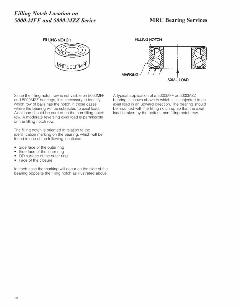
MRC Bearing ServicesFilling Notch Location on 5000-MFF and 5000-MZZ Series
88
Since the filling notch row is not visible on 5000MFFand 5000MZZ bearings, it is necessary to identify which row of balls has the notch in those cases where the bearing will be subjected to axial load. Axial load should be carried on the non-filling notchrow. A moderate reversing axial load is permissible on the filling notch row.
The filling notch is oriented in relation to theidentification marking on the bearing, which will befound in one of the following locations:
• Side face of the outer ring• Side face of the inner ring• OD surface of the outer ring• Face of the closure
In each case the marking will occur on the side of thebearing opposite the filling notch as illustrated above.
A typical application of a 5000MFF or 5000MZZbearing is shown above in which it is subjected to anaxial load in an upward direction. The bearing shouldbe mounted with the filling notch up so that the axialload is taken by the bottom, non-filling notch row.
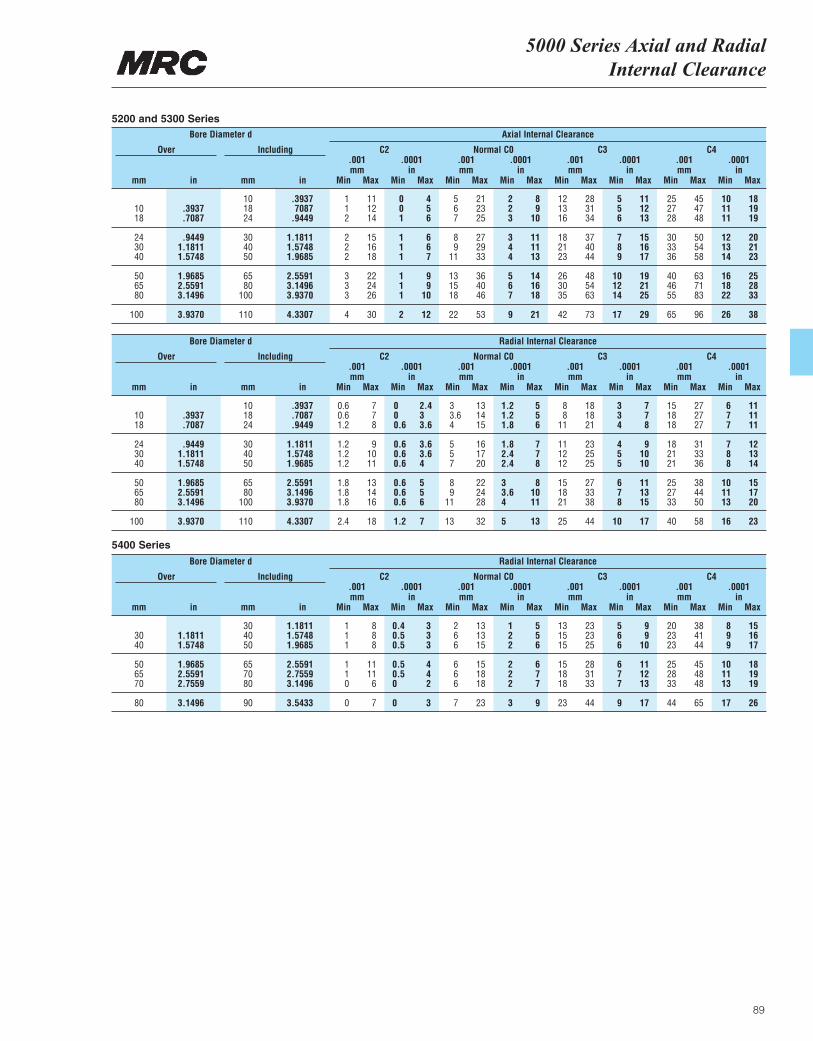
5000 Series Axial and RadialInternal Clearance
89
Bore Diameter d Axial Internal Clearance
Over
mm mmin in Min Min Min Min Min Min Min Minmm in in in inmm mm mm.001 .0001 .0001 .0001 .0001.001 .001 .001
Max Max Max Max Max Max Max Max
Including C2 Normal C0 C3 C4
10 .3937 1 11 0 4 5 21 2 8 12 28 5 11 25 45 10 1810 .3937 18 7087 1 12 0 5 6 23 2 9 13 31 5 12 27 47 11 1918 .7087 24 .9449 2 14 1 6 7 25 3 10 16 34 6 13 28 48 11 19
24 .9449 30 1.1811 2 15 1 6 8 27 3 11 18 37 7 15 30 50 12 2030 1.1811 40 1.5748 2 16 1 6 9 29 4 11 21 40 8 16 33 54 13 2140 1.5748 50 1.9685 2 18 1 7 11 33 4 13 23 44 9 17 36 58 14 23
50 1.9685 65 2.5591 3 22 1 9 13 36 5 14 26 48 10 19 40 63 16 2565 2.5591 80 3.1496 3 24 1 9 15 40 6 16 30 54 12 21 46 71 18 2880 3.1496 100 3.9370 3 26 1 10 18 46 7 18 35 63 14 25 55 83 22 33
100 3.9370 110 4.3307 4 30 2 12 22 53 9 21 42 73 17 29 65 96 26 38
Bore Diameter d Radial Internal Clearance
Over
mm mmin in Min Min Min Min Min Min Min Minmm in in in inmm mm mm.001 .0001 .0001 .0001 .0001.001 .001 .001
Max Max Max Max Max Max Max Max
Including C2 Normal C0 C3 C4
10 .3937 0.6 7 0 2.4 3 13 1.2 5 8 18 3 7 15 27 6 1110 .3937 18 .7087 0.6 7 0 3 3.6 14 1.2 5 8 18 3 7 18 27 7 1118 .7087 24 .9449 1.2 8 0.6 3.6 4 15 1.8 6 11 21 4 8 18 27 7 11
24 .9449 30 1.1811 1.2 9 0.6 3.6 5 16 1.8 7 11 23 4 9 18 31 7 1230 1.1811 40 1.5748 1.2 10 0.6 3.6 5 17 2.4 7 12 25 5 10 21 33 8 1340 1.5748 50 1.9685 1.2 11 0.6 4 7 20 2.4 8 12 25 5 10 21 36 8 14
50 1.9685 65 2.5591 1.8 13 0.6 5 8 22 3 8 15 27 6 11 25 38 10 1565 2.5591 80 3.1496 1.8 14 0.6 5 9 24 3.6 10 18 33 7 13 27 44 11 1780 3.1496 100 3.9370 1.8 16 0.6 6 11 28 4 11 21 38 8 15 33 50 13 20
100 3.9370 110 4.3307 2.4 18 1.2 7 13 32 5 13 25 44 10 17 40 58 16 23
Bore Diameter d Radial Internal Clearance
Over
mm mmin in Min Min Min Min Min Min Min Minmm in in in inmm mm mm.001 .0001 .0001 .0001 .0001.001 .001 .001
Max Max Max Max Max Max Max Max
Including C2 Normal C0 C3 C4
30 1.1811 1 8 0.4 3 2 13 1 5 13 23 5 9 20 38 8 1530 1.1811 40 1.5748 1 8 0.5 3 6 13 2 5 15 23 6 9 23 41 9 1640 1.5748 50 1.9685 1 8 0.5 3 6 15 2 6 15 25 6 10 23 44 9 17
50 1.9685 65 2.5591 1 11 0.5 4 6 15 2 6 15 28 6 11 25 45 10 1865 2.5591 70 2.7559 1 11 0.5 4 6 18 2 7 18 31 7 12 28 48 11 1970 2.7559 80 3.1496 0 6 0 2 6 18 2 7 18 33 7 13 33 48 13 19
80 3.1496 90 3.5433 0 7 0 3 7 23 3 9 23 44 9 17 44 65 17 26
5200 and 5300 Series
5400 Series
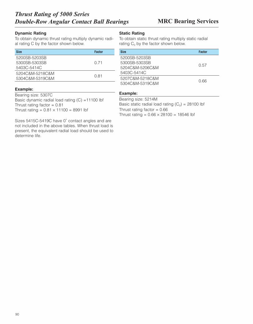
MRC Bearing ServicesThrust Rating of 5000 SeriesDouble-Row Angular Contact Ball Bearings
90
Dynamic RatingTo obtain dynamic thrust rating multiply dynamic radi-al rating C by the factor shown below.
Static Rating To obtain static thrust rating multiply static radial rating C0 by the factor shown below.
Size Factor Size Factor
5200SB-5203SB 5300SB-5303SB 0.71 5403C-5414C5204C&M-5218C&M 5304C&M-5319C&M
0.81
Example:Bearing size: 5307C Basic dynamic radial load rating (C) =11100 lbf Thrust rating factor = 0.81 Thrust rating = 0.81 × 11100 = 8991 lbf
Sizes 5415C-5419C have 0˚ contact angles and arenot included in the above tables. When thrust load ispresent, the equivalent radial load should be used todetermine life.
5200SB-5203SB 5300SB-5303SB 5204C&M-5206C&M
0.57
5403C-5414C5207C&M-5218C&M 5304C&M-5319C&M
0.66
Example:Bearing size: 5214M Basic static radial load rating (C0) = 28100 lbf Thrust rating factor = 0.66 Thrust rating = 0.66 × 28100 = 18546 lbf
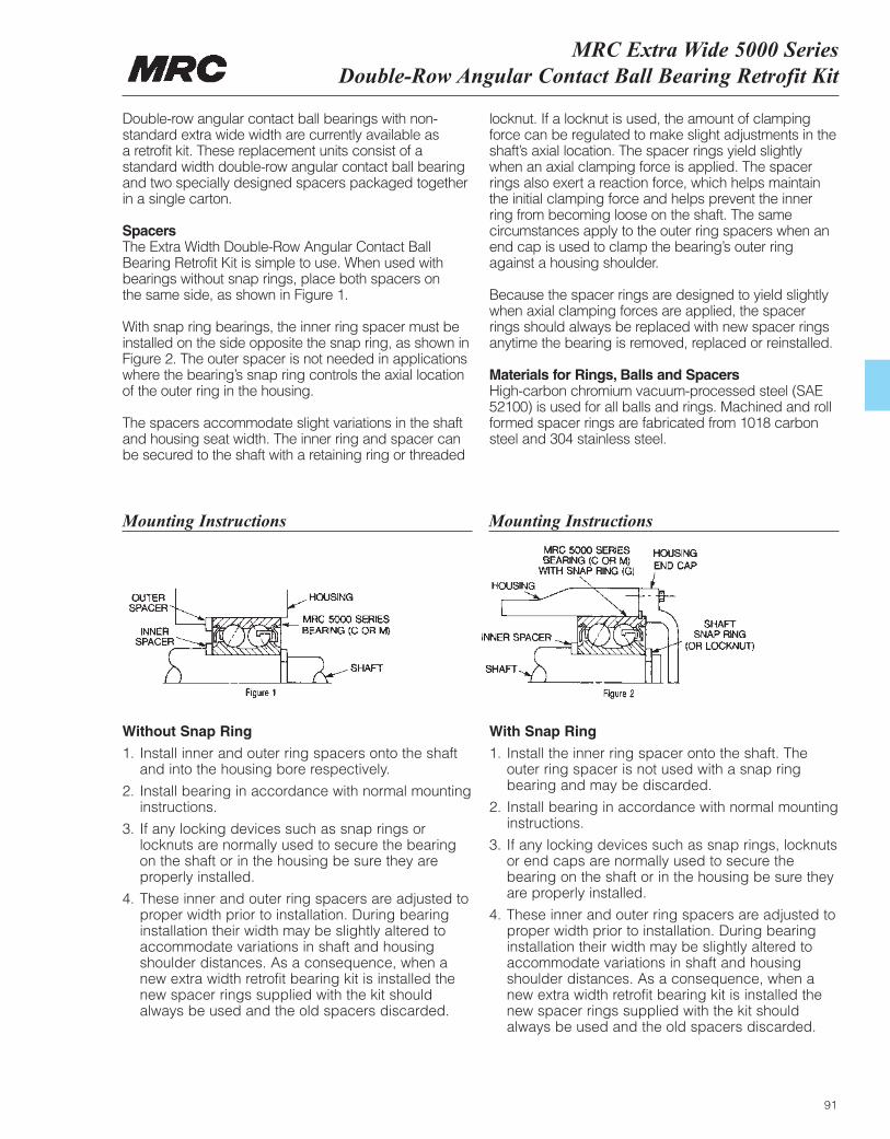
MRC Extra Wide 5000 Series Double-Row Angular Contact Ball Bearing Retrofit Kit
91
Double-row angular contact ball bearings with non-standard extra wide width are currently available as a retrofit kit. These replacement units consist of astandard width double-row angular contact ball bearingand two specially designed spacers packaged togetherin a single carton.
Spacers The Extra Width Double-Row Angular Contact BallBearing Retrofit Kit is simple to use. When used withbearings without snap rings, place both spacers on the same side, as shown in Figure 1.
With snap ring bearings, the inner ring spacer must beinstalled on the side opposite the snap ring, as shown inFigure 2. The outer spacer is not needed in applicationswhere the bearing’s snap ring controls the axial locationof the outer ring in the housing.
The spacers accommodate slight variations in the shaftand housing seat width. The inner ring and spacer canbe secured to the shaft with a retaining ring or threaded
locknut. If a locknut is used, the amount of clampingforce can be regulated to make slight adjustments in theshaft’s axial location. The spacer rings yield slightlywhen an axial clamping force is applied. The spacerrings also exert a reaction force, which helps maintainthe initial clamping force and helps prevent the innerring from becoming loose on the shaft. The samecircumstances apply to the outer ring spacers when anend cap is used to clamp the bearing’s outer ringagainst a housing shoulder.
Because the spacer rings are designed to yield slightlywhen axial clamping forces are applied, the spacerrings should always be replaced with new spacer ringsanytime the bearing is removed, replaced or reinstalled.
Materials for Rings, Balls and Spacers High-carbon chromium vacuum-processed steel (SAE52100) is used for all balls and rings. Machined and rollformed spacer rings are fabricated from 1018 carbonsteel and 304 stainless steel.
Without Snap Ring
1. Install inner and outer ring spacers onto the shaftand into the housing bore respectively.
2. Install bearing in accordance with normal mountinginstructions.
3. If any locking devices such as snap rings orlocknuts are normally used to secure the bearingon the shaft or in the housing be sure they areproperly installed.
4. These inner and outer ring spacers are adjusted toproper width prior to installation. During bearinginstallation their width may be slightly altered toaccommodate variations in shaft and housingshoulder distances. As a consequence, when anew extra width retrofit bearing kit is installed thenew spacer rings supplied with the kit shouldalways be used and the old spacers discarded.
With Snap Ring
1. Install the inner ring spacer onto the shaft. Theouter ring spacer is not used with a snap ringbearing and may be discarded.
2. Install bearing in accordance with normal mountinginstructions.
3. If any locking devices such as snap rings, locknutsor end caps are normally used to secure thebearing on the shaft or in the housing be sure theyare properly installed.
4. These inner and outer ring spacers are adjusted toproper width prior to installation. During bearinginstallation their width may be slightly altered toaccommodate variations in shaft and housingshoulder distances. As a consequence, when anew extra width retrofit bearing kit is installed thenew spacer rings supplied with the kit shouldalways be used and the old spacers discarded.
Mounting Instructions Mounting Instructions
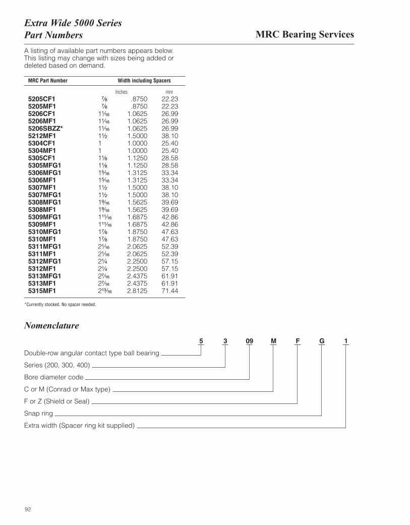
MRC Bearing ServicesExtra Wide 5000 SeriesPart Numbers
92
A listing of available part numbers appears below.This listing may change with sizes being added ordeleted based on demand.
MRC Part Number Width including Spacers
Inches mm5205CF1 ⁷|₈ .8750 22.235205MF1 ⁷|₈ .8750 22.235206CF1 1¹|₁₆ 1.0625 26.995206MF1 1¹|₁₆ 1.0625 26.995206SBZZ* 1¹|₁₆ 1.0625 26.995212MF1 1¹|₂ 1.5000 38.105304CF1 1 1.0000 25.405304MF1 1 1.0000 25.405305CF1 1¹|₈ 1.1250 28.585305MFG1 1¹|₈ 1.1250 28.585306MFG1 1⁵|₁₆ 1.3125 33.345306MF1 1⁵|₁₆ 1.3125 33.345307MF1 1¹|₂ 1.5000 38.105307MFG1 1¹|₂ 1.5000 38.105308MFG1 1⁹|₁₆ 1.5625 39.695308MF1 1⁹|₁₆ 1.5625 39.695309MFG1 1¹¹|₁₆ 1.6875 42.865309MF1 1¹¹|₁₆ 1.6875 42.865310MFG1 1⁷|₈ 1.8750 47.635310MF1 1⁷|₈ 1.8750 47.635311MFG1 2¹|₁₆ 2.0625 52.395311MF1 2¹|₁₆ 2.0625 52.395312MFG1 2¹|₄ 2.2500 57.155312MF1 2¹|₄ 2.2500 57.155313MFG1 2⁷|₁₆ 2.4375 61.915313MF1 2⁷|₁₆ 2.4375 61.915315MF1 2¹³|₁₆ 2.8125 71.44
*Currently stocked. No spacer needed.
Nomenclature
5 3 09 M F G 1
Double-row angular contact type ball bearing
Series (200, 300, 400)
Bore diameter code
C or M (Conrad or Max type)
F or Z (Shield or Seal)
Snap ring
Extra width (Spacer ring kit supplied)
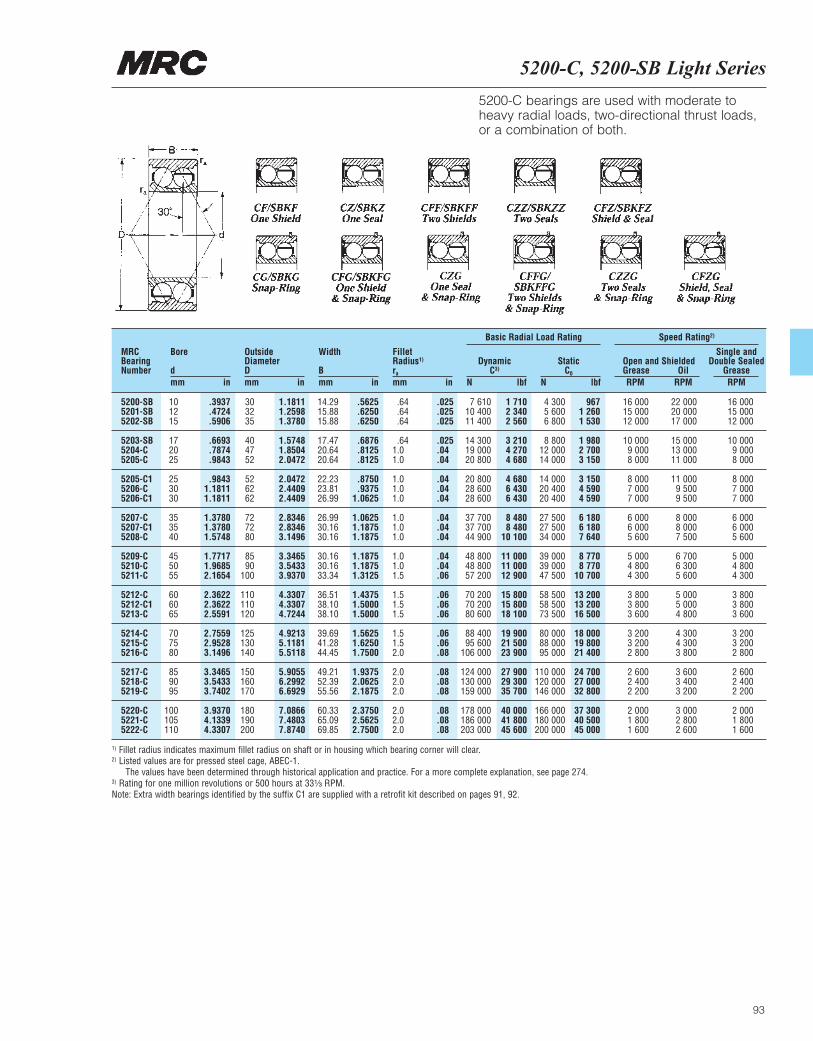
5200-C, 5200-SB Light Series
93
MRCBearingNumber
Bore
dmm in
OutsideDiameterDmm in
Width
Bmm in
FilletRadius1)
ra
mm in
DynamicC3)
N lbf
Basic Radial Load Rating Speed Rating2)
StaticC0
N lbf
Open and ShieldedGrease OilRPM RPM
Single andDouble Sealed
GreaseRPM
5200-SB 10 .3937 30 1.1811 14.29 .5625 .64 .025 7 610 1 710 4 300 967 16 000 22 000 16 0005201-SB 12 .4724 32 1.2598 15.88 .6250 .64 .025 10 400 2 340 5 600 1 260 15 000 20 000 15 0005202-SB 15 .5906 35 1.3780 15.88 .6250 .64 .025 11 400 2 560 6 800 1 530 12 000 17 000 12 000
5203-SB 17 .6693 40 1.5748 17.47 .6876 .64 .025 14 300 3 210 8 800 1 980 10 000 15 000 10 0005204-C 20 .7874 47 1.8504 20.64 .8125 1.0 .04 19 000 4 270 12 000 2 700 9 000 13 000 9 0005205-C 25 .9843 52 2.0472 20.64 .8125 1.0 .04 20 800 4 680 14 000 3 150 8 000 11 000 8 000
5205-C1 25 .9843 52 2.0472 22.23 .8750 1.0 .04 20 800 4 680 14 000 3 150 8 000 11 000 8 0005206-C 30 1.1811 62 2.4409 23.81 .9375 1.0 .04 28 600 6 430 20 400 4 590 7 000 9 500 7 0005206-C1 30 1.1811 62 2.4409 26.99 1.0625 1.0 .04 28 600 6 430 20 400 4 590 7 000 9 500 7 000
5207-C 35 1.3780 72 2.8346 26.99 1.0625 1.0 .04 37 700 8 480 27 500 6 180 6 000 8 000 6 0005207-C1 35 1.3780 72 2.8346 30.16 1.1875 1.0 .04 37 700 8 480 27 500 6 180 6 000 8 000 6 0005208-C 40 1.5748 80 3.1496 30.16 1.1875 1.0 .04 44 900 10 100 34 000 7 640 5 600 7 500 5 600
5209-C 45 1.7717 85 3.3465 30.16 1.1875 1.0 .04 48 800 11 000 39 000 8 770 5 000 6 700 5 0005210-C 50 1.9685 90 3.5433 30.16 1.1875 1.0 .04 48 800 11 000 39 000 8 770 4 800 6 300 4 8005211-C 55 2.1654 100 3.9370 33.34 1.3125 1.5 .06 57 200 12 900 47 500 10 700 4 300 5 600 4 300
5212-C 60 2.3622 110 4.3307 36.51 1.4375 1.5 .06 70 200 15 800 58 500 13 200 3 800 5 000 3 8005212-C1 60 2.3622 110 4.3307 38.10 1.5000 1.5 .06 70 200 15 800 58 500 13 200 3 800 5 000 3 8005213-C 65 2.5591 120 4.7244 38.10 1.5000 1.5 .06 80 600 18 100 73 500 16 500 3 600 4 800 3 600
5214-C 70 2.7559 125 4.9213 39.69 1.5625 1.5 .06 88 400 19 900 80 000 18 000 3 200 4 300 3 2005215-C 75 2.9528 130 5.1181 41.28 1.6250 1.5 .06 95 600 21 500 88 000 19 800 3 200 4 300 3 2005216-C 80 3.1496 140 5.5118 44.45 1.7500 2.0 .08 106 000 23 900 95 000 21 400 2 800 3 800 2 800
5217-C 85 3.3465 150 5.9055 49.21 1.9375 2.0 .08 124 000 27 900 110 000 24 700 2 600 3 600 2 6005218-C 90 3.5433 160 6.2992 52.39 2.0625 2.0 .08 130 000 29 300 120 000 27 000 2 400 3 400 2 4005219-C 95 3.7402 170 6.6929 55.56 2.1875 2.0 .08 159 000 35 700 146 000 32 800 2 200 3 200 2 200
5220-C 100 3.9370 180 7.0866 60.33 2.3750 2.0 .08 178 000 40 000 166 000 37 300 2 000 3 000 2 0005221-C 105 4.1339 190 7.4803 65.09 2.5625 2.0 .08 186 000 41 800 180 000 40 500 1 800 2 800 1 8005222-C 110 4.3307 200 7.8740 69.85 2.7500 2.0 .08 203 000 45 600 200 000 45 000 1 600 2 600 1 600
5200-C bearings are used with moderate toheavy radial loads, two-directional thrust loads,or a combination of both.
1) Fillet radius indicates maximum fillet radius on shaft or in housing which bearing corner will clear.2) Listed values are for pressed steel cage, ABEC-1.
The values have been determined through historical application and practice. For a more complete explanation, see page 274.3) Rating for one million revolutions or 500 hours at 33¹|₃ RPM.Note: Extra width bearings identified by the suffix C1 are supplied with a retrofit kit described on pages 91, 92.
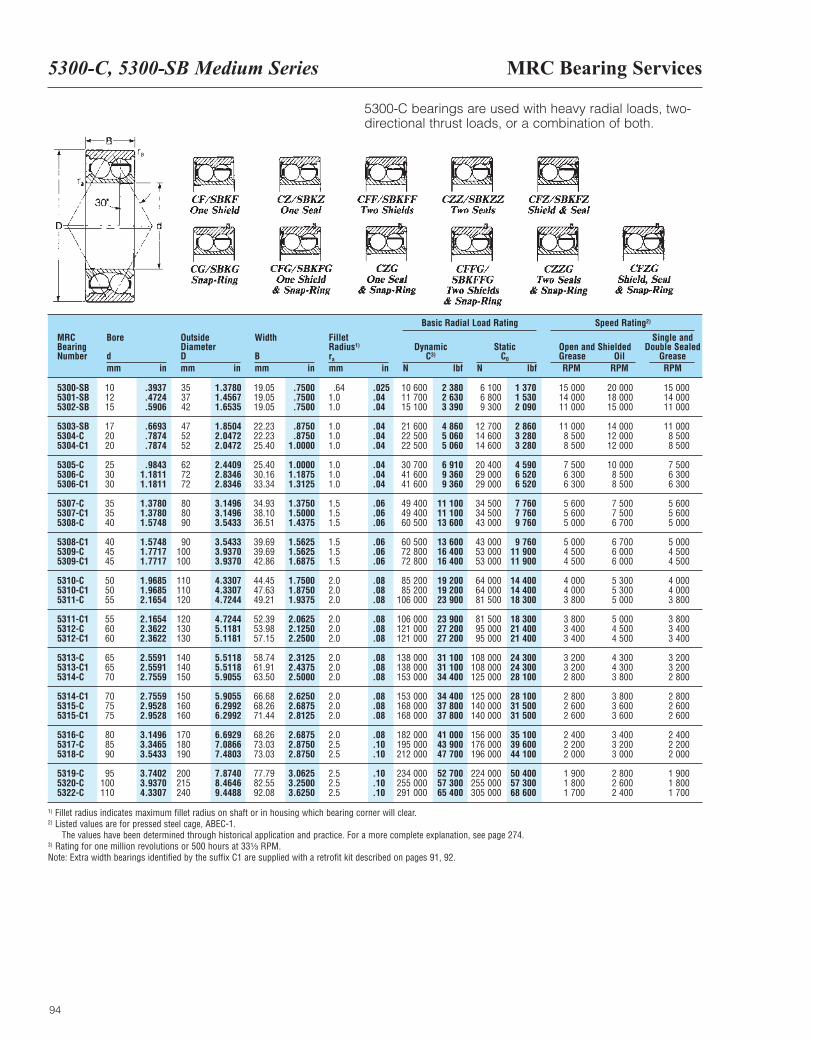
MRC Bearing Services5300-C, 5300-SB Medium Series
94
MRCBearingNumber
Bore
dmm in
OutsideDiameterDmm in
Width
Bmm in
FilletRadius1)
ra
mm in
DynamicC3)
N lbf
Basic Radial Load Rating Speed Rating2)
StaticC0
N lbf
Open and ShieldedGrease OilRPM RPM
Single andDouble Sealed
GreaseRPM
5300-SB 10 .3937 35 1.3780 19.05 .7500 .64 .025 10 600 2 380 6 100 1 370 15 000 20 000 15 0005301-SB 12 .4724 37 1.4567 19.05 .7500 1.0 .04 11 700 2 630 6 800 1 530 14 000 18 000 14 0005302-SB 15 .5906 42 1.6535 19.05 .7500 1.0 .04 15 100 3 390 9 300 2 090 11 000 15 000 11 000
5303-SB 17 .6693 47 1.8504 22.23 .8750 1.0 .04 21 600 4 860 12 700 2 860 11 000 14 000 11 0005304-C 20 .7874 52 2.0472 22.23 .8750 1.0 .04 22 500 5 060 14 600 3 280 8 500 12 000 8 5005304-C1 20 .7874 52 2.0472 25.40 1.0000 1.0 .04 22 500 5 060 14 600 3 280 8 500 12 000 8 500
5305-C 25 .9843 62 2.4409 25.40 1.0000 1.0 .04 30 700 6 910 20 400 4 590 7 500 10 000 7 5005306-C 30 1.1811 72 2.8346 30.16 1.1875 1.0 .04 41 600 9 360 29 000 6 520 6 300 8 500 6 3005306-C1 30 1.1811 72 2.8346 33.34 1.3125 1.0 .04 41 600 9 360 29 000 6 520 6 300 8 500 6 300
5307-C 35 1.3780 80 3.1496 34.93 1.3750 1.5 .06 49 400 11 100 34 500 7 760 5 600 7 500 5 6005307-C1 35 1.3780 80 3.1496 38.10 1.5000 1.5 .06 49 400 11 100 34 500 7 760 5 600 7 500 5 6005308-C 40 1.5748 90 3.5433 36.51 1.4375 1.5 .06 60 500 13 600 43 000 9 760 5 000 6 700 5 000
5308-C1 40 1.5748 90 3.5433 39.69 1.5625 1.5 .06 60 500 13 600 43 000 9 760 5 000 6 700 5 0005309-C 45 1.7717 100 3.9370 39.69 1.5625 1.5 .06 72 800 16 400 53 000 11 900 4 500 6 000 4 5005309-C1 45 1.7717 100 3.9370 42.86 1.6875 1.5 .06 72 800 16 400 53 000 11 900 4 500 6 000 4 500
5310-C 50 1.9685 110 4.3307 44.45 1.7500 2.0 .08 85 200 19 200 64 000 14 400 4 000 5 300 4 0005310-C1 50 1.9685 110 4.3307 47.63 1.8750 2.0 .08 85 200 19 200 64 000 14 400 4 000 5 300 4 0005311-C 55 2.1654 120 4.7244 49.21 1.9375 2.0 .08 106 000 23 900 81 500 18 300 3 800 5 000 3 800
5311-C1 55 2.1654 120 4.7244 52.39 2.0625 2.0 .08 106 000 23 900 81 500 18 300 3 800 5 000 3 8005312-C 60 2.3622 130 5.1181 53.98 2.1250 2.0 .08 121 000 27 200 95 000 21 400 3 400 4 500 3 4005312-C1 60 2.3622 130 5.1181 57.15 2.2500 2.0 .08 121 000 27 200 95 000 21 400 3 400 4 500 3 400
5313-C 65 2.5591 140 5.5118 58.74 2.3125 2.0 .08 138 000 31 100 108 000 24 300 3 200 4 300 3 2005313-C1 65 2.5591 140 5.5118 61.91 2.4375 2.0 .08 138 000 31 100 108 000 24 300 3 200 4 300 3 2005314-C 70 2.7559 150 5.9055 63.50 2.5000 2.0 .08 153 000 34 400 125 000 28 100 2 800 3 800 2 800
5314-C1 70 2.7559 150 5.9055 66.68 2.6250 2.0 .08 153 000 34 400 125 000 28 100 2 800 3 800 2 8005315-C 75 2.9528 160 6.2992 68.26 2.6875 2.0 .08 168 000 37 800 140 000 31 500 2 600 3 600 2 6005315-C1 75 2.9528 160 6.2992 71.44 2.8125 2.0 .08 168 000 37 800 140 000 31 500 2 600 3 600 2 600
5316-C 80 3.1496 170 6.6929 68.26 2.6875 2.0 .08 182 000 41 000 156 000 35 100 2 400 3 400 2 4005317-C 85 3.3465 180 7.0866 73.03 2.8750 2.5 .10 195 000 43 900 176 000 39 600 2 200 3 200 2 2005318-C 90 3.5433 190 7.4803 73.03 2.8750 2.5 .10 212 000 47 700 196 000 44 100 2 000 3 000 2 000
5319-C 95 3.7402 200 7.8740 77.79 3.0625 2.5 .10 234 000 52 700 224 000 50 400 1 900 2 800 1 9005320-C 100 3.9370 215 8.4646 82.55 3.2500 2.5 .10 255 000 57 300 255 000 57 300 1 800 2 600 1 8005322-C 110 4.3307 240 9.4488 92.08 3.6250 2.5 .10 291 000 65 400 305 000 68 600 1 700 2 400 1 700
1) Fillet radius indicates maximum fillet radius on shaft or in housing which bearing corner will clear.2) Listed values are for pressed steel cage, ABEC-1.
The values have been determined through historical application and practice. For a more complete explanation, see page 274.3) Rating for one million revolutions or 500 hours at 33¹|₃ RPM. Note: Extra width bearings identified by the suffix C1 are supplied with a retrofit kit described on pages 91, 92.
5300-C bearings are used with heavy radial loads, two-directional thrust loads, or a combination of both.
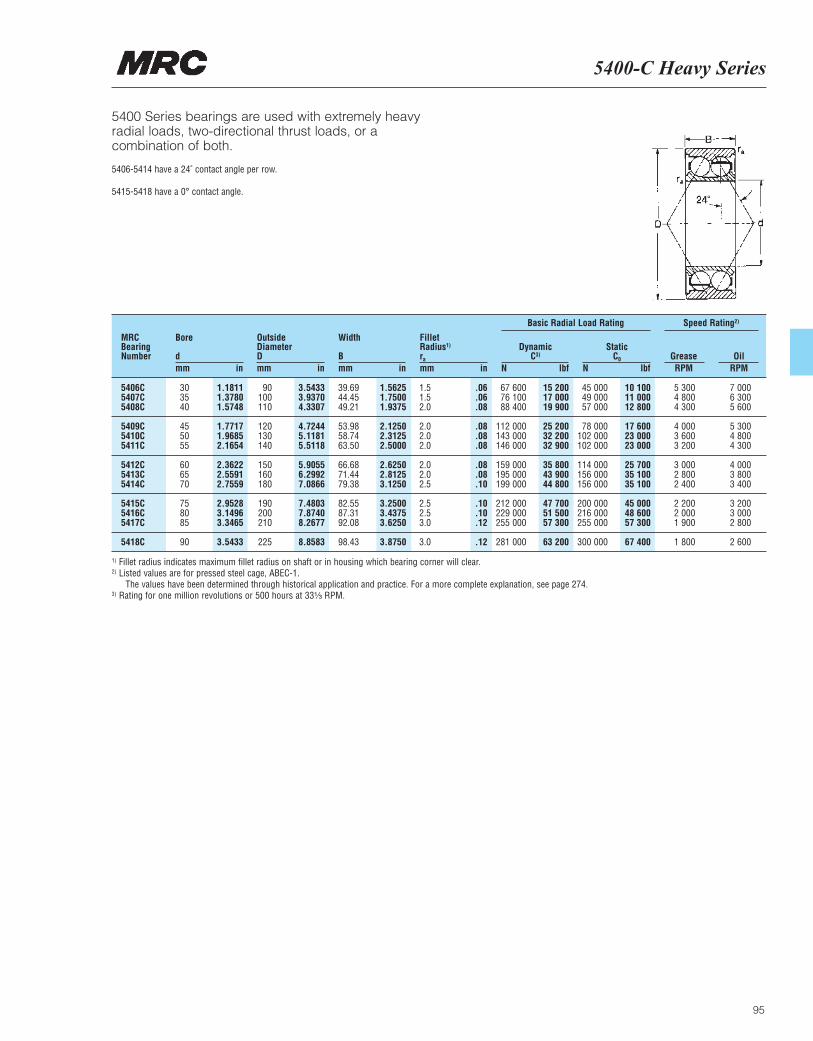
95
5400-C Heavy Series
5400 Series bearings are used with extremely heavyradial loads, two-directional thrust loads, or acombination of both.
5406-5414 have a 24˚ contact angle per row.
5415-5418 have a 0° contact angle.
MRCBearingNumber
Bore
dmm in
OutsideDiameterDmm in
Width
Bmm in
ra
mm in
DynamicC3)
N lbf
Basic Radial Load Rating Speed Rating2)
StaticC0
N lbfGrease OilRPM RPM
Fillet Radius1)
5406C 30 1.1811 90 3.5433 39.69 1.5625 1.5 .06 67 600 15 200 45 000 10 100 5 300 7 0005407C 35 1.3780 100 3.9370 44.45 1.7500 1.5 .06 76 100 17 000 49 000 11 000 4 800 6 3005408C 40 1.5748 110 4.3307 49.21 1.9375 2.0 .08 88 400 19 900 57 000 12 800 4 300 5 600
5409C 45 1.7717 120 4.7244 53.98 2.1250 2.0 .08 112 000 25 200 78 000 17 600 4 000 5 3005410C 50 1.9685 130 5.1181 58.74 2.3125 2.0 .08 143 000 32 200 102 000 23 000 3 600 4 8005411C 55 2.1654 140 5.5118 63.50 2.5000 2.0 .08 146 000 32 900 102 000 23 000 3 200 4 300
5412C 60 2.3622 150 5.9055 66.68 2.6250 2.0 .08 159 000 35 800 114 000 25 700 3 000 4 0005413C 65 2.5591 160 6.2992 71.44 2.8125 2.0 .08 195 000 43 900 156 000 35 100 2 800 3 8005414C 70 2.7559 180 7.0866 79.38 3.1250 2.5 .10 199 000 44 800 156 000 35 100 2 400 3 400
5415C 75 2.9528 190 7.4803 82.55 3.2500 2.5 .10 212 000 47 700 200 000 45 000 2 200 3 2005416C 80 3.1496 200 7.8740 87.31 3.4375 2.5 .10 229 000 51 500 216 000 48 600 2 000 3 0005417C 85 3.3465 210 8.2677 92.08 3.6250 3.0 .12 255 000 57 300 255 000 57 300 1 900 2 800
5418C 90 3.5433 225 8.8583 98.43 3.8750 3.0 .12 281 000 63 200 300 000 67 400 1 800 2 600
1) Fillet radius indicates maximum fillet radius on shaft or in housing which bearing corner will clear.2) Listed values are for pressed steel cage, ABEC-1.
The values have been determined through historical application and practice. For a more complete explanation, see page 274.3) Rating for one million revolutions or 500 hours at 33¹|₃ RPM.
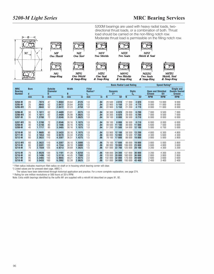
MRC Bearing Services
96
5200-M Light Series
MRCBearingNumber
Bore
dmm in
OutsideDiameterDmm in
Width
Bmm in
FilletRadius1)
ra
mm in
DynamicC3)
N lbf
Basic Radial Load Rating Speed Rating2)
StaticC0
N lbf
Open and ShieldedGrease OilRPM RPM
Single andDouble Sealed
GreaseRPM
5204-M 20 .7874 47 1.8504 20.64 .8125 1.0 .04 20 500 4 610 17 000 3 820 9 000 13 000 9 0005205-M 25 .9843 52 2.0472 20.64 .8125 1.0 .04 22 900 5 150 21 200 4 770 8 000 11 000 8 0005205-M1 25 .9843 52 2.0472 22.23 .8750 1.0 .04 22 900 5 150 21 200 4 770 8 000 11 000 8 000
5206-M 30 1.1811 62 2.4409 23.81 .9375 1.0 .04 30 300 6 820 28 000 6 290 7 000 9 500 7 0005206-M1 30 1.1811 62 2.4409 26.99 1.0625 1.0 .04 30 300 6 820 28 000 6 290 7 000 9 500 7 0005207-M 35 1.3780 72 2.8346 26.99 1.0625 1.0 .04 39 100 8 800 36 500 8 210 6 000 8 000 6 000
5207-M1 35 1.3780 72 2.8346 30.16 1.1875 1.0 .04 39 100 8 800 36 500 8 210 6 000 8 000 6 0005208-M 40 1.5748 80 3.1496 30.16 1.1875 1.0 .04 49 500 11 100 49 000 11 000 5 600 7 500 5 6005209-M 45 1.7717 85 3.3465 30.16 1.1875 1.0 .04 51 200 11 500 54 000 12 100 5 000 6 700 5 000
5210-M 50 1.9685 90 3.5433 30.16 1.1875 1.0 .04 53 900 12 100 58 500 13 200 4 800 6 300 4 8005211-M 55 2.1654 100 3.9370 33.34 1.3125 1.5 .06 66 000 14 900 76 500 17 200 4 300 5 600 4 3005212-M 60 2.3622 110 4.3307 36.51 1.4375 1.5 .06 78 100 17 600 88 000 19 800 3 800 5 000 3 800
5212-M1 60 2.3622 110 4.3307 38.10 1.5000 1.5 .06 78 100 17 600 88 000 19 800 3 800 5 000 3 8005213-M 65 2.5591 120 4.7244 38.10 1.5000 1.5 .06 88 000 19 800 106 000 23 800 3 600 4 800 3 6005214-M 70 2.7559 125 4.9213 39.69 1.5625 1.5 .06 101 000 22 700 125 000 28 100 3 200 4 300 3 200
5215-M 75 2.9528 130 5.1181 41.28 1.6250 1.5 .06 108 000 24 300 137 000 30 800 3 200 4 300 3 2005216-M 80 3.1496 140 5.5118 44.45 1.7500 2.0 .08 128 000 28 800 160 000 36 000 2 800 3 800 2 8005217-M 85 3.3465 150 5.9055 49.21 1.9375 2.0 .08 142 000 32 000 176 000 39 600 2 600 3 600 2 6005218-M 90 3.5433 160 6.2992 52.39 2.0625 2.0 .08 151 000 34 000 193 000 43 400 2 400 3 400 2 400
1) Fillet radius indicates maximum fillet radius on shaft or in housing which bearing corner will clear.2) Listed values are for pressed steel cage, ABEC-1.
The values have been determined through historical application and practice. For a more complete explanation, see page 274.3) Rating for one million revolutions or 500 hours at 33¹|₃ RPM. Note: Extra width bearings identified by the suffix M1 are supplied with a retrofit kit described on pages 91, 92.
5200M bearings are used with heavy radial loads, two-directional thrust loads, or a combination of both. Thrustload should be carried on the non-filling notch row.Moderate thrust load is permissible on the filling notch row.
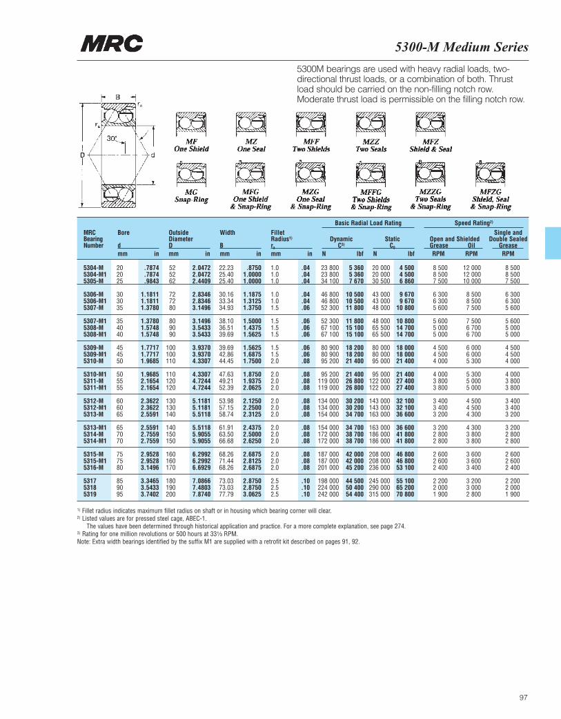
5300-M Medium Series
97
MRCBearingNumber
Bore
dmm in
OutsideDiameterDmm in
Width
Bmm in
FilletRadius1)
ra
mm in
DynamicC3)
N lbf
Basic Radial Load Rating Speed Rating2)
StaticC0
N lbf
Open and ShieldedGrease OilRPM RPM
Single andDouble Sealed
GreaseRPM
5304-M 20 .7874 52 2.0472 22.23 .8750 1.0 .04 23 800 5 360 20 000 4 500 8 500 12 000 8 5005304-M1 20 .7874 52 2.0472 25.40 1.0000 1.0 .04 23 800 5 360 20 000 4 500 8 500 12 000 8 5005305-M 25 .9843 62 2.4409 25.40 1.0000 1.0 .04 34 100 7 670 30 500 6 860 7 500 10 000 7 500
5306-M 30 1.1811 72 2.8346 30.16 1.1875 1.0 .04 46 800 10 500 43 000 9 670 6 300 8 500 6 3005306-M1 30 1.1811 72 2.8346 33.34 1.3125 1.0 .04 46 800 10 500 43 000 9 670 6 300 8 500 6 3005307-M 35 1.3780 80 3.1496 34.93 1.3750 1.5 .06 52 300 11 800 48 000 10 800 5 600 7 500 5 600
5307-M1 35 1.3780 80 3.1496 38.10 1.5000 1.5 .06 52 300 11 800 48 000 10 800 5 600 7 500 5 6005308-M 40 1.5748 90 3.5433 36.51 1.4375 1.5 .06 67 100 15 100 65 500 14 700 5 000 6 700 5 0005308-M1 40 1.5748 90 3.5433 39.69 1.5625 1.5 .06 67 100 15 100 65 500 14 700 5 000 6 700 5 000
5309-M 45 1.7717 100 3.9370 39.69 1.5625 1.5 .06 80 900 18 200 80 000 18 000 4 500 6 000 4 5005309-M1 45 1.7717 100 3.9370 42.86 1.6875 1.5 .06 80 900 18 200 80 000 18 000 4 500 6 000 4 5005310-M 50 1.9685 110 4.3307 44.45 1.7500 2.0 .08 95 200 21 400 95 000 21 400 4 000 5 300 4 000
5310-M1 50 1.9685 110 4.3307 47.63 1.8750 2.0 .08 95 200 21 400 95 000 21 400 4 000 5 300 4 0005311-M 55 2.1654 120 4.7244 49.21 1.9375 2.0 .08 119 000 26 800 122 000 27 400 3 800 5 000 3 8005311-M1 55 2.1654 120 4.7244 52.39 2.0625 2.0 .08 119 000 26 800 122 000 27 400 3 800 5 000 3 800
5312-M 60 2.3622 130 5.1181 53.98 2.1250 2.0 .08 134 000 30 200 143 000 32 100 3 400 4 500 3 4005312-M1 60 2.3622 130 5.1181 57.15 2.2500 2.0 .08 134 000 30 200 143 000 32 100 3 400 4 500 3 4005313-M 65 2.5591 140 5.5118 58.74 2.3125 2.0 .08 154 000 34 700 163 000 36 600 3 200 4 300 3 200
5313-M1 65 2.5591 140 5.5118 61.91 2.4375 2.0 .08 154 000 34 700 163 000 36 600 3 200 4 300 3 2005314-M 70 2.7559 150 5.9055 63.50 2.5000 2.0 .08 172 000 38 700 186 000 41 800 2 800 3 800 2 8005314-M1 70 2.7559 150 5.9055 66.68 2.6250 2.0 .08 172 000 38 700 186 000 41 800 2 800 3 800 2 800
5315-M 75 2.9528 160 6.2992 68.26 2.6875 2.0 .08 187 000 42 000 208 000 46 800 2 600 3 600 2 6005315-M1 75 2.9528 160 6.2992 71.44 2.8125 2.0 .08 187 000 42 000 208 000 46 800 2 600 3 600 2 6005316-M 80 3.1496 170 6.6929 68.26 2.6875 2.0 .08 201 000 45 200 236 000 53 100 2 400 3 400 2 400
5317 85 3.3465 180 7.0866 73.03 2.8750 2.5 .10 198 000 44 500 245 000 55 100 2 200 3 200 2 2005318 90 3.5433 190 7.4803 73.03 2.8750 2.5 .10 224 000 50 400 290 000 65 200 2 000 3 000 2 0005319 95 3.7402 200 7.8740 77.79 3.0625 2.5 .10 242 000 54 400 315 000 70 800 1 900 2 800 1 900
1) Fillet radius indicates maximum fillet radius on shaft or in housing which bearing corner will clear.2) Listed values are for pressed steel cage, ABEC-1.
The values have been determined through historical application and practice. For a more complete explanation, see page 274.3) Rating for one million revolutions or 500 hours at 33¹|₃ RPM. Note: Extra width bearings identified by the suffix M1 are supplied with a retrofit kit described on pages 91, 92.
5300M bearings are used with heavy radial loads, two-directional thrust loads, or a combination of both. Thrustload should be carried on the non-filling notch row.Moderate thrust load is permissible on the filling notch row.
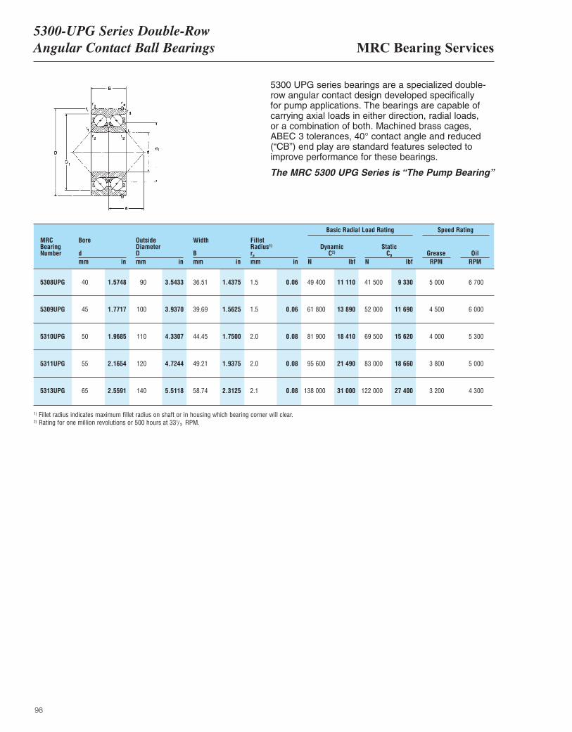
98
5300 UPG series bearings are a specialized double-row angular contact design developed specifically for pump applications. The bearings are capable ofcarrying axial loads in either direction, radial loads, or a combination of both. Machined brass cages,ABEC 3 tolerances, 40° contact angle and reduced(“CB”) end play are standard features selected toimprove performance for these bearings.
The MRC 5300 UPG Series is “The Pump Bearing”
MRCBearingNumber
Bore
dmm in
OutsideDiameterDmm in
Width
Bmm in
ra
mm in
DynamicC2)
N lbf
Basic Radial Load Rating Speed Rating
StaticC0
N lbfGrease OilRPM RPM
Fillet Radius1)
5308UPG 40 1.5748 90 3.5433 36.51 1.4375 1.5 0.06 49 400 11 110 41 500 9 330 5 000 6 700
5309UPG 45 1.7717 100 3.9370 39.69 1.5625 1.5 0.06 61 800 13 890 52 000 11 690 4 500 6 000
5310UPG 50 1.9685 110 4.3307 44.45 1.7500 2.0 0.08 81 900 18 410 69 500 15 620 4 000 5 300
5311UPG 55 2.1654 120 4.7244 49.21 1.9375 2.0 0.08 95 600 21 490 83 000 18 660 3 800 5 000
5313UPG 65 2.5591 140 5.5118 58.74 2.3125 2.1 0.08 138 000 31 000 122 000 27 400 3 200 4 300
1) Fillet radius indicates maximum fillet radius on shaft or in housing which bearing corner will clear.2) Rating for one million revolutions or 500 hours at 33 RPM.1/3
MRC Bearing Services5300-UPG Series Double-RowAngular Contact Ball Bearings
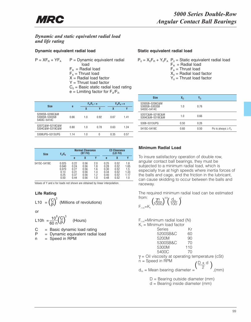
5000 Series Double-Row Angular Contact Ball Bearings
5200SB–5206C&M 5300SB–5303SB 0.66 1.0 0.92 0.67 1.415403C–5414C
5207C&M–5218C&M 0.80 1.0 0.78 0.63 1.24 5304C&M–5319C&M
5308UPG–5313UPG 1.14 1.0 0 0.35 0.57
5415C–5419C 0.025 0.22 0.56 2.0 0.25 0.52 1.80.040 0.24 0.56 1.8 0.28 0.52 1.650.070 0.27 0.56 1.6 0.30 0.52 1.50.13 0.31 0.56 1.4 0.34 0.52 1.330.25 0.37 0.56 1.2 0.40 0.52 1.170.50 0.44 0.56 1.0 0.48 0.52 1.0
99
Size X0 Y0
5200SB–5206C&M 5300SB–5303SB 1.0 0.76 5403C–5414C
5207C&M–5218C&M 1.0 0.66 5304C&M–5319C&M
5308–5313UPG 0.50 0.26
5415C–5419C 0.60 0.50 Po is always ≥ FR
Size eFA/FR ≤ e
X XY Y
FA/FR > e
Size FA/C0
Normal Clearance(ST Fit)
e eX XY Y
C3 Clearance(LO Fit)
Dynamic and static equivalent radial loadand life rating
Dynamic equivalent radial load
P = XFR + YFA P = Dynamic equivalent radial load
FR = Radial loadFA = Thrust loadX = Radial load factorY = Thrust load factorC0 = Basic static radial load ratinge = Limiting factor for FA/FR
Life Rating
L10 = (Millions of revolutions)
or
L10h = (Hours)
C = Basic dynamic load ratingP = Dynamic equivalent radial loadn = Speed in RPM
Static equivalent radial load
P0 = X0FR + Y0FA P0 = Static equivalent radial loadFR = Radial loadFA = Thrust loadX0 = Radial load factorY0 = Thrust load factor
( )CP
3
( )CP
1060 n
36
Minimum Radial Load
To insure satisfactory operation of double row,angular contact ball bearings, they must besubjected to a minimum radial load, which isespecially true at high speeds where inertia forces ofthe balls and cage, and the friction in the lubricant,can cause skidding to occur between the balls andraceway.
The required minimum radial load can be estimatedfrom:
Fr m=Kr
Fr m=Minimum radial load (N) Kr = Minimum load factor
Series Kr 5200SB&C 605200M 90 5300SB&C 70 5300M 110 5400C 70
γ = Oil viscosity at operating temperature (cSt) n = Speed in RPM
dm = Mean bearing diameter = ,(mm)
D = Bearing outside diameter (mm)d = Bearing inside diameter (mm)
Values of Y and e for loads not shown are obtained by linear interpolation.
D + d2( )
dm
100( )2γn
1000( )2/3
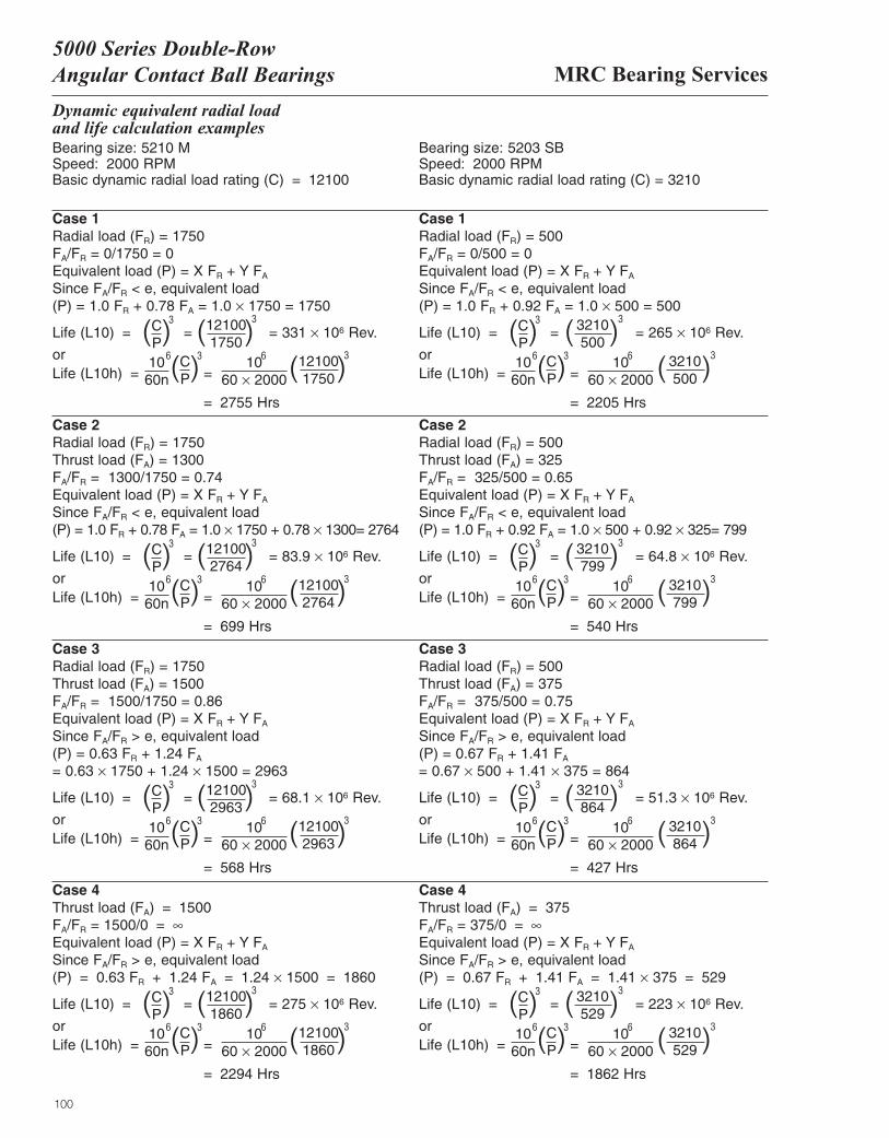
100
MRC Bearing Services5000 Series Double-RowAngular Contact Ball Bearings
Dynamic equivalent radial load and life calculation examplesBearing size: 5210 MSpeed: 2000 RPMBasic dynamic radial load rating (C) = 12100
Bearing size: 5203 SBSpeed: 2000 RPMBasic dynamic radial load rating (C) = 3210
Case 1Radial load (FR) = 1750FA/FR = 0/1750 = 0Equivalent load (P) = X FR + Y FA
Since FA/FR < e, equivalent load (P) = 1.0 FR + 0.78 FA = 1.0 × 1750 = 1750
Case 2Radial load (FR) = 1750Thrust load (FA) = 1300FA/FR = 1300/1750 = 0.74Equivalent load (P) = X FR + Y FA
Since FA/FR < e, equivalent load (P) = 1.0 FR + 0.78 FA = 1.0 × 1750 + 0.78 × 1300= 2764
Case 2Radial load (FR) = 500Thrust load (FA) = 325FA/FR = 325/500 = 0.65Equivalent load (P) = X FR + Y FA
Since FA/FR < e, equivalent load (P) = 1.0 FR + 0.92 FA = 1.0 × 500 + 0.92 × 325= 799
Life (L10) = = = 331 × 106 Rev.
orLife (L10h) = =
= 2755 Hrs
( )CP
3
( )CP
1060n
36 1060 × 2000
6
( )121001750
3
( )121001750
3
Case 1Radial load (FR) = 500FA/FR = 0/500 = 0Equivalent load (P) = X FR + Y FA
Since FA/FR < e, equivalent load (P) = 1.0 FR + 0.92 FA = 1.0 × 500 = 500
Life (L10) = = = 265 × 106 Rev.
orLife (L10h) = =
= 2205 Hrs
( )CP
3
( )CP
1060n
36 1060 × 2000
6
( )3210500
3
( )3210500
3
Life (L10) = = = 83.9 × 10⁶ Rev.
orLife (L10h) = =
= 699 Hrs
( )CP
3
( )CP
1060n
36 1060 × 2000
6
( )121002764
3
( )121002764
3
Life (L10) = = = 64.8 × 10⁶ Rev.
orLife (L10h) = =
= 540 Hrs
( )CP
3
( )CP
1060n
36 1060 × 2000
6
( )3210799
3
( )3210799
3
Case 3Radial load (FR) = 1750Thrust load (FA) = 1500FA/FR = 1500/1750 = 0.86Equivalent load (P) = X FR + Y FA
Since FA/FR > e, equivalent load (P) = 0.63 FR + 1.24 FA
= 0.63 × 1750 + 1.24 × 1500 = 2963
Life (L10) = = = 68.1 × 10⁶ Rev.
orLife (L10h) = =
= 568 Hrs
( )CP
3
( )CP
1060n
36 1060 × 2000
6
( )121002963
3
( )121002963
3
Case 3Radial load (FR) = 500Thrust load (FA) = 375FA/FR = 375/500 = 0.75Equivalent load (P) = X FR + Y FA
Since FA/FR > e, equivalent load (P) = 0.67 FR + 1.41 FA
= 0.67 × 500 + 1.41 × 375 = 864
Life (L10) = = = 51.3 × 10⁶ Rev.
orLife (L10h) = =
= 427 Hrs
( )CP
3
( )CP
1060n
36 1060 × 2000
6
( )3210864
3
( )3210864
3
Case 4Thrust load (FA) = 1500FA/FR = 1500/0 = ∞Equivalent load (P) = X FR + Y FA
Since FA/FR > e, equivalent load (P) = 0.63 FR + 1.24 FA = 1.24 × 1500 = 1860
Life (L10) = = = 275 × 106 Rev.
orLife (L10h) = =
= 2294 Hrs
( )CP
3
( )CP
1060n
36 1060 × 2000
6
( )121001860
3
( )121001860
3
Case 4Thrust load (FA) = 375FA/FR = 375/0 = ∞Equivalent load (P) = X FR + Y FA
Since FA/FR > e, equivalent load (P) = 0.67 FR + 1.41 FA = 1.41 × 375 = 529
Life (L10) = = = 223 × 106 Rev.
orLife (L10h) = =
= 1862 Hrs
( )CP
3
( )CP
1060n
36 1060 × 2000
6
( )3210529
3
( )3210529
3

101

102
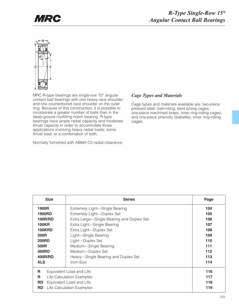
R-Type Single-Row 15°Angular Contact Ball Bearings
103
MRC R-type bearings are single-row 15° angularcontact ball bearings with one heavy race shoulderand one counterbored race shoulder on the outer ring. Because of this construction, it is possible toincorporate a greater number of balls than in the deep-groove nonfilling notch bearing. R-typebearings have ample radial capacity and moderatethrust capacity in order to accomodate thoseapplications involving heavy radial loads; somethrust load; or a combination of both.
Normally furnished with ABMA C3 radial clearance.
Cage Types and Materials
Cage types and materials available are: two-piecepressed steel, ball-riding, bent prong cages; one-piece machined brass, inner ring-riding cages; and one-piece phenolic (bakelite), inner ring-ridingcages.
Size
1900R1900RD100R/RD100KR100KRD200R200RD300R300RD400R/RDXLS
Extremely Light—Single BearingExtremely Light—Duplex SetExtra Large—Single Bearing and Duplex SetExtra Light—Single BearingExtra Light—Duplex SetLight—Single BearingLight—Duplex SetMedium—Single BearingMedium—Duplex SetHeavy—Single Bearing and Duplex SetInch-Size
104105106107108109110111112113114
Series Page
R Equivalent Load and LifeR Life Calculation ExamplesRD Equivalent Load and LifeRD Life Calculation Examples
116117118119
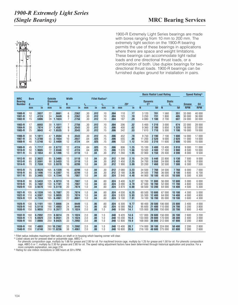
MRC Bearing Services1900-R Extremely Light Series(Single Bearings)
104
1900-R Extremely Light Series bearings are made with bores ranging from 10 mm to 200 mm. Theextremely light section on the 1900-R bearingpermits the use of these bearings in applicationswhere there are space and weight limitations.These bearings can accommodate light radialloads and one directional thrust loads, or acombination of both. Use duplex bearings for two-directional thrust loads. 1900-R bearings can befurnished duplex ground for installation in pairs.
MRCBearingNumber
Bore
dmm in
OutsideDiameterDmm in
Width
Bmm in
ra
mm inrb
mm inZD2
mm in
DynamicC3)
N lbf
Basic Radial Load Rating Speed Rating2)
StaticC0
N lbfGrease OilRPM RPM
1900-R1901-R1902-R
1903-R1904-R1905-R
1906-R1907-R1908-R
1909-R1910-R1911-R
1912-R1913-R1914-R
1915-R1916-R1917-R
1918-R1919-R1920-R
1921-R1922-R1924-R
1926-R1928-R1930-R
1932-R1934-R1936-R
1938-R1940-R
101215
172025
303540
455055
606570
758085
9095
100
105110120
130140150
160170180
190200
222428
303742
475562
687280
8590
100
105110120
125130140
145150165
180190210
220230250
260280
667
799
91012
121213
131316
161618
181820
202022
242428
282833
3338
.30
.30
.30
.30
.30
.30
.30
.64
.64
.64
.641.0
1.01.01.0
1.01.01.0
1.01.01.0
1.01.01.0
1.51.52.0
2.02.02.0
2.02.0
110123187
206400342
452555722
8061 0701 260
1 3901 4501 990
2 0802 1802 840
3 4003 0903 870
4 0303 8205 100
6 3006 5809 090
9 42010 20012 800
13 40016 800
.10
.10
.10
.10
.15
.15
.15
.15
.15
.15
.15
.30
.30
.30
.30
.30
.30
.60
.60
.60
.60
.60
.60
.60
.60
.601.0
1.01.01.0
1.01.0
3 1203 2504 880
5 4009 3607 610
9 75011 20014 300
15 10019 50022 900
24 20024 70033 200
34 50034 50044 900
52 70047 50058 500
60 50055 30074 100
90 40095 600
125 000
127 000133 000168 000
174 000216 100
1 5601 8002 700
3 0005 8505 300
7 1009 000
11 600
13 40017 30020 400
22 80024 00032 500
34 50036 00046 500
56 00052 00064 000
67 00064 00085 000
106 000110 000150 000
156 000170 000212 000
224 000275 000
33 00030 00024 000
22 00018 00016 000
14 00011 00010 000
9 0008 5008 000
7 5006 7006 300
6 0005 6005 300
5 0004 8004 500
4 3004 0003 600
3 4003 2002 800
2 6002 4002 200
2 2002 000
40 00036 00030 000
28 00022 00019 000
17 00014 00015 000
11 00010 0009 500
9 0008 0007 500
7 0006 7006 300
6 0005 6005 300
5 0004 8004 300
4 0003 8003 400
3 2003 0002 800
2 8002 600
.3937
.4724
.5906
.6693
.7874
.9843
1.18111.37801.5748
1.77171.96852.1654
2.36222.55912.7559
2.95283.14963.3465
3.54333.74023.9370
4.13394.33074.7244
5.11815.51185.9055
6.29926.69297.0866
7.48037.8740
.8661
.94491.1024
1.18111.45671.6535
1.85042.16542.4409
2.67722.83463.1496
3.34653.54333.9370
4.13394.33074.7244
4.92135.11815.5118
5.70875.90556.4961
7.08667.48038.2677
8.66149.05519.8425
10.236211.0236
.2362
.2362
.2756
.2756
.3543
.3543
.3543
.3937
.4724
.4724
.4724
.5118
.5118
.5118
.6299
.6299
.6299
.7087
.7087
.7087
.7874
.7874
.7874
.8661
.9449
.94491.1024
1.10241.10241.2992
1.29921.4961
.17
.19
.29
.32
.62
.53
.70
.861.12
1.251.661.95
2.152.253.09
3.233.384.40
5.274.796.00
6.255.937.91
9.7710.214.1
14.615.819.9
20.726.0
.004
.004
.004
.004
.006
.006
.006
.006
.006
.006
.006
.012
.012
.012
.012
.012
.012
.024
.024
.024
.024
.024
.024
.024
.024
.024
.040
.040
.040
.040
.040
.040
.012
.012
.012
.012
.012
.012
.012
.025
.025
.025
.025
.04
.04
.04
.04
.04
.04
.04
.04
.04
.04
.04
.04
.04
.06
.06
.08
.08
.08
.08
.08
.08
701731
1 100
1 2102 1001 710
2 1902 5203 210
3 4004 3805 150
5 4405 5507 460
7 7607 760
10 100
11 80010 70013 200
13 60012 40016 700
20 50021 40028 200
28 60029 80036 000
39 10048 600
351405607
6741 3201 190
1 6002 0202 600
3 0103 9004 590
5 1305 4007 300
7 7608 100
10 500
12 60011 70014 400
15 10014 40019 100
23 80024 70033 700
35 10038 30047 800
50 40061 800
1) Fillet radius indicates maximum fillet radius on shaft or in housing which bearing corner will clear.2) Listed values are for pressed steel or polyamide cage, ABEC-1.
For phenolic composition cage, multiply by 1.66 for grease and 2.00 for oil. For machined bronze cage, multiply by 1.25 for grease and 1.50 for oil. For phenolic compositioncage, ABEC-5 or 7, multiply by 2.30 for grease and 2.80 for oil. The speed rating adjustment factors have been determined through historical application and practice. For amore complete explanation, see page 274.
3) Rating for one million revolutions or 500 hours at 33¹|₃ RPM.
Fillet Radius1)
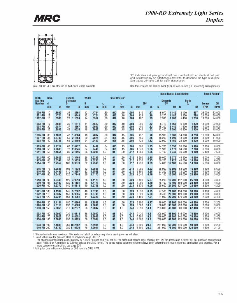
1900-RD Extremely Light SeriesDuplex
105
“D” indicates a duplex ground half pair matched with an identical half pairand is followed by an additional suffix letter to describe the type of duplex.See pages 234 and 235 for suffix description.
Use these values for back-to-back (DB) or face-to-face (DF) mounting arrangements.Note: ABEC 1 & 3 are stocked as half-pairs where available.
MRCBearingNumber
Bore
dmm in
OutsideDiameterDmm in
Width
Bmm in
ra
mm inrb
mm inZD2
mm in
DynamicC3)
N lbf
Basic Radial Load Rating Speed Rating2)
StaticC0
N lbfGrease OilRPM RPM
1900-RD1901-RD1902-RD
1903-RD1904-RD1905-RD
1906-RD1907-RD1908-RD
1909-RD1910-RD1911-RD
1912-RD1913-RD1914-RD
1915-RD1916-RD1917-RD
1918-RD1919-RD1920-RD
1921-RD1922-RD1924-RD
1926-RD1928-RD1930-RD
1932-RD1934-RD1936-RD
1938-RD1940-RD
101215
172025
303540
455055
606570
758085
9095
100
105110120
130140150
160170180
190200
222428
303742
475562
687280
8590
100
105110120
125130140
145150165
180190210
220230250
260280
121214
141818
182024
242426
262632
323236
363640
404044
484856
565666
6676
.30
.30
.30
.30
.30
.30
.30
.64
.64
.64
.641.0
1.01.01.0
1.01.01.0
1.01.01.0
1.01.01.0
1.51.52.0
2.02.02.0
2.02.0
110123187
206400342
452555722
8061 0701 260
1 3901 4501 990
2 0802 1802 840
3 4003 0903 870
4 0303 8205 100
6 3006 5809 090
9 42010 20012 800
13 40016 800
.10
.10
.10
.10
.15
.15
.15
.15
.15
.15
.15
.30
.30
.30
.30
.30
.30
.60
.60
.60
.60
.60
.60
.60
.60
.601.0
1.01.01.0
1.01.0
5 0705 2707 930
8 71015 30012 400
15 90018 20022 900
24 70031 90037 100
39 00039 70054 000
55 90057 20074 100
85 20076 10095 600
97 50090 400
121 000
146 000156 000203 000
208 000216 000276 000
281 000351 000
3 1003 5505 400
6 10011 60010 800
14 30018 00023 200
26 50034 50040 500
45 50048 00065 500
68 00072 00093 000
112 000104 000127 000
134 000129 000170 000
208 000220 000300 000
315 000340 000425 000
440 000550 000
26 00024 00019 000
18 00014 00013 000
11 0008 8008 000
7 2006 8006 400
6 0005 4005 000
4 8004 5004 200
4 0003 8003 600
3 4003 2002 900
2 7002 6002 200
2 1001 9001 800
1 8001 600
32 00029 00024 000
22 00018 00015 000
14 00011 00010 000
8 8008 0007 600
7 2006 4006 000
5 6005 4005 000
4 8004 5004 200
4 0003 8003 400
3 2003 0002 700
2 6002 4002 200
2 2002 100
.3937
.4724
.5906
.6693
.7874
.9843
1.18111.37801.5748
1.77171.96852.1654
2.36222.55912.7559
2.95283.14963.3465
3.54333.74023.9370
4.13394.33074.7244
5.11815.51185.9055
6.29926.69297.0866
7.48037.8740
.8661
.94491.1024
1.18111.45671.6535
1.85042.16542.4409
2.67722.83463.1496
3.34653.54333.9370
4.13394.33074.7244
4.92135.11815.5118
5.70875.90556.4961
7.08667.48038.2677
8.66149.05519.8425
10.236211.0236
.4724
.4724
.5512
.5512
.7087
.7087
.7087
.7874
.9449
.9449
.94491.0236
1.02361.02361.2598
1.25981.25981.4173
1.41731.41731.5748
1.57481.57481.7323
1.88981.88982.2047
2.20472.20472.5984
2.59842.9921
.17
.19
.29
.32
.62
.53
.70
.861.12
1.251.661.95
2.152.253.09
3.233.384.40
5.274.796.00
6.255.937.91
9.7710.214.1
14.615.819.9
20.726.0
.004
.004
.004
.004
.006
.006
.006
.006
.006
.006
.006
.012
.012
.012
.012
.012
.012
.024
.024
.024
.024
.024
.024
.024
.024
.024
.040
.040
.040
.040
.040
.040
.012
.012
.012
.012
.012
.012
.012
.025
.025
.025
.025
.04
.04
.04
.04
.04
.04
.04
.04
.04
.04
.04
.04
.04
.06
.06
.08
.08
.08
.08
.08
.08
1 1401 1801 780
1 9603 4402 790
3 5804 0905 150
5 5507 1708 340
8 7708 920
12 100
12 60012 90016 700
19 20017 10021 500
21 90020 30027 200
32 80035 10045 600
46 80048 60062 000
63 20078 900
697798
1 210
1 3702 6002 430
3 2104 0505 220
5 9607 7609 100
10 20010 80014 700
15 30016 20020 900
25 20023 40028 600
30 10029 00038 200
46 80049 50067 400
70 80076 40095 600
98 900124 000
1) Fillet radius indicates maximum fillet radius on shaft or in housing which bearing corner will clear.2) Listed values are for pressed steel or polyamide cage, ABEC-1.
For phenolic composition cage, multiply by 1.66 for grease and 2.00 for oil. For machined bronze cage, multiply by 1.25 for grease and 1.50 for oil. For phenolic compositioncage, ABEC-5 or 7, multiply by 2.30 for grease and 2.80 for oil. The speed rating adjustment factors have been determined through historical application and practice. For amore complete explanation, see page 274.
3) Rating for one million revolutions or 500 hours at 33¹|₃ RPM.
Fillet Radius1)
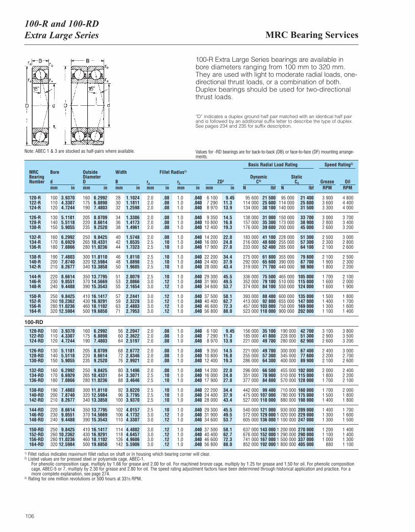
MRC Bearing Services100-R and 100-RDExtra Large Series
106
100-R Extra Large Series bearings are available inbore diameters ranging from 100 mm to 320 mm.They are used with light to moderate radial loads, one-directional thrust loads, or a combination of both.Duplex bearings should be used for two-directionalthrust loads.
MRCBearingNumber
Bore
dmm in
OutsideDiameterDmm in
Width
Bmm in
ra
mm inrb
mm inZD2
mm in
DynamicC3)
N lbf
Basic Radial Load Rating Speed Rating2)
StaticC0
N lbfGrease OilRPM RPM
120-R122-R124-R
126-R128-R130-R
132-R134-R136-R
138-R140-R142-R
144-R146-R148-R
150-R152-R156-R164-R
100110120
130140150
160170180
190200210
220230240
250260280320
160175190
205220235
250265280
300320340
350370390
410430460500
283032
343638
404244
464850
515355
57596371
2.02.02.0
2.02.02.0
2.02.52.5
2.52.52.5
2.53.03.0
3.03.03.03.0
6 1007 2908 970
9 35010 80012 400
14 20016 00017 900
22 20024 40028 000
29 30031 90034 600
37 50040 40046 60056 800
1.01.01.0
1.01.01.0
1.01.01.0
1.01.01.0
1.01.01.0
1.01.01.01.0
95 600114 000134 000
138 000157 000176 000
183 000216 000233 000
275 000292 000319 000
336 000352 000374 000
393 000413 000457 000523 000
95 000114 000140 000
150 000173 000200 000
228 000255 000285 000
355 000390 000440 000
465 000510 000550 000
600 000655 000750 000900 000
3 9003 6003 300
3 0002 8002 600
2 5002 3002 100
2 1001 9001 800
1 7001 6001 600
1 5001 4001 3001 100
4 8004 4004 000
3 7003 4003 200
3 0002 8002 600
2 5002 3002 200
2 1002 0001 900
1 8001 7001 6001 400
3.93704.33074.7244
5.11815.51185.9055
6.29926.69297.0866
7.48037.87408.2677
8.66149.05519.4488
9.842510.236211.023612.5984
6.29926.88987.4803
8.07098.66149.2520
9.842510.433111.0236
11.811012.598413.3858
13.779514.566915.3543
16.141716.929118.110219.6850
1.10241.18111.2598
1.33861.41731.4961
1.57481.65351.7323
1.81101.88981.9685
2.00792.08662.1654
2.24412.32282.48032.7953
9.4511.313.9
14.516.819.3
22.024.827.8
34.437.943.4
45.549.553.7
58.162.772.388.0
.040
.040
.040
.040
.040
.040
.040
.040
.040
.040
.040
.040
.040
.040
.040
.040
.040
.040
.040
.08
.08
.08
.08
.08
.08
.08
.10
.10
.10
.10
.10
.10
.12
.12
.12
.12
.12
.12
21 50025 60030 100
31 00035 30039 600
41 10048 60052 400
61 80065 60071 700
75 50079 10084 100
88 40092 800
103 000118 000
21 40025 60031 500
33 70038 90045 000
51 30057 30064 100
79 80087 70098 900
105 000115 000124 000
135 000147 000169 000202 000
1) Fillet radius indicates maximum fillet radius on shaft or in housing which bearing corner will clear.2) Listed values are for pressed steel or polyamide cage, ABEC-1.
For phenolic composition cage, multiply by 1.66 for grease and 2.00 for oil. For machined bronze cage, multiply by 1.25 for grease and 1.50 for oil. For phenolic compositioncage, ABEC-5 or 7, multiply by 2.30 for grease and 2.80 for oil. The speed rating adjustment factors have been determined through historical application and practice. For amore complete explanation, see page 274.
3) Rating for one million revolutions or 500 hours at 33¹|₃ RPM.
Fillet Radius1)
120-RD122-RD124-RD
126-RD128-RD130-RD
132-RD134-RD136-RD
138-RD140-RD142-RD
144-RD146-RD148-RD
150-RD152-RD156-RD164-RD
100110120
130140150
160170180
190200210
220230240
250260280320
160175190
205220235
250265280
300320340
350370390
410430460500
566064
687276
808488
9296
100
102106110
114118126142
2.02.02.0
2.02.02.0
2.02.52.5
2.52.52.5
2.53.03.0
3.03.03.03.0
6 1007 2908 970
9 35010 80012 400
14 20016 00017 900
22 20024 40028 000
29 30031 90034 600
37 50040 40046 60056 800
1.01.01.0
1.01.01.0
1.01.01.0
1.01.01.0
1.01.01.0
1.01.01.01.0
156 000185 000221 000
221 000255 000286 000
296 000351 000377 000
442 000475 000527 000
540 000572 000605 000
637 000676 000741 000852 000
190 000228 000280 000
300 000345 000400 000
455 000510 000570 000
710 000780 000880 000
930 0001 020 0001 100 000
1 200 0001 290 0001 500 0001 800 000
3 1002 9002 600
2 4002 2002 100
2 0001 8001 700
1 7001 5001 400
1 4001 3001 300
1 2001 1001 000
880
3 8003 5003 200
3 0002 7002 600
2 4002 2002 100
2 0001 8001 800
1 7001 6001 500
1 4001 4001 3001 100
3.93704.33074.7244
5.11815.51185.9055
6.29926.69297.0866
7.48037.87408.2677
8.66149.05519.4488
9.842510.236211.023612.5984
6.29926.88987.4803
8.07098.66149.2520
9.842510.433111.0236
11.811012.598413.3858
13.779514.566915.3543
16.141716.929118.110219.6850
2.20472.36222.5197
2.67722.83462.9921
3.14963.30713.4646
3.62203.77953.9370
4.01574.17324.3307
4.48824.64574.96065.5906
9.4511.313.9
14.516.819.3
22.024.827.8
34.437.943.4
45.549.553.7
58.162.772.388.0
.040
.040
.040
.040
.040
.040
.040
.040
.040
.040
.040
.040
.040
.040
.040
.040
.040
.040
.040
.08
.08
.08
.08
.08
.08
.08
.10
.10
.10
.10
.10
.10
.12
.12
.12
.12
.12
.12
35 10041 80049 700
49 70057 30064 300
66 50078 90084 800
99 400107 000118 000
121 000129 000136 000
143 000152 000167 000192 000
42 70051 30062 900
67 40077 60089 900
102 000115 000128 000
160 000175 000198 000
209 000229 000247 000
270 000290 000337 000405 000
“D” indicates a duplex ground half pair matched with an identical half pair and is followed by an additional suffix letter to describe the type of duplex. See pages 234 and 235 for suffix description.
Note: ABEC 1 & 3 are stocked as half-pairs where available. Values for -RD bearings are for back-to-back (DB) or face-to-face (DF) mounting arrange-ments.
100-RD
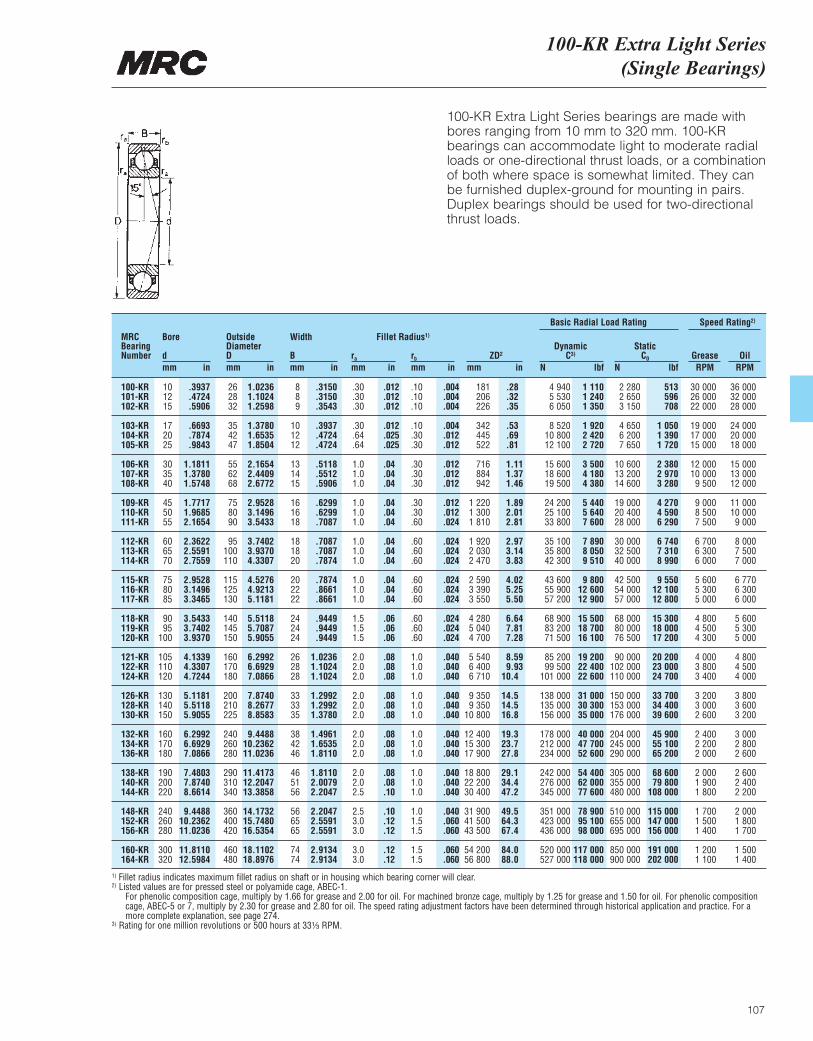
100-KR Extra Light Series(Single Bearings)
107
100-KR Extra Light Series bearings are made withbores ranging from 10 mm to 320 mm. 100-KRbearings can accommodate light to moderate radialloads or one-directional thrust loads, or a combinationof both where space is somewhat limited. They canbe furnished duplex-ground for mounting in pairs.Duplex bearings should be used for two-directionalthrust loads.
MRCBearingNumber
Bore
dmm in
OutsideDiameterDmm in
Width
Bmm in
ra
mm inrb
mm inZD2
mm in
DynamicC3)
N lbf
Basic Radial Load Rating Speed Rating2)
StaticC0
N lbfGrease OilRPM RPM
100-KR101-KR102-KR
103-KR104-KR105-KR
106-KR107-KR108-KR
109-KR110-KR111-KR
112-KR113-KR114-KR
115-KR116-KR117-KR
118-KR119-KR120-KR
121-KR122-KR124-KR
126-KR128-KR130-KR
132-KR134-KR136-KR
138-KR140-KR144-KR
148-KR152-KR156-KR
160-KR164-KR
101215
172025
303540
455055
606570
758085
9095
100
105110120
130140150
160170180
190200220
240260280
300320
262832
354247
556268
758090
95100110
115125130
140145150
160170180
200210225
240260280
290310340
360400420
460480
889
101212
131415
161618
181820
202222
242424
262828
333335
384246
465156
566565
7474
.30
.30
.30
.30
.64
.64
1.01.01.0
1.01.01.0
1.01.01.0
1.01.01.0
1.51.51.5
2.02.02.0
2.02.02.0
2.02.02.0
2.02.02.5
2.53.03.0
3.03.0
181206226
342445522
716884942
1 2201 3001 810
1 9202 0302 470
2 5903 3903 550
4 2805 0404 700
5 5406 4006 710
9 3509 350
10 800
12 40015 30017 900
18 80022 20030 400
31 90041 50043 500
54 20056 800
.10
.10
.10
.10
.30
.30
.30
.30
.30
.30
.30
.60
.60
.60
.60
.60
.60
.60
.60
.60
.60
1.01.01.0
1.01.01.0
1.01.01.0
1.01.01.0
1.01.51.5
1.51.5
4 9405 5306 050
8 52010 80012 100
15 60018 60019 500
24 20025 10033 800
35 10035 80042 300
43 60055 90057 200
68 90083 20071 500
85 20099 500
101 000
138 000135 000156 000
178 000212 000234 000
242 000276 000345 000
351 000423 000436 000
520 000527 000
2 2802 6503 150
4 6506 2007 650
10 60013 20014 600
19 00020 40028 000
30 00032 50040 000
42 50054 00057 000
68 00080 00076 500
90 000102 000110 000
150 000153 000176 000
204 000245 000290 000
305 000355 000480 000
510 000655 000695 000
850 000900 000
30 00026 00022 000
19 00017 00015 000
12 00010 0009 500
9 0008 5007 500
6 7006 3006 000
5 6005 3005 000
4 8004 5004 300
4 0003 8003 400
3 2003 0002 600
2 4002 2002 000
2 0001 9001 800
1 7001 5001 400
1 2001 100
36 00032 00028 000
24 00020 00018 000
15 00013 00012 000
11 00010 0009 000
8 0007 5007 000
6 7706 3006 000
5 6005 3005 000
4 8004 5004 000
3 8003 6003 200
3 0002 8002 600
2 6002 4002 200
2 0001 8001 700
1 5001 400
.3937
.4724
.5906
.6693
.7874
.9843
1.18111.37801.5748
1.77171.96852.1654
2.36222.55912.7559
2.95283.14963.3465
3.54333.74023.9370
4.13394.33074.7244
5.11815.51185.9055
6.29926.69297.0866
7.48037.87408.6614
9.448810.236211.0236
11.811012.5984
1.02361.10241.2598
1.37801.65351.8504
2.16542.44092.6772
2.95283.14963.5433
3.74023.93704.3307
4.52764.92135.1181
5.51185.70875.9055
6.29926.69297.0866
7.87408.26778.8583
9.448810.236211.0236
11.417312.204713.3858
14.173215.748016.5354
18.110218.8976
.3150
.3150
.3543
.3937
.4724
.4724
.5118
.5512
.5906
.6299
.6299
.7087
.7087
.7087
.7874
.7874
.8661
.8661
.9449
.9449
.9449
1.02361.10241.1024
1.29921.29921.3780
1.49611.65351.8110
1.81102.00792.2047
2.20472.55912.5591
2.91342.9134
.28
.32
.35
.53
.69
.81
1.111.371.46
1.892.012.81
2.973.143.83
4.025.255.50
6.647.817.28
8.599.93
10.4
14.514.516.8
19.323.727.8
29.134.447.2
49.564.367.4
84.088.0
.004
.004
.004
.004
.012
.012
.012
.012
.012
.012
.012
.024
.024
.024
.024
.024
.024
.024
.024
.024
.024
.040
.040
.040
.040
.040
.040
.040
.040
.040
.040
.040
.040
.040
.060
.060
.060
.060
.012
.012
.012
.012
.025
.025
.04
.04
.04
.04
.04
.04
.04
.04
.04
.04
.04
.04
.06
.06
.06
.08
.08
.08
.08
.08
.08
.08
.08
.08
.08
.08
.10
.10
.12
.12
.12
.12
1 1101 2401 350
1 9202 4202 720
3 5004 1804 380
5 4405 6407 600
7 8908 0509 510
9 80012 60012 900
15 50018 70016 100
19 20022 40022 600
31 00030 30035 000
40 00047 70052 600
54 40062 00077 600
78 90095 10098 000
117 000118 000
513596708
1 0501 3901 720
2 3802 9703 280
4 2704 5906 290
6 7407 3108 990
9 55012 10012 800
15 30018 00017 200
20 20023 00024 700
33 70034 40039 600
45 90055 10065 200
68 60079 800
108 000
115 000147 000156 000
191 000202 000
1) Fillet radius indicates maximum fillet radius on shaft or in housing which bearing corner will clear.2) Listed values are for pressed steel or polyamide cage, ABEC-1.
For phenolic composition cage, multiply by 1.66 for grease and 2.00 for oil. For machined bronze cage, multiply by 1.25 for grease and 1.50 for oil. For phenolic compositioncage, ABEC-5 or 7, multiply by 2.30 for grease and 2.80 for oil. The speed rating adjustment factors have been determined through historical application and practice. For amore complete explanation, see page 274.
3) Rating for one million revolutions or 500 hours at 33¹|₃ RPM.
Fillet Radius1)
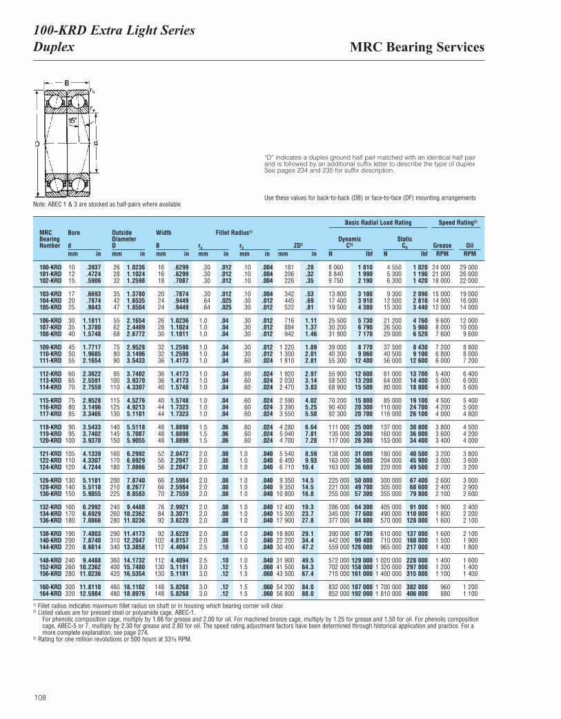
MRC Bearing Services100-KRD Extra Light SeriesDuplex
108
“D” indicates a duplex ground half pair matched with an identical half pairand is followed by an additional suffix letter to describe the type of duplexSee pages 234 and 235 for suffix description.
Note: ABEC 1 & 3 are stocked as half-pairs where available Use these values for back-to-back (DB) or face-to-face (DF) mounting arrangements
MRCBearingNumber
Bore
dmm in
OutsideDiameterDmm in
Width
Bmm in
ra
mm inrb
mm inZD2
mm in
DynamicC3)
N lbf
Basic Radial Load Rating Speed Rating2)
StaticC0
N lbfGrease OilRPM RPM
100-KRD101-KRD102-KRD
103-KRD104-KRD105-KRD
106-KRD107-KRD108-KRD
109-KRD110-KRD111-KRD
112-KRD113-KRD114-KRD
115-KRD116-KRD117-KRD
118-KRD119-KRD120-KRD
121-KRD122-KRD124-KRD
126-KRD128-KRD130-KRD
132-KRD134-KRD136-KRD
138-KRD140-KRD144-KRD
148-KRD152-KRD156-KRD
160-KRD164-KRD
101215
172025
303540
455055
606570
758085
9095
100
105110120
130140150
160170180
190200220
240260280
300320
262832
354247
556268
758090
95100110
115125130
140145150
160170180
200210225
240260280
290310340
360400420
460480
161618
202424
262830
323236
363640
404444
484848
525656
666670
768492
92102112
112130130
148148
.30
.30
.30
.30
.64
.64
1.01.01.0
1.01.01.0
1.01.01.0
1.01.01.0
1.51.51.5
2.02.02.0
2.02.02.0
2.02.02.0
2.02.02.5
2.53.03.0
3.03.0
181206226
342445522
716884942
1 2201 3001 810
1 9202 0302 470
2 5903 3903 550
4 2805 0404 700
5 5406 4006 710
9 3509 350
10 800
12 40015 30017 900
18 80022 20030 400
31 90041 50043 500
54 20056 800
.10
.10
.10
.10
.30
.30
.30
.30
.30
.30
.30
.60
.60
.60
.60
.60
.60
.60
.60
.60
.60
1.01.01.0
1.01.01.0
1.01.01.0
1.01.01.0
1.01.51.5
1.51.5
8 0608 8409 750
13 80017 40019 500
25 50030 20031 900
39 00040 30055 300
55 90058 50068 900
70 20090 40092 300
111 000135 000117 000
138 000163 000163 000
225 000221 000255 000
286 000345 000377 000
390 000442 000559 000
572 000702 000715 000
832 000852 000
4 5505 3006 300
9 30012 50015 300
21 20026 50029 000
37 50040 50056 000
61 00064 00080 000
85 000110 000116 000
137 000160 000153 000
180 000204 000220 000
300 000305 000355 000
405 000490 000570 000
610 000710 000965 000
1 020 0001 320 0001 400 000
1 700 0001 810 000
24 00021 00018 000
15 00014 00012 000
9 6008 0007 600
7 2006 8006 000
5 4005 0004 800
4 5004 2004 000
3 8003 6003 400
3 2003 0002 700
2 6002 4002 100
1 9001 8001 600
1 6001 5001 400
1 4001 2001 100
960880
29 00026 00022 000
19 00016 00014 000
12 00010 0009 600
8 8008 0007 200
6 4006 0005 600
5 4005 0004 800
4 5004 2004 000
3 8003 6003 200
3 0002 9002 600
2 4002 2002 100
2 1001 9001 800
1 6001 4001 400
1 2001 100
.3937
.4724
.5906
.6693
.7874
.9843
1.18111.37801.5748
1.77171.96852.1654
2.36222.55912.7559
2.95283.14963.3465
3.54333.74023.9370
4.13394.33074.7244
5.11815.51185.9055
6.29926.69297.0866
7.48037.87408.6614
9.448810.236211.0236
11.811012.5984
1.02361.10241.2598
1.37801.65351.8504
2.16542.44092.6772
2.95283.14963.5433
3.74023.93704.3307
4.52764.92135.1181
5.51185.70875.9055
6.29926.69297.0866
7.87408.26778.8583
9.448810.236211.0236
11.417312.204713.3858
14.173215.748016.5354
18.110218.8976
.6299
.6299
.7087
.7874
.9449
.9449
1.02361.10241.1811
1.25981.25981.4173
1.41731.41731.5748
1.57481.73231.7323
1.88981.88981.8898
2.04722.20472.2047
2.59842.59842.7559
2.99213.30713.6220
3.62204.01574.4094
4.40945.11815.1181
5.82685.8268
.28
.32
.35
.53
.69
.81
1.111.371.46
1.892.012.81
2.973.143.83
4.025.255.50
6.647.817.28
8.599.93
10.4
14.514.516.8
19.323.727.8
29.134.447.2
49.564.367.4
84.088.0
.004
.004
.004
.004
.012
.012
.012
.012
.012
.012
.012
.024
.024
.024
.024
.024
.024
.024
.024
.024
.024
.040
.040
.040
.040
.040
.040
.040
.040
.040
.040
.040
.040
.040
.060
.060
.060
.060
.012
.012
.012
.012
.025
.025
.04
.04
.04
.04
.04
.04
.04
.04
.04
.04
.04
.04
.06
.06
.06
.08
.08
.08
.08
.08
.08
.08
.08
.08
.08
.08
.10
.10
.12
.12
.12
.12
1 8101 9902 190
3 1003 9104 380
5 7306 7907 170
8 7709 060
12 400
12 60013 20015 500
15 80020 30020 700
25 00030 30026 300
31 00036 60036 600
50 00049 70057 300
64 30077 60084 800
87 70099 400
126 000
129 000158 000161 000
187 000192 000
1 0201 1901 420
2 0902 8103 440
4 7605 9606 520
8 4309 100
12 600
13 70014 40018 000
19 10024 70026 100
30 80036 00034 400
40 50045 90049 500
67 40068 60079 800
91 000110 000128 000
137 000160 000217 000
228 000297 000315 000
382 000406 000
1) Fillet radius indicates maximum fillet radius on shaft or in housing which bearing corner will clear.2) Listed values are for pressed steel or polyamide cage, ABEC-1.
For phenolic composition cage, multiply by 1.66 for grease and 2.00 for oil. For machined bronze cage, multiply by 1.25 for grease and 1.50 for oil. For phenolic compositioncage, ABEC-5 or 7, multiply by 2.30 for grease and 2.80 for oil. The speed rating adjustment factors have been determined through historical application and practice. For amore complete explanation, see page 274.
3) Rating for one million revolutions or 500 hours at 33¹|₃ RPM.
Fillet Radius1)
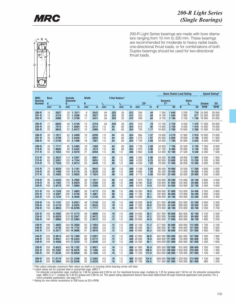
200-R Light Series(Single Bearings)
109
200-R Light Series bearings are made with bore diame-ters ranging from 10 mm to 320 mm. These bearings are recommended for moderate to heavy radial loads,one-directional thrust loads, or for combinations of both.Duplex bearings should be used for two-directional thrust loads.
MRCBearingNumber
Bore
dmm in
OutsideDiameterDmm in
Width
Bmm in
ra
mm inrb
mm inZD2
mm in
DynamicC3)
N lbf
Basic Radial Load Rating Speed Rating2)
StaticC0
N lbfGrease OilRPM RPM
200-R201-R202-R
203-R204-R205-R
206-R207-R208-R
209-R210-R211-R
212-R213-R214-R
215-R216-R217-R
218-R219-R220-R
221-R222-R224-R
226-R228-R230-R
232-R234-R236-R
238-R240-R242-R
244-R246-R248-R
250-R252-R256-R
260-R264-R
101215
172025
303540
455055
606570
758085
9095
100
105110120
130140150
160170180
190200210
220230240
250260280
300320
303235
404752
627280
8590
100
110120125
130140150
160170180
190200215
230250270
290310320
340360380
400420440
460480500
540580
91011
121415
161718
192021
222324
252628
303234
363840
404245
485252
555861
656872
768080
8592
.64
.64
.64
.641.01.0
1.01.01.0
1.01.01.5
1.51.51.5
1.52.02.0
2.02.02.0
2.02.02.0
2.52.52.5
2.53.03.0
3.03.03.0
3.03.03.0
4.04.04.0
4.04.0
284323406
510613755
8841 2701 730
1 7301 9702 860
3 2604 0304 530
5 1904 8806 170
7 8708 3909 610
10 30011 70013 000
15 50017 20020 700
24 60027 20029 000
33 10035 50040 800
43 90049 50055 500
61 90068 40072 200
80 00087 700
.30
.30
.30
.30
.60
.60
.60
.60
.60
.60
.601.0
1.01.01.0
1.01.01.0
1.01.01.0
1.01.01.0
1.01.01.0
1.01.01.0
1.01.01.0
1.01.01.0
1.51.51.5
1.51.5
7 2808 1909 750
12 10014 00016 800
19 00026 00034 500
34 50037 70054 000
59 20060 50078 000
88 40085 200
104 000
130 000138 000153 000
168 000182 000199 000
221 000238 000270 000
307 000332 000345 000
377 000390 000436 000
462 000494 000540 000
585 000624 000650 000
689 000741 000
3 2003 9005 100
6 5508 500
10 600
12 90018 60025 000
25 50030 00041 500
49 00058 50068 000
76 50073 50093 000
116 000125 000143 000
153 000170 000193 000
232 000260 000310 000
365 000400 000430 000
500 000540 000610 000
655 000735 000830 000
915 0001 020 0001 100 000
1 220 0001 340 000
24 00022 00019 000
17 00015 00012 000
10 0009 0008 500
7 5007 0006 300
6 0005 3005 000
4 8004 5004 300
3 8003 6003 400
3 2003 0002 800
2 6002 4002 200
2 1001 9001 800
1 7001 6001 600
1 5001 4001 300
1 2001 1001 100
1 100980
30 00028 00024 000
20 00018 00015 000
13 00011 00010 000
9 0008 5007 500
7 0006 3006 000
5 6005 3005 000
4 5004 3004 000
3 8003 6003 400
3 2002 9002 700
2 5002 3002 200
2 1002 0001 900
1 8001 7001 600
1 5001 4001 400
1 3001 200
.3937
.4724
.5906
.6693
.7874
.9843
1.18111.37801.5748
1.77171.96852.1654
2.36222.55912.7559
2.95283.14963.3465
3.54333.74023.9370
4.13394.33074.7244
5.11815.51185.9055
6.29926.69297.0866
7.48037.87408.2677
8.66149.05519.4488
9.842510.236211.0236
11.811012.5984
1.18111.25981.3780
1.57481.85042.0472
2.44092.83463.1496
3.34653.54333.9370
4.33074.72444.9213
5.11815.51185.9055
6.29926.69297.0866
7.48037.87408.4646
9.05519.8425
10.6299
11.417312.204712.5984
13.385814.173214.9606
15.748016.535417.3228
18.110218.897619.6850
21.259822.8346
.3543
.3937
.4331
.4724
.5512
.5906
.6299
.6693
.7087
.7480
.7874
.8268
.8661
.9055
.9449
.98431.02361.1024
1.18111.25981.3386
1.41731.49611.5748
1.57481.65351.7717
1.88982.04722.0472
2.16542.28352.4016
2.55912.67722.8346
2.99213.14963.1496
3.34653.6220
.44
.50
.63
.79
.951.17
1.371.972.68
2.683.064.43
5.066.257.03
8.047.569.56
12.213.014.9
16.018.120.2
24.026.632.1
38.242.244.9
51.355.163.3
68.076.886.1
95.9106.0112.0
124.0136.0
.012
.012
.012
.012
.024
.024
.024
.024
.024
.024
.024
.040
.040
.040
.040
.040
.040
.040
.040
.040
.040
.040
.040
.040
.040
.040
.040
.040
.040
.040
.040
.040
.040
.040
.040
.040
.060
.060
.060
.060
.060
.025
.025
.025
.025
.04
.04
.04
.04
.04
.04
.04
.06
.06
.06
.06
.06
.08
.08
.08
.08
.08
.08
.08
.08
.10
.10
.10
.10
.12
.12
.12
.12
.12
.12
.12
.12
.16
.16
.16
.16
.16
1 6401 8402 190
2 7203 1503 780
4 2705 8507 760
7 7608 480
12 100
13 30013 60017 500
19 90019 20023 400
29 20031 00034 000
37 80040 90044 700
49 60053 50060 700
69 00074 60077 600
84 80087 70098 000
104 000111 000121 000
132 000140 000146 000
155 000167 000
719877
1 150
1 4701 9102 380
2 9104 1805 620
5 7306 7409 330
11 00013 20015 300
17 20016 50020 900
26 10028 00032 100
34 40038 20043 300
52 20058 50069 700
82 10089 90096 700
112 000121 000137 000
147 000165 000187 000
206 000229 000247 000
274 000301 000
1) Fillet radius indicates maximum fillet radius on shaft or in housing which bearing corner will clear.2) Listed values are for pressed steel or polyamide cage, ABEC-1.
For phenolic composition cage, multiply by 1.66 for grease and 2.00 for oil. For machined bronze cage, multiply by 1.25 for grease and 1.50 for oil. For phenolic compositioncage, ABEC-5 or 7, multiply by 2.30 for grease and 2.80 for oil. The speed rating adjustment factors have been determined through historical application and practice. For amore complete explanation, see page 274.
3) Rating for one million revolutions or 500 hours at 33¹|₃ RPM.
Fillet Radius1)
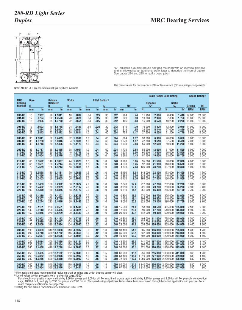
MRC Bearing Services200-RD Light SeriesDuplex
110
“D” indicates a duplex ground half pair matched with an identical half pairand is followed by an additional suffix letter to describe the type of duplexSee pages 234 and 235 for suffix description.
Note: ABEC 1 & 3 are stocked as half-pairs where available Use these values for back-to-back (DB) or face-to-face (DF) mounting arrangements
MRCBearingNumber
Bore
dmm in
OutsideDiameterDmm in
Width
Bmm in
ra
mm inrb
mm inZD2
mm in
DynamicC3)
N lbf
Basic Radial Load Rating Speed Rating2)
StaticC0
N lbfGrease OilRPM RPM
200-RD201-RD202-RD
203-RD204-RD205-RD
206-RD207-RD208-RD
209-RD210-RD211-RD
212-RD213-RD214-RD
215-RD216-RD217-RD
218-RD219-RD220-RD
221-RD222-RD224-RD
226-RD228-RD230-RD
232-RD234-RD236-RD
238-RD240-RD242-RD
244-RD246-RD248-RD
250-RD252-RD256-RD
260-RD264-RD
101215
172025
303540
455055
606570
758085
9095
100
105110120
130140150
160170180
190200210
220230240
250260280
300320
303235
404752
627280
8590
100
110120125
130140150
160170180
190200215
230250270
290310320
340360380
400420440
460480500
540580
182022
242830
323436
384042
444648
505256
606468
727680
808490
96104104
110116122
130136144
152160160
170184
.64
.64
.64
.641.01.0
1.01.01.0
1.01.01.5
1.51.51.5
1.52.02.0
2.02.02.0
2.02.02.0
2.52.52.5
2.53.03.0
3.03.03.0
3.03.03.0
4.04.04.0
4.04.0
284323406
510613755
8841 2701 730
1 7301 9702 860
3 2604 0304 530
5 1904 8806 170
7 8708 3909 610
10 30011 70013 000
15 50017 20020 700
24 60027 20029 000
33 10035 50040 800
43 90049 50055 500
61 90068 40072 200
80 00087 700
.30
.30
.30
.30
.60
.60
.60
.60
.60
.60
.601.0
1.01.01.0
1.01.01.0
1.01.01.0
1.01.01.0
1.01.01.0
1.01.01.0
1.01.01.0
1.01.01.0
1.51.51.5
1.51.5
11 90013 30015 900
19 90022 90027 600
30 70042 30055 900
55 90060 50087 100
95 60097 500
125 000
143 000138 000168 000
212 000221 000251 000
270 000296 000325 000
358 000390 000442 000
494 000527 000559 000
605 000637 000702 000
741 000806 000871 000
956 0001 010 0001 060 000
1 140 0001 210 000
6 4007 800
10 200
13 20017 00021 200
26 00037 50050 000
51 00060 00083 000
98 000118 000137 000
153 000140 000186 000
232 000250 000285 000
305 000340 000390 000
465 000510 000620 000
735 000800 000865 000
1 000 0001 080 0001 220 000
1 320 0001 500 0001 660 000
1 830 0002 040 0002 200 000
2 400 0002 700 000
19 00018 00015 000
14 00012 0009 600
8 0007 2006 800
6 0005 6005 000
4 8004 2004 000
3 8003 6003 400
3 0002 9002 700
2 6002 4002 200
2 1001 9001 800
1 7001 5001 400
1 4001 3001 300
1 2001 1001 000
960880880
880780
24 00022 00019 000
16 00014 00012 000
10 0008 8008 000
7 2006 8006 000
5 6005 0004 800
4 5004 2004 000
3 6003 4003 200
3 0002 9002 700
2 6002 3002 200
2 0001 8001 800
1 7001 6001 500
1 4001 4001 300
1 2001 1001 100
1 000960
.3937
.4724
.5906
.6693
.7874
.9843
1.18111.37801.5748
1.77171.96852.1654
2.36222.55912.7559
2.95283.14963.3465
3.54333.74023.9370
4.13394.33074.7244
5.11815.51185.9055
6.29926.69297.0866
7.48037.87408.2677
8.66149.05519.4488
9.842510.236211.0236
11.811012.5984
1.18111.25981.3780
1.57481.85042.0472
2.44092.83463.1496
3.34653.54333.9370
4.33074.72444.9213
5.11815.51185.9055
6.29926.69297.0866
7.48037.87408.4646
9.05519.8425
10.6299
11.417312.204712.5984
13.385814.173214.9606
15.748016.535417.3228
18.110218.897619.6850
21.259822.8346
.7087
.7874
.8661
.94491.10241.1811
1.25981.33861.4173
1.49611.57481.6535
1.73231.81101.8898
1.96852.04722.2047
2.36222.51972.6772
2.83462.99213.1496
3.14963.30713.5433
3.77954.09454.0945
4.33074.56694.8031
5.11815.35435.6693
5.98436.29926.2992
6.69297.2441
.44
.50
.63
.79
.951.17
1.371.972.68
2.683.064.43
5.066.257.03
8.047.569.56
12.213.014.9
16.018.120.2
24.026.632.1
38.242.244.9
51.355.163.3
68.076.886.1
95.9106.0112.0
124.0136.0
.012
.012
.012
.012
.024
.024
.024
.024
.024
.024
.024
.040
.040
.040
.040
.040
.040
.040
.040
.040
.040
.040
.040
.040
.040
.040
.040
.040
.040
.040
.040
.040
.040
.040
.040
.040
.060
.060
.060
.060
.060
.025
.025
.025
.025
.04
.04
.04
.04
.04
.04
.04
.06
.06
.06
.06
.06
.08
.08
.08
.08
.08
.08
.08
.08
.10
.10
.10
.10
.12
.12
.12
.12
.12
.12
.12
.12
.16
.16
.16
.16
.16
2 6802 9903 570
4 4705 1406 200
6 9009 510
12 600
12 60013 60019 600
21 50021 90028 200
32 10031 00037 800
47 70049 70056 400
60 70066 50073 100
80 50087 70099 400
111 000118 000126 000
136 000143 000158 000
167 000181 000196 000
215 000227 000238 000
256 000272 000
1 4401 7502 290
2 9703 8204 770
5 8508 430
11 200
11 50013 50018 700
22 00026 50030 800
34 40031 50041 800
52 20056 20064 100
68 60076 40087 700
105 000115 000139 000
165 000180 000194 000
225 000243 000274 000
297 000337 000373 000
411 000459 000495 000
540 000607 000
1) Fillet radius indicates maximum fillet radius on shaft or in housing which bearing corner will clear.2) Listed values are for pressed steel or polyamide cage, ABEC-1.
For phenolic composition cage, multiply by 1.66 for grease and 2.00 for oil. For machined bronze cage, multiply by 1.25 for grease and 1.50 for oil. For phenolic compositioncage, ABEC-5 or 7, multiply by 2.30 for grease and 2.80 for oil. The speed rating adjustment factors have been determined through historical application and practice. For amore complete explanation, see page 274.
3) Rating for one million revolutions or 500 hours at 33¹|₃ RPM.
Fillet Radius1)
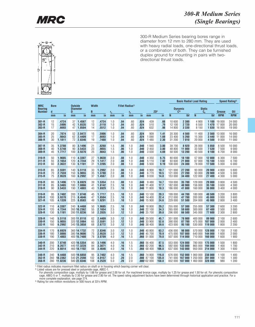
300-R Medium Series(Single Bearings)
111
300-R Medium Series bearing bores range indiameter from 12 mm to 280 mm. They are used with heavy radial loads, one-directional thrust loads,or a combination of both. They can be furnishedduplex ground for mounting in pairs with two-directional thrust loads.
MRCBearingNumber
Bore
dmm in
OutsideDiameterDmm in
Width
Bmm in
ra
mm inrb
mm inZD2
mm in
DynamicC3)
N lbf
Basic Radial Load Rating Speed Rating2)
StaticC0
N lbfGrease OilRPM RPM
301-R302-R303-R
304-R305-R306-R
307-R308-R309-R
310-R311-R312-R
313-R314-R315-R
316-R317-R318-R
319-R320-R321-R
322-R324-R326-R
328-R330-R332-R
334-R336-R338-R
340-R342-R344-R
348-R352-R356-R
121517
202530
354045
505560
657075
808590
95100105
110120130
140150160
170180190
200210220
240260280
374247
526272
8090
100
110120130
140150160
170180190
200215225
240260280
300320340
360380400
420440460
500540580
121314
151719
212325
272931
333537
394143
454749
505558
626568
727578
808488
95102108
1.01.01.0
1.01.01.0
1.51.51.5
2.02.02.0
2.02.02.0
2.02.52.5
2.52.52.5
2.52.53.0
3.03.03.0
3.03.04.0
4.04.04.0
4.05.05.0
439510632
9091 0901 480
1 9402 4503 030
4 3505 1105 930
6 9006 7709 030
9 48011 40011 800
13 10014 40015 900
18 80022 10025 700
29 50033 90038 400
40 80045 70051 000
56 40062 20068 400
74 80087 100
102 000
.60
.60
.60
.60
.60
.60
1.01.01.0
1.01.01.0
1.01.01.0
1.01.01.0
1.01.01.0
1.01.01.0
1.01.01.0
1.01.01.5
1.51.51.5
1.52.02.0
10 60012 10014 800
20 30023 40031 200
39 70048 80058 500
80 60093 600
108 000
121 000121 000153 000
159 000182 000186 000
199 000212 000229 000
255 000265 000296 000
351 000390 000423 000
436 000475 000507 000
553 000592 000637 000
676 000741 000832 000
4 9006 5508 150
11 40015 30020 000
26 00033 50040 500
57 00067 00078 000
93 00093 000
122 000
129 000156 000160 000
180 000200 000204 000
255 000300 000345 000
400 000475 000530 000
570 000640 000710 000
780 000865 000950 000
1 060 0001 250 0001 460 000
19 00017 00016 000
13 00011 0009 000
8 5007 5006 700
6 3005 6005 000
4 8004 5004 300
3 8003 6003 400
3 2003 0002 800
2 6002 5002 300
2 1002 0001 800
1 7001 6001 600
1 5001 4001 300
1 1001 100
980
24 00020 00019 000
16 00014 00011 000
10 0009 0008 000
7 5006 7006 000
5 6005 3005 000
4 5004 3004 000
3 8003 6003 400
3 2003 0002 800
2 6002 4002 200
2 1002 0001 900
1 8001 7001 600
1 4001 3001 200
.4724
.5906
.6693
.7874
.98431.1811
1.37801.57481.7717
1.96852.16542.3622
2.55912.75592.9528
3.14963.34653.5433
3.74023.93704.1339
4.33074.72445.1181
5.51185.90556.2992
6.69297.08667.4803
7.87408.26778.6614
9.448810.236211.0236
1.45671.65351.8504
2.04722.44092.8346
3.14963.54333.9370
4.33074.72445.1181
5.51185.90556.2992
6.69297.08667.4803
7.87408.46468.8583
9.448810.236211.0236
11.811012.598413.3858
14.173214.960615.7480
16.535417.322818.1102
19.685021.259822.8346
.4724
.5118
.5512
.5906
.6693
.7480
.8268
.9055
.9843
1.06301.14171.2205
1.29921.37801.4567
1.53541.61421.6929
1.77171.85041.9291
1.96852.16542.2835
2.44092.55912.6772
2.83462.95283.0709
3.14963.30713.4646
3.74024.01574.2520
.68
.79
.98
1.411.692.30
3.003.804.69
6.757.929.19
10.710.514.0
14.717.718.3
20.322.424.6
29.234.339.8
45.752.659.6
63.270.979.0
87.596.5
106.0
116.0135.0158.0
.024
.024
.024
.024
.024
.024
.040
.040
.040
.040
.040
.040
.040
.040
.040
.040
.040
.040
.040
.040
.040
.040
.040
.040
.040
.040
.040
.040
.040
.060
.060
.060
.060
.060
.080
.080
.04
.04
.04
.04
.04
.04
.06
.06
.06
.08
.08
.08
.08
.08
.08
.08
.10
.10
.10
.10
.10
.10
.10
.12
.12
.12
.12
.12
.12
.16
.16
.16
.16
.16
.20
.20
2 3802 7203 330
4 5605 2607 010
8 92011 00013 200
18 10021 00024 300
27 20027 20034 400
35 70040 90041 800
44 70047 70051 500
57 30059 60066 500
78 90087 70095 100
98 000107 000114 000
124 000133 000143 000
152 000167 000187 000
1 1001 4701 830
2 5603 4404 500
5 8507 5309 100
12 80015 10017 500
20 90020 90027 400
29 00035 10036 000
40 50045 00045 900
57 30067 40077 600
89 900107 000119 000
128 000144 000160 000
175 000194 000214 000
238 000281 000328 000
1) Fillet radius indicates maximum fillet radius on shaft or in housing which bearing corner will clear.2) Listed values are for pressed steel or polyamide cage, ABEC-1.
For phenolic composition cage, multiply by 1.66 for grease and 2.00 for oil. For machined bronze cage, multiply by 1.25 for grease and 1.50 for oil. For phenolic compositioncage, ABEC-5 or 7, multiply by 2.30 for grease and 2.80 for oil. The speed rating adjustment factors have been determined through historical application and practice. For amore complete explanation, see page 274.
3) Rating for one million revolutions or 500 hours at 33¹|₃ RPM.
Fillet Radius1)
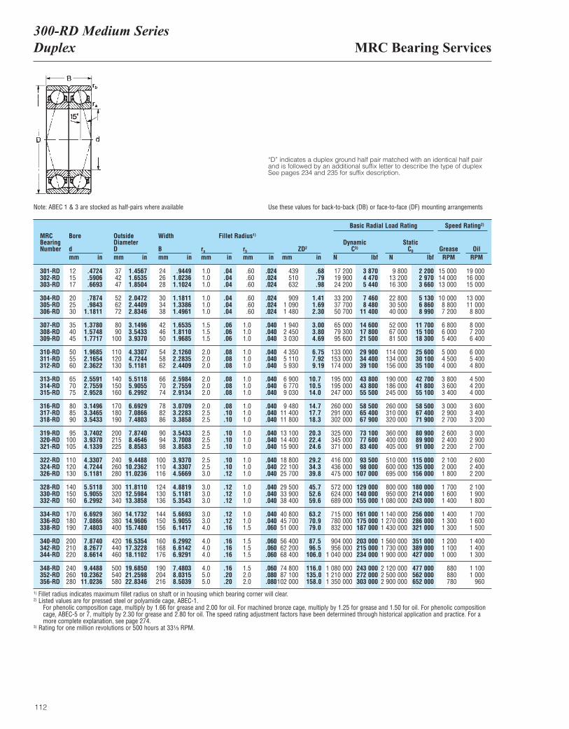
MRC Bearing Services300-RD Medium SeriesDuplex
112
“D” indicates a duplex ground half pair matched with an identical half pairand is followed by an additional suffix letter to describe the type of duplexSee pages 234 and 235 for suffix description.
Note: ABEC 1 & 3 are stocked as half-pairs where available Use these values for back-to-back (DB) or face-to-face (DF) mounting arrangements
MRCBearingNumber
Bore
dmm in
OutsideDiameterDmm in
Width
Bmm in
ra
mm inrb
mm inZD2
mm in
DynamicC3)
N lbf
Basic Radial Load Rating Speed Rating2)
StaticC0
N lbfGrease OilRPM RPM
301-RD302-RD303-RD
304-RD305-RD306-RD
307-RD308-RD309-RD
310-RD311-RD312-RD
313-RD314-RD315-RD
316-RD317-RD318-RD
319-RD320-RD321-RD
322-RD324-RD326-RD
328-RD330-RD332-RD
334-RD336-RD338-RD
340-RD342-RD344-RD
348-RD352-RD356-RD
121517
202530
354045
505560
657075
808590
95100105
110120130
140150160
170180190
200210220
240260280
374247
526272
8090
100
110120130
140150160
170180190
200215225
240260280
300320340
360380400
420440460
500540580
242628
303438
424650
545862
667074
788286
909498
100110116
124130136
144150156
160168176
190204216
1.01.01.0
1.01.01.0
1.51.51.5
2.02.02.0
2.02.02.0
2.02.52.5
2.52.52.5
2.52.53.0
3.03.03.0
3.03.04.0
4.04.04.0
4.05.05.0
439510632
9091 0901 480
1 9402 4503 030
4 3505 1105 930
6 9006 7709 030
9 48011 40011 800
13 10014 40015 900
18 80022 10025 700
29 50033 90038 400
40 80045 70051 000
56 40062 20068 400
74 80087 100
102 000
.60
.60
.60
.60
.60
.60
1.01.01.0
1.01.01.0
1.01.01.0
1.01.01.0
1.01.01.0
1.01.01.0
1.01.01.0
1.01.01.5
1.51.51.5
1.52.02.0
17 20019 90024 200
33 20037 70050 700
65 00079 30095 600
133 000153 000174 000
195 000195 000247 000
260 000291 000302 000
325 000345 000371 000
416 000436 000475 000
572 000624 000689 000
715 000780 000832 000
904 000956 000
1 040 000
1 080 0001 210 0001 350 000
9 80013 20016 300
22 80030 50040 000
52 00067 00081 500
114 000134 000156 000
190 000186 000245 000
260 000310 000320 000
360 000400 000405 000
510 000600 000695 000
800 000950 000
1 080 000
1 140 0001 270 0001 430 000
1 560 0001 730 0001 900 000
2 120 0002 500 0002 900 000
15 00014 00013 000
10 0008 8007 200
6 8006 0005 400
5 0004 5004 000
3 8003 6003 400
3 0002 9002 700
2 6002 4002 200
2 1002 0001 800
1 7001 6001 400
1 4001 3001 300
1 2001 1001 000
880880780
19 00016 00015 000
13 00011 0008 800
8 0007 2006 400
6 0005 4004 800
4 5004 2004 000
3 6003 4003 200
3 0002 9002 700
2 6002 4002 200
2 1001 9001 800
1 7001 6001 500
1 4001 4001 300
1 1001 000
960
.4724
.5906
.6693
.7874
.98431.1811
1.37801.57481.7717
1.96852.16542.3622
2.55912.75592.9528
3.14963.34653.5433
3.74023.93704.1339
4.33074.72445.1181
5.51185.90556.2992
6.69297.08667.4803
7.87408.26778.6614
9.448810.236211.0236
1.45671.65351.8504
2.04722.44092.8346
3.14963.54333.9370
4.33074.72445.1181
5.51185.90556.2992
6.69297.08667.4803
7.87408.46468.8583
9.448810.236211.0236
11.811012.598413.3858
14.173214.960615.7480
16.535417.322818.1102
19.685021.259822.8346
.94491.02361.1024
1.18111.33861.4961
1.65351.81101.9685
2.12602.28352.4409
2.59842.75592.9134
3.07093.22833.3858
3.54333.70083.8583
3.93704.33074.5669
4.88195.11815.3543
5.66935.90556.1417
6.29926.61426.9291
7.48038.03158.5039
.68
.79
.98
1.411.692.30
3.003.804.69
6.757.929.19
10.710.514.0
14.717.718.3
20.322.424.6
29.234.339.8
45.752.659.6
63.270.979.0
87.596.5
106.0
116.0135.0158.0
.024
.024
.024
.024
.024
.024
.040
.040
.040
.040
.040
.040
.040
.040
.040
.040
.040
.040
.040
.040
.040
.040
.040
.040
.040
.040
.040
.040
.040
.060
.060
.060
.060
.060
.080
.080
.04
.04
.04
.04
.04
.04
.06
.06
.06
.08
.08
.08
.08
.08
.08
.08
.10
.10
.10
.10
.10
.10
.10
.12
.12
.12
.12
.12
.12
.16
.16
.16
.16
.16
.20
.20
3 8704 4705 440
7 4608 480
11 400
14 60017 80021 500
29 90034 40039 100
43 80043 80055 500
58 50065 40067 900
73 10077 60083 400
93 50098 000
107 000
129 000140 000155 000
161 000175 000187 000
203 000215 000234 000
243 000272 000303 000
2 2002 9703 660
5 1306 8608 990
11 70015 10018 300
25 60030 10035 100
42 70041 80055 100
58 50067 40071 900
80 90089 90091 000
115 000135 000156 000
180 000214 000243 000
256 000286 000321 000
351 000389 000427 000
477 000562 000652 000
1) Fillet radius indicates maximum fillet radius on shaft or in housing which bearing corner will clear.2) Listed values are for pressed steel or polyamide cage, ABEC-1.
For phenolic composition cage, multiply by 1.66 for grease and 2.00 for oil. For machined bronze cage, multiply by 1.25 for grease and 1.50 for oil. For phenolic compositioncage, ABEC-5 or 7, multiply by 2.30 for grease and 2.80 for oil. The speed rating adjustment factors have been determined through historical application and practice. For amore complete explanation, see page 274.
3) Rating for one million revolutions or 500 hours at 33¹|₃ RPM.
Fillet Radius1)
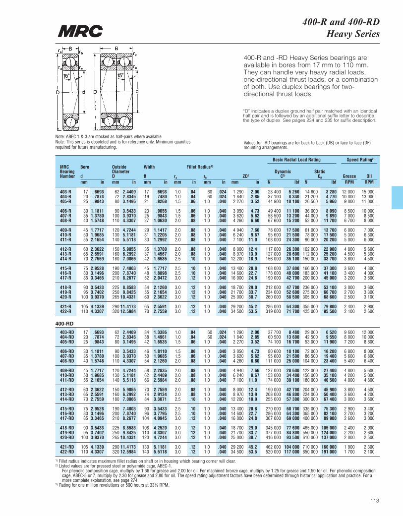
400-R and 400-RDHeavy Series
113
400-R and -RD Heavy Series bearings areavailable in bores from 17 mm to 110 mm. They can handle very heavy radial loads, one-directional thrust loads, or a combination of both. Use duplex bearings for two-directional thrust loads.
Note: ABEC 1 & 3 are stocked as half-pairs where available Note: This series is obsoleted and is for reference only. Minimum quanitiesrequired for future manufacturing.
MRCBearingNumber
Bore
dmm in
OutsideDiameterDmm in
Width
Bmm in
ra
mm inrb
mm inZD2
mm in
DynamicC3)
N lbf
Basic Radial Load Rating Speed Rating2)
StaticC0
N lbfGrease OilRPM RPM
403-RD 17 .6693 62 2.4409 34 1.3386 1.0 .04 .60 .024 1 290 2.00 37 700 8 480 29 000 6 520 9 600 12 000404-RD 20 .7874 72 2.8346 38 1.4961 1.0 .04 .60 .024 1 840 2.85 60 500 13 600 42 500 9 550 8 000 10 000405-RD 25 .9843 80 3.1496 42 1.6535 1.5 .06 1.0 .040 2 270 3.52 74 100 16 700 53 000 11 900 7 200 8 800
406-RD 30 1.1811 90 3.5433 46 1.8110 1.5 .06 1.0 .040 3 050 4.73 80 600 18 100 72 000 16 200 6 800 8 000407-RD 35 1.3780 100 3.9370 50 1.9685 1.5 .06 1.0 .040 3 620 5.62 95 600 21 500 86 500 19 400 5 600 6 800408-RD 40 1.5748 110 4.3307 54 2.1260 2.0 .08 1.0 .040 4 260 6.60 111 000 25 000 104 000 23 400 5 400 6 400
409-RD 45 1.7717 120 4.7244 58 2.2835 2.0 .08 1.0 .040 4 940 7.66 127 000 28 600 122 000 27 400 4 800 5 600410-RD 50 1.9685 130 5.1181 62 2.4409 2.0 .08 1.0 .040 6 240 9.67 153 000 34 400 156 000 35 100 4 200 5 000411-RD 55 2.1654 140 5.5118 66 2.5984 2.0 .08 1.0 .040 7 100 11.0 174 000 39 100 180 000 40 500 4 000 4 800
412-RD 60 2.3622 150 5.9055 70 2.7559 2.0 .08 1.0 .040 8 000 12.4 190 000 42 700 204 000 45 900 3 800 4 500413-RD 65 2.5591 160 6.2992 74 2.9134 2.0 .08 1.0 .040 8 970 13.9 208 000 46 800 224 000 50 400 3 600 4 200414-RD 70 2.7559 180 7.0866 84 3.3071 2.5 .10 1.0 .040 12 200 18.9 255 000 57 300 300 000 67 400 3 000 3 600
415-RD 75 2.9528 190 7.4803 90 3.5433 2.5 .10 1.0 .040 13 400 20.8 270 000 60 700 335 000 75 300 2 900 3 400416-RD 80 3.1496 200 7.8740 96 3.7795 2.5 .10 1.0 .040 14 600 22.7 286 000 64 300 365 000 82 100 2 700 3 200417-RD 85 3.3465 210 8.2677 104 4.0945 3.0 .12 1.0 .040 16 000 24.8 307 000 69 000 400 000 89 900 2 600 3 000
418-RD 90 3.5433 225 8.8583 108 4.2520 3.0 .12 1.0 .040 18 700 29.0 345 000 77 600 465 000 105 000 2 400 2 900419-RD 95 3.7402 250 9.8425 110 4.3307 3.0 .12 1.0 .040 21 700 33.7 377 000 84 800 550 000 124 000 2 200 2 600420-RD 100 3.9370 265 10.4331 120 4.7244 3.0 .12 1.0 .040 25 000 38.7 416 000 93 500 610 000 137 000 2 000 2 500
421-RD 105 4.1339 290 11.4173 130 5.1181 3.0 .12 1.0 .040 29 200 45.2 462 000 104 000 710 000 160 000 1 900 2 300422-RD 110 4.3307 320 12.5984 140 5.5118 3.0 .12 1.0 .040 34 500 53.5 520 000 117 000 850 000 191 000 1 700 2 100
1) Fillet radius indicates maximum fillet radius on shaft or in housing which bearing corner will clear.2) Listed values are for pressed steel or polyamide cage, ABEC-1.
For phenolic composition cage, multiply by 1.66 for grease and 2.00 for oil. For machined bronze cage, multiply by 1.25 for grease and 1.50 for oil. For phenolic compositioncage, ABEC-5 or 7, multiply by 2.30 for grease and 2.80 for oil. The speed rating adjustment factors have been determined through historical application and practice. For amore complete explanation, see page 274.
3) Rating for one million revolutions or 500 hours at 33¹|₃ RPM.
Fillet Radius1)
403-R 17 .6693 62 2.4409 17 .6693 1.0 .04 .60 .024 1 290 2.00 23 400 5 260 14 600 3 280 12 000 15 000404-R 20 .7874 72 2.8346 19 .7480 1.0 .04 .60 .024 1 840 2.85 37 100 8 340 21 200 4 770 10 000 13 000405-R 25 .9843 80 3.1496 21 .8268 1.5 .06 1.0 .040 2 270 3.52 44 900 10 100 26 500 5 960 9 000 11 000
406-R 30 1.1811 90 3.5433 23 .9055 1.5 .06 1.0 .040 3 050 4.73 49 400 11 100 36 000 8 090 8 500 10 000407-R 35 1.3780 100 3.9370 25 .9843 1.5 .06 1.0 .040 3 620 5.62 58 500 13 200 44 000 9 890 7 000 8 500408-R 40 1.5748 110 4.3307 27 1.0630 2.0 .08 1.0 .040 4 260 6.60 67 600 15 200 52 000 11 700 6 700 8 000
409-R 45 1.7717 120 4.7244 29 1.1417 2.0 .08 1.0 .040 4 940 7.66 78 000 17 500 61 000 13 700 6 000 7 000410-R 50 1.9685 130 5.1181 31 1.2205 2.0 .08 1.0 .040 6 240 9.67 95 600 21 500 78 000 17 500 5 300 6 300411-R 55 2.1654 140 5.5118 33 1.2992 2.0 .08 1.0 .040 7 100 11.0 108 000 24 300 90 000 20 200 5 000 6 000
412-R 60 2.3622 150 5.9055 35 1.3780 2.0 .08 1.0 .040 8 000 12.4 117 000 26 300 102 000 22 900 4 800 5 600413-R 65 2.5591 160 6.2992 37 1.4567 2.0 .08 1.0 .040 8 970 13.9 127 000 28 600 112 000 25 200 4 500 5 300414-R 70 2.7559 180 7.0866 42 1.6535 2.5 .10 1.0 .040 12 200 18.9 156 000 35 100 150 000 33 700 3 800 4 500
415-R 75 2.9528 190 7.4803 45 1.7717 2.5 .10 1.0 .040 13 400 20.8 168 000 37 800 166 000 37 300 3 600 4 300416-R 80 3.1496 200 7.8740 48 1.8898 2.5 .10 1.0 .040 14 600 22.7 178 000 40 000 183 000 41 100 3 400 4 000417-R 85 3.3465 210 8.2677 52 2.0472 3.0 .12 1.0 .040 16 000 24.8 190 000 42 700 200 000 45 000 3 200 3 800
418-R 90 3.5433 225 8.8583 54 2.1260 3.0 .12 1.0 .040 18 700 29.0 212 000 47 700 236 000 53 100 3 000 3 600419-R 95 3.7402 250 9.8425 55 2.1654 3.0 .12 1.0 .040 21 700 33.7 234 000 52 600 275 000 60 700 2 700 3 300420-R 100 3.9370 265 10.4331 60 2.3622 3.0 .12 1.0 .040 25 000 38.7 260 000 58 500 305 000 68 600 2 500 3 100
421-R 105 4.1339 290 11.4173 65 2.5591 3.0 .12 1.0 .040 29 200 45.2 286 000 64 300 355 000 79 800 2 400 2 900422-R 110 4.3307 320 12.5984 70 2.7559 3.0 .12 1.0 .040 34 500 53.5 319 000 71 700 425 000 95 500 2 100 2 600
400-RD
“D” indicates a duplex ground half pair matched with an identicalhalf pair and is followed by an additional suffix letter to describethe type of duplex See pages 234 and 235 for suffix description.
Values for -RD bearings are for back-to-back (DB) or face-to-face (DF)mounting arrangements.
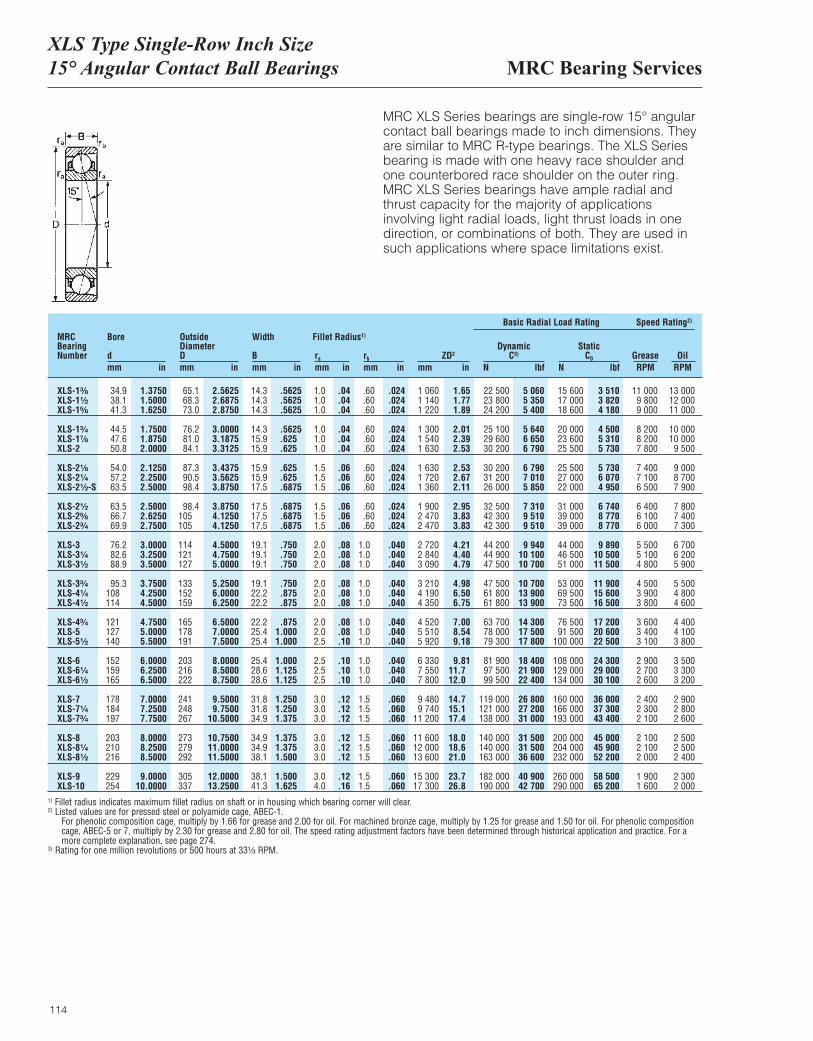
MRC Bearing ServicesXLS Type Single-Row Inch Size15° Angular Contact Ball Bearings
114
MRC XLS Series bearings are single-row 15° angularcontact ball bearings made to inch dimensions. Theyare similar to MRC R-type bearings. The XLS Seriesbearing is made with one heavy race shoulder and one counterbored race shoulder on the outer ring. MRC XLS Series bearings have ample radial and thrust capacity for the majority of applications involving light radial loads, light thrust loads in onedirection, or combinations of both. They are used insuch applications where space limitations exist.
MRCBearingNumber
Bore
dmm in
OutsideDiameterDmm in
Width
Bmm in
ra
mm inrb
mm inZD2
mm in
DynamicC3)
N lbf
Basic Radial Load Rating Speed Rating2)
StaticC0
N lbfGrease OilRPM RPM
Fillet Radius1)
XLS-1³|₈ 34.9 1.3750 65.1 2.5625 14.3 .5625 1.0 .04 .60 .024 1 060 1.65 22 500 5 060 15 600 3 510 11 000 13 000XLS-1¹|₂ 38.1 1.5000 68.3 2.6875 14.3 .5625 1.0 .04 .60 .024 1 140 1.77 23 800 5 350 17 000 3 820 9 800 12 000XLS-1⁵|₈ 41.3 1.6250 73.0 2.8750 14.3 .5625 1.0 .04 .60 .024 1 220 1.89 24 200 5 400 18 600 4 180 9 000 11 000
XLS-1³|₄ 44.5 1.7500 76.2 3.0000 14.3 .5625 1.0 .04 .60 .024 1 300 2.01 25 100 5 640 20 000 4 500 8 200 10 000XLS-1⁷|₈ 47.6 1.8750 81.0 3.1875 15.9 .625 1.0 .04 .60 .024 1 540 2.39 29 600 6 650 23 600 5 310 8 200 10 000XLS-2 50.8 2.0000 84.1 3.3125 15.9 .625 1.0 .04 .60 .024 1 630 2.53 30 200 6 790 25 500 5 730 7 800 9 500
XLS-2¹|₈ 54.0 2.1250 87.3 3.4375 15.9 .625 1.5 .06 .60 .024 1 630 2.53 30 200 6 790 25 500 5 730 7 400 9 000XLS-2¹|₄ 57.2 2.2500 90.5 3.5625 15.9 .625 1.5 .06 .60 .024 1 720 2.67 31 200 7 010 27 000 6 070 7 100 8 700XLS-2¹|₂-S 63.5 2.5000 98.4 3.8750 17.5 .6875 1.5 .06 .60 .024 1 360 2.11 26 000 5 850 22 000 4 950 6 500 7 900
XLS-2¹|₂ 63.5 2.5000 98.4 3.8750 17.5 .6875 1.5 .06 .60 .024 1 900 2.95 32 500 7 310 31 000 6 740 6 400 7 800XLS-2⁵|₈ 66.7 2.6250 105 4.1250 17.5 .6875 1.5 .06 .60 .024 2 470 3.83 42 300 9 510 39 000 8 770 6 100 7 400XLS-2³|₄ 69.9 2.7500 105 4.1250 17.5 .6875 1.5 .06 .60 .024 2 470 3.83 42 300 9 510 39 000 8 770 6 000 7 300
XLS-3 76.2 3.0000 114 4.5000 19.1 .750 2.0 .08 1.0 .040 2 720 4.21 44 200 9 940 44 000 9 890 5 500 6 700XLS-3¹|₄ 82.6 3.2500 121 4.7500 19.1 .750 2.0 .08 1.0 .040 2 840 4.40 44 900 10 100 46 500 10 500 5 100 6 200XLS-3¹|₂ 88.9 3.5000 127 5.0000 19.1 .750 2.0 .08 1.0 .040 3 090 4.79 47 500 10 700 51 000 11 500 4 800 5 900
XLS-3³|₄ 95.3 3.7500 133 5.2500 19.1 .750 2.0 .08 1.0 .040 3 210 4.98 47 500 10 700 53 000 11 900 4 500 5 500XLS-4¹|₄ 108 4.2500 152 6.0000 22.2 .875 2.0 .08 1.0 .040 4 190 6.50 61 800 13 900 69 500 15 600 3 900 4 800XLS-4¹|₂ 114 4.5000 159 6.2500 22.2 .875 2.0 .08 1.0 .040 4 350 6.75 61 800 13 900 73 500 16 500 3 800 4 600
XLS-4³|₄ 121 4.7500 165 6.5000 22.2 .875 2.0 .08 1.0 .040 4 520 7.00 63 700 14 300 76 500 17 200 3 600 4 400XLS-5 127 5.0000 178 7.0000 25.4 1.000 2.0 .08 1.0 .040 5 510 8.54 78 000 17 500 91 500 20 600 3 400 4 100XLS-5¹|₂ 140 5.5000 191 7.5000 25.4 1.000 2.5 .10 1.0 .040 5 920 9.18 79 300 17 800 100 000 22 500 3 100 3 800
XLS-6 152 6.0000 203 8.0000 25.4 1.000 2.5 .10 1.0 .040 6 330 9.81 81 900 18 400 108 000 24 300 2 900 3 500XLS-6¹|₄ 159 6.2500 216 8.5000 28.6 1.125 2.5 .10 1.0 .040 7 550 11.7 97 500 21 900 129 000 29 000 2 700 3 300XLS-6¹|₂ 165 6.5000 222 8.7500 28.6 1.125 2.5 .10 1.0 .040 7 800 12.0 99 500 22 400 134 000 30 100 2 600 3 200
XLS-7 178 7.0000 241 9.5000 31.8 1.250 3.0 .12 1.5 .060 9 480 14.7 119 000 26 800 160 000 36 000 2 400 2 900XLS-7¹|₄ 184 7.2500 248 9.7500 31.8 1.250 3.0 .12 1.5 .060 9 740 15.1 121 000 27 200 166 000 37 300 2 300 2 800XLS-7³|₄ 197 7.7500 267 10.5000 34.9 1.375 3.0 .12 1.5 .060 11 200 17.4 138 000 31 000 193 000 43 400 2 100 2 600
XLS-8 203 8.0000 273 10.7500 34.9 1.375 3.0 .12 1.5 .060 11 600 18.0 140 000 31 500 200 000 45 000 2 100 2 500XLS-8¹|₄ 210 8.2500 279 11.0000 34.9 1.375 3.0 .12 1.5 .060 12 000 18.6 140 000 31 500 204 000 45 900 2 100 2 500XLS-8¹|₂ 216 8.5000 292 11.5000 38.1 1.500 3.0 .12 1.5 .060 13 600 21.0 163 000 36 600 232 000 52 200 2 000 2 400
XLS-9 229 9.0000 305 12.0000 38.1 1.500 3.0 .12 1.5 .060 15 300 23.7 182 000 40 900 260 000 58 500 1 900 2 300XLS-10 254 10.0000 337 13.2500 41.3 1.625 4.0 .16 1.5 .060 17 300 26.8 190 000 42 700 290 000 65 200 1 600 2 000
1) Fillet radius indicates maximum fillet radius on shaft or in housing which bearing corner will clear.2) Listed values are for pressed steel or polyamide cage, ABEC-1.
For phenolic composition cage, multiply by 1.66 for grease and 2.00 for oil. For machined bronze cage, multiply by 1.25 for grease and 1.50 for oil. For phenolic compositioncage, ABEC-5 or 7, multiply by 2.30 for grease and 2.80 for oil. The speed rating adjustment factors have been determined through historical application and practice. For amore complete explanation, see page 274.
3) Rating for one million revolutions or 500 hours at 33¹|₃ RPM.

115
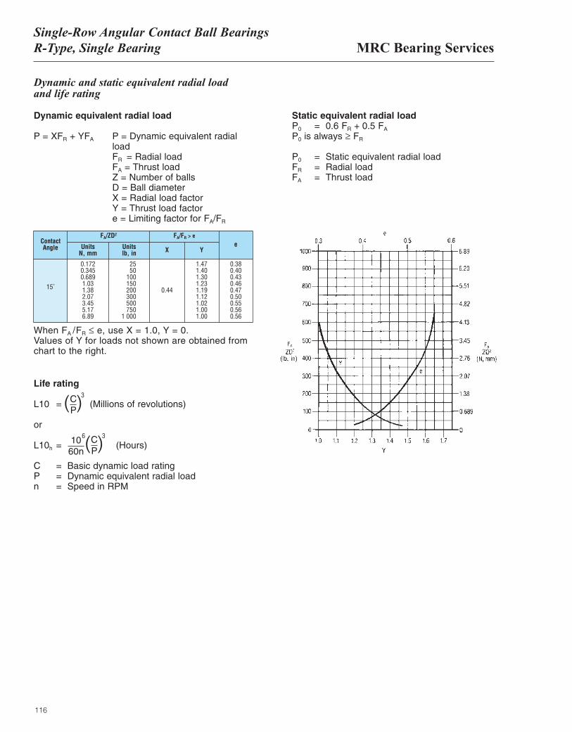
MRC Bearing ServicesSingle-Row Angular Contact Ball BearingsR-Type, Single Bearing
116
ContactAngle
FA/ZD2
UnitsN, mm
Unitslb, in
FA/FR > e
X Ye
15˚
0.1720.3450.6891.031.382.073.455.176.89
2550
100150200300500750
1,000
0.44
1.471.401.301.231.191.121.021.001.00
0.380.400.430.460.470.500.550.560.56
When FA /FR ≤ e, use X = 1.0, Y = 0.Values of Y for loads not shown are obtained fromchart to the right.
Dynamic and static equivalent radial loadand life rating
Dynamic equivalent radial load
P = XFR + YFA P = Dynamic equivalent radial loadFR = Radial loadFA = Thrust loadZ = Number of ballsD = Ball diameterX = Radial load factorY = Thrust load factore = Limiting factor for FA/FR
Life rating
L10 = (Millions of revolutions)
or
L10h = (Hours)
C = Basic dynamic load ratingP = Dynamic equivalent radial loadn = Speed in RPM
Static equivalent radial loadP0 = 0.6 FR + 0.5 FA
P0 is always ≥ FR
P0 = Static equivalent radial loadFR = Radial loadFA = Thrust load
( )CP
3
( )CP
1060n
36
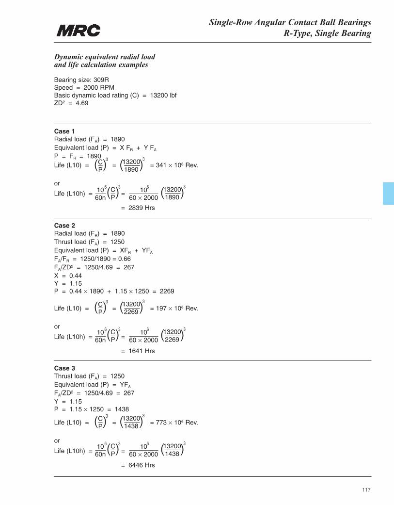
Single-Row Angular Contact Ball BearingsR-Type, Single Bearing
117
Life (L10) = = = 773 × 106 Rev.
or
Life (L10h) = =
= 6446 Hrs
Life (L10) = = = 197 × 106 Rev.
or
Life (L10h) = =
= 1641 Hrs
Dynamic equivalent radial load and life calculation examples
Bearing size: 309RSpeed = 2000 RPMBasic dynamic load rating (C) = 13200 lbfZD2 = 4.69
Case 1Radial load (FR) = 1890Equivalent load (P) = X FR + Y FA
P = FR = 1890
Case 2Radial load (FR) = 1890Thrust load (FA) = 1250Equivalent load (P) = XFR + YFA
FA/FR = 1250/1890 = 0.66FA/ZD2 = 1250/4.69 = 267X = 0.44Y = 1.15P = 0.44 × 1890 + 1.15 × 1250 = 2269
Case 3Thrust load (FA) = 1250Equivalent load (P) = YFA
FA/ZD2 = 1250/4.69 = 267Y = 1.15P = 1.15 × 1250 = 1438
Life (L10) = = = 341 × 106 Rev.
or
Life (L10h) = =
= 2839 Hrs
( )CP
3
( )CP
3
( )CP
3
( )132001890
3
( )CP
1060n
3
( )CP
3
( )CP
3
6
1060n
6
1060n
6
1060 × 2000
6
1060 × 2000
6
1060 × 2000
6
( )132002269
3
( )132001438
3
( )132001890
3
( )132002269
3
( )132001438
3
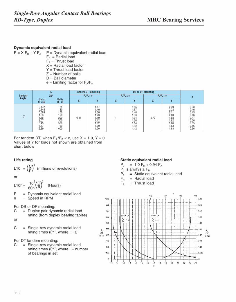
MRC Bearing ServicesSingle-Row Angular Contact Ball BearingsRD-Type, Duplex
118
Dynamic equivalent radial loadP = X FR + Y FA P = Dynamic equivalent radial load
FR = Radial loadFA = Thrust loadX = Radial load factorY = Thrust load factorZ = Number of ballsD = Ball diametere = Limiting factor for FA/FR
ContactAngle
15˚
0.1720.3450.6891.031.382.073.455.176.89
2550
100150200300500750
1,000
0.44
1.471.401.301.231.191.121.021.001.00
1
1.651.571.461.381.341.261.141.121.12
0.72
2.392.282.112.001.931.821.661.631.63
0.380.400.430.460.470.500.550.560.56
FA
ZD2
Tandem DT Mounting DB or DF MountingFA/FR > e FA/FR ≤ e FA/FR > e
UnitsN, mm
Unitslb, in X X XY Y Y
e
For tandem DT, when FA /FR < e, use X = 1.0, Y = 0Values of Y for loads not shown are obtained fromchart below
Life rating
L10 = (millions of revolutions)
or
L10h = (Hours)
P = Dynamic equivalent radial loadn = Speed in RPM
For DB or DF mounting:C = Duplex pair dynamic radial load
rating (from duplex bearing tables)or
C = Single-row dynamic radial loadrating times (i)0.7, where i = 2
For DT tandem mounting:C = Single-row dynamic radial load
rating times (i)0.7, where i = numberof bearings in set
Static equivalent radial loadP0 = 1.0 FR + 0.94 FA
P0 is always ≥ FR
P0 = Static equivalent radial loadFR = Radial loadFA = Thrust load
( )CP
3
( )CP
1060n
36
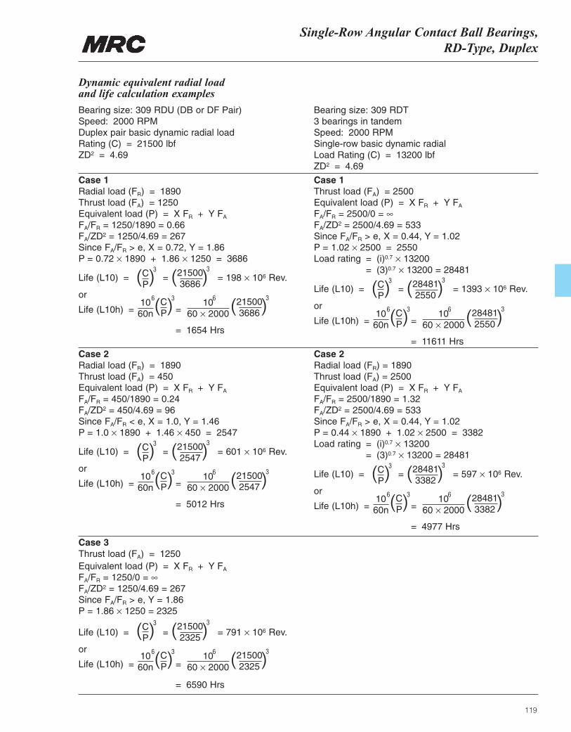
Single-Row Angular Contact Ball Bearings, RD-Type, Duplex
119
Life (L10) = = = 791 × 106 Rev.
or
Life (L10h) = =
= 6590 Hrs
Dynamic equivalent radial load and life calculation examples
Bearing size: 309 RDU (DB or DF Pair)Speed: 2000 RPMDuplex pair basic dynamic radial loadRating (C) = 21500 lbfZD2 = 4.69
Bearing size: 309 RDT3 bearings in tandemSpeed: 2000 RPMSingle-row basic dynamic radial Load Rating (C) = 13200 lbfZD2 = 4.69
Case 1Radial load (FR) = 1890Thrust load (FA) = 1250Equivalent load (P) = X FR + Y FA
FA/FR = 1250/1890 = 0.66FA/ZD2 = 1250/4.69 = 267Since FA/FR > e, X = 0.72, Y = 1.86P = 0.72 × 1890 + 1.86 × 1250 = 3686
Case 2Radial load (FR) = 1890Thrust load (FA) = 450Equivalent load (P) = X FR + Y FA
FA/FR = 450/1890 = 0.24FA/ZD2 = 450/4.69 = 96Since FA/FR < e, X = 1.0, Y = 1.46P = 1.0 × 1890 + 1.46 × 450 = 2547
Case 3Thrust load (FA) = 1250Equivalent load (P) = X FR + Y FA
FA/FR = 1250/0 = ∞FA/ZD2 = 1250/4.69 = 267Since FA/FR > e, Y = 1.86P = 1.86 × 1250 = 2325
( )CP
3
( )CP
31060n
6 1060 × 2000
6
( )215002325
3
( )215002325
3
Life (L10) = = = 198 × 106 Rev.
or
Life (L10h) = =
= 1654 Hrs
( )CP
3
( )CP
1060n
36 1060 × 2000
6
( )215003686
3
( )215003686
3
Life (L10) = = = 601 × 106 Rev.
or
Life (L10h) = =
= 5012 Hrs
( )CP
3
( )CP
1060n
36 1060 × 2000
6
( )215002547
3
( )215002547
3
Case 1Thrust load (FA) = 2500Equivalent load (P) = X FR + Y FA
FA/FR = 2500/0 = ∞FA/ZD2 = 2500/4.69 = 533Since FA/FR > e, X = 0.44, Y = 1.02P = 1.02 × 2500 = 2550Load rating = (i)0.7 × 13200
= (3)0.7 × 13200 = 28481
Case 2Radial load (FR) = 1890Thrust load (FA) = 2500Equivalent load (P) = X FR + Y FA
FA/FR = 2500/1890 = 1.32FA/ZD2 = 2500/4.69 = 533Since FA/FR > e, X = 0.44, Y = 1.02P = 0.44 × 1890 + 1.02 × 2500 = 3382Load rating = (i)0.7 × 13200
= (3)0.7 × 13200 = 28481
Life (L10) = = = 1393 × 106 Rev.
or
Life (L10h) = =
= 11611 Hrs
( )CP
3
( )CP
1060n
36 1060 × 2000
6
( )284812550
3
( )284812550
3
Life (L10) = = = 597 × 106 Rev.
or
Life (L10h) = =
= 4977 Hrs
( )CP
3
( )CP
1060n
36 1060 × 2000
6
( )284813382
3
( )284813382
3

120
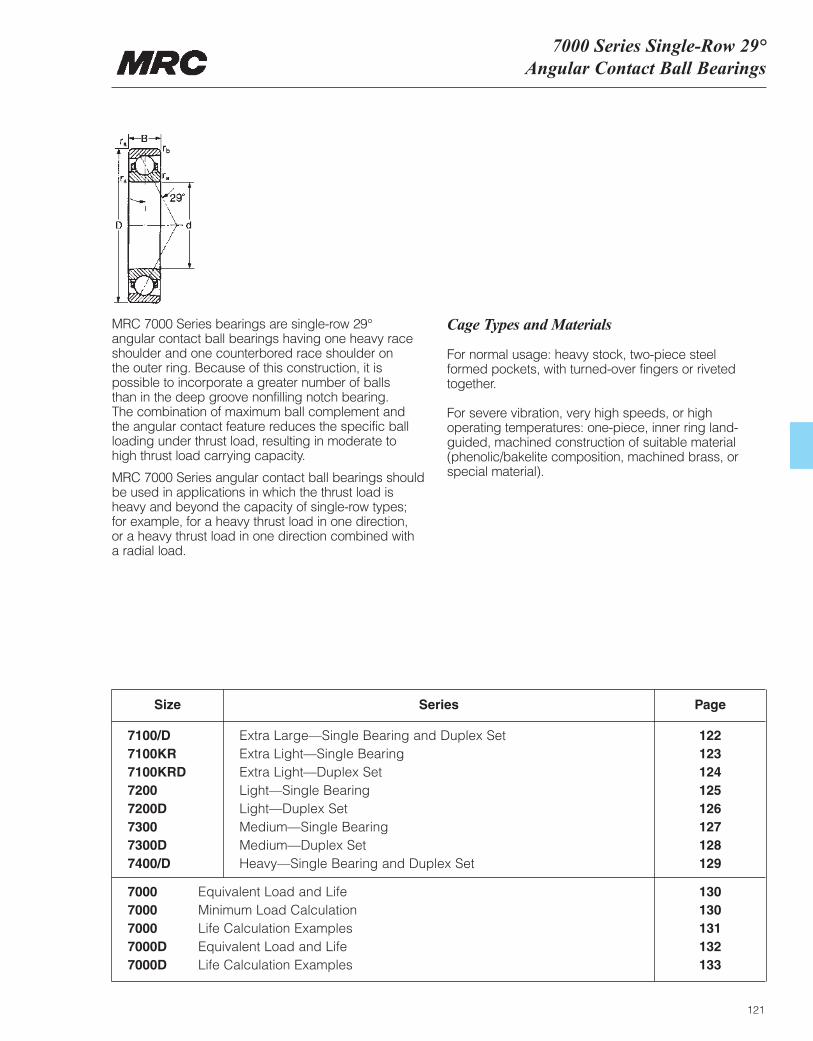
7000 Series Single-Row 29°Angular Contact Ball Bearings
121
MRC 7000 Series bearings are single-row 29°angular contact ball bearings having one heavy raceshoulder and one counterbored race shoulder on the outer ring. Because of this construction, it ispossible to incorporate a greater number of balls than in the deep groove nonfilling notch bearing. The combination of maximum ball complement and the angular contact feature reduces the specific ballloading under thrust load, resulting in moderate to high thrust load carrying capacity.
MRC 7000 Series angular contact ball bearings shouldbe used in applications in which the thrust load isheavy and beyond the capacity of single-row types; for example, for a heavy thrust load in one direction, or a heavy thrust load in one direction combined with a radial load.
Cage Types and Materials
For normal usage: heavy stock, two-piece steel formed pockets, with turned-over fingers or rivetedtogether.
For severe vibration, very high speeds, or highoperating temperatures: one-piece, inner ring land-guided, machined construction of suitable material(phenolic/bakelite composition, machined brass, orspecial material).
Size
7100/D Extra Large—Single Bearing and Duplex Set 1227100KR Extra Light—Single Bearing 1237100KRD Extra Light—Duplex Set 1247200 Light—Single Bearing 1257200D Light—Duplex Set 1267300 Medium—Single Bearing 1277300D Medium—Duplex Set 1287400/D Heavy—Single Bearing and Duplex Set 129
Series Page
7000 Equivalent Load and Life 1307000 Minimum Load Calculation 1307000 Life Calculation Examples 1317000D Equivalent Load and Life 1327000D Life Calculation Examples 133
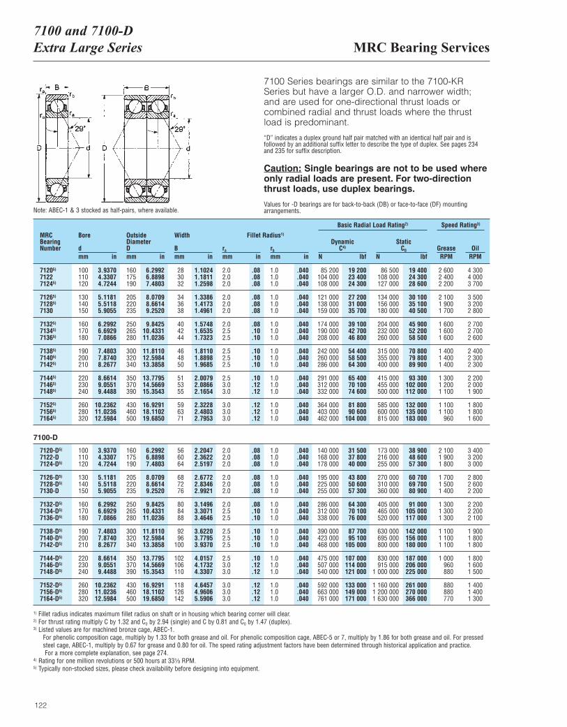
MRC Bearing Services7100 and 7100-DExtra Large Series
122
7100 Series bearings are similar to the 7100-KRSeries but have a larger O.D. and narrower width;and are used for one-directional thrust loads orcombined radial and thrust loads where the thrustload is predominant.
“D” indicates a duplex ground half pair matched with an identical half pair and isfollowed by an additional suffix letter to describe the type of duplex. See pages 234 and 235 for suffix description.
Caution: Single bearings are not to be used whereonly radial loads are present. For two-directionthrust loads, use duplex bearings.
Values for -D bearings are for back-to-back (DB) or face-to-face (DF) mountingarrangements.
MRCBearingNumber
Bore
dmm in
OutsideDiameterDmm in
Width
Bmm in
ra
mm inrb
mm in
DynamicC4)
N lbf
Basic Radial Load Rating2) Speed Rating3)
StaticC0
N lbfGrease OilRPM RPM
Fillet Radius1)
71205) 100 3.9370 160 6.2992 28 1.1024 2.0 .08 1.0 .040 85 200 19 200 86 500 19 400 2 600 4 3007122 110 4.3307 175 6.8898 30 1.1811 2.0 .08 1.0 .040 104 000 23 400 108 000 24 300 2 400 4 00071245) 120 4.7244 190 7.4803 32 1.2598 2.0 .08 1.0 .040 108 000 24 300 127 000 28 600 2 200 3 700
71265) 130 5.1181 205 8.0709 34 1.3386 2.0 .08 1.0 .040 121 000 27 200 134 000 30 100 2 100 3 50071285) 140 5.5118 220 8.6614 36 1.4173 2.0 .08 1.0 .040 138 000 31 000 156 000 35 100 1 900 3 2007130 150 5.9055 235 9.2520 38 1.4961 2.0 .08 1.0 .040 159 000 35 700 180 000 40 500 1 700 2 800
71325) 160 6.2992 250 9.8425 40 1.5748 2.0 .08 1.0 .040 174 000 39 100 204 000 45 900 1 600 2 70071345) 170 6.6929 265 10.4331 42 1.6535 2.5 .10 1.0 .040 190 000 42 700 232 000 52 200 1 600 2 70071365) 180 7.0866 280 11.0236 44 1.7323 2.5 .10 1.0 .040 208 000 46 800 260 000 58 500 1 600 2 600
71385) 190 7.4803 300 11.8110 46 1.8110 2.5 .10 1.0 .040 242 000 54 400 315 000 70 800 1 400 2 40071405) 200 7.8740 320 12.5984 48 1.8898 2.5 .10 1.0 .040 260 000 58 500 355 000 79 800 1 400 2 30071425) 210 8.2677 340 13.3858 50 1.9685 2.5 .10 1.0 .040 286 000 64 300 400 000 89 900 1 400 2 300
71445) 220 8.6614 350 13.7795 51 2.0079 2.5 .10 1.0 .040 291 000 65 400 415 000 93 300 1 300 2 20071465) 230 9.0551 370 14.5669 53 2.0866 3.0 .12 1.0 .040 312 000 70 100 455 000 102 000 1 200 2 00071485) 240 9.4488 390 15.3543 55 2.1654 3.0 .12 1.0 .040 332 000 74 600 500 000 112 000 1 100 1 900
71525) 260 10.2362 430 16.9291 59 2.3228 3.0 .12 1.0 .040 364 000 81 800 585 000 132 000 1 100 1 80071565) 280 11.0236 460 18.1102 63 2.4803 3.0 .12 1.0 .040 403 000 90 600 600 000 135 000 1 100 1 80071645) 320 12.5984 500 19.6850 71 2.7953 3.0 .12 1.0 .040 462 000 104 000 815 000 183 000 960 1 600
7120-D5) 100 3.9370 160 6.2992 56 2.2047 2.0 .08 1.0 .040 140 000 31 500 173 000 38 900 2 100 3 4007122-D 110 4.3307 175 6.8898 60 2.3622 2.0 .08 1.0 .040 168 000 37 800 216 000 48 600 1 900 3 2007124-D5) 120 4.7244 190 7.4803 64 2.5197 2.0 .08 1.0 .040 178 000 40 000 255 000 57 300 1 800 3 000
7126-D5) 130 5.1181 205 8.0709 68 2.6772 2.0 .08 1.0 .040 195 000 43 800 270 000 60 700 1 700 2 8007128-D5) 140 5.5118 220 8.6614 72 2.8346 2.0 .08 1.0 .040 225 000 50 600 310 000 69 700 1 500 2 6007130-D 150 5.9055 235 9.2520 76 2.9921 2.0 .08 1.0 .040 255 000 57 300 360 000 80 900 1 400 2 200
7132-D5) 160 6.2992 250 9.8425 80 3.1496 2.0 .08 1.0 .040 286 000 64 300 405 000 91 000 1 300 2 2007134-D5) 170 6.6929 265 10.4331 84 3.3071 2.5 .10 1.0 .040 312 000 70 100 465 000 105 000 1 300 2 2007136-D5) 180 7.0866 280 11.0236 88 3.4646 2.5 .10 1.0 .040 338 000 76 000 520 000 117 000 1 300 2 100
7138-D5) 190 7.4803 300 11.8110 92 3.6220 2.5 .10 1.0 .040 390 000 87 700 630 000 142 000 1 100 1 9007140-D5) 200 7.8740 320 12.5984 96 3.7795 2.5 .10 1.0 .040 423 000 95 100 695 000 156 000 1 100 1 8007142-D5) 210 8.2677 340 13.3858 100 3.9370 2.5 .10 1.0 .040 468 000 105 000 800 000 180 000 1 100 1 800
7144-D5) 220 8.6614 350 13.7795 102 4.0157 2.5 .10 1.0 .040 475 000 107 000 830 000 187 000 1 000 1 8007146-D5) 230 9.0551 370 14.5669 106 4.1732 3.0 .12 1.0 .040 507 000 114 000 915 000 206 000 960 1 6007148-D5) 240 9.4488 390 15.3543 110 4.3307 3.0 .12 1.0 .040 540 000 121 000 1 000 000 225 000 880 1 500
7152-D5) 260 10.2362 430 16.9291 118 4.6457 3.0 .12 1.0 .040 592 000 133 000 1 160 000 261 000 880 1 4007156-D5) 280 11.0236 460 18.1102 126 4.9606 3.0 .12 1.0 .040 663 000 149 000 1 200 000 270 000 880 1 4007164-D5) 320 12.5984 500 19.6850 142 5.5906 3.0 .12 1.0 .040 761 000 171 000 1 630 000 366 000 770 1 300
1) Fillet radius indicates maximum fillet radius on shaft or in housing which bearing corner will clear.2) For thrust rating multiply C by 1.32 and C0 by 2.94 (single) and C by 0.81 and C0 by 1.47 (duplex).3) Listed values are for machined bronze cage, ABEC-1.
For phenolic composition cage, multiply by 1.33 for both grease and oil. For phenolic composition cage, ABEC-5 or 7, multiply by 1.86 for both grease and oil. For pressedsteel cage, ABEC-1, multiply by 0.67 for grease and 0.80 for oil. The speed rating adjustment factors have been determined through historical application and practice.For a more complete explanation, see page 274.
4) Rating for one million revolutions or 500 hours at 33¹|₃ RPM.5) Typically non-stocked sizes, please check availability before designing into equipment.
Note: ABEC-1 & 3 stocked as half-pairs, where available.
7100-D
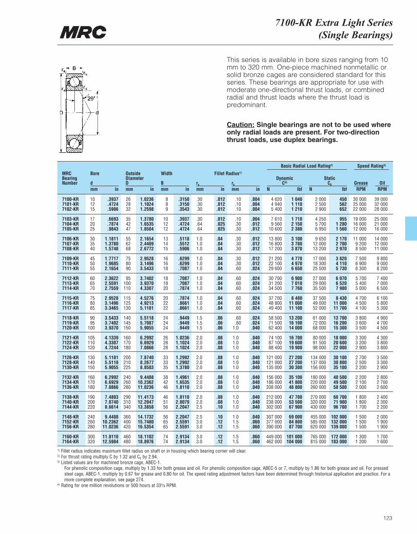
7100-KR Extra Light Series(Single Bearings)
123
This series is available in bore sizes ranging from 10mm to 320 mm. One-piece machined nonmetallic orsolid bronze cages are considered standard for thisseries. These bearings are appropriate for use withmoderate one-directional thrust loads, or combinedradial and thrust loads where the thrust load is predominant.
Caution: Single bearings are not to be used whereonly radial loads are present. For two-directionthrust loads, use duplex bearings.
MRCBearingNumber
Bore
dmm in
OutsideDiameterDmm in
Width
Bmm in
ra
mm inrb
mm in
DynamicC4)
N lbf
Basic Radial Load Rating2) Speed Rating3)
StaticC0
N lbfGrease OilRPM RPM
Fillet Radius1)
7100-KR 10 .3937 26 1.0236 8 .3150 .30 .012 .10 .004 4 620 1 040 2 000 450 30 000 39 0007101-KR 12 .4724 28 1.1024 8 .3150 .30 .012 .10 .004 4 940 1 110 2 500 562 25 000 32 0007102-KR 15 .5906 32 1.2598 9 .3543 .30 .012 .10 .004 5 400 1 210 2 900 652 22 000 28 000
7103-KR 17 .6693 35 1.3780 10 .3937 .30 .012 .10 .004 7 610 1 710 4 250 955 19 000 25 0007104-KR 20 .7874 42 1.6535 12 .4724 .64 .025 .30 .012 9 560 2 150 5 700 1 280 16 000 21 0007105-KR 25 .9843 47 1.8504 12 .4724 .64 .025 .30 .012 10 600 2 380 6 950 1 560 12 000 16 000
7106-KR 30 1.1811 55 2.1654 13 .5118 1.0 .04 .30 .012 13 800 3 100 9 650 2 170 11 000 14 0007107-KR 35 1.3780 62 2.4409 14 .5512 1.0 .04 .30 .012 16 800 3 780 12 000 2 700 9 200 12 0007108-KR 40 1.5748 68 2.6772 15 .5906 1.0 .04 .30 .012 17 200 3 870 13 200 2 970 8 500 11 000
7109-KR 45 1.7717 75 2.9528 16 .6299 1.0 .04 .30 .012 21 200 4 770 17 000 3 820 7 500 9 8007110-KR 50 1.9685 80 3.1496 16 .6299 1.0 .04 .30 .012 22 100 4 970 18 300 4 110 6 900 9 0007111-KR 55 2.1654 90 3.5433 18 .7087 1.0 .04 .60 .024 29 600 6 650 25 500 5 730 6 300 8 200
7112-KR 60 2.3622 95 3.7402 18 .7087 1.0 .04 .60 .024 30 700 6 900 27 000 6 070 5 700 7 4007113-KR 65 2.5591 100 3.9370 18 .7087 1.0 .04 .60 .024 31 200 7 010 29 000 6 520 5 400 7 0007114-KR 70 2.7559 110 4.3307 20 .7874 1.0 .04 .60 .024 34 500 7 760 35 500 7 980 5 000 6 500
7115-KR 75 2.9528 115 4.5276 20 .7874 1.0 .04 .60 .024 37 700 8 480 37 500 8 430 4 700 6 1007116-KR 80 3.1496 125 4.9213 22 .8661 1.0 .04 .60 .024 48 800 11 000 49 000 11 000 4 500 5 8007117-KR 85 3.3465 130 5.1181 22 .8661 1.0 .04 .60 .024 49 400 11 100 52 000 11 700 4 100 5 300
7118-KR 90 3.5433 140 5.5118 24 .9449 1.5 .06 .60 .024 58 500 13 200 61 000 13 700 3 800 4 9007119-KR 95 3.7402 145 5.7087 24 .9449 1.5 .06 .60 .024 71 500 16 100 72 000 16 200 3 600 4 7007120-KR 100 3.9370 150 5.9055 24 .9449 1.5 .06 1.0 .040 62 400 14 000 68 000 15 300 3 500 4 500
7121-KR 105 4.1339 160 6.2992 26 1.0236 2.0 .08 1.0 .040 74 100 16 700 80 000 18 000 3 300 4 3007122-KR 110 4.3307 170 6.6929 28 1.1024 2.0 .08 1.0 .040 87 100 19 600 91 500 20 600 3 200 3 8007124-KR 120 4.7244 180 7.0866 28 1.1024 2.0 .08 1.0 .040 88 400 19 900 98 000 22 000 2 900 3 800
7126-KR 130 5.1181 200 7.8740 33 1.2992 2.0 .08 1.0 .040 121 000 27 200 134 000 30 100 2 700 3 5007128-KR 140 5.5118 210 8.2677 33 1.2992 2.0 .08 1.0 .040 121 000 27 200 137 000 30 800 2 500 3 3007130-KR 150 5.9055 225 8.8583 35 1.3780 2.0 .08 1.0 .040 135 000 30 300 156 000 35 100 2 200 2 900
7132-KR 160 6.2992 240 9.4488 38 1.4961 2.0 .08 1.0 .040 156 000 35 100 180 000 40 500 2 200 2 8007134-KR 170 6.6929 260 10.2362 42 1.6535 2.0 .08 1.0 .040 186 000 41 800 220 000 49 500 2 100 2 7007136-KR 180 7.0866 280 11.0236 46 1.8110 2.0 .08 1.0 .040 208 000 46 800 260 000 58 500 2 000 2 600
7138-KR 190 7.4803 290 11.4173 46 1.8110 2.0 .08 1.0 .040 212 000 47 700 270 000 60 700 1 800 2 4007140-KR 200 7.8740 310 12.2047 51 2.0079 2.0 .08 1.0 .040 238 000 53 500 320 000 71 900 1 800 2 3007144-KR 220 8.6614 340 13.3858 56 2.2047 2.5 .10 1.0 .040 302 000 67 900 430 000 96 700 1 700 2 200
7148-KR 240 9.4488 360 14.1732 56 2.2047 2.5 .10 1.0 .040 307 000 69 000 455 000 102 000 1 500 2 0007152-KR 260 10.2362 400 15.7480 65 2.5591 3.0 .12 1.5 .060 377 000 84 800 585 000 132 000 1 500 1 9007156-KR 280 11.0236 420 16.5354 65 2.5591 3.0 .12 1.5 .060 390 000 87 700 620 000 139 000 1 500 1 900
7160-KR 300 11.8110 460 18.1102 74 2.9134 3.0 .12 1.5 .060 449 000 101 000 765 000 172 000 1 300 1 7007164-KR 320 12.5984 480 18.8976 74 2.9134 3.0 .12 1.5 .060 462 000 104 000 815 000 183 000 1 200 1 600
30 00025 00022 000
19 00016 00012 000
11 0009 2008 500
7 5006 9006 300
5 7005 4005 000
4 7004 5004 100
3 8003 6003 500
3 3003 2002 900
2 7002 5002 200
2 2002 1002 000
1 8001 8001 700
1 5001 5001 500
1 3001 200
1) Fillet radius indicates maximum fillet radius on shaft or in housing which bearing corner will clear.2) For thrust rating multiply C by 1.32 and C0 by 2.94.3) Listed values are for machined bronze cage, ABEC-1.
For phenolic composition cage, multiply by 1.33 for both grease and oil. For phenolic composition cage, ABEC-5 or 7, multiply by 1.86 for both grease and oil. For pressedsteel cage, ABEC-1, multiply by 0.67 for grease and 0.80 for oil. The speed rating adjustment factors have been determined through historical application and practice. For amore complete explanation, see page 274.
4) Rating for one million revolutions or 500 hours at 33¹|₃ RPM.
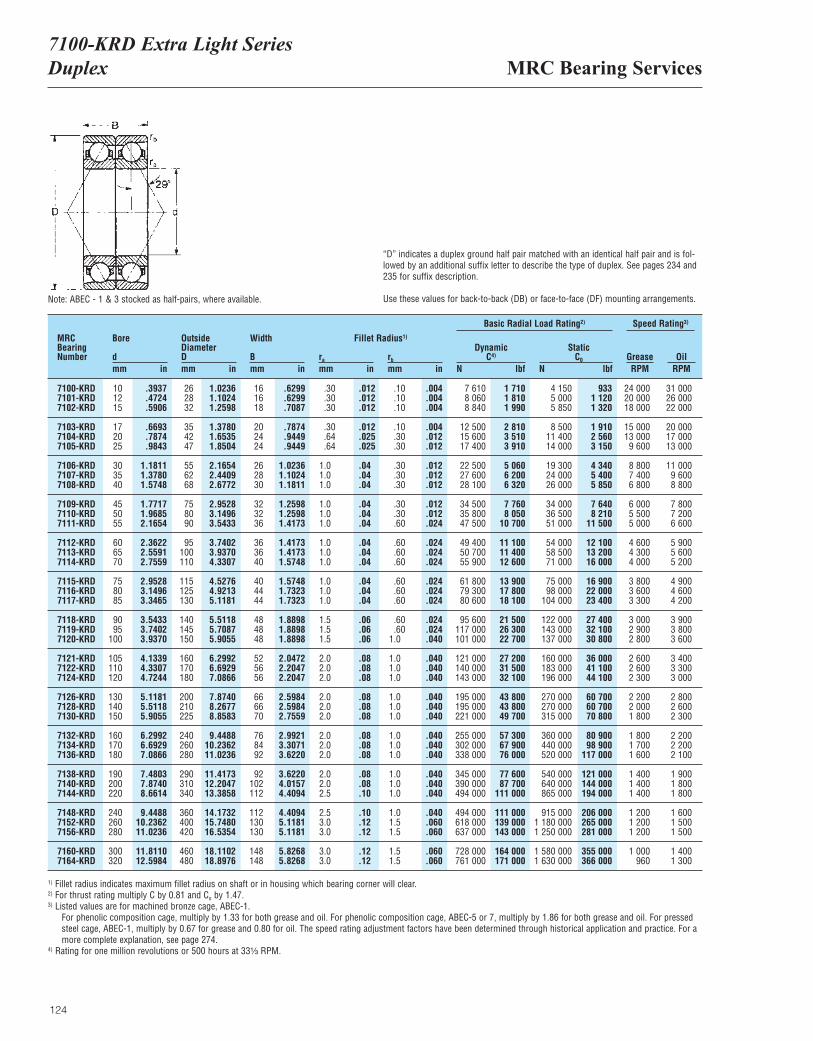
MRC Bearing Services7100-KRD Extra Light SeriesDuplex
124
“D” indicates a duplex ground half pair matched with an identical half pair and is fol-lowed by an additional suffix letter to describe the type of duplex. See pages 234 and235 for suffix description.
Use these values for back-to-back (DB) or face-to-face (DF) mounting arrangements.
MRCBearingNumber
Bore
dmm in
OutsideDiameterDmm in
Width
Bmm in
ra
mm inrb
mm in
DynamicC4)
N lbf
Basic Radial Load Rating2) Speed Rating3)
StaticC0
N lbfGrease OilRPM RPM
Fillet Radius1)
7100-KRD 10 .3937 26 1.0236 16 .6299 .30 .012 .10 .004 7 610 1 710 4 150 933 24 000 31 0007101-KRD 12 .4724 28 1.1024 16 .6299 .30 .012 .10 .004 8 060 1 810 5 000 1 120 20 000 26 0007102-KRD 15 .5906 32 1.2598 18 .7087 .30 .012 .10 .004 8 840 1 990 5 850 1 320 18 000 22 000
7103-KRD 17 .6693 35 1.3780 20 .7874 .30 .012 .10 .004 12 500 2 810 8 500 1 910 15 000 20 0007104-KRD 20 .7874 42 1.6535 24 .9449 .64 .025 .30 .012 15 600 3 510 11 400 2 560 13 000 17 0007105-KRD 25 .9843 47 1.8504 24 .9449 .64 .025 .30 .012 17 400 3 910 14 000 3 150 9 600 13 000
7106-KRD 30 1.1811 55 2.1654 26 1.0236 1.0 .04 .30 .012 22 500 5 060 19 300 4 340 8 800 11 0007107-KRD 35 1.3780 62 2.4409 28 1.1024 1.0 .04 .30 .012 27 600 6 200 24 000 5 400 7 400 9 6007108-KRD 40 1.5748 68 2.6772 30 1.1811 1.0 .04 .30 .012 28 100 6 320 26 000 5 850 6 800 8 800
7109-KRD 45 1.7717 75 2.9528 32 1.2598 1.0 .04 .30 .012 34 500 7 760 34 000 7 640 6 000 7 8007110-KRD 50 1.9685 80 3.1496 32 1.2598 1.0 .04 .30 .012 35 800 8 050 36 500 8 210 5 500 7 2007111-KRD 55 2.1654 90 3.5433 36 1.4173 1.0 .04 .60 .024 47 500 10 700 51 000 11 500 5 000 6 600
7112-KRD 60 2.3622 95 3.7402 36 1.4173 1.0 .04 .60 .024 49 400 11 100 54 000 12 100 4 600 5 9007113-KRD 65 2.5591 100 3.9370 36 1.4173 1.0 .04 .60 .024 50 700 11 400 58 500 13 200 4 300 5 6007114-KRD 70 2.7559 110 4.3307 40 1.5748 1.0 .04 .60 .024 55 900 12 600 71 000 16 000 4 000 5 200
7115-KRD 75 2.9528 115 4.5276 40 1.5748 1.0 .04 .60 .024 61 800 13 900 75 000 16 900 3 800 4 9007116-KRD 80 3.1496 125 4.9213 44 1.7323 1.0 .04 .60 .024 79 300 17 800 98 000 22 000 3 600 4 6007117-KRD 85 3.3465 130 5.1181 44 1.7323 1.0 .04 .60 .024 80 600 18 100 104 000 23 400 3 300 4 200
7118-KRD 90 3.5433 140 5.5118 48 1.8898 1.5 .06 .60 .024 95 600 21 500 122 000 27 400 3 000 3 9007119-KRD 95 3.7402 145 5.7087 48 1.8898 1.5 .06 .60 .024 117 000 26 300 143 000 32 100 2 900 3 8007120-KRD 100 3.9370 150 5.9055 48 1.8898 1.5 .06 1.0 .040 101 000 22 700 137 000 30 800 2 800 3 600
7121-KRD 105 4.1339 160 6.2992 52 2.0472 2.0 .08 1.0 .040 121 000 27 200 160 000 36 000 2 600 3 4007122-KRD 110 4.3307 170 6.6929 56 2.2047 2.0 .08 1.0 .040 140 000 31 500 183 000 41 100 2 600 3 3007124-KRD 120 4.7244 180 7.0866 56 2.2047 2.0 .08 1.0 .040 143 000 32 100 196 000 44 100 2 300 3 000
7126-KRD 130 5.1181 200 7.8740 66 2.5984 2.0 .08 1.0 .040 195 000 43 800 270 000 60 700 2 200 2 8007128-KRD 140 5.5118 210 8.2677 66 2.5984 2.0 .08 1.0 .040 195 000 43 800 270 000 60 700 2 000 2 6007130-KRD 150 5.9055 225 8.8583 70 2.7559 2.0 .08 1.0 .040 221 000 49 700 315 000 70 800 1 800 2 300
7132-KRD 160 6.2992 240 9.4488 76 2.9921 2.0 .08 1.0 .040 255 000 57 300 360 000 80 900 1 800 2 2007134-KRD 170 6.6929 260 10.2362 84 3.3071 2.0 .08 1.0 .040 302 000 67 900 440 000 98 900 1 700 2 2007136-KRD 180 7.0866 280 11.0236 92 3.6220 2.0 .08 1.0 .040 338 000 76 000 520 000 117 000 1 600 2 100
7138-KRD 190 7.4803 290 11.4173 92 3.6220 2.0 .08 1.0 .040 345 000 77 600 540 000 121 000 1 400 1 9007140-KRD 200 7.8740 310 12.2047 102 4.0157 2.0 .08 1.0 .040 390 000 87 700 640 000 144 000 1 400 1 8007144-KRD 220 8.6614 340 13.3858 112 4.4094 2.5 .10 1.0 .040 494 000 111 000 865 000 194 000 1 400 1 800
7148-KRD 240 9.4488 360 14.1732 112 4.4094 2.5 .10 1.0 .040 494 000 111 000 915 000 206 000 1 200 1 6007152-KRD 260 10.2362 400 15.7480 130 5.1181 3.0 .12 1.5 .060 618 000 139 000 1 180 000 265 000 1 200 1 5007156-KRD 280 11.0236 420 16.5354 130 5.1181 3.0 .12 1.5 .060 637 000 143 000 1 250 000 281 000 1 200 1 500
7160-KRD 300 11.8110 460 18.1102 148 5.8268 3.0 .12 1.5 .060 728 000 164 000 1 580 000 355 000 1 000 1 4007164-KRD 320 12.5984 480 18.8976 148 5.8268 3.0 .12 1.5 .060 761 000 171 000 1 630 000 366 000 960 1 300
Note: ABEC - 1 & 3 stocked as half-pairs, where available.
1) Fillet radius indicates maximum fillet radius on shaft or in housing which bearing corner will clear.2) For thrust rating multiply C by 0.81 and Co by 1.47.3) Listed values are for machined bronze cage, ABEC-1.
For phenolic composition cage, multiply by 1.33 for both grease and oil. For phenolic composition cage, ABEC-5 or 7, multiply by 1.86 for both grease and oil. For pressedsteel cage, ABEC-1, multiply by 0.67 for grease and 0.80 for oil. The speed rating adjustment factors have been determined through historical application and practice. For amore complete explanation, see page 274.
4) Rating for one million revolutions or 500 hours at 33¹|₃ RPM.
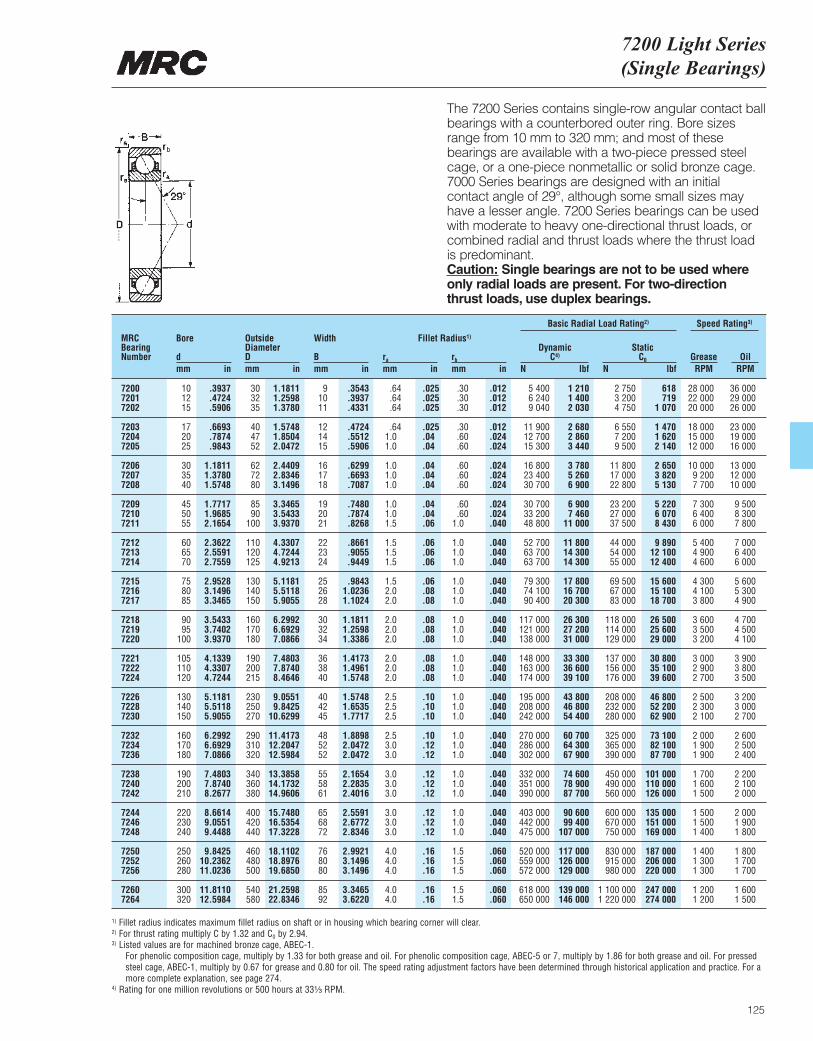
7200 Light Series (Single Bearings)
125
The 7200 Series contains single-row angular contact ballbearings with a counterbored outer ring. Bore sizesrange from 10 mm to 320 mm; and most of thesebearings are available with a two-piece pressed steelcage, or a one-piece nonmetallic or solid bronze cage.7000 Series bearings are designed with an initial contact angle of 29°, although some small sizes mayhave a lesser angle. 7200 Series bearings can be usedwith moderate to heavy one-directional thrust loads, orcombined radial and thrust loads where the thrust loadis predominant. Caution: Single bearings are not to be used whereonly radial loads are present. For two-directionthrust loads, use duplex bearings.
MRCBearingNumber
Bore
dmm in
OutsideDiameterDmm in
Width
Bmm in
ra
mm inrb
mm in
DynamicC4)
N lbf
Basic Radial Load Rating2) Speed Rating3)
StaticC0
N lbfGrease OilRPM RPM
Fillet Radius1)
7200 10 .3937 30 1.1811 9 .3543 .64 .025 .30 .012 5 400 1 210 2 750 618 28 000 36 0007201 12 .4724 32 1.2598 10 .3937 .64 .025 .30 .012 6 240 1 400 3 200 719 22 000 29 0007202 15 .5906 35 1.3780 11 .4331 .64 .025 .30 .012 9 040 2 030 4 750 1 070 20 000 26 000
7203 17 .6693 40 1.5748 12 .4724 .64 .025 .30 .012 11 900 2 680 6 550 1 470 18 000 23 0007204 20 .7874 47 1.8504 14 .5512 1.0 .04 .60 .024 12 700 2 860 7 200 1 620 15 000 19 0007205 25 .9843 52 2.0472 15 .5906 1.0 .04 .60 .024 15 300 3 440 9 500 2 140 12 000 16 000
7206 30 1.1811 62 2.4409 16 .6299 1.0 .04 .60 .024 16 800 3 780 11 800 2 650 10 000 13 0007207 35 1.3780 72 2.8346 17 .6693 1.0 .04 .60 .024 23 400 5 260 17 000 3 820 9 200 12 0007208 40 1.5748 80 3.1496 18 .7087 1.0 .04 .60 .024 30 700 6 900 22 800 5 130 7 700 10 000
7209 45 1.7717 85 3.3465 19 .7480 1.0 .04 .60 .024 30 700 6 900 23 200 5 220 7 300 9 5007210 50 1.9685 90 3.5433 20 .7874 1.0 .04 .60 .024 33 200 7 460 27 000 6 070 6 400 8 3007211 55 2.1654 100 3.9370 21 .8268 1.5 .06 1.0 .040 48 800 11 000 37 500 8 430 6 000 7 800
7212 60 2.3622 110 4.3307 22 .8661 1.5 .06 1.0 .040 52 700 11 800 44 000 9 890 5 400 7 0007213 65 2.5591 120 4.7244 23 .9055 1.5 .06 1.0 .040 63 700 14 300 54 000 12 100 4 900 6 4007214 70 2.7559 125 4.9213 24 .9449 1.5 .06 1.0 .040 63 700 14 300 55 000 12 400 4 600 6 000
7215 75 2.9528 130 5.1181 25 .9843 1.5 .06 1.0 .040 79 300 17 800 69 500 15 600 4 300 5 6007216 80 3.1496 140 5.5118 26 1.0236 2.0 .08 1.0 .040 74 100 16 700 67 000 15 100 4 100 5 3007217 85 3.3465 150 5.9055 28 1.1024 2.0 .08 1.0 .040 90 400 20 300 83 000 18 700 3 800 4 900
7218 90 3.5433 160 6.2992 30 1.1811 2.0 .08 1.0 .040 117 000 26 300 118 000 26 500 3 600 4 7007219 95 3.7402 170 6.6929 32 1.2598 2.0 .08 1.0 .040 121 000 27 200 114 000 25 600 3 500 4 5007220 100 3.9370 180 7.0866 34 1.3386 2.0 .08 1.0 .040 138 000 31 000 129 000 29 000 3 200 4 100
7221 105 4.1339 190 7.4803 36 1.4173 2.0 .08 1.0 .040 148 000 33 300 137 000 30 800 3 000 3 9007222 110 4.3307 200 7.8740 38 1.4961 2.0 .08 1.0 .040 163 000 36 600 156 000 35 100 2 900 3 8007224 120 4.7244 215 8.4646 40 1.5748 2.0 .08 1.0 .040 174 000 39 100 176 000 39 600 2 700 3 500
7226 130 5.1181 230 9.0551 40 1.5748 2.5 .10 1.0 .040 195 000 43 800 208 000 46 800 2 500 3 2007228 140 5.5118 250 9.8425 42 1.6535 2.5 .10 1.0 .040 208 000 46 800 232 000 52 200 2 300 3 0007230 150 5.9055 270 10.6299 45 1.7717 2.5 .10 1.0 .040 242 000 54 400 280 000 62 900 2 100 2 700
7232 160 6.2992 290 11.4173 48 1.8898 2.5 .10 1.0 .040 270 000 60 700 325 000 73 100 2 000 2 6007234 170 6.6929 310 12.2047 52 2.0472 3.0 .12 1.0 .040 286 000 64 300 365 000 82 100 1 900 2 5007236 180 7.0866 320 12.5984 52 2.0472 3.0 .12 1.0 .040 302 000 67 900 390 000 87 700 1 900 2 400
7238 190 7.4803 340 13.3858 55 2.1654 3.0 .12 1.0 .040 332 000 74 600 450 000 101 000 1 700 2 2007240 200 7.8740 360 14.1732 58 2.2835 3.0 .12 1.0 .040 351 000 78 900 490 000 110 000 1 600 2 1007242 210 8.2677 380 14.9606 61 2.4016 3.0 .12 1.0 .040 390 000 87 700 560 000 126 000 1 500 2 000
7244 220 8.6614 400 15.7480 65 2.5591 3.0 .12 1.0 .040 403 000 90 600 600 000 135 000 1 500 2 0007246 230 9.0551 420 16.5354 68 2.6772 3.0 .12 1.0 .040 442 000 99 400 670 000 151 000 1 500 1 9007248 240 9.4488 440 17.3228 72 2.8346 3.0 .12 1.0 .040 475 000 107 000 750 000 169 000 1 400 1 800
7250 250 9.8425 460 18.1102 76 2.9921 4.0 .16 1.5 .060 520 000 117 000 830 000 187 000 1 400 1 8007252 260 10.2362 480 18.8976 80 3.1496 4.0 .16 1.5 .060 559 000 126 000 915 000 206 000 1 300 1 7007256 280 11.0236 500 19.6850 80 3.1496 4.0 .16 1.5 .060 572 000 129 000 980 000 220 000 1 300 1 700
7260 300 11.8110 540 21.2598 85 3.3465 4.0 .16 1.5 .060 618 000 139 000 1 100 000 247 000 1 200 1 6007264 320 12.5984 580 22.8346 92 3.6220 4.0 .16 1.5 .060 650 000 146 000 1 220 000 274 000 1 200 1 500
1) Fillet radius indicates maximum fillet radius on shaft or in housing which bearing corner will clear.2) For thrust rating multiply C by 1.32 and C0 by 2.94.3) Listed values are for machined bronze cage, ABEC-1.
For phenolic composition cage, multiply by 1.33 for both grease and oil. For phenolic composition cage, ABEC-5 or 7, multiply by 1.86 for both grease and oil. For pressedsteel cage, ABEC-1, multiply by 0.67 for grease and 0.80 for oil. The speed rating adjustment factors have been determined through historical application and practice. For amore complete explanation, see page 274.
4) Rating for one million revolutions or 500 hours at 33¹|₃ RPM.
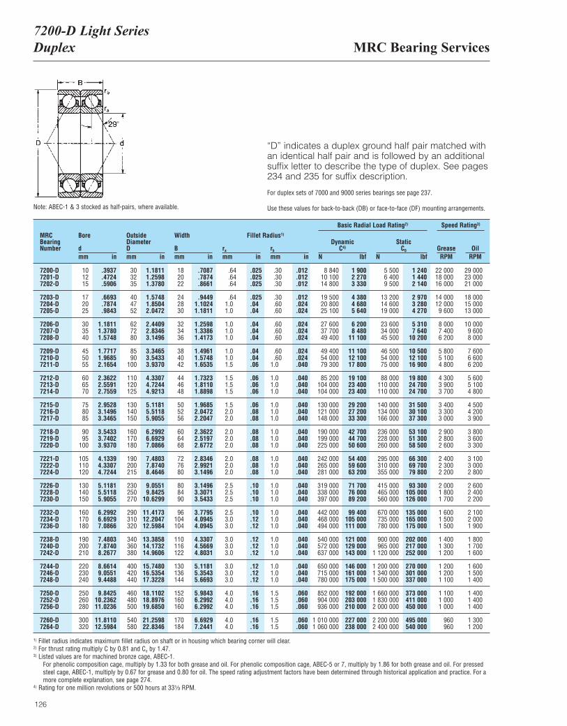
MRC Bearing Services7200-D Light SeriesDuplex
126
“D” indicates a duplex ground half pair matched withan identical half pair and is followed by an additionalsuffix letter to describe the type of duplex. See pages234 and 235 for suffix description.
For duplex sets of 7000 and 9000 series bearings see page 237.
Use these values for back-to-back (DB) or face-to-face (DF) mounting arrangements.
MRCBearingNumber
Bore
dmm in
OutsideDiameterDmm in
Width
Bmm in
ra
mm inrb
mm in
DynamicC4)
N lbf
Basic Radial Load Rating2) Speed Rating3)
StaticC0
N lbfGrease OilRPM RPM
Fillet Radius1)
7200-D 10 .3937 30 1.1811 18 .7087 .64 .025 .30 .012 8 840 1 900 5 500 1 240 22 000 29 0007201-D 12 .4724 32 1.2598 20 .7874 .64 .025 .30 .012 10 100 2 270 6 400 1 440 18 000 23 0007202-D 15 .5906 35 1.3780 22 .8661 .64 .025 .30 .012 14 800 3 330 9 500 2 140 16 000 21 000
7203-D 17 .6693 40 1.5748 24 .9449 .64 .025 .30 .012 19 500 4 380 13 200 2 970 14 000 18 0007204-D 20 .7874 47 1.8504 28 1.1024 1.0 .04 .60 .024 20 800 4 680 14 600 3 280 12 000 15 0007205-D 25 .9843 52 2.0472 30 1.1811 1.0 .04 .60 .024 25 100 5 640 19 000 4 270 9 600 13 000
7206-D 30 1.1811 62 2.4409 32 1.2598 1.0 .04 .60 .024 27 600 6 200 23 600 5 310 8 000 10 0007207-D 35 1.3780 72 2.8346 34 1.3386 1.0 .04 .60 .024 37 700 8 480 34 000 7 640 7 400 9 6007208-D 40 1.5748 80 3.1496 36 1.4173 1.0 .04 .60 .024 49 400 11 100 45 500 10 200 6 200 8 000
7209-D 45 1.7717 85 3.3465 38 1.4961 1.0 .04 .60 .024 49 400 11 100 46 500 10 500 5 800 7 6007210-D 50 1.9685 90 3.5433 40 1.5748 1.0 .04 .60 .024 54 000 12 100 54 000 12 100 5 100 6 6007211-D 55 2.1654 100 3.9370 42 1.6535 1.5 .06 1.0 .040 79 300 17 800 75 000 16 900 4 800 6 200
7212-D 60 2.3622 110 4.3307 44 1.7323 1.5 .06 1.0 .040 85 200 19 100 88 000 19 800 4 300 5 6007213-D 65 2.5591 120 4.7244 46 1.8110 1.5 .06 1.0 .040 104 000 23 400 110 000 24 700 3 900 5 1007214-D 70 2.7559 125 4.9213 48 1.8898 1.5 .06 1.0 .040 104 000 23 400 110 000 24 700 3 700 4 800
7215-D 75 2.9528 130 5.1181 50 1.9685 1.5 .06 1.0 .040 130 000 29 200 140 000 31 500 3 400 4 5007216-D 80 3.1496 140 5.5118 52 2.0472 2.0 .08 1.0 .040 121 000 27 200 134 000 30 100 3 300 4 2007217-D 85 3.3465 150 5.9055 56 2.2047 2.0 .08 1.0 .040 148 000 33 300 166 000 37 300 3 000 3 900
7218-D 90 3.5433 160 6.2992 60 2.3622 2.0 .08 1.0 .040 190 000 42 700 236 000 53 100 2 900 3 8007219-D 95 3.7402 170 6.6929 64 2.5197 2.0 .08 1.0 .040 199 000 44 700 228 000 51 300 2 800 3 6007220-D 100 3.9370 180 7.0866 68 2.6772 2.0 .08 1.0 .040 225 000 50 600 260 000 58 500 2 600 3 300
7221-D 105 4.1339 190 7.4803 72 2.8346 2.0 .08 1.0 .040 242 000 54 400 295 000 66 300 2 400 3 1007222-D 110 4.3307 200 7.8740 76 2.9921 2.0 .08 1.0 .040 265 000 59 600 310 000 69 700 2 300 3 0007224-D 120 4.7244 215 8.4646 80 3.1496 2.0 .08 1.0 .040 281 000 63 200 355 000 79 800 2 200 2 800
7226-D 130 5.1181 230 9.0551 80 3.1496 2.5 .10 1.0 .040 319 000 71 700 415 000 93 300 2 000 2 6007228-D 140 5.5118 250 9.8425 84 3.3071 2.5 .10 1.0 .040 338 000 76 000 465 000 105 000 1 800 2 4007230-D 150 5.9055 270 10.6299 90 3.5433 2.5 .10 1.0 .040 397 000 89 200 560 000 126 000 1 700 2 200
7232-D 160 6.2992 290 11.4173 96 3.7795 2.5 .10 1.0 .040 442 000 99 400 670 000 135 000 1 600 2 1007234-D 170 6.6929 310 12.2047 104 4.0945 3.0 .12 1.0 .040 468 000 105 000 735 000 165 000 1 500 2 0007236-D 180 7.0866 320 12.5984 104 4.0945 3.0 .12 1.0 .040 494 000 111 000 780 000 175 000 1 500 1 900
7238-D 190 7.4803 340 13.3858 110 4.3307 3.0 .12 1.0 .040 540 000 121 000 900 000 202 000 1 400 1 8007240-D 200 7.8740 360 14.1732 116 4.5669 3.0 .12 1.0 .040 572 000 129 000 965 000 217 000 1 300 1 7007242-D 210 8.2677 380 14.9606 122 4.8031 3.0 .12 1.0 .040 637 000 143 000 1 120 000 252 000 1 200 1 600
7244-D 220 8.6614 400 15.7480 130 5.1181 3.0 .12 1.0 .040 650 000 146 000 1 200 000 270 000 1 200 1 6007246-D 230 9.0551 420 16.5354 136 5.3543 3.0 .12 1.0 .040 715 000 161 000 1 340 000 301 000 1 200 1 5007248-D 240 9.4488 440 17.3228 144 5.6693 3.0 .12 1.0 .040 780 000 175 000 1 500 000 337 000 1 100 1 400
7250-D 250 9.8425 460 18.1102 152 5.9843 4.0 .16 1.5 .060 852 000 192 000 1 660 000 373 000 1 100 1 4007252-D 260 10.2362 480 18.8976 160 6.2992 4.0 .16 1.5 .060 904 000 203 000 1 830 000 411 000 1 000 1 4007256-D 280 11.0236 500 19.6850 160 6.2992 4.0 .16 1.5 .060 936 000 210 000 2 000 000 450 000 1 000 1 400
7260-D 300 11.8110 540 21.2598 170 6.6929 4.0 .16 1.5 .060 1 010 000 227 000 2 200 000 495 000 960 1 3007264-D 320 12.5984 580 22.8346 184 7.2441 4.0 .16 1.5 .060 1 060 000 238 000 2 400 000 540 000 960 1 200
Note: ABEC-1 & 3 stocked as half-pairs, where available.
1) Fillet radius indicates maximum fillet radius on shaft or in housing which bearing corner will clear.2) For thrust rating multiply C by 0.81 and Co by 1.47.3) Listed values are for machined bronze cage, ABEC-1.
For phenolic composition cage, multiply by 1.33 for both grease and oil. For phenolic composition cage, ABEC-5 or 7, multiply by 1.86 for both grease and oil. For pressedsteel cage, ABEC-1, multiply by 0.67 for grease and 0.80 for oil. The speed rating adjustment factors have been determined through historical application and practice. For amore complete explanation, see page 274.
4) Rating for one million revolutions or 500 hours at 33¹|₃ RPM.
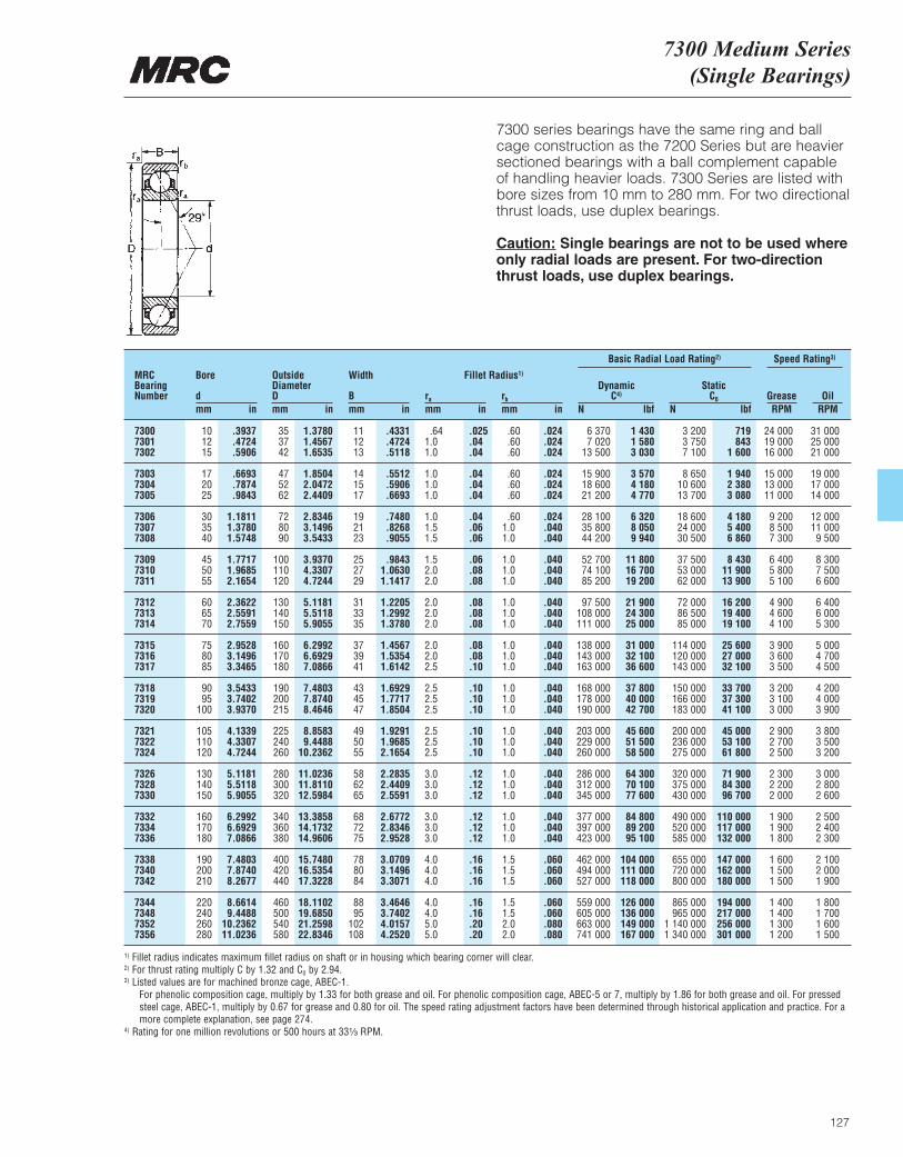
7300 Medium Series (Single Bearings)
127
7300 series bearings have the same ring and ballcage construction as the 7200 Series but are heaviersectioned bearings with a ball complement capableof handling heavier loads. 7300 Series are listed withbore sizes from 10 mm to 280 mm. For two directionalthrust loads, use duplex bearings.
Caution: Single bearings are not to be used whereonly radial loads are present. For two-directionthrust loads, use duplex bearings.
MRCBearingNumber
Bore
dmm in
OutsideDiameterDmm in
Width
Bmm in
ra
mm inrb
mm in
DynamicC4)
N lbf
Basic Radial Load Rating2) Speed Rating3)
StaticC0
N lbfGrease OilRPM RPM
Fillet Radius1)
7300 10 .3937 35 1.3780 11 .4331 .64 .025 .60 .024 6 370 1 430 3 200 719 24 000 31 0007301 12 .4724 37 1.4567 12 .4724 1.0 .04 .60 .024 7 020 1 580 3 750 843 19 000 25 0007302 15 .5906 42 1.6535 13 .5118 1.0 .04 .60 .024 13 500 3 030 7 100 1 600 16 000 21 000
7303 17 .6693 47 1.8504 14 .5512 1.0 .04 .60 .024 15 900 3 570 8 650 1 940 15 000 19 0007304 20 .7874 52 2.0472 15 .5906 1.0 .04 .60 .024 18 600 4 180 10 600 2 380 13 000 17 0007305 25 .9843 62 2.4409 17 .6693 1.0 .04 .60 .024 21 200 4 770 13 700 3 080 11 000 14 000
7306 30 1.1811 72 2.8346 19 .7480 1.0 .04 .60 .024 28 100 6 320 18 600 4 180 9 200 12 0007307 35 1.3780 80 3.1496 21 .8268 1.5 .06 1.0 .040 35 800 8 050 24 000 5 400 8 500 11 0007308 40 1.5748 90 3.5433 23 .9055 1.5 .06 1.0 .040 44 200 9 940 30 500 6 860 7 300 9 500
7309 45 1.7717 100 3.9370 25 .9843 1.5 .06 1.0 .040 52 700 11 800 37 500 8 430 6 400 8 3007310 50 1.9685 110 4.3307 27 1.0630 2.0 .08 1.0 .040 74 100 16 700 53 000 11 900 5 800 7 5007311 55 2.1654 120 4.7244 29 1.1417 2.0 .08 1.0 .040 85 200 19 200 62 000 13 900 5 100 6 600
7312 60 2.3622 130 5.1181 31 1.2205 2.0 .08 1.0 .040 97 500 21 900 72 000 16 200 4 900 6 4007313 65 2.5591 140 5.5118 33 1.2992 2.0 .08 1.0 .040 108 000 24 300 86 500 19 400 4 600 6 0007314 70 2.7559 150 5.9055 35 1.3780 2.0 .08 1.0 .040 111 000 25 000 85 000 19 100 4 100 5 300
7315 75 2.9528 160 6.2992 37 1.4567 2.0 .08 1.0 .040 138 000 31 000 114 000 25 600 3 900 5 0007316 80 3.1496 170 6.6929 39 1.5354 2.0 .08 1.0 .040 143 000 32 100 120 000 27 000 3 600 4 7007317 85 3.3465 180 7.0866 41 1.6142 2.5 .10 1.0 .040 163 000 36 600 143 000 32 100 3 500 4 500
7318 90 3.5433 190 7.4803 43 1.6929 2.5 .10 1.0 .040 168 000 37 800 150 000 33 700 3 200 4 2007319 95 3.7402 200 7.8740 45 1.7717 2.5 .10 1.0 .040 178 000 40 000 166 000 37 300 3 100 4 0007320 100 3.9370 215 8.4646 47 1.8504 2.5 .10 1.0 .040 190 000 42 700 183 000 41 100 3 000 3 900
7321 105 4.1339 225 8.8583 49 1.9291 2.5 .10 1.0 .040 203 000 45 600 200 000 45 000 2 900 3 8007322 110 4.3307 240 9.4488 50 1.9685 2.5 .10 1.0 .040 229 000 51 500 236 000 53 100 2 700 3 5007324 120 4.7244 260 10.2362 55 2.1654 2.5 .10 1.0 .040 260 000 58 500 275 000 61 800 2 500 3 200
7326 130 5.1181 280 11.0236 58 2.2835 3.0 .12 1.0 .040 286 000 64 300 320 000 71 900 2 300 3 0007328 140 5.5118 300 11.8110 62 2.4409 3.0 .12 1.0 .040 312 000 70 100 375 000 84 300 2 200 2 8007330 150 5.9055 320 12.5984 65 2.5591 3.0 .12 1.0 .040 345 000 77 600 430 000 96 700 2 000 2 600
7332 160 6.2992 340 13.3858 68 2.6772 3.0 .12 1.0 .040 377 000 84 800 490 000 110 000 1 900 2 5007334 170 6.6929 360 14.1732 72 2.8346 3.0 .12 1.0 .040 397 000 89 200 520 000 117 000 1 900 2 4007336 180 7.0866 380 14.9606 75 2.9528 3.0 .12 1.0 .040 423 000 95 100 585 000 132 000 1 800 2 300
7338 190 7.4803 400 15.7480 78 3.0709 4.0 .16 1.5 .060 462 000 104 000 655 000 147 000 1 600 2 1007340 200 7.8740 420 16.5354 80 3.1496 4.0 .16 1.5 .060 494 000 111 000 720 000 162 000 1 500 2 0007342 210 8.2677 440 17.3228 84 3.3071 4.0 .16 1.5 .060 527 000 118 000 800 000 180 000 1 500 1 900
7344 220 8.6614 460 18.1102 88 3.4646 4.0 .16 1.5 .060 559 000 126 000 865 000 194 000 1 400 1 8007348 240 9.4488 500 19.6850 95 3.7402 4.0 .16 1.5 .060 605 000 136 000 965 000 217 000 1 400 1 7007352 260 10.2362 540 21.2598 102 4.0157 5.0 .20 2.0 .080 663 000 149 000 1 140 000 256 000 1 300 1 6007356 280 11.0236 580 22.8346 108 4.2520 5.0 .20 2.0 .080 741 000 167 000 1 340 000 301 000 1 200 1 500
1) Fillet radius indicates maximum fillet radius on shaft or in housing which bearing corner will clear.2) For thrust rating multiply C by 1.32 and C0 by 2.94.3) Listed values are for machined bronze cage, ABEC-1.
For phenolic composition cage, multiply by 1.33 for both grease and oil. For phenolic composition cage, ABEC-5 or 7, multiply by 1.86 for both grease and oil. For pressedsteel cage, ABEC-1, multiply by 0.67 for grease and 0.80 for oil. The speed rating adjustment factors have been determined through historical application and practice. For amore complete explanation, see page 274.
4) Rating for one million revolutions or 500 hours at 33¹|₃ RPM.

MRC Bearing Services7300-D Medium SeriesDuplex
128
“D” indicates a duplex ground half pair matched with an identical half pair and is followed by an additionalsuffix letter to describe the type of duplex. See pages234 and 235 for suffix description.
For duplex sets of 7000 and 9000 series bearings see page 237.
Use these values for back-to-back (DB) or face-to-face (DF) mounting arrangements.
MRCBearingNumber
Bore
dmm in
OutsideDiameterDmm in
Width
Bmm in
ra
mm inrb
mm in
DynamicC4)
N lbf
Basic Radial Load Rating2) Speed Rating3)
StaticC0
N lbfGrease OilRPM RPM
Fillet Radius1)
7300-D 10 .3937 35 1.3780 22 .8661 .64 .025 .60 .024 10 400 2 340 6 400 1 440 19 000 25 0007301-D 12 .4724 37 1.4567 24 .9449 1.0 .04 .60 .024 11 400 2 560 7 500 1 690 15 000 20 0007302-D 15 .5906 42 1.6535 26 1.0236 1.0 .04 .60 .024 21 600 4 860 14 300 3 210 13 000 17 000
7303-D 17 .6693 47 1.8504 28 1.1024 1.0 .04 .60 .024 26 000 5 850 17 300 3 890 12 000 15 0007304-D 20 .7874 52 2.0472 30 1.1811 1.0 .04 .60 .024 30 200 6 790 21 200 4 770 10 000 14 0007305-D 25 .9843 62 2.4409 34 1.3386 1.0 .04 .60 .024 34 500 7 760 27 000 6 070 8 800 11 000
7306-D 30 1.1811 72 2.8346 38 1.4961 1.0 .04 .60 .024 46 200 10 400 37 500 8 430 7 400 9 6007307-D 35 1.3780 80 3.1496 42 1.6535 1.5 .06 1.0 .040 58 500 13 200 48 000 10 800 6 800 8 8007308-D 40 1.5748 90 3.5433 46 1.8110 1.5 .06 1.0 .040 71 500 16 100 61 000 13 700 5 800 7 600
7309-D 45 1.7717 100 3.9370 50 1.9685 1.5 .06 1.0 .040 85 200 19 200 75 000 16 900 5 100 6 6007310-D 50 1.9685 110 4.3307 54 2.1260 2.0 .08 1.0 .040 121 000 27 200 106 000 23 800 4 600 6 0007311-D 55 2.1654 120 4.7244 58 2.2835 2.0 .08 1.0 .040 140 000 31 500 125 000 28 100 4 100 5 300
7312-D 60 2.3622 130 5.1181 62 2.4409 2.0 .08 1.0 .040 159 000 35 700 146 000 32 800 3 900 5 1007313-D 65 2.5591 140 5.5118 66 2.5984 2.0 .08 1.0 .040 178 000 40 000 173 000 38 900 3 700 4 8007314-D 70 2.7559 150 5.9055 70 2.7559 2.0 .08 1.0 .040 182 000 40 900 170 000 38 200 3 300 4 200
7315-D 75 2.9528 160 6.2992 74 2.9134 2.0 .08 1.0 .040 225 000 50 600 228 000 51 300 3 100 4 0007316-D 80 3.1496 170 6.6929 78 3.0709 2.0 .08 1.0 .040 234 000 52 600 240 000 54 000 2 900 3 8007317-D 85 3.3465 180 7.0866 82 3.2283 2.5 .10 1.0 .040 265 000 59 600 285 000 64 100 2 800 3 600
7318-D 90 3.5433 190 7.4803 86 3.3858 2.5 .10 1.0 .040 276 000 62 000 300 000 67 400 2 600 3 4007319-D 95 3.7402 200 7.8740 90 3.5433 2.5 .10 1.0 .040 291 000 65 400 325 000 73 100 2 500 3 2007320-D 100 3.9370 215 8.4646 94 3.7008 2.5 .10 1.0 .040 312 000 70 100 365 000 82 100 2 400 3 100
7321-D 105 4.1339 225 8.8583 98 3.8583 2.5 .10 1.0 .040 332 000 74 600 400 000 89 900 2 300 3 0007322-D 110 4.3307 240 9.4488 100 3.9370 2.5 .10 1.0 .040 371 000 83 400 475 000 107 000 2 200 2 8007324-D 120 4.7244 260 10.2362 110 4.3307 2.5 .10 1.0 .040 423 000 95 100 560 000 126 000 2 000 2 600
7326-D 130 5.1181 280 11.0236 116 4.5669 3.0 .12 1.0 .040 468 000 105 000 640 000 144 000 1 800 2 4007328-D 140 5.5118 300 11.8110 124 4.8819 3.0 .12 1.0 .040 507 000 114 000 735 000 165 000 1 800 2 2007330-D 150 5.9055 320 12.5984 130 5.1181 3.0 .12 1.0 .040 559 000 126 000 865 000 194 000 1 600 2 100
7332-D 160 6.2992 340 13.3858 136 5.3543 3.0 .12 1.0 .040 618 000 139 000 965 000 217 000 1 500 2 0007334-D 170 6.6929 360 14.1732 144 5.6693 3.0 .12 1.0 .040 650 000 146 000 1 040 000 234 000 1 500 1 9007336-D 180 7.0866 380 14.9606 150 5.9055 3.0 .12 1.0 .040 689 000 155 000 1 160 000 261 000 1 400 1 800
7338-D 190 7.4803 400 15.7480 156 6.1417 4.0 .16 1.5 .060 761 000 171 000 1 290 000 270 000 1 300 1 7007340-D 200 7.8740 420 16.5354 160 6.2992 4.0 .16 1.5 .060 806 000 181 000 1 430 000 321 000 1 200 1 6007342-D 210 8.2677 440 17.3228 168 6.6142 4.0 .16 1.5 .060 852 000 192 000 1 600 000 360 000 1 200 1 500
7344-D 220 8.6614 460 18.1102 176 6.9291 4.0 .16 1.5 .060 904 000 203 000 1 730 000 389 000 1 100 1 4007348-D 240 9.4488 500 19.6850 190 7.4803 4.0 .16 1.5 .060 975 000 219 000 1 930 000 434 000 1 000 1 4007352-D 260 10.2362 540 21.2598 204 8.0315 5.0 .20 2.0 .080 1 080 000 243 000 2 280 000 513 000 960 1 3007356-D 280 11.0236 580 22.8346 216 8.5039 5.0 .20 2.0 .080 1 210 000 272 000 2 650 000 596 000 960 1 200
Note: ABEC-1 & 3 stocked as half-pairs where available.
1) Fillet radius indicates maximum fillet radius on shaft or in housing which bearing corner will clear.2) For thrust rating multiply C by 0.81 and C0 by 1.47.3) Listed values are for machined bronze cage, ABEC-1.
For phenolic composition cage, multiply by 1.33 for both grease and oil. For phenolic composition cage, ABEC-5 or 7, multiply by 1.86 for both grease and oil. For pressedsteel cage, ABEC-1, multiply by 0.67 for grease and 0.80 for oil. The speed rating adjustment factors have been determined through historical application and practice. For amore complete explanation, see page 274.
4) Rating for one million revolutions or 500 hours at 33¹|₃ RPM.
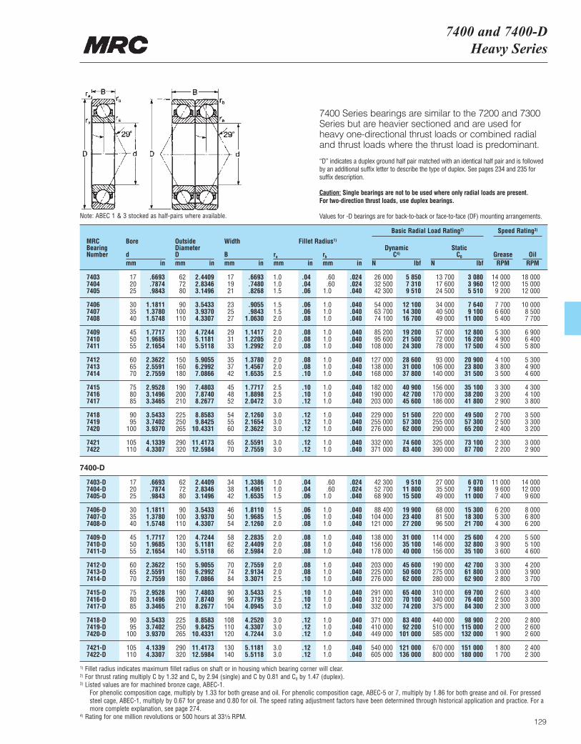
7400 and 7400-DHeavy Series
129
7400 Series bearings are similar to the 7200 and 7300Series but are heavier sectioned and are used forheavy one-directional thrust loads or combined radialand thrust loads where the thrust load is predominant.
“D” indicates a duplex ground half pair matched with an identical half pair and is followedby an additional suffix letter to describe the type of duplex. See pages 234 and 235 for suffix description.
Caution: Single bearings are not to be used where only radial loads are present. For two-direction thrust loads, use duplex bearings.
Values for -D bearings are for back-to-back or face-to-face (DF) mounting arrangements.
MRCBearingNumber
Bore
dmm in
OutsideDiameterDmm in
Width
Bmm in
ra
mm inrb
mm in
DynamicC4)
N lbf
Basic Radial Load Rating2) Speed Rating3)
StaticC0
N lbfGrease OilRPM RPM
Fillet Radius1)
7403 17 .6693 62 2.4409 17 .6693 1.0 .04 .60 .024 26 000 5 850 13 700 3 080 14 000 18 0007404 20 .7874 72 2.8346 19 .7480 1.0 .04 .60 .024 32 500 7 310 17 600 3 960 12 000 15 0007405 25 .9843 80 3.1496 21 .8268 1.5 .06 1.0 .040 42 300 9 510 24 500 5 510 9 200 12 000
7406 30 1.1811 90 3.5433 23 .9055 1.5 .06 1.0 .040 54 000 12 100 34 000 7 640 7 700 10 0007407 35 1.3780 100 3.9370 25 .9843 1.5 .06 1.0 .040 63 700 14 300 40 500 9 100 6 600 8 5007408 40 1.5748 110 4.3307 27 1.0630 2.0 .08 1.0 .040 74 100 16 700 49 000 11 000 5 400 7 700
7409 45 1.7717 120 4.7244 29 1.1417 2.0 .08 1.0 .040 85 200 19 200 57 000 12 800 5 300 6 9007410 50 1.9685 130 5.1181 31 1.2205 2.0 .08 1.0 .040 95 600 21 500 72 000 16 200 4 900 6 4007411 55 2.1654 140 5.5118 33 1.2992 2.0 .08 1.0 .040 108 000 24 300 78 000 17 500 4 500 5 800
7412 60 2.3622 150 5.9055 35 1.3780 2.0 .08 1.0 .040 127 000 28 600 93 000 20 900 4 100 5 3007413 65 2.5591 160 6.2992 37 1.4567 2.0 .08 1.0 .040 138 000 31 000 106 000 23 800 3 800 4 9007414 70 2.7559 180 7.0866 42 1.6535 2.5 .10 1.0 .040 168 000 37 800 140 000 31 500 3 500 4 600
7415 75 2.9528 190 7.4803 45 1.7717 2.5 .10 1.0 .040 182 000 40 900 156 000 35 100 3 300 4 3007416 80 3.1496 200 7.8740 48 1.8898 2.5 .10 1.0 .040 190 000 42 700 170 000 38 200 3 200 4 1007417 85 3.3465 210 8.2677 52 2.0472 3.0 .12 1.0 .040 203 000 45 600 186 000 41 800 2 900 3 800
7418 90 3.5433 225 8.8583 54 2.1260 3.0 .12 1.0 .040 229 000 51 500 220 000 49 500 2 700 3 5007419 95 3.7402 250 9.8425 55 2.1654 3.0 .12 1.0 .040 255 000 57 300 255 000 57 300 2 500 3 3007420 100 3.9370 265 10.4331 60 2.3622 3.0 .12 1.0 .040 276 000 62 000 290 000 65 200 2 400 3 200
7421 105 4.1339 290 11.4173 65 2.5591 3.0 .12 1.0 .040 332 000 74 600 325 000 73 100 2 300 3 0007422 110 4.3307 320 12.5984 70 2.7559 3.0 .12 1.0 .040 371 000 83 400 390 000 87 700 2 200 2 900
7403-D 17 .6693 62 2.4409 34 1.3386 1.0 .04 .60 .024 42 300 9 510 27 000 6 070 11 000 14 0007404-D 20 .7874 72 2.8346 38 1.4961 1.0 .04 .60 .024 52 700 11 800 35 500 7 980 9 600 12 0007405-D 25 .9843 80 3.1496 42 1.6535 1.5 .06 1.0 .040 68 900 15 500 49 000 11 000 7 400 9 600
7406-D 30 1.1811 90 3.5433 46 1.8110 1.5 .06 1.0 .040 88 400 19 900 68 000 15 300 6 200 8 0007407-D 35 1.3780 100 3.9370 50 1.9685 1.5 .06 1.0 .040 104 000 23 400 81 500 18 300 5 300 6 8007408-D 40 1.5748 110 4.3307 54 2.1260 2.0 .08 1.0 .040 121 000 27 200 96 500 21 700 4 300 6 200
7409-D 45 1.7717 120 4.7244 58 2.2835 2.0 .08 1.0 .040 138 000 31 000 114 000 25 600 4 200 5 5007410-D 50 1.9685 130 5.1181 62 2.4409 2.0 .08 1.0 .040 156 000 35 100 146 000 32 800 3 900 5 1007411-D 55 2.1654 140 5.5118 66 2.5984 2.0 .08 1.0 .040 178 000 40 000 156 000 35 100 3 600 4 600
7412-D 60 2.3622 150 5.9055 70 2.7559 2.0 .08 1.0 .040 203 000 45 600 190 000 42 700 3 300 4 2007413-D 65 2.5591 160 6.2992 74 2.9134 2.0 .08 1.0 .040 225 000 50 600 275 000 61 800 3 000 3 9007414-D 70 2.7559 180 7.0866 84 3.3071 2.5 .10 1.0 .040 276 000 62 000 280 000 62 900 2 800 3 700
7415-D 75 2.9528 190 7.4803 90 3.5433 2.5 .10 1.0 .040 291 000 65 400 310 000 69 700 2 600 3 4007416-D 80 3.1496 200 7.8740 96 3.7795 2.5 .10 1.0 .040 312 000 70 100 340 000 76 400 2 500 3 3007417-D 85 3.3465 210 8.2677 104 4.0945 3.0 .12 1.0 .040 332 000 74 200 375 000 84 300 2 300 3 000
7418-D 90 3.5433 225 8.8583 108 4.2520 3.0 .12 1.0 .040 371 000 83 400 440 000 98 900 2 200 2 8007419-D 95 3.7402 250 9.8425 110 4.3307 3.0 .12 1.0 .040 410 000 92 200 510 000 115 000 2 000 2 6007420-D 100 3.9370 265 10.4331 120 4.7244 3.0 .12 1.0 .040 449 000 101 000 585 000 132 000 1 900 2 600
7421-D 105 4.1339 290 11.4173 130 5.1181 3.0 .12 1.0 .040 540 000 121 000 670 000 151 000 1 800 2 4007422-D 110 4.3307 320 12.5984 140 5.5118 3.0 .12 1.0 .040 605 000 136 000 800 000 180 000 1 700 2 300
Note: ABEC 1 & 3 stocked as half-pairs where available.
1) Fillet radius indicates maximum fillet radius on shaft or in housing which bearing corner will clear.2) For thrust rating multiply C by 1.32 and Co by 2.94 (single) and C by 0.81 and C0 by 1.47 (duplex).3) Listed values are for machined bronze cage, ABEC-1.
For phenolic composition cage, multiply by 1.33 for both grease and oil. For phenolic composition cage, ABEC-5 or 7, multiply by 1.86 for both grease and oil. For pressedsteel cage, ABEC-1, multiply by 0.67 for grease and 0.80 for oil. The speed rating adjustment factors have been determined through historical application and practice. For amore complete explanation, see page 274.
4) Rating for one million revolutions or 500 hours at 33¹|₃ RPM.
7400-D
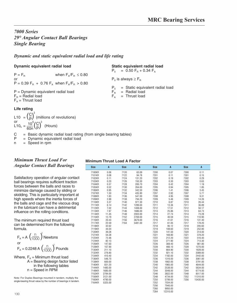
MRC Bearing Services
130
Dynamic and static equivalent radial load and life rating
Dynamic equivalent radial load
P = FR when FA/FR ≤ 0.80orP = 0.39 FR + 0.76 FA when FA/FR > 0.80
P = Dynamic equivalent radial loadFR = Radial loadFA = Thrust load
Static equivalent radial loadP0 = 0.50 FR + 0.34 FA
P0 is always ≥ FR
P0 = Static equivalent radial loadFR = Radial loadFA = Thrust load
Life rating
L10 = (millions of revolutions)orL10h = (Hours)
C = Basic dynamic radial load rating (from single bearing tables)P = Dynamic equivalent radial loadn = Speed in rpm
( )CP
3
( )CP
1060n
36
7000 Series 29° Angular Contact Ball BearingsSingle Bearing
Size Size Size SizeA A A A
Minimum Thrust Load A Factor
7100KR 0.067101KR 0.087102KR 0.117103KR 0.207104KR 0.377105KR 0.527106KR 0.957107KR 1.507108KR 1.837109KR 2.887110KR 3.377111KR 6.147112KR 7.027113KR 7.977114KR 11.457115KR 12.797116KR 20.437117KR 22.597118KR 32.627119KR 44.047120KR 39.287121KR 54.287122KR 72.467124KR 82.137126KR 147.607128KR 157.907130KR 211.107132KR 276.807134KR 410.407136KR 546.707138KR 600.007140KR 831.207144KR 1485.007148KR 1685.007152KR 2784.007156KR 3121.007160KR 4790.007164KR 5325.00
7120 63.097122 94.787124 131.207126 150.307128 200.707130 264.007132 342.507134 435.907136 547.007138 794.207140 977.307142 1289.007144 1408.007146 1686.007148 2003.007152 2769.007156 3679.007164 5481.00
7200 0.077201 0.117202 0.197203 0.307204 0.427205 0.947206 1.417207 2.827208 4.957209 5.467210 6.877211 13.367212 17.517213 25.867214 27.747215 40.597216 41.617217 61.057218 95.127219 108.607220 141.507221 169.807222 212.207224 271.907226 369.407228 466.107230 664.907232 921.107234 1182.007236 1316.007238 1662.007240 1965.007242 2538.007244 3048.007246 3822.007248 4734.007250 5799.007252 7034.007256 7940.007260 9950.007264 12310.00
7300 0.117301 0.157302 0.297303 0.637304 1.197305 1.857306 3.457307 5.777308 9.317309 14.267310 26.447311 36.897312 50.177313 64.737314 73.287315 110.907316 131.407317 178.207318 205.607319 252.807320 314.007321 378.207322 516.407324 713.307326 961.807328 1270.007330 1628.007332 2089.007334 2442.007336 3061.007338 3791.007340 4644.007342 5634.007344 6774.007348 8517.007352 11310.007356 15430.00
Satisfactory operation of angular contactball bearings requires sufficient tractionforces between the balls and races tominimize damage caused by sliding orskidding. This is particularly important athigh speeds where the inertia forces ofthe balls and cage and the viscous dragin the lubricant can have a detrimentalinfluence on the rolling conditions.
The minimum required thrust load can be determined from the followingformula.
FA = A Newtons
or
FA = 0.2248 A Pounds
Where, FA = Minimum thrust load A = Bearing design factor listed
in the following tables n = Speed in RPM
Note: For Duplex Bearings mounted in tandem, multiply thesingle-bearing thrust value by the number of bearings in tandem.
n1000( )
2
n1000( )
2
Minimum Thrust Load ForAngular Contact Ball Bearings
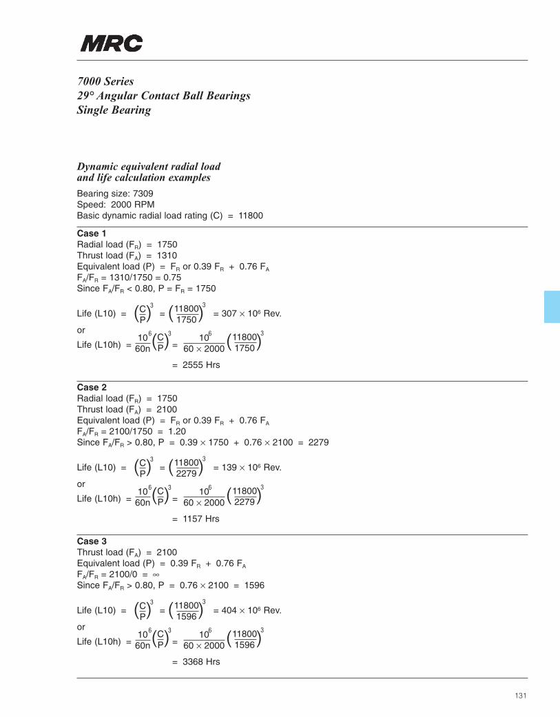
131
7000 Series 29° Angular Contact Ball BearingsSingle Bearing
Dynamic equivalent radial load and life calculation examples
Bearing size: 7309Speed: 2000 RPMBasic dynamic radial load rating (C) = 11800
Case 1Radial load (FR) = 1750Thrust load (FA) = 1310Equivalent load (P) = FR or 0.39 FR + 0.76 FA
FA/FR = 1310/1750 = 0.75Since FA/FR < 0.80, P = FR = 1750
Life (L10) = = = 307 × 106 Rev.
or
Life (L10h) = =
= 2555 Hrs
( )CP
3
( )CP
1060n
36 1060 × 2000
6
( )118001750
3
( )118001750
3
Case 2Radial load (FR) = 1750Thrust load (FA) = 2100Equivalent load (P) = FR or 0.39 FR + 0.76 FA
FA/FR = 2100/1750 = 1.20Since FA/FR > 0.80, P = 0.39 × 1750 + 0.76 × 2100 = 2279
Life (L10) = = = 139 × 106 Rev.
or
Life (L10h) = =
= 1157 Hrs
( )CP
3
( )CP
1060n
36 1060 × 2000
6
( )118002279
3
( )118002279
3
Case 3Thrust load (FA) = 2100Equivalent load (P) = 0.39 FR + 0.76 FA
FA/FR = 2100/0 = ∞Since FA/FR > 0.80, P = 0.76 × 2100 = 1596
Life (L10) = = = 404 × 106 Rev.
or
Life (L10h) = =
= 3368 Hrs
( )CP
3
( )CP
1060n
36 1060 × 2000
6
( )118001596
3
( )118001596
3
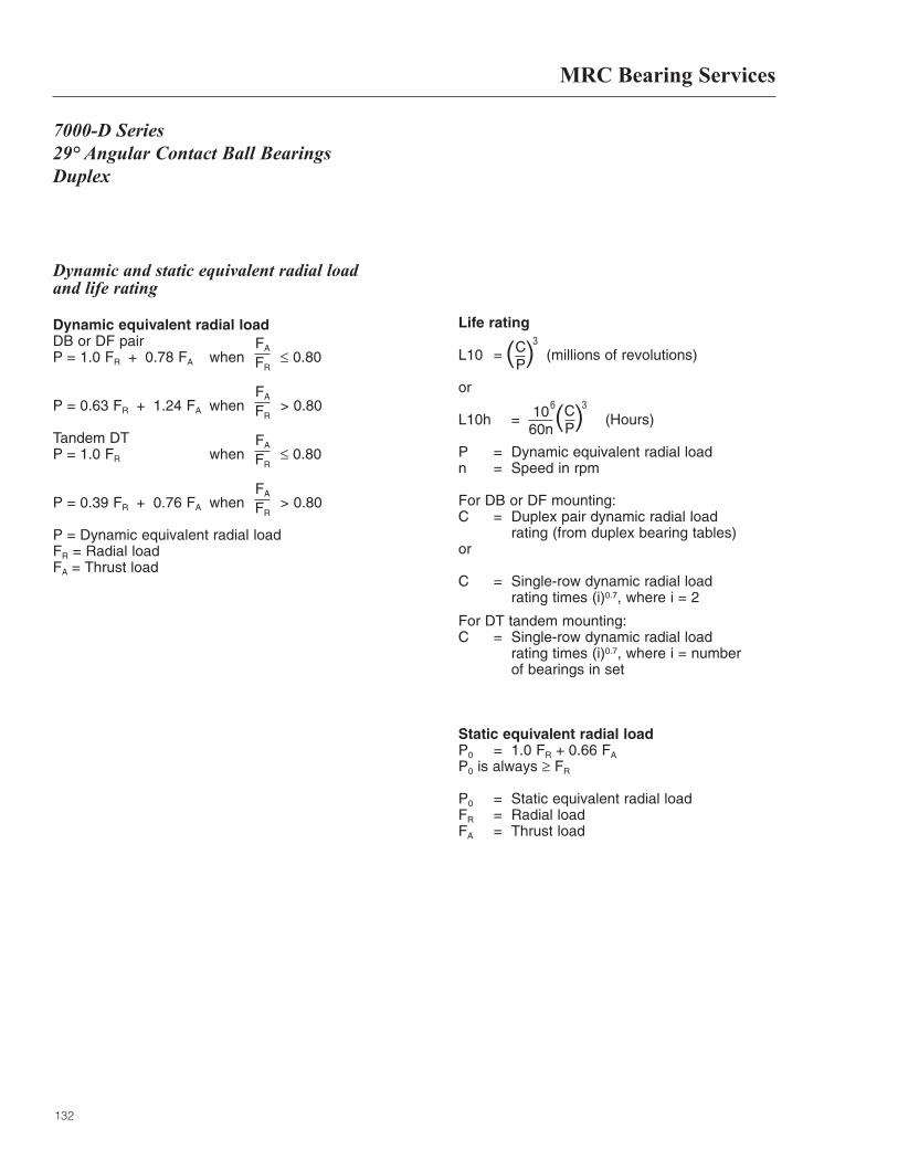
MRC Bearing Services
132
7000-D Series 29° Angular Contact Ball BearingsDuplex
Dynamic and static equivalent radial load and life rating
Dynamic equivalent radial loadDB or DF pairP = 1.0 FR + 0.78 FA when ≤ 0.80
P = 0.63 FR + 1.24 FA when > 0.80
Tandem DTP = 1.0 FR when ≤ 0.80
P = 0.39 FR + 0.76 FA when > 0.80
P = Dynamic equivalent radial loadFR = Radial loadFA = Thrust load
Life rating
L10 = (millions of revolutions)
or
L10h = (Hours)
P = Dynamic equivalent radial loadn = Speed in rpm
For DB or DF mounting:C = Duplex pair dynamic radial load
rating (from duplex bearing tables)or
C = Single-row dynamic radial load rating times (i)0.7, where i = 2
For DT tandem mounting:C = Single-row dynamic radial load
rating times (i)0.7, where i = numberof bearings in set
Static equivalent radial loadP0 = 1.0 FR + 0.66 FA
P0 is always ≥ FR
P0 = Static equivalent radial loadFR = Radial loadFA = Thrust load
( )CP
3FA
FR
FA
FR
FA
FR
FA
FR
( )CP
1060n
36
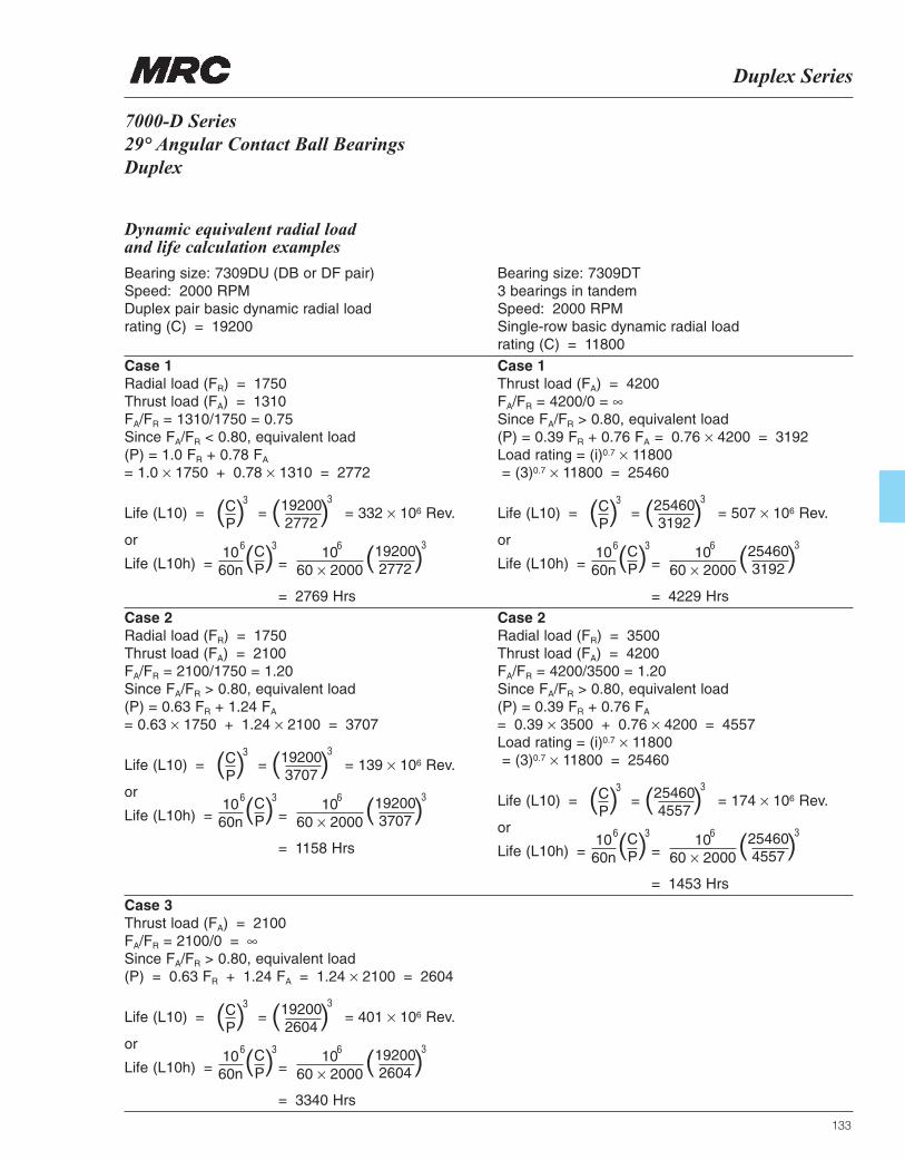
Duplex Series
133
7000-D Series 29° Angular Contact Ball BearingsDuplex
Dynamic equivalent radial load and life calculation examples
Bearing size: 7309DU (DB or DF pair)Speed: 2000 RPMDuplex pair basic dynamic radial load rating (C) = 19200
Bearing size: 7309DT3 bearings in tandemSpeed: 2000 RPMSingle-row basic dynamic radial load rating (C) = 11800
Case 1Radial load (FR) = 1750Thrust load (FA) = 1310FA/FR = 1310/1750 = 0.75Since FA/FR < 0.80, equivalent load (P) = 1.0 FR + 0.78 FA
= 1.0 × 1750 + 0.78 × 1310 = 2772
Case 2Radial load (FR) = 1750Thrust load (FA) = 2100FA/FR = 2100/1750 = 1.20Since FA/FR > 0.80, equivalent load (P) = 0.63 FR + 1.24 FA
= 0.63 × 1750 + 1.24 × 2100 = 3707
Case 1Thrust load (FA) = 4200FA/FR = 4200/0 = ∞Since FA/FR > 0.80, equivalent load (P) = 0.39 FR + 0.76 FA = 0.76 × 4200 = 3192Load rating = (i)0.7 × 11800= (3)0.7 × 11800 = 25460
Case 2Radial load (FR) = 3500Thrust load (FA) = 4200FA/FR = 4200/3500 = 1.20Since FA/FR > 0.80, equivalent load (P) = 0.39 FR + 0.76 FA
= 0.39 × 3500 + 0.76 × 4200 = 4557Load rating = (i)0.7 × 11800= (3)0.7 × 11800 = 25460
Life (L10) = = = 332 × 106 Rev.
or
Life (L10h) = =
= 2769 Hrs
( )CP
3
( )CP
1060n
36 1060 × 2000
6
( )192002772
3
( )192002772
3
Life (L10) = = = 139 × 106 Rev.
or
Life (L10h) = =
= 1158 Hrs
( )CP
3
( )CP
1060n
36 1060 × 2000
6
( )192003707
3
( )192003707
3
Life (L10) = = = 507 × 106 Rev.
or
Life (L10h) = =
= 4229 Hrs
( )CP
3
( )CP
1060n
36 1060 × 2000
6
( )254603192
3
( )254603192
3
Life (L10) = = = 174 × 106 Rev.
or
Life (L10h) = =
= 1453 Hrs
( )CP
3
( )CP
1060n
36 1060 × 2000
6
( )254604557
3
( )254604557
3
Case 3Thrust load (FA) = 2100FA/FR = 2100/0 = ∞Since FA/FR > 0.80, equivalent load (P) = 0.63 FR + 1.24 FA = 1.24 × 2100 = 2604
Life (L10) = = = 401 × 106 Rev.
or
Life (L10h) = =
= 3340 Hrs
( )CP
3
( )CP
1060n
36 1060 × 2000
6
( )192002604
3
( )192002604
3

134
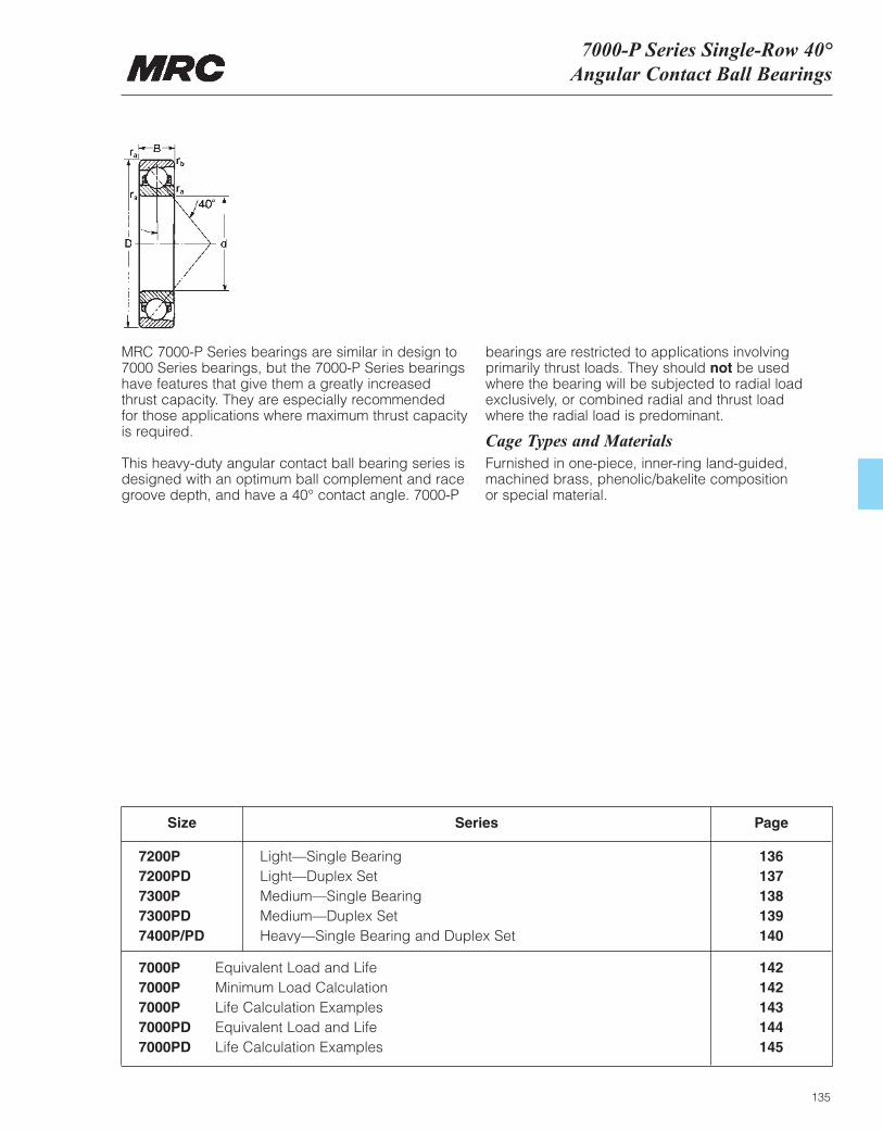
Size
7200P Light—Single Bearing 136 7200PD Light—Duplex Set 137 7300P Medium—Single Bearing 138 7300PD Medium—Duplex Set 139 7400P/PD Heavy—Single Bearing and Duplex Set 140
Series Page
7000P Equivalent Load and Life 1427000P Minimum Load Calculation 1427000P Life Calculation Examples 1437000PD Equivalent Load and Life 1447000PD Life Calculation Examples 145
7000-P Series Single-Row 40°Angular Contact Ball Bearings
135
MRC 7000-P Series bearings are similar in design to7000 Series bearings, but the 7000-P Series bearingshave features that give them a greatly increased thrust capacity. They are especially recommended for those applications where maximum thrust capacityis required.
This heavy-duty angular contact ball bearing series isdesigned with an optimum ball complement and racegroove depth, and have a 40° contact angle. 7000-P
bearings are restricted to applications involvingprimarily thrust loads. They should not be usedwhere the bearing will be subjected to radial loadexclusively, or combined radial and thrust load where the radial load is predominant.
Cage Types and MaterialsFurnished in one-piece, inner-ring land-guided,machined brass, phenolic/bakelite composition or special material.
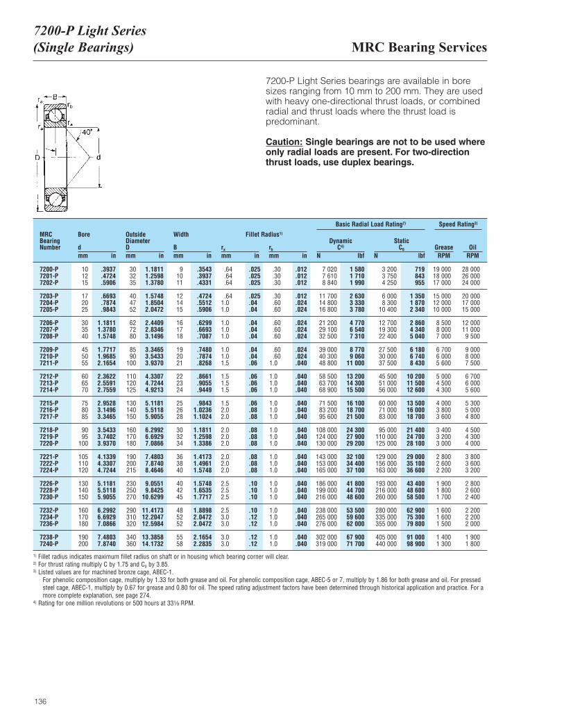
MRC Bearing Services7200-P Light Series (Single Bearings)
136
7200-P Light Series bearings are available in bore sizes ranging from 10 mm to 200 mm. They are usedwith heavy one-directional thrust loads, or combinedradial and thrust loads where the thrust load ispredominant.
Caution: Single bearings are not to be used whereonly radial loads are present. For two-directionthrust loads, use duplex bearings.
MRCBearingNumber
Bore
dmm in
OutsideDiameterDmm in
Width
Bmm in
ra
mm inrb
mm in
DynamicC4)
N lbf
Basic Radial Load Rating2) Speed Rating3)
StaticC0
N lbfGrease OilRPM RPM
Fillet Radius1)
7200-P 10 .3937 30 1.1811 9 .3543 .64 .025 .30 .012 7 020 1 580 3 200 719 19 000 28 0007201-P 12 .4724 32 1.2598 10 .3937 .64 .025 .30 .012 7 610 1 710 3 750 843 18 000 26 0007202-P 15 .5906 35 1.3780 11 .4331 .64 .025 .30 .012 8 840 1 990 4 250 955 17 000 24 000
7203-P 17 .6693 40 1.5748 12 .4724 .64 .025 .30 .012 11 700 2 630 6 000 1 350 15 000 20 0007204-P 20 .7874 47 1.8504 14 .5512 1.0 .04 .60 .024 14 800 3 330 8 300 1 870 12 000 17 0007205-P 25 .9843 52 2.0472 15 .5906 1.0 .04 .60 .024 16 800 3 780 10 400 2 340 10 000 15 000
7206-P 30 1.1811 62 2.4409 16 .6299 1.0 .04 .60 .024 21 200 4 770 12 700 2 860 8 500 12 0007207-P 35 1.3780 72 2.8346 17 .6693 1.0 .04 .60 .024 29 100 6 540 19 300 4 340 8 000 11 0007208-P 40 1.5748 80 3.1496 18 .7087 1.0 .04 .60 .024 32 500 7 310 22 400 5 040 7 000 9 500
7209-P 45 1.7717 85 3.3465 19 .7480 1.0 .04 .60 .024 39 000 8 770 27 500 6 180 6 700 9 0007210-P 50 1.9685 90 3.5433 20 .7874 1.0 .04 .60 .024 40 300 9 060 30 000 6 740 6 000 8 0007211-P 55 2.1654 100 3.9370 21 .8268 1.5 .06 1.0 .040 48 800 11 000 37 500 8 430 5 600 7 500
7212-P 60 2.3622 110 4.3307 22 .8661 1.5 .06 1.0 .040 58 500 13 200 45 500 10 200 5 000 6 7007213-P 65 2.5591 120 4.7244 23 .9055 1.5 .06 1.0 .040 63 700 14 300 51 000 11 500 4 500 6 0007214-P 70 2.7559 125 4.9213 24 .9449 1.5 .06 1.0 .040 68 900 15 500 56 000 12 600 4 300 5 600
7215-P 75 2.9528 130 5.1181 25 .9843 1.5 .06 1.0 .040 71 500 16 100 60 000 13 500 4 000 5 3007216-P 80 3.1496 140 5.5118 26 1.0236 2.0 .08 1.0 .040 83 200 18 700 71 000 16 000 3 800 5 0007217-P 85 3.3465 150 5.9055 28 1.1024 2.0 .08 1.0 .040 95 600 21 500 83 000 18 700 3 600 4 800
7218-P 90 3.5433 160 6.2992 30 1.1811 2.0 .08 1.0 .040 108 000 24 300 95 000 21 400 3 400 4 5007219-P 95 3.7402 170 6.6929 32 1.2598 2.0 .08 1.0 .040 124 000 27 900 110 000 24 700 3 200 4 3007220-P 100 3.9370 180 7.0866 34 1.3386 2.0 .08 1.0 .040 130 000 29 200 125 000 28 100 3 000 4 000
7221-P 105 4.1339 190 7.4803 36 1.4173 2.0 .08 1.0 .040 143 000 32 100 129 000 29 000 2 800 3 8007222-P 110 4.3307 200 7.8740 38 1.4961 2.0 .08 1.0 .040 153 000 34 400 156 000 35 100 2 600 3 6007224-P 120 4.7244 215 8.4646 40 1.5748 2.0 .08 1.0 .040 165 000 37 100 163 000 36 600 2 200 3 200
7226-P 130 5.1181 230 9.0551 40 1.5748 2.5 .10 1.0 .040 186 000 41 800 193 000 43 400 1 900 2 8007228-P 140 5.5118 250 9.8425 42 1.6535 2.5 .10 1.0 .040 199 000 44 700 216 000 48 600 1 800 2 6007230-P 150 5.9055 270 10.6299 45 1.7717 2.5 .10 1.0 .040 216 000 48 600 260 000 58 500 1 700 2 400
7232-P 160 6.2992 290 11.4173 48 1.8898 2.5 .10 1.0 .040 238 000 53 500 280 000 62 900 1 600 2 2007234-P 170 6.6929 310 12.2047 52 2.0472 3.0 .12 1.0 .040 265 000 59 600 335 000 75 300 1 600 2 2007236-P 180 7.0866 320 12.5984 52 2.0472 3.0 .12 1.0 .040 276 000 62 000 355 000 79 800 1 500 2 000
7238-P 190 7.4803 340 13.3858 55 2.1654 3.0 .12 1.0 .040 302 000 67 900 405 000 91 000 1 400 1 9007240-P 200 7.8740 360 14.1732 58 2.2835 3.0 .12 1.0 .040 319 000 71 700 440 000 98 900 1 300 1 800
1) Fillet radius indicates maximum fillet radius on shaft or in housing which bearing corner will clear.2) For thrust rating multiply C by 1.75 and C0 by 3.85.3) Listed values are for machined bronze cage, ABEC-1.
For phenolic composition cage, multiply by 1.33 for both grease and oil. For phenolic composition cage, ABEC-5 or 7, multiply by 1.86 for both grease and oil. For pressedsteel cage, ABEC-1, multiply by 0.67 for grease and 0.80 for oil. The speed rating adjustment factors have been determined through historical application and practice. For amore complete explanation, see page 274.
4) Rating for one million revolutions or 500 hours at 33¹|₃ RPM.
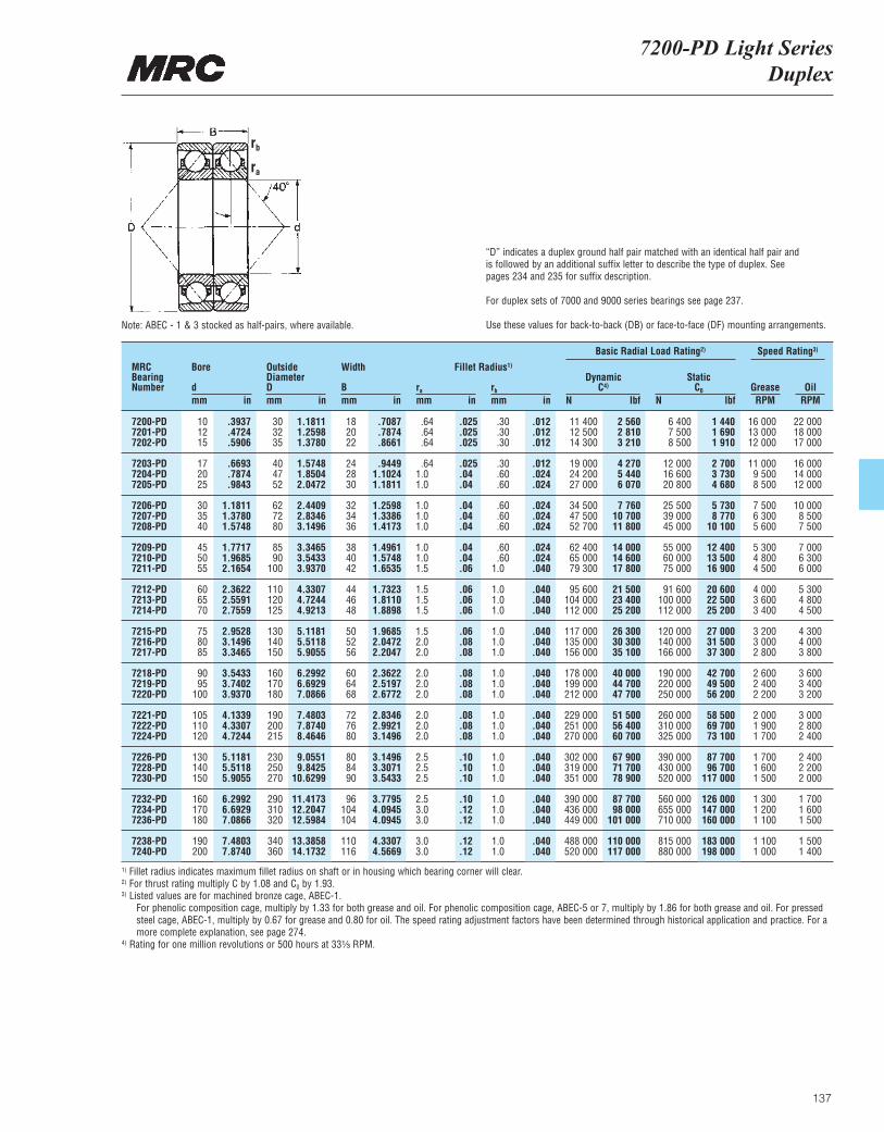
7200-PD Light SeriesDuplex
137
“D” indicates a duplex ground half pair matched with an identical half pair and is followed by an additional suffix letter to describe the type of duplex. See pages 234 and 235 for suffix description.
For duplex sets of 7000 and 9000 series bearings see page 237.
Use these values for back-to-back (DB) or face-to-face (DF) mounting arrangements.
MRCBearingNumber
Bore
dmm in
OutsideDiameterDmm in
Width
Bmm in
ra
mm inrb
mm in
DynamicC4)
N lbf
Basic Radial Load Rating2) Speed Rating3)
StaticC0
N lbfGrease OilRPM RPM
Fillet Radius1)
7200-PD 10 .3937 30 1.1811 18 .7087 .64 .025 .30 .012 11 400 2 560 6 400 1 440 16 000 22 0007201-PD 12 .4724 32 1.2598 20 .7874 .64 .025 .30 .012 12 500 2 810 7 500 1 690 13 000 18 0007202-PD 15 .5906 35 1.3780 22 .8661 .64 .025 .30 .012 14 300 3 210 8 500 1 910 12 000 17 000
7203-PD 17 .6693 40 1.5748 24 .9449 .64 .025 .30 .012 19 000 4 270 12 000 2 700 11 000 16 0007204-PD 20 .7874 47 1.8504 28 1.1024 1.0 .04 .60 .024 24 200 5 440 16 600 3 730 9 500 14 0007205-PD 25 .9843 52 2.0472 30 1.1811 1.0 .04 .60 .024 27 000 6 070 20 800 4 680 8 500 12 000
7206-PD 30 1.1811 62 2.4409 32 1.2598 1.0 .04 .60 .024 34 500 7 760 25 500 5 730 7 500 10 0007207-PD 35 1.3780 72 2.8346 34 1.3386 1.0 .04 .60 .024 47 500 10 700 39 000 8 770 6 300 8 5007208-PD 40 1.5748 80 3.1496 36 1.4173 1.0 .04 .60 .024 52 700 11 800 45 000 10 100 5 600 7 500
7209-PD 45 1.7717 85 3.3465 38 1.4961 1.0 .04 .60 .024 62 400 14 000 55 000 12 400 5 300 7 0007210-PD 50 1.9685 90 3.5433 40 1.5748 1.0 .04 .60 .024 65 000 14 600 60 000 13 500 4 800 6 3007211-PD 55 2.1654 100 3.9370 42 1.6535 1.5 .06 1.0 .040 79 300 17 800 75 000 16 900 4 500 6 000
7212-PD 60 2.3622 110 4.3307 44 1.7323 1.5 .06 1.0 .040 95 600 21 500 91 600 20 600 4 000 5 3007213-PD 65 2.5591 120 4.7244 46 1.8110 1.5 .06 1.0 .040 104 000 23 400 100 000 22 500 3 600 4 8007214-PD 70 2.7559 125 4.9213 48 1.8898 1.5 .06 1.0 .040 112 000 25 200 112 000 25 200 3 400 4 500
7215-PD 75 2.9528 130 5.1181 50 1.9685 1.5 .06 1.0 .040 117 000 26 300 120 000 27 000 3 200 4 3007216-PD 80 3.1496 140 5.5118 52 2.0472 2.0 .08 1.0 .040 135 000 30 300 140 000 31 500 3 000 4 0007217-PD 85 3.3465 150 5.9055 56 2.2047 2.0 .08 1.0 .040 156 000 35 100 166 000 37 300 2 800 3 800
7218-PD 90 3.5433 160 6.2992 60 2.3622 2.0 .08 1.0 .040 178 000 40 000 190 000 42 700 2 600 3 6007219-PD 95 3.7402 170 6.6929 64 2.5197 2.0 .08 1.0 .040 199 000 44 700 220 000 49 500 2 400 3 4007220-PD 100 3.9370 180 7.0866 68 2.6772 2.0 .08 1.0 .040 212 000 47 700 250 000 56 200 2 200 3 200
7221-PD 105 4.1339 190 7.4803 72 2.8346 2.0 .08 1.0 .040 229 000 51 500 260 000 58 500 2 000 3 0007222-PD 110 4.3307 200 7.8740 76 2.9921 2.0 .08 1.0 .040 251 000 56 400 310 000 69 700 1 900 2 8007224-PD 120 4.7244 215 8.4646 80 3.1496 2.0 .08 1.0 .040 270 000 60 700 325 000 73 100 1 700 2 400
7226-PD 130 5.1181 230 9.0551 80 3.1496 2.5 .10 1.0 .040 302 000 67 900 390 000 87 700 1 700 2 4007228-PD 140 5.5118 250 9.8425 84 3.3071 2.5 .10 1.0 .040 319 000 71 700 430 000 96 700 1 600 2 2007230-PD 150 5.9055 270 10.6299 90 3.5433 2.5 .10 1.0 .040 351 000 78 900 520 000 117 000 1 500 2 000
7232-PD 160 6.2992 290 11.4173 96 3.7795 2.5 .10 1.0 .040 390 000 87 700 560 000 126 000 1 300 1 7007234-PD 170 6.6929 310 12.2047 104 4.0945 3.0 .12 1.0 .040 436 000 98 000 655 000 147 000 1 200 1 6007236-PD 180 7.0866 320 12.5984 104 4.0945 3.0 .12 1.0 .040 449 000 101 000 710 000 160 000 1 100 1 500
7238-PD 190 7.4803 340 13.3858 110 4.3307 3.0 .12 1.0 .040 488 000 110 000 815 000 183 000 1 100 1 5007240-PD 200 7.8740 360 14.1732 116 4.5669 3.0 .12 1.0 .040 520 000 117 000 880 000 198 000 1 000 1 400
1) Fillet radius indicates maximum fillet radius on shaft or in housing which bearing corner will clear.2) For thrust rating multiply C by 1.08 and C0 by 1.93.3) Listed values are for machined bronze cage, ABEC-1.
For phenolic composition cage, multiply by 1.33 for both grease and oil. For phenolic composition cage, ABEC-5 or 7, multiply by 1.86 for both grease and oil. For pressedsteel cage, ABEC-1, multiply by 0.67 for grease and 0.80 for oil. The speed rating adjustment factors have been determined through historical application and practice. For amore complete explanation, see page 274.
4) Rating for one million revolutions or 500 hours at 33¹|₃ RPM.
Note: ABEC - 1 & 3 stocked as half-pairs, where available.
rb
ra
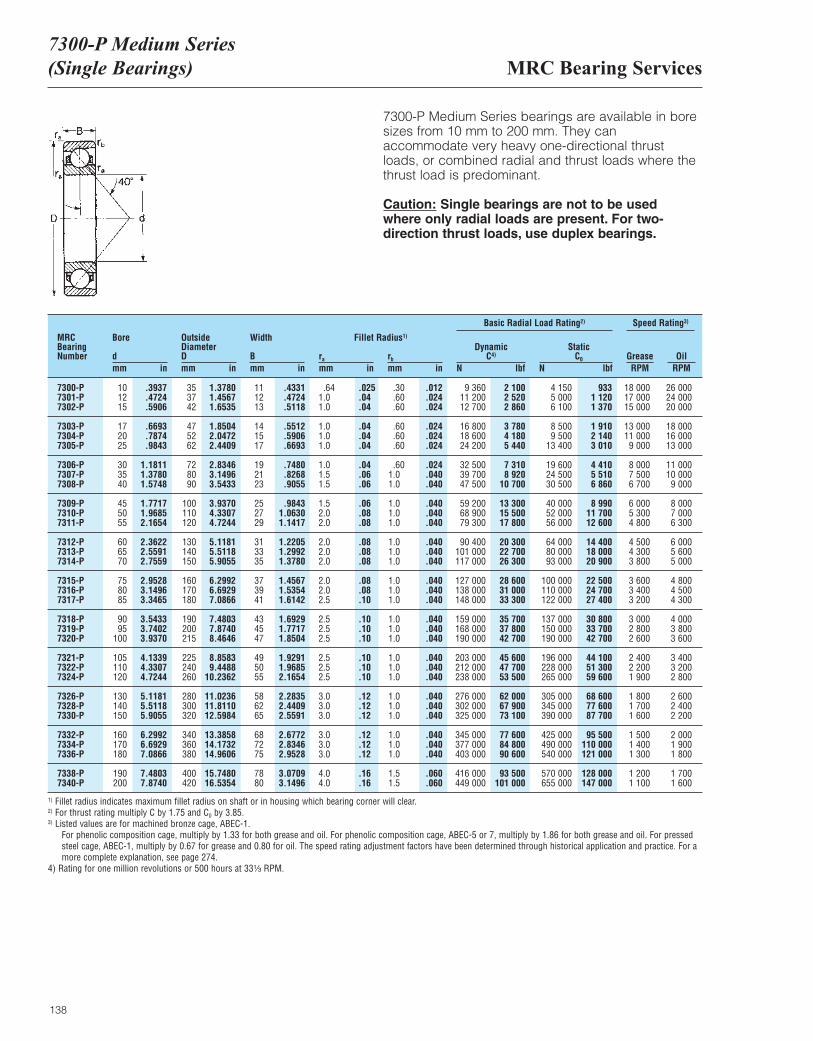
MRC Bearing Services7300-P Medium Series (Single Bearings)
138
7300-P Medium Series bearings are available in boresizes from 10 mm to 200 mm. They can accommodate very heavy one-directional thrustloads, or combined radial and thrust loads where thethrust load is predominant.
Caution: Single bearings are not to be used where only radial loads are present. For two-direction thrust loads, use duplex bearings.
MRCBearingNumber
Bore
dmm in
OutsideDiameterDmm in
Width
Bmm in
ra
mm inrb
mm in
DynamicC4)
N lbf
Basic Radial Load Rating2) Speed Rating3)
StaticC0
N lbfGrease OilRPM RPM
Fillet Radius1)
7300-P 10 .3937 35 1.3780 11 .4331 .64 .025 .30 .012 9 360 2 100 4 150 933 18 000 26 0007301-P 12 .4724 37 1.4567 12 .4724 1.0 .04 .60 .024 11 200 2 520 5 000 1 120 17 000 24 0007302-P 15 .5906 42 1.6535 13 .5118 1.0 .04 .60 .024 12 700 2 860 6 100 1 370 15 000 20 000
7303-P 17 .6693 47 1.8504 14 .5512 1.0 .04 .60 .024 16 800 3 780 8 500 1 910 13 000 18 0007304-P 20 .7874 52 2.0472 15 .5906 1.0 .04 .60 .024 18 600 4 180 9 500 2 140 11 000 16 0007305-P 25 .9843 62 2.4409 17 .6693 1.0 .04 .60 .024 24 200 5 440 13 400 3 010 9 000 13 000
7306-P 30 1.1811 72 2.8346 19 .7480 1.0 .04 .60 .024 32 500 7 310 19 600 4 410 8 000 11 0007307-P 35 1.3780 80 3.1496 21 .8268 1.5 .06 1.0 .040 39 700 8 920 24 500 5 510 7 500 10 0007308-P 40 1.5748 90 3.5433 23 .9055 1.5 .06 1.0 .040 47 500 10 700 30 500 6 860 6 700 9 000
7309-P 45 1.7717 100 3.9370 25 .9843 1.5 .06 1.0 .040 59 200 13 300 40 000 8 990 6 000 8 0007310-P 50 1.9685 110 4.3307 27 1.0630 2.0 .08 1.0 .040 68 900 15 500 52 000 11 700 5 300 7 0007311-P 55 2.1654 120 4.7244 29 1.1417 2.0 .08 1.0 .040 79 300 17 800 56 000 12 600 4 800 6 300
7312-P 60 2.3622 130 5.1181 31 1.2205 2.0 .08 1.0 .040 90 400 20 300 64 000 14 400 4 500 6 0007313-P 65 2.5591 140 5.5118 33 1.2992 2.0 .08 1.0 .040 101 000 22 700 80 000 18 000 4 300 5 6007314-P 70 2.7559 150 5.9055 35 1.3780 2.0 .08 1.0 .040 117 000 26 300 93 000 20 900 3 800 5 000
7315-P 75 2.9528 160 6.2992 37 1.4567 2.0 .08 1.0 .040 127 000 28 600 100 000 22 500 3 600 4 8007316-P 80 3.1496 170 6.6929 39 1.5354 2.0 .08 1.0 .040 138 000 31 000 110 000 24 700 3 400 4 5007317-P 85 3.3465 180 7.0866 41 1.6142 2.5 .10 1.0 .040 148 000 33 300 122 000 27 400 3 200 4 300
7318-P 90 3.5433 190 7.4803 43 1.6929 2.5 .10 1.0 .040 159 000 35 700 137 000 30 800 3 000 4 0007319-P 95 3.7402 200 7.8740 45 1.7717 2.5 .10 1.0 .040 168 000 37 800 150 000 33 700 2 800 3 8007320-P 100 3.9370 215 8.4646 47 1.8504 2.5 .10 1.0 .040 190 000 42 700 190 000 42 700 2 600 3 600
7321-P 105 4.1339 225 8.8583 49 1.9291 2.5 .10 1.0 .040 203 000 45 600 196 000 44 100 2 400 3 4007322-P 110 4.3307 240 9.4488 50 1.9685 2.5 .10 1.0 .040 212 000 47 700 228 000 51 300 2 200 3 2007324-P 120 4.7244 260 10.2362 55 2.1654 2.5 .10 1.0 .040 238 000 53 500 265 000 59 600 1 900 2 800
7326-P 130 5.1181 280 11.0236 58 2.2835 3.0 .12 1.0 .040 276 000 62 000 305 000 68 600 1 800 2 6007328-P 140 5.5118 300 11.8110 62 2.4409 3.0 .12 1.0 .040 302 000 67 900 345 000 77 600 1 700 2 4007330-P 150 5.9055 320 12.5984 65 2.5591 3.0 .12 1.0 .040 325 000 73 100 390 000 87 700 1 600 2 200
7332-P 160 6.2992 340 13.3858 68 2.6772 3.0 .12 1.0 .040 345 000 77 600 425 000 95 500 1 500 2 0007334-P 170 6.6929 360 14.1732 72 2.8346 3.0 .12 1.0 .040 377 000 84 800 490 000 110 000 1 400 1 9007336-P 180 7.0866 380 14.9606 75 2.9528 3.0 .12 1.0 .040 403 000 90 600 540 000 121 000 1 300 1 800
7338-P 190 7.4803 400 15.7480 78 3.0709 4.0 .16 1.5 .060 416 000 93 500 570 000 128 000 1 200 1 7007340-P 200 7.8740 420 16.5354 80 3.1496 4.0 .16 1.5 .060 449 000 101 000 655 000 147 000 1 100 1 600
1) Fillet radius indicates maximum fillet radius on shaft or in housing which bearing corner will clear.2) For thrust rating multiply C by 1.75 and C0 by 3.85.3) Listed values are for machined bronze cage, ABEC-1.
For phenolic composition cage, multiply by 1.33 for both grease and oil. For phenolic composition cage, ABEC-5 or 7, multiply by 1.86 for both grease and oil. For pressedsteel cage, ABEC-1, multiply by 0.67 for grease and 0.80 for oil. The speed rating adjustment factors have been determined through historical application and practice. For amore complete explanation, see page 274.
4) Rating for one million revolutions or 500 hours at 33¹|₃ RPM.
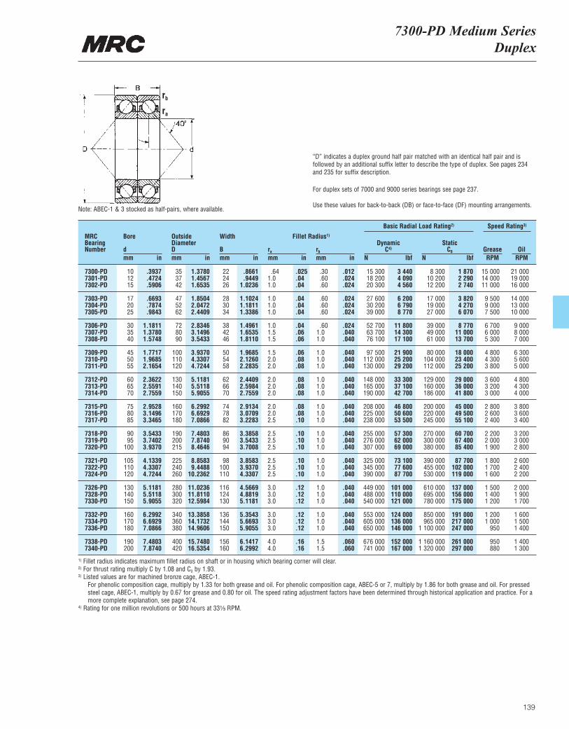
7300-PD Medium SeriesDuplex
139
“D” indicates a duplex ground half pair matched with an identical half pair and isfollowed by an additional suffix letter to describe the type of duplex. See pages 234and 235 for suffix description.
For duplex sets of 7000 and 9000 series bearings see page 237.
Use these values for back-to-back (DB) or face-to-face (DF) mounting arrangements.
MRCBearingNumber
Bore
dmm in
OutsideDiameterDmm in
Width
Bmm in
ra
mm inrb
mm in
DynamicC4)
N lbf
Basic Radial Load Rating2) Speed Rating3)
StaticC0
N lbfGrease OilRPM RPM
Fillet Radius1)
7300-PD 10 .3937 35 1.3780 22 .8661 .64 .025 .30 .012 15 300 3 440 8 300 1 870 15 000 21 0007301-PD 12 .4724 37 1.4567 24 .9449 1.0 .04 .60 .024 18 200 4 090 10 200 2 290 14 000 19 0007302-PD 15 .5906 42 1.6535 26 1.0236 1.0 .04 .60 .024 20 300 4 560 12 200 2 740 11 000 16 000
7303-PD 17 .6693 47 1.8504 28 1.1024 1.0 .04 .60 .024 27 600 6 200 17 000 3 820 9 500 14 0007304-PD 20 .7874 52 2.0472 30 1.1811 1.0 .04 .60 .024 30 200 6 790 19 000 4 270 9 000 13 0007305-PD 25 .9843 62 2.4409 34 1.3386 1.0 .04 .60 .024 39 000 8 770 27 000 6 070 7 500 10 000
7306-PD 30 1.1811 72 2.8346 38 1.4961 1.0 .04 .60 .024 52 700 11 800 39 000 8 770 6 700 9 0007307-PD 35 1.3780 80 3.1496 42 1.6535 1.5 .06 1.0 .040 63 700 14 300 49 000 11 000 6 000 8 0007308-PD 40 1.5748 90 3.5433 46 1.8110 1.5 .06 1.0 .040 76 100 17 100 61 000 13 700 5 300 7 000
7309-PD 45 1.7717 100 3.9370 50 1.9685 1.5 .06 1.0 .040 97 500 21 900 80 000 18 000 4 800 6 3007310-PD 50 1.9685 110 4.3307 54 2.1260 2.0 .08 1.0 .040 112 000 25 200 104 000 23 400 4 300 5 6007311-PD 55 2.1654 120 4.7244 58 2.2835 2.0 .08 1.0 .040 130 000 29 200 112 000 25 200 3 800 5 000
7312-PD 60 2.3622 130 5.1181 62 2.4409 2.0 .08 1.0 .040 148 000 33 300 129 000 29 000 3 600 4 8007313-PD 65 2.5591 140 5.5118 66 2.5984 2.0 .08 1.0 .040 165 000 37 100 160 000 36 000 3 200 4 3007314-PD 70 2.7559 150 5.9055 70 2.7559 2.0 .08 1.0 .040 190 000 42 700 186 000 41 800 3 000 4 000
7315-PD 75 2.9528 160 6.2992 74 2.9134 2.0 .08 1.0 .040 208 000 46 800 200 000 45 000 2 800 3 8007316-PD 80 3.1496 170 6.6929 78 3.0709 2.0 .08 1.0 .040 225 000 50 600 220 000 49 500 2 600 3 6007317-PD 85 3.3465 180 7.0866 82 3.2283 2.5 .10 1.0 .040 238 000 53 500 245 000 55 100 2 400 3 400
7318-PD 90 3.5433 190 7.4803 86 3.3858 2.5 .10 1.0 .040 255 000 57 300 270 000 60 700 2 200 3 2007319-PD 95 3.7402 200 7.8740 90 3.5433 2.5 .10 1.0 .040 276 000 62 000 300 000 67 400 2 000 3 0007320-PD 100 3.9370 215 8.4646 94 3.7008 2.5 .10 1.0 .040 307 000 69 000 380 000 85 400 1 900 2 800
7321-PD 105 4.1339 225 8.8583 98 3.8583 2.5 .10 1.0 .040 325 000 73 100 390 000 87 700 1 800 2 6007322-PD 110 4.3307 240 9.4488 100 3.9370 2.5 .10 1.0 .040 345 000 77 600 455 000 102 000 1 700 2 4007324-PD 120 4.7244 260 10.2362 110 4.3307 2.5 .10 1.0 .040 390 000 87 700 530 000 119 000 1 600 2 200
7326-PD 130 5.1181 280 11.0236 116 4.5669 3.0 .12 1.0 .040 449 000 101 000 610 000 137 000 1 500 2 0007328-PD 140 5.5118 300 11.8110 124 4.8819 3.0 .12 1.0 .040 488 000 110 000 695 000 156 000 1 400 1 9007330-PD 150 5.9055 320 12.5984 130 5.1181 3.0 .12 1.0 .040 540 000 121 000 780 000 175 000 1 200 1 700
7332-PD 160 6.2992 340 13.3858 136 5.3543 3.0 .12 1.0 .040 553 000 124 000 850 000 191 000 1 200 1 6007334-PD 170 6.6929 360 14.1732 144 5.6693 3.0 .12 1.0 .040 605 000 136 000 965 000 217 000 1 000 1 5007336-PD 180 7.0866 380 14.9606 150 5.9055 3.0 .12 1.0 .040 650 000 146 000 1 100 000 247 000 950 1 400
7338-PD 190 7.4803 400 15.7480 156 6.1417 4.0 .16 1.5 .060 676 000 152 000 1 160 000 261 000 950 1 4007340-PD 200 7.8740 420 16.5354 160 6.2992 4.0 .16 1.5 .060 741 000 167 000 1 320 000 297 000 880 1 300
1) Fillet radius indicates maximum fillet radius on shaft or in housing which bearing corner will clear.2) For thrust rating multiply C by 1.08 and C0 by 1.93.3) Listed values are for machined bronze cage, ABEC-1.
For phenolic composition cage, multiply by 1.33 for both grease and oil. For phenolic composition cage, ABEC-5 or 7, multiply by 1.86 for both grease and oil. For pressedsteel cage, ABEC-1, multiply by 0.67 for grease and 0.80 for oil. The speed rating adjustment factors have been determined through historical application and practice. For amore complete explanation, see page 274.
4) Rating for one million revolutions or 500 hours at 33¹|₃ RPM.
Note: ABEC-1 & 3 stocked as half-pairs, where available.
rb
ra
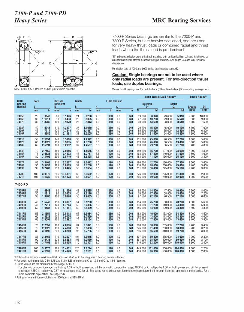
MRC Bearing Services7400-P and 7400-PDHeavy Series
140
7400-P Series bearings are similar to the 7200-P and 7300-P Series, but are heavier sectioned, and are used for very heavy thrust loads or combined radial and thrustloads where the thrust load is predominant.
“D” indicates a duplex ground half pair matched with an identical half pair and is followed byan additional suffix letter to describe the type of duplex. See pages 234 and 235 for suffixdescription.
For duplex sets of 7000 and 9000 series bearings see page 237.
Caution: Single bearings are not to be used whereonly radial loads are present. For two-direction thrustloads, use duplex bearings.Values for -D bearings are for back-to-back (DB) or face-to-face (DF) mounting arrangements.
MRCBearingNumber
Bore
dmm in
OutsideDiameterDmm in
Width
Bmm in
ra
mm inrb
mm in
DynamicC4)
N lbf
Basic Radial Load Rating2) Speed Rating3)
StaticC0
N lbfGrease OilRPM RPM
Fillet Radius1)
7405P 25 .9843 80 3.1496 21 .8268 1.5 .060 1.0 .040 39 700 8 920 23 600 5 310 7 000 10 0007406P 30 1.1811 90 3.5433 23 .9055 1.5 .060 1.0 .040 47 500 10 700 29 000 6 520 6 300 9 0007407P 35 1.3780 100 3.9370 25 .9843 1.5 .060 1.0 .040 60 500 13 600 38 000 8 540 5 600 7 500
7408P 40 1.5748 110 4.3307 27 1.0630 2.0 .080 1.0 .040 70 200 15 800 45 000 10 100 5 300 7 0007409P 45 1.7717 120 4.7244 29 1.1417 2.0 .080 1.0 .040 85 200 19 200 55 000 12 400 4 800 6 3007410P 50 1.9685 130 5.1181 31 1.2205 2.0 .080 1.0 .040 95 600 21 500 64 000 14 400 4 300 6 000
7411P 55 2.1654 140 5.5118 33 1.2992 2.0 .080 1.0 .040 111 000 25 000 76 500 17 200 4 000 5 6007412P 60 2.3622 150 5.9055 35 1.3780 2.0 .080 1.0 .040 119 000 26 800 86 500 19 400 3 600 5 0007413P 65 2.5591 160 6.2992 37 1.4567 2.0 .080 1.0 .040 130 000 29 200 96 500 21 700 3 400 4 800
7414P 70 2.7559 180 7.0866 42 1.6535 2.5 .100 1.0 .040 159 000 35 700 127 000 28 600 3 000 4 3007415P 75 2.9528 190 7.4803 45 1.7717 2.5 .100 1.0 .040 168 000 37 800 140 000 31 500 2 800 4 0007416P 80 3.1496 200 7.8740 48 1.8898 2.5 .100 1.0 .040 183 000 41 100 156 000 35 100 2 600 3 800
7417P 85 3.3465 210 8.2677 52 2.0472 3.0 .120 1.0 .040 190 000 42 700 166 000 37 300 2 500 3 6007418P 90 3.5433 225 8.8583 54 2.1260 3.0 .120 1.0 .040 216 000 48 600 200 000 45 000 2 400 3 4007419P 95 3.7402 250 9.8425 55 2.1654 3.0 .120 1.0 .040 251 000 56 400 245 000 55 100 2 200 3 000
7420P 100 3.9370 265 10.4331 60 2.3622 3.0 .120 1.0 .040 276 000 62 000 275 000 61 800 2 000 2 8007421P 105 4.1339 290 11.4173 65 2.5591 3.0 .120 1.0 .040 265 000 59 600 280 000 62 900 1 900 2 600
7405PD 25 .9843 80 3.1496 42 1.6535 1.5 .060 1.0 .040 65 000 14 500 47 500 10 600 5 600 8 0007406PD 30 1.1811 90 3.5433 46 1.8110 1.5 .060 1.0 .040 78 000 17 400 58 500 13 000 5 000 7 2007407PD 35 1.3780 100 3.9370 50 1.9685 1.5 .060 1.0 .040 97 500 22 100 76 500 17 100 4 500 6 000
7408PD 40 1.5748 110 4.3307 54 2.1260 2.0 .080 1.0 .040 114 000 25 700 90 000 20 200 4 300 5 6007409PD 45 1.7717 120 4.7244 58 2.2835 2.0 .080 1.0 .040 138 000 31 200 110 000 24 800 3 800 5 0007410PD 50 1.9685 130 5.1181 62 2.4409 2.0 .080 1.0 .040 156 000 34 900 129 000 28 800 3 400 4 800
7411PD 55 2.1654 140 5.5118 66 2.5984 2.0 .080 1.0 .040 182 000 40 600 153 000 34 400 3 200 4 5007412PD 60 2.3622 150 5.9055 70 2.7559 2.0 .080 1.0 .040 195 000 43 600 173 000 38 800 2 800 4 0007413PD 65 2.5591 160 6.2992 74 2.9134 2.0 .080 1.0 .040 212 000 47 400 193 000 43 400 2 700 3 800
7414PD 70 2.7559 180 7.0866 84 3.3071 2.5 .100 1.0 .040 260 000 58 000 255 000 57 200 2 400 3 4007415PD 75 2.9528 190 7.4803 90 3.5433 2.5 .100 1.0 .040 276 000 61 400 280 000 63 000 2 200 3 2007416PD 80 3.1496 200 7.8740 96 3.7795 2.5 .100 1.0 .040 296 000 66 500 310 000 69 700 2 000 3 000
7417PD 85 3.3465 210 8.2677 104 4.0945 3.0 .120 1.0 .040 307 000 69 400 335 000 74 600 2 000 2 8007418PD 90 3.5433 225 8.8583 108 4.2520 3.0 .120 1.0 .040 351 000 78 900 400 000 89 900 1 900 2 7007419PD 95 3.7402 250 9.8425 110 4.3307 3.0 .120 1.0 .040 410 000 92 200 490 000 110 000 1 800 2 400
7420PD 100 3.9370 265 10.4331 120 4.7244 3.0 .120 1.0 .040 449 000 101 000 550 000 124 000 1 600 2 2007421PD 105 4.1339 290 11.4173 130 5.1181 3.0 .120 1.0 .040 436 000 96 900 560 000 126 000 1 500 2 000
Note: ABEC 1 & 3 stocked as half-pairs where available.
7400-PD
1) Fillet radius indicates maximum fillet radius on shaft or in housing which bearing corner will clear.2) For thrust rating multiply C by 1.75 and C0 by 3.85 (single) and C by 1.08 and C0 by 1.93 (duplex).3) Listed values are for machined bronze cage, ABEC-1.
For phenolic composition cage, multiply by 1.33 for both grease and oil. For phenolic composition cage, ABEC-5 or 7, multiply by 1.86 for both grease and oil. For pressedsteel cage, ABEC-1, multiply by 0.67 for grease and 0.80 for oil. The speed rating adjustment factors have been determined through historical application and practice. For amore complete explanation, see page 276.
4) Rating for one million revolutions or 500 hours at 33¹|₃ RPM.

141
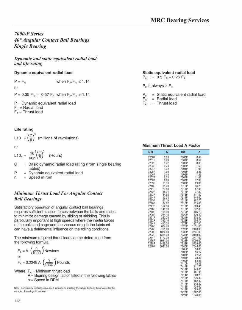
MRC Bearing Services
142
Dynamic and static equivalent radial load and life rating
Dynamic equivalent radial load
P = FR when FA/FR ≤ 1.14
or
P = 0.35 FR + 0.57 FA when FA/FR > 1.14
P = Dynamic equivalent radial loadFR = Radial loadFA = Thrust load
Static equivalent radial loadP0 = 0.5 FR + 0.26 FA
P0 is always ≥ FR
P0 = Static equivalent radial loadFR = Radial loadFA = Thrust load
Life rating
L10 = (millions of revolutions)
or
L10h = (Hours)
C = Basic dynamic radial load rating (from single bearingtables)
P = Dynamic equivalent radial loadn = Speed in rpm
( )CP
3
( )CP
1060n
36
7000-P Series 40° Angular Contact Ball BearingsSingle Bearing
Size SizeA A
Minimum Thrust Load A Factor
7200P 0.237201P 0.297202P 0.427203P 0.747204P 1.327205P 1.907206P 3.457207P 6.737208P 9.287209P 13.137210P 15.487211P 23.887212P 35.317213P 44.557214P 53.747215P 61.157216P 84.077217P 112.907218P 148.507219P 191.907220P 224.107221P 282.707222P 352.107224P 450.507226P 604.707228P 761.607230P 1074.007232P 1314.007234P 1777.007236P 1981.007238P 2499.007240P 3081.00
7300P 0.417301P 0.597302P 0.857303P 1.537304P 1.917305P 3.857306P 7.397307P 11.667308P 17.317309P 29.087310P 36.267311P 57.367312P 77.307313P 111.407314P 144.607315P 182.707316P 215.807317P 269.407318P 332.307319P 405.707320P 629.407321P 673.407322P 904.707324P 1227.007326P 1631.007328P 2128.007330P 2731.007332P 3198.007334P 3717.007336P 5006.007338P 5739.007340P 7048.007405P 10.807406P 16.177407P 27.547408P 38.497409P 58.467410P 78.467411P 111.707412P 143.607413P 181.907414P 309.207415P 376.407416P 452.407417P 542.307418P 724.607419P 1083.007420P 1387.007421P 1546.00
Satisfactory operation of angular contact ball bearingsrequires sufficient traction forces between the balls and racesto minimize damage caused by sliding or skidding. This isparticularly important at high speeds where the inertia forcesof the balls and cage and the viscous drag in the lubricantcan have a detrimental influence on the rolling conditions.
The minimum required thrust load can be determined fromthe following formula.
FA = A Newtons
or
FA = 0.2248 A Pounds
Where, FA = Minimum thrust load A = Bearing design factor listed in the following tables n = Speed in RPM
Note: For Duplex Bearings mounted in tandem, multiply the single-bearing thrust value by thenumber of bearings in tandem.
n1000( )
2
n1000( )
2
Minimum Thrust Load For Angular Contact Ball Bearings
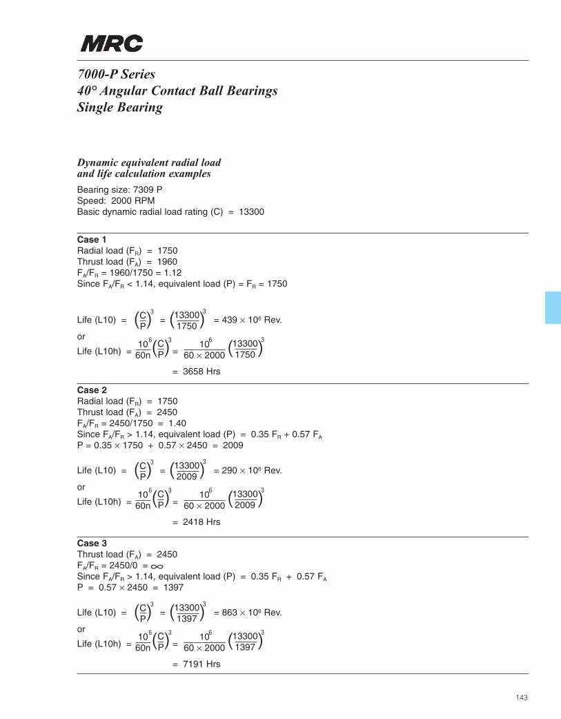
143
Dynamic equivalent radial load and life calculation examples
Bearing size: 7309 PSpeed: 2000 RPMBasic dynamic radial load rating (C) = 13300
Case 1Radial load (FR) = 1750Thrust load (FA) = 1960FA/FR = 1960/1750 = 1.12Since FA/FR < 1.14, equivalent load (P) = FR = 1750
Life (L10) = = = 439 × 106 Rev.
or
Life (L10h) = =
= 3658 Hrs
( )CP
3
( )CP
1060n
36 1060 × 2000
6
( )133001750
3
( )133001750
3
Case 2Radial load (FR) = 1750Thrust load (FA) = 2450FA/FR = 2450/1750 = 1.40Since FA/FR > 1.14, equivalent load (P) = 0.35 FR + 0.57 FA
P = 0.35 × 1750 + 0.57 × 2450 = 2009
Life (L10) = = = 290 × 106 Rev.
or
Life (L10h) = =
= 2418 Hrs
( )CP
3
( )CP
1060n
36 1060 × 2000
6
( )133002009
3
( )133002009
3
Case 3Thrust load (FA) = 2450FA/FR = 2450/0 = ∞Since FA/FR > 1.14, equivalent load (P) = 0.35 FR + 0.57 FA
P = 0.57 × 2450 = 1397
Life (L10) = = = 863 × 106 Rev.
or
Life (L10h) = =
= 7191 Hrs
( )CP
3
( )CP
1060n
36 1060 × 2000
6
( )133001397
3
( )133001397
3
7000-P Series40° Angular Contact Ball BearingsSingle Bearing
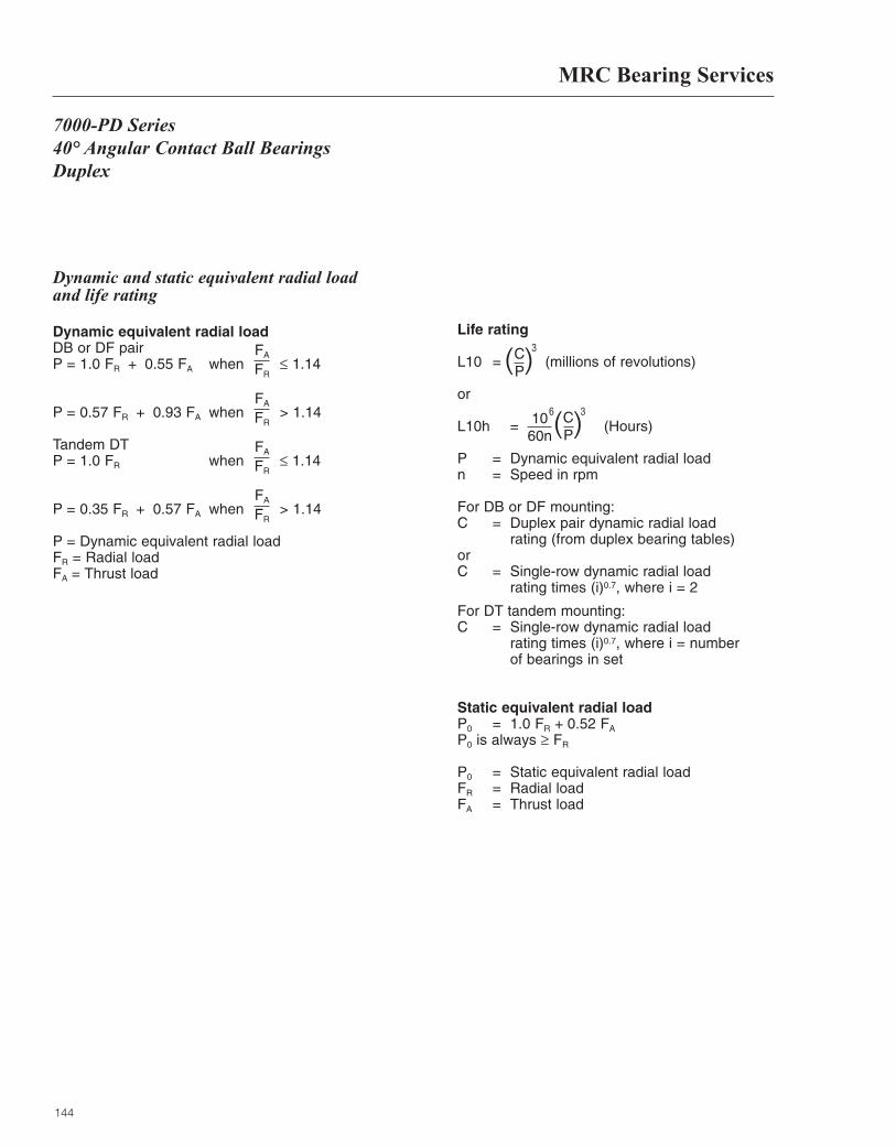
MRC Bearing Services
144
7000-PD Series 40° Angular Contact Ball BearingsDuplex
Dynamic and static equivalent radial load and life rating
Dynamic equivalent radial loadDB or DF pairP = 1.0 FR + 0.55 FA when ≤ 1.14
P = 0.57 FR + 0.93 FA when > 1.14
Tandem DTP = 1.0 FR when ≤ 1.14
P = 0.35 FR + 0.57 FA when > 1.14
P = Dynamic equivalent radial loadFR = Radial loadFA = Thrust load
Life rating
L10 = (millions of revolutions)
or
L10h = (Hours)
P = Dynamic equivalent radial loadn = Speed in rpm
For DB or DF mounting:C = Duplex pair dynamic radial load
rating (from duplex bearing tables)orC = Single-row dynamic radial load
rating times (i)0.7, where i = 2
For DT tandem mounting:C = Single-row dynamic radial load
rating times (i)0.7, where i = number of bearings in set
Static equivalent radial loadP0 = 1.0 FR + 0.52 FA
P0 is always ≥ FR
P0 = Static equivalent radial loadFR = Radial loadFA = Thrust load
( )CP
3FA
FR
FA
FR
FA
FR
FA
FR
( )CP
1060n
36
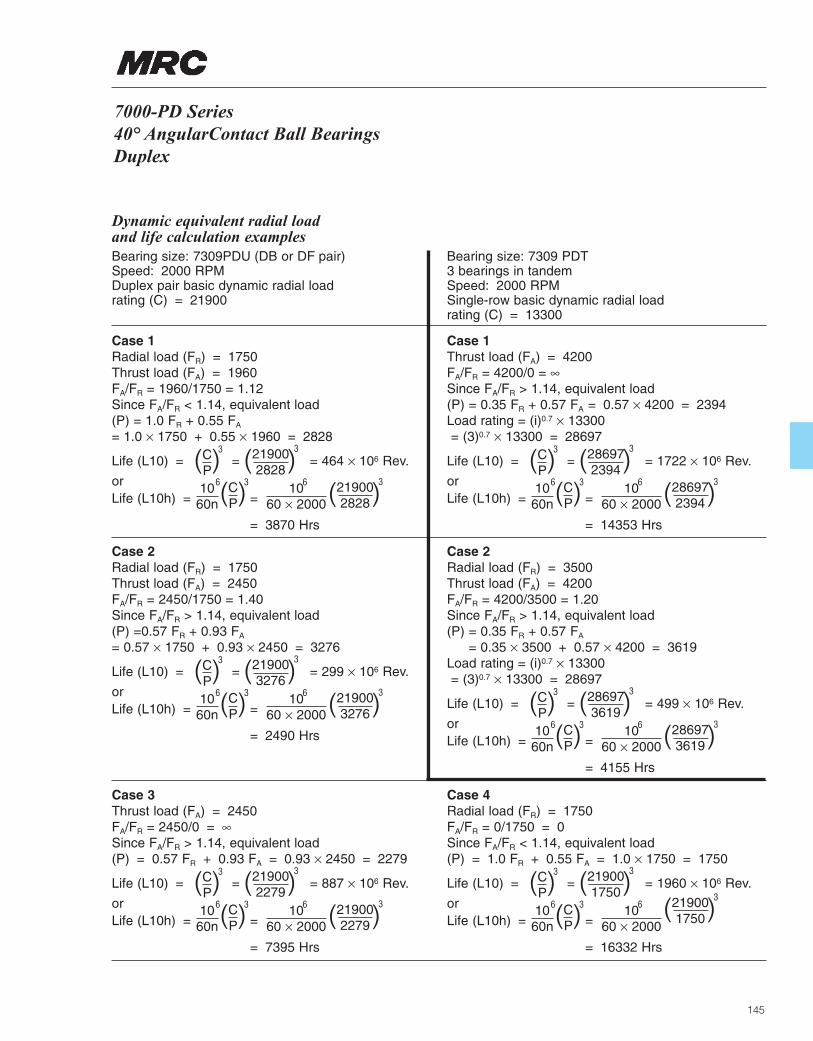
Dynamic equivalent radial load and life calculation examplesBearing size: 7309PDU (DB or DF pair)Speed: 2000 RPMDuplex pair basic dynamic radial load rating (C) = 21900
Bearing size: 7309 PDT3 bearings in tandemSpeed: 2000 RPMSingle-row basic dynamic radial load rating (C) = 13300
Case 1Radial load (FR) = 1750Thrust load (FA) = 1960FA/FR = 1960/1750 = 1.12Since FA/FR < 1.14, equivalent load (P) = 1.0 FR + 0.55 FA
= 1.0 × 1750 + 0.55 × 1960 = 2828
Case 2Radial load (FR) = 1750Thrust load (FA) = 2450FA/FR = 2450/1750 = 1.40Since FA/FR > 1.14, equivalent load (P) =0.57 FR + 0.93 FA
= 0.57 × 1750 + 0.93 × 2450 = 3276
Case 1Thrust load (FA) = 4200FA/FR = 4200/0 = ∞Since FA/FR > 1.14, equivalent load (P) = 0.35 FR + 0.57 FA = 0.57 × 4200 = 2394Load rating = (i)0.7 × 13300= (3)0.7 × 13300 = 28697
Case 2Radial load (FR) = 3500Thrust load (FA) = 4200FA/FR = 4200/3500 = 1.20Since FA/FR > 1.14, equivalent load (P) = 0.35 FR + 0.57 FA
= 0.35 × 3500 + 0.57 × 4200 = 3619Load rating = (i)0.7 × 13300= (3)0.7 × 13300 = 28697
Life (L10) = = = 464 × 106 Rev.
orLife (L10h) = =
= 3870 Hrs
( )CP
3
( )CP
1060n
36 1060 × 2000
6
( )219002828
3
( )219002828
3
Life (L10) = = = 299 × 106 Rev.
orLife (L10h) = =
= 2490 Hrs
( )CP
3
( )CP
1060n
36 1060 × 2000
6
( )219003276
3
( )219003276
3
Life (L10) = = = 1722 × 106 Rev.
orLife (L10h) = =
= 14353 Hrs
( )CP
3
( )CP
1060n
36 1060 × 2000
6
( )286972394
3
( )286972394
3
Life (L10) = = = 499 × 106 Rev.
orLife (L10h) = =
= 4155 Hrs
( )CP
3
( )CP
1060n
36 1060 × 2000
6
( )286973619
3
( )286973619
3
Case 3Thrust load (FA) = 2450FA/FR = 2450/0 = ∞Since FA/FR > 1.14, equivalent load (P) = 0.57 FR + 0.93 FA = 0.93 × 2450 = 2279
Life (L10) = = = 887 × 106 Rev.
orLife (L10h) = =
= 7395 Hrs
( )CP
3
( )CP
1060n
36 1060 × 2000
6
( )219002279
3
( )219002279
3
Case 4Radial load (FR) = 1750FA/FR = 0/1750 = 0Since FA/FR < 1.14, equivalent load (P) = 1.0 FR + 0.55 FA = 1.0 × 1750 = 1750
Life (L10) = = = 1960 × 106 Rev.
orLife (L10h) = =
= 16332 Hrs
( )CP
3
( )CP
1060n
36 1060 × 2000
6
( )219001750
3
( )219001750
3
7000-PD Series40° AngularContact Ball BearingsDuplex
145

146
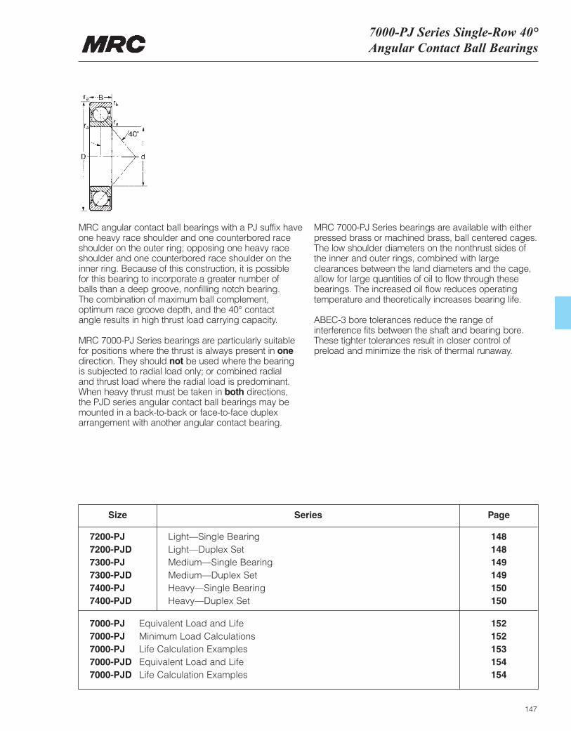
7000-PJ Series Single-Row 40°Angular Contact Ball Bearings
147
MRC angular contact ball bearings with a PJ suffix have one heavy race shoulder and one counterbored raceshoulder on the outer ring; opposing one heavy raceshoulder and one counterbored race shoulder on theinner ring. Because of this construction, it is possible for this bearing to incorporate a greater number of balls than a deep groove, nonfilling notch bearing. The combination of maximum ball complement,optimum race groove depth, and the 40° contact angle results in high thrust load carrying capacity.
MRC 7000-PJ Series bearings are particularly suitablefor positions where the thrust is always present in onedirection. They should not be used where the bearing is subjected to radial load only; or combined radial and thrust load where the radial load is predominant. When heavy thrust must be taken in both directions, the PJD series angular contact ball bearings may bemounted in a back-to-back or face-to-face duplexarrangement with another angular contact bearing.
MRC 7000-PJ Series bearings are available with eitherpressed brass or machined brass, ball centered cages.The low shoulder diameters on the nonthrust sides of the inner and outer rings, combined with largeclearances between the land diameters and the cage,allow for large quantities of oil to flow through thesebearings. The increased oil flow reduces operatingtemperature and theoretically increases bearing life.
ABEC-3 bore tolerances reduce the range ofinterference fits between the shaft and bearing bore.These tighter tolerances result in closer control ofpreload and minimize the risk of thermal runaway.
Size
7200-PJ Light—Single Bearing 1487200-PJD Light—Duplex Set 1487300-PJ Medium—Single Bearing 1497300-PJD Medium—Duplex Set 1497400-PJ Heavy—Single Bearing 1507400-PJD Heavy—Duplex Set 150
Series Page
7000-PJ Equivalent Load and Life 1527000-PJ Minimum Load Calculations 1527000-PJ Life Calculation Examples 1537000-PJD Equivalent Load and Life 1547000-PJD Life Calculation Examples 154
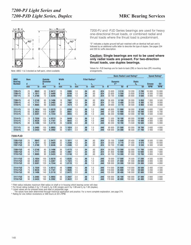
MRC Bearing Services7200-PJ Light Series and 7200-PJD Light Series, Duplex
148
7200-PJ and -PJD Series bearings are used for heavyone-directional thrust loads, or combined radial andthrust loads where the thrust load is predominant.
“D” indicates a duplex ground half pair matched with an identical half pair and is followed by an additional suffix letter to describe the type of duplex. See pages 234and 235 for suffix description.
Caution: Single bearings are not to be used whereonly radial loads are present. For two-directionthrust loads, use duplex bearings.
Values for -PJD bearings are for back-to-back (DB) or face-to-face (DF) mounting arrangements.
MRCBearingNumber
Bore
dmm in
OutsideDiameterDmm in
Width
Bmm in
ra
mm inrb
mm in
DynamicC4)
N lbf
Basic Radial Load Rating2) Speed Rating3)
StaticC0
N lbfGrease OilRPM RPM
Fillet Radius1)
7205-PJ 25 .9843 52 2.0472 15 .5906 1.0 .04 .60 .024 15 600 3 510 10 200 2 290 10 000 15 0007206-PJ 30 1.1811 62 2.4409 16 .6299 1.0 .04 .60 .024 23 800 5 350 15 600 3 510 8 500 12 0007207-PJ 35 1.3780 72 2.8346 17 .6693 1.0 .04 .60 .024 30 700 6 900 20 800 4 680 8 000 11 000
7208-PJ 40 1.5748 80 3.1496 18 .7087 1.0 .04 .60 .024 36 400 8 180 26 000 5 850 7 000 9 5007209-PJ 45 1.7717 85 3.3465 19 .7480 1.0 .04 .60 .024 37 700 8 480 28 000 6 300 6 700 9 0007210-PJ 50 1.9685 90 3.5433 20 .7874 1.0 .04 .60 .024 39 000 8 770 30 500 6 860 6 000 8 000
7211-PJ 55 2.1654 100 3.9370 21 .8268 1.5 .06 1.0 .040 48 800 11 000 38 000 8 540 5 600 7 5007212-PJ 60 2.3622 110 4.3307 22 .8661 1.5 .06 1.0 .040 57 200 12 900 45 500 10 200 5 000 6 7007213-PJ 65 2.5591 120 4.7244 23 .9055 1.5 .06 1.0 .040 66 300 14 900 54 000 12 100 4 500 6 000
7214-PJ 70 2.7559 125 4.9213 24 .9449 1.5 .06 1.0 .040 71 500 16 100 60 000 13 500 4 300 5 6007215-PJ 75 2.9528 130 5.1181 25 .9843 1.5 .06 1.0 .040 72 800 16 400 64 000 14 400 4 000 5 3007216-PJ 80 3.1496 140 5.5118 26 1.0236 2.0 .08 1.0 .040 83 200 18 700 73 500 16 500 3 800 5 000
7217-PJ 85 3.3465 150 5.9055 28 1.1024 2.0 .08 1.0 .040 95 600 21 500 83 000 18 700 3 600 4 8007218-PJ 90 3.5433 160 6.2992 30 1.1811 2.0 .08 1.0 .040 108 000 24 300 96 500 21 700 3 400 4 500
7205-PJD 25 .9843 52 2.0472 30 1.1811 1.0 .04 .60 .024 25 100 5 640 20 400 4 590 8 500 12 0007206-PJD 30 1.1811 62 2.4409 32 1.2598 1.0 .04 .60 .024 39 000 8 770 31 000 6 970 7 500 10 0007207-PJD 35 1.3780 72 2.8346 34 1.3386 1.0 .04 .60 .024 50 700 11 400 41 500 9 330 6 300 8 500
7208-PJD 40 1.5748 80 3.1496 36 1.4173 1.0 .04 .60 .024 59 200 13 300 52 000 11 700 5 600 7 5007209-PJD 45 1.7717 85 3.3465 38 1.4961 1.0 .04 .60 .024 61 800 13 900 56 000 12 600 5 300 7 0007210-PJD 50 1.9685 90 3.5433 40 1.5748 1.0 .04 .60 .024 63 700 14 300 61 000 13 700 4 800 6 300
7211-PJD 55 2.1654 100 3.9370 42 1.6535 1.5 .06 1.0 .040 78 000 17 500 76 500 17 200 4 500 6 0007212-PJD 60 2.3622 110 4.3307 44 1.7323 1.5 .06 1.0 .040 93 600 21 000 91 500 20 600 4 000 5 3007213-PJD 65 2.5591 120 4.7244 46 1.8110 1.5 .06 1.0 .040 108 000 24 300 108 000 24 300 3 600 4 800
7214-PJD 70 2.7559 125 4.9213 48 1.8898 1.5 .06 1.0 .040 114 000 25 600 118 000 26 500 3 400 4 5007215-PJD 75 2.9528 130 5.1181 50 1.9685 1.5 .06 1.0 .040 119 000 26 800 127 000 28 600 3 200 4 3007216-PJD 80 3.1496 140 5.5118 52 2.0472 2.0 .08 1.0 .040 135 000 30 400 146 000 32 800 3 000 4 000
7217-PJD 85 3.3465 150 5.9055 56 2.2047 2.0 .08 1.0 .040 156 000 35 100 166 000 37 300 2 800 3 8007218-PJD 90 3.5433 160 6.2992 60 2.3622 2.0 .08 1.0 .040 178 000 40 000 193 000 43 400 2 600 3 600
Note: ABEC 1 & 3 stocked as half-pairs, where available.
7200-PJD
1) Fillet radius indicates maximum fillet radius on shaft or in housing which bearing corner will clear.2) For thrust rating multiply C by 1.75 and C0 by 3.85 (single) and C by 1.08 and C0 by 1.93 (duplex).3) Listed values are for pressed brass and steel or polyamide cage.
The values have been determined through historical application and practice. For a more complete explanation, see page 274.4) Rating for one million revolutions or 500 hours at 33¹|₃ RPM.
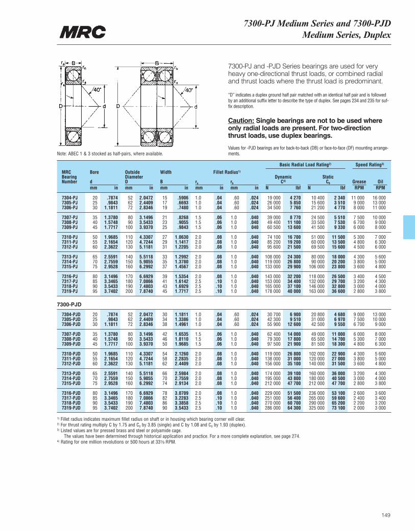
7300-PJ Medium Series and 7300-PJDMedium Series, Duplex
149
7300-PJ and -PJD Series bearings are used for veryheavy one-directional thrust loads, or combined radialand thrust loads where the thrust load is predominant.
“D” indicates a duplex ground half pair matched with an identical half pair and is followedby an additional suffix letter to describe the type of duplex. See pages 234 and 235 for suf-fix description.
Caution: Single bearings are not to be used whereonly radial loads are present. For two-directionthrust loads, use duplex bearings.
Values for -PJD bearings are for back-to-back (DB) or face-to-face (DF) mounting arrange-ments.
MRCBearingNumber
Bore
dmm in
OutsideDiameterDmm in
Width
Bmm in
ra
mm inrb
mm in
DynamicC4)
N lbf
Basic Radial Load Rating2) Speed Rating3)
StaticC0
N lbfGrease OilRPM RPM
Fillet Radius1)
7304-PJ 20 .7874 52 2.0472 15 .5906 1.0 .04 .60 .024 19 000 4 270 10 400 2 340 11 000 16 0007305-PJ 25 .9843 62 2.4409 17 .6693 1.0 .04 .60 .024 26 000 5 850 15 600 3 510 9 000 13 0007306-PJ 30 1.1811 72 2.8346 19 .7480 1.0 .04 .60 .024 34 500 7 760 21 200 4 770 8 000 11 000
7307-PJ 35 1.3780 80 3.1496 21 .8268 1.5 .06 1.0 .040 39 000 8 770 24 500 5 510 7 500 10 0007308-PJ 40 1.5748 90 3.5433 23 .9055 1.5 .06 1.0 .040 49 400 11 100 33 500 7 530 6 700 9 0007309-PJ 45 1.7717 100 3.9370 25 .9843 1.5 .06 1.0 040 60 500 13 600 41 500 9 330 6 000 8 000
7310-PJ 50 1.9685 110 4.3307 27 1.0630 2.0 .08 1.0 .040 74 100 16 700 51 000 11 500 5 300 7 0007311-PJ 55 2.1654 120 4.7244 29 1.1417 2.0 .08 1.0 .040 85 200 19 200 60 000 13 500 4 800 6 3007312-PJ 60 2.3622 130 5.1181 31 1.2205 2.0 .08 1.0 .040 95 600 21 500 69 500 15 600 4 500 6 000
7313-PJ 65 2.5591 140 5.5118 33 1.2992 2.0 .08 1.0 .040 108 000 24 300 80 000 18 000 4 300 5 6007314-PJ 70 2.7559 150 5.9055 35 1.3780 2.0 .08 1.0 .040 119 000 26 800 90 000 20 200 3 800 5 0007315-PJ 75 2.9528 160 6.2992 37 1.4567 2.0 .08 1.0 .040 133 000 29 900 106 000 23 800 3 600 4 800
7316-PJ 80 3.1496 170 6.6929 39 1.5354 2.0 .08 1.0 .040 143 000 32 200 118 000 26 500 3 400 4 5007317-PJ 85 3.3465 180 7.0866 41 1.6142 2.5 .10 1.0 .040 153 000 34 400 132 000 29 700 3 200 4 3007318-PJ 90 3.5433 190 7.4803 43 1.6929 2.5 .10 1.0 .040 165 000 37 100 146 000 32 800 3 000 4 0007319-PJ 95 3.7402 200 7.8740 45 1.7717 2.5 .10 1.0 .040 178 000 40 000 163 000 36 600 2 800 3 800
7304-PJD 20 .7874 52 2.0472 30 1.1811 1.0 .04 .60 .024 30 700 6 900 20 800 4 680 9 000 13 0007305-PJD 25 .9843 62 2.4409 34 1.3386 1.0 .04 .60 .024 42 300 9 510 31 000 6 970 7 500 10 0007306-PJD 30 1.1811 72 2.8346 38 1.4961 1.0 .04 .60 .024 55 900 12 600 42 500 9 550 6 700 9 000
7307-PJD 35 1.3780 80 3.1496 42 1.6535 1.5 .06 1.0 .040 62 400 14 000 49 000 11 000 6 000 8 0007308-PJD 40 1.5748 90 3.5433 46 1.8110 1.5 .06 1.0 .040 79 300 17 800 65 500 14 700 5 300 7 0007309-PJD 45 1.7717 100 3.9370 50 1.9685 1.5 .06 1.0 .040 97 500 21 900 81 500 18 300 4 800 6 300
7310-PJD 50 1.9685 110 4.3307 54 2.1260 2.0 .08 1.0 .040 119 000 26 800 102 000 22 900 4 300 5 6007311-PJD 55 2.1654 120 4.7244 58 2.2835 2.0 .08 1.0 .040 138 000 31 000 120 000 27 000 3 800 5 0007312-PJD 60 2.3622 130 5.1181 62 2.4409 2.0 .08 1.0 .040 156 000 35 100 140 000 31 500 3 600 4 800
7313-PJD 65 2.5591 140 5.5118 66 2.5984 2.0 .08 1.0 .040 174 000 39 100 160 000 36 000 3 200 4 3007314-PJD 70 2.7559 150 5.9055 70 2.7559 2.0 .08 1.0 .040 195 000 43 800 180 000 40 500 3 000 4 0007315-PJD 75 2.9528 160 6.2992 74 2.9134 2.0 .08 1.0 .040 212 000 47 700 212 000 47 700 2 800 3 800
7316-PJD 80 3.1496 170 6.6929 78 3.0709 2.0 .08 1.0 .040 229 000 51 500 236 000 53 100 2 600 3 6007317-PJD 85 3.3465 180 7.0866 82 3.2283 2.5 .10 1.0 .040 251 000 56 400 265 000 59 600 2 400 3 4007318-PJD 90 3.5433 190 7.4803 86 3.3858 2.5 .10 1.0 .040 270 000 60 700 290 000 65 200 2 200 3 2007319-PJD 95 3.7402 200 7.8740 90 3.5433 2.5 .10 1.0 .040 286 000 64 300 325 000 73 100 2 000 3 000
Note: ABEC 1 & 3 stocked as half-pairs, where available.
7300-PJD
1) Fillet radius indicates maximum fillet radius on shaft or in housing which bearing corner will clear.2) For thrust rating multiply C by 1.75 and C0 by 3.85 (single) and C by 1.08 and C0 by 1.93 (duplex).3) Listed values are for pressed brass and steel or polyamide cage.
The values have been determined through historical application and practice. For a more complete explanation, see page 274.4) Rating for one million revolutions or 500 hours at 33¹|₃ RPM.
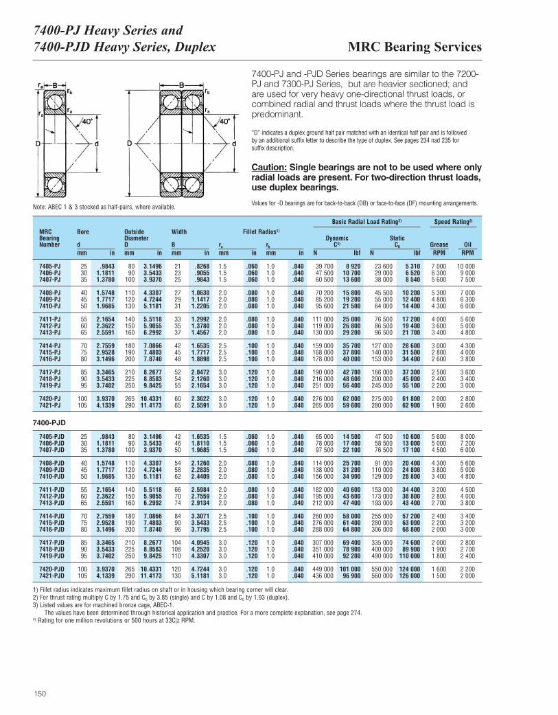
MRC Bearing Services7400-PJ Heavy Series and7400-PJD Heavy Series, Duplex
150
7400-PJ and -PJD Series bearings are similar to the 7200-PJ and 7300-PJ Series, but are heavier sectioned; andare used for very heavy one-directional thrust loads, orcombined radial and thrust loads where the thrust load ispredominant.
“D” indicates a duplex ground half pair matched with an identical half pair and is followed by an additional suffix letter to describe the type of duplex. See pages 234 nad 235 for suffix description.
Caution: Single bearings are not to be used where onlyradial loads are present. For two-direction thrust loads,use duplex bearings.
Values for -D bearings are for back-to-back (DB) or face-to-face (DF) mounting arrangements.
MRCBearingNumber
Bore
dmm in
OutsideDiameterDmm in
Width
Bmm in
ra
mm inrb
mm in
DynamicC4)
N lbf
Basic Radial Load Rating2) Speed Rating3)
StaticC0
N lbfGrease OilRPM RPM
Fillet Radius1)
7405-PJ 25 .9843 80 3.1496 21 .8268 1.5 .060 1.0 .040 39 700 8 920 23 600 5 310 7 000 10 0007406-PJ 30 1.1811 90 3.5433 23 .9055 1.5 .060 1.0 .040 47 500 10 700 29 000 6 520 6 300 9 0007407-PJ 35 1.3780 100 3.9370 25 .9843 1.5 .060 1.0 .040 60 500 13 600 38 000 8 540 5 600 7 500
7408-PJ 40 1.5748 110 4.3307 27 1.0630 2.0 .080 1.0 .040 70 200 15 800 45 500 10 200 5 300 7 0007409-PJ 45 1.7717 120 4.7244 29 1.1417 2.0 .080 1.0 .040 85 200 19 200 55 000 12 400 4 800 6 3007410-PJ 50 1.9685 130 5.1181 31 1.2205 2.0 .080 1.0 .040 95 600 21 500 64 000 14 400 4 300 6 000
7411-PJ 55 2.1654 140 5.5118 33 1.2992 2.0 .080 1.0 .040 111 000 25 000 76 500 17 200 4 000 5 6007412-PJ 60 2.3622 150 5.9055 35 1.3780 2.0 .080 1.0 .040 119 000 26 800 86 500 19 400 3 600 5 0007413-PJ 65 2.5591 160 6.2992 37 1.4567 2.0 .080 1.0 .040 130 000 29 200 96 500 21 700 3 400 4 800
7414-PJ 70 2.7559 180 7.0866 42 1.6535 2.5 .100 1.0 .040 159 000 35 700 127 000 28 600 3 000 4 3007415-PJ 75 2.9528 190 7.4803 45 1.7717 2.5 .100 1.0 .040 168 000 37 800 140 000 31 500 2 800 4 0007416-PJ 80 3.1496 200 7.8740 48 1.8898 2.5 .100 1.0 .040 178 000 40 000 153 000 34 400 2 600 3 800
7417-PJ 85 3.3465 210 8.2677 52 2.0472 3.0 .120 1.0 .040 190 000 42 700 166 000 37 300 2 500 3 6007418-PJ 90 3.5433 225 8.8583 54 2.1260 3.0 .120 1.0 .040 216 000 48 600 200 000 45 000 2 400 3 4007419-PJ 95 3.7402 250 9.8425 55 2.1654 3.0 .120 1.0 .040 251 000 56 400 245 000 55 100 2 200 3 000
7420-PJ 100 3.9370 265 10.4331 60 2.3622 3.0 .120 1.0 .040 276 000 62 000 275 000 61 800 2 000 2 8007421-PJ 105 4.1339 290 11.4173 65 2.5591 3.0 .120 1.0 .040 265 000 59 600 280 000 62 900 1 900 2 600
7405-PJD 25 .9843 80 3.1496 42 1.6535 1.5 .060 1.0 .040 65 000 14 500 47 500 10 600 5 600 8 0007406-PJD 30 1.1811 90 3.5433 46 1.8110 1.5 .060 1.0 .040 78 000 17 400 58 500 13 000 5 000 7 2007407-PJD 35 1.3780 100 3.9370 50 1.9685 1.5 .060 1.0 .040 97 500 22 100 76 500 17 100 4 500 6 000
7408-PJD 40 1.5748 110 4.3307 54 2.1260 2.0 .080 1.0 .040 114 000 25 700 91 000 20 400 4 300 5 6007409-PJD 45 1.7717 120 4.7244 58 2.2835 2.0 .080 1.0 .040 138 000 31 200 110 000 24 800 3 800 5 0007410-PJD 50 1.9685 130 5.1181 62 2.4409 2.0 .080 1.0 .040 156 000 34 900 129 000 28 800 3 400 4 800
7411-PJD 55 2.1654 140 5.5118 66 2.5984 2.0 .080 1.0 .040 182 000 40 600 153 000 34 400 3 200 4 5007412-PJD 60 2.3622 150 5.9055 70 2.7559 2.0 .080 1.0 .040 195 000 43 600 173 000 38 800 2 800 4 0007413-PJD 65 2.5591 160 6.2992 74 2.9134 2.0 .080 1.0 .040 212 000 47 400 193 000 43 400 2 700 3 800
7414-PJD 70 2.7559 180 7.0866 84 3.3071 2.5 .100 1.0 .040 260 000 58 000 255 000 57 200 2 400 3 4007415-PJD 75 2.9528 190 7.4803 90 3.5433 2.5 .100 1.0 .040 276 000 61 400 280 000 63 000 2 200 3 2007416-PJD 80 3.1496 200 7.8740 96 3.7795 2.5 .100 1.0 .040 288 000 64 800 306 000 68 800 2 000 3 000
7417-PJD 85 3.3465 210 8.2677 104 4.0945 3.0 .120 1.0 .040 307 000 69 400 335 000 74 600 2 000 2 8007418-PJD 90 3.5433 225 8.8583 108 4.2520 3.0 .120 1.0 .040 351 000 78 900 400 000 89 900 1 900 2 7007419-PJD 95 3.7402 250 9.8425 110 4.3307 3.0 .120 1.0 .040 410 000 92 200 490 000 110 000 1 800 2 400
7420-PJD 100 3.9370 265 10.4331 120 4.7244 3.0 .120 1.0 .040 449 000 101 000 550 000 124 000 1 600 2 2007421-PJD 105 4.1339 290 11.4173 130 5.1181 3.0 .120 1.0 .040 436 000 96 900 560 000 126 000 1 500 2 000
Note: ABEC 1 & 3 stocked as half-pairs, where available.
7400-PJD
1) Fillet radius indicates maximum fillet radius on shaft or in housing which bearing corner will clear.2) For thrust rating multiply C by 1.75 and C0 by 3.85 (single) and C by 1.08 and C0 by 1.93 (duplex).3) Listed values are for machined bronze cage, ABEC-1.
The values have been determined through historical application and practice. For a more complete explanation, see page 274.4) Rating for one million revolutions or 500 hours at 33C|z RPM.

151
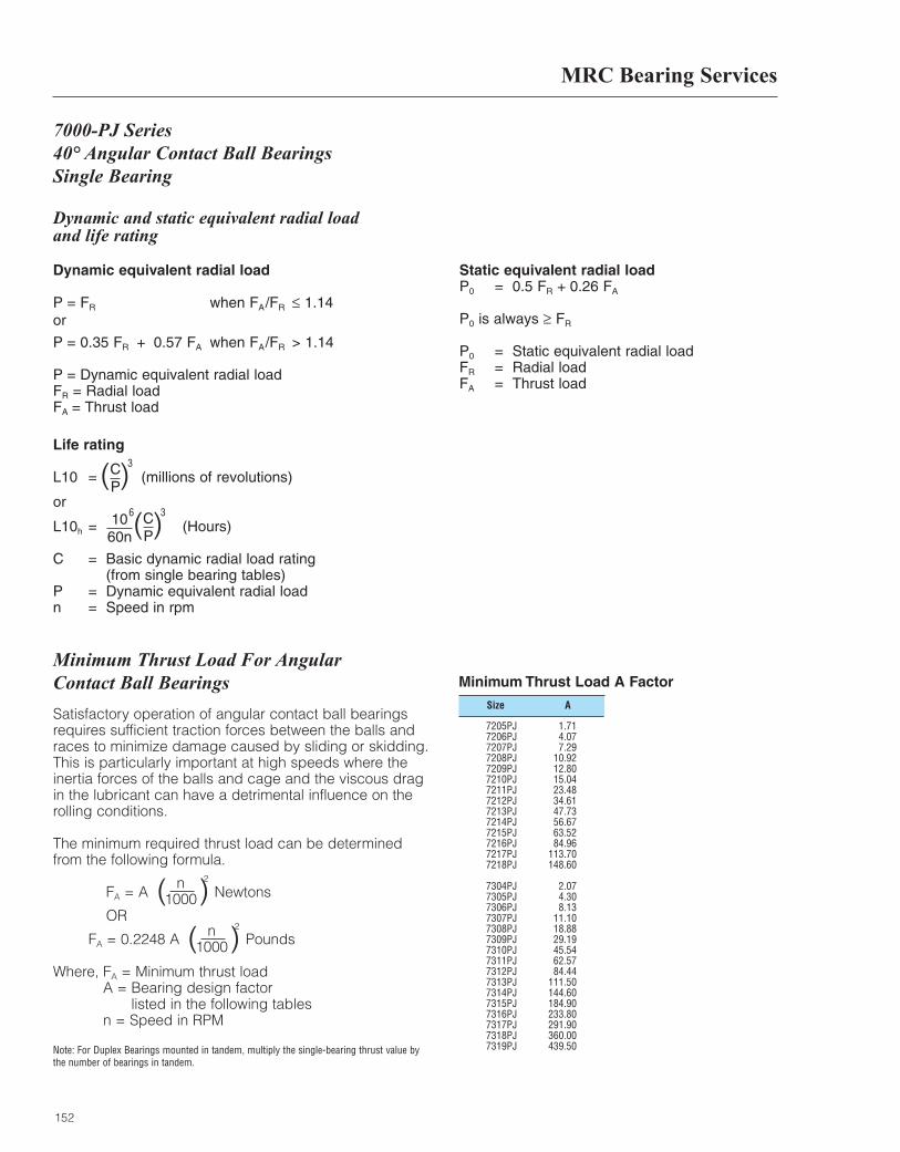
MRC Bearing Services
152
Dynamic and static equivalent radial load and life rating
Dynamic equivalent radial load
P = FR when FA/FR ≤ 1.14or
P = 0.35 FR + 0.57 FA when FA/FR > 1.14
P = Dynamic equivalent radial loadFR = Radial loadFA = Thrust load
Static equivalent radial loadP0 = 0.5 FR + 0.26 FA
P0 is always ≥ FR
P0 = Static equivalent radial loadFR = Radial loadFA = Thrust load
Life rating
L10 = (millions of revolutions)
or
L10h = (Hours)
C = Basic dynamic radial load rating(from single bearing tables)
P = Dynamic equivalent radial loadn = Speed in rpm
( )CP
3
( )CP
1060n
36
7000-PJ Series 40° Angular Contact Ball BearingsSingle Bearing
Size A
Minimum Thrust Load A Factor
7205PJ 1.717206PJ 4.077207PJ 7.297208PJ 10.927209PJ 12.807210PJ 15.047211PJ 23.487212PJ 34.617213PJ 47.737214PJ 56.677215PJ 63.527216PJ 84.967217PJ 113.707218PJ 148.60
7304PJ 2.077305PJ 4.307306PJ 8.137307PJ 11.107308PJ 18.887309PJ 29.197310PJ 45.547311PJ 62.577312PJ 84.447313PJ 111.507314PJ 144.607315PJ 184.907316PJ 233.807317PJ 291.907318PJ 360.007319PJ 439.50
Minimum Thrust Load For Angular Contact Ball Bearings
Satisfactory operation of angular contact ball bearingsrequires sufficient traction forces between the balls andraces to minimize damage caused by sliding or skidding.This is particularly important at high speeds where theinertia forces of the balls and cage and the viscous dragin the lubricant can have a detrimental influence on therolling conditions.
The minimum required thrust load can be determinedfrom the following formula.
FA = A Newtons
OR
FA = 0.2248 A Pounds
Where, FA = Minimum thrust load A = Bearing design factor
listed in the following tables n = Speed in RPM
Note: For Duplex Bearings mounted in tandem, multiply the single-bearing thrust value bythe number of bearings in tandem.
n1000( )
2
n1000( )
2

7000-PJ Series40° Angular Contact Ball Bearings Single Bearing
153
Dynamic equivalent radial load and life calculation examples
Bearing size: 7309 PJSpeed: 2000 RPMBasic dynamic radial load rating (C) = 13600
Case 1Radial load (FR) = 1750Thrust load (FA) = 1960FA/FR = 1960/1750 = 1.12Since FA/FR < 1.14, equivalent load (P) = FR = 1750
Life (L10) = = = 469 × 106 Rev.
or
Life (L10h) = =
= 3911 Hrs
( )CP
3
( )CP
1060n
36 1060 × 2000
6
( )136001750
3
( )136001750
3
Case 2Radial load (FR) = 1750Thrust load (FA) = 2450FA/FR = 2450/1750 = 1.40Since FA/FR > 1.14, equivalent load (P) = 0.35 FR + 0.57 FA
P = 0.35 × 1750 + 0.57 × 2450 = 2009
Life (L10) = = = 310 × 106 Rev.
or
Life (L10h) = =
= 2585 Hrs
( )CP
3
( )CP
1060n
36 1060 × 2000
6
( )136002009
3
( )136002009
3
Case 3Thrust load (FA) = 2450FA/FR = 2450/0 = ∞Since FA/FR > 1.14, equivalent load (P) = 0.35 FR + 0.57 FA
P = 0.57 × 2450 = 1397
Life (L10) = = = 923 × 106 Rev.
or
Life (L10h) = =
= 7689 Hrs
( )CP
3
( )CP
1060n
36 1060 × 2000
6
( )136001397
3
( )136001397
3
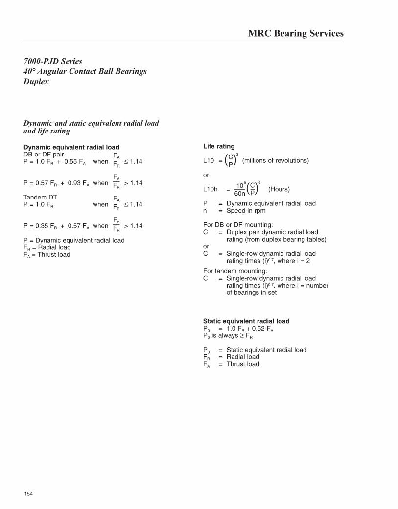
MRC Bearing Services
154
7000-PJD Series 40° Angular Contact Ball BearingsDuplex
Dynamic and static equivalent radial load and life rating
Dynamic equivalent radial loadDB or DF pairP = 1.0 FR + 0.55 FA when ≤ 1.14
P = 0.57 FR + 0.93 FA when > 1.14
Tandem DTP = 1.0 FR when ≤ 1.14
P = 0.35 FR + 0.57 FA when > 1.14
P = Dynamic equivalent radial loadFR = Radial loadFA = Thrust load
Life rating
L10 = (millions of revolutions)
or
L10h = (Hours)
P = Dynamic equivalent radial loadn = Speed in rpm
For DB or DF mounting:C = Duplex pair dynamic radial load
rating (from duplex bearing tables)orC = Single-row dynamic radial load
rating times (i)0.7, where i = 2
For tandem mounting:C = Single-row dynamic radial load
rating times (i)0.7, where i = number of bearings in set
Static equivalent radial loadP0 = 1.0 FR + 0.52 FA
P0 is always ≥ FR
P0 = Static equivalent radial loadFR = Radial loadFA = Thrust load
( )CP
3FA
FR
FA
FR
FA
FR
FA
FR
( )CP
1060n
36
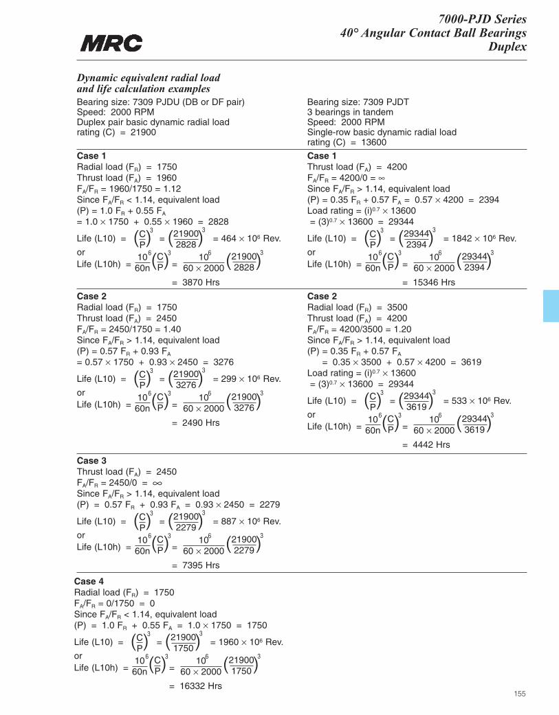
7000-PJD Series40° Angular Contact Ball Bearings
Duplex
155
Dynamic equivalent radial load and life calculation examplesBearing size: 7309 PJDU (DB or DF pair)Speed: 2000 RPMDuplex pair basic dynamic radial load rating (C) = 21900
Bearing size: 7309 PJDT3 bearings in tandemSpeed: 2000 RPMSingle-row basic dynamic radial load rating (C) = 13600
Case 1Radial load (FR) = 1750Thrust load (FA) = 1960FA/FR = 1960/1750 = 1.12Since FA/FR < 1.14, equivalent load (P) = 1.0 FR + 0.55 FA
= 1.0 × 1750 + 0.55 × 1960 = 2828
Case 2Radial load (FR) = 1750Thrust load (FA) = 2450FA/FR = 2450/1750 = 1.40Since FA/FR > 1.14, equivalent load (P) = 0.57 FR + 0.93 FA
= 0.57 × 1750 + 0.93 × 2450 = 3276
Case 1Thrust load (FA) = 4200FA/FR = 4200/0 = ∞Since FA/FR > 1.14, equivalent load (P) = 0.35 FR + 0.57 FA = 0.57 × 4200 = 2394Load rating = (i)0.7 × 13600= (3)0.7 × 13600 = 29344
Case 2Radial load (FR) = 3500Thrust load (FA) = 4200FA/FR = 4200/3500 = 1.20Since FA/FR > 1.14, equivalent load (P) = 0.35 FR + 0.57 FA
= 0.35 × 3500 + 0.57 × 4200 = 3619Load rating = (i)0.7 × 13600= (3)0.7 × 13600 = 29344
Life (L10) = = = 464 × 106 Rev.
orLife (L10h) = =
= 3870 Hrs
( )CP
3
( )CP
1060n
36 1060 × 2000
6
( )219002828
3
( )219002828
3
Life (L10) = = = 299 × 106 Rev.
orLife (L10h) = =
= 2490 Hrs
( )CP
3
( )CP
1060n
36 1060 × 2000
6
( )219003276
3
( )219003276
3
Life (L10) = = = 1842 × 106 Rev.
orLife (L10h) = =
= 15346 Hrs
( )CP
3
( )CP
1060n
36 1060 × 2000
6
( )293442394
3
( )293442394
3
Life (L10) = = = 533 × 106 Rev.
orLife (L10h) = =
= 4442 Hrs
( )CP
3
( )CP
1060n
36 1060 × 2000
6
( )293443619
3
( )293443619
3
Case 3Thrust load (FA) = 2450FA/FR = 2450/0 = ∞Since FA/FR > 1.14, equivalent load (P) = 0.57 FR + 0.93 FA = 0.93 × 2450 = 2279
Life (L10) = = = 887 × 106 Rev.
orLife (L10h) = =
= 7395 Hrs
( )CP
3
( )CP
1060n
36 1060 × 2000
6
( )219002279
3
( )219002279
3
Case 4Radial load (FR) = 1750FA/FR = 0/1750 = 0Since FA/FR < 1.14, equivalent load (P) = 1.0 FR + 0.55 FA = 1.0 × 1750 = 1750
Life (L10) = = = 1960 × 106 Rev.
orLife (L10h) = =
= 16332 Hrs
( )CP
3
( )CP
1060n
36 1060 × 2000
6
( )219001750
3
( )219001750
3

156
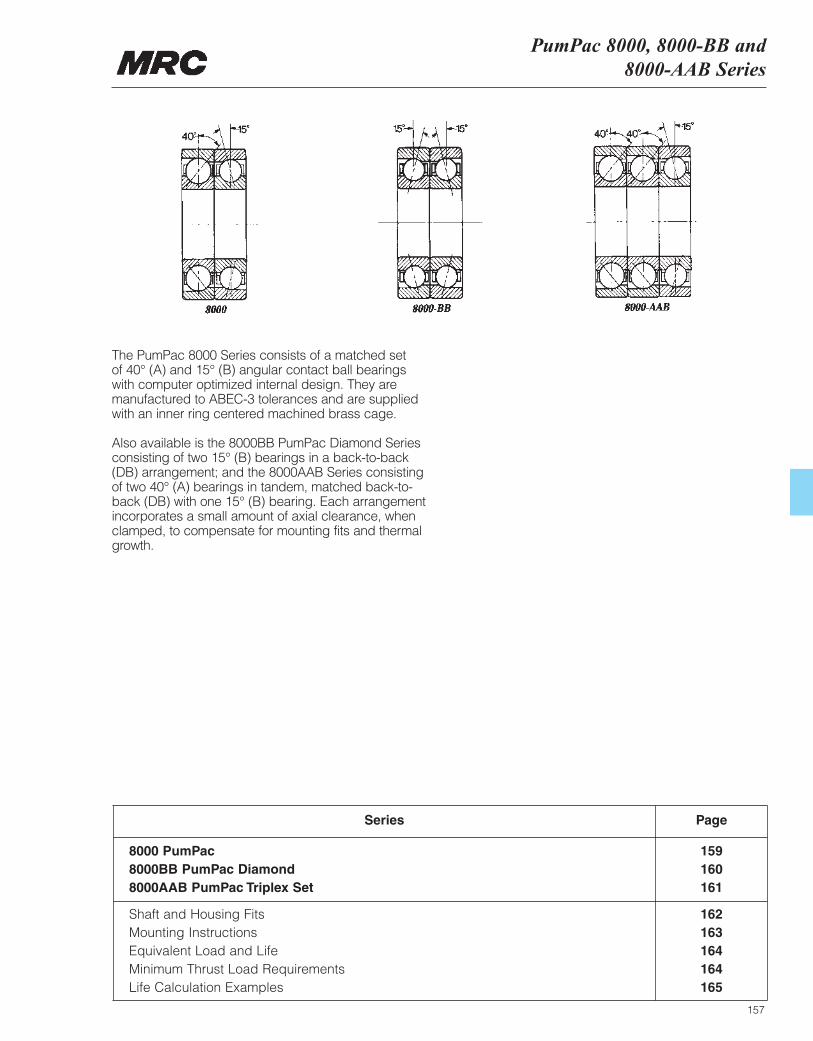
PumPac 8000, 8000-BB and8000-AAB Series
157
8000 PumPac 1598000BB PumPac Diamond 1608000AAB PumPac Triplex Set 161
Series Page
Shaft and Housing Fits 162Mounting Instructions 163Equivalent Load and Life 164Minimum Thrust Load Requirements 164Life Calculation Examples 165
The PumPac 8000 Series consists of a matched set of 40° (A) and 15° (B) angular contact ball bearingswith computer optimized internal design. They aremanufactured to ABEC-3 tolerances and are suppliedwith an inner ring centered machined brass cage.
Also available is the 8000BB PumPac Diamond Seriesconsisting of two 15° (B) bearings in a back-to-back(DB) arrangement; and the 8000AAB Series consistingof two 40° (A) bearings in tandem, matched back-to-back (DB) with one 15° (B) bearing. Each arrangementincorporates a small amount of axial clearance, whenclamped, to compensate for mounting fits and thermalgrowth.
MRC Bearing ServicesPumPac 8000, 8000-BB and8000-AAB Series
158
The PumPac 8000 Series is used in centrifugal pumps,large vertical electric motors, compressors, centrifuges,and other applications subject to thrust loads operatingat relatively high speeds. The bearings are mounted sothat the 40° (A) bearing takes the primary thrust load.
Traditionally, matched sets of 40° angular contact ballbearings are used to obtain maximum theoreticalfatigue life, but in most instances only a fraction of thecalculated life is actually achieved. At the heart of thesepremature failures are phenomena known as “ballsliding” and “ball shuttling” in the unloaded (or inactive)bearing. Angular contact bearings used in high speed(e.g. 3600 RPM) pumps and other applications requirea minimum axial load for proper operation. Without axialload, gyroscopic forces in the unloaded bearing cancause the balls to rotate perpendicular to their truerolling axis and momentarily lose contact with theraceway. As a result, a microscopic wear (or lapping)process occurs giving the appearance of a burnishedor polished raceway. The oil film thickness separatingthe ball and raceway is reduced, producing friction andheat which lowers oil viscosity and accelerates wear.This thermally unstable condition dramatically reducesbearing service life.
The main benefit of the PumPac system is that the 15°(B) bearing is designed with considerably less internalclearance than the 40° (A) bearing, making it lesssusceptible to the gyroscopic forces which result in ballsliding or shuttling. The 15° bearing also providesadditional radial stiffness helping to maintain theintegrity of the shaft and mechanical seals. The 40°(loaded) bearing provides sufficient axial rigidity underthe imposed thrust load.
The PumPac is furnished with a one piece, inner ringland-guided, machined brass cage and ismanufactured to meet ABEC-3 grade tolerances.Dimensional stability is assured by heat treating thebearing’s rings and rolling elements for operation up to375˚F (190˚C).
For identification purposes, the 40° bearing is markedwith the letter “A,” and the 15° bearing with the letter“B”. A “V” is etched on the outer ring surface of the pairso that the apex falls on the “B” bearing. The pairshould always be mounted so that the “V” points in thesame direction as the primary thrust load, which placesthis load on bearing “A”. Any reversing load is carriedon bearing “B”.
The PumPac is also available in the 8000BB PumPacDiamond series, which consists of a matched set of 15° (B) bearings in a back-to-back arrangement. When mounted correctly, the marking on the outer ringsurface forms a diamond. This series is desirable inhigh speed, lightly loaded applications in which axialloads are balanced, resulting in reduced operatingtemperatures and increased life.
For applications involving very heavy primary thrustloads, the PumPac may be furnished as a triplex setidentified as the 8000AAB Series. It consists of two 40°(A) bearings in tandem matched back-to-back (DB)with one 15° (B) bearing. The outer ring surface of theset is marked with a “V” pointing in the direction ofprimary thrust.
For applications having a rotating shaft and stationaryhousing, an ISO k5 shaft fit and an ISO H6 housing fitare recommended as shown in the table on page 162.
NOTE: The basic radial load rating, C, is calculatedaccording to the actual bearing geometry and notaccording to ISO/ABMA Standards.
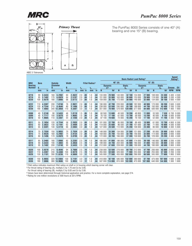
PumPac 8000 Series
159
The PumPac 8000 Series consists of one 40° (A)bearing and one 15° (B) bearing.
MRCBearingNumber
Bore
dmm in
OutsideDiameterDmm in
Width
Bmm in
ra
mm inrb
mm in
DynamicC4)
N lbf
DynamicC4)
N lbf
StaticC0
N lbf
StaticC0
N lbf
Basic Radial Load Rating2)Speed
Rating3)
Grease OilRPM RPM
Fillet Radius1)
8218 90 3.5433 160 6.2992 60 2.3622 2.0 .08 1.0 .04 133 000 29 900 143 000 32 100 124 000 27 900 108 000 24 300 3 400 4 5008219 95 3.7402 170 6.6929 64 2.5197 2.0 .08 1.0 .04 151 000 33 900 163 000 36 600 133 000 29 900 118 000 26 500 3 200 4 3008220 100 3.9370 180 7.0866 68 2.6772 2.0 .08 1.0 .04 159 000 35 700 173 000 38 900 146 000 32 800 134 000 30 100 3 000 4 000
8222 110 4.3307 200 7.8740 76 2.9921 2.0 .08 1.0 .04 190 000 42 700 220 000 49 500 182 000 40 900 170 000 38 200 2 600 3 6008224 120 4.7244 215 8.4646 80 3.1496 2.0 .08 1.0 .04 238 000 53 500 245 000 55 100 199 000 44 700 193 000 43 400 2 200 3 2008238 190 7.4803 340 13.3858 110 4.3307 3.0 .12 1.0 .04 351 000 78 900 570 000 128 000 377 000 84 800 500 000 112 000 1 400 1 900
8308 40 1.5748 90 3.5433 46 1.8110 1.5 .06 1.0 .04 60 500 13 600 45 500 10 200 48 800 11 000 33 500 7 530 6 700 9 0008309 45 1.7717 100 3.9370 50 1.9685 1.5 .06 1.0 .04 76 100 17 100 61 000 13 700 58 500 13 200 40 500 9 100 6 000 8 0008310 50 1.9685 110 4.3307 54 2.1260 2.0 .08 1.0 .04 87 100 19 600 72 000 16 200 76 100 17 100 52 000 11 700 5 300 7 000
8311 55 2.1654 120 4.7244 58 2.2835 2.0 .08 1.0 .04 101 000 22 700 85 000 19 100 88 400 19 900 61 000 13 700 4 800 6 3008312 60 2.3622 130 5.1181 62 2.4409 2.0 .08 1.0 .04 114 000 25 600 96 500 21 700 101 000 22 700 71 000 16 000 4 500 6 0008313 65 2.5591 140 5.5118 66 2.5984 2.0 .08 1.0 .04 127 000 28 500 112 000 25 200 108 000 24 300 80 000 18 000 4 300 5 600
8314 70 2.7559 150 5.9055 70 2.7559 2.0 .08 1.0 .04 148 000 33 300 134 000 31 500 121 000 27 200 93 000 20 900 3 800 5 0008315 75 2.9528 160 6.2992 74 2.9134 2.0 .08 1.0 .04 159 000 35 700 150 000 33 700 146 000 32 800 114 000 25 600 3 600 4 8008316 80 3.1496 170 6.6929 78 3.0709 2.0 .08 1.0 .04 172 000 38 700 166 000 37 300 159 000 35 700 129 000 29 200 3 400 4 500
8317 85 3.3465 180 7.0866 82 3.2283 2.5 .10 1.0 .04 186 000 41 800 186 000 41 800 174 000 39 100 146 000 32 800 3 200 4 3008318 90 3.5433 190 7.4803 86 3.3858 2.5 .10 1.0 .04 199 000 44 700 204 000 45 900 186 000 41 800 160 000 36 000 3 000 4 0008319 95 3.7402 200 7.8740 90 3.5433 2.5 .10 1.0 .04 212 000 47 600 228 000 51 300 199 000 44 700 180 000 40 500 2 800 3 800
8320 100 3.9370 215 8.4646 94 3.7008 2.5 .10 1.0 .04 238 000 53 500 270 000 60 700 212 000 47 700 200 000 45 000 2 600 3 6008322 110 4.3307 240 9.4488 100 3.9370 2.5 .10 1.0 .04 265 000 59 600 320 000 71 900 255 000 57 300 255 000 57 300 2 200 3 2008326 130 5.1181 280 11.0236 116 4.5669 3.0 .12 1.0 .04 345 000 77 500 455 000 102 000 296 000 66 500 345 000 77 600 1 800 2 600
8330 150 5.9055 320 12.5984 130 5.1181 3.0 .12 1.0 .04 410 000 92 100 585 000 132 000 390 000 87 700 475 000 107 000 1 600 2 2008336 180 7.0866 380 14.9606 150 5.9055 3.0 .12 1.0 .04 507 000 114 000 815 000 183 000 475 000 107 000 640 000 144 000 1 300 1 600
40˚ (A) 15˚ (B)
1) Fillet radius indicates maximum fillet radius on shaft or in housing which bearing corner will clear.2) For thrust rating of bearing (A), multiply C by 1.75 and Co by 3.85.
For thrust rating of bearing (B), multiply C by 0.83 and Co by 2.00.3) Values have been determined through historical application and practice. For a more complete explanation, see page 274.4) Rating for one million revolutions or 500 hours at 33¹|₃ RPM.
ABEC 3 Tolerances
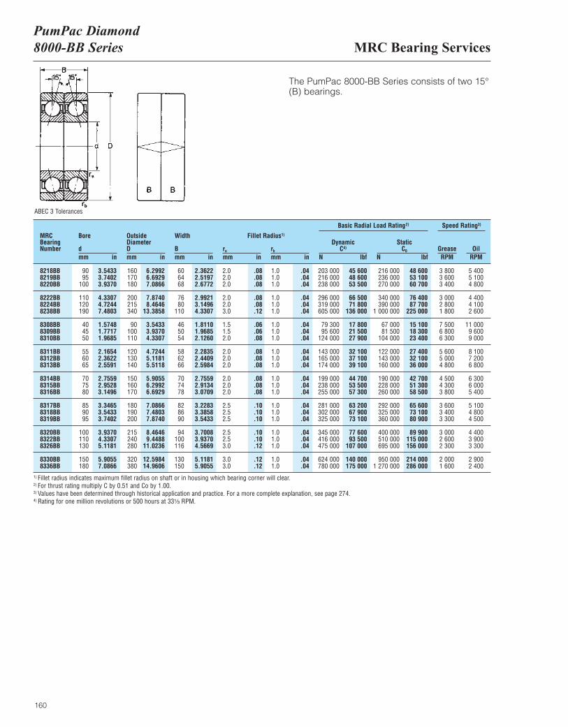
MRC Bearing ServicesPumPac Diamond 8000-BB Series
160
The PumPac 8000-BB Series consists of two 15°(B) bearings.
MRCBearingNumber
Bore
dmm in
OutsideDiameterDmm in
Width
Bmm in
ra
mm inrb
mm in
DynamicC4)
N lbf
Basic Radial Load Rating2) Speed Rating3)
StaticC0
N lbfGrease OilRPM RPM
Fillet Radius1)
8218BB 90 3.5433 160 6.2992 60 2.3622 2.0 .08 1.0 .04 203 000 45 600 216 000 48 600 3 800 5 4008219BB 95 3.7402 170 6.6929 64 2.5197 2.0 .08 1.0 .04 216 000 48 600 236 000 53 100 3 600 5 1008220BB 100 3.9370 180 7.0866 68 2.6772 2.0 .08 1.0 .04 238 000 53 500 270 000 60 700 3 400 4 800
8222BB 110 4.3307 200 7.8740 76 2.9921 2.0 .08 1.0 .04 296 000 66 500 340 000 76 400 3 000 4 4008224BB 120 4.7244 215 8.4646 80 3.1496 2.0 .08 1.0 .04 319 000 71 800 390 000 87 700 2 800 4 1008238BB 190 7.4803 340 13.3858 110 4.3307 3.0 .12 1.0 .04 605 000 136 000 1 000 000 225 000 1 800 2 600
8308BB 40 1.5748 90 3.5433 46 1.8110 1.5 .06 1.0 .04 79 300 17 800 67 000 15 100 7 500 11 0008309BB 45 1.7717 100 3.9370 50 1.9685 1.5 .06 1.0 .04 95 600 21 500 81 500 18 300 6 800 9 6008310BB 50 1.9685 110 4.3307 54 2.1260 2.0 .08 1.0 .04 124 000 27 900 104 000 23 400 6 300 9 000
8311BB 55 2.1654 120 4.7244 58 2.2835 2.0 .08 1.0 .04 143 000 32 100 122 000 27 400 5 600 8 1008312BB 60 2.3622 130 5.1181 62 2.4409 2.0 .08 1.0 .04 165 000 37 100 143 000 32 100 5 000 7 2008313BB 65 2.5591 140 5.5118 66 2.5984 2.0 .08 1.0 .04 174 000 39 100 160 000 36 000 4 800 6 800
8314BB 70 2.7559 150 5.9055 70 2.7559 2.0 .08 1.0 .04 199 000 44 700 190 000 42 700 4 500 6 3008315BB 75 2.9528 160 6.2992 74 2.9134 2.0 .08 1.0 .04 238 000 53 500 228 000 51 300 4 300 6 0008316BB 80 3.1496 170 6.6929 78 3.0709 2.0 .08 1.0 .04 255 000 57 300 260 000 58 500 3 800 5 400
8317BB 85 3.3465 180 7.0866 82 3.2283 2.5 .10 1.0 .04 281 000 63 200 292 000 65 600 3 600 5 1008318BB 90 3.5433 190 7.4803 86 3.3858 2.5 .10 1.0 .04 302 000 67 900 325 000 73 100 3 400 4 8008319BB 95 3.7402 200 7.8740 90 3.5433 2.5 .10 1.0 .04 325 000 73 100 360 000 80 900 3 300 4 500
8320BB 100 3.9370 215 8.4646 94 3.7008 2.5 .10 1.0 .04 345 000 77 600 400 000 89 900 3 000 4 4008322BB 110 4.3307 240 9.4488 100 3.9370 2.5 .10 1.0 .04 416 000 93 500 510 000 115 000 2 600 3 9008326BB 130 5.1181 280 11.0236 116 4.5669 3.0 .12 1.0 .04 475 000 107 000 695 000 156 000 2 300 3 300
8330BB 150 5.9055 320 12.5984 130 5.1181 3.0 .12 1.0 .04 624 000 140 000 950 000 214 000 2 000 2 9008336BB 180 7.0866 380 14.9606 150 5.9055 3.0 .12 1.0 .04 780 000 175 000 1 270 000 286 000 1 600 2 400
1) Fillet radius indicates maximum fillet radius on shaft or in housing which bearing corner will clear.2) For thrust rating multiply C by 0.51 and Co by 1.00.3) Values have been determined through historical application and practice. For a more complete explanation, see page 274.4) Rating for one million revolutions or 500 hours at 33¹|₃ RPM.
ABEC 3 Tolerances
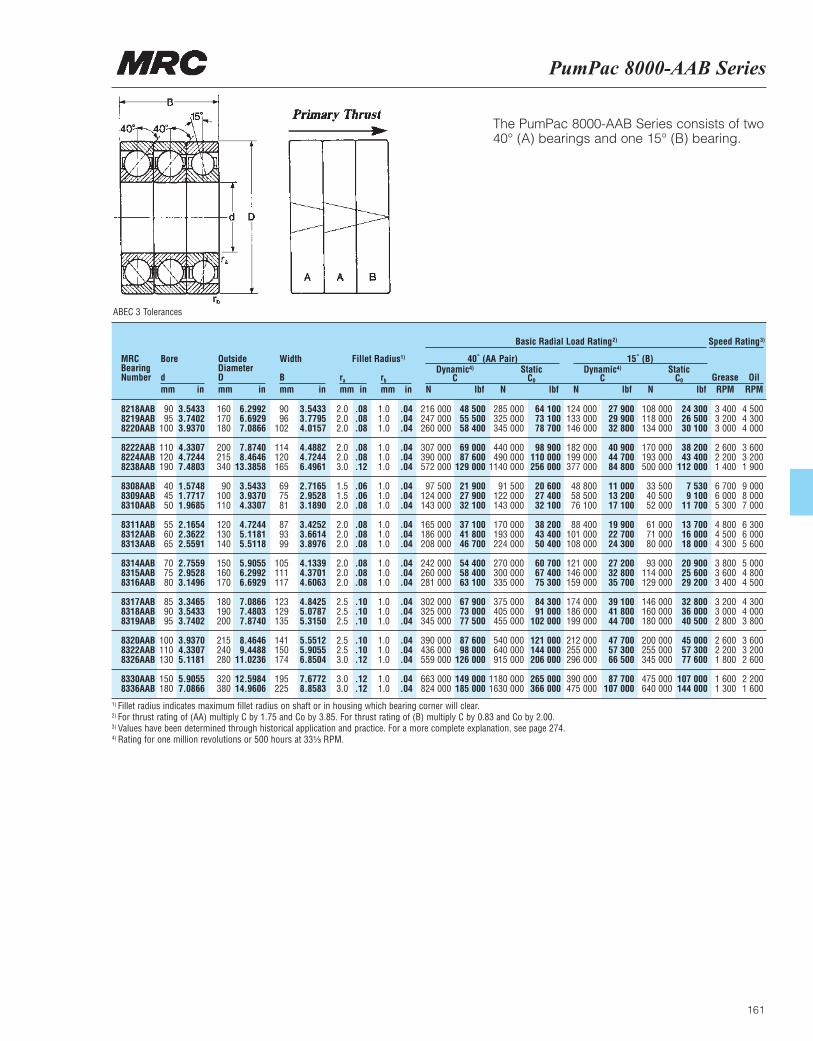
PumPac 8000-AAB Series
161
The PumPac 8000-AAB Series consists of two 40° (A) bearings and one 15° (B) bearing.
MRCBearingNumber
Bore
dmm in
OutsideDiameterDmm in
Width
Bmm in
ra
mm inrb
mm in
Dynamic4)
CN lbf
Dynamic4)
CN lbf
StaticC0
N lbf
StaticC0
N lbf
Basic Radial Load Rating2) Speed Rating3)
Grease OilRPM RPM
Fillet Radius1) 40˚ (AA Pair) 15˚ (B)
8218AAB 90 3.5433 160 6.2992 90 3.5433 2.0 .08 1.0 .04 216 000 48 500 285 000 64 100 124 000 27 900 108 000 24 300 3 400 4 5008219AAB 95 3.7402 170 6.6929 96 3.7795 2.0 .08 1.0 .04 247 000 55 500 325 000 73 100 133 000 29 900 118 000 26 500 3 200 4 3008220AAB 100 3.9370 180 7.0866 102 4.0157 2.0 .08 1.0 .04 260 000 58 400 345 000 78 700 146 000 32 800 134 000 30 100 3 000 4 000
8222AAB 110 4.3307 200 7.8740 114 4.4882 2.0 .08 1.0 .04 307 000 69 000 440 000 98 900 182 000 40 900 170 000 38 200 2 600 3 6008224AAB 120 4.7244 215 8.4646 120 4.7244 2.0 .08 1.0 .04 390 000 87 600 490 000 110 000 199 000 44 700 193 000 43 400 2 200 3 2008238AAB 190 7.4803 340 13.3858 165 6.4961 3.0 .12 1.0 .04 572 000 129 000 1140 000 256 000 377 000 84 800 500 000 112 000 1 400 1 900
8308AAB 40 1.5748 90 3.5433 69 2.7165 1.5 .06 1.0 .04 97 500 21 900 91 500 20 600 48 800 11 000 33 500 7 530 6 700 9 0008309AAB 45 1.7717 100 3.9370 75 2.9528 1.5 .06 1.0 .04 124 000 27 900 122 000 27 400 58 500 13 200 40 500 9 100 6 000 8 0008310AAB 50 1.9685 110 4.3307 81 3.1890 2.0 .08 1.0 .04 143 000 32 100 143 000 32 100 76 100 17 100 52 000 11 700 5 300 7 000
8311AAB 55 2.1654 120 4.7244 87 3.4252 2.0 .08 1.0 .04 165 000 37 100 170 000 38 200 88 400 19 900 61 000 13 700 4 800 6 3008312AAB 60 2.3622 130 5.1181 93 3.6614 2.0 .08 1.0 .04 186 000 41 800 193 000 43 400 101 000 22 700 71 000 16 000 4 500 6 0008313AAB 65 2.5591 140 5.5118 99 3.8976 2.0 .08 1.0 .04 208 000 46 700 224 000 50 400 108 000 24 300 80 000 18 000 4 300 5 600
8314AAB 70 2.7559 150 5.9055 105 4.1339 2.0 .08 1.0 .04 242 000 54 400 270 000 60 700 121 000 27 200 93 000 20 900 3 800 5 0008315AAB 75 2.9528 160 6.2992 111 4.3701 2.0 .08 1.0 .04 260 000 58 400 300 000 67 400 146 000 32 800 114 000 25 600 3 600 4 8008316AAB 80 3.1496 170 6.6929 117 4.6063 2.0 .08 1.0 .04 281 000 63 100 335 000 75 300 159 000 35 700 129 000 29 200 3 400 4 500
8317AAB 85 3.3465 180 7.0866 123 4.8425 2.5 .10 1.0 .04 302 000 67 900 375 000 84 300 174 000 39 100 146 000 32 800 3 200 4 3008318AAB 90 3.5433 190 7.4803 129 5.0787 2.5 .10 1.0 .04 325 000 73 000 405 000 91 000 186 000 41 800 160 000 36 000 3 000 4 0008319AAB 95 3.7402 200 7.8740 135 5.3150 2.5 .10 1.0 .04 345 000 77 500 455 000 102 000 199 000 44 700 180 000 40 500 2 800 3 800
8320AAB 100 3.9370 215 8.4646 141 5.5512 2.5 .10 1.0 .04 390 000 87 600 540 000 121 000 212 000 47 700 200 000 45 000 2 600 3 6008322AAB 110 4.3307 240 9.4488 150 5.9055 2.5 .10 1.0 .04 436 000 98 000 640 000 144 000 255 000 57 300 255 000 57 300 2 200 3 2008326AAB 130 5.1181 280 11.0236 174 6.8504 3.0 .12 1.0 .04 559 000 126 000 915 000 206 000 296 000 66 500 345 000 77 600 1 800 2 600
8330AAB 150 5.9055 320 12.5984 195 7.6772 3.0 .12 1.0 .04 663 000 149 000 1180 000 265 000 390 000 87 700 475 000 107 000 1 600 2 2008336AAB 180 7.0866 380 14.9606 225 8.8583 3.0 .12 1.0 .04 824 000 185 000 1630 000 366 000 475 000 107 000 640 000 144 000 1 300 1 600
1) Fillet radius indicates maximum fillet radius on shaft or in housing which bearing corner will clear.2) For thrust rating of (AA) multiply C by 1.75 and Co by 3.85. For thrust rating of (B) multiply C by 0.83 and Co by 2.00.3) Values have been determined through historical application and practice. For a more complete explanation, see page 274.4) Rating for one million revolutions or 500 hours at 33¹|₃ RPM.
ABEC 3 Tolerances
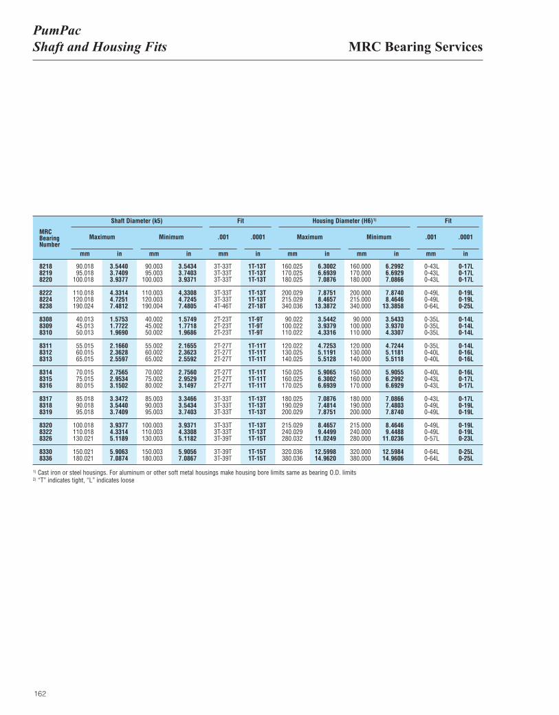
MRC Bearing ServicesPumPac Shaft and Housing Fits
162
1) Cast iron or steel housings. For aluminum or other soft metal housings make housing bore limits same as bearing O.D. limits2) “T” indicates tight, “L” indicates loose
Shaft and housing limits to ISO k5 and H6 tolerances.MRCBearingNumber
Maximum MaximumMinimum Minimum.001 .001
Fit FitShaft Diameter (k5) Housing Diameter (H6)1)
.0001 .0001
8218 90.018 3.5440 90.003 3.5434 3T-33T 1T-13T 160.025 6.3002 160.000 6.2992 0-43L 0-17L8219 95.018 3.7409 95.003 3.7403 3T-33T 1T-13T 170.025 6.6939 170.000 6.6929 0-43L 0-17L8220 100.018 3.9377 100.003 3.9371 3T-33T 1T-13T 180.025 7.0876 180.000 7.0866 0-43L 0-17L
8222 110.018 4.3314 110.003 4,3308 3T-33T 1T-13T 200.029 7.8751 200.000 7.8740 0-49L 0-19L8224 120.018 4.7251 120.003 4.7245 3T-33T 1T-13T 215.029 8.4657 215.000 8.4646 0-49L 0-19L8238 190.024 7.4812 190.004 7.4805 4T-46T 2T-18T 340.036 13.3872 340.000 13.3858 0-64L 0-25L
8308 40.013 1.5753 40.002 1.5749 2T-23T 1T-9T 90.022 3.5442 90.000 3.5433 0-35L 0-14L8309 45.013 1.7722 45.002 1.7718 2T-23T 1T-9T 100.022 3.9379 100.000 3.9370 0-35L 0-14L8310 50.013 1.9690 50.002 1.9686 2T-23T 1T-9T 110.022 4.3316 110.000 4.3307 0-35L 0-14L
8311 55.015 2.1660 55.002 2.1655 2T-27T 1T-11T 120.022 4.7253 120.000 4.7244 0-35L 0-14L8312 60.015 2.3628 60.002 2.3623 2T-27T 1T-11T 130.025 5.1191 130.000 5.1181 0-40L 0-16L8313 65.015 2.5597 65.002 2.5592 2T-27T 1T-11T 140.025 5.5128 140.000 5.5118 0-40L 0-16L
8314 70.015 2.7565 70.002 2.7560 2T-27T 1T-11T 150.025 5.9065 150.000 5.9055 0-40L 0-16L8315 75.015 2.9534 75.002 2.9529 2T-27T 1T-11T 160.025 6.3002 160.000 6.2992 0-43L 0-17L8316 80.015 3.1502 80.002 3.1497 2T-27T 1T-11T 170.025 6.6939 170.000 6.6929 0-43L 0-17L
8317 85.018 3.3472 85.003 3.3466 3T-33T 1T-13T 180.025 7.0876 180.000 7.0866 0-43L 0-17L8318 90.018 3.5440 90.003 3.5434 3T-33T 1T-13T 190.029 7.4814 190.000 7.4803 0-49L 0-19L8319 95.018 3.7409 95.003 3.7403 3T-33T 1T-13T 200.029 7.8751 200.000 7.8740 0-49L 0-19L
8320 100.018 3.9377 100.003 3.9371 3T-33T 1T-13T 215.029 8.4657 215.000 8.4646 0-49L 0-19L8322 110.018 4.3314 110.003 4.3308 3T-33T 1T-13T 240.029 9.4499 240.000 9.4488 0-49L 0-19L8326 130.021 5.1189 130.003 5.1182 3T-39T 1T-15T 280.032 11.0249 280.000 11.0236 0-57L 0-23L
8330 150.021 5.9063 150.003 5.9056 3T-39T 1T-15T 320.036 12.5998 320.000 12.5984 0-64L 0-25L8336 180.021 7.0874 180.003 7.0867 3T-39T 1T-15T 380.036 14.9620 380.000 14.9606 0-64L 0-25L
mm mmmm mmmm mmin inin inin in
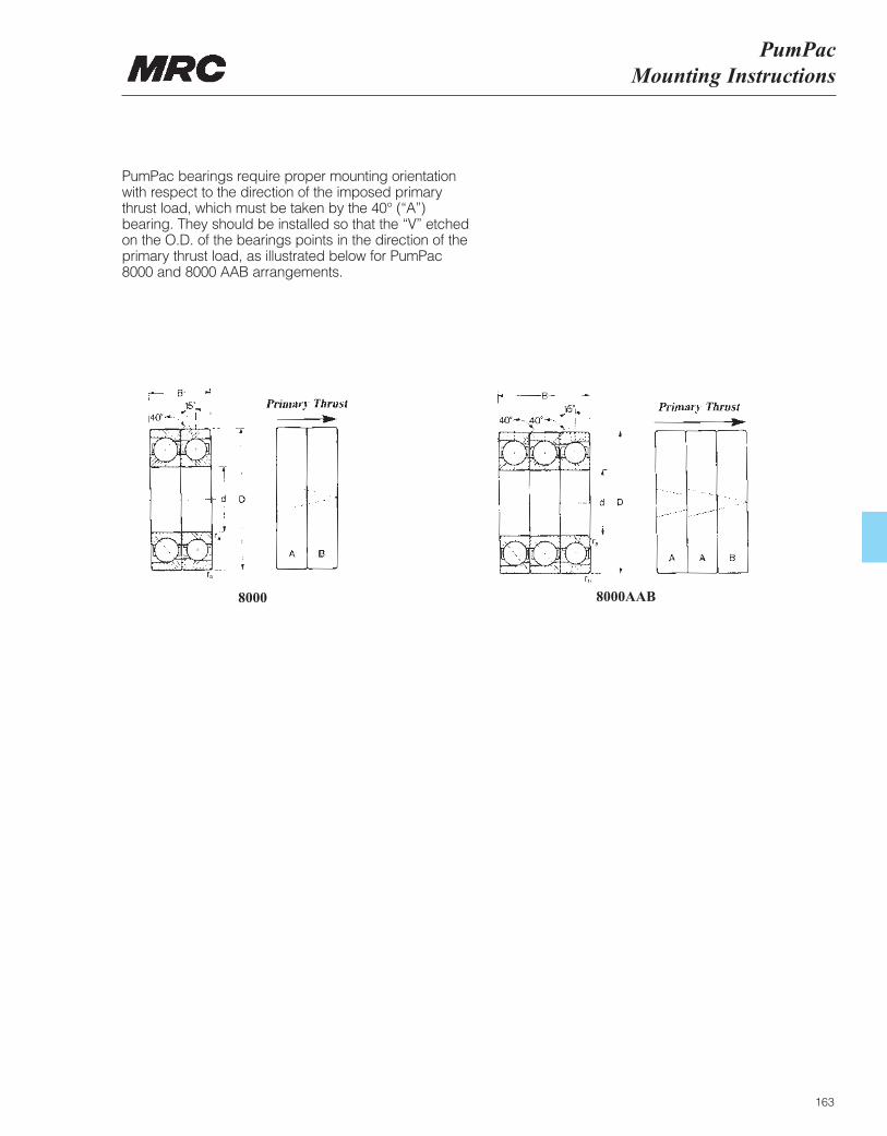
PumPacMounting Instructions
163
PumPac bearings require proper mounting orientationwith respect to the direction of the imposed primarythrust load, which must be taken by the 40° (“A”)bearing. They should be installed so that the “V” etchedon the O.D. of the bearings points in the direction of theprimary thrust load, as illustrated below for PumPac8000 and 8000 AAB arrangements.
8000 8000AAB
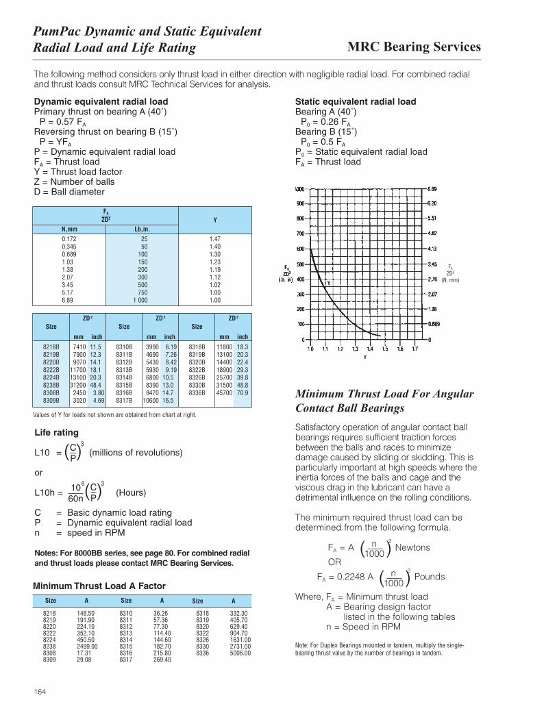
MRC Bearing ServicesPumPac Dynamic and Static EquivalentRadial Load and Life Rating
164
0.172 25 1.470.345 50 1.400.689 100 1.301.03 150 1.231.38 200 1.192.07 300 1.123.45 500 1.025.17 750 1.006.89 1 000 1.00
8218B 7410 11.5 8310B 3990 6.19 8318B 11800 18.38219B 7900 12.3 8311B 4690 7.26 8319B 13100 20.38220B 9070 14.1 8312B 5430 8.42 8320B 14400 22.48222B 11700 18.1 8313B 5930 9.19 8322B 18900 29.38224B 13100 20.3 8314B 6800 10.5 8326B 25700 39.88238B 31200 48.4 8315B 8390 13.0 8330B 31500 48.88308B 2450 3.80 8316B 9470 14.7 8336B 45700 70.98309B 3020 4.69 8317B 10600 16.5
FA
ZD2 YN,mm Lb,in.
Size
mm inch inch inchmm mm
Size SizeZD2 ZD2 ZD2
The following method considers only thrust load in either direction with negligible radial load. For combined radialand thrust loads consult MRC Technical Services for analysis.
Dynamic equivalent radial loadPrimary thrust on bearing A (40˚)
P = 0.57 FA
Reversing thrust on bearing B (15˚)P = YFA
P = Dynamic equivalent radial loadFA = Thrust loadY = Thrust load factorZ = Number of ballsD = Ball diameter
Life rating
L10 = (millions of revolutions)
or
L10h = (Hours)
C = Basic dynamic load ratingP = Dynamic equivalent radial loadn = speed in RPM
Notes: For 8000BB series, see page 80. For combined radialand thrust loads please contact MRC Bearing Services.
Static equivalent radial loadBearing A (40˚)
P0 = 0.26 FA
Bearing B (15˚)P0 = 0.5 FA
P0 = Static equivalent radial loadFA = Thrust load
( )CP
3
( )CP
1060n
36
Values of Y for loads not shown are obtained from chart at right.
FA
ZD2
(N, mm)
Size A
Minimum Thrust Load A Factor
8218 148.508219 191.908220 224.108222 352.108224 450.508238 2499.008308 17.318309 29.08
8310 36.268311 57.368312 77.308313 114.408314 144.608315 182.708316 215.808317 269.40
8318 332.308319 405.708320 629.408322 904.708326 1631.008330 2731.008336 5006.00
Minimum Thrust Load For Angular Contact Ball Bearings
Satisfactory operation of angular contact ballbearings requires sufficient traction forcesbetween the balls and races to minimizedamage caused by sliding or skidding. This isparticularly important at high speeds where theinertia forces of the balls and cage and theviscous drag in the lubricant can have adetrimental influence on the rolling conditions.
The minimum required thrust load can bedetermined from the following formula.
FA = A Newtons
OR
FA = 0.2248 A Pounds
Where, FA = Minimum thrust load A = Bearing design factor
listed in the following tables n = Speed in RPM
Note: For Duplex Bearings mounted in tandem, multiply the single-bearing thrust value by the number of bearings in tandem.
n1000( )
2
n1000( )
2
Size A Size A
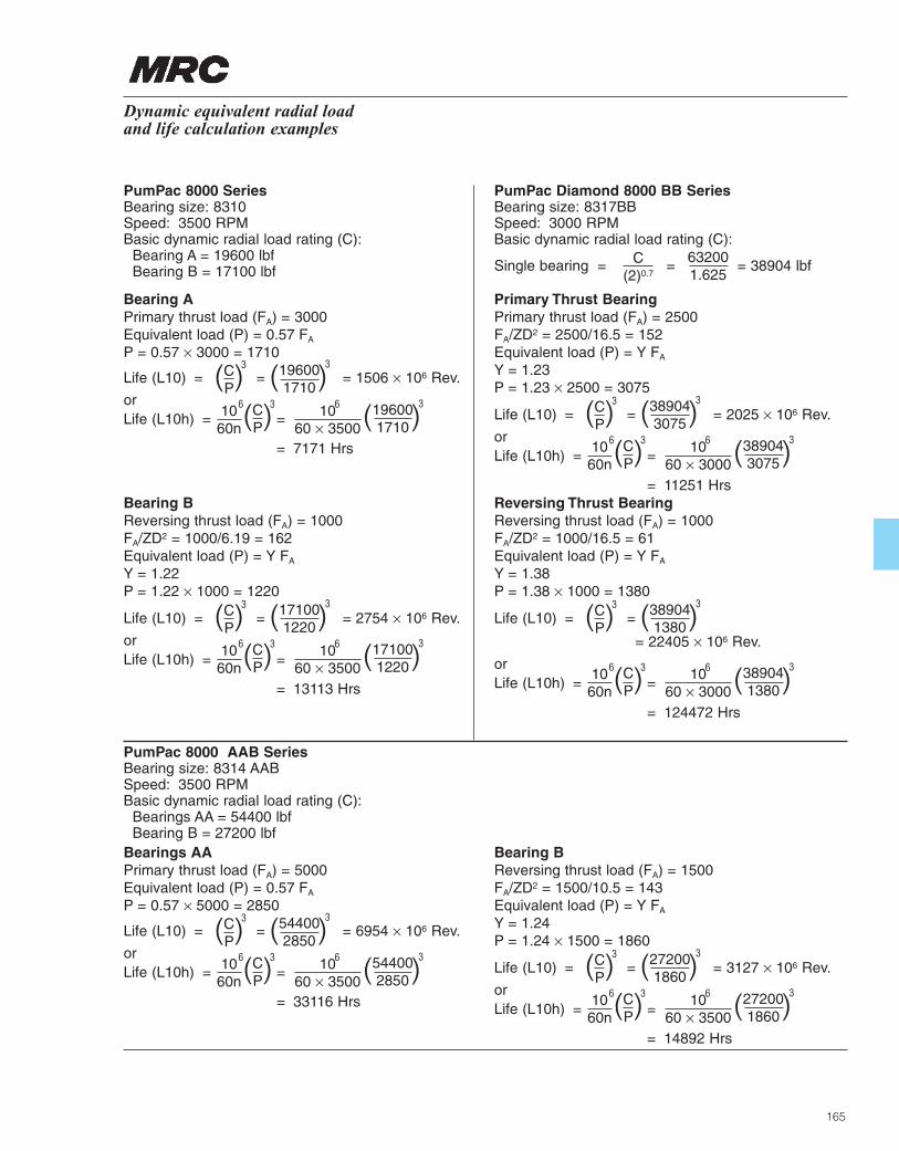
165
Dynamic equivalent radial load and life calculation examples
PumPac 8000 SeriesBearing size: 8310Speed: 3500 RPMBasic dynamic radial load rating (C):
Bearing A = 19600 lbfBearing B = 17100 lbf
PumPac 8000 AAB SeriesBearing size: 8314 AABSpeed: 3500 RPMBasic dynamic radial load rating (C):
Bearings AA = 54400 lbfBearing B = 27200 lbf
PumPac Diamond 8000 BB SeriesBearing size: 8317BBSpeed: 3000 RPMBasic dynamic radial load rating (C):
Single bearing = = = 38904 lbf
Bearing APrimary thrust load (FA) = 3000Equivalent load (P) = 0.57 FA
P = 0.57 × 3000 = 1710
Life (L10) = = = 1506 × 106 Rev.
orLife (L10h) = =
= 7171 Hrs
( )CP
3
( )CP
1060n
36 1060 × 3500
6
( )196001710
3
( )196001710
3
Primary Thrust BearingPrimary thrust load (FA) = 2500FA/ZD2 = 2500/16.5 = 152Equivalent load (P) = Y FA
Y = 1.23P = 1.23 × 2500 = 3075
Life (L10) = = = 2025 × 106 Rev.
orLife (L10h) = =
= 11251 Hrs
( )CP
3
( )CP
1060n
36 1060 × 3000
6
( )389043075
3
( )389043075
3
Reversing Thrust BearingReversing thrust load (FA) = 1000FA/ZD2 = 1000/16.5 = 61Equivalent load (P) = Y FA
Y = 1.38P = 1.38 × 1000 = 1380
Life (L10) = =
= 22405 × 106 Rev.
orLife (L10h) = =
= 124472 Hrs
( )CP
3
( )CP
1060n
36 1060 × 3000
6
( )389041380
3
( )389041380
3
Bearing BReversing thrust load (FA) = 1000FA/ZD2 = 1000/6.19 = 162Equivalent load (P) = Y FA
Y = 1.22P = 1.22 × 1000 = 1220
Life (L10) = = = 2754 × 106 Rev.
orLife (L10h) = =
= 13113 Hrs
( )CP
3
( )CP
1060n
36 1060 × 3500
6
( )171001220
3
( )171001220
3
C(2)0.7
632001.625
Bearings AAPrimary thrust load (FA) = 5000Equivalent load (P) = 0.57 FA
P = 0.57 × 5000 = 2850
Life (L10) = = = 6954 × 106 Rev.
orLife (L10h) = =
= 33116 Hrs
( )CP
3
( )CP
1060n
36 1060 × 3500
6
( )544002850
3
( )544002850
3
Bearing BReversing thrust load (FA) = 1500FA/ZD2 = 1500/10.5 = 143Equivalent load (P) = Y FA
Y = 1.24P = 1.24 × 1500 = 1860
Life (L10) = = = 3127 × 106 Rev.
orLife (L10h) = =
= 14892 Hrs
( )CP
3
( )CP
1060n
36 1060 × 3500
6
( )272001860
3
( )272001860
3

166
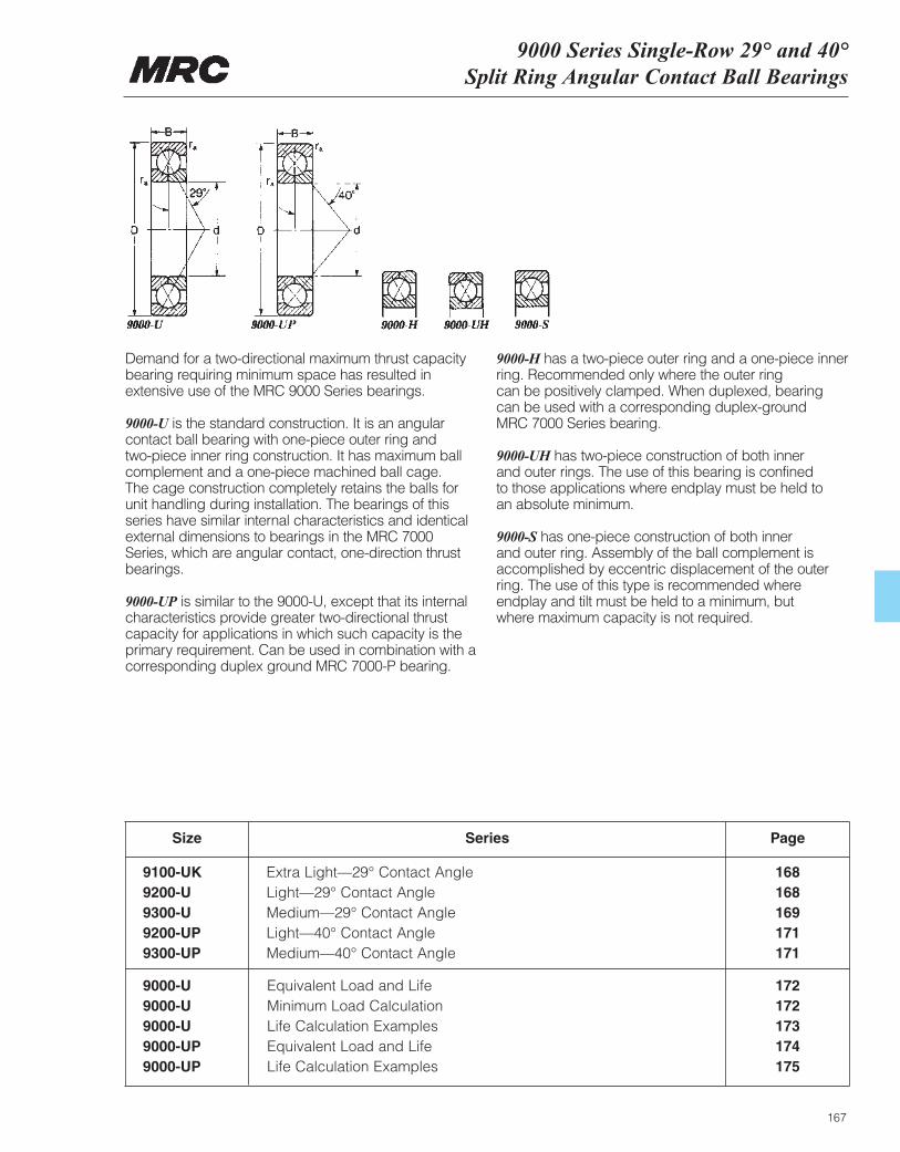
9000 Series Single-Row 29° and 40°Split Ring Angular Contact Ball Bearings
167
Demand for a two-directional maximum thrust capacitybearing requiring minimum space has resulted inextensive use of the MRC 9000 Series bearings.
9000-U is the standard construction. It is an angularcontact ball bearing with one-piece outer ring and two-piece inner ring construction. It has maximum ballcomplement and a one-piece machined ball cage. The cage construction completely retains the balls forunit handling during installation. The bearings of thisseries have similar internal characteristics and identicalexternal dimensions to bearings in the MRC 7000Series, which are angular contact, one-direction thrustbearings.
9000-UP is similar to the 9000-U, except that its internalcharacteristics provide greater two-directional thrustcapacity for applications in which such capacity is theprimary requirement. Can be used in combination with acorresponding duplex ground MRC 7000-P bearing.
9000-H has a two-piece outer ring and a one-piece innerring. Recommended only where the outer ring can be positively clamped. When duplexed, bearingcan be used with a corresponding duplex-ground MRC 7000 Series bearing.
9000-UH has two-piece construction of both inner and outer rings. The use of this bearing is confined to those applications where endplay must be held to an absolute minimum.
9000-S has one-piece construction of both inner and outer ring. Assembly of the ball complement isaccomplished by eccentric displacement of the outerring. The use of this type is recommended where endplay and tilt must be held to a minimum, but where maximum capacity is not required.
Size
9100-UK Extra Light—29° Contact Angle 1689200-U Light—29° Contact Angle 1689300-U Medium—29° Contact Angle 1699200-UP Light—40° Contact Angle 1719300-UP Medium—40° Contact Angle 171
Series Page
9000-U Equivalent Load and Life 1729000-U Minimum Load Calculation 1729000-U Life Calculation Examples 1739000-UP Equivalent Load and Life 1749000-UP Life Calculation Examples 175
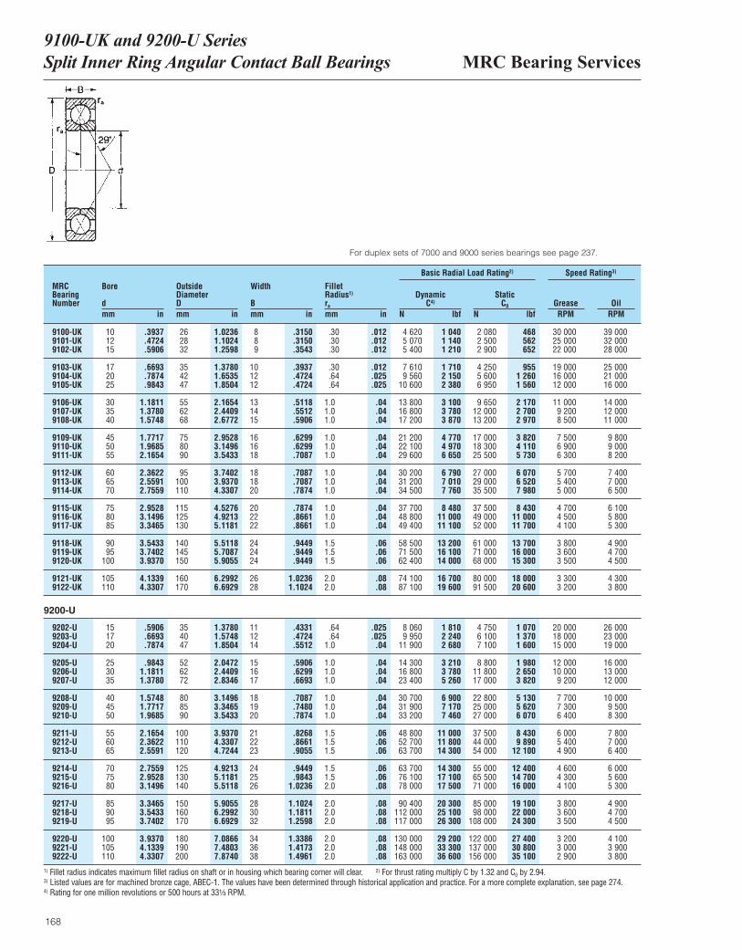
MRC Bearing Services9100-UK and 9200-U Series Split Inner Ring Angular Contact Ball Bearings
168
MRCBearingNumber
Bore
dmm in
OutsideDiameterDmm in
Width
Bmm in
ra
mm in
DynamicC4)
N lbf
Basic Radial Load Rating2) Speed Rating3)
StaticC0
N lbfGrease OilRPM RPM
Fillet Radius1)
9100-UK 10 .3937 26 1.0236 8 .3150 .30 .012 4 620 1 040 2 080 468 30 000 39 0009101-UK 12 .4724 28 1.1024 8 .3150 .30 .012 5 070 1 140 2 500 562 25 000 32 0009102-UK 15 .5906 32 1.2598 9 .3543 .30 .012 5 400 1 210 2 900 652 22 000 28 000
9103-UK 17 .6693 35 1.3780 10 .3937 .30 .012 7 610 1 710 4 250 955 19 000 25 0009104-UK 20 .7874 42 1.6535 12 .4724 .64 .025 9 560 2 150 5 600 1 260 16 000 21 0009105-UK 25 .9843 47 1.8504 12 .4724 .64 .025 10 600 2 380 6 950 1 560 12 000 16 000
9106-UK 30 1.1811 55 2.1654 13 .5118 1.0 .04 13 800 3 100 9 650 2 170 11 000 14 0009107-UK 35 1.3780 62 2.4409 14 .5512 1.0 .04 16 800 3 780 12 000 2 700 9 200 12 0009108-UK 40 1.5748 68 2.6772 15 .5906 1.0 .04 17 200 3 870 13 200 2 970 8 500 11 000
9109-UK 45 1.7717 75 2.9528 16 .6299 1.0 .04 21 200 4 770 17 000 3 820 7 500 9 8009110-UK 50 1.9685 80 3.1496 16 .6299 1.0 .04 22 100 4 970 18 300 4 110 6 900 9 0009111-UK 55 2.1654 90 3.5433 18 .7087 1.0 .04 29 600 6 650 25 500 5 730 6 300 8 200
9112-UK 60 2.3622 95 3.7402 18 .7087 1.0 .04 30 200 6 790 27 000 6 070 5 700 7 4009113-UK 65 2.5591 100 3.9370 18 .7087 1.0 .04 31 200 7 010 29 000 6 520 5 400 7 0009114-UK 70 2.7559 110 4.3307 20 .7874 1.0 .04 34 500 7 760 35 500 7 980 5 000 6 500
9115-UK 75 2.9528 115 4.5276 20 .7874 1.0 .04 37 700 8 480 37 500 8 430 4 700 6 1009116-UK 80 3.1496 125 4.9213 22 .8661 1.0 .04 48 800 11 000 49 000 11 000 4 500 5 8009117-UK 85 3.3465 130 5.1181 22 .8661 1.0 .04 49 400 11 100 52 000 11 700 4 100 5 300
9118-UK 90 3.5433 140 5.5118 24 .9449 1.5 .06 58 500 13 200 61 000 13 700 3 800 4 9009119-UK 95 3.7402 145 5.7087 24 .9449 1.5 .06 71 500 16 100 71 000 16 000 3 600 4 7009120-UK 100 3.9370 150 5.9055 24 .9449 1.5 .06 62 400 14 000 68 000 15 300 3 500 4 500
9121-UK 105 4.1339 160 6.2992 26 1.0236 2.0 .08 74 100 16 700 80 000 18 000 3 300 4 3009122-UK 110 4.3307 170 6.6929 28 1.1024 2.0 .08 87 100 19 600 91 500 20 600 3 200 3 800
9202-U 15 .5906 35 1.3780 11 .4331 .64 .025 8 060 1 810 4 750 1 070 20 000 26 0009203-U 17 .6693 40 1.5748 12 .4724 .64 .025 9 950 2 240 6 100 1 370 18 000 23 0009204-U 20 .7874 47 1.8504 14 .5512 1.0 .04 11 900 2 680 7 100 1 600 15 000 19 000
9205-U 25 .9843 52 2.0472 15 .5906 1.0 .04 14 300 3 210 8 800 1 980 12 000 16 0009206-U 30 1.1811 62 2.4409 16 .6299 1.0 .04 16 800 3 780 11 800 2 650 10 000 13 0009207-U 35 1.3780 72 2.8346 17 .6693 1.0 .04 23 400 5 260 17 000 3 820 9 200 12 000
9208-U 40 1.5748 80 3.1496 18 .7087 1.0 .04 30 700 6 900 22 800 5 130 7 700 10 0009209-U 45 1.7717 85 3.3465 19 .7480 1.0 .04 31 900 7 170 25 000 5 620 7 300 9 5009210-U 50 1.9685 90 3.5433 20 .7874 1.0 .04 33 200 7 460 27 000 6 070 6 400 8 300
9211-U 55 2.1654 100 3.9370 21 .8268 1.5 .06 48 800 11 000 37 500 8 430 6 000 7 8009212-U 60 2.3622 110 4.3307 22 .8661 1.5 .06 52 700 11 800 44 000 9 890 5 400 7 0009213-U 65 2.5591 120 4.7244 23 .9055 1.5 .06 63 700 14 300 54 000 12 100 4 900 6 400
9214-U 70 2.7559 125 4.9213 24 .9449 1.5 .06 63 700 14 300 55 000 12 400 4 600 6 0009215-U 75 2.9528 130 5.1181 25 .9843 1.5 .06 76 100 17 100 65 500 14 700 4 300 5 6009216-U 80 3.1496 140 5.5118 26 1.0236 2.0 .08 78 000 17 500 71 000 16 000 4 100 5 300
9217-U 85 3.3465 150 5.9055 28 1.1024 2.0 .08 90 400 20 300 85 000 19 100 3 800 4 9009218-U 90 3.5433 160 6.2992 30 1.1811 2.0 .08 112 000 25 100 98 000 22 000 3 600 4 7009219-U 95 3.7402 170 6.6929 32 1.2598 2.0 .08 117 000 26 300 108 000 24 300 3 500 4 500
9220-U 100 3.9370 180 7.0866 34 1.3386 2.0 .08 130 000 29 200 122 000 27 400 3 200 4 1009221-U 105 4.1339 190 7.4803 36 1.4173 2.0 .08 148 000 33 300 137 000 30 800 3 000 3 9009222-U 110 4.3307 200 7.8740 38 1.4961 2.0 .08 163 000 36 600 156 000 35 100 2 900 3 800
For duplex sets of 7000 and 9000 series bearings see page 237.
9200-U
1) Fillet radius indicates maximum fillet radius on shaft or in housing which bearing corner will clear. 2) For thrust rating multiply C by 1.32 and C0 by 2.94.3) Listed values are for machined bronze cage, ABEC-1. The values have been determined through historical application and practice. For a more complete explanation, see page 274.4) Rating for one million revolutions or 500 hours at 33¹|₃ RPM.
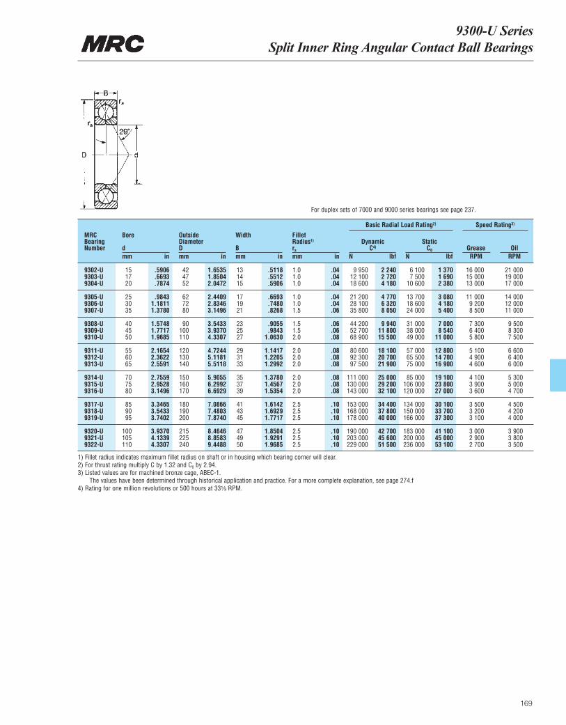
9300-U Series Split Inner Ring Angular Contact Ball Bearings
169
For duplex sets of 7000 and 9000 series bearings see page 237.
MRCBearingNumber
Bore
dmm in
OutsideDiameterDmm in
Width
Bmm in
ra
mm in
DynamicC4)
N lbf
Basic Radial Load Rating2) Speed Rating3)
StaticC0
N lbfGrease OilRPM RPM
Fillet Radius1)
9302-U 15 .5906 42 1.6535 13 .5118 1.0 .04 9 950 2 240 6 100 1 370 16 000 21 0009303-U 17 .6693 47 1.8504 14 .5512 1.0 .04 12 100 2 720 7 500 1 690 15 000 19 0009304-U 20 .7874 52 2.0472 15 .5906 1.0 .04 18 600 4 180 10 600 2 380 13 000 17 000
9305-U 25 .9843 62 2.4409 17 .6693 1.0 .04 21 200 4 770 13 700 3 080 11 000 14 0009306-U 30 1.1811 72 2.8346 19 .7480 1.0 .04 28 100 6 320 18 600 4 180 9 200 12 0009307-U 35 1.3780 80 3.1496 21 .8268 1.5 .06 35 800 8 050 24 000 5 400 8 500 11 000
9308-U 40 1.5748 90 3.5433 23 .9055 1.5 .06 44 200 9 940 31 000 7 000 7 300 9 5009309-U 45 1.7717 100 3.9370 25 .9843 1.5 .06 52 700 11 800 38 000 8 540 6 400 8 3009310-U 50 1.9685 110 4.3307 27 1.0630 2.0 .08 68 900 15 500 49 000 11 000 5 800 7 500
9311-U 55 2.1654 120 4.7244 29 1.1417 2.0 .08 80 600 18 100 57 000 12 800 5 100 6 6009312-U 60 2.3622 130 5.1181 31 1.2205 2.0 .08 92 300 20 700 65 500 14 700 4 900 6 4009313-U 65 2.5591 140 5.5118 33 1.2992 2.0 .08 97 500 21 900 75 000 16 900 4 600 6 000
9314-U 70 2.7559 150 5.9055 35 1.3780 2.0 .08 111 000 25 000 85 000 19 100 4 100 5 3009315-U 75 2.9528 160 6.2992 37 1.4567 2.0 .08 130 000 29 200 106 000 23 800 3 900 5 0009316-U 80 3.1496 170 6.6929 39 1.5354 2.0 .08 143 000 32 100 120 000 27 000 3 600 4 700
9317-U 85 3.3465 180 7.0866 41 1.6142 2.5 .10 153 000 34 400 134 000 30 100 3 500 4 5009318-U 90 3.5433 190 7.4803 43 1.6929 2.5 .10 168 000 37 800 150 000 33 700 3 200 4 2009319-U 95 3.7402 200 7.8740 45 1.7717 2.5 .10 178 000 40 000 166 000 37 300 3 100 4 000
9320-U 100 3.9370 215 8.4646 47 1.8504 2.5 .10 190 000 42 700 183 000 41 100 3 000 3 9009321-U 105 4.1339 225 8.8583 49 1.9291 2.5 .10 203 000 45 600 200 000 45 000 2 900 3 8009322-U 110 4.3307 240 9.4488 50 1.9685 2.5 .10 229 000 51 500 236 000 53 100 2 700 3 500
1) Fillet radius indicates maximum fillet radius on shaft or in housing which bearing corner will clear.2) For thrust rating multiply C by 1.32 and C0 by 2.94.3) Listed values are for machined bronze cage, ABEC-1.
The values have been determined through historical application and practice. For a more complete explanation, see page 274.f4) Rating for one million revolutions or 500 hours at 33¹|₃ RPM.

170
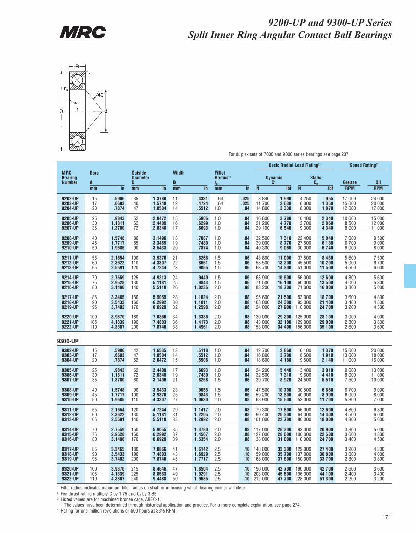
171
9200-UP and 9300-UP Series Split Inner Ring Angular Contact Ball Bearings
MRCBearingNumber
Bore
dmm in
OutsideDiameterDmm in
Width
Bmm in
ra
mm in
DynamicC4)
N lbf
Basic Radial Load Rating2) Speed Rating3)
StaticC0
N lbfGrease OilRPM RPM
Fillet Radius1)
9202-UP 15 .5906 35 1.3780 11 .4331 .64 .025 8 840 1 990 4 250 955 17 000 24 0009203-UP 17 .6693 40 1.5748 12 .4724 .64 .025 11 700 2 630 6 000 1 350 15 000 20 0009204-UP 20 .7874 47 1.8504 14 .5512 1.0 .04 14 800 3 330 8 300 1 870 12 000 17 000
9205-UP 25 .9843 52 2.0472 15 .5906 1.0 .04 16 800 3 780 10 400 2 340 10 000 15 0009206-UP 30 1.1811 62 2.4409 16 .6299 1.0 .04 21 200 4 770 12 700 2 860 8 500 12 0009207-UP 35 1.3780 72 2.8346 17 .6693 1.0 .04 29 100 6 540 19 300 4 340 8 000 11 000
9208-UP 40 1.5748 80 3.1496 18 .7087 1.0 .04 32 500 7 310 22 400 5 040 7 000 9 5009209-UP 45 1.7717 85 3.3465 19 .7480 1.0 .04 39 000 8 770 27 500 6 180 6 700 9 0009210-UP 50 1.9685 90 3.5433 20 .7874 1.0 .04 40 300 9 060 30 000 6 740 6 000 8 000
9211-UP 55 2.1654 100 3.9370 21 .8268 1.5 .06 48 800 11 000 37 500 8 430 5 600 7 5009212-UP 60 2.3622 110 4.3307 22 .8661 1.5 .06 58 500 13 200 45 500 10 200 5 000 6 7009213-UP 65 2.5591 120 4.7244 23 .9055 1.5 .06 63 700 14 300 51 000 11 500 4 500 6 000
9214-UP 70 2.7559 125 4.9213 24 .9449 1.5 .06 68 900 15 500 56 000 12 600 4 300 5 6009215-UP 75 2.9528 130 5.1181 25 .9843 1.5 .06 71 500 16 100 60 000 13 500 4 000 5 3009216-UP 80 3.1496 140 5.5118 26 1.0236 2.0 .08 83 200 18 700 71 000 16 000 3 800 5 000
9217-UP 85 3.3465 150 5.9055 28 1.1024 2.0 .08 95 600 21 500 83 000 18 700 3 600 4 8009218-UP 90 3.5433 160 6.2992 30 1.1811 2.0 .08 108 000 24 300 95 000 21 400 3 400 4 5009219-UP 95 3.7402 170 6.6929 32 1.2598 2.0 .08 124 000 27 900 110 000 24 700 3 200 4 300
9220-UP 100 3.9370 180 7.0866 34 1.3386 2.0 .08 130 000 29 200 125 000 28 100 3 000 4 0009221-UP 105 4.1339 190 7.4803 36 1.4173 2.0 .08 143 000 32 100 129 000 29 000 2 800 3 8009222-UP 110 4.3307 200 7.8740 38 1.4961 2.0 .08 153 000 34 400 156 000 35 100 2 600 3 600
9302-UP 15 .5906 42 1.6535 13 .5118 1.0 .04 12 700 2 860 6 100 1 370 15 000 20 0009303-UP 17 .6693 47 1.8504 14 .5512 1.0 .04 16 800 3 780 8 500 1 910 13 000 18 0009304-UP 20 .7874 52 2.0472 15 .5906 1.0 .04 18 600 4 180 9 500 2 140 11 000 16 000
9305-UP 25 .9843 62 2.4409 17 .6693 1.0 .04 24 200 5 440 13 400 3 010 9 000 13 0009306-UP 30 1.1811 72 2.8346 19 .7480 1.0 .04 32 500 7 310 19 600 4 410 8 000 11 0009307-UP 35 1.3780 80 3.1496 21 .8268 1.5 .06 39 700 8 920 24 500 5 510 7 500 10 000
9308-UP 40 1.5748 90 3.5433 23 .9055 1.5 .06 47 500 10 700 30 500 6 860 6 700 9 0009309-UP 45 1.7717 100 3.9370 25 .9843 1.5 .06 59 200 13 300 40 000 8 990 6 000 8 0009310-UP 50 1.9685 110 4.3307 27 1.0630 2.0 .08 68 900 15 500 52 000 11 700 5 300 7 000
9311-UP 55 2.1654 120 4.7244 29 1.1417 2.0 .08 79 300 17 800 56 000 12 600 4 800 6 3009312-UP 60 2.3622 130 5.1181 31 1.2205 2.0 .08 90 400 20 300 64 000 14 400 4 500 6 0009313-UP 65 2.5591 140 5.5118 33 1.2992 2.0 .08 101 000 22 700 80 000 18 000 4 300 5 600
9314-UP 70 2.7559 150 5.9055 35 1.3780 2.0 .08 117 000 26 300 93 000 20 900 3 800 5 0009315-UP 75 2.9528 160 6.2992 37 1.4567 2.0 .08 127 000 28 600 100 000 22 500 3 600 4 8009316-UP 80 3.1496 170 6.6929 39 1.5354 2.0 .08 138 000 31 000 110 000 24 700 3 400 4 500
9317-UP 85 3.3465 180 7.0866 41 1.6142 2.5 .10 148 000 33 300 122 000 27 400 3 200 4 3009318-UP 90 3.5433 190 7.4803 43 1.6929 2.5 .10 159 000 35 700 137 000 30 800 3 000 4 0009319-UP 95 3.7402 200 7.8740 45 1.7717 2.5 .10 168 000 37 800 150 000 33 700 2 800 3 800
9320-UP 100 3.9370 215 8.4646 47 1.8504 2.5 .10 190 000 42 700 190 000 42 700 2 600 3 6009321-UP 105 4.1339 225 8.8583 49 1.9291 2.5 .10 203 000 45 600 196 000 44 100 2 400 3 4009322-UP 110 4.3307 240 9.4488 50 1.9685 2.5 .10 212 000 47 700 228 000 51 300 2 200 3 200
For duplex sets of 7000 and 9000 series bearings see page 237.
9300-UP
1) Fillet radius indicates maximum fillet radius on shaft or in housing which bearing corner will clear.2) For thrust rating multiply C by 1.75 and C0 by 3.85.3) Listed values are for machined bronze cage, ABEC-1.
The values have been determined through historical application and practice. For a more complete explanation, see page 274.4) Rating for one million revolutions or 500 hours at 33¹|₃ RPM.
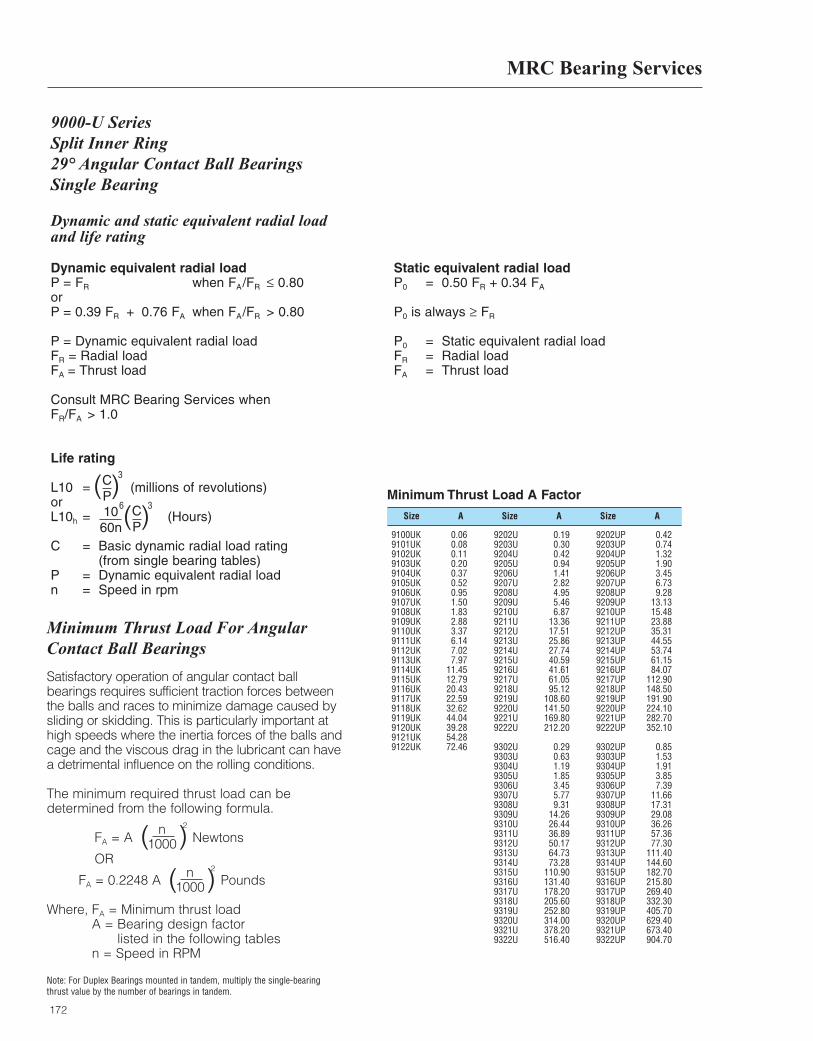
MRC Bearing Services
172
Dynamic and static equivalent radial load and life rating
Dynamic equivalent radial loadP = FR when FA/FR ≤ 0.80orP = 0.39 FR + 0.76 FA when FA/FR > 0.80
P = Dynamic equivalent radial loadFR = Radial loadFA = Thrust load
Consult MRC Bearing Services whenFR/FA > 1.0
Static equivalent radial loadP0 = 0.50 FR + 0.34 FA
P0 is always ≥ FR
P0 = Static equivalent radial loadFR = Radial loadFA = Thrust load
Life rating
L10 = (millions of revolutions)orL10h = (Hours)
C = Basic dynamic radial load rating(from single bearing tables)
P = Dynamic equivalent radial loadn = Speed in rpm
( )CP
3
( )CP
1060n
36
9000-U Series Split Inner Ring29° Angular Contact Ball BearingsSingle Bearing
Size Size SizeA A A
Minimum Thrust Load A Factor
9100UK 0.069101UK 0.089102UK 0.119103UK 0.209104UK 0.379105UK 0.529106UK 0.959107UK 1.509108UK 1.839109UK 2.889110UK 3.379111UK 6.149112UK 7.029113UK 7.979114UK 11.459115UK 12.799116UK 20.439117UK 22.599118UK 32.629119UK 44.049120UK 39.289121UK 54.289122UK 72.46
9202U 0.199203U 0.309204U 0.429205U 0.949206U 1.419207U 2.829208U 4.959209U 5.469210U 6.879211U 13.369212U 17.519213U 25.869214U 27.749215U 40.599216U 41.619217U 61.059218U 95.129219U 108.609220U 141.509221U 169.809222U 212.20
9302U 0.299303U 0.639304U 1.199305U 1.859306U 3.459307U 5.779308U 9.319309U 14.269310U 26.449311U 36.899312U 50.179313U 64.739314U 73.289315U 110.909316U 131.409317U 178.209318U 205.609319U 252.809320U 314.009321U 378.209322U 516.40
9202UP 0.429203UP 0.749204UP 1.329205UP 1.909206UP 3.459207UP 6.739208UP 9.289209UP 13.139210UP 15.489211UP 23.889212UP 35.319213UP 44.559214UP 53.749215UP 61.159216UP 84.079217UP 112.909218UP 148.509219UP 191.909220UP 224.109221UP 282.709222UP 352.10
9302UP 0.859303UP 1.539304UP 1.919305UP 3.859306UP 7.399307UP 11.669308UP 17.319309UP 29.089310UP 36.269311UP 57.369312UP 77.309313UP 111.409314UP 144.609315UP 182.709316UP 215.809317UP 269.409318UP 332.309319UP 405.709320UP 629.409321UP 673.409322UP 904.70
Minimum Thrust Load For Angular Contact Ball Bearings
Satisfactory operation of angular contact ballbearings requires sufficient traction forces betweenthe balls and races to minimize damage caused bysliding or skidding. This is particularly important athigh speeds where the inertia forces of the balls andcage and the viscous drag in the lubricant can havea detrimental influence on the rolling conditions.
The minimum required thrust load can bedetermined from the following formula.
FA = A Newtons
OR
FA = 0.2248 A Pounds
Where, FA = Minimum thrust load A = Bearing design factor
listed in the following tables n = Speed in RPM
Note: For Duplex Bearings mounted in tandem, multiply the single-bearingthrust value by the number of bearings in tandem.
n1000( )
2
n1000( )
2
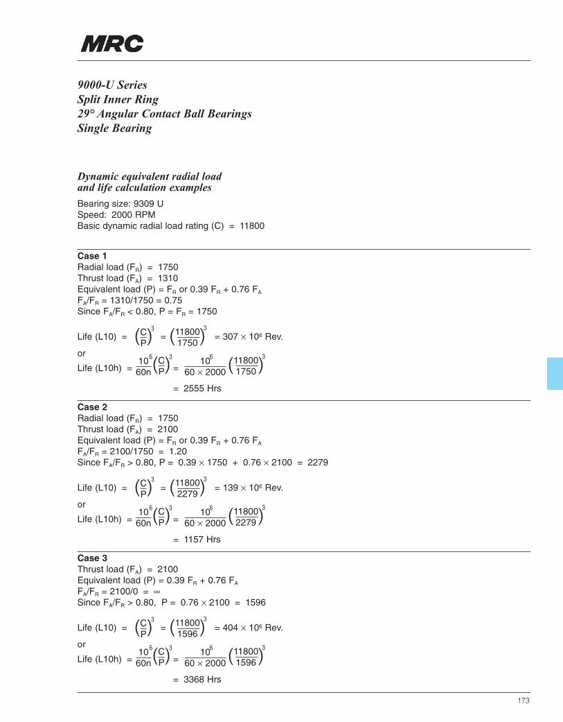
173
9000-U Series Split Inner Ring29° Angular Contact Ball BearingsSingle Bearing
Dynamic equivalent radial load and life calculation examples
Bearing size: 9309 USpeed: 2000 RPMBasic dynamic radial load rating (C) = 11800
Case 1Radial load (FR) = 1750Thrust load (FA) = 1310Equivalent load (P) = FR or 0.39 FR + 0.76 FA
FA/FR = 1310/1750 = 0.75Since FA/FR < 0.80, P = FR = 1750
Life (L10) = = = 307 × 106 Rev.
or
Life (L10h) = =
= 2555 Hrs
( )CP
3
( )CP
1060n
36 1060 × 2000
6
( )118001750
3
( )118001750
3
Case 2Radial load (FR) = 1750Thrust load (FA) = 2100Equivalent load (P) = FR or 0.39 FR + 0.76 FA
FA/FR = 2100/1750 = 1.20Since FA/FR > 0.80, P = 0.39 × 1750 + 0.76 × 2100 = 2279
Life (L10) = = = 139 × 106 Rev.
or
Life (L10h) = =
= 1157 Hrs
( )CP
3
( )CP
1060n
36 1060 × 2000
6
( )118002279
3
( )118002279
3
Case 3Thrust load (FA) = 2100Equivalent load (P) = 0.39 FR + 0.76 FA
FA/FR = 2100/0 = ∞Since FA/FR > 0.80, P = 0.76 × 2100 = 1596
Life (L10) = = = 404 × 106 Rev.
or
Life (L10h) = =
= 3368 Hrs
( )CP
3
( )CP
1060n
36 1060 × 2000
6
( )118001596
3
( )118001596
3
MRC Bearing Services
174
Dynamic and static equivalent radial load and life rating
Dynamic equivalent radial loadP = FR when FA/FR ≤ 1.14
or
P = 0.35 FR + 0.57 FA when FA/FR > 1.14
P = Dynamic equivalent radial loadFR = Radial loadFA = Thrust load
Consult MRC Bearing Services whenFR/FA > 1.0
Static equivalent radial loadP0 = 0.5 FR + 0.26 FA
P0 is always ≥ FR
P0 = Static equivalent radial loadFR = Radial loadFA = Thrust load
Life rating
L10 = (millions of revolutions)
or
L10h = (Hours)
C = Basic dynamic radial load rating(from single bearing tables)
P = Dynamic equivalent radial loadn = Speed in rpm
( )CP
3
( )CP
1060n
36
9000-UP SeriesSplit Inner Ring40° Angular Contact Ball BearingsSingle Bearing
9000-UP SeriesSplit Inner Ring40˚ Angular Contact Ball BearingsSingle Bearing
175
Dynamic equivalent radial load and life calculation examples
Bearing size: 9309 UPSpeed: 2000 RPMBasic dynamic radial load rating (C) = 13300
Case 1Radial load (FR) = 1750Thrust load (FA) = 1960FA/FR = 1960/1750 = 1.12Since FA/FR < 1.14, equivalent load (P) = FR = 1750
Life (L10) = = = 439 × 106 Rev.
or
Life (L10h) = =
= 3658 Hrs
( )CP
3
( )CP
1060n
36 1060 × 2000
6
( )133001750
3
( )133001750
3
Case 2Radial load (FR) = 1750Thrust load (FA) = 2450FA/FR = 2450/1750 = 1.40Since FA/FR > 1.14, equivalent load (P) = 0.35 FR + 0.57 FA
P = 0.35 × 1750 + 0.57 × 2450 = 2009
Life (L10) = = = 290 × 106 Rev.
or
Life (L10h) = =
= 2418 Hrs
( )CP
3
( )CP
1060n
36 1060 × 2000
6
( )133002009
3
( )133002009
3
Case 3Thrust load (FA) = 2450FA/FR = 2450/0 = ∞Since FA/FR > 1.14, equivalent load (P) = 0.35 FR + 0.57 FA
P = 0.57 × 2450 = 1397
Life (L10) = = = 863 × 106 Rev.
or
Life (L10h) = =
= 7191 Hrs
( )CP
3
( )CP
1060n
36 1060 × 2000
6
( )133001397
3
( )133001397
3

176
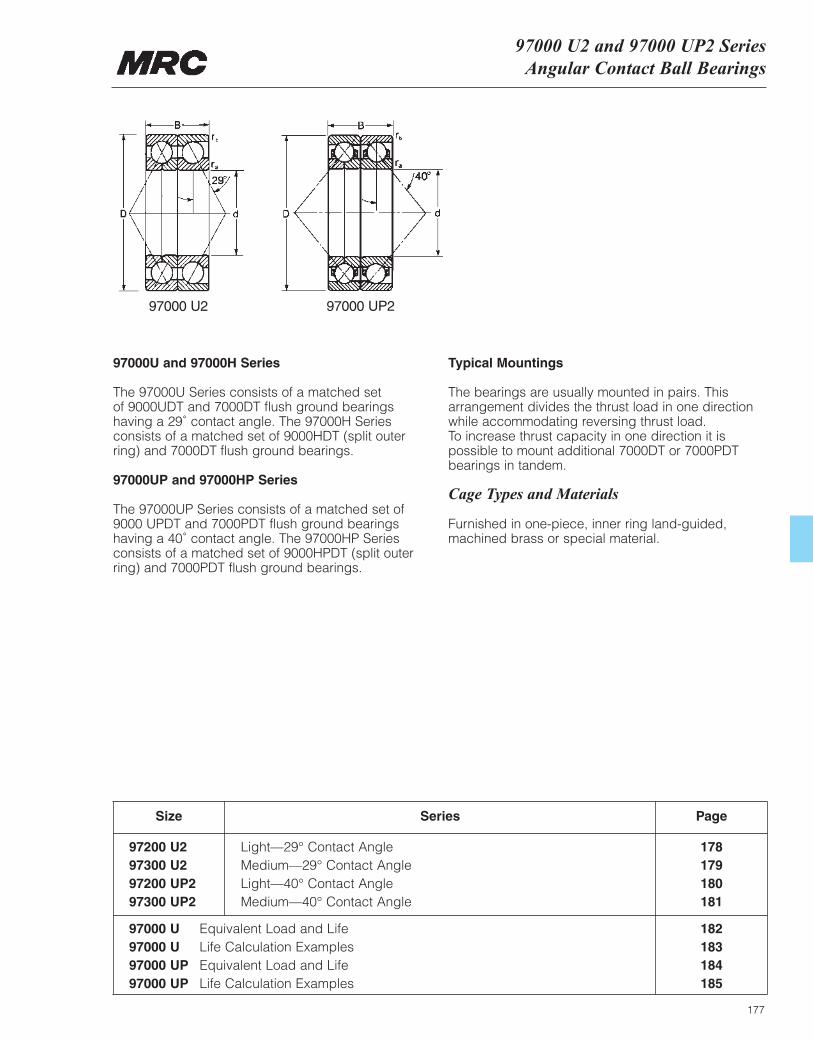
97000 U2 and 97000 UP2 SeriesAngular Contact Ball Bearings
177
97000U and 97000H Series
The 97000U Series consists of a matched set of 9000UDT and 7000DT flush ground bearings having a 29˚ contact angle. The 97000H Seriesconsists of a matched set of 9000HDT (split outer ring) and 7000DT flush ground bearings.
97000UP and 97000HP Series
The 97000UP Series consists of a matched set of9000 UPDT and 7000PDT flush ground bearingshaving a 40˚ contact angle. The 97000HP Seriesconsists of a matched set of 9000HPDT (split outer ring) and 7000PDT flush ground bearings.
Typical Mountings
The bearings are usually mounted in pairs. Thisarrangement divides the thrust load in one directionwhile accommodating reversing thrust load. To increase thrust capacity in one direction it is possible to mount additional 7000DT or 7000PDTbearings in tandem.
Cage Types and Materials
Furnished in one-piece, inner ring land-guided,machined brass or special material.
Size
97200 U2 Light—29° Contact Angle 17897300 U2 Medium—29° Contact Angle 17997200 UP2 Light—40° Contact Angle 18097300 UP2 Medium—40° Contact Angle 181
Series Page
97000 U Equivalent Load and Life 18297000 U Life Calculation Examples 18397000 UP Equivalent Load and Life 18497000 UP Life Calculation Examples 185
97000 U2 97000 UP2
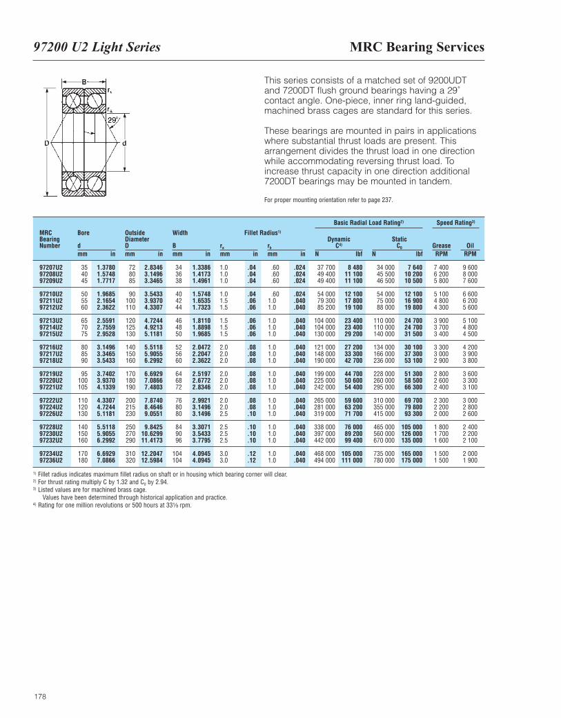
MRC Bearing Services97200 U2 Light Series
178
This series consists of a matched set of 9200UDTand 7200DT flush ground bearings having a 29˚contact angle. One-piece, inner ring land-guided,machined brass cages are standard for this series.
These bearings are mounted in pairs in applicationswhere substantial thrust loads are present. Thisarrangement divides the thrust load in one directionwhile accommodating reversing thrust load. Toincrease thrust capacity in one direction additional7200DT bearings may be mounted in tandem.
For proper mounting orientation refer to page 237.
MRCBearingNumber
Bore
dmm in
OutsideDiameterDmm in
Width
Bmm in
ra
mm inrb
mm in
DynamicC4)
N lbf
Basic Radial Load Rating2) Speed Rating3)
StaticC0
N lbfGrease OilRPM RPM
Fillet Radius1)
97207U2 35 1.3780 72 2.8346 34 1.3386 1.0 .04 .60 .024 37 700 8 480 34 000 7 640 7 400 9 60097208U2 40 1.5748 80 3.1496 36 1.4173 1.0 .04 .60 .024 49 400 11 100 45 500 10 200 6 200 8 00097209U2 45 1.7717 85 3.3465 38 1.4961 1.0 .04 .60 .024 49 400 11 100 46 500 10 500 5 800 7 600
97210U2 50 1.9685 90 3.5433 40 1.5748 1.0 .04 .60 .024 54 000 12 100 54 000 12 100 5 100 6 60097211U2 55 2.1654 100 3.9370 42 1.6535 1.5 .06 1.0 .040 79 300 17 800 75 000 16 900 4 800 6 20097212U2 60 2.3622 110 4.3307 44 1.7323 1.5 .06 1.0 .040 85 200 19 100 88 000 19 800 4 300 5 600
97213U2 65 2.5591 120 4.7244 46 1.8110 1.5 .06 1.0 .040 104 000 23 400 110 000 24 700 3 900 5 10097214U2 70 2.7559 125 4.9213 48 1.8898 1.5 .06 1.0 .040 104 000 23 400 110 000 24 700 3 700 4 80097215U2 75 2.9528 130 5.1181 50 1.9685 1.5 .06 1.0 .040 130 000 29 200 140 000 31 500 3 400 4 500
97216U2 80 3.1496 140 5.5118 52 2.0472 2.0 .08 1.0 .040 121 000 27 200 134 000 30 100 3 300 4 20097217U2 85 3.3465 150 5.9055 56 2.2047 2.0 .08 1.0 .040 148 000 33 300 166 000 37 300 3 000 3 90097218U2 90 3.5433 160 6.2992 60 2.3622 2.0 .08 1.0 .040 190 000 42 700 236 000 53 100 2 900 3 800
97219U2 95 3.7402 170 6.6929 64 2.5197 2.0 .08 1.0 .040 199 000 44 700 228 000 51 300 2 800 3 60097220U2 100 3.9370 180 7.0866 68 2.6772 2.0 .08 1.0 .040 225 000 50 600 260 000 58 500 2 600 3 30097221U2 105 4.1339 190 7.4803 72 2.8346 2.0 .08 1.0 .040 242 000 54 400 295 000 66 300 2 400 3 100
97222U2 110 4.3307 200 7.8740 76 2.9921 2.0 .08 1.0 .040 265 000 59 600 310 000 69 700 2 300 3 00097224U2 120 4.7244 215 8.4646 80 3.1496 2.0 .08 1.0 .040 281 000 63 200 355 000 79 800 2 200 2 80097226U2 130 5.1181 230 9.0551 80 3.1496 2.5 .10 1.0 .040 319 000 71 700 415 000 93 300 2 000 2 600
97228U2 140 5.5118 250 9.8425 84 3.3071 2.5 .10 1.0 .040 338 000 76 000 465 000 105 000 1 800 2 40097230U2 150 5.9055 270 10.6299 90 3.5433 2.5 .10 1.0 .040 397 000 89 200 560 000 126 000 1 700 2 20097232U2 160 6.2992 290 11.4173 96 3.7795 2.5 .10 1.0 .040 442 000 99 400 670 000 135 000 1 600 2 100
97234U2 170 6.6929 310 12.2047 104 4.0945 3.0 .12 1.0 .040 468 000 105 000 735 000 165 000 1 500 2 00097236U2 180 7.0866 320 12.5984 104 4.0945 3.0 .12 1.0 .040 494 000 111 000 780 000 175 000 1 500 1 900
1) Fillet radius indicates maximum fillet radius on shaft or in housing which bearing corner will clear.2) For thrust rating multiply C by 1.32 and C0 by 2.94.3) Listed values are for machined brass cage.
Values have been determined through historical application and practice.4) Rating for one million revolutions or 500 hours at 33¹|₃ rpm.
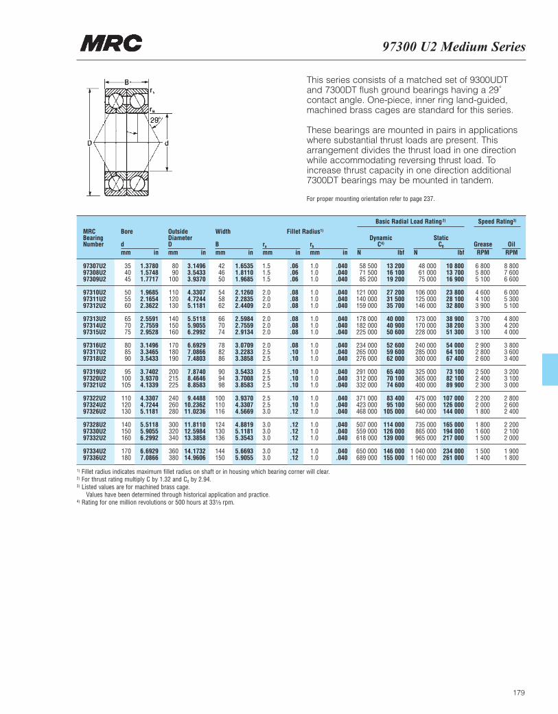
97300 U2 Medium Series
179
This series consists of a matched set of 9300UDTand 7300DT flush ground bearings having a 29˚contact angle. One-piece, inner ring land-guided,machined brass cages are standard for this series.
These bearings are mounted in pairs in applicationswhere substantial thrust loads are present. Thisarrangement divides the thrust load in one directionwhile accommodating reversing thrust load. Toincrease thrust capacity in one direction additional7300DT bearings may be mounted in tandem.
For proper mounting orientation refer to page 237.
MRCBearingNumber
Bore
dmm in
OutsideDiameterDmm in
Width
Bmm in
ra
mm inrb
mm in
DynamicC4)
N lbf
Basic Radial Load Rating2) Speed Rating3)
StaticC0
N lbfGrease OilRPM RPM
Fillet Radius1)
97307U2 35 1.3780 80 3.1496 42 1.6535 1.5 .06 1.0 .040 58 500 13 200 48 000 10 800 6 800 8 80097308U2 40 1.5748 90 3.5433 46 1.8110 1.5 .06 1.0 .040 71 500 16 100 61 000 13 700 5 800 7 60097309U2 45 1.7717 100 3.9370 50 1.9685 1.5 .06 1.0 .040 85 200 19 200 75 000 16 900 5 100 6 600
97310U2 50 1.9685 110 4.3307 54 2.1260 2.0 .08 1.0 .040 121 000 27 200 106 000 23 800 4 600 6 00097311U2 55 2.1654 120 4.7244 58 2.2835 2.0 .08 1.0 .040 140 000 31 500 125 000 28 100 4 100 5 30097312U2 60 2.3622 130 5.1181 62 2.4409 2.0 .08 1.0 .040 159 000 35 700 146 000 32 800 3 900 5 100
97313U2 65 2.5591 140 5.5118 66 2.5984 2.0 .08 1.0 .040 178 000 40 000 173 000 38 900 3 700 4 80097314U2 70 2.7559 150 5.9055 70 2.7559 2.0 .08 1.0 .040 182 000 40 900 170 000 38 200 3 300 4 20097315U2 75 2.9528 160 6.2992 74 2.9134 2.0 .08 1.0 .040 225 000 50 600 228 000 51 300 3 100 4 000
97316U2 80 3.1496 170 6.6929 78 3.0709 2.0 .08 1.0 .040 234 000 52 600 240 000 54 000 2 900 3 80097317U2 85 3.3465 180 7.0866 82 3.2283 2.5 .10 1.0 .040 265 000 59 600 285 000 64 100 2 800 3 60097318U2 90 3.5433 190 7.4803 86 3.3858 2.5 .10 1.0 .040 276 000 62 000 300 000 67 400 2 600 3 400
97319U2 95 3.7402 200 7.8740 90 3.5433 2.5 .10 1.0 .040 291 000 65 400 325 000 73 100 2 500 3 20097320U2 100 3.9370 215 8.4646 94 3.7008 2.5 .10 1.0 .040 312 000 70 100 365 000 82 100 2 400 3 10097321U2 105 4.1339 225 8.8583 98 3.8583 2.5 .10 1.0 .040 332 000 74 600 400 000 89 900 2 300 3 000
97322U2 110 4.3307 240 9.4488 100 3.9370 2.5 .10 1.0 .040 371 000 83 400 475 000 107 000 2 200 2 80097324U2 120 4.7244 260 10.2362 110 4.3307 2.5 .10 1.0 .040 423 000 95 100 560 000 126 000 2 000 2 60097326U2 130 5.1181 280 11.0236 116 4.5669 3.0 .12 1.0 .040 468 000 105 000 640 000 144 000 1 800 2 400
97328U2 140 5.5118 300 11.8110 124 4.8819 3.0 .12 1.0 .040 507 000 114 000 735 000 165 000 1 800 2 20097330U2 150 5.9055 320 12.5984 130 5.1181 3.0 .12 1.0 .040 559 000 126 000 865 000 194 000 1 600 2 10097332U2 160 6.2992 340 13.3858 136 5.3543 3.0 .12 1.0 .040 618 000 139 000 965 000 217 000 1 500 2 000
97334U2 170 6.6929 360 14.1732 144 5.6693 3.0 .12 1.0 .040 650 000 146 000 1 040 000 234 000 1 500 1 90097336U2 180 7.0866 380 14.9606 150 5.9055 3.0 .12 1.0 .040 689 000 155 000 1 160 000 261 000 1 400 1 800
1) Fillet radius indicates maximum fillet radius on shaft or in housing which bearing corner will clear.2) For thrust rating multiply C by 1.32 and C0 by 2.94.3) Listed values are for machined brass cage.
Values have been determined through historical application and practice.4) Rating for one million revolutions or 500 hours at 33¹|₃ rpm.
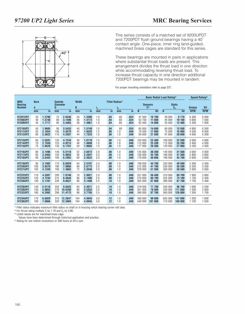
MRC Bearing Services97200 UP2 Light Series
180
This series consists of a matched set of 9200UPDTand 7200PDT flush ground bearings having a 40˚contact angle. One-piece, inner ring land-guided,machined brass cages are standard for this series.
These bearings are mounted in pairs in applicationswhere substantial thrust loads are present. Thisarrangement divides the thrust load in one directionwhile accommodating reversing thrust load. Toincrease thrust capacity in one direction additional7200PDT bearings may be mounted in tandem.
For proper mounting orientation refer to page 237.
MRCBearingNumber
Bore
dmm in
OutsideDiameterDmm in
Width
Bmm in
ra
mm inrb
mm in
DynamicC4)
N lbf
Basic Radial Load Rating2) Speed Rating3)
StaticC0
N lbfGrease OilRPM RPM
Fillet Radius1)
97207UP2 35 1.3780 72 2.8346 34 1.3386 1.0 .04 .60 .024 47 500 10 700 39 000 8 770 6 300 8 50097208UP2 40 1.5748 80 3.1496 36 1.4173 1.0 .04 .60 .024 52 700 11 800 45 000 10 100 5 600 7 50097209UP2 45 1.7717 85 3.3465 38 1.4961 1.0 .04 .60 .024 62 400 14 000 55 000 12 400 5 300 7 000
97210UP2 50 1.9685 90 3.5433 40 1.5748 1.0 .04 .60 .024 65 000 14 600 60 000 13 500 4 800 6 30097211UP2 55 2.1654 100 3.9370 42 1.6535 1.5 .06 1.0 .040 79 300 17 800 75 000 16 900 4 500 6 00097212UP2 60 2.3622 110 4.3307 44 1.7323 1.5 .06 1.0 .040 95 600 21 500 91 600 20 600 4 000 5 300
97213UP2 65 2.5591 120 4.7244 46 1.8110 1.5 .06 1.0 .040 104 000 23 400 100 000 22 500 3 600 4 80097214UP2 70 2.7559 125 4.9213 48 1.8898 1.5 .06 1.0 .040 112 000 25 200 112 000 25 200 3 400 4 50097215UP2 75 2.9528 130 5.1181 50 1.9685 1.5 .06 1.0 .040 117 000 26 300 120 000 27 000 3 200 4 300
97216UP2 80 3.1496 140 5.5118 52 2.0472 2.0 .08 1.0 .040 135 000 30 300 140 000 31 500 3 000 4 00097217UP2 85 3.3465 150 5.9055 56 2.2047 2.0 .08 1.0 .040 156 000 35 100 166 000 37 300 2 800 3 80097218UP2 90 3.5433 160 6.2992 60 2.3622 2.0 .08 1.0 .040 178 000 40 000 190 000 42 700 2 600 3 600
97219UP2 95 3.7402 170 6.6929 64 2.5197 2.0 .08 1.0 .040 199 000 44 700 220 000 49 500 2 400 3 40097220UP2 100 3.9370 180 7.0866 68 2.6772 2.0 .08 1.0 .040 212 000 47 700 250 000 56 200 2 200 3 20097221UP2 105 4.1339 190 7.4803 72 2.8346 2.0 .08 1.0 .040 229 000 51 500 260 000 58 500 2 000 3 000
97222UP2 110 4.3307 200 7.8740 76 2.9921 2.0 .08 1.0 .040 251 000 56 400 310 000 69 700 1 900 2 80097224UP2 120 4.7244 215 8.4646 80 3.1496 2.0 .08 1.0 .040 270 000 60 700 325 000 73 100 1 700 2 40097226UP2 130 5.1181 230 9.0551 80 3.1496 2.5 .10 1.0 .040 302 000 67 900 390 000 87 700 1 700 2 400
97228UP2 140 5.5118 250 9.8425 84 3.3071 2.5 .10 1.0 .040 319 000 71 700 430 000 96 700 1 600 2 20097230UP2 150 5.9055 270 10.6299 90 3.5433 2.5 .10 1.0 .040 351 000 78 900 520 000 117 000 1 500 2 00097232UP2 160 6.2992 290 11.4173 96 3.7795 2.5 .10 1.0 .040 390 000 87 700 560 000 126 000 1 300 1 700
97234UP2 170 6.6929 310 12.2047 104 4.0945 3.0 .12 1.0 .040 436 000 98 000 655 000 147 000 1 200 1 60097236UP2 180 7.0866 320 12.5984 104 4.0945 3.0 .12 1.0 .040 449 000 101 000 710 000 160 000 1 100 1 500
1) Fillet radius indicates maximum fillet radius on shaft or in housing which bearing corner will clear.2) For thrust rating multiply C by 1.76 and C0 by 3.86.3) Listed values are for machined brass cage.
Values have been determined through historical application and practice.4) Rating for one million revolutions or 500 hours at 33¹|₃ rpm.
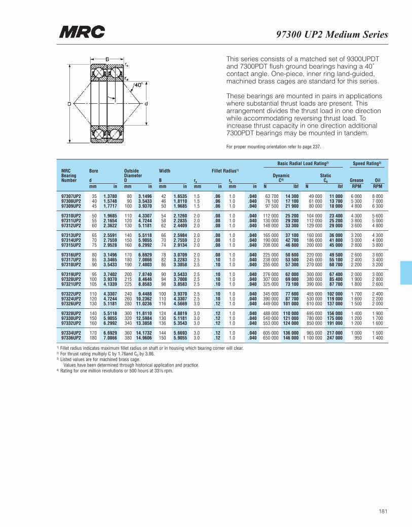
181
97300 UP2 Medium Series
This series consists of a matched set of 9300UPDTand 7300PDT flush ground bearings having a 40˚contact angle. One-piece, inner ring land-guided,machined brass cages are standard for this series.
These bearings are mounted in pairs in applicationswhere substantial thrust loads are present. Thisarrangement divides the thrust load in one directionwhile accommodating reversing thrust load. Toincrease thrust capacity in one direction additional7300PDT bearings may be mounted in tandem.
For proper mounting orientation refer to page 237.
MRCBearingNumber
Bore
dmm in
OutsideDiameterDmm in
Width
Bmm in
ra
mm inrb
mm in
DynamicC4)
N lbf
Basic Radial Load Rating2) Speed Rating3)
StaticC0
N lbfGrease OilRPM RPM
Fillet Radius1)
97307UP2 35 1.3780 80 3.1496 42 1.6535 1.5 .06 1.0 .040 63 700 14 300 49 000 11 000 6 000 8 00097308UP2 40 1.5748 90 3.5433 46 1.8110 1.5 .06 1.0 .040 76 100 17 100 61 000 13 700 5 300 7 00097309UP2 45 1.7717 100 3.9370 50 1.9685 1.5 .06 1.0 .040 97 500 21 900 80 000 18 000 4 800 6 300
97310UP2 50 1.9685 110 4.3307 54 2.1260 2.0 .08 1.0 .040 112 000 25 200 104 000 23 400 4 300 5 60097311UP2 55 2.1654 120 4.7244 58 2.2835 2.0 .08 1.0 .040 130 000 29 200 112 000 25 200 3 800 5 00097312UP2 60 2.3622 130 5.1181 62 2.4409 2.0 .08 1.0 .040 148 000 33 300 129 000 29 000 3 600 4 800
97313UP2 65 2.5591 140 5.5118 66 2.5984 2.0 .08 1.0 .040 165 000 37 100 160 000 36 000 3 200 4 30097314UP2 70 2.7559 150 5.9055 70 2.7559 2.0 .08 1.0 .040 190 000 42 700 186 000 41 800 3 000 4 00097315UP2 75 2.9528 160 6.2992 74 2.9134 2.0 .08 1.0 .040 208 000 46 800 200 000 45 000 2 800 3 800
97316UP2 80 3.1496 170 6.6929 78 3.0709 2.0 .08 1.0 .040 225 000 50 600 220 000 49 500 2 600 3 60097317UP2 85 3.3465 180 7.0866 82 3.2283 2.5 .10 1.0 .040 238 000 53 500 245 000 55 100 2 400 3 40097318UP2 90 3.5433 190 7.4803 86 3.3858 2.5 .10 1.0 .040 255 000 57 300 270 000 60 700 2 200 3 200
97319UP2 95 3.7402 200 7.8740 90 3.5433 2.5 .10 1.0 .040 276 000 62 000 300 000 67 400 2 000 3 00097320UP2 100 3.9370 215 8.4646 94 3.7008 2.5 .10 1.0 .040 307 000 69 000 380 000 85 400 1 900 2 80097321UP2 105 4.1339 225 8.8583 98 3.8583 2.5 .10 1.0 .040 325 000 73 100 390 000 87 700 1 800 2 600
97322UP2 110 4.3307 240 9.4488 100 3.9370 2.5 .10 1.0 .040 345 000 77 600 455 000 102 000 1 700 2 40097324UP2 120 4.7244 260 10.2362 110 4.3307 2.5 .10 1.0 .040 390 000 87 700 530 000 119 000 1 600 2 20097326UP2 130 5.1181 280 11.0236 116 4.5669 3.0 .12 1.0 .040 449 000 101 000 610 000 137 000 1 500 2 000
97328UP2 140 5.5118 300 11.8110 124 4.8819 3.0 .12 1.0 .040 488 000 110 000 695 000 156 000 1 400 1 90097330UP2 150 5.9055 320 12.5984 130 5.1181 3.0 .12 1.0 .040 540 000 121 000 780 000 175 000 1 200 1 70097332UP2 160 6.2992 340 13.3858 136 5.3543 3.0 .12 1.0 .040 553 000 124 000 850 000 191 000 1 200 1 600
97334UP2 170 6.6929 360 14.1732 144 5.6693 3.0 .12 1.0 .040 605 000 136 000 965 000 217 000 1 000 1 50097336UP2 180 7.0866 380 14.9606 150 5.9055 3.0 .12 1.0 .040 650 000 146 000 1 100 000 247 000 950 1 400
1) Fillet radius indicates maximum fillet radius on shaft or in housing which bearing corner will clear.2) For thrust rating multiply C by 1.76and C0 by 3.86.3) Listed values are for machined brass cage.
Values have been determined through historical application and practice.4) Rating for one million revolutions or 500 hours at 33¹|₃ rpm.
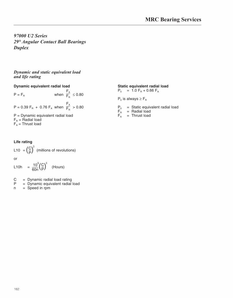
MRC Bearing Services
182
97000 U2 Series29° Angular Contact Ball BearingsDuplex
Dynamic and static equivalent load and life rating
Dynamic equivalent radial load
P = FR when ≤ 0.80
P = 0.39 FR + 0.76 FA when > 0.80
P = Dynamic equivalent radial loadFR = Radial loadFA = Thrust load
Static equivalent radial loadP0 = 1.0 FR + 0.66 FA
P0 is always ≥ FR
P0 = Static equivalent radial loadFR = Radial loadFA = Thrust load
Life rating
L10 = (millions of revolutions)
or
L10h = (Hours)
C = Dynamic radial load rating P = Dynamic equivalent radial loadn = Speed in rpm
( )CP
3
FA
FR
FA
FR
( )CP
1060n
36
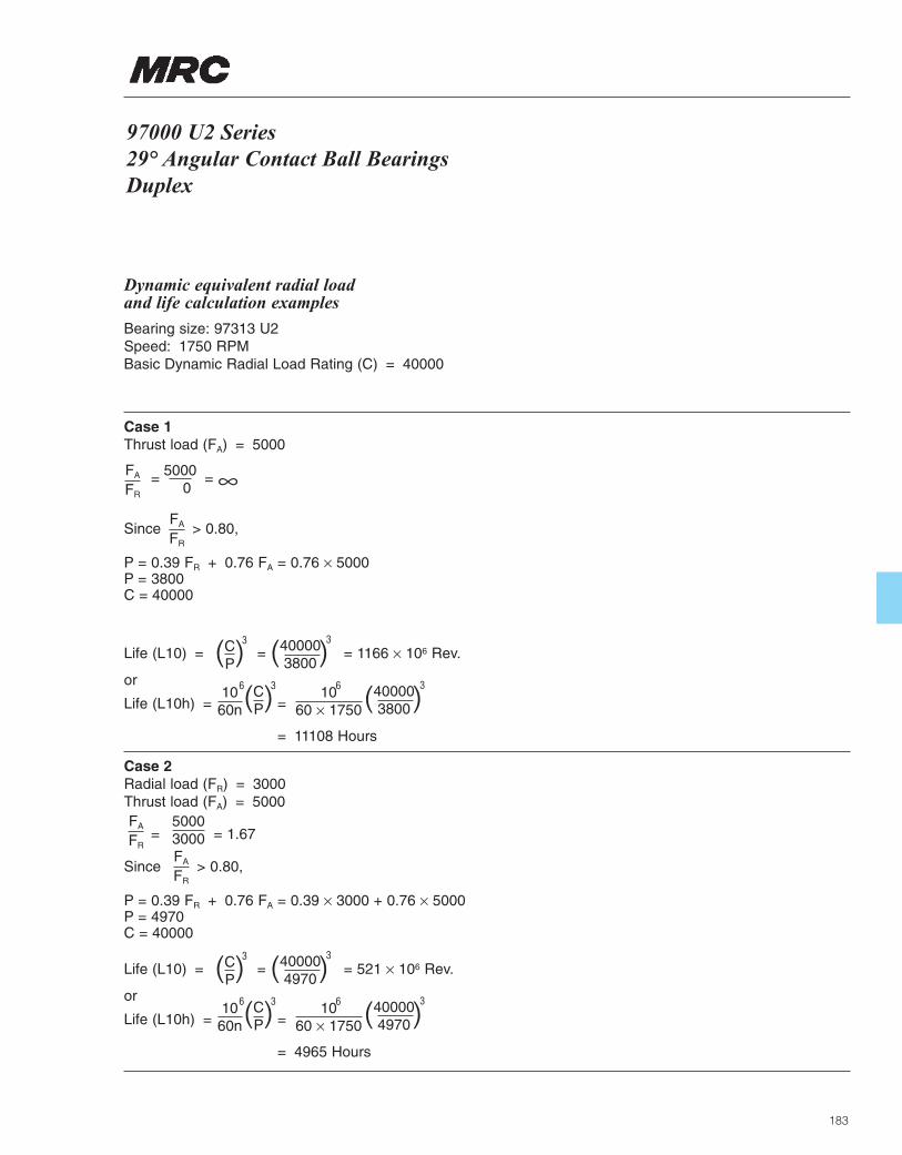
97000 U2 Series29° Angular Contact Ball BearingsDuplex
183
Dynamic equivalent radial load and life calculation examples
Bearing size: 97313 U2Speed: 1750 RPMBasic Dynamic Radial Load Rating (C) = 40000
Case 1Thrust load (FA) = 5000
= = ∞
Since > 0.80,
P = 0.39 FR + 0.76 FA = 0.76 × 5000P = 3800C = 40000
Life (L10) = = = 1166 × 106 Rev.
or
Life (L10h) = =
= 11108 Hours
( )CP
3
( )CP
1060n
36 1060 × 1750
6
( )400003800
3
( )400003800
3
Case 2Radial load (FR) = 3000Thrust load (FA) = 5000
= = 1.67
Since > 0.80,
P = 0.39 FR + 0.76 FA = 0.39 × 3000 + 0.76 × 5000P = 4970C = 40000
Life (L10) = = = 521 × 106 Rev.
or
Life (L10h) = =
= 4965 Hours
( )CP
3
( )CP
1060n
36 1060 × 1750
6
( )400004970
3
( )400004970
3
FA
FR
FA
FR
50003000
FA
FR
50000
FA
FR
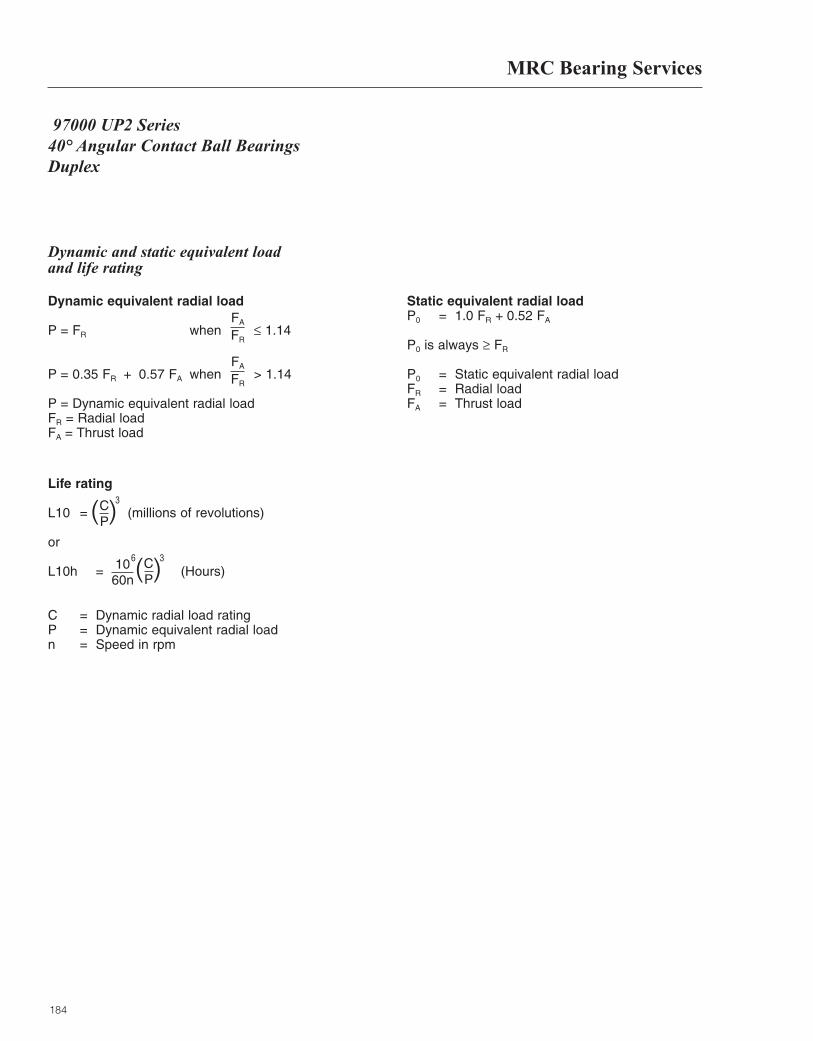
MRC Bearing Services
184
97000 UP2 Series40° Angular Contact Ball BearingsDuplex
Dynamic and static equivalent load and life rating
Dynamic equivalent radial load
P = FR when ≤ 1.14
P = 0.35 FR + 0.57 FA when > 1.14
P = Dynamic equivalent radial loadFR = Radial loadFA = Thrust load
Static equivalent radial loadP0 = 1.0 FR + 0.52 FA
P0 is always ≥ FR
P0 = Static equivalent radial loadFR = Radial loadFA = Thrust load
Life rating
L10 = (millions of revolutions)
or
L10h = (Hours)
C = Dynamic radial load rating P = Dynamic equivalent radial loadn = Speed in rpm
( )CP
3
FA
FR
FA
FR
( )CP
1060n
36
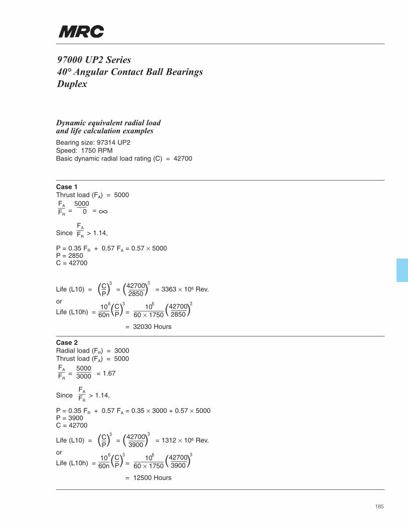
97000 UP2 Series 40° Angular Contact Ball BearingsDuplex
185
Dynamic equivalent radial load and life calculation examples
Bearing size: 97314 UP2Speed: 1750 RPMBasic dynamic radial load rating (C) = 42700
Case 1Thrust load (FA) = 5000
= = ∞
Since > 1.14,
P = 0.35 FR + 0.57 FA = 0.57 × 5000P = 2850C = 42700
Life (L10) = = = 3363 × 106 Rev.
or
Life (L10h) = =
= 32030 Hours
( )CP
3
( )CP
1060n
36 1060 × 1750
6
( )427002850
3
( )427002850
3
Case 2Radial load (FR) = 3000Thrust load (FA) = 5000
= = 1.67
Since > 1.14,
P = 0.35 FR + 0.57 FA = 0.35 × 3000 + 0.57 × 5000P = 3900C = 42700
Life (L10) = = = 1312 × 106 Rev.
or
Life (L10h) = =
= 12500 Hours
( )CP
3
( )CP
1060n
36 1060 × 1750
6
( )427003900
3
( )427003900
3
FA
FR
FA
FR
FA
FR
50003000
FA
FR
50000

186
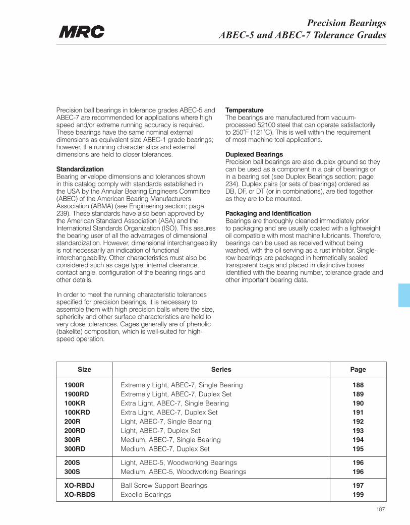
Precision Bearings ABEC-5 and ABEC-7 Tolerance Grades
187
1900R Extremely Light, ABEC-7, Single Bearing 1881900RD Extremely Light, ABEC-7, Duplex Set 189100KR Extra Light, ABEC-7, Single Bearing 190100KRD Extra Light, ABEC-7, Duplex Set 191200R Light, ABEC-7, Single Bearing 192200RD Light, ABEC-7, Duplex Set 193300R Medium, ABEC-7, Single Bearing 194300RD Medium, ABEC-7, Duplex Set 195
200S Light, ABEC-5, Woodworking Bearings 196300S Medium, ABEC-5, Woodworking Bearings 196
XO-RBDJ Ball Screw Support Bearings 197XO-RBDS Excello Bearings 199
SeriesSize Page
Precision ball bearings in tolerance grades ABEC-5 andABEC-7 are recommended for applications where highspeed and/or extreme running accuracy is required.These bearings have the same nominal externaldimensions as equivalent size ABEC-1 grade bearings;however, the running characteristics and externaldimensions are held to closer tolerances.
Standardization Bearing envelope dimensions and tolerances shown in this catalog comply with standards established in the USA by the Annular Bearing Engineers Committee(ABEC) of the American Bearing ManufacturersAssociation (ABMA) (see Engineering section; page239). These standards have also been approved by the American Standard Association (ASA) and theInternational Standards Organization (ISO). This assuresthe bearing user of all the advantages of dimensionalstandardization. However, dimensional interchangeabilityis not necessarily an indication of functionalinterchangeability. Other characteristics must also beconsidered such as cage type, internal clearance,contact angle, configuration of the bearing rings andother details.
In order to meet the running characteristic tolerancesspecified for precision bearings, it is necessary toassemble them with high precision balls where the size,sphericity and other surface characteristics are held tovery close tolerances. Cages generally are of phenolic(bakelite) composition, which is well-suited for high-speed operation.
Temperature The bearings are manufactured from vacuum-processed 52100 steel that can operate satisfactorily to 250˚F (121˚C). This is well within the requirement of most machine tool applications.
Duplexed BearingsPrecision ball bearings are also duplex ground so theycan be used as a component in a pair of bearings or in a bearing set (see Duplex Bearings section; page234). Duplex pairs (or sets of bearings) ordered as DB, DF, or DT (or in combinations), are tied together as they are to be mounted.
Packaging and Identification Bearings are thoroughly cleaned immediately prior to packaging and are usually coated with a lightweightoil compatible with most machine lubricants. Therefore,bearings can be used as received without beingwashed, with the oil serving as a rust inhibitor. Single-row bearings are packaged in hermetically sealedtransparent bags and placed in distinctive boxesidentified with the bearing number, tolerance grade andother important bearing data.
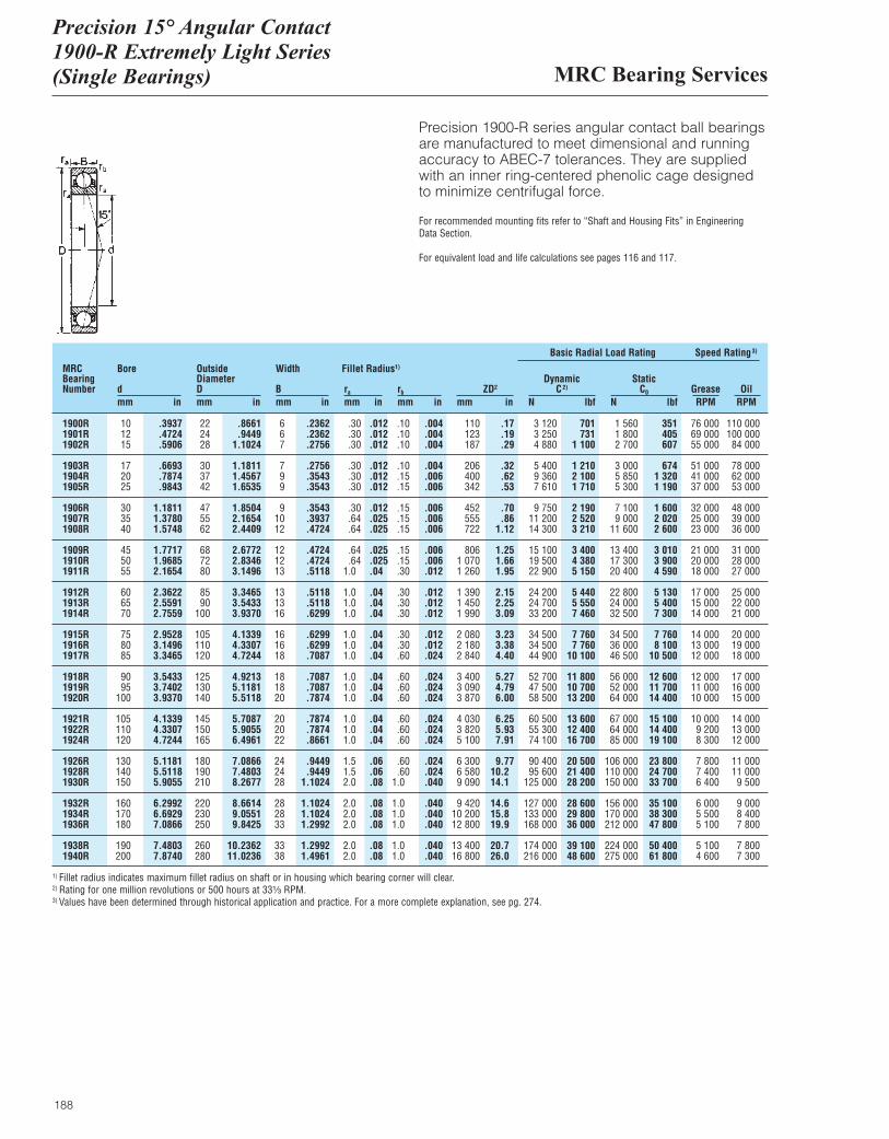
MRC Bearing Services
Precision 15° Angular Contact1900-R Extremely Light Series (Single Bearings)
188
Precision 1900-R series angular contact ball bearingsare manufactured to meet dimensional and runningaccuracy to ABEC-7 tolerances. They are suppliedwith an inner ring-centered phenolic cage designedto minimize centrifugal force.
For recommended mounting fits refer to “Shaft and Housing Fits” in Engineering Data Section.
For equivalent load and life calculations see pages 116 and 117.
MRCBearingNumber
Bore
dmm in
OutsideDiameterDmm in
Width
Bmm in
ra
mm inrb
mm inZD2
mm in
DynamicC2)
N lbf
Basic Radial Load Rating Speed Rating3)
StaticC0
N lbfGrease OilRPM RPM
Fillet Radius1)
1900R 10 .3937 22 .8661 6 .2362 .30 .012 .10 .004 110 .17 3 120 701 1 560 351 76 000 110 0001901R 12 .4724 24 .9449 6 .2362 .30 .012 .10 .004 123 .19 3 250 731 1 800 405 69 000 100 0001902R 15 .5906 28 1.1024 7 .2756 .30 .012 .10 .004 187 .29 4 880 1 100 2 700 607 55 000 84 000
1903R 17 .6693 30 1.1811 7 .2756 .30 .012 .10 .004 206 .32 5 400 1 210 3 000 674 51 000 78 0001904R 20 .7874 37 1.4567 9 .3543 .30 .012 .15 .006 400 .62 9 360 2 100 5 850 1 320 41 000 62 0001905R 25 .9843 42 1.6535 9 .3543 .30 .012 .15 .006 342 .53 7 610 1 710 5 300 1 190 37 000 53 000
1906R 30 1.1811 47 1.8504 9 .3543 .30 .012 .15 .006 452 .70 9 750 2 190 7 100 1 600 32 000 48 0001907R 35 1.3780 55 2.1654 10 .3937 .64 .025 .15 .006 555 .86 11 200 2 520 9 000 2 020 25 000 39 0001908R 40 1.5748 62 2.4409 12 .4724 .64 .025 .15 .006 722 1.12 14 300 3 210 11 600 2 600 23 000 36 000
1909R 45 1.7717 68 2.6772 12 .4724 .64 .025 .15 .006 806 1.25 15 100 3 400 13 400 3 010 21 000 31 0001910R 50 1.9685 72 2.8346 12 .4724 .64 .025 .15 .006 1 070 1.66 19 500 4 380 17 300 3 900 20 000 28 0001911R 55 2.1654 80 3.1496 13 .5118 1.0 .04 .30 .012 1 260 1.95 22 900 5 150 20 400 4 590 18 000 27 000
1912R 60 2.3622 85 3.3465 13 .5118 1.0 .04 .30 .012 1 390 2.15 24 200 5 440 22 800 5 130 17 000 25 0001913R 65 2.5591 90 3.5433 13 .5118 1.0 .04 .30 .012 1 450 2.25 24 700 5 550 24 000 5 400 15 000 22 0001914R 70 2.7559 100 3.9370 16 .6299 1.0 .04 .30 .012 1 990 3.09 33 200 7 460 32 500 7 300 14 000 21 000
1915R 75 2.9528 105 4.1339 16 .6299 1.0 .04 .30 .012 2 080 3.23 34 500 7 760 34 500 7 760 14 000 20 0001916R 80 3.1496 110 4.3307 16 .6299 1.0 .04 .30 .012 2 180 3.38 34 500 7 760 36 000 8 100 13 000 19 0001917R 85 3.3465 120 4.7244 18 .7087 1.0 .04 .60 .024 2 840 4.40 44 900 10 100 46 500 10 500 12 000 18 000
1918R 90 3.5433 125 4.9213 18 .7087 1.0 .04 .60 .024 3 400 5.27 52 700 11 800 56 000 12 600 12 000 17 0001919R 95 3.7402 130 5.1181 18 .7087 1.0 .04 .60 .024 3 090 4.79 47 500 10 700 52 000 11 700 11 000 16 0001920R 100 3.9370 140 5.5118 20 .7874 1.0 .04 .60 .024 3 870 6.00 58 500 13 200 64 000 14 400 10 000 15 000
1921R 105 4.1339 145 5.7087 20 .7874 1.0 .04 .60 .024 4 030 6.25 60 500 13 600 67 000 15 100 10 000 14 0001922R 110 4.3307 150 5.9055 20 .7874 1.0 .04 .60 .024 3 820 5.93 55 300 12 400 64 000 14 400 9 200 13 0001924R 120 4.7244 165 6.4961 22 .8661 1.0 .04 .60 .024 5 100 7.91 74 100 16 700 85 000 19 100 8 300 12 000
1926R 130 5.1181 180 7.0866 24 .9449 1.5 .06 .60 .024 6 300 9.77 90 400 20 500 106 000 23 800 7 800 11 0001928R 140 5.5118 190 7.4803 24 .9449 1.5 .06 .60 .024 6 580 10.2 95 600 21 400 110 000 24 700 7 400 11 0001930R 150 5.9055 210 8.2677 28 1.1024 2.0 .08 1.0 .040 9 090 14.1 125 000 28 200 150 000 33 700 6 400 9 500
1932R 160 6.2992 220 8.6614 28 1.1024 2.0 .08 1.0 .040 9 420 14.6 127 000 28 600 156 000 35 100 6 000 9 0001934R 170 6.6929 230 9.0551 28 1.1024 2.0 .08 1.0 .040 10 200 15.8 133 000 29 800 170 000 38 300 5 500 8 4001936R 180 7.0866 250 9.8425 33 1.2992 2.0 .08 1.0 .040 12 800 19.9 168 000 36 000 212 000 47 800 5 100 7 800
1938R 190 7.4803 260 10.2362 33 1.2992 2.0 .08 1.0 .040 13 400 20.7 174 000 39 100 224 000 50 400 5 100 7 8001940R 200 7.8740 280 11.0236 38 1.4961 2.0 .08 1.0 .040 16 800 26.0 216 000 48 600 275 000 61 800 4 600 7 300
1) Fillet radius indicates maximum fillet radius on shaft or in housing which bearing corner will clear.2) Rating for one million revolutions or 500 hours at 33¹|₃ RPM.3) Values have been determined through historical application and practice. For a more complete explanation, see pg. 274.
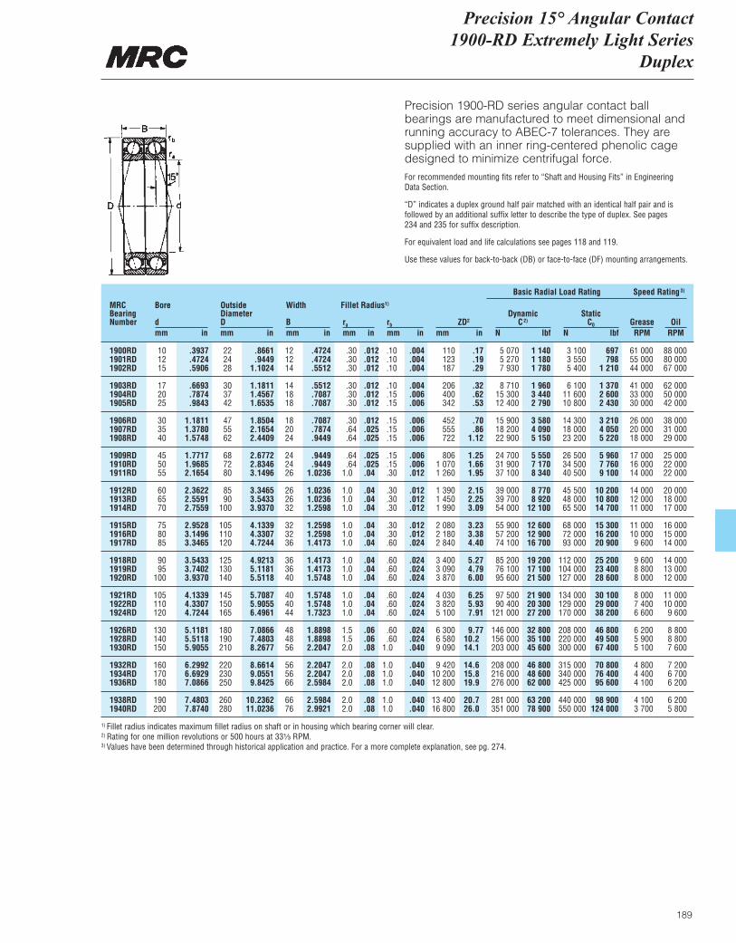
Precision 15° Angular Contact 1900-RD Extremely Light Series
Duplex
189
Precision 1900-RD series angular contact ballbearings are manufactured to meet dimensional andrunning accuracy to ABEC-7 tolerances. They aresupplied with an inner ring-centered phenolic cagedesigned to minimize centrifugal force.For recommended mounting fits refer to “Shaft and Housing Fits” in Engineering Data Section.
“D” indicates a duplex ground half pair matched with an identical half pair and is followed by an additional suffix letter to describe the type of duplex. See pages 234 and 235 for suffix description.
For equivalent load and life calculations see pages 118 and 119.
Use these values for back-to-back (DB) or face-to-face (DF) mounting arrangements.
MRCBearingNumber
Bore
dmm in
OutsideDiameterDmm in
Width
Bmm in
ra
mm inrb
mm inZD2
mm in
DynamicC2)
N lbf
Basic Radial Load Rating Speed Rating3)
StaticC0
N lbfGrease OilRPM RPM
Fillet Radius1)
1900RD 10 .3937 22 .8661 12 .4724 .30 .012 .10 .004 110 .17 5 070 1 140 3 100 697 61 000 88 0001901RD 12 .4724 24 .9449 12 .4724 .30 .012 .10 .004 123 .19 5 270 1 180 3 550 798 55 000 80 0001902RD 15 .5906 28 1.1024 14 .5512 .30 .012 .10 .004 187 .29 7 930 1 780 5 400 1 210 44 000 67 000
1903RD 17 .6693 30 1.1811 14 .5512 .30 .012 .10 .004 206 .32 8 710 1 960 6 100 1 370 41 000 62 0001904RD 20 .7874 37 1.4567 18 .7087 .30 .012 .15 .006 400 .62 15 300 3 440 11 600 2 600 33 000 50 0001905RD 25 .9843 42 1.6535 18 .7087 .30 .012 .15 .006 342 .53 12 400 2 790 10 800 2 430 30 000 42 000
1906RD 30 1.1811 47 1.8504 18 .7087 .30 .012 .15 .006 452 .70 15 900 3 580 14 300 3 210 26 000 38 0001907RD 35 1.3780 55 2.1654 20 .7874 .64 .025 .15 .006 555 .86 18 200 4 090 18 000 4 050 20 000 31 0001908RD 40 1.5748 62 2.4409 24 .9449 .64 .025 .15 .006 722 1.12 22 900 5 150 23 200 5 220 18 000 29 000
1909RD 45 1.7717 68 2.6772 24 .9449 .64 .025 .15 .006 806 1.25 24 700 5 550 26 500 5 960 17 000 25 0001910RD 50 1.9685 72 2.8346 24 .9449 .64 .025 .15 .006 1 070 1.66 31 900 7 170 34 500 7 760 16 000 22 0001911RD 55 2.1654 80 3.1496 26 1.0236 1.0 .04 .30 .012 1 260 1.95 37 100 8 340 40 500 9 100 14 000 22 000
1912RD 60 2.3622 85 3.3465 26 1.0236 1.0 .04 .30 .012 1 390 2.15 39 000 8 770 45 500 10 200 14 000 20 0001913RD 65 2.5591 90 3.5433 26 1.0236 1.0 .04 .30 .012 1 450 2.25 39 700 8 920 48 000 10 800 12 000 18 0001914RD 70 2.7559 100 3.9370 32 1.2598 1.0 .04 .30 .012 1 990 3.09 54 000 12 100 65 500 14 700 11 000 17 000
1915RD 75 2.9528 105 4.1339 32 1.2598 1.0 .04 .30 .012 2 080 3.23 55 900 12 600 68 000 15 300 11 000 16 0001916RD 80 3.1496 110 4.3307 32 1.2598 1.0 .04 .30 .012 2 180 3.38 57 200 12 900 72 000 16 200 10 000 15 0001917RD 85 3.3465 120 4.7244 36 1.4173 1.0 .04 .60 .024 2 840 4.40 74 100 16 700 93 000 20 900 9 600 14 000
1918RD 90 3.5433 125 4.9213 36 1.4173 1.0 .04 .60 .024 3 400 5.27 85 200 19 200 112 000 25 200 9 600 14 0001919RD 95 3.7402 130 5.1181 36 1.4173 1.0 .04 .60 .024 3 090 4.79 76 100 17 100 104 000 23 400 8 800 13 0001920RD 100 3.9370 140 5.5118 40 1.5748 1.0 .04 .60 .024 3 870 6.00 95 600 21 500 127 000 28 600 8 000 12 000
1921RD 105 4.1339 145 5.7087 40 1.5748 1.0 .04 .60 .024 4 030 6.25 97 500 21 900 134 000 30 100 8 000 11 0001922RD 110 4.3307 150 5.9055 40 1.5748 1.0 .04 .60 .024 3 820 5.93 90 400 20 300 129 000 29 000 7 400 10 0001924RD 120 4.7244 165 6.4961 44 1.7323 1.0 .04 .60 .024 5 100 7.91 121 000 27 200 170 000 38 200 6 600 9 600
1926RD 130 5.1181 180 7.0866 48 1.8898 1.5 .06 .60 .024 6 300 9.77 146 000 32 800 208 000 46 800 6 200 8 8001928RD 140 5.5118 190 7.4803 48 1.8898 1.5 .06 .60 .024 6 580 10.2 156 000 35 100 220 000 49 500 5 900 8 8001930RD 150 5.9055 210 8.2677 56 2.2047 2.0 .08 1.0 .040 9 090 14.1 203 000 45 600 300 000 67 400 5 100 7 600
1932RD 160 6.2992 220 8.6614 56 2.2047 2.0 .08 1.0 .040 9 420 14.6 208 000 46 800 315 000 70 800 4 800 7 2001934RD 170 6.6929 230 9.0551 56 2.2047 2.0 .08 1.0 .040 10 200 15.8 216 000 48 600 340 000 76 400 4 400 6 7001936RD 180 7.0866 250 9.8425 66 2.5984 2.0 .08 1.0 .040 12 800 19.9 276 000 62 000 425 000 95 600 4 100 6 200
1938RD 190 7.4803 260 10.2362 66 2.5984 2.0 .08 1.0 .040 13 400 20.7 281 000 63 200 440 000 98 900 4 100 6 2001940RD 200 7.8740 280 11.0236 76 2.9921 2.0 .08 1.0 .040 16 800 26.0 351 000 78 900 550 000 124 000 3 700 5 800
1) Fillet radius indicates maximum fillet radius on shaft or in housing which bearing corner will clear.2) Rating for one million revolutions or 500 hours at 33¹|₃ RPM.3) Values have been determined through historical application and practice. For a more complete explanation, see pg. 274.
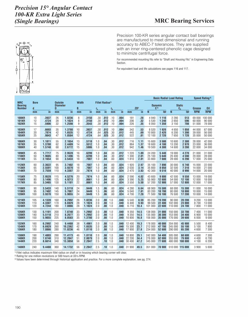
MRC Bearing Services
Precision 15° Angular Contact 100-KR Extra Light Series(Single Bearings)
190
Precision 100-KR series angular contact ball bearingsare manufactured to meet dimensional and runningaccuracy to ABEC-7 tolerances. They are suppliedwith an inner ring-centered phenolic cage designedto minimize centrifugal force.For recommended mounting fits refer to “Shaft and Housing Fits” in Engineering DataSection.
For equivalent load and life calculations see pages 116 and 117.
MRCBearingNumber
Bore
dmm in
OutsideDiameterDmm in
Width
Bmm in
ra
mm inrb
mm inZD2
mm in
DynamicC2)
N lbf
Basic Radial Load Rating Speed Rating3)
StaticC0
N lbfGrease OilRPM RPM
Fillet Radius1)
100KR 10 .3937 26 1.0236 8 .3150 .30 .012 .10 .004 181 .28 4 940 1 110 2 280 513 69 000 100 000101KR 12 .4724 28 1.1024 8 .3150 .30 .012 .10 .004 206 .32 5 530 1 240 2 650 596 60 000 90 000102KR 15 .5906 32 1.2598 9 .3543 .30 .012 .10 .004 226 .35 6 050 1 350 3 150 708 51 000 78 000
103KR 17 .6693 35 1.3780 10 .3937 .30 .012 .10 .004 342 .53 8 520 1 920 4 650 1 050 44 000 67 000104KR 20 .7874 42 1.6535 12 .4724 .64 .025 .30 .012 445 .69 10 800 2 420 6 200 1 390 39 000 56 000105KR 25 .9843 47 1.8504 12 .4724 .64 .025 .30 .012 522 .81 12 100 2 720 7 650 1 720 35 000 50 000
106KR 30 1.1811 55 2.1654 13 .5118 1.0 .04 .30 .012 716 1.11 15 600 3 500 10 600 2 380 28 000 42 000107KR 35 1.3780 62 2.4409 14 .5512 1.0 .04 .30 .012 884 1.37 18 600 4 180 13 200 2 970 23 000 36 000108KR 40 1.5748 68 2.6772 15 .5906 1.0 .04 .30 .012 942 1.46 19 500 4 380 14 600 3 280 22 000 34 000
109KR 45 1.7717 75 2.9528 16 .6299 1.0 .04 .30 .012 1 220 1.89 24 200 5 440 19 000 4 270 21 000 31 000110KR 50 1.9685 80 3.1496 16 .6299 1.0 .04 .30 .012 1 300 2.01 25 100 5 640 20 400 4 590 20 000 28 000111KR 55 2.1654 90 3.5433 18 .7087 1.0 .04 .60 .024 1 810 2.81 33 800 7 600 28 000 6 290 17 000 25 000
112KR 60 2.3622 95 3.7402 18 .7087 1.0 .04 .60 .024 1 920 2.97 35 100 7 890 30 000 6 740 15 000 22 000113KR 65 2.5591 100 3.9370 18 .7087 1.0 .04 .60 .024 2 030 3.14 35 800 8 050 32 500 7 310 14 000 21 000114KR 70 2.7559 110 4.3307 20 .7874 1.0 .04 .60 .024 2 470 3.83 42 300 9 510 40 000 8 990 14 000 20 000
115KR 75 2.9528 115 4.5276 20 .7874 1.0 .04 .60 .024 2 590 4.02 43 600 9 800 42 500 9 550 13 000 19 000116KR 80 3.1496 125 4.9213 22 .8661 1.0 .04 .60 .024 3 390 5.25 55 900 12 600 54 000 12 100 12 000 18 000117KR 85 3.3465 130 5.1181 22 .8661 1.0 .04 .60 .024 3 550 5.50 57 200 12 900 57 000 12 800 12 000 17 000
118KR 90 3.5433 140 5.5118 24 .9449 1.5 .06 .60 .024 4 280 6.64 68 900 15 500 68 000 15 300 11 000 16 000119KR 95 3.7402 145 5.7087 24 .9449 1.5 .06 .60 .024 5 040 7.81 83 200 18 700 80 000 18 000 10 000 15 000120KR 100 3.9370 150 5.9055 24 .9449 1.5 .06 .60 .024 4 700 7.28 71 500 16 100 76 500 17 200 10 000 14 000
121KR 105 4.1339 160 6.2992 26 1.0236 2.0 .08 1.0 .040 5 540 8.59 85 200 19 200 90 000 20 200 9 200 13 000122KR 110 4.3307 170 6.6929 28 1.1024 2.0 .08 1.0 .040 6 400 9.93 99 500 22 400 102 000 23 000 8 700 13 000124KR 120 4.7244 180 7.0866 28 1.1024 2.0 .08 1.0 .040 6 710 10.4 101 000 22 600 110 000 24 700 7 800 11 000
126KR 130 5.1181 200 7.8740 33 1.2992 2.0 .08 1.0 .040 9 350 14.5 138 000 31 000 150 000 33 700 7 400 11 000128KR 140 5.5118 210 8.2677 33 1.2992 2.0 .08 1.0 .040 9 350 14.5 135 000 30 300 153 000 34 400 6 900 10 000130KR 150 5.9055 225 8.8583 35 1.3780 2.0 .08 1.0 .040 10 800 16.8 156 000 35 000 176 000 39 600 6 000 9 000
132KR 160 6.2992 240 9.4488 38 1.4961 2.0 .08 1.0 .040 12 400 19.3 178 000 40 000 204 000 45 900 5 500 8 400134KR 170 6.6929 260 10.2362 42 1.6535 2.0 .08 1.0 .040 15 300 23.7 212 000 47 700 245 000 55 100 5 100 7 800136KR 180 7.0866 280 11.0236 46 1.8110 2.0 .08 1.0 .040 17 900 27.8 234 000 52 600 290 000 65 200 4 600 7 300
138KR 190 7.4803 290 11.4173 46 1.8110 2.0 .08 1.0 .040 18 800 29.1 242 000 54 400 305 000 68 600 4 600 7 300140KR 200 7.8740 310 12.2047 51 2.0079 2.0 .08 1.0 .040 22 200 34.4 276 000 62 000 355 000 79 800 4 400 6 700144KR 220 8.6614 340 13.3858 56 2.2047 2.5 .10 1.0 .040 30 400 47.2 345 000 77 600 480 000 108 000 4 100 6 200
148KR 240 9.4488 360 14.1732 56 2.2047 2.5 .10 1.0 .040 31 900 49.5 351 000 78 900 510 000 115 000 3 900 5 600
1) Fillet radius indicates maximum fillet radius on shaft or in housing which bearing corner will clear.2) Rating for one million revolutions or 500 hours at 33¹|₃ RPM.3) Values have been determined through historical application and practice. For a more complete explanation, see pg. 274.
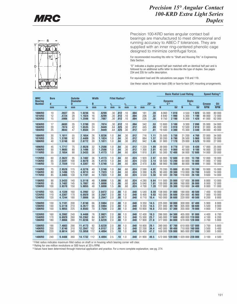
Precision 15° Angular Contact 100-KRD Extra Light Series
Duplex
191
Precision 100-KRD series angular contact ballbearings are manufactured to meet dimensional andrunning accuracy to ABEC-7 tolerances. They aresupplied with an inner ring-centered phenolic cagedesigned to minimize centrifugal force.For recommended mounting fits refer to “Shaft and Housing Fits” in Engineering Data Section.
“D” indicates a duplex ground half pair matched with an identical half pair and is followed by an additional suffix letter to describe the type of duplex. See pages 234 and 235 for suffix description.
For equivalent load and life calculations see pages 118 and 119.
Use these values for back-to-back (DB) or face-to-face (DF) mounting arrangements.
MRCBearingNumber
Bore
dmm in
OutsideDiameterDmm in
Width
Bmm in
ra
mm inrb
mm inZD2
mm in
DynamicC2)
N lbf
Basic Radial Load Rating Speed Rating3)
StaticC0
N lbfGrease OilRPM RPM
Fillet Radius1)
100KRD 10 .3937 26 1.0236 16 .6299 .30 .012 .10 .004 181 .28 8.060 1 810 4 550 1 020 55 000 80 000101KRD 12 .4724 28 1.1024 16 .6299 .30 .012 .10 .004 206 .32 8 840 1 990 5 300 1 190 48 000 72 000102KRD 15 .5906 32 1.2598 18 .7087 .30 .012 .10 .004 226 .35 9 750 2 190 6 300 1 420 41 000 62 000
103KRD 17 .6693 35 1.3780 20 .7874 .30 .012 .10 .004 342 .53 13 800 3 100 9 300 2 090 35 000 54 000104KRD 20 .7874 42 1.6535 24 .9449 .64 .025 .30 .012 445 .69 17 400 3 910 12 500 2 810 31 000 45 000105KRD 25 .9843 47 1.8504 24 .9449 .64 .025 .30 .012 522 .81 19 500 4 380 15 300 3 440 28 000 40 000
106KRD 30 1.1811 55 2.1654 26 1.0236 1.0 .04 .30 .012 716 1.11 25 500 5 730 21 200 4 760 22 000 34 000107KRD 35 1.3780 62 2.4409 28 1.1024 1.0 .04 .30 .012 884 1.37 30 200 6 790 26 500 5 960 18 000 29 000108KRD 40 1.5748 68 2.6772 30 1.1811 1.0 .04 .30 .012 942 1.46 31 900 7 170 29 000 6 520 18 000 27 000
109KRD 45 1.7717 75 2.9528 32 1.2598 1.0 .04 .30 .012 1 220 1.89 39 000 8 770 37 500 8 430 17 000 25 000110KRD 50 1.9685 80 3.1496 32 1.2598 1.0 .04 .30 .012 1 300 2.01 40 300 9 060 40 500 9 100 16 000 22 000111KRD 55 2.1654 90 3.5433 36 1.4173 1.0 .04 .60 .024 1 810 2.81 55 300 12 400 56 000 12 600 14 000 20 000
112KRD 60 2.3622 95 3.7402 36 1.4173 1.0 .04 .60 .024 1 920 2.97 55 900 12 600 61 000 13 700 12 000 18 000113KRD 65 2.5591 100 3.9370 36 1.4173 1.0 .04 .60 .024 2 030 3.14 58 500 13 200 64 000 14 400 11 000 17 000114KRD 70 2.7559 110 4.3307 40 1.5748 1.0 .04 .60 .024 2 470 3.83 68 900 15 500 80 000 18 000 11 000 16 000
115KRD 75 2.9528 115 4.5276 40 1.5748 1.0 .04 .60 .024 2 590 4.02 70 200 15 800 85 000 19 100 10 000 15 000116KRD 80 3.1496 125 4.9213 44 1.7323 1.0 .04 .60 .024 3 390 5.25 90 400 20 300 110 000 24 700 9 600 14 000117KRD 85 3.3465 130 5.1181 44 1.7323 1.0 .04 .60 .024 3 550 5.50 92 300 20 700 116 000 26 100 9 600 14 000
118KRD 90 3.5433 140 5.5118 48 1.8898 1.5 .06 .60 .024 4 280 6.64 111 000 25 000 137 000 30 800 8 800 13 000119KRD 95 3.7402 145 5.7087 48 1.8898 1.5 .06 .60 .024 5 040 7.81 135 000 30 300 160 000 36 000 8 000 12 000120KRD 100 3.9370 150 5.9055 48 1.8898 1.5 .06 .60 .024 4 700 7.28 117 000 26 300 153 000 34 400 8 000 11 000
121KRD 105 4.1339 160 6.2992 52 2.0472 2.0 .08 1.0 .040 5 540 8.59 138 000 31 000 180 000 40 500 7 400 10 000122KRD 110 4.3307 170 6.6929 56 2.2047 2.0 .08 1.0 .040 6 400 9.93 163 000 36 600 204 000 45 900 7 000 10 000124KRD 120 4.7244 180 7.0866 56 2.2047 2.0 .08 1.0 .040 6 710 10.4 163 000 36 600 220 000 49 500 6 200 8 800
126KRD 130 5.1181 200 7.8740 66 2.5984 2.0 .08 1.0 .040 9 350 14.5 225 000 50 000 300 000 67 400 5 900 8 800128KRD 140 5.5118 210 8.2677 66 2.5984 2.0 .08 1.0 .040 9 350 14.5 221 000 49 700 305 000 68 600 5 500 8 000130KRD 150 5.9055 225 8.8583 70 2.7559 2.0 .08 1.0 .040 10 800 16.8 255 000 57 300 355 000 79 800 4 800 7 200
132KRD 160 6.2992 240 9.4488 76 2.9921 2.0 .08 1.0 .040 12 400 19.3 286 000 64 300 405 000 91 000 4 400 6 700134KRD 170 6.6929 260 10.2362 84 3.3071 2.0 .08 1.0 .040 15 300 23.7 345 000 77 600 490 000 110 000 4 100 6 200136KRD 180 7.0866 280 11.0236 92 3.6220 2.0 .08 1.0 .040 17 900 27.8 377 000 84 800 570 000 128 000 3 700 5 800
138KRD 190 7.4803 290 11.4173 92 3.6220 2.0 .08 1.0 .040 18 800 29.1 390 000 87 700 610 000 137 000 3 700 5 800140KRD 200 7.8740 310 12.2047 102 4.0157 2.0 .08 1.0 .040 22 200 34.4 442 000 99 400 710 000 160 000 3 500 5 400144KRD 220 8.6614 340 13.3858 112 4.4094 2.5 .10 1.0 .040 30 400 47.2 559 000 126 000 965 000 217 000 3 300 5 000
148KRD 240 9.4488 360 14.1732 112 4.4094 2.5 .10 1.0 .040 31 900 49.5 572 000 129 000 1 020 000 228 000 3 100 4 500
1) Fillet radius indicates maximum fillet radius on shaft or in housing which bearing corner will clear.2) Rating for one million revolutions or 500 hours at 33¹|₃ RPM.3) Values have been determined through historical application and practice. For a more complete explanation, see pg. 274.
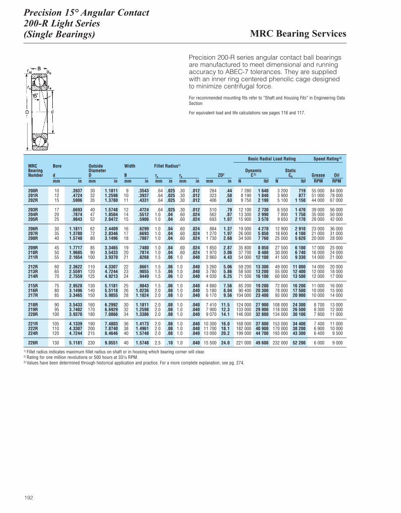
MRC Bearing Services
Precision 15° Angular Contact 200-R Light Series(Single Bearings)
192
Precision 200-R series angular contact ball bearingsare manufactured to meet dimensional and runningaccuracy to ABEC-7 tolerances. They are suppliedwith an inner ring centered phenolic cage designedto minimize centrifugal force.
For recommended mounting fits refer to “Shaft and Housing Fits” in Engineering DataSection
For equivalent load and life calculations see pages 116 and 117.
MRCBearingNumber
Bore
dmm in
OutsideDiameterDmm in
Width
Bmm in
ra
mm inrb
mm inZD2
mm in
DynamicC2)
N lbf
Basic Radial Load Rating Speed Rating3)
StaticC0
N lbfGrease OilRPM RPM
Fillet Radius1)
200R 10 .3937 30 1.1811 9 .3543 .64 .025 .30 .012 284 .44 7 280 1 640 3 200 719 55 000 84 000201R 12 .4724 32 1.2598 10 .3937 .64 .025 .30 .012 323 .50 8 190 1 840 3 900 877 51 000 78 000202R 15 .5906 35 1.3780 11 .4331 .64 .025 .30 .012 406 .63 9 750 2 190 5 100 1 150 44 000 67 000
203R 17 .6693 40 1.5748 12 .4724 .64 .025 .30 .012 510 .79 12 100 2 730 6 550 1 470 39 000 56 000204R 20 .7874 47 1.8504 14 .5512 1.0 .04 .60 .024 562 .87 13 300 2 990 7 800 1 750 35 000 50 000205R 25 .9843 52 2.0472 15 .5906 1.0 .04 .60 .024 693 1.07 15 900 3 570 9 650 2 170 28 000 42 000
206R 30 1.1811 62 2.4409 16 .6299 1.0 .04 .60 .024 884 1.37 19 000 4 270 12 900 2 910 23 000 36 000207R 35 1.3780 72 2.8346 17 .6693 1.0 .04 .60 .024 1 270 1.97 26 000 5 850 18 600 4 180 21 000 31 000208R 40 1.5748 80 3.1496 18 .7087 1.0 .04 .60 .024 1 730 2.68 34 500 7 760 25 000 5 620 20 000 28 000
209R 45 1.7717 85 3.3465 19 .7480 1.0 .04 .60 .024 1 850 2.87 35 800 8 050 27 500 6 180 17 000 25 000210R 50 1.9685 90 3.5433 20 .7874 1.0 .04 .60 .024 1 970 3.06 37 700 8 480 30 000 6 740 16 000 24 000211R 55 2.1654 100 3.9370 21 .8268 1.5 .06 1.0 .040 2 860 4.43 54 000 12 100 41 500 9 330 14 000 21 000
212R 60 2.3622 110 4.3307 22 .8661 1.5 .06 1.0 .040 3 260 5.06 59 200 13 300 49 000 11 000 14 000 20 000213R 65 2.5591 120 4.7244 23 .9055 1.5 .06 1.0 .040 3 780 5.86 58 500 13 200 55 000 12 400 12 000 18 000214R 70 2.7559 125 4.9213 24 .9449 1.5 .06 1.0 .040 4 030 6.25 71 500 16 100 60 000 13 500 12 000 17 000
215R 75 2.9528 130 5.1181 25 .9843 1.5 .06 1.0 .040 4 880 7.56 85 200 19 200 72 000 16 200 11 000 16 000216R 80 3.1496 140 5.5118 26 1.0236 2.0 .08 1.0 .040 5 180 8.04 90 400 20 300 78 000 17 500 10 000 15 000217R 85 3.3465 150 5.9055 28 1.1024 2.0 .08 1.0 .040 6 170 9.56 104 000 23 400 93 000 20 900 10 000 14 000
218R 90 3.5433 160 6.2992 30 1.1811 2.0 .08 1.0 .040 7 410 11.5 124 000 27 900 108 000 24 300 8 700 13 000219R 95 3.7402 170 6.6929 32 1.2598 2.0 .08 1.0 .040 7 900 12.3 133 000 29 900 118 000 26 500 8 300 12 000220R 100 3.9370 180 7.0866 34 1.3386 2.0 .08 1.0 .040 9 070 14.1 146 000 32 800 134 000 30 100 7 800 11 000
221R 105 4.1339 190 7.4803 36 1.4173 2.0 .08 1.0 .040 10 300 16.0 168 000 37 800 153 000 34 400 7 400 11 000222R 110 4.3307 200 7.8740 38 1.4961 2.0 .08 1.0 .040 11 700 18.1 182 000 40 900 170 000 38 200 6 900 10 000224R 120 4.7244 215 8.4646 40 1.5748 2.0 .08 1.0 .040 13 000 20.2 199 000 44 700 193 000 43 300 6 400 9 500
226R 130 5.1181 230 9.0551 40 1.5748 2.5 .10 1.0 .040 15 500 24.0 221 000 49 600 232 000 52 200 6 000 9 000
1) Fillet radius indicates maximum fillet radius on shaft or in housing which bearing corner will clear.2) Rating for one million revolutions or 500 hours at 33¹|₃ RPM.3) Values have been determined through historical application and practice. For a more complete explanation, see pg. 274.
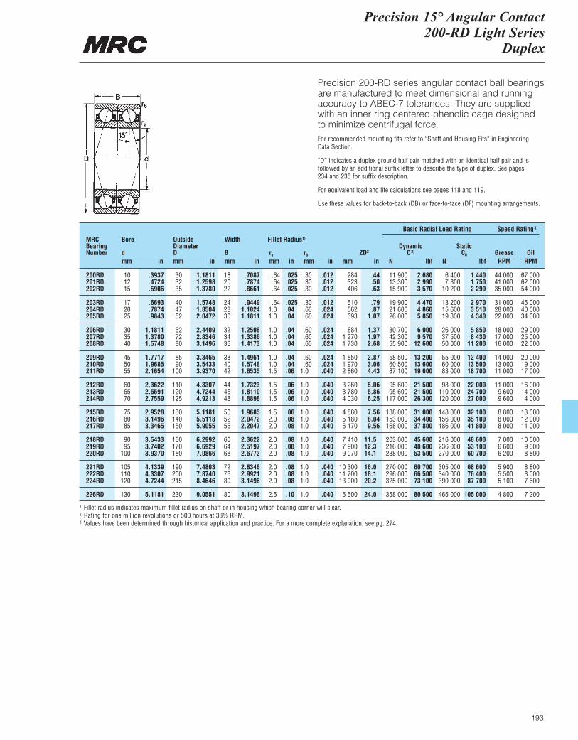
Precision 15° Angular Contact 200-RD Light Series
Duplex
193
Precision 200-RD series angular contact ball bearingsare manufactured to meet dimensional and runningaccuracy to ABEC-7 tolerances. They are suppliedwith an inner ring centered phenolic cage designedto minimize centrifugal force.For recommended mounting fits refer to “Shaft and Housing Fits” in Engineering Data Section.
“D” indicates a duplex ground half pair matched with an identical half pair and is followed by an additional suffix letter to describe the type of duplex. See pages 234 and 235 for suffix description.
For equivalent load and life calculations see pages 118 and 119.
Use these values for back-to-back (DB) or face-to-face (DF) mounting arrangements.
MRCBearingNumber
Bore
dmm in
OutsideDiameterDmm in
Width
Bmm in
ra
mm inrb
mm inZD2
mm in
DynamicC2)
N lbf
Basic Radial Load Rating Speed Rating3)
StaticC0
N lbfGrease OilRPM RPM
Fillet Radius1)
200RD 10 .3937 30 1.1811 18 .7087 .64 .025 .30 .012 284 .44 11 900 2 680 6 400 1 440 44 000 67 000201RD 12 .4724 32 1.2598 20 .7874 .64 .025 .30 .012 323 .50 13 300 2 990 7 800 1 750 41 000 62 000202RD 15 .5906 35 1.3780 22 .8661 .64 .025 .30 .012 406 .63 15 900 3 570 10 200 2 290 35 000 54 000
203RD 17 .6693 40 1.5748 24 .9449 .64 .025 .30 .012 510 .79 19 900 4 470 13 200 2 970 31 000 45 000204RD 20 .7874 47 1.8504 28 1.1024 1.0 .04 .60 .024 562 .87 21 600 4 860 15 600 3 510 28 000 40 000205RD 25 .9843 52 2.0472 30 1.1811 1.0 .04 .60 .024 693 1.07 26 000 5 850 19 300 4 340 22 000 34 000
206RD 30 1.1811 62 2.4409 32 1.2598 1.0 .04 .60 .024 884 1.37 30 700 6 900 26 000 5 850 18 000 29 000207RD 35 1.3780 72 2.8346 34 1.3386 1.0 .04 .60 .024 1 270 1.97 42 300 9 570 37 500 8 430 17 000 25 000208RD 40 1.5748 80 3.1496 36 1.4173 1.0 .04 .60 .024 1 730 2.68 55 900 12 600 50 000 11 200 16 000 22 000
209RD 45 1.7717 85 3.3465 38 1.4961 1.0 .04 .60 .024 1 850 2.87 58 500 13 200 55 000 12 400 14 000 20 000210RD 50 1.9685 90 3.5433 40 1.5748 1.0 .04 .60 .024 1 970 3.06 60 500 13 600 60 000 13 500 13 000 19 000211RD 55 2.1654 100 3.9370 42 1.6535 1.5 .06 1.0 .040 2 860 4.43 87 100 19 600 83 000 18 700 11 000 17 000
212RD 60 2.3622 110 4.3307 44 1.7323 1.5 .06 1.0 .040 3 260 5.06 95 600 21 500 98 000 22 000 11 000 16 000213RD 65 2.5591 120 4.7244 46 1.8110 1.5 .06 1.0 .040 3 780 5.86 95 600 21 500 110 000 24 700 9 600 14 000214RD 70 2.7559 125 4.9213 48 1.8898 1.5 .06 1.0 .040 4 030 6.25 117 000 26 300 120 000 27 000 9 600 14 000
215RD 75 2.9528 130 5.1181 50 1.9685 1.5 .06 1.0 .040 4 880 7.56 138 000 31 000 148 000 32 100 8 800 13 000216RD 80 3.1496 140 5.5118 52 2.0472 2.0 .08 1.0 .040 5 180 8.04 153 000 34 400 156 000 35 100 8 000 12 000217RD 85 3.3465 150 5.9055 56 2.2047 2.0 .08 1.0 .040 6 170 9.56 168 000 37 800 186 000 41 800 8 000 11 000
218RD 90 3.5433 160 6.2992 60 2.3622 2.0 .08 1.0 .040 7 410 11.5 203 000 45 600 216 000 48 600 7 000 10 000219RD 95 3.7402 170 6.6929 64 2.5197 2.0 .08 1.0 .040 7 900 12.3 216 000 48 600 236 000 53 100 6 600 9 600220RD 100 3.9370 180 7.0866 68 2.6772 2.0 .08 1.0 .040 9 070 14.1 238 000 53 500 270 000 60 700 6 200 8 800
221RD 105 4.1339 190 7.4803 72 2.8346 2.0 .08 1.0 .040 10 300 16.0 270 000 60 700 305 000 68 600 5 900 8 800222RD 110 4.3307 200 7.8740 76 2.9921 2.0 .08 1.0 .040 11 700 18.1 296 000 66 500 340 000 76 400 5 500 8 000224RD 120 4.7244 215 8.4646 80 3.1496 2.0 .08 1.0 .040 13 000 20.2 325 000 73 100 390 000 87 700 5 100 7 600
226RD 130 5.1181 230 9.0551 80 3.1496 2.5 .10 1.0 .040 15 500 24.0 358 000 80 500 465 000 105 000 4 800 7 200
1) Fillet radius indicates maximum fillet radius on shaft or in housing which bearing corner will clear.2) Rating for one million revolutions or 500 hours at 33¹|₃ RPM.3) Values have been determined through historical application and practice. For a more complete explanation, see pg. 274.
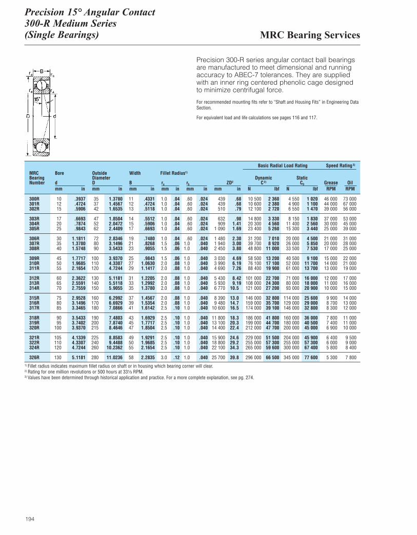
MRC Bearing Services
Precision 15° Angular Contact300-R Medium Series(Single Bearings)
194
Precision 300-R series angular contact ball bearingsare manufactured to meet dimensional and runningaccuracy to ABEC-7 tolerances. They are suppliedwith an inner ring centered phenolic cage designedto minimize centrifugal force.
For recommended mounting fits refer to “Shaft and Housing Fits” in Engineering DataSection.
For equivalent load and life calculations see pages 116 and 117.
MRCBearingNumber
Bore
dmm in
OutsideDiameterDmm in
Width
Bmm in
ra
mm inrb
mm inZD2
mm in
DynamicC2)
N lbf
Basic Radial Load Rating Speed Rating3)
StaticC0
N lbfGrease OilRPM RPM
Fillet Radius1)
300R 10 .3937 35 1.3780 11 .4331 1.0 .04 .60 .024 439 .68 10 500 2 360 4 550 1 020 46 000 73 000301R 12 .4724 37 1.4567 12 .4724 1.0 .04 .60 .024 439 .68 10 600 2 380 4 900 1 100 44 000 67 000302R 15 .5906 42 1.6535 13 .5118 1.0 .04 .60 .024 510 .79 12 100 2 720 6 550 1 470 39 000 56 000
303R 17 .6693 47 1.8504 14 .5512 1.0 .04 .60 .024 632 .98 14 800 3 330 8 150 1 830 37 000 53 000304R 20 .7874 52 2.0472 15 .5906 1.0 .04 .60 .024 909 1.41 20 300 4 560 11 400 2 560 30 000 45 000305R 25 .9843 62 2.4409 17 .6693 1.0 .04 .60 .024 1 090 1.69 23 400 5 260 15 300 3 440 25 000 39 000
306R 30 1.1811 72 2.8346 19 .7480 1.0 .04 .60 .024 1 480 2.30 31 200 7 010 20 000 4 500 21 000 31 000307R 35 1.3780 80 3.1496 21 .8268 1.5 .06 1.0 .040 1 940 3.00 39 700 8 920 26 000 5 850 20 000 28 000308R 40 1.5748 90 3.5433 23 .9055 1.5 .06 1.0 .040 2 450 3.80 48 800 11 000 33 500 7 530 17 000 25 000
309R 45 1.7717 100 3.9370 25 .9843 1.5 .06 1.0 .040 3 030 4.69 58 500 13 200 40 500 9 100 15 000 22 000310R 50 1.9685 110 4.3307 27 1.0630 2.0 .08 1.0 .040 3 990 6.19 76 100 17 100 52 000 11 700 14 000 21 000311R 55 2.1654 120 4.7244 29 1.1417 2.0 .08 1.0 .040 4 690 7.26 88 400 19 900 61 000 13 700 13 000 19 000
312R 60 2.3622 130 5.1181 31 1.2205 2.0 .08 1.0 .040 5 430 8.42 101 000 22 700 71 000 16 000 12 000 17 000313R 65 2.5591 140 5.5118 33 1.2992 2.0 .08 1.0 .040 5 930 9.19 108 000 24 300 80 000 18 000 11 000 16 000314R 70 2.7559 150 5.9055 35 1.3780 2.0 .08 1.0 .040 6 770 10.5 121 000 27 200 93 000 20 900 10 000 15 000
315R 75 2.9528 160 6.2992 37 1.4567 2.0 .08 1.0 .040 8 390 13.0 146 000 32 800 114 000 25 600 9 900 14 000316R 80 3.1496 170 6.6929 39 1.5354 2.0 .08 1.0 .040 9 480 14.7 159 000 35 700 129 000 29 000 8 700 13 000317R 85 3.3465 180 7.0866 41 1.6142 2.5 .10 1.0 .040 10 600 16.5 174 000 39 100 146 000 32 800 8 300 12 000
318R 90 3.5433 190 7.4803 43 1.6929 2.5 .10 1.0 .040 11 800 18.3 186 000 41 800 160 000 36 000 7 800 11 000319R 95 3.7402 200 7.8740 45 1.7717 2.5 .10 1.0 .040 13 100 20.3 199 000 44 700 180 000 40 500 7 400 11 000320R 100 3.9370 215 8.4646 47 1.8504 2.5 .10 1.0 .040 14 400 22.4 212 000 47 700 200 000 45 000 6 900 10 000
321R 105 4.1339 225 8.8583 49 1.9291 2.5 .10 1.0 .040 15 900 24.6 229 000 51 500 204 000 45 900 6 400 9 500322R 110 4.3307 240 9.4488 50 1.9685 2.5 .10 1.0 .040 18 800 29.2 255 000 57 300 255 000 57 300 6 000 9 000324R 120 4.7244 260 10.2362 55 2.1654 2.5 .10 1.0 .040 22 100 34.3 265 000 59 600 300 000 67 400 5 800 8 400
326R 130 5.1181 280 11.0236 58 2.2835 3.0 .12 1.0 .040 25 700 39.8 296 000 66 500 345 000 77 600 5 300 7 8001) Fillet radius indicates maximum fillet radius on shaft or in housing which bearing corner will clear.2) Rating for one million revolutions or 500 hours at 33¹|₃ RPM.3) Values have been determined through historical application and practice. For a more complete explanation, see pg. 274.
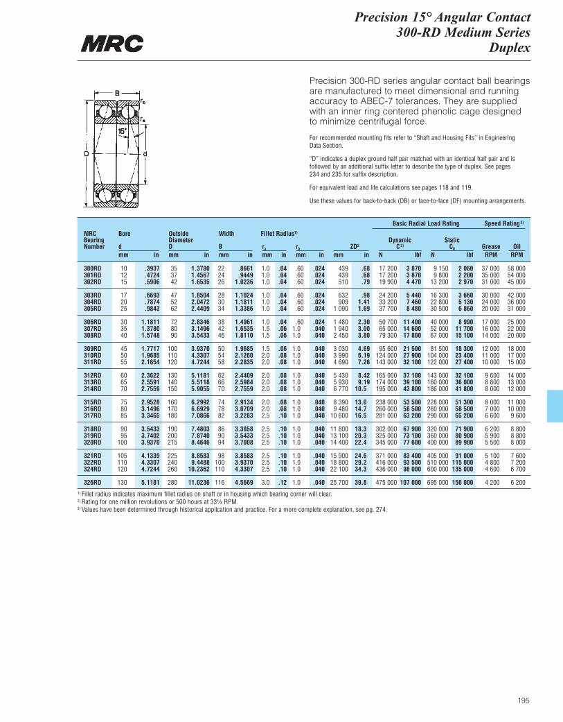
Precision 15° Angular Contact300-RD Medium Series
Duplex
195
Precision 300-RD series angular contact ball bearingsare manufactured to meet dimensional and runningaccuracy to ABEC-7 tolerances. They are suppliedwith an inner ring centered phenolic cage designedto minimize centrifugal force.
For recommended mounting fits refer to “Shaft and Housing Fits” in Engineering Data Section.
“D” indicates a duplex ground half pair matched with an identical half pair and is followed by an additional suffix letter to describe the type of duplex. See pages 234 and 235 for suffix description.
For equivalent load and life calculations see pages 118 and 119.
Use these values for back-to-back (DB) or face-to-face (DF) mounting arrangements.
MRCBearingNumber
Bore
dmm in
OutsideDiameterDmm in
Width
Bmm in
ra
mm inrb
mm inZD2
mm in
DynamicC2)
N lbf
Basic Radial Load Rating Speed Rating3)
StaticC0
N lbfGrease OilRPM RPM
Fillet Radius1)
300RD 10 .3937 35 1.3780 22 .8661 1.0 .04 .60 .024 439 .68 17 200 3 870 9 150 2 060 37 000 58 000301RD 12 .4724 37 1.4567 24 .9449 1.0 .04 .60 .024 439 .68 17 200 3 870 9 800 2 200 35 000 54 000302RD 15 .5906 42 1.6535 26 1.0236 1.0 .04 .60 .024 510 .79 19 900 4 470 13 200 2 970 31 000 45 000
303RD 17 .6693 47 1.8504 28 1.1024 1.0 .04 .60 .024 632 .98 24 200 5 440 16 300 3 660 30 000 42 000304RD 20 .7874 52 2.0472 30 1.1811 1.0 .04 .60 .024 909 1.41 33 200 7 460 22 800 5 130 24 000 36 000305RD 25 .9843 62 2.4409 34 1.3386 1.0 .04 .60 .024 1 090 1.69 37 700 8 480 30 500 6 860 20 000 31 000
306RD 30 1.1811 72 2.8346 38 1.4961 1.0 .04 .60 .024 1 480 2.30 50 700 11 400 40 000 8 990 17 000 25 000307RD 35 1.3780 80 3.1496 42 1.6535 1.5 .06 1.0 .040 1 940 3.00 65 000 14 600 52 000 11 700 16 000 22 000308RD 40 1.5748 90 3.5433 46 1.8110 1.5 .06 1.0 .040 2 450 3.80 79 300 17 800 67 000 15 100 14 000 20 000
309RD 45 1.7717 100 3.9370 50 1.9685 1.5 .06 1.0 .040 3 030 4.69 95 600 21 500 81 500 18 300 12 000 18 000310RD 50 1.9685 110 4.3307 54 2.1260 2.0 .08 1.0 .040 3 990 6.19 124 000 27 900 104 000 23 400 11 000 17 000311RD 55 2.1654 120 4.7244 58 2.2835 2.0 .08 1.0 .040 4 690 7.26 143 000 32 100 122 000 27 400 10 000 15 000
312RD 60 2.3622 130 5.1181 62 2.4409 2.0 .08 1.0 .040 5 430 8.42 165 000 37 100 143 000 32 100 9 600 14 000313RD 65 2.5591 140 5.5118 66 2.5984 2.0 .08 1.0 .040 5 930 9.19 174 000 39 100 160 000 36 000 8 800 13 000314RD 70 2.7559 150 5.9055 70 2.7559 2.0 .08 1.0 .040 6 770 10.5 195 000 43 800 186 000 41 800 8 000 12 000
315RD 75 2.9528 160 6.2992 74 2.9134 2.0 .08 1.0 .040 8 390 13.0 238 000 53 500 228 000 51 300 8 000 11 000316RD 80 3.1496 170 6.6929 78 3.0709 2.0 .08 1.0 .040 9 480 14.7 260 000 58 500 260 000 58 500 7 000 10 000317RD 85 3.3465 180 7.0866 82 3.2283 2.5 .10 1.0 .040 10 600 16.5 281 000 63 200 290 000 65 200 6 600 9 600
318RD 90 3.5433 190 7.4803 86 3.3858 2.5 .10 1.0 .040 11 800 18.3 302 000 67 900 320 000 71 900 6 200 8 800319RD 95 3.7402 200 7.8740 90 3.5433 2.5 .10 1.0 .040 13 100 20.3 325 000 73 100 360 000 80 900 5 900 8 800320RD 100 3.9370 215 8.4646 94 3.7008 2.5 .10 1.0 .040 14 400 22.4 345 000 77 600 400 000 89 900 5 500 8 000
321RD 105 4.1339 225 8.8583 98 3.8583 2.5 .10 1.0 .040 15 900 24.6 371 000 83 400 405 000 91 000 5 100 7 600322RD 110 4.3307 240 9.4488 100 3.9370 2.5 .10 1.0 .040 18 800 29.2 416 000 93 500 510 000 115 000 4 800 7 200324RD 120 4.7244 260 10.2362 110 4.3307 2.5 .10 1.0 .040 22 100 34.3 436 000 98 000 600 000 135 000 4 600 6 700
326RD 130 5.1181 280 11.0236 116 4.5669 3.0 .12 1.0 .040 25 700 39.8 475 000 107 000 695 000 156 000 4 200 6 2001) Fillet radius indicates maximum fillet radius on shaft or in housing which bearing corner will clear.2) Rating for one million revolutions or 500 hours at 33¹|₃ RPM.3) Values have been determined through historical application and practice. For a more complete explanation, see pg. 274.
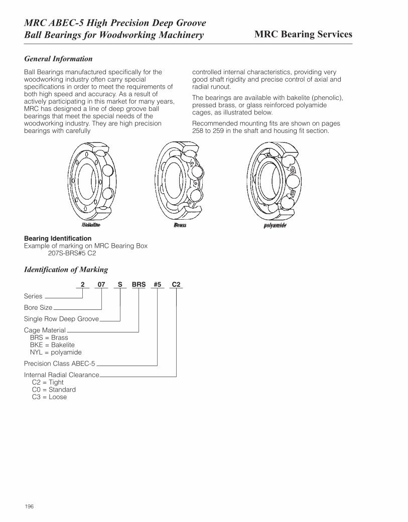
MRC Bearing ServicesMRC ABEC-5 High Precision Deep Groove Ball Bearings for Woodworking Machinery
196
General Information
Ball Bearings manufactured specifically for thewoodworking industry often carry specialspecifications in order to meet the requirements ofboth high speed and accuracy. As a result ofactively participating in this market for many years,MRC has designed a line of deep groove ballbearings that meet the special needs of thewoodworking industry. They are high precisionbearings with carefully
controlled internal characteristics, providing verygood shaft rigidity and precise control of axial andradial runout.
The bearings are available with bakelite (phenolic),pressed brass, or glass reinforced polyamidecages, as illustrated below.
Recommended mounting fits are shown on pages258 to 259 in the shaft and housing fit section.
Bearing Identification Example of marking on MRC Bearing Box
207S-BRS#5 C2
Identification of Marking
2 07 S BRS #5 C2
Series
Bore Size
Single Row Deep Groove
Cage Material BRS = Brass BKE = Bakelite NYL = polyamide
Precision Class ABEC-5
Internal Radial Clearance C2 = TightC0 = Standard C3 = Loose
Bakelite Brass polyamide
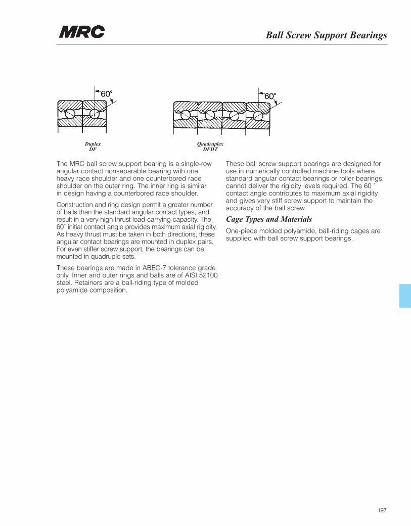
Ball Screw Support Bearings
197
The MRC ball screw support bearing is a single-rowangular contact nonseparable bearing with oneheavy race shoulder and one counterbored raceshoulder on the outer ring. The inner ring is similar in design having a counterbored race shoulder.
Construction and ring design permit a greater numberof balls than the standard angular contact types, andresult in a very high thrust load-carrying capacity. The60˚ initial contact angle provides maximum axial rigidity.As heavy thrust must be taken in both directions, theseangular contact bearings are mounted in duplex pairs.For even stiffer screw support, the bearings can bemounted in quadruple sets.
These bearings are made in ABEC-7 tolerance gradeonly. Inner and outer rings and balls are of AISI 52100steel. Retainers are a ball-riding type of moldedpolyamide composition.
These ball screw support bearings are designed foruse in numerically controlled machine tools wherestandard angular contact bearings or roller bearingscannot deliver the rigidity levels required. The 60 ˚contact angle contributes to maximum axial rigidityand gives very stiff screw support to maintain theaccuracy of the ball screw.
Cage Types and Materials
One-piece molded polyamide, ball-riding cages aresupplied with ball screw support bearings.
Duplex DF
Quadruplex DFDT
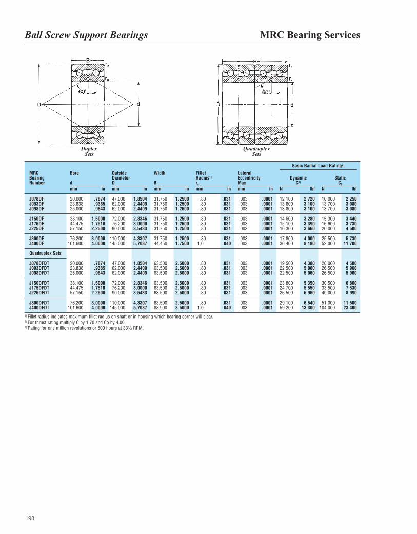
MRC Bearing ServicesBall Screw Support Bearings
198
MRCBearingNumber
Bore
dmm in
OutsideDiameterDmm in
Width
Bmm in
ra
mm in
LateralEccentricityMaxmm in
DynamicC3)
N lbf
Basic Radial Load Rating2)
StaticC0
N lbf
Fillet Radius1)
J078DF 20.000 .7874 47.000 1.8504 31.750 1.2500 .80 .031 .003 .0001 12 100 2 720 10 000 2 250J093DF 23.838 .9385 62.000 2.4409 31.750 1.2500 .80 .031 .003 .0001 13 800 3 100 13 700 3 080J098DF 25.000 .9843 62.000 2.4409 31.750 1.2500 .80 .031 .003 .0001 13 800 3 100 13 700 3 080
J150DF 38.100 1.5000 72.000 2.8346 31.750 1.2500 .80 .031 .003 .0001 14 600 3 280 15 300 3 440J175DF 44.475 1.7510 76.200 3.0000 31.750 1.2500 .80 .031 .003 .0001 15 100 3 390 16 600 3 730J225DF 57.150 2.2500 90.000 3.5433 31.750 1.2500 .80 .031 .003 .0001 16 300 3 660 20 000 4 500
J300DF 76.200 3.0000 110.000 4.3307 31.750 1.2500 .80 .031 .003 .0001 17 800 4 000 25 500 5 730J400DF 101.600 4.0000 145.000 5.7087 44.450 1.7500 1.0 .040 .003 .0001 36 400 8 180 52 000 11 700
Quadruplex Sets
J078DFDT 20.000 .7874 47.000 1.8504 63.500 2.5000 .80 .031 .003 .0001 19 500 4 380 20 000 4 500J093DFDT 23.838 .9385 62.000 2.4409 63.500 2.5000 .80 .031 .003 .0001 22 500 5 060 26 500 5 960J098DFDT 25.000 .9843 62.000 2.4409 63.500 2.5000 .80 .031 .003 .0001 22 500 5 060 26 500 5 960
J150DFDT 38.100 1.5000 72.000 2.8346 63.500 2.5000 .80 .031 .003 0001 23 800 5 350 30 500 6 860J175DFDT 44.475 1.7510 76.200 3.0000 63.500 2.5000 .80 .031 .003 .0001 24 700 5 550 33 500 7 530J225DFDT 57.150 2.2500 90.000 3.5433 63.500 2.5000 .80 .031 .003 .0001 26 500 5 960 40 000 8 990
J300DFDT 76.200 3.0000 110.000 4.3307 63.500 2.5000 .80 .031 .003 .0001 29 100 6 540 51 000 11 500J400DFDT 101.600 4.0000 145.000 5.7087 88.900 3.5000 1.0 .040 .003 .0001 59 200 13 300 104 000 23 400
Duplex Sets
QuadruplexSets
1) Fillet radius indicates maximum fillet radius on shaft or in housing which bearing corner will clear.2) For thrust rating multiply C by 1.70 and Co by 4.00.3) Rating for one million revolutions or 500 hours at 33¹|₃ RPM.
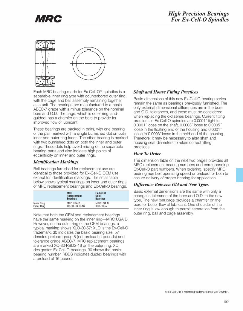
High Precision Bearings For Ex-Cell-O Spindles
199
Each MRC bearing made for Ex-Cell-O®‚ spindles is aseparable inner ring type with counterbored outer ring,with the cage and ball assembly remaining together as a unit. The bearings are manufactured to a basicABEC-7 grade with a minus tolerance on the nominalbore and O.D. The cage, which is outer ring land-guided, has a chamfer on the bore to provide forimproved flow of lubricant.
These bearings are packed in pairs, with one bearingof the pair marked with a single burnished dot on bothinner and outer ring faces. The other bearing is markedwith two burnished dots on both the inner and outerrings. These dots help avoid mixing of the separablebearing parts and also indicate high points ofeccentricity on inner and outer rings.
Identification Markings
Ball bearings furnished for replacement use areidentical to those provided for Ex-Cell-O OEM useexcept for identification markings. The small tablebelow shows typical markings on inner and outer ringsof MRC replacement bearings and Ex-Cell-O bearings.
Note that both the OEM and replacement bearingshave the same marking on the inner ring—MRC USA D.However, on the outer ring of the OEM bearings, atypical marking shows XLO-30-57: XLO is the Ex-Cell-Otrademark, 30 indicates the basic bearing size, 57denotes preload group 5 (not preload in pounds) andtolerance grade ABEC-7. MRC replacement bearingsare marked XO-30-RBDS-16 on the outer ring: XOdesignates Ex-Cell-O bearings, 30 shows the basicbearing number, RBDS indicates duplex bearings witha preload of 16 pounds.
Shaft and House Fitting Practices
Basic dimensions of this new Ex-Cell-O bearing seriesremain the same as bearings previously furnished. Theonly external dimensional differences are in the boreand O.D. tolerances, and these must be consideredwhen replacing the old series bearings. Current fittingpractices in Ex-Cell-O spindles are 0.0001˝ tight to0.0001˝ loose on the shaft, 0.0003˝ loose to 0.0005˝loose in the floating end of the housing and 0.0001˝loose to 0.0003˝ loose in the held end of the housing.Therefore, it may be necessary to alter shaft andhousing seat diameters to retain correct fittingpractices.
How To Order
The dimension table on the next two pages provides allMRC replacement bearing numbers and correspondingEx-Cell-O part numbers. When ordering, specify MRCbearing number, operating speed or preload, or both toassure delivery of proper bearing for application.
Difference Between Old and New Types
Basic external dimensions are the same with only achange in tolerance of the bore and O.D. in the newtype. The new ball cage provides a chamfer on thebore for better flow of lubricant. One shoulder of theinner ring is low enough to permit separation from theouter ring, ball and cage assembly.
® Ex-Cell-O is a registered trademark of Ex-Cell-O GmbH.
MRC Ex-Cell-O Replacement OEM Bearings Bearings
Inner Ring MRC USA D MRC USA D Outer Ring XO-30-RBDS-16 XLO-30-57
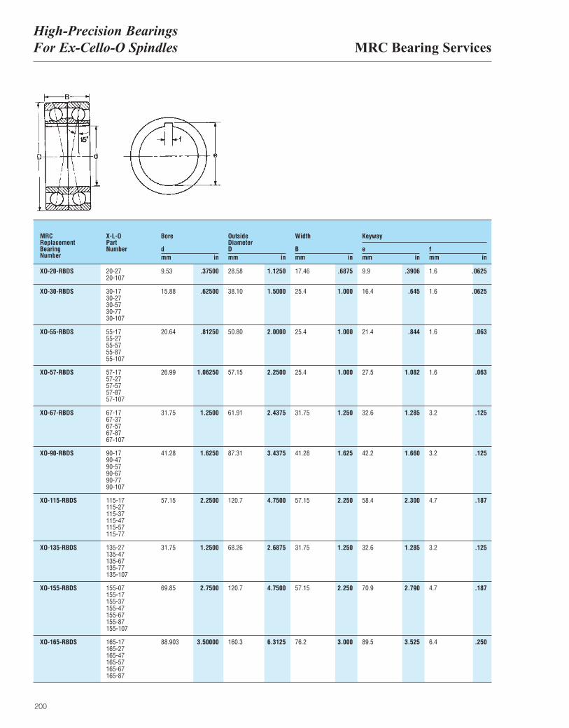
MRC Bearing ServicesHigh-Precision Bearings For Ex-Cello-O Spindles
200
MRCReplacementBearingNumber
X-L-OPartNumber f
mm inemm in
Width
Bmm in
OutsideDiameterDmm in
Bore
dmm in
Keyway
XO-20-RBDS 20-27 9.53 .37500 28.58 1.1250 17.46 .6875 9.9 .3906 1.6 .062520-107
XO-30-RBDS 30-17 15.88 .62500 38.10 1.5000 25.4 1.000 16.4 .645 1.6 .062530-2730-5730-7730-107
XO-55-RBDS 55-17 20.64 .81250 50.80 2.0000 25.4 1.000 21.4 .844 1.6 .06355-2755-5755-8755-107
XO-57-RBDS 57-17 26.99 1.06250 57.15 2.2500 25.4 1.000 27.5 1.082 1.6 .06357-2757-5757-8757-107
XO-67-RBDS 67-17 31.75 1.2500 61.91 2.4375 31.75 1.250 32.6 1.285 3.2 .12567-3767-5767-8767-107
XO-90-RBDS 90-17 41.28 1.6250 87.31 3.4375 41.28 1.625 42.2 1.660 3.2 .12590-4790-5790-6790-7790-107
XO-115-RBDS 115-17 57.15 2.2500 120.7 4.7500 57.15 2.250 58.4 2.300 4.7 .187115-27115-37115-47115-57115-77
XO-135-RBDS 135-27 31.75 1.2500 68.26 2.6875 31.75 1.250 32.6 1.285 3.2 .125135-47135-67135-77135-107
XO-155-RBDS 155-07 69.85 2.7500 120.7 4.7500 57.15 2.250 70.9 2.790 4.7 .187155-17155-37155-47155-67155-87155-107
XO-165-RBDS 165-17 88.903 3.50000 160.3 6.3125 76.2 3.000 89.5 3.525 6.4 .250165-27165-47165-57165-67165-87
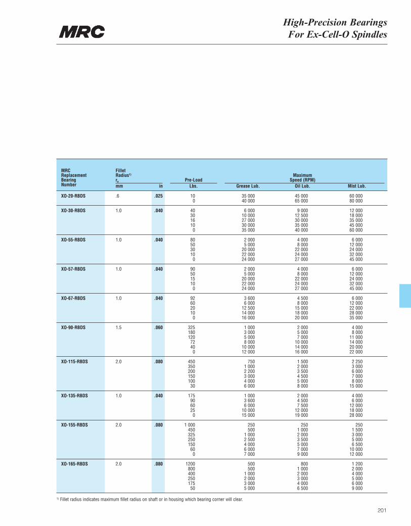
High-Precision Bearings For Ex-Cell-O Spindles
201
MRCReplacementBearingNumber
ra
mm inPre-Load
Lbs. Grease Lub.
MaximumSpeed (RPM)
Oil Lub. Mist Lub.
Fillet Radius1)
XO-20-RBDS .6 .025 10 35 000 45 000 60 0000 40 000 65 000 80 000
XO-30-RBDS 1.0 .040 40 6 000 9 000 12 00030 10 000 12 500 18 00016 27 000 30 000 35 00010 30 000 35 000 45 0000 35 000 40 000 60 000
XO-55-RBDS 1.0 .040 80 2 000 4 000 6 00050 5 000 8 000 12 00030 20 000 22 000 24 00010 22 000 24 000 32 0000 24 000 27 000 45 000
XO-57-RBDS 1.0 .040 90 2 000 4 000 6 00050 5 000 8 000 12 00015 20 000 22 000 24 00010 22 000 24 000 32 0000 24 000 27 000 45 000
XO-67-RBDS 1.0 .040 92 3 600 4 500 6 00060 6 000 8 000 12 00020 12 500 15 000 22 00010 14 000 18 000 28 0000 16 000 20 000 35 000
XO-90-RBDS 1.5 .060 325 1 000 2 000 4 000180 3 000 5 000 8 000120 5 000 7 000 11 000
72 8 000 10 000 14 00040 10 000 14 000 20 0000 12 000 16 000 22 000
XO-115-RBDS 2.0 .080 450 750 1 500 2 250350 1 000 2 000 3 000200 2 200 3 500 6 000150 3 000 4 500 7 000100 4 000 5 000 8 00030 6 000 8 000 15 000
XO-135-RBDS 1.0 .040 175 1 000 2 000 4 00090 3 600 4 500 6 00060 6 000 7 500 12 00025 10 000 12 000 18 000
0 15 000 19 000 28 000
XO-155-RBDS 2.0 .080 1 000 250 250 250 450 500 1 000 1 500325 1 000 2 000 3 000250 2 500 3 500 5 000150 4 000 5 000 6 500
60 6 000 7 000 10 0000 7 000 9 000 12 000
XO-165-RBDS 2.0 .080 1200 500 800 1 200800 500 1 000 2 000400 1 000 2 000 4 000250 2 000 3 000 5 000175 3 000 4 000 6 00050 5 000 6 500 9 000
1) Fillet radius indicates maximum fillet radius on shaft or in housing which bearing corner will clear.

202
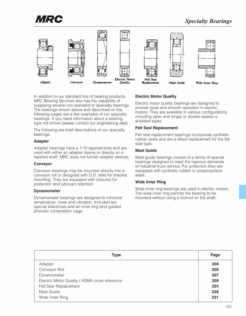
Specialty Bearings
203
Type Page
Adapter 204Conveyor Roll 205Dynamometer 207Electric Motor Quality / ASMA cross reference 209Felt Seal Replacement 224Mast Guide 228Wide Inner Ring 231
In addition to our standard line of bearing products,MRC Bearing Services also has the capability ofsupplying several non standard or specialty bearings.The bearings shown above and described on thefollowing pages are a few examples of our specialtybearings. If you need information about a bearingtype not shown please contact our engineering dept.
The following are brief descriptions of our specialtybearings.
Adapter
Adapter bearings have a 1:12 tapered bore and areused with either an adapter sleeve or directly on atapered shaft. MRC does not furnish adapter sleeves.
Conveyor
Conveyor bearings may be mounted directly into aconveyor roll or designed with O.D. slots for bracketmounting. They are equipped with closures forprotection and lubricant retention.
Dynamometer
Dynamometer bearings are designed to minimizetemperature, noise and vibration. Included arespecial tolerances and an inner ring land guidedphenolic composition cage.
Electric Motor Quality
Electric motor quality bearings are designed toprovide quiet and smooth operation in electricmotors. They are available in various configurationsincluding open and single or double sealed orshielded types.
Felt Seal Replacement
Felt seal replacement bearings incorporate syntheticrubber seals and are a direct replacement for the feltseal type.
Mast Guide
Mast guide bearings consist of a family of specialbearings designed to meet the rigorous demands of industrial truck service. For protection they areequipped with synthetic rubber or polypropyleneseals.
Wide Inner Ring
Wide inner ring bearings are used in electric motors.The wide inner ring permits the bearing to bemounted without using a locknut on the shaft.
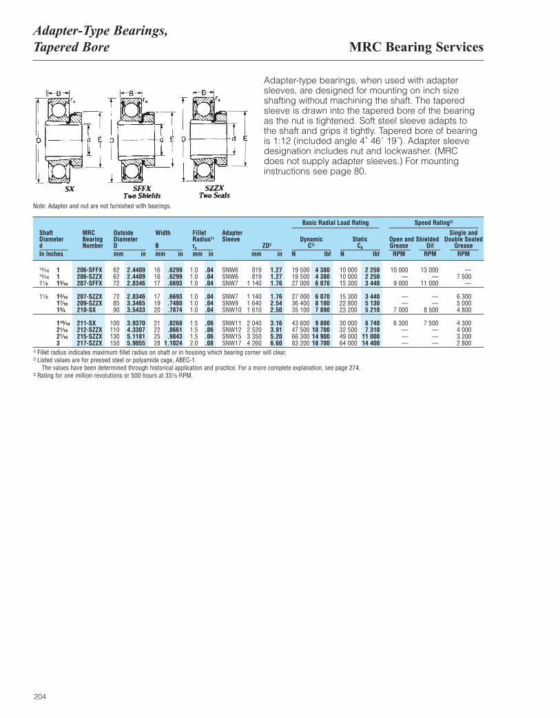
MRC Bearing ServicesAdapter-Type Bearings, Tapered Bore
204
Adapter-type bearings, when used with adaptersleeves, are designed for mounting on inch sizeshafting without machining the shaft. The taperedsleeve is drawn into the tapered bore of the bearing as the nut is tightened. Soft steel sleeve adapts to the shaft and grips it tightly. Tapered bore of bearing is 1:12 (included angle 4˚ 46´ 19˝). Adapter sleevedesignation includes nut and lockwasher. (MRC does not supply adapter sleeves.) For mountinginstructions see page 80.
MRCBearingNumber
OutsideDiameterDmm in
ShaftDiameterdIn Inches
Width
Bmm in
ra
mm inZD2
mm in
DynamicC3)
N lbf
Basic Radial Load Rating Speed Rating2)
StaticC0
N lbf
Single andOpen and Shielded Double SealedGrease Oil GreaseRPM RPM RPM
Fillet Radius1)
AdapterSleeve
¹⁵|₁₆ 1 206-SFFX 62 2.4409 16 .6299 1.0 .04 SNW6 819 1.27 19 500 4 380 10 000 2 250 10 000 13 000 —¹⁵|₁₆ 1 206-SZZX 62 2.4409 16 .6299 1.0 .04 SNW6 819 1.27 19 500 4 380 10 000 2 250 — — 7 5001¹|₈ 1³|₁₆ 207-SFFX 72 2.8346 17 .6693 1.0 .04 SNW7 1 140 1.76 27 000 6 070 15 300 3 440 9 000 11 000 —
1¹|₈ 1³|₁₆ 207-SZZX 72 2.8346 17 .6693 1.0 .04 SNW7 1 140 1.76 27 000 6 070 15 300 3 440 — — 6 3001⁷|₁₆ 209-SZZX 85 3.3465 19 .7480 1.0 .04 SNW9 1 640 2.54 36 400 8 180 22 800 5 130 — — 5 0001³|₄ 210-SX 90 3.5433 20 .7874 1.0 .04 SNW10 1 610 2.50 35 100 7 890 23 200 5 210 7 000 8 500 4 800
1¹⁵|₁₆ 211-SX 100 3.9370 21 .8268 1.5 .06 SNW11 2 040 3.16 43 600 9 800 30 000 6 740 6 300 7 500 4 3002¹|₁₆ 212-SZZX 110 4.3307 22 .8661 1.5 .06 SNW12 2 520 3.91 47 500 10 700 32 500 7 310 — — 4 0002⁷|₁₆ 215-SZZX 130 5.1181 25 .9843 1.5 .06 SNW15 3 350 5.20 66 300 14 900 49 000 11 000 — — 3 2003 217-SZZX 150 5.9055 28 1.1024 2.0 .08 SNW17 4 260 6.60 83 200 18 700 64 000 14 400 — — 2 800
Note: Adapter and nut are not furnished with bearings.
1) Fillet radius indicates maximum fillet radius on shaft or in housing which bearing corner will clear.2) Listed values are for pressed steel or polyamide cage, ABEC-1.
The values have been determined through historical application and practice. For a more complete explanation, see page 274.3) Rating for one million revolutions or 500 hours at 33¹|₃ RPM.
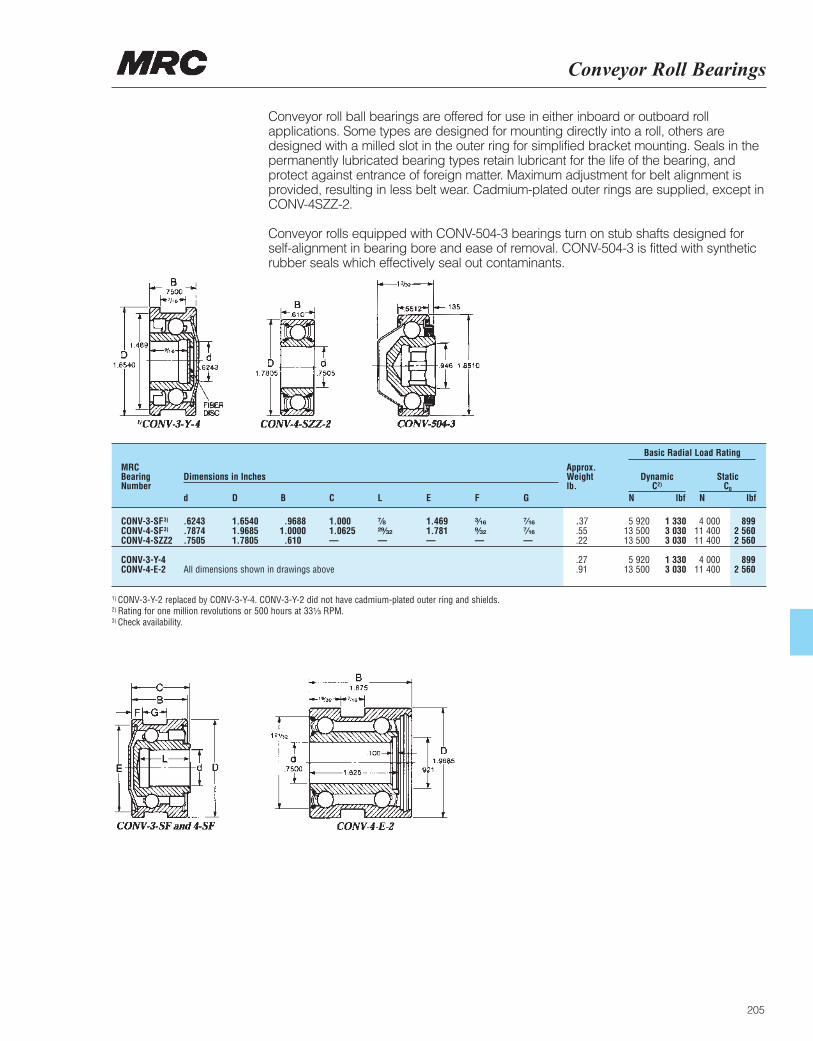
Conveyor Roll Bearings
205
MRCBearingNumber
Approx.Weightlb.
Dimensions in Inches DynamicC2)
N lbfd D B C L E F G
Basic Radial Load Rating
StaticC0
N lbf
CONV-3-SF3) .6243 1.6540 .9688 1.000 ⁷|₈ 1.469 ³|₁₆ ⁷|₁₆ .37 5 920 1 330 4 000 899CONV-4-SF3) .7874 1.9685 1.0000 1.0625 ²⁹|₃₂ 1.781 ⁹|₃₂ ⁷|₁₆ .55 13 500 3 030 11 400 2 560CONV-4-SZZ2 .7505 1.7805 .610 — — — — — .22 13 500 3 030 11 400 2 560
CONV-3-Y-4 .27 5 920 1 330 4 000 899CONV-4-E-2 All dimensions shown in drawings above .91 13 500 3 030 11 400 2 560
1) CONV-3-Y-2 replaced by CONV-3-Y-4. CONV-3-Y-2 did not have cadmium-plated outer ring and shields.2) Rating for one million revolutions or 500 hours at 33¹|₃ RPM.3) Check availability.
Conveyor roll ball bearings are offered for use in either inboard or outboard rollapplications. Some types are designed for mounting directly into a roll, others aredesigned with a milled slot in the outer ring for simplified bracket mounting. Seals in thepermanently lubricated bearing types retain lubricant for the life of the bearing, andprotect against entrance of foreign matter. Maximum adjustment for belt alignment isprovided, resulting in less belt wear. Cadmium-plated outer rings are supplied, except inCONV-4SZZ-2.
Conveyor rolls equipped with CONV-504-3 bearings turn on stub shafts designed forself-alignment in bearing bore and ease of removal. CONV-504-3 is fitted with syntheticrubber seals which effectively seal out contaminants.

206
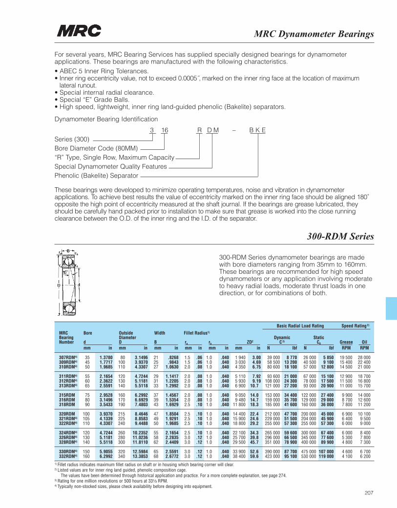
MRC Dynamometer Bearings
207
For several years, MRC Bearing Services has supplied specially designed bearings for dynamometerapplications. These bearings are manufactured with the following characteristics.• ABEC 5 Inner Ring Tolerances. • Inner ring eccentricity value, not to exceed 0.0005˝, marked on the inner ring face at the location of maximum
lateral runout. • Special internal radial clearance. • Special “E” Grade Balls. • High speed, lightweight, inner ring land-guided phenolic (Bakelite) separators.
Dynamometer Bearing Identification
3 16 R D M – B K ESeries (300)Bore Diameter Code (80MM)“R” Type, Single Row, Maximum CapacitySpecial Dynamometer Quality FeaturesPhenolic (Bakelite) Separator
These bearings were developed to minimize operating temperatures, noise and vibration in dynamometerapplications. To achieve best results the value of eccentricity marked on the inner ring face should be aligned 180˚opposite the high point of eccentricity measured at the shaft journal. If the bearings are grease lubricated, theyshould be carefully hand packed prior to installation to make sure that grease is worked into the close runningclearance between the O.D. of the inner ring and the I.D. of the separator.
300-RDM Series
300-RDM Series dynamometer bearings are made with bore diameters ranging from 35mm to 160mm.These bearings are recommended for high speeddynamometers or any application involving moderate to heavy radial loads, moderate thrust loads in onedirection, or for combinations of both.
MRCBearingNumber
Bore
dmm in
OutsideDiameterDmm in
Width
Bmm in
ra
mm inrb
mm inZD2
mm in
DynamicC3)
N lbf
Basic Radial Load Rating Speed Rating2)
StaticC0
N lbfGrease OilRPM RPM
Fillet Radius1)
307RDM4) 35 1.3780 80 3.1496 21 .8268 1.5 .06 1.0 .040 1 940 3.00 39 000 8 770 26 000 5 850 19 500 28 000309RDM4) 45 1.7717 100 3.9370 25 .9843 1.5 .06 1.0 .040 3 030 4.69 58 500 13 200 40 500 9 100 15 400 22 400310RDM4) 50 1.9685 110 4.3307 27 1.0630 2.0 .08 1.0 .040 4 350 6.75 80 600 18 100 57 000 12 800 14 500 21 000
311RDM4) 55 2.1654 120 4.7244 29 1.1417 2.0 .08 1.0 .040 5 110 7.92 93 600 21 000 67 000 15 100 12 900 18 700312RDM4) 60 2.3622 130 5.1181 31 1.2205 2.0 .08 1.0 .040 5 930 9.19 108 000 24 300 78 000 17 500 11 500 16 800313RDM4) 65 2.5591 140 5.5118 33 1.2992 2.0 .08 1.0 .040 6 900 10.7 121 000 27 200 93 000 20 900 11 000 15 700
315RDM 75 2.9528 160 6.2992 37 1.4567 2.0 .08 1.0 .040 9 050 14.0 153 000 34 400 122 000 27 400 9 900 14 000316RDM 80 3.1496 170 6.6929 39 1.5354 2.0 .08 1.0 .040 9 480 14.7 159 000 35 700 129 000 29 000 8 700 12 600318RDM 90 3.5433 190 7.4803 43 1.6929 2.5 .10 1.0 .040 11 800 18.3 185 000 41 600 160 000 36 000 7 800 11 200
320RDM 100 3.9370 215 8.4646 47 1.8504 2.5 .10 1.0 .040 14 400 22.4 212 000 47 700 200 000 45 000 6 900 10 100321RDM4) 105 4.1339 225 8.8583 49 1.9291 2.5 .10 1.0 .040 15 900 24.6 229 000 51 500 204 000 45 900 6 400 9 500322RDM4) 110 4.3307 240 9.4488 50 1.9685 2.5 .10 1.0 .040 18 800 29.2 255 000 57 300 255 000 57 300 6 000 9 000
324RDM4) 120 4.7244 260 10.2352 55 2.1654 2.5 .10 1.0 .040 22 100 34.3 265 000 59 600 300 000 67 400 6 000 8 400326RDM4) 130 5.1181 280 11.0236 58 2.2835 3.0 .12 1.0 .040 25 700 39.8 296 000 66 500 345 000 77 600 5 300 7 800328RDM4) 140 5.5118 300 11.8110 62 2.4409 3.0 .12 1.0 .040 29 500 45.7 351 000 78 900 400 000 89 900 4 800 7 300
330RDM4) 150 5.9055 320 12.5984 65 2.5591 3.0 .12 1.0 .040 33 900 52.6 390 000 87 700 475 000 107 000 4 600 6 700332RDM4) 160 6.2992 340 13.3853 68 2.6772 3.0 .12 1.0 .040 38 400 59.6 423 000 95 100 530 000 119 000 4 100 6 200
1) Fillet radius indicates maximum fillet radius on shaft or in housing which bearing corner will clear.2) Listed values are for inner ring land guided, phenolic composition cage.
The values have been determined through historical application and practice. For a more complete explanation, see page 274.3) Rating for one million revolutions or 500 hours at 33¹|₃ RPM.4) Typically non-stocked sizes, please check availability before designing into equipment.

208
ABMA Cross Reference
209
MRC Bearing Services manufactures its deep grooveball bearings to meet the high demands for quiet andsmooth running bearings for the electric motor market.MRC boxes are clearly labeled with the letters EMQ to identify them as being Electric Motor Quality. Many electric motors specification plates identify thebearings to be used in the motor with an AmericanBearing Manufacturers Association (ABMA) number.For your convenience, an ABMA identification codechart is provided along with a list of popular ABMAnumbers and their corresponding MRC part number.MRC EMQ bearings are packaged with a premiumquality polyurea grease having an NLGI #2 rating.
Bearing Data Page
ABMA Identification Code ChartABMA cross reference to MRC part numbers
210212
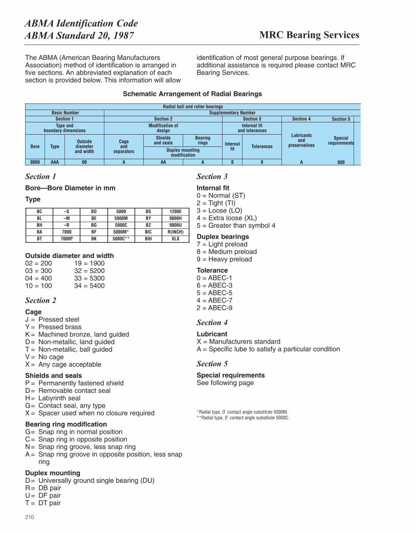
210
MRC Bearing ServicesABMA Identification CodeABMA Standard 20, 1987
The ABMA (American Bearing ManufacturersAssociation) method of identification is arranged in five sections. An abbreviated explanation of eachsection is provided below. This information will allow
identification of most general purpose bearings. Ifadditional assistance is required please contact MRCBearing Services.
Schematic Arrangement of Radial Bearings
Radial ball and roller bearingsBasic Number
Section 1 Type and
boundary dimensions
Bore
0000 AAA 00 A AA A 0 0 A 000
TypeOutside
diameter and width
Cage and
separators
Shields and seals
Duplex mounting modification
Bearing rings Internal
fit Tolerances
Section 2 Modification of
design
Section 3 Internal fit
and tolerances
Section 4
Lubricants and
preservativesSpecial
requirements
Section 5 Supplementary Number
Section 1 Bore—Bore Diameter in mm
Type
Outside diameter and width 02 = 200 19 = 1900 03 = 300 32 = 5200 04 = 400 33 = 5300 10 = 100 34 = 5400
Section 2 Cage J = Pressed steel Y = Pressed brass K = Machined bronze, land guided D= Non-metallic, land guided T = Non-metallic, ball guided V = No cage X = Any cage acceptable
Shields and seals P = Permanently fastened shield D= Removable contact seal H= Labyrinth seal G= Contact seal, any type X = Spacer used when no closure required
Bearing ring modification G= Snap ring in normal position C= Snap ring in opposite position N= Snap ring groove, less snap ring A = Snap ring groove in opposite position, less snap
ring
Duplex mounting D= Universally ground single bearing (DU) R= DB pair U= DF pair T = DT pair
Section 3 Internal fit 0 = Normal (ST) 2 = Tight (TI) 3 = Loose (LO) 4 = Extra loose (XL) 5 = Greater than symbol 4
Duplex bearings 7 = Light preload 8 = Medium preload 9 = Heavy preload
Tolerance 0 = ABEC-1 6 = ABEC-3 5 = ABEC-5 4 = ABEC-7 2 = ABEC-9
Section 4 Lubricant X = Manufacturers standard A = Specific lube to satisfy a particular condition
Section 5 Special requirements See following page
*Radial type, 0˚ contact angle substitute 5000M. **Radial type, 0˚ contact angle substitute 5000C.
BC –S BD 5000 BS 1200EBL –M BE 5000M BY 9000HBH –R BG 5000C BZ 9000UBA 7000 BF 5000M* BIC R(INCH)BT 7000P BK 5000C** BIH XLS
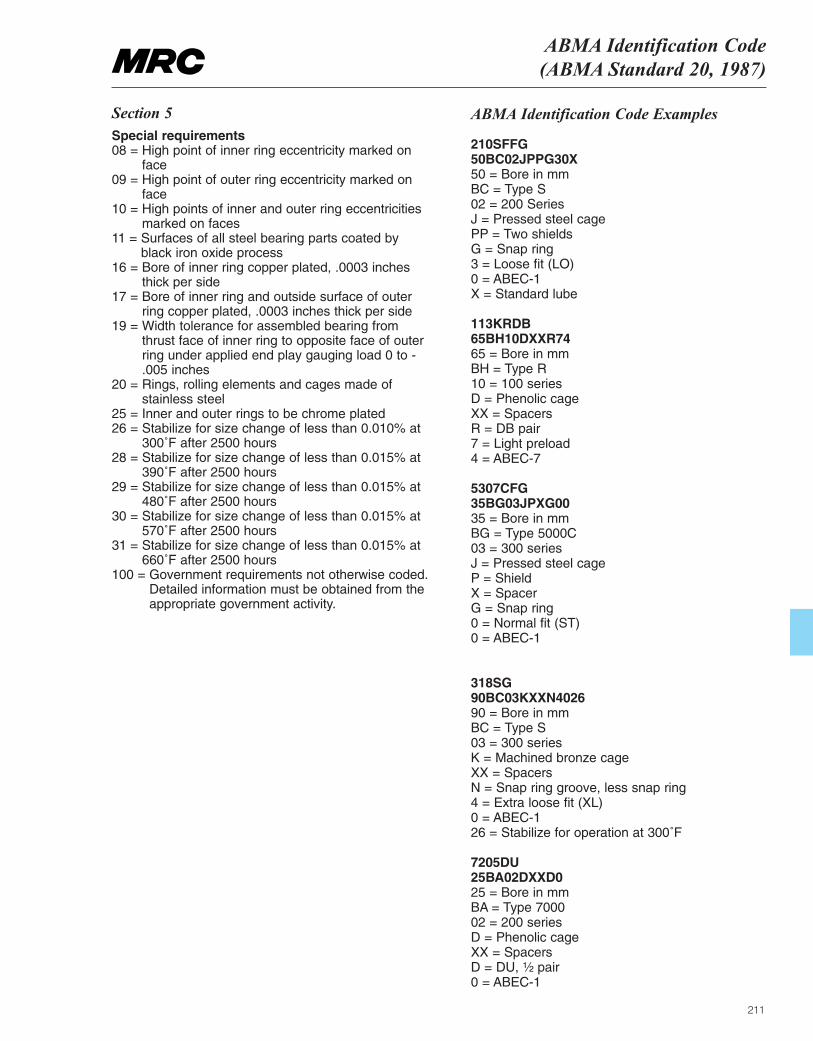
211
ABMA Identification Code(ABMA Standard 20, 1987)
Section 5 Special requirements08 = High point of inner ring eccentricity marked on
face09 = High point of outer ring eccentricity marked on
face 10 = High points of inner and outer ring eccentricities
marked on faces 11 = Surfaces of all steel bearing parts coated by
black iron oxide process 16 = Bore of inner ring copper plated, .0003 inches
thick per side 17 = Bore of inner ring and outside surface of outer
ring copper plated, .0003 inches thick per side 19 = Width tolerance for assembled bearing from
thrust face of inner ring to opposite face of outerring under applied end play gauging load 0 to -.005 inches
20 = Rings, rolling elements and cages made ofstainless steel
25 = Inner and outer rings to be chrome plated 26 = Stabilize for size change of less than 0.010% at
300˚F after 2500 hours 28 = Stabilize for size change of less than 0.015% at
390˚F after 2500 hours 29 = Stabilize for size change of less than 0.015% at
480˚F after 2500 hours 30 = Stabilize for size change of less than 0.015% at
570˚F after 2500 hours 31 = Stabilize for size change of less than 0.015% at
660˚F after 2500 hours 100 = Government requirements not otherwise coded.
Detailed information must be obtained from theappropriate government activity.
ABMA Identification Code Examples
210SFFG 50BC02JPPG30X 50 = Bore in mm BC = Type S 02 = 200 Series J = Pressed steel cage PP = Two shields G = Snap ring 3 = Loose fit (LO) 0 = ABEC-1 X = Standard lube
113KRDB 65BH10DXXR74 65 = Bore in mm BH = Type R 10 = 100 series D = Phenolic cage XX = Spacers R = DB pair 7 = Light preload 4 = ABEC-7
5307CFG 35BG03JPXG00 35 = Bore in mm BG = Type 5000C 03 = 300 series J = Pressed steel cage P = Shield X = Spacer G = Snap ring 0 = Normal fit (ST) 0 = ABEC-1
318SG 90BC03KXXN4026 90 = Bore in mm BC = Type S 03 = 300 series K = Machined bronze cage XX = Spacers N = Snap ring groove, less snap ring 4 = Extra loose fit (XL) 0 = ABEC-1 26 = Stabilize for operation at 300˚F
7205DU 25BA02DXXD0 25 = Bore in mm BA = Type 7000 02 = 200 series D = Phenolic cage XX = Spacers D = DU, ¹|₂ pair 0 = ABEC-1

MRC Bearing ServicesABMA Numbers and MRC Equivalent
212
ABMA Number BearingSize
8BIC00X30 R8
8BIC10XD30 R8Z
8BIC10XDD30 R8ZZ
8BIC10XP30 R8F
8BIC10XPP30 R8FF
10BIC10X30 R10
10BIC10XD30 R10Z
10BIC10XDD30 R10ZZ
10BIC10XP30 R10F
10BIC10XPP30 R10FF
12BIC10X30 R12
12BIC10XD30 R12Z
12BIC10XDD30 R12ZZ
12BIC10XP30 R12F
12BIC10XPP30 R12FF
14BIC10X30 R14
14BIC10XD30 R14Z
14BIC10XDD30 R14ZZ
14BIC10XP30 R14F
14BIC10XPP30 R14FF
15BC02X30 202S
15BC02XD30 202SZ
15BC02XDD30 202SZZ
15BC02XDDG30 202SZZG
15BC02XDXG30 202SZG
15BC02XP30 202SF
15BC02XPP30 202SFF
15BC02XPPG30 202SFFG
15BC02XPXG30 202SFG
15BC02XXXG30 202SG
15BC03X30 302S
15BC03XD30 302SZ
15BC03XDD30 302SZZ
15BC03XDDG30 302SZZG
15BC03XDXG30 302SZG
15BC03XP30 302SF
15BC03XPP30 302SFF
15BC03XPPG30 302SFFG
15BC03XPXG30 302SFG
15BC03XXXG30 302SG
15BC10X30 102KS
15BC10XD30 102KSZ
ABMA Number BearingSize
15BC10XDD30 102KSZZ
15BC10XDDG30 102KSZZG
15BC10XDXG30 102KSZG
15BC10XPP30 102KSFF
15BC10XP30 102KSF
15BC10XPPG30 102KSFFG
15BC10XPXG30 102KSFG
15BC10XXXG30 102KSG
15BC19X30 1902S
15BC19XD30 1902SZ
15BC19XDD30 1902SZZ
15BC19XP30 1902SF
15BC19XPP30 1902SFF
15BC32XDD30 202SZZC
15BC32XDDG30 202SZZCG
15BC32XPP30 202SFFC
15BC32XPPG30 202SFFCG
15BC33XDD30 302SZZC
15BC33XDDG30 302SZZCG
15BC33XPP30 302SFFC
15BC33XPPG30 302SFFCG
16BIC10X30 R16
16BIC10XD30 R16Z
16BIC10XDD30 R16ZZ
16BIC10XP30 R16F
16BIC10XPP30 R16FF
17BC02X30 203S
17BC02XD30 203SZ
17BC02XDD30 203SZZ
17BC02XDDG30 203SZZG
17BC02XDXG30 203SZG
17BC02XP30 203SF
17BC02XPP30 203SFF
17BC02XPXG30 203SFG
17BC02XPPG30 203SFFG
17BC02XXXG30 203SG
17BC03X30 303S
17BC03XD30 303SZ
17BC03XDD30 303SZZ
17BC03XDDG30 303SZZG
17BC03XDXG30 303SZG
17BC03XP30 303SF
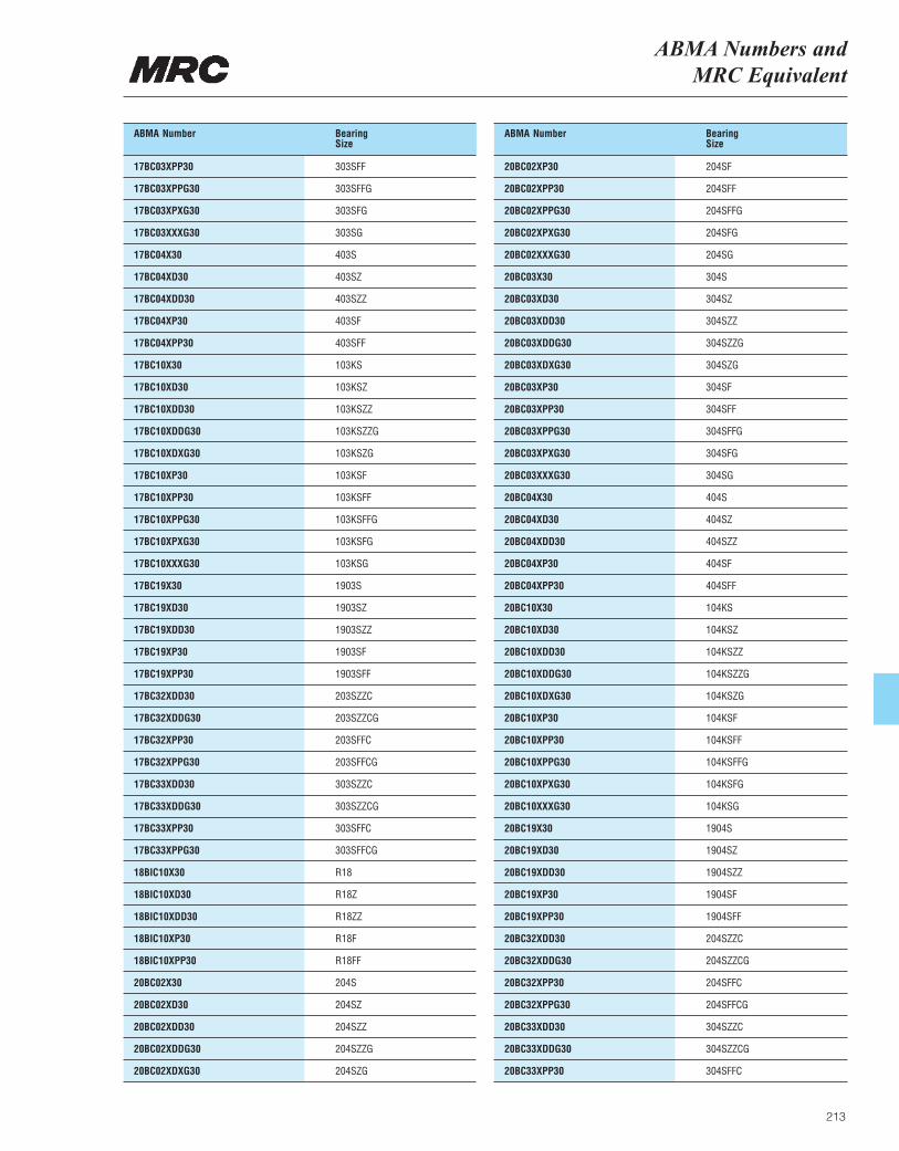
ABMA Numbers and MRC Equivalent
213
ABMA Number BearingSize
17BC03XPP30 303SFF
17BC03XPPG30 303SFFG
17BC03XPXG30 303SFG
17BC03XXXG30 303SG
17BC04X30 403S
17BC04XD30 403SZ
17BC04XDD30 403SZZ
17BC04XP30 403SF
17BC04XPP30 403SFF
17BC10X30 103KS
17BC10XD30 103KSZ
17BC10XDD30 103KSZZ
17BC10XDDG30 103KSZZG
17BC10XDXG30 103KSZG
17BC10XP30 103KSF
17BC10XPP30 103KSFF
17BC10XPPG30 103KSFFG
17BC10XPXG30 103KSFG
17BC10XXXG30 103KSG
17BC19X30 1903S
17BC19XD30 1903SZ
17BC19XDD30 1903SZZ
17BC19XP30 1903SF
17BC19XPP30 1903SFF
17BC32XDD30 203SZZC
17BC32XDDG30 203SZZCG
17BC32XPP30 203SFFC
17BC32XPPG30 203SFFCG
17BC33XDD30 303SZZC
17BC33XDDG30 303SZZCG
17BC33XPP30 303SFFC
17BC33XPPG30 303SFFCG
18BIC10X30 R18
18BIC10XD30 R18Z
18BIC10XDD30 R18ZZ
18BIC10XP30 R18F
18BIC10XPP30 R18FF
20BC02X30 204S
20BC02XD30 204SZ
20BC02XDD30 204SZZ
20BC02XDDG30 204SZZG
20BC02XDXG30 204SZG
ABMA Number BearingSize
20BC02XP30 204SF
20BC02XPP30 204SFF
20BC02XPPG30 204SFFG
20BC02XPXG30 204SFG
20BC02XXXG30 204SG
20BC03X30 304S
20BC03XD30 304SZ
20BC03XDD30 304SZZ
20BC03XDDG30 304SZZG
20BC03XDXG30 304SZG
20BC03XP30 304SF
20BC03XPP30 304SFF
20BC03XPPG30 304SFFG
20BC03XPXG30 304SFG
20BC03XXXG30 304SG
20BC04X30 404S
20BC04XD30 404SZ
20BC04XDD30 404SZZ
20BC04XP30 404SF
20BC04XPP30 404SFF
20BC10X30 104KS
20BC10XD30 104KSZ
20BC10XDD30 104KSZZ
20BC10XDDG30 104KSZZG
20BC10XDXG30 104KSZG
20BC10XP30 104KSF
20BC10XPP30 104KSFF
20BC10XPPG30 104KSFFG
20BC10XPXG30 104KSFG
20BC10XXXG30 104KSG
20BC19X30 1904S
20BC19XD30 1904SZ
20BC19XDD30 1904SZZ
20BC19XP30 1904SF
20BC19XPP30 1904SFF
20BC32XDD30 204SZZC
20BC32XDDG30 204SZZCG
20BC32XPP30 204SFFC
20BC32XPPG30 204SFFCG
20BC33XDD30 304SZZC
20BC33XDDG30 304SZZCG
20BC33XPP30 304SFFC
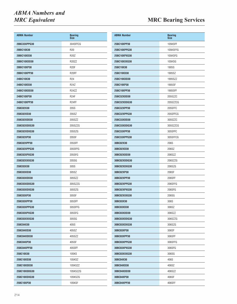
MRC Bearing ServicesABMA Numbers and MRC Equivalent
214
ABMA Number BearingSize
20BC33XPPG30 304SFFCG
20BIC10X30 R20
20BIC10XD30 R20Z
20BIC10XDD30 R20ZZ
20BIC10XP30 R20F
20BIC10XPP30 R20FF
24BIC10X30 R24
24BIC10XD30 R24Z
24BIC10XDD30 R24ZZ
24BIC10XP30 R24F
24BIC10XPP30 R24FF
25BC02X30 205S
25BC02XD30 205SZ
25BC02XDD30 205SZZ
25BC02XDDG30 205SZZG
25BC02XDXG30 205SZG
25BC02XP30 205SF
25BC02XPP30 205SFF
25BC02XPPG30 205SFFG
25BC02XPXG30 205SFG
25BC02XXXG30 205SG
25BC03X30 305S
25BC03XD30 305SZ
25BC03XDD30 305SZZ
25BC03XDDG30 305SZZG
25BC03XDXG30 305SZG
25BC03XP30 305SF
25BC03XPP30 305SFF
25BC03XPPG30 305SFFG
25BC03XPXG30 305SFG
25BC03XXXG30 305SG
25BC04X30 405S
25BC04XD30 405SZ
25BC04XDD30 405SZZ
25BC04XP30 405SF
25BC04XPP30 405SFF
25BC10X30 105KS
25BC10XD30 105KSZ
25BC10XDD30 105KSZZ
25BC10XDDG30 105KSZZG
25BC10XDXG30 105KSZG
25BC10XP30 105KSF
ABMA Number BearingSize
25BC10XPP30 105KSFF
25BC10XPPG30 105KSFFG
25BC10XPXG30 105KSFG
25BC10XXXG30 105KSG
25BC19X30 1905S
25BC19XD30 1905SZ
25BC19XDD30 1905SZZ
25BC19XP30 1905SF
25BC19XPP30 1905SFF
25BC32XDD30 205SZZC
25BC32XDDG30 205SZZCG
25BC32XPP30 205SFFC
25BC32XPPG30 205SFFCG
25BC33XDD30 305SZZC
25BC33XDDG30 305SZZCG
25BC33XPP30 305SFFC
25BC33XPPG30 305SFFCG
30BC02X30 206S
30BC02XD30 206SZ
30BC02XDD30 206SZZ
30BC02XDDG30 206SZZG
30BC02XDXG30 206SZG
30BC02XP30 206SF
30BC02XPP30 206SFF
30BC02XPPG30 206SFFG
30BC02XPXG30 206SFG
30BC02XXXG30 206SG
30BC03X30 306S
30BC03XD30 306SZ
30BC03XDD30 306SZZ
30BC03XDDG30 306SZZG
30BC03XDXG30 306SZG
30BC03XP30 306SF
30BC03XPP30 306SFF
30BC03XPPG30 306SFFG
30BC03XPXG30 306SFG
30BC03XXXG30 306SG
30BC04X30 406S
30BC04XD30 406SZ
30BC04XDD30 406SZZ
30BC04XP30 406SF
30BC04XPP30 406SFF
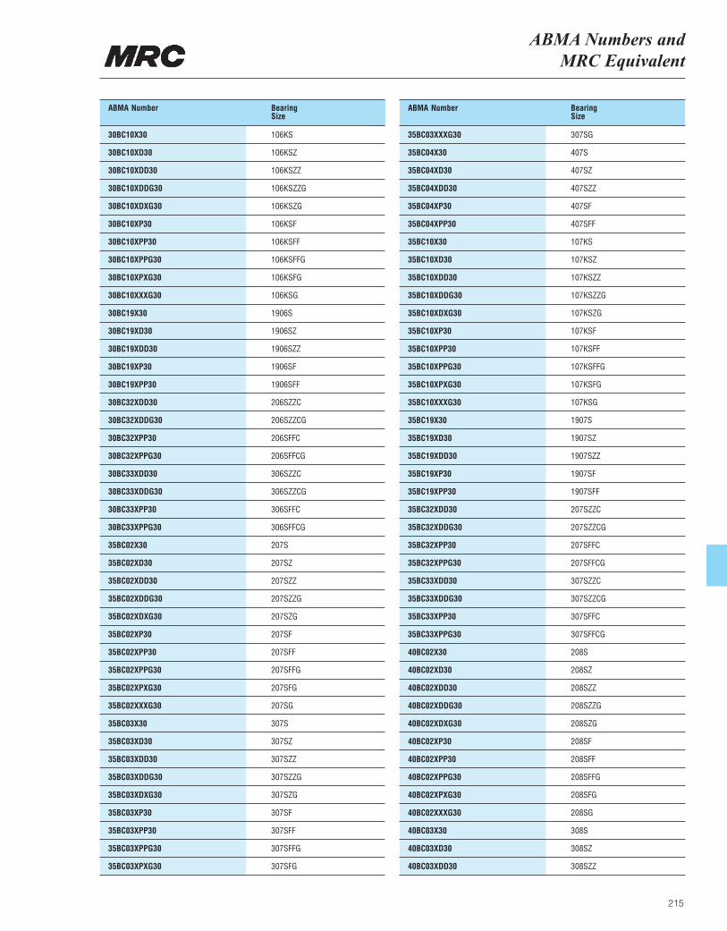
ABMA Numbers and MRC Equivalent
215
ABMA Number BearingSize
30BC10X30 106KS
30BC10XD30 106KSZ
30BC10XDD30 106KSZZ
30BC10XDDG30 106KSZZG
30BC10XDXG30 106KSZG
30BC10XP30 106KSF
30BC10XPP30 106KSFF
30BC10XPPG30 106KSFFG
30BC10XPXG30 106KSFG
30BC10XXXG30 106KSG
30BC19X30 1906S
30BC19XD30 1906SZ
30BC19XDD30 1906SZZ
30BC19XP30 1906SF
30BC19XPP30 1906SFF
30BC32XDD30 206SZZC
30BC32XDDG30 206SZZCG
30BC32XPP30 206SFFC
30BC32XPPG30 206SFFCG
30BC33XDD30 306SZZC
30BC33XDDG30 306SZZCG
30BC33XPP30 306SFFC
30BC33XPPG30 306SFFCG
35BC02X30 207S
35BC02XD30 207SZ
35BC02XDD30 207SZZ
35BC02XDDG30 207SZZG
35BC02XDXG30 207SZG
35BC02XP30 207SF
35BC02XPP30 207SFF
35BC02XPPG30 207SFFG
35BC02XPXG30 207SFG
35BC02XXXG30 207SG
35BC03X30 307S
35BC03XD30 307SZ
35BC03XDD30 307SZZ
35BC03XDDG30 307SZZG
35BC03XDXG30 307SZG
35BC03XP30 307SF
35BC03XPP30 307SFF
35BC03XPPG30 307SFFG
35BC03XPXG30 307SFG
ABMA Number BearingSize
35BC03XXXG30 307SG
35BC04X30 407S
35BC04XD30 407SZ
35BC04XDD30 407SZZ
35BC04XP30 407SF
35BC04XPP30 407SFF
35BC10X30 107KS
35BC10XD30 107KSZ
35BC10XDD30 107KSZZ
35BC10XDDG30 107KSZZG
35BC10XDXG30 107KSZG
35BC10XP30 107KSF
35BC10XPP30 107KSFF
35BC10XPPG30 107KSFFG
35BC10XPXG30 107KSFG
35BC10XXXG30 107KSG
35BC19X30 1907S
35BC19XD30 1907SZ
35BC19XDD30 1907SZZ
35BC19XP30 1907SF
35BC19XPP30 1907SFF
35BC32XDD30 207SZZC
35BC32XDDG30 207SZZCG
35BC32XPP30 207SFFC
35BC32XPPG30 207SFFCG
35BC33XDD30 307SZZC
35BC33XDDG30 307SZZCG
35BC33XPP30 307SFFC
35BC33XPPG30 307SFFCG
40BC02X30 208S
40BC02XD30 208SZ
40BC02XDD30 208SZZ
40BC02XDDG30 208SZZG
40BC02XDXG30 208SZG
40BC02XP30 208SF
40BC02XPP30 208SFF
40BC02XPPG30 208SFFG
40BC02XPXG30 208SFG
40BC02XXXG30 208SG
40BC03X30 308S
40BC03XD30 308SZ
40BC03XDD30 308SZZ
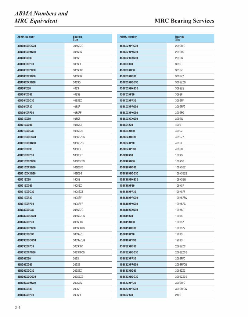
MRC Bearing ServicesABMA Numbers and MRC Equivalent
216
ABMA Number BearingSize
40BC03XDDG30 308SZZG
40BC03XDXG30 308SZG
40BC03XP30 308SF
40BC03XPP30 308SFF
40BC03XPPG30 308SFFG
40BC03XPXG30 308SFG
40BC03XXXG30 308SG
40BC04X30 408S
40BC04XD30 408SZ
40BC04XDD30 408SZZ
40BC04XP30 408SF
40BC04XPP30 408SFF
40BC10X30 108KS
40BC10XD30 108KSZ
40BC10XDD30 108KSZZ
40BC10XDDG30 108KSZZG
40BC10XDXG30 108KSZG
40BC10XP30 108KSF
40BC10XPP30 108KSFF
40BC10XPPG30 108KSFFG
40BC10XPXG30 108KSFG
40BC10XXXG30 108KSG
40BC19X30 1908S
40BC19XD30 1908SZ
40BC19XDD30 1908SZZ
40BC19XP30 1908SF
40BC19XPP30 1908SFF
40BC32XDD30 208SZZC
40BC32XDDG30 208SZZCG
40BC32XPP30 208SFFC
40BC32XPPG30 208SFFCG
40BC33XDD30 308SZZC
40BC33XDDG30 308SZZCG
40BC33XPP30 308SFFC
40BC33XPPG30 308SFFCG
45BC02X30 209S
45BC02XD30 209SZ
45BC02XDD30 209SZZ
45BC02XDDG30 209SZZG
45BC02XDXG30 209SZG
45BC02XP30 209SF
45BC02XPP30 209SFF
ABMA Number BearingSize
45BC02XPPG30 209SFFG
45BC02XPXG30 209SFG
45BC02XXXG30 209SG
45BC03X30 309S
45BC03XD30 309SZ
45BC03XDD30 309SZZ
45BC03XDDG30 309SZZG
45BC03XDXG30 309SZG
45BC03XP30 309SF
45BC03XPP30 309SFF
45BC03XPPG30 309SFFG
45BC03XPXG30 309SFG
45BC03XXXG30 309SG
45BC04X30 409S
45BC04XD30 409SZ
45BC04XDD30 409SZZ
45BC04XP30 409SF
45BC04XPP30 409SFF
45BC10X30 109KS
45BC10XD30 109KSZ
45BC10XDD30 109KSZZ
45BC10XDDG30 109KSZZG
45BC10XDXG30 109KSZG
45BC10XP30 109KSF
45BC10XPP30 109KSFF
45BC10XPPG30 109KSFFG
45BC10XPXG30 109KSFG
45BC10XXXG30 109KSG
45BC19X30 1909S
45BC19XD30 1909SZ
45BC19XDD30 1909SZZ
45BC19XP30 1909SF
45BC19XPP30 1909SFF
45BC32XDD30 209SZZC
45BC32XDDG30 209SZZCG
45BC32XPP30 209SFFC
45BC32XPPG30 209SFFCG
45BC33XDD30 309SZZC
45BC33XDDG30 309SZZCG
45BC33XPP30 309SFFC
45BC33XPPG30 309SFFCG
50BC02X30 210S

ABMA Numbers and MRC Equivalent
217
ABMA Number BearingSize
50BC02XD30 210SZ
50BC02XDD30 210SZZ
50BC02XDDG30 210SZZG
50BC02XDXG30 210SZG
50BC02XP30 210SF
50BC02XPP30 210SFF
50BC02XPPG30 210SFFG
50BC02XPXG30 210SFG
50BC02XXXG30 210SG
50BC03X30 310S
50BC03XD30 310SZ
50BC03XDD30 310SZZ
50BC03XDDG30 310SZZG
50BC03XDXG30 310SZG
50BC03XP30 310SF
50BC03XPP30 310SFF
50BC03XPPG30 310SFFG
50BC03XPXG30 310SFG
50BC03XXXG30 310SG
50BC04X30 410S
50BC04XD30 410SZ
50BC04XDD30 410SZZ
50BC04XP30 410SF
50BC04XPP30 410SFF
50BC10X30 110KS
50BC10XD30 110KSZ
50BC10XDD30 110KSZZ
50BC10XDDG30 110KSZZG
50BC10XDXG30 110KSZG
50BC10XP30 110KSF
50BC10XPP30 110KSFF
50BC10XPPG30 110KSFFG
50BC10XPXG30 110KSFG
50BC10XXXG30 110KSG
50BC19X30 1910S
50BC19XD30 1910SZ
50BC19XDD30 1910SZZ
50BC19XP30 1910SF
50BC19XPP30 1910SFF
50BC32XDD30 210SZZC
50BC32XDDG30 210SZZCG
50BC32XPP30 210SFFC
ABMA Number BearingSize
50BC32XSPPG30 210SFFCG
50BC33XDD30 310SZZC
50BC33XDDG30 310SZZCG
50BC33XPP30 310SFFC
50BC33XPPG30 310SFFCG
55BC02X30 211S
55BC02XD30 211SZ
55BC02XDD30 211SZZ
55BC02XDDG30 211SZZG
55BC02XDXG30 211SZG
55BC02XP30 211SF
55BC02XPP30 211SFF
55BC02XPPG30 211SFFG
55BC02XPXG30 211SFG
55BC02XXXG30 211SG
55BC03X30 311S
55BC03XD30 311SZ
55BC03XDD30 311SZZ
55BC03XDDG30 311SZZG
55BC03XDXG30 311SZG
55BC03PP30 311SFF
55BC03XP30 311SF
55BC03XPPG30 311SFFG
55BC03XPXG30 311SFG
55BC03XXXG30 311SG
55BC04X30 411S
55BC04XD30 411SZ
55BC04XDD30 411SZZ
55BC04XP30 411SF
55BC04XPP30 411SFF
55BC10X30 111KS
55BC10XD30 111KSZ
55BC10XDD30 111KSZZ
55BC10XDDG30 111KSZZG
55BC10XDXG30 111KSZG
55BC10XP30 111KSF
55BC10XPP30 111KSFF
55BC10XPPG30 111KSFFG
55BC10XPXG30 111KSFG
55BC10XXXG30 111KSG
55BC19X30 1911S
55BC19XD30 1911SZ
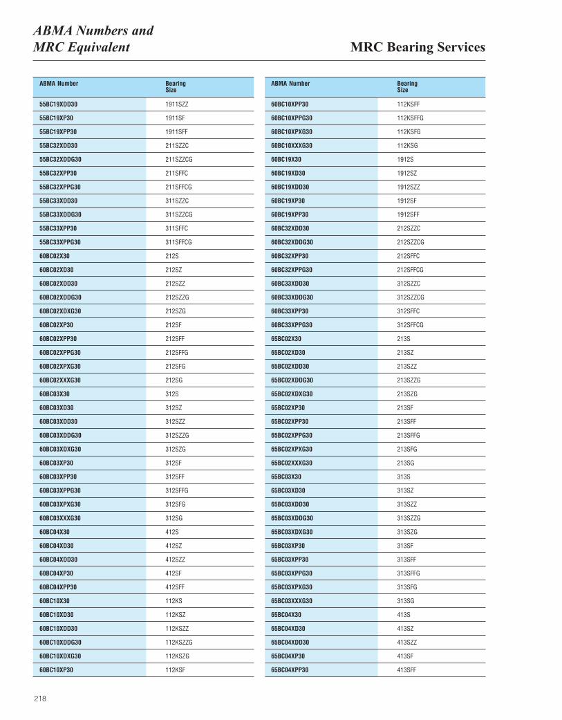
MRC Bearing ServicesABMA Numbers and MRC Equivalent
218
ABMA Number BearingSize
55BC19XDD30 1911SZZ
55BC19XP30 1911SF
55BC19XPP30 1911SFF
55BC32XDD30 211SZZC
55BC32XDDG30 211SZZCG
55BC32XPP30 211SFFC
55BC32XPPG30 211SFFCG
55BC33XDD30 311SZZC
55BC33XDDG30 311SZZCG
55BC33XPP30 311SFFC
55BC33XPPG30 311SFFCG
60BC02X30 212S
60BC02XD30 212SZ
60BC02XDD30 212SZZ
60BC02XDDG30 212SZZG
60BC02XDXG30 212SZG
60BC02XP30 212SF
60BC02XPP30 212SFF
60BC02XPPG30 212SFFG
60BC02XPXG30 212SFG
60BC02XXXG30 212SG
60BC03X30 312S
60BC03XD30 312SZ
60BC03XDD30 312SZZ
60BC03XDDG30 312SZZG
60BC03XDXG30 312SZG
60BC03XP30 312SF
60BC03XPP30 312SFF
60BC03XPPG30 312SFFG
60BC03XPXG30 312SFG
60BC03XXXG30 312SG
60BC04X30 412S
60BC04XD30 412SZ
60BC04XDD30 412SZZ
60BC04XP30 412SF
60BC04XPP30 412SFF
60BC10X30 112KS
60BC10XD30 112KSZ
60BC10XDD30 112KSZZ
60BC10XDDG30 112KSZZG
60BC10XDXG30 112KSZG
60BC10XP30 112KSF
ABMA Number BearingSize
60BC10XPP30 112KSFF
60BC10XPPG30 112KSFFG
60BC10XPXG30 112KSFG
60BC10XXXG30 112KSG
60BC19X30 1912S
60BC19XD30 1912SZ
60BC19XDD30 1912SZZ
60BC19XP30 1912SF
60BC19XPP30 1912SFF
60BC32XDD30 212SZZC
60BC32XDDG30 212SZZCG
60BC32XPP30 212SFFC
60BC32XPPG30 212SFFCG
60BC33XDD30 312SZZC
60BC33XDDG30 312SZZCG
60BC33XPP30 312SFFC
60BC33XPPG30 312SFFCG
65BC02X30 213S
65BC02XD30 213SZ
65BC02XDD30 213SZZ
65BC02XDDG30 213SZZG
65BC02XDXG30 213SZG
65BC02XP30 213SF
65BC02XPP30 213SFF
65BC02XPPG30 213SFFG
65BC02XPXG30 213SFG
65BC02XXXG30 213SG
65BC03X30 313S
65BC03XD30 313SZ
65BC03XDD30 313SZZ
65BC03XDDG30 313SZZG
65BC03XDXG30 313SZG
65BC03XP30 313SF
65BC03XPP30 313SFF
65BC03XPPG30 313SFFG
65BC03XPXG30 313SFG
65BC03XXXG30 313SG
65BC04X30 413S
65BC04XD30 413SZ
65BC04XDD30 413SZZ
65BC04XP30 413SF
65BC04XPP30 413SFF
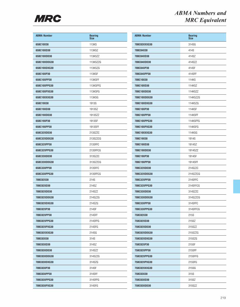
ABMA Numbers and MRC Equivalent
219
ABMA Number BearingSize
65BC10X30 113KS
65BC10XD30 113KSZ
65BC10XDD30 113KSZZ
65BC10XDDG30 113KSZZG
65BC10XDXG30 113KSZG
65BC10XP30 113KSF
65BC10XPP30 113KSFF
65BC10XPPG30 113KSFFG
65BC10XPXG30 113KSFG
65BC10XXXG30 113KSG
65BC19X30 1913S
65BC19XD30 1913SZ
65BC19XDD30 1913SZZ
65BC19XP30 1913SF
65BC19XPP30 1913SFF
65BC32XDD30 213SZZC
65BC32XDDG30 213SZZCG
65BC32XPP30 213SFFC
65BC32XPPG30 213SFFCG
65BC33XDD30 313SZZC
65BC33XDDG30 313SZZCG
65BC33XPP30 313SFFC
65BC33XPPG30 313SFFCG
70BC02X30 214S
70BC02XD30 214SZ
70BC02XDD30 214SZZ
70BC02XDDG30 214SZZG
70BC02XDXG30 214SZG
70BC02XP30 214SF
70BC02XPP30 214SFF
70BC02XPPG30 214SFFG
70BC02XPXG30 214SFG
70BC02XXXG30 214SG
70BC03X30 314S
70BC03XD30 314SZ
70BC03XDD30 314SZZ
70BC03XDDG30 314SZZG
70BC03XDXG30 314SZG
70BC03XP30 314SF
70BC03XPP30 314SFF
70BC03XPPG30 314SFFG
70BC03XPXG30 314SFG
ABMA Number BearingSize
70BC03XXXG30 314SG
70BC04X30 414S
70BC04XD30 414SZ
70BC04XDD30 414SZZ
70BC04XP30 414SF
70BC04XPP30 414SFF
70BC10X30 114KS
70BC10XD30 114KSZ
70BC10XDD30 114KSZZ
70BC10XDDG30 114KSZZG
70BC10XDXG30 114KSZG
70BC10XP30 114KSF
70BC10XPP30 114KSFF
70BC10XPPG30 114KSFFG
70BC10XPXG30 114KSFG
70BC10XXXG30 114KSG
70BC19X30 1914S
70BC19XD30 1914SZ
70BC19XDD30 1914SZZ
70BC19XP30 1914SF
70BC19XPP30 1914SFF
70BC32XDD30 214SZZC
70BC32XDDG30 214SZZCG
70BC32XPP30 214SFFC
70BC32XPPG30 214SFFCG
70BC33XDD30 314SZZC
70BC33XDDG30 314SZZCG
70BC33XPP30 314SFFC
70BC33XPPG30 314SFFCG
75BC02X30 215S
75BC02XD30 215SZ
75BC02XDD30 215SZZ
75BC02XDDG30 215SZZG
75BC02XDXG30 215SZG
75BC02XP30 215SF
75BC02XPP30 215SFF
75BC02XPPG30 215SFFG
75BC02XPXG30 215SFG
75BC02XXXG30 215SG
75BC03X30 315S
75BC03XD30 315SZ
75BC03XDD30 315SZZ
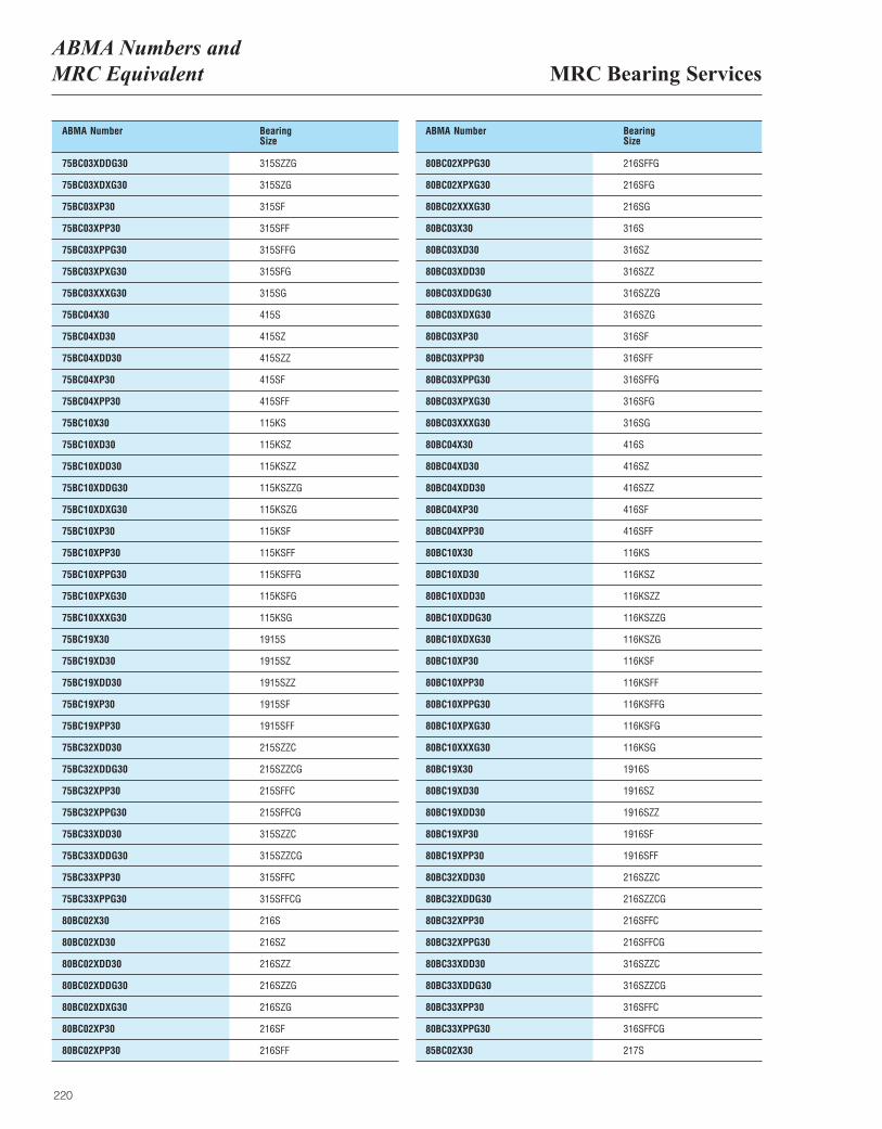
MRC Bearing ServicesABMA Numbers and MRC Equivalent
220
ABMA Number BearingSize
75BC03XDDG30 315SZZG
75BC03XDXG30 315SZG
75BC03XP30 315SF
75BC03XPP30 315SFF
75BC03XPPG30 315SFFG
75BC03XPXG30 315SFG
75BC03XXXG30 315SG
75BC04X30 415S
75BC04XD30 415SZ
75BC04XDD30 415SZZ
75BC04XP30 415SF
75BC04XPP30 415SFF
75BC10X30 115KS
75BC10XD30 115KSZ
75BC10XDD30 115KSZZ
75BC10XDDG30 115KSZZG
75BC10XDXG30 115KSZG
75BC10XP30 115KSF
75BC10XPP30 115KSFF
75BC10XPPG30 115KSFFG
75BC10XPXG30 115KSFG
75BC10XXXG30 115KSG
75BC19X30 1915S
75BC19XD30 1915SZ
75BC19XDD30 1915SZZ
75BC19XP30 1915SF
75BC19XPP30 1915SFF
75BC32XDD30 215SZZC
75BC32XDDG30 215SZZCG
75BC32XPP30 215SFFC
75BC32XPPG30 215SFFCG
75BC33XDD30 315SZZC
75BC33XDDG30 315SZZCG
75BC33XPP30 315SFFC
75BC33XPPG30 315SFFCG
80BC02X30 216S
80BC02XD30 216SZ
80BC02XDD30 216SZZ
80BC02XDDG30 216SZZG
80BC02XDXG30 216SZG
80BC02XP30 216SF
80BC02XPP30 216SFF
ABMA Number BearingSize
80BC02XPPG30 216SFFG
80BC02XPXG30 216SFG
80BC02XXXG30 216SG
80BC03X30 316S
80BC03XD30 316SZ
80BC03XDD30 316SZZ
80BC03XDDG30 316SZZG
80BC03XDXG30 316SZG
80BC03XP30 316SF
80BC03XPP30 316SFF
80BC03XPPG30 316SFFG
80BC03XPXG30 316SFG
80BC03XXXG30 316SG
80BC04X30 416S
80BC04XD30 416SZ
80BC04XDD30 416SZZ
80BC04XP30 416SF
80BC04XPP30 416SFF
80BC10X30 116KS
80BC10XD30 116KSZ
80BC10XDD30 116KSZZ
80BC10XDDG30 116KSZZG
80BC10XDXG30 116KSZG
80BC10XP30 116KSF
80BC10XPP30 116KSFF
80BC10XPPG30 116KSFFG
80BC10XPXG30 116KSFG
80BC10XXXG30 116KSG
80BC19X30 1916S
80BC19XD30 1916SZ
80BC19XDD30 1916SZZ
80BC19XP30 1916SF
80BC19XPP30 1916SFF
80BC32XDD30 216SZZC
80BC32XDDG30 216SZZCG
80BC32XPP30 216SFFC
80BC32XPPG30 216SFFCG
80BC33XDD30 316SZZC
80BC33XDDG30 316SZZCG
80BC33XPP30 316SFFC
80BC33XPPG30 316SFFCG
85BC02X30 217S
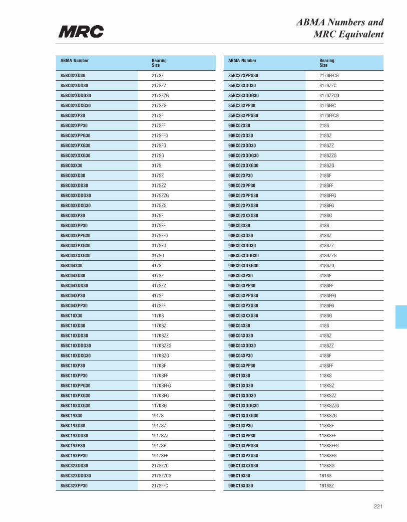
ABMA Numbers and MRC Equivalent
221
ABMA Number BearingSize
85BC02XD30 217SZ
85BC02XDD30 217SZZ
85BC02XDDG30 217SZZG
85BC02XDXG30 217SZG
85BC02XP30 217SF
85BC02XPP30 217SFF
85BC02XPPG30 217SFFG
85BC02XPXG30 217SFG
85BC02XXXG30 217SG
85BC03X30 317S
85BC03XD30 317SZ
85BC03XDD30 317SZZ
85BC03XDDG30 317SZZG
85BC03XDXG30 317SZG
85BC03XP30 317SF
85BC03XPP30 317SFF
85BC03XPPG30 317SFFG
85BC03XPXG30 317SFG
85BC03XXXG30 317SG
85BC04X30 417S
85BC04XD30 417SZ
85BC04XDD30 417SZZ
85BC04XP30 417SF
85BC04XPP30 417SFF
85BC10X30 117KS
85BC10XD30 117KSZ
85BC10XDD30 117KSZZ
85BC10XDDG30 117KSZZG
85BC10XDXG30 117KSZG
85BC10XP30 117KSF
85BC10XPP30 117KSFF
85BC10XPPG30 117KSFFG
85BC10XPXG30 117KSFG
85BC10XXXG30 117KSG
85BC19X30 1917S
85BC19XD30 1917SZ
85BC19XDD30 1917SZZ
85BC19XP30 1917SF
85BC19XPP30 1917SFF
85BC32XDD30 217SZZC
85BC32XDDG30 217SZZCG
85BC32XPP30 217SFFC
ABMA Number BearingSize
85BC32XPPG30 217SFFCG
85BC33XDD30 317SZZC
85BC33XDDG30 317SZZCG
85BC33XPP30 317SFFC
85BC33XPPG30 317SFFCG
90BC02X30 218S
90BC02XD30 218SZ
90BC02XDD30 218SZZ
90BC02XDDG30 218SZZG
90BC02XDXG30 218SZG
90BC02XP30 218SF
90BC02XPP30 218SFF
90BC02XPPG30 218SFFG
90BC02XPXG30 218SFG
90BC02XXXG30 218SG
90BC03X30 318S
90BC03XD30 318SZ
90BC03XDD30 318SZZ
90BC03XDDG30 318SZZG
90BC03XDXG30 318SZG
90BC03XP30 318SF
90BC03XPP30 318SFF
90BC03XPPG30 318SFFG
90BC03XPXG30 318SFG
90BC03XXXG30 318SG
90BC04X30 418S
90BC04XD30 418SZ
90BC04XDD30 418SZZ
90BC04XP30 418SF
90BC04XPP30 418SFF
90BC10X30 118KS
90BC10XD30 118KSZ
90BC10XDD30 118KSZZ
90BC10XDDG30 118KSZZG
90BC10XDXG30 118KSZG
90BC10XP30 118KSF
90BC10XPP30 118KSFF
90BC10XPPG30 118KSFFG
90BC10XPXG30 118KSFG
90BC10XXXG30 118KSG
90BC19X30 1918S
90BC19XD30 1918SZ
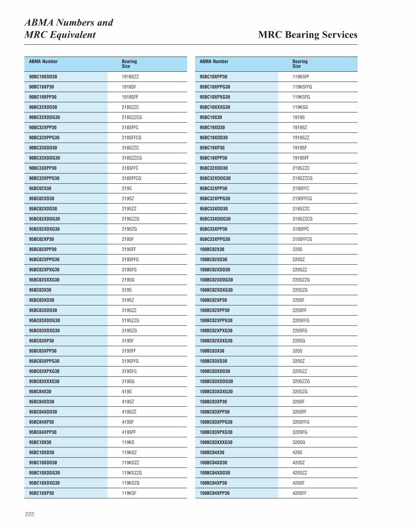
MRC Bearing ServicesABMA Numbers and MRC Equivalent
222
ABMA Number BearingSize
90BC19XDD30 1918SZZ
90BC19XP30 1918SF
90BC19XPP30 1918SFF
90BC32XDD30 218SZZC
90BC32XDDG30 218SZZCG
90BC32XPP30 218SFFC
90BC32XPPG30 218SFFCG
90BC33XDD30 318SZZC
90BC33XDDG30 318SZZCG
90BC33XPP30 318SFFC
90BC33XPPG30 318SFFCG
95BC02X30 219S
95BC02XD30 219SZ
95BC02XDD30 219SZZ
95BC02XDDG30 219SZZG
95BC02XDXG30 219SZG
95BC02XP30 219SF
95BC02XPP30 219SFF
95BC02XPPG30 219SFFG
95BC02XPXG30 219SFG
95BC02XXXG30 219SG
95BC03X30 319S
95BC03XD30 319SZ
95BC03XDD30 319SZZ
95BC03XDDG30 319SZZG
95BC03XDXG30 319SZG
95BC03XP30 319SF
95BC03XPP30 319SFF
95BC03XPPG30 319SFFG
95BC03XPXG30 319SFG
95BC03XXXG30 319SG
95BC04X30 419S
95BC04XD30 419SZ
95BC04XDD30 419SZZ
95BC04XP30 419SF
95BC04XPP30 419SFF
95BC10X30 119KS
95BC10XD30 119KSZ
95BC10XDD30 119KSZZ
95BC10XDDG30 119KSZZG
95BC10XDXG30 119KSZG
95BC10XP30 119KSF
ABMA Number BearingSize
95BC10XPP30 119KSFF
95BC10XPPG30 119KSFFG
95BC10XPXG30 119KSFG
95BC10XXXG30 119KSG
95BC19X30 1919S
95BC19XD30 1919SZ
95BC19XDD30 1919SZZ
95BC19XP30 1919SF
95BC19XPP30 1919SFF
95BC32XDD30 219SZZC
95BC32XDDG30 219SZZCG
95BC32XPP30 219SFFC
95BC32XPPG30 219SFFCG
95BC33XDD30 319SZZC
95BC33XDDG30 319SZZCG
95BC33XPP30 319SFFC
95BC33XPPG30 319SFFCG
100BC02X30 220S
100BC02XD30 220SZ
100BC02XDD30 220SZZ
100BC02XDDG30 220SZZG
100BC02XDXG30 220SZG
100BC02XP30 220SF
100BC02XPP30 220SFF
100BC02XPPG30 220SFFG
100BC02XPXG30 220SFG
100BC02XXXG30 220SG
100BC03X30 320S
100BC03XD30 320SZ
100BC03XDD30 320SZZ
100BC03XDDG30 320SZZG
100BC03XDXG30 320SZG
100BC03XP30 320SF
100BC03XPP30 320SFF
100BC03XPPG30 320SFFG
100BC03XPXG30 320SFG
100BC03XXXG30 320SG
100BC04X30 420S
100BC04XD30 420SZ
100BC04XDD30 420SZZ
100BC04XP30 420SF
100BC04XPP30 420SFF
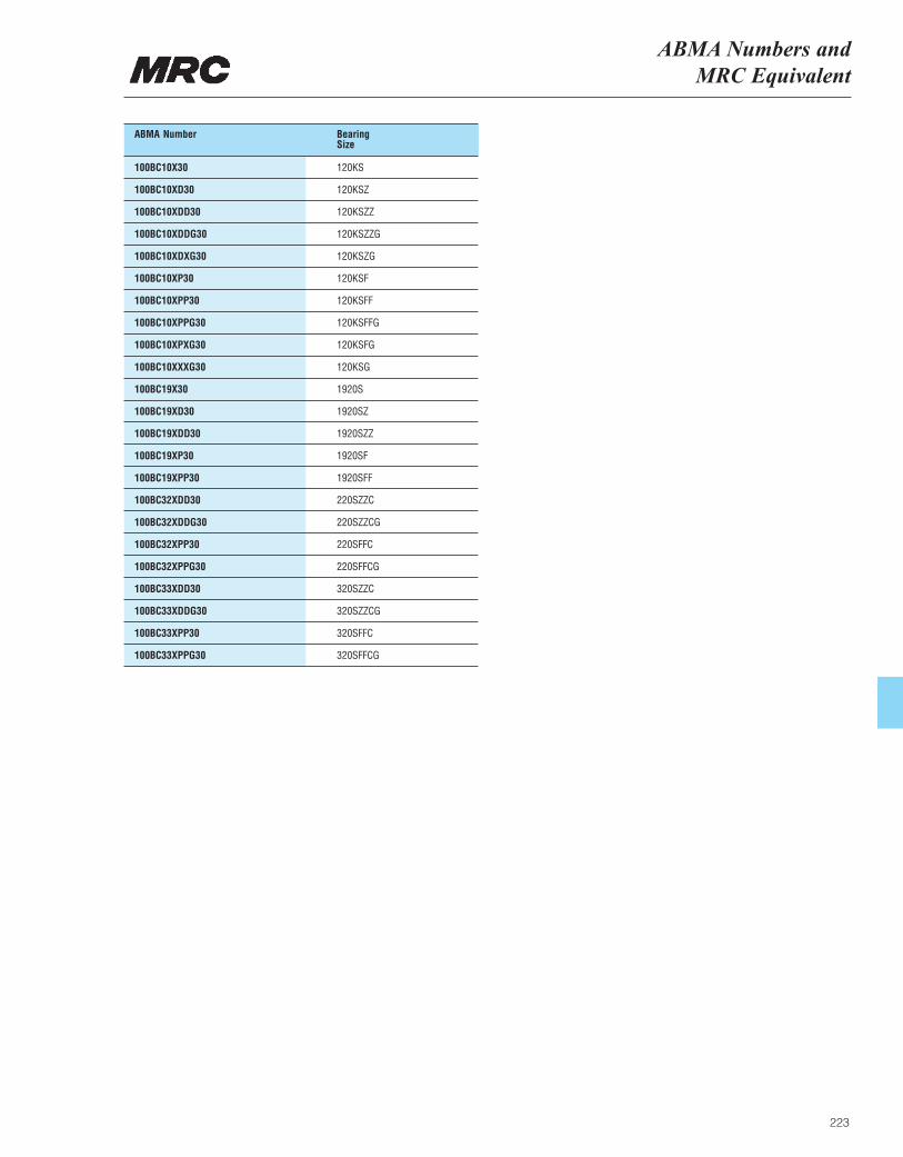
ABMA Numbers and MRC Equivalent
223
ABMA Number BearingSize
100BC10X30 120KS
100BC10XD30 120KSZ
100BC10XDD30 120KSZZ
100BC10XDDG30 120KSZZG
100BC10XDXG30 120KSZG
100BC10XP30 120KSF
100BC10XPP30 120KSFF
100BC10XPPG30 120KSFFG
100BC10XPXG30 120KSFG
100BC10XXXG30 120KSG
100BC19X30 1920S
100BC19XD30 1920SZ
100BC19XDD30 1920SZZ
100BC19XP30 1920SF
100BC19XPP30 1920SFF
100BC32XDD30 220SZZC
100BC32XDDG30 220SZZCG
100BC32XPP30 220SFFC
100BC32XPPG30 220SFFCG
100BC33XDD30 320SZZC
100BC33XDDG30 320SZZCG
100BC33XPP30 320SFFC
100BC33XPPG30 320SFFCG
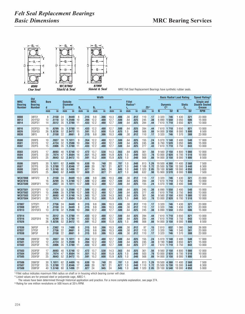
MRC Bearing ServicesFelt Seal Replacement BearingsBasic Dimensions
224
MRCBearingNumber
OldMRCBearingNumber
Bore
dmm in
OutsideDiameterDmm in
B0
mm inB1
mm inBmm in
FilletRadius1)
ra
mm inZD 2
mm in
DynamicC3)
N lbf
Basic Radial Load RatingWidth Speed Rating2)
StaticC0
N lbf
Single andDouble Sealed
GreaseRPM
8008 38FS1 8 .3150 24 .9449 8 .315 9.8 .386 10.3 .406 .30 .012 110 .17 3 320 746 1 430 321 23 0008013 201FS2 13 .5118 32 1.2598 10 .394 12.2 .480 12.7 .500 .64 .025 245 .38 6 890 1 550 3 050 686 15 0008014 202FS1 14 .5512 35 1.3780 11 .433 12.2 .480 12.7 .500 .64 .025 284 .44 7 610 1 710 3 650 821 13 000
8016 202FS3 16 .6299 35 1.3780 11 .433 12.2 .480 12.7 .500 .64 .025 284 .44 7 610 1 710 3 650 821 13 0008026 205FS3 26 1.0236 52 2.0472 15 .591 15.2 .600 15.9 .625 1.0 .040 568 .88 14 000 3 150 8 000 1 800 8 5008038 38FS 8 .3150 22 .8661 8 .315 9.8 .386 10.3 .406 .30 .012 110 .17 3 320 746 1 370 308 23 000
8500 200FS 10 .3937 30 1.1811 9 .354 12.2 .480 12.7 .500 .64 .025 155 .24 5 070 1 140 2 400 540 17 0008501 201FS 12 .4724 32 1.2598 10 .394 12.2 .480 12.7 .500 .64 .025 245 .38 6 760 1 520 3 050 685 15 0008502 202FS 15 .5906 35 1.3780 11 .433 12.2 .480 12.7 .500 .64 .025 277 .43 7 610 1 710 3 750 843 13 000
8503 203FS 17 .6693 40 1.5748 12 .472 13.7 .538 14.3 .563 .64 .025 361 .56 9 560 2 150 4 800 1 080 12 0008504 204FS 20 .7874 47 1.8504 14 .551 15.2 .600 15.9 .625 1.0 .040 503 .78 13 000 2 920 6 700 1 510 10 0008505 205FS 25 .9843 52 2.0472 15 .591 15.2 .600 15.9 .625 1.0 .040 568 .88 14 000 3 150 8 000 1 800 8 500
8506 206FS 30 1.1811 62 2.4409 16 .630 19 .748 20 .787 1.0 .040 813 1.26 19 500 4 380 11 400 2 560 7 5008507 207FS 35 1.3780 72 2.8346 17 .669 20 .787 21 .827 1.0 .040 1 109 1.72 25 500 5 730 15 300 3 440 6 3008508 208FS 40 1.5748 80 3.1496 21 .827 24 .945 24 .945 1.0 .040 1 320 2.05 29 100 6 540 18 000 4 050 5 6008605 305FS 25 .9843 62 2.4409 17 .669 21 .827 21 .827 1.0 .040 632 .98 15 900 3 570 8 000 1 800 7 500
WC87008 38FSF2 8 .3150 24 .9449 10.3 .406 9.8 .386 10.3 .406 .30 .012 110 .17 3 320 746 1 430 321 23 000WC87016 16 .6299 35 1.3780 12.7 .500 12.2 .480 12.7 .500 .64 .025 284 .44 7 610 1 710 3 750 843 13 000WC87500 200FSF1 10 .3937 30 1.1811 12.7 .500 12.2 .480 12.7 .500 .64 .025 155 .24 5 070 1 140 2 400 540 17 000
WC87501 201FSF1 12 .4724 32 1.2598 12.7 .500 12.2 .480 12.7 .500 .64 .025 245 .38 6 890 1 550 2 400 540 15 000WC87502 202FSF1 15 .5906 35 1.3780 12.7 .500 12.2 .480 12.7 .500 .64 .025 277 .43 7 610 1 710 3 750 843 13 000WC87503 203FSF1 17 .6693 40 1.5748 14.3 .563 13.7 .538 14.3 .563 .64 .025 361 .56 9 560 2 150 4 800 1 080 12 000WC87504 204FSF1 20 .7874 47 1.8504 15.9 .625 15.2 .600 15.9 .625 1.0 .040 503 .78 13 000 2 920 6 700 1 510 10 000
87007 37FSF1 7 .2756 24 .9449 8 .315 9.8 .386 10.3 .406 .30 .012 110 .17 3 320 746 1 430 321 23 00087008 38FSF1 8 .3150 24 .9449 8 .315 9.8 .386 10.3 .406 .30 .012 110 .17 3 320 746 1 430 321 23 00087013 201FSF3 13 .5118 32 1.2598 10 .394 12.2 .480 12.7 .500 .64 .025 245 .38 6 890 1 550 3 050 686 15 000
87014 14 .5512 35 1.3780 11 .433 12.2 .480 12.7 .500 .64 .025 284 .44 7 610 1 710 3 650 821 13 00087016 202FSF4 16 .6299 35 1.3780 11 .433 12.2 .480 12.7 .500 .64 .025 284 .44 7 610 1 710 3 750 843 13 00087026 26 1.0236 52 2.0472 15 .591 15.2 .600 15.9 .625 1.0 .040 568 .88 14 000 3 150 8 000 1 800 8 500
87036 36FSF 6 .2362 19 .7480 8 .315 9.8 .386 10.3 .406 .30 .012 97 .15 2 810 632 1 080 243 26 00087037 37FSF 7 .2756 22 .8661 8 .315 9.8 .386 10.3 .406 .30 .012 110 .17 3 320 746 1 340 301 23 00087038 38FSF 8 .3150 22 .8661 8 .315 9.8 .386 10.3 .406 .30 .012 110 .17 3 320 746 1 370 308 23 000
87500 200FSF 10 .3937 30 1.1811 9 .354 12.2 .480 12.7 .500 .64 .025 155 .24 5 070 1 140 2 400 540 17 00087501 201FSF 12 .4724 32 1.2598 9 .394 12.2 .480 12.7 .500 .64 .025 245 .38 8 190 1 840 3 650 821 15 00087502 202FSF 15 .5906 35 1.3780 11 .433 12.2 .480 12.7 .500 .64 .025 277 .43 7 610 1 710 3 750 843 13 000
87503 203FSF 17 .6693 40 1.5748 12 .472 13.7 .538 14.3 .563 .64 .025 361 .56 9 560 2 150 4 800 1 080 12 00087504 204FSF 20 .7874 47 1.8504 14 .551 15.2 .600 15.9 .625 1.0 .040 503 .78 13 000 2 920 6 700 1 510 10 00087505 205FSF 25 .9843 52 2.0472 15 .591 15.2 .600 15.9 .625 1.0 .040 568 .88 14 000 3 150 8 000 1 800 8 500
87506 206FSF 30 1.1811 62 2.4409 16 .630 19 .748 20 .787 1.0 .040 813 1.26 19 500 4 380 11 400 2 560 7 50087507 207FSF 35 1.3780 72 2.8346 17 .669 20 .787 21 .827 1.0 .040 1 110 1.72 25 500 5 730 15 300 3 440 6 30087508 208FSF 40 1.5748 80 3.1496 21 .827 24 .945 24 .945 1.0 .040 1 320 2.05 29 100 6 540 18 000 4 050 5 000
MRC Felt Seal Replacement Bearings have synthetic rubber seals.
1) Fillet radius indicates maximum fillet radius on shaft or in housing which bearing corner will clear.2) Listed values are for pressed steel or polyamide cage, ABEC-1.
The values have been determined through historical application and practice. For a more complete explanation, see page 274.3) Rating for one million revolutions or 500 hours at 33¹|₃ RPM.

Felt Seal Replacement BearingsBasic Dimensions
225
MRCBearingNumber
OldMRCBearingNumber
Bore
dmm in
OutsideDiameterDmm in
B0
mm inB1
mm inBmm in
FilletRadius1)
ra
mm inZD 2
mm in
DynamicC3)
N lbf
Basic Radial Load RatingWidth Speed Rating2)
StaticC0
N lbf
Single andDouble Sealed
GreaseRPM
88007 7 .2756 24 .9449 8 .315 12.6 .497 12.6 .497 .30 .012 110 .17 3 320 746 1 430 321 23 00088008 38FFS2 8 .3150 24 .9449 8 .315 12.6 .497 12.6 .497 .30 .012 110 .17 3 320 746 1 430 321 23 00088009 9 .3543 30 1.1811 9 .354 16.4 .646 16.4 .646 .64 .025 155 .24 4 620 1 040 2 040 459 17 000
88011 11 .4331 32 1.2598 10 .394 15.4 .606 15.4 .606 .64 .025 245 .38 6 760 1 520 3 000 674 15 00088013 201FFS2 13 .5118 32 1.2598 10 .394 15.4 .606 15.4 .606 .64 .025 245 .38 6 890 1 550 3 050 686 15 00088016 202FFS5 16 .6299 35 1.3780 11 .433 14.4 .567 14.4 .567 .64 .025 284 .44 7 610 1 710 3 750 843 13 000
88500 200FFS 10 .3937 30 1.1811 9 .354 16.4 .646 16.4 .646 .64 .025 155 .24 5 070 1 140 2 400 540 17 00088501 201FFS 12 .4724 32 1.2598 10 .394 15.4 .606 15.4 .606 .64 .025 245 .38 6 760 1 520 3 050 685 15 00088502 202FFS 15 .5906 35 1.3780 11 .433 14.4 .567 14.4 .567 .64 .025 277 .43 7 610 1 710 3 750 843 13 000
88503 203FFS 17 .6693 40 1.5748 12 .472 16.6 .654 16.6 .654 .64 .025 361 .56 9 560 2 150 4 800 1 080 12 00088504 204FFS 20 .7874 47 1.8504 14 .551 17.8 .699 17.8 .699 1.0 .040 503 .78 13 000 2 920 6 700 1 510 10 00088505 205FFS 25 .9843 52 2.0472 15 .591 16.7 .659 16.7 .659 1.0 .040 568 .88 14 000 3 150 8 000 1 800 8 500
88506 206FFS 30 1.1811 62 2.4409 16 .630 24 .945 24 .945 1.0 .040 813 1.26 19 500 4 380 11 400 2 560 7 50088507 207FFS 35 1.3780 72 2.8346 17 .669 25 .984 25 .984 1.0 .040 1 110 1.72 25 500 5 730 15 300 3 440 6 30088508 208FFS 40 1.5748 80 3.1496 21 .827 27 1.063 27 1.063 1.0 .040 1 320 2.05 29 100 6 540 18 000 4 050 5 600
487502 G202FSF 15 .5906 35 1.3780 11 .433 12.2 .480 12.7 .500 .64 .025 277 .43 7 610 1 710 3 750 843 13 000487503 G203FSF 17 .6693 40 1.5748 12 .472 13.7 .538 14.3 .563 .64 .025 361 .56 9 560 2 150 4 800 1 080 12 000487508 G208FSF 40 1.5748 80 3.1496 21 .827 24 .945 24 .945 1.0 .040 1 320 2.05 29 100 6 540 18 000 4 050 5 600
488016 202FFS2G 16 .6299 35 1.3780 11 .433 14.4 .567 14.4 .567 .64 .025 284 .44 7 610 1 710 3 750 843 13 000488502 202FFSG 15 .5906 35 1.3780 11 .433 14.4 .567 14.4 .567 .64 .025 277 .43 7 610 1 710 3 750 843 13 000488503 203FFSG 17 .6693 40 1.5748 12 .472 16.6 .654 16.6 .654 .64 .025 361 .56 9 560 2 150 4 800 1 080 12 000
488504 204FFSG 20 .7874 47 1.8504 14 .551 17.8 .699 17.8 .699 1.0 .040 503 .78 13 000 2 920 6 700 1 510 10 000488505 205FFSG 25 .9843 52 2.0472 15 .591 16.7 .659 16.7 .659 1.0 .040 568 .88 14 000 3 150 8 000 1 800 8 500488506 206FFSG 30 1.1811 62 2.4409 16 .630 24 .945 24 .945 1.0 .040 813 1.26 19 500 4 380 11 400 2 560 7 500
488507 207FFSG 35 1.3780 72 2.8346 17 .669 25 .984 25 .984 1.0 .040 1 110 1.72 25 500 5 730 15 300 3 440 6 300488508 208FFSG 40 1.5748 80 3.1496 21 .827 27 1.063 27 1.063 1.0 .040 1 320 2.05 29 100 6 540 18 000 4 050 5 600
MRC Felt Seal Replacement Bearings have synthetic rubber seals.
1) Fillet radius indicates maximum fillet radius on shaft or in housing which bearing corner will clear.2) Listed values are for pressed steel or polyamide cage, ABEC-1.
The values have been determined through historical application and practice. For a more complete explanation, see page 274.3) Rating for one million revolutions or 500 hours at 33¹|₃ RPM.4) Add suffix “V” when snap ring is on seal side.
88000 487000 4) 488000Two Seals Shield, Seal Two Seals
& Snap-Ring & Snap-Ring
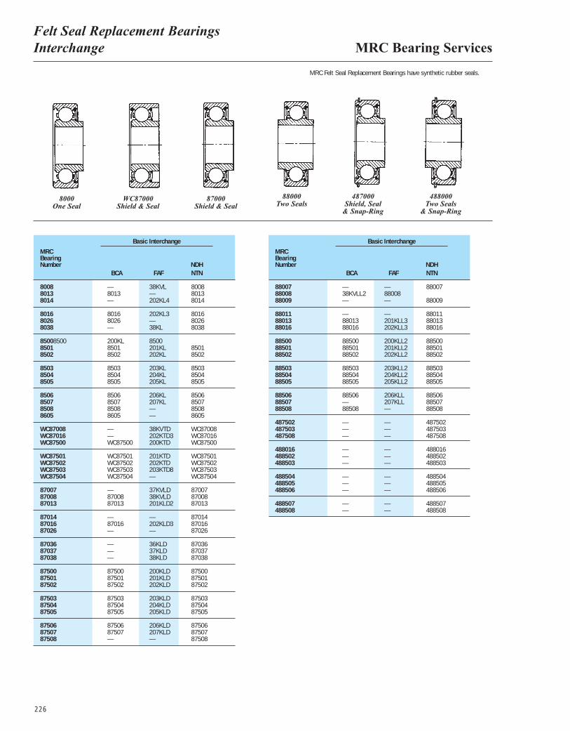
MRC Bearing ServicesFelt Seal Replacement Bearings Interchange
226
MRCBearingNumber
Basic Interchange
BCA FAFNDHNTN
8008 — 38KVL 80088013 8013 — 80138014 — 202KL4 8014
8016 8016 202KL3 80168026 8026 — 80268038 — 38KL 8038
85008500 200KL 85008501 8501 201KL 85018502 8502 202KL 8502
8503 8503 203KL 85038504 8504 204KL 85048505 8505 205KL 8505
8506 8506 206KL 85068507 8507 207KL 85078508 8508 — 85088605 8605 — 8605
WC87008 — 38KVTD WC87008WC87016 — 202KTD3 WC87016WC87500 WC87500 200KTD WC87500
WC87501 WC87501 201KTD WC87501WC87502 WC87502 202KTD WC87502WC87503 WC87503 203KTD8 WC87503WC87504 WC87504 — WC87504
87007 — 37KVLD 8700787008 87008 38KVLD 8700887013 87013 201KLD2 87013
87014 — — 8701487016 87016 202KLD3 8701687026 — — 87026
87036 — 36KLD 8703687037 — 37KLD 8703787038 — 38KLD 87038
87500 87500 200KLD 8750087501 87501 201KLD 8750187502 87502 202KLD 87502
87503 87503 203KLD 8750387504 87504 204KLD 8750487505 87505 205KLD 87505
87506 87506 206KLD 8750687507 87507 207KLD 8750787508 — — 87508
MRCBearingNumber
Basic Interchange
BCA FAFNDHNTN
88007 — — 8800788008 38KVLL2 8800888009 — — 88009
88011 — — 8801188013 88013 201KLL3 8801388016 88016 202KLL3 88016
88500 88500 200KLL2 8850088501 88501 201KLL2 8850188502 88502 202KLL2 88502
88503 88503 203KLL2 8850388504 88504 204KLL2 8850488505 88505 205KLL2 88505
88506 88506 206KLL 8850688507 — 207KLL 8850788508 88508 — 88508
487502 — — 487502487503 — — 487503487508 — — 487508
488016 — — 488016488502 — — 488502488503 — — 488503
488504 — — 488504488505 — — 488505488506 — — 488506
488507 — — 488507488508 — — 488508
8000 WC87000 87000One Seal Shield & Seal Shield & Seal
88000 487000 488000 Two Seals Shield, Seal Two Seals
& Snap-Ring & Snap-Ring
MRC Felt Seal Replacement Bearings have synthetic rubber seals.

227
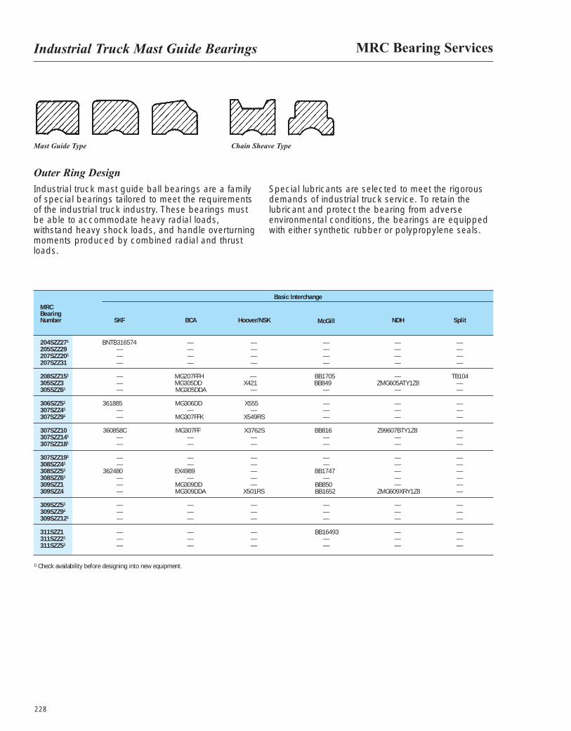
MRC Bearing ServicesIndustrial Truck Mast Guide Bearings
228
Industrial truck mast guide ball bearings are a family of special bearings tailored to meet the requirements of the industrial truck industry. These bearings must be able to accommodate heavy radial loads, withstand heavy shock loads, and handle overturningmoments produced by combined radial and thrustloads.
Special lubricants are selected to meet the rigorousdemands of industrial truck service. To retain thelubricant and protect the bearing from adverseenvironmental conditions, the bearings are equippedwith either synthetic rubber or polypropylene seals.
Outer Ring Design
Mast Guide Type Chain Sheave Type
MRCBearingNumber SKF BCA Hoover/NSK McGill NDH Split
204SZZ271 BNTB316574 — — — — —205SZZ29 — — — — — —207SZZ201 — — — — — —207SZZ31 — — — — — —
208SZZ151 — MG207FFH — BB1705 — TB104305SZZ3 — MG305DD X421 BB849 ZMG605ATY1Z8 —305SZZ61 — MG305DDA — — — —
306SZZ51 361885 MG306DD X555 — — —307SZZ41 — — — — — —307SZZ91 — MG307FFK X549RS — — —
307SZZ10 360858C MG307FF X3762S BB816 Z99607BTY1Z8 —307SZZ141 — — — — — —307SZZ181 — — — — — —
307SZZ191 — — — — — —308SZZ41 — — — — — —308SZZ51 362480 EX4989 — BB1747 — —308SZZ61 — — — — — —309SZZ1 — MG309DD — BB850 — —309SZZ4 — MG309DDA X501RS BB1652 ZMG609XRY1Z8 —
309SZZ51 — — — — — —309SZZ91 — — — — — —309SZZ121 — — — — — —
311SZZ1 — — — BB16493 — —311SZZ21 — — — — — —311SZZ51 — — — — — —
Basic Interchange
1) Check availability before designing into new equipment.
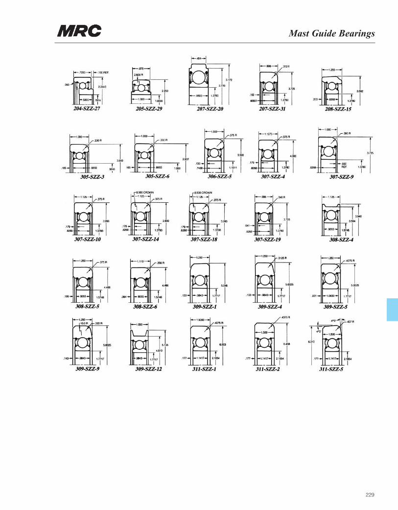
Mast Guide Bearings
229
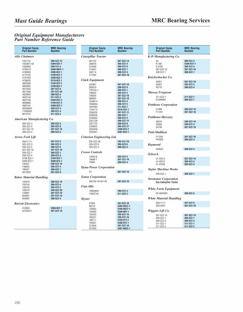
MRC Bearing ServicesMast Guide Bearings
230
Original Equipment ManufacturersPart Number Reference Guide
Original Equip. MRC Bearing Part Number Number
Allis Chalmers1001732 208-SZZ-151002841-02 5309-BZZ-11005603 309-SZZ-44756413 5206-BKFF-14769905 5306-BZZ-14774102 5108-BZZ-14797550 5209-BZZ-14798050 5210-BZZ-14803599 5109-BZZ-24803665 5109-BZZ-14812920 307-SZZ-94817265 207-SZZ-204820659 309-SZZ-44832744 311-SZZ-24842106 5209-BZZ-24859065 5109-BZZ-34863104 5309-RZZ-148206693 309-SZZ-471005603 309-SZZ-48612154 311-SZZ-5
American Manufacturing Co.305-SZZ-3 305-SZZ-3305-SZZ-6 305-SZZ-6307-SZZ-10 307-SZZ-10309-SZZ-4 309-SZZ-4
Arrow Fork Lift35A11111 307-SZZ-8305-SZZ-3 305-SZZ-3306-SZZ-5 306-SZZ-5307-SZZ-10 307-SZZ-10309-SZZ-1 309-SZZ-1309-SZZ-4 309-SZZ-45108-BZZ-1 5108-BZZ-15208-BTZ-1 5208-BTZ-1185531 208-SZZ-16746623 305-SZZ-3789401 308-SZZ-14812920 307-SZZ-9
Baker Material Handling102916 206-SZZ-16104744 309-SZZ-4105475 306-SZZ-5105476 204-SZZ-20120891 307-SZZ-10504001 307-SZZ-10504002 309-SZZ-4
Barrett ElectronicsA10650 5306-BZZ-1A27690-2 307-SZZ-10
Original Equip. MRC Bearing Part Number Number
Caterpillar Tractor091132 307-SZZ-14308918 305-SZZ-3314046 309-SZZ-9314047 309-SZZ-1346114 308-SZZ-4371202 307-SZZ-18
Clark Equipment342957 307-SZZ-10665619 208-SZZ-9738752-J 309-SZZ-1746623 305-SZZ-3746624 307-SZZ-10996829 307-SZZ-101654614 309-SZZ-41695854 306-SZZ-51697663 311-SZZ-11764714 5316-SZZ-12306335 307-SZZ-112306336 305-SZZ-72326653 308-SZZ-52357128 309-SZZ-122357723 308-SZZ-62359625 204-SZZ-272359446 5309-BZZ-22359447 5307-BZZ-1
Criterion Engineering Ltd.205-SZZ-29 205-SZZ-29305-SZZ-6 305-SZZ-6309-SZZ-4 309-SZZ-4
Crown Controls74020-B 305-SZZ-374668-1 307-SZZ-1079943 309-SZZ-4
Dyna-Power CorporationR1 307-SZZ-10
Eaton Corporation260100-18-001-00 307-SZZ-16
Fiat-Allis74820659 309-SZZ-474832744 311-SZZ-2
Hyster87905 307-SZZ-1089219 5205-BKZZ-1129002 5206-BKZZ-1143493 5208-BKT-1185530 208-SZZ-15185531 208-SZZ-16186711 5208-BTT-2193557 5208-BTZ-1212956 307-SZZ-10231020 5207-BKZZ-1
Original Equip. MRC Bearing Part Number Number
K-D Manufacturing Co.R2 309-SZZ-4R-186 5309-RZZ-1R 5182 308-SZZ-4307-SZZ-10 307-SZZ-10309-SZZ-1 309-SZZ-1
Knickerbocker Co.30451 307-SZZ-1030487 305-SZZ-330719 309-SZZ-4
Massey Ferguson311-SZZ-1 311-SZZ-1672896M1 309-SZZ-1
Pettibone Corporation31486 206-SZZ-16F11201 307-SZZ-10
Pettibone-Mercury30076 206-SZZ-1633569 309-SZZ-433799 307-SZZ-10
Petti-MullikenF11205 307-SZZ-10P45900 309-SZZ-4
Raymond449033 309-SZZ-4
Schreck31-42014 307-SZZ-1031-42015 309-SZZ-431-43450 305-SZZ-3
Taylor Machine Works309-SZZ-1 309-SZZ-1
Towmotor Corporation See Caterpillar Tractor
White Farm Equipment20-3004059 309-SZZ-5
White Material Handling35A11111 307-SZZ-835A12631 307-SZZ-10
Wiggins Lift Co.307-SZZ-10 307-SZZ-10309-SZZ-1 309-SZZ-1309-SZZ-4 309-SZZ-4311-SZZ-1 311-SZZ-1311-SZZ-2 311-SZZ-2
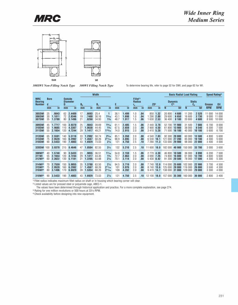
Wide Inner Ring Medium Series
231
MRCBearingNumber
Bore
dmm in
OutsideDiameterDmm in
B0
mm inB1
mm inEmm in
ZD2
mm inra
mm in
DynamicC3)
N lbf
Basic Radial Load RatingWidth Speed Rating2)
StaticC0
N lbfGrease OilRPM RPM
Fillet1)
Radius
305SWI 25 .9843 62 2.4409 17 .6693 25.4 1 38.1 1.499 1.0 .04 850 1.32 20 800 4 680 11 200 2 520 11 000 14 000306SWI 30 1.1811 72 2.8346 19 .7480 30.16 1³|₁₆ 43.1 1.698 1.0 .04 1 290 2.00 29 600 6 650 16 600 3 730 9 000 11 000 307SWI 35 1.3780 80 3.1496 21 .8268 34.93 1³|₈ 48.7 1.917 1.5 .06 1 630 2.53 36 400 8 180 20 800 4 680 8 500 10 000
309SWI 45 1.7717 100 3.9370 25 .9843 39.69 1⁹|₁₆ 61.1 2.405 1.5 .06 2 440 3.78 52 700 11 900 31 500 7 080 6 700 8 000310SWI 50 1.9685 110 4.3307 27 1.0630 44.45 1³|₄ 67.5 2.659 2.0 .08 2 900 4.50 61 800 13 900 38 000 8 540 6 300 7 500311SWI 55 2.1654 120 4.7244 29 1.1417 49.21 1¹⁵|₁₆ 74.0 2.915 2.0 .08 3 410 5.28 71 500 16 100 45 000 10 100 5 600 6 700
313SWI 65 2.5591 140 5.5118 33 1.2992 58.74 2⁵|₁₆ 85.1 3.350 2.0 .08 4 540 7.03 92 300 20 800 60 000 13 500 4 800 5 600315SWI 75 2.9528 160 6.2992 37 1.4567 68.26 2¹¹|₁₆ 98.9 3.895 2.0 .08 6 530 10.1 121 000 27 200 85 000 19 100 4 300 5 000318SWI 90 3.5433 190 7.4803 43 1.6929 73.03 2⁷|₈ 121 4.750 2.5 .10 7 280 11.3 133 000 29 900 98 000 22 000 3 400 4 000
320SWI 100 3.9370 215 8.4646 47 1.8504 82.55 3¹|₄ 132 5.210 2.5 .10 11 600 18.0 182 000 40 900 150 000 33 700 3 000 3 600
308WI4) 40 1.5748 90 3.5433 23 .9055 36.51 1⁷|₁₆ 54.8 2.159 1.5 .06 2 770 4.30 46 800 10 500 36 000 8 090 6 200 7 500311WI 55 2.1654 120 4.7244 29 1.1417 44.45 1³|₄ 72.7 2.863 2.0 .08 4 690 7.26 74 800 16 800 61 000 13 700 4 600 5 600312WI4) 60 2.3622 130 5.1181 31 1.2205 53.98 2¹|₈ 79.1 3.114 2.0 .08 5 430 8.42 91 300 20 500 78 000 17 500 4 300 5 300
314WI4) 70 2.7559 150 5.9055 35 1.3780 63.50 2¹|₂ 94.5 3.719 2.0 .08 7 740 12.0 114 000 25 600 102 000 22 900 3 700 4 500315WI4) 75 2.9528 160 6.2992 37 1.4567 68.26 2¹¹|₁₆ 101 3.976 2.0 .08 8 740 13.6 125 000 28 000 116 000 26 000 3 500 4 300316WI4) 80 3.1496 170 6.6929 39 1.5354 68.26 2¹¹|₁₆ 109 4.282 2.0 .08 9 470 14.7 138 000 31 000 129 000 29 000 3 300 4 000
318WI4) 90 3.5433 190 7.4803 43 1.6929 73.03 2⁷|₈ 121 4.750 2.5 .10 12 100 18.8 157 000 35 300 160 000 36 000 2 800 3 400
300SWI Non-Filling Notch Type 300WI Filling Notch Type To determine bearing life, refer to page 52 for SWI, and page 62 for WI.
1) Fillet radius indicates maximum fillet radius on shaft or in housing which bearing corner will clear.2) Listed values are for pressed steel or polyamide cage, ABEC-1.
The values have been determined through historical application and practice. For a more complete explanation, see page 274.3) Rating for one million revolutions or 500 hours at 33¹|₃ RPM.4) Check availability before designing into new equipment.

232

BEARINGSPECIFICATION TABLES
INTRODUCTION ENGINEERING DATA MARATHON SERIES MADE-TO-ORDER
Engineering Data

Section IIIEngineering Data
233
Duplex Bearings ........................................................................................................................234
97000 Series ..............................................................................................................................237
ABEC Tolerances ........................................................................................................................239
Shaft and Housing Fits................................................................................................................245
Internal Radial Clearance ...........................................................................................................270
Dynamic and Static Load Ratings ..............................................................................................271
Bearing Life .................................................................................................................................272
Speed Factors.............................................................................................................................273
Speed Ratings.............................................................................................................................274
Materials and Limitations ............................................................................................................277
Lubrication ..................................................................................................................................281
Vibration Data..............................................................................................................................299
Snap Ring Data...........................................................................................................................321
Locknuts and Lockwashers ........................................................................................................325
Locknut Torque and Clamping Force .........................................................................................328
Installation Procedures................................................................................................................329
Shaft and Housing Shoulder Diameters .....................................................................................336
Bearing Weights..........................................................................................................................340
Millimeter-Inch Equivalents .........................................................................................................342
Fraction-Decimal Equivalents .....................................................................................................344
Metric Conversion Factors ..........................................................................................................345
Useful Formulae ..........................................................................................................................348
Product Index..............................................................................................................................371
Table of Contents Page
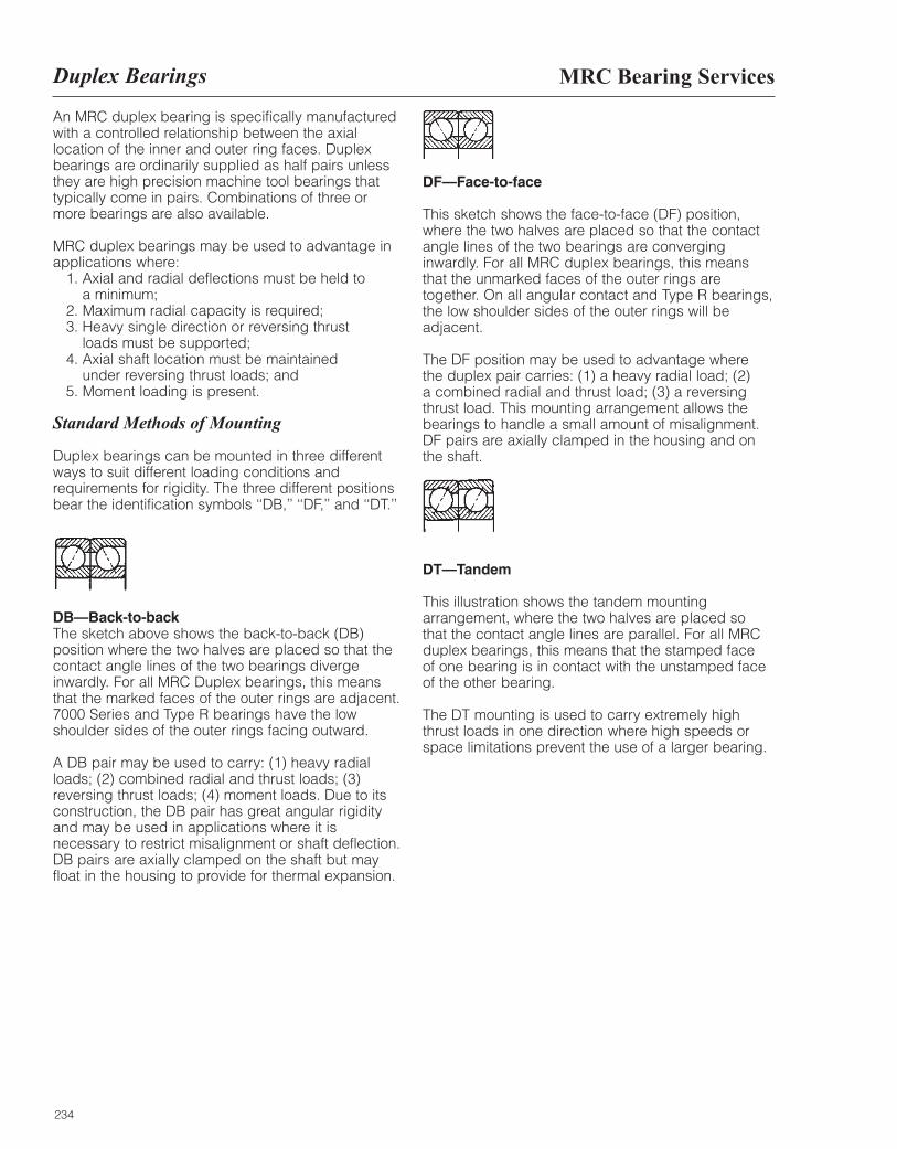
An MRC duplex bearing is specifically manufacturedwith a controlled relationship between the axial location of the inner and outer ring faces. Duplexbearings are ordinarily supplied as half pairs unlessthey are high precision machine tool bearings thattypically come in pairs. Combinations of three ormore bearings are also available.
MRC duplex bearings may be used to advantage inapplications where:
1. Axial and radial deflections must be held to a minimum;
2. Maximum radial capacity is required;3. Heavy single direction or reversing thrust
loads must be supported;4. Axial shaft location must be maintained
under reversing thrust loads; and5. Moment loading is present.
Standard Methods of Mounting
Duplex bearings can be mounted in three differentways to suit different loading conditions andrequirements for rigidity. The three different positionsbear the identification symbols ‘‘DB,’’ ‘‘DF,’’ and ‘‘DT.’’
DB—Back-to-backThe sketch above shows the back-to-back (DB)position where the two halves are placed so that thecontact angle lines of the two bearings divergeinwardly. For all MRC Duplex bearings, this means that the marked faces of the outer rings are adjacent.7000 Series and Type R bearings have the lowshoulder sides of the outer rings facing outward.
A DB pair may be used to carry: (1) heavy radialloads; (2) combined radial and thrust loads; (3)reversing thrust loads; (4) moment loads. Due to itsconstruction, the DB pair has great angular rigidityand may be used in applications where it isnecessary to restrict misalignment or shaft deflection.DB pairs are axially clamped on the shaft but mayfloat in the housing to provide for thermal expansion.
DF—Face-to-face
This sketch shows the face-to-face (DF) position,where the two halves are placed so that the contactangle lines of the two bearings are converginginwardly. For all MRC duplex bearings, this meansthat the unmarked faces of the outer rings aretogether. On all angular contact and Type R bearings,the low shoulder sides of the outer rings will beadjacent.
The DF position may be used to advantage where the duplex pair carries: (1) a heavy radial load; (2) a combined radial and thrust load; (3) a reversingthrust load. This mounting arrangement allows thebearings to handle a small amount of misalignment.DF pairs are axially clamped in the housing and onthe shaft.
DT—Tandem
This illustration shows the tandem mountingarrangement, where the two halves are placed so that the contact angle lines are parallel. For all MRCduplex bearings, this means that the stamped faceof one bearing is in contact with the unstamped faceof the other bearing.
The DT mounting is used to carry extremely highthrust loads in one direction where high speeds orspace limitations prevent the use of a larger bearing.
234
MRC Bearing ServicesDuplex Bearings
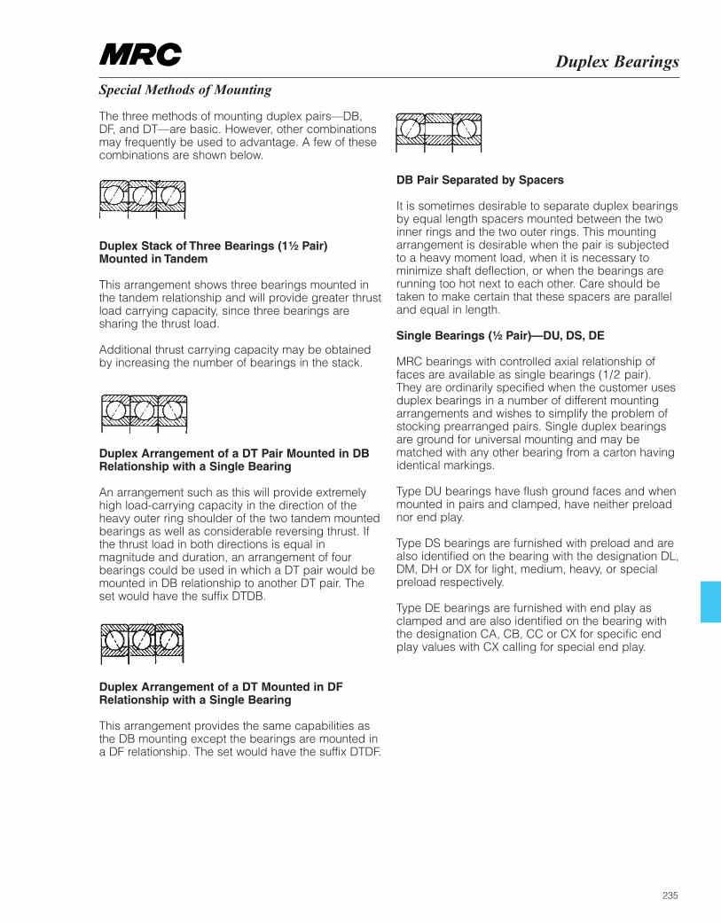
Duplex Bearings
235
Special Methods of Mounting
The three methods of mounting duplex pairs—DB, DF, and DT—are basic. However, other combinationsmay frequently be used to advantage. A few of thesecombinations are shown below.
Duplex Stack of Three Bearings (1¹⁄₂ Pair) Mounted in Tandem
This arrangement shows three bearings mounted in the tandem relationship and will provide greater thrustload carrying capacity, since three bearings aresharing the thrust load.
Additional thrust carrying capacity may be obtained by increasing the number of bearings in the stack.
Duplex Arrangement of a DT Pair Mounted in DBRelationship with a Single Bearing
An arrangement such as this will provide extremely high load-carrying capacity in the direction of the heavy outer ring shoulder of the two tandem mountedbearings as well as considerable reversing thrust. If the thrust load in both directions is equal inmagnitude and duration, an arrangement of fourbearings could be used in which a DT pair would bemounted in DB relationship to another DT pair. Theset would have the suffix DTDB.
Duplex Arrangement of a DT Mounted in DFRelationship with a Single Bearing
This arrangement provides the same capabilities asthe DB mounting except the bearings are mounted ina DF relationship. The set would have the suffix DTDF.
DB Pair Separated by Spacers
It is sometimes desirable to separate duplex bearingsby equal length spacers mounted between the twoinner rings and the two outer rings. This mountingarrangement is desirable when the pair is subjected to a heavy moment load, when it is necessary tominimize shaft deflection, or when the bearings arerunning too hot next to each other. Care should be taken to make certain that these spacers are paralleland equal in length.
Single Bearings (¹⁄₂ Pair)—DU, DS, DE
MRC bearings with controlled axial relationship of faces are available as single bearings (1/2 pair). They are ordinarily specified when the customer usesduplex bearings in a number of different mountingarrangements and wishes to simplify the problem ofstocking prearranged pairs. Single duplex bearingsare ground for universal mounting and may bematched with any other bearing from a carton havingidentical markings.
Type DU bearings have flush ground faces and whenmounted in pairs and clamped, have neither preloadnor end play.
Type DS bearings are furnished with preload and arealso identified on the bearing with the designation DL,DM, DH or DX for light, medium, heavy, or specialpreload respectively.
Type DE bearings are furnished with end play asclamped and are also identified on the bearing with the designation CA, CB, CC or CX for specific end play values with CX calling for special end play.
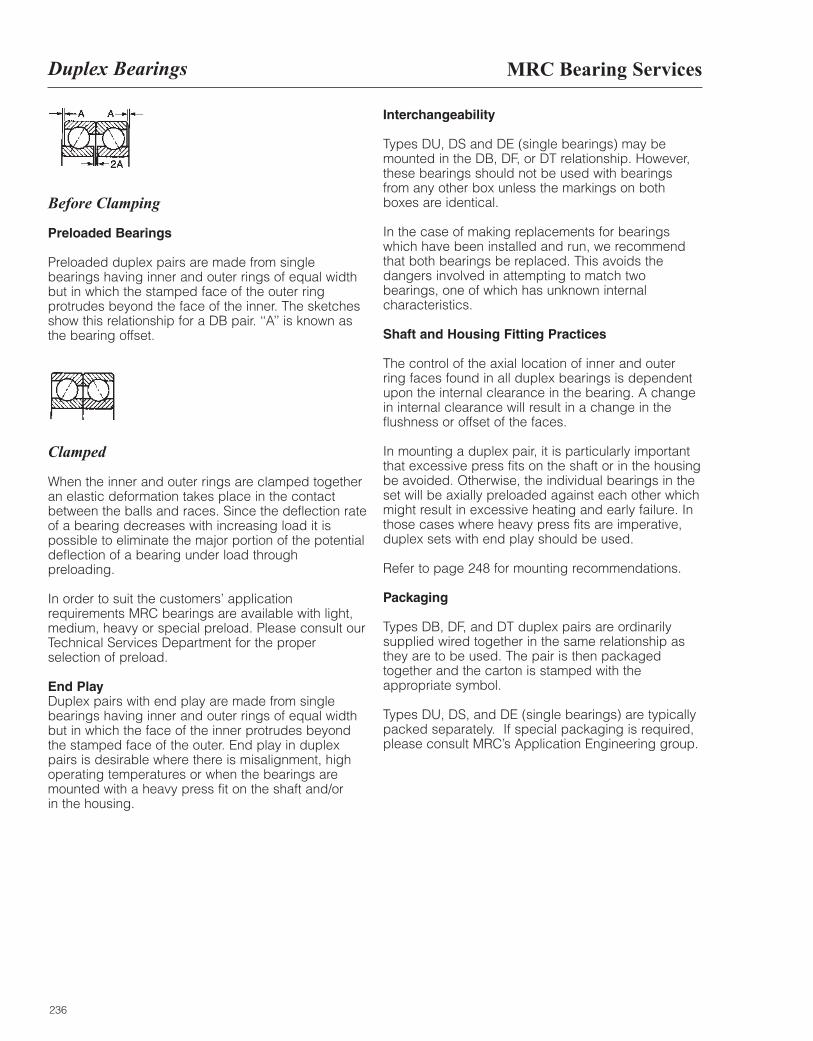
236
Before Clamping
Preloaded Bearings
Preloaded duplex pairs are made from singlebearings having inner and outer rings of equal widthbut in which the stamped face of the outer ringprotrudes beyond the face of the inner. The sketchesshow this relationship for a DB pair. ‘‘A’’ is known asthe bearing offset.
Clamped
When the inner and outer rings are clamped togetheran elastic deformation takes place in the contactbetween the balls and races. Since the deflection rateof a bearing decreases with increasing load it ispossible to eliminate the major portion of the potentialdeflection of a bearing under load throughpreloading.
In order to suit the customers’ applicationrequirements MRC bearings are available with light,medium, heavy or special preload. Please consult ourTechnical Services Department for the properselection of preload.
End PlayDuplex pairs with end play are made from singlebearings having inner and outer rings of equal widthbut in which the face of the inner protrudes beyondthe stamped face of the outer. End play in duplexpairs is desirable where there is misalignment, highoperating temperatures or when the bearings aremounted with a heavy press fit on the shaft and/or in the housing.
Interchangeability
Types DU, DS and DE (single bearings) may bemounted in the DB, DF, or DT relationship. However,these bearings should not be used with bearingsfrom any other box unless the markings on bothboxes are identical.
In the case of making replacements for bearingswhich have been installed and run, we recommendthat both bearings be replaced. This avoids thedangers involved in attempting to match twobearings, one of which has unknown internalcharacteristics.
Shaft and Housing Fitting Practices
The control of the axial location of inner and outerring faces found in all duplex bearings is dependentupon the internal clearance in the bearing. A changein internal clearance will result in a change in theflushness or offset of the faces.
In mounting a duplex pair, it is particularly importantthat excessive press fits on the shaft or in the housingbe avoided. Otherwise, the individual bearings in theset will be axially preloaded against each other whichmight result in excessive heating and early failure. Inthose cases where heavy press fits are imperative,duplex sets with end play should be used.
Refer to page 248 for mounting recommendations.
Packaging
Types DB, DF, and DT duplex pairs are ordinarilysupplied wired together in the same relationship asthey are to be used. The pair is then packagedtogether and the carton is stamped with theappropriate symbol.
Types DU, DS, and DE (single bearings) are typicallypacked separately. If special packaging is required,please consult MRC’s Application Engineering group.
MRC Bearing ServicesDuplex Bearings
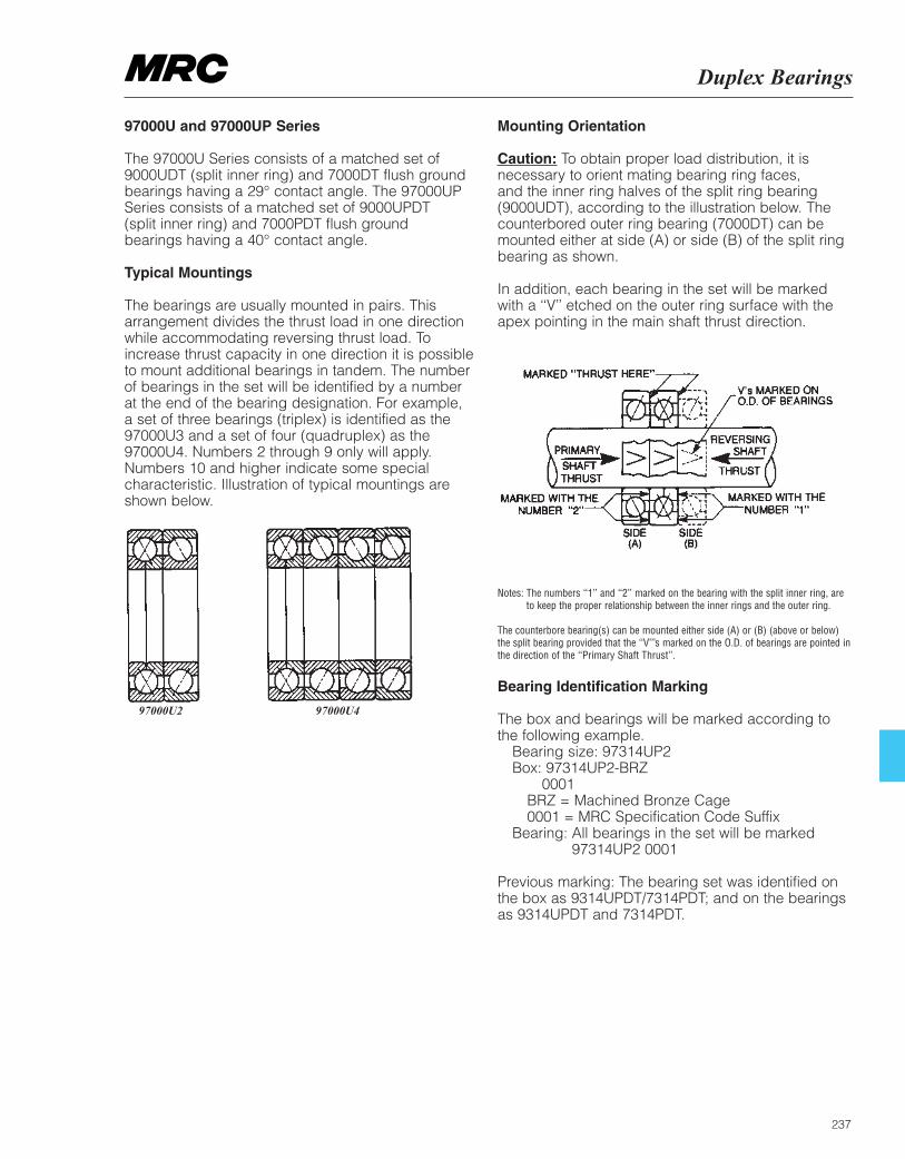
Duplex Bearings
237
97000U and 97000UP Series
The 97000U Series consists of a matched set of9000UDT (split inner ring) and 7000DT flush groundbearings having a 29° contact angle. The 97000UPSeries consists of a matched set of 9000UPDT (split inner ring) and 7000PDT flush ground bearings having a 40° contact angle.
Typical Mountings
The bearings are usually mounted in pairs. Thisarrangement divides the thrust load in one directionwhile accommodating reversing thrust load. Toincrease thrust capacity in one direction it is possibleto mount additional bearings in tandem. The numberof bearings in the set will be identified by a number at the end of the bearing designation. For example, a set of three bearings (triplex) is identified as the97000U3 and a set of four (quadruplex) as the97000U4. Numbers 2 through 9 only will apply.Numbers 10 and higher indicate some specialcharacteristic. Illustration of typical mountings areshown below.
97000U2 97000U4
Mounting Orientation
Caution: To obtain proper load distribution, it isnecessary to orient mating bearing ring faces, and the inner ring halves of the split ring bearing(9000UDT), according to the illustration below. Thecounterbored outer ring bearing (7000DT) can bemounted either at side (A) or side (B) of the split ringbearing as shown.
In addition, each bearing in the set will be markedwith a ‘‘V’’ etched on the outer ring surface with theapex pointing in the main shaft thrust direction.
Notes: The numbers ‘‘1’’ and ‘‘2’’ marked on the bearing with the split inner ring, areto keep the proper relationship between the inner rings and the outer ring.
The counterbore bearing(s) can be mounted either side (A) or (B) (above or below)the split bearing provided that the ‘‘V’’’s marked on the O.D. of bearings are pointed inthe direction of the ‘‘Primary Shaft Thrust’’.
Bearing Identification Marking
The box and bearings will be marked according tothe following example.
Bearing size: 97314UP2 Box: 97314UP2-BRZ
0001 BRZ = Machined Bronze Cage 0001 = MRC Specification Code Suffix
Bearing: All bearings in the set will be marked97314UP2 0001
Previous marking: The bearing set was identified onthe box as 9314UPDT/7314PDT; and on the bearingsas 9314UPDT and 7314PDT.

238
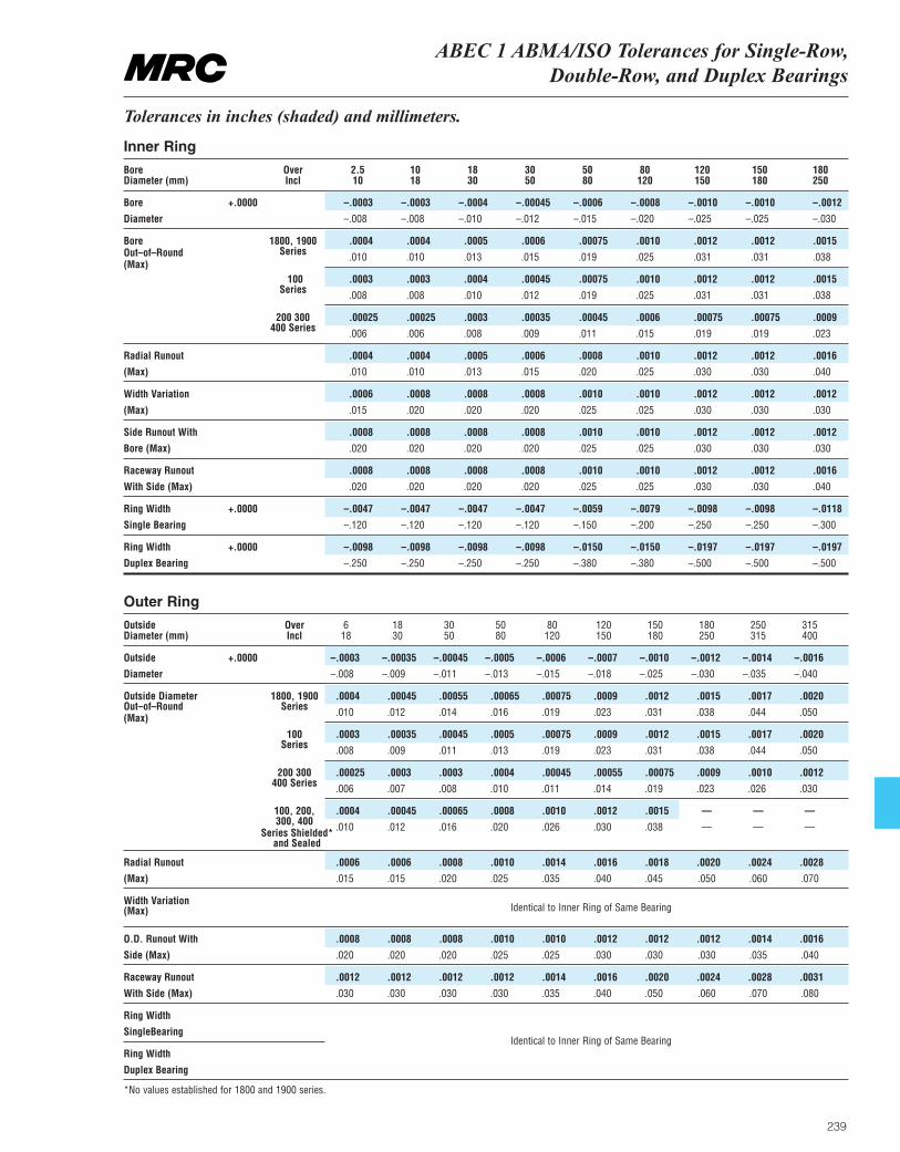
ABEC 1 ABMA/ISO Tolerances for Single-Row, Double-Row, and Duplex Bearings
239
Tolerances in inches (shaded) and millimeters.
Inner Ring
Bore Over 2.5 10 18 30 50 80 120 150 180Diameter (mm) Incl 10 18 30 50 80 120 150 180 250
Bore +.0000 –.0003 –.0003 –.0004 –.00045 –.0006 –.0008 –.0010 –.0010 –.0012
Diameter –.008 –.008 –.010 –.012 –.015 –.020 –.025 –.025 –.030
Bore 1800, 1900 .0004 .0004 .0005 .0006 .00075 .0010 .0012 .0012 .0015Out–of–Round Series .010 .010 .013 .015 .019 .025 .031 .031 .038(Max)
100 .0003 .0003 .0004 .00045 .00075 .0010 .0012 .0012 .0015Series .008 .008 .010 .012 .019 .025 .031 .031 .038
200 300 .00025 .00025 .0003 .00035 .00045 .0006 .00075 .00075 .0009400 Series .006 .006 .008 .009 .011 .015 .019 .019 .023
Radial Runout .0004 .0004 .0005 .0006 .0008 .0010 .0012 .0012 .0016
(Max) .010 .010 .013 .015 .020 .025 .030 .030 .040
Width Variation .0006 .0008 .0008 .0008 .0010 .0010 .0012 .0012 .0012
(Max) .015 .020 .020 .020 .025 .025 .030 .030 .030
Side Runout With .0008 .0008 .0008 .0008 .0010 .0010 .0012 .0012 .0012
Bore (Max) .020 .020 .020 .020 .025 .025 .030 .030 .030
Raceway Runout .0008 .0008 .0008 .0008 .0010 .0010 .0012 .0012 .0016
With Side (Max) .020 .020 .020 .020 .025 .025 .030 .030 .040
Ring Width +.0000 –.0047 –.0047 –.0047 –.0047 –.0059 –.0079 –.0098 –.0098 –.0118
Single Bearing –.120 –.120 –.120 –.120 –.150 –.200 –.250 –.250 –.300
Ring Width +.0000 –.0098 –.0098 –.0098 –.0098 –.0150 –.0150 –.0197 –.0197 –.0197
Duplex Bearing –.250 –.250 –.250 –.250 –.380 –.380 –.500 –.500 –.500
Outer Ring
Outside Over 6 18 30 50 80 120 150 180 250 315Diameter (mm) Incl 18 30 50 80 120 150 180 250 315 400
Outside +.0000 –.0003 –.00035 –.00045 –.0005 –.0006 –.0007 –.0010 –.0012 –.0014 –.0016
Diameter –.008 –.009 –.011 –.013 –.015 –.018 –.025 –.030 –.035 –.040
Outside Diameter 1800, 1900 .0004 .00045 .00055 .00065 .00075 .0009 .0012 .0015 .0017 .0020Out–of–Round Series .010 .012 .014 .016 .019 .023 .031 .038 .044 .050(Max)
100 .0003 .00035 .00045 .0005 .00075 .0009 .0012 .0015 .0017 .0020Series .008 .009 .011 .013 .019 .023 .031 .038 .044 .050
200 300 .00025 .0003 .0003 .0004 .00045 .00055 .00075 .0009 .0010 .0012400 Series .006 .007 .008 .010 .011 .014 .019 .023 .026 .030
100, 200, .0004 .00045 .00065 .0008 .0010 .0012 .0015 — — —300, 400 .010 .012 .016 .020 .026 .030 .038 — — —
Radial Runout .0006 .0006 .0008 .0010 .0014 .0016 .0018 .0020 .0024 .0028
(Max) .015 .015 .020 .025 .035 .040 .045 .050 .060 .070
Width Variation(Max)
O.D. Runout With .0008 .0008 .0008 .0010 .0010 .0012 .0012 .0012 .0014 .0016
Side (Max) .020 .020 .020 .025 .025 .030 .030 .030 .035 .040
Raceway Runout .0012 .0012 .0012 .0012 .0014 .0016 .0020 .0024 .0028 .0031
With Side (Max) .030 .030 .030 .030 .035 .040 .050 .060 .070 .080
Ring Width
SingleBearing
Ring Width
Duplex Bearing
*No values established for 1800 and 1900 series.
Identical to Inner Ring of Same Bearing
Identical to Inner Ring of Same Bearing
Series Shielded*and Sealed
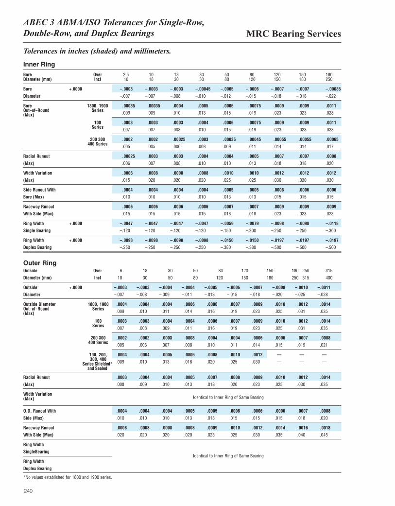
MRC Bearing ServicesABEC 3 ABMA/ISO Tolerances for Single-Row, Double-Row, and Duplex Bearings
240
Tolerances in inches (shaded) and millimeters.
Inner Ring
Bore Over 2.5 10 18 30 50 80 120 150 180Diameter (mm) Incl 10 18 30 50 80 120 150 180 250
Bore +.0000 –.0003 –.0003 –.0003 –.00045 –.0005 –.0006 –.0007 –.0007 –.00085
Diameter –.007 –.007 –.008 –.010 –.012 –.015 –.018 –.018 –.022
Bore 1800, 1900 .00035 .00035 .0004 .0005 .0006 .00075 .0009 .0009 .0011Out–of–Round Series .009 .009 .010 .013 .015 .019 .023 .023 .028(Max)
100 .0003 .0003 .0003 .0004 .0006 .00075 .0009 .0009 .0011Series .007 .007 .008 .010 .015 .019 .023 .023 .028
200 300 .0002 .0002 .00025 .0003 .00035 .00045 .00055 .00055 .00065400 Series .005 .005 .006 .008 .009 .011 .014 .014 .017
Radial Runout .00025 .0003 .0003 .0004 .0004 .0005 .0007 .0007 .0008
(Max) .006 .007 .008 .010 .010 .013 .018 .018 .020
Width Variation .0006 .0008 .0008 .0008 .0010 .0010 .0012 .0012 .0012
(Max) .015 .020 .020 .020 .025 .025 .030 .030 .030
Side Runout With .0004 .0004 .0004 .0004 .0005 .0005 .0006 .0006 .0006
Bore (Max) .010 .010 .010 .010 .013 .013 .015 .015 .015
Raceway Runout .0006 .0006 .0006 .0006 .0007 .0007 .0009 .0009 .0009
With Side (Max) .015 .015 .015 .015 .018 .018 .023 .023 .023
Ring Width +.0000 –.0047 –.0047 –.0047 –.0047 –.0059 –.0079 –.0098 –.0098 –.0118
Single Bearing –.120 –.120 –.120 –.120 –.150 –.200 –.250 –.250 –.300
Ring Width +.0000 –.0098 –.0098 –.0098 –.0098 –.0150 –.0150 –.0197 –.0197 –.0197
Duplex Bearing –.250 –.250 –.250 –.250 –.380 –.380 –.500 –.500 –.500
Outer RingOutside Over 6 18 30 50 80 120 150 180 250 315
Diameter (mm) Incl 18 30 50 80 120 150 180 250 315 400
Outside +.0000 –.0003 –.0003 –.0004 –.0004 –.0005 –.0006 –.0007 –.0008 –.0010 –.0011
Diameter –.007 –.008 –.009 –.011 –.013 –.015 –.018 –.020 –.025 –.028
Outside Diameter 1800, 1900 .0004 .0004 .0004 .0006 .0006 .0007 .0009 .0010 .0012 .0014Out–of–Round Series .009 .010 .011 .014 .016 .019 .023 .025 .031 .035(Max)
100 .0003 .0003 .0004 .0004 .0006 .0007 .0009 .0010 .0012 .0014Series .007 .008 .009 .011 .016 .019 .023 .025 .031 .035
200 300 .0002 .0002 .0003 .0003 .0004 .0004 .0006 .0006 .0007 .0008400 Series .005 .006 .007 .008 .010 .011 .014 .015 .019 .021
100, 200, .0004 .0004 .0005 .0006 .0008 .0010 .0012 — — —300, 400 .009 .010 .013 .016 .020 .025 .030 — — —
Radial Runout .0003 .0004 .0004 .0005 .0007 .0008 .0009 .0010 .0012 .0014
(Max) .008 .009 .010 .013 .018 .020 .023 .025 .030 .035
Width Variation(Max)
O.D. Runout With .0004 .0004 .0004 .0005 .0005 .0006 .0006 .0006 .0007 .0008
Side (Max) .010 .010 .010 .013 .013 .015 .015 .015 .018 .020
Raceway Runout .0008 .0008 .0008 .0008 .0009 .0010 .0012 .0014 .0016 .0018
With Side (Max) .020 .020 .020 .020 .023 .025 .030 .035 .040 .045
Ring Width
SingleBearing
Ring Width
Duplex Bearing
*No values established for 1800 and 1900 series.
Identical to Inner Ring of Same Bearing
Identical to Inner Ring of Same Bearing
Series Shielded*and Sealed
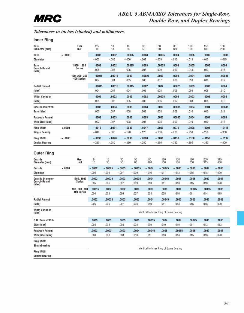
241
ABEC 5 ABMA/ISO Tolerances for Single-Row, Double-Row, and Duplex Bearings
Tolerances in inches (shaded) and millimeters.
Inner Ring
Bore Over 2.5 10 18 30 50 80 120 150 180Diameter (mm) Incl 10 18 30 50 80 120 150 180 250
Bore + .0000 –.0002 –.0002 –.00025 –.0003 –.00035 –.0004 –.0005 –.0005 –.0006
Diameter –.005 –.005 –.006 –.008 –.009 –.010 –.013 –.013 –.015
Bore 1800, 1900 .0002 .0002 .00025 .0003 .00035 .0004 .0005 .0005 .0006 Out–of–Round Series .005 .005 .006 .008 .009 .010 .013 .013 .015(Max)
100, 200, 300 .00015 .00015 .0002 .00025 .0003 .0003 .0004 .0004 .00045400 Series .004 .004 .005 .006 .007 .008 .010 .010 .012
Radial Runout .00015 .00015 .00015 .0002 .0002 .00025 .0003 .0003 .0004
(Max) .004 .004 .004 .005 .005 .006 .008 .008 .010
Width Variation .0002 .0002 .0002 .0002 .00025 .0003 .0003 .0003 .0004
(Max) .005 .005 .005 .005 .006 .007 .008 .008 .010
Side Runout With .0003 .0003 .0003 .0003 .0003 .00035 .0004 .0004 .00045
Bore (Max) .007 .007 .008 .008 .008 .009 .010 .010 .011
Raceway Runout .0003 .0003 .0003 .0003 .0003 .00035 .0004 .0004 .0005
With Side (Max) .007 .007 .008 .008 .008 .009 .010 .010 .013
Ring Width +.0000 –.0016 –.0031 –.0047 –.0047 –.0059 –.0079 –.0098 –.0098 –.0118
Single Bearing –.040 –.080 –.120 –.120 –.150 –.200 –.250 –.250 –.300
Ring Width + .0000 –.0098 –.0098 –.0098 –.0098 –.0098 –.0150 –.0150 –.0150 –.0197
Duplex Bearing –.250 –.250 –.250 –.250 –.250 –.380 –.380 –.380 –.500
Outer Ring
Outside Over 6 18 30 50 80 120 150 180 250 315Diameter (mm) Incl 18 30 50 80 120 150 180 250 315 400
Outside +.0000 –.0002 –.00025 –.0003 –.00035 –.0004 –.00045 –.0005 –.0006 –.0007 –.0008
Diameter –.005 –.006 –.007 –.009 –.010 –.011 –.013 –.015 –.018 –.020
Outside Diameter 1800, 1900 .0002 .00025 .0003 .00035 .0004 .00045 .0005 .0006 .0007 .0008Out–of–Round Series .005 .006 .007 .009 .010 .011 .013 .015 .018 .020(Max)
100, 200, 300 .00015 .0002 .0002 .0003 .0003 .0003 .0004 .00045 .00055 .0006400 Series .004 .005 .005 .007 .008 .008 .010 .011 .014 .015
Radial Runout .0002 .00025 .0003 .0003 .0004 .00045 .0005 .0006 .0007 .0008
(Max) .005 .006 .007 .008 .010 .011 .013 .015 .018 .020
Width Variation(Max)
O.D. Runout With .0003 .0003 .0003 .0003 .00035 .0004 .0004 .00045 .0005 .0005
Side (Max) .008 .008 .008 .008 .009 .010 .010 .011 .013 .013
Raceway Runout .0003 .0003 .0003 .0004 .00045 .0005 .00055 .0006 .0007 .0008
With Side (Max) .008 .008 .008 .010 .011 .013 .014 .015 .018 .020
Ring Width
SingleBearing
Ring Width
Duplex Bearing
Identical to Inner Ring of Same Bearing
Identical to Inner Ring of Same Bearing
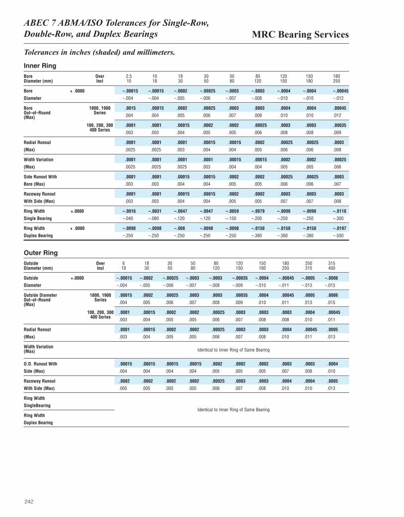
MRC Bearing ServicesABEC 7 ABMA/ISO Tolerances for Single-Row, Double-Row, and Duplex Bearings
242
Tolerances in inches (shaded) and millimeters.
Inner Ring
Bore Over 2.5 10 18 30 50 80 120 150 180Diameter (mm) Incl 10 18 30 50 80 120 150 180 250
Bore + .0000 –.00015 –.00015 –.0002 –.00025 –.0003 –.0003 –.0004 –.0004 –.00045
Diameter –.004 –.004 –.005 –.006 –.007 –.008 –.010 –.010 –.012
Bore 1800, 1900 .0015 .00015 .0002 .00025 .0003 .0003 .0004 .0004 .00045 Out–of–Round Series .004 .004 .005 .006 .007 .008 .010 .010 .012(Max)
100, 200, 300 .0001 .0001 .00015 .0002 .0002 .00025 .0003 .0003 .00035400 Series .003 .003 .004 .005 .005 .006 .008 .008 .009
Radial Runout .0001 .0001 .0001 .00015 .00015 .0002 .00025 .00025 .0003
(Max) .0025 .0025 .003 .004 .004 .005 .006 .006 .008
Width Variation .0001 .0001 .0001 .0001 .00015 .00015 .0002 .0002 .00025
(Max) .0025 .0025 .0025 .003 .004 .004 .005 .005 .006
Side Runout With .0001 .0001 .00015 .00015 .0002 .0002 .00025 .00025 .0003
Bore (Max) .003 .003 .004 .004 .005 .005 .006 .006 .007
Raceway Runout .0001 .0001 .00015 .00015 .0002 .0002 .0003 .0003 .0003
With Side (Max) .003 .003 .004 .004 .005 .005 .007 .007 .008
Ring Width +.0000 –.0016 –.0031 –.0047 –.0047 –.0059 –.0079 –.0098 –.0098 –.0118
Single Bearing –.040 –.080 –.120 –.120 –.150 –.200 –.250 –.250 –.300
Ring Width + .0000 –.0098 –.0098 –.008 –.0098 –.0098 –.0150 –.0150 –.0150 –.0197
Duplex Bearing –.250 –.250 –.250 –.250 –.250 –.380 –.380 –.380 –.500
Outer Ring
Outside Over 6 18 30 50 80 120 150 180 250 315Diameter (mm) Incl 18 30 50 80 120 150 180 250 315 400
Outside +.0000 –.00015 –.0002 –.00025 –.0003 –.0003 –.00035 –.0004 –.00045 –.0005 –.0006
Diameter –.004 –.005 –.006 –.007 –.008 –.009 –.010 –.011 –.013 –.015
Outside Diameter 1800, 1900 .00015 .0002 .00025 .0003 .0003 .00035 .0004 .00045 .0005 .0006Out–of–Round Series .004 .005 .006 .007 .008 .009 .010 .011 .013 .015(Max)
100, 200, 300 .0001 .00015 .0002 .0002 .00025 .0003 .0003 .0003 .0004 .00045400 Series .003 .004 .005 .005 .006 .007 .008 .008 .010 .011
Radial Runout .0001 .00015 .0002 .0002 .00025 .0003 .0003 .0004 .00045 .0005
(Max) .003 .004 .005 .005 .006 .007 .008 .010 .011 .013
Width Variation(Max)
O.D. Runout With .00015 .00015 .00015 .00015 .0002 .0002 .0002 .0003 .0003 .0004
Side (Max) .004 .004 .004 .004 .005 .005 .005 .007 .008 .010
Raceway Runout .0002 .0002 .0002 .0002 .00025 .0003 .0003 .0004 .0004 .0005
With Side (Max) .005 .005 .005 .005 .006 .007 .008 .010 .010 .013
Ring Width
SingleBearing
Ring Width
Duplex Bearing
Identical to Inner Ring of Same Bearing
Identical to Inner Ring of Same Bearing
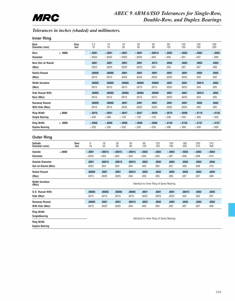
ABEC 9 ABMA/ISO Tolerances for Single-Row, Double-Row, and Duplex Bearings
243
Tolerances in inches (shaded) and millimeters.
Inner Ring
Bore Over 2.5 10 18 30 50 80 120 150 180Diameter (mm) Incl 10 18 30 50 80 120 150 180 250
Bore + .0000 –.0001 –.0001 –.0001 –.0001 –.00015 –.0002 –.0003 –.0003 –.0003
Diameter –.0025 –.0025 –.0025 –.0025 –.004 –.005 –.007 –.007 –.008
Bore Out–of–Round .0001 .0001 .0001 .0001 .0015 .0002 .0003 .0003 .0003
(Max) .0025 .0025 .0025 .0025 .004 .005 .007 .007 .008
Radial Runout .00005 .00005 .0001 .0001 .0001 .0001 .0001 .0002 .0002
(Max) .0015 .0015 .0025 .0025 .0025 .0025 .0025 .005 .005
Width Variation .00005 .00005 .00005 .00005 .00005 .0001 .0001 .00015 .0002
(Max) .0015 .0015 .0015 .0015 .0015 .0025 .0025 .004 .005
Side Runout With .00005 .00005 .00005 .00005 .00005 .0001 .0001 .00015 .0002
Bore (Max) .0015 .0015 .0015 .0015 .0015 .0025 .0025 .004 .005
Raceway Runout .00005 .00005 .0001 .0001 .0001 .0001 .0001 .0002 .0002
With Side (Max) .0015 .0015 .0025 .0025 .0025 .0025 .0025 .005 .005
Ring Width +.0000 –.0016 –.0031 –.0047 –.0047 –.0059 –.0079 –.0098 –.0118 –.0138
Single Bearing –.040 –.080 –.120 –.120 –.150 –.200 –.250 –.300 –.350
Ring Width + .0000 –.0098 –.0098 –.0098 –.0098 –.0098 –.0150 –.0150 –.0197 –.0197
Duplex Bearing –.250 –.250 –.250 –.250 –.250 –.380 –.380 –.500 –.500
Outer Ring
Outside Over 6 18 30 50 80 120 150 180 250 315Diameter (mm) Incl 18 30 50 80 120 150 180 250 315 400
Outside +.0000 –.0001 –.00015 –.00015 –.00015 –.0002 –.0002 –.0003 –.0003 –.0003 –.0004
Diameter –.0025 –.004 –.004 –.004 –.005 –.005 –.007 –.008 –.008 –.010
Outside Diameter .0001 .00015 .00015 .00015 .0002 .0002 .0003 .0003 .0003 .0004
Out–of–Round (Max) .0025 .004 .004 .004 .005 .005 .007 .008 .008 .010
Radial Runout .00005 .0001 .0001 .00015 .0002 .0002 .0002 .0003 .0003 .0005
(Max) .0015 .0025 .0025 .004 .005 .005 .005 .007 .007 .008
Width Variation(Max)
O.D. Runout With .00005 .00005 .00005 .00005 .0001 .0001 .0001 .00015 .0002 .0003
Side (Max) .0015 .0015 .0015 .0015 .0025 .0025 .0025 .004 .005 .007
Raceway Runout .00005 .0001 .0001 .00015 .0002 .0002 .0002 .0003 .0003 .0003
With Side (Max) .0015 .0025 .0025 .004 .005 .005 .005 .007 .007 .008
Ring Width
SingleBearing
Ring Width
Duplex Bearing
Identical to Inner Ring of Same Bearing
Identical to Inner Ring of Same Bearing

244
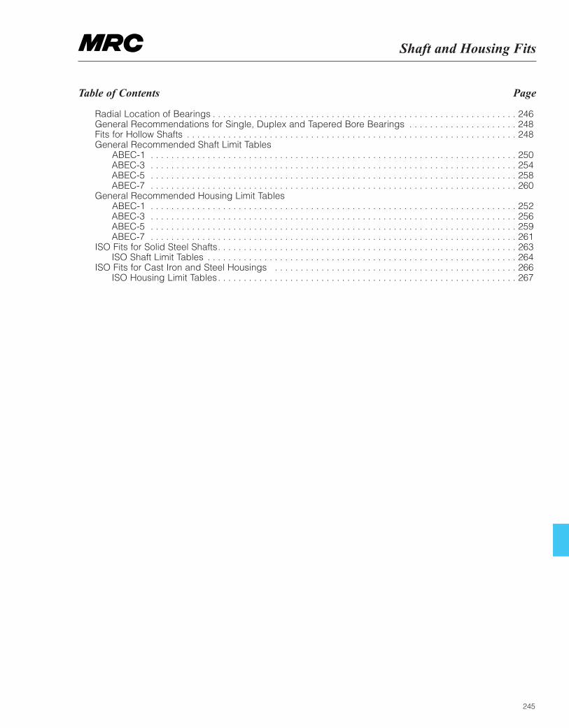
Shaft and Housing Fits
245
Table of Contents Page
Radial Location of Bearings . . . . . . . . . . . . . . . . . . . . . . . . . . . . . . . . . . . . . . . . . . . . . . . . . . . . . . . . . . . 246General Recommendations for Single, Duplex and Tapered Bore Bearings . . . . . . . . . . . . . . . . . . . . . 248 Fits for Hollow Shafts . . . . . . . . . . . . . . . . . . . . . . . . . . . . . . . . . . . . . . . . . . . . . . . . . . . . . . . . . . . . . . . . 248 General Recommended Shaft Limit Tables
ABEC-1 . . . . . . . . . . . . . . . . . . . . . . . . . . . . . . . . . . . . . . . . . . . . . . . . . . . . . . . . . . . . . . . . . . . . . . . 250 ABEC-3 . . . . . . . . . . . . . . . . . . . . . . . . . . . . . . . . . . . . . . . . . . . . . . . . . . . . . . . . . . . . . . . . . . . . . . . 254 ABEC-5 . . . . . . . . . . . . . . . . . . . . . . . . . . . . . . . . . . . . . . . . . . . . . . . . . . . . . . . . . . . . . . . . . . . . . . . 258 ABEC-7 . . . . . . . . . . . . . . . . . . . . . . . . . . . . . . . . . . . . . . . . . . . . . . . . . . . . . . . . . . . . . . . . . . . . . . . 260
General Recommended Housing Limit Tables ABEC-1 . . . . . . . . . . . . . . . . . . . . . . . . . . . . . . . . . . . . . . . . . . . . . . . . . . . . . . . . . . . . . . . . . . . . . . . 252 ABEC-3 . . . . . . . . . . . . . . . . . . . . . . . . . . . . . . . . . . . . . . . . . . . . . . . . . . . . . . . . . . . . . . . . . . . . . . . 256 ABEC-5 . . . . . . . . . . . . . . . . . . . . . . . . . . . . . . . . . . . . . . . . . . . . . . . . . . . . . . . . . . . . . . . . . . . . . . . 259 ABEC-7 . . . . . . . . . . . . . . . . . . . . . . . . . . . . . . . . . . . . . . . . . . . . . . . . . . . . . . . . . . . . . . . . . . . . . . . 261
ISO Fits for Solid Steel Shafts. . . . . . . . . . . . . . . . . . . . . . . . . . . . . . . . . . . . . . . . . . . . . . . . . . . . . . . . . . 263ISO Shaft Limit Tables . . . . . . . . . . . . . . . . . . . . . . . . . . . . . . . . . . . . . . . . . . . . . . . . . . . . . . . . . . . . 264
ISO Fits for Cast Iron and Steel Housings . . . . . . . . . . . . . . . . . . . . . . . . . . . . . . . . . . . . . . . . . . . . . . . 266 ISO Housing Limit Tables. . . . . . . . . . . . . . . . . . . . . . . . . . . . . . . . . . . . . . . . . . . . . . . . . . . . . . . . . . 267
MRC Bearing ServicesShaft and Housing Fits
246
If the load carrying ability of a bearing is to be fullyutilized, its rings or washers must be supported aroundtheir complete circumference and across the wholewidth of the raceway. The support must be firm andeven and, for inner rings, can be provided by acylindrical or tapered seating or, for washers, by a flat(plane) support surface. This means that the seatingsmust be made with adequate accuracy and that theyhave a surface which is uninterrupted by grooves, holesor other features. In addition the rings must be reliablysecured to prevent them from turning on or in theirseatings under load. Inadequately or incorrectly securedbearing rings generally produce damage to thebearings and associated components.
A satisfactory radial location and an adequate supportcan generally only be obtained when the rings aremounted with an appropriate° of interference. However,when simple mounting and dismounting are desirable,or when axial displacement is required with a non-locating bearing, interference fits cannot be used.
Selection of fit
When selecting a fit, the factors discussed in thefollowing and the general guidelines in respect of themshould be considered.
1. Conditions of rotation
Conditions of rotation refer to the movement of thebearing ring being considered in relation to the directionof the load. Essentially there are three differentconditions: ‘‘rotating load’’ ‘‘stationary load’’ and‘‘direction of load indeterminate’’.
If the bearing ring rotates and the load is stationary, or if the ring is stationary and the load rotates so that all points on the raceway are subjected to load in thecourse of one revolution, the load is defined as a‘‘rotating load’’. Heavy loads which do not rotate butoscillate (for example, those acting on the outer rings of connecting rod bearings) are generally considered as rotating loads.
‘‘Stationary load’’ applies if the bearing ring is stationaryand the load is also stationary, or if the ring and loadrotate at the same speed so that the load is alwaysdirected to the same point on the raceway.
Variable external loads, shock loads, vibrations andunbalance loads in high-speed machines give rise tochanges in the direction of load which cannot beaccurately described. Such conditions are classified as‘‘direction of load indeterminate’’.
A bearing ring subjected to a rotating load will turn(creep) on its own seating if mounted with a clearancefit, and wear (fretting corrosion) of the contactingsurfaces will occur. To prevent this, interference fits mustbe used. The° of interference needed is dictated by theoperating conditions (see points 2 and 4).
When a stationary load exists, a bearing ring will notnormally turn on its seating. Therefore, the ring need notnecessarily have an interference fit unless this isrequired for other reasons.
When the direction of load is indeterminate andparticularly where heavy loads are involved, it isdesirable that both rings have an interference fit. For theinner ring the fit recommended for rotating load isnormally used. However, when the outer ring must befree to move axially in the housing and the load is notheavy, a somewhat looser fit than that recommended forrotating load may be used. When interference fits areused on both the inner ring and outer ring, the remaininginternal clearance of the bearing should be consideredto avoid excessive clearance reduction, i.e. internalpreloading.
2. Magnitude of the load.
The interference fit of a bearing inner ring on its seatingwill be loosened with increasing load as the ring willexpand. Under the influence of rotating load the ringmay begin to creep. The° of interference must thereforebe related to the magnitude of the load: the heavier theload, particularly if it is of shock character, the greaterthe interference required.
3. Bearing internal clearance
An interference fit of a bearing on the shaft or in thehousing means that the ring is elastically deformed(expanded or compressed) and the bearing internalclearance reduced. A certain minimum clearanceshould remain, however (see also ‘‘Bearing radialclearance’’, page 270). The initial clearance andpermissible reduction depend on the type and size ofthe bearing. The reduction in clearance due to theinterference fit can be so large that bearings withincreased radial clearance have to be used in order toprevent the bearing from becoming preloaded.
4. Temperature conditions
In service, bearing rings normally reach a temperaturewhich is higher than that of the components to whichthey are fitted. This can result in an easing of the fit ofthe inner ring on its seating, while outer ring expansionmay prevent the desired axial displacement of the ringin its housing. Temperature differentials and the directionof heat flow must therefore be carefully considered.
5. Running accuracy requirements
To reduce resilience and vibration, clearance fits shouldgenerally not be used for bearings where high demandsare placed on running accuracy. Bearing seatings onthe shaft and in the housing should be made to narrow
Radial Location of Bearings
Shaft and Housing Fits
247
Radial Location of Bearings (continued)
made to narrow dimensional tolerances,corresponding at least to ABEC-5 for the shaft andABEC-3 for the housing as shown in the tables.
6. Design and material of shaft and housing
CAUTION: The fit of a bearing ring on its seatingmust not lead to uneven distortion of the ring(out-of- round). This can be caused for example bydiscontinuities in the seating surface. Split housingsare therefore not generally suitable where outer ringsare to have an interference fit.
To ensure adequate support for bearing ringsmounted in thin-walled housings, light alloy housingsor on hollow shafts, heavier interference fits thanthose normally selected for thick-walled steel or castiron housings or for solid shafts should be used (seealso ‘‘Fits for hollow shafts’’, page 248).
For stainless steel shafts, reduced shaft interferenceor increased bearing internal clearance should beconsidered because of the high coefficient ofexpansion of stainless steel.
7. Ease of mounting and dismounting
Bearings with clearance fits are usually easier tomount or dismount than those with interference fits.Where operating conditions necessitate interferencefits and it is essential that mounting and dismountingcan be done easily, separable bearings, or bearingswith tapered bore and adapter or withdrawal sleevemay be used.
8. Displacement of non-locating bearing
If non-separable bearings are used as non-locatingbearings it is imperative that one of the bearing ringsis free to move axially at all times during operation.This is ensured by adopting a clearance fit for thatring which carries a stationary load. When the outerring is under stationary load so that axialdisplacement has to take place in the housing bore, ahardened intermediate bushing is often fitted to theouter ring, for example, where light alloy housings areemployed. In this way a ‘‘hammering out’’ of thehousing seating because of the lower materialhardness is avoided; it would otherwise result in theaxial displacement being restricted or evenimpossible after a time. If cylindrical or needle rollerbearings having one ring without flanges are used,both bearing rings may be mounted with aninterference fit because axial displacement will takeplace within the bearing.
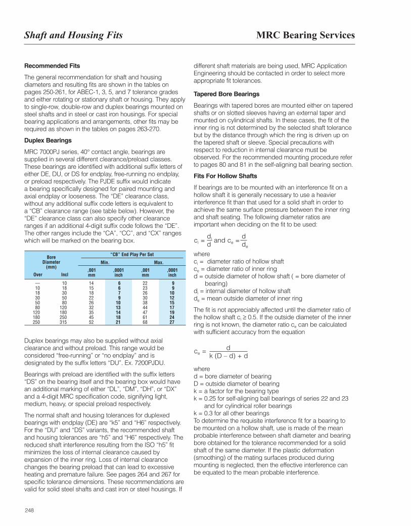
MRC Bearing ServicesShaft and Housing Fits
248
Recommended Fits
The general recommendation for shaft and housingdiameters and resulting fits are shown in the tables onpages 250-261, for ABEC-1, 3, 5, and 7 tolerance gradesand either rotating or stationary shaft or housing. They applyto single-row, double-row and duplex bearings mounted onsteel shafts and in steel or cast iron housings. For specialbearing applications and arrangements, other fits may berequired as shown in the tables on pages 263-270.
Duplex Bearings
MRC 7000PJ series, 40° contact angle, bearings aresupplied in several different clearance/preload classes.These bearings are identified with additional suffix letters ofeither DE, DU, or DS for endplay, free-running no endplay,or preload respectively. The PJDE suffix would indicate a bearing specifically designed for paired mounting andaxial endplay or looseness. The “DE” clearance class,without any additional suffix code letters is equivalent to a “CB” clearance range (see table below). However, the“DE” clearance class can also specify other clearanceranges if an additional 4-digit suffix code follows the “DE”.The other ranges include the “CA”, “CC”, and “CX” rangeswhich will be marked on the bearing box.
Duplex bearings may also be supplied without axialclearance and without preload. This range would beconsidered “free-running” or “no endplay” and isdesignated by the suffix letters “DU”. Ex. 7200PJDU.
Bearings with preload are identified with the suffix letters“DS” on the bearing itself and the bearing box would havean additional marking of either “DL”, “DM”, “DH”, or “DX”and a 4-digit MRC specification code, signifying light,medium, heavy, or special preload respectively.
The normal shaft and housing tolerances for duplexedbearings with endplay (DE) are “k5” and “H6” respectively.For the “DU” and “DS” variants, the recommended shaftand housing tolerances are “h5” and “H6” respectively. Thereduced shaft interference resulting from the ISO “h5” fitminimizes the loss of internal clearance caused byexpansion of the inner ring. Loss of internal clearancechanges the bearing preload that can lead to excessiveheating and premature failure. See pages 264 and 267 forspecific tolerance dimensions. These recommendations arevalid for solid steel shafts and cast iron or steel housings. If
different shaft materials are being used, MRC ApplicationEngineering should be contacted in order to select moreappropriate fit tolerances.
Tapered Bore Bearings
Bearings with tapered bores are mounted either on taperedshafts or on slotted sleeves having an external taper andmounted on cylindrical shafts. In these cases, the fit of theinner ring is not determined by the selected shaft tolerancebut by the distance through which the ring is driven up onthe tapered shaft or sleeve. Special precautions withrespect to reduction in internal clearance must beobserved. For the recommended mounting procedure referto pages 80 and 81 in the self-aligning ball bearing section.
Fits For Hollow Shafts
If bearings are to be mounted with an interference fit on ahollow shaft it is generally necessary to use a heavierinterference fit than that used for a solid shaft in order toachieve the same surface pressure between the inner ringand shaft seating. The following diameter ratios areimportant when deciding on the fit to be used:
whereci = diameter ratio of hollow shaft ce = diameter ratio of inner ring d = outside diameter of hollow shaft ( = bore diameter of
bearing) di = internal diameter of hollow shaft de = mean outside diameter of inner ring
The fit is not appreciably affected until the diameter ratio ofthe hollow shaft ci ≥ 0.5. If the outside diameter of the innerring is not known, the diameter ratio ce can be calculatedwith sufficient accuracy from the equation
where d = bore diameter of bearing D = outside diameter of bearing k = a factor for the bearing type k = 0.25 for self-aligning ball bearings of series 22 and 23
and for cylindrical roller bearings k = 0.3 for all other bearingsTo determine the requisite interference fit for a bearing to be mounted on a hollow shaft, use is made of the meanprobable interference between shaft diameter and bearingbore obtained for the tolerance recommended for a solidshaft of the same diameter. If the plastic deformation(smoothing) of the mating surfaces produced duringmounting is neglected, then the effective interference canbe equated to the mean probable interference.
ci =di and ce =
dd de
ce = dk (D – d) + d
Bore Diameter
(mm)
“CB” End Play Per Set
Min.
,001mmOver Incl
,001mm
,0001inch
,0001inch
Max.
— 10 14 6 22 910 18 15 6 23 918 30 18 7 26 1030 50 22 9 30 1250 80 26 10 38 1580 120 32 13 44 17
120 180 35 14 47 19180 250 45 18 61 24250 315 52 21 68 27
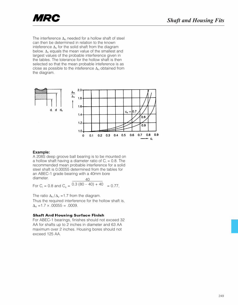
249
Shaft and Housing Fits
The interference ∆H needed for a hollow shaft of steelcan then be determined in relation to the knowninteference ∆V for the solid shaft from the diagrambelow. ∆V equals the mean value of the smallest andlargest values of the probable interference given inthe tables. The tolerance for the hollow shaft is thenselected so that the mean probable inteference is asclose as possible to the inteference ∆H obtained fromthe diagram.
Example:A 208S deep groove ball bearing is to be mounted ona hollow shaft having a diameter ratio of Ci = 0.8. Therecommended mean probable interference for a solidsteel shaft is 0.00055 determined from the tables foran ABEC-1 grade bearing with a 40mm borediameter.
For Ci = 0.8 and Ce = = 0.77,
The ratio ∆H / ∆V =1.7 from the diagram.Thus the required interference for the hollow shaft is,∆H =1.7 × .00055 = .0009.
Shaft And Housing Surface FinishFor ABEC-1 bearings, finishes should not exceed 32AA for shafts up to 2 inches in diameter and 63 AAmaximum over 2 inches. Housing bores should notexceed 125 AA.
400.3 (80 – 40) + 40
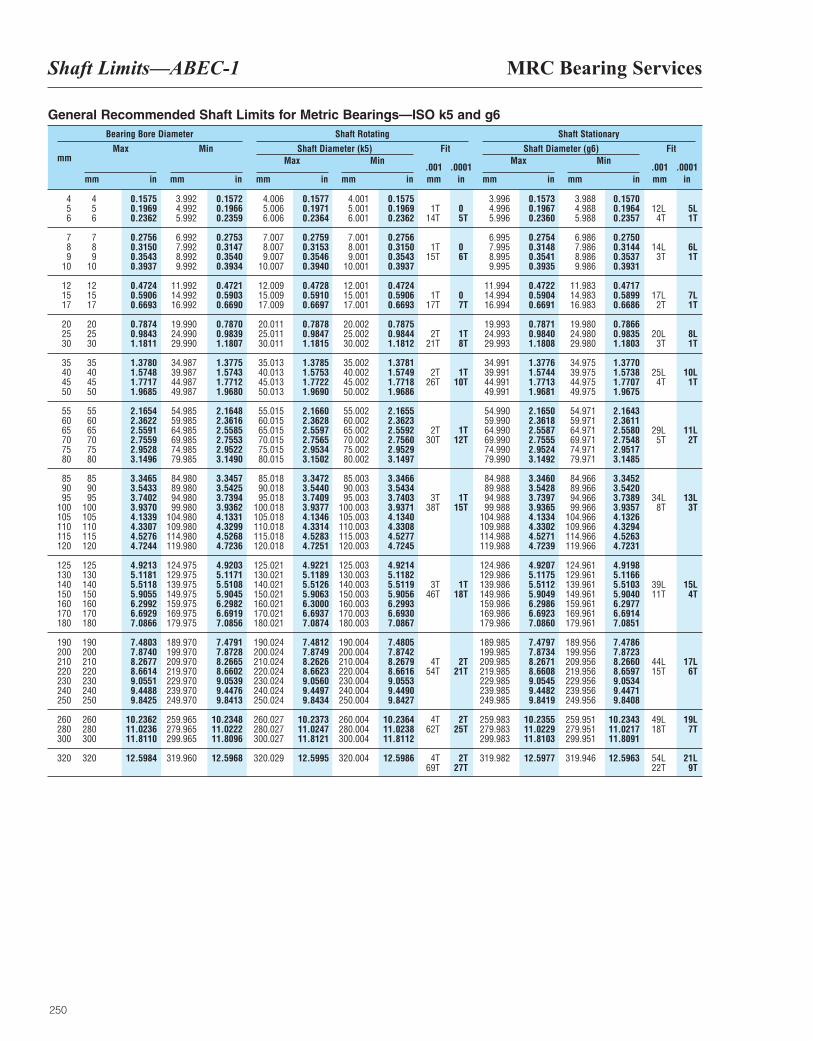
MRC Bearing ServicesShaft Limits—ABEC-1
250
mm Max
mm in
Min
mm in
Fit
.001 .0001mm in
Fit
.001 .0001mm in
Max
mm in
Max
mm in
Min
mm in
Min
mm in
Bearing Bore Diameter Shaft Rotating Shaft Stationary
Shaft Diameter (k5) Shaft Diameter (g6)
4 4 0.1575 3.992 0.1572 4.006 0.1577 4.001 0.1575 3.996 0.1573 3.988 0.15705 5 0.1969 4.992 0.1966 5.006 0.1971 5.001 0.1969 1T 0 4.996 0.1967 4.988 0.1964 12L 5L6 6 0.2362 5.992 0.2359 6.006 0.2364 6.001 0.2362 14T 5T 5.996 0.2360 5.988 0.2357 4T 1T
7 7 0.2756 6.992 0.2753 7.007 0.2759 7.001 0.2756 6.995 0.2754 6.986 0.27508 8 0.3150 7.992 0.3147 8.007 0.3153 8.001 0.3150 1T 0 7.995 0.3148 7.986 0.3144 14L 6L9 9 0.3543 8.992 0.3540 9.007 0.3546 9.001 0.3543 15T 6T 8.995 0.3541 8.986 0.3537 3T 1T
10 10 0.3937 9.992 0.3934 10.007 0.3940 10.001 0.3937 9.995 0.3935 9.986 0.3931
12 12 0.4724 11.992 0.4721 12.009 0.4728 12.001 0.4724 11.994 0.4722 11.983 0.471715 15 0.5906 14.992 0.5903 15.009 0.5910 15.001 0.5906 1T 0 14.994 0.5904 14.983 0.5899 17L 7L17 17 0.6693 16.992 0.6690 17.009 0.6697 17.001 0.6693 17T 7T 16.994 0.6691 16.983 0.6686 2T 1T
20 20 0.7874 19.990 0.7870 20.011 0.7878 20.002 0.7875 19.993 0.7871 19.980 0.786625 25 0.9843 24.990 0.9839 25.011 0.9847 25.002 0.9844 2T 1T 24.993 0.9840 24.980 0.9835 20L 8L30 30 1.1811 29.990 1.1807 30.011 1.1815 30.002 1.1812 21T 8T 29.993 1.1808 29.980 1.1803 3T 1T
35 35 1.3780 34.987 1.3775 35.013 1.3785 35.002 1.3781 34.991 1.3776 34.975 1.377040 40 1.5748 39.987 1.5743 40.013 1.5753 40.002 1.5749 2T 1T 39.991 1.5744 39.975 1.5738 25L 10L45 45 1.7717 44.987 1.7712 45.013 1.7722 45.002 1.7718 26T 10T 44.991 1.7713 44.975 1.7707 4T 1T50 50 1.9685 49.987 1.9680 50.013 1.9690 50.002 1.9686 49.991 1.9681 49.975 1.9675
55 55 2.1654 54.985 2.1648 55.015 2.1660 55.002 2.1655 54.990 2.1650 54.971 2.164360 60 2.3622 59.985 2.3616 60.015 2.3628 60.002 2.3623 59.990 2.3618 59.971 2.361165 65 2.5591 64.985 2.5585 65.015 2.5597 65.002 2.5592 2T 1T 64.990 2.5587 64.971 2.5580 29L 11L70 70 2.7559 69.985 2.7553 70.015 2.7565 70.002 2.7560 30T 12T 69.990 2.7555 69.971 2.7548 5T 2T75 75 2.9528 74.985 2.9522 75.015 2.9534 75.002 2.9529 74.990 2.9524 74.971 2.951780 80 3.1496 79.985 3.1490 80.015 3.1502 80.002 3.1497 79.990 3.1492 79.971 3.1485
85 85 3.3465 84.980 3.3457 85.018 3.3472 85.003 3.3466 84.988 3.3460 84.966 3.345290 90 3.5433 89.980 3.5425 90.018 3.5440 90.003 3.5434 89.988 3.5428 89.966 3.542095 95 3.7402 94.980 3.7394 95.018 3.7409 95.003 3.7403 3T 1T 94.988 3.7397 94.966 3.7389 34L 13L
100 100 3.9370 99.980 3.9362 100.018 3.9377 100.003 3.9371 38T 15T 99.988 3.9365 99.966 3.9357 8T 3T105 105 4.1339 104.980 4.1331 105.018 4.1346 105.003 4.1340 104.988 4.1334 104.966 4.1326110 110 4.3307 109.980 4.3299 110.018 4.3314 110.003 4.3308 109.988 4.3302 109.966 4.3294115 115 4.5276 114.980 4.5268 115.018 4.5283 115.003 4.5277 114.988 4.5271 114.966 4.5263120 120 4.7244 119.980 4.7236 120.018 4.7251 120.003 4.7245 119.988 4.7239 119.966 4.7231
125 125 4.9213 124.975 4.9203 125.021 4.9221 125.003 4.9214 124.986 4.9207 124.961 4.9198130 130 5.1181 129.975 5.1171 130.021 5.1189 130.003 5.1182 129.986 5.1175 129.961 5.1166140 140 5.5118 139.975 5.5108 140.021 5.5126 140.003 5.5119 3T 1T 139.986 5.5112 139.961 5.5103 39L 15L150 150 5.9055 149.975 5.9045 150.021 5.9063 150.003 5.9056 46T 18T 149.986 5.9049 149.961 5.9040 11T 4T160 160 6.2992 159.975 6.2982 160.021 6.3000 160.003 6.2993 159.986 6.2986 159.961 6.2977170 170 6.6929 169.975 6.6919 170.021 6.6937 170.003 6.6930 169.986 6.6923 169.961 6.6914180 180 7.0866 179.975 7.0856 180.021 7.0874 180.003 7.0867 179.986 7.0860 179.961 7.0851
190 190 7.4803 189.970 7.4791 190.024 7.4812 190.004 7.4805 189.985 7.4797 189.956 7.4786200 200 7.8740 199.970 7.8728 200.024 7.8749 200.004 7.8742 199.985 7.8734 199.956 7.8723210 210 8.2677 209.970 8.2665 210.024 8.2626 210.004 8.2679 4T 2T 209.985 8.2671 209.956 8.2660 44L 17L220 220 8.6614 219.970 8.6602 220.024 8.6623 220.004 8.6616 54T 21T 219.985 8.6608 219.956 8.6597 15T 6T230 230 9.0551 229.970 9.0539 230.024 9.0560 230.004 9.0553 229.985 9.0545 229.956 9.0534240 240 9.4488 239.970 9.4476 240.024 9.4497 240.004 9.4490 239.985 9.4482 239.956 9.4471250 250 9.8425 249.970 9.8413 250.024 9.8434 250.004 9.8427 249.985 9.8419 249.956 9.8408
260 260 10.2362 259.965 10.2348 260.027 10.2373 260.004 10.2364 4T 2T 259.983 10.2355 259.951 10.2343 49L 19L280 280 11.0236 279.965 11.0222 280.027 11.0247 280.004 11.0238 62T 25T 279.983 11.0229 279.951 11.0217 18T 7T300 300 11.8110 299.965 11.8096 300.027 11.8121 300.004 11.8112 299.983 11.8103 299.951 11.8091
320 320 12.5984 319.960 12.5968 320.029 12.5995 320.004 12.5986 4T 2T 319.982 12.5977 319.946 12.5963 54L 21L69T 27T 22T 9T
General Recommended Shaft Limits for Metric Bearings—ISO k5 and g6
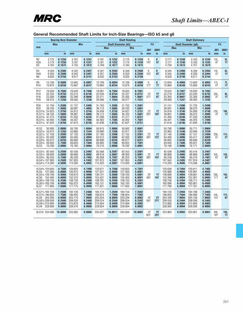
Shaft Limits—ABEC-1
251
mm Max
mm in
Min
mm in
Fit
.001 .0001mm in
Fit
.001 .0001mm in
Max
mm in
Max
mm in
Min
mm in
Min
mm in
Bearing Bore Diameter Shaft Rotating Shaft Stationary
Shaft Diameter (k5) Shaft Diameter (g6)
R2 3.175 0.1250 3.167 0.1247 3.181 0.1252 3.175 0.1250 0 0 3.171 0.1248 3.163 0.1245 12L 5LR2A 3.175 0.1250 3.167 0.1247 3.181 0.1252 3.175 0.1250 14T 5T 3.171 0.1248 3.163 0.1245 4T 1TR3 4.763 0.1875 4.755 0.1872 4.769 0.1877 4.763 0.1875 4.759 0.1873 4.751 0.1870
R4 6.350 0.2500 6.342 0.2497 6.357 0.2503 6.350 0.2500 0 0 6.345 0.2498 6.336 0.2494 14L 6LR4A 6.350 0.2500 6.342 0.2497 6.357 0.2503 6.350 0.2500 15T 6T 6.345 0.2498 6.336 0.2494 3T 1TR6 9.525 0.3750 9.517 0.3747 9.532 0.3753 9.525 0.3750 9.520 0.3748 9.511 0.3744
R8 12.700 0.5000 12.692 0.4997 12.709 0.5004 12.700 0.5000 0 0 12.694 0.4998 12.683 0.4993 17L 7LR10 15.875 0.6250 15.867 0.6247 15.884 0.6254 15.875 0.6250 17T 7T 15.869 0.6248 15.858 0.6243 2T 1T
R12 19.050 0.7500 19.040 0.7496 19.061 0.7504 19.052 0.7501 19.043 0.7497 19.030 0.7492R14 22.225 0.8750 22.215 0.8746 22.236 0.8754 22.227 0.8751 2T 1T 22.218 0.8747 22.205 0.8742 20L 8LR16 25.400 1.0000 25.390 0.9996 25.411 1.0004 25.402 1.0001 21T 8T 25.393 0.9997 25.380 0.9992 3T 1TR18 28.575 1.1250 28.565 1.1246 28.586 1.1254 28.577 1.1251 28.568 1.1247 28.555 1.1242
R20 31.750 1.2500 31.737 1.2495 31.763 1.2505 31.752 1.2501 31.741 1.2496 31.725 1.2490R24 38.100 1.5000 38.087 1.4995 38.113 1.5005 38.102 1.5001 38.091 1.4996 38.075 1.4990XLS1³|₈ 34.925 1.3750 34.912 1.3745 34.938 1.3755 34.927 1.3751 2T 1T 34.916 1.3746 34.900 1.3740 25L 10LXLS1¹|₂ 38.100 1.5000 38.087 1.4995 38.113 1.5005 38.102 1.5001 26T 10T 38.091 1.4996 38.075 1.4990 4T 1TXLS1⁵|₈ 41.275 1.6250 41.262 1.6245 41.288 1.6255 41.277 1.6251 41.266 1.6246 41.250 1.6240XLS1³|₄ 44.450 1.7500 44.437 1.7495 44.463 1.7505 44.452 1.7501 44.441 1.7496 44.425 1.7490XLS1⁷|₈ 47.625 1.8750 47.612 1.8745 47.638 1.8755 47.627 1.8751 47.616 1.8746 47.600 1.8740
XLS2 50.800 2.0000 50.785 1.9994 50.815 2.0006 50.802 2.0001 50.790 1.9996 50.771 1.9989XLS2¹|₈ 53.975 2.1250 53.960 2.1244 53.990 2.1256 53.977 2.1251 53.965 2.1246 53.946 2.1239XLS2¹|₄ 57.150 2.2500 57.135 2.2494 57.165 2.2506 57.152 2.2501 2T 1T 57.140 2.2496 57.121 2.2489 29L 11LXLS2¹|₂ 63.500 2.5000 63.485 2.4994 63.515 2.5006 63.502 2.5001 30T 12T 63.490 2.4996 63.471 2.4989 5T 2TXLS2⁵|₈ 66.675 2.6250 66.660 2.6244 66.690 2.6256 66.677 2.6251 66.665 2.6246 66.646 2.6239XLS2³|₄ 69.850 2.7500 69.835 2.7494 69.865 2.7506 69.852 2.7501 69.840 2.7496 69.821 2.7489XLS3 76.200 3.0000 76.185 2.9994 76.215 3.0006 76.202 3.0001 76.190 2.9996 76.171 2.9989
XLS3¹|₄ 82.550 3.2500 82.530 3.2492 82.568 3.2507 82.553 3.2501 82.538 3.2495 82.516 3.2487XLS3¹|₂ 88.900 3.5000 88.880 3.4992 88.918 3.5007 88.903 3.5001 3T 1T 88.888 3.4995 88.866 3.4987 34L 13LXLS3³|₄ 95.250 3.7500 95.230 3.7492 95.268 3.7507 95.253 3.7501 38T 15T 95.238 3.7495 95.216 3.7487 8T 3TXLS4¹|₄ 107.950 4.2500 107.935 4.2492 107.973 4.2507 107.953 4.2501 107.943 4.2495 107.916 4.2487XLS4¹|₂ 114.300 4.5000 114.285 4.4992 114.323 4.5007 114.303 4.5001 114.293 4.4995 114.266 4.4987
XLS4³|₄ 120.650 4.7500 120.625 4.7490 120.671 4.7508 120.653 4.7501 120.636 4.7494 120.611 4.7485XLS5 127.000 5.0000 126.975 4.9990 127.021 5.0008 127.003 5.0001 126.986 4.9994 126.961 4.9985XLS5¹|₂ 139.700 5.5000 139.675 5.4990 139.721 5.5008 139.703 5.5001 3T 1T 139.686 5.4994 139.661 5.4985 39L 15LXLS6 152.400 6.0000 152.375 5.9990 152.421 6.0008 152.403 6.0001 46T 18T 152.386 5.9994 152.361 5.9985 11T 4TXLS6¹|₄ 158.750 6.2500 158.735 6.2490 158.781 6.2508 158.753 6.2501 158.746 6.2494 158.711 6.2485XLS6¹|₂ 165.100 6.5000 165.075 6.4990 165.121 6.5008 165.103 6.5001 165.086 6.4994 165.061 6.4985XLS7 177.800 7.0000 177.775 6.9990 177.821 7.0008 177.803 7.0001 177.786 6.9994 177.761 6.9985
XLS7¹|₄ 184.150 7.2500 184.120 7.2488 184.174 7.2509 184.154 7.2502 184.135 7.2494 184.106 7.2483XLS7³|₄ 196.850 7.7500 196.820 7.7488 196.874 7.7509 196.854 7.7502 196.835 7.7494 196.806 7.7483 44L 17LXLS8 203.200 8.0000 203.170 7.9988 203.224 8.0009 203.204 8.0002 4T 2T 203.185 7.9994 203.156 7.9983 15T 6TXLS8¹|₄ 209.950 8.2500 209.520 8.2488 209.574 8.2509 209.554 8.2502 54T 21T 209.535 8.2494 209.506 8.2483XLS8¹|₂ 215.900 8.5000 215.870 8.4988 215.924 8.5009 215.904 8.5002 215.885 8.4994 215.856 8.4983XLS9 228.600 9.0000 228.570 8.9988 228.624 9.0009 228.604 9.0002 228.585 8.9994 228.556 8.9983
XLS10 254.000 10.0000 253.965 9.9986 254.027 10.0011 254.004 10.0002 4T 2T 253.983 9.9993 253.951 9.9981 49L 19L62T 25T 18T 7T
General Recommended Shaft Limits for Inch-Size Bearings—ISO k5 and g6
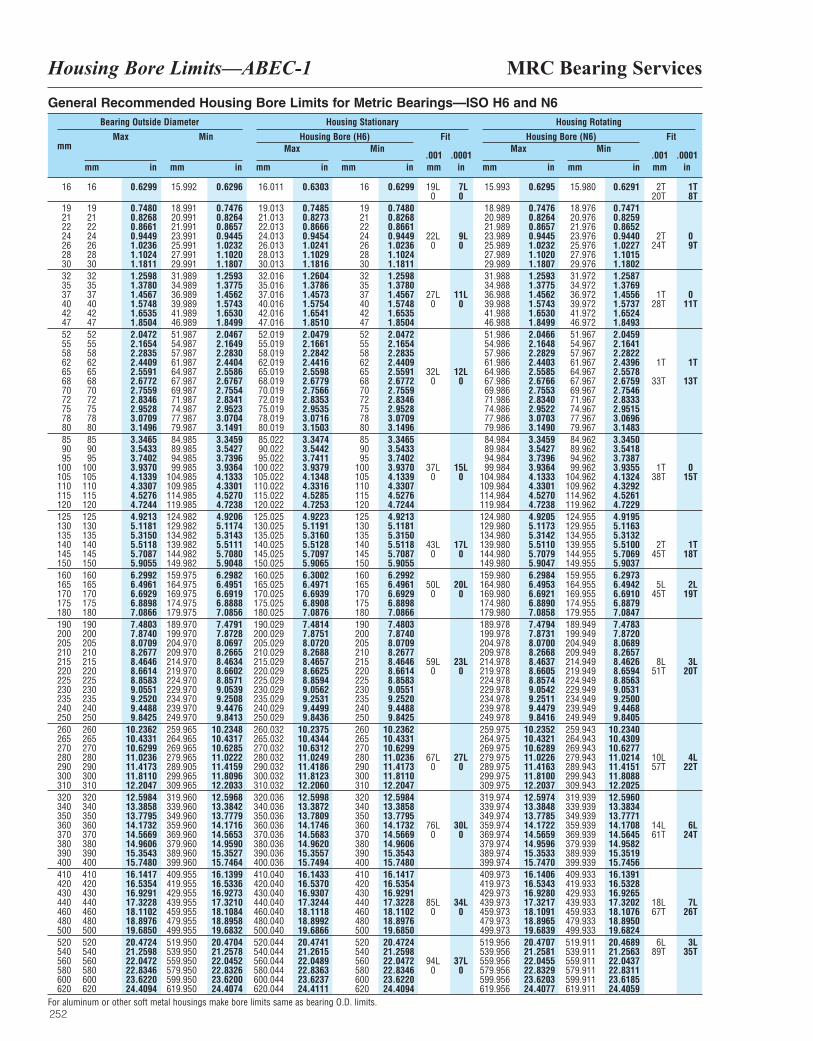
MRC Bearing ServicesHousing Bore Limits—ABEC-1
252
mm Max
mm in
Min
mm in
Fit
.001 .0001mm in
Fit
.001 .0001mm in
Max
mm in
Max
mm in
Min
mm in
Min
mm in
Bearing Outside Diameter Housing Stationary Housing Rotating
Housing Bore (H6) Housing Bore (N6)
16 16 0.6299 15.992 0.6296 16.011 0.6303 16 0.6299 19L 7L 15.993 0.6295 15.980 0.6291 2T 1T0 0 20T 8T
19 19 0.7480 18.991 0.7476 19.013 0.7485 19 0.7480 18.989 0.7476 18.976 0.747121 21 0.8268 20.991 0.8264 21.013 0.8273 21 0.8268 20.989 0.8264 20.976 0.825922 22 0.8661 21.991 0.8657 22.013 0.8666 22 0.8661 21.989 0.8657 21.976 0.865224 24 0.9449 23.991 0.9445 24.013 0.9454 24 0.9449 22L 9L 23.989 0.9445 23.976 0.9440 2T 026 26 1.0236 25.991 1.0232 26.013 1.0241 26 1.0236 0 0 25.989 1.0232 25.976 1.0227 24T 9T28 28 1.1024 27.991 1.1020 28.013 1.1029 28 1.1024 27.989 1.1020 27.976 1.101530 30 1.1811 29.991 1.1807 30.013 1.1816 30 1.1811 29.989 1.1807 29.976 1.180232 32 1.2598 31.989 1.2593 32.016 1.2604 32 1.2598 31.988 1.2593 31.972 1.258735 35 1.3780 34.989 1.3775 35.016 1.3786 35 1.3780 34.988 1.3775 34.972 1.376937 37 1.4567 36.989 1.4562 37.016 1.4573 37 1.4567 27L 11L 36.988 1.4562 36.972 1.4556 1T 040 40 1.5748 39.989 1.5743 40.016 1.5754 40 1.5748 0 0 39.988 1.5743 39.972 1.5737 28T 11T42 42 1.6535 41.989 1.6530 42.016 1.6541 42 1.6535 41.988 1.6530 41.972 1.652447 47 1.8504 46.989 1.8499 47.016 1.8510 47 1.8504 46.988 1.8499 46.972 1.849352 52 2.0472 51.987 2.0467 52.019 2.0479 52 2.0472 51.986 2.0466 51.967 2.045955 55 2.1654 54.987 2.1649 55.019 2.1661 55 2.1654 54.986 2.1648 54.967 2.164158 58 2.2835 57.987 2.2830 58.019 2.2842 58 2.2835 57.986 2.2829 57.967 2.282262 62 2.4409 61.987 2.4404 62.019 2.4416 62 2.4409 61.986 2.4403 61.967 2.4396 1T 1T65 65 2.5591 64.987 2.5586 65.019 2.5598 65 2.5591 32L 12L 64.986 2.5585 64.967 2.557868 68 2.6772 67.987 2.6767 68.019 2.6779 68 2.6772 0 0 67.986 2.6766 67.967 2.6759 33T 13T70 70 2.7559 69.987 2.7554 70.019 2.7566 70 2.7559 69.986 2.7553 69.967 2.754672 72 2.8346 71.987 2.8341 72.019 2.8353 72 2.8346 71.986 2.8340 71.967 2.833375 75 2.9528 74.987 2.9523 75.019 2.9535 75 2.9528 74.986 2.9522 74.967 2.951578 78 3.0709 77.987 3.0704 78.019 3.0716 78 3.0709 77.986 3.0703 77.967 3.069680 80 3.1496 79.987 3.1491 80.019 3.1503 80 3.1496 79.986 3.1490 79.967 3.148385 85 3.3465 84.985 3.3459 85.022 3.3474 85 3.3465 84.984 3.3459 84.962 3.345090 90 3.5433 89.985 3.5427 90.022 3.5442 90 3.5433 89.984 3.5427 89.962 3.541895 95 3.7402 94.985 3.7396 95.022 3.7411 95 3.7402 94.984 3.7396 94.962 3.7387
100 100 3.9370 99.985 3.9364 100.022 3.9379 100 3.9370 37L 15L 99.984 3.9364 99.962 3.9355 1T 0105 105 4.1339 104.985 4.1333 105.022 4.1348 105 4.1339 0 0 104.984 4.1333 104.962 4.1324 38T 15T110 110 4.3307 109.985 4.3301 110.022 4.3316 110 4.3307 109.984 4.3301 109.962 4.3292115 115 4.5276 114.985 4.5270 115.022 4.5285 115 4.5276 114.984 4.5270 114.962 4.5261120 120 4.7244 119.985 4.7238 120.022 4.7253 120 4.7244 119.984 4.7238 119.962 4.7229125 125 4.9213 124.982 4.9206 125.025 4.9223 125 4.9213 124.980 4.9205 124.955 4.9195130 130 5.1181 129.982 5.1174 130.025 5.1191 130 5.1181 129.980 5.1173 129.955 5.1163135 135 5.3150 134.982 5.3143 135.025 5.3160 135 5.3150 134.980 5.3142 134.955 5.3132140 140 5.5118 139.982 5.5111 140.025 5.5128 140 5.5118 43L 17L 139.980 5.5110 139.955 5.5100 2T 1T145 145 5.7087 144.982 5.7080 145.025 5.7097 145 5.7087 0 0 144.980 5.7079 144.955 5.7069 45T 18T150 150 5.9055 149.982 5.9048 150.025 5.9065 150 5.9055 149.980 5.9047 149.955 5.9037160 160 6.2992 159.975 6.2982 160.025 6.3002 160 6.2992 159.980 6.2984 159.955 6.2973165 165 6.4961 164.975 6.4951 165.025 6.4971 165 6.4961 50L 20L 164.980 6.4953 164.955 6.4942 5L 2L170 170 6.6929 169.975 6.6919 170.025 6.6939 170 6.6929 0 0 169.980 6.6921 169.955 6.6910 45T 19T175 175 6.8898 174.975 6.8888 175.025 6.8908 175 6.8898 174.980 6.8890 174.955 6.8879180 180 7.0866 179.975 7.0856 180.025 7.0876 180 7.0866 179.980 7.0858 179.955 7.0847190 190 7.4803 189.970 7.4791 190.029 7.4814 190 7.4803 189.978 7.4794 189.949 7.4783200 200 7.8740 199.970 7.8728 200.029 7.8751 200 7.8740 199.978 7.8731 199.949 7.8720205 205 8.0709 204.970 8.0697 205.029 8.0720 205 8.0709 204.978 8.0700 204.949 8.0689210 210 8.2677 209.970 8.2665 210.029 8.2688 210 8.2677 209.978 8.2668 209.949 8.2657215 215 8.4646 214.970 8.4634 215.029 8.4657 215 8.4646 59L 23L 214.978 8.4637 214.949 8.4626 8L 3L220 220 8.6614 219.970 8.6602 220.029 8.6625 220 8.6614 0 0 219.978 8.6605 219.949 8.6594 51T 20T225 225 8.8583 224.970 8.8571 225.029 8.8594 225 8.8583 224.978 8.8574 224.949 8.8563230 230 9.0551 229.970 9.0539 230.029 9.0562 230 9.0551 229.978 9.0542 229.949 9.0531235 235 9.2520 234.970 9.2508 235.029 9.2531 235 9.2520 234.978 9.2511 234.949 9.2500240 240 9.4488 239.970 9.4476 240.029 9.4499 240 9.4488 239.978 9.4479 239.949 9.4468250 250 9.8425 249.970 9.8413 250.029 9.8436 250 9.8425 249.978 9.8416 249.949 9.8405260 260 10.2362 259.965 10.2348 260.032 10.2375 260 10.2362 259.975 10.2352 259.943 10.2340265 265 10.4331 264.965 10.4317 265.032 10.4344 265 10.4331 264.975 10.4321 264.943 10.4309270 270 10.6299 269.965 10.6285 270.032 10.6312 270 10.6299 269.975 10.6289 269.943 10.6277280 280 11.0236 279.965 11.0222 280.032 11.0249 280 11.0236 67L 27L 279.975 11.0226 279.943 11.0214 10L 4L290 290 11.4173 289.905 11.4159 290.032 11.4186 290 11.4173 0 0 289.975 11.4163 289.943 11.4151 57T 22T300 300 11.8110 299.965 11.8096 300.032 11.8123 300 11.8110 299.975 11.8100 299.943 11.8088310 310 12.2047 309.965 12.2033 310.032 12.2060 310 12.2047 309.975 12.2037 309.943 12.2025320 320 12.5984 319.960 12.5968 320.036 12.5998 320 12.5984 319.974 12.5974 319.939 12.5960340 340 13.3858 339.960 13.3842 340.036 13.3872 340 13.3858 339.974 13.3848 339.939 13.3834350 350 13.7795 349.960 13.7779 350.036 13.7809 350 13.7795 349.974 13.7785 349.939 13.7771360 360 14.1732 359.960 14.1716 360.036 14.1746 360 14.1732 76L 30L 359.974 14.1722 359.939 14.1708 14L 6L370 370 14.5669 369.960 14.5653 370.036 14.5683 370 14.5669 0 0 369.974 14.5659 369.939 14.5645 61T 24T380 380 14.9606 379.960 14.9590 380.036 14.9620 380 14.9606 379.974 14.9596 379.939 14.9582390 390 15.3543 389.960 15.3527 390.036 15.3557 390 15.3543 389.974 15.3533 389.939 15.3519400 400 15.7480 399.960 15.7464 400.036 15.7494 400 15.7480 399.974 15.7470 399.939 15.7456410 410 16.1417 409.955 16.1399 410.040 16.1433 410 16.1417 409.973 16.1406 409.933 16.1391420 420 16.5354 419.955 16.5336 420.040 16.5370 420 16.5354 419.973 16.5343 419.933 16.5328430 430 16.9291 429.955 16.9273 430.040 16.9307 430 16.9291 429.973 16.9280 429.933 16.9265440 440 17.3228 439.955 17.3210 440.040 17.3244 440 17.3228 85L 34L 439.973 17.3217 439.933 17.3202 18L 7L460 460 18.1102 459.955 18.1084 460.040 18.1118 460 18.1102 0 0 459.973 18.1091 459.933 18.1076 67T 26T480 480 18.8976 479.955 18.8958 480.040 18.8992 480 18.8976 479.973 18.8965 479.933 18.8950500 500 19.6850 499.955 19.6832 500.040 19.6866 500 19.6850 499.973 19.6839 499.933 19.6824520 520 20.4724 519.950 20.4704 520.044 20.4741 520 20.4724 519.956 20.4707 519.911 20.4689 6L 3L540 540 21.2598 539.950 21.2578 540.044 21.2615 540 21.2598 539.956 21.2581 539.911 21.2563 89T 35T560 560 22.0472 559.950 22.0452 560.044 22.0489 560 22.0472 94L 37L 559.956 22.0455 559.911 22.0437580 580 22.8346 579.950 22.8326 580.044 22.8363 580 22.8346 0 0 579.956 22.8329 579.911 22.8311600 600 23.6220 599.950 23.6200 600.044 23.6237 600 23.6220 599.956 23.6203 599.911 23.6185620 620 24.4094 619.950 24.4074 620.044 24.4111 620 24.4094 619.956 24.4077 619.911 24.4059
General Recommended Housing Bore Limits for Metric Bearings—ISO H6 and N6
For aluminum or other soft metal housings make bore limits same as bearing O.D. limits.
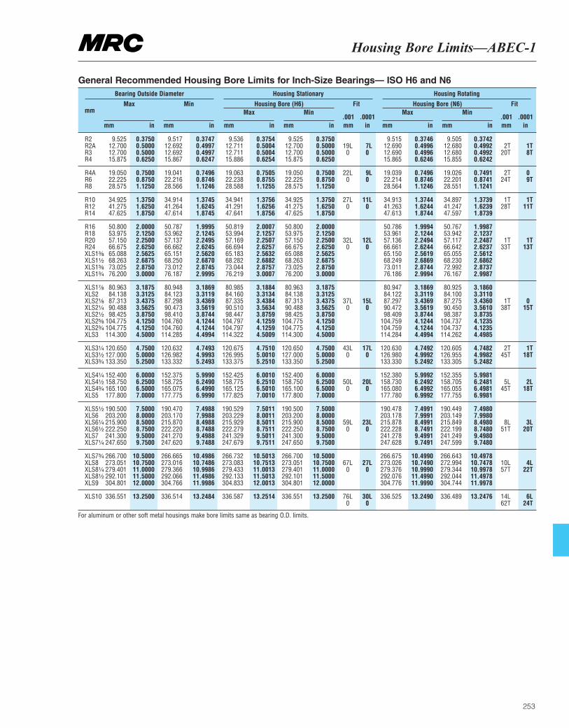
Housing Bore Limits—ABEC-1
253
mm Max
mm in
Min
mm in
Fit
.001 .0001mm in
Fit
.001 .0001mm in
Max
mm in
Max
mm in
Min
mm in
Min
mm in
Bearing Outside Diameter Housing Stationary Housing Rotating
Housing Bore (H6) Housing Bore (N6)
R2 9.525 0.3750 9.517 0.3747 9.536 0.3754 9.525 0.3750 9.515 0.3746 9.505 0.3742R2A 12.700 0.5000 12.692 0.4997 12.711 0.5004 12.700 0.5000 19L 7L 12.690 0.4996 12.680 0.4992 2T 1TR3 12.700 0.5000 12.692 0.4997 12.711 0.5004 12.700 0.5000 0 0 12.690 0.4996 12.680 0.4992 20T 8TR4 15.875 0.6250 15.867 0.6247 15.886 0.6254 15.875 0.6250 15.865 0.6246 15.855 0.6242
R4A 19.050 0.7500 19.041 0.7496 19.063 0.7505 19.050 0.7500 22L 9L 19.039 0.7496 19.026 0.7491 2T 0R6 22.225 0.8750 22.216 0.8746 22.238 0.8755 22.225 0.8750 0 0 22.214 0.8746 22.201 0.8741 24T 9TR8 28.575 1.1250 28.566 1.1246 28.588 1.1255 28.575 1.1250 28.564 1.1246 28.551 1.1241
R10 34.925 1.3750 34.914 1.3745 34.941 1.3756 34.925 1.3750 27L 11L 34.913 1.3744 34.897 1.3739 1T 1TR12 41.275 1.6250 41.264 1.6245 41.291 1.6256 41.275 1.6250 0 0 41.263 1.6244 41.247 1.6239 28T 11TR14 47.625 1.8750 47.614 1.8745 47.641 1.8756 47.625 1.8750 47.613 1.8744 47.597 1.8739
R16 50.800 2.0000 50.787 1.9995 50.819 2.0007 50.800 2.0000 50.786 1.9994 50.767 1.9987R18 53.975 2.1250 53.962 2.1245 53.994 2.1257 53.975 2.1250 53.961 2.1244 53.942 2.1237R20 57.150 2.2500 57.137 2.2495 57.169 2.2507 57.150 2.2500 32L 12L 57.136 2.2494 57.117 2.2487 1T 1TR24 66.675 2.6250 66.662 2.6245 66.694 2.6257 66.675 2.6250 0 0 66.661 2.6244 66.642 2.6237 33T 13TXLS1³|₈ 65.088 2.5625 65.151 2.5620 65.183 2.5632 65.088 2.5625 65.150 2.5619 65.055 2.5612XLS1¹|₂ 68.263 2.6875 68.250 2.6870 68.282 2.6882 68.263 2.6875 68.249 2.6869 68.230 2.6862XLS1³|₈ 73.025 2.8750 73.012 2.8745 73.044 2.8757 73.025 2.8750 73.011 2.8744 72.992 2.8737XLS1³|₄ 76.200 3.0000 76.187 2.9995 76.219 3.0007 76.200 3.0000 76.186 2.9994 76.167 2.9987
XLS1⁷|₈ 80.963 3.1875 80.948 3.1869 80.985 3.1884 80.963 3.1875 80.947 3.1869 80.925 3.1860XLS2 84.138 3.3125 84.123 3.3119 84.160 3.3134 84.138 3.3125 84.122 3.3119 84.100 3.3110XLS2¹|₈ 87.313 3.4375 87.298 3.4369 87.335 3.4384 87.313 3.4375 37L 15L 87.297 3.4369 87.275 3.4360 1T 0XLS2¹|₄ 90.488 3.5625 90.473 3.5619 90.510 3.5634 90.488 3.5625 0 0 90.472 3.5619 90.450 3.5610 38T 15TXLS2¹|₂ 98.425 3.8750 98.410 3.8744 98.447 3.8759 98.425 3.8750 98.409 3.8744 98.387 3.8735XLS2⁵|₈ 104.775 4.1250 104.760 4.1244 104.797 4.1259 104.775 4.1250 104.759 4.1244 104.737 4.1235XLS2³|₄ 104.775 4.1250 104.760 4.1244 104.797 4.1259 104.775 4.1250 104.759 4.1244 104.737 4.1235XLS3 114.300 4.5000 114.285 4.4994 114.322 4.5009 114.300 4.5000 114.284 4.4994 114.262 4.4985
XLS3¹|₄ 120.650 4.7500 120.632 4.7493 120.675 4.7510 120.650 4.7500 43L 17L 120.630 4.7492 120.605 4.7482 2T 1TXLS3¹|₂ 127.000 5.0000 126.982 4.9993 126.995 5.0010 127.000 5.0000 0 0 126.980 4.9992 126.955 4.9982 45T 18TXLS3³|₄ 133.350 5.2500 133.332 5.2493 133.375 5.2510 133.350 5.2500 133.330 5.2492 133.305 5.2482
XLS4¹|₄ 152.400 6.0000 152.375 5.9990 152.425 6.0010 152.400 6.0000 152.380 5.9992 152.355 5.9981XLS4¹|₂ 158.750 6.2500 158.725 6.2490 158.775 6.2510 158.750 6.2500 50L 20L 158.730 6.2492 158.705 6.2481 5L 2LXLS4³|₄ 165.100 6.5000 165.075 6.4990 165.125 6.5010 165.100 6.5000 0 0 165.080 6.4992 165.055 6.4981 45T 18TXLS5 177.800 7.0000 177.775 6.9990 177.825 7.0010 177.800 7.0000 177.780 6.9992 177.755 6.9981
XLS5¹|₂ 190.500 7.5000 190.470 7.4988 190.529 7.5011 190.500 7.5000 190.478 7.4991 190.449 7.4980XLS6 203.200 8.0000 203.170 7.9988 203.229 8.0011 203.200 8.0000 203.178 7.9991 203.149 7.9980XLS6¹|₄ 215.900 8.5000 215.870 8.4988 215.929 8.5011 215.900 8.5000 59L 23L 215.878 8.4991 215.849 8.4980 8L 3LXLS6¹|₂ 222.250 8.7500 222.220 8.7488 222.279 8.7511 222.250 8.7500 0 0 222.228 8.7491 222.199 8.7480 51T 20TXLS7 241.300 9.5000 241.270 9.4988 241.329 9.5011 241.300 9.5000 241.278 9.4991 241.249 9.4980XLS7¹|₄ 247.650 9.7500 247.620 9.7488 247.679 9.7511 247.650 9.7500 247.628 9.7491 247.599 9.7480
XLS7³|₄ 266.700 10.5000 266.665 10.4986 266.732 10.5013 266.700 10.5000 266.675 10.4990 266.643 10.4978XLS8 273.051 10.7500 273.016 10.7486 273.083 10.7513 273.051 10.7500 67L 27L 273.026 10.7490 272.994 10.7478 10L 4LXLS8¹|₄ 279.401 11.0000 279.366 10.9986 279.433 11.0013 279.401 11.0000 0 0 279.376 10.9990 279.344 10.9978 57T 22TXLS8¹|₂ 292.101 11.5000 292.066 11.4986 292.133 11.5013 292.101 11.5000 292.076 11.4990 292.044 11.4978XLS9 304.801 12.0000 304.766 11.9986 304.833 12.0013 304.801 12.0000 304.776 11.9990 304.744 11.9978
XLS10 336.551 13.2500 336.514 13.2484 336.587 13.2514 336.551 13.2500 76L 30L 336.525 13.2490 336.489 13.2476 14L 6L0 0 62T 24T
General Recommended Housing Bore Limits for Inch-Size Bearings— ISO H6 and N6
For aluminum or other soft metal housings make bore limits same as bearing O.D. limits.
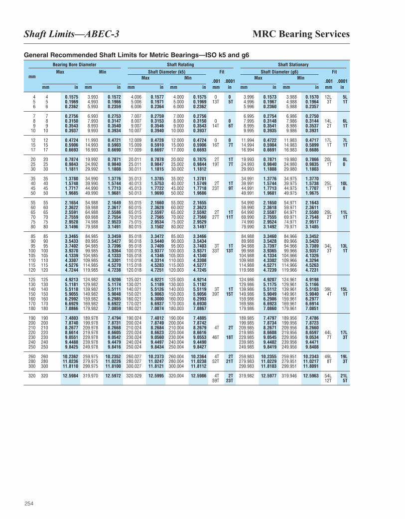
MRC Bearing ServicesShaft Limits—ABEC-3
254
mm Max
mm in
Min
mm in
Fit
.001 .0001mm in
Fit
.001 .0001mm in
Max
mm in
Max
mm in
Min
mm in
Min
mm in
Bearing Bore Diameter Shaft Rotating Shaft Stationary
Shaft Diameter (k5) Shaft Diameter (g6)
4 4 0.1575 3.993 0.1572 4.006 0.1577 4.000 0.1575 0 0 3.996 0.1573 3.988 0.1570 12L 5L5 5 0.1969 4.993 0.1966 5.006 0.1971 5.000 0.1969 13T 5T 4.996 0.1967 4.988 0.1964 3T 1T6 6 0.2362 5.993 0.2359 6.006 0.2364 6.000 0.2362 5.996 0.2360 5.988 0.2357
7 7 0.2756 6.993 0.2753 7.007 0.2759 7.000 0.2756 6.995 0.2754 6.986 0.27508 8 0.3150 7.993 0.3147 8.007 0.3153 8.000 0.3150 0 0 7.995 0.3148 7.986 0.3144 14L 6L9 9 0.3543 8.993 0.3540 9.007 0.3546 9.000 0.3543 14T 6T 8.995 0.3541 8.986 0.3537 2T 1T
10 10 0.3937 9.993 0.3934 10.007 0.3940 10.000 0.3937 9.995 0.3935 9.986 0.3931
12 12 0.4724 11.993 0.4721 12.009 0.4728 12.000 0.4724 0 0 11.994 0.4722 11.983 0.4717 17L 7L15 15 0.5906 14.993 0.5903 15.009 0.5910 15.000 0.5906 16T 7T 14.994 0.5904 14.983 0.5899 1T 1T17 17 0.6693 16.993 0.6690 17.009 0.6697 17.000 0.6693 16.994 0.6691 16.983 0.6686
20 20 0.7874 19.992 0.7871 20.011 0.7878 20.002 0.7875 2T 1T 19.993 0.7871 19.980 0.7866 20L 8L25 25 0.9843 24.992 0.9840 25.011 0.9847 25.002 0.9844 19T 7T 24.993 0.9840 24.980 0.9835 1T 030 30 1.1811 29.992 1.1808 30.011 1.1815 30.002 1.1812 29.993 1.1808 29.980 1.1803
35 35 1.3780 34.990 1.3776 35.013 1.3785 35.002 1.3781 34.991 1.3776 34.975 1.377040 40 1.5748 39.990 1.5744 40.013 1.5753 40.002 1.5749 2T 1T 39.991 1.5744 39.975 1.5738 25L 10L45 45 1.7717 44.990 1.7713 45.013 1.7722 45.002 1.7718 23T 9T 44.991 1.7713 44.975 1.7707 1T 050 50 1.9685 49.990 1.9681 50.013 1.9690 50.002 1.9686 49.991 1.9681 49.975 1.9675
55 55 2.1654 54.988 2.1649 55.015 2.1660 55.002 2.1655 54.990 2.1650 54.971 2.164360 60 2.3622 59.988 2.3617 60.015 2.3628 60.002 2.3623 59.990 2.3618 59.971 2.361165 65 2.5591 64.988 2.5586 65.015 2.5597 65.002 2.5592 2T 1T 64.990 2.5587 64.971 2.5580 29L 11L70 70 2.7559 69.988 2.7554 70.015 2.7565 70.002 2.7560 27T 11T 69.990 2.7555 69.971 2.7548 2T 1T75 75 2.9528 74.988 2.9523 75.015 2.9534 75.002 2.9529 74.990 2.9524 74.971 2.951780 80 3.1496 79.988 3.1491 80.015 3.1502 80.002 3.1497 79.990 3.1492 79.971 3.1485
85 85 3.3465 84.985 3.3459 85.018 3.3472 85.003 3.3466 84.988 3.3460 84.966 3.345290 90 3.5433 89.985 3.5427 90.018 3.5440 90.003 3.5434 89.988 3.5428 89.966 3.542095 95 3.7402 94.985 3.7396 95.018 3.7409 95.003 3.7403 3T 1T 94.988 3.7397 94.966 3.7389 34L 13L
100 100 3.9370 99.985 3.9364 100.018 3.9377 100.003 3.9371 33T 13T 99.988 3.9365 99.966 3.9357 3T 1T105 105 4.1339 104.985 4.1333 105.018 4.1346 105.003 4.1340 104.988 4.1334 104.966 4.1326110 110 4.3307 109.985 4.3301 110.018 4.3314 110.003 4.3308 109.988 4.3302 109.966 4.3294115 115 4.5276 114.985 4.5270 115.018 4.5283 115.003 4.5277 114.988 4.5271 114.966 4.5263120 120 4.7244 119.985 4.7238 120.018 4.7251 120.003 4.7245 119.988 4.7239 119.966 4.7231
125 125 4.9213 124.982 4.9206 125.021 4.9221 125.003 4.9214 124.986 4.9207 124.961 4.9198130 130 5.1181 129.982 5.1174 130.021 5.1189 130.003 5.1182 129.986 5.1175 129.961 5.1166140 140 5.5118 139.982 5.5111 140.021 5.5126 140.003 5.5119 3T 1T 139.986 5.5112 139.961 5.5103 39L 15L150 150 5.9055 149.982 5.9048 150.021 5.9063 150.003 5.9056 39T 15T 149.986 5.9049 149.961 5.9040 4T 1T160 160 6.2992 159.982 6.2985 160.021 6.3000 160.003 6.2993 159.986 6.2986 159.961 6.2977170 170 6.6929 169.982 6.6922 170.021 6.6937 170.003 6.6930 169.986 6.6923 169.961 6.6914180 180 7.0866 179.982 7.0859 180.021 7.0874 180.003 7.0867 179.986 7.0860 179.961 7.0851
190 190 7.4803 189.978 7.4794 190.024 7.4812 190.004 7.4805 189.985 7.4797 189.956 7.4786200 200 7.8740 199.978 7.8731 200.024 7.8749 200.004 7.8742 199.985 7.8734 199.956 7.8723210 210 8.2677 209.978 8.2668 210.024 8.2684 210.004 8.2679 4T 2T 209.985 8.2671 209.956 8.2660220 220 8.6614 219.978 8.6605 220.024 8.6623 220.004 8.6616 219.985 8.6608 219.956 8.6597 44L 17L230 230 9.0551 229.978 9.0542 230.024 9.0560 230.004 9.0553 46T 18T 229.985 9.0545 229.956 9.0534 7T 3T240 240 9.4488 239.978 9.4479 240.024 9.4497 240.004 9.4490 239.985 9.4482 239.956 9.4471250 250 9.8425 249.978 9.8416 250.024 9.8434 250.004 9.8427 249.985 9.8419 249.956 9.8408
260 260 10.2362 259.975 10.2352 260.027 10.2373 260.004 10.2364 4T 2T 259.983 10.2355 259.951 10.2343 49L 19L280 280 11.0236 279.975 11.0226 280.027 11.0247 280.004 11.0238 52T 21T 279.983 11.0229 279.951 11.0217 8T 3T300 300 11.8110 299.975 11.8100 300.027 11.8121 300.004 11.8112 299.983 11.8103 299.951 11.8091
320 320 12.5984 319.970 12.5972 320.029 12.5995 320.004 12.5986 4T 2T 319.982 12.5977 319.946 12.5963 54L 21L59T 23T 12T 5T
General Recommended Shaft Limits for Metric Bearings—ISO k5 and g6
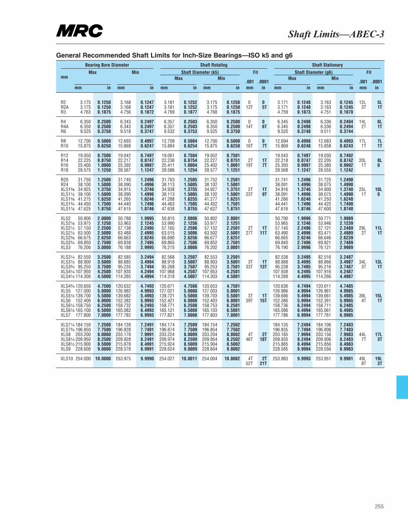
Shaft Limits—ABEC-3
255
mm Max
mm in
Min
mm in
Fit
.001 .0001mm in
Fit
.001 .0001mm in
Max
mm in
Max
mm in
Min
mm in
Min
mm in
Bearing Bore Diameter Shaft Rotating Shaft Stationary
Shaft Diameter (k5) Shaft Diameter (g6)
R2 3.175 0.1250 3.168 0.1247 3.181 0.1252 3.175 0.1250 0 0 3.171 0.1248 3.163 0.1245 12L 5LR2A 3.175 0.1250 3.168 0.1247 3.181 0.1252 3.175 0.1250 13T 5T 3.171 0.1248 3.163 0.1245 3T 1TR3 4.763 0.1875 4.756 0.1872 4.769 0.1877 4.768 0.1875 4.759 0.1873 4.751 0.1870
R4 6.350 0.2500 6.343 0.2497 6.357 0.2503 6.350 0.2500 0 0 6.345 0.2498 6.336 0.2494 14L 6LR4A 6.350 0.2500 6.343 0.2497 6.357 0.2503 6.350 0.2500 14T 6T 6.345 0.2498 6.336 0.2494 2T 1TR6 9.525 0.3750 9.518 0.3747 9.532 0.3753 9.525 0.3750 9.520 0.3748 9.511 0.3744
R8 12.700 0.5000 12.693 0.4997 12.709 0.5004 12.700 0.5000 0 0 12.694 0.4998 12.683 0.4993 17L 7LR10 15.875 0.6250 15.868 0.6247 15.884 0.6254 15.875 0.6250 16T 7T 15.869 0.6248 15.858 0.6243 1T 1T
R12 19.050 0.7500 19.042 0.7497 19.061 0.7504 19.052 0.7501 19.043 0.7497 19.030 0.7492R14 22.225 0.8750 22.217 0.8747 22.236 0.8754 22.227 0.8751 2T 1T 22.218 0.8747 22.205 0.8742 20L 8LR16 25.400 1.0000 25.392 0.9997 25.411 1.0004 25.402 1.0001 19T 7T 25.393 0.9997 25.380 0.9992 1T 0R18 28.575 1.1250 28.567 1.1247 28.586 1.1254 28.577 1.1251 28.568 1.1247 28.555 1.1242
R20 31.750 1.2500 31.740 1.2496 31.763 1.2505 31.752 1.2501 31.741 1.2496 31.725 1.2490R24 38.100 1.5000 38.090 1.4996 38.113 1.5005 38.102 1.5001 38.091 1.4996 38.075 1.4990XLS1³|₈ 34.925 1.3750 34.915 1.3746 34.938 1.3755 34.927 1.3751 2T 1T 34.916 1.3746 34.900 1.3740 25L 10LXLS1¹|₂ 38.100 1.5000 38.090 1.4996 38.113 1.5005 38.102 1.5001 23T 9T 38.091 1.4996 38.075 1.4990 1T 0XLS1⁵|₈ 41.275 1.6250 41.265 1.6246 41.288 1.6255 41.277 1.6251 41.266 1.6246 41.250 1.6240XLS1³|₄ 44.450 1.7500 44.440 1.7496 44.463 1.7505 44.452 1.7501 44.441 1.7496 44.425 1.7490XLS1⁷|₈ 47.625 1.8750 47.615 1.8746 47.638 1.8755 47.627 1.8751 47.616 1.8746 47.600 1.8740
XLS2 50.800 2.0000 50.788 1.9995 50.815 2.0006 50.802 2.0001 50.790 1.9996 50.771 1.9989XLS2¹|₈ 53.975 2.1250 53.963 2.1245 53.990 2.1256 53.977 2.1251 53.965 2.1246 53.946 2.1239XLS2¹|₄ 57.150 2.2500 57.138 2.2495 57.165 2.2506 57.152 2.2501 2T 1T 57.140 2.2496 57.121 2.2489 29L 11LXLS2¹|₂ 63.500 2.5000 63.488 2.4995 63.515 2.5006 63.502 2.5001 27T 11T 63.490 2.4996 63.471 2.4989 2T 1TXLS2⁵|₈ 66.675 2.6250 66.663 2.6245 66.690 2.6256 66.677 2.6251 66.665 2.6246 66.646 2.6239XLS2³|₄ 69.850 2.7500 69.838 2.7495 69.865 2.7506 69.852 2.7501 69.840 2.7496 69.821 2.7489XLS3 76.200 3.0000 76.188 2.9995 76.215 3.0006 76.202 3.0001 76.190 2.9996 76.121 2.9989
XLS3¹|₄ 82.550 3.2500 82.585 3.2494 82.568 3.2507 82.553 3.2501 82.538 3.2495 82.516 3.2487XLS3¹|₂ 88.900 3.5000 88.885 3.4994 88.918 3.5007 88.903 3.5001 3T 1T 88.888 3.4995 88.866 3.4987 34L 13LXLS3³|₄ 95.250 3.7500 95.235 3.7494 95.268 3.7507 95.253 3.7501 33T 13T 95.238 3.7495 95.216 3.7487 3T 1TXLS4¹|₄ 107.950 4.2500 107.935 4.2494 107.968 4.2507 107.953 4.2501 107.938 4.2495 107.916 4.2487XLS4¹|₂ 114.300 4.5000 114.285 4.4994 114.318 4.5007 114.303 4.5001 114.288 4.4995 114.266 4.4987
XLS4³|₄ 120.650 4.7500 120.632 4.7493 120.671 4.7508 120.653 4.7501 120.636 4.7494 120.611 4.7485XLS5 127.000 5.0000 126.982 4.9993 127.021 5.0008 127.003 5.0001 126.986 4.9994 126.961 4.9985XLS5¹|₂ 139.700 5.5000 139.682 5.4993 139.721 5.5008 139.703 5.5001 3T 1T 139.686 5.4994 139.661 5.4985 39L 15LXLS6 152.400 6.0000 152.382 5.9993 152.421 6.0008 152.403 6.0001 39T 15T 152.386 5.9994 152.361 5.9985 4T 1TXLS6¹|₄ 158.750 6.2500 158.732 6.2493 158.771 6.2508 158.753 6.2501 158.736 6.2494 158.711 6.2485XLS6¹|₂ 165.100 6.5000 165.082 6.4993 165.121 6.5008 165.103 6.5001 165.086 6.4994 165.061 6.4985XLS7 177.800 7.0000 177.782 6.9993 177.821 7.0008 177.803 7.0001 177.786 6.9994 177.761 6.9985
XLS7¹|₄ 184.150 7.2500 184.128 7.2491 184.174 7.2509 184.154 7.2502 184.135 7.2494 184.106 7.2483XLS7³|₄ 196.850 7.7500 196.828 7.7491 196.874 7.7509 196.854 7.7502 196.835 7.7494 196.806 7.7483XLS8 203.200 8.0000 203.178 7.9991 203.224 8.0009 203.204 8.0002 4T 2T 203.185 7.9994 203.156 7.9983 44L 17LXLS8¹|₄ 209.950 8.2500 209.928 8.2491 209.974 8.2509 209.954 8.2502 46T 18T 209.935 8.2494 209.906 8.2483 7T 3TXLS8¹|₂ 215.900 8.5000 215.878 8.4991 215.924 8.5009 215.904 8.5002 215.885 8.4994 215.856 8.4983XLS9 228.600 9.0000 228.578 8.9991 228.624 9.0009 228.604 9.0002 228.585 8.9994 228.556 8.9983
XLS10 254.000 10.0000 253.975 9.9990 254.027 10.0011 254.004 10.0002 4T 2T 253.983 9.9993 253.951 9.9981 49L 19L52T 21T 8T 3T
General Recommended Shaft Limits for Inch-Size Bearings—ISO k5 and g6
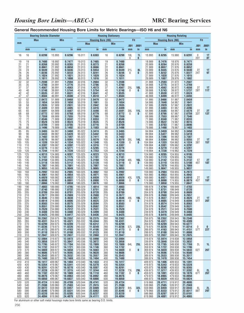
MRC Bearing ServicesHousing Bore Limits—ABEC-3
256
mm Max
mm in
Min
mm in
Fit
.001 .0001mm in
Fit
.001 .0001mm in
Max
mm in
Max
mm in
Min
mm in
Min
mm in
Bearing Outside Diameter Housing Stationary Housing Rotating
Housing Bore (H6) Housing Bore (N6)
16 16 0.6299 15.993 0.6296 16.011 0.6303 16 0.6299 18L 7L 15.993 0.6295 15.980 0.6291 0 1T0 0 20T 8T
19 19 0.7480 18.992 0.7477 19.013 0.7485 19 0.7480 18.989 0.7476 18.976 0.747121 21 0.8268 20.992 0.8265 21.013 0.8273 21 0.8268 20.989 0.8264 20.976 0.825922 22 0.8661 21.992 0.8658 22.013 0.8666 22 0.8661 21.989 0.8657 21.976 0.865224 24 0.9449 23.992 0.9446 24.013 0.9454 24 0.9449 21L 8L 23.989 0.9445 23.976 0.9440 3T 1T26 26 1.0236 25.992 1.0233 26.013 1.0241 26 1.0236 0 0 25.989 1.0232 25.976 1.0227 24T 9T28 28 1.1024 27.992 1.1021 28.013 1.1029 28 1.1024 27.989 1.1020 27.976 1.101530 30 1.1811 29.992 1.1808 30.013 1.1816 30 1.1811 29.989 1.1807 29.976 1.180232 32 1.2598 31.991 1.2594 32.016 1.2604 32 1.2598 31.988 1.2593 31.972 1.258735 35 1.3780 34.991 1.3776 35.016 1.3786 35 1.3780 34.988 1.3775 34.972 1.376937 37 1.4567 36.991 1.4563 37.016 1.4573 37 1.4567 25L 10L 36.988 1.4562 36.972 1.4556 3T 1T40 40 1.5748 39.991 1.5744 40.016 1.5754 40 1.5748 0 0 39.988 1.5743 39.972 1.5737 28T 11T42 42 1.6535 41.991 1.6531 42.016 1.6541 42 1.6535 41.988 1.6530 41.972 1.652447 47 1.8504 46.991 1.8500 47.016 1.8510 47 1.8504 46.988 1.8499 46.972 1.849352 52 2.0472 51.989 2.0468 52.019 2.0479 52 2.0472 51.986 2.0466 51.967 2.045955 55 2.1654 54.989 2.1650 55.019 2.1661 55 2.1654 54.986 2.1648 54.967 2.164158 58 2.2835 57.989 2.2831 58.019 2.2842 58 2.2835 57.986 2.2829 57.967 2.282262 62 2.4409 61.989 2.4405 62.019 2.4416 62 2.4409 61.986 2.4403 61.967 2.439665 65 2.5591 64.989 2.5587 65.019 2.5598 65 2.5591 30L 11L 64.986 2.5585 64.967 2.5578 3T 2T68 68 2.6772 67.989 2.6768 68.019 2.6779 68 2.6772 0 0 67.886 2.6766 67.967 2.6759 33T 13T70 70 2.7559 69.989 2.7555 70.019 2.7566 70 2.7559 69.986 2.7553 69.967 2.754672 72 2.8346 71.989 2.8342 72.019 2.8353 72 2.8346 71.986 2.8340 71.967 2.833375 75 2.9528 74.989 2.9524 75.019 2.9535 75 2.9528 74.986 2.9522 74.967 2.951578 78 3.0709 77.989 3.0705 78.019 3.0716 78 3.0709 77.986 3.0703 77.967 3.069680 80 3.1496 79.989 3.1492 80.019 3.1503 80 3.1496 79.986 3.1490 79.967 3.148385 85 3.3465 84.987 3.3460 85.022 3.3474 85 3.3465 84.984 3.3459 84.962 3.345090 90 3.5433 89.987 3.5428 90.022 3.5442 90 3.5433 89.984 3.5427 89.962 3.541895 95 3.7402 94.987 3.7397 95.022 3.7411 95 3.7402 94.984 3.7396 94.962 3.7387
100 100 3.9370 99.987 3.9365 100.022 3.9379 100 3.9370 35L 14L 99.984 3.9364 99.962 3.9355 3T 1T105 105 4.1339 104.987 4.1334 105.022 4.1348 105 4.1339 0 0 104.984 4.1333 104.962 4.1324 38T 15T110 110 4.3307 109.987 4.3302 110.022 4.3316 110 4.3307 109.984 4.3301 109.962 4.3292115 115 4.5276 114.987 4.5271 115.022 4.5285 115 4.5276 114.984 4.5270 114.962 4.5261120 120 4.7244 119.987 4.7239 120.022 4.7253 120 4.7244 119.984 4.7238 119.962 4.7229125 125 4.9213 124.985 4.9207 125.025 4.9223 125 4.9213 124.980 4.9205 124.955 4.9195130 130 5.1181 129.985 5.1175 130.025 5.1191 130 5.1181 129.980 5.1173 129.955 5.1163135 135 5.3150 134.985 5.3144 135.025 5.3160 135 5.3150 40L 16L 134.980 5.3142 134.955 5.3132 5T 2T140 140 5.5118 139.985 5.5112 140.025 5.5128 140 5.5118 0 0 139.980 5.5110 139.955 5.5100 45T 18T145 145 5.7087 144.985 5.7081 145.025 5.7097 145 5.7087 144.980 5.7079 144.955 5.7069150 150 5.9055 149.985 5.9049 150.025 5.9065 150 5.9055 149.980 5.9047 149.955 5.9037160 160 6.2992 159.982 6.2985 160.025 6.3002 160 6.2992 159.980 6.2984 159.955 6.2973165 165 6.4961 164.982 6.4954 165.025 6.4971 165 6.4961 164.980 6.4953 164.955 6.4942170 170 6.6929 169.982 6.6922 170.025 6.6939 170 6.6929 43L 17L 169.980 6.6921 169.955 6.6910 2T 1T175 175 6.8898 174.982 6.8891 175.025 6.8908 175 6.8898 0 0 174.980 6.8890 174.955 6.8879 45T 19T180 180 7.0866 179.982 7.0859 180.025 7.0876 180 7.0866 179.980 7.0858 179.955 7.0847190 190 7.4803 189.980 7.4795 190.029 7.4814 190 7.4803 189.978 7.4794 189.949 7.4783200 200 7.8740 199.980 7.8732 200.029 7.8751 200 7.8740 199.978 7.8731 199.949 7.8720205 205 8.0709 204.980 8.0701 205.029 8.0720 205 8.0709 204.978 8.0700 204.949 8.0689210 210 8.2677 209.980 8.2669 210.029 8.2688 210 8.2677 209.978 8.2668 209.949 8.2657215 215 8.4646 214.980 8.4638 215.029 8.4657 215 8.4646 49L 19L 214.978 8.4637 214.949 8.4626 2T 1T220 220 8.6614 219.980 8.6606 220.029 8.6625 220 8.6614 0 0 219.978 8.6605 219.949 8.6594 51T 20T225 225 8.8583 224.980 8.8575 225.029 8.8594 225 8.8583 224.978 8.8574 224.949 8.8563230 230 9.0551 229.980 9.0543 230.029 9.0562 230 9.0551 229.978 9.0542 229.949 9.0531235 235 9.2520 234.980 9.2512 235.029 9.2531 235 9.2520 234.978 9.2511 234.949 9.2500240 240 9.4488 239.980 9.4480 240.029 9.4499 240 9.4488 239.978 9.4479 239.949 9.4468250 250 9.8425 249.980 9.8417 250.029 9.8436 250 9.8425 249.978 9.8416 249.949 9.8405260 260 10.2362 259.975 10.2352 260.032 10.2375 260 10.2362 259.975 10.2352 259.943 10.2340265 265 10.4331 264.975 10.4321 265.032 10.4344 265 10.4331 264.975 10.4321 264.943 10.4309270 270 10.6299 269.975 10.6289 270.032 10.6312 270 10.6299 269.975 10.6289 269.943 10.6277280 280 11.0236 279.975 11.0226 280.032 11.0249 280 11.0236 57L 23L 279.975 11.0226 279.943 11.0214 0 0290 290 11.4173 289.975 11.4163 290.032 11.4186 290 11.4173 0 0 289.975 11.4163 289.943 11.4151 57T 22T300 300 11.8110 299.975 11.8100 300.032 11.8123 300 11.8110 299.975 11.8100 299.943 11.8088310 310 12.2047 309.975 12.2037 310.032 12.2060 310 12.2047 309.975 12.2037 309.943 12.2025320 320 12.5984 319.972 12.5973 320.036 12.5998 320 12.5984 319.974 12.5974 319.938 12.5958340 340 13.3858 339.972 13.3847 340.036 13.3872 340 13.3858 339.974 13.3848 339.938 13.3832350 350 13.7795 349.972 13.7784 350.036 13.7809 350 13.7809 64L 25L 349.974 13.7785 349.938 13.7769 2L 1L360 360 14.1732 359.972 14.1721 360.036 14.1746 360 14.1732 359.974 14.1722 359.938 14.1706370 370 14.5669 369.972 14.5658 370.036 14.5683 370 14.5669 0 0 369.974 14.5659 369.938 14.5643 62T 26T380 380 14.9606 379.972 14.9595 380.036 14.9620 380 14.9606 379.974 14.9596 379.938 14.9580390 390 15.3543 389.972 15.3532 390.036 15.3557 390 15.3543 389.974 15.3533 389.938 15.3517400 400 15.7480 399.972 15.7469 400.036 15.7494 400 15.7480 399.974 15.7470 399.938 15.7454410 410 16.1417 409.967 16.1404 410.040 16.1433 410 16.1417 409.973 16.1406 409.933 16.1391420 420 16.5354 419.967 16.5341 420.040 16.5370 420 16.5354 419.973 16.5343 419.933 16.5328430 430 16.9291 429.967 16.9278 430.040 16.9307 430 16.9291 429.973 16.9280 429.933 16.9265440 440 17.3228 439.967 17.3215 440.040 17.3244 440 17.3228 73L 29L 439.973 17.3217 439.933 17.3202 6L 2L460 460 18.1102 459.967 18.1089 460.040 18.1118 460 18.1102 0 0 459.973 18.1091 459.933 18.1076 67T 26T480 480 18.8976 479.967 18.8963 480.040 18.8992 480 18.8976 479.973 18.8965 479.933 18.8950500 500 19.6850 499.967 19.6837 500.040 19.6866 500 19.6850 499.973 19.6839 499.933 19.6824520 520 20.4724 519.960 20.4709 520.044 20.4741 520 20.4724 519.966 20.4711 519.912 20.4695540 540 21.2598 539.960 21.2583 540.044 21.2615 540 21.2598 539.966 21.2585 539.912 21.2569560 560 22.0472 559.960 22.0457 560.044 22.0489 560 22.0472 84L 32L 559.966 22.0459 559.912 22.0443 6L 2L580 580 22.8346 579.960 22.8331 580.044 22.8363 580 22.8346 0 0 579.966 22.8333 579.912 22.8317 88T 29T600 600 23.6220 599.960 23.6205 600.044 23.6237 600 23.6220 599.966 23.6207 599.912 23.6191620 620 24.4094 619.960 24.4079 620.044 24.4111 620 24.4094 619.966 24.4081 619.912 24.4065
General Recommended Housing Bore Limits for Metric Bearings—ISO H6 and N6
For aluminum or other soft metal housings make bore limits same as bearing O.D. limits.
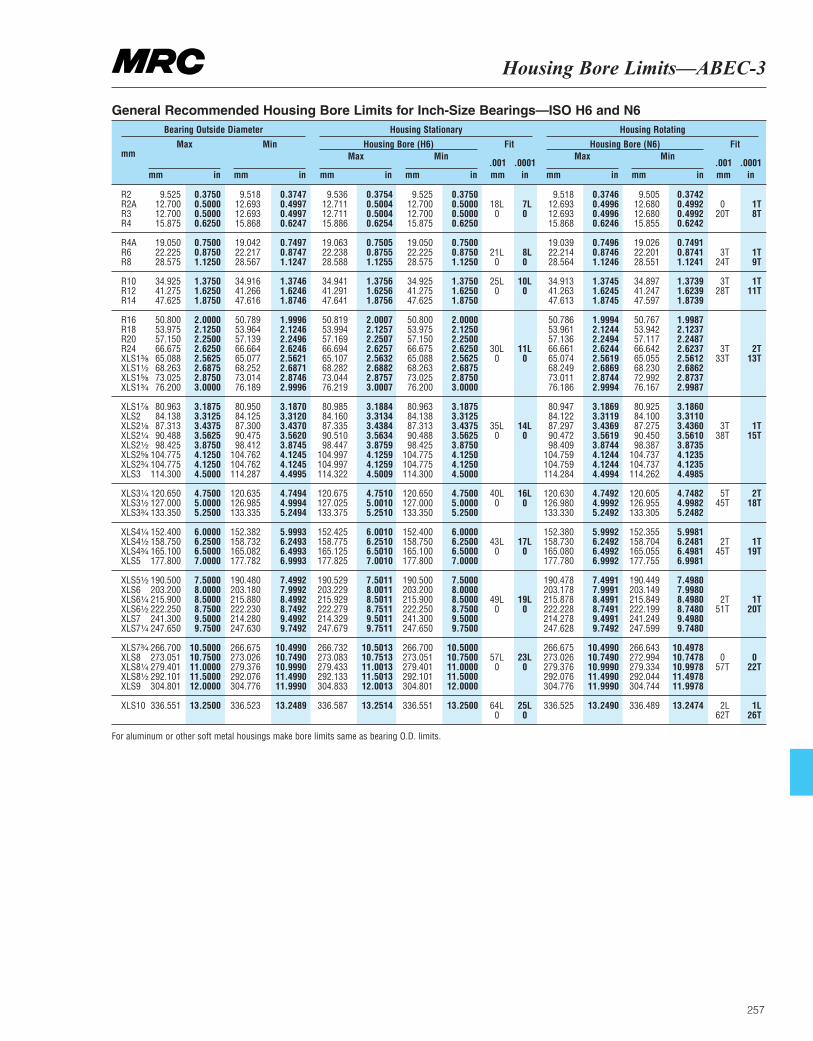
Housing Bore Limits—ABEC-3
257
mm Max
mm in
Min
mm in
Fit
.001 .0001mm in
Fit
.001 .0001mm in
Max
mm in
Max
mm in
Min
mm in
Min
mm in
Bearing Outside Diameter Housing Stationary Housing Rotating
Housing Bore (H6) Housing Bore (N6)
R2 9.525 0.3750 9.518 0.3747 9.536 0.3754 9.525 0.3750 9.518 0.3746 9.505 0.3742R2A 12.700 0.5000 12.693 0.4997 12.711 0.5004 12.700 0.5000 18L 7L 12.693 0.4996 12.680 0.4992 0 1TR3 12.700 0.5000 12.693 0.4997 12.711 0.5004 12.700 0.5000 0 0 12.693 0.4996 12.680 0.4992 20T 8TR4 15.875 0.6250 15.868 0.6247 15.886 0.6254 15.875 0.6250 15.868 0.6246 15.855 0.6242
R4A 19.050 0.7500 19.042 0.7497 19.063 0.7505 19.050 0.7500 19.039 0.7496 19.026 0.7491R6 22.225 0.8750 22.217 0.8747 22.238 0.8755 22.225 0.8750 21L 8L 22.214 0.8746 22.201 0.8741 3T 1TR8 28.575 1.1250 28.567 1.1247 28.588 1.1255 28.575 1.1250 0 0 28.564 1.1246 28.551 1.1241 24T 9T
R10 34.925 1.3750 34.916 1.3746 34.941 1.3756 34.925 1.3750 25L 10L 34.913 1.3745 34.897 1.3739 3T 1TR12 41.275 1.6250 41.266 1.6246 41.291 1.6256 41.275 1.6250 0 0 41.263 1.6245 41.247 1.6239 28T 11TR14 47.625 1.8750 47.616 1.8746 47.641 1.8756 47.625 1.8750 47.613 1.8745 47.597 1.8739
R16 50.800 2.0000 50.789 1.9996 50.819 2.0007 50.800 2.0000 50.786 1.9994 50.767 1.9987R18 53.975 2.1250 53.964 2.1246 53.994 2.1257 53.975 2.1250 53.961 2.1244 53.942 2.1237R20 57.150 2.2500 57.139 2.2496 57.169 2.2507 57.150 2.2500 57.136 2.2494 57.117 2.2487R24 66.675 2.6250 66.664 2.6246 66.694 2.6257 66.675 2.6250 30L 11L 66.661 2.6244 66.642 2.6237 3T 2TXLS1³|₈ 65.088 2.5625 65.077 2.5621 65.107 2.5632 65.088 2.5625 0 0 65.074 2.5619 65.055 2.5612 33T 13TXLS1¹|₂ 68.263 2.6875 68.252 2.6871 68.282 2.6882 68.263 2.6875 68.249 2.6869 68.230 2.6862XLS1⁵|₈ 73.025 2.8750 73.014 2.8746 73.044 2.8757 73.025 2.8750 73.011 2.8744 72.992 2.8737XLS1³|₄ 76.200 3.0000 76.189 2.9996 76.219 3.0007 76.200 3.0000 76.186 2.9994 76.167 2.9987
XLS1⁷|₈ 80.963 3.1875 80.950 3.1870 80.985 3.1884 80.963 3.1875 80.947 3.1869 80.925 3.1860XLS2 84.138 3.3125 84.125 3.3120 84.160 3.3134 84.138 3.3125 84.122 3.3119 84.100 3.3110XLS2¹|₈ 87.313 3.4375 87.300 3.4370 87.335 3.4384 87.313 3.4375 35L 14L 87.297 3.4369 87.275 3.4360 3T 1TXLS2¹|₄ 90.488 3.5625 90.475 3.5620 90.510 3.5634 90.488 3.5625 0 0 90.472 3.5619 90.450 3.5610 38T 15TXLS2¹|₂ 98.425 3.8750 98.412 3.8745 98.447 3.8759 98.425 3.8750 98.409 3.8744 98.387 3.8735XLS2⁵|₈ 104.775 4.1250 104.762 4.1245 104.997 4.1259 104.775 4.1250 104.759 4.1244 104.737 4.1235XLS2³|₄ 104.775 4.1250 104.762 4.1245 104.997 4.1259 104.775 4.1250 104.759 4.1244 104.737 4.1235XLS3 114.300 4.5000 114.287 4.4995 114.322 4.5009 114.300 4.5000 114.284 4.4994 114.262 4.4985
XLS3¹|₄ 120.650 4.7500 120.635 4.7494 120.675 4.7510 120.650 4.7500 40L 16L 120.630 4.7492 120.605 4.7482 5T 2TXLS3¹|₂ 127.000 5.0000 126.985 4.9994 127.025 5.0010 127.000 5.0000 0 0 126.980 4.9992 126.955 4.9982 45T 18TXLS3³|₄ 133.350 5.2500 133.335 5.2494 133.375 5.2510 133.350 5.2500 133.330 5.2492 133.305 5.2482
XLS4¹|₄ 152.400 6.0000 152.382 5.9993 152.425 6.0010 152.400 6.0000 152.380 5.9992 152.355 5.9981XLS4¹|₂ 158.750 6.2500 158.732 6.2493 158.775 6.2510 158.750 6.2500 43L 17L 158.730 6.2492 158.704 6.2481 2T 1TXLS4³|₄ 165.100 6.5000 165.082 6.4993 165.125 6.5010 165.100 6.5000 0 0 165.080 6.4992 165.055 6.4981 45T 19TXLS5 177.800 7.0000 177.782 6.9993 177.825 7.0010 177.800 7.0000 177.780 6.9992 177.755 6.9981
XLS5¹|₂ 190.500 7.5000 190.480 7.4992 190.529 7.5011 190.500 7.5000 190.478 7.4991 190.449 7.4980XLS6 203.200 8.0000 203.180 7.9992 203.229 8.0011 203.200 8.0000 203.178 7.9991 203.149 7.9980XLS6¹|₄ 215.900 8.5000 215.880 8.4992 215.929 8.5011 215.900 8.5000 49L 19L 215.878 8.4991 215.849 8.4980 2T 1TXLS6¹|₂ 222.250 8.7500 222.230 8.7492 222.279 8.7511 222.250 8.7500 0 0 222.228 8.7491 222.199 8.7480 51T 20TXLS7 241.300 9.5000 214.280 9.4992 214.329 9.5011 241.300 9.5000 214.278 9.4991 241.249 9.4980XLS7¹|₄ 247.650 9.7500 247.630 9.7492 247.679 9.7511 247.650 9.7500 247.628 9.7492 247.599 9.7480
XLS7³|₄ 266.700 10.5000 266.675 10.4990 266.732 10.5013 266.700 10.5000 266.675 10.4990 266.643 10.4978XLS8 273.051 10.7500 273.026 10.7490 273.083 10.7513 273.051 10.7500 57L 23L 273.026 10.7490 272.994 10.7478 0 0XLS8¹|₄ 279.401 11.0000 279.376 10.9990 279.433 11.0013 279.401 11.0000 0 0 279.376 10.9990 279.334 10.9978 57T 22TXLS8¹|₂ 292.101 11.5000 292.076 11.4990 292.133 11.5013 292.101 11.5000 292.076 11.4990 292.044 11.4978XLS9 304.801 12.0000 304.776 11.9990 304.833 12.0013 304.801 12.0000 304.776 11.9990 304.744 11.9978
XLS10 336.551 13.2500 336.523 13.2489 336.587 13.2514 336.551 13.2500 64L 25L 336.525 13.2490 336.489 13.2474 2L 1L0 0 62T 26T
General Recommended Housing Bore Limits for Inch-Size Bearings—ISO H6 and N6
For aluminum or other soft metal housings make bore limits same as bearing O.D. limits.
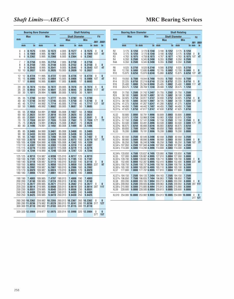
MRC Bearing ServicesShaft Limits—ABEC-5
258
mm Max
mm in
Min
mm in
Fit
.001 .0001mm in
Max
mm in
Min
mm in
Bearing Bore Diameter Shaft Rotating
Shaft Diameter
4 4 0.1575 3.995 0.1573 4.005 0.1577 4 0.1575 0 05 5 0.1969 4.995 0.1967 5.005 0.1971 5 0.1969 10T 4T6 6 0.2362 5.995 0.2360 6.005 0.2364 6 0.2362
7 7 0.2756 6.995 0.2754 7.005 0.2758 7 0.27568 8 0.3150 7.995 0.3148 8.005 0.3152 8 0.3150 0 09 9 0.3543 8.995 0.3541 9.005 0.3545 9 0.3543 10T 4T
10 10 0.3937 9.995 0.3935 10.005 0.3939 10 0.3937
12 12 0.4724 11.995 0.4722 12.005 0.4726 12 0.4724 0 015 15 0.5906 14.995 0.5904 15.005 0.5908 15 0.5906 10T 4T17 17 0.6693 16.995 0.6691 17.005 0.6695 17 0.6693
20 20 0.7874 19.994 0.7872 20.005 0.7876 20 0.7874 0 025 25 0.9843 24.994 0.9841 25.005 0.9845 25 0.9843 11T 4T30 30 1.1811 29.994 1.1809 30.005 1.1813 30 1.1811
35 35 1.3780 34.992 1.3777 35.005 1.3782 35 1.378040 40 1.5748 39.992 1.5745 40.005 1.5750 40 1.5748 0 045 45 1.7717 44.992 1.7714 45.005 1.7719 45 1.7717 13T 5T50 50 1.9685 49.992 1.9682 50.005 1.9687 50 1.9685
55 55 2.1654 54.991 2.1650 55.008 2.1657 55 2.165460 60 2.3622 59.991 2.3618 60.008 2.3625 60 2.362265 65 2.5591 64.991 2.5587 65.008 2.5594 65 2.5591 0 070 70 2.7559 69.991 2.7555 70.008 2.7562 70 2.7559 17T 7T75 75 2.9528 74.991 2.9524 75.008 2.9531 75 2.952880 80 3.1496 79.991 3.1492 80.008 3.1499 80 3.1496
85 85 3.3465 84.990 3.3461 85.008 3.3468 85 3.346590 90 3.5433 89.990 3.5429 90.008 3.5436 90 3.543395 95 3.7402 94.990 3.7398 95.008 3.7405 95 3.7402 0 0
100 100 3.9370 99.990 3.9366 100.008 3.9373 100 3.9370 18T 7T105 105 4.1339 104.990 4.1335 105.008 4.1342 105 4.1339110 110 4.3307 109.990 4.3303 110.008 4.3310 110 4.3307115 115 4.5276 114.990 4.5272 115.008 4.5279 115 4.5276120 120 4.7244 119.990 4.7240 120.008 4.7247 120 4.7244
125 125 4.9213 124.987 4.9208 125.010 4.9217 125 4.9213130 130 5.1181 129.987 5.1176 130.010 5.1185 130 5.1181140 140 5.5118 139.987 5.5113 140.010 5.5122 140 5.5118 0 0150 150 5.9055 149.987 5.9050 150.010 5.9059 150 5.9055 23T 9T160 160 6.2992 159.987 6.2987 160.010 6.2996 160 6.2992170 170 6.6929 169.987 6.6924 170.010 6.6933 170 6.6929180 180 7.0866 179.987 7.0861 180.010 7.0870 180 7.0866
190 190 7.4803 189.985 7.4797 190.013 7.4808 190 7.4803200 200 7.8740 199.985 7.8724 200.013 7.8745 200 7.8740210 210 8.2677 209.985 8.2671 210.013 8.2682 210 8.2677 0 0220 220 8.6614 219.985 8.6608 220.013 8.6619 220 8.6614 28T 11T230 230 9.0551 229.985 9.0545 230.013 9.0556 230 9.0551240 240 9.4488 239.985 9.4482 240.013 9.4493 240 9.4488250 250 9.8425 249.985 9.8419 250.013 9.8430 250 9.8425
260 260 10.2362 259.982 10.2355 260.013 10.2367 260 10.2362 0 0280 280 11.0236 279.982 11.0229 280.013 11.0241 280 11.0236 31T 12T300 300 11.8110 299.982 11.8103 300.013 11.8115 300 11.8110
320 320 12.5984 319.977 12.5975 320.014 12.5990 320 12.5984 0 037T 15T
mm Max
mm in
Min
mm in
Fit
.001 .0001mm in
Max
mm in
Min
mm in
Bearing Bore Diameter Shaft Rotating
Shaft Diameter
R2 3.175 0.1250 3.170 0.1248 3.180 0.1252 3.175 0.1250R2A 3.175 0.1250 3.170 0.1248 3.180 0.1252 3.175 0.1250 0 0R3 4.763 0.1875 4.758 0.1873 4.767 0.1877 4.763 0.1875 10T 4TR4 6.350 0.2500 6.345 0.2498 6.355 0.2502 6.350 0.2500R4A 6.350 0.2500 6.345 0.2498 6.355 0.2502 6.350 0.2500
R6 9.525 0.3750 9.520 0.3748 9.580 0.3752 9.525 0.3750R8 12.700 0.5000 12.695 0.4998 12.705 0.5002 12.700 0.5000 0 0R10 15.875 0.6250 15.870 0.6248 15.880 0.6252 15.875 0.6250 10T 4T
R12 19.050 0.7500 19.044 0.7498 19.055 0.7502 19.050 0.7500R14 22.225 0.8750 22.219 0.8748 22.230 0.8752 22.225 0.8750 0 0R16 25.400 1.0000 25.394 0.9998 25.405 1.0002 25.400 1.0000 11T 4TR18 28.575 1.1250 28.769 1.1248 28.580 1.1252 28.575 1.1250
R20 31.750 1.2500 31.742 1.2497 31.755 1.2502 31.750 1.2500R24 38.100 1.5000 38.092 1.4997 38.105 1.5002 38.100 1.5000XLS1³|₈ 34.925 1.3750 34.917 1.3747 34.930 1.3752 34.925 1.3750 0 0XLS1¹|₂ 38.100 1.5000 38.092 1.4997 38.105 1.5002 38.100 1.5000 13T 5TXLS1⁵|₈ 41.275 1.6250 41.267 1.6247 41.280 1.6252 41.275 1.6250XLS1³|₄ 44.450 1.7500 44.442 1.7497 44.455 1.7502 44.450 1.7500XLS1⁷|₈ 47.625 1.8750 47.617 1.8747 47.630 1.8752 47.625 1.8750
XLS2 50.800 2.0000 50.791 1.9996 50.808 2.0003 50.800 2.0000XLS2¹|₈ 53.975 2.1250 53.966 2.1246 53.983 2.1253 53.975 2.1250XLS2¹|₄ 57.150 2.2500 57.141 2.2496 57.158 2.2503 57.150 2.2500 0 0XLS2¹|₂ 63.500 2.5000 63.491 2.4996 63.508 2.5003 63.500 2.5000 17T 7TXLS2⁵|₈ 66.675 2.6250 66.666 2.6246 66.683 2.6253 66.675 2.6250XLS2³|₄ 69.850 2.7500 69.841 2.7496 69.858 2.7503 69.850 2.7500XLS3 76.200 3.0000 76.191 2.9996 76.208 3.0003 76.200 3.0000
XLS3¹|₄ 82.550 3.2500 82.540 3.2496 82.558 3.2503 82.550 3.2500XLS3¹|₂ 88.900 3.5000 88.890 3.4996 88.908 3.5003 88.900 3.5000 0 0XLS3³|₄ 95.250 3.7500 95.240 3.7496 95.258 3.7503 95.250 3.7500 18T 7TXLS4¹|₄ 107.950 4.2500 107.940 4.2496 107.958 4.2503 107.950 4.2500XLS4¹|₂ 114.300 4.5000 114.290 4.4996 114.808 4.5003 114.300 4.5000
XLS4³|₄ 120.650 4.7500 120.637 4.7495 120.660 4.7504 120.650 4.7500XLS5 127.000 5.0000 126.987 4.9995 127.010 5.0004 127.000 5.0000XLS5¹|₂ 139.700 5.5000 139.687 5.4995 139.710 5.5004 139.700 5.5000 0 0XLS6 152.400 6.0000 152.387 5.9995 152.410 6.0004 152.400 6.0000 23T 9TXLS6¹|₄ 158.750 6.2500 158.737 6.2495 158.760 6.2504 158.750 6.2500XLS6¹|₂ 165.100 6.5000 165.087 6.4995 165.110 6.5004 165.100 6.5000XLS7 177.800 7.0000 177.787 6.9995 177.810 7.0004 177.800 7.0000
XLS7¹|₄ 184.150 7.2500 184.135 7.2494 184.163 7.2505 184.150 7.2500XLS7³|₄ 196.850 7.7500 196.835 7.7494 196.863 7.7505 196.850 7.7500XLS8 203.200 8.0000 203.185 7.9994 203.213 8.0005 203.200 8.0000 0 0XLS8¹|₄ 209.950 8.2500 209.935 8.2494 209.963 8.2505 209.950 8.2500 28T 11TXLS8¹|₂ 215.900 8.5000 215.885 8.4994 215.913 8.5005 215.900 8.5000XLS9 228.600 9.0000 228.585 8.9994 228.613 9.0005 228.600 9.0000
XLS10 254.000 10.0000 253.982 9.9993 254.013 10.0005 254.000 10.0000 0 031T 12T
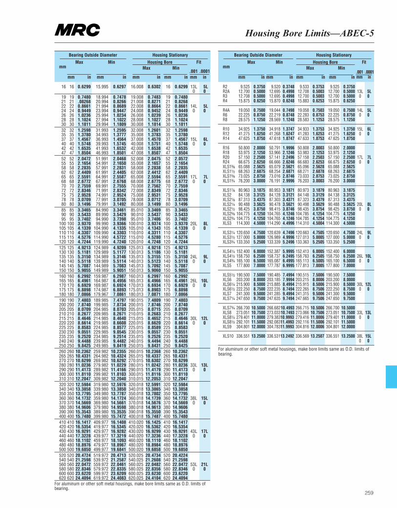
Housing Bore Limits—ABEC-5
259
mm Max
mm in
Min
mm in
Fit
.001 .0001mm in
Max
mm in
Min
mm in
Bearing Outside Diameter Housing Stationary
Housing Bore
16 16 0.6299 15.995 0.6297 16.008 0.6302 16 0.6299 13L 5L0 0
19 19 0.7480 18.994 0.7478 19.008 0.7483 19 0.748021 21 .08268 20.994 0.8266 21.008 0.8271 21 0.826822 22 0.8661 21.994 0.8689 22.008 0.8664 22 0.8661 14L 5L24 24 0.9449 23.994 0.9447 24.008 0.9452 24 0.9449 0 026 26 1.0236 25.994 1.0234 26.008 1.0239 26 1.023628 28 1.1024 27.994 1.1022 28.008 1.1027 28 1.102430 30 1.1811 29.994 1.1809 30.008 1.1814 30 1.181132 32 1.2598 31.993 1.2595 32.008 1.2601 32 1.259835 35 1.3780 34.993 1.3777 35.008 1.3783 35 1.378037 37 1.4567 36.993 1.4564 37.008 1.4570 37 1.4567 15L 6L40 40 1.5748 39.993 1.5745 40.008 1.5751 40 1.5748 0 042 42 1.6535 41.993 1.6532 42.008 1.6538 42 1.653547 47 1.8504 46.993 1.8501 47.008 1.8507 47 1.850452 52 2.0472 51.991 2.0468 52.008 2.0475 52 2.057255 55 2.1654 54.991 2.1650 55.008 2.1657 55 2.165458 58 2.2835 57.991 2.2831 58.008 2.2838 58 2.283562 62 2.4409 61.991 2.4405 62.008 2.4412 62 2.440965 65 2.5591 64.991 2.5587 65.008 2.5594 65 2.5591 17L 7L68 68 2.6772 67.991 2.6768 68.008 2.6775 68 2.6772 0 070 70 2.7559 69.991 2.7555 70.008 2.7562 70 2.755972 72 2.8346 71.991 2.8342 72.008 2.8349 72 2.834675 75 2.9528 74.991 2.9524 75.008 2.9531 75 2.952878 78 3.0709 77.991 3.0705 78.008 3.0712 78 3.070980 80 3.1496 79.991 3.1492 80.008 3.1499 80 3.149685 85 3.3465 84.990 3.3461 85.010 3.3469 85 3.346590 90 3.5433 89.990 3.5429 90.010 3.5437 90 3.543395 95 3.7402 94.990 3.7398 95.010 3.7406 95 3.7402
100 100 3.9370 99.990 3.9366 100.010 3.9374 100 3.9370 20L 8L105 105 4.1339 104.990 4.1335 105.010 4.1343 105 4.1339 0 0110 110 4.3307 109.990 4.3303 110.010 4.3311 110 4.3307115 115 4.5276 114.990 4.5722 115.010 4.5280 115 4.5276120 120 4.7244 119.990 4.7240 120.010 4.7248 120 4.7244125 125 4.9213 124.989 4.9209 125.013 4.9218 125 4.9213130 130 5.1181 129.989 5.1177 130.013 5.1186 130 5.1181135 135 5.3150 134.989 5.3146 135.013 5.3155 135 5.3150 24L 9L140 140 5.5118 139.989 5.5114 140.013 5.5123 140 5.5118 0 0145 145 5.7087 144.989 5.7083 145.013 5.7092 145 5.7087150 150 5.9055 149.989 5.9051 150.013 5.9060 150 5.9055160 160 6.2992 159.987 6.2987 160.013 6.2997 160 6.2992165 165 6.4961 164.987 6.4956 165.013 6.4966 165 6.4961 26L 10L170 170 6.6929 169.987 6.6924 170.013 6.6934 170 6.6929 0 0175 175 6.8898 174.987 6.8893 175.013 6.8903 175 6.8898180 180 7.0866 179.967 7.0861 180.013 7.0871 180 7.0866190 190 7.4803 189.985 7.4797 190.015 7.4809 190 7.4803200 200 7.8740 199.985 7.8734 200.015 7.8746 200 7.8740205 205 8.0709 204.985 8.0703 205.015 8.0715 205 8.0709210 210 8.2677 209.985 8.2671 210.015 8.2683 210 8.2677215 215 8.4646 214.985 8.4640 215.015 8.4652 215 8.4646 30L 12L220 220 8.6614 219.985 8.6608 220.015 8.6620 220 8.6614 0 0225 225 8.8583 224.985 8.8577 225.015 8.8589 225 8.8583230 230 9.0551 229.985 9.0545 230.015 9.0557 230 9.0551235 235 9.2520 234.985 9.2514 235.015 9.2526 235 9.2520240 240 9.4488 239.985 9.4482 240.015 9.4494 240 9.4488250 250 9.8425 249.985 9.8419 250.015 9.8431 250 9.8425260 260 10.2362 259.982 10.2355 260.015 10.2368 260 10.2362265 265 10.4331 264.982 10.4324 265.015 10.4337 265 10.4331270 270 10.6299 269.982 10.6292 270.015 10.6302 270 10.6299280 280 11.0236 279.982 11.0229 280.015 11.0242 280 11.0236 33L 13L290 290 11.4173 289.982 11.4166 290.015 11.4179 290 11.4173 0 0300 300 11.8110 299.982 11.8103 300.015 11.8116 300 11.8110310 310 12.2047 309.982 12.2040 310.015 12.2053 310 12.2047320 320 12.5984 319.980 12.5976 320.018 12.5991 320 12.5984340 340 13.3858 339.980 13.3850 340.018 13.3865 340 13.3858350 350 13.7795 349.980 13.7787 350.018 13.7802 350 13.7795360 360 14.1732 359.980 14.1724 360.018 14.1739 360 14.1732 38L 15L370 370 14.5669 369.980 14.5661 370.018 14.5676 370 14.5669 0 0380 380 14.9606 379.980 14.9598 380.018 14.9613 380 14.9606390 390 15.3543 389.980 15.3535 390.018 15.3550 390 15.3543400 400 15.7480 399.980 15.7472 400.018 15.7487 400 15.7480410 410 16.1417 409.977 16.1408 410.020 16.1425 410 16.1417420 420 16.5354 419.977 16.5345 420.020 16.5362 420 16.5354430 430 16.9291 429.977 16.9282 430.020 16.9299 430 16.9291 43L 17L440 440 17.3228 439.977 17.3219 440.020 17.3236 440 17.3228 0 0460 460 18.1102 459.977 18.1093 460.020 18.1110 460 18.1102480 480 18.8976 479.977 18.8967 480.020 18.8984 480 18.8976500 500 19.6850 499.977 19.6841 500.020 19.6858 500 19.6850520 520 20.4724 519.972 20.4713 520.025 20.4734 520 20.4224540 540 21.2598 539.972 21.2587 540.025 21.2608 540 21.2598560 560 22.0472 559.972 22.0461 560.025 22.0482 560 22.0472 53L 21L580 580 22.8346 579.972 22.8335 580.025 22.8356 580 22.8346 0 0600 600 23.6220 599.972 23.6209 600.025 23.6230 600 23.6220620 620 24.4094 619.972 24.4083 620.025 24.4104 620 24.4094
mm Max
mm in
Min
mm in
Fit
.001 .0001mm in
Max
mm in
Min
mm in
Bearing Outside Diameter Housing Stationary
Housing Bore
R2 9.525 0.3750 9.520 0.3748 9.533 0.3753 9.525 0.3750R2A 12.700 0.5000 12.695 0.4998 12.708 0.5003 12.700 0.5000 13L 5LR3 12.708 0.5000 12.695 0.4998 12.700 0.5003 12.700 0.5000 0 0R4 15.875 0.6250 15.870 0.6248 15.883 0.6253 15.875 0.6250
R4A 19.050 0.7500 19.044 0.7498 19.058 0.7503 19.050 0.7500 14L 5LR6 22.225 0.8750 22.219 0.8748 22.283 0.8753 22.225 0.8750 0 0R8 28.575 1.1250 28.569 1.1248 28.583 1.1253 28.575 1.1250
R10 34.925 1.3750 34.918 1.3747 34.933 1.3753 34.925 1.3750 15L 6LR12 41.275 1.6250 41.268 1.6247 41.283 1.6253 41.275 1.6250 0 0R14 47.625 1.8750 47.618 1.8747 47.633 1.8753 47.625 1.8750
R16 50.800 2.0000 50.791 1.9996 50.808 2.0003 50.800 2.0000R18 53.975 2.1250 53.966 2.1246 53.983 2.1253 53.975 2.1250R20 57.150 2.2500 57.141 2.2496 57.158 2.2503 57.150 2.2500 17L 7LR24 66.675 2.6250 66.666 2.6246 66.683 2.6253 66.675 2.6250 0 0XLS1³|₈ 65.088 2.5625 65.079 2.5621 65.096 2.5628 65.088 2.5625XLS1¹|₂ 68.263 2.6875 68.254 2.6871 68.271 2.6878 68.263 2.6875XLS1⁵|₈ 73.025 2.8750 73.016 2.8746 73.033 2.8753 73.025 2.8750XLS1³|₄ 76.200 3.0000 76.191 2.9996 76.203 3.0003 76.200 3.0000
XLS1⁷|₈ 80.963 3.1875 80.953 3.1871 80.973 3.1879 80.963 3.1875XLS2 84.138 3.3125 84.128 3.3121 84.148 3.3129 84.138 3.3125XLS2¹|₈ 87.313 3.4375 87.303 3.4371 87.323 3.4379 87.313 3.4375XLS2¹|₄ 90.488 3.5625 90.478 3.5621 90.498 3.5629 90.488 3.5625 20L 8LXLS2¹|₂ 98.425 3.8750 98.415 3.8746 98.435 3.8754 98.425 3.8750 0 0XLS2⁵|₈ 104.775 4.1250 104.765 4.1246 104.785 4.1254 104.775 4.1250XLS2³|₄ 104.775 4.1250 104.765 4.1246 104.785 4.1254 104.775 4.1250XLS3 114.300 4.5000 114.290 4.4996 114.310 4.5004 114.300 4.5000
XLS3¹|₄ 120.650 4.7500 120.639 4.7496 120.663 4.7505 120.650 4.7500 24L 9LXLS3¹|₂ 127.000 5.0000 126.989 4.9996 127.013 5.0005 127.000 5.0000 0 0XLS3³|₄ 133.350 5.2500 133.339 5.2496 133.363 5.2505 133.350 5.2500
XLS4¹|₄ 152.400 6.0000 152.387 5.9995 152.413 6.0005 152.400 6.0000XLS4¹|₂ 158.750 6.2500 158.737 6.2495 158.763 6.2505 158.750 6.2500 26L 10LXLS4³|₄ 165.100 6.5000 165.087 6.4995 165.113 6.5005 165.100 6.5000 0 0XLS5 177.800 7.0000 177.787 6.9995 177.813 7.0005 177.800 7.0000
XLS5¹|₂ 190.500 7.5000 190.485 7.4994 190.515 7.5006 190.500 7.5000XLS6 203.200 8.0000 203.185 7.9994 203.215 8.0006 203.200 8.0000XLS6¹|₄ 215.900 8.5000 215.885 8.4994 215.915 8.5006 215.900 8.5000 30L 12LXLS6¹|₂ 222.250 8.7500 222.235 8.7494 222.265 8.7506 222.250 8.7500 0 0XLS7 241.300 9.5000 241.285 9.4994 241.315 9.5006 241.300 9.5000XLS7¹|₄ 247.650 9.7500 247.635 9.7494 247.665 9.7506 247.650 9.7500
XLS7³|₄ 266.700 10.5000 266.68210.4993 266.715 10.5006 266.700 10.5000XLS8 273.051 10.7500 273.03310.7493 273.066 10.7506 273.051 10.7500 33L 13LXLS8¹|₄ 279.401 11.0000 279.38310.9993 279.416 11.0006 279.401 11.0000 0 0XLS8¹|₂ 292.101 11.5000 292.08311.4993 292.116 11.5006 292.101 11.5000XLS9 304.801 12.0000 304.78311.9993 304.816 12.0006 304.801 12.0000
XLS10 336.551 13.2500 336.53113.2492 336.569 13.2507 336.551 13.2500 38L 15L0 0
For aluminum or other soft metal housings, make bore limits same as O.D. limits of bearing.
For aluminum or other soft metal housings, make bore limits same as O.D. limits ofbearing.
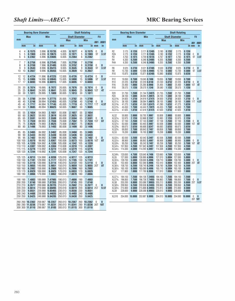
MRC Bearing ServicesShaft Limits—ABEC-7
260
mm Max
mm in
Min
mm in
Fit
.001 .0001mm in
Max
mm in
Min
mm in
Bearing Bore Diameter Shaft Rotating
Shaft Diameter
4 4 0.1575 3.996 0.15735 4.005 0.1577 4 0.1575 0 05 5 0.1969 4.996 0.19675 5.005 0.1971 5 0.1969 9T 3.5T6 6 0.2362 5.996 0.23605 6.005 0.2364 6 0.2362
7 7 0.2756 6.996 0.27545 7.005 0.2758 7 0.27568 8 0.3150 7.996 0.31485 8.005 0.3152 8 0.3150 0 09 9 0.3543 8.996 0.35415 9.005 0.3545 9 0.3543 9T 3.5T
10 10 0.3937 9.996 0.39355 10.005 0.3939 10 0.3937
12 12 0.4724 11.996 0.47225 12.005 0.4726 12 0.4724 0 015 15 0.5906 14.996 0.59045 15.005 0.5908 15 0.5906 9T 3.5T17 17 0.6693 16.996 0.66915 17.005 0.6695 17 0.6693
20 20 0.7874 19.995 0.7872 20.005 0.7876 20 0.7874 0 025 25 0.9843 24.995 0.9841 25.005 0.9845 25 0.9843 10T 4T30 30 1.1811 29.995 1.1809 30.005 1.1813 30 1.1811
35 35 1.3780 34.994 1.37775 35.005 1.3782 35 1.378040 40 1.5748 39.994 1.57455 40.005 1.5750 40 1.5748 0 045 45 1.7717 44.994 1.77145 45.005 1.7719 45 1.7717 11T 4.5T50 50 1.9685 49.994 1.96825 50.005 1.9687 50 1.9685
55 55 2.1654 54.993 2.1651 55.008 2.1657 55 2.165460 60 2.3622 59.993 2.3619 60.008 2.3625 60 2.362265 65 2.5591 64.993 2.5588 65.008 2.5594 65 2.5591 0 070 70 2.7559 69.993 2.7556 70.008 2.7562 70 2.7559 15T 6T75 75 2.9528 74.993 2.9525 75.008 2.9531 75 2.952880 80 3.1496 79.993 3.1493 80.008 3.1499 80 3.1496
85 85 3.3465 84.992 3.3462 85.008 3.3468 85 3.346590 90 3.5433 89.992 3.5430 90.008 3.5436 90 3.543395 95 3.7402 94.992 3.7399 95.008 3.7405 95 3.7402 0 0
100 100 3.9370 99.992 3.9367 100.008 3.9373 100 3.9370 16T 6T105 105 4.1339 104.992 4.1336 105.008 4.1342 105 4.1339110 110 4.3307 109.992 4.3304 110.008 4.3310 110 4.3307115 115 4.5276 114.992 4.5273 115.008 4.5279 115 4.5276120 120 4.7244 119.992 4.7241 120.008 4.7247 120 4.7244
125 125 4.9213 124.990 4.9209 125.010 4.9217 125 4.9213130 130 5.1181 129.990 5.1177 130.010 5.1185 130 5.1181140 140 5.5118 139.990 5.5114 140.010 5.5122 140 5.5118 0 0150 150 5.9055 149.990 5.9051 150.010 5.9059 150 5.9055 20T 8T160 160 6.2992 159.990 6.2988 160.010 6.2996 160 6.2992170 170 6.6929 169.990 6.6925 170.010 6.6933 170 6.6929180 180 7.0866 179.990 7.0862 180.010 7.0870 180 7.0866
190 190 7.4803 189.988 7.47985 190.013 7.4808 190 7.4803200 200 7.8740 199.988 7.87355 200.013 7.8745 200 7.8740210 210 8.2677 209.988 8.26725 210.013 8.2682 210 8.2677 0 0220 220 8.6614 219.988 8.66095 220.018 8.6619 220 8.6614 25T 9.5T230 230 9.0551 229.988 9.05465 230.013 9.0556 230 9.0551240 240 9.4488 239.988 9.44835 240.013 9.4493 240 9.4488250 250 9.8425 249.988 9.84205 250.013 9.8430 250 9.8425
260 260 10.2362 259.987 10.2357 260.013 10.2367 260 10.2362 0 0280 280 11.0236 279.987 11.0231 280.013 11.0241 280 11.0236 26T 10T300 300 11.8110 299.987 11.8105 300.013 11.8115 300 11.8110
mm Max
mm in
Min
mm in
Fit
.001 .0001mm in
Max
mm in
Min
mm in
Bearing Bore Diameter Shaft Rotating
Shaft Diameter
R2 3.175 0.1250 3.171 0.12485 3.180 0.1252 3.175 0.1250R2A 3.175 0.1250 3.171 0.12485 3.180 0.1252 3.175 0.1250 0 0R3 4.763 0.1875 4.759 0.18735 4.767 0.1877 4.763 0.1875 9T 3.5TR4 6.350 0.2500 6.346 0.24985 6.355 0.2502 6.350 0.2500R4A 6.350 0.2500 6.346 0.24985 6.355 0.2502 6.350 0.2500
R6 9.525 0.3750 9.521 0.37485 9.530 0.3752 9.525 0.3750 0 0R8 12.700 0.5000 12.696 0.49985 12.705 0.5002 12.700 0.5000 9T 3.5TR10 15.875 0.6250 15.871 0.62485 15.880 0.6252 15.875 0.6250
R12 19.050 0.7500 19.045 0.7498 19.055 0.7502 19.050 0.7500R14 22.225 0.8750 22.220 0.8748 22.230 0.8752 22.225 0.8750 0 0R16 25.400 1.0000 25.395 0.9998 25.405 1.0002 25.400 1.0000 10T 4TR18 28.575 1.1250 28.570 1.1248 28.580 1.1252 28.575 1.1250
R20 31.750 1.2500 31.744 1.24975 31.755 1.2502 31.750 1.2500R24 38.100 1.5000 38.094 1.49975 38.105 1.5002 38.100 1.5000XLS1³|₈ 34.925 1.3750 34.919 1.37475 34.930 1.3752 34.925 1.3750 0 0XLS1¹|₂ 38.100 1.5000 38.094 1.49975 38.105 1.5002 38.100 1.5000 11T 4.5TXLS1⁵|₈ 41.275 1.6250 41.269 1.62475 41.280 1.6252 41.275 1.6250XLS1³|₄ 44.450 1.7500 44.444 1.74975 44.455 1.7502 44.450 1.7500XLS1⁷|₈ 47.625 1.8750 47.619 1.87475 47.630 1.8752 47.625 1.8750
XLS2 50.800 2.0000 50.793 1.9997 50.808 2.0003 50.800 2.0000XLS2¹|₈ 53.975 2.1250 53.968 2.1247 53.983 2.1253 53.975 2.1250XLS2¹|₄ 57.150 2.2500 57.143 2.2497 57.158 2.2503 57.150 2.2500 0 0XLS2¹|₂ 63.500 2.5000 63.493 2.4997 63.508 2.5003 63.500 2.5000 15T 6TXLS2⁵|₈ 66.675 2.6250 66.668 2.6247 66.683 2.6253 66.675 2.6250XLS2³|₄ 69.850 2.7500 69.843 2.7497 69.858 2.7503 69.850 2.7500XLS3 76.200 3.0000 76.193 2.9997 76.208 3.0003 76.200 3.0000
XLS3¹|₄ 82.550 3.2500 82.542 3.2497 82.558 3.2503 82.550 3.2500XLS3¹|₂ 88.900 3.5000 88.892 3.4997 88.908 3.5003 88.900 3.5000 0 0XLS3³|₄ 95.250 3.7500 95.242 3.7497 95.258 3.7503 95.250 3.7500 16T 6TXLS4¹|₄ 107.950 4.2500 107.942 4.2497 107.958 4.2503 107.950 4.2500XLS4¹|₂ 114.300 4.5000 114.292 4.4997 114.308 4.5003 114.300 4.5000
XLS4³|₄ 120.650 4.7500 120.640 4.7496 120.660 4.7504 120.650 4.7500XLS5 127.000 5.0000 126.990 4.9996 127.010 5.0004 127.000 5.0000XLS5¹|₂ 139.700 5.5000 139.690 5.4996 139.710 5.5004 139.700 5.5000 0 0XLS6 152.400 6.0000 152.390 5.9996 152.410 6.0004 152.400 6.0000 20T 8TXLS6¹|₄ 158.750 6.2500 158.740 6.2496 158.760 6.2504 158.750 6.2500XLS6¹|₂ 165.100 6.5000 165.090 6.4996 165.110 6.5004 165.100 6.5000XLS7 177.800 7.0000 177.790 6.9996 177.810 7.0004 177.800 7.0000
XLS7¹|₄ 184.150 7.2500 184.138 7.24955 184.163 7.2505 184.150 7.2500XLS7³|₄ 196.850 7.7500 196.738 7.74955 196.863 7.7505 196.850 7.7500 0 0XLS8 203.200 8.0000 203.088 7.99955 203.213 8.0005 203.200 8.0000 25T 9.5TXLS8¹|₄ 209.950 8.2500 209.938 8.24955 209.963 8.2505 209.950 8.2500XLS8¹|₂ 215.900 8.5000 215.888 8.49955 215.913 8.5005 215.900 8.5000XLS9 228.600 9.0000 228.588 8.99955 228.613 9.0005 228.600 9.0000
XLS10 254.000 10.0000 253.987 9.9995 254.013 10.0005 254.000 10.0000 0 026T 10T
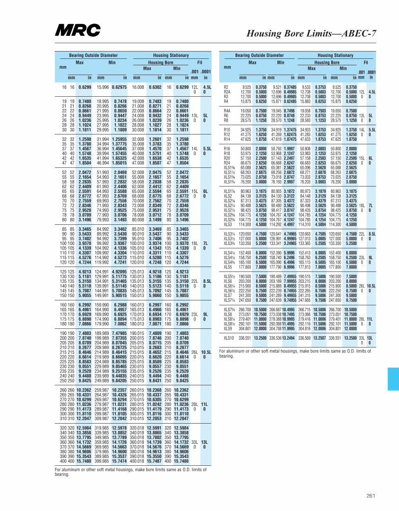
Housing Bore Limits—ABEC-7
261
mm Max
mm in
Min
mm in
Fit
.001 .0001mm in
Max
mm in
Min
mm in
Bearing Outside Diameter Housing Stationary
Housing Bore
16 16 0.6299 15.996 0.62975 16.008 0.6302 16 0.6299 12L 4.5L0 0
19 19 0.7480 18.995 0.7478 19.008 0.7483 19 0.748021 21 0.8268 20.995 0.8266 21.008 0.8271 21 0.826822 22 0.8661 21.995 0.8659 22.008 0.8664 22 0.866124 24 0.9449 23.995 0.9447 24.008 0.9432 24 0.9449 13L 5L26 26 1.0236 25.995 1.0234 26.008 1.0239 26 1.0236 0 028 28 1.1024 27.995 1.1022 28.008 1.1027 28 1.102430 30 1.1811 29.995 1.1809 30.008 1.1814 30 1.1811
32 32 1.2598 31.994 1.25955 32.008 1.2601 32 1.259835 35 1.3780 34.994 1.37775 35.008 1.3783 35 1.378037 37 1.4567 36.994 1.45645 37.008 1.4570 37 1.4567 14L 5.5L40 40 1.5748 39.994 1.57455 40.008 1.5751 40 1.5748 0 042 42 1.6535 41.994 1.65325 42.008 1.6538 42 1.653547 47 1.8504 46.994 1.85015 47.008 1.8507 47 1.8504
52 52 2.0472 51.993 2.0469 52.008 2.0475 52 2.047255 55 2.1654 54.993 2.1651 55.008 2.1657 55 2.165458 58 2.2835 57.993 2.2832 58.008 2.2838 58 2.283562 62 2.4409 61.993 2.4406 62.008 2.4412 62 2.440965 65 2.5591 64.993 2.5588 65.008 2.5594 65 2.5591 15L 6L68 68 2.6772 67.993 2.6769 68.008 2.6775 68 2.6772 0 070 70 2.7559 69.993 2.7556 70.008 2.7562 70 2.755972 72 2.8346 71.993 2.8343 72.008 2.8349 72 2.834675 75 2.9528 74.993 2.9525 75.008 2.9531 75 2.952878 78 3.0709 77.993 3.0706 78.008 3.0712 78 3.070980 80 3.1496 79.993 3.1493 80.008 3.1499 80 3.1496
85 85 3.3465 84.992 3.3462 85.010 3.3469 85 3.346590 90 3.5433 89.992 3.5430 90.010 3.5437 90 3.543395 95 3.7402 94.992 3.7399 95.010 3.7406 95 3.7402
100 100 3.9370 99.992 3.9367 100.010 3.9374 100 3.9370 18L 7L105 105 4.1339 104.992 4.1336 105.010 4.1343 105 4.1339 0 0110 110 4.3307 109.992 4.3304 110.010 4.3311 110 4.3307115 115 4.5276 114.992 4.5273 115.010 4.5280 115 4.5276120 120 4.7244 119.992 4.7241 120.010 4.7248 120 4.7244
125 125 4.9213 124.991 4.92095 125.013 4.9218 125 4.9213130 130 5.1181 129.991 5.11775 130.013 5.1186 130 5.1181135 135 5.3150 134.991 5.31465 135.013 5.3155 135 5.3150 22L 8.5L140 140 5.5118 139.991 5.51145 140.013 5.5123 140 5.5118 0 0145 145 5.7087 144.991 5.70835 145.013 5.7092 145 5.7087150 150 5.9055 149.991 5.90515 150.013 5.9060 150 5.9055
160 160 6.2992 159.990 6.2988 160.013 6.2997 160 6.2992165 165 6.4961 164.990 6.4957 165.013 6.4966 165 6.4961170 170 6.6929 169.990 6.6925 170.013 6.6934 170 6.6929 23L 9L175 175 6.8898 174.990 6.8894 175.013 6.8903 175 6.8898 0 0180 180 7.0866 179.990 7.0862 180.013 7.0871 180 7.0866
190 190 7.4803 189.989 7.47985 190.015 7.4809 190 7.4803200 200 7.8740 199.989 7.87355 200.015 7.8746 200 7.8740205 205 8.0709 204.989 8.07045 205.015 8.0715 205 8.0709210 210 8.2677 209.989 8.26725 210.015 8.2683 210 8.2677215 215 8.4646 214.989 8.46415 215.015 8.4652 215 8.4646 26L 10.5L220 220 8.6614 219.989 8.66095 220.015 8.6620 220 8.6614 0 0225 225 8.8583 224.989 8.85785 225.015 8.8589 225 8.8583230 230 9.0551 229.989 9.05465 230.015 9.0557 230 9.0551235 235 9.2520 234.989 9.25155 235.015 9.2526 235 9.2520240 240 9.4488 239.989 9.44835 240.015 9.4494 240 9.4488250 250 9.8425 249.989 9.84205 250.015 9.8431 250 9.8425
260 260 10.2362 259.987 10.2357 260.015 10.2368 260 10.2362265 265 10.4331 264.987 10.4326 265.015 10.4337 265 10.4331270 270 10.6299 269.987 10.6294 270.015 10.6305 270 10.6299280 280 11.0236 279.987 11.0231 280.015 11.0242 280 11.0236 28L 11L290 290 11.4173 289.987 11.4168 290.015 11.4179 290 11.4173 0 0300 300 11.8110 299.987 11.8105 300.015 11.8116 300 11.8110310 310 12.2047 309.987 12.2042 310.015 12.2053 310 12.2047
320 320 12.5984 319.985 12.5978 320.018 12.5991 320 12.5984340 340 13.3858 339.985 13.8852 340.018 13.8865 340 13.3858350 350 13.7795 349.985 13.7789 350.018 13.7802 350 13.7795360 360 14.1732 359.985 14.1726 360.018 14.1739 360 14.1732 33L 13L370 370 14.5669 369.985 14.5663 370.018 14.5676 370 14.5669 0 0380 380 14.9606 379.985 14.9600 380.018 14.9613 380 14.9606390 390 15.3543 389.985 15.3537 390.018 15.3550 390 15.3543400 400 15.7480 399.985 15.7474 400.018 15.7487 400 15.7480
mm Max
mm in
Min
mm in
Fit
.001 .0001mm in
Max
mm in
Min
mm in
Bearing Outside Diameter Housing Stationary
Housing Bore
R2 9.525 0.3750 9.521 0.37485 9.533 0.3753 9.525 0.3750R2A 12.700 0.5000 12.696 0.49985 12.708 0.5003 12.700 0.5000 12L 4.5LR3 12.700 0.5000 12.696 0.49985 12.708 0.5003 12.700 0.5000 0 0R4 15.875 0.6250 15.871 0.62485 15.883 0.6253 15.875 0.6250
R4A 19.050 0.7500 19.045 0.7498 19.058 0.7503 19.050 0.7500R6 22.225 0.8750 22.220 0.8748 22.233 0.8753 22.225 0.8750 13L 5LR8 28.575 1.1250 28.570 1.1248 28.583 1.1253 28.575 1.1250 0 0
R10 34.925 1.3750 34.919 1.37475 34.933 1.3753 34.925 1.3750 14L 5.5LR12 41.275 1.6250 41.269 1.62475 41.283 1.6253 41.275 1.6250 0 0R14 47.625 1.8750 47.619 1.87475 47.633 1.8753 47.625 1.8750
R16 50.800 2.0000 50.793 1.9997 50.808 2.0003 50.800 2.0000R18 53.975 2.1250 53.968 2.1247 53.983 2.1253 53.975 2.1250R20 57.150 2.2500 57.143 2.2497 57.158 2.2503 57.150 2.2500 15L 6LR24 66.675 2.6250 66.668 2.6247 66.683 2.6253 66.675 2.6250 0 0XLS1³|₈ 65.088 2.5625 65.081 2.5622 65.096 2.5628 65.088 2.5625XLS1¹|₂ 68.263 2.6875 68.256 2.6872 68.271 2.6878 68.263 2.6875XLS1⁵|₈ 73.025 2.8750 73.018 2.8747 73.033 2.8753 73.025 2.8750XLS1³|₄ 76.200 3.0000 76.193 2.9997 76.203 3.0003 76.200 3.0000
XLS1⁷|₈ 80.963 3.1875 80.955 3.1872 80.973 3.1879 80.963 3.1875XLS2 84.138 3.3125 84.130 3.3122 84.148 3.3129 84.138 3.3125XLS2¹|₈ 87.313 3.4375 87.305 3.4372 87.323 3.4379 87.313 3.4375XLS2¹|₄ 90.488 3.5625 90.480 3.5622 90.498 3.5629 90.488 3.5625 18L 7LXLS2¹|₂ 98.425 3.8750 98.417 3.8747 98.435 3.8754 98.425 3.8750 0 0XLS2⁵|₈ 104.775 4.1250 104.767 4.1247 104.785 4.1254 104.775 4.1250XLS2³|₄ 104.775 4.1250 104.767 4.1247 104.785 4.1254 104.775 4.1250XLS3 114.300 4.5000 114.292 4.4997 114.310 4.5004 114.300 4.5000
XLS3¹|₄ 120.650 4.7500 120.641 4.74965 120.663 4.7505 120.650 4.7500 22L 8.5LXLS3¹|₂ 127.000 5.0000 126.991 4.99965 127.013 5.0005 127.000 5.0000 0 0XLS3³|₄ 133.350 5.2500 133.341 3.24965 133.365 5.2505 133.350 5.2500
XLS4¹|₄ 152.400 6.0000 152.390 5.9996 152.413 6.0005 152.400 6.0000XLS4¹|₂ 158.750 6.2500 158.740 6.2496 158.763 6.2505 158.750 6.2500 23L 9LXLS4³|₄ 165.100 6.5000 165.090 6.4996 165.113 6.5005 165.100 6.5000 0 0XLS5 177.800 7.0000 177.790 6.9996 177.813 7.0005 177.800 7.0000
XLS5¹|₂ 190.500 7.5000 190.489 7.49955 190.515 7.5006 190.500 7.5000XLS6 203.200 8.0000 203.189 7.99955 203.215 8.0006 203.200 8.0000XLS6¹|₄ 215.900 8.5000 215.889 8.49955 215.915 8.5006 215.900 8.5000 26L 10.5LXLS6¹|₂ 222.250 8.7500 222.239 8.74955 222.265 8.7506 222.250 8.7500 0 0XLS7 241.300 9.5000 241.289 9.49955 241.315 9.5006 241.300 9.5000XLS7¹|₄ 247.650 9.7500 247.639 9.74955 247.665 9.7506 247.650 9.7500
XLS7³|₄ 266.700 10.5000 266.687 10.4995 266.715 10.5006 266.700 10.5000XLS8 273.051 10.7500 273.038 10.7495 273.066 10.7506 273.051 10.7500XLS8¹|₄ 279.401 11.0000 279.388 10.9995 279.416 11.0006 279.401 11.0000 28L 11LXLS8¹|₂ 292.101 11.5000 292.088 11.4995 292.116 11.5006 292.101 11.5000 0 0XLS9 304.801 12.0000 304.788 11.9995 304.816 12.0006 304.801 12.0000
XLS10 336.551 13.2500 336.536 13.2494 336.569 13.2507 336.551 13.2500 33L 13L0 0
For aluminum or other soft metal housings, make bore limits same as O.D. limits of bearing.
For aluminum or other soft metal housings, make bore limits same as O.D. limits ofbearing.

262
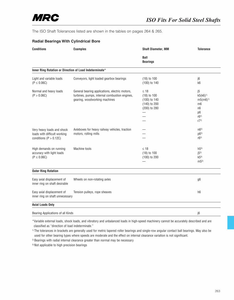
ISO Fits For Solid Steel Shafts
263
The ISO Shaft Tolerances listed are shown in the tables on pages 264 & 265.
Radial Bearings With Cylindrical Bore
Conditions Examples Shaft Diameter, MM Tolerance
Ball Bearings
Inner Ring Rotation or Direction of Load Indeterminate*
Light and variable loads Conveyors, light loaded gearbox bearings (18) to 100 j6(P ≤ 0.06C) (100) to 140 k6
Normal and heavy loads General bearing applications, electric motors, ≤ 18 j5 (P > 0.06C) turbines, pumps, internal combustion engines, (18) to 100 k5(k6)1)
gearing, woodworking machines (100) to 140 m5(m6)1)
(140) to 200 m6(200) to 280 n6 — p6— r62)
— r72)
Outer Ring Rotation
Easy axial displacement of Wheels on non-rotating axles g6inner ring on shaft desirable
Easy axial displacement of Tension pulleys, rope sheaves h6inner ring on shaft unnecessary
Axial Loads Only
Bearing Applications of all Kinds j6
*Variable external loads, shock loads, and vibratory and unbalanced loads in high-speed machinery cannot be accurately described and are classified as ‘‘direction of load indeterminate.’’
1) The tolerances in brackets are generally used for metric tapered roller bearings and single-row angular contact ball bearings. May also be used for other bearing types where speeds are moderate and the effect on internal clearance variation is not significant.
2) Bearings with radial internal clearance greater than normal may be necessary 3) Not applicable to high precision bearings
Very heavy loads and shockloads with difficult workingconditions (P > 0.12C)
High demands on runningaccuracy with light loads (P ≤ 0.06C)
Axleboxes for heavy railway vehicles, tractionmotors, rolling mills
Machine tools
———
≤ 18 (18) to 100 (100) to 200 —
n62)
p62)
r62)
h53)
j53)
k53)
m53)
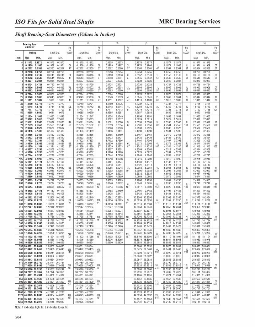
MRC Bearing ServicesISO Fits for Solid Steel Shafts
264
Shaft Bearing-Seat Diameters (Values in Inches)
Bearing BoreDiameter
g6 h6 h5 j5 j6 k5
Shaft Dia.
Max. Min.
Shaft Dia.
Max. Min.
Shaft Dia.
Max. Min.
Shaft Dia.
Max. Min.
Shaft Dia.
Max. Min.
Shaft Dia.
Max. Min.
Fitin
0.0001"
Fitin
0.0001"
Fitin
0.0001"
Fitin
0.0001"
Fitin
0.0001"
Fitin
0.0001"Inches
mm Max Min.
4 0.1575 0.1572 0.1573 0.1570 0.1575 0.1572 0.1575 0.1573 0.1576 0.1574 0.1577 0.1574 0.1577 0.15755 0.1969 0.1966 0.1967 0.1964 5L 0.1969 0.1966 3L 0.1969 0.1967 2L 0.1970 0.1968 1L 0.1971 0.1968 1L 0.1971 0.1969 0T6 0.2362 0.2359 0.2360 0.2357 1T 0.2362 0.2359 3T 0.2362 0.2360 3T 0.2363 0.2361 4T 0.2364 0.2361 5T 0.2364 0.2362 5T7 0.2756 0.2753 0.2754 0.2750 0.2756 0.2752 0.2756 0.2754 0.2758 0.2755 0.2759 0.2755 0.2759 0.27568 0.3150 0.3147 0.3148 0.3144 6L 0.3150 0.3146 4L 0.3150 0.3148 2L 0.3152 0.3149 1L 0.3153 0.3149 1L 0.3153 0.3150 0T9 0.3543 0.3540 0.3541 0.3537 1T 0.3543 0.3539 3T 0.3543 0.3541 3T 0.3545 0.3542 5T 0.3546 0.3542 6T 0.3546 0.3543 6T
10 0.3937 0.3934 0.3935 0.3931 0.3937 0.3933 0.3937 0.3935 0.3939 0.3936 0.3940 0.3936 0.3940 0.393712 0.4724 0.4721 0.4722 0.4717 0.4724 0.4720 0.4724 0.4721 0.4726 0.4723 0.4727 0.4723 0.4728 0.472415 0.5906 0.5903 0.5904 0.5899 7L 0.5906 0.5902 4L 0.5906 0.5903 3L 0.5908 0.5905 1L 0.5909 0.5905 1L 0.5910 0.5906 0T17 0.6693 0.6690 0.6691 0.6686 1T 0.6693 0.6689 3T 0.6693 0.6690 3T 0.6695 0.6692 5T 0.6696 0.6692 6T 0.6697 0.6693 7T20 0.7874 0.7870 0.7871 0.7866 0.7874 0.7869 0.7874 0.7870 0.7876 0.7872 0.7878 0.7872 0.7878 0.787525 0.9843 0.9839 0.9840 0.9835 8L 0.9843 0.9838 5L 0.9843 0.9839 4L 0.9845 0.9841 2L 0.9847 0.9841 2L 0.9847 0.9844 1T30 1.1811 1.1807 1.1808 1.1803 1T 1.1811 1.1806 4T 1.1811 1.1807 4T 1.1813 1.1809 6T 1.1815 1.1809 8T 1.1815 1.1812 8T35 1.3780 1.3775 1.3776 1.3770 1.3780 1.3774 1.3780 1.3776 1.3782 1.3778 1.3784 1.3778 1.3785 1.378140 1.5748 1.5743 1.5744 1.5738 10L 1.5748 1.5742 6L 1.5748 1.5744 4L 1.5750 1.5746 2L 1.5752 1.5746 2L 1.5753 1.5749 1T45 1.7717 1.7712 1.7713 1.7707 1T 1.7717 1.7711 5T 1.7717 1.7713 5T 1.7719 1.7715 7T 1.7721 1.7715 9T 1.7722 1.7718 10T50 1.9685 1.9680 1.9681 1.9675 1.9685 1.9679 1.9685 1.9681 1.9687 1.9683 1.9689 1.9683 1.9690 1.968655 2.1654 2.1648 2.1650 2.1643 2.1654 2.1647 2.1654 2.1649 2.1656 2.1651 2.1659 2.1651 2.1660 2.165560 2.3622 2.3616 2.3618 2.3611 2.3622 2.3615 2.3622 2.3617 2.3624 2.3619 2.3627 2.3619 2.3628 2.362365 2.5591 2.5585 2.5587 2.5580 11L 2.5591 2.5584 7L 2.5591 2.5586 5L 2.5593 2.5588 3L 2.5596 2.5588 3L 2.5597 2.5592 1T70 2.7559 2.7553 2.7555 2.7548 2T 2.7559 2.7552 6T 2.7559 2.7554 6T 2.7561 2.7556 8T 2.7564 2.7556 11T 2.7565 2.7560 12T75 2.9528 2.9522 2.9524 2.9517 2.9528 2.9521 2.9528 2.9523 2.9530 2.9525 2.9533 2.9525 2.9534 2.952980 3.1496 3.1490 3.1492 3.1485 3.1496 3.1489 3.1496 3.1491 3.1498 3.1493 3.1501 3.1493 3.1502 3.149785 3.3465 3.3457 3.3460 3.3452 3.3465 3.3456 3.3465 3.3459 3.3467 3.3461 3.3470 3.3461 3.3472 3.346690 3.5433 3.5425 3.5428 3.5420 3.5433 3.5424 3.5433 3.5427 3.5435 3.5429 3.5438 3.5429 3.5440 3.543495 3.7402 3.7394 3.7397 3.7389 3.7402 3.7393 3.7402 3.7396 3.7404 3.7398 3.7407 3.7398 3.7409 3.7403
100 3.9370 3.9362 3.9365 3.9357 13L 3.9370 3.9361 9L 3.9370 3.9364 6L 3.9372 3.9366 4L 3.9375 3.9366 4L 3.9377 3.9371 1T105 4.1339 4.1331 4.1334 4.1326 3T 4.1339 4.1330 8T 4.1339 4.1333 8T 4.1341 4.1335 10T 4.1344 4.1335 13T 4.1346 4.1340 15T110 4.3307 4.3299 4.3302 4.3294 4.3307 4.3298 4.3307 4.3301 4.3309 4.3303 4.3312 4.3303 4.3314 4.3308115 4.5276 4.5268 4.5271 4.5263 4.5276 4.5267 4.5276 4.5270 4.5278 4.5272 4.5281 4.5272 4.5283 4.5277120 4.7244 4.7236 4.7239 4.7231 4.7244 4.7235 4.7244 4.7238 4.7246 4.7240 4.7249 4.7240 4.7251 4.7245125 4.9213 4.9203 4.9207 4.9198 4.9213 4.9203 4.9213 4.9206 4.9216 4.9209 4.9219 4.9209 4.9221 4.9214130 5.1181 5.1171 5.1175 5.1166 5.1181 5.1171 5.1181 5.1174 5.1184 5.1177 5.1187 5.1177 5.1189 5.1182140 5.5118 5.5108 5.5112 5.5103 5.5118 5.5108 5.5118 5.5111 5.5121 5.5114 5.5124 5.5114 5.5126 5.5119150 5.9055 5.9045 5.9049 5.9040 15L 5.9055 5.9045 10L 5.9055 5.9048 7L 5.9058 5.9051 4L 5.9061 5.9051 4L 5.9063 5.9056 1T160 6.2992 6.2982 6.2986 6.2977 4T 6.2992 6.2982 10T 6.2992 6.2985 10T 6.2995 6.2988 13T 6.2998 6.2988 16T 6.3000 6.2993 18T170 6.6929 6.6919 6.6923 6.6914 6.6929 6.6919 6.6929 6.6922 6.6932 6.6925 6.6935 6.6925 6.6937 6.6930180 7.0866 7.0856 7.0860 7.0851 7.0866 7.0856 7.0866 7.0859 7.0869 7.0862 7.0872 7.0862 7.0874 7.0867190 7.4803 7.4791 7.4797 7.4786 7.4803 7.4792 7.4803 7.4795 7.4806 7.4798 7.4809 7.4798 7.4812 7.4805200 7.8740 7.8728 7.8734 7.8723 7.8740 7.8729 7.8740 7.8732 7.8743 7.3735 7.8746 7.8735 7.8749 7.8742220 8.6614 8.6602 8.6608 8.6597 6T 8.6614 8.6603 12T 8.6614 8.6606 12T 8.6617 8.6609 15T 8.6620 8.6609 18T 8.6623 8.6616 21T240 9.4488 9.4476 9.4482 9.4471 9.4488 9.4477 9.4488 9.4480 9.4491 9.4483 9.4494 9.4483 9.4497 9.4490250 9.8425 9.8413 9.8419 9.8408 9.8425 9.8414 9.8425 9.8417 9.8428 9.8420 9.8431 9.8420 9.8434 9.8427260 10.2362 10.2348 10.2355 10.2343 10.2362 10.2349 10.2362 10.2353 10.2365 10.2356 10.2368 10.2356 10.2373 10.2364280 11.0236 11.0222 11.0229 11.0217 11.0236 11.0223 11.0236 11.0225 11.0239 11.0230 11.0242 11.0230 11.0247 11.0238300 11.8110 11.8096 11.8103 11.8091 11.8110 11.8097 11.8110 11.8101 11.8113 11.8104 11.8116 11.8104 11.8121 11.8112310 12.2047 12.2033 12.2040 12.2028 12.2047 12.2034 12.2047 12.2038 12.2050 12.2041 12.2053 12.2041 12.2058 12.2049320 12.5984 12.5968 12.5977 12.5963 12.5984 12.5970 12.5984 12.5974 12.5987 12.5977 12.5991 12.5977 12.5995 12.5986340 13.3858 13.3842 13.3851 13.3837 13.3858 13.3844 13.3858 13.3848 13.3861 13.3851 13.3865 13.3851 13.3869 13.3860350 13.7795 13.7779 13.7788 13.7774 13.7795 13.7781 13.7795 13.7785 13.7798 13.7788 13.7802 13.7788 13.7806 13.7797360 14.1732 14.1716 14.1725 14.1711 14.1732 14.1718 14.1732 14.1722 14.1735 14.1725 14.1739 14.1725 14.1743 14.1734380 14.9606 14.9590 14.9599 14.9585 14.9606 14.9592 14.9606 14.9596 14.9609 14.9599 14.9613 14.9599 14.9617 14.9608400 15.7480 15.7464 15.7473 15.7459 15.7480 15.7466 15.7480 15.7470 15.7483 15.7473 15.7487 15.7473 15.7491 15.7482420 16.5354 16.5336 16.5346 16.5330 16.5354 16.5338 16.5354 16.5343 16.5357 16.5346 16.5362 16.5346 16.5367 16.5356440 17.3228 17.3210 17.3220 17.3204 17.3228 17.3212 17.3228 17.3217 17.3231 17.3220 17.3236 17.3220 17.3241 17.3230460 18.1102 18.1084 18.1094 18.1078 10T 18.1102 18.1086 18T 18.1102 18.1091 18T 18.1105 18.1094 21T 18.1110 18.1094 26T 18.1115 18.1104 31T480 18.8976 18.8958 18.8968 18.8952 18.8976 18.8960 18.8976 18.8965 18.8979 18.8968 18.8984 18.8968 18.8989 18.8978500 19.6850 19.6832 19.6842 19.6826 19.6850 19.6834 19.6850 19.6839 19.6853 19.6842 19.6858 19.6842 19.6863 19.6852530 20.8661 20.8641 20.8652 20.8635 20.8661 20.8644 20.8664 20.8652 20.8670 20.8652 20.8673 20.8661560 22.0472 22.0452 22.0463 22.0446 22.0472 22.0455 22.0475 22.0463 22.0481 22.0463 22.0484 22.0472600 23.6220 23.6200 23.6211 23.6194 23.6220 23.6203 23.6223 23.6211 23.6229 23.6211 23.6232 23.6220630 24.8031 24.8011 24.8022 24.8005 24.8031 24.8014 24.8034 24.8022 24.8040 24.8012 24.8043 24.8031660 25.9843 25.9813 25.9834 25.9814 25.9843 25.9823 25.9847 25.9833 25.9853 25.9833 25.9857 25.9843670 26.3780 26.3750 26.3771 26.3751 26.3780 26.3760 26.3784 26.3770 26.3790 26.3770 26.3794 26.3780710 27.9528 27.9498 27.9519 27.9499 27.9528 27.9508 27.9532 27.9518 27.9538 27.9518 27.9542 27.9528750 29.5276 29.5246 29.5267 29.5247 29.5276 29.5256 29.5280 29.5266 29.5286 29.5266 29.5290 29.5276780 30.7087 30.7057 30.7078 30.7058 30.7087 30.7067 30.7091 30.7077 30.7097 30.7077 30.7101 30.7087800 31.4961 31.4931 31.4952 31.4932 31.4961 31.4941 31.4965 31.4951 31.4971 31.4951 31.4975 31.4961850 33.4646 33.4607 33.4636 33.4614 33.4646 33.4624 33.4651 33.4635 33.4657 33.4635 33.4662 33.4646900 35.4331 35.4292 35.4321 35.4299 35.4331 35.4309 35.4336 35.4320 35.4342 35.4320 35.4347 35.4331950 37.4016 37.3977 37.4006 37.3984 37.4016 37.3994 37.4021 37.4005 37.4027 37.4005 37.4032 37.4016
1000 39.3701 39.3662 39.3691 39.3669 39.3701 39.3679 39.3706 39.3690 39.3712 39.3690 39.3717 39.37011060 41.7323 41.7274 41.7312 41.7286 41.7323 41.7297 41.7328 41.7310 41.7336 41.7310 41.7341 41.73231120 44.0945 44.0896 44.0934 44.0908 44.0945 44.0919 44.0950 44.0932 44.0958 44.0932 44.0963 44.09451180 46.4567 46.4518 46.4556 46.4530 46.4567 46.4541 46.4572 46.4554 46.4580 46.4554 46.4585 46.45671250 49.2126 49.2077 49.2115 49.2089 49.2126 49.2100 49.2131 49.2113 49.2139 49.2113 49.2144 49.2126
17L 11L 8L 5L 5L 2T
19L 13L 9L 6L 6L 2T7T 14T 14T 17T 20T 25T
21L 14L 10L 7L 7L 2T9T 16T 16T 19T 23T 27T
24L 16L 11L 8L 8L 2T
26L 17L 9L 9L 0T11T 20T 23T 29T 32T
29L 20L 10L 10L 0T21T 30T 34T 40T 44T
32L 22L 11L 11L 0T29T 39T 44T 50T 55T
37L 26L 13L 13L 0T38T 49T 54T 62T 67T
Note: T indicates tight fit. L indicates loose fit.
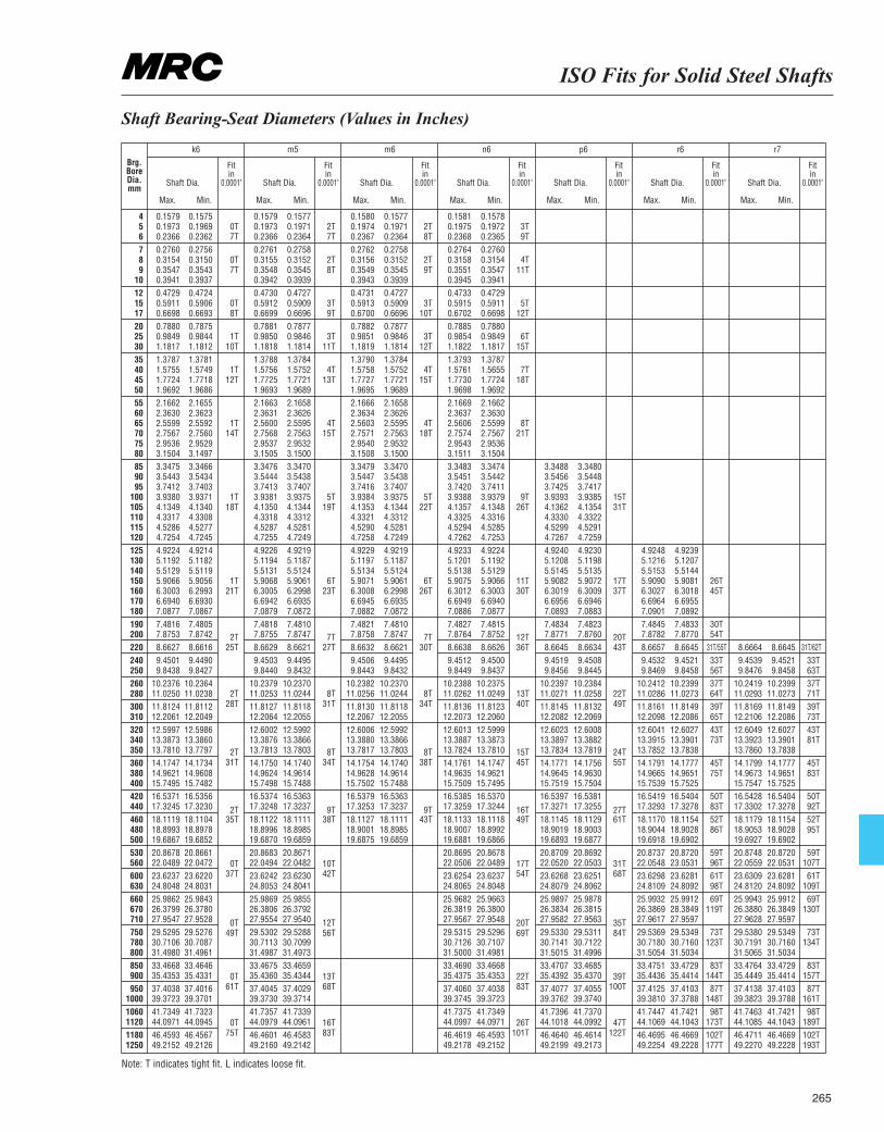
ISO Fits for Solid Steel Shafts
265
Shaft Bearing-Seat Diameters (Values in Inches)
Brg.BoreDia.mm
k6 m5 m6 n6 p6 r6 r7
Shaft Dia.
Max. Min.
Shaft Dia.
Max. Min.
Shaft Dia.
Max. Min.
Shaft Dia.
Max. Min.
Shaft Dia.
Max. Min.
Shaft Dia.
Max. Min.
Shaft Dia.
Max. Min.
Fitin
0.0001"
Fitin
0.0001"
Fitin
0.0001"
Fitin
0.0001"
Fitin
0.0001"
Fitin
0.0001"
Fitin
0.0001"
4 0.1579 0.1575 0.1579 0.1577 0.1580 0.1577 0.1581 0.15785 0.1973 0.1969 0T 0.1973 0.1971 2T 0.1974 0.1971 2T 0.1975 0.1972 3T6 0.2366 0.2362 7T 0.2366 0.2364 7T 0.2367 0.2364 8T 0.2368 0.2365 9T7 0.2760 0.2756 0.2761 0.2758 0.2762 0.2758 0.2764 0.27608 0.3154 0.3150 0T 0.3155 0.3152 2T 0.3156 0.3152 2T 0.3158 0.3154 4T9 0.3547 0.3543 7T 0.3548 0.3545 8T 0.3549 0.3545 9T 0.3551 0.3547 11T
10 0.3941 0.3937 0.3942 0.3939 0.3943 0.3939 0.3945 0.394112 0.4729 0.4724 0.4730 0.4727 0.4731 0.4727 0.4733 0.472915 0.5911 0.5906 0T 0.5912 0.5909 3T 0.5913 0.5909 3T 0.5915 0.5911 5T17 0.6698 0.6693 8T 0.6699 0.6696 9T 0.6700 0.6696 10T 0.6702 0.6698 12T20 0.7880 0.7875 0.7881 0.7877 0.7882 0.7877 0.7885 0.788025 0.9849 0.9844 1T 0.9850 0.9846 3T 0.9851 0.9846 3T 0.9854 0.9849 6T30 1.1817 1.1812 10T 1.1818 1.1814 11T 1.1819 1.1814 12T 1.1822 1.1817 15T35 1.3787 1.3781 1.3788 1.3784 1.3790 1.3784 1.3793 1.378740 1.5755 1.5749 1T 1.5756 1.5752 4T 1.5758 1.5752 4T 1.5761 1.5655 7T45 1.7724 1.7718 12T 1.7725 1.7721 13T 1.7727 1.7721 15T 1.7730 1.7724 18T50 1.9692 1.9686 1.9693 1.9689 1.9695 1.9689 1.9698 1.969255 2.1662 2.1655 2.1663 2.1658 2.1666 2.1658 2.1669 2.166260 2.3630 2.3623 2.3631 2.3626 2.3634 2.3626 2.3637 2.363065 2.5599 2.5592 1T 2.5600 2.5595 4T 2.5603 2.5595 4T 2.5606 2.5599 8T70 2.7567 2.7560 14T 2.7568 2.7563 15T 2.7571 2.7563 18T 2.7574 2.7567 21T75 2.9536 2.9529 2.9537 2.9532 2.9540 2.9532 2.9543 2.953680 3.1504 3.1497 3.1505 3.1500 3.1508 3.1500 3.1511 3.150485 3.3475 3.3466 3.3476 3.3470 3.3479 3.3470 3.3483 3.3474 3.3488 3.348090 3.5443 3.5434 3.5444 3.5438 3.5447 3.5438 3.5451 3.5442 3.5456 3.544895 3.7412 3.7403 3.7413 3.7407 3.7416 3.7407 3.7420 3.7411 3.7425 3.7417
100 3.9380 3.9371 1T 3.9381 3.9375 5T 3.9384 3.9375 5T 3.9388 3.9379 9T 3.9393 3.9385 15T105 4.1349 4.1340 18T 4.1350 4.1344 19T 4.1353 4.1344 22T 4.1357 4.1348 26T 4.1362 4.1354 31T110 4.3317 4.3308 4.3318 4.3312 4.3321 4.3312 4.3325 4.3316 4.3330 4.3322115 4.5286 4.5277 4.5287 4.5281 4.5290 4.5281 4.5294 4.5285 4.5299 4.5291120 4.7254 4.7245 4.7255 4.7249 4.7258 4.7249 4.7262 4.7253 4.7267 4.7259125 4.9224 4.9214 4.9226 4.9219 4.9229 4.9219 4.9233 4.9224 4.9240 4.9230 4.9248 4.9239130 5.1192 5.1182 5.1194 5.1187 5.1197 5.1187 5.1201 5.1192 5.1208 5.1198 5.1216 5.1207140 5.5129 5.5119 5.5131 5.5124 5.5134 5.5124 5.5138 5.5129 5.5145 5.5135 5.5153 5.5144150 5.9066 5.9056 1T 5.9068 5.9061 6T 5.9071 5.9061 6T 5.9075 5.9066 11T 5.9082 5.9072 17T 5.9090 5.9081 26T160 6.3003 6.2993 21T 6.3005 6.2998 23T 6.3008 6.2998 26T 6.3012 6.3003 30T 6.3019 6.3009 37T 6.3027 6.3018 45T170 6.6940 6.6930 6.6942 6.6935 6.6945 6.6935 6.6949 6.6940 6.6956 6.6946 6.6964 6.6955180 7.0877 7.0867 7.0879 7.0872 7.0882 7.0872 7.0886 7.0877 7.0893 7.0883 7.0901 7.0892190 7.4816 7.4805 7.4818 7.4810 7.4821 7.4810 7.4827 7.4815 7.4834 7.4823 7.4845 7.4833 30T200 7.8753 7.8742 7.8755 7.8747 7.8758 7.8747 7.8764 7.8752 7.8771 7.8760 7.8782 7.8770 54T220 8.6627 8.6616 25T 8.6629 8.6621 27T 8.6632 8.6621 30T 8.6638 8.6626 36T 8.6645 8.6634 43T 8.6657 8.6645 31T/55T 8.6664 8.6645 31T/62T240 9.4501 9.4490 9.4503 9.4495 9.4506 9.4495 9.4512 9.4500 9.4519 9.4508 9.4532 9.4521 33T 9.4539 9.4521 33T250 9.8438 9.8427 9.8440 9.8432 9.8443 9.8432 9.8449 9.8437 9.8456 9.8445 9.8469 9.8458 56T 9.8476 9.8458 63T260 10.2376 10.2364 10.2379 10.2370 10.2382 10.2370 10.2388 10.2375 10.2397 10.2384 10.2412 10.2399 37T 10.2419 10.2399 37T280 11.0250 11.0238 11.0253 11.0244 11.0256 11.0244 11.0262 11.0249 11.0271 11.0258 11.0286 11.0273 64T 11.0293 11.0273 71T300 11.8124 11.8112 11.8127 11.8118 11.8130 11.8118 11.8136 11.8123 11.8145 11.8132 11.8161 11.8149 39T 11.8169 11.8149 39T310 12.2061 12.2049 12.2064 12.2055 12.2067 12.2055 12.2073 12.2060 12.2082 12.2069 12.2098 12.2086 65T 12.2106 12.2086 73T320 12.5997 12.5986 12.6002 12.5992 12.6006 12.5992 12.6013 12.5999 12.6023 12.6008 12.6041 12.6027 43T 12.6049 12.6027 43T340 13.3873 13.3860 13.3876 13.3866 13.3880 13.3866 13.3887 13.3873 13.3897 13.3882 13.3915 13.3901 73T 13.3923 13.3901 81T350 13.7810 13.7797 13.7813 13.7803 13.7817 13.7803 13.7824 13.7810 13.7834 13.7819 13.7852 13.7838 13.7860 13.7838360 14.1747 14.1734 14.1750 14.1740 14.1754 14.1740 14.1761 14.1747 14.1771 14.1756 14.1791 14.1777 45T 14.1799 14.1777 45T380 14.9621 14.9608 14.9624 14.9614 14.9628 14.9614 14.9635 14.9621 14.9645 14.9630 14.9665 14.9651 75T 14.9673 14.9651 83T400 15.7495 15.7482 15.7498 15.7488 15.7502 15.7488 15.7509 15.7495 15.7519 15.7504 15.7539 15.7525 15.7547 15.7525420 16.5371 16.5356 16.5374 16.5363 16.5379 16.5363 16.5385 16.5370 16.5397 16.5381 16.5419 16.5404 50T 16.5428 16.5404 50T440 17.3245 17.3230 17.3248 17.3237 17.3253 17.3237 17.3259 17.3244 17.3271 17.3255 17.3293 17.3278 83T 17.3302 17.3278 92T460 18.1119 18.1104 35T 18.1122 18.1111 38T 18.1127 18.1111 43T 18.1133 18.1118 49T 18.1145 18.1129 61T 18.1170 18.1154 52T 18.1179 18.1154 52T480 18.8993 18.8978 18.8996 18.8985 18.9001 18.8985 18.9007 18.8992 18.9019 18.9003 18.9044 18.9028 86T 18.9053 18.9028 95T500 19.6867 19.6852 19.6870 19.6859 19.6875 19.6859 19.6881 19.6866 19.6893 19.6877 19.6918 19.6902 19.6927 19.6902530 20.8678 20.8661 20.8683 20.8671 20.8695 20.8678 20.8709 20.8692 20.8737 20.8720 59T 20.8748 20.8720 59T560 22.0489 22.0472 22.0494 22.0482 22.0506 22.0489 22.0520 22.0503 22.0548 23.0531 96T 22.0559 22.0531 107T600 23.6237 23.6220 23.6242 23.6230 23.6254 23.6237 23.6268 23.6251 23.6298 23.6281 61T 23.6309 23.6281 61T630 24.8048 24.8031 24.8053 24.8041 24.8065 24.8048 24.8079 24.8062 24.8109 24.8092 98T 24.8120 24.8092 109T660 25.9862 25.9843 25.9869 25.9855 25.9682 25.9663 25.9897 25.9878 25.9932 25.9912 69T 25.9943 25.9912 69T670 26.3799 26.3780 26.3806 26.3792 26.3819 26.3800 26.3834 26.3815 26.3869 28.3849 119T 26.3880 26.3849 130T710 27.9547 27.9528 27.9554 27.9540 27.9567 27.9548 27.9582 27.9563 27.9617 27.9597 27.9628 27.9597750 29.5295 29.5276 29.5302 29.5288 29.5315 29.5296 29.5330 29.5311 29.5369 29.5349 73T 29.5380 29.5349 73T780 30.7106 30.7087 30.7113 30.7099 30.7126 30.7107 30.7141 30.7122 30.7180 30.7160 123T 30.7191 30.7160 134T800 31.4980 31.4961 31.4987 31.4973 31.5000 31.4981 31.5015 31.4996 31.5054 31.5034 31.5065 31.5034850 33.4668 33.4646 33.4675 33.4659 33.4690 33.4668 33.4707 33.4685 33.4751 33.4729 83T 33.4764 33.4729 83T900 35.4353 35.4331 35.4360 35.4344 35.4375 35.4353 35.4392 35.4370 35.4436 35.4414 144T 35.4449 35.4414 157T950 37.4038 37.4016 37.4045 37.4029 37.4060 37.4038 37.4077 37.4055 37.4125 37.4103 87T 37.4138 37.4103 87T
1000 39.3723 39.3701 39.3730 39.3714 39.3745 39.3723 39.3762 39.3740 39.3810 37.3788 148T 39.3823 39.3788 161T1060 41.7349 41.7323 41.7357 41.7339 41.7375 41.7349 41.7396 41.7370 41.7447 41.7421 98T 41.7463 41.7421 98T1120 44.0971 44.0945 44.0979 44.0961 44.0997 44.0971 44.1018 44.0992 44.1069 44.1043 173T 44.1085 44.1043 189T1180 46.4593 46.4567 46.4601 46.4583 46.4619 46.4593 46.4640 46.4614 46.4695 46.4669 102T 46.4711 46.4669 102T1250 49.2152 49.2126 49.2160 49.2142 49.2178 49.2152 49.2199 49.2173 49.2254 49.2228 177T 49.2270 49.2228 193T
2T 7T 7T 12T 20T
Note: T indicates tight fit. L indicates loose fit.
2T 8T 8T 13T 22T28T 31T 34T 40T 49T
2T 8T 8T 15T 24T31T 34T 38T 45T 55T
2T 9T 9T 16T 27T
0T 10T 17T 31T37T 42T 54T 68T
0T 12T 20T 35T49T 56T 69T 84T
0T 13T 22T 39T61T 68T 83T 100T
0T 16T 26T 47T75T 83T 101T 122T
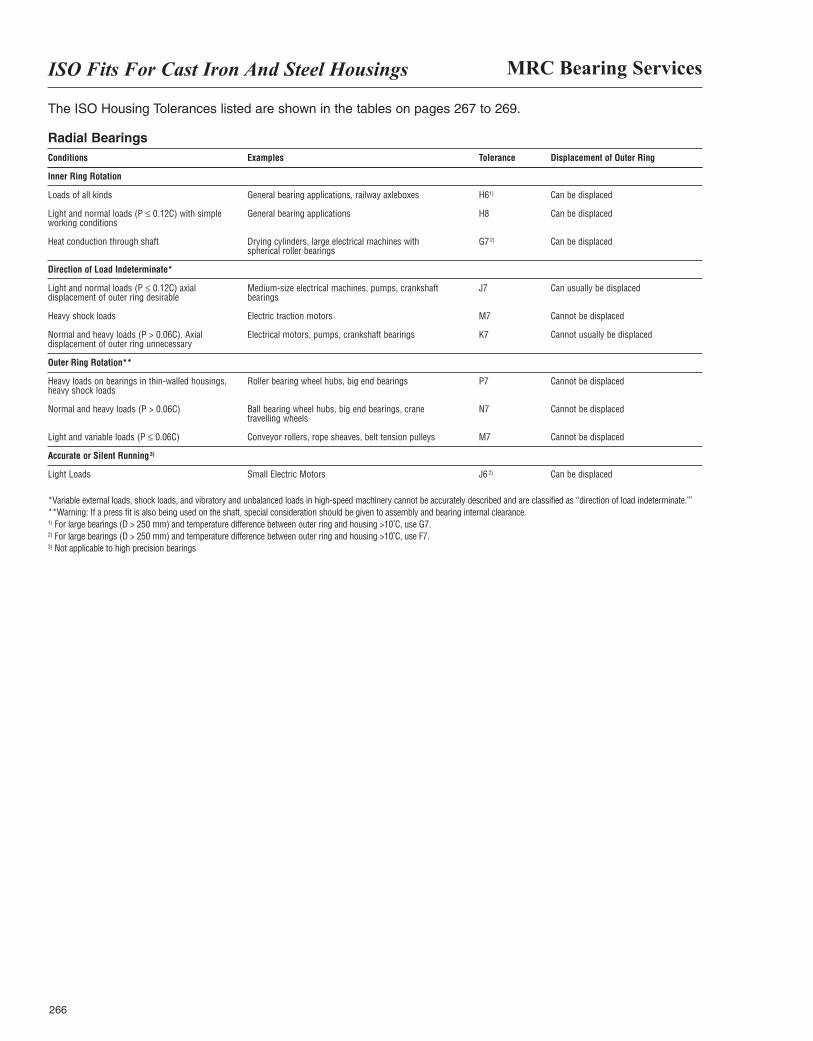
MRC Bearing ServicesISO Fits For Cast Iron And Steel Housings
266
The ISO Housing Tolerances listed are shown in the tables on pages 267 to 269.
Radial BearingsConditions Examples Tolerance Displacement of Outer Ring
Inner Ring Rotation
Loads of all kinds General bearing applications, railway axleboxes H61) Can be displaced
Light and normal loads (P ≤ 0.12C) with simple General bearing applications H8 Can be displacedworking conditions
Heat conduction through shaft Drying cylinders, large electrical machines with G72) Can be displacedspherical roller bearings
Direction of Load Indeterminate*
Light and normal loads (P ≤ 0.12C) axial Medium-size electrical machines, pumps, crankshaft J7 Can usually be displaceddisplacement of outer ring desirable bearings
Heavy shock loads Electric traction motors M7 Cannot be displaced
Normal and heavy loads (P > 0.06C). Axial Electrical motors, pumps, crankshaft bearings K7 Cannot usually be displaceddisplacement of outer ring unnecessary
Outer Ring Rotation**
Heavy loads on bearings in thin-walled housings, Roller bearing wheel hubs, big end bearings P7 Cannot be displacedheavy shock loads
Normal and heavy loads (P > 0.06C) Ball bearing wheel hubs, big end bearings, crane N7 Cannot be displacedtravelling wheels
Light and variable loads (P ≤ 0.06C) Conveyor rollers, rope sheaves, belt tension pulleys M7 Cannot be displaced
Accurate or Silent Running3)
Light Loads Small Electric Motors J62) Can be displaced
*Variable external loads, shock loads, and vibratory and unbalanced loads in high-speed machinery cannot be accurately described and are classified as “direction of load indeterminate.’”**Warning: If a press fit is also being used on the shaft, special consideration should be given to assembly and bearing internal clearance.1) For large bearings (D > 250 mm) and temperature difference between outer ring and housing >10˚C, use G7.2) For large bearings (D > 250 mm) and temperature difference between outer ring and housing >10˚C, use F7.3) Not applicable to high precision bearings
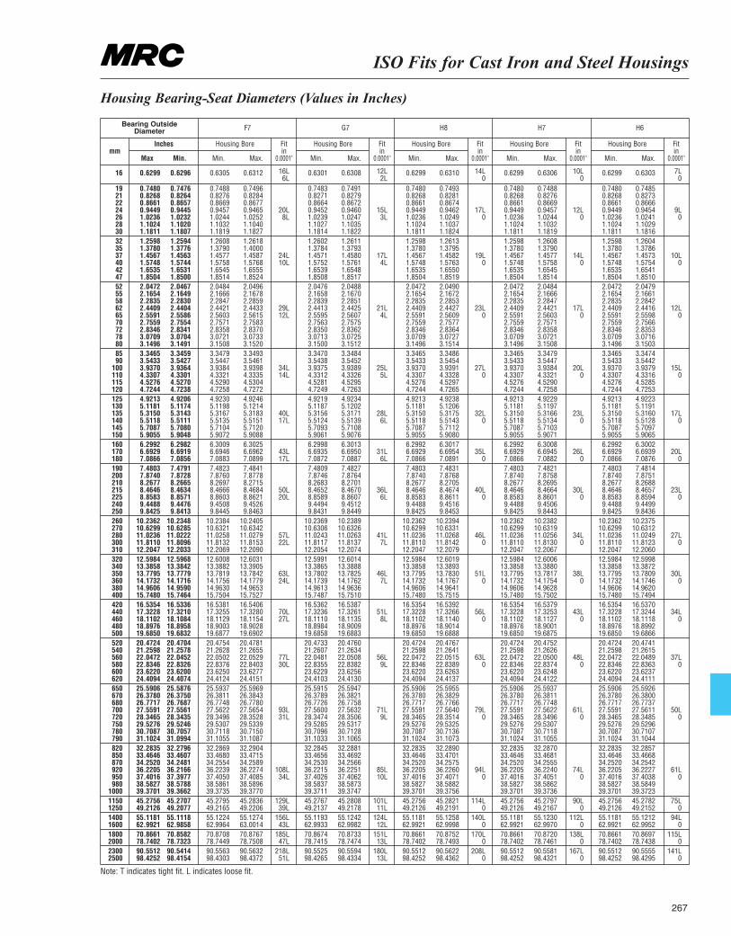
ISO Fits for Cast Iron and Steel Housings
267
Housing Bearing-Seat Diameters (Values in Inches)
Bearing OutsideDiameter F7 G7 H8 H7 H6
Housing Bore
Min. Max.
Housing Bore
Min. Max.
Housing Bore
Min. Max.
Housing Bore
Min. Max.
Housing Bore
Min. Max.
Fitin
0.0001"
Fitin
0.0001"
Fitin
0.0001"
Fitin
0.0001"
Fitin
0.0001"
Inches
Max Min.mm
16 0.6299 0.6296 0.6305 0.6312 0.6301 0.6308 0.6299 0.6310 0.6299 0.6306 0.6299 0.6303
19 0.7480 0.7476 0.7488 0.7496 0.7483 0.7491 0.7480 0.7493 0.7480 0.7488 0.7480 0.748521 0.8268 0.8264 0.8276 0.8284 0.8271 0.8279 0.8268 0.8281 0.8268 0.8276 0.8268 0.827322 0.8661 0.8657 0.8669 0.8677 0.8664 0.8672 0.8661 0.8674 0.8661 0.8669 0.8661 0.866624 0.9449 0.9445 0.9457 0.9465 20L 0.9452 0.9460 15L 0.9449 0.9462 17L 0.9449 0.9457 12L 0.9449 0.9454 9L26 1.0236 1.0232 1.0244 1.0252 8L 1.0239 1.0247 3L 1.0236 1.0249 0 1.0236 1.0244 0 1.0236 1.0241 028 1.1024 1.1020 1.1032 1.1040 1.1027 1.1035 1.1024 1.1037 1.1024 1.1032 1.1024 1.102930 1.1811 1.1807 1.1819 1.1827 1.1814 1.1822 1.1811 1.1824 1.1811 1.1819 1.1811 1.181632 1.2598 1.2594 1.2608 1.2618 1.2602 1.2611 1.2598 1.2613 1.2598 1.2608 1.2598 1.260435 1.3780 1.3776 1.3790 1.4000 1.3784 1.3793 1.3780 1.3795 1.3780 1.3790 1.3780 1.378637 1.4567 1.4563 1.4577 1.4587 24L 1.4571 1.4580 17L 1.4567 1.4582 19L 1.4567 1.4577 14L 1.4567 1.4573 10L40 1.5748 1.5744 1.5758 1.5768 10L 1.5752 1.5761 4L 1.5748 1.5763 0 1.5748 1.5758 0 1.5748 1.5754 042 1.6535 1.6531 1.6545 1.6555 1.6539 1.6548 1.6535 1.6550 1.6535 1.6545 1.6535 1.654147 1.8504 1.8500 1.8514 1.8524 1.8508 1.8517 1.8504 1.8519 1.8504 1.8514 1.8504 1.851052 2.0472 2.0467 2.0484 2.0496 2.0476 2.0488 2.0472 2.0490 2.0472 2.0484 2.0472 2.047955 2.1654 2.1649 2.1666 2.1678 2.1658 2.1670 2.1654 2.1672 2.1654 2.1666 2.1654 2.166158 2.2835 2.2830 2.2847 2.2859 2.2839 2.2851 2.2835 2.2853 2.2835 2.2847 2.2835 2.284262 2.4409 2.4404 2.4421 2.4433 29L 2.4413 2.4425 21L 2.4409 2.4427 23L 2.4409 2.4421 17L 2.4409 2.4416 12L65 2.5591 2.5586 2.5603 2.5615 12L 2.5595 2.5607 4L 2.5591 2.5609 0 2.5591 2.5603 0 2.5591 2.5598 070 2.7559 2.7554 2.7571 2.7583 2.7563 2.7575 2.7559 2.7577 2.7559 2.7571 2.7559 2.756672 2.8346 2.8341 2.8358 2.8370 2.8350 2.8362 2.8346 2.8364 2.8346 2.8358 2.8346 2.835378 3.0709 3.0704 3.0721 3.0733 3.0713 3.0725 3.0709 3.0727 3.0709 3.0721 3.0709 3.071680 3.1496 3.1491 3.1508 3.1520 3.1500 3.1512 3.1496 3.1514 3.1496 3.1508 3.1496 3.150385 3.3465 3.3459 3.3479 3.3493 3.3470 3.3484 3.3465 3.3486 3.3465 3.3479 3.3465 3.347490 3.5433 3.5427 3.5447 3.5461 3.5438 3.5452 3.5433 3.5454 3.5433 3.5447 3.5433 3.5442
100 3.9370 3.9364 3.9384 3.9398 34L 3.9375 3.9389 25L 3.9370 3.9391 27L 3.9370 3.9384 20L 3.9370 3.9379 15L110 4.3307 4.3301 4.3321 4.3335 14L 4.3312 4.3326 5L 4.3307 4.3328 0 4.3307 4.3321 0 4.3307 4.3316 0115 4.5276 4.5270 4.5290 4.5304 4.5281 4.5295 4.5276 4.5297 4.5276 4.5290 4.5276 4.5285120 4.7244 4.7238 4.7258 4.7272 4.7249 4.7263 4.7244 4.7265 4.7244 4.7258 4.7244 4.7253125 4.9213 4.9206 4.9230 4.9246 4.9219 4.9234 4.9213 4.9238 4.9213 4.9229 4.9213 4.9223130 5.1181 5.1174 5.1198 5.1214 5.1187 5.1202 5.1181 5.1206 5.1181 5.1197 5.1181 5.1191135 5.3150 5.3143 5.3167 5.3183 40L 5.3156 5.3171 28L 5.3150 5.3175 32L 5.3150 5.3166 23L 5.3150 5.3160 17L140 5.5118 5.5111 5.5135 5.5151 17L 5.5124 5.5139 6L 5.5118 5.5143 0 5.5118 5.5134 0 5.5118 5.5128 0145 5.7087 5.7080 5.7104 5.7120 5.7093 5.7108 5.7087 5.7112 5.7087 5.7103 5.7087 5.7097150 5.9055 5.9048 5.9072 5.9088 5.9061 5.9076 5.9055 5.9080 5.9055 5.9071 5.9055 5.9065160 6.2992 6.2982 6.3009 6.3025 6.2998 6.3013 6.2992 6.3017 6.2992 6.3008 6.2992 6.3002170 6.6929 6.6919 6.6946 6.6962 43L 6.6935 6.6950 31L 6.6929 6.6954 35L 6.6929 6.6945 26L 6.6929 6.6939 20L180 7.0866 7.0856 7.0883 7.0899 17L 7.0872 7.0887 6L 7.0866 7.0891 0 7.0866 7.0882 0 7.0866 7.0876 0190 7.4803 7.4791 7.4823 7.4841 7.4809 7.4827 7.4803 7.4831 7.4803 7.4821 7.4803 7.4814200 7.8740 7.8728 7.8760 7.8778 7.8746 7.8764 7.8740 7.8768 7.8740 7.8758 7.8740 7.8751210 8.2677 8.2665 8.2697 8.2715 8.2683 8.2701 8.2677 8.2705 8.2677 8.2695 8.2677 8.2688215 8.4646 8.4634 8.4666 8.4684 50L 8.4652 8.4670 36L 8.4646 8.4674 40L 8.4646 8.4664 30L 8.4646 8.4657 23L225 8.8583 8.8571 8.8603 8.8621 20L 8.8589 8.8607 6L 8.8583 8.8611 0 8.8583 8.8601 0 8.8583 8.8594 0240 9.4488 9.4476 9.4508 9.4526 9.4494 9.4512 9.4488 9.4516 9.4488 9.4506 9.4488 9.4499250 9.8425 9.8413 9.8445 9.8463 9.8431 9.8449 9.8425 9.8453 9.8425 9.8443 9.8425 9.8436260 10.2362 10.2348 10.2384 10.2405 10.2369 10.2389 10.2362 10.2394 10.2362 10.2382 10.2362 10.2375270 10.6299 10.6285 10.6321 10.6342 10.6306 10.6326 10.6299 10.6331 10.6299 10.6319 10.6299 10.6312280 11.0236 11.0222 11.0258 11.0279 57L 11.0243 11.0263 41L 11.0236 11.0268 46L 11.0236 11.0256 34L 11.0236 11.0249 27L300 11.8110 11.8096 11.8132 11.8153 22L 11.8117 11.8137 7L 11.8110 11.8142 0 11.8110 11.8130 0 11.8110 11.8123 0310 12.2047 12.2033 12.2069 12.2090 12.2054 12.2074 12.2047 12.2079 12.2047 12.2067 12.2047 12.2060320 12.5984 12.5968 12.6008 12.6031 12.5991 12.6014 12.5984 12.6019 12.5984 12.6006 12.5984 12.5998340 13.3858 13.3842 13.3882 13.3905 13.3865 13.3888 13.3858 13.3893 13.3858 13.3880 13.3858 13.3872350 13.7795 13.7779 13.7819 13.7842 63L 13.7802 13.7825 46L 13.7795 13.7830 51L 13.7795 13.7817 38L 13.7795 13.7809 30L360 14.1732 14.1716 14.1756 14.1779 24L 14.1739 14.1762 7L 14.1732 14.1767 0 14.1732 14.1754 0 14.1732 14.1746 0380 14.9606 14.9590 14.9630 14.9653 14.9613 14.9636 14.9606 14.9641 14.9606 14.9628 14.9606 14.9620400 15.7480 15.7464 15.7504 15.7527 15.7487 15.7510 15.7480 15.7515 15.7480 15.7502 15.7480 15.7494420 16.5354 16.5336 16.5381 16.5406 16.5362 16.5387 16.5354 16.5392 16.5354 16.5379 16.5354 16.5370440 17.3228 17.3210 17.3255 17.3280 70L 17.3236 17.3261 51L 17.3228 17.3266 56L 17.3228 17.3253 43L 17.3228 17.3244 34L460 18.1102 18.1084 18.1129 18.1154 27L 18.1110 18.1135 8L 18.1102 18.1140 0 18.1102 18.1127 0 18.1102 18.1118 0480 18.8976 18.8958 18.9003 18.9028 18.8984 18.9009 18.8976 18.9014 18.8976 18.9001 18.8976 18.8992500 19.6850 19.6832 19.6877 19.6902 19.6858 19.6883 19.6850 19.6888 19.6850 19.6875 19.6850 19.6866520 20.4724 20.4704 20.4754 20.4781 20.4733 20.4760 20.4724 20.4767 20.4724 20.4752 20.4724 20.4741540 21.2598 21.2578 21.2628 21.2655 21.2607 21.2634 21.2598 21.2641 21.2598 21.2626 21.2598 21.2615560 22.0472 22.0452 22.0502 22.0529 77L 22.0481 22.0508 56L 22.0472 22.0515 63L 22.0472 22.0500 48L 22.0472 22.0489 37L580 22.8346 22.8326 22.8376 22.8403 30L 22.8355 22.8382 9L 22.8346 22.8389 0 22.8346 22.8374 0 22.8346 22.8363 0600 23.6220 23.6200 23.6250 23.6277 23.6229 23.6256 23.6220 23.6263 23.6220 23.6248 23.6220 23.6237620 24.4094 24.4074 24.4124 24.4151 24.4103 24.4130 24.4094 24.4137 24.4094 24.4122 24.4094 24.4111650 25.5906 25.5876 25.5937 25.5969 25.5915 25.5947 25.5906 25.5955 25.5906 25.5937 25.5906 25.5926670 26.3780 26.3750 26.3811 26.3843 26.3789 26.3821 26.3780 26.3829 26.3780 26.3811 26.3780 26.3800680 26.7717 26.7687 26.7748 26.7780 26.7726 26.7758 26.7717 26.7766 26.7717 26.7748 26.7717 26.7737700 27.5591 27.5561 27.5622 27.5654 93L 27.5600 27.5632 71L 27.5591 27.5640 79L 27.5591 27.5622 61L 27.5591 27.5611 50L720 28.3465 28.3435 28.3496 28.3528 31L 28.3474 28.3506 9L 28.3465 28.3514 0 28.3465 28.3496 0 28.3465 28.3485 0750 29.5276 29.5246 29.5307 29.5339 29.5285 29.5317 29.5276 29.5325 29.5276 29.5307 29.5276 29.5296780 30.7087 30.7057 30.7118 30.7150 30.7096 30.7128 30.7087 30.7136 30.7087 30.7118 30.7087 30.7107790 31.1024 31.0994 31.1055 31.1087 31.1033 31.1065 31.1024 31.1073 31.1024 31.1055 31.1024 31.1044820 32.2835 32.2796 32.2869 32.2904 32.2845 32.2881 32.2835 32.2890 32.2835 32.2870 32.2835 32.2857850 33.4646 33.4607 33.4680 33.4715 33.4656 33.4692 33.4646 33.4701 33.4646 33.4681 33.4646 33.4668870 34.2520 34.2481 34.2554 34.2589 34.2530 34.2566 34.2520 34.2575 34.2520 34.2555 34.2520 34.2542920 36.2205 36.2166 36.2239 36.2274 108L 36.2215 36.2251 85L 36.2205 36.2260 94L 36.2205 36.2240 74L 36.2205 36.2227 61L950 37.4016 37.3977 37.4050 37.4085 34L 37.4026 37.4062 10L 37.4016 37.4071 0 37.4016 37.4051 0 37.4016 37.4038 0980 38.5827 38.5788 38.5861 38.5896 38.5837 38.5873 38.5827 38.5882 38.5827 38.5862 38.5827 38.5849
1000 39.3701 39.3662 39.3735 39.3770 39.3711 39.3747 39.3701 39.3756 39.3701 39.3736 39.3701 39.37231150 45.2756 45.2707 45.2795 45.2836 129L 45.2767 45.2808 101L 45.2756 45.2821 114L 45.2756 45.2797 90L 45.2756 45.2782 75L1250 49.2126 49.2077 49.2165 49.2206 39L 49.2137 49.2178 11L 49.2126 49.2191 0 49.2126 49.2167 0 49.2126 49.2152 01400 55.1181 55.1118 55.1224 55.1274 156L 55.1193 55.1242 124L 55.1181 55.1258 140L 55.1181 55.1230 112L 55.1181 55.1212 94L1600 62.9921 62.9858 62.9964 63.0014 43L 62.9933 62.9982 12L 62.9921 62.9998 0 62.9921 62.9970 0 62.9921 62.9952 01800 70.8661 70.8582 70.8708 70.8767 185L 70.8674 70.8733 151L 70.8661 70.8752 170L 70.8661 70.8720 138L 70.8661 70.8697 115L2000 78.7402 78.7323 78.7449 78.7508 47L 78.7415 78.7474 13L 78.7402 78.7493 0 78.7402 78.7461 0 78.7402 78.7438 02300 90.5512 90.5414 90.5563 90.5632 218L 90.5525 90.5594 180L 90.5512 90.5622 208L 90.5512 90.5581 167L 90.5512 90.5555 141L2500 98.4252 98.4154 98.4303 98.4372 51L 98.4265 98.4334 13L 98.4252 98.4362 0 98.4252 98.4321 0 98.4252 98.4295 0
Note: T indicates tight fit. L indicates loose fit.
16L 12L 14L 10L 7L6L 2L 0 0 0
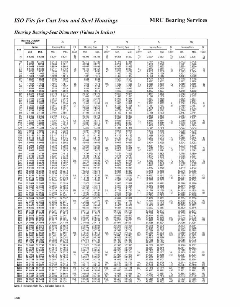
MRC Bearing ServicesISO Fits for Cast Iron and Steel Housings
268
Housing Bearing-Seat Diameters (Values in Inches)
Bearing OutsideDiameter J6 J7 K6 K7 M6
Housing Bore
Min. Max.
Housing Bore
Min. Max.
Housing Bore
Min. Max.
Housing Bore
Min. Max.
Housing Bore
Min. Max.
Fitin
0.0001"
Fitin
0.0001"
Fitin
0.0001"
Fitin
0.0001"
Fitin
0.0001"
Inches
Max Min.mm
16 0.6299 0.6296 0.6297 0.6301 0.6296 0.6303 0.6295 0.6300 0.6294 0.6301 0.6293 0.6297
19 0.7480 0.7476 0.7478 0.7483 0.7476 0.7485 0.7476 0.7481 0.7474 0.7482 0.7473 0.747821 0.8268 08264 0.8266 0.8271 0.8264 0.8273 0.8264 0.8269 0.8262 0.8270 0.8261 0.826622 0.8661 0.8657 0.8659 0.8664 0.8657 0.8666 0.8657 0.8662 0.8655 0.8663 0.8654 0.865924 0.9449 0.9445 0.9447 0.9452 7L 0.9445 0.9454 9L 0.9445 0.9450 5L 0.9443 0.9451 6L 0.9442 0.9447 2L26 1.0236 1.0232 1.0234 1.0239 2T 1.0232 1.0241 4T 1.0232 1.0237 4T 1.0230 1.0238 6T 1.0229 1.0234 7T28 1.1024 1.1020 1.1022 1.1027 1.1020 1.1029 1.1020 1.1025 1.1018 1.1026 1.1017 1.102230 1.1811 1.1807 1.1809 1.1814 1.1807 1.1816 1.1807 1.1812 1.1805 1.1813 1.1804 1.180932 1.2598 1.2594 1.2596 1.2602 1.2594 1.2604 1.2593 1.2599 1.2591 1.2601 1.2590 1.259635 1.3780 1.3776 1.3778 1.3784 1.3776 1.3786 1.3775 1.3781 1.3773 1.3783 1.3772 1.377837 1.4567 1.4563 1.4565 1.4571 8L 1.4563 1.4573 10L 1.4562 1.4568 5L 1.4560 1.4570 7L 1.4559 1.4565 2L40 1.5748 1.5744 1.5746 1.5752 2T 1.5744 1.5754 4T 1.5743 1.5749 5T 1.5741 1.5751 7T 1.5740 1.5746 8T42 1.6535 1.6531 1.6533 1.6539 1.6531 1.6541 1.6530 1.6536 1.6528 1.6538 1.6527 1.653347 1.8504 1.8500 1.8502 1.8508 1.8500 1.8510 1.8499 1.8505 1.8497 1.8507 1.8496 1.850252 2.0472 2.0467 2.0470 2.0477 2.0467 2.0479 2.0466 2.0474 2.0464 2.0476 2.0463 2.047055 2.1654 2.1649 2.1652 2.1659 2.1649 2.1661 2.1648 2.1656 2.1646 2.1658 2.1645 2.165258 2.2835 2.2830 2.2833 2.2840 2.2830 2.2842 2.2829 2.2837 2.2827 2.2839 2.2826 2.283362 2.4409 2.4404 2.4407 2.4414 2.4404 2.4416 2.4403 2.4411 2.4401 2.4413 2.4400 2.440765 2.5591 2.5586 2.2589 2.2596 10L 2.5586 2.5598 12L 2.5585 2.5593 7L 2.5583 2.5595 9L 2.5582 2.5589 3L70 2.7559 2.7554 2.7557 2.7564 2T 2.7554 2.7566 5T 2.7553 2.7561 6T 2.7551 2.7563 8T 2.7550 2.7557 9T72 2.8346 2.8341 2.8344 2.8351 2.8341 2.8353 2.8340 2.8348 2.8338 2.8350 2.8337 2.834478 3.0709 3.0704 3.0707 3.0714 3.0704 3.0716 3.0703 3.0711 3.0701 3.0713 3.0700 3.070780 3.1496 3.1491 3.1494 3.1501 3.1491 3.1503 3.1490 3.1498 3.1488 3.1500 3.1487 3.149485 3.3465 3.3459 3.3463 3.3471 3.3460 3.3474 3.3458 3.3467 3.3455 3.3469 3.3454 3.346390 3.5433 3.5427 3.5431 3.5439 3.5428 3.5442 3.5426 3.5435 3.5423 3.5437 3.5422 3.5431
100 3.9370 3.9364 3.9368 3.9376 12L 3.9365 3.9379 15L 3.9363 3.9372 8L 3.9360 3.9374 10L 3.9359 3.9368 4L110 4.3307 4.3301 4.3305 4.3313 2T 4.3302 4.3316 5T 4.3300 4.3309 7T 4.3297 4.3311 10T 4.3296 4.3305 11T115 4.5276 4.5270 4.5274 4.5282 4.5271 4.5285 4.5269 4.5278 4.5266 4.5280 4.5265 4.5274120 4.7244 4.7238 4.7242 4.7250 4.7239 4.7253 4.7237 4.7246 4.7234 4.7248 4.7233 4.7242125 4.9213 4.9206 4.9210 4.9220 4.9207 4.9223 4.9205 4.9215 4.9202 4.9218 4.9200 4.9210130 5.1181 5.1174 5.1178 5.1188 5.1175 5.1191 5.1173 5.1183 5.1170 5.1186 5.1168 5.1178135 5.3150 5.3143 5.3147 5.3157 5.3144 5.3160 5.3142 5.3152 5.3139 5.3155 5.3137 5.3147140 5.5118 5.5111 5.5115 5.5125 14L 5.5112 5.5128 17L 5.5110 5.5120 9L 5.5107 5.5123 12L 5.5105 5.5115 4L145 5.7087 5.7080 5.7084 5.7094 3T 5.7081 5.7097 6T 5.7079 5.7089 8T 5.7076 5.7092 11T 5.7074 5.7084 13T150 5.9055 5.9048 5.9052 5.9062 5.9049 5.9065 5.9047 5.9057 5.9044 5.9060 5.9042 5.9052160 6.2992 6.2982 6.2989 6.2999 6.2986 6.3002 6.2984 6.2994 6.2981 6.2997 6.2979 6.2989170 6.6929 6.6919 6.6926 6.6936 17L 6.6923 6.6939 20L 6.6921 6.6931 12L 6.6918 6.6934 15L 6.6916 6.6926 7L180 7.0866 7.0856 7.0863 7.0873 3T 7.0860 7.0876 6T 7.0858 7.0868 8T 7.0855 7.0871 11T 7.0853 7.0863 13T190 7.4803 7.4791 7.4800 7.4812 7.4797 7.4815 7.4794 7.4805 7.4790 7.4808 7.4788 7.4800200 7.8740 7.8728 7.8737 7.8749 7.8734 7.8752 7.8731 7.8742 7.8727 7.8745 7.8725 7.8737210 8.2677 8.2665 8.2674 8.2686 8.2671 8.2689 8.2668 8.2679 8.2664 8.2682 8.2662 8.2674215 8.4646 8.4634 8.4643 8.4655 21L 8.4640 8.4658 24L 8.4637 8.4648 14L 8.4633 8.4651 17L 8.4631 8.4643 9L225 8.8583 8.8571 8.8580 8.8592 3T 8.8577 8.8595 6T 8.8574 8.8585 9T 8.8570 8.8588 13T 8.8568 8.8580 15T240 9.4488 9.4476 9.4485 9.4497 9.4482 9.4500 9.4479 9.4490 9.4475 9.4493 9.4473 9.4485250 9.8425 9.8413 9.8422 9.8434 9.8419 9.8437 9.8416 9.8427 9.8412 9.8430 9.8410 9.8422260 10.2362 10.2348 10.2359 10.2372 10.2356 10.2376 10.2351 10.2364 10.2348 10.2368 10.2346 10.2358270 10.6299 10.6285 10.6296 10.6309 10.6293 10.6313 10.6288 10.6301 10.6285 10.6305 10.6283 10.6295280 11.0236 11.0222 11.0233 11.0246 24L 11.0230 11.0250 28L 11.0225 11.0238 16L 11.0222 11.0242 20L 11.0220 11.0232 10L300 11.8110 11.8096 11.8107 11.8120 3T 11.8104 11.8124 6T 11.8099 11.8112 11T 11.8096 11.8116 14T 11.8094 11.8106 16T310 12.2047 12.2033 12.2044 12.2057 12.2041 12.2061 12.2036 12.2049 12.2033 12.2053 12.2031 12.2043320 12.5984 12.5968 12.5981 12.5995 12.5977 12.5999 12.5973 12.5987 12.5968 12.5991 12.5966 12.5980340 13.3858 13.3842 13.3855 13.3869 13.3851 13.3873 13.3847 13.3861 13.3842 13.3865 13.3840 13.3854350 13.7795 13.7779 13.7792 13.7806 13.7788 13.7810 13.7784 13.7798 13.7779 13.7802 13.7777 13.7791360 14.1732 14.1716 14.1729 14.1743 27L 14.1725 14.1747 31L 14.1721 14.1735 19L 14.1716 14.1739 23L 14.1714 14.1728 12L380 14.9606 14.9590 14.9603 14.9617 3T 14.9599 14.9621 7T 14.9595 14.9609 11T 14.9590 14.9613 16T 14.9588 14.9602 18T400 15.7480 15.7464 15.7477 15.7491 15.7473 15.7495 15.7469 15.7483 15.7464 15.7487 15.7462 15.7476420 16.5354 16.5336 16.5351 16.5367 16.5346 16.5371 16.5341 16.5357 16.5336 16.5361 16.5334 16.5350440 17.3228 17.3210 17.3225 17.3241 31L 17.3220 17.3245 35L 17.3215 17.3231 21L 17.3210 17.3235 25L 17.3208 17.3224 14L460 18.1102 18.1084 18.1099 18.1115 3T 18.1094 18.1119 8T 18.1089 18.1105 13T 18.1084 18.1109 18T 18.1082 18.1098 20T480 18.8976 18.8958 18.8973 18.8989 18.8968 18.8993 18.8963 18.8979 18.8958 18.8983 18.8956 18.8972500 19.6850 19.6832 19.6847 19.6863 19.6842 19.6867 19.6837 19.6853 19.6832 19.6857 19.6830 19.6846520 20.4724 20.4704 20.4721 20.4739 20.4715 20.4743 20.4707 20.4724 20.4696 20.4724 20.4696 20.4714540 21.2598 21.2578 21.2595 21.2613 21.2589 21.2617 21.2581 21.2598 21.2570 21.2598 21.2570 21.2588560 22.0472 22.0452 22.0469 22.0487 22.0463 22.0491 22.0455 22.0472 22.0444 22.0472 22.0444 22.0462580 22.8346 22.8326 22.8343 22.8361 35L 22.8337 22.8365 39L 22.8329 22.8346 20L 22.8318 22.8346 20L 22.8318 22.8336 10L600 23.6220 23.6200 23.6217 23.6235 3T 23.6211 23.6239 9T 23.6203 23.6220 17T 23.6192 23.6220 28T 23.6192 23.6210 28T620 24.4094 24.4074 24.4091 24.4109 24.4085 24.4113 24.4077 24.4094 24.4066 24.4094 24.4066 24.4084650 25.5906 25.5876 25.5902 25.5922 25.5897 25.5928 25.5886 25.5906 25.5875 25.5906 25.5875 25.5894670 26.3780 26.3750 26.3776 26.3796 26.3771 26.3802 26.3760 26.3780 26.3749 26.3780 26.3749 26.3768680 26.7717 26.7687 26.7713 26.7733 26.7708 26.7739 26.7697 26.7717 26.7686 26.7717 26.7686 26.7705700 27.5591 27.5561 27.5587 27.5607 46L 27.5582 27.5613 52L 27.5571 27.5590 30L 27.5560 27.5590 30L 27.5560 27.5579 18L720 28.3465 28.3435 28.3461 28.3481 4T 28.3456 28.3487 9T 28.3445 28.3465 20T 28.3434 28.3465 31T 28.3434 28.3453 31T750 29.5276 29.5246 29.5272 29.5292 29.5267 29.5298 29.5256 29.5276 29.5245 29.5276 29.5245 29.5264780 30.7087 30.7057 30.7083 30.7103 30.7078 30.7109 30.7067 30.7087 30.7056 30.7087 30.7056 30.7075790 31.1024 31.0994 31.1020 31.1040 31.1015 31.1046 31.1004 31.1024 31.0993 31.1024 31.0993 31.1012820 32.2835 32.2796 32.2831 32.2853 32.2825 32.2860 32.2813 32.2835 32.2800 32.2835 32.2800 32.2822850 33.4646 33.4607 33.4642 33.4664 33.4636 33.4671 33.4624 33.4646 33.4611 33.4646 33.4611 33.4633870 34.2520 34.2481 34.2516 34.2538 34.2510 34.2545 34.2498 34.2520 34.2485 34.2520 34.2485 34.2507920 36.2205 36.2166 36.2201 36.2223 57L 36.2195 36.2230 64L 36.2183 36.2205 39L 36.2170 36.2205 39L 36.2170 36.2192 26L950 37.4016 37.3977 37.4012 37.4034 4T 37.4006 37.4041 10T 37.3994 37.4016 22T 37.3981 37.4016 35T 37.3981 37.4003 35T980 38.5827 38.5788 38.5823 38.5845 38.5817 38.5852 38.5805 38.5827 38.5792 38.5827 38.5792 38.5814
1000 39.3701 39.3662 39.3697 39.3719 39.3691 39.3726 39.3679 39.3701 39.3666 39.3701 39.3666 39.36881150 45.2756 45.2707 45.2752 45.2778 71L 45.2745 45.2786 79L 45.2730 45.2756 49L 45.2715 45.2756 49L 45.2714 45.2740 33L1250 49.2126 49.2077 49.2122 49.2148 4T 49.2115 49.2156 11T 49.2100 49.2126 26T 49.2085 49.2126 41T 49.2084 49.2110 42T1400 55.1181 55.1118 55.1177 55.1208 90L 55.1169 55.1218 100L 55.1150 55.1181 63L 55.1132 55.1181 63L 55.1131 55.1162 44L1600 62.9921 62.9858 62.9917 62.9948 4T 62.9909 62.9958 12T 62.9890 62.9921 31T 62.9872 62.9921 49T 62.9871 62.9902 50T1800 70.8661 70.8582 70.8657 70.8693 111L 70.8648 70.8707 125L 70.8625 70.8661 79L 70.8602 70.8661 79L 70.8602 70.8638 56L2000 78.7402 78.7323 78.7398 78.7434 4T 78.7389 78.7448 13T 78.7366 78.7402 36T 78.7343 78.7402 59T 78.7343 78.7379 59T2300 90.5512 90.5414 90.5508 90.5551 137L 90.5499 90.5568 154L 90.5469 90.5512 98L 90.5443 90.5512 98L 90.5442 90.5485 71L2500 98.4252 98.4154 98.4248 98.4291 4T 98.4239 98.4308 13T 98.4209 98.4252 43T 98.4183 98.4252 69T 98.4182 98.4225 70T
Note: T indicates tight fit. L indicates loose fit.
5L 7L 4L 5L 1L2T 3T 4T 5T 6T
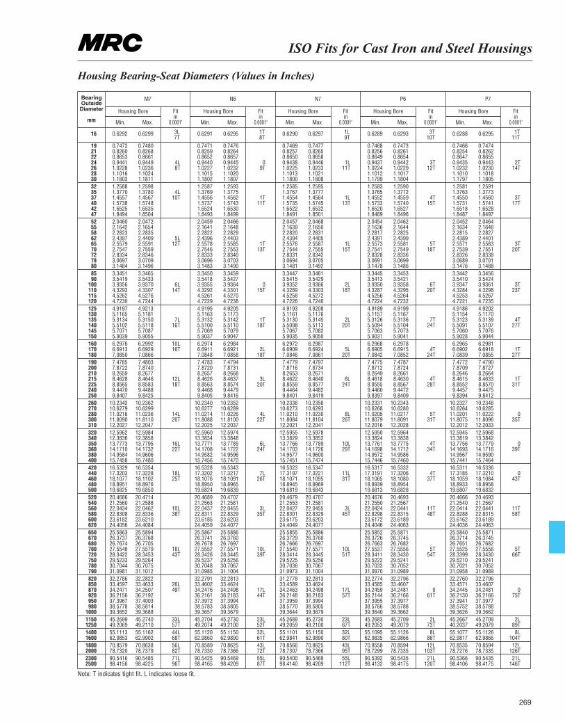
ISO Fits for Cast Iron and Steel Housings
269
Housing Bearing-Seat Diameters (Values in Inches)
M7 N6 N7 P6 P7
Housing Bore
Min. Max.
Housing Bore
Min. Max.
Housing Bore
Min. Max.
Housing Bore
Min. Max.
Housing Bore
Min. Max.
Fitin
0.0001"
Fitin
0.0001"
Fitin
0.0001"
Fitin
0.0001"
Fitin
0.0001"
BearingOutside
Diameter
mm
16 0.6292 0.6299 0.6291 0.6295 0.6290 0.6297 0.6289 0.6293 0.6288 0.6295
19 0.7472 0.7480 0.7471 0.7476 0.7469 0.7477 0.7468 0.7473 0.7466 0.747421 0.8260 0.8268 0.8259 0.8264 0.8257 0.8265 0.8256 0.8261 0.8254 0.826222 0.8653 0.8661 0.8652 0.8657 0.8650 0.8658 0.8649 0.8654 0.8647 0.865524 0.9441 0.9449 4L 0.9440 0.9445 0 0.9438 0.9446 1L 0.9437 0.9442 3T 0.9435 0.9443 2T26 1.0228 1.0236 8T 1.0227 1.0232 9T 1.0225 1.0233 11T 1.0224 1.0229 12T 1.0232 1.0230 14T28 1.1016 1.1024 1.1015 1.1020 1.1013 1.1021 1.1012 1.1017 1.1010 1.101830 1.1803 1.1811 1.1802 1.1807 1.1800 1.1808 1.1799 1.1804 1.1797 1.180532 1.2588 1.2598 1.2587 1.2593 1.2585 1.2595 1.2583 1.2590 1.2581 1.259135 1.3770 1.3780 4L 1.3769 1.3775 1.3767 1.3777 1.3765 1.3772 1.3763 1.377337 1.4557 1.4567 10T 1.4556 1.4562 1T 1.4554 1.4564 1L 1.4552 1.4559 4T 1.4550 1.4560 3T40 1.5738 1.5748 1.5737 1.5743 11T 1.5735 1.5745 13T 1.5733 1.5740 15T 1.5731 1.5741 17T42 1.6525 1.6535 1.6524 1.6530 1.6522 1.6532 1.6520 1.6527 1.6518 1.652847 1.8494 1.8504 1.8493 1.8499 1.8491 1.8501 1.8489 1.8496 1.8487 1.849752 2.0460 2.0472 2.0459 2.0466 2.0457 2.0468 2.0454 2.0462 2.0452 2.046455 2.1642 2.1654 2.1641 2.1648 2.1639 2.1650 2.1636 2.1644 2.1634 2.164658 2.2823 2.2835 2.2822 2.2829 2.2820 2.2831 2.2817 2.2825 2.2815 2.282762 2.4397 2.4409 5L 2.4396 2.4403 2.4394 2.4405 2.4391 2.4399 2.4389 2.440165 2.5579 2.5591 12T 2.5578 2.5585 1T 2.5576 2.5587 1L 2.5573 2.5581 5T 2.5571 2.5583 3T70 2.7547 2.7559 2.7546 2.7553 13T 2.7544 2.7555 15T 2.7541 2.7549 18T 2.7539 2.7551 20T72 2.8334 2.8346 2.8333 2.8340 2.8331 2.8342 2.8328 2.8336 2.8326 2.833878 3.0697 3.0709 3.0696 3.0703 3.0694 3.0705 3.0691 3.0699 3.0689 3.070180 3.1484 3.1496 3.1483 3.1490 3.1481 3.1492 3.1478 3.1486 3.1476 3.148885 3.3451 3.3465 3.3450 3.3459 3.3447 3.3461 3.3445 3.3453 3.3442 3.345690 3.5419 3.5433 3.5418 3.5427 3.5415 3.5429 3.5413 3.5421 3.5410 3.5424
100 3.9356 3.9370 6L 3.9355 3.9364 0 3.9352 3.9366 2L 3.9350 3.9358 6T 3.9347 3.9361 3T110 4.3293 4.3307 14T 4.3292 4.3301 15T 4.3289 4.3303 18T 4.3287 4.3295 20T 4.3284 4.3298 23T115 4.5262 4.5276 4.5261 4.5270 4.5258 4.5272 4.5256 4.5264 4.5253 4.5267120 4.7230 4.7244 4.7229 4.7238 4.7226 4.7240 4.7224 4.7232 4.7221 4.7235125 4.9197 4.9213 4.9195 4.9205 4.9193 4.9208 4.9189 4.9199 4.9186 4.9202130 5.1165 5.1181 5.1163 5.1173 5.1161 5.1176 5.1157 5.1167 5.1154 5.1170135 5.3134 5.3150 7L 5.3132 5.3142 1T 5.3130 5.3145 2L 5.3126 5.3136 7T 5.3123 5.3139 4T140 5.5102 5.5118 16T 5.5100 5.5110 18T 5.5098 5.5113 20T 5.5094 5.5104 24T 5.5091 5.5107 27T145 5.7071 5.7087 5.7069 5.7079 5.7067 5.7082 5.7063 5.7073 5.7060 5.7076150 5.9039 5.9055 5.9037 5.9047 5.9035 5.9050 5.9031 5.9041 5.9028 5.9044160 6.2976 6.2992 10L 6.2974 6.2984 6.2972 6.2987 6.2968 6.2978 6.2965 6.2981170 6.6913 6.6929 16T 6.6911 6.6921 2L 6.6909 6.6924 5L 6.6905 6.6915 4T 6.6902 6.6918 1T180 7.0850 7.0866 7.0848 7.0858 18T 7.0846 7.0861 20T 7.0842 7.0852 24T 7.0839 7.0855 27T190 7.4785 7.4803 7.4783 7.4794 7.4779 7.4797 7.4775 7.4787 7.4772 7.4790200 7.8722 7.8740 7.8720 7.8731 7.8716 7.8734 7.8712 7.8724 7.8709 7.8727210 8.2659 8.2677 8.2657 8.2668 8.2653 8.2671 8.2649 8.2661 8.2646 8.2664215 8.4628 8.4646 12L 8.4626 8.4637 3L 8.4622 8.4640 6L 8.4618 8.4630 4T 8.4615 8.4633 1T225 8.8565 8.8583 18T 8.8563 8.8574 20T 8.8559 8.8577 24T 8.8555 8.8567 28T 8.8552 8.8570 31T240 9.4470 9.4488 9.4468 9.4479 9.4464 9.4482 9.4460 9.4472 9.4457 9.4475250 9.8407 9.8425 9.8405 9.8416 9.8401 9.8419 9.8397 9.8409 9.8394 9.8412260 10.2342 10.2362 10.2340 10.2352 10.2336 10.2356 10.2331 10.2343 10.2327 10.2348270 10.6279 10.6299 10.6277 10.6289 10.6273 10.6293 10.6268 10.6280 10.6264 10.6285280 11.0216 11.0236 14L 11.0214 11.0226 4L 11.0210 11.0230 8L 11.0205 11.0217 5T 11.0201 11.0222 0300 11.8090 11.8110 20T 11.8088 11.8100 22T 11.8084 11.8104 26T 11.8079 11.8091 31T 11.8075 11.8096 35T310 12.2027 12.2047 12.2025 12.2037 12.2021 12.2041 12.2016 12.2028 12.2012 12.2033320 12.5962 12.5984 12.5960 12.5974 12.5955 12.5978 12.5950 12.5964 12.5945 12.5968340 12.3836 12.3858 13.3834 13.3848 13.3829 13.3852 13.3824 13.3838 13.3819 13.3842350 13.7773 13.7795 16L 13.7771 13.7785 6L 13.7766 13.7789 10L 13.7761 13.7775 4T 13.7756 13.7779 0360 14.1710 14.1732 22T 14.1708 14.1722 24T 14.1703 14.1726 29T 14.1698 14.1712 34T 14.1693 14.1716 39T380 14.9584 14.9606 14.9582 14.9596 14.9577 14.9600 14.9572 14.9586 14.9567 14.9590400 15.7458 15.7480 15.7456 15.7470 15.7451 15.7474 15.7446 15.7460 15.7441 15.7464420 16.5329 16.5354 16.5328 16.5343 16.5323 16.5347 16.5317 16.5332 16.5311 16.5336440 17.3203 17.3228 18L 17.3202 17.3217 7L 17.3197 17.3221 11L 17.3191 17.3206 4T 17.3185 17.3210 0460 18.1077 18.1102 25T 18.1076 18.1091 26T 18.1071 18.1095 31T 18.1065 18.1080 37T 18.1059 18.1084 43T480 18.8951 18.8976 18.8950 18.8965 18.8945 18.8969 18.8939 18.8954 18.8933 18.8958500 19.6825 19.6850 19.6824 19.6839 19.6819 19.6843 19.6813 19.6828 19.6807 19.6832520 20.4686 20.4714 20.4689 20.4707 20.4679 20.4707 20.4676 20.4693 20.4666 20.4693540 21.2560 21.2588 21.2563 21.2581 21.2553 21.2581 21.2550 21.2567 21.2540 21.2567560 22.0434 22.0462 10L 22.0437 22.0455 3L 22.0427 22.0455 3L 22.0424 22.0441 11T 22.0414 22.0441 11T580 22.8308 22.8336 38T 22.8311 22.8329 35T 22.8301 22.8329 45T 22.8298 22.8315 48T 22.8288 22.8315 58T600 23.6182 23.6210 23.6185 23.6203 23.6175 23.6203 23.6172 23.6189 23.6162 23.6189620 24.4056 24.4084 24.4059 24.4077 24.4049 24.4077 24.4046 24.4063 24.4036 24.4063650 25.5863 25.5894 25.5867 25.5886 25.5855 25.5886 25.5852 25.5871 25.5840 25.5871670 26.3737 26.3768 26.3741 26.3760 26.3729 26.3760 26.3726 26.3745 26.3714 26.3745680 26.7674 26.7705 26.7678 26.7697 26.7666 26.7697 26.7663 26.7682 26.7651 26.7682700 27.5548 27.5579 18L 27.5552 27.5571 10L 27.5540 27.5571 10L 27.5537 27.5556 5T 27.5525 27.5556 5T720 28.3422 28.3453 43T 28.3426 28.3445 39T 28.3414 28.3445 51T 28.3411 28.3430 54T 28.3399 28.3430 66T750 29.5233 29.5264 29.5237 29.5256 29.5225 29.5256 29.5222 29.5241 29.5210 29.5241780 30.7044 30.7075 30.7048 30.7067 30.7036 30.7067 30.7033 30.7052 30.7021 30.7052790 31.0981 31.1012 31.0985 31.1004 31.0973 31.1004 31.0970 31.0989 31.0958 31.0989820 32.2786 32.2822 32.2791 32.2813 31.2778 32.2813 32.2774 32.2796 32.2760 32.2796850 33.4597 33.4633 26L 33.4602 33.4624 33.4589 33.4624 33.4585 33.4607 33.4571 33.4607870 34.2471 34.2507 49T 34.2476 34.2498 17L 34.2463 34.2498 17L 34.2459 34.2481 0 34.2445 34.2481 0920 36.2156 36.2192 36.2161 36.2183 44T 36.2148 36.2183 57T 36.2144 36.2166 61T 36.2130 36.2166 75T950 37.3967 37.4003 37.3972 37.3994 37.3959 37.3994 37.3955 37.3977 37.3941 37.3977980 38.5778 38.5814 38.5783 38.5805 38.5770 38.5805 38.5766 38.5788 38.5752 38.5788
1000 39.3652 39.3688 39.3657 39.3679 39.3644 39.3679 39.3640 39.3662 39.3626 39.36621150 45.2699 45.2740 33L 45.2704 45.2730 23L 45.2689 45.2730 23L 45.2683 45.2709 2L 45.2667 45.2709 2L1250 49.2069 49.2110 57T 49.2074 49.2100 52T 49.2059 49.2100 67T 49.2053 49.2079 73T 40.2037 49.2079 89T1400 55.1113 55.1162 44L 55.1120 55.1150 32L 55.1101 55.1150 32L 55.1095 55.1126 8L 55.1077 55.1126 8L1600 62.9853 62.9902 68T 62.9860 62.9890 61T 62.9841 62.9890 80T 62.9835 62.9866 86T 62.9817 62.9866 104T1800 70.8579 70.8638 56L 70.8589 70.8625 43L 70.8566 70.8625 43L 70.8558 70.8594 12L 70.8535 70.8594 12L2000 78.7320 78.7379 82T 78.7330 78.7366 72T 78.7307 78.7366 95T 78.7299 78.7335 103T 78.7276 78.7335 126T2300 90.5416 90.5485 71L 90.5425 90.5469 55L 90.5400 90.5469 55L 90.5392 90.5435 21L 90.5366 90.5435 21L2500 98.4156 98.4225 96T 98.4165 98.4209 87T 98.4140 98.4209 112T 98.4132 98.4175 120T 98.4106 98.4175 146T
Note: T indicates tight fit. L indicates loose fit.
3L 1T 1L 3T 1T7T 8T 9T 10T 11T
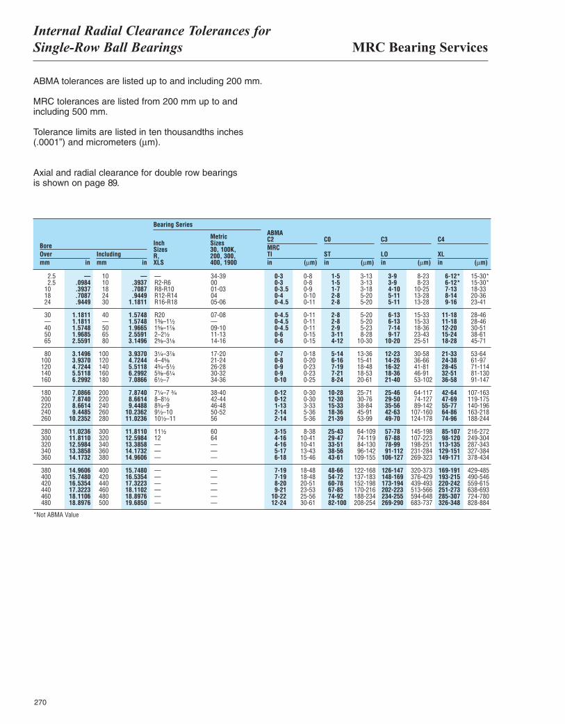
MRC Bearing ServicesInternal Radial Clearance Tolerances forSingle-Row Ball Bearings
270
ABMA tolerances are listed up to and including 200 mm.
MRC tolerances are listed from 200 mm up to andincluding 500 mm.
Tolerance limits are listed in ten thousandths inches(.0001”) and micrometers (µm).
Axial and radial clearance for double row bearingsis shown on page 89.
BoreOvermm in
Includingmm in
Bearing Series
2.5 — 10 — — 34-39 0-3 0-8 1-5 3-13 3-9 8-23 6-12* 15-30*2.5 .0984 10 .3937 R2-R6 00 0-3 0-8 1-5 3-13 3-9 8-23 6-12* 15-30*
10 .3937 18 .7087 R8-R10 01-03 0-3.5 0-9 1-7 3-18 4-10 10-25 7-13 18-3318 .7087 24 .9449 R12-R14 04 0-4 0-10 2-8 5-20 5-11 13-28 8-14 20-3624 .9449 30 1.1811 R16-R18 05-06 0-4.5 0-11 2-8 5-20 5-11 13-28 9-16 23-41
30 1.1811 40 1.5748 R20 07-08 0-4.5 0-11 2-8 5-20 6-13 15-33 11-18 28-46— 1.1811 — 1.5748 1³|₈–1¹|₂ — 0-4.5 0-11 2-8 5-20 6-13 15-33 11-18 28-4640 1.5748 50 1.9665 1⁵|₈–1⁷|₈ 09-10 0-4.5 0-11 2-9 5-23 7-14 18-36 12-20 30-5150 1.9685 65 2.5591 2–2¹|₂ 11-13 0-6 0-15 3-11 8-28 9-17 23-43 15-24 38-6165 2.5591 80 3.1496 2⁵|₈–3¹|₈ 14-16 0-6 0-15 4-12 10-30 10-20 25-51 18-28 45-71
80 3.1496 100 3.9370 3¹|₄–3⁷|₈ 17-20 0-7 0-18 5-14 13-36 12-23 30-58 21-33 53-64100 3.9370 120 4.7244 4–4⁵|₈ 21-24 0-8 0-20 6-16 15-41 14-26 36-66 24-38 61-97120 4.7244 140 5.5118 4³|₄–5¹|₂ 26-28 0-9 0-23 7-19 18-48 16-32 41-81 28-45 71-114140 5.5118 160 6.2992 5³|₈–6¹|₄ 30-32 0-9 0-23 7-21 18-53 18-36 46-91 32-51 81-130160 6.2992 180 7.0866 6¹|₂–7 34-36 0-10 0-25 8-24 20-61 21-40 53-102 36-58 91-147
180 7.0866 200 7.8740 7¹|₄–7 ³|₄ 38-40 0-12 0-30 10-28 25-71 25-46 64-117 42-64 107-163200 7.8740 220 8.6614 8–8¹|₂ 42-44 0-12 0-30 12-30 30-76 29-50 74-127 47-69 119-175220 8.6614 240 9.4488 8³|₄–9 46-48 1-13 3-33 15-33 38-84 35-56 89-142 55-77 140-196240 9.4485 260 10.2362 9¹|₂–10 50-52 2-14 5-36 18-36 45-91 42-63 107-160 64-86 163-218260 10.2352 280 11.0236 10¹|₂–11 56 2-14 5-36 21-39 53-99 49-70 124-178 74-96 188-244
280 11.0236 300 11.8110 11¹|₂ 60 3-15 8-38 25-43 64-109 57-78 145-198 85-107 216-272300 11.8110 320 12.5984 12 64 4-16 10-41 29-47 74-119 67-88 107-223 98-120 249-304320 12.5984 340 13.3858 — — 4-16 10-41 33-51 84-130 78-99 198-251 113-135 287-343340 13.3858 360 14.1732 — — 5-17 13-43 38-56 96-142 91-112 231-284 129-151 327-384360 14.1732 380 14.9606 — — 6-18 15-46 43-61 109-155 106-127 269-323 149-171 378-434
380 14.9606 400 15.7480 — — 7-19 18-48 48-66 122-168 126-147 320-373 169-191 429-485400 15.7480 420 16.5354 — — 7-19 18-48 54-72 137-183 148-169 376-429 193-215 490-546420 16.5354 440 17.3223 — — 8-20 20-51 60-78 152-198 173-194 439-493 220-242 559-615440 17.3223 460 18.1102 — — 9-21 23-53 67-85 170-216 202-223 513-566 251-273 638-693460 18.1106 480 18.8976 — — 10-22 25-56 74-92 188-234 234-255 594-648 285-307 724-780480 18.8976 500 19.6850 — — 12-24 30-61 82-100 208-254 269-290 683-737 326-348 828-884
InchSizesR,XLS
MetricSizes30, 100K,200, 300,400, 1900
ABMAC2MRCTIin (µm)
C0
STin (µm)
C3
LOin (µm)
C4
XLin (µm)
*Not ABMA Value
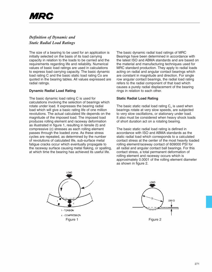
271
Definition of Dynamic andStatic Radial Load Ratings
The size of a bearing to be used for an application isinitially selected on the basis of its load carryingcapacity in relation to the loads to be carried and therequirements regarding life and reliability. Numericalvalues of basic load ratings are used in calculations to express load carrying capacity. The basic dynamicload rating C and the basic static load rating Co arequoted in the bearing tables. All values expressed areradial ratings.
Dynamic Radial Load Rating
The basic dynamic load rating C is used forcalculations involving the selection of bearings whichrotate under load. It expresses the bearing radial load which will give a basic rating life of one millionrevolutions. The actual calculated life depends on themagnitude of the imposed load. The imposed loadproduces rolling element and raceway deformation as illustrated in figure 1, resulting in tensile (t) andcompressive (c) stresses as each rolling elementpasses through the loaded zone. As these stresscycles are repeated, as determined by the number of revolutions of calculated life, sub-surface metalfatigue cracks occur which eventually propagate to the raceway surface causing metal flaking, or spalling,at which time the bearing has achieved its useful life.
The basic dynamic radial load ratings of MRCBearings have been determined in accordance withthe latest ISO and ABMA standards and are based onthe material and manufacturing techniques used forMRC standard production. They apply to radial loadsacting on radial and angular contact bearings whichare constant in magnitude and direction. For singlerow angular contact bearings, the radial load ratingrefers to the radial component of that load whichcauses a purely radial displacement of the bearingrings in relation to each other.
Static Radial Load Rating
The basic static radial load rating Co is used whenbearings rotate at very slow speeds, are subjected to very slow oscillations, or stationary under load. It also must be considered when heavy shock loads of short duration act on a rotating bearing.
The basic static radial load rating is defined inaccordance with ISO and ABMA standards as thestatic radial load which corresponds to a calculatedcontact stress at the center of the most heavily loadedrolling element/raceway contact of 609000 PSI for all radial and angular contact ball bearings. For thiscontact stress, a total permanent deformation ofrolling element and raceway occurs which isapproximately 0.0001 of the rolling element diameteras shown in figure 2.
Figure 1 Figure 2
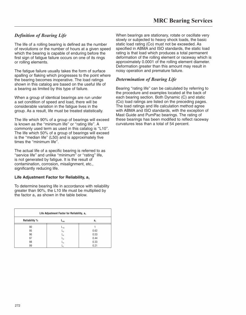
MRC Bearing Services
272
Definition of Bearing Life
The life of a rolling bearing is defined as the numberof revolutions or the number of hours at a given speedwhich the bearing is capable of enduring before the first sign of fatigue failure occurs on one of its rings or rolling elements.
The fatigue failure usually takes the form of surfacespalling or flaking which progresses to the point wherethe bearing becomes inoperative. The load ratingsshown in this catalog are based on the useful life of a bearing as limited by this type of failure.
When a group of identical bearings are run under a set condition of speed and load, there will beconsiderable variation in the fatigue lives in the group. As a result, life must be treated statistically.
The life which 90% of a group of bearings will exceed is known as the ‘‘minimum life’’ or ‘‘rating life’’. Acommonly used term as used in this catalog is ‘‘L10’’.The life which 50% of a group of bearings will exceedis the ‘‘median life’’ (L50) and is approximately fivetimes the ‘‘minimum life’’.
The actual life of a specific bearing is referred to as‘‘service life’’ and unlike ‘‘minimum’’ or ‘‘rating’’ life, is not generated by fatigue. It is the result ofcontamination, corrosion, misalignment, etc.,significantly reducing life.
Life Adjustment Factor for Reliability, a1
To determine bearing life in accordance with reliabilitygreater than 90%, the L10 life must be multiplied by the factor a1 as shown in the table below.
When bearings are stationary, rotate or oscillate veryslowly or subjected to heavy shock loads, the basicstatic load rating (Co) must not be exceeded. Asspecified in ABMA and ISO standards, the static loadrating is that load which produces a total permanentdeformation of the rolling element or raceway which isapproximately 0.0001 of the rolling element diameter.Deformation greater than this amount may result innoisy operation and premature failure.
Determination of Bearing Life
Bearing ‘‘rating life’’ can be calculated by referring tothe procedure and examples located at the back ofeach bearing section. Both Dynamic (C) and static(Co) load ratings are listed on the preceding pages.The load ratings and life calculation method agreewith ABMA and ISO standards, with the exception ofMast Guide and PumPac bearings. The rating ofthese bearings has been modified to reflect racewaycurvatures less than a total of 54 percent.
Life Adjustment Factor for Reliability, a1
Reliability % Lma a1
90 L10 195 L5 0.6296 L4 0.5397 L3 0.4498 L2 0.3399 L1 0.21
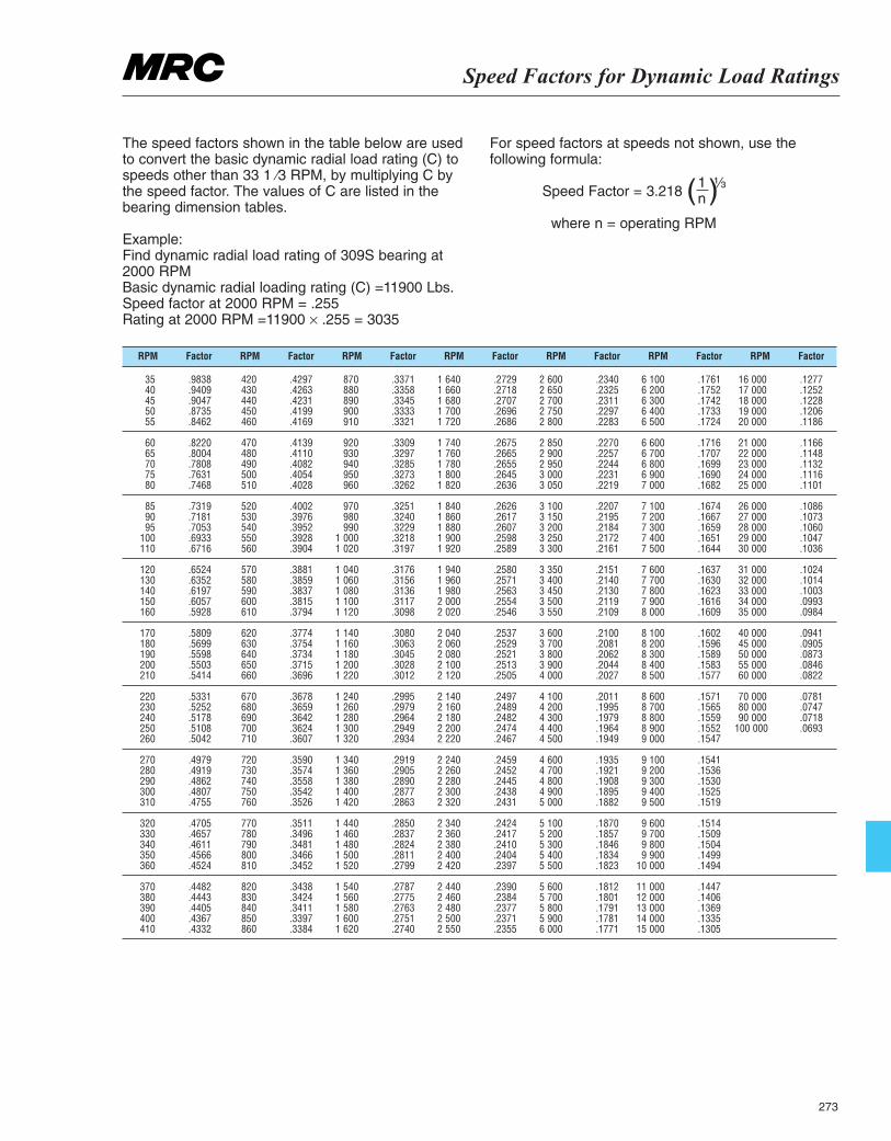
Speed Factors for Dynamic Load Ratings
273
The speed factors shown in the table below are usedto convert the basic dynamic radial load rating (C) tospeeds other than 33 1 ⁄3 RPM, by multiplying C bythe speed factor. The values of C are listed in thebearing dimension tables.
Example: Find dynamic radial load rating of 309S bearing at 2000 RPM Basic dynamic radial loading rating (C) =11900 Lbs.Speed factor at 2000 RPM = .255 Rating at 2000 RPM =11900 × .255 = 3035
For speed factors at speeds not shown, use thefollowing formula:
Speed Factor = 3.218
where n = operating RPM
RPM RPM RPM RPM RPM RPM RPMFactor Factor Factor Factor Factor Factor Factor
35 .983840 .940945 .904750 .873555 .8462
60 .822065 .800470 .780875 .763180 .7468
85 .731990 .718195 .7053
100 .6933110 .6716
120 .6524130 .6352140 .6197150 .6057160 .5928
170 .5809180 .5699190 .5598200 .5503210 .5414
220 .5331230 .5252240 .5178250 .5108260 .5042
270 .4979280 .4919290 .4862300 .4807310 .4755
320 .4705330 .4657340 .4611350 .4566360 .4524
370 .4482380 .4443390 .4405400 .4367410 .4332
1n( )¹|₃
420 .4297430 .4263440 .4231450 .4199460 .4169
470 .4139480 .4110490 .4082500 .4054510 .4028
520 .4002530 .3976540 .3952550 .3928560 .3904
570 .3881580 .3859590 .3837600 .3815610 .3794
620 .3774630 .3754640 .3734650 .3715660 .3696
670 .3678680 .3659690 .3642700 .3624710 .3607
720 .3590730 .3574740 .3558750 .3542760 .3526
770 .3511780 .3496790 .3481800 .3466810 .3452
820 .3438830 .3424840 .3411850 .3397860 .3384
870 .3371880 .3358890 .3345900 .3333910 .3321
920 .3309930 .3297940 .3285950 .3273960 .3262
970 .3251980 .3240990 .3229
1 000 .32181 020 .3197
1 040 .31761 060 .31561 080 .31361 100 .31171 120 .3098
1 140 .30801 160 .30631 180 .30451 200 .30281 220 .3012
1 240 .29951 260 .29791 280 .29641 300 .29491 320 .2934
1 340 .29191 360 .29051 380 .28901 400 .28771 420 .2863
1 440 .28501 460 .28371 480 .28241 500 .28111 520 .2799
1 540 .27871 560 .27751 580 .27631 600 .27511 620 .2740
1 640 .27291 660 .27181 680 .27071 700 .26961 720 .2686
1 740 .26751 760 .26651 780 .26551 800 .26451 820 .2636
1 840 .26261 860 .26171 880 .26071 900 .25981 920 .2589
1 940 .25801 960 .25711 980 .25632 000 .25542 020 .2546
2 040 .25372 060 .25292 080 .25212 100 .25132 120 .2505
2 140 .24972 160 .24892 180 .24822 200 .24742 220 .2467
2 240 .24592 260 .24522 280 .24452 300 .24382 320 .2431
2 340 .24242 360 .24172 380 .24102 400 .24042 420 .2397
2 440 .23902 460 .23842 480 .23772 500 .23712 550 .2355
2 600 .23402 650 .23252 700 .23112 750 .22972 800 .2283
2 850 .22702 900 .22572 950 .22443 000 .22313 050 .2219
3 100 .22073 150 .21953 200 .21843 250 .21723 300 .2161
3 350 .21513 400 .21403 450 .21303 500 .21193 550 .2109
3 600 .21003 700 .20813 800 .20623 900 .20444 000 .2027
4 100 .20114 200 .19954 300 .19794 400 .19644 500 .1949
4 600 .19354 700 .19214 800 .19084 900 .18955 000 .1882
5 100 .18705 200 .18575 300 .18465 400 .18345 500 .1823
5 600 .18125 700 .18015 800 .17915 900 .17816 000 .1771
6 100 .17616 200 .17526 300 .17426 400 .17336 500 .1724
6 600 .17166 700 .17076 800 .16996 900 .16907 000 .1682
7 100 .16747 200 .16677 300 .16597 400 .16517 500 .1644
7 600 .16377 700 .16307 800 .16237 900 .16168 000 .1609
8 100 .16028 200 .15968 300 .15898 400 .15838 500 .1577
8 600 .15718 700 .15658 800 .15598 900 .15529 000 .1547
9 100 .15419 200 .15369 300 .15309 400 .15259 500 .1519
9 600 .15149 700 .15099 800 .15049 900 .1499
10 000 .1494
11 000 .144712 000 .140613 000 .136914 000 .133515 000 .1305
16 000 .127717 000 .125218 000 .122819 000 .120620 000 .1186
21 000 .116622 000 .114823 000 .113224 000 .111625 000 .1101
26 000 .108627 000 .107328 000 .106029 000 .104730 000 .1036
31 000 .102432 000 .101433 000 .100334 000 .099335 000 .0984
40 000 .094145 000 .090550 000 .087355 000 .084660 000 .0822
70 000 .078180 000 .074790 000 .0718
100 000 .0693
MRC Bearing ServicesSpeed Rating
274
There is a limit to the speed at which rolling bearingscan be operated. Generally it is the operatingtemperature which can be permitted, with respect tothe lubricant being used or to the material of thebearing components, that sets the limit. The speed atwhich this bearing temperature is reached depends onthe frictional heat generated in the bearing (includingany externally applied heat) and the amount of heatwhich can be transported away from the bearing.Bearing type and size, internal design, load,lubrication and cooling conditions as well as cagedesign, accuracy and internal clearance all play a partin determining the permissible speed.
Speed ratings Speed ratings for grease and oil lubrication are quotedin the bearing tables. The speed rating for a givenbearing represents the speed at which, under normalloading conditions there is a balance between theheat which can be removed from the bearing via theshaft and housing and sometimes via the lubricantand the heat generated in the bearing by friction atacceptable temperature interval above ambient.
The speed ratings apply to bearings where the innerring rotates. Some reduction may be necessary wherebearings are to operate with rotating outer ring. Moredetailed information will be supplied on request.
When heavier loads are applied to the bearing, thefriction in the bearing will be increased so that thebearing cannot be operated at such high speeds as the speed rating would indicate unless highertemperatures can be permitted. However, theinfluence of heavier loads on the permissible speed is generally only of importance for large bearings(≥100mm).
Speeds above the speed rating It is possible to operate bearings at speeds above thespeed ratings given in the bearing tables if the bearingfriction can be reduced by lubrication considerationsor when heat can be removed from the bearing bycirculating oil lubrication with cooling of the oil, bycooling ribs on the housing or by directed cold airstreams. Any increase in speed above the speedrating without taking any of these precautions wouldonly cause the temperature to rise excessively. Anincrease of bearing temperature means that lubricantviscosity is reduced and lubricant film formation ismade more difficult, thus leading to higher friction andfurther temperature increases. If, at the same time,
the operational clearance in the bearing is reducedbecause of increased inner ring temperature, the finalconsequence would be bearing seizure. Any increasein speed above the speed rating generally means thatthe temperature difference between inner and outerring is greater than normal. Usually, therefore, aninternal clearance greater than Normal (C3) isrequired, and it may be necessary to look moreclosely at the temperature distribution in the bearing.
The speed limit as defined by the speed rating is thefirst limit to be reached with almost all bearing types.Above this limit, other criteria have a strongerinfluence, depending on bearing type. These criteriainclude the form stability or strength of the cage,lubrication of cage guiding surfaces, centrifugal andgyratory forces acting on the rolling elements andother speed-limiting factors.
Another limit is set with grease lubrication by thegrease used. The base oil viscosity and thickenerdetermine the shear strength of the lubricant, which inturn determines the permissible operating speed forthe particular bearing.
For high speed bearing arrangements, allcomponents, particularly those which rotate, musthave a higher accuracy than normal to take accountof the vibrating behaviour. Special cage designs mayalso be required and it is therefore advisable tocontact MRC Bearing Services.
For satisfactory bearing operation, especially at highspeeds, a minimum load must be applied.
The speed ratings listed in the tables may be modifieddue to grade and cage variants. The multiplyingfactors shown in the footnotes are based on historicalapplication and experience.

275

276
Materials and Limitations
277
Materials for Rolling Bearings
The performance and reliability of rolling bearings aredetermined to a large° by the materials from which thebearing components are made.
Steels for Bearing Rings and Rolling Elements
Steels used for bearing rings and rolling elements mustbe capable of high fatigue strength and wear resistance.The structural and dimensional stability of the bearingcomponents must be satisfactory at the operatingtemperatures which can be expected. In most cases thechoice of a particular steel is dictated by the applicationrequirements.
Through-Hardening Steels
The most common through-hardening steel used forrolling bearings is a carbon chromium steel containingapproximately 1% carbon and 1.5% chromium. Forbearing components having large cross sections steelsalloyed with manganese and molybdenum are usedbecause of their superior through-hardening properties.
Much development has been accomplished in the areaof through hardened steels. Particular attention has beenpaid to cleanliness and modern bearing steels have suchsmall contents of inclusions that it is now recognized thatunder ideal conditions bearings should no longer fail fromfatigue.
Case-Hardening Steels
Chromium-nickel and manganese-chromium alloyedsteels with a carbon content of approximately 0.15% arethose case-hardening steels most commonly used forrolling bearings.
Steels for MRC Rolling Bearings
In the majority of applications there is virtually nodifference in behavior between bearings made ofthrough-hardened or case-hardened steels. This fact hasbeen acknowledged by ISO in that no distinction is madebetween steel types in the life calculation. In fact, steelcleanliness and proper manufacturing methods as wellas bearing design are the decisive factors. However,there are applications where a particular type of steel hascertain advantages.
Because MRC has both the competence and thefacilities for through hardening, case hardening andinduction hardening, attention is paid to the mainapplication fields for each particular bearing and the steeland method of heat treatment are chosen to give thebest performance in these applications.
Steels for Temperature-Resistant Bearings
MRC rolling bearings can generally be used at operatingtemperatures up to 250˚F (121˚C). If the operatingtemperatures are higher than this, the bearings must besubjected to a special heat treatment (stabilization) sothat inadmissible changes in dimensions do not occur as
a result of microstructural changes. However, thebearings should not be stabilized for a highertemperature than the expected operating temperature.
For bearings which are required to operate attemperatures in excess of 450˚F (232˚C) special steelswith high hot hardness are required. In such cases it isadvisable to contact MRC Bearing Services Engineering.
Steels for Corrosion-Resistant Bearings
For bearings that come into contact with corrosive mediaduring operation, there are a couple options. Historically,chromium or chromium/molybdenum stainless steel hasbeen used. Because of the reduced hardness of thesesteels, the bearings do not have the same high loadcarrying capacity as bearings made of conventionalsteels. The corrosion resistance is only available whenthe whole surface is perfectly polished and if it is notroughened or damaged during mounting. Some specialtyhigh nitrogen steels have been developed which providebetter corrosion resistant than the chromium stainlesssteels as well as the same high load carrying capacity as conventional bearing steels. For more information onthe different types of corrosion resistant steels and theirapplication, it is recommended to contact MRCApplication Engineering.
Hybrid Bearings with Ceramic Balls
MRC hybrid bearings use steel inner and outer rings with ceramic balls. This combination provides a bearingthat has greater stiffness, is able to handle higher speedsand higher temperatures.
The lower density of the silicon nitride ceramic ballscreates less centrifugal force than steel balls. Lowerdensity combined with the reduced friction due to theball’s smooth surface, allows the bearing to run at muchhigher speeds. The low thermal expansion of theceramic balls makes them less sensitive to differences in temperature between the inner and outer rings. Thehigher modulus of elasticity makes the bearings muchstiffer.
Materials for Cages
The main purpose of the cage is to keep the rollingelements at an appropriate distance from each other andto prevent immediate contact between two neighboringrolling elements in order to keep friction and thus heatgeneration in the bearing at a minimum.
In grease lubricated bearings some of the grease insidethe bearing will adhere to the cage forming a lubricantreservoir and ensuring good lubrication of the operatingsurfaces of the bearing.
The cage is guided either on the rolling elements or onone of the bearing rings and is thus radially centered.Pressed steel or brass cages are generally guided on the rolling elements. Inner or outer ring land guidedmachined cages generally permit operation at higherspeeds and are necessary when movements additional
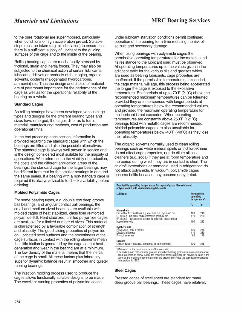
MRC Bearing ServicesMaterials and Limitations
278
to the pure rotational are superimposed, particularlywhen conditions of high acceleration prevail. Suitablesteps must be taken (e.g. oil lubrication) to ensure thatthere is a sufficient supply of lubricant to the guidingsurfaces of the cage and to the inside of the bearing.
Rolling bearing cages are mechanically stressed byfrictional, strain and inertia forces. They may also besubjected to the chemical action of certain lubricants,lubricant additives or products of their aging, organicsolvents, coolants (halogenated hydrocarbons,ammonia) etc. Thus the design and choice of materialare of paramount importance for the performance of thecage as well as for the operational reliability of thebearing as a whole.
Standard Cages
As rolling bearings have been developed various cagetypes and designs for the different bearing types andsizes have emerged; the cages differ as to form,material, manufacturing methods, cost of production andoperational limits.
In the text preceding each section, information isprovided regarding the standard cages with which thebearings are fitted and also the possible alternatives. The standard cage is always well proven in service andis the design considered most suitable for the majority ofapplications. With reference to the viability of production,the costs and the different application areas of thebearings, the standard cage for the larger bearings maybe different from that for the smaller bearings in one andthe same series. If a bearing with a non-standard cage isrequired it is always advisable to check availability beforeordering.
Molded Polyamide Cages
For some bearing types, e.g. double row deep grooveball bearings, and angular contact ball bearings, thesmall and medium-sized bearings are available withmolded cages of heat stabilized, glass fiber reinforcedpolyamide 6.6. Heat stabilized, unfilled polyamide cagesare available for a limited number of sizes. This materialis characterized by a favorable combination of strengthand elasticity. The good sliding properties of polyamideon lubricated steel surfaces and the smoothness of thecage surfaces in contact with the rolling elements meanthat little friction is generated by the cage so that heatgeneration and wear in the bearing are at a minimum.The low density of the material means that the inertia of the cage is small. All these factors plus inherentlysuperior dynamic balance result in smoother and quieterrunning bearings.
The injection molding process used to produce thecages allows functionally suitable designs to be made.The excellent running properties of polyamide cages
under lubricant starvation conditions permit continuedoperation of the bearing for a time reducing the risk ofseizure and secondary damage.
When using bearings with polyamide cages thepermissible operating temperatures for the material andits resistance to the lubricant used must be observed. At operating temperatures up to the values given in theadjacent table for the various oils and greases which are used as bearing lubricants, cage properties areunaffected. If the permissible temperature is exceeded,the cage material will age, this process being acceleratedthe longer the cage is exposed to the excessivetemperature. Brief periods at up to 70˚F (21˚C) above therecommended maximum temperatures can be toleratedprovided they are interspersed with longer periods atoperating temperatures below the recommended values,and provided the maximum operating temperature forthe lubricant is not exceeded. When operatingtemperatures are constantly above 250˚F (121˚C)bearings fitted with metallic cages are recommended.Molded polyamide cages are also unsuitable foroperating temperatures below -40˚F (-40˚C) as they losetheir elasticity.
The organic solvents normally used to clean rollingbearings such as white mineral spirits or trichloroethanedo not affect cage properties, nor do dilute alkalinecleaners (e.g. soda) if they are at room temperature andthe period during which they are in contact is short. Thechlorofluorocarbons or ammonia used in refrigeration donot attack polyamide. In vacuum, polyamide cagesbecome brittle because they become dehydrated.
Permissible operating temperatures for cages of glass fibre reinforced polyamide 6.6 with various bearing lubricants
Lubricant Permissible operatingtemperature1)
˚C ˚F
Mineral oils Oils without EP additives e.g. machine oils, hydraulic oils 120 248 EP oils e.g. industrial and automotive gearbox oils 110 230 EP oils e.g. rear axle and differential gear oils (automotive), hypoid gear oils 100 212
Synthetic oils Polyglycols, poly-a-olefins 120 248 Diesters, silicones 110 230 Phosphate esters 80 176
Greases Lithium base,2) polyurea, bentonite, calcium complex 120 248
1)Measured on the outside surface of the outer ring.2)For sodium and calcium base greases and other bearing greases with a maximum oper-ating temperature below 120˚C, the maximum temperature for the polyamide cage is thesame as the maximum temperature for the grease, otherwise the permissible operatingtemperature is 120˚C.
Steel Cages
Pressed cages of steel sheet are standard for manydeep groove ball bearings. These cages have relatively
Materials and Limitations
279
high strength and weigh little. To reduce friction and wearthey may be hardened and surface treated. Highstrength, machined steel cages, often silver plated arealso available for critical and extra heavy dutyapplications.
Machined Bronze
Machined bronze cages are used for heavy dutyapplications and larger size bearings. Machined bronzecages can be used at operating temperatures up to450˚F (232˚C). They are not affected by the mineral orsynthetic oil based lubricants normally used for rollingbearings nor by the organic solvents used to cleanbearings. They are very resistant to corrosive attack.
Brass Cages
Pressed brass cages are used for some small andmedium-sized bearings, but most brass cages are
machined from cast or wrought material.Brass cagesshould not be used at temperatures in excess of 450˚F(232˚C). They are unaffected by most of the commonlyused bearing lubricants, including synthetic oils andgreases, and can be cleaned using normal organicsolvents. The use of alkaline cleaning agents is notrecommended. Ammonia (e.g. in refrigeration) causesembrittlement in brass so that brass cages areunsuitable and other alternatives should be considered.
Phenolic (Bakelite) Cages
Phenolic cages are used primarily for angular contactball bearings. These cages are composed of machined,cotton fabric impregnated with phenolic resin. The lightweight construction of the phenolic cage makes it idealfor high speed applicatons. Phenolic cages should not beused in temperatures in excess of 225˚F (107˚C).
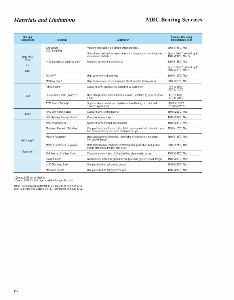
MRC Bearing ServicesMaterials and Limitations
280
Bearing Dynamic Operating Component Material Description Temperature Limits
Seals
Shields
Ball Cages2)
(Separator)
Race Way Rings
and
Balls
SAE 52100 (AISI E-52100)
440C martensitic stainless steel1)
XD15NW
M50 tool steel1)
Nitrile Rubber
Fluorocarbon seals (Viton®)1)
PTFE Seals (Teflon®)1)
1010 Low Carbon Steel
302 Stainless Pressed Steel1)
1010 Pressed Steel
Machined Phenolic (Bakelite)
Molded Polyamide
Molded Reinforced Polyamide
302 Pressed Stainless Steel
Pressed Brass
4340 Machined Steel
Machined Bronze
Vacuum processed high carbon chromium steel.
Special heat teatment increases maximum temperatures and improvesdimensional stability.1)
Moderate corrosive environments
High corrosive environments
High temperature service, improved life at elevated temperatures
Standard MRC seal material, identified by black color
Better temperature and chemical resistance, identified by grey or brown color
Superior chemical and heat resistance, identified by tan color and ‘‘woven’’ appearance
Standard MRC shield material
Corrosive environments
Standard MRC pressed cage material
Composition made from a cotton fabric impregnated with phenolic resin; two piece riveted or one piece machined design
Heat stabilized 6.6 polyamide. Identifiable by natural (cream color); ball guided design
Heat stabilized 6.6 polyamide reinforced with glass fiber; ball guided design identifiable by dark grey color
Corrosive environments; ball guided two piece riveted design
Stamped one piece ball guided or two piece ball guided riveted design
One piece land or ball guided design
One piece land or ball guided design
250˚F (121˚C) Max.
Special Heat Treatment up to 400˚F (204˚C) Max.1)
300˚F (148˚C) Max.
Special Heat Treatment up to 800˚F (426˚C) Max.1)
300˚F (150˚C) Max.
600˚F (315˚C) Max.
-70˚F to 250˚F -56˚C to 121˚C
-40˚F to 400˚F -40˚C to 204˚C
-450˚F to 550˚F -267˚C to 288˚C
450˚F (232˚C) Max.
450˚F (232˚C) Max.
450˚F (232˚C) Max.
225˚F (110˚C) Max.
250˚F (121˚C) Max.
250˚F (121˚C) Max.
450˚F (232˚C) Max.
450˚F (232˚C) Max.
575˚F (302˚C) Max.
450˚F (232˚C) Max.
1) Contact MRC for availability 2) Contact MRC for ball cages available for specific sizes.
Teflon is a registered trademark of E.I. duPont de Nemours & Co. Viton is a registered trademark of E. I. duPont de Nemours & Co.
Lubrication
281
Introduction . . . . . . . . . . . . . . . . . . . . . . . . . . . . . . . . . . . . . . . . . . . . . . . . . . . . . . . . . . . . . . . . . . . . . . . . 282Bearing Construction . . . . . . . . . . . . . . . . . . . . . . . . . . . . . . . . . . . . . . . . . . . . . . . . . . . . . . . . . . . . . . . . 282Principle Of Operation . . . . . . . . . . . . . . . . . . . . . . . . . . . . . . . . . . . . . . . . . . . . . . . . . . . . . . . . . . . . . . . 282Friction Torque . . . . . . . . . . . . . . . . . . . . . . . . . . . . . . . . . . . . . . . . . . . . . . . . . . . . . . . . . . . . . . . . . . . . . 283Function Of The Lubricant . . . . . . . . . . . . . . . . . . . . . . . . . . . . . . . . . . . . . . . . . . . . . . . . . . . . . . . . . . . . 283Oil vs Grease . . . . . . . . . . . . . . . . . . . . . . . . . . . . . . . . . . . . . . . . . . . . . . . . . . . . . . . . . . . . . . . . . . . . . . 283Oil Characteristics. . . . . . . . . . . . . . . . . . . . . . . . . . . . . . . . . . . . . . . . . . . . . . . . . . . . . . . . . . . . . . . . . . . 283Application Of Lubrication Fluids . . . . . . . . . . . . . . . . . . . . . . . . . . . . . . . . . . . . . . . . . . . . . . . . . . . . . . . 284Selection Of Oil . . . . . . . . . . . . . . . . . . . . . . . . . . . . . . . . . . . . . . . . . . . . . . . . . . . . . . . . . . . . . . . . . . . . 285Viscosity Conversion Chart . . . . . . . . . . . . . . . . . . . . . . . . . . . . . . . . . . . . . . . . . . . . . . . . . . . . . . . . . . . 285Oil Flow Requirement . . . . . . . . . . . . . . . . . . . . . . . . . . . . . . . . . . . . . . . . . . . . . . . . . . . . . . . . . . . . . . . 286Comparative Viscosity Classifications . . . . . . . . . . . . . . . . . . . . . . . . . . . . . . . . . . . . . . . . . . . . . . . . . . . 287Grease Lubrication . . . . . . . . . . . . . . . . . . . . . . . . . . . . . . . . . . . . . . . . . . . . . . . . . . . . . . . . . . . . . . . . . 286Grease Characteristics . . . . . . . . . . . . . . . . . . . . . . . . . . . . . . . . . . . . . . . . . . . . . . . . . . . . . . . . . . . . . . . 288Operating Conditions . . . . . . . . . . . . . . . . . . . . . . . . . . . . . . . . . . . . . . . . . . . . . . . . . . . . . . . . . . . . . . . . 289Relubrication Intervals . . . . . . . . . . . . . . . . . . . . . . . . . . . . . . . . . . . . . . . . . . . . . . . . . . . . . . . . . . . . . . . 291Bearing Cleaning . . . . . . . . . . . . . . . . . . . . . . . . . . . . . . . . . . . . . . . . . . . . . . . . . . . . . . . . . . . . . . . . . . . 292Things You Should Know About Lubrication . . . . . . . . . . . . . . . . . . . . . . . . . . . . . . . . . . . . . . . . . . . . . . 293Lubrication Methods . . . . . . . . . . . . . . . . . . . . . . . . . . . . . . . . . . . . . . . . . . . . . . . . . . . . . . . . . . . . . . . . . 294
Table of Contents Page
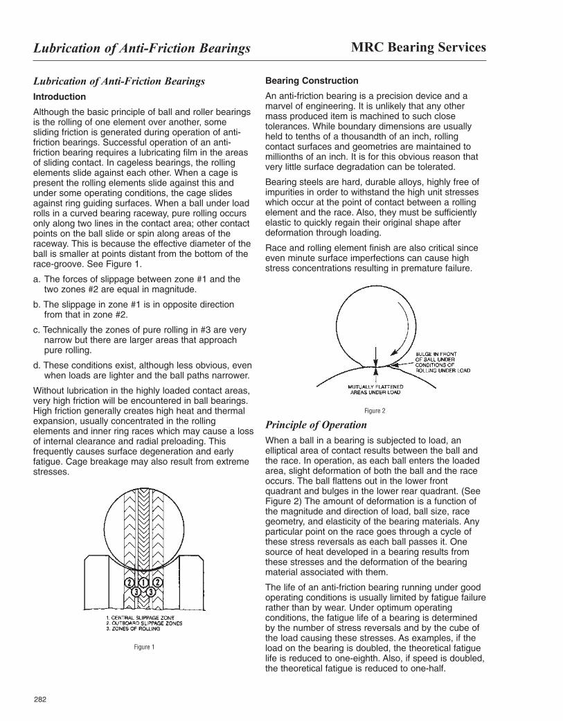
MRC Bearing ServicesLubrication of Anti-Friction Bearings
282
Lubrication of Anti-Friction Bearings Introduction
Although the basic principle of ball and roller bearingsis the rolling of one element over another, somesliding friction is generated during operation of anti-friction bearings. Successful operation of an anti-friction bearing requires a lubricating film in the areasof sliding contact. In cageless bearings, the rollingelements slide against each other. When a cage ispresent the rolling elements slide against this andunder some operating conditions, the cage slidesagainst ring guiding surfaces. When a ball under loadrolls in a curved bearing raceway, pure rolling occursonly along two lines in the contact area; other contactpoints on the ball slide or spin along areas of theraceway. This is because the effective diameter of theball is smaller at points distant from the bottom of therace-groove. See Figure 1.
a. The forces of slippage between zone #1 and thetwo zones #2 are equal in magnitude.
b. The slippage in zone #1 is in opposite directionfrom that in zone #2.
c. Technically the zones of pure rolling in #3 are verynarrow but there are larger areas that approachpure rolling.
d. These conditions exist, although less obvious, evenwhen loads are lighter and the ball paths narrower.
Without lubrication in the highly loaded contact areas,very high friction will be encountered in ball bearings.High friction generally creates high heat and thermalexpansion, usually concentrated in the rollingelements and inner ring races which may cause a lossof internal clearance and radial preloading. Thisfrequently causes surface degeneration and earlyfatigue. Cage breakage may also result from extremestresses.
Bearing Construction
An anti-friction bearing is a precision device and amarvel of engineering. It is unlikely that any othermass produced item is machined to such closetolerances. While boundary dimensions are usuallyheld to tenths of a thousandth of an inch, rollingcontact surfaces and geometries are maintained tomillionths of an inch. It is for this obvious reason thatvery little surface degradation can be tolerated.
Bearing steels are hard, durable alloys, highly free ofimpurities in order to withstand the high unit stresseswhich occur at the point of contact between a rollingelement and the race. Also, they must be sufficientlyelastic to quickly regain their original shape afterdeformation through loading.
Race and rolling element finish are also critical sinceeven minute surface imperfections can cause highstress concentrations resulting in premature failure.
Principle of OperationWhen a ball in a bearing is subjected to load, anelliptical area of contact results between the ball andthe race. In operation, as each ball enters the loadedarea, slight deformation of both the ball and the raceoccurs. The ball flattens out in the lower frontquadrant and bulges in the lower rear quadrant. (SeeFigure 2) The amount of deformation is a function ofthe magnitude and direction of load, ball size, racegeometry, and elasticity of the bearing materials. Anyparticular point on the race goes through a cycle ofthese stress reversals as each ball passes it. Onesource of heat developed in a bearing results fromthese stresses and the deformation of the bearingmaterial associated with them.
The life of an anti-friction bearing running under goodoperating conditions is usually limited by fatigue failurerather than by wear. Under optimum operatingconditions, the fatigue life of a bearing is determinedby the number of stress reversals and by the cube ofthe load causing these stresses. As examples, if theload on the bearing is doubled, the theoretical fatiguelife is reduced to one-eighth. Also, if speed is doubled,the theoretical fatigue is reduced to one-half.
Figure 1
Figure 2
Lubrication of Anti-Friction Bearings
283
Friction TorqueThe friction torque in an anti-friction bearing consistsessentially of two components. One of these is afunction of the bearing design and the load imposedon the bearing. The other is a function of the lubricanttype, the quantity, and the speed of the bearing.
It has been found that the friction torque in a bearingis lowest with a quantity of the correct viscosity oil justsufficient to form a film over the contacting surfaces.The friction will increase with greater quantity and/orhigh viscosity of the oil. With more oil than justenough to make a film, the friction torque will alsoincrease with the speed.
Function of The Lubricant1. To lubricate sliding contact between the cage and
other parts of the bearing.
2. To provide a film of oil between rolling contactsurfaces (elastohydrodynamic lubrication).
3. To lubricate the sliding contact between the rollsand guiding elements in roller bearings.
4. In some cases, to carry away the heat developed inthe bearing.
5. To protect the highly finished surfaces fromcorrosion.
6. To provide a sealing barrier against foreign matter.
Oil Versus GreaseThe ideal lubricant for rolling element bearings is oil.Grease, formed by combining oil with soap or non-soap thickeners, is simply a means of effectinggreater utilization of the oil. In a grease, the thickeneracts fundamentally as a carrier and not as a lubricant.
Greases are now used for lubricating by far the largernumber of rolling bearings. The extensive use ofgrease has been dictated by the possibilities ofsimpler housing designs, less maintenance, lessdifficulty with leakage, and better sealing against dirt.On the other hand, there are limitations which do notpermit the use of grease. Where a lubricant mustdissipate heat rapidly, grease should not be used. Inmany cases, associated machine elements that are oillubricated dictate the use of oil for anti-frictionbearings. Listed below are some of the advantagesand disadvantages of grease lubrication.
Advantages
1. Simpler housing designs are possible; piping isgreatly reduced or eliminated.
2. Maintenance is greatly reduced since oil levels donot have to be maintained.
3. Being a solid when not under shear, grease formsan effective collar at bearing edges to help sealagainst dirt and water.
4. With grease lubrication, leakage is minimizedwhere contamination of products must be avoided.
5. During start-up periods, the bearing is instantlylubricated whereas with pressure or splash oilsystems, there can be a time interval during whichthe bearing may operate before oil flow reaches thebearing.
Disadvantages
1. Extreme loads at low speed or moderate loads athigh speed may create sufficient heat in thebearing to make grease lubrication unsatisfactory.
2. Oil may flush debris out of the bearing. Grease willnot.
3. The correct amount of lubricant is not easilycontrolled as with oil.
Oil CharacteristicsThe ability of any oil to meet the requirements ofspecific operating conditions depends upon certainphysical and chemical properties.
Viscosity
The single most important property of oil is viscosity. Itis the relative resistance to flow. A high viscosity oilwill flow less readily than a thinner, low viscosity oil.
Lubrication Viscosity
There are a number of instruments used fordetermining the viscosity of oil. In the United Statesthe instruments that are usually used are theViscosimeter or the Viscometer. The Saybolt UniversalViscosimeter measures the time in seconds requiredfor 60cc of oil to drain through a standard hole atsome fixed temperature. When this unit is used theviscosities are quoted in terms of Saybolt UniversalSeconds (SUS).
When the Kinematic Viscometer is used to measureoil viscosity, the time required for a fixed amount of oilto flow through a calibrated capillary is used as anintermediate value for calculating viscosity. The unit ofkinematic viscosity is the stoke or the centistoke (cSt).The common temperatures for reporting viscosity are104˚F and 212˚F (40˚C and 100˚C).
Generally, for ball bearings and cylindrical rollerbearings, it is a good rule to select an oil which willhave a viscosity of at least 70 SUS (15 cSt) atoperating temperature.
MRC Bearing ServicesLubrication of Anti-Friction Bearings
284
Viscosity Index
All oils are more viscous when cold and becomethinner when heated. However, some oils resist thischange of viscosity more than others. Such oils aresaid to have a high viscosity index (V.I.). Viscosityindex is most important in an oil where it must beused over a wide range of temperatures. Such an oilshould resist excessive changes in viscosity. A highV.I. is usually associated with good oxidation stabilityand can be used as a rough indication of such quality.
Pour Point
Any oil, when cooled, eventually reaches atemperature below which it will no longer flow. Thistemperature is said to be the pour point of the oil. Attemperatures below its pour point an oil will not feedinto the bearing and lubricant starvation may result.
In selecting an oil for anti-friction bearings, the pourpoint must be considered in relation to the operatingtemperature.
Flash and Fire Point
As an oil is heated, the lighter fractions tend tovolatilize. With any oil, there is some temperature atwhich enough vapor is liberated to flash intomomentary flame when ignition is applied. Thistemperature is called the flash point of the oil. At asomewhat higher temperature enough vapors areliberated to support continuous combustion. This iscalled the fire point of the oil. The flash and fire pointsare significant indications of the tendency of an oil tovolatilize at high operating temperatures. High V.I.base oils generally have higher flash and fire pointsthan lower V.I. base oils of the same viscosity.
Oxidation Resistance
All petroleum oils are subject to oxidation by chemicalreaction with oxygen of air. This reaction results in theformation of acids, gum, sludge, and varnish residueswhich can reduce bearing clearances, plug oil linesand cause corrosion.
Some lubricating fluids are more resistant to thisaction than others. Oxidation resistance dependsupon the fluid type, the methods and° of refining used,and whether oxidation inhibitors are used.
There are many factors which contribute to theoxidation of oils and practically all of these are presentin lubricating systems. These include temperature,agitation, and the effects of metals and variouscontaminants which increase the rate of oxidation.
Temperature is a primary accelerator of oxidation. It iswell known that rates of chemical reaction double forevery 18˚F (10˚C) increase in temperature. Below140˚F (60˚C), the rate of oxidation of oil is rather slow.Above this temperature, however, the rate of oxidation
increases to such an extent that it becomes animportant factor in the life of the oil. It is for this reasonthat it is desirable that oil systems operate at as lowan over-all temperature as is practical.
The oxidation rate of oil is accelerated by metals suchas copper and copper-containing alloys and to a muchlesser extent by steel. Contaminants such as waterand dust also act as catalysts to promote oxidation ofthe oil.
Emulsification
Generally, water and straight oils do not mix.However, when an oil becomes dirty, thecontaminating particles act as agents to promoteemulsification. In anti-friction bearing lubricatingsystems, emulsification is undesirable and the oilshould separate readily from any water present. Theoil should have good demulsibility characteristics.
Rust Prevention
Although straight petroleum oils have some rustprotective properties, they can not be depended uponto do an unfailing job of protecting rust-susceptiblemetallic surfaces. In many instances, water candisplace the oil from the surfaces and cause rusting.Rust is particularly undesirable in an anti-frictionbearing because it can seriously abrade the bearingelements and areas that are pitted by rust will causerough operation or failure of the bearing.
Additives
High grade lubricating fluids are formulated to containsmall amounts of special chemical materials calledadditives. Additives are used to increase the viscosityindex, fortify oxidation resistance, improve rustprotection, provide detergent properties, increase filmstrength, provide extreme pressure properties, orlower the pour point.
Application of Lubrication FluidsThe amount of oil needed to maintain a satisfactorylubricant film in an anti-friction bearing is extremelysmall. The minimum quantity required is a filmaveraging only a few microinches in thickness. Oncethis small amount has been supplied, make-up isrequired only to replace that lost by vaporization,atomization, and creepage from the bearing surfaces.Some idea of the small quantity of oil required can berealized when it is known that 1/1000 of a drop of oil,having a viscosity of 300 SUS at 100˚F (38˚C) perhour can lubricate a 50 mm bore bearing running at3,600 RPM. Although this small amount of oil canadequately lubricate a bearing, much more oil isneeded to dissipate heat generated in high speed,heavily loaded bearings.
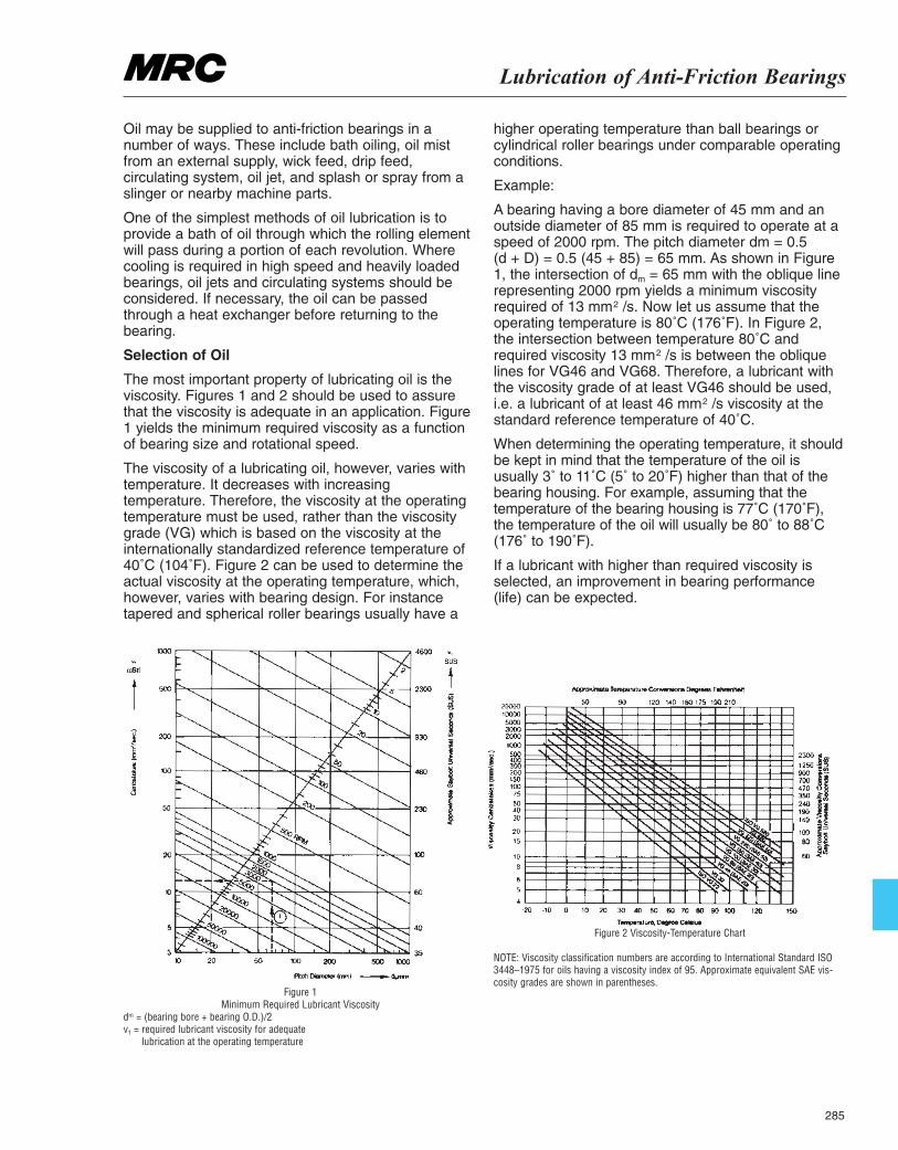
Lubrication of Anti-Friction Bearings
285
Oil may be supplied to anti-friction bearings in anumber of ways. These include bath oiling, oil mistfrom an external supply, wick feed, drip feed,circulating system, oil jet, and splash or spray from aslinger or nearby machine parts.
One of the simplest methods of oil lubrication is toprovide a bath of oil through which the rolling elementwill pass during a portion of each revolution. Wherecooling is required in high speed and heavily loadedbearings, oil jets and circulating systems should beconsidered. If necessary, the oil can be passedthrough a heat exchanger before returning to thebearing.
Selection of Oil
The most important property of lubricating oil is theviscosity. Figures 1 and 2 should be used to assurethat the viscosity is adequate in an application. Figure1 yields the minimum required viscosity as a functionof bearing size and rotational speed.
The viscosity of a lubricating oil, however, varies withtemperature. It decreases with increasingtemperature. Therefore, the viscosity at the operatingtemperature must be used, rather than the viscositygrade (VG) which is based on the viscosity at theinternationally standardized reference temperature of40˚C (104˚F). Figure 2 can be used to determine theactual viscosity at the operating temperature, which,however, varies with bearing design. For instancetapered and spherical roller bearings usually have a
higher operating temperature than ball bearings orcylindrical roller bearings under comparable operatingconditions.
Example:
A bearing having a bore diameter of 45 mm and anoutside diameter of 85 mm is required to operate at aspeed of 2000 rpm. The pitch diameter dm = 0.5(d + D) = 0.5 (45 + 85) = 65 mm. As shown in Figure1, the intersection of dm = 65 mm with the oblique linerepresenting 2000 rpm yields a minimum viscosityrequired of 13 mm2 /s. Now let us assume that theoperating temperature is 80˚C (176˚F). In Figure 2,the intersection between temperature 80˚C andrequired viscosity 13 mm2 /s is between the obliquelines for VG46 and VG68. Therefore, a lubricant withthe viscosity grade of at least VG46 should be used,i.e. a lubricant of at least 46 mm2 /s viscosity at thestandard reference temperature of 40˚C.
When determining the operating temperature, it shouldbe kept in mind that the temperature of the oil isusually 3˚ to 11˚C (5˚ to 20˚F) higher than that of thebearing housing. For example, assuming that thetemperature of the bearing housing is 77˚C (170˚F),the temperature of the oil will usually be 80˚ to 88˚C(176˚ to 190˚F).
If a lubricant with higher than required viscosity isselected, an improvement in bearing performance(life) can be expected.
Figure 1 Minimum Required Lubricant Viscosity
dm = (bearing bore + bearing O.D.)/2 v1 = required lubricant viscosity for adequate
lubrication at the operating temperature
Figure 2 Viscosity-Temperature Chart
NOTE: Viscosity classification numbers are according to International Standard ISO3448–1975 for oils having a viscosity index of 95. Approximate equivalent SAE vis-cosity grades are shown in parentheses.
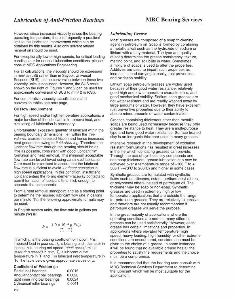
MRC Bearing ServicesLubrication of Anti-Friction Bearings
286
However, since increased viscosity raises the bearingoperating temperature, there is frequently a practicallimit to the lubrication improvement which can beobtained by this means. Also only solvent refinedmineral oil should be used.
For exceptionally low or high speeds, for critical loadingconditions or for unusual lubrication conditions, pleaseconsult MRC Applications Engineering.
For all calculations, the viscosity should be expressedin mm2 /s (cSt) rather than in Saybolt UniversalSeconds (SUS), as the conversion between these twoviscosity units is nonlinear. However, the SUS scaleshown on the right of Figures 1 and 2 can be used forapproximate conversion of SUS to mm2 2 /s (cSt).
For comparative viscosity classifications andconversion tables see next page.
Oil Flow Requirement
For high speed and/or high temperature applications, amajor function of the lubricant is to remove heat, andcirculating oil lubrication is necessary.
Unfortunately, excessive quantity of lubricant within thebearing boundary dimensions, i.e., within the freevolume, causes increased friction and hence increasedheat generation owing to fluid churning. Therefore thelubricant flow rate through the bearing should be aslittle as possible, consistent with good lubricant filmformation and heat removal. This minimum acceptableflow rate can be achieved using air-oil mist lubrication.Care must be exercised to assure that the lubricantflow rate is sufficient to avoid lubricant starvation inhigh speed applications. In this condition, insufficientlubricant enters the rolling element-raceway contacts topermit formation of lubricant films thick enough toseparate the components.
From a heat removal standpoint and as a starting pointto determine the required lubricant flow rate in gallonsper minute (W), the following approximate formula maybe used:
In English system units, the flow rate in gallons perminute (W) is:
W =
in which µ is the bearing coefficient of friction, P isimposed load in pounds, dm is bearing pitch diameter ininches, n is bearing net speed (shaft speed minusouter ring speed) in rpm, To is lubricant outlettemperature in ˚F and Ti is lubricant inlet temperature in˚F. The table below gives appropriate values of µ.
Coefficient of Friction (µ)Radial ball bearings 0.0015 Angular-contact ball bearings 0.0020 Split inner ring ball bearings 0.0024 Cylindrical roller bearings 0.0011
Lubricating GreaseMost greases are composed of a soap thickeningagent in petroleum oil. Soap is formed by combining a metallic alkali such as the hydroxide of sodium orlithium with a fatty material. The type and quality of soap determines the grease consistency, texture,melting point, and solubility in water. Sometimes a mixture of soaps is used to alter the properties.Additives are used to impart such properties asincrease in load carrying capacity, rust prevention, and oxidation stability.
Lithium soap petroleum greases are widely usedbecause of their good water resistance, relativelygood high and low temperature characteristics, andgood mechanical stability. Sodium soap greases arenot water resistant and are readily washed away bylarge amounts of water. However, they have excellentrust preventive properties due to their ability to absorb minor amounts of water contamination.
Greases containing thickeners other than metallicsoaps are being used increasingly because they offergreater resistance to heat. They are a multi-purposetype and have good water resistance. Surface treatedclay is an inorganic thickener used in many greases.
Intensive research in the development of oxidationresistant formulations has resulted in great increasesin the life which lubricating greases can provide.Through the use of synthetic oily compounds andnon-soap thickeners, grease lubrication can now beachieved over a temperature range of –100˚F to +500˚F (–73˚C to 260˚C) and higher in some cases.
Synthetic greases are formulated with synthetic fluids such as silicones, esters, perfluoroalkyl ethers,or polyphenyl ethers instead of petroleum oil. Thethickener may be soap or non-soap. Syntheticgreases are used in extremely high or lowtemperature applications that are outside the range for petroleum greases. They are relatively expensiveand therefore are not usually recommended ifpetroleum greases will serve the purpose.
In the great majority of applications where theoperating conditions are normal, many differentgreases can be used satisfactorily. However, eachgrease has certain limitations and properties. Inapplications where elevated temperature, high speed, heavy loading, high humidity, or other extremeconditions are encountered, consideration must begiven to the choice of a grease. In some instances it will be found that no available grease has all theproperties to satisfy the requirements and the choicemust be a compromise.
It is recommended that the bearing user consult withMRC Technical Services Department to determine the lubricant which will be most suitable for theapplication.
1.9 × 10 –4 µ Pdmn(To - Ti )
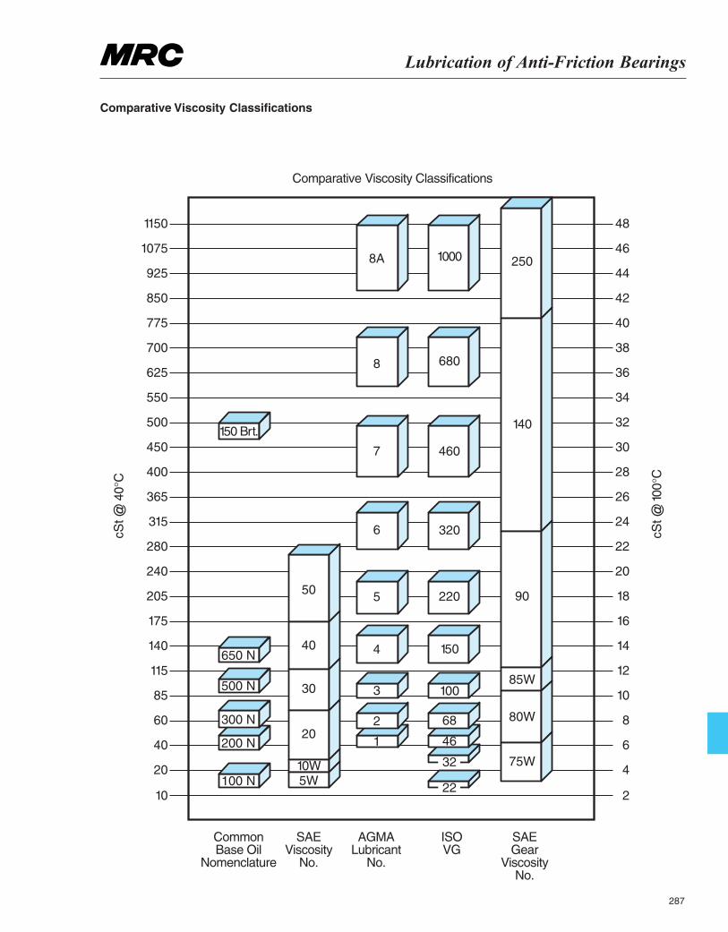
Lubrication of Anti-Friction Bearings
287
10
1150
1075
925
850
775
700
625
550
500
450
400
365
315
280
240
205
175
140
115
85
60
40
20
Common Base Oil
Nomenclature
ComparativeViscosity Classifications
SAE Viscosity
No.
SAE Gear
Viscosity No.
AGMA Lubricant
No.
ISO VG
2
48
46
44
42
40
38
36
34
32
30
28
26
cSt @
100°
C
cSt @
40°C
24
22
20
18
16
14
12
10
8
6
4
8A
8
7
6
550
40650 N
150 Brt.
500 N
300 N
200 N
100 N
30
20
10W5W
4
3
2
22
32
46
68
100
150
220
320
460
680
250
140
90
80W
75W
85W
1000
1
Comparative Viscosity Classifications
MRC Bearing ServicesLubrication of Anti-Friction Bearings
288
Grease Characteristics Consistency
Greases vary in consistency from semi-fluids to hard,brick type greases which are cut with a knife. Themethod for measuring grease consistency (ASTM D-217), established by the American Society for Testingand Materials, uses a penetrometer with which a coneof standard shape and weight is dropped into thegrease and the depth of penetration in five seconds at 77˚F (25˚C) is measured in tenths of a mm. Thepenetration is usually measured on both unworkedgrease as it comes from its shipping container and also after it has been worked 60 strokes by aperforated disc plunger.
Usually greases become softer when subjected tomechanical working action. These consistencymeasurements are expressed as unworked andworked. The 60 stroke working is done to minimize theeffects of any previous manipulation of the grease insampling. Also, the worked penetration indicates therelative softening after a limited amount of shear.However, this working cannot be correlated to the muchmore severe shearing action that occurs in a bearing.
Listed in the table below is a classification of theconsistency of grease in terms of worked penetrationas developed by the National Lubricating Grease
Institute.
Most rolling bearing greases fall into classes 1-4. By farthe greater portion of bearing applications use NLGIGrade 2 grease.
Dropping Point
When a grease is heated, it softens. The temperatureat which a drop falls from a sample in a standard test(ASTM D-566) is called its dropping point. The droppingpoint cannot be used to indicate the maximumoperating temperature for a grease since some greasesoxidize or decompose rapidly at temperatures belowthe dropping point. Dropping point is of little significanceto the grease user but it is of significant value to thegrease maker as means of quality control.
Oxidation Stability
Reaction with oxygen in the air, which is acceleratedwith higher temperatures, is one of the main factors
limiting the life of bearing greases. This reactionultimately results in drying and hardening of the greasewith total loss of lubricating properties.
The standard test used to measure the oxidationstability of grease is the Oxygen Bomb Method (ASTMD-942). In this test, the rate of absorption of oxygen by the grease at 210˚F (99˚C) and 110 PSI is recorded.This test is conducted under static conditions and isintended only to be useful in estimating the shelf life of greases. However, it has been found that greaseswhich show low oxygen absorption usually performreasonably well in service.
Water Resistance
Water resistance varies with the different types ofgreases. Most sodium soap greases emulsify and thinout when mixed with water. Other types are lessaffected but their resistance to washout varies with the viscosity of the oil and the amount and type ofthickener. No lubricating grease is completely waterresistant. Even those classed as water insoluble orwater resistant can be washed out of a bearing ifexposed to large volumes of water.
The ability of a grease to withstand water washout froma bearing is determined by ASTM Method D-1264. A ball bearing with a specified quantity of the testgrease is mounted in a housing with specifiedclearances to allow entry of water from a jet. After one hour of operation at 600 RPM with the water at acontrolled temperature impinging on the housing at a specified rate, the bearing is reweighed and theamount of grease lost is determined.
Shear Stability (Mechanical Stability)
This is the resistance of a grease to structuralbreakdown when subjected to the shearing action ofbeing worked.
Two grease working tests are used to measuresoftening of grease due to working. ASTM Method D-217, described earlier under Consistency, forces thegrease through a perforated plate at a rate of 60 timesper minute. The Shell Roll Test subjects the grease tothe working action of a roll inside a rotating cylinder.Penetration values are determined before and afterrolling. The° of softening that results from working isimportant from the aspect of leakage from the bearing.However, the results cannot be correlated to bearingperformance since greases which have appearedunsatisfactory in these tests have been found toprovide very satisfactory bearing performance.
Oil Separation
Most greases show some tendency to allow oilseparation in certain circumstances. During storage,depressions in the grease surface or voids collect oil.
NLGI Worked No. Penetration
000 445 – 475 00 400 – 4300 355 – 385
1 310 – 3402 265 – 2953 220 – 250
4 175 – 2055 130 – 1606 85 – 115
Lubrication of Anti-Friction Bearings
289
This separation increases with higher storagetemperatures as the viscosity of the oil phase islowered. Oil separation, unless excessive, is not reasonfor rejection of a rolling bearing grease. Five percent istypically permitted. Usually the separated oil can beeasily stirred back into the grease body.
The standard test method for determining oil separationfrom grease during storage is ASTM D-1742. This is asimple test where the sample is placed on a sievestrainer in a pressure cell with inlet air pressuremaintained at 0.25 PSI. The test is conducted at 77˚F(25˚C) and after 24 hours the separated oil that hascollected on the bottom of the cell is weighed andexpressed as a percentage by weight of the originalsample. This test is only intended to measure thetendency of a grease to separate oil during storage. Itis not intended to predict the stability of grease underdynamic service conditions.
Channeling
Channeling is a term referring to the tendency of agrease to separate and form a channel after thepassage of the balls and cage around the ball race.Some greases channel very little and flow back rapidlyto fill the voids left by the rotating elements to causehigher torque and higher operating temperatures fromthe shear stresses within the lubricant. Poor channelingcharacteristics can make some greases unsatisfactoryfor high speed operation when a channeling typegrease will provide minimum torque and heat rise.Channeling type greases are usually of NLGI No. 3 or No. 4 consistency.
Special Properties
There are many special grease formulations to meet a variety of unusual requirements. Special properties,which have been listed below, are often required in a grease. These special requirements may include:1. Extra tackiness or adhesiveness to resist leakage
or throw-out. 2. Proper structure for sealing to exclude contaminates. 3. Resistance to the action of certain chemicals. 4. Resistance to the action of solvents. 5. Electrical conductivity. 6. Resistance to the effects of nuclear radiation. 7. Resistance to the effects of high vacuum. 8. Non-toxic for use where there may be contact
with food.9. High oil bleed rates ≥ 2.5% for machined land
guided cages
Operating ConditionsLow Temperature
Oils and greases tend to thicken and resist flow astemperatures are decreased. For oil lubricated bearings
operating at cold temperatures, an oil that has asufficiently low pour point to remain fluid at the lowtemperature and the proper viscosity for the operatingtemperature should be chosen. If the oil is subjected tolow temperature start-up but operates at highertemperatures, a high viscosity index is desirable.
Usually the most important consideration in selecting agrease for low temperature operation is start-up torque.Some greases may function satisfactorily duringoperation but require excessive torque for start-up.Starting torque is not a function of the consistency orthe channeling properties of a grease. It appears to bea function of the individual properties of the grease andis difficult to measure. Experience alone will showwhether one grease is better than another in thisrespect. Greases formulated with synthetic oils areavailable which provide very low starting and runningtorque at temperatures as low as –100˚F (–73˚C).Generally, a correctly selected grease provides lowertorque than an oil.
High Temperature
In oil lubricated bearing applications where ambienttemperatures are high, such as in ovens, some meansof cooling is usually necessary to avoid excessivebearing temperatures and premature lubricant failure.Some of the commonly used methods for decreasingthe oil temperature are cooling coils, water jackets, oilcooling tanks, cooling discs, and fans.
The rate of oxidation of lubricating fluids increasesrapidly with temperature rise. As mentioned earlier, therate of oxidation doubles for each 18˚F (10˚C)temperature rise above 140˚F (60˚C). Above 250˚F(121˚C), petroleum oils tend to oxidize rapidly andsometimes it becomes necessary to use specialpetroleum oils or synthetic oils to increase the servicelife of the lubricant.
Where the only heat is that generated by the bearing,temperature rise can usually be held to a reasonablelevel by the use of a suitable lubricant in properquantity.
The high temperature limit for greases, i.e. themaximum temperature at which a grease will provide areasonable life in a non-relubricable bearing, is largelya function of the oxidation stability of the fluid and thethickener. The oxidation process is greatly acceleratedwith increasing temperature. Another factor isevaporation of the fluid phase. Also, greases thin out athigh temperatures. If the grease consistency becomestoo soft at operating temperatures there may beleakage from the bearing.
High Speeds
Small size anti-friction bearings are often successfullygrease lubricated at high speeds. Larger sizes usuallyrequire oil to remove heat as well as to lubricate.
MRC Bearing ServicesLubrication of Anti-Friction Bearings
290
Where extensive cooling is required in high speed andheavily loaded bearings operating with high frictionalheat, oil jets and circulating systems should beconsidered. For small and medium size bearingsrotating at high speeds, an oil circulating system, dripfeed or oil mist is satisfactory.
With other influences being equal, increasingly lowerviscosities are needed with increasing speeds. Thequantity of oil needed for successful operationbecomes greater with increasing temperature, load,speed, and bearing size.
Extreme Pressures
Various extreme pressure agents are compoundedinto some greases and oils. These include additivessuch as sulfur, phosphorus, and chlorine compounds,graphite, and molybdenum disulfide. However, suchadditives are generally not required in anti-frictionbearing lubricants and should be avoided unless theiruse is dictated by other associated equipment such asgears.
For most applications, higher viscosity oils arerequired to prevent metal to metal contact if pressuresare higher than normal or if shock loading occurs. Incases where heavily loaded bearings operate at highspeeds, the selection of oil viscosity must be acompromise between a heavy oil which is desirablefor heavy loading and a light oil which is desirable forhigh speeds.
Wet Conditions
Whenever possible, an anti-friction bearing should beprotected from water and moisture to avoid corrosion.Even slight corrosion on the internal surfaces mayinitiate bearing failure.
Ball and roller bearings are, however, often usedsuccessfully where moisture is present. The presenceof moisture will affect the choice of a grease with theselection depending upon the quantity of moisturepresent.
Water soluble sodium base greases will form a non-corrosive emulsion when mixed with a limited quantityof water. However, agitation is necessary to form thisemulsion. If water should enter an idle bearing, thebearing may become corroded. There is a limit to theamount of water which a water soluble grease canabsorb and still protect the bearing surfaces.
A water resistant grease, such as a lithium basegrease that contains an effective rust inhibitor shouldbe used where large amounts of water are present.The term ‘‘water resistant grease’’ is actually amisnomer since no grease will totally resist largeamounts of water for extended periods.
Slow moving bearings can be packed full of acohesive, water resistant grease formulated with avery heavy oil to afford maximum protection againstlarge amounts of water.Where wet conditions are sosevere that satisfactory protection cannot be providedby a lubricant, it is sometimes necessary to usebearings fabricated of special corrosion resistantalloys or bearings with corrosion resistant coatings.
Fretting
Anti-friction bearings are sometimes damaged by awear effect that is variously called fretting corrosion,fretting, friction oxidation and false brinneling. Thiseffect evidences itself by the formation of rust-likewear debris and the formation of wear spots.
Fretting can occur in bearings subjected to vibration,vibratory loads, or oscillation of small amplitudes. It issometimes seen in the bearings of idle machinery thathas been subjected to the vibrations of nearbymachines. The wear spots can be recognized asdepressions or indentations in the races at the pointswhere they have been in contact with the balls or rolls.If allowed to progress, the wear in these contact areaswill become so extensive as to prevent functioning ofthe bearings.
Fretting can be eliminated or minimized by theselection of a lubricant which has good feed ability.Low viscosity oils minimize fretting to a greater extentthan oils of higher viscosities.
With grease lubrication in applications where fretting isa problem, it is good general practice to use a softgrease such as an NLGI 0 or 1 grade or a hardergrease which tends to soften considerably uponworking.
Dust and Dirt
A high percentage of ball and roller bearing troublescan be attributed to foreign matter entering thebearing after mounting. Because anti-friction bearingsare highly sensitive to dust and dirt, elaborateprotective devices are necessary in someapplications.
Oil lubricated bearings are generally protected fromforeign particle contamination by the use of oil filtersand the properly designed seals required in oillubricated systems.
Grease in sealed and shielded bearings can providean effective barrier against dust and dirt. Where thebearings operate in dusty or dirty atmosphere thegrease should be chosen with its sealing properties inmind. Such a product should have good resistance tostructural break-down on working. Usually, the stiffconsistency of an NLGI Grade 3 grease will provide agood sealing barrier.
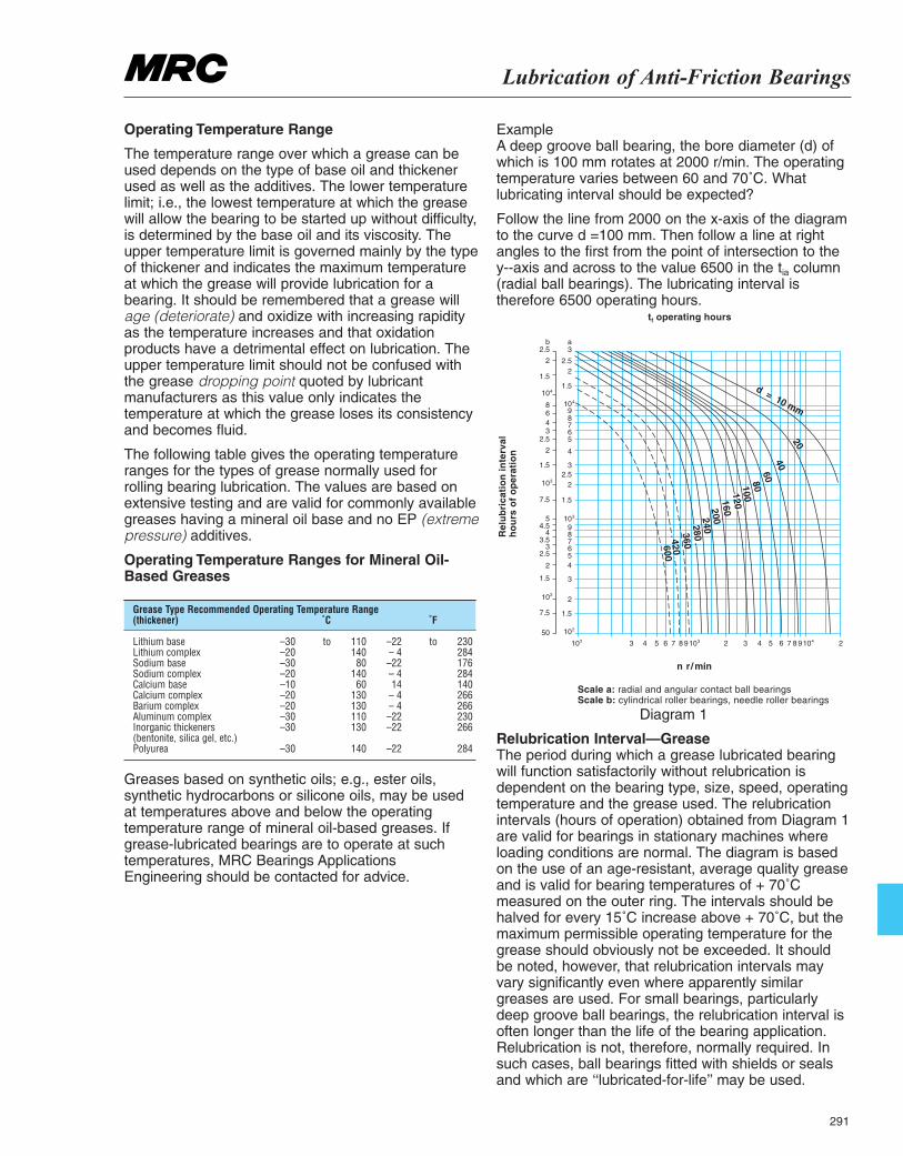
Lubrication of Anti-Friction Bearings
291
Operating Temperature Range
The temperature range over which a grease can beused depends on the type of base oil and thickenerused as well as the additives. The lower temperaturelimit; i.e., the lowest temperature at which the greasewill allow the bearing to be started up without difficulty,is determined by the base oil and its viscosity. Theupper temperature limit is governed mainly by the typeof thickener and indicates the maximum temperatureat which the grease will provide lubrication for abearing. It should be remembered that a grease willage (deteriorate) and oxidize with increasing rapidityas the temperature increases and that oxidationproducts have a detrimental effect on lubrication. Theupper temperature limit should not be confused withthe grease dropping point quoted by lubricantmanufacturers as this value only indicates thetemperature at which the grease loses its consistencyand becomes fluid.
The following table gives the operating temperatureranges for the types of grease normally used forrolling bearing lubrication. The values are based onextensive testing and are valid for commonly availablegreases having a mineral oil base and no EP (extremepressure) additives.
Operating Temperature Ranges for Mineral Oil-Based Greases
Greases based on synthetic oils; e.g., ester oils,synthetic hydrocarbons or silicone oils, may be usedat temperatures above and below the operatingtemperature range of mineral oil-based greases. Ifgrease-lubricated bearings are to operate at suchtemperatures, MRC Bearings ApplicationsEngineering should be contacted for advice.
Example A deep groove ball bearing, the bore diameter (d) ofwhich is 100 mm rotates at 2000 r/min. The operatingtemperature varies between 60 and 70˚C. Whatlubricating interval should be expected?
Follow the line from 2000 on the x-axis of the diagramto the curve d =100 mm. Then follow a line at rightangles to the first from the point of intersection to they--axis and across to the value 6500 in the tia column(radial ball bearings). The lubricating interval istherefore 6500 operating hours.
Diagram 1
Relubrication Interval—Grease The period during which a grease lubricated bearingwill function satisfactorily without relubrication isdependent on the bearing type, size, speed, operatingtemperature and the grease used. The relubricationintervals (hours of operation) obtained from Diagram 1are valid for bearings in stationary machines whereloading conditions are normal. The diagram is basedon the use of an age-resistant, average quality greaseand is valid for bearing temperatures of + 70˚Cmeasured on the outer ring. The intervals should behalved for every 15˚C increase above + 70˚C, but themaximum permissible operating temperature for thegrease should obviously not be exceeded. It shouldbe noted, however, that relubrication intervals mayvary significantly even where apparently similargreases are used. For small bearings, particularlydeep groove ball bearings, the relubrication interval isoften longer than the life of the bearing application.Relubrication is not, therefore, normally required. Insuch cases, ball bearings fitted with shields or sealsand which are ‘‘lubricated-for-life’’ may be used.
Grease Type Recommended Operating Temperature Range (thickener) ˚C ˚F
Lithium base –30 to 110 –22 to 230 Lithium complex –20 140 – 4 284 Sodium base –30 80 –22 176 Sodium complex –20 140 – 4 284 Calcium base –10 60 14 140 Calcium complex –20 130 – 4 266 Barium complex –20 130 – 4 266 Aluminum complex –30 110 –22 230 Inorganic thickeners –30 130 –22 266 (bentonite, silica gel, etc.) Polyurea –30 140 –22 284
2.5b
2
1.5
10
8643
2.5
2
1.5
10
7.5
5
4
3
2
4.5
3.5
2.5
1.5
10
7.5
50
2
3
109
1.5
2
3
4
56789
1.5
2.52
3a
2.5
87654
3
2
1.5
3
104
102
102 103 10987654329876
n r/min
Scale a: radial and angular contact ball bearingsScale b: cylindrical roller bearings, needle roller bearings
Diagram 1
543
20
d = 10 mm
40
6080100120160200240280360420600
24
4
Rel
ub
rica
tio
nin
terv
alh
ou
rso
fo
per
atio
n
tf operating hours
MRC Bearing ServicesLubrication of Anti-Friction Bearings
292
Where there is a risk of the grease becomingcontaminated the relubrication intervals should bereduced. This reduction also applies to applicationswhere the grease is required to seal against moisture,e.g. bearings in papermaking machines, where waterruns over the bearing housings, should be relubricatedonce a week.
Relubrication
The amount of grease needed for relubrication can beobtained from
Gp = 0.005 D B
where Gp = grease quantity, g
D = bearing outside diameter, mm B = total bearing width, mm
When operating conditions are such that relubricationcan be carried out at infrequent intervals, it is sufficientif the bearing housing is accessible and can be openedeasily. The cap of split housings and the cover of one-piece housings can usually be taken off to expose thebearing. After removing the used grease, fresh greaseshould first be packed between the rolling elements.
Where more frequent relubrication is required provisionshould be made for regreasing; preferably a greasenipple should be fitted to the housing. A grease gun(lubricator) can then be used. To ensure that freshgrease actually reaches the bearing and replaces theold grease, the lubrication duct in the housing shouldeither feed the grease adjacent to the outer ring sideface, or, better still, into the bearing.
After a number of such relubrications the housingshould be opened and the used grease removedbefore fresh grease is added.
Relubrication Intervals—Oil
The frequency at which the oil must be changed ismainly dependent on the operating conditions and onthe quantity of oil used.
Where oil bath lubrication is employed it is normallysufficient to change the oil once a year, provided thebearing temperature does not exceed 50˚C (120˚F) andthere is no contamination. Higher temperatures or morearduous running conditions necessitate more frequentchanges, e.g. at a temperature of 100˚C (220˚F) the oilshould be changed every 3 months.
For circulating oil systems the period between completeoil changes is dependent on how often the oil iscirculated over a given period of time and whether it iscooled, etc. The most suitable period can generally onlybe determined by trial runs and frequent examination ofthe oil. The same practice also applies to oil jetlubrication.
In oil mist lubrication, most of the oil is lost, as it isconveyed to the bearing only once.
Bearing Cleaning New bearings should be cleaned only if they have beenexposed to dirt after removal from their package orlubricated with an oil or grease that is incompatible withthe preservative. (See Compatibility of Lubricants, pg.294). Bearings which have been in service and requirecleaning due to accumulated dirt or deterioratedlubricant may be cleaned as follows: All cleaningoperations should be done in a dirt free area and onlyclean solvents of good quality should be used. Lighttransformer oils, spindle oils, or automotive flushing oilsare suitable for cleaning bearings but oils heavier thanSAE 10 motor oils are not recommended. The use ofchlorinated solvents of any kind is not recommended inbearing cleaning operations because of the rust hazardinvolved. The use of compressed air for blowing dirt outof bearings and drying solvents is not recommendedunless the air system is filtered to remove moisture anddirt. Bearings should never be spun at high speed by astream of compressed air during cleaning as this maycause damage to the balls and raceways.
Cleaning Unmounted Used Bearings
Place bearings in a wire or mesh basket and suspendthe basket in a suitable container of clean petroleumsolvent or kerosene. Allow them to soak, preferablyovernight or longer, until all hard deposits havesoftened. Bearings which contain badly oxidized greasemay require soaking in hot, light oil (200˚ to 240˚F) tosoften the deposits. The basket should be agitatedslowly through the oil from time to time. After depositshave softened, the bearings should be immersed insolvent for cleaning. In extreme cases, boiling inemulsified cleaners (i.e. grinding, cutting, or floorcleaning compounds) may be more effective to softenhard deposits. A stiff brush may be used to dislodgesolid particles. If hot emulsion solutions have beenused, it is important that all entrapped water beremoved from the bearings. This may be accomplishedby draining and slowly rotating the individual bearingswhile hot until the water has been completelyevaporated. A more preferable method of removingentrapped water after draining is to spin the bearings ina water displacing type rust preventive oil. Afterremoving the water, the bearings should immediatelybe immersed in clean petroleum solvent for furthercleaning. After the used bearings have been thoroughlycleaned, their condition may be judged by hand. A lighthand thrust should be applied against one bearing ringwhile slowly rotating the other ring. The° of smoothnessfelt in rotation will indicate whether the bearing issatisfactory for further service. Bearings which aresatisfactory for further service should be immediatelyrotated in light oil to displace the solvent. Those whichwill not be installed immediately should be coated witha good rust preventive oil and wrapped in clean oil-proof paper.
Lubrication of Anti-Friction Bearings
293
Cleaning Mounted Used Bearings
For cleaning bearings without removing them fromtheir mounted assembly, hot, light oil at 180˚F (82˚C)may be flushed through the housing while the shaft orspindle is slowly rotated. In cases of badly oxidizedgrease and oil, hot water emulsions can be used inplace of flushing oil. The solution should be drainedthoroughly and the housing flushed with hot, light oil.The shaft should be rotated slowly throughout theseoperations.
In some cases where deposits are extremely difficultto remove, an intermediate flushing with a mixture ofalcohol and light petroleum solvent after the emulsiontreatment may be helpful. The flushing oil should bedrained completely and oil passages checked to makesure they are not clogged before adding newlubricant.
If the bearing is lubricated with grease, new greasemay be forced through the bearing to purge the oldgrease and contaminates. This may be done,however, only if contamination is not severe and ventopenings are provided in the housing for exhaustingthe old grease. After purging with grease, the bearingsshould be operated for about ten minutes before thevent plugs are replaced to avoid serious over-heatingof the bearing due to churning of excess grease.
Cleaning Sealed or Shielded Used Bearings
Bearings which have non-removable double shields orseals cannot be cleaned. These bearings are normallyinspected and reused or rejected on the basis ofsmoothness and looseness.
Bearings having one seal or one shield may becleaned satisfactorily by the methods outlined here.Bearings having two shields that are held in place bysnap rings can be cleaned and regreased by carefullyremoving the shields and reinstalling them.
Bearings having two removable rubber seals can becleaned and regreased if care is exercised inremoving and reinstalling the seals. The bestprocedure for removing the seal is to insert a thin,knife-like blade between the O.D. of the seal and theseal groove in the outer ring, then slowly work aroundthe periphery of the seal, working the seal from thegroove. It is important to work around the peripheryrather than exert too much pressure at one pointwhich may damage the seal. Usually the seal can beremoved without damage.
Things You Should Know About LubricationMRC bearings that have seals or shields are generallylubricated for the life of the bearing. Bearings that donot have seals or shields are protected from corrosionby coating the bearing with a preservative. Thepreservative is compatible with petroleum base oilsand lubricants. It is not necessary to remove the
preservative from the bearing surfaces when thebearing will be lubricated with either a petroleum baseoil or grease.
It is possible that either synthetic oil or greasescompounded with synthetic oils, will not be compatiblewith a petroleum base preservative. It isrecommended that the preservative be removed fromthe bearing surfaces before lubricating with either ofthese products. Synthetic hydrocarbons are anexception. It is also possible that greasescompounded with a polyurea thickener may causeexcessive grease softening due to incompatibility witha petroleum base preservative.
Synthetic oils and greases compounded with syntheticoils are classified as special condition lubricants. Theyare usually not the best choice for operatingconditions that fall within the capability of petroleumbase lubricants. They are expensive and lack some ofthe desirable lubricating qualities of petroleum baselubricants. Synthetic hydrocarbon may be anexception.
Because machined phenolic or metal separatorsoccupy a considerable amount of the space betweenthe bore of the outer ring and the OD of the inner ringin a bearing, special care must be exercised whenintroducing grease into these bearings to ensure thatit is uniformly distributed in the bearing. Operation ofthe bearing will eventually uniformly distribute thegrease, but it is possible to initiate a heating-typefailure or to cause damage to the active surfaces inthe bearing before this occurs. This precaution isespecially important when there is a close runningclearance between the separator and one of the rings.One method of introducing grease between the ringsand the separator is to use a plastic bag. If grease issealed in a plastic bag and a small opening is cutacross one of the corners, the bag can be insertedbetween the separator and either ring. Grease canthen be forced into the bearing by squeezing it fromthe bag.
In applications where either water or air is used todissipate heat from the bearing cavity, care must beexercised not to create a significant temperaturedifferential between the bearing inner ring and outerring. Some cooling methods, i.e. water jacketedhousings, very efficiently dissipate heat from thehousing and outer ring of the bearing, but have littleeffect on the shaft and bearing inner ring. Under theseconditions, internal clearance in the bearing isremoved as the result of thermal expansion of theinner ring and thermal contraction of the outer ring.The loss of internal clearance can result in prematurebearing failures due to a significant increase in balland race stresses, and also due to excessive heatgeneration. One way to avoid this problem is tocirculate and cool the oil.
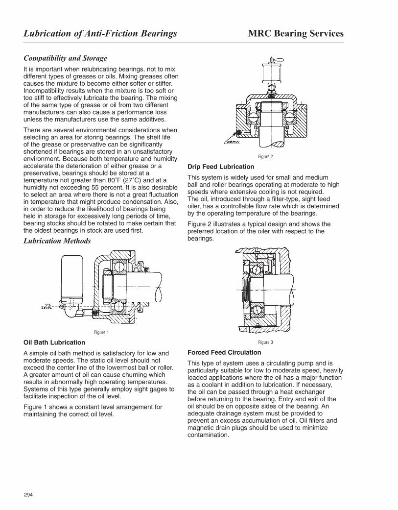
MRC Bearing ServicesLubrication of Anti-Friction Bearings
294
Compatibility and StorageIt is important when relubricating bearings, not to mixdifferent types of greases or oils. Mixing greases oftencauses the mixture to become either softer or stiffer.Incompatibility results when the mixture is too soft ortoo stiff to effectively lubricate the bearing. The mixingof the same type of grease or oil from two differentmanufacturers can also cause a performance lossunless the manufacturers use the same additives.
There are several environmental considerations whenselecting an area for storing bearings. The shelf life of the grease or preservative can be significantlyshortened if bearings are stored in an unsatisfactoryenvironment. Because both temperature and humidityaccelerate the deterioration of either grease or apreservative, bearings should be stored at atemperature not greater than 80˚F (27˚C) and at ahumidity not exceeding 55 percent. It is also desirableto select an area where there is not a great fluctuationin temperature that might produce condensation. Also,in order to reduce the likelihood of bearings beingheld in storage for excessively long periods of time,bearing stocks should be rotated to make certain thatthe oldest bearings in stock are used first.
Lubrication Methods
Figure 1
Oil Bath Lubrication
A simple oil bath method is satisfactory for low andmoderate speeds. The static oil level should notexceed the center line of the lowermost ball or roller. A greater amount of oil can cause churning whichresults in abnormally high operating temperatures.Systems of this type generally employ sight gages tofacilitate inspection of the oil level.
Figure 1 shows a constant level arrangement formaintaining the correct oil level.
Figure 2
Drip Feed Lubrication
This system is widely used for small and medium ball and roller bearings operating at moderate to highspeeds where extensive cooling is not required. The oil, introduced through a filter-type, sight feedoiler, has a controllable flow rate which is determinedby the operating temperature of the bearings.
Figure 2 illustrates a typical design and shows thepreferred location of the oiler with respect to thebearings.
Figure 3
Forced Feed Circulation
This type of system uses a circulating pump and isparticularly suitable for low to moderate speed, heavilyloaded applications where the oil has a major functionas a coolant in addition to lubrication. If necessary, the oil can be passed through a heat exchangerbefore returning to the bearing. Entry and exit of theoil should be on opposite sides of the bearing. Anadequate drainage system must be provided toprevent an excess accumulation of oil. Oil filters andmagnetic drain plugs should be used to minimizecontamination.
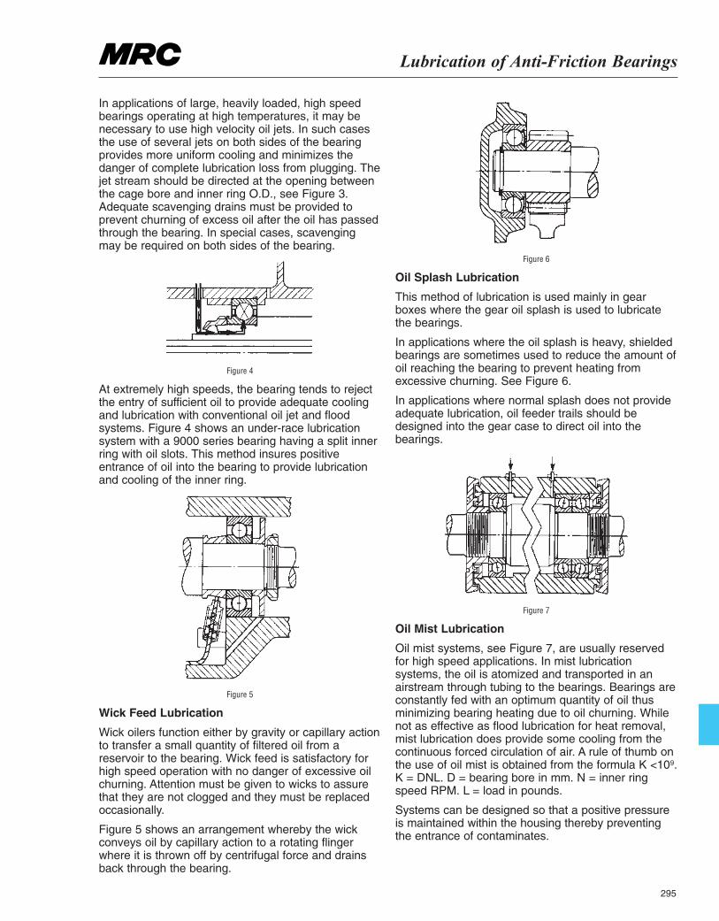
Lubrication of Anti-Friction Bearings
295
In applications of large, heavily loaded, high speedbearings operating at high temperatures, it may benecessary to use high velocity oil jets. In such casesthe use of several jets on both sides of the bearingprovides more uniform cooling and minimizes thedanger of complete lubrication loss from plugging. Thejet stream should be directed at the opening betweenthe cage bore and inner ring O.D., see Figure 3.Adequate scavenging drains must be provided toprevent churning of excess oil after the oil has passedthrough the bearing. In special cases, scavengingmay be required on both sides of the bearing.
Figure 4
At extremely high speeds, the bearing tends to rejectthe entry of sufficient oil to provide adequate coolingand lubrication with conventional oil jet and floodsystems. Figure 4 shows an under-race lubricationsystem with a 9000 series bearing having a split innerring with oil slots. This method insures positiveentrance of oil into the bearing to provide lubricationand cooling of the inner ring.
Figure 5
Wick Feed Lubrication
Wick oilers function either by gravity or capillary actionto transfer a small quantity of filtered oil from areservoir to the bearing. Wick feed is satisfactory forhigh speed operation with no danger of excessive oilchurning. Attention must be given to wicks to assurethat they are not clogged and they must be replacedoccasionally.
Figure 5 shows an arrangement whereby the wickconveys oil by capillary action to a rotating flingerwhere it is thrown off by centrifugal force and drainsback through the bearing.
Figure 6
Oil Splash Lubrication
This method of lubrication is used mainly in gearboxes where the gear oil splash is used to lubricatethe bearings.
In applications where the oil splash is heavy, shieldedbearings are sometimes used to reduce the amount ofoil reaching the bearing to prevent heating fromexcessive churning. See Figure 6.
In applications where normal splash does not provideadequate lubrication, oil feeder trails should bedesigned into the gear case to direct oil into thebearings.
Figure 7
Oil Mist Lubrication
Oil mist systems, see Figure 7, are usually reservedfor high speed applications. In mist lubricationsystems, the oil is atomized and transported in anairstream through tubing to the bearings. Bearings areconstantly fed with an optimum quantity of oil thusminimizing bearing heating due to oil churning. Whilenot as effective as flood lubrication for heat removal,mist lubrication does provide some cooling from thecontinuous forced circulation of air. A rule of thumb onthe use of oil mist is obtained from the formula K <109.K = DNL. D = bearing bore in mm. N = inner ringspeed RPM. L = load in pounds.
Systems can be designed so that a positive pressureis maintained within the housing thereby preventingthe entrance of contaminates.
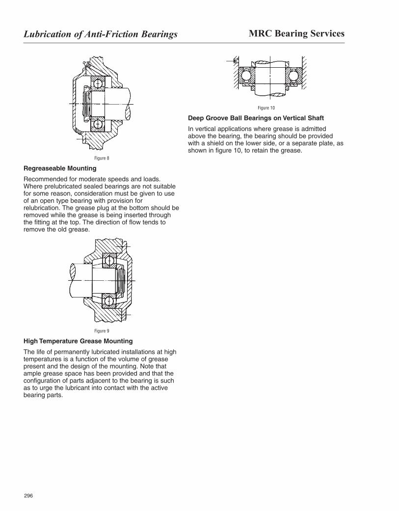
MRC Bearing ServicesLubrication of Anti-Friction Bearings
296
Figure 8
Regreaseable Mounting
Recommended for moderate speeds and loads.Where prelubricated sealed bearings are not suitablefor some reason, consideration must be given to useof an open type bearing with provision forrelubrication. The grease plug at the bottom should beremoved while the grease is being inserted throughthe fitting at the top. The direction of flow tends toremove the old grease.
Figure 9
High Temperature Grease Mounting
The life of permanently lubricated installations at hightemperatures is a function of the volume of greasepresent and the design of the mounting. Note thatample grease space has been provided and that theconfiguration of parts adjacent to the bearing is suchas to urge the lubricant into contact with the activebearing parts.
Figure 10
Deep Groove Ball Bearings on Vertical Shaft
In vertical applications where grease is admittedabove the bearing, the bearing should be providedwith a shield on the lower side, or a separate plate, asshown in figure 10, to retain the grease.
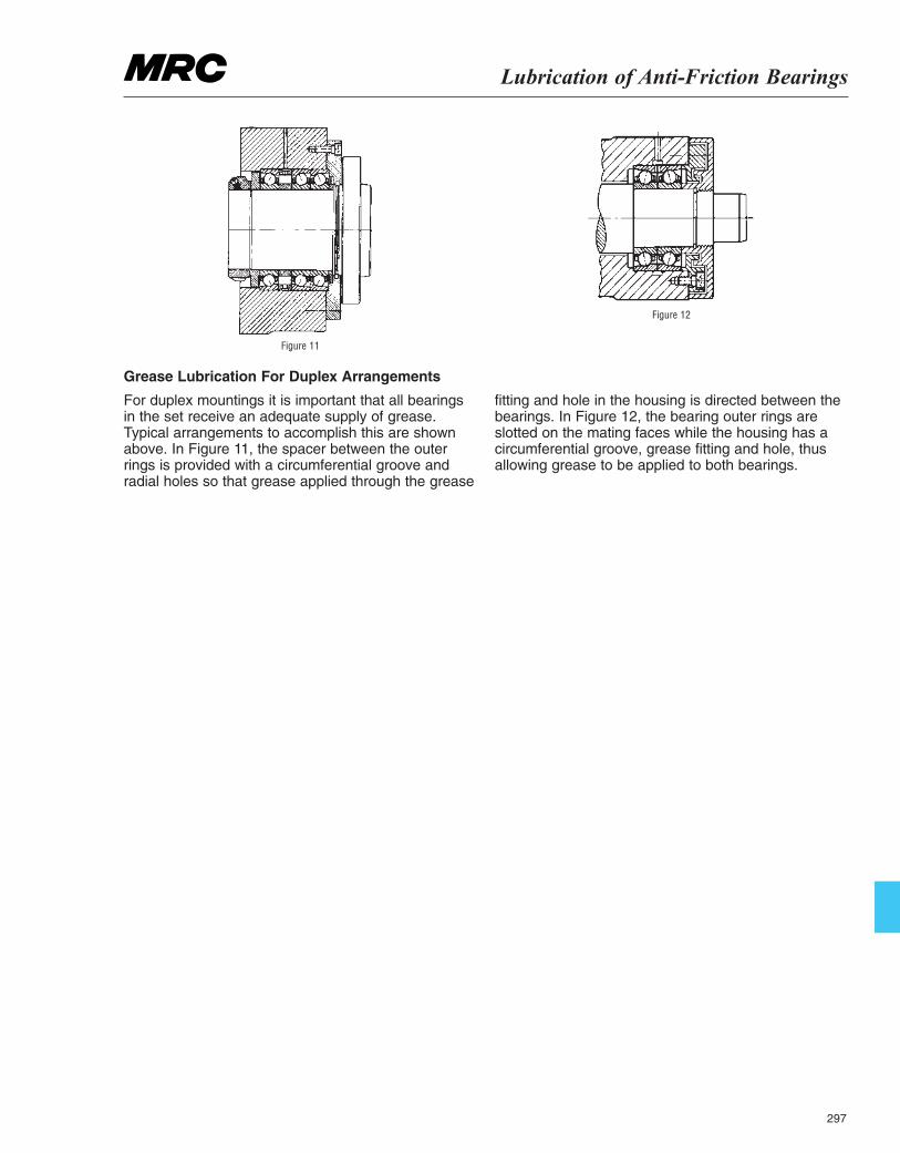
Lubrication of Anti-Friction Bearings
297
Figure 11
Figure 12
Grease Lubrication For Duplex Arrangements
For duplex mountings it is important that all bearingsin the set receive an adequate supply of grease.Typical arrangements to accomplish this are shownabove. In Figure 11, the spacer between the outerrings is provided with a circumferential groove andradial holes so that grease applied through the grease
fitting and hole in the housing is directed between thebearings. In Figure 12, the bearing outer rings areslotted on the mating faces while the housing has acircumferential groove, grease fitting and hole, thusallowing grease to be applied to both bearings.

298
Bearing Vibration Data
299
Bearing Frequency DataVibration monitoring is becoming an important tool inpreventive maintenance of equipment. Vibrationmonitoring can detect abnormalities in equipmentcomponents and indicate their replacement before acatastrophic failure occurs. This reduces expensiveunplanned breakdown and loss of production.
To assist you in this monitoring, the following pagesinclude frequency data for many of our popularbearing sizes. The bearing suffix code, which isprinted on the bearing carton, identifies particulardesign features of the bearing. Although a change insuffix code for a bearing size normally causes little orno change in the frequency data for that bearing, ifyou are unable to match your suffix code to one in thechart and your application is sensitive, please callMRC Engineering for exact values.
The frequency data in the following pages is suppliedbased on a speed of one RPM. To obtain thefrequency at your shaft or housing speed simplymultiply the number given in the table by your speed.
Ex. What is the Inner ring ball pass frequency for a100KR with inner ring rotation of 1,000 RPM.
Inner Ring frequency at 1 RPM = 5.0159 cycles/min(CPM) (from table) Inner Ring frequency at 1,000 RPM =5.0159 CPM × 1000
Inner Ring frequency at 1,000 RPM = 5015.9 CPM
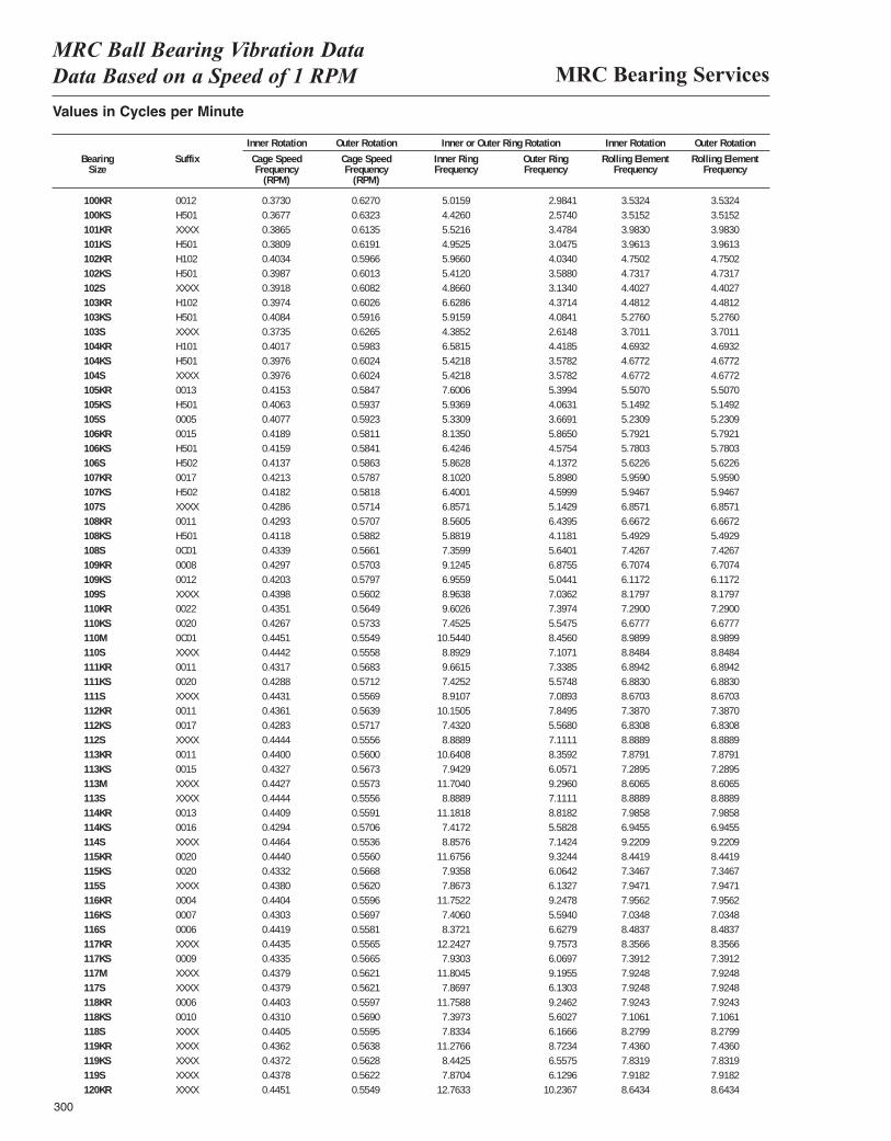
MRC Bearing ServicesMRC Ball Bearing Vibration Data Data Based on a Speed of 1 RPM
300
Values in Cycles per Minute
Inner Rotation Outer Rotation Inner or Outer Ring Rotation Inner Rotation Outer Rotation
Bearing Suffix Cage Speed Cage Speed Inner Ring Outer Ring Rolling Element Rolling ElementSize Frequency Frequency Frequency Frequency Frequency Frequency
(RPM) (RPM)
100KR 0012 0.3730 0.6270 0.0836 0.0497 0.0295 0.0294100KS H501 0.3677 0.6323 0.0738 0.0429 0.0293 0.0293101KR XXXX 0.3865 0.6135 0.0920 0.0580 0.0332 0.0331101KS H501 0.3809 0.6191 0.0825 0.0508 0.0330 0.0330102KR H102 0.4034 0.5966 0.0994 0.0672 0.0396 0.0395102KS H501 0.3987 0.6013 0.0902 0.0598 0.0394 0.0394102S XXXX 0.3918 0.6082 0.0811 0.0522 0.0367 0.0367103KR H102 0.3974 0.6026 0.1105 0.0729 0.0373 0.0373103KS H501 0.4084 0.5916 0.0986 0.0681 0.0440 0.0440103S XXXX 0.3735 0.6265 0.0731 0.0436 0.0308 0.0308104KR H101 0.4017 0.5983 0.1097 0.0736 0.0391 0.0390104KS H501 0.3976 0.6024 0.0904 0.0596 0.0390 0.0390104S XXXX 0.3976 0.6024 0.0904 0.0596 0.0390 0.0390105KR 0013 0.4153 0.5847 0.1267 0.0900 0.0459 0.0458105KS H501 0.4063 0.5937 0.0990 0.0677 0.0429 0.0429105S 0005 0.4077 0.5923 0.0888 0.0612 0.0436 0.0436106KR 0015 0.4189 0.5811 0.1356 0.0978 0.0483 0.0482106KS H501 0.4159 0.5841 0.1071 0.0763 0.0482 0.0482106S H502 0.4137 0.5863 0.0977 0.0690 0.0469 0.0469107KR 0017 0.4213 0.5787 0.1350 0.0983 0.0497 0.0496107KS H502 0.4182 0.5818 0.1067 0.0767 0.0496 0.0496107S XXXX 0.4286 0.5714 0.1143 0.0857 0.0571 0.0571108KR 0011 0.4293 0.5707 0.1427 0.1073 0.0556 0.0555108KS H501 0.4118 0.5882 0.0980 0.0686 0.0458 0.0458108S 0C01 0.4339 0.5661 0.1227 0.0940 0.0619 0.0619109KR 0008 0.4297 0.5703 0.1521 0.1146 0.0559 0.0559109KS 0012 0.4203 0.5797 0.1159 0.0841 0.0510 0.0510109S XXXX 0.4398 0.5602 0.1494 0.1173 0.0682 0.0682110KR 0022 0.4351 0.5649 0.1600 0.1233 0.0607 0.0607110KS 0020 0.4267 0.5733 0.1242 0.0925 0.0556 0.0556110M 0C01 0.4451 0.5549 0.1757 0.1409 0.0749 0.0749110S XXXX 0.4442 0.5558 0.1482 0.1185 0.0737 0.0737111KR 0011 0.4317 0.5683 0.1610 0.1223 0.0575 0.0574111KS 0020 0.4288 0.5712 0.1238 0.0929 0.0574 0.0574111S XXXX 0.4431 0.5569 0.1485 0.1182 0.0723 0.0723112KR 0011 0.4361 0.5639 0.1692 0.1308 0.0616 0.0615112KS 0017 0.4283 0.5717 0.1239 0.0928 0.0569 0.0569112S XXXX 0.4444 0.5556 0.1481 0.1185 0.0741 0.0741113KR 0011 0.4400 0.5600 0.1773 0.1393 0.0657 0.0656113KS 0015 0.4327 0.5673 0.1324 0.1010 0.0607 0.0607113M XXXX 0.4427 0.5573 0.1951 0.1549 0.0717 0.0717113S XXXX 0.4444 0.5556 0.1481 0.1185 0.0741 0.0741114KR 0013 0.4409 0.5591 0.1864 0.1470 0.0665 0.0665114KS 0016 0.4294 0.5706 0.1236 0.0930 0.0579 0.0579114S XXXX 0.4464 0.5536 0.1476 0.1190 0.0768 0.0768115KR 0020 0.4440 0.5560 0.1946 0.1554 0.0703 0.0703115KS 0020 0.4332 0.5668 0.1323 0.1011 0.0612 0.0612115S XXXX 0.4380 0.5620 0.1311 0.1022 0.0662 0.0662116KR 0004 0.4404 0.5596 0.1959 0.1541 0.0663 0.0663116KS 0007 0.4303 0.5697 0.1234 0.0932 0.0586 0.0586116S 0006 0.4419 0.5581 0.1395 0.1105 0.0707 0.0707117KR XXXX 0.4435 0.5565 0.2040 0.1626 0.0696 0.0696117KS 0009 0.4335 0.5665 0.1322 0.1012 0.0616 0.0616117M XXXX 0.4379 0.5621 0.1967 0.1533 0.0660 0.0660117S XXXX 0.4379 0.5621 0.1312 0.1022 0.0660 0.0660118KR 0006 0.4403 0.5597 0.1959 0.1541 0.0661 0.0661118KS 0010 0.4310 0.5690 0.1233 0.0934 0.0592 0.0592118S XXXX 0.4405 0.5595 0.1306 0.1028 0.0690 0.0690119KR XXXX 0.4362 0.5638 0.1879 0.1454 0.0620 0.0619119KS XXXX 0.4372 0.5628 0.1407 0.1093 0.0653 0.0653119S XXXX 0.4378 0.5622 0.1312 0.1022 0.0660 0.0660120KR XXXX 0.4451 0.5549 0.2127 0.1706 0.0720 0.0720
5.01594.42605.52164.95255.96605.41204.86606.62865.91594.38526.58155.42185.42187.60065.93695.33098.13506.42465.86288.10206.40016.85718.56055.88197.35999.12456.95598.96389.60267.4525
10.54408.89299.66157.42528.9107
10.15057.43208.8889
10.64087.9429
11.70408.8889
11.18187.41728.8576
11.67567.93587.8673
11.75227.40608.3721
12.24277.9303
11.80457.8697
11.75887.39737.8334
11.27668.44257.8704
12.7633
2.98412.57403.47843.04754.03403.58803.13404.37144.08412.61484.41853.57823.57825.39944.06313.66915.86504.57544.13725.89804.59995.14296.43954.11815.64016.87555.04417.03627.39745.54758.45607.10717.33855.57487.08937.84955.56807.11118.35926.05719.29607.11118.81825.58287.14249.32446.06426.13279.24785.59406.62799.75736.06979.19556.13039.24625.60276.16668.72346.55756.1296
10.2367
3.53243.51523.98303.96134.75024.73174.40274.48125.27603.70114.69324.67724.67725.50705.14925.23095.79215.78035.62265.95905.94676.85716.66725.49297.42676.70746.11728.17977.29006.67778.98998.84846.89426.88308.67037.38706.83088.88897.87917.28958.60658.88897.98586.94559.22098.44197.34677.94717.95627.03488.48378.35667.39127.92487.92487.92437.10618.27997.43607.83197.91828.6434
3.53243.51523.98303.96134.75024.73174.40274.48125.27603.70114.69324.67724.67725.50705.14925.23095.79215.78035.62265.95905.94676.85716.66725.49297.42676.70746.11728.17977.29006.67778.98998.84846.89426.88308.67037.38706.83088.88897.87917.28958.60658.88897.98586.94559.22098.44197.34677.94717.95627.03488.48378.35667.39127.92487.92487.92437.10618.27997.43607.83197.91828.6434
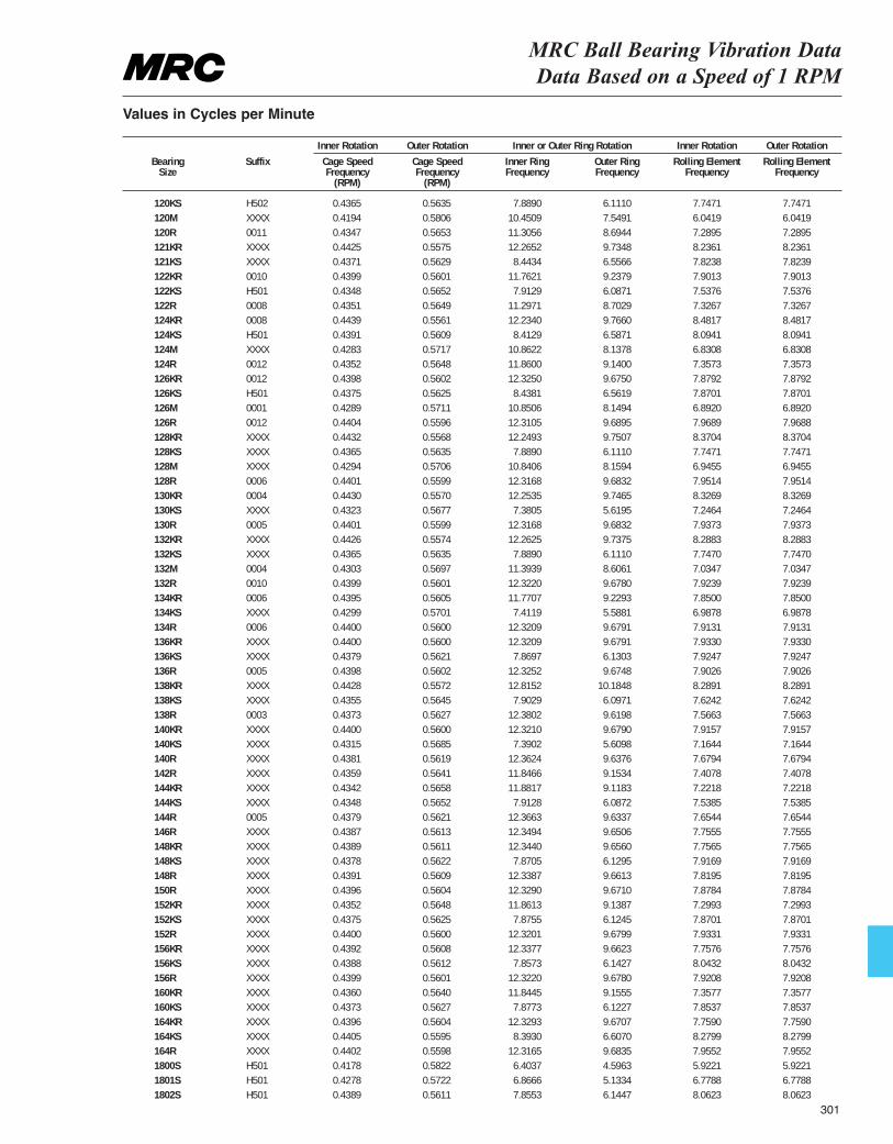
MRC Ball Bearing Vibration Data Data Based on a Speed of 1 RPM
Values in Cycles per Minute
Inner Rotation Outer Rotation Inner or Outer Ring Rotation Inner Rotation Outer Rotation
Bearing Suffix Cage Speed Cage Speed Inner Ring Outer Ring Rolling Element Rolling ElementSize Frequency Frequency Frequency Frequency Frequency Frequency
(RPM) (RPM)
120KS H502 0.4365 0.5635 0.1315 0.1019 0.0646 0.0646120M XXXX 0.4194 0.5806 0.1742 0.1258 0.0503 0.0503120R 0011 0.4347 0.5653 0.1884 0.1449 0.0607 0.0607121KR XXXX 0.4425 0.5575 0.2044 0.1622 0.0686 0.0686121KS XXXX 0.4371 0.5629 0.1407 0.1093 0.0652 0.0652122KR 0010 0.4399 0.5601 0.1960 0.1540 0.0658 0.0658122KS H501 0.4348 0.5652 0.1319 0.1015 0.0628 0.0628122R 0008 0.4351 0.5649 0.1883 0.1450 0.0611 0.0610124KR 0008 0.4439 0.5561 0.2039 0.1628 0.0707 0.0706124KS H501 0.4391 0.5609 0.1402 0.1098 0.0675 0.0675124M XXXX 0.4283 0.5717 0.1810 0.1356 0.0569 0.0569124R 0012 0.4352 0.5648 0.1977 0.1523 0.0613 0.0613126KR 0012 0.4398 0.5602 0.2054 0.1612 0.0657 0.0656126KS H501 0.4375 0.5625 0.1406 0.1094 0.0656 0.0656126M 0001 0.4289 0.5711 0.1808 0.1358 0.0574 0.0574126R 0012 0.4404 0.5596 0.2052 0.1615 0.0664 0.0664128KR XXXX 0.4432 0.5568 0.2042 0.1625 0.0698 0.0697128KS XXXX 0.4365 0.5635 0.1315 0.1019 0.0646 0.0646128M XXXX 0.4294 0.5706 0.1807 0.1360 0.0579 0.0579128R 0006 0.4401 0.5599 0.2053 0.1614 0.0663 0.0662130KR 0004 0.4430 0.5570 0.2042 0.1624 0.0694 0.0694130KS XXXX 0.4323 0.5677 0.1230 0.0937 0.0604 0.0604130R 0005 0.4401 0.5599 0.2053 0.1614 0.0661 0.0661132KR XXXX 0.4426 0.5574 0.2044 0.1623 0.0691 0.0690132KS XXXX 0.4365 0.5635 0.1315 0.1018 0.0646 0.0646132M 0004 0.4303 0.5697 0.1899 0.1434 0.0586 0.0586132R 0010 0.4399 0.5601 0.2054 0.1613 0.0660 0.0660134KR 0006 0.4395 0.5605 0.1962 0.1538 0.0654 0.0654134KS XXXX 0.4299 0.5701 0.1235 0.0931 0.0582 0.0582134R 0006 0.4400 0.5600 0.2053 0.1613 0.0659 0.0659136KR XXXX 0.4400 0.5600 0.2053 0.1613 0.0661 0.0661136KS XXXX 0.4379 0.5621 0.1312 0.1022 0.0660 0.0660136R 0005 0.4398 0.5602 0.2054 0.1612 0.0659 0.0658138KR XXXX 0.4428 0.5572 0.2136 0.1697 0.0691 0.0690138KS XXXX 0.4355 0.5645 0.1317 0.1016 0.0635 0.0635138R 0003 0.4373 0.5627 0.2063 0.1603 0.0631 0.0630140KR XXXX 0.4400 0.5600 0.2054 0.1613 0.0660 0.0659140KS XXXX 0.4315 0.5685 0.1232 0.0935 0.0597 0.0597140R XXXX 0.4381 0.5619 0.2060 0.1606 0.0640 0.0640142R XXXX 0.4359 0.5641 0.1974 0.1526 0.0617 0.0617144KR XXXX 0.4342 0.5658 0.1980 0.1520 0.0602 0.0601144KS XXXX 0.4348 0.5652 0.1319 0.1015 0.0628 0.0628144R 0005 0.4379 0.5621 0.2061 0.1606 0.0638 0.0638146R XXXX 0.4387 0.5613 0.2058 0.1608 0.0646 0.0646148KR XXXX 0.4389 0.5611 0.2057 0.1609 0.0646 0.0646148KS XXXX 0.4378 0.5622 0.1312 0.1022 0.0660 0.0660148R XXXX 0.4391 0.5609 0.2056 0.1610 0.0652 0.0651150R XXXX 0.4396 0.5604 0.2055 0.1612 0.0657 0.0656152KR XXXX 0.4352 0.5648 0.1977 0.1523 0.0608 0.0608152KS XXXX 0.4375 0.5625 0.1313 0.1021 0.0656 0.0656152R XXXX 0.4400 0.5600 0.2053 0.1613 0.0661 0.0661156KR XXXX 0.4392 0.5608 0.2056 0.1610 0.0646 0.0646156KS XXXX 0.4388 0.5612 0.1310 0.1024 0.0670 0.0670156R XXXX 0.4399 0.5601 0.2054 0.1613 0.0660 0.0660160KR XXXX 0.4360 0.5640 0.1974 0.1526 0.0613 0.0613160KS XXXX 0.4373 0.5627 0.1313 0.1020 0.0654 0.0654164KR XXXX 0.4396 0.5604 0.2055 0.1612 0.0647 0.0646164KS XXXX 0.4405 0.5595 0.1399 0.1101 0.0690 0.0690164R XXXX 0.4402 0.5598 0.2053 0.1614 0.0663 0.06631800S H501 0.4178 0.5822 0.1067 0.0766 0.0494 0.04941801S H501 0.4278 0.5722 0.1144 0.0856 0.0565 0.05651802S H501 0.4389 0.5611 0.1309 0.1024 0.0672 0.0672
7.889010.450911.305612.26528.4434
11.76217.9129
11.297112.23408.4129
10.862211.860012.32508.4381
10.850612.310512.24937.8890
10.840612.316812.25357.3805
12.316812.26257.8890
11.393912.322011.77077.4119
12.320912.32097.8697
12.325212.81527.9029
12.380212.32107.3902
12.362411.846611.88177.9128
12.366312.349412.34407.8705
12.338712.329011.86137.8755
12.320112.33777.8573
12.322011.84457.8773
12.32938.3930
12.31656.40376.86667.8553
6.11107.54918.69449.73486.55669.23796.08718.70299.76606.58718.13789.14009.67506.56198.14949.68959.75076.11108.15949.68329.74655.61959.68329.73756.11108.60619.67809.22935.58819.67919.67916.13039.6748
10.18486.09719.61989.67905.60989.63769.15349.11836.08729.63379.65069.65606.12959.66139.67109.13876.12459.67999.66236.14279.67809.15556.12279.67076.60709.68354.59635.13346.1447
7.74716.04197.28958.23617.82387.90137.53767.32678.48178.09416.83087.35737.87927.87016.89207.96898.37047.74716.94557.95148.32697.24647.93738.28837.74707.03477.92397.85006.98787.91317.93307.92477.90268.28917.62427.56637.91577.16447.67947.40787.22187.53857.65447.75557.75657.91697.81957.87847.29937.87017.93317.75768.04327.92087.35777.85377.75908.27997.95525.92216.77888.0623
7.74716.04197.28958.23617.82397.90137.53767.32678.48178.09416.83087.35737.87927.87016.89207.96888.37047.74716.94557.95148.32697.24647.93738.28837.74707.03477.92397.85006.98787.91317.93307.92477.90268.28917.62427.56637.91577.16447.67947.40787.22187.53857.65447.75557.75657.91697.81957.87847.29937.87017.93317.75768.04327.92087.35777.85377.75908.27997.95525.92216.77888.0623
301
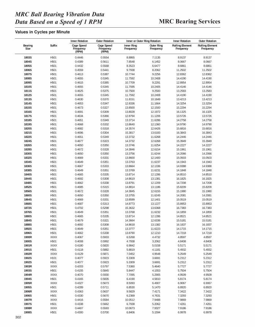
MRC Bearing ServicesMRC Ball Bearing Vibration Data Data Based on a Speed of 1 RPM
302
Values in Cycles per Minute
Inner Rotation Outer Rotation Inner or Outer Ring Rotation Inner Rotation Outer Rotation
Bearing Suffix Cage Speed Cage Speed Inner Ring Outer Ring Rolling Element Rolling ElementSize Frequency Frequency Frequency Frequency Frequency Frequency
(RPM) (RPM)
1803S H501 0.4446 0.5554 0.1481 0.1186 0.0743 0.07431804S H501 0.4389 0.5611 0.1309 0.1024 0.0672 0.06721805S H501 0.4432 0.5568 0.1392 0.1108 0.0724 0.07241806S H501 0.4559 0.5441 0.1632 0.1368 0.0938 0.09381807S H501 0.4613 0.5387 0.1796 0.1538 0.1070 0.10701808S H501 0.4655 0.5345 0.1960 0.1707 0.1202 0.12021809S H501 0.4615 0.5385 0.1795 0.1538 0.1075 0.10751810S H501 0.4655 0.5345 0.1960 0.1707 0.1201 0.12011811S H501 0.4625 0.5375 0.1792 0.1542 0.1105 0.11051812S H501 0.4655 0.5345 0.1960 0.1707 0.1202 0.12021813S H501 0.4630 0.5370 0.1969 0.1697 0.1118 0.11181814S H501 0.4653 0.5347 0.2139 0.1861 0.1194 0.11941815S H501 0.4673 0.5327 0.2308 0.2025 0.1269 0.12691816S H501 0.4691 0.5309 0.2300 0.2033 0.1344 0.13441817S H501 0.4634 0.5366 0.2147 0.1853 0.1131 0.11311818S H501 0.4651 0.5349 0.2229 0.1938 0.1190 0.11901819S H501 0.4668 0.5332 0.2311 0.2023 0.1248 0.12481820S H501 0.4682 0.5318 0.2393 0.2107 0.1307 0.13071821S H501 0.4696 0.5304 0.2564 0.2270 0.1365 0.13651822S H501 0.4651 0.5349 0.2229 0.1938 0.1187 0.11871824S H501 0.4677 0.5323 0.2396 0.2104 0.1283 0.12831826S H501 0.4650 0.5350 0.2229 0.1938 0.1185 0.11851828S H501 0.4672 0.5328 0.2397 0.2103 0.1266 0.12661830S H501 0.4650 0.5350 0.2229 0.1937 0.1184 0.11841832S H501 0.4669 0.5331 0.2310 0.2023 0.1254 0.12541834S H501 0.4649 0.5351 0.2229 0.1937 0.1183 0.11831836S H501 0.4667 0.5333 0.2311 0.2022 0.1245 0.12451838S H501 0.4649 0.5351 0.2229 0.1937 0.1182 0.11821840S H501 0.4665 0.5335 0.2312 0.2021 0.1238 0.12381844S H501 0.4692 0.5308 0.2477 0.2190 0.1349 0.13491848S H501 0.4662 0.5338 0.2313 0.2020 0.1227 0.12271852S H501 0.4685 0.5315 0.2480 0.2186 0.1318 0.13181856S H501 0.4672 0.5328 0.2397 0.2103 0.1266 0.12661860S H501 0.4650 0.5350 0.2229 0.1937 0.1184 0.11841864S H501 0.4669 0.5331 0.2310 0.2023 0.1254 0.12541868S H501 0.4687 0.5313 0.2480 0.2187 0.1325 0.13251872S H501 0.4702 0.5298 0.2561 0.2273 0.1395 0.13951876S H501 0.4649 0.5351 0.2229 0.1937 0.1182 0.11821880S H501 0.4665 0.5335 0.2312 0.2021 0.1238 0.12381884S H501 0.4679 0.5321 0.2394 0.2106 0.1293 0.12931888S H501 0.4692 0.5308 0.2477 0.2190 0.1349 0.13491892S H501 0.4649 0.5351 0.2230 0.1937 0.1181 0.11811896S H501 0.4662 0.5338 0.2313 0.2020 0.1227 0.12271900R XXXX 0.4067 0.5933 0.1088 0.0746 0.0405 0.04041900S H501 0.4008 0.5992 0.0799 0.0534 0.0403 0.04031901R XXXX 0.4180 0.5820 0.1164 0.0836 0.0460 0.04591901S H501 0.4118 0.5882 0.0980 0.0686 0.0458 0.04581902R XXXX 0.4129 0.5871 0.1174 0.0826 0.0438 0.04371902S H101 0.4077 0.5923 0.0888 0.0612 0.0436 0.04361902S H501 0.4077 0.5923 0.0888 0.0612 0.0436 0.04361903R XXXX 0.4203 0.5797 0.1256 0.0911 0.0481 0.04801903S H501 0.4155 0.5845 0.0974 0.0693 0.0479 0.04791904R XXXX 0.4070 0.5930 0.1285 0.0882 0.0413 0.04121904S H501 0.4165 0.5835 0.1070 0.0763 0.0485 0.04851905R XXXX 0.4327 0.5673 0.1418 0.1082 0.0576 0.05751905S H501 0.4289 0.5711 0.1142 0.0858 0.0574 0.05741906R XXXX 0.4363 0.5637 0.1597 0.1236 0.0612 0.06111906S H501 0.4330 0.5670 0.1039 0.0794 0.0611 0.06111907R XXXX 0.4416 0.5584 0.1675 0.1325 0.0666 0.06651907S H501 0.4338 0.5662 0.1132 0.0868 0.0619 0.06191908R XXXX 0.4407 0.5593 0.1678 0.1322 0.0660 0.06591908S H501 0.4300 0.5700 0.1140 0.0860 0.0583 0.0583
8.88657.85488.35239.7938
10.774411.759210.770911.759510.750011.759211.815112.833613.850013.802812.879413.371413.864014.357415.381713.373214.373213.374614.384613.375613.860013.376313.866413.376913.871414.861913.879114.881414.384513.375513.859914.877315.363213.376813.871414.366414.861813.377713.87906.52684.79386.98425.88197.04525.33095.33097.53605.84477.70956.41908.50936.85309.58296.2369
10.05126.7938
10.06736.8406
7.11356.14526.64778.20629.2256
10.24089.2291
10.24059.2500
10.240810.184911.166412.150012.197211.120611.628612.136012.642613.618311.626812.626811.625412.615411.624412.140011.623712.133611.623112.128613.138112.120913.118612.615511.624512.140113.122713.636811.623212.128612.633613.138211.622312.12104.47323.20625.01584.11814.95483.66913.66915.46404.15535.29054.58106.49075.14707.41714.76317.94885.20627.93275.1594
8.91378.06678.6861
11.250212.836214.419012.895414.414613.258314.419013.421314.325415.229416.132513.572614.275814.979015.681616.384314.244615.394914.222715.196114.206615.050314.194314.938814.184814.851016.182514.720815.820915.198014.208115.051915.895316.738314.185914.852115.518116.183714.171514.72184.85974.84085.51715.49325.25495.23125.23125.77275.75044.95095.81746.90676.89207.34227.32937.98697.42617.91866.9978
8.91378.06678.6861
11.250212.836214.419012.895414.414613.258314.419013.421313.325415.229416.132513.572614.275814.979015.681616.384314.244615.394914.222715.196114.206615.050314.194314.938814.184814.851016.182514.720815.820915.198014.208115.051915.895316.738314.185914.852115.518116.183714.171514.72184.85974.84085.51715.49325.25495.23125.23125.77275.75044.95095.81746.90676.89207.34227.32937.98697.42617.91866.9978
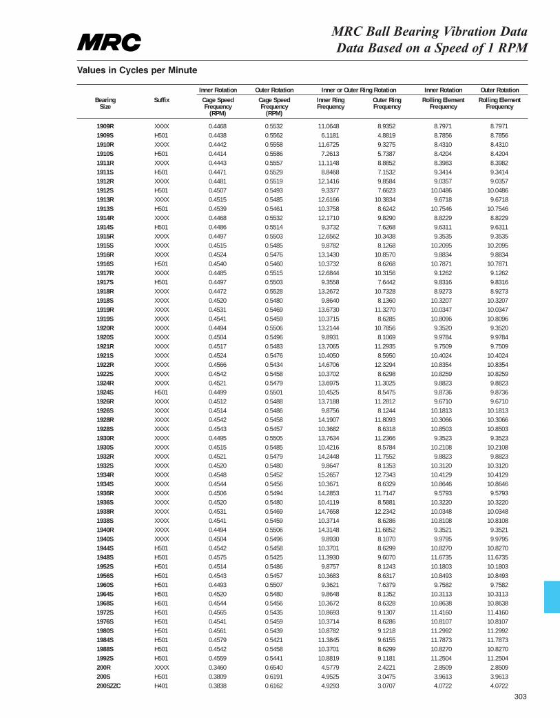
MRC Ball Bearing Vibration Data Data Based on a Speed of 1 RPM
Values in Cycles per Minute
Inner Rotation Outer Rotation Inner or Outer Ring Rotation Inner Rotation Outer Rotation
Bearing Suffix Cage Speed Cage Speed Inner Ring Outer Ring Rolling Element Rolling ElementSize Frequency Frequency Frequency Frequency Frequency Frequency
(RPM) (RPM)
1909R XXXX 0.4468 0.5532 0.1844 0.1489 0.0733 0.07331909S H501 0.4438 0.5562 0.1020 0.0814 0.0732 0.07321910R XXXX 0.4442 0.5558 0.1945 0.1555 0.0703 0.07021910S H501 0.4414 0.5586 0.1210 0.0956 0.0702 0.07021911R XXXX 0.4443 0.5557 0.1852 0.1481 0.0700 0.06991911S H501 0.4471 0.5529 0.1474 0.1192 0.0778 0.07781912R XXXX 0.4481 0.5519 0.2024 0.1643 0.0753 0.07531912S H501 0.4507 0.5493 0.1556 0.1277 0.0837 0.08371913R XXXX 0.4515 0.5485 0.2103 0.1731 0.0806 0.08061913S H501 0.4539 0.5461 0.1729 0.1437 0.0896 0.08961914R XXXX 0.4468 0.5532 0.2029 0.1638 0.0735 0.07351914S H501 0.4486 0.5514 0.1562 0.1271 0.0803 0.08031915R XXXX 0.4497 0.5503 0.2109 0.1724 0.0779 0.07791915S XXXX 0.4515 0.5485 0.1646 0.1354 0.0851 0.08511916R XXXX 0.4524 0.5476 0.2191 0.1809 0.0824 0.08231916S H501 0.4540 0.5460 0.1729 0.1438 0.0899 0.08991917R XXXX 0.4485 0.5515 0.2114 0.1719 0.0761 0.07601917S H501 0.4497 0.5503 0.1559 0.1274 0.0819 0.08191918R XXXX 0.4472 0.5528 0.2211 0.1789 0.0744 0.07441918S XXXX 0.4520 0.5480 0.1644 0.1356 0.0860 0.08601919R XXXX 0.4531 0.5469 0.2279 0.1888 0.0836 0.08361919S XXXX 0.4541 0.5459 0.1729 0.1438 0.0901 0.09011920R XXXX 0.4494 0.5506 0.2202 0.1798 0.0779 0.07791920S XXXX 0.4504 0.5496 0.1649 0.1351 0.0832 0.08321921R XXXX 0.4517 0.5483 0.2284 0.1882 0.0813 0.08121921S XXXX 0.4524 0.5476 0.1734 0.1433 0.0867 0.08671922R XXXX 0.4566 0.5434 0.2445 0.2055 0.0903 0.09031922S XXXX 0.4542 0.5458 0.1728 0.1438 0.0902 0.09021924R XXXX 0.4521 0.5479 0.2283 0.1884 0.0824 0.08231924S H501 0.4499 0.5501 0.1742 0.1425 0.0823 0.08231926R XXXX 0.4512 0.5488 0.2286 0.1880 0.0806 0.08061926S XXXX 0.4514 0.5486 0.1646 0.1354 0.0848 0.08481928R XXXX 0.4542 0.5458 0.2365 0.1968 0.0859 0.08591928S XXXX 0.4543 0.5457 0.1728 0.1439 0.0904 0.09041930R XXXX 0.4495 0.5505 0.2294 0.1873 0.0779 0.07791930S XXXX 0.4515 0.5485 0.1737 0.1430 0.0851 0.08511932R XXXX 0.4521 0.5479 0.2374 0.1959 0.0824 0.08231932S XXXX 0.4520 0.5480 0.1644 0.1356 0.0859 0.08591934R XXXX 0.4548 0.5452 0.2544 0.2122 0.0868 0.08671934S XXXX 0.4544 0.5456 0.1728 0.1439 0.0905 0.09051936R XXXX 0.4506 0.5494 0.2381 0.1952 0.0798 0.07981936S XXXX 0.4520 0.5480 0.1735 0.1431 0.0860 0.08601938R XXXX 0.4531 0.5469 0.2461 0.2039 0.0836 0.08361938S XXXX 0.4541 0.5459 0.1729 0.1438 0.0901 0.09011940R XXXX 0.4494 0.5506 0.2386 0.1948 0.0779 0.07791940S XXXX 0.4504 0.5496 0.1649 0.1351 0.0832 0.08321944S H501 0.4542 0.5458 0.1728 0.1438 0.0902 0.09021948S H501 0.4575 0.5425 0.1899 0.1601 0.0973 0.09731952S H501 0.4514 0.5486 0.1646 0.1354 0.0848 0.08481956S H501 0.4543 0.5457 0.1728 0.1439 0.0904 0.09041960S H501 0.4493 0.5507 0.1560 0.1273 0.0813 0.08131964S H501 0.4520 0.5480 0.1644 0.1356 0.0859 0.08591968S H501 0.4544 0.5456 0.1728 0.1439 0.0905 0.09051972S H501 0.4565 0.5435 0.1812 0.1522 0.0951 0.09511976S H501 0.4541 0.5459 0.1729 0.1438 0.0901 0.09011980S H501 0.4561 0.5439 0.1813 0.1520 0.0942 0.09421984S H501 0.4579 0.5421 0.1897 0.1603 0.0982 0.09821988S H501 0.4542 0.5458 0.1728 0.1438 0.0902 0.09021992S H501 0.4559 0.5441 0.1814 0.1520 0.0938 0.0938200R XXXX 0.3460 0.6540 0.0763 0.0404 0.0238 0.0237200S H501 0.3809 0.6191 0.0825 0.0508 0.0330 0.0330200SZZC H401 0.3838 0.6162 0.0822 0.0512 0.0339 0.0339
11.06486.1181
11.67257.2613
11.11488.8468
12.14169.3377
12.616610.375812.17109.3732
12.65629.8782
13.143010.373212.68449.3558
13.26729.8640
13.673010.371513.21449.8931
13.706510.405014.670610.370213.697510.452513.71889.8756
14.190710.368213.763410.421614.24489.8647
15.265710.367114.285310.411914.765810.371414.31489.8930
10.370111.39309.8757
10.36839.36219.8648
10.367210.869310.371410.878211.384510.370110.88194.57794.95254.9293
8.93524.88199.32755.73878.88527.15329.85847.6623
10.38348.62429.82907.6268
10.34388.1268
10.85708.6268
10.31567.6442
10.73288.1360
11.32708.6285
10.78568.1069
11.29358.5950
12.32948.6298
11.30258.5475
11.28128.1244
11.80938.6318
11.23668.5784
11.75528.1353
12.73438.6329
11.71478.5881
12.23428.6286
11.68528.10708.62999.60708.12438.63177.63798.13528.63289.13078.62869.12189.61558.62999.11812.42213.04753.0707
8.79718.78568.43108.42048.39839.34149.0357
10.04869.6718
10.75468.82299.63119.3535
10.20959.8834
10.78719.12629.83168.9273
10.320710.034710.80969.35209.97849.7509
10.402410.835410.82599.88239.87369.6710
10.181310.306610.85039.3523
10.21089.8823
10.312010.412910.86469.5793
10.322010.034810.81089.35219.9795
10.827011.673510.180310.84939.7582
10.311310.863811.416010.810711.299211.787310.827011.25042.85093.96134.0722
8.79718.78568.43108.42048.39829.34149.0357
10.04869.6718
10.75468.82299.63119.3535
10.20959.8834
10.78719.12629.83168.9273
10.320710.034710.80969.35209.97849.7509
10.402410.835410.82599.88239.87369.6710
10.181310.306610.85039.3523
10.21089.8823
10.312010.412910.86469.5793
10.322010.034810.81089.35219.9795
10.827011.673510.180310.84939.7582
10.311310.863811.416010.810711.299211.787310.827011.25042.85093.96134.0722
303
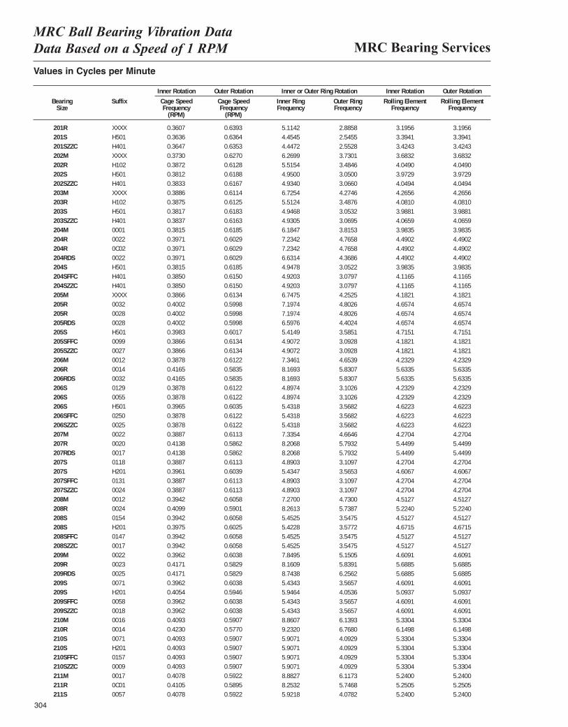
MRC Bearing ServicesMRC Ball Bearing Vibration Data Data Based on a Speed of 1 RPM
304
Values in Cycles per Minute
Inner Rotation Outer Rotation Inner or Outer Ring Rotation Inner Rotation Outer Rotation
Bearing Suffix Cage Speed Cage Speed Inner Ring Outer Ring Rolling Element Rolling ElementSize Frequency Frequency Frequency Frequency Frequency Frequency
(RPM) (RPM)
201R XXXX 0.3607 0.6393 0.0852 0.0481 0.0266 0.0265201S H501 0.3636 0.6364 0.0742 0.0424 0.0283 0.0283201SZZC H401 0.3647 0.6353 0.0741 0.0425 0.0285 0.0285202M XXXX 0.3730 0.6270 0.1045 0.0622 0.0307 0.0307202R H102 0.3872 0.6128 0.0919 0.0581 0.0337 0.0337202S H501 0.3812 0.6188 0.0825 0.0508 0.0331 0.0331202SZZC H401 0.3833 0.6167 0.0822 0.0511 0.0337 0.0337203M XXXX 0.3886 0.6114 0.1121 0.0712 0.0355 0.0355203R H102 0.3875 0.6125 0.0919 0.0581 0.0340 0.0339203S H501 0.3817 0.6183 0.0824 0.0509 0.0332 0.0332203SZZC H401 0.3837 0.6163 0.0822 0.0512 0.0339 0.0339204M 0001 0.3815 0.6185 0.1031 0.0636 0.0332 0.0332204R 0022 0.3971 0.6029 0.1206 0.0794 0.0374 0.0374204R 0C02 0.3971 0.6029 0.1206 0.0794 0.0374 0.0374204RDS 0022 0.3971 0.6029 0.1105 0.0728 0.0374 0.0374204S H501 0.3815 0.6185 0.0825 0.0509 0.0332 0.0332204SFFC H401 0.3850 0.6150 0.0820 0.0513 0.0343 0.0343204SZZC H401 0.3850 0.6150 0.0820 0.0513 0.0343 0.0343205M XXXX 0.3866 0.6134 0.1125 0.0709 0.0349 0.0349205R 0032 0.4002 0.5998 0.1200 0.0800 0.0388 0.0388205R 0028 0.4002 0.5998 0.1200 0.0800 0.0388 0.0388205RDS 0028 0.4002 0.5998 0.1100 0.0734 0.0388 0.0388205S H501 0.3983 0.6017 0.0902 0.0598 0.0393 0.0393205SFFC 0099 0.3866 0.6134 0.0818 0.0515 0.0349 0.0349205SZZC 0027 0.3866 0.6134 0.0818 0.0515 0.0349 0.0349206M 0012 0.3878 0.6122 0.1224 0.0776 0.0353 0.0353206R 0014 0.4165 0.5835 0.1362 0.0972 0.0469 0.0469206RDS 0032 0.4165 0.5835 0.1362 0.0972 0.0469 0.0469206S 0129 0.3878 0.6122 0.0816 0.0517 0.0353 0.0353206S 0055 0.3878 0.6122 0.0816 0.0517 0.0353 0.0353206S H501 0.3965 0.6035 0.0905 0.0595 0.0385 0.0385206SFFC 0250 0.3878 0.6122 0.0816 0.0517 0.0353 0.0353206SZZC 0025 0.3878 0.6122 0.0816 0.0517 0.0353 0.0353207M 0022 0.3887 0.6113 0.1223 0.0777 0.0356 0.0356207R 0020 0.4138 0.5862 0.1368 0.0966 0.0454 0.0454207RDS 0017 0.4138 0.5862 0.1368 0.0966 0.0454 0.0454207S 0118 0.3887 0.6113 0.0815 0.0518 0.0356 0.0356207S H201 0.3961 0.6039 0.0906 0.0594 0.0384 0.0384207SFFC 0131 0.3887 0.6113 0.0815 0.0518 0.0356 0.0356207SZZC 0024 0.3887 0.6113 0.0815 0.0518 0.0356 0.0356208M 0012 0.3942 0.6058 0.1212 0.0788 0.0376 0.0376208R 0024 0.4099 0.5901 0.1377 0.0956 0.0435 0.0435208S 0154 0.3942 0.6058 0.0909 0.0591 0.0376 0.0376208S H201 0.3975 0.6025 0.0904 0.0596 0.0389 0.0389208SFFC 0147 0.3942 0.6058 0.0909 0.0591 0.0376 0.0376208SZZC 0017 0.3942 0.6058 0.0909 0.0591 0.0376 0.0376209M 0022 0.3962 0.6038 0.1308 0.0858 0.0384 0.0384209R 0023 0.4171 0.5829 0.1360 0.0973 0.0474 0.0474209RDS 0025 0.4171 0.5829 0.1457 0.1043 0.0474 0.0474209S 0071 0.3962 0.6038 0.0906 0.0594 0.0384 0.0384209S H201 0.4054 0.5946 0.0991 0.0676 0.0424 0.0424209SFFC 0058 0.3962 0.6038 0.0906 0.0594 0.0384 0.0384209SZZC 0018 0.3962 0.6038 0.0906 0.0594 0.0384 0.0384210M 0016 0.4093 0.5907 0.1477 0.1023 0.0444 0.0444210R 0014 0.4230 0.5770 0.1539 0.1128 0.0512 0.0512210S 0071 0.4093 0.5907 0.0985 0.0682 0.0444 0.0444210S H201 0.4093 0.5907 0.0985 0.0682 0.0444 0.0444210SFFC 0157 0.4093 0.5907 0.0985 0.0682 0.0444 0.0444210SZZC 0009 0.4093 0.5907 0.0985 0.0682 0.0444 0.0444211M 0017 0.4078 0.5922 0.1480 0.1020 0.0437 0.0437211R 0C01 0.4105 0.5895 0.1376 0.0958 0.0438 0.0437211S 0057 0.4078 0.5922 0.0987 0.0680 0.0437 0.0437
5.11424.45454.44726.26995.51544.95004.93406.72545.51244.94684.93056.18477.23427.23426.63144.94784.92034.92036.74757.19747.19746.59765.41494.90724.90727.34618.16938.16934.89744.89745.43185.43185.43187.33548.20688.20684.89035.43474.89034.89037.27008.26135.45255.42285.45255.45257.84958.16098.74385.43435.94645.43435.43438.86079.23205.90715.90715.90715.90718.88278.25325.9218
2.88582.54552.55283.73013.48463.05003.06604.27463.48763.05323.06953.81534.76584.76584.36863.05223.07973.07974.25254.80264.80264.40243.58513.09283.09284.65395.83075.83073.10263.10263.56823.56823.56824.66465.79325.79323.10973.56533.10973.10974.73005.73873.54753.57723.54753.54755.15055.83916.25623.56574.05363.56573.56576.13936.76804.09294.09294.09294.09296.11735.74684.0782
3.19563.39413.42433.68324.04903.97294.04944.26564.08103.98814.06593.98354.49024.49024.49023.98354.11654.11654.18214.65744.65744.65744.71514.18214.18214.23295.63355.63354.23294.23294.62234.62234.62234.27045.44995.44994.27044.60674.27044.27044.51275.22404.51274.67154.51274.51274.60915.68855.68854.60915.09374.60914.60915.33046.14985.33045.33045.33045.33045.24005.25055.2400
3.19563.39413.42433.68324.04903.97294.04944.26564.08103.98814.06593.98354.49024.49024.49023.98354.11654.11654.18214.65744.65744.65744.71514.18214.18214.23295.63355.63354.23294.23294.62234.62234.62234.27045.44995.44994.27044.60674.27044.27044.51275.22404.51274.67154.51274.51274.60915.68855.68854.60915.09374.60914.60915.33046.14985.33045.33045.33045.33045.24005.25055.2400
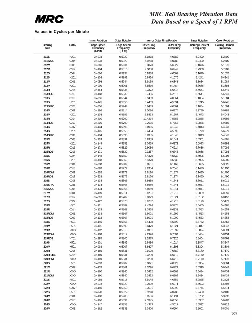
211S H201 0.4078 0.5922 0.0987 0.0680 0.0437 0.0437211SZZC 0004 0.4078 0.5922 0.0987 0.0680 0.0437 0.0437212M 0005 0.4066 0.5934 0.1385 0.0949 0.0431 0.0431212R 0012 0.4184 0.5816 0.1551 0.1116 0.0483 0.0482212S 0064 0.4066 0.5934 0.0989 0.0678 0.0431 0.0431212S H201 0.4108 0.5892 0.0982 0.0685 0.0452 0.0452213M 0001 0.4056 0.5944 0.1486 0.1014 0.0426 0.0426213M H201 0.4099 0.5901 0.1475 0.1025 0.0447 0.0447213R 0016 0.4164 0.5836 0.1556 0.1110 0.0472 0.0472213RDS 0013 0.4168 0.5832 0.1458 0.1042 0.0472 0.0472213S 0010 0.4056 0.5944 0.0991 0.0676 0.0426 0.0426213S H201 0.4145 0.5855 0.1073 0.0760 0.0473 0.0473213SFFC 0026 0.4056 0.5944 0.0991 0.0676 0.0426 0.0426214M 0001 0.4186 0.5814 0.1550 0.1116 0.0498 0.0498214M H201 0.4104 0.5896 0.1474 0.1026 0.0450 0.0450214R 0014 0.4210 0.5790 0.1737 0.1263 0.0499 0.0499214RDS 0010 0.4210 0.5790 0.1544 0.1123 0.0499 0.0499214S 0037 0.4104 0.5896 0.0983 0.0684 0.0450 0.0450214S H201 0.4145 0.5855 0.1073 0.0760 0.0473 0.0473214SFFC 0034 0.4104 0.5896 0.0983 0.0684 0.0450 0.0450215M 0003 0.4109 0.5891 0.1473 0.1027 0.0453 0.0453215M H201 0.4148 0.5852 0.1560 0.1106 0.0475 0.0475215R 0015 0.4171 0.5829 0.1651 0.1182 0.0476 0.0475215RDS 0013 0.4171 0.5829 0.1554 0.1112 0.0476 0.0475215S 0024 0.4148 0.5852 0.1073 0.0761 0.0475 0.0475215S H201 0.4148 0.5852 0.1073 0.0760 0.0475 0.0475216M 0004 0.4098 0.5902 0.1476 0.1024 0.0447 0.0447216R 0018 0.4228 0.5772 0.1539 0.1127 0.0512 0.0512216RDM 0001 0.4228 0.5772 0.1635 0.1198 0.0512 0.0512216RDS 0018 0.4228 0.5772 0.1635 0.1198 0.0512 0.0512216S 0015 0.4134 0.5866 0.0978 0.0689 0.0467 0.0467216SFFC 0031 0.4134 0.5866 0.0978 0.0689 0.0467 0.0467216SZZC 0005 0.4134 0.5866 0.0978 0.0689 0.0467 0.0467217M 0001 0.4189 0.5811 0.1646 0.1187 0.0500 0.0500217R 0012 0.4213 0.5787 0.1640 0.1194 0.0501 0.0501217S 0022 0.4122 0.5878 0.0980 0.0687 0.0460 0.0460218M H501 0.4111 0.5889 0.1570 0.1096 0.0454 0.0454218R 0014 0.4133 0.5867 0.1564 0.1102 0.0455 0.0454218RDM 0001 0.4133 0.5867 0.1467 0.1033 0.0455 0.0454218RDS 0007 0.4133 0.5867 0.1467 0.1033 0.0455 0.0454218S H501 0.4145 0.5855 0.1073 0.0760 0.0473 0.0473219M H501 0.4101 0.5899 0.1475 0.1025 0.0449 0.0449219R XXXX 0.4182 0.5818 0.1648 0.1185 0.0484 0.0483219RDM XXXX 0.4188 0.5812 0.1550 0.1117 0.0487 0.0487219RDS H701 0.4195 0.5805 0.1548 0.1119 0.0487 0.0487219S H501 0.4101 0.5899 0.0983 0.0684 0.0449 0.0449220M H501 0.4093 0.5907 0.1477 0.1023 0.0444 0.0444220R 0016 0.4169 0.5831 0.1652 0.1181 0.0476 0.0476220R-BKE 0015 0.4169 0.5831 0.1555 0.1112 0.0476 0.0476220RDM XXXX 0.4169 0.5831 0.1555 0.1112 0.0476 0.0476220S H501 0.4093 0.5907 0.0985 0.0682 0.0444 0.0444221M 0002 0.4139 0.5861 0.1563 0.1104 0.0470 0.0470221R XXXX 0.4160 0.5840 0.1557 0.1109 0.0470 0.0470221RDM XXXX 0.4160 0.5840 0.1557 0.1109 0.0470 0.0470221S H501 0.4085 0.5915 0.0986 0.0681 0.0440 0.0440222M XXXX 0.4078 0.5922 8.8830 6.1170 5.2400 5.2400222R 0007 0.4150 0.5850 0.1560 0.1107 0.0465 0.0464222S H501 0.4078 0.5922 0.0987 0.0680 0.0437 0.0437224M 0001 0.4100 0.5900 0.1475 0.1025 0.0448 0.0448224R 0013 0.4166 0.5834 0.1556 0.1111 0.0475 0.0475224S XXXX 0.4147 0.5853 0.1073 0.0760 0.0474 0.0474226M 0001 0.4162 0.5838 0.1557 0.1110 0.0483 0.0483
MRC Ball Bearing Vibration Data Data Based on a Speed of 1 RPM
Values in Cycles per Minute
Inner Rotation Outer Rotation Inner or Outer Ring Rotation Inner Rotation Outer Rotation
Bearing Suffix Cage Speed Cage Speed Inner Ring Outer Ring Rolling Element Rolling ElementSize Frequency Frequency Frequency Frequency Frequency Frequency
(RPM) (RPM)
5.92185.92188.30739.30585.93385.89248.91598.85169.33728.74855.94396.44095.94399.30268.8433
10.42149.26355.89556.44045.89558.83599.36299.90869.32576.43706.43708.85319.23549.81269.81265.86595.86595.86599.87819.83795.87829.42249.38688.80018.80016.44088.84799.89019.29969.28755.89868.86079.91209.32909.32905.90719.37769.34329.34325.91489.39299.36015.92188.85069.33456.43839.3406
4.07824.07825.69276.69424.06624.10766.08416.14846.66186.25154.05614.55914.05616.69746.15677.57866.73654.10454.55964.10456.16416.63717.09146.67434.56304.56306.14696.76467.18747.18744.13414.13414.13417.12197.16214.12186.57766.61326.19996.19994.55926.15217.10996.70046.71254.10146.13937.08806.67106.67104.09296.62246.65686.65684.08526.60716.63994.07826.14946.66554.56176.6594
5.24005.24005.16765.79085.16765.42415.10845.36865.66415.66415.10845.67455.10845.97895.40435.98865.98865.40435.67795.40435.43615.69935.70865.70865.69955.69955.36256.14906.14906.14905.60115.60115.60116.00596.01525.51795.44655.45535.45535.45535.67525.38475.80245.84345.84645.38475.33045.71705.71705.71705.33045.63495.64345.64345.28255.56935.57745.24005.37325.69875.69125.8001
5.24005.24005.16765.79085.16765.42415.10845.36865.66415.66415.10845.67455.10845.97895.40435.98865.98865.40435.67795.40435.43615.69935.70865.70865.69955.69955.36256.14906.14906.14905.60115.60115.60116.00596.01525.51795.44655.45535.45535.45535.67525.38475.80245.84345.84645.38475.33045.71705.71705.71705.33045.63495.64345.64345.28255.56935.57745.24005.37325.69875.69125.8001
305
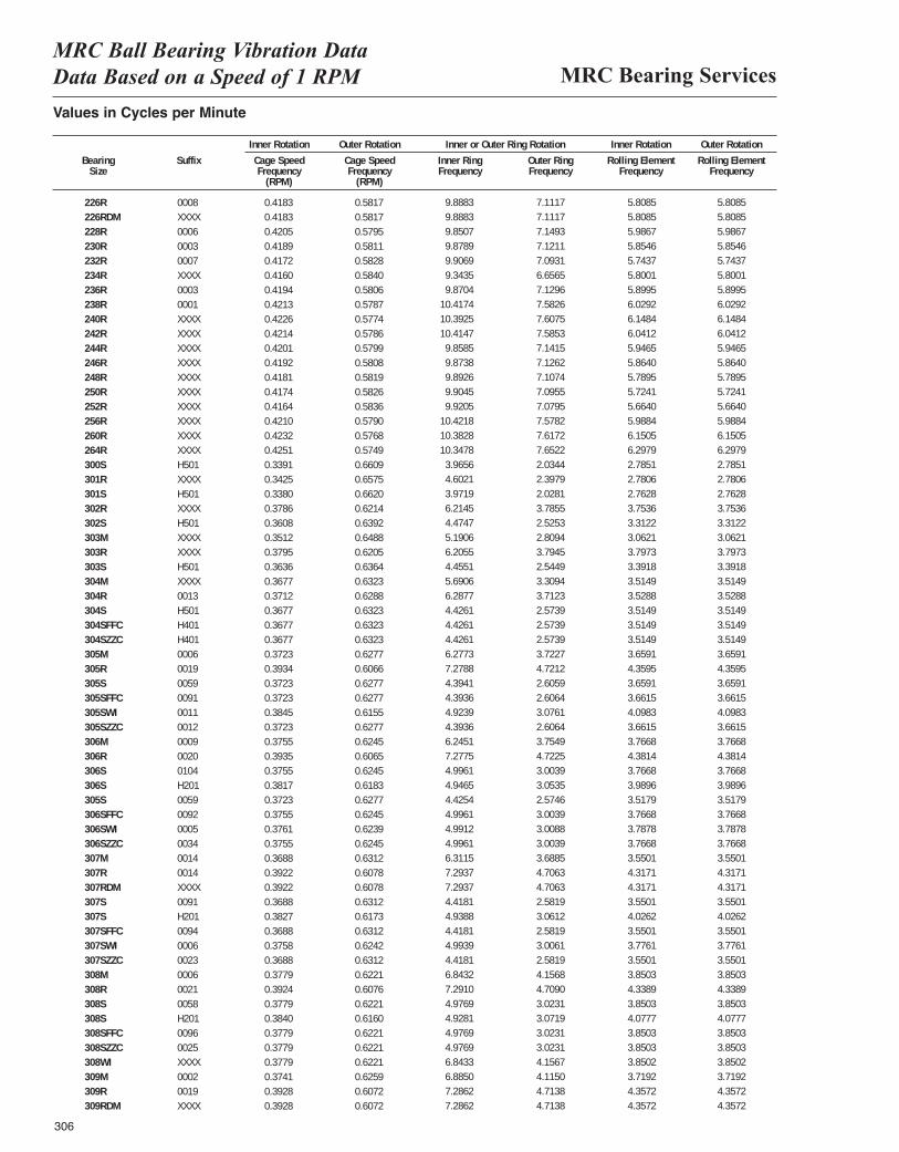
226R 0008 0.4183 0.5817 0.1648 0.1185 0.0484 0.0484226RDM XXXX 0.4183 0.5817 0.1648 0.1185 0.0484 0.0484228R 0006 0.4205 0.5795 0.1642 0.1192 0.0499 0.0499230R 0003 0.4189 0.5811 0.1646 0.1187 0.0488 0.0488232R 0007 0.4172 0.5828 0.1651 0.1182 0.0479 0.0478234R XXXX 0.4160 0.5840 0.1557 0.1109 0.0471 0.0471236R 0003 0.4194 0.5806 0.1645 0.1188 0.0492 0.0491238R 0001 0.4213 0.5787 0.1736 0.1264 0.0502 0.0502240R XXXX 0.4226 0.5774 0.1732 0.1268 0.0512 0.0512242R XXXX 0.4214 0.5786 0.1736 0.1264 0.0503 0.0503244R XXXX 0.4201 0.5799 0.1643 0.1190 0.0496 0.0495246R XXXX 0.4192 0.5808 0.1646 0.1188 0.0489 0.0488248R XXXX 0.4181 0.5819 0.1649 0.1185 0.0482 0.0482250R XXXX 0.4174 0.5826 0.1651 0.1183 0.0477 0.0477252R XXXX 0.4164 0.5836 0.1653 0.1180 0.0472 0.0472256R XXXX 0.4210 0.5790 0.1737 0.1263 0.0499 0.0499260R XXXX 0.4232 0.5768 0.1730 0.1270 0.0513 0.0512264R XXXX 0.4251 0.5749 0.1725 0.1275 0.0525 0.0524300S H501 0.3391 0.6609 0.0661 0.0339 0.0232 0.0232301R XXXX 0.3425 0.6575 0.0767 0.0400 0.0232 0.0231301S H501 0.3380 0.6620 0.0662 0.0338 0.0230 0.0230302R XXXX 0.3786 0.6214 0.1036 0.0631 0.0313 0.0312302S H501 0.3608 0.6392 0.0746 0.0421 0.0276 0.0276303M XXXX 0.3512 0.6488 0.0865 0.0468 0.0255 0.0255303R XXXX 0.3795 0.6205 0.1034 0.0632 0.0316 0.0316303S H501 0.3636 0.6364 0.0743 0.0424 0.0283 0.0283304M XXXX 0.3677 0.6323 0.0948 0.0552 0.0293 0.0293304R 0013 0.3712 0.6288 0.1048 0.0619 0.0294 0.0293304S H501 0.3677 0.6323 0.0738 0.0429 0.0293 0.0293304SFFC H401 0.3677 0.6323 0.0738 0.0429 0.0293 0.0293304SZZC H401 0.3677 0.6323 0.0738 0.0429 0.0293 0.0293305M 0006 0.3723 0.6277 0.1046 0.0620 0.0305 0.0305305R 0019 0.3934 0.6066 0.1213 0.0787 0.0363 0.0363305S 0059 0.3723 0.6277 0.0732 0.0434 0.0305 0.0305305SFFC 0091 0.3723 0.6277 0.0732 0.0434 0.0305 0.0305305SWI 0011 0.3845 0.6155 0.0821 0.0513 0.0342 0.0342305SZZC 0012 0.3723 0.6277 0.0732 0.0434 0.0305 0.0305306M 0009 0.3755 0.6245 0.1041 0.0626 0.0314 0.0314306R 0020 0.3935 0.6065 0.1213 0.0787 0.0365 0.0365306S 0104 0.3755 0.6245 0.0833 0.0501 0.0314 0.0314306S H201 0.3817 0.6183 0.0824 0.0509 0.0332 0.0332305S 0059 0.3723 0.6277 0.0732 0.0434 0.0305 0.0305306SFFC 0092 0.3755 0.6245 0.0833 0.0501 0.0314 0.0314306SWI 0005 0.3761 0.6239 0.0832 0.0501 0.0316 0.0316306SZZC 0034 0.3755 0.6245 0.0833 0.0501 0.0314 0.0314307M 0014 0.3688 0.6312 0.1052 0.0615 0.0296 0.0296307R 0014 0.3922 0.6078 0.1216 0.0784 0.0360 0.0359307RDM XXXX 0.3922 0.6078 0.1216 0.0784 0.0360 0.0359307S 0091 0.3688 0.6312 0.0736 0.0430 0.0296 0.0296307S H201 0.3827 0.6173 0.0823 0.0510 0.0336 0.0336307SFFC 0094 0.3688 0.6312 0.0736 0.0430 0.0296 0.0296307SWI 0006 0.3758 0.6242 0.0832 0.0501 0.0315 0.0315307SZZC 0023 0.3688 0.6312 0.0736 0.0430 0.0296 0.0296308M 0006 0.3779 0.6221 0.1141 0.0693 0.0321 0.0321308R 0021 0.3924 0.6076 0.1215 0.0785 0.0362 0.0361308S 0058 0.3779 0.6221 0.0829 0.0504 0.0321 0.0321308S H201 0.3840 0.6160 0.0821 0.0512 0.0340 0.0340308SFFC 0096 0.3779 0.6221 0.0829 0.0504 0.0321 0.0321308SZZC 0025 0.3779 0.6221 0.0829 0.0504 0.0321 0.0321308WI XXXX 0.3779 0.6221 0.1141 0.0693 0.0321 0.0321309M 0002 0.3741 0.6259 0.1148 0.0686 0.0310 0.0310309R 0019 0.3928 0.6072 0.1214 0.0786 0.0363 0.0363309RDM XXXX 0.3928 0.6072 0.1214 0.0786 0.0363 0.0363
MRC Bearing ServicesMRC Ball Bearing Vibration Data Data Based on a Speed of 1 RPM
Values in Cycles per Minute
Inner Rotation Outer Rotation Inner or Outer Ring Rotation Inner Rotation Outer Rotation
Bearing Suffix Cage Speed Cage Speed Inner Ring Outer Ring Rolling Element Rolling ElementSize Frequency Frequency Frequency Frequency Frequency Frequency
(RPM) (RPM)
306
9.88839.88839.85079.87899.90699.34359.8704
10.417410.392510.41479.85859.87389.89269.90459.9205
10.421810.382810.34783.96564.60213.97196.21454.47475.19066.20554.45515.69066.28774.42614.42614.42616.27737.27884.39414.39364.92394.39366.24517.27754.99614.94654.42544.99614.99124.99616.31157.29377.29374.41814.93884.41814.99394.41816.84327.29104.97694.92814.97694.97696.84336.88507.28627.2862
7.11177.11177.14937.12117.09316.65657.12967.58267.60757.58537.14157.12627.10747.09557.07957.57827.61727.65222.03442.39792.02813.78552.52532.80943.79452.54493.30943.71232.57392.57392.57393.72274.72122.60592.60643.07612.60643.75494.72253.00393.05352.57463.00393.00883.00393.68854.70634.70632.58193.06122.58193.00612.58194.15684.70903.02313.07193.02313.02314.15674.11504.71384.7138
5.80855.80855.98675.85465.74375.80015.89956.02926.14846.04125.94655.86405.78955.72415.66405.98846.15056.29792.78512.78062.76283.75363.31223.06213.79733.39183.51493.52883.51493.51493.51493.65914.35953.65913.66154.09833.66153.76684.38143.76683.98963.51793.76683.78783.76683.55014.31714.31713.55014.02623.55013.77613.55013.85034.33893.85034.07773.85033.85033.85023.71924.35724.3572
5.80855.80855.98675.85465.74375.80015.89956.02926.14846.04125.94655.86405.78955.72415.66405.98846.15056.29792.78512.78062.76283.75363.31223.06213.79733.39183.51493.52883.51493.51493.51493.65914.35953.65913.66154.09833.66153.76684.38143.76683.98963.51793.76683.78783.76683.55014.31714.31713.55014.02623.55013.77613.55013.85034.33893.85034.07773.85033.85033.85023.71924.35724.3572
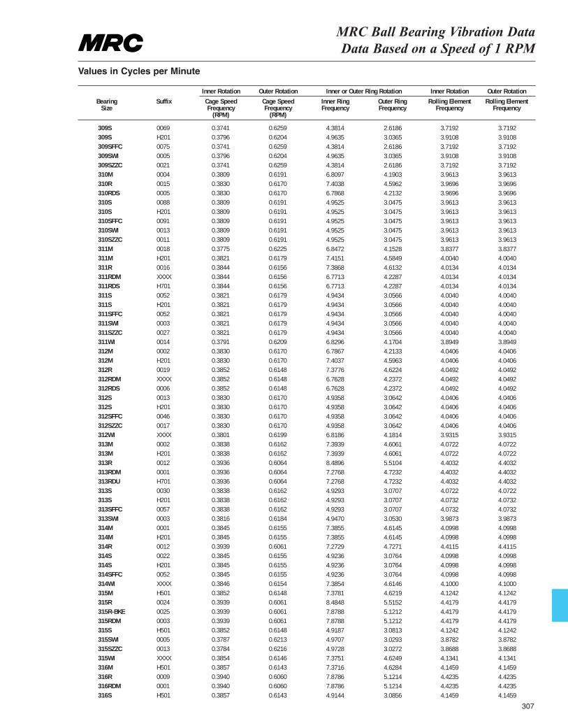
309S 0069 0.3741 0.6259 0.0730 0.0436 0.0310 0.0310309S H201 0.3796 0.6204 0.0827 0.0506 0.0326 0.0326309SFFC 0075 0.3741 0.6259 0.0730 0.0436 0.0310 0.0310309SWI 0005 0.3796 0.6204 0.0827 0.0506 0.0326 0.0326309SZZC 0021 0.3741 0.6259 0.0730 0.0436 0.0310 0.0310310M 0004 0.3809 0.6191 0.1135 0.0698 0.0330 0.0330310R 0015 0.3830 0.6170 0.1234 0.0766 0.0331 0.0330310RDS 0005 0.3830 0.6170 0.1131 0.0702 0.0331 0.0330310S 0088 0.3809 0.6191 0.0825 0.0508 0.0330 0.0330310S H201 0.3809 0.6191 0.0825 0.0508 0.0330 0.0330310SFFC 0091 0.3809 0.6191 0.0825 0.0508 0.0330 0.0330310SWI 0013 0.3809 0.6191 0.0825 0.0508 0.0330 0.0330310SZZC 0011 0.3809 0.6191 0.0825 0.0508 0.0330 0.0330311M 0018 0.3775 0.6225 0.1141 0.0692 0.0320 0.0320311M H201 0.3821 0.6179 0.1236 0.0764 0.0334 0.0334311R 0016 0.3844 0.6156 0.1231 0.0769 0.0334 0.0334311RDM XXXX 0.3844 0.6156 0.1129 0.0705 0.0334 0.0334311RDS H701 0.3844 0.6156 0.1129 0.0705 0.0334 0.0334311S 0052 0.3821 0.6179 0.0824 0.0509 0.0334 0.0334311S H201 0.3821 0.6179 0.0824 0.0509 0.0334 0.0334311SFFC 0052 0.3821 0.6179 0.0824 0.0509 0.0334 0.0334311SWI 0003 0.3821 0.6179 0.0824 0.0509 0.0334 0.0334311SZZC 0027 0.3821 0.6179 0.0824 0.0509 0.0334 0.0334311WI 0014 0.3791 0.6209 0.1138 0.0695 0.0325 0.0325312M 0002 0.3830 0.6170 0.1131 0.0702 0.0337 0.0337312M H201 0.3830 0.6170 0.1234 0.0766 0.0337 0.0337312R 0019 0.3852 0.6148 0.1230 0.0770 0.0337 0.0337312RDM XXXX 0.3852 0.6148 0.1127 0.0706 0.0337 0.0337312RDS 0006 0.3852 0.6148 0.1127 0.0706 0.0337 0.0337312S 0013 0.3830 0.6170 0.0823 0.0511 0.0337 0.0337312S H201 0.3830 0.6170 0.0823 0.0511 0.0337 0.0337312SFFC 0046 0.3830 0.6170 0.0823 0.0511 0.0337 0.0337312SZZC 0017 0.3830 0.6170 0.0823 0.0511 0.0337 0.0337312WI XXXX 0.3801 0.6199 0.1136 0.0697 0.0328 0.0328313M 0002 0.3838 0.6162 0.1232 0.0768 0.0339 0.0339313M H201 0.3838 0.6162 0.1232 0.0768 0.0339 0.0339313R 0012 0.3936 0.6064 0.1415 0.0918 0.0367 0.0367313RDM 0001 0.3936 0.6064 0.1213 0.0787 0.0367 0.0367313RDU H701 0.3936 0.6064 0.1213 0.0787 0.0367 0.0367313S 0030 0.3838 0.6162 0.0822 0.0512 0.0339 0.0339313S H201 0.3838 0.6162 0.0822 0.0512 0.0339 0.0339313SFFC 0057 0.3838 0.6162 0.0822 0.0512 0.0339 0.0339313SWI 0003 0.3816 0.6184 0.0824 0.0509 0.0332 0.0332314M 0001 0.3845 0.6155 0.1231 0.0769 0.0342 0.0342314M H201 0.3845 0.6155 0.1231 0.0769 0.0342 0.0342314R 0012 0.3939 0.6061 0.1212 0.0788 0.0368 0.0367314S 0022 0.3845 0.6155 0.0821 0.0513 0.0342 0.0342314S H201 0.3845 0.6155 0.0821 0.0513 0.0342 0.0342314SFFC 0052 0.3845 0.6155 0.0821 0.0513 0.0342 0.0342314WI XXXX 0.3846 0.6154 0.1231 0.0769 0.0342 0.0342315M H501 0.3852 0.6148 0.1230 0.0770 0.0344 0.0344315R 0024 0.3939 0.6061 0.1414 0.0919 0.0368 0.0368315R-BKE 0025 0.3939 0.6061 0.1313 0.0854 0.0368 0.0368315RDM 0003 0.3939 0.6061 0.1313 0.0854 0.0368 0.0368315S H501 0.3852 0.6148 0.0820 0.0514 0.0344 0.0344315SWI 0005 0.3787 0.6213 0.0828 0.0505 0.0323 0.0323315SZZC 0013 0.3784 0.6216 0.0829 0.0505 0.0322 0.0322315WI XXXX 0.3854 0.6146 0.1229 0.0771 0.0345 0.0345316M H501 0.3857 0.6143 0.1229 0.0771 0.0345 0.0345316R 0009 0.3940 0.6060 0.1313 0.0854 0.0369 0.0368316RDM 0001 0.3940 0.6060 0.1313 0.0854 0.0369 0.0368316S H501 0.3857 0.6143 0.0819 0.0514 0.0345 0.0345
MRC Ball Bearing Vibration Data Data Based on a Speed of 1 RPM
Values in Cycles per Minute
Inner Rotation Outer Rotation Inner or Outer Ring Rotation Inner Rotation Outer Rotation
Bearing Suffix Cage Speed Cage Speed Inner Ring Outer Ring Rolling Element Rolling ElementSize Frequency Frequency Frequency Frequency Frequency Frequency
(RPM) (RPM)
4.38144.96354.38144.96354.38146.80977.40386.78684.95254.95254.95254.95254.95256.84727.41517.38686.77136.77134.94344.94344.94344.94344.94346.82966.78677.40377.37766.76286.76284.93584.93584.93584.93586.81867.39397.39398.48967.27687.27684.92934.92934.92934.94707.38557.38557.27294.92364.92364.92367.38547.37818.48487.87887.87884.91874.97074.97287.37517.37167.87867.87864.9144
2.61863.03652.61863.03652.61864.19034.59624.21323.04753.04753.04753.04753.04754.15284.58494.61324.22874.22873.05663.05663.05663.05663.05664.17044.21334.59634.62244.23724.23723.06423.06423.06423.06424.18144.60614.60615.51044.72324.72323.07073.07073.07073.05304.61454.61454.72713.07643.07643.07644.61464.62195.51525.12125.12123.08133.02933.02724.62494.62845.12145.12143.0856
3.71923.91083.71923.91083.71923.96133.96963.96963.96133.96133.96133.96133.96133.83774.00404.01344.01344.01344.00404.00404.00404.00404.00403.89494.04064.04064.04924.04924.04924.04064.04064.04064.04063.93154.07224.07224.40324.40324.40324.07224.07324.07323.98734.09984.09984.41154.09984.09984.09984.10004.12424.41794.41794.41794.12423.87823.86884.13414.14594.42354.42354.1459
3.71923.91083.71923.91083.71923.96133.96963.96963.96133.96133.96133.96133.96133.83774.00404.01344.01344.01344.00404.00404.00404.00404.00403.89494.04064.04064.04924.04924.04924.04064.04064.04064.04063.93154.07224.07224.40324.40324.40324.07224.07324.07323.98734.09984.09984.41154.09984.09984.09984.10004.12424.41794.41794.41794.12423.87823.86884.13414.14594.42354.42354.1459
307
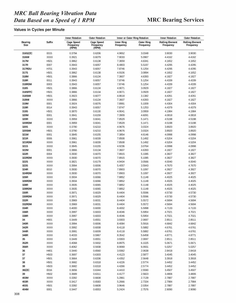
MRC Bearing ServicesMRC Ball Bearing Vibration Data Data Based on a Speed of 1 RPM
308
Values in Cycles per Minute
Inner Rotation Outer Rotation Inner or Outer Ring Rotation Inner Rotation Outer Rotation
Bearing Suffix Cage Speed Cage Speed Inner Ring Outer Ring Rolling Element Rolling ElementSize Frequency Frequency Frequency Frequency Frequency Frequency
(RPM) (RPM)
316SZZC 0015 0.3794 0.6206 0.0828 0.0506 0.0325 0.0325316WI XXXX 0.3921 0.6079 0.1317 0.0849 0.0368 0.0368317M H501 0.3862 0.6138 0.1228 0.0772 0.0347 0.0347317R 0007 0.3943 0.6057 0.1413 0.0920 0.0369 0.0369317RDU H701 0.3943 0.6057 0.1312 0.0854 0.0369 0.0369317S H501 0.3862 0.6138 0.0818 0.0515 0.0347 0.0347318M H501 0.3866 0.6134 0.1227 0.0773 0.0349 0.0349318R 0011 0.3943 0.6057 0.1312 0.0854 0.0369 0.0369318RDM 0003 0.3943 0.6057 0.1312 0.0854 0.0369 0.0369318S H501 0.3866 0.6134 0.0818 0.0515 0.0349 0.0349318SFFC H501 0.3866 0.6134 0.0818 0.0515 0.0349 0.0349318SWI H501 0.3923 0.6077 0.0810 0.0523 0.0369 0.0369318WI XXXX 0.3866 0.6134 0.1227 0.0773 0.0349 0.0349319M 0001 0.3924 0.6076 0.1317 0.0850 0.0369 0.0369319R 0014 0.3943 0.6057 0.1312 0.0854 0.0370 0.0370319S H501 0.3870 0.6130 0.0817 0.0516 0.0350 0.0350320M 0001 0.3841 0.6159 0.1232 0.0768 0.0340 0.0340320R XXXX 0.3959 0.6041 0.1309 0.0858 0.0377 0.0376320RDM 0001 0.3959 0.6041 0.1309 0.0858 0.0377 0.0376320S XXXX 0.3790 0.6210 0.0828 0.0505 0.0324 0.0324320SWI H501 0.3790 0.6210 0.0828 0.0505 0.0324 0.0324321M 0001 0.3845 0.6155 0.1231 0.0769 0.0342 0.0342321R 0006 0.3961 0.6039 0.1308 0.0858 0.0377 0.0376321RDM XXXX 0.3961 0.6039 0.1308 0.0858 0.0377 0.0376321S XXXX 0.3845 0.6155 0.0821 0.0513 0.0342 0.0342322M 0001 0.3866 0.6134 0.1227 0.0773 0.0349 0.0349322R 0004 0.3930 0.6070 0.1315 0.0851 0.0365 0.0365322RDM XXXX 0.3930 0.6070 0.1315 0.0851 0.0365 0.0365322S XXXX 0.3821 0.6179 0.0824 0.0509 0.0334 0.0334323S XXXX 0.3994 0.6006 0.0901 0.0599 0.0397 0.0397324R 0010 0.3930 0.6070 0.1315 0.0852 0.0366 0.0366324RDM XXXX 0.3930 0.6070 0.1315 0.0852 0.0366 0.0366326R XXXX 0.3934 0.6066 0.1314 0.0852 0.0367 0.0367326RDM XXXX 0.3934 0.6066 0.1314 0.0852 0.0367 0.0367328R XXXX 0.3935 0.6065 0.1314 0.0853 0.0367 0.0367328RDM XXXX 0.3935 0.6065 0.1314 0.0853 0.0367 0.0367330R XXXX 0.3971 0.6029 0.1407 0.0927 0.0381 0.0381330RDM XXXX 0.3971 0.6029 0.1407 0.0927 0.0381 0.0381332R XXXX 0.3969 0.6031 0.1407 0.0926 0.0381 0.0380332RDM XXXX 0.3969 0.6031 0.1407 0.0926 0.0381 0.0380334R XXXX 0.4000 0.6000 0.1400 0.0933 0.0393 0.0392336R XXXX 0.3997 0.6003 0.1401 0.0933 0.0392 0.0392338R XXXX 0.3997 0.6003 0.1401 0.0933 0.0391 0.039134 H001 0.3449 0.6551 0.0655 0.0345 0.0238 0.0237340R XXXX 0.3994 0.6006 0.1401 0.0932 0.0390 0.0390342R XXXX 0.3992 0.6008 0.1402 0.0931 0.0390 0.0389344R XXXX 0.3991 0.6009 0.1402 0.0931 0.0389 0.0389348R XXXX 0.4033 0.5967 0.1392 0.0941 0.0406 0.040635 XXXX 0.3449 0.6551 0.0655 0.0345 0.0238 0.0237352R XXXX 0.4068 0.5932 0.1483 0.1017 0.0422 0.0422356R XXXX 0.4062 0.5938 0.1484 0.1016 0.0419 0.041836 H401 0.3440 0.6560 0.0656 0.0344 0.0237 0.023637 H503 0.3697 0.6303 0.0735 0.0431 0.0284 0.028337 H501 0.3664 0.6336 0.0739 0.0427 0.0283 0.028238 H501 0.3682 0.6318 0.0737 0.0430 0.0287 0.028738 H503 0.3682 0.6318 0.0737 0.0430 0.0287 0.028738ZZC 0016 0.3656 0.6344 0.0740 0.0427 0.0288 0.028839 H502 0.3689 0.6311 0.0736 0.0430 0.0290 0.0290403M XXXX 0.3392 0.6608 0.0881 0.0452 0.0232 0.0232403R XXXX 0.3417 0.6583 0.0878 0.0456 0.0233 0.0233403S H501 0.3392 0.6608 0.0661 0.0339 0.0232 0.0232404M 0001 0.3447 0.6553 0.0874 0.0460 0.0242 0.0242
4.96527.90337.36598.48037.87464.91067.36077.87467.87464.90714.90714.86187.36077.89917.87474.90417.39097.85297.85294.96764.96767.38547.85087.85084.92367.36077.89157.89154.94345.40577.89037.89037.88527.88527.88527.88528.44048.44048.44048.44048.40028.40468.40463.93038.40848.41188.41188.35423.93038.89758.90693.93624.41234.43524.42264.42664.44104.41775.28615.26663.96465.2424
3.03485.09674.63415.51975.12543.08944.63935.12545.12543.09293.09293.13824.63935.10095.12533.09594.60915.14715.14713.03243.03244.61465.14925.14923.07644.63935.10855.10853.05663.59435.10975.10975.11485.11485.11485.11485.55965.55965.55725.55725.59985.59545.59542.06975.59165.58825.58825.64582.06976.10256.09312.06382.58772.56482.57742.57742.55902.58232.71392.73342.03542.7576
3.90304.41624.16524.42954.42954.16524.18274.43394.43394.18274.18274.42614.18274.43044.43794.19844.08184.51984.51983.89203.89204.09984.52044.52044.09984.18274.38274.38274.00404.76704.39274.39274.40254.40254.40254.40254.57304.57304.56944.56944.71334.70214.70212.85114.68424.67614.67614.87712.85115.06715.02572.84183.40453.39183.44523.44523.45073.48062.78872.79842.78872.9090
3.90304.41624.16524.42954.42954.16524.18274.43394.43394.18274.18274.42614.18274.43044.43794.19844.08184.51984.51983.89203.89204.09984.52044.52044.09984.18274.38274.38274.00404.76704.39274.39274.40254.40254.40254.40254.57304.57304.56944.56944.71334.70214.70212.85114.68424.67614.67614.87712.85115.06715.02572.84183.40453.39183.44523.44523.45073.48062.78872.79842.78872.9090
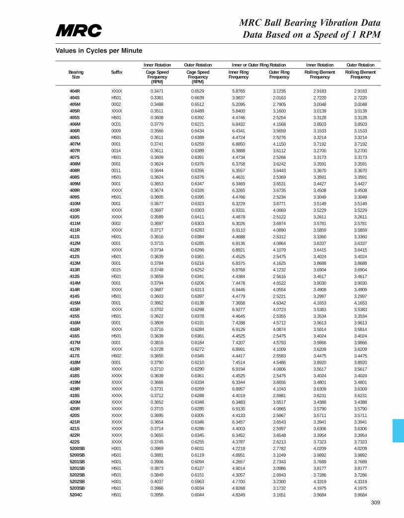
MRC Ball Bearing Vibration Data Data Based on a Speed of 1 RPM
Values in Cycles per Minute
Inner Rotation Outer Rotation Inner or Outer Ring Rotation Inner Rotation Outer Rotation
Bearing Suffix Cage Speed Cage Speed Inner Ring Outer Ring Rolling Element Rolling ElementSize Frequency Frequency Frequency Frequency Frequency Frequency
(RPM) (RPM)
404R XXXX 0.3471 0.6529 0.0979 0.0521 0.0243 0.0243404S H501 0.3361 0.6639 0.0664 0.0336 0.0227 0.0227405M 0002 0.3488 0.6512 0.0868 0.0465 0.0250 0.0250405R XXXX 0.3511 0.6489 0.0973 0.0527 0.0251 0.0251405S H501 0.3608 0.6392 0.0746 0.0421 0.0276 0.0276406M 0C01 0.3779 0.6221 0.1141 0.0693 0.0321 0.0321406R 0009 0.3566 0.6434 0.1072 0.0594 0.0263 0.0262406S H501 0.3611 0.6389 0.0745 0.0421 0.0277 0.0277407M 0001 0.3741 0.6259 0.1148 0.0686 0.0310 0.0310407R 0014 0.3611 0.6389 0.1065 0.0602 0.0272 0.0272407S H501 0.3609 0.6391 0.0746 0.0421 0.0276 0.0276408M 0001 0.3624 0.6376 0.1063 0.0604 0.0280 0.0280408R 0011 0.3644 0.6356 0.1059 0.0607 0.0281 0.0280408S H501 0.3624 0.6376 0.0744 0.0423 0.0280 0.0280409M 0001 0.3653 0.6347 0.1058 0.0609 0.0287 0.0287409R XXXX 0.3674 0.6326 0.1054 0.0612 0.0288 0.0287409S H501 0.3605 0.6395 0.0746 0.0421 0.0275 0.0275410M 0001 0.3677 0.6323 0.1054 0.0613 0.0293 0.0293410R XXXX 0.3697 0.6303 0.1156 0.0678 0.0294 0.0293410S XXXX 0.3589 0.6411 0.0748 0.0419 0.0272 0.0272411M 0002 0.3697 0.6303 0.1050 0.0616 0.0298 0.0298411R XXXX 0.3717 0.6283 0.1152 0.0681 0.0299 0.0299411S H501 0.3616 0.6384 0.0745 0.0422 0.0278 0.0278412M 0001 0.3715 0.6285 0.1152 0.0681 0.0303 0.0303412R XXXX 0.3734 0.6266 0.1149 0.0685 0.0303 0.0303412S H501 0.3639 0.6361 0.0742 0.0425 0.0284 0.0284413M 0001 0.3784 0.6216 0.1140 0.0694 0.0322 0.0322413R 0015 0.3748 0.6252 0.1146 0.0687 0.0308 0.0307413S H501 0.3659 0.6341 0.0740 0.0427 0.0288 0.0288414M 0001 0.3794 0.6206 0.1241 0.0759 0.0325 0.0325414R XXXX 0.3687 0.6313 0.1157 0.0676 0.0291 0.0291414S H501 0.3603 0.6397 0.0746 0.0420 0.0275 0.0275415M 0001 0.3862 0.6138 0.1228 0.0772 0.0347 0.0347415R XXXX 0.3702 0.6298 0.1155 0.0679 0.0295 0.0295415S H501 0.3622 0.6378 0.0744 0.0423 0.0279 0.0279416M 0001 0.3809 0.6191 0.1238 0.0762 0.0330 0.0330416R XXXX 0.3716 0.6284 0.1152 0.0681 0.0298 0.0298416S H501 0.3639 0.6361 0.0742 0.0425 0.0284 0.0284417M 0001 0.3816 0.6184 0.1237 0.0763 0.0332 0.0332417R XXXX 0.3728 0.6272 0.1150 0.0683 0.0302 0.0301417S H502 0.3655 0.6345 0.0740 0.0426 0.0287 0.0287418M 0001 0.3790 0.6210 0.1242 0.0758 0.0324 0.0324418R XXXX 0.3710 0.6290 0.1153 0.0680 0.0297 0.0296418S XXXX 0.3639 0.6361 0.0742 0.0425 0.0284 0.0284419M XXXX 0.3666 0.6334 0.1056 0.0611 0.0290 0.0290419R XXXX 0.3731 0.6269 0.1149 0.0684 0.0303 0.0302419S XXXX 0.3712 0.6288 0.0734 0.0433 0.0302 0.0302420M XXXX 0.3652 0.6348 0.1058 0.0609 0.0287 0.0287420R XXXX 0.3715 0.6285 0.1152 0.0681 0.0298 0.0298420S XXXX 0.3695 0.6305 0.0736 0.0431 0.0298 0.0298421R XXXX 0.3654 0.6346 0.1058 0.0609 0.0283 0.0282421S XXXX 0.3714 0.6286 0.0733 0.0433 0.0303 0.0303422R XXXX 0.3655 0.6345 0.1058 0.0609 0.0283 0.0283422S XXXX 0.3745 0.6255 0.0730 0.0437 0.0311 0.03115200SB H301 0.3969 0.6031 0.0704 0.0463 0.0335 0.03335200SB H501 0.3881 0.6119 0.0816 0.0517 0.0332 0.03315201SB H301 0.3906 0.6094 0.0711 0.0456 0.0314 0.03125201SB H501 0.3873 0.6127 0.0817 0.0516 0.0318 0.03165202SB H501 0.3849 0.6151 0.0718 0.0449 0.0311 0.03095202SB H301 0.4037 0.5963 0.0795 0.0538 0.0361 0.03595203SB H501 0.3966 0.6034 0.0804 0.0529 0.0350 0.03485204C H501 0.3956 0.6044 0.0806 0.0527 0.0331 0.0328
5.87653.98375.20955.84004.47466.84326.43414.47246.88506.38884.47346.37586.35574.46316.34696.32654.47666.32296.93314.48786.30266.91104.46886.91366.89214.45256.83756.87684.43847.44786.94464.47797.36586.92774.46457.42886.91264.45257.42076.89914.44177.45146.91944.45256.33446.89574.40196.34836.91354.41336.34574.40036.34524.37874.22184.89514.26574.90144.30574.77004.82684.8349
3.12352.01632.79053.16002.52544.15683.56592.52764.11503.61122.52663.62423.64432.53693.65313.67352.52343.67714.06692.51223.69744.08902.53124.08644.10792.54754.16254.12322.56164.55224.05542.52214.63424.07232.53554.57124.08742.54754.57934.10092.55834.54864.08062.54753.66564.10432.59813.65174.08652.58673.65432.59973.65482.62132.77823.10492.73433.09862.69433.23003.17323.1651
2.91832.72203.00483.01393.31283.85033.15333.32143.71923.27003.31733.35913.36703.35913.44273.45083.30493.51493.52293.26113.57813.58593.33603.63373.64153.40243.86883.69043.46173.90303.49093.29974.16533.53833.35343.96133.58143.40243.98663.62093.44753.89203.56173.40243.48013.63093.62313.43883.57903.57113.39413.63063.39543.73234.02093.98923.76893.81773.72864.33194.19753.9684
2.91832.72203.00483.01393.31283.85033.15333.32143.71923.27003.31733.35913.36703.35913.44273.45083.30493.51493.52293.26113.57813.58593.33603.63373.64153.40243.86883.69043.46173.90303.49093.29974.16533.53833.35343.96133.58143.40243.98663.62093.44753.89203.56173.40243.48013.63093.62313.43883.57903.57113.39413.63063.39543.73234.02093.98923.76893.81773.72864.33194.19753.9684
309
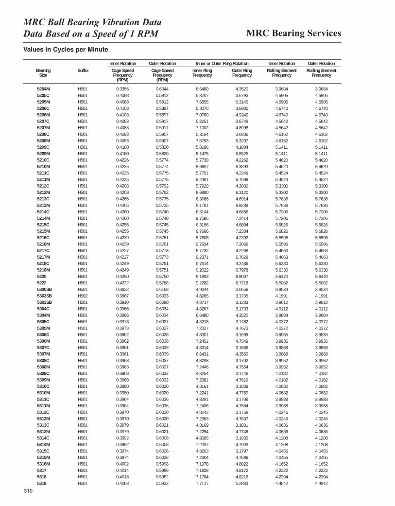
MRC Bearing ServicesMRC Ball Bearing Vibration Data Data Based on a Speed of 1 RPM
Values in Cycles per Minute
Inner Rotation Outer Rotation Inner or Outer Ring Rotation Inner Rotation Outer Rotation
Bearing Suffix Cage Speed Cage Speed Inner Ring Outer Ring Rolling Element Rolling ElementSize Frequency Frequency Frequency Frequency Frequency Frequency
(RPM) (RPM)
5204M H501 0.3956 0.6044 0.1108 0.0725 0.0331 0.03285205C H501 0.4088 0.5912 0.0887 0.0613 0.0383 0.03815205M H501 0.4088 0.5912 0.1281 0.0886 0.0383 0.03815206C H501 0.4103 0.5897 0.0885 0.0615 0.0389 0.03875206M H501 0.4103 0.5897 0.1179 0.0821 0.0389 0.03875207C H501 0.4083 0.5917 0.0888 0.0612 0.0380 0.03785207M H501 0.4083 0.5917 0.1183 0.0817 0.0380 0.03785208C H501 0.4093 0.5907 0.0886 0.0614 0.0385 0.03835208M H501 0.4093 0.5907 0.1280 0.0887 0.0385 0.03835209C H501 0.4180 0.5820 0.0970 0.0697 0.0428 0.04275209M H501 0.4180 0.5820 0.1358 0.0975 0.0428 0.04275210C H501 0.4226 0.5774 0.0962 0.0704 0.0455 0.04535210M H501 0.4226 0.5774 0.1443 0.1057 0.0455 0.04535211C H501 0.4225 0.5775 0.0963 0.0704 0.0454 0.04535211M H501 0.4225 0.5775 0.1540 0.1127 0.0454 0.04535212C H501 0.4208 0.5792 0.0965 0.0701 0.0444 0.04425212M H501 0.4208 0.5792 0.1448 0.1052 0.0444 0.04425213C H501 0.4265 0.5735 0.1051 0.0782 0.0480 0.04795213M H501 0.4265 0.5735 0.1529 0.1137 0.0480 0.04795214C H501 0.4260 0.5740 0.1052 0.0781 0.0477 0.04755214M H501 0.4260 0.5740 0.1626 0.1207 0.0477 0.04755215C H501 0.4255 0.5745 0.1053 0.0780 0.0474 0.04725215M H501 0.4255 0.5745 0.1628 0.1206 0.0474 0.04725216C H501 0.4239 0.5761 0.0960 0.0707 0.0463 0.04625216M H501 0.4239 0.5761 0.1632 0.1201 0.0463 0.04625217C H501 0.4227 0.5773 0.0962 0.0704 0.0456 0.04545217M H501 0.4227 0.5773 0.1540 0.1127 0.0456 0.04545218C H501 0.4249 0.5751 0.0959 0.0708 0.0469 0.04685218M H501 0.4249 0.5751 0.1534 0.1133 0.0469 0.04685220 H501 0.4250 0.5750 0.1533 0.1133 0.0471 0.04695222 H501 0.4232 0.5768 0.1538 0.1129 0.0459 0.04575300SB H501 0.3832 0.6168 0.0822 0.0511 0.0317 0.03165302SB H502 0.3967 0.6033 0.0804 0.0529 0.0350 0.03485303SB H501 0.3910 0.6090 0.0812 0.0521 0.0330 0.03285304C H501 0.3966 0.6034 0.0804 0.0529 0.0334 0.03325304M H501 0.3966 0.6034 0.1106 0.0727 0.0334 0.03325305C H501 0.3973 0.6027 0.0804 0.0530 0.0336 0.03345305M H501 0.3973 0.6027 0.1205 0.0795 0.0336 0.03345306C H501 0.3962 0.6038 0.0805 0.0528 0.0333 0.03305306M H501 0.3962 0.6038 0.1208 0.0792 0.0333 0.03305307C H501 0.3961 0.6039 0.0805 0.0528 0.0332 0.03305307M H501 0.3961 0.6039 0.1107 0.0726 0.0332 0.03305308C H501 0.3963 0.6037 0.0805 0.0528 0.0333 0.03315308M H501 0.3963 0.6037 0.1207 0.0793 0.0333 0.03315309C H501 0.3968 0.6032 0.0804 0.0529 0.0335 0.03335309M H501 0.3968 0.6032 0.1206 0.0794 0.0335 0.03335310C H501 0.3980 0.6020 0.0803 0.0531 0.0339 0.03375310M H501 0.3980 0.6020 0.1204 0.0796 0.0339 0.03375311C H501 0.3964 0.6036 0.0805 0.0528 0.0333 0.03315311M H501 0.3964 0.6036 0.1207 0.0793 0.0333 0.03315312C H501 0.3970 0.6030 0.0804 0.0529 0.0335 0.03335312M H501 0.3970 0.6030 0.1206 0.0794 0.0335 0.03335313C H501 0.3979 0.6021 0.0803 0.0530 0.0339 0.03365313M H501 0.3979 0.6021 0.1204 0.0796 0.0339 0.03365314C H501 0.3992 0.6008 0.0801 0.0532 0.0343 0.03415314M H501 0.3992 0.6008 0.1202 0.0798 0.0343 0.03415315C H501 0.3974 0.6026 0.0803 0.0530 0.0337 0.03355315M H501 0.3974 0.6026 0.1205 0.0795 0.0337 0.03355316M H501 0.4002 0.5998 0.1200 0.0800 0.0347 0.03455317 H501 0.4014 0.5986 0.1197 0.0803 0.0352 0.03505318 H501 0.4018 0.5982 0.1196 0.0804 0.0353 0.03515319 H501 0.4068 0.5932 0.1285 0.0881 0.0374 0.0372
310
6.64805.32077.68555.30707.07605.32517.10025.31647.67935.81968.14755.77388.66075.77519.24015.79208.68806.30869.17616.31449.75866.31969.76665.76089.79345.77329.23715.75149.20229.19939.22824.93444.82654.87174.82676.64804.82187.23274.83017.24514.83146.64314.82987.24464.82547.23814.81617.22414.82917.24364.82427.23634.81697.22544.80657.20974.82037.23047.19787.18287.17847.7117
4.35203.67935.31453.69304.92403.67494.89983.68365.32074.18045.85254.22626.33934.22496.75994.20806.31204.69146.82394.68567.24144.68047.23344.23927.20664.22686.76294.24866.79786.80076.77183.06563.17353.12833.17334.35203.17824.76733.16994.75493.16864.35693.17024.75543.17464.76193.18394.77593.17094.75643.17584.76373.18314.77463.19354.79033.17974.76964.80224.81724.82165.2883
3.96844.59054.59054.67404.67404.56424.56424.61624.61625.14115.14115.46205.46205.45245.45245.33005.33005.76365.76365.72065.72065.68265.68265.55965.55965.46635.46635.63305.63305.64705.50823.80344.19913.96124.01123.96844.03724.03723.99353.99353.98683.98683.99523.99524.01824.01824.06824.06823.99883.99884.02464.02464.06364.06364.12084.12084.04554.04554.16524.22224.23944.4842
3.96844.59054.59054.67404.67404.56424.56424.61624.61625.14115.14115.46205.46205.45245.45245.33005.33005.76365.76365.72065.72065.68265.68265.55965.55965.46635.46635.63305.63305.64705.50823.80344.19913.96124.01123.96844.03724.03723.99353.99353.98683.98683.99523.99524.01824.01824.06824.06823.99883.99884.02464.02464.06364.06364.12084.12084.04554.04554.16524.22224.23944.4842
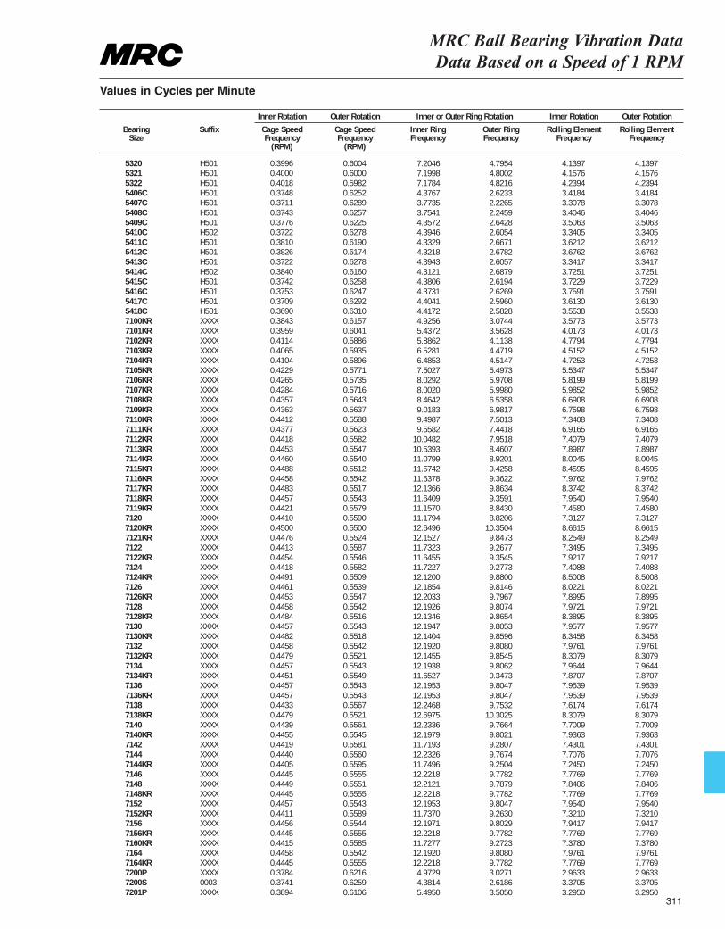
5320 H501 0.3996 0.6004 0.1201 0.0799 0.0345 0.03435321 H501 0.4000 0.6000 0.1200 0.0800 0.0346 0.03445322 H501 0.4018 0.5982 0.1196 0.0804 0.0353 0.03515406C H501 0.3748 0.6252 0.0821 0.0572 0.0298 0.02965407C H501 0.3711 0.6289 0.0906 0.0594 0.0335 0.03335408C H501 0.3743 0.6257 0.0981 0.0686 0.0398 0.03965409C H501 0.3776 0.6225 0.1088 0.0745 0.0376 0.03745410C H502 0.3722 0.6278 0.1081 0.0752 0.0394 0.03925411C H501 0.3810 0.6190 0.1250 0.0916 0.0461 0.04605412C H501 0.3826 0.6174 0.1338 0.0995 0.0485 0.04835413C H501 0.3722 0.6278 0.1334 0.1000 0.0499 0.04975414C H502 0.3840 0.6160 0.1411 0.1089 0.0558 0.05565415C H501 0.3742 0.6258 0.1503 0.1164 0.0563 0.05625416C H501 0.3753 0.6247 0.1583 0.1250 0.0612 0.06115417C H501 0.3709 0.6292 0.1593 0.1240 0.0576 0.05755418C H501 0.3690 0.6310 0.1675 0.1325 0.0617 0.06167100KR XXXX 0.3843 0.6157 0.0821 0.0512 0.0298 0.02967101KR XXXX 0.3959 0.6041 0.0906 0.0594 0.0335 0.03337102KR XXXX 0.4114 0.5886 0.0981 0.0686 0.0398 0.03967103KR XXXX 0.4065 0.5935 0.1088 0.0745 0.0376 0.03747104KR XXXX 0.4104 0.5896 0.1081 0.0752 0.0394 0.03927105KR XXXX 0.4229 0.5771 0.1250 0.0916 0.0461 0.04607106KR XXXX 0.4265 0.5735 0.1338 0.0995 0.0485 0.04837107KR XXXX 0.4284 0.5716 0.1334 0.1000 0.0499 0.04977108KR XXXX 0.4357 0.5643 0.1411 0.1089 0.0558 0.05567109KR XXXX 0.4363 0.5637 0.1503 0.1164 0.0563 0.05627110KR XXXX 0.4412 0.5588 0.1583 0.1250 0.0612 0.06117111KR XXXX 0.4377 0.5623 0.1593 0.1240 0.0576 0.05757112KR XXXX 0.4418 0.5582 0.1675 0.1325 0.0617 0.06167113KR XXXX 0.4453 0.5547 0.1757 0.1410 0.0658 0.06577114KR XXXX 0.4460 0.5540 0.1847 0.1487 0.0667 0.06667115KR XXXX 0.4488 0.5512 0.1929 0.1571 0.0705 0.07047116KR XXXX 0.4458 0.5542 0.1940 0.1560 0.0665 0.06647117KR XXXX 0.4483 0.5517 0.2023 0.1644 0.0698 0.06977118KR XXXX 0.4457 0.5543 0.1940 0.1560 0.0663 0.06627119KR XXXX 0.4421 0.5579 0.1860 0.1474 0.0621 0.06207120 XXXX 0.4410 0.5590 0.1863 0.1470 0.0609 0.06087120KR XXXX 0.4500 0.5500 0.2108 0.1725 0.0722 0.07217121KR XXXX 0.4476 0.5524 0.2025 0.1641 0.0688 0.06877122 XXXX 0.4413 0.5587 0.1955 0.1545 0.0612 0.06117122KR XXXX 0.4454 0.5546 0.1941 0.1559 0.0660 0.06597124 XXXX 0.4418 0.5582 0.1954 0.1546 0.0617 0.06167124KR XXXX 0.4491 0.5509 0.2020 0.1647 0.0708 0.07077126 XXXX 0.4461 0.5539 0.2031 0.1636 0.0669 0.06677126KR XXXX 0.4453 0.5547 0.2034 0.1633 0.0658 0.06577128 XXXX 0.4458 0.5542 0.2032 0.1635 0.0664 0.06637128KR XXXX 0.4484 0.5516 0.2022 0.1644 0.0699 0.06987130 XXXX 0.4457 0.5543 0.2032 0.1634 0.0663 0.06627130KR XXXX 0.4482 0.5518 0.2023 0.1643 0.0695 0.06947132 XXXX 0.4458 0.5542 0.2032 0.1635 0.0665 0.06647132KR XXXX 0.4479 0.5521 0.2024 0.1642 0.0692 0.06917134 XXXX 0.4457 0.5543 0.2032 0.1634 0.0664 0.06637134KR XXXX 0.4451 0.5549 0.1942 0.1558 0.0656 0.06557136 XXXX 0.4457 0.5543 0.2033 0.1634 0.0663 0.06627136KR XXXX 0.4457 0.5543 0.2033 0.1634 0.0663 0.06627138 XXXX 0.4433 0.5567 0.2041 0.1626 0.0635 0.06347138KR XXXX 0.4479 0.5521 0.2116 0.1717 0.0692 0.06917140 XXXX 0.4439 0.5561 0.2039 0.1628 0.0642 0.06417140KR XXXX 0.4455 0.5545 0.2033 0.1634 0.0661 0.06607142 XXXX 0.4419 0.5581 0.1953 0.1547 0.0619 0.06187144 XXXX 0.4440 0.5560 0.2039 0.1628 0.0642 0.06417144KR XXXX 0.4405 0.5595 0.1958 0.1542 0.0604 0.06037146 XXXX 0.4445 0.5555 0.2037 0.1630 0.0648 0.06477148 XXXX 0.4449 0.5551 0.2035 0.1631 0.0653 0.06527148KR XXXX 0.4445 0.5555 0.2037 0.1630 0.0648 0.06477152 XXXX 0.4457 0.5543 0.2033 0.1634 0.0663 0.06627152KR XXXX 0.4411 0.5589 0.1956 0.1544 0.0610 0.06097156 XXXX 0.4456 0.5544 0.2033 0.1634 0.0662 0.06617156KR XXXX 0.4445 0.5555 0.2037 0.1630 0.0648 0.06477160KR XXXX 0.4415 0.5585 0.1955 0.1545 0.0615 0.06147164 XXXX 0.4458 0.5542 0.2032 0.1635 0.0665 0.06647164KR XXXX 0.4445 0.5555 0.2037 0.1630 0.0648 0.06477200P XXXX 0.3784 0.6216 0.0829 0.0504 0.0247 0.02427200S 0003 0.3741 0.6259 0.0730 0.0436 0.0281 0.02797201P XXXX 0.3894 0.6106 0.0916 0.0584 0.0275 0.0270
MRC Ball Bearing Vibration Data Data Based on a Speed of 1 RPM
Values in Cycles per Minute
Inner Rotation Outer Rotation Inner or Outer Ring Rotation Inner Rotation Outer Rotation
Bearing Suffix Cage Speed Cage Speed Inner Ring Outer Ring Rolling Element Rolling ElementSize Frequency Frequency Frequency Frequency Frequency Frequency
(RPM) (RPM)
7.20467.19987.17844.37673.77353.75414.35724.39464.33294.32184.39434.31214.38064.37314.40414.41724.92565.43725.88626.52816.48537.50278.02928.00208.46429.01839.49879.5582
10.048210.539311.079911.574211.637812.136611.640911.157011.179412.649612.152711.732311.645511.722712.120012.185412.203312.192612.134612.194712.140412.192012.145512.193811.652712.195312.195312.246812.697512.233612.197911.719312.232611.749612.221812.212112.221812.195311.737012.197112.221811.727712.192012.22184.97294.38145.4950
4.79544.80024.82162.62332.22652.24592.64282.60542.66712.67822.60572.68792.61942.62692.59602.58283.07443.56284.11384.47194.51475.49735.97085.99806.53586.98177.50137.44187.95188.46078.92019.42589.36229.86349.35918.84308.8206
10.35049.84739.26779.35459.27739.88009.81469.79679.80749.86549.80539.85969.80809.85459.80629.34739.80479.80479.7532
10.30259.76649.80219.28079.76749.25049.77829.78799.77829.80479.26309.80299.77829.27239.80809.77823.02712.61863.5050
4.13974.15764.23943.41843.30783.40463.50633.34053.62123.67623.34173.72513.72293.75913.61303.55383.57734.01734.77944.51524.72535.53475.81995.98526.69086.75987.34086.91657.40797.89878.00458.45957.97628.37427.95407.45807.31278.66158.25497.34957.92177.40888.50088.02217.89957.97218.38957.95778.34587.97618.30797.96447.87077.95397.95397.61748.30797.70097.93637.43017.70767.24507.77697.84067.77697.95407.32107.94177.77697.37807.97617.77692.96333.37053.2950
4.13974.15764.23943.41843.30783.40463.50633.34053.62123.67623.34173.72513.72293.75913.61303.55383.57734.01734.77944.51524.72535.53475.81995.98526.69086.75987.34086.91657.40797.89878.00458.45957.97628.37427.95407.45807.31278.66158.25497.34957.92177.40888.50088.02217.89957.97218.38957.95778.34587.97618.30797.96447.87077.95397.95397.61748.30797.70097.93637.43017.70767.24507.77697.84067.77697.95407.32107.94177.77697.37807.97617.77692.96333.37053.2950
311
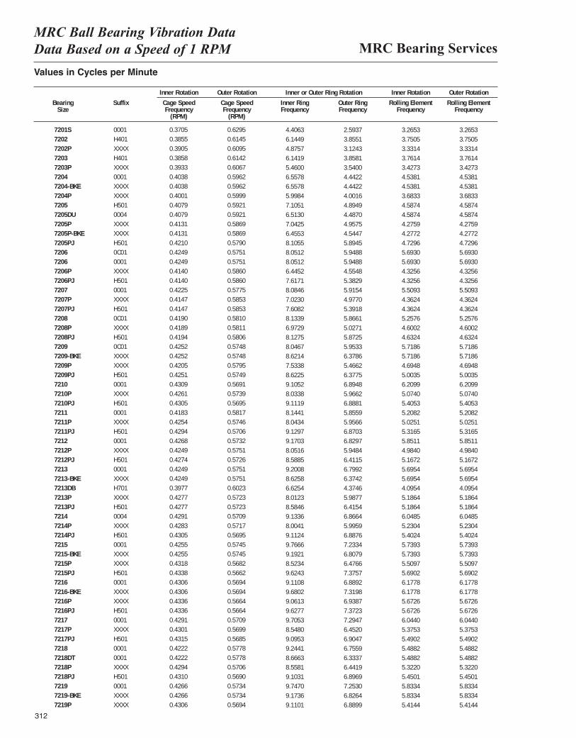
MRC Bearing ServicesMRC Ball Bearing Vibration Data Data Based on a Speed of 1 RPM
312
Values in Cycles per Minute
Inner Rotation Outer Rotation Inner or Outer Ring Rotation Inner Rotation Outer Rotation
Bearing Suffix Cage Speed Cage Speed Inner Ring Outer Ring Rolling Element Rolling ElementSize Frequency Frequency Frequency Frequency Frequency Frequency
(RPM) (RPM)
7201S 0001 0.3705 0.6295 0.0734 0.0432 0.0272 0.02707202 H401 0.3855 0.6145 0.1024 0.0642 0.0313 0.03117202P XXXX 0.3905 0.6095 0.0813 0.0521 0.0278 0.02737203 H401 0.3858 0.6142 0.1024 0.0643 0.0313 0.03127203P XXXX 0.3933 0.6067 0.0910 0.0590 0.0286 0.02817204 0001 0.4038 0.5962 0.1093 0.0740 0.0378 0.03777204-BKE XXXX 0.4038 0.5962 0.1093 0.0740 0.0378 0.03777204P XXXX 0.4001 0.5999 0.1000 0.0667 0.0307 0.03037205 H501 0.4079 0.5921 0.1184 0.0816 0.0382 0.03807205DU 0004 0.4079 0.5921 0.1086 0.0748 0.0382 0.03807205P XXXX 0.4131 0.5869 0.1174 0.0826 0.0356 0.03537205P-BKE XXXX 0.4131 0.5869 0.1076 0.0757 0.0356 0.03537205PJ H501 0.4210 0.5790 0.1351 0.0982 0.0394 0.03917206 0C01 0.4249 0.5751 0.1342 0.0991 0.0474 0.04737206 0001 0.4249 0.5751 0.1342 0.0991 0.0474 0.04737206P XXXX 0.4140 0.5860 0.1074 0.0759 0.0360 0.03577206PJ H501 0.4140 0.5860 0.1270 0.0897 0.0360 0.03577207 0001 0.4225 0.5775 0.1347 0.0986 0.0459 0.04577207P XXXX 0.4147 0.5853 0.1171 0.0829 0.0364 0.03607207PJ H501 0.4147 0.5853 0.1268 0.0899 0.0364 0.0367208 0C01 0.4190 0.5810 0.1356 0.0978 0.0438 0.04367208P XXXX 0.4189 0.5811 0.1162 0.0838 0.0383 0.03807208PJ H501 0.4194 0.5806 0.1355 0.0979 0.0386 0.03837209 0C01 0.4252 0.5748 0.1341 0.0992 0.0477 0.04757209-BKE XXXX 0.4252 0.5748 0.1437 0.1063 0.0477 0.04757209P XXXX 0.4205 0.5795 0.1256 0.0911 0.0391 0.03887209PJ H501 0.4251 0.5749 0.1437 0.1063 0.0417 0.04147210 0001 0.4309 0.5691 0.1518 0.1149 0.0517 0.05167210P XXXX 0.4261 0.5739 0.1339 0.0994 0.0423 0.04207210PJ H501 0.4305 0.5695 0.1519 0.1148 0.0450 0.04487211 0001 0.4183 0.5817 0.1357 0.0976 0.0434 0.04327211P XXXX 0.4254 0.5746 0.1341 0.0993 0.0419 0.04167211PJ H501 0.4294 0.5706 0.1522 0.1145 0.0443 0.04407212 0001 0.4268 0.5732 0.1528 0.1138 0.0488 0.04867212P XXXX 0.4249 0.5751 0.1342 0.0991 0.0415 0.04127212PJ H501 0.4274 0.5726 0.1431 0.1069 0.0431 0.04287213 0001 0.4249 0.5751 0.1534 0.1133 0.0475 0.04737213-BKE XXXX 0.4249 0.5751 0.1438 0.1062 0.0475 0.04737213DB H701 0.3977 0.6023 0.1104 0.0729 0.0341 0.03397213P XXXX 0.4277 0.5723 0.1335 0.0998 0.0432 0.04297213PJ H501 0.4277 0.5723 0.1431 0.1069 0.0432 0.04297214 0004 0.4291 0.5709 0.1522 0.1144 0.0504 0.05037214P XXXX 0.4283 0.5717 0.1334 0.0999 0.0436 0.04337214PJ H501 0.4305 0.5695 0.1519 0.1148 0.0450 0.04477215 0001 0.4255 0.5745 0.1628 0.1206 0.0478 0.04777215-BKE XXXX 0.4255 0.5745 0.1532 0.1135 0.0478 0.04777215P XXXX 0.4318 0.5682 0.1421 0.1079 0.0459 0.04567215PJ H501 0.4338 0.5662 0.1604 0.1229 0.0474 0.04727216 0001 0.4306 0.5694 0.1518 0.1148 0.0515 0.05137216-BKE XXXX 0.4306 0.5694 0.1613 0.1220 0.0515 0.05137216P XXXX 0.4336 0.5664 0.1510 0.1156 0.0473 0.04707216PJ H501 0.4336 0.5664 0.1605 0.1229 0.0473 0.04707217 0001 0.4291 0.5709 0.1618 0.1216 0.0504 0.05027217P XXXX 0.4301 0.5699 0.1425 0.1075 0.0448 0.04457217PJ H501 0.4315 0.5685 0.1516 0.1151 0.0458 0.04557218 0001 0.4222 0.5778 0.1541 0.1126 0.0457 0.04567218DT 0001 0.4222 0.5778 0.1444 0.1056 0.0457 0.04567218P XXXX 0.4294 0.5706 0.1426 0.1074 0.0443 0.04417218PJ H501 0.4310 0.5690 0.1517 0.1149 0.0454 0.04517219 0001 0.4266 0.5734 0.1625 0.1209 0.0486 0.04857219-BKE XXXX 0.4266 0.5734 0.1529 0.1138 0.0486 0.04857219P XXXX 0.4306 0.5694 0.1518 0.1148 0.0451 0.0448
4.40636.14494.87576.14195.46006.55786.55785.99847.10516.51307.04256.45538.10558.05128.05126.44527.61718.08467.02307.60828.13396.97298.12758.04678.62147.53388.62259.10528.03389.11198.14418.04349.12979.17038.05168.58859.20088.62586.62548.01238.58469.13368.00419.11249.76669.19218.52349.62439.11089.68029.06139.62779.70538.54809.09539.24418.66638.55819.10319.74709.17369.1101
2.59373.85513.12433.85813.54004.44224.44224.00164.89494.48704.95754.54475.89455.94885.94884.55485.38295.91544.97705.39185.86615.02715.87255.95336.37865.46626.37756.89485.96626.88815.85595.95666.87036.82975.94846.41156.79926.37424.37465.98776.41546.86645.99596.88767.23346.80796.47667.37576.88927.31986.93877.37237.29476.45206.90476.75596.33376.44196.89697.25306.82646.8899
3.26533.75053.33143.76143.42734.53814.53813.68334.58744.58744.27594.27724.72965.69305.69304.32564.32565.50934.36244.36245.25764.60024.63245.71865.71864.69485.00356.20995.07405.40535.20825.02515.31655.85114.98405.16725.69545.69544.09545.18645.18646.04855.23045.40245.73935.73935.50975.69026.17786.17785.67265.67266.04405.37535.49025.48825.48825.32205.45015.83345.83345.4144
3.26533.75053.33143.76143.42734.53814.53813.68334.58744.58744.27594.27724.72965.69305.69304.32564.32565.50934.36244.36245.25764.60024.63245.71865.71864.69485.00356.20995.07405.40535.20825.02515.31655.85114.98405.16725.69545.69544.09545.18645.18646.04855.23045.40245.73935.73935.50975.69026.17786.17785.67265.67266.04405.37535.49025.48825.48825.32205.45015.83345.83345.4144
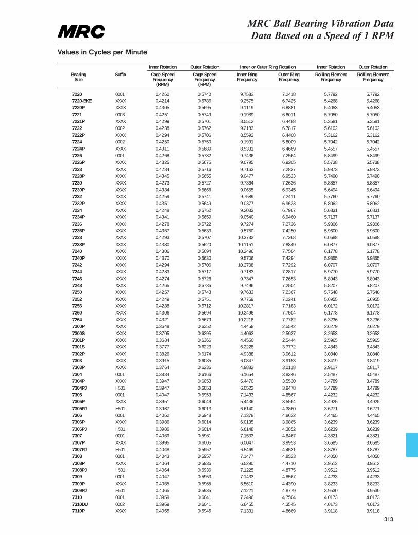
MRC Ball Bearing Vibration Data Data Based on a Speed of 1 RPM
Values in Cycles per Minute
Inner Rotation Outer Rotation Inner or Outer Ring Rotation Inner Rotation Outer Rotation
Bearing Suffix Cage Speed Cage Speed Inner Ring Outer Ring Rolling Element Rolling ElementSize Frequency Frequency Frequency Frequency Frequency Frequency
(RPM) (RPM)
7220 0001 0.4260 0.5740 0.1626 0.1207 0.0482 0.04807220-BKE XXXX 0.4214 0.5786 0.1543 0.1124 0.0452 0.04517220P XXXX 0.4305 0.5695 0.1519 0.1148 0.0450 0.04487221 0003 0.4251 0.5749 0.1533 0.1133 0.0475 0.04747221P XXXX 0.4299 0.5701 0.1425 0.1075 0.0447 0.04447222 0002 0.4238 0.5762 0.1536 0.1130 0.0468 0.04667222P XXXX 0.4294 0.5706 0.1427 0.1073 0.0443 0.04407224 0002 0.4250 0.5750 0.1533 0.1133 0.0475 0.04747224P XXXX 0.4311 0.5689 0.1422 0.1078 0.0455 0.04527226 0001 0.4268 0.5732 0.1624 0.1209 0.0487 0.04867226P XXXX 0.4325 0.5675 0.1513 0.1153 0.0464 0.04627228 XXXX 0.4284 0.5716 0.1619 0.1214 0.0499 0.04977228P XXXX 0.4345 0.5655 0.1508 0.1159 0.0479 0.04777230 XXXX 0.4273 0.5727 0.1623 0.1211 0.0490 0.04897230P XXXX 0.4334 0.5666 0.1511 0.1156 0.0471 0.04687232 XXXX 0.4259 0.5741 0.1627 0.1207 0.0481 0.04807232P XXXX 0.4351 0.5649 0.1506 0.1160 0.0484 0.04817234 XXXX 0.4248 0.5752 0.1534 0.1133 0.0474 0.04727234P XXXX 0.4341 0.5659 0.1509 0.1158 0.0476 0.04747236 XXXX 0.4278 0.5722 0.1621 0.1212 0.0494 0.04937236P XXXX 0.4367 0.5633 0.1596 0.1237 0.0497 0.04947238 XXXX 0.4293 0.5707 0.1712 0.1288 0.0505 0.05037238P XXXX 0.4380 0.5620 0.1686 0.1314 0.0507 0.05057240 XXXX 0.4306 0.5694 0.1708 0.1292 0.0515 0.05137240P XXXX 0.4370 0.5630 0.1595 0.1238 0.0499 0.04967242 XXXX 0.4294 0.5706 0.1712 0.1288 0.0506 0.05047244 XXXX 0.4283 0.5717 0.1620 0.1214 0.0498 0.04977246 XXXX 0.4274 0.5726 0.1622 0.1211 0.0491 0.04907248 XXXX 0.4265 0.5735 0.1625 0.1208 0.0485 0.04847250 XXXX 0.4257 0.5743 0.1627 0.1206 0.0480 0.04787252 XXXX 0.4249 0.5751 0.1629 0.1204 0.0475 0.04737256 XXXX 0.4288 0.5712 0.1714 0.1286 0.0501 0.05007260 XXXX 0.4306 0.5694 0.1708 0.1292 0.0515 0.05137264 XXXX 0.4321 0.5679 0.1704 0.1296 0.0527 0.05267300P XXXX 0.3648 0.6352 0.0741 0.0426 0.0219 0.02147300S XXXX 0.3705 0.6295 0.0734 0.0432 0.0272 0.02707301P XXXX 0.3634 0.6366 0.0743 0.0424 0.0216 0.02117301S XXXX 0.3777 0.6223 0.1037 0.0630 0.0290 0.02887302P XXXX 0.3826 0.6174 0.0823 0.0510 0.0257 0.02527303 XXXX 0.3915 0.6085 0.1014 0.0653 0.0320 0.03187303P XXXX 0.3764 0.6236 0.0831 0.0502 0.0243 0.02387304 0001 0.3834 0.6166 0.1028 0.0639 0.0296 0.02937304P XXXX 0.3947 0.6053 0.0908 0.0592 0.0290 0.02867304PJ H501 0.3947 0.6053 0.1009 0.0658 0.0290 0.02867305 0001 0.4047 0.5953 0.1191 0.0809 0.0369 0.03677305P XXXX 0.3951 0.6049 0.0907 0.0593 0.0291 0.02877305PJ H501 0.3987 0.6013 0.1102 0.0731 0.0302 0.02987306 0001 0.4052 0.5948 0.1190 0.0810 0.0371 0.03697306P XXXX 0.3986 0.6014 0.1002 0.0664 0.0302 0.02987306PJ H501 0.3986 0.6014 0.1103 0.0731 0.0302 0.02987307 0C01 0.4039 0.5961 0.1192 0.0808 0.0365 0.03637307P XXXX 0.3995 0.6005 0.1001 0.0666 0.0305 0.03017307PJ H501 0.4048 0.5952 0.1091 0.0742 0.0323 0.03207308 0001 0.4043 0.5957 0.1191 0.0809 0.0367 0.03657308P XXXX 0.4064 0.5936 0.1088 0.0745 0.0329 0.03267308PJ H501 0.4064 0.5936 0.1187 0.0813 0.0329 0.03267309 0001 0.4047 0.5953 0.1191 0.0809 0.0369 0.03677309P XXXX 0.4035 0.5965 0.1094 0.0740 0.0319 0.03157309PJ H501 0.4065 0.5935 0.1187 0.0813 0.0329 0.03267310 0001 0.3959 0.6041 0.1208 0.0792 0.0335 0.03337310DU 0002 0.3959 0.6041 0.1108 0.0726 0.0335 0.03337310P XXXX 0.4055 0.5945 0.1189 0.0811 0.0326 0.0322
9.75829.25759.11199.19898.55129.21838.55929.19918.53319.74369.07959.71639.04779.73649.06559.75899.03779.20339.05409.72749.5750
10.273210.115110.24969.5706
10.27089.71839.73479.74969.76339.7759
10.281710.249610.22184.44584.40634.45566.22284.93886.08474.98826.16545.44706.05227.14335.44366.61407.13786.01356.61487.15336.00476.54697.14776.52907.12257.14336.56107.12217.24966.64557.1331
7.24186.74256.88816.80116.44886.78176.44085.80096.46697.25646.92057.28376.95237.26366.93457.24116.96236.79676.94607.27267.42507.72687.88497.75047.42947.72927.28177.26537.25047.23677.22417.71837.75047.77822.55422.59372.54443.77723.06123.91533.01183.83463.55303.94784.85673.55644.38604.86223.98654.38524.84673.99534.45314.85234.47104.87754.85674.43904.87794.75044.35454.8669
5.77925.42685.40535.70505.35815.61025.31625.70425.45575.84995.57385.98735.74905.88575.64945.77605.80625.68315.71375.93065.96006.05886.08776.17785.98556.07075.97705.89435.82075.75485.69556.01726.17786.32362.62793.26532.59653.48433.08403.84192.91173.54873.47893.47894.42323.49253.62714.44653.62393.62394.38213.65853.87874.40503.95123.95124.42333.82333.95304.01734.01733.9118
5.77925.42685.40535.70505.35815.61025.31625.70425.45575.84995.57385.98735.74905.88575.64945.77605.80625.68315.71375.93065.96006.05886.08776.17785.98556.07075.97705.89435.82075.75485.69556.01726.17786.32362.62793.26532.59653.48433.08403.84192.81173.54873.47893.47894.42323.49253.62714.44653.62393.62394.38213.65853.87874.40503.95123.95124.42333.82333.95304.01734.01733.9118
313
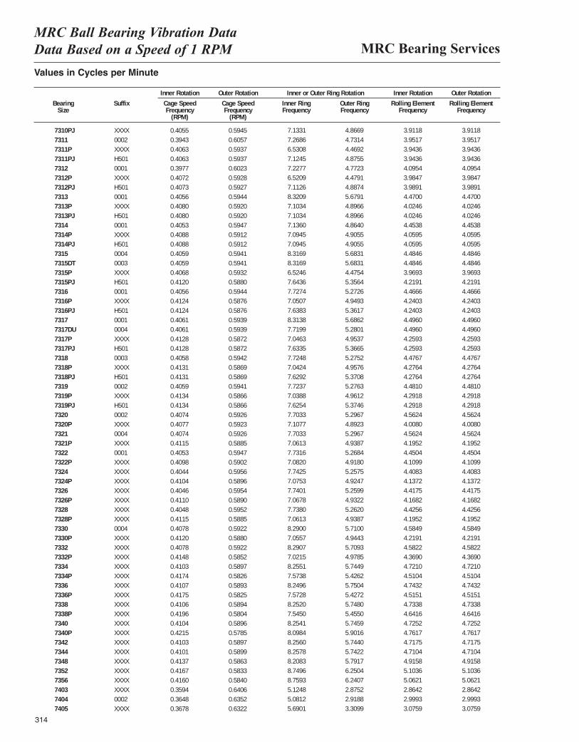
MRC Bearing ServicesMRC Ball Bearing Vibration Data Data Based on a Speed of 1 RPM
314
Values in Cycles per Minute
Inner Rotation Outer Rotation Inner or Outer Ring Rotation Inner Rotation Outer Rotation
Bearing Suffix Cage Speed Cage Speed Inner Ring Outer Ring Rolling Element Rolling ElementSize Frequency Frequency Frequency Frequency Frequency Frequency
(RPM) (RPM)
7310PJ XXXX 0.4055 0.5945 0.1189 0.0811 0.0326 0.03227311 0002 0.3943 0.6057 0.1211 0.0789 0.0329 0.03277311P XXXX 0.4063 0.5937 0.1089 0.0745 0.0329 0.03257311PJ H501 0.4063 0.5937 0.1187 0.0813 0.0329 0.03257312 0001 0.3977 0.6023 0.1205 0.0795 0.0341 0.03397312P XXXX 0.4072 0.5928 0.1087 0.0746 0.0332 0.03287312PJ H501 0.4073 0.5927 0.1185 0.0815 0.0332 0.03297313 0001 0.4056 0.5944 0.1387 0.0946 0.0373 0.03717313P XXXX 0.4080 0.5920 0.1184 0.0816 0.0335 0.03327313PJ H501 0.4080 0.5920 0.1184 0.0816 0.0335 0.03327314 0001 0.4053 0.5947 0.1189 0.0811 0.0371 0.03697314P XXXX 0.4088 0.5912 0.1182 0.0818 0.0338 0.03357314PJ H501 0.4088 0.5912 0.1182 0.0818 0.0338 0.03357315 0004 0.4059 0.5941 0.1386 0.0947 0.0374 0.03727315DT 0003 0.4059 0.5941 0.1386 0.0947 0.0374 0.03727315P XXXX 0.4068 0.5932 0.1087 0.0746 0.0331 0.03277315PJ H501 0.4120 0.5880 0.1274 0.0893 0.0352 0.03487316 0001 0.4056 0.5944 0.1288 0.0879 0.0372 0.03707316P XXXX 0.4124 0.5876 0.1175 0.0825 0.0353 0.03507316PJ H501 0.4124 0.5876 0.1273 0.0894 0.0353 0.03507317 0001 0.4061 0.5939 0.1386 0.0948 0.0375 0.03737317DU 0004 0.4061 0.5939 0.1287 0.0880 0.0375 0.03737317P XXXX 0.4128 0.5872 0.1174 0.0826 0.0355 0.03527317PJ H501 0.4128 0.5872 0.1272 0.0894 0.0355 0.03527318 0003 0.4058 0.5942 0.1287 0.0879 0.0373 0.03717318P XXXX 0.4131 0.5869 0.1174 0.0826 0.0356 0.03537318PJ H501 0.4131 0.5869 0.1272 0.0895 0.0356 0.03537319 0002 0.4059 0.5941 0.1287 0.0879 0.0373 0.03717319P XXXX 0.4134 0.5866 0.1173 0.0827 0.0358 0.03547319PJ H501 0.4134 0.5866 0.1271 0.0896 0.0358 0.03547320 0002 0.4074 0.5926 0.1284 0.0883 0.0380 0.03787320P XXXX 0.4077 0.5923 0.1185 0.0815 0.0334 0.03307321 0004 0.4074 0.5926 0.1284 0.0883 0.0380 0.03787321P XXXX 0.4115 0.5885 0.1177 0.0823 0.0350 0.03467322 0001 0.4053 0.5947 0.1289 0.0878 0.0371 0.03697322P XXXX 0.4098 0.5902 0.1180 0.0820 0.0342 0.03397324 XXXX 0.4044 0.5956 0.1290 0.0876 0.0367 0.03657324P XXXX 0.4104 0.5896 0.1179 0.0821 0.0345 0.03417326 XXXX 0.4046 0.5954 0.1290 0.0877 0.0368 0.03667326P XXXX 0.4110 0.5890 0.1178 0.0822 0.0347 0.03447328 XXXX 0.4048 0.5952 0.1290 0.0877 0.0369 0.03677328P XXXX 0.4115 0.5885 0.1177 0.0823 0.0350 0.03467330 0004 0.4078 0.5922 0.1382 0.0952 0.0382 0.03807330P XXXX 0.4120 0.5880 0.1176 0.0824 0.0352 0.03487332 XXXX 0.4078 0.5922 0.1382 0.0952 0.0382 0.03807332P XXXX 0.4148 0.5852 0.1170 0.0830 0.0364 0.03617334 XXXX 0.4103 0.5897 0.1376 0.0957 0.0393 0.03927334P XXXX 0.4174 0.5826 0.1262 0.0904 0.0376 0.03737336 XXXX 0.4107 0.5893 0.1375 0.0958 0.0395 0.03937336P XXXX 0.4175 0.5825 0.1262 0.0904 0.0376 0.03737338 XXXX 0.4106 0.5894 0.1375 0.0958 0.0394 0.03937338P XXXX 0.4196 0.5804 0.1258 0.0909 0.0387 0.03847340 XXXX 0.4104 0.5896 0.1376 0.0958 0.0394 0.03927340P XXXX 0.4215 0.5785 0.1350 0.0984 0.0397 0.03947342 XXXX 0.4103 0.5897 0.1376 0.0957 0.0393 0.03917344 XXXX 0.4101 0.5899 0.1376 0.0957 0.0393 0.03917348 XXXX 0.4137 0.5863 0.1368 0.0965 0.0410 0.04087352 XXXX 0.4167 0.5833 0.1458 0.1042 0.0425 0.04247356 XXXX 0.4160 0.5840 0.1460 0.1040 0.0422 0.04207403 XXXX 0.3594 0.6406 0.0854 0.0479 0.0239 0.02367404 0002 0.3648 0.6352 0.0847 0.0486 0.0250 0.02477405 XXXX 0.3678 0.6322 0.0948 0.0552 0.0256 0.0254
7.13317.26866.53087.12457.22776.52097.11268.32097.10347.10347.13607.09457.09458.31698.31696.52467.64367.72747.05077.63838.31387.71997.04637.63357.72487.04247.62927.72377.03887.62547.70337.10777.70337.06137.73167.08207.74257.07537.74017.06787.73807.06138.29007.05578.29077.02158.25517.57388.24967.57288.25207.54508.25418.09848.25608.25788.20838.74968.75935.12485.08125.6901
4.86694.73144.46924.87554.77234.47914.88745.67914.89664.89664.86404.90554.90555.68315.68314.47545.35645.27264.94935.36175.68625.28014.95375.36655.27524.95765.37085.27634.96125.37465.29674.89235.29674.93875.26844.91805.25754.92475.25994.93225.26204.93875.71004.94435.70934.97855.74495.42625.75045.42725.74805.45505.74595.90165.74405.74225.79176.25046.24072.87522.91883.3099
3.91183.95173.94363.94364.09543.98473.98914.47004.02464.02464.45384.05954.05954.48464.48463.96934.21914.46664.24034.24034.49604.49604.25934.25934.47674.27644.27644.48104.29184.29184.56244.00804.56244.19524.45044.10994.40834.13724.41754.16824.42564.19524.58494.21914.58224.36904.72104.51044.74324.51514.73384.64164.72524.76174.71754.71044.91585.10365.06212.86422.99933.0759
3.91183.95173.94363.94364.09543.98473.98914.47004.02464.02464.45384.05954.05954.48464.48463.96934.21914.46664.24034.24034.49604.49604.25934.25934.47674.27644.27644.48104.29184.29184.56244.00804.56244.19524.45044.10994.40834.13724.41754.16824.42564.19524.58494.21914.58224.36904.72104.51044.74324.51514.73384.64164.72524.76174.71754.71044.91585.10365.06212.86422.99933.0759
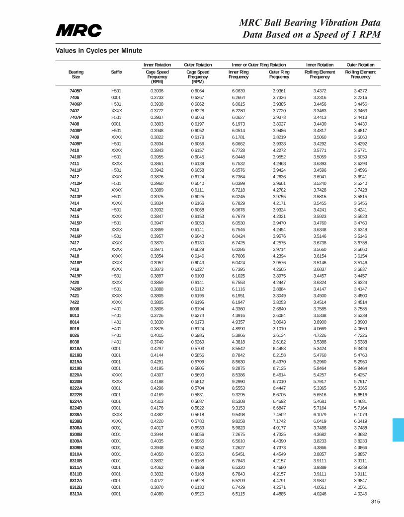
MRC Ball Bearing Vibration Data Data Based on a Speed of 1 RPM
Values in Cycles per Minute
Inner Rotation Outer Rotation Inner or Outer Ring Rotation Inner Rotation Outer Rotation
Bearing Suffix Cage Speed Cage Speed Inner Ring Outer Ring Rolling Element Rolling ElementSize Frequency Frequency Frequency Frequency Frequency Frequency
(RPM) (RPM)
7405P H501 0.3936 0.6064 0.1011 0.0656 0.0286 0.02827406 0001 0.3733 0.6267 0.1044 0.0622 0.0269 0.02677406P H501 0.3938 0.6062 0.1010 0.0656 0.0287 0.02837407 XXXX 0.3772 0.6228 0.1038 0.0629 0.0279 0.02767407P H501 0.3937 0.6063 0.1011 0.0656 0.0287 0.02837408 0001 0.3803 0.6197 0.1033 0.0634 0.0287 0.02847408P H501 0.3948 0.6052 0.1009 0.0658 0.0290 0.02867409 XXXX 0.3822 0.6178 0.1030 0.0637 0.0292 0.02907409P H501 0.3934 0.6066 0.1011 0.0656 0.0286 0.02827410 XXXX 0.3843 0.6157 0.1129 0.0705 0.0298 0.02967410P H501 0.3955 0.6045 0.1008 0.0659 0.0292 0.02887411 XXXX 0.3861 0.6139 0.1126 0.0708 0.0303 0.03017411P H501 0.3942 0.6058 0.1010 0.0657 0.0288 0.02847412 XXXX 0.3876 0.6124 0.1123 0.0711 0.0308 0.03057412P H501 0.3960 0.6040 0.1007 0.0660 0.0294 0.02907413 XXXX 0.3889 0.6111 0.1120 0.0713 0.0312 0.03107413P H501 0.3975 0.6025 0.1004 0.0663 0.0298 0.02947414 XXXX 0.3834 0.6166 0.1131 0.0703 0.0295 0.02937414P H501 0.3932 0.6068 0.1011 0.0655 0.0285 0.02817415 XXXX 0.3847 0.6153 0.1128 0.0705 0.0299 0.02977415P H501 0.3947 0.6053 0.1009 0.0658 0.0290 0.02867416 XXXX 0.3859 0.6141 0.1126 0.0708 0.0303 0.03017416P H501 0.3957 0.6043 0.1007 0.0660 0.0293 0.02897417 XXXX 0.3870 0.6130 0.1124 0.0710 0.0306 0.03047417P XXXX 0.3971 0.6029 0.1005 0.0662 0.0297 0.02937418 XXXX 0.3854 0.6146 0.1127 0.0707 0.0301 0.02997418P XXXX 0.3957 0.6043 0.1007 0.0660 0.0293 0.02897419 XXXX 0.3873 0.6127 0.1123 0.0710 0.0307 0.03057419P H501 0.3897 0.6103 0.1017 0.0650 0.0287 0.02837420 XXXX 0.3859 0.6141 0.1126 0.0707 0.0303 0.03007420P H501 0.3888 0.6112 0.1019 0.0648 0.0285 0.02817421 XXXX 0.3805 0.6195 0.1033 0.0634 0.0287 0.02857422 XXXX 0.3805 0.6195 0.1032 0.0634 0.0288 0.02858008 H401 0.3806 0.6194 0.0723 0.0444 0.0313 0.03128013 H401 0.3726 0.6274 0.0732 0.0435 0.0294 0.02948014 H401 0.3830 0.6170 0.0823 0.0511 0.0324 0.03238016 H401 0.3876 0.6124 0.0817 0.0517 0.0339 0.03388026 H401 0.4015 0.5985 0.0898 0.0602 0.0394 0.03938038 H401 0.3740 0.6260 0.0730 0.0436 0.0295 0.02948218A 0001 0.4297 0.5703 0.1426 0.1074 0.0445 0.04428218B 0001 0.4144 0.5856 0.1464 0.1036 0.0456 0.04568219A 0001 0.4291 0.5709 0.1427 0.1073 0.0441 0.04398219B 0001 0.4195 0.5805 0.1548 0.1119 0.0487 0.04878220A XXXX 0.4307 0.5693 0.1423 0.1077 0.0452 0.04498220B XXXX 0.4188 0.5812 0.1550 0.1117 0.0483 0.04828222A 0001 0.4296 0.5704 0.1426 0.1074 0.0445 0.04428222B 0001 0.4169 0.5831 0.1555 0.1112 0.0471 0.04708224A 0001 0.4313 0.5687 0.1422 0.1078 0.0456 0.04538224B 0001 0.4178 0.5822 0.1553 0.1114 0.0476 0.04768238A XXXX 0.4382 0.5618 0.1592 0.1242 0.0509 0.05078238B XXXX 0.4220 0.5780 0.1638 0.1196 0.0503 0.05038308A 0C01 0.4017 0.5983 0.0997 0.0670 0.0312 0.03098308B 0C01 0.3944 0.6056 0.1211 0.0789 0.0364 0.03638309A 0C01 0.4035 0.5965 0.1094 0.0740 0.0319 0.03158309B 0C01 0.3948 0.6052 0.1210 0.0790 0.0366 0.03658310A 0C01 0.4050 0.5950 0.1091 0.0742 0.0324 0.03208310B 0C01 0.3832 0.6168 0.1131 0.0703 0.0326 0.03258311A 0001 0.4062 0.5938 0.1089 0.0745 0.0328 0.03258311B 0001 0.3832 0.6168 0.1131 0.0703 0.0326 0.03258312A 0001 0.4072 0.5928 0.1087 0.0746 0.0332 0.03288312B 0001 0.3870 0.6130 0.1124 0.0710 0.0338 0.03378313A 0001 0.4080 0.5920 0.1085 0.0748 0.0335 0.0332
6.06396.26646.06156.22806.06276.19736.05146.17816.06626.77286.04486.75326.05766.73646.03996.72186.02456.78296.06766.76796.05306.75466.04246.74256.02866.76066.04246.73956.10256.75536.11166.19516.19474.33604.39164.93574.89905.38664.38188.55428.78428.56309.28758.53869.29908.55539.32958.53089.31539.54989.82585.98237.26756.56107.26276.54516.78436.53206.78436.52096.74296.5115
3.93613.73363.93853.77203.93733.80273.94863.82193.93384.22723.95524.24683.94244.26363.96014.27823.97554.21713.93244.23213.94704.24543.95764.25753.97144.23943.95764.26053.89754.24473.88843.80493.80532.66402.60843.06433.10103.61342.61826.44586.21586.43706.71256.46146.70106.44476.67056.46926.68477.45027.17424.01774.73254.43904.73734.45494.21574.46804.21574.47914.25714.4885
3.43723.23163.44563.34633.44133.44303.48173.50603.42923.57713.50593.63933.45963.69413.52403.74283.58153.54553.42413.59233.47603.63483.51463.67383.56603.61543.51463.68373.44573.63243.41473.45003.45143.75853.53383.89004.06694.72263.53885.34245.47605.29605.84645.42575.79175.33655.65165.46815.71646.10796.04193.74884.36823.82334.38663.88573.91113.93893.91113.98474.05614.0246
3.43723.23163.44563.34633.44133.44303.48173.50603.42923.57713.50593.63933.45963.69413.52403.74283.58153.54553.42413.59233.47603.63483.51463.67383.56603.61543.51463.68373.44573.63243.41473.45003.45143.75853.53383.89004.06694.72263.53885.34245.47605.29605.84645.42575.79175.33655.65165.46815.71646.10796.04193.74884.36823.82334.38663.88573.91113.93893.91113.98474.05614.0246
315
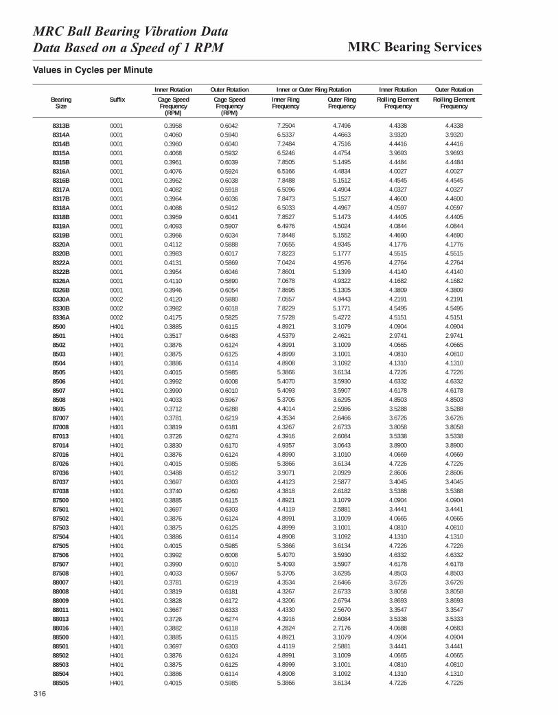
MRC Bearing ServicesMRC Ball Bearing Vibration Data Data Based on a Speed of 1 RPM
316
Values in Cycles per Minute
Inner Rotation Outer Rotation Inner or Outer Ring Rotation Inner Rotation Outer Rotation
Bearing Suffix Cage Speed Cage Speed Inner Ring Outer Ring Rolling Element Rolling ElementSize Frequency Frequency Frequency Frequency Frequency Frequency
(RPM) (RPM)
8313B 0001 0.3958 0.6042 0.1208 0.0792 0.0369 0.03698314A 0001 0.4060 0.5940 0.1089 0.0744 0.0328 0.03248314B 0001 0.3960 0.6040 0.1208 0.0792 0.0370 0.03708315A 0001 0.4068 0.5932 0.1087 0.0746 0.0331 0.03278315B 0001 0.3961 0.6039 0.1308 0.0858 0.0371 0.03708316A 0001 0.4076 0.5924 0.1086 0.0747 0.0334 0.03308316B 0001 0.3962 0.6038 0.1308 0.0859 0.0371 0.03718317A 0001 0.4082 0.5918 0.1085 0.0748 0.0336 0.03328317B 0001 0.3964 0.6036 0.1308 0.0859 0.0372 0.03718318A 0001 0.4088 0.5912 0.1084 0.0749 0.0338 0.03358318B 0001 0.3959 0.6041 0.1309 0.0858 0.0370 0.03698319A 0001 0.4093 0.5907 0.1083 0.0750 0.0340 0.03378319B 0001 0.3966 0.6034 0.1307 0.0859 0.0372 0.03728320A 0001 0.4112 0.5888 0.1178 0.0822 0.0348 0.03458320B 0001 0.3983 0.6017 0.1304 0.0863 0.0379 0.03798322A 0001 0.4131 0.5869 0.1174 0.0826 0.0356 0.03538322B 0001 0.3954 0.6046 0.1310 0.0857 0.0368 0.03678326A 0001 0.4110 0.5890 0.1178 0.0822 0.0347 0.03448326B 0001 0.3946 0.6054 0.1312 0.0855 0.0365 0.03648330A 0002 0.4120 0.5880 0.1176 0.0824 0.0352 0.03488330B 0002 0.3982 0.6018 0.1304 0.0863 0.0379 0.03798336A 0002 0.4175 0.5825 0.1262 0.0904 0.0376 0.03738500 H401 0.3885 0.6115 0.0815 0.0518 0.0341 0.03408501 H401 0.3517 0.6483 0.0756 0.0410 0.0248 0.02478502 H401 0.3876 0.6124 0.0817 0.0517 0.0339 0.03388503 H401 0.3875 0.6125 0.0817 0.0517 0.0340 0.03398504 H401 0.3886 0.6114 0.0815 0.0518 0.0344 0.03448505 H401 0.4015 0.5985 0.0898 0.0602 0.0394 0.03938506 H401 0.3992 0.6008 0.0901 0.0599 0.0386 0.03868507 H401 0.3990 0.6010 0.0902 0.0598 0.0385 0.03848508 H401 0.4033 0.5967 0.0895 0.0605 0.0404 0.04048605 H401 0.3712 0.6288 0.0734 0.0433 0.0294 0.029387007 H401 0.3781 0.6219 0.0726 0.0441 0.0306 0.030587008 H401 0.3819 0.6181 0.0721 0.0446 0.0317 0.031687013 H401 0.3726 0.6274 0.0732 0.0435 0.0294 0.029487014 H401 0.3830 0.6170 0.0823 0.0511 0.0324 0.032387016 H401 0.3876 0.6124 0.0817 0.0517 0.0339 0.033887026 H401 0.4015 0.5985 0.0898 0.0602 0.0394 0.039387036 H401 0.3488 0.6512 0.0651 0.0349 0.0238 0.023787037 H401 0.3697 0.6303 0.0735 0.0431 0.0284 0.028387038 H401 0.3740 0.6260 0.0730 0.0436 0.0295 0.029487500 H401 0.3885 0.6115 0.0815 0.0518 0.0341 0.034087501 H401 0.3697 0.6303 0.0735 0.0431 0.0287 0.028687502 H401 0.3876 0.6124 0.0817 0.0517 0.0339 0.033887503 H401 0.3875 0.6125 0.0817 0.0517 0.0340 0.033987504 H401 0.3886 0.6114 0.0815 0.0518 0.0344 0.034487505 H401 0.4015 0.5985 0.0898 0.0602 0.0394 0.039387506 H401 0.3992 0.6008 0.0901 0.0599 0.0386 0.038687507 H401 0.3990 0.6010 0.0902 0.0598 0.0385 0.038487508 H401 0.4033 0.5967 0.0895 0.0605 0.0404 0.040488007 H401 0.3781 0.6219 0.0726 0.0441 0.0306 0.030588008 H401 0.3819 0.6181 0.0721 0.0446 0.0317 0.031688009 H401 0.3828 0.6172 0.0720 0.0447 0.0322 0.032288011 H401 0.3667 0.6333 0.0739 0.0428 0.0280 0.027988013 H401 0.3726 0.6274 0.0732 0.0435 0.0294 0.029488016 H401 0.3882 0.6118 0.0714 0.0453 0.0339 0.033888500 H401 0.3885 0.6115 0.0815 0.0518 0.0341 0.034088501 H401 0.3697 0.6303 0.0735 0.0431 0.0287 0.028688502 H401 0.3876 0.6124 0.0817 0.0517 0.0339 0.033888503 H401 0.3875 0.6125 0.0817 0.0517 0.0340 0.033988504 H401 0.3886 0.6114 0.0815 0.0518 0.0344 0.034488505 H401 0.4015 0.5985 0.0898 0.0602 0.0394 0.0393
7.25046.53377.24846.52467.85056.51667.84886.50967.84736.50337.85276.49767.84487.06557.82237.04247.86017.06787.86957.05577.82297.57284.89214.53794.89914.89994.89085.38665.40705.40935.37054.40144.35344.32674.39164.93574.89905.38663.90714.41234.38184.89214.41194.89914.89994.89085.38665.40705.40935.37054.35344.32674.32064.43304.39164.28244.89214.41194.89914.89994.89085.3866
4.74964.46634.75164.47545.14954.48345.15124.49045.15274.49675.14734.50245.15524.93455.17774.95765.13994.93225.13054.94435.17715.42723.10792.46213.10093.10013.10923.61343.59303.59073.62952.59862.64662.67332.60843.06433.10103.61342.09292.58772.61823.10792.58813.10093.10013.10923.61343.59303.59073.62952.64662.67332.67942.56702.60842.71763.10792.58813.10093.10013.10923.6134
4.43383.93204.44163.96934.44844.00274.45454.03274.46004.05974.44054.08444.46904.17764.55154.27644.41404.16824.38094.21914.54954.51514.09042.97414.06654.08104.13104.72264.63324.61784.85033.52883.67263.80583.53383.89004.06694.72262.86063.40453.53884.09043.44414.06654.08104.13104.72264.63324.61784.85033.67263.80583.86933.35473.53384.06884.09043.44414.06654.08104.13104.7226
4.43383.93204.44163.96934.44844.00274.45454.03274.46004.05974.44054.08444.46904.17764.55154.27644.41404.16824.38094.21914.54954.51514.09042.97414.06654.08104.13104.72264.63324.61784.85033.52883.67263.80583.53383.89004.06694.72262.86063.40453.53884.09043.44414.06654.08104.13104.72264.63324.61784.85033.67263.80583.86933.35473.53334.06834.09043.44414.06654.08104.13104.7226
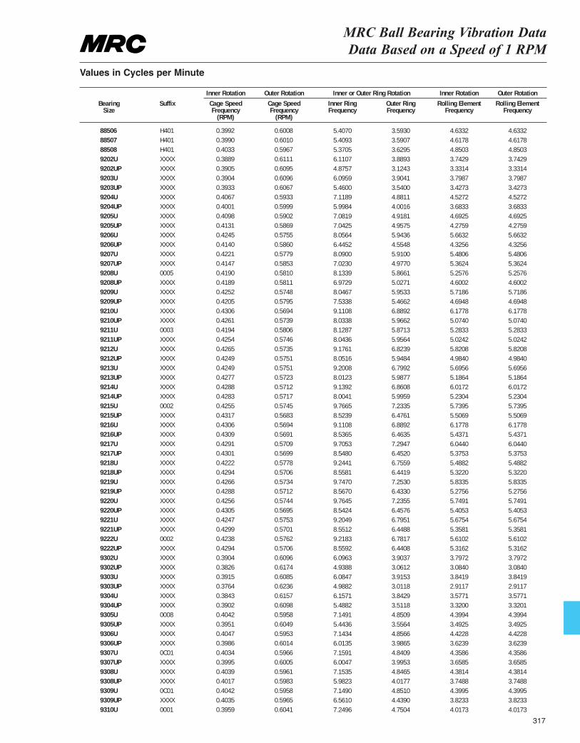
MRC Ball Bearing Vibration Data Data Based on a Speed of 1 RPM
Values in Cycles per Minute
Inner Rotation Outer Rotation Inner or Outer Ring Rotation Inner Rotation Outer Rotation
Bearing Suffix Cage Speed Cage Speed Inner Ring Outer Ring Rolling Element Rolling ElementSize Frequency Frequency Frequency Frequency Frequency Frequency
(RPM) (RPM)
88506 H401 0.3992 0.6008 0.0901 0.0599 0.0386 0.038688507 H401 0.3990 0.6010 0.0902 0.0598 0.0385 0.038488508 H401 0.4033 0.5967 0.0895 0.0605 0.0404 0.04049202U XXXX 0.3889 0.6111 0.1018 0.0648 0.0312 0.03109202UP XXXX 0.3905 0.6095 0.0813 0.0521 0.0278 0.02739203U XXXX 0.3904 0.6096 0.1016 0.0651 0.0317 0.03149203UP XXXX 0.3933 0.6067 0.0910 0.0590 0.0286 0.02819204U XXXX 0.4067 0.5933 0.1187 0.0813 0.0377 0.03759204UP XXXX 0.4001 0.5999 0.1000 0.0667 0.0307 0.03039205U XXXX 0.4098 0.5902 0.1180 0.0820 0.0391 0.03899205UP XXXX 0.4131 0.5869 0.1174 0.0826 0.0356 0.03539206U XXXX 0.4245 0.5755 0.1343 0.0991 0.0472 0.04709206UP XXXX 0.4140 0.5860 0.1074 0.0759 0.0360 0.03579207U XXXX 0.4221 0.5779 0.1348 0.0985 0.0457 0.04559207UP XXXX 0.4147 0.5853 0.1171 0.0829 0.0364 0.03609208U 0005 0.4190 0.5810 0.1356 0.0978 0.0438 0.04369208UP XXXX 0.4189 0.5811 0.1162 0.0838 0.0383 0.03809209U XXXX 0.4252 0.5748 0.1341 0.0992 0.0477 0.04759209UP XXXX 0.4205 0.5795 0.1256 0.0911 0.0391 0.03889210U XXXX 0.4306 0.5694 0.1518 0.1148 0.0515 0.05139210UP XXXX 0.4261 0.5739 0.1339 0.0994 0.0423 0.04209211U 0003 0.4194 0.5806 0.1355 0.0979 0.0440 0.04399211UP XXXX 0.4254 0.5746 0.1341 0.0993 0.0419 0.04169212U XXXX 0.4265 0.5735 0.1529 0.1137 0.0485 0.04849212UP XXXX 0.4249 0.5751 0.1342 0.0991 0.0415 0.04129213U XXXX 0.4249 0.5751 0.1533 0.1133 0.0475 0.04739213UP XXXX 0.4277 0.5723 0.1335 0.0998 0.0432 0.04299214U XXXX 0.4288 0.5712 0.1523 0.1143 0.0501 0.05009214UP XXXX 0.4283 0.5717 0.1334 0.0999 0.0436 0.04339215U 0002 0.4255 0.5745 0.1628 0.1206 0.0478 0.04779215UP XXXX 0.4317 0.5683 0.1421 0.1079 0.0459 0.04569216U XXXX 0.4306 0.5694 0.1518 0.1148 0.0515 0.05139216UP XXXX 0.4309 0.5691 0.1423 0.1077 0.0453 0.04509217U XXXX 0.4291 0.5709 0.1618 0.1216 0.0504 0.05029217UP XXXX 0.4301 0.5699 0.1425 0.1075 0.0448 0.04459218U XXXX 0.4222 0.5778 0.1541 0.1126 0.0457 0.04569218UP XXXX 0.4294 0.5706 0.1426 0.1074 0.0443 0.04419219U XXXX 0.4266 0.5734 0.1625 0.1209 0.0486 0.04859219UP XXXX 0.4288 0.5712 0.1428 0.1072 0.0440 0.04379220U XXXX 0.4256 0.5744 0.1627 0.1206 0.0479 0.04789220UP XXXX 0.4305 0.5695 0.1424 0.1076 0.0450 0.04489221U XXXX 0.4247 0.5753 0.1534 0.1132 0.0473 0.04719221UP XXXX 0.4299 0.5701 0.1425 0.1075 0.0447 0.04449222U 0002 0.4238 0.5762 0.1536 0.1130 0.0468 0.04669222UP XXXX 0.4294 0.5706 0.1427 0.1073 0.0443 0.04409302U XXXX 0.3904 0.6096 0.1016 0.0651 0.0316 0.03149302UP XXXX 0.3826 0.6174 0.0823 0.0510 0.0257 0.02529303U XXXX 0.3915 0.6085 0.1014 0.0653 0.0320 0.03189303UP XXXX 0.3764 0.6236 0.0831 0.0502 0.0243 0.02389304U XXXX 0.3843 0.6157 0.1026 0.0640 0.0298 0.02969304UP XXXX 0.3902 0.6098 0.0915 0.0585 0.0277 0.02729305U 0008 0.4042 0.5958 0.1192 0.0808 0.0367 0.03659305UP XXXX 0.3951 0.6049 0.0907 0.0593 0.0291 0.02879306U XXXX 0.4047 0.5953 0.1191 0.0809 0.0369 0.03679306UP XXXX 0.3986 0.6014 0.1002 0.0664 0.0302 0.02989307U 0C01 0.4034 0.5966 0.1193 0.0807 0.0363 0.03619307UP XXXX 0.3995 0.6005 0.1001 0.0666 0.0305 0.03019308U XXXX 0.4039 0.5961 0.1192 0.0808 0.0365 0.03639308UP XXXX 0.4017 0.5983 0.0997 0.0670 0.0312 0.03099309U 0C01 0.4042 0.5958 0.1192 0.0808 0.0367 0.03659309UP XXXX 0.4035 0.5965 0.1094 0.0740 0.0319 0.03159310U 0001 0.3959 0.6041 0.1208 0.0792 0.0335 0.0333
5.40705.40935.37056.11074.87576.09595.46007.11895.99847.08197.04258.05646.44528.09007.02308.13396.97298.04677.53389.11088.03388.12878.04369.17618.05169.20088.01239.13928.00419.76658.52399.11088.53659.70538.54809.24418.55819.74708.56709.76458.54249.20498.55129.21838.55926.09634.93886.08474.98826.15715.48827.14915.44367.14346.01357.15916.00477.15355.98237.14906.56107.2496
3.59303.59073.62953.88933.12433.90413.54004.88114.00164.91814.95755.94364.55485.91004.97705.86615.02715.95335.46626.88925.96625.87135.95646.82395.94846.79925.98776.86085.99597.23356.47616.88926.46357.29476.45206.75596.44197.25306.43307.23556.45766.79516.44886.78176.44083.90373.06123.91533.01183.84293.51184.85093.55644.85663.98654.84093.99534.84654.01774.85104.43904.7504
4.63324.61784.85033.74293.33143.79873.42734.52723.68334.69254.27595.66324.32565.48065.36245.25764.60025.71864.69486.17785.07405.28335.02425.82084.98405.69565.18646.01725.23045.73955.50696.17785.43716.04405.37535.48825.32205.83355.27565.74915.40535.67545.35815.61025.31623.79723.08403.84192.91173.57713.32004.39943.49254.42283.62394.35863.65854.38143.74884.39953.82334.0173
4.63324.61784.85033.74293.33143.79873.42734.52723.68334.69254.27595.66324.32565.48065.36245.25764.60025.71864.69486.17785.07405.28335.02425.82084.98405.69565.18646.01725.23045.73955.50696.17785.43716.04405.37535.48825.32205.83355.27565.74915.40535.67545.35815.61025.31623.79723.08403.84192.91173.57713.32014.39943.49254.42283.62394.35863.65854.38143.74884.39953.82334.0173
317
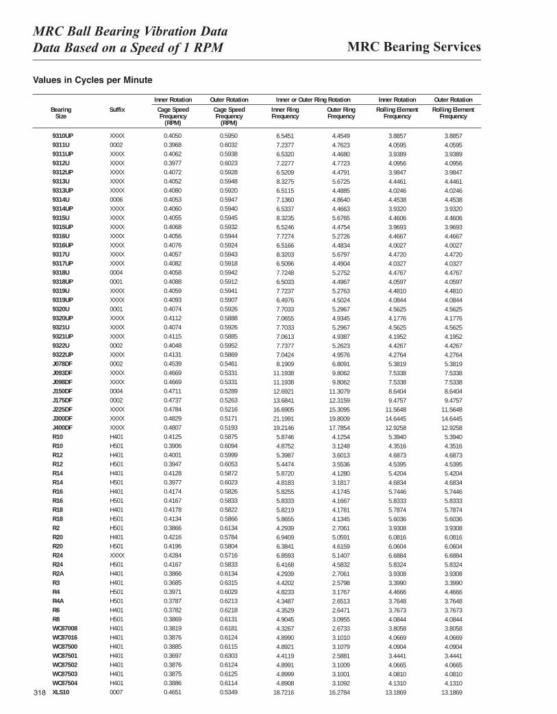
MRC Bearing ServicesMRC Ball Bearing Vibration Data Data Based on a Speed of 1 RPM
318
Values in Cycles per Minute
Inner Rotation Outer Rotation Inner or Outer Ring Rotation Inner Rotation Outer Rotation
Bearing Suffix Cage Speed Cage Speed Inner Ring Outer Ring Rolling Element Rolling ElementSize Frequency Frequency Frequency Frequency Frequency Frequency
(RPM) (RPM)
9310UP XXXX 0.4050 0.5950 0.1091 0.0742 0.0324 0.03209311U 0002 0.3968 0.6032 0.1206 0.0794 0.0338 0.03369311UP XXXX 0.4062 0.5938 0.1089 0.0745 0.0328 0.03259312U XXXX 0.3977 0.6023 0.1205 0.0795 0.0341 0.03399312UP XXXX 0.4072 0.5928 0.1087 0.0746 0.0332 0.03289313U XXXX 0.4052 0.5948 0.1388 0.0945 0.0371 0.03699313UP XXXX 0.4080 0.5920 0.1085 0.0748 0.0335 0.03329314U 0006 0.4053 0.5947 0.1189 0.0811 0.0371 0.03699314UP XXXX 0.4060 0.5940 0.1089 0.0744 0.0328 0.03249315U XXXX 0.4055 0.5945 0.1387 0.0946 0.0372 0.03709315UP XXXX 0.4068 0.5932 0.1087 0.0746 0.0331 0.03279316U XXXX 0.4056 0.5944 0.1288 0.0879 0.0372 0.03709316UP XXXX 0.4076 0.5924 0.1086 0.0747 0.0334 0.03309317U XXXX 0.4057 0.5943 0.1387 0.0947 0.0373 0.03719317UP XXXX 0.4082 0.5918 0.1085 0.0748 0.0336 0.03329318U 0004 0.4058 0.5942 0.1287 0.0879 0.0373 0.03719318UP 0001 0.4088 0.5912 0.1084 0.0749 0.0338 0.03359319U XXXX 0.4059 0.5941 0.1287 0.0879 0.0373 0.03719319UP XXXX 0.4093 0.5907 0.1083 0.0750 0.0340 0.03379320U 0001 0.4074 0.5926 0.1284 0.0883 0.0380 0.03789320UP XXXX 0.4112 0.5888 0.1178 0.0822 0.0348 0.03459321U XXXX 0.4074 0.5926 0.1284 0.0883 0.0380 0.03789321UP XXXX 0.4115 0.5885 0.1177 0.0823 0.0350 0.03469322U 0002 0.4048 0.5952 0.1290 0.0877 0.0369 0.03679322UP XXXX 0.4131 0.5869 0.1174 0.0826 0.0356 0.0353J078DF 0002 0.4539 0.5461 0.1365 0.1135 0.0448 0.0445J093DF XXXX 0.4669 0.5331 0.1866 0.1634 0.0628 0.0625J098DF XXXX 0.4669 0.5331 0.1866 0.1634 0.0628 0.0625J150DF 0004 0.4711 0.5289 0.2115 0.1885 0.0720 0.0718J175DF 0002 0.4737 0.5263 0.2281 0.2053 0.0790 0.0787J225DF XXXX 0.4784 0.5216 0.2782 0.2551 0.0964 0.0962J300DF XXXX 0.4829 0.5171 0.3533 0.3300 0.1220 0.1219J400DF XXXX 0.4807 0.5193 0.3203 0.2964 0.1077 0.1076R10 H401 0.4125 0.5875 0.0979 0.0688 0.0449 0.0449R10 H501 0.3906 0.6094 0.0813 0.0521 0.0363 0.0363R12 H401 0.4001 0.5999 0.0900 0.0600 0.0391 0.0390R12 H501 0.3947 0.6053 0.0908 0.0592 0.0378 0.0378R14 H401 0.4128 0.5872 0.0979 0.0688 0.0452 0.0451R14 H501 0.3977 0.6023 0.0803 0.0530 0.0390 0.0390R16 H401 0.4174 0.5826 0.0971 0.0696 0.0479 0.0478R16 H501 0.4167 0.5833 0.0972 0.0694 0.0486 0.0486R18 H401 0.4178 0.5822 0.0970 0.0696 0.0482 0.0482R18 H501 0.4134 0.5866 0.0978 0.0689 0.0467 0.0467R2 H501 0.3866 0.6134 0.0716 0.0451 0.0328 0.0326R20 H401 0.4216 0.5784 0.1157 0.0843 0.0507 0.0507R20 H501 0.4196 0.5804 0.1064 0.0769 0.0505 0.0505R24 XXXX 0.4284 0.5716 0.1143 0.0857 0.0557 0.0557R24 H501 0.4167 0.5833 0.1069 0.0764 0.0486 0.0486R2A H401 0.3866 0.6134 0.0716 0.0451 0.0328 0.0326R3 H401 0.3685 0.6315 0.0737 0.0430 0.0283 0.0282R4 H501 0.3971 0.6029 0.0804 0.0529 0.0372 0.0372R4A H501 0.3787 0.6213 0.0725 0.0442 0.0314 0.0313R6 H401 0.3782 0.6218 0.0725 0.0441 0.0314 0.0313R8 H501 0.3869 0.6131 0.0817 0.0516 0.0340 0.0340WC87008 H401 0.3819 0.6181 0.0721 0.0446 0.0317 0.0316WC87016 H401 0.3876 0.6124 0.0817 0.0517 0.0339 0.0338WC87500 H401 0.3885 0.6115 0.0815 0.0518 0.0341 0.0340WC87501 H401 0.3697 0.6303 0.0735 0.0431 0.0287 0.0286WC87502 H401 0.3876 0.6124 0.0817 0.0517 0.0339 0.0338WC87503 H401 0.3875 0.6125 0.0817 0.0517 0.0340 0.0339WC87504 H401 0.3886 0.6114 0.0815 0.0518 0.0344 0.0344XLS10 0007 0.4651 0.5349 0.3120 0.2713 0.1099 0.1098
6.54517.23776.53207.22776.52098.32756.51157.13606.53378.32356.52467.72746.51668.32036.50967.72486.50337.72376.49767.70337.06557.70337.06137.73777.04248.1909
11.193811.193812.692113.684116.690521.199119.21465.87464.87525.39875.44745.87204.81835.82555.83335.82195.86554.29396.94096.38416.85936.41684.29394.42024.82334.34874.35294.90454.32674.89904.89214.41194.89914.89994.8908
18.7216
4.45494.76234.46804.77234.47915.67254.48854.86404.46635.67654.47545.27264.48345.67974.49045.27524.49675.27634.50245.29674.93455.29674.93875.26234.95766.80919.80629.8062
11.307912.315915.309519.800917.78544.12543.12483.60133.55364.12803.18174.17454.16674.17814.13452.70615.05914.61595.14074.58322.70612.57983.17672.65132.64713.09552.67333.10103.10792.58813.10093.10013.1092
16.2784
3.88574.05953.93894.09563.98474.44614.02464.45383.93204.46063.96934.46674.00274.47204.03274.47674.05974.48104.08444.56254.17764.56254.19524.42674.27645.38197.53387.53388.64049.4757
11.564814.644512.92585.39404.35164.68734.53955.42044.68345.74465.83335.78745.60363.93086.08166.06046.68845.83243.93083.39904.46663.76483.76734.08443.80584.06694.09043.44414.06654.08104.1310
13.1869
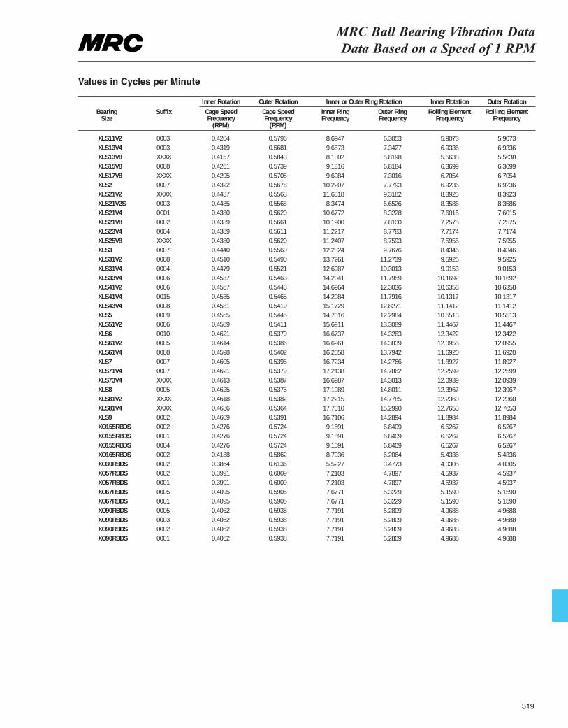
MRC Ball Bearing Vibration Data Data Based on a Speed of 1 RPM
Values in Cycles per Minute
Inner Rotation Outer Rotation Inner or Outer Ring Rotation Inner Rotation Outer Rotation
Bearing Suffix Cage Speed Cage Speed Inner Ring Outer Ring Rolling Element Rolling ElementSize Frequency Frequency Frequency Frequency Frequency Frequency
(RPM) (RPM)
XLS11V2 0003 0.4204 0.5796 0.1449 0.1051 0.0492 0.0492XLS13V4 0003 0.4319 0.5681 0.1610 0.1224 0.0578 0.0577XLS13V8 XXXX 0.4157 0.5843 0.1363 0.0970 0.0464 0.0463XLS15V8 0008 0.4261 0.5739 0.1530 0.1136 0.0531 0.0530XLS17V8 XXXX 0.4295 0.5705 0.1616 0.1217 0.0559 0.0558XLS2 0007 0.4322 0.5678 0.1703 0.1297 0.0577 0.0576XLS21V2 XXXX 0.4437 0.5563 0.1947 0.1553 0.0699 0.0699XLS21V2S 0003 0.4435 0.5565 0.1391 0.1109 0.0697 0.0696XLS21V4 0C01 0.4380 0.5620 0.1780 0.1387 0.0633 0.0633XLS21V8 0002 0.4339 0.5661 0.1698 0.1302 0.0605 0.0605XLS23V4 0004 0.4389 0.5611 0.1870 0.1463 0.0643 0.0643XLS25V8 XXXX 0.4380 0.5620 0.1873 0.1460 0.0633 0.0633XLS3 0007 0.4440 0.5560 0.2039 0.1628 0.0703 0.0703XLS31V2 0008 0.4510 0.5490 0.2288 0.1879 0.0799 0.0799XLS31V4 0004 0.4479 0.5521 0.2116 0.1717 0.0751 0.0751XLS33V4 0006 0.4537 0.5463 0.2367 0.1966 0.0847 0.0847XLS41V2 0006 0.4557 0.5443 0.2449 0.2051 0.0886 0.0886XLS41V4 0015 0.4535 0.5465 0.2368 0.1965 0.0844 0.0844XLS43V4 0008 0.4581 0.5419 0.2529 0.2138 0.0928 0.0928XLS5 0009 0.4555 0.5445 0.2450 0.2050 0.0879 0.0879XLS51V2 0006 0.4589 0.5411 0.2615 0.2218 0.0954 0.0954XLS6 0010 0.4621 0.5379 0.2779 0.2388 0.1029 0.1028XLS61V2 0005 0.4614 0.5386 0.2783 0.2384 0.1008 0.1008XLS61V4 0008 0.4598 0.5402 0.2701 0.2299 0.0974 0.0974XLS7 0007 0.4605 0.5395 0.2787 0.2379 0.0991 0.0991XLS71V4 0007 0.4621 0.5379 0.2869 0.2464 0.1022 0.1021XLS73V4 XXXX 0.4613 0.5387 0.2783 0.2384 0.1008 0.1007XLS8 0005 0.4625 0.5375 0.2866 0.2467 0.1033 0.1033XLS81V2 XXXX 0.4618 0.5382 0.2870 0.2463 0.1020 0.1019XLS81V4 XXXX 0.4636 0.5364 0.2950 0.2550 0.1064 0.1063XLS9 0002 0.4609 0.5391 0.2785 0.2382 0.0992 0.0991XO155RBDS 0002 0.4276 0.5724 0.1527 0.1140 0.0544 0.0543XO155RBDS 0001 0.4276 0.5724 0.1527 0.1140 0.0544 0.0543XO155RBDS 0004 0.4276 0.5724 0.1527 0.1140 0.0544 0.0543XO165RBDS 0002 0.4138 0.5862 0.1466 0.1034 0.0453 0.0452XO30RBDS 0002 0.3864 0.6136 0.0920 0.0580 0.0336 0.0335XO57RBDS 0002 0.3991 0.6009 0.1202 0.0798 0.0383 0.0382XO57RBDS 0001 0.3991 0.6009 0.1202 0.0798 0.0383 0.0382XO67RBDS 0005 0.4095 0.5905 0.1280 0.0887 0.0430 0.0429XO67RBDS 0001 0.4095 0.5905 0.1280 0.0887 0.0430 0.0429XO90RBDS 0005 0.4062 0.5938 0.1287 0.0880 0.0414 0.0414XO90RBDS 0003 0.4062 0.5938 0.1287 0.0880 0.0414 0.0414XO90RBDS 0002 0.4062 0.5938 0.1287 0.0880 0.0414 0.0414XO90RBDS 0001 0.4062 0.5938 0.1287 0.0880 0.0414 0.0414
319
8.69479.65738.18029.18169.6984
10.220711.68188.3474
10.677210.190011.221711.240712.232413.726112.698714.204114.696414.208415.172914.701615.691116.673716.696116.205816.723417.213816.698717.198917.221517.701016.71069.15919.15919.15918.79365.52277.21037.21037.67717.67717.71917.71917.71917.7191
6.30537.34275.81986.81847.30167.77939.31826.65268.32287.81008.77838.75939.7676
11.273910.301311.795912.303611.791612.827112.298413.308914.326314.303913.794214.276614.786214.301314.801114.778515.299014.28946.84096.84096.84096.20643.47734.78974.78975.32295.32295.28095.28095.28095.2809
5.90736.93365.56386.36996.70546.92368.39238.35867.60157.25757.71747.59558.43469.59259.0153
10.169210.635810.131711.141210.551311.446712.342212.095511.692011.892712.259912.093912.396712.236012.765311.89846.52676.52676.52675.43364.03054.59374.59375.15905.15904.96884.96884.96884.9688
5.90736.93365.56386.36996.70546.92368.39238.35867.60157.25757.71747.59558.43469.59259.0153
10.169210.635810.131711.141210.551311.446712.342212.095511.692011.892712.259912.093912.396712.236012.765311.89846.52676.52676.52675.43364.03054.59374.59375.15905.15904.96884.96884.96884.9688

320
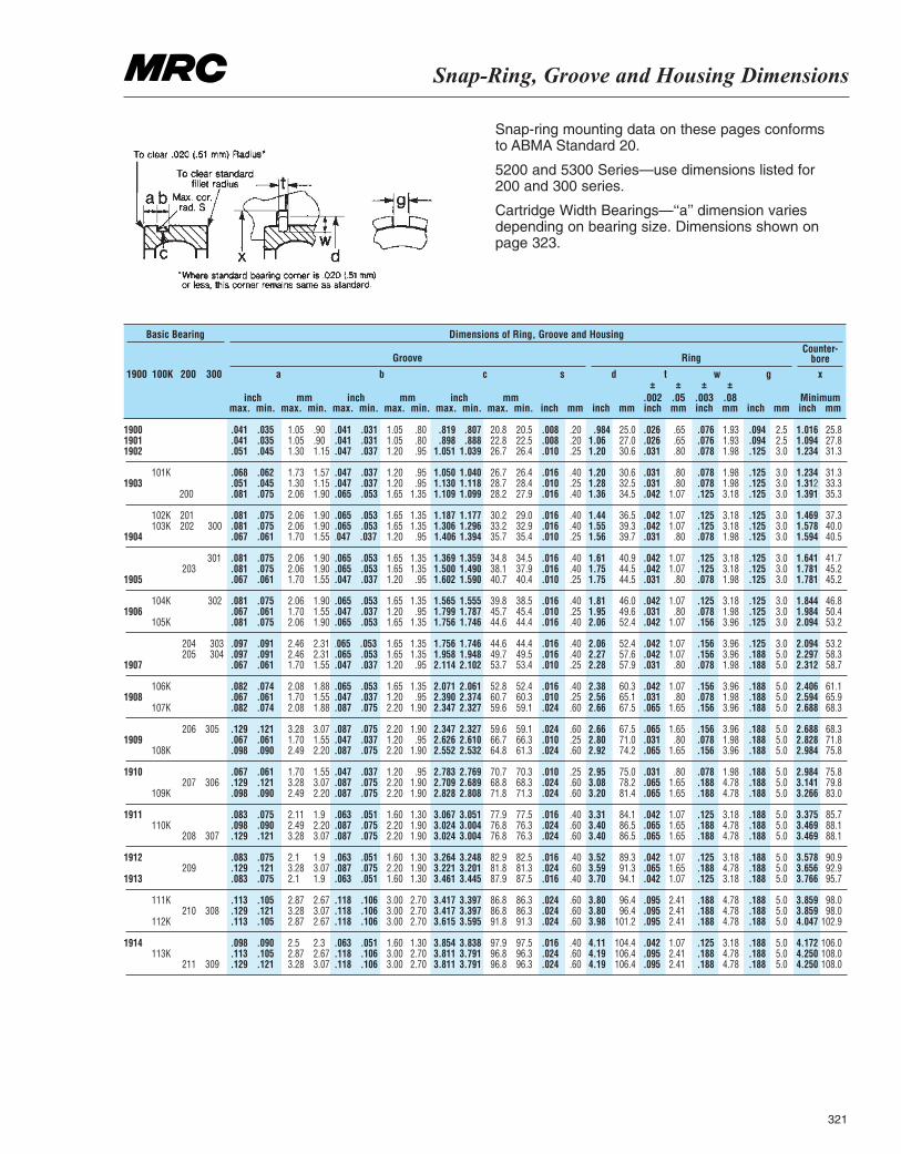
Snap-Ring, Groove and Housing Dimensions
321
Snap-ring mounting data on these pages conforms to ABMA Standard 20.
5200 and 5300 Series—use dimensions listed for 200 and 300 series.
Cartridge Width Bearings—‘‘a’’ dimension variesdepending on bearing size. Dimensions shown onpage 323.
1900 100K 200 300
max. max. max. inch
±.002inch inchmax. max. max. inch
±.003inch inch
inch inch inchmm mm mm Minimummin. min. min. mm
±.05mm mmmin. min. min. mm
±.08mm mm
Groove RingCounter-
bore
Basic Bearing Dimensions of Ring, Groove and Housing
1900 .041 .035 1.05 .90 .041 .031 1.05 .80 .819 .807 20.8 20.5 .008 .20 .984 25.0 .026 .65 .076 1.93 .094 2.5 1.016 25.81901 .041 .035 1.05 .90 .041 .031 1.05 .80 .898 .888 22.8 22.5 .008 .20 1.06 27.0 .026 .65 .076 1.93 .094 2.5 1.094 27.81902 .051 .045 1.30 1.15 .047 .037 1.20 .95 1.051 1.039 26.7 26.4 .010 .25 1.20 30.6 .031 .80 .078 1.98 .125 3.0 1.234 31.3
101K .068 .062 1.73 1.57 .047 .037 1.20 .95 1.050 1.040 26.7 26.4 .016 .40 1.20 30.6 .031 .80 .078 1.98 .125 3.0 1.234 31.31903 .051 .045 1.30 1.15 .047 .037 1.20 .95 1.130 1.118 28.7 28.4 .010 .25 1.28 32.5 .031 .80 .078 1.98 .125 3.0 1.312 33.3
200 .081 .075 2.06 1.90 .065 .053 1.65 1.35 1.109 1.099 28.2 27.9 .016 .40 1.36 34.5 .042 1.07 .125 3.18 .125 3.0 1.391 35.3
102K 201 .081 .075 2.06 1.90 .065 .053 1.65 1.35 1.187 1.177 30.2 29.0 .016 .40 1.44 36.5 .042 1.07 .125 3.18 .125 3.0 1.469 37.3103K 202 300 .081 .075 2.06 1.90 .065 .053 1.65 1.35 1.306 1.296 33.2 32.9 .016 .40 1.55 39.3 .042 1.07 .125 3.18 .125 3.0 1.578 40.0
1904 .067 .061 1.70 1.55 .047 .037 1.20 .95 1.406 1.394 35.7 35.4 .010 .25 1.56 39.7 .031 .80 .078 1.98 .125 3.0 1.594 40.5
301 .081 .075 2.06 1.90 .065 .053 1.65 1.35 1.369 1.359 34.8 34.5 .016 .40 1.61 40.9 .042 1.07 .125 3.18 .125 3.0 1.641 41.7203 .081 .075 2.06 1.90 .065 .053 1.65 1.35 1.500 1.490 38.1 37.9 .016 .40 1.75 44.5 .042 1.07 .125 3.18 .125 3.0 1.781 45.2
1905 .067 .061 1.70 1.55 .047 .037 1.20 .95 1.602 1.590 40.7 40.4 .010 .25 1.75 44.5 .031 .80 .078 1.98 .125 3.0 1.781 45.2
104K 302 .081 .075 2.06 1.90 .065 .053 1.65 1.35 1.565 1.555 39.8 38.5 .016 .40 1.81 46.0 .042 1.07 .125 3.18 .125 3.0 1.844 46.81906 .067 .061 1.70 1.55 .047 .037 1.20 .95 1.799 1.787 45.7 45.4 .010 .25 1.95 49.6 .031 .80 .078 1.98 .125 3.0 1.984 50.4
105K .081 .075 2.06 1.90 .065 .053 1.65 1.35 1.756 1.746 44.6 44.4 .016 .40 2.06 52.4 .042 1.07 .156 3.96 .125 3.0 2.094 53.2
204 303 .097 .091 2.46 2.31 .065 .053 1.65 1.35 1.756 1.746 44.6 44.4 .016 .40 2.06 52.4 .042 1.07 .156 3.96 .125 3.0 2.094 53.2205 304 .097 .091 2.46 2.31 .065 .053 1.65 1.35 1.958 1.948 49.7 49.5 .016 .40 2.27 57.6 .042 1.07 .156 3.96 .188 5.0 2.297 58.3
1907 .067 .061 1.70 1.55 .047 .037 1.20 .95 2.114 2.102 53.7 53.4 .010 .25 2.28 57.9 .031 .80 .078 1.98 .188 5.0 2.312 58.7
106K .082 .074 2.08 1.88 .065 .053 1.65 1.35 2.071 2.061 52.8 52.4 .016 .40 2.38 60.3 .042 1.07 .156 3.96 .188 5.0 2.406 61.11908 .067 .061 1.70 1.55 .047 .037 1.20 .95 2.390 2.374 60.7 60.3 .010 .25 2.56 65.1 .031 .80 .078 1.98 .188 5.0 2.594 65.9
107K .082 .074 2.08 1.88 .087 .075 2.20 1.90 2.347 2.327 59.6 59.1 .024 .60 2.66 67.5 .065 1.65 .156 3.96 .188 5.0 2.688 68.3
206 305 .129 .121 3.28 3.07 .087 .075 2.20 1.90 2.347 2.327 59.6 59.1 .024 .60 2.66 67.5 .065 1.65 .156 3.96 .188 5.0 2.688 68.31909 .067 .061 1.70 1.55 .047 .037 1.20 .95 2.626 2.610 66.7 66.3 .010 .25 2.80 71.0 .031 .80 .078 1.98 .188 5.0 2.828 71.8
108K .098 .090 2.49 2.20 .087 .075 2.20 1.90 2.552 2.532 64.8 61.3 .024 .60 2.92 74.2 .065 1.65 .156 3.96 .188 5.0 2.984 75.8
1910 .067 .061 1.70 1.55 .047 .037 1.20 .95 2.783 2.769 70.7 70.3 .010 .25 2.95 75.0 .031 .80 .078 1.98 .188 5.0 2.984 75.8207 306 .129 .121 3.28 3.07 .087 .075 2.20 1.90 2.709 2.689 68.8 68.3 .024 .60 3.08 78.2 .065 1.65 .188 4.78 .188 5.0 3.141 79.8
109K .098 .090 2.49 2.20 .087 .075 2.20 1.90 2.828 2.808 71.8 71.3 .024 .60 3.20 81.4 .065 1.65 .188 4.78 .188 5.0 3.266 83.0
1911 .083 .075 2.11 1.9 .063 .051 1.60 1.30 3.067 3.051 77.9 77.5 .016 .40 3.31 84.1 .042 1.07 .125 3.18 .188 5.0 3.375 85.7110K .098 .090 2.49 2.20 .087 .075 2.20 1.90 3.024 3.004 76.8 76.3 .024 .60 3.40 86.5 .065 1.65 .188 4.78 .188 5.0 3.469 88.1
208 307 .129 .121 3.28 3.07 .087 .075 2.20 1.90 3.024 3.004 76.8 76.3 .024 .60 3.40 86.5 .065 1.65 .188 4.78 .188 5.0 3.469 88.1
1912 .083 .075 2.1 1.9 .063 .051 1.60 1.30 3.264 3.248 82.9 82.5 .016 .40 3.52 89.3 .042 1.07 .125 3.18 .188 5.0 3.578 90.9209 .129 .121 3.28 3.07 .087 .075 2.20 1.90 3.221 3.201 81.8 81.3 .024 .60 3.59 91.3 .065 1.65 .188 4.78 .188 5.0 3.656 92.9
1913 .083 .075 2.1 1.9 .063 .051 1.60 1.30 3.461 3.445 87.9 87.5 .016 .40 3.70 94.1 .042 1.07 .125 3.18 .188 5.0 3.766 95.7
111K .113 .105 2.87 2.67 .118 .106 3.00 2.70 3.417 3.397 86.8 86.3 .024 .60 3.80 96.4 .095 2.41 .188 4.78 .188 5.0 3.859 98.0210 308 .129 .121 3.28 3.07 .118 .106 3.00 2.70 3.417 3.397 86.8 86.3 .024 .60 3.80 96.4 .095 2.41 .188 4.78 .188 5.0 3.859 98.0
112K .113 .105 2.87 2.67 .118 .106 3.00 2.70 3.615 3.595 91.8 91.3 .024 .60 3.98 101.2 .095 2.41 .188 4.78 .188 5.0 4.047 102.9
1914 .098 .090 2.5 2.3 .063 .051 1.60 1.30 3.854 3.838 97.9 97.5 .016 .40 4.11 104.4 .042 1.07 .125 3.18 .188 5.0 4.172 106.0113K .113 .105 2.87 2.67 .118 .106 3.00 2.70 3.811 3.791 96.8 96.3 .024 .60 4.19 106.4 .095 2.41 .188 4.78 .188 5.0 4.250 108.0
211 309 .129 .121 3.28 3.07 .118 .106 3.00 2.70 3.811 3.791 96.8 96.3 .024 .60 4.19 106.4 .095 2.41 .188 4.78 .188 5.0 4.250 108.0
a b c s d t w g x
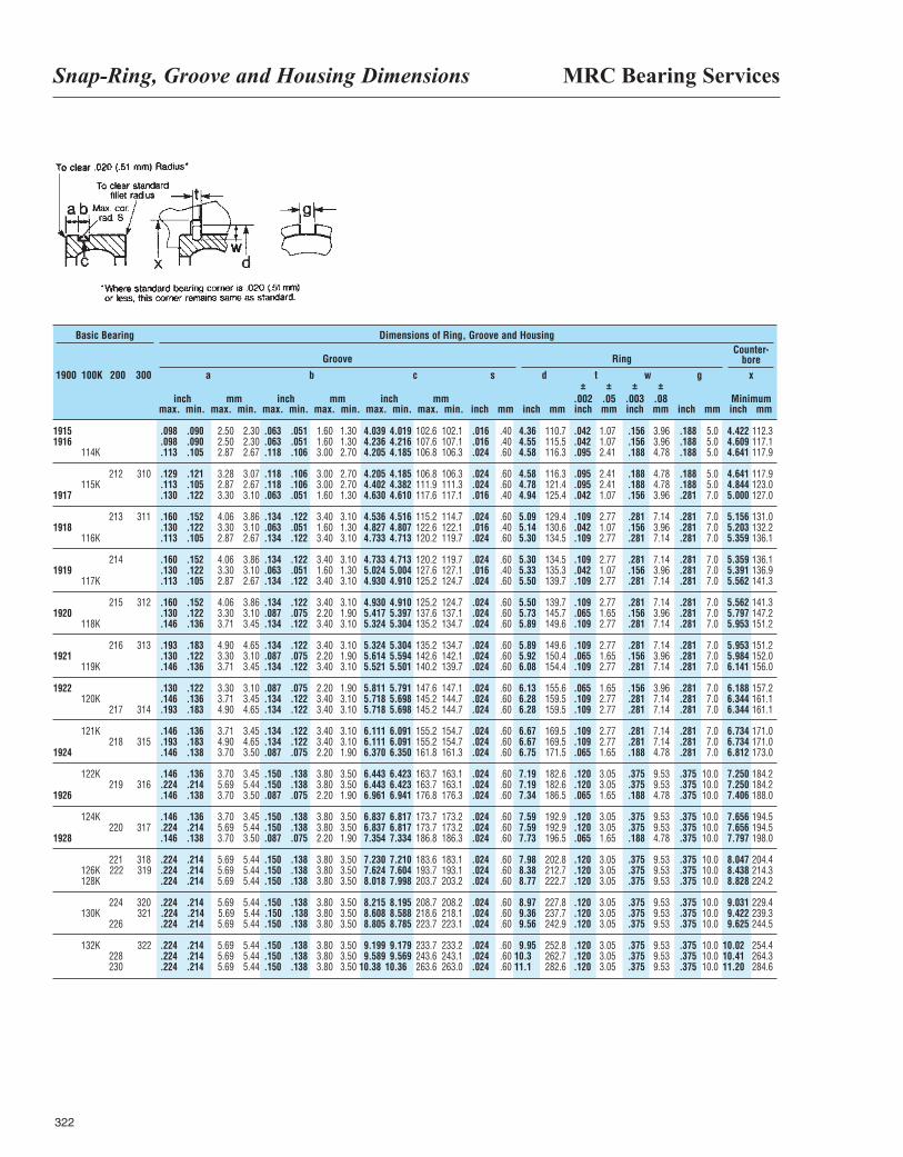
MRC Bearing ServicesSnap-Ring, Groove and Housing Dimensions
322
1900 100K 200 300
max. max. max. inch
±.002inch inchmax. max. max. inch
±.003inch inch
inch inch inchmm mm mm Minimummin. min. min. mm
±.05mm mmmin. min. min. mm
±.08mm mm
Groove RingCounter-
bore
Basic Bearing Dimensions of Ring, Groove and Housing
1915 .098 .090 2.50 2.30 .063 .051 1.60 1.30 4.039 4.019 102.6 102.1 .016 .40 4.36 110.7 .042 1.07 .156 3.96 .188 5.0 4.422 112.31916 .098 .090 2.50 2.30 .063 .051 1.60 1.30 4.236 4.216 107.6 107.1 .016 .40 4.55 115.5 .042 1.07 .156 3.96 .188 5.0 4.609 117.1
114K .113 .105 2.87 2.67 .118 .106 3.00 2.70 4.205 4.185 106.8 106.3 .024 .60 4.58 116.3 .095 2.41 .188 4.78 .188 5.0 4.641 117.9
212 310 .129 .121 3.28 3.07 .118 .106 3.00 2.70 4.205 4.185 106.8 106.3 .024 .60 4.58 116.3 .095 2.41 .188 4.78 .188 5.0 4.641 117.9115K .113 .105 2.87 2.67 .118 .106 3.00 2.70 4.402 4.382 111.9 111.3 .024 .60 4.78 121.4 .095 2.41 .188 4.78 .188 5.0 4.844 123.0
1917 .130 .122 3.30 3.10 .063 .051 1.60 1.30 4.630 4.610 117.6 117.1 .016 .40 4.94 125.4 .042 1.07 .156 3.96 .281 7.0 5.000 127.0
213 311 .160 .152 4.06 3.86 .134 .122 3.40 3.10 4.536 4.516 115.2 114.7 .024 .60 5.09 129.4 .109 2.77 .281 7.14 .281 7.0 5.156 131.01918 .130 .122 3.30 3.10 .063 .051 1.60 1.30 4.827 4.807 122.6 122.1 .016 .40 5.14 130.6 .042 1.07 .156 3.96 .281 7.0 5.203 132.2
116K .113 .105 2.87 2.67 .134 .122 3.40 3.10 4.733 4.713 120.2 119.7 .024 .60 5.30 134.5 .109 2.77 .281 7.14 .281 7.0 5.359 136.1
214 .160 .152 4.06 3.86 .134 .122 3.40 3.10 4.733 4.713 120.2 119.7 .024 .60 5.30 134.5 .109 2.77 .281 7.14 .281 7.0 5.359 136.11919 .130 .122 3.30 3.10 .063 .051 1.60 1.30 5.024 5.004 127.6 127.1 .016 .40 5.33 135.3 .042 1.07 .156 3.96 .281 7.0 5.391 136.9
117K .113 .105 2.87 2.67 .134 .122 3.40 3.10 4.930 4.910 125.2 124.7 .024 .60 5.50 139.7 .109 2.77 .281 7.14 .281 7.0 5.562 141.3
215 312 .160 .152 4.06 3.86 .134 .122 3.40 3.10 4.930 4.910 125.2 124.7 .024 .60 5.50 139.7 .109 2.77 .281 7.14 .281 7.0 5.562 141.31920 .130 .122 3.30 3.10 .087 .075 2.20 1.90 5.417 5.397 137.6 137.1 .024 .60 5.73 145.7 .065 1.65 .156 3.96 .281 7.0 5.797 147.2
118K .146 .136 3.71 3.45 .134 .122 3.40 3.10 5.324 5.304 135.2 134.7 .024 .60 5.89 149.6 .109 2.77 .281 7.14 .281 7.0 5.953 151.2
216 313 .193 .183 4.90 4.65 .134 .122 3.40 3.10 5.324 5.304 135.2 134.7 .024 .60 5.89 149.6 .109 2.77 .281 7.14 .281 7.0 5.953 151.21921 .130 .122 3.30 3.10 .087 .075 2.20 1.90 5.614 5.594 142.6 142.1 .024 .60 5.92 150.4 .065 1.65 .156 3.96 .281 7.0 5.984 152.0
119K .146 .136 3.71 3.45 .134 .122 3.40 3.10 5.521 5.501 140.2 139.7 .024 .60 6.08 154.4 .109 2.77 .281 7.14 .281 7.0 6.141 156.0
1922 .130 .122 3.30 3.10 .087 .075 2.20 1.90 5.811 5.791 147.6 147.1 .024 .60 6.13 155.6 .065 1.65 .156 3.96 .281 7.0 6.188 157.2120K .146 .136 3.71 3.45 .134 .122 3.40 3.10 5.718 5.698 145.2 144.7 .024 .60 6.28 159.5 .109 2.77 .281 7.14 .281 7.0 6.344 161.1
217 314 .193 .183 4.90 4.65 .134 .122 3.40 3.10 5.718 5.698 145.2 144.7 .024 .60 6.28 159.5 .109 2.77 .281 7.14 .281 7.0 6.344 161.1
121K .146 .136 3.71 3.45 .134 .122 3.40 3.10 6.111 6.091 155.2 154.7 .024 .60 6.67 169.5 .109 2.77 .281 7.14 .281 7.0 6.734 171.0218 315 .193 .183 4.90 4.65 .134 .122 3.40 3.10 6.111 6.091 155.2 154.7 .024 .60 6.67 169.5 .109 2.77 .281 7.14 .281 7.0 6.734 171.0
1924 .146 .138 3.70 3.50 .087 .075 2.20 1.90 6.370 6.350 161.8 161.3 .024 .60 6.75 171.5 .065 1.65 .188 4.78 .281 7.0 6.812 173.0
122K .146 .136 3.70 3.45 .150 .138 3.80 3.50 6.443 6.423 163.7 163.1 .024 .60 7.19 182.6 .120 3.05 .375 9.53 .375 10.0 7.250 184.2219 316 .224 .214 5.69 5.44 .150 .138 3.80 3.50 6.443 6.423 163.7 163.1 .024 .60 7.19 182.6 .120 3.05 .375 9.53 .375 10.0 7.250 184.2
1926 .146 .138 3.70 3.50 .087 .075 2.20 1.90 6.961 6.941 176.8 176.3 .024 .60 7.34 186.5 .065 1.65 .188 4.78 .375 10.0 7.406 188.0
124K .146 .136 3.70 3.45 .150 .138 3.80 3.50 6.837 6.817 173.7 173.2 .024 .60 7.59 192.9 .120 3.05 .375 9.53 .375 10.0 7.656 194.5220 317 .224 .214 5.69 5.44 .150 .138 3.80 3.50 6.837 6.817 173.7 173.2 .024 .60 7.59 192.9 .120 3.05 .375 9.53 .375 10.0 7.656 194.5
1928 .146 .138 3.70 3.50 .087 .075 2.20 1.90 7.354 7.334 186.8 186.3 .024 .60 7.73 196.5 .065 1.65 .188 4.78 .375 10.0 7.797 198.0
221 318 .224 .214 5.69 5.44 .150 .138 3.80 3.50 7.230 7.210 183.6 183.1 .024 .60 7.98 202.8 .120 3.05 .375 9.53 .375 10.0 8.047 204.4126K 222 319 .224 .214 5.69 5.44 .150 .138 3.80 3.50 7.624 7.604 193.7 193.1 .024 .60 8.38 212.7 .120 3.05 .375 9.53 .375 10.0 8.438 214.3128K .224 .214 5.69 5.44 .150 .138 3.80 3.50 8.018 7.998 203.7 203.2 .024 .60 8.77 222.7 .120 3.05 .375 9.53 .375 10.0 8.828 224.2
224 320 .224 .214 5.69 5.44 .150 .138 3.80 3.50 8.215 8.195 208.7 208.2 .024 .60 8.97 227.8 .120 3.05 .375 9.53 .375 10.0 9.031 229.4130K 321 .224 .214 5.69 5.44 .150 .138 3.80 3.50 8.608 8.588 218.6 218.1 .024 .60 9.36 237.7 .120 3.05 .375 9.53 .375 10.0 9.422 239.3
226 .224 .214 5.69 5.44 .150 .138 3.80 3.50 8.805 8.785 223.7 223.1 .024 .60 9.56 242.9 .120 3.05 .375 9.53 .375 10.0 9.625 244.5
132K 322 .224 .214 5.69 5.44 .150 .138 3.80 3.50 9.199 9.179 233.7 233.2 .024 .60 9.95 252.8 .120 3.05 .375 9.53 .375 10.0 10.02 254.4228 .224 .214 5.69 5.44 .150 .138 3.80 3.50 9.589 9.569 243.6 243.1 .024 .60 10.3 262.7 .120 3.05 .375 9.53 .375 10.0 10.41 264.3230 .224 .214 5.69 5.44 .150 .138 3.80 3.50 10.38 10.36 263.6 263.0 .024 .60 11.1 282.6 .120 3.05 .375 9.53 .375 10.0 11.20 284.6
a b c s d t w g x
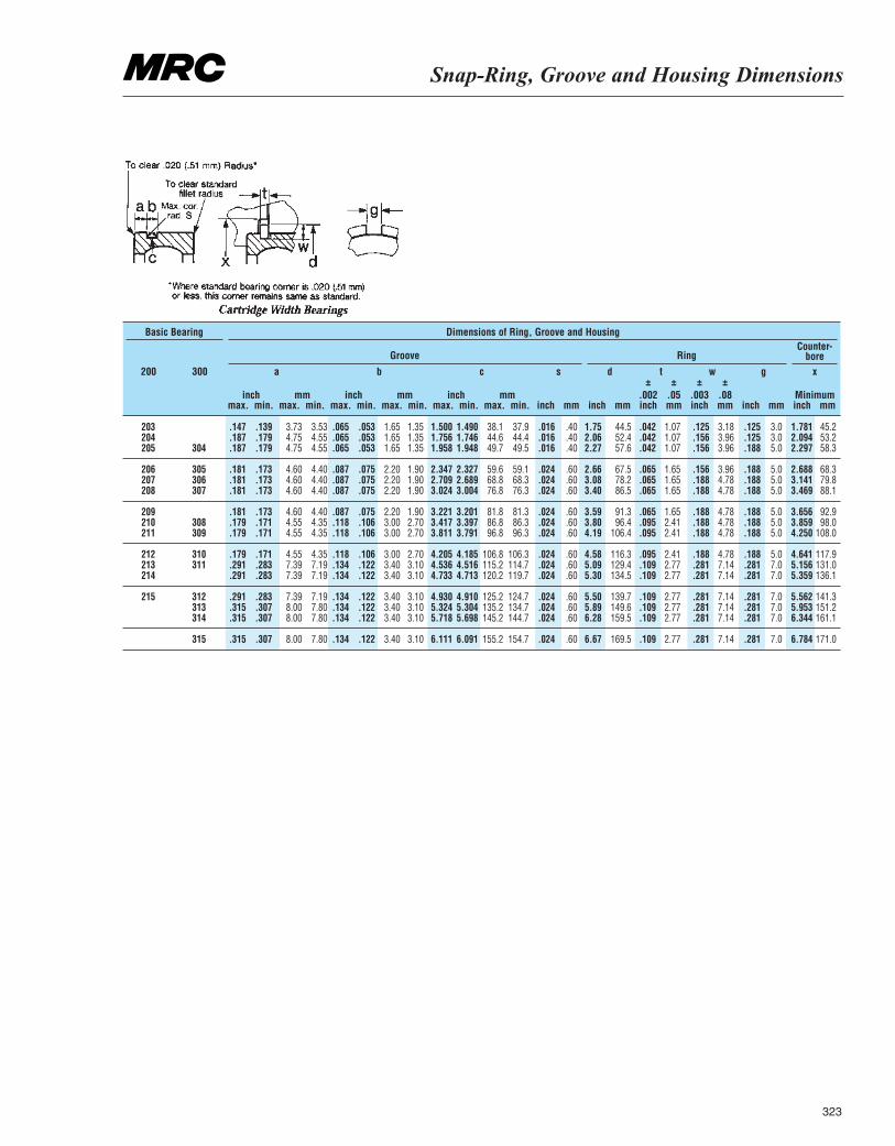
Snap-Ring, Groove and Housing Dimensions
323
200 300
max. max. max. inch
±.002inch inchmax. max. max. inch
±.003inch inch
inch inch inchmm mm mm Minimummin. min. min. mm
±.05mm mmmin. min. min. mm
±.08mm mm
Groove RingCounter-
bore
Basic Bearing Dimensions of Ring, Groove and Housing
203 .147 .139 3.73 3.53 .065 .053 1.65 1.35 1.500 1.490 38.1 37.9 .016 .40 1.75 44.5 .042 1.07 .125 3.18 .125 3.0 1.781 45.2204 .187 .179 4.75 4.55 .065 .053 1.65 1.35 1.756 1.746 44.6 44.4 .016 .40 2.06 52.4 .042 1.07 .156 3.96 .125 3.0 2.094 53.2205 304 .187 .179 4.75 4.55 .065 .053 1.65 1.35 1.958 1.948 49.7 49.5 .016 .40 2.27 57.6 .042 1.07 .156 3.96 .188 5.0 2.297 58.3
206 305 .181 .173 4.60 4.40 .087 .075 2.20 1.90 2.347 2.327 59.6 59.1 .024 .60 2.66 67.5 .065 1.65 .156 3.96 .188 5.0 2.688 68.3207 306 .181 .173 4.60 4.40 .087 .075 2.20 1.90 2.709 2.689 68.8 68.3 .024 .60 3.08 78.2 .065 1.65 .188 4.78 .188 5.0 3.141 79.8208 307 .181 .173 4.60 4.40 .087 .075 2.20 1.90 3.024 3.004 76.8 76.3 .024 .60 3.40 86.5 .065 1.65 .188 4.78 .188 5.0 3.469 88.1
209 .181 .173 4.60 4.40 .087 .075 2.20 1.90 3.221 3.201 81.8 81.3 .024 .60 3.59 91.3 .065 1.65 .188 4.78 .188 5.0 3.656 92.9210 308 .179 .171 4.55 4.35 .118 .106 3.00 2.70 3.417 3.397 86.8 86.3 .024 .60 3.80 96.4 .095 2.41 .188 4.78 .188 5.0 3.859 98.0211 309 .179 .171 4.55 4.35 .118 .106 3.00 2.70 3.811 3.791 96.8 96.3 .024 .60 4.19 106.4 .095 2.41 .188 4.78 .188 5.0 4.250 108.0
212 310 .179 .171 4.55 4.35 .118 .106 3.00 2.70 4.205 4.185 106.8 106.3 .024 .60 4.58 116.3 .095 2.41 .188 4.78 .188 5.0 4.641 117.9213 311 .291 .283 7.39 7.19 .134 .122 3.40 3.10 4.536 4.516 115.2 114.7 .024 .60 5.09 129.4 .109 2.77 .281 7.14 .281 7.0 5.156 131.0214 .291 .283 7.39 7.19 .134 .122 3.40 3.10 4.733 4.713 120.2 119.7 .024 .60 5.30 134.5 .109 2.77 .281 7.14 .281 7.0 5.359 136.1
215 312 .291 .283 7.39 7.19 .134 .122 3.40 3.10 4.930 4.910 125.2 124.7 .024 .60 5.50 139.7 .109 2.77 .281 7.14 .281 7.0 5.562 141.3313 .315 .307 8.00 7.80 .134 .122 3.40 3.10 5.324 5.304 135.2 134.7 .024 .60 5.89 149.6 .109 2.77 .281 7.14 .281 7.0 5.953 151.2314 .315 .307 8.00 7.80 .134 .122 3.40 3.10 5.718 5.698 145.2 144.7 .024 .60 6.28 159.5 .109 2.77 .281 7.14 .281 7.0 6.344 161.1
315 .315 .307 8.00 7.80 .134 .122 3.40 3.10 6.111 6.091 155.2 154.7 .024 .60 6.67 169.5 .109 2.77 .281 7.14 .281 7.0 6.784 171.0
a b c s d t w g x
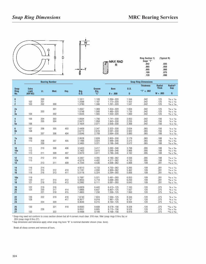
MRC Bearing ServicesSnap Ring Dimensions
324
Ring Section 1) (Typical R)Gage ‘‘T’’
.042 .035
.065 .050
.095 .060
.109 .075
.120 .090
SnapRing No.
ExtraLight
(KR-KS)Lt. Med. Hvy. Brg.
O.D.
GrooveDia.“C”
Bore
B + .000
O.D.
D
Thickness
“T” ± .002
RadialThick
W + .003
Radial2)
Gap
G
Snap Ring DimensionsBearing Number
0 200 1.1811 1.109 1.094–.020 1.344 .042 .125 ³|₃₂ ± ¹|₃₂1 102 201 1.2598 1.187 1.172–.020 1.422 .042 .125 ³|₃₂ ± ¹|₃₂2 103 202 300 1.3780 1.306 1.291–.020 1.541 .042 .125 ³|₃₂ ± ¹|₃₂
2a 301 1.4567 1.369 1.354–.020 1.604 .042 .125 ³|₃₂ ± ¹|₃₂3 203 1.5748 1.500 1.485–.020 1.735 .042 .125 ³|₃₂ ± ¹|₃₂3a 104 302 1.6535 1.565 1.550–.020 1.800 .042 .125 ³|₃₂ ± ¹|₃₂
4 105 204 303 1.8504 1.756 1.741–.030 2.053 .042 .156 ¹|₈ ± ¹|₃₂5 205 304 2.0472 1.958 1.943–.030 2.255 .042 .156 ¹|₈ ± ¹|₃₂5a 106 2.1654 2.071 2.056–.030 2.368 .042 .156 ¹|₈ ± ¹|₃₂
6 107 206 305 403 2.4409 2.347 2.322–.030 2.634 .065 .156 ¹|₈ ± ¹|₃₂6b 108 2.6772 2.616 2.591–.030 2.922 .065 .156 ¹|₈ ± ¹|₃₂7 207 306 404 2.8346 2.709 2.684–.030 3.060 .065 .188 ¹|₈ ± ¹|₃₂
7a 109 2.9528 2.828 2.803–.030 3.179 .065 .188 ¹|₈ ± ¹|₃₂8 110 208 307 405 3.1496 3.024 2.999–.046 3.375 .065 .188 ⁵|₃₂ ± ³|₆₄9 209 3.3465 3.221 3.196–.046 3.572 .065 .188 ⁵|₃₂ ± ³|₆₄
10 111 210 308 406 3.5433 3.417 3.392–.046 3.768 .095 .188 ⁵|₃₂ ± ³|₆₄10a 112 3.7402 3.615 3.590–.046 3.966 .095 .188 ⁵|₃₂ ± ³|₆₄11 113 211 309 407 3.9370 3.811 3.786–.046 4.162 .095 .188 ⁵|₃₂ ± ³|₆₄
12 114 212 310 408 4.3307 4.205 4.180–.062 4.556 .095 .188 ³|₁₆ ± ¹|₁₆12a 115 4.5276 4.402 4.377–.062 4.753 .095 .188 ³|₁₆ ± ¹|₁₆13 213 311 409 4.7244 4.536 4.506–.062 5.068 .109 .281 ³|₁₆ ± ¹|₁₆
14 116 214 4.9213 4.733 4.703–.062 5.265 .109 .281 ³|₁₆ ± ¹|₁₆15 117 215 312 410 5.1181 4.930 4.900–.062 5.462 .109 .281 ³|₁₆ ± ¹|₁₆16 118 216 313 411 5.5118 5.324 5.294–.093 5.856 .109 .281 ⁹|₃₂ ± ¹|₁₆
16a 119 5.7087 5.521 5.491–.093 6.053 .109 .281 ⁹|₃₂ ± ¹|₁₆17 120 217 314 412 5.9055 5.718 5.688–.093 6.250 .109 .281 ⁹|₃₂ ± ¹|₁₆18 121 218 315 413 6.2992 6.111 6.081–.093 6.643 .109 .281 ⁹|₃₂ ± ¹|₁₆
19 122 219 316 6.6929 6.443 6.413–.125 7.163 .120 .375 ³|₈ ± ¹|₁₆20 124 220 317 414 7.0866 6.837 6.807–.125 7.557 .120 .375 ³|₈ ± ¹|₁₆21 221 318 415 7.4803 7.230 7.200–.125 7.950 .120 .375 ³|₈ ± ¹|₁₆
22 126 222 319 416 7.8740 7.624 7.594–.125 8.344 .120 .375 ³|₈ ± ¹|₁₆23 128 417 8.2677 8.018 7.987–.125 8.737 .120 .375 ³|₈ ± ¹|₁₆24 224 320 8.4646 8.215 8.184–.125 8.934 .120 .375 ³|₈ ± ¹|₁₆
25 130 321 418 8.8583 8.608 8.578–.156 9.328 .120 .375 ¹⁵|₃₂ ± ³|₃₂26 226 9.0551 8.805 8.775–.156 9.525 .120 .375 ¹⁵|₃₂ ± ³|₃₂27 132 322 9.4488 9.199 9.168–.156 9.918 .120 .375 ¹⁵|₃₂ ± ³|₃₂
1) Snap-ring need not conform to cross section shown but all 4 corners must clear .016 max. fillet (snap rings 0 thru 5a) or.024 (snap rings 6 thru 27).
2) Gap dimension and tolerance apply when snap ring bore ‘‘B’’ is nominal diameter shown (max. bore).
Break all sharp corners and remove all burs.
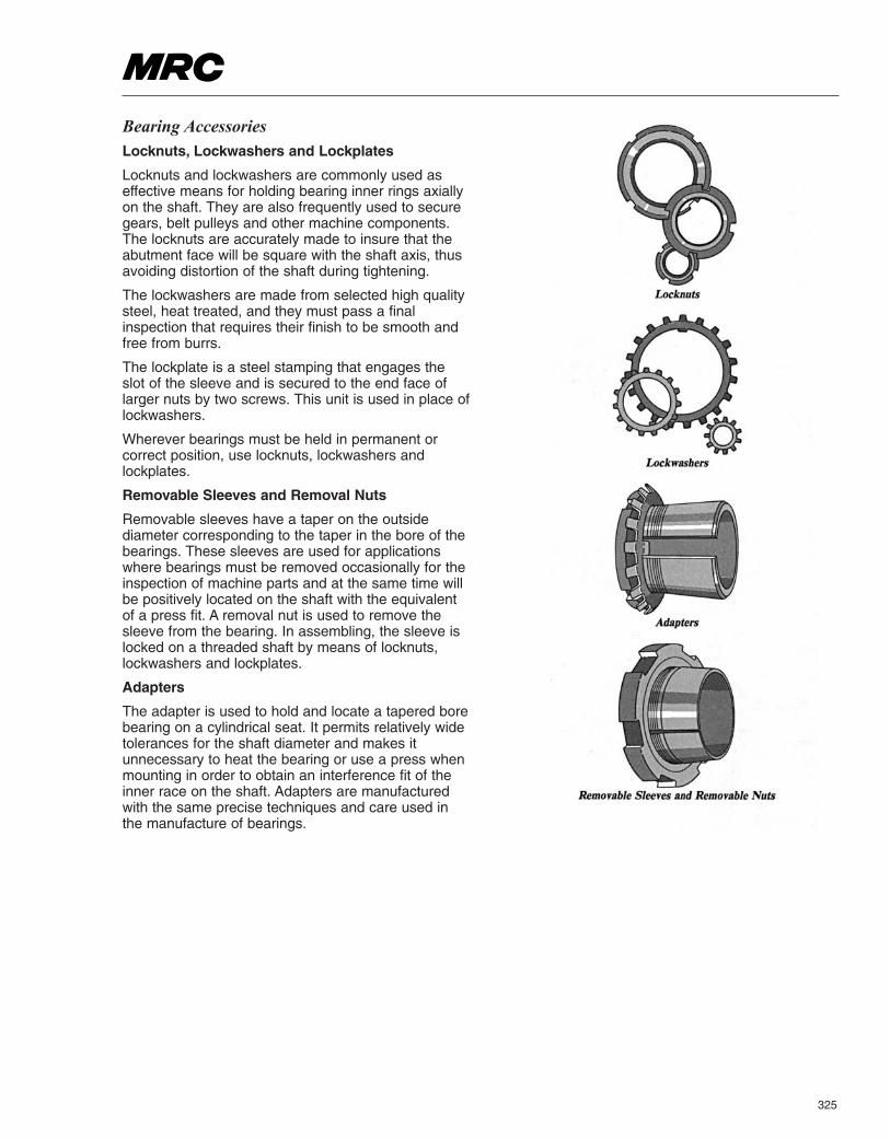
325
Bearing Accessories Locknuts, Lockwashers and Lockplates
Locknuts and lockwashers are commonly used aseffective means for holding bearing inner rings axiallyon the shaft. They are also frequently used to securegears, belt pulleys and other machine components.The locknuts are accurately made to insure that theabutment face will be square with the shaft axis, thusavoiding distortion of the shaft during tightening.
The lockwashers are made from selected high qualitysteel, heat treated, and they must pass a finalinspection that requires their finish to be smooth andfree from burrs.
The lockplate is a steel stamping that engages theslot of the sleeve and is secured to the end face oflarger nuts by two screws. This unit is used in place oflockwashers.
Wherever bearings must be held in permanent orcorrect position, use locknuts, lockwashers andlockplates.
Removable Sleeves and Removal Nuts
Removable sleeves have a taper on the outsidediameter corresponding to the taper in the bore of thebearings. These sleeves are used for applicationswhere bearings must be removed occasionally for theinspection of machine parts and at the same time willbe positively located on the shaft with the equivalentof a press fit. A removal nut is used to remove thesleeve from the bearing. In assembling, the sleeve islocked on a threaded shaft by means of locknuts,lockwashers and lockplates.
Adapters
The adapter is used to hold and locate a tapered borebearing on a cylindrical seat. It permits relatively widetolerances for the shaft diameter and makes itunnecessary to heat the bearing or use a press whenmounting in order to obtain an interference fit of theinner race on the shaft. Adapters are manufacturedwith the same precise techniques and care used inthe manufacture of bearings.
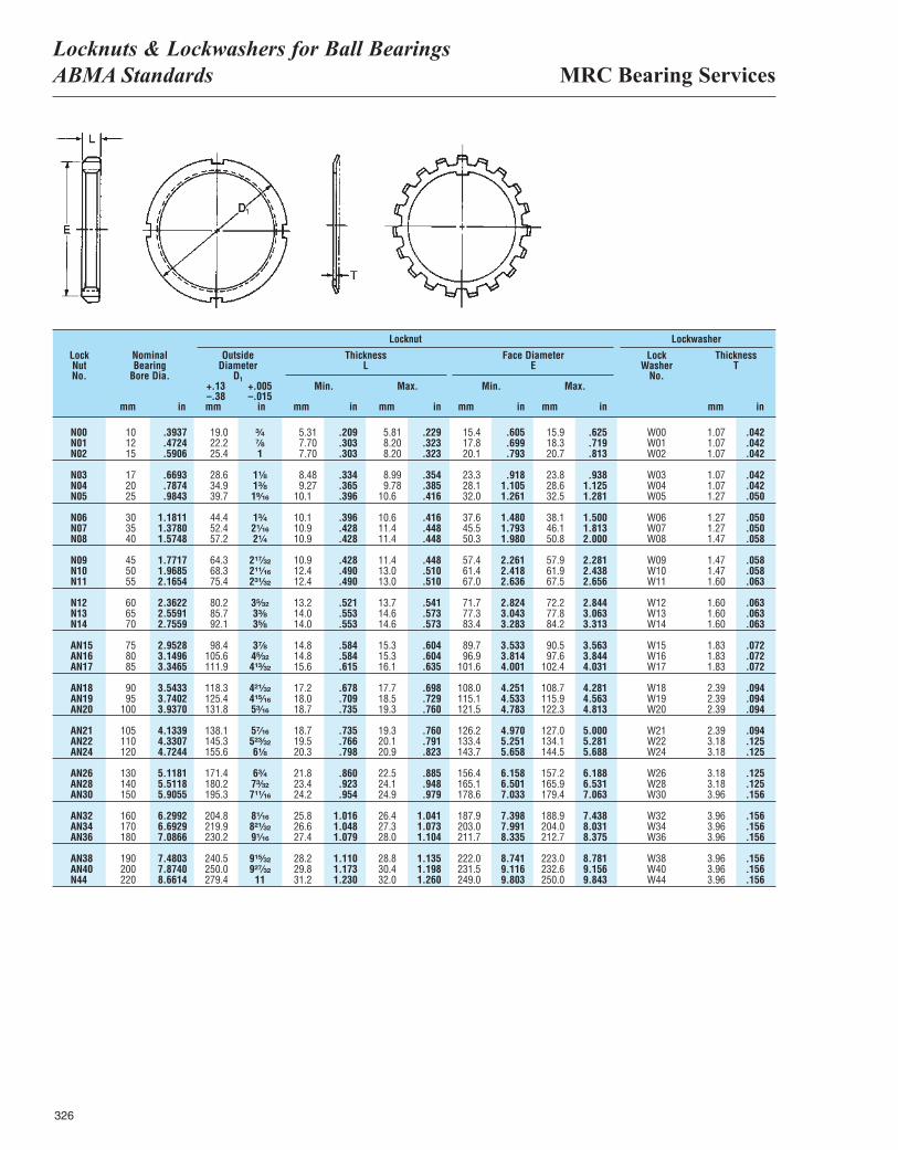
MRC Bearing ServicesLocknuts & Lockwashers for Ball BearingsABMA Standards
326
LockNutNo.
mm
+.13–.38mm mm mmmm mm mm in
Min. Min.Max. Max.
NominalBearing
Bore Dia.
OutsideDiameter
D1
ThicknessL
Face DiameterE
LockWasher
No.
ThicknessT
in
+.005–.015
in in inin in
LockwasherLocknut
N00 10 .3937 19.0 ³|₄ 5.31 .209 5.81 .229 15.4 .605 15.9 .625 W00 1.07 .042N01 12 .4724 22.2 ⁷|₈ 7.70 .303 8.20 .323 17.8 .699 18.3 .719 W01 1.07 .042N02 15 .5906 25.4 1 7.70 .303 8.20 .323 20.1 .793 20.7 .813 W02 1.07 .042
N03 17 .6693 28.6 1¹|₈ 8.48 .334 8.99 .354 23.3 .918 23.8 .938 W03 1.07 .042N04 20 .7874 34.9 1³|₈ 9.27 .365 9.78 .385 28.1 1.105 28.6 1.125 W04 1.07 .042N05 25 .9843 39.7 1⁹|₁₆ 10.1 .396 10.6 .416 32.0 1.261 32.5 1.281 W05 1.27 .050
N06 30 1.1811 44.4 1³|₄ 10.1 .396 10.6 .416 37.6 1.480 38.1 1.500 W06 1.27 .050N07 35 1.3780 52.4 2¹|₁₆ 10.9 .428 11.4 .448 45.5 1.793 46.1 1.813 W07 1.27 .050N08 40 1.5748 57.2 2¹|₄ 10.9 .428 11.4 .448 50.3 1.980 50.8 2.000 W08 1.47 .058
N09 45 1.7717 64.3 2¹⁷|₃₂ 10.9 .428 11.4 .448 57.4 2.261 57.9 2.281 W09 1.47 .058N10 50 1.9685 68.3 2¹¹|₁₆ 12.4 .490 13.0 .510 61.4 2.418 61.9 2.438 W10 1.47 .058N11 55 2.1654 75.4 2³¹|₃₂ 12.4 .490 13.0 .510 67.0 2.636 67.5 2.656 W11 1.60 .063
N12 60 2.3622 80.2 3⁵|₃₂ 13.2 .521 13.7 .541 71.7 2.824 72.2 2.844 W12 1.60 .063N13 65 2.5591 85.7 3³|₈ 14.0 .553 14.6 .573 77.3 3.043 77.8 3.063 W13 1.60 .063N14 70 2.7559 92.1 3⁵|₈ 14.0 .553 14.6 .573 83.4 3.283 84.2 3.313 W14 1.60 .063
AN15 75 2.9528 98.4 3⁷|₈ 14.8 .584 15.3 .604 89.7 3.533 90.5 3.563 W15 1.83 .072AN16 80 3.1496 105.6 4⁵|₃₂ 14.8 .584 15.3 .604 96.9 3.814 97.6 3.844 W16 1.83 .072AN17 85 3.3465 111.9 4¹³|₃₂ 15.6 .615 16.1 .635 101.6 4.001 102.4 4.031 W17 1.83 .072
AN18 90 3.5433 118.3 4²¹|₃₂ 17.2 .678 17.7 .698 108.0 4.251 108.7 4.281 W18 2.39 .094AN19 95 3.7402 125.4 4¹⁵|₁₆ 18.0 .709 18.5 .729 115.1 4.533 115.9 4.563 W19 2.39 .094AN20 100 3.9370 131.8 5³|₁₆ 18.7 .735 19.3 .760 121.5 4.783 122.3 4.813 W20 2.39 .094
AN21 105 4.1339 138.1 5⁷|₁₆ 18.7 .735 19.3 .760 126.2 4.970 127.0 5.000 W21 2.39 .094AN22 110 4.3307 145.3 5²³|₃₂ 19.5 .766 20.1 .791 133.4 5.251 134.1 5.281 W22 3.18 .125AN24 120 4.7244 155.6 6¹|₈ 20.3 .798 20.9 .823 143.7 5.658 144.5 5.688 W24 3.18 .125
AN26 130 5.1181 171.4 6³|₄ 21.8 .860 22.5 .885 156.4 6.158 157.2 6.188 W26 3.18 .125AN28 140 5.5118 180.2 7³|₃₂ 23.4 .923 24.1 .948 165.1 6.501 165.9 6.531 W28 3.18 .125AN30 150 5.9055 195.3 7¹¹|₁₆ 24.2 .954 24.9 .979 178.6 7.033 179.4 7.063 W30 3.96 .156
AN32 160 6.2992 204.8 8¹|₁₆ 25.8 1.016 26.4 1.041 187.9 7.398 188.9 7.438 W32 3.96 .156AN34 170 6.6929 219.9 8²¹|₃₂ 26.6 1.048 27.3 1.073 203.0 7.991 204.0 8.031 W34 3.96 .156AN36 180 7.0866 230.2 9¹|₁₆ 27.4 1.079 28.0 1.104 211.7 8.335 212.7 8.375 W36 3.96 .156
AN38 190 7.4803 240.5 9¹⁵|₃₂ 28.2 1.110 28.8 1.135 222.0 8.741 223.0 8.781 W38 3.96 .156AN40 200 7.8740 250.0 9²⁷|₃₂ 29.8 1.173 30.4 1.198 231.5 9.116 232.6 9.156 W40 3.96 .156N44 220 8.6614 279.4 11 31.2 1.230 32.0 1.260 249.0 9.803 250.0 9.843 W44 3.96 .156
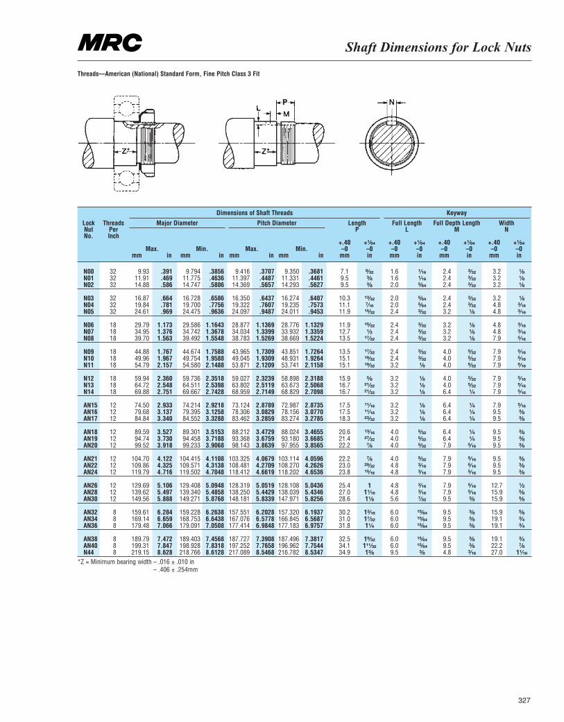
Shaft Dimensions for Lock Nuts
327
LockNutNo.
ThreadsPerInch
mm mm mmmmMax. Max.Min. Min.
in in in in
+.40–0
mm
+.40–0
mm
+.40–0
mm
+.40–0
mm
+¹|₆₄–0in
+¹|₆₄–0in
+¹|₆₄–0in
+¹|₆₄–0in
Major Diameter Pitch Diameter LengthP
Full LengthL
Full Depth LengthM
WidthN
KeywayDimensions of Shaft Threads
N00 32 9.93 .391 9.794 .3856 9.416 .3707 9.350 .3681 7.1 ⁹|₃₂ 1.6 ¹|₁₆ 2.4 ³|₃₂ 3.2 ¹|₈N01 32 11.91 .469 11.775 .4636 11.397 .4487 11.331 .4461 9.5 ³|₈ 1.6 ¹|₁₆ 2.4 ³|₃₂ 3.2 ¹|₈N02 32 14.88 .586 14.747 .5806 14.369 .5657 14.293 .5627 9.5 ³|₈ 2.0 ⁵|₆₄ 2.4 ³|₃₂ 3.2 ¹|₈
N03 32 16.87 .664 16.728 .6586 16.350 .6437 16.274 .6407 10.3 ¹³|₃₂ 2.0 ⁵|₆₄ 2.4 ³|₃₂ 3.2 ¹|₈N04 32 19.84 .781 19.700 .7756 19.322 .7607 19.235 .7573 11.1 ⁷|₁₆ 2.0 ⁵|₆₄ 2.4 ³|₃₂ 4.8 ³|₁₆N05 32 24.61 .969 24.475 .9636 24.097 .9487 24.011 .9453 11.9 ¹⁵|₃₂ 2.4 ³|₃₂ 3.2 ¹|₈ 4.8 ³|₁₆
N06 18 29.79 1.173 29.586 1.1643 28.877 1.1369 28.776 1.1329 11.9 ¹⁵|₃₂ 2.4 ³|₃₂ 3.2 ¹|₈ 4.8 ³|₁₆N07 18 34.95 1.376 34.742 1.3678 34.034 1.3399 33.932 1.3359 12.7 ¹|₂ 2.4 ³|₃₂ 3.2 ¹|₈ 4.8 ³|₁₆N08 18 39.70 1.563 39.492 1.5548 38.783 1.5269 38.669 1.5224 13.5 ¹⁷|₃₂ 2.4 ³|₃₂ 3.2 ¹|₈ 7.9 ⁵|₁₆
N09 18 44.88 1.767 44.674 1.7588 43.965 1.7309 43.851 1.7264 13.5 ¹⁷|₃₂ 2.4 ³|₃₂ 4.0 ⁵|₃₂ 7.9 ⁵|₁₆N10 18 49.96 1.967 49.754 1.9588 49.045 1.9309 48.931 1.9264 15.1 ¹⁹|₃₂ 2.4 ³|₃₂ 4.0 ⁵|₃₂ 7.9 ⁵|₁₆N11 18 54.79 2.157 54.580 2.1488 53.871 2.1209 53.741 2.1158 15.1 ¹⁹|₃₂ 3.2 ¹|₈ 4.0 ⁵|₃₂ 7.9 ⁵|₁₆
N12 18 59.94 2.360 59.736 2.3518 59.027 2.3239 58.898 2.3188 15.9 ⁵|₈ 3.2 ¹|₈ 4.0 ⁵|₃₂ 7.9 ⁵|₁₆N13 18 64.72 2.548 64.511 2.5398 63.802 2.5119 63.673 2.5068 16.7 ²¹|₃₂ 3.2 ¹|₈ 4.0 ⁵|₃₂ 7.9 ⁵|₁₆N14 18 69.88 2.751 69.667 2.7428 68.959 2.7149 68.829 2.7098 16.7 ²¹|₃₂ 3.2 ¹|₈ 6.4 ¹|₄ 7.9 ⁵|₁₆
AN15 12 74.50 2.933 74.214 2.9218 73.124 2.8789 72.987 2.8735 17.5 ¹¹|₁₆ 3.2 ¹|₈ 6.4 ¹|₄ 7.9 ⁵|₁₆AN16 12 79.68 3.137 79.395 3.1258 78.306 3.0829 78.156 3.0770 17.5 ¹¹|₁₆ 3.2 ¹|₈ 6.4 ¹|₄ 9.5 ³|₈AN17 12 84.84 3.340 84.552 3.3288 83.462 3.2859 83.274 3.2785 18.3 ²³|₃₂ 3.2 ¹|₈ 6.4 ¹|₄ 9.5 ³|₈
AN18 12 89.59 3.527 89.301 3.5153 88.212 3.4729 88.024 3.4655 20.6 ¹³|₁₆ 4.0 ⁵|₃₂ 6.4 ¹|₄ 9.5 ³|₈AN19 12 94.74 3.730 94.458 3.7188 93.368 3.6759 93.180 3.6685 21.4 ²⁷|₃₂ 4.0 ⁵|₃₂ 6.4 ¹|₄ 9.5 ³|₈AN20 12 99.52 3.918 99.233 3.9068 98.143 3.8639 97.955 3.8565 22.2 ⁷|₈ 4.0 ⁵|₃₂ 7.9 ⁵|₁₆ 9.5 ³|₈
AN21 12 104.70 4.122 104.415 4.1108 103.325 4.0679 103.114 4.0596 22.2 ⁷|₈ 4.0 ⁵|₃₂ 7.9 ⁵|₁₆ 9.5 ³|₈AN22 12 109.86 4.325 109.571 4.3138 108.481 4.2709 108.270 4.2626 23.0 ²⁹|₃₂ 4.8 ³|₁₆ 7.9 ⁵|₁₆ 9.5 ³|₈AN24 12 119.79 4.716 119.502 4.7048 118.412 4.6619 118.202 4.6536 23.8 ¹⁵|₁₆ 4.8 ³|₁₆ 7.9 ⁵|₁₆ 9.5 ³|₈
AN26 12 129.69 5.106 129.408 5.0948 128.319 5.0519 128.108 5.0436 25.4 1 4.8 ³|₁₆ 7.9 ⁵|₁₆ 12.7 ¹|₂AN28 12 139.62 5.497 139.340 5.4858 138.250 5.4429 138.039 5.4346 27.0 1¹|₁₆ 4.8 ³|₁₆ 7.9 ⁵|₁₆ 15.9 ⁵|₈AN30 12 149.56 5.888 149.271 5.8768 148.181 5.8339 147.971 5.8256 28.6 1¹|₈ 5.6 ⁷|₃₂ 9.5 ³|₈ 15.9 ⁵|₈
AN32 8 159.61 6.284 159.228 6.2638 157.551 6.2028 157.320 6.1937 30.2 1³|₁₆ 6.0 ¹⁵|₆₄ 9.5 ³|₈ 15.9 ⁵|₈AN34 8 169.14 6.659 168.753 6.6438 167.076 6.5778 166.845 6.5687 31.0 1⁷|₃₂ 6.0 ¹⁵|₆₄ 9.5 ³|₈ 19.1 ³|₄AN36 8 179.48 7.066 179.091 7.0508 177.414 6.9848 177.183 6.9757 31.8 1¹|₄ 6.0 ¹⁵|₆₄ 9.5 ³|₈ 19.1 ³|₄
AN38 8 189.79 7.472 189.403 7.4568 187.727 7.3908 187.496 7.3817 32.5 1⁹|₃₂ 6.0 ¹⁵|₆₄ 9.5 ³|₈ 19.1 ³|₄AN40 8 199.31 7.847 198.928 7.8318 197.252 7.7658 196.962 7.7544 34.1 1¹¹|₃₂ 6.0 ¹⁵|₆₄ 9.5 ³|₈ 22.2 ⁷|₈N44 8 219.15 8.628 218.766 8.6128 217.089 8.5468 216.782 8.5347 34.9 1³|₈ 9.5 ³|₈ 4.8 ³|₁₆ 27.0 1¹|₁₆
Threads—American (National) Standard Form, Fine Pitch Class 3 Fit
*Z = Minimum bearing width – .016 ± .010 in– .406 ± .254mm
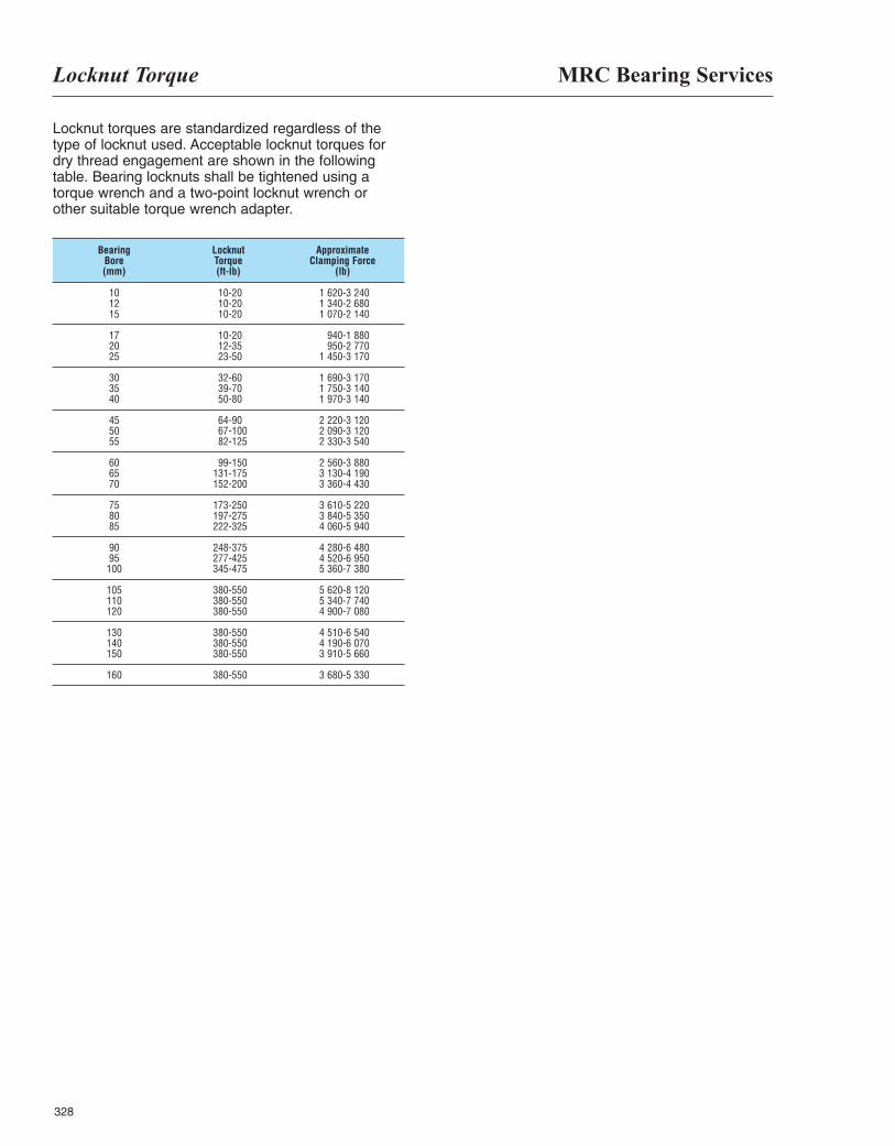
MRC Bearing ServicesLocknut Torque
328
Locknut torques are standardized regardless of thetype of locknut used. Acceptable locknut torques fordry thread engagement are shown in the followingtable. Bearing locknuts shall be tightened using atorque wrench and a two-point locknut wrench orother suitable torque wrench adapter.
Bearing Locknut Approximate Bore Torque Clamping Force (mm) (ft-lb) (lb)
10 10-20 1 620-3 24012 10-20 1 340-2 68015 10-20 1 070-2 140
17 10-20 940-1 88020 12-35 950-2 77025 23-50 1 450-3 170
30 32-60 1 690-3 17035 39-70 1 750-3 14040 50-80 1 970-3 140
45 64-90 2 220-3 12050 67-100 2 090-3 12055 82-125 2 330-3 540
60 99-150 2 560-3 88065 131-175 3 130-4 19070 152-200 3 360-4 430
75 173-250 3 610-5 22080 197-275 3 840-5 35085 222-325 4 060-5 940
90 248-375 4 280-6 48095 277-425 4 520-6 950100 345-475 5 360-7 380
105 380-550 5 620-8 120110 380-550 5 340-7 740120 380-550 4 900-7 080
130 380-550 4 510-6 540140 380-550 4 190-6 070150 380-550 3 910-5 660
160 380-550 3 680-5 330
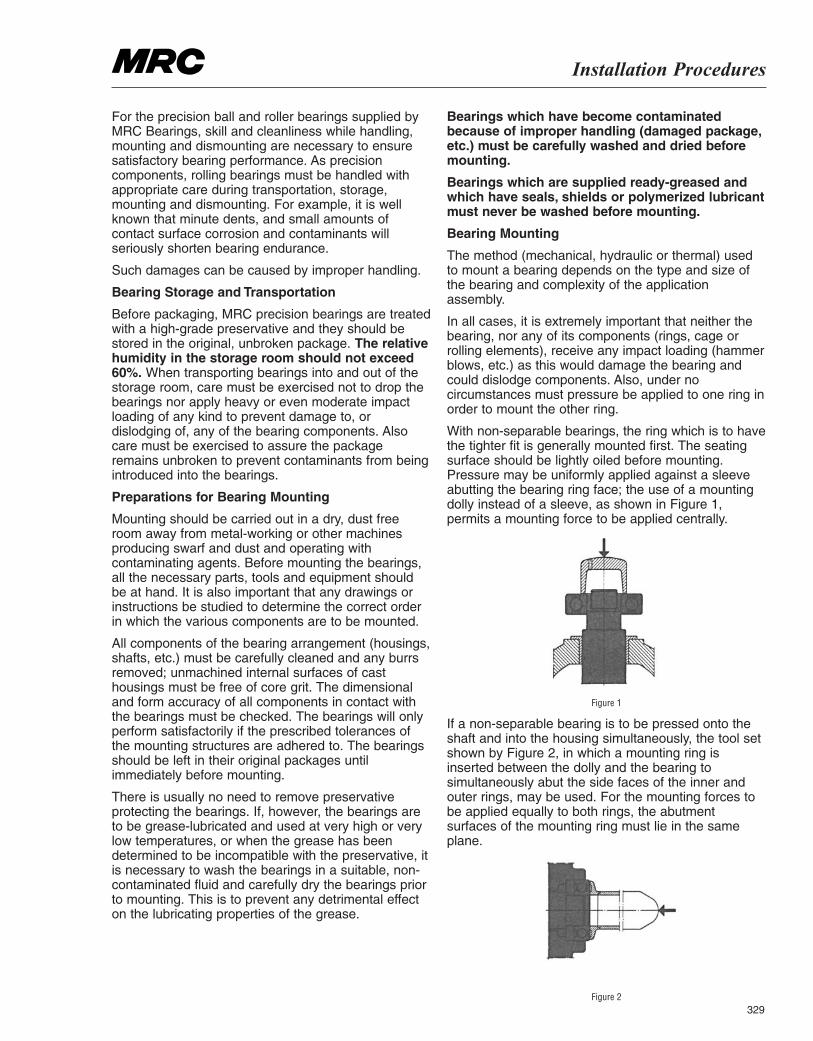
Installation Procedures
329
For the precision ball and roller bearings supplied byMRC Bearings, skill and cleanliness while handling,mounting and dismounting are necessary to ensuresatisfactory bearing performance. As precisioncomponents, rolling bearings must be handled withappropriate care during transportation, storage,mounting and dismounting. For example, it is wellknown that minute dents, and small amounts ofcontact surface corrosion and contaminants willseriously shorten bearing endurance.
Such damages can be caused by improper handling.
Bearing Storage and Transportation
Before packaging, MRC precision bearings are treatedwith a high-grade preservative and they should bestored in the original, unbroken package. The relativehumidity in the storage room should not exceed60%. When transporting bearings into and out of thestorage room, care must be exercised not to drop thebearings nor apply heavy or even moderate impactloading of any kind to prevent damage to, ordislodging of, any of the bearing components. Alsocare must be exercised to assure the packageremains unbroken to prevent contaminants from beingintroduced into the bearings.
Preparations for Bearing Mounting
Mounting should be carried out in a dry, dust freeroom away from metal-working or other machinesproducing swarf and dust and operating withcontaminating agents. Before mounting the bearings,all the necessary parts, tools and equipment shouldbe at hand. It is also important that any drawings orinstructions be studied to determine the correct orderin which the various components are to be mounted.
All components of the bearing arrangement (housings,shafts, etc.) must be carefully cleaned and any burrsremoved; unmachined internal surfaces of casthousings must be free of core grit. The dimensionaland form accuracy of all components in contact withthe bearings must be checked. The bearings will onlyperform satisfactorily if the prescribed tolerances ofthe mounting structures are adhered to. The bearingsshould be left in their original packages untilimmediately before mounting.
There is usually no need to remove preservativeprotecting the bearings. If, however, the bearings areto be grease-lubricated and used at very high or verylow temperatures, or when the grease has beendetermined to be incompatible with the preservative, itis necessary to wash the bearings in a suitable, non-contaminated fluid and carefully dry the bearings priorto mounting. This is to prevent any detrimental effecton the lubricating properties of the grease.
Bearings which have become contaminatedbecause of improper handling (damaged package,etc.) must be carefully washed and dried beforemounting.
Bearings which are supplied ready-greased andwhich have seals, shields or polymerized lubricantmust never be washed before mounting.
Bearing Mounting
The method (mechanical, hydraulic or thermal) usedto mount a bearing depends on the type and size ofthe bearing and complexity of the applicationassembly.
In all cases, it is extremely important that neither thebearing, nor any of its components (rings, cage orrolling elements), receive any impact loading (hammerblows, etc.) as this would damage the bearing andcould dislodge components. Also, under nocircumstances must pressure be applied to one ring inorder to mount the other ring.
With non-separable bearings, the ring which is to havethe tighter fit is generally mounted first. The seatingsurface should be lightly oiled before mounting.Pressure may be uniformly applied against a sleeveabutting the bearing ring face; the use of a mountingdolly instead of a sleeve, as shown in Figure 1,permits a mounting force to be applied centrally.
Figure 1
If a non-separable bearing is to be pressed onto theshaft and into the housing simultaneously, the tool setshown by Figure 2, in which a mounting ring isinserted between the dolly and the bearing tosimultaneously abut the side faces of the inner andouter rings, may be used. For the mounting forces tobe applied equally to both rings, the abutmentsurfaces of the mounting ring must lie in the sameplane.
Figure 2
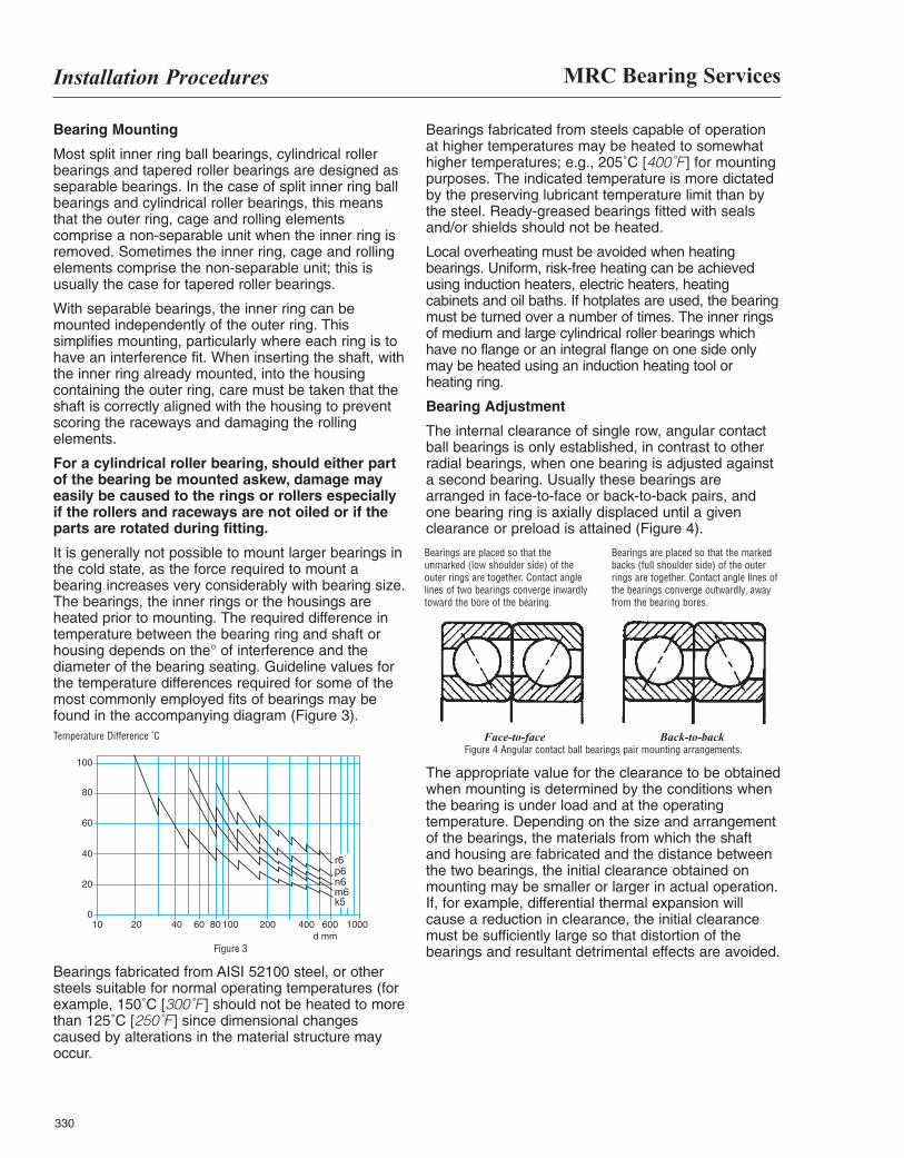
MRC Bearing ServicesInstallation Procedures
330
Bearing Mounting
Most split inner ring ball bearings, cylindrical rollerbearings and tapered roller bearings are designed asseparable bearings. In the case of split inner ring ballbearings and cylindrical roller bearings, this meansthat the outer ring, cage and rolling elementscomprise a non-separable unit when the inner ring isremoved. Sometimes the inner ring, cage and rollingelements comprise the non-separable unit; this isusually the case for tapered roller bearings.
With separable bearings, the inner ring can bemounted independently of the outer ring. Thissimplifies mounting, particularly where each ring is tohave an interference fit. When inserting the shaft, withthe inner ring already mounted, into the housingcontaining the outer ring, care must be taken that theshaft is correctly aligned with the housing to preventscoring the raceways and damaging the rollingelements.
For a cylindrical roller bearing, should either partof the bearing be mounted askew, damage mayeasily be caused to the rings or rollers especiallyif the rollers and raceways are not oiled or if theparts are rotated during fitting.
It is generally not possible to mount larger bearings inthe cold state, as the force required to mount abearing increases very considerably with bearing size.The bearings, the inner rings or the housings areheated prior to mounting. The required difference intemperature between the bearing ring and shaft orhousing depends on the° of interference and thediameter of the bearing seating. Guideline values forthe temperature differences required for some of themost commonly employed fits of bearings may befound in the accompanying diagram (Figure 3).Temperature Difference ˚C
Figure 3
Bearings fabricated from AISI 52100 steel, or othersteels suitable for normal operating temperatures (forexample, 150˚C [300˚F ] should not be heated to morethan 125˚C [250˚F ] since dimensional changescaused by alterations in the material structure mayoccur.
Bearings fabricated from steels capable of operationat higher temperatures may be heated to somewhathigher temperatures; e.g., 205˚C [400˚F ] for mountingpurposes. The indicated temperature is more dictatedby the preserving lubricant temperature limit than bythe steel. Ready-greased bearings fitted with sealsand/or shields should not be heated.
Local overheating must be avoided when heatingbearings. Uniform, risk-free heating can be achievedusing induction heaters, electric heaters, heatingcabinets and oil baths. If hotplates are used, the bearingmust be turned over a number of times. The inner ringsof medium and large cylindrical roller bearings whichhave no flange or an integral flange on one side onlymay be heated using an induction heating tool orheating ring.
Bearing Adjustment
The internal clearance of single row, angular contactball bearings is only established, in contrast to otherradial bearings, when one bearing is adjusted againsta second bearing. Usually these bearings arearranged in face-to-face or back-to-back pairs, andone bearing ring is axially displaced until a givenclearance or preload is attained (Figure 4).
Face-to-face Back-to-back Figure 4 Angular contact ball bearings pair mounting arrangements.
The appropriate value for the clearance to be obtainedwhen mounting is determined by the conditions whenthe bearing is under load and at the operatingtemperature. Depending on the size and arrangementof the bearings, the materials from which the shaftand housing are fabricated and the distance betweenthe two bearings, the initial clearance obtained onmounting may be smaller or larger in actual operation.If, for example, differential thermal expansion willcause a reduction in clearance, the initial clearancemust be sufficiently large so that distortion of thebearings and resultant detrimental effects are avoided.
Bearings are placed so that theunmarked (low shoulder side) of theouter rings are together. Contact anglelines of two bearings converge inwardlytoward the bore of the bearing.
Bearings are placed so that the markedbacks (full shoulder side) of the outerrings are together. Contact angle lines ofthe bearings converge outwardly, awayfrom the bearing bores.
100
20
40
60
80
100
20 40 60 80 100 200 400 600
r6p6n6m6k5
d mm
Figure 3
1000
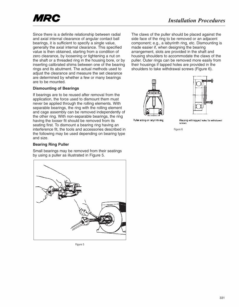
Installation Procedures
331
Since there is a definite relationship between radialand axial internal clearance of angular contact ballbearings, it is sufficient to specify a single value,generally the axial internal clearance. This specifiedvalue is then obtained, starting from a condition ofzero clearance, by loosening or tightening a nut onthe shaft or a threaded ring in the housing bore, or byinserting calibrated shims between one of the bearingrings and its abutment. The actual methods used toadjust the clearance and measure the set clearanceare determined by whether a few or many bearingsare to be mounted.
Dismounting of Bearings
If bearings are to be reused after removal from theapplication, the force used to dismount them mustnever be applied through the rolling elements. Withseparable bearings, the ring with the rolling elementand cage assembly can be removed independently ofthe other ring. With non-separable bearings, the ringhaving the looser fit should be removed from itsseating first. To dismount a bearing ring having aninterference fit, the tools and accessories described inthe following may be used depending on bearing typeand size.
Bearing Ring Puller
Small bearings may be removed from their seatingsby using a puller as illustrated in Figure 5.
Figure 5
The claws of the puller should be placed against theside face of the ring to be removed or an adjacentcomponent; e.g., a labyrinth ring, etc. Dismounting ismade easier if, when designing the bearingarrangement, slots are provided in the shaft andhousing shoulders to accommodate the claws of thepuller. Outer rings can be removed more easily fromtheir housings if tapped holes are provided in theshoulders to take withdrawal screws (Figure 6).
Figure 6
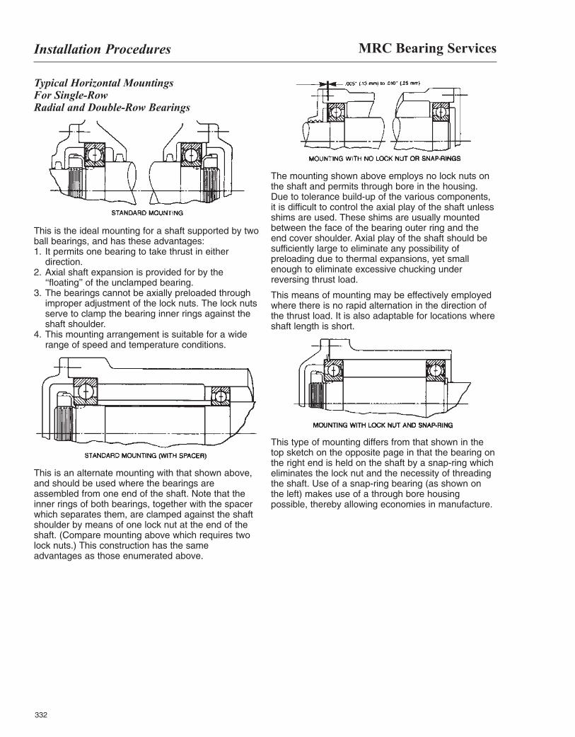
MRC Bearing ServicesInstallation Procedures
332
Typical Horizontal Mountings For Single-Row Radial and Double-Row Bearings
This is the ideal mounting for a shaft supported by twoball bearings, and has these advantages: 1. It permits one bearing to take thrust in either
direction. 2. Axial shaft expansion is provided for by the
‘‘floating’’ of the unclamped bearing. 3. The bearings cannot be axially preloaded through
improper adjustment of the lock nuts. The lock nutsserve to clamp the bearing inner rings against theshaft shoulder.
4. This mounting arrangement is suitable for a widerange of speed and temperature conditions.
This is an alternate mounting with that shown above,and should be used where the bearings areassembled from one end of the shaft. Note that theinner rings of both bearings, together with the spacerwhich separates them, are clamped against the shaftshoulder by means of one lock nut at the end of theshaft. (Compare mounting above which requires twolock nuts.) This construction has the sameadvantages as those enumerated above.
The mounting shown above employs no lock nuts onthe shaft and permits through bore in the housing.Due to tolerance build-up of the various components,it is difficult to control the axial play of the shaft unlessshims are used. These shims are usually mountedbetween the face of the bearing outer ring and theend cover shoulder. Axial play of the shaft should besufficiently large to eliminate any possibility ofpreloading due to thermal expansions, yet smallenough to eliminate excessive chucking underreversing thrust load.
This means of mounting may be effectively employedwhere there is no rapid alternation in the direction ofthe thrust load. It is also adaptable for locations whereshaft length is short.
This type of mounting differs from that shown in thetop sketch on the opposite page in that the bearing onthe right end is held on the shaft by a snap-ring whicheliminates the lock nut and the necessity of threadingthe shaft. Use of a snap-ring bearing (as shown onthe left) makes use of a through bore housingpossible, thereby allowing economies in manufacture.
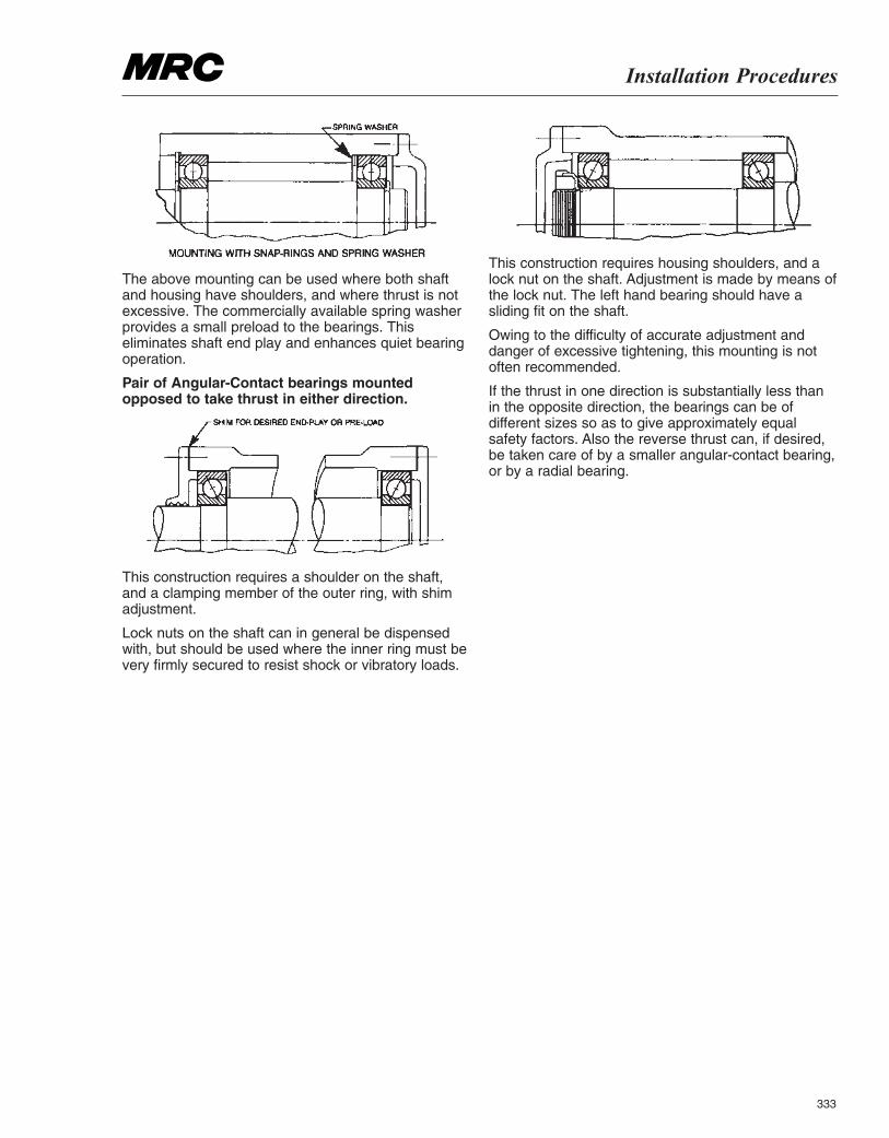
Installation Procedures
333
The above mounting can be used where both shaftand housing have shoulders, and where thrust is notexcessive. The commercially available spring washerprovides a small preload to the bearings. Thiseliminates shaft end play and enhances quiet bearingoperation.
Pair of Angular-Contact bearings mountedopposed to take thrust in either direction.
This construction requires a shoulder on the shaft,and a clamping member of the outer ring, with shimadjustment.
Lock nuts on the shaft can in general be dispensedwith, but should be used where the inner ring must bevery firmly secured to resist shock or vibratory loads.
This construction requires housing shoulders, and alock nut on the shaft. Adjustment is made by means ofthe lock nut. The left hand bearing should have asliding fit on the shaft.
Owing to the difficulty of accurate adjustment anddanger of excessive tightening, this mounting is notoften recommended.
If the thrust in one direction is substantially less thanin the opposite direction, the bearings can be ofdifferent sizes so as to give approximately equalsafety factors. Also the reverse thrust can, if desired,be taken care of by a smaller angular-contact bearing,or by a radial bearing.
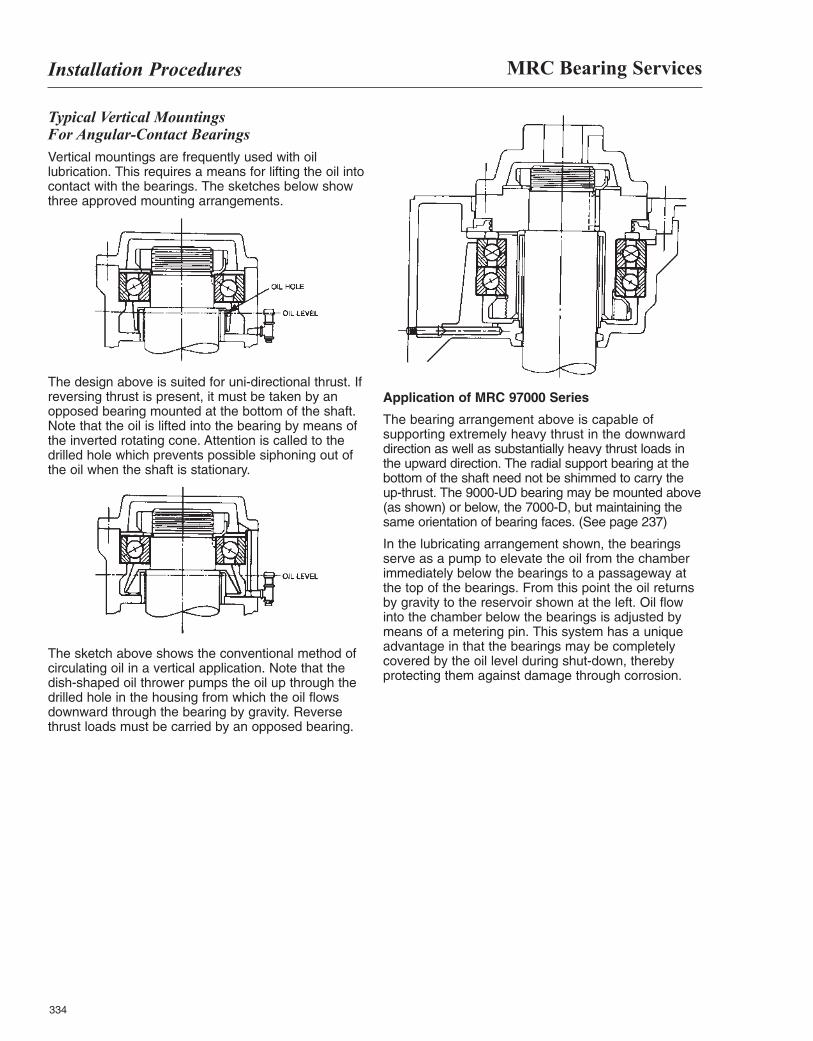
MRC Bearing ServicesInstallation Procedures
334
Typical Vertical Mountings For Angular-Contact BearingsVertical mountings are frequently used with oillubrication. This requires a means for lifting the oil intocontact with the bearings. The sketches below showthree approved mounting arrangements.
The design above is suited for uni-directional thrust. Ifreversing thrust is present, it must be taken by anopposed bearing mounted at the bottom of the shaft.Note that the oil is lifted into the bearing by means ofthe inverted rotating cone. Attention is called to thedrilled hole which prevents possible siphoning out ofthe oil when the shaft is stationary.
The sketch above shows the conventional method ofcirculating oil in a vertical application. Note that thedish-shaped oil thrower pumps the oil up through thedrilled hole in the housing from which the oil flowsdownward through the bearing by gravity. Reversethrust loads must be carried by an opposed bearing.
Application of MRC 97000 Series
The bearing arrangement above is capable ofsupporting extremely heavy thrust in the downwarddirection as well as substantially heavy thrust loads inthe upward direction. The radial support bearing at thebottom of the shaft need not be shimmed to carry theup-thrust. The 9000-UD bearing may be mounted above(as shown) or below, the 7000-D, but maintaining thesame orientation of bearing faces. (See page 237)
In the lubricating arrangement shown, the bearingsserve as a pump to elevate the oil from the chamberimmediately below the bearings to a passageway atthe top of the bearings. From this point the oil returnsby gravity to the reservoir shown at the left. Oil flowinto the chamber below the bearings is adjusted bymeans of a metering pin. This system has a uniqueadvantage in that the bearings may be completelycovered by the oil level during shut-down, therebyprotecting them against damage through corrosion.
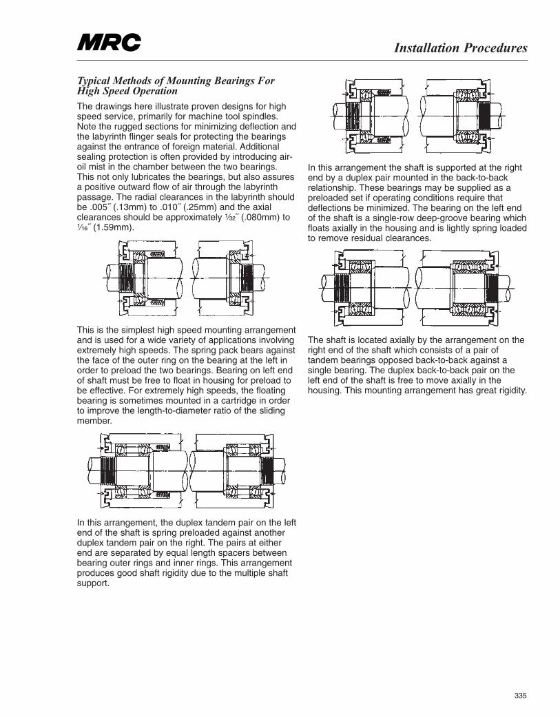
Installation Procedures
335
Typical Methods of Mounting Bearings ForHigh Speed OperationThe drawings here illustrate proven designs for highspeed service, primarily for machine tool spindles.Note the rugged sections for minimizing deflection andthe labyrinth flinger seals for protecting the bearingsagainst the entrance of foreign material. Additionalsealing protection is often provided by introducing air-oil mist in the chamber between the two bearings.This not only lubricates the bearings, but also assuresa positive outward flow of air through the labyrinthpassage. The radial clearances in the labyrinth shouldbe .005˝ (.13mm) to .010˝ (.25mm) and the axialclearances should be approximately ¹|₃₂˝ (.080mm) to¹|₁₆˝ (1.59mm).
This is the simplest high speed mounting arrangementand is used for a wide variety of applications involvingextremely high speeds. The spring pack bears againstthe face of the outer ring on the bearing at the left inorder to preload the two bearings. Bearing on left endof shaft must be free to float in housing for preload tobe effective. For extremely high speeds, the floatingbearing is sometimes mounted in a cartridge in orderto improve the length-to-diameter ratio of the slidingmember.
In this arrangement, the duplex tandem pair on the leftend of the shaft is spring preloaded against anotherduplex tandem pair on the right. The pairs at eitherend are separated by equal length spacers betweenbearing outer rings and inner rings. This arrangementproduces good shaft rigidity due to the multiple shaftsupport.
In this arrangement the shaft is supported at the rightend by a duplex pair mounted in the back-to-backrelationship. These bearings may be supplied as apreloaded set if operating conditions require thatdeflections be minimized. The bearing on the left endof the shaft is a single-row deep-groove bearing whichfloats axially in the housing and is lightly spring loadedto remove residual clearances.
The shaft is located axially by the arrangement on theright end of the shaft which consists of a pair oftandem bearings opposed back-to-back against asingle bearing. The duplex back-to-back pair on theleft end of the shaft is free to move axially in thehousing. This mounting arrangement has great rigidity.
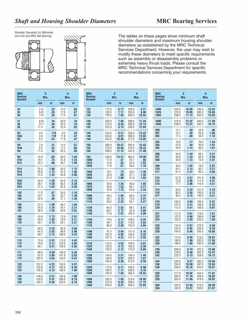
MRC Bearing ServicesShaft and Housing Shoulder Diameters
336
The tables on these pages show minimum shaftshoulder diameters and maximum housing shoulderdiameters as established by the MRC TechnicalServices Department. However, the user may wish tomodify these diameters to meet specific requirementssuch as assembly or disassembly problems orextremely heavy thrust loads. Please consult the MRC Technical Services Department for specificrecommendations concerning your requirements.
MRCBearingNumber
mm
SMin.
HMax.
mmin in
34 5.51 .22 14.2 .5635 6.61 .26 17.0 .6736 7.61 .30 17.0 .67
37 8.61 .34 20.0 .7938 9.71 .38 20.0 .7939 11.4 .45 23.4 .92
R2 4.6 .179 8.3 .33R2A 4.6 .179 11.8 .47R3 6.2 .24 11.8 .47
R4 7.9 .31 14.4 .57R4A 8.2 .32 17.2 .68R6 11.5 .45 20.3 .80
R8 15.9 .63 26.0 1.03R10 19.1 .75 31.8 1.25R12 22.2 .88 38.1 1.50
R14 25.4 1.00 44.5 1.75R16 28.6 1.13 47.6 1.88R18 31.8 1.25 50.8 2.00
R20 34.9 1.38 54.0 2.13R22 38.1 1.50 60.3 2.38R24 41.3 1.63 63.5 2.50
102 17.0 .67 30.0 1.18103 19.1 .75 35.1 1.38104 22.6 .89 37.1 1.46
105 27.4 1.08 46.7 1.84106 34.0 1.34 56.1 2.21107 38.9 1.53 64.0 2.52
108 43.9 1.73 73.9 2.91109 49.3 1.94 79.0 3.11110 54.1 2.13 83.1 3.27
111 59.2 2.33 92.9 3.66112 64.3 2.53 98.0 3.86113 69.1 2.72 108.0 4.25
114 73.9 2.91 113.0 4.45115 79.0 3.11 123.0 4.84116 84.1 3.31 128.0 5.05
117 88.9 3.50 136.0 5.35118 97.5 3.84 141.0 5.55119 102.0 4.05 150.0 5.91
120 107.0 4.23 150.0 5.91122 120.0 4.72 165.0 6.49124 130.0 5.12 180.0 7.09
126 140.0 5.51 195.0 7.68128 150.0 5.91 208.0 8.19130 162.0 6.38 223.0 8.78
MRCBearingNumber
mm
SMin.
HMax.
mmin in
132 172.0 6.77 238.0 9.37134 182.0 7.17 253.0 9.96136 192.0 7.56 266.0 10.55
138 202.0 7.95 288.0 11.34140 212.0 8.35 308.0 12.13142 222.0 8.74 326.0 12.84
144 234.0 9.21 336.0 13.23146 244.0 9.61 356.0 14.02148 254.0 10.00 372.0 14.65
150 266.0 10.47 392.0 15.43152 278.0 10.95 412.0 16.22156 298.0 11.73 442.0 17.40
164 338.0 13.31 482.0 18.98100K 11.9 .47 24.1 .95101K 14.0 .55 25.9 1.02102K 17.0 .67 30.0 1.18
103K 19.1 .75 33.0 1.30104K 22.6 .89 37.1 1.46105K 27.4 1.08 41.9 1.65
106K 34.0 1.34 49.0 1.93107K 38.9 1.53 56.1 2.21108K 43.9 1.73 62.0 2.44
109K 49.3 1.94 69.0 2.72110K 54.1 2.13 73.9 2.91111K 59.2 2.33 83.1 3.27
112K 64.3 2.53 88.1 3.47113K 69.1 2.72 92.9 3.66114K 73.9 2.91 103.0 4.06
115K 79.0 3.11 108.0 4.25116K 84.1 3.31 118.0 4.65117K 88.9 3.50 123.0 4.84
118K 97.5 3.84 131.0 5.16119K 102.0 4.05 136.0 5.35120K 107.0 4.23 141.0 5.55
121K 115.0 4.53 150.0 5.91122K 120.0 4.72 160.0 6.30124K 130.0 5.12 170.0 6.69
126K 140.0 5.51 190.0 7.48128K 150.0 5.91 200.0 7.87130K 162.0 6.38 213.0 8.39
132K 172.0 6.77 228.0 8.98134K 182.0 7.17 248.0 9.76136K 192.0 7.56 266.0 10.55
138K 202.0 7.95 278.0 10.95140K 212.0 8.35 298.0 11.73144K 234.0 9.21 326.0 12.84
MRCBearingNumber
mm
SMin.
HMax.
mmin in
148K 254.0 10.00 346.0 13.62152K 278.0 10.95 382.0 15.04156K 298.0 11.73 402.0 15.83
160K 318.0 12.52 442.0 17.40164K 338.0 13.31 462.0 18.19
200 12.7 .50 24.9 .98201 14.7 .58 26.9 1.06202 17.5 .69 30.0 1.18
203 19.6 .77 34.0 1.34204 23.9 .94 40.9 1.61205 29.0 1.14 46.0 1.81
206 34.0 1.34 56.1 2.21207 38.9 1.53 65.0 2.56208 43.9 1.73 72.9 2.87
209 49.3 1.94 78.0 3.07210 54.1 2.13 83.1 3.27211 61.2 2.41 93.5 3.68
212 67.8 2.67 101.0 3.98213 72.6 2.86 111.0 4.37214 77.7 3.06 116.0 4.57
215 82.6 3.25 121.0 4.76216 90.2 3.55 130.0 5.12217 95.3 3.75 140.0 5.51
218 100.0 3.94 150.0 5.91219 107.0 4.21 158.0 6.22220 112.0 4.41 168.0 6.61
221 117.0 4.61 178.0 7.01222 122.0 4.80 188.0 7.40224 132.0 5.20 203.0 7.99
226 144.0 5.67 216.0 8.50228 154.0 6.05 236.0 9.29230 164.0 6.46 256.0 10.08
232 174.0 6.85 276.0 10.87234 188.0 7.40 292.0 11.50236 198.0 7.80 302.0 11.89
238 208.0 8.19 322.0 12.68240 218.0 8.58 342.0 13.47242 232.0 9.13 359.0 14.13
244 238.0 9.37 382.0 15.04246 254.0 10.00 397.0 15.63248 258.0 10.16 422.0 16.61
250 277.0 10.92 434.0 17.07252 282.0 11.10 458.0 18.03256 302.0 11.89 478.0 18.82
260 322.0 12.68 518.0 20.39264 342.0 13.47 558.0 21.97
Shoulder Diameters for Millimeterand Inch-size MRC Ball Bearings
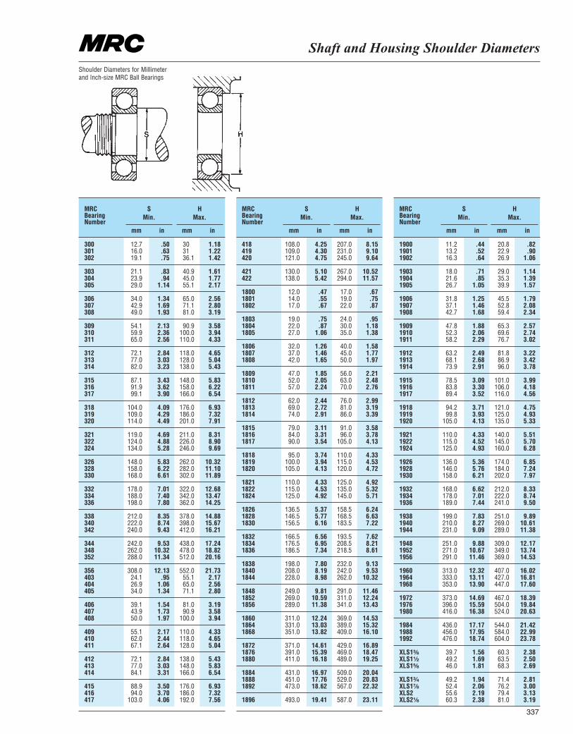
Shaft and Housing Shoulder Diameters
337
Shoulder Diameters for Millimeterand Inch-size MRC Ball Bearings
MRCBearingNumber
mm
SMin.
HMax.
mmin in
300 12.7 .50 30 1.18301 16.0 .63 31 1.22302 19.1 .75 36.1 1.42
303 21.1 .83 40.9 1.61304 23.9 .94 45.0 1.77305 29.0 1.14 55.1 2.17
306 34.0 1.34 65.0 2.56307 42.9 1.69 71.1 2.80308 49.0 1.93 81.0 3.19
309 54.1 2.13 90.9 3.58310 59.9 2.36 100.0 3.94311 65.0 2.56 110.0 4.33
312 72.1 2.84 118.0 4.65313 77.0 3.03 128.0 5.04314 82.0 3.23 138.0 5.43
315 87.1 3.43 148.0 5.83316 91.9 3.62 158.0 6.22317 99.1 3.90 166.0 6.54
318 104.0 4.09 176.0 6.93319 109.0 4.29 186.0 7.32320 114.0 4.49 201.0 7.91
321 119.0 4.69 211.0 8.31322 124.0 4.88 226.0 8.90324 134.0 5.28 246.0 9.69
326 148.0 5.83 262.0 10.32328 158.0 6.22 282.0 11.10330 168.0 6.61 302.0 11.89
332 178.0 7.01 322.0 12.68334 188.0 7.40 342.0 13.47336 198.0 7.80 362.0 14.25
338 212.0 8.35 378.0 14.88340 222.0 8.74 398.0 15.67342 240.0 9.43 412.0 16.21
344 242.0 9.53 438.0 17.24348 262.0 10.32 478.0 18.82352 288.0 11.34 512.0 20.16
356 308.0 12.13 552.0 21.73403 24.1 .95 55.1 2.17404 26.9 1.06 65.0 2.56405 34.0 1.34 71.1 2.80
406 39.1 1.54 81.0 3.19407 43.9 1.73 90.9 3.58408 50.0 1.97 100.0 3.94
409 55.1 2.17 110.0 4.33410 62.0 2.44 118.0 4.65411 67.1 2.64 128.0 5.04
412 72.1 2.84 138.0 5.43413 77.0 3.03 148.0 5.83414 84.1 3.31 166.0 6.54
415 88.9 3.50 176.0 6.93416 94.0 3.70 186.0 7.32417 103.0 4.06 192.0 7.56
MRCBearingNumber
mm
SMin.
HMax.
mmin in
418 108.0 4.25 207.0 8.15419 109.0 4.30 231.0 9.10420 121.0 4.75 245.0 9.64
421 130.0 5.10 267.0 10.52422 138.0 5.42 294.0 11.57
1800 12.0 .47 17.0 .671801 14.0 .55 19.0 .751802 17.0 .67 22.0 .87
1803 19.0 .75 24.0 .951804 22.0 .87 30.0 1.181805 27.0 1.06 35.0 1.38
1806 32.0 1.26 40.0 1.581807 37.0 1.46 45.0 1.771808 42.0 1.65 50.0 1.97
1809 47.0 1.85 56.0 2.211810 52.0 2.05 63.0 2.481811 57.0 2.24 70.0 2.76
1812 62.0 2.44 76.0 2.991813 69.0 2.72 81.0 3.191814 74.0 2.91 86.0 3.39
1815 79.0 3.11 91.0 3.581816 84.0 3.31 96.0 3.781817 90.0 3.54 105.0 4.13
1818 95.0 3.74 110.0 4.331819 100.0 3.94 115.0 4.531820 105.0 4.13 120.0 4.72
1821 110.0 4.33 125.0 4.921822 115.0 4.53 135.0 5.321824 125.0 4.92 145.0 5.71
1826 136.5 5.37 158.5 6.241828 146.5 5.77 168.5 6.631830 156.5 6.16 183.5 7.22
1832 166.5 6.56 193.5 7.621834 176.5 6.95 208.5 8.211836 186.5 7.34 218.5 8.61
1838 198.0 7.80 232.0 9.131840 208.0 8.19 242.0 9.531844 228.0 8.98 262.0 10.32
1848 249.0 9.81 291.0 11.461852 269.0 10.59 311.0 12.241856 289.0 11.38 341.0 13.43
1860 311.0 12.24 369.0 14.531864 331.0 13.03 389.0 15.321868 351.0 13.82 409.0 16.10
1872 371.0 14.61 429.0 16.891876 391.0 15.39 469.0 18.471880 411.0 16.18 489.0 19.25
1884 431.0 16.97 509.0 20.041888 451.0 17.76 529.0 20.831892 473.0 18.62 567.0 22.32
1896 493.0 19.41 587.0 23.11
MRCBearingNumber
mm
SMin.
HMax.
mmin in
1900 11.2 .44 20.8 .821901 13.2 .52 22.9 .901902 16.3 .64 26.9 1.06
1903 18.0 .71 29.0 1.141904 21.6 .85 35.3 1.391905 26.7 1.05 39.9 1.57
1906 31.8 1.25 45.5 1.791907 37.1 1.46 52.8 2.081908 42.7 1.68 59.4 2.34
1909 47.8 1.88 65.3 2.571910 52.3 2.06 69.6 2.741911 58.2 2.29 76.7 3.02
1912 63.2 2.49 81.8 3.221913 68.1 2.68 86.9 3.421914 73.9 2.91 96.0 3.78
1915 78.5 3.09 101.0 3.991916 83.8 3.30 106.0 4.181917 89.4 3.52 116.0 4.56
1918 94.2 3.71 121.0 4.751919 99.8 3.93 125.0 4.931920 105.0 4.13 135.0 5.33
1921 110.0 4.33 140.0 5.511922 115.0 4.52 145.0 5.701924 125.0 4.93 160.0 6.28
1926 136.0 5.36 174.0 6.851928 146.0 5.76 184.0 7.241930 158.0 6.21 202.0 7.97
1932 168.0 6.62 212.0 8.331934 178.0 7.01 222.0 8.741936 189.0 7.44 241.0 9.50
1938 199.0 7.83 251.0 9.891940 210.0 8.27 269.0 10.611944 231.0 9.09 289.0 11.38
1948 251.0 9.88 309.0 12.171952 271.0 10.67 349.0 13.741956 291.0 11.46 369.0 14.53
1960 313.0 12.32 407.0 16.021964 333.0 13.11 427.0 16.811968 353.0 13.90 447.0 17.60
1972 373.0 14.69 467.0 18.391976 396.0 15.59 504.0 19.841980 416.0 16.38 524.0 20.63
1984 436.0 17.17 544.0 21.421988 456.0 17.95 584.0 22.991992 476.0 18.74 604.0 23.78
XLS1³|₈ 39.7 1.56 60.3 2.38XLS1¹|₂ 49.2 1.69 63.5 2.50XLS1⁵|₈ 46.0 1.81 68.3 2.69
XLS1³|₄ 49.2 1.94 71.4 2.81XLS1⁷|₈ 52.4 2.06 76.2 3.00XLS2 55.6 2.19 79.4 3.13XLS2¹|₈ 60.3 2.38 81.0 3.19
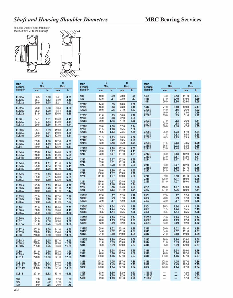
MRC Bearing ServicesShaft and Housing Shoulder Diameters
338
Shoulder Diameters for Millimeterand Inch-size MRC Ball Bearings
MRCBearingNumber mm
SMin.
HMax.
mmin in
MRCBearingNumber mm
SMin.
HMax.
mmin in
MRCBearingNumber mm
SMin.
HMax.
mmin in
XLS2¹|₄ 63.5 2.50 84.1 3.31XLS2³|₈ 66.7 2.63 88.9 3.50XLS2¹|₂ 69.9 2.75 92.1 3.63
XLS2⁵|₈ 73.0 2.88 98.4 3.88XLS2³|₄ 76.2 3.00 98.4 3.88XLS2⁷|₈ 81.0 3.19 106.0 4.19
XLS3 84.1 3.31 106.0 4.19XLS3¹|₈ 87.3 3.44 113.0 4.44XLS3¹|₄ 90.5 3.56 113.0 4.44
XLS3³|₈ 93.7 3.69 119.0 4.69XLS3¹|₂ 96.8 3.81 119.0 4.69XLS3⁵|₈ 100.0 3.94 122.0 4.81
XLS3³|₄ 103.0 4.06 122.0 4.81XLS3⁷|₈ 106.0 4.19 135.0 5.31XLS4 110.0 4.31 135.0 5.31
XLS4¹|₈ 113.0 4.44 144.0 5.69XLS4¹|₄ 116.0 4.56 144.0 5.69XLS4³|₈ 119.0 4.69 151.0 5.94
XLS4¹|₂ 122.0 4.81 151.0 5.94XLS4⁵|₈ 125.0 4.94 157.0 6.19XLS4³|₄ 129.0 5.06 157.0 6.19
XLS4⁷|₈ 132.0 5.19 170.0 6.69XLS5 135.0 5.31 170.0 6.69XLS5¹|₈ 140.0 5.50 175.0 6.88
XLS5¹|₄ 143.0 5.63 175.0 6.88XLS5³|₈ 146.0 5.75 181.0 7.13XLS5¹|₂ 149.0 5.88 181.0 7.13
XLS5⁵|₈ 152.0 6.00 187.0 7.38XLS5³|₄ 156.0 6.13 187.0 7.38XLS5⁷|₈ 159.0 6.25 194.0 7.63
XLS6 162.0 6.38 194.0 7.63XLS6¹|₄ 168.0 6.63 206.0 8.13XLS6¹|₂ 175.0 6.88 213.0 8.38
XLS6³|₄ 184.0 7.25 216.0 8.50XLS7 191.0 7.50 229.0 9.00XLS7¹|₄ 197.0 7.75 235.0 9.25
XLS7¹|₂ 203.0 8.00 241.0 9.50XLS7³|₄ 210.0 8.25 254.0 10.00XLS8 216.0 8.50 260.0 10.25
XLS8¹|₄ 222.0 8.75 267.0 10.50XLS8¹|₂ 229.0 9.00 279.0 11.00XLS8³|₄ 235.0 9.25 286.0 11.25
XLS9 241.0 9.50 292.0 11.50XLS9¹|₂ 257.0 10.13 308.0 12.13XLS10 270.0 10.63 321.0 12.63
XLS10¹|₂ 283.0 11.13 340.0 13.38XLS11 295.0 11.63 352.0 13.88XLS11¹|₂ 308.0 12.13 371.0 14.63
XLS12 321.0 12.63 391.0 15.38
135 7.0 .28 17.0 .67126 8.0 .32 17.0 .67127 9.0 .35 20.0 .79
108 10.0 .39 20.0 .79129 13.0 .51 22.0 .87
1200E 14.0 .55 26.0 1.021201E 16.0 .63 28.0 1.101202E 19.0 .75 31.0 1.22
1203E 21.0 .83 36.0 1.421204E 25.0 .98 42.0 1.651205E 30.0 1.18 47.0 1.85
1206E 35.0 1.38 57.0 2.241207E 41.5 1.63 65.5 2.581208E 46.5 1.83 73.5 2.89
1209E 51.5 2.03 78.5 3.091210E 56.5 2.22 83.5 3.291211E 63.0 2.48 95.0 3.74
1212E 68.0 2.68 102.0 4.021213E 73.0 2.87 112.0 4.411214 78.0 3.07 117.0 4.61
1215 83.0 3.27 122.0 4.801216 89.0 3.51 131.0 5.161217 94.0 3.70 141.0 5.55
1218 99.0 3.90 151.0 5.951219 106.0 4.17 159.0 6.261220 111.0 4.37 169.0 6.65
1221 116.0 4.57 178.0 7.051222 121.0 4.76 189.0 7.441224 131.0 5.16 204.0 8.031226 143.0 5.63 217.0 8.54
1301E 17.0 .67 32.0 1.261302E 20.0 .79 37.0 1.461303E 22.0 .87 42.0 1.65
1304E 26.5 1.04 45.5 1.791305E 31.5 1.24 55.5 2.191306E 36.5 1.44 65.5 2.58
1307E 43.0 1.69 72.0 2.841308E 48.0 1.89 82.0 3.231309E 53.0 2.09 92.0 3.62
1310E 59.0 2.32 101.0 3.981311E 64.0 2.52 111.0 4.371312E 71.0 2.80 119.0 4.69
1313E 76.0 2.99 129.0 5.081314 81.0 3.19 139.0 5.471315 86.0 3.39 149.0 5.87
1316 91.0 3.58 159.0 6.261317 98.0 3.86 167.0 6.581318 103.0 4.06 177.0 6.97
1319 108.0 4.25 187.0 7.361320 113.0 4.45 202.0 7.951322 123.0 4.84 227.0 8.94
1406 38.0 1.50 82.0 3.231407 43.0 1.69 92.0 3.621408 49.0 1.93 101.0 3.98
1409 54.0 2.13 111.0 4.371410 61.0 2.40 119.0 4.691411 66.0 2.60 129.0 5.08
1412 71.0 2.80 139.0 5.472200E 14.0 .55 26.0 1.022201E 16.0 .63 28.0 1.102202E 19.0 .75 31.0 1.22
2203E 21.0 .83 36.0 1.412204E 25.0 .98 42.0 1.652205E 30.0 1.18 47.0 1.85
2206E 35.0 1.38 57.0 2.242207E 41.5 1.63 65.5 2.582208E 46.5 1.83 73.5 2.89
2209E 51.5 2.03 78.5 3.092210E 56.5 2.22 83.5 3.292211E 63.0 2.48 92.0 3.62
2212E 68.0 2.68 102.0 4.022213E 73.0 2.87 112.0 4.412214 78.0 3.07 117.0 4.61
2215 83.0 3.27 122.0 4.812216E 89.0 3.50 131.0 5.162217 94.0 3.70 141.0 5.55
2218 99.0 3.90 151.0 5.952219 106.0 4.17 159.0 6.262220 111.0 4.37 169.0 6.65
2221 116.0 4.57 179.0 7.052222 121.0 4.76 189.0 7.44
2301 17.0 .67 32.0 1.262302 20.0 .79 37.0 1.462303 22.0 .87 42.0 1.65
2304 26.5 1.04 45.5 1.792305 31.5 1.24 55.5 2.192306 36.5 1.44 65.5 2.58
2307E 43.0 1.69 72.0 2.842308E 48.0 1.89 82.0 3.232309E 53.0 2.09 92.0 3.62
2310 59.0 2.32 101.0 3.982311 64.0 2.52 111.0 4.372312 71.0 2.80 119.0 4.69
2313 76.0 2.99 129.0 5.082314 81.0 3.19 139.0 5.472315 86.0 3.39 149.0 5.87
2316 91.0 3.58 159.0 6.262317 98.0 3.86 167.0 6.582318 103.0 4.06 177.0 6.97
2319 108.0 4.25 187.0 7.362320 113.0 4.45 202.0 7.952322 123.0 4.84 227.0 8.94
11204E — — 42.0 1.6511205E — — 47.0 1.8511206E — — 57.0 2.24
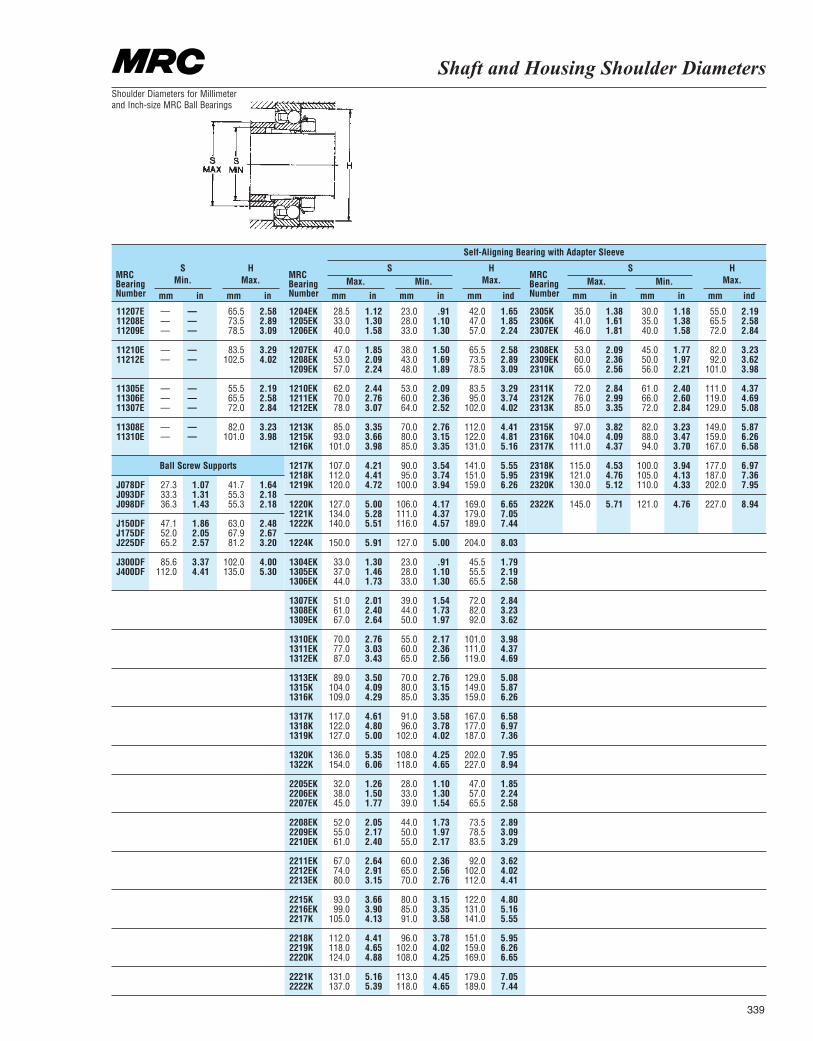
Shaft and Housing Shoulder Diameters
339
MRCBearingNumber
MRCBearingNumber
MRCBearingNumbermm mm mmmm mmmm mmmmin in inin inind indin
SMin. Max. Max.
S
Self-Aligning Bearing with Adapter Sleeve
SMin. Min.
HMax.
HMax.
HMax.
11207E — — 65.5 2.5811208E — — 73.5 2.8911209E — — 78.5 3.09
11210E — — 83.5 3.2911212E — — 102.5 4.02
11305E — — 55.5 2.1911306E — — 65.5 2.5811307E — — 72.0 2.84
11308E — — 82.0 3.2311310E — — 101.0 3.98
Ball Screw Supports
J078DF 27.3 1.07 41.7 1.64J093DF 33.3 1.31 55.3 2.18J098DF 36.3 1.43 55.3 2.18
J150DF 47.1 1.86 63.0 2.48J175DF 52.0 2.05 67.9 2.67J225DF 65.2 2.57 81.2 3.20
J300DF 85.6 3.37 102.0 4.00J400DF 112.0 4.41 135.0 5.30
1204EK 28.5 1.12 23.0 .91 42.0 1.651205EK 33.0 1.30 28.0 1.10 47.0 1.851206EK 40.0 1.58 33.0 1.30 57.0 2.24
1207EK 47.0 1.85 38.0 1.50 65.5 2.581208EK 53.0 2.09 43.0 1.69 73.5 2.891209EK 57.0 2.24 48.0 1.89 78.5 3.09
1210EK 62.0 2.44 53.0 2.09 83.5 3.291211EK 70.0 2.76 60.0 2.36 95.0 3.741212EK 78.0 3.07 64.0 2.52 102.0 4.02
1213K 85.0 3.35 70.0 2.76 112.0 4.411215K 93.0 3.66 80.0 3.15 122.0 4.811216K 101.0 3.98 85.0 3.35 131.0 5.16
1217K 107.0 4.21 90.0 3.54 141.0 5.551218K 112.0 4.41 95.0 3.74 151.0 5.951219K 120.0 4.72 100.0 3.94 159.0 6.26
1220K 127.0 5.00 106.0 4.17 169.0 6.651221K 134.0 5.28 111.0 4.37 179.0 7.051222K 140.0 5.51 116.0 4.57 189.0 7.44
1224K 150.0 5.91 127.0 5.00 204.0 8.03
1304EK 33.0 1.30 23.0 .91 45.5 1.791305EK 37.0 1.46 28.0 1.10 55.5 2.191306EK 44.0 1.73 33.0 1.30 65.5 2.58
1307EK 51.0 2.01 39.0 1.54 72.0 2.841308EK 61.0 2.40 44.0 1.73 82.0 3.231309EK 67.0 2.64 50.0 1.97 92.0 3.62
1310EK 70.0 2.76 55.0 2.17 101.0 3.981311EK 77.0 3.03 60.0 2.36 111.0 4.371312EK 87.0 3.43 65.0 2.56 119.0 4.69
1313EK 89.0 3.50 70.0 2.76 129.0 5.081315K 104.0 4.09 80.0 3.15 149.0 5.871316K 109.0 4.29 85.0 3.35 159.0 6.26
1317K 117.0 4.61 91.0 3.58 167.0 6.581318K 122.0 4.80 96.0 3.78 177.0 6.971319K 127.0 5.00 102.0 4.02 187.0 7.36
1320K 136.0 5.35 108.0 4.25 202.0 7.951322K 154.0 6.06 118.0 4.65 227.0 8.94
2205EK 32.0 1.26 28.0 1.10 47.0 1.852206EK 38.0 1.50 33.0 1.30 57.0 2.242207EK 45.0 1.77 39.0 1.54 65.5 2.58
2208EK 52.0 2.05 44.0 1.73 73.5 2.892209EK 55.0 2.17 50.0 1.97 78.5 3.092210EK 61.0 2.40 55.0 2.17 83.5 3.29
2211EK 67.0 2.64 60.0 2.36 92.0 3.622212EK 74.0 2.91 65.0 2.56 102.0 4.022213EK 80.0 3.15 70.0 2.76 112.0 4.41
2215K 93.0 3.66 80.0 3.15 122.0 4.802216EK 99.0 3.90 85.0 3.35 131.0 5.162217K 105.0 4.13 91.0 3.58 141.0 5.55
2218K 112.0 4.41 96.0 3.78 151.0 5.952219K 118.0 4.65 102.0 4.02 159.0 6.262220K 124.0 4.88 108.0 4.25 169.0 6.65
2221K 131.0 5.16 113.0 4.45 179.0 7.052222K 137.0 5.39 118.0 4.65 189.0 7.44
2305K 35.0 1.38 30.0 1.18 55.0 2.192306K 41.0 1.61 35.0 1.38 65.5 2.582307EK 46.0 1.81 40.0 1.58 72.0 2.84
2308EK 53.0 2.09 45.0 1.77 82.0 3.232309EK 60.0 2.36 50.0 1.97 92.0 3.622310K 65.0 2.56 56.0 2.21 101.0 3.98
2311K 72.0 2.84 61.0 2.40 111.0 4.372312K 76.0 2.99 66.0 2.60 119.0 4.692313K 85.0 3.35 72.0 2.84 129.0 5.08
2315K 97.0 3.82 82.0 3.23 149.0 5.872316K 104.0 4.09 88.0 3.47 159.0 6.262317K 111.0 4.37 94.0 3.70 167.0 6.58
2318K 115.0 4.53 100.0 3.94 177.0 6.972319K 121.0 4.76 105.0 4.13 187.0 7.362320K 130.0 5.12 110.0 4.33 202.0 7.95
2322K 145.0 5.71 121.0 4.76 227.0 8.94
Shoulder Diameters for Millimeter and Inch-size MRC Ball Bearings
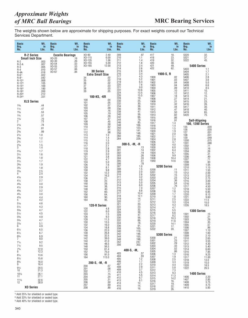
MRC Bearing ServicesApproximate Weights of MRC Ball Bearings
340
The weights shown below are approximate for shipping purposes. For exact weights consult our TechnicalServices Department.
R-2 Series Small Inch Size
R-2 .003R-2-A .007R-3 .005R-4 .010R-4A .018R-61) .022R-81) .042R-101) .069R-123) .105R-142) .169R-162) .180R-182) .200R-202) .212R-242) .331
XLS Series1³|₈ .441¹|₂ .471⁵|₈ .531³|₄ .571⁷|₈ .702 .732¹|₈ .782¹|₄ .812³|₈ .992¹|₂ 1.02⁵|₈ 1.22³|₄ 1.12⁷|₈ 1.53 1.43¹|₈ 1.73¹|₄ 1.63³|₈ 1.83¹|₂ 1.73⁵|₈ 1.93³|₄ 1.83⁷|₈ 2.54 2.44¹|₈ 2.94¹|₄ 2.74³|₈ 3.04¹|₂ 2.94⁵|₈ 3.24³|₄ 3.04⁷|₈ 4.45 4.25¹|₈ 4.65¹|₄ 4.35³|₈ 4.75¹|₂ 4.55⁵|₈ 4.95³|₄ 4.75⁷|₈ 5.16 4.96¹|₄ 6.56¹|₂ 6.76³|₄ 6.97 9.07¹|₄ 9.27¹|₂ 9.57³|₄ 12.08 12.38¹|₄ 13.68¹|₂ 15.68³|₄ 16.09 16.49¹|₂ 20.510 21.310¹|₂ 26.111 27.111¹|₂ 32.612 38.9
XO Series
Excello BearingsXO-20 .16XO-30 .26XO-54 .53XO-55 .53XO-57 .66XO-67 .84
XO-90 2.40XO-115 6.00XO-135 1.06XO-155 5.00XO-165 12.00
30 Series Extra Small Size
34 .0235 .0236 .0237 .0338 .0339 .05
100-KS, -KR100 .04101 .05102 .07103 .09104 .16105 .19106 .28107 .37108 .45109 .58110 .62111 .91112 .98113 1.0114 1.4115 1.5116 2.0117 2.1118 2.8119 2.9120 3.0121 3.8122 4.7124 5.0126 7.6128 8.1130 9.8132 12.2134 16.3136 21.138 22.140 29.144 38.148 40.152 60.156 64.160 90.164 95.
120-R Series120 4.8122 6.0124 7.5126 9.3128 11.3130 13.5132 16.0134 18.8136 22.0138 26.8140 32.5142 39.0144 41.0146 48.5148 56.5150 61.4152 75.0156 91.0164 113.0
200-S, -M, -R200 .07201 .08202 .11203 .15204 .24205 .31206 .50207 .69208 .88
209 .97210 1.1211 1.4212 1.8213 2.4214 2.6215 2.8216 3.4217 4.3218 5.2219 6.4220 7.6221 9.0222 10.6224 13.5226 15.5228 19.230 25.232 30.234 38.236 39.238 47.240 56.242 66.244 79.246 85.248 106.250 123.252 141.256 148.260 185.264 226.
300-S, -M, -R300 .13301 .14302 .19303 .26304 .33305 .51306 .78307 1.0308 1.5309 2.0310 2.6311 3.2312 4.0313 5.0314 6.0315 7.4316 8.8317 10.4318 12.1319 14.320 17.321 20.322 23.324 32.326 38.328 47.330 56.332 66.334 78.336 91.338 105.340 118.342 146.344 155.348 198.352 247.356 302.
400-S, -M,403 .57404 .93405 1.2406 1.7407 2.2408 2.9409 3.7410 4.5411 5.5412 6.7413 8.1414 12.415 14.416 16.
417 18.418 23.419 32.420 38.421 49.422 62.
1900-S, R1900 .021901 .031902 .041903 .041904 .091905 .101906 .121907 .181908 .271909 .311910 .321911 .441912 .471913 .501914 .821915 .861916 .911917 1.31918 1.41919 1.51920 1.91921 2.01922 2.11924 2.81926 3.71928 4.01930 6.01932 6.41934 6.71936 9.91938 10.41940 14.6
5200 Series5200 .115201 .135202 .155203 .235204 .365205 .545206 .765207 1.25208 1.65209 1.75210 1.85211 2.55212 3.35213 4.35214 4.75215 5.55216 6.65217 8.25218 10.35219 11.65220 14.15221 17.5222 20.
5300 Series5300 .215301 .235302 .295303 .435304 .525305 .865306 1.35307 1.95308 2.55309 3.35310 4.45311 5.85312 7.35313 9.35314 11.35315 14.25316 16.5317 19.5318 22.5319 26.
5320 32.5321 37.5322 45.
5400 Series5403 1.15404 1.75405 2.15406 2.85407 3.65408 5.05409 6.65410 8.55411 10.5412 12.5413 15.5414 21.5415 23.5416 26.5417 30.5418 40.5419 65.5420 75.
Self-Aligning100, 1200 Series
135 .020126 .020127 .031108 .031129 .0491200 .0751201 .0881202 .111203 .161204 .261205 .311206 .491207 .711208 .931209 1.051210 1.151211 1.551212 2.001213 2.551214 2.751215 3.001216 3.651217 4.501218 5.501219 6.851220 8.151221 9.601222 11.51224 15.01226 18.5
1300 Series1301 .151302 .211303 .291304 .351305 .571306 .861307 1.101308 1.601309 2.101310 2.651311 3.551312 4.301313 5.401314 6.601315 7.851316 9.251317 11.001318 13.01319 15.01320 18.51322 26.5
1400 Series1406 2.201407 2.851408 3.751409 4.751410 5.85
Basic Wt.Brg. inNo. Lbs.
Basic Wt.Brg. inNo. Lbs.
Basic Wt.Brg. inNo. Lbs.
Basic Wt.Brg. inNo. Lbs.
Basic Wt.Brg. inNo. Lbs.
Basic Wt.Brg. inNo. Lbs.
1) Add 25% for shielded or sealed type.2) Add 33% for shielded or sealed type.3) Add 40% for shielded or sealed type.
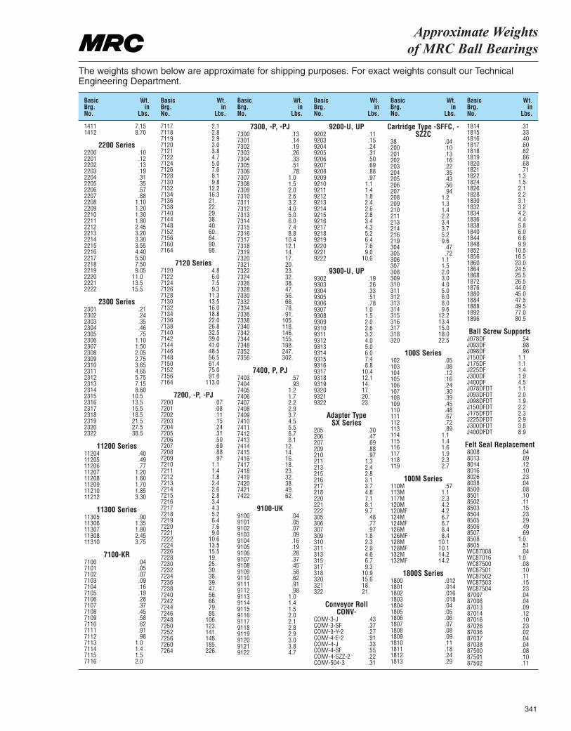
Approximate Weights of MRC Ball Bearings
341
The weights shown below are approximate for shipping purposes. For exact weights consult our Technical Engineering Department.
1411 7.151412 8.70
2200 Series2200 .102201 .122202 .132203 .192204 .312205 .352206 .572207 .882208 1.102209 1.202210 1.302211 1.802212 2.452213 3.202214 3.302215 3.552216 4.402217 5.502218 7.502219 9.052220 11.02221 13.52222 15.5
2300 Series2301 .212302 .242303 .352304 .462305 .752306 1.102307 1.502308 2.052309 2.752310 3.652311 4.652312 5.752313 7.152314 8.602315 10.52316 13.52317 15.52318 18.52319 21.52320 27.52322 38.5
11200 Series11204 .4011205 .4911206 .7711207 1.2011208 1.6011209 1.7011210 1.8511212 3.30
11300 Series11305 .9011306 1.3511307 1.8011308 2.4511310 3.75
7100-KR7100 .047101 .057102 .077103 .097104 .167105 .197106 .287107 .377108 .457109 .587110 .627111 .917112 .987113 1.07114 1.47115 1.57116 2.0
7117 2.17118 2.87119 2.97120 3.07121 3.87122 4.77124 5.07126 7.67128 8.17130 9.87132 12.27134 16.37136 21.7138 22.7140 29.7144 38.7148 40.7152 60.7156 64.7160 90.7164 95.
7120 Series7120 4.87122 6.07124 7.57126 9.37128 11.37130 13.57132 16.07134 18.87136 22.07138 26.87140 32.57142 39.07144 41.07146 48.57148 56.57150 61.47152 75.07156 91.07164 113.0
7200, -P, -PJ7200 .077201 .087202 .117203 .157204 .247205 .317206 .507207 .697208 .887209 .977210 1.17211 1.47212 1.87213 2.47214 2.67215 2.87216 3.47217 4.37218 5.27219 6.47220 7.67221 9.07222 10.67224 13.57226 15.57228 19.7230 25.7232 30.7234 38.7236 39.7238 47.7240 56.7242 66.7244 79.7246 85.7248 106.7250 123.7252 141.7256 148.7260 185.7264 226.
7300, -P, -PJ7300 .137301 .147302 .197303 .267304 .337305 .517306 .787307 1.07308 1.57309 2.07310 2.67311 3.27312 4.07313 5.07314 6.07315 7.47316 8.87317 10.47318 12.17319 14.7320 17.7321 20.7322 23.7324 32.7326 38.7328 47.7330 56.7332 66.7334 78.7336 91.7338 105.7340 118.7342 146.7344 155.7348 198.7352 247.7356 302.
7400, P, PJ7403 .577404 .937405 1.27406 1.77407 2.27408 2.97409 3.77410 4.57411 5.57412 6.77413 8.17414 12.7415 14.7416 16.7417 18.7418 23.7419 32.7420 38.7421 49.7422 62.
9100-UK9100 .049101 .059102 .079103 .099104 .169105 .199106 .289107 .379108 .459109 .589110 .629111 .919112 .989113 1.09114 1.49115 1.59116 2.09117 2.19118 2.89119 2.99120 3.09121 3.89122 4.7
9200-U, UP9202 .119203 .159204 .249205 .319206 .509207 .699208 .889209 .979210 1.19211 1.49212 1.89213 2.49214 2.69215 2.89216 3.49217 4.39218 5.29219 6.49220 7.69221 9.09222 10.6
9300-U, UP9302 .199303 .269304 .339305 .519306 .789307 1.09308 1.59309 2.09310 2.69311 3.29312 4.09313 5.09314 6.09315 7.49316 8.89317 10.49318 12.19319 14.9320 17.9321 20.9322 23.
Adapter Type SX Series
205 .30206 .47207 .69209 .88210 .97211 1.3213 2.4215 2.8216 3.1217 3.7218 4.8220 7.1221 8.1222 9.7305 .48306 .77307 .97309 1.8310 2.3311 2.9313 4.6315 6.7317 9.3318 10.9320 15.6321 18.322 21.
Conveyor Roll CONV-
CONV-3-J .43CONV-3-SF .37CONV-3-Y-2 .27CONV-4-E-2 .91CONV-4-J .33CONV-4-SF .55CONV-4-SZZ-2 .22CONV-504-3 .31
Cartridge Type -SFFC, -SZZC
38 .04200 .10201 .13202 .16203 .22204 .35205 .43206 .56207 .94208 1.2209 1.3210 1.4211 2.2213 3.4214 3.7216 5.2219 9.6304 .47305 .72306 1.1307 1.5308 2.0309 3.0310 4.0311 5.0312 6.0313 8.0314 9.6315 12.2316 13.4317 15.0318 18.0320 22.5
100S Series102 .05103 .08104 .12105 .16106 .24107 .30108 .39109 .45110 .48111 .67112 .72113 .89114 1.1115 1.4116 1.6117 1.9118 2.3119 2.7
100M Series110M .57113M 1.1117M 2.3120M 4.2120MF 4.2124M 6.7124MF 6.7126M 8.4126MF 8.4128M 10.1128MF 10.1132M 14.2132MF 14.2
1800S Series1800 .0121801 .0141802 .0161803 .0181804 .041805 .051806 .061807 .071808 .081809 .091810 .111811 .181812 .241813 .29
1814 .311815 .331816 .401817 .601818 .621819 .661820 .681821 .711822 1.31824 1.51826 2.11828 2.21830 3.11832 3.21834 4.21836 4.41838 5.81840 6.01844 6.61848 9.91852 10.51856 16.51860 23.01864 24.51868 25.51872 26.51876 44.01880 45.01884 47.51888 49.51892 77.01896 80.5
Ball Screw SupportsJ078DF .54J093DF .98J098DF .96J150DF 1.1J175DF 1.1J225DF 1.4J300DF 1.9J400DF 4.5J078DFDT 1.1J093DFDT 2.0J098DFDT 1.9J150DFDT 2.2J175DFDT 2.3J225DFDT 2.9J300DFDT 3.8J400DFDT 8.9
Felt Seal Replacement8008 .048013 .098014 .128016 .108026 .238038 .048500 .088501 .108502 .118503 .158504 .238505 .298506 .498507 .698508 1.08605 .51WC87008 .04WC87016 1.0WC87500 .08WC87501 .10WC87502 .11WC87503 .15WC87504 .2387007 .0487008 .0487013 .0987014 .1287016 .1087026 .2387036 .0287037 .0487038 .0487500 .0887501 .1087502 .11
Basic Wt.Brg. inNo. Lbs.
Basic Wt.Brg. inNo. Lbs.
Basic Wt.Brg. inNo. Lbs.
Basic Wt.Brg. inNo. Lbs.
Basic Wt.Brg. inNo. Lbs.
Basic Wt.Brg. inNo. Lbs.
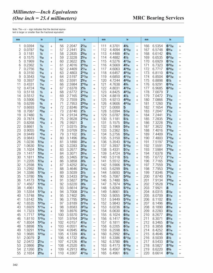
MRC Bearing ServicesMillimeter—Inch Equivalents (One inch = 25.4 millimeters)
342
Note: The + or – sign indicates that the decimal equiva-lent is larger or smaller than the fractional equivalent.
mm in mm in mm in mm in
1 0.0394 ¹|₃₂ +2 0.0787 ³|₃₂ –3 0.1181 ¹|₈ –4 0.1575 ⁵|₃₂ +5 0.1969 ³|₁₆ +6 0.2362 ¹|₄ –7 0.2756 ⁹|₃₂ –8 0.3150 ⁵|₁₆ +9 0.3543 ¹¹|₃₂ +
10 0.3937 ¹³|₃₂ –11 0.4331 ⁷|₁₆ –12 0.4724 ¹⁵|₃₂ +13 0.5118 ¹|₂ +14 0.5512 ⁹|₁₆ –15 0.5906 ¹⁹|₃₂ –16 0.6299 ⁵|₈ +17 0.6693 ²¹|₃₂ +18 0.7087 ²³|₃₂ –19 0.7480 ³|₄ –20 0.7874 ²⁵|₃₂ +21 0.8268 ¹³|₁₆ +22 0.8661 ⁷|₈ –23 0.9055 ²⁹|₃₂ –24 0.9449 ¹⁵|₁₆ +25 0.9843 ³¹|₃₂ +26 1.0236 1¹|₃₂ –27 1.0630 1¹|₁₆ +28 1.1024 1³|₃₂ +29 1.1417 1⁵|₃₂ –30 1.1811 1³|₁₆ –31 1.2205 1⁷|₃₂ +32 1.2598 1¹|₄ +33 1.2992 1⁵|₁₆ –34 1.3386 1¹¹|₃₂ –35 1.3780 1³|₈ +36 1.4173 1¹³|₃₂ +37 1.4567 1¹⁵|₃₂ –38 1.4961 1¹|₂ –39 1.5354 1¹⁷|₃₂ +40 1.5748 1⁹|₁₆ +41 1.6142 1⁵|₈ –42 1.6535 1²¹|₃₂ –43 1.6929 1¹¹|₁₆ +44 1.7323 1²³|₃₂ +45 1.7717 1²⁵|₃₂ –46 1.8110 1¹³|₁₆ –47 1.8504 1²⁷|₃₂ +48 1.8898 1⁷|₈ +49 1.9291 1¹⁵|₁₆ –50 1.9685 1³¹|₃₂ –51 2.0079 2 +52 2.0472 2¹|₁₆ –53 2.0866 2³|₃₂ –54 2.1260 2¹|₈ +55 2.1654 2⁵|₃₂ +
56 2.2047 2⁷|₃₂ –57 2.2441 2¹|₄ –58 2.2835 2⁹|₃₂ +59 2.3228 2⁵|₁₆ +60 2.3622 2³|₈ –61 2.4016 2¹³|₃₂ –62 2.4409 2⁷|₁₆ +63 2.4803 2¹⁵|₃₂ +64 2.5197 2¹⁷|₃₂ –65 2.5591 2⁹|₁₆ –66 2.5984 2¹⁹|₃₂ +67 2.6378 2⁵|₈ +68 2.6772 2¹¹|₁₆ –69 2.7165 2²³|₃₂ –70 2.7559 2³|₄ +71 2.7953 2²⁵|₃₂ +72 2.8346 2²⁷|₃₂ –73 2.8740 2⁷|₈ –74 2.9134 2²⁹|₃₂ +75 2.9528 2¹⁵|₁₆ +76 2.9921 3 –77 3.0315 3¹|₃₂ +78 3.0709 3¹|₁₆ +79 3.1102 3¹|₈ –80 3.1496 3⁵|₃₂ –81 3.1890 3³|₁₆ +82 3.2283 3⁷|₃₂ +83 3.2677 3⁹|₃₂ –84 3.3071 3⁵|₁₆ –85 3.3465 3¹¹|₃₂ +86 3.3858 3³|₈ +87 3.4252 3⁷|₁₆ –88 3.4646 3¹⁵|₃₂ –89 3.5039 3¹|₂ +90 3.5433 3¹⁷|₃₂ +91 3.5827 3¹⁹|₃₂ –92 3.6220 3⁵|₈ –93 3.6614 3²¹|₃₂ +94 3.7008 3¹¹|₁₆ +95 3.7402 3³|₄ –96 3.7795 3²⁵|₃₂ –97 3.8189 3¹³|₁₆ +98 3.8583 3²⁷|₃₂ +99 3.8976 3²⁹|₃₂ –
100 3.9370 3¹⁵|₁₆ –101 3.9764 3³¹|₃₂ +102 4.0157 4¹|₃₂ –103 4.0551 4¹|₁₆ –104 4.0945 4³|₃₂ +105 4.1339 4¹|₈ +106 4.1732 4³|₁₆ –107 4.2126 4⁷|₃₂ –108 4.2520 4¹|₄ +109 4.2913 4⁹|₃₂ +110 4.3307 4¹¹|₃₂ –
111 4.3701 4³|₈ –112 4.4094 4¹³|₃₂ +113 4.4488 4⁷|₁₆ +114 4.4882 4¹|₂ –115 4.5276 4¹⁷|₃₂ –116 4.5669 4⁹|₁₆ +117 4.6063 4¹⁹|₃₂ +118 4.6457 4²¹|₃₂ –119 4.6850 4¹¹|₁₆ –120 4.7244 4²³|₃₂ +121 4.7638 4³|₄ +122 4.8031 4¹³|₁₆ –123 4.8425 4²⁷|₃₂ –124 4.8819 4⁷|₈ +125 4.9213 4²⁹|₃₂ +126 4.9606 4³¹|₃₂ –127 5.0000 5128 5.0394 5¹|₃₂ +129 5.0787 5³|₃₂ –130 5.1181 5¹|₈ –131 5.1575 5⁵|₃₂ +132 5.1969 5³|₁₆ +133 5.2362 5¹|₄ –134 5.2756 5⁹|₃₂ –135 5.3150 5⁵|₁₆ +136 5.3543 5¹¹|₃₂ +137 5.3937 5¹³|₃₂ –138 5.4331 5⁷|₁₆ –139 5.4724 5¹⁵|₃₂ +140 5.5118 5¹|₂ +141 5.5512 5⁹|₁₆ –142 5.5906 5¹⁹|₃₂ –143 5.6299 5⁵|₈ +144 5.6693 5²¹|₃₂ +145 5.7087 5²³|₃₂ –146 5.7480 5³|₄ –147 5.7874 5²⁵|₃₂ +148 5.8268 5¹³|₁₆ +149 5.8661 5⁷|₈ –150 5.9055 5²⁹|₃₂ –151 5.9449 5¹⁵|₁₆ +152 5.9843 5³¹|₃₂ +153 6.0236 6¹|₃₂ –154 6.0630 6¹|₁₆ +155 6.1024 6³|₃₂ +156 6.1417 6⁵|₃₂ –157 6.1811 6³|₁₆ –158 6.2205 6⁷|₃₂ +159 6.2598 6¹|₄ +160 6.2992 6⁵|₁₆ –161 6.3386 6¹¹|₃₂ –162 6.3780 6³|₈ +163 6.4173 6¹³|₃₂ +164 6.4567 6¹⁵|₃₂ –165 6.4961 6¹|₂ –
166 6.5354 6¹⁷|₃₂ +167 6.5748 6⁹|₁₆ +168 6.6142 6⁵|₈ –169 6.6535 6²¹|₃₂ –170 6.6929 6¹¹|₁₆ +171 6.7323 6²³|₃₂ +172 6.7717 6²⁵|₃₂ –173 6.8110 6¹³|₁₆ –174 6.8504 6²⁷|₃₂ +175 6.8898 6⁷|₈ +176 6.9291 6¹⁵|₁₆ –177 6.9685 6³¹|₃₂ –178 7.0079 7 +179 7.0472 7¹|₁₆ –180 7.0866 7³|₃₂ –181 7.1260 7¹|₈ +182 7.1654 7⁵|₃₂ +183 7.2047 7⁷|₃₂ –184 7.2441 7¹|₄ –185 7.2835 7⁹|₃₂ +186 7.3228 7⁵|₁₆ +187 7.3622 7³|₈ –188 7.4016 7¹³|₃₂ –189 7.4409 7⁷|₁₆ +190 7.4803 7¹⁵|₃₂ +191 7.5197 7¹⁷|₃₂ –192 7.5591 7⁹|₁₆ –193 7.5984 7¹⁹|₃₂ +194 7.6378 7⁵|₈ +195 7.6772 7¹¹|₁₆ –196 7.7165 7²³|₃₂ –197 7.7559 7³|₄ +198 7.7953 7²⁵|₃₂ +199 7.8346 7²⁷|₃₂ –200 7.8740 7⁷|₈ –201 7.9134 7²⁹|₃₂ +202 7.9528 7¹⁵|₁₆ +203 7.9921 8 –204 8.0315 8¹|₃₂ +205 8.0709 8¹|₁₆ +206 8.1102 8¹|₈ –207 8.1496 8⁵|₃₂ –208 8.1890 8³|₁₆ +209 8.2283 8⁷|₃₂ +210 8.2677 8⁹|₃₂ –211 8.3071 8⁵|₁₆ –212 8.3465 8¹¹|₃₂ +213 8.3858 8³|₈ +214 8.4252 8⁷|₁₆ –215 8.4646 8¹⁵|₃₂ –216 8.5039 8¹|₂ +217 8.5433 8¹⁷|₃₂ +218 8.5827 8¹⁹|₃₂ –219 8.6220 8⁵|₈ –220 8.6614 8²¹|₃₂ +
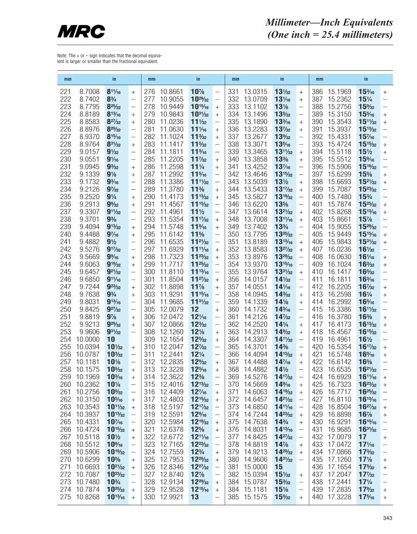
343
Millimeter—Inch Equivalents (One inch = 25.4 millimeters)
Note: The + or – sign indicates that the decimal equiva-lent is larger or smaller than the fractional equivalent.
mm in mm in mm in mm in
221 8.7008 8¹¹|₁₆ +222 8.7402 8³|₄ –223 8.7795 8²⁵|₃₂ –224 8.8189 8¹³|₁₆ +225 8.8583 8²⁷|₃₂ +226 8.8976 8²⁹|₃₂ –227 8.9370 8¹⁵|₁₆ –228 8.9764 8³¹|₃₂ +229 9.0157 9¹|₃₂ –230 9.0551 9¹|₁₆ –231 9.0945 9³|₃₂ +232 9.1339 9¹|₈ +233 9.1732 9³|₁₆ –234 9.2126 9⁷|₃₂ –235 9.2520 9¹|₄ +236 9.2913 9⁹|₃₂ +237 9.3307 9¹¹|₃₂ –238 9.3701 9³|₈ –239 9.4094 9¹³|₃₂ +240 9.4488 9⁷|₁₆ +241 9.4882 9¹|₂ –242 9.5276 9¹⁷|₃₂ –243 9.5669 9⁹|₁₆ +244 9.6063 9¹⁹|₃₂ +245 9.6457 9²¹|₃₂ –246 9.6850 9¹¹|₁₆ –247 9.7244 9²³|₃₂ +248 9.7638 9³|₄ +249 9.8031 9¹³|₁₆ –250 9.8425 9²⁷|₃₂ –251 9.8819 9⁷|₈ +252 9.9213 9²⁹|₃₂ +253 9.9606 9³¹|₃₂ –254 10.0000 10255 10.0394 10¹|₃₂ +256 10.0787 10³|₃₂ –257 10.1181 10¹|₈ –258 10.1575 10⁵|₃₂ +259 10.1969 10³|₁₆ +260 10.2362 10¹|₄ –261 10.2756 10⁹|₃₂ –262 10.3150 10⁵|₁₆ +263 10.3543 10¹¹|₃₂ +264 10.3937 10¹³|₃₂ –265 10.4331 10⁷|₁₆ –266 10.4724 10¹⁵|₃₂ +267 10.5118 10¹|₂ +268 10.5512 10⁹|₁₆ –269 10.5906 10¹⁹|₃₂ –270 10.6299 10⁵|₈ +271 10.6693 10²¹|₃₂ +272 10.7087 10²³|₃₂ –273 10.7480 10³|₄ –274 10.7874 10²⁵|₃₂ +275 10.8268 10¹³|₁₆ +
276 10.8661 10⁷|₈ –277 10.9055 10²⁹|₃₂ –278 10.9449 10¹⁵|₁₆ +279 10.9843 10³¹|₃₂ +280 11.0236 11¹|₃₂ –281 11.0630 11¹|₁₆ +282 11.1024 11³|₃₂ +283 11.1417 11⁵|₃₂ –284 11.1811 11³|₁₆ –285 11.2205 11⁷|₃₂ +286 11.2598 11¹|₄ +287 11.2992 11⁵|₁₆ –288 11.3386 11¹¹|₃₂ –289 11.3780 11³|₈ +290 11.4173 11¹³|₃₂ +291 11.4567 11¹⁵|₃₂ –292 11.4961 11¹|₂ –293 11.5354 11¹⁷|₃₂ +294 11.5748 11⁹|₁₆ +295 11.6142 11⁵|₈ –296 11.6535 11²¹|₃₂ –297 11.6929 11¹¹|₁₆ +298 11.7323 11²³|₃₂ +299 11.7717 11²⁵|₃₂ –300 11.8110 11¹³|₁₆ –301 11.8504 11²⁷|₃₂ +302 11.8898 11⁷|₈ +303 11.9291 11¹⁵|₁₆ –304 11.9685 11³¹|₃₂ –305 12.0079 12 +306 12.0472 12¹|₁₆ –307 12.0866 12³|₃₂ –308 12.1260 12¹|₈ +309 12.1654 12⁵|₃₂ +310 12.2047 12⁷|₃₂ –311 12.2441 12¹|₄ –312 12.2835 12⁹|₃₂ +313 12.3228 12⁵|₁₆ +314 12.3622 12³|₈ –315 12.4016 12¹³|₃₂ –316 12.4409 12⁷|₁₆ +317 12.4803 12¹⁵|₃₂ +318 12.5197 12¹⁷|₃₂ –319 12.5591 12⁹|₁₆ –320 12.5984 12¹⁹|₃₂ +321 12.6378 12⁵|₈ +322 12.6772 12¹¹|₁₆ –323 12.7165 12²³|₃₂ –324 12.7559 12³|₄ +325 12.7953 12²⁵|₃₂ +326 12.8346 12²⁷|₃₂ –327 12.8740 12⁷|₈ –328 12.9134 12²⁹|₃₂ +329 12.9528 12¹⁵|₁₆ +330 12.9921 13 –
331 13.0315 13¹|₃₂ +332 13.0709 13¹|₁₆ +333 13.1102 13¹|₈ –334 13.1496 13⁵|₃₂ –335 13.1890 13³|₁₆ +336 13.2283 13⁷|₃₂ +337 13.2677 13⁹|₃₂ –338 13.3071 13⁵|₁₆ –339 13.3465 13¹¹|₃₂ +340 13.3858 13³|₈ +341 13.4252 13⁷|₁₆ –342 13.4646 13¹⁵|₃₂ –343 13.5039 13¹|₂ +344 13.5433 13¹⁷|₃₂ +345 13.5827 13¹⁹|₃₂ –346 13.6220 13⁵|₈ –347 13.6614 13²¹|₃₂ +348 13.7008 13¹¹|₁₆ +349 13.7402 13³|₄ –350 13.7795 13²⁵|₃₂ –351 13.8189 13¹³|₁₆ +352 13.8583 13²⁷|₃₂ +353 13.8976 13²⁹|₃₂ –354 13.9370 13¹⁵|₁₆ –355 13.9764 13³¹|₃₂ +356 14.0157 14¹|₃₂ –357 14.0551 14¹|₁₆ –358 14.0945 14³|₃₂ +359 14.1339 14¹|₈ +360 14.1732 14³|₁₆ –361 14.2126 14⁷|₃₂ –362 14.2520 14¹|₄ +363 14.2913 14⁹|₃₂ +364 14.3307 14¹¹|₃₂ –365 14.3701 14³|₈ –366 14.4094 14¹³|₃₂ +367 14.4488 14⁷|₁₆ +368 14.4882 14¹|₂ –369 14.5276 14¹⁷|₃₂ –370 14.5669 14⁹|₁₆ +371 14.6063 14¹⁹|₃₂ +372 14.6457 14²¹|₃₂ –373 14.6850 14¹¹|₁₆ –374 14.7244 14²³|₃₂ +375 14.7638 14³|₄ +376 14.8031 14¹³|₁₆ –377 14.8425 14²⁷|₃₂ –378 14.8819 14⁷|₈ +379 14.9213 14²⁹|₃₂ +380 14.9606 14³¹|₃₂ –381 15.0000 15382 15.0394 15¹|₃₂ +384 15.0787 15³|₃₂ –384 15.1181 15¹|₈ –385 15.1575 15⁵|₃₂ +
386 15.1969 15³|₁₆ +387 15.2362 15¹|₄ –388 15.2756 15⁹|₃₂ –389 15.3150 15⁵|₁₆ +390 15.3543 15¹¹|₃₂ +391 15.3937 15¹³|₃₂ –392 15.4331 15⁷|₁₆ –393 15.4724 15¹⁵|₃₂ +394 15.5118 15¹|₂ +395 15.5512 15⁹|₁₆ –396 15.5906 15¹⁹|₃₂ –397 15.6299 15⁵|₈ +398 15.6693 15²¹|₃₂ +399 15.7087 15²³|₃₂ –400 15.7480 15³|₄ –401 15.7874 15²⁵|₃₂ +402 15.8268 15¹³|₁₆ +403 15.8661 15⁷|₈ –404 15.9055 15²⁹|₃₂ –405 15.9449 15¹⁵|₁₆ +406 15.9843 15³¹|₃₂ +407 16.0236 16¹|₃₂ –408 16.0630 16¹|₁₆ +409 16.1024 16³|₃₂ +410 16.1417 16⁵|₃₂ –411 16.1811 16³|₁₆ –412 16.2205 16⁷|₃₂ +413 16.2598 16¹|₄ +414 16.2992 16⁵|₁₆ –415 16.3386 16¹¹|₃₂ –416 16.3780 16³|₈ +417 16.4173 16¹³|₃₂ +418 16.4567 16¹⁵|₃₂ –419 16.4961 16¹|₂ –420 16.5354 16¹⁷|₃₂ +421 16.5748 16⁹|₁₆ +422 16.6142 16⁵|₈ –423 16.6535 16²¹|₃₂ –424 16.6929 16¹¹|₁₆ +425 16.7323 16²³|₃₂ +426 16.7717 16²⁵|₃₂ –427 16.8110 16¹³|₁₆ –428 16.8504 16²⁷|₃₂ +429 16.8898 16⁷|₈ +430 16.9291 16¹⁵|₁₆ –431 16.9685 16³¹|₃₂ –432 17.0079 17 +433 17.0472 17¹|₁₆ –434 17.0866 17³|₃₂ –435 17.1260 17¹|₈ +436 17.1654 17⁵|₃₂ +437 17.2047 17⁷|₃₂ –438 17.2441 17¹|₄ –439 17.2835 17⁹|₃₂ +440 17.3228 17⁵|₁₆ +
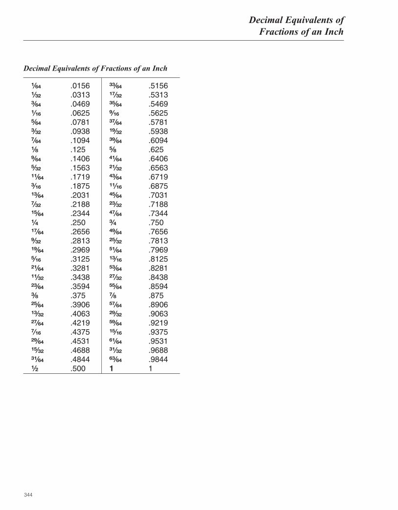
344
Decimal Equivalents ofFractions of an Inch
Decimal Equivalents of Fractions of an Inch
¹|₆₄ .0156¹|₃₂ .0313³|₆₄ .0469¹|₁₆ .0625⁵|₆₄ .0781³|₃₂ .0938⁷|₆₄ .1094¹|₈ .125⁹|₆₄ .1406⁵|₃₂ .1563¹¹|₆₄ .1719³|₁₆ .1875¹³|₆₄ .2031⁷|₃₂ .2188¹⁵|₆₄ .2344¹|₄ .250¹⁷|₆₄ .2656⁹|₃₂ .2813¹⁹|₆₄ .2969⁵|₁₆ .3125²¹|₆₄ .3281¹¹|₃₂ .3438²³|₆₄ .3594³|₈ .375²⁵|₆₄ .3906¹³|₃₂ .4063²⁷|₆₄ .4219⁷|₁₆ .4375²⁹|₆₄ .4531¹⁵|₃₂ .4688³¹|₆₄ .4844¹|₂ .500
³³|₆₄ .5156¹⁷|₃₂ .5313³⁵|₆₄ .5469⁹|₁₆ .5625³⁷|₆₄ .5781¹⁹|₃₂ .5938³⁹|₆₄ .6094⁵|₈ .625⁴¹|₆₄ .6406²¹|₃₂ .6563⁴³|₆₄ .6719¹¹|₁₆ .6875⁴⁵|₆₄ .7031²³|₃₂ .7188⁴⁷|₆₄ .7344³|₄ .750⁴⁹|₆₄ .7656²⁵|₃₂ .7813⁵¹|₆₄ .7969¹³|₁₆ .8125⁵³|₆₄ .8281²⁷|₃₂ .8438⁵⁵|₆₄ .8594⁷|₈ .875⁵⁷|₆₄ .8906²⁹|₃₂ .9063⁵⁹|₆₄ .9219¹⁵|₁₆ .9375⁶¹|₆₄ .9531³¹|₃₂ .9688⁶³|₆₄ .98441 1
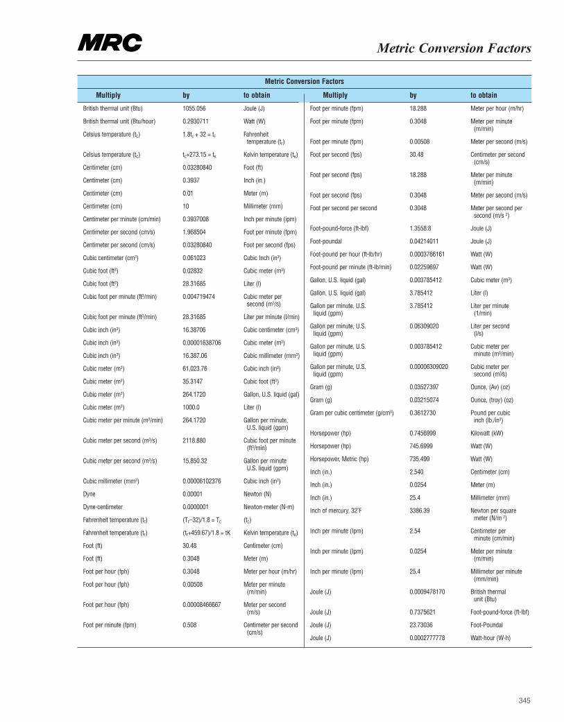
Metric Conversion Factors
Metric Conversion Factors
Multiply by to obtain Multiply by to obtain
British thermal unit (Btu) 1055.056 Joule (J)
British thermal unit (Btu/hour) 0.2930711 Watt (W)
Celsius temperature (tC) 1.8tc + 32 = tF Fahrenheittemperature (tF)
Celsius temperature (tC) tC+273.15 = tK Kelvin temperature (tK)
Centimeter (cm) 0.03280840 Foot (ft)
Centimeter (cm) 0.3937 Inch (in.)
Centimeter (cm) 0.01 Meter (m)
Centimeter (cm) 10 Millimeter (mm)
Centimeter per minute (cm/min) 0.3937008 Inch per minute (ipm)
Centimeter per second (cm/s) 1.968504 Foot per minute (fpm)
Centimeter per second (cm/s) 0.03280840 Foot per second (fps)
Cubic centimeter (cm3) 0.061023 Cubic Inch (in3)
Cubic foot (ft3) 0.02832 Cubic meter (m3)
Cubic foot (ft3) 28.31685 Liter (l)
Cubic foot per minute (ft3/min) 0.004719474 Cubic meter per second (m3/s)
Cubic foot per minute (ft3/min) 28.31685 Liter per minute (l/min)
Cubic inch (in3) 16.38706 Cubic centimeter (cm3)
Cubic inch (in3) 0.00001638706 Cubic meter (m3)
Cubic inch (in3) 16.387.06 Cubic millimeter (mm3)
Cubic meter (m3) 61,023.76 Cubic inch (in3)
Cubic meter (m3) 35.3147 Cubic foot (ft3)
Cubic meter (m3) 264.1720 Gallon, U.S. liquid (gal)
Cubic meter (m3) 1000.0 Liter (l)
Cubic meter per minute (m3/min) 264.1720 Gallon per minute, U.S. liquid (gpm)
Cubic meter per second (m3/s) 2118.880 Cubic foot per minute (ft3/min)
Cubic meter per second (m3/s) 15,850.32 Gallon per minute U.S. liquid (gpm)
Cubic millimeter (mm3) 0.00006102376 Cubic inch (in3)
Dyne 0.00001 Newton (N)
Dyne-centimeter 0.0000001 Newton-meter (N-m)
Fahrenheit temperature (tF) (TF–32)/1.8 = TC (tC)
Fahrenheit temperature (tF) (tF+459.67)/1.8 = tK Kelvin temperature (tK)
Foot (ft) 30.48 Centimeter (cm)
Foot (ft) 0.3048 Meter (m)
Foot per hour (fph) 0.3048 Meter per hour (m/hr)
Foot per hour (fph) 0.00508 Meter per minute (m/min)
Foot per hour (fph) 0.00008466667 Meter per second (m/s)
Foot per minute (fpm) 0.508 Centimeter per second (cm/s)
Foot per minute (fpm) 18.288 Meter per hour (m/hr)
Foot per minute (fpm) 0.3048 Meter per minute (m/min)
Foot per minute (fpm) 0.00508 Meter per second (m/s)
Foot per second (fps) 30.48 Centimeter per second (cm/s)
Foot per second (fps) 18.288 Meter per minute (m/min)
Foot per second (fps) 0.3048 Meter per second (m/s)
Foot per second per second 0.3048 Meter per second per second (m/s 2)
Foot-pound-force (ft-lbf) 1.3558:8 Joule (J)
Foot-poundal 0.04214011 Joule (J)
Foot-pound per hour (ft-lb/hr) 0.0003766161 Watt (W)
Foot-pound per minute (ft-lb/min) 0.02259697 Watt (W)
Gallon, U.S. liquid (gal) 0.003785412 Cubic meter (m3)
Gallon, U.S. liquid (gal) 3.785412 Liter (l)
Gallon per minute, U.S. 3.785412 Liter per minuteliquid (gpm) (1/min)
Gallon per minute, U.S. 0.06309020 Liter per secondliquid (gpm) (l/s)
Gallon per minute, U.S. 0.003785412 Cubic meter perliquid (gpm) minute (m3/min)
Gallon per minute, U.S. 0.00006309020 Cubic meter perliquid (gpm) second (m3⁄s)
Gram (g) 0.03527397 Ounce, (Av) (oz)
Gram (g) 0.03215074 Ounce, (troy) (oz)
Gram per cubic centimeter (g/cm3) 0.3612730 Pound per cubic inch (lb./in3)
Horsepower (hp) 0.7456999 Kilowatt (kW)
Horsepower (hp) 745.6999 Watt (W)
Horsepower, Metric (hp) 735.499 Watt (W)
Inch (in.) 2.540 Centimeter (cm)
Inch (in.) 0.0254 Meter (m)
Inch (in.) 25.4 Millimeter (mm)
Inch of mercury, 32˚F 3386.39 Newton per square meter (N/m 2)
Inch per minute (Ipm) 2.54 Centimeter per minute (cm/min)
Inch per minute (Ipm) 0.0254 Meter per minute (m/min)
Inch per minute (Ipm) 25.4 Millimeter per minute (mm/min)
Joule (J) 0.0009478170 British thermal unit (Btu)
Joule (J) 0.7375621 Foot-pound-force (ft-lbf)
Joule (J) 23.73036 Foot-Poundal
Joule (J) 0.0002777778 Watt-hour (W-h)
345
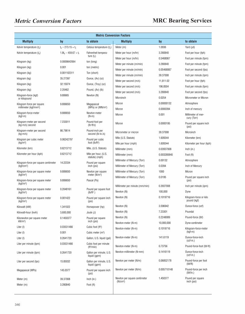
MRC Bearing ServicesMetric Conversion Factors
346
Metric Conversion Factors
Multiply by to obtain Multiply by to obtain
Kelvin temperature (tK) tK – 273.15 = tC Celsius temperature (tC)
Kelvin temperature (tK) 1.8tK – 459.67 = tF Fahrenheit tempera-ture (tF)
Kilogram (kg) 0.0009842064 ton (long)
Kilogram (kg) 0.001 ton (metric)
Kilogram (kg) 0.001102311 Ton (short)
kilogram (kg) 35.27397 Ounce, (Av) (oz)
Kilogram (kg) 32.15074 Ounce, (Troy) (oz)
Kilogram (kg) 2.20462 Pound, (Av) (lb)
Kilogram-force (kgf) 9.80665 Newton (N)or kilopound
Kilogram force per square 9.806650 Megapascalmillimeter (kgf/mm2) (MPa) or (MN/m2)
Kilogram-force-meter 9.806650 Newton-meter(kgf-m) (N-m)
Kilogram-meter per second 7.233011 Pound-foot per(kg-m/s) second (lb-ft/s)
Kilogram-meter per second 86.79614 Pound-inch per(kg-m/s) second (lb-in./s)
Kilogram per cubic meter 0.06242797 Pound per cubic(kg/m3) foot (lb/ft3)
Kilometer (km) 0.6213712 Mile, (U.S. Statute)
Kilometer per hour (kph) 0.6213712 Mile per hour, (U.S. statute) (mph)
Kilogram-force per square centimeter 14.22334 Pound per square(kgf/cm2) inch (psi)
Kilogram-force per square meter 9.806650 Newton per square (kgf/m2) meter (N/m2)
Kilogram-force per square meter 9.806650 Pascal (Pa)(kgf/m2)
Kilogram-force per square meter 0.2048161 Pound per square foot (kgf/m2) (lb/ft2 )
Kilogram-force per square meter 0.001422 Pound per square inch (kgf/m2) (psi)
Kilowatt (kW) 1.341022 Horsepower (hp)
Kilowatt-hour (kwh) 3,600,000 Joule (J)
Kilonewton per square meter 0.1450377 Pound per squarekN/m2) inch (psi)
Liter (l) 0.03531466 Cubic foot (ft3)
Liter (l) 0.001 Cubic meter (m3)
Liter (l) 0.2641720 Gallon, U.S. liquid (gal)
Liter per minute (lpm) 0.03531466 Cubic foot per minute (ft3/min)
Liter per minute (lpm) 0.2641720 Gallon per minute, U.S. liquid (gpm)
Liter per second (lps) 15.85032 Gallon per minute, U.S. liquid (gpm)
Megapascal (MPa) 145.0377 Pound per square inch (psi)
Meter (m) 39.37008 Inch (in.)
Meter (m) 3.280840 Foot (ft)
Meter (m) 1.0936 Yard (yd)
Meter per hour (m/hr) 3.280840 Foot per hour (fph)
Meter per hour (m/hr) 0.5468067 Foot per minute (fpm)
Meter per minute (m/min) 3.280840 Foot per minute (fpm)
Meter per minute (m/min) 0.05468067 Foot per second (fps)
Meter per minute (m/min) 39.37008 Inch per minute (Ipm)
Meter per second (m/s) 11,811.02 Foot per hour (fph)
Meter per second (m/s) 196.8504 Foot per minute (fpm)
Meter per second (m/s) 3.280840 Foot per second (fps)
Microinch 0.0254 Micrometer or Micron
Micron 0.00000132 Atmosphere
Micron 0.0000394 Inch of mercury
Micron 0.001 Millimeter of mer-cury (Torr)
Micron 0.0000195 Pound per square inch (psi)
Micrometer or micron 39.37008 Microinch
Mile (U.S. Statute) 1.609344 Kilometer (km)
Mile per hour (mph) 1.609344 Kilometer per hour (kph)
Millimeter (mm) 0.03937008 Inch (in.)
Millimeter (mm) 0.003280840 Foot (ft)
Millimeter of Mercury (Torr) 0.00132 Atmosphere
Millimeter of Mercury (Torr) 0.0394 Inch of Mercury
Millimeter of Mercury (Torr) 1000 Micron
Millimeter of Mercury (Torr) 0.0195 Pound per square inch(psi)
Millimeter per minute (mm/min) 0.3937008 Inch per minute (ipm)
Newton (N) 100,000 Dyne
Newton (N) 0.1019716 Kilogram-force or kilopound (kgf)
Newton (N) 3.596942 Ounce-force (ozf)
Newton (N) 7.23301 Poundal
Newton (N) 0.2248089 Pound-force (lbf)
Newton-meter (N-m) 10,000,000 Dyne-centimeter
Newton-meter (N-m) 0.1019716 Kilogram-force-meter (kgf-m)
Newton-meter (N-m) 141.6119 Ounce-force-inch (ozf-in.)
Newton-meter (N-m) 0.73756 Pound-force-foot (lbf-ft)
Newton-millimeter (N-mm) 0.1416119 Ounce-force-inch (ozf-in.)
Newton per meter (N/m) 0.06852178 Pound-force per foot (lbf/ft)
Newton per meter (N/m) 0.005710148 Pound-force per inch (lbf/in.)
Newton per square centimeter 1.450377 Pound per square(N/cm2) inch (psi)
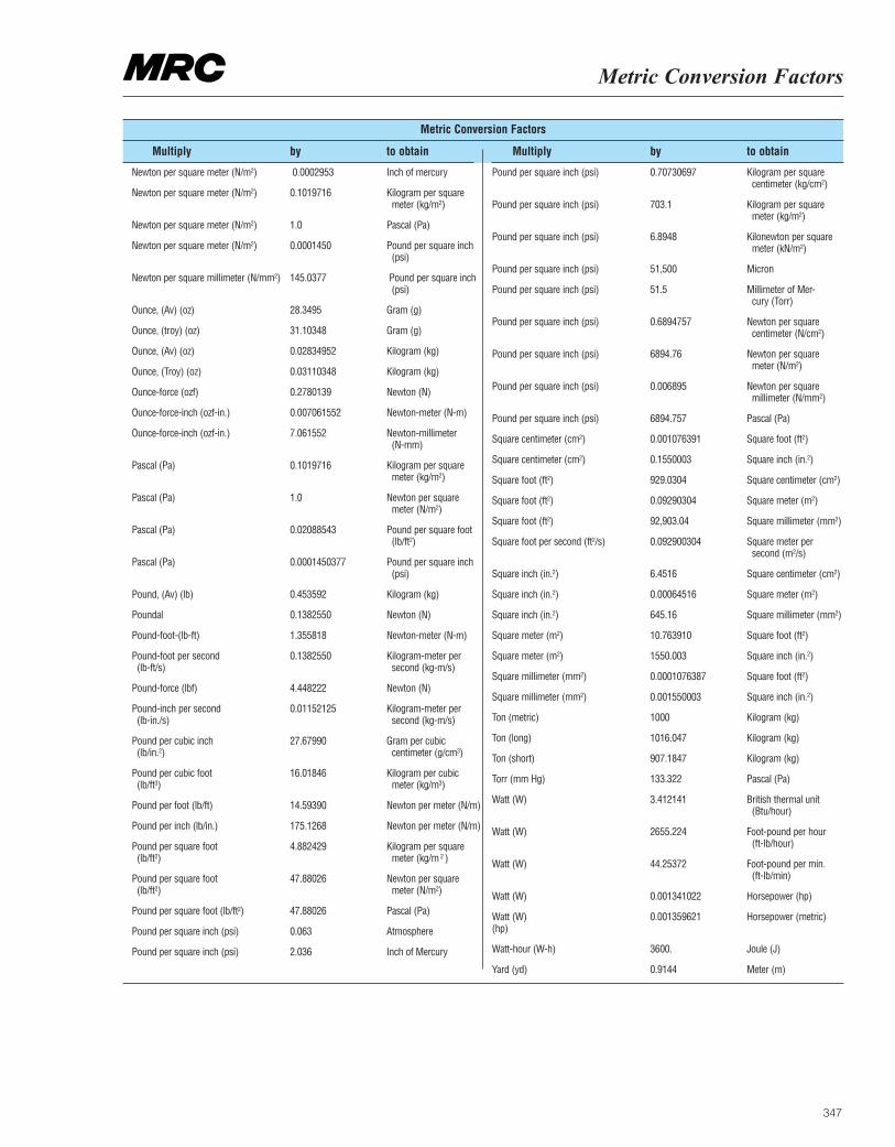
347
Metric Conversion Factors
Metric Conversion Factors
Multiply by to obtain Multiply by to obtain
Newton per square meter (N/m2) 0.0002953 Inch of mercury
Newton per square meter (N/m2) 0.1019716 Kilogram per square meter (kg/m2)
Newton per square meter (N/m2) 1.0 Pascal (Pa)
Newton per square meter (N/m2) 0.0001450 Pound per square inch (psi)
Newton per square millimeter (N/mm2) 145.0377 Pound per square inch (psi)
Ounce, (Av) (oz) 28.3495 Gram (g)
Ounce, (troy) (oz) 31.10348 Gram (g)
Ounce, (Av) (oz) 0.02834952 Kilogram (kg)
Ounce, (Troy) (oz) 0.03110348 Kilogram (kg)
Ounce-force (ozf) 0.2780139 Newton (N)
Ounce-force-inch (ozf-in.) 0.007061552 Newton-meter (N-m)
Ounce-force-inch (ozf-in.) 7.061552 Newton-millimeter (N-mm)
Pascal (Pa) 0.1019716 Kilogram per square meter (kg/m2)
Pascal (Pa) 1.0 Newton per square meter (N/m2)
Pascal (Pa) 0.02088543 Pound per square foot (lb/ft2)
Pascal (Pa) 0.0001450377 Pound per square inch (psi)
Pound, (Av) (lb) 0.453592 Kilogram (kg)
Poundal 0.1382550 Newton (N)
Pound-foot-(lb-ft) 1.355818 Newton-meter (N-m)
Pound-foot per second 0.1382550 Kilogram-meter per(lb-ft/s) second (kg-m/s)
Pound-force (lbf) 4.448222 Newton (N)
Pound-inch per second 0.01152125 Kilogram-meter per(lb-in./s) second (kg-m/s)
Pound per cubic inch 27.67990 Gram per cubic(lb/in.2) centimeter (g/cm3)
Pound per cubic foot 16.01846 Kilogram per cubic(lb/ft3) meter (kg/m3)
Pound per foot (lb/ft) 14.59390 Newton per meter (N/m)
Pound per inch (lb/in.) 175.1268 Newton per meter (N/m)
Pound per square foot 4.882429 Kilogram per square(lb/ft2) meter (kg/m 2 )
Pound per square foot 47.88026 Newton per square(lb/ft2) meter (N/m2)
Pound per square foot (lb/ft2) 47.88026 Pascal (Pa)
Pound per square inch (psi) 0.063 Atmosphere
Pound per square inch (psi) 2.036 Inch of Mercury
Pound per square inch (psi) 0.70730697 Kilogram per square centimeter (kg/cm2)
Pound per square inch (psi) 703.1 Kilogram per square meter (kg/m2)
Pound per square inch (psi) 6.8948 Kilonewton per square meter (kN/m2)
Pound per square inch (psi) 51,500 Micron
Pound per square inch (psi) 51.5 Millimeter of Mer-cury (Torr)
Pound per square inch (psi) 0.6894757 Newton per square centimeter (N/cm2)
Pound per square inch (psi) 6894.76 Newton per square meter (N/m2)
Pound per square inch (psi) 0.006895 Newton per square millimeter (N/mm2)
Pound per square inch (psi) 6894.757 Pascal (Pa)
Square centimeter (cm2) 0.001076391 Square foot (ft2)
Square centimeter (cm2) 0.1550003 Square inch (in.2)
Square foot (ft2) 929.0304 Square centimeter (cm2)
Square foot (ft2) 0.09290304 Square meter (m2)
Square foot (ft2) 92,903.04 Square millimeter (mm2)
Square foot per second (ft2/s) 0.092900304 Square meter per second (m2/s)
Square inch (in.2) 6.4516 Square centimeter (cm2)
Square inch (in.2) 0.00064516 Square meter (m2)
Square inch (in.2) 645.16 Square millimeter (mm2)
Square meter (m2) 10.763910 Square foot (ft2)
Square meter (m2) 1550.003 Square inch (in.2)
Square millimeter (mm2) 0.0001076387 Square foot (ft2)
Square millimeter (mm2) 0.001550003 Square inch (in.2)
Ton (metric) 1000 Kilogram (kg)
Ton (long) 1016.047 Kilogram (kg)
Ton (short) 907.1847 Kilogram (kg)
Torr (mm Hg) 133.322 Pascal (Pa)
Watt (W) 3.412141 British thermal unit (Btu/hour)
Watt (W) 2655.224 Foot-pound per hour (ft-lb/hour)
Watt (W) 44.25372 Foot-pound per min. (ft-lb/min)
Watt (W) 0.001341022 Horsepower (hp)
Watt (W) 0.001359621 Horsepower (metric)(hp)
Watt-hour (W-h) 3600. Joule (J)
Yard (yd) 0.9144 Meter (m)
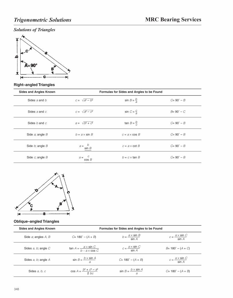
348
MRC Bearing ServicesTrigonometric Solutions
Solutions of Triangles
Oblique–angled Triangles
Sides and Angles Known Formulas for Sides and Angles to be Found
Side a; angles A, B C= 180˚ – (A + B) b = ———— c = ————
Sides a, b; angle C tan A = ————–––– c = ———— B= 180˚ – (A + C)
Sides a, b; angle A sin B = ———— C= 180˚ – (A + B) c = ————
Sides a, b, c cos A = ————–– sin B = ———— C= 180˚ – (A + B)
a × sin Bsin A
a × sin Csin A
a × sin Csin A
b × sin Aa
b × sin Aa
b2 + c2 – a2
2 bc
a × sin Cb – a × cos C
a × sin Csin A
Right–angled Triangles
Sides and Angles Known Formulas for Sides and Angles to be Found
Sides a and b c = a2 – b2 sin B = ba C= 90˚ – B
Sides a and c c = a2 – c2 sin C = ca B= 90˚ – C
Sides b and c a = b2 + c2 tan B = bc C= 90˚ – B
Side a; angle B b = a × sin B c = a × cos B C= 90˚ – B
Side b; angle B a =sin B
b c = a × cot B C= 90˚ – B
Side c; angle B a =cos B
c b = c × tan B C= 90˚ – B
√
√
√
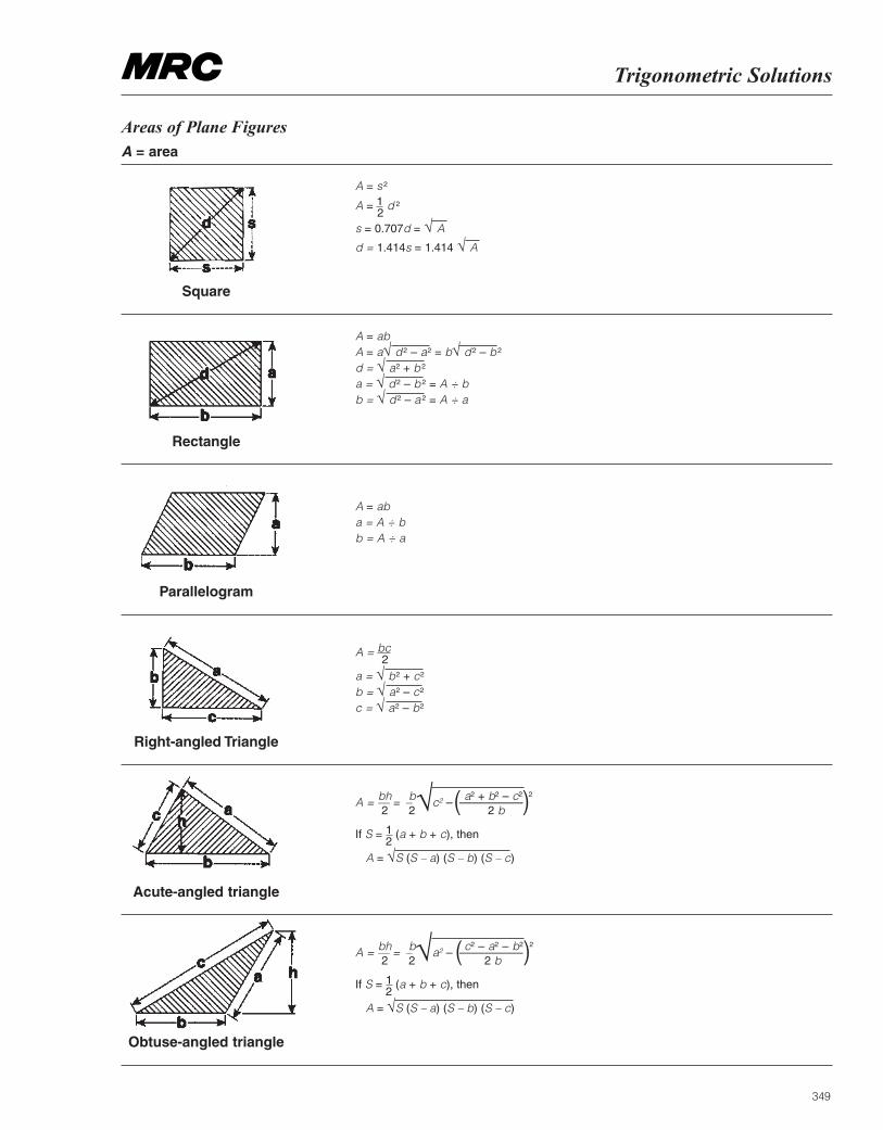
349
Trigonometric Solutions
Areas of Plane FiguresA = area
A = s 2
A = 12
d 2
s = 0.707d = √ A
d = 1.414s = 1.414 √ A
A = abA = a√ d 2 – a2 = b√ d 2 – b 2
d = √ a2 + b 2
a = √ d 2 – b 2 = A ÷ bb = √ d 2 – a 2 = A ÷ a
A = aba = A ÷ bb = A ÷ a
A = bc2
a = √ b2 + c2
b = √ a2 – c2
c = √ a2 – b2
A = –– = – c2 – ––––––––––
If S = 12
(a + b + c), then
A = √S (S – a) (S – b) (S – c)
Square
Parallelogram
Right-angled Triangle
Acute-angled triangle
Obtuse-angled triangle
bh b a2 + b2 – c2 2
2 2 2 b( )√
A = –– = – a2 – ––––––––––
If S = 12
(a + b + c), then
A = √S (S – a) (S – b) (S – c)
bh b c2 – a2 – b2 2
2 2 2 b( )√
Rectangle
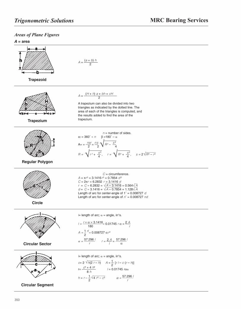
350
MRC Bearing ServicesTrigonometric Solutions
Areas of Plane FiguresA = area
A = ––––––––
A = –––––––––––––––––––
A trapezium can also be divided into two triangles as indicated by the dotted line. The area of each of the triangles is computed, and the results added to find the area of the trapezium.
n = number of sides.α = 360˚ ÷ n β =180˚ – a
A= = ––– = –– R2 – ––
R = r 2 + –– , r = R2 + –– , s = 2 R 2 – r 2
C = circumference. A = πr 2 = 3.1416 r 2 = 0.7854 d 2
C = 2πr = 6.2832 r = 3.1416 dr = C ÷ 6.2832 = A ÷ 3.1416 = 0.564 Ad = C ÷ 3.1416 = A ÷ 0.7854 = 1.128 ALength of arc for center-angle of 1˚ = 0.008727 dLength of arc for center-angle of n˚ = 0.008727 nd
l= length of arc; a = angle, in°s.
l = –––––––––––– = 0.01745 r α = –––
A = – = 0.008727 αr 2
a = ––––––– r = ––– = –––––––
Trapezoid
Regular Polygon
Circle
Circular Sector
Circular Segment
r × α × 3.1416 2 A180 r
1 rl257.296 l
r57.296 l
α2 A
l
l= length of arc; a = angle, in°s.
c= 2 h(2 r – h) A = – [r l – c (r – h)]
r= –––––––– l = 0.01745 rαa
h = r – – 4 r 2 – c2 α = –––––––
Trapezium
(a + b) h2
(H + h) a + bh + cH2
nsr ns s 2
2 2 4
s 2
4s 2
4
√√ √ √
√ √√
√
√
c2 + 4 h2
8 h
12
12
√ 57.296 lr
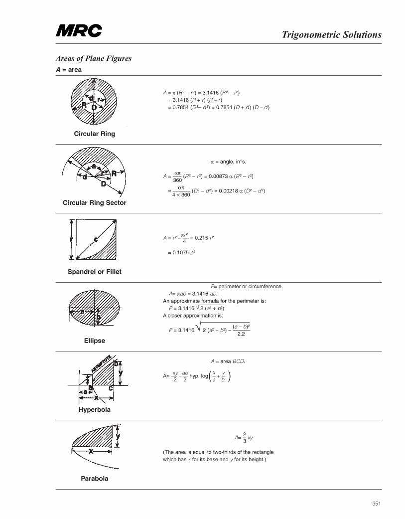
351
Trigonometric Solutions
Areas of Plane FiguresA = area
A = π (R 2 – r 2) = 3.1416 (R 2 – r 2)= 3.1416 (R + r) (R – r )= 0.7854 (D 2– d 2) = 0.7854 (D + d ) (D – d )
a = angle, in°s.
A = ––– (R 2 – r 2) = 0.00873 α (R 2 – r 2)
= –––––– (D2 – d 2) = 0.00218 α (D2 – d 2)
A = r 2 – –– = 0.215 r 2
= 0.1075 c2
P= perimeter or circumference.A= πab = 3.1416 ab.
An approximate formula for the perimeter is:P = 3.1416 2 (a2 + b2)
A closer approximation is:
P = 3.1416 2 (a2 + b2) – ––––––
A = area BCD.
A= –– – –– hyp. log – + –
Circular Ring
Spandrel or Fillet
Ellipse
Hyperbola
Parabola
A= – xy
(The area is equal to two-thirds of the rectangle which has x for its base and y for its height.)
Circular Ring Sector
απ360
απ4 × 360
πr 2
4
√
(a – b)2
2.2√
xy2
ab2 ( )x y
a b
23
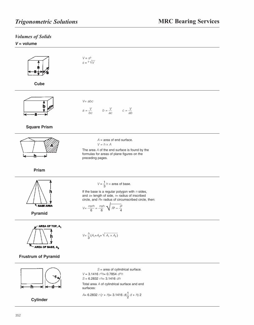
352
MRC Bearing ServicesTrigonometric Solutions
Volumes of SolidsV = volume
V = s3
s = 3 V
V= abc
a = –– b = –– c = ––
A = area of end surface.V = h × A
The area A of the end surface is found by the formulas for areas of plane figures on the preceding pages.
V = – h × area of base.
If the base is a regular polygon with n sides, and s= length of side, r= radius of inscribed circle, and R= radius of circumscribed circle, then:
V= –––– = ––– R2 – ––
V= – (A1+A2+ √ A1 × A2 )
Cube
Prism
Pyramid
Frustrum of Pyramid
Cylinder
S = area of cylindrical surface.V = 3.1416 r 2h= 0.7854 d 2hS = 6.2832 rh= 3.1416 dh
Total area A of cylindrical surface and end surfaces:
A= 6.2832 r (r + h)= 3.1416 d(– d + h) 2
Square Prism
√
Vbc
Vac
Vab
13
nsrh6
nsh 6
s2
4
h3
12
√
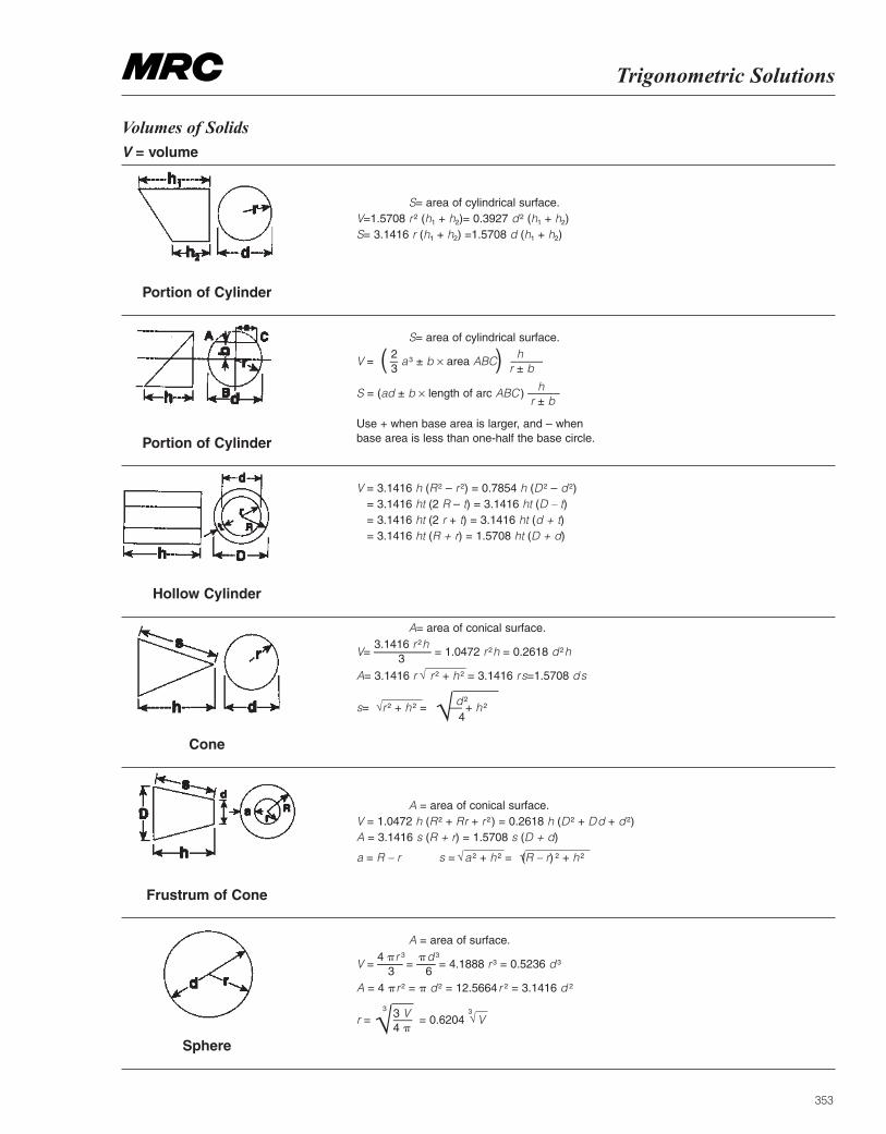
353
Trigonometric Solutions
Volumes of SolidsV = volume
S= area of cylindrical surface.V=1.5708 r 2 (h1 + h2)= 0.3927 d 2 (h1 + h2)S= 3.1416 r (h1 + h2) =1.5708 d (h1 + h2)
S= area of cylindrical surface.
V = – a 3 ± b × area ABC –––––
S = (ad ± b × length of arc ABC ) –––––
Use + when base area is larger, and – when base area is less than one-half the base circle.
V = 3.1416 h (R 2 – r 2) = 0.7854 h (D 2 – d 2)= 3.1416 ht (2 R – t) = 3.1416 ht (D – t)= 3.1416 ht (2 r + t) = 3.1416 ht (d + t)= 3.1416 ht (R + r) = 1.5708 ht (D + d)
A= area of conical surface.
V= ––––––––– = 1.0472 r 2h = 0.2618 d 2h
A= 3.1416 r r 2 + h 2 = 3.1416 rs=1.5708 ds
s= r 2 + h 2 = –– + h 2
A = area of conical surface.V = 1.0472 h (R 2 + Rr + r 2) = 0.2618 h (D 2 + Dd + d 2)A = 3.1416 s (R + r) = 1.5708 s (D + d)
a = R – r s = a 2 + h 2 = (R – r) 2 + h 2
Portion of Cylinder
Hollow Cylinder
Cone
Frustrum of Cone
Sphere
A = area of surface.
V = –––– = ––– = 4.1888 r 3 = 0.5236 d 3
A = 4 pr 2 = p d 2 = 12.5664 r 2 = 3.1416 d 2
r = ––– = 0.6204 V
Portion of Cylinder
23( ) h
r ± b
hr ± b
d 2
4
3.1416 r 2h3
√
√ √
√ √
4 pr 3
3pd 3
6
3 V4 p√ √
33
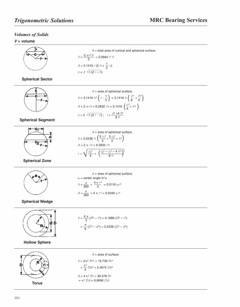
354
MRC Bearing ServicesTrigonometric Solutions
Volumes of SolidsV = volume
A = total area of conical and spherical surface.
V = –––––– = 2.0944 r 2 h
A = 3.1416 r (2 h + –– c)
c = 2 h (2 r – h)
A = area of spherical surface.
V = 3.1416 h 2 r – –– = 3.1416 h –– + ––
A = 2 prh = 6.2832 rh = 3.1416 –– + h 2
c = 2 h (2 r – h) ; r = –––––––
A = area of spherical surface.
V = 0.5236 h ––– + ––– + h 2
A = 2 p rh = 6.2832 rh
r = ––– + –––––––––––––
A = area of spherical surface;a = center angle in°s
V = ––– × –––– = 0.0116 ar 3
A = ––– × 4 p r 2 = 0.0349 ar 2
V = ––– (R 3 – r 3) = 4.1888 (R 3 – r 3)
= –– (D 3 – d 3) = 0.5236 (D 3 – d 3)
Spherical Sector
Spherical Zone
Spherical Wedge
Hollow Sphere
Torus
A = area of surface.
V = 2p2 Rr 2 = 19.739 Rr 2
= –– Dd 2 = 2.4674 Dd 2
A = 4 p2 Rr = 39.478 Rr= p2 Dd = 9.8696 Dd
Spherical Segment
12
2 pr 2 h3
√
( ) ( )
( )
( )
( )
c 2
8h 2
6
c 2
4
c2 +4 h2
8 h√
h3
3 c12
4
c22
4
a360
4 p3p
6
p2
4
a360
4 p r 3
3
c22 – c1
2 – 4 h 2
8 h
3 c22
4
√ 2
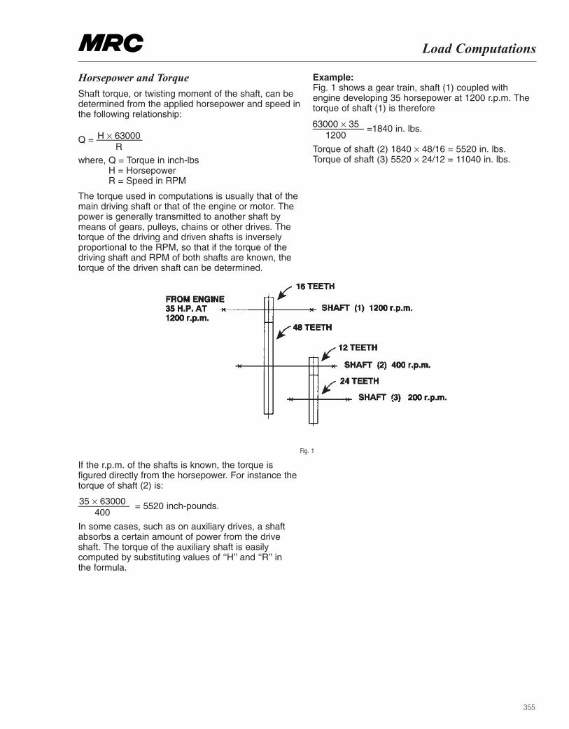
355
Load Computations
Horsepower and TorqueShaft torque, or twisting moment of the shaft, can bedetermined from the applied horsepower and speed inthe following relationship:
Q = –––––––––
where, Q = Torque in inch-lbs H = HorsepowerR = Speed in RPM
The torque used in computations is usually that of themain driving shaft or that of the engine or motor. Thepower is generally transmitted to another shaft bymeans of gears, pulleys, chains or other drives. Thetorque of the driving and driven shafts is inverselyproportional to the RPM, so that if the torque of thedriving shaft and RPM of both shafts are known, thetorque of the driven shaft can be determined.
Example:Fig. 1 shows a gear train, shaft (1) coupled with engine developing 35 horsepower at 1200 r.p.m. Thetorque of shaft (1) is therefore
–––––––––– =1840 in. lbs.
Torque of shaft (2) 1840 × 48/16 = 5520 in. lbs.Torque of shaft (3) 5520 × 24/12 = 11040 in. lbs.
H × 63000R
63000 × 351200
If the r.p.m. of the shafts is known, the torque isfigured directly from the horsepower. For instance thetorque of shaft (2) is:
–––––––––– = 5520 inch-pounds.
In some cases, such as on auxiliary drives, a shaftabsorbs a certain amount of power from the drive shaft. The torque of the auxiliary shaft is easilycomputed by substituting values of ‘‘H’’ and ‘‘R’’ in the formula.
Fig. 1
35 × 63000400
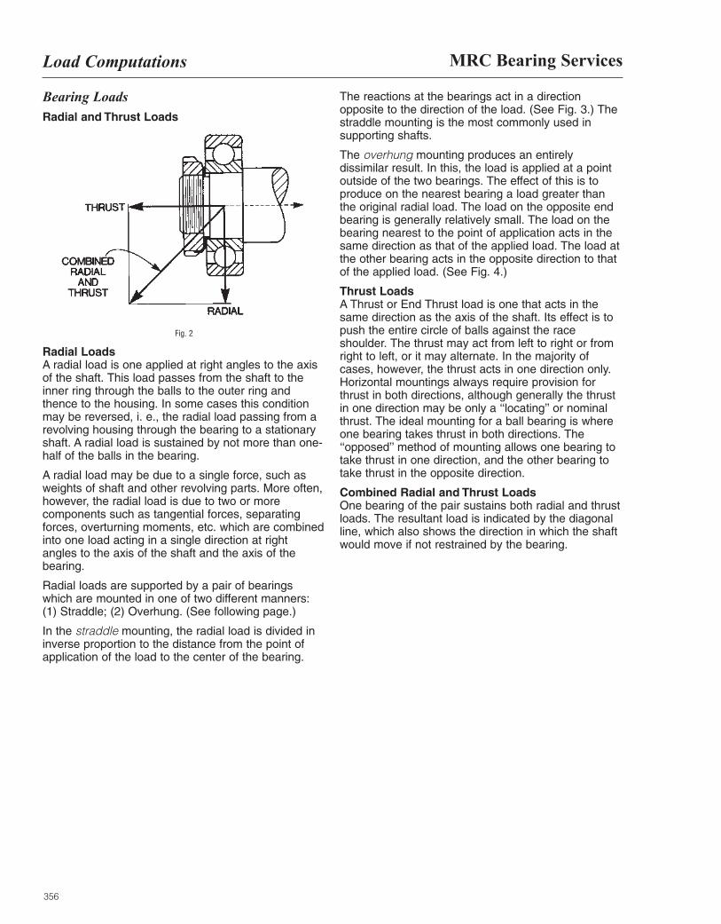
356
MRC Bearing ServicesLoad Computations
Bearing Loads Radial and Thrust Loads
Fig. 2
Radial Loads A radial load is one applied at right angles to the axisof the shaft. This load passes from the shaft to theinner ring through the balls to the outer ring andthence to the housing. In some cases this conditionmay be reversed, i. e., the radial load passing from arevolving housing through the bearing to a stationaryshaft. A radial load is sustained by not more than one-half of the balls in the bearing.
A radial load may be due to a single force, such asweights of shaft and other revolving parts. More often,however, the radial load is due to two or morecomponents such as tangential forces, separatingforces, overturning moments, etc. which are combinedinto one load acting in a single direction at rightangles to the axis of the shaft and the axis of thebearing.
Radial loads are supported by a pair of bearingswhich are mounted in one of two different manners:(1) Straddle; (2) Overhung. (See following page.)
In the straddle mounting, the radial load is divided ininverse proportion to the distance from the point ofapplication of the load to the center of the bearing.
The reactions at the bearings act in a directionopposite to the direction of the load. (See Fig. 3.) Thestraddle mounting is the most commonly used insupporting shafts.
The overhung mounting produces an entirelydissimilar result. In this, the load is applied at a pointoutside of the two bearings. The effect of this is toproduce on the nearest bearing a load greater thanthe original radial load. The load on the opposite endbearing is generally relatively small. The load on thebearing nearest to the point of application acts in thesame direction as that of the applied load. The load atthe other bearing acts in the opposite direction to thatof the applied load. (See Fig. 4.)
Thrust Loads A Thrust or End Thrust load is one that acts in thesame direction as the axis of the shaft. Its effect is topush the entire circle of balls against the raceshoulder. The thrust may act from left to right or fromright to left, or it may alternate. In the majority ofcases, however, the thrust acts in one direction only.Horizontal mountings always require provision forthrust in both directions, although generally the thrustin one direction may be only a ‘‘locating’’ or nominalthrust. The ideal mounting for a ball bearing is whereone bearing takes thrust in both directions. The‘‘opposed’’ method of mounting allows one bearing totake thrust in one direction, and the other bearing totake thrust in the opposite direction.
Combined Radial and Thrust Loads One bearing of the pair sustains both radial and thrustloads. The resultant load is indicated by the diagonalline, which also shows the direction in which the shaftwould move if not restrained by the bearing.
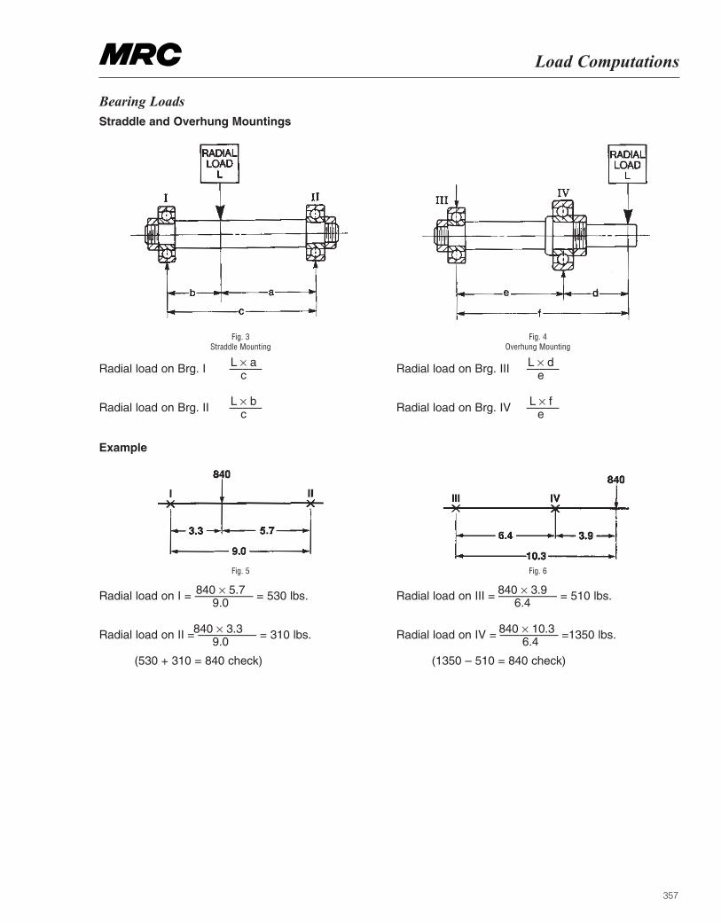
357
Load Computations
Fig. 3Straddle Mounting
Radial load on Brg. I –––––
Radial load on Brg. II –––––
Fig. 4 Overhung Mounting
Radial load on Brg. III –––––
Radial load on Brg. IV –––––
Fig. 5
Radial load on I = ––––––––– = 530 lbs.
Radial load on II = ––––––––– = 310 lbs.
(530 + 310 = 840 check)
Fig. 6
Radial load on III = ––––––––– = 510 lbs.
Radial load on IV = ––––––––– =1350 lbs.
(1350 – 510 = 840 check)
Bearing Loads Straddle and Overhung Mountings
Example
L × ac
840 × 5.7 9.0
840 × 3.96.4
840 × 3.39.0
840 × 10.36.4
L × de
L × bc
L × fe
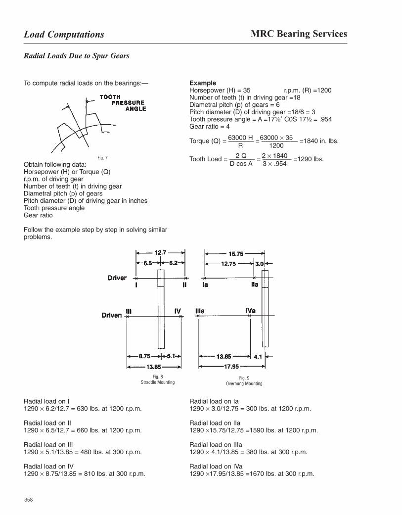
358
MRC Bearing ServicesLoad Computations
Radial Loads Due to Spur Gears
To compute radial loads on the bearings:—
Fig. 7
Obtain following data:Horsepower (H) or Torque (Q)r.p.m. of driving gearNumber of teeth (t) in driving gearDiametral pitch (p) of gearsPitch diameter (D) of driving gear in inchesTooth pressure angleGear ratio
Follow the example step by step in solving similarproblems.
ExampleHorsepower (H) = 35 r.p.m. (R) =1200Number of teeth (t) in driving gear =18Diametral pitch (p) of gears = 6Pitch diameter (D) of driving gear =18/6 = 3Tooth pressure angle = A =17¹|₂˚ C0S 17¹|₂ = .954Gear ratio = 4
Torque (Q) = ––––––– = –––––––––– =1840 in. lbs.
Tooth Load = ––––––– = –––––––– =1290 lbs.
Radial load on I1290 × 6.2/12.7 = 630 lbs. at 1200 r.p.m.
Radial load on II1290 × 6.5/12.7 = 660 lbs. at 1200 r.p.m.
Radial load on III1290 × 5.1/13.85 = 480 lbs. at 300 r.p.m.
Radial load on IV1290 × 8.75/13.85 = 810 lbs. at 300 r.p.m.
Radial load on Ia1290 × 3.0/12.75 = 300 lbs. at 1200 r.p.m.
Radial load on IIa1290 ×15.75/12.75 =1590 lbs. at 1200 r.p.m.
Radial load on IIIa1290 × 4.1/13.85 = 380 lbs. at 300 r.p.m.
Radial load on IVa1290 ×17.95/13.85 =1670 lbs. at 300 r.p.m.
63000 HR
2 QD cos A
2 × 18403 × .954
63000 × 351200
Fig. 8Straddle Mounting
Fig. 9Overhung Mounting
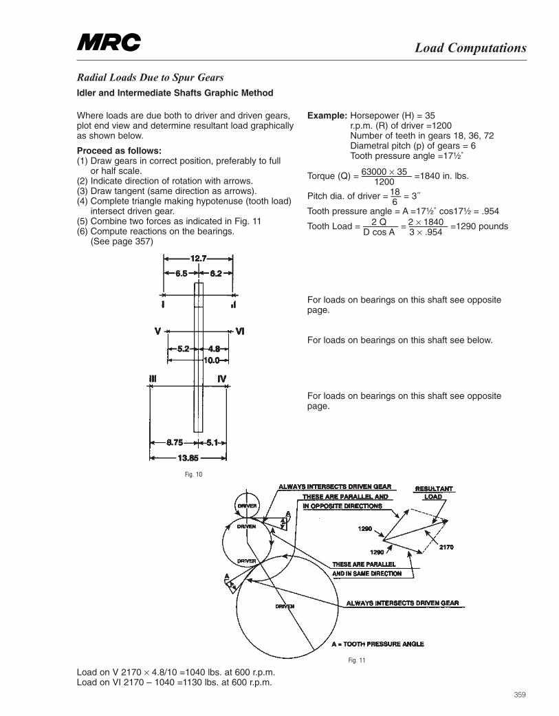
359
Load Computations
Radial Loads Due to Spur Gears Idler and Intermediate Shafts Graphic Method
Where loads are due both to driver and driven gears,plot end view and determine resultant load graphicallyas shown below.
Proceed as follows:(1) Draw gears in correct position, preferably to full
or half scale. (2) Indicate direction of rotation with arrows. (3) Draw tangent (same direction as arrows). (4) Complete triangle making hypotenuse (tooth load)
intersect driven gear. (5) Combine two forces as indicated in Fig. 11 (6) Compute reactions on the bearings.
(See page 357)
Example: Horsepower (H) = 35 r.p.m. (R) of driver =1200 Number of teeth in gears 18, 36, 72 Diametral pitch (p) of gears = 6 Tooth pressure angle =17¹|₂˚
Torque (Q) = –––––––––– =1840 in. lbs.
Pitch dia. of driver = –– = 3˝
Tooth pressure angle = A =17¹|₂˚ cos17¹|₂ = .954
Tooth Load = ––––––– = ––––––– =1290 pounds
For loads on bearings on this shaft see oppositepage.
For loads on bearings on this shaft see below.
For loads on bearings on this shaft see oppositepage.
Load on V 2170 × 4.8/10 =1040 lbs. at 600 r.p.m. Load on VI 2170 – 1040 =1130 lbs. at 600 r.p.m.
Fig. 10
Fig. 11
63000 × 351200
186
2 QD cos A
2 × 18403 × .954
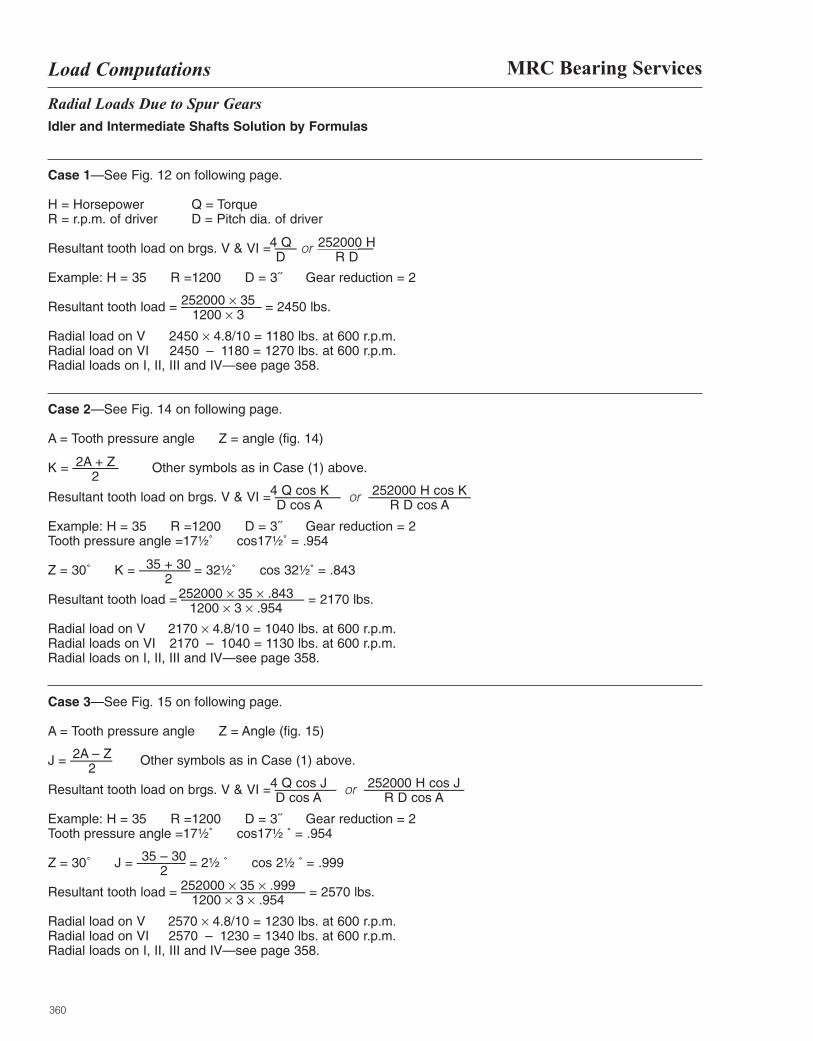
360
MRC Bearing ServicesLoad Computations
Radial Loads Due to Spur Gears Idler and Intermediate Shafts Solution by Formulas
Case 1—See Fig. 12 on following page.
H = Horsepower Q = Torque R = r.p.m. of driver D = Pitch dia. of driver
Resultant tooth load on brgs. V & VI = ––– or ––––––––
Example: H = 35 R =1200 D = 3˝ Gear reduction = 2
Resultant tooth load = ––––––––––– = 2450 lbs.
Radial load on V 2450 × 4.8/10 = 1180 lbs. at 600 r.p.m. Radial load on VI 2450 – 1180 = 1270 lbs. at 600 r.p.m. Radial loads on I, II, III and IV—see page 358.
Case 2—See Fig. 14 on following page.
A = Tooth pressure angle Z = angle (fig. 14)
K = –––––– Other symbols as in Case (1) above.
Resultant tooth load on brgs. V & VI = ––––––––– or ––––––––––––––
Example: H = 35 R =1200 D = 3˝ Gear reduction = 2 Tooth pressure angle =17¹|₂˚ cos17¹|₂˚ = .954
Z = 30˚ K = ––––––– = 32¹|₂˚ cos 32¹|₂˚ = .843
Resultant tooth load = ––––––––––––––––– = 2170 lbs.
Radial load on V 2170 × 4.8/10 = 1040 lbs. at 600 r.p.m. Radial loads on VI 2170 – 1040 = 1130 lbs. at 600 r.p.m. Radial loads on I, II, III and IV—see page 358.
Case 3—See Fig. 15 on following page.
A = Tooth pressure angle Z = Angle (fig. 15)
J = –––––– Other symbols as in Case (1) above.
Resultant tooth load on brgs. V & VI = ––––––––– or ––––––––––––––
Example: H = 35 R =1200 D = 3˝ Gear reduction = 2 Tooth pressure angle =17¹|₂˚ cos17¹|₂ ˚ = .954
Z = 30˚ J = ––––––– = 2¹|₂ ˚ cos 2¹|₂ ˚ = .999
Resultant tooth load = ––––––––––––––––– = 2570 lbs.
Radial load on V 2570 × 4.8/10 = 1230 lbs. at 600 r.p.m. Radial load on VI 2570 – 1230 = 1340 lbs. at 600 r.p.m. Radial loads on I, II, III and IV—see page 358.
4 QD
252000 H R D
252000 × 351200 × 3
2A + Z 2
4 Q cos KD cos A
252000 H cos KR D cos A
35 + 302
252000 × 35 × .8431200 × 3 × .954
2A – Z2
4 Q cos JD cos A
35 – 302
252000 × 35 × .9991200 × 3 × .954
252000 H cos JR D cos A
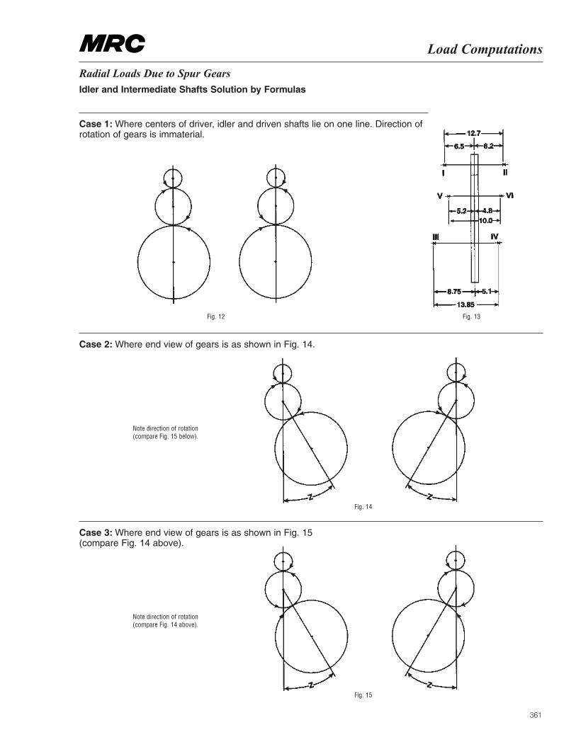
361
Load Computations
Radial Loads Due to Spur Gears Idler and Intermediate Shafts Solution by Formulas
Case 1: Where centers of driver, idler and driven shafts lie on one line. Direction ofrotation of gears is immaterial.
Case 2: Where end view of gears is as shown in Fig. 14.
Case 3: Where end view of gears is as shown in Fig. 15(compare Fig. 14 above).
Fig. 12 Fig. 13
Note direction of rotation(compare Fig. 15 below).
Note direction of rotation(compare Fig. 14 above).
Fig. 14
Fig. 15
362
MRC Bearing ServicesLoad Computations
Loads Due to Planetary Gears The Methods Shown Consider Simple Planetary Spur Gear Arrangements Only
To compute radial loads on the bearings:
(1) Refer to page 357 for distribution of load (L) onbearings.
(2) Obtain following data: Horsepower (H) or Torque (Q)
Torque in in. lbs. (Q) = ––––––––––––––––
Pitch diameter (s) of sun gear Pitch diameter (p) of planet gear Pitch diameter (g) of internal gear Tooth pressure angle (necessary for singleplanet drive only)
(3) See table on opposite page which gives resultantradial loads on bearings, and also the r.p.m.’s of themembers. Note that the portion of the table devoted toloads is divided into two parts. The first is for theresultant radial load ‘‘L’’ on bearings III & IV for singleplanet, two planets or three planets. The second is forthe resultant radial load ‘‘P’’ on bearings I & II and V &VI for single planet.
(4) Consider first bearings III & IV. Select the properexpression for ‘‘L’’ according to whether your particularproblem involves single planet, two planets or threeplanets.
(5) Resultant radial load ‘‘L’’ is imposed on bearings III& IV. Compute individual loads on III & IV by methodshown on page 357, unless planet is supported by asingle centrally located bearing in which case ‘‘L’’ isthe resultant bearing load.
(6) Bearings III & IV are also subjected to centrifugalforces (except in combinations 3 and 4, see oppositepage) which, if the speeds are very high, should becomputed and combined with ‘‘L’’ as obtained in (5)above.
These centrifugal forces can be computed from theformula shown below, noting that : ‘‘W’’ equals theweight of the planet gear and shaft; r.p.m. is that ofthe cage; ‘‘r’’ is as shown in Fig. 19 on the oppositepage.
Centrifugal Force (CF) and ‘‘L’’ are combined asfollows: (CF)2 + L2. Use this instead of ‘‘L’’ whenconsidering centrifugal force. The loads on theindividual bearings must be computed as describedon page 357.(Note: the centrifugal force to weight ratio –– is of prime importance in the proper
selection of the cage used in the bearing, or bearings, on the planet shaft. Send com-plete data on high speed planetary gear problems for review and selection of bearingtype.)
(7) When the planetary drive has a single planet thereare also loads on the bearings supporting the drivingand driven members. These values are given in thetable on the opposite page as load ‘‘P’’ and areimposed on bearings I, II, V & VI. (Note that theexpression for ‘‘P’’ is given in terms of ‘‘L’’ as obtainedfor bearings III & IV due to a single planet.)
Compute the loads on the individual bearings asdescribed on page 357.
For two or more planets, there is no theoretical loadon bearings I, II, V & VI. Actually there is some loaddue to mechanical unbalance and machininginaccuracies, but generally can be neglected.
Centrifugal ForceCentrifugal Force = –––––––––
where W = Weight in pounds r = Radius in inches R = r.p.m.
63000 Hr.p.m. of driver
√
CFW
W × r × R2
35200
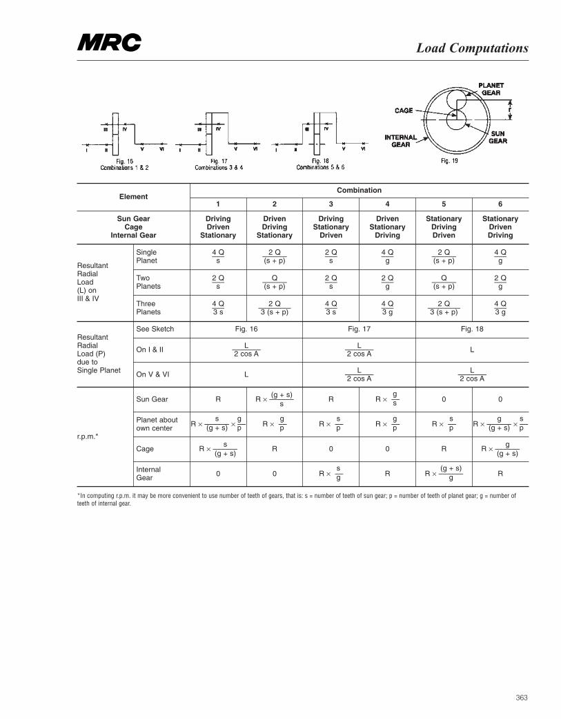
363
Load Computations
Element
Sun GearCage
Internal Gear
ResultantRadialLoad(L) onIII & IV
ResultantRadialLoad (P)due toSingle Planet
r.p.m.*
SinglePlanet
4 Qs
2 Qs
4 Q3 s
–––
–––
–––
––––––
––––––
––––––––
–––
–––
–––
–––
–––
–––
––––––
––––––
––––––––
–––
–––
–––
2 Q(s + p)
Q(s + p)
2 Q3 (s + p)
2 Qs
2 Qs
4 Q3 s
4 Qg
2 Qg
4 Q3 g
2 Q(s + p)
Q(s + p)
2 Q3 (s + p)
4 Qg
2 Qg
4 Q3 g
TwoPlanets
Three Planets
See Sketch
On I & II L2 cos A
L2 cos A
–––––––
–––––––
–––––––
–––––––
L2 cos A
L2 cos A
L
L
R
R
R
R
R
R
s(g + s)
g(g + s)
s(g + s)
g(g + s)
(g + s)g
(g + s)s
gp
sp
gp
gp
sp
gs
sg
spR × –––––– × –– R × –––––– × ––R × –– R × ––R × ––
R × ––
R × ––
R × ––
R × –––––– R × ––––––
R × ––––––
R × ––––––
0 0
0 0
0 0
On V & VI
Sun Gear
Planet aboutown center
Cage
Internal Gear
Fig. 16 Fig. 17 Fig. 18
DrivingDriven
Stationary
DrivenDriving
Stationary
DrivingStationary
Driven
DrivenStationary
Driving
StationaryDrivingDriven
StationaryDrivenDriving
Combination
1 2 3 4 5 6
*In computing r.p.m. it may be more convenient to use number of teeth of gears, that is: s = number of teeth of sun gear; p = number of teeth of planet gear; g = number ofteeth of internal gear.
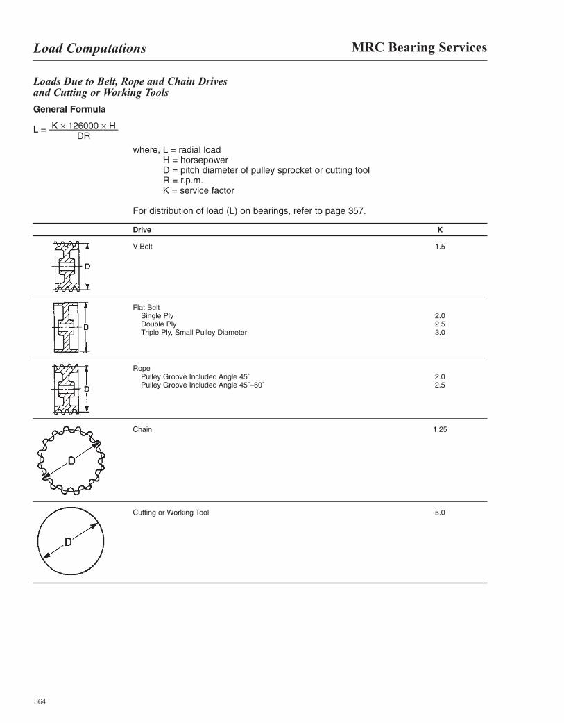
364
MRC Bearing ServicesLoad Computations
Loads Due to Belt, Rope and Chain Drives and Cutting or Working Tools
General Formula
L = ––––––––––––––
where, L = radial load H = horsepower D = pitch diameter of pulley sprocket or cutting tool R = r.p.m. K = service factor
For distribution of load (L) on bearings, refer to page 357.
Drive K
V-Belt 1.5
Flat Belt Single Ply 2.0 Double Ply 2.5 Triple Ply, Small Pulley Diameter 3.0
Rope Pulley Groove Included Angle 45˚ 2.0 Pulley Groove Included Angle 45˚–60˚ 2.5
Chain 1.25
Cutting or Working Tool 5.0
K × 126000 × HDR
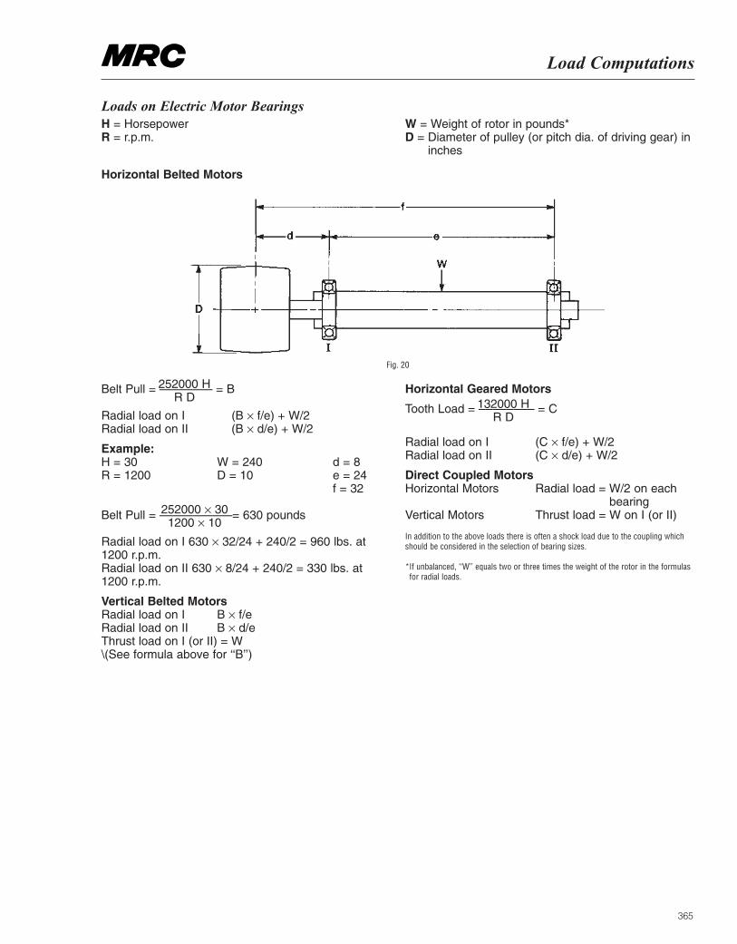
365
Load Computations
Loads on Electric Motor BearingsH = Horsepower R = r.p.m.
W = Weight of rotor in pounds* D = Diameter of pulley (or pitch dia. of driving gear) in
inches
Horizontal Belted Motors
Fig. 20
Belt Pull = –––––––– = B
Radial load on I (B × f/e) + W/2 Radial load on II (B × d/e) + W/2
Example:H = 30 W = 240 d = 8R = 1200 D = 10 e = 24
f = 32
Belt Pull = –––––––––––= 630 pounds
Radial load on I 630 × 32/24 + 240/2 = 960 lbs. at1200 r.p.m. Radial load on II 630 × 8/24 + 240/2 = 330 lbs. at 1200 r.p.m.
Vertical Belted MotorsRadial load on I B × f/e Radial load on II B × d/e Thrust load on I (or II) = W \(See formula above for ‘‘B’’)
Horizontal Geared Motors
Tooth Load = –––––––– = C
Radial load on I (C × f/e) + W/2 Radial load on II (C × d/e) + W/2
Direct Coupled MotorsHorizontal Motors Radial load = W/2 on each
bearing Vertical Motors Thrust load = W on I (or II)
In addition to the above loads there is often a shock load due to the coupling whichshould be considered in the selection of bearing sizes.
*If unbalanced, ‘‘W’’ equals two or three times the weight of the rotor in the formulasfor radial loads.
252000 HR D
252000 × 30 1200 × 10
132000 HR D
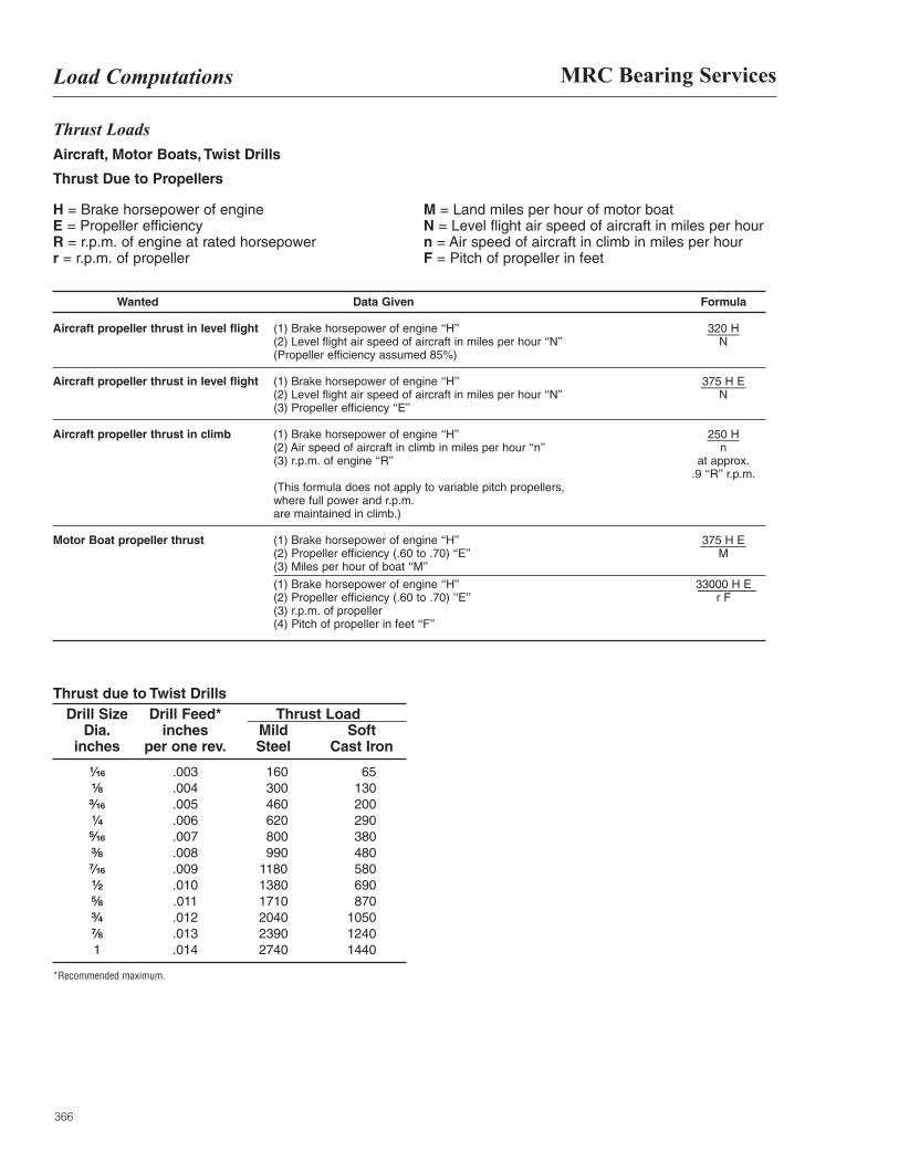
366
MRC Bearing ServicesLoad Computations
Thrust Loads Aircraft, Motor Boats, Twist Drills
Thrust Due to Propellers
H = Brake horsepower of engine E = Propeller efficiency R = r.p.m. of engine at rated horsepower r = r.p.m. of propeller
M = Land miles per hour of motor boat N = Level flight air speed of aircraft in miles per hour n = Air speed of aircraft in climb in miles per hour F = Pitch of propeller in feet
Wanted Data Given Formula
Aircraft propeller thrust in level flight (1) Brake horsepower of engine ‘‘H’’ 320 H (2) Level flight air speed of aircraft in miles per hour ‘‘N’’ N (Propeller efficiency assumed 85%)
Aircraft propeller thrust in level flight (1) Brake horsepower of engine ‘‘H’’ 375 H E (2) Level flight air speed of aircraft in miles per hour ‘‘N’’ N (3) Propeller efficiency ‘‘E’’
Aircraft propeller thrust in climb (1) Brake horsepower of engine ‘‘H’’ 250 H (2) Air speed of aircraft in climb in miles per hour ‘‘n’’ n (3) r.p.m. of engine ‘‘R’’ at approx.
.9 ‘‘R’’ r.p.m. (This formula does not apply to variable pitch propellers, where full power and r.p.m. are maintained in climb.)
Motor Boat propeller thrust (1) Brake horsepower of engine ‘‘H’’ 375 H E(2) Propeller efficiency (.60 to .70) ‘‘E’’ M (3) Miles per hour of boat ‘‘M’’
(1) Brake horsepower of engine ‘‘H’’ 33000 H E (2) Propeller efficiency (.60 to .70) ’‘E’’ r F (3) r.p.m. of propeller (4) Pitch of propeller in feet ‘‘F’’
Thrust due to Twist DrillsDrill Size Drill Feed* Thrust Load
Dia. inches Mild Soft inches per one rev. Steel Cast Iron
¹|₁₆ .003 160 65¹|₈ .004 300 130³|₁₆ .005 460 200¹|₄ .006 620 290⁵|₁₆ .007 800 380³|₈ .008 990 480⁷|₁₆ .009 1180 580¹|₂ .010 1380 690⁵|₈ .011 1710 870³|₄ .012 2040 1050⁷|₈ .013 2390 12401 .014 2740 1440
*Recommended maximum.
–––––
–––––––
–––––
–––––––
–––––––––
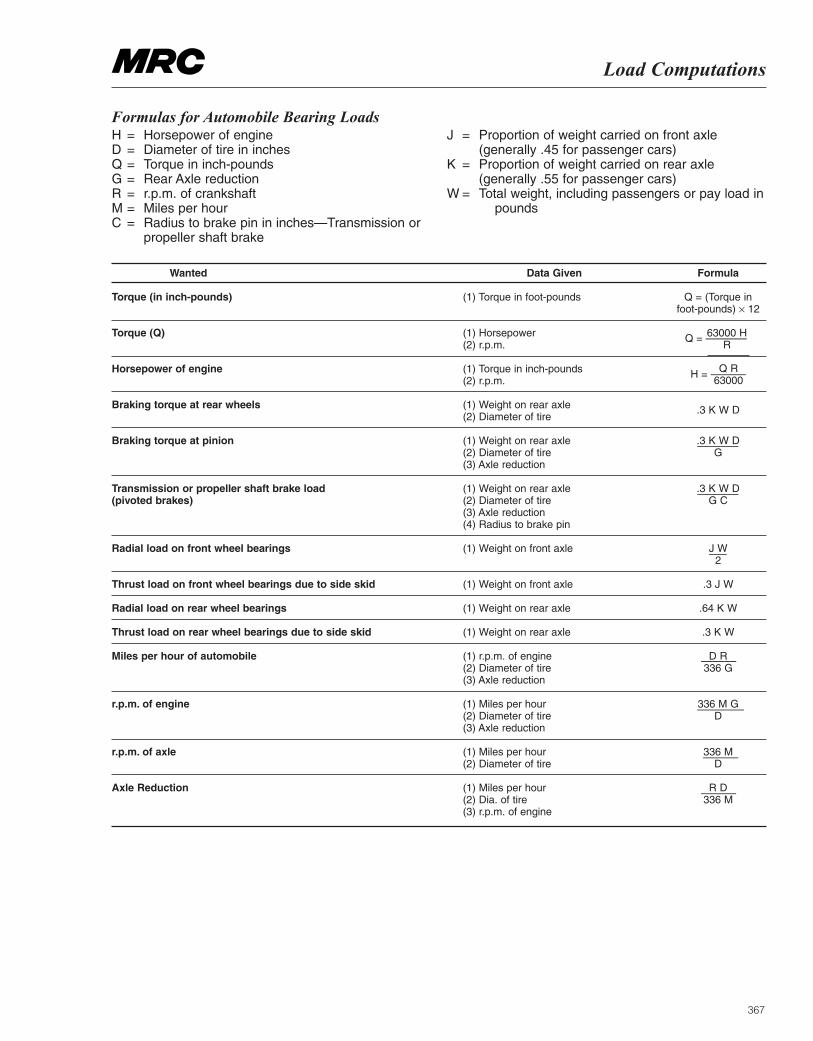
367
Load Computations
Formulas for Automobile Bearing LoadsH = Horsepower of engine D = Diameter of tire in inches Q = Torque in inch-pounds G = Rear Axle reduction R = r.p.m. of crankshaft M = Miles per hour C = Radius to brake pin in inches—Transmission or
propeller shaft brake
J = Proportion of weight carried on front axle(generally .45 for passenger cars)
K = Proportion of weight carried on rear axle(generally .55 for passenger cars)
W = Total weight, including passengers or pay load inpounds
Wanted Data Given Formula
Torque (in inch-pounds) (1) Torque in foot-pounds Q = (Torque in foot-pounds) × 12
Torque (Q) (1) Horsepower 63000 H(2) r.p.m. R
Horsepower of engine (1) Torque in inch-pounds H = –––––– (2) r.p.m.
Braking torque at rear wheels (1) Weight on rear axle .3 K W D (2) Diameter of tire
Braking torque at pinion (1) Weight on rear axle .3 K W D (2) Diameter of tire G (3) Axle reduction
Transmission or propeller shaft brake load (1) Weight on rear axle .3 K W D (pivoted brakes) (2) Diameter of tire G C
(3) Axle reduction (4) Radius to brake pin
Radial load on front wheel bearings (1) Weight on front axle J W2
Thrust load on front wheel bearings due to side skid (1) Weight on front axle .3 J W
Radial load on rear wheel bearings (1) Weight on rear axle .64 K W
Thrust load on rear wheel bearings due to side skid (1) Weight on rear axle .3 K W
Miles per hour of automobile (1) r.p.m. of engine D R (2) Diameter of tire 336 G(3) Axle reduction
r.p.m. of engine (1) Miles per hour 336 M G (2) Diameter of tire D (3) Axle reduction
r.p.m. of axle (1) Miles per hour 336 M (2) Diameter of tire D
Axle Reduction (1) Miles per hour R D (2) Dia. of tire 336 M (3) r.p.m. of engine
Q R63000
––––––
––––––––
––––––
––––––
Q = –––––––
–––––––
–––––––
–––
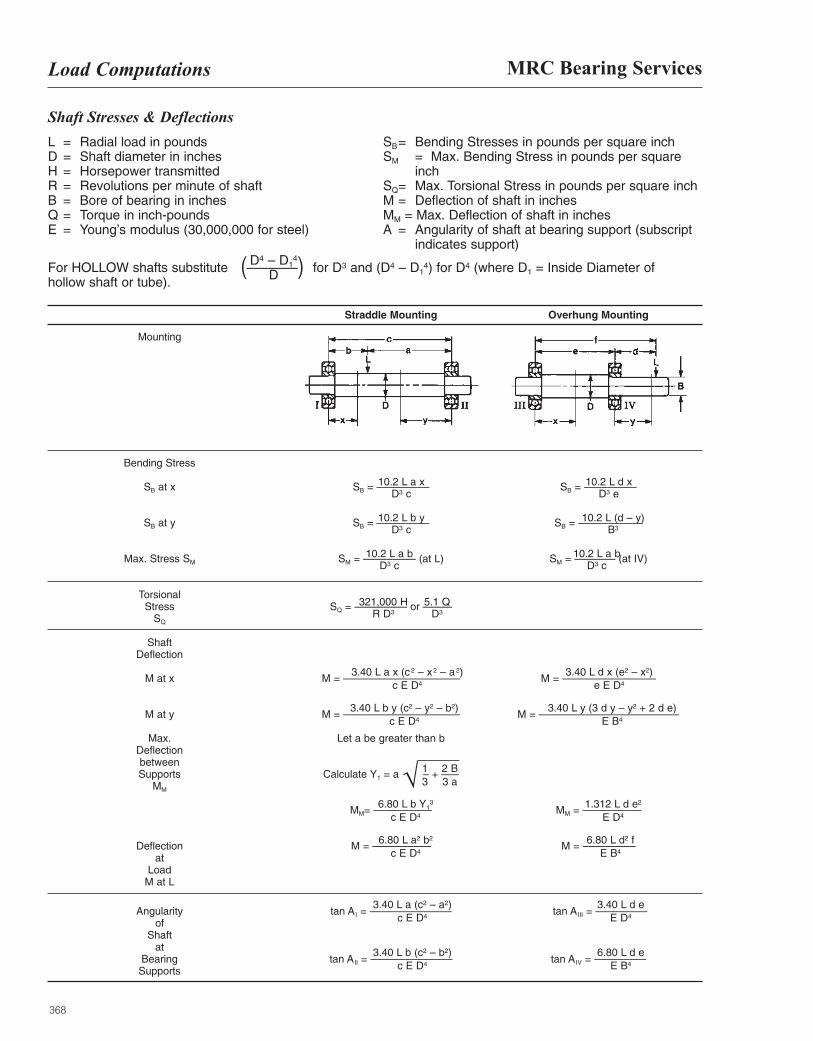
368
MRC Bearing ServicesLoad Computations
Shaft Stresses & Deflections
L = Radial load in pounds D = Shaft diameter in inches H = Horsepower transmitted R = Revolutions per minute of shaft B = Bore of bearing in inches Q = Torque in inch-pounds E = Young’s modulus (30,000,000 for steel)
SB= Bending Stresses in pounds per square inch SM = Max. Bending Stress in pounds per square
inch SQ= Max. Torsional Stress in pounds per square inch M = Deflection of shaft in inches MM = Max. Deflection of shaft in inches A = Angularity of shaft at bearing support (subscript
indicates support)
For HOLLOW shafts substitute ––––––– for D3 and (D4 – D14) for D4 (where D1 = Inside Diameter of
hollow shaft or tube).( )D4 – D1
4
D
Straddle Mounting Overhung Mounting
Mounting
Bending Stress
SB at x SB = ––––––––– SB = –––––––––
SB at y SB = ––––––––– SB = –––––––––––
Max. Stress SM SM = ––––––––– (at L) SM = ––––––– (at IV)
Torsional Stress SQ = ––––––––– or –––––
SQ
Shaft Deflection
M at x M = –––––––––––––––––––– M = ––––––––––––––––
M at y M = –––––––––––––––––––– M = ––––––––––––––––––––––––
Max. Let a be greater than bDeflection between Supports Calculate Y1 = a – + –––
MM
MM= –––––––––– MM = ––––––––––
Deflection M = –––––––––– M = –––––––––at
Load M at L
Angularity tan AI = –––––––––––––– tan AIII = –––––––––of
Shaft at
Bearing tan AII = –––––––––––––– tan AIV = –––––––––Supports
10.2 L a xD3 c
10.2 L b y D3 c
10.2 L a bD3 c
10.2 L a bD3 c
321,000 HR D3
3.40 L a x (c2 – x2 – a2)c E D4
3.40 L b y (c2 – y2 – b2)c E D4
3.40 L y (3 d y – y2 + 2 d e)E B4
3.40 L d x (e2 – x2)e E D4
5.1 QD3
10.2 L d x D3 e
10.2 L (d – y) B3
√ 13
2 B3 a
6.80 L b Y13
c E D4
6.80 L a2 b2
c E D4
3.40 L a (c2 – a2)c E D4
3.40 L b (c2 – b2)c E D4
3.40 L d e E D4
6.80 L d e E B4
1.312 L d e2
E D4
6.80 L d2 fE B4
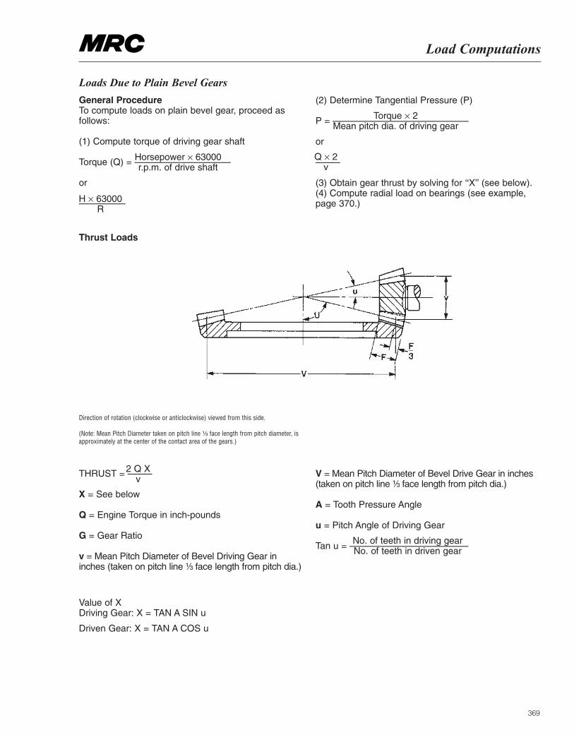
369
Load Computations
Loads Due to Plain Bevel Gears
General Procedure To compute loads on plain bevel gear, proceed asfollows:
(1) Compute torque of driving gear shaft
Torque (Q) = –––––––––––––––––––
or
–––––––––
(2) Determine Tangential Pressure (P)
P = –––––––––––––––––––––––––––
or
–––––
(3) Obtain gear thrust by solving for ‘‘X’’ (see below).(4) Compute radial load on bearings (see example,page 370.)
Thrust Loads
Direction of rotation (clockwise or anticlockwise) viewed from this side.
(Note: Mean Pitch Diameter taken on pitch line ¹|₃ face length from pitch diameter, isapproximately at the center of the contact area of the gears.)
THRUST = –––––
X = See below
Q = Engine Torque in inch-pounds
G = Gear Ratio
v = Mean Pitch Diameter of Bevel Driving Gear ininches (taken on pitch line ¹|₃ face length from pitch dia.)
V = Mean Pitch Diameter of Bevel Drive Gear in inches(taken on pitch line ¹|₃ face length from pitch dia.)
A = Tooth Pressure Angle
u = Pitch Angle of Driving Gear
Tan u = –––––––––––––––––––––––
Horsepower × 63000r.p.m. of drive shaft
H × 63000R
Torque × 2Mean pitch dia. of driving gear
Q × 2v
2 Q Xv
No. of teeth in driving gearNo. of teeth in driven gear
Value of X Driving Gear: X = TAN A SIN u
Driven Gear: X = TAN A COS u
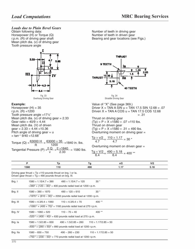
370
MRC Bearing ServicesLoad Computations
Loads due to Plain Bevel GearsObtain following data: Horsepower (H) or Torque (Q) r.p.m. (R) of driving gear shaft Mean pitch dia. (v) of driving gear Tooth pressure angle
Number of teeth in driving gear Number of teeth in driven gear Bearing and gear locations (see Figs.)
Example:Horsepower (H) = 35 r.p.m. (R) =1200 Tooth pressure angle =17¹|₂˚Mean pitch dia. (v) of driving gear = 2.33 Gear ratio = 40/9 = 4.44 Mean pitch dia. (V) of driven gear = 2.33 × 4.44 =10.36 Pitch angle of driving gear = u = tan–1 9/40 =12.68˚
Torque (Q) = ––––––– = –––––––––– =1840 in. lbs.
Tangential Pressure (P) = ––– = ––––––– = 1580 lbs.
Value of ‘‘X’’ (See page 369.) Driver X = TAN A SIN u = TAN 17.5 SIN 12.68 = .07 Driven X = TAN A COS u = TAN 17.5 COS 12.68
= .31 Thrust on driving gear (Tp) = P × X =1580 × .07 =110 lbs. Thrust on driven gear (Tg) = P × X =1580 × .31 = 490 lbs. Overturning moment on driving gear =
–––––––= ––––––––– = 30 *
Overturning moment on driven gear =
–––––––= ––––––––– = 400 **
P Tp Tg v/2 V/2
1580 110 490 1.17 5.18
Driving gear thrust = Tp =110 pounds thrust on brg. I or Ia. Driven gear thrust = Tg = 490 pounds thrust on brg. III.
Brg. I 1580 × 1.15/4.7 = 390 490 × 1.15/4.7 = 120 30 *
3902 + (120 – 30)2 = 400 pounds radial load at 1200 r.p.m.
Brg. II 1580 + 390 = 1970 490 + 120 = 610 30 *
1970 2 + (610 – 30)2 = 2050 pounds radial load at 1200 r.p.m.
Brg. III 1580 × 4.3/6.4 = 1060 110 × 4.3/6.4 = 70 400 **
1060 2 + (400 + 70)2 = 1160 pounds radial load at 270 r.p.m.
Brg. IV 1580 – 1060 = 520 110 – 70 = 40 400 **
520 2 + (400 – 40)2 = 630 pounds radial load at 270 r.p.m.
Brg. Ia 1580 × 1.5/2.85 = 830 490 × 1.5/2.85 = 260 110 × 1.17/2.85 = 50
830 2 + (260 + 50)2 = 890 pounds radial load at 1200 r.p.m.
Brg. IIa 1580 – 830 = 750 490 – 260 = 230 110 × 1.17/2.85 = 50
750 2 + (230 – 50)2 = 770 pounds radial load at 1200 r.p.m.
Fig. 24 Straddle Driving Gear
Fig. 23 Overhung Driving Gear
63000 HR
2 Qv
2 ×18402.33
63000 × 351200
Tp × v/2 4.7
Tg × V/26.4
110 × 1.174.7
490 × 5.186.4
√
√
√
√
√
√
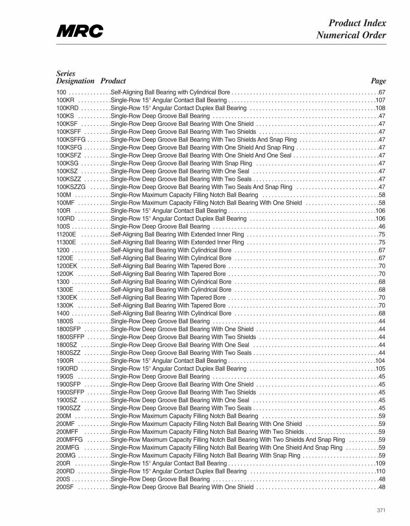
Product Index Numerical Order
371
Series Designation Product Page100 . . . . . . . . . . . . . .Self-Aligning Ball Bearing with Cylindrical Bore . . . . . . . . . . . . . . . . . . . . . . . . . . . . . . . . . . . . . . . . . . . . . . . .67 100KR . . . . . . . . . . .Single-Row 15° Angular Contact Ball Bearing . . . . . . . . . . . . . . . . . . . . . . . . . . . . . . . . . . . . . . . . . . . . . . . .107 100KRD . . . . . . . . . .Single-Row 15° Angular Contact Duplex Ball Bearing . . . . . . . . . . . . . . . . . . . . . . . . . . . . . . . . . . . . . . . . .108 100KS . . . . . . . . . . .Single-Row Deep Groove Ball Bearing . . . . . . . . . . . . . . . . . . . . . . . . . . . . . . . . . . . . . . . . . . . . . . . . . . . . . .47 100KSF . . . . . . . . . .Single-Row Deep Groove Ball Bearing With One Shield . . . . . . . . . . . . . . . . . . . . . . . . . . . . . . . . . . . . . . . .47 100KSFF . . . . . . . . .Single-Row Deep Groove Ball Bearing With Two Shields . . . . . . . . . . . . . . . . . . . . . . . . . . . . . . . . . . . . . . .47 100KSFFG . . . . . . . .Single-Row Deep Groove Ball Bearing With Two Shields And Snap Ring . . . . . . . . . . . . . . . . . . . . . . . . . .47 100KSFG . . . . . . . . .Single-Row Deep Groove Ball Bearing With One Shield And Snap Ring . . . . . . . . . . . . . . . . . . . . . . . . . . .47 100KSFZ . . . . . . . . .Single-Row Deep Groove Ball Bearing With One Shield And One Seal . . . . . . . . . . . . . . . . . . . . . . . . . . . .47 100KSG . . . . . . . . . .Single-Row Deep Groove Ball Bearing With Snap Ring . . . . . . . . . . . . . . . . . . . . . . . . . . . . . . . . . . . . . . . .47 100KSZ . . . . . . . . . .Single-Row Deep Groove Ball Bearing With One Seal . . . . . . . . . . . . . . . . . . . . . . . . . . . . . . . . . . . . . . . . .47 100KSZZ . . . . . . . . .Single-Row Deep Groove Ball Bearing With Two Seals . . . . . . . . . . . . . . . . . . . . . . . . . . . . . . . . . . . . . . . . .47 100KSZZG . . . . . . .Single-Row Deep Groove Ball Bearing With Two Seals And Snap Ring . . . . . . . . . . . . . . . . . . . . . . . . . . .47 100M . . . . . . . . . . . .Single-Row Maximum Capacity Filling Notch Ball Bearing . . . . . . . . . . . . . . . . . . . . . . . . . . . . . . . . . . . . . .58 100MF . . . . . . . . . . .Single-Row Maximum Capacity Filling Notch Ball Bearing With One Shield . . . . . . . . . . . . . . . . . . . . . . . .58 100R . . . . . . . . . . . .Single-Row 15° Angular Contact Ball Bearing . . . . . . . . . . . . . . . . . . . . . . . . . . . . . . . . . . . . . . . . . . . . . . . .106 100RD . . . . . . . . . . .Single-Row 15° Angular Contact Duplex Ball Bearing . . . . . . . . . . . . . . . . . . . . . . . . . . . . . . . . . . . . . . . . .106 100S . . . . . . . . . . . . .Single-Row Deep Groove Ball Bearing . . . . . . . . . . . . . . . . . . . . . . . . . . . . . . . . . . . . . . . . . . . . . . . . . . . . . .46 11200E . . . . . . . . . .Self-Aligning Ball Bearing With Extended Inner Ring . . . . . . . . . . . . . . . . . . . . . . . . . . . . . . . . . . . . . . . . . . .7511300E . . . . . . . . . .Self-Aligning Ball Bearing With Extended Inner Ring . . . . . . . . . . . . . . . . . . . . . . . . . . . . . . . . . . . . . . . . . . .751200 . . . . . . . . . . . . .Self-Aligning Ball Bearing With Cylindrical Bore . . . . . . . . . . . . . . . . . . . . . . . . . . . . . . . . . . . . . . . . . . . . . . .671200E . . . . . . . . . . .Self-Aligning Ball Bearing With Cylindrical Bore . . . . . . . . . . . . . . . . . . . . . . . . . . . . . . . . . . . . . . . . . . . . . . .671200EK . . . . . . . . . .Self-Aligning Ball Bearing With Tapered Bore . . . . . . . . . . . . . . . . . . . . . . . . . . . . . . . . . . . . . . . . . . . . . . . . .701200K . . . . . . . . . . .Self-Aligning Ball Bearing With Tapered Bore . . . . . . . . . . . . . . . . . . . . . . . . . . . . . . . . . . . . . . . . . . . . . . . . .701300 . . . . . . . . . . . . .Self-Aligning Ball Bearing With Cylindrical Bore . . . . . . . . . . . . . . . . . . . . . . . . . . . . . . . . . . . . . . . . . . . . . . .681300E . . . . . . . . . . .Self-Aligning Ball Bearing With Cylindrical Bore . . . . . . . . . . . . . . . . . . . . . . . . . . . . . . . . . . . . . . . . . . . . . . .681300EK . . . . . . . . . .Self-Aligning Ball Bearing With Tapered Bore . . . . . . . . . . . . . . . . . . . . . . . . . . . . . . . . . . . . . . . . . . . . . . . . .701300K . . . . . . . . . . .Self-Aligning Ball Bearing With Tapered Bore . . . . . . . . . . . . . . . . . . . . . . . . . . . . . . . . . . . . . . . . . . . . . . . . .701400 . . . . . . . . . . . . .Self-Aligning Ball Bearing With Cylindrical Bore . . . . . . . . . . . . . . . . . . . . . . . . . . . . . . . . . . . . . . . . . . . . . . .681800S . . . . . . . . . . .Single-Row Deep Groove Ball Bearing . . . . . . . . . . . . . . . . . . . . . . . . . . . . . . . . . . . . . . . . . . . . . . . . . . . . . .44 1800SFP . . . . . . . . .Single-Row Deep Groove Ball Bearing With One Shield . . . . . . . . . . . . . . . . . . . . . . . . . . . . . . . . . . . . . . . .44 1800SFFP . . . . . . . .Single-Row Deep Groove Ball Bearing With Two Shields . . . . . . . . . . . . . . . . . . . . . . . . . . . . . . . . . . . . . . .44 1800SZ . . . . . . . . . .Single-Row Deep Groove Ball Bearing With One Seal . . . . . . . . . . . . . . . . . . . . . . . . . . . . . . . . . . . . . . . . .44 1800SZZ . . . . . . . . .Single-Row Deep Groove Ball Bearing With Two Seals . . . . . . . . . . . . . . . . . . . . . . . . . . . . . . . . . . . . . . . . .44 1900R . . . . . . . . . . .Single-Row 15° Angular Contact Ball Bearing . . . . . . . . . . . . . . . . . . . . . . . . . . . . . . . . . . . . . . . . . . . . . . . .104 1900RD . . . . . . . . . .Single-Row 15° Angular Contact Duplex Ball Bearing . . . . . . . . . . . . . . . . . . . . . . . . . . . . . . . . . . . . . . . . .105 1900S . . . . . . . . . . .Single-Row Deep Groove Ball Bearing . . . . . . . . . . . . . . . . . . . . . . . . . . . . . . . . . . . . . . . . . . . . . . . . . . . . . .45 1900SFP . . . . . . . . .Single-Row Deep Groove Ball Bearing With One Shield . . . . . . . . . . . . . . . . . . . . . . . . . . . . . . . . . . . . . . . .451900SFFP . . . . . . . .Single-Row Deep Groove Ball Bearing With Two Shields . . . . . . . . . . . . . . . . . . . . . . . . . . . . . . . . . . . . . . .45 1900SZ . . . . . . . . . .Single-Row Deep Groove Ball Bearing With One Seal . . . . . . . . . . . . . . . . . . . . . . . . . . . . . . . . . . . . . . . . .45 1900SZZ . . . . . . . . .Single-Row Deep Groove Ball Bearing With Two Seals . . . . . . . . . . . . . . . . . . . . . . . . . . . . . . . . . . . . . . . . .45 200M . . . . . . . . . . . .Single-Row Maximum Capacity Filling Notch Ball Bearing . . . . . . . . . . . . . . . . . . . . . . . . . . . . . . . . . . . . . .59 200MF . . . . . . . . . . .Single-Row Maximum Capacity Filling Notch Ball Bearing With One Shield . . . . . . . . . . . . . . . . . . . . . . . .59 200MFF . . . . . . . . .Single-Row Maximum Capacity Filling Notch Ball Bearing With Two Shields . . . . . . . . . . . . . . . . . . . . . . . .59 200MFFG . . . . . . . .Single-Row Maximum Capacity Filling Notch Ball Bearing With Two Shields And Snap Ring . . . . . . . . . .59200MFG . . . . . . . . .Single-Row Maximum Capacity Filling Notch Ball Bearing With One Shield And Snap Ring . . . . . . . . . . .59200MG . . . . . . . . . . .Single-Row Maximum Capacity Filling Notch Ball Bearing With Snap Ring . . . . . . . . . . . . . . . . . . . . . . . . .59 200R . . . . . . . . . . . .Single-Row 15° Angular Contact Ball Bearing . . . . . . . . . . . . . . . . . . . . . . . . . . . . . . . . . . . . . . . . . . . . . . . .109 200RD . . . . . . . . . . .Single-Row 15° Angular Contact Duplex Ball Bearing . . . . . . . . . . . . . . . . . . . . . . . . . . . . . . . . . . . . . . . . .110 200S . . . . . . . . . . . . .Single-Row Deep Groove Ball Bearing . . . . . . . . . . . . . . . . . . . . . . . . . . . . . . . . . . . . . . . . . . . . . . . . . . . . . .48 200SF . . . . . . . . . . .Single-Row Deep Groove Ball Bearing With One Shield . . . . . . . . . . . . . . . . . . . . . . . . . . . . . . . . . . . . . . . .48
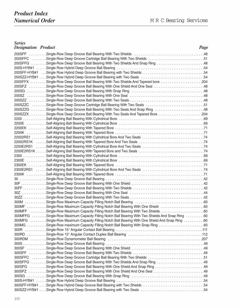
M R C Bearing ServicesProduct Index Numerical Order
372
Series Designation Product Page200SFF . . . . . . . . . .Single-Row Deep Groove Ball Bearing With Two Shields . . . . . . . . . . . . . . . . . . . . . . . . . . . . . . . . . . . . . . .48 200SFFC . . . . . . . .Single-Row Deep Groove Cartridge Ball Bearing With Two Shields . . . . . . . . . . . . . . . . . . . . . . . . . . . . . . .51 200SFFG . . . . . . . . .Single-Row Deep Groove Ball Bearing With Two Shields And Snap Ring . . . . . . . . . . . . . . . . . . . . . . . . . .48200S-HYB#1 . . . . . .Single Row Hybrid Deep Groove Ball Bearing . . . . . . . . . . . . . . . . . . . . . . . . . . . . . . . . . . . . . . . . . . . . . . . .54200SFF-HYB#1 . . .Single Row Hybrid Deep Groove Ball Bearing with Two Shields . . . . . . . . . . . . . . . . . . . . . . . . . . . . . . . . . .54200SZZ-HYB#1 . . . .Single Row Hybrid Deep Groove Ball Bearing with Two Seals . . . . . . . . . . . . . . . . . . . . . . . . . . . . . . . . . . .54200SFFX . . . . . . . . .Single-Row Deep Groove Ball Bearing With Two Shields And Tapered bore . . . . . . . . . . . . . . . . . . . . . . .204200SFZ . . . . . . . . . .Single-Row Deep Groove Ball Bearing With One Shield And One Seal . . . . . . . . . . . . . . . . . . . . . . . . . . . .48 200SG . . . . . . . . . . .Single-Row Deep Groove Ball Bearing With Snap Ring . . . . . . . . . . . . . . . . . . . . . . . . . . . . . . . . . . . . . . . .48 200SZ . . . . . . . . . . .Single-Row Deep Groove Ball Bearing With One Seal . . . . . . . . . . . . . . . . . . . . . . . . . . . . . . . . . . . . . . . . .48 200SZZ . . . . . . . . . .Single-Row Deep Groove Ball Bearing With Two Seals . . . . . . . . . . . . . . . . . . . . . . . . . . . . . . . . . . . . . . . . .48 200SZZC . . . . . . . .Single-Row Deep Groove Cartridge Ball Bearing With Two Seals . . . . . . . . . . . . . . . . . . . . . . . . . . . . . . . .51 200SZZG . . . . . . . . .Single-Row Deep Groove Ball Bearing With Two Seals And Snap Ring . . . . . . . . . . . . . . . . . . . . . . . . . . .48 200SZZX . . . . . . . . .Single-Row Deep Groove Ball Bearing With Two Seals And Tapered Bore . . . . . . . . . . . . . . . . . . . . . . . .2042200 . . . . . . . . . . . . .Self-Aligning Ball Bearing With Cylindrical Bore . . . . . . . . . . . . . . . . . . . . . . . . . . . . . . . . . . . . . . . . . . . . . . .692200E . . . . . . . . . . .Self-Aligning Ball Bearing With Cylindrical Bore . . . . . . . . . . . . . . . . . . . . . . . . . . . . . . . . . . . . . . . . . . . . . . .692200EK . . . . . . . . . .Self-Aligning Ball Bearing With Tapered Bore . . . . . . . . . . . . . . . . . . . . . . . . . . . . . . . . . . . . . . . . . . . . . . . . .712200K . . . . . . . . . . .Self-Aligning Ball Bearing With Tapered Bore . . . . . . . . . . . . . . . . . . . . . . . . . . . . . . . . . . . . . . . . . . . . . . . . .7122002RS1 . . . . . . . .Self-Aligning Ball Bearing With Cylindrical Bore And Two Seals . . . . . . . . . . . . . . . . . . . . . . . . . . . . . . . . . .7422002RS1K . . . . . .Self-Aligning Ball Bearing With Tapered Bore And Two Seals . . . . . . . . . . . . . . . . . . . . . . . . . . . . . . . . . . . .742200E2RS1 . . . . . .Self-Aligning Ball Bearing With Cylindrical Bore And Two Seals . . . . . . . . . . . . . . . . . . . . . . . . . . . . . . . . . .742200E2RS1K . . . . . .Self-Aligning Ball Bearing With Tapered Bore and Two Seals . . . . . . . . . . . . . . . . . . . . . . . . . . . . . . . . . . . .742300 . . . . . . . . . . . . .Self-Aligning Ball Bearing With Cylindrical Bore . . . . . . . . . . . . . . . . . . . . . . . . . . . . . . . . . . . . . . . . . . . . . . .692300E . . . . . . . . . . .Self-Aligning Ball Bearing With Cylindrical Bore . . . . . . . . . . . . . . . . . . . . . . . . . . . . . . . . . . . . . . . . . . . . . . .692300EK . . . . . . . . . .Self-Aligning Ball Bearing With Tapered Bore . . . . . . . . . . . . . . . . . . . . . . . . . . . . . . . . . . . . . . . . . . . . . . . . .712300E2RS1 . . . . . .Self-Aligning Ball Bearing With Cylindrical Bore And Two Seals . . . . . . . . . . . . . . . . . . . . . . . . . . . . . . . . . .742300K . . . . . . . . . . .Self-Aligning Ball Bearing With Tapered Bore . . . . . . . . . . . . . . . . . . . . . . . . . . . . . . . . . . . . . . . . . . . . . . . . .7130 . . . . . . . . . . . . . . .Single-Row Deep Groove Ball Bearing . . . . . . . . . . . . . . . . . . . . . . . . . . . . . . . . . . . . . . . . . . . . . . . . . . . . . .42 30F . . . . . . . . . . . . . .Single-Row Deep Groove Ball Bearing With One Shield . . . . . . . . . . . . . . . . . . . . . . . . . . . . . . . . . . . . . . . .42 30FF . . . . . . . . . . . . .Single-Row Deep Groove Ball Bearing With Two Shields . . . . . . . . . . . . . . . . . . . . . . . . . . . . . . . . . . . . . . .42 30Z . . . . . . . . . . . . . .Single-Row Deep Groove Ball Bearing With One Seal . . . . . . . . . . . . . . . . . . . . . . . . . . . . . . . . . . . . . . . . .44 30ZZ . . . . . . . . . . . . .Single-Row Deep Groove Ball Bearing With Two Seals . . . . . . . . . . . . . . . . . . . . . . . . . . . . . . . . . . . . . . . . .42 300M . . . . . . . . . . . .Single-Row Maximum Capacity Filling Notch Ball Bearing . . . . . . . . . . . . . . . . . . . . . . . . . . . . . . . . . . . . . .60 300MF . . . . . . . . . . .Single-Row Maximum Capacity Filling Notch Ball Bearing With One Shield . . . . . . . . . . . . . . . . . . . . . . . .60 300MFF . . . . . . . . .Single-Row Maximum Capacity Filling Notch Ball Bearing With Two Shields . . . . . . . . . . . . . . . . . . . . . . . .60 300MFFG . . . . . . . .Single-Row Maximum Capacity Filling Notch Ball Bearing With Two Shields And Snap Ring . . . . . . . . . .60300MFG . . . . . . . . .Single-Row Maximum Capacity Filling Notch Ball Bearing With One Shield And Snap Ring . . . . . . . . . . .60300MG . . . . . . . . . . .Single-Row maximum Capacity Filling Notch Ball Bearing With Snap Ring . . . . . . . . . . . . . . . . . . . . . . . . .60 300R . . . . . . . . . . . .Single-Row 15° Angular Contact Ball Bearing . . . . . . . . . . . . . . . . . . . . . . . . . . . . . . . . . . . . . . . . . . . . . . . .111 300RD . . . . . . . . . . .Single-Row 15° Angular Contact Duplex Ball Bearing . . . . . . . . . . . . . . . . . . . . . . . . . . . . . . . . . . . . . . . . .112 300RDM . . . . . . . . .Single-Row Dynamometer Ball Bearing . . . . . . . . . . . . . . . . . . . . . . . . . . . . . . . . . . . . . . . . . . . . . . . . . . . .207300S . . . . . . . . . . . . .Single-Row Deep Groove Ball Bearing . . . . . . . . . . . . . . . . . . . . . . . . . . . . . . . . . . . . . . . . . . . . . . . . . . . . . .49 300SF . . . . . . . . . . .Single-Row Deep Groove Ball Bearing With One Shield . . . . . . . . . . . . . . . . . . . . . . . . . . . . . . . . . . . . . . . .49 300SFF . . . . . . . . . .Single-Row Deep Groove Ball Bearing With Two Shields . . . . . . . . . . . . . . . . . . . . . . . . . . . . . . . . . . . . . . .49 300SFFC . . . . . . . .Single-Row Deep Groove Cartridge Ball Bearing With Two Shields . . . . . . . . . . . . . . . . . . . . . . . . . . . . . . .51 300SFFG . . . . . . . . .Single-Row Deep Groove Ball Bearing With Two Shields And Snap Ring . . . . . . . . . . . . . . . . . . . . . . . . . .49 300SFG . . . . . . . . .Single-Row Deep Groove Ball Bearing With One Shield And Snap Ring . . . . . . . . . . . . . . . . . . . . . . . . . . .49 300SFZ . . . . . . . . . .Single-Row Deep Groove Ball Bearing With One Shield And One Seal . . . . . . . . . . . . . . . . . . . . . . . . . . . .49 300SG . . . . . . . . . . .Single-Row Deep Groove Ball Bearing With Snap Ring . . . . . . . . . . . . . . . . . . . . . . . . . . . . . . . . . . . . . . . .49300S-HYB#1 . . . . . .Single Row Hybrid Deep Groove Ball Bearing . . . . . . . . . . . . . . . . . . . . . . . . . . . . . . . . . . . . . . . . . . . . . . . .54300SFF-HYB#1 . . . .Single Row Hybrid Deep Groove Ball Bearing with Two Shields . . . . . . . . . . . . . . . . . . . . . . . . . . . . . . . . . .54300SZZ-HYB#1 . . . .Single Row Hybrid Deep Groove Ball Bearing with Two Seals . . . . . . . . . . . . . . . . . . . . . . . . . . . . . . . . . . .54
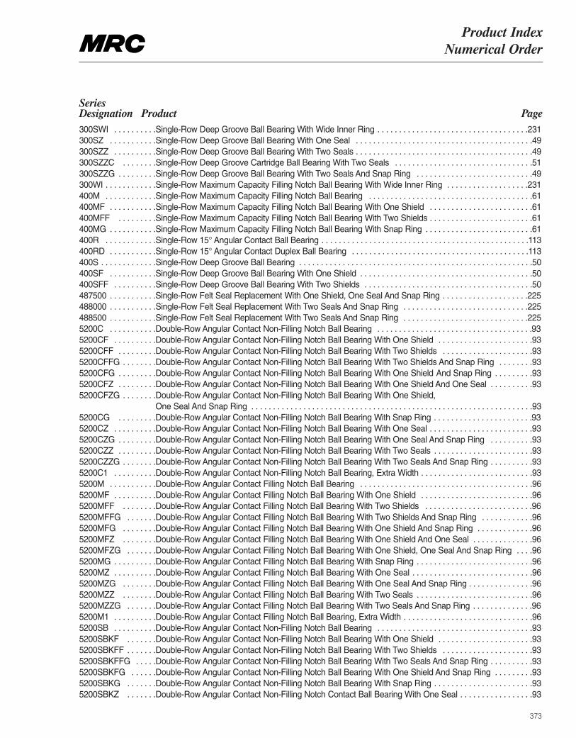
Product Index Numerical Order
373
Series Designation Product Page300SWI . . . . . . . . . .Single-Row Deep Groove Ball Bearing With Wide Inner Ring . . . . . . . . . . . . . . . . . . . . . . . . . . . . . . . . . . .231300SZ . . . . . . . . . . .Single-Row Deep Groove Ball Bearing With One Seal . . . . . . . . . . . . . . . . . . . . . . . . . . . . . . . . . . . . . . . . .49 300SZZ . . . . . . . . . .Single-Row Deep Groove Ball Bearing With Two Seals . . . . . . . . . . . . . . . . . . . . . . . . . . . . . . . . . . . . . . . . .49 300SZZC . . . . . . . .Single-Row Deep Groove Cartridge Ball Bearing With Two Seals . . . . . . . . . . . . . . . . . . . . . . . . . . . . . . . .51300SZZG . . . . . . . . .Single-Row Deep Groove Ball Bearing With Two Seals And Snap Ring . . . . . . . . . . . . . . . . . . . . . . . . . . .49 300WI . . . . . . . . . . . .Single-Row Maximum Capacity Filling Notch Ball Bearing With Wide Inner Ring . . . . . . . . . . . . . . . . . . .231400M . . . . . . . . . . . .Single-Row Maximum Capacity Filling Notch Ball Bearing . . . . . . . . . . . . . . . . . . . . . . . . . . . . . . . . . . . . . .61 400MF . . . . . . . . . . .Single-Row Maximum Capacity Filling Notch Ball Bearing With One Shield . . . . . . . . . . . . . . . . . . . . . . . .61 400MFF . . . . . . . . .Single-Row Maximum Capacity Filling Notch Ball Bearing With Two Shields . . . . . . . . . . . . . . . . . . . . . . . .61 400MG . . . . . . . . . . .Single-Row Maximum Capacity Filling Notch Ball Bearing With Snap Ring . . . . . . . . . . . . . . . . . . . . . . . . .61 400R . . . . . . . . . . . .Single-Row 15° Angular Contact Ball Bearing . . . . . . . . . . . . . . . . . . . . . . . . . . . . . . . . . . . . . . . . . . . . . . . .113 400RD . . . . . . . . . . .Single-Row 15° Angular Contact Duplex Ball Bearing . . . . . . . . . . . . . . . . . . . . . . . . . . . . . . . . . . . . . . . . .113 400S . . . . . . . . . . . . .Single-Row Deep Groove Ball Bearing . . . . . . . . . . . . . . . . . . . . . . . . . . . . . . . . . . . . . . . . . . . . . . . . . . . . . .50 400SF . . . . . . . . . . .Single-Row Deep Groove Ball Bearing With One Shield . . . . . . . . . . . . . . . . . . . . . . . . . . . . . . . . . . . . . . . .50400SFF . . . . . . . . . .Single-Row Deep Groove Ball Bearing With Two Shields . . . . . . . . . . . . . . . . . . . . . . . . . . . . . . . . . . . . . . .50 487500 . . . . . . . . . . .Single-Row Felt Seal Replacement With One Shield, One Seal And Snap Ring . . . . . . . . . . . . . . . . . . . .225488000 . . . . . . . . . . .Single-Row Felt Seal Replacement With Two Seals And Snap Ring . . . . . . . . . . . . . . . . . . . . . . . . . . . . .225488500 . . . . . . . . . . .Single-Row Felt Seal Replacement With Two Seals And Snap Ring . . . . . . . . . . . . . . . . . . . . . . . . . . . . .2255200C . . . . . . . . . . .Double-Row Angular Contact Non-Filling Notch Ball Bearing . . . . . . . . . . . . . . . . . . . . . . . . . . . . . . . . . . . .935200CF . . . . . . . . . .Double-Row Angular Contact Non-Filling Notch Ball Bearing With One Shield . . . . . . . . . . . . . . . . . . . . . .935200CFF . . . . . . . . .Double-Row Angular Contact Non-Filling Notch Ball Bearing With Two Shields . . . . . . . . . . . . . . . . . . . . .935200CFFG . . . . . . . .Double-Row Angular Contact Non-Filling Notch Ball Bearing With Two Shields And Snap Ring . . . . . . . .935200CFG . . . . . . . . .Double-Row Angular Contact Non-Filling Notch Ball Bearing With One Shield And Snap Ring . . . . . . . . .935200CFZ . . . . . . . . .Double-Row Angular Contact Non-Filling Notch Ball Bearing With One Shield And One Seal . . . . . . . . . .935200CFZG . . . . . . . .Double-Row Angular Contact Non-Filling Notch Ball Bearing With One Shield,
One Seal And Snap Ring . . . . . . . . . . . . . . . . . . . . . . . . . . . . . . . . . . . . . . . . . . . . . . . . . . . . . . . . . . . . . . . . .935200CG . . . . . . . . .Double-Row Angular Contact Non-Filling Notch Ball Bearing With Snap Ring . . . . . . . . . . . . . . . . . . . . . . .935200CZ . . . . . . . . . .Double-Row Angular Contact Non-Filling Notch Ball Bearing With One Seal . . . . . . . . . . . . . . . . . . . . . . . .935200CZG . . . . . . . . .Double-Row Angular Contact Non-Filling Notch Ball Bearing With One Seal And Snap Ring . . . . . . . . . .935200CZZ . . . . . . . . .Double-Row Angular Contact Non-Filling Notch Ball Bearing With Two Seals . . . . . . . . . . . . . . . . . . . . . . .935200CZZG . . . . . . . .Double-Row Angular Contact Non-Filling Notch Ball Bearing With Two Seals And Snap Ring . . . . . . . . . .935200C1 . . . . . . . . . .Double-Row Angular Contact Non-Filling Notch Ball Bearing, Extra Width . . . . . . . . . . . . . . . . . . . . . . . . . .935200M . . . . . . . . . . .Double-Row Angular Contact Filling Notch Ball Bearing . . . . . . . . . . . . . . . . . . . . . . . . . . . . . . . . . . . . . . . .965200MF . . . . . . . . . .Double-Row Angular Contact Filling Notch Ball Bearing With One Shield . . . . . . . . . . . . . . . . . . . . . . . . . .965200MFF . . . . . . . .Double-Row Angular Contact Filling Notch Ball Bearing With Two Shields . . . . . . . . . . . . . . . . . . . . . . . . .965200MFFG . . . . . . .Double-Row Angular Contact Filling Notch Ball Bearing With Two Shields And Snap Ring . . . . . . . . . . . .965200MFG . . . . . . . .Double-Row Angular Contact Filling Notch Ball Bearing With One Shield And Snap Ring . . . . . . . . . . . . .965200MFZ . . . . . . . .Double-Row Angular Contact Filling Notch Ball Bearing With One Shield And One Seal . . . . . . . . . . . . . .965200MFZG . . . . . . .Double-Row Angular Contact Filling Notch Ball Bearing With One Shield, One Seal And Snap Ring . . . .965200MG . . . . . . . . . .Double-Row Angular Contact Filling Notch Ball Bearing With Snap Ring . . . . . . . . . . . . . . . . . . . . . . . . . . .965200MZ . . . . . . . . . .Double-Row Angular Contact Filling Notch Ball Bearing With One Seal . . . . . . . . . . . . . . . . . . . . . . . . . . . .965200MZG . . . . . . . .Double-Row Angular Contact Filling Notch Ball Bearing With One Seal And Snap Ring . . . . . . . . . . . . . . .965200MZZ . . . . . . . .Double-Row Angular Contact Filling Notch Ball Bearing With Two Seals . . . . . . . . . . . . . . . . . . . . . . . . . . .965200MZZG . . . . . . .Double-Row Angular Contact Filling Notch Ball Bearing With Two Seals And Snap Ring . . . . . . . . . . . . . .965200M1 . . . . . . . . . .Double-Row Angular Contact Filling Notch Ball Bearing, Extra Width . . . . . . . . . . . . . . . . . . . . . . . . . . . . . .965200SB . . . . . . . . . .Double-Row Angular Contact Non-Filling Notch Ball Bearing . . . . . . . . . . . . . . . . . . . . . . . . . . . . . . . . . . . .935200SBKF . . . . . . .Double-Row Angular Contact Non-Filling Notch Ball Bearing With One Shield . . . . . . . . . . . . . . . . . . . . . .935200SBKFF . . . . . . .Double-Row Angular Contact Non-Filling Notch Ball Bearing With Two Shields . . . . . . . . . . . . . . . . . . . . .935200SBKFFG . . . . .Double-Row Angular Contact Non-Filling Notch Ball Bearing With Two Seals And Snap Ring . . . . . . . . . .935200SBKFG . . . . . .Double-Row Angular Contact Non-Filling Notch Ball Bearing With One Shield And Snap Ring . . . . . . . . .935200SBKG . . . . . . .Double-Row Angular Contact Non-Filling Notch Ball Bearing With Snap Ring . . . . . . . . . . . . . . . . . . . . . . .935200SBKZ . . . . . . .Double-Row Angular Contact Non-Filling Notch Contact Ball Bearing With One Seal . . . . . . . . . . . . . . . . .93
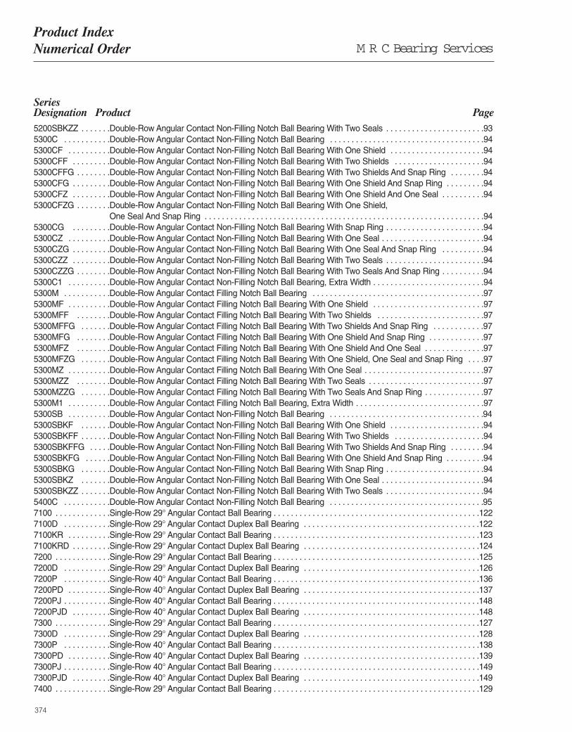
M R C Bearing ServicesProduct Index Numerical Order
374
Series Designation Product Page5200SBKZZ . . . . . . .Double-Row Angular Contact Non-Filling Notch Ball Bearing With Two Seals . . . . . . . . . . . . . . . . . . . . . . .935300C . . . . . . . . . . .Double-Row Angular Contact Non-Filling Notch Ball Bearing . . . . . . . . . . . . . . . . . . . . . . . . . . . . . . . . . . . .945300CF . . . . . . . . . .Double-Row Angular Contact Non-Filling Notch Ball Bearing With One Shield . . . . . . . . . . . . . . . . . . . . . .945300CFF . . . . . . . . .Double-Row Angular Contact Non-Filling Notch Ball Bearing With Two Shields . . . . . . . . . . . . . . . . . . . . .945300CFFG . . . . . . . .Double-Row Angular Contact Non-Filling Notch Ball Bearing With Two Shields And Snap Ring . . . . . . . .945300CFG . . . . . . . . .Double-Row Angular Contact Non-Filling Notch Ball Bearing With One Shield And Snap Ring . . . . . . . . .945300CFZ . . . . . . . . .Double-Row Angular Contact Non-Filling Notch Ball Bearing With One Shield And One Seal . . . . . . . . . .945300CFZG . . . . . . . .Double-Row Angular Contact Non-Filling Notch Ball Bearing With One Shield,
One Seal And Snap Ring . . . . . . . . . . . . . . . . . . . . . . . . . . . . . . . . . . . . . . . . . . . . . . . . . . . . . . . . . . . . . . . . .945300CG . . . . . . . . .Double-Row Angular Contact Non-Filling Notch Ball Bearing With Snap Ring . . . . . . . . . . . . . . . . . . . . . . .945300CZ . . . . . . . . . .Double-Row Angular Contact Non-Filling Notch Ball Bearing With One Seal . . . . . . . . . . . . . . . . . . . . . . . .945300CZG . . . . . . . . .Double-Row Angular Contact Non-Filling Notch Ball Bearing With One Seal And Snap Ring . . . . . . . . . .945300CZZ . . . . . . . . .Double-Row Angular Contact Non-Filling Notch Ball Bearing With Two Seals . . . . . . . . . . . . . . . . . . . . . . .945300CZZG . . . . . . . .Double-Row Angular Contact Non-Filling Notch Ball Bearing With Two Seals And Snap Ring . . . . . . . . . .945300C1 . . . . . . . . . .Double-Row Angular Contact Non-Filling Notch Ball Bearing, Extra Width . . . . . . . . . . . . . . . . . . . . . . . . . .945300M . . . . . . . . . . .Double-Row Angular Contact Filling Notch Ball Bearing . . . . . . . . . . . . . . . . . . . . . . . . . . . . . . . . . . . . . . . .975300MF . . . . . . . . . .Double-Row Angular Contact Filling Notch Ball Bearing With One Shield . . . . . . . . . . . . . . . . . . . . . . . . . .975300MFF . . . . . . . .Double-Row Angular Contact Filling Notch Ball Bearing With Two Shields . . . . . . . . . . . . . . . . . . . . . . . . .975300MFFG . . . . . . .Double-Row Angular Contact Filling Notch Ball Bearing With Two Shields And Snap Ring . . . . . . . . . . . .975300MFG . . . . . . . .Double-Row Angular Contact Filling Notch Ball Bearing With One Shield And Snap Ring . . . . . . . . . . . . .975300MFZ . . . . . . . .Double-Row Angular Contact Filling Notch Ball Bearing With One Shield And One Seal . . . . . . . . . . . . . .975300MFZG . . . . . . .Double-Row Angular Contact Filling Notch Ball Bearing With One Shield, One Seal and Snap Ring . . . .975300MZ . . . . . . . . . .Double-Row Angular Contact Filling Notch Ball Bearing With One Seal . . . . . . . . . . . . . . . . . . . . . . . . . . . .975300MZZ . . . . . . . .Double-Row Angular Contact Filling Notch Ball Bearing With Two Seals . . . . . . . . . . . . . . . . . . . . . . . . . . .975300MZZG . . . . . . .Double-Row Angular Contact Filling Notch Ball Bearing With Two Seals And Snap Ring . . . . . . . . . . . . . .975300M1 . . . . . . . . . .Double-Row Angular Contact Filling Notch Ball Bearing, Extra Width . . . . . . . . . . . . . . . . . . . . . . . . . . . . . .975300SB . . . . . . . . . .Double-Row Angular Contact Non-Filling Notch Ball Bearing . . . . . . . . . . . . . . . . . . . . . . . . . . . . . . . . . . . .945300SBKF . . . . . . .Double-Row Angular Contact Non-Filling Notch Ball Bearing With One Shield . . . . . . . . . . . . . . . . . . . . . .945300SBKFF . . . . . . .Double-Row Angular Contact Non-Filling Notch Ball Bearing With Two Shields . . . . . . . . . . . . . . . . . . . . .945300SBKFFG . . . . .Double-Row Angular Contact Non-Filling Notch Ball Bearing With Two Shields And Snap Ring . . . . . . . .945300SBKFG . . . . . .Double-Row Angular Contact Non-Filling Notch Ball Bearing With One Shield And Snap Ring . . . . . . . . .945300SBKG . . . . . . .Double-Row Angular Contact Non-Filling Notch Ball Bearing With Snap Ring . . . . . . . . . . . . . . . . . . . . . . .945300SBKZ . . . . . . .Double-Row Angular Contact Non-Filling Notch Ball Bearing With One Seal . . . . . . . . . . . . . . . . . . . . . . . .945300SBKZZ . . . . . . .Double-Row Angular Contact Non-Filling Notch Ball Bearing With Two Seals . . . . . . . . . . . . . . . . . . . . . . .945400C . . . . . . . . . . .Double-Row Angular Contact Non-Filling Notch Ball Bearing . . . . . . . . . . . . . . . . . . . . . . . . . . . . . . . . . . . .957100 . . . . . . . . . . . . .Single-Row 29° Angular Contact Ball Bearing . . . . . . . . . . . . . . . . . . . . . . . . . . . . . . . . . . . . . . . . . . . . . . . .122 7100D . . . . . . . . . . .Single-Row 29° Angular Contact Duplex Ball Bearing . . . . . . . . . . . . . . . . . . . . . . . . . . . . . . . . . . . . . . . . .122 7100KR . . . . . . . . . .Single-Row 29° Angular Contact Ball Bearing . . . . . . . . . . . . . . . . . . . . . . . . . . . . . . . . . . . . . . . . . . . . . . . .123 7100KRD . . . . . . . . .Single-Row 29° Angular Contact Duplex Ball Bearing . . . . . . . . . . . . . . . . . . . . . . . . . . . . . . . . . . . . . . . . .124 7200 . . . . . . . . . . . . .Single-Row 29° Angular Contact Ball Bearing . . . . . . . . . . . . . . . . . . . . . . . . . . . . . . . . . . . . . . . . . . . . . . . .125 7200D . . . . . . . . . . .Single-Row 29° Angular Contact Duplex Ball Bearing . . . . . . . . . . . . . . . . . . . . . . . . . . . . . . . . . . . . . . . . .126 7200P . . . . . . . . . . .Single-Row 40° Angular Contact Ball Bearing . . . . . . . . . . . . . . . . . . . . . . . . . . . . . . . . . . . . . . . . . . . . . . . .136 7200PD . . . . . . . . . .Single-Row 40° Angular Contact Duplex Ball Bearing . . . . . . . . . . . . . . . . . . . . . . . . . . . . . . . . . . . . . . . . .137 7200PJ . . . . . . . . . . .Single-Row 40° Angular Contact Ball Bearing . . . . . . . . . . . . . . . . . . . . . . . . . . . . . . . . . . . . . . . . . . . . . . . .1487200PJD . . . . . . . . .Single-Row 40° Angular Contact Duplex Ball Bearing . . . . . . . . . . . . . . . . . . . . . . . . . . . . . . . . . . . . . . . . .1487300 . . . . . . . . . . . . .Single-Row 29° Angular Contact Ball Bearing . . . . . . . . . . . . . . . . . . . . . . . . . . . . . . . . . . . . . . . . . . . . . . . .127 7300D . . . . . . . . . . .Single-Row 29° Angular Contact Duplex Ball Bearing . . . . . . . . . . . . . . . . . . . . . . . . . . . . . . . . . . . . . . . . .128 7300P . . . . . . . . . . .Single-Row 40° Angular Contact Ball Bearing . . . . . . . . . . . . . . . . . . . . . . . . . . . . . . . . . . . . . . . . . . . . . . . .138 7300PD . . . . . . . . . .Single-Row 40° Angular Contact Duplex Ball Bearing . . . . . . . . . . . . . . . . . . . . . . . . . . . . . . . . . . . . . . . . .139 7300PJ . . . . . . . . . . .Single-Row 40° Angular Contact Ball Bearing . . . . . . . . . . . . . . . . . . . . . . . . . . . . . . . . . . . . . . . . . . . . . . . .1497300PJD . . . . . . . . .Single-Row 40° Angular Contact Duplex Ball Bearing . . . . . . . . . . . . . . . . . . . . . . . . . . . . . . . . . . . . . . . . .1497400 . . . . . . . . . . . . .Single-Row 29° Angular Contact Ball Bearing . . . . . . . . . . . . . . . . . . . . . . . . . . . . . . . . . . . . . . . . . . . . . . . .129
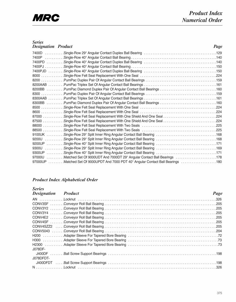
Product Index Numerical Order
375
Series Designation Product Page7400D . . . . . . . . . . .Single-Row 29° Angular Contact Duplex Ball Bearing . . . . . . . . . . . . . . . . . . . . . . . . . . . . . . . . . . . . . . . . .129 7400P . . . . . . . . . . .Single-Row 40° Angular Contact Ball Bearing . . . . . . . . . . . . . . . . . . . . . . . . . . . . . . . . . . . . . . . . . . . . . . . .140 7400PD . . . . . . . . . .Single-Row 40° Angular Contact Duplex Ball Bearing . . . . . . . . . . . . . . . . . . . . . . . . . . . . . . . . . . . . . . . . .1407400PJ . . . . . . . . . . .Single-Row 40° Angular Contact Ball Bearing . . . . . . . . . . . . . . . . . . . . . . . . . . . . . . . . . . . . . . . . . . . . . . . .1507400PJD . . . . . . . . .Single-Row 40° Angular Contact Duplex Ball Bearing . . . . . . . . . . . . . . . . . . . . . . . . . . . . . . . . . . . . . . . . .1508000 . . . . . . . . . . . . .Single-Row Felt Seal Replacement With One Seal . . . . . . . . . . . . . . . . . . . . . . . . . . . . . . . . . . . . . . . . . . .2248200 . . . . . . . . . . . . .PumPac Duplex Pair Of Angular Contact Ball Bearings . . . . . . . . . . . . . . . . . . . . . . . . . . . . . . . . . . . . . . . .1598200AAB . . . . . . . . .PumPac Triplex Set Of Angular Contact Ball Bearings . . . . . . . . . . . . . . . . . . . . . . . . . . . . . . . . . . . . . . . . .1618200BB . . . . . . . . . .PumPac Diamond Duplex Pair Of Angular Contact Ball Bearings . . . . . . . . . . . . . . . . . . . . . . . . . . . . . . . .1608300 . . . . . . . . . . . . .PumPac Duplex Pair Of Angular Contact Ball Bearings . . . . . . . . . . . . . . . . . . . . . . . . . . . . . . . . . . . . . . . .1598300AAB . . . . . . . . .PumPac Triplex Set Of Angular Contact Ball Bearings . . . . . . . . . . . . . . . . . . . . . . . . . . . . . . . . . . . . . . . . .1618300BB . . . . . . . . . .PumPac Diamond Duplex Pair Of Angular Contact Ball Bearings . . . . . . . . . . . . . . . . . . . . . . . . . . . . . . . .1608500 . . . . . . . . . . . . .Single-Row Felt Seal Replacement With One Seal . . . . . . . . . . . . . . . . . . . . . . . . . . . . . . . . . . . . . . . . . . .2248600 . . . . . . . . . . . . .Single-Row Felt Seal Replacement With One Seal . . . . . . . . . . . . . . . . . . . . . . . . . . . . . . . . . . . . . . . . . . .22487000 . . . . . . . . . . . .Single-Row Felt Seal Replacement With One Shield And One Seal . . . . . . . . . . . . . . . . . . . . . . . . . . . . . .22487500 . . . . . . . . . . . .Single-Row Felt Seal Replacement With One Shield And One Seal . . . . . . . . . . . . . . . . . . . . . . . . . . . . . .22488000 . . . . . . . . . . . .Single-Row Felt Seal Replacement With Two Seals . . . . . . . . . . . . . . . . . . . . . . . . . . . . . . . . . . . . . . . . . .22588500 . . . . . . . . . . . .Single-Row Felt Seal Replacement With Two Seals . . . . . . . . . . . . . . . . . . . . . . . . . . . . . . . . . . . . . . . . . .2259100UK . . . . . . . . . .Single-Row 29° Split Inner Ring Angular Contact Ball Bearing . . . . . . . . . . . . . . . . . . . . . . . . . . . . . . . . . .1689200U . . . . . . . . . . .Single-Row 29° Split Inner Ring Angular Contact Ball Bearing . . . . . . . . . . . . . . . . . . . . . . . . . . . . . . . . . .1689200UP . . . . . . . . . .Single-Row 40° Split Inner Ring Angular Contact Ball Bearing . . . . . . . . . . . . . . . . . . . . . . . . . . . . . . . . . .1719300U . . . . . . . . . . .Single-Row 29° Split Inner Ring Angular Contact Ball Bearing . . . . . . . . . . . . . . . . . . . . . . . . . . . . . . . . . .1699300UP . . . . . . . . . .Single-Row 40° Split Inner Ring Angular Contact Ball Bearing . . . . . . . . . . . . . . . . . . . . . . . . . . . . . . . . . .17197000U . . . . . . . . . .Matched Set Of 9000UDT And 7000DT 29° Angular Contact Ball Bearings . . . . . . . . . . . . . . . . . . . . . . .17897000UP . . . . . . . . .Matched Set Of 9000UPDT And 7000 PDT 40° Angular Contact Ball Bearings . . . . . . . . . . . . . . . . . . . .180
Product Index Alphabetical Order
Series Designation Product PageAN . . . . . . . . . . . . . .Locknut . . . . . . . . . . . . . . . . . . . . . . . . . . . . . . . . . . . . . . . . . . . . . . . . . . . . . . . . . . . . . . . . . . . . . . . . . . . . . .326 CONV3SF . . . . . . . .Conveyor Roll Ball Bearing . . . . . . . . . . . . . . . . . . . . . . . . . . . . . . . . . . . . . . . . . . . . . . . . . . . . . . . . . . . . . . .205CONV3Y2 . . . . . . . .Conveyor Roll Ball Bearing . . . . . . . . . . . . . . . . . . . . . . . . . . . . . . . . . . . . . . . . . . . . . . . . . . . . . . . . . . . . . . .205CONV3Y4 . . . . . . . .Conveyor Roll Ball Bearing . . . . . . . . . . . . . . . . . . . . . . . . . . . . . . . . . . . . . . . . . . . . . . . . . . . . . . . . . . . . . . .205CONV4E2 . . . . . . . .Conveyor Roll Ball Bearing . . . . . . . . . . . . . . . . . . . . . . . . . . . . . . . . . . . . . . . . . . . . . . . . . . . . . . . . . . . . . . .205CONV4SF . . . . . . . .Conveyor Roll Ball Bearing . . . . . . . . . . . . . . . . . . . . . . . . . . . . . . . . . . . . . . . . . . . . . . . . . . . . . . . . . . . . . . .205CONV4SZZ2 . . . . .Conveyor Roll Ball Bearing . . . . . . . . . . . . . . . . . . . . . . . . . . . . . . . . . . . . . . . . . . . . . . . . . . . . . . . . . . . . . . .205CONV5043 . . . . . . .Conveyor Roll Ball Bearing . . . . . . . . . . . . . . . . . . . . . . . . . . . . . . . . . . . . . . . . . . . . . . . . . . . . . . . . . . . . . . .204 H200 . . . . . . . . . . . .Adapter Sleeve For Tapered Bore Bearing . . . . . . . . . . . . . . . . . . . . . . . . . . . . . . . . . . . . . . . . . . . . . . . . . . .72 H300 . . . . . . . . . . . .Adapter Sleeve For Tapered Bore Bearing . . . . . . . . . . . . . . . . . . . . . . . . . . . . . . . . . . . . . . . . . . . . . . . . . . .73 H2300 . . . . . . . . . . .Adapter Sleeve For Tapered Bore Bearing . . . . . . . . . . . . . . . . . . . . . . . . . . . . . . . . . . . . . . . . . . . . . . . . . . .73 J078DF-
J400DF . . . . . . . .Ball Screw Support Bearings . . . . . . . . . . . . . . . . . . . . . . . . . . . . . . . . . . . . . . . . . . . . . . . . . . . . . . . . . . . . .198J078DFDT-
J400DFDT . . . . .Ball Screw Support Bearings . . . . . . . . . . . . . . . . . . . . . . . . . . . . . . . . . . . . . . . . . . . . . . . . . . . . . . . . . . . . .198N . . . . . . . . . . . . . . . .Locknut . . . . . . . . . . . . . . . . . . . . . . . . . . . . . . . . . . . . . . . . . . . . . . . . . . . . . . . . . . . . . . . . . . . . . . . . . . . . . .326
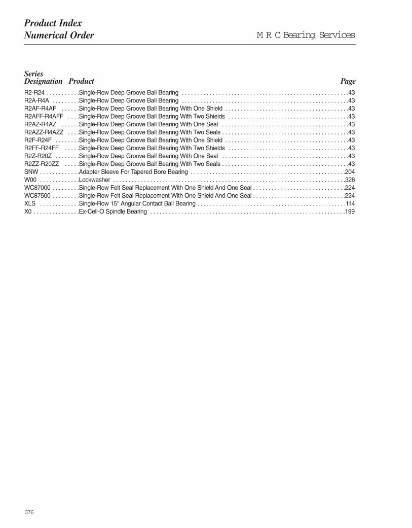
M R C Bearing ServicesProduct Index Numerical Order
376
Series Designation Product PageR2-R24 . . . . . . . . . . .Single-Row Deep Groove Ball Bearing . . . . . . . . . . . . . . . . . . . . . . . . . . . . . . . . . . . . . . . . . . . . . . . . . . . . . .43 R2A-R4A . . . . . . . . .Single-Row Deep Groove Ball Bearing . . . . . . . . . . . . . . . . . . . . . . . . . . . . . . . . . . . . . . . . . . . . . . . . . . . . . .43 R2AF-R4AF . . . . . .Single-Row Deep Groove Ball Bearing With One Shield . . . . . . . . . . . . . . . . . . . . . . . . . . . . . . . . . . . . . . . .43 R2AFF-R4AFF . . . .Single-Row Deep Groove Ball Bearing With Two Shields . . . . . . . . . . . . . . . . . . . . . . . . . . . . . . . . . . . . . . .43 R2AZ-R4AZ . . . . . .Single-Row Deep Groove Ball Bearing With One Seal . . . . . . . . . . . . . . . . . . . . . . . . . . . . . . . . . . . . . . . . .43R2AZZ-R4AZZ . . . .Single-Row Deep Groove Ball Bearing With Two Seals . . . . . . . . . . . . . . . . . . . . . . . . . . . . . . . . . . . . . . . . .43 R2F-R24F . . . . . . . .Single-Row Deep Groove Ball Bearing With One Shield . . . . . . . . . . . . . . . . . . . . . . . . . . . . . . . . . . . . . . . .43 R2FF-R24FF . . . . .Single-Row Deep Groove Ball Bearing With Two Shields . . . . . . . . . . . . . . . . . . . . . . . . . . . . . . . . . . . . . . .43 R2Z-R20Z . . . . . . . .Single-Row Deep Groove Ball Bearing With One Seal . . . . . . . . . . . . . . . . . . . . . . . . . . . . . . . . . . . . . . . . .43 R2ZZ-R20ZZ . . . . .Single-Row Deep Groove Ball Bearing With Two Seals . . . . . . . . . . . . . . . . . . . . . . . . . . . . . . . . . . . . . . . . .43 SNW . . . . . . . . . . . . .Adapter Sleeve For Tapered Bore Bearing . . . . . . . . . . . . . . . . . . . . . . . . . . . . . . . . . . . . . . . . . . . . . . . . . .204W00 . . . . . . . . . . . . .Lockwasher . . . . . . . . . . . . . . . . . . . . . . . . . . . . . . . . . . . . . . . . . . . . . . . . . . . . . . . . . . . . . . . . . . . . . . . . . . .326WC87000 . . . . . . . . .Single-Row Felt Seal Replacement With One Shield And One Seal . . . . . . . . . . . . . . . . . . . . . . . . . . . . . .224WC87500 . . . . . . . . .Single-Row Felt Seal Replacement With One Shield And One Seal . . . . . . . . . . . . . . . . . . . . . . . . . . . . . .224XLS . . . . . . . . . . . . .Single-Row 15° Angular Contact Ball Bearing . . . . . . . . . . . . . . . . . . . . . . . . . . . . . . . . . . . . . . . . . . . . . . . .114 X0 . . . . . . . . . . . . . . .Ex-Cell-O Spindle Bearing . . . . . . . . . . . . . . . . . . . . . . . . . . . . . . . . . . . . . . . . . . . . . . . . . . . . . . . . . . . . . . .199

377

378

379

380

381

382

383

384
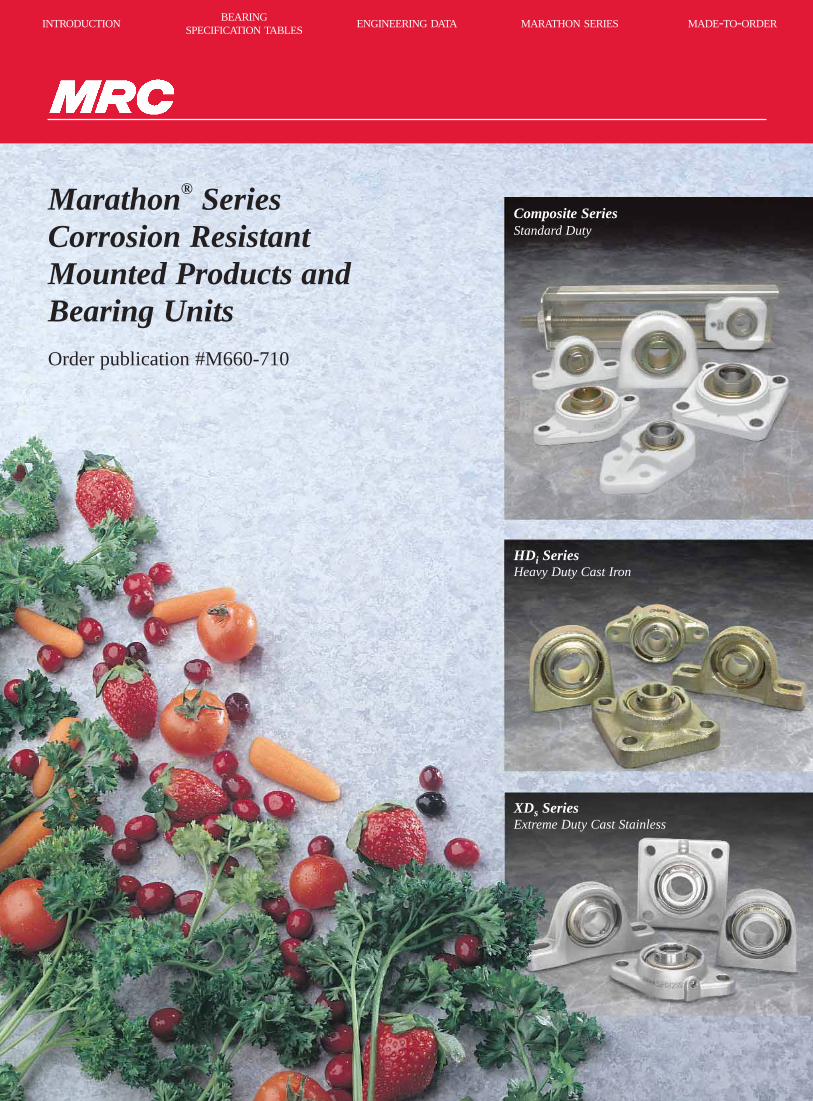
Composite SeriesStandard Duty
HDi SeriesHeavy Duty Cast Iron
XDs SeriesExtreme Duty Cast Stainless
BEARINGSPECIFICATION TABLES
INTRODUCTION ENGINEERING DATA MARATHON SERIES MADE-TO-ORDER
Marathon® SeriesCorrosion ResistantMounted Products andBearing UnitsOrder publication #M660-710

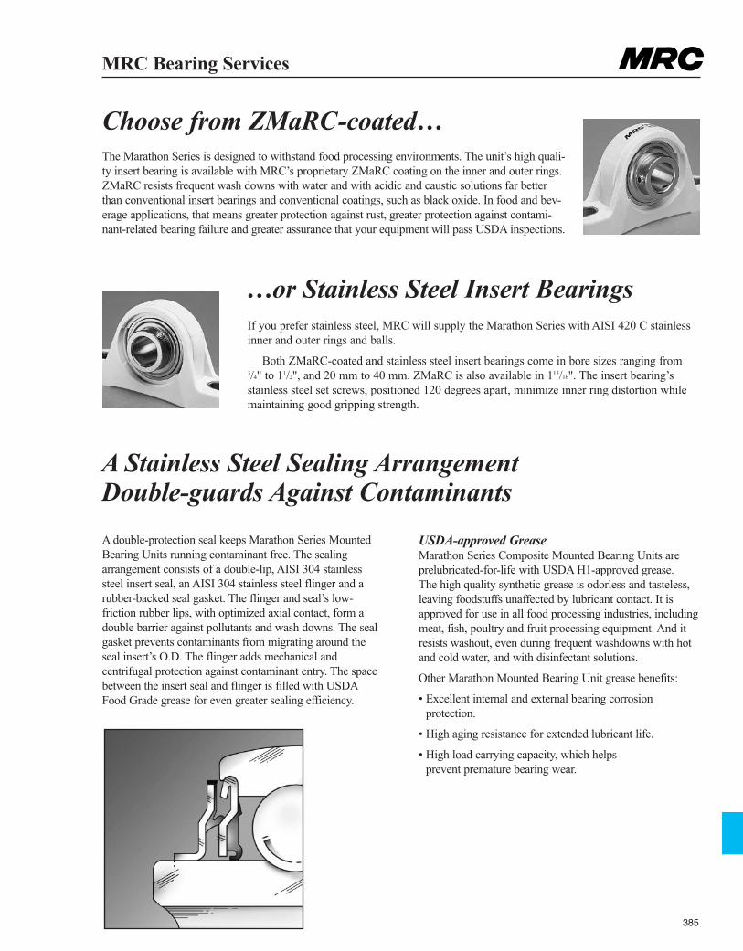
385
MRC Bearing Services
Choose from ZMaRC-coated…The Marathon Series is designed to withstand food processing environments. The unit’s high quali-ty insert bearing is available with MRC’s proprietary ZMaRC coating on the inner and outer rings.ZMaRC resists frequent wash downs with water and with acidic and caustic solutions far betterthan conventional insert bearings and conventional coatings, such as black oxide. In food and bev-erage applications, that means greater protection against rust, greater protection against contami-nant-related bearing failure and greater assurance that your equipment will pass USDA inspections.
If you prefer stainless steel, MRC will supply the Marathon Series with AISI 420 C stainlessinner and outer rings and balls.
Both ZMaRC-coated and stainless steel insert bearings come in bore sizes ranging from 3/4" to 11/2", and 20 mm to 40 mm. ZMaRC is also available in 115/16". The insert bearing’sstainless steel set screws, positioned 120 degrees apart, minimize inner ring distortion whilemaintaining good gripping strength.
A double-protection seal keeps Marathon Series MountedBearing Units running contaminant free. The sealingarrangement consists of a double-lip, AISI 304 stainlesssteel insert seal, an AISI 304 stainless steel flinger and arubber-backed seal gasket. The flinger and seal’s low-friction rubber lips, with optimized axial contact, form adouble barrier against pollutants and wash downs. The sealgasket prevents contaminants from migrating around theseal insert’s O.D. The flinger adds mechanical andcentrifugal protection against contaminant entry. The spacebetween the insert seal and flinger is filled with USDAFood Grade grease for even greater sealing efficiency.
USDA-approved GreaseMarathon Series Composite Mounted Bearing Units areprelubricated-for-life with USDA H1-approved grease. The high quality synthetic grease is odorless and tasteless,leaving foodstuffs unaffected by lubricant contact. It isapproved for use in all food processing industries, includingmeat, fish, poultry and fruit processing equipment. And itresists washout, even during frequent washdowns with hotand cold water, and with disinfectant solutions.
Other Marathon Mounted Bearing Unit grease benefits:
• Excellent internal and external bearing corrosionprotection.
• High aging resistance for extended lubricant life.
• High load carrying capacity, which helps prevent premature bearing wear.
…or Stainless Steel Insert Bearings
A Stainless Steel Sealing ArrangementDouble-guards Against Contaminants
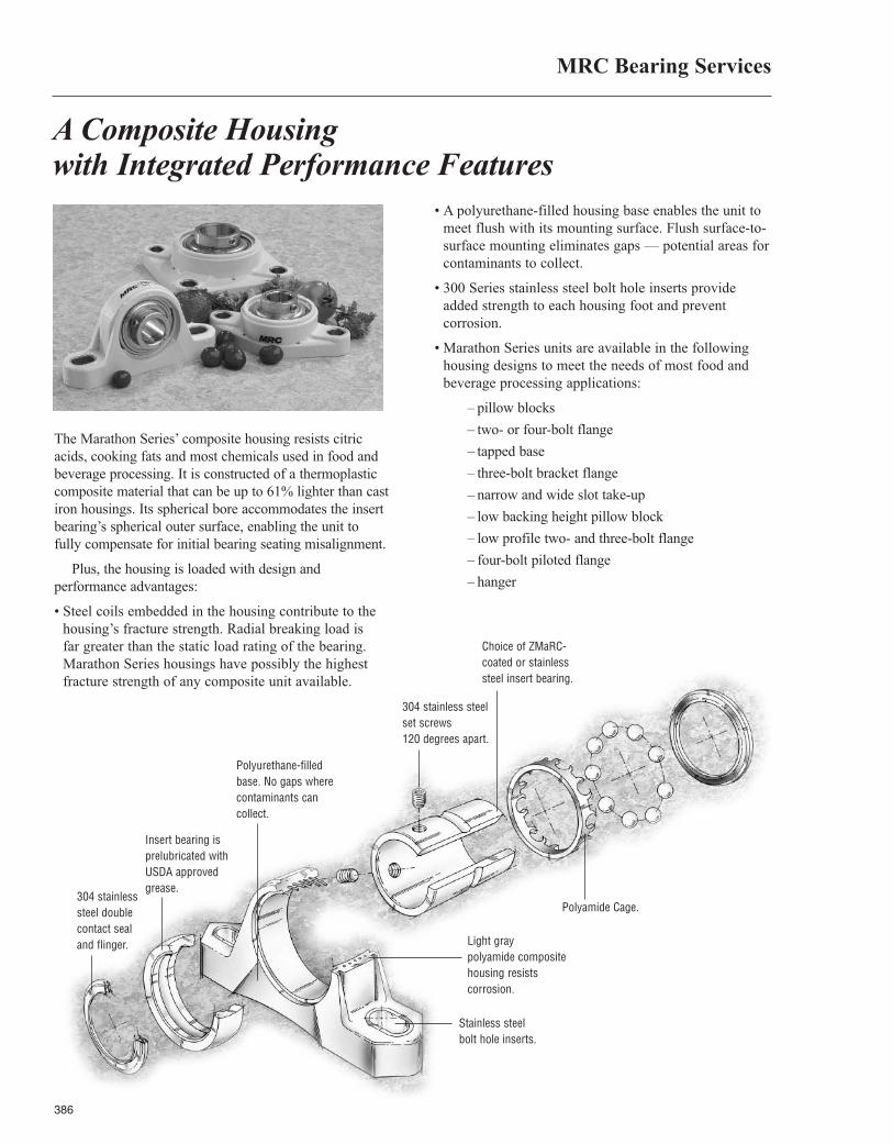
386
A Composite Housingwith Integrated Performance Features
The Marathon Series’ composite housing resists citric acids, cooking fats and most chemicals used in food andbeverage processing. It is constructed of a thermoplasticcomposite material that can be up to 61% lighter than castiron housings. Its spherical bore accommodates the insertbearing’s spherical outer surface, enabling the unit to fully compensate for initial bearing seating misalignment.
Plus, the housing is loaded with design and performance advantages:
• Steel coils embedded in the housing contribute to thehousing’s fracture strength. Radial breaking load is far greater than the static load rating of the bearing.Marathon Series housings have possibly the highestfracture strength of any composite unit available.
• A polyurethane-filled housing base enables the unit tomeet flush with its mounting surface. Flush surface-to-surface mounting eliminates gaps — potential areas forcontaminants to collect.
• 300 Series stainless steel bolt hole inserts provideadded strength to each housing foot and preventcorrosion.
• Marathon Series units are available in the followinghousing designs to meet the needs of most food andbeverage processing applications:
– pillow blocks
– two- or four-bolt flange
– tapped base
– three-bolt bracket flange
– narrow and wide slot take-up
– low backing height pillow block
– low profile two- and three-bolt flange
– four-bolt piloted flange
– hanger
Insert bearing is prelubricated withUSDA approvedgrease.
304 stainlesssteel doublecontact sealand flinger.
Polyurethane-filled base. No gaps wherecontaminants can collect.
Light gray polyamide compositehousing resists corrosion.
Stainless steelbolt hole inserts.
304 stainless steelset screws120 degrees apart.
Choice of ZMaRC-coated or stainlesssteel insert bearing.
Polyamide Cage.
MRC Bearing Services
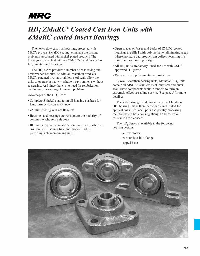
387
HDi ZMaRC® Coated Cast Iron Units with ZMaRC coated Insert Bearings
The heavy duty cast iron housings, protected withMRC’s proven ZMaRC coating, eliminate the flakingproblems associated with nickel-plated products. Thehousings are matched with our ZMaRC-plated, lubed-for-life, quality insert bearings.
The HDi series provides a number of cost-saving andperformance benefits. As with all Marathon products,MRC’s patented two-part stainless steel seals allow theunits to operate in heavy washdown environments withoutregreasing. And since there is no need for relubrication,continuous grease purge is never a problem.
Advantages of the HDi Series:
• Complete ZMaRC coating on all housing surfaces forlong-term corrosion resistance.
• ZMaRC coating will not flake off.
• Housings and bearings are resistant to the majority ofcommon washdown solutions.
• HDi units require no relubrication, even in a washdownenvironment—saving time and money—whileproviding a cleaner-running unit.
• Open spaces on bases and backs of ZMaRC-coatedhousings are filled with polyurethane, eliminating areaswhere moisture and product can collect, resulting in amore sanitary housing design.
• All HDi units are factory lubed-for-life with USDAapproved H1 grease.
• Two-part sealing for maximum protection
Like all Marathon bearing units, Marathon HDi unitscontain an AISI 304 stainless steel inner seal and outerseal. These components work in tandem to form anextremely effective sealing system. (See page 5 for moredetails.)
The added strength and durability of the Marathon HDi housings make them particularly well suited forapplications in red meat, pork and poultry processingfacilities where both housing strength and corrosionresistance are a concern.
The HDi Series is available in the following housing designs:
– pillow blocks
– two- or four-bolt flange
– tapped base
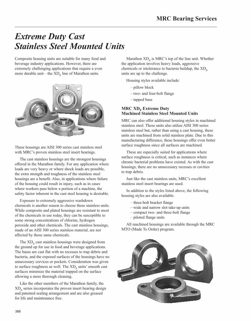
388
Composite housing units are suitable for many food andbeverage industry applications. However, there areextremely challenging applications that require a evenmore durable unit—the XDs line of Marathon units.
These housings are AISI 300 series cast stainless steelwith MRC’s proven stainless steel insert bearings.
The cast stainless housings are the strongest housingsoffered in the Marathon family. For any application whereloads are very heavy or where shock loads are possible,the extra strength and toughness of the stainless steelhousings are a benefit. Also, in applications where failureof the housing could result in injury, such as in caseswhere workers pass below a portion of a machine, thesafety factor inherent in the cast steel housing is desirable.
Exposure to extremely aggressive washdownchemicals is another reason to choose these stainless units.While composite and plated housings are resistant to mostof the chemicals in use today, they can be susceptible tosome strong concentrations of chlorine, hydrogenperoxide and other chemicals. The cast stainless housings,made of an AISI 300 series stainless material, are notaffected by those same chemicals.
The XDs cast stainless housings were designed fromthe ground up for use in food and beverage applications.The bases are cast flat with no recesses to trap debris andbacteria, and the exposed surfaces of the housings have nounnecessary crevices or pockets. Consideration was givento surface roughness as well. The XDs units’ smooth castsurfaces minimize the material trapped on the surfaceallowing a more thorough cleaning.
Like the other members of the Marathon family, theXDs series incorporates the proven insert bearing designand patented sealing arrangement and are also greased for life and maintenance free.
Marathon XDs is MRC’s top of the line unit. Whetherthe application involves heavy loads, aggressivechemicals or intolerance to bacteria buildup, the XDsunits are up to the challenge.
Housing styles available include:
– pillow block
– two- and four-bolt flange
– tapped base
MRC XDs Extreme Duty Machined Stainless Steel Mounted Units
MRC can also offer additional housing styles in machinedstainless steel. These units also utilize AISI 300 seriesstainless steel but, rather than using a cast housing, theseunits are machined from solid stainless plate. Due to thismanufacturing difference, these housings offer even bettersurface roughness since all surfaces are machined.
These are especially suited for applications wheresurface roughness is critical, such as instances wherechronic bacterial problems have existed. As with the casthousings, there are no unnecessary recesses or cavitiesto trap debris.
Just like the cast stainless units, MRC’s excellentstainless steel insert bearings are used.
In addition to the styles listed above, the followinghousing styles are also available:
– three-bolt bracket flange– wide and narrow slot take-up units– compact two- and three-bolt flange– piloted flange units
All machined housings are available through the MRCMTO (Made To Order) program.
Extreme Duty Cast Stainless Steel Mounted Units
MRC Bearing Services
Made-To-OrderSolutions from MRC
Order publication #M200-111
BEARINGSPECIFICATION TABLES
INTRODUCTION ENGINEERING DATA MARATHON SERIES MADE-TO-ORDER

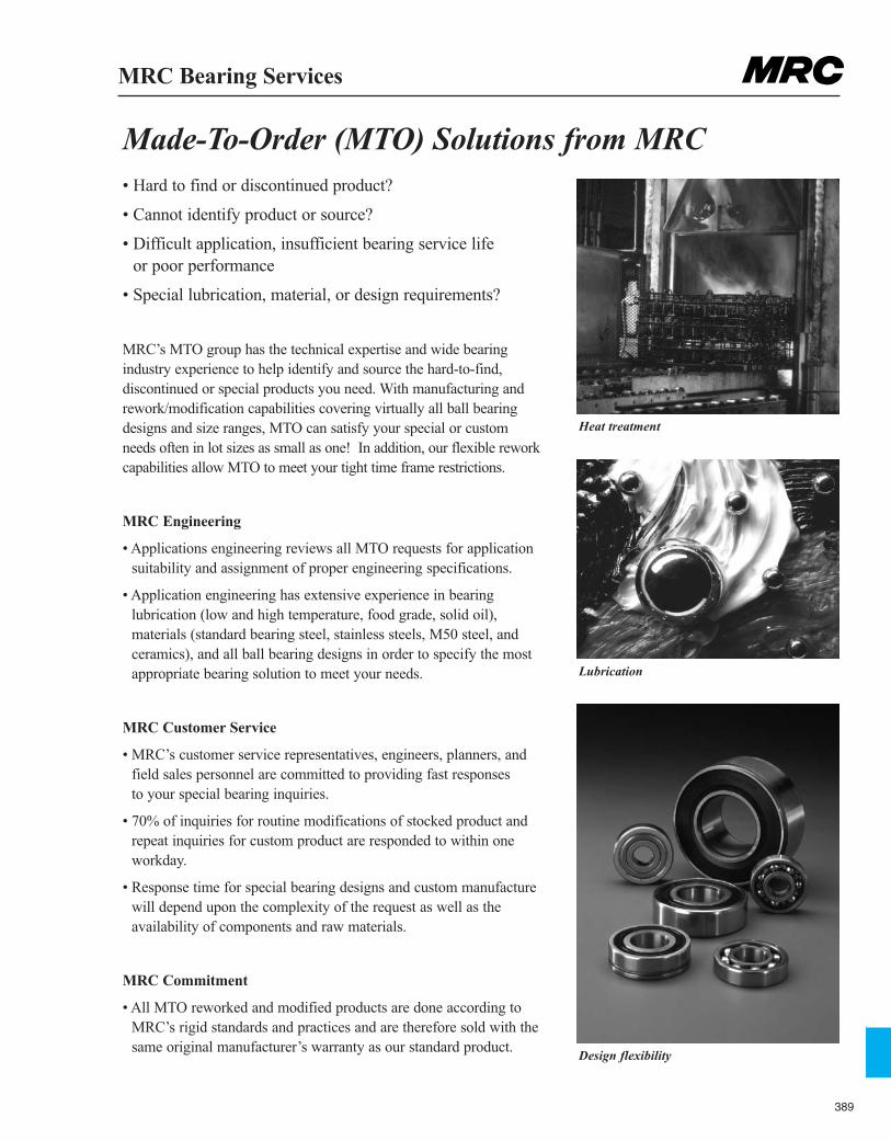
389
MRC Bearing Services
• Hard to find or discontinued product?
• Cannot identify product or source?
• Difficult application, insufficient bearing service life or poor performance
• Special lubrication, material, or design requirements?
MRC’s MTO group has the technical expertise and wide bearing industry experience to help identify and source the hard-to-find, discontinued or special products you need. With manufacturing andrework/modification capabilities covering virtually all ball bearingdesigns and size ranges, MTO can satisfy your special or custom needs often in lot sizes as small as one! In addition, our flexible reworkcapabilities allow MTO to meet your tight time frame restrictions.
MRC Engineering
• Applications engineering reviews all MTO requests for applicationsuitability and assignment of proper engineering specifications.
• Application engineering has extensive experience in bearing lubrication (low and high temperature, food grade, solid oil), materials (standard bearing steel, stainless steels, M50 steel, andceramics), and all ball bearing designs in order to specify the mostappropriate bearing solution to meet your needs.
MRC Customer Service
• MRC’s customer service representatives, engineers, planners, andfield sales personnel are committed to providing fast responses to your special bearing inquiries.
• 70% of inquiries for routine modifications of stocked product andrepeat inquiries for custom product are responded to within oneworkday.
• Response time for special bearing designs and custom manufacturewill depend upon the complexity of the request as well as the availability of components and raw materials.
MRC Commitment
• All MTO reworked and modified products are done according toMRC’s rigid standards and practices and are therefore sold with thesame original manufacturer’s warranty as our standard product.
Made-To-Order (MTO) Solutions from MRC
Heat treatment
Lubrication
Design flexibility
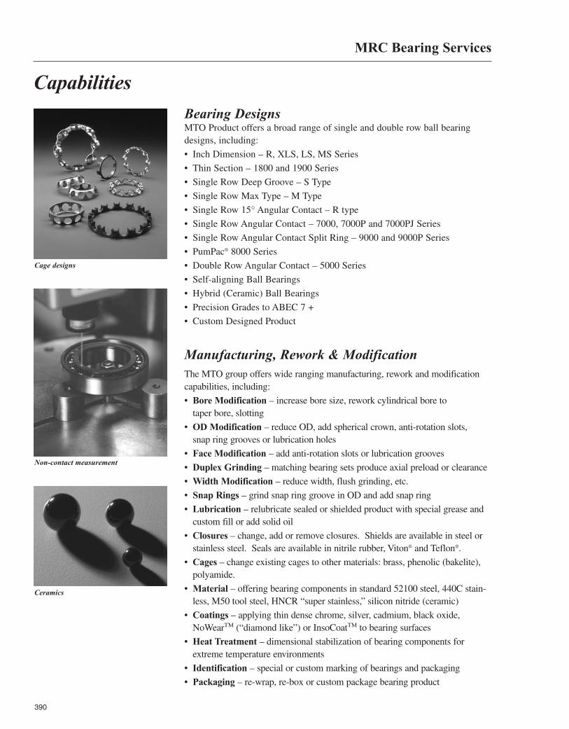
390
Capabilities
MRC Bearing Services
Bearing DesignsMTO Product offers a broad range of single and double row ball bearingdesigns, including:
• Inch Dimension – R, XLS, LS, MS Series
• Thin Section – 1800 and 1900 Series
• Single Row Deep Groove – S Type
• Single Row Max Type – M Type
• Single Row 15° Angular Contact – R type
• Single Row Angular Contact – 7000, 7000P and 7000PJ Series
• Single Row Angular Contact Split Ring – 9000 and 9000P Series
• PumPac® 8000 Series
• Double Row Angular Contact – 5000 Series
• Self-aligning Ball Bearings
• Hybrid (Ceramic) Ball Bearings
• Precision Grades to ABEC 7 +
• Custom Designed Product
Ceramics
Non-contact measurement
Manufacturing, Rework & ModificationThe MTO group offers wide ranging manufacturing, rework and modificationcapabilities, including:
• Bore Modification – increase bore size, rework cylindrical bore to taper bore, slotting
• OD Modification – reduce OD, add spherical crown, anti-rotation slots, snap ring grooves or lubrication holes
• Face Modification – add anti-rotation slots or lubrication grooves
• Duplex Grinding – matching bearing sets produce axial preload or clearance
• Width Modification – reduce width, flush grinding, etc.
• Snap Rings – grind snap ring groove in OD and add snap ring
• Lubrication – relubricate sealed or shielded product with special grease andcustom fill or add solid oil
• Closures – change, add or remove closures. Shields are available in steel orstainless steel. Seals are available in nitrile rubber, Viton® and Teflon®.
• Cages – change existing cages to other materials: brass, phenolic (bakelite),polyamide.
• Material – offering bearing components in standard 52100 steel, 440C stain-less, M50 tool steel, HNCR “super stainless,” silicon nitride (ceramic)
• Coatings – applying thin dense chrome, silver, cadmium, black oxide,NoWear™ (“diamond like”) or InsoCoat™ to bearing surfaces
• Heat Treatment – dimensional stabilization of bearing components forextreme temperature environments
• Identification – special or custom marking of bearings and packaging
• Packaging – re-wrap, re-box or custom package bearing product
Cage designs

MRC Bearing Services
MRC Bearing ServicesCall Toll Free1 (800) MRC-7000
Headquarters1510 Gehman RoadKulpsville, PA 19443USA
® MRC is a registered trademark of SKF USA Inc. The contents of this publication are the copyright of the publisher and may not be reproduced (even extracts) unless prior written permission is granted. Every care has been taken to ensure the accuracy of the information contained in this publication but no liability can be accepted for any loss or damage whether direct, indirect or consequential arising out of use of the information contained herein.© 2005 SKF USA Inc. Publication M190-730 (7.5M/CW 6/2005) Fifth Edition Version 6/2005 Printed in U.S.A.
Engineering HandbookEngineering Handbook