Embed Size (px)
Citation preview
Engineering Failure Analysis xxx (2008) xxx–xxx
ARTICLE IN PRESS
Contents lists available at ScienceDirect
Engineering Failure Analysis
journal homepage: www.elsevier .com/locate /engfai lanal
Residual stress effects on fatigue life of welded structures using LEFM
Z. Barsoum a,*, I. Barsoum b
a Kungliga Tekniska Högskolan (KTH), Department of Aeronautical and Vehicle Engineering, Teknikringen 8, 100 44 Stockholm, Swedenb Kungliga Tekniska Högskolan (KTH), Department of Solid Mechanics, 100 44 Stockholm, Sweden
a r t i c l e i n f o a b s t r a c t
Article history:Received 11 April 2008Accepted 4 June 2008Available online xxxx
Keywords:Welding simulationFEMResidual stressesFatigue crack growthLinear elastic fracture mechanics
1350-6307/$ - see front matter � 2008 Elsevier Ltddoi:10.1016/j.engfailanal.2008.06.017
* Corresponding author.E-mail addresses: [email protected] (Z. Barsoum), im
Please cite this article in press as: BarsouLEFM, Eng Fail Anal (2008), doi:10.1016/
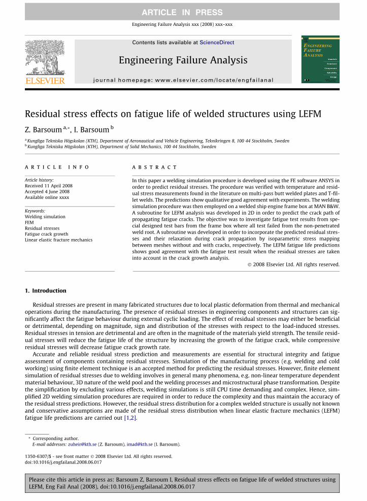
In this paper a welding simulation procedure is developed using the FE software ANSYS inorder to predict residual stresses. The procedure was verified with temperature and resid-ual stress measurements found in the literature on multi-pass butt welded plates and T-fil-let welds. The predictions show qualitative good agreement with experiments. The weldingsimulation procedure was then employed on a welded ship engine frame box at MAN B&W.A subroutine for LEFM analysis was developed in 2D in order to predict the crack path ofpropagating fatigue cracks. The objective was to investigate fatigue test results from spe-cial designed test bars from the frame box where all test failed from the non-penetratedweld root. A subroutine was developed in order to incorporate the predicted residual stres-ses and their relaxation during crack propagation by isoparametric stress mappingbetween meshes without and with cracks, respectively. The LEFM fatigue life predictionsshows good agreement with the fatigue test result when the residual stresses are takeninto account in the crack growth analysis.
� 2008 Elsevier Ltd. All rights reserved.
1. Introduction
Residual stresses are present in many fabricated structures due to local plastic deformation from thermal and mechanicaloperations during the manufacturing. The presence of residual stresses in engineering components and structures can sig-nificantly affect the fatigue behaviour during external cyclic loading. The effect of residual stresses may either be beneficialor detrimental, depending on magnitude, sign and distribution of the stresses with respect to the load-induced stresses.Residual stresses in tension are detrimental and are often in the magnitude of the materials yield strength. The tensile resid-ual stresses will reduce the fatigue life of the structure by increasing the growth of the fatigue crack, while compressiveresidual stresses will decrease fatigue crack growth rate.
Accurate and reliable residual stress prediction and measurements are essential for structural integrity and fatigueassessment of components containing residual stresses. Simulation of the manufacturing process (e.g. welding and coldworking) using finite element technique is an accepted method for predicting the residual stresses. However, finite elementsimulation of residual stresses due to welding involves in general many phenomena, e.g. non-linear temperature dependentmaterial behaviour, 3D nature of the weld pool and the welding processes and microstructural phase transformation. Despitethe simplification by excluding various effects, welding simulations is still CPU time demanding and complex. Hence, sim-plified 2D welding simulation procedures are required in order to reduce the complexity and thus maintain the accuracy ofthe residual stress predictions. However, the residual stress distribution for a complex welded structure is usually not knownand conservative assumptions are made of the residual stress distribution when linear elastic fracture mechanics (LEFM)fatigue life predictions are carried out [1,2].
. All rights reserved.
[email protected] (I. Barsoum).
m Z, Barsoum I, Residual stress effects on fatigue life of welded structures usingj.engfailanal.2008.06.017
2 Z. Barsoum, I. Barsoum / Engineering Failure Analysis xxx (2008) xxx–xxx
ARTICLE IN PRESS
LEFM is frequently employed for fatigue assessment of cracks and flaws in critical welds. In cases when the residual stressdistribution is known its effect could be incorporated into the LEFM fatigue life estimation by applying the distribution as astatic internal load on the un-cracked component using the weight function method [3] for calculation of the stress intensityfactor, KI. These weight function techniques are limited to basic geometry cases and are out dated. However, Finite elementtechniques are more general.
The initial residual stresses are redistributed during fatigue crack growth and this effect is incorporated in the developedsubroutine for LEFM fatigue life assessment. The work within this paper is divided into five different steps:
1. Development of a FE subroutine for welding simulation procedure in order to predict the residual stresses due to thewelding process.
2. Development of a LEFM subroutine for automatic simulation of fatigue crack propagation in order to predict the crackpath and to calculate the stress intensity factors (KI and KII) and the crack deflection angle (ui).
3. Development of a subroutine for incorporation of the simulated residual stresses into the LEFM based crack propagationanalysis in order to take account of the residual stress redistribution effects into the fatigue life assessment.
4. Validation of the subroutines with experimental and numerical data found in the literature.5. Implementation of the developed subroutines for the fatigue assessment of a real application welded structure.
Finite element simulations in order to predict temperature fields, residual stresses and deformation due to welding in 2-and 3-dimensional is used more frequently nowadays [4–6]. Also 2D and 3D LEFM fatigue crack growth simulators havebeen developed [7–9] in order to predict the fatigue life for, i.e. welded joints [9]. There are several research contributions[2,10–12] on the incorporation of residual stress into the fracture mechanical defect assessment. However, limited work hasbeen done on the development of reliable simulation tool in order to include all these features in the same package.
2. Welding simulation procedure
2.1. Finite element modelling
The welding simulation procedure is developed in the FE software ANSYS [13]. The purpose of the welding simulationprocedure is to predict temperature, HAZ weld penetration and residual stresses due to welding with simplified 2Dwelding simulations. A sequentially coupled analysis is carried out starting with the thermal analysis. The results fromthe thermal analysis – the temperature distributions, were used as loads in the elastic–plastic mechanical analysis. Gen-eralized plane strain was assumed for the FE models, i.e. the strain in the longitudinal welding direction is constant(e 6¼ 0) unlike the plane strain condition where the strain is zero (e = 0). The addition of weld filler material is simulatedby using the birth/death of elements in ANSYS for the thermal transient analysis and the elastic–plastic analysis,respectively.
2.2. Heat source modelling
The temperature distribution in a weldment is mainly determined by the gross heat input, the pre-heat temperature, thewelding process, type and geometry of the joint [14].
The heat source used in this study assumes a constant distribution of volume heat flux over the cross section of the weldfiller material. The volume flux is applied simultaneously with the reactivation of the elements representing the weld fillermaterial with a pre-heating melting temperature (1500 �C). The principal parameter of the welding heat source for the tem-perature field is heat flow Qtot (J/s) which can be expressed as,
PleaLEFM
Q tot ¼ garcU � I; ð1Þ
where garc � arc efficiency, which account for radiative and other losses from the arc to the ambient environment, i.e. it isassumed that some portion of the energy (1 � garc) leaving the electrode never reach the melt pool surface.
U – arc voltageI – arc current.The equivalent heat input can be assumed as the combination of prescribed pre-heat temperature, surface and volume
heat flux components [15]. Therefore, the total heat input can be written as
Q tot ¼ Q surface þ Q volume þ Q filler; ð2Þ
where Qsurface and Qvolume indicate heat contents resulting from a specific surface heat flux and volume heat flux, respec-tively. The Qfiller indicate heat content resulting from the prescribed preheating temperature. The specific surface heat flux(area-specific heat flow density) qsurface (J/mm2 s) and specific volume heat flux (volume-specific heat flow density) qvolume (J/mm3 s) can be expressed by
qsurface ¼Q surface
S; qvolume ¼
Q volume
V; ð3Þ
se cite this article in press as: Barsoum Z, Barsoum I, Residual stress effects on fatigue life of welded structures using, Eng Fail Anal (2008), doi:10.1016/j.engfailanal.2008.06.017
Z. Barsoum, I. Barsoum / Engineering Failure Analysis xxx (2008) xxx–xxx 3
ARTICLE IN PRESS
where S is the surface area and V is the volume of weld filler material, respectively. The ratio of Qsurface/Qvolume and Qvolume/Qfiller can be tuned to achieve an accurate representation of the fusion zone. In the present study the surface heat flux isignored and the equivalent heat input, Qtot, is a combination of Qvolume and Qfiller, i.e. the tuning is restricted to Qvolume/Qfiller.
There are two approaches to tune a simplified heat source model described above:
� When experiment data is available, ‘‘tuning” is accomplished by bringing the calculated temperature histories into agree-ment with those experimental data measured by the thermocouples.
� When there is no experiment data available, ‘‘tuning” means adjusting the weld parameters to achieve a reasonable mol-ten zone size and distance to the HAZ (800–900 �C) from the fusion zone boundary. A reasonable molten zone size isachieved when at least the melting temperature (1340–1390 �C) is reached in all the elements that are included in theparticular weld pass.
In the present study the both approaches are utilized in order to predict the fusion zone, HAZ and weld depth penetrationwith the heat source model described above.
2.3. Material modelling
Accurate material data in the high temperature region is in general difficult to obtain and becomes at best a reasonableapproximation. However, the material model and relevant properties need only to represent the real material behaviourwith sufficient accuracy.
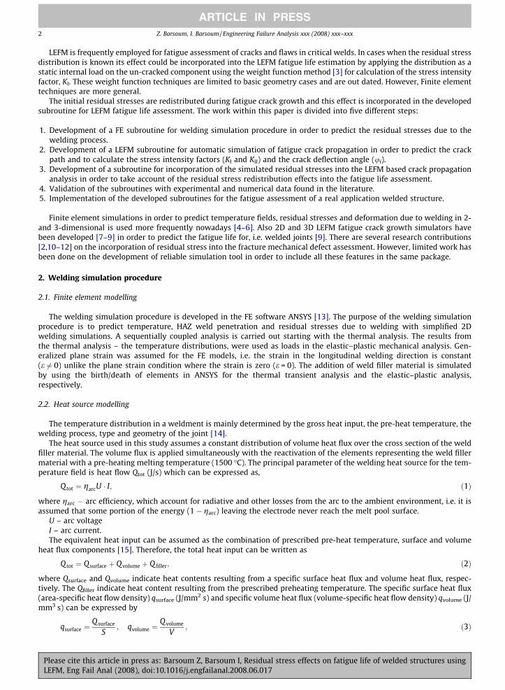
The material of the weld metal, HAZ and the base metal are assumed to be the same. The material considered is mild steelwith the grade of steel ST37-2 [16]. The thermal and mechanical material properties are illustrated as function of temper-ature in Fig. 1. The stir effect caused by the fluid flow in the molten weld pool has been modelled by applying a thermal con-ductivity of 300 W/m �C above the melt temperature [17]. The largest effect of transformations in mild steels is the solid
0
100
200
300
400
0 500 1000 1500 2000Temperature (ºC)
Ther
mal
con
duct
ivity
(W/m
ºC)
0
300
600
900
1200
1500
Spec
ific
heat
(JKg
/ ºC)
ConductivitySpecific heat
0
50
100
150
200
250
0 100 200 300 400 500 600 700Temperature (ºC)
Yiel
d st
ress
(MPa
)Ta
ngen
t mod
ulus
102
(MPa
)El
astic
mod
ulus
103 (M
Pa)
0
0.1
0.2
0.3
0.4
0.5
Pois
sion
s ra
tio (-
)
Yield StressTangent modulusElastic modulusPoissons ratio
11
12
13
14
15
0 200 400 600 800 1000 1200
Temperature (ºC)
Ther
mal
exp
ansi
on c
oeffi
cien
t 10-6
(1/º C
)
Tcut of f = 700 ºC
a
c
b
Fig. 1. Material model used for the welding simulations: (a) conductivity and specific heat; (b) yield stress, tangent modulus and elastic modulus and (c)thermal expansion coefficient.
Please cite this article in press as: Barsoum Z, Barsoum I, Residual stress effects on fatigue life of welded structures usingLEFM, Eng Fail Anal (2008), doi:10.1016/j.engfailanal.2008.06.017
-400
-300
-200
-100
0
100
200
300
400
500
0 300 600 900 1200 1500
Res
idua
l Str
ess
(MPa
)
data basevolume change + transformation plasticityvolume change
Heating
Cooling
Cooling rate = 425 ºC/s
Temperature (ºC)
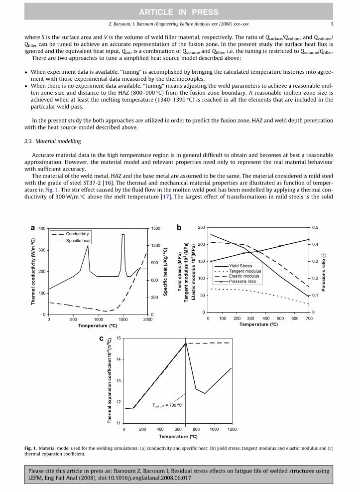
Fig. 2. Effect of phase microstructural transformation on formation of residual stress: (a) schematic diagram of volume change due to phase transformationand (b) influence of volume change, transformation plasticity and base data during heating and cooling, after [20].
4 Z. Barsoum, I. Barsoum / Engineering Failure Analysis xxx (2008) xxx–xxx
ARTICLE IN PRESS
phase transformation by austenite decomposition at 700 �C. The latent heat in the solid phase transformation and the solid–liquids phase transformation at the melting point (1480–1530 �C) are included in the heat capacity curve, see Fig. 1a.
The mechanical material properties as function of temperature are shown in Fig. 1b and c. The material model is elastic–plastic with linear kinematic hardening. For typical carbon steels the yield stress is considerably reduced for temperatureabove 800 �C and naturally vanishes at the melting temperature. The high temperature range, T P 0.5 * Tmelting, is of littlesignificance for the formation of residual stresses because of the disappearing yield limit in this range [18]. Therefore, acut-off temperature of 700 �C is used in the mechanical material model, i.e. if the temperature from the thermal analysisis higher than 700 �C then material properties are evaluated at the cut off temperature.
The thermal expansion coefficient as function of temperature for low-alloy steels including the phase transformationfrom ferrite to austenite at 700 �C is shown in Fig. 1c as a solid line. This is analogous to the specific heat in thermal materialmodel, Fig. 1a. Hansen [19] compared the significances of including this phase transformation in thermal expansion curveand by assuming constant coefficient for temperatures above 700 �C for mild steel. This resulted in no noticeable effecton the residual stress calculations. The dashed line for thermal expansion coefficient in Fig. 1c is used in the present study.
Goldak [20] recommend the following guidelines for the significant effect of microstructure on residual stress formation:
� High yield strength.� If the phase transformation temperature is close to room temperature.� If the volume change is large due to the phase transformation.
In low alloy low strength steels with fairly high weld power, the transformation of austenite is usually to ferrite/pearliteand that occurs above 500–600 �C, the yield stress is low, the volume change is small and the transformation temperature ishigh. The transformation temperature means that plastic deformation after the phase transformation is assumed to erase thememory of the phase transformation, see Fig. 2.
The effect of transformation plasticity on heating around 870 �C is very small. The effect of transformation plasticity oncooling around 250 �C is very large but there is no effect on residual stress at room temperature, 25 �C. If the transformationon cooling had occurred near room temperature, the residual stress would have been compressive. No transformation plas-ticity is considered in the present work.
3. Validation of welding simulation procedure
The validation of the developed welding simulation procedure is carried out on a single pass butt weld, a two pass buttweld and a T-fillet weld, respectively. The results are compared with predicted and measured temperature and residualstresses found in the literature.
3.1. Butt welded plates
Hansen [19] carried out comprehensive welding simulation, temperature and residual stress measurements on buttwelded plates with detailed documentation. The welding was carried out using submerged arc welding. Fig. 3 shows a sche-matic illustration of the butt welded plates and location temperature measurements and residual stress measurements.
The results form the thermal analysis for the one and two pass butt welded plates are presented in Figs. 4 and 5, respec-tively. The weld fillers are deposit initially stress free with prescribed melting temperature and heat distribution. The
Please cite this article in press as: Barsoum Z, Barsoum I, Residual stress effects on fatigue life of welded structures usingLEFM, Eng Fail Anal (2008), doi:10.1016/j.engfailanal.2008.06.017

10 mm
240
480 mm
240Residual stress measurements
Temperaturemeasurements
Fig. 3. Schematic illustration of the butt welded plates used in the validation of the welding simulation procedure.
0
200
400
600
800
0 200 400 600 800 1000
Seconds
Tem
pera
ture
(ºC
)
FEM 15 mm
FEM 21 mm
FEM 27 mm
Measurement 15 mm
Measurement 21 mm
Measurement 27 mm
a b
Fig. 4. Thermal analysis of one pass butt welded plate: (a) fusion zone and isotherms and (b) transient temperature curves as function of time.
0
200
400
600
800
0 200 400 600 800 1000
Seconds
Tem
pera
ture
(ºC
)
FEM 15 mm
FEM 21 mm
FEM 27 mm
Measurement 15 mm
Measurement 21 mm
Measurement 27 mm
a b
Fig. 5. Thermal analysis of two pass butt welded plate: (a) fusion zone and isotherms and (b) transient temperature curves as function of time.
Z. Barsoum, I. Barsoum / Engineering Failure Analysis xxx (2008) xxx–xxx 5
ARTICLE IN PRESS
welding simulation starts with the root pass and continue to build up pass after pass. The isothermal contour plots for thefusion zone, HAZ and penetration profile shows qualitative good agreement with the micro samples. The temperature curvesat 15, 21, and 27 mm from the weld centre line shows good agreement with the temperature measurements carried out inHansen [19]. However, the predicted peak temperatures in the two pass butt welded plate are slightly higher than themeasurements.
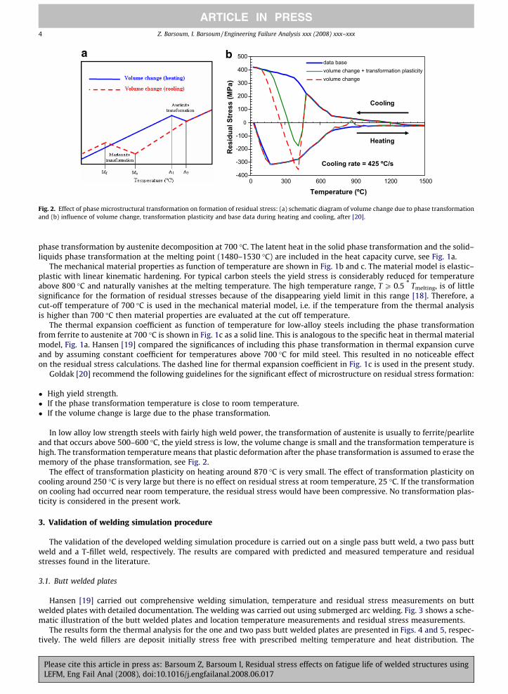
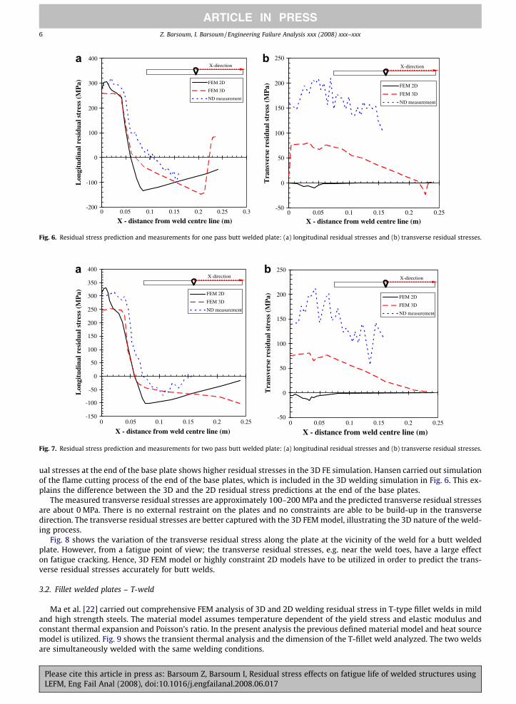
The results from the mechanical analysis for the one and two pass butt welded plates are presented in Figs. 6 and 7,respectively. The longitudinal residual stresses at the vicinity of the weld in Figs. 6a and 7a shows good agreement withthe neutron diffraction measurements and the 3D FE simulation carried out in Hansen [19]. However, the longitudinal resid-
Please cite this article in press as: Barsoum Z, Barsoum I, Residual stress effects on fatigue life of welded structures usingLEFM, Eng Fail Anal (2008), doi:10.1016/j.engfailanal.2008.06.017
-200
-100
0
100
200
300
400
0 0.05 0.1 0.15 0.2 0.25 0.3
X - distance from weld centre line (m)
Lon
gitu
dina
l res
idua
l str
ess
(MP
a) FEM 2D
FEM 3D
ND measurement
X-direction
-50
0
50
100
150
200
250
0 0.05 0.1 0.15 0.2 0.25
X - distance from weld centre line (m)
Tra
nsve
rse
resi
dual
str
ess
(MP
a) FEM 2D
FEM 3D
ND measurement
X-directiona b
Fig. 6. Residual stress prediction and measurements for one pass butt welded plate: (a) longitudinal residual stresses and (b) transverse residual stresses.
-150
-100
-50
0
50
100
150
200
250
300
350
400
0 0.05 0.1 0.15 0.2 0.25
X - distance from weld centre line (m)
Lon
gitu
dina
l res
idua
l str
ess
(MP
a) FEM 2D
FEM 3D
ND measurement
X-direction
-50
0
50
100
150
200
250
0 0.05 0.1 0.15 0.2 0.25
X - distance from weld centre line (m)
Tra
nsve
rse
resi
dual
str
ess
(MP
a) FEM 2D
FEM 3D
ND measurement
X-directiona b
Fig. 7. Residual stress prediction and measurements for two pass butt welded plate: (a) longitudinal residual stresses and (b) transverse residual stresses.
6 Z. Barsoum, I. Barsoum / Engineering Failure Analysis xxx (2008) xxx–xxx
ARTICLE IN PRESS
ual stresses at the end of the base plate shows higher residual stresses in the 3D FE simulation. Hansen carried out simulationof the flame cutting process of the end of the base plates, which is included in the 3D welding simulation in Fig. 6. This ex-plains the difference between the 3D and the 2D residual stress predictions at the end of the base plates.
The measured transverse residual stresses are approximately 100–200 MPa and the predicted transverse residual stressesare about 0 MPa. There is no external restraint on the plates and no constraints are able to be build-up in the transversedirection. The transverse residual stresses are better captured with the 3D FEM model, illustrating the 3D nature of the weld-ing process.
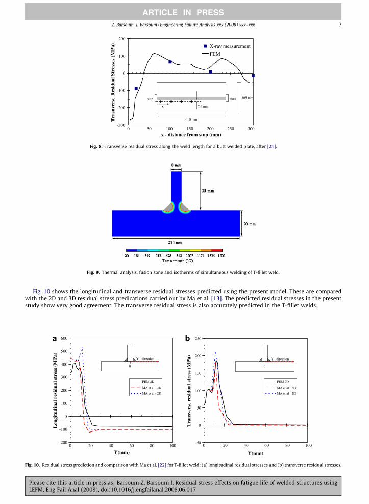
Fig. 8 shows the variation of the transverse residual stress along the plate at the vicinity of the weld for a butt weldedplate. However, from a fatigue point of view; the transverse residual stresses, e.g. near the weld toes, have a large effecton fatigue cracking. Hence, 3D FEM model or highly constraint 2D models have to be utilized in order to predict the trans-verse residual stresses accurately for butt welds.
3.2. Fillet welded plates – T-weld
Ma et al. [22] carried out comprehensive FEM analysis of 3D and 2D welding residual stress in T-type fillet welds in mildand high strength steels. The material model assumes temperature dependent of the yield stress and elastic modulus andconstant thermal expansion and Poisson’s ratio. In the present analysis the previous defined material model and heat sourcemodel is utilized. Fig. 9 shows the transient thermal analysis and the dimension of the T-fillet weld analyzed. The two weldsare simultaneously welded with the same welding conditions.
Please cite this article in press as: Barsoum Z, Barsoum I, Residual stress effects on fatigue life of welded structures usingLEFM, Eng Fail Anal (2008), doi:10.1016/j.engfailanal.2008.06.017
-300
-200
-100
0
100
200
0 50 100 150 200 250 300
x - distance from stop (mm)
Tra
snve
rse
Res
idua
l Str
esse
s (M
Pa) X-ray measurement
FEM
stop start
610 mm
305 mm
7.6 mmx
Fig. 8. Transverse residual stress along the weld length for a butt welded plate, after [21].
Fig. 9. Thermal analysis, fusion zone and isotherms of simultaneous welding of T-fillet weld.
Z. Barsoum, I. Barsoum / Engineering Failure Analysis xxx (2008) xxx–xxx 7
ARTICLE IN PRESS
Fig. 10 shows the longitudinal and transverse residual stresses predicted using the present model. These are comparedwith the 2D and 3D residual stress predications carried out by Ma et al. [13]. The predicted residual stresses in the presentstudy show very good agreement. The transverse residual stress is also accurately predicted in the T-fillet welds.
-200
-100
0
100
200
300
400
500
600
0 20 40 60 80 100
Y(mm)
Lon
gitu
dina
l res
idua
l str
ess
(MP
a)
FEM 2D
MA et al - 3D
MA et al - 2D
0
Y - direction
-50
0
50
100
150
200
250
0 20 40 60 80 100
Y(mm)
Tra
nsve
rse
resi
dual
str
ess
(MP
a)
FEM 2D
MA et al - 3D
MA et al - 2D
0
Y - direction
a b
Fig. 10. Residual stress prediction and comparison with Ma et al. [22] for T-fillet weld: (a) longitudinal residual stresses and (b) transverse residual stresses.
Please cite this article in press as: Barsoum Z, Barsoum I, Residual stress effects on fatigue life of welded structures usingLEFM, Eng Fail Anal (2008), doi:10.1016/j.engfailanal.2008.06.017
8 Z. Barsoum, I. Barsoum / Engineering Failure Analysis xxx (2008) xxx–xxx
ARTICLE IN PRESS
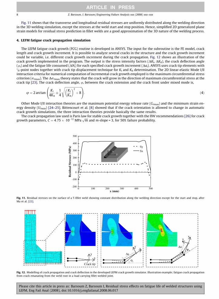
Fig. 11 shows that the transverse and longitudinal residual stresses are uniformly distributed along the welding directionin the 3D welding simulation, except the stresses at the weld start and stop position. Hence, simplified 2D generalized planestrain models for residual stress prediction in fillet welds are a good approximation of the 3D nature of the welding process.
4. LEFM fatigue crack propagation simulation
The LEFM fatigue crack growth (FCG) routine is developed in ANSYS. The input for the subroutine is the FE model, cracklength and crack growth increment. It is possible to analyze several cracks in the structure and the crack growth incrementcould be variable, i.e. different crack growth increment during the crack propagation. Fig. 12 shows an illustration of thecrack growth implemented in the program. The output is the stress intensity factors (DKI, DKII), the crack deflection angle(ui) and the fatigue life consumed (DNi) for each specified crack growth increment (Dai). ANSYS uses crack tip elements with1=4-point nodes together with crack tip displacement technique for KI and KII determination. The 2D linear-elastic Mode I/IIinteraction criteria for numerical computation of incremental crack growth employed is the maximum circumferential stresscriterion (rhmax). The Drhmax theory states that the crack will grow in the direction of maximum circumferential stress at thecrack tip [23]. The crack deflection angle, u, between the crack extension and the crack front under mixed mode is,
Fig. 11Ma et a
Fig. 12.from cr
PleaLEFM
u ¼ 2 arctanK I
4K II� 1
4
ffiffiffiffiffiffiffiffiffiffiffiffiffiffiffiffiffiffiffiffiffiffiffiffiK I
K II
� �2
þ 8
s0@
1A: ð4Þ
Other Mode I/II interaction theories are the maximum potential energy release rate (Ghmax) and the minimum strain en-ergy density (Uhmin) [24–25]. Bittencourt et al. [8] showed that if the crack orientation is allowed to change in automaticcrack growth simulations, the three interaction theories provide basically the same results.
The crack propagation law used is Paris law for stable crack growth together with the IIW recommendations [26] for crackgrowth parameters, C ¼ 4:75� �10�12 MPa
ffiffiffiffiffimp
and m-slope = 3, for 50% failure probability.
-200
-100
0
100
200
300
400
500
0 100 200 300 400 500x (mm)
Res
idua
l Str
esse
s (M
Pa) Sy
Sxxy
z
. Residual stresses on the surface of a T-fillet weld showing constant distribution along the welding direction except for the start and stop, afterl. [22].
Modelling of crack propagation and crack deflection in the developed LEFM crack growth simulator. Illustration example; fatigue crack propagationack emanating from the weld root in a load carrying fillet welded joint.
se cite this article in press as: Barsoum Z, Barsoum I, Residual stress effects on fatigue life of welded structures using, Eng Fail Anal (2008), doi:10.1016/j.engfailanal.2008.06.017
06 7 8 9
5
10
15
20
25
30
35
40
10 11 12 6 7 8 9 10 11 12crack length (mm)
Cyc
les
(104 )
delta_a = 0.01 mmdelta_a = 0.1 mmdelta_a = 0.5 mmdelta_a = 1 mmdelta_a = 2 mmdelta_a = 3 mm
Load carrying fillet weldWeld root crack : 6 mm
0
2
4
6
8
10
12
14
16
18
crack length (mm)
crac
k d
efle
ctio
n a
ng
le (
ϕº)
delta_a = 0.5 mmdelta_a = 1 mmdelta_a = 2 mmdelta_a = 3 mm
Load carrying fillet weldWeld root crack : 6 mm
a b
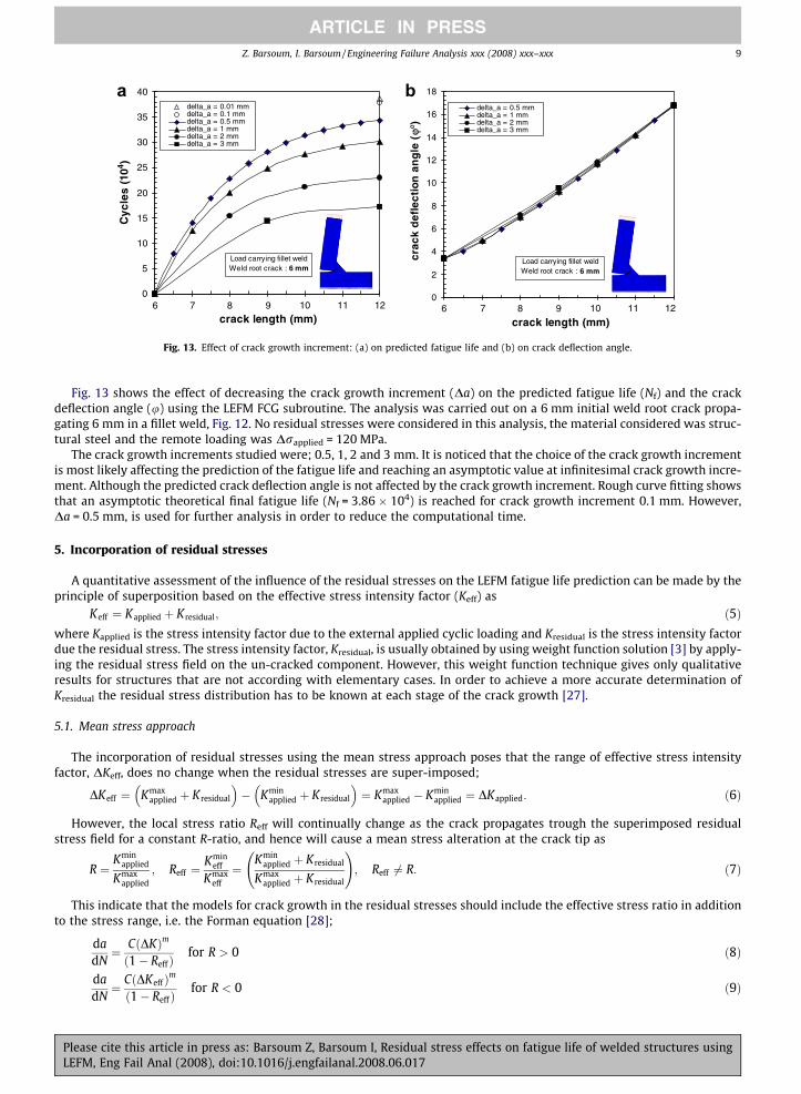
Fig. 13. Effect of crack growth increment: (a) on predicted fatigue life and (b) on crack deflection angle.
Z. Barsoum, I. Barsoum / Engineering Failure Analysis xxx (2008) xxx–xxx 9
ARTICLE IN PRESS
Fig. 13 shows the effect of decreasing the crack growth increment (Da) on the predicted fatigue life (Nf) and the crackdeflection angle (u) using the LEFM FCG subroutine. The analysis was carried out on a 6 mm initial weld root crack propa-gating 6 mm in a fillet weld, Fig. 12. No residual stresses were considered in this analysis, the material considered was struc-tural steel and the remote loading was Drapplied = 120 MPa.
The crack growth increments studied were; 0.5, 1, 2 and 3 mm. It is noticed that the choice of the crack growth incrementis most likely affecting the prediction of the fatigue life and reaching an asymptotic value at infinitesimal crack growth incre-ment. Although the predicted crack deflection angle is not affected by the crack growth increment. Rough curve fitting showsthat an asymptotic theoretical final fatigue life (Nf = 3.86 � 104) is reached for crack growth increment 0.1 mm. However,Da = 0.5 mm, is used for further analysis in order to reduce the computational time.
5. Incorporation of residual stresses
A quantitative assessment of the influence of the residual stresses on the LEFM fatigue life prediction can be made by theprinciple of superposition based on the effective stress intensity factor (Keff) as
PleaLEFM
Keff ¼ Kapplied þ Kresidual; ð5Þ
where Kapplied is the stress intensity factor due to the external applied cyclic loading and Kresidual is the stress intensity factordue the residual stress. The stress intensity factor, Kresidual, is usually obtained by using weight function solution [3] by apply-ing the residual stress field on the un-cracked component. However, this weight function technique gives only qualitativeresults for structures that are not according with elementary cases. In order to achieve a more accurate determination ofKresidual the residual stress distribution has to be known at each stage of the crack growth [27].5.1. Mean stress approach
The incorporation of residual stresses using the mean stress approach poses that the range of effective stress intensityfactor, DKeff, does no change when the residual stresses are super-imposed;
DKeff ¼ Kmaxapplied þ Kresidual
� �� Kmin
applied þ Kresidual
� �¼ Kmax
applied � Kminapplied ¼ DKapplied: ð6Þ
However, the local stress ratio Reff will continually change as the crack propagates trough the superimposed residualstress field for a constant R-ratio, and hence will cause a mean stress alteration at the crack tip as
R ¼Kmin
applied
Kmaxapplied
; Reff ¼Kmin
eff
Kmaxeff
¼Kmin
applied þ Kresidual
Kmaxapplied þ Kresidual
!; Reff 6¼ R: ð7Þ
This indicate that the models for crack growth in the residual stresses should include the effective stress ratio in additionto the stress range, i.e. the Forman equation [28];
dadN¼ C DKð Þm
1� Reffð Þ for R > 0 ð8Þ
dadN¼ C DKeffð Þm
1� Reffð Þ for R < 0 ð9Þ
se cite this article in press as: Barsoum Z, Barsoum I, Residual stress effects on fatigue life of welded structures using, Eng Fail Anal (2008), doi:10.1016/j.engfailanal.2008.06.017
10 Z. Barsoum, I. Barsoum / Engineering Failure Analysis xxx (2008) xxx–xxx
ARTICLE IN PRESS
The mean stress approach is implemented in the weight function LEFM software AFGROW [3] which will not changeDKeff, but will change the stress ratio (Reff), and will result in a change in the crack growth rate.
5.2. Crack closure approach
The superimposed residual stress intensity factor, Kresidual, can either decrease or increase Keff depending on the sign ofKresidual and the crack can only propagate if the crack tip experiences tensile mode-I condition, i.e. Keff > 0. Considering con-stant R-ratio, only part of the crack will be open if Keff > 0 and closed if Keff < 0. In comparison with the mean stress approach,the crack closure approach can take into account the compressive residual stresses. The fatigue crack growth simulatorFranc2D [7] incorporate the residual stress by implementing the crack closure approach. However, no redistribution ofthe residual stress field is considered in Franc2D during the crack propagation.
6. Residual stress mapping
The welding simulation procedure uses a relatively coarse mesh in comparison to the LEFM FCG subroutine. Also differentmaterial models are used; elastic–plastic in the weld simulation procedure and linear elastic in the LEFM FCG subroutine,respectively. In order to incorporate the predicted residual stresses into the crack growth analysis it is necessary to employa stress mapping algorithm from the old to the new mesh.
ANSYS allows the user to specify initial stress as a loading in a structural analysis which can be specified at the centroid ofeach element or at the element integration point for each element. When the residual stress field is applied by the ISFILEcommand an equilibrium calculation step with no additional load and boundary conditions applied is necessary in orderto retain the original residual stress field.
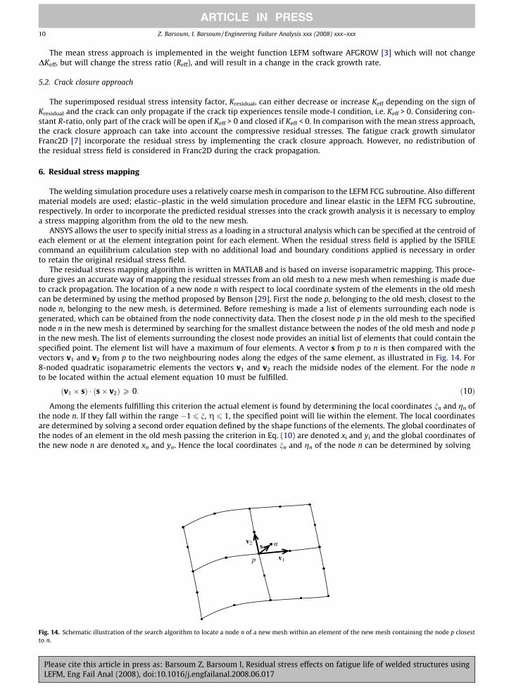
The residual stress mapping algorithm is written in MATLAB and is based on inverse isoparametric mapping. This proce-dure gives an accurate way of mapping the residual stresses from an old mesh to a new mesh when remeshing is made dueto crack propagation. The location of a new node n with respect to local coordinate system of the elements in the old meshcan be determined by using the method proposed by Benson [29]. First the node p, belonging to the old mesh, closest to thenode n, belonging to the new mesh, is determined. Before remeshing is made a list of elements surrounding each node isgenerated, which can be obtained from the node connectivity data. Then the closest node p in the old mesh to the specifiednode n in the new mesh is determined by searching for the smallest distance between the nodes of the old mesh and node pin the new mesh. The list of elements surrounding the closest node provides an initial list of elements that could contain thespecified point. The element list will have a maximum of four elements. A vector s from p to n is then compared with thevectors v1 and v2 from p to the two neighbouring nodes along the edges of the same element, as illustrated in Fig. 14. For8-noded quadratic isoparametric elements the vectors v1 and v2 reach the midside nodes of the element. For the node nto be located within the actual element equation 10 must be fulfilled.
Fig. 14.to n.
PleaLEFM
ðv1 � sÞ � ðs� v2ÞP 0: ð10Þ
Among the elements fulfilling this criterion the actual element is found by determining the local coordinates nn and gn ofthe node n. If they fall within the range �1 6 n, g 6 1, the specified point will lie within the element. The local coordinatesare determined by solving a second order equation defined by the shape functions of the elements. The global coordinates ofthe nodes of an element in the old mesh passing the criterion in Eq. (10) are denoted xi and yi and the global coordinates ofthe new node n are denoted xn and yn. Hence the local coordinates nn and gn of the node n can be determined by solving
v1
v2 s n
p
Schematic illustration of the search algorithm to locate a node n of a new mesh within an element of the new mesh containing the node p closest
se cite this article in press as: Barsoum Z, Barsoum I, Residual stress effects on fatigue life of welded structures using, Eng Fail Anal (2008), doi:10.1016/j.engfailanal.2008.06.017

Z. Barsoum, I. Barsoum / Engineering Failure Analysis xxx (2008) xxx–xxx 11
ARTICLE IN PRESS
PleaLEFM
xn �X8
i¼1
Niðnn;gnÞxi ¼ 0;
yn �X8
i¼1
Niðnn;gnÞyi ¼ 0;
ð11Þ
where Ni are the shape functions of the 8-noded quadratic isoparametric element. These sets of nonlinear equations aresolved using an iterative Newton–Raphson method. The starting guess of the local coordinate nn and gn is supplied by solvingEq. (11) for a 4-noded linear isoparametric element, which is readily obtained.
Now that the nodes of the new mesh can be located with respect to the elements of the old mesh, the residual stressesfrom the old mesh are mapped onto the new mesh by inverse isoparametric mapping. Here the stresses at the centroid of theelements of the old mesh are mapped onto the nodes of the new mesh by using the shape functions of the elements.
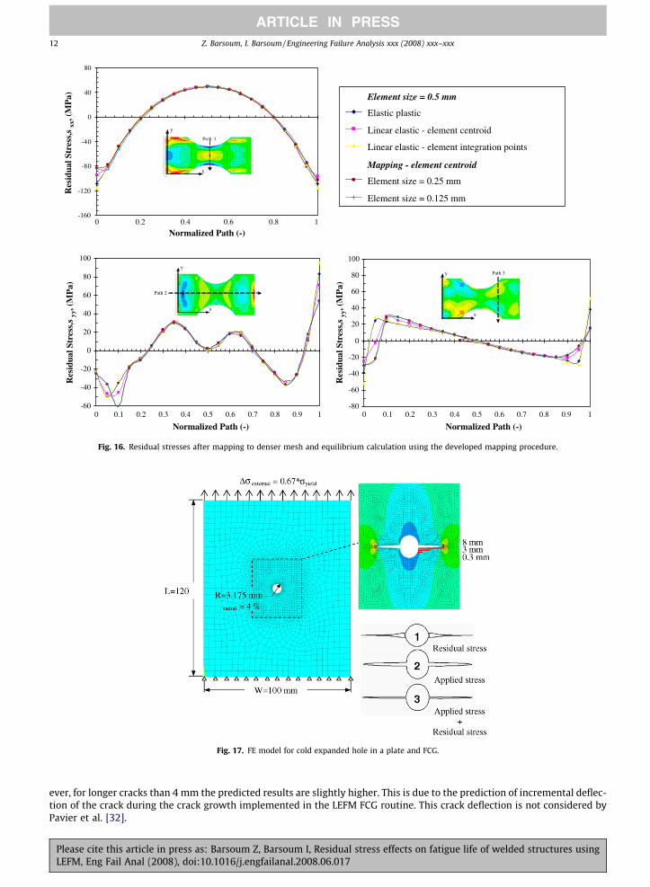
A numerical experiment is performed in order to ensure and verify that original residual stress field is retained after theresidual stress mapping procedure between two different meshes and the subsequent equilibrium calculation in ANSYS. Themodel is illustrated in Fig. 15. The numerical specimen is loaded to yielding and then unloaded. The residual stresses createdare then mapped to a denser mesh with element sizes 0.25 and 0.125 mm, respectively. Fig. 16 shows the original residualstresses (rxx, ryy and rxy) and the residual stresses after mapping. The residual stress generation is carried out with a 0.5 mmelement size. These residual stresses are mapped on a linear elastic material model with identical mesh on the integrationpoints and the element centroid, i.e. constant stress at each element. This shows small variation in the residual stress field;±10% in comparison with the original residual stress field.
7. Validation of incorporation of residual stresses
7.1. Cold expanded hole in aluminium plate
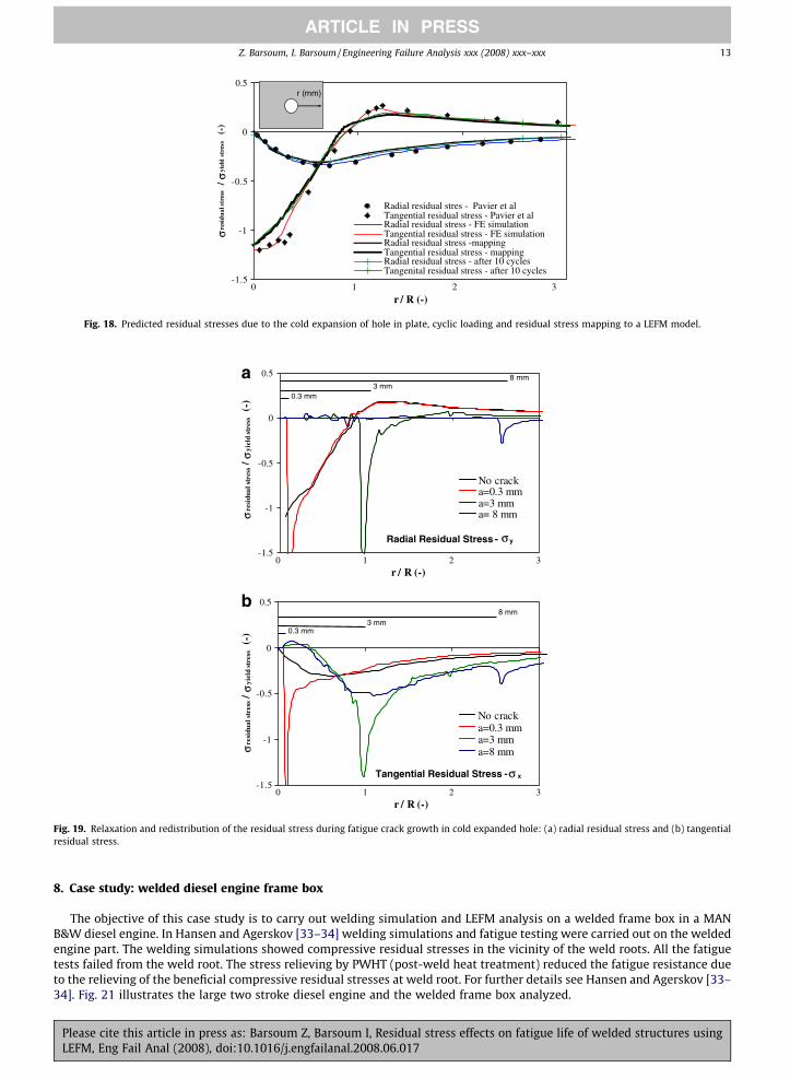
The validation of the residual stress incorporation technique was carried out on cold expanded holes in an aluminiumalloy (2024-T351 Al). Pavier et al. [30–32] carried out extensive research on fatigue crack growth from plain and cold ex-panded holes in aluminium alloys. Cold expansion of holes is widely used in aerospace structures and introduces compres-sive residual stresses in the vicinity of the hole. These compressive residual stresses prevent fatigue cracks to initiate andgrow during cyclic loading [30]. The elastic–plastic 2D plane strain FE simulation of the cold expansion process is carriedout in ANSYS by applying a uniform displacement on the hole edge. The FE-model and dimension is illustrated in Fig. 17.The material model used for the linear elastic–plastic analysis was a von-Mises bi-linear kinematic hardening behaviourwith elastic modulus of 71.6 GPa, a Poission’s ratio of 0.28, yield stress of 375 MPa and tangent modulus 850 MPa (Et = E/84). The FE analysis started with expanding the hole (4% expansion) and removal of the nodal displacements on the holeto simulate the removal of the mandrel and the residual stresses due to the hole expansion are created. Furthermore,external applied stress, Drexternal = 0.67 * ryield (251 MPa), in form of cyclic loading (R = 0) is applied to the plate for 10cycles, see Fig. 18, in order to study redistribution of residual stresses due to external loading. The residual stress mappingprocedure was utilized in order to apply the simulated residual stresses after cyclic loading on the linear elastic fracturemechanical FE model with a predefined crack emanating from the cold expanded hole in order to carry out fatigue crackgrowth analysis.
Fig. 18 shows the tangential and radial residual stresses due to the cold expansion in the crack growth direction. Theresidual stresses in the tangential direction shows compressive residual stresses in the magnitude of the yield stress. Thetangential residual stress will effect the crack growth in the Mode I direction and will decrease Keff (Kapplied + Kresidual) dueto the compressive residual stress, and hence result in crack closure (Keff < 0) for external loads less than Drexter-
nal = 0.46 * ryield (160 MPa). Fig. 19 shows the residual stress redistribution due to the crack growth for 0.3, 3 and 8 mm initialcrack.
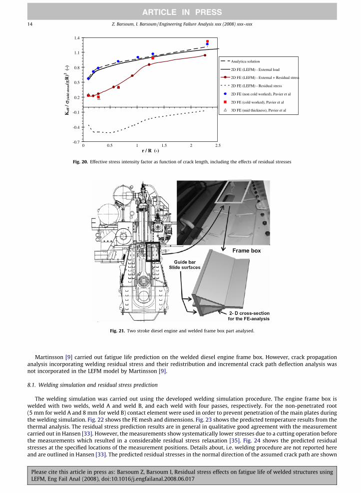
Fig. 20 shows the Keff with and without residual stress predicted using the developed LEFM FCG and residual stress map-ping routine. These results are in good agreement with 2D and 3D crack growth simulation carried out by Pavier et al. How-
Loading: σ = σ yield
Unloading: σ = 0
Material model: yield = 375 MPa E = 72 GPa
= 0.28 Et = E/100
W = 200 mm
W/4 W/4 W/2
W/2 R=5*W/16 σ
ν
Fig. 15. Numerical model for residual stress mapping study.
se cite this article in press as: Barsoum Z, Barsoum I, Residual stress effects on fatigue life of welded structures using, Eng Fail Anal (2008), doi:10.1016/j.engfailanal.2008.06.017
-160
-120
-80
-40
0
40
80
0 0.2 0.4 0.6 0.8 1
Normalized Path (-)
Res
idua
l Str
ess,
s xx
, (M
Pa)
y
x
Pa th 1
Element size = 0.5 mm
Elastic plastic
Linear elastic - element centroid
Linear elastic - element integration points
Mapping - element centroid
Element size = 0.25 mm
Element size = 0.125 mm
-60
-40
-20
0
20
40
60
80
100
0 0.1 0.2 0.3 0.4 0.5 0.6 0.7 0.8 0.9 1 0 0.1 0.2 0.3 0.4 0.5 0.6 0.7 0.8 0.9 1
Normalized Path (-)
Res
idua
l Str
ess,
s yy
, (M
Pa)
Res
idua
l Str
ess,
s yy
, (M
Pa)
y
x
Path 2
-80
-60
-40
-20
0
20
40
60
80
100
Normalized Path (-)
y
x
Path 3
Fig. 16. Residual stresses after mapping to denser mesh and equilibrium calculation using the developed mapping procedure.
Fig. 17. FE model for cold expanded hole in a plate and FCG.
12 Z. Barsoum, I. Barsoum / Engineering Failure Analysis xxx (2008) xxx–xxx
ARTICLE IN PRESS
ever, for longer cracks than 4 mm the predicted results are slightly higher. This is due to the prediction of incremental deflec-tion of the crack during the crack growth implemented in the LEFM FCG routine. This crack deflection is not considered byPavier et al. [32].
Please cite this article in press as: Barsoum Z, Barsoum I, Residual stress effects on fatigue life of welded structures usingLEFM, Eng Fail Anal (2008), doi:10.1016/j.engfailanal.2008.06.017
-1.5
-1
0 1 2 3
-0.5
0
0.5
r / R (-)
σre
sid
ual
str
ess
/σ
yiel
d s
tres
s (
-)Radial residual stres - Pavier et alTangential residual stress - Pavier et alRadial residual stress - FE simulationTangential residual stress - FE simulationRadial residual stress -mappingTangential residual stress - mappingRadial residual stress - after 10 cyclesTangenital residual stress - after 10 cycles
r (mm)
Fig. 18. Predicted residual stresses due to the cold expansion of hole in plate, cyclic loading and residual stress mapping to a LEFM model.
-1.5
-1
-0.5
0
0.5
σre
sidu
al s
tres
s / σ
yiel
d st
ress
(-)
No crack a=0.3 mm a=3 mma= 8 mm
Radial Residual Stress - y
0.3 mm3 mm
8 mm
-1.5
-1
0 1 2 3
-0.5
0
0.5
r / R (-)
0 1 2 3r / R (-)
σ
σ
σ
resi
dual
str
ess
/ σyi
eld
stre
ss(-
)
No cracka=0.3 mma=3 mma=8 mm
Tangential Residual Stress - x
0.3 mm3 mm
8 mm
a
b
Fig. 19. Relaxation and redistribution of the residual stress during fatigue crack growth in cold expanded hole: (a) radial residual stress and (b) tangentialresidual stress.
Z. Barsoum, I. Barsoum / Engineering Failure Analysis xxx (2008) xxx–xxx 13
ARTICLE IN PRESS
8. Case study: welded diesel engine frame box
The objective of this case study is to carry out welding simulation and LEFM analysis on a welded frame box in a MANB&W diesel engine. In Hansen and Agerskov [33–34] welding simulations and fatigue testing were carried out on the weldedengine part. The welding simulations showed compressive residual stresses in the vicinity of the weld roots. All the fatiguetests failed from the weld root. The stress relieving by PWHT (post-weld heat treatment) reduced the fatigue resistance dueto the relieving of the beneficial compressive residual stresses at weld root. For further details see Hansen and Agerskov [33–34]. Fig. 21 illustrates the large two stroke diesel engine and the welded frame box analyzed.
Please cite this article in press as: Barsoum Z, Barsoum I, Residual stress effects on fatigue life of welded structures usingLEFM, Eng Fail Anal (2008), doi:10.1016/j.engfailanal.2008.06.017
-0.7
-0.4
-0.1
0.2
0.5
0.8
1.1
1.4
0 0.5 1 21.5 2.5r / R (-)
Kef
f / σ
yiel
d st
ress( π
R)2 (
-)Analytica solution
2D FE (LEFM) - External load
2D FE (LEFM) - External + Residual stress
2D FE (LEFM) - Residual stress
2D FE (non cold worked), Pavier et al
2D FE (cold worked), Pavier et al
3D FE (mid thickness), Pavier et al
Fig. 20. Effective stress intensity factor as function of crack length, including the effects of residual stresses
Fig. 21. Two stroke diesel engine and welded frame box part analysed.
14 Z. Barsoum, I. Barsoum / Engineering Failure Analysis xxx (2008) xxx–xxx
ARTICLE IN PRESS
Martinsson [9] carried out fatigue life prediction on the welded diesel engine frame box. However, crack propagationanalysis incorporating welding residual stress and their redistribution and incremental crack path deflection analysis wasnot incorporated in the LEFM model by Martinsson [9].
8.1. Welding simulation and residual stress prediction
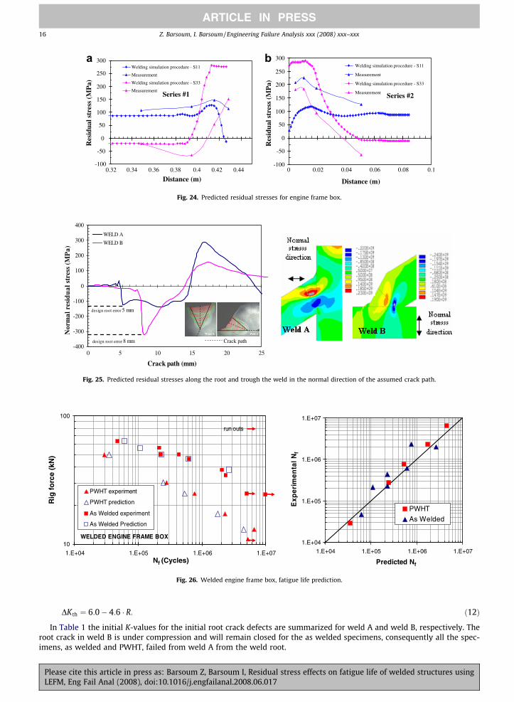
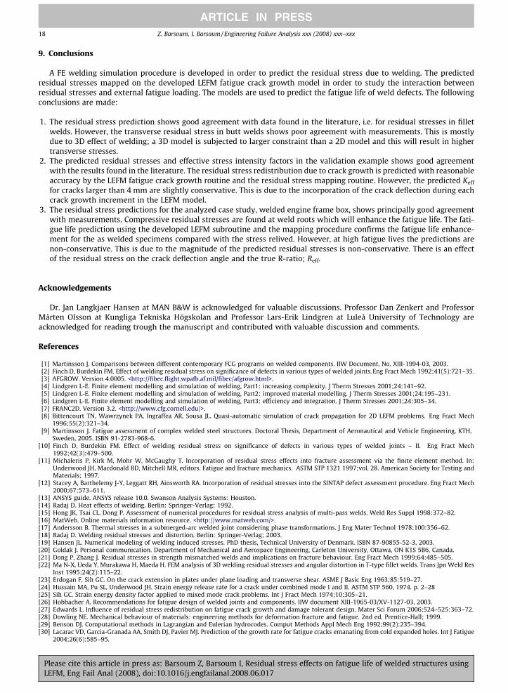
The welding simulation was carried out using the developed welding simulation procedure. The engine frame box iswelded with two welds, weld A and weld B, and each weld with four passes, respectively. For the non-penetrated root(5 mm for weld A and 8 mm for weld B) contact element were used in order to prevent penetration of the main plates duringthe welding simulation. Fig. 22 shows the FE mesh and dimensions. Fig. 23 shows the predicted temperature results from thethermal analysis. The residual stress prediction results are in general in qualitative good agreement with the measurementcarried out in Hansen [33]. However, the measurements show systematically lower stresses due to a cutting operation beforethe measurements which resulted in a considerable residual stress relaxation [35]. Fig. 24 shows the predicted residualstresses at the specified locations of the measurement positions. Details about, i.e. welding procedure are not reported hereand are outlined in Hansen [33]. The predicted residual stresses in the normal direction of the assumed crack path are shown
Please cite this article in press as: Barsoum Z, Barsoum I, Residual stress effects on fatigue life of welded structures usingLEFM, Eng Fail Anal (2008), doi:10.1016/j.engfailanal.2008.06.017
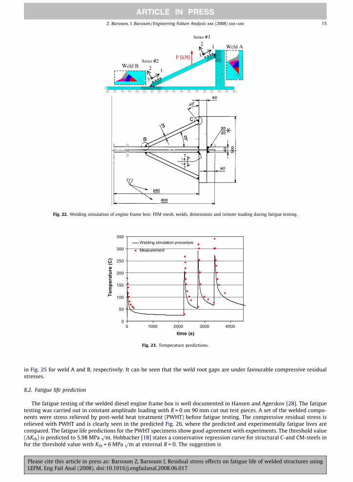
Fig. 22. Welding simulation of engine frame box: FEM mesh, welds, dimensions and remote loading during fatigue testing.
0
50
100
150
200
250
300
350
0 1000 2000 3000 4000
time (s)
Tem
pera
ture
(C)
Welding simulation procedure
Measurement
Fig. 23. Temperature predictions.
Z. Barsoum, I. Barsoum / Engineering Failure Analysis xxx (2008) xxx–xxx 15
ARTICLE IN PRESS
in Fig. 25 for weld A and B, respectively. It can be seen that the weld root gaps are under favourable compressive residualstresses.
8.2. Fatigue life prediction
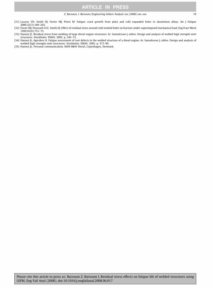
The fatigue testing of the welded diesel engine frame box is well documented in Hansen and Agerskov [28]. The fatiguetesting was carried out in constant amplitude loading with R = 0 on 90 mm cut out test pieces. A set of the welded compo-nents were stress relieved by post-weld heat treatment (PWHT) before fatigue testing. The compressive residual stress isrelieved with PWHT and is clearly seen in the predicted Fig. 26, where the predicted and experimentally fatigue lives arecompared. The fatigue life predictions for the PWHT specimens show good agreement with experiments. The threshold value(DKth) is predicted to 5.98 MPa
pm. Hobbacher [18] states a conservative regression curve for structural C-and CM-steels in
for the threshold value with Kth = 6 MPap
m at external R = 0. The suggestion is
Please cite this article in press as: Barsoum Z, Barsoum I, Residual stress effects on fatigue life of welded structures usingLEFM, Eng Fail Anal (2008), doi:10.1016/j.engfailanal.2008.06.017
-400
-300
-200
-100
0
100
200
300
400
0 5 10 15 20 25
Crack path (mm)
Nor
mal
res
idua
l str
ess
(MP
a)
WELD A
WELD B
Crack path
design root error 5 mm
design root error 8 mm
Fig. 25. Predicted residual stresses along the root and trough the weld in the normal direction of the assumed crack path.
Series #1
-100
-50
0
50
100
150
200
250
300
0.32 0.34 0.36 0.38 0.4 0.42 0.44
Distance (m)
Res
idua
l str
ess
(MP
a)
Welding simulation procedure - S11
Measurement
Welding simulation procedure - S33
MeasurementSeries #2
-100
-50
0
50
100
150
200
250
300
0 0.02 0.04 0.06 0.08 0.1
Distance (m)
Res
idua
l str
ess
(MP
a)
Welding simulation procedure - S11
Measurement
Welding simulation procedure - S33
Measurement
a b
Fig. 24. Predicted residual stresses for engine frame box.
WELDED ENGINE FRAME BOX10
100
1.E+04 1.E+05 1.E+06 1.E+07Nf (Cycles)
Rig
fo
rce
(kN
)
PWHT experiment
PWHT prediction
As Welded experiment
As Welded Prediction
run outs
1.E+04
1.E+05
1.E+06
1.E+07
1.E+04 1.E+05 1.E+06 1.E+07
Predicted Nf
Exp
erim
enta
l Nf
PWHTAs Welded
Fig. 26. Welded engine frame box, fatigue life prediction.
16 Z. Barsoum, I. Barsoum / Engineering Failure Analysis xxx (2008) xxx–xxx
ARTICLE IN PRESS
PleaLEFM
DKth ¼ 6:0� 4:6 � R: ð12Þ
In Table 1 the initial K-values for the initial root crack defects are summarized for weld A and weld B, respectively. Theroot crack in weld B is under compression and will remain closed for the as welded specimens, consequently all the spec-imens, as welded and PWHT, failed from weld A from the weld root.
se cite this article in press as: Barsoum Z, Barsoum I, Residual stress effects on fatigue life of welded structures using, Eng Fail Anal (2008), doi:10.1016/j.engfailanal.2008.06.017

0
10
20
30
40
50
60
0 5 10 15 20 25Crack length (mm)
crac
k de
flect
ion
angl
e [
]ϕº ϕ
0
0.1
0.2
0.3
0.4
0.5
0.6
0.7
0.8
0.9
alph
a (K
I_ap
plie
d/P
ext)
[MPa
m/k
N]
theta Weld Atheta Weld Balpha Weld Aalpha Weld B
PWHT
0
10
20
30
40
50
20 30 40 50 60 70PΔ ext [kN]
Initi
al c
rack
def
lect
ion
angl
e [
initi
al]
As Welded
PWHT
Weld A
a b
√
Fig. 27. Welded engine frame box: (a) crack deflection angle as function of crack length for PWHT weld A and B and (b) initial crack deflection for weld A.
Table 1Predicted threshold values in (MPa
pm)
As welded PWHT
Weld A Weld B Weld A Weld B
KI, res �2.3 �15 – –KI, applied (min) 13.05 6.8 5.98 3.1KI 10.75 �8.2 5.98 3.1ainital (mm) 5 8 5 8DKI, threshold 10.75 (24 kN) – (46 kN) 5.98 (11 kN) – (21 kN)
-0.6
-0.4
-0.2
0
0.2
0.4
0.6
0.8
1
5 6 7 8 9 10 11 12 13 14
Crack length (mm)
alp
ha
- K
I/Pex
t [
MP
a√m
/kN
]
-2.5
-2
-1.5
-1
-0.5
0
R -
str
ess
rati
o
alpha_eff
alpha_app
alpha_res
R_eff
R_app
Fig. 28. Welded engine frame box, weld A. Predicted KI due to applied loading and residual stress along the crack path, Reff and Rapp. KI normalized withapplied loading.
Z. Barsoum, I. Barsoum / Engineering Failure Analysis xxx (2008) xxx–xxx 17
ARTICLE IN PRESS
In Fig. 27a the predicted crack deflection angle (u) is plotted against the crack length for PWHT (no residual stresses)specimens for weld A and B, respectively. The crack deflection is increasing for the growing root crack in weld A with increas-ing crack growth and DKI. However, the initial crack deflection angle in weld A is affected by the presence of residual stressand different magnitude of external loading; hence increase of DPext will decrease uinitial as can be seen in Fig. 27b. In Fig. 28the stress intensity factor due to applied loading (KI,applied), residual stress (KI,res) and effective (KI,eff) is normalized with ap-plied loading DPext and plotted as a function of crack length. It can be noted that the presence of compressive residual stresswill considerably decrease the effective KI. The effective R-ratio and the applied R-ratio (0) is also plotted in Fig. 28.
Please cite this article in press as: Barsoum Z, Barsoum I, Residual stress effects on fatigue life of welded structures usingLEFM, Eng Fail Anal (2008), doi:10.1016/j.engfailanal.2008.06.017
18 Z. Barsoum, I. Barsoum / Engineering Failure Analysis xxx (2008) xxx–xxx
ARTICLE IN PRESS
9. Conclusions
A FE welding simulation procedure is developed in order to predict the residual stress due to welding. The predictedresidual stresses mapped on the developed LEFM fatigue crack growth model in order to study the interaction betweenresidual stresses and external fatigue loading. The models are used to predict the fatigue life of weld defects. The followingconclusions are made:
1. The residual stress prediction shows good agreement with data found in the literature, i.e. for residual stresses in filletwelds. However, the transverse residual stress in butt welds shows poor agreement with measurements. This is mostlydue to 3D effect of welding; a 3D model is subjected to larger constraint than a 2D model and this will result in highertransverse stresses.
2. The predicted residual stresses and effective stress intensity factors in the validation example shows good agreementwith the results found in the literature. The residual stress redistribution due to crack growth is predicted with reasonableaccuracy by the LEFM fatigue crack growth routine and the residual stress mapping routine. However, the predicted Keff
for cracks larger than 4 mm are slightly conservative. This is due to the incorporation of the crack deflection during eachcrack growth increment in the LEFM model.
3. The residual stress predictions for the analyzed case study, welded engine frame box, shows principally good agreementwith measurements. Compressive residual stresses are found at weld roots which will enhance the fatigue life. The fati-gue life prediction using the developed LEFM subroutine and the mapping procedure confirms the fatigue life enhance-ment for the as welded specimens compared with the stress relived. However, at high fatigue lives the predictions arenon-conservative. This is due to the magnitude of the predicted residual stresses is non-conservative. There is an effectof the residual stress on the crack deflection angle and the true R-ratio; Reff.
Acknowledgements
Dr. Jan Langkjaer Hansen at MAN B&W is acknowledged for valuable discussions. Professor Dan Zenkert and ProfessorMårten Olsson at Kungliga Tekniska Högskolan and Professor Lars-Erik Lindgren at Luleå University of Technology areacknowledged for reading trough the manuscript and contributed with valuable discussion and comments.
References
[1] Martinsson J. Comparisons between different contemporary FCG programs on welded components. IIW Document, No. XIII-1994-03, 2003.[2] Finch D, Burdekin FM. Effect of welding residual stress on significance of defects in various types of welded joints. Eng Fract Mech 1992;41(5):721–35.[3] AFGROW. Version 4.0005. <http://fibec.flight.wpafb.af.mil/fibec/afgrow.html>.[4] Lindgren L-E. Finite element modelling and simulation of welding, Part1: increasing complexity. J Therm Stresses 2001;24:141–92.[5] Lindgren L-E. Finite element modelling and simulation of welding, Part2: improved material modelling. J Therm Stresses 2001;24:195–231.[6] Lindgren L-E. Finite element modelling and simulation of welding, Part3: efficiency and integration. J Therm Stresses 2001;24:305–34.[7] FRANC2D. Version 3.2. <http://www.cfg.cornell.edu/>.[8] Bittencourt TN, Wawrzynek PA, Ingraffea AR, Sousa JL. Quasi-automatic simulation of crack propagation for 2D LEFM problems. Eng Fract Mech
1996;55(2):321–34.[9] Martinsson J. Fatigue assessment of complex welded steel structures. Doctoral Thesis, Department of Aeronautical and Vehicle Engineering, KTH,
Sweden, 2005. ISBN 91-2783-968-6.[10] Finch D, Burdekin FM. Effect of welding residual stress on significance of defects in various types of welded joints – II. Eng Fract Mech
1992;42(3):479–500.[11] Michaleris P, Kirk M, Mohr W, McGaughy T. Incorporation of residual stress effects into fracture assessment via the finite element method. In:
Underwood JH, Macdonald BD, Mitchell MR, editors. Fatigue and fracture mechanics. ASTM STP 1321 1997;vol. 28. American Society for Testing andMaterials; 1997.
[12] Stacey A, Barthelemy J-Y, Leggatt RH, Ainsworth RA. Incorporation of residual stresses into the SINTAP defect assessment procedure. Eng Fract Mech2000;67:573–611.
[13] ANSYS guide. ANSYS release 10.0. Swanson Analysis Systems: Houston.[14] Radaj D. Heat effects of welding. Berlin: Springer-Verlag; 1992.[15] Hong JK, Tsai CL, Dong P. Assessment of numerical procedures for residual stress analysis of multi-pass welds. Weld Res Suppl 1998:372–82.[16] MatWeb. Online materials information resource. <http://www.matweb.com/>.[17] Andersson B. Thermal stresses in a submerged-arc welded joint considering phase transformations. J Eng Mater Technol 1978;100:356–62.[18] Radaj D. Welding residual stresses and distortion. Berlin: Springer-Verlag; 2003.[19] Hansen JL. Numerical modeling of welding induced stresses. PhD thesis, Technical University of Denmark. ISBN 87-90855-52-3, 2003.[20] Goldak J. Personal communication. Department of Mechanical and Aerospace Engineering, Carleton University, Ottawa, ON K1S 5B6, Canada.[21] Dong P, Zhang J. Residual stresses in strength mismatched welds and implications on fracture behaviour. Eng Fract Mech 1999;64:485–505.[22] Ma N-X, Ueda Y, Murakawa H, Maeda H. FEM analysis of 3D welding residual stresses and angular distortion in T-type fillet welds. Trans Jpn Weld Res
Inst 1995;24(2):115–22.[23] Erdogan F, Sih GC. On the crack extension in plates under plane loading and transverse shear. ASME J Basic Eng 1963;85:519–27.[24] Hussain MA, Pu SL, Underwood JH. Strain energy release rate for a crack under combined mode I and II. ASTM STP 560, 1974. p. 2–28[25] Sih GC. Strain energy density factor applied to mixed mode crack problems. Int J Fract Mech 1974;10:305–21.[26] Hobbacher A. Recommendations for fatigue design of welded joints and components. IIW document XIII-1965-03/XV-1127-03, 2003.[27] Edwards L. Influence of residual stress redistribution on fatigue crack growth and damage tolerant design. Mater Sci Forum 2006;524–525:363–72.[28] Dowling NE. Mechanical behaviour of materials: engineering methods for deformation fracture and fatigue. 2nd ed. Prentice-Hall; 1999.[29] Benson DJ. Computational methods in Lagrangian and Eulerian hydrocodes. Comput Methods Appl Mech Eng 1992;99(2):235–394.[30] Lacarac VD, Garcia-Granada AA, Smith DJ, Pavier MJ. Prediction of the growth rate for fatigue cracks emanating from cold expanded holes. Int J Fatigue
2004;26(6):585–95.
Please cite this article in press as: Barsoum Z, Barsoum I, Residual stress effects on fatigue life of welded structures usingLEFM, Eng Fail Anal (2008), doi:10.1016/j.engfailanal.2008.06.017
Z. Barsoum, I. Barsoum / Engineering Failure Analysis xxx (2008) xxx–xxx 19
ARTICLE IN PRESS
[31] Lacarac VD, Smith DJ, Pavier MJ, Priest M. Fatigue crack growth from plain and cold expanded holes in aluminium alloys. Int J Fatigue2000;22(3):189–203.
[32] Pavier MJ, Poussard CGC, Smith DJ. Effect of residual stress around cold worked holes on fracture under superimposed mechanical load. Eng Fract Mech1999;63(6):751–73.
[33] Hansen JL. Residual stress from welding of large diesel engine structures. In: Samulesson J, editor. Design and analysis of welded high strength steelstructures. Stockholm: EMAS; 2002. p. 345–72.
[34] Hansen JL, Agerskov H. Fatigue assessment of root defects in the welded structure of a diesel engine. In: Samulesson J, editor. Design and analysis ofwelded high strength steel structures. Stockholm: EMAS; 2002. p. 373–90.
[35] Hansen JL. Personal communication. MAN B&W Diesel, Copenhagen, Denmark.
Please cite this article in press as: Barsoum Z, Barsoum I, Residual stress effects on fatigue life of welded structures usingLEFM, Eng Fail Anal (2008), doi:10.1016/j.engfailanal.2008.06.017