Embed Size (px)
Citation preview

NASA/TP–20205003646
Engineering Elegant Systems:The Practice of Systems EngineeringM.D. WatsonMarshall Space Flight Center, Huntsville, Alabama
B.L. Mesmer and P.A. FarringtonThe University of Alabama in Huntsville, Huntsville, Alabama
June 2020
National Aeronautics andSpace AdministrationIS02George C. Marshall Space Flight CenterHuntsville, Alabama 35812

The NASA STI Program…in Profile
Since its founding, NASA has been dedicated to the advancement of aeronautics and space science. The NASA Scientific and Technical Information (STI) Program Office plays a key part in helping NASA maintain this important role.
The NASA STI Program Office is operated by Langley Research Center, the lead center for NASA’s scientific and technical information. The NASA STI Program Office provides access to the NASA STI Database, the largest collection of aeronautical and space science STI in the world. The Program Office is also NASA’s institutional mechanism for disseminating the results of its research and development activities. These results are published by NASA in the NASA STI Report Series, which includes the following report types:
• TECHNICAL PUBLICATION. Reports of completed research or a major significant phase of research that present the results of NASA programs and include extensive data or theoretical analysis. Includes compilations of significant scientific and technical data and information deemed to be of continuing reference value. NASA’s counterpart of peer-reviewed formal professional papers but has less stringent limitations on manuscript length and extent of graphic presentations.
• TECHNICAL MEMORANDUM. Scientific and technical findings that are preliminary or of specialized interest, e.g., quick release reports, working papers, and bibliographies that contain minimal annotation. Does not contain extensive analysis.
• CONTRACTOR REPORT. Scientific and technical findings by NASA-sponsored contractors and grantees.
• CONFERENCE PUBLICATION. Collected papers from scientific and technical conferences, symposia, seminars, or other meetings sponsored or cosponsored by NASA.
• SPECIAL PUBLICATION. Scientific, technical, or historical information from NASA programs, projects, and mission, often concerned with subjects having substantial public interest.
• TECHNICAL TRANSLATION. English-language translations of foreign
scientific and technical material pertinent to NASA’s mission.
Specialized services that complement the STI Program Office’s diverse offerings include creating custom thesauri, building customized databases, organizing and publishing research results…even providing videos.
For more information about the NASA STI Program Office, see the following:
• Access the NASA STI program home page at <http://www.sti.nasa.gov>
• E-mail your question via the Internet to <[email protected]>
• Phone the NASA STI Help Desk at 757 –864–9658
• Write to: NASA STI Information Desk Mail Stop 148 NASA Langley Research Center Hampton, VA 23681–2199, USA

i
NASA/TP–20205003646
Engineering Elegant Systems: The Practice of Systems EngineeringM.D. WatsonMarshall Space Flight Center, Huntsville, Alabama
B.L. Mesmer and P.A. FarringtonThe University of Alabama in Huntsville, Huntsville, Alabama
June 2020
National Aeronautics andSpace Administration
Marshall Space Flight Center • Huntsville, Alabama 35812

ii
Available from:
NASA STI Information DeskMail Stop 148
NASA Langley Research CenterHampton, VA 23681–2199, USA
757–864–9658
This report is also available in electronic form at<http://www.sti.nasa.gov>
Acknowledgments
The progress made in defining elegant, product focused systems engineering is due to the work by the past and present mem-bers of the Systems Engineering Research Consortium. These researchers represent excellence in their areas of expertise and have impressed with their knowledge, intuition, and research. It is a pleasure working with and discussing with them the challenging questions raised in the discipline of systems engineering. Phil Farrington, Paul Collopy, and Bryan Mesmer at The University of Alabama in Huntsville have been outstanding leaders for the consortium. Present and past members are:
• Michael D. Griffin, Ph.D., former NASA Administrator• Air Force Research Laboratory—Wright Patterson, Multidisciplinary Science and Technology Center: Jose A. Camberos,
Ph.D., Kirk L. Yerkes, Ph.D.• George Mason University: John S. Gero, Ph.D.• George Washington University: Zoe Szajnfarber, Ph.D., Samantha Marquart Brainard, Ph.D.• Iowa State University: Christina L. Bloebaum, Ph.D., Michael C. Dorneich, Ph.D.• JBS Solutions: Sherrie Nash, Ph.D., Robert S. Ryan, Kenny Mitchell, Jeff Downs• Massachusetts Institute of Technology: Maria C. Yang, Ph.D.• Missouri University of Science & Technology: David Riggins, Ph.D.• Multidisciplinary Software Systems Research Corporation (MSSRC): Larry Lambe• NASA Langley Research Center: Peter A. Parker, Ph.D., Ken Toro, Anna R. McGowan, Ph.D., William Cirillo, Marie Ivanco,
Kevin D. Earle• NASA Marshall Space Flight Center: James G. Andrews, Jeri G. Eckley, Jennifer S. Stevens• NASA Marshall Space Flight Center, Aetos Corporation: Michael L. Culver• NASA Johnson Space Center: Gordon A. Vos, Ph.D.• North Carolina State University: Jon Stallings, Ph.D.• Alabama A&M University: Emeka Dunu, Ph.D.• Oregon State University: Irem Tumer, Ph.D., Christopher Hoyle, Ph.D.• SpaceWorks Enterprises, Inc.: John Olds, Ph.D.• Stevens Institute of Technology: Khaldoun Khashanah• Texas A&M University: Richard Malak, Ph.D., Robert Price• Tri-Vector Corporation: Joey Shelton, Ph.D.• The University of Alabama in Huntsville: Phillip A. Farrington, Ph.D., Dawn R. Utley, Ph.D., Laird Burns, Ph.D., Paul Collopy,
Ph.D., Bryan Mesmer, Ph.D., P. J. Benfield, Ph.D., Wes Colley, Ph.D., Jeff Little, Ph.D., Dale Thomas, Ph.D., George J. Nelson, Ph.D., Casey Eaton
• University of Arkansas: David C. Jensen, Ph.D. • University of Bergen: Erika Palmer• University of Colorado – Colorado Springs: Stephen B. Johnson, Ph.D.• Doty Consulting Services: John Doty, Ph.D.• University of Maryland Eastern Shore: Andrew Barth• University of Michigan: Panos Y. Papalambros, Ph.D., Melissa Greene, Ph.D., Arianne Collopy, Ph.D.• The University of Texas at Arlington: Paul J. Componation, Ph.D., Susan Ferreira, Ph.D.

iii
PREFACE
The NASA Systems Engineering Research Consortium was founded to investigate the engi-neering and mathematical basis of systems engineering. The Consortium brought together some tremendous systems engineering researchers from across the country to contribute their investigative work to an integrated body of knowledge. I have had the great privilege of working with the research-ers, discussing their research, and bringing together their tremendous intellectual understandings to define the basis of systems engineering.
In the summer of 2010, as NASA was transitioning from the cancellation of the Constella-tion program to the Exploration Systems Framework, NASA Marshall Space Flight Center (MSFC) Engineering Directorate Associate Director, Garry Lyles, asked my thoughts on systems engineer-ing. He was looking for a way to advance the discipline. After discussing some of the characteristics of a systems engineer stated by the Jet Propulsion Laboratory/Gentry Lee, Garry asked that I speak with former NASA Administrator Mike Griffin, who was serving as The University of Alabama in Huntsville (UAH) Eminent Scholar and Professor of Mechanical and Aerospace Engineering. The conversation with Mike revealed several common ideas on the challenges for systems engineering and the path systems engineering needed to take to advance as a discipline. We agreed to establish a research effort to consider the advancement of systems engineering and provide an engineering and mathematical basis for the emerging discipline. The MSFC Space Launch System (SLS) program supported the establishment of the Consortium, and a list of researchers who had a strong focus on the engineering basis of systems engineering were asked to participate in early research efforts.
Initial efforts in the consortium were an exploration of different engineering approaches for systems engineering. Phillip Farrington became the principle investigator (PI) when Mike left UAH and became Chief Executive Officer of Schaffer Corporation. The four characteristics of an elegant system defined in Mike’s paper, ‘How do we fix System Engineering?’ guided the effort. These char-acteristics provided some focus, but a framework needed to bring all of the different engineering aspects together and show their relationships to these characteristics of systems engineering. We derived the framework, beginning in the spring of 2013, looking at the four different aspects of sys-tems engineering identified in the early research: Mission context, system integrating physics, organi-zational structure and culture, and policy and law. These four areas provided two focuses to systems engineering: system design and integration, and discipline integration.
The systems engineering framework helped to focus the research and identify areas not stud-ied by the Consortium. The Consortium adjusted the research portfolio at this point to address these understudied areas. Mike and I had lunch or breakfast about every 3 months to discuss the progress and direction of the research. Mike challenged the Consortium to find a set of postulates that pro-vided the basis for systems engineering. He used Maxwell Boltzmann’s work on the gas distribution laws as an example. After looking at this, the Consortium drafted the first set of systems engineering postulates in the fall of 2013. These postulates have changed and improved over the last 5 years as the Consortium membership reviewed them and contributed new understanding.
iv
The development of the framework, postulates, and hypotheses integrated the research results progressing at each of the Consortium member organizations. This progress led to several advances in system design and integration, and discipline integration, forming the engineering and sociological basis of systems engineering. System design and integration advances include the understanding of the application of systems engineering processes, identification of system integrating physics (system exergy and optical transfer function), information theoretic statistics, state variable approaches (goal function tree and state analysis model), application of Multidiscipline Design Optimization (MDO), system value modeling, and various system modeling approaches in these areas. Section 3 of this Technical Publication describes the application of these system design and integration approaches. Discipline integration approaches include understanding organizational social behavior influences on systems engineering, cognitive science, sociological principles, understanding the impact of government oversight, and various system modeling approaches in these areas. Section 4 describes the application of these discipline integration approaches.
As our research went on, Phillip Farrington retired from UAH and Bryan Mesmer became the Consortium PI. The research led to a deeper understanding of the postulates and their expansion into a set of principles. These principles provided more indepth understanding of systems engineer-ing, providing guidance on systems engineering that leads to the realization of elegant systems. In addition, a set of hypothesis emerged to address some limitations defined in some areas of system complexity and system value modeling. Proofs are in development for these and one hypothesis has been promoted to a principle once a proof (following information theoretic statistical approaches) was constructed.
After an initial draft of the Systems Engineering Practitioner’s Guide in December 2014, the Consortium decided to split the document into two separate documents: “Engineering Elegant Systems: Theory of Systems Engineering,” and “Engineering Elegant Systems: The Practice of Systems Engineering.” This allowed them to follow an outline organized solely by the systems engineering framework for the presentation of theoretical materials and allowed them to base the framework in a lifecycle context for the presentation of practical approaches. Thus, this Technical Publication (TP) provides the view of how the different theoretical aspects are applied in practice.
As the Theory of Systems Engineering progressed, the Practice of Systems Engineering has followed. This TP captures the current understanding of how to apply the theory in the practice of systems engineering. The practical approaches take much longer to develop, so this represents an initial view point of the practice stemming from the maturation of the theory. There will doubtless be an increase in the knowledge of how to put these approaches into practice as systems engineering matures as an engineering discipline.
It has truly been a pleasure to work with all of the researchers participating in the Consortium. Their intellectual might and enthusiasm for the advancement of systems engineering is energizing. The contributions made by these researchers are available on the Consortium Web site (https://www.nasa.gov/consortium). There are over 100 papers on the site documenting the significant contributions by the researchers. Their contributions have been the foundation to advancing the engineering basis of systems engineering!
Michael D. Watson, Ph.D.NASA Marshall Space Flight Center

v
TABLE OF CONTENTS
1. ENGINEERING ELEGANT SYSTEMS ........................................................................... 1
1.1 Definition of Systems Engineering ................................................................................ 51.2 Overview ....................................................................................................................... 6
2. BASIS OF SYSTEMS ENGINEERING ............................................................................ 7
2.1 Characteristics of an Elegant System ............................................................................. 7 2.2 Systems Engineering Framework ................................................................................. 92.3 Systems Engineering Principles .................................................................................... 11
3. ENGINEERING THE SYSTEM IN THE SYSTEMS ENGINEERING FRAMEWORK .................................................................................................................. 27
3.1 Defining Mission Context (System Application)/Understanding the System ................ 283.2 System Design and Analysis .......................................................................................... 433.3 System Analysis and Modeling ..................................................................................... 473.4 System Testing .............................................................................................................. 104 3.5 System Manufacturing ................................................................................................. 108 3.6 System Operations ........................................................................................................ 108 3.7 Engineering the System in System Lifecycle Summary ................................................. 109
4. PRACTICE OF DISCIPLINE INTEGRATION ................................................................ 111
4.1 Organizational Structure and Information Flow .......................................................... 111 4.2 Policy and Law ............................................................................................................. 1404.3 Discipline Integration Modeling ................................................................................... 1494.4 Discipline Integration Summary .................................................................................. 151
5. SYSTEMS ENGINEERING PROCESSES ........................................................................ 153
5.1 Systems Engineering Management Plan Technical Content ......................................... 153 5.2 Systems Engineering Management Plan Technical Approach ...................................... 154
6. CHARACTERISTICS OF A SYSTEMS ENGINEER ...................................................... 155
7. SUMMARY ........................................................................................................................ 159
vi
APPENDIX A—SYSTEMS ENGINEERING POSTULATES, STRATEGIES, AND HYPOTHESES .................................................................................. 161
A.1 Systems Engineering Postulates ................................................................................... 161 A.2 Systems Engineering Strategies ................................................................................... 166 A.3 Systems Engineering Hypotheses ................................................................................ 173
REFERENCES ....................................................................................................................... 177
TABLE OF CONTENTS (Continued)

vii
LIST OF FIGURES
1. System lifecycles ........................................................................................................ 2
2. Systems engineering framework relationships ........................................................... 10
3. DC-3 aircraft ............................................................................................................. 25
4. Saturn concept .......................................................................................................... 33
5. The approach for determining derived technical requirements .................................. 34
6. HSI infuses human considerations into all phases of the engineering lifecycle ...................................................................................................................... 39
7. The cost to make design changes significantly increases later in the engineering lifecycle ......................................................................................... 40
8. NASA HSI technical domains ................................................................................... 41
9. Space Shuttle ............................................................................................................. 46
10. Elegant system design ................................................................................................ 48
11. System model relationships ....................................................................................... 49
12. System development model mapping to system operations functions ........................ 53
13. System model mapping to operations engineering activities ...................................... 54
14. System robustness capability mapping ...................................................................... 62
15. Launch vehicle attributes related to a system value ................................................... 63
16. Screenshot of a slide from the 2017 satellite industry report ...................................... 66
17. Exergy destruction components for a C-17 airlifter ................................................... 81
18. Organizational culture influences .............................................................................. 112
19. Discipline integration functions ................................................................................. 113

viii
20. President Kennedy addresses Congress and the Nation on May 25, 1961 .................. 141
21. Governmental stakeholders influencing the development and operations organizations and working level ................................................................................ 146
22. Example of a system dynamics model as an SFD ...................................................... 150
23. System behavior: Simulated (stock 1) versus actual (reference model behavior) ........ 150
24. Characteristics of a systems engineer ........................................................................ 156
LIST OF FIGURES (Continued)

ix
LIST OF TABLES
1. Typical events and models for a launch vehicle .......................................................... 35
2. NASA HSI technical domains ................................................................................... 42
3. Value of satellite benefits ........................................................................................... 67
4. Launch vehicle benefits for various mission types ...................................................... 67
5. Human exploration benefits to the U.S. economy ...................................................... 67
6. $USD/kg values for launch vehicle propellants ......................................................... 68
7. Launch vehicle value ................................................................................................. 69
8. Launch vehicle mission reliability .............................................................................. 69
9. Value of mission reliability for satellite mission types ................................................ 69
10. Lost value of unsuccessful satellite missions .............................................................. 70
11. Value of 96% mission reliability ................................................................................ 70
12. Percentage of satellite market supported by different fairing sizes ............................. 71
13. Value to satellite market of different fairing sizes ...................................................... 71
14. Preference values for a heavy-lift launch vehicle with 10-m fairing ............................ 72
15. Exergy relationships .................................................................................................. 78
16. Post variables for exergy calculations ......................................................................... 84
17. Exergy balance equations for crew modules .............................................................. 87
18. Exergy destruction calculations for the OGA ............................................................ 89
19. Exergy destruction calculations for the CDRA ......................................................... 90
20. Exergy destruction calculations for the MCA ............................................................ 92

x
21. Exergy destruction calculations for the TCCS ........................................................... 93
22. Exergy destruction calculations for the THC ............................................................. 95
23. Exergy destruction calculations for the WRM ........................................................... 96
24. Exergy destruction calculations for the WM subsystem ............................................ 97
25. System statistical model comparison based on AIC or AICc deltas ........................... 99
26. MDO model architecture types ................................................................................. 101
27. Functional departmentation advantages and disadvantages ...................................... 130
28. Divisional or team departmentation advantages and disadvantages .......................... 131
29. Matrix departmentation advantages and disadvantages ............................................ 132
LIST OF TABLES (Continued)

xi
LIST OF ACRONYMS, ABBREVIATIONS, AND DESIGNATORS
AAA avionics air assembly
ABM agent-based model
AIC Akaike information criteria
AICc Akaike information criteria corrected
ASO asymmetric subspace optimization
ATC analytical target cascading
BIC Bayesian information criteria
BLISS bilevel integrated system synthesis
CAC control of airborne contaminants
CAD computer-aided design
CAM computer-aided manufacturing
CCAA common cabin air assembly
CDR critical design review
CDRA carbon dioxide removal assembly
CLD casual loop diagram
CM configuration management
ConOps concept of operations
CoP communities of practice
COPUOS Committee on the Peaceful Uses of Outer Space
CR change request
xii
CSSO concurrent subspace optimization
DAC design analysis cycle
DES discrete event simulation
DM data management
DoD Department of Defense
DoE Department of Energy
DoT Department of Transportation
DRM design reference mission
ECLSS Environmental Control and Life Support System
ECO enhanced collaborative optimization
EPA Environmental Protection Agency
EPD exact penalty decomposition
EVM earned value management
FAA Federal Aviation Administration
FCA functional configuration audit
FEM finite element model
FFRDC federally funded research and development center
FM functional line manager
FMEA failure mode and effects analysis
GDP gross domestic product
GFT goal function tree
LIST OF ACRONYMS, ABBREVIATIONS, AND DESIGNATORS (Continued)
xiii
GN&C guidance, navigation, and control
HQ Headquarters
HSI Human System Integration
HTPB hydroxyl-terminated polybutadiene
IDF individual discipline feasible
IMV intermodule ventilation
IPD inexact penalty decomposition
IPT integrated product team
ISS International Space Station
JPL Jet Propulsion Laboratory
LiOH lithium hydroxide
M&FM mission and fault management
MAT maintenance access time
MAVERIC Marshall Aerospace Vehicle Representation in C
MBSE model-based systems engineering
MCA major constituents analyzer
MDF multidiscipline feasible
MDO multidisciplinary design optimization
MDOCA multidisciplinary design optimization coupling analysis
MDOIS multidisciplinary design optimization of independent design subspaces
MoE measures of elegance
LIST OF ACRONYMS, ABBREVIATIONS, AND DESIGNATORS (Continued)
xiv
MOO multi-objective optimization
MTBF mean time between failures
MTTR mean time to repair
NGO needs, goals, and objectives
NRC Nuclear Regulatory Commission
OGA oxygen generator assembly
OMB Office of Management and Budget
OML outer mold line
OSHA Occupational Healthy and Safety Administration
PBAN polybutadiene acrylonitrile
PBR President’s budget request
PBS product breakdown structure
PCA physical configuration audit
PDR preliminary design review
PM project manager
POST Program to Optimize Simulated Trajectories
PRA probabilistic risk assessment
QSD quasi-separable decomposition
R&D research and development
RAM reliability, availability, and maintainability
RP-1 kerosene
RTD resistance temperature detector
LIST OF ACRONYMS, ABBREVIATIONS, AND DESIGNATORS (Continued)
xv
S&MA Safety and Mission Assurance
SAM state analysis model
SAND simultaneous analysis and design
SCM system capability model
SDR system design review
SEMP Systems Engineering Management Plan
SETA Systems Engineering and Technical Assistance
SFD stock and flow diagram
SLS Space Launch System
STS Space Transportation System
TCCS trace contaminant control subsystem
THC temperature and humidity control
TIC Takeuchi information criteria
TP Technical Publication
UN United Nations
V&V verification and validation
VRA volatile removal assembly
WBS work breakdown structure
WM waste management
WRM water recovery module
WSM water separator module
LIST OF ACRONYMS, ABBREVIATIONS, AND DESIGNATORS (Continued)

xvi
NOMENCLATURE
Amodule cross-sectional area of vehicle or capsule
AO operational availability
CD drag coefficient
CT total cost
!CT total annual cost of the launch vehicle
Cp,propellant heat capacity of propellant
Ct system cost
cei unit cost of external exergy output
ds differential entropy
dT differential temperature
dt differential time
E energy
Fthrust thrust
f physical system
G universal gravitational constant
g gravitational acceleration, model of the system
HHV high heating value
Htotal total enthalpy
h enthalpy
h0,propellant entropy of propellant in reference environment conditions

xvii
h1 enthalpy at the beginning of the heating part of the cycle
h2 enthalpy at the beginning of the cooling part of the cycle
hair,in specific enthalpy of air entering
hair,out specific enthalpy of air exiting
hcabin enthalpy in the cabin
hcoolant,in specific enthalpy of coolant entering
hcoolant,out specific enthalpy of coolant exiting
hfinal specific enthalpy leaving
hH2,in specific enthalpy of hydrogen entering
hH2,out specific enthalpy of hydrogen leaving
hH2O,in specific enthalpy of liquid water entering
hH2O,out specific enthalpy of liquid water leaving
hin specific enthalpy entering
hinitial initial enthalpy
hmoist air,in specific enthalpy of moist air entering
hmoist air,out specific enthalpy of moist air exiting
hO2,in specific enthalpy of oxygen entering
hO2,out specific enthalpy of oxygen leaving
hout specific enthalpy leaving
hprop propulsion enthalpy
hprop,engine propulsion enthalpy in the engine
hι,i enthalpy of injected propellant reactants
NOMENCLATURE (Continued)

xviii
hι,wake specific enthalpy of propellant reactants in the wake
hι,urine,in specific enthalpy of urine entering
hι,urine,out specific enthalpy of urine leaving
heightin height entering
heightout height leaving
I information discriminator
Ic information capacity
Ic,final final information capacity
Ic,initial initial information capacity
Isp specific impulse
i interest rate
LR launch rate
M maintainability, mass
ME mass of the Earth
Mvehicle mass of vehicle
Mvehicle,final final vehicle mass
Mvehicle,initial initial vehicle mass
!m mass flow rate
!mair mass flow rate of air
!mair,in mass flow rate of air entering
mCO2 mass of carbon dioxide vented to space
!mcoolant mass flow rate of coolant flow through the precooler
NOMENCLATURE (Continued)

xix
!mdeposited mass flow rate deposited
mfluid fluid mass
!mH2,in mass flow rate of hydrogen entering
!mH2,out mass flow rate of hydrogen leaving
!mH2O,in mass flow rate of water entering
!mH2O,out mass flow rate of water leaving
!mi mass flow rate of chemical species i
!mmoist air,in mass flow rate of moist air entering
!mmoist air,out mass flow rate of moist air leaving
!mO2,in mass flow rate of oxygen entering
!mO2,out mass flow rate of oxygen leaving
!mpropellant mass flow rate of propellant
!murine mass flow rate of urine
!mwake mass flow rate of air in the wake
P pressure, principle revenue
P0 reference environment pressure
Pcabin pressure in the cabin
Pi initial pressure
Pwake pressure in the wake
!Qblower heat transfer rate from the blower
Qcrew amount of heat from the crew
!Qelec heat transfer rate in the electrolyzer
NOMENCLATURE (Continued)
xx
!Qfan separator heat transfer rate from the fan separator
!QHTCO heat transfer rate from high-temperature catalytic oxidizers
Qin heat entering
!Qk heat transfer rate of source
Qout heat leaving
!Qpump heat transfer rate in the pump
QTMS amount of heat in the thermal management system
!Qvent heat transfer rate in the vent
!QVRA heat loss rate from the VRA
!Qwaste can heat transfer rate in the waste can
R reliability
Rflight flight reliability
Rlaunch launch reliability
Rmission mission reliability
raltitude,final final altitude of vehicle
raltitude,initial initial altitude of vehicle
S entropy
S0 reference entropy
Sgen entropy generated by the system
s1 entropy at the beginning of the heating part of the cycle
s2 entropy at the beginning of the cooling part of the cycle
sair,in specific entropy of air entering the blower/precooler
NOMENCLATURE (Continued)

xxi
sair,out specific entropy of air leaving the blower/precooler
scabin specific entropy in the cabin
scoolant,in specific entropy of coolant entering the precooler
scoolant,out specific entropy of coolant leaving the precooler
sfinal final entropy
sH2,in entropy of hydrogen entering
sH2,out entropy of hydrogen leaving
sH2O,in entropy of liquid water entering
sH2O,out entropy of liquid water leaving
sin entropy entering
sinitial initial entropy
sO2,in entropy of oxygen entering
sO2,out entropy of oxygen leaving
sout entropy leaving
!s tanks irreversible entropy of the tanks
surine,in entropy of urine entering
surine,out entropy of urine leaving
!svehicle irreversible irreversible vehicle entropy
swake entropy of the wake
sι entropy of propellant reactant
T temperature
T0 reference environment temperature
NOMENCLATURE (Continued)

xxii
Tambient ambient temperature
Tblower operating temperature of the blower
Tcoolant temperature of the coolant
Telec operating temperature of the electrolyzer
THTCO temperature of the high-temperature catalytic oxidizers
Tin temperature entering
Tpropellant,injection temperature of injected propellant
Tpump temperature of the pump
Tref reference temperature
Tsurface surface temperature
Twake temperature of the wake
tcycle total duration of a full cycle
theating duration of the heating part of the cycle
uCO2 internal energy of carbon dioxide vented to space
V velocity, value
V1 value of revenue
V2 value of the mission reliability
V3 value of payload size
Ve equivalent exhaust velocity of engines or booster motors
Ve,engine equivalent exhaust velocity of engine
Ve,thruster equivalent exhaust velocity of thrusters
Vfinal final velocity
NOMENCLATURE (Continued)

xxiii
Vin velocity entering
Vinitial initial velocity
VL value of loss
Vmodule,final final velocity of the module
Vmodule,initial initial velocity of the module
Vout velocity leaving
VT total value
Vvehicle velocity of vehicle
Volfinal final volume
Volinitial initial volume
!Wactual,HTCO actual work rate in the high-temperature catalytic oxidizer
!Wactual,mass spec actual work rate in the mass spectrometer
!Wactual,pump actual work rate in the pump
!Wactual,UP actual work rate of the urine processor
!Wactual,WP actual work rate of the water processor
!Wblower actual work rate in the blower
!W elec power consumption in the electrolyzer
WEPS work of the electrical power system
!W fan work rate in the fan
!W fan separator work rate in the fan separator
!Wheating power consumption rate during the heating part of the cycle
Win work entering
NOMENCLATURE (Continued)

xxiv
Wout work leaving
!Wpiston work rate in the piston
!Wpump work rate in the pump
!W rev,blower reversible work rate limit of the blower
!W rev,HTCO reversible work rate limit in the high-temperature catalytic oxidizer
!W rev,mass pump reversible work rate limit in the mass pump
!WRTD work rate in the resistance temperature detector
!WUP work rate of the urine processor
!WWP work rate of the water processor
w weighting
&XACS rate of change of exergy of the atmospheric control and supply
XACS exergy of the atmospheric control and supply &X
AR rate of change of exergy of the atmospheric revitalization
XAR exergy of the atmospheric revitalization
&XECLSS rate of change of exergy of environmental control and life support
system
XECLSS exergy of the environmental control and life support system
XKE change in kinetic exergy
XPE change in potential exergy
&XTHC rate of change of exergy of the temperature and humidity control
XTHC exergy of temperature and humidity control
&XWM rate of change of exergy of the waste management system
NOMENCLATURE (Continued)

xxv
XWM exergy of waste management
&XWRM rate of change of exergy of the water recovery management system
XWRM exergy of water recovery management
&Xdes rate of change of exergy destroyed
Xdes exergy destroyed
&Xdes,blower rate of change of exergy in the blower
&Xdes,CDRA rate of change of exergy destroyed in the carbon dioxide removal
assembly
&Xdes,CO2venting rate of change of exergy destroyed in the carbon dioxide venting
&Xdes,commode rate of change of exergy destroyed in the commode
&Xdes,flowmeter rate of change of exergy destroyed in the flowmeter
&Xdes,heater rate of change of exergy destroyed of the heater
&Xdes,HTCO rate of change of exergy destroyed in the high-temperature catalytic
oxidizer
&Xdes,LiOH bed rate of change of exergy destroyed in the lithium hydroxide bed
&Xdes,mass spec rate of change of exergy destroyed of the mass spectrometer
&Xdes,MCA rate of change of exergy destroyed in the major constituents analyzer
&Xdes,OGA rate of change of exergy destroyed in the oxygen generator assembly
&Xdes,other electrical work rate of change of exergy destroyed in electrical work other than the
water processor, vent, or urine processor
&Xdes,precooler rate of change of exergy destroyed of the precooler
&Xdes,pump rate of change of exergy destroyed of the pump
&Xdes,sorbent bed rate of change of exergy destroyed in the sorbent bed
NOMENCLATURE (Continued)

xxvi
&Xdes,TCCS rate of change of exergy destroyed in the trace contaminant control
subsystem
&Xdes,THC components rate of change of exergy destroyed for the temperature and humidity
control components
&Xdes,urinal rate of change of exergy destroyed of the urinal
&Xdes,UP rate of change of exergy destroyed in the urine processor
&Xdes,vent rate of change of exergy destroyed in the vent
&Xdes,WP rate of change of exergy destroyed in the water processor
&Xdes,WRM rate of change of exergy destroyed of the WRM
Xexpended exergy expended
Xfinal final exergy
Xheat heat exergy
Xin exergy into the system
Xinitial initial exergy
&Xinput,CDRA rate of change of exergy input to the CDRA
&Xinput,MCA rate of change of exergy input in the major constituents analyzer
&Xinput,OGA rate of change of exergy input in the oxygen generator assembly
&Xinput,TCCS rate of change of exergy input in the trace contaminant control
subsystem
&Xinput,WRM rate of change of exergy input to the WRM
Xmass in exergy mass into the system
Xmass out exergy mass out of the system
Xout exergy out of the system
NOMENCLATURE (Continued)

xxvii
Xrecovered exergy recovered
Xstatic nonflow exergy
Xwork mechanical and electrical work exergy
x physical variable
!Zn annual zonal cost of capital expenditure and other associated costs
αι,i mass fraction of the different injected propellant reactants
∆m change in mass
∆mpropellant change in propellant mass for each stage or booster
∆mpropellant,engine change in propellant mass for the engine
∆mpropellant,thrusters change in propellant mass for the thrusters
!∈ι annual exergy input from external sources
ηexergy system exergy efficiency
ηι,i efficiency of the different injected propellant reactants
θ model parameters
ρatm,final final planetary atmospheric density
ρatm,initial initial planetary atmospheric density
ψflow fluid flow exergy
ωvehicle angular velocity of the vehicle
ωvehicle,final final angular velocity of the vehicle
ωvehicle,initial initial angular velocity of the vehicle
NOMENCLATURE (Continued)

xxviii

1
TECHNICAL PUBLICATION
ENGINEERING ELEGANT SYSTEMS: THE PRACTICE OF SYSTEMS ENGINEERING
1. ENGINEERING ELEGANT SYSTEMS
The practice of systems engineering is based on a set of processes that organize the engineering of the system. These processes developed from a list of pragmatic practices that were viewed as successful in 1993.1 They have been refined over the subsequent years, but the application of the processes varies greatly among different organizations.2 The formula for success seems more dependent on the individual systems engineer characteristics than a systematic following of any set of processes.3 To advance the discipline of systems engineering, the underlying theory of the discipline4 must be incorporated into the practice of systems engineering.
Systems engineering today follows a sequence of events to produce a system. The process begins with understanding the application of the system and the desires of the identified system stakeholders. This understanding guides the definition of the system architecture. Systems engineers typically conduct a series of architecture trade studies that culminate in the selection of a specific system configuration. System design proceeds from this configuration definition executed by various engineering disciplines. Systems engineers often assume, sometimes implicitly, that the decomposi-tion of the system functions to these various engineering disciplines is linear. They define this linear decomposition as a set of functional requirements and interface requirements for each subsystem. The separate engineering disciplines design the system functions and subsystems and integrate these functions and subsystems via interfaces into a consolidated system. System interactions are assumed to be contained by the interfaces and generate derived requirements for the subsystems traceable back to the system functions. System production and operations are considered in the development phase; and in turn, development information is used to define system production and operations activities that occur at the end of the design process.
This engineering process can work well, but it can also work poorly or not at all.3 Often, the approach to managing the sequence of events leads to very inelegant systems. Considering a systems engineering process that can sometimes succeed and sometimes fail brings to the forefront a num-ber of questions, which include “What are we doing correctly?” and “What are we doing wrong?” The answer to these questions leads to a new understanding of systems engineering to engineer elegant systems.
What are we doing correctly? Several aspects of systems engineering provide a template to engineer a system: system lifecycle, use of engineering disciplines in design, system testing, and configuration management (CM). The engineering lifecycle has an important sequence of events:

2
Understanding the system application, defining the system architecture, selecting the system configuration, designing the system, testing the system, and then operating the system, is a correct sequence. There are many variations to the system development lifecycle (e.g., waterfall, spiral, block, agile) but they all use this basic construct. Figure 1 illustrates the differences between the NASA and Department of Defense system lifecycles.5
Pre-Systems Acquisition
Concept & Technology Development
ConceptRefinement
MissionFeasibility
Prime ContractAward
SystemDefinition
PreliminaryDesign
Fabricationand Integration
Prepare forDeployment
FRPDecisionReivew
Deployand
VerifyMission
Definition
MissionOperations
Disposal
ConceptDecision Decision
Review
DesignReadiness
Review
TechnologyDevelopment
TechnologyDevelopmentAuthorization
AcquisitionProgramIntuition
SystemIntegration
SystemDemonstration
ProductionCommittment
Full-RateProduction and
Deployment
Low-RateInitial Production
(LRIP)
System Development & Demonstration Production & Development Operations & Support
Systems Acquisition Sustainment
Sustainment Disposal
AOAA SRR
MCR MDR SRR SDRNAR/ICR*
CDR TRR FQR FRR SR PRR ORROAR ASOR DRSARPDR
SFR PDR CDR TRR FCASVR
PCA
A B C
Analysis of AlternativesAnnual Systems Operations ReviewCritical Design ReviewDecommissioning ReviewFunctional Configuration AuditFull Operational CapabilityFormal Qualification ReviewFlight Readiness ReviewIndependent Cost Review
AOAASORCDRDRFCAFOCFQRFRRICE
Initial Operational CapabilityMission Concept ReviewMission Design ReviewNon-Advocate ReviewOperational Acceptance ReviewOperational Requirements ReviewPhysical Configuration AuditPreliminary Design ReviewProduction Readiness Review
IOCMCRMDRNAROARORRPCAPDRPRR
System Acceptance ReviewSystem Design ReviewSystem Functional ReviewSafety ReviewSystem Requirements ReviewSystem Verification ReviewTest Readiness Review
SARSDRSFRSRSRRSVRTRR
FinalDesign
DOD IOC FOC
NASA
Phase EOperations
Phase DDevelopment
Phase CDesign
Phase BDefinition
Phase APreliminary
Analysis
Pre-Phase AAdvanced Studies
Formulation Implementation
Figure 1. System lifecycles.
Another correct aspect of systems engineering is the use of engineering disciplines to develop the various subsystems. This is a well-established practice, based primarily on the physics or logic of the system as applied by the various engineering disciplines. Another valid emphasis in systems engineering is system testing. This is important to confirm engineering assumptions, uncertainties, and sensitivities. Configuration management and associated reviews and analyses of performance and risks associated with the system configuration have also proven to be durable and suc cessful aspects of systems engineering. The level of effort and detail devoted to these practices should be tailored to the system based on factors such as system cost, complexity, and risk to humans or infrastructure. System production and operations activities are based on the system information

3
generated during system development. These are all successful aspects of the engineering process used in system development and are the main reasons that we achieve system success.
So, what is missing? What are we doing wrong? There are several areas that need to be improved in systems engineering: Understanding of stakeholder value, system integration and design, linear assumptions in systems decomposition and configuration definition, identification of system interactions, understanding of production changes on system functionality, understanding of operational interactions, and understanding of organizational influences on system design and integration. System stakeholder values are often not connected well, or only loosely connected, to the actual system implementation. Stakeholder expectations are often biased by what is available rather than what new capabilities can be developed to meet their objectives. This makes new ideas difficult to match with expectations based on the stakeholder’s experience. These factors lead to inelegant systems that do not fully meet the expectations for the system. Poorly defined system design and integration (at the system level) leads to more emphasis on subsystem aspects than a balance of the system as a whole. Configuration management, which includes the capture and documentation of mechanical, electrical, and data interface requirements and design, is a necessary but not sufficient aspect of integration. Configuration management covers a large portion of the interfaces yet does not capture all system interactions because it often implicitly uses the previously mentioned linear assumptions. System decomposition and system integration (recomposing the system from its parts) using interface documentation are assumed linear and are usually mapped hierarchically. This is not true for all system functions. For example, nonlinear interrelationships, such as those encoded in software algorithms (including feedback loops) or created by fluid dynamics, can significantly affect systems functions, increasing uncertainty and creating unexpected sensitivities. The hierarchical representation does not reflect the complex interactions that occur among the subsystems and the system environment.
Unrecognized interactions lead to unexpected system responses and to changes in design and function to correct the system design, sometimes late in the development phase. Subsystem testing does not identify system interactions not visible from the disciplinary design perspective and is insuf-ficient to assess human factor considerations. Designing the system from the contributing discipline perspective is necessary but not sufficient and is often difficult for a design to close (i.e., successfully achieve all requirements). Finally, system production can create new interactions (e.g., with produc-tion tooling), which often lead to design changes after the system enters production. Tooling ability to fit (or interact) with some aspect of the system, human interfaces to the system for manual opera-tions and inspections, material issues (e.g., stress, voids, inclusions (impurities)), or other production-induced defects lead to production changes to the system. System operations may have the greatest need to understand the full set of system interactions properly defining operational sequences and procedures. This requires the full set of system interactions be defined early and system operations to play a considerable role in the design of these system functions and interactions. System interaction with human operators is an important part of this operations understanding, taking into consider-ation the capabilities and limitations of the human as a functional part of the final system. As dis-cussed, the current approach to system design misses many important system interactions and does not allow a ‘best balance’ for the system as a whole.

4
In addition, there are many systems engineering processes that focus on technical manage-ment addressing the organizational side of systems engineering. Even within their organizational domain, these processes are limited. They do not address the organization as a whole, do not explic-itly address the effects of the organization on the system design, and do not address system infor-mation flow through the organization. The technical planning portion of technical management is important early in the program. Although a Systems Engineering Management Plan (SEMP) can include some identification of information flow through the organization, this is not necessarily explicit and not consistently done. If the organizational understanding is not present in the SEMP, then the organization is not well understood and not likely tuned for good system information flow. A poor organization is not likely to create an elegant system.
So, how do we address these challenges? An approach to systems engineering is needed that focuses on the entire system, including the effects from the system’s designing and supporting organizations. Approaches and tools are needed to conduct system design and system integration from a holistic perspective, rather than from discipline perspectives. There are several tools which provide system-level engineering approaches: system value models, system-integrating physics relationships, system state variable approaches, multidisciplinary design optimization (MDO), and engineering statistics. These tool models and results can be validated by system testing. System stakeholder preferences can be captured by a system value model that enables comparison of the entire system design with the system expectations. System design then needs to be accomplished at the system level, rather than the discipline level. While the disciplines are governed by their discipline physics, what physics governs the integration of these disciplines? Is it a new physics or some combination of the physics emanating from the disciplines and from other sources, such as human and social sciences? Physics already contains the system-integrating relationships necessary to understand the integrated system. The application of this system-integrating physics is addressed as part of system integration in this Technical Publication (TP). Designing at the system level also requires system level design and analysis. System state variables are the integration points of the system and allow a coupling of the discipline designs into a system as a whole. Multidisciplinary optimization makes use of these state variables to design and analyze the system as a whole, incorporating the full set of system interactions and defining the best balance of all the subsystems for an optimized system design. Engineering statistics allow analysis of the system uncertainties and sensitivities leading to better balance of competing and cooperating influences and disciplines within the system and from outside the system. Full system testing is an important aspect of systems engineering. System-level testing confirms the understanding of the system interactions as a whole and builds on the understanding gained from the system design and integration applications discussed in this TP.
Discipline integration is an aspect of systems engineering dealing with the organizational structure and information flow. Since these organizations are social structures, aspects of sociology can help explain how an organization functions, defining characteristics of the organizational structure, and the organizational communication. These characteristics are as important to systems engineering as the system design. Some aspects of the system design reside more in the organization than in the physical/logical design. The information flow through the organization and organizational structure is crucial to the development of an elegant system, as it deals with the integration of the disciplines that develop or operate the system. The flow of information through the decision structure is also important to minimize uncertainty in decisions made about the system. The ability to reconsider

5
decisions outside the decision structure, when warranted, is also an important sociological aspect. Cognitive science and information theory provide important keys to understand system thinking and the flow of information through decision-making boards. A properly constructed SEMP can establish the key principles of discipline integration early in the system development lifecycle and provide a great aide in understanding and managing system information flow through the organization.
This practice TP deals directly with the two systems engineering elements needed for devel-opment and operations at the system level: system design and integration and discipline integration. These approaches are applied across the system lifecycle so that a holistic system development and operational approach can be attained, enabling the engineering of elegant systems. The specific the-ory of these approaches is contained in the companion TP, “Engineering Elegant Systems: Theory of Systems Engineering.” 4
1.1 Definition of Systems Engineering
Systems engineering is the engineering discipline that focuses on the whole system. Webster defines a system as ‘a set or arrangement of things so related or connected as to form a unity or organic whole.6 One can find systems in many contexts and they do not exist in true isolation. There are three system types: physical, social, or logical. Physical systems include those that are mechani-cal, electrical, chemical, biological, etc. Physical systems operate in environments whose interac-tions with the system significantly affect the system’s functions and performance. Social systems exist in expanding spheres of social environments. Social systems include organizational, corporate, regional, national, and international. These systems have structure and include culture. Regional and national cultures affect the local culture that, in turn, affects organizational social systems. For example, international efforts are affected by multiple national cultures. Software systems contain logical (mathematical) systems in the form of algorithms. Inputs affect logical systems and the physi-cal and social environments affect these inputs when interacting with the human community and physical equipment. These system types exist in interrelationships of many systems that provide the specific services or functions intended by the user. Interactive gaming, for example, involves logical systems coupled through the social system of the users.
Systems engineering must account for the ‘connections’ or interactions among the system functions and with the system environments. In many cases this includes physical, social, and logical interrelationships and environments. The systems engineer must account for these interrelationships and design them in such a way as to provide reliable, intended results for the system use (i.e., a best-balanced system). A mechanical, electrical, social, or software engineer may design the individual functions within a system. However, the integration of these functions with themselves and with the environment is the domain of the systems engineer.
Systems are unique in their functions, environments, and interactions. Thus, the systems engi-neer must clearly understand the context for the system application and the defining integrating relationships of the system. One cannot approach systems engineering generically but must consider the unique characteristics and intended outcomes for the system.
6
Considering all of these characteristics, systems engineering can be defined as: the engineering discipline that integrates the system functions, system environment, and the engineering disciplines necessary to produce and/or operate an elegant system.
1.2 Overview
This TP was developed to capture the emerging picture of elegant, product-focused systems engineering as an engineering discipline. The volume contains practical guidance for systems engi-neers to implement the approaches defined in Engineering Elegant Systems: Theory of Systems Engineering.4 It captures the primary concepts of the discipline while constructing an integrated view of the approach.
Section 2 details the characteristics of elegant systems and provides a basic framework for the discipline of systems engineering in section 2.2. Principles, as defined in Engineering Elegant Systems: Theory of Systems Engineering,4 form the basis for practical guidance in the implemen-tation of systems engineering in section 2.3. Systems engineering encompasses analysis tools and techniques that are specific to the function of the system which are detailed in section 3. Guidance in the use of these tools throughout the lifecycle is provided.
Discipline integration is a crucial function in the practice of systems engineering, as discussed in section 4. Sociological principles have been applied to support the flow of information through the organization and also contribute to a healthy and manageable organization. Guidance on the appropriate application of policy and law to the system lifecycle phase have also been supplied in section 4.2.
Processes related to systems engineering must be established within the context of the system being developed or operated as discussed in section 5. Systems engineers need to be aware of process limitations and not to rely completely on process. The SEMP serves as the communication mechanism to describe systems engineering processes in the context of the system. Important elements of this plan are the technical content and the technical approach.
Understanding the characteristics of a great systems engineer is critically important in selecting the right person to serve in that role as discussed in section 6. Cognitive abilities are as important as technical abilities, and each must be possessed by a highly effective systems engineer. This volume describes these characteristics in detail.
Guiding postulates, strategies, and hypotheses are repeated from Engineering Elegant Systems: Theory of Systems Engineering,4 including the supporting evidence and implications of each. These postulates, strategies, and hypotheses were used to articulate basic principles that guide systems engineering implementation and are contained in appendix A.

7
2. BASIS OF SYSTEMS ENGINEERING
Systems engineering is based on the system understanding necessary to develop an elegant system in form and operation. The characteristics of an elegant system provide the definition for this concept. A systems engineering framework identifies the major focus of systems engineers. This is followed by a set of systems engineering principles which define and guide the systems engineering efforts in order to accomplish system elegance.
2.1 Characteristics of an Elegant System
Engineering a system involves the development of a specific system configuration with its set of functions and interrelationships from a group of possible system configurations. Systems engi-neering intends to generate a system that best meets the needs of the intended system users. System elegance is a descriptive term often given to highly successful systems in this regard.
The idea that the proper goal of systems engineering is to produce an elegant design was first introduced in a speech by Robert Frosch.7 He noted that he often got no response when he asked sys-tems analysts, “Is it an elegant solution to a real problem?”7 They did not understand the question. Elegance is something you know when you see it, but is not something easily defined, particularly in the sense of a system. Webster defines elegance as a “dignified richness and grace.” 6 This articulates an attitude of intent and a social response to the system. This definition identifies key system attri-butes. ‘Dignified grace’ conveys a notable ease of use or operation in a variety of applications. ‘Dig-nified richness’ conveys a notable robustness in application, a full achievement of the system intent, and a satisfaction of intent not fully specified. A term that provides further help with this definition is concinnity. Webster defines concinnity as ‘a skillful arrangement of parts, harmony, and elegance’. This conveys the idea of a well-organized system with skillfully defined system interrelationships. System aesthetics are accounted for in the idea of richness, grace, and harmony. An efficiency in the system layout and construction is also seen in the ‘skillful arrangement of parts, harmony’ of the system. A well-structured system is an efficient system. Perhaps one can state a definition of system elegance as ‘a system that is robust in application, fully meeting specified and adumbrated intent, is well structured, and is graceful in operation.’
Note that there should be a deep understanding of the system application in meeting intent without full specification in advance. This connotes the idea that, in meeting the intent of the system, there are aspects of the system capabilities where one can naturally extend or configure to meet appli-cation needs that are not well defined during system development. Working from options that meet the current system intent, one makes design choices that support natural extension or configuration of the system for future applications that may not be fully known. The evolution of Apple iPods to iPhones to iPads is an example of a system design that supported expanding capabilities not clearly seen at the beginning of the development. The idea of what they could do was there, but the specifics of how these would work in future applications were not fully clear.

8
This brings to the front the ideas posed in the paper, “How do We Fix Systems Engineering”? 3 This paper defined elegance as a set of system characteristics (sometimes referred to as attributes). These characteristics provide some guidance in the engineering of elegant systems and provide a mea-sure of what a good system design embodies. A set of questions presents the following characteristics:
• Efficacy: How well does the system achieve the intended outcomes?
Efficacy provides a measure of how well the system achieves the intended outcomes. Under-standing the context of the system application (or mission) and capturing the system concept as documented in the Concept of Operations establishes the outcome. As the system progresses through development, the systems engineer should check the progress against the intended outcomes. One should also check against intended outcomes during proposed modifications or upgrades.
• Efficiency: How economical is the design in terms of its performance and the resources required to build and operate it, with respect to competing alternatives?
Efficiency deals with the idea of a best solution given the various system configuration options. It embodies the idea that the intended output is obtained from the system inputs with a well- structured system that has no unnecessary capacities. This necessitates a comparison of design options within all constraint and performance boundaries. The ability to compare configuration options early is paramount to selecting the most efficient design option for the intended outcomes. The Concept of Operations captures the selected option. One should update the efficiency measures of the system with each design phase (sometimes executed as design analysis cycles) to ensure the design or operational changes maintain the system efficiency.
• Robustness : How well does the system perform in unanticipated circumstances and in collateral usage?
Robustness deals with the ability of the system to handle unexpected or uncertain events or variability of applications. This measures the system’s ability to meet the intended mission objectives (or system uses to achieve goals) in the face of uncertainty or variability. This allows a measure of the system’s usefulness in alternative applications (i.e., the intended outcomes of a new or different mission). Robustness in this context incorporates the scope of system resilience, system dependabil-ity, and system reliability. Intended and known potential mission variations should be captured by the definition of the Mission Context and documented in the Concept of Operations. Robustness addresses the utility of the system within the Mission Context.
• Unintended Consequences: What does the design do, or produce, that is unanticipated and unwanted?
Unintended consequences are those results of systems development and operation not antici-pated by the system design or in system operation. These unintended results have a variety of forms including system failures, environmental impacts, social impacts, legal ramifications, and/or political ramifications. These bring into view the various system constraints such as those arising from bud-get, schedule, policy, and law, and account for both physical and social consequences in the system

9
development and operations. The source of these unintended consequences is generally human and social. The system’s physics do not fail or cease to exist. The system behaves unexpectedly because the system’s designers and operators do not fully understand all the interactions that the system can have among its own components and with the environment. Thus, recognizing and managing the factors that lead to unintended consequences is a key role of the systems engineer.
Robert Frosch also indicated some of the qualities of a systems engineer needed to produce a practical, useful system. The Jet Propulsion Laboratory’s (JPL’s) Gentry Lee 8—who laid out a set of 10 characteristics of the systems engineer—greatly expanded these qualities. Happenstance does not achieve elegance. Rather, a systems engineer knowledgeable of the systems integrating physics and mathematics governing the system and skilled in working with the people within the organiza-tion producing the system guides the design and organization to an elegant solution.
Remember that the intent is to design, produce, and operate an elegant system. Starting with an elegant concept and ending with a poor system is not elegant. System elegance is an intentional achievement that one must actively and visibly manage during the entire system development and operation lifecycles.
Achieving an elegant system is not an easy or simple effort. A systems engineering frame-work is provided to identify the various aspects of the systems engineering efforts needed to achieve an elegant system. To aid the systems engineer in achieving this elegant system, a set of systems engineering principles provide guidance in the application of the systems engineering processes, system design and integration tools, and the discipline integration methods.
2.2 Systems Engineering Framework
Systems engineering as a discipline is comprised of two main elements: system design and integration and discipline integration. In this framework, these two elements encompass four com-ponents: mission context, system integrating physics, organizational structure and information flow, and policy and law.
System design and integration consists of the physical and logical aspects of the system. System integrating physics includes the system integrating logic (for logical systems) as the control of many systems is based on logic (i.e., software). The software must have input on the system state to affect the intended system control, and is thus coupled with the physical system. Environmental interactions such as thermal or radiation, where hardware bit errors create logical anomalies in the operation of the system, affect software. Also, included as part of system integrating physics are the human system integration aspects where the physical and logical functional design must consider human physiology and psychology. This couples the user, operator, maintainer, and manufacturer to the system structure, and forms a bridge with the social systems that build, operate, and use the system. Mission context affects both the physical/logical system aspects as well as the social aspects. The physical/logical choices made for the system can emphasize or amplify the social aspects of the mission context. For example, when a planetary satellite is intended to explore Neptune, the social perturbations are small. When the physics determines that a nuclear-powered satellite is necessary for this distance from the Sun, much greater social concern is generated due to potential interaction

10
of the nuclear device with the Earth’s environment in the unlikely occurrence of an accident during launch. In this example, mission context influence of the physical system can be seen on the social response.
The social aspects are a major element defined by the organizational structure and infor-mation flow, and in the policy and law. Organizational structure and information flow deal with the maintenance and flow of system information within the organization to which sociological approaches apply. Information flow is a key element in designing and operating an elegant system. Systems engineering, working with program management, assures that the organizational structure supports the necessary flow of information among the system disciplines and assures the design cap-tures this information flow. Gaps, barriers, and organizational reservoirs of information in the flow of information through the organization are the main organizational concern of systems engineers. Configuration management and data management provide support in this area. Program managers and line managers deal with the fiscal, political, and human capital concerns. The system design and operations represent the knowledge of the system residing in the organizational structure.
Policy and law are social influences on the system. Policy and law certainly influence the physical/logical aspects of the system (e.g., requiring a crash-proof casing for the nuclear power cell for launch for the Neptune mission) but are included with the social aspects of the system due to their social origins. Figure 2 illustrates this systems engineering framework.
Physical
Social
System
SystemIntegrating
Physics
OrganizationalStructure andInformation
Flow
Policyand Law
MissionContext
Figure 2. Systems engineering framework relationships.

11
2.3 Systems Engineering Principles
Systems engineering postulates and hypotheses shown in appendix A form the basis of the principles of systems engineering. Principles are accepted truths which apply throughout the disci-pline. These truths build on the systems engineering postulates and serve as a guide to the application of systems engineering. These principles provide guidance in the application of systems engineer-ing processes, system design and integration tools, and discipline integration methods. Each of the principles statements include a description of the principle, evidence of the principles validity, and implications that derive from the principle statement.
• Principle 1: Systems engineering integrates the system and the disciplines considering the budget and schedule constraints.
– Description: This is the application of postulate 5. Systems engineering solutions must address the stakeholder’s needs and their constraints. Budget and schedule constrains the development and integration of the system, the operation and maintenance of the system, and the integration of the disciplines developing or operating the system. Note that budget is the amount allocated to execute the system development or operation and is not the actual cost. A focus of systems engineering is to keep the system cost within the budget or recommend when the solution space defined by budget and schedule does not meet the intended system application. In addition, other expectations and constraints such as environmental impacts, economic impacts, or social impacts may also affect the system solution options. The systems engineer must account for each of these to ensure a system is developed and operated to satisfy the stakeholder’s needs and constraints as captured by the mission context.
– Evidence: Solutions defined in response to stakeholder needs drive system cost, schedule, and other expectations and constraints. System budget and schedule problems result from a lack of understanding of the best balance of the system within the resource allocations provided and the technical needs of the stakeholders. Unexpected consequences can be realized by systems where envi-ronmental impacts, economic impacts, social impacts, etc. are not recognized or understood.
– Implications: System solutions account for not only the technical performance (including human factors) but also must fit the allocated budget, schedule for development and operation, and other expectations and constraints (e.g., environmental impact, social impact). The systems engineer must understand the cost, schedule, and other impacts as well as they understand the technical perfor-mance of the system. The systems engineer develops this understanding from the initial concept definition and maintains it through the system lifecycle.
• Principle 2: Complex systems build complex systems.
– Description: This principle is fundamental to the execution of systems engineering. The systems engineer must deal with both the complex system (the organization) that develops the system and the complex system itself. This dual focus forms the basis of systems engineering. The systems engineer is responsible for both integration of the system functions and the integration of the disciplines developing these functions. The social interaction within organizations working on complex systems
12
is itself complex and is a strong driver in budget and schedule efficiency or inefficiency. Configuration Management (CM) and Data Management (DM) are key systems engineering capabilities providing for effective management of the information about the system from the different disciplines that flow through the complex organizational structure. Postulates 2 and 3 also capture this duality when the systems engineer is responsible for both integration of the systems discipline functions and interactions defined in postulate 2 and the development organization disciplines defined in postulate 3.
– Evidence: Major system failures have occurred due to the lack of information flow through the organization. Organizational structures, particularly for large system developments, are highly socially diverse with diversity in people, the engineering disciplines, and the organizational culture. Projects with more than one company involved see this organizational complexity increase tremen-dously. It is difficult in some organizational structures to understand how to share the information and what information to share.
– Implications: Complexity resides not only in the system but also in the organization(s) developing and operating complex systems. Thus, systems engineers must deal with both the complexity of the system and the complexity of the development and operation organization(s). Understanding the system integrating perspective (defined in sec. 3.3.6) provides an engineering basis to understand what information should be shared. This guides the management of information flow. CM and DM provide tools and approaches that aid the systems engineer in managing the complex information flow through the organizational structures.
• Principle 3: A focus of systems engineering during the development phase is a progressively deeper understanding of the interactions, sensitivities, and behaviors of the system, stakeholder needs, and its operational environment.
– Description: This principle is the application of postulate 7. What you do upfront does not fully define systems engineering and it does not fade as one progresses through the system development. Instead, the knowledge captured, maintained, and improved by systems engineering deepens as the discipline organizations complete their development work and the system functions are integrated. This deepening of understanding enables the systems engineering decisions necessary to produce an elegant system. The focus of systems engineering is on understanding the interactions of the system, many of which are not apparent until system integration (e.g., physical integration, logical integration), as current systems engineering tools often do not allow sufficiently deep understanding of system interactions (which we are addressing with tools discussed in secs. 3 and 4). This leads to a continuous reduction in system uncertainties and identification of system sensitivities. The systems engineer should understand the behavior of the system, including the emergent behaviors, prior to the operational phase. As the development progresses, the systems engineer seeks the best balance of performance, cost, schedule, and risk.
– Evidence: In practice, this deepening of understanding is in any system development or opera-tion. The technical assessment process shows this as systems progress from concept review to require-ments review to design review to acceptance review. Lessons learned from the operations phase are abundant for any system. This deepening of understanding of the system and its application drives

13
commercial product upgrades or new models. Regression of system understanding can also occur in some lifecycle extension activities. When system understanding is not maintained, the basis of sys-tem specification becomes unclear and some systems have been found not to perform (either under-perform or overperform) to their system specifications. In addition, operational procedures can lose their basis and be difficult to determine when they should be retired or maintained as the system ages.
– Implications: Systems engineers derive requirements as the system design progresses. Thus, while systems engineers define the mission requirements (i.e., part of understanding the mission context) at the beginning of development, the system requirements are defined progressively. They are a func-tion of the design choices made and understood progressively throughout the development phase. This also applies to cost and schedules, particularly for new systems where the development or opera-tions result in unexpected changes. Similarly, systems engineers develop models to predict system capabilities, and then refine these models as they obtain testing and operational experience. System models gain fidelity as the design progresses and the systems engineer must manage the interac-tion between subsystem design maturity and system model maturity. These system models become the basis of system operations, as discussed in section 3.3.2. If the system basis is not maintained, then the understanding of why certain procedures or specifications where defined can be lost. This becomes problematic for aging systems, particularly as they reach the generational gap for the work-force after 20 years of service.
There are several subprinciples to this progressively deeper understanding of the system inter-actions, sensitivities, and behaviors.
– Subprinciple 3(a): Mission context is defined based on the understanding of the stake-holder needs and constraints.
The understanding and definition of the mission context (i.e., the system application) is essential to a well-developed and operated system. An understanding of the stakeholder needs and constraints on the system defines the mission context. This requires an understanding of the stake-holders’ relationship to the system in operation. Different stakeholders have different perspectives on what is important (developer versus operator versus maintainer versus general community). For example, the manufacturer (and developer), the driver, mechanic, and general public are all stake-holders for an automobile. The perspectives that each of these provide is different and can be either enforcing or conflicting. The manufacturer is concerned with production costs and appeal to cus-tomers. The driver is concerned with the general appearance, amenities, and ease of operation. The mechanic is concerned with accessibility to the vehicle’s engine and components. The general public is concerned with safety and environmental impacts. The definition of the system application must bring together all of these perspectives.
– Subprinciple 3(b): Requirements and models reflect the understanding of the system.
The accuracy and completeness of system requirements and system models reflect the understanding of the system. A system that is not well understood leads to poorly stated require-ments, requirement gaps, and inaccurate system models and representations. An objective of system engineering is to understand the system (principle 4(a)) which then leads to the proper specification of requirements and proper representation of the system in the system models.

14
– Subprinciple 3(c): Requirements are specific, agreed-to preferences by the developing organization.
Preferences are held by individuals. The organization as a whole, however, must at some point consolidate these individual preferences and agree on specific values (i.e., performance, cost, schedule) that the system will achieve. These agreed-to preferences along with some agreement on the uncertainty in their measure are the system requirements. These are specific to the system being developed and the requirements (agreements) that are necessary for the successful completion of the system should be carefully defined as part of systems engineering. Integration of the disciplines is dependent on these requirements (agreements) between the different disciplines developing or oper-ating the system. Configuration management is an important systems engineering function in main-taining these requirements (agreements) and managing their change in a consistent and coherent manner.
– Subprinciple 3(d): Requirements and design are progressively elaborated as the development progresses.
Mission requirements are defined early in the understanding of the system as a part of mis-sion context. The remaining technical requirements are derived based on system design decisions that progress throughout the development phase. Subsystem requirements are not defined completely until Preliminary Design Review (PDR), and component requirements may not be fully defined until Critical Design Review (CDR).
– Subprinciple 3(e): Hierarchical structures are not sufficient to fully model system interac-tions and couplings.
System interactions and couplings are varied, involving serial, parallel, nested, and loop-ing relationships. Often there are multiple peer relationships that provide connections among system functions and the environment. Looping, nested, and peer relationships support interactions and couplings not seen in hierarchical structures, which generally only indicate parent/child relationships. In addition, hierarchical structures do not distinguish subtle interaction effects from strong interac-tion effects.
– Subprinciple 3(f): A Product Breakdown Structure (PBS) provides a structure to integrate cost and schedule with system functions.
The PBS integrates cost and schedule with the system functions and components. Cost and schedule are defining constraints (postulate 5) on the system and must be clearly integrated to the system functions and operations. The PBS provides the integration of the system functions (defined by the goal-function tree (GFT) in sec. 3.3.4.1), the system component cost from the cost modeling tool, and the system schedule from the scheduling tool. Configuration management is important to ensure the PBS reflects the baseline system functions, cost, and schedule. A separate version can be used for trading options. The project manager is concerned with labor allocations through the Work Breakdown Structure (WBS). The systems engineer is concerned with the system unit cost and the driving cost components seen through the PBS.

15
– Subprinciple 3(g): As the system progresses through development, a deeper understanding of the organizational relationships needed to develop the system are gained.
As the organization works through the development activities, new relationships may be defined and the magnitude of these relationships may change as the design matures. Organizational groups that do not have information to share in early development may be critical in sharing infor-mation late in the development. Similarly, organizational groups that may be critical at the concept development phase may complete the transfer of information, becoming less critical to information flow as the development matures.
– Subprinciple 3(h): Systems engineering achieves an understanding of the system’s value to the system stakeholders.
System success is contingent on stakeholders’ expectations, not on the system requirements, models, and design information. System success melds the system as designed and as built with the system as expected by the stakeholders. Often, systems engineers assume that the requirements reflect the stakeholder expectations. This is difficult to accomplish in practice due to the melding of external stakeholder expectations with developer expectations. Thus, requirements do not clearly reflect the stakeholder (internal or external) expectations in many system developments. System value models appear to provide a mathematical basis to define and guide the system development with stakeholder expectations.
– Subprinciple 3(i): Systems engineering seeks a best balance of functions and interactions within the system budget, schedule, technical, and other expectations and constraints.
In accounting for all of the system needs and constraints defined in the system’s mission context (i.e., system’s application), the systems engineer seeks to obtain a best balance of all of the stakeholders’ differing preferences. This best balance provides a system that most fully meets the system context (i.e., resource allocations, political, economic, social, technological, environmental, and legal factors, and the differing stakeholders’ preferences). This balance requires a thorough understanding of the system and its mission context in order to achieve a best balance within the full system context.
• Principle 4: Systems engineering has a critical role through the entire system lifecycle.
– Description: This is the application of postulate 6. Systems engineering is not just a development phase activity but continues throughout system operation, decommissioning, and disposal. The orga-nizational relationships and goals change as the system progresses through these phases, but systems engineering continues to integrate the system functions and the system disciplines throughout all phases of the system lifecycle. Operations engineering is responsible for the operation of the system. Systems engineering is responsible for the various changes/upgrades to the system capabilities.
– Evidence: Systems engineering is well understood during the development phases. During the operational phases, systems engineering is still essential as the system goes through maintenance
16
upgrades, new application adaptations, obsolescence driven redesigns, etc. In addition, during decommissioning and disposal, systems engineering is essential to deal with the proper decoupling of the system and its infrastructure, and ensuring conformance with policy and laws affecting the system disposal.
– Implications: As the system progresses through its lifecycle, the need for systems engineering changes. A shift takes place from development to operations in terms of the scope of changes and organizational responsibility. Operations engineering is responsible for operating the system while systems engineering is responsible for the system changes/upgrades. The baseline operational system then becomes the medium in which operational phase system changes take place. The organization changes significantly as the system transitions from development to operations. Organizational rela-tionships and needs are different. Culture can be very different. All of this affects the system and systems engineering must deal with these organizational changes. Another organizational change and culture shift occurs during decommissioning and disposal.
A set of subprinciples defines the specific aspects of systems engineering throughout all of the system lifecycle phases:
– Subprinciple 4(a): Systems engineering obtains an understanding of the system.
Understanding the system is essential to the successful development of any system. The level of understanding possessed by the systems engineer underpins everything they do in terms of engineering the system. This includes understanding of system function and interactions defined in postulate 2 in the system context defined in postulate 1.
– Subprinciple 4(b): Systems engineering defines the mission context (system application).
The systems engineer integrates all of the different stakeholder preferences and resource allocations (budget and schedule) to produce a well-founded understanding of the mission context (i.e., system application). The mission context evolves from this integration and understanding activity and is the essential starting point for system development and operations activities.
– Subprinciple 4(c): Systems engineering models the system.
Systems engineering develops and maintains system-level models to aid in the design and analysis of the system. System modeling provides a means to understand the system including its functions and interactions. Section 3.3 describes specific system-level modeling approaches.
– Subprinciple 4(d): Systems engineering designs and analyzes the system.
Systems engineering performs design and analysis at the system level. Ideally, this is not merely a cognitive integration of the results of various discipline models, but rather uses system-level models to perform design at the system level. This then informs the system-level guidance to the dis-cipline design to ensure the design closes at the system level as design analysis cycles are conducted.

17
System analysis of the integrated results from the discipline analysis is then performed based on the system-integrating physics/logic.
– Subprinciple 4(e): Systems engineering tests the system.
System engineering is a critical contributor to system testing. The system engineer should define test objectives at the system level to ensure testing not only accomplishes specific discipline test objectives but also system level test objectives. This can involve separate system tests, modifica-tion of discipline tests for system-level objectives, or system-level integrated analysis of data from separate discipline tests to obtain a system-level understanding.
– Subprinciple 4(f): Systems engineering has an essential role in the assembly and manufacturing of the system.
The manufacturing of the system is an integrated activity between the system components and the tooling. In addition, changes during manufacturing often have system-level implications and can unexpectedly change system interactions. While this subphase is the purview of the manu-facturing engineer, the systems engineer must stay involved to understand changes, update models, and perform analysis to ensure manufacturing change impacts are identified and understood at the system level.
– Subprinciple 4(g): Systems engineering has an essential role during operations, mainte-nance, and decommissioning.
Systems engineering has a key role in system operations which feature a host of system interactions. We obtain further understanding of the system interactions as the system operational experiences mature. These lead to updates of system models used for operations, and potential system maintenance upgrades or fixes. Similarly, systems engineering provides the understanding during decommissioning in how to deintegrate the system.
• Principle 5: Systems engineering is based on a middle range set of theories.
– Description: There are many types of systems simply categorized as physical systems, logical systems, social systems, or some combination. Since there is not a unified theory of physics, a uni-fied theory of logic, nor a unified theory of sociology, then there is not a unified theory of systems engineering. Instead, systems engineering derives from a set of middle range theories which form the basis of the system and the engineering of the system. Systems theory exists in various forms (e.g., general systems theory, system dynamics) and seeks to define the unique system aspects of the system. System theory does not replace the physical, logical, or social basis of a system but seeks to look at the interactions among the different aspects of the system. All of these system theoretical bases have a mathematical underpinning. Category theory provides a mathematical structure that integrates the system physical, logical, and social aspects. This system provides the mathematical framework of the system. Systems engineering then has three theoretical bases represented in the subprinciples below. These categories are system specific physics/logic systems engineering theoreti-cal basis, mathematical basis, and sociological theoretical basis.

18
– Evidence: Systems exist as either physical systems, logical systems, social systems, or some com-bination of these. These systems incorporate all of the sciences that define their physical, logical, and social nature. Category theory provides the mathematical definition of a system. Category theory provides the mathematical structure to identify the system theoretical aspects from the physical, logical, and social functions and interrelationships of the system. Sociological principles define organizational information flow paths, gaps, and barriers. These principles also provide the basis for understanding system interactions with social systems as part of the system context.
There are several theories that are important to systems engineering, which enable a math-ematical basis for the discipline. Systems engineers, in engineering the system, manage information about the system and its interactions as defined in postulate 2, using this information to make devel-opment and operational decisions. The laws and relationships defined in the information theory govern the information on the system. This also applies to the management of system information through the organization as contained in postulate 3. Systems engineers use this information to control the system design or system operations. This implies the use of concepts from control theory to control the information flow about the system and in defining the control methods to be used to control system states within relevant acceptable ranges over time. Statistical engineering is also a sig-nificant mathematical tool that supports systems understanding and accounts for uncertainties and sensitivities as indicated by postulate 2.
Below are eight theoretical bases for systems engineering. These modeling bases provide a structure to model the various aspects of the system, bringing in the theoretical bases defined in this principle.
(1) Systems Theory Basis: Postulate 2 derives this basis. Systems engineering uses key con-cepts such as the division between system and the environment, and the recursive nature of systems engineering concepts as they apply to different ‘levels’ of the system.
(2) Decision and Value Theory Basis: Rational decision making about the design of a sys-
tem requires mapping of stakeholder preferences into a single scale of value. Hypothesis (3) below states that this is a feasible approach.
(3) Model Basis: System information is represented and maintained in models, and exported
to documents when needed. Sections 3.3 and 4.3 discuss specific system-level models. (4) State Basis: Systems representations maximize use of state variables, and functions are
defined as mappings from input states to output states. Section 3.3.4 addresses this explicitly.
(5) Goal Basis: Systems exist to achieve goals, which are represented as constraints on the output state variables of functions. Section 3.3.4 also addresses this explicitly.
(6) Control Basis: Constraints on function output state variables are achieved by using the physical laws to control those state variables within their ranges.

19
(7) Knowledge Basis: Individuals and organizations construct and maintain knowledge of the system. Systems engineering takes advantage of existing knowledge structures and improves for-mation of new knowledge across them. Information theory is an important part of this basis. This knowledge basis is a key aspect of discipline integration discussed in section 4.
(8) Predictive Basis: Knowledge of the system is inherently uncertain. Uncertainties must be
modeled probabilistically to understand the level of confidence in system knowledge so as to enable proper decision making.
– Implications: This middle range set of theories provides a complete basis for the systems engi-neer to understand a system. The specific application will be specific to each system (i.e., the theo-ries needed for a cyber system are very different from those needed to build a ship). This structure provides for these differences and allows the systems engineer to incorporate the theories needed to understand both the system and the organization developing or operating the system. The systems engineer does not need expertise to design each component of the system. The system engineer is the expert in how to integrate these components into the intended system. This requires a broad under-standing of several disciplines rather than a deep understanding in only one. The systems engineer must communicate clearly among the engineering disciplines, including understanding terminology differences and the use of similar terms to mean something different to a particular discipline (e.g., to an optical engineer ω is the angular frequency of light while to the mechanical engineer working on the same system it means the angular rotational velocity of a component). Systems engineers should translate terminology and not try to enforce commonality among the engineering disciplines.
– Subprinciple 5(a): Systems engineering has a physical/logical basis specific to the system.
Systems engineering incorporates the fundamental physical and logical mathematical concepts specific to the system. Thus, the mathematical basis of systems engineering incorporates the mathematical basis of the system physics/logic. The systems engineer must recognize that these differ for different system types (postulate 1).
– Subprinciple 5(b): Systems engineering has a mathematical basis.
Mathematical category theory provides a mathematical structure for systems engineering. A mathematical category provides a definition of a system that provides a structure to incorporate various physical, logical, and mathematical theories into a system representation. Category theory integrates several theories that are important to systems engineering. Systems engineers, in engineer-ing the system, manage information about the system and its interactions, using this information to make development and operational decisions. The laws and relationships defined in information theory govern the information on the system. This also applies to the management of system infor-mation through the organization as contained. Note that information theory has a set theory basis and naturally extends to the construction of a mathematical category. Systems engineers use infor-mation to control the system design or system operations that bring in control theory in a broad scope of controlling the information flow about the system and in defining the control methods to control system states within relevant acceptable ranges over time. Category theory provides for the interaction structure to show these control relationships for the system. Statistical engineering is also

20
a significant mathematical tool that allows for systems understanding and accounts for uncertainties and sensitivities. Category theory allows for the absence of details within an element and allows for variations of relationships that support the application of statistics in defining system relationships. Category theory provides the mathematical structure to integrate these various theoretical basis into a complete, coherent system representation. This theory is described more fully in section 3.3.3.
– Subprinciple 5(c): Systems engineering has a sociological basis specific to the organization(s).
Systems engineering incorporates the fundamental sociological concepts specific to the development and operations organization. This is a result of postulates 3, 4, and 5.
• Principle 6: Systems engineering maps and manages the discipline interactions within the
organization.
– Description: The correspondence of the organization to the system (whether the organizational structure mirrors the system structure or not) is an essential mapping activity in managing the infor-mation flow and engineering of the system. The maturity of the engineering organization establishes the need for organizational structure formality. Successful development of a system by organizations inexperienced in that specific system will require structure that is more formal. Seasoned organiza-tions with a specific system can operate successfully with little formal organization. Note that project management and organizational line management are concerned with organizational unit responsi-bilities and personnel matters. A concern of the systems engineer is how these units interact as part of system knowledge and understanding (system information) flows through the organization. The systems engineer works with project management and line management to resolve identified system information gaps or barriers in the organizational structure as these gaps and barriers will lead to flaws in system design, manufacturing, and operation. System dynamics models provide an approach to model this principle as discussed in section 4.3.1.
– Evidence: The engineering disciplines each create their building blocks of the system in coordi-nation with other engineering disciplines. For example, system dynamics drive the structural loads. System efficiency increases at the expense of subsystem efficiency. Integrated performance of the system drives the best balance of system performance. Independent subsystem optimization leads to poorer system performance and system efficiency goes down. Appropriate information interchange among the engineering disciplines aids in the recognition of impacts to the overall system balance.
– Implications: Systems engineers are responsible for understanding how the organizational struc-ture and culture affect the flow of information about the system. The systems engineer ensures proper interaction between the engineering disciplines as they produce their aspect of the system. Similarly, in operations, the disciplines must work together to ensure consistent and intended system opera-tion and maintenance. Creating a map of this information flow aides in understanding how this flow occurs within the organization. Where difficulties are identified, the systems engineer should discuss potential changes for improvement with project management and organizational (i.e., line) manage-ment. Adjusting systems engineering process flows may handle some difficult situations. Some may require organizational changes by the project manager or line management. These changes may solve one issue and make another information flow path more difficult in complex organizations. The
21
systems engineer should evaluate each change and strive for the best balance of systems engineering process application with project and line organization structures.
• Principle 7: Decision quality depends on the system knowledge present in the decision-making process.
– Description: This principle derives from postulate 2. Engineering organizations often create trade study or task teams to investigate and resolve specific problems, which is a process of organi-zational flattening. Decision effectiveness depends on involving the right decision makers with a suf-ficiently complete understanding of the decision context and the decision need. Decisions are process dependent. Information needed by the decision makers directly drives the decision methods.
– Evidence: Decisions made without a full understanding of the impacts on all phases of the system are known to be flawed in practice. These decisions lead to impacts to subsystems, enabling systems, and interoperating systems when the knowledge of these systems is not present among the decision makers.
– Implications: Good decision quality requires the right knowledge be present in the decision-making process. This drives the membership of boards in the decision-making process, membership on trade study teams, Integrated Product Team structures, and the approach for external coordina-tion. Systems engineers should avoid decision-making processes where the system knowledge needed for the system decision is fragmented. Fragmented decision bodies lead to system decisions that do not properly balance all aspects of the system and the impacts to the enabling systems and interop-erating systems.
• Principle 8: Both policy and law must be properly understood to not overly constrain or underconstrain the system implementation.
– Description: This is the application of postulate 5. Policy and law act as important constraints on the system. Requirements should not always contain policy and law though they are often written in a requirement-like format. The context for the policies and laws is much different, often being much looser than requirements and more likely reflecting high-level system expectations than specific system functional or operational choices. Often, most interpret policy as having more flexibility than law. The systems engineer should understand how much flexibility is acceptable by those who set the policy (whether government or organizational) and those who pass the laws.
– Evidence: Government policy and law are based on the legislators’ understanding of solutions needed to accomplish their intents. Similarly, corporate/company budgets and schedules are based on the executives’ understanding of the budget and timeframe necessary to develop a system. There are many examples where policy and law have influenced engineering solutions substantially includ-ing the nuclear power industry, field-testing of recombinant DNA in agriculture, and use of growth hormones in dairy cows9 as well as impacts of the Clean Water Act on Boston Harbor.10 Policy engi-neering (understanding both policy and the engineering solutions driven by policy) has been cited as an important industrial effort to ensure policy and law do not overconstrain or underconstrain industry implementation.11 Proper engineering understanding of policy and law as well as properly

22
written policy and law reflecting engineering solutions in industry are essential for any industries’ health. Universities have also developed curriculum to teach engineering students how to properly understand and interpret policy and law.12
– Implications: Overconstraining the system due to misunderstanding of policy and law can lead to ineffective and, therefore, inelegant solutions. The system may not have all necessary functions and, in some cases, good solutions may not be seen as viable. Underconstraining the system can lead to exceedances in budget and/or schedule. Underconstrained systems are a source of unintended consequences, particularly with regard to environment or social impacts. It is essential that the sys-tems engineer understand how the policy and law apply to the system appropriately and how the appropriately applied policy and law then constrain the system solutions.
• Principle 9: Systems engineering decisions are made under uncertainty, accounting for risk.
– Description: This principle derives from postulates 2, 3, 4, and 7. Systems engineers progres-sively understand information about the system through the development process and through the operations process. There are several sources of uncertainty in the development and operations. Some of this is natural based on the progressive understanding of the system. Uncertainty exists due to the inability to predict the future with certainty and decision which require an understanding of a future system state naturally have a risk in the state not actually being realized. Uncertainty arises from many aspects of systems engineering, including limited knowledge on system environments and social aspects of the organization that affects information maintenance, creation, and flow. Systems engineering must also understand sensitivities to ensure the proper focus on the different uncertain-ties. Systems engineering models the uncertainty and sensitivities throughout the process. Risk in decision making comes from the need for a sufficient understanding of the system context and the knowledge that uncertainty does exist even as understanding improves.
– Evidence: Systems engineering risk processes exist to address this reality. The inability to predict future decisions and their impacts leads to risk in the decisions about the system. Selected system solutions have assumptions on what factors may or may not manifest themselves. In addition, the unknown factors can drive risk unexpectedly. Systems engineers will recognize many of these factors as the system proceeds through development and operations, but they may not recognize them at the time needed for the decision.
– Implications: Systems engineers are responsible for understanding the system and the system solution implications. Systems engineering must properly identify and track risk factor through the development. Systems engineers may realize new risks at any point in the development or operations lifecycle phases. As the system decisions are made, the risks associated with the decision become apparent.
• Principle 10: Verification is a demonstrated understanding of all the system functions and
interactions in the operational environment.
– Description: Ideally, requirements are level (i.e., at the same level of detail in the design) and balanced in their representation of system functions and interactions. In practice, requirements are
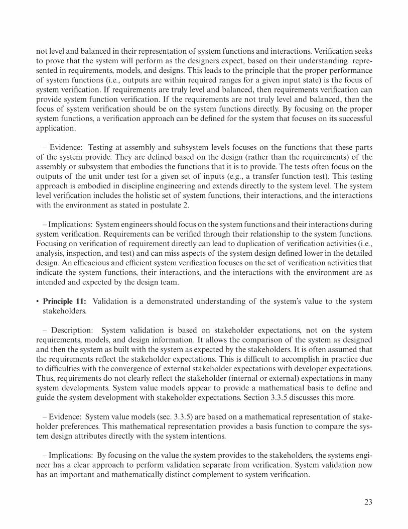
23
not level and balanced in their representation of system functions and interactions. Verification seeks to prove that the system will perform as the designers expect, based on their understanding repre-sented in requirements, models, and designs. This leads to the principle that the proper performance of system functions (i.e., outputs are within required ranges for a given input state) is the focus of system verification. If requirements are truly level and balanced, then requirements verification can provide system function verification. If the requirements are not truly level and balanced, then the focus of system verification should be on the system functions directly. By focusing on the proper system functions, a verification approach can be defined for the system that focuses on its successful application.
– Evidence: Testing at assembly and subsystem levels focuses on the functions that these parts of the system provide. They are defined based on the design (rather than the requirements) of the assembly or subsystem that embodies the functions that it is to provide. The tests often focus on the outputs of the unit under test for a given set of inputs (e.g., a transfer function test). This testing approach is embodied in discipline engineering and extends directly to the system level. The system level verification includes the holistic set of system functions, their interactions, and the interactions with the environment as stated in postulate 2.
– Implications: System engineers should focus on the system functions and their interactions during system verification. Requirements can be verified through their relationship to the system functions. Focusing on verification of requirement directly can lead to duplication of verification activities (i.e., analysis, inspection, and test) and can miss aspects of the system design defined lower in the detailed design. An efficacious and efficient system verification focuses on the set of verification activities that indicate the system functions, their interactions, and the interactions with the environment are as intended and expected by the design team.
• Principle 11: Validation is a demonstrated understanding of the system’s value to the system stakeholders.
– Description: System validation is based on stakeholder expectations, not on the system requirements, models, and design information. It allows the comparison of the system as designed and then the system as built with the system as expected by the stakeholders. It is often assumed that the requirements reflect the stakeholder expectations. This is difficult to accomplish in practice due to difficulties with the convergence of external stakeholder expectations with developer expectations. Thus, requirements do not clearly reflect the stakeholder (internal or external) expectations in many system developments. System value models appear to provide a mathematical basis to define and guide the system development with stakeholder expectations. Section 3.3.5 discusses this more.
– Evidence: System value models (sec. 3.3.5) are based on a mathematical representation of stake-holder preferences. This mathematical representation provides a basis function to compare the sys-tem design attributes directly with the system intentions.
– Implications: By focusing on the value the system provides to the stakeholders, the systems engi-neer has a clear approach to perform validation separate from verification. System validation now has an important and mathematically distinct complement to system verification.

24
• Principle 12: Systems engineering solutions are constrained based on the decision timeframe for the system need.
– Description: This principle deals with constraints imposed on engineering decision and system configuration options based on when the system is needed for operations. The systems engineering solution for a system is formed by the context of the current state of the art and emerging available technologies. For example, what formed the context for air passenger travel in 1933 (mail and pas-senger transport)13 was very different from the context found in 1965 (transatlantic jet transport).14
With the pace of technological advancements, the available solution sets for a given system can change noticeably over as a little as 5 to 10 years, such as seen in the electronics industry over the last 5 decades. Thus, the decision timeframe is an important aspect of the solution set available to the systems engineer.
– Evidence: A model rocket can be designed and built in a few weeks. A large rocket carrying cargo and/or crew to orbit currently takes 10 years. Similarly, a model airplane can be designed and flown in a few weeks. A modern jet fighter may take 10 years or longer. If you have a year to deliver a system, that is going to limit you to existing (or possibly some emerging) technology. If you have 20 years, you can spend a good amount of time developing new technologies to improve the system performance, manufacturability, etc.
– Implications: Systems engineers need to understand the timeframe they have to deliver a com-pleted system and the implications that has to the system solution set. The timeframe for the system need (whether that is market driven, national policy driven, or natural event driven) is an early filter on solution space. The solutions that are included or excluded must be understood well enough to be able to determine their fit with the system need timeframe. The first step is to gain the understanding necessary to define what solutions fit within this timeframe.
• Principle 13: Stakeholder expectations change with advancement in technology and understand-ing of system application.
– Description: Over time, the degree of consistency in stakeholder and user preferences tends to diminish due to environmental changes, emerging technologies, or changes in the makeup of stake-holder and user communities. For systems with long lifecycle phases, these communities and their preferences can change significantly. This is seen primarily in the operations phase and can also occur in the development phase of long developments. This variation becomes more pronounced as the system lifetime increases. And with more variation in stakeholders and stakeholder prefer-ences, changes can be introduced to the system that can impact the system’s ability to adapt to these preferences or stretch out long-duration system developments. System robustness in application can provide pathways for changing system uses. The DC-3 aircraft15 is a good example of an aircraft that has proven highly adaptable to uses and highly reliable in operation (see fig. 3). The changing missions of the B-52 Stratofortress16 over the lifecycle is another good example of an aircraft that has been robust in application. A key to managing these socially-driven changes is to recognize how the system can be evolved or migrated to new applications and when these shifts indicate the need for a different system, indicating the time for the current system to move into decommissioning.

25
Figure 3. DC-3 aircraft.
– Evidence: This is a normal occurrence in the practice of systems engineering. The systems engi-neering processes deal with the change in stakeholder expectations. These changes are a major source of change in mission context and system requirements.
– Implications: This leads to instability in expectations for the system and in the system require-ments. The systems engineers must be aware of these changes and account for them as early as possi-ble. Early identification can provide for lower impacts to system development cost and schedule and to system operational change timeframes. Systems where stakeholder expectations have the potential to change should employ more flexible system engineering process application (e.g., agile systems engineering) to accommodate the changes as the system moves through the lifecycle.
• Principle 14: The real physical system is the only perfect representation of the system.
– Description: This principle provides a statement of the idea that has long been espoused among statistical modelers. The physical system is the only perfect (complete, full) model of the system. Or stating more simply, the perfect model of the system is the system itself.
– Proof: Kullback-Liebler information provides a definition for ‘ideal’ information.17 This infor-mation measure indicates how close a particular model matches the real physical system and is defined as:
I ( f ,g) = f (x) log f (x)( )dx −∫ f (x) log g(x θ )( )dx∫ , (1)
where
I = information distance between the physical system and the model f = physical system g = model of the system x = physical variables θ = model parameters.
Note that θ is typically an estimation of the actual system physical variables. Setting this relation-ship to zero provides a relationship to define the differences in a given model to the real system, and provides proof that the perfect model of the system is the system itself:

26
f (x) log f (x)( )dx −∫ f (x) log g(x θ )( )dx = 0∫ , (2)
and
f (x) log f (x)( )dx =∫ f (x) log g(x θ )( )dx∫ . (3)
Also note that copies of systems are not physically identical:
f1(x) ≠ f2(x) ≠!≠ fn(x) . (4)
Copies of the system are similar, not identical. This is evidenced where systems do not have identical behavior. Hence, a car can have a manufacturing failure while most will not exhibit this failure. Thus, the physical system only represents itself identically and no other physical copies of the system.
– Implications: This provides a mathematical proof of the idea that has long been espoused among statistical modelers. A perfect model, being the system itself, means all other models have limitations that must be recognized. There are various system models that can show various aspects of the system, but no system model can perfectly show the complete system. In addition, one copy of the physical system is not identical with another copy of the system. Thus, variation in copies of the same physical system is to be expected at various tolerance levels depending on the design and fabrication approaches.

27
3. ENGINEERING THE SYSTEM IN THE SYSTEMS ENGINEERING FRAMEWORK
This TP follows the system lifecycle. Program and project lifecycles have been documented in several ways and vary with the size and type of project or program18–20 as illustrated in figure 1.
Within the systems engineering framework, the system lifecycle can generally be divided into six categories and based on the seven subprinciples of principle 4. These six categories map to the two systems engineering framework elements comprising system design and integration: system applica-tion context and the system integrating physics. These define the engineering approach and balance the fundamental physics relationships with cost and schedule. The six categories are as follows:
(1) Defining the mission context (system application)/understanding the system (lifecycle phase A): (a) System application context • Design reference mission • Functional analysis (b) Architecture and concept analysis (c) Requirements definition
(2) Modeling the system (all lifecycle phases): (a) GFT (b) Value model/capability model (c) System physics/integrating physics (d) Engineering statistics (e) Multidisciplinary design optimization (MDO) (f) System state transition
(3) Designing and analyzing the system (lifecycle phases B and C): (a) Design at the system level to provide clear guidance to the disciplines design (b) Integrate the discipline designs in a coherent and efficient manner (c) Analyze the system behaviors and performance as the design progresses through the development lifecycle using appropriate system models
(4) Testing the system (lifecycle phases C and D): (a) Development testing (b) Qualification testing (c) Verification testing (d) Validation testing
(5) Assembling/manufacturing the system (lifecycle phase D)
(6) Operating the system (lifecycle phases E and F): (a) Operations (b) Decommissioning (c) Disposal

28
There are many examples of complex systems that have been or are being engineered. These include naval systems, transportation systems, electrical power systems, mining systems, building systems, aircraft, and space systems. These systems are, in general, so complex that application of a generic approach to address complexities and interactions is not feasible, thus the systems engi-neering approach to the various types of applications is very specific to each system (postulate 1 in appendix A) as seen in the physics of the system.
3.1 Defining Mission Context (System Application)/Understanding the System
3.1.1 System Application Context
The first step in developing a system is understanding the system’s intended purpose and application. The system application context (i.e., mission context) establishes the system applica-tion, uses, and operation. Understanding how the system will be utilized is essential to the design of elegant systems. This sets the expectations for the system and provides the touchstone for evaluating and validating the design.
There are several aspects to the system application context. Stakeholder expectation defini-tion provides an understanding of what funding sources, operators (including flight crew for crewed missions), and maintainers are expecting from a system utilization, operations, and maintenance viewpoint. Mission definition provides specific context for how the system will be used, its role in the mission, and the criticality of its functions regarding crew safety and mission success. This includes the Design Reference Missions (DRMs), often employed for NASA missions, and the iden-tification of the intended outcomes for the system. The measures of elegance (MoE) provide the metrics for measuring the system in terms of its elegance as it progresses through development, during operations, and for any block upgrades performed over its lifecycle. Design definition intent provides the initial system configuration selection and the set of mission requirements to include the system robustness requirements. Also, part of the system application context are the constraints imposed by national and company policy, law, allocated budget, and any external schedule.
3.1.2 Stakeholder Expectation Definition
There are two broad classes of stakeholders which must be addressed in understanding the need for the system: affected stakeholders and interested stakeholders.
Affected stakeholders are those directly impacted by the use and operations of the system. These would include operations and maintenance personnel, flight crew (where applicable) or onboard operators, system developers, and program and line management. These groups have a high interest in the definition of the system capabilities and should be intimately involved in early discussions of the system functions. This group of stakeholders is concerned with the system configuration, human system integration, and how the system will achieve the intended outcomes.
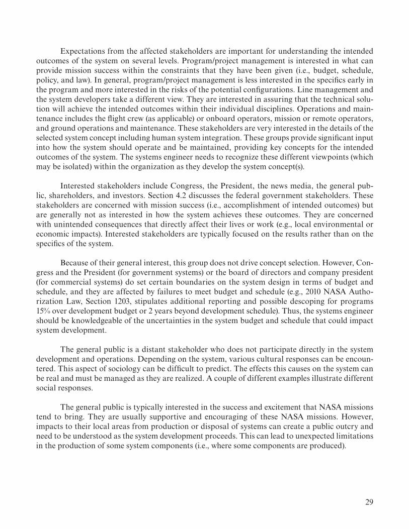
29
Expectations from the affected stakeholders are important for understanding the intended outcomes of the system on several levels. Program/project management is interested in what can provide mission success within the constraints that they have been given (i.e., budget, schedule, policy, and law). In general, program/project management is less interested in the specifics early in the program and more interested in the risks of the potential configurations. Line management and the system developers take a different view. They are interested in assuring that the technical solu-tion will achieve the intended outcomes within their individual disciplines. Operations and main-tenance includes the flight crew (as applicable) or onboard operators, mission or remote operators, and ground operations and maintenance. These stakeholders are very interested in the details of the selected system concept including human system integration. These groups provide significant input into how the system should operate and be maintained, providing key concepts for the intended outcomes of the system. The systems engineer needs to recognize these different viewpoints (which may be isolated) within the organization as they develop the system concept(s).
Interested stakeholders include Congress, the President, the news media, the general pub-lic, shareholders, and investors. Section 4.2 discusses the federal government stakeholders. These stakeholders are concerned with mission success (i.e., accomplishment of intended outcomes) but are generally not as interested in how the system achieves these outcomes. They are concerned with unintended consequences that directly affect their lives or work (e.g., local environmental or economic impacts). Interested stakeholders are typically focused on the results rather than on the specifics of the system.
Because of their general interest, this group does not drive concept selection. However, Con-gress and the President (for government systems) or the board of directors and company president (for commercial systems) do set certain boundaries on the system design in terms of budget and schedule, and they are affected by failures to meet budget and schedule (e.g., 2010 NASA Autho-rization Law, Section 1203, stipulates additional reporting and possible descoping for programs 15% over development budget or 2 years beyond development schedule). Thus, the systems engineer should be knowledgeable of the uncertainties in the system budget and schedule that could impact system development.
The general public is a distant stakeholder who does not participate directly in the system development and operations. Depending on the system, various cultural responses can be encoun-tered. This aspect of sociology can be difficult to predict. The effects this causes on the system can be real and must be managed as they are realized. A couple of different examples illustrate different social responses.
The general public is typically interested in the success and excitement that NASA missions tend to bring. They are usually supportive and encouraging of these NASA missions. However, impacts to their local areas from production or disposal of systems can create a public outcry and need to be understood as the system development proceeds. This can lead to unexpected limitations in the production of some system components (i.e., where some components are produced).

30
The nuclear power industry has generally received a much different response. Public interest turned very negative, particularly after the Three Mile Island events, leading to protests and dif-ficulty getting designs and as-built construction plans approved by the Nuclear Regulatory Com-mission (NRC). The designs and construction plans had to be much more robust from a safety perspective than fossil fuel electrical plants. The system designs had to be done with these public concerns in mind.9
Understanding stakeholder expectations is necessary to ensure the system development is progressing toward the stakeholder’s intended outcome. System value modeling provides a tool to capture and track the preferences for different capabilities provided by the system. In addition to understanding these expectations, thresholds should also be established to determine what an acceptable achievement of the expectations is. For example, the stakeholder may have an expecta-tion on system capacity (i.e., aircraft or launch vehicle payload). The threshold is the acceptable range (i.e., tolerance or uncertainty) in achieving the system value. This threshold is an important characteristic in system validation as discussed in System Value Modeling, section 3.3.5.
In addition, the relative importance (i.e., weighting) of each of the preferences is important to understand the total system value to the stakeholder. These weightings provide the mechanism to ensure different value preferences are not overemphasized or underemphasized. See the discussion of weighting for equation (24) at the end of the system value model example in section 3.3.5.3.
3.1.3 Application Definition
Defining the mission is the critical step in understanding the system application context. This includes the understanding of reference application, definition of application requirements, and definition of the system Concept of Operations (ConOps).
3.1.3.1 Definition of Application Requirements/Design Reference Missions. The definition of the application includes definition of the function(s) (e.g., features, payload), operational environ-ment (i.e., at destination if system is mobile), duration, operation and maintenance concepts, and flexibility (an aspect of robustness). This includes the inputs from the stakeholders (including the application timeframes or schedule constraints).
A DRM can be used to answer these questions. DRMs are used to explore various application and system configuration options. They enable the definition of the application factors, providing a clear understanding of the system’s intended outcomes. The application factors become the initial system requirements for the development phase. These are the extent of the requirements that can be defined early (i.e., before configuration selection) for the system (subprinciple 3(a)). Other technical requirements are derived from the design decisions as the system progresses through development. These derived technical requirements are addressed in section 3.2.

31
These application requirements include the definition of system robustness requirements. This requires an understanding of the application of the system as well as potential future uses. The DC-3 aircraft (fig. 3) is an excellent example of a robust system. The DC-3 had an operational life for decades (well beyond what may have been expected) performing many missions and operating from several different landing environments. This aircraft performed its missions well and was proven to be adaptable to many new uses over its operational life.
Application definition includes the assessment of application criticality. Application critical-ity (i.e., mission criticality for some systems) is based on several factors including:
• Intended outcome success• Safety• Corporate and governmental policies• Corporate and governmental strategic plans• Any international agreements.
Understanding these relationships provides the systems engineer with an understanding of possible constraints on the system, particularly for large programs or projects. International agreements, if applicable, are important national or corporate commitments and must be met by the system development or operation. It is important for the systems engineer to understand how these relate to the application of the system and the system configuration options. The role the system plays in its overall application must be clearly understood. An example is Earth-moving equipment. The application of this equipment in residential areas can be much different than when used in mining applications. Safety critical for the system can change (or its potential impact on safety can change) and the operational environment can be very different. This sets the system reliability and associated failure tolerance and failure responses during application. Systems where the operators or users are on board (e.g., aircraft, crewed spacecraft, and ships) will have high system reliability and failure tolerance characteristics.
3.1.3.2 Definition of Concept of Operations. The system concept is captured in a formal system ConOps. This addresses the system application context, the intended outcomes for the operation and use of the system, and the selected system configuration. This information is essential to maintaining an elegant design of the system throughout all development activities.
The ConOps should be the most dog-eared document on the systems engineer’s desk (or the most frequently referenced model on their computer) as all design decisions are measured by their effect on the intended outcomes. Retiring the ConOps in favor of requirements is a significant mistake and leads to the loss of visibility in many of the intended outcomes. The ConOps provides the application context to understand the intents behind the system requirements. When this connection is broken, the requirements can drift away from the stakeholders intentions. System elegance mandates that all intended outcomes be maintained and considered for development and operations decisions throughout the system lifecycle.

32
The visibility of the system concept provides a safeguard against unintentional consequences caused by historical and cultural bias. The use of the ConOps as a standard for system development focuses the organization on all of the intended outcomes for the system. Biases that exist within the organization (e.g., views on proper approach, views on techniques that work or don’t work espe-cially when transfered from other contexts) lead to removal or minimizing of some intended out-comes for the system. Production and operations budget, schedule, and broad system application can all be negatively impacted by these unintended consequences.
3.1.4 Architecture and Concept Selection
Architecture and concept selection is the pivotal point in the engineering of an elegant sys-tem. An elegant system cannot be salvaged from a poor concept. As stated in subprinciple 3(i), systems engineering seeks a best balance of functions and interactions within the system budget, schedule, technical, and other expectations and constraints. The selection of the configuration with the best balance of functions and interactions is the objective of the systems engineer. The configura-tion options for the system can vary greatly in their fundamental systems integrating physics and in the set of system interactions which form the system concept. Note that the timeframe of the system need plays a factor in concept definition and selection (principle 12). A capability needed in a year has fewer options than a capability needed in 10 or 20 years. The systems engineer selects a con-figuration from these various options. From this point, the selected concept establishes many of the system interactions that will be realized during the system development. In making this selection, the systems engineer is asking, “What makes a particular set of system interactions better than the other configuration’s system interactions?” This is the focus of architecture and concept selection—to identify the set of system interactions which are more efficient than other options to achieve the intended system outcomes. The detailed system interactions are not likely to be known at this point. The focus of the systems engineer is to understand the key system interactions that determine the system’s success and elegance (postulate 2). For example, during Saturn/Apollo concept selection (see fig. 4), engineers conducted several trades that had major influences on the various missions it accomplished. The first was the trade between direct ascents to the Moon, Earth orbit rendezvous and lunar orbit rendezvous (LOR). Choosing LOR led to a smaller launch vehicle and the ability to add margins for future flexibility. The second trade added a fifth engine to the first and second stage even though the early analysis indicated that four engines on each stage was sufficient but with small margins. This not only allowed for system maturity growth in weight but made possible the Lunar Rover Mission and later the Skylab Mission. Thirdly, trading refined petroleum (RP) propellant on the first stage versus hydrogen propellant produced a shorter vehicle and provided the high thrust needed during the initial phase of the trajectory. Using hydrogen on the second and third stage was more efficient because of the higher Isp. Finally, using the third stage to perform two functions: Earth orbit insertion and translunar injection (which required an engine restart) provided a more efficient vehicle configuration.

33
Apollo Capsule
Saturn V
Lunar Module
Lox Tank
Lox Tank
Lox TankFuel Tank
Fuel Tank
5 F-1 Engines
5 J-2 Engines
1 J-2 Engine
Figure 4. Saturn concept.
The task of developing architecture starts with understanding the system application context framed by the application definition requirements. These requirements become the input to analy-sis, trade studies, and models based on candidate (e.g., historical, similar) components that can be scaled up or down to meet the requirements. System efficiency measures (which incorporate techni-cal performance metrics, such as system exergy efficiency or optical transfer function) are defined to measure the total system attributes. Choosing different sets of components, a set of architecture trade studies are conducted using the MoE to evaluate each potential system configuration and the associated set of system interactions. Figure 5 21 provides an example of a launch vehicle archi-tecture trade study. The systems engineer must integrate across all of the contributing or affected system disciplines in conducting the architecture trades.

34
System Engineering is the “Technical Integrator” forthe Above Steps in the Launch Vehicle Design Process
NaturalEnvironments
ModelsAero
Iterate/Trades
TrajectoryDesign
GN&C Design&
Responses
InducedEnvironment
Subsystem/System DesignRequirements
SubsystemDesign/
Iterations
Integration ofSubsystem Into
System
CriticalInteractions
ConceptConfiguration
Definition
–Aerodynamics–Propulsion–GN&C–Structures–Thermal–Avionics–Life Support–Verification Plan–Ops Constraints–Manufacturing
PhilosophiesGuidelines
Monographs
–Concept/Configuration–Requirements–Constraints
Design Management
Figure 5. The approach for determining derived technical requirements.
Using the three or four top system configurations from the architecture study, a more in-depth analysis should be conducted to select the system configuration for design. The in-depth analysis of these down-selected configurations looks at the MoE and the key system interactions in more detail, expanding the type and depth of analysis models, test, simulations, etc.
The concept selection trade study starts with the requirements and metrics. A model of the natural environments and system-environment interactions (e.g., aerodynamic coefficients for a launch vehicle) is developed for each configuration in the trade study. The key system interac-tions (e.g., aerodynamic, hydrodynamic, thermal, mechanical, mass flow, and data) are identified for each configuration. In addition, preliminary materials should be identified for each configura-tion to ensure the material properties are properly accounted for in the system models. Reference use cases (which can involve more complicated analysis such as generation of reference trajectories for an aircraft or launch vehicle) are generated for these configurations using the natural environ-ment interaction data. Based on this model and models of the system elements, induced environ-ments (environments induced due to operation of the system) model is generated. Generation of the induced environments consists of many types of models including use case, subsystem, and disci-pline unique models. A launch vehicle is a complex system that provides a good example of concept selection. The models typically found in a launch vehicle design are shown in table 1.

35
Table 1. Typical events and models for a launch vehicle.
Launch Vehicle Mission Events Launch Vehicle Subsystem/Discipline Model ExamplesGround transportation Trajectories (Plane changes, wind biasing etc.)
On pad Vehicle Management (i.e., Guidance, Navigation, and Control (GN&C), and Mission and Fault Management (M&FM)
Liftoff Avionics: data, electrical, communication linksAtmospheric flight Propulsion: Power Balance, Computational Fluid Dynamics (CFD)Separation LoadsRendezvous and Docking Vibration
Thermal Software: State ModelsStructures: Finite Element Model (FEM), CAD ModelsMechanism: CAD ModelsTesting (Development, Verification, etc.)Operations: Discrete Event Simulations (DES)
The induced environments are used to determine the characteristics of each element and its functions, including design and operational requirements. Integrating them together in a top-level system model predicts system interactions that occur when the elements work together which are not predicted by the interfaces and data flow. These system interactions can be balanced between the functions or elements through trade studies and parameter sensitivity analysis. There is a class of known interactions (system failures) that we assess to identify and then design the system to preclude or mitigate.
Once the system interactions have been engineered, the configuration information is used to perform the concept selection. This is an iterative process that requires intensive systems engineer-ing. An important focus in this process is that during all these activities, from architecture selection to final design, the system interactions are identified and balanced. These interactions include those necessary for manufacturing (manufacturability) and operation (operability and maintainability) of the system. The selected configuration represents the most efficient set of system interactions to accomplish the intended system outcomes.
3.1.5 Identify Measures of Elegance/Effectiveness (for Specific System)
MoE are defined to provide an assessment of the system’s elegance. These measures are based on the four Characteristics of an Elegant System:
3.1.5.1 Maximize System Efficiency. System efficiency allows for a relative comparison of the possible system configurations with the goal to select the most efficient option. This measure is based on the system integrating physics (e.g., system exergy efficiency or optical transfer function image resolution) of the options, and social choice factors from the system constraints (e.g., budget, schedule, policy, and law). Once a configuration is selected, the focus shifts from a comparison measure to a guide to maximize the chosen system configuration efficiency. A reduction in system

36
efficiency indicates a design decision not as desirable as other choices. Maximizing a specific attribute (e.g., budget, schedule, and performance) is relatively straightforward. Maximizing the system efficiency across the set of all system performance attributes and system constraints makes use of the system integrating physics. Treating these attributes as independent is not a reasonable assumption. They are dependent on each other, and these relationships will need to be understood to define a total measure of system efficiency. These measures vary with the system type: thermodynamic, optical, structural, communication, biological, and social. Systems have a physics integration relationship that integrates many physics relationships. A space telescope is integrated by its optical transfer function, though structural and thermodynamic are import factors in these optical systems. The measure of structural and thermodynamic sufficiency is determined based on their impact to image resolution. Thus, the optical transfer function is the integrating physics relationship for an optical system.
The system-integrating physics provides the basis for the determination of system efficiency and comparison across the possible system configurations. Guidance on this is provided in section 3.3.5. Details of the Theory are provided in reference 4.
3.1.5.2 Maximize System Effectiveness. System effectiveness is measured by a set of system descriptors. These include system availability, system readiness (i.e., ability to have the system ready for its intended use in application (e.g., ready for mission initiation such as launch)), system reliabil-ity (including both the inability to satisfy the application (i.e., loss of mission) and human injury (i.e., loss of crew where applicable) measures), and system performance. These characterize the system’s ability to perform the application achieving the intended outcomes. The systems engineer should take care to ensure these system descriptors are clearly tied to the affected stakeholder expectations, DRMs, application requirements, and system functions. The GFT provides a formal method to evaluate the integrated system effectiveness.
In addition, the system cost and schedule performance are essential characteristics of the progress in development of the system operations. During development, both development cost and production and operation cost should be tracked. A PBS is an essential tool for understand-ing these aspects of the cost. Note that the cost values in the PBS will be different for development than for production and operations. Both costs should be measured or predicted. The schedule should provide integrated system metrics (i.e., not segmented by system elements or subsystems) on available slack, static progress, early completions and late completions. A schedule health status application should be used to aid in evaluating the system schedule progress. Note that earned value management (EVM), if done properly, can aid in measuring cost and schedule progress. This can be a cumbersome tool, though, and is not well suited for smaller system developments or operations.
The systems engineer should bear in mind that the overarching goal is achievement of the intended outcomes defined during application definition. The goal is using the metrics to under-stand how well the system is achieving the goals. Balance between the metrics is essential to achieve an elegant system.

37
The system value model, which incorporates the system-integrating physics results along with budget, schedule, and stakeholder preferences, provides an excellent measure of the system effectiveness from the stakeholder’s viewpoint. The system value, as described in section 3.3.4 and detailed in reference 4, should be calculated at each major design phase and operations phase mile-stone (including those for system block upgrades and obsolescence management upgrades) as shown in figure 5. This provides the systems engineer with an indicator of how well the system is meeting stakeholder expectations and when the system is deviating significantly from these expectations.
3.1.5.3 Achieve Desired Robustness. System robustness can be tracked through the develop-ment of a system capability model mapped to a comprehensive set of applications (i.e., DRMs) the system is designed to support (or to new applications that arise during the operations phase). The capabilities address the ability of the system to perform in various environmental and operational conditions. The mapping provides an indication of how broadly the system performs its intended functions. This mapping is discussed in section 3.3.4 and detailed in Engineering Elegant Systems: Theory of Systems Engineering4 of this TP series.
3.1.5.4 Minimize Unintended Consequences. Minimizing unintended consequences is chal-lenging. Unintended consequences stem from some form of human error or unmitigated bias in sys-tem development or operation. The systems-integrating physics do not fail; we (the system designers/operators) fail to see the flaws that induce these consequences. Social science provides six catego-ries of sources for unintended consequences: (1) ignorance (not understanding some aspect of the system), (2) error (mistakes), (3) short sightedness (focusing on near term rather than longer term implications), (4) historical precedent (working from habit or using approaches from previous work not applicable to the current system), (5) cultural bias (organizational beliefs on what can or should be or not be done), and the (6) self-defeating prophecy.22 Generally, the existence of these factors will show up in the other system measures showing unrealistic results or failures in some aspect of system efficiency, system efficacy, or system robustness. The systems engineer must recognize the existence of these sources in the system development and operation and work to provide controls so that they do not adversely affect system decisions.
3.1.6 Budget Requirements/Constraints
The system budget is a significant constraint on system development and operation. Budget can play a constraining role in the selection of a system configuration. Where the budget is tightly held and reserves are not readily available, system development and operation must meet the con-straint. For federal government projects, Congress requires reporting of major programs or projects that exceed their budgets by 15%. Corporate projects will have different metrics for this and these should be known and managed by the systems engineer.
In some cases, the budget is a guideline more than a tight constraint. The system configuration must still fit within the budget but the systems engineer should be aware that greater flexibility exists in the system configuration selection (principle 1). This allows system configuration options which are on the edge of the budget envelope (or even slightly outside) or that have higher uncertainty in costs (making exceeding the budget more likely) to be considered. The systems engineer should consider such configuration options in consultation with the program or project manager.

38
3.1.7 Schedule Requirements/Constraints
The system schedule may or may not be a significant constraint on the system development and operation. The significance is determined from the application definition or organizational goals. Space systems illustrate this well. Planetary missions may have specific schedule requirements, which if missed, invalidate the entire mission or result in lengthy delays. Missions to low Earth orbit, however, may have schedule flexibility making the schedule a loose constraint. International agreements also play a significant factor in determining the significance of schedule constraints. It is important to meet the schedule milestones defined in these agreements (S. Pace: George Washington University, Teleconference, Personal Communication, November 2013). The systems engineer will need to consider the significance of the schedule in selecting system configurations.
The systems engineer also needs to recognize the coupling between schedule and budget. Moving the schedule may lower annual costs but increase total development or operation costs. Thus, the budget may have more of a constraint on some schedules than other factors and must be considered during system configuration selection (principle 1).
3.1.8 Human Systems Integration
Systems engineering strives to view the system as a whole. The individual components and their interactions with the system result in emergent properties that may be difficult to anticipate or assess without evaluating the integrated system, including all of its components assembled and working together as intended. In systems that are operated by, maintained by, or communicate with humans, the human is a key component of the overall system, and one with unique capabili-ties and limitations. Humans are adaptable and capable of responding to unforeseen consequences in innovative ways, allowing for system resiliency to unanticipated failures or events. Humans can also have limitations in cognitive processing capability, mental and physical workload, situation awareness, anthropometric variables (strength, reach, range of motion, etc.). If the system does not accommodate for human capabilities and limitations, mismatches can occur between the inputs and outputs of the system and what the human can manage or provide, resulting in system fail-ure. Incorporating these considerations as part of the systems engineering process is referred to as Human Systems Integration (HSI). HSI definition: An interdisciplinary integration of the human as an element of the system to ensure that the human and software/hardware components cooperate, coordinate, and communicate effectively to perform a specific function or mission (application) successfully.
HSI scope: HSI covers all aspects of the system with human interactions. This includes manufacturing, operations, and maintenance. HSI considers how the system interacts with humans through communication, human computer interfaces, physical access and interfaces, and social structures incorporating the system. HSI is applied throughout the mission lifecycle from pre-formulation and acquisition through design, development, operations, maintenance, and decommissioning.

39
HSI benefits: Proper HSI practices enhances human system design, reduces system opera-tions and maintenance cost, and optimizes total system performance. Through the process of inclu-sion of technical disciplines and domains, HSI provides a capability that ensures the limitations and abilities of humans are adequately addressed in the system capabilities.
HSI works to infuse human considerations into the engineering lifecycle from the very beginning, and continuing throughout all phases (fig. 6).
Formulation ImplementationApproval
Pre-Phase AConceptStudies
Phase AConcept &Tech Dev
Phase BPrelim Design
& Tech Completion
Phase CFinal Design
& Fab
Phase DSys Assembly, IntgTest, and Launch
Phase EOperations and
Sustainment
Phase FCloseout
Figure 6. HSI infuses human considerations into all phases of the engineering lifecycle.
Consideration of human concerns early and often in the design cycle serves to reduce over-all costs in the long term. According to studies by the Department of Defense, documented by INCOSE, and corroborated by NASA experiences, the cost of making late changes to a design to fix a problem associated with human capabilities is far greater after the design has been established through PDR or CDR, or even worse, during operations. Figure 7 is a modified version of a graphic found in the INCOSE Systems Engineering Handbook (2007),23 incorporating the NASA lifecycle phases. This illustrates the need to ensure that human considerations are made a core part of the design early on, rather than tacked on as a final requirement right before operations, or compen-sated for through training or operational/administrative practices rather than through effective engineering design.

40
10090%
75%
45%
3–6×
20–100×
20–1,000×
90
80
70
60
50
40
30
20
10
0
OperationsthroughDisposal
Prod/Test
Develop
100
50
2015
8
MCR SRR SDR PDR CDR SIR ORR DR/DRR
MCRSRRSDRPDR
Mission Concept ReviewSystem Requirments ReviewSystem Definition ReviewPreliminary Design Review
CDRSIRORRDR/DRR
Critical Design ReviewSystem Integration ReviewOperational Readiness ReviewDecommissioning/Disposal Reading
Cost to Change Design Directio
nCommitted Life
Cycle Costs
% Completed
Costs Expenditure
Cum
mul
ative
Per
cent
age C
ycle
Cost
Aga
inst
Tim
e
ConceptDesign
Time
Figure 7. The cost to make design changes significantly increases later in the engineering lifecycle.
Failure to address the human interactions with the system can lead to substantial cost and schedule impacts. These impacts result from the system not being useable, operable, or maintainable in an economically feasible or time-dependent manner.
To implement HSI, many of the considerations put forth in the postulates and principles of this TP are key, including consideration and integration of multiple technical disciplines and an understanding of the sociological concerns. From a technical discipline perspective, HSI focusses on incorporating six ‘domains’ of technical expertise: Human Factors Engineering (HFE), operations resources, maintainability and supportability, habitability and environment, safety, and training. These domains, shown in figure 8, are not exclusive, and have significant overlap in their technical content.

41
Design for human-systeminterations given humanlimitations and capabilities
Efficient and effectivetraining systems andtraining design
Design to simplify andoptimize humanresources for M&S withgiven mission constraints
Design for flight and ground crew objectives and constraints including autonomy and automation
Minimize risks to personnel and designfor mission success
Ensure design supportscrew human health andperformance for all livingand working conditions
Human FactorsEngineering
Training
Maintainabilityand
Supportability
Habitability andEnvironment
Safety
OperationsResources
HSI
Figure 8. NASA HSI technical domains.
Each of these technical domains are further defined and examples of their expertise illustrated in table 2.

42
Table 2. NASA HSI technical domains.
Domain Definition Examples of ExpertiseHuman Factors Engineering (HFE)
• Designing hardware and software to optimize human well-being and overall system safety, performance, and operability
• Done by designing with an emphasis on human capabilities and limitations as they impact and are impacted by system design across mission environments and conditions (nominal, contingency, and emergency)
• This supports robust integration of all humans interacting with a system throughout its lifecycle
• HFE solutions are guided by three principles: – System demands shall be compatible with human capabilities and
limitations – Systems shall enable utilization of human capabilities in nonroutine
and unpredicted situations – Systems shall tolerate and recover from human error
• Task analysis• Human performance measures
– Workload– Usability– Situation awareness
• HFE design– Anthropometry and biomechanics– Crew functions– Habitat architecture
• Human in the loop (HITL) evaluation• Human error analysis• Human-system interfaces• Systems design• HFE analysis
Operations resources
• The considerations and resources required for operations planning and execution
• This includes operability and human effectiveness for flight and ground crews to drive system design and development phases, as well as trades for function allocation, automation, and autonomy
• Operations process design for both ground and flight crew• Human/machine resource allocation• Mission operations• Resource modeling and complexity analysis• Flight operations• Procedure development• Crew time• Staffing/qualifications analysis
Maintainability and supportability
Design to simplify maintenance and optimize human resources, spares, consumables, and logistics• These are essential due to limited time, access, and distance for space
missions
• In-flight maintenance and housekeeping• Ground maintenance and assembly• Sustainability and logistics
Habitabilityand environment
• Safety factors ensure the execution of mission activities with minimal risk to personnel
• Mission success includes returning the crew following completion of mission objectives and maintaining the safety of ground personnel
• Medical• Crew health and countermeasures• Environmental• Radiation• Toxicology• Nutrition• Acoustics• Architecture • Lighting• EVA physiology
Safety • Safety factors ensure the execution of mission activities with minimal risk to personnel
• Mission success includes returning the crew following completion of mission objectives and maintaining the safety of ground personnel
• Safety analysis• Reliability• Quality assurance• Factors of survivability• Human rating analysis• Hazard analysis
Training • Design training program to simplify the resources that are required to provide personnel with requisite knowledge, skills, and abilities to properly operate, maintain, and support the system
• Instructional design• Training facility development• Onboard training

43
3.1.9 System Requirements
Based on the mission context (system application), system architecture and configuration, system metrics, and system constraints, the system requirements emerge from these activities providing guidance for system design and analysis. System requirements represent the understanding of the system that the system engineer has gained from past experience and through the Mission Concept definition phase activities. These requirements represent agreements among all participating disciplines in the development of the system and are reviewed at the System Requirement Review (SRR). Note, that as the design matures, the requirements understanding increases which can lead to changes and updates to the system requirements. In addition, design decisions (or choices) are often necessary in order to establish requirements for lower level system capabilities and components. Thus, the evolving understanding of the system leads to evolving specification of requirements (agreements) necessary to develop the system.
3.2 System Design and Analysis
System design and analysis starts with the application requirements and the selected system configuration requirements. The systems integrating physics and/or software logic understanding of the system at this point is simplistic, with many assumptions on integrated system performance, system state variables that do not represent the full system (not yet defined), only primary materi-als properties preliminarily identified, and a high-level understanding of the system interactions. The system, its interactions within itself, and its interactions with the environment (both natural and induced) must be understood. Identifying the system state variables is an essential element in system design and analysis. The understanding of the system interactions allows for the reduc-tion in the uncertainties about the system and an understanding of the sensitivities of the system to specific interactions. The system models provide the systems engineer with the tools to develop this understanding and then engineer the system to be effective. The design phase brings about this understanding (principle 3).
There are two main objects of the design phase: (1) a set of manufacturable drawings, mate-rial usage agreements (statements of material properties for the environments that they function), models, and instructions; and (2) a full understanding of the system interactions within itself and with its environment. The drawings, material properties, models, and instructions enabling the manufacturing of the system are mainly accomplished by the mechanical, electrical, manufactur-ing, and software disciplines. The systems engineer is the primary integrator of these disciplines and discipline products. The focus of system integration is on compatibility of the components to allow full assembly of the system. Interfaces between these components and also between these disciplines (addressed in section 4) are an aid in this integration. There are several aspects of system integration including hardware integration, software integration, hardware/software integration, and human system integration. All of these components must be integrated to produce a complete system.

44
Understanding the system interactions is more subtle and complex. This requires a solid understanding of the systems integrating physics and/or software logic. This understanding goes well beyond the interface controls used for integration. All of the system interactions must be under-stood for the design phase to result in an elegant system. System interactions require models of the systems integrating physics and/or software logic based on the system state variables. This requires an understanding of the driving systems integrating physics and/or software logic as discussed in section 3.3. Based on this understanding, system interaction models can be developed which include the full set of system state variables and accommodate all possible system interactions. This is the cornerstone of the system analysis in section 3.3.
System analysis is a key responsibility and focus of the systems engineer during design and operations. The system, its interactions within itself, and its interactions with the environment (both natural and induced) must be understood. Identifying the system state variables is an essential ele-ment in this analysis. There are several methods which support the systems engineer developing this understanding then engineering the system to be effective in light of this understanding. These methods are applied with a progressive extension of detail from system requirements definition through final system design. This extension increases as design decisions are made and the under-standing of the system deepens (subprinciple 3(d)).
Statistics is a key mathematical tool for the systems engineer. There is much uncertainty in the physics that drive system interactions. The uncertainty quantification of the system design parameters and their estimates must be understood by the responsible disciplines. The systems engineer must understand how these uncertainties aggregate and influence system performance. Monte Carlo analysis is a useful and often used method to analyze complicated system interactions. The validity of the analysis must be understood by the systems engineer. In addition, the sensitivity estimates are statistically based and their meaning must also be understood. Parameters and data which have poor statistical confidence or where uncertainty is not known are indicators that the system interaction is not well understood. The level of understanding needed is related to the sen-sitivity. The more sensitive the system is to the interactions, the more tightly bounded the estimates must be (i.e., no or small uncertainty at the boundary).
As the systems integrating physics and/or software logic interactions are understood, derived technical requirements are generated to account for the interactions and overall system perfor-mance. There are several iterations of derived technical requirements. An output of the system configuration selection is a set of system requirements derived from the specifics of the chosen con-figuration. These are typically combined with the mission definition requirements and reviewed at a requirements review. Design activities lead to a progressively more detailed understanding of the system, the interactions within the system, and the interaction of the system with the environment. A set of derived technical requirements emerges from this deepening understanding and is captured in the system design models, interface specifications, material usage agreements, and subsystem specifications. The relationship of each of these with the system requirements is important to ensure the system is properly understood and captured in the design. The system design is reviewed during system design reviews which may be a single review for smaller projects or as many as three reviews (System Design Review (SDR), PDR, and CDR) for systems with more complex functions, environ-ments, and uses.

45
A critical result of deepened understanding of the systems integrating physics is the under-standing the system sensitivities to various events and/or environments. These sensitivities are essential to ensuring that design uncertainties are properly addressed and quantified, and result-ing margins are appropriate for the design. The nonlinear nature of many complex system sensi-tivities makes them difficult to assess and require a statistically significant analysis (not a single point estimation). An event or an environment in which the system has low or no sensitivity may require no margin. An event or an environment in which the system has high sensitivity requires much more detailed system analysis and testing. Uncertainty and margins must be much more carefully examined for these cases of high sensitivity. For example, the Space Shuttle (fig. 9), as a stage and one half, could not have the margins of Saturn V. This led to the high sensitivity of the systems in the operational environment and required fine tuning of all the STS systems. This development of very in-depth and often nonlinear models was necessary to handle the resulting interactions. Interaction of the aerodynamic flow with the propulsion system plumes increased the STS-1 measured orbiter wing load 30% over prediction. These sensitivities had not been well understood during design and testing. A trade was necessary to consider wing redesign for the flight loads or to modify the vehicle trajectory to loft the vehicle and reduce the loads. In either case the mass penalty was a loss of 5,000 lbm payload to orbit. Trajectory limits also resulted in a reduced launch availability. The trajectory modifications where chosen based on development cost and schedule for the wing redesign. To increase the launch availability, a sophisticated day of launch trajectory tilt approach based on wind measurements made 4 hours prior to launch was implemented. This required updating the tilt program to fly through the predicted mean of the measured wind on the day of launch. Thus, this physics sensitivity resulted in a reduced payload mass to orbit and a new set of operational procedures and constraints on the STS flight.

46
Figure 9. Space Shuttle.

47
Failure management is one of the critical aspects of managing system interactions. Complex systems fail in unexpected ways, so the system interactions must be well understood in order to eliminate failure modes or properly mitigate those which cannot be eliminated. A mark of elegance is the ability of the system to function in the presence of failures. This is part of the characteristic of system robustness and must be managed clearly by the systems engineer. Culture and historical biases can sometimes occlude the realistic failure possibilities of the system through subjective deci-sions. To combat this, failure management should be based on an understanding of the systems inte-grating physics and/or software logic. A clear understanding of this can allow the systems engineer to properly determine what can be eliminated in design and what the proper mitigation steps are for failures inherent in the system interactions.
3.3 System Analysis and Modeling
System understanding continues to grow deeper as the system progressed through design and development into operations. System models consist of the modeling tool (including equations) and the model data. The system models provide the medium to capture and transfer this under-standing through all of the lifecycle phases. Early modeling will have less depth than models further into the development cycle where system details have been defined and are available to increase the depth of the system models. The models themselves consist of the system definition data defining the system and the system analysis data containing the results of the analysis. The capture and mainte-nance of both of these data sets is essential to transfer the understanding of the system through the development and operations lifecycle.
There is not a single system model, but several system models shown in figure 10 and dis-cussed in this section. Each of these models considers a particular system view and provides data for the understanding of key aspects of the system. These model types include system integrating phys-ics models, the GFT, system state analysis model (SAM), system value model, engineering statistical models, multidisciplinary design optimization (MDO) models, discrete event simulations (DESs) and system dynamics models. These models are not separate from the discipline models but incor-porate system parameters (i.e., system state variables) controlled by the disciplines into a complete suite of system models. The system models focus more on the interactions among the state variables (i.e., system state variables), which is the domain of the systems engineer, while the discipline focuses on the ranges of state variables to accomplish necessary system functions.
System state variables provide the key to system-level design and integration as well as sys-tem operations. This links the system discipline designs, guides the design and operation of the system, and allows both top-down and bottom-up system design. This section describes the system models and their application in the lifecycle phase of the system. Before putting these into practice, the relationship of each of the system models and data is important to understand. This section addresses these relationships for both the system development phases and the system operations phases. Following this is a more detailed description of the application of each system model type.

48
CostPerformance
Etc.Availability
System Capability Model Scenario Portfolio Usage Simulation
System Value
Lifetime of SystemScenario ValueGeneration TrackedExternal FactorsIncorporatedAny Additional Info
••
•
•
•••
•••
Scenario 3
•••
Scenario 2
•••
Scenario 1DefinitionValue ModelDemand
EfficiencyWeightReliabilityMaintainabilityMaintenance CostSupport EquipmentManufacturing CostDesign Value
90%700
1,5007.850012700
150,000–130
2–340–1–151
135,00041,0003,450–2,652
250–180700
43,648
Status Gradient Value
CostPerformance
Etc.Availability
System Capability Model Scenario Portfolio Usage Simulation
System Value
Lifetime of SystemScenario ValueGeneration TrackedExternal FactorsIncorporatedAny Additional Info
••
•
•
•••
•••
Scenario 3
•••
Scenario 2
•••
Scenario 1DefinitionValue ModelDemand
Mission Requirements(i.e., Level 1
Requirements, Needs,Goals, and Objectives
(NGOs))
Structures
AcousticsYF
YS YS
YA
Structures
FluidDynamics Acoustics
YF YA
YF
YS YS
YA
Structures
FluidDynamics Acoustics
YF YA
YF
YS YS
YA
Structures
AcousticsYF
YS YS
YA
Structures
FluidDynamics Acoustics
YF YA
YF
YS YS
YA
Structures
FluidDynamics Acoustics
YF YA
YF
YS YS
YA
Structures
AcousticsYF
YS YS
YA
Structures
FluidDynamics Acoustics
YF YA
YF
YS YS
YA
Structures
FluidDynamics Acoustics
YF YA
YF
YS YS
YA
UncertaintiesSensitivities
MDOCA
PreliminaryDesign
Verificationand
Validation
CostPerformance
Etc.Availability
System Capability Model Scenario Portfolio Usage Simulation
System Value
Lifetime of SystemScenario ValueGeneration TrackedExternal FactorsIncorporatedAny Additional Info
••
•
•
•••
•••
Scenario 3
•••
Scenario 2
•••
Scenario 1DefinitionValue ModelDemand
Requirements
System Conceptof Operations
EfficiencyWeightReliabilityMaintainabilityMaintenance CostSupport EquipmentManufacturing CostDesign Value
90%700
1,5007.850012700
150,000–130
2–340–1–151
135,00041,0003,450
–2,652250
–180700
43,648
Status Gradient Value
CriticalDesign
Design Information
UncertaintiesSensitivities
EfficiencyWeightReliabilityMaintainabilityMaintenance CostSupport EquipmentManufacturing CostDesign Value
90%700
1,5007.850012700
150,000–130
2–340–1–151
135,00041,0003,450–2,652
250–180700
43,648
Status Gradient Value
Goal Function Tree (GFT)
System Value Model
System Capability Model
System Integrating Physics Model
System Design and Analysis ModelMDO/MCA System State Transition Model
Concept/ArchitectureSelection
Structures
AcousticsYF
YS YS
YA
Structures
FluidDynamics Acoustics
YF YA
YF
YS YS
YA
Structures
FluidDynamics Acoustics
YF YA
YF
YS YS
YA
Figure 10. Elegant system design.
3.3.1 Modeling the System During Development
The various system models developed for system design, analysis, and integration, as described above, form an integrated set of system representations (i.e., system model data and system analysis data) as illustrated in figure 11. The key to integrating these models is the structure of goals, functions, and state variables contained in the GFT. Each of the system models then makes use of various aspects of GFT information to consistently model the system for a specific viewpoint (e.g., performance, value, behavior).

49
Goal Function Tree
Value Model
System State Transition Model
Multidisciplinary Design Optimization (MDO)
System Integrated Physics Model(System Exergy)
Engineering Statistics
GoalsState Variables
Max Q
S-II EngineMixtureRatio Shift
S-IC StageSeparationS-IC Center Engine
Cut-Off
S-II Center EngineCut-Off
AS-512, Apollo 17
S-II Stage Separation
S-IVB Burn 1 Cut-OffLEO Insertion
S-IVB Burn 2 EngineMixture Ratio Shift
S-IVBSeparation
S-IVBBurn 2Cut-Off
0.45
0.4
0.35
0.3
0.25
0.2
0.15
0.10 0.5 1 1.5 2 2.5 3 3.5 4 4.5
Vehicle Velocity (ft/s)
Ener
gy E
fficie
ncyDiscipline
PhysicsModel
System Functions
and State System Functions
and State
Figure 11. System model relationships.
The GFT provides an integrating structure that gains depth as the understanding of the system increases. Early in concept selection, the system goals are derived directly from the system mission (application) context requirements and the stakeholder’s intent. This captures the intended uses and functions of the system. The GFT then grows as the design matures. As concept selection is made, a set of top-level state variables are identified and added to the tree. The system functions become visible in the tree, as these are necessary to accomplish the goals. This growth continues to expand as the subsystem and component definitions mature.
A system value model can be constructed during mission definition activities. This captures the stakeholder’s intents and preferences. These intents and preferences are also the goals in the GFT at this early stage of system definition. There may be more than one class of stakeholders, such as investors (e.g., stockholders or Congress), users, operators, organization management, etc. A value model of each of these group’s preferences should be developed and compared with each other. This provides early identification of conflicts in expectations and the ability to resolve these conflicts before design decisions are made. As the design progresses, changes in the value model are tracked, typically at major system lifecycle milestones. A value model based on system design decisions can be compared to the value model of the stakeholders, thereby providing identification

50
of deviations of the system design to the stakeholder’s preferences. This is a key tool for the systems engineer, as socially the design organization’s preferences can be very different from the external stakeholders (e.g., users, operators, investors). This can lead to very inelegant systems in operation and use. The system value model enables these differences to be identified and design adjustments made to correct for this.
In government design organizations, performance may become much more valuable than operational cost efficiency, whereas the stakeholders may desire operational cost efficiency much more strongly. This can potentially lead to two very different system designs. This divergence can also occur in a commercial setting. Commercial design organizations can be much more cost attuned than the stakeholders who may have a strong preference for specific system features. This also leads to two very different designs. System elegance is dependent on knowing how well the system meets the intents/desires of the system stakeholders.
Part of the input to the GFT and the value model is the system integrating physics and the preference that the stakeholders have for the systems performance. The system integrating physics, whether system exergy, optical transfer function, structural loads, algorithm mathematics, social statistics, etc., provide the initial set of state variables for the GFT and the performance measures for the determination of value preference by the stakeholders. The evaluation of system configura-tion options is conducted using the relationships and properties of the system integrating physics. This evaluation provides a quantitative measure of which system is the most efficient from a physics/logic standpoint.
Based on the system goals and functions, a top-level system capability model can be devel-oped to compare against potential system applications (e.g., design reference missions (DRMs)). This provides an understanding of the system robustness in application (which includes the concepts of system resilience and system reliability). The capability can be updated as the design matures and further system design decisions are made, allowing system robustness to be tracked and system design changes updated to maintain or improve the robustness of the system. System reliability is also tracked, sometimes through a PRA, which can be generated using the GFT as a starting point. The GFT and its logical complement fault trees provide the integration of system reliability aspects of system robustness with the system success goals.
As the design progresses, design decisions and subsequent technically derived requirements are guided by the system integrating physics. This enables a measure of the system performance changes as the design matures. Each design decision is evaluated with respect to the system inte-grating physics (e.g., exergy efficiency, image quality, total loads with margins, computational effi-ciency). This also enables a first look of system sensitivities and uncertainties. Uncertainties of the system state variables defined by the system integrating physics are key system parameters to con-sider for sensitivities. As the depth of understanding in the design deepens, subsystem choices may provide additional state variables for incorporation in the GFT and also for further understanding of system uncertainties and sensitivities. The system integrating physics provides the framework in which to identify system interactions which can then be input to the GFT.

51
Once the initial configuration is selected, preliminary and then detailed design ensues. Mul-tidisciplinary design optimization (MDO) and multidisciplinary optimization coupling analysis (MDOCA) provide methods to optimize the system, accounting for all the system internal and environmental interactions (i.e., physical, logical, human). These methods allow design at the sys-tem level to be performed, providing guidance to subsystem designs and integrating the results of subsystem decisions. Analysis can be performed on manufacturing, operations, and maintenance features (including human system interaction) of the design to bring together an elegant system.
Statistical analysis of the complex system interactions also provides an important set of tools for system design including information theoretic, Bayesian, and frequentist methods. These methods support the design and optimization of complex system interactions, such as sensor configurations, system protuberances, social interactions, etc.
Cost and schedule models (i.e., development, production, and operations) are driven by the design decisions and are updated as the understanding of the design progresses. These models should support all options considered in configuration selection, preliminary design, and detailed design. PBS, which follows the structure of the GFT, provides a method to view the cost relationships and determine the cost drivers of the design. These cost models provide input to the system value model to assess the design’s satisfaction of the stakeholder’s preferences.
As the design progresses through preliminary design, a system state analysis model (SAM) can be developed to model the system’s state changes (both hardware and software) relative to various operation sequences including interaction with the human operators and maintainers. This provides an understanding of the integrated system hardware, software, and human responses in system operation. This also provides an integrated system model and system medium to design integrated hardware/software products, as well as some aspects of human system integration.
System verification and validation (V&V) occurs progressively throughout the design pro-cess as the understanding of the system deepens (postulate 7, principle 10, and principle 11). This V&V is supported by system models in two ways: (1) System models are validated by comparison to test data, and (2) the system design is verified and validated by comparison to analytical data output from the system models. Inspection is also an appropriate verification method where the system is visually compared to a model (e.g., drawing or code list). At each lifecycle review, the system physics models verify the system design (sometimes referred to as the design ‘closing’). The system value for the stakeholders and for the system and the system capability model are compared with the system value generated by the system design providing incremental system validation. The system models them selves are validated (in terms of accurately representing the system interactions and responses (i.e., system behavior)) against test data and are used to understand unexpected system interactions with the test fixtures and test environment. The state variables captured in the system integrating physics models, GFT, and system state model provide guidance in the proper structuring of final system veri fication at the end of the development phase. Separately, the system value model provides guidance in the establishment of the final system validation (comparison of as-built design with stakeholders’ expectations). These results of the system V&V provide the basis to accept the system or correct the system design or production processes prior to system release (e.g., first flight, system fielding, system deployment, market release date).

52
Systems engineers should ensure the capture and maintenance of the model data, not just the equations (T. Mcdermott, Stevens Institute of Technology, Personal Communication, July 21, 2019). These data represent the understanding of the system at various points in the lifecycle. This understanding is contained in both the system model data that contain the specific configuration of the system and the system analysis data that contain the specific understanding of the system in various scenarios or conditions. The capture and transfer of these models and their data are the basis for the next phase of the system lifecycle, from concept definition through decommissioning.
3.3.2 Modeling the System During Operations
System operations makes use of the system models and data developed during system devel-opment as discussed in section 3.3 illustrated in figure 12. The system operational phase includes system production, system operation (use), and system maintenance and upgrade. Each of these phases uses the input from the system models constructed during system development as a basis for understanding the system.

53
Goal Function Tree
OperationsEngineering
System Value Model
System Capability Model
System Integrating PhysicsModel
Detailed System Designand Analysis Models
System Maintenanceand Upgrade
SystemsProduction Engineering
Structures
FluidDynamics Acoustics
YF YA
YF
YS YS
YA
Structures
FluidDynamics Acoustics
YF YA
YF
YS YS
YA
Structures
FluidDynamics Acoustics
YF YA
YF
YS YS
YA
MDOCA
EfficiencyWeightReliabilityMaintainabilityMaintenance CostSupport EquipmentManufacturing CostDesign Value
90%700
1,5007.850012700
150,000–130
2–340
–1–15
1
135,00041,0003,450–2,652
250–180700
43,648
Status Gradient Value
CostPerformance
Etc.Availability
System Capability Model Scenario Portfolio Usage Simulation
System Value
Lifetime of SystemScenario ValueGeneration TrackedExternal FactorsIncorporatedAny Additional Info
••
•
•
•••
•••
Scenario 3
•••
Scenario 2
•••
Scenario 1DefinitionValue ModelDemand
Figure 12. System development model mapping to system operations functions.
System production primarily uses the system models and data to produce the system. A standard approach is to use the hardware computer-aided design (CAD) models and data, CAD generated drawings, and software object code (source code uses data to generate the object code) to produce the system. Advances in production, including computer-aided manufacturing (CAM), additive manufacturing, and plant automation are dependent on system models and data. These models provide a complete representation of the system used to develop production processes and verify the accuracy of the system physical and functional characteristics. This accuracy can only be checked by system models which include the subsystem interactions of the system. Decisions

54
on changes or modifications to production processes depend on a check against the stakeholder preferences to ensure production changes do not impact the expected functionality of the system. These decisions make use of both the system value model and system capability model to identify any changes (i.e., system cost, capability differences, application differences) induced by the production process modifications.
System operations can include operators (e.g., the draw bridge operator) and system use (e.g., the motorist using the draw bridge to cross the channel). In some systems, operators are different from users. The flight crew on a rocket or aircraft are the actual users of the system. The ground and mission operations teams are the system operators. These lines are not as clearly drawn (i.e., the flight crew is a user and also part of the operations team), as these simple examples assume.
Systems operations are generally the role of operations engineering. The procedures and tools used for system operations are based on the system models discussed in section 3.3. Figure 13 illustrates these relationships. The GFT and SAM based on the Concept of Operations provide a structure for the system operations. This provides a basis for the development of operational plans, resource allocations, and data flows. The SAM provides a tool to check executable sequences and to monitor the execution to aid in the detection of variances indicating an anomaly or emergent behavior. This state model provides a basis for the operational procedures and aids in operational troubleshooting.
Goal Function Tree
System Integrating Physics
System State Transition Model
System Capability Model
System Value Model
Structures
FluidDynamics Acoustics
YF YA
YF
YS YS
YA
Structures
FluidDynamics Acoustics
YF YA
YF
YS YS
YA
Structures
FluidDynamics Acoustics
YF YA
YF
YS YS
YA
MDOCA
SystemOperation
Constraints
OperationsProcedures
(use instructions)
Mission Objectives(StakeholderPreferences)
System Missionand Fault
Management
SystemPlanning
SystemExecutionTimeline
EfficiencyWeightReliabilityMaintainabilityMaintenance CostSupport EquipmentManufacturing CostDesign Value
90%700
1,5007.850012700
150,000–130
2–340
–1–15
1
135,00041,0003,450–2,652
250–180700
43,648
Status Gradient Value
Operations Engineering
CostPerformance
Etc.Availability
System Capability Model Scenario Portfolio Usage Simulation
System Value
Lifetime of SystemScenario ValueGeneration TrackedExternal FactorsIncorporatedAny Additional Info
••
•
•
•••
•••
Scenario 3
•••
Scenario 2
•••
Scenario 1DefinitionValue ModelDemand
Figure 13. System model mapping to operations engineering activities.

55
Systems engineers can monitor system performance through the health of the subsystems for most degradations. However, the impact of any subsystem failure on the total system can only be seen in the context of the system integrating physics. In addition, system interaction effects can cause degra dation in system performance even though the subsystems are not indicating an off nominal condition. Thus, the system integrating physics provides a basis to periodically track the system’s performance.
The system capability model used for system robustness is the basis for operational decisions on new system applications. This model and data can be used by systems engineers to advise the operations engineers on the suitability of the system for the new application, including any operational constraints that will need to be imposed or relieved in the new application.
Statistical models are updated periodically by systems engineering, based on system operational performance measures. The operational history provides a basis for identifying and quantifying uncertainties in a system. This knowledge enables the system engineer to focus on reducing those uncertainties with the largest values and the greatest impact upon a system state. This potential reduction in uncertainty increases the depth and quality of the understanding of the system, particularly in the operational environment.
DESs provide an operational flow-modeling capability to examine manufacturing, mainte-nance, and operations process flows. The DES provides statistical variations and can be used in the design phase to analyze the system manufacturing, transportation, operations, and maintenance flows to identify choke points, gaps, and duplications in flow paths. This model and data provide the systems engineer the ability to examine the plans for these activities and provide guidance on improvements to meet system readiness and system availability needs. These models also provide early identification of flow problems that can lead to cost and schedule overruns. Supply chain man-agement maps are important for the manufacturing flows and should be developed. These SCM maps can be used in the DES to determine component availability issues.
Systems engineering uses the system cost model and data to compare against system pro-duction and operations costs and identify areas that can be reduced or improved. Operational experience generally creates a learning curve as production and operations personnel learn how to effectively produce and operate the system. The learning curve is the mathematical curve of the production cost changes as the system progresses through the end of the development phase and into operational phase of the system lifecycle. The curve generally slopes down with increasing time as the manufacturing team learns more efficient processes to produce the system. The system cost model will need to incorporate this experience.
System maintenance actions, obsolescence upgrades, or planned block capability upgrades are the systems engineering activities during operations. These activities are all based on the base-line system models and data discussed in section 3.3. These models will be updated with the new information as necessary for the planned system changes. MDO/MDOCA are important system design models for these efforts.

56
System value models and data are also updated during maintenance and upgrade activities by systems engineers. These activities can potentially lead to changes in the system operations as compared to the expectations of stakeholders (operators and users in particular). In addition, stakeholders’ expectations or preferences can change with their experience in the systems application. These changes are identified through the system value model and will need to be incorporated into the system design.
3.3.3 Category Theory
The mathematical basis of systems engineering is Category theory. Category theory provides a basis that allows the rigorous construction of system representations. The application of Category theory can be seen in various system engineering constructs, providing a firm structure to understand and model the system.
3.3.3.1 Category Theory Representation of Systems. A system is a form of a mathematical category. The objects, or elements, of the system are its components, assemblies, and subsystems. The relationships are the physics interactions between these objects. This set of objects and relation-ships defines the system as a category. Category theory then can be used to organize and under-stand the structure and relationships of the system. Category theory does not define the system but provides the mathematical structure to understand the system. The design of the system is done through the definition of the system subsystems and interactions through the application of engi-neering processes and methods. Category theory provides the mathematical structure to organize and understand the system.
By knowing the objects and relationships, one knows the basis of the system. Changing the objects or relationships changes the mathematical category and, thus, is a different system. Therefore, a specific system must have, or is required to have, a specific set of objects and relationships. Thus, the definition of these objects and relationships form the set of requirements necessary to define the system. By defining the mathematical category of the system, the requirements are completely defined.
Category theory provides a structure to identify potentially hidden relationships as the system is defined and the category structure is filled out. This structure allows one to look at all of the objects and explore the potential relationships that exist to all other objects. The underlying structure of a category can be seen as a directed graph of the objects and relations. Directed graphs are used quite extensively in engineering applications and provide a way for engineers to visualize the basic structure of a category. Directed graphs become categories when compatibility conditions are applied. The nodes (i.e., objects) and lines (i.e., relations) in the directed graphs cannot be arbitrary. The compatibility conditions define the limits on the graph structure (i.e., object and relations). A system also is defined by these limits that are well represented by the category.
As noted in principle 3(c), you define system requirements as you progress through the system. An important property of categories is that the objects of large categories can themselves be categories. This is seen in the example of the category of categories, cat, which is the mathematical category (a super category) that contains all other mathematical categories. So, early in the system

57
definition and design phases, subsystems may be represented as objects in the system category without defining any of their internal properties (i.e., objects and relationships). Only the external subsystem properties may be initially defined. Thus, the subsystem is a smaller category that fits within the larger system category. This provides a mathematical approach to general engineering ‘black box’ analysis where the external relationships with the box are known but not the internal functionality (i.e., objects and their relationships). As the design progresses, category theory supports the further design of each of these subsystem categories. Functors between categories preserve the relationships between the internal objects of the category. For a system composed of subsystems, the Functor provides for the interconnection of the subsystems while maintaining the internal structure and relationships of the subsystems. For example, thermodynamic exergy provides for a system balance equation which preserves the subsystem thermodynamic relationships including the mass balance, energy balance, and entropy balance. Exergy can be expanded to show all of the constituent equations or abstracted to show only the subsystem interactions. This abstraction always preserves and is dependent on the internal relationships of the subsystems.
A set of parts contained in assembly bins are mapped into a final assembly by a Cocone. The term ‘cone’ or ‘cocone’ comes from the category representation of the different objects mapped onto a resulting object (the assembly is now a new object in the system category) which resembles a geometrical cone. A colimit also exists for this mapping that defines the direct limit (direct mapping) of the source (i.e., part) object to the resultant (i.e., assembly) object. This construction represents translating the design (a category let us call the Design Category) to the real physical system (let us call the Physical Category). The cocone provides the mapping from a set of functors that show the assembly step for a given object (i.e., part) to the final assembly. The complete mapping of these functors is the cocone that results in the completed assembly (the colimit).
The objects of the category defining the system are important for the system engineer to identify and understand. These are an integral part of the system as seen in the definition of a category. However, a category can be described abstractly as only the relations between the objects, thus hiding the objects. The objects are identified in this case by the identity property that yields the source object back. This abstract idea illustrates the focus of the system engineer not on the objects individually, but on the relationships between the objects (i.e., system interactions). Having the objects in view, however, is necessary to clearly represent the system. This full view of both the object and the relations is the power of category theory to fully describe a system.
Systems are composed of both fixed objects and expendable or consumable objects. Category theory provides a representation of this through the concept that a value of zero does not mean the object no longer exists. The object contributes the properties of the zero identity and multiplication by zero to any relationship associated with the object. Thus, the zero value affects the value of the relations but not the existence of the object or relations. This is fundamental to representing items that are ‘empty’ such as tanks, batteries, or bins.

58
In contrast, if a component is removed from a system, then the structure of the category changes with changes in the object content and the relationships. For example, a battery that is drained yields a value of zero electrical power to the connected system relations. However, a battery that is removed from the system no longer exists as part of the system. These two conditions are different and category theory treats them as different conditions.
3.3.3.2 Systems Engineering Application of Category Theory. Application of Category theory can be seen in several current engineering representations including functional analysis, State Analysis Model, manufacturing and operations. Functional analysis is constructed as a directed graph. Often the functions defined are based on the subjective organizational understanding of the system. Directed graphs, when following the axioms for the definition of a category, provide a rigorous representation of the system. Note, that these representations require proper mathematical relationships between the subsystem objects. These are provided for the system from the physical/logical basis mentioned in principle 5(a). This provides a grounding of the directed graph to the reality of the system. The use of the system integrating physics relationship defines these relationships at the subsystem level. Thus, the application of category theory in system functional analysis provides an objective, physics basis for the system rather than a subjective organizational based representation.
Similarly, state transitions such as those used in SAM, software state analysis, and electronic state analysis are essentially directed graph constructions. Constructing these following the Category theory axioms provided a more rigorous definition of the states required to achieve the system functionality and operational flows.
Category theory also defines the engineering design process. The flow of information into the system design constitutes a set of cocones, where intermediate steps are colimits of the resultant design activity (whether a computer, an engine, or a stage). Thus, the flow of proper information and the integration of this information is defined through this set of cocones. Functors provide the translation from one design result to the next.
Category theory defines the manufacturing process, which is very different from the engineering process, in a similar manner using cocones for the system assembly. Exploded views of assemblies, often used in manufacturing, are basically cocone representations of the assembly process. This cocone incorporates the specific assembly functions necessary to produce the assembly unit. The resultant assembly itself being the colimit of the manufacturing process. Thus, Category theory provides for a rigorous mathematical definition of the assembly process.
The application of Category theory is still a developing process, but the connections to the existing engineering constructs such as directed graphs, state analysis, engineering process flows, and manufacturing process flow provide for quick application as the mathematical are more formally defined and understood.
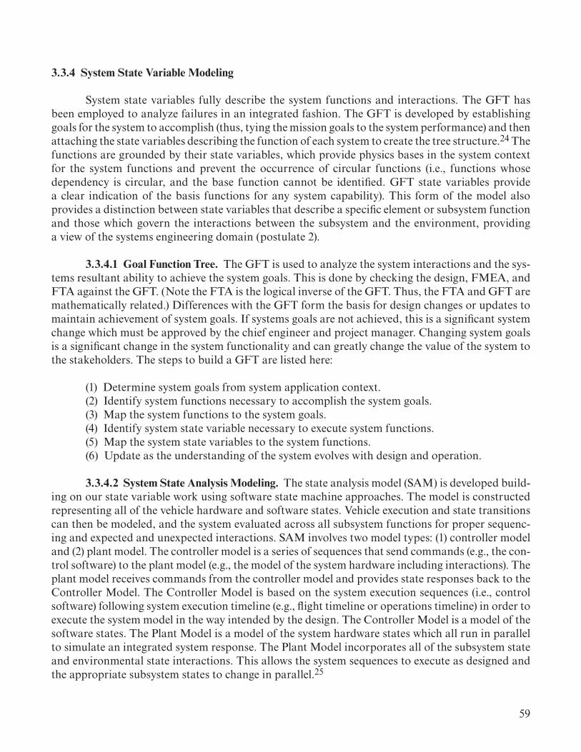
59
3.3.4 System State Variable Modeling
System state variables fully describe the system functions and interactions. The GFT has been employed to analyze failures in an integrated fashion. The GFT is developed by establishing goals for the system to accomplish (thus, tying the mission goals to the system performance) and then attaching the state variables describing the function of each system to create the tree structure.24 The functions are grounded by their state variables, which provide physics bases in the system context for the system functions and prevent the occurrence of circular functions (i.e., functions whose dependency is circular, and the base function cannot be identified. GFT state variables provide a clear indication of the basis functions for any system capability). This form of the model also provides a distinction between state variables that describe a specific element or subsystem function and those which govern the interactions between the subsystem and the environment, providing a view of the systems engineering domain (postulate 2).
3.3.4.1 Goal Function Tree. The GFT is used to analyze the system interactions and the sys-tems resultant ability to achieve the system goals. This is done by checking the design, FMEA, and FTA against the GFT. (Note the FTA is the logical inverse of the GFT. Thus, the FTA and GFT are mathematically related.) Differences with the GFT form the basis for design changes or updates to maintain achievement of system goals. If systems goals are not achieved, this is a significant system change which must be approved by the chief engineer and project manager. Changing system goals is a significant change in the system functionality and can greatly change the value of the system to the stakeholders. The steps to build a GFT are listed here:
(1) Determine system goals from system application context. (2) Identify system functions necessary to accomplish the system goals. (3) Map the system functions to the system goals. (4) Identify system state variable necessary to execute system functions. (5) Map the system state variables to the system functions. (6) Update as the understanding of the system evolves with design and operation.
3.3.4.2 System State Analysis Modeling. The state analysis model (SAM) is developed build-ing on our state variable work using software state machine approaches. The model is constructed representing all of the vehicle hardware and software states. Vehicle execution and state transitions can then be modeled, and the system evaluated across all subsystem functions for proper sequenc-ing and expected and unexpected interactions. SAM involves two model types: (1) controller model and (2) plant model. The controller model is a series of sequences that send commands (e.g., the con-trol software) to the plant model (e.g., the model of the system hardware including interactions). The plant model receives commands from the controller model and provides state responses back to the Controller Model. The Controller Model is based on the system execution sequences (i.e., control software) following system execution timeline (e.g., flight timeline or operations timeline) in order to execute the system model in the way intended by the design. The Controller Model is a model of the software states. The Plant Model is a model of the system hardware states which all run in parallel to simulate an integrated system response. The Plant Model incorporates all of the subsystem state and environmental state interactions. This allows the system sequences to execute as designed and the appropriate subsystem states to change in parallel.25

60
The SAM provides the ability to execute the operational or flight timeline in a significantly faster than real-time manner. The state changes are managed as defined by the software algorithms and hardware designs. Thus, the SAM provides the ability to execute thousands of scenarios in a few seconds. This allows algorithm testing to be much broader and more comprehensive enabling real-time software testing to focus on operational hardware timing interactions and events determined necessary to demonstrate for operational safety. This can greatly reduce and accelerate software testing.
3.3.5 System Value Modeling
3.3.5.1 System Value Model. A system value model represents the value the system provides to various stakeholders. This brings in specific aspects of the design and relates them to the value the system provides.26–29 Thus, a value model integrates the physical and organizational aspects of the system in a single model.30 The value model will capture the stakeholder preferences (expecta-tions) along with the system integrating physics and system robustness aspects. This model provides a mathematical representation for the value of the system to relevant stakeholders (e.g., flight crew, President of the United States, the United States Congress). Depending on the stakeholder, this model will vary in its relative value to the stakeholder.
The system value should be tracked from initial stakeholder definition, through design, and finally to system validation. This provides a measure of the system capabilities, tied directly to the system design, which can guide decisions during system development. When variances between the stakeholder values and the calculated system value arise, the systems engineer should address the sources of the differences by correcting the design or discussing changes in expectations for the system with the stakeholders.
In addition, stakeholder expectations can change over time (principle 13), indicating changes in system value preferences. The change in stakeholder expectations can shift system goals that may affect some or all aspects of the system design. Changes to these expectations could yield the need for a different configuration which may or may not be possible for the system, depending on its maturity in design. The systems engineer needs to be very cognizant of these value changes and ensure the system decision authorities (i.e., chief engineer and project manager) are well aware if these occur. If a major change in stakeholders’ expectations does occur, then these changes and the resulting impacts to the design will need to be discussed with the stakeholders to resolve the differences.
The system value model provides a mathematical basis for system validation, clearly differ-entiating system validation from system verification (principle 11). The system value to the stake-holders is the basis for system validation. By capturing the stakeholders preferences in a value model and then comparing the system capabilities (using a system capability model) the ability of the system to achieve value for the stakeholder can be measured. Note that, this is not a 100% achieve-ment level. The deviations from the stakeholders’ expectations are the important aspect and the systems engineer needs to define acceptable thresholds for preferences with the stakeholders. This is an important negotiation process that should occur during stakeholder expectation definition in section 3.1.2.

61
The calculation of a system value can be a complicated process. The example of the value provided by a launch vehicle is provided in section 3.3.5.3. The calculation of the system value var-ies with the types of payloads and the end destination (i.e., low Earth orbit, lunar surface, asteroids, Mars) for the payload. This creates some important variations—the calculation of the systems value that the systems engineer should account for through discussion with the stakeholders. Note also that some mission types are gained for the rocket, independent of the stakeholder’s expectations. These lower capability levels are gained as part of the system definition (a 2-ton pickup truck can easily carry a 500-lbm load, even if that does not generate value for the stakeholder buying the truck). These subtleties are important to capture as the system value is determined.
3.3.5.2 System Robustness. Robustness follows from effectiveness and efficiency when they are viewed under uncertainty. The systems engineering hypothesis 2 implies that any two system designs can be compared to see which is better. Engineering assessment processes look at Efficiency and Effectiveness for a specific mission with particular environmental conditions and state of the health of all the elements of the system. If this assessment is comprehensive (i.e., it considers all the significant attributes), then utility theory31 shows that the optimum system is one with optimum average value under uncertainty (precisely, the expectation of value). To take this average correctly, ‘better’ must be measured. That is, value has to be a real number such that, if the engineering assessment assigns a higher value to one design than to another, the higher valued system is better than the other. This kind of value assignment is possible given that an optimum system exists (even just a local optimum) because the existence of ‘better’ is a precondition of the existence of ‘best’.32 Averaging under uncertainty inherently assesses robustness in an elegant and rigorous manner.
A note concerning utility theory: Most people behave in a risk-averse manner, in an eco-nomic sense, which means that the loss of a dollar is a greater change in value than the gain of a dollar. However, both theory33 and federal policy34 demand that government choices be made on the basis that all dollars are of equal value, whether they are losses or gains. That is, for government agency programs and projects, value can be measured in dollars, and conversion to utility is unnec-essary. The system design that maximizes the expectation of the dollar value of benefits minus costs is the optimum decision.
Robustness is strongly impacted by system properties that are not found in the components, but in the relations among components. Combustion instabilities and pogo do not result from the aggregate attributes of parts, but instead from the way parts interconnect. While we understand these two particular examples, complex engineered systems are plagued with losses of effective-ness and safety issues resulting from interactions or relationships between well-functioning compo-nents. With the increasing complexity of cyber-physical systems, these problems will become more prevalent. Systems engineering should characterize component interactions in a formal elegant way to assess their impact on effectiveness. This assessment must be incorporated into the MoE (section 3.1.5) in order to usefully measure robustness.

62
To characterize system robustness, a model of system capability can be developed by describ-ing the key attributes of the system in its application environment. This model considers system characteristics. The concept of operations should contain the key system characteristics defining the system application and operation including environments. These capabilities are then mapped to the complete set of system applications (e.g., DRMs) to characterize how well the system performs in different uses, as illustrated in figure 14. The capability model is expected to yield characterstics in terms of environmental and failure robustness as well as different application effectiveness.
“How often can it launch?”• Roll-out time• Assembly time• Controllability envelope
“Will it work?”(Reliability)
“How expensive is it?”• Production cost• Launch cost• etc.
“What can it carry?”• Load Factors• Shock Loads• Payload Volume• Payload Services• Injection Accuracy
Mission 1Value = f (Capabilities)
Mission 2Value = f (Capabilities)
Mission 3Value = f (Capabilities)
Mission 4Value = f (Capabilities)
Mission Value Models
Delta V/Payload Mass
Vehicle Capabilities
Interface
Capa
bility
Env
elope
“How much, how far?”
Figure 14. System robustness capability mapping.
This provides a relative measure of the robustness of the system. Based on this mapping, different system configurations can be compared to determine which provides the most robust performance in various environments and applications.
3.3.5.3 System Value Model Example: Launch Vehicle Value Model. The value generated by a launch vehicle provides critical information enabling the system design to be compared to the expectations of the stakeholders. This value model is based on the system capability model discussed in section 3.3.5.2. The capability model allows project managers and engineers to explicitly visualize and measure the benefits of different types of missions that utilize the launch vehicle, the value of various attributes of the launch vehicle capabilities, and the overall value of the benefits provided by the launch vehicle. This can help resolve conflicting preferences between different stakeholders or between stakeholders and the development organizations expectations.
This example is based on a study done as part of the NASA Internship Program (Barth, Andrew, “Development of a System Value Model for the SLS, NASA Internship Final Report,” August 2017, unpublished data). The launch vehicle attributes can be determined by analyzing the concept of operations document. A system attribute is a quality of the system as a whole that directly impacts the value of the system. For a launch vehicle, these attributes affect the benefits of the supported missions. The attributes of a launch vehicle are cost, mission reliability, launch rate, launch availability, launch vehicle thermodynamic efficiency, and fairing geometry (representing the ability to carry larger diameter payloads). The attribute of lower cost is based on the comparison

63
of total cost of the systems (manufacture, design, and launch). Cost links all the attributes together (see fig. 15). In addition, launch vehicle cost factors also include the potential loss of mission costs. In these cases, revenue is lost for the customer and the cost to replace the launch vehicle and pay-loads, if possible, may be necessary to regain the planned revenue. Mission reliability is the percent-age number that includes the successful launch of the launch vehicle, the successful achievement of the ascent target, and the successful achievement of the payload mission. The launch rate is the number of launches per year. The launch rate is driven by planetary windows and commercial busi-ness needs among other considerations.
Launch Rate Launch VehicleThermodynamic
Efficiency
Mission Reliability Fairing Geometry
Cost
Launch Availability
Maintainability
CharacteristicEnergy Provided (C3)
Figure 15. Launch vehicle attributes related to a system value.
Launch availability can be calculated using a DES. The system simulation takes into account the various factors affecting the launch vehicle’s ability to launch as planned. These factors include weather, range safety, launch vehicle subsystem failures and repair, maintenance operations, and the ability to have the vehicle at the launch pad based on manufacturing and assembly schedules.
The relationships between the attributes, whether they are independent or dependent of each other and how important each attribute is to the overall system, is illustrated in figure 15. This model indicates mission reliability is dependent on launch availability.
Thermoeconomics calculates the cost of the system based on the system thermodynamics expenditures. Thermoeconomics integrates the laws of thermodynamics with economic theory. Thermoeconomics states that the total annual cost of thermodynamic inputs, and the total annual capital expenditures of a system can be added together to calculate a system’s annual cost. The cost relationship for a launch vehicle is defined by equations (5)–(12). These equations are based on the manufacturing base producing multiple discrete units, not a continuous flow of products (like gasses or liquids) and not a single unit (such as a building).35
!CT = cei !∈i∑ ι+ !Znn∑ . (5)

64
The components (cei and !∈ι=Jyr
) of the objective function are defined as:
cei =$J (6)
and
!∈ι=J
year. (7)
For a rocket, the cost and exergy terms relate to the propellant cost and energy provided during combustion:
!∈ι=kg
yearJ
kg⎛⎝⎜
⎞⎠⎟→ mass
year⎛⎝⎜
⎞⎠⎟×HHV = J
year (8)
and
!∈ι=kg
yearJ
kg⎛⎝⎜
⎞⎠⎟→ mass
year⎛⎝⎜
⎞⎠⎟×HHV = J
year. (9)
!Zn is based on both the unit cost and the manufacturing base cost each year:
!Zn =$
year→ unit cost + manufacturing cost
year , (10)
where
unit cost
year= LR × unit cost , (11)
where LR = launch rate.
Therefore,
!Zn = LR × unit cost + manufacturing base cost
year . (12)
Reliability, availability, and maintainability (RAM)36 are also important factors in the value of the launch vehicle to the stakeholders. Operational availability, AO, is defined as:
AO= MTBF/(MTBF+M) , (13)
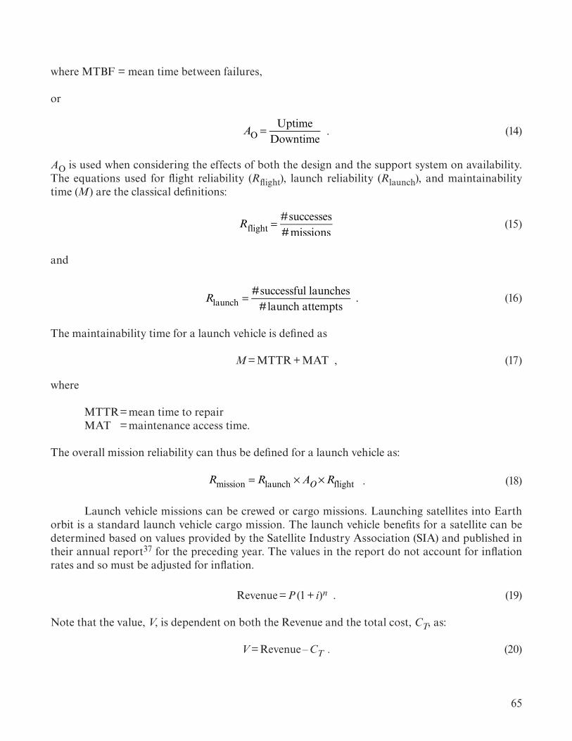
65
where MTBF = mean time between failures,
or
AO = UptimeDowntime
. (14)
AO is used when considering the effects of both the design and the support system on availability. The equations used for flight reliability (Rflight), launch reliability (Rlaunch), and maintainability time (M) are the classical definitions:
Rflight =#successes#missions
(15)
and
Rlaunch = #successful launches#launch attempts
. (16)
The maintainability time for a launch vehicle is defined as
M = MTTR + MAT , (17)
where
MTTR = mean time to repair MAT = maintenance access time.
The overall mission reliability can thus be defined for a launch vehicle as:
Rmission = Rlaunch ×AO×Rflight . (18)
Launch vehicle missions can be crewed or cargo missions. Launching satellites into Earth orbit is a standard launch vehicle cargo mission. The launch vehicle benefits for a satellite can be determined based on values provided by the Satellite Industry Association (SIA) and published in their annual report37 for the preceding year. The values in the report do not account for inflation rates and so must be adjusted for inflation.
Revenue = P (1 + i)n . (19)
Note that the value, V, is dependent on both the Revenue and the total cost, CT, as:
V = Revenue – CT . (20)

66
Figure 16 shows various satellite functions and the percentage of the functions’ usage from the SIA report.
Figure 16. Screenshot of a slide from the 2017 satellite industry report.
This example considers three preferences considered for a launch vehicle. (There may be others beyond those considered here.) These are revenue, mission reliability, and payload capacity. A heavy-lift launch vehicle is considered here with a flight rate of two per year.
Revenue that can be obtained from use of the launch vehicle to perform certain missions is a preference of many launch vehicle payload providers. Cargo missions are a large portion of the cur-rent launch vehicle market, placing satellites in orbit for various purposes. Satellite revenue for 2016 was P = $127.7 billion. With the average annual inflation rate serving as the interest rate, i =2.22% and n = 1, the actual revenue is calculated using equation (19) as $130.5 billion in 2017 USD. Using the percentages shown in figure 16, the values in table 3 were calculated by multiplying the total rev-enue of $130.5 billion by the percentage of the selected functions. The Earth observation percentage of 19% was used to determine the monetary value for optical sensing. Interplanetary mission value was assumed to be 5% of the scientific function. The benefit of the astronomical telescope was based on the value of space observation (1%).
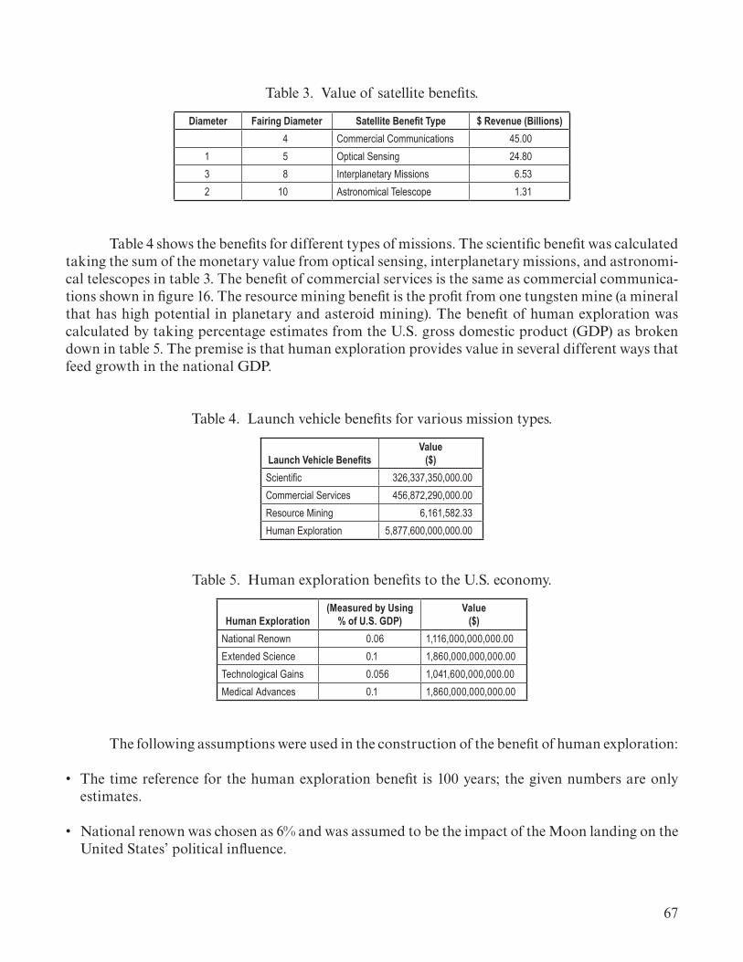
67
Table 3. Value of satellite benefits.
Diameter Fairing Diameter Satellite Benefit Type $ Revenue (Billions)4 Commercial Communications 45.00
1 5 Optical Sensing 24.803 8 Interplanetary Missions 6.532 10 Astronomical Telescope 1.31
Table 4 shows the benefits for different types of missions. The scientific benefit was calculated taking the sum of the monetary value from optical sensing, interplanetary missions, and astronomi-cal telescopes in table 3. The benefit of commercial services is the same as commercial communica-tions shown in figure 16. The resource mining benefit is the profit from one tungsten mine (a mineral that has high potential in planetary and asteroid mining). The benefit of human exploration was calculated by taking percentage estimates from the U.S. gross domestic product (GDP) as broken down in table 5. The premise is that human exploration provides value in several different ways that feed growth in the national GDP.
Table 4. Launch vehicle benefits for various mission types.
Launch Vehicle BenefitsValue
($)Scientific 326,337,350,000.00Commercial Services 456,872,290,000.00Resource Mining 6,161,582.33Human Exploration 5,877,600,000,000.00
Table 5. Human exploration benefits to the U.S. economy.
Human Exploration(Measured by Using
% of U.S. GDP)Value
($)National Renown 0.06 1,116,000,000,000.00Extended Science 0.1 1,860,000,000,000.00Technological Gains 0.056 1,041,600,000,000.00Medical Advances 0.1 1,860,000,000,000.00
The following assumptions were used in the construction of the benefit of human exploration:
• The time reference for the human exploration benefit is 100 years; the given numbers are only estimates.
• National renown was chosen as 6% and was assumed to be the impact of the Moon landing on the United States’ political influence.

68
• Extended science and medical advancement are 10%, assumed to be the possibility of a scientific breakthrough happening in the span of 100 years.
• The percentage for technological gains was chosen since, as 2016, the internet’s impact of the U.S. GDP is 5.62%.
To calculate V1, the value of CT must be determined from equations (5)–(11). The value of !CT is found from the launch vehicle stages propellant cost/mass (i.e., $/lbm or $/kg) (e.g., liquid
hydrogen, kerosene (RP-1), liquid oxygen, polybutadiene acrylonitrile (PBAN) or hydroxyl-termi-nated polybutadiene (HTPB)). The Defense Logistics Agency has a standard price listing for various propellants.38
The values of cei and !∈ι=Jyr
of each fuel type (liquid hydrogen, liquid oxygen, RP-1, and solid rocket motor propellant) are found from equations (8) and (9) using the appropriate values from table 6. Zn is calculated from equation (13). Using the manufacturing base cost for a typical heavy launch vehicle and a flight rate of two per year yields Zn = $2.21 billion/yr. !CT is calculated from equation (5) yielding a value of Zn = $2.26 billion/yr.
Table 6. $USD/kg values for launch vehicle propellants.
PropellantCost ($/kg)
Liquid Hydrogen 4.63Liquid Oxygen 0.18RP-1 6.30SRB Propellant 37.48
Propellant High Heating Value (HHV)Cost (J/kg)
H2, O2 141,800,000.00RP-1 43,600,000.00SRB Propellant 1,850,000.00
With the system cost, Ct, known, the value of the launch vehicle, Ct can be calculated by subtracting the launch vehicle cost from the launch vehicle benefit (shown individually in table 4). The benefits in table 3 are used to provide four separate values for four launch vehicle missions as shown in table 7. These calculations assume a flight rate of two per year with one flight being used in each category (i.e., scientific, commercial, mining, human exploration) every 2 years. Thus, the total value assumes four separate launch vehicles, one for each mission, produce the total cost indi-cated in table 7. The value to resource mining is negative, indicating that one launch every 2 years to support a single mine is not valuable at the assumed benefit generated by the mine. Instead, it would take 366 tungsten mines in order to provide neutral value for one launch every 2 years. This indicates the mining of minerals on other solar system bodies would need to be on a planetary scale and are not individually sustainable at current launch costs.
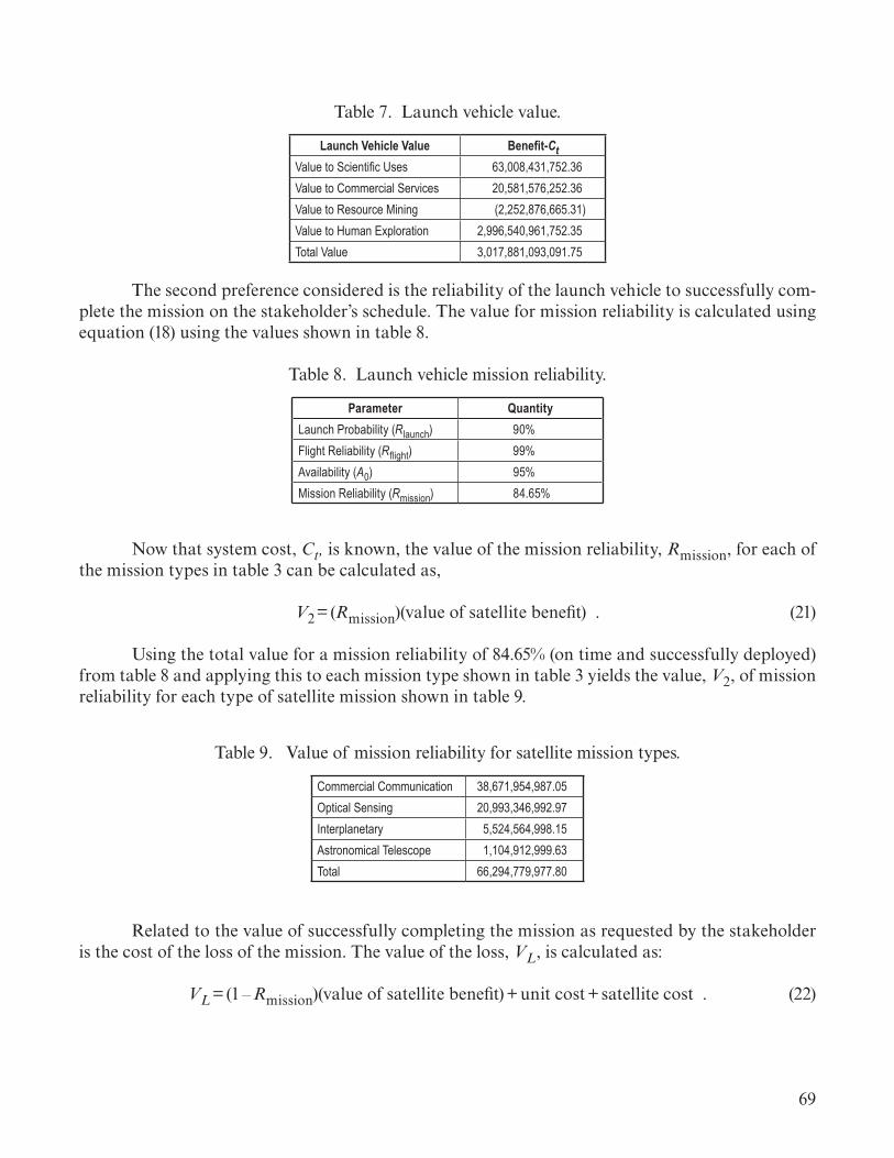
69
Table 7. Launch vehicle value.
Launch Vehicle Value Benefit-CttValue to Scientific Uses 63,008,431,752.36Value to Commercial Services 20,581,576,252.36Value to Resource Mining (2,252,876,665.31)Value to Human Exploration 2,996,540,961,752.35Total Value 3,017,881,093,091.75
The second preference considered is the reliability of the launch vehicle to successfully com-plete the mission on the stakeholder’s schedule. The value for mission reliability is calculated using equation (18) using the values shown in table 8.
Table 8. Launch vehicle mission reliability.
Parameter QuantityLaunch Probability (Rlaunch) 90%Flight Reliability (Rflight) 99%Availability (A0) 95%Mission Reliability (Rmission) 84.65%
Now that system cost, Ct, is known, the value of the mission reliability, Rmission, for each of the mission types in table 3 can be calculated as,
V2 = (Rmission)(value of satellite benefit) . (21)
Using the total value for a mission reliability of 84.65% (on time and successfully deployed) from table 8 and applying this to each mission type shown in table 3 yields the value, V2, of mission reliability for each type of satellite mission shown in table 9.
Table 9. Value of mission reliability for satellite mission types.
Commercial Communication 38,671,954,987.05Optical Sensing 20,993,346,992.97Interplanetary 5,524,564,998.15Astronomical Telescope 1,104,912,999.63Total 66,294,779,977.80
Related to the value of successfully completing the mission as requested by the stakeholder is the cost of the loss of the mission. The value of the loss, VL, is calculated as:
VL = (1 – Rmission)(value of satellite benefit) + unit cost + satellite cost . (22)

70
Table 10 shows the value lost for a mission not successfully completed. This is not only the cost of the launch vehicle and satellite, but also the revenue and other aspects lost due to mission failure.
Table 10. Lost value of unsuccessful satellite missions.
Failed Mission Value LostCommercial Communication 7,995,274,012.95Optical Sensing 6,538,291,607.03Interplanetary 3,732,182,001.85Astronomical Telescope 2,930,436,400.37Total 21,196,184,022.20
The system value model can also help understand the difference that system reliability makes on the benefit provided by the system. For example, if mission reliability where increased from 84.65% to 96%, the system value increases based on a higher benefit return. Table 11 shows the increase is system value when the mission reliability (on schedule and successfully) is increased to 96%. This assumes the cost of increased reliability is balanced by increases and decreases, yielding a ‘no change’ in the vehicle cost. For example, adding redundant components or increasing testing adds cost, whereas reduced machining yielding thicker structures can be both less costly and more reliable. Under this no-net-cost change assumption, the value of the launch vehicle increases by $8,893,345,462. Thus, an 11.35% increase in reliability yields almost $9 billion in increased value. This is a reliability increase of $783,209,640.00/1%.
Table 11. Value of 96% mission reliability.
MissionMission Reliability
($)Commercial Communication 43,859,739,840.00Optical Sensing 23,809,573,056.00Interplanetary 6,265,677,120.00Astronomical Telescope 1,253,135,424.00Total 75,188,125,440.00
The third preference considered is the value, V3, to accommodate larger diameter pay-loads. This is calculated looking at changes in fairing diameter. The change in the diameter enables a larger class of payloads to be accommodated such that the increased value in the larger payload is related to the diameter as shown in the relationship:
V3 = Δdiameter× Δvalue of payloadmeter
⎛⎝⎜
⎞⎠⎟ . (23)

71
To evaluate the differences, value was calculated for 4-m, 5-m, 8-m, and 10-m payload fairing diameters. The 4-m fairing is of value primarily to commercial communications. Forty percent of interplanetary satellites and 50% of optical sensing satellites are also assumed to be accommodated by this fairing diameter. The 5-m fairing increases the value to the optical sensing satellites, provid-ing room for larger monolithic mirror diameters. Ninety percent of planetary missions are assumed to be accommodated by this larger fairing. Planetary missions gain benefit from an 8-m fairing supporting the larger satellite dimensions when deploying landers or rovers. This fairing also allows for larger satellite busses to accommodate more instruments (and thus more measurements). Ten percent of the interplanetary satellites are assumed to benefit from this diameter. The 10-meter fair-ing is of most value to astronomical telescopes where large-diameter monolithic mirrors are needed to reduce development costs and increase imaging capabilities for distant astronomical phenom-ena including identification of terrestrial planets around other stars. The value changes assume the larger fairings still provide the same value for the smaller satellites. Table 12 shows the percentage of satellite missions supported by the different fairing diameters. Table 13 shows the value of each fairing diameter to the various satellite mission types.
Table 12. Percentage of satellite market supported by different fairing sizes.
Satellite Benefit4 m(%)
5 m(%)
8 m(%)
10 m(%)
Commercial Communication 100 100 100 100Optical Sensing 50 100 100 100Interplanetary Missions 40 90 100 100Astronomical Telescope 0 0 10 100
Table 13. Value to satellite market of different fairing sizes.
Satellite Benefit4 m($)
5 m($)
8 m($)
10 m($)
Commercial Communication 45.69 45.69 45.69 45.69Optical Sensing 12.40 24.80 24.80 24.80Interplanetary Missions 2.61 5.87 6.53 6.53Astronomical Telescope 0.00 0.00 0.13 1.31Total 60.70 76.36 77.15 78.32
From the delta total values in table 12, the biggest value increase for the satellite market is from the 4-m to the 5-m fairing at a value of $15,664,192,800. The increase from 5 m to 8 m yielded a smaller increase of $783,209,649 (or $261,069,880/m). The 10-m fairing yielded an increase of $1,174,814,460 (or $587,407,230/m). Thus, the 5-m fairing has the most increase in value over the other fairing dimension. The 8-m fairing has only a modest increase over the 5-m faring. The 10-m fairing provides more value in total and in overall increase to the heavy-lift launch vehicle as compared to the 8-m fairing.

72
Table 14 gives the three preference values calculated for the heavy-lift launch vehicle with a 10-m fairing. Weighting of each system value preference to properly combine the preferences into a total value for the system is important. The weighting, w, takes into account the relative importance of specific system characteristics to the stakeholder as determined in discussion with the stakeholders (see section 3.1.2). Properly combining the values must take into account the relationship of the system characteristics that are common across multiple value preferences (i.e., common to two or more of the values V1, V2, and V3). This prevents unintentional inflating of the total system value when combining preferences. This yields the total value of the launch vehicle, VT, as:
VT = w1V1 + w2V2 + w3V3 . (24)
Table 14. Preference values for a heavy-lift launch vehicle with 10-m fairing.
Launch Vehicle ValueValue
($)Revenue Value (V1) 3,017,881,093,091.75Mission Reliability Value (V2) 66,294,779,977.00Payload Size Value (10-m Fairing) V3) 78,320,964,000.00
This example of a launch vehicle cost demonstrates some of the factors in a value model. Note that individual stakeholder preferences may differ from the main preferences used in this example. The construction of the value model depends on the specific stakeholders, both affected and interested, as well as on the specific mission context for the system. A proper understanding of how the system achieves the preferred benefits must be achieved to construct a representative system value model.
3.3.5.4 System Cost. A related aspect of system value is the system cost. The system cost is not the value of the system but contributes to the value of the system as illustrated in the example in the previous section. While program and project management is responsible for the system budget and managing the overall organizational cost, the major cost of the system is defined by the engi-neering design choices made during development. The systems engineer should understand how the systems integrating physics and/or software logic drives the overall system cost. Thus, the systems engineer should understand how engineering the system drives both the development costs and the production and operation costs (principle 1).
The primary component of the system cost is labor—not materials—and is based on the tasks necessary to achieve the systems-integrating physics or logic that defines the system functions. A PBS, which captures the architectural view of the system, provides a system-based cost structure for the system cost. This PBS provides a basis to understand the major system cost elements, the regulatory costs incurred on the project. Using this cost structure, a story of the system’s value and benefits to various system stakeholders (including manufacturers, operators, and users) can be constructed.

73
Note that specifying detailed budget requirements may overconstrain the system, leading to inelegant solutions or cost conflicts. The component costs are not important; the total cost is. At the component level, it is important to understand the cost drivers so these can be managed to keep the total system cost within budget. The PBS provides the cost structure to identify the cost drivers and analyze the alternatives. Stakeholders generally do not buy parts of the system; they buy the whole system.
The system is comprised of components, and the PBS provides a useful integration struc-ture to view the costs associated with each component in the design (principle 3(f)). This cost is focused on the design and test costs leading up to the development of the first system. The WBS has a separate focus, not on the system, but on the labor centers within the organization. The WBS provides the organizational view of the costs, while the PBS provides the system view of the cost. Program and project management is typically focused on the WBS, while the systems engineer is more focused on the PBS.
When more than one copy of the system is manufactured, the PBS provides a clear view of the system production and operations costs on a per-unit basis. This system unit cost provides the systems engineer with a clear view of the longer-term cost impacts of the design decisions and a clearer view of manufacturing and operational cost drivers for the system. Thus, the systems engineer is primarily concerned with the system unit cost. The PBS allows the system costs to be rolled-up from component designs, allowing design engineering and the manufacturing engineering to see how their design decisions are affecting the overall unit cost of the system.
For all costs (i.e., development, production, and operation) to be explicit in the design, the systems engineer should maintain a consistent rollup of these costs and report them at regular program or project status meetings. The cost of design decisions must be understood before the decisions are made in order to maintain control of the system development, production, and operation cost.
The largest potential cost during production and operations is the system manufacturing base. The manufacturing approach, fixed facilities, and contract arrangements required to maintain the manufacturing base may be much larger than the system unit cost if not visibly and explicitly managed. This is a program manager responsibility. However, the systems engineer must under-stand the impact of design and manufacturing decisions on the manufacturing base costs39 and understand the system development and operations design choices to keep these costs within the budget.
Thus, understanding the potential cost of the system configuration solutions is an important aspect of finding the best balanced system that fits within the system budget constraints. The system cost is not simply a business artifact but a key constraint on available system configuration solutions.
3.3.6 Modeling the System Integrating Physics
The key to systems engineering is understanding the physical and logical interactions of the system. This provides an integrated engineering basis for the system design and is fundamental
74
to system analysis, system design allocations, and system optimization. As systems engineering is system specific (postulate 1), the systems integrating physics and/or software logic are also system specific. The focus for the systems engineer is the selection of a system configuration with a set of system interactions that is most efficient in achieving the system’s intended outcomes. The systems-integrating physics and/or software logic are the basis of the design cycles and form the basis of the operational procedures, limits, and constraints as shown in figures 5, 7, and 8. The understanding of the systems-integrating physics evolves as the system design matures. The design starts with the physics-based models and system state variables used for the high-level architecture and concept selection. System state variables are essential to defining and understand-ing the system interactions. These variables provide a complete representation of the system, and its interactions are necessary for a complete and integrated system model. At the concept level, simple representations of the system are used, and uncertainties in these representations (models) of the system are high. Concept development concludes with the system requirements review, assessing the most efficient system configuration for design and associated system requirements that fits within the system context (budget, schedule, policy, and law).
Design is focused on a quickly expanding set of representations, models, and state variables leading to a much more detailed understanding of the system interaction physics and/or software logic. The system interactions become clear as the design progresses and are monitored and man-aged to ensure the system is efficient and effective in achieving the intended outcomes, is robust for the current or future applications, and unintended consequences are mitigated. This includes the understanding of system manufacturing and assembly which can affect the system interaction paths and provide some constraints to ensure the manufacturability of the system. System sensitivities are identified during this phase, and the system design is adjusted to account for these. As the system physics and/or software logic interactions are understood, derived technical requirements are gener-ated to account for the interactions and overall system performance. The system design is reviewed during system design reviews.
Verification of the system interactions is a key aspect to identifying the physics and/or soft-ware logic basis for the interactions. The systems engineer should not only ensure the individual system elements/functions perform correctly, but that the system as a whole performs correctly, accounting for all system interactions. Validation of models used for system and component designs is essential and often based on development testing, qualification testing, and verification testing results. System testing provides the opportunity to measure and identify system interactions whether previously anticipated or unexpected.
With the evolving understanding of the physics and/or software logic, the operations rules, limits, constraints, and procedures also advance. The physics and/or software logic are the basis for the system operations as discussed in section 3.3.5. Note that the intended uses of the system drive the design through the system application context with the system design physics and/or software logic providing a final basis for the specific system operational approaches. Keeping the system application context, and therefore the system operations, in view throughout system design is essen-tial for an effective and robust system design.

75
Understanding the driving physics and/or software logic relationships of a system enables the systems engineer to effectively integrate the system and manage the system interactions. Com-plex system interactions are intricate and difficult to understand. The driving physics and logical relationships provide a basic guide in understanding the system functions. Providing the integrating relationships, the physics and/or software logic can be expanded to greater detail. This expansion is the domain of the specific discipline engineers. The systems engineer is focused on the relation-ships and interaction between the system functions and the system environment (i.e., natural and induced) (postulate 2).
3.3.6.1 Design Analysis Cycle Application. Design analysis cycles (DAC) are a key systems engineering activity during system design. DACs involve all of the relevant engineering disciplines for the system in a coordinated system design effort. One challenge with the DAC is to provide consistent guidance across all of the engineering disciplines, such that they can run their particu-lar discipline models to mature the design. Another challenge is to have systems engineering be able to integrate the results into a ‘closed’ or operable system design. This is truly an engineering integration activity and involves the integration of results from tens to hundreds of mathematical relationships.
The key to approaching this problem in a consistent and efficient manner is to understand the system integrating physics (or logic for logic-based systems). For a particular system type, there is an integrating physics that ties all other physics relationships together. This integration relation-ship is particular to the system type. For example, thermodynamic systems are integrated through the thermodynamic property of exergy. Exergy brings the physics of thermodynamic systems into a single integrating relationship. Many current systems in use today are thermodynamic systems including aircraft, automobiles, electrical power, nuclear systems, rockets, ships, etc.
Not all systems are primarily thermodynamic systems, though all physical systems have thermodynamic properties. Optical systems are not defined by how well-balanced they are thermodynamically, although this is certainly an important aspect of the system. Instead, optical systems are defined by their imaging qualities. Thus, optical systems are integrated by their optical transfer function, whether for coherent or incoherent imaging. The transfer function allows the physical properties to be characterized for each optical element through the elements’ spatial filtering properties (defined by physical relationships). Structural systems, such as buildings, bridges, launch towers, etc., are defined by their structural loads and mass matrices, biological systems through the biological processes, and data and communication systems through their electromagnetic properties.
By applying the appropriate integrating physics relationship (i.e., the integrating perspec-tive), the system engineer can quickly identify the key system parameters from each discipline that contrib ute to the system integration. The integrating physics also provides a relation to balance the system parameters with a clearer measure of the integrated system balance. This allows clear guidance to be provided to the discipline engineering teams at the beginning of the DAC, knowing that the ini tial configuration for the DAC is balanced. The systems integrating physics also provide more clear direction to balance the integrated system performance, reducing the amount of itera-tions necessary to find a closed solution. At the completion of the DAC, this integrating relationship

76
provides the integration approach with the ability to confirm that the system balances (i.e., closes). This provides the systems engineer with a powerful engineering integration tool and improves the DAC by reduc ing or eliminating time the discipline engineers spend on configuration points that are not balanced (i.e., do not close). This leads to a reduced number of DAC iterations necessary to find a balanced solution.40
In addition, SAMs provide a broader testing of the software algorithms than real-time soft-ware testing can afford. Thus, software testing can be reduced to those necessary to confirm hard-ware integration and validate SAM results. This provides more comprehensive software algorithm testing and a reduction in the amount of time needed for software testing.
Note that the application of the system integrating physics and SAM complements and makes use of the design work done by other engineering disciplines. As such, the systems design and integration is dependent on the discipline engineering designs, and not an independent effort as the system progresses through the system lifecycle.
3.3.6.2 System Exergy. System exergy is the system integrating physics and serves as the basis for integrated system analysis for many types of systems including, aircraft, rockets, space capsules, ships, electrical power generation plants, etc. In a system, the subsystems represents differ-ent types of machines (mechanical, electrical, thermal). When integrating different machine types, the common physical input and output is work (whether electrical, mechanical, thermal, kinetic, or potential). The work output of one machine becomes a work input of another. The work relation-ships are not independent of the physical flows (e.g., thermal, mass, electrical), but contain all the physical parameters that generate the work for each subsystem. Thus, the system is integrated by the work done among the subsystems. This work is the basis of the thermodynamics integration prop-erty for systems such as aircraft, hypersonic vehicles, spacecraft, etc. This integration property is system exergy that integrates all of the work-producing terms (i.e., kinetic energy, potential energy, mechanical work, electrical work, thermal work, and flow work) into a balance condition that all systems must meet. The exergy relationship enforces energy balance, entropy balance, and mass balance, and is measured against the reference environment in which the system operates. There-fore, system exergy provides category theory functorial relationships, preserving both the subsys-tem representations and their interactions. System exergy requires proper relationships between the parameters in the balance equation. Thus, for spacecraft, orbital mechanics must be met in the relationship between vehicle velocity and reference body distance (altitude). In addition, the rocket equation must be met for rocket propulsion. Breguet’s range equation must be met for aircraft. Vio-lation of any of these physics conditions will lead to nonphysical (i.e., efficiency >100%) or negative exergy destroyed (meaning the creation of energy by the system to meet the balance). Exergy is not an independent property of the system but an integration result of the system physics.
System exergy analysis provides a means for analyzing an integrated system using exergy as a quantifiable attribute of the integrated system. This attribute, system exergy (sometimes referred to as system availability), is useful in tradeoffs both between subsystems and when comparing systems holistically. Furthermore, exergy can be used as an attribute in a system value function or as the objective function to provide a basis for a subsystem or system level optimization. System exergy analysis provides a source for information useful in requirements, tradeoffs, and optimization.

77
Exergy takes into account all of the physics aspects of the system, including the system environment, the system functional interactions, system performance, and losses. The losses from all sources such as combustion, friction, etc. are treated in the same manner using exergy analysis. Therefore, exergy provides systems engineers with a meaningful measure of efficiency applicable across the whole system and throughout the design process, inherently invoking the combination of performance and losses in the efficiency. The focus of exergy-based optimization provides maximal system performance in the system’s operating environment, while simultaneously minimizing losses. System exergy analysis provides powerful and useful knowledge throughout the design process, from conceptual to detailed design. For systems in the operations lifecycle phase, application of exergy analysis to existing systems may offer insights to improve the system efficiency by operating the system differently.
Steps to engineering a system integrated by thermodynamics follow:
(1) Define the system as a control volume or control mass. A control volume is a system that has a flow of mass across the system boundaries while the volume of the system is fixed. A control mass is a system that has a constant mass while the system volume may change. Some systems may be a control volume in some contexts and a control mass in other contexts (or environments). This is illustrated below in the discussion of spacecraft.
(2) Determine the appropriate exergy balance equation using the specific exergy components of the system under analysis. The exergy balance states that the change in system exergy is equal to the sum of the exergy input, exergy output, and exergy destroyed. Equation (25) gives the exergy balance for a control volume system, and equation (26) gives the exergy balance for a control mass system: Xheat + Xin – Xwork + Xmass in – Xmass out – Xout – Xdes = Xfinal – Xinitial . (25)
The various components of these equations represent the exergy values of the different aspects of the system:
Xheat – Xwork – Xdes = Xfinal – Xinitial . (26)
The exergy destroyed term is the amount of entropy generated by the system at the reference envi-ronment temperature and is written as:
Xdes = T0sgen , (27)
where
T0 = reference environment temperature sgen = entropy generated.
The rate form of these equations can be obtained by dividing by the time interval over which a change takes place. This is denoted as !X . This form allows the balance to be stated in terms of the flow rates and rates of change for the system such as mass flow rate, heat transfer rate, etc.

78
These relationships can be expanded using the different forms of exergy shown in table 15. In this table, the 0 terms represent the reference state (sometimes referred to as the dead state, ambient condition, standard temperature and pressure, etc.). Work can only be done by a system when its state is different than its reference environment. When its state equals the reference environment (i.e., x = x0 (x is any state variable), final = initial) then all of the exergy terms are 0. Thus, exergy relationships take into account the system environment.
Table 15. Exergy relationships.
Exergy Relationships Exergy Term
XKE =mfinal
2Vfinal
2 −minitial
2Vinitial
2 Change in kinetic energy
XPE = mfinalgheightfinal −m initialgheightinitialChange in potential energy
Xheat = Qnn∑ 1−
T0Tn
⎛
⎝⎜⎞
⎠⎟Heat transfer exergy for n heat flows
Xwork =W −P0 Volfinal − Volinitial( ) Mechanical work exergy
ψ flow = m h − h0( )+T0{ s − s0( )+ Vfinal2
2−Vinitial
2
2
⎛
⎝⎜
⎞
⎠⎟
+ g heightfinal − heightinitial( )}
Fluid flow exergy
Xstatic = E − E0( )+P0Xfluid = P0 Vol − Vol 0( )−T0 s − s0( ) where energy = E = Usystem +KEsystem +PEsystem
Nonflow exergy
Using the relationships in table 14, the exergy balance equations can be expanded for a con-trol volume system in equation (28) and for a control mass system in equation (29) as:
1−
T0Tin
⎛
⎝⎜⎞
⎠⎟Qin −
T0 −TcoolantTcoolant
⎛
⎝⎜⎞
⎠⎟Qout + Win −P0 Volfinal − Volinitial( )( )−Wout −Xdes = X final −X initial
+Δm hin − hout( )−T0 sin − sout( )+Vin2 −Vout
2
2+ g heightin − heightout( )
⎛
⎝⎜
⎞
⎠⎟ −Xdes
= X final −X initial
(28)

79
1−
T0Tin
⎛
⎝⎜⎞
⎠⎟Qin −
T0 −TcoolantTcoolant
⎛
⎝⎜⎞
⎠⎟Qout + Win −P0 Volfinal − Volinitial( )( )
−Wout −Xdes = X final −X initial , (29) where hin = specific enthalpy entering hout = specific enthalpy leaving heightin = entering height heightout = leaving height P0 = reference environment pressure Qin = heat entering Qout = heat leaving sin = entropy entering sout = entropy leaving Tcoolant = coolant temperature T0 = reference environment temperature Tin = input temperature Vin = velocity entering Vout = velocity leaving Volinitial = initial volume Volfinal = final volume Win = work entering Wout = work leaving Xdestroyed = exergy destroyed Xinitial = initial exergy Xfinal = final exergy ∆m = change in mass.
(3) The third step makes use of the summative property of exergy. Exergy can be separated into the individual contributions of the subsystems and then added together. This is illustrated clearly in the examples of aircraft and Environmental Control and Life Support Systems (ECLSS). This allows an allocation of exergy contributions to subsystems during design. The systems engineer will need to ensure that these allocations are adjusted for input/outputs across subsystem boundaries. These may cancel when combined as a system but will need to be added/subtracted from the subsystem allocations to maintain the system balance.
(4) Finally, the system exergy efficiency can be calculated. System exergy efficiency is defined as the ratio of exergy recovered to exergy expended and can also be shown as a relationship of exergy destroyed to exergy expended. These relationships are given in equation (30) for an accelerating system and equation (31) for a decelerating (i.e., braking) system:

80
ηexergy =XrecoveredXexpended
= 1−Xdes
Xexpended (30)
and
ηexergy =−XrecoveredXexpended
= 1−X initial −X finalXexpended
= 1−Xdes
Xexpended. (31)
3.3.6.2.1 Aircraft Exergy. The exergy balance for an aircraft is given in equation (32). Exergy for aircraft involve calculating the exergy contributions from each of the aircraft systems and air-flow:
Fthrust ×Vvehicle = !mpropellantV 2
vehicle2
+Htotal
⎛
⎝⎜
⎞
⎠⎟ −T0 svehicle irreversible − swake( ) , (32)
where
!mpropellantHtotal = !mpropellant h0,propellant + Cp,propellantT0
Tpropellant injection∫ dT⎧⎨⎩
⎫⎬⎭
⎛⎝⎜
⎞⎠⎟−T0stanks + !mi α l,i hl,i −Tisl Ti,Pi ,ηl,i( )⎡
⎣⎤⎦l=1
n∑ − !mwake α l,il=1n∑ hl,wake −Twakesl Twake,Pwake,ηl,wake( )⎡
⎣⎤⎦
!mpropellantHtotal = !mpropellant h0,propellant + Cp,propellantT0
Tpropellant injection∫ dT⎧⎨⎩
⎫⎬⎭
⎛⎝⎜
⎞⎠⎟−T0stanks + !mi α l,i hl,i −Tisl Ti,Pi ,ηl,i( )⎡
⎣⎤⎦l=1
n∑ − !mwake α l,il=1n∑ hl,wake −Twakesl Twake,Pwake,ηl,wake( )⎡
⎣⎤⎦
!mpropellantHtotal = !mpropellant h0,propellant + Cp,propellantT0
Tpropellant injection∫ dT⎧⎨⎩
⎫⎬⎭
⎛⎝⎜
⎞⎠⎟−T0stanks + !mi α l,i hl,i −Tisl Ti,Pi ,ηl,i( )⎡
⎣⎤⎦l=1
n∑ − !mwake α l,il=1n∑ hl,wake −Twakesl Twake,Pwake,ηl,wake( )⎡
⎣⎤⎦ , (33)
where Cp,propellant = propellant specific heat at constant pressure Fthrust = thrust Htotal = total enthalpy h0,propellant = entropy value of propellant in reference environment conditions hι,i = enthalpy of different injected propellant reactants hι,wake = enthalpy of chemical propellant reactants in the wake !m i = mass flowrate of chemical species i !m propellant = mass flowrate of propellant !mwake = mass flowrate of air in wake Pi = input pressure Pwake = pressure of wake sl = entropy of chemical propellant reactants !stanks = entropy rate of change for propellant in tanks !s vehicle,irreversible = irreversible entropy rate of change of vehicle swake = entropy of aircraft wake Ti = input temperature Tpropellant,injection = temperature of injected propellant
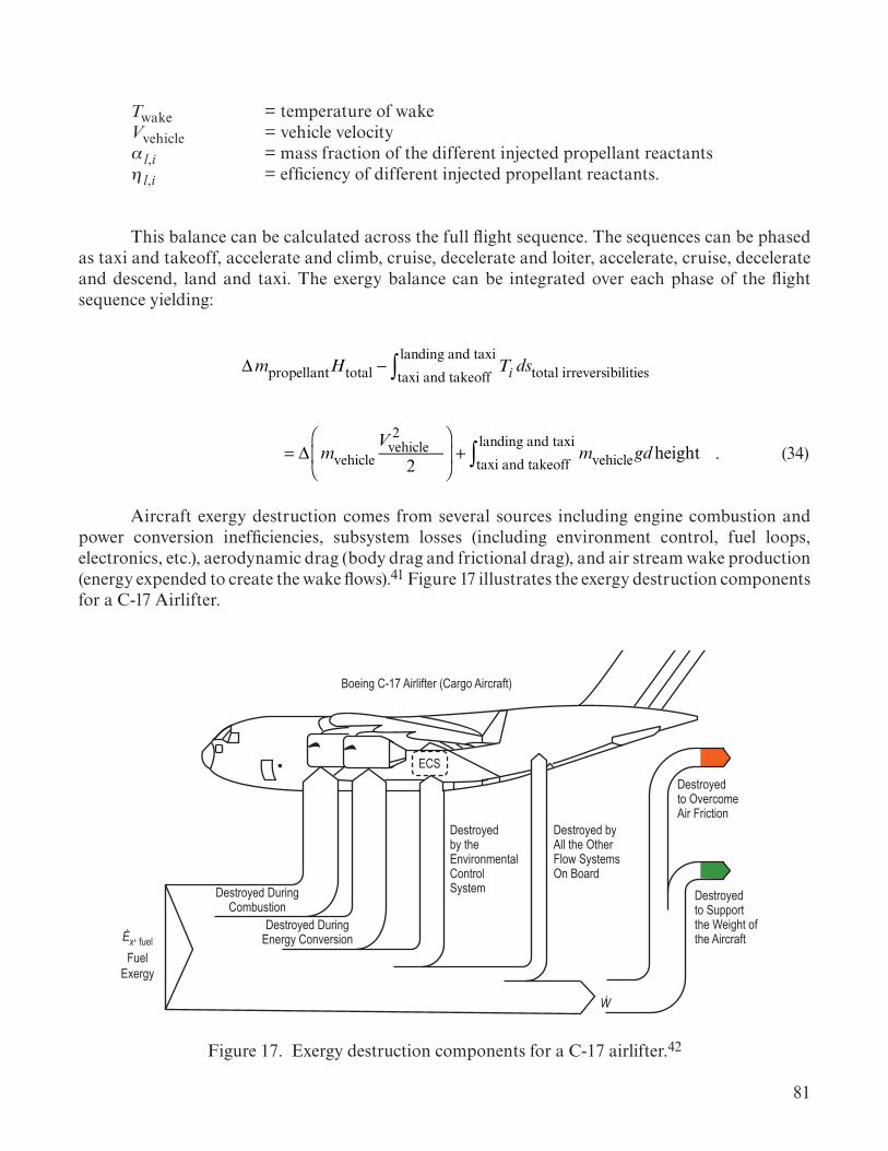
81
Twake = temperature of wake Vvehicle = vehicle velocity αl,i = mass fraction of the different injected propellant reactants ηl,i = efficiency of different injected propellant reactants.
This balance can be calculated across the full flight sequence. The sequences can be phased as taxi and takeoff, accelerate and climb, cruise, decelerate and loiter, accelerate, cruise, decelerate and descend, land and taxi. The exergy balance can be integrated over each phase of the flight sequence yielding:
ΔmpropellantHtotal − Ti dstotal irreversibilitiestaxi and takeoff
landing and taxi∫ = Δ mvehicle
V 2vehicle
2
⎛
⎝⎜
⎞
⎠⎟ + mvehicletaxi and takeoff
landing and taxi∫ gdheight
ΔmpropellantHtotal − Ti dstotal irreversibilitiestaxi and takeoff
landing and taxi∫ = Δ mvehicle
V 2vehicle
2
⎛
⎝⎜
⎞
⎠⎟ + mvehicletaxi and takeoff
landing and taxi∫ gdheight . (34)
Aircraft exergy destruction comes from several sources including engine combustion and power conversion inefficiencies, subsystem losses (including environment control, fuel loops, electronics, etc.), aerodynamic drag (body drag and frictional drag), and air stream wake production (energy expended to create the wake flows).41 Figure 17 illustrates the exergy destruction components for a C-17 Airlifter.
Boeing C-17 Airlifter (Cargo Aircraft)
ECS
Ẃ
Ėx, fuelFuel
Exergy
Destroyed DuringCombustion
Destroyed DuringEnergy Conversion
Destroyed by theEnvironmentalControlSystem
Destroyed byAll the OtherFlow SystemsOn Board
Destroyed to OvercomeAir Friction
Destroyed to Supportthe Weight of the Aircraft
Figure 17. Exergy destruction components for a C-17 airlifter.42

82
3.3.6.2.2 Launch Vehicle Exergy. Rockets and launch vehicles are thermodynamic systems. These systems function by converting chemical energy stored in the propellants into thrust to provide the vehicle with kinetic and potential energy. Thus, thermodynamics form the systems integrating physics for these vehicles.40
These systems can be considered as control volumes. Mass flows from the tanks, through the engines, and is exhausted out of the nozzles. As such, the vehicle outer mold line (OML) remains constant as mass is expelled across the boundary at the nozzle exits. At booster or stage separation, mass is also lost from the system as separated mass. The OML (i.e., volume) also changes. The sys-tem is best characterized as a control volume since each stage or booster OML remains constant, and the active stage continues to expel mass across the boundaries. The vehicle can be viewed as a combination of control volumes which incrementally drop the separate volumes but maintain the integrity of the individual control volumes as they separate.
For a launch vehicle, which is a propulsion system, the exergy balance equation reflects the propulsion energy, vehicle kinetic energy, and vehicle potential energy as the systems integrating physics. Each of the launch vehicle subsystems contribute to one or more of these terms. The pro-pulsion energy is summed over each stage (or booster set). Equation (35) gives the exergy balance equation for a rocket:
Δmpropellant hprop +V 2e2
⎛
⎝⎜
⎞
⎠⎟
⎡
⎣⎢⎢
⎤
⎦⎥⎥stages∑ − !Xdes , (35)
where
Δmpropellant = change in propellant mass for each stage or booster hprop = propulsion enthalpy in the combustion chamber for engines or booster motors Ve = equivalent exhaust velocity of engines or booster motors.
The vehicle ∆KE and ∆PE have discrete changes with each mass separation (e.g., booster separation, stage separation, launch abort system jettison, fairing jettison). Also, the hprop and Ve terms are the single engine or motor values. The ∆mpropellant accounts for the number of engines or boosters as the mass change is based on the mass flow rate to the total number of engines or boosters. Engine parameters are obtained from the engine power balance model. Booster parameters are obtained from ballistic flow models.
Equation (35) may be solved for the exergy destruction, &X des. This result may then be substituted into equation (30) to solve for the efficiency of an accelerating vehicle. Performing these operations yields the exergy efficiency of a rocket during acceleration as:

83
ηexergy =
Δmpropellant hprop +V2e2
⎛
⎝⎜
⎞
⎠⎟
⎡
⎣⎢⎢
⎤
⎦⎥⎥stages∑ −Xdes
Δmpropellant hprop +V2e2
⎛
⎝⎜
⎞
⎠⎟
⎡
⎣⎢⎢
⎤
⎦⎥⎥stages∑
= 1− M vehicle, final
V 2vehicle,final
2−Mvehicle,initial
V 2vehicle,initial
2
⎛
⎝⎜⎜
⎞
⎠⎟⎟+
GMEMvehicle,initial
raltitude,initial−GMEMvehicle,initial
raltitude,final
⎛
⎝⎜
⎞
⎠⎟
⎡
⎣⎢⎢
⎤
⎦⎥⎥stages∑
⎧⎨⎪
⎩⎪
⎫⎬⎪
⎭⎪÷ Δmpropellant hprop +
V 2e2
⎛
⎝⎜
⎞
⎠⎟
⎡
⎣⎢⎢
⎤
⎦⎥⎥stages∑
⎧⎨⎪
⎩⎪
⎫⎬⎪
⎭⎪
ηexergy =Δmpropellant hprop +V
2e2
⎛
⎝⎜
⎞
⎠⎟
⎡
⎣⎢⎢
⎤
⎦⎥⎥stages∑ −Xdes
Δmpropellant hprop +V2e2
⎛
⎝⎜
⎞
⎠⎟
⎡
⎣⎢⎢
⎤
⎦⎥⎥stages∑
= 1− M vehicle, final
V 2vehicle,final
2−Mvehicle,initial
V 2vehicle,initial
2
⎛
⎝⎜⎜
⎞
⎠⎟⎟+
GMEMvehicle,initial
raltitude,initial−GMEMvehicle,initial
raltitude,final
⎛
⎝⎜
⎞
⎠⎟
⎡
⎣⎢⎢
⎤
⎦⎥⎥stages∑
⎧⎨⎪
⎩⎪
⎫⎬⎪
⎭⎪÷ Δmpropellant hprop +
V 2e2
⎛
⎝⎜
⎞
⎠⎟
⎡
⎣⎢⎢
⎤
⎦⎥⎥stages∑
⎧⎨⎪
⎩⎪
⎫⎬⎪
⎭⎪ , (36)
where
Mvehicle,initial = initial mass of the vehicle Mvehicle,final = final mass of the vehicle Vvehicle,initial = initial velocity of vehicle Vvehicle,final = final velocity of vehicle G = universal gravitational constant ME = mass of the Earth raltitude,initial = initial altitude of the vehicle raltitude,final = final altitude of vehicle.
For a rocket that is decelerating (i.e., braking) such as lander or during spacecraft re-entry, the recovered exergy by the system is negative (intentionally lost). This sign change reverses the delta calculations from (final – initial) to (initial – final) leading to the exergy efficiency relationship as:
ηexergy = Mvehicle,initial
V 2vehicle,initial
2−Mvehicle,final
V 2vehicle,final
2
⎛
⎝⎜⎜
⎞
⎠⎟⎟+
GMEM vehicle,final
raltitude,final−GMEM vehicle,initial
raltitude,initial
⎛
⎝⎜
⎞
⎠⎟
⎡
⎣⎢⎢
⎤
⎦⎥⎥stages∑
⎧⎨⎪
⎩⎪
⎫⎬⎪
⎭⎪÷ Δmpropellant hprop+
V 2e
2
⎛
⎝⎜
⎞
⎠⎟
⎡
⎣⎢⎢
⎤
⎦⎥⎥stages∑
⎧⎨⎪
⎩⎪
⎫⎬⎪
⎭⎪
ηexergy = Mvehicle,initial
V 2vehicle,initial
2−Mvehicle,final
V 2vehicle,final
2
⎛
⎝⎜⎜
⎞
⎠⎟⎟+
GMEM vehicle,final
raltitude,final−GMEM vehicle,initial
raltitude,initial
⎛
⎝⎜
⎞
⎠⎟
⎡
⎣⎢⎢
⎤
⎦⎥⎥stages∑
⎧⎨⎪
⎩⎪
⎫⎬⎪
⎭⎪÷ Δmpropellant hprop+
V 2e
2
⎛
⎝⎜
⎞
⎠⎟
⎡
⎣⎢⎢
⎤
⎦⎥⎥stages∑
⎧⎨⎪
⎩⎪
⎫⎬⎪
⎭⎪
ηexergy = Mvehicle,initial
V 2vehicle,initial
2−Mvehicle,final
V 2vehicle,final
2
⎛
⎝⎜⎜
⎞
⎠⎟⎟+
GMEM vehicle,final
raltitude,final−GMEM vehicle,initial
raltitude,initial
⎛
⎝⎜
⎞
⎠⎟
⎡
⎣⎢⎢
⎤
⎦⎥⎥stages∑
⎧⎨⎪
⎩⎪
⎫⎬⎪
⎭⎪÷ Δmpropellant hprop+
V 2e
2
⎛
⎝⎜
⎞
⎠⎟
⎡
⎣⎢⎢
⎤
⎦⎥⎥stages∑
⎧⎨⎪
⎩⎪
⎫⎬⎪
⎭⎪ . (37)
The reversal of the delta calculations can be seen by comparing equations (36) and (37).
A Program to Optimize Simulated Trajectories (POST)43 simulation file can be used to generate the necessary data for a given configuration. POST is a 3 degree-of-freedom (DoF) code that calculates the translation of the vehicle in all three directions. For vehicles, such as spacecraft, where rotations in three directions are also needed to calculation maneuvers, a 6-DoF code such as Marshall Aerospace Vehicle Representation in C (MAVERIC) can be used. The simulation variables

84
in these codes corresponding to the exergy balance parameters must be identified. Sometimes these code variables must be translated into the necessary parameters. Table 16 gives the POST simulation variables needed to calculate the exergy balance and exergy efficiency. The exergy balance uses mass remaining (i.e., wprp in POST). POST wprus (propellant used) can also be used for mass calculations but must be converted to remaining propellant by subtracting from the initial propellant mass value. Flow rate can be calculated by dividing the change in propellant mass for a step in the simulation by the change in time over that step. Specific vehicle configuration simulations can make use of different simulation variables (e.g., thrust instead of Isp or wprp and not wprus). The location of these variables can also shift for different configurations. Each new file should be checked to ensure the exergy balance calculation is reading the correct simulations variables, confirming correct units (i.e., English or metric), and making any proper translations to the needed parameters.
Table 16. Post variables for exergy calculations.
POST Variable POST Description Exergy Balance Equation Term
time Used to calculate flow rates for rate-based equations e.g.,Δmpropellant
Δt= !mpropellant
gdalt Geodesic altitude raltitude
weight Vehicle mass Mvehicle
veli Vehicle inertial velocity Vvehicle
Isp Specific impulse Ve= Isp*g0
thrust Thrust can also be used to find Ve Ve= thrust/∆mp
wprp Remaining propellant mass in tanks. wprp(0) – wprp yields propellant used wprp(0) – wprp =∆mpropellant
wprus Propellant mass used wprus =∆mpropellant
Integrated System Exergy Example: Aircraft Boost for a Launch Vehicle
3.3.6.2.3 Planetary Transfer Exergy. Planetary transfer involves large change in energy driven by the spacecraft propulsion system and the gravity of the solar system bodies (e.g., Sun, planets, moons). Exergy balance provides a way to integrate the spacecraft performance (i.e., kinetic energy and potential energy changes) across all of the forces on the spacecraft (e.g., planetary, moon, and solar gravitational forces). The approach for an accelerating departure or arrival burn follows that described for a launch vehicle in section 3.3.6.2.2. POST can be used for local planetary operations and ensuring that the right planetary mass and radius is used for gravitational and surface height calculations. However, interplanetary trajectories often use packages such as Copernicus that are designed to calculate interplanetary transfer trajectories including multibody gravitational effects.

85
A heliocentric reference frame is necessary to calculate planetary transfer trajectories. The gravitational force of the Sun (i.e., potential energy) has a large effect on the transfer exergy. A shift to planetary reference systems (e.g., geocentric) can be made inside the planetary sphere of influence (similar to a patched conics approach) but is not necessary until orbit insertion where planetary potential energy begins to dominate. Note that this patched conics approach does not consider multibody effects and is usually less accurate than multibody models, particularly if the planetary moons have sizable mass. These considerations also effect the kinetic energy calculations for the spacecraft. On the launch pad, the spacecraft has the same velocity around the Sun as the Earth. Thus, the delta-v is measured as change in velocity from the departure planet to the arrival planet. The difference in their velocities (which can be positive or negative depending on the two planets orbital velocity) defines the velocity change which must be made by the propulsion system and trajectory energy changes. The propulsion system contributes to the departure velocity change and the arrival velocity change. For departure or arrival burns where the spacecraft is slowing down relative to the reference (i.e., planet or heliocentric), the braking relationships should be employed where the recovered exergy is negative as seen in equation (42). Again, reference is important. A spacecraft approach to a planet can be moving away from the Sun. Thus, the reference systems can have different signs in some of the terms in the balance equation.
The propulsion system allows access to the trajectory path which leads to the large changes in kinetic and potential energy necessary to transfer between planets. Vehicle propulsion allows the spacecraft to access the needed trajectory path. The key parameter typically used to measure this is the C3, the specific energy provided by the launch vehicle and spacecraft propulsion system to access the trajectory. Higher C3 values allow the spacecraft to access trajectories with shorter transfer times. The exergy balance accounts for C3 in the delta kinetic energy and the delta potential energy terms.
Having a reference orbit for planetary departure and orbital insertion is important. Some concept analysis will use the energy change between two planets, using the center of the planet as a reference. The differences are small between the planet’s energy and the energy for an orbit around the planet in heliocentric reference systems. However, in exergy balance, the spacecraft propulsion is used for the operations, and these errors have significant impacts on the exergy balance. Exergy requires a complete specification of the planetary departure orbit and the planetary arrival orbit to achieve a physically realizable balance. The energy differences to access the chosen planetary orbital plane can be large.
System exergy balance accounts for the gravitational forces applied from the various bodies. These show up as potential energy forces added to the thrust provided by the propulsion system. These forces must have the proper sign to account for a spacecraft moving away (the planet is pulling in the opposite direction and has a negative force) or a spacecraft moving toward (the planet has a positive force) the planet.

86
In order to properly balance the exergy equation, the potential energy of the exhausted propellant must also be accounted for. If not, then the potential energy change does not preserve the mass balance (exhausted propellant mass must be accounted for to maintain the balance). Just as the rocket equation maintains the momentum relationship, exergy balance must maintain both the kinetic energy balance and the potential energy balance.
For crewed interplanetary vehicles, the crew modules are integrated through the ECLSS relationships derived in section 3.3.6.2.4.
3.3.6.2.4 Crew Module Exergy. Capsules sometimes also form a dual role and function as a control mass during re-entry. Thus, capsules have two functions: maintenance of the crew environment and re-entry. The re-entry functions are also managed by an exergy balance. Re-entry is a braking function with efficiency defined by equation (37) and atmospheric drag work accounted for as the mechanism to slow the vehicle. Similarly, planetary landers are integrated by exergy where they have propulsion stages for descent and an additional stage for ascent. Crewed landers also provide habitable volumes for transporting the crew.
Crewed spacecraft exergy models can be developed using the variables identified in table 14 and the equations in table 17. These equations provide the necessary relationships for both spacecraft motion (accelerating, braking, and attitude control) and crew volume maintenance. For a crewed volume, the exergy balance of the ECLSS provides the integrating relationship. The reference state for a crewed spacecraft is the cabin atmosphere which is the largest volume. The ECLSS systems are referenced against this state. The only time the space environment is used as the reference state is when the system is venting fluids or radiating heat from the vehicle. The ECLSS subsystem function in a somewhat serial fashion as cabin air or water flows through a set of treatments. Thus, the mass flow relationship is fairly constant and the key is to solve the exit (to the cabin environment) thermodynamic conditions based on the input conditions and the process changes that occur during the treatment.

87
Table 17. Exergy balance equations for crew modules.
System Type General Integrating EquationPropulsion
Δmpropellant,engine hprop,engine +V 2e,engine
2
⎛
⎝⎜⎜
⎞
⎠⎟⎟+ Δmpropellant,thrusters hprop,thrusters +
V 2e,thrusters
2
⎛
⎝⎜⎜
⎞
⎠⎟⎟
⎡
⎣
⎢⎢
⎤
⎦
⎥⎥stages∑ −Xdes
= Mvehicle,final
Ic,finalω2
vehicle,final
2+V 2
vehicle,final
2
⎛
⎝⎜⎜
⎞
⎠⎟⎟−Mvehicle,initial
Ic,initialω2
vehicle,initial
2+V 2
vehicle,initial
2
⎛
⎝⎜⎜
⎞
⎠⎟⎟
⎛
⎝⎜⎜
⎞
⎠⎟⎟+GMEMvehicle,initial
raltitude,initial−GMEMvehicle,final
raltitude,final
⎛
⎝⎜
⎞
⎠⎟
⎡
⎣
⎢⎢
⎤
⎦
⎥⎥stages∑
= Mvehicle,final
Ic,finalω2
vehicle,final
2+V 2
vehicle,final
2
⎛
⎝⎜⎜
⎞
⎠⎟⎟−Mvehicle,initial
Ic,initialω2
vehicle,initial
2+V 2
vehicle,initial
2
⎛
⎝⎜⎜
⎞
⎠⎟⎟
⎛
⎝⎜⎜
⎞
⎠⎟⎟+GMEMvehicle,initial
raltitude,initial−GMEMvehicle,final
raltitude,final
⎛
⎝⎜
⎞
⎠⎟
⎡
⎣
⎢⎢
⎤
⎦
⎥⎥stages∑
Crewed SpacecraftΔXECLSS = mfluid h final+ hcabin( )−Tcabin sfinal − scabin( )+ V 2
final2
⎛
⎝⎜
⎞
⎠⎟
⎛
⎝⎜⎜
⎞
⎠⎟⎟
process∑
− mfluid hinitial − hcabin( )−Tcabin sinitial − scabin( )+ V 2
initial2
⎛
⎝⎜
⎞
⎠⎟
⎛
⎝⎜⎜
⎞
⎠⎟⎟
process∑
= 1−
TcabinTcrew
⎛
⎝⎜⎞
⎠⎟∑ Qcrew −
Tcabin −TcoolantTcoolant
⎛
⎝⎜⎞
⎠⎟∑ QTMS
+ WEPS −Pcabin∑ Volfinal − Volinitial( )
+min hin + hcabin( )−Tcabin sin − scabin( )+ V 2
in2
⎛
⎝⎜
⎞
⎠⎟∑
⎡
⎣⎢⎢
⎤
⎦⎥⎥
− hout − hcabin( )−Tcabin sout − scabin( )+ V 2
out2
⎛
⎝⎜
⎞
⎠⎟∑∑
⎡
⎣⎢⎢
⎤
⎦⎥⎥−Xdes
Atmospheric Re-entry Vehicle 1−
TambientTsurface
⎛
⎝⎜⎞
⎠⎟k∑ !Qk+AmoduleCD ρatm,final
V 2module,final
2− ρatm,initial
V 2module,initial
2
⎛
⎝⎜⎜
⎞
⎠⎟⎟− !Xdes
= Mmodule,initial
V 2module,initial
2−Mmodule,final
V 2module,final
2
⎛
⎝⎜⎜
⎞
⎠⎟⎟+
GMEMmodule,final
raltitude,final−GMEMmodule,initial
raltitude,initial
⎛
⎝⎜
⎞
⎠⎟
In developing the system integrating physics model for a crew module, it is important to determine the functions of the ECLSS. System characteristics of the crew module include the number of crew members, chemical processes, electrical power required for all instrumentation (e.g., ECLSS, avionics, experiments), thermal management, and the location and orientation to the Sun and planets of the crew module (which is important in system thermal management and solar electric power generation).

88
The ECLSS executes vital functions that sustain the crew inside the crew module compartments. The ECLSS is divided into multiple subsystems that each does very specific tasks. As an example, the ECLSS system for the International Space Station (ISS) was divided into five subsystems, which were then further divided into components for analysis. For each individual component in the ECLSS, a black box assumption is made and a general exergy balance is derived as shown in equation (38). Components can be combined in order to calculate exergy destruction rates and efficiencies for subsystems and the overall system as shown in equation (39). For components that have multiple operating conditions, the exergy destruction rate can be time averaged.
∆XECLSS = ∆XACS + ∆XAR + ∆XTHC + ∆XWRM + ∆XWM , (38)
where
XECLSS = exergy of the environmental control and life support system XACS = exergy of the atmospheric control and supply XAR = exergy of the atmospheric revitalization XTHC = exergy of temperature and humidity control XWRM = exergy of water recovery management XWM = exergy of waste management.
The superposable concept of exergy for subsystems to obtain the system exergy change is clearly illustrated in equation (38). And similarly, in rate form in equation (39),
&XECLSS = &XACS + &XAR + &XTHC + &XWRM + &XWM , (39)
where
&XECLSS = rate of change of exergy of the environmental control and life support system &XACS = rate of change of exergy of the atmospheric control and supply &XAR = rate of change of exergy of the atmospheric revitalization &XTHC = rate of change of exergy of temperature and humidity control &XWRM = rate of change of exergy of water recovery management &XWM = rate of change of exergy of waste management.
A program can be written to model exergy balances for the ECLSS components, subsystems, and overall system. From these exergy balances, exergy destruction rates and efficiencies can be calculated. The exergy balance equations for the subsystems and components within an ECLSS system are summarized in tables 18–24. Subsystems include the major constituents analyzer (MCA), trace contaminant control subsystem (TCCS), temperature and humidity control (THC), waste management (WM), and water recovery module (WRM).

89
Table 18. Exergy destruction calculations for the OGA.
Component Exergy Destruction Exergy EfficiencyOGA (overall)
!Xdes, OGA = !Welec − 1−T0Telec
⎛
⎝⎜⎞
⎠⎟!Qelec
+ !mH2O, in hH2O, in −T0 sH2O, in( )( )− !mH2, out hH2, out −T0 sH2, out( )( )⎡⎣⎢
+ !mO2, out hO2, out −T0 sO2, out( )( )+ !mH2O, out hH2O, out −T0 sH2O, out( )( )⎤⎦⎥
1−!Xdes, OGA!X input, OGA
where
!X des, OGA = rate of change of exergy destroyed of the OGA !W elec = power consumption rate of the electrolyzer Telec = operating temperature of the electrolyzer !Q
elec = heat transfer rate from the electrolyzer !mH2O, in = mass flow rate of liquid water entering the component hH2O, in = enthalpy of liquid water entering the component sH2O, in = specific entropy of liquid water entering the component !mH2, in = mass flow rate of hydrogen entering the component
hH2, in = enthalpy of hydrogen entering the component
sH2, in = specific entropy of hydrogen entering the component
!mO2, in = mass flow rate of oxygen entering the component sO2, in = specific entropy of oxygen entering the component hO2, in = enthalpy of oxygen entering the component !mH2, out = mass flow rate of hydrogen leaving the component hH2, out = enthalpy of hydrogen leaving the component sH2, out = specific entropy of hydrogen leaving the component !mO2, out = mass flow rate of oxygen leaving the component hO2, out = enthalpy of oxygen leaving the component sO2, out = specific entropy of oxygen leaving the component !mH2O, out = mass flow rate of liquid water out of the component hH2O, out = enthalpy of liquid water out of the component sH2O, out = specific entropy of liquid water out of the component.
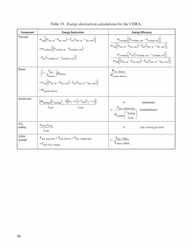
90
Table 19. Exergy destruction calculations for the CDRA.
Component Exergy Destruction Exergy EfficiencyPrecooler
!m air hair, in − hair, out( )−Tref sair, in − sair, out( )⎡⎣⎢
⎤⎦⎥
+ !m coolant hcoolant, in − hcoolant, out( )⎡⎣⎢
−Tref scoolant, in − scoolant, out( )⎤⎦
!m coolant hcoolant, out − hcoolant, in( )⎡⎣⎢
⎤⎦⎥
!m air hair, in − hair, out( )−Tref sair, in − sair, out( )⎡⎣⎢
⎤⎦⎥
−&m coolant Tref s coolant, out − s coolant, in( )⎡
⎣⎢⎤⎦⎥
&m air hair, in − hair, out( )−Tref sair, in − sair, out( )⎡⎣⎢
⎤⎦⎥
Blower− 1−
TrefTblower
⎛
⎝⎜⎞
⎠⎟!Qblower
+ !m air hair, in − hair, out( )−Tref sair, in − sair, out( )⎡⎣⎢
⎤⎦⎥
+ !Wactual, blower
!Wrev, blower!Wactual, blower
Sorbent bed!Wheating( ) t heating( )
tcycle+
2 h2 − h1( )−Tref s2 − s1( )( )tcycle
0 (adiabatic)
1−&Xdes, sorbent bed
&Wheating
t heating
tcycle
⎛
⎝⎜
⎞
⎠⎟
(nonadiabatic)
CO2 venting
mCO2uCO2
tcycle
0 (all vented gas lost)
CDRA (overall)
!Xdes, precooler + !Xdes, blower + !Xdes, sorbent bed
+ !Xdes, CO2,venting
1−!Xdes, CDRA!X input, CDRA

91
where
!mair = mass flow rate of air through component hair, in = specific enthalpy of air entering the component hair, out = specific enthalpy of air leaving the component sair, in = specific entropy of air entering the component sair, out = specific entropy of air leaving the component !mcoolant = mass flow rate of coolant through the component hcoolant, in = specific enthalpy of coolant entering the component hcoolant, out = specific enthalpy of coolant leaving the component Tref = reference temperature Tblower = temperature of the blower W rev, blower = reversible work rate limit of the blower W actual, blower = actual work rate limit of the blower !Qblower = heat transfer rate from the blower scoolant, in = specific entropy of coolant entering the component scoolant, out = specific entropy of coolant leaving the component. !W heating = power consumption rate during the heating part of the cycle theating = duration of the heating part of the cycle tcycle = total duration of a full cycle h1 = enthalpy at the beginning of the heating part of the cycle h2 = enthalpy at the beginning of the cooling part of the cycle s1 = entropy at the beginning of the heating part of the cycle s2 = entropy at the beginning of the cooling part of the cycle !X des, sorbent bed = rate of change of exergy destroyed of the sorbent bed !X des, precooler = rate of change of exergy destroyed of the precooler !X des, blower = rate of change of exergy destroyed of the blower !X des, CO2, venting = rate of change of exergy destroyed from venting CO2 to space mCO2
= mass of CO2 vented to space uCO2
= internal energy of CO2 vented to space !X des, CDRA = rate of change of exergy destroyed of the CDRA !X input, CDRA = rate of change of exergy input to the CDRA..

92
Table 20. Exergy destruction calculations for the MCA.
Component Exergy Destruction Exergy EfficiencyMass spectrometer !Wpump − 1−
TrefTpump
⎛
⎝⎜
⎞
⎠⎟ !Qpump + !m air hair, in − hair, out( )⎡
⎣⎢
!Wrev, mass spec
− !Wactual, mass spec
Pump!Wpump − 1−
TrefTpump
⎛
⎝⎜
⎞
⎠⎟ !Qpump + !m air hair, in − hair, out( )⎡
⎣⎢
−Tref sair, in − sair, out( )⎤⎦⎥
!Wrev, pump
− !Wactual, pump
Heater !Wheater–
MCA (overall) !Xdes, mass spec + !Xdes, pump + !Xdes, heater 1−!Xdes, MCA!X input, MCA
where
!W pump = work rate of the pump Tpump = temperature in the pump !Q
pump = heat transfer rate from the pump !W rev, mass spec = reversible work rate limit in the mass spec !W actual, mass spec = actual work rate in the spec !W rev, pump = reversible work rate in the pump !W actual, pump = actual work rate in the mass pump !W heater = power consumption during heating !X des, mass spec = rate of change of exergy destroyed of the mass spectrometer !X des, pump = rate of change of exergy destroyed of the pump !X des, heater = rate of change of exergy destroyed of the heater !X des, MCA = rate of change of exergy destroyed of the MCA !X input, MCA = rate of change of exergy input to the MCA.
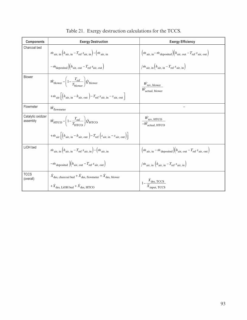
93
Table 21. Exergy destruction calculations for the TCCS.
Components Exergy Destruction Exergy EfficiencyCharcoal bed
!m air, in hair, in −Tref sair, in( )− !m air, in (
− !mdeposited ) hair, out −Tref sair, out( )
!m air, in− !m deposited( ) hair, out −Tref sair, out( )!m air, in hair, in −Tref sair, in( )
Blower!Wblower − 1−
TrefTblower
⎛
⎝⎜⎞
⎠⎟!Q blower
+ !m air hair, in − hair, out ( )−Tref sair, in − sair, out⎡⎣⎢
⎤⎦⎥
!Wrev, blower!Wactual, blower
Flowmeter !Wflowmeter –
Catalytic oxidizer assembly !WHTCO − 1−
Tref THTCO
⎛
⎝⎜⎞
⎠⎟!QHTCO
+ !m air hair, in − hair, out ( )−Tref sair, in − sair, out( )⎡⎣⎢
⎤⎦⎥
!Wrev, HTCO
− !Wactual, HTCO
LiOH bed!m air, in hair, in −Tref sair, in( ) − !m air, in (
− !m deposited ) hair, out −Tref sair, out( )
!m air, in − !m deposited( ) hair, out −Tref sair, out( )
!m air, in hair, in −Tref sair, in( )TCCS (overall)
!Xdes, charcoal bed + !Xdes, flowmeter + !Xdes, blower
+ !Xdes, LiOH bed + !Xdes, HTCO1−
!Xdes, TCCS!X input, TCCS

94
where
!mair, in = mass flow rate of air entering !mdeposited = mass flow rate deposited THTCO = temperature of the high-temperature catalytic oxidizers !W blower = work rate of blower !W actual, blower = actual work rate of blower !W rev, blower = reversible work rate of blower !W flowmeter = work rate of the flowmeter !WHTCO = work rate of the HTCO !W rev, HTCO = reversible work rate of the HTCO !W actual, HTCO = actual work rate of the HTCO !QHTCO = heat transfer rate from the HTCO &X des, LiOH bed = rate of change of exergy destroyed of the LiOH bed &X des, flowmeter = rate of change of exergy destroyed of the flowmeter &X des, HTCO = rate of change of exergy destroyed of the HTCO &X des, TCCS = rate of change of exergy destroyed of the TCCS &X input, TCCS = rate of change of exergy input to the TCCS.

95
Table 22. Exergy destruction calculations for the THC.
Component Exergy Destruction Exergy EfficiencyResistance temperature detector
!WRTD –
Fans (located in the common cabin air assembly (CCAA), avionics air assembly (AAA), and intermodule ventilation)
+ !m air hair, in − hair, out ( )−Tref sair, in − sair, out( )⎡⎣⎢
⎤⎦⎥
+ !m air hair, in − hair, out ( )−Tref sair, in − sair, out( )⎡⎣⎢
⎤⎦⎥
1−!Xdes, fan!Wfan
Condensing heat exchangers (located in the CCAA and AAA)
!mmoist air, in hmoist air, in −Tref smoist air, in( )
− !mmoist air, out hmoist air, out −Tref smoist air, out( )
− !mH2O, out hH2O, out −Tref sH2O, out( )+ !m coolant hcoolant, in − hcoolant, out( )⎡
⎣⎢ )−Tref s coolant, in − s coolant, out( )⎤⎦⎥
!mmoist air, in hmoist air, in −Tref smoist air, in( )⎡⎣⎢
− !mmoist air, out hmoist air, out −Tref smoist air, out( )
− !mH2O, out hH2O, out −Tref sH2O, out( ) ⎤⎦⎥!m coolant hcoolant, in − hcoolant, out( )⎡
⎣⎢
−Tref s coolant, in − s coolant, out( )⎤⎦⎥
Control of airborne contaminants/ filter !m air, in hair, in −Tref sair, in( )
− !m air, in− !m deposited( ) hair, out −Tref sair, out( )
!m air, in− !m deposited( ) hair, out −Tref sair, out( )!m air in hair, in −Tref sair, in( )
Water separator module !mH2O hH2O, in − hH2O, out( )−Tref sH2O, in − sH2O, out( )⎤⎦⎥⎡
⎣⎢!mH2O, out hH2O, out −Tref sH2O, out( )!mH2O, in hH2O, in −Tref sH2O, in( )
THC (overall) !Xdes, THC components∑1−
!Xdes, THC!X input, THC
where
!WRTD = work rate of the resistance temperature detector !mmoist air, in = mass flow rate of moist air entering !mmoist air, out = mass flow rate of moist air leaving &X des, THC components = rate of change of exergy destroyed of the THC components.

96
Table 23. Exergy destruction calculations for the WRM.
Component Exergy Destruction Exergy EfficiencyWater processor (WP) !WWP − 1−
TrefTVRA
⎛
⎝⎜⎞
⎠⎟!QVRA
+ !mH2O hH2O, in − hH2O, out( )(−Tref sH2O, in − sH2O, out( ))+ !mO2
hO2, in − hO2, out( )(−Tcabin sO2, in − sO2, out( ))
1−!Xdes, WP
− !Wactual, WP
Urine processor (UP)
!WUP + !murine −h urine, in − h urine, out( )(−Tref surine, in − surine, out( ))+ !mcoolant hcoolant, in − hcoolant, out( )(−Tref scoolant, in − scoolant, out( ))
1−&Xdes, UP
− &Wactual, UP
Vent− 1−
TrefTheater
⎛
⎝⎜⎞
⎠⎟!Qvent
+ &mH2Ogas hH2Ogas, in − hH2Ogas, out( )(−Tref sH2Ogas, in − sH2Ogas, out( ))
− 1−TrefTheater
⎛
⎝⎜⎞
⎠⎟!Qvent
⎛
⎝⎜
+ &mH2Ogas hH2Ogas, out−Tref sH2Ogas, out( ))&mH2Ogas hH2Ogas, in−Tref sH2Ogas, in( )( )
WRM (overall)
&Xdes, UP + &Xdes, WP
+ !Xdes, vent + !Xdes, other electrical work
1−!Xdes, WRM!X input, WRM
where
!WWP = work rate of the water processor !W actual, WP = actual rate of work of the water processor !WUP = work rate of the urine processor !W actual, UP = actual rate of work of the urine processor !Q
VRA = heat transfer rate from the VRA !Qvent = heat transfer rate in the vent

97
surine, in = entropy of urine entering surine, out = entropy of urine leaving !X des, UP = rate of change of exergy destroyed of the urine processor !X des, WP = rate of change of exergy destroyed of the water processor &X des, vent = rate of change of exergy destroyed of the vent !X des, other electrical work = rate of change of exergy destroyed of other electrical work !X des, WRM = rate of change of exergy destroyed of the WRM !X input, WRM = rate of change of exergy input to the WRM.
Table 24. Exergy destruction calculations for the WM subsystem.
Component Exergy Destruction Exergy Efficiency
Commode!Wfan + !Wpiston − 1−
TrefTwaste can
⎛
⎝⎜⎞
⎠⎟!Qwaste can
+ !m air hair, in − hair, out( )( −Tref sair, in − sair, out( ))
1−!Xdes, commode!Wfan + !Wpiston
Urinal!Wfan separator − 1−
TrefTfan separator
⎛
⎝⎜
⎞
⎠⎟ !Qfan separator
+ !m air hair, in − hair, out( )( −Tref sair, in − sair, out( ))
+ !m urine hurine, in − hurine, out( )(−Tref surine, in − surine, out( ))
1−!Xdes, urinal!Wfan separator
WM (overall)
!Xdes, commode + !Xdes, urinal 1−!Xdes, WM!Wfan separator
where
!W fan = work rate of the fan !W piston = work rate of the piston !Q
waste can = heat transfer rate from the waste can !X des, commode = rate of change of exergy destroyed of the commode !W fan separator = power consumption of the fan separator !Q
fan separator = heat transfer rate from the fan separator !murine = mass flow rate of urine hurine, in = specific enthalpy of urine entering hurine, out = specific enthalpy of urine leaving !X des, urinal = rate of change of exergy destroyed of the urinal.
98
3.3.7 Engineering Statistics
System parameters and environmental properties are not precisely known. There are many variations within tolerances of assembled systems and many variations and averages of environ-mental properties. These variations create distributions of values for the parameters and properties. Engineering statistics incorporate these distributions into the understanding of the systems, defin-ing the uncertainty in models and predictions, and allowing unexpected interactions to be seen in the overlap of these distributions.
System measurements are gathered about the system through testing and operation. Without an understanding of the system interaction physics, these measurements are often determined sub-jectively leading to unintended gaps and duplications (an unintended consequence of ignorance of these interactions). A better approach is to apply statistical methods along with an understanding of the system interaction physics to provide a more rigorous mathematical basis for measurement locations. Two statistical methodologies are often employed to assist in the identification and evalu-ation of the value of information. The first is an a priori methodology to guide future experiments or simulations to provide maximal information value of data yet to be taken. The second is an a posterriori methodology used when data already exists.
One of the most powerful and unifying concepts of information theory is the Akaike Infor-mation Criteria (AIC).44 Knowing the system state variables, AIC can be used to provide a statisti-cal measure of the system state. The difference in the measure of the system state and the actual system state provides knowledge of the gap of between how well the given state variables and their values describe the system. Quantification and allocation of this knowledge gap provides guidance on the next set of experiments to be designed to improve that knowledge, employing such techniques as Bayesian updating. AIC can also be corrected (AICc ) for system statistical models with a large number of parameters compared to the available system assessment data. This provides a penalty for models having too many parameters for the available system data. Employing AIC along with both the a priori and a posterriori methodologies acts as a filter to ensure that only the relevant, value-adding information from the state variables is included in the assessment(s). In so doing, the models are simpler, and the information content is the same. Knowing the parameters required for a system characterization notably reduces the requirements for sensors and sensor data in complex systems.
The first step in conducting an information theoretic statistical analysis is selection of an appropriate statistical model for the system. This is based on the system integrating physics. By understanding the system functions and environmental interactions, statistical models with relevant parameters describing all the system functions and interactions can be determined. A single model may not be obvious depending on the maturity of the system design information and maturity of system test data needed to validate the models. Thus, a set of models should be considered.
When evaluating system measurements, a system truth reference must be selected. One approach to this selection is to establish a model based on a complete set of sensor measurements of the system. Modern discipline models provide fairly high fidelity physical interactions and support a reference model approach using a network of sensors to fully characterize the system. This is

99
similar to the finite element matrix models used in structural analysis, where each node serves as a reference point in the model. The important idea is that the reference model captures all effects intended for the system sensor suite to monitor.
If actual system test data are used, these data contain the physical truth of the system, though all of the interaction parameters may not be obvious and measurement errors will be present. The system reference model then should provide a more accurate representation of the system data. Other measurements will need to be considered for the system reference model if there are signifi-cant errors with the system test data (beyond those which can be accounted in the measurement error).
Each candidate statistical model of the system can then be compared with the system refer-ence model to calculate the AIC or AICc relative measure. Remember that AIC and AICc provide a relative measure, indicating which model is closest to the physical truth. This calculation provides a set of deltas for each model as compared to the model with the lowest AIC or AICc score (but not a delta with the system reference model). The system reference model is not used as the delta, as it has unknown errors with regard to the actual system truth which are constant in all comparisons. Thus, the difference between the reference model and physical truth is removed from the delta calculations as a constant.
Having determined the best relative model within the original selected set of system statis-tical models, selections can now proceed. As a rule of thumb, table 25 provides the deltas which should be considered further.
Table 25. System statistical model comparison based on AIC or AICc deltas.
∆ AIC or AICc Value Indication0 to 2 The system statistical models are almost equivalent representations of the system
>2 to <4 There are significant contributions contained within the models compared with the best model4 to 7 There may be some important contributions from different model parameters which should be
considered based on system integrating physics>7 to 10 Less significant differences in parameters. Could be some important parameters in the differ-
ent models but not as compelling>10 The model is not comparable to the best model in the set being considered
Models with values of 4 or less should be considered as relatively good models. Combining these models in a weighted average may provide a better representation of the system. The AIC or AICc weight can be used for the weighted averages in these cases. Be aware that weights < 0.1 indi-cate a very low contribution by the particular model, and this model(s) may be best excluded from the averaging.
Having calculated a best model or subset of statistical models for the system, two paths are available. Additional models can be formulated to determine whether a better understanding of the system is obtained through other parameters or relationships, or assessment of the system can

100
proceed with best model or weighted average of closely related models. Sensor selection then is based on the parameters used in the selected model (single best of weighted average). These parameters indicated the measurement that should be made to provide the most information about the system.
Other approaches may be considered, including Takeuchi Information Criteria (TIC) and Bayesian Information Criteria (BIC). TIC uses the trace of the product of the Jacobian Matrix with the Fisher Information Matrix. These matrices require some mathematical effort to construct, and the trace of this product generally converges to the number of parameters, K, used in the AIC adjustment parameter. Thus AIC is generally the recommended approach over TIC.
BIC uses the logarithm of the number of data points as the adjustment factor and is not actually an information theoretic representation. If the actual true physical representation of the system can be achieved and is in the set of system statistical models, then BIC will identify this model always. This is important but has some limiting assumptions. From a full system perspective, BIC assumes a small number of model parameters (<5). For complex systems, the number of parameters is generally >100. (A launch vehicle has over 200 state variables in its full system representation.) As the number of parameters increases, the results of AIC and BIC become similar. BIC also assumes that all the system statistical models have equal probability prior to application and does not factor in the knowledge of the system which may change the understanding of these probabilities. Thus, the specific system being analyzed and the size of the statistical model needed to represent the system are important factors in determining whether to use BIC or AIC.
3.3.8 Multidisciplinary Design Optimization
An important modeling technique that utilizes system state variables and accounts for statistical variations in modeling the system is multidisciplinary design optimization (MDO). MDO can use system efficiency or system value to determine the optimal (i.e., best balance) for the system function. This modeling approach examines the holistic analysis and optimization of a system comprising subsystems that interact through inherent couplings (i.e., state variables). Because of emergent properties, systems cannot generally be optimized for a given characteristic by optimizing the functions or disciplines and combining them. MDO provides a method to balance the full integrated system rather than the components individually.
MDO evolved from structural optimization in the 1980s, with a primary focus on system design space search. Subsequent expansion of the field included emphasis on analysis of coupled subsystems, decomposition, surrogate modeling, sensitivity analysis, organization of information flow, coupling suspension, trade space exploration, and exploitation of concurrent processing capabilities for increased efficiency and efficacy.
In MDO, couplings refer to the inherent connections between one discipline or component of the overall system being designed and another discipline or component. These couplings do not necessarily have to be physical connections, but may be connections through physics (i.e., air distur-bances), or information (i.e., fuel pressures measurements). These couplings form the holistic system and must be properly captured to ensure system-level optimization. An understanding of the system interactions is necessary to develop an appropriate system model. Where there is uncertainty in

101
interactions, some MDO frameworks can be used to assess the sensitivity of the system to various system interactions.
Numerous MDO frameworks have been developed. These can be categorized as either mono-lithic or distributed model architectures. Table 26 lists the different model types in each of these cat-egories following the classification summary defined by Martins and Lambe.45 Other methods are also available depending on the specific system structure and interactions including:
• Monolithic architecture (simultaneous analysis and design (SAND)) • Distributed individual discipline feasible (IDF) architecture (enhanced collaborative optimiza tion (ECO))• Quasi-separable decomposition (QSD) • Exact penalty decomposition (EPD) • Inexact penalty decomposition (IPD) • Distributed multidiscipline feasible (MDF) architecture (asymmetric subspace optimization (ASO)).
Table 26. MDO model architecture types.
Monolithic Architecture Types
Previous System
ApplicationsDistributed IDF
Architecture Types
Previous System
Applications
Distributed MDF Architecture
TypesPrevious System
ApplicationsAll at Once Optimi-zation (AAO)
General Collaborative Optimi-zation (CO)
Aerospace, Aircraft, Air-craft Families, Automobile Engines, Bridges, Flight Control Systems, Flight Trajectories, Instruments, Launch Vehicles, Railway Cars, Rocket Engines, Satellite Constellations
Concurrent Sub-space Optimization (CSSO)
Aircraft Engines
Individual Discipline Feasible (IDF)
High Fidelity Models Bi-level Integrated System Synthesis 2000 (BLISS 2000)
Launch Vehicles Bi-level Integrated System Synthesis (BLISS)
Multidiscipline Feasible (MDF)
Analytical Target Cascading (ATC)
Aircraft, Automobiles, Buildings, Manufacturing, Supply Chain Manage-ment, Marketing
MDO of Indepen-dent Design Sub-spaces (MDOIS)
Aircraft, Systems with large discipline/ sub-system computational imbalances
Each MDO framework has different advantages, requiring an understanding of the system before selecting the framework to enable optimization. Advances in concurrent processing (includ-ing multiprocessing, field-programmable gate arrays, graphic processing units, and decomposition approaches, etc.) have provided new avenues of exploitation for MDO.
Related fields offer valuable tools to be used in relationship to MDO. Traditional and heuristic optimization methods offer algorithms to perform the system’s optimization. Multi-objective optimization (MOO) offers algorithms and methods to optimize a system using more than one objective or preference. Value-driven design offers tools to determine and model a single

102
preference for the system. Design structure matrices (DSM) enable a visualization of the couplings that exist between the subsystems and components, enabling resequencing to accomplish system level targets in cost, time, or iteration. Trade space exploration enables the engineer to explore the design in manageable portions, streamlining the data that are being gathered to provide for more informed decision-making. MDO and these related research areas provide a powerful set of tools to optimize and analyze a system comprising a complex network of interactions. MDO Coupling Analysis (MDOCA) provides an optimization of the coupling variables (i.e., system state variables) of the system.
The following are general steps in the application of MDO for system design:
(1) Determine the system state variables. These are contained in the GFT which provides an input to the MDO model development. The system integrating physics should be included in this.
(2) Determine the relationships between the state variables in the system. This supports the definition of shared variables and system constraints for the model. The MDO model may require the incorporation of mathematical models from the different disciplines, subsystems, and environ-ments that comprise the system and its operational environment.
(3) Determine the structure of the system model. The system integrating physics provides a structure in which to attach the differing discipline and subsystem models into the full system model. In addition, the GFT structure can be used to help determine the allocation of subsystems or discipline submodels within the MDO or MDOCA system model. The GFT and system integrat-ing physics models will deepen as design decisions are made and knowledge of the system increases. This can guide the maturation of the MDO/MDOCA model as the system progresses through the design.
(4) Select the appropriate MDO model architecture for the system design and design matu-rity. Monolithic architectures may be sufficient and most efficient early in the system development lifecycle. As the system progresses through the design lifecycle and design decisions are made, the understanding of the system deepens and the model maturity should also increase. This may lead to a distributed MDO architecture as the design progresses. The need for the more comprehensive model may occur early in the design cycle in support of PDR or similar type design assessment point.
(5) Construct and execute the MDO model. Note that super computer execution platforms may be necessary for complex system model execution. Results will provide input back to the sys-tem functional designs and subsystem designs and will form the basis of some system level and subsystem level requirements as model constraints and coupling variables are determined for the optimized system.
3.3.9 Relational Models
System models that are focused on the functional relationships and process flows in the development cycle are useful to the systems engineer, especially early in the system lifecycle. Sometimes referred to as model-based systems engineering (MBSE), these models are typically built

103
using a System Modeling Language (SysML) tool (e.g., Cameo Magic Draw, IBM Rhapsody, and Enterprise Architect). These type of models allow relationships to be visualized for requirements, for functions, and for process flows. Various types of model views can be generated including requirement traceability, system functional flows (i.e., functional flow block diagrams), and system process flow use cases such as development cycle activities, production activities, and operational activities. These models are abstracted from the system physics and provide a visualization to create an organizational understanding of the requirements, functions, and process flow relationships. These models can provide input to more detailed models such as production activity flows providing initial structure for the development of a discrete event simulation (DES).
3.3.10 System Schedule
The system milestones serve as constraints on the system development or operation as discussed in section 3.1.7. The full system schedule is a model of the activities and timelines to develop, manufacture, and operate the system consistent with the schedule constraints. The schedule is a plan, not a fact, and it should be expected that changes will occur in the system schedule as the understanding of the systems integrating physics and/or software logic expands through the design process. The schedule is dependent on the systems integrating physics because the decisions made during design can impact the timelines. Choosing a fossil fuel electrical power plant or a nuclear electrical power plant impacts the development schedule as well as the manufacturing and operational timelines. The physics of these systems drive very different schedules in the system development.
The systems engineer should understand the schedule and the timeline implications for each configuration and specific design decisions prior to the decision (principle 1). The system schedules and timelines can be organized around a properly structured system PBS (principle 3(f)), providing a common framework for both budget and schedule decisions based on a system view point.
3.3.11 Safety and Mission Assurance Analysis Models
Safety and Mission Assurance (S&MA) also has some analysis techniques which provide a limited view of system interactions. Failure mode and effects analysis (FMEA) is a bottom-up technique to consider system failures. Because this is a bottom-up technique, it matures very late in the design and does not provide the systems engineer with a good understanding of the system interactions early in the design process. It is based on an understanding of the system integrating physics of the system but does not address all of the systems integrating physics interactions intended for the system, only those identified as failure modes. The effects considered are also generally limited and do not always trace through the full system or capture all possible interactions. Frequently, only the most severe interactions are captured. Hazard Analysis is a top-down technique and is more useful earlier in the design process. This takes several forms, including fault tree analysis (FTA). Similar to the FMEA, FTA identifies potential failure points (i.e., hazards) in the system design and operation, but it may not identify all hazards in system interactions. This analysis typically focuses on the most severe results and may not trace all system interactions. While these techniques are helpful for S&MA purposes, the systems engineer should view this from the deeper system
104
interaction understanding viewpoint to ensure these analyses have captured all system failure modes and hazards correctly.
Failure models (i.e., Fault Trees, Probablistic Risk Assessments (PRA), Failure Models and Effects Assessments (FMEAs)) represent mechanisms by which design components fail and their effects propagate through the system, or by which intentions are violated. Since many failure effects propagate along the same paths as exist in the nominal design, nominal design models are a starting point to create design failure models. However, failures often create new paths that are not represented in the nominal design models, such as electrical short-circuits, or an explosion releasing debris that impacts other components that are not physically connected to each other nominally. Thus, failure models are more complete representations of the system than nominal models. Other failure models are based on intention, by assessing ways by which intention is violated using a top-down hierarchy of failure to meet goals. While today these are usually based on natural language, these can be transformed into state-based models (i.e., Fault Trees) that are the logical complements of the GFT.
3.3.11.1 Risk Identification. Decisions about the system are generally made under uncer-tainty, accounting for system risk (principle 9). System risk includes technical performance risk, cost risk, schedule risk, and safety risk. These risks are inherently related to the ability of the system to fulfill the system application context and are derived from organizational sources as well as from an understanding of the systems integrating physics and/or software logic. System uncertainty and sensitivities are a source of risk in the system, as they indicate areas where a detailed knowledge of the system is not present in the organization. Decisions made on these poorly understood aspects of the system lead to unintended consequences (see “Unintended Consequences, Ignorance” in section 4.1.2.11). Thus, knowing where the systems integrating physics, including all system interac-tions, is understood and not understood is essential to system risk definition and system decision making.
3.4 System Testing
System testing is an important source of information to understand the system prior to operations. There are several different types of testing including development testing, qualification testing, verification testing, system certification, and system validation testing. These types of test-ing provide specific information on the functions and interactions of the system, subsystems, and environment.
3.4.1 Development Testing
As the system design progresses, assembling and operating components are necessary to understand their functionality and interactions. These activities are performed as part of develop-ment testing. This testing can occur from benchtop to scaled test articles to full-scale systems. Com-ponents, assemblies, and subsystems are generally tested and provide a wealth of understanding on

105
the functioning of these test objects (i.e., the object being tested as opposed to other components needed to support or conduct the test). These tests are often early in the development cycle, starting just before PDR and extending to CDR. These development tests provide information guiding the designers in the construction of their component designs. When systems become extremely large and complex, such as launch vehicles, ships, etc., then full-scale system tests are not always conducted. If the system is known or similar to an existing system, then a full-scale test may not be necessary. These tests can be a strong budget and schedule driver, so the systems engineer needs to look at the technical rationale for full-scale testing to determine if the system can meet its intended goals without this testing. When full-scale testing is not accomplished, portions of the system are generally tested as elements (i.e., contained segments of a system) or subsystems. The systems engineer should use these partial system tests to gain information on the expected system functionality. System-level test objectives should be included as part of these partial system tests to ensure valuable understanding is included in the test construction and information on system performance is not lost or overlooked in measurements and analysis results.
As the design is completed, developmental testing transitions to qualification testing.
3.4.2 System Qualification
System qualification involves ensuring that the system will operate as intended at the design limits. The focus is on the design limits, including the system margins (e.g., factors of safety). This can involve testing the system or components to failure showing that the system is functional at the design limits and determining the actual system failure point (and therefore actual margin). Proper qualification requires a complete understanding of the systems integrating physics and the system environments (both natural and induced). Knowing the uncertainties and sensitivities of the system is necessary to properly set the qualification limits.
For smaller systems, complete qualification units may be fabricated and tested at the limits of the specifications. These test results are a final source of information on system interactions across the system operational limits. The qualification limits should be analyzed to ensure all system interactions are fully understood.
For larger systems, system elements or subsystems may be qualification tested and the final system qualification determined through integrating the results of the individual element or subsystem tests through analysis. As with system development testing, these partial system (i.e., element or subsystem) qualification tests should include system test objectives. In these cases, full system interactions may not be reproduced or seen in the testing, and more dependence is placed on analysis. This requires a strong understanding of the system interactions and will lead to more uncertainty margins during the first full system operation. Expected sensitivities are critical to understand, and margins will need to be carried for integrated system sensitivities as well. It is critical for these systems that the sensitivities be well understood to avoid unexpected performance during initial operations.

106
Once the system is qualified, verification testing takes place. Note that qualification testing can often be used for verification testing, depending on the specific test criteria and the scenarios used in the qualification test.
3.4.3 System Verification Testing
Verification of the system interactions is a key aspect in ensuring the system design meets the intended outcomes (system efficacy measure) for the system. The focus in verification is on the system functions, their interactions, and the interactions with the system operational environment (both natural and induced environments) (principle 10). The intent of verification is that the design will perform as intended in the system requirements and design. Note, this is not a rote verifica-tion of requirements, which represent the organizational understanding of the system, but do not necessarily contain a full representation of the system. The systems engineer should ensure that the individual system elements/functions perform correctly, and that the system as a whole performs correctly, accounting for all system interactions. This provides a focus during verification on the operation of the system.
Verification should make use of the system models in analysis and make use of system test-ing. System models must be validated to ensure they properly represent the functioning of the real system. NASA-STD-7009A46 and NASA-HDBK-7009A47 provide guidance on this validation, the information needed to be collected about system models (i.e., the metadata), and the information needed for the operational applications of models. Validation of models used for system and compo-nent design and verification is essential and often based on development testing, qualification test-ing, or specific verification testing results. System testing also provides the opportunity to measure and identify system interactions whether previously anticipated or unexpected.
System verification occurs progressively throughout the design process as the understand-ing of the system deepens (principle 3). This verification occurs in two ways: (1) System models are validated against test data, and (2) the system design is verified against system test data and the sys-tem model analysis results (principle 10). At each lifecycle review, the system physics models verify the system design (sometimes referred to as the design ‘closing’). The system models themselves are validated (in terms of accurately representing the system interactions and responses) against test data early in the design phases of the development lifecycle and are used to understand unexpected system interactions with the test fixtures and test environment. The state variables captured in the system integrating physics models, GFT, and system SAM provide guidance in how to structure the final system verification at the end of the development phase. SAM provides the capability to more fully test the system algorithms in a full system state model to ensure they function as expected. This enables the reduction of real-time software testing to only those aspects needed to validate the SAM, confirm hardware timing, and confirm critical events. System verification should be a culmi-nation of a progressive verification approach rather than waiting until the system design is complete to start verification. Verification ends with the first full-scale system use or flight (flight systems include aircraft, rockets, ships, etc.). The results of this operational use provide confirmation that the system functions as intended. If the system does not function fully as intended, then a corrective development cycle will be necessary. System models are essential to analyze the operations data and ensure that the system corrections will achieve the intended system functionality.

107
3.4.4 System Validation
Separate from verification, the system value model provides guidance in the establishment of the system validation (comparison of the as-built design to the stakeholder’s expectations). System validation is also a progressive activity, with the as-designed system value model compared against the stakeholder’s value model to ensure the system design is converging toward the intended system capabilities.
System validation is based on meeting the stakeholder’s preferences as captured in the system value model (principle 11). The system value for the stakeholders and for the system and the system capability model are compared with the system value generated as the system design progresses through the system lifecycle, providing incremental system validation. This also allows changes in the stakeholder’s preference as technology changes and application understanding change (principle 13) to be managed during the design. The system definition concept progressing into the system design value model should be compared with the stakeholder’s value model at each major milestone (e.g., SRR, SDR, PDR, and CDR). The as-designed and as-built systems should be compared to the stakeholder’s value model to determine how well the system meets the intended outcomes at the System Acceptance Review (SAR) (which may also be in the form of the initial Flight Readiness Review). The value model’s final confirmation is after the first full test of the operational system. These results feed into the Systems Acceptance Review.
The results of the system verification and the system validation provide the basis to accept the system or correct the system design or production processes prior to system release (e.g., first flight, system fielding, system deployment, market release date).
3.4.5 System Acceptance
System acceptance is the culmination of all system development (i.e., design and testing) activities. The results of the qualification, verification, and validation activities are reviewed to ensure that the developed system will perform the intended functions. In addition, system accep-tance involves ensuring all of the pieces of the system are delivered physically with all of the intended functionality. Physical Configuration Audit (PCA)) confirms that the all system physical compo-nents and software are present. The Functional Configuration Audit (FCA) confirms that the sys-tem has all of its intended functions. These important audits focus on accounting of the system against the final design baseline.
Some organizations will also conduct a Design Certification Review (DCR) to certify the system design is complete and contains all of the intended functions. This DCR can be in concert with the PCA and FCA. For flight systems, the results of the DCR form the basis of the AR and the first vehicle’s Flight Readiness Review (FRR). System design certification involves an assurance that the system can successfully accomplish a specific mission. System certification encompasses system verification, qualification, and validation activities for the specific system instantiation (e.g., launch vehicle, space capsule, satellite, aircraft, power plant). While certification is a comprehensive view of previous system development and manufacturing activities, the focus of certification is on the specific system’s ability to accomplish the planned mission. This brings together all aspects of

108
system application context understanding and the systems integrating physics and/or software logic basis. Certification is primarily focused on system effectiveness, that the system will perform all intended functions within the system application context. System acceptance is generally concur-rent with transition from the development phase to the operational phase. As such, information needed for maintenance and operation is typically included in the acceptance package.
3.5 System Manufacturing
Manufacturability is a critical part of the system design. The design must support manufac-turing methods and approaches within the system budget, including human factors. Poor manufac-turing designs can lead to repetitive work, rework, or retesting, which drives cost and manufacturing timelines. Materials chosen for the system design affect the selection of manufacturing processes that can drive manufacturing costs and schedules. Manufacturing engineers are responsible for the definition of manufacturing constraints, and the systems engineer should ensure that these manu-facturing and materials constraints are properly integrated into the design early in the development lifecycle.
Manufacturing changes to address tool path interaction and limitations can also lead to subtle changes in system behavior. These changes should be captured in updates to the system models to ensure unexpected adverse system behavior does not result in the system design. Small dimensional changes can sometimes create thermal lead paths, frictional wear, electrical lead paths, stresses or strains, etc. These can be sources of fault paths in the system and should be assessed to ensure the system does not have any adverse effects from these changes.
Analysis of manufacturing includes several aspects including human factors and manufac-turing process flows. Manufacturing uses models to consider accessibility of parts and compo-nents during manufacturing and assembly. Human factor interactions can be modeled or tested to ensure proper clearances exist for manufacturing, maintenance, and operations personnel to properly interact with the system including any tools, equipment, or personal protective equipment necessary. These assessments should be done early in the design cycle to help drive the design for accessibility to support manufacturing.
Manufacturing process flows are extremely important to understand as part of manufac-turing facilities layout planning. Relational models can be used to define high-level process flows early in the development phase. These models should flow into Discrete Event Simulations (DES) to allow for much more detailed flows with statistical variations to understand the sensitivities in the manufacturing flows as the design progresses and manufacturing needs are understood. These process flows can constrain the production rate and have an effect on the availability of operational systems for a specific mission or set of missions. DES provides an excellent modeling tool to under-stand production bottlenecks and limits so that the manufacturing process does not limit the system applications.
Manufacturing typically starts with the first test unit of the system. This provides for check-out of the manufacturing process as well as a test unit for the system. The first test unit is the final verification of the system as discussed above. As manufacturing baselines are defined, the system moves into the operational phase.

109
3.6 System Operations
Systems engineering is an important part of the operations lifecycle phase. Relationships can change frequently with the advent of system operations. In systems that have operators, such as industrial plants, electrical power plants, air traffic control systems, space systems and ships, the operators become a primary focus in system execution with the systems engineer providing the basis for the system operations.
System models provide the medium for the transfer and maintenance of system knowledge from the development lifecycle phases to the operational lifecycle phase as discussed at the end of section 3.3.1 and in section 3.3.2. The information contained in the systems models are necessary for the proper construction of operational processes and procedures. State variable models provide the basis for parameters to be monitored for proper system operations. SAM also provides an analysis for operational sequences of the system. The systems integrating physics basis establishes the operations limits and constraints. These limits and constraints are incorporated into the operational procedures and must be understood by the operators. Operations are often based on resource allocations taking into account the system’s ability to supply electrical power, thermal conditioning, fluids, gases, and crew time. The operations engineers are responsible for the definition of the system operation, providing input during all phases of the design process to ensure system operability. Note, these are not design metrics but realizable system attributes that provide for an effective, efficient, and robust system operation. The systems engineer should ensure that these inputs and constraints are properly integrated into the system design. The operations engineers depend on the systems engineer to ensure that the correct system information (drawings, models, specifications) are provided as the basis for operations. NASA-STD-7009A addresses the use of system models for operational decision making and is an important standard for systems engineering to ensure that design or analysis models used in operations are properly validated and documented.46
Systems engineering continues to make use of the system models as the work in system repair responses, system upgrades, and replacement of components, assemblies, or subsystems as part of obsolescence management. The system models provide the system baseline as the starting point for the system changes and are updated to reflect the system evolution due to these factors. These models then support operations engineering in the revision of processes and procedures.46
The final lifecycle phase, decommissioning and disposal, starts with the system models. These provide the fabric from which to identify and construct the plan for disassembly and disposition of systems, manufacturing facilities, and operations facilities. These models also provide significant value as input to future programs and as the repository of system understanding for lessons learned.
3.7 Engineering the System in System Lifecycle Summary
The system lifecycle provides a strong progression for the development of the system. Systems engineering follows this lifecycle well, using the systems engineering processes to organize the engineering activities and results. Whether employing a waterfall, spiral, agile, or other lifecycle model, the lifecycle involves several phases.

110
The system lifecycle begins with the definition of the mission context (system application) and the understanding of the system needed to achieve the intended results for the application. This phase results in an understanding of both affected and interested stakeholder’s preferences, definition of the application or uses of the system, definition of system MoE and measures of effectiveness, and definition of system constraints.
Following definition of mission context and understanding of the system, system design and analysis occurs. This phase employs system models to understand the system state variables, system integrating physics, engineering statistics, MDO application, relational model, schedule models, and S&MA models. The results of this phase are a much deeper understanding of the system functions, the interactions between the system functions, and the interactions with the system environment.
System testing follows design and analysis. This phase provides system qualification, veri-fication and validation (including model validation), system acceptance, and system certification. This phase involves a focus on gaining an understanding of the system functions, their interactions, and the interactions with the system environment. Specific system tests can be conducted or system knowledge can be explicitly gained from discipline-based tests if these tests are properly constructed to include system responses.
System manufacturing follows system testing dealing with the production of the system, hardware and software, and the final preparation for system deployment or use. System operations result from the deployed system. System operational procedures, constraints, maintenance and repair all stem from system understanding gained during earlier system lifecycle phases. System decommissioning is the final portion of the operational phase.
In addition, to these aspects of the system lifecycle, systems engineering integrates and coordinates the efforts of the different engineering disciplines involved in the system development and operations. The aspects of Discipline Integration are addressed in section 4.

111
4. PRACTICE OF DISCIPLINE INTEGRATION
Discipline Integration is a critical activity of the systems engineer. Information about the system resides in the organization, and information about the system can be filtered or changed as information passes between disciplines. Configuration management and data management of the system information are important aspects of managing the system information flow. The flow of information through the organization brings into play several practices from sociology and orga-nization theory. Related to this is putting policy and law into practice. These are generally socially constructed, focused statements that are important for the systems engineer to properly understand and apply to systems in development and operation.
4.1 Organizational Structure and Information Flow
The organization that designs the system is an integration of the disciplines which develop, manufacture, and operate the system. The organization itself is a complex system, which is put in place to develop a complex system (principle 2). The relationship between the system being developed and the organization is a key factor in system elegance that results from the development process and the execution of the manufacturing and operations of the system. Because of these relationships, the systems engineer has a special interest in the organizational structure and relationships.
The organizational structure and relationships are primarily the responsibility of the line organization and the program manager. They establish and manage the various disciplines or branches within the organization. These relationships form the medium through which the system information flows during the development and operation of the system and are vital to the suc-cess of the system. Figure 18 shows how the cultural influences are distributed among the systems engineers, project management, and line management. The systems engineer must recognize and understand the information flow that occurs through the organization to ensure an elegant system development and operation (principle 6). The systems engineer should work closely with the pro-gram or project manager ensuring the organizational structure is properly understood, blind spots and information choke points identified, and efficient forms of program organization within the line organization (e.g., design team structure, co-location, intra-organization communication, decision board structure) are considered. The systems engineer, taking into account how information flows through the organization, should recommend an efficient organizational structure and decision board structure to the program or project manager.

112
• Leader Behaviors
• Level of Employee Empowerment, Engagement, Teamwork
• Nature of Working Relationships (Internal & External)
• “Unwritten” Behavioral Expectations
• Celebrations/ Rituals/Traditions
• Archives/Stories
• Shared Basic Assumptions
• Monuments, Key Historical Events
• Heroes, Villains Ghosts
• The Way We Do Things Around Here
• The “Feel” of the Place
• Effects of External Image
• Mission
• Vision
• Values
• Philosophy/ Strategic Intent
• Key Objectives
• Key Strategies
Culture
Competency
Systems
Structure
Strategy
Line Management
Line ManagementSystems Engineering
Systems EngineeringProject Management
Project ManagementSystems EngineeringLine Management
Project Management
• Reporting reliability
• Roles and responsibilities
• Authority levels
• Defined Interfaces Internal/External
• Expectations
• Stated Norms
• Strategic/Tactical Planning
• Metrics/Balanced Scorecard
• Quality Systems
• Work Flow
• Information Flow
• Decision Making Processes
• Information Systems
• Personnel Systems
• Training & Development Systems
• Performance Management
• Feedback Processes
• Reward Systems
• Financial Systems
• Leadership and Management Skills
• Systems Engineering Skills
• Technical/Job Skills
• Financial Management Skills
• Project Management Skills
• Change Management Skills
• Interpersonal Skills
• Teaming Skills
• Continuous Improvement Skills
• Other Skills & Competencies as Indicated by Strategy, Structures Systems
Figure 18. Organizational culture influences.
Difficulties and inefficiencies within the organizational information flow and the board structure change flow can result in unintended consequences. Mitigation of these unintended consequences starts with a complete understanding of the organization structure and information flow. This section addresses the systems engineer’s role in recommending, understanding, and maintaining information flow in the program structure.
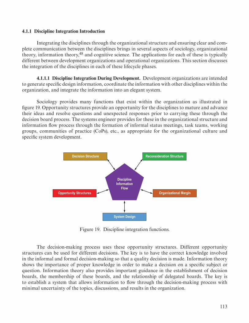
113
4.1.1 Discipline Integration Introduction
Integrating the disciplines through the organizational structure and ensuring clear and com-plete communication between the disciplines brings in several aspects of sociology, organizational theory, information theory,48 and cognitive science. The applications for each of these is typically different between development organizations and operational organizations. This section discusses the integration of the disciplines in each of these lifecycle phases.
4.1.1.1 Discipline Integration During Development. Development organizations are intended to generate specific design information, coordinate the information with other disciplines within the organization, and integrate the information into an elegant system.
Sociology provides many functions that exist within the organization as illustrated in figure 19. Opportunity structures provide an opportunity for the disciplines to mature and advance their ideas and resolve questions and unexpected responses prior to carrying these through the decision board process. The systems engineer provides for these in the organizational structure and information flow process through the formation of informal status meetings, task teams, working groups, communities of practice (CoPs), etc., as appropriate for the organizational culture and specific system development.
DisciplineInformation
Flow
Reconsideration StructureDecision Structure
Opportunity Structures Organizational Margin
System Design
Figure 19. Discipline integration functions.
The decision-making process uses these opportunity structures. Different opportunity structures can be used for different decisions. The key is to have the correct knowledge involved in the informal and formal decision-making so that a quality decision is made. Information theory shows the importance of proper knowledge in order to make a decision on a specific subject or question. Information theory also provides important guidance in the establishment of decision boards, the membership of these boards, and the relationship of delegated boards. The key is to establish a system that allows information to flow through the decision-making process with minimal uncertainty of the topics, discussions, and results in the organization.

114
Reconsideration paths (i.e., reclama paths) are a key sociological mitigation for those within the organization who disagree with a specific system decision or topic. This can lead to a social ambivalence in the organization that needs to be addressed through this mitigation (i.e., opportunity) path. The reconsideration boards should not be made up of participants in the development organizational culture, but should be able to discern the sociological as well as the technical forces contributing to the perceived conflict in the system. This helps mitigate social responses that can lead to system design activities or decisions moving outside the organizational structure or attempting to bypass certain decision-making steps.
The systems engineer should be aware that information may reside in the organization, but be unidentifiable in the design. A design that does not close may be due to margin in the design that is only identifiable by a discipline. Before action is taken to significantly change the system, the systems engineer should engage in unbiased information sharing with the affected disciplines to determine if there are factors (e.g., margin) which the discipline organization can change to support an improved design. The basic approach is to ask questions about conservative estimates, uncertainty margins, and actual factors of safety that may indicate design margin not otherwise identified. As discussed in section 4.1.5, this may be an iterative negotiation process where disciplines slowly release margins as their confidence in the system design grows.
Cognitive science is important in the consideration of both information flow quantity and in teaching systems thinking to engineers. Information flow quantity is based on the amount of infor-mation an individual can deal with at one time. This will place a limit on the amount of decisions that can be made about the system in a given board meeting and over a defined period of time.
Mediated Learning provides an approach to train engineers in how to consider designs at a systems level. These techniques can help in developing trade study teams, system integration teams, and systems engineers in general.
Policy and law understanding is essential to the systems engineer. Decisions on the system design must be made with a proper understanding of the intent behind organizational policy, government policy, and laws. Misunderstanding the intent can lead to over constrained or under constrained systems detracting from system elegance.
4.1.1.1.1 Discipline Integration During Operations. Operations organizations are intended to coordinate specific actions about a system based on a detailed understanding of the system’s behav-iors and responses defined during the system development. The discipline integration approaches are similar to those discussed with development organizations.
Operational organizations take many forms. Customer service operations organizations need the ability to matrix into the engineering teams for defined questions or issues. High-reliability organizations (such as those encountered in electrical plant operations, ship crews, or spacecraft operations teams) can have a more hierarchical structure which flattens during critical operations events to address high-risk factors in a timely and successful manner. Systems engineering must recognize the organizational constructs, how the engineering team integrates with these operations organizations, and how to ensure the correct information flows to the operations teams.
115
4.1.2 Sociological Principles in Practice
Sociology provides the basis for many important activities and organizational structures in a system development or operations organization.49,50 The practice of sociological principles provides the basis for various aspects of discipline integration. The systems engineer works in concert with both project management and line management as indicated in figure 18. The systems engineer’s focus is on the coherent flow of information through the organization.
In the systems engineering context, the systems engineer is aided by the technical nature of system design and operations. The physical reality of the system and the physics/logic rules that it must meet in order to achieve the intended outcomes, provides a diagnostic on the sociological nature of discipline integration. The technical basis provides a check against social biases in the organization. Social justification can quickly go to one of intent, where the technical justification is one of physics and mathematics. Using the technical basis, the systems engineer as a guide to iden-tify and adjust any social biases that exist in an organization. This is a tremendous help available in the systems engineering context.
4.1.2.1 Specification of Ignorance. Developers and operators need to understand what they do not know. The specification of ignorance is a social process where one is acknowledging not everything is understood. This forms a basis for the areas of investigation, analysis, and testing that should occur in order to learn what is presently not known. This is also a strong driver to the speci-fication of system risks where uncertainties are specified and dealt with. Risk definition starts with the specification of ignorance on a subject(s).
Systems engineers should identify what the unknowns are about the system. This can come in a variety of forms including system performance, margins, sensitivities, environments, interac-tions, etc. This provides important guidance for system analysis, discipline analysis, and develop-ment testing to determine the unknown system characteristics. The systems engineer should also be aware of sociological biases that lead to statements that there are no unknowns. This can lead to serious unintended consequences in system capabilities, schedule, and budget.
4.1.2.2 Socially Expected Durations. The participants in the system development or opera-tion will have an expectation for how long an activity should endure. When these expectations are not met, unease can develop in the organization which can lead to social ambivalence (discussed in section 4.1.2.8). The systems engineer must recognize what the socially expected durations are for the various system activities. Where new approaches, methods, or structures are applied in the orga-nization, it is important that these changes are explained and rationale provided to provide a basis from which to change the expectation and mitigate unease developing in the organization. Project managers, organizational line managers, or chief engineers can help in explaining the changes to the organization.
The systems engineer should ensure that the appropriate authority (project management, line management, chief engineer, systems engineer) explain the rationale and what their new expectations for project duration will be. This is a form of planned renegotiation51 that provides for adjustments in the social structure of the project and avoiding potential causes of social ambivalence.

116
Specifically, changing schedules can produce pressure on individuals in the organization which lead to ambivalent situations—situations where assigned goals appear to be blocked or unattainable in the new time schedule provided (either shorter or longer). If a schedule or budget is viewed as unrealistic, then social (organizational) commitment to accomplishing the budget or schedule may not exist.
4.1.2.3 Consistent Terminology. The systems engineer has to understand all of the contribut-ing disciplines to the system development or operation. It is important, at the system level, to use consistent terminology to aid in clear communication.
The systems engineer is not responsible for changing discipline terminology but translat-ing terminology to ensure communication is clear and consistent. Discipline-specific terminology is good and useful within the discipline and should not be discouraged. Communication between disciplines and at the system level should use consistent terminology. This can be derived from dis-cipline terms, especially when more than one discipline uses and understands the term in the same way. Creation of new terms is not the goal; translation of terms is the goal. Discipline terminology has developed over the history of the discipline (for most, this is well over 200 years) and is not easily changed as the terms are embedded in textbooks, references, and tools. This will be strongly driven by the type of system being developed or operated (postulate 1). Communication with external groups such as stakeholders, corporate management, and government agency leadership should also be taken into account when translating and establishing a consistent terminology.
4.1.2.4 Opportunity Structures. Opportunity structures are crucial to the successful development and operation of an elegant system. Opportunity structures are the social structures that exist within the organization that lead to social and cultural success. Systems engineers should establish organizational paths for the advancement of ideas to successfully accomplish the system goals. For example, an opportunity structure could be a peer review forum to express, explore, and vet new ideas and approaches in the system development or operation. A key characteristic of these structures is that they are not decision-making structures. Formal decision-making structures such as decision boards are not opportunity structures and are not intended for introduction of new ideas in the midst of decision. These formal structures depend on the exploration of ideas occurring in opportunity structures before a decision is brought to the decision-making body.
Opportunity structures can have many forms. CoPs provide an excellent manner for practitioners to share new ideas and perspective, gain feedback and critique, and improve on their idea (or abandon an idea shown not to be valid). Design team meetings, in some forms Integrated Product Team (IPT) meetings, provide another excellent forum for these types of ideas. It is fine to have an agenda for specific meetings and even a specific topic(s) for discussion; however, these should not be decision-making meetings. (Note that developing a recommendation can still be the objective in an opportunity structure.) Agile software and agile system approaches have these types of structures embedded in their daily and weekly team meetings and provide good approaches for some types of systems. Working groups, task teams, status meetings, and other similar type structures also provide this where they are not used in a decision-making capacity.

117
In contrast, decision-making bodies, (e.g., control boards) are not opportunity structures. These bodies function to select a single option. Their function is on filtering options down to a single course of action. Thus, they tend to stop ideas rather than allow them to mature. These bodies are not necessarily opposed to idea maturation, but they are expecting that has been done prior to presenting recommendations to the decision body.
The systems engineer should work with project management and line management to ensure opportunity structures are available at both the discipline or subsystem level and at the system level. Having these open expression forums is essential for the avoidance of unintended consequences (by providing an opportunity to recognize these consequences) and development of approaches that provide for an elegant system approach.
4.1.2.5 Organizational Culture and Cultural Subsets. There are three lenses from which to view social structure: Individual, group, and organizational.52 The individual view deals with roles (i.e., role sets as discussed in ref. 4) of individuals within the organization. The group view deals with languages and status (i.e., disciplines can have their own technical language and can be viewed as a group). The organizational view looks at organizational structure and culture (i.e., project and organizational norms). Sociology deals with all three of these views in various forms. This section deals with the organizational view and the group view (as it defines a cultural subset).
There are both manifest and latent social forces at work in the organization. Manifest social forces are visible and direct. Latent social forces are invisible and indirect.53 Most of what is addressed in this section are the more visible, manifest social forces. These are visible in policy statements, written norms, and behaviors in meetings and discipline interactions.
The culture of an organization defines its beliefs, assumptions, and behavioral norms. In other words, behavioral expectations are defined by the culture. A person’s best chance to be accepted, to be successful, to be listened to, or to be valued, is to conform to the set of behaviors that are defined by the culture. To behave otherwise (i.e., in a way that is counter to the culture) will almost certainly reduce a person’s effectiveness, influence, or opportunities in the organization. Thus, expecting individuals to act differently than their discipline subculture values is difficult and may not be possible. Thus, the systems engineer seeks to understand and relate to individuals within the subcultures in a way that is valued by that discipline. This supports open communication with engineers in the discipline.
Like the technical system, the social system (or culture) can be a source of high performance and competitive advantage if it is healthy. Or, it can be a source of risk if it is unhealthy. In spite of the impact of culture on performance, many organizations just allow their culture to evolve. This is a risk to the organizational information flow. Culture can be either anticipative (looking for what may happen next and how to respond) or resilient (stable and unmoving to change).54 The specific cultural form is important to understand and changing from anticipative to resilient or vice versa can be challenging. A lot of attention is paid to the technical side —the ‘hard’ skills, the work itself, the organization, roles and responsibilities, and processes. But the culture simply unfolds over time. And once culture has become ingrained in an organization (i.e., accepted as ‘the way we do things here’), it can be very difficult to change. This leads to cultures which have some aspects as helpful

118
and constructive, while other aspects may be impediments, hindrances, and roadblocks to progress. The systems engineer may need to work with line management and project management to address aspects of the discipline culture which make information difficult to flow.
Organizational culture can also drift over time, become accepting of anomalies or unknown areas of the system. There can be incremental descents into poor decisions if not addressed. The concept of normalization of deviance,55 the acceptance of system or organizational behavior that deviates from previous behavior, is an example of cultural drift. This is a risk to the system function-ing properly and to fulfilling system needs, goals, and objectives. Being able to specify ignorance and address it, not accept it, is a crucial aspect of systems engineering.50
Senior management shapes processes and organizational structure through reinforcement of rewards, status, resources allocations, and compensation. These influences are meant to engage indi-viduals within the organization to contributing behaviors to system success. Systems engineers can recommend individuals, disciplines, and subteams for recognition using the reinforcement means. Systems engineering recognition should focus on open and honest flow of information through the system, contributing to the systems success, even if the information challenges some beliefs held by the culture.
Middle management tends to hold the organizational culture in place. They are charged with stability, and they are rewarded based on the cultural values of the organization.56 Middle manag-ers can be project subsystem leads or chief engineers, organizational unit managers, and discipline leads or managers. Thus, a good indicator of organizational culture is to look at what this level of management within the organization and project actually value. This level of management is important for adoption of new ideas or approaches. Technical experts push ideas to middle manag-ers for sponsorship. If middle management adopts the ideas, then the organizational structure will drive the project strategy, and management will push the idea to senior executives (e.g., department managers, project managers, project chief engineers) for sponsorship and decision.57 Note also that communication flow through managers is more formal and can lead to poor information trans-fer and misunderstandings between disciplines.54 Informal communication is needed among peers with input and concurrence by managers.
Edgar Schein58 established the five characteristics of culture that are described as follows:
• Artifacts and symbols—visible signs and other evidence of what the organization values– Architecture of the organization and the facilities– Technology it chooses– Office layout– Manner of dress– Public documents like mission statements– Pictures and decorations on the wall and at desks– Cohesive symbols: uniform dress, no locks, pictures of employees on the wall; suggestion system– Stratifying symbols: separate washroom/cafeteria/floors, time clocks, reserved parking, special offices, progress briefing.

119
• Language—words and labels propagating throughout the organization– Jargon: language of the day, acronyms used, reference labels for customers or employees– Slogans: a phrase expressing the aims or nature of an enterprise; a motto– Metaphors: a figure of speech in which a word or phrase that ordinarily designates one thing is used to designate another, thus making an implicit comparison: e.g., blue suits, ivory tower, bean counters– Myths: a popular belief or story that has become associated with a person, institution, or occur rence, especially one considered to illustrate a cultural ideal; exaggerated stories based in fact that are meant to convey the culture
• Organization values: what the company thinks is important– General criteria, standards, or guiding principles that are used to determine the types of behaviors and outcomes that are desirable or undesirable– Terminal value: desired end state or outcome– Instrumental value: desired mode of behavior– Norms: standards of behavior that are considered acceptable or typical for a group of people.
• Basic underlying assumptions—how do people think and feel – Mental models of how the world works– Hidden within policies and procedures
• Patterns of behavior: those norms manifested in actions– Organizational norms: certain way we do things– Attitudes and behaviors: work ethics, adding margins, etc.– Subcultures: unions or different functional groups (i.e., disciplines)– Rites and rituals: coffee/lunch breaks, briefing approvals, celebrations– Heroes and role models who personify the culture.
Cultures can be very strong and can enhance or impede appropriate design endeavors and decisions. It is important to understand the aspects of culture that currently exist in the overall organization. If a change needs to be made, the systems engineer should make a conscious effort to work with program or project management to put the appropriate norms in place to facilitate pro-gram/project success. Pictures of successful projects should be prominently displayed. The language used should be respectful, honest, and complete. Values should be easily detected in the language and symbols. How the program operates (e.g., integrity, openness) and how the product is perceived (e.g., quality, safety) should be a visible and consistent theme within the value set. Then, underlying assumptions and patterns of behavior can be guided by the values established and communicated through the language and symbols.
Organizational culture needs to embrace failure possibility in order to understand the system and the organization. The complexity of the system needs to be embraced rather than looking to simplify the understanding of interactions (hides information). There are ambiguous threats to the system and organization that afford time to respond if identified instead of hidden in the social structure. Sensitive information needs to be free to share with decision makers. Opportunity structures can help frame these presentations more carefully. Small problems provide a causal chain in the organizational structure that may indicate larger problems. Looking for blame is localized and misses the broader systemic problems that may exist in the organization.54 Root cause has a specific
120
initiator. Root cause also has a systemic facilitator or transfer medium. Both exist compatibly to produce failures in complex systems and complex organizations.
Cultural subsets will exist in any complex organization. These subsets are natural and can be based on a variety of cultural factors. In an engineering context, engineering disciplines form cultural subsets. The systems engineer should be aware that these exist and help to mitigate any actions that impede information flow through the system. This may involve discussions with project management and line management to help deal with any insider activities (i.e., activities where a group believes they are the only ones who can understand certain facts or information and act to withhold access to this from those outside the group). These types of actions can lead to failure of the organization; therefore, a failure of the system (or result in an inelegant system at best) in extreme cases where social ambivalence (discussed in section 4.1.2.8) and dysfunction sets in. These extreme difficulties lead to a disruption in information flow within the organization and failure of the system.
Insider behavior, where organizations withhold ‘private’ information and share more gener-ally known information, is a serious information flow block. Organizations can also withhold infor-mation as a form of leverage or power. They can filter released information for fear of failure or loss of control.53 Biased information sharing is a form of information leveraging and filtering by which the organization ensures that it can be successful with its system functions. However, this can also be a risk to the system because it can force unnecessary design changes (due to more margin being held in the design than is needed and can be supported). A data clearinghouse could be established (some model-based systems engineering approaches attempt to do this), but the risk is added hier-archical complexity in the information flow. Peer-to-peer information flow is crucial, especially in complex organizational structures to ensure information is flowing as needed.
At the discipline level, there can be a shift from project policy to local discipline policy (termed practical drift). These policy shifts typically are not explicitly communicated.53 The systems engineer should ensure transparency in information transfer and avoid information silos that can form from local policy differences. The systems engineer should ensure that there are clear processes for transfer of system information between the disciplines and that the discipline teams understand these. Note that these differences can lead to a socially ambivalent situation.
Groupthink54 is an aspect to understand in various forms and organizational subsets. This can occur in trade study teams, working groups, disciplines, subsystems, at the project level, etc. This can cause a serious filtering of information flow and can lead to a shift or nonassignment of accountability. This results in hidden information and a lack of responsibility to resolve issues, in particular, organizational issues. Individuals in groupthink situations can choose psychological safety and do not express counter or dissenting opinions (fear to speak up), a serious block in information flow. Opportunity structures can help mitigate this with diverse thinkers as members to counter the formation of groupthink. Cross-discipline teams may also help counter groupthink tendencies. Groupthink is dangerous in changing or renegotiating events and leads to a failure to address or adapt to the changes needed for system success. Systems engineers participating in teams that appear to be operating in groupthink should openly challenge this thinking to encourage individual discussion and different opinions from the team members. Outside experts

121
may also be brought in to help spur new thinking on the topic. Groupthink can be acceptable in stable organizational situations where system design and development activities are standard practice, indicating everyone is on the same page. The systems engineer needs to recognize when this is happening and ensure that groupthink is not ignoring important social conditions or system challenges.
The systems engineer should recognize and seek to understand these cultures. This understanding provides a key element to communicating with the different subcultures (e.g., disciplines, departments, divisions) within the organization in an effective manner. The intent of systems engineering is not to change the discipline subcultures but to effectively integrate the discipline subcultures.
4.1.2.6 Accumulation of Advantage and Disadvantage. Sociologically, when an organizational group is highly successful, they are rewarded with access to more resources and greater opportunity for future success. The opposite is also true. When an organizational group is viewed as not being effective (which socially can be real or perceived), then their resources and opportunities are reduced. An elegant system requires that the correct engineering be done to meet the system goals. The systems engineer must work with program or project management and line management to ensure that an appropriate balance is maintained for the organizational effort for the specific system (postulate 1). Organizational units that struggle must be provided with necessary corrections (which can be skills, tools, computer time, fabrication priority, materials, or leadership) to enable them to provide the needed and appropriate effort for the system. Highly successful organizational units should not be given unnecessary resources that do not improve the engineering for the system. The balance of engineering to achieve an elegant system is a focus of the systems engineer.
4.1.2.7 Social Adaptation. Within a social structure, people will adapt to the cultural expectations (i.e., norms) in some manner.59 These social adaptations can be positive for the system’s success or negative. These adaptations can be generated by the organization (i.e., unreasonable expectations or contradictory expectations) or by an individual person in response to cultural pressures in some form. Systems engineers should be aware of these and work with project management and line management to address negative responses by the culture or by the person. There are five types of individual adaptations to the social structure:
(1) Conformity: Most people seek to conform to the cultural norms and the social structure to achieve these norms. They will try to stay within these bounds as they work in the organization. This can lead to success or failure in achieving assignments, as individuals seek to conform to the social structure.
(2) Innovation: Individuals caught in a conflict between the cultural norms and social struc-ture may try to create a new path through the social structure. This typically involves violating some minor cultural norm or organizational constraint to resolve the conflict (or organizational pinch) that they are in. An example may be in skipping a level in the chain of command or bypassing an approval cycle to move forward. There are many more creative ways that people may find to move forward in satisfying a cultural norm that the social structure is not facilitating. Social structure in this case would include the formal approval cycle (e.g., decision-making boards). The systems

122
engineer needs to recognize when information is moving outside the project structure and seek to address with program management and line management the perceived barriers that are leading to this deviation.
(3) Ritualism: In some cases, the frustration in conflicts can lead to an abandonment or reduction in importance to achieving a cultural norm leading to a ritualistic following of the organizational structure processes. This can be dangerous to the system as ambivalence (discussed in sec. 4.1.2.8) has developed, and conflicts in the system design or operation may not be identified, as discussed previously. This often leads to a failure to accomplish goals, as the social structure is given precedence.
(4) Retreatism: Occasionally, an individual will retreat from both the cultural norms and the organizational structure. A person who is in such an ambivalent situation (discussed in sec.4.1.2.8 below) simply withdraws from significant participation in the system development or design. When this occurs, the person should seek a different position in the project or with another project where the conflict they have encountered does not exist. These cases should be discussed with line management or project management at an appropriate level. Systems engineering is focused on the success of the system. When these deep sociological conflicts develop, line management is primarily responsible to help the individual deal with the conflict. Systems engineering ensures the conflict does not indicate an issue in organizational culture values or structure that needs to be addressed and works with project management to resolve the issue if programmatic issues are the source.
(5) Rebellion: This is the most radical of the responses to sociological anomie situations. Rebellion is a strong form of social dysfunction attempting to bring about a new social structure within the organization. This can occur in cases in which an organization views the success of system based on different values than are required for the system in application. This can occur when a traditional organization attempts to adapt to a disruptive technological approach. This may mean the organization is not suited to the system development or operation.
4.1.2.8 Social Ambivalence. Sociological ambivalence is an “incompatible normative expectation of attitudes, beliefs, and behavior assigned to a social status (i.e., position) or a set of statuses in a society.”60 An ambivalence can be created if a discipline or position within the organization is confronted with conflicting norms. This condition can pose a threat to the system’s success. Note, the conflicts with the norms are not ethical conflicts but rather conflicts in what is valued by the social structure. There are six types of sociological ambivalence (quotes in this list are taken from Merton):60
(1) “Inherent in the social position”:60 Government employee relationships with contractors are an example where government ethics demands disinterest while social etiquette requires personal interest. There are many examples of these types of cases in the literature.54
(2) “A conflict of interests or values”:60 These may arise when a person is a member of two different organizations, such as in a matrix organizational structure or when a person is working two projects. If the normative values are different the person can become socially ambivalent. For example, when one project norm is to do what it takes to solve a problem conflicts with the time

123
agreed to spend on another project. A conflict in time priority arises where one cannot satisfy both norms. These can also arise between organizational values and values from a person’s life outside the organization. (3) “Conflict between roles associated with a particular”60 position: These are conflicts in cultural norms that occur inherent to a given job position. These can occur in discipline integration where a representative to the system team may find oneself in conflict between norms of the system team and norms of their discipline team. Another example may be in procurement, balancing the norms of the procurement office with that of what the program views as necessary for success.
(4) “Contradictory cultural values”:60 These can be a risk to the system and occur when different cultural values collide. For example, an emphasis on high reliability can conflict with the need to focus only on events or situations seen as credible. High reliability is sensitive to even low probability events and requires the organization to address situations that the organization may not believe are possible. This can lead to severe tension and conflict in the organization as the organizational cultural beliefs collide with the new high reliability project culture.
(5) “The disjunction between culturally prescribed aspirations and socially structured ave-nues for realizing these aspirations”:60 This illustrates a disconnect between social expectations and the structure to achieve these expectations. An example is when a quick change is needed in the system design or operation and the organizational structure does not support a quick assessment and implementation of the change. The engineer is faced with either allowing a larger impact to the system later or moving ahead of approval with a change (i.e., proceeding at risk). Systems engineer-ing is to ensure that the decision-making structures are efficient and that mechanisms are in place for the types of disjunctions.
(6) That which “develops among people who have lived in two or more societies and so have become oriented to differing set of cultural values”:60 This occurs when an engineer has worked for different companies, in different disciplines, or supported projects with very different cultural values. The varying cultural values experienced can lead to ambivalence to cultural values in the current system that conflict or contradict what has been successful in the engineer’s past. This can lead to a strong disinterest in the social structure of the system development or operation. These types of issues should be brought to line management or project management (at the appropriate level) to address. It is important that the members of the organization have agreed to a set of values, or sociological dysfunction can develop within the sociological structure of the organization.
Sociological ambivalence can lead to a failure to deal with or possibly to acknowledge condi-tions that affect system reliability and success. Systems engineering must be aware of these condi-tions when they occur in the organization and seek to find a new balance for the norms. This may involve the precedence of conflicting norms elevating one as more prominent to resolve a conflict or finding a common understanding that balances the norms and addressing the concerns that may be suppressed in the ambivalent situation.
An extreme sociologically ambivalent context lead to sociological anomie. In this case, an individual in the culture can become normless or rootless.59 A no-win situation has been perceived

124
where an individual moves outside the organizational structure and opposes the organizational norms to achieve what the sociological culture calls for and the organizational structure is prevent-ing. This imbalance occurs when the emphasis on success-goals of the system are much greater than the emphasis on the institutional means to achieve these goals.
Dealing with these various levels of social ambivalence, the systems engineer has to deal with the pinch that leads to the ambivalence. Disruptions to the social structure leads to uncertainty in what the actual organizational expectations are for accomplishing a task. Individually, this can lead to anxiety. Organizationally, this also opens the door for potential renegotiation of social expectations (i.e., a process change is possible) based on new understandings of what is necessary for a successful system. Note that this is also accompanied by social resistance to change, which can be strong. This social resistance seeks to keep the social structure the same and needs to be managed with line management and project management to help correct the ambivalent situation. Middle management, who are charged with maintaining organizational stability, are often sources of resistance to organizational change.56 The anxiety response can be a driving force for three of the adaptations previously discussed:
• Innovate by renegotiating expectations within the social structure.• Retreat from the situation, terminating efforts toward the task.• Return to the previous social structure expectations which leads to a failure of the task (ritualism).
Ritualism may be seen through an apology to not be able to do the task (i.e., returning to the previous social structure expectation), or some other means of expressing understanding of the problem with an inability to deal with the obstacles to address the task. If the return to previous expectations, a closed response to change, is not feasible for the system progress, the organization and system can fail.
If the social ambivalence is not addressed, it can lead to repetitive and more intense dis-ruptions of the organizational relationships. The previous disruptions feed the intensity of future disruptions. The systems engineer needs to be aware of this cycle and work with project and line management to address the imbalance in the organizational structure. Staying on the status quo (i.e., being inflexible), and not addressing the imbalance in the organization, can lead to significant organizational, project, and system failures.51
One possible avenue for dealing with these organizational imbalances, which social ambivalence indicates, is to plan to renegotiate social expectations and arrangements as a part of the system development or operations activity. This is a form of reclama process (discussed more below) and allows the organization to adjust to unforeseen needs in the system development and operation as the organization gains a better understanding of the system and the approaches to successfully develop an elegant system. When an imbalance occurs, the organization can use this renegotiation process to develop a more fitting balance for the system. This relieves the anxiety produced by a socially ambivalent circumstance and allows the organization to flex and accommodate the system needs. A more stable renegotiation is allowed through this planning. As the organization experiences this response to imbalances, the planned renegotiation process acts as a stabilizing force in the social expectations for the project.51

125
One of the signs of a socially ambivalent situation is sometimes referred to as a ‘pinch’.50 As individuals begin to feel a pinch, an organizational disruption is developing. Signs of a pinch are increased tension in meetings and discussions on how to proceed with a need in the system development. Stress levels become visible as the pinch increases. Sources of this anxiety-based stress include the impression that freedom to pursue a course of action has been restricted, responsibility has been removed or replaced, resources are reallocated between groups, and system needs, goals, and objectives (NGO) are shifting which changes the importance of certain approaches or disciplines. These are all social stresses that need to be managed in conjunction with project management and line management. The systems engineer should be aware that these factors will cause stress in the organization and individuals and seek to restore a balance based on the needs of the successful elegant system development or operation.
4.1.2.9 Social Dysfunction. Social dysfunction is “any process that undermines the stability of survival of a social system.”61 Systems engineering helps to mitigate dysfunctions that can cause information about the system to be suppressed or inaccurately communicated. These dysfunctions are a risk factor for the system and can greatly affect the ability of an organization to accomplish a given system design or operation. Note that innovative approaches to accomplishing a system can be very disruptive to an organization’s sociological values. This can mean that a given organizational culture is not able to develop the system, which embodies values contrary to what the organization has come to believe as most important. Innovative system approaches often entail the formation of an entirely new organizational structure and culture with a different view on what is most sig-nificant in the system. Examples can be found in various industries including the computer indus-try (mainframe versus networked workstations), heavy equipment industry (steam-driven systems versus hydraulic systems), medical practice, etc.56 Automation of previously manual operations is a current topic in the United States culture.
4.1.2.10 Reconsideration Process. The reconsideration process, or reclama process, is a crucial sociological mitigation forum within the organizational structure. The systems engineer works with project management or line management to establish a process for appeal or reconsideration of decisions about the system, organization, or project structure. This provides those who find themselves in a socially ambivalent situation (i.e., given an objective to achieve and find the organizational structure does not support accomplishment of that objective) to have an avenue to address the ambivalent situation. The reconsideration process should be able to recognize and handle organizational biases that exist and may be leading to unrecognized and unintended consequences. These reclama processes can be in the form of dissenting opinions expressed in decision-making forums (by decision-making body members or by members of a discipline affected by a decision), or formal paths outside the project in line management or safety or both. Thus, the reconsideration process provides an avenue to mitigate unintended consequences in decisions about the system, project structure, and organization.
4.1.2.11 Minimize Unintended Consequences. The systems engineer must manage the sources that lead to unintended consequences. Unintended consequences are based on human action or inaction resulting in unanticipated outcomes. The systems integrating physics do not fail; we simply do not always recognize the consequences of our actions/decisions. Robert Merton developed four sources of unintended consequences (i.e., knowledge, error, ‘imperious immediacy of interest,’ and

126
self-defeating prophecy).61 Considering the systems engineering context, these four sources have been decomposed into a set of six sources of unintended consequences that provide a framework to understand and manage these difficult results.
4.1.2.11.1 Ignorance. Ignorance is a limited knowledge of the problem, leading to unexpected performance (i.e., anomalous) or failure of the system. Failing to understand the system’s interactions within itself and with its environment is a major source of ignorance leading to poor (though not realized) design decisions. Often the engineering and science is not well understood, and the system models do not capture these interactions. The systems engineer must realize where knowledge is lacking and manage the risks, uncertainties, and sensitivities to these unknown or poorly understood interactions. Conducting tests, where possible, provides a method to reduce the ignorance in system interactions. Validation of models is also a crucial method to reduce the uncertainty in the system models used for design and operation.
Another form of ignorance is the effect of the system, its fabrication, or its operation on the environment or local cultures. This can lead to effects which limit or eliminate design, fabrication, or operational configuration options. This requires a good understanding of policies and laws (e.g., Environmental Protection Agency regulations) as discussed in section 4.2.
4.1.2.11.2 Historical Precedent. Historical precedent (i.e., confirmation bias) is character-ized by expecting previous efforts to result in the same outcomes. This bias often overlooks the changes that may make the previous efforts inapplicable. This is frequently encountered when using ‘heritage’ components in similar but not the same applications. These components will need to be requalified for the new applications and new environments which often leads to design changes. The NASA Air Force Cost Model (NAFCOM) were generally based on historical precedents and were frequently inaccurate due to the presence of this unrecognized bias. New methods, procedures, and materials change the basis of the cost models but were not anticipated in the referenced historical efforts and are not explicit in the model structure. This bias can be mitigated by recognizing the dif-ferences in the system technology, application, and environment from previous uses and accounting for these differences in the design, budget, schedule, manufacturing, and operations.
4.1.2.11.3 Error. Errors are simply undetected mistakes in the design or operation of a sys-tem. This encompasses mistakes in calculations, mistakes in communications, and working from habit. Error is different from ignorance in that the correct solution is known but not implemented. The systems engineer should recognize the sources of error and develop checks for these. V&V are part of the checks for errors in design. Model validation plays a crucial part in ensuring that the model accurately represents the systems integrating physics or logic (software) of the system. In complex designs, independent evaluations provide a check against errors in the system. This is often done for flight critical software.
Communication errors are a significant concern in organizational information flow. The systems engineer should ensure that the correct information is provided to the designers and decision makers for the design to achieve the intended consequences. If inaccurate or incomplete information is allowed to propagate through the organizational structure, design or operation decisions can be adversely affected resulting in unintended consequences.

127
4.1.2.11.4 Short-Sightedness. Short-sightedness (what Robert Merton called the “imperious immediacy of interest”)22 is focusing on near-term consequences and ignoring long-term conse-quences. Government-driven projects are particularly susceptible to this type of unintended con-sequence. This can lead to budget, schedule, and performance issues or failures. Budget cycles are annual, and the consequences of the budget in 5 or 10 years are often not credibly considered (since situations in the country will be different then). This leads to an emphasis on next year’s budget at the expense of the budget in the next decade. Although not intended, design decisions are driven by near-term cost savings, which could increase long-term costs. Accountability in the Government system reinforces this and it must be actively and consciously addressed by the systems engineer in all phases of the system design and operation. The systems engineer will also need to work with program management and organizational management to keep this tendency in check. Part of bal-ancing an unintended consequence is to have visible and explicit metrics and cost data to provide a current view of the long-term consequences.
Schedule can also be driven by shortsightedness, by making decisions to achieve near-term milestones that may delay future efforts by months or years. Mission dates are often well known, providing a clear and explicit target of the future consequences. Planetary missions, in particular, have ‘must achieve’ dates that keep the near-term decision drivers in check. Understanding the relationships of today’s decisions to future limitations is a major factor in ensuring the system effectiveness in achieving its intended consequences.
System performance is well understood if the system application context is well defined. This provides a guard against making near-term over longer term performance. System performance can be adversely affected by budget and schedule decisions, and the consequences of these decisions needs to be clearly understood as part of the decision. There can be a tendency to look past these consequences leading to a system with reduced capability or failure to meet the mission objectives. The systems engineer is responsible for ensuring these consequences are identified and discussed as part of the decision process. Without this understanding, it is easy to reduce or remove major system capabilities unintentionally.
4.1.2.11.5 Cultural Values. Cultural values can lead to cultural bias regarding what can and cannot happen. Cultural values exist in every organization. Many of these values are positive and help the organization be successful in its execution of system design and operation. Cultural values, though, can also create blind spots for the organization. If the organization believes that a consequence will not occur, then it will not guard against the consequence (if negative) or pursue the consequence (if positive). The Columbia Accident Investigation Board62 and the Roger’s Commission63 both cited strong cultural biases leading to the Columbia and Challenger accidents. The organizational culture supported the belief that the failure sources were not credible and did not adequately protect against these failures, resulting in the two disasters.55 The systems engineer must first recognize the organizational culture and then protect the system design from any cultural bias that may exist. A key to this is considering consequences with objective facts, recognizing uncertainties and sensitivities, and providing systems integrating physics-based or mathematically-based answers. Cultural bias can be stated more subjectively and may not be based on facts directly relevant to the current system. This difference must be understood to avoid culturally-induced unintended consequences.

128
There are two cognitive biases within cultural values that should be considered: (1) confirmation bias and (2) over confidence.54 Confirmation bias seeks to confirm pre-existing understanding (and therefore does not acknowledge specification of ignorance about the topic). This bias leads to a focus that what one already knows is right. The self-fulfilling prophecy64 is a large factor in these situations where no matter the outcome of a situation, the situation is always viewed as confirmatory to the cultural belief system. This can create significant blind spots in system development and operations. Opportunity structure having diverse opinions can mitigate confirmation bias. Over confidence leads to a failure to recognize important information about the system. Signs of emerging issues can be missed, resulting in a failure to explore unknown phenomena. This form of bias also results in a failure to specify ignorance of a topic or area. The culture believes it understands and does not recognize the limitations of the actual knowledge of the system, its environment, nor its application.
4.1.2.11.6 Self-Defeating Prophecy. The self-defeating prophecy (i.e., by stating the hypoth-esis, one induces a set of conditions that prevent the hypothesized outcome) is a strong, yet subtle, form of bias in system design and operations decisions. A simple example of this is the statement, “All colors being equal, I like blue.” The hypothesis, “All colors being equal,” is immediately defeated by the statement, “I like blue.” Thus, placing stronger consideration of blue over all other colors means they are now not all equal in the social context. The systems engineer will need to recognize these subtleties in meetings and discussions and ensure that problem statements do not contain subjective statements that bias the solution.
The corollary of the source, the self-fulfilling prophecy,64 must also be guarded against. The self-fulfilling prophecy is complex in action. It involves declaring an option to be the best (or the worst) and interpreting all evidence as supporting the conclusion regardless of the outcome. This creates a bias in the design or operations team for or against a particular option without objectively considering all aspects of that or the other options. This can be a dangerous bias and can lead to system failures or other unexpected/undesirable results.
The normalization of deviance (i.e., that the deviated results are expected) is another similar construct where the abnormal performance becomes expected and then becomes the normal course of the system operation.55 This was cited as a factor in the Columbia accident.62 The systems engi-neer must guard against such normalization, keeping the uncertainties and sensitivities before the system design or operations team.
4.1.3 Organizational Structure
The organizational structure governs the flow of information on the system. The informa-tion flow must support the proper application of system knowledge that resides in the organiza-tional units (e.g., discipline engineering units) into the system design. Information can reside in the organizational understanding that is not identifiable in the design. Systems engineering seeks to identify information flow gaps and duplications and recommend efficient information flow paths for the specific organizational structure. In order to manage the flow of information through the orga-nization, the organizational structure must be understood. This section provides a basic discussion of various organizational structures.
The first organizational aspect is defined by the leadership team. Leadership is extremely important to the success of the program/project or system. Good leadership skills can make
129
a mediocre structure work, and bad leadership can cause a good structure to fail. Leadership, by definition, is having influence over a group of individuals to accomplish a common goal.
4.1.3.1 Critical Leadership Characteristics. Ability to Build Positive Relationships: The leader is responsible for building positive relationships throughout the project staff and across the organization. This is necessary in order to have influence.
Respect: Leaders must be respected for their knowledge and management skills. They must display integrity, honesty, and openness. Leaders must also respect the project workforce and be able to encourage respect among the workforce.
Good Communicators: Leaders should be able to engage the workforce through clear direction, goal identification, and motivation. It is important that communication flows in in both directions. Leaders must be good listeners, being open to novel ideas, suggestions, and cautions. There needs to be an atmosphere of trust so that honest communication can happen.
4.1.3.2 Organizational Design. The next important aspect of successful systems engineering is understanding the organizational design (principle 6). Before the program/project begins, there are some fundamental considerations to be made when establishing the organization structure. There is no perfect structure, but with informed choices, the disadvantages can be minimized while taking advantage of the benefits of the chosen structure.
Culture is an important aspect of organizational design. There are a couple of organizational reference frames that should be considered: operational, and research and development (R&D). Operational organizations are often confirmatory in their culture. These organizations are confirming that the system is performing as designed and expected. In the development phase, this is the reference frame for V&V activities. Organizational structure hierarchy tends to a confirmatory approach. The other organizational reference frame is the R&D reference frame. Research and development organizations are exploring unknown areas, rather than confirming existing understanding (which would be a bias against understanding the unknown as discussed in section 4.1.2.11.5. Thus, R&D organization cultures should seek to explore and understand rather than confirm existing knowledge. Understanding this reference frame, or context, that the organization is operating can be a factor in understanding the organizational design.54
This section gives a brief description of pure structure types along with the advantages and disadvantages of each so that they may be properly understood. The forms of departmentation discussed (functional, division or team, matrix) are not often implemented in their pure form. They are often mixed. Line management can be a functional form while the project may choose a matrix form to pull resources from the line functional departments. The interaction among these different models can be integrated or differentiated or some mixture of both. Integrated structures are tightly coupled with well-defined lines of communication and interaction among the departments. Differentiated structures are much more independent or loosely coupled.54 The appropriate organizational form depends on the system being developed or operated. For example, a system of systems may have various loosely coupled systems, and the organizations are differentiated. On the other hand, a nuclear power plant is highly integrated, and the organization needs a more integrated structure.
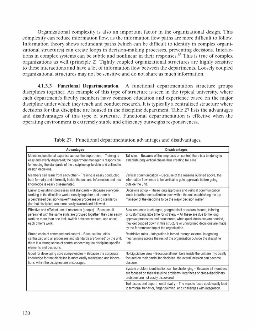
130
Organizational complexity is also an important factor in the organizational design. This complexity can reduce information flow, as the information flow paths are more difficult to follow. Information theory shows redundant paths (which can be difficult to identify in complex organi-zational structures) can create loops in decision-making processes, preventing decisions. Interac-tions in complex systems can be subtle and nonlinear in their responses.65 This is true of complex organizations as well (principle 2). Tightly coupled organizational structures are highly sensitive to these interactions and have a lot of information flow between the departments. Loosely coupled organizational structures may not be sensitive and do not share as much information.
4.1.3.3 Functional Departmentation. A functional departmentation structure groups disciplines together. An example of this type of structure is seen in the typical university, where each department’s faculty members have common education and experience based on the major discipline under which they teach and conduct research. It is typically a centralized structure where decisions for that discipline are housed in the discipline department. Table 27 lists the advantages and disadvantages of this type of structure. Functional departmentation is effective when the operating environment is extremely stable and efficiency outweighs responsiveness.
Table 27. Functional departmentation advantages and disadvantages.
Advantages DisadvantagesMaintains functional expertise across the department – Training is easy and evenly dispersed; the department manager is responsible for keeping the standards of the discipline up-to-date and utilized in design decisions.
Tall silos – Because of the emphasis on control, there is a tendency to establish long vertical chains thus creating tall silos
Members can learn from each other – Training is easily conducted both formally and informally inside the unit and information and new knowledge is easily disseminated.
Vertical communication – Because of the reasons outlined above, the information flow tends to be vertical to gain approvals before going outside the unit.
Easier to establish processes and standards – Because everyone working in the discipline works closely together and there is a centralized decision-maker/manager processes and standards (for that discipline) are more easily tracked and followed.
Decisions at top – These long approvals and vertical communication leads to further centralization even within the unit establishing the top manager of the discipline to be the major decision maker.
Effective and efficient use of resources (people) – Because all personnel with the same skills are grouped together, they can easily work on more than one task, switch between workers, and check each other’s work.
Slow response to changes, geographical or cultural issues, tailoring or customizing, little time for strategy – All these are due to the long approval processes and procedures; when quick decisions are needed, they get bogged down in this structure or uninformed decisions are made by the far removed top of the organization.
Strong chain of command and control – Because the unit is centralized and all processes and standards are ‘owned’ by the unit, there is a strong sense of control concerning the discipline specific elements and decisions.
Restrictive rules – Integration is forced through external integrating mechanisms across the rest of the organization outside the discipline unit.
Good for developing core competencies – Because the corporate knowledge for that discipline is more easily maintained and innova-tions within the discipline are encouraged.
No big picture view – Because all members inside the unit are myopically focused on their particular discipline, the overall mission can become obscure.System problem identification can be challenging – Because all members are focused on their discipline problems, interfaces or cross-disciplinary problems are not easily discoveredTurf issues and departmental rivalry – The myopic focus could easily lead to territorial behavior, finger pointing, and challenges with integration.
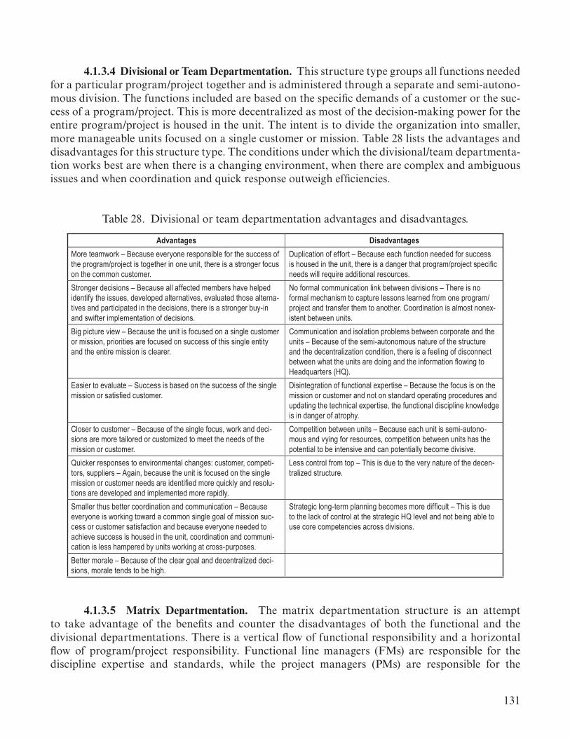
131
4.1.3.4 Divisional or Team Departmentation. This structure type groups all functions needed for a particular program/project together and is administered through a separate and semi-autono-mous division. The functions included are based on the specific demands of a customer or the suc-cess of a program/project. This is more decentralized as most of the decision-making power for the entire program/project is housed in the unit. The intent is to divide the organization into smaller, more manageable units focused on a single customer or mission. Table 28 lists the advantages and disadvantages for this structure type. The conditions under which the divisional/team departmenta-tion works best are when there is a changing environment, when there are complex and ambiguous issues and when coordination and quick response outweigh efficiencies.
Table 28. Divisional or team departmentation advantages and disadvantages.
Advantages DisadvantagesMore teamwork – Because everyone responsible for the success of the program/project is together in one unit, there is a stronger focus on the common customer.
Duplication of effort – Because each function needed for success is housed in the unit, there is a danger that program/project specific needs will require additional resources.
Stronger decisions – Because all affected members have helped identify the issues, developed alternatives, evaluated those alterna-tives and participated in the decisions, there is a stronger buy-in and swifter implementation of decisions.
No formal communication link between divisions – There is no formal mechanism to capture lessons learned from one program/project and transfer them to another. Coordination is almost nonex-istent between units.
Big picture view – Because the unit is focused on a single customer or mission, priorities are focused on success of this single entity and the entire mission is clearer.
Communication and isolation problems between corporate and the units – Because of the semi-autonomous nature of the structure and the decentralization condition, there is a feeling of disconnect between what the units are doing and the information flowing to Headquarters (HQ).
Easier to evaluate – Success is based on the success of the single mission or satisfied customer.
Disintegration of functional expertise – Because the focus is on the mission or customer and not on standard operating procedures and updating the technical expertise, the functional discipline knowledge is in danger of atrophy.
Closer to customer – Because of the single focus, work and deci-sions are more tailored or customized to meet the needs of the mission or customer.
Competition between units – Because each unit is semi-autono-mous and vying for resources, competition between units has the potential to be intensive and can potentially become divisive.
Quicker responses to environmental changes: customer, competi-tors, suppliers – Again, because the unit is focused on the single mission or customer needs are identified more quickly and resolu-tions are developed and implemented more rapidly.
Less control from top – This is due to the very nature of the decen-tralized structure.
Smaller thus better coordination and communication – Because everyone is working toward a common single goal of mission suc-cess or customer satisfaction and because everyone needed to achieve success is housed in the unit, coordination and communi-cation is less hampered by units working at cross-purposes.
Strategic long-term planning becomes more difficult – This is due to the lack of control at the strategic HQ level and not being able to use core competencies across divisions.
Better morale – Because of the clear goal and decentralized deci-sions, morale tends to be high.
4.1.3.5 Matrix Departmentation. The matrix departmentation structure is an attempt to take advantage of the benefits and counter the disadvantages of both the functional and the divisional departmentations. There is a vertical flow of functional responsibility and a horizontal flow of program/project responsibility. Functional line managers (FMs) are responsible for the discipline expertise and standards, while the project managers (PMs) are responsible for the

132
success of the project and meeting the mission or customer requirements. It is designed so that the vertical and horizontal managers have different responsibilities, but not necessarily the complete authority to make all decisions. This forces cooperation and, in theory, creates better solutions and ultimate success. Table 29 lists the advantages and disadvantages of this structure type. The Matrix Departmentation is a good choice when the organization faces multiple, short-term (less than 3 years), complex projects.
Table 29. Matrix departmentation advantages and disadvantages.
Advantages DisadvantagesBenefits of both the functional and divisional departmentations – Almost all of the benefits of both are designed to exist in the matrix structure.
Two boss problem – While the matrix structure can enjoy the advan-tages of both functional and divisional departmentation, it creates its own unique problems, not the least of which is that the workforce now reports to at least two bosses, making priorities and direction problematic.
Minimizes the disadvantages of both the functional and divisional departmentations – Quicker response, no duplication, efficient use of resources and enhanced communications are features of this structure.
Lack of clarity of authority – The matrix intentionally pits the FM concern for quality and high performance against the PM’s concern for cost and schedule. This is designed to bring about the best deci-sions, but it, in fact, clutters the lines of authority.
Provides home base – As programs/projects are completed and end, the matrixed worker goes back to the functional group for reassignment to another project.
Members may belong to more than one project team – This can cause further challenges in understanding and establishing priori-ties.
Good for fluctuating work loads May never meet as a team – Depending on where the member sits (i.e., with the functional group or the project group), it could cause the typical disadvantages from the other departmentation unit.
Promotes concern over cost, schedule (PM) and quality (FM). Functional line manager does not understand his/her role – The FM should be preparing the workforce to hold the capabilities needed for future projects and to hold standards high. Many times the FM gets too involved in the daily operations of the projects.No company-wide objectives – Because the accounting system is usually tied to project costs, the improvements and future strategic direction of the overall organization often get little attention.Rarely assessing lessons learned as a team, or sharing them for-mally with others – As soon as a member’s role is accomplished on the project he/she is reassigned, frequently leaving the team before lessons learned can be developed.Often leads to top-heavy centralized structure due to complex and ambiguous authority of the PMs and FMs.
4.1.3.6 High-Reliability Organizations. High-reliability organizations are organizations who function successfully in highly stressful and quickly changing situations. The theory for these organizations was initially developed based on aircraft carrier flight deck operations and nuclear power plant operations during crisis situations.66
High-reliability organizations collapse from their standard hierarchical structure to a flat team with strong peer to peer communication regardless of hierarchical position. The hierarchy provides a stable organization during routine activities. The flat instantiation of that hierarchy allows for quick and complete responses to difficulties. Trade study teams, task teams, operations teams,

133
etc. operate in this flat mode in the midst of the project structure and line organizational structure. Operations engineering will operate in this mode when dealing with off-nominal operational situations. The systems engineer is responsible to know when to invoke these teams in order to address unknown areas and gain improvement in system understanding.54
4.1.4 Decision-Making and Information Flow
Information flow is a key organizational and design control loop for the systems engineer. Incomplete or inaccurate information leads directly to bad decisions (principle 7). Information must flow smoothly and efficiently through the organization. This directly improves the organiza-tional efficiency, which drives the system cost and schedule. Information flows both formally and informally through the organization. Decisions can be driven from technical concerns within the organization as well as external influences outside the organization. Formally, decision boards, management chains, working groups, IPTs, etc. all provide channels of communication. Informally, information flows through personal relationships, historical organizational relationships, etc. These factors are discussed below.
4.1.4.1 Configuration Management/Data Management. Configuration Management (CM) and Data Management (DM) provide important systems engineering tools and techniques for controlling information flow within the program or project organization. These are key to ensuring the organization has a common understanding of system information and data. CM and DM ensure that the organization has a clear authoritative source for system information and program or project decisions. For specific approaches to CM/DM, reference the NASA Systems Engineering Handbook.67
4.1.4.2 Decision Analysis. At the beginning of any complex system development project, it is critical to establish three important attributes to facilitate smooth decision making throughout the life of the project.68
(1) Clear goal(s), commonly understood: It is important that all constituents have a common mental model of the goal(s) of the project. Individual interpretations of what the group is trying to accomplish will lead to misdirection, conflicting decisions, and confusion. Time invested in developing a common understanding of the goal(s) will pay dividends in the future as more decisions are made in alignment with the goal(s). The GFT provides the model structure to gain this understanding.
(2) Unified commitment to the goal(s): It is important that not only are there a commonly understood goal, but there is a unified commitment to achieving the goal(s). If the group members do not agree that these are worthy goal(s) or commitment to the goal(s) are absent or less than optimal, decisions are haphazard, ineffective, and possibly counterproductive (principle 3(c)).
(3) Collaborative environment, so that a commonly understand goal(s) can develop, and a unified commitment can be established: Cultivating a collaborative environment is important to ensure all perspectives are taken into account, and the best systems decision can be made. If all constituent perspectives have been uncovered, assessed, and considered, then a systems decision

134
can be reached and supported. In a complex system design, many components are brought together to form and operate the best system possible. No one component can be optimized independently of the others. Tradeoffs must be made. This requires a collaborative environment in which all con-siderations are shared and evaluated. The formation of the decision analysis team (specific to the decision) is a key piece of the collaborative environment. The decision analysis teams go by many names (task teams, tiger teams, working groups, integrated product teams, etc.). The systems engi-neer should determine the approach based on the specific decision need and organizational cultures performing the system design or operation. The various system models discussed in sections 3.3 and 4.3 provide the system level analysis for these decisions.
Decision making should include the following six aspects in order to maintain these three decision-making attributes:
(1) Offering an opportunity for comments on decisions to a slightly larger number of people than needed is better than make the error of leaving an important perspective out of the opportu-nity. On average, expect to include 20% more commenters than absolutely needed (principle 7).
(2) Balancing between adequate time to review and number of change requests (CRs) flowing through the process at any one time is needed. There is a real danger of overburdening the technical reviewers, resulting in impaired review of the CRs (principle 7).
(3) Encouraging all technical reviewers to review any modifications made to the CR as a result of the initial collection of comments. At times, a comment may cause the CR decision to be modified resulting in a conflict not previously apparent prior to the modification (principle 7).
(4) Discussing the comments and evaluation of alternatives thoroughly can effectively alleviate con-flict over the ultimate decision made. This upfront investment in time can benefit the project later (principle 7).
(5) Keeping the timeline between parent organization decisions and the supporting orga-nization (e.g., contracted organization) decisions tightly coupled is important. Allowing the sup-porting organization to develop designs too rapidly can lead to massive cost issues if the parent organization needs to make changes (principle 1).
(6) Consider the drivers of overall decision-making at the beginning of every decision point. If cost is an overall driver, then cost impacts need to be considered at every change for every deci-sion (likewise for schedule) (principle 1).
In addition to the decision-making activity, communication is an important part of making the decision a success. Communicating the decision results is essential to maintaining the design or operations teams’ commitment towards the outcomes of the decision. Effective communication of the resulting decision includes the following:
(1) It is appropriate for the initial contact of constituents of a CR review to be formal (i.e., written, traceable, and hierarchical). Subsequent contacts for reviews can be more informal (i.e., verbally delegated, off-the-cuff included, etc.).

135
(2) A complete description of the problem the change is addressing and the intent of the change solution should be carefully communicated.
(3) A complete description of the final decision should be thoroughly communicated across all constituents and commenters. Included in the final decision description should be realistic lifecycle cost impacts (no ‘piling on’) and schedule impacts.
(4) Make everyone aware that lifecycle cost concerns are everyone’s responsibility.
In decision making and the associated decision analysis, the application of these principles is crucial to effective decisions. The evidence suggests that decision making is less process dependent than typical systems engineers might expect. As long as the process matches the needs of the deci-sion makers and the appropriate expertise to make the decision is involved (principle 7), different processes can be used effectively.
Organizational culture also plays a large part in decision making. There are several biases which affect decision making. These include:
• Anchoring—the mind gives more weight than it should to the first information it receives. (Error)
• Status Quo—we have a strong preference for staying with what already exists. (Historical Precedent)
• Sunk Costs—because we would rather not admit mistakes, we have a difficult time writing off investments we already have made when making a decision. (Historical Precedent)
• Confirming Evidence—we tend to seek out information that supports our existing view and ignore information that disconfirms our existing view. (Self-Fulfilling Prophecy)
• Framing—once we think we understand a problem, it can be difficult to break out of that way of understanding the problem, even if our initial understanding is inaccurate. (Error, Historical Precedent)
• Estimating/Forecasting—our minds are not well-suited to make estimates in the face of uncertainty. We tend to be conservative, influenced most by what just occurred, and overconfident about our accuracy. (Error, Historical Precedent)
These biases can limit information flow and lead to blind spots in the organizational approach to system development and operations. The systems engineer should be aware when the biases are present and work to create a balance based on the system physics, logic, environment, and mission context (application). Dismissing options without strong technical rationale, or making decisions without good technical rationale related to the success of the system are indications that one or more of these biases are present in the decision-making process.

136
4.1.4.3 Knowledge Retention. Knowledge capture and retention is important to ensure previ-ous mistakes are not repeated and previous successes are properly understood and applied to the current system. As part of gaining an understanding of the system, the systems engineer should be familiar with similar systems lessons learned. This will help identify difficult to recognize system interactions and sensitivities which could lead to unintended consequences.
As the system development progresses or as the system operations mature, the systems engi-neer should contribute to this body of knowledge for future system developments. This includes cap-turing important system understanding, lessons learned, and important knowledge in what worked and what did not work in system development. System operations knowledge should be captured from the operations engineering team on a regular basis. Operations-phase knowledge should also be captured by the systems engineer for system production, block upgrades, maintenance upgrades (in particular, if driven by system operational failures), and obsolescence upgrades.
Capture and retention of this knowledge requires explicit actions by the systems engineer. System models provide a medium for capturing and transferring system knowledge across the lifecycle phases. In addition, knowledge capture systems for both system and social knowledge can be established. The key is simplicity in access and use, so that engineers and managers will use these systems to capture their system understanding, lessons learned, and what worked or did not work. Knowledge capture can be semi-passive or active, depending on the institutional capabilities and design of the systems engineering organizational work tools and flow. Active knowledge capture in the forms of discreet meetings or activities to capture lessons learned can be task or phase driven. After action-type lessons learned capture is advisable after each system lifecycle review or major operational milestone. Intentional pauses in system development schedules to capture lessons learned or design knowledge provide both reflective learning immediately beneficial to the current project and longer-term capture that promotes the technical and programmatic fidelity of the involved organizations. As such, project managers, lead systems engineers, chief engineers, or other leadership should advocate and prioritize these activities. Engineering in general is the application of knowledge to fill an identified need. Systems engineers structure this knowledge at the system level. Innovative and effective teams will tap into knowledge consistently and store knowledge accessibly for future use as their organizations and projects move forward.
4.1.4.4 Decision-Making Structure. The decision maker can range from the program manager, chief engineer, or line manager to formal decision-making bodies such as control boards or working groups. These include both formal decision authorities and delegated decision makers. The decision-making structure must be properly organized to be effective and efficient. When a hierarchy of decision authorities is used, these bodies (i.e., boards, working groups) must have clear scopes that fit with the system under development. If too many decision-making bodies are employed, decision making can become extremely slow and limited by available expertise to represent all required disciplines in these decisions (principle 7). The number and relationship of decision making bodies should follow the program or project type for the system being developed. For loosely coupled projects, each project may require a separate decision body that feeds a higher level body at the program level. For tightly coupled projects, a single decision body at the program level may be optimal. Small projects or activities may not need large decision bodies and can have decision-making structures where all relevant disciplines meet with the project manager and chief engineer to make a decision.

137
The key decision makers should sit on the decision-making body (principle 7). Authority comes through the decision-making process for the project.69 The key focus for the decision makers is knowing the right question to ask. That leads to an answer that provides the proper understand-ing. Systems engineers should understand the system so that they can help frame the right questions and inform the decision-making body members as necessary on important questions. In this role, systems engineers are problem finders first, then problem solvers. This helps to identify the right question.70
When decision-making bodies start claiming their value (trying to control some aspect of the system) rather than creating value (contributing content to the system), then the decision-making body is working more in the social system than with the physical system. This is unbalanced. The imbalance should be addressed in the board’s charter and scope including definition of responsibili-ties for each member. Violations of the charter is an indication of a shifting social structure, which can lead to social ambivalence in parts of the organization. This must be managed through the decision-making body chairperson holding members accountable to the charter while allowing for discussion of change when needed based on the success of the system.69
Having the right expertise represented in the decision-making body is essential (principle 7). The systems engineer must ensure that all affected or contributing expertise are members of the decision-making body or in attendance at the decision meeting. Each engineering discipline, S&MA, procurement office (as applicable), and the program or project business office should be represented in the decision body.
Information theory provides a good understanding of decision-making processes and a set of rules in organizing decision-making bodies. The decision-maker and each decision-making body member (or decision-making participant) is a source of information to the decision-making body. The communication between these members during the decision-making body discussion is the communication channel between the members. All information necessary for the decision must be represented in the membership. A range of information that is not complete cannot be mapped properly to the full domain of solutions and the information provided will not fully support the decision. This leads to decisions based on assumed understanding (a source of uncertainty or noise) of the question being decided. This uncertainty is a result of bias (e.g., allows self-fulfilling prophecy bias) that could lead to unintended consequences as a result of partially informed decisions. There are many instances where information not presented or withheld for some reason has led to failures of some type in the mission.
Central to considering the distribution of decision-making bodies is the scope of each decision-making body. These scopes must comprise separate sets of information in which they work. Each decision-making body should have a clear and non-overlapping scope with other decision-making bodies in the program, project, or activity. Overlapping scopes will generate much more uncertainty and effort in decision making, leading to confusion, disagreement, delays, poor decision quality, or the inability to make a decision. Note, these overlapping structures also create a workforce skill drain, where multiple representatives are needed to cover all of the boards discussing the same information.
138
On the other hand, decision-making scopes, which are separate, operating on different infor-mation sets, can be distributed to different boards. Generally, a top-level decision body may still be needed with representation from each of the lower boards (such as the case of a program control board) to integrate decisions. This is illustrated in loosely coupled projects where each function is somewhat separate from the other, and the program provides the integrating function. Again, understanding the set of information, or scope, that each board has and the relationship between the scopes is essential to setting an efficient decision-making structure.
These basic rules governing the structuring of decision-making bodies follow:
• Understand and define the scope of each decision-making body.• Ensure that each decision-making body has all affected or contributing disciplines represented, including understanding the types and magnitudes of uncertainties affecting decisions within that decision-making body’s scope.• Minimize the number of decision-making bodies based on scope. The efficiency of the structure decreases with distributed and overlapping scopes.
4.1.5 Managing Inter and Intra Organizational Interactions
Communication is a key aspect of systems engineering. Communication can enable or prevent an effective system development or operation. Organizational interactions are key communication channels for information flow. These can be in both formal and informal communications, and the systems engineer should be aware of all of the communication pathways used within the organization. The various disciplines and stakeholders all have different ways of presenting and understanding information. These unique terms can make communication ineffective in complex system development or operations. These differences are culturally based and can create barriers to effective communication if not managed appropriately. To address this, the systems engineer must understand the discipline terminology and related culture that defines their communication as discussed in section 4.1.2.3. The systems engineer must then translate the various terminology to ensure information is effectively shared across the system and can be integrated into a common understanding of the system. These communications can affect key system parameters, including design margins and operations margins.
4.1.5.1 Design Margins (Biased Information Sharing). Design margins for complex system development resides within the informal organizational structure of the system design team rather than in formally tracked allocations. Designers often include conservatism in information reported to the program formally, and are used in resource negotiations between design teams (generally, informally). This conservatism resides in a design team’s budget, mass, volume, and time to completion estimates. The design teams are motivated to include this conservatism for several culturally based reasons including insurance against future budget cuts, schedule changes, and mission requirements growth. The conservatism takes various forms such as budget off-ramps, extra tests and tasks that were not strictly necessary, and additional margin added to engineering estimates in addition to the design uncertainties. This can contribute to cost overruns, unnecessary schedule slips, and system performance issues.

139
The systems engineer needs to be aware of the culture of the design organization and the level of margin being retained within the organizational structure. This conservatism can have positive or negative effects. On the positive side, the organizational design conservatism can lead to improved system robustness to budget, schedule, and performance perturbations. However, this robustness is not an engineered robustness, it can be haphazard, and does not generally lead to sys-tem elegance. On the negative side, the organizational design conservatism can lead to suboptimal budget, schedule, or performance of the system. This can lead to poor or failed systems. System issues should first address the existence of this conservatism before major system configuration decisions are made. Awareness of this organizational conservatism requires the systems engineer to have an in-depth knowledge of both the system and the design organization. This will allow the sys-tems engineer to identify where the organization is conservative in their estimates. A caution is also warranted here, where misidentifying uncertainty margin as organizational conservatism can lead to system failures. Thus, a detailed understanding of the system is essential to identify and manage this conservatism. This is a difficult factor to account for in system analysis.
4.1.5.2 Operations Margins. Operational margins are managed in a more specific manner than design margins by the operations engineers. If any design margin has not been fully allocated, the remaining margin provides constraints on the system operation. These margins are viewed as fixed commodities, and the question is not whether to release them or not but how close can the sys-tem operate against the constraints. Part of this is a belief about how firm the constraint actually is. Will the system fail at this limit or can it move past it? Is the risk to the system or users (e.g., crew) worth the operation in this way? These can be very subjective or very hard limits when planning and executing the system operations.
The responsibility of the systems engineer is to ensure system margins are well defined and hard limits clearly defined. Where system constraints are dependent on the specific operational circumstances, the systems engineer should ensure that these specific circumstances are properly identified in the system design and operations information. Having a clear transfer of systems under-standing from the development phase to the operations phase is a key responsibility of the systems engineer.
4.1.5.3 Teaching Systems Thinking. Mediated learning experience is a framework that may teach systems thinking for systems engineers, project managers, line managers, and discipline leads that need to have a system perspective. Mediated learning has three basic tenets: (1) The brain is plastic and structurally modifiable throughout life; (2) cultural transmission provides an important method for the creation of cognitive structures; and (3) a human mediator may intervene in the mental processes of a learner, creating missing structures or correcting dysfunctional structures in the brain. The essential feature of this approach is that these changes are not simply psychological, but rather of a structural nature that alter the course and direction of cognitive development. The changes that occur “are not a fragmented, episodic consequence of exposure to experiences, but rather a type of change that affects the basic structure of behavior.”71 Through use of a well-trained mediator, subconscious information processing skills can be brought to conscious awareness and be created, corrected, and improved, ultimately resulting in physiological changes in the brain in addition to the psychological.
140
4.2 Policy and Law
As discipline integration is driven by sociological principles, policy and law are driven by social forces within a country, region, or organization. These social forces result in constraints within which the system must be developed and operated.
Policy and law includes federal, state, and local policies and laws affecting the system as well as organizational policies that affect the approach to the system. These policies and laws span the range or intent from suggested practice or approach to strictly enforced regulations. Policies and laws, however, can be interpreted and enforced in different ways. Some policies are strictly enforced, while others are seen as suggestions. As a result, the systems engineer must distinguish between those policies and laws which constrain the system and those that are more suggestive. The systems engineer must distinguish between all of these policies and laws without violating those strictly enforced or overconstraining the system approach for those that are more suggestive than binding.
4.2.1 Government Context of Systems Engineering
The U.S. Government is highly involved in the development of space systems. Any systems engineering analysis must include the impacts of both technical and political decisions.72 For exam-ple, space policy is heavily influenced by the following: policy statements and speeches by public officials, including the President; directives from the Office of Science Technology Policy and the National Security Council in the White House; policies by the National Aeronautics and Space Administration (NASA), Department of Defense (DoD), and other government agencies; appro-priations and authorization laws passed by Congress; policy statements by national commissions; lobbying efforts by industry and research organizations; and opinions published by space advo-cacy groups.73 Integrating these different viewpoints into a cohesive focus can be a challenge.74 Each stakeholder has unique interests, views, and goals. While the President and key members of Congress are highly visible in the decision-making process, career civil servants and congressional staff are often the drivers of policy decisions. Policy interpretation is frequently done at lower levels of government, empowering the people who carry out federal programs to interpret and enforce policies.75 This process can cause some program requirements to seem hard when they are actually malleable (e.g., congressionally directed completion dates), or soft when they cannot be influenced (e.g., International Agreement), depending on who is interpreting them. Better understanding this complex political context can make systems engineers more effective in their core functions.
There are strongly driven social interactions between decision makers and engineers in driv-ing large corporations or countries to accomplish a specific course of action. The Apollo/Saturn Program is a great example of this. In November 1959, Abe Silverstein, NASA’s Chief of Space Flight Programs, led a committee (the Silverstein Committee) to study exploration of the Moon. The committee, which included Dr. Werner von Braun, planned out a succession of Saturn boosters and the Apollo capsule for lunar exploration. This included a budget to accomplish these objectives in a 10-year period. The Agency began moving forward on research, development, and demonstra-tion of needed technologies, including liquid hydrogen engines necessary for the lunar mission.76 As this was progressing, President John F. Kennedy requested Vice President Lyndon B. Johnson to assess the United States’ capabilities. He asked the Vice President in April 1961, “Do we have a

141
chance of beating the Soviets by putting a laboratory in space, or by a trip around the Moon, or by a rocket to land on the Moon, or by a rocket to go to the Moon and back with a man. Is there any other space program which promises dramatic results in which we could win?”77 As Chairman of the Space Council, Vice President Johnson incorporated the results of the Silverstein Committee and recommended that landing a man on the Moon. He stated, “As for a manned trip around the Moon or a safe landing and return by a man to the Moon…the United States could conceivably be first in the two accomplishments by 1966 or 1967.”78 This led to the famous address to Congress and the Nation by President Kennedy on May 25, 1961 (see fig. 20).
Figure 20. President Kennedy addresses Congress and the Nation on May 25, 1961.
The United States was provided the following mission objective which drove national space policy for a decade. During President John F. Kennedy’s Address to Congress on Urgent National Needs on May 25, 1961, Kennedy stated, “I believe that this nation should commit itself to achieving the goal, before this decade is out, of landing a man on the moon and returning him safely to the earth. No single space project in this period will be more impressive to mankind, or more important to the long-range exploration of space.”

142
The speech delivered by the President did not spark the development of the Moon landing, but was based on the technical evidence that a Moon landing was indeed possible and that the known technology would support the endeavor. The President’s challenge also secured the funding and national priority needed for NASA to accomplish the plan the Silverstein Committee had initi-ated in early 1960. Without this strong technical basis, the President would not have made this chal-lenge, and without the President’s challenge, NASA was not likely to have the funding and priority to accomplish the lunar missions. Thus, systems engineers must understand the importance of early development activities and their potential to influence political decisions. In addition, systems engi-neers must also be aware of the importance of support from the funding stakeholders (e.g., Congress and the President) to accomplish the mission.
4.2.1.1 Government Oversight of Contract Work. On a programmatic working level, the impacts of government are typically seen through oversight-required activities. These activities and reporting systems can reduce program risks and ensure that systems being built by contractors will meet the government’s needs. Activities exist to monitor many facets of a program including, but not limited to, cost, schedule, and major milestone performance, delivery of certified cost and pricing data, earned value management as required, and other Federal contracting requirements, product safety; health, safety, and environment; data protection; employment laws; export controls; fair competition; information technology safety and security; and anticorruption activities.79,80
Oversight can also require the use of certain reporting systems per contract requirements. All of the activities and reporting systems that the government uses to monitor its contractors are considered oversight.
Oversight is critical to mission success; but the Government and its contractors incur high costs to comply with oversight. It requires extensive documentation requirements, inspections, and audits of both the technical systems being built and the contractors’ financial and business pro-cesses. These activities can be extremely detail-oriented and require significant amounts of time to complete. Oversight involves a large number of stakeholders, long timelines, and extensive review processes. Research has shown that oversight has a large impact on the work performed by contrac-tor engineers. Requests for oversight-related work can require engineers perform many other activi-ties than just the requested activity (e.g., meeting, request, audit), and many of those activities are often performed in multiple iterations. This research also showed that oversight can extend the time spent on all work activities, not just those requested by the Government.
There are several factors that contribute to understanding the burden of government oversight. Systems engineers should be aware of these factors and consider the impact of requests and oversight activities on the system development or operations timeline. Oversight involves reporting on technical work performed, phone calls and meetings to gain understanding of reports and issues, modifications to the reports, and modifications to technical activities. These are not simple tasks, but involve a series of iterative activities that can be very time consuming. Reporting requires time to capture significant points, write them consistent with contract formatting requirements, and write them in a manner that communicates points clearly. Meetings require preparation to gather data and information, prepare presentations, coordinate information with the appropriate people within the contractor organization (e.g., dry runs of presentations, draft reviews), and then any follow-up actions that can result from a meeting. Thus, meetings can create a set of nested activities that require much more time than just the time in the meeting itself. Modifications requested to

143
reporting for clarification or corrections also take time to update reports and process back through contractor organization approval cycles. Modifications to technical activities themselves can have a much larger impact, involving task replanning, technical changes to models and documents, schedule updates, and budget updates.81
There are various reasons for requesting status reports, meetings, and modifications. These can be either value added to the successful completion of the system or nonvalue added. There is some subjectivity in understanding what is considered a value added task and what is considered nonvalue added. The government generally views all requests as value added, while the contrac-tor organization may see some requests as nonvalue added. Communication between the govern-ment organization and the contractor organization on rationale for requests may help to change the perspective of the contractor organization. And similarly, the contractor organization may have a process to deal successfully with the government intents. Communication to explain this may help alleviate some nonvalue added requests.82
Government oversight can extend time to perform the system development or operations tasks. Government requests can create ‘churn’ where a cycle of meeting preparations, updates, re-work can be generated. These can stem from not recognizing the differences in processes, all of which actually meet intents, duplicate questions that have to be answered several times to differ-ent people on the government side. ‘Extra’ work can be generated due to personnel changes or late assessments on the government side. Sometimes the government will ask the contractor to ‘stretch’ (i.e., perform unplanned work, more detailed analysis) to address concerns and provide more in-depth explanations of results. Oversight activities can also disrupt ongoing work when tasks are interrupted to address urgent questions. This can often require complex tasks to be restarted in order for the contractor engineers to maintain clarity in the execution of an analysis or simulation. Finally, tasks can experience ‘delay’ where the contractor is waiting on the government to proceed. This is often related to chain of command approval processes within the government.81
Sociological principles discussed in section 4.1.2 are important in understanding where requests are value added or nonvalue added. Value-added reasons include ensuring proper under-standing of the systems progress between the contractor organization and the government orga-nization, modifications necessary for the system to meet the intentions of the government, and modifications to minimize risks realized as the understanding of the system deepens. These value-added requests may lead to some stretch of the time needed to finalize an activity, and matters to address system issues to maintain system schedule may disrupt other activities leading to some task restarts. These are important interactions for the successful development of the system. Non-value added interactions can result from a failure to understand organizational differences that affect the engineering processes leading to churn, disruption, and extra work within the system contractor. Organizational structure is different between each contractor and government organizations and therefore engineering processes will be different. This should be understood and recognized by the systems engineers on both sides of the government-contractor relationship. The systems engineer should translate these differences, not try to enforce changes to one side or the other. There are many approaches to processes that can be successful for the system. Understanding the relation-ships between each organization’s engineering processes and translating between the organizations is the role of the systems engineer. Attempting to enforce the organizational processes from one organization onto another can be a source of nonvalue-added work.

144
The U.S. Government can utilize Federally Funded Research and Development Centers (FFRDC) to execute research and development, system development, and system operation and maintenance needs. NASA employs the JPL to execute advanced research and technology of space science instruments and the development and operation of several space science missions. JPL has successfully developed and operated several space science missions since the 1960s. The Department of Energy (DoE) has organized their research laboratories as FFRDCs. These laboratories provide energy research and technology and have made several advancements in nuclear and renewable energy since the 1970s.
The U.S. Government also augments technical or skills availability through the use of Sys-tems Engineering and Technical Assistance (SETA) contractors or FFRDCs in the development and operations of systems. These SETA and FFRDC contractors provide necessary and valuable skills to the Government efforts. These contract arrangements also make for a much more complex orga-nizational structure for a project. As contract organizations are added, each organization brings in unique capabilities, interests, and priorities in their support. The importance of translation from the Government organizational structure to the SETA/FFRDC structure to the system development or operations contractor is much more complex. The social factors stemming from organization cul-tures can create more questions to the development and operations contractor. These are based not only on the Government project office interests, but potentially other contracted interests from the SETA/FFRDC. The Government can task these contractors not only with roles and responsibilities for the specific system development, but may also contract them to provide a larger industry health monitoring role. This can lead to additional questions and actions submitted to the system develop-ment or operations contractor. In addition, having additional organizations involved can lead to more educational questions as the government project office and the SETA/FFRDC are all striving to understand information on the system development and operation. Many of the questions gener-ated from the SETA/FFRDC are often perceived as nonvalue added by the system contractor.82 For systems engineers at any of these three levels of the project structure, translation of processes and intents are essential and may require more effort to communicate. This communication is important to ensure the need for the requests is properly understood and to distinguish questions stemming from systems development or operations needs from those stemming from industry monitoring or other contracted roles held by the SETA/FFRDC. SETA/FFRDC questions and actions have been cited as a source of a larger percentage of non-value added activity. Systems engineers should ensure that questions and actions at any level of this organizational structure are contributing to system success or clearly identified as fulfilling other functions requested by the Government.
Systems engineers working in government oversight structures should strive to ensure that communication is clear and concise (not duplicated) between the different organizations, the requests are necessary for the understanding and success of the system, the differences between engineering processes are understood and translated, and the need for requests are well defined. This interac-tion among the social structures of the different organizations is a complex and challenging activity. The systems engineer should be prepared to spend regular effort in ensuring the efficiency of these relationships.
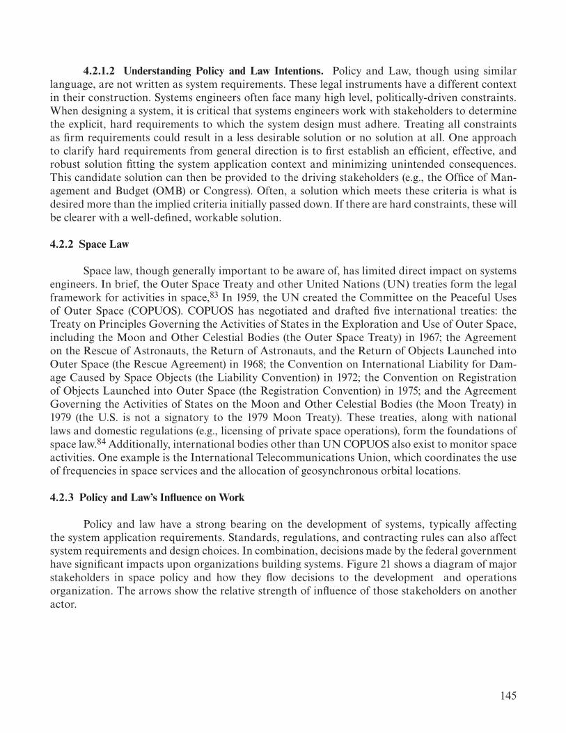
145
4.2.1.2 Understanding Policy and Law Intentions. Policy and Law, though using similar language, are not written as system requirements. These legal instruments have a different context in their construction. Systems engineers often face many high level, politically-driven constraints. When designing a system, it is critical that systems engineers work with stakeholders to determine the explicit, hard requirements to which the system design must adhere. Treating all constraints as firm requirements could result in a less desirable solution or no solution at all. One approach to clarify hard requirements from general direction is to first establish an efficient, effective, and robust solution fitting the system application context and minimizing unintended consequences. This candidate solution can then be provided to the driving stakeholders (e.g., the Office of Man-agement and Budget (OMB) or Congress). Often, a solution which meets these criteria is what is desired more than the implied criteria initially passed down. If there are hard constraints, these will be clearer with a well-defined, workable solution.
4.2.2 Space Law
Space law, though generally important to be aware of, has limited direct impact on systems engineers. In brief, the Outer Space Treaty and other United Nations (UN) treaties form the legal framework for activities in space,83 In 1959, the UN created the Committee on the Peaceful Uses of Outer Space (COPUOS). COPUOS has negotiated and drafted five international treaties: the Treaty on Principles Governing the Activities of States in the Exploration and Use of Outer Space, including the Moon and Other Celestial Bodies (the Outer Space Treaty) in 1967; the Agreement on the Rescue of Astronauts, the Return of Astronauts, and the Return of Objects Launched into Outer Space (the Rescue Agreement) in 1968; the Convention on International Liability for Dam-age Caused by Space Objects (the Liability Convention) in 1972; the Convention on Registration of Objects Launched into Outer Space (the Registration Convention) in 1975; and the Agreement Governing the Activities of States on the Moon and Other Celestial Bodies (the Moon Treaty) in 1979 (the U.S. is not a signatory to the 1979 Moon Treaty). These treaties, along with national laws and domestic regulations (e.g., licensing of private space operations), form the foundations of space law.84 Additionally, international bodies other than UN COPUOS also exist to monitor space activities. One example is the International Telecommunications Union, which coordinates the use of frequencies in space services and the allocation of geosynchronous orbital locations.
4.2.3 Policy and Law’s Influence on Work
Policy and law have a strong bearing on the development of systems, typically affecting the system application requirements. Standards, regulations, and contracting rules can also affect system requirements and design choices. In combination, decisions made by the federal government have significant impacts upon organizations building systems. Figure 21 shows a diagram of major stakeholders in space policy and how they flow decisions to the development and operations organization. The arrows show the relative strength of influence of those stakeholders on another actor.
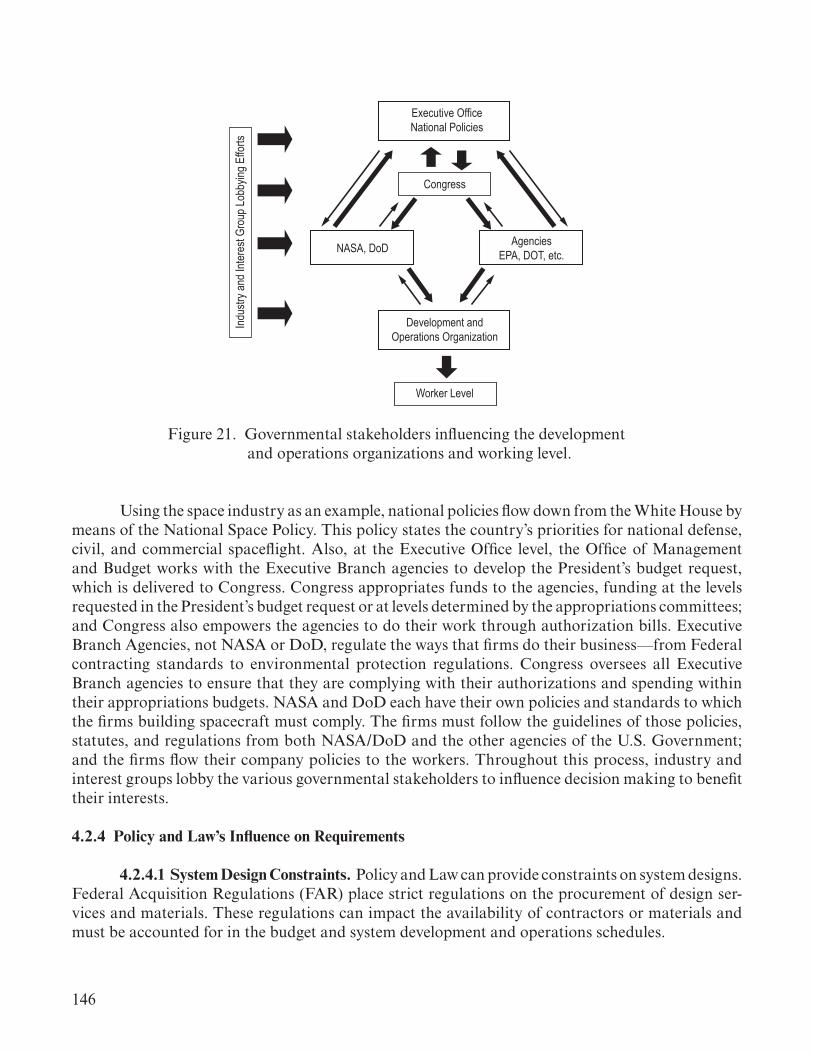
146
Executive OfficeNational Policies
AgenciesEPA, DOT, etc.NASA, DoD
Congress
Development andOperations Organization
Worker Level
Indus
try an
d Inte
rest
Grou
p Lob
bying
Effo
rts
Figure 21. Governmental stakeholders influencing the development and operations organizations and working level.
Using the space industry as an example, national policies flow down from the White House by means of the National Space Policy. This policy states the country’s priorities for national defense, civil, and commercial spaceflight. Also, at the Executive Office level, the Office of Management and Budget works with the Executive Branch agencies to develop the President’s budget request, which is delivered to Congress. Congress appropriates funds to the agencies, funding at the levels requested in the President’s budget request or at levels determined by the appropriations committees; and Congress also empowers the agencies to do their work through authorization bills. Executive Branch Agencies, not NASA or DoD, regulate the ways that firms do their business —from Federal contracting standards to environmental protection regulations. Congress oversees all Executive Branch agencies to ensure that they are complying with their authorizations and spending within their appropriations budgets. NASA and DoD each have their own policies and standards to which the firms building spacecraft must comply. The firms must follow the guidelines of those policies, statutes, and regulations from both NASA/DoD and the other agencies of the U.S. Government; and the firms flow their company policies to the workers. Throughout this process, industry and interest groups lobby the various governmental stakeholders to influence decision making to benefit their interests.
4.2.4 Policy and Law’s Influence on Requirements
4.2.4.1 System Design Constraints. Policy and Law can provide constraints on system designs. Federal Acquisition Regulations (FAR) place strict regulations on the procurement of design ser-vices and materials. These regulations can impact the availability of contractors or materials and must be accounted for in the budget and system development and operations schedules.
147
Regulations on systems come from various sources depending on the specific system (postulate 1). These include agencies such as the Environmental Protection Agency (EPA), Nuclear Regulatory Commission (NRC), Department of Transportation (DoT), NASA, Department of Defense, and Federal Aviation Administration (FAA).
4.2.4.2 System Fabrication Constraints. EPA regulations impact fabrication solutions and can limit or eliminate materials for use in the system or fabrication of the system. The limits on Freon, used as a cleaning agent in many systems, have affected the fabrication aspects of these sys-tems even in the space industry (i.e., launch vehicles and spacecraft). The systems engineer should be aware of the fabrication limitations and the future limitations that may impose constraints (or possibly a complete redesign). Environmental impact statements will also be required for any new manufacturing sites or new processes.
Occupational Health and Safety Administration (OSHA) regulations constrain fabrication operations to eliminate or carefully control safety hazards. Manufacturing engineers generally handle these type of constraints.
4.2.4.3 System Operations Constraints. EPA regulations impact operations and can limit or eliminate materials for use in the system or operation of the system. The systems engineer should be aware of the operation limitations and the future limitations that may impose constraints (or pos-sibly a complete redesign) in the future. Environmental impact statements will also be required for any new operations sites.
Transportation of space hardware often involves adherence to transportation regulations and scheduling of transportation routes through the DoT. The systems engineer must be aware of these constraints, ensuring operations is coordinating these and the schedule reflects these constraints.
4.2.5 National, Agency, Local, Government, and Industry Support for System Concept
4.2.5.1 National Interest/Stakeholder Interest. National interest is focused more on mission success than on specific system implementations as discussed in section 3.1.2 above. The general public looks for National systems to be successful in their primary mission objectives. They are generally not as aware of secondary objectives and are curious of the specific solution as a point of interest. Thus, the general public are interested stakeholders but not directly affected by the system configuration.
The general public can have strong input on unintended consequences of system fabrica-tion and operation. Environmental impacts or perceived impacts can create concern and must be considered. For example, modification of the New Orleans levee wall was perceived as a risk to the area by the local public and government leaders. Thus, while no additional flood risk was present, alternate approaches had to be pursued at higher cost to allow level transport of the Space Launch System (SLS) Core Stage to the barge dock for transportation to the Kennedy Space Center. The systems engineer should recognize these cultural biases and realize that while they may not be based in strong technical factors (or even technically correct factors) they involve strong social factors that
148
affect the system development. The systems engineer will need to understand these biases and be able to determine when the system application context and system efficiency require solutions that may encounter cultural bias (e.g., nuclear powered systems and some defense systems) or where the cultural bias should be handled as a constraint on the system.
The budget and schedule of a specific solution as well as the mission objectives are much more visible to the President and Congress. Thus, there will be more interest in the specific solution by these branches of the government. System efficiency is a driving characteristic for these stakeholders, though other specific factors are not as much of a concern.
Agency management, program management, and contractor management are significantly impacted by the specific system configuration choices. They are directly concerned with mission success, budget, and schedule. These stakeholders tend to view system success as completing the mission objectives, not necessarily on how efficiently the system was able to accomplish the objectives. One should note that for contractors, contract success is not necessarily aligned with system success. This can lead to budget and schedule increases if the contracts are not structured to emphasize system success rather than simply fulfilling contract deliverables. The systems engineer should ensure that the contract technical language has the correct focus on system success.
System operators, system users, and flight crew (where appropriate) are directly affected stakeholders and have a strong input on all aspects of the system configuration and operation. These represent the most influential stakeholders for the system, their input should be gathered early in system application context definition, and their feedback sought at design reviews or major configuration changes throughout the system development and operations lifecycles.
4.2.5.2 National Security Implications/Stakeholder Proprietary Interest. Protection of national security data has significant implications for the development and operation of the system. Systems or subsystems that require national security classification must be strictly controlled and protected. In these cases, system design may need to occur in a tightly controlled facility to allow design teams to discuss the design without risking violation of security requirements.
Systems used for national security classified operations have many requirements on the operational facilities and systems. Assembly areas may need tight physical and data security. Operational facilities, communication systems, and data systems will require tight control before, during, and after the operations. This extends to the post-mission data analysis. This type of security is not achieved by simply placing locked doors on facilities and firewalls in data and communication systems. This type of security requires specialized areas and systems, which are designed and controlled from their inception. Systems with these types of requirements must be identified early and planning should include the needs of these requirements. The systems engineer needs to ensure that these systems have their security requirements identified during system application context definition, and these requirements are accommodated in the system budget and schedule.

149
Proprietary data have similar, and in some cases, more restrictive protection requirements. Proprietary data are not owned by the U.S. Government and cannot be shared with those outside the company, which owns the data. This can require tight controls on data management and configuration management to protect these data. This can also result in limited rights on the use of the data for U.S. Government purposes. The restrictions imposed by proprietary data must be clearly understood and carefully considered in the establishment of the system data management and configuration management systems and processes.
Companies protect their proprietary information strictly, as this consists of the viability of the company in the commercial markets. The systems engineer must manage the system development and operations within these constraints and ensure that the system goals can be accomplished in a manner adhering to the security controls while achieving an elegant system.
4.3 Discipline Integration Modeling
Discipline Integration models provide tools to understand the detailed interactions between the organizational/social structure and the system. These models can also provide statistical analy-sis on process flows that occur in manufacturing and operations. There are three types of models that can be used to understand organizational information flow and identify gaps and conflicts in this flow. These are: system dynamics, agent-based modeling (ABM), and discrete event simulation (DES).
4.3.1 System Dynamics Modeling
There are both qualitative and quantitative modeling techniques in system dynamics. The qualitative system dynamics modeling usually takes the form of causal loop diagrams (CLDs). CLDs are a simplified form of the system structure and are usually used in conjunction with quantitative modeling. The main modeling technique is stock and flow modeling represented as stock and flow diagrams (SFDs —see figure 22). Stock and flow models are often termed ‘system dynamics models,’ which are ordinary differential equation (ODE) models. System dynamics models consist of stocks, flows, and variables in an SFD. Stocks are an accumulation of flows over time, and flows represent addition and subtraction to the stock over time. Variables in stock and flow models are elements that affect the inflows and outflows. The variables are linked to other variables and flows through instantaneous causal links. The accumulated causal behavior in the stock is affected by the flows, which are in turn affected by the variables in figure 22.

150
Flow 1 Flow 2
Flow 3 Flow 4
Stock 2
Stock 1
Variable 1 Variable 2
Figure 22. Example of a system dynamics model as an SFD.
System dynamics modeling is aided using software. Popular programs include Powersim, Vensim, and Stella Architect. The structure of a system yields the behavior over time (accumulated in stocks), and the goal is to discover all the elements and relationships in a system and reproduce the observable reference mode behavior (actual system behavior shown in figure 23). In system dynamics models, there are endogenous and exogenous elements. Endogenous elements are incorporated in the model structure in relation to other structural elements. Exogenous elements are variables that contain data that are directly imported into the model structure. One of the major goals of system dynamics is to understand the structure of the system (as shown in figure 22) that results in the observable behavior (seen in figure 23).
2
2000 2003.75 2007.5 2011.25 2015
1
0
Stock 1Reference Model Behavior
Years
Figure 23. System behavior: Simulated (stock 1) versus actual (reference model behavior).

151
Originally, system dynamics modeling was applied in industrial engineering, but over time, its application broadened to a wide variety of research areas, such as supply chain management, economics, sustainable development, human health, and social systems. System dynamics is especially useful for exploring the underlying structure of a complex, dynamic problem with the objective to eliminate undesirable dynamics and to strengthen the desirable dynamics. In addition to this, system dynamics modeling is interdisciplinary, with experts on specific model sectors giving input into how the system operates.85 Because of this, system dynamics modeling can be very helpful in the analysis of problems arising in a multidisciplinary environment.
4.3.2 Agent-Based Modeling
Agent-based models represent humans with simple heuristics to produce behaviors. The behaviors are a consequence of the interactions of agents. The rules that the agents follow can range from simple logic (always turn right when colliding with someone) to more complex game theory (have the agent use their probabilistically defined beliefs and preferences to determine the Nash equilibrium of the collision situation). Uncertainty is typically a part of the ABM driving the use of Monte Carlo simulations in order to determine a probabilistic distribution of the outcome. ABM is most prevalent in work that tries to capture the impact of humans and their interactions on a system without having to do a human study. This can be seen in examples such as evacuees interacting with planes or buildings during an egress.86–88 ABM enables an examination that would take years, decades, or centuries, to be performed in a matter of minutes. ABMs will become an important tool as systems become increasingly complex with complex social interactions enabling systems engineers to understand the interactions with stakeholders rapidly, further enabling rapid optimization frameworks. An important topic that must be addressed in any ABM application is the identification of the bounds of the work and the relationship between the model and the related real-world situation.
4.3.3 Discrete Event Simulation
DES provides a tool to model organizational activities and system responses to discrete events in the operational flow as discussed in section 3.3.2. DES supports Monte Carlo analysis and can be used for manufacturing flows, operational processing flows, supply chain flows, and flows of information through an organization.
4.4 Discipline Integration Summary
The practice of discipline integration is a key element to engineering a system. This section provides the basic understanding in the principles and approaches to practicing discipline integration.
Discipline integration is a sociologically based aspect of systems engineering. Sociological principles apply to any organization and in all lifecycle phases. These principles aid the systems engineer in understanding organizational barriers and gaps to information flow about the system. The organizational structure forms the formal social structure and the formal information flow paths within the organization. Decision making is a critical aspect of information flow and depends on the proper integration of discipline engineering information.

152
Policy and law stem from social forces and are extremely important to understand and respond to correctly. The influence exerted by policy and law is not one way but two ways where the need for the system and the possible solutions for the system interact in the policy and law mak-ing arena. Although policy and law can be stated as requirements, they can be more desires than required aspects. Properly understanding this distinction is essential to not over or under constrain the system.
There are several models which aid the systems engineer in understanding information flow and social factors in the development and operations organizations. These include systems dynam-ics models, ABM, and DES. These models provide significant tools in the modeling of discipline integration aspects for a specific system development or operations effort.
The practice of discipline integration provides the systems engineer with key aspects of engineering an elegant system. This basic understanding aids the systems engineer in ensuring the system progresses to an elegant solution.

153
5. SYSTEMS ENGINEERING PROCESSES
The approach to conducting systems engineering is dependent on the specific system being developed or operated. In the development phase, these processes aid the systems engineer in a logical sequence of events to achieve the system. The execution of these processes do not accomplish the engineering of the system but rather provide a schema in coordinating design activities between the various system design disciplines. NASA/SP-2016-6105, Rev. 2, NASA Systems Engineering Handbook67 provides a good description of the potential processes to be applied.
Systems engineering during the operations phases is also critically important. Processes for these phases (i.e., operations, decommissioning, and disposal) are much less defined within the prac-ticing body of systems engineers. These processes depend very heavily on the specific system and its operations and utilization characteristics. Maintenance, logistics, and obsolescence management are some of the activities that are necessary in these operations phases. A basic summary of these can be found in the INCOSE: Systems Engineering Handbook, 4th Edition.20
In looking at the systems engineering processes, it is important to recognize that all engineering disciplines have processes by which they accomplish their designs and analysis. These disciplines focus on the engineering equations and solutions that achieve the goals of the component being designed, using their processes to ensure a consistent approach. The disciplines build models based on their specific physics or logic. They use the models to determine performance, and then based on that, create a design, then update the models, update the analyses, then based on those, update the design, etc. in a spiral process of model and design maturation. Systems engineering should work in a similar manner to engineer the system. Systems engineering processes are important and necessary to achieve a consistent system design approach within an organization, but they are not sufficient to ensure that an elegant system is the end result. A successful, elegant system is achieved by engineering the system to ensure the physical aspects and social aspects meet the system intents.
The specific systems engineering processes implemented for a system by an organization are communicated to all participating disciplines, ensuring a well-coordinated development or opera-tion. The Systems Engineering Management Plan (SEMP) serves as an excellent communication mechanism to describe systems engineering processes in context of the system. Both handbooks mentioned above discuss development of a SEMP and the NASA handbook provides a template for a development phase SEMP.
5.1 Systems Engineering Management Plan Technical Content
A SEMP is used to establish the technical content of the engineering work early in the formu-lation phase for each project and is updated as needed throughout the project lifecycle. The SEMP provides the specifics of the technical effort and describes what technical processes will be used, how the processes will be applied using appropriate activities, how the project will be organized to accom-

154
plish the activities, information flow within the organization, its decision-making structure, and the resources required for accomplishing the activities. The process activities are driven by the critical events during any phase of a lifecycle (including operations) that set the objectives and work product outputs of the processes and how the processes are integrated. The SEMP provides the communi-cation bridge between the project management team and the engineering discipline teams. It also facilitates effective communication within the discipline teams. The SEMP provides the framework to realize the appropriate work products that meet the entry and exit criteria of the applicable project lifecycle phases to provide management with necessary information for assessing technical progress.
5.2 Systems Engineering Management Plan Technical Approach
The role of the SEMP is to document and communicate the technical approach. This includes the application of the common technical processes, resources to be used, system analysis to be conducted, approach to understanding system sensitivities and uncertainties, system model development and model integration, system testing and V&V, and other key technical tasks, activities, and events along with their metrics and success criteria as required by the specific system. The SEMP communicates the technical effort that will be performed by the assigned discipline team to the team itself, managers, customers, and other stakeholders. The SEMP should cover the systems engineering plans for all relevant lifecycle phases. This may require substantial revisions due to organizational changes, sustaining engineering plans, and decommissioning plans as the system transitions from the development phase to the operations phase and from the operations phase to the decommissioning and disposal phase.

155
6. CHARACTERISTICS OF A SYSTEMS ENGINEER
Systems engineering requires familiarity with a broad set of system applications (i.e., System Application Context), physics, sociological, and policy and law factors. This challenging discipline drives the need for several skills that the systems engineer must possess or develop. Skill develop-ment will be a recursive process for a systems engineer : As one system is completed, a new system, with different physics and different organizational structure, is begun.
The role of the systems engineer is pervasive in engineering complex systems. Engineering Elegant Systems: Theory of Systems Engineering4 provides foundational information to help guide that effort. The principles forming the basis of their work, and the characteristics of elegance present the goal they are striving to achieve. This requires a particular set of abilities and characteristics. In a speech on systems engineering, former NASA Administrator Michael D. Griffin summed up the characteristics of systems engineering. “Systems engineering is a holistic, integrative discipline, wherein the contributions of structural engineers, electrical engineers, mechanism designers, power engineers, and many, many more disciplines are weighted and considered and balanced, one against another, to produce a coherent whole that has a best balance of the disciplines needed for the system (principle 6). Systems engineering is about tradeoffs and compromises, about generalists rather than specialists.”89 With this foundation laid, let us address the characteristics of a systems engineer.
If one was to look for people ready to take their first steps in a career as a systems engineer working on complex systems, for what attributes would one be looking? The person would have great vision, insatiable curiosity, the determination, and the discipline to focus on the challenge and would operate with integrity in all activities. A good systems engineer works the problem, but a great systems engineer works with the design team in solving the problem while facilitating teamwork. He/She recognizes that the primary resource in solving any problem is the people avail-able. The systems engineer has a great sense of what is important, which includes knowing when something is right or wrong, how to set priorities, what matters, how to drive something through to completion, how systems interact, their sensitivities, and uncertainties.90
Gentry Lee, Systems Engineer and Chief Engineer at JPL, has defined 10 characteristics of highly effective systems engineers.8 Building on these 10 characteristics, a set of 11 abilities and skills a system engineer should have or develop are illustrated in figure 24 and elaborated as follows:91
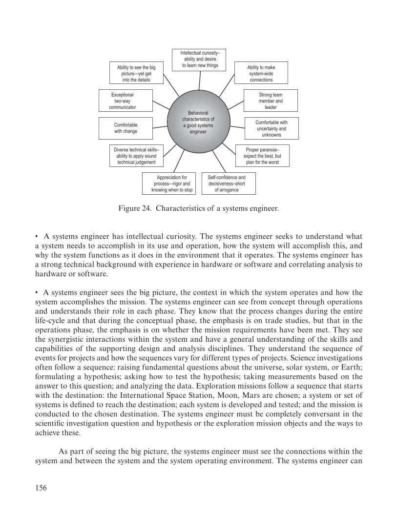
156
Ability to see the bigpicture—yet getinto the details
Exceptionaltwo-way
communicator
Comfortablewith change
Diverse technical skills–ability to apply soundtechnical judgement
Appreciation forprocess—rigor and
knowing when to stop
Self-confidence anddecisiveness–short
of arrogance
Proper paranoia–expect the best, butplan for the worst
Comfortable withuncertainty and
unknowns
Strong teammember and
leaderBehavioral
characteristics ofa good systems
engineer
Ability to makesystem-wideconnections
Intellectual curiosity–ability and desire
to learn new things
Figure 24. Characteristics of a systems engineer.
• A systems engineer has intellectual curiosity. The systems engineer seeks to understand what a system needs to accomplish in its use and operation, how the system will accomplish this, and why the system functions as it does in the environment that it operates. The systems engineer has a strong technical background with experience in hardware or software and correlating analysis to hardware or software.
• A systems engineer sees the big picture, the context in which the system operates and how the system accomplishes the mission. The systems engineer can see from concept through operations and understands their role in each phase. They know that the process changes during the entire life-cycle and that during the conceptual phase, the emphasis is on trade studies, but that in the operations phase, the emphasis is on whether the mission requirements have been met. They see the synergistic interactions within the system and have a general understanding of the skills and capabilities of the supporting design and analysis disciplines. They understand the sequence of events for projects and how the sequences vary for different types of projects. Science investigations often follow a sequence: raising fundamental questions about the universe, solar system, or Earth; formulating a hypothesis; asking how to test the hypothesis; taking measurements based on the answer to this question; and analyzing the data. Exploration missions follow a sequence that starts with the destination: the International Space Station, Moon, Mars are chosen; a system or set of systems is defined to reach the destination; each system is developed and tested; and the mission is conducted to the chosen destination. The systems engineer must be completely conversant in the scientific investigation question and hypothesis or the exploration mission objects and the ways to achieve these.
As part of seeing the big picture, the systems engineer must see the connections within the system and between the system and the system operating environment. The systems engineer can
157
see the flow of things through the entire project. They look for these connections and question how the system interacts between all of its functions and environment. The great systems engineer knows the partial derivative of everything with respect to everything and how these affect the total derivatives. Systems engineering is not effective when we believe the partial derivatives stop at the interfaces. The systems engineer also knows that requirements are only an approximation using the inefficacious language of human beings and therefore do not necessarily capture all system interactions.
Each program presents unique challenges that require specific engineering solutions. Tech-nical integration is a key systems engineering skill to provide integrated design and analysis of the system. As such, a systems engineer must have an understanding and knowledge of the system in order to elegantly integrate the system. The systems engineer needs a clear knowledge of how the parts work together to make a whole and what the sensitivities, uncertainties, interactions, risks, and resulting trades required to make the system work.
Systems engineers are comfortable with change. They constantly are responding to events (and needs) within the system and continuously reprioritize to address these. Systems engineers do not require a highly circumscribed space but are comfortable in the gray area of the design space. They understand that unexpected events happen, and adjustments have to be made when it is learned that a requirement cannot be met or a new system characteristic is discovered. The systems engineer knows that this environment of change means the job is never done.
Corresponding to this, the systems engineer is comfortable with uncertainty. Thus, knowl-edge of probability and statistics along with the ability to define and understand probabilistic state-ments are essential tools of the systems engineer. The systems engineer knows when the statistics are meaningful and when they are not. They recognize the uncertain uncertainties (such as planetary environments) and understand how to employ appropriate methods to estimate these.
Systems engineers are properly paranoid and question other engineers and their engineer-ing approach. They understand failure management and the interactions that lead to failures of the system. They strive to design systems that minimize the steps in critical sequences that can lead to mission failure.
The systems engineer keeps track of resources and margins. They keep a running score of resources including power, mass, delta v, and know the system margins. They understand the dif-ference between requirements and capabilities. They know the scope of these by heart and under-stand their partial derivatives. The systems engineer can communicate an understanding of the trade study process and the sensitivities of the systems design, and represent a best balance between project technical requirements and available resources and margins (and they do not try to over engineer or over optimize solutions).
Systems engineers have good organizational and personal skills. The human mind is our most important and powerful resource. The systems engineer needs to understand how to work with people to get their best ideas, creativity, and innovation to produce their best effort in design and analysis. The systems engineer must be a critical thinker and inspire others to think critically.

158
They are good communicators in both speaking and listening. They facilitate communication among all the disciplines on the development or operations team. They operate with integrity in all activities and relationships. They understand their own blind spots, biases, and work to ensure they are effectively communicating with the other engineers on the project.
Systems engineers have self-confidence and energy. They are not arrogant in their confi-dence, know what they do know and what they do not know, and understand that everyone is wrong at times. Being wrong is not bad, not recognizing when you are wrong is. The systems engineer executes by commission, not omission. Omission is not acceptable to the systems engineer. They know that their scope is the whole design and operations space and have the authority to investigate any question in that space.
Systems engineers have an appreciation for process, knowing that the focus is on the opera-tional system, not the process itself. The systems engineering process is a tool with which the system design can be achieved. Yet, the process itself is not a guarantee of an elegant system. Systems engi-neers understand the use and limit of procedures and rely on the systems integrating physics more than relying on process, procedures, and codes. A systems engineer who knows no process cannot possibly do the job. A systems engineer who knows nothing but process is not much better. The systems engineer understands how to use the process to achieve an elegant product.
A systems engineer needs to develop experience in engineering a system. This may require the systems engineer to follow several paths. Experience may be gained by engineering smaller sys-tems (or subsystems) and progressing to larger and more complex systems. Systems engineers may also gain experience in at least one penetrating discipline/area, understanding the depth required to get the right answers and the integration necessary to gain a functioning system. Fault protection is another area where these systems engineering attributes are acquired before a systems engineer becomes fully responsible for an entire systems engineering task.
These characteristics are not filters, but areas that all systems engineers should seek to develop. A continuous learning approach is a key to continually addressing new challenges as the systems engineer transitions from one system to another during the progression of their career. These characteristics provide an excellent metric to guide personal development as a systems engineer.

159
7. SUMMARY
This TP was developed to capture elegant, product-focused systems engineering as an engineering discipline. The volume presented practical guidance for systems engineers to implement the theory found in Engineering Elegant Systems: Theory of Systems Engineering.4 This TP captures the primary concepts of the discipline while constructing a lifecycle view of the approach.
This volume detailed the characteristics of elegant systems and provides a basic framework for the discipline of systems engineering. Principles, as defined in reference 4, form the basis for practical guidance in the implementation of systems engineering. Systems engineering encompasses analysis tools and techniques that are specific to the function of the system. Guidance has been provided in the use of these tools throughout the lifecycle. In particular, system design and analysis approaches have been presented, which define design at the system level complementary to disci-pline design efforts. A set of systems models has been identified, providing systems engineering with the tools necessary to conduct complete system design and analysis at the system level.
Discipline integration is a crucial function in the practice of systems engineering. Sociologi-cal principles have been applied to support a healthy and manageable organization and the flow of information through the organization. Guidance on the appropriate application of policy and law to the system lifecycle phase has also been supplied.
Processes related to systems engineering must be established within the context of the system being developed or operated. Systems engineers need to be aware of process limitations and not to rely completely on process. The SEMP serves as the communication mechanism to describe systems engineering processes in the context of the system. Important elements of this plan are the technical content and the technical approach. The SEMP may require significant revisions as the system tran-sitions from the development phase to the operational phase to the decommissioning and disposal phase.
Understanding the characteristics of a great systems engineer is critically important in devel-oping people to serve in this role. Social abilities are as important as technical abilities, and a highly effective systems engineer must possess each. This TP described these characteristics in detail.
Guiding postulates, strategies, and hypotheses have been repeated from reference 4 including the supporting evidence and implications of each. These postulates and hypotheses, shown in appendix A, were used to articulate basic principles that guide systems engineering implementation.
The guidance in this TP is intended to aid the systems engineering in understanding the system, appropriately applying the systems engineering processes, using the appropriate system models, and appropriately integrating the various engineering disciplines across the system lifecycle phases. Discipline integration is based on sociological principles and helps the systems engineer

160
maintain a proper flow of information about the system through the organization. The practice of systems engineering involves many aspects that the systems engineer must employ to achieve the development and operation of elegant systems.

161
APPENDIX A—SYSTEMS ENGINEERING POSTULATES, STRATEGIES, AND HYPOTHESES
The Systems Engineering Consortium has, over time, drafted a set of postulates, strategies, and hypotheses to articulate some basic principles that can serve as a guide to systems engineering. These postulates, strategies, and hypotheses emerged in discussions on the basis of systems engineering. In particular, looking at the work of Ludwig Boltzmann and his postulates on gas distributions as an early example of how to characterize the interactions of complex systems. This led us to examine the underlying postulates, strategies, and hypotheses from which the team is working, leading to the seven postulates, eight strategies, and three hypotheses stated in this section.
The principles which govern systems engineering as stated in section 2.3 were defined from this set of system postulates, strategies, and hypothesis. These postulates define the domain of systems engineering as well as the system aspects and system influences that are of concern to the systems engineer. The seeds of a holistic modeling basis for systems engineering are contained by the strategies and hypotheses.
A.1 Systems Engineering Postulates
A postulate is something assumed without proof to be true, real, or necessary.6 The postulates of systems engineering identify the basis for the discipline. These are further expanded by a set of principles in section 2.3.
• Postulate 1: Systems engineering is system specific and context dependent in application.
– Description: This is the first and foundational statement on systems engineering. The product (i.e., the system) and its operational environment drives systems engineering and the system’s inte-grating physics, logic, and social and cognitive relationships (i.e., context) that are foundational to the specific product or system. Essential to this is the understanding of the mission or use of the product as stated by the product goals. This includes the aspects of the system needed to operate in an elegant manner and thus considers the entire system lifecycle.
– Evidence: The ubiquitous tailoring of systems engineering approaches provides strong support for this postulate. Tailoring is the manifestation of making the processes fit the system context. Systems engineering must be consistent with the system being developed or operated. Our research surveying the ‘NASA 17 Systems Engineering Processes’ provides support for this postulate indicating 72% of companies interviewed have systems engineering processes unique to their product. More than 7% of the respondents2 do not follow a standard process.
– Implications: This postulate states that any application of systems engineering should be organized based on consideration of the system being developed or operated and the characteristics of the engineering organization. The systems engineering methods applied to a product will and

162
should vary in emphasis and application based on the nature of that product, its environment, its organization, and context.
• Postulate 2: The systems engineering domain consists of subsystems, their interactions among themselves, and their interactions with the system environment.
– Description: From a physical, logical, and structural sense, a system is not a single mechanical, or electrical, or chemical entity; it encompasses a set of interacting subsystems. Systems engineering is concerned with combining multiple subsystems of various physical and logical types into a best-balanced functional whole to accomplish the mission goals. This whole includes considering the human role in system operations and maintenance, taking into account human capabilities and limitations. This postulate is a mathematical definition of a system containing both the system objects (subsystems) and system interactions. This postulate addresses the system integration aspects of systems engineering. Postulate 3 addresses the discipline integration aspects below.
– Evidence: The individual engineering disciplines generally deal with the development of their specific functions extremely well. When these functions are integrated with each other and with the environment, the inter-relationships drive the final system performance including emergent properties not evident from the individual subsystem functions. This is particularly true when human inputs contribute to the emergent properties, where humans can be both a source of resilience and adaptability as well as a source of error or degradation in system performance (the determination of which is often based on how well the system design incorporates consideration of human factors engineering principles and practices). Thus, the engineering of the individual functions is well addressed while the integration of the engineering functions is what makes these functions a system. The domain of systems engineering is the set of these integrated relationships.
– Implications: The systems engineer focuses on the interaction of these subsystems, not as a design engineer focused on the details, but as a well-versed integrator. These system interactions, including interactions with the system environment and human interactions, can drive the design as strongly as the subsystem functions themselves and, when coupled, can potentially create unexpected system responses. Human System Integration (HSI) focuses on the human interactions explicitly. The systems engineer must predict and manage all of these system responses. Note that subsystems can be treated as systems in a limited sense, taking into account the external dependencies on the other subsystems. Subsystems may not be independently functional outside of the system context they are designed. Providing a mathematical basis for the system, this postulate frames the basic entities needed to represent a system.
• Postulate 3: The function of systems engineering is to integrate engineering and science disciplines in an elegant manner.
– Description: The systems engineering discipline is its own engineering discipline, but it is not independent from other engineering, science, and social disciplines. Systems engineering seeks to integrate and incorporate the other engineering and social disciplines solutions and designs in an ele-gant manner to produce an elegant system throughout the system lifecycle. This postulate addresses the discipline integration aspects of systems engineering. Postulate 2 above addresses the system integration aspects.

163
– Evidence: Any engineered complex system is developed by multiple engineering (e.g., aerospace, chemical, civil, electrical, mechanical), science, and social disciplines with many social aspects influ-encing the integration. These engineering disciplines with social influences work in an integrated fashion, formally and informally, to produce these systems.
– Implications: The interaction of these disciplines is a focus of systems engineering. Systems engi-neers integrate information deriving from the various disciplines via a detailed understanding of their interactions. This requires a basic understanding of each discipline involved in the engineering of the system as well as an understanding of the organizational relationships. Note that for subsystems and assemblies, the system integration can be more engineering discipline based. Systems engineering recognizes and accounts for these disciple integration functions as part of discipline integration. The systems engineer must be cognizant of the organizational and sociological influences on the system development and operations. The systems engineer in conjunction with program management also guides the engineering of these relationships.
• Postulate 4: Systems engineering influences and is influenced by organizational structure and culture.
– Description: The technical aspects of the system are not the only focus of systems engineering. The system under development drives the development process which has a corresponding influence on the structure of the system’s developmental and operational organizations. Similarly, the structure of the organization has an influence on the engineering of the system. These factors also impact the culture of the organization.
– Evidence: Organizational mirroring provides examples where the organization maps to system functions. Our research in Biased Information Sharing (section 4.1.5.1) also shows that system techni-cal margin is maintained by the organization and not always clearly identifiable in the system design.
– Implications: The systems engineer must be cognizant of the culture, the organizational interac-tions, and their potential impact on the design of the system. The systems engineer must understand how information flows through the organization, is filtered and interpreted by the organization, and is captured by the system design or operational procedures. The systems engineer should work with project management and line management to address issues in organizational information flow and culture to improve the elegance of the system.
• Postulate 5: Systems engineering influences and is influenced by budget, schedule, policy, and law.
– Description: Every project has overarching constraints that extend beyond the physical and environmental. Specifically, most, if not all, projects have a limited budget and schedule. In addition, all systems must conform to established organizational and government policy and laws. These poli-cies and laws put additional constraints on budgets, schedules, and technical solutions and provide a context in which the system is developed and operated. In addition, the system design choices also influence these factors. Government policy and law is based on the understanding of legislators on which systems can actually achieve their intents. Similarly, corporate/company policy is influenced by the types of systems the corporation or company chooses to develop, and vice versa.

164
– Evidence: Every project has these constraints. Infinite budgets or schedules do not exist. Policy and law application pervade our systems. Government policy and law are based on the legislators’ understanding of solutions needed to accomplish their intents. Similarly, corporate/company budgets and schedules are based on the executives’ understanding of the budget and timeframe necessary to develop a system. This understanding can be seen in budget and schedule allocations, which encompass both a total funding and a timeframe understanding, that are provided by the government or corporate/company executives.
– Implications: Social choices drive the establishment of these constraints. People make choices to define budget limits, schedule limits, policies, and laws, whether at the national or organizational level. Physical and logical solutions through these constraints can be assessed by social choice theory. These choices are based on an understanding of the system’s abilities to achieve the government and corporate/company executives’ intents. This understanding drives the interactions with budget and schedule allocations and the policies put in place. Similarly, the available budget, available expected duration, existing policy, and law interact with and can influence choices in the development of a system.
• Postulate 6: Systems engineering spans the entire system lifecycle.
– Description: Systems engineering is not just a development phase activity but continues through-out system operation, decommissioning, and disposal. Organizational relationships and goals change as the system progresses through these phases, but systems engineering continues to integrate the system functions and the system disciplines throughout all phases of the system lifecycle. Operations engineering is responsible for the operation of the system. Systems engineering is responsible for the various changes and upgrades to the system capabilities.
– Evidence: The necessity of systems engineering during the development phases is well understood. During the operational phases, systems engineering is still essential as the system goes through maintenance upgrades, new application adaptations, obsolescence-driven redesigns, etc. In addition, during decommissioning and disposal, systems engineering is essential to deal with the proper decommissioning and dispositioning of the system and supporting infrastructure, ensuring conformance with policy and laws affecting the system disposal.
– Implications: As the system progresses through its lifecycle, the need for systems engineering changes. A shift takes place from development to operations in terms of the scope of changes and organizational responsibility. Operations engineering is responsible for operating the system while systems engineering is responsible for the system changes and upgrades. The baseline operational system then becomes the medium in which operational phase system changes take place. The organization changes significantly as the system transitions from development to operations. Organizational relationships and needs are different. Culture can be very different. All of this affects the system and must be dealt with in systems engineering. Another organizational change and culture shift occurs after operations during decommissioning and disposal.

165
• Postulate 7: Understanding of the system evolves as the system development or operation progresses.
– Description: A deeper understanding of the system as a whole is gained as the system progresses through development and operations. As the system progresses through development, more detailed decisions are needed, and as understanding deepens, these detailed decisions can be made. – Evidence: This deepening of understanding is seen in any system development. The technical assessment process shows this as systems progress from concept review to requirements review to design review to acceptance review. Lessons learned from the operations phase are abundant for any system once operation begins. This deepening of understanding of the system and its application enables commercial product upgrades or new models.
– Implications: Requirements are derived as the system design progresses. Thus, while mission requirements (i.e., part of understanding the mission context) are defined at the beginning of devel-opment, the system requirements cannot be established upfront. They are a function of the design choices made and are understood progressively throughout the development phase. This also applies to cost and schedules, particularly for new systems where the development or operations result in unexpected changes. Similarly, systems engineers develop models to predict system capabilities, and then refine these models as testing and operational experience is achieved. System models gain fidel-ity as the design progresses and the interaction between subsystem design maturity and system model maturity must be managed by the systems engineer. These system models become the basis of system operations, as discussed in section 3.3.2.
• Postulate 7 Corollary: Understanding of the system degrades during operations if system under-standing is not maintained.
– Description: Understanding of the system regresses if organizational changes occur (postulate 4) due to inactivity of an organizational element (loss of experience), retirement of key experienced individuals, or closure of suppliers.
– Evidence: Regression of system understanding can be seen in some lifecycle extension activities. When system understanding is not actively maintained, the basis of system specifications become unclear and some systems have been found not to perform (either underperform or overperform) to their system specifications. This loss of understanding can impair long-term operations as operator errors can increase. In addition, operational procedures can lose their basis and it can become difficult to determine when the system should be retired or maintained as the system ages.
– Implications: If the system basis is not maintained, then the understanding of why certain procedures or specifications were defined can be lost. This becomes problematic for aging systems, particularly as they reach the generational gap for the workforce after 20 years of service.
166
A.2 Systems Engineering Strategies
Based on the current postulates and principles discussed above, there are several strategies of systems engineering. These strategies are approaches to systems engineering modeling that flow out from the mathematical basis defined in subprinciple 5(b). These strategies provide the basic approach to engineer a system at the system level.
• Strategy 1: System Theory Strategies
– Description: There are two aspects to this strategy dealing with the system as a whole:
(1) Systems engineering divides its space of representation into the system, the system’s environ-ment, and the system’s internal and external contexts (postulate 2).
The system is the item being designed, assessed, built, and operated to achieve one or more purposes. The environment is the physical, logical, and human environment in which the system is operated. The context constitutes the institutional, legal, political, and economic elements that do not directly interact with the operational system, but define the system’s purpose(s), create the system, and otherwise influence the system. The ‘internal context’ includes the organizations that design, assess, build, verify, and validate the system over which the systems engineer and project manager have some control. The ‘external context’ includes organizations that provide guidance and resources to these organizations, and other factors often beyond direct control of any organization, such as economic and political influences and constraints. Over the life of a system, there can be changes to the system itself, to its operational environment, and to its context. All of them influence a system’s purposes, and to the judgment of how well or poorly those purposes are being achieved.
(2) In hierarchical representations, systems engineering concepts are typically applied recursively to each level of the hierarchy.
The recursive strategy is typical of systems. One frequently finds the same idea, such as what ‘the system’ is or what constitutes cause or effect, being applied in different ways to the same physical components or behaviors. This is often due to people having control of, or being interested in dif-ferent parts of the system. As an example, for an organization that builds a system component, that component is ‘the system’ of most relevance for them. They can and should apply systems engineer-ing strategies and concepts to their component in a manner equally valid as those in charge of the entire larger system. Systems engineering theory, concepts, practices, and terminology must allow for these differences in point of view and should enable accurate communication of information across them. Note that, as stated in subprinciple 3(d), hierarchical representations do not sufficiently rep-resent the system interactions.
• Strategy 2: Value Theory Strategies
– Description: These strategies deal with the value that the system provides to the stakeholders of the system. System users and operators are an important group of stakeholders when examining system value. Section 3.3.5 describes an approach to system value modeling which is based on these strategies.
167
(1) System value is derived from von Neumann-Morgenstern (vN-M) utility functions.
Von Neumann-Morgenstern utility functions were a starting point for the development of game theory31 and are now the basis for an active ongoing program of engineering research in what is often called value theory. This research is based on the idea that, to make rational decisions from human preferences, one must create a mathematical representation that is based on a single axis of scalar numbers. For example, money measured in dollars, euros, yen, or some other comparable scale is a very common way in which humans use a single scale of value across a variety of human preferences. Von Neumann and Morgenstern showed that if value can be measured with a single scalar metric, then a variety of mathematical operations can be performed and be used as the basis for a ‘rational decision.’ Of course, this is a very strict interpretation of what ‘rational’ means, clearly fitting the needs of mathematical and economic research. However, much effort is now going into applying this approach to engineering as a means to rigorously specify the purpose(s) of a system, and then be able to assess designs against those purposes. Ideally, one desires to create and select the optimal design among all possible design options, and this measure of optimality needs to use a single scale of value.
(2) When it is not possible to construct vN-M utility, other goals, constraints, or uses of the system can be used to define system goals and preferences.
For systems whose purposes can be clearly stated monetarily in terms of making profits, for example, the application of vN-M utility is relatively straightforward. However, for any system in which profit is not the primary purpose, then some other scalar metric could be selected and used as the single measure of value for that system. It is not always possible to do this, and in such cases, other nonscalar goals and measures can be used. When this occurs, the systems engineer must be aware that this will make the process of coming to agreement on goals, preferences, and requirements more difficult and subject to error.
(3) Specification of requirements should be delayed if practicable during system design and development, in favor of mathematical representation of preferences.
This is derived from principle 3 where requirements are progressively defined as the design matures. Specifying requirements too early leads to unnecessary constraints on the system design and can lead to the failure or violation of system constraints during development.
• Strategy 3: Model Strategies
– Description: System models are an essential systems engineering tool as stated in subprinciple 4(b). System models provide integrated knowledge about the system and the system environment as a whole. Models may be formal or informal (in the minds of individuals). Improving systems engineering requires increasing use of appropriate formal models (e.g., state variable models, integrating physics models, value models, statistical models, information models, process models) that have specific uses. Building formal models for their own sake is worse than useless, as it diverts time and resources from useful purposes. All formal models must have specific, known uses to be worthwhile to create and maintain:

168
(1) Systems engineering maximizes the use of models to represent, maintain, and generate knowledge.
System models provide integrated knowledge bases of the system. Among other things, these models provide a transport medium to communicate system-level information across the system lifecycle. The knowledge developed about the system in the development phase is transferred to the operations phase through the system models, and then transferred to the decommissioning phase in a similar manner.
(2) System-level representations at a minimum include those for value, intention, design, failure, performance, behavior, and agency.
These types of system models provide valuable information on various aspects at the sys-tem level. Of course, the system itself is the full representation of the system (principle 14). System models, collectively intended to cover the full scope of the system, only provide a partial view of the systems. The model types identified here provide a set of system models that provide useful system-level, integrated views of the system:
• Value models represent stakeholder preferences, ideally using a single scalar metric.
• Intention models translate the preferences of the value models into more specific statements of intention for the system, specified ideally as constraints on state variables over time. Models of intention specify what the system ‘should do’ or ‘ought to do,’ as opposed to what the designed system actually does. Two types of intention models have been identified to date, a formal Concept of Operations (operational description model) and the GFT.
• Design models represent the designed system, as opposed intentions for the system. Information from intention models can be mapped to design models by mapping the common state variables and constraints between the two types of models. Since the designed system aims to achieve the goals specified by intentions for the system, by definition there must be at least one output of func-tions in design models that correspond to a stated intention in the intention models. The mapping from intention to design can be ‘many to many’ as opposed to merely ‘one to one,’ ‘many to one,’ or ‘one to many.’ Design models include ‘physical containment models,’ which represent components existing inside of other components, such as subsystems existing inside the physical mold-line of the system as a whole. Directed graphs represent abstract component connectivity.
• Failure models (i.e., Fault Trees, Probablistic Risk Assessments (PRA), Failure Models and Effects Assessments (FMEAs)) represent mechanisms by which design model components fail and their effects propagate through the system, or by which intentions are violated. Since many failure effects propagate along the same paths as exist in the nominal design, nominal design models are a starting point to create design failure models. However, failures often create new paths that are not represented in the nominal design models, such as electrical short-circuits, or an explosion releasing debris that impacts other components that are not physically connected to each other nominally. Thus, failure models are more complete representations of the system than nominal

169
models. Other failure models are based on intention, by assessing ways by which intention is violated using a top-down hierarchy of failure to meet goals. While today these are usually based on natural language, these can be transformed into state-based models (i.e., Fault Trees) that are the logical complements of the GFT.
• Performance models come in a variety of types. The main types described here are nonsimulation performance models, such as root-locus analyses in linear control theory or Fourier techniques used in radio frequency system analysis. Any nonbehavioral methods of assessing performance are included here.
• Behavior models are representations that simulate system behavior. These can include abstract models such as executable state machines (State Analysis Models (SAMs)), but can also include time-domain simulations that range from purely software simulations with no ‘real’ hardware or software (software simulations), to simulations that include mixes of the system’s actual hardware, software, and humans (Hardware Software Integrated (HSI) simulations), to full system tests in which the entire actual system is being tested using a simulated environment. The data generated using these models mimic to greater or lesser degree the actual behavior of the system.
• Agency models are representations of the ‘agents’ that manage, design, build, test, and analyze the system. These include representations of the organizations and individuals involved with these activities (e.g., agent based models (ABMs)), and include critical management representations such as cost, schedule, and organization hierarchy models. System dynamics models provide a model-ing framework to capture the organizational interaction with the system or system design. Agency models are essential to describe and assess critical attributes and performance of the organizations that create the system.
(3) Systems engineering provides abstract, system-level compatible representations of discipline models.
System models provide a medium to integrate the various discipline model results, provid-ing the integrated system view to inform engineering decisions at the system level. To do this, there must be representations of disciplinary knowledge that can integrate with system-level models. This is related to postulates 2 and 3 and principles 7 and 9.
• Strategy 4: State Strategies
– Description: Systems engineering is concerned with sufficient knowledge and understanding of system state over time. The state representations of the system then are an essential strategy for elegant systems engineering. State Analysis Models provide the representation.
(1) Systems engineering makes use of system state variables in system representations.
System state variables are essential to represent actual system conditions in any set of cir-cumstances (e.g., environmental conditions, performance conditions, operational uses). As such, this is a key tool for the systems engineer as discussed in section 3.3.4.

170
(2) System functions are defined as mappings of input states of state variables to output states of state variables.
Defining functions as mapping of input and output state variables (y = f (x)) provides an unambiguous definition of system functions separate from the specifics of the design that perform those functions (transformations-mappings). This is invaluable to systems engineering and provides the basis for structuring system requirements, system-level design, and guidance for discipline-level design and analysis.
• Strategy 5: Goal Strategies
– Description: The goals of the system define the intended uses of the system. Understanding these goals is critical to an elegant system design. System development and operation must be tracked to these goals to ensure that the design and operations are meeting the stakeholders’ intents. GFTs provide this modeling representation. Modeling system goals is discussed in section 3.3.4.
(1) System goals are represented both in terms of operational description and of hierarchy.
Goals define the intentions for the system. Operational description of the goals is necessary to ensure the system application is properly understood. Goals are typically hierarchical (i.e., goals and subgoals). This hierarchy can have many forms (e.g., needs, goals, and objectives (NGO)) and must be understood and managed by systems engineering.
(2) To the maximum extent practicable, systems engineering defines goals as constraints on the ranges of output state variables of a function over a specified period of time.
Mathematically, a goal forms a constraint on the system operation, defining when the system is successful in achieving the goal and when it is not. This is represented as: Goal = rl < y < rh , where y = f(x) between times t 0 and t1.
• Strategy 6: Control Strategies
– Description: Because engineered systems are mechanisms that use and control physical laws to achieve goals, systems engineering relies heavily on control theory concepts. That is, achieving a goal means constraining state variables within relevant ranges, which is what is meant by ‘controlling’ the state variable. Systems engineering takes it as axiomatic that engineering is by its very nature about control. Given this point of view, control theory concepts and strategies are fundamental. This does not mean that systems engineering is limited by current control theory. Rather, systems engineer-ing assumes that current control theory applies, but also that its ideas must be extended beyond the classical domains of linear and robust control. Five aspects of the application of control theory in systems engineering is described below:
(1) Systems engineering provides design and performance representations of the system.

171
This is related to system modeling as discussed under strategy 3 and subprinciple 4(b).
(2) Systems engineering simultaneously, with nominal system design, also addresses design of the system to mitigate the failure to achieve goals.
Systems engineering is not only concerned with the success of the system but in addressing and responding to system failures (minimizing unintended consequences and providing for the sys-tem robustness). This is a fundamental part of the system design and must be addressed in concert with the nominal system design.
(3) Systems engineering deploys passive and active means to control state variables within appro-priate constraints so as to achieve the corresponding goal.
Systems engineering should consider all means available to achieve system goals. Control of state variables can be achieved by providing passive control of system physics, such as with structural margins, or active control through open- or closed-loop control systems.
(4) Systems engineering uses and extends classical control theory concepts of state estimation and state control to assess the system’s ability to achieve goals.
Control theory application is an essential part of the system design and analysis as discussed in subprinciple 5(b). Using concepts of state estimation and control provides a basis for defining system performance metrics for those parts of the system under active control.
(5) System engineering uses control theory to understand decision-making process flows.
Control theory and information theory are used to model information flow in a decision-making process in Engineering Elegant Systems: Theory of Systems Engineering4, section 5.3.1.
• Strategy 7: Knowledge Strategies
– Description: Knowledge strategies aim to address the human cognitive and social factors at play in the engineering of complex systems (postulate 4 and principle 6). These include the fact that organizations and institutions are the centers of knowledge generation and maintenance, but that ‘knowledge’ as such refers to what individual humans understand about a system. In some sense organizations ‘know’ more than any of the individuals in the organization; in other equally impor-tant sense, only individuals in an organization ‘know’ anything at all. There is no collective mind, only individual minds in a collective enterprise. Working together through social mechanisms and organizations, these individual minds can create a device that uses and encapsulates their knowledge.
(1) Systems engineering uses existing sources of knowledge about the system.
There are many sources of knowledge about the system within the development or operations organization. Systems engineering should know and make use of these sources of information.
172
(2) Systems engineering accepts the variability of human interpretation of acceptable and expected system behaviors.
Individuals can and do differ in their interpretation of system behaviors. For example, prior to the Challenger accident, some engineers at Thiokol were worried that erosion of O-rings discovered after some flights indicated a serious design problem. In other words, they viewed this as a failure. Others believed that the fact that no major solid rocket motor failure had yet occurred despite the erosion indicated that the erosion was a minor problem. While the Challenger accident showed that the ‘failure’ interpretation to be correct, this was not known until a disaster occurred.55 Instead of viewing this situation and many others like it as anomalous with some being right and others wrong, these differences are typical of engineering and must be treated as such, both in practice and in theory. Differences of opinion and judgment occur all the time in engineering, and the theory and practice of systems engineering must be designed to account for these differences and use them to an advantage in system success.
(3) Systems engineering models the interaction of the system and the organization to identify information gaps, barriers, and reservoirs.
System organizations are social structures and sociological principles are important for sys-tems engineering to understand how information (i.e., knowledge) about the system flows through the organization. Information gaps, barriers, and reservoirs all exist within the social structure of the orga-nization. Systems engineering must be cognizant of how the social structure of the organization affects the understanding of the system and the transferal of system knowledge from the organization to the design and operation. Section 4.3.1 addresses this through the application of systems dynamics mod-eling and, in general, by creating new system-level knowledge capture and maintenance mechanisms.
• Strategy 8: Predictive Strategies
– Description: Predictive strategies aim to forecast a variety of future events and their ramifica-tions for the project building the system, and of the system itself (postulate 7 and principles 1, 3, 4, 5, 7, and 9). These include prediction of cost and schedule information for managing the project that creates the system, but also similar information for operations. Important predictive methods are deployed to assess various characteristics of the future system, such as performance, mass margins, computer resource margins, availability, and reliability. All of these methods use probabilistic tech-niques to address uncertainties of prediction (e.g., PRA), making probabilistic methods a central aspect of systems engineering.
(1) Systems engineering uses predictive models of performance, dependability, cost, and schedule described above.
(2) Systems engineering predictive models include assessments of uncertainty.
All predictions are uncertain, and hence require estimates of these uncertainties.
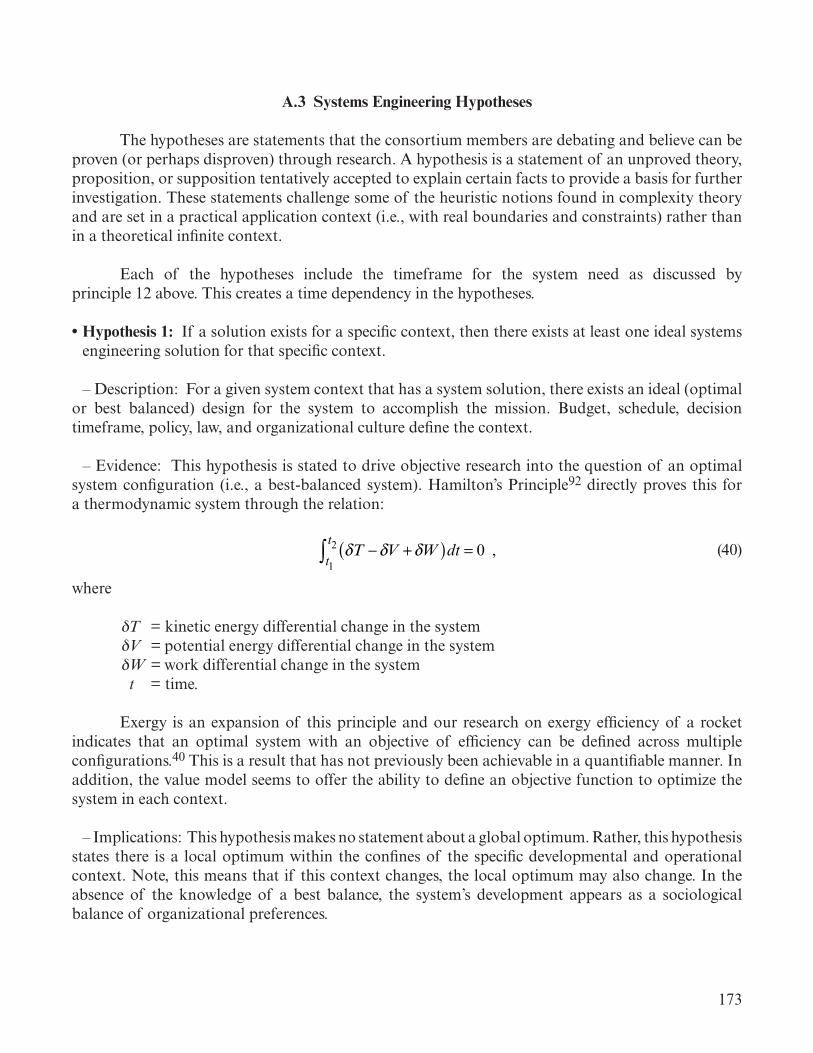
173
A.3 Systems Engineering Hypotheses
The hypotheses are statements that the consortium members are debating and believe can be proven (or perhaps disproven) through research. A hypothesis is a statement of an unproved theory, proposition, or supposition tentatively accepted to explain certain facts to provide a basis for further investigation. These statements challenge some of the heuristic notions found in complexity theory and are set in a practical application context (i.e., with real boundaries and constraints) rather than in a theoretical infinite context.
Each of the hypotheses include the timeframe for the system need as discussed by principle 12 above. This creates a time dependency in the hypotheses.
• Hypothesis 1: If a solution exists for a specific context, then there exists at least one ideal systems engineering solution for that specific context.
– Description: For a given system context that has a system solution, there exists an ideal (optimal or best balanced) design for the system to accomplish the mission. Budget, schedule, decision timeframe, policy, law, and organizational culture define the context.
– Evidence: This hypothesis is stated to drive objective research into the question of an optimal system configuration (i.e., a best-balanced system). Hamilton’s Principle92 directly proves this for a thermodynamic system through the relation:
δT −δV +δW( )dt = 0 ,t1
t2∫ (40)
where
δT = kinetic energy differential change in the system δV = potential energy differential change in the system δW = work differential change in the system t = time.
Exergy is an expansion of this principle and our research on exergy efficiency of a rocket indicates that an optimal system with an objective of efficiency can be defined across multiple configurations.40 This is a result that has not previously been achievable in a quantifiable manner. In addition, the value model seems to offer the ability to define an objective function to optimize the system in each context.
– Implications: This hypothesis makes no statement about a global optimum. Rather, this hypothesis states there is a local optimum within the confines of the specific developmental and operational context. Note, this means that if this context changes, the local optimum may also change. In the absence of the knowledge of a best balance, the system’s development appears as a sociological balance of organizational preferences.

174
• Hypothesis 2: System complexity is greater than or equal to the ideal system complexity necessary to fulfill all system intended goals.
– Description: In each operational context and decision timeframe, the minimum system complex-ity required to fulfill all the system outputs (accomplish all the system intended goals) is the optimal system complexity and the complexity of alternative system designs are equal to or greater than the ideal (i.e., optimal). Note that this is not a ‘simpler is better’ hypothesis. Minimal complexity involves all aspects of the system as defined by context in the hypothesis 1 description. Being simple in only one context is not necessarily the system with the minimal complexity. The minimal complexity solu-tion involves a best balance of the system and may lead to some aspects being more complex than alternatives and other aspects being less complex. Systems engineers define the minimal complex-ity holistically and not based on a subset of system aspects. The definition of system complexity is a much debated topic.
– Evidence: This is similar to the statement of Occam’s razor.93 As Albert Einstein is reputed to have said, “everything should be made as simple as possible, but not simpler” (Einstein, n.d.), which underlines a powerful truth of system modeling and systems engineering.
– Implications: This hypothesis asserts that less complexity is preferable for a given context. This also states that a more complex system solution than the optimum can fulfill the system application, but not as elegantly. One must realize that the system complexity necessary to complete all intended outcomes of the system satisfies all its operational needs.
• Hypothesis 3: Key stakeholders preferences can be represented mathematically.
– Description: A system results from a large set of decisions made by decision makers throughout an organization. To analyze a decision, three key elements are necessary: preference, beliefs, and alternatives. Hence, for a systems engineer to understand how an organization arrives at a particular system, an understanding of the set of decisions, each with their elements, is necessary. Each deci-sion maker may have different preferences, beliefs, and alternatives. While each of these elements are challenging to understand, preferences are of particular interest to systems engineering as they relate to desired system goals. If different preferences are being used to make decisions on a system, then those decisions would be inconsistent with each other, meaning it is possible that given the same beliefs and alternatives, decision makers may decide on different solutions. To enable consistent deci-sion making throughout the organization, systems engineers must elicit, represent, and communicate preferences of key stakeholders to drive to outcomes that the key stakeholder prefers. A mathemati-cal representation supports the modeling of the preferences and enables analysis of the differences and commonalities in the preferences of different stakeholders.
– Evidence: Many systems engineering approaches use a representation of preference to guide decision making. Goals in GFTs, objective functions in multidisciplinary design optimization, payoffs in game theory, and utility functions in value-based engineering are just a few examples of mathematical representations of preferences used in systems engineering approaches. The premise of these approaches is that preferences are mathematically representable and enable a rank ordering of

175
alternatives. Based on these examples, system engineers can create a mathematical function that rank orders alternatives in the same way that a preference does. Decision theory also uses mathematical functions to rank order alternatives as an individual with their preference would, and is widely advocated as a rigorous approach to design and systems engineering.
– Implications: The accurate representation of stakeholder preferences enables the systems engineer to assess how well the system fulfills these preferences as the system progresses through its lifecycle. While many systems engineering approaches assume a mathematical representation of preference exists, accurately representing preferences mathematically is still a significant challenge. The elicitation and formation of mathematical representations must become a significant task undertaken by systems engineers to adopt these approaches. Beyond enablement of approaches that strive to find the best system, mathematical representation of preferences also enables meaningful validation of the system. Mathematical representations of preferences allow comparison of the system characteristics with the stakeholder’s preferences, answering the validation question: ‘does the system meet the stakeholder’s intent.’

176

177
REFERENCES
1. SE Practice Working Group, Subgroup on Pragmatic Principles: “National Council on Systems Engineering: An Identification of pragmatic principles, Final Report,” INCOSE, Defoe, J.C. (ed.), Bethesda, MD, 13 pp., 1993.
2. Componation, P.J.; Dorneich, M.; Guiping, H.; et al.: “Systems Engineering and Project Suc-cess in Government and Commercial Organizations,” in 34th International Conference of the American Society for Engineering Management, October 3–5, 2013, Curran Associates, Vol. 1, Minneapolis, MN, pp. 72–78, 2013.
3. Griffin, M.D.: “How Do We Fix System Engineering?” Paper Presented at 61st International Astronautical Congress, Prague, Czech Republic, September 21–October 1, 2010.
4. NASA Systems Engineering Research Consortium: “Engineering Elegant Systems: Theory of Systems Engineering,” NASA/TP–20205003644, NASA Marshall Space Flight Center, Huntsville, AL, 278 pp., 2020.
5. Watson, M.D.; and Kelley, G.W.: “Application of System Operational Effectiveness Methodol-ogy to Space Launch Vehicle Development and Operations,” Paper Presented at AIAA Space Operations Conference, Stockholm, Sweden, June 11–15, 2012.
6. Neufeldt, V.; and Guralnik, D.B. (eds.): Webster’s New World Dictionary, Third College Edition, Simon and Schuster, NY, 1988.
7. Frosch, R.A.: “A Classic Look at Systems Engineering,” in Readings in Systems Engineering, F.T. Hoban and W.M. Lawbaugh (eds.), NASA Headquarters, Washington, DC, pp. 1–8, 1993.
8. Lee, G.: “Systems Engineering Advancement Seminar Series,” <https://surp.jpl.nasa.gov/vid-eos/index.cfm?fuseaction=ShowVideo&VNum=10&MainVNum=3>, 2005.
9. Pool, R.: Beyond Engineering: How Society Shapes Technology, Oxford University Press, New York, NY, 368 pp., 1997.
10. Wang, Y.: “The Importance of Politics in Engineering: Lessons from a Hands-on Experience,” Leadership and Management in Engineering, Vol. 2, No. 3, pp. 27–32, 2002.
11. Finley, K.: “Is This a Real Job? An Engineer Who Hacks Policy, Not Code,” June 5, 2015, <https://www.wired.com/2015/06/policy-engineering/>, June 18, 2019.
12. Denny, F.I.; and Robinson, R.L.: “The Engineers Role in Public Policy,” in Proc. of the 2003 American Society of Engineering Education Annual Conference and Exposition, American Soci-ety of Engineering Education, June 22–25, 2003, Nashville, TN, pp. 8.1130.1–8.1130.10, 2003.

178
13. Vincenti, W.G.: What Engineers Know and How They Know It, The John Hopkins University Press, Baltimore, MD, 1993.
14. Brennan, J.F.: The Elegant Solution, 1st ed., Van Nostrand, Princeton, NJ, 183 pp., 1967.
15. Boeing, “DC-3 Commercial Transport,” <https://www.boeing.com/history/products/dc-3.page>, 2019.
16. Boeing, “B-52 Stratofortress,” <https://www.boeing.com/history/products/b-52-stratofortress.page>, 2019.
17. Burnham, K.P.; and Anderson, D.R.: Model Selection and Multimodal Inference: A Practical Information-Theoretic Approach, 2nd ed., Springer-Verlag, New York, NY, pp. 60–64, 2002.
18. NASA: “NASA Space Flight Program and Project Management Requirements w/Changes,” NPR 7150.2E, August 2012.
19. NASA: “NASA Systems Engineering Processes and Requirements,” NPR 7123.1B, April 18, 2013.
20. INCOSE: Systems Engineering Handbook: A Guide for System Life Cycle Processes and Activi-ties, 4th ed., Wiley, NY, 2015.
21. NASA Science Solar System Exploration: “What Was the Saturn V?” <https://solarsystem.nasa.gov/news/337/what-was-the-saturn-v/>, April 10, 2020.
22. Merton, R.K.: “The Unanticipated Consequences of Social Action,” in Social Structure and Science, Piotr Sztompka (ed.), University of Chicago Press, Chicago, IL, pp. 173–182, 1996.
23. INCOSE: “Systems Engineering Handbook: A Guide for System Life Cycle Processes and Activities,” Version 3.1, Wiley, NY, 2007.
24. Yohon, L.; Breckenridge, J.T.; and Johnson, S.B.: “Application of Fault Management theory to the quantitative selection of a launch vehicle Abort Trigger suite,” Paper Presented at IEEE International Conference on Prognostics and Health Management, Cheney, WA, June 22–25, 2014.
25. Berg, P.; Johnson, S.B.; and Trevino, L.: “State Analysis Modeling for Space Launch System Mission and Fault Management Analysis,” in Proc., AIAA Infotech@Aerospace Conference, San Diego, CA, January 4–8, 2016.
26. Cheung, J.; Scanlan, J.; Wong, J.; et al.: “Application of Value-Driven Design to Commercial AeroEngine Systems,” Paper Presented at 10th AIAA Aviation Technology, Integration and Operations Conference, Fort Worth, TX, Sept 13–15, 2010.

179
27. Collopy, P.: “Value of the Probability of Success,” Paper Presented at AIAA Space 2008 Con-ference and Exposition, San Diego, CA, September 9–11, 2008.
28. Collopy, P., “Value-Driven Design and the Global Positioning System,” Paper Presented at AIAA Space 2006, San Jose, CA, September 19–21, 2006.
29. Maddox, I.D.; Collopy, P.; and Farrington P.A.: “Value-Based Assessment of DoD Acquisition Programs,” Procedia Computer Science, Vol. 16, pp. 1161–1169, 2013.
30. Keller, S.; and Collopy, P: “Value Modeling for a Space Launch System,” Procedia Computer Science, Vol. 16, pp. 1152–1160.
31. von Neumann, J.; and Morgenstern, O.: Theory of Games and Economic Behavior, 2nd ed., Princeton University Press, Princeton, NJ, 669 pp., 1947.
32. Collopy, P.D.: “Aerospace System Value Models: A Survey and Observations,” Paper Presented at AIAA SPACE 2009 Conference and Exposition, Reston, VA, September 14–17, 2009.
33. Arrow, K.J. and Lind, R.C.: “Uncertainty and the Evaluation of Public Investment Decisions,” The American Economic Review, Vol. 60, No 3, pp. 364–378, 1970.
34. Circular A–94: “Guidelines and Discount Rates for Benefit-Cost Analysis of Federal Pro-grams,” Office of Management and Budget, Washington DC, 1992.
35. El-Sayed, Y.M.; and Evans, R.B.: “Thermoeconomics and the Design of Heat Systems,” Jour-nal of Engineering for Power, 1st ed., Vol. 92, No. 1, pp. 27–35, 1970.
36. Department of Defense: DoD Guide for Achieving Reliability, Availability, and Maintainability, Department of Defense, Washington, DC, 266 pp., August 2005.
37. Bryce Space and Technology: 2017 State of the Satellite Industry Report, Vol. 20, Satellite Indus-try Association, 33 pp., 2017.
38. Defense Logistics Agency: “Aerospace Energy Standard Prices for DoD Custom-ers Effective 1 Oct 2017,” <https://www.dla.mil/Portals/104/Documents/Energy/Stan-dard%20Prices/Aerospace%20Prices/E_2017Oct1AerospaceStandardPrices_170913.pdf?ver=2017-09-13-145335-477>, October 2017.
39. Watson, M.D.; Neeley, J.R.; and Blackburn, R.F.: “Launch Vehicle Production and Operations Cost Metrics,” Paper Presented at AIAA SpaceOps 2014 Conference, Pasadena, CA, May 5–9, 2014.
40. Watson, M.D.: “System Exergy: System Integrating Physics of Launch Vehicles and Space-craft,” AIAA Journal of Spacecraft and Rockets, Vol. 55, No. 22, March–April, pp. 1–11, 2018.

180
41. Riggins, D.W.; Moorhouse, D.J.; and Camberos, J.A.: “Characterization of Aerospace Vehicle Performance and Mission Analysis Using Exergy,” in Exergy Analysis and Design Optimization for Aerospace Vehicles and Systems, J.A. Camberos and D.J. Moorhouse (eds.), AIAA, Res ton, VA, pp. 275–285, 2011, doi:10.2514/4.868405, August 24, 2012.
42. Camberos, J.A.; and Moorhouse, D.J.: “Exergy Based Methods for Multidisciplinary Analy-sis and Design,” Presented at the Thermodynamics: Can macro learn from nano? Workshop, Sogeholm Castle, Sjobo Municipality, Sweden, May 22–25, 2013.
43. Powell, R.W.; Striepe, S.A.; and Desai, P.N.; et al.: “Program to Optimize Simulated Trajecto-ries (POST), Volume II: Utilization Manual,” Version 5.2, October 1997.
44. Akaike, H.: “A new look at the statistical model identification,” IEEE Transactions on Auto-matic Control, Vol. 19, No. 6, pp. 716–723, 1975.
45. Martins, J.R.R.A.; and Lambe, A.B.: “Multidisciplinary Design Optimization: A Survey of Architectures,” AIAA Journal, Vol. 51, No. 9, pp. 2049–2075, September 2013.
46. Standard for Models and Simulations, NASA-STD-7009A, 2016.
47. NASA Handbook for Models and Simulations: An Implementation Guide for NASA-STD-7009, NASA-HDBK-7009, Rev. A, 2019.
48. Watson, M.D.: “Information Theory Applied to Decision Making Structures,” Paper Presented at 2018 Conference on Systems Engineering Research, Charlottesville, VA, May 8–9, 2018.
49. Watson, M.D.; Andrews, J.G.; and Larsen, J.A.: “Principles of Sociology in Systems Engineer-ing,” Paper Presented at the 2017 International Annual Conference of the American Soci-ety for Engineering Management, Annapolis, MD, E-H. Ng, B. Nepal, and E. Schott (eds.), October 18–21, 2017.
50. Watson, M.D.; Andrews, J.G.; Eckley, J.C.; and Culver, M.L.: “Practical Application of Sociol-ogy in Systems Engineering,” Paper Presented at the 2017 International Annual Conference of the American Society for Engineering Management, Annapolis, MD, E-H. Ng, B. Nepal, and E. Schott (eds.), October 18–21, 2017.
51. Sherwood, J.H.; and Glidewell, J.C.: “Planned renegotiation: A norm-setting Organization Development intervention,” Contemporary Organization Development: Approach and Interven-tions, W.W. Burke (ed.), NTL Learning Resources Corporation, Washington, DC, 1972.
52. Page, K.L.; and Page, J.B.: “Reframing Systems Disasters With Three Perspectives of organi-zational Culture,” Journal of Business and Leadership: Research, Practice, and Teaching, Vol. 4, No. 1, 8 pp., January 2008.
53. Turner, B.A.; and Pidgeon, N.F.: Man-Made Disasters, 2nd ed., Butterworth-Heinemann, Oxford, U.K., 200 pp., 1978.

181
54. Roberto, M.A.: Know What You Don’t Know: How Great Leaders Prevent Problems Before They Happen, 228 pp., Prentice Hall, NJ, 2009.
55. Vaughan, D.: Challenger Launch Decision: Risky Technology, Culture, and Deviance at NASA, University of Chicago Press, Chicago, IL, 592 pp., 1997.
56. Christensen, C.M.: The Innovators Dilemma: The Revolutionary Book that Will Change the Way You Do Business, Harper Collins, New York, NY, pp. 120, 2003.
57. Cannon-Bowers, J.A.; and Salas, E. (eds.): Making Decision Under Stress: Implications for Indi-vidual and Team Training, American Psychological Association, Washington, DC, 447 pp., 1998.
58. Schein, E.H.: “Coming to a new awareness of organizational culture,” Sloan Management Review, Vol. 25, No. 2, pp. 3–16, 1984.
59. Merton, R.K.: “Social Structure and Anomie,” in Social Structure and Science, P. Sztompka (ed.), University of Chicago Press, Chicago, IL, pp. 132–152, 1996.
60. Merton, R.K.: “Sociological Ambivalence,” in Social Structure and Science, P. Sztompka (ed.), University of Chicago Press, Chicago, IL, pp. 123–131, 1996.
61. Merton, R.K.: “Social Dysfunctions,” in Social Structure and Science, P. Sztompka (ed.), University of Chicago Press, Chicago, IL, pp. 96–100, 1996.
62. Columbia Accident Investigation Board: Columbia Accident Investigation Board Report, Vol. 1, NASA, Washington, DC, 248 pp., August 2003.
63. Rogers Commission: Report by the Presidential Commission on the Space Shuttle Challenger Accident, NASA, Washington, DC, pp. 261, 1986.
64. Merton, R.K.: “The Self-Fulfilling Prophecy,” in Social Structure and Science, P. Sztompka (ed.), University of Chicago Press, Chicago, IL, pp. 183–201, 1996.
65. Perrow, C.: Normal Accidents: Living with High Risk Technologies, Princeton University Press, Princeton, NJ, 456 pp., 1999.
66. Pool, R.: Beyond Engineering: How Society Shapes Technology, Oxford University Press, New York, NY, pp. 258–270, 1997.
67. “NASA Systems Engineering Handbook,” NASA/SP-2016-6105, 2016.
68. Larson, C.; and LaFasto, F.M.J.: Teamwork: What Must Go Right/What Can Go Wrong, Sage Publications, Newbury Park, CA, 152 pp., 1989.

182
69. Allison, G.; and Zelikow, P.: 69. Allison, G.; and Zelikow, P.: Essence of Decision: Explaining the Cuban Missile CrisisEssence of Decision: Explaining the Cuban Missile Crisis, 2nd ed., , 2nd ed., Longman, New York, NY, 416 pp., 1999.Longman, New York, NY, 416 pp., 1999.
70. Roberto, M.: The Art of Critical Decision Making, <https://www.thegreatcourses.com/courses/70. Roberto, M.: The Art of Critical Decision Making, <https://www.thegreatcourses.com/courses/art-of-critical-decision-making.html>, 2009.art-of-critical-decision-making.html>, 2009.
71. Kozulin, A.; and Presseisen, B.Z.: “Mediated learning experience and psychological tools – Vygotsky and Feuerstein perspectives in a study of student learning,” Educational Psychologist, Vol. 30, No. 2, pp. 67–75, 1995.
72. Weigel, A.L.: “Bringing Policy Into Space Systems Conceptual Design: Qualitative and Quan-titative Methods,” Ph.D. dissertation, MIT, Cambridge, MA, 168 pp., June 2002.
73. Sadeh, E. (ed.): Space Politics and Policy: An Evolutionary Perspective, Kluwer Academic Pub-lishers, Dordrecht, The Netherlands, 522 pp., 2002.
74. Johnson, S.B.: The Secret of Apollo: Systems Management in American and European Space Programs, Johns Hopkins University Press, Baltimore, MD, 312 pp., 2002.
75. Neal, H.A.: Beyond Sputnik: U.S. Science Policy in the Twenty-First Century, Ann Arbor, MI, 312 pp., 2008.
76. Bilstein, R.E.: Stages to Saturn, NASA-SP-4206, 1980.
77. Kennedy, J.F.: “20 April 1961,” Memorandum for Vice President, Presidential Files, John F. Kennedy Presidential Library, Boston, Massachusetts.
78. Johnson, L.B.: “Evaluation of Space Program,” Memorandum for the President, NASA His-torical Reference Collection, NASA Headquarters, Washington, DC, April 28, 1961.
79. Wolters Kluwer: “Small Business Government Contracting Initiatives Can Give You an Edge,” <http://www.bizfilings.com/toolkit/sbg/run-a-business/govt-contracts/govt-contracting-rules-you-need-to-know.aspx>, 2019.
80. Rehling, T.: “Compliance in Manufacturing: A Very Personal Affair,” at Kearney, <https://www.atkearney.com/industrial-goods-services/article?/a/compliance-in-manufacturing-a-very-personal-affair>, 2013.
81. Brainard, S.M.; and Szajnfarber, Z.: “How government oversight adds time to contractor engi-neering work,” Systems Engineering, Journal of INCOSE, Vol. 22, No. 1, pp. 54–65, January 2019.
82. Brainard, S.; and Szajnfarber, Z.: “Understanding the burden of government oversight on engi-neering work: Adding empirical data to the debate,” Space Policy, Vol. 42, Washington, DC, pp. 70–80, November 2017.

183
83. Lyall, F.; and Larsen, P.B.: Space Law: A Treatise, Ashgate Publishing, Farnham, UK, 610 pp., 2013.
84. Brunner, C.; and Soucek, A. (eds.): Outer Space in Society, Politics and Law, Springer-Verlag, Wien, Vienna, Austria, 876 pp., 2011.
85. Barlas, Y.: “System Dynamics: Systemic Feedback Modeling for Policy Analysis,” System Dynamics, Vol. 1, No. 59, 2007.
86. Mesmer, B.; and Bloebaum, C.L.: “Modeling Decision and Game Theory Based Pedestrian Velocity Vector Decisions with Interacting Individuals,” Safety Science, Vol. 87, pp. 116–130, August 2016.
87. Mesmer, B.; and Bloebaum, C.L.: “An End-User Decision Model with Information Represen-tation for Improved Performance and Robustness in Complex System Design,” Research in Engineering Design, Vol. 26, No. 3, pp. 235–251, July 2015.
88. Mesmer, B.; and Bloebaum, C.L.: “Incorporation of Decision, Game, and Bayesian Game Theory in an Emergency Evacuation Exit Decision Model,” Fire Safety Journal, Vol. 67, pp. 121–134, July 2014.
89. Griffin, M.D.: “System Engineering and the “two cultures” of Engineering,” Leadership in Space: Selected Speeches of NASA Administrator Michael Griffin, May 2005–October 2008, NASA Headquarters, Washington, DC, pp. 223–243, 2008.
90. Bay, M.; Gerstenmaier, B.; Griffin, M.; et al.: “The art and science of Systems Engineering,” Systems Research Forum, Vol. 3, No. 2, pp. 81–100, 2009.
91. Larson, W.; Kirkpatrick, D.; Sellers, J.; Thomas, L.; and Verma, D. (eds.): LSC Applied Space Systems Engineering (Space Technology Series), McGraw-Hill Education, Boston, MA, 920 pp., 2009.
92. Ginsberg, J.H.: Advanced Engineering Dynamics, Cambridge University Press, Cambridge, UK, 1998.
91. Duignan, B.: “Occam’s Razor,” <https://www.britannica.com/topic/Occams-razor>, 1998.

184
REPORT DOCUMENTATION PAGE Form ApprovedOMB No. 0704-0188
The public reporting burden for this collection of information is estimated to average 1 hour per response, including the time for reviewing instructions, searching existing data sources, gathering and maintaining the data needed, and completing and reviewing the collection of information. Send comments regarding this burden estimate or any other aspect of this collection of information, including suggestions for reducing this burden, to Department of Defense, Washington Headquarters Services, Directorate for Information Operation and Reports (0704-0188), 1215 Jefferson Davis Highway, Suite 1204, Arlington, VA 22202-4302. Respondents should be aware that notwithstanding any other provision of law, no person shall be subject to any penalty for failing to comply with a collection of information if it does not display a currently valid OMB control number.PLEASE DO NOT RETURN YOUR FORM TO THE ABOVE ADDRESS.
1. REPORT DATE (DD-MM-YYYY) 2. REPORT TYPE 3. DATES COVERED (From - To)
4. TITLE AND SUBTITLE 5a. CONTRACT NUMBER
5b. GRANT NUMBER
5c. PROGRAM ELEMENT NUMBER
6. AUTHOR(S) 5d. PROJECT NUMBER
5e. TASK NUMBER
5f. WORK UNIT NUMBER
7. PERFORMING ORGANIZATION NAME(S) AND ADDRESS(ES) 8. PERFORMING ORGANIZATION REPORT NUMBER
9. SPONSORING/MONITORING AGENCY NAME(S) AND ADDRESS(ES) 10. SPONSORING/MONITOR’S ACRONYM(S)
11. SPONSORING/MONITORING REPORT NUMBER
12. DISTRIBUTION/AVAILABILITY STATEMENT
13. SUPPLEMENTARY NOTES
14. ABSTRACT
15. SUBJECT TERMS
16. SECURITY CLASSIFICATION OF:a. REPORT b. ABSTRACT c. THIS PAGE
17. LIMITATION OF ABSTRACT 18. NUMBER OF PAGES
19a. NAME OF RESPONSIBLE PERSON
19b. TELEPHONE NUMBER (Include area code)
Standard Form 298 (Rev. 8-98)Prescribed by ANSI Std. Z39-18
Engineering Elegant Systems: The Practice of Systems Engineering
M.D. Watson, B.L. Mesmer,* and P.A. Farrington*
George C. Marshall Space Flight CenterHuntsville, AL 35812
National Aeronautics and Space AdministrationWashington, DC 20546–0001
Unclassified-UnlimitedSubject Category 31Availability: NASA STI Information Desk (757–864–9658)
Prepared by the Technical Management Office, Engineering Directorate*The University of Alabama in Huntsville
M–1510
Technical Publication
NASA/TP–20205003646
01–06–2020
UU 216
NASA
U U U
This Technical Publication describes the practical application of the theoretical basis for systems engi-neering across the engineering lifecycle. Systems engineering is applied focused on both system design and integration, and discipline integration, through a set of principles. The systems engineering processes are discussed as organizing the engineering efforts. The application of the system modeling and analysis approaches across the lifecycle are discussed including system integrating physics, system state variables, engineering statistics, system value models, Human Systems Integration, and multidisciplinary design optimization. Discipline integration applies sociological principles, organizational management, decision making, cognitive science, and policy and law in the systems engineering context.
STI Help Desk at email: [email protected]
STI Help Desk at: 757–864–9658
systems engineering, systems engineering principles, system design, system integration, system integrating physics, system state vari-ables, engineering statistics, discipline integration, systems engineering sociology, information theory, decision-making structures


NASA/TP—2020–
Engineering Elegant Systems:The Practice of Systems EngineeringM.D. WatsonMarshall Space Flight Center, Huntsville, Alabama
B.L. Mesmer and P.A. FarringtonThe University of Alabama—Huntsville, Huntsville, Alabama
March 2020
National Aeronautics andSpace AdministrationIS02George C. Marshall Space Flight CenterHuntsville, Alabama 35812