Embed Size (px)
Citation preview
44865 LOUDOUN WATER WAY ASHBURN, VA 20147 TEL: 571.291.7700 | FAX: 571.223.2912 www.loudounwater.org
Engineering Design Manual
Originally Adopted September 2010 October 2016 Edition


Engineering Design Manual October 2016
Change Log
This Engineering Design Manual was originally adopted in September 2010. From time to time, new editions are issued. During the life of an edition, limited revisions will be made and adopted. The table below lists the editions, with all revision dates.
The date appearing in the footer of the each page reflects the current edition. Where a page has been revised since adoption of the full edition, the page’s footer will list the date of most recent revision to that page.
Edition Dates of Components
Chapters 1-9 Appendices
A B C D E F G
September 2010
Sept. 2010 Sept. 2010 Sept.2010
Sept.2010
Sept.2010
Sept.2010
Sept. 2010 (including figures dated Apr. 2010)
Sept. 2010
Feb. 2012 Feb. 2012 Oct. 2012 Apr. 2013
Jul. 2013: UER form
October 2013
Oct. 2013 Oct. 2013 Oct. 2013
Oct. 2013
Oct.2013
Oct.2013
Oct. 2013 Oct. 2013
Apr. 2014: Page 63- revised allowable leakage formula
May 2016: figure W-20
October 2016
Oct. 2016 Oct. 2016 Oct. 2016
Oct. 2016
Oct. 2016
Oct. 2016
Oct. 2016 Oct. 2016

TABLE OF CONTENTS
PAGE
Engineering Design Manual October 2016 i
Chapter 1: Loudoun Water’s Role ................................................................ 1
1.1 MISSION ................................................................................................................................ 1
1.2 INTRODUCTION ...................................................................................................................... 1 A. Basis and Intent .............................................................................................................................1 B. Limitations .....................................................................................................................................1 C. Legal Authority .............................................................................................................................. 2 D. Statement of Policy ....................................................................................................................... 2 E. Rates, Rules and Regulations ....................................................................................................... 2
1.3 SERVICE AREAS .................................................................................................................... 2 A. Central System .............................................................................................................................. 3 B. Landfill Water Service District ..................................................................................................... 3 C. Community Systems ..................................................................................................................... 4 D. Systems Not Belonging to Loudoun Water ................................................................................. 4 E. Private Facilities ............................................................................................................................ 5 F. Reclaimed Water ........................................................................................................................... 8
1.4 THE PLANNING & ENGINEERING DIVISION............................................................................ 9
1.5 PUBLIC INQUIRIES ................................................................................................................ 9
1.6 INITIATION OF SERVICE ...................................................................................................... 10
1.7 CONNECTION PERMIT ......................................................................................................... 10 A. Work Requiring Loudoun Water’s Connection Permit ............................................................ 10 B. Applying for a Connection Permit............................................................................................... 11 C. Fees and Charges ........................................................................................................................ 12 D. Installation and Inspections ....................................................................................................... 14 E. Acquiring the Meter .....................................................................................................................15
Chapter 2: Project Administration ............................................................. 17
2.1 EXTENSION OF PUBLIC FACILITIES ....................................................................................... 17 A. Applicant to Furnish Facilities within the Development Area .................................................. 17 B. Public Main Required at the Property Served ............................................................................ 17 C. Public Gravity Sewer Required ................................................................................................... 17 D. Easements for Proposed and Future Extensions ...................................................................... 18 E. Enlarged Facilities ...................................................................................................................... 18 F. Determining Project Scope ......................................................................................................... 18
2.2 OFFSITE FACILITIES ............................................................................................................ 18 A. Construction by Loudoun Water ................................................................................................ 19 B. Construction by Applicant .......................................................................................................... 19
2.3 SPECIAL CONTRACTS ............................................................................................................ 19
2.4 SERVICE TO DEVELOPED COMMUNITIES ............................................................................... 19 A. Direct Funding by Users ............................................................................................................. 20 B. Funding by a Public Body ........................................................................................................... 20
2.5 AGREEMENTS ..................................................................................................................... 20
2.6 BONDING ............................................................................................................................ 20 A. Facilities Requiring 100% Guarantee ........................................................................................ 21

TABLE OF CONTENTS
PAGE
Engineering Design Manual October 2016 ii
B. Subdivision of Land .................................................................................................................... 21 C. Multifamily, Commercial, or Industrial Site Plan ..................................................................... 21 D. Reduction for Work Completed .................................................................................................. 22 E. Acceptance of Facilities ............................................................................................................... 23
2.7 CURRENT CONSTRUCTION PLANS REQUIRED ...................................................................... 23
2.8 CONSTRUCTION PERMIT ..................................................................................................... 23
2.9 PRECONSTRUCTION MEETING ............................................................................................. 24
2.10 CONSTRUCTION .................................................................................................................. 24 A. Notification .................................................................................................................................. 24 B. Approved Construction Plans ..................................................................................................... 24 C. Protection of Existing Utilities ................................................................................................... 25 D. Safety ............................................................................................................................................ 26 E. Responsible Supervision ............................................................................................................. 26 F. Protection of New Work .............................................................................................................. 26 G. Operations within VDOT Right of Way or Private Roadways .................................................. 26
2.11 PROGRESS MEETINGS ......................................................................................................... 26
2.12 FIELD ENGINEERING .......................................................................................................... 27
2.13 INSPECTION ........................................................................................................................ 27 A. Progress Inspections ................................................................................................................... 27 B. Testing.......................................................................................................................................... 27 C. Beneficial Use ..............................................................................................................................28 D. Final Inspection ...........................................................................................................................28
2.14 CONNECTION PERMIT ......................................................................................................... 28
2.15 PROJECT CLOSEOUT ........................................................................................................... 28 A. As-built Survey and Record Drawings .......................................................................................28 B. Bond Release ............................................................................................................................... 29 C. Land Use Permit .......................................................................................................................... 29 D. Maintenance Bond Release ........................................................................................................ 30
Chapter 3: Application and Plan Preparation ............................................ 31
3.1 PURPOSE ............................................................................................................................. 31
3.2 LOUDOUN COUNTY PLANNING AND LAND DEVELOPMENT REFERRALS ................................. 31
3.3 APPLICATION PROCEDURES ................................................................................................. 31 A. Initial Application ....................................................................................................................... 31 B. Subsequent Submissions ............................................................................................................ 32 C. Signature Sets .............................................................................................................................. 32 D. Easement Documents ................................................................................................................. 32 E. Revisions to Approved Construction Plans ............................................................................... 32
3.4 CALCULATION OF REVIEW FEES .......................................................................................... 33 A. Pipeline Projects .......................................................................................................................... 33 B. Pumping, Treatment and Other Non-linear Facilities .............................................................. 34
3.5 LOCAL REVIEW AUTHORITY ................................................................................................ 34 A. Water ............................................................................................................................................ 34 B. Wastewater and Reclaimed Water ............................................................................................. 34
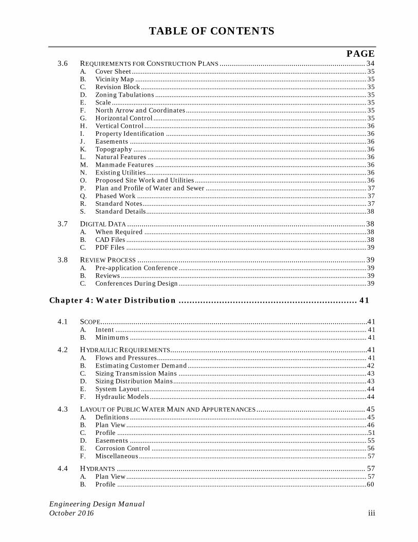
TABLE OF CONTENTS
PAGE
Engineering Design Manual October 2016 iii
3.6 REQUIREMENTS FOR CONSTRUCTION PLANS ....................................................................... 34 A. Cover Sheet .................................................................................................................................. 35 B. Vicinity Map ................................................................................................................................ 35 C. Revision Block ............................................................................................................................. 35 D. Zoning Tabulations ..................................................................................................................... 35 E. Scale ............................................................................................................................................. 35 F. North Arrow and Coordinates .................................................................................................... 35 G. Horizontal Control ...................................................................................................................... 35 H. Vertical Control ........................................................................................................................... 36 I. Property Identification ............................................................................................................... 36 J. Easements ................................................................................................................................... 36 K. Topography ................................................................................................................................. 36 L. Natural Features ......................................................................................................................... 36 M. Manmade Features ..................................................................................................................... 36 N. Existing Utilities .......................................................................................................................... 36 O. Proposed Site Work and Utilities ............................................................................................... 36 P. Plan and Profile of Water and Sewer ......................................................................................... 37 Q. Phased Work ............................................................................................................................... 37 R. Standard Notes ............................................................................................................................ 37 S. Standard Details .......................................................................................................................... 38
3.7 DIGITAL DATA .................................................................................................................... 38 A. When Required ........................................................................................................................... 38 B. CAD Files ..................................................................................................................................... 38 C. PDF Files ..................................................................................................................................... 39
3.8 REVIEW PROCESS ............................................................................................................... 39 A. Pre-application Conference ........................................................................................................ 39 B. Reviews ........................................................................................................................................ 39 C. Conferences During Design ........................................................................................................ 39
Chapter 4: Water Distribution .................................................................. 41
4.1 SCOPE.................................................................................................................................. 41 A. Intent ........................................................................................................................................... 41 B. Minimums ................................................................................................................................... 41
4.2 HYDRAULIC REQUIREMENTS ................................................................................................ 41 A. Flows and Pressures.................................................................................................................... 41 B. Estimating Customer Demand ................................................................................................... 42 C. Sizing Transmission Mains ........................................................................................................ 43 D. Sizing Distribution Mains ........................................................................................................... 43 E. System Layout ............................................................................................................................. 44 F. Hydraulic Models ........................................................................................................................ 44
4.3 LAYOUT OF PUBLIC WATER MAIN AND APPURTENANCES ..................................................... 45 A. Definitions ................................................................................................................................... 45 B. Plan View ..................................................................................................................................... 46 C. Profile ...........................................................................................................................................51 D. Easements ................................................................................................................................... 55 E. Corrosion Control ....................................................................................................................... 56 F. Miscellaneous .............................................................................................................................. 57
4.4 HYDRANTS ......................................................................................................................... 57 A. Plan View ..................................................................................................................................... 57 B. Profile .......................................................................................................................................... 60
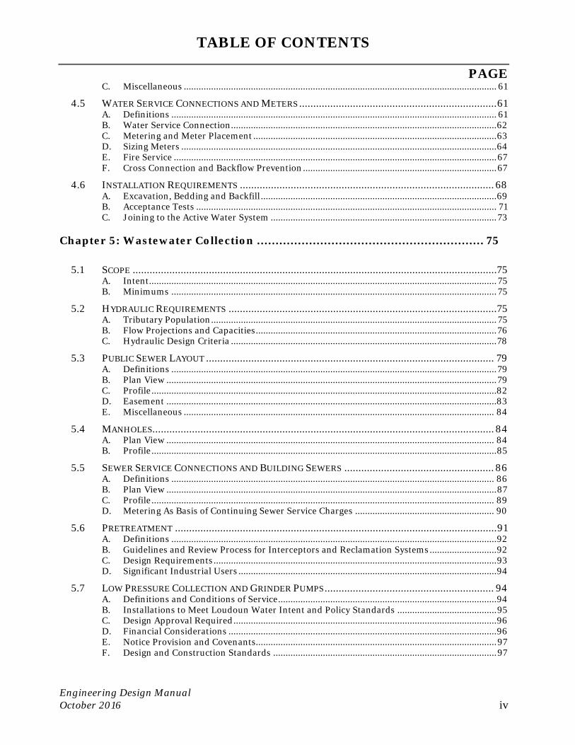
TABLE OF CONTENTS
PAGE
Engineering Design Manual October 2016 iv
C. Miscellaneous .............................................................................................................................. 61
4.5 WATER SERVICE CONNECTIONS AND METERS ...................................................................... 61 A. Definitions ................................................................................................................................... 61 B. Water Service Connection ........................................................................................................... 62 C. Metering and Meter Placement .................................................................................................. 63 D. Sizing Meters ............................................................................................................................... 64 E. Fire Service .................................................................................................................................. 67 F. Cross Connection and Backflow Prevention .............................................................................. 67
4.6 INSTALLATION REQUIREMENTS .......................................................................................... 68 A. Excavation, Bedding and Backfill ............................................................................................... 69 B. Acceptance Tests ......................................................................................................................... 71 C. Joining to the Active Water System ........................................................................................... 73
Chapter 5: Wastewater Collection ............................................................. 75
5.1 SCOPE ................................................................................................................................. 75 A. Intent............................................................................................................................................ 75 B. Minimums ................................................................................................................................... 75
5.2 HYDRAULIC REQUIREMENTS ............................................................................................... 75 A. Tributary Population ................................................................................................................... 75 B. Flow Projections and Capacities ................................................................................................. 76 C. Hydraulic Design Criteria ........................................................................................................... 78
5.3 PUBLIC SEWER LAYOUT ...................................................................................................... 79 A. Definitions ................................................................................................................................... 79 B. Plan View ..................................................................................................................................... 79 C. Profile ...........................................................................................................................................82 D. Easement .....................................................................................................................................83 E. Miscellaneous ............................................................................................................................. 84
5.4 MANHOLES ......................................................................................................................... 84 A. Plan View .................................................................................................................................... 84 B. Profile ........................................................................................................................................... 85
5.5 SEWER SERVICE CONNECTIONS AND BUILDING SEWERS ..................................................... 86 A. Definitions .................................................................................................................................. 86 B. Plan View ..................................................................................................................................... 87 C. Profile .......................................................................................................................................... 89 D. Metering As Basis of Continuing Sewer Service Charges ........................................................ 90
5.6 PRETREATMENT .................................................................................................................. 91 A. Definitions ................................................................................................................................... 92 B. Guidelines and Review Process for Interceptors and Reclamation Systems ........................... 92 C. Design Requirements .................................................................................................................. 93 D. Significant Industrial Users ........................................................................................................ 94
5.7 LOW PRESSURE COLLECTION AND GRINDER PUMPS ............................................................ 94 A. Definitions and Conditions of Service ........................................................................................ 94 B. Installations to Meet Loudoun Water Intent and Policy Standards ........................................ 95 C. Design Approval Required .......................................................................................................... 96 D. Financial Considerations ............................................................................................................ 96 E. Notice Provision and Covenants................................................................................................. 97 F. Design and Construction Standards .......................................................................................... 97
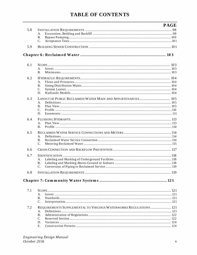
TABLE OF CONTENTS
PAGE
Engineering Design Manual October 2016 v
5.8 INSTALLATION REQUIREMENTS .......................................................................................... 98 A. Excavation, Bedding and Backfill .............................................................................................. 98 B. Bypass Pumping ........................................................................................................................ 100 C. Acceptance Tests ........................................................................................................................ 101
5.9 BUILDING SEWER CONSTRUCTION ..................................................................................... 101
Chapter 6: Reclaimed Water ................................................................... 103
6.1 SCOPE............................................................................................................................... 103 A. Intent ......................................................................................................................................... 103 B. Minimums ................................................................................................................................. 103
6.2 HYDRAULIC REQUIREMENTS ............................................................................................. 104 A. Flows and Pressures.................................................................................................................. 104 B. Sizing Distribution Mains ......................................................................................................... 104 C. System Layout ........................................................................................................................... 104 D. Hydraulic Models ...................................................................................................................... 104
6.3 LAYOUT OF PUBLIC RECLAIMED WATER MAIN AND APPURTENANCES ................................ 105 A. Definitions ................................................................................................................................. 105 B. Plan View ................................................................................................................................... 105 C. Profile ......................................................................................................................................... 110 D. Easements .................................................................................................................................. 111
6.4 FLUSHING HYDRANTS ........................................................................................................ 113 A. Plan View .................................................................................................................................... 113 B. Profile ......................................................................................................................................... 114
6.5 RECLAIMED WATER SERVICE CONNECTIONS AND METERS ................................................. 114 A. Definitions .................................................................................................................................. 114 B. Reclaimed Water Service Connection ....................................................................................... 114 C. Metering Reclaimed Water ........................................................................................................ 115
6.6 CROSS CONNECTION AND BACKFLOW PREVENTION ............................................................ 117
6.7 IDENTIFICATION ................................................................................................................ 118 A. Labeling and Marking of Underground Facilities .................................................................... 118 B. Labeling and Marking Above-Ground or Indoors ................................................................... 118 C. Conversion of Piping to Reclaimed Service .............................................................................. 119
6.8 INSTALLATION REQUIREMENTS ......................................................................................... 119
Chapter 7: Community Water Systems ..................................................... 121
7.1 SCOPE................................................................................................................................ 121 A. Intent .......................................................................................................................................... 121 B. Standards .................................................................................................................................... 121 C. Interpretation ............................................................................................................................. 121
7.2 REQUIREMENTS SUPPLEMENTAL TO VIRGINIA WATERWORKS REGULATIONS ..................... 121 A. Definitions .................................................................................................................................. 121 B. Administration of Regulations ................................................................................................. 122 C. Reserved Section ....................................................................................................................... 122 D. Variances ................................................................................................................................... 124 E. Construction Permits ................................................................................................................ 124
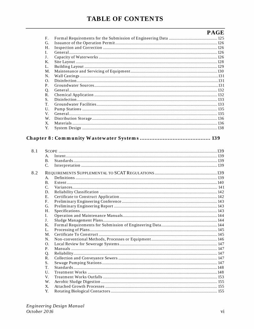
TABLE OF CONTENTS
PAGE
Engineering Design Manual October 2016 vi
F. Formal Requirements for the Submission of Engineering Data ............................................ 125 G. Issuance of the Operation Permit ............................................................................................. 126 H. Inspection and Correction ........................................................................................................ 126 I. General ....................................................................................................................................... 126 J. Capacity of Waterworks ............................................................................................................ 126 K. Site Layout ................................................................................................................................. 128 L. Building Layout ......................................................................................................................... 129 M. Maintenance and Servicing of Equipment ............................................................................... 130 N. Wall Castings ..............................................................................................................................131 O. Disinfection.................................................................................................................................131 P. Groundwater Sources .................................................................................................................131 Q. General ....................................................................................................................................... 132 R. Chemical Application ................................................................................................................ 132 S. Disinfection................................................................................................................................ 133 T. Groundwater Facilities .............................................................................................................. 133 U. Pump Stations ........................................................................................................................... 135 V. General ....................................................................................................................................... 135 W. Distribution Storage .................................................................................................................. 136 X. Materials .................................................................................................................................... 136 Y. System Design ........................................................................................................................... 138
Chapter 8: Community Wastewater Systems ........................................... 139
8.1 SCOPE ............................................................................................................................... 139 A. Intent.......................................................................................................................................... 139 B. Standards ................................................................................................................................... 139 C. Interpretation ............................................................................................................................ 139
8.2 REQUIREMENTS SUPPLEMENTAL TO SCAT REGULATIONS .................................................. 139 A. Definitions ................................................................................................................................. 139 B. Extent ......................................................................................................................................... 140 C. Variances.................................................................................................................................... 141 D. Reliability Classification ........................................................................................................... 142 E. Certificate to Construct Application ......................................................................................... 142 F. Preliminary Engineering Conference ....................................................................................... 143 G. Preliminary Engineering Report .............................................................................................. 143 H. Specifications ............................................................................................................................. 143 I. Operation and Maintenance Manuals ...................................................................................... 144 J. Sludge Management Plans ........................................................................................................ 144 K. Formal Requirements for Submission of Engineering Data ................................................... 144 L. Processing of Plans .................................................................................................................... 145 M. Certificate To Construct ............................................................................................................ 145 N. Non-conventional Methods, Processes or Equipment ............................................................ 146 O. Local Review for Sewerage Systems ......................................................................................... 147 P. Manuals ..................................................................................................................................... 147 Q. Reliability ................................................................................................................................... 147 R. Collection and Conveyance Sewers .......................................................................................... 147 S. Sewage Pumping Stations ......................................................................................................... 147 T. Standards ................................................................................................................................... 148 U. Treatment Works ...................................................................................................................... 148 V. Treatment Works Outfalls ........................................................................................................ 153 W. Aerobic Sludge Digestion .......................................................................................................... 155 X. Attached Growth Processes ...................................................................................................... 155 Y. Rotating Biological Contactors ................................................................................................. 155
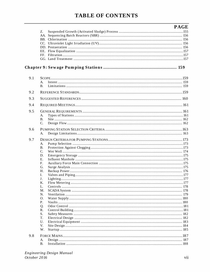
TABLE OF CONTENTS
PAGE
Engineering Design Manual October 2016 vii
Z. Suspended Growth (Activated Sludge) Process .......................................................................155 AA. Sequencing Batch Reactors (SBR) ........................................................................................... 156 BB. Chlorination .............................................................................................................................. 156 CC. Ultraviolet Light Irradiation (UV)............................................................................................ 156 DD. Postaeration .............................................................................................................................. 156 EE. Flow Equalization ...................................................................................................................... 157 FF. Filtration ..................................................................................................................................... 157 GG. Land Treatment ......................................................................................................................... 157
Chapter 9: Sewage Pumping Stations ...................................................... 159
9.1 SCOPE................................................................................................................................ 159 A. Intent ......................................................................................................................................... 159 B. Limitations ................................................................................................................................ 159
9.2 REFERENCE STANDARDS .................................................................................................... 159
9.3 SUGGESTED REFERENCES ................................................................................................. 160
9.4 REQUIRED MEETINGS ........................................................................................................ 161
9.5 GENERAL REQUIREMENTS ................................................................................................. 161 A. Types of Stations ........................................................................................................................ 161 B. Site ............................................................................................................................................. 162 C. Design Flow ............................................................................................................................... 162
9.6 PUMPING STATION SELECTION CRITERIA ........................................................................... 163 A. Design Limitations .................................................................................................................... 163
9.7 DESIGN CRITERIA FOR PUMPING STATIONS ........................................................................ 173 A. Pump Selection ..........................................................................................................................173 B. Protection Against Clogging ......................................................................................................173 C. Wet Well .................................................................................................................................... 174 D. Emergency Storage .................................................................................................................... 175 E. Influent Manhole ....................................................................................................................... 175 F. Auxiliary Force Main Connection ............................................................................................. 175 G. Surge Analysis ............................................................................................................................ 175 H. Backup Power ............................................................................................................................ 176 I. Valves and Piping ....................................................................................................................... 177 J. Lighting....................................................................................................................................... 177 K. Flow Metering ............................................................................................................................ 177 L. Controls ..................................................................................................................................... 178 M. SCADA System .......................................................................................................................... 178 N. Ventilation ................................................................................................................................. 179 O. Water Supply ............................................................................................................................. 180 P. Vaults ......................................................................................................................................... 180 Q. Odor Control .............................................................................................................................. 181 R. Control Building ......................................................................................................................... 181 S. Safety Measures ........................................................................................................................ 182 T. Electrical Design ....................................................................................................................... 182 U. Electrical Equipment ................................................................................................................ 183 V. Site Design ................................................................................................................................. 184 W. Startup ....................................................................................................................................... 185
9.8 FORCE MAINS .................................................................................................................... 187 A. Design ........................................................................................................................................ 187 B. Installation ................................................................................................................................ 188

TABLE OF CONTENTS
PAGE
Engineering Design Manual October 2016 viii
9.9 MATERIALS .......................................................................................................................189
9.10 MISCELLANEOUS SUPPLIES ............................................................................................... 190
Appendix A: Application and Plan Preparation....................................... 193
UTILITY EXTENSION REQUEST (UER) ........................................................................................... 193
CHECKLIST FOR CONSTRUCTION PLANS ........................................................................................ 193
TABLE OF MINIMUM SEPARATIONS ............................................................................................... 193
HYDRAULIC MODEL RESULTS AND DATA SUMMARY ...................................................................... 193
CENTRAL SYSTEM WATER PRESSURE ZONES ................................................................................. 193
SANITARY SEWER - DESIGN COMPUTATION TABLE ........................................................................ 193
SANITARY SEWER – ANGLES FOR MINIMUM CORE SEPARATION .................................................... 193
MATERIALS SUBMITTAL ................................................................................................................ 193
Appendix B: Estimating Construction Cost for Bonding ......................... 195
ESTIMATE OF CONSTRUCTION COST .............................................................................................. 195
EXTENSION BOND FOR SUBDIVISIONS ........................................................................................... 195
ESTIMATE OF CONSTRUCTION COST FOR SITE PLANS ..................................................................... 195
Appendix C: Easements .......................................................................... 197
GUIDE TO EASEMENT DOCUMENTS ............................................................................................... 197
Appendix D: Community Systems ........................................................... 199
KEY TO ABBREVIATIONS ................................................................................................................ 199
CHART OF DESIGN REVIEW PROCESS ............................................................................................ 199
PROJECT INITIATION INFORMATION SHEET .................................................................................. 199
AGENDA FOR PROJECT INITIATION MEETING ................................................................................ 199
CHART OF CONSTRUCTION PROCESS ............................................................................................. 199
AGENDA FOR PRECONSTRUCTION CONFERENCE ............................................................................ 199
Appendix E: Corrosion Control .............................................................. 201
DESIGN AND INSTALLATION REQUIREMENTS ............................................................................... 201
Appendix F: Standard Details ................................................................. 203
FOR LATEST STANDARD DETAILS PLEASE REFER TO OUR WEBSITE. ............................................... 203

TABLE OF CONTENTS
PAGE
Engineering Design Manual October 2016 ix
Appendix G: Materials ............................................................................ 205
FOR LATEST APPROVED MATERIALS LIST PLEASE REFER TO OUR WEBSITE. ................................... 205

Chapter 1: Loudoun Water’s Role
Engineering Design Manual October 2016 1
Chapter 1: Loudoun Water’s Role
1.1 Mission
We provide sustainable water services to protect health, the environment and quality of life.
1.2 Introduction
A. Basis and Intent
By action dated September 9, 2010, Loudoun Water’s Board of Directors has adopted this Engineering Design Manual, to establish standards for the construction of water, reclaimed water, and wastewater infrastructure within the utility’s service areas. This Manual replaces the Water Distribution – Standards and Extensions and Sewer System – Standards and Extensions, which formerly served this purpose. This Manual will be amended and updated from time to time by staff, without formal action of Loudoun Water’s Board. Loudoun Water reserves the right to amend or modify this publication without notice, and to interpret the meaning of all statements made herein.
This Manual documents the accepted practices and procedures for projects, serving two audiences.
1. Engineers, developers, applicants for new service, builders and installers may find guidance needed to prepare construction plans and specifications, and work through the administrative procedures that support their projects.
2. Loudoun Water staff can use this information to implement and administrate construction projects, conforming to established policies, standards and procedures.
Chapters and Appendices in the Manual are to be applied together to produce optimum designs. For example, Chapter 4, Water Distribution; Chapter 5, Wastewater Collection; and Chapter 6, Reclaimed Water contain descriptions of installations and assemblies depicted in the Standard Details, found in Appendix F. Also, the Approved Materials List, Appendix G should be consulted when making specifications.
B. Limitations
1. Due to the wide variety of situations that arise, it is impossible to address all scenarios. Exceptional measures may be required to address project-specific conditions. Many criteria listed are minimums. Loudoun Water reserves the right to exercise engineering and judgment, and will make the final determination as to the acceptability of each design. Final design decisions will be made, favoring the minimum life-cycle costs.
Where the designer believes that project-specific conditions warrant a variance to or waiver from the provisions of this Manual, they should forward a request for such consideration to the assigned Project Engineer. In cases where the applicant wishes to dispute the determination of the Project Engineer, a request for further consideration is to be made in writing. Further review of the matter will be given by the Manager of Land
Chapter 1: Loudoun Water’s Role
Engineering Design Manual October 2016 2
Development Programs, in consultation with other Loudoun Water staff as appropriate. If necessary, the Director of Engineering will review the matter and resolve to final decision.
2. All designs must comply with the requirements of all applicable regulatory agencies including Virginia Department of Health (VDH), Virginia Department of Environmental Quality (DEQ), Virginia Department of Transportation (VDOT) and Loudoun County.
3. Where a conflict occurs between this Manual and project–specific contract documents (specifications and drawings) on Loudoun Water advertised capital construction, the project-specific documents shall govern. Where the contract for the work has been issued by a developer, the provisions of this Manual shall govern.
C. Legal Authority
The Loudoun County Sanitation Authority, doing business as Loudoun Water, was created in 1959 as a public utility, body politic and corporate under the provisions of the Virginia Water and Waste Authorities Act (Chapter 15.2-5100 et. seq., Code of Virginia, as amended). Powers conferred by the Virginia Water and Waste Authorities Act include that of issuing rules, regulations and standards for the design, construction and/or installation of any facilities to be operated and maintained by Loudoun Water.
Loudoun Water is not a division of the County of Loudoun. As a public utility, we are financially separate from the County. Our Board of Directors is appointed by the Loudoun County Board of Supervisors. Loudoun Water is delegated by County Ordinance to perform certain enforcement actions that pertain to the use of our public water and sewer systems.
D. Statement of Policy
Loudoun Water’s Board maintains a document titled Statement of Policy that guides the conduct of the utility’s business.
E. Rates, Rules and Regulations
The document titled Rates, Rules and Regulations, and its companion documents the Rates, Rules and Regulations for Community Systems and Rates, Rules and Regulations for Reclaimed Water Service, establish the terms of receiving service from Loudoun Water, all fees and charges for such service, and all fees pertaining to the application, permitting, and construction processes discussed in this Manual. Designs of service connections and local mains must conform to principles established in the Rates, Rules and Regulations.
1.3 Service Areas
Loudoun Water owns and operates drinking water (potable), reclaimed water (non-potable), and sanitary sewer systems throughout Unincorporated Loudoun County. In all situations involving the initiation of new service from one of these systems, or the modification of an existing service, the landowner is responsible for acquiring the appropriate Connection Permit from Loudoun Water, prior to beginning work. Often this procedure is delegated to
Chapter 1: Loudoun Water’s Role
Engineering Design Manual October 2016 3
the owner’s contractor or builder. Connection Permitting is discussed in Section 1.7 of this Chapter.
In addition to making service connections, it is necessary to extend the public main in all situations where the property in question does not have immediate access to Loudoun Water’s distribution or collection mains. Extensions of the public main entail design and installation of new pipeline, in accordance with the provisions of this Manual, and all applicable statutes of Loudoun County, the Commonwealth of Virginia, and the United States of America.
Prospective applicants should consult Loudoun Water’s Planning & Engineering Division to determine whether the property in question can be served. The Division includes the Department of Land Development Programs, where an engineer is on call to address these inquiries. Such inquiries can be placed through Loudoun Water’s website by using the form titled “Engineering Inquiry Form”.
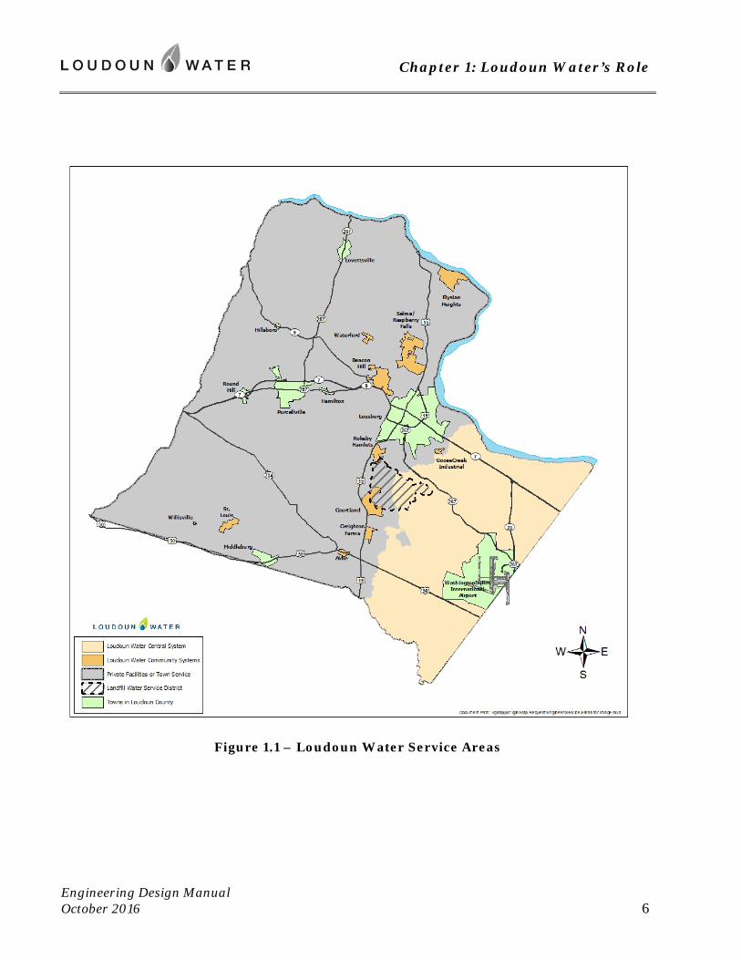
Figure 1.1 below shows the locations where service may be available from Loudoun Water’s Central System or from one of our Community Systems.
A. Central System
Loudoun Water’s Central System consists of an integrated water distribution and a wastewater collection system. Among the communities served are Sterling, Dulles, Lansdowne, Ashburn, Broadlands, Brambleton, South Riding, and Stone Ridge.
Loudoun Water currently owns and operates the Goose Creek Treatment Plant and the associated Beaverdam Reservoir. Water is also purchased on a wholesale basis from Fairfax Water. To meet future demand, Loudoun Water’s Potomac Water Supply Program has been undertaken. This program consists of a withdrawal of water from the Potomac River, for treatment at the Trap Rock Water Treatment Facility. This facility is being constructed during this decade. The program will also include water banking, using retired stone quarries to store water for times when the Potomac is low.
Wastewater is treated at the Blue Plains Facility, belonging to the District of Columbia Water and Sewer Authority (DCWASA). To accommodate recent and future growth, Loudoun Water’s Broad Run Water Reclamation Facility was placed into service in 2008, whereupon it began to treat a portion of the flow.
The limits to which the Central System may be extended are depicted by Figure 1.1. This system may be extended within the Suburban and Transition Policy Areas, as outlined in Loudoun County’s Comprehensive Plan.
B. Landfill Water Service District
The Landfill Water Service District was created in April 1994 by the Loudoun County Board of Supervisors. Comprehensive Plan Amendment CPAM 1993-0002 amended policies within the County’s Comprehensive Plan to do the following:
1. establish a Landfill Water Service District in the proximity of the Woods Road Solid Waste Management Facility;
Chapter 1: Loudoun Water’s Role
Engineering Design Manual October 2016 4
2. provide for the construction of public waterlines within that District to permanently avoid potential problems with potable water for the existing residences and properties within the service area; and
3. establish sizing of waterlines that was consistent with the maximum density of development allowed under the zoning at that date, and with land uses envisioned within the Choices and Changes General Plan.
A water distribution system was built and placed into service in 1996. This system was designed to accommodate only the service needed to support development at a density attainable under the A-3 zoning then in place. Most mains are of 4-inch diameter, thereby decreasing the likelihood of stagnant water. Provisions for fire protection to buildings within the District were made by means of underground storage tanks. Fire flow requirements in Chapter 4 of this Manual do not apply to new extensions within the Landfill Water Service District, except on those properties that have since become part of the County’s Transition Policy Area. Within the Transition Policy Area (east of Route 621 Evergreen Mills Road), the Central System is to be extended, and fire flow requirements of Chapter 4 apply to all new applications for the extension of service.
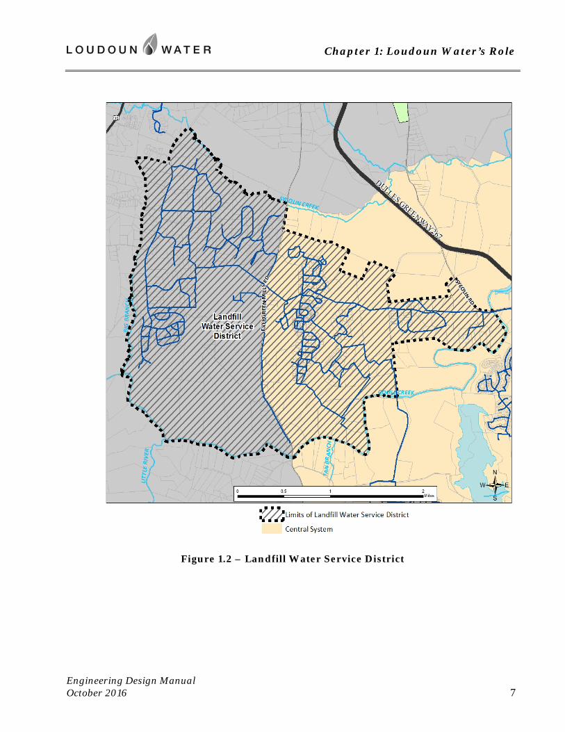
Loudoun County has adopted a mandatory connection ordinance, such that new buildings within the Landfill Water Service District may only receive water from Loudoun Water’s distribution system. The limits of District are depicted in Figure 1.2.
C. Community Systems
Loudoun Water owns and operates various stand-alone water and sewer systems, located throughout the County, and shown on Figure 1.1. Generally known as Community Systems, each is of small scale and functions with an independent water source and treatment, or independent wastewater treatment and discharge. Community Systems serve at least fifteen premises. In accordance with the County’s Comprehensive Plan, each Community System has a limited service area, beyond which it may not serve.
D. Systems Not Belonging to Loudoun Water
The Towns of Leesburg, Hamilton, Purcellville, Lovettsville, Round Hill, Hillsboro, and Middleburg own their respective public water and sewer systems. These systems are generally within the corporate limits of the respective town, but may also extend into an associated Joint Land Management Area, in accordance with Loudoun County’s Comprehensive Plan. Connections to these systems are not regulated by Loudoun Water. Applicants for service from these systems should consult the respective town for permits and inspections. Typically the underground building sewer tributary to these systems is inspected by Loudoun County’s Plumbing Department, under the appropriate County Plumbing Permit.
A privately owned water system serving a number of customers exists in the Village of Aldie.
Chapter 1: Loudoun Water’s Role
Engineering Design Manual October 2016 5
E. Private Facilities
Throughout the Rural Policy Area, as established by the County’s Comprehensive Plan, land use is rural in nature, and so properties typically do not have access to water or sewer service from a public utility. Buildings with plumbing are typically connected to privately owned wells and wastewater disposal systems. The Loudoun County Department of Environmental Health handles permitting, inspection, monitoring and record keeping for such individual private facilities.
Chapter 1: Loudoun Water’s Role
Engineering Design Manual October 2016 6
Figure 1.1 – Loudoun Water Service Areas
Chapter 1: Loudoun Water’s Role
Engineering Design Manual October 2016 7
Figure 1.2 – Landfill Water Service District
Chapter 1: Loudoun Water’s Role
Engineering Design Manual October 2016 8
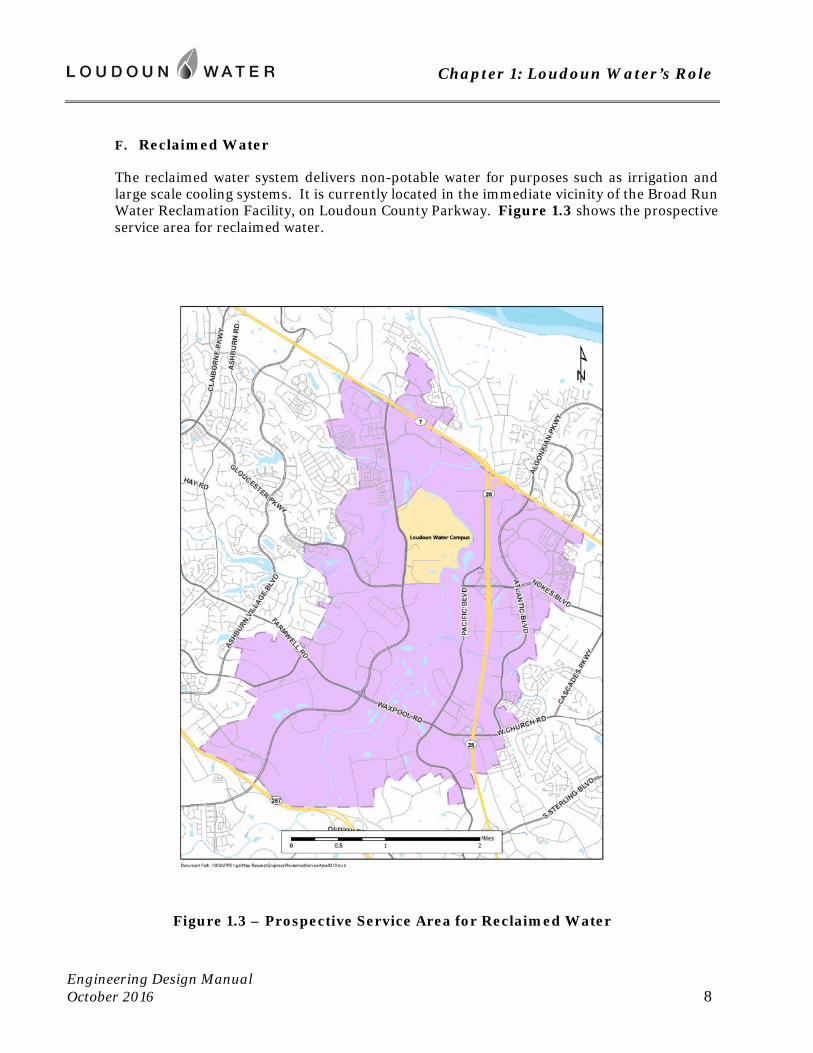
F. Reclaimed Water
The reclaimed water system delivers non-potable water for purposes such as irrigation and large scale cooling systems. It is currently located in the immediate vicinity of the Broad Run Water Reclamation Facility, on Loudoun County Parkway. Figure 1.3 shows the prospective service area for reclaimed water.
Figure 1.3 – Prospective Service Area for Reclaimed Water

Chapter 1: Loudoun Water’s Role
Engineering Design Manual October 2016 9
1.4 The Planning & Engineering Division
Loudoun Water’s Planning & Engineering Division is responsible for comprehensive utility planning, design and construction; including developing and updating the water and wastewater master plans, managing the design and construction of capital facilities, and reviewing land development applications to ensure compliance to standards of Loudoun Water and regulations of the Commonwealth of Virginia.
Planning Programs guides future system development and expansion, ensures adequacy of planned facilities with regard to sizing and location, and enhances reliability and readiness for emergency situations.
Land Development Programs reviews construction plans and responds to public inquiries to coordinate the installation of water, reclaimed water and wastewater projects initiated by builders and developers.
Capital Design prepares construction plans and specifications for water, reclaimed water, and wastewater facilities that are being financed and advertised for construction by Loudoun Water.
Capital Construction administers construction contracts whereby Loudoun Water is having work done.
Inspection Services provides inspections for all construction of Loudoun Water’s facilities. This department also provides utility locating and protection services.
1.5 Public Inquiries
The public is encouraged to use the website http://www.loudounwater.org, where a variety of information and several services are available. Topics of interest, current activities and projects of Loudoun Water are featured. This Manual and several references cited herein may be found on this website as well.
Loudoun Water assigns an engineer or technician to be “on-call” during regular business hours. The general responsibility of that person is to answer development related questions for projects not already assigned to a Project Engineer. Verbal responses to public inquiries should be considered advisory in nature. Written responses to inquiries via letter or e-mail will be provided as appropriate. The assigned Project Engineer will provide final input as to Loudoun Water’s standards and policies during the plan review and approval process.
Inquiries can be placed through Loudoun Water’s website by using the form titled “Engineering Inquiry Form”.
Chapter 1: Loudoun Water’s Role
Engineering Design Manual October 2016 10
1.6 Initiation of Service
Where it has been determined that there are adequate public water main, public sewer, and/or public reclaimed water main, to provide the desired service, applicants for new or expanded service may apply by providing these items:
1. payment of the Water Service Connection Charge and/or Building Sewer Charge;
2. payment of the Availability Charge(s);
3. payment of a Local Facilities Charge, where applicable; and
4. any easement on the applicant’s land that is determined by Loudoun Water to be needed for the present or future continuation or completion of the public system(s). Easement is to be conveyed to Loudoun Water free of charge, and may be required for the purpose of extending any of the public systems (water, sewer, or reclaimed water), regardless of the type of service that the applicant seeks.
1.7 Connection Permit
A. Work Requiring Loudoun Water’s Connection Permit
Where service is by Loudoun Water’s Central or Community System, the owner, tenant, or builder must acquire Loudoun Water’s Connection Permit for the following work:
1. Single Family Residences
a. To establish a new water and/or sewer service. This may be at a home under construction, the conversion to public service at a home that has previously been connected to a private well or septic system, or where plumbing is being added to an outbuilding.
2. Multifamily Residential, Commercial, Institutional and Industrial Construction
a. To establish a new water and/or sewer service. This may be at a building under construction, or to retrofit a building that has previously been connected to a private well or septic system.
b. To add a water or sewer service connection for a building that already has service. A building may have more than one water service connection to the public main, provided that each service line supplies an independent distribution within the building. That is, the distribution piping from one service connection must not be joined to the distribution from another supply. Also, for each water service to fixtures generating wastewater, there must be a corresponding, independent building sewer (lateral), extending to the public sanitary main.
c. To increase the size or capacity of a service connection or meter.
Chapter 1: Loudoun Water’s Role
Engineering Design Manual October 2016 11
d. To establish a subtraction meter (also called “submeter”). A subtraction meter may be installed in a branch of a building’s plumbing that supplies only uses that do not discharge to the sanitary sewer. To compensate for use of water in ways that do not generate wastewater, Loudoun Water will meter that branch of a building’s plumbing, and deduct the subtraction meter’s reading from that of the primary meter, for purposes of billing ongoing sewer service. Also, meters may be installed to measure industrial process waters discharging to the sanitary sewer, as basis for sewer service charges, where evaporation consumes a portion of the process’s supply.
B. Applying for a Connection Permit
1. Connections Proposed Under an Active Construction Permit for Site Work
If the desired service connection to the public main is proposed by a current site plan, subdivision plan, or public improvement plan, then service lines are installed under Loudoun Water’s Construction Permit for that project. The layout, size, and engineering of each connection and service line is governed by the construction plan, which must have Loudoun Water’s approval. Prior to making these services active, the associated Connection Permits must be acquired.
Anytime after the project’s Construction Permit has been issued, the associated Connection Permit(s) may be obtained. To initiate the preparation of a Connection Permit, submit a request to Land Development Programs. This must be submitted using the form “Request for Connection Invoice” through the Loudoun Water website.
Connection Permits will be based upon the latest approved construction plans. For a connection or metering that is sized or configured differently than indicated on the approved plan, contact the assigned Project Engineer at the Department of Land Development Programs to make the appropriate arrangements.
Once the permit is prepared, execute it by paying the associated fees to Loudoun Water.
2. Connections Proposed Independently of an Active Construction Permit
When the desired connection is to an existing main, and proposed service line and building to be served are not proposed by an ongoing construction project that Loudoun Water has permitted, then the applicant should consult with a Project Engineer in Land Development Programs to make arrangements to acquire a Connection Permit.
The Project Engineer will determine whether sufficient public main is available to support the desired connection. Generally the property in question must have frontage on, or direct access to a public main; without the need to traverse another parcel of land. Where new water service from the Central System is desired (excluding the Landfill Service Area), the building to receive service must have fire protection from hydrants according to Loudoun Water’s standards. If adequate main is not available, then the applicant will need to apply to extend the main, through the procedures outlined in Chapter 3 of this Manual.
Where supporting main is available, the applicant and Loudoun Water’s Project Engineer will work to determine an appropriate layout and size for the service line and/or meter.
Chapter 1: Loudoun Water’s Role
Engineering Design Manual October 2016 12
The applicant must prepare a sketch addressing the pertinent details to describe the work. A load letter and/or fixture count may be necessary as basis of meter size. Once the layout and sizes are approved, the applicant for service must file the form “Request for Connection Invoice” through the Loudoun Water website. The Project Engineer will then prepare the Connection Permit and the applicant may execute it by paying the applicable fees.
Should easements be required in support of the new service line, then such must be conveyed prior to execution of the associated Connection Permit. This will entail the preparation by a licensed land surveyor of the necessary easement plat. Review, approval, execution, and recordation procedures are found in Appendix C of this Manual.
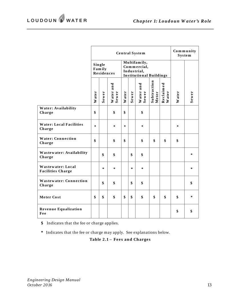
C. Fees and Charges
The fees and charges are established by the document Rates, Rules and Regulations. Refer to this document for complete information. Table 2.1 below lists which fees and charges apply, depending upon the type of service. A brief description of each fee or charge follows.
Chapter 1: Loudoun Water’s Role
Engineering Design Manual October 2016 13
Central System Community
System
Single Family Residences
Multifamily, Commercial, Industrial, Institutional Buildings
Wat
er
Sew
er
Wat
er
Sew
er
Wat
er a
nd
S
ewer
Wat
er
Sew
er
Wat
er a
nd
S
ewer
Su
btr
acti
on
M
eter
Rec
laim
ed
Wat
er
Water: Availability Charge
$ $ $ $
Water: Local Facilities Charge * * * * *
Water: Connection Charge $ $ $ $ $ $ $
Wastewater: Availability Charge $ $ $ $ *
Wastewater: Local Facilities Charge * * * * *
Wastewater: Connection Charge $ $ $ $ $
Meter Cost $ $ $ $ $ $ $ $ $ *
Revenue Equalization Fee $ $
$ Indicates that the fee or charge applies.
* Indicates that the fee or charge may apply. See explanations below.
Table 2.1 – Fees and Charges
Chapter 1: Loudoun Water’s Role
Engineering Design Manual October 2016 14
Availability Charges -- Payment of an Availability Charge constitutes a purchase of capacity in the respective water or sewer system. The collected charges are used in part to finance Loudoun Water’s capital construction of facilities such as treatment plants, tanks, pumps, and transmission lines. The purchase permanently entitles the landowner and their successors in title to this capacity.
In most cases, the availability charge is based upon the size of meter needed to convey the desired flow. However, in cases such as multifamily buildings, large connections, or atypical use, the charge may be based on an estimate of the flow that the proposed use will demand. Consult the Department of Land Development Programs for assistance in estimating availability charges for a specific project.
Connections to most Community Systems do not involve an availability charge. This is because the system has typically been provided by the developer of the community which it serves, so that Loudoun Water has no capital cost to recover. However, where a pre-existing community has received service as a retrofit, an availability charge may have been established.
Local Facilities Charge -- A local facilities charge may be applied where the desired connection is to a main provided by others, without substantial assistance by the applicant for service, or their predecessor in title. The local facilities charge is an assessment toward the value of the local waterline or sanitary sewer adjoining the property in question. The charge serves to compensate the party who built the pipeline.
Meter Cost -- Loudoun Water provides its standard meter for use in the new installation.
For accounts providing sewer service only, a meter is installed in the building’s water supply line, so that continuing sewer service can be based on actual consumption. However, at the Villages of Saint Louis, Willisville, Waterford and Aldie, accounts are not metered.
Connection Charge -- The Connection Charge is used to defray the administrative and inspection costs associated with the activities to be conducted under the Connection Permit.
Revenue Equalization Fee – A Revenue Equalization Fee will be applied where the desired connection is to a Community System for which this fee has been established. The fee is used to defray the ongoing costs of operation and maintenance, where these cost may exceed revenue generated from those using the system.
D. Installation and Inspections
1. All installations must conform to the standards of Loudoun Water in materials, methods, and workmanship. For underground building sewer, requirements of the International Plumbing Code also apply. Work must be witnessed and approved by Loudoun Water’s Project Inspector prior to placing it into service.
2. Loudoun Water inspects the water service connection at the public main, and service line to the meter, including the meter setting and its enclosure.

Chapter 1: Loudoun Water’s Role
Engineering Design Manual October 2016 15
3. As a courtesy to the Loudoun County Plumbing Department, Loudoun Water inspects all sewer service connections and underground building sewers that discharge to Loudoun Water’s collection system. This includes the service connection at the public main, the service spur installed by the installer of the main (where applicable), and the entire continuation of underground building sewer, ending at the building’s exterior.
4. For connections and building sewer installations occurring through an active site plan, subdivision plan, or public improvement plan, inspection of service lines will occur under the open Construction Permit for the project. Connection Permits may be executed subsequently, but must be in place prior to initiating service.
5. For connections and/or building sewer installations being made independently of an open Construction Permit, the Connection Permit(s) must be executed first. In this instance, the applicant or installation contractor must contact Loudoun Water’s Inspections Department to arrange for a pre-construction conference. This must be done through Loudoun Water’s website, by completing the form “Pre-construction Meeting Request”. At the meeting the Project Inspector and the contractor doing the installation will review the location of each connection, and the methods and materials to be used. As construction progresses, the contractor must arrange for each service line to be fully viewed by the inspector prior to backfilling, and the contractor will be responsible for all required testing. The inspector must witness the testing. When new building sewer is ready for inspection, the contractor must complete the form “Lateral Inspection Request” through Loudoun Water’s website.
6. For making a building sewer repair or replacement, no Connection Permit is required. Instead, the installer must request inspection using the form “Lateral Inspection Request” through Loudoun Water’s website. This procedure is also to be followed where an existing building sewer is to be abandoned, due to renovation or demolition.
E. Acquiring the Meter
Once Loudoun Water’s Inspector has approved placing the new lines into service, the owner or builder may request that the water meter be installed. On new construction projects, this is typically done just prior to completion of the building’s plumbing system. The meter must be in place for successful completion of the final inspection by the Loudoun County Plumbing Department.
Loudoun Water will install all primary meters of sizes 1-inch and smaller. Meters 1.5-inch and larger, and all subtraction meters must be installed by the contractor.
Where the installation is sewer service only, Loudoun Water will deliver the meter, for installation in the building’s water supply line. The meter must be installed by the contractor prior to the sewer service becoming active.
To request a meter installation or arrange to pick up a larger meter, requests must be made by completing the form “Water Meter Request” through Loudoun Water’s website.
-- end of Chapter 1 --


Chapter 2: Project Administration
Engineering Design Manual October 2016 17
Chapter 2: Project Administration
2.1 Extension of Public Facilities
The applicant, as referred to in this and the following Chapters, is the project’s owner or developer, with whom Loudoun Water will enter into agreement for the construction of facilities. The term applicant shall also be understood to include engineers, employees, agents, contractors, subcontractors, and vendors providing support to the project’s owner. It is the prime responsibility of the applicant to make all necessary provisions for the construction, and to execute the project per the approved construction plans and specifications. The applicant must ensure that all work is conducted in conformance with current guidelines and standards of federal, state, and local governing agencies.
Applicants desiring water and/or sewerage service for specified areas shall make application to Loudoun Water and receive the applicable Construction Permit(s) before starting construction of any water and/or sewerage facilities.
A. Applicant to Furnish Facilities within the Development Area
Within the area being developed, the applicant will be required to furnish and construct all water and sewerage facilities required to complete Loudoun Water’s planned systems. The applicant shall agree to transfer these public water and sewer facilities to Loudoun Water, free of debts, liens and/or other legal encumbrances, for ownership, operation and maintenance. Facilities not complying with Loudoun Water’s standards will not be accepted and will not be supplied with water or sewer service until the deficiencies are corrected to the satisfaction of Loudoun Water.
The applicant must extend water and sewer mains and services to the limits of proposed site improvements. Terminations of pipeline will be beyond the limits of proposed pavements, past adjacent buildings, and beyond crossing storm drains, ducts, or other utilities that would otherwise be undermined during the subsequent installation. In cases where the future extension will provide a water distribution loop that is necessary to support the applicant’s project, the public main must be provided to the site or subdivision boundary.
B. Public Main Required at the Property Served
In all situations where the property being developed does not already have direct access and frontage on a suitable public main, the applicant must extend the public main, so as to establish sufficient main to receive a service connection for each premises being developed. The extension of a privately owned facility across an adjacent property is prohibited, unless otherwise determined by Loudoun Water.
C. Public Gravity Sewer Required
To provide for a sustainable system, Loudoun Water has planned an integrated wastewater collection system of gravity mains. Except where specifically planned and approved by Loudoun Water, wastewater pumping stations and low pressure collection systems are prohibited.
Chapter 2: Project Administration
Engineering Design Manual October 2016 18
D. Easements for Proposed and Future Extensions
Applicants for service must convey to Loudoun Water all on-site easements needed to enable the extension, installation, operation, maintenance, and renovation of the proposed public water, reclaimed water, and sewer systems, including appropriate access easements. Where the applicant proposes facilities across lands of others, it is the applicant’s responsibility to cause the conveyance of the supporting easements to Loudoun Water.
Loudoun Water must plan and maintain fully integrated utility systems (water, sewer, and reclaimed water). The extensions by each application are an integral part of the overall public utility system. In support of the fully integrated system, on-site easements may be required in areas outside of the proposed improvements, for the purpose of extending any of the public systems. Such easements must be extended to the site or subdivision boundary. Where the installation is to occur in future, temporary construction easements will be required to enable the future installation. To establish the limits of temporary construction easements, designers will consider the depth of future excavation, as this will control the width of the work area. Consideration will also be made for access to the work area from public roadways, and for staging the construction.
E. Enlarged Facilities
Applicants may be required to provide enlarged water mains, sewers, or other facilities that are to be located within the area being developed, and that are required to serve adjacent areas and/or upstream areas, in accordance with Loudoun Water’s standards, utility master plans, and area facilities plans, as are adopted by Loudoun Water from time to time. Where applicable and in accordance with current policy, terms of reimbursement will be incorporated into the agreement for the project, to compensate the developer for the enlargement of facilities, or for other system improvements.
F. Determining Project Scope
As the basis of design and engineering of projects, applicants are encouraged to meet with a representative of the Department of Land Development Programs, to discuss project specific conditions and site specific application of the Engineering Design Manual and Rates, Rules and Regulations.
2.2 Offsite Facilities
Offsite Facilities shall include, but not be limited to, (1) supply mains, including pumping or pressure reducing installations, necessary to extend from existing transmission or trunk mains, to the development area; (2) trunk sewers from the development area to existing trunk sewers or sewage treatment plants, or to new sewage treatment plants or interceptors; (3) temporary sewage pumping stations or treatment plants for the development area only; (4) capacity in existing and/or proposed consolidated sewage treatment plants; (5) sewage lift stations; and (6) all necessary accessories and appurtenances to the water and/or sewerage systems.
Chapter 2: Project Administration
Engineering Design Manual October 2016 19
A. Construction by Loudoun Water
Developers will be required to enter into contract with Loudoun Water and to deposit with Loudoun Water upon issuance of permit for construction, a sum of money equal to the estimated construction cost, including engineering, legal and administrative costs, of all facilities required beyond the limits of the area under development, referred to hereafter as the "Offsite Facilities", said facilities to be constructed by Loudoun Water. This contract will establish the responsibility for complete funding of the project, and the terms of accounting for funds advanced by the developer.
B. Construction by Applicant
Loudoun Water, in its sole discretion, may permit construction of Offsite Facilities by others with such facilities to be deeded to Loudoun Water after inspection and acceptance. In determining whether to allow construction of Offsite Facilities by others, Loudoun Water shall consider the following factors: (1) complexity of the Offsite Facility in terms of its cost and engineering and construction detail; (2) the total area to be served by the facility; (3) number of properties to be crossed, including public ways and water courses for which governmental approvals or permits may be required; (4) the likelihood that all needed permits and rights of way will not be granted voluntarily.
In situations where the level of complexity suggested by the factors listed above is great, Loudoun Water generally will maintain responsibility for and control over such Offsite Facilities and shall construct the same in its own name.
In the event Loudoun Water permits construction of Offsite Facilities by others, it shall require plan approval and execution of an agreement by the developer or landowner proposing to construct and donate such facilities.
2.3 Special Contracts
Loudoun Water may enter into contracts with any person, firm, or corporation, including municipalities, sanitary districts and other political subdivisions and public bodies, for the rendering of any unusual or extraordinary water and/or sewerage service; provided, however, that the rates or charges to be paid under such contract shall not be less than an amount which is fair and equitable, taking into account the cost to Loudoun Water of providing such service.
2.4 Service to Developed Communities
Developed communities which may be served by Loudoun Water are defined as those areas already populated by separate owners and/or renters, including commercial and/or industrial establishments, not provided with water supply and/or sewage disposal service. Developed communities may receive water and/or sewage disposal service from Loudoun Water by one of the following methods.
Chapter 2: Project Administration
Engineering Design Manual October 2016 20
A. Direct Funding by Users
Loudoun Water may, at its option, install the necessary facilities for a community, providing (a) the project is economically feasible and justifiable, (b) the finances of Loudoun Water are such as to warrant the necessary expenditure, and (c) the potential users of the facilities in the community agree to connect to the facilities immediately and to pay in cash in advance, the applicable availability, service connection and local facilities charges, and also agree to pay the account charges and continuing service charges as provided in the Rates, Rules and Regulations of Loudoun Water in order to finance the project.
B. Funding by a Public Body
Loudoun Water may, at its option, provide the necessary facilities within the community, together with water and sewer mains leading to and from the community, providing that Loudoun County or other public body enters into a contract and advances to Loudoun Water sufficient cash to construct the facilities. Such deposits shall be subject to partial reimbursement as provided for in the project’s agreement.
2.5 Agreements
Upon Loudoun Water’s approval of the application, the project’s owner or developer shall enter into a contract with Loudoun Water, agreeing to perform all construction in accordance with the approved plans and specifications, and in accordance with all standards of design and construction presented in this Manual. Standard forms of agreement are used, specifying the responsibilities of the respective parties. Where applicable and in accordance with current policy, terms of reimbursement will be incorporated, to compensate the developer for the enlargement of facilities, or other system improvements.
All water and sewerage lines shall be constructed on public right of way or upon private land with perpetual easements, providing free, unobstructed and uninterrupted right of way for inspection, operation, maintenance, enlargement, replacement, alteration and extension of the installation. Lift stations, booster stations, storage tanks, and treatment works must be located on property dedicated to Loudoun Water, or where so approved, in perpetual easement. The agreement for the project will establish the applicant’s responsibility for acquiring the supporting conveyances and dedications, free of cost to Loudoun Water.
2.6 Bonding
Prior to commencing construction, the applicant shall furnish a Performance, Labor and Material Payment, and Maintenance Bond with Loudoun Water named as beneficiary. The bond may take the form of a surety, a letter of credit, or cash to be held by Loudoun Water. Recommended forms for sureties and letters of credit may be found in Appendix A of this Manual or on Loudoun Water’s website. The amount of the bond will be 100% of the estimated cost of the public water, reclaimed water, and sewer improvements, except where a lesser amount is approved.
Chapter 2: Project Administration
Engineering Design Manual October 2016 21
A. Facilities Requiring 100% Guarantee
For the following facilities, the bond will be in the amount of 100% of the estimated cost of the public water, reclaimed water, and sewer construction:
1. offsite facilities as described in Section 2.2 above.
2. facilities that develop a subdivision, where the resultant lots are being created prior to substantial completion of the facilities.
3. facilities that continue the public water, reclaimed water or sewer system through and across the development area, and that enable the extension of the system to areas or properties beyond the development area.
B. Subdivision of Land
To guarantee the installation of water and sewer improvements that will serve a proposed subdivision, the applicant may furnish a bond in the amount of 100% of the estimated construction cost as indicated at Section 2.6 A. 3 above.
Alternately, the applicant may elect to begin construction by posting a lesser bond, the amount of which has been approved as adequate to cover Loudoun Water’s exposure at the locations of extension from the existing public system. This lesser amount is termed an Extension Bond. If the applicant elects to begin by simply posting an Extension Bond, then the recordation of the subdivision plat will not be allowed, until Loudoun Water’s remaining exposure has been reassessed, and a sufficient bond has been posted to cover the remaining work. Often, to cover the remaining work, the amount of the original bond will simply be adjusted by means of a rider on the original surety.
For more information on the process for starting work under an Extension Bond, see the process description and flowchart at Loudoun Water’s website or discuss with a Loudoun Water project engineer.
C. Multifamily, Commercial, or Industrial Site Plan
To guarantee the installation of water, reclaimed water and sewer improvements that will serve a site under development, the applicant may furnish a bond in the amount of 100% of the estimated construction cost.
Alternately, in as much as segments of the proposed water, reclaimed water, or sewer facilities on the site serve only the proposed onsite uses, and do not enable the extension of the public water, reclaimed water, or sewer system through and across the development area, those facilities may be bonded at 35% of their estimated construction cost. All other portions of facilities shall be bonded at 100%.
Where a bond has been posted, based upon some or all of the facilities being bonded at 35% of their estimated construction cost, that bond may not be reduced to less than 35% of the total estimated construction cost, until such time as Loudoun Water approves the facilities for Beneficial Use, or their Final Inspection has been passed.
Chapter 2: Project Administration
Engineering Design Manual October 2016 22
For more information on the process for bonding facilities by a site plan at less than 100% of their estimated construction cost, see the process description at Appendix A of this Manual.
D. Reduction for Work Completed
Once the installed facilities are substantially complete, and have successfully undergone inspection and testing, the corresponding bond may be reduced, at the applicant’s request. Tiers of reduction are as follows.
1. Reduction to 50% of Estimated Construction Cost
Where more than half of the proposed water and sewer facilities by a project have been constructed and have passed progress inspections and testing, the applicant may request a reduction in the amount of the bond to 50% of the original estimated construction cost. Beneficial Use Inspection is not required prior to making such a request. To make such a request, the applicant must provide:
a. a written request, citing the project name, Loudoun Water Project ID Number, bond number, and percentage of reduction requested.
b. lien releases and affidavits of payments, demonstrating that contractors and suppliers have been paid.
c. payment of the Record Drawing Fee, if not paid prior.
d. an administrative processing fee.
Upon receipt of the items listed above, the Project Engineer and Project Inspector will verify that at least 50% of the work has been satisfactorily installed, inspected and tested. Upon successful verification, a letter stating the reduced bond amount will be sent to the applicant, to serve as basis of the reduction rider.
2. Reduction to 20% of Estimated Construction Cost
Where all proposed water and sewer facilities by a project have passed a Beneficial Use Inspection, the applicant may request a reduction in the amount of the bond to 20% of the original estimated construction cost. To make such a request, the applicant must provide:
a. a written request, citing the project name, Loudoun Water Project ID Number, bond number, and percentage of reduction requested.
b. lien releases and affidavits of payments, demonstrating that contractors and suppliers have been paid.
c. payment of the Record Drawing Fee, if not paid prior.

Chapter 2: Project Administration
Engineering Design Manual October 2016 23
E. Acceptance of Facilities
Once the installed facilities are fully complete and successfully undergo a Final Inspection, Loudoun Water will provide a letter to the applicant, outlining the paperwork needed for acceptance and bond release. In accordance with the agreement for the project, Loudoun Water requires that a maintenance bond remain in effect for one year, beginning at acceptance of the facilities, to serve as a warranty against defects in the work. The amount of the maintenance bond is 5% of the cost of the facilities. The amount of the required maintenance bond will be established in this letter.
If the performance and payment bond in effect has been written to also accomplish the maintenance function, then it may simply be reduced to remain in effect during the warranty year. Alternately, where such is not the case, a maintenance bond must be furnished prior to release of the performance and payment bond.
2.7 Current Construction Plans Required
Where approved construction plans no longer accurately depict conditions of the subject land and/or its surroundings, updated construction drawings must be submitted for review and approval. Proposed construction on or around the area of the subject work must be accurately reflected. Where standards of design or construction have changed, subsequent to Loudoun Water’s approval of a construction plan or specification, the subject engineering shall be brought into conformance with the latest standard, such that all installations are made according to current standards. Construction drawings and specifications that have been approved for 5 years or more in advance of construction permitting shall be resubmitted, with review fee, to determine their suitability.
2.8 Construction Permit
The applicant must fulfill his obligations to Loudoun Water before obtaining the Construction Permit, needed to perform any work associated with Loudoun Water’s facilities. If work is conducted without the applicable permit(s), or is not inspected by Loudoun Water, such is deemed to be at applicant’s risk and may result in rejection and removal.
Once plan approval is obtained, Loudoun Water will issue a letter to the project’s owner, outlining items that must be furnished in support of the Construction Permit. These include, but are not limited to:
a Virginia Waterworks Permit from the Department of Health (applicable for water mains 16-inch and larger, and for water pumping or treatment facilities).
a Certificate to Construct from the Virginia Department of Environmental Quality (applicable for sewers 16-inch and larger, and for sewage pumping or treatment facilities).
executed Developer Agreement.
a Performance Bond, Labor and Materials Payment, and Maintenance Bond.
Chapter 2: Project Administration
Engineering Design Manual October 2016 24
a Certificate of Insurance, naming Loudoun Water as additional insured. Certificate must cite the project in question, using its Loudoun Water Project ID Number.
a materials submittal using the form titled “Proposed Materials”, found in Appendix A of the Manual. Include shop drawings where so indicated.
payment of the Inspection Fee; and for sewers, a Closed Circuit Television (CCTV) Inspection Fee.
conveyance and recordation of supporting easement.
Upon receipt of all applicable items listed above, Loudoun Water will execute the Construction Permit, and send a copy to the applicant, along with information outlining the required steps during construction, as well as the name of the assigned Project Inspector.
2.9 Preconstruction Meeting
Prior to the commencement of any water or sewer installation, the applicant shall request a pre-construction conference by filing the form “Pre-construction Meeting Request” through Loudoun Water’s website. Requests should be made a minimum of 72 hours before the intended start of work.
Loudoun Water’s Project Inspector will schedule the pre-construction meeting with the contractor. At a minimum, attendees shall be the utility contractor’s superintendent and foreman, and Loudoun Water’s Project Inspector. As appropriate to the work at hand, other attendees may be the developer, design engineer, Loudoun Water’s Project Engineer, principal subcontractors, and suppliers. Participants in the pre-construction conference shall have on hand a complete copy of the most recent approved construction plans for the project, and any supporting permits. Participants will review the scope of work, and the installation and inspection procedures to be followed. Project schedules and sequences may be reviewed to ensure consensus.
2.10 Construction
A. Notification
Prior to any work associated with the installation, testing, repair, or replacement of Loudoun Water’s facilities, or grading that impacts these facilities, the applicant or contractor shall contact the designated Project Inspector, to request that an Inspector monitor the work.
B. Approved Construction Plans
A copy of the approved plans for the project shall be on the project site throughout duration to final acceptance of the work. Approved copies of submittals, revised plan sheets, and engineer’s cut sheets shall be readily available. A copy of any water or sewer cut sheet shall be furnished to the Project Inspector, prior to installation by the corresponding stake-out.
Chapter 2: Project Administration
Engineering Design Manual October 2016 25
C. Protection of Existing Utilities
For excavations in the vicinity of Loudoun Water’s existing facilities, a Miss Utility ticket number that has been cleared must be available upon the request of Loudoun Water’s Inspector. The contractor must take all measures to ensure that existing facilities are not damaged by his operations. Specific requirements are listed in the Virginia Professional Excavator’s Manual, issued by the Virginia State Corporation Commission.
Contractors shall take such provisions as are determined necessary by Loudoun Water to ensure that existing facilities are not damaged, and to verify their condition after adjacent construction is complete.
1. Blasting
Blasting, where required, shall be done in accordance with all applicable Federal, State, and local laws, ordinances and regulations, and shall not be done within a distance of 25 feet of a Loudoun Water pipe or structure.
Loudoun Water may require blast monitors where proposed blasts are large, or where facilities are deemed by Loudoun Water to be at risk.
A sketch shall be provided to Loudoun Water, showing the locations of the proposed blasts in relation to the Loudoun Water facilities. Provide information regarding the magnitude of the charge and the blast radius, as well as the proposed schedule for the blasting activities (dates and times). If the blast date or time changes, Loudoun Water must be notified at least twenty-four hours prior to the new date and time.
Based on the information provided, Loudoun Water may elect to conduct closed circuit television inspection (CCTV) of nearby sewers, before and after the blasting activities, to ensure that sewers are not damaged.
For nearby water lines, the Contractor may be required to perform a water leak study before and after blasting, in order to confirm that the utility has not been damaged.
It is the Contractor’s responsibility to repair any damage or leaks to Loudoun Water’s facilities, incurred as a result of the blasting activities.
2. Construction Crossings
Where construction traffic must cross a Loudoun Water facility, or where substantial grading is to occur, Loudoun Water may require plan and profile drawings, cross-sections, loading plane diagrams, and loading calculations, signed and sealed by a Professional Engineer, to demonstrate that the existing facility will not be compromised by construction traffic or grade changes, and that the proposed means and methods for protecting the facility will be adequate. Loudoun Water’s facilities must be shown to be protected against compromised structural integrity, loss of pipe slope, deformation, and loss of water tightness.

Chapter 2: Project Administration
Engineering Design Manual October 2016 26
If the placement of additional soil over the facility is used to cushion and bride a Loudoun Water facility at a temporary crossing, the added material must be removed immediately after construction activities cease, unless otherwise directed by Loudoun Water.
D. Safety
Applicant and all contractors are responsible for the safety and protection of persons and property that may be directly or indirectly affected by construction activities. All activities shall be performed within current industry standards and guidelines set forth by federal, state, and local governing agencies.
E. Responsible Supervision
Applicant and/or utility contractor shall appoint a full-time, competent and reliable employee or consultant, who will be responsible for supervising and maintaining:
1. quality control per Loudoun Water’s standard and guidelines as specified herein.
2. health and safety of project workers and the general public.
3. protection of stored materials and equipment, existing utilities, facilities and properties per federal, state, and local agencies.
4. corrective measures as necessary to ensure safety and quality assurance.
5. discipline or dismissal of any employee from the project who does not demonstrate proper industry safe and healthy work habits.
F. Protection of New Work
Applicant and/or utility contractor shall be fully responsible to protect all work completed or under construction, materials, and equipment from theft and damage until the project’s final acceptance by Loudoun Water.
G. Operations within VDOT Right of Way or Private Roadways
All industry related activities within VDOT right of way or privately maintained roadways, shall implement and maintain safety precautions and procedures outlined on the approved VDOT maintenance of traffic/sequence of construction plans or current federal, state, and local governing standards and policies.
2.11 Progress Meetings
Formal or informal meetings shall be conducted regularly as the project progresses, to ensure and maintain open communication between participants.
Chapter 2: Project Administration
Engineering Design Manual October 2016 27
2.12 Field Engineering
During construction, where it is determined by the applicant, the utility contractor, and/or Loudoun Water that changes or corrections to the approved plans are warranted, such changes or corrections shall be brought to the attention of Loudoun Water’s Inspector and Project Engineer. Minor changes to alignment; certain additions, deletions, and substitutions; and minor changes to grading may be approved by the Inspector. More significant changes, and all changes to utility sizing, require the approval of Loudoun Water’s Project Engineer. Where the scope of the change is sufficiently limited, this approval may take the form of a red line revision, whereby a markup of the plan is made to reflect the desired change, and submitted for approval, without a full submission of a revision to approved plan (RAP). Where significant changes to line and grade or utility size are desired, a revision to approved plan (RAP) will be submitted, with review fee, for comment and approval.
All changes made during construction will be recorded and reflected on record drawings prepared by Loudoun Water.
2.13 Inspection
Loudoun Water shall be permitted to safely access the project at any time to perform inspections, to ensure quality of work and safe construction methods. Work not conforming to the approved construction plans, Loudoun Water’s standards or industry standards will be subject to rejection. Any work that has been rejected must be replaced or corrected to the satisfaction of Loudoun Water.
A. Progress Inspections
During the installation, Loudoun Water’s Inspector will visit the site routinely to observe the installation practices, ensure compliance with the plans and Loudoun Water’s standards, and to address questions that might arise. Before making an installation, the contractor must ensure that the Inspector is advised of the working schedule, and is provided with a copy of the cut sheets corresponding to the water and sewer stakeout. It will be at the discretion of the Inspector to determine whether any work may receive backfill without first being witnessed by Loudoun Water. All ductile iron mechanical joints will be subject to a required visual inspection, as will all concrete form work and reinforcement, and concrete thrust blocks. In advance of backfilling, all sanitary sewer laterals and building sewers must successfully undergo an inspection for proper bedding and slope.
B. Testing
Hydrostatic testing of all water and sewer lines shall be conducted by contractor and witnessed by Loudoun Water. Bacteriological samples from new water mains will be collected and analyzed by Loudoun Water. For gravity sewer mains, Loudoun Water will conduct closed circuit television inspections of the lines, as a condition of Beneficial Use and Final Inspections.
Chapter 2: Project Administration
Engineering Design Manual October 2016 28
Start-up of more complex facilities will be conducted by the contractor and witnessed by Loudoun Water to ensure operation and performance per manufacturer’s and industry standards.
C. Beneficial Use
Once all water and sewer facilities are substantially complete, have passed the applicable testing, and the surrounding grading and base pavements are in place, the applicant or contractor may request a Beneficial Use Inspection. Requests must be made by filing the “Beneficial Use Inspection Request Form” through Loudoun Water’s website.
Upon making the inspection, the Project Inspector will issue a list of remaining items, found to be in need of additional work. The contractor will complete all deficiencies, and contact the inspector for reinspection. Upon successful completion of the Beneficial Use Inspection, the new work may be put into service.
D. Final Inspection
Once all water and sewer facilities are fully complete, final grading and stabilization are complete, and final pavements are in place, the applicant or contractor may request a Final Inspection. Requests must be made by filing the “Final Inspection Request Form” through Loudoun Water’s website.
Upon making the inspection, the Project Inspector will issue a list of remaining items, found to be in need of additional work. The contractor will complete all deficiencies, and contact the inspector for reinspection. Upon successful completion of the Final Inspection, the new work will be subject to acceptance for ownership and maintenance by Loudoun Water.
2.14 Connection Permit
Where service is to be initiated to a structure by the project, a Connection Permit for each such service connection is to be acquired. Procedures are outlined at Chapter 1, Section 1.7.
2.15 Project Closeout
A. As-built Survey and Record Drawings
To ensure consistency and quality within and among surveys and record drawings, Loudoun Water has engaged one or more firms to conduct this work, under direction of Loudoun Water’s staff. A fee for this service is collected from the applicant, and must be paid prior to the work receiving the status Beneficial Use.
This program is not employed for new pumping stations or for the treatment facilities at community systems. For these facilities, the developer’s engineer will conduct the as-built survey and prepare the record drawings, with input from Loudoun Water Inspections.
Chapter 2: Project Administration
Engineering Design Manual October 2016 29
B. Bond Release
To obtain Performance and Payment Bond release, the applicant must obtain and provide the following items.
1. The subject improvements must have received Final Inspection approval, issued by the Inspections Department.
2. Provide copies of lien releases and affidavits of payments, ensuring that contractors/suppliers have been paid.
3. Submit total water and sewer installation cost in writing.
4. If not already in place as a function of the Performance and Payment bond, provide Maintenance Bond in acceptable form.
5. Provide executed Deed, transferring ownership of utilities to Loudoun Water. Loudoun Water will prepare and record this instrument.
C. Land Use Permit
The Virginia Department of Transportation (VDOT) requires that Loudoun Water’s facilities within public rights of way be permitted, using the form known as Land Use Permit (LUP). Where the applicant wishes to dedicate improvements within a public right of way to Loudoun County and VDOT, and Loudoun Water’s lines are therein, the LUP-IPP form must be included in the road acceptance package, which is submitted to Loudoun County. This Land Use Permit serves as an “in place permit” for Loudoun Water’s facilities.
To initiate the preparation of this LUP-IPP, the applicant must obtain and provide the following items.
1. The subject improvements must have received Final Inspection approval, issued by the Inspections Department.
2. Provide 2 copies of the approved construction plan and profile sheets, whereby the roadway improvements have been built. Water and sewer lines must appear on these sheets. Include cover sheet of plan set. Other sheets should not be included.
3. Provide name, address, and telephone or e-mail address of the applicant’s representative, who is handling the road acceptance package.
Loudoun Water’s Project Engineer will provide the completed LUP-IPP form and attach it to the plan sets, all of which will be returned to the applicant’s representative. Packages are typically held for pick-up at the Engineering Department.
Chapter 2: Project Administration
Engineering Design Manual October 2016 30
D. Maintenance Bond Release
Provided that no unresolved defects in the water or sewer improvements remain outstanding, Loudoun Water automatically returns the maintenance bond to the Developer, one year from the final inspection date.
-- end of Chapter 2 --
Chapter 3: Application and Plan Preparation
Engineering Design Manual October 2016 31
Chapter 3: Application and Plan Preparation
3.1 Purpose
Loudoun Water reviews the construction plans for all projects that will extend its water, wastewater, or water reuse systems. Conformance to the procedures and standards outlined in this Manual will expedite the review process. This application and review process ensures that projects are built to conform to Loudoun Water’s standards.
3.2 Loudoun County Planning and Land Development Referrals
Prior to submission of construction plans and profiles to Loudoun Water, the corresponding land use application(s) must first be approved by Loudoun County. Such applications include rezoning, special exception, and preliminary plat of subdivision. Loudoun Water participates in the County’s referral system as an outside agency. Review of the application can result in the following responses from Loudoun Water.
Comment is provided on general location and configuration of proposed water and sewer system.
Need for special studies to determine feasibility of providing service is identified.
Transmission mains, trunk sewers, and other facilities traversing or needed to serve the proposed development are identified.
Areas for easement and/or line extensions necessary to provide access to water and sewer lines to adjacent properties are identified.
3.3 Application Procedures
The applicant is required to submit construction plans to Loudoun County, VDOT, etc. in accordance with the requirements of those agencies. Loudoun Water’s approval of construction plans requires a separate submittal from that made to other agencies. Loudoun Water’s review occurs on an independent track.
A. Initial Application
Initial submission must include the following:
1. Utility Extension Request Form (UER) found in Appendix A of this Manual
2. Review Fee
3. CAD files as described in Section 3.7 of this Chapter
4. construction plans – one full set
Chapter 3: Application and Plan Preparation
Engineering Design Manual October 2016 32
B. Subsequent Submissions
After addressing comments, subsequent plan submissions include:
1. UER Form
2. Review Fee
3. Estimate of construction cost using the form titled Estimate of Construction Cost, found in Appendix B of this Manual. Where the applicant seeks to start installing facilities in support of a subdivision under an Extension Bond, also include form for calculation of the Extension Bond. Where facilities by a site plan qualify for bonding at less than 100% of estimated construction cost, provide the completed form titled Onsite/System Wide Cost Determination.
4. response letter, stating how each comment has been addressed and/or reason for action taken
5. revised construction plans – one full set
C. Signature Sets
Once the construction plans are approved, Loudoun Water will request signature sets, consisting of 2 full sets for Loudoun Water’s use. Also provide one complete digital document in Portable Document Format (PDF).
D. Easement Documents
If only Loudoun Water easements are required for the project, submit easement plat and instrument directly to Loudoun Water.
For projects involving subdivision, dedication, boundary adjustment and/or conveyances to other entities, easement approval is obtained through the Loudoun County process. Loudoun Water will review such documents and plats on referral from the County Project Manager.
For additional information and forms used in the conveyance and processing of easements, see Appendix C of this Manual.
E. Revisions to Approved Construction Plans
Revisions to approved plans require:
1. UER Form
2. Review Fee
3. letter listing the impacted sheet numbers and the nature of design modifications
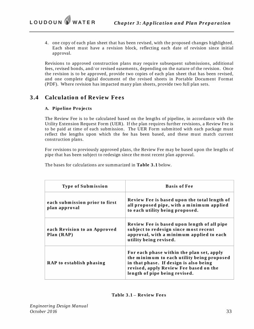
Chapter 3: Application and Plan Preparation
Engineering Design Manual October 2016 33
4. one copy of each plan sheet that has been revised, with the proposed changes highlighted. Each sheet must have a revision block, reflecting each date of revision since initial approval.
Revisions to approved construction plans may require subsequent submissions, additional fees, revised bonds, and/or revised easements, depending on the nature of the revision. Once the revision is to be approved, provide two copies of each plan sheet that has been revised, and one complete digital document of the revised sheets in Portable Document Format (PDF). Where revision has impacted many plan sheets, provide two full plan sets.
3.4 Calculation of Review Fees
A. Pipeline Projects
The Review Fee is to be calculated based on the lengths of pipeline, in accordance with the Utility Extension Request Form (UER). If the plan requires further revisions, a Review Fee is to be paid at time of each submission. The UER Form submitted with each package must reflect the lengths upon which the fee has been based, and these must match current construction plans.
For revisions to previously approved plans, the Review Fee may be based upon the lengths of pipe that has been subject to redesign since the most recent plan approval.
The bases for calculations are summarized in Table 3.1 below.
Type of Submission Basis of Fee
each submission prior to first plan approval
Review Fee is based upon the total length of all proposed pipe, with a minimum applied to each utility being proposed.
each Revision to an Approved Plan (RAP)
Review Fee is based upon length of all pipe subject to redesign since most recent approval, with a minimum applied to each utility being revised.
RAP to establish phasing
For each phase within the plan set, apply the minimum to each utility being proposed in that phase. If design is also being revised, apply Review Fee based on the length of pipe being revised.
Table 3.1 – Review Fees
Chapter 3: Application and Plan Preparation
Engineering Design Manual October 2016 34
B. Pumping, Treatment and Other Non-linear Facilities
For facilities other than pipelines that are to be dedicated to Loudoun Water, the Review Fee is a percentage of the estimated construction cost of the facility. This amount is to be paid at time initial plan submission. At time of construction plan approval, the approved bond amount will determine the final review fee, and an accounting will be made.
3.5 Local Review Authority
A. Water
Loudoun Water has been granted local review authority by the Virginia Department of Health (VDH). This applies to public water mains less than 16-inch in diameter. For projects including water main 16-inch or greater, and for all pumping stations and treatment facilities, Loudoun Water will submit the required documentation to VDH. Construction of the project may not begin until the Commonwealth’s Waterworks Permit has been obtained.
In support of submission to VDH, the applicant shall provide a set of the construction plans and specifications, all supporting documentation and hydraulic modeling, and a completed application for Waterworks Permit, as directed by Loudoun Water. If the size of a subject pipeline is not established in Loudoun Water’s water utility master plan, the engineer of record will need to complete the forms Hydraulic Model Data Summary and Hydraulic Modeling Analysis Certification for inclusion in the application package.
Plans for submission to VDH shall bear the design engineer’s original signature and seal (wet stamp) on the cover sheet. Seals and signatures must appear on all plan sheets. The initial submission requires one set of construction drawings on paper. Also provide one complete plan set as a digital document in Portable Document Format (PDF) on compact disc. Once the design is approved by VDH, Loudoun Water will forward the PDF file to VDH.
B. Wastewater and Reclaimed Water
Loudoun Water has been granted local review authority by the Virginia Department of Environmental Quality (DEQ). This applies to public sewers less than 16-inch in diameter. For projects including sewers 16-inch or greater, and for all pumping stations and treatment facilities, the applicant shall obtain a Certificate to Construct (CTC) from DEQ. Construction of the project may not begin until the CTC has been obtained. At the completion of certain projects, a Certificate to Operate (CTO) shall be obtained by the applicant. The CTO will be required for project closeout.
3.6 Requirements for Construction Plans
Plan sheets are to be prepared for printing on 24-inch x 36-inch paper. Certification will be made by a licensed Professional Engineer with a valid and current registration in the Commonwealth of Virginia, unless otherwise exempted in the Code of Virginia (§54.1-401).
Chapter 3: Application and Plan Preparation
Engineering Design Manual October 2016 35
Construction plans should include the components listed below. For convenience, a check list is included in Appendix A of this Manual. The checklist is strictly for the use of designers and reviewers. This checklist should not be submitted with plans for review.
A. Cover Sheet
Provide a Cover Sheet that includes the project name; the Loudoun Water project identification number(s); a sheet index; a vicinity map; and a revision block. Cover Sheet shall bear the name, address, and phone number of the developer, and of the engineering firm that prepared the plans. List the national telephone number for the Miss Utility System, 811. For Loudoun Water Operations and Maintenance list telephone number 571-291-7878.
B. Vicinity Map
1. Typical scale is 1 inch=1000 feet.
2. Show and label the Virginia State Plane North Coordinate grid at suitable intervals.
3. Show and label the adjacent streets and roads.
4. Show the limits of the site.
C. Revision Block
Each sheet pertaining to water and sewer construction shall have a revision block, in which the engineer will log each revision requiring Loudoun Water’s approval, and occurring after the initial plan approval.
D. Zoning Tabulations
Provide table including number of dwelling units and/or building square footages with respective proposed uses.
E. Scale
Identify the scale(s) by numeric conversion on all plan sheets. To make grading and utility plan views properly legible, 1 inch=30 feet is preferred. Scales that cannot be read with a standard engineer’s box scale will not be accepted.
F. North Arrow and Coordinates
A north arrow and a minimum of four coordinate grid references (tic marks) must appear on each plan view used to establish the placement of water and sewer lines.
G. Horizontal Control
Horizontal control is to be based on the Virginia State Plane North Coordinate System, North American Datum of 1983, High Accuracy Reference Network (NAD83HARN). Linear units shall be US Survey Feet (not International Feet). Projects that were started prior to September 1, 2008 may use the previous NAD27 datum standard. All new projects started
Chapter 3: Application and Plan Preparation
Engineering Design Manual October 2016 36
after September 1, 2008 must use the NAD83 HARN horizontal datum. Plans shall clearly note the horizontal datum used.
H. Vertical Control
Vertical measurements, including elevations, shall be based on the North American Vertical Datum of 1988 (NAVD 88), with feet as the measurement unit. Projects that were started prior to February 18, 2009 may use the previously required National Geodetic Vertical Datum of 1929 (NGVD 29). Plans shall clearly note the vertical datum used.
I. Property Identification
Show Property Identification Numbers (PIN) of all parcels that are part of the application, and where proposed water and sewer lines are to be installed. Show the name of each property’s owner. Show property lines, owners’ names and PIN numbers of properties adjacent to the proposed work.
J. Easements
In plan view of water and sewer, show all existing and proposed easements conveyed to Loudoun Water. Also, show all existing and proposed easements benefiting the County of Loudoun, other public entities, and purveyors of electricity, gas, and communications services.
K. Topography
Provide contours at maximum 2 foot interval.
L. Natural Features
Show limits of Wetlands and Waters of the United States, intermittent streams, ponds, limits of tree canopy, steep slopes as designated by Loudoun County, and other features that may impact location or installation of proposed facilities.
M. Manmade Features
Show all buildings, above and below ground structures, roads, bridges, trails and sidewalks, fences and walls, wells and potable springs, and wastewater disposal systems.
N. Existing Utilities
Show and label all overhead and underground utility lines and associated facilities. Test pits may be required as basis of design to determine depth and nature of facilities.
O. Proposed Site Work and Utilities
Within water and sewer corridors, show all grading, roadway, utility, and building construction that is currently proposed by the project’s owner and by others. Work being proposed in other plan sets must be reflected in all instances where the subject installation is impacted by this other work, or will be in future.

Chapter 3: Application and Plan Preparation
Engineering Design Manual October 2016 37
Pursuant to Section 2.6 of this Manual, coordination between designs must be effectively maintained throughout the entire design period, and continue through actual installation. Failure to incorporate into the water and sewer designs, features to be constructed by the project’s developer or by others, will result in withholding of plan approval, Construction Permitting, and/or acceptance of work.
P. Plan and Profile of Water and Sewer
Provide plan and profile of all proposed water and sanitary sewer mains with complete stationing, consistent among views. It is Loudoun Water’s preference, where applicable (e.g. offsite work), that plan views of each proposed water or sewer main appear with its corresponding profile on the same plan sheet. Show existing water and sanitary sewer facilities within and immediately adjacent to proposed limits of construction. Include profile of existing pipelines if their cover is to be increased or decreased.
Waterline profile shall include complete call outs of fittings, appurtenances, and the extent of locking gaskets, restraining glands, and/or restrained joint piping systems. Sewer profiles shall include specification of pipe inverts at each manhole, distance between manholes, slopes of lines, and stations of service connections.
Show location of water and sewer service lines to each proposed structure and/or to each proposed lot. For water services, line size and meter size must be specified. Water services are to be profiled to the meter, except that no profile is required for the services of homes and townhomes. For sewer service line, provide profile or tabulation to establish length, slope, invert elevations, and diameter throughout each service.
All crossings of storm sewers and other utilities must be accurately depicted on profiles of water and sanitary sewer, with minimum clearances specified.
Q. Phased Work
Where utility lines are to be temporarily terminated between mobilizations, design must include clear phase lines in plan and profile views. Sufficient lines and appurtenances shall be specified to enable the full operation of the initial portion of piping, before and during the subsequent extension.
For work that is intended to be accomplished in two or more mobilizations, the developer should consider the desired extent of initial bonding of the work. Construction plans should be structured accordingly. It is preferred, but not required, that a set of plans contain only the work to be done under a single bond to Loudoun Water. If, however, the developer chooses to include within a set of plans scope to be implemented under more than one bond, then a unique Loudoun Water Project ID Number must be established to correspond to each phase’s bond. A maximum of four projects (four bonds) may be supported by a single set of drawings.
R. Standard Notes
Include current Loudoun Water standard notes. These are as listed on G-5, STANDARD NOTES of the Standard Details. Ensure that this figure is reproduced at a scale that will make the text readily legible.

Chapter 3: Application and Plan Preparation
Engineering Design Manual October 2016 38
S. Standard Details
Include all applicable Loudoun Water Standard Details. Select those that pertain to the proposed scope. Do not include figures that apply to installations that are not within the scope of the project.
3.7 Digital Data
A. When Required
At time of initial application, a digital file in CAD format shall be submitted with the application. This file is simply used in Loudoun Water’s Geographic Information System, to track proposed construction.
At time of plan approval, or the approval of any subsequent revision, Loudoun Water requires that the construction plan set be provided in the form of one complete digital document in Portable Document Format (PDF).
B. CAD Files
Loudoun Water agrees to protect CAD files as intellectual property, and will not distribute the drawings in their CAD form to any third party without the owner’s consent. Digitally signed/sealed drawings are not required.
The entire project area is to be covered in the file submitted. Please do not split the project into multiple files corresponding to the individual plan sheets. Omit topography. Ensure that the file is geographically referenced. See Section 3.6 G. above for preferred coordinate system. Provide the following information where applicable:
1. water utility pipes and appurtenances
2. sanitary sewer utility pipes and appurtenance
3. reclaimed water utility pipes and appurtenances
4. right of way
5. lot/parcel boundaries
6. building footprints
7. edge of pavement/curb and gutter
8. project limits
9. easements
Chapter 3: Application and Plan Preparation
Engineering Design Manual October 2016 39
The following is a list of acceptable formats/version:
AutoCAD 2000-2010 (versions 12-18.2)
AutoCAD DXF 2000-2010 (versions 12-18.2)
Microstation SE/J, (versions 5-8)
ESRI ArcView Shapefile
ESRI File/Personal Geodatabase
C. PDF Files
When required, provide one complete digital document of the construction plan set in Portable Document Format (PDF). This file is to contain the entire latest approved sealed drawings of the construction plan set. Each drawing shall be captured at 1:1 scale (such that the PDF can be plotted at the original scale of the hard copy without scaling the plot). If the PDF is produced by scanning the hard-copy drawings, then the scanning shall be performed at 300 dots per inch (DPI). The scans shall be black and white, and shall be free of distortions.
3.8 Review Process
A. Pre-application Conference
No pre-application conference is required. However, engineers preparing construction plans for submission to Loudoun Water are encouraged to seek information from Loudoun Water’s Department of Land Development Programs as basis of design. Among items that can be provided are record drawings of existing facilities on, adjoining, or supporting the subject site; the nature of planned facilities that impact the site; capacity limitations that may exist; and preferences as to layout.
B. Reviews
In response to each plan submission, Loudoun Water will provide written comments or approval. Priority will be given to revisions, where construction is already underway.
C. Conferences During Design
Throughout design or redesign, engineers are encouraged to confer with Loudoun Water’s assigned Project Engineer, as to the suitability of contemplated layouts or design features. This may take the form of electronic mail and telephone calls, or if needed, design meetings.
-- end of Chapter 3 --


Chapter 4: Water Distribution
Engineering Design Manual October 2016 41
Chapter 4: Water Distribution
4.1 Scope
A. Intent
This chapter describes the planning, layout, design and construction of water distribution systems of Loudoun Water. The information contained in this chapter must be applied in conjunction with the latest edition of the Waterworks Regulations 12 VAC 5-590-10 et. seq., published by the Commonwealth of Virginia, Department of Health; standard practices of the American Water Works Association (AWWA); and with other sections of this Manual.
B. Minimums
Many criteria listed are minimums. Additional separations and clearances are to be furnished as practical to optimize each design. Attention shall be given to locating utilities so as to facilitate their re-excavation. Loudoun Water will consider factors such as depth and magnitude of facility in determining the adequacy of each design, and may relax or increase dimensional requirements accordingly. A design is to be sought which minimizes maintenance costs.
4.2 Hydraulic Requirements
A. Flows and Pressures
1. The water distribution systems and any extensions thereof shall have adequate capacity to supply the normal (average) and peak hour demands of all customers – domestic, public, commercial and industrial – while maintaining a pressure of not less than 30 pounds per square inch (psi) at all points of delivery. Loudoun Water further intends to provide a static service pressure of 40 psi or better to all customers. If considering an extension at higher elevations, such that lesser service pressures could result, the designer should consult with Loudoun Water Project Manager to evaluate options for enhancing pressure.
2. Throughout Loudoun Water’s Central System, extensions shall be capable of delivering, on the day of maximum customer demand, flows required for the fire protection to within 300 feet of each building to be served, while maintaining a residual pressure of not less than 20 psi. Flows required for fire protection shall be in accordance with the National Fire Protection Association Standards, and shall not be less than those listed in Table 4.1 below.
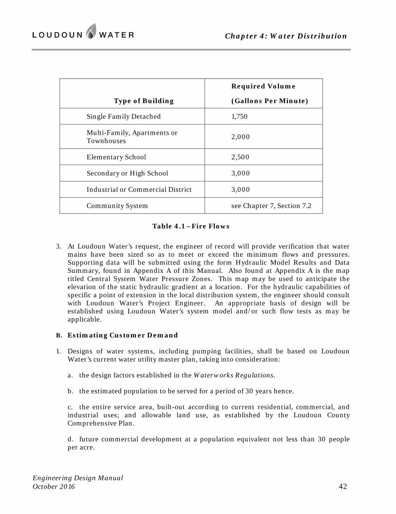
Chapter 4: Water Distribution
Engineering Design Manual October 2016 42
Type of Building
Required Volume
(Gallons Per Minute)
Single Family Detached 1,750
Multi-Family, Apartments or Townhouses 2,000
Elementary School 2,500
Secondary or High School 3,000
Industrial or Commercial District 3,000
Community System see Chapter 7, Section 7.2
Table 4.1 –Fire Flows
3. At Loudoun Water’s request, the engineer of record will provide verification that water mains have been sized so as to meet or exceed the minimum flows and pressures. Supporting data will be submitted using the form Hydraulic Model Results and Data Summary, found in Appendix A of this Manual. Also found at Appendix A is the map titled Central System Water Pressure Zones. This map may be used to anticipate the elevation of the static hydraulic gradient at a location. For the hydraulic capabilities of specific a point of extension in the local distribution system, the engineer should consult with Loudoun Water’s Project Engineer. An appropriate basis of design will be established using Loudoun Water’s system model and/or such flow tests as may be applicable.
B. Estimating Customer Demand
1. Designs of water systems, including pumping facilities, shall be based on Loudoun Water’s current water utility master plan, taking into consideration:
a. the design factors established in the Waterworks Regulations.
b. the estimated population to be served for a period of 30 years hence.
c. the entire service area, built-out according to current residential, commercial, and industrial uses; and allowable land use, as established by the Loudoun County Comprehensive Plan.
d. future commercial development at a population equivalent not less than 30 people per acre.
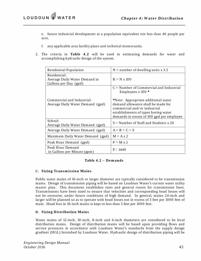
Chapter 4: Water Distribution
Engineering Design Manual October 2016 43
e. future industrial development at a population equivalent not less than 40 people per acre.
f. any applicable area facility plans and technical memoranda.
2. The criteria in Table 4.2 will be used in estimating demands for water and accomplishing hydraulic design of the system.
Residential Population N = number of dwelling units x 3.5 Residential: Average Daily Water Demand in Gallons per Day (gpd)
R = N x 100
Commercial and Industrial: Average Daily Water Demand (gpd)
C = Number of Commercial and Industrial Employees x 100 * *Note: Appropriate additional water demand allowance shall be made for commercial and/or industrial establishments of types having water demands in excess of 100 gpd per employee
School: Average Daily Water Demand (gpd)
S = Number of Staff and Students x 20
Average Daily Water Demand (gpd) A = R + C + S
Maximum Daily Water Demand (gpd) M = A x 2
Peak Hour Demand (gpd) P = M x 2 Peak Hour Demand in Gallons per Minute (gpm)
P / 1440
Table 4.2 – Demands
C. Sizing Transmission Mains
Public water mains of 16-inch or larger diameter are typically considered to be transmission mains. Design of transmission piping will be based on Loudoun Water’s current water utility master plan. This document establishes sizes and general routes for transmission lines. Transmissions have been sized to ensure that velocities and corresponding head losses will not be excessive, under future conditions of high demand. In general, mains 24-inch and larger will be planned so as to operate with head losses not in excess of 3 feet per 1000 feet of main. Head loss in 16-inch mains is kept to less than 5 feet per 1000 feet.
D. Sizing Distribution Mains
Water mains of 12-inch, 10-inch, 8-inch and 6-inch diameters are considered to be local distribution mains. Design of distribution mains will be based upon providing flows and service pressures in accordance with Loudoun Water’s standards from the supply design gradient (HGL) furnished by Loudoun Water. Hydraulic design of distribution piping will be
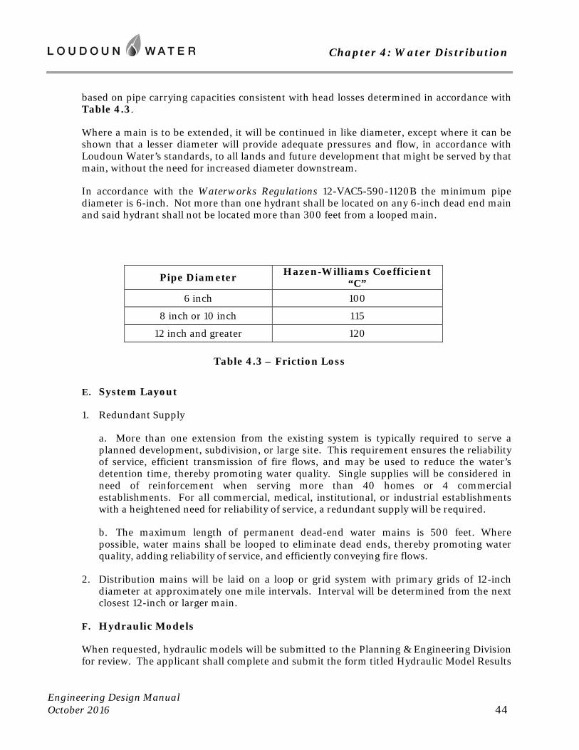
Chapter 4: Water Distribution
Engineering Design Manual October 2016 44
based on pipe carrying capacities consistent with head losses determined in accordance with Table 4.3.
Where a main is to be extended, it will be continued in like diameter, except where it can be shown that a lesser diameter will provide adequate pressures and flow, in accordance with Loudoun Water’s standards, to all lands and future development that might be served by that main, without the need for increased diameter downstream.
In accordance with the Waterworks Regulations 12-VAC5-590-1120B the minimum pipe diameter is 6-inch. Not more than one hydrant shall be located on any 6-inch dead end main and said hydrant shall not be located more than 300 feet from a looped main.
Pipe Diameter Hazen-Williams Coefficient “C”
6 inch 100
8 inch or 10 inch 115
12 inch and greater 120
Table 4.3 – Friction Loss
E. System Layout
1. Redundant Supply
a. More than one extension from the existing system is typically required to serve a planned development, subdivision, or large site. This requirement ensures the reliability of service, efficient transmission of fire flows, and may be used to reduce the water’s detention time, thereby promoting water quality. Single supplies will be considered in need of reinforcement when serving more than 40 homes or 4 commercial establishments. For all commercial, medical, institutional, or industrial establishments with a heightened need for reliability of service, a redundant supply will be required.
b. The maximum length of permanent dead-end water mains is 500 feet. Where possible, water mains shall be looped to eliminate dead ends, thereby promoting water quality, adding reliability of service, and efficiently conveying fire flows.
2. Distribution mains will be laid on a loop or grid system with primary grids of 12-inch diameter at approximately one mile intervals. Interval will be determined from the next closest 12-inch or larger main.
F. Hydraulic Models
When requested, hydraulic models will be submitted to the Planning & Engineering Division for review. The applicant shall complete and submit the form titled Hydraulic Model Results
Chapter 4: Water Distribution
Engineering Design Manual October 2016 45
and Data Summary, found in Appendix A of this Manual. The following are minimum requirements for all models submitted.
1. Provide a written model summary, area map, along with an electronic copy of the model for review. Identify the computer modeling software used to create the model. Submit all related database files to ensure the model will import into WaterGEMS software Version 8, or Loudoun Water’s latest software.
2. Provide a map showing pipe network. Label all pipes, nodes, road names, north arrow, scale, number of units, unit type, demands, elevation contours, and outline the phasing of the project.
3. Demonstrate that the development(s) can meet the following demands: average day, maximum daily, peak hour, and maximum daily plus fire flow, throughout development.
4. Model must represent the entire development, including each planned sequence of phases. Each phase of the development must be hydraulically adequate. The model must support the desired phasing in the order that the construction will occur.
5. Neighboring developments and system demands must be included in model to accurately represent system pressures.
6. Identify model assumptions, including water source and calculated demands based on the number of units and the type of units in the development. Only one water source may be used to supply the model, except where two hydraulically independent sources exist, such as from two separate pressure zones.
7. State the required fire flow demands for each unit type and call out specific nodes that require different fire flow demands, such as a development of single family homes with a school; where the school requires a higher fire flow demand, the node needs to be identified.
8. Include a node report showing elevation, demand, hydraulic grade line (HGL), and pressure. A pipe report showing diameter, flow, velocity, length, and head loss must also be included.
9. Provide a conclusion of the model results identifying the nodes with the lowest pressure during the various scenarios.
4.3 Layout of Public Water Main and Appurtenances
A. Definitions
The term “Public Water Main” and “Water Main” shall mean a water main which is owned and controlled by Loudon Water.
Where the term “Pipe” is used, the design criteria and installation requirements may be considered to apply to both Public Water Mains and “Water Service Connections”, as these are defined at Section 4.5.
Chapter 4: Water Distribution
Engineering Design Manual October 2016 46
B. Plan View
1. Public water mains of 16-inch or larger diameter are typically considered to be transmission mains. Such mains are to be located in easements on private property, and are to be routed exterior to streets and pavements, crossing streets only where necessary. Service connections to theses mains are prohibited, except in accordance with Sections 4.5 B.8. and 4.5 B.9 of this chapter.
2. Water mains of 12-inch, 10-inch, 8-inch and 6-inch diameters are considered to be local distribution mains, to which service connections may be made. These mains are typically routed within streets and pavements.
3. Water pipes (and associated land disturbance) shall be located outside of very steep slope areas in accordance with Section 5-1508 and other pertinent sections of the Loudoun County Zoning Ordinance.
4. Routes for pipes shall be selected so as to provide the required separations from buildings and other utilities, while minimizing the use of horizontal and vertical bends, and minimizing the number of crossings with curbing and sidewalks.
5. Encumbrance of preexisting pipes for future access and/or re-excavation will not be permitted. Any necessary relocation of existing water facilities due to development is the responsibility of the Developer, and will be replacement in kind, in the form of a new, parallel facility. Where grading is to occur, see Section 4.3 C.3 for limitations.
6. The maximum curvature by joint deflection for water mains equal to or less than 12-inch diameter is a 300 foot radius arc (3.5 degrees/joint with 18 foot pipe sections). For mains larger than 12 inches, the maximum curvature by deflection is a 500 foot radius arc. Where a restrained joint piping system is specified, consult manufacturer’s recommendation for maximum joint deflection.
7. Fittings and blockings should not be placed atop other utilities to avoid placement in disturbed ground.
8. Separations
a. Provide a minimum 10 foot horizontal separation (outside to outside) with sanitary sewers, including manholes.
b. Reduced separation with sanitary sewer will be considered in unusual situations, subject to the limitations established in the Waterworks Regulations 12 VAC 5-590-1150 B.2.
c. Provide a minimum 6 foot horizontal separation (outside to outside) with storm drains and drainage structures, duct banks, communications or electrical vaults, and with other underground utilities or structures.
d. For water main with 5 feet of cover or less, provide a minimum 10 foot horizontal separation to a building or other above-ground structure. For deeper water main, provide a minimum of 15 feet of separation.
Chapter 4: Water Distribution
Engineering Design Manual October 2016 47
e. Where water main passes adjacent to a building, the design will ensure that water main can be excavated for repair or replacement, without undermining the building’s foundation. Provide sectional views of the building’s loading plane. For proposed buildings, provide clear specification on the site plan, stating the highest elevation at which the foundation will bear.
9. Street Design
a. In public right of way, placement must be in accordance with current requirements of the Virginia Department of Transportation.
b. Where future roadway improvements have been designed, or future limits can be reasonably anticipated, locate water main outside the ultimate right of way.
c. Along median divided roads, water mains will generally be located exterior to right of way, in easement on private property.
d. In limited circumstances, as outlined in Loudoun County’s Facilities Standards Manual, water mains may be placed within the pavements of median divided roads. Each such design requires the concurrence of VDOT and Loudoun Water, who will consider the maintenance and safety concerns posed by the specific design.
e. Along undivided roads, water mains will be installed under the pavement, a minimum 5 feet from the outside edge of pavement or gutter pan (7 feet from the face of standard curb and gutter). Where the pavement width is 24 feet or less, 3 foot horizontal separation from the gutter pan is permitted, if needed to attain separation from sanitary sewer. Generally centerline of water main should be located 8 feet off the centerline of subdivision streets, with sewer on the opposite side of street, resulting in the required 10 foot separation (outside to outside).
f. When located with sanitary sewer in curved streets, locate water on the outside of prominent turns. Such is intended to foster separation with sewer while minimizing the number of sanitary sewer manholes, and to provide undisturbed ground for the blocking of water bends.
g. Keep the water main on one side of the street as much as practical, crossing only where necessary to provide needed branches or where imperative for attaining separations with other utilities.
h. Where water main is within the right of way, it is to be under a travel way or lane of the road. Placement in median, shoulder, pedestrian trail, or other green space is strictly prohibited. This is due to the maintenance concerns that arise from encumbrance of such spaces by other utilities.
i. In easements on private properties, water main may be located under pedestrian trails with asphalt surface. Placement under concrete sidewalk is typically prohibited.
Chapter 4: Water Distribution
Engineering Design Manual October 2016 48
10. Surface Water Crossing
Where water main is to cross a natural stream or large engineered drainage channel, the water main is to be designed so as to ensure its integrity during flooding. A restrained joint piping system may be employed. Use of steel casing may be considered as a protection measure. Provide valves to allow for the segment to be isolated, and a hydrant (preferably low in segment) to enable the segment to be flushed and tested. These appurtenances are to be beyond limits of 100 year flood waters.
Concrete encasement of water main crossing a watercourse or drainage channel is not typically employed, since such treatment of main obstructs repair or replacement.
Above grade crossing of a watercourse by means of piers or bridge attachment is prohibited. However, should Loudoun Water determine, at its sole discretion, to employ an above grade crossing, the design will provide the water main with protection from freezing, pursuant to the Waterworks Regulations 12-VAC5-590-1180. A.2.
11. Future Extensions of Main
a. Where deemed appropriate by Loudoun Water, to allow for the extension of the public system to other properties, or for the future installation of planned facilities, easement for future main must be conveyed, extending to the site or subdivision boundary. Associated temporary construction easement may also be needed, as dictated by the anticipated scope of the future installation.
b. No appurtenances will be provided for anticipated future mains, unless in the sole discretion of Loudoun Water, sufficient basis of design exists. Where sufficient certainty does not exist, pipe is to be left without appurtenances, for subsequent tapping.
c. Where Loudoun Water determines that a future extension is practical, desirable, and likely, a spur of main will be installed. This spur is to be constructed to the limits of the area being developed, and shall be terminated in a location from which it can readily be extended in the future. This will be beyond the limits of proposed pavements, past adjacent buildings, and beyond crossing storm drains, ducts, or other utilities that would otherwise be undermined during subsequent water installation. Provide a spur, terminating in a valve, line anchor, and temporary blow-off.
d. In cases where the future continuation of the distribution system will complete a loop, necessary to support the subject project, continue the water main to the site or subdivision boundary with current construction.
e. Where excavation is to be in rock, a 25 foot advance blast shall be specified in all alignments that might be utilized for future extensions or connections.
12. Future Service Connections
No appurtenances will be provided for anticipated future service connections, unless in the sole discretion of Loudoun Water, sufficient basis of design exists. Such basis must establish with certainty the size of service, and exact horizontal and vertical location of
Chapter 4: Water Distribution
Engineering Design Manual October 2016 49
the service line and meter, so that they will correspond correctly to the future development condition.
13. Hydrants
See Section 4.4 of this chapter for guidelines on hydrant placements.
14. Valves
Valves shall be installed at appropriate points in all public water mains to permit interruption of flow to segments of the system, as needed to facilitate operation, maintenance, and repair. In most instances a full cluster of valves is necessary, however not every instance warrants a full cluster of valves. The following shall be the minimum number of valves required. Where two mains intersect at a tee, provide a minimum of two valves. At a cross, provide a minimum of three valves. Provide additional mainline valves as necessary to accomplish the segmenting criteria listed below.
a. Valves shall be arranged to isolate no more than 15 connections of single-family detached units, or 25 connections of townhouses.
b. Valves shall be provided so that no more than two commercial or multifamily buildings are served from the segment. Where the reliability of a service is of particularly high importance, a full cluster of valves may be specified at the water service connection.
c. Within subdivisions provide valves to allow segments across private lots to be isolated.
d. Provide a valve on each side of a surface water crossing.
e. Provide valves in transmission and distribution mains to establish maximum 1500 foot segments.
f. Locate valves within paved area where possible. Locate valves with other appurtenances and/or with fittings to the greatest practical degree. Valves must be placed where they are practical for maintenance staff to access and operate, and where not subject to obstruction by parked vehicles. Do not locate valves within pedestrian paths.
g. Where extension from existing water main is proposed, show on construction plans the locations of existing valves and hydrants requiring operation.
h. In diameters 12-inch and smaller, gate vales are employed. In diameters 16-inch and larger, butterfly valves are typically employed. Gates valves may be specified in these larger mains, where cover allows for vertical installation. Where butterfly valves occur in mains operating at pressures of 100psi or above, specify Class 250B valves.
i. Where determined by Loudoun Water that it is necessary to avoid service outage to customers, specify that an insert valve be installed while the water main remains in service.

Chapter 4: Water Distribution
Engineering Design Manual October 2016 50
15. Air Release/Vacuum Breaker Valves
a. High points of transmission mains, 16 inches in diameter and larger, shall be provided with automatic air release/vacuum breaker valves, to allow for the release of accumulated air.
b. In isolated instances, air release valves may be required at high points of smaller distribution mains. However, hydrants are typically preferred for this purpose.
c. On larger transmission mains, a hydrant may be employed in addition to an automatic air release. This serves to allow the discharge of the particularly large volumes of air generated during refilling of the line.
16. Temporary Blow-off Assemblies
a. Blow-off assemblies are to be used only as a temporary terminus of main, where such has been determined appropriate in accordance with Section 4.3 B. 11 above. No other purpose for this device is acceptable.
b. Where a spur of main with temporary blow-off exists within a development area, it is to be extended so as to accomplish permanent termination by means of a hydrant assembly.
c. Where a blow-off assembly is to be used, specify a corresponding mainline valve, located immediately upstream of the assembly. This is needed to enable the subsequent extension to be isolated for disinfection and testing. Where a fittings cluster upstream of the blow-off contains a valve to control flow to the blow-off, this valve may be considered sufficient, if it is within some 100 feet of the blow-off, and provided that there is no intermediate service connection or appurtenance.
d. In determining the location of a blow-off assembly, consider the spatial requirements of the line anchor within the blow-off assembly.
e. In accordance with the Waterworks Regulations 12-VAC5-590-1130C and 12-VAC5-590-1160B, no flushing device shall be directly connected to any sanitary or storm sewer.
17. Provisions for Sampling of New Main
The Waterworks Regulations require that new mains undergo bacteriologic testing in segments not to exceed 1200 feet. Samples can be collected from a hydrant, temporary blow-off, or air release. Each design must make provisions accordingly. Designers will consider this requirement in selecting hydrant locations.
18. Steel Casings
Casing will be specified where trenchless installation of water pipe is to be made. Casings will also be required where, in the opinion of Loudoun Water, such is needed to accomplish the following:
Chapter 4: Water Distribution
Engineering Design Manual October 2016 51
a. protect the water pipe from freezing, superimposed loads, or impact. Examples are at surface water crossings or large culvert crossings.
b. protect the public in the event of a water main break.
c. enable future access to the water pipe, where re-excavation would not be practicable.
d. to facilitate a future installation of water pipe.
Where conditions necessitate a trenchless installation by tunnel, make method and material specifications, using bolted liner plate in place of casing.
19. Miscellaneous
a. For transmission mains 30-inch or larger in diameter, provide project specific design for concrete reaction blockings and line anchors.
b. Water mains not in public right of way or pavement way shall be installed with markers according to G-16, MARKER POSTS AND TRACER PEDESTALS of the Standard Details.
c. Landscape features including trees, shrubs, walls and monuments are not permitted within Loudoun Water’s easements.
C. Profile
1. Where other utilities are proposed in proximity to an existing water main, test pits may be required by Loudoun Water as basis of design, to ensure adequate clearances, and viability of the design.
2. Where water main is proposed in the proximity of existing utilities, test pits may be required as basis of design. At Loudoun Water’s discretion, these test pits may be deferred to after the approval of the design, provided that test reports are submitted to Loudoun Water for review in advance of the Construction Permit being issued. If test pit results render an approved design invalid, a revision will be submitted for review and approval, prior to issuance of the Construction Permit.
3. Where changes to finished grade are proposed above an existing pipe, a profile of the line shall be provided. Resulting cover on the water main will be considered excessive if more than 6 feet. Limited segments with resulting cover up to 8 feet may be approved, if no service connections are within the segment. Covers of more than 8 feet are not acceptable.
4. Where pipes are to be located within paved areas, specify a minimum cover of 3 feet for pipe of 10 inch or smaller diameter, and of 3.5 feet for mains of 12 inch or larger diameter. Specify a minimum cover of 4 feet for all mains to be located outside of pavements. Provide additional cover where pipe passes below rip rap or is susceptible to extraordinary loadings.
Chapter 4: Water Distribution
Engineering Design Manual October 2016 52
5. Where passing below rip rap, water main must have 2.5 feet of clearance below bottom of rip rap mat.
6. On water profile, show all crossing utilities. Specify required minimum clearances from all pipes and ducts. Crossings shown in profile must account for thickness of pipe walls and be based on the computed design clearances.
7. Where a hydrant comes off the main, provide at least 4 feet of cover on main. This is necessary to allow a minimum 5 foot hydrant to be set.
8. Where an air release is specified, the profile of the main must provide at least 5 feet of cover. This is necessary to accomplish the stack-out of the structure, in accordance with W-4, AIR RELEASE of the Standard Details. If the device is to occur within a pavement, such that a flat top manhole cannot be used, provide additional cover. The associated tee and tapped plug in main should be called out on the profile.
9. Water pipes crossing sewers (including building sewers) shall have a separation of at least 18 inches between the bottom of the water and the top of the sewer. Water should always cross over sewers where possible.
10. Where local conditions prevent a vertical water/sewer separation described above and water pipe passes under sewer, the following protection shall be provided subject to approval by Loudoun Water.
a. Provide vertical separation of at least 18 inches (outside to outside) between the bottom of the sewer and the top of the water.
b. Provide adequate structural support for the sewer to prevent excessive deflection of the joints and settling over the water.
c. A full section of the water pipe shall be centered at the point of the crossing so that joints shall be equidistant from the sewer.
d. Sewer must be made of PVC pipe conforming to AWWA C900/905, or of ductile iron conforming to AWWA C151, pressure tested in place, and exhibiting no leakage.
11. Provide a minimum vertical clearance of 1.5 feet with other utilities. If water is atop other utilities, this requirement may be relaxed to as little as 0.5 foot, if such is critical to maintaining water’s position on top. If absolutely necessary, reduced cover on water main will be considered, but in no case will this result in a cover of less than 2 feet.
12. Unless otherwise approved by Loudoun Water, do not route water main below concrete encased duct bank.
13. If the water main will cross under a storm drain 48 inches or larger in diameter, investigate routing around the drain. Crossing below such storm sewers is discouraged. Where no viable alternative for rerouting exists, install water main in steel casing.
14. Specify controlled fill wherever the water pipe will be above the existing grade.
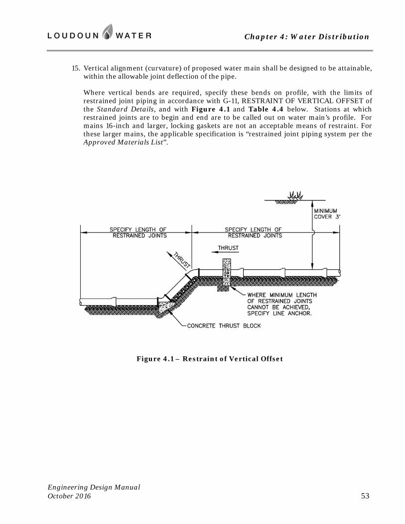
Chapter 4: Water Distribution
Engineering Design Manual October 2016 53
15. Vertical alignment (curvature) of proposed water main shall be designed to be attainable, within the allowable joint deflection of the pipe.
Where vertical bends are required, specify these bends on profile, with the limits of restrained joint piping in accordance with G-11, RESTRAINT OF VERTICAL OFFSET of the Standard Details, and with Figure 4.1 and Table 4.4 below. Stations at which restrained joints are to begin and end are to be called out on water main’s profile. For mains 16-inch and larger, locking gaskets are not an acceptable means of restraint. For these larger mains, the applicable specification is “restrained joint piping system per the Approved Materials List”.
Figure 4.1 – Restraint of Vertical Offset
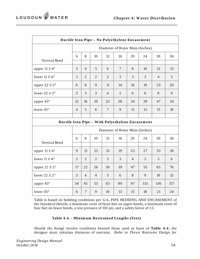
Chapter 4: Water Distribution
Engineering Design Manual October 2016 54
Ductile Iron Pipe – No Polyethylene Encasement
Vertical Bend
Diameter of Water Main (Inches)
6 8 10 12 16 20 24 30 36
upper 11 1/4° 3 4 5 6 7 8 10 12 13
lower 11 1/4° 1 2 2 2 3 3 3 4 5
upper 22 1/2° 6 8 9 11 14 16 19 23 26
lower 22 1/2° 2 3 3 4 5 6 6 8 9
upper 45° 12 16 19 22 28 34 39 47 54
lower 45° 4 5 6 7 9 11 13 15 18
Ductile Iron Pipe – With Polyethylene Encasement
Vertical Bend
Diameter of Water Main (Inches)
6 8 10 12 16 20 24 30 36
upper 11 1/4° 9 11 13 15 19 23 27 33 38
lower 11 1/4° 2 2 2 3 3 4 5 5 6
upper 22 1/2° 17 22 26 30 39 47 55 65 76
lower 22 1/2° 3 4 4 5 6 8 9 10 12
upper 45° 34 45 53 63 80 97 113 136 157
lower 45° 6 7 9 10 13 15 18 21 24
Table is based on bedding conditions per G-6, PIPE BEDDING AND ENCASEMENT of the Standard Details, a minimum cover of three feet on upper bends, a minimum cover of four feet on lower bends, a test pressure of 150 psi, and a safety factor of 1.5.
Table 4.4 – Minimum Restrained Lengths (Feet)
Should the design involve conditions beyond those used as basis of Table 4.4, the designer must calculate distances of restraint. Refer to Thrust Restraint Design for
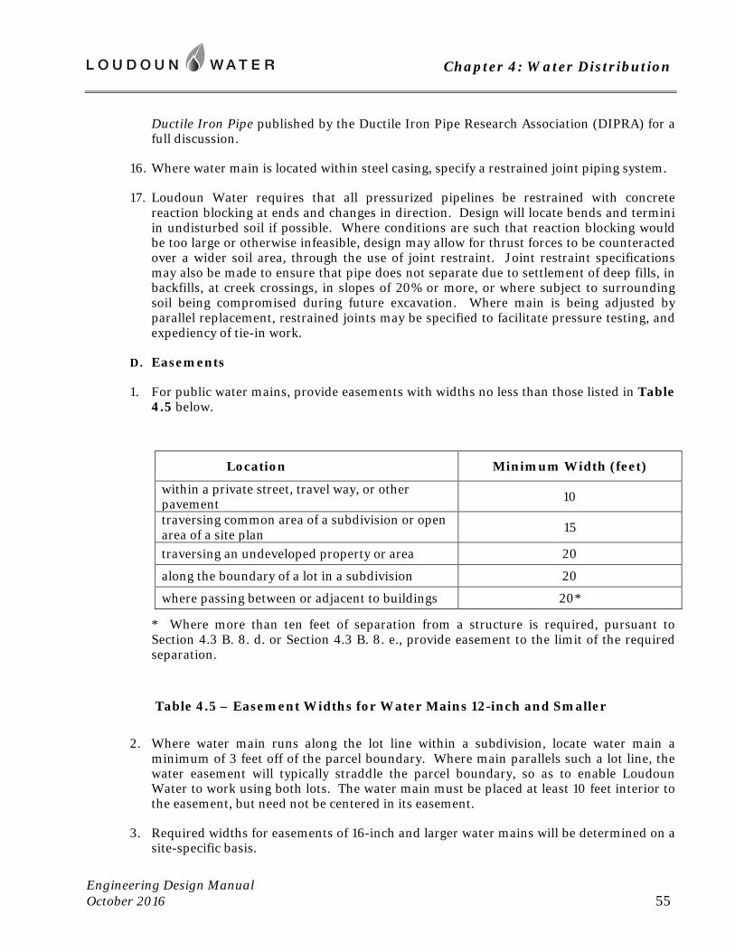
Chapter 4: Water Distribution
Engineering Design Manual October 2016 55
Ductile Iron Pipe published by the Ductile Iron Pipe Research Association (DIPRA) for a full discussion.
16. Where water main is located within steel casing, specify a restrained joint piping system.
17. Loudoun Water requires that all pressurized pipelines be restrained with concrete reaction blocking at ends and changes in direction. Design will locate bends and termini in undisturbed soil if possible. Where conditions are such that reaction blocking would be too large or otherwise infeasible, design may allow for thrust forces to be counteracted over a wider soil area, through the use of joint restraint. Joint restraint specifications may also be made to ensure that pipe does not separate due to settlement of deep fills, in backfills, at creek crossings, in slopes of 20% or more, or where subject to surrounding soil being compromised during future excavation. Where main is being adjusted by parallel replacement, restrained joints may be specified to facilitate pressure testing, and expediency of tie-in work.
D. Easements
1. For public water mains, provide easements with widths no less than those listed in Table 4.5 below.
Location Minimum Width (feet)
within a private street, travel way, or other pavement 10
traversing common area of a subdivision or open area of a site plan 15
traversing an undeveloped property or area 20
along the boundary of a lot in a subdivision 20
where passing between or adjacent to buildings 20*
* Where more than ten feet of separation from a structure is required, pursuant to Section 4.3 B. 8. d. or Section 4.3 B. 8. e., provide easement to the limit of the required separation.
Table 4.5 – Easement Widths for Water Mains 12-inch and Smaller
2. Where water main runs along the lot line within a subdivision, locate water main a minimum of 3 feet off of the parcel boundary. Where main parallels such a lot line, the water easement will typically straddle the parcel boundary, so as to enable Loudoun Water to work using both lots. The water main must be placed at least 10 feet interior to the easement, but need not be centered in its easement.
3. Required widths for easements of 16-inch and larger water mains will be determined on a site-specific basis.
Chapter 4: Water Distribution
Engineering Design Manual October 2016 56
4. Provide 10 foot wide easement on each hydrant branch.
5. Where metering is outdoors, service line and meter shall be placed within an easement of at least 5 feet in width. Within private traffic courts and streets, upon which public ingress and egress is being conveyed to Loudoun County, that easement is considered sufficient for water services. Should meters be exterior to the platted ingress/egress easement, then water easement must be provided for the exterior portion of water service, and shall extend to the downstream side of meter.
6. Where the service is metered indoors, no easement is to be placed on the service line.
7. No easement shall be placed on a fire service line.
8. Where proposed construction is across land of others, temporary construction easements will be established in sufficient widths to accommodate the work area.
9. Provide access easement with adequate grading to allow vehicular access. Where proposed water main is to pass out of street and between or behind homes or buildings, ensure sufficient access to enable operation, repair, or replacement of water main. Where development is to occur on land occupied by a preexisting water main, ensure that access to the water easement is maintained, and not cut off by proposed grading or improvements.
10. Easement plats and instruments shall be reviewed and executed according to the procedures found in Appendix C of this Manual.
11. Should water main, water service connection, or meter be installed outside the boundaries of the recorded easement, a Deed of Easement and Vacation with accompanying plat shall be prepared, approved, and recorded, so as to establish easement at the as-built locations.
E. Corrosion Control
1. Proposed water mains shall be evaluated to determine the need for corrosion control measures. Requirements and guidelines for this evaluation, as well as the design, installation, and acceptance testing of corrosion controls may be found in Appendix E of this Manual. The Standard Details and the Approved Materials List provide further guidance for installations.
2. Evaluation to determine the need for control measures will be based on these factors.
a. corrosiveness of soil
b. diameter of water main
c. consequences of failure, including impact on water system and cost to repair
d. susceptibility to stray currents
Chapter 4: Water Distribution
Engineering Design Manual October 2016 57
3. Where water main is within 100 feet of a steel gas main or other electrically continuous metallic pipeline with impressed current, or upon which impressed current may be later added, design will specify measures to prevent corrosion of the water main. PVC DR14 (AWWA C900 or C905) pipe may be selected by Loudoun Water. Alternately the water main may be ductile iron with full passive cathodic protection system.
4. Where water main crosses or is adjacent to power transmission lines, proposed water main must be evaluated for the potential for induced alternating current.
5. Corrosion control may be required for steel casings.
F. Miscellaneous
1. Ensure complete and accurate pipe stationing in plan and profile views. Call out all appurtenances by station on the profile.
2. Water sampling stations shall be located as directed and shall be constructed in accordance with W-22, SAMPLING STATION of the Standard Details. In new subdivisions and developments, provide one sampling station for every 400 service connections. Station should be located upstream of the customers’ connections that it serves. Place stations where readily accessible for flushing and collecting samples, and where flushing water will readily drain into the storm water collection system. Sampling stations are to be located where not subject to damage by vehicles. Provide easement of same dimensions as for water service with meter.
3. Where water pipes are to be abandoned, specify that pipes be removed and associated easements vacated. Where specifically approved by Loudoun Water, abandoned pipes may be left in place. Such abandonment in place will be considered based on field conditions. Re-excavation may be determined impractical, due to such factors as depth relative to surrounding buildings, roadways, or utilities. However, preference will be for full removal, so as to release Loudoun Water from the permanent obligation to locate and mark its abandoned facilities. Where water main is to be abandoned in place, the end shall be covered with an MJ cap. All appurtenances such as hydrants, valve boxes, air releases, and meter boxes or vaults will be removed.
4.4 Hydrants
A. Plan View
1. Hydrants along the main shall be designed and installed according to W-10, FIRE HYDRANT ALONG STREET, or W-11, FIRE HYDRANT BEHIND DITCH of the Standard Details. The associated tee and auxiliary branch valve must be shown in plan view and called out in profile. No service connection or branch of main shall come off between the hydrant and its auxiliary valve.
2. Each permanent termination of water main must be by means of a fire hydrant. Such dead end assemblies are to be designed and installed according to W-12, DEAD END HYDRANT of the Standard Details. No service connection or branch of main shall come off between the hydrant and its auxiliary valve.
Chapter 4: Water Distribution
Engineering Design Manual October 2016 58
3. Hydrants are to come off the main by means of a tee and branch valve, or as a dead end assembly. Hydrants shall not come off the main at a cross.
4. In one- or two-family residential areas, hydrants shall be installed such that there will be at least one hydrant within 300 feet of the nearest corner of any building.
5. In commercial, industrial, multi-family residential and townhouse areas, hydrants shall be placed such that a maximum of 300 feet of hose is required to reach any point on the exterior of all buildings.
6. A hydrant is required within 100 feet of the siamese connection, also known as fire department connection (FDC), of a building’s fire suppression system.
7. Locate hydrants a minimum of 50 feet from building being protected.
8. When locating dead end fire hydrants ensure adequate space is provided for appurtenances upstream of hydrant. See Figure 4.2 below for dimensional requirements.
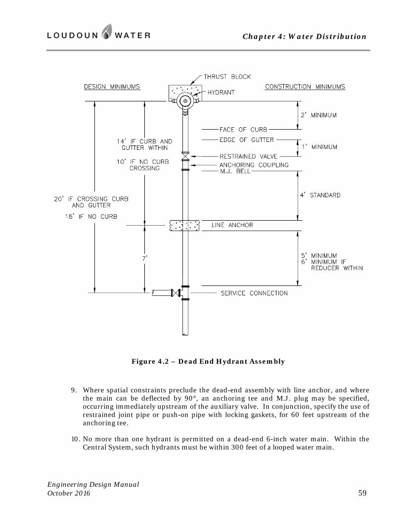
Chapter 4: Water Distribution
Engineering Design Manual October 2016 59
Figure 4.2 – Dead End Hydrant Assembly
9. Where spatial constraints preclude the dead-end assembly with line anchor, and where the main can be deflected by 90°, an anchoring tee and M.J. plug may be specified, occurring immediately upstream of the auxiliary valve. In conjunction, specify the use of restrained joint pipe or push-on pipe with locking gaskets, for 60 feet upstream of the anchoring tee.
10. No more than one hydrant is permitted on a dead-end 6-inch water main. Within the Central System, such hydrants must be within 300 feet of a looped water main.
Chapter 4: Water Distribution
Engineering Design Manual October 2016 60
11. At stream crossing, place one hydrant to enable draining, sampling and flushing of the segment between required isolation valves. Position hydrant as low in segment as practical, while keeping away from bed and banks of the natural water course.
12. Along distribution and transmission mains, provide hydrants at intervals not exceeding 1500 feet.
13. Along ditch and shoulder roadways, where water main is near the edge of pavement, fire hydrants are typically placed on the opposite side of road from the water main. This enables the auxiliary valve to occur in pavement, as it must not occur in the shoulder.
14. Locate hydrants a minimum of 2 feet behind the face of curb and in straight segments of curb as much as practical. The distance behind the face of curb may be increased at Loudoun Water’s discretion where roadway design speed is 45 miles per hour and greater.
15. Provide a minimum separation of 5 feet between a hydrant and any driveway. Additional separation is desired.
16. Hydrants shall not be placed in area of concrete pavement.
17. Specify bollards where hydrants are unprotected by curb and gutter, placed in open space or at the rear of commercial/industrial buildings.
18. Where an existing hydrant must be relocated, specify that a new hydrant be provided at the new location. Where tee may remain to serve hydrant at new location, the auxiliary valve must be replaced, if the existing valve does not hold test pressure. Reinstallation of existing materials is not permitted.
19. For community water systems, specify hydrant paint colors, according to the designed fire flow. Specify that hydrant body is to be white. For system delivering 500-1000 gpm, specify that bonnet and caps be orange. For system delivering less than 500 gpm, specify that bonnet and caps be red.
20. For community water systems delivering 500 gpm or less, specify hydrants as post type.
B. Profile
1. In establishing the elevation of main, and placement of hydrants, consideration must be given to the profile of branching hydrants. Ensure adequate cover on hydrant branch. Avoid taking hydrants from deep main. Where another utility crosses a hydrant branch, provide profile of hydrant branch and specify clearance.
2. To facilitate release of air, fire hydrants are to be placed at significant high points of mains. See Section 4.3 B. 15 concerning air release/vacuum breaker valves, which may be used in conjunction with hydrants at high points.
3. To enable the draining and flushing of all mains, specify fire hydrants at significant low points.
Chapter 4: Water Distribution
Engineering Design Manual October 2016 61
4. Where a hydrant is provided at a significant low point on 16-inch or larger main, specify a tangent tee. Specify that the branch be placed on the bottom of main.
5. Ensure that hydrants leave the main where depth of main will enable a proper hydrant setting, in accordance with the following limitations on hydrant barrels:
Acceptable hydrant heights are 5 feet, 6 feet and 7 feet (measured from the invert of the hydrant’s inlet to the finished grade). Use of 4 foot hydrants is typically prohibited. Therefore, where a hydrant comes off the main, provide at least 4 feet of cover on main. This is necessary to allow a minimum 5 foot hydrant to be set.
Maximum height of a fire hydrant is 7 feet. Wherever practical, select a hydrant placement that will allow for installation of a 7 foot hydrant or shorter. For deeper mains, a vertical offset in the hydrant’s lead is to be specified in accordance with G-11, RESTRAINT OF VERTICAL OFFSET of the Standard Details. Such offsets should be designed to allow placement of a standard 5 foot hydrant. Provide profile of any hydrant lead with an offset.
Use of barrel extensions is discouraged, and where site specific permission is granted, will be limited to a maximum of one extension.
C. Miscellaneous
1. Landscaping, trees, signs and light poles are not permitted within 5 feet of a hydrant.
4.5 Water Service Connections and Meters
A. Definitions
The term “Water Service Connection” shall mean:
Where meter is installed exterior to the building, Water Service Connection shall include the corporation stop or fittings at the main, by which the water service is joined to the Public Water Main; the service from the Public Water Main to the meter; and the meter with its box or vault.
Where the meter is installed inside the building, Water Service Connection shall include the corporation stop or fittings at the main, by which the water service is joined to the Public Water Main; the service extending to the property line or easement line only; and the meter at the location provided by the building’s owner.
The term “Building Service Pipe” shall mean the extension from the end of the Water Service Connection to the inner face of the building wall. Where meter is located indoors, the Building Service Pipe shall include all service piping between Water Service Connection and meter.
Design criteria and installation requirements that refer to “Pipes” may be considered to apply to Water Service Connections, as well as to Public Water Mains.
Chapter 4: Water Distribution
Engineering Design Manual October 2016 62
B. Water Service Connection
1. A separate water service connection to the public water main is required for each premises, as the term “premises” is defined in the publication Rates, Rules and Regulations. However, Loudoun Water may, at its sole discretion, allow a group of premises to be served through a common water service connection. In this case, there must be a management entity that will be responsible for the account and for maintenance of the associated building service pipe and indoor distribution system.
2. Each building, for which a service connection is made, must have adequate hydrant coverage, as defined in this Manual.
3. The main, to which a building’s service connection is to be made, must be on the same parcel of land as the building, or be in a right of way or easement directly adjoining that parcel. Where such is not the case, the applicant for service will be required to extend the public main to the parcel to be served.
4. No two service connections may serve the same plumbing distribution unless the second service is separated from that distribution by an air gap.
5. Where a building contains both residential and nonresidential uses, separate service connections, building service pipes, and distribution systems within the building are required for the respective uses.
6. Where more than one water service connection, building service pipe, and distribution pipe is to be within a building; each such distribution must drain to a corresponding, independent system of drain, waste and vent; building sewer; and sewer service connection.
7. At multi-family structures, where the building service pipe serves more than one dwelling unit, that service pipe shall enter through a mechanical room. Where the associated meter is 1.5-inch or larger, a backflow prevention device is to be housed in this mechanical room, to accomplish the required service protection.
8. Water service connection shall not be permitted to mains 20 inches and greater in diameter. Services shall be provided from distribution mains running parallel to these transmission mains.
9. Services connections may occasionally be permitted to 16-inch mains with special approval of Loudoun Water. In such cases the connection may be required to be by means of tee and restrained 6-inch branch valve.
10. Service connections shall not come off mains with reduced cover, or off deep mains.
11. Service connections on commercial, industrial and institutional sites must be profiled to the meter. Where meter is to be indoors, the entire building service pipe must be profiled.
12. Vertical curvature of 1.5-inch and 2-inch water service connections must be moderate, due to the fairly rigid nature of large copper tubing.
Chapter 4: Water Distribution
Engineering Design Manual October 2016 63
13. Provide a minimum 6 foot horizontal separation with sanitary laterals.
14. Provide a minimum 5 foot separation with driveways.
15. Provide a minimum 5 foot separation between water service connections along the main.
16. For 1.5-inch and 2-inch services, the maximum length of service is 50 feet (main to meter). For 1-inch services this maximum length is 90 feet. This is necessary to avoid couplings in the copper service line. In isolated instances, a longer service may be approved, utilizing ductile iron pipe.
17. Services of 1-inch diameter are typically connected to the main with a corporation stop. Where 1.5-inch and larger services leave the main, the connection shall be by means of a mainline anchoring tee, minimum 6-inch branch valve, and a tapped MJ plug. On nonresidential sites, 1-inch services may connect by means of such a tee and branch valve, to reduce the chances of service outages on the site, and to make provision, in the event that a larger service is desired in future.
C. Metering and Meter Placement
1. Loudoun Water employs the Sensus line of water meters. The operating characteristics of these meters can be found at the Sensus website: sensus.com. Table 4.6 below lists the available sizes, types, locations, and respective service line sizes.
2. The location of outdoor water meters shall be shown on the plans. For indoor meters, provide note specifying indoor placement. In each case, call out meter size and name, as listed in Table 4.6.
3. All single family homes and townhomes are served with a ¾-inch meter. For all other applications, the size and name of meter must be clearly specified on the site plan.
4. For proper placement and requirements of the meter box, see the standard detail applicable to the selected meter.
5. The meter box is to be located immediately behind the curb and as close as possible to the main. For meters of 1-inch and smaller sizes, grass area must be at least 2 feet wide. For 1.5-inch and 2-inch Omni C2 meters installed per W-27, SERVICE CONNECTION FOR 1 ½” OR 2” OMNI C2 METER of the Standard Details, the grass area shall be a minimum of 3 feet wide. Omni or accuMAG meters housed outdoors per W-28, 2” OMNI C2, OMNI T2,OR ACCUMAG METER of the Standard Details require an area at least 8 feet by 8 feet.
6. Placement of meter boxes in the sidewalk or driveway is to be avoided, and will be approved only as a last resort. Where no adequate unpaved space is available, such that meter box must be installed in a pavement or sidewalk, and meter is 1-inch or smaller, specify a frame and cover for “special applications”, as established in WATER, SECTION 5 of the Approved Materials List. This type of frame is made for embedment in concrete or bituminous pavement. For meters 1.5-inch and larger, the standard frame and cover may be embedded if necessary. Installations in concrete are to be made according to W-25, WATER METER IN SIDEWALK OR SLAB of the Standard Details.
Chapter 4: Water Distribution
Engineering Design Manual October 2016 64
7. If water meter must be placed over storm sewer, there must be a minimum 5-foot cover on the storm sewer.
8. For 2-inch Omni C2 in high flow applications, Omni T2, or accuMAG meter, see W-28, 2” OMNI C2, OMNI T2, OR ACCUMAG METER of the Standard Details. Design and installation will be according to this figure. This outdoor placement is strongly preferred. Meter box must not be subject to traffic loadings. In isolated instances, these meters may be approved for indoor installation.
9. For services with meters 3-inch and larger, the meter may be located in an outdoor vault or in an accessible mechanical room. Plans must specify the meter’s location and provide appropriate detail. If an indoor setting is chosen, the service shall be an independent, privately owned branch from Loudoun Water’s main, constructed of ductile iron with a restrained branch valve (minimum 6 inches in diameter) at the main.
10. Where meter is to be located indoors, the site plan must specify that the building’s owner will provide the access features listed below. Building construction plans must be coordinated accordingly.
a. Provide a heated mechanical/meter room with a floor drain and sufficient wall space to accomplish piping as depicted on W-30, 3”, 4” OR 6” OMNI C2, OMNI T2 OR ACCUMAG METER INDOORS of the Standard Details.
b. Meter room shall have a lockable exterior door with a key provided to Loudoun Water.
c. An outdoor drain capable of receiving 400 gpm must be within 75 feet of meter room door. This is needed during meter calibration.
d. If determined necessary during meter installation, provide a remote installation of the meter’s transmitter, mounting it on the building’s exterior. Wire from meter to transmitter is to be within a dedicated PVC conduit, with run not exceeding 300 feet.
11. For all services with outdoor meters 1.5-inches and larger, and all indoor meters, provide an approved backflow prevention device to accomplish the required service line protection. There devices are to be located in the building’s mechanical room, within the service entrance. This requirement shall be noted on the site plan.
12. Landscaping is not permitted within 5 feet of the meter box.
D. Sizing Meters
All single family homes and townhomes are served with a ¾-inch meter. For all other applications, provide documentation supporting the size of each water service connection and water meter. Supply a letter from the mechanical engineer stating the design flows or supporting calculations using fixture supply units (Appendix E of the current International Plumbing Code), or other appropriate method of estimating demand. Identify irrigation demands and other flows not returning to sanitary sewer.
Chapter 4: Water Distribution
Engineering Design Manual October 2016 65
Best available estimates of demands, initial and future, are critical as basis of design for the service(s) and meter(s). It is advisable to discuss the available options for service and meter sizing, location, and configuration with Loudoun Water’s Project Engineer. Various configurations for metering are possible. Metering may also be specified to measure flows that do not return to the sanitary sewer, so as to avoid unnecessary sewer service charges.
Loudoun Water will determine the appropriate size and type of meter, in consultation with the owner and owner’s mechanical engineer. Table 4.6 below lists the available sizes and types. Where the demand could be accommodated by various meter types, the characteristics of the demand will be taken into consideration, and Loudoun Water will select the appropriate type of meter to best capture the usage over the range of flow rates. Omni C2 series will typically be used for multifamily dwelling structures and commercial establishments. Omni T2 series meters will be used in applications where low rates of flow are not anticipated, but where sustained rates of high demand are planned. The Sensus accuMAG line of meters may occasionally be specified in industrial applications.
The operating characteristics of the above mentioned meters can be found at the Sensus website: sensus.com.
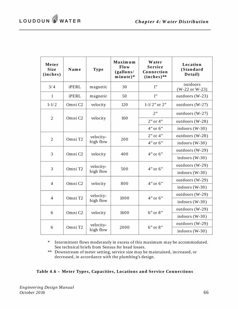
Chapter 4: Water Distribution
Engineering Design Manual October 2016 66
Meter Size
(inches) Name Type
Maximum Flow
(gallons/minute)*
Water Service
Connection (inches)**
Location (Standard
Detail)
3/4 iPERL magnetic 30 1” outdoors (W-22 or W-23)
1 iPERL magnetic 50 1” outdoors (W-23)
1-1/2 Omni C2 velocity 120 1-1/2” or 2” outdoors (W-27)
2
Omni C2
velocity
160
2” outdoors (W-27)
2” or 4” outdoors (W-28)
4” or 6” indoors (W-30)
2 Omni T2 velocity-high flow 200
2” or 4” outdoors (W-28)
4” or 6” indoors (W-30)
3 Omni C2 velocity 400 4” or 6” outdoors (W-29)
indoors (W-30)
3 Omni T2 velocity-high flow 500 4” or 6”
outdoors (W-29)
indoors (W-30)
4 Omni C2 velocity 800 4” or 6” outdoors (W-29)
indoors (W-30)
4 Omni T2 velocity-high flow 1000 4” or 6”
outdoors (W-29)
indoors (W-30)
6 Omni C2 velocity 1600 6” or 8” outdoors (W-29)
indoors (W-30)
6 Omni T2 velocity-high flow 2000 6” or 8”
outdoors (W-29)
indoors (W-30) * Intermittent flows moderately in excess of this maximum may be accommodated.
See technical briefs from Sensus for head losses. ** Downstream of meter setting, service size may be maintained, increased, or
decreased, in accordance with the plumbing’s design.
Table 4.6 – Meter Types, Capacities, Locations and Service Connections
Chapter 4: Water Distribution
Engineering Design Manual October 2016 67
E. Fire Service
1. The service to a fire suppression system must branch off the public water main independently of other service demands. Where it leaves the main, the fire service shall include a valve of a minimum 6 inches in branch diameter. This valve shall be restrained to the tee.
2. A separate fire service connection is required for each premises, as premises is defined in the Rates, Rules and Regulations.
3. Fire service connections shall be downstream of domestic service connections where located on dead end main.
4. Fire services are not metered, and are to be installed according to W-20, FIRE SERVICE CONNECTION of the Standard Details. A backflow prevention device is to be provided in the building’s fire service entrance.
5. Provide profile of fire service from main to building.
6. Where a limited fire suppression system is to be supplied by a branch of the domestic water service, a backflow prevention device is to be installed, as required by the International Residential Code. This device must be testable. Dual cartridge checks do not meet this requirement. A double check-valve assembly or reduced pressure principle device is required.
F. Cross Connection and Backflow Prevention
1. An approved backflow prevention device is required at the service entrance of all buildings in multifamily residential, commercial, industrial, or institutional use. The back flow prevention device must be certified by ASSE or CSA. Installation and testing shall be in accordance with the International Plumbing Code (currently including Sections 312.9.2, 608.2, 608.3), the Virginia Waterworks Regulations Section 12VAC5 590-590, and Loudoun Water’s Cross Connection/Backflow Prevention Program. The latter is available at our website.
2. Where water is supplied to fixtures or systems deemed high hazard, the device providing service line protection is typically required to be one using the reduced pressure zone principle. High hazard fixtures and systems are associated with the following facilities, among others:
a. multi-use commercial, office, or warehouse facilities
b. high rise buildings (four or more stories)
c. lawn sprinkler systems and irrigation systems
d. fire suppression systems with chemical additives
Chapter 4: Water Distribution
Engineering Design Manual October 2016 68
e. hospitals, mortuaries, clinics, veterinary establishments, nursing homes, and medical buildings
f. laboratories, and schools or colleges with laboratory facilities
g. sewage treatment plants, sewage pumping stations or water pumping stations
h. food and beverage processing plants
i. health clubs with swimming pools, therapeutic baths, hot tubs or saunas
j. metal plating industries
k. petroleum or natural gas processing or storage plants
l. car washes and laundries
m. pesticide or exterminating companies, and associated vehicles with storage or mixing tanks
n. farms where water is used for purposes other than typical household use
o. commercial greenhouses and nurseries
3. As required by the Virginia Waterworks Regulations Section 12VAC5 590-590, Loudoun Water will inspect new buildings that will receive our water service, and those of customers receiving continuing service, to ensure the adequacy of backflow prevention devices within the building’s plumbing system. Branches serving certain fixtures must be fitted with the appropriate device for the application, as established by the International Plumbing Code. All backflow prevention devices that incorporate testing ports are to undergo initial and annual testing by a technician, certified to conduct such testing. Where the device is found to be less than fully effective, it shall be repaired or replaced at once. Test reports must be filed with Loudoun Water’s Backflow Protection Specialist, as a condition of the initial building occupancy, and annually thereafter.
4. Where a building’s plumbing or industrial process piping is supplied with potable water by Loudoun Water, and also incorporates an auxiliary supply, an air gap shall be provided between the building service pipe, and the subject plumbing or process piping. This will be the case where a well, cistern, or reclaimed water supply is used.
5. Where potable water is stored in a basin, tank, or reservoir that is open to the atmosphere, an air gap must be provided between the incoming potable supply and the storage vessel.
4.6 Installation Requirements
All water pipe and appurtenances shall be installed in accordance with best practice, with materials and workmanship of full quality. Materials and installation shall be in accordance with all applicable sections of American Water Works Association Standards. Installation
Chapter 4: Water Distribution
Engineering Design Manual October 2016 69
shall conform to AWWA C600, Installation of Ductile-Iron Water Mains and Their Appurtenances, or AWWA C605, Underground Installation of Polyvinyl Chloride (PVC) and Molecularly Oriented Polyvinyl Chloride (PVCO) Pressure Pipe and Fittings; with all manufacturers’ instructions and recommendations; and the provisions of this Manual. The installing contractor shall be solely responsible for ensuring that appropriate and acceptable construction materials, means and methods are used. Reuse of previously installed materials is prohibited, except where specifically approved by Loudoun Water.
A. Excavation, Bedding and Backfill
1. Prior to any clearing or excavation, all required sedimentation and erosion control measures shall be in place, as required by Loudoun County and in accordance with the approved plans. As the work progresses, these control measures shall be properly maintained, and subsequent control measures shall be taken, all as required by Loudoun County and in accordance with the approved plans.
2. The site of an excavation shall first be cleared of all lumber, stumps, trees, brush and rubbish, which shall be removed or disposed of in a satisfactory manner.
3. During excavation operations, material suitable for backfilling shall be piled in an orderly manner a sufficient distance from the banks of the trench to avoid overloading and to prevent slides or cave-ins. All excavated material not suitable and/or required for backfill shall be removed and disposed of in an approved manner. Such grading shall be done as may be necessary to prevent water from flowing into trenches or other excavations, and any water accumulating therein shall be removed by approved methods. All excavations shall be made by open cut unless otherwise specified.
4. The width of the trench above the top of the pipe may be as wide as necessary for sheeting and bracing and the proper performance of the work. All trenches in soil shall be undercut 6 inches below the pipe invert. All trenches in rock shall be undercut 10 inches below the pipe invert. Minimum clearance between the side of the trench and the pipe shall be in accordance with G-6, PIPE BEDDING AND ENCASEMENT, of the Standard Details. Excavations at valve vaults and similar structures shall be sufficient to leave at least 12 inches clear between their outer surface and the embankment or sheeting. The trench shall be excavated to a uniform sub-grade as required for installation of pipe bedding material.
5. All trenches and excavations shall be properly sheeted and braced for the safety of personnel and protection of the work, to maintain the maximum trench widths permitted, and to prevent the disturbance or settlement of adjacent foundations or structures. When so required by Loudoun Water, sheeting shall be left in place by cutting off no higher than 12 inches below the finished surface grade and no lower than 12 inches above the top of the pipe. The requirement of sheeting and/or bracing left in place shall not obligate Loudoun Water in any manner.
6. Blasting, where required, shall be done in accordance with all applicable Federal, State, and local laws, ordinances and regulations and shall not be done within a distance of 25 feet from previously laid pipe or a previously installed structure. See Chapter 2, Section 2.10 C. for additional requirements concerning blasting.
Chapter 4: Water Distribution
Engineering Design Manual October 2016 70
7. Pipe to be installed in an embankment at elevations above the existing ground level shall be installed in trenches excavated after the embankment has been constructed to an elevation that is within 12 inches of finished grade. Embankment supporting Loudoun Water’s facility will be a controlled fill of suitable material or select material, as these are defined in the Virginia Department of Transportation’s Road and Bridge Specifications. Fill shall be placed at a moisture content that is within 2 percentage points of optimum moisture, and compacted to a density of at least 95 percent of the maximum dry density, as determined by the Standard Proctor (AASHTO T99).
8. Where the soil at the trench sub-grade elevation is soft, unstable, or saturated with water, such unsuitable material will be removed and the trench sub-grade stabilized with appropriate material. The depth of stabilization shall be as required to construct a firm sub-grade for pipe bedding material. Maximum size of material shall be 6 inches in longest dimension to within 6 inches of pipe invert, at which point specified bedding material shall be used.
9. Pipe shall be bedded from the trench sub-grade according to G-6, PIPE BEDDING AND ENCASEMENT, of the Standard Details.
10. All bends and elbows of 4-inch diameter or larger shall be installed with suitable concrete thrust blocks poured in place with the concrete deposited against firm, undisturbed earth, as indicated on G-7, CONCRETE THRUST BLOCK, of the Standard Details.
11. Backfill
a. Backfill shall be placed promptly after inspection by Loudoun Water.
b. Backfill shall be placed in 6-inch layers from top of pipe bedding to a point at least 12 inches above the top of pipe. Above this point, backfill shall be deposited in lift thickness that permits compaction to a density as specified hereinafter.
c. Roadway Areas:
i) Within existing public rights of way, select backfill (VDOT 21A or 21B) may be required in place for suitable material. This requirement may be a condition of the Land Use Permit issued by the Virginia Department of Transportation. All requirements and specifications of this permit will govern the work.
ii) Within private roadways, including the areas of future roads, suitable or select material per the VDOT Road and Bridge Specifications may be used. Where native material is not suitable, or cannot be placed within three percentage points of its optimum moisture, backfill must be imported.
iii) Under all pavements and future pavements, the backfill shall be compacted to a density of at least 95 percent of the maximum dry density as determined by the Standard Proctor (AASHTO T99). Pavements shall not be restored over trenches until the backfill material has been tested and determined as satisfactory according to the tests.
d. Open Areas:
i) Beyond pavements and where structural backfills are not required, all material used for backfilling of trenches shall be free of excessive amounts of deleterious materials
Chapter 4: Water Distribution
Engineering Design Manual October 2016 71
such as all organic matter, frozen clods, and masses of fat clay, which are difficult to properly compact. Any rock materials used for backfill shall be no longer than 4 inches in greatest dimension, and shall not be placed within 12 inches of the installed pipe in any direction.
ii) The layers of material shall be compacted to a density of at least 90 percent of the maximum density, as determined by the Standard Proctor (AASHTO T99) wherever pipe is installed in open fields or areas which will not carry vehicular traffic. Where seed or sod is to be placed, the upper layer of backfill shall be composed of topsoil at least 6 inches in depth.
B. Acceptance Tests
1. Not more than 4,000 feet of public water main shall be installed without testing and sterilizing. The contractor shall not proceed with further installation until the preceding section has been approved by Loudoun Water. Hydrostatic testing shall be conducted on segments not exceeding 2000 feet in length.
2. Hydrostatic testing shall be conducted according to the procedures established in AWWA C600.
a. Test Requirements and Limitations
Test pressure (as measured on the test gauge) shall not be less than 1.25 times the working pressure at the highest point along the test section, and not less than 1.5 times the working pressure at the location of the gauge. Minimum test pressure is 150 psi, corresponding to a working pressure of 100 psi. For mains that will operate at pressures in excess of 100 psi, Loudoun Water will specify the working pressure.
The test pressure shall not exceed the pipe or thrust-restraint design pressures, or the rated pressure of any valves that are being used to isolate the segment under test.
The hydrostatic test shall be of at least 2 hours in duration.
Test pressure shall not vary by more than ±5 psi for the duration of the leakage test.
Test setup shall include a provision for reducing the line pressure, without operating valves within the water main. Gauges shall be in good working order, and graduated in increments of 1 psi or less.
b. Filling and Air Removal
After the pipe has been laid and backfill completed, the segment to be tested shall be slowly filled with water. All hydrants, blow-off valves, and air release valves within the segment will be open during filling, and will be closed only once they deliver a solid stream of water. Once all hydrants and air release valves are closed, allow segment to stabilize at the pressure available from the water source, and bleed accumulated air from high points as necessary. Disconnect or close off water source, and leave off through hydrostatic testing. Where hydrants are within the test segment, the test shall be made against the main valve in the hydrant.
Chapter 4: Water Distribution
Engineering Design Manual October 2016 72
c. Testing
Apply test pressure using a pump and clean, chlorinated water. Allow pressure to stabilize, prior to beginning leakage test. Any exposed pipe, fittings, valves, hydrants and joints shall be examined during the test. Any visible leakage will be considered unsatisfactory must be repaired, prior to continuing the testing.
The test result will be pass/fail, based upon allowable leakage. Should the segment under test be found to lose more than the allowable volume, repairs and/or replacement shall be made, and the work will undergo further testing until it attains passing results.
d. Allowable Leakage
Leakage is defined as the quantity of water that must be supplied into the section under test, to maintain a pressure within 5 psi of the specified test pressure. Leakage shall not be estimated from the pressure drop, but rather by measuring the quantity of water pumped into the pipe to reestablish the test pressure. No pipe installation will be accepted if the leakage is greater than that determined using this formula:
L = SD(P)1/2/148,000
Where: L = allowable leakage in gallons per hour
S = length of pipe being tested in feet
D = nominal diameter of pipe in inches
P = average pressure during the test in psi
This formula is based on an allowable leakage at 150 psi of 10.486 gallons/day/mile/inch of diameter.
3. New water mains will be disinfected in accordance with AWWA C651 Disinfecting Water Mains. Granulated chlorine or tablets are typically employed. On occasion, Loudoun Water may approve the continuous feed or slug method of disinfection. All lines shall be thoroughly flushed through the blow-offs and/or hydrants provided in accordance with AWWA C600 and AWWA C651. Water used will be estimated by Loudoun Water and its cost charged to the developer.
4. Loudoun Water will sample for cleanliness and sterilization of the water main before permitting connection for service. Prior to sampling, all mains shall be flushed, with all valves and hydrants being operated during flushing. Best practice is to discharge between 2 and 3 pipe volumes. Two consecutive, satisfactory bacteriological samples are required, taken at intervals not to exceed 1200 feet. Each dead end of main and each branch of 20 feet or more in length must be sampled. The typical interval between the two samples on a segment is 24 hours, and will be no less than 16 hours.
5. Continuity of tracer wires will be tested.
Chapter 4: Water Distribution
Engineering Design Manual October 2016 73
6. Cathodic protection systems will be tested by a NACE Certified Engineer, and reports submitted in accordance with Appendix E of this Manual.
C. Joining to the Active Water System
1. The contractor shall join the proposed water mains and make all water service connections to existing water mains as shown on the approved construction drawings.
2. Where system shutdown is necessary, the contractor shall give Loudoun Water sufficient notice before these operations are to be performed so that advanced notice may be given to any affected customers. Where interruption of flow would result in an unacceptable interruption of service, specialized methods may be required for maintaining flow. This may include the use of insert valves and/or temporary bypass piping.
3. Loudoun Water staff will operate valves in making shutdown and in restoring pressure to the existing pipe and initiating pressures in the new installation. In order that the duration of the shutdown may be as short as possible, connections to water pipes shall be made by the contractor only after complete preparation (including sub-assembly of fittings) for such work has been made.
4. Where existing pipes are provided with fittings for the purpose of connecting to the new pipes, the contractor shall remove the plugs or bulkheads, clean the ends, prepare them for connection to the pipe, and make the new joint.
5. The water released by cutting or opening existing pipes shall be removed and the excavations kept dry until all necessary work within the excavation has been completed.
6. The developer and/or contractor shall notify Loudoun Water prior to the installation of interior plumbing to determine the location of any indoor water meter and any wiring for remote transmitter.
-- end of Chapter 4 --

Chapter 5: Wastewater Collection
Engineering Design Manual October 2016 75
Chapter 5: Wastewater Collection
5.1 Scope
A. Intent
This chapter describes practices to be followed in the planning, layout, design, and construction of sewerage collection systems of Loudoun Water. The information contained in this chapter must be applied in conjunction with the latest edition of the Sewage Collection and Treatment (SCAT) Regulations 9 VAC 25-790, as published by the Commonwealth of Virginia, Department of Environmental Quality; and with other sections of this Manual.
B. Minimums
Many criteria listed are minimums. Additional separations and clearances are to be furnished as practical to optimize each design. Attention shall be given to locating utilities so as to facilitate their re-excavation. Loudoun Water will consider factors such as depth and magnitude of facility in determining the adequacy of each design, and may relax or increase dimensional requirements accordingly. A design is to be sought which minimizes maintenance costs.
5.2 Hydraulic Requirements
Tributary population and projected volume of flow shall be calculated as basis of design for all sewers. Data shall be provided with a map of the tributary area, with topographic contours, showing where loadings have been assigned. Capacity evaluation of proposed facilities and demonstration of their hydraulic adequacy shall be tabulated on the form included in Appendix B of this Manual. Applicants for service may be required to demonstrate the capacity and hydraulic adequacy of existing downstream local collection mains, to the nearest trunk main or interceptor.
A. Tributary Population
1. Designs of sewer systems, including pumping facilities, shall be based on Loudoun Water’s current sewer utility master plan, taking into consideration:
a. the general design factors noted in the Commonwealth of Virginia Sewage Collection and Treatment (SCAT) Regulations.
b. the estimated tributary population for a period of 50 years hence.
c. the entire watershed, built-out according to current residential, commercial, and industrial uses; and where land is vacant, according to allowable land use, as established by current zonings and by the Loudoun County Comprehensive Plan. Where land is vacant, and uses allowed under the Comprehensive Plan differ from current zoning, the more intensive use will be used as basis of design. Where redevelopment of land to more
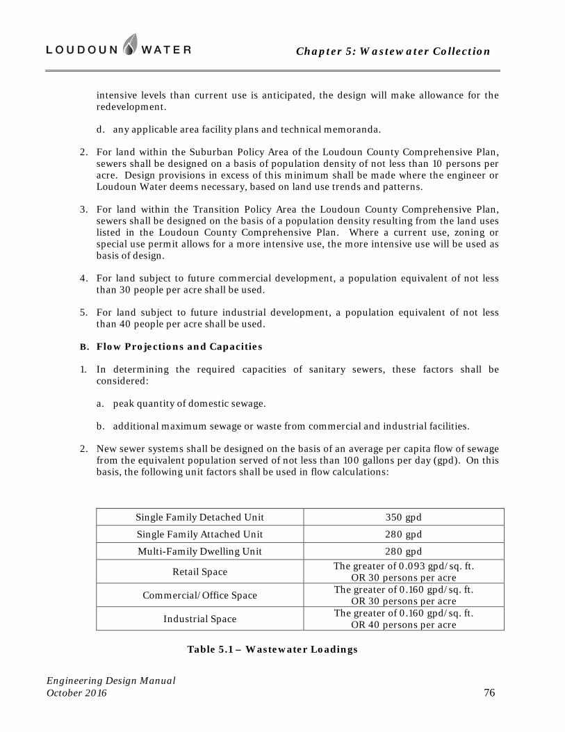
Chapter 5: Wastewater Collection
Engineering Design Manual October 2016 76
intensive levels than current use is anticipated, the design will make allowance for the redevelopment.
d. any applicable area facility plans and technical memoranda.
2. For land within the Suburban Policy Area of the Loudoun County Comprehensive Plan, sewers shall be designed on a basis of population density of not less than 10 persons per acre. Design provisions in excess of this minimum shall be made where the engineer or Loudoun Water deems necessary, based on land use trends and patterns.
3. For land within the Transition Policy Area the Loudoun County Comprehensive Plan, sewers shall be designed on the basis of a population density resulting from the land uses listed in the Loudoun County Comprehensive Plan. Where a current use, zoning or special use permit allows for a more intensive use, the more intensive use will be used as basis of design.
4. For land subject to future commercial development, a population equivalent of not less than 30 people per acre shall be used.
5. For land subject to future industrial development, a population equivalent of not less than 40 people per acre shall be used.
B. Flow Projections and Capacities
1. In determining the required capacities of sanitary sewers, these factors shall be considered:
a. peak quantity of domestic sewage.
b. additional maximum sewage or waste from commercial and industrial facilities.
2. New sewer systems shall be designed on the basis of an average per capita flow of sewage from the equivalent population served of not less than 100 gallons per day (gpd). On this basis, the following unit factors shall be used in flow calculations:
Single Family Detached Unit 350 gpd
Single Family Attached Unit 280 gpd
Multi-Family Dwelling Unit 280 gpd
Retail Space The greater of 0.093 gpd/sq. ft. OR 30 persons per acre
Commercial/Office Space The greater of 0.160 gpd/sq. ft. OR 30 persons per acre
Industrial Space The greater of 0.160 gpd/sq. ft. OR 40 persons per acre
Table 5.1 – Wastewater Loadings
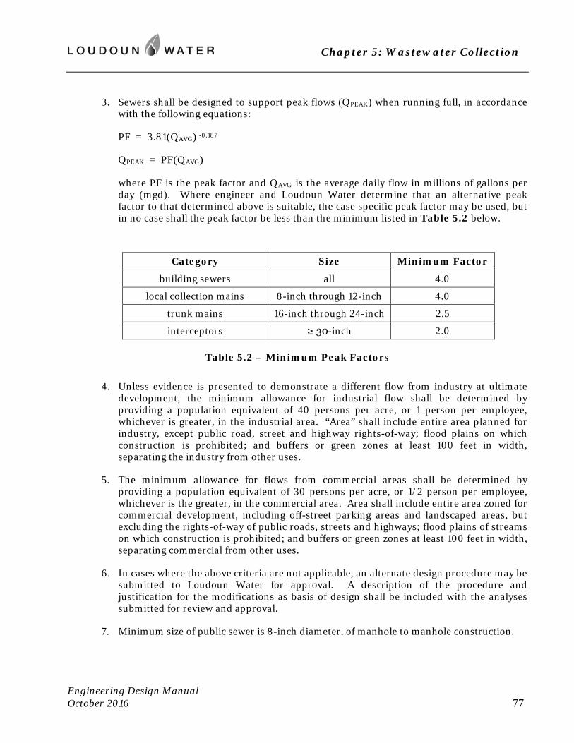
Chapter 5: Wastewater Collection
Engineering Design Manual October 2016 77
3. Sewers shall be designed to support peak flows (QPEAK) when running full, in accordance with the following equations:
PF = 3.81(QAVG) -0.187
QPEAK = PF(QAVG)
where PF is the peak factor and QAVG is the average daily flow in millions of gallons per day (mgd). Where engineer and Loudoun Water determine that an alternative peak factor to that determined above is suitable, the case specific peak factor may be used, but in no case shall the peak factor be less than the minimum listed in Table 5.2 below.
Category Size Minimum Factor
building sewers all 4.0
local collection mains 8-inch through 12-inch 4.0
trunk mains 16-inch through 24-inch 2.5
interceptors ≥ 30-inch 2.0
Table 5.2 – Minimum Peak Factors
4. Unless evidence is presented to demonstrate a different flow from industry at ultimate development, the minimum allowance for industrial flow shall be determined by providing a population equivalent of 40 persons per acre, or 1 person per employee, whichever is greater, in the industrial area. “Area” shall include entire area planned for industry, except public road, street and highway rights-of-way; flood plains on which construction is prohibited; and buffers or green zones at least 100 feet in width, separating the industry from other uses.
5. The minimum allowance for flows from commercial areas shall be determined by providing a population equivalent of 30 persons per acre, or 1/2 person per employee, whichever is the greater, in the commercial area. Area shall include entire area zoned for commercial development, including off-street parking areas and landscaped areas, but excluding the rights-of-way of public roads, streets and highways; flood plains of streams on which construction is prohibited; and buffers or green zones at least 100 feet in width, separating commercial from other uses.
6. In cases where the above criteria are not applicable, an alternate design procedure may be submitted to Loudoun Water for approval. A description of the procedure and justification for the modifications as basis of design shall be included with the analyses submitted for review and approval.
7. Minimum size of public sewer is 8-inch diameter, of manhole to manhole construction.
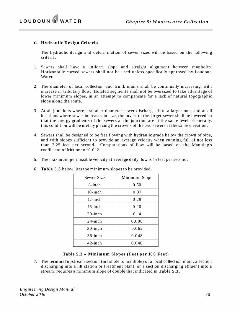
Chapter 5: Wastewater Collection
Engineering Design Manual October 2016 78
C. Hydraulic Design Criteria
The hydraulic design and determination of sewer sizes will be based on the following criteria.
1. Sewers shall have a uniform slope and straight alignment between manholes. Horizontally curved sewers shall not be used unless specifically approved by Loudoun Water.
2. The diameter of local collection and trunk mains shall be continually increasing, with increase in tributary flow. Isolated segments shall not be oversized to take advantage of lower minimum slopes, in an attempt to compensate for a lack of natural topographic slope along the route.
3. At all junctions where a smaller diameter sewer discharges into a larger one, and at all locations where sewer increases in size, the invert of the larger sewer shall be lowered so that the energy gradients of the sewers at the junction are at the same level. Generally, this condition will be met by placing the crowns of the two sewers at the same elevation.
4. Sewers shall be designed to be free flowing with hydraulic grade below the crown of pipe, and with slopes sufficient to provide an average velocity when running full of not less than 2.25 feet per second. Computations of flow will be based on the Manning’s coefficient of friction: n=0.012.
5. The maximum permissible velocity at average daily flow is 15 feet per second.
6. Table 5.3 below lists the minimum slopes to be provided.
Sewer Size Minimum Slope
8-inch 0.50
10-inch 0.37
12-inch 0.29
16-inch 0.20
20-inch 0.14
24-inch 0.088
30-inch 0.062
36-inch 0.048
42-inch 0.040
Table 5.3 – Minimum Slopes (Feet per 100 Feet)
7. The terminal upstream section (manhole to manhole) of a local collection main, a section discharging into a lift station or treatment plant, or a section discharging effluent into a stream, requires a minimum slope of double that indicated in Table 5.3.
Chapter 5: Wastewater Collection
Engineering Design Manual October 2016 79
8. Where liquid depth to pipe diameter ratio (D/d) at average daily flow is more than one third (1/3), slopes less than those listed in Table 5.3 may be approved. For public sewers larger than 42-inch, slopes will be determined on a project specific basis. In all cases, the requirements of the Sewage Collection and Treatment (SCAT) Regulations must be met.
9. Maximum slope on all gravity sewers is 10 percent.
5.3 Public Sewer Layout
A. Definitions
“Public Sewer” shall mean a sewer which is owned and controlled by Loudoun Water.
B. Plan View
1. Public sewers of 16-inch or larger diameter are typically considered to be trunk mains or interceptors, such that service connections are not permitted directly to these pipes. Service connections may be made at manholes. Interceptors and trunk mains are to be located in easements on private property, and are to be routed exterior to streets and pavements, crossing streets only where necessary.
2. Public sewers of 12-inch, 10-inch, and 8-inch diameters are considered to be local collection mains, to which service connections may be made along the pipe. These mains may be routed within streets and pavements, or be located in easements on private property.
3. Sewers (and associated land disturbance) shall be located outside of very steep slope areas in accordance with Section 5-1508 and other pertinent sections of the Loudoun County Zoning Ordinance.
4. Routes for sewers shall be selected so as to provide the required separations from buildings and other utilities, while minimizing the use of manholes, and minimizing the number of crossings with curbing and sidewalks.
5. Sewer routes and manhole placements are to be selected so that manholes will be accessible for maintenance operations. Where sewer is in easement and beyond the street, Loudoun Water will determine the extent of vehicular access needed to accomplish maintenance operations. Where determined necessary, provide vehicular access to easement from street. Drop curb may be required. For easements where vehicular traverse is required, grade easement to allow traverse, with slopes not to exceed 8 percent. Road shall be at least 10 feet wide. Use of pavement or gravel surface is typically limited to facilities that require maintenance visits on a daily, weekly, or monthly basis. Pavement or stone and gravel stabilization may also be required where slopes or drainage would otherwise result in difficulty of traverse in wet conditions. Requirements may be reduced in environmentally sensitive areas.
6. Encumbrance of preexisting sewers for future access and/or re-excavation will not be permitted. Any necessary relocation of existing sewer facilities due to development is the
Chapter 5: Wastewater Collection
Engineering Design Manual October 2016 80
responsibility of the developer, and will be replacement in kind, in the form of a new, parallel facility. Where grading is to occur, resulting cover on existing sewer must remain above design minimum and may be considered excessive if resulting in total cover in excess of 20 feet.
7. If parallel to a public street which is divided by a median, locate sewer outside of the ultimate right of way. However, where a median is being placed in a local subdivision street for aesthetic purposes, sewer may be located within the driving lanes of the street. Along undivided roads, sewer is allowed under pavement.
8. At manholes, the minimum angle between influent and effluent lines is 90-degrees.
9. Separations
a. Provide a minimum 10 foot horizontal separation (outside to outside) with water main, including at sanitary manholes, in accordance with the Waterworks Regulations (12 VAC 5-590-1150).
Provide minimum 6 foot horizontal separation (outside to outside) with storm drains and drainage structures, duct banks, communications or electrical vaults, and with other underground utilities or structures. This separation is to be provided at sanitary manholes. Under no circumstances may any sewer cross beneath a storm drainage structure, or beneath any other above ground or underground structure.
b. Provide minimum 15 foot horizontal separation with a building or any other above ground structure. This requirement may be increased for deep and/or large diameter sewers, as determined by Loudoun Water.
c. Where sewer passes adjacent to a building, the design will ensure that the sewer can be excavated for repair or replacement, without undermining the building’s foundation. Provide sectional views of the building’s loading plane. For proposed buildings, provide clear specification on the site plan, stating the highest elevation at which the foundation will bear.
d. Show all existing and proposed wells within 100 feet of sanitary sewer easements, to include potable wells and those non-potable wells as are used in industrial and geothermal applications. Provide minimum 50 foot horizontal separation between sewer and all potable wells. In accordance with Loudoun County Ordinance, Chapter 1040, this separation may be reduced to as little as 35 feet where the sewer is constructed of pressure pipe, tested in place. Provide a minimum 25 foot separation between sewer and all non-potable wells.
10. Street Design
a. Manhole location in pavement is preferred. Locate manholes at crown of pavement if possible. Where separation requirements preclude manholes on crown or centerline, manholes should be placed in the center of the travel lane.
b. In public roads containing both water mains and public sewers, there will typically not be sufficient width to accommodate waterline with sewer on centerline. In this case,
Chapter 5: Wastewater Collection
Engineering Design Manual October 2016 81
center manhole 5 feet from the centerline of the roadway. In such cases, waterline is typically located 8 feet from centerline, on opposite side of street, resulting in the required 10 foot separation (outside to outside).
11. Locate manholes beyond spread of gutter’s flow.
12. Future Extensions of Public Sewer or Future Service Connection
Identify places where future extension of public sewer, or future sewer service connection appears practical, to allow service to other properties or buildings. Sewer is to be constructed to the limits of the area being developed, so as to terminate in a location from which it can readily be extended in the future. This will be beyond proposed pavements, past adjacent buildings, and beyond adjacent or crossing waterlines or storm drains, ducts, or other utilities that would otherwise be undermined during subsequent sewer installation. Temporary terminations of public sewer will be at a manhole. Easement for the future line must be conveyed, extending to the site or subdivision boundary. Associated temporary construction easement may also be needed, as dictated by the scope of the future installation.
13. Sewers parallel to or crossing streams shall be designed as follows:
a. Sewers and their appurtenances located along streams shall be protected against the 100-year flood. Sewers located along streams shall be located outside of the streambed wherever possible and be sufficiently separated to provide for possible future channel widening. Reasons for requesting sewer lines to be located within streambeds shall be given in the application.
b. Depending on cover and magnitude of stream, sewers crossing streams may require concrete encasement according to G-6, PIPE BEDDING AND ENCASEMENT, of the Standard Details. Where encasement is determined necessary, encasement shall extend minimum 15 feet beyond bank on each side of the stream. The pipe and joints shall be tested in place, must exhibit zero infiltration, and shall be designed, constructed and protected against anticipated hydraulic and physical stresses; longitudinal, vertical and horizontal loads; and erosion.
c. Sewers parallel to streams shall be of sufficient depth so that tributary extensions can be made under the streams while maintaining adequate cover. See Section 5.3.C of this Chapter for cover requirements. Anticipated future extensions must be shown in plan view, and corresponding actual surveyed stream depths will be required for plan review. When requested by Loudoun Water, the designer will provide profiles for these future extensions, proving adequate depth of the sewer.
d. Sewers placed on piers across ravines or streams shall be allowed only when it can be demonstrated that no practical alternative exists. Such sewers on piers shall be constructed in accordance with the requirements for sewers entering or crossing under streams. Construction methods and materials of construction shall be such that sewers will remain watertight and free from change in alignment or grade.
Chapter 5: Wastewater Collection
Engineering Design Manual October 2016 82
C. Profile
1. Maintain a minimum cover of 6.0 feet. Cover may be reduced to 4.0 feet in isolated instances at the upper reaches of the system, and where the public sewer is located outside pavement. Where approved to be at less than four feet of cover, sewers may be required to be protected from superimposed loads by means of concrete encasement.
2. Minimum cover at a stream crossing is 1 foot if in rock or 3 feet if in soil or alluvium. Concrete encasement shall be provided where cover is less than 4 feet, and may be specified wherever needed to ensure that the sewer is not compromised during flooding. Specify concrete encasement of existing or proposed sewer where below rip rap.
3. Maintain minimum vertical separation of 1.5 feet below crossing water main, 2.0 feet if sewer is below utility drain or duct, and 1.5 feet if sewer is above another utility.
4. Show all crossing utilities and specify required clearances for all pipes. Crossings shown in profile must account for pipe wall thicknesses and be labeled with designed clearances, not required clearances.
5. Include the following note, prominently displayed on each profile view: “THE CONTRACTOR SHALL ENSURE THAT SANITARY SEWER IS CONSTRUCTED TO THE APPROVED SLOPES. IF DURING THE ASBUILT SURVEY, THE SLOPE OF ANY SEWER IS FOUND TO BE INADEQUATE TO CONVEY THE DESIGN FLOW, OR LESS THAN THE MINIMUM PER VIRGINIA REGULATIONS, SEWER WILL BE REINSTALLED TO CORRECT SLOPES AT THE EXPENSE OF THE CONTRACTOR OR OWNER.”
6. Sewers installed above existing grade shall be placed in controlled fill.
7. Locate out of areas supporting foundations of structures. Where sewers are deep and in close proximity to structures, Loudoun Water may request a loading plane diagram showing that the sewer may be excavated through conventional means without disturbance to the surrounding structure(s). Adequate easement must be provided so that future excavation and maintenance is feasible.
8. Specify type of pipe for each run. Typical pipe material is PVC DR25 conforming to AWWA C900/905. Where cover is less than 6 feet, or where cover exceeds 20 feet, gravity sewers of diameter 24-inch or smaller shall be constructed of PVC DR18. For additional strength, PVC DR 14 may be specified, but must not be used where there are fittings in the run, due to the difference in inside diameter between PVC DR 14 pipe and AWWA C907 fittings.
For gravity sewers larger than 24 inches in diameter, specification of pipe material shall be made in accordance with SEWER, SECTION 1 of the Approved Materials List. Preference will be given to PVC conforming to AWWA C905. Appropriate dimension ratios will be selected based on pipe covers.
Pipe material and dimension ratio shall remain constant between manholes.
Chapter 5: Wastewater Collection
Engineering Design Manual October 2016 83
D. Easement
1. For public sewer mains, provide easements with widths no less than those listed in Table 5.4 below.
Location Diameter of Sewer
Minimum Width (feet)
within a private street or travel way 6”-12” 10 traversing common area of a subdivision or open area of a site plan 6”-12” 15
traversing an undeveloped property or area 6”-12” 20
along the boundary of a lot in a subdivision 6”-12” 20
where passing between or adjacent to buildings all sizes 30*
within a private street or travel way 16” and larger 15
traversing an undeveloped property or area 16” and larger 25
* Sewer must be located a minimum of 15 feet from structures per Section 5.3 B. 9. b. Easement must extend to the limit of this required separation.
Table 5.4 – Easement Widths for Sewer
1. Where public sewer runs along a lot line within a subdivision, locate the sewer a minimum of 3 feet off of the parcel boundary. Where public sewer parallels such a lot line, the sewer easement will straddle the parcel boundary, so as to enable Loudoun Water to work using both lots. The public sewer must be placed at least 10 feet interior to the easement, but need not be centered in easement. Additional width of easement may be required where sewer is not centered in its easement.
2. Loudoun Water does not take easement on the building sewer, between the public sewer and the premises served. However, where a short length of building sewer is approved to be run on land of others, between the parcel served and the public right of way or easement, Loudoun Water will consider taking easement across the land of others. Such occurs in planned developments, where common ground is traversed. Alternately, private easement, with rights running to the property served, may be used for this purpose. In considering which type of easement to apply, Loudoun Water will consider the length and setting, and whether taking easement as public might foster a future mainline extension.
3. Where proposed construction is across land of others, temporary construction easements will be established in sufficient widths to accommodate the work area.
4. Provide access easement with adequate grading to allow vehicular access. Where proposed sewer is to pass out of street and between or behind homes or buildings, ensure
Chapter 5: Wastewater Collection
Engineering Design Manual October 2016 84
sufficient access to enable operation, repair, or replacement of sewer. Where development is to occur on land occupied by a preexisting sewer, ensure that access to the sewer easement is maintained, and not cut off by proposed grading or improvements.
5. Easement plats and instruments shall be reviewed and executed according to the procedures found in Appendix C of this Manual.
6. Should public sewer be installed outside the boundaries of the recorded easement, a Deed of Easement and Vacation with accompanying plat shall be prepared, approved, and recorded, so as to establish easement at the as-built locations.
E. Miscellaneous
1. Show sanitary sewer crossings on all applicable profiles of other utilities.
2. Facilities being decommissioned shall be abandoned and associated easements vacated. Manholes, structures, and appurtenances are to be removed to the depth specified by Loudoun Water. Removal of pipe will be required in all places where deemed practical by Loudoun Water. This is intended to minimize the need to perpetually mark abandoned lines in response to requests for location services. Under circumstances where excavation is deemed impractical, such as below existing roadways, Loudoun Water may approve abandonment of segments of pipe by means of grouting in place.
5.4 Manholes
A. Plan View
1. Provide a manhole at:
a. all junctions, changes in horizontal alignment, changes in gradient, and temporary or permanent terminus of public sewer;
b. every 400 feet of developed length (8-inch through 16-inch diameter) and every 500 feet of developed length (greater than 16-inch diameter);
c. changes in pipe diameter;
d. lateral connections for laterals 8-inch diameter and larger.
2. Separation
a. Provide a minimum horizontal separation of 10 feet between exterior of manhole and all water pipes.
b. Provide minimum 6 foot horizontal separation (outside to outside) with storm structures, drainage piping, duct banks, vaults, and other structures.
c. Do not locate a manhole in a parking space, or where continuous access would otherwise be obstructed.
Chapter 5: Wastewater Collection
Engineering Design Manual October 2016 85
3. Maximum number of connecting pipes per manhole is four, (one out; three in), with a pipe entering by a drop connection counting as one.
4. Inside diameter of manholes shall be 4.0 feet for public sewers less than or equal to 24-inch diameter. Manhole diameter requirements for sewers larger than 24-inch diameter will be specified on a project-specific basis.
5. Provide a minimum of 6 inches between openings (cores). Sample calculations are provided in Appendix B of this Manual.
6. Existing manholes to receive proposed pipe shall be core bored.
7. A manhole is required at each temporary termination of the public sewer. In isolated instances, when stubbing out of commercially zoned land which is not fully planned or engineered, plugged stubs of 8-inch diameter may be used. Minimum slope for such a stub is 1.00 percent.
8. A 25 foot advance blast shall be specified in all alignments that might be utilized for future extensions or connections.
9. For all sewers receiving pumped sewage, downstream manholes shall have protective lining, to such point as the proportion of pumped sewage to gravity collected sewage is equal (50 percent dilution). Lining shall be in accordance with SEWER, SECTION 3 of the Approved Materials List. New manholes shall be specified as having HDPE cast-in lining system. Such lining systems typically preclude the use of cone sections, so such manholes cannot be located in public streets, and should typically not be located in pavements. If downstream manholes must be within a pavement, or they pre-exist, then one of the approved coatings for field application may be specified.
B. Profile
1. Minimum depth of manhole in pavement is 6 feet. Minimum depth of manhole in grass is 4 feet.
2. Sewers are to be routed so that depth at manholes is limited to a maximum of 20 feet. Where greater cover on sewer would result, investigate alternate route to better mirror the topography. Sewer involving manholes in excess of 20 feet will only be considered where, in Loudoun Water’s judgment, an alternate route is not viable.
3. Provide a maximum of 0.50 feet and a minimum 0.10 feet between invert elevations of pipes of like diameter. When influent pipe is of smaller diameter than effluent pipe, its minimum invert elevation is that which results in matched elevations between crowns of influent and effluent pipes. Additional drop across manholes may be required to insure that a positive hydraulic grade is maintained across the manhole so that flows do not surcharge one or more of the influent pipes.
4. Use of drop connections will be limited to instances where, in Loudoun Water’s discretion, excessive slope or depth of sewer would otherwise result. Drop connections will be considered where slope of main would otherwise exceed 10 percent, or to avoid conflict with other utilities that cannot be readily relocated. Slope of sewer upstream of a
Chapter 5: Wastewater Collection
Engineering Design Manual October 2016 86
drop connection shall be 2 percent. Outside drop connections in accordance with S-4, OUTSIDE DROP CONNECTION, of the Standard Details shall be utilized in new manhole construction. Inside drop connections in accordance with S-5, INSIDE DROP CONNECTION, of the Standard Details will be considered where connecting to sewers that have been in service for more than one year, and where manhole re-excavation for the installation of an outside drop connection or lateral with riser is determined by Loudoun Water to be impractical.
5. “Doghouse” manholes are not permitted. Any manhole installed on an existing sewer must be installed by cut-in.
6. Specify heavy-duty cover in proposed or future pavement.
7. Specify watertight cover if less than 1 foot above the 100-year water surface elevation.
8. Provide ventilation where continuous watertight sections greater than 1,000 feet would otherwise occur.
9. Specify elevation of the vent’s opening, establishing between 3 and 5 feet above surrounding grade. If the opening is to be below 100-year water surface, then specify a float valve in the vent.
10. When top is not in developed lawn or pavement, specify elevation 1 foot above surrounding grade.
11. Provide positive drainage for sanitary manholes located outside of pavement.
12. Where future grading can be anticipated, manholes are to be installed to ultimate top elevations, wherever practical. However, where doing so would result in tops that are more than 4 feet above the interim grade, manhole tops are to be set to the interim condition.
13. Where grading is being proposed at preexisting manholes, specify adjustment of tops so as to conform to the new grade. Due to the limited adjustment available within the manhole chimney, the components of the manhole will typically need to be disassembled, and new sections installed to accomplish the necessary stack-out. Joints in new components must be made with dimensions that conform to the joints of existing components, where new and old must mate. The new assembly will be subject to exfiltration testing, and watertight construction is required. If watertight joining to existing components cannot be attained, the entire manhole must be replaced.
5.5 Sewer Service Connections and Building Sewers
A. Definitions
The term “Sewer Service Connection” shall mean the fittings through which the building sewer is joined to the Public Sewer, and constitutes the point of service by Loudoun Water.
Chapter 5: Wastewater Collection
Engineering Design Manual October 2016 87
The term “Building Sewer” shall mean the extension from the Sewer Service Connection to the Building Drain.
The term “Building Drain” shall mean that part of the lowest horizontal piping of a drainage system which receives discharges from the drain, waste and vent system within the building. The Building Drain extends to five feet exterior to the building, where it is joined to the Building Sewer.
Within this Manual, the term “Lateral” will be used to describe the initial stub-out of Building Sewer, that is installed with the site work, and from which a subsequent extension of Building Sewer is made.
B. Plan View
1. A separate sewer service connection to the public sewer is required for each premises, as the term “premises” is defined in the publication Rates, Rules and Regulations. However, Loudoun Water may, at its sole discretion, allow a group of premises to be served through a common sewer service connection. In this case, there must be a single water service connection serving this same group, and a management entity that will be responsible for the account and for maintenance of the associated building sewer and drain, waste and vent system.
2. Where a building contains both residential and nonresidential uses, separate sewer service connections, building sewers, and drain, waste and vent systems within the building are required for the respective uses.
3. The public sewer to which a building’s sewer service connection is to be made, must be on the parcel of land served, or in right of way or easement which directly adjoins that parcel. Where such is not the case, extension of the public sewer is required. Short, incidental length of building sewer across lands of others may occasionally be approved, with corresponding easement.
4. Sewer service connections and building sewers for single family homes shall be 4-inch minimum. Service connections and building sewers for multi-family, commercial, and industrial buildings shall be 6-inch minimum, except where the building and upstream plumbing are known to be so small as to never warrant 6-inch building sewer.
5. Direct connection of 4-inch and 6-inch services is permitted on 12-inch or smaller public sewer that is being simultaneously installed. Service connections to larger public sewers, and to all sewers already conveying flow, should be made at manholes. Where a sewer service connection must be made to a main conveying flow, and no manhole can be accessed, connection by cut-in will be considered. Connection by saddle tap is prohibited, except where determined preferable by Loudoun Water. Saddle taps will typically be limited to connections on asbestos cement pipe (ACP) and ductile iron pipe (DIP).
6. Building sewers of 8-inch diameter or larger must connect to the public sewer at a manhole. Pursuant to the International Plumbing Code, manholes are required in lieu of clean-outs at all changes in horizontal alignment and vertical grade on building sewers of 8-inch diameter and larger. The clean-out at the junction of building sewer and building drain may be omitted, provided that a manhole occurs within 200 feet of this location.
Chapter 5: Wastewater Collection
Engineering Design Manual October 2016 88
7. It is preferred that service connections of single family dwelling units (attached or detached) be made along the pipe of the public main, rather than at a manhole. Service connections of multi-family residential, commercial, and industrial premises are preferred at a manhole.
8. Where Loudoun Water determines that a practical layout can be attained, a building sewer draining a grease interceptor or oil/water separator shall connect to the main at a manhole, and be routed to the main independently of other drain, waste and vent systems.
9. All building sewers from customers classified as a Significant Industrial User (SIU) must connect to the public sewer at a manhole. Loudoun Water may require that the building sewers of such customers be of 8-inch minimum diameter, with provisions for sample collection.
10. No drains subject to receiving storm water may be tributary to the sanitary sewer.
11. Discharge of unpolluted waters, as defined in Chapter 1064 of Loudoun County Ordinance, to the public sewer is unlawful and prohibited. Condensate from heating, cooling, and dehumidification systems will be considered to be unpolluted waters, unless the building’s owner demonstrates that the chemistry of the condensate does not meet the definition of unpolluted water.
12. When connecting to the public sewer just outside of a manhole, a minimum distance of 5.0 feet is required between outside wall of manhole and service connection. On a standard 4.0-foot diameter manhole, this corresponds to 7.5 feet between service connection and center of manhole.
13. Minimize length of laterals, with initial stub-out to be less than 100 feet wherever possible. Clean outs are not permitted within the initial stub-out.
14. Provide minimum horizontal separation of 5.0 feet (center to center) between sewer service connections along the public sewer.
15. Where the sewer service connection is made to the pubic sewer along the pipe, and not at a manhole, the lateral shall extend at 90 degrees to the main.
16. When connecting at a manhole, a lateral must be separated by at least 90 degrees with the effluent public sewer.
17. Bends in laterals are prohibited within public right of way.
18. Laterals shall be located so as to minimize the number of bends in the subsequent extension of building sewer, taking into account all known architectural constraints or proposed homes.
19. Laterals in residential subdivisions shall be extended a minimum of 1 foot beyond the Utility Easement (gas, electric, and communications), or 16 feet inside lot, whichever is greater.
Chapter 5: Wastewater Collection
Engineering Design Manual October 2016 89
20. Laterals must be terminated at least 5.0 feet short of the anticipated house site. Additional distance between the end of the lateral and the structure is desirable, particularly if a vertical offset (1:1 riser) is likely to occur with the extension of the building sewer.
21. At town homes, service from the rear of lots is discouraged, due to the typical encumbrance of pipes for maintenance. If considering such a layout, investigate alternatives and consult Loudoun Water’s Project Manager as basis of design.
22. For multi-family residential, commercial, and industrial site plans, laterals should be proposed as complete building sewers, extending to the respective buildings.
23. Where feasible, provide minimum horizontal separation of 6.0 feet between lateral and driveway apron.
24. Provide minimum horizontal separation of 6.0 feet between lateral and water service.
25. Provide minimum 50 foot horizontal separation between building sewer and a potable water well. In accordance with Loudoun County Ordinance, Chapter 1040, separation may be reduced to as little as 35 feet where the building sewer is constructed of pressure pipe, tested in place.
C. Profile
1. All sewer service connections must be stationed on the profile of the public main.
2. Tabulation and/or profile must be provided for each lateral. Any non-residential or multifamily lateral crossing another utility shall be profiled.
3. Show crossing laterals on profiles of storm drains and water pipes if vertical clearance (outside to outside) is less than 3.0 feet.
4. Maintain minimum vertical separation of 2.0 feet where building sewer is below another utility, and 1.5 feet if building sewer is above another utility. Where conditions preclude these minimum recommended clearances, reduced clearance to as little as 0.5 feet may be approved.
5. The PVC fittings employed at the sewer service connection result in a difference between invert elevation of the public sewer and invert elevation of the lateral of 1.25 feet for 4-inch diameter service connections, and 1.50 feet for 6-inch diameter service connections, where the connection is to a public sewer of 8-inch diameter. For larger public sewers, the additional diameter of the main should be added to this elevation difference. Laterals shall be constructed in accordance with S-10, LATERAL of the Standard Details.
6. Sewer service connections made at a manhole may match crown elevations with the highest influent sewer, or be higher. However, the invert elevation of the service connection shall not exceed the crown of the highest influent sewer.
7. Building sewers serving single family homes (detached or attached) must have a minimum slope of 2.08% (¼ inch : 1 foot).

Chapter 5: Wastewater Collection
Engineering Design Manual October 2016 90
8. Laterals are to be at sufficient depth to sewer the lowest portion of a structure, including basement. Recommended calculation provides a minimum slope of 2.08 percent to a point 2 feet below the lowest floor elevation, at the most remote portion of the building.
Where adequate depth of lateral cannot otherwise be achieved, designer should confer with Loudoun Water’s Project Manager to arrive at an acceptable design. Initially, the designer should investigate raising the elevation of the building.
Hung sewers are discouraged. Where gravity service cannot be attained, such that a hung sewer is to exit a home, provide prominent label to this effect on the plan view at that home’s footprint.
9. Where depth of public sewer would result in excess depth of lateral, the slope of the lateral may be increased from 2.08 percent (¼ inch : 1 foot) to 4.17 percent (½ inch : 1 foot). If further reduction of cover is warranted, specify a vertical offset (1:1 riser) in accordance with S-11, LATERAL WITH VERTICAL BENDS of the Standard Details. Such vertical offsets must be 3.0 vertical feet or more, and must be exterior to right of way, easement, and traffic court.
10. Building sewers serving multifamily residential, commercial and industrial uses must have a minimum slope of 1.04% (1/8 inch : 1 foot), and be of minimum 6-inch diameter. These building sewers may be run at higher slopes, typically not to exceed 8.32 percent (1 inch : 1 foot). Where surplus gradient exists, one or more vertical offsets (1:1 risers) may be employed. Vertical offsets shall be located a minimum of 5.0 feet off of the public sewer, or outside edge of manhole.
11. Specify a clean-out where developed length reaches 100 feet. Where practical, position clean-out immediately upstream of bends.
12. Specify a clean-out within 5.0 feet of the building’s exterior wall. This serves as the clean-out at junction of building sewer and building drain, required by the International Plumbing Code.
13. Clean-outs must be shown in plan and profile of all multifamily residential, commercial, and industrial laterals.
D. Metering As Basis of Continuing Sewer Service Charges
1. Where customer is not served by Loudoun Water’s water system, specify an appropriately sized meter to be installed in the private water supply, in accordance with S-13, WATER METER SETTING–SEWER ONLY ACCOUNTS of the Standard Details. This meter will allow the billing for continuing sewer service to be based upon actual consumption. The meter will be supplied and maintained by Loudoun Water. The meter and its setting will be initially installed by the customer’s contractor.
2. Where an evaporative cooling system or industrial process discharges to the sanitary sewer, in an amount that is significantly different from the water supplied to the process through Loudoun Water’s metered supply, metering may be installed at the point of discharge into the drain, waste and vent system. By having Loudoun Water’s meter at
Chapter 5: Wastewater Collection
Engineering Design Manual October 2016 91
this location, billing for continuing sewer service can reflect the actual sewerage discharged. Magnetic meters are used for this purpose.
Confer with Loudoun Water’s Project Manager for arrangements. Approved installation details are required for each such meter. Design details are to be submitted to Loudoun Water for review and approval prior to plumbing installation. Requirements include the following:
a. The wastewater discharge shall be of a quality that will not damage the meter. Parameters such as suspended solids and temperature will be considered.
b. The plumbing shall be installed in a manner that will keep the meter below a column of water at all times. Where possible, locate meter upstream of the valve that actuates the discharge. Where this is not possible, such that discharge is conveyed to metering location by gravity, a riser of at least four feet in height must be installed downstream of the meter, to supply the required column of water. A sight-glass or clear pipe shall be provided to allow the column to be monitored. At least 1.5 psi of backpressure must be provided at the meter.
c. Accommodations must be made to prevent separation of the water column (air entrapment). This can be accomplished with an air-gap at the discharge point and venting of the upstream gravity piping and hydraulic riser, to produce a solid flow through the meter.
d. Minimum straight pipe lengths shall be provided upstream and downstream of the meter in accordance with the meter’s installation instructions. Provide a ball valve upstream and downstream of the meter. For 1-inch magnetic meter, use approved iron yoke and meter valves.
e. A bypass for maintenance may be included within the plumbing of the meter. This bypass shall include a valve; normally closed.
f. A sample tap shall be provided at the meter setting.
g. Typically these meters are located within the customer’s building. Requirements pertaining to access, provisions for reading and maintenance of indoor meters apply, and may be found at Chapter 4, Section 4.5.C.
h. An electrical ground shall be provided to 1.5-inch and larger meters, where a magnetic meter is specified.
5.6 Pretreatment
Loudoun Water defines pretreatment as any process which removes a substance from the wastewater stream before it enters Loudoun Water’s sanitary sewer. Loudoun Water separates pretreatment processes into the following categories: Grease, Oil, Sand, Carwash Reclamation Systems, and Significant Industrial Users.
Chapter 5: Wastewater Collection
Engineering Design Manual October 2016 92
In addition to the requirements herein, all building sewers and pretreatment systems shall be constructed and maintained in accordance with Loudoun County Ordinance, Chapters 1064 and 1068; the International Plumbing Code; the Standard Details, and SEWER, SECTION 6 of the Approved Materials List.
A. Definitions
Grease – Fat, oil, or grease (liquid or solid) from an animal, vegetable, or mineral source; as identified by EPA Method 1664, Revision A. Loudoun Water’s action level is >100 mg/L.
Grease Trap – A device installed inside a facility, designed to separate grease from the kitchen wastewater. Grease traps are typically smaller than grease interceptors and are usually installed in the kitchen under the floor or next to a sink.
Grease Interceptor – A device installed outside of a building, designed to separate grease from the kitchen wastewater. The structure shall only receive wastewater from kitchen drains (no sanitary wastewater).
Oil – Any greasy, combustible substance obtained from an animal, vegetable, or mineral source. Oils are liquid at ordinary temperatures and soluble in certain organic solvents, but not in water. Loudoun Water usually refers to oil more specifically as petroleum products, detected by EPA Method 8015. Loudoun Water’s action level is >100 mg/L.
Oil/Water Separator – A device designed to separate oil from wastewater, through the use of baffled compartments and corrugated plates (coalescing plates).
Sand Interceptor (Grit Interceptor) – A device, installed outside of the building, designed to separate sand, grit, or other inorganic particles from wastewater, prior to discharging to Loudoun Water’s sanitary sewer.
Carwash Water Reclamation System – Any system which treats the water used in a carwash, in order to reuse the water in the carwash.
B. Guidelines and Review Process for Interceptors and Reclamation Systems
All commercial kitchens are required to be fitted with a suitable grease interceptor. All automotive facilities (except for completely dry shops) require an oil-water separator, outside of the building. The location of establishments requiring a pretreatment device shall be identified prior to construction, preferably during the construction plan review. Additionally, Loudoun Water may identify existing establishments that need new or improved pretreatment devices.
The developer, owner, and their consultant are responsible for proper design, installation, and maintenance of any pretreatment system.
Developers shall select a device from SEWER, SECTION 6 of the Approved Materials List and provide sizing calculations certified by a Professional Engineer licensed by the Commonwealth of Virginia. Loudoun Water’s Project Engineer will review the selection to verify that the sizing, cover, and other site constraints are suitable for application of the selected device.
Chapter 5: Wastewater Collection
Engineering Design Manual October 2016 93
For devices not listed by the Approved Materials List, (including carwash water reclamation systems) the device manufacturer shall provide a product submittal. Loudoun Water’s Project Engineer will review the device, for compliance with these guidelines and applicable requirements of the Approved Materials List. Discrepancies and inadequacies identified must be addressed in order for the device to be approved for installation.
Loudoun Water requires the sizing calculations and device selection or product submittal receive approval before Loudoun Water will execute the construction permit. These items may be submitted to Loudoun Water any time before construction permitting. Loudoun Water recommends initiating this process as soon as possible, because review and approval is not immediate.
C. Design Requirements
1. All pretreatment devices shall have a sampling port on the effluent plumbing, at a point prior to combining with other untreated flows.
2. Grease interceptors shall be designed to meet the limit of 100 mg/L maximum oil and grease content at all times of discharge. The following minimum features must be incorporated:
a. The grease mat shall be less than 25 percent of the liquid depth and solids accumulation shall be less than 10 percent of the liquid depth.
b. The design will not require owner maintenance more frequently than once per month, to meet the above discharge limit.
c. Unless an alternate method of sizing is approved, the volume of the grease interceptor shall be based on a detention time of at least 30 minutes at peak flow. However, the volume should not be excessive, so as to avoid septic conditions. Additional detention time may be required for large dishwashing machines. Peak flow shall be calculated as follows:
i) Use the International Plumbing Code (currently Section 709) to calculate the total number of drainage fixture units (DFU) which drain to the grease interceptor.
ii) Calculate the peak flow, based on 1 DFU = 2.5 gpm at peak flow. For commercial dishwashing machines, use the manufacturer’s specified drainage rate.
d. Loudoun Water will consider alternative sizing methodology, and recommendations from the grease interceptor manufacturer. Where third party testing of hydraulically engineered units has demonstrated the effectiveness and efficiency of the unit, the corresponding flow rating may be used as basis of unit sizing and selection.
3. Oil/water separators shall be designed and proven to produce effluent with less than 15 parts per million (ppm) free oil; with influents containing oils of 0.90 or lighter specific gravity, up to 20 percent (200,000 ppm) oil content in the water at temperatures of 40° to 140° F.
4. Carwash water reclamation system submittals shall include a system flow chart, a statement as to percentage water that is reused from each wash, description of any
Chapter 5: Wastewater Collection
Engineering Design Manual October 2016 94
treatment process, and tank or structure details. Also provide a completed Wastewater Pretreatment Questionnaire, Form 101, as discussed in Section 5.6.D below.
5. Solids removed from the carwash reclamation systems may not be discharged into the sanitary sewer, and will not be accepted at Loudoun Water’s Septage Receiving Station.
6. Carwash reclamation systems shall be designed so that any water discharged to the sanitary sewer shall contain less than 15 ppm free oil; with influents containing oils of 0.90 or lighter specific gravity, up to 20 percent (200,000 ppm) oil content in the water at temperatures of 40° to 140° F. If this cannot be achieved within the reclamation system, an independent oil/water separator will be provided between the reclamation system and the sanitary sewer.
7. The drain in an elevator pit may be routed to the building’s drain, waste and vent system, provided that it is fitted with industry standard detection and alarm for detection of oil in the discharge.
D. Significant Industrial Users
Loudoun Water’s Industrial Pretreatment Program utilizes Chapter 1068 of the Loudoun County Codified Ordinance. The ordinance covers pre-treatment; to remove materials determined by the EPA and/or Loudoun Water to have harmful effects on the wastewater collection system, wastewater reclamation facility (WRF) operations, receiving stream of the WRF, or WRF residuals program. Typical substances controlled by this program include toxic organic compounds, metals, extreme pH, and cyanide. Industries identified, through this program, as Significant Industrial Users (SIUs) are issued a wastewater discharge permit, which contains monitoring requirements. This program does not address sewer blockages caused by grease buildup.
Wastewater Pretreatment Questionnaire, Form 101 – This questionaire is used to identify and track industries that may warrant specialized pretreatment devices, and/or be SIUs. Loudoun Water requires that Form 101 to be completed by the industry in question, prior to construction or installation of the facilities. Loudoun Water’s Pretreatment Coordinator will review the completed form and determine if the industry is an SIU. Additionally, Loudoun Water may identify an existing business or industry that might be a SIU. These customers will also be required to complete Form 101. The questionnaire can be found at the Loudoun Water website. Questions regarding Industrial Pretreatment should be directed to Loudoun Water’s Regulatory Affairs and Compliance Department.
5.7 Low Pressure Collection and Grinder Pumps
A. Definitions and Conditions of Service
Resident User – A Resident User is defined as the person(s) registered as a sewer customer of Loudoun Water and responsible for payment of invoices rendered for said service.
Grinder System – A Grinder System is defined as a wastewater collection system that serves two or more properties discharging through a common low pressure pipe. Loudoun Water shall be responsible for emergency and scheduled maintenance of Grinder Systems.
Chapter 5: Wastewater Collection
Engineering Design Manual October 2016 95
Grinder Pump Service Connection – A Grinder Pump Service Connection includes the grinder pump, pump chamber, the control panel, the cable interconnecting the pump to the panel, and low pressure lateral, serving the primary structure on a property. Only one Grinder Pump Service Connection per property is permitted to connect to a Grinder System. Additional structures on a single property may have separate pressurized or gravity laterals that are the responsibility of the Resident User, and that deliver sewage to the pump chamber for the Grinder Pump Service Connection. Loudoun Water will maintain the Grinder Pump Service Connection, subject to the Rates, Rules and Regulations.
Private Grinder Pump – A Private Grinder Pump is defined as serving one property, discharging to a gravity lateral or gravity collection system, and includes the pump, low pressure lateral, and appurtenances. Maintenance of a Private Grinder Pump shall be the responsibility of the Resident User. The low pressure lateral from a Private Grinder Pump shall be located only upon the property served, and shall not extend across other properties.
The Resident User is responsible for securing the necessary VDOT permit for any private low pressure lateral of a Private Grinder Pump that crosses the VDOT right of way. Such permit shall state that the User will own and maintain the pressure lateral within the right of way.
Commercial/Industrial/Institutional Grinders – Loudoun Water does not own or maintain grinder pumps or low pressure laterals serving commercial, industrial, or institutional premises. Where public low pressure collection to such premises is approved, Loudoun Water will maintain the low pressure mains.
B. Installations to Meet Loudoun Water Intent and Policy Standards
1. Proposed sewer systems must adhere to Loudoun Water’s current sewer utility master plan. Gravity collection in combination with regional pumping stations identified in the master plan or applicable area facilities plan must be used where feasible.
2. As compared to collection by gravity, Grinder Systems are less reliable, pose greater risks to health, and require substantially more emergency and scheduled maintenance. The intent and policy is to reinforce the objective of using Grinder Systems only where gravity collectors and/or a centralized pumping station is not feasible, in Loudoun Water’s sole discretion.
3. Loudoun Water shall not accept ownership, maintenance or operation of any Grinder System which does not meet the provisions herein.
4. Grinder Systems shall not be used to avoid placing collectors at appropriate depths to serve upstream areas within the sanitary sewer shed or sub-shed.
5. In occasional, isolated instances, Loudoun Water may determine that the installation of gravity collectors or centralized pumping is not feasible. In such cases, Private Grinder Pump(s) or Grinder System(s) may be permitted.
6. The force main from a Private Grinder Pump shall be located only upon the property served, and shall not extend across other properties.
Chapter 5: Wastewater Collection
Engineering Design Manual October 2016 96
7. Sewage ejectors serving a basement will not be considered as part of, or compatible with, a Grinder System and shall be the full responsibility of the Resident User. As such, operation and maintenance of ejectors shall be the sole responsibility of the Resident User.
C. Design Approval Required
1. Before agreeing to allow any Grinder System, Loudoun Water shall review and approve the construction design and details applicable to that system. Loudoun Water review and approval shall be in addition to any review, approval or standards which may be adopted and enforced by county, state and federal regulatory authorities.
2. Loudoun Water’s design standards shall require Grinder Systems and Grinder Pump Service Connections to be of a standard configuration, capable of being compatible when connected to Loudoun Water sewerage system. SEWER, SECTION 7 of the Approved Materials List specifies pump type/model permitted for Grinder Pump Service Connections.
3. The design of any Grinder System shall make acceptable provision for necessary easements and maintenance access to all portions of the Grinder System, the Grinder Pump Service Connection, and any planned extensions. The Grinder System shall be conveyed, along with all necessary easements and manufacturers’ warranties, by general deed with title satisfactory to Loudoun Water
D. Financial Considerations
1. Grinder Systems, Grinder Pump Service Connections, and Private Grinder Pumps shall be constructed at no cost to Loudoun Water and in accordance with construction and design criteria approved by Loudoun Water and appropriate regulatory agencies.
2. Grinder Systems with Grinder Pump Service Connections represent a unique circumstance for sewer service. As such, the Project’s Agreements shall include the following paragraph:
Grinder Systems. This development may contain a Grinder System in lieu of gravity collectors and conventional, regional pumping stations. Lots { list of lots } may be served by a Grinder System. The Grinder System shall adhere to Loudoun Water’s Engineering Design Manual in effect at time of full execution of this Agreement. The availability fee associated with service to each of the listed lots will include an additional fee of { current price } to address pump replacement, maintenance, and repairs for each Grinder Pump Service Connection. Fee shall be paid prior to issuance of the Connection Permit.
3. Maintenance of any Private Grinder Pump shall be the responsibility of the Resident User, and, therefore, no additional fees will be collected by Loudoun Water. If emergency repairs are performed, Loudoun Water shall be reimbursed for all labor and material expenses.
Chapter 5: Wastewater Collection
Engineering Design Manual October 2016 97
E. Notice Provision and Covenants
1. For lots associated with Grinder Systems, the Developer shall cause to be recorded on the official record plat for the subdivision or development, the following two notices:
Lots { list of lots } receive wastewater collection service by means of Grinder Pump Service Connections. Terms and conditions of this service are governed by Loudoun Water’s Rates, Rules and Regulations, as may be amended from time to time.
Extraneous flows, such as from roof drains or sump pumps, are prohibited from being routed to the public wastewater collection system. Resident Users may not flush unauthorized products or materials deleterious to the Grinder System. Such products and materials are defined in Loudoun Water’s Grinder Pump Brochure as provided to each property connected to a Grinder System.
2. Covenants for Grinder Systems and Grinder Pump Service Connections include:
Should the Grinder System be compromised by unauthorized products as detailed in the Grinder Pump Brochure, Loudoun Water will maintain/repair the Grinder System and will issue a warning notice to the Resident User. Upon second and subsequent occurrences, Loudoun Water will charge the Resident User a fee in accordance with Loudoun Water policies.
Loudoun Water offers maintenance for, but does not own, the components associated with the Grinder Pump Service Connection. Therefore, Loudoun Water is not responsible for any property damage which may result from failure of any Grinder Pump Service Connection component.
F. Design and Construction Standards
1. Grinder Systems and Grinder Pump Service Connections shall be designed according to the technical requirements and design guidelines established by the pump manufacturer. Grinder Systems shall be built according to the Standard Details (LPC-1 through LPC-8), and specifications in applicable sections of the Approved Materials List.
2. Grinder Systems and Grinder Pump Service Connections shall be designed for a minimum flow velocity of 2.0 feet per second, and a maximum velocity of 8.0 feet per second. Pipes shall be no less than 1.25-inch diameter.
3. The pressurized lateral from a Private Grinder Pump shall enter the gravity sewer system via a section of gravity lateral, built in accordance with S-10, LATERAL, of the Standard Details. Where connection is at a manhole, the manhole will be lined to prevent deterioration due to hydrogen sulfide. Where the manhole is being simultaneously installed, the protection will be by polyethylene lining, embedded during manhole manufacture. Where an unlined manhole already exists at the point of connection, this manhole may be protected with an approved protective coating.
4. All mains of Grinder Systems and all pressurized laterals shall be tested at a pressure of at least 150 percent of the design operating pressure for at least 30 minutes. Leakage shall not exceed the amount specified in AWWA Standard C600.
Chapter 5: Wastewater Collection
Engineering Design Manual October 2016 98
5.8 Installation Requirements
All sewer pipe and appurtenances shall be installed in accordance with best practice, with materials and workmanship of full quality. Materials and installation shall be in accordance with all applicable sections of American Water Works Association Standards. Installation shall conform to AWWA C605, Standard for Underground Installation of PVC and PVCO Pressure Pipe and Fittings; with all manufacturers’ instructions and recommendations; and the provisions of this Manual. The installing contractor shall be solely responsible for ensuring that appropriate and acceptable construction materials, means and methods are used. Reuse of previously installed materials is prohibited, except where specifically approved by Loudoun Water.
As a courtesy to the Loudoun County Plumbing Department, Loudoun Water will inspect the entire building sewer, from all sewer service connections made to one of Loudoun Water’s collection systems. Where subject to Loudoun Water’s inspection, building sewers shall be constructed in accordance with the currently adopted International Plumbing Code; and the provisions of this Manual. See Section 5.9 below for a discussion of the building sewer installation, upstream of the sewer service connection and lateral spur.
A. Excavation, Bedding and Backfill
1. Prior to any clearing or excavation, all required sedimentation and erosion control measures shall be in place as required by Loudoun County and in accordance with the approved plans. As the work progresses, these control measures shall be properly maintained and subsequent control measures taken, all as required by Loudoun County and in accordance with approved plans.
2. The site of all excavation shall be first cleared of all lumber, stumps, trees, brush and rubbish which shall be removed or disposed of in a satisfactory manner.
3. During excavation operations, material suitable for backfilling shall be piled in an orderly manner a sufficient distance from the banks of the trench to avoid overloading and to prevent slides or cave-ins. All excavated material not suitable and/or required for backfill shall be removed and disposed or in an approved manner. Such grading shall be done as may be necessary to prevent water from flowing into trenches or other excavations, and any water accumulating therein shall be removed by approved methods. All excavation shall be made by open cut unless otherwise specified.
4. The trench shall not be opened for a distance exceeding 300 feet at any time, when located along streets or highways. The width of the trench above the top of the pipe may be as wide as necessary for sheeting and bracing and the proper performance of the work. All trenches in soil shall be undercut 6 inches below the pipe invert. All trenches in rock shall be undercut 10 inches below the pipe invert. Minimum clearance between side of trench and pipe shall be in accordance with G-6, PIPE BEDDING AND ENCASEMENT, of the Standard Details. Excavation at manholes, vaults, and similar structures shall be sufficient to leave at least 12 inches clear between their outer surface and the embankment or sheeting. The trench shall be excavated to a uniform subgrade as required for installation of pipe bedding material.
Chapter 5: Wastewater Collection
Engineering Design Manual October 2016 99
5. All trenches and excavations shall be properly sheeted and braced for the safety of personnel and/or protection of the work; and/or to maintain the maximum trench widths permitted; and/or to prevent the disturbance or settlement of adjacent foundations or structures. Where so required by Loudoun Water, sheeting shall be left in place by cutting off no higher than 1.0 foot below finished surface grade and no lower than 1.0 foot above the top of the pipe. The requirement of sheeting and/or bracing left in place shall not obligate Loudoun Water in any manner.
6. Blasting, where required, shall be done with care in accordance with all applicable Federal, State and local laws, ordinances and regulations, and shall not be done within a distance of 25 feet from a previously laid pipe or a previously installed structure. See Chapter 2, Section 2.10 C. for additional requirements concerning blasting.
7. Pipe to be located at elevations above the existing ground level shall be installed in trenches excavated after embankment has been constructed to a minimum elevation of 6 feet above the pipe. Embankment supporting Loudoun Water’s facility will be a controlled fill of suitable material or select material, as these are defined in the Virginia Department of Transportation’s Road and Bridge Specifications. Fill shall be placed at a moisture content that is within 2 percentage points of optimum moisture, and compacted to a density of at least 95 percent of the maximum dry density, as determined by the Standard Proctor (AASHTO T99).
8. The pipe shall be bedded from the trench subgrade to a point 4 inches above the crown of pipe in bedding material, in accordance with G-6, PIPE BEDDING AND ENCASEMENT, of the Standard Details.
9. Wherever the soil at the trench subgrade elevation is soft, unstable, or saturated with water, such unsuitable material will be removed and the trench subgrade stabilized with a granular stabilization material. Maximum size of granular material shall be 6 inches in its longest dimension to within 6 inches of pipe invert, at which point specified bedding material shall be used. Depth of stabilization shall be as required to construct a firm subgrade for pipe bedding material. Lean concrete may be used as a stabilization mat. Concrete encasement shall be provided where necessary to bridge highly unstable soils. Where encasement is required, it shall be installed in accordance with G-6, PIPE BEDDING AND ENCASEMENT of the Standard Details.
10. Backfill
a. Backfill shall be placed promptly after inspection by Loudoun Water.
b. Backfill shall be placed in 12-inch layers from top of pipe bedding to a point at least 24 inches above the top of pipe. Above this point, backfill shall be deposited in layers of a thickness which will permit compaction to a density as specified hereinafter.
c. Roadway Areas:
i) Within existing public rights of way, select backfill (VDOT 21A or 21B) may be required in place for suitable material. This requirement may be a condition of the Land Use Permit issued by the Virginia Department of Transportation. All requirements and specifications of this permit will govern the work.

Chapter 5: Wastewater Collection
Engineering Design Manual October 2016 100
ii) Within private roadways, including the areas of future roads, suitable or select material per the VDOT Road and Bridge Specifications may be used. Where native material is not suitable, or cannot be placed within three percentage points of its optimum moisture, backfill must be imported.
iii) Under all pavements and future pavements, the backfill shall be compacted to a density of at least 95 percent of the maximum dry density as determined by the Standard Proctor (AASHTO T99). Pavements shall not be restored over trenches until the backfill material has been tested and determined as satisfactory according to the tests.
d. Open Areas:
i) All material used for backfilling of trenches in open fields or areas which will carry no vehicular traffic shall be free of excessive amounts of deleterious materials such as all organic matter, frozen clods and masses of fat clay which are difficult to properly compact. Backfill shall not contain earth clods or rock material greater than 12 inches in greatest dimension.
ii) The layers of material shall be compacted to a density of at least 90 percent of the maximum density as determined by the Standard Proctor (AASHTO T99). Where seed or sod is to be placed, the upper layer of backfill shall be composed of topsoil at least 6 inches in depth.
B. Bypass Pumping
Where an existing public sewer is subject to being rerouted, or a manhole or fittings must be cut into a public sewer, bypass pumping may be required to transmit flow during the work. Pumping will be required, unless the flow is sufficiently small as to make detention within the system, or pump and haul practical for the entire duration of the work, including the time needed for testing. Use of newly installed pipe to convey flow is prohibited, until such time as that pipe has successfully undergone acceptance testing and inspection.
Where bypass pumping is determined to be necessary, the following features must be incorporated into the pump-around system.
1. one standby pump, in addition to the pump or pumps sized to convey the flow
2. engine(s) or generator(s) to run the pumps
3. sufficient above ground piping to reliably convey flow to the receiving manhole
4. float system to control the pumps and provide an alarm in the event of system failure
5. auto dialer to transmit warning of alarm condition by telephone
6. an emergency response plan
For each pump-around, the installation contractor will submit a bypass pumping plan to Loudoun Water for review and approval. This plan is to be submitted no later than the project’s preconstruction meeting.
Chapter 5: Wastewater Collection
Engineering Design Manual October 2016 101
C. Acceptance Tests
1. Sewers will be checked by Loudoun Water to determine whether any displacement of pipe has occurred, through use of closed circuit television inspection, prior to Beneficial Use, and during Final Inspection. Contractor shall clean sewers prior to each television inspection. If interior of pipe shows poor alignment, incorrect joining, displaced pipe, leakage, or any other defect, the defect shall be remedied before acceptance.
2. Completed sewers will be tested for leakage by a hydrostatic exfiltration test. For hydrostatic test, all outlets or inlets shall be plugged and secured in a manner to resist the internal pressure of the test without leakage or failure. The test section shall be filled with water to an elevation up to the top of the manhole at the upstream end, providing an internal pressure head. This level of water shall be maintained as long as necessary to determine acceptability of sewer being tested, but not less than 2 hours. Measurements shall be made of the rate of leakage (exfiltration) from the sewer by determining the amount of water required to maintain the initial level at the upstream manhole. Contractor shall provide all water used in testing from an approved source. Leakage shall not exceed 100 gallons per inch of diameter of sewer per mile per day. Sewers crossing streams shall exhibit zero exfiltration.
3. In limited cases where in Loudoun Water’s determination, groundwater conditions or installation logistics warrant the air testing of pipes will serve as an alternate acceptance test. Air test is to be conducted in accordance with ASTM F1417.
4. All completed manholes shall be tested for leakage. Manholes may be tested with associated pipe. Where entire depth has not been included in the testing of pipe, the manholes shall be used to plug all lines into and out of the manhole being tested. The manhole shall be plugged independently and filled with water to the top. Manholes must exhibit no appreciable leakage during a two hour period.
5. Vacuum testing of manholes will be considered in certain conditions, such as connections during parallel replacement work. Vacuum testing should be done only prior to backfill. Damage to manhole joints and pipe connectors may occur, if test is done after backfill and in the presence of groundwater. Vacuum test is to be done according to ASTM C 1244.
6. Contractors may low-pressure air test sewer pipe for their verification purposes, at their own risk, prior to hydrostatic acceptance testing. Contractors who wish to vacuum test manholes prior to acceptance testing may do so only prior to placing backfill.
5.9 Building Sewer Construction
As a courtesy to the Loudoun County Plumbing Department, Loudoun Water will inspect the entire building sewer, from all sewer service connections made to one of Loudoun Water’s collection systems. Where subject to Loudoun Water’s inspection, building sewers shall be constructed in accordance with the currently adopted International Plumbing Code; and the applicable requirements listed in this Manual.
The following figures of the Standard Details, Appendix F of this Manual, apply to this work:
Chapter 5: Wastewater Collection
Engineering Design Manual October 2016 102
G-6 PIPE BEDDING AND ENCASEMENT
S-10 LATERAL
S-11 LATERAL WITH VERTICAL BENDS
S-12 SANITARY CLEANOUT
S-13 WATER METER SETTING – SEWER ONLY ACCOUNTS
See the Approved Materials List, Appendix G of this Manual, for acceptable pipe, fittings, cleanout covers, tracer wire and soil markers.
1. Where a spur has already been provided from the sewer service connection, it will have been constructed in accordance with S-10, LATERAL or S-11, LATERAL WITH VERTICAL BENDS of the Standard Details. Pipe material (typically PVC) will have cast iron outside diameter. For multifamily and commercial construction, the building sewer is to be continued in PVC DR25 conforming to AWWA C900. For single family home construction, a transition coupling may used to adapt to IPS outside dimensions. A SCH40 PVC test tee is typically employed, with bushing in upstream bell to adapt to outside dimensions of PVC SDR 35.
2. Vertical offsets, where necessary, will be by means of two 45 degree vertical bends. Vertical stacks are prohibited.
3. Excavation, bedding and backfill are to be done according to Section 5.8 above. Pipe bedding is to be per G-6, PIPE BEDDING AND ENCASEMENT.
4. Where building is to have hung sewer, foundation backfill must provide foundation for the building sewer. The builder will demonstrate that a structural backfill has been placed in accordance with Section 5.8 A.9 and 5.8 A.10 above. Structural backfill will be considered to be the same as is specified at Section 5.8 A.10 for placement in roadway areas.
5. Prior to backfill, the entire installation, fully bedded, will be presented for Loudoun Water’s inspection. Testing will be by hydrostatic exfiltration.
-- end of Chapter 5 --
Chapter 6: Reclaimed Water
Engineering Design Manual October 2016 103
Chapter 6: Reclaimed Water
6.1 Scope
A. Intent
This chapter describes practices to be followed in the planning, layout, design, and construction of water reuse systems of Loudoun Water. The information contained in this chapter must be applied in conjunction with the regulations of the Commonwealth of Virginia and the other chapters of this Manual. Information on the reclaimed water connection process is available on Loudoun Water’s website to assist developers and contractors.
All designs and installations of reclaimed water facilities must conform to the Virginia Water Reclamation and Reuse Regulation (9VAC25-740-10 et. seq.), published by the Commonwealth of Virginia, State Water Control Board. Uses for reclaimed water are those established in this regulation. The reclaimed water supplied from the Broad Run Water Reclamation Facility meets the standard of Level 1, per the regulation. Prior to final design of any extension of the reclaimed distribution system, a preliminary engineering report, describing the proposed extension must be reviewed and approved by the Virginia Department of Environmental Quality (DEQ).
Each customer of the system must enter into an Agreement for the Delivery and Use of Reclaimed Water. This service agreement will estimate the quantity of supply, and specify the customer’s responsibilities, as must be met in accordance with the Reclaimed Water Management Plan, which Loudoun Water maintains with DEQ.
Developers considering the use of reclaimed water on a site are strongly advised to incorporate the layout of the reclaimed water distribution into the site plan from its origination onward. This is necessary to ensure adequate corridor and separations, even where construction of the reclaimed water main is to be subsequent to initial site development.
Where reclaimed water is to serve a process critical to a business, the customer is advised to establish a back-up supply to serve that process, should reclaimed water service be interrupted.
Delivery of reclaimed water does not provide the volumes and pressures needed by fire suppression systems.
B. Minimums
Many criteria listed are minimums. Additional separations and clearances are to be furnished as practical to optimize each design. Attention shall be given to locating utilities so as to facilitate their re-excavation. Loudoun Water will consider factors such as depth and magnitude of facility in determining the adequacy of each design, and may relax or increase dimensional requirements accordingly. In general, a design is to be sought which minimizes the length of piping and the number of appurtenances, while providing a system which minimizes maintenance costs, and includes loops for redundancy.
Chapter 6: Reclaimed Water
Engineering Design Manual October 2016 104
6.2 Hydraulic Requirements
A. Flows and Pressures
1. The water reuse system and any extensions thereof shall have adequate capacity to supply the maximum daily and peak hour demands of all customers, while maintaining a pressure of no less than 30 pounds per square inch at all points of delivery.
2. The sum of the quantities of reclaimed water agreed upon in the service agreements shall provide the basis for estimating demands for reclaimed water and accomplishing hydraulic design of the system. Where Loudoun Water has identified potential future customers along the route of a planned extension of reclaimed water main, allowance shall be made for projected demands of those future customers.
B. Sizing Distribution Mains
1. No public reclaimed water main shall be less than 6 inches in diameter.
2. Hydraulic design of reclaimed water mains will be based on pipe carrying capacities consistent with head losses determined in accordance Table 6.1 below.
Pipe Diameter Hazen-Williams Coefficient “C”
6-inch 100
8-inch 110
10-inch 115
12-inch and greater 120
Table 6.1 – Friction Loss
C. System Layout
Public reclaimed water mains developed for local areas and sites under development shall be compatible with Loudoun Water’s plan for an integrated water reuse system. Loudoun Water is developing a system of transmission and distribution mains from which the local service will be supplied. Reclaimed water mains will be laid on a loop or grid system with primary grids of 16-inch diameter at approximately 1 mile intervals. Secondary loops and cross mains of smaller diameter shall be spaced not more than 1,000 feet apart.
D. Hydraulic Models
When requested, hydraulic models will be submitted to the Engineering Division for review. The following are minimum requirements for all models submitted.
1. Provide a written model summary, area map, along with an electronic copy of the model for review. Identify the computer modeling software used to create the model. Submit all
Chapter 6: Reclaimed Water
Engineering Design Manual October 2016 105
related database files to ensure the model will import into WaterGEMS software version 8, or Loudoun Water’s latest software.
2. Provide a map showing pipe network. Label all pipes, nodes, road names, north arrow, scale, number of units, unit type, demands and outline the division of different unit types.
3. Demonstrate that the development(s) can meet the following demands: average day, maximum daily, and peak hour, throughout development. For indoor uses where pumping is required, applicant must demonstrate that the hydraulic gradient of reclaimed water is less than that of potable water.
4. Model must represent the entire development, including each planned sequence of phases. Each phase of the development must be hydraulically adequate. The model must support the desired phasing.
5. Adjoining developments and system-wide demands must be included in the model.
6. Identify model assumptions, including water source and calculated demands based on the number of units and type of units in the development.
7. Include a node report showing elevation, demand, hydraulic grade line (HGL), and pressure. A pipe report showing diameter, flow, velocity, length, and head loss must also be included.
8. Write a conclusion of the model results identifying the nodes with the lowest pressure during the various scenarios.
6.3 Layout of Public Reclaimed Water Main and Appurtenances
A. Definitions
The term “Public Reclaimed Water Main” shall mean a reclaimed water main that is owned and controlled by Loudoun Water.
Where the term “Reclaimed Waterline” is used, the design criteria may be considered to apply to both public reclaimed water mains and to “Reclaimed Water Service Connections”, as these are defined at Section 6.5.
B. Plan View
1. Public reclaimed water mains of 16-inch and larger diameters are typically considered to be transmission mains. Such mains are to be located in easements on private property, and are to be routed exterior to streets and pavements, crossing only where necessary.
2. Public reclaimed water mains of 12-inch, 10-inch, 8-inch and 6-inch diameters are considered to be local distribution mains, to which service connections may be made. These mains may be located within streets and pavements.
Chapter 6: Reclaimed Water
Engineering Design Manual October 2016 106
3. Reclaimed waterlines (and associated land disturbance) shall be located outside of very steep slope areas in accordance with Section 5-1508 and other pertinent sections of the Loudoun County Zoning Ordinance.
4. Routes for reclaimed waterlines shall be selected so as to provide the required separations from buildings and other utilities, while minimizing the use of horizontal and vertical bends, and minimizing the number of crossings with curbing and sidewalks.
5. Encumbrance of preexisting reclaimed waterlines for future access and/or re-excavation will not be permitted. Any necessary relocation of existing reclaimed water facilities due to development is the responsibility of the Developer, and will be replacement in kind, in the form of a new, parallel facility. Where grading is to occur, see Section 6.3 C. 2 for limitations.
6. Fittings and blockings should not be placed atop other utilities to avoid placement in disturbed ground.
7. PVC conforming to AWWA C900 or C905, DR18 or better, is Loudoun Water’s standard pipe material for distribution of reclaimed water, and will be specified, except where the properties of ductile iron are desired, as outlined below.
Substantial changes in horizontal or vertical alignment by joint deflection in PVC pipe are minimal. Manufacturer recommendations typically limit deflection to 1° or 2° per pipe section. Designs must provide horizontal bends in place of curved alignments. Profiles must be within the corresponding vertical curves, specifying vertical bends where absolutely necessary.
8. Ductile iron pipe is to be specified through air release structures, as flushing hydrant leads, as material for nipples in fitting and valve clusters, at surface water crossings, and for segments where restrained joints are needed, such as through casings and vertical offsets. At Loudoun Water discretion, ductile iron will be specified through areas where reclaimed water main will be subject to future grading or site work, or where separation with adjacent facilities is or will be limited.
The maximum curvature by joint deflection for ductile iron pipe equal to or less than 12-inch diameter is a 300 foot radius arc (3.5 degrees/joint with 18 foot pipe sections). For mains larger than 12 inches, the maximum curvature by deflection is a 500 foot radius arc. Where a restrained joint piping system is specified, consult manufacturer’s recommendation for maximum joint deflection.
9. Along profile of reclaimed water main, provide continuous specification to distinguish between PVC and DIP.
10. Where ductile iron pipe is to be used, evaluate for corrosion control measures pursuant to Appendix E of this Manual.
11. Separations
a. Provide a minimum 10 foot horizontal separation (outside to outside) to any potable water main.
Chapter 6: Reclaimed Water
Engineering Design Manual October 2016 107
b. Provide a minimum 6 foot horizontal separation (outside to outside) with sanitary sewer, including manholes.
c. Provide a minimum 6 foot horizontal separation (outside to outside) with storm drains and drainage structures, duct banks, communications or electrical vaults, and with other underground utilities or structures.
d. For reclaimed water main with 5 feet of cover or less, provide a minimum 10 foot horizontal separation to a building or other above-ground structure. For deeper reclaimed water main, provide a minimum of 15 feet of separation.
e. Where reclaimed water main passes adjacent to a building, the design will ensure that main can be excavated for repair or replacement, without undermining the building’s foundation. Provide sectional views of the building’s loading plane. For proposed buildings, provide clear specification on the site plan, stating the maximum elevation at which the foundation will bear.
f. The reclaimed waterlines shall be at least 50 feet apart from any potable water supply well, potable water spring or water supply intake that are part of a regulated waterworks. The same separation distance shall be required between a reclaimed waterlines and a private potable water supply well or spring, but may be reduced to not less than 35 feet provided special construction and pipe materials are used to obtain adequate protection of the potable water supply.
g. No reclaimed waterlines shall pass through or come in contact with any sanitary sewer, storm sewer or sewer manhole.
12. Surface Water Crossing
Where reclaimed water main is to cross a natural stream or large engineered drainage channel, the reclaimed water main is to be designed so as to ensure its integrity during flooding. A restrained joint piping system may be employed. Use of steel casing may be considered as a protection measure. Provide valves to allow for the segment to be isolated, and a flushing hydrant (preferably low in segment) to enable the segment to be flushed and tested. These appurtenances are to be beyond limits of 100 year flood waters.
Concrete encasement of reclaimed water main crossing a watercourse or drainage channel is not typically employed, since such treatment of main obstructs repair or replacement.
13. Future Extensions of Reclaimed Water Main
a. Where deemed appropriate by Loudoun Water, to allow for the extension of the public system to other properties, easement for future reclaimed water main must be conveyed, extending to the site or subdivision boundary. Associated temporary construction easement may also be needed, as dictated by the anticipated scope of the future installation. This provision may apply, regardless of whether or not the reclaimed water system is being extended by the subject project.
Chapter 6: Reclaimed Water
Engineering Design Manual October 2016 108
b. On projects proposing an extension of the reclaimed water main, at locations where the future continuation of a proposed reclaimed water main is deemed by Loudoun Water to be probable and practical, reclaimed water main is to be constructed to the limits of the area being developed, and will be terminated in a location from which it can readily be extended in the future. This will be beyond proposed pavements, past adjacent buildings, and beyond crossing storm drains, ducts, or other utilities that would otherwise be undermined during the subsequent reclaimed water installation.
c. No appurtenances will be provided for anticipated future mains, unless in the sole discretion of Loudoun Water, sufficient basis of design exists. Where the subsequent extension is designed, guaranteed and definite, a spur of main with temporary termination by blow-off assembly may be approved. A spur of main with a temporary termination by flushing hydrant will be installed, where the future extension is less certain, but where a spur is necessary to get the terminus to beyond the limit of proposed improvements. Where sufficient certainty of future extension does not exist, pipe should be left without appurtenances, for subsequent tapping or cut-in.
14. Future Service Connections
No appurtenances will be provided for anticipated future service connections, unless in the sole discretion of Loudoun Water, sufficient basis of design exists. Such basis must establish with certainty the size of service, and exact horizontal and vertical location of the service line and meter, so that they will correspond correctly to the future development condition.
15. Flushing Hydrants
See Section 6.4 of this chapter for guidelines on placement of flushing hydrants.
16. Valves
a. Valves shall be installed at appropriate points in all reclaimed water mains to permit interruption of flow to segments of the system, as needed to facilitate operation, maintenance, and repair.
b. Valves shall be provided so that no more than one building is served from the segment.
c. Locate valves within paved area where possible. Locate valves with other appurtenances and/or with fittings to the greatest practical degree. Valves must be placed where they are practical for maintenance staff to access and operate, and where not subject to obstruction by parked vehicles.
d. Provide a valve on each side of a surface water crossing.
e. Provide valves in transmission and distribution mains to establish maximum 1,500 foot segments.
Chapter 6: Reclaimed Water
Engineering Design Manual October 2016 109
f. Where extension from to existing reclaimed water mains is proposed, show on construction plans the locations of existing valves and flushing hydrants requiring operation.
g. All valves shall be accessible for operation through a valve box, extending to the ground surface. Valves and valve boxes shall be as designated in R-1, REUSE VALVE BOX of the Standard Details; and RECLAIMED WATER, SECTION 3 of the Approved Materials List. Valve box covers shall be square in shape and bear raised lettering indicating “Reclaim” or “Reuse”. Covers are to be painted with approved purple coating.
17. Air Release/Vacuum Breaker Valves
High points of transmission mains, 16 inches in diameter and larger, shall be provided with automatic air release/vacuum breaker valves, to allow for the release of accumulated air.
In isolated instances, air release valves may be required at high points of smaller distribution mains. However, flushing hydrants are typically preferred for this purpose.
18. Blow-off Assemblies
Blow-off assemblies are to be used only in isolated circumstances as a temporary terminus of main, where extension is certain, and such has been determined appropriate in accordance with Section 6.3 B.13 above. No other purpose for this device is acceptable. Where a spur of main with temporary blow-off exists within a development area, it is to be extended so as to accomplish permanent termination by means of a flushing hydrant assembly.
19. Steel Casings
Casings will be specified where installation of reclaimed waterline is to be made by jack and bore. Casings will also be required where, in the opinion of Loudoun Water, such is needed to accomplish the following:
a. protect the reclaimed water main from freezing, superimposed loads, or impact. Examples are at surface water crossings or large culvert crossings.
b. protect the public in the event of a reclaimed water main break.
c. enable future access to the reclaimed waterline where re-excavation would not be practicable.
d. to facilitate a future installation of public reclaimed water main.
20. Miscellaneous
a. Reclaimed water mains not in public right of way or pavement way shall be installed with markers according to G-16, MARKER POSTS AND TRACER PEDESTALS of the Standard Details.
Chapter 6: Reclaimed Water
Engineering Design Manual October 2016 110
b. Landscape features including trees, shrubs, walls and monuments are not permitted within Loudoun Water’s reclaimed water easements.
C. Profile
1. Where other utilities are proposed in proximity to an existing reclaimed waterline, test holes may be required by Loudoun Water as basis of design, to ensure adequate clearances.
2. Where changes to finished grade are proposed above an existing reclaimed waterline, a profile of the line shall be provided. Resulting cover on the reclaimed waterline will be considered excessive if more than 6 feet. Limited segments with resulting cover up to 8 feet may be approved, if no service connections are within the segment. Covers of more than 8 feet will not be acceptable.
3. Where reclaimed waterlines are to be located within paved areas, specify a minimum cover of 3 feet for reclaimed waterlines of 10 inches or smaller diameter, and of 3.5 feet for reclaimed water mains of 12 inches or larger diameter. Specify a minimum cover of 4 feet where the reclaimed water main is to be located outside of pavement. Provide additional cover where reclaimed waterline passes below rip rap or is susceptible to extraordinary loadings.
4. Where passing below rip rap, reclaimed water main must have 2.5 feet of clearance below bottom of rip rap mat.
5. On reclaimed water profile, show all crossing utilities. Specify required minimum clearances from all pipes and ducts. Crossings shown in profile must account for thickness of pipe walls and be based on the computed design clearances
6. Where a flushing hydrant comes off the main, provide at least 4.5 feet of cover on main. This is necessary to allow a minimum 5 foot hydrant to be set.
7. Where an air release is specified, the profile of the reclaimed water main must prove at least 5 feet of cover. This is necessary to accomplish the stack-out of the structure, in accordance with R-2, REUSE AIR RELEASE of the Standard Details. If the device is to occur within a pavement, such that a flat top manhole cannot be used, provide additional cover. The associated tee and tapped plug in main should be called out on the profile.
8. Reclaimed waterlines crossing sewers (including service spurs) shall have a separation of at least 18 inches between the bottom of the reclaimed waterline and the top of the sewer. Reclaimed waterlines should always cross over sewers where possible.
9. Where local conditions prevent a vertical reclaimed water/sewer separation described above and reclaimed waterline passes under sewer, the following protection shall be provided subject to approval by Loudoun Water.
a. Provide vertical separation of at least 18 inches (outside to outside) between the bottom of the sewer and the top of the reclaimed waterline.
Chapter 6: Reclaimed Water
Engineering Design Manual October 2016 111
b. Provide adequate structural support for the sewer to prevent excessive deflection of the joints and settling over the reclaimed waterline.
c. A full section of the reclaimed waterline shall be centered at the point of the crossing so that joints shall be equidistant from the sewer.
d. Sewer must be made of PVC pipe conforming to AWWA C900/905, or of ductile iron conforming to AWWA C151, pressure tested in place, and exhibiting no leakage.
10. Provide a minimum vertical clearance of 1.5 feet with other utilities. If reclaimed water is atop other utilities, this requirement may be relaxed to as little as 0.5 foot, if such is critical to maintaining reclaimed water’s position on top. If absolutely necessary, reduced cover on reclaimed water main will be considered, but in no case will this result in a cover of less than 2 feet.
11. Unless otherwise approved by Loudoun Water, do not route reclaimed water main below concrete encased duct bank.
12. If the reclaimed waterline will cross under a storm drain 48 inches or larger in diameter, investigate routing around the drain. Crossing below such storm sewers is discouraged. Where no viable alternative for rerouting exists, install reclaimed water main in steel casing.
13. Specify controlled fill wherever the reclaimed waterline is above the existing grade.
14. Vertical alignment (curvature) of proposed reclaimed water mains shall be designed to be attainable, within the allowable joint deflection of the pipe.
Where vertical bends are required, specify on profile the limits of restrained joint piping in accordance with Figure 4.1 and Table 4.4 in Chapter 4. Stations at which restrained joints are to begin and end are to be called out on the reclaimed water main’s profile. Through this span, ductile iron pipe is to be specified.
Should the design involve conditions beyond those used as basis of Table 4.4, the designer must calculate distances of restraint. Refer to Thrust Restraint Design for Ductile Iron Pipe published by the Ductile Iron Pipe Research Association (DIPRA) for a full discussion.
15. Where reclaimed water main is located within steel casing, specify restrained joint ductile iron pipe.
16. Where reclaimed water main crosses a steel gas main or other underground facility with impressed current, or upon which impressed current may later be added, design will specify measures to prevent corrosion of the reclaimed water main. PVC pipe will be considered to address this concern.
D. Easements
1. For reclaimed water mains, provide easements with widths no less than those listed in Table 6.2 below.
Chapter 6: Reclaimed Water
Engineering Design Manual October 2016 112
Location Minimum Width (feet)
within a private street, travel way, or other pavement 10
traversing common area of a subdivision or open area of a site plan 15
traversing an undeveloped property or area 20
along the boundary of a lot in a subdivision 20
where passing between or adjacent to buildings 20*
* Where more than ten feet of separation from a structure is required, pursuant to Sections 6.3 B. 11 d. or Section 6.3 B. 11. e., provide easement to the limit of the required separation.
Table 6.2 Easement Widths for Reclaimed Water Main 12-inch and Smaller
1. Where reclaimed water main runs along the lot line within a subdivision, locate main a minimum of 3 feet off of the parcel boundary. Where main parallels such a lot line, the water easement will straddle the parcel boundary, so as to enable Loudoun Water to work on both lots. The reclaimed water main must be at least 10 feet interior to the easement, but need not be centered in easement.
2. Required widths for easements of 16-inch and larger mains will be determined on a site-specific basis.
3. Provide 10 foot wide easement on each flushing hydrant branch.
4. Where metering is outdoors, provide a minimum 10 foot wide easement from main to meter. Where service is metered indoors, no easement is to be placed on the building’s reclaimed water service pipe.
5. Loudoun Water may require the conveyance of reclaimed water easement across a site or subdivision, regardless of whether an extension of reclaimed water main is proposed by the site plan or subdivision plan. This is necessary to enable the continuation of the reclaimed water distribution system. Loudoun Water will determine the need for such a conveyance, in concert with the reclaimed water master plan.
6. Where proposed construction is across land of others, temporary construction easements will be established in sufficient widths to accommodate the work area.
7. Provide access easement with adequate grading to allow vehicular access. Where proposed water main is to pass out of street and between or behind homes or buildings, ensure sufficient access to enable operation, repair, or replacement of reclaimed water main. Where development is to occur on land occupied by a preexisting water main, ensure that access to the water easement is maintained, and not cut off by proposed grading or improvements.
Chapter 6: Reclaimed Water
Engineering Design Manual October 2016 113
8. Easement plats and instruments shall be reviewed and executed according to the procedures found in Appendix C of this Manual.
9. Should reclaimed water main, service connection, or meter be installed outside the boundaries of the recorded easement, a Deed of Easement and Vacation with accompanying plat shall be prepared, approved, and recorded, so as to establish easement at the as-built locations.
6.4 Flushing Hydrants
A. Plan View
1. Flushing hydrants along the main shall be designed and installed according to R-5, REUSE FLUSHING HYDRANT BELOW GRADE and R-6, REUSE FLUSHING HYDRANT ABOVE GRADE of the Standard Details. The above grade installation is preferred, and will be specified wherever practical. The below-grade flushing hydrant will only be specified where an above grade installation is not suitable. The tee and auxiliary branch valve associated with each flushing hydrant must be shown/called out in plan and profile.
2. Each permanent termination of reuse main must be with a flushing hydrant. Such terminal assemblies are to be designed and installed according to R-3, TERMINUS BY FLUSHING HYDRANT of the Standard Details. However, because termination is deemed permanent, reduction to 6-inch diameter may be accomplished upstream of the line anchor, and auxiliary valve may be 6-inch.
3. Flushing hydrants are to come off the main by means of a tee and branch valve, or as part of a dead end assembly. Flushing hydrants shall not come off the main at a cross.
4. Flushing hydrants shall be located within 100 feet of sanitary manhole, wherever possible.
5. Locate flushing hydrants a minimum of 2 feet behind the face of curb and along straight segments of curb as much as practical. The distance behind the face or curb should be increased (at Loudoun Water’s discretion) where design speed is 45 miles per hour and greater.
6. Provide a minimum separation of 5 feet between a flushing hydrant and any driveway. Additional separation is desired.
7. Flushing hydrants shall not be placed in paved areas, or where subject to wheel loads.
8. Provide bollards where flushing hydrant is unprotected by curb and gutter, placed in open space, or at the rear of commercial/industrial buildings.
9. Reclaimed water services are not allowed to connect to a flushing hydrant’s lead.
10. Landscaping is not permitted within 5 feet of a flushing hydrant.
Chapter 6: Reclaimed Water
Engineering Design Manual October 2016 114
B. Profile
1. Maximum depth of a hydrant is 7 feet (measured from the invert of the hydrant’s inlet to finished grade). For deeper mains, a vertical offset in the hydrant’s lead is to be specified according to G-11, RESTRAINT OF VERTICAL OFFSET, of the Standard Details.
6.5 Reclaimed Water Service Connections and Meters
A. Definitions
The term “Reclaimed Water Service Connection” shall mean:
Where meter is installed exterior to the building, the Reclaimed Water Service Connection shall include the corporation stop or fittings at the main, by which the Reclaimed Water Service Pipe is joined to the Public Reclaimed Water Main; the service from the public main to the meter; and the meter with its box or vault.
Where the meter is installed inside the building, the Reclaimed Water Service Connection shall include the corporation stop or fittings at the main, by which the water service is joined to the public main; service extending to the property line or easement line only; and the meter at the location provided by the building’s owner.
The term “Building Service Pipe” shall mean the extension from the end of the Reclaimed Water Service Connection to the inner face of the building wall. Where meter is located indoors, the Building Service Pipe shall include all service piping between Reclaimed Water Service Connection and meter.
Design criteria and installation requirements that refer to “reclaimed waterlines” may be considered to apply to Reclaimed Water Service Connections, as well as to Public Reclaimed Water Mains.
B. Reclaimed Water Service Connection
1. A separate reclaimed water service connection to the public reclaimed water main is required for each premises, as the term “premises” is defined in the publication Rates, Rules and Regulations for Reclaimed Water Service. However, Loudoun Water may, at its sole discretion, allow a group of premises to be served through a common water service connection. In this case, there must be a management entity that will be responsible for the account and for maintenance of the associated building service pipe and indoor distribution system.
2. The public reclaimed water main, to which a building’s service connection is to be made, must be on the parcel of land served, or in right of way or easement which directly adjoins that parcel. Where such is not the case, extension of the public main will be required.
3. No two reclaimed water service connections may serve the same distribution within the building, unless the second service is separated from that distribution by an air gap.

Chapter 6: Reclaimed Water
Engineering Design Manual October 2016 115
4. Service connections must be profiled if they are 1.5-inch or larger in diameter. Vertical curvature of 1.5-inch and 2-inch service connections must be moderate, due to the fairly rigid nature of large copper tubing.
5. Where meter is to be indoors, the entire building service pipe must be profiled.
6. All reclaimed water services are to come off the main by means of a tee and anchored branch valve. Show/call out these items in plan and profile.
7. Provide a minimum 6-foot horizontal separation with sanitary laterals.
8. Provide a minimum 10 foot separation between reclaimed water service connections.
9. For 1.5-inch and 2-inch services, the maximum length of service is 50 feet (main to meter). For 1-inch services this maximum length is 90 feet. This is necessary to avoid couplings in the copper service line.
10. Service connections shall not come off mains with reduced cover or off deep mains.
C. Metering Reclaimed Water
Virginia regulations require that Loudoun Water make ongoing reports as to the quantity of water reuse, separated by certain categories of reuse. To determine the appropriate configuration of service(s) and meter(s), the applicant should evaluate how reclaimed water is to be used, and estimate maximum peak demands in gallons per minute. These determinations are essential as basis of design. Then, it is advisable to discuss the available options for service and meter configuration with Loudoun Water’s Project Engineer.
Irrigation systems using reclaimed water must be designed to strictly supplement natural rainfall, and to avoid ground saturation and runoff. Each system must have a mechanism to determine rainfall and ground moisture. Loudoun Water will require an irrigation plan and a material submittal on the irrigation system prior to installation. If the area being irrigated constitutes bulk irrigation as defined in the Virginia Regulations, additional design considerations apply.
Storage for reclaimed water is not allowed unless approved by Loudoun Water and the Virginia Department of Environmental Quality. Reclaimed water shall not be returned to the reclaimed water distribution system after the reclaimed water has been delivered to a customer.
Provide documentation supporting the size of the service line(s) and reuse meter(s). Supply either a letter from the mechanical engineer stating the design flows or supporting calculations using fixture supply units (Appendix E of 2006 International Plumbing Code).
Loudoun Water will determine the appropriate size and type of meter, in consultation with the owner and owner’s mechanical engineer. Where the demand could be accommodated by various meter types, the characteristics of the demand will be taken into consideration, and Loudoun Water will select the appropriate type of meter to best capture the usage over the range of flow rates. Loudoun Water employs the Sensus iPERL and accuMAG lines for
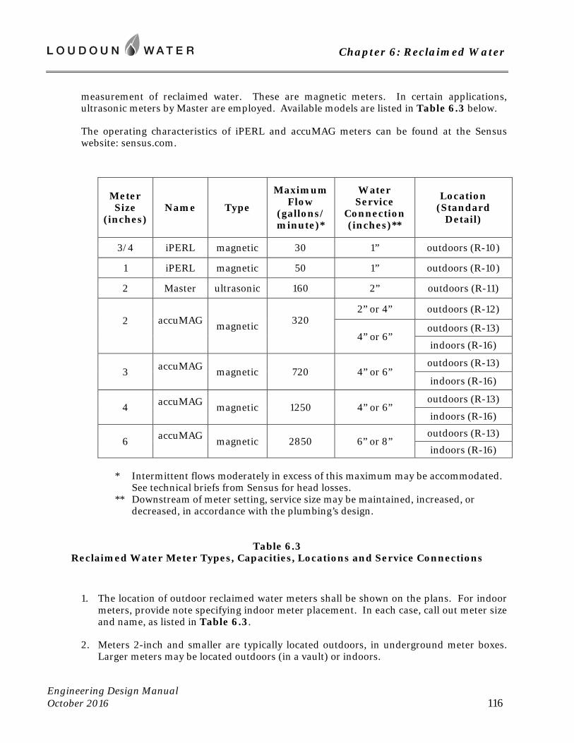
Chapter 6: Reclaimed Water
Engineering Design Manual October 2016 116
measurement of reclaimed water. These are magnetic meters. In certain applications, ultrasonic meters by Master are employed. Available models are listed in Table 6.3 below.
The operating characteristics of iPERL and accuMAG meters can be found at the Sensus website: sensus.com.
Meter Size
(inches) Name Type
Maximum Flow
(gallons/minute)*
Water Service
Connection (inches)**
Location (Standard
Detail)
3/4 iPERL magnetic 30 1” outdoors (R-10)
1 iPERL magnetic 50 1” outdoors (R-10)
2 Master ultrasonic 160 2” outdoors (R-11)
2
accuMAG magnetic 320
2” or 4” outdoors (R-12)
4” or 6” outdoors (R-13)
indoors (R-16)
3 accuMAG magnetic 720 4” or 6”
outdoors (R-13)
indoors (R-16)
4 accuMAG magnetic 1250 4” or 6”
outdoors (R-13)
indoors (R-16)
6 accuMAG magnetic 2850 6” or 8”
outdoors (R-13)
indoors (R-16) * Intermittent flows moderately in excess of this maximum may be accommodated.
See technical briefs from Sensus for head losses. ** Downstream of meter setting, service size may be maintained, increased, or
decreased, in accordance with the plumbing’s design.
Table 6.3 Reclaimed Water Meter Types, Capacities, Locations and Service Connections
1. The location of outdoor reclaimed water meters shall be shown on the plans. For indoor meters, provide note specifying indoor meter placement. In each case, call out meter size and name, as listed in Table 6.3.
2. Meters 2-inch and smaller are typically located outdoors, in underground meter boxes. Larger meters may be located outdoors (in a vault) or indoors.
Chapter 6: Reclaimed Water
Engineering Design Manual October 2016 117
3. See R-10, REUSE SERVICE FOR ¾”, AND 1” METERS; or R-11, 2” ACCUMAG REUSE METER of the Standard Details for desired placement of meter box. The meter box is to be located immediately behind the curb and as close as possible to the main. For meters of 1-inch and smaller sizes, grass area must be at least 2 feet wide. For 2-inch, the grass area shall be a minimum of 8 feet by 8 feet square.
4. For services of 3-inches and larger meters, the meter may be located in an outdoor vault or in an accessible mechanical room. Plans must specify the meter’s location and provide appropriate detail. See R-13, 3”, 4” OR 6” ACCUMAG REUSE METER IN VAULT and R-15, 3”, 4” OR 6” ACCUMAG REUSE METER INDOORS of the Standard Details for requirements. If an indoor setting is chosen, the service shall be an independent, privately owned branch from Loudoun Water’s reclaimed water main, constructed according to R-14, REUSE SERVICE ENTRANCE WITH INDOOR METERING.
5. Where meter is to be indoors, the site plan must specify that the building’s owner will provide these access features. Building construction plans must be coordinated accordingly.
a. a heated mechanical/meter room with a floor drain and sufficient wall space to accomplish piping as depicted on R-15, 3”, 4”OR 6” ACCUMAG REUSE METER INDOORS of the Standard Details.
b. a lockable exterior door from the meter room, with a key provided to Loudoun Water.
c. an outdoor drain capable of receiving 400 gpm, located within 75 feet of meter room door. This is needed during meter calibration.
d. where determined necessary, a remote transmitter installation on the outside of the building. Wire from meter to transmitter is to be within a dedicated PVC conduit, with run not exceeding 300 feet.
6. Landscaping is not permitted within 5 feet of the meter box.
6.6 Cross Connection and Backflow Prevention
The customer’s reclaimed water distribution system shall be in compliance with the cross connection control and backflow prevention requirements listed in local building and plumbing codes, the Cross Connection/Backflow Prevention Program (available at Loudoun Water’s website), and the Virginia Waterworks Regulations. Loudoun Water will require review of plumbing plans for any building being served by both reclaimed water and potable water. Review will ensure the physical separation of the systems within the building.
Service Line Protection -- For all services with outdoor meters 1.5-inch and larger, and all service to indoor meters, provide an approved backflow prevention device to accomplish the required service line protection. These devices are to be located in the building’s mechanical room, within the service entrance. This requirement shall be noted on the site plan.
Chapter 6: Reclaimed Water
Engineering Design Manual October 2016 118
Air Gap Required -- Potable water may be used to supplement reclaimed water for a reuse, provided there is an air gap separation of at least 8 inches or twice the pipe diameter, whichever is greater, between the potable water and the reclaimed water systems. A reduced pressure principle backflow prevention device installed at the potable water service connection to the reuse is only acceptable in certain, limited instances such as fire suppression systems, where an air gap is not practicable.
Shut off and dye testing procedures will be required prior to operation of a customer’s reuse system. The system’s operator is required to procure the dye for the test. The customer will conduct the cross connection/backflow test annually in the presence of Loudoun Water, to verify that no cross connections have been made.
6.7 Identification
All installations of reclaimed water facilities must conform to the Virginia Water Reclamation and Reuse Regulations, which contains specific requirements for marking, labeling, and cautionary signage. Where purple identification features are cited, the Regulation specifies the purple be Pantone 522. This purple is to be used wherever commercially available. Consult the Approved Materials List for suppliers. Where this purple cannot be attained, Safety Purple may be substituted.
A. Labeling and Marking of Underground Facilities
1. All reclaimed waterlines shall have identification tape permanently affixed on the top of the pipe, centered over the pipe. Identification tape shall be vinyl adhesive tape prepared with black print on a Pantone 522 purple field, or white print on Safety Purple; and having the words “CAUTION: RECLAIMED WATER – DO NOT DRINK.” The overall width of the tape must be at least 3 inches. Tape shall be parallel to the axis of the pipe, fastened at least every ten feet, to each pipe section, and continuously for the entire length of the pipe.
2. Beyond pavements, reclaimed waterlines shall be fitted with marking stakes, installed in accordance with G-5, STANDARD NOTES, and G-16, MARKER POSTS AND TRACER PEDESTALS, of the Standard Details.
3. All visible pipe within vaults and meter boxes, all valves, outlets, and other appurtenances shall be color coded, purple taped, labeled, tagged or otherwise marked to notify the public and employees that the source of the water is reclaimed water. All at-grade access points shall be consistently color coded purple and marked to differentiate reclaimed water facilities from potable water or wastewater facilities.
B. Labeling and Marking Above-Ground or Indoors
1. All pipe, valves, outlets, and other appurtenances shall be color coded, purple painted or taped, labeled/tagged, signed, and otherwise marked to notify the public and employees that the source of the water is reclaimed water.
Chapter 6: Reclaimed Water
Engineering Design Manual October 2016 119
2. All reclaimed water outlets shall be of a type, or secured in a manner, that permits operation by authorized personnel. Public access to reclaimed water outlets shall be controlled in areas where reclaimed water outlets are accessible to the public as follows:
a. If quick connection couplers are used on above-ground portions of the reclaimed water distribution system, they shall differ materially from those used on the potable water supply.
b. Above-ground hose bibs, spigots or other hand-operated connections used on the reclaimed water distribution system must differ materially from those used on the local potable water distribution system and must be clearly distinguishable as reclaimed water connections (i.e., painted purple, valve operation with a special tool) so as not to be mistaken for potable water connections.
c. Where below-grade vaults are used to house reclaimed water connections, the connections in the vault may have potable water distribution system thread and bib size service provided the bib valves can be operated only by a special tool. The below-grade vaults shall also be labeled as being part of the reclaimed water distribution system (i.e., painted purple, sign).
3. Areas irrigated with reclaimed water will display signage at the entrances to the area. See R-18 WARNING SIGNS AT REUSE FIXTURES of the Standard Details for an example of such a sign.
C. Conversion of Piping to Reclaimed Service
Appurtenances retrofitted for the purpose of distributing reclaimed water shall be color coded, purple painted or taped, labeled/tagged, signed, and otherwise marked. Underground, this identification need not extend the entire length of the system, but is required within 10 feet of locations where the reclaimed water distribution system crosses a potable water pipe or sanitary pipe. Any areas excavated during the conversion will be labeled.
6.8 Installation Requirements
All reclaimed waterlines and appurtenances shall be installed in accordance with best practice, with materials and workmanship of full quality. Materials and installation shall be in accordance with all applicable sections of American Water Works Association Standards. Installation shall conform with AWWA C600, Installation of Ductile Iron Water Pipes or AWWA C605, Standard for Underground Installation of PVC and PVCO Pressure Pipe and Fittings; with all manufacturers’ instructions and recommendations; and the provisions of this Manual. The installing contractor shall be solely responsible for ensuring that appropriate and acceptable construction materials, means and methods are used. Reuse of previously installed materials is prohibited, except where specifically approved by Loudoun Water.
Installation requirements for reclaimed water shall be the same as are listed for potable water at Section 4.6 of this Manual, except that bacteriologic sampling is not required. New reclaimed water main shall be disinfected and flushed, but sampling is not necessary. Water discharged during flushing shall be routed to sanitary sewer, unless arrangements have been
Chapter 6: Reclaimed Water
Engineering Design Manual October 2016 120
made with the Virginia Department of Environmental Quality (DEQ) to discharge into a storm drain or natural watercourse. Where such arrangements are approved by DEQ, dechlorination of discharge water is required. Sampling shall be performed to determine that residual chlorine is not present in the discharge. The flow must also be sampled for total suspended solids. The dates and volumes discharged, along with sample results will be reported to DEQ in the monthly report for the wastewater treatment facility. Where potable water pipe is being converted for reclaimed water distribution, conduct dye test in accordance with Loudoun Water’s Cross Connection/Backflow Prevention Program.
-- end of Chapter 6 --
Chapter 7: Community Water Systems
Engineering Design Manual October 2016 121
Chapter 7: Community Water Systems
7.1 Scope
A. Intent
These community water system standards have been authorized by the Statement of Policy concerning Community Water and Sewer Systems as adopted by Loudoun Water Board of Directors on December 15, 1989, as amended. As such, this chapter establishes requirements and standards for water systems designed and constructed on behalf of Loudoun Water. These standards are not intended to be all-inclusive. Loudoun Water will consider alternative means and methods to accomplish its objectives, based upon good engineering practice and demonstrated technical effectiveness, reliability, and cost-effectiveness.
B. Standards
The community water system standards presented herein shall supplement the latest edition of the Waterworks Regulations 12 VAC 5-590-10 et seq., as published by the Commonwealth of Virginia, Department of Health (VDH). The Waterworks Regulations represent the minimum design requirements set forth by VDH. All requirements of the Waterworks Regulations shall be adhered to. As the owner, Loudoun Water may identify and determine the need for standards and requirements that are more stringent than those contained in the Waterworks Regulations.
The headings and sub-headings of this chapter are based on the Waterworks Regulations. In instances where no additional requirements are specified, Waterworks Regulations shall apply as written.
C. Interpretation
Waterworks infrastructure shall meet all applicable requirements of this Manual. Loudoun Water will grant no exceptions to the requirements of these water system standards except where doing so provides a direct benefit to Loudoun Water.
7.2 Requirements Supplemental to Virginia Waterworks Regulations
A. Definitions
To 12 VAC 5-590-10 add the following:
“Applicant” means developer or property owner seeking approval of the Community Water System.
“Loudoun Water Design Standards” means Loudoun Water - approved procedures, methods and materials as promulgated in this Manual.
Chapter 7: Community Water Systems
Engineering Design Manual October 2016 122
“Community Water System” means any freestanding system to be owned and/or operated by Loudoun Water. Freestanding systems are not connected to Loudoun Water’s central water system.
“Major Process Equipment” means mechanically or electrically actuated process equipment requiring routine maintenance and specified in Divisions 11 through 16 of contract specifications formatted in accordance with the Construction Specifications Institute. Major process equipment includes pumping and treatment unit processes and associated electrical controllers.
“SCADA System” means Loudoun Water’s system control and data acquisition system for instrumentation, whereby equipment and processes are remotely monitored.
“Water Budget” means a quantitative accounting of volumes that are to be used in the community to be served, and the patterns of this usage, to include irrigation, if such is to be permitted.
“Waterworks Regulations” means the latest edition of the Waterworks Regulations 12 VAC 5-590, as published by the Commonwealth of Virginia, Department of Health.
B. Administration of Regulations
To 12 VAC 5-590-40 add the following:
Loudoun Water, which shall become the owner and operator of the facility that is to be designed and constructed, is responsible for definition and specification of standards, including equipment, and materials and design criteria.
C. Reserved Section
To 12 VAC 5-590-90 add the following:
1. The service area of any Community Water System shall be as reviewed by Loudoun Water and approved by the Loudoun County Board of Supervisors. The Applicant shall provide a certificate from the Loudoun County Zoning Administrator, establishing that the area to be served by the proposed water system has been zoned for the particular land use or uses described in the application.
2. If, in the future determination of Loudoun Water, the system may be connected to another water system, Loudoun Water may do so at its discretion, but in accordance with the requirements of Loudoun County.
3. The Community Water System shall be approved by Loudoun Water. Loudoun Water will only consider for approval, groundwater systems not influenced by surface water. As owner and operator, Loudoun Water represents the future customers who will depend on a reliable and durable facility. As such, Loudoun Water reserves the right of approval. Before agreeing to accept any Community Water System, Loudoun Water shall review and approve all design documents applicable to that system, including the Basis of Design, Preliminary Engineering Report, and Plans and Specifications. Said review and approval shall be in accordance with these standards and shall be in addition to, and take
Chapter 7: Community Water Systems
Engineering Design Manual October 2016 123
precedence over, required approvals by county, state, and federal authorities. Loudoun Water’s procedure is shown by the chart “DESIGN REVIEW PROCESS” in Appendix D of this Manual. This procedure shall govern all review and approvals. The procedure requires that Loudoun Water approve a “Basis of Design” prior to the Preliminary Engineering Conference required by the VDH. It also requires approval of a “Preliminary Engineering Report” prior to submitting the official Engineer’s Report to VDH.
4. Community Water Systems shall be constructed at no cost to Loudoun Water. In order to ensure standardization, reasonable equipment inventories, and compatibility with efficient maintenance procedures, the design and construction shall be in accordance with all applicable sections of this Manual, and the Waterworks Regulations.
5. Each Community Water System shall be financially self-sustaining. Loudoun Water has adopted a single rate structure for all developer initiated Community Systems. A “Cost of Service Review”, consisting of a rate study, shall be provided to Loudoun Water for review no later than the final submission of the plans and specifications. The review shall determine annual costs for a five-year basis, replacement costs for 40 years, and determine how anticipated costs and revenues compare. If the cost of service over a 40 year like-cycle exceeds the anticipated revenue then the Applicant must submit a Revenue Equalization Fee payable in installments, once the system is operational. As such, operating, maintenance, repair and replacement, and upgrade costs shall be borne by the owners of all properties within the service area for said system and a notice to this effect shall be recorded in each homeowner’s covenant. In the interest of economy-of-scale, a mandatory connection provision may be required by Loudoun Water Board for inclusion within the homeowner’s covenant.
6. Adequate construction and maintenance easements or access rights-of-way for all Community Water Systems shall be provided for future extensions as well as new infrastructure. Perpetual easements in lieu of fee simple property for pumping stations and treatment facilities shall not be provided unless specifically approved by Loudoun Water.
7. Community Water Systems shall require an Agreement (Water Agreement) between Loudoun Water and the Applicant. The Water Agreement shall require the Applicant to subsidize the operation and maintenance of the waterworks until such time that 90 percent of the units within the development are sold and connected to the system. The Applicant shall agree to perform all construction in accordance with the plans and specifications approved by Loudoun Water and in accordance with Loudoun Water standards. Applicant shall agree to transfer to Loudoun Water all property and facilities free of debts, liens and/or other legal encumbrances, for ownership, operation and maintenance. The Water Agreement shall be completed prior to issuance of the Construction Permit by Loudoun Water.
8. The design of the Community Water System shall incorporate such features as are determined by Loudoun Water to be warranted, to facilitate system expansion or upgrade of treatment processes in the future. This may include branches of pipe, valves, vaults, and reserved spaces for the future addition of Major Process Equipment.
Chapter 7: Community Water Systems
Engineering Design Manual October 2016 124
9. As the applicant identifies well sites, the proposed well locations must be submitted to Loudoun Water for informational purposes. Loudoun Water must be given notification and access, so that drilling and well development can be monitored. Where conditions warrant, Loudoun Water may require special steps in commissioning the well, to assure and verify its performance. Failure to make the well available for Loudoun Water’s inspection during its drilling and development may result in the well being ineligible for acceptance as a water source for the project.
10. Wells must be developed in conformance with the Loudoun County Facilities Standards Manual, including its requirements for investigation of the site’s hydrogeology, with corresponding reporting and testing. Loudoun Water will be furnished with these reports and test results by the Applicant.
11. Once the system is operational, Loudoun Water will operate the system under a contract with the Applicant for at least one year, prior to the system being accepted for Loudoun Water’s ownership.
D. Variances
To 12 VAC 5-590-140 add the following:
The applicant may apply to Loudoun Water for variances to these Community Water Standards provided the variance requests are made in writing to Loudoun Water.
E. Construction Permits
To 12 VAC 5-590-200 add the following:
1. Refer to Chapter 3 of this Manual for complete permitting and bonding procedures. General requirements for permits are as described below.
2. Loudoun Water must review and approve the construction drawings, plans and specifications for a project prior to issuing Loudoun Water’s Construction Permit. This construction permit references the executed Community Water System Agreement between Loudoun Water and the developer, and summarizes terms and conditions between the parties. A Waterworks Permit is required from the Virginia Department of Health, executed by a Virginia licensed Professional Engineer.
Upon approval, Loudoun Water will send notice and a Construction Permit for execution by the project’s developer. The following items must be in place prior to execution of Construction Permit by Loudoun Water:
a. Performance Bond and Labor and Materials Payment Bond
b. Certificate of Insurance, naming Loudoun Water as additional insured
c. payment of balance (if any) of Plan Review Fee
d. payment of Inspection Fee
Chapter 7: Community Water Systems
Engineering Design Manual October 2016 125
e. digital data reflecting the approved construction plans
f. executed Agreement
g. conveyance and recordation of supporting easements
Once all necessary items are in place, Loudoun Water will fully execute the permit and send approved plans and permit to the Inspections Department for pre-construction meeting.
3. Prior to commencement of construction, a mandatory pre-construction conference shall be held and a list of major process equipment shop drawings to be reviewed by Loudoun Water shall be established. The applicant shall submit its proposed agenda to Loudoun Water for approval at least 7 days prior to the conference.
F. Formal Requirements for the Submission of Engineering Data
To 12 VAC 5-590-210 add the following:
1. In accordance with Appendix D of this Manual, provide a Basis of Design Report which shall include:
a. Proposed Service Area, including a detailed vicinity map, showing individual lots within the proposed subdivision; the required system capacity (based on number of proposed lots and Loudoun Water-required flow rates); and the number of wells.
b. Treatment Technology to include applicable (and Loudoun Water acceptable) treatment technologies; provide a process flow diagram for each unit process.
c. If necessary, like-cycle cost comparisons among competing technologies considering initial and replacement costs, maintenance costs, operational costs and reliability.
d. For selected treatment technology, provide design criteria, catalog cut sheets of major process equipment, and a detailed process flow diagram showing number of units and capacities of the major process equipment components. Design criteria must meet the more stringent of the Waterworks Regulations or Loudoun Water standards. Calculations shall include hydraulics, process chemistry, anti-flotation calculations, and water hammer analyses. Water hammer analyses may be waived by Loudoun Water for booster pumping station capacities less than 500 gallons per minute, or station pressures less than 50-feet total dynamic head. Systems where column separation can occur shall have water hammer analyses conducted.
2. Before Loudoun Water will review the applicant’s plans and specifications, the Applicant must pay applicable engineering review fees as described in the Rates, Rules and Regulations for Community Systems. Plan review will not commence until all plans, including architectural, site/civil, and electrical/mechanical are submitted to make a complete package.
Chapter 7: Community Water Systems
Engineering Design Manual October 2016 126
G. Issuance of the Operation Permit
To 12 VAC 5-590-260 add the following:
1. The Applicant shall complete and submit the “Statement of Completion of Construction” to the VDH upon its satisfaction that the Treatment Works meets the requirements of the approved plans and specifications and only when a final inspection by the VDH is warranted. Loudoun Water shall approve the “Statement of Completion of Construction” prior to the Applicant submitting it to the VDH.
2. The Applicant shall maintain record drawings of as-built conditions that vary from the work as originally shown on the contract drawings. The Applicant shall submit electronic files of the record drawings within 30 days after completion of construction and prior to acceptance of the facility by Loudoun Water. Provide coordinates for field location of valves, manholes, and other buried facilities. For required electronic format, see Chapter 3 of this Manual.
3. Draft and Final Operation and Maintenance Manuals must be approved by Loudoun Water before substantial completion and prior to submittal to the VDH for approval.
H. Inspection and Correction
To 12 VAC 5-590-270 add the following:
1. Loudoun Water will accept or reject shop drawings for major process equipment and provide inspection of the Community Water Systems in accordance with the Community Water System Agreement. All shop drawing submittals shall bear the stamp of approval of the Applicant as evidence that the Applicant has checked the shop drawings. Submittals without this stamp of approval will not be reviewed and will be returned to the Applicant for resubmission. The Applicant shall cite in the letter of the transmittal all shop drawing variances from the requirements of the contract Documents and the design modifications proposed to accommodate the variances. If variances are not cited, the Applicant will not be relieved of the responsibility for executing the work in full conformance with the Contract Documents even though such submittals have been accepted by Loudoun Water.
2. Pumps and other major process equipment shall be certified by the manufacturer. Certifications shall be provided to Loudoun Water prior to shipping to the site.
I. General
To 12 VAC5-590-640 add the following:
Plans shall be submitted in accordance with the requirements of Chapter 3 of this Manual.
J. Capacity of Waterworks
To 12 VAC 5-590-690 add the following:
Chapter 7: Community Water Systems
Engineering Design Manual October 2016 127
1. The applicant for the proposed system will prepare a Water Budget for the community, to establish the quantity and patterns of usage that may be anticipated. Irrigation (if any) must be considered in this accounting. Unless otherwise determined by Loudoun Water upon review of the Water Budget, the system will be designed to meet a maximum daily demand of 900 gallons per equivalent residential connection.
2. Treatment process units shall be sized to match the well pumping capacity.
3. It is strongly recommended that where underground irrigation systems are to be allowed within the community, that a separate water system with a separate source of water be constructed to serve irrigation. Under this arrangement, the irrigation supply and potable water system are to be designed as hydraulically independent of one another.
4. Minimum acceptable effective storage for domestic purposes shall be not less than 450 gallons per equivalent residential connection while maintaining minimum working pressures. Storage for fire suppression shall be in addition to that demanded by service connections.
5. Minimum working pressure at service connections shall be 50 psi at peak hourly flow rates under build-out conditions, and with system equalization storage at either low level or low pressure.
6. All groundwater systems shall provide the number of wells that are anticipated to be capable of continuously pumping no less than 1.2 gpm per connection for 60 consecutive days.
7. Groundwater systems having more than fifty connections shall have wells as indicated below, all wells having been determined to be independent of one another in hydrogeology. All well yield combinations stated below refer to the minimum pumping test rates to be used during a 72 hour groundwater testing program, as described in Section P Groundwater Sources (12 VAC 5-590-840) of this chapter.
Provide three wells, with each producing a minimum of 0.6 gpm per connection. Two wells shall be in service. The third well shall be identified and developed and reserved as a backup well with the required easements. Once the development reaches 60% of build-out, Loudoun Water will assess whether the raw water line and the reserve well must be placed in service.
Provide four or more wells, the two smallest of which shall produce a combined minimum of 0.6 gpm per connection and with the smallest well producing at least 0.12 gpm per connection. A standby well shall undergo initial hydro geological testing and be reserved as a backup well with the required easements. Once the development reaches 60% of build-out, Loudoun Water will assess whether the raw water line and backup well must be developed by the applicant and placed in service. Wells in service shall produce a minimum of 1.2 gpm per connection.
8. Groundwater systems serving 26 to 50 connections shall have at least 2 wells producing a combined total of 1.8 gpm per connection, the smallest of which must produce a minimum of 0.6 gpm per connection.
Chapter 7: Community Water Systems
Engineering Design Manual October 2016 128
9. Groundwater systems serving 25 or fewer connections shall have at least 2 wells producing a combined total of 2.4 gpm per connection, the smallest of which must produce a minimum of 0.6 gpm per connection.
10. Within the Limestone Overlay District, the potential for well failure is greater. Therefore, all such groundwater systems shall have in addition to what is stated above, at least one additional standby well, developed and capable of producing at least 0.3 gpm per connection.
11. Unless otherwise approved by Loudoun County, Community Water Systems shall have fire flow capability. System design will be based on the following criteria, but not less than that established by Loudoun County Ordinance, Chapter 1042.03:
a. Less than 100 homes – 250 gpm for 2 hours plus maximum daily demand at 20 psi minimum
b. 100 to 199 homes – 500 gpm for 2 hours plus maximum day demand at 20 psi minimum
c. More than 200 homes – 750 gpm for 2 hours plus maximum day demand at 20 psi minimum
d. Distribution mains conveying water for fire suppression shall be of a minimum 6-inch diameter.
K. Site Layout
To 12 VAC 5-590-710 add the following:
1. Provide exterior lighting around all major process equipment and controls with luminance ranging from 10 to 20 foot-candles.
2. Facilities shall be enclosed by steel security fence. Fence shall provide adequate clearance for maintenance, snow removal and other required activities. Fencing shall be black, PVC-coated (ASTM F668 Class 2b) chain link (8 feet fabric height) with 6 barbed wire strands (3 facing in, 3 facing out) on top. Gateposts shall be 4 inches in diameter and corner posts shall be 2.625 inches in diameter. Provide pad lock per Loudoun Water standard with a shank size of ¼-inch in diameter.
3. Provide facility address sign at facility entrance in accordance with County standards.
4. Building sites shall have access by roadways a minimum of 12 feet wide, with maximum 8% slope, and minimum 50-foot radius of horizontal curvature. Surfaces of roadways and parking areas are to be bituminous concrete equal to a minimum of 3 inches of intermediate mix (IM1-A) on 6 inches of 21A subbase. A minimum of 3 parking spaces shall be provided. A turnaround area shall be provided for large trucks, turning at a 50-foot radius. Roadways to treatment and pumping facilities shall be gated. The gates shall have reflectors. In cases where the treatment plan and/or pumping facility are fenced, the gate shall be a fenced gate with pad lock per Loudoun Water standard with a shank
Chapter 7: Community Water Systems
Engineering Design Manual October 2016 129
size of ¼-inch in diameter. Where the treatment plant and/or pumping facility is not fenced, the gate shall be constructed in accordance with Loudoun Water’s standards.
5. Provide antenna needed by the Loudoun Water’s SCADA, in accordance with the current standards for that system.
6. Provide antenna, data collector, and communications service needed by the Loudoun Water’s automated meter reading system, whereby meters within the associated distribution system will be monitored. This may be located at the site of a well, treatment, or water storage.
L. Building Layout
To 12 VAC 5-590-720 add the following:
1. Provide suitable architectural treatment. Brick/block shall be provided. Provide quality interior block filler and paint. Split-faced CMU with foam insulation may also be used. Slope roofs and provide aluminum gutters with leaf guards and downspouts. Use standing seam metal roof with Kynar finish for high visibility areas. Soffit and fascia shall be of low maintenance vinyl materials. Provide insulated, moisture-resistant, painted drywall finish on interior walls and ceilings in laboratory office and hypochlorite storage areas in accordance with Loudoun County code for residential occupancy.
2. A minimum laboratory space of 400 square feet shall be provided, unless Loudoun Water determines that another of Loudoun Water’s laboratories can serve this purpose. Note that sufficient work space and equipment must be provided in the building for daily operational tests.
3. Floor slabs within all building shall be steel reinforced and shall be sloped 1/8-inch per foot to a floor drain. Floor to have power-trowel finish and waterproofing sealer applied. Provide Dri-deck in potential spill areas. Provide industrial grade vinyl tile, or equal, for office and laboratory areas. Floor drains shall be provided in laboratory and lavatory. Well blow-off line and floor drain shall have separate discharge piping to grade (if possible) with a screened or capped discharge end.
4. Provide minimum 3 feet separation between all equipment and walls or other equipment.
5. Provide standard Loudoun Water building inventory to include maintenance equipment, safety equipment, supplies, shelving, desk and chair, and file cabinet for on-site record storage.
6. Provide lightning arrestor/protection for each well house and treatment plant.
7. Provide running time meters for all pumps.
8. Doors shall have a closer and wall mounted hook doorstop, and replaceable cores with keys matched to Loudoun Water standard.
9. Intake and exhaust louvers shall have stainless steel insect screens. Provide gravity dampers with PVC seal strips.
Chapter 7: Community Water Systems
Engineering Design Manual October 2016 130
10. Electrical equipment shall meet the following Loudoun Water standards:
a. Breakers are to be made by Square D or Cutler-Hammer.
b. Provide automatic reset and startup for all electrical relays.
c. Provide GFI protected electrical receptacles on all interior walls, a maximum of 12 feet apart.
d. Exterior control panels shall be stainless steel NEMA 4X. Interior control panels shall be fiberglass NEMA 4X.
e. Do not mount equipment and electrical panels on tanks or wet wells.
f. Provide lights over all exterior doors.
g. Provide GFI protected electrical outlets all four exterior sides or every 40 (horizontal) feet.
h. Conduct arc flash study and make corresponding provisions to ensure operator safety. Design system to Class 2 or lower rating for arc flash.
11. Process equipment shall be fitted for monitoring the flow of raw and finished waters, using flow indicators, totalizers and digital recorders. Flow meters 1.5-inch and larger will be electromagnetic type, fitted with appropriate options. Acceptable flow meters are Badger M3000 Series or Invensys FOXBORO 9100 Series.
12. Instrumentation shall be integrated with Loudoun Water’s SCADA, in accordance with the current standards for that system. Should it be determined that the community is too remote to receive a signal from this system, then provisions will be made for possible future integration.
13. Provide heat and air conditioning in laboratory and sodium hypochlorite storage rooms.
14. Where emergency generator is to be indoors, it shall be in a room dedicated to this purpose.
15. At Loudoun Water’s discretion, a lavatory (toilet, sink, and shower with a 30-gallon water heater) may be required to serve operators of the community system. Where building is fitted with water distribution plumbing, there will be a strainer installed immediately upstream of the backflow prevention device that constitutes the service line protection.
M. Maintenance and Servicing of Equipment
To 12 VAC 5-590-740 add the following:
1. Specifications for major process equipment shall include provisions for start-up, testing and training of Loudoun Water personnel in operation and maintenance of the equipment. Minimum training provided shall include 2 separate days of on-site instruction to allow attendance by different shifts of Loudoun Water personnel.
Chapter 7: Community Water Systems
Engineering Design Manual October 2016 131
Instructors shall be certified by the equipment manufacturers as competent to provide the required training.
2. At the option of the Loudoun Water, the applicant shall provide a lump sum payment to Loudoun Water equal to 3 percent of the construction costs of major process equipment in lieu of manufacturer-recommended spare parts. Under this option, Loudoun Water will order and store spare parts.
N. Wall Castings
To 12 VAC 5-590-780 add the following:
Pipe through floor or wall shall have Omni Sleeve by Sigma or Loudoun Water approved equal.
O. Disinfection
To 12 VAC 5-590-800 add the following:
Use of chlorine gas is prohibited.
P. Groundwater Sources
To 12 VAC 5-590-840 add the following:
1. Hydrogeologic study is required per Loudoun County requirements, and shall be approved by Loudoun County Health Department and a copy provided to Loudoun Water for review and comment. All wells shall be Class I construction.
2. A 100-foot radial or a square, 200 feet by 200 feet, well lot will be required as a minimum for each well.
3. Wells shall not be located within any major 100-year flood plain (per Loudoun County codified ordinance).
4. A 72-hour yield test followed by recovery test must be performed. If more than one well is proposed, the yield and recovery tests must be sufficiently overlapping for all the wells so as to confirm that wells do not influence each other during pumping. Wells located in karst geology will be subject to additional testing requirements to assure their suitability. Note that Loudoun Water requires minimum of 1.2 gpm production for each residential connection to the system. Well yield and drawdown information will be subject to disapproval if the information is older than 5 years, is not performed simultaneously with other nearby proposed wells, or negatively impacts nearby preexisting wells.
5. A total of 20 water samples for total coliform analysis using MPN method must be collected from each well. Samples must be collected in accordance with an approved plan starting 8 hours after the yield test has begun. This groundwater sampling plan will be submitted to Loudoun Water as indicated below. If concentration of total coliform in any sample is greater than 3, the sample must further be analyzed for presence of fecal coliform.
Chapter 7: Community Water Systems
Engineering Design Manual October 2016 132
6. Water samples for complete chemical, physical and radiological analyses must be collected towards the end of the yield test, e.g., 70th hour for 72-hour test. List of the parameters to be analyzed must comply with the most recent edition of these Waterworks Regulations and any upcoming federal regulations.
7. A daily log of weather conditions during the pumping test program must be kept by the driller. The log must include rain events and their magnitude.
8. Results of all sample analyses shall be submitted to Loudoun Water and to the Virginia Department of Health if required, as part of the overall hydrogeology report.
9. A written schedule of events shall be submitted to Loudoun Water 2 weeks prior to start of the above evaluation. Loudoun Water normally will provide comments within five days after receipt.
10. Any negative impact to surrounding wells is unacceptable and must be addressed by the applicant to the satisfaction of the respective owners of the wells.
11. Well head protection measures shall be employed in accordance with the Handbook for Developing a Public Water Supply Well, published by the Virginia Department of Health.
Q. General
To 12 VAC 5-590-850 add the following:
1. Treatment systems shall be based on conventional technology and be supported by references, as required by Loudoun Water, from 5 similar systems, each with at least 3 years of successful operation at build-out capacity. Examples of conventional technology are manganese greensand filters for iron, manganese, and radium removal; membrane filtration; chlorination for disinfection; ultraviolet (UV) disinfection; sequestration for low levels of iron and manganese; and the addition of VDH-approved chemicals for corrosion control.
R. Chemical Application
To 12 VAC 5-590-860 add the following:
1. Chemical systems utilizing sodium hypochlorite shall utilize 15%-50% solutions per AWWA B300 standard, depending on the feed rate and storage time.
2. Chemical feed systems shall use liquid solutions or, if approved by Loudoun Water, liquid solutions prepared from dry chemicals. A spare chemical feed pump shall be provided for each system. Adequate facility room and climate control shall be provided for bulk chemical storage and solution day tanks, as Loudoun Water deems necessary.
3. The applicant shall provide secondary containment for day solution tanks and raw chemical drums, adequate raw chemical transfer equipment, and calibration tubes for all chemical feeders. Size chemical feeders to operate near middle of capacity range. Provide separate chemical storage room and ventilation for highly corrosive chemicals.
Chapter 7: Community Water Systems
Engineering Design Manual October 2016 133
4. Chemical feed systems shall have:
a. peristaltic type feed pumps with an anti-siphon valve and backpressure valve at the discharge.
b. Dry tanks and transfer pumps where required to make up 15% feed solutions.
c. chemical feed tubing as specified in Table 7.1 of this Chapter. Support tubing with lengths of Schedule 40 PVC pipe, with chamfer cut ends.
d. translucent solution tank with liquid level scale and weight scale.
e. vacuum breaker on makeup water spigot when hoses are used.
f. room temperature control for hypochlorite storage.
g. protective equipment (rubber apron, rubber gloves, combination face shield/head gear, safety shower and eyewash station).
S. Disinfection
To 12 VAC 5-590-1000 add the following:
1. Where groundwater source is in a karst topography, the risk of contaminants in the groundwater is higher. Therefore, in addition to the chlorination system, Loudoun Water may require UV disinfection.
2. In karst topographies where there are insufficient soil strata to act as a filter for groundwater recharge, Loudoun Water may further require filtration by membranes. Parameters to be considered in the determination to use membrane filtration are presence/absence of E-coli, Microscopic Particle Analysis result in excess of 15, and/or Total Coliform count greater than 100.
T. Groundwater Facilities
To 12 VAC 5-590-1030 add the following:
1. Well meter shall have counter that has readout suitable for RTU service.
2. Drawdown gauges and airlines are prohibited. Provide Loudoun Water approved level transducer, with data logger, installed inside protective HDPE conduit.
3. Electric power cables shall be attached to the pump riser with approved plastic fasteners. Adhesive tapes are prohibited.
4. Well pumping controls shall be based on storage tank level, shall have remote LCD tank level indicators, and shall include provisions for future wells.
5. Alarms are to be transmitted by telephone auto dialer. Instrumentation shall also be integrated with Loudoun Water’s SCADA, in accordance with the current standards for
Chapter 7: Community Water Systems
Engineering Design Manual October 2016 134
that system. Should it be determined that the community is too remote to receive a signal from this system, then provisions will be made for possible future integration.
6. Dry, normally open contacts will be provided for all status and alarm circuits. This will include pump run/fail, generator run/fail, AC power status, generator starting system loss of charge, and pump overload. Both audible and visual alarms will be provided at the pumping station. A press-to-test circuit will be installed for all of the control and alarm panel indicator lights. Generator fail and power fail alarms shall function upon complete loss of power. All alarms shall clear after events and return to normal (no latching alarms to SCADA). An antenna pole or tower will be installed at the station near the control building for the SCADA antenna. The location of the antenna pole will be shown on the project plans.
7. At a minimum, the following telemetry shall be provided at each pumping station:
a. Pump On (each pump)
b. Pump Fail (each pump)
c. Flow Rate/Total
d. Tank Level with High Water Alarm and Low Water Alarm
e. Loss of Primary Power
f. Generator Standby/Secondary Power On/Generator Failure
g. Generator Fuel Low
h. Building/Hatch Intrusion Alarm
i. UPS Run/Fail
j. Building Temperature Alarm
8. Standby generator (or at Loudoun Water’s discretions, a NEMA 4X capped receptacle, 4P5W design of adequate rating for portable generator) shall be provided with the capability to power the closest water supply well, and any booster pumps, to meet the peak demand. Fuel storage will be adequate for 36 hours of operation. Generator shall be by Cummins Onan.
9. Well house piping shall utilize:
a. separate blow-off lines and floor drains. Provide blow-off lines downstream of the meter and check valve.
b. concrete headwalls and rip rap for termination of drain lines. Cover flanged discharge opening with #4 mesh stainless steel screen and bolted flange.
Chapter 7: Community Water Systems
Engineering Design Manual October 2016 135
c. Omni Sleeve by Sigma or other Loudoun Water approved system for all pipes passing through slabs or walls.
d. Dresser couplings.
e. straight pipe at least 5 times the pipe diameter prior to meters.
f. 12 inches of vertical clearance between floors and flanges.
g. ¾-inch brass ball valves for sample taps.
10. Wells in remote locations shall be housed and fenced.
U. Pump Stations
To 12 VAC 5-590-1040 add the following:
1. Pumping stations shall be protected against lightning.
2. Pump motors 7.5 horsepower and larger shall be 480 volt and shall be equipped with reduced-voltage starters. Ramp up and ramp down time shall each be limited to 3 seconds.
3. Standby generator (or at Loudoun Water’s discretions, a NEMA 4X capped receptacle, 4P5W design of adequate rating for portable generator) shall be provided with the capability to power the closest water supply well, any booster pumps, and any air compressors, so as to meet the peak demand. Fuel storage will be adequate for 36 hours of operation. Generator shall be by Cummins Onan.
4. Telemetry and instrumentation shall be provided as described above for groundwater pumping facilities.
V. General
To 12 VAC 5-590-1080 add the following:
1. Storage tanks for community systems shall be glass-lined bolted tanks conforming to AWWA D103. Glass-lined tanks shall have:
a. copolymer caps on all interior and exterior nuts and bolts.
b. fall prevention system and 2 climbing harnesses. Provide foldback on ladder to prevent unauthorized entry.
c. curbed, sleeved and sealed float tube entrance through the roof.
d. drain tank sump within the concrete foundation.
e. ductile iron pipe, in accordance with Table 7.1 of this Chapter.

Chapter 7: Community Water Systems
Engineering Design Manual October 2016 136
f. independently valved tank drain.
g. adequate roof vent area for draining (vacuum) and filling.
h. lightning protection.
i. 2 lockable access hatches on opposite ends of tank shell bottom.
j. standard cobalt-blue exterior finish unless otherwise approved.
k. brackets on tank roof for future attachment of 2 communications antennae.
l. a foundation design with adequate capacity to increase tank volume by 25 percent.
m. provision for disinfecting and filling of the tank by the contractor.
2. Provide a valved connection between the well supply and the gravity storage tank suitable for a portable truck hook-up in case the gravity tank is taken off-line for maintenance or repair.
W. Distribution Storage
To 12 VAC 5-590-1100 add the following:
1. Gravity storage (elevated tank, reservoir or standpipe) facilities shall be used where possible. If one or more hydro pneumatic tanks are required, at least 2 booster pumps shall be provided for each tank. The maximum-hour domestic demand flow shall be met with the largest pump offline.
2. Elevated tanks and standpipes shall be provided with ladders incorporating the Miller VI-GO™ fall prevention system. For standpipes, provide separate inlet and outlet lines with weep hole near bottom of internal inlet. Floats and electrodes are prohibited within tanks. Provide ultrasonic level transmitter.
3. Hydropneumatic tank systems shall be provided with lead/lag air compressors.
4. Telemetry and instrumentation shall be provided as described above for groundwater pumping facilities.
X. Materials
To 12 VAC 5-590-1110 add the following:
1. Piping materials shall be provided in accordance with Loudoun Water’s Approved Materials List and Table 7.1 below.
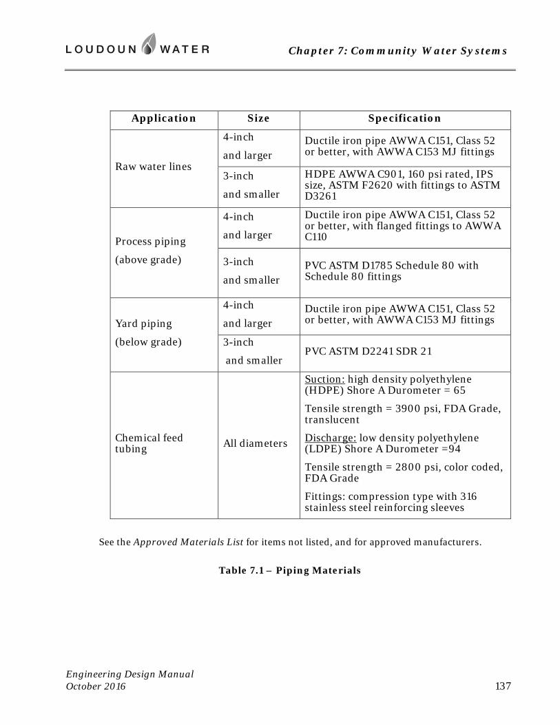
Chapter 7: Community Water Systems
Engineering Design Manual October 2016 137
Application Size Specification
Raw water lines
4-inch
and larger Ductile iron pipe AWWA C151, Class 52 or better, with AWWA C153 MJ fittings
3-inch
and smaller
HDPE AWWA C901, 160 psi rated, IPS size, ASTM F2620 with fittings to ASTM D3261
Process piping
(above grade)
4-inch
and larger
Ductile iron pipe AWWA C151, Class 52 or better, with flanged fittings to AWWA C110
3-inch
and smaller PVC ASTM D1785 Schedule 80 with Schedule 80 fittings
Yard piping
(below grade)
4-inch
and larger Ductile iron pipe AWWA C151, Class 52 or better, with AWWA C153 MJ fittings
3-inch
and smaller PVC ASTM D2241 SDR 21
Chemical feed tubing All diameters
Suction: high density polyethylene (HDPE) Shore A Durometer = 65
Tensile strength = 3900 psi, FDA Grade, translucent
Discharge: low density polyethylene (LDPE) Shore A Durometer =94
Tensile strength = 2800 psi, color coded, FDA Grade
Fittings: compression type with 316 stainless steel reinforcing sleeves
See the Approved Materials List for items not listed, and for approved manufacturers.
Table 7.1 – Piping Materials
Chapter 7: Community Water Systems
Engineering Design Manual October 2016 138
Y. System Design
To 12 VAC 5-590-1130 add the following:
1. A computerized hydraulic analysis of the distribution system shall be submitted to Loudoun Water for review and approval. See Chapter 4 of this Manual for requirements.
2. Water distribution system design shall comply with Chapter 4 this Manual.
-- end of Chapter 7 --
Chapter 8: Community Wastewater Systems
Engineering Design Manual October 2016 139
Chapter 8: Community Wastewater Systems
8.1 Scope
A. Intent
These community wastewater system standards have been authorized by the Statement of Policy Concerning Community Water and Sewer Systems as adopted by Loudoun Water’s Board of Directors on December 15, 1989. As such, this document provides requirements and standards for wastewater systems designed and constructed on behalf of Loudoun Water. These standards are not intended to be all-inclusive. Loudoun Water will consider alternative means and methods to accomplish its objectives based upon good engineering practices and demonstrated technical effectiveness, reliability and cost effectiveness.
B. Standards
The community wastewater system standards presented herein shall supplement the latest edition of the Sewage Collection and Treatment (SCAT) Regulations 9 VAC 25-790, as published by the Commonwealth of Virginia, Department of Environmental Quality (DEQ). The SCAT Regulations represent the minimum design requirements. All requirements of the SCAT Regulations shall be adhered to. As the owner, Loudoun Water may identify and determine the need for standards and requirements that are more stringent than those contained in Part III of the SCAT Regulations.
The headings and sub-headings of this chapter are based on the SCAT Regulations. In instances where no additional requirements are specified, the SCAT Regulations shall apply as written.
If the proposed system uses a soil-based effluent discharge, wastewater infrastructure shall meet the requirements of the latest edition of the Sewage Handling and Disposal Regulations 12 VAC 5-610, as published by the Commonwealth of Virginia, Department of Environmental Quality.
If reuse of reclaimed wastewater is to be practiced at locations other than the wastewater treatment plant site, the project shall adhere to the Water Reclamation and Reuse Regulation 9 VAC 25-740-10 et seq.
C. Interpretation
Wastewater infrastructure shall meet the applicable requirements of this Manual. Loudoun Water will grant no exceptions to the requirements of these standards, except where doing so provides a direct benefit to Loudoun Water.
8.2 Requirements Supplemental to SCAT Regulations
A. Definitions
To 9 VAC 25-790-10 add the following:

Chapter 8: Community Wastewater Systems
Engineering Design Manual October 2016 140
“Applicant” means the developer or property owner seeking approval of the Community Wastewater System.
“Loudoun Water Design Standards” means Loudoun Water-approved procedures, methods, and materials as promulgated in this Manual.
“Community Wastewater System” means any free-standing system to be owned and/or operated by Loudoun Water. Free-standing systems are not connected to Loudoun Water’s central wastewater system.
“Major Process Equipment” means mechanically or electrically actuated process equipment requiring routine maintenance and specified in Divisions 11 through 16 of contract specifications formatted in accordance with the Construction Specifications Institute. Major process equipment includes, but is not limited to, pumping and treatment unit processes and associated electrical controllers, motor control center, SCADA equipment, and standby generator/transfer switch.
“SCADA System” means Loudoun Water’s system control and data acquisition system for instrumentation, whereby equipment and processes are remotely monitored.
B. Extent
To 9 VAC 25-790-30 add the following:
1. The service area of any Community Wastewater System shall be as reviewed by Loudoun Water and approved by the Loudoun County Board of Supervisors. A copy of the site plan permit also is required of the applicant. If, in the future determination of Loudoun Water, the system may be connected to another water system, Loudoun Water may do so at its discretion.
2. The Community Wastewater System shall be approved by Loudoun Water. As owner and operator, Loudoun Water represents the future customers who will depend on a reliable and durable facility. As such, Loudoun Water reserves the right of approval. Before agreeing to accept any Community Wastewater System, Loudoun Water shall review and approve all design documents applicable to that system, including the Basis of Design, Preliminary Engineering Report, and Plans and Specifications. Said review and approval shall be in accordance with these standards and shall be in addition to, and take precedence over, required approvals by County, State, and Federal authorities. Loudoun Water’s procedure is shown by the chart “DESIGN REVIEW PROCESS” in Appendix D of this Manual. This procedure shall govern all reviews and approvals. The process allows the Design Engineer to apply for a VPDES or VPA permit directly to the Department of Environmental Quality (DEQ), but thereafter requires that Loudoun Water approve a Basis of Design prior to the Preliminary Engineering Conference. It also requires approval of a Preliminary Engineering Report prior to submitting the official Preliminary Engineering Proposal to DEQ. Applications to DEQ shall be made with the knowledge and approval of Loudoun Water who, acting as owner and operator, shall become the permit holder.
3. Community Wastewater Systems shall be constructed at no cost to Loudoun Water. In order to ensure standardization, reasonable equipment inventories and compatibility
Chapter 8: Community Wastewater Systems
Engineering Design Manual October 2016 141
with efficient maintenance procedures, the design and construction shall be in accordance with these standards, as well as the latest editions of the Sewage Collection and Treatment Regulations; the Biosolids Use Regulations 12 VAC 5-585, the Sewage Handling and Disposal Regulations 12 VAC 5-610, and the applicable Chapters of this Manual.
4. Each Community Wastewater System shall be financially self-sustaining. As such, operation, maintenance, repair and replacement, and upgrade costs shall be borne by the owners of all properties within the service area for said system, and a notice to this effect shall be recorded in each property’s covenants. In the interest of economy-of-scale, a mandatory connection provision may be required by the Loudoun Water Board for inclusion within the property covenants.
5. Adequate construction and maintenance easements or access rights-of-way for all Community Wastewater Systems shall be provided. Said easement access shall be provided for planned extensions as well as new infrastructure. Perpetual easements in lieu of fee simple property for pumping stations and treatment facilities shall not be accepted unless specifically approved by Loudoun Water. See the Developers Guide to Loudoun Water Easements, Appendix C of this Manual for requirements.
6. Community Wastewater Systems must be built under an Agreement between Loudoun Water and the Applicant. The Agreement shall provide for the Applicant to subsidize the operation and maintenance of the plant until such time as 90 percent of the units within the development are sold and connected to the system. The Applicant shall agree to perform all construction in accordance with plans and specifications approved by Loudoun Water and in accordance with Loudoun Water standards. The Applicant shall agree to transfer to Loudoun Water all property and facilities free of debts, liens, and/or other legal encumbrances, for ownership, operation and maintenance. The Agreement shall be completed prior to acceptance of the Plans and Specifications by Loudoun Water.
7. “Cost of Service Review”, consisting of a rate study, shall be provided to Loudoun Water for review no later than the final submission of the plans and specifications. The review shall determine annual costs for a 5 year period, replacement costs for 40 years, and determine how anticipated costs and revenues compare.
8. The design of the Community Wastewater System shall incorporate any such features as are determined by Loudoun Water to be warranted, to facilitate system expansion or upgrade of treatment processes in the future. This may include branches of pipe, valves, vaults, and reserved spaces for the future addition of Major Process Equipment.
C. Variances
To 9 VAC 25-790-40 add the following:
The Applicant may apply to Loudoun Water for variances to these Community Wastewater Standards provided the variance requests are made in writing to Loudoun Water.
Chapter 8: Community Wastewater Systems
Engineering Design Manual October 2016 142
D. Reliability Classification
To 9 VAC 25-790-70 add the following:
Community Wastewater Systems shall be classified as Reliability Class I.
E. Certificate to Construct Application
To 9 VAC 25-790-90 add the following:
1. The Applicant shall provide a certificate from the Loudoun County Zoning Administrator that the area to be served by the proposed treatment facility has been officially zoned for the particular type, or types, of land use described in the application. A copy of the Site Plan Permit is also required of the applicant.
2. Provide a basis of design report that shall include:
a. Proposed Service Area
Detailed vicinity map showing layout of lots within the proposed community.
Required system capacity based on number of proposed lots and Loudoun Water required flow rates.
b. Discharge/Land Application Determination
Description of discharge location.
Required permit.
Required treatment limits.
c. Treatment Technology
Describe proposed treatment technologies and provide sizing calculations and a process flow diagram for each.
Perform, if necessary, like-cycle cost comparisons among competing technologies considering initial and replacement costs, maintenance costs, operational costs and reliability. Labor and power cost estimates will be provided by Loudoun Water.
For the selected treatment technology, provide design criteria, catalog cut sheets of major process equipment, and a detailed process flow diagram showing number of units and capacities of the major equipment components. Design criteria must meet the more stringent of SCAT Regulations or Loudoun Water standards.
d. Land Application of Treated Effluent
Chapter 8: Community Wastewater Systems
Engineering Design Manual October 2016 143
Spray Application – preliminary phase site evaluation (per SCAT Regulations). Loudoun Water promotes land application for reuse purposes. However, if spray application is proposed for disposal purposes only, this method of disposal is discouraged, and the Applicant must request a variance from Loudoun Water during the Basis of Design. Loudoun Water will only consider spray irrigation for effluent disposal if the Applicant can show that subsurface disposal is not possible on the Applicant’s property.
Subsurface Disposal - provide the same applicable information as for spray application.
e. Other Requirements:
Sludge Management Plan (Loudoun Water will provide upon request)
Facility location & site plan
Architectural Issues – provide brief description of proposed buildings
F. Preliminary Engineering Conference
To 9 VAC 25-790-100 add the following:
The Applicant will coordinate the meeting with DEQ and Loudoun Water after approval of the Basis of Design.
G. Preliminary Engineering Report
To 9 VAC 25-790-110 add the following:
The applicant will coordinate the meeting with DEQ and Loudoun Water after approval of the Preliminary Engineering Report. The Preliminary Engineering Report shall also include the following:
Process and instrumentation diagram
Equipment selection
Materials of construction
Soil investigation reports
Community Wastewater System Agreement modification requests
H. Specifications
To 12 VAC 25-790-130 add the following:

Chapter 8: Community Wastewater Systems
Engineering Design Manual October 2016 144
The Applicant initially will submit the specifications to Loudoun Water for review. The Applicant may send subsequent submissions to Loudoun Water and DEQ for parallel review.
I. Operation and Maintenance Manuals
To 9 VAC 25-790-140 add the following:
1. Draft and final Operation and Maintenance Manuals must be approved by Loudoun Water prior to submittal to DEQ for approval.
2. At the option of Loudoun Water, the applicant shall provide a lump sum payment to Loudoun Water equal to 3 percent of the construction costs of major process equipment in lieu of manufacturer-recommended spare parts. Under this option Loudoun Water will order and store spare parts.
3. Specifications for major process equipment shall include provisions for start-up testing and training of Loudoun Water personnel in operation and maintenance of the equipment. Minimum training provided shall include 2 separate days of onsite instruction to allow attendance by different shifts of Loudoun Water personnel. Instructors shall be certified by the equipment manufacturers as competent to provide the required training.
J. Sludge Management Plans
To 9 VAC 25-790-150 add the following:
A Sludge Management Plan is available from Loudoun Water.
K. Formal Requirements for Submission of Engineering Data
To 9 VAC 25-790-160 add the following:
1. Surveying shall meet State grid coordinate specifications. Provide four northern Virginia grid coordinates for plan views and two horizontal and vertical control benchmarks per site. All drawings shall be 24 x 36 inches in size. Pipeline profiles shall have a horizontal scale of 1 inches = 50 feet or less. Vertical control shall be based on NAVD 88.
2. Geotechnical evaluation, including adequate borings, shall be provided as part of the formal submission of plans and specifications.
3. VDH written approval of active and reserve drain field sites shall be required. All soils investigation reports completed for the applicant shall be provided to Loudoun Water during the Preliminary Engineering Report phase.
4. Calculations shall be submitted for review, and will include hydraulics, process kinetics, anti-flotation calculations, generator sizing, and pressure surge analyses for force mains. Surge analyses may be waived by Loudoun Water for pump station capacities less than 500 gallons per minute and pump discharge pressures less than 50 feet total dynamic head. Systems where water column separation can occur (with significant high or low

Chapter 8: Community Wastewater Systems
Engineering Design Manual October 2016 145
points) shall have surge pressure analyses conducted, also where force main length is less than 20 times the total dynamic head (TDH) or velocity is greater than 3.5 fps.
5. A clean water testing and start-up plan shall be provided for review and approval by Loudoun Water.
6. Before Loudoun Water will review the Applicant’s plans and specifications, the Applicant must pay applicable engineering review fees as described in the Community Wastewater System Agreement. A plan review will not begin until a complete set of construction plans, including architectural, civil/site, mechanical and electrical, is submitted.
L. Processing of Plans
To 9 VAC 25-790-170 add the following:
The applicant initially will submit the construction documents to Loudoun Water for review. The Applicant may send subsequent submissions to Loudoun Water and DEQ for parallel review.
M. Certificate To Construct
To 9 VAC 25-790-180 add the following:
1. Loudoun Water must review and approve the construction drawings, plans and specifications for a project prior to construction permitting, and will submit the same to the Virginia Department of Environmental Quality or Virginia Department of Health (as required) for a Certificate to Construct. The construction permit references the executed Community Wastewater System Agreement between Loudoun Water and the owner/developer and summarizes the terms and conditions between the parties. Complete execution of this agreement is required before the project receives approval by Loudoun Water. A construction permit must be issued and executed by an engineer licensed in the Commonwealth of Virginia as a Professional Engineer.
2. Upon approval, Loudoun Water will send notice and a construction permit for execution by the project’s developer. The following items must be in place prior to execution of construction permit by Loudoun Water:
a. Performance Bond and Labor and Materials Payment Bond
b. Certificate of Insurance, naming Loudoun Water as additional insured
c. payment of balance (if any) of Plan Review Fee
d. payment of Inspection Fee
e. digital data reflecting the approved construction plans
f. executed Agreement
g. conveyance and recordation of supporting easements
Chapter 8: Community Wastewater Systems
Engineering Design Manual October 2016 146
Once all necessary items are in place, Loudoun Water will fully execute the permit and send approved plans and permit to Loudoun Water’s Inspections Department for pre-construction meeting.
The Applicant shall also submit a proposed list of major process equipment shop drawings to be reviewed by Loudoun Water.
3. Loudoun Water will accept or reject shop drawings for major process equipment and provide inspection of the Community Wastewater Systems in accordance with the Community Wastewater System Agreement. All shop drawing submittals shall bear the stamp of approval of the Applicant’s Engineer as evidence that the Applicant has checked the shop drawings. Submittals without this stamp of approval will not be reviewed and will be returned to the Applicant for resubmission. The Applicant shall cite in the letter of transmittal all shop drawing variances from the requirements of the Contract Documents and the design modifications proposed to accommodate the variances. If variances are not cited, the Applicant will not be relieved of the responsibility for executing the work in full conformance with the Contract Documents even though such submittals have been accepted by Loudoun Water.
4. Pumps and other major process equipment shall be certified by the manufacturer. Certifications shall be provided to Loudoun Water prior to shipping to the site.
Completion of Construction
5. The Applicant’s Engineer shall complete and submit the “Statement of Completion of Construction” to DEQ or VDH (as required) upon Loudoun Water’s satisfaction that the Community System meets the requirements of the approved plans and specifications and only when a final inspection by the DEQ or VDH is warranted. Loudoun Water shall approve the “Statement of Completion of Construction” prior to the Applicant submitting to DEQ or VDH.
6. The Applicant shall maintain record drawings of as-built conditions that vary from the work as originally shown on the contract drawings. Prior to acceptance of the facility by Loudoun Water, the Applicant shall submit electronic PDF files of the record drawings to Loudoun Water.
N. Non-conventional Methods, Processes or Equipment
To 9 VAC 25-790-210 add the following:
1. Land application processes shall be based on proven, conventional technology. Land application processes not specifically defined within the SCAT Regulations shall be treated by Loudoun Water and the DEQ or VDH (as required) as non-conventional and subject to the Commonwealth’s Provisional Operation Permit for a period of 18-months. Loudoun Water shall first review any request for non-conventional methods prior to the Applicant’s submission to DEQ or VDH. The applicant must provide pilot data and operational experience in similar situations and conditions demonstrating that the non-conventional system will operate as designed. An operating and maintenance bond for non-conventional systems, equal to 50% of the construction cost of the treatment facilities, will be provided to Loudoun Water for an operating period of five years.
Chapter 8: Community Wastewater Systems
Engineering Design Manual October 2016 147
2. Filtration and disinfection units shall be required for non-conventional land application systems, except that post aeration, chlorine contact tanks and dechlorination shall not be necessary. Gas facilities for chlorination and dechlorination shall not be utilized.
3. If the Applicant intends to construct a non-discharging treatment works, a soil profile report must be submitted to Loudoun Water which includes soil classifications and depth to bedrock, utilizing one boring per 1,000 square feet of absorption field.
4. Due to nutrient offset and BNR requirements, water reclamation or non-point source treatment works are the preferred treatment options.
O. Local Review for Sewerage Systems
To 9 VAC 25-790-220 add the following:
Loudoun Water has local review authority for wastewater collection systems up to 12-inch diameter.
P. Manuals
To 9 VAC 25-790-290 add the following:
Draft and Final “Operating and Maintenance Manuals” must be approved by Loudoun Water prior to Substantial Completion before submittal to DEQ for approval. The operating manual shall be specifically written for the facility and not simply refer to the vendor’s O&M manuals.
Q. Reliability
To 9 VAC 25-790-300 add the following:
Operability
For treatment facilities larger than 0.40 mgd, dual process units shall be required. For treatment facilities 0.20–0.40 mgd, this requirement will be evaluated on case-by-case basis depending on treatment technology and disposal method.
R. Collection and Conveyance Sewers
Comply with the SCAT Regulations (9 VAC 25-790-310 thru 9 VAC 25-790-370) and Chapter 5 of this Manual.
S. Sewage Pumping Stations
Comply with the SCAT Regulations (9 VAC 25-790-380 thru 9 VAC 25-790-440) and Chapter 9 of this Manual.
Chapter 8: Community Wastewater Systems
Engineering Design Manual October 2016 148
T. Standards
To 9 VAC 25-790-460 add the following:
For wastewater flows of less than 0.02 mgd, the required treatment system is septic tanks/recirculating sand filters (RSF) with subsurface land disposal. For flows from 0.02 – 0.04 mgd, RSF and subsurface disposal shall be compared on a cost-of-service basis to other technologies. For flows greater than 0.04 mgd the most cost effective technology shall be provided.
U. Treatment Works
To 9 VAC 25-790-470 add the following:
Instrumentation
1. All influent and effluent flow meters shall be provided with indicating, totalizing and digital recording equipment. Flow meters 1.5-inch and larger will be electromagnetic type, fitted with appropriate options. Acceptable flow meters are Badger M3000 Series or Invensys FOXBORO 9100 Series.
2. Process equipment will have instrumentation to provide alarm upon malfunction or failure. Alarms are to be transmitted by telephone auto dialer.
3. Telemetry and instrumentation shall be integrated with Loudoun Water’s SCADA, in accordance with the current standards for that system. Should it be determined that the community is too remote to receive a signal from this system, then provisions will be made for possible future integration.
4. Dry, normally open contacts will be provided for all status and alarm circuits. This will include pump run/fail, generator run/fail, high wet well, AC power status, generator starting system loss of charge, and pump overload. Both audible and visual alarms will be provided at the treatment works. A press-to-test circuit will be installed for all of the control and alarm panel indicator lights. High wet well, generator fail and power fail alarms shall function upon complete loss of power. All alarms shall clear after events return to normal (no latching alarms to SCADA). An antenna pole or tower will be installed at the station near the control building for the SCADA antenna. The location of the antenna pole will be shown on the project plans.
5. At a minimum, the following telemetry shall be provided at each treatment facility:
a. Pump On (each pump)
b. Pump Fail (each pump)
c. Flow Rate/Total
d. Wet Well High Water Alarm and Low Water Alarm
Chapter 8: Community Wastewater Systems
Engineering Design Manual October 2016 149
e. Loss of Primary Power
f. Generator Standby/Secondary Power On/Generator Failure
g. Building/Hatch Intrusion Alarm
h. Grinder/Comminutor Failure
i. Generator Fuel Low
j. UPS Run/Fail
k. Building Temperature Alarm
6. If customer’s service is to be metered, provide antenna, data collector, and communications service for Loudoun Water’s automated meter reading system. This will be accomplished by the community’s water system, if any.
Essential Facilities
7. Loudoun Water owns and operates a regional laboratory and as such, the minimum laboratory space of 400 square feet shall not be required unless specifically required by Loudoun Water in the Basis of Design. Note that sufficient work space must still be provided for daily operational tests.
Odor Control
8. Odor control provisions shall be required.
Standard Equipment
9. Treatment facilities shall provide the following standard equipment:
a. safety equipment and signs, including appropriate arc flash protective equipment.
b. maintenance equipment.
c. laboratory equipment and supplies.
d. confined entry equipment.
e. Doors shall have closers and wall mounted hook doorstops. Keys shall have replaceable cores and be matched using the Loudoun Water standard.
f. potable water system for wash down facilities, lavatory and laboratory.
g. wash down facilities for each major unit process. Major unit processes will be identified as such by Loudoun Water during the review of the “Basis of Design”. Each major unit process shall have a hose bib with 50 feet of 1-inch diameter hose capable of producing at least 20 gpm at 60 psi.
Chapter 8: Community Wastewater Systems
Engineering Design Manual October 2016 150
h. lavatory (toilet, sink, and shower) with a 30-gallon hot water heater. Where building is fitted with water distribution plumbing, there will be a strainer installed immediately upstream of the backflow prevention device that constitutes the service line protection.
i. heating and air conditioning in the laboratory and sodium hypochlorite storage rooms.
j. facility address sign at facility entrance in accordance with County standards.
k. emergency showers and eyewashes per OSHA requirements.
l. gas monitors per OSHA and Loudoun Water requirements.
10. Systems utilizing drain field applications shall be provided with adequate provisions to protect the fields from heavy equipment and recreational usage detrimental to the drain field soils and piping. Drain field piping materials and construction shall be designed for AASHTO H20 wheel loading.
11. Building sites shall have access by roadways a minimum of 12 feet wide, with maximum 8% slope, and minimum 50-foot radius of horizontal curvature. Surfaces of roadways and parking areas are to be bituminous concrete equal to a minimum of 3 inches of intermediate mix (IM1-A) on 6 inches of 21A subbase. A minimum of 3 parking spaces shall be provided. A turnaround area shall be provided for large trucks, turning at a 50-foot radius. Roadways to treatment and pumping facilities shall be gated. The gates shall have reflectors. In cases where the treatment plant and/or pumping facility are fenced then the gate shall be a fenced gate with pad lock per Loudoun Water standard with a shank size of ¼-inch in diameter. Where the treatment plant and/or pumping facility is not fenced, the gate shall be constructed in accordance with Loudoun Water’s standards.
12. Provide a minimum of 3 feet clearance around all equipment.
13. In cases where future additional unit processes may be required in the opinion of Loudoun Water, adequate physical space and hydraulic grade line shall be provided.
14. Where emergency generator is to be indoors, it shall be in a room dedicated to this purpose.
15. Buried steel tanks shall not be allowed without the specific approval of Loudoun Water. In all such cases, cathodic protection and monitoring systems shall be provided.
16. Painting systems for steel tanks shall be according to Table 8.1 below.

Chapter 8: Community Wastewater Systems
Engineering Design Manual October 2016 151
Table 8.1 -- Painting Systems for Steel Tanks
17. Provide suitable architectural treatment. Brick/block shall be provided. Provide insulated, quality interior block filler and paint. Split-faced CMU with foam insulation may also be used. Roofs must be sloped and have aluminum gutters with leaf guards and downspouts. Use standing seam metal roof with Kynar finish for high visibility areas. Soffit and fascia shall be of low maintenance vinyl or aluminum materials. Provide moisture-resistant painted drywall finish on interior walls and ceiling in office and laboratory areas in accordance with Loudoun County code for residential occupancy.
18. Floor slabs within all buildings shall be steel reinforced and shall slope 1/8-inch per foot to a floor drain. Floor to have power-trowel finish and waterproofing sealer applied. Provide Dri-deck in potential spill areas. Provide industrial grade vinyl tile, or equal, for office and laboratory areas. Floor drains shall be provided in laboratory and lavatory.
19. Provide standard building inventory to include suitable shelving, desk and chair for operators, as well as file cabinet for on-site records.
Exposure Su
rfac
e Pr
epar
atio
n
Prim
e C
oat
Dry
Film
Thi
ckne
ss (m
ils)
Inte
r- m
edia
te C
oat
Dry
Film
Thi
ckne
ss (m
ils)
Fini
sh C
oat
Dry
Film
Thi
ckne
ss (m
ils)
Tota
l Dry
Film
Thi
ckne
ss
(mils
)
Exposed Exterior SSSP-SP10 Epoxy 2.5-3.5 Epoxy 2.0-3.0 Polyurethane 2.0-5.0 6.5-11.5
Immersion SSSP-SP10 Zinc-rich epoxy 2.5-3.5 Coal tar
epoxy 4.0-6.0 Epoxy 4.0-6.0 10.5-15.5
Chapter 8: Community Wastewater Systems
Engineering Design Manual October 2016 152
Chemical Application
20. Chemical systems utilizing sodium hypochlorite shall utilize 15% solutions per AWWA B300 standard.
21. Chemical feed systems shall use liquid solutions or, if approved by Loudoun Water, liquid solutions prepared from dry chemicals. A spare chemical feed pump shall be provided for each system. Adequate facility room and climate control shall be provided for bulk chemical storage and solution day tanks, as Loudoun Water deems necessary. Do not locate process or chemical feed equipment in laboratory or office areas.
22. The Applicant shall provide secondary containment for day solution tanks and raw chemical drums, adequate raw chemical transfer equipment, and calibration tubes for all chemical feeders; size chemical feeders to operate near middle of capacity range; and provide separate chemical storage room and ventilation for highly corrosive chemicals.
23. Chemical feed systems shall have the following:
a. Peristaltic type feed pumps with antisiphon valve
b. Chemical tubing shall be provided as specified in Table 8.2. Support tubing with lengths of Schedule 40 PVC pipe, with chamfer cut ends.
c. Translucent solution tank with liquid level scale and weight scale
d. Vacuum breaker on makeup water spigot when hoses are used
e. Room temperature control for hypochlorite storage
f. Protective equipment (rubber apron, rubber gloves, combination face shield/head gear, safety shower and eyewash station)
Electrical
24. Electrical equipment shall meet the following Loudoun Water standards:
a. Breakers shall be Square D or Cutler-Hammer.
b. Provide automatic reset and startup for all electrical relays.
c. Provide GFI electrical receptacles on all walls, a maximum of 12 feet apart.
d. Exterior control panels shall be stainless steel NEMA 4X. Interior control panels shall be fiberglass NEMA 4X.
e. Equipment and electrical panels shall not be mounted on tanks or wet wells.
f. Provide lights over all exterior doors.
Chapter 8: Community Wastewater Systems
Engineering Design Manual October 2016 153
g. Provide exterior, GFI protected, electrical outlets on front, sides and back of each building.
h. Provided additional GFI protected electrical outlets every 40 (horizontal) feet in each building.
i. Provide exterior lights around all major process equipment and controls with luminance ranging from 10 to 20 foot-candles.
25. Standby generator (or at Loudoun Water’s discretions, a NEMA 4X capped receptacle, 4P5W design of adequate rating for portable generator) shall be provided with the capability to power critical process equipment. Fuel storage will be adequate for 36 hours of operation. Generator shall be by Cummins Onan.
26. Conduct arc flash study and make corresponding provisions to ensure operator safety. Design system to Class 2 or lower rating for arc flash.
Miscellaneous
27. Miscellaneous standards are as follows:
a. Pipe through floors and wall shall have sleeves with link-seal or equivalent.
b. Air control valves shall be stainless steel ball valves.
c. Below grade and submerged reinforced and pre-cast concrete shall have bituminous coating. Below grade rooms or vaults containing mechanical or electrical equipment shall have exterior coating of bituminous waterproofing or equivalent.
d. Minimum steel thickness shall be ¼ - inch plate.
e. Parshall flume ultrasonic flow meters shall be American Sigma Model 980.
f. Provide stainless steel insect screens for all intake and exhaust louvers. Provide gravity dampers with PVC seal strips.
g. Valve stems, wheel and chains shall be readily accessible.
h. Provide sufficient diesel fuel storage to allow all generation equipment to operate 36 hours at full load.
V. Treatment Works Outfalls
To 9 VAC 25-790-480 add the following:
Accessibility – Provide parallel access road 12 feet wide along outfall easement.
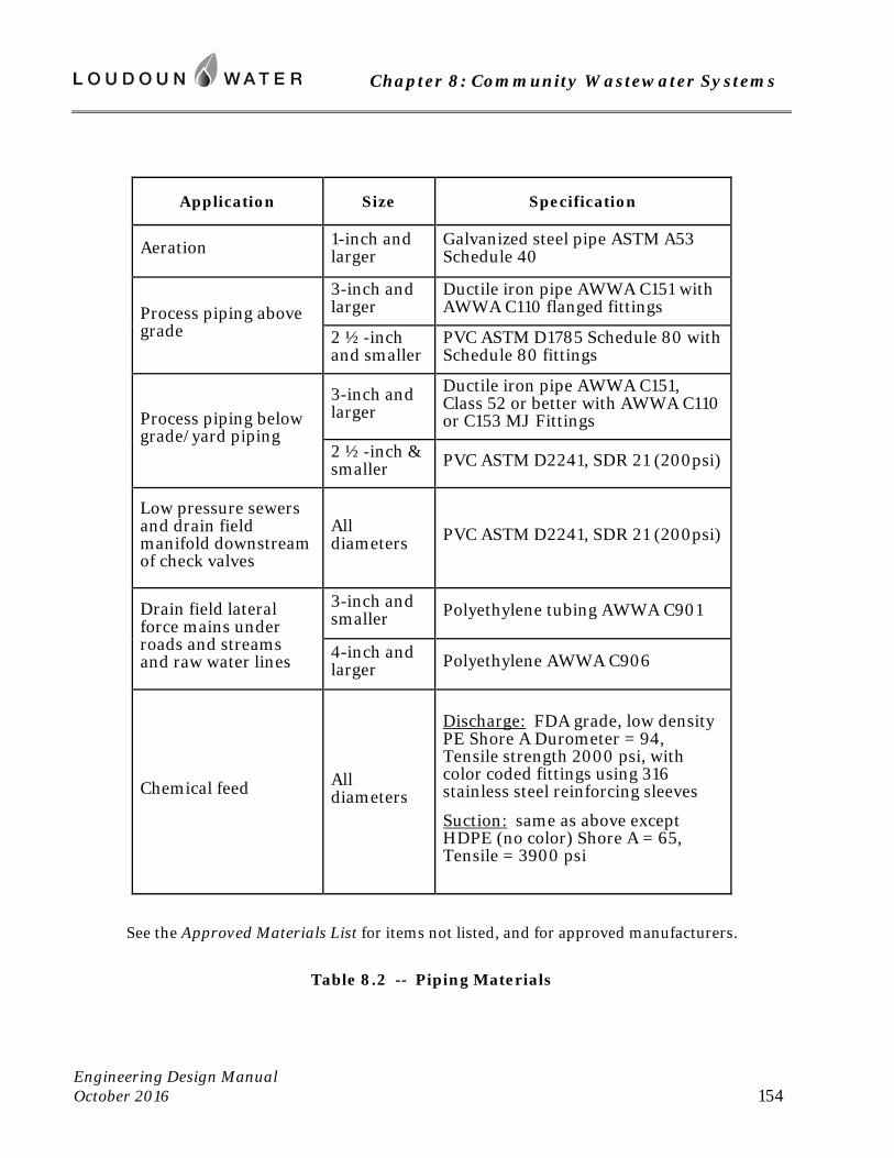
Chapter 8: Community Wastewater Systems
Engineering Design Manual October 2016 154
Application Size Specification
Aeration 1-inch and larger
Galvanized steel pipe ASTM A53 Schedule 40
Process piping above grade
3-inch and larger
Ductile iron pipe AWWA C151 with AWWA C110 flanged fittings
2 ½-inch and smaller
PVC ASTM D1785 Schedule 80 with Schedule 80 fittings
Process piping below grade/yard piping
3-inch and larger
Ductile iron pipe AWWA C151, Class 52 or better with AWWA C110 or C153 MJ Fittings
2 ½-inch & smaller PVC ASTM D2241, SDR 21 (200psi)
Low pressure sewers and drain field manifold downstream of check valves
All diameters PVC ASTM D2241, SDR 21 (200psi)
Drain field lateral force mains under roads and streams and raw water lines
3-inch and smaller Polyethylene tubing AWWA C901
4-inch and larger Polyethylene AWWA C906
Chemical feed All diameters
Discharge: FDA grade, low density PE Shore A Durometer = 94, Tensile strength 2000 psi, with color coded fittings using 316 stainless steel reinforcing sleeves
Suction: same as above except HDPE (no color) Shore A = 65, Tensile = 3900 psi
See the Approved Materials List for items not listed, and for approved manufacturers.
Table 8.2 -- Piping Materials
Chapter 8: Community Wastewater Systems
Engineering Design Manual October 2016 155
W. Aerobic Sludge Digestion
To 9 VAC 25-790-560 add the following:
1. Sludge holding for a period of 30 days shall be required; thickening to accomplish this holding volume may be provided.
2. Aerobic digesters shall use forced air and coarse bubble diffusers for mixing.
3. Supernatant piping in aerobic digesters will not be required. Provide 3, 1/2 HP submersible, supernatant sump pumps with 20 feet of 1 1/4 –inch diameter corrugated hose.
X. Attached Growth Processes
To 9 VAC 25-790-670 add the following:
Except as noted above, attached growth processes are prohibited, except for deep bed denitrification filters, or where specifically approved by Loudoun Water.
Y. Rotating Biological Contactors
To 9 VAC 25-790-680 add the following:
Rotating Biological Contactors are prohibited.
Z. Suspended Growth (Activated Sludge) Process
To 9 VAC 25-790-690 add the following:
Design
1. Subsurface disposal wastewater treatment facilities shall be designed for a year-round Total Nitrogen effluent concentration based on plant capacity and effluent requirements and should utilize either an SBR with tertiary filter or another Loudoun Water-approved process. Process kinetics for all biological treatment processes shall be designed using a minimum wastewater temperature of 12 degrees centigrade.
Fine bubble diffused aeration shall be utilized for all suspended growth activated sludge processes with a grid of EPDM membrane tube diffusers and an oxygen transfer efficiency (SOTE) of 25 percent (25 degrees centigrade shall be used for the maximum wastewater temperature when calculating maximum diffused air requirements). Drop pipes and diffuser shall be removable, with swing joints and winch for larger plants. For systems using return activated sludge (RAS) piping, such piping from geyser airlift pumps shall be hard-piped to discharge into a calibrated weir box for flow measurement. Common blowers shall not be used for aeration and sludge holding tanks; provide separate blowers or the ability to isolate blowers and maintain adequate airflow to the biological reactors. Blowers shall be low decibel models with inlet filters, residential-type inlet and outlet silencers and shall be housed in a separate sound-insulated room within
Chapter 8: Community Wastewater Systems
Engineering Design Manual October 2016 156
the treatment plant enclosure. Lobe, helical screw, turbo and centrifugal blowers shall be considered based on air volume requirements, reliability, and efficiency. If the treatment plant is not enclosed, provide sound insulated housings made by West Chester Manufacturing of Avondale, Pennsylvania or approved equal.
Alkalinity addition shall be provided using magnesium hydroxide to maintain a minimum secondary effluent alkalinity of at least 50 mg/l (as CaCO3). Alkalinity shall be fed using multiple feed points in the aeration basins. Lime shall not be used for alkalinity addition.
All package plant systems shall minimally have 5 installations treating 100 percent domestic wastewater of similar design size of the proposed system. One of these installations must be operating in Virginia for at least 3 years from the date of initiating the Basis of Design Report. Provide references for all regional and Virginia installations. Provide operating data as requested by Loudoun Water.
AA. Sequencing Batch Reactors (SBR)
To 9 VAC 25-790-710 add the following:
Provide retrievable diffuser assemblies. Each diffuser assembly shall be retrievable (at least 4 feet above the high water level) with an electric winch.
BB. Chlorination
To 9 VAC 25-790-750 add the following:
Chemical
1. Use of gaseous chlorine is prohibited.
Design
2. Subsurface wastewater disposal systems and wastewater disposal systems incorporating holding ponds shall use calcium hypochlorite.
CC. Ultraviolet Light Irradiation (UV)
To 9 VAC 25-790-770 add the following:
Surface discharge treatment facilities utilizing filtration shall utilize UV disinfection.
DD. Postaeration
To 9 VAC 25-790-820 add the following:
Cascade Type
Cascade type aerators shall be concrete steps.
Chapter 8: Community Wastewater Systems
Engineering Design Manual October 2016 157
EE. Flow Equalization
To 9 VAC 25-790-830 add the following:
Usage
Provide a separate in-line equalization basin, minimum 8-hour HRT based upon design average daily flow, for the wastewater treatment facility
FF. Filtration
To 9 VAC 25-790-860 add the following:
General Design
Tertiary filtration is required by VDH when effluent TSS permit limits are less than or equal to 15 mg/l TSS.
GG. Land Treatment
To 9 VAC 25-790-880 add the following:
Land Treatment Methods
1. Land application systems shall be low intensity spray application adhering to reuse standards or dispersal by a low pressure distribution mass drain field system or drip system. Buffer zones shall, at a minimum, meet regulations of Virginia, but may be increased if there are environmental or community considerations.
Field Area Design
2. Not less than 3 monitoring wells (1 up-gradient and 2 down-gradient) shall be constructed for land application systems at least one year prior to completion of construction of the treatment facility. Background ground water quality monitoring shall be conducted quarterly for at least one year. Provide official laboratory results to Loudoun Water within 60 days after sampling.
Low Intensity Design
3. Loudoun Water is considering establishing specific minimum design criteria for spray application area design. Before any Applicant begins design of a spray field, Loudoun Water should be contacted, asking whether the criteria have been established.
4. Unless specifically waived by Loudoun Water, the Applicant must complete a prevailing wind study for the proposed application sites. The study must statistically determine typical wind speeds and directions. This information must be taken into consideration during design of the system so as to prevent off-site migration of aerosols while assuring all effluent can be irrigated in a given year.
Chapter 8: Community Wastewater Systems
Engineering Design Manual October 2016 158
5. Low intensity spray systems shall include automatic operational controls that cease spray operations if sustained wind speed or precipitation exceeds certain programmable levels.
-- end of Chapter 8 --
Chapter 9: Sewage Pumping Stations
Engineering Design Manual October 2016 159
Chapter 9: Sewage Pumping Stations
9.1 Scope
A. Intent
These sewage pumping station (SPS) design standards are intended to assist design engineers in the development of plans and specifications for Loudoun Water projects. The materials, configurations, and features described here represent the minimum acceptable level of quality expected in pumping station design and reflect the goal of standardizing Loudoun Water equipment. These standards should not be construed as being a complete description of the necessary features for a particular pumping station design. Deviations from these standards must be approved by Loudoun Water during the Basis of Design phase of the project. Loudoun Water has the final authority regarding the acceptability of any particular pumping station design.
B. Limitations
The sewage pumping station standards presented herein shall supplement the latest edition of the Sewage Collection and Treatment (SCAT) Regulations 9 VAC 25-790, as published by the Commonwealth of Virginia, Virginia Department of Environmental Quality (DEQ). The SCAT Regulations represent the minimum design requirements set forth by the DEQ. All aspects of the SCAT Regulations shall be adhered to. As the owner, Loudoun Water may identify and determine the need for standards and requirements that are more stringent than those contained in Part III of the SCAT Regulations.
9.2 Reference Standards
The design engineer will comply with all relevant industry standards and federal, state and local regulations, including the following standards:
Virginia Sewage Collection and Treatment Regulations
Virginia Building Code
Virginia Water Control Board: Dulles Area Watershed Policy
Virginia Water Control Board: Occoquan Policy
Virginia Department of Transportation (VDOT): Road and Bridge Specifications
National Fire Protection Association (NFPA): 820 Standard for Fire Protection in Wastewater Treatment and Collection Facilities
Loudoun County: Facilities Standards Manual
Regulations of the Occupational Safety and Health Administration (OSHA)
Chapter 9: Sewage Pumping Stations
Engineering Design Manual October 2016 160
Loudoun Water: Safety Specification for Capital Projects
Loudoun Water: Spare Parts Checklist
Loudoun Water: SCADA and Control System Standards
Loudoun Water: Approved Materials List
9.3 Suggested References
Additional standards and regulations to be considered, incorporated herein by reference are as follows:
Hydraulic Standards Institute
American Concrete Institute (ACI) 308-01, Guide to Curing Concrete
American Concrete Institute (ACI) 318, Building Code Requirements for Structural Concrete
American Concrete Institute (ACI) 530-02, Building Code Requirements for Masonry Structures and Specifications for Masonry Structures
American Concrete Institute (ACI) 350, Code Requirements for Environmental Engineering Concrete Structures
National Electric Code (NEC)
National Electric Manufacturers Association (NEMA)
National Fire Protection Association (NFPA)
Standard Rules of American Institute of Electrical Engineers
Environmental Protection Agency (EPA)
International Building Code
American National Standards Institute (ANSI)
American Institute for Steel Construction (AISC)
National Association of Corrosion Engineers (NACE)
Chapter 9: Sewage Pumping Stations
Engineering Design Manual October 2016 161
9.4 Required Meetings
During the course of the pumping station design, meetings shall take place at the following project milestones:
Initial Planning/Kickoff Meeting
Immediately after Basis of Design Report submittal
Preliminary Engineering Report
90% Design Submittal (when requested)
Loudoun Water has established a procedure for the review of pumping station plans. The design engineer shall meet with Loudoun Water prior to start of design to discuss Loudoun Water’s procedures and requirements.
9.5 General Requirements
Sewage pumping stations will be designed in conformance with the Commonwealth of Virginia SCAT Regulations. The sewage pumping station will not be accepted by Loudoun Water until the following items have been provided:
a Certificate to Construct (CTC) from Virginia DEQ. This is a condition of Loudoun Water’s approval of design.
a Certificate to Operate (CTO) the pumping station from the Virginia DEQ. This is a condition of Loudoun Water’s Certificate of Substantial Completion.
five copies of Operations and Maintenance Manual, and one digital copy on CD, approved by Loudoun Water and Virginia DEQ
certified pump curves and actual pump curve at startup
a certificate of substantial completion issued by Loudoun Water
A. Types of Stations
The 3 types of sewage pumping stations used by Loudoun Water are:
1. Temporary Pumping Station -- A temporary sewage pumping station will be used to serve a single subdivision or commercial site. The location of the station does not conform to Loudoun Water’s master plan and the station will be abandoned when gravity sewers reach the station or the permanent facility is constructed.
2. Interim Sewage Pumping Station -- An interim sewage pumping station shall be designed to serve the portion of the sewer shed upstream of the permanent station’s site. The station is in conformance with Loudoun Water’s master sewer plan except that, due
Chapter 9: Sewage Pumping Stations
Engineering Design Manual October 2016 162
to financial considerations, it is not located at the ultimate location of the permanent facility or is not constructed to serve the entire shed. The station will be abandoned when the permanent sewage pumping station and associated interceptor sewers are constructed.
3. Permanent Pumping Station -- Permanent sewage pumping stations shall be designed and sited to serve the entire sewer shed service area and are identified as part of Loudoun Water’s master plan. A permanent station may not be initially constructed with capacity for the entire sewer shed, but the major structures in the facility will be designed and constructed to accommodate the ultimate capacity of the station.
B. Site
1. Sewage pumping stations will be located so as to prevent flooding during large storms. Finished floor of the control building, the tops of all below ground structures, and all outdoor tanks and equipment will be above 100-year flood elevation.
2. The fee simple ownership of the pumping station’s parcel will be transferred to Loudoun Water. A Loudoun Water easement may be substituted in place of a parcel with Loudoun Water’s approval.
C. Design Flow
1. Sewage pumping stations will be designed for peak flow from the drainage area. The peak flow for a sewage pumping station will be a minimum of 2.5 times the average daily flow. Pump and system curves, flow calculations and a drainage area map must be included in the project plans for sewage pumping stations.
2. Provisions for future expansion include the possible selection of pumps with higher than required motor horsepower to allow the future installation of larger diameter impellers, capable of pumping increased flows. Other possible features to consider include sizing of the force main, wet well dimensions, incorporating variable frequency drives, generator selection, electrical service, and other components, so as to allow for the increase in capacity, without causing problems during initial operation. Life-cycle costs will be considered.
3. All sewage pumping stations will have at least 2 pumps. For stations with 2 pumps, each pump must be able to pump the design peak flow with the other pump out of service.
4. For sewage pumping stations with more than 2 pumps, with the largest pump out of service, the remaining pumps must be able to pump the design peak flow.
Chapter 9: Sewage Pumping Stations
Engineering Design Manual October 2016 163
9.6 Pumping Station Selection Criteria
The selection of which style of pumping station to use will depend on several factors including capacity, depth, location, and life-cycle costs. The following are four basic styles of pumping stations that are used in the Loudoun Water system:
Suction Lift: Wet well depths to 20 ft.; maximum 20 HP pumps
Submersible: Wet well depths greater than 15 ft.; maximum 20 HP pumps; capacities under 1 mgd
Package: Wet well depths to 25 ft.; capacities under 3 mgd
Conventional: Wet well depths greater than 25 ft. or capacities of 3 mgd or more
There are situations where more than one type of station may be appropriate. A conceptual or schematic design along with important design criteria submitted as the Basis of Design shall be approved by Loudoun Water before proceeding with the development of the Preliminary Engineering Report and contract plans and specifications.
A. Design Limitations
The following design limitations should be observed for each style of station.
1. Suction Lift Pumping Stations
a. Definition -- Suction Lift stations are defined here as those stations where the pumps are located above the water level in the wet well and hence must employ some means of lifting the sewage to the pumps in order for the pumps to be primed. The pumps shall be of the self-priming, flooded box type.
b. Configuration -- Suction Lift pumping stations shall be designed with the pumps mounted directly above the wet well and shall have suction pipes that are straight. Suction Lift stations shall satisfy the pump’s NPSH requirements. The outside wall of the pumping station building shall be located above the wet well with the pumps and piping located inside the building and the wet well entrance hatch located outside. A roll-up type door shall be provided for access to the pumps. A swinging jib crane or rolling floor crane shall be provided to facilitate pump removal. See Figures 9.1 and 9.2.
2. Submersible Pumping Stations
a. Definition -- Submersible stations are defined here as those where the pumps are “submerged” in the wet well. Because the pumps operate under water in the wet well, there is no need for a separate pump room. The pumps can be raised and lowered out of the wet well by means of a jib crane located at the top of the wet well. Guide rails enable the pump to be raised and lowered into place without requiring entry by personnel under normal circumstances.
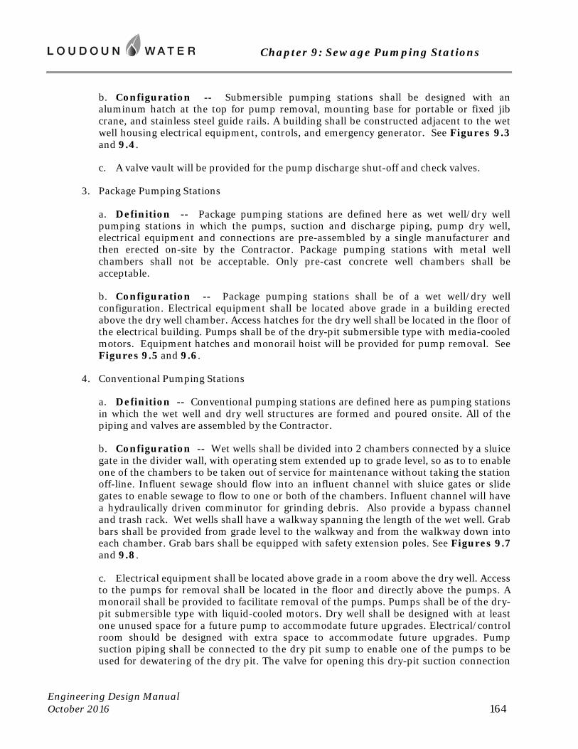
Chapter 9: Sewage Pumping Stations
Engineering Design Manual October 2016 164
b. Configuration -- Submersible pumping stations shall be designed with an aluminum hatch at the top for pump removal, mounting base for portable or fixed jib crane, and stainless steel guide rails. A building shall be constructed adjacent to the wet well housing electrical equipment, controls, and emergency generator. See Figures 9.3 and 9.4.
c. A valve vault will be provided for the pump discharge shut-off and check valves.
3. Package Pumping Stations
a. Definition -- Package pumping stations are defined here as wet well/dry well pumping stations in which the pumps, suction and discharge piping, pump dry well, electrical equipment and connections are pre-assembled by a single manufacturer and then erected on-site by the Contractor. Package pumping stations with metal well chambers shall not be acceptable. Only pre-cast concrete well chambers shall be acceptable.
b. Configuration -- Package pumping stations shall be of a wet well/dry well configuration. Electrical equipment shall be located above grade in a building erected above the dry well chamber. Access hatches for the dry well shall be located in the floor of the electrical building. Pumps shall be of the dry-pit submersible type with media-cooled motors. Equipment hatches and monorail hoist will be provided for pump removal. See Figures 9.5 and 9.6.
4. Conventional Pumping Stations
a. Definition -- Conventional pumping stations are defined here as pumping stations in which the wet well and dry well structures are formed and poured onsite. All of the piping and valves are assembled by the Contractor.
b. Configuration -- Wet wells shall be divided into 2 chambers connected by a sluice gate in the divider wall, with operating stem extended up to grade level, so as to to enable one of the chambers to be taken out of service for maintenance without taking the station off-line. Influent sewage should flow into an influent channel with sluice gates or slide gates to enable sewage to flow to one or both of the chambers. Influent channel will have a hydraulically driven comminutor for grinding debris. Also provide a bypass channel and trash rack. Wet wells shall have a walkway spanning the length of the wet well. Grab bars shall be provided from grade level to the walkway and from the walkway down into each chamber. Grab bars shall be equipped with safety extension poles. See Figures 9.7 and 9.8.
c. Electrical equipment shall be located above grade in a room above the dry well. Access to the pumps for removal shall be located in the floor and directly above the pumps. A monorail shall be provided to facilitate removal of the pumps. Pumps shall be of the dry-pit submersible type with liquid-cooled motors. Dry well shall be designed with at least one unused space for a future pump to accommodate future upgrades. Electrical/control room should be designed with extra space to accommodate future upgrades. Pump suction piping shall be connected to the dry pit sump to enable one of the pumps to be used for dewatering of the dry pit. The valve for opening this dry-pit suction connection
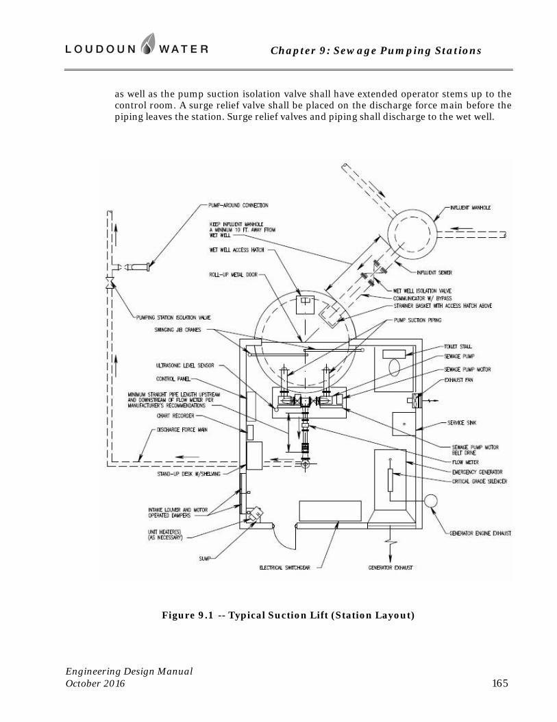
Chapter 9: Sewage Pumping Stations
Engineering Design Manual October 2016 165
as well as the pump suction isolation valve shall have extended operator stems up to the control room. A surge relief valve shall be placed on the discharge force main before the piping leaves the station. Surge relief valves and piping shall discharge to the wet well.
Figure 9.1 -- Typical Suction Lift (Station Layout)
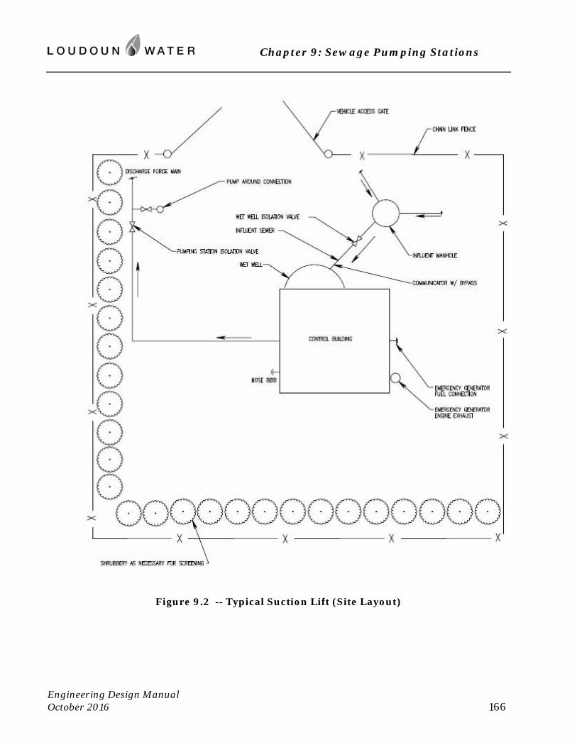
Chapter 9: Sewage Pumping Stations
Engineering Design Manual October 2016 166
Figure 9.2 -- Typical Suction Lift (Site Layout)
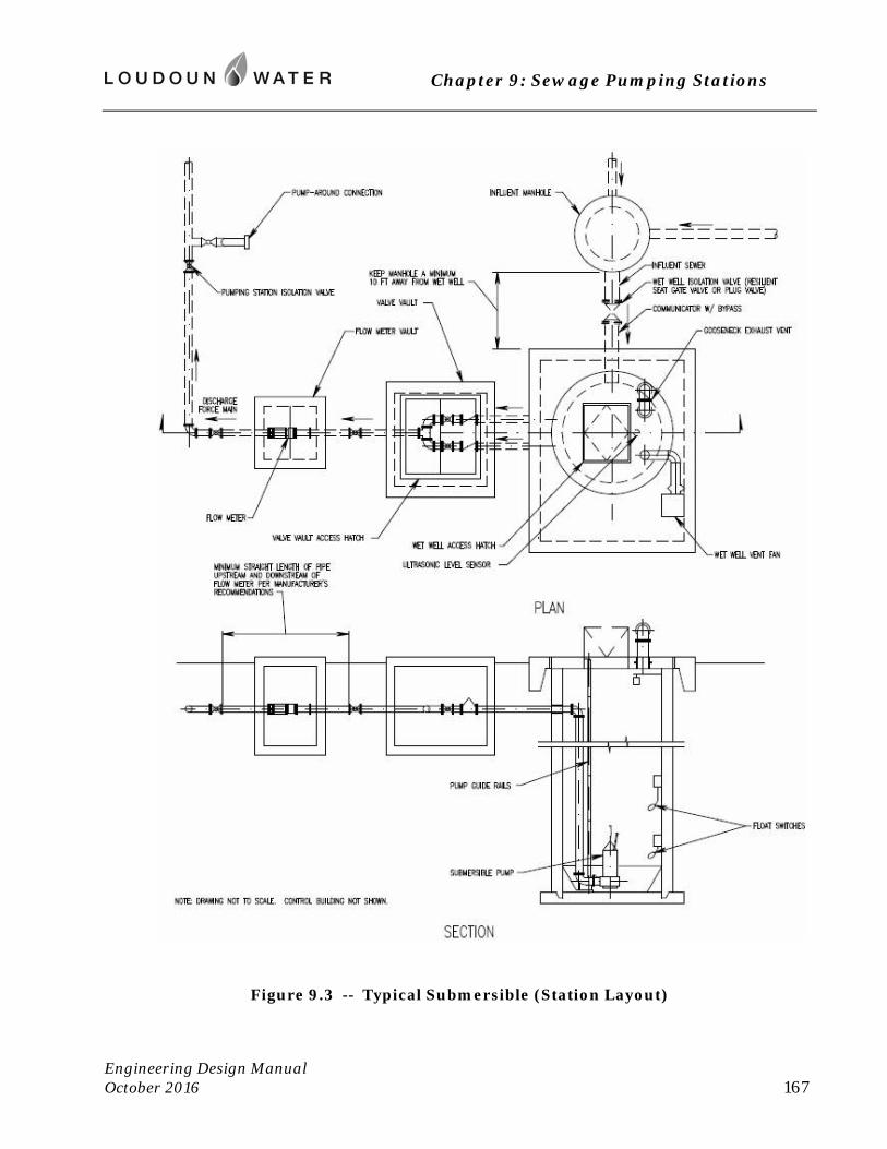
Chapter 9: Sewage Pumping Stations
Engineering Design Manual October 2016 167
Figure 9.3 -- Typical Submersible (Station Layout)
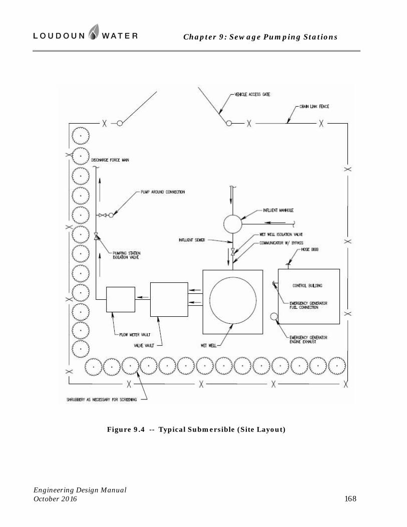
Chapter 9: Sewage Pumping Stations
Engineering Design Manual October 2016 168
Figure 9.4 -- Typical Submersible (Site Layout)
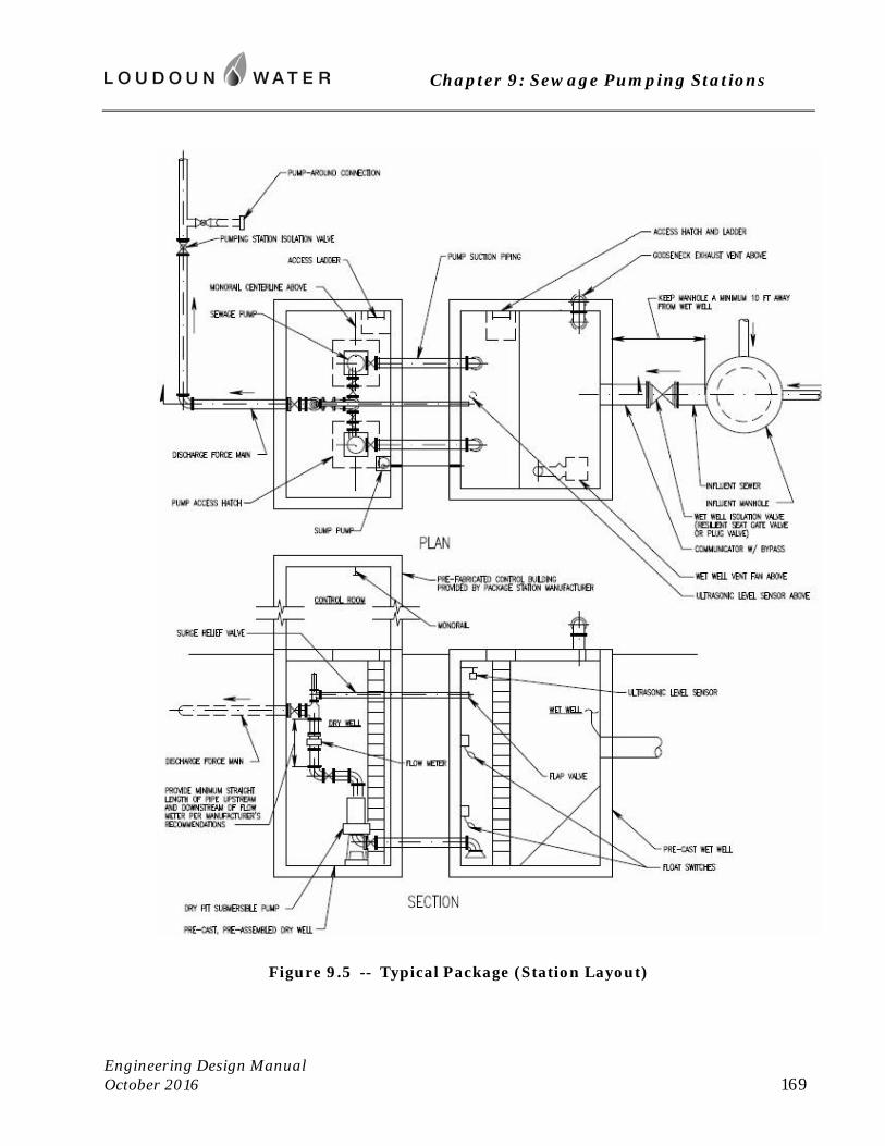
Chapter 9: Sewage Pumping Stations
Engineering Design Manual October 2016 169
Figure 9.5 -- Typical Package (Station Layout)
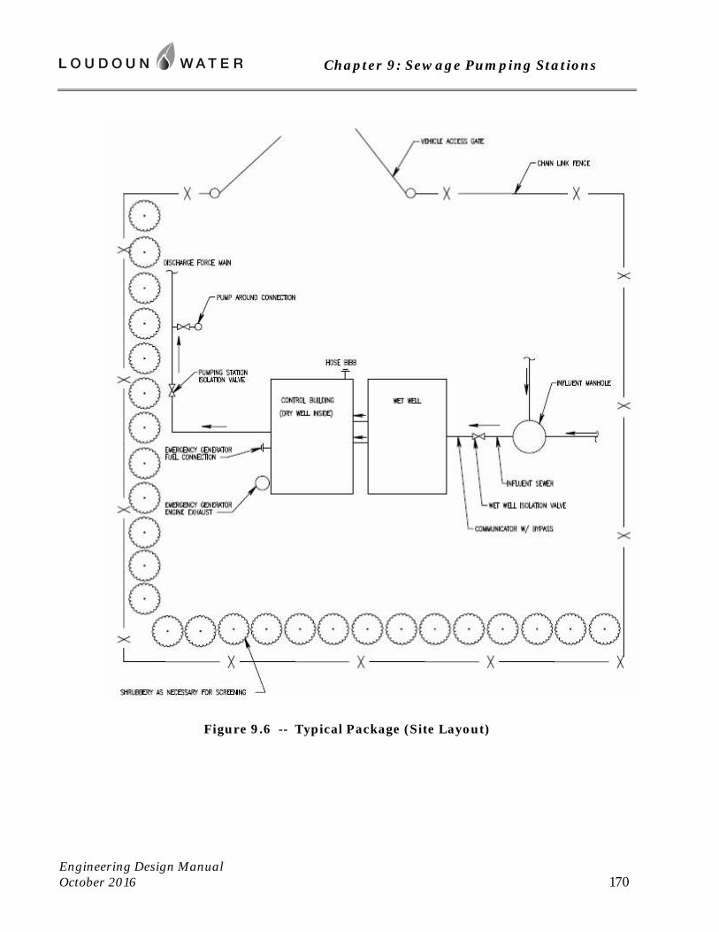
Chapter 9: Sewage Pumping Stations
Engineering Design Manual October 2016 170
Figure 9.6 -- Typical Package (Site Layout)
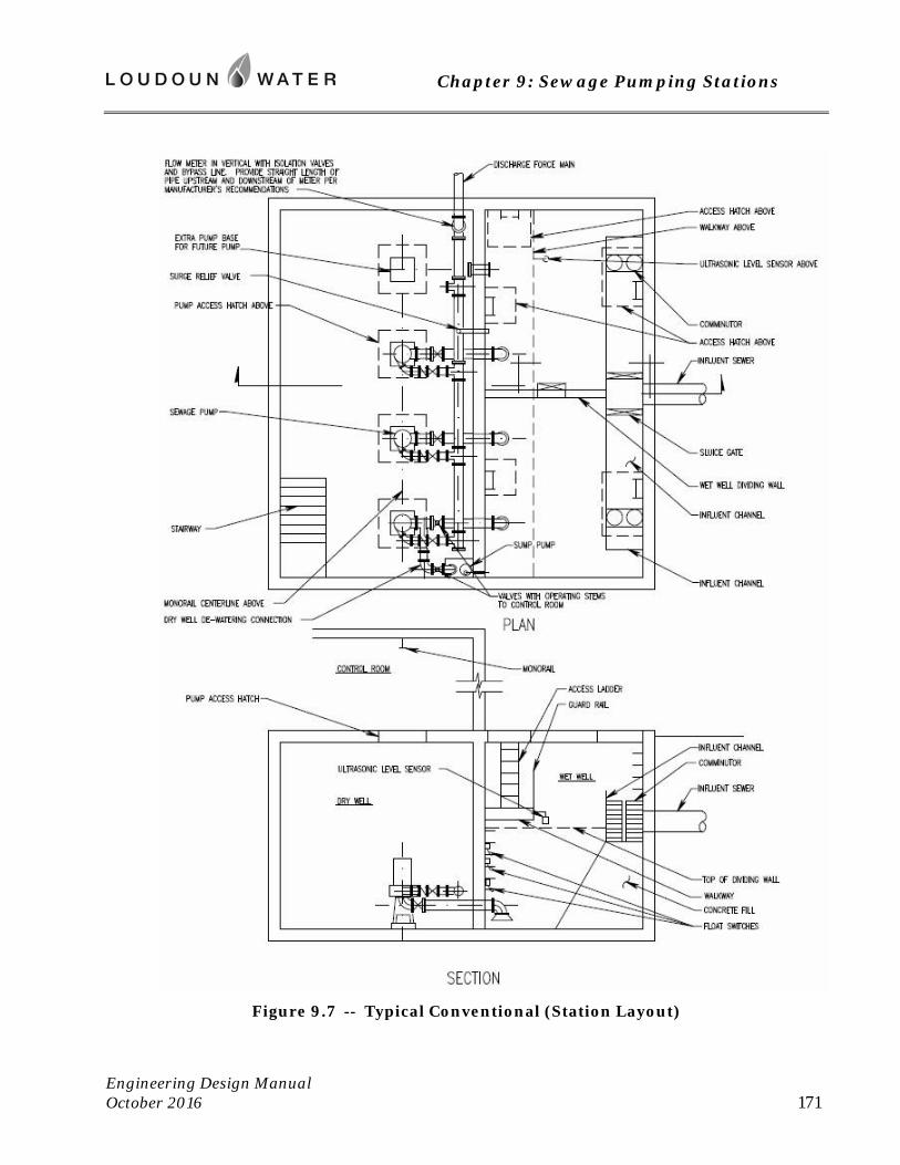
Chapter 9: Sewage Pumping Stations
Engineering Design Manual October 2016 171
Figure 9.7 -- Typical Conventional (Station Layout)
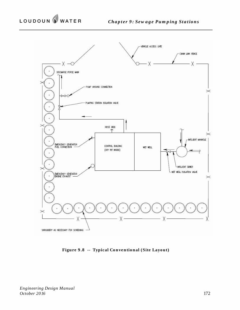
Chapter 9: Sewage Pumping Stations
Engineering Design Manual October 2016 172
Figure 9.8 -- Typical Conventional (Site Layout)
Chapter 9: Sewage Pumping Stations
Engineering Design Manual October 2016 173
9.7 Design Criteria for Pumping Stations
All sewage pumping stations will be designed in accordance with the following criteria. Additional requirements of SCAT Regulations shall also apply.
A. Pump Selection
1. All pumps shall be warranted against defects in workmanship and material for a period of 5 years or 10,000 hours of operation under normal use, operation and service. The warranty period must start at time of final acceptance of the station by Loudoun Water, and shall be non-prorated. All pumps using a center shaft shall be equipped with oversized bearings (Class B).
2. All pump openings and passages shall be large enough to permit the passage of a sphere 3-inch in diameter and any trash that can pass through a 4-inch house collection system. All pumps will have cleanout ports on the volute.
3. For new pumping stations, prepare Total Dynamic Head (TDH) calculations based on the pipe C factor anticipated after the force main has been in service for ten years. When expanding the capacity of an existing pumping station which has been in service for many years, the actual C factor of the force main should be determined by field measurements.
4. Typically the TDH calculations are based on the entire length of force main pipe from the pumping discharge to the discharge manhole of the gravity system. However, when pumping from one valley over a hill to a gravity sewer on the other side of the hill, it is important to consider whether or not there is free fall in the downhill segment of the force main such that the downhill length of pipe does not need to be considered in the TDH calculations. If the static head from the force main’s high point to the discharge point exceeds the full flow head loss in the downhill segment of force main, sewage should flow by gravity through the force main similar to a gravity sewer instead of as a full pipe under pressure.
5. Consideration must be given during design to include a small submersible jockey pump in the wet well, which will operate almost continuously through the day at a lower flow rate. This lower flow rate will significantly reduce the friction loss and energy requirements while providing reliable service. The larger pumps should only operate a few times a day, (during peak flow periods in the morning and evening) which is sufficient to scour the force main.
B. Protection Against Clogging
1. All pumping stations shall have a comminutor vault at the influent portion of the station. The comminutor will be sized for the estimated peak hourly flow into the station.
2. The comminutor will be designed to be easily removed from the flow channel without disturbing any piping connections. The comminutor channel shall be designed to settle out grit upstream of the screening area. On larger stations, a separate grit chamber may be required.
Chapter 9: Sewage Pumping Stations
Engineering Design Manual October 2016 174
3. Comminutors shall be designed for continuous operation and will automatically restart after power failures. The vault shall also be equipped with an aluminum bar screen (inline or as a bypass), so that the comminutor can be taken out of service for repair and maintenance.
4. The clear openings on the bar screen will not exceed 2.5 inches in any dimension. In the event the comminutor must be taken out of service, slide gates are provided to direct comminutor vault influent flow to a bypass bar screen. Also, in the event flow backs up upstream of the comminutor the influent channel wall shall have an overflow notch just upstream of the bar screen. The bar screen shall be constructed of stainless steel bars and must be manually cleaned with a rake.
5. The comminutor vault may be a precast concrete manhole with high density polyethylene (HDPE) liner per the Approved Materials List. Aluminum alternating tread stairs shall be used for access to the bottom of the vault.
6. All lighting and electrical equipment shall be explosion proof inside the vault.
7. A ventilation fan shall be provided on top of the comminutor vault.
8. An emergency stop button shall be provided in the comminutor vault for the comminutor
C. Wet Well
1. Wet wells shall be designed for a minimum pump cycle time of 10 minutes as defined by the following formula:
T = 4V/Q where,
T = Pump Cycle Time (time between pump starts)
V = Volume of wet well between the lead pump start and pump stop elevations, in gallons
Q = Design Flow rate of the pumping station, in gallons per minute
2. The wet wells at stations 3 million gallons per day or larger shall be divided into two interconnected sections to facilitate repairs and cleaning. The effective capacity of the wet well shall be such that one pump will run continuously at least 5 minutes of every 30-minute period at the minimum flow. The wet well fillets shall be sloped at 1:1 to the hopper bottom. The hopper bottom shall be no larger than necessary for the proper installation and function of the inlet. To prevent corrosion, all wet wells shall be of hydraulic content concrete with an approved lining system, or of an approved circular polymer concrete. The wet well size and control settings shall be designed to avoid heat buildup in the pump motor due to frequent starting and to avoid septic conditions due to excessive detention times. A visual gauge of the wet well level shall be provided.
3. Wet wells shall be designed to have not less than 1 foot between alarm points and set points. See Sections L. Controls and M. SCADA System of this Chapter. Wet wells shall be
Chapter 9: Sewage Pumping Stations
Engineering Design Manual October 2016 175
designed with an additional 2 feet of depth above the highest alarm as a safety factor to accommodate unexpected increases in station capacity.
4. Wet wells shall be approved polymer concrete or be lined with approved HDPE protective liner. Bottom of wet well shall be grouted to a minimum slope of 45 degrees toward the pump suction inlet.
5. A wet well mixer may be required.
D. Emergency Storage
Underground storage structures for wastewater will be provided at all lift stations. The structure(s) will be sized to hold at least the estimated 2-hour peak flow volume.
E. Influent Manhole
An influent manhole collecting all of the gravity sewers and force mains that flow to the pumping station shall be provided if practical. The influent manhole shall be located on the same site as the pumping station as close as possible to the wet well. A short gravity sewer shall carry sewage from the influent manhole to the wet well. The influent manhole shall be capable of being isolated from the pumping station wet well by means of a yard valve. Yard valve shall be a buried resilient wedge valve with valve box to grade.
F. Auxiliary Force Main Connection
Pumping stations shall be provided with a bypass pumping connection downstream of the station. In conjunction with the influent manhole described above, this connection riser enables the station to be taken off-line for periodic maintenance or repairs. Slope auxiliary force main piping so that it can be drained to the wet well.
G. Surge Analysis
1. When pumps cycle off or there is a power failure, transient surge pressures can damage piping. Reduced voltage solid state starters may be required to reduce surge pressures. As backup protection, a surge relief valve may be required at the pumping station, to provide for events of power failure, or a failure of the soft start/stop equipment. Design Engineer shall perform a surge analysis of the discharge force main when the velocity exceeds 3.5 fps and/or the total dynamic head (TDH) of the system’s design exceeds 150 feet.
2. On package, submersible and conventional stations, surge relief valves or accumulators shall be provided, where the following conditions will exist.
a. Force main contains substantial high points in its profile, or contains a steep gradient.
b. Length of force main is less than 20 times the total dynamic head.
c. Velocity in force main will be above 4 feet/second.
d. There can be slowdown and reversal of flow in less than tc.
Chapter 9: Sewage Pumping Stations
Engineering Design Manual October 2016 176
e. There is check valve closure in less than tc.
f. There can be damage to pump and motor if allowed to run backward.
g. Pump can stop or speed be reduced to the point that the shut-off head is less than static head, before the discharge valve is fully closed.
H. Backup Power
1. All pumping stations shall be provided with either a standby generator or a secondary power feed with automatic transfer switches to achieve Class I reliability as described in the SCAT Regulations. Pumps shall be capable of automatic restart after power failures. Generator shall be rated for primary service, and have permanent magnet excitation.
2. Standby generators shall be diesel driven with fuel storage on the underside of the generator in a belly tank or outside the building in an above ground, double walled storage tank.
3. Tank size shall be suitable for 48 hours of generator operation at full load. Skid mounted tanks shall be double-walled for leak containment and shall meet all DEQ and EPA regulations. A fuel storage level indicator will be provided in the generator and control building. Fuel tank shall be refilled after all startup and testing is complete.
4. The generator will be equipped with an alarm indicator and output contacts to display the cause of a generator failure, both locally and remotely. The means for starting an emergency generator shall be completely independent of the normal electric power source. The starting system shall be sufficient to start the generator a minimum of 3 times without recharging. The starting system shall be alarmed and instrumented to indicate a loss of readiness.
5. It is preferred that emergency generators shall be located in a separate room inside the pumping station building, mounted on vibration isolators, with a fuel tank fill connection to the outside. A spill containment area around the generator shall be provided. This spill containment area shall consist of a 4-inch curb surrounding the generator. Generator engine exhaust shall be provided with a critical grade silencer and piped to the outside of the building. Generator exhaust shall face away from nearby neighbors. If this is not possible, a baffle wall shall be constructed in front of the generator exhaust. A plenum shall be provided for generation intake exhaust. Generator installations of 100 kW or less will have gravity dampers on the air supply and exhaust louvers. Installations larger than 100 kW shall have motorized dampers. Acoustic baffles shall be installed on exhaust louvers for units larger than 250 kW.
6. The generator switch gear shall be provided by the same manufacturer as the generator. All electrical distribution equipment shall be protected by a solid state advanced control phase monitor. The generator shall be equipped with a battery charger and block heater. The transfer switch shall include a plant exerciser, adjustable time delays between all functions and transitions. The switch shall also be capable of holding in the “neutral” position for an adjustable time period between all transitions. All electrical switch gear
Chapter 9: Sewage Pumping Stations
Engineering Design Manual October 2016 177
and controls will be located in a building. Any equipment remotely located from the distribution panel shall have a lockable service disconnect on the line side.
I. Valves and Piping
1. Valves shall be located on the suction and discharge lines of each pump to allow the pump to be isolated. A check valve shall be installed on each discharge line, between the pump and the valve. Isolation and check valves may be located either inside the pumping station building or in a separate valve vault. Pump isolation or check valves shall not be located in the wet well. Isolation valves for pumps in wet well/dry well stations shall be plug valves, installed in the horizontal position, so that the plug is in the top when open.
2. Valves shall be installed on each side of the flow meter.
3. The velocity in the suction line will not exceed 4 fps. The velocity in the discharge line will not exceed 6 fps. Pressure gauges with isolation valves will be installed on the discharge side of the check valve. Gauge taps with valves will be installed on the suction side of each pump.
4. Flexible, watertight connections shall be provided for all below grade pipe and conduit connections to concrete structures. Gravity sewers entering structures shall have boots. Pressure pipe will penetrate walls by means of an Omni-Sleeve by Sigma, or approved equal. Link seal will not be permitted.
5. A tee and necessary valves shall be provided on the discharge force main to allow the force main to be drained, while operating with the auxiliary by-pass force main.
J. Lighting
Adequate lighting will be provided throughout the station. All lighting fixtures shall be rated for the environment in which they are installed. Where applicable fluorescent fixtures shall be installed in accordance with the manufacturer’s recommendations to provide adequate heat dissipation, and maximize the life expectancy of the fixture. Fluorescent fixtures shall have a 0ºF start ballast and have a plastic lens to protect the lamps. Fluorescent fixtures shall use F40 lamps and shall be constructed so as to allow the entrance of conduits to the ends of the fixture. A skylight will be installed in the generator and control building to provide natural light. All lighting located in a wet well shall be serviceable from the catwalk. All lighting located in a dry well shall be vapor proof, corrosion resistant, and shall be mounted with stainless steel hardware. All exterior-photoelectric switches shall be intrinsic. All lighting shall have an HOA switch.
K. Flow Metering
1. All pumping stations shall be provided with a magnetic type flow meter, equipped for wastewater service, with a bypass line and valves to enable pumping station to operate when meter is being serviced. Acceptable flow meters are Invensys FOXBORO 9100 Series.
2. Range of flow meter shall be twice the normal pump output.
Chapter 9: Sewage Pumping Stations
Engineering Design Manual October 2016 178
3. All flow meters shall have an adequate length of straight pipe both upstream and downstream of the meter in accordance with manufacturer’s recommendations.
4. Provide a totalizer and indicator/transmitter in units of gpm. Flow metering equipment except for the sensor will be located in the control building.
L. Controls
1. The pumps shall be controlled by means of a pressure transducer. The pressure transducer shall be programmed to turn the pumps on or off at various levels in the wet well.
2. The transmitter sensor shall be mounted near the top of the wet well and be removable without entering the wet well. The transmitter shall also report the level in the wet well on an indicator located inside the station.
3. The pumping station shall also have a back-up pressure transducer control system with transducers for turning the individual pumps on and off if the primary pressure transducer malfunctions. Back-up transducers shall be wired to individual pump motor starters. Enough pumps shall have back-up transducers to maintain the “safe pumping capacity” (i.e. largest pump out of service) of the station.
4. Where variable speed pumps are specified, an Allen-Bradley 7000 Series controller shall be used in addition to the pump controller specified above.
5. Check valve limit switch circuitry shall be used for pump failure logic.
6. An elapsed run time indicator will be provided for each pump.
7. A press-to-test circuit will be provided for the control panel indicator lights.
8. All control wiring and interface wiring shall be number coordinated with schematic. All panel and field wiring shall be identified with non-repeating numbers. All instrumentation and control devices shall be wired with stranded copper conductors.
9. All motor controls shall be equipped with a motor overload indicator light for each motor equipped with a thermal overload protection device.
10. Provide an uninterruptible power supply (UPS) with 2 hour battery for the control system.
M. SCADA System
1. Loudoun Water shall specify the method of communications and the specific brands of hardware and software to be used. See Loudoun Water’s Supervisory Control and Data Acquisition (SCADA) and Control System Standards for details. Loudoun Water may require additional telemetry and SCADA communications at a particular station.
2. A radio path study is required during the design of the pump station in order to size the antenna needed to transmit data.
Chapter 9: Sewage Pumping Stations
Engineering Design Manual October 2016 179
3. Pumping stations will be monitored by Loudoun Water’s SCADA system. Dry, normally open contacts will be provided for all status and alarm circuits. This will include pump run/fail, generator run/fail, high wet well, AC power status, generator starting system loss of charge and pump overload. Both audible and visual alarms will be provided at the pumping station. A press-to-test circuit will be installed for all of the control and alarm panel indicator lights. High wet well, generator fail and power fail alarms shall function upon complete loss of power. All alarms shall clear after events return to normal (no latching alarms to SCADA). An antenna pole or tower will be installed at the station near the control building for the SCADA antenna. The location of the antenna pole will be shown on the project plans.
4. At a minimum, the following telemetry shall be provided at each pumping station:
a. Pump On (each pump)
b. Pump Fail (each pump)
c. High Wet Well Water Level Alarm
d. Low Wet Well Water Level Alarm
e. Loss of Primary Power
f. Generator/Secondary Power On/Fail
g. Building/Hatch Intrusion Alarm
h. Grinder Failure
i. Generator Failure
j. Bioxide Tank Empty
k. Comminutor Fail
l. Generator Fuel Low
m. UPS Run/Fail
n. Flow Rate/Total
o. Wet Well Level
p. Building Temperature Alarm
N. Ventilation
1. Ventilation shall be by means of wall mounted exhaust fans with backdraft dampers operated by thermostats, freezestats and intake louvers with motor operated dampers, where required. Pumping station wet wells shall be ventilated in accordance with the
Chapter 9: Sewage Pumping Stations
Engineering Design Manual October 2016 180
SCAT Regulations. Dry wells in package and conventional stations shall also be ventilated per the SCAT Regulations.
2. Ventilation shall be provided for pumping stations during all periods when the station is occupied. Where the pumps are below ground, mechanical ventilation is required and shall be arranged so as to independently ventilate all of the wells and/or vaults at the station. Dry well supply and exhaust louvers shall have insect screens. Exhaust air shall be drawn from the lowest floor or area of the structure. Supply air will enter at the top floor or area. No damper shall be used on the exhaust or fresh air ducts, and the screens will be ¼-inch stainless steel. The switches for the operation of the ventilation equipment shall be well marked and located above grade near the entrance doors or hatches. The lighting and ventilation switches on all wet wells shall be interlocking. If 3-phase service is available, the exhaust fan motors shall be 3-phase motors. Time clock switches will be provided to allow a programmed run time of the exhaust fans. There will be no interconnection between the ventilation systems in the wet well and dry well. Dry well entrances shall not be in close proximity to the wet well or generator exhausts.
3. Wet wells ventilation may be either continuous or intermittent. Ventilation, if continuous, shall provide at least 12 complete air changes per hour; if intermittent, at least 30 complete air changes per hour. Wet well ventilation fans and ducts shall be constructed of either stainless steel or fiberglass.
4. Dry well ventilation may be either continuous or intermittent. Ventilation, if continuous, shall provide at least 6 complete air changes per hour; if intermittent, at least 30 complete air changes per hour.
5. Ventilation openings shall be protected with aluminum louvers with bird-screens.
O. Water Supply
1. Wherever possible, public water will be extended to the pumping station for wash down and cleanup operations. The water service into the station will be a 1-inch, type “K” copper. A fire hydrant shall be provided on site. The meter will be set as shown in the details of this manual. If public water is not available, a potable well will be provided at the site.
2. Appropriate cross connection measures shall be used to ensure that no physical connection exists between any potable water supply and a sewage pumping station that under any conditions might cause a contamination of the potable water supply. A non freeze yard hydrant will be installed at the station. A 50 foot long, 1-inch diameter hose and a hose rack will be provided at the control building. When required, restroom facilities will be provided at pumping stations. Where building is fitted with water distribution plumbing, there will be a strainer installed immediately upstream of the backflow prevention device that constitutes the service line protection.
P. Vaults
1. Access hatches will be located in the vault so as to facilitate the removal of the pump’s, motor and other equipment in the station without disrupting the operation of the facility.
Chapter 9: Sewage Pumping Stations
Engineering Design Manual October 2016 181
2. All hatches will be aluminum with stainless steel hardware. All hatches will have locking hasps and automatic hold-open arms with safety grates.
3. A fixed or portable hoist suitable for removing the comminutor, pumps and other equipment will be provided at the vault. If a portable hoist is provided, surface mount sockets will be installed at the comminutor vault and pump well. Sockets shall be above grade, painted yellow, and located such that the hatch can be open while operating the hoist.
4. The valve vault, and flow meter vault will have floor drains. The floor drain will have a “P” trap and will discharge into the wet well. The floor drain shall be installed with a check valve or flapper valve on the end to prevent sewage from entering the structures if the wet well floods.
Q. Odor Control
1. Odor control measures must be designed and installed as part of the station. The odor control measures to be used will be determined by Loudoun Water during plan review.
2. All pumping stations shall be provided with an odor control system designed to mitigate odors from the wet well and influent manhole. Different acceptable methods include but are not limited to carbon adsorption (air scrubbing), and chemical addition at the wet well or influent manhole.
3. Pumping stations should be designed to minimize the possible formation of odors by limiting wet well retention times and avoiding high drops for influent sewers, which cause odors to be released.
4. The pumping station design shall include a pad mounted chemical storage tank and automatic chemical feed equipment to control odors at the force main discharge. The chemical shall be pumped directly into the force main.
R. Control Building
1. The Control building shall be of brick and block design with pitched roof and wooden roof trusses, to house the generator, electrical, and control equipment. The use of pre-cast or pre-fabricated buildings must be approved by Loudoun Water.
2. Ensure positive drainage away from building at a minimum 4 percent slope. Provide foundation drain.
3. There shall be no exposed woodwork on the outside of the building. The control building exteriors include stone faced block walls or other features to match the surrounding architecture. All exterior woodwork shall have vinyl or aluminum siding.
4. Building finished floor, vault hatches, and all electrical equipment shall be located at least 1 foot above the 100-year flood elevation.
5. Pump room floor shall be sloped to a sump. A sanitary lateral with piping leading to the wet well shall be provided. Building shall be furnished with a service sink with both hot

Chapter 9: Sewage Pumping Stations
Engineering Design Manual October 2016 182
and cold water, outside non-freeze hose bib and toilet stall with waste piped to influent manhole or wet well.
6. A thermostatically controlled heater and exhaust fan sized for the building will be provided in the control building. The exhaust fans shall be adequately sized to cool the heat generating equipment located in the building. The thermostats controlling all HVAC equipment shall be located in an easily accessible area. Heaters shall not be located near exhaust louvers.
7. Floors shall be epoxy coated.
8. All heated areas shall include R-13 wall insulation and R-30 ceiling insulation.
9. Pumping station doors shall be steel with locks keyed as specified by Loudoun Water. Building shall be provided with entry alarm connected to the station telemetry.
10. Building shall include a small desk with chair.
11. Security measures at all pump stations shall be as determined by Loudoun Water. Security measures can include, but are not limited to fencing, keypad gate entry, security cameras, intrusion alarms and barb wire atop fence.
S. Safety Measures
1. Ensure that effective safety measures are incorporated into the design and specifications, so as to enable operation and maintenance to be conducted in accordance with current requirements of the Occupational Safety and Health Administration. This will include fall protection and retrieval measures as applicable, an eye wash station, and yellow nosing on stair treads.
T. Electrical Design
1. All pumping stations will be reliability Class I. Electric power shall be provided to the station by distribution lines and by a standby generator. Both power sources shall be sufficient to operate all pumps, critical lighting and ventilation systems during peak flow conditions.
2. The distribution lines and generator shall have a means of being disconnected before the transfer switch. The generator will automatically switch sources in the event of a power failure. The transfer switch will be fully automatic with the ability to sense a single-phase power condition and switch to the generator power system with a minimum time delay. Both power sources shall be protected by fuses or breakers prior to the transfer switch. The transfer switch shall be capable of being operated manually.
3. The station’s power supply shall be protected from lightning.
4. A final step-down transformer shall be provided on each electric feed line with adequate physical separation between them to prevent a common mode failure. Separate fuses shall be provided for each power source.
Chapter 9: Sewage Pumping Stations
Engineering Design Manual October 2016 183
5. The electric transmission line and the standby generator will remain separate and form separate distributions up to the internal fuse system to preclude a common mode failure of both sources.
6. Breaker settings or fuse ratings shall be coordinated to effect sequential tripping such that the breaker or fuse nearest the fault will clear the fault prior to activations of other breakers or fuses to the degree practical.
7. All lighting transformers shall be pad mounted. The load distribution panel shall not be an internal part of the transformer.
8. All motors and control enclosures will be adequately protected from moisture, the weather and water under pressure.
9. All equipment shall be installed in accordance with the manufacturer’s recommendations. When laying out the location of the equipment in the control and generator building, the engineer will consider the necessary separation between devices to provide adequate ventilation and the location of doors, hatches and panel covers to avoid conflicts between these items when they are opened and closed. Also, provide housekeeping pads to keep equipment off of the floor.
10. Provide arc flash study and rating for the facility, with design of corresponding safety features. Design system to Class 2 or lower rating for arc flash. Arc flash study shall be performed on the design, and again at the substantial completion of the station.
U. Electrical Equipment
1. The electrical equipment in the generator and control building, wet well, dry well and the valve vault, will comply with the appropriate requirements of the National Electrical Code. No aluminum bus bars, wire connectors or lugs shall be allowed.
2. Housing of electrical equipment within the pump room is to be minimized.
3. Three-phase motors and their starters will be protected from electric overload and short circuits on all 3 phases.
4. All motors will have a low voltage protection device which will cause and maintain the interruption of power to the motor upon the reduction or failure of voltage.
5. To indicate overheating problems, temperature detectors shall be provided in the pump bearings, stators, and the bearings of larger motors.
6. Indoor motors shall be of splash resistant design.
7. All wires installed in underground conduits will have moisture resistant insulation as identified in the National Electric Code. All wiring installed in raceways shall be THHN stranded wire. Electrical cables shall be type SO with sunlight and ultraviolet protection. All 4 – 20 milliamp signal cables shall have shielding properly terminated on one end of the cable run.

Chapter 9: Sewage Pumping Stations
Engineering Design Manual October 2016 184
8. Electrical power devices or equipment used to convert single-phase power to three-phase power will be dedicated to a single specific motor.
9. All surface mounted electrical device boxes and small junction boxes subject to moisture shall be constructed of non-corrosive materials. All boxes shall have mounting lugs. Drilling mounting holes in the back of the box is unacceptable. Gasketed covers with stainless steel screws will be provided for all boxes. The covers will be from the same manufacturer as the boxes. All boxes will be mounted with stainless steel hardware. Moisture proof bell boxes are not acceptable.
10. Any cable subjected to stress or strain shall be equipped with a stainless steel wire mesh strain relief fitting that is properly sized for the cable. All cables shall be routed and installed so as to be protected from stress, pinching, crushing and abrasion.
11. All electrical enclosures located outdoors shall be NEMA 4X, 304 Stainless Steel. Electrical enclosures located in the wet well shall be explosion proof and corrosion resistant. All pulling devices and junction boxes in the wet well shall be 304 Stainless Steel. All conduit termination points shall be potted with duct seal or equivalent to reduce the potential of migrating gases.
12. Wiring conduit shall be galvanized rigid conduit no smaller than 0.75-inch diameter except for conduits located in the wet well. Conduits located in the wet well shall be PVC coated or aluminum rigid conduit, no smaller than 0.75-inch diameter. Conduits shall be sized to facilitate wiring for the ultimate design conditions. The rigid conduit will be recoated with PVC at all locations where the coating was removed during the installation of the conduit. All conduit straps used in the wet well will be PVC coated. All other conduit straps shall be corrosion resistant. Fasteners used outdoors, below grade, or in wet well shall be 304 Stainless Steel. Channels used to mount electrical equipment or conduit shall be aluminum or other material approved by Loudoun Water.
13. All foreign sources of electrical power entering a control cabinet or motor control cabinet shall be identified and a means of disconnecting power shall be provided.
V. Site Design
1. Pumping station site shall have a paved access road with enough room to allow access to the wet well with a vacuum truck, and to accommodate deliveries by a chemical tanker.
2. The need for and quantity of exterior lighting shall be determined on a case-by-case basis. The site shall be landscaped so as to require a minimum of maintenance. Wherever possible, pumping station shall be hidden from view of nearby neighbors and roads. If necessary, pumping station shall be hidden through the use of tree plantings. Quantity and type of tree must be approved by Loudoun Water. Required buffers shall comply with Loudoun County Zoning Ordinance.
3. The sewage pumping station’s lot will be fenced and screened/landscaped per Loudoun County requirements.
4. A 12 foot wide, paved access road with gravel shoulders will be provided to the station. The minimum road section will consist of a compacted sub-grade, 8 inches of VDOT 21A
Chapter 9: Sewage Pumping Stations
Engineering Design Manual October 2016 185
stone and 2 inches of compacted VDOT SM9.5 bituminous concrete. The gradient of the roadway centerline will not exceed 8 percent. Unrestricted ingress and egress will be granted to Loudoun Water from a public right of way to the pumping station. On all access roads, a locking gate will be provided at the entrance to the access road from the public right of way.
5. An unrestricted, all weather access road to the station will be maintained by the contractor/developer until the permanent access road is complete and accepted by Loudoun Water. Loudoun Water must have access to the station at all times.
6. An 8 foot high, black or green chain link security fence topped with angle arms pointing out and 3 strands of barbed wire shall be provided around the pumping station lot. The total height of this assembly is 10 feet. The fence shall be equipped with a top rail and a bottom tension wire. Access into the station will be through a minimum 12 foot wide, lockable gate. All door locks and padlocks in the station will be keyed to Loudoun Water’s standard keys.
7. Adequate provisions will be made for parking and turning large vehicles around at the station.
8. The project specifications will specify a paint or other protective coating for all corrodible materials not otherwise protected. The type, color and thickness of the paint or other protective coating are subject to the approval of Loudoun Water.
9. Where a dewatering well has been placed adjacent to the station’s wet well, dewatering may be left in place for future use. Casing will be securely capped above grade.
W. Startup
1. Five Day Reliability Test
a. The purpose of the 5 day reliability test is to operate the pumping station in a operational mode for 5 continuous days (24 hours per day). The intent is to test all the major pieces of equipment, the control systems, the SCADA system, other pumping station components, and alarm modes (including confirmed call-outs to the SCADA system or external phone lines) under conditions as close as possible to normal operating conditions.
b. Following completion of the equipment start-up and performance testing, the Contractor shall schedule a 5 day reliability test for the sewage pumping station.
i) The test shall be scheduled after the major equipment has been installed, tested, and individually started up.
ii) The 5 day reliability test shall not be scheduled to take place during any of the manufacturer training events.
iii) A successful 5 day reliability test shall be performed by the Contractor, certified by the Engineer, and accepted by the Owner prior to Substantial Completion of the project.
Chapter 9: Sewage Pumping Stations
Engineering Design Manual October 2016 186
c. Major pieces of equipment shall include comminutor, pumps, flow meter, surge tank, check valves, generator, automatic transfer switch, control system, and SCADA system.
d. The Owner operated wastewater pump-and-haul operation shall remain in operation for the duration of the 5 day reliability testing.
e. The Owner’s representatives shall witness the 5 day reliability test. The Contractor shall schedule the 5 day reliability test with the Owner and the Owner’s representative.
f. Submit a detailed plan for the 5 day reliability test. Obtain approval of the detailed plan prior to scheduling the 5 day reliability test.
g. The cost for the 5 day reliability test shall be included in the Contractor’s services, including, but not limited to equipment, personnel, piping, valves, storage tank, test water, and disposal.
h. A successful 5 day reliability test shall be a requirement for substantial completion.
2. Successful test shall include confirmation that:
a. all the major equipment worked, as specified, for the duration of the 5 day reliability test.
b. the control systems worked, as specified, for the duration of the 5 day reliability test.
c. the SCADA systems worked, as specified, for the duration of the 5 day reliability test.
d. Adjustments of control settings within the normal operating parameters are allowed as long as the pumping station remains operational and no unplanned alarm signals are generated.
3. Substantial Completion
a. All successful 5 day reliability tests shall be performed by the Contractor, certified by the Engineer, and accepted by the Owner prior to the Certificate of Substantial Completion.
b. Loudoun Water shall be provided with sufficient spare parts for all major equipment. See Loudoun Water’s Spare Parts Checklist. Special tools may also be required for a given station that uses special (non-standard) equipment. Special tools shall be specified during the review of the pumping station plans by Loudoun Water.
c. Five copies of the approved Operations and Maintenance Manual and one digital copy on CD will be supplied to Loudoun Water prior to completion of the station. The Operations and Maintenance Manual will be reviewed and approved by the Virginia DEQ and Loudoun Water. The Operations and Maintenance Manual will contain a reduced set of the pumping station plans, including as-built electrical and control schematics, equipment model and serial numbers, installation instructions, maintenance schedules, names and telephone numbers for local representative for each item of equipment.
Chapter 9: Sewage Pumping Stations
Engineering Design Manual October 2016 187
d. Developer may have to make arrangement for temporary pump and haul until sufficient wastewater flows to the pumping station, so that pumps and force mains operate properly.
9.8 Force Mains
A. Design
1. Force main materials shall conform to the Approved Materials List.
2. Force mains shall be located in publicly owned right of way parallel to the centerline, if practical, or in a minimum 15 foot wide sanitary sewer easement.
3. To the greatest degree possible, force mains shall be designed and laid on a continuously ascending gradient. Avoid vertical offsets.
4. Except for small grinder and effluent pump installations, piping for force mains should not be less than 4 inches in diameter. No 90 degree bends will be used. Such changes in direction are to be accomplished using a sweep consisting of two 45 degree bends, with a section of pipe between.
5. At pumping capacity, a minimum self-scouring velocity of 2 fps should be maintained unless flushing facilities are provided. Velocity should not exceed 6 fps. Optimum velocities for reducing maintenance costs and preventing accumulation of solids range between 2.5 and 3.5 fps.
6. Valves shall be located as directed by Loudoun Water. Valves may be required at tees, pig launching stations, or to isolate segments of force main that cross environmentally sensitive areas.
7. The minimum depth of cover shall be 48 inches. Future grading shall be taken into consideration.
8. Force mains discharging into gravity sewer shall be laid horizontal for at least ten feet before discharging into a manhole. The receiving manhole requires an approved polyethylene lining for protection from the deteriorationthat results from exposure to hydrogen sulfide. Also, downstream facilities may warrant protection. Where the manhole(s) pre-exists the project in question, an interior coating may be approved for this purpose in lieu of the polyethylene. See SEWER, SECTION 3 of the Approved Materials List for manhole linings and interior coatings.
9. Sewage force mains discharging into a gravity sewer should enter the receiving manhole so that the force main’s invert elevation is at the centerline of the downstream gravity sewer. A channel shall be constructed to transition the flow from the force main invert down to the gravity sewer’s invert. Special attention shall be paid to the design of the termination in order to prevent turbulence at this point. Downstream gravity sewer must be at least one pipe size larger than that of the force main.
Chapter 9: Sewage Pumping Stations
Engineering Design Manual October 2016 188
10. If determined necessary by Loudoun Water, a blow-off or pigging station may be installed at substantial low points of force main, to enable removal of grit or draining of sewage during maintenance operations.
11. An air relief valve shall be placed at high points in the force main to prevent air locking. Vacuum relief valves may be necessary to relieve negative pressures on force mains. The force main configuration and head conditions should be evaluated as to the need for and placement of vacuum relief valves. Air relief and air/vacuum valves should be designed with cleanout or flushing attachments to facilitate maintenance. These valves should be protected from freezing and from damage by heavy equipment.
12. Friction losses through force mains shall be based on the Hazen and Williams Formula or other acceptable methods. When the Hazen and Williams formula is used, the value for “C” shall be 120 for smooth pipe materials such as PVC, polyethylene, lined ductile iron, etc. When initially installed, force mains will have significantly higher “C” factor. The effect of the higher “C” factor should be considered in calculating maximum power requirements and duty cycle time to prevent damage to the motor.
13. Where force main is to be of ductile iron pipe, evaluate for corrosion control measures pursuant to Appendix E of this Manual.
14. Provisions for launching and retrieving cleaning pigs should be considered in the design of a force main. Provisions should be made for attaching gauges to monitor pressure.
B. Installation
1. Force main installation shall be in accordance with the applicable portions of Chapter 4, Section 4.6.
2. All force mains shall be tested for leakage as determined by the following formula:
L = SD(P)1/2/148,000
Where: L = allowable leakage in gallons per hour
S = length of pipe being tested in feet
D = nominal diameter of pipe in inches
P = average pressure during the test in psi
This formula is based on an allowable leakage at 150 psi of 10.486 gallons/day/mile/inch of diameter.
The hydrostatic test pressure shall be maintained for at least 30 minutes at 100 PSI or 1.5 times the working pressure, whichever is greater, based on the elevation of the lowest point in the line under test, and shall be corrected to the elevation of the test gauge. The tester shall ascertain the specific working pressure of the force main from the design engineer. Visible leaks shall be satisfactorily repaired regardless of the amount of allowable leakage.
Chapter 9: Sewage Pumping Stations
Engineering Design Manual October 2016 189
9.9 Materials
The design engineer shall follow the Loudoun Water SCADA and control system standards and Approved Materials List when specifying materials and equipment with the following additions and exceptions:
Suction Lift Pumping Station: Gorman-Rupp Co.
Submersible, Package or Conventional Pump: Flygt
Comminutor: Channel Monster type by JWC Environmental
Isolation Valves in Wet Well/Dry Well Station: DeZurik or Val-Matic Plug Valves
Chemical Injection Equipment: Siemens, Bioxide Odor Control with NBox Controller
Magnetic Flow Meter: Foxboro 9100 Series
Pressure Transducer: Foxboro IGP Series
Swing Check Valve: American Flow Control, VAG USA, LLC (formerly GA Industries), or APCO
Engine/Generator Set: Cummins/Onan (includes transfer switch)
Submersible Level Transducer: Endress and Hauser Water Pilot
Wet Well Lining System: Agru Sure Grip HDPE Concrete Protective Liner
Automatic Air Release : ARI D-020,
Plug Valve: DeZurik or Val-Matic
Wet Well Mixer: Flygt Flush Valves for submersibles; Flygt 4620 Submersible Mixer for package or conventional station
Access Cover: Flygt Safe Hatch, Bilco or Halliday
Programmable Logic Controller (PLC): Allen Bradley Rockwell Automation Compact Logix
Sump Pump: Zoeller 98-0006, Model M98-B
Electrical Transfer Switch (plug-in stations only): Eaton or Cutler Hammer
Auto Dialer: Racco Verbatim
Variable Frequency Pump Drive: Allen-Bradley
Power Monitor: Allen Bradley Power Monitor 5000
Chapter 9: Sewage Pumping Stations
Engineering Design Manual October 2016 190
9.10 Miscellaneous Supplies
These miscellaneous supplies are to be furnished with the station:
brooms (1 push, 1 regular) and dustpan
squeegees (2)
mop and mop bucket with wringer
50 feet of 5/8-inch heavy duty hose with fire hose type nozzle (2), with hose reel (outside near hose bib) and hose hanger (inside near hose bib)
step ladder (sized to reach interior light fixtures)
extension ladder (sized to access wet well with 3 feet of ladder above top of slab, stored on wall hangers on outside of building – mounted out of view of the general public
industrial grade storage cabinet (general purpose, 48 inches wide x 78 inches high x 24 inches deep or equivalent)
fire proof cabinet (30 gallon or equivalent)
single pedestal desk with chair; 2-drawer file cabinet; cordless phone with answering machine; bulletin board (combo: ½ dri-erase, ½ cork)
55 gallon trash can with lid and dolly
50 feet of 12 gauge electrical extension cord
paper towel dispenser and soap dispenser (near sink)
streamlight lightbox (color: yellow, Model SQ-FL-45109)
4-gas portable, rechargeable gas monitor (pHDPlus or equivalent with calibration kit)
brass combination locks (4 number): 2-1/4-inch shank for gate (Model 175LH), and 1 for each hatch (Model 177)
DBI Sala Safety Harness (fall protection) (DBI Sala Model No. 1107800, Size: Large, Quantitiy:2)
face shields (ratchet headgear with crown extension and clear polycarbonate lens)
fire extinguishers (suitable for electrical fires in control panels; include minimum of 1 extinguisher per floor level)
First Aid Kit, OSHA approved (1 per floor level)
Chapter 9: Sewage Pumping Stations
Engineering Design Manual October 2016 191
ear muff hearing protectors (2 per generator room with storage cabinet mounted outside generator room door)
MSDS binder with applicable information (i.e. bioxide, fuel, oil, etc.)
elbow length, acid resistant gloves (2 pair)
any applicable specialty tools required for SPS maintenance/repair
Lockout/Tagout Station/Center (center should include minimum of the following –Equipped with 6 locks, 25+ lockout tags and fasteners, 2-1.5-inch multi-lockout device, 2-single pole breaker lockouts, 1 small plug lockout, 1 large plug lockout, 2 wall switch lockouts)
-- end of Chapter 9 --

Appendix A
Engineering Design Manual October 2016
Appendix A: Application and Plan Preparation
Utility Extension Request (UER)
Checklist for Construction Plans
Table of Minimum Separations
Hydraulic Model Results and Data Summary
Central System Water Pressure Zones
Sanitary Sewer - Design Computation Table
Sanitary Sewer – Angles for Minimum Core Separation
Materials Submittal

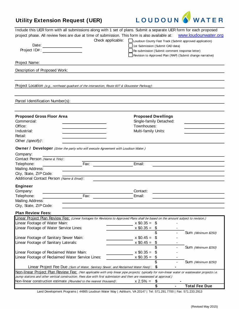
project phase. All review fees are due at time of submission. This form is also available at: www.loudounwater.orgCheck applicable:
Date:Project ID#:
Project Name:
Proposed Dwellings
Owner / Developer (Enter the party who will execute Agreement with Loudoun Water.)
Company:Contact Person (Name & Title) : Telephone: Fax: Email:Mailing Address: City, State, ZIP Code: Additional Contact Person (Name & Email) :
EngineerCompany: Contact: Telephone: Fax: Email:
Plan Review Fees:
Linear Footage of Water Main: x $0.35 = -$ Linear Footage of Water Service Lines: x $0.35 = -$
-$ Sum (Minimum $250)Linear Footage of Sanitary Sewer Main: x $0.45 = -$ Linear Footage of Sanitary Laterals: x $0.45 = -$
-$ Sum (Minimum $250)Linear Footage of Reclaimed Water Main: x $0.35 = -$ Linear Footage of Reclaimed Water Service Lines: x $0.35 = -$
-$ Sum (Minimum $250)-$
Non-linear construction estimate (Rounded to the nearest thousand) : x 2.5% = -$ -$ Total Fee Due
Linear Project Fee Due (Sum of Water, Sanitary Sewer, and Reclaimed Water Fees) :
Other (specify) :
City, State, ZIP Code: Mailing Address:
Include this UER form with all submissions along with 1 set of plans. Submit a separate UER form for each proposed
Parcel Identification Number(s):
Description of Proposed Work:
Project Location (e.g., northeast quadrant of the intersection, Route 607 & Gloucester Parkway) :
Single-family Detached:
Utility Extension Request (UER)
Townhouses:Multi-family Units:
Land Development Programs | 44865 Loudoun Water Way | Ashburn, VA 20147 | Tel: 571.291.7700 | Fax: 571.233.2913
Linear Project Plan Review Fee: (Linear footages for Revisions to Approved Plans shall be based on the amount subject to revision.)
Industrial:Retail:
Non-linear Project Plan Review Fee: (Not applicable with only linear pipe projects; typically for non-linear water or wastewater projects i.e. pump stations and other vertical construction. Fees due with first submission and then are reassessed at approval.)
Proposed Gross Floor AreaCommercial:Office:
Loudoun County Fast Track (Submit approved application)
1st Submission (Submit CAD data)
Re-submission (Submit comment response letter)Revision to Approved Plan (RAP) (Submit change narrative)
(Revised May 2015)

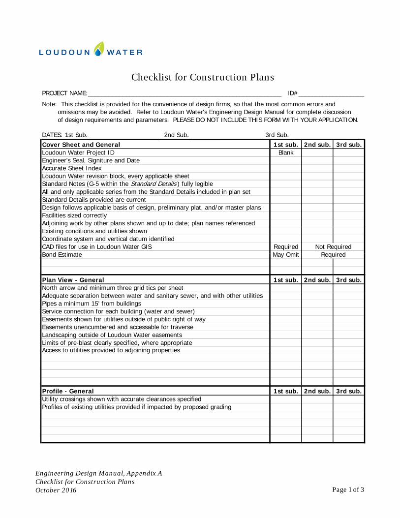
Note: This checklist is provided for the convenience of design firms, so that the most common errors and omissions may be avoided. Refer to Loudoun Water's Engineering Design Manual for complete discussion
Cover Sheet and General 1st sub. 2nd sub. 3rd sub.Loudoun Water Project ID BlankEngineer's Seal, Signiture and DateAccurate Sheet IndexLoudoun Water revision block, every applicable sheetStandard Notes (G-5 within the Standard Details ) fully legibleAll and only applicable series from the Standard Details included in plan setStandard Details provided are currentDesign follows applicable basis of design, preliminary plat, and/or master plansFacilities sized correctlyAdjoining work by other plans shown and up to date; plan names referencedExisting conditions and utilities shownCoordinate system and vertical datum identifiedCAD files for use in Loudoun Water GIS RequiredBond Estimate May Omit Required
DATES: 1st Sub._____________________ 2nd Sub. _____________________ 3rd Sub. ___________________
Checklist for Construction Plans
of design requirements and parameters. PLEASE DO NOT INCLUDE THIS FORM WITH YOUR APPLICATION.
PROJECT NAME:________________________________________________________ ID#___________________
Not RequiredBond Estimate May Omit
Plan View - General 1st sub. 2nd sub. 3rd sub.North arrow and minimum three grid tics per sheetAdequate separation between water and sanitary sewer, and with other utilitiesPipes a minimum 15' from buildingsService connection for each building (water and sewer)Easements shown for utilities outside of public right of wayEasements unencumbered and accessable for traverseLandscaping outside of Loudoun Water easementsLimits of pre-blast clearly specified, where appropriateAccess to utilities provided to adjoining properties
Profile - General 1st sub. 2nd sub. 3rd sub.Utility crossings shown with accurate clearances specifiedProfiles of existing utilities provided if impacted by proposed grading
Required
Engineering Design Manual, Appendix AChecklist for Construction PlansOctober 2016 Page 1 of 3
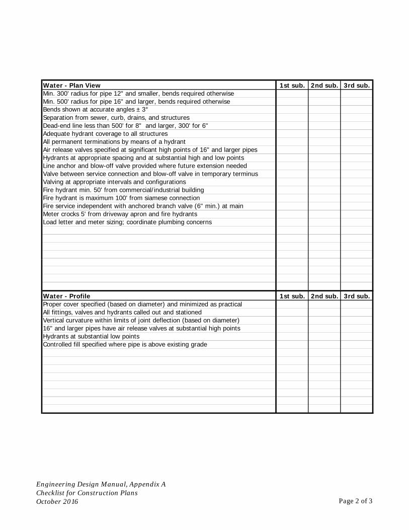
Water - Plan View 1st sub. 2nd sub. 3rd sub.Min. 300' radius for pipe 12" and smaller, bends required otherwiseMin. 500' radius for pipe 16" and larger, bends required otherwiseBends shown at accurate angles ± 3°Separation from sewer, curb, drains, and structuresDead-end line less than 500' for 8" and larger, 300' for 6" Adequate hydrant coverage to all structuresAll permanent terminations by means of a hydrantAir release valves specified at significant high points of 16" and larger pipesHydrants at appropriate spacing and at substantial high and low pointsLine anchor and blow-off valve provided where future extension neededValve between service connection and blow-off valve in temporary terminusValving at appropriate intervals and configurationsFire hydrant min. 50' from commercial/industrial buildingFire hydrant is maximum 100' from siamese connectionFire service independent with anchored branch valve (6" min.) at mainMeter crocks 5' from driveway apron and fire hydrantsLoad letter and meter sizing; coordinate plumbing concerns
Water - Profile 1st sub. 2nd sub. 3rd sub.Proper cover specified (based on diameter) and minimized as practical All fittings, valves and hydrants called out and stationedVertical curvature within limits of joint deflection (based on diameter)16" and larger pipes have air release valves at substantial high pointsHydrants at substantial low pointsControlled fill specified where pipe is above existing grade
Engineering Design Manual, Appendix AChecklist for Construction PlansOctober 2016 Page 2 of 3
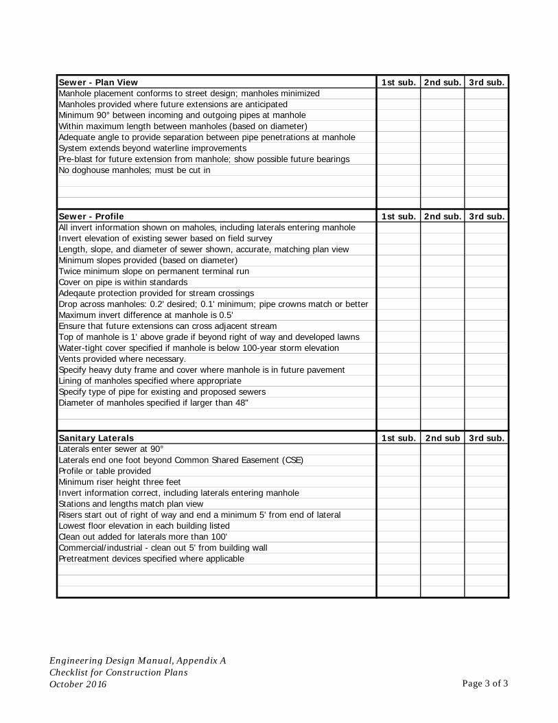
Sewer - Plan View 1st sub. 2nd sub. 3rd sub.Manhole placement conforms to street design; manholes minimizedManholes provided where future extensions are anticipatedMinimum 90° between incoming and outgoing pipes at manholeWithin maximum length between manholes (based on diameter)Adequate angle to provide separation between pipe penetrations at manholeSystem extends beyond waterline improvementsPre-blast for future extension from manhole; show possible future bearingsNo doghouse manholes; must be cut in
Sewer - Profile 1st sub. 2nd sub. 3rd sub.All invert information shown on maholes, including laterals entering manholeInvert elevation of existing sewer based on field surveyLength, slope, and diameter of sewer shown, accurate, matching plan viewMinimum slopes provided (based on diameter)Twice minimum slope on permanent terminal runCover on pipe is within standardsAdeqaute protection provided for stream crossingsDrop across manholes: 0.2' desired; 0.1' minimum; pipe crowns match or betterMaximum invert difference at manhole is 0.5'Ensure that future extensions can cross adjacent streamTop of manhole is 1' above grade if beyond right of way and developed lawnsWater-tight cover specified if manhole is below 100-year storm elevationVents provided where necessary.Specify heavy duty frame and cover where manhole is in future pavementLining of manholes specified where appropriateSpecify type of pipe for existing and proposed sewersDiameter of manholes specified if larger than 48"
Sanitary Laterals 1st sub. 2nd sub 3rd sub.Laterals enter sewer at 90°Laterals end one foot beyond Common Shared Easement (CSE)Profile or table providedMinimum riser height three feetInvert information correct, including laterals entering manholeStations and lengths match plan viewRisers start out of right of way and end a minimum 5' from end of lateralLowest floor elevation in each building listedClean out added for laterals more than 100'Commercial/industrial - clean out 5' from building wallPretreatment devices specified where applicable
Engineering Design Manual, Appendix AChecklist for Construction PlansOctober 2016 Page 3 of 3


Type of Pipe Diameter of Pipe Minimum Soil Cover
to Sanitary Sewer Main, Manhole, or
Other Sewer Structure
to Building or Other Above Ground
Structure
to Storm Drain or Other Underground Utility
to Sanitary Sewerto Other Utillity**
Main 12-inch and Larger 10 feet 15 feet* 6 feet 3.5 feet 1.5 feet 1.5 feet
Main 6-inch to 10-inch 10 feet 15 feet* 6 feet 3 feet 1.5 feet 1.5 feet
Service all sizes6 feet from a
sanitary lateral
5 feet from building, structure,
or driveway5 feet 3 feet 1.5 feet 1.5 feet
Type of Pipe Diameter of Pipe Minimum Soil Cover
Maximum Cover
to Water Mainto Building or Other
Above Ground Structure
to Storm Drain or Other Underground Utility
to Non-Potable Well to Potable Well*Sewer is Below
UtililtySewer is
Above Utillity
Trunk Main or Interceptor 16-inch and larger 10 feet 15 feet 6 feet 25 feet 50 feet 2 feet 1.5 feet 6 feet ** 20 feet ***
Local Collection Main 8-inch to 12-inch 10 feet 15 feet 6 feet 25 feet 50 feet 2 feet 1.5 feet 6 feet ** 20 feet ***
Lateral or Bulding Sewer 4-inch and larger6 feet from a water
service6 feet 6 feet 25 feet 50 feet 2 feet 1.5 feet 2 feet --
Manhole All 10 ft 15 feet 6 feet 25 feet 50 feet
Minimum Horizontal Separation
Minimum Horizontal Separation
Sanitary Sewer
Water and Reclaimed Water
*** Deeper sewers are discouraged, but are occasionally necessary, based on available routes and topography. Successful designs will be those that follow the natural topography. See Chapter 5 for design parameters. Consult Loudoun Water staff where considering a design requiring sewer deeper than 20 vertical feet.
Minimum separation between sewer service connections along the main is 5 feet.
Minimum separation between water service connections along the main is 5 feet.
Minimum Vertical Separation
Minimum Vertical Separation
* For water mains 12-inch and smaller with no more than 5 feet of cover, separation may be reduced to as little as 10 feet with case specific approval from Loudoun Water.
All clearances are as measured outside to outside.
** Where water is above other utility, clearance may be reduced to as little as 0.5 foot, with case specific approval from Loudoun Water. Minimum soil cover on water can be no less than 2 feet. Additional clearance and/or casing may be required where water passes below a large drain or duct. Reduced separation is not permitted where water preexists and other utility is being installed subsequently.
All clearances are as measured outside to outside.
* May be reduced to as little as 35 feet if sewer is pressure pipe, tested in place. This separation is regulated by the Code of Viriginia and Loudoun County Ordinance.
** May be reduced to as little as 3 feet in isolated instances, with case specific approval from Loudoun Water. See Chapter 5 for parameters. At least 4 vertical feet are needed to accomodate a manhole.
Engineering Design Manual, Appendix ATable of Minimum SeparationsOctober 2016

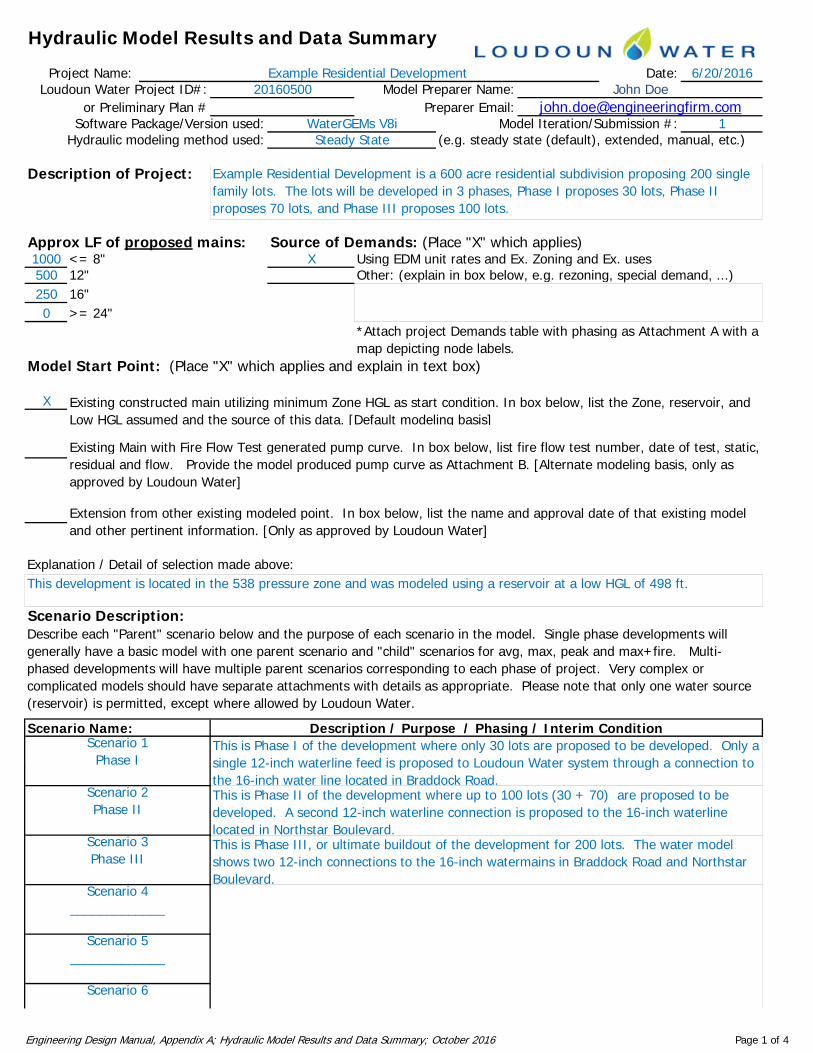
Hydraulic Model Results and Data Summary
Project Name: Date: 6/20/2016Loudoun Water Project ID#: Model Preparer Name:
or Preliminary Plan # Preparer Email:Software Package/Version used: Model Iteration/Submission #: 1
Hydraulic modeling method used: (e.g. steady state (default), extended, manual, etc.)Steady StateWaterGEMs V8i
Example Residential Development 20160500 John Doe
y g ( g y ( ), , , )
Description of Project:
Approx LF of proposed mains: Source of Demands: (Place "X" which applies)1000 <= 8" X Using EDM unit rates and Ex. Zoning and Ex. uses
" h ( l b b l l d d )
y
Example Residential Development is a 600 acre residential subdivision proposing 200 single family lots. The lots will be developed in 3 phases, Phase I proposes 30 lots, Phase II proposes 70 lots, and Phase III proposes 100 lots.
500 12" Other: (explain in box below, e.g. rezoning, special demand, ...)250 16"0 >= 24"
Model Start Point: (Place "X" which applies and explain in text box)
*Attach project Demands table with phasing as Attachment A with a map depicting node labels.
X Existing constructed main utilizing minimum Zone HGL as start condition. In box below, list the Zone, reservoir, and Low HGL assumed and the source of this data. [Default modeling basis]
Existing Main with Fire Flow Test generated pump curve. In box below, list fire flow test number, date of test, static, residual and flow. Provide the model produced pump curve as Attachment B. [Alternate modeling basis, only as approved by Loudoun Water]
Extension from other existing modeled point In box below list the name and approval date of that existing model
Explanation / Detail of selection made above:
Scenario Description:
Extension from other existing modeled point. In box below, list the name and approval date of that existing model and other pertinent information. [Only as approved by Loudoun Water]
This development is located in the 538 pressure zone and was modeled using a reservoir at a low HGL of 498 ft.
Describe each "Parent" scenario below and the purpose of each scenario in the model. Single phase developments will
Scenario 1Phase I
This is Phase I of the development where only 30 lots are proposed to be developed. Only a single 12 inch waterline feed is proposed to Loudoun Water system through a connection to
p p g p pgenerally have a basic model with one parent scenario and "child" scenarios for avg, max, peak and max+fire. Multi-phased developments will have multiple parent scenarios corresponding to each phase of project. Very complex or complicated models should have separate attachments with details as appropriate. Please note that only one water source (reservoir) is permitted, except where allowed by Loudoun Water.
Scenario Name: Description / Purpose / Phasing / Interim Condition
Scenario 2Phase II
This is Phase II of the development where up to 100 lots (30 + 70) are proposed to be developed. A second 12-inch waterline connection is proposed to the 16-inch waterline located in Northstar Boulevard.
Scenario 3Phase III
This is Phase III, or ultimate buildout of the development for 200 lots. The water model shows two 12-inch connections to the 16-inch watermains in Braddock Road and Northstar Boulevard.
Phase I single 12-inch waterline feed is proposed to Loudoun Water system through a connection to the 16-inch water line located in Braddock Road.
Scenario 5_____________
Scenario 6
Scenario 4_____________
Engineering Design Manual, Appendix A; Hydraulic Model Results and Data Summary; October 2016 Page 1 of 4
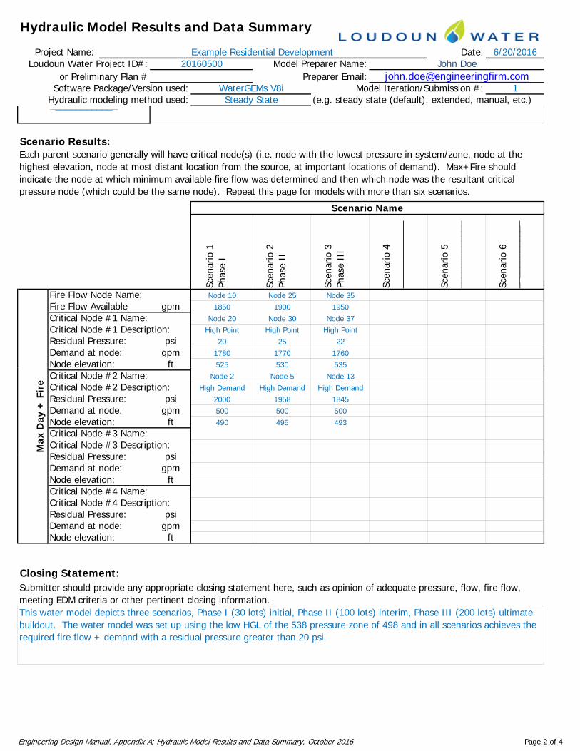
Hydraulic Model Results and Data Summary
Project Name: Date: 6/20/2016Loudoun Water Project ID#: Model Preparer Name:
or Preliminary Plan # Preparer Email:Software Package/Version used: Model Iteration/Submission #: 1
Hydraulic modeling method used: (e.g. steady state (default), extended, manual, etc.)Steady StateWaterGEMs V8i
Example Residential Development 20160500 John Doe
y g ( g y ( ), , , )y
Scenario Results:
_____________
Each parent scenario generally will have critical node(s) (i.e. node with the lowest pressure in system/zone, node at the highest elevation, node at most distant location from the source, at important locations of demand). Max+Fire should indicate the node at which minimum available fire flow was determined and then which node was the resultant critical pressure node (which could be the same node) Repeat this page for models with more than six scenarios
cena
rio 1
hase
I
cena
rio 2
hase
II
cena
rio 3
hase
III
cena
rio 4
____
____
____
cena
rio 5
____
____
____
cena
rio 6
____
____
____
pressure node (which could be the same node). Repeat this page for models with more than six scenarios.
Scenario NameSc Ph Sc Ph Sc Ph Sc __ Sc __ Sc __
Fire Flow Node Name: Node 10 Node 25 Node 35Fire Flow Available gpm 1850 1900 1950Critical Node #1 Name: Node 20 Node 30 Node 37Critical Node #1 Description: High Point High Point High PointResidual Pressure: psi 20 25 22Demand at node: gpm 1780 1770 1760Node elevation: ft 525 530 535Critical Node #2 Name: Node 2 Node 5 Node 13Critical Node #2 Description: High Demand High Demand High DemandResidual Pressure: psi 2000 1958 1845Demand at node: gpm 500 500 500Node elevation: ft 490 495 493Critical Node #3 Name:Critical Node #3 Description:Residual Pressure: psi
Max
Day
+ F
ire
Residual Pressure: psiDemand at node: gpmNode elevation: ftCritical Node #4 Name:Critical Node #4 Description:Residual Pressure: psiDemand at node: gpmNode elevation: ft
Closing Statement: Submitter should provide any appropriate closing statement here, such as opinion of adequate pressure, flow, fire flow, meeting EDM criteria or other pertinent closing information.This water model depicts three scenarios, Phase I (30 lots) initial, Phase II (100 lots) interim, Phase III (200 lots) ultimate buildout. The water model was set up using the low HGL of the 538 pressure zone of 498 and in all scenarios achieves the required fire flow + demand with a residual pressure greater than 20 psi.
Engineering Design Manual, Appendix A; Hydraulic Model Results and Data Summary; October 2016 Page 2 of 4
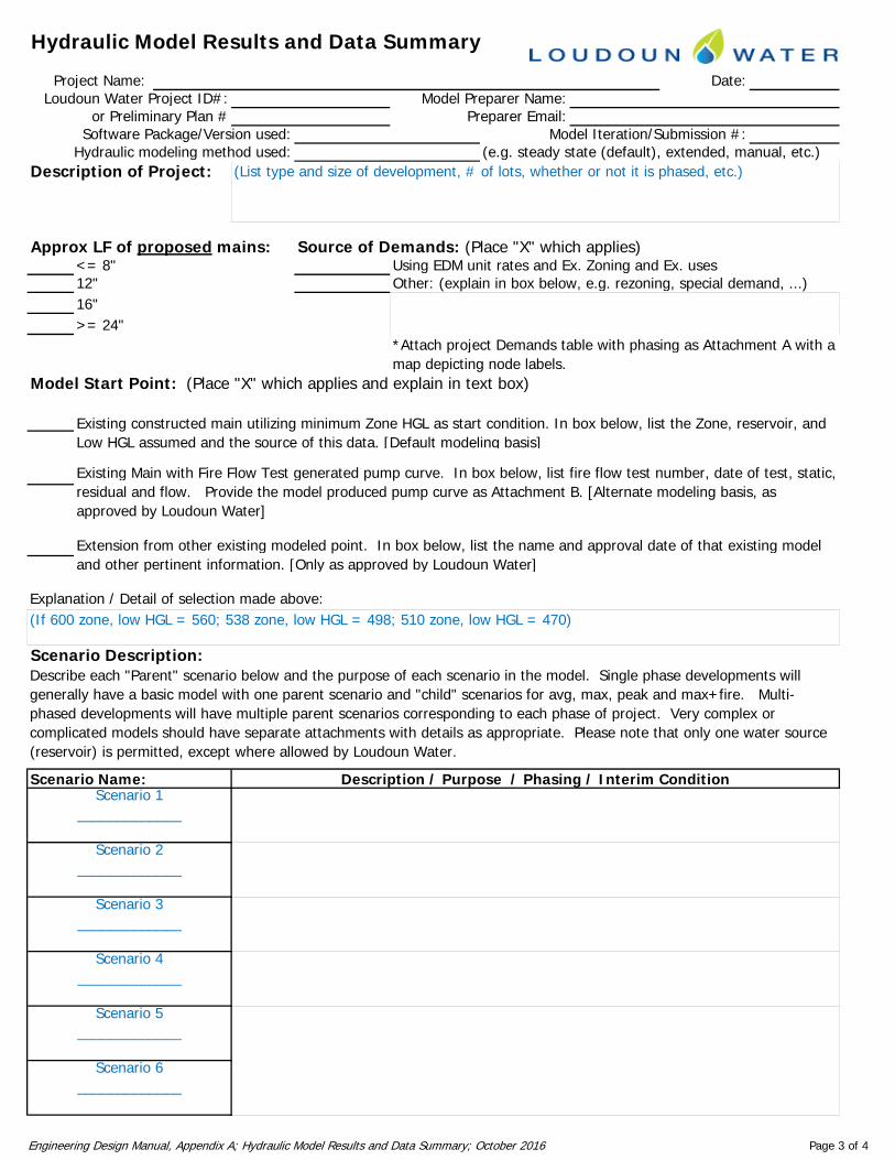
Hydraulic Model Results and Data Summary
Project Name: Date:Loudoun Water Project ID#: Model Preparer Name:
or Preliminary Plan # Preparer Email:Software Package/Version used: Model Iteration/Submission #:
Hydraulic modeling method used: (e.g. steady state (default), extended, manual, etc.)Description of Project:
Approx LF of proposed mains: Source of Demands: (Place "X" which applies)<= 8" Using EDM unit rates and Ex. Zoning and Ex. uses12" Other: (explain in box below, e.g. rezoning, special demand, ...)
(List type and size of development, # of lots, whether or not it is phased, etc.)
16">= 24"
Model Start Point: (Place "X" which applies and explain in text box)
Existing constructed main utilizing minimum Zone HGL as start condition. In box below, list the Zone, reservoir, and
*Attach project Demands table with phasing as Attachment A with a map depicting node labels.
Low HGL assumed and the source of this data. [Default modeling basis]
Extension from other existing modeled point. In box below, list the name and approval date of that existing model and other pertinent information. [Only as approved by Loudoun Water]
Existing Main with Fire Flow Test generated pump curve. In box below, list fire flow test number, date of test, static, residual and flow. Provide the model produced pump curve as Attachment B. [Alternate modeling basis, as approved by Loudoun Water]
Explanation / Detail of selection made above:
Scenario Description:
and other pertinent information. [Only as approved by Loudoun Water]
Describe each "Parent" scenario below and the purpose of each scenario in the model. Single phase developments will generally have a basic model with one parent scenario and "child" scenarios for avg, max, peak and max+fire. Multi-
(If 600 zone, low HGL = 560; 538 zone, low HGL = 498; 510 zone, low HGL = 470)
Description / Purpose / Phasing / Interim ConditionScenario Name:Scenario 1
_____________
phased developments will have multiple parent scenarios corresponding to each phase of project. Very complex or complicated models should have separate attachments with details as appropriate. Please note that only one water source (reservoir) is permitted, except where allowed by Loudoun Water.
Scenario 2_____________
Scenario 3_____________
Scenario 4_____________
Scenario 5_____________
Scenario 6_____________
Engineering Design Manual, Appendix A; Hydraulic Model Results and Data Summary; October 2016 Page 3 of 4
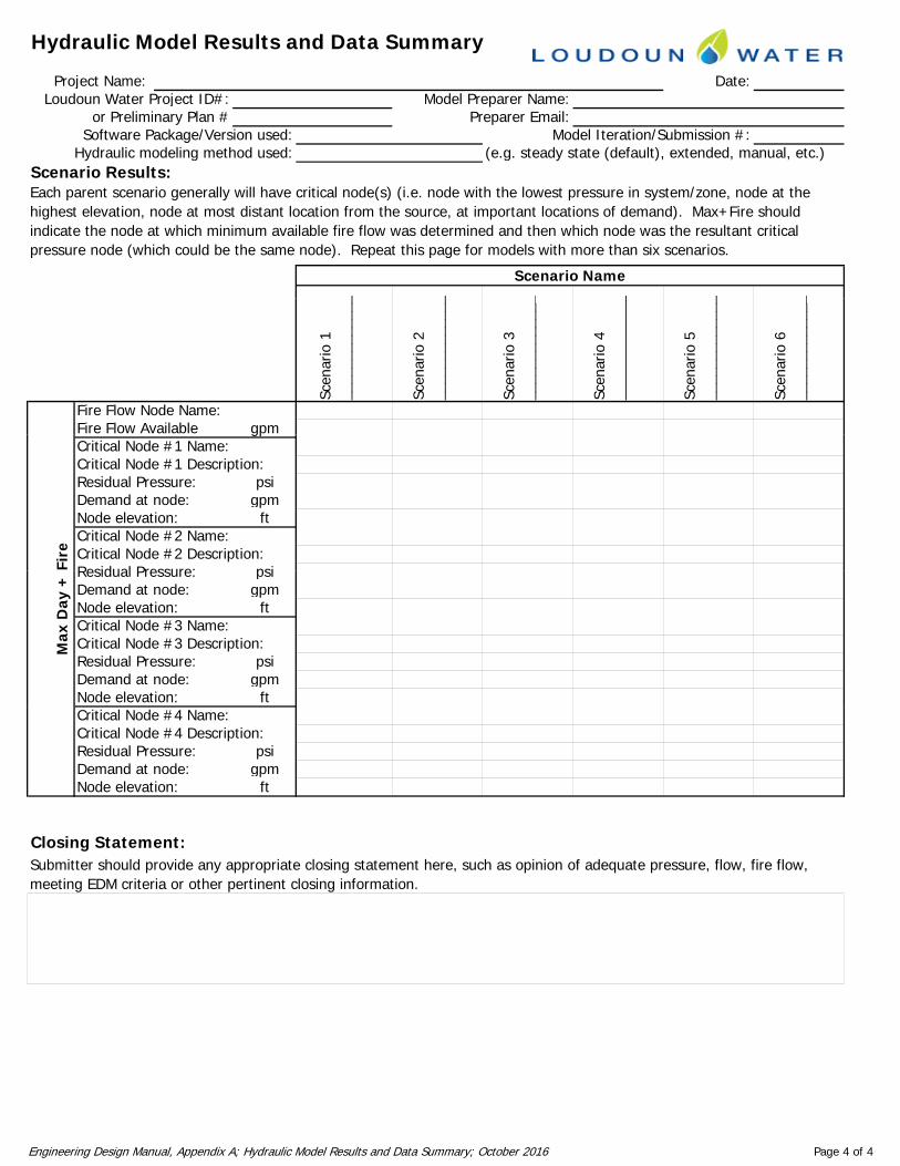
Hydraulic Model Results and Data Summary
Project Name: Date:Loudoun Water Project ID#: Model Preparer Name:
or Preliminary Plan # Preparer Email:Software Package/Version used: Model Iteration/Submission #:
Hydraulic modeling method used: (e.g. steady state (default), extended, manual, etc.)Scenario Results:
_ _ _ _ _ _
Each parent scenario generally will have critical node(s) (i.e. node with the lowest pressure in system/zone, node at the highest elevation, node at most distant location from the source, at important locations of demand). Max+Fire should indicate the node at which minimum available fire flow was determined and then which node was the resultant critical pressure node (which could be the same node). Repeat this page for models with more than six scenarios.
Scenario Name
Scen
ario
1__
____
____
___
Scen
ario
2__
____
____
___
Scen
ario
3__
____
____
___
Scen
ario
4__
____
____
___
Scen
ario
5__
____
____
___
Scen
ario
6__
____
____
___
Fire Flow Node Name:Fire Flow Available gpmgpCritical Node #1 Name:Critical Node #1 Description:Residual Pressure: psiDemand at node: gpmNode elevation: ftCritical Node #2 Name:Critical Node #2 Description:Residual Pressure: psiFi
re
Residual Pressure: psiDemand at node: gpmNode elevation: ftCritical Node #3 Name:Critical Node #3 Description:Residual Pressure: psiDemand at node: gpmNode elevation: ft
Max
Day
+
Critical Node #4 Name:Critical Node #4 Description:Residual Pressure: psiDemand at node: gpmNode elevation: ft
Closing Statement:Closing Statement: Submitter should provide any appropriate closing statement here, such as opinion of adequate pressure, flow, fire flow, meeting EDM criteria or other pertinent closing information.
Engineering Design Manual, Appendix A; Hydraulic Model Results and Data Summary; October 2016 Page 4 of 4
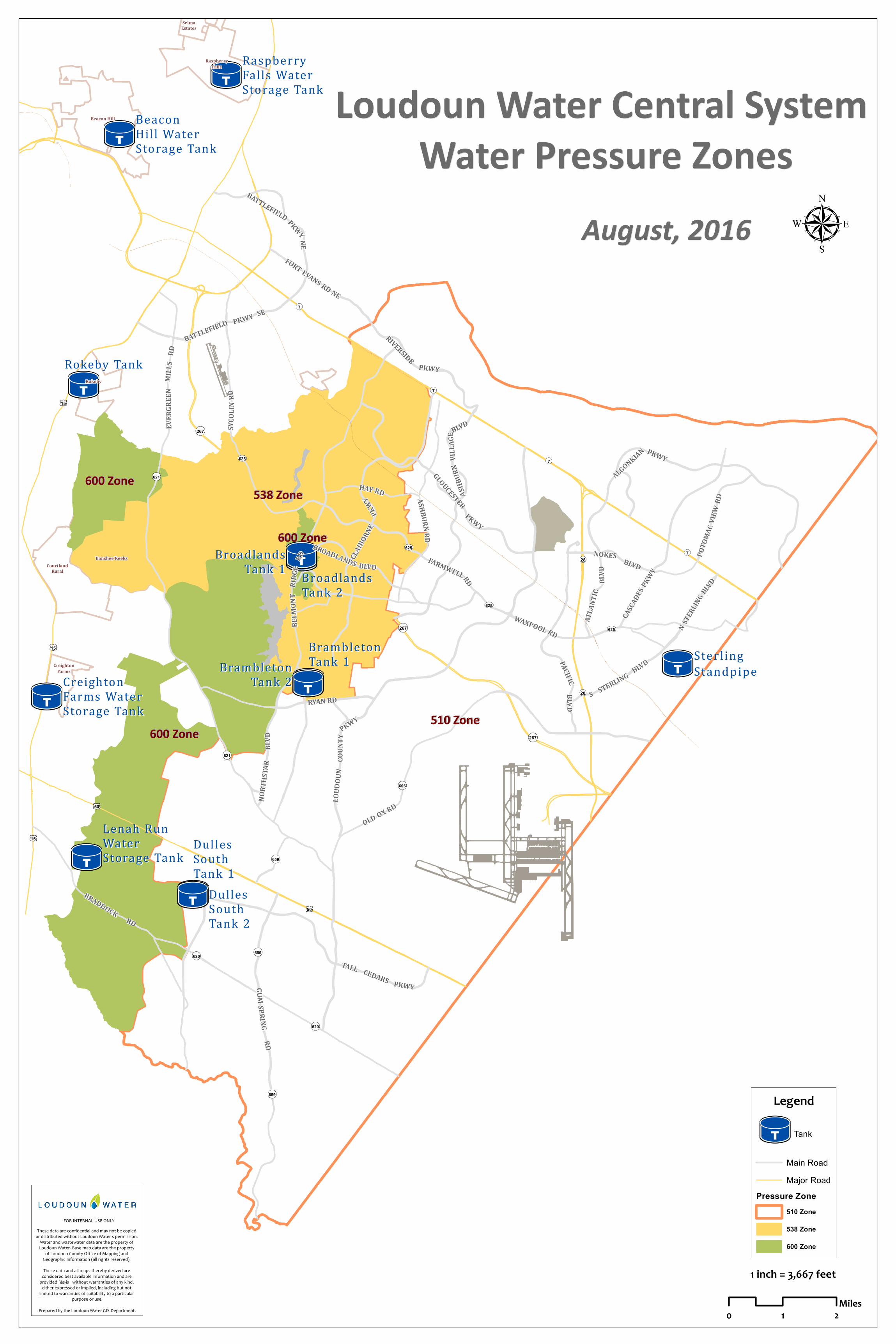
TUTT
TUTT
TUTTTUTTTUTT
TUTT
TUTT
TUTT
TUTT
TUTT
TUTTTUTT
¬(7
¬(7
¬(7¬(28
¬(28
¡¢50
¡¢50
!(620
!(620
!(606
¬(267
¬(267
!(621
!(621
¡¢15
¡¢15
¡¢15
¬(7
!(659
!(659
!(659
¬(267
UV625
UV625
UV625
UV625
SelmaEstates
RaspberryFalls
Beacon Hill
CreightonFarms
Banshee ReeksCourtland
Rural
Rokeby
BroadlandsBroadlandsTank 2Tank 2
SterlingSterlingStandpipeStandpipe
Lenah RunLenah RunWaterWaterStorage TankStorage Tank
DullesDullesSouthSouthTank 1Tank 1
DullesDullesSouthSouthTank 2Tank 2
Rokeby TankRokeby Tank
RaspberryRaspberryFalls WaterFalls WaterStorage TankStorage Tank
BeaconBeaconHill WaterHill WaterStorage TankStorage Tank
CreightonCreightonFarms WaterFarms WaterStorage TankStorage Tank
BroadlandsBroadlandsTank 1Tank 1
BrambletonBrambletonTank 1Tank 1BrambletonBrambleton
Tank 2Tank 2
600 Zone600 Zone
510 Zone510 Zone600 Zone600 Zone
600 Zone600 Zone
538 Zone538 Zone
OLD OX RD
GLOUCESTER
PKWY
WAXPOOL RD
TALL CEDARS PKWY
RYAN RD
HAY RD
NORT
HSTA
RBL
VD
SYCO
L INRD
RIVERSIDE
PKWY
CASCA
DESPK
WY
BATTLEFIELD PKWY SE
LOUD
OUN
COUN
T Y
PKWY
BROADLANDS BLVD
S STERLING BLVD
ALGONKIAN PKWY
NOKES BLVD
BRADDOCKRD
FARMWELLRD
N STERLIN
G BLVDPO
TOMA
C VIEW
RD
ASHB
URN
VILLA
GE
BLVD
ATLA
NTIC
BLVD
GUMSPRING
RD
CLAIBO
RNE
PKWY
EVER
GREE
NMI
LLS
RD
BATTLEFIELD PKWYNE
PACIFICBL VD
BELM
ONT
RIDGE
RD
ASHBURNRD
FORT EVANS RD NE
Loudoun Water Central System Loudoun Water Central System Water Pressure ZonesWater Pressure Zones
August, 2016August, 2016 µ
FOR INTERNAL USE ONLYThese data are confidential and may not be copied or distribu ted w ithou t Lou dou n Water’s permission. Water and w astew ater data are the p roperty of Lou dou n Water. Base map data are the p roperty of Lou dou n Cou nty Office of Map ping and Geog raphic Information (all rig hts reserv ed). These data and all maps thereby deriv ed are considered best available information and are p rov ided “as-is” w ithou t w arranties of any kind, either exp ressed or implied, inclu ding bu t not limited to w arranties of su itability to a particu lar
p u rp ose or u se.Prepared by the Lou dou n Water GIS Department. 0 1 2
Miles
1 inch = 3,667 feet
Legend
TUTT Tank
Main RoadMajor Road
Pressure Zone510 Zone
538 Zone
600 Zone

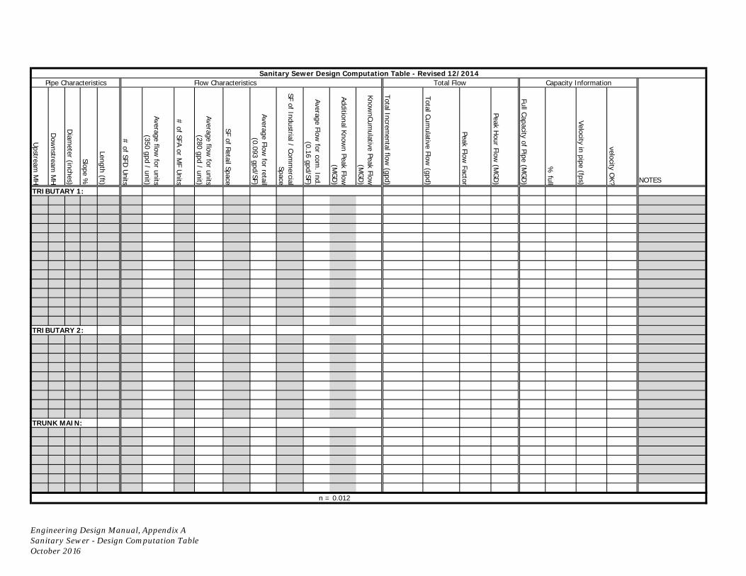
Upstream
MH
Dow
nstream M
H
Diam
eter (inches)
Slope %
Length (ft)
# of SFD
Units
Average flow for units
(350 gpd / unit)
# of SFA or M
F Units
Average flow for units
(280 gpd / unit)
SF of Retail Space
Average Flow for retail
(0.093 gpd/SF)
SF of Industrial / Comm
ercial Space
Average Flow for com
. Ind. (0.16 gpd/SF)
Additional Known Peak Flow
(M
GD
)
KnownCum
ulative Peak Flow
(MG
D)
Total Incremental flow
(gpd)
Total Cumulative Flow
(gpd)
Peak Flow Factor
Peak Hour Flow
(MG
D)
Full Capacity of Pipe (MG
D)
% full
Velocity in pipe (fps)
velocity OK?
NOTES
TRIBUTARY 1:
TRIBUTARY 2:
TRUNK MAIN:
n = 0.012
Sanitary Sewer Design Computation Table - Revised 12/2014Pipe Characteristics Flow Characteristics Total Flow Capacity Information
Engineering Design Manual, Appendix ASanitary Sewer - Design Computation TableOctober 2016

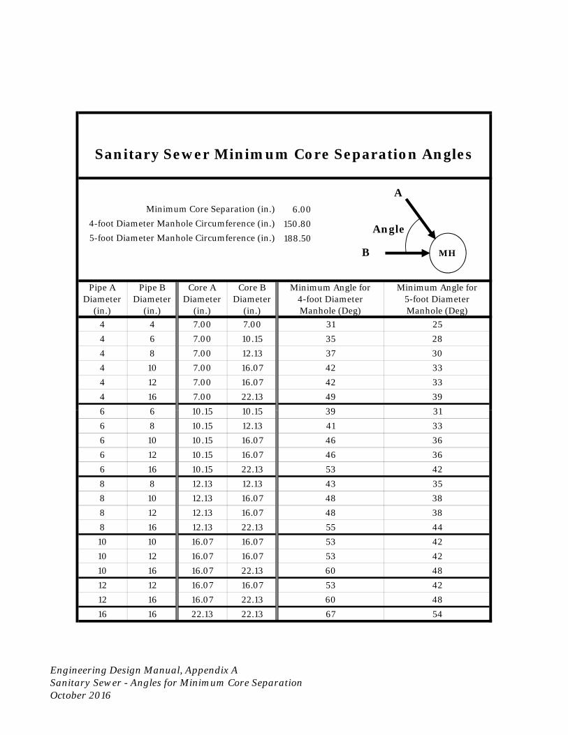
6.00
150.80
188.50
Pipe ADiameter
(in.)
Pipe BDiameter
(in.)
Core ADiameter
(in.)
Core BDiameter
(in.)
Minimum Angle for4-foot DiameterManhole (Deg)
Minimum Angle for5-foot DiameterManhole (Deg)
4 4 7.00 7.00 31 25
4 6 7.00 10.15 35 28
4 8 7.00 12.13 37 30
4 10 7.00 16.07 42 33
4 12 7.00 16.07 42 33
4 16 7.00 22.13 49 396 6 10 15 10 15 39 31
Minimum Core Separation (in.)
Sanitary Sewer Minimum Core Separation Angles
4-foot Diameter Manhole Circumference (in.)
5-foot Diameter Manhole Circumference (in.)
MH
A
B
Angle
6 6 10.15 10.15 39 316 8 10.15 12.13 41 33
6 10 10.15 16.07 46 36
6 12 10.15 16.07 46 36
6 16 10.15 22.13 53 42
8 8 12.13 12.13 43 35
8 10 12.13 16.07 48 38
8 12 12.13 16.07 48 38
8 16 12.13 22.13 55 44
10 10 16.07 16.07 53 42
10 12 16.07 16.07 53 42
10 16 16.07 22.13 60 48
12 12 16.07 16.07 53 42
12 16 16.07 22.13 60 48
16 16 22.13 22.13 67 54
Engineering Design Manual, Appendix ASanitary Sewer - Angles for Minimum Core SeparationOctober 2016

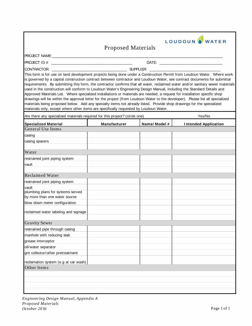
Are there any specialized materials required for this project? (circle one) Yes/No
Specialized Material Manufacturer Name/Model # Intended Application
casing
casing spacers
General Use Items
Water
Proposed MaterialsPROJECT NAME:____________________________________________________________________________________
PROJECT ID # ________________________________________ DATE: _______________________________
CONTRACTOR: _____________________________________ SUPPLIER: ___________________________________This form is for use on land development projects being done under a Construction Permit from Loudoun Water. Where work is governed by a capital construction contract between contractor and Loudoun Water, see contract documents for submittal requirements. By submitting this form, the contractor confirms that all water, reclaimed water and/or sanitary sewer materials used in the construction will conform to Loudoun Water's Engineering Design Manual, including the Standard Details and Approved Materials List. Where specialized installations or materials are needed, a request for installation specific shop drawings will be within the approval letter for the project (from Loudoun Water to the developer). Please list all specialized materials being proposed below. Add any specialty items not already listed. Provide shop drawings for the specialized materials only, except where other items are specifically requested by Loudoun Water.
restrained joint piping system
vault
restrained joint piping system
vaultplumbing plans for systems served by more than one water source
blow down meter configuration
reclaimed water labeling and signage
restrained pipe through casing
manhole with reducing slab
grease interceptor
oil/water separator
grit collector/other pretreatment
reclamation system (e.g at car wash)
Reclaimed Water
Other Items
Water
Gravity Sewer
Engineering Design Manual, Appendix AProposed MaterialsProposed MaterialsOctober 2016 Page 1 of 1

Appendix B
Engineering Design Manual October 2016
Appendix B: Estimating Construction Cost for Bonding
Estimate of Construction Cost
Extension Bond for Subdivisions
Estimate of Construction Cost for Site Plans

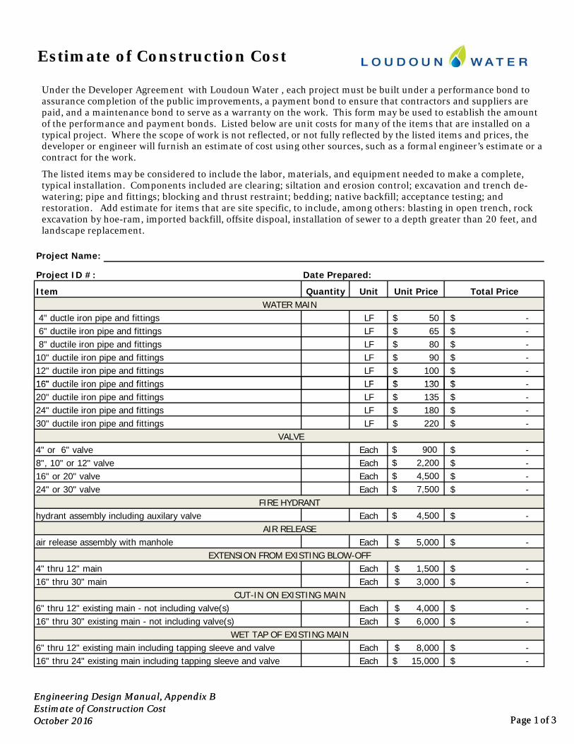
Quantity Unit Unit Price Total Price
LF 50$ -$ LF 65$ -$ LF 80$ -$ LF 90$ -$ LF 100$ -$ LF 130$ $
WATER MAIN 4" ductle iron pipe and fittings
Item
12" ductile iron pipe and fittings16" ductile iron pipe and fittings
Project Name:
Date Prepared:Project ID #:
Estimate of Construction Cost
6" ductile iron pipe and fittings 8" ductile iron pipe and fittings10" ductile iron pipe and fittings
Under the Developer Agreement with Loudoun Water , each project must be built under a performance bond to assurance completion of the public improvements, a payment bond to ensure that contractors and suppliers are paid, and a maintenance bond to serve as a warranty on the work. This form may be used to establish the amount of the performance and payment bonds. Listed below are unit costs for many of the items that are installed on a typical project. Where the scope of work is not reflected, or not fully reflected by the listed items and prices, the developer or engineer will furnish an estimate of cost using other sources, such as a formal engineer’s estimate or a contract for the work.
The listed items may be considered to include the labor, materials, and equipment needed to make a complete, typical installation. Components included are clearing; siltation and erosion control; excavation and trench de-watering; pipe and fittings; blocking and thrust restraint; bedding; native backfill; acceptance testing; and restoration. Add estimate for items that are site specific, to include, among others: blasting in open trench, rock excavation by hoe-ram, imported backfill, offsite dispoal, installation of sewer to a depth greater than 20 feet, and landscape replacement.
Engineering Design Manual, Appendix BEstimate of Construction CostOctober 2016 Page 1 of 3
LF 130$ -$ LF 135$ -$ LF 180$ -$ LF 220$ -$
Each $ 900 -$ Each $ 2,200 -$ Each $ 4,500 -$ Each $ 7,500 -$
Each $ 4,500 -$
Each 5,000$ -$
Each 1,500$ -$ Each 3,000$ -$
Each 4,000$ -$ Each 6,000$ -$
Each 8,000$ -$ Each 15,000$ -$
16" ductile iron pipe and fittings
hydrant assembly including auxilary valve
4" thru 12" mainEXTENSION FROM EXISTING BLOW-OFF
CUT-IN ON EXISTING MAIN
4" or 6" valve 8", 10" or 12" valve16" or 20" valve24" or 30" valve
20" ductile iron pipe and fittings
16" thru 30" main
6" thru 12" existing main - not including valve(s)16" thru 30" existing main - not including valve(s)
6" thru 12" existing main including tapping sleeve and valve
VALVE
FIRE HYDRANT
24" ductile iron pipe and fittings
AIR RELEASEair release assembly with manhole
30" ductile iron pipe and fittings
WET TAP OF EXISTING MAIN
16" thru 24" existing main including tapping sleeve and valve
Engineering Design Manual, Appendix BEstimate of Construction CostOctober 2016 Page 1 of 3
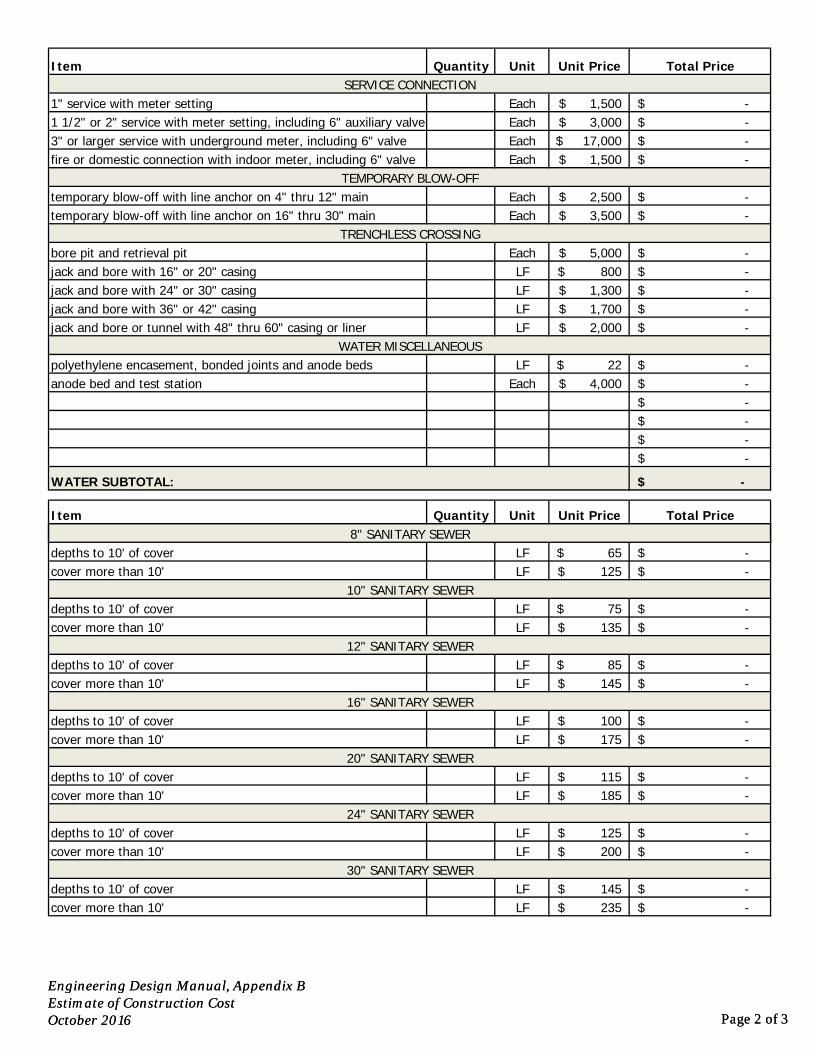
Quantity Unit Unit Price Total Price
Each 1,500$ -$ Each 3,000$ -$ Each 17,000$ -$ Each 1,500$ -$
Each 2,500$ -$ Each 3,500$ -$
Each 5,000$ -$ LF 800$ -$ LF 1,300$ -$ LF 1,700$ -$ LF 2,000$ -$
LF 22$ -$ Each 4,000$ -$
-$ -$ -$ -$
-$
Quantity Unit Unit Price Total Price
SERVICE CONNECTION
WATER MISCELLANEOUS
Item
polyethylene encasement, bonded joints and anode bedsanode bed and test station
bore pit and retrieval pit
jack and bore or tunnel with 48" thru 60" casing or liner
TRENCHLESS CROSSING
3" or larger service with underground meter, including 6" valve
temporary blow-off with line anchor on 16" thru 30" main
jack and bore with 36" or 42" casing
Item8" SANITARY SEWER
WATER SUBTOTAL:
1" service with meter setting1 1/2" or 2" service with meter setting, including 6" auxiliary valve
jack and bore with 16" or 20" casingjack and bore with 24" or 30" casing
TEMPORARY BLOW-OFFfire or domestic connection with indoor meter, including 6" valve
temporary blow-off with line anchor on 4" thru 12" main
Engineering Design Manual, Appendix BEstimate of Construction CostOctober 2016 Page 2 of 3
LF 65$ -$ LF 125$ -$
LF 75$ -$ LF 135$ -$
LF 85$ -$ LF 145$ -$
LF 100$ -$ LF 175$ -$
LF 115$ -$ LF 185$ -$
LF 125$ -$ LF 200$ -$
LF 145$ -$ LF 235$ -$
depths to 10' of cover20" SANITARY SEWER
16" SANITARY SEWER
depths to 10' of cover
30" SANITARY SEWER
cover more than 10'
cover more than 10'
24" SANITARY SEWER
cover more than 10'
depths to 10' of cover
depths to 10' of covercover more than 10'
depths to 10' of cover
depths to 10' of cover
depths to 10' of cover12" SANITARY SEWER
8 SANITARY SEWER
10" SANITARY SEWERcover more than 10'
cover more than 10'
cover more than 10'
Engineering Design Manual, Appendix BEstimate of Construction CostOctober 2016 Page 2 of 3
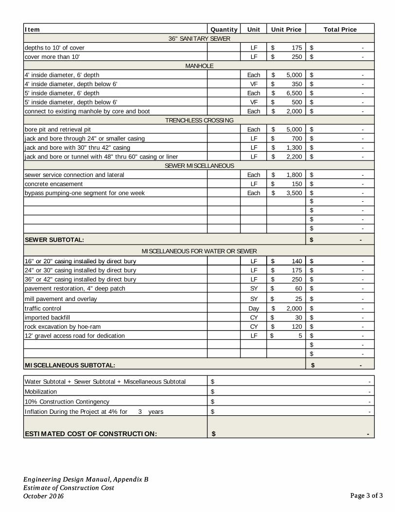
Quantity Unit Unit Price Total Price
LF 175$ -$ LF 250$ -$
Each 5,000$ -$ VF 350$ -$
Each 6,500$ -$ VF 500$ -$
Each 2,000$ -$
Each 5,000$ -$ LF 700$ -$ LF 1,300$ -$ LF 2,200$ -$
Each 1,800$ -$ LF 150$ -$
Each 3,500$ -$ -$ -$ -$ -$
-$
LF 140$ -$
SEWER MISCELLANEOUS
4' inside diameter, depth below 6'
TRENCHLESS CROSSING
5' inside diameter, 6' depth
Item
jack and bore or tunnel with 48" thru 60" casing or liner
bore pit and retrieval pit
4' inside diameter, 6' depth
jack and bore through 24" or smaller casing
connect to existing manhole by core and boot
jack and bore with 30" thru 42" casing
SEWER SUBTOTAL:
36" SANITARY SEWER
MANHOLE
depths to 10' of cover
sewer service connection and lateral
cover more than 10'
5' inside diameter, depth below 6'
bypass pumping-one segment for one week
MISCELLANEOUS FOR WATER OR SEWER
16" or 20" casing installed by direct bury
concrete encasement
Engineering Design Manual, Appendix BEstimate of Construction CostOctober 2016 Page 3 of 3
LF 140$ $ LF 175$ -$ LF 250$ -$ SY 60$ -$
SY 25$ -$ Day 2,000$ -$ CY 30$ -$ CY 120$ -$ LF 5$ -$
-$ -$
-$
3 years
MISCELLANEOUS SUBTOTAL:
imported backfill
pavement restoration, 4" deep patch
Inflation During the Project at 4% for
Mobilization
10% Construction Contingency
mill pavement and overlay
24" or 30" casing installed by direct bury
-$
12' gravel access road for dedicationrock excavation by hoe-ram
ESTIMATED COST OF CONSTRUCTION:
-$
-$
-$
36" or 42" casing installed by direct bury
Water Subtotal + Sewer Subtotal + Miscellaneous Subtotal
16 or 20 casing installed by direct bury
traffic control
-$
Engineering Design Manual, Appendix BEstimate of Construction CostOctober 2016 Page 3 of 3

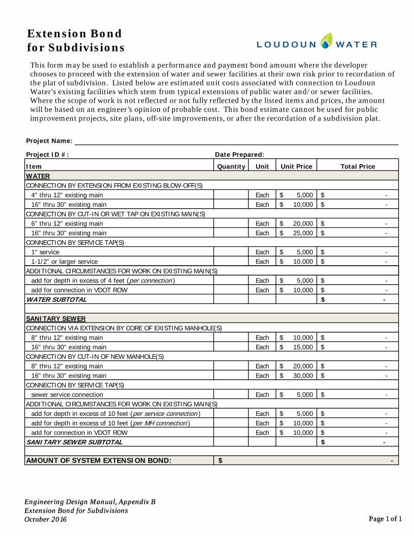
Quantity Unit Unit Price Total Price
Each 5,000$ -$ Each 10,000$ -$
Each 20,000$ -$ Each 25,000$ -$
Each 5,000$ -$ Each 10,000$ -$
Extension Bond for Subdivisions
6" thru 12" existing main
4" thru 12" existing main
16" thru 30" existing main
ItemWATER
16" thru 30" existing main
CONNECTION BY EXTENSION FROM EXISTING BLOW-OFF(S)
Project Name:
Project ID #: Date Prepared:
ADDITIONAL CIRCUMSTANCES FOR WORK ON EXISTING MAIN(S)
CONNECTION BY SERVICE TAP(S)
CONNECTION BY CUT-IN OR WET TAP ON EXISTING MAIN(S)
1-1/2" or larger service1" service
This form may be used to establish a performance and payment bond amount where the developer chooses to proceed with the extension of water and sewer facilities at their own risk prior to recordation of the plat of subdivision. Listed below are estimated unit costs associated with connection to Loudoun Water's existing facilities which stem from typical extensions of public water and/or sewer facilities. Where the scope of work is not reflected or not fully reflected by the listed items and prices, the amount will be based on an engineer’s opinion of probable cost. This bond estimate cannot be used for public improvement projects, site plans, off-site improvements, or after the recordation of a subdivision plat.
Engineering Design Manual, Appendix BExtension Bond for Subdivisions October 2016 Page 1 of 1
Each 5,000$ -$ Each 10,000$ -$
-$
Each 10,000$ -$ Each 15,000$ -$
Each 20,000$ -$ Each 30,000$ -$
Each 5,000$ -$
Each 5,000$ -$ Each 10,000$ -$ Each 10,000$ -$
-$
8" thru 12" existing main
AMOUNT OF SYSTEM EXTENSION BOND: -$
SANITARY SEWER SUBTOTAL add for connection in VDOT ROW
16" thru 30" existing mainCONNECTION BY SERVICE TAP(S)
add for depth in excess of 10 feet (per MH connection )add for depth in excess of 10 feet (per service connection )
ADDITIONAL CIRCUMSTANCES FOR WORK ON EXISTING MAIN(S)sewer service connection
( )
add for connection in VDOT ROW
CONNECTION BY CUT-IN OF NEW MANHOLE(S)
add for depth in excess of 4 feet (per connection )
8" thru 12" existing mainCONNECTION VIA EXTENSION BY CORE OF EXISTING MANHOLE(S)SANITARY SEWER
16" thru 30" existing main
WATER SUBTOTAL
Engineering Design Manual, Appendix BExtension Bond for Subdivisions October 2016 Page 1 of 1

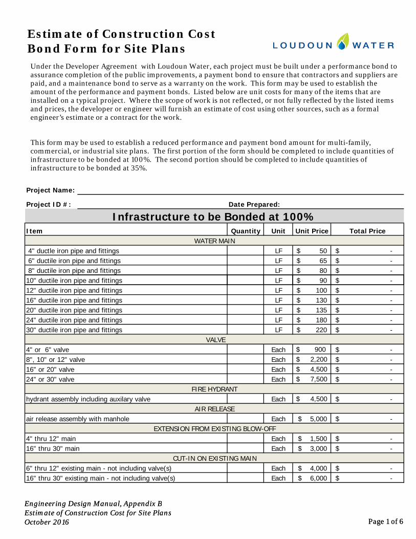
Quantity Unit Unit Price Total Price
LF 50$ -$ LF 65$ -$ LF 80$ -$
Infrastructure to be Bonded at 100%
Estimate of Construction Cost Bond Form for Site Plans
6" ductile iron pipe and fittings 8" ductile iron pipe and fittings
Project Name:
Date Prepared:Project ID #:
WATER MAIN 4" ductle iron pipe and fittings
Item
Under the Developer Agreement with Loudoun Water, each project must be built under a performance bond to assurance completion of the public improvements, a payment bond to ensure that contractors and suppliers are paid, and a maintenance bond to serve as a warranty on the work. This form may be used to establish the amount of the performance and payment bonds. Listed below are unit costs for many of the items that are installed on a typical project. Where the scope of work is not reflected, or not fully reflected by the listed items and prices, the developer or engineer will furnish an estimate of cost using other sources, such as a formal engineer’s estimate or a contract for the work.
This form may be used to establish a reduced performance and payment bond amount for multi-family, commercial, or industrial site plans. The first portion of the form should be completed to include quantities of infrastructure to be bonded at 100%. The second portion should be completed to include quantities of infrastructure to be bonded at 35%.
Engineering Design Manual, Appendix BEstimate of Construction Cost for Site PlansOctober 2016 Page 1 of 6
LF 90$ -$ LF 100$ -$ LF 130$ -$ LF 135$ -$ LF 180$ -$ LF 220$ -$
Each $ 900 -$ Each $ 2,200 -$ Each $ 4,500 -$ Each $ 7,500 -$
Each $ 4,500 -$
Each 5,000$ -$
Each 1,500$ -$ Each 3,000$ -$
Each 4,000$ -$ Each 6,000$ -$
FIRE HYDRANT
24" ductile iron pipe and fittings
AIR RELEASEair release assembly with manhole
10" ductile iron pipe and fittings
30" ductile iron pipe and fittings
8", 10" or 12" valve16" or 20" valve24" or 30" valve
20" ductile iron pipe and fittings
16" thru 30" main
6" thru 12" existing main - not including valve(s)16" thru 30" existing main - not including valve(s)
VALVE
hydrant assembly including auxilary valve
4" thru 12" mainEXTENSION FROM EXISTING BLOW-OFF
12" ductile iron pipe and fittings16" ductile iron pipe and fittings
CUT-IN ON EXISTING MAIN
4" or 6" valve
Engineering Design Manual, Appendix BEstimate of Construction Cost for Site PlansOctober 2016 Page 1 of 6
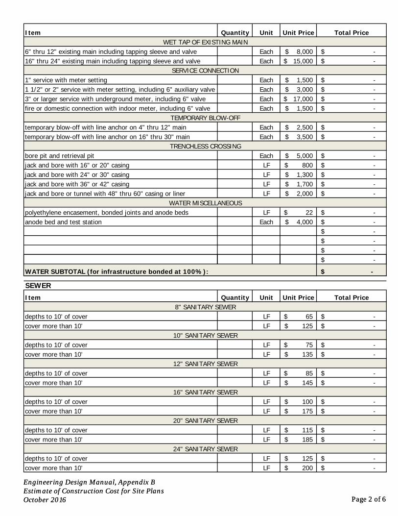
Quantity Unit Unit Price Total Price
Each 8,000$ -$ Each 15,000$ -$
Each 1,500$ -$ Each 3,000$ -$ Each 17,000$ -$ Each 1,500$ -$
Each 2,500$ -$ Each 3,500$ -$
Each 5,000$ -$ LF 800$ -$ LF 1,300$ -$ LF 1,700$ -$ LF 2,000$ -$
LF 22$ -$ Each 4,000$ -$
-$ -$ -$ -$
1" service with meter setting1 1/2" or 2" service with meter setting, including 6" auxiliary valve
jack and bore with 16" or 20" casingjack and bore with 24" or 30" casing
temporary blow-off with line anchor on 16" thru 30" main
jack and bore with 36" or 42" casing
TRENCHLESS CROSSING
6" thru 12" existing main including tapping sleeve and valve
3" or larger service with underground meter, including 6" valve
TEMPORARY BLOW-OFFfire or domestic connection with indoor meter, including 6" valve
temporary blow-off with line anchor on 4" thru 12" main
WET TAP OF EXISTING MAIN
16" thru 24" existing main including tapping sleeve and valve
Item
polyethylene encasement, bonded joints and anode beds
SERVICE CONNECTION
WATER MISCELLANEOUS
anode bed and test station
bore pit and retrieval pit
jack and bore or tunnel with 48" thru 60" casing or liner
Engineering Design Manual, Appendix BEstimate of Construction Cost for Site PlansOctober 2016 Page 2 of 6
-$
Quantity Unit Unit Price Total Price
LF 65$ -$ LF 125$ -$
LF 75$ -$ LF 135$ -$
LF 85$ -$ LF 145$ -$
LF 100$ -$ LF 175$ -$
LF 115$ -$ LF 185$ -$
LF 125$ -$ LF 200$ -$
SEWER
depths to 10' of cover
depths to 10' of cover
cover more than 10'depths to 10' of cover
Item
12" SANITARY SEWER
8" SANITARY SEWER
WATER SUBTOTAL (for infrastructure bonded at 100%):
10" SANITARY SEWERcover more than 10'
cover more than 10'
cover more than 10'
depths to 10' of cover
cover more than 10'
cover more than 10'
24" SANITARY SEWER
depths to 10' of cover20" SANITARY SEWER
16" SANITARY SEWER
depths to 10' of cover
Engineering Design Manual, Appendix BEstimate of Construction Cost for Site PlansOctober 2016 Page 2 of 6
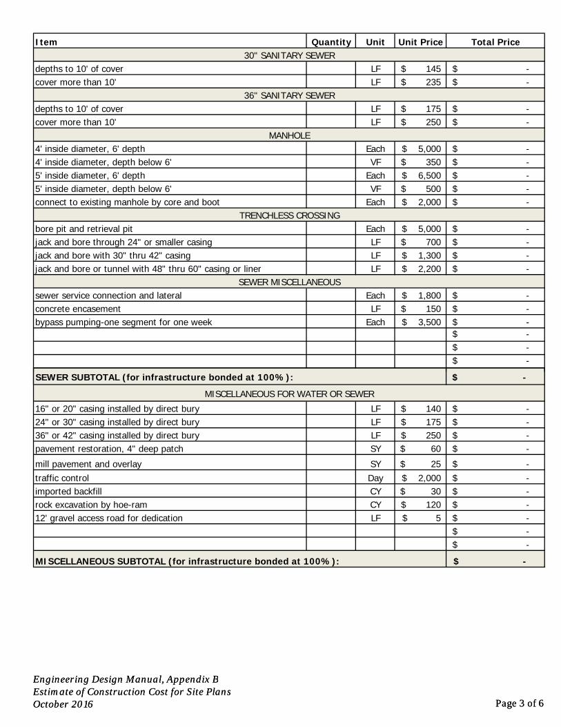
Quantity Unit Unit Price Total Price
LF 145$ -$ LF 235$ -$
LF 175$ -$ LF 250$ -$
Each 5,000$ -$ VF 350$ -$
Each 6,500$ -$ VF 500$ -$
Each 2,000$ -$
Each 5,000$ -$ LF 700$ -$ LF 1,300$ -$ LF 2,200$ -$
Each 1,800$ -$ LF 150$ -$
Each 3,500$ -$ -$ -$ -$
$
concrete encasementsewer service connection and lateral
depths to 10' of covercover more than 10'
cover more than 10'
5' inside diameter, depth below 6'
bypass pumping-one segment for one week
connect to existing manhole by core and boot
jack and bore with 30" thru 42" casing
36" SANITARY SEWER
MANHOLE
depths to 10' of cover
(f i f b d d )
Item30" SANITARY SEWER
jack and bore or tunnel with 48" thru 60" casing or liner
bore pit and retrieval pit
4' inside diameter, 6' depth
jack and bore through 24" or smaller casing
SEWER MISCELLANEOUS
4' inside diameter, depth below 6'
TRENCHLESS CROSSING
5' inside diameter, 6' depth
Engineering Design Manual, Appendix BEstimate of Construction Cost for Site PlansOctober 2016 Page 3 of 6
-$
LF 140$ -$ LF 175$ -$ LF 250$ -$ SY 60$ -$
SY 25$ -$ Day 2,000$ -$ CY 30$ -$ CY 120$ -$ LF 5$ -$
-$ -$
-$
mill pavement and overlay
24" or 30" casing installed by direct bury
12' gravel access road for dedicationrock excavation by hoe-ram
SEWER SUBTOTAL (for infrastructure bonded at 100%):
MISCELLANEOUS FOR WATER OR SEWER
36" or 42" casing installed by direct bury
16" or 20" casing installed by direct bury
traffic control
MISCELLANEOUS SUBTOTAL (for infrastructure bonded at 100%):
imported backfill
pavement restoration, 4" deep patch
Engineering Design Manual, Appendix BEstimate of Construction Cost for Site PlansOctober 2016 Page 3 of 6
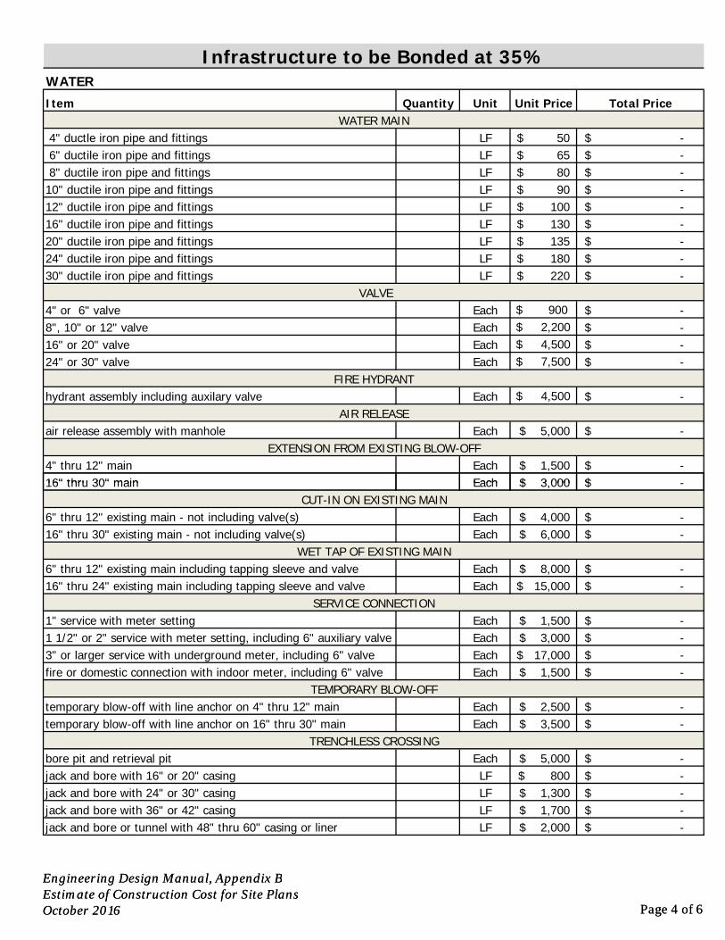
Quantity Unit Unit Price Total Price
LF 50$ -$ LF 65$ -$ LF 80$ -$ LF 90$ -$ LF 100$ -$ LF 130$ -$ LF 135$ -$ LF 180$ -$ LF 220$ -$
Each $ 900 -$ Each $ 2,200 -$ Each $ 4,500 -$ Each $ 7,500 -$
Each $ 4,500 -$
Each 5,000$ -$
Each 1,500$ -$ Each 3 000$ -$
hydrant assembly including auxilary valveAIR RELEASE
air release assembly with manholeEXTENSION FROM EXISTING BLOW-OFF
4" thru 12" main16" thru 30" main
Infrastructure to be Bonded at 35%
ItemWATER MAIN
4" ductle iron pipe and fittings
WATER
6" ductile iron pipe and fittings 8" ductile iron pipe and fittings10" ductile iron pipe and fittings12" ductile iron pipe and fittings16" ductile iron pipe and fittings20" ductile iron pipe and fittings24" ductile iron pipe and fittings30" ductile iron pipe and fittings
VALVE4" or 6" valve 8", 10" or 12" valve16" or 20" valve24" or 30" valve
FIRE HYDRANT
Engineering Design Manual, Appendix BEstimate of Construction Cost for Site PlansOctober 2016 Page 4 of 6
Each 3,000$ -$
Each 4,000$ -$ Each 6,000$ -$
Each 8,000$ -$ Each 15,000$ -$
Each 1,500$ -$ Each 3,000$ -$ Each 17,000$ -$ Each 1,500$ -$
Each 2,500$ -$ Each 3,500$ -$
Each 5,000$ -$ LF 800$ -$ LF 1,300$ -$ LF 1,700$ -$ LF 2,000$ -$
WET TAP OF EXISTING MAIN6" thru 12" existing main including tapping sleeve and valve16" thru 24" existing main including tapping sleeve and valve
SERVICE CONNECTION1" service with meter setting1 1/2" or 2" service with meter setting, including 6" auxiliary valve3" or larger service with underground meter, including 6" valvefire or domestic connection with indoor meter, including 6" valve
TEMPORARY BLOW-OFFtemporary blow-off with line anchor on 4" thru 12" maintemporary blow-off with line anchor on 16" thru 30" main
TRENCHLESS CROSSINGbore pit and retrieval pitjack and bore with 16" or 20" casingjack and bore with 24" or 30" casingjack and bore with 36" or 42" casingjack and bore or tunnel with 48" thru 60" casing or liner
16" thru 30" mainCUT-IN ON EXISTING MAIN
6" thru 12" existing main - not including valve(s)16" thru 30" existing main - not including valve(s)
Engineering Design Manual, Appendix BEstimate of Construction Cost for Site PlansOctober 2016 Page 4 of 6
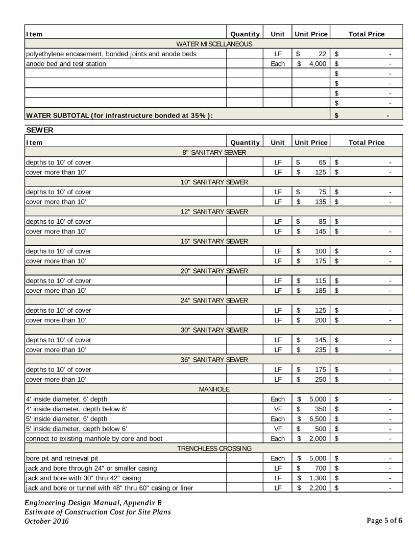
Quantity Unit Unit Price Total Price
LF 22$ -$ Each 4,000$ -$
-$ -$ -$ -$
-$
Quantity Unit Unit Price Total Price
LF 65$ -$ LF 125$ -$
LF 75$ -$ LF 135$ -$
LF 85$ -$ LF 145$ -$
LF 100$ -$ LF 175$ -$
SEWER
Item8" SANITARY SEWER
depths to 10' of covercover more than 10'
10" SANITARY SEWERdepths to 10' of covercover more than 10'
12" SANITARY SEWERdepths to 10' of covercover more than 10'
16" SANITARY SEWERdepths to 10' of covercover more than 10'
20" SANITARY SEWER
WATER MISCELLANEOUSpolyethylene encasement, bonded joints and anode bedsanode bed and test station
WATER SUBTOTAL (for infrastructure bonded at 35%):
Item
Engineering Design Manual, Appendix BEstimate of Construction Cost for Site PlansOctober 2016 Page 5 of 6
LF 115$ -$ LF 185$ -$
LF 125$ -$ LF 200$ -$
LF 145$ -$ LF 235$ -$
LF 175$ -$ LF 250$ -$
Each 5,000$ -$ VF 350$ -$
Each 6,500$ -$ VF 500$ -$
Each 2,000$ -$
Each 5,000$ -$ LF 700$ -$ LF 1,300$ -$ LF 2,200$ -$
36" SANITARY SEWERdepths to 10' of covercover more than 10'
MANHOLE4' inside diameter, 6' depth4' inside diameter, depth below 6'5' inside diameter, 6' depth5' inside diameter, depth below 6'connect to existing manhole by core and boot
TRENCHLESS CROSSINGbore pit and retrieval pitjack and bore through 24" or smaller casingjack and bore with 30" thru 42" casingjack and bore or tunnel with 48" thru 60" casing or liner
depths to 10' of covercover more than 10'
depths to 10' of covercover more than 10'
24" SANITARY SEWERdepths to 10' of covercover more than 10'
30" SANITARY SEWER
Engineering Design Manual, Appendix BEstimate of Construction Cost for Site PlansOctober 2016 Page 5 of 6
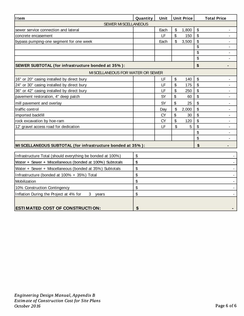
Quantity Unit Unit Price Total Price
Each 1,800$ -$ LF 150$ -$
Each 3,500$ -$ -$ -$ -$
-$
LF 140$ -$ LF 175$ -$ LF 250$ -$ SY 60$ -$
SY 25$ -$ Day 2,000$ -$ CY 30$ -$ CY 120$ -$ LF 5$ -$
-$ -$
-$
Infrastructure Total (should everything be bonded at 100%) -$
mill pavement and overlaytraffic controlimported backfillrock excavation by hoe-ram12' gravel access road for dedication
MISCELLANEOUS SUBTOTAL (for infrastructure bonded at 35%):
-$
pavement restoration, 4" deep patch
SEWER MISCELLANEOUSsewer service connection and lateralconcrete encasementbypass pumping-one segment for one week
Item
SEWER SUBTOTAL (for infrastructure bonded at 35%):
MISCELLANEOUS FOR WATER OR SEWER
16" or 20" casing installed by direct bury24" or 30" casing installed by direct bury36" or 42" casing installed by direct bury
Water + Sewer + Miscellaneous (bonded at 100%) Subtotals
Engineering Design Manual, Appendix BEstimate of Construction Cost for Site PlansOctober 2016 Page 6 of 6
3 years
Infrastructure (bonded at 100% + 35%) Total -$
Water + Sewer + Miscellaneous (bonded at 35%) Subtotals -$
-$
Inflation During the Project at 4% for
Mobilization
10% Construction Contingency
-$
ESTIMATED COST OF CONSTRUCTION:
-$
-$
-$
Water + Sewer + Miscellaneous (bonded at 100%) Subtotals
Engineering Design Manual, Appendix BEstimate of Construction Cost for Site PlansOctober 2016 Page 6 of 6
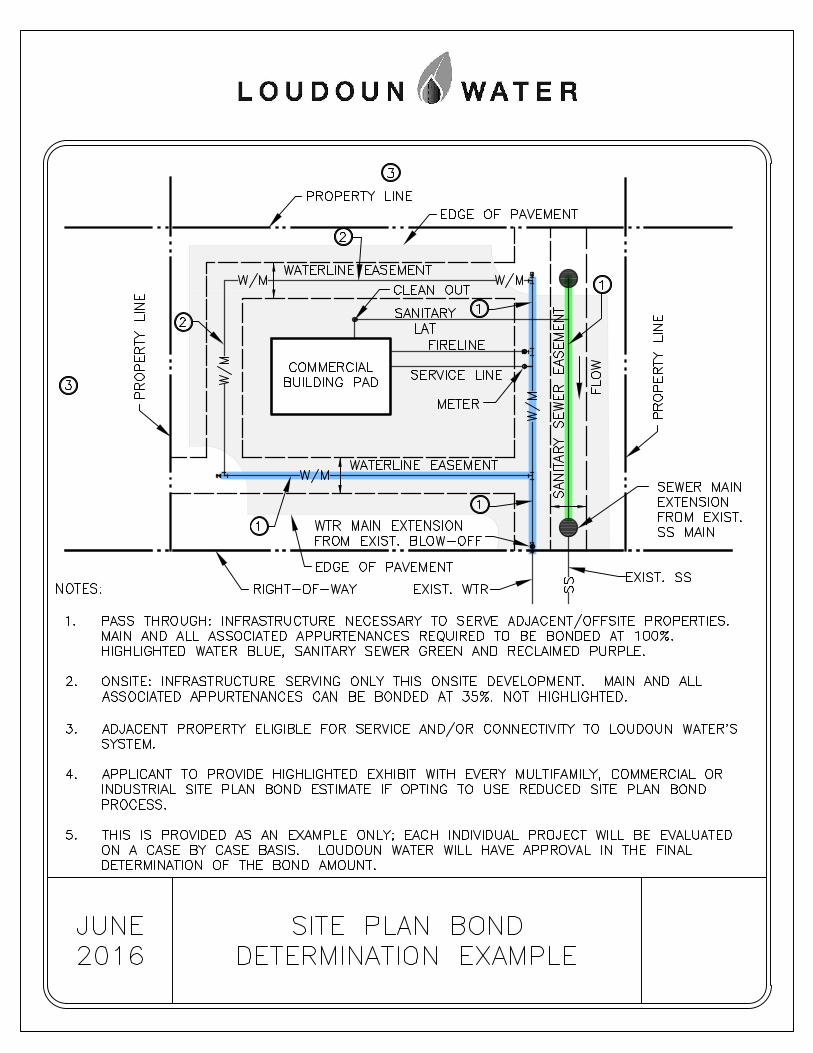

Appendix C
Engineering Design Manual October 2016
Appendix C: Easements
Guide to Easement Documents

Engineering Design Manual, Appendix C October 2016 Page 1 of 4
I. Introduction The Loudoun County Sanitation Authority, doing business as Loudoun Water, was created in 1959 as a public utility, body politic and corporate under the provisions of the Virginia Water and Sewer Authorities Act (Chapter 28, Title 15.1, Section 1239 et seq., Code of Virginia, 1950, as amended). The Authority acquires an interest in all lands traversed by its facilities. All legal documents used for this purpose will refer to the utility as the Loudoun County Sanitation Authority, in accordance with its Charter.
Developers and/or individuals wishing to obtain public water, sanitary sewer and reclaimed water service are responsible for construction of pipelines and their appurtenances. The proposed construction plans must first be reviewed and approved by Loudoun Water’s Department of Land Development Programs. Where not located within the rights of way of public streets, facilities are constructed within deeded easements or on land owned by Loudoun Water. A project’s approval process may include easement acquisitions. The construction plans must be approved and all necessary offsite easements must be recorded prior to issuance of a Construction Permit for the project.
The Engineering Division’s Department of Land Development Programs is responsible for approving and processing all Loudoun Water easements associated with land development projects. For capital projects, easement acquisition is handled by Loudoun Water’s Project Engineer.
II. Easement Standards and Policies A. Exclusivity
Loudoun Water’s easements establish areas in which the landowner has agreed not to erect structures or use the land in ways that are in conflict with Loudoun Water’s uses. As such, the easements are considered exclusive; however, other utilities may cross Loudoun Water easements at, or as nearly as possible to a 90-degree angle with prior written consent by Loudoun Water, provided the crossing utility does not interfere with Loudoun Water’s use of their existing easement.
B. Ownership vs. Easement
It is the preference of Loudoun Water that major facilities such as treatment plants, pumping stations, and water storage tanks be located on lots for which ownership has been deeded to Loudoun Water. The minimum lot size required shall be in accordance with the Loudoun County Zoning Ordinance.
C. Private Streets
Loudoun Water’s facilities located within private streets must be within appropriate water and sanitary sewer easements conveyed to Loudoun Water. Where public ingress and egress is being conveyed to Loudoun County, that easement is considered sufficient for water and sewer service branches.
D. Community Systems
Easements supporting community water and wastewater systems are discussed in the respective chapters of the Engineering Design Manual.
Engineering Design Manual, Appendix C October 2016 Page 2 of 4
E. Easement Plats
An easement plat will be prepared by a Land Surveyor, licensed in the Commonwealth of Virginia, establishing the metes and bounds of the area upon which easement is being conveyed and/or vacated. These will correspond to the approved construction plans for the project they support.
F. Notary Block
Effective July 1, 2007, the laws of the Commonwealth of Virginia require that notary block be on the same page as the signature being witnessed, and that the notary’s registration number appear on each notary statement.
III. “Loudoun Water Only” Instruments If Loudoun Water’s easements proposed in support of a project for which no right of way or other public easement is to be dedicated or conveyed, and no subdivision or boundary adjustment is to occur, then the “Loudoun Water Only” process may be followed.
A. Deed of Easement
Developers have the option of submitting Deeds of Easement prepared by their attorneys or of completing the appropriate standard instrument, which is available on Loudoun Water’s website. Instruments must contain the standard Loudoun Water deed language, which is not to be altered.
B. Instrument and Plat Review
The developer or his representative shall submit a package containing the following:
1. a completed “Loudoun Water Only” Easement Processing Request Form, available on the website;
2. draft Deed of Easement;
3. one full-sized copy of the easement plat, prepared in accordance with the Easement Plat Checklist, available on the website;
4. upon request, a title report for the property in question.
C. Approval
The easement plat and draft deed will be reviewed by Loudoun Water’s Project Engineer, who will advise the applicant of any revisions that may be required prior to plat or deed approval. Once approved, the applicant may submit the final instrument for execution.
D. Execution
The signature package must include the original, executed instrument, and a final plat of recordation quality, with surveyor’s original signature and seal. Plat must be current, and bear the most recent revision date, corresponding to that referenced in the instrument.
Prior to recordation the instrument must be signed by:
1. Owner(s) of Record. Owners of title include all parties who have an ownership interest in the property, including lenders and trustees. In situations such as property titled in the name of an estate, or where the owner has provided power of attorney to another
Engineering Design Manual, Appendix C October 2016 Page 3 of 4
individual, someone other than the property owner may sign the deed. However, in such cases, proof of authorization is to be provided to Loudoun Water in support of the signature package.
2. Loudoun Water. All Deeds of Easement must be signed by the Chairman, General Manager or Deputy General Manager. The original, executed Deed will then be returned to the applicant from whom it was received.
E. Recordation
All “Loudoun Water Only” instruments with associated plats are recorded by the applicant, within the Land Records of the Loudoun County Clerk of the Circuit Court.
IV. Loudoun Water/County of Loudoun Joint Instruments (“Signature Deeds”)
As of August 1997, Loudoun Water’s Department of Land Development Programs and the Loudoun County Department of Building and Development has entered into an arrangement whereby a joint instrument and plat are to be used to convey easements for land development projects where both Loudoun Water and County easements are being provided. This is referred to herein as the “Signature Deed” process.
A. Review and Approval of Draft Deed and Plat
The plat and draft deed documents are submitted to the Loudoun County Department of Building and Development in support of an active land development application. A copy of the plat and deed are forwarded by the County’s Project Manager to Loudoun Water for referral review at the same time they are being reviewed by the Office of the County Attorney. Loudoun Water will not review plats and deeds conveying Loudoun Water easement, until Loudoun Water has approved the construction plans for the project, and the Loudoun Water Project Engineer is assured that the easement locations will not change. Once the plat and deed have been approved by Loudoun Water and the County, a signature deed package is submitted by the applicant to Loudoun Water for execution. Deeds and/or plats are not submitted directly to Loudoun Water until they have been approved by all parties and are ready for execution.
1. Residential Subdivisions -- For residential subdivisions, easements are typically conveyed as part of the application for a subdivision record plat (SBRD), a subdivision waiver (SBWV), or a family subdivision (SBFM).
2. Non-Residential Site Plans. -- For multi-family residential projects and non-residential projects, easements are typically conveyed as part of an application for site plan (STPL), as an easement plat (ESMT), or as a dedication plat (DEDI).
B. Deed Language for Loudoun Water Easements
The required standard deed language that must be included in all instruments processed through the Signature Deed process may be found on Loudoun County’s website.
C. Execution Process
1. Signature Deed Package
The signature deed package should be submitted to the Department of Land Development Programs, and must contain the following items to ensure processing:
Engineering Design Manual, Appendix C October 2016 Page 4 of 4
a. a completed form titled Signature Deed Request and Checklist, which is available on the website;
b. the original deed, with original signatures of all parties except Loudoun County and Loudoun Water;
c. one copy of the approved plat, bearing the most recent revision date;
d. one copy of the County Attorney’s letter approving the deed and plat as to form;
e. one copy of the County Project Manager’s request for signature deeds. This may be a printed copy of an e-mail, but it must be included in the deed package.
2. Final Review and Execution
Applicants should allow a minimum of 5 working days for Loudoun Water to process signature deed packages.
If inconsistencies are found during final review of the deed and/or plat, the applicant will be notified, and the package will be returned for the necessary revisions. The County Project Manager and Loudoun Water will determine whether additional referral review is required prior to resubmission of the signature deed package.
Once the final review has been completed and the deed and plat determined to be accurate, the deed is forwarded to the General Manager’s office for execution. The original deed with plat will be returned to the applicant for recordation.
Appendix D
Engineering Design Manual October 2016
Appendix D: Community Systems
Key to Abbreviations
Chart of Design Review Process
Project Initiation Information Sheet
Agenda for Project Initiation Meeting
Chart of Construction Process
Agenda for Preconstruction Conference

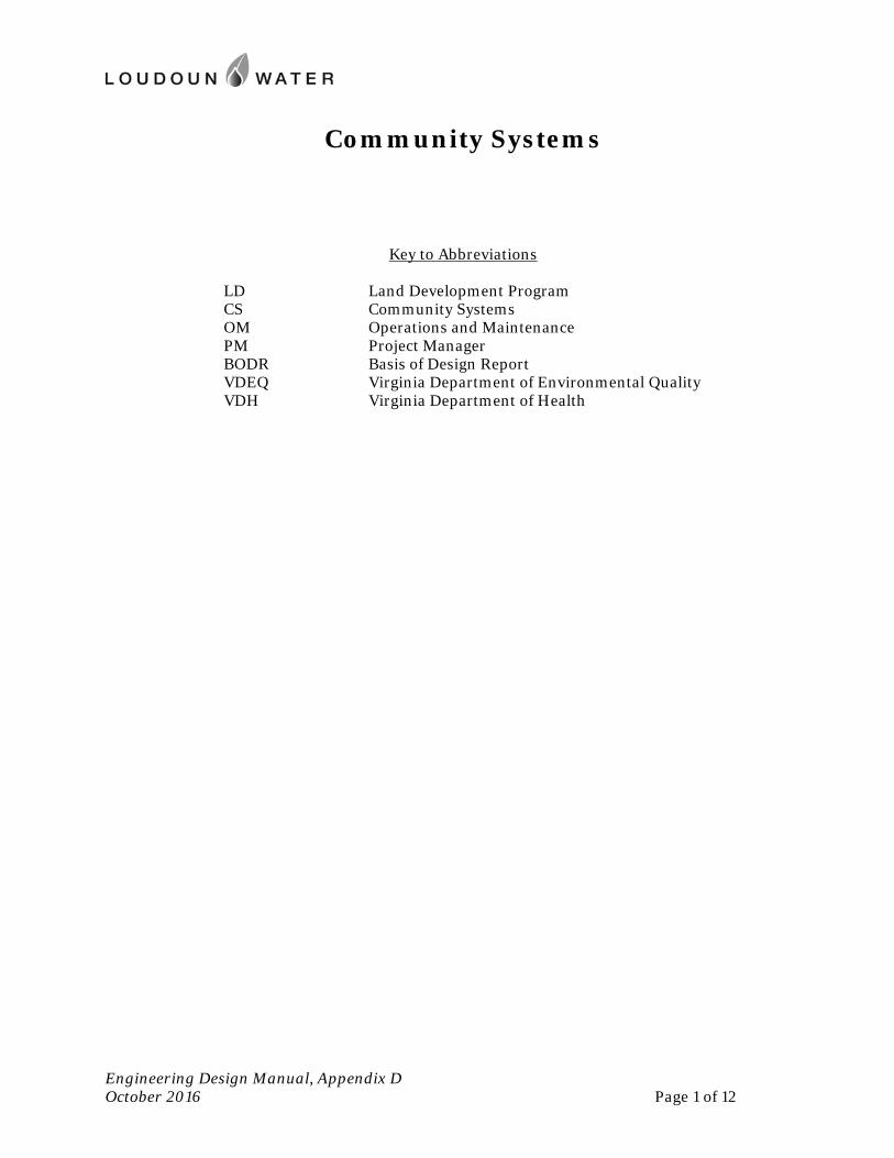
Community Systems
Engineering Design Manual, Appendix D October 2016 Page 1 of 12
Key to Abbreviations
LD Land Development Program CS Community Systems OM Operations and Maintenance PM Project Manager BODR Basis of Design Report VDEQ Virginia Department of Environmental Quality VDH Virginia Department of Health
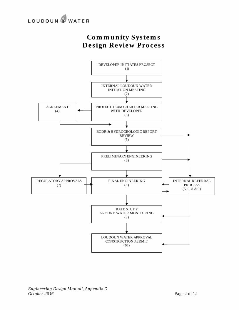
Community Systems Design Review Process
Engineering Design Manual, Appendix D October 2016 Page 2 of 12
DEVELOPER INITIATES PROJECT (1)
INTERNAL LOUDOUN WATER INITIATION MEETING
(2)
PROJECT TEAM CHARTER MEETING WITH DEVELOPER
(3)
BODR & HYDROGEOLOGIC REPORT REVIEW
(5)
PRELIMINARY ENGINEERING (6)
FINAL ENGINEERING (8)
RATE STUDY GROUND WATER MONITORING
(9)
LOUDOUN WATER APPROVAL CONSTRUCTION PERMIT
(10)
AGREEMENT (4)
REGULATORY APPROVALS (7)
INTERNAL REFERRAL PROCESS
(5, 6, 8 & 9)
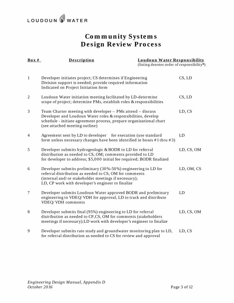
Community Systems Design Review Process
Engineering Design Manual, Appendix D October 2016 Page 3 of 12
Box # Description Loudoun Water Responsibility
(listing denotes order of responsibility*)
1 Developer initiates project; CS determines if Engineering CS, LD Division support is needed; provide required information Indicated on Project Initiation form 2 Loudoun Water initiation meeting facilitated by LD-determine CS, LD scope of project; determine PMs, establish roles & responsibilities 3 Team Charter meeting with developer – PMs attend – discuss LD, CS Developer and Loudoun Water roles & responsibilities, develop schedule - initiate agreement process, prepare organizational chart (see attached meeting outline) 4 Agreement sent by LD to developer for execution (use standard LD form unless necessary changes have been identified in boxes #1 thru #3) 5 Developer submits hydrogeologic & BODR to LD for referral LD, CS, OM distribution as needed to CS, OM; comments provided to LD for developer to address; $5,000 initial fee required; BODR finalized 6 Developer submits preliminary (30%-50%) engineering to LD for LD, OM, CS referral distribution as needed to CS, OM for comments (internal and/or stakeholder meetings if necessary); LD, CP work with developer’s engineer to finalize 7 Developer submits Loudoun Water approved BODR and preliminary LD engineering to VDEQ/VDH for approval, LD to track and distribute VDEQ/VDH comments 8 Developer submits final (95%) engineering to LD for referral LD, CS, OM distribution as needed to CP,CS, OM for comments (stakeholders meetings if necessary);LD work with developer’s engineer to finalize 9 Developer submits rate study and groundwater monitoring plan to LD, LD, CS for referral distribution as needed to CS for review and approval
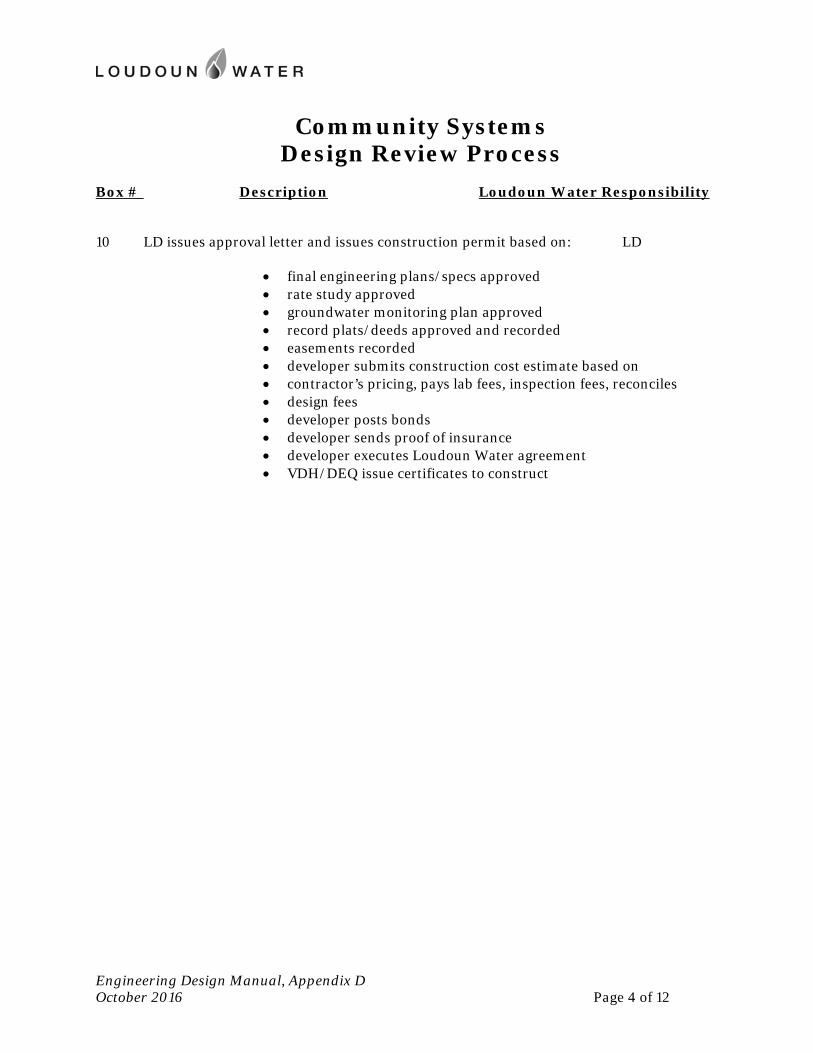
Community Systems Design Review Process
Engineering Design Manual, Appendix D October 2016 Page 4 of 12
Box # Description Loudoun Water Responsibility 10 LD issues approval letter and issues construction permit based on: LD
final engineering plans/specs approved rate study approved groundwater monitoring plan approved record plats/deeds approved and recorded easements recorded developer submits construction cost estimate based on contractor’s pricing, pays lab fees, inspection fees, reconciles design fees developer posts bonds developer sends proof of insurance developer executes Loudoun Water agreement VDH/DEQ issue certificates to construct
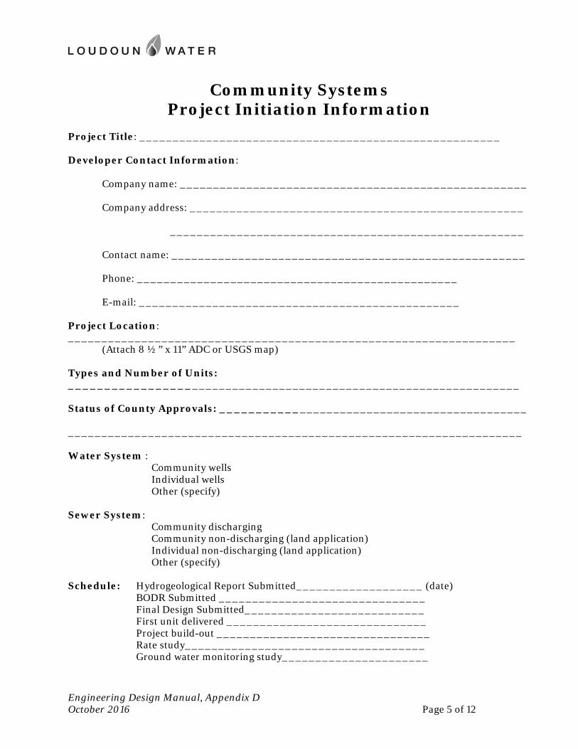
Community Systems Project Initiation Information
Engineering Design Manual, Appendix D October 2016 Page 5 of 12
Project Title: ______________________________________________________ Developer Contact Information: Company name: ____________________________________________________ Company address: __________________________________________________ _____________________________________________________ Contact name: _____________________________________________________ Phone: ________________________________________________ E-mail: ________________________________________________ Project Location: ___________________________________________________________________ (Attach 8 ½” x 11” ADC or USGS map) Types and Number of Units: __________________________________________________________________ Status of County Approvals: _____________________________________________ ____________________________________________________________________ Water System : Community wells Individual wells Other (specify) Sewer System: Community discharging Community non-discharging (land application) Individual non-discharging (land application) Other (specify) Schedule: Hydrogeological Report Submitted___________________ (date) BODR Submitted _______________________________ Final Design Submitted___________________________ First unit delivered ______________________________ Project build-out ________________________________ Rate study____________________________________ Ground water monitoring study______________________

Community Systems Project Initiation Meeting
Engineering Design Manual, Appendix D October 2016 Page 6 of 12
(Project Title) (Project ID#)
Location: Date: Time:
AGENDA 1. Attendees:
Developer Design engineer Loudoun Water – Project Manager and representatives for CS, LD
2. Confirm meeting objectives 3. Review data provided on project initiation form
Address comments and any missing information Provide organizational chart Confirm schedule Provide copy of submittal/review guidelines
4. Developer’s responsibilities (to obtain construction permit):
Executed agreement Schedule (detailed) Hydrogeological report BODR (bring copies of required submittals for developer to review) Preliminary engineering report for sewer-per VDEQ SCAT regulations Engineer’s report and preliminary plans-water-per VDH Waterworks regulations Final construction specifications and plans – water/sewer Rate study Groundwater monitoring plan County and VDOT approvals Engineer’s cost estimate Plats/deeds recorded Fees:
$5,000 up-front Design review/lab/inspection
Bonds Proof of insurance
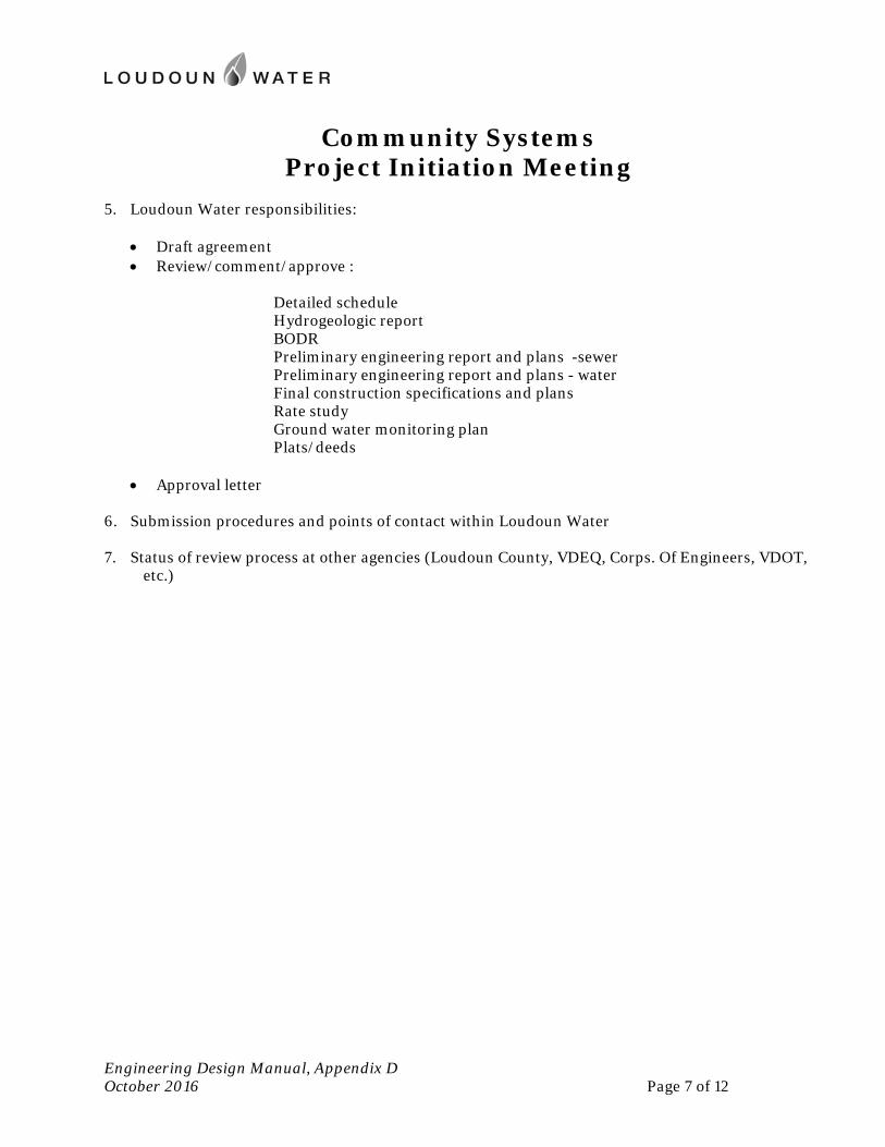
Community Systems Project Initiation Meeting
Engineering Design Manual, Appendix D October 2016 Page 7 of 12
5. Loudoun Water responsibilities:
Draft agreement Review/comment/approve :
Detailed schedule Hydrogeologic report BODR Preliminary engineering report and plans -sewer Preliminary engineering report and plans - water Final construction specifications and plans Rate study Ground water monitoring plan Plats/deeds
Approval letter 6. Submission procedures and points of contact within Loudoun Water 7. Status of review process at other agencies (Loudoun County, VDEQ, Corps. Of Engineers, VDOT,
etc.)
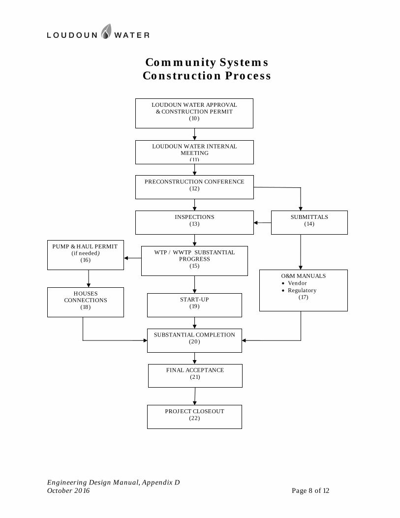
Community Systems Construction Process
Engineering Design Manual, Appendix D October 2016 Page 8 of 12
LOUDOUN WATER INTERNAL MEETING
(11)
PRECONSTRUCTION CONFERENCE (12)
INSPECTIONS (13)
WTP / WWTP SUBSTANTIAL PROGRESS
(15)
START-UP (19)
FINAL ACCEPTANCE (21)
PUMP & HAUL PERMIT (if needed)
(16)
SUBMITTALS (14)
O&M MANUALS Vendor Regulatory
(17) HOUSES CONNECTIONS
(18)
LOUDOUN WATER APPROVAL & CONSTRUCTION PERMIT
(10)
SUBSTANTIAL COMPLETION (20)
PROJECT CLOSEOUT (22)
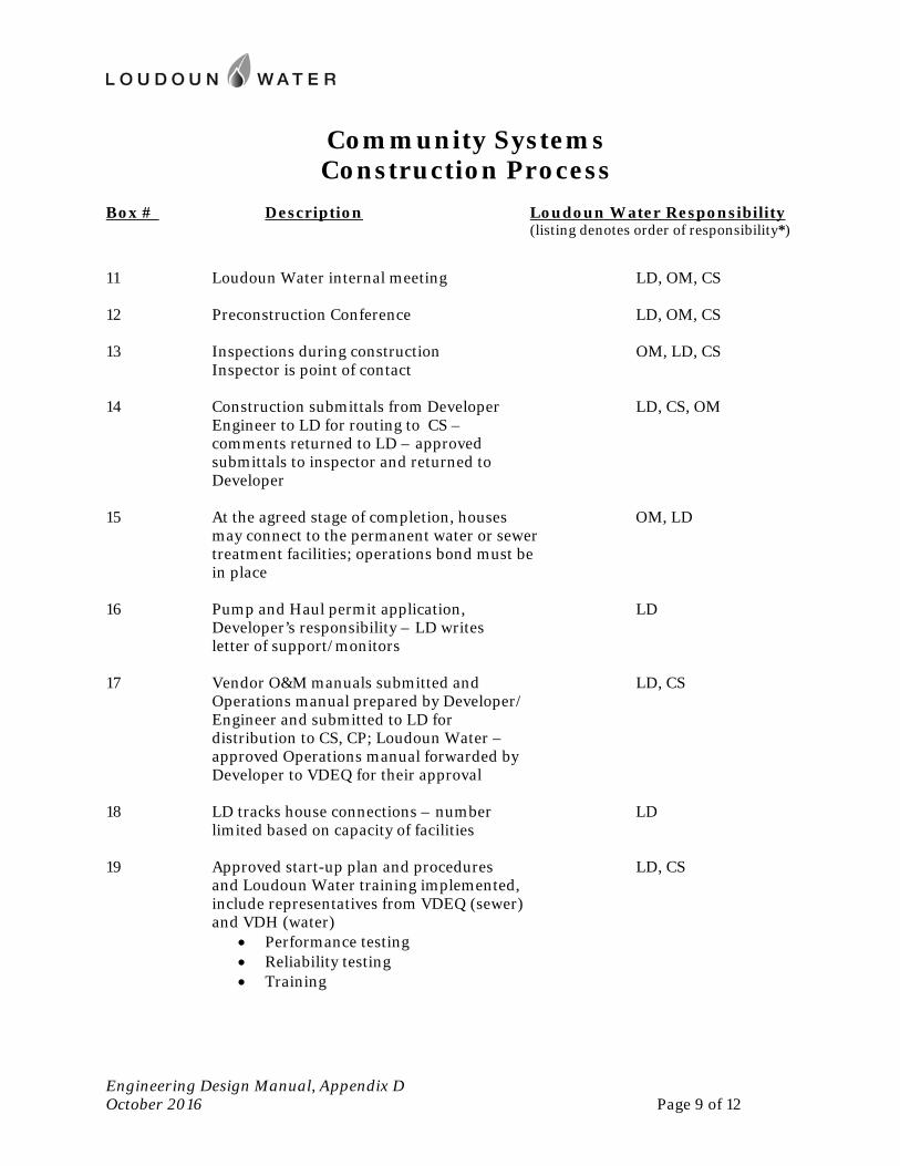
Community Systems Construction Process
Engineering Design Manual, Appendix D October 2016 Page 9 of 12
Box # Description Loudoun Water Responsibility
(listing denotes order of responsibility*)
11 Loudoun Water internal meeting LD, OM, CS 12 Preconstruction Conference LD, OM, CS 13 Inspections during construction OM, LD, CS Inspector is point of contact 14 Construction submittals from Developer LD, CS, OM Engineer to LD for routing to CS – comments returned to LD – approved submittals to inspector and returned to Developer 15 At the agreed stage of completion, houses OM, LD may connect to the permanent water or sewer
treatment facilities; operations bond must be in place
16 Pump and Haul permit application, LD Developer’s responsibility – LD writes letter of support/monitors 17 Vendor O&M manuals submitted and LD, CS Operations manual prepared by Developer/ Engineer and submitted to LD for
distribution to CS, CP; Loudoun Water – approved Operations manual forwarded by Developer to VDEQ for their approval
18 LD tracks house connections – number LD limited based on capacity of facilities 19 Approved start-up plan and procedures LD, CS and Loudoun Water training implemented, include representatives from VDEQ (sewer) and VDH (water)
Performance testing Reliability testing Training
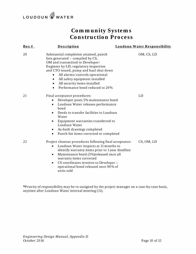
Community Systems Construction Process
Engineering Design Manual, Appendix D October 2016 Page 10 of 12
Box # Description Loudoun Water Responsibility 20 Substantial completion attained, punch OM, CS, LD lists generated – compiled by CS,
OM and transmitted to Developer/ Engineer by LD; regulatory inspection and CTO issued, pump and haul shut down
All alarms/controls operational All safety equipment installed All security items installed Performance bond reduced to 20%
21 Final acceptance procedures: LD
Developer posts 5% maintenance bond Loudoun Water releases performance
bond Deeds to transfer facilities to Loudoun
Water Equipment warranties transferred to
Loudoun Water As-built drawings completed Punch list items corrected or completed
22 Project closeout procedures following final acceptance: CS, OM, LD
Loudoun Water inspects at 11 months to identify warranty items prior to 1 year deadline
Maintenance bond (5%)released once all warranty items corrected
CS coordinates invoices to Developer – operational bond released once 90% of units sold
*Priority of responsibility may be re-assigned by the project manager on a case-by-case basis, anytime after Loudoun Water internal meeting (11).
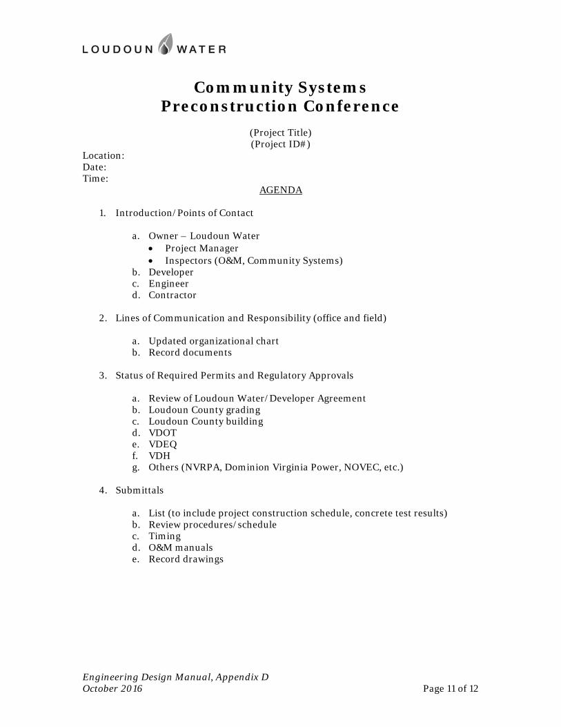
Community Systems Preconstruction Conference
Engineering Design Manual, Appendix D October 2016 Page 11 of 12
(Project Title) (Project ID#)
Location: Date: Time:
AGENDA
1. Introduction/Points of Contact
a. Owner – Loudoun Water Project Manager Inspectors (O&M, Community Systems)
b. Developer c. Engineer d. Contractor
2. Lines of Communication and Responsibility (office and field)
a. Updated organizational chart b. Record documents
3. Status of Required Permits and Regulatory Approvals
a. Review of Loudoun Water/Developer Agreement b. Loudoun County grading c. Loudoun County building d. VDOT e. VDEQ f. VDH g. Others (NVRPA, Dominion Virginia Power, NOVEC, etc.)
4. Submittals
a. List (to include project construction schedule, concrete test results) b. Review procedures/schedule c. Timing d. O&M manuals e. Record drawings
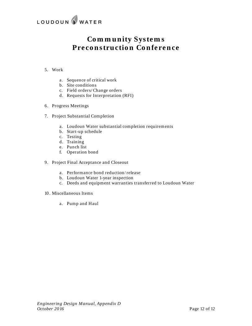
Community Systems Preconstruction Conference
Engineering Design Manual, Appendix D October 2016 Page 12 of 12
5. Work
a. Sequence of critical work b. Site conditions c. Field orders/Change orders d. Requests for Interpretation (RFI)
6. Progress Meetings
7. Project Substantial Completion
a. Loudoun Water substantial completion requirements b. Start-up schedule c. Testing d. Training e. Punch list f. Operation bond
9. Project Final Acceptance and Closeout
a. Performance bond reduction/release b. Loudoun Water 1-year inspection c. Deeds and equipment warranties transferred to Loudoun Water
10. Miscellaneous Items
a. Pump and Haul
Appendix E
Engineering Design Manual October 2016
Appendix E: Corrosion Control
Design and Installation Requirements

Engineering Design Manual, Appendix E October 2016 Page 1 of 14
I. Corrosion Control
All storage tanks, pumping stations, vaults, treatment equipment, and similar facilities shall be protected from corrosion using project-specific design guidelines, which are not included within this discussion. The following is to be applied to all underground water, reclaimed water, and pressurized wastewater pipelines that are to be made of metallic pipe.
In certain cases, upon completion of the Decision Process described below, Loudoun Water may choose to specify a nonmetallic piping material in an application that would otherwise be built of ductile iron.
II. Design
A. Summary
This summary outlines how Loudoun Water will determine and implement corrosion control decisions for buried metallic pipelines. The decision process considers criteria including: pipeline’s size, function, accessibility, cost of repair; anticipated corrosiveness of soil; and the potential for stray currents that may affect the pipelines. Based on an evaluation of these criteria, Loudoun Water will determine the level of corrosion protection to be applied to the pipeline. Three levels of protection are considered for every pipeline and include the following:
1. standard installation with no additional features
2. enhanced protection (including polyethylene encasement and mechanical joint coating)
3. specific corrosion control design (such as joint bonding, test stations, and cathodic protection)
The decision process is described in the following sections and summarized in Figure E.1. The decision process consists of four steps:
Step 1: classify each pipeline
Step 2: evaluate the anticipated soil conditions for each pipeline
Step 3: identify stray currents
Step 4: determine the level of corrosion protection to be applied to each pipeline and incorporate into the construction plans and specifications
B. Decision Process
Step 1: Pipeline Classification Proposed pipelines shall be designated one of three classifications (Class 1, 2, or 3). Classifications are primarily based on size, function, and accessibility of the pipeline. Loudoun Water reserves the right to adjust the classification of individual pipelines at its own discretion.

Engineering Design Manual, Appendix E October 2016 Page 2 of 14
Class 1 pipelines represent the highest priority classification. These pipelines meet any of the following criteria:
all metallic sewer force mains, regardless of diameter;
water mains 16 inches in diameter and greater.
Class 2 pipelines meet any of the following criteria:
water mains 12 inches in diameter;
water mains providing a single feed to distribution systems where a failure would result in significant disruption to customer service (approximately 50 or more service connections);
any pipeline where repair or taking the line out of service would require exceptionally high repair costs, difficult repair conditions, or long-term customer service disruption.
Class 3 pipelines are:
water mains less than 12 inches in diameter.
Step 2: Soil Evaluation Soil characteristics surrounding the pipeline trench significantly affect the rate of metallic pipeline corrosion. Where ductile iron lines are to be constructed, soil samples shall be collected and analyzed as described herein. The results of the analysis shall be submitted to Loudoun Water by the Engineer at the time of the second submission of construction plans. Construction plans will not be approved by Loudoun Water until soil results have been submitted and appropriate corrosion protection measures incorporated into the design. Guidelines for soil sample collection and analysis follow.
For all Class 1 pipes, and for Class 2 pipes where initial soil sampling and analysis warrants further investigation, Loudoun Water will require additional soil investigations, to include in situ soil resistivity and pH. These tests must be conducted and reports prepared under the supervision of an engineer who is certified by the National Association of Corrosion Engineers (NACE).
1. Collection of Soil Samples
a. Soil samples may be collected by the geotechnical engineering firm performing geotechnical investigations for development activities as required by the Loudoun County Facility Standards Manual. Loudoun Water reserves the right to require the Engineer to collect additional samples other than those detailed herein. Further, Loudoun Water may perform additional soil investigations for corrosion considerations.
b. Loudoun Water will direct the collection of additional soil samples of fill transported from offsite locations used for controlled backfill, in the backfill of rock trenches, or other fill conditions.
c. Soil samples shall be collected as follows:
Engineering Design Manual, Appendix E October 2016 Page 3 of 14
i) The depths of soil samples collected for corrosion evaluation shall be representative of anticipated pipeline depths. If pipeline locations and depths are not known, the samples shall be collected at a depth approximately 4.5 feet below existing grade, or the deepest location where soil is available for testing (if rock is encountered before 4.5 feet).
ii) Soil samples shall be collected from each soil boring performed as part of subdivision geotechnical investigations. The number and location of soil borings shall be consistent with the subdivision geotechnical guidelines specified by the Loudoun County Facility Standards Manual.
iii) Soil samples for pipelines outside of subdivisions evaluated by subdivision geotechnical investigations shall be taken at intervals of 1,000 linear feet along proposed pipeline alignments.
iv) Soil samples for Class 1 pipelines shall be taken at intervals of 1,000 linear feet along the anticipated alignment. Loudoun Water will supplement Class 1 soil samples with additional field data to design applicable corrosion protection components.
v) The coordinates and elevation where the sample was obtained shall be recorded and provided to Loudoun Water, including horizontal and vertical datum of the coordinate system used.
2. Analysis of Soil Samples
a. All soil samples shall be tested for pH, chloride concentrations, sulfate concentration, sulfide content and resistivity (as is and saturated). Data for each sample shall be recorded on the data sheet form that accompanied the soil sample.
b. The test methods to be used for laboratory analysis shall comply with the following ASTM standards.
i) Sample Preparation (ASTM D1193)
ii) Sulfate Content (ASTM Standard Test Method D516)
iii) Chloride Content (ASTM Standard Test Method D512)
iv) Resistivity (ASTM Standard Test Method G57)
v) pH (ASTM Standard Test Method G51)
vi) Sulfide test per sodium azide-iodine qualitative tests per AWWA C105
3. Soil Classification
Based on the soil testing results, the soil shall be categorized into one of two categories: Class A or Class B. General guidelines for categorizing soils are presented below; while Loudoun Water reserves the right to adjust these guidelines based on project-specific data.
Class A-Highly Corrosive Soils The following laboratory test results from the collected soil samples will be used for interpretation of Class A soils. If any of these criteria are met, the soil will be considered Class A:
a. Soil resistivity values <= 5,000 ohm/cm
Engineering Design Manual, Appendix E October 2016 Page 4 of 14
b. pH values of the soil <= 4.0
c. Consistent presence of sulfides in samples
d. Consistent presence of sulfates content > 50 ppm in samples
e. Consistent presence of chlorides > 50 ppm in samples
f. Four-pin (in situ) soil resistivity values <= 5,000 ohm/cm
g. In situ pH <= 4.0
Class B-Moderately Corrosive Soils The following laboratory test results from the collected soil samples will be used for the interpretation of Class B soils. All of these criteria must be met in order for the soil to be considered Class B:
a. Soil resistivity values > 5,000 ohm/cm
b. pH values of the soil > 4.0
c. Consistent absence of sulfides in samples
d. Consistent presence of sulfate contents < 50 ppm in samples
e. Consistent presence of chlorides < 50 ppm in samples
f. Four-pin (in situ) soil resistivity values > 5,000 ohm/cm.
g. In situ pH > 4.0
Step 3: Stray Currents Stray current risks for all classes of pipelines shall be identified and evaluated by the designer. The potential for stray currents will be determined using the database of impressed current systems, maintained by the Nation Association of Corrosion Engineers (NACE), Baltimore-Washington Chapter; and using information from the owner of the facility carrying the current. Mitigation measures will be incorporated into the design of the proposed pipe.
Step 4: Evaluation Using the information collected in Steps 1, 2, and 3, Loudoun Water will determine the level of corrosion protection to be included in the pipeline design. The decision process is included in Figure E.1. Loudoun Water reserves the right to adjust the decision process as necessary based on project-specific conditions.
All Class 1 pipelines and Class 2 pipelines in highly corrosive soils (Class A) will require a project-specific corrosion protection design. The design shall be prepared by a NACE registered engineer and incorporated into the construction plans and specifications for the proposed pipe. Generally, pipeline corrosion protection in these cases may include any of the following: polyethylene encasement, joint bonding, test stations, cathodic protection, and stray current mitigation.

Engineering Design Manual, Appendix E October 2016 Page 5 of 14
Class 2 pipelines in moderately corrosive soils (Class B) and Class 3 pipelines in highly corrosive soils (Class A) will require enhanced corrosion control protection. This includes stray current mitigation as necessary, wrapping in polyethylene encasement, and coating of mechanical joints.
Class 3 pipelines in moderately corrosive soils (Class B) will be installed in accordance with standard Loudoun Water installation requirements. With the exception of stray current mitigation where necessary, corrosion protection measures will not be required.
Figure E.1 – Decision Process
Pipe Classification Soil Classification Design
Class 1 Pipeline • Metallic Sewer Force Mains
(>=6” Diameter) • >=16” Water Mains
Class 2 Pipeline • 12” Water Mains • Single Feeds • Difficult to Repair
Class 3 Pipeline • < 12” Water Mains
Class A Soil
Class B Soil
Class A Soil
Incorporate Appropriate Measures to Include:
• Joint Bonding • Test Stations • Polyethylene Encasement or
Bonded Coating • Mechanical Joint Coating
(standard) • Cathodic Protection • Stray Current Mitigation • Alternative Piping Materials
(e.g. PVC Pipe)
Class B Soil
Class A Soil
Class B Soil
Enhanced Protection • Mechanical Joint Coating
(standard) • PVC Pipe • Stray Current Mitigation
Standard Installation • Mechanical Joint coating
(standard) • Stray Current Mitigation
Engineering Design Manual, Appendix E October 2016 Page 6 of 14
III. Installation Requirements
All installations of corrosion control measures shall be made according to the approved construction plans and specifications for the project, the Standard Details and the Approved Materials List (Appendices F and G of this Manual). Upon completion of the work, it shall be tested, operated, inspected and surveyed. Any and all repairs or replacement of defective or improperly installed corrosion control systems shall be made by the contractor, no additional cost to Loudoun Water.
A. Contractor Qualifications
1. Installation, quality assurance, and testing personnel must have demonstrated experience with similar work. Resume of work experience shall be submitted to the Loudoun Water for approval.
2. Personnel shall be specifically named in qualification submittal and have completed at least three successful corrosion control systems within the last three years for underground pipelines of similar type, similar size and equal complexity.
3. Personnel shall be a full-time contractor or subcontractor employees. Part-time or contract personnel hired only for this work will not be permitted.
4. Only personnel approved by Loudoun Water shall be permitted. Personnel changes during course of project must be minimized and submitted by Loudoun Water at least two (2) weeks prior to planned implementation.
5. The contractor shall oversee and certify installation and related testing, including pipe joint bonding, magnesium anode ground-beds, and corrosion control equipment.
6. The contractor shall issue a letter of compliance indicating all corrosion control measures are satisfactorily installed and are in compliance with contract documents. The letter of compliance shall be signed by the contractor's responsible person.
B. Thermite Welding
1. All thermite welds shall be made as shown on Figure CP-2 of the Standard Details and in accordance with the manufacturer’s recommendations using the proper combination of equipment for the pipe and wire size being welded. All welding materials and equipment shall be the product of a single manufacturer.
2. Assure that the area where the attachment is to be made is absolutely dry. Remove mill coating, dirt, grime, and grease from the pipe or fitting surface at the weld location by wire brushing or by the use of suitable safety solvents. Clean a two-inch square area of the pipe or fitting surface at the weld location to a bright shiny surface, free of all serious pits and flaws by the use of a mechanical grinder.
3. Prepare the wire for welding by assuring that the cable is absolutely dry. The cable shall be free of dirt, grease, and other foreign products. Cut the cable in such a way as to avoid flattening or forcing it out of round. To prevent deformation of the cable, cut the cable
Engineering Design Manual, Appendix E October 2016 Page 7 of 14
with cable cutters. Remove the insulation in such a manner that will avoid damage to strands. Install adapter sleeves for all bonds and test wires prior to welding. Either prefabricated factory sleeved joint bonds or bond wires with formed sleeves made in the field are acceptable. Hold the cable at an approximate 30 degree angle to the pipe surface when welding.
4. When the weld has cooled, tap with the two pound hammer while pulling firmly on the wire. Remake unsound welds and retest. Thoroughly clean mold and mold covers after completion of each weld to assure that no slag will penetrate into the next weld.
5. After the soundness of the weld has been verified, thoroughly clean the weld with a stiff wire brush and coat with an elastometric cap. Apply primer over the entire weld area. Push the dome of the prefabricated cap containing elastometric material firmly into the weld area. Lift the wire away from the pipe and apply the elastometric material coating completely around and underneath the wire. Push the wire back down on the pipe.
C. Prepackaged Anodes
1. The prepackaged anodes shall be installed where indicated. Prior to installation, remove all shipping covers from the anode (the packaged box shall not be removed). Install the anodes in existing soils (free from rocks, roots, organic material, trash or any other debris) and backfill with existing soil (as described above). Do not install the anode in sand, rock, or gravel backfill. Do not lower the anode into the excavation by the lead wire. If necessary, temporarily wrap a rope around the anode and lower the anode into the excavation by the rope. Remove the rope after the anode is installed. Provide a minimum spacing of two feet from other pipelines. Pre-soak the anode with 5 gallons of water after placement, but prior to backfilling.
2. Anode header cable shall be buried a minimum of 18 inches below grade. Handle wire with care. All anode lead wire to header cable splices shall be made with a compression connector as shown in Figure CP-5 of the Standard Details. Tape the splice with three layers of high voltage rubber splicing tape (50% overlap). Terminate the ends of the anode lead cable in the test stations in accordance with Figure CP-6 of the Standard Details.
D. Bonded Joints
1. All pipeline joints within the cathodic protection areas, including those on pipe, fittings, valves, all branch connections, shall be bonded with two insulated copper cables as shown on Figure CP-1 of the Standard Details.
E. Test Station
1. Install test stations at the locations required. Test stations are to be located directly over the pipeline except in areas that would place the station in the roadway. Locate these test stations to the closest point at the edge of the road. Test station pedestals or boxes shall be in accordance with Figures CP-6, CP-7, CP-8, CP-9, and CP-10 of the Standard Details. Pedestals are preferred, and will be used where suitable to their surroundings. Test boxes will be used where test station must be flush with the surrounding grade.
Engineering Design Manual, Appendix E October 2016 Page 8 of 14
2. Attach test wires as indicated using the proper thermite welding equipment and charges specified for the wire size and respective pipe material. Follow all procedures as outlined above.
3. All test station wires shall be routed a minimum of 18 inches below finish grade. Maintain sufficient slack in the test wires so that the wires can extend a minimum of 18 inches from the compression thermal lugs for 0.25 inch bolt size. Install a shunt to connect the anode lead to the pipe lead where indicated on the design drawings.
4. The test stations shall be set in poured concrete in accordance with Figure CP-11 of the Standard Details. Cathodic protection test station pad concrete shall be Class B concrete. The flush mounted test station lids shall be free of concrete and not cemented over.
F. Clearance Requirements
1. A minimum of 6” separation shall be maintained from any foreign pipeline or structures. If 12” separation is not possible, positive separation shall be provided using glass mesh.
G. Electrical Isolation
1. Insulating Flanges: Approved insulating flanges shall be installed in accordance with specific design considerations.
2. Insulating Unions: Approved insulating unions shall be installed in accordance with specific design considerations to isolate bimetallic service lines and other type connections that may create corrosion conditions from dissimilar metallic connections.
3. Die-electric Pipe Materials: Approved die-electric pipe materials shall be used to isolate metallic pipe where specified as part of design consideration for foreign pipe line crossings as part of stray current mitigation considerations. A section of polyvinyl chloride (PVC) pipe may be a suitable material for this purpose. Pipe materials, thickness design, and pipe specifications shall be provided by Loudoun Water.
H. Trench Excavation
1. The trench and backfill material around the pipeline shall be clean of all debris, such as trash, wood, and rocks. Strip forms at blockings.
I. Record Drawings
Record Drawings will be prepared to accurately document the installed location and configuration of each test station, including:
1. test station number per the test station schedule on the plans and installed pipeline station number.
2. three dimensional ties between test station and existing permanent datum.
3. wire routing, size, insulation color and termination configured on terminal board.
Engineering Design Manual, Appendix E October 2016 Page 9 of 14
4. pipeline station numbers for wire attachments to pipe.
5. anode locations, where installed, including pipeline station number, depth and distance from pipe.
IV. Post-Installation Quality Assurance and Acceptance Testing
After the installation is complete, the contractor or the owner’s consulting engineer will conduct the following post-installation quality assurance and acceptance testing, to verify the work. The repair or replacement of any defective or improperly installed systems shall be the sole responsibility of the contractor.
A. Test Station Wires
1. All test station wires shall be field verified for electrical continuity after connection of the wires on the terminal board in the test station and prior to the installation of any shunts on the terminal board. The testing will verify that the test wires have been properly installed and have not been damaged during backfilling and final test station installation. The test station wire verification shall be performed with an industry standard high impedance voltmeter and a copper/copper sulfate reference electrode.
2. The test station wire verification shall be performed by placing a copper/copper sulfate reference electrode in the soil adjacent to the test station being tested. Connect the copper/copper sulfate reference electrode to the positive terminal of the voltmeter with a test lead. Connect the test wire to be verified to the negative terminal of the voltmeter with a test lead. Record the resultant structure-to-earth potential. Without moving the copper/copper sulfate reference electrode, repeat this measurement for every wire in the test station.
3. Acceptance criteria shall be as follows:
a. Ductile iron pipe normally has a voltage to ground potential of between 0.50 and 0.65 volt to a copper/copper sulfate reference, adjacent test leads on the pipe shall have the exact same potential. Voltage to ground measurements outside of this range will require further evaluation.
b. Magnesium anodes shall be between 1.55 and 1.65 volts to a copper/copper sulfate reference. Voltage to ground measurements outside of this range will require further evaluation.
4. Results of the test wire verification testing shall be documented. Documentation shall include the following (Table 1):
a. name of the Corrosion Technician performing test;
b. date of each test;
c. station number of test wires;
d. test wire color and size;
Engineering Design Manual, Appendix E October 2016 Page 10 of 14
e. structure that the test wire is connected to;
f. structure-to-earth potential for each test wire;
g. statement that the test wire has been installed properly in accordance with the criteria listed above. Data shall be maintained for inclusion in the final quality assurance report.
B. Linear Electrical Continuity
1. The linear electrical continuity of the bonded water main shall be tested to confirm that pipe joint bond cables have been properly installed and have not been damaged during backfilling. The testing will verify that the water main is electrically continuous in accordance with design specifications (Table 2).
2. The linear electrical continuity testing shall be performed with a combination voltmeter/ammeter, a 12-volt battery capable of at least 80 amperes short circuit current, and test wires and leads of sufficient length to extend over the length of pipe being tested (Table 2).
3. The linear electrical continuity testing shall be performed by impressing a DC current between adjacent test stations while simultaneously measuring the resultant voltage drop on the pipeline between the adjacent test stations. Voltage and current measurements shall be recorded with the current applied and immediately after the current is turned off (Table 2).
4. Calculate the voltage and current delta readings for each measurement by subtracting the "Instant Off' values from the "Current On" values. Divide the voltage delta by the current delta to calculate the measured resistance value (Table 2).
5. Calculate the theoretical resistance of the pipe section using published resistance tables for the type and diameter of the pipe that was installed (Table 3). Multiply the length of the pipe being tested by the resistance value for the type and size of pipe being tested (Table 4). Determine the number of pipe joints in the section being tested. Multiply the number of pipe joints by the theoretical resistance of the bond wires that were installed. Add the resistance value for the length of pipe to the resistance value for the pipe joints to determine the theoretical resistance value of the section of pipeline being tested.
6. Compare the measured resistance value to that calculated resistance value for the test section. The measured linear electrical resistance of the test section will be acceptable if the measured resistance value is no greater than 115% of the theoretical linear resistance value for the test station (Table 3).
7. Repeat the above test procedures between all adjacent test stations on the water main until the entire length of pipeline is tested. Actual resistances greater than 115% of the theoretical resistance will have to be re-evaluated to assure adequate electrical continuity of the pipe span.
8. Results of the linear continuity testing shall be documented. Documentation shall include the following (Tables 2 and 3):
Engineering Design Manual, Appendix E October 2016 Page 11 of 14
a. name of the Corrosion Technician performing test;
b. date of each test;
c. beginning and end station numbers of test section;
d. length of the test section;
e. amount of current applied for the test;
f. voltage drop measured over the test section with current applied;
g. voltage drop measured over the test section immediately after the current is turned off;
h. calculated measured resistance of the test section;
i. type and diameter of pipe;
j. theoretical resistance per foot of pipe length;
k. length, size and number of bond cables per joint;
l. calculated resistance of bond cables across one joint;
m. number of pipe joints in test section;
n. calculated theoretical resistance of the entire pipe section;
o. percentage that the measured resistance is greater than or less than the theoretical resistance of the pipe section;
p. statement that the section of pipe has been properly bonded in accordance with acceptance criteria listed above. Continuity data shall be maintained for inclusion in the final quality assurance acceptance report.
C. Electrical Isolation
1. All insulating couplings, insulating flanges, insulating unions and insulating casing spacers shall be tested to confirm that effective electrical isolation exists between the isolated structures. The testing will verify that the insulating couplings, flanges, unions and casing spacers have been installed properly and are providing effective isolation.
2. The electrical isolation testing shall be performed with a high impedance combination volt/ammeter, a copper/copper sulfate reference electrode, a 12-volt battery and test leads of sufficient length to obtain structure-to-earth potentials and apply current to each side of the insulator.
3. The effectiveness of the electrical isolation shall be verified by measuring structure-to-earth potentials of each side of the insulator while a DC current is applied between one
Engineering Design Manual, Appendix E October 2016 Page 12 of 14
side of the insulator and a temporary ground-bed. Install a temporary ground-bed by inserting steel pins into the ground directly over the pipeline and approximately 50 feet from the insulator being tested. Impress a DC current between the temporary ground-bed and the opposite side of the insulator. Using a portable reference electrode placed over the insulator, measure the structure-to-earth potential on each side of the insulator. Structure-to-earth potentials shall be measured with the current applied and immediately after the current is turned off. Structure-to-earth and current readings shall be obtained simultaneously. Record the potential and current data.
4. Effective electrical isolation of the insulating coupling, insulating flange, insulating union or insulating casing spacers will be indicated by a negative potential shift ("On" reading minus the "Instant Off' reading) on the side of the insulator closest to the ground-bed. The far side of the insulator will have a positive voltage shift ("On" reading minus the "Instant Off' reading) if the test circuit is set up properly.
5. Results of the electrical isolation testing shall be documented. Documentation shall include the following (Table 5):
a. name of the Corrosion Technician performing test;
b. date of each test;
c. station number of electrical isolation;
d. location and type of insulator tested;
e. pipe-to-earth potentials ("On" and "Instant Off' values) on both sides of the insulator;
f. test current ("On" and "Instant Off' values);
g. statement that the electrical isolation is effective. Electrical isolation data must be maintained for inclusion of the final quality assurance acceptance report
D. Cathodic Protection and Stray Current Mitigation Potentials
1. For pipelines with cathodic protection and/or stray current mitigation anodes, testing shall be performed to evaluate the effectiveness of the anodes. Base structure-to-earth potential data shall be obtained at all test stations before any anode lead wires are connected to the pipe leads. The initial operating structure-to-earth potentials shall be obtained at each test station immediately after installing the shunts between the pipe and the anode leads. The base and initial operating potentials shall be measured with a high impedance digital voltmeter and a copper/copper sulfate reference electrode.
2. The structure-to-earth potential between the pipeline test lead wire, which is not directly connected to the anode leads in the test station, and a portable copper/copper sulfate reference electrode contacting the soil shall be measured, using the voltmeter. The portable electrode shall be placed adjacent to the test station for the measurement. Connect the copper/copper sulfate reference electrode to the positive terminal of the voltmeter with a test lead and connect pipeline test wire to the negative terminal of the
Engineering Design Manual, Appendix E October 2016 Page 13 of 14
voltmeter with a test lead. Obtain structure-to-earth potentials ("On" values) on all test wires with the anode leads connected to the pipe.
3. Results of the structure-to-earth potential testing shall be documented. Documentation shall include the following (Table 1):
a. name of the Corrosion Technician performing test;
b. date of each test;
c. station number of test wires;
d. structure-to-earth potentials ("Native Potentials") on each test wire;
e. structure-to-earth potentials ("On potentials") on all test wires with all anode lead wires connected to the appropriate pipe leads in all test stations;
f. structure-to-earth potentials ("Instant Off Potentials") on all test wires immediately after the anode leads at the test station are temporary disconnected (testing performed with all other anode ground beds connected in their respective test stations and after the piping has had a minimum of one month to polarize);
g. statement that the corrosion control system is operating in accordance with the designed corrosion control plan. Potential data shall be maintained for inclusion in the final quality assurance acceptance report.
E. Anode Operating Current
1. Initial anode operating current shall be measured at each test station where anodes are installed. The initial anode operating current shall be measured using the test station shunt and a digital voltmeter. The anode current shall be measured by connecting the positive terminal of the millivolt meter to one side of the shunt and the negative terminal of the millivolt meter to the other side if the shunt. The millivolt reading shall be obtained and recorded. Using the calibration factor of the shunt, calculate the anode current in milliamps. The anode current will be equal to the voltage reading across the shunt divided by the resistance of the shunt. Record the calculated current output of the anodes.
2. Results of the initial and final anode operating current testing shall be documented. Documentation shall include the following (Table 1):
a. name of the corrosion technician performing tests
b. date of each test
c. station number of anode test wires
d. initial anode current output (shunt measurement)
Engineering Design Manual, Appendix E October 2016 Page 14 of 14
e. final anode current output (shunt measurement), testing to performed with all other anode ground-beds connected in their respective test stations and after the piping has had a minimum of one month to polarize
f. statement that the anodes are operating in accordance with the design documents. Anode current data shall be maintained for inclusion in the final quality assurance acceptance report.
F. Close-Interval Potential Survey
1. Approximately one month after the pipeline is installed and the initial anode measurements are obtained (for pipelines designated for supplemental cathodic protection), Loudoun Water shall conduct a close-interval survey on the pipeline. Close interval potential survey data will be used to evaluate the effectiveness of applied cathodic protection.
2. The close-interval potential survey shall be performed using a high impedance voltmeter, a copper/ copper sulfate reference electrode, test lead wire long enough to survey the test area, and associated clips and test leads.
3. Connect the high impedance voltmeter between the pipe leads in a test station and the copper/copper sulfate reference electrode. The voltmeter is reconnected to the pipeline at each test station along the pipeline. The Corrosion Technician places the electrodes in contact with the earth directly over the pipeline and the structure-to-earth potentials at that point are recorded. The reference electrode is then placed approximately 5 feet away from the site of the first reading and the measurement is recorded. This process continues along the entire pipeline route and potential data are collected and recorded every 5 feet.
4. The data that were collected are then tabulated and entered into a database to be graphed. The tabulated data and graphs are then submitted for analysis by the NACE certified corrosion specialist.
5. Results of the close-interval potential survey shall be documented. Documentation shall include the following (Table 6):
a. name of the Corrosion Technician performing test;
b. date of the test;
c. tabulated pipe-to-earth with station numbers, test stations and features identified;
d. graphed profile data with station numbers, test stations and features identified on the graph;
e. statement that the corrosion control system is operating in accordance with the design considerations. Close interval survey data shall be maintained for inclusion in the final quality assurance acceptance report.

Appendix F
Engineering Design Manual October 2016
Appendix F: Standard Details
For latest Standard Details please refer to our website.

Appendix G
Engineering Design Manual October 2016
Appendix G: Materials
For latest Approved Materials List please refer to our website.


![[ CIVIL ENGINEERING ] WATER RESOURCES ENGINEERING€¦ · 5th Semester B.TECH. [ CIVIL ENGINEERING ] WATER RESOURCES ENGINEERING The Need… water is curative in indigestion, water](https://img.pdfslide.us/doc/110x75/5e95b6ba269fea172b4b7b4e/-civil-engineering-water-resources-engineering-5th-semester-btech-civil-engineering.jpg)