Embed Size (px)
Citation preview
Engineering Design I: Methods and SkillsTopic Readings
Jun Hong Park and Steven H. Collins
December 5, 2015

Chapter 11
Engineering Drawings
An engineering drawing is a representation of an engineered product used toclearly define all features and requirements. Good engineering drawings mustbe clear, organized and thorough. In this reading, we will learn where engineeringdrawings are used, what their basic elements are, and how to generate a drawingwith geometric dimensioning and tolerancing.
11.1 How are Engineering drawings used?
Documenting a Product’s Life: Engineered products are often designed and re-vised by multiple people over long periods of time. A CAD model can be veryuseful for visually understanding the product, but it is not very good at document-ing changes and highlighting important features. With engineering drawings, youcan denote important features and document revisions and changes made in therevision.
Manufacturing: Engineering drawings are still the primary tool machinists andtechnicians use to understand the geometry of a product and its important designfeatures. Depending on how you dimension and tolerance your drawing, the man-ufacturing method can vary significantly, effecting the final cost of production.
Quality Inspection: No part will ever be a perfect match to the CAD model. Partswill have variation in geometries and dimensions based on material and manufac-turing methods. Proper engineering drawings give inspectors ranges of acceptabledimensions and geometries and any other important information.
2

11.2. ELEMENTS OF A DRAWING 3
Figure 11.1: Primary elements of an engineering drawing. See Section 11.2.1 foran explanation of each.
11.2 Elements of a Drawing
Most engineering companies will have a unique template, but there are some engi-neering standards set by the International Organization for Standardization (ISO).These standards are adopted by most if not all engineering firms, and cover mostimportant aspects of engineering drawings. Some symbols, footnotes and aspectsof the layout style can vary, but in this reading we will go over the most widelyused conventions and common elements.
11.2.1 Basic Layouts & Notes
The primary elements of an engineering drawing (Figure 11.1) are:
1. Grid System: Drawings are designed to communicate an idea, and a con-venient way to locate specific parts of the drawing is to have a grid. Forexample, in this drawing, the dimension of 1.18” will be in grid B-4
2. Title Block: Title block holds general information like the part number, de-scription, author and approvers. It also contains general information that
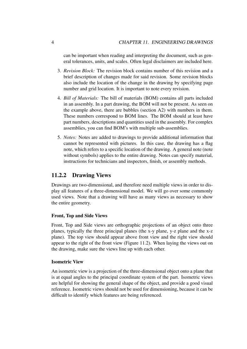
4 CHAPTER 11. ENGINEERING DRAWINGS
can be important when reading and interpreting the document, such as gen-eral tolerances, units, and scales. Often legal disclaimers are included here.
3. Revision Block: The revision block contains number of this revision and abrief description of changes made for said revision. Some revision blocksalso include the location of the change in the drawing by specifying pagenumber and grid location. It is important to note every revision.
4. Bill of Materials: The bill of materials (BOM) contains all parts includedin an assembly. In a part drawing, the BOM will not be present. As seen onthe example above, there are bubbles (section A2) with numbers in them.These numbers correspond to BOM lines. The BOM should at least havepart numbers, descriptions and quantities used in the assembly. For complexassemblies, you can find BOM’s with multiple sub-assemblies.
5. Notes: Notes are added to drawings to provide additional information thatcannot be represented with pictures. In this case, the drawing has a flagnote, which refers to a specific location of the drawing. A general note (notewithout symbols) applies to the entire drawing. Notes can specify material,instructions for technicians and inspectors, finish, or assembly methods.
11.2.2 Drawing ViewsDrawings are two-dimensional, and therefore need multiple views in order to dis-play all features of a three-dimensional model. We will go over some commonlyused views. Note that a drawing will have as many views as necessary to showthe entire geometry.
Front, Top and Side Views
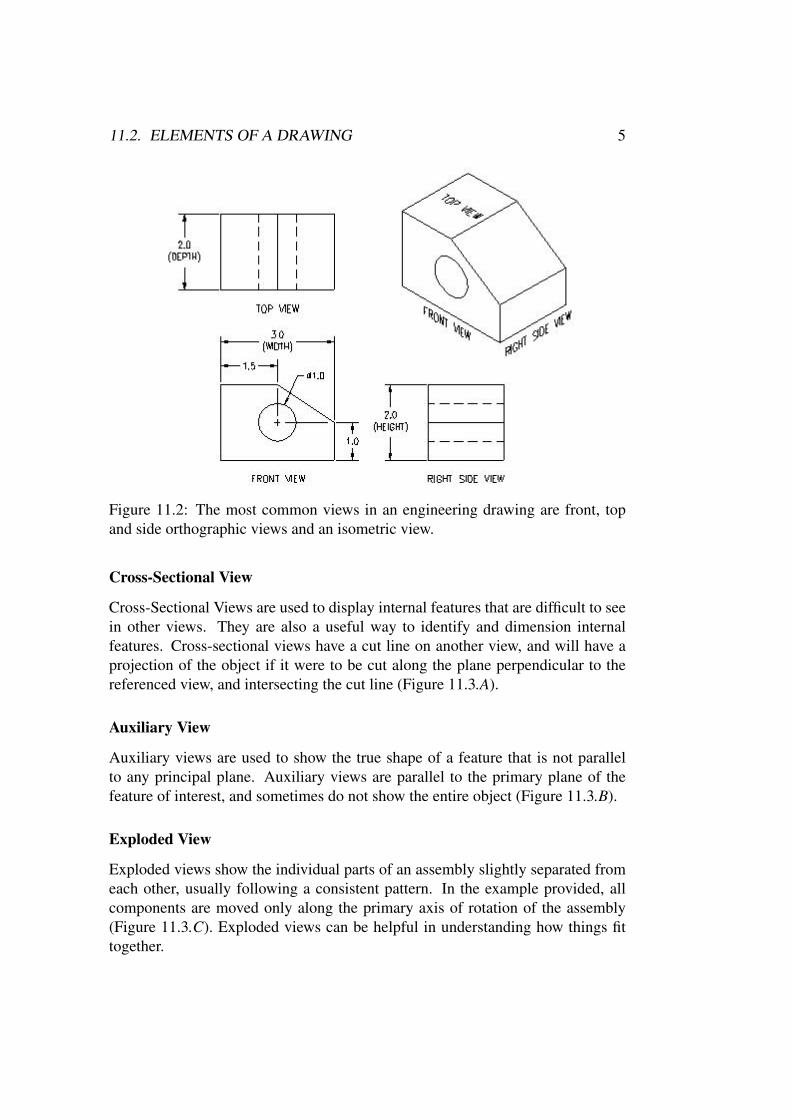
Front, Top and Side views are orthographic projections of an object onto threeplanes, typically the three principal planes (the x-y plane, y-z plane and the x-zplane). The top view should appear above front view and the right view shouldappear to the right of the front view (Figure 11.2). When laying the views out onthe drawing, make sure the views line up with each other.
Isometric View
An isometric view is a projection of the three-dimensional object onto a plane thatis at equal angles to the principal coordinate system of the part. Isometric viewsare helpful for showing the general shape of the object, and provide a good visualreference. Isometric views should not be used for dimensioning, because it can bedifficult to identify which features are being referenced.
11.2. ELEMENTS OF A DRAWING 5
Figure 11.2: The most common views in an engineering drawing are front, topand side orthographic views and an isometric view.
Cross-Sectional View
Cross-Sectional Views are used to display internal features that are difficult to seein other views. They are also a useful way to identify and dimension internalfeatures. Cross-sectional views have a cut line on another view, and will have aprojection of the object if it were to be cut along the plane perpendicular to thereferenced view, and intersecting the cut line (Figure 11.3.A).
Auxiliary View
Auxiliary views are used to show the true shape of a feature that is not parallelto any principal plane. Auxiliary views are parallel to the primary plane of thefeature of interest, and sometimes do not show the entire object (Figure 11.3.B).
Exploded View
Exploded views show the individual parts of an assembly slightly separated fromeach other, usually following a consistent pattern. In the example provided, allcomponents are moved only along the primary axis of rotation of the assembly(Figure 11.3.C). Exploded views can be helpful in understanding how things fittogether.

6 CHAPTER 11. ENGINEERING DRAWINGS
A. Cross-Sectional View
B. Auxiliary Views
C. Exploded View
Figure 11.3: Examples of specialty views.

11.2. ELEMENTS OF A DRAWING 7
Figure 11.4: Line types used in engineering drawings and their meaning.
11.2.3 Lines Used in Engineering Drawings
Line weight, dash and other properties are used to indicate the meaning of a line inengineering drawings. The most common line type is ‘continuous thick’, used todepict visible part edges (corners or places where a curve becomes tangent to theline of view). Another common line type is ‘dashed thick’, used to depict hiddenedges (part edges behind material from the current view). Dimensioning lines aretypically ‘continuous thin’. Additional line types are explained in Figure 11.4.

8 CHAPTER 11. ENGINEERING DRAWINGS
11.3 GD&T BasicsGeometric Dimensioning and Tolerancing (GD&T) refers to a set of symbolscommonly used in engineering drawings to define allowable deviations in ge-ometry. The language of GD&T consists of dimensions, tolerances, symbols,definitions, and conventions that can be used to precisely communicate functionalrequirements for the location, orientation, size, and form of each feature of a de-sign. These symbols communicate design design intent and requirements to man-ufacturers and quality inspectors. The current standard is ASME Y14.5-2009.
11.3.1 DimensionsBy dimensioning a feature, the author of the drawing is implying the importanceof the accuracy and the acceptable tolerance. In the title block, default tolerancesare often specified based on number of decimal points, e.g.: “Unless specified oth-erwise, x.xxx ± 0.005, x.xx ± 0.01, x.x ± 0.1”. If a different tolerance is required,± x.xxx should be added to the dimension. All specified dimensions imply im-portance, and will be assessed during quality inspection. When designing a part,think carefully about which dimensions are most important and how much erroris acceptable. If required tolerances are tight, try to make design changes thatimprove robustness against manufacturing errors and therefore increase the ac-ceptable error and reduce part cost. After working through this process iteratively,be sure to note the acceptable tolerances in the engineering drawing of the part.
Reference dimensions are used to specify overall dimension (good for pickingstarting material) or dimensions driven by other features (useful for helping thereader to understand the intent of the non-reference dimensions). Reference di-mensions are identified by putting parentheses around the dimension value, suchas: “(3.450)”. Reference dimensions are considered secondary, and will not bechecked by quality inspectors.
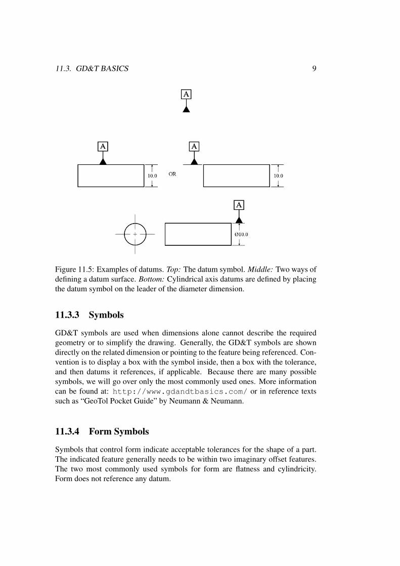
11.3.2 DatumsDatum symbols define the locations which will be used as a reference for otherdrawing dimensions and constraints. All GD&T symbols except for the set defin-ing form (Straightness, Flatness, Circularity, Cylindricity) can or must use datums.A datum can be plane, axis or point that is theoretically exact. Because datumsare theoretically exact it is good to use datums on surfaces, axes or points that canbe realistically measured. Keep in mind that no real surface or edge can be exact.Datums are listed in alphabetical order by importance, so when manufacturing apart datum A will be set first, then datum B and so on.
11.3. GD&T BASICS 9
Figure 11.5: Examples of datums. Top: The datum symbol. Middle: Two ways ofdefining a datum surface. Bottom: Cylindrical axis datums are defined by placingthe datum symbol on the leader of the diameter dimension.
11.3.3 Symbols
GD&T symbols are used when dimensions alone cannot describe the requiredgeometry or to simplify the drawing. Generally, the GD&T symbols are showndirectly on the related dimension or pointing to the feature being referenced. Con-vention is to display a box with the symbol inside, then a box with the tolerance,and then datums it references, if applicable. Because there are many possiblesymbols, we will go over only the most commonly used ones. More informationcan be found at: http://www.gdandtbasics.com/ or in reference textssuch as “GeoTol Pocket Guide” by Neumann & Neumann.
11.3.4 Form Symbols
Symbols that control form indicate acceptable tolerances for the shape of a part.The indicated feature generally needs to be within two imaginary offset features.The two most commonly used symbols for form are flatness and cylindricity.Form does not reference any datum.

10 CHAPTER 11. ENGINEERING DRAWINGS
Flatness
By adding the flatness symbol, the engineer is requiring a surface to be flat withinspecified tolerance. This means that the irregularity of the surface has to be withintwo parallel surfaces that are separated by the specified tolerance. The largestdifference (highest peak and lowest valley) must be within the tolerance or thepart will be rejected. Usually when setting a surface as a datum, the surface willalso have a flatness requirement.
Figure 11.6: The flatness symbol and its use and meaning.
Cylindricity
By adding the cylindricity symbol, the engineer is requiring a surface to be cylin-drical. This means that the irregularity of the surface has to be within two concen-tric cylinders that are separated by the specified tolerance. The largest differencemust be within the tolerance.
Figure 11.7: The cylindricity symbol and its use and meaning.
11.3. GD&T BASICS 11
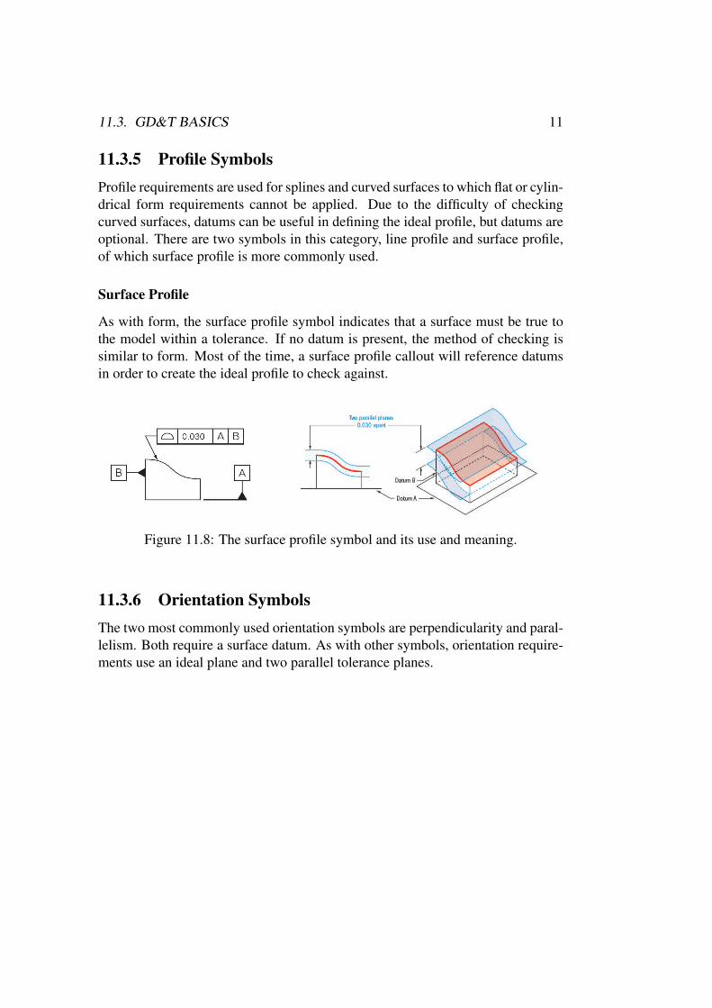
11.3.5 Profile SymbolsProfile requirements are used for splines and curved surfaces to which flat or cylin-drical form requirements cannot be applied. Due to the difficulty of checkingcurved surfaces, datums can be useful in defining the ideal profile, but datums areoptional. There are two symbols in this category, line profile and surface profile,of which surface profile is more commonly used.
Surface Profile
As with form, the surface profile symbol indicates that a surface must be true tothe model within a tolerance. If no datum is present, the method of checking issimilar to form. Most of the time, a surface profile callout will reference datumsin order to create the ideal profile to check against.
Figure 11.8: The surface profile symbol and its use and meaning.
11.3.6 Orientation SymbolsThe two most commonly used orientation symbols are perpendicularity and paral-lelism. Both require a surface datum. As with other symbols, orientation require-ments use an ideal plane and two parallel tolerance planes.

12 CHAPTER 11. ENGINEERING DRAWINGS
Perpendicularity
Perpendicularity is used very often, and just like other symbols, the tolerancezones are 2 parallel planes that are equidistance away from the ideal parallel plane.Perpendicularity can also be applied to an axis, and often used for hole alignments.For axis perpendicularity, a tolerance cylinder is drawn around the ideal axis thatis perpendicular to the datum surface.
Figure 11.9: The perpendicularity symbol and its use and meaning.
Parallelism
Parallelism is very intuitive, in a sense that that the tolerance surfaces will be par-allel to the datum surface. Sometime, an inspector gets a large set of coordinatesof the datum surface and the called out surface, and individually check the paral-lelism, to get even more accurate data, but if the datum surface is out of tolerance,this method will not work.
Figure 11.10: The parallelism symbol and its use and meaning.

11.3. GD&T BASICS 13
11.3.7 Location SymbolsLocation requirements are important, but can be complicated to implement be-cause they require more datums and dimensions to be defined and incorporated.
Position (True Position)
True position is one of the most useful GD&T symbol but also the most compli-cated. Unlike other symbols, True Position uses relative distance from the “trueposition” to actual position. True position is commonly used for finding centersof holes, and typically requires two datums. Because the tolerance is set by theradius around the true position, the equation shown below must be used to see ifthe true position is met.
Figure 11.11: The position symbol. The top diameter callout defines the diameterand diameter tolerance for the hole. The boxed elements on the dimension leaderare, from left to right, the position symbol, the hole axis position tolerance (thediameter of the circle defining the tolerable region), and the datums of the firstand second reference edges. Note that the dimensions defining hole location arealso boxed, as they are part of the position requirement.
Figure 11.12: Evaluating the position tolerance.

14 CHAPTER 11. ENGINEERING DRAWINGS
Concentricity
Concentricity is checked by making a tolerance cylinder around the ideal axis thatis set by the datum axis. The datum axis needs to be set by a cylindrical featurewith an axis. The tolerance appearing to the right of the concentricity symboldefines the diameter of the cylindrical tolerance zone in which the feature axiscan be located.
Figure 11.13: The concentricity symbol and its use and meaning.
11.3.8 Runout Symbols
Runout refers to the variation in the radius of a cylindrical feature as it is rotatedabout a datum axis. This is similar to cylindricity, with the difference being thatthe datum axis is not the same as the feature axis. There are two types of runout,circular and total, of which total runout is the more common and more restrictive.
11.4. ACKNOWLEDGMENTS 15
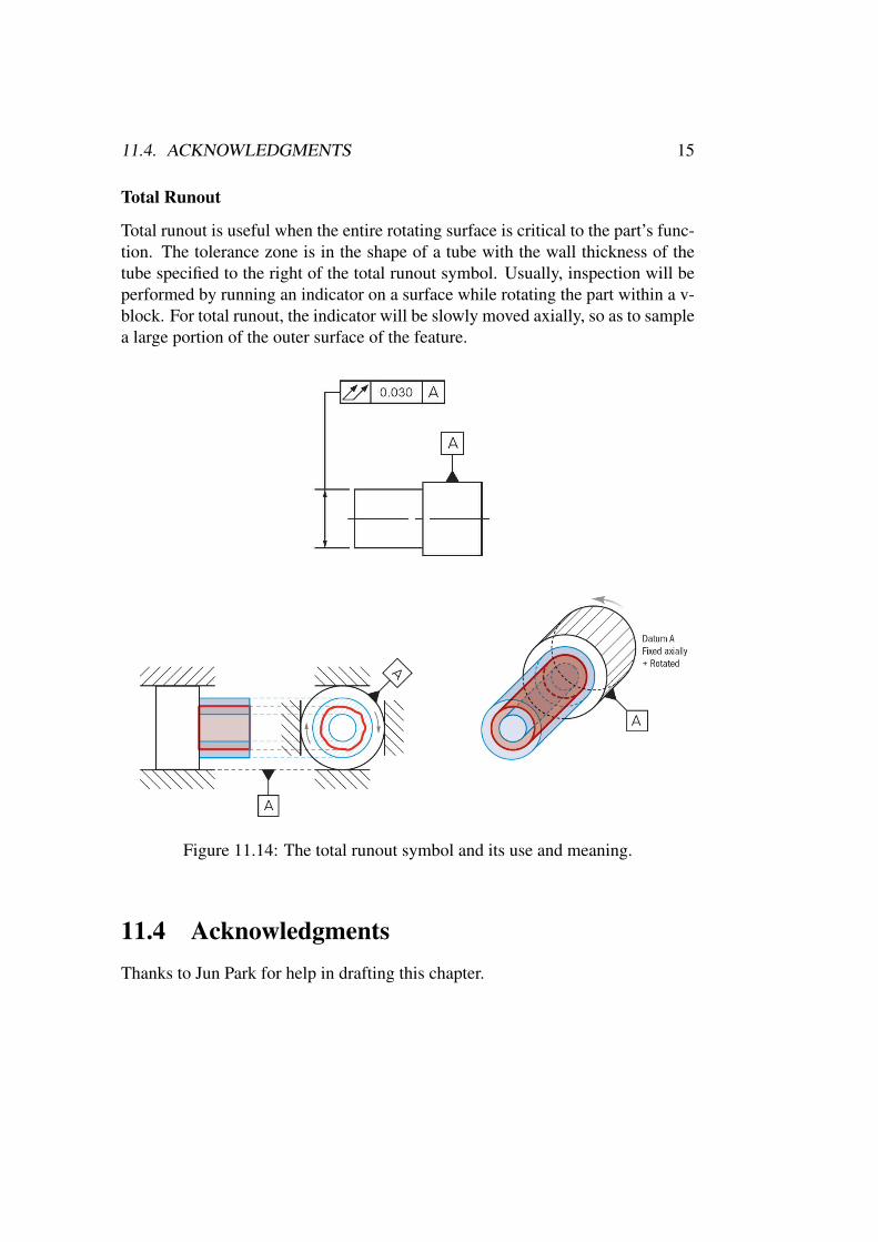
Total Runout
Total runout is useful when the entire rotating surface is critical to the part’s func-tion. The tolerance zone is in the shape of a tube with the wall thickness of thetube specified to the right of the total runout symbol. Usually, inspection will beperformed by running an indicator on a surface while rotating the part within a v-block. For total runout, the indicator will be slowly moved axially, so as to samplea large portion of the outer surface of the feature.
Figure 11.14: The total runout symbol and its use and meaning.
11.4 AcknowledgmentsThanks to Jun Park for help in drafting this chapter.

16 CHAPTER 11. ENGINEERING DRAWINGS
Figure 11.15: Table of common GD&T symbols with abbreviated meaning anduse. From http://opensourceecology.org/w/images/0/03/Gdt_diagram.jpg)