Embed Size (px)
Citation preview
Document ID: EDF-3061 Revision ID: 0 Effective Date: 3.07.02
Engineering Design File
PROJECT FILE NO. 020996
Staging, Storage, Sizing and Treatment Facility
Post-tensioned Slab Design
Prepared for: U.S. Department of Energy Idaho Operations Dffice Idaho Falls, Idaho
Form 412.14 07/24/2001 Rev. 03
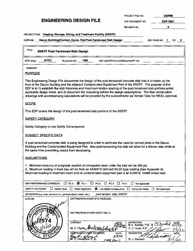
PROJECT FILE NO. 020996
ENGINEERING DESIGN FILE EDF DOCUMENT NO. EDF-3061
REVISION NO. 0
PWJECT~ASK Staging, Storage, Sizing, and Treatment Facility (SSSTF)
SUBTASK Decon BuildinglContam. Equip. Pad Post-Tensioned Slab Design EDFPAGE NO. 1 OF 2 - -
TITLE SSSTF Post-Tensioned Slab Design
SITE AREA INTEC BUILDING NO. 1688 SSC IDENTIFICATION/EQUIPMENT NO.
SUMMARY
PURPOSE
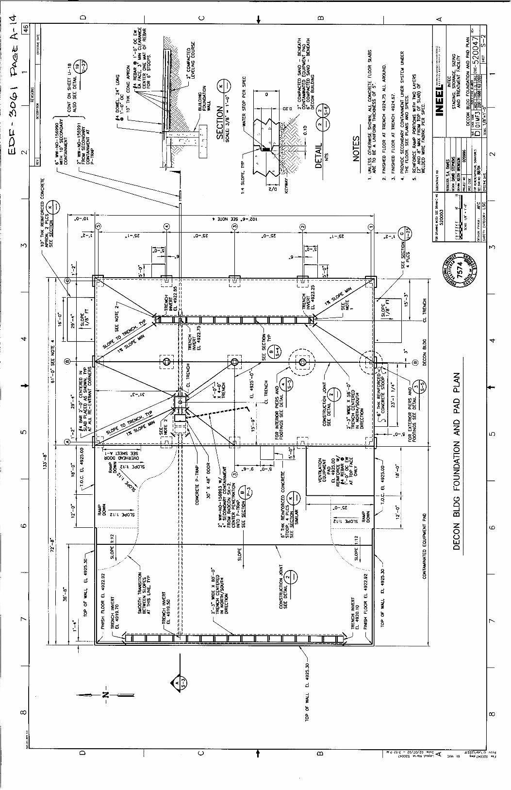
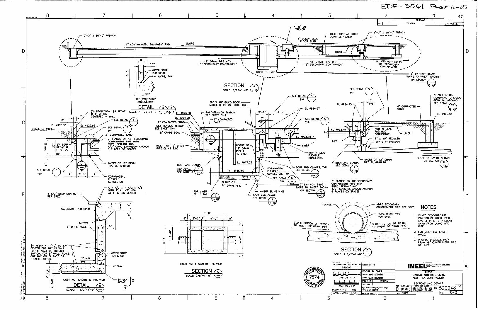
This Engineering Design File documents the design of the post-tensioned concrete slab that is to make up the floor of the Decon Building and the adjacent Contaminated Equipment Pad of the SSSTF. The purpose of this EDF is to 1) establish the slab thickness and maximum tendon spacing of the post-tensioned slab portions under applicable design loads, and 2) document the reasoning behind the design assumptions. The final construction drawings with accompanying calculations will be provided by the subcontractor as Vendor Data for INEEL approval.
SCOPE
This EDF covers the design of the’post-tensioned slab portions of the SSSTF.
SAFETY CATEGORY
Safety Category is Low Safety Consequence
SUBJECT SPECIFIC DATA
A post tensioned concrete slab is being designed in order to eliminate the need for control joints in the Decon Building and the Contaminated Equipment Pad. Also post-tensioning the slab will allow for a thinner slab while at the same time preventing cracks from developing.
ASSUMPTIONS
1. Minimum modulus of subgrade reaction of compacted sand under the slab will be 400 pci. 2. Maximum loading in truck bay will be from an AASHTO defined HS-20 type loading (See Appendix A). Maximum loading in treatment room and on contaminated equipment pad is an 8,008 lb. forklift wheel load.
NPH PERFORMANCECATEGORY q PC-O p PC-l 0 PC-2 0 PC-3 [7 PC-4 0 Not Applicable
SAFETY CATEGORY q Safety Class q Safety Significant q Low Safety Consequence 0 Consumer Grade 0 Not Applicable
KEYWORDS (e.g. area, structure no., general subject matter, etc.) : post-tension, slab, SSSTF
DISTRIBUTION (COVER SHEET ONLY):
C. J. Hurst, P.E.
PROJECT FILE NO. 020996
ENGINEERING DESIGN FILE EDF DOCUMENT NO. EDF-3061
REVISION NO. 0
PROJECTlTASK Staging, Storage, Sizing, and Treatment Facility (SSSTF)
SUBTASK Decon BuildinglContam. Equip. Pad Post-Tensioned Slab Design EDF PAGE NO. 2 OF 2 - ‘,
SUMMARY (Continued)
ACCEPTANCE CRITERIA
N/A
CALCULATIONS
See Appendix A for Detailed Calculations
CONCLUSIONS
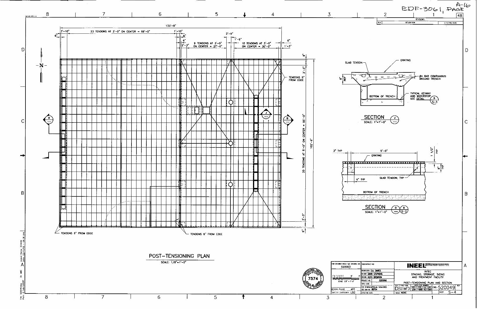
Use 5” thick, post-tensioned slab for Decon Building and Contaminated Equipment Pad with maximum tendon spacing as shown on subcontract drawings.
RECOMMENDATIONS
N/A
REFERENCES
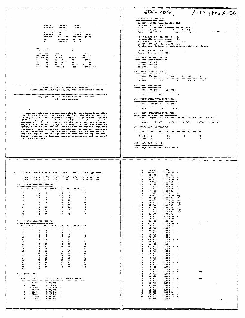
1. Design and Construction of Post-Tensioned Slabs-On-Ground, 2nd edition, Post-Tensioning Institute, 1996. 2. Construction and Maintenance Procedures Manual for Post-Tensioned Slabs-On-Ground Construction, 2nd edtion, Post-Tesioning Institute, 1998. 3. Standard Specifications For Highway Bridges, American Association of State Highway and Transportion Officials (AASHTO ), Sixteeneth Edition, 1996. 4. PCA-MATS, Version 5.10, a finite element slab and mat foundation analysis software, Portland Cement Association, 1994.
Appendix A Calculations, PCA-MATS Plots and
Output Results, Reference Drawings
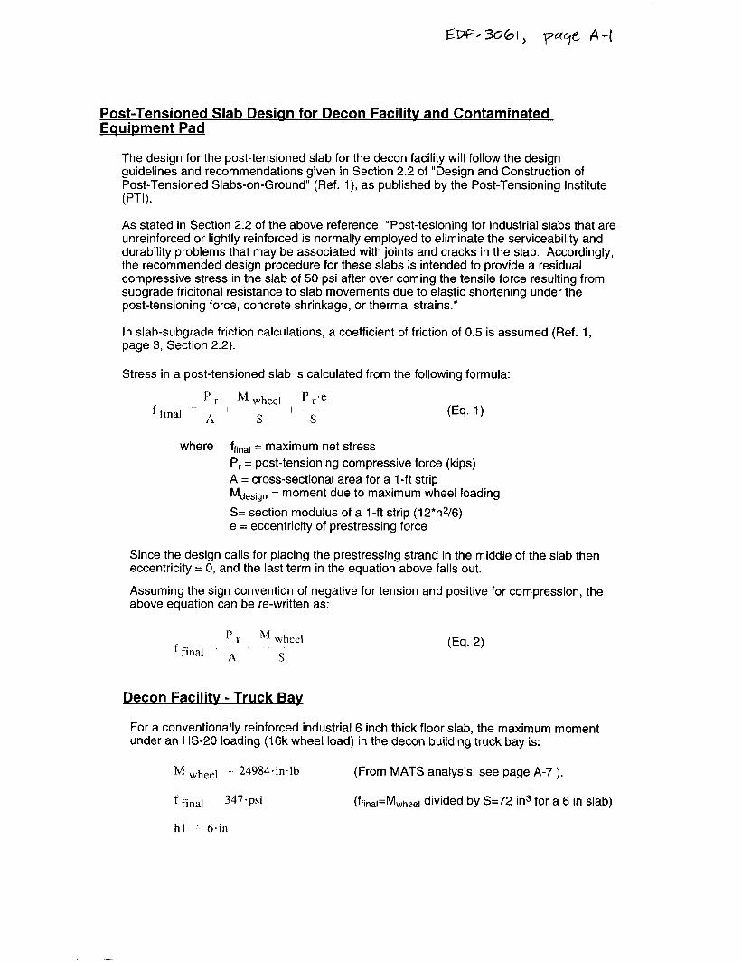
Post-Tensioned Slab Desian for Decon Facilitv and Contaminated Equipment Pad
The design for the post-tensioned slab for the decon facility will follow the design guidelines and recommendations given in Section 2.2 of “Design and Construction of Post-Tensioned Slabs-on-Ground” (Ref. l), as published by the Post-Tensioning Institute (PTI).
As stated in Section 2.2 of the above reference: “Post-tesioning for industrial slabs that are unreinforced or lightly reinforced is normally employed to eliminate the serviceability and durability problems that may be associated with joints and cracks in the slab. Accordingly, the recommended design procedure for these slabs is intended to provide a residual compressive stress in the slab of 50 psi after over coming the tensile force resulting from subgrade fricitonal resistance to slab movements due to elastic shortening under the post-tensioning force, concrete shrinkage, or thermal strains.”
In slab-subgrade friction calculations, a coefficient of friction of 0.5 is assumed (Ref. 1, page 3, Section 2.2).
Stress in a post-tensioned slab is calculated from the following formula:
(Eq. 1)
where frinar = maximum net stress P, = post-tensioning compressive force (kips) A = cross-sectional area for a 1 -ft strip Mdesign = moment due to maximum wheel loading
S= section modulus of a 14 strip (12*h2/6) e = eccentricity of prestressing force
Since the design calls for placing the prestressing strand in the middle of the slab then eccentricity = 0, and the last term in the equation above falls out.
Assuming the sign convention of negative for tension and positive for compression, the above equation can be re-written as:
(Eq. 2)
Decon Facilitv - Truck Bav
For a conventionally reinforced industrial 6 inch thick floor slab, the maximum moment under an HS-20 loading (16k wheel load) in the decon building truck bay is:
Ik4 wheel r 24984.in.lb (From MATS analysis, see page A-7 ).
f final 347.psi (frinar=Mwheer divided by S=72 in3 for a 6 in slab)
hl 6.in
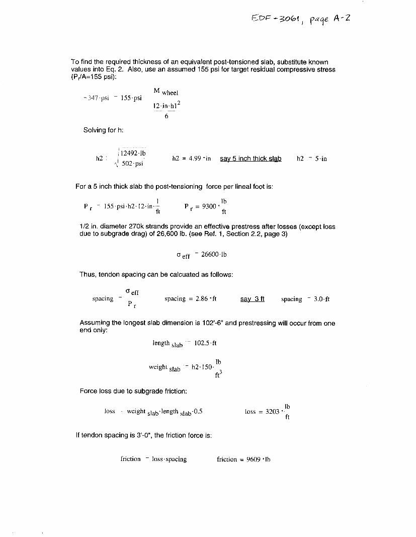
To find the required thickness of an equivalent post-tensioned slab, substitute known values into Eq. 2. Also, use an assumed 155 psi for target residual compressive stress (P,./A=155 psi):
M wheel - 347. psi - 155.psi
12.in.h12 6
Solving for h:
,,2 ~ /------mm 12492.1b
fij 502.psi h2 = 4.99 ‘in sav 5 inch thick slab h2 = 5.in
For a 5 inch thick slab the post-tensioning force per lineal foot is:
P, - 155.psi.h2.12.in.1 ft
P, = 9300.;
l/2 in. diameter 270k strands provide an effective prestress after losses (except loss due to subgrade drag) of 26,600 lb. (see Ref. 1, Section 2.2, page 3)
(3 eff - 26600.1b
Thus, tendon spacing can be calcuated as follows:
o eff spacing r -6~
r spacing = 2.86 *ft say 3 ft spacing = 3.o.ft
Assuming the longest slab dimension is 102’-6” and prestressing will occur from one end only:
length slab : r 102.5.ft
Weight slab 7 h2. &b ft3
Force loss due to subgrade friction:
loss ~ weight slab’length slab.o.5
If tendon spacing is 3’-0”, the friction force is:
loss = 3203 *;
friction - loss ’ spacing friction = 9609 -lb
Em=- 3061, qcfge k-3
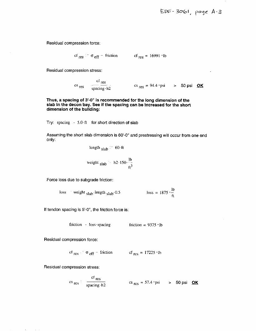
Residual compression force:
cf ‘1 res (3 eff - friction cf res = 16991 *lb
Residual compression stress:
cs res cf res
spacing. h2 cs res = 94.4 *psi > 50 psi OK
Thus, a spacing of 3’-0” is recommended for the long dimension of the slab in the decon bay. See if the spacing can be increased for the short dimension of the building:
Try: spacing = 5.O.ft for short direction of slab
Assuming the short slab dimension is 60’-0” and prestressing will occur from one end only:
length slab : 6O.ft
weight slab :I- h2.150.& ft3
Force loss due to subgrade friction:
loss weight s,ab ’ length s,ab’ 0.5 loss = 1875 *;
If tendon spacing is S-O”, the friction force is:
friction L loss. spacing friction = 9375 *lb
Residual compression force:
cf res 0 eff - friction
Residual compression stress:
cs res cf res
spacing. h2
cf res = 17225 -lb
cs res = 57.4 ‘psi > 50 psi OK
W=-3Oobl) p4q9 A-4
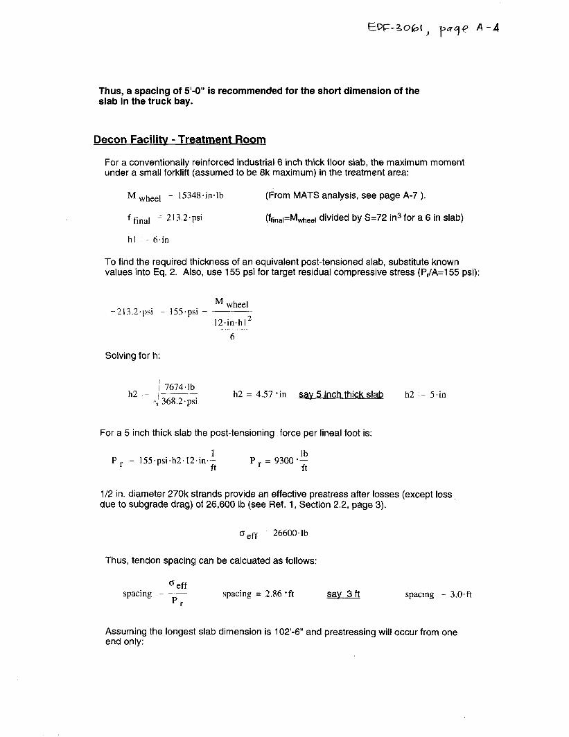
Thus, a spacing of 5’-0” is recommended for the short dimension of the slab in the truck bay.
Decon Facility - Treatment Room
For a conventionally reinforced industrial 6 inch thick floor slab, the maximum moment under a small forklift (assumed to be 8k maximum) in the treatment area:
M wheel - 15348.in.lb (From MATS analysis, see page A-7 ).
f final - 213.2.psi (ffinal=Mwheel divided by S=72 in3 for a 6 in slab)
hl ‘- 6+in
To find the required thickness of an equivalent post-tensioned slab, substitute known values into Eq. 2. Also, use 155 psi for target residual compressive stress (P,/A=155 psi):
M wheel -213.2.psi - 155.psi -
12.in*h12 6
Solving for h:
! 7674.1b h2 - 1 h2 = 4.57 ‘in
q 368.2.psi sav 5 inch thick slab h2 .- 5.in
For a 5 inch thick slab the post-tensioning force per lineal foot is:
Pr z 155.psi.h2.12.ineL ft
P r = 9300 .$
l/2 in. diameter 270k strands provide an effective prestress after losses (except loss due to subgrade drag) of 26,600 lb (see Ref. 1, Section 2.2, page 3).
o eff - 26600.1b
Thus, tendon spacing can be calcuated as follows:
o eff spacing - ___
pr- spacing = 2.86 ‘ft 3 ft say spacing - 3.O.ft
Assuming the longest slab dimension is 102’-6” and prestressing will occur from one end only:
Is-3065 ‘p”6j-e P-S
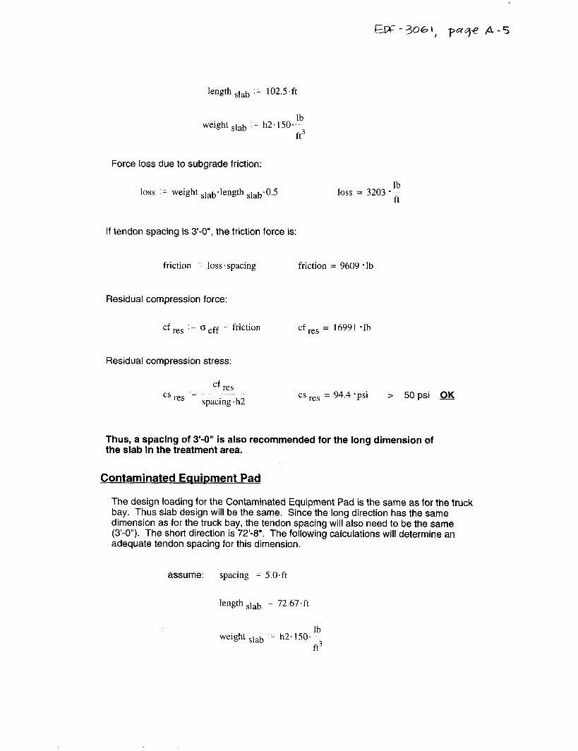
length slab L 102.5.ft
lb weight slab ,: h2.150.
ft3
Force loss due to subgrade friction:
loss z weight slabdength slab’0.5 loss = 3203 .;
If tendon spacing is 3-O”, the friction force is:
friction - loss .spacing friction = 9609 *lb
Residual compression force:
cf res ‘I 0 eff friction cf res = 16991 -lb
Residual compression stress:
cs res cf res
spacing. h2 cs res = 94.4 *psi > 50 psi OK
Thus, a spacing of 3’-0” is also recommended for the long dimension of the slab in the treatment area.
Contaminated Equipment Pad
The design loading for the Contaminated Equipment Pad is the same as for the truck bay. Thus slab design will be the same. Since the long direction has the same dimension as for the truck bay, the tendon spacing will also need to be the same (3’-0”). The short direction is 72’-8”. The following calculations will determine an adequate tendon spacing for this dimension.
assume: spacing z 5.O.ft
length slab - 72.67.ft
weight slab - h2.150.‘b ft3
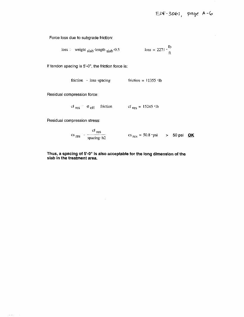
Force loss due to subgrade friction:
loss weight slab.length s,ab’o.5 loss = 2271 *;
If tendon spacing is 5’-O”, the friction force is:
friction - loss. spacing friction = 11355 *lb
Residual compression force:
cf res o eff friction cf res = 15245 *lb
Residual compression stress:
cf res cs res ‘: spacing. h2 cs res = 50.8 *psi > 50 psi OK
Thus, a spacing of 5’-0” is also acceptable for the long dimension of the slab in the treatment area.
LJ>G-3061, -ysqe p-7
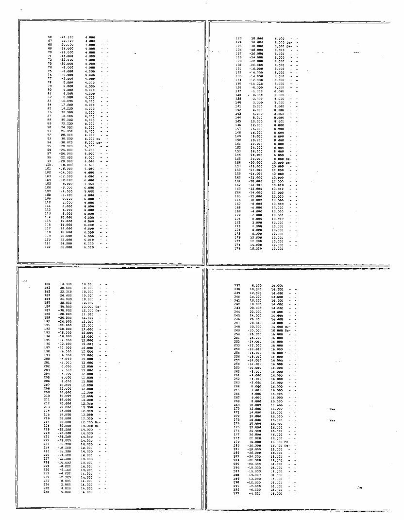
PCA-MATS Analvsis
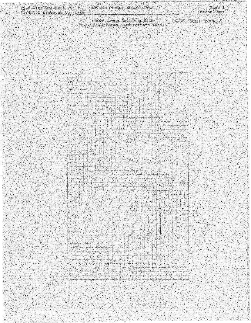
The decon truck bay and treatment room floor slab was modeled in PCA-MATS (Ref 4) a finite element concrete slab and mat foundation computer program. The trenches and pits were modeled also. Downward deflection was restrained at the building perimeter and at the trench and pit edges to simulate the extra stiffness due to the presence of the grade beam and the trench and pit walls.
A envelope type loading pattern was applied for both the HS-20 load and the forklift load. The approach was to place the maximum load with an assumed wheel spacing of 6 ft and 4 ft respectively at multiple locations in order to evaluate the full range of response to the loads as the vehicles travel across the slab. (See loading plots on A-10 and A-l 1).
Truck Bay (also Contaminated Eaubment Pad (not modeledu
For a conventionally reinforced industrial 6 inch thick floor slab, the maximum moment under an HS-20 loading (16k wheel load) in the decon truck bay is:
M YY 2.082. ft zip (tensile)
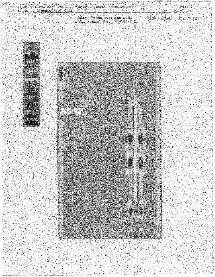
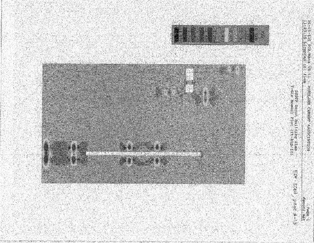
The above value is the moment (for either y-dir or x-dir) taken a distance of approximately 1 ft either direction from the point of application. This value was taken from the plot instead of the plotted maximum since the load was applied as a concentrated load in the program (which is conservative) and the actual tire contact area is 20” x 8” (See Ref. 2, page 41). From the PCA-MATS analysis (See results plots on page A-12 and A-13):
M max MYY
in.lb M max = 24984 -
ft
Treatment Room
For a conventionally reinforced industrial 6 inch thick floor slab, the maximum moment under a forklift loading (8k wheel load) in the decon treatment room is:
M YY 1.279. ft.kip
ft (tensile)
The above value is the maximum moment (for either y-dir or x-dir) from the PCA-MATS analysis (See results plots on page A-12 and A-13). Thus,
M max M YY
in.lb M max = 15348 -
ft
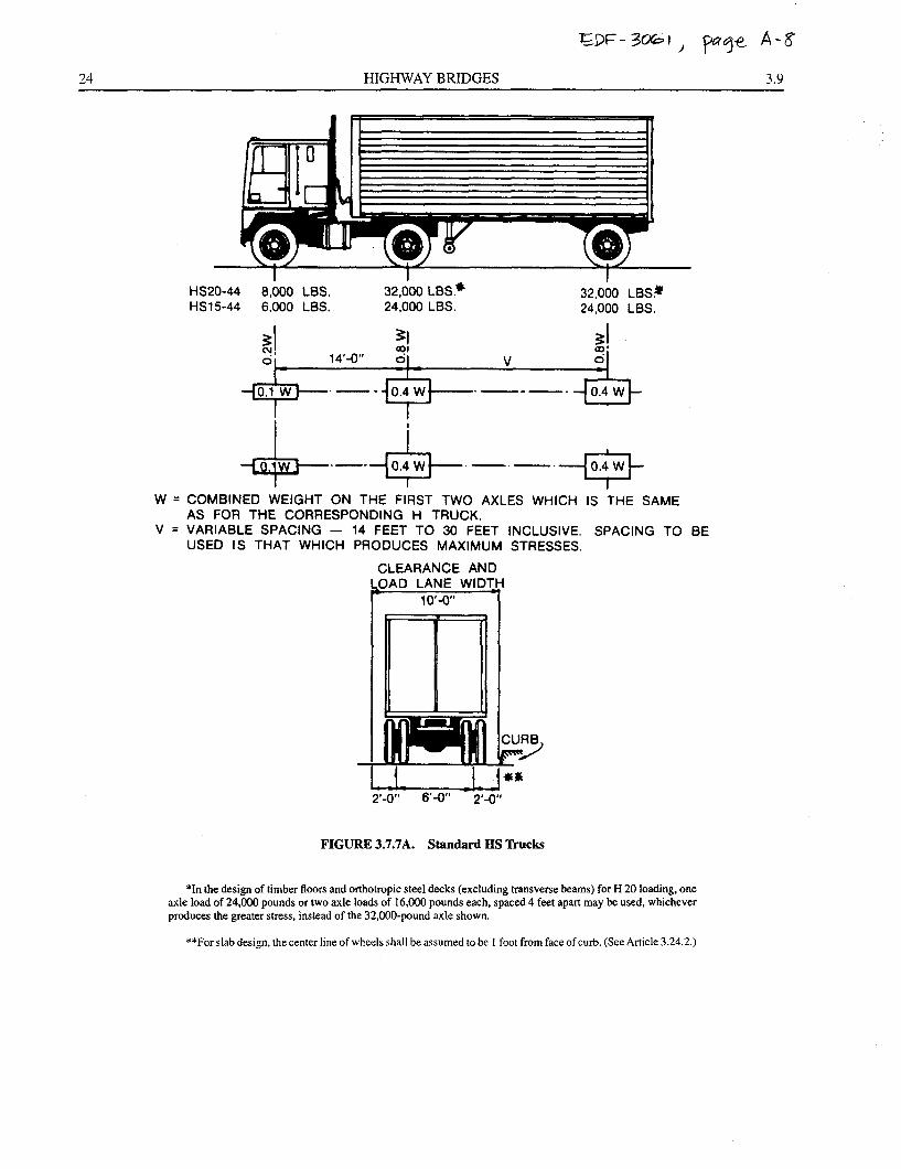
24 HIGHWAY BRIDGES 3.9
HS20-44 8,000 LBS. 32,000 LBS.+ 32.060 LBS.w HSl5-44 6.000 LBS. 24,000 LBS. 24,000 LBS.
W = COMBINED WEIGHT ON THE FIRST TWO AXLES WHICH IS THE SAME AS FOR THE CORRESPONDING H TRUCK.
V = VARIABLE SPACING - 14 FEET TO 30 FEET INCLUSIVE. SPACING TO BE USED IS THAT WHICH PRODUCES MAXIMUM STRESSES.
CLEARANCE AND 3AD LANE WIDT ‘H
lo’-cY
1
C
‘-0” 6’4,” 2*-o,,
FIGURE 3.7.7A. Standard HS Trucks
*In the design of timber floors and orthotropic steel decks (excluding transverse beams) for H 20 loading, one axle load of 24,000 pounds or two axle loads of 16,000 pounds each, spaced 4 feet apart may be used, whichever produces the greater stress, instead of the 32,000~pound axle shown.
**For slab design, the center line of wheels shall be assumed to be 1 foot from face of curb. (See Article 3.24.2.)
ED=- 3021, ‘pqe A-9
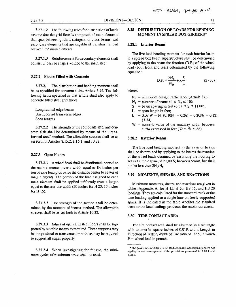
3.27.1.2 DIVISION I-DESIGN 41
3.27.1.2 The following rules for distribution of loads assume that the grid floor is composed of main elements that span between girders, stringers, or cross beams, and secondary elements that are capable of transferring load between the main elements.
3.27.1.3 Reinforcement for secondary elements shall consist of bars or shapes welded to the main steel.
3.27.2 Floors Filled with Concrete
3.27.2.1 The distribution and bending moment shall be as specified for concrete slabs, Article 3.24. The fol- lowing items specified in that article shall also apply to concrete filled steel grid floors:
Longitudinal edge beams Unsupported transverse edges Span lengths
3.27.2.2 The strength of the composite steel and con- crete slab shall be determined by means of the “trans- formed area” method. The allowable stresses shall be as set forth in Articles 8.15.2, 8.16.1, and 10.32.
3.27.3 Open Floors
3.27.3.1 A wheel load shall be distributed, normal to the main elements, over a width equal to 1% inches per ton of axle load plus twice the distance center to center of main elements. The portion of the load assigned to each main element shall be applied uniformly over a length equal to the rear tire width (20 inches for H 20, 15 inches for H 15).
3.27.3.2 The strength of the section shall be deter- mined by the moment of inertia method. The allowable stresses shall be as set forth in Article 10.32.
3.27.3.3 Edges of open grid steel floors shall be sup- ported by suitable means as required. These supports may be longitudinal or transverse, or both, as may be required to support ail edges properly.
3.27.3.4 When investigating for fatigue, the mini- mum cycles of maximum stress shall be used.
3.28 DISTRIBUTION OF LOADS FOR BENDING MOMENT IN SPREAD BOX GIRDERS*
3.28.1 Interior Beams
The live load bending moment for each interior beam in a spread box beam superstructure shall be determined by applying to the beam the fraction (D.F.) of the wheel load (both front and rear) determined by the following equation:
D.F. = ~NL -+k; NB
(3 - 33)
where,
NL = number of design traffic lanes (Article 3.6); Ne = number of beams (4 I Ns I 10); S = beam spacing in feet (6.57 I S 5 11.00); L = span length in feet; k = 0.07 W - NL (O.lONL - 0.26) - 0.20NB - 0.12;
(3-34) W = numeric value of the roadway width between
curbs expressed in feet (32 I W % 66).
3.28.2 Exterior Beams
The live load bending moment in the exterior beams shall be determined by applying to the beams the reaction of the wheel loads obtained by assuming the flooring to act as a simple span (of length S) between beams, but shall not be less than 2NL/NB.
3.29 MOMENTS, SHEARS, AND REACTIONS
Maximum moments, shears, and reactions are given in tables, Appendix A, for H 15, H 20, HS 15, and HS 20 loadings. They are calculated for the standard truck or the lane loading applied to a single lane on freely supported spans. It is indicated in the table whether the standard truck or the lane loadings produces the maximum stress.
3.30 TIRE CONTACT AREA
The tire contact area shall be assumed as a rectangle with an area in square inches of O.OlP, and a Length in Direction of Traffic/Width of Tire ratio of l/2.5, in which P = wheel load in pounds.
*The provisions of Article 3.12, Reduction in Load Intensity, were not applied in the development of the provisions presented in 3.28.1 and 3.28.2.
k .o-.OL
u-l l
.z-. L .l -.SL
- .o-.s
”
‘Fl
+ 310N 3X .9-.tOL
ho I
I - .o-.s
r--l ,A, > ’ ~ ____ In~-i~~--~-~---\---~c---i ____ -----Ani-- __________ -i?ll GIL
In ‘t-% -I - II
ik II \\ \ L -1
b L- L-. I
DI-l(" JJ 8 7 6 5 4 4 3 2 1 k I RFVlUONS
2’-3’ X 80*-O” TRENCH _I ----.. -.-- 1T AT CONST
2’-3’ X 58’-O- TRENCH _-----___
3 DtCUN ULDG FLOOR SLAB
5’ CONTAMINATE0 EOUIPMENT PAD
1:4 SLOPE, TYP
SECOND - CONTAINMENT _ _ .’
I , / 4’
*- --_ __---
. 2’ SW-NO-156991 SLOPE TO INVERT SHOWN
ON SECTION f;;\
I 3=b”“‘y c A I w -....- . ,... _I ̂ . c ., SEE DETAIL m -
e 0 TYP wm
AND KFYWAY
t
DETAIL m ,I- ~‘,!$‘z~L 14 REBAR SCALE: I 1/2-=1*-O- -4 EL 4g25.00
\ r POST-TENSION TENDON SEE SHEET S-4
---l&v CENTEREOFkEE oETAIL ~
\\
_-- - -_ - EL 4924.00
2’ COMPACTED%ii&\ r 6’ COMPACTEO SAND
2’-6” , / 4.-O’
‘/
- EL 4925.00
POST-TENSION TENDON- SEE SHEET S-4
8” GRADE BEAM
! .I I I
F@i &--12-:MPACTEO%
r --ri 1”. 7 2’ FLANGE ON 18’ SECONDARY CONTAlNMENT PIPE WITH
KOR-N-SEAL FLEXIBLE
BUlYL SEALANT AND l/2” CONC EXPANSION ANCHOR R DLACES EO SPACES
INVERT OF 12” DRAJN PIPE EL 4919.00
RT OF 12’ ORAJN -. _ - _ - - - BOO
SEE ZFF TYP- 6-11 2*-J- 1 I- 6”
I I
L --- -.--- -
KOR-N-SEAL t FLEXIBLE CONNECTOR
INVERT OF 12’ DRAlN BOOT AND CLAMPS PIPE EL 4918.70
SLOPE TO INVERT SHOWN
ON sEw
2‘ FLANGE ON 18” SECONDARY CONTAJNMENT PIPE WITH BUM SEALANT AND l/2- CONC EXPANSION ANCHOR 8 PLACES EO SPACES
1 l/2” DEEP GRATING PER SPEC
L 1 l/2 X 1 l/2 X l/8 WITH 4’ X l/2- HSA AT l’-6” ON CENTER
FOR LINER SEE DETAIL ‘3 3
-2
INVERT EL 4914.06
BOOT AND CLAMP SEE OETAJL m
WATERSTOP PER SPEC CONTAINMENT PIPE PER SPEC NOTES
HOPE DRAlN PIPE 1. PLACE GEOCOMPOSITE PORTION OF LINER OVER
SLOPE BOTTOM OF TRENCH To IM’ERT OF tN?AJN PIPE
END OF PIPE TO PREVENT ;;“p”p FROM GOING INTO
2. FOR ‘LINER SEE SHEET u-20.
L 8’-O- -1
8” 2’-2” 6” 4*-o- 8”
6” OR 8” WALL 6’
,r WATER STOP PER SPEC
3. PROVlOE DRAlNAGE PATH FROM 18” CONTAINMENT PIPE TO LINER
#4 REBAR AT l’-0” OC EW CENTER ONE MAT IN WALL FOR 6” WALL OR TRENCH
KEYWAY LINER NOT SHOWN IN THIS VIEW
I’ 0 I’ 2’ r 4’ 5’ ,o REmsm SA MS INTEC B-1 ~~CJJ Mwo slmms STAGING. STORAGE, SIZING
SC&L J/16’ = 1’4 cuAw. KIlTI ellwjw AND TREATMENT FACILITY LINER NOT SHOWN IN THIS VlEW $
SECTIONS AND DETAILS
8 7 6 5 t 4 3
I -N-
i
B - B A--
133’-8’
3’-10” 23 TENDONS AT 3*-O” ON CENTER = 69,-D” l’-lD-
62 i-E
2’-9’
-t-p-9- C” JZ- ”
9 TENDONS AT 3’-0’ .--- 10 TENDONS AT 3,-D- - 2’-3’ _ ON CENTER = 27*-D” ON CENTER - JO’-0” l- l’-3’
k
.dY TENDONS 6’ FROM EDGE \ TENDONS 6” FROM EDGE
POST-TENSIONING PIAN SCALE: l/S”= 1 ‘-0”
5’-0’ ‘N I >; r GRATING
BOTTOM OF TRENCH
SCALE: 1 --a 1 ‘-0”
*:a NODAL o*TR: . ..*.............
N”de x ,tt, Y
: ,:I M,0 i -28.0”” ? -26.00” 4 -24.000 5 -22.000 c -20.00” 7 -18.00”
^ 8 -:6.000
?D=-3061 ) pp A-19
--
--
-“.“‘ -0.02
131 !OO 130
99 132
0.00 -“.01
0.09 u.05 0.0”
-0.02 -0.02 -0.08 -0.08 -0.08 -0.08 -0.03 -0.02 -0.04
“(XI, ..---- __________ _.
-0.0” 0.0” 0.0” -0.0”
-0.0” 0.0” -0.01 U.0”
0.0” -0.0” -0.“” -0.0” -0.0” -0.0”
0.“” -0.0” 0.0” -0.0”
-0.08 -0.1 -0.08 0.8 -“.“B 1.: -“.“3 2.7 -0.03 3.5 -0.04 z.1
-0.03 -5.6 -0.m -4.9 -0.08 -i.9 -0.08 -1.7 -0.08 0.2 -0.08 0.8 -0.03 1.0 -0.03 2.7
H IXYI .-___ -- _.
M(XY) __-_---_
l !oTM” IOUCNT ENVELOPES:
C”“dml COmbO: combo? c”dm: ;on*u;
2.4 2.9
0.00 0.00 0.00 0.00 0.00 0.00 0.00 0.00
-0.00 -0.00
0.00 0.00
-0.00 -0.00 -0.00 -0.00 -0.00 -0.00 -0.00 -0.00
0.00 0.00
-0.00 -0.00
0.00 0.00 0.00 0.00 0.00
-0.00 0.00 0.00
-0.00 -0.00
0.00 -0.00 -0.00 -0.00 -0.00 -0.00
0.00 0.00 0.00 d.00 0.00 0.00 0.00 0.00 O.“O 0.00 0.00 0.00 0.00 0.00 0.00 0.00 0.00 0.00 0.00 0.00 0.00 0.00 0.00 0.00 0.00 0.00 0.00 0.00 0.00
-0.00 0.00 0.00
-0.00 -0.00
0.00 -0.00 -0.00 -0.00 -0.00 -0.00
0.00 0.00 0.00 0.00
9.00 0.00 0.00 0.00 0.00 0.00 0.00 0.00 0.00 0.00 0.00 0.00
-0.00 -0.00
0.00 0.00
-0.00 -0.00 -0.00 -0.00 -0.00 -0.00 -0.00 -0.00 -0.00 -0.00 -0.00 -0.00
0.00 0.00
-0.00 0.00 0.00 0.00 0.00 0.00
-0.01 -0.01 -0.08 -0.08 -0.01 -0.01. -0.01 -0.04
0.00 0.00
-0.01 -0.01
0.00 0.00 0.00 0.00 0.00 0.00 0.00 0.00 0.00 0.00 0.00 0.00
-0.00 -0.00
0.00 0.00
-0.00 -0.00 -0.00 -0.00 -0.00 -0.00 -u.ou -0.00
0.00 0.00
-0.00 -0.00
0.00 0.00 0.00 0.00 0.00 0.00 0.00 0.00 0.00
-0.00 0.00 0.00 0.00
-0.00 -0.00 -0.00
0.00
0.00 0.00 0.00 0.00 0.00 0.00 0.00 0.00 0.00 0.00 0.00 0.00 0.00 0.00 0.00 0.00 0.00 0.00 0.00 0.00 0.00 0.00 0.00 0.00 0.00 0.00 0.00 0.00 0.00 0."" 0.00 0.00 0.00 0.00 0.00 0.00 0.00 0.00 0.00 0.00 0.00 0.00 0‘00 0.00 0.00 0.00 0.00 0.00 0.00
-0.00 0.00 0.00
-0.00 -0.00
0.00 -0.00 -0.00
0.00 0.00 0.00
-0.00 0.00 0.00 0.00 0.00 0.00 0.00 0.00 0.00 0.00 0.00 0.00 0.00 0.00 o.o* 0.00 0.00 0.00 0.00 0.00 0.00 0.00 0.00 0.00 0.00 0.00 0."" 0.00 0.00
-0.00 -0.00
0.00 0.00
-0.00 -0.00
0.00 -0.00
0.00 -0.00
0.00 -0.00
0.00 -0.00
0.00 -0.00
0.00 0.00
-0.00 -0.00
0.00 0.00
-0.00 0.00 0.00
0.00 0.00 0.01 0.00 0.01 0.00 0.01 0.00 0.00
-0.00 -0.01
0.00 -0.00
0.01 -0.02
0.02 -0.01
0.03 0.01
-0.03 0.02
-0.02 0.00
-0.01 0.01
-0.00 -0.0"
0.00 -0.01 -0.00 -0.01 -0.00 -0.01 -0.00 -0.00 -0.00 -0.00 -0.00 -0.00 -0.00 -0.00 -0.00 -0.00 -0.00 -0.00 -0.00
0.00 0.00 0.00 0.00
0.0” 0.00 “,rl, 0.0” 0.00 0.00 D.00
47” 439
___
547 577
MP cm - ELEMENT BOTTOM HlHENT ENVELOPES: -_--_____-____-_--_-_---_I
!4c4*, -__--___- __
0.00 0.00
-0.00 -0.00
0.00 0.00 0.00 0.00
-0.00 -0.00
0.00
niYY)
-0.00 0.00
-0.00 0.00
-0.00 0.00
-0.00 0.00 0.00 0.00
-0.00
n,w,
0.00 0.00 0.00
-0.00 0.00 0.00 0.00 0.00
-0.00 -0.00 -0.00
MJrl,
-0.00 0.00
-0.00 -0.00 -0.00
0.00 -0.00
0.00 -0.00 -0.00 -0.00
0.00 0.0 -0.00 1.0 . -0.00 3.6 -0.00 -25.3 -0.00 32.6 -0.00 .A.3 -0.00 5.5
0.00 -“.“O -0.00
936 905 938 907 931
W P
C4b - ELEMENT BOTTOM MJMENT ENVELOPES: ===3_E--__I===_-_N===-=-------==
-2.2 -93.0
COP C4b - ELWNT MTrnM EOmeNT ENVEILWES: ----=*-_----_p__=I==------~----==~=~==
C4b - ELEHeNT EOTTO” M)MEWT ENVELOPES: l - -___-___-=--- - -________l__l
-0.0” -“.“B -0.00 -U.38
___-______ -__....___ U.00 -“.,I* 0.00 -“.08 0.00 -0.03 0.3” -0.03 0.00 -0.“4 0.0” -u.u4
MP
Elem Node ‘d comb-. H,XXl --__ _-__ __..._-- ---_-----_
0.0” -0.“” -44.2 0.00 -“.I30 -25.8
C46 - ELEIlENT BOTTOH EaHENT EWVEWPES: ************U***-*-****-**-******
EOP
C4b - ELEMENT B O T T O M HOMEr iT EN”EIX)PES:
***** -****************v*************
- -
FOP Clb - ELEHENT DOTTOIl HDHCNT EWMmPES: ------------________-____lo___l=l
Elan Node Id comb. MIXX, ..-- . . ..-... __-_--_--_
-0.“1 LO,.” -‘I.01 94.: -“.O” -0.1 -0.“” -2.9
‘>.I,” ‘).(a 0.0” 3.”
-0.0” L4.8 -0.00 2.9
-r,.oo -0.00 -0.0”
25.3 -29.1
Clb ELEMENT DOTTOM HDMENT ENvEmPEs: =E=I=_j_======_==______=1__3____11
-0.00 -0.00 0.00 0.00
-0.00 -0.00 -0.00 -0.00 0.00
-0.00 -0.00 -0.00 0.00 0.00
-0.00 -0.00
-0.“” 0.“” 0.00 0.00 0.00 0.00 0.00 0.00
-0.00 0.00 -0.00 0.00 -0.0” 0.00 0.00 0.00
-0.00 0.00 -0.00 0.00 -0.m 0.00 -0.00 0.00 0.00 0.00 u.00 0.00
-0.00 0.00 -0.00 O.“O
-0.00 -0.00 0.00 0.00
-0.00 -0.00 -0.00 -0.00 -0.00 -0.00 -0.00 -0.00
0.00 U.00
-0.00 -0.00
1.6 3.2 0.0 0.0 1.0 2.7 1.5 3.2
-0.5 1.: 1.5 2.4 0.0 0.0 0.4 0.4
-0.70 -0.71 0.15 0.15
-0.16 -0.16
0.10 “.OO 0.00 0.00 0.03 0.00 0.10 0.00 0.00 0.00 0.03 0.00
-0.00 -0.00
0.00 0.00
-0.00 -0 .oo -0.00 -0.00
0.10 0.41 0.00 0.02 0.14 0.15
-0.01 0.00 0.00 0.00
-0.01 0.00
-0.01 0.00
-0.01 -0.00 -0.01 0.00
-0.01 -0.00 -0.01 -0.00 -0.01 -0.00 -0.01 -0.00
COmbOl
co*o:
CDer3) H(W)
0.00 0.00 0.00 0.0” U.00 0.00 0 .oo 0.00 0.00 0.00 0.00 0.00 0.00 0.00 0.00 0.00 0.00 0.00 0.00 0.00
-0.00 0.00 0.00 0.00 0.00
-0.00 -0.00
0.00 0.40 0.41 0.00 0.00 o.i4 0.15
bl,r:, Angle
U.0 0.0 0.0 0.0 0.” 0.0 0.0 0.0 0.” 0.0 0.0 0.0 5.1 1.9 0.” 0.0 2.0 I.” 5.2 1.6 1.3 0.8 1.9 I.0 3.5 2.8 1.: 0.8
-9.9 9.7
-39.0 38.9 17.7
-17.6
0.00 -0.00 -0.00
U.00 -0.00 -0.00 -“.OO -0.00 -0.00
-0.0" -0.01
0.00 -0.01 -0.00 -0.01
0.00 -0.01
0.00
-0.01 0.0”
-0.01 0.0”
-0.01 0.0”
-0.01 0.0”
-0.01 0.0”
-0.01 0.0”
-0.01 0.0”
-0.01 0.0”
-0.01 0.0”
-0.01 0.0”
-0.01 0.0”
-0.01 0.0”
-0.01 0.0”
-“.“l 0.0”
-0.01 0.0”
-0.01 0.0”
-0.01 0.0”
-0.01 0.0”
0.0” -0.0” -0.0” -0.0” 4.0”
-0.0” -0.0” -0.0”
0.0” 0.0” 0.0”
-0.0” 0.0” 0.0” 0.0” 0.0” 0.0” 0.0” 0.0” U.“”
-0.0” -0.0” 0.0” 0.0” 0.0”
-0.0” 0.0”
-0.0” 0.0”
-0.0” 0.0”
-0.0” 0.0” 0.0” 0.0” 0.0”
-0.01 -0.0” -0.01 -0.0” -0.01 -0.0” -0.01 -0.0” -0.01
0.0” -0.01 -0.0” -0.01
0.0” -“.“1 0.0”
-0.01 0.0”
-0.01 0.0”
-0.01 -0.0” -0.01 0.0”
-0.01 -0.0” -0.01 -0.0” -0.01 -0.0” -0.01 -0.0” -“.“I
0.0” -0.01 -0.0”
0.0” 0.0”
-0.04 -0.04 -0.01 -0.01 -0.08 -0.08 -0.04 -0.04 -0.02 -0.02 -0.08 -0.08 -1.45 -0.73 0.1”
-0.09 0.27
-0.22 -1.5” -0.7” 0.13 0.15 “.i3
-0.16 0.08 0.1” 0.18 0.13 0.03 0.03 0.09 0.1” 0.0” 0.0” 0.03 0.03
-0.0” -0.0” 0.0” 0.0”
-0.0” -0.0” -0.0” -0.0”
-0.0” 0.0”
-0.0” -0.0” -0.0” -0.0” 0.0”
-0.0” -0.0” -0.0” 0.0”
-0.0” 0.0”
-0.0” -0.27 -“.“I -0.0” 0.26 0.02
-“. 1” 0.17 0.05 0.07
-0.02 -0.07 -0.16 0.02
-0.0” 0.01
-0.02 0.0”
-0.0” 0.01 0.0”
-0.0” -0.0” 0.0” 0.0”
-0.0” -0.0” -0.0” -0.0” -0.0” 0.0”
-0.0” -0.0”
3.1 -90.4
8.3 90.4 0.0
90.1 1.3
90.2 0.0
9O.J 0.”
90.1 0.0
90.3 0.0
-90.0 1.3
90.1 0.0
9o.i 1.2
90.0 1.5
90.3 0.1
90.0 1.0
4”.3 0.0
90.1 -0.5
“WY,
-0.0” 0.0” 0.0” 0.0”
-0.0” 0.0”
-0. “0 0.0”
-0.0” 0.0”
-0.0” 0.0”
-0.0” -0.0”
bl,=1, _____-___- -0.01
0.0” -“.“I
0.0” -0.01
0.0” -0. “1 0.0”
-0.01 0.0”
-0.01 0.0”
-0.01 -0.01
Angle
-90.3 0.0
90.1 0.0
-91.9 0.0
-90.7 0.0
-95.2 0.0
-92.4 0.0
-134.9 5.1
H,I1, Aogle
-0.04 -90.3 -0.01 -90.: -0.01 -90.7 -0.01 -‘):.a
-0.0” -0.0” -0.0” -0.0”
0.0” 0.0”
-0.0” -0.0”
0.0” 0.0” 0.0” 0.0” 0.0”
-0.0” 0.0” 0.0” 0.0”
-0.0” 0.0”
-0.0” 0.0”
-0.0” 0.0”
-0.0” 0.0” 0.0” 0.0”
-0.00 0.0” 0.“” 0.0” 0.“” 0.0” 0.0” 0.0” 0.0”
-0.0” 0.0” 0.0” 0.0”
-“.“” -0.0”
0.0” D.“”
-0.0” -0.“” -0.0” -0.0” -0.0” -0.0” -0.0” -0.0”
0.0” 0.0”
-0.0” -0.0”
-0.0” -0.0” -0.0” -0.0” -0.0” -0.“” 0.0”
-0.0” -0.0” -0.0” 0.0”
-0.0” 0.0”
-0.0” -0.0” -0. “0
0.0” -0.0” -0.0” -0.0”
0.0” -0.0”
0.0” -0.0”
0.0” 0.0” 0.0”
-0. “0 0.0” 0.0” 0.0” 0.0” 0.0” 0.0” 0.0” 0.0” “.“(I 0.“” 0.“” 0.0” 0.0” 0.0” 0.0” 0.“” 0.0” 0.0” “-0” 0.0” D.“” 0.“” 0.0” 0.0” 0.“” 0.0” 0.0” 0.0”
-0.0” -0.“” -0.“” 0.0”
-0.0” -0.0” -0.0” -0.0” -0.0” -0.0” -0.0” -0.0” -0.0” -0.0” -0.0” -0.0” U.“” 0.0” 0.0”
-0.0” 0.01 0.0” 0.01
-0.0” 0.02 0.0” 0.02 0.“”
-0.14 0.21
-0.51 -0.15 0.14 0.02
-0.15 -0.27 0.12
-u.o: 0.23 0.:” 0 0 ‘I
-“.13 3.:” 0.05 0.0:
-0.0” 0.03 0.02
-0.0” -0.0” 0.0”
-
--