Embed Size (px)
Citation preview
Engineering an Anthropomorphic Exoskeleton for Actively Controlled Space Suit Simulation
Forrest Meyen
Qualifying Exam Research Presentation
January 28, 2012
Professor Dava Newman
Advisor
Project is a Collaboration of Aurora Flight Sciences and
the MIT Man Vehicle Laboratory
Funded by NASA and the National Science Foundation
1
Introduction Background Methods Results Conclusion
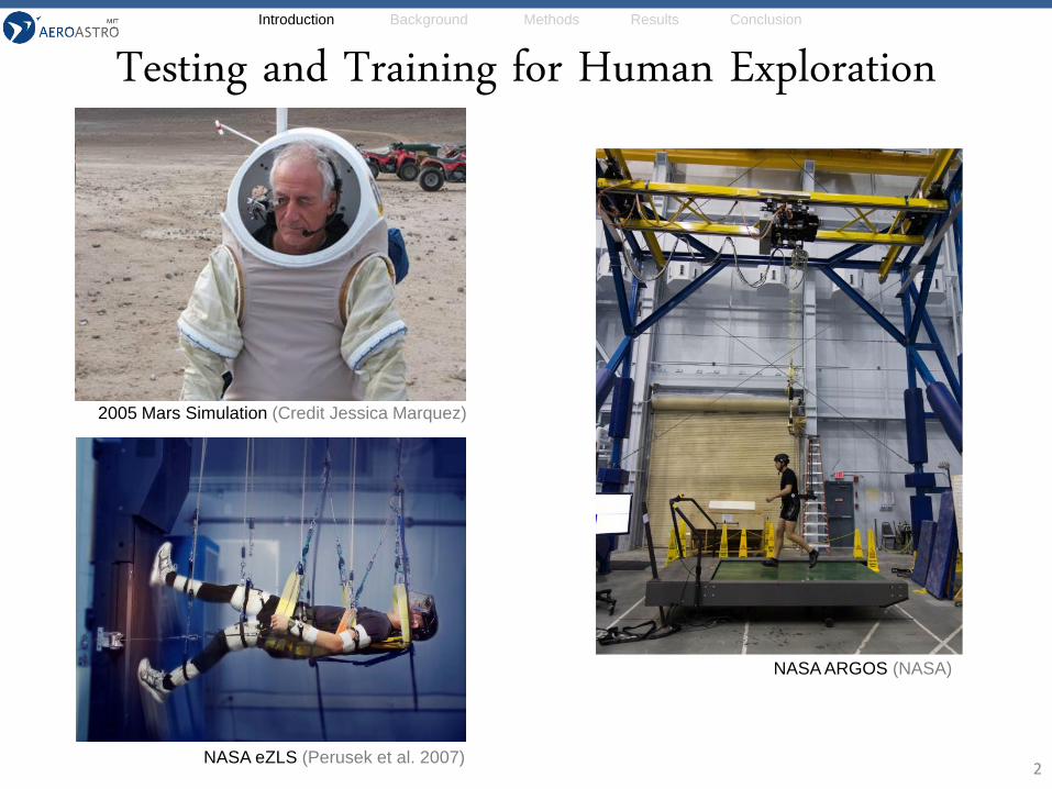
Testing and Training for Human Exploration
2NASA eZLS (Perusek et al. 2007)
NASA ARGOS (NASA)
2005 Mars Simulation (Credit Jessica Marquez)
Introduction Background Methods Results Conclusion
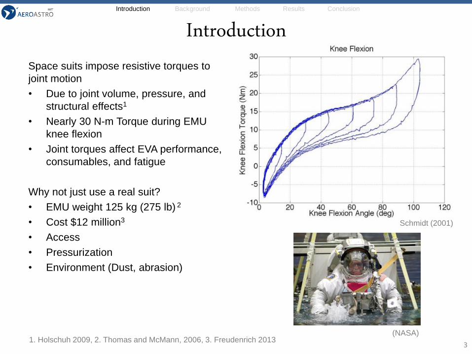
Introduction
3
Space suits impose resistive torques to
joint motion
• Due to joint volume, pressure, and
structural effects1
• Nearly 30 N-m Torque during EMU
knee flexion
• Joint torques affect EVA performance,
consumables, and fatigue
Why not just use a real suit?
• EMU weight 125 kg (275 lb) 2
• Cost $12 million3
• Access
• Pressurization
• Environment (Dust, abrasion)
1. Holschuh 2009, 2. Thomas and McMann, 2006, 3. Freudenrich 2013(NASA)
Schmidt (2001)
Introduction Background Methods Results Conclusion
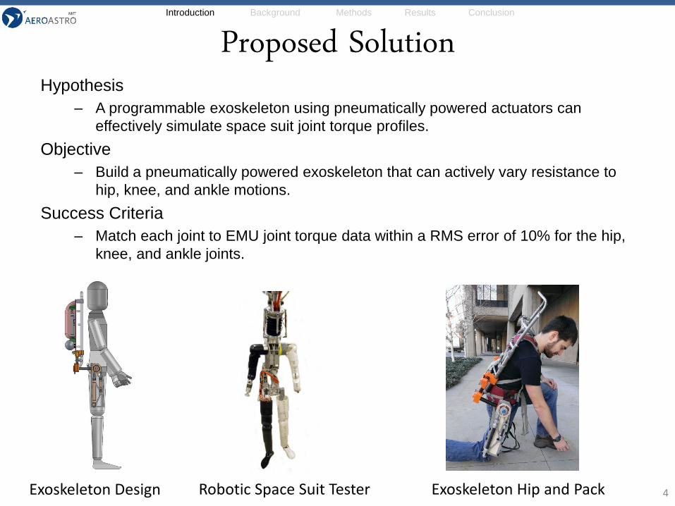
Proposed SolutionHypothesis
– A programmable exoskeleton using pneumatically powered actuators can
effectively simulate space suit joint torque profiles.
Objective
– Build a pneumatically powered exoskeleton that can actively vary resistance to
hip, knee, and ankle motions.
Success Criteria
– Match each joint to EMU joint torque data within a RMS error of 10% for the hip,
knee, and ankle joints.
4Robotic Space Suit TesterExoskeleton Design Exoskeleton Hip and Pack
Introduction Background Methods Results Conclusion
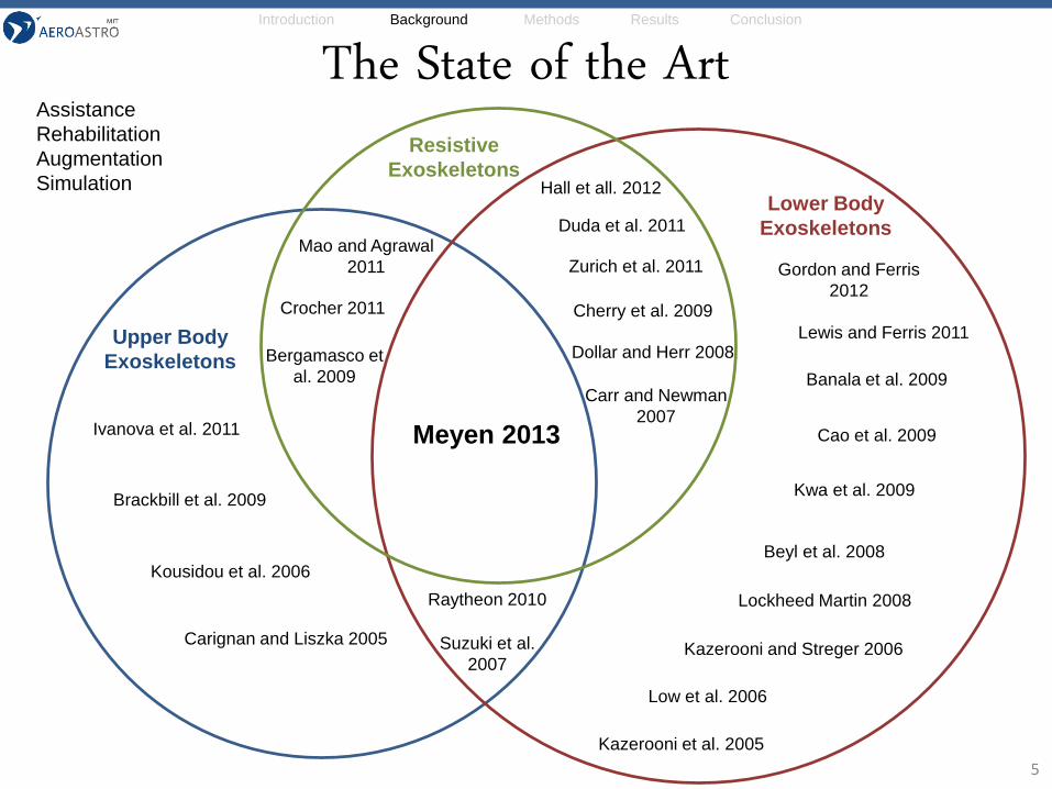
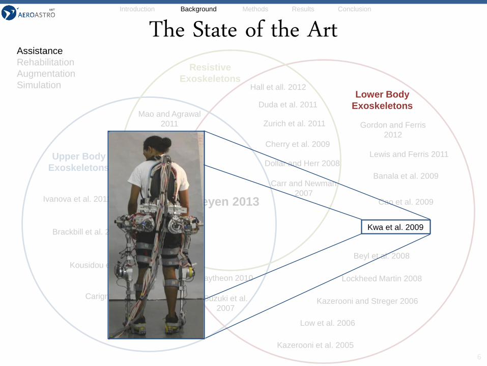
The State of the Art
5
Upper Body
Exoskeletons
Lower Body
Exoskeletons
Resistive
Exoskeletons
Kwa et al. 2009
Banala et al. 2009
Brackbill et al. 2009
Bergamasco et
al. 2009
Cao et al. 2009
Carignan and Liszka 2005
Cherry et al. 2009Crocher 2011
Dollar and Herr 2008
Ivanova et al. 2011
Hall et all. 2012
Gordon and Ferris
2012
Kazerooni and Streger 2006
Kazerooni et al. 2005
Kousidou et al. 2006
Lewis and Ferris 2011
Low et al. 2006
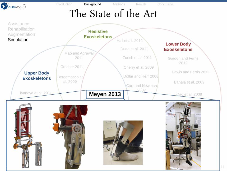
Meyen 2013
Mao and Agrawal
2011
Lockheed Martin 2008
Zurich et al. 2011
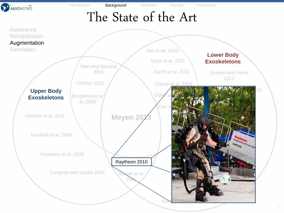
Raytheon 2010
Suzuki et al.
2007
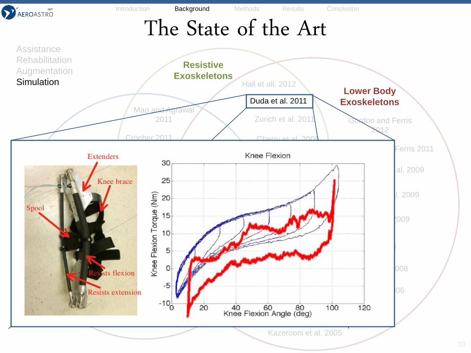
Duda et al. 2011
Beyl et al. 2008
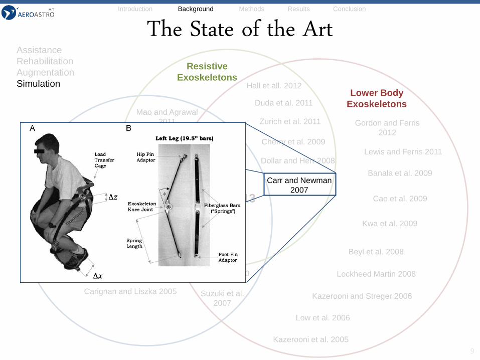
Carr and Newman
2007
Assistance
Rehabilitation
Augmentation
Simulation
Introduction Background Methods Results Conclusion
The State of the Art
6
Upper Body
Exoskeletons
Resistive
Exoskeletons
Banala et al. 2009
Brackbill et al. 2009
Bergamasco et
al. 2009
Cao et al. 2009
Carignan and Liszka 2005
Cherry et al. 2009Crocher 2011
Dollar and Herr 2008
Ivanova et al. 2011
Hall et all. 2012
Gordon and Ferris
2012
Kazerooni and Streger 2006
Kazerooni et al. 2005
Kousidou et al. 2006
Lewis and Ferris 2011
Low et al. 2006
Meyen 2013
Mao and Agrawal
2011
Lockheed Martin 2008
Zurich et al. 2011
Raytheon 2010
Suzuki et al.
2007
Duda et al. 2011
Beyl et al. 2008
Carr and Newman
2007
Lower Body
Exoskeletons
Kwa et al. 2009
Assistance
Rehabilitation
Augmentation
Simulation
Introduction Background Methods Results Conclusion
The State of the Art
7
Lower Body
Exoskeletons
Kwa et al. 2009
Banala et al. 2009
Brackbill et al. 2009
Bergamasco et
al. 2009
Cao et al. 2009
Carignan and Liszka 2005
Cherry et al. 2009Crocher 2011
Dollar and Herr 2008
Ivanova et al. 2011
Hall et all. 2012
Gordon and Ferris
2012
Kazerooni and Streger 2006
Kazerooni et al. 2005
Kousidou et al. 2006
Lewis and Ferris 2011
Low et al. 2006
Meyen 2013
Lockheed Martin 2008
Zurich et al. 2011
Raytheon 2010
Suzuki et al.
2007
Duda et al. 2011
Beyl et al. 2008
Carr and Newman
2007
Upper Body
Exoskeletons
Resistive
Exoskeletons
Mao and Agrawal
2011
Assistance
Rehabilitation
Augmentation
Simulation
Introduction Background Methods Results Conclusion
The State of the Art
8
Upper Body
Exoskeletons
Lower Body
Exoskeletons
Kwa et al. 2009
Banala et al. 2009
Brackbill et al. 2009
Bergamasco et
al. 2009
Cao et al. 2009
Carignan and Liszka 2005
Cherry et al. 2009Crocher 2011
Dollar and Herr 2008
Ivanova et al. 2011
Hall et all. 2012
Gordon and Ferris
2012
Kazerooni and Streger 2006
Kazerooni et al. 2005
Kousidou et al. 2006
Lewis and Ferris 2011
Low et al. 2006
Meyen 2013
Mao and Agrawal
2011
Lockheed Martin 2008
Zurich et al. 2011
Suzuki et al.
2007
Duda et al. 2011
Beyl et al. 2008
Carr and Newman
2007
Upper Body
Exoskeletons
Lower Body
Exoskeletons
Raytheon 2010
Assistance
Rehabilitation
Augmentation
Simulation
Introduction Background Methods Results Conclusion
The State of the Art
9
Upper Body
Exoskeletons
Kwa et al. 2009
Banala et al. 2009
Brackbill et al. 2009
Bergamasco et
al. 2009
Cao et al. 2009
Carignan and Liszka 2005
Cherry et al. 2009Crocher 2011
Dollar and Herr 2008
Ivanova et al. 2011
Hall et all. 2012
Gordon and Ferris
2012
Kazerooni and Streger 2006
Kazerooni et al. 2005
Kousidou et al. 2006
Lewis and Ferris 2011
Low et al. 2006
Meyen 2013
Mao and Agrawal
2011
Lockheed Martin 2008
Zurich et al. 2011
Raytheon 2010
Suzuki et al.
2007
Duda et al. 2011
Beyl et al. 2008
Lower Body
Exoskeletons
Resistive
Exoskeletons
Carr and Newman
2007
Assistance
Rehabilitation
Augmentation
Simulation
Introduction Background Methods Results Conclusion
The State of the Art
10
Upper Body
Exoskeletons
Kwa et al. 2009
Banala et al. 2009
Brackbill et al. 2009
Bergamasco et
al. 2009
Cao et al. 2009
Carignan and Liszka 2005
Cherry et al. 2009Crocher 2011
Dollar and Herr 2008
Ivanova et al. 2011
Hall et all. 2012
Gordon and Ferris
2012
Kazerooni and Streger 2006
Kazerooni et al. 2005
Kousidou et al. 2006
Lewis and Ferris 2011
Low et al. 2006
Meyen 2013
Mao and Agrawal
2011
Lockheed Martin 2008
Zurich et al. 2011
Raytheon 2010
Suzuki et al.
2007
Beyl et al. 2008
Carr and Newman
2007
Lower Body
Exoskeletons
Resistive
Exoskeletons
Duda et al. 2011
Assistance
Rehabilitation
Augmentation
Simulation
Introduction Background Methods Results Conclusion
The State of the Art
11
Kwa et al. 2009
Banala et al. 2009
Brackbill et al. 2009
Bergamasco et
al. 2009
Cao et al. 2009
Carignan and Liszka 2005
Cherry et al. 2009Crocher 2011
Dollar and Herr 2008
Ivanova et al. 2011
Hall et all. 2012
Gordon and Ferris
2012
Kazerooni and Streger 2006
Kazerooni et al. 2005
Kousidou et al. 2006
Lewis and Ferris 2011
Low et al. 2006
Mao and Agrawal
2011
Lockheed Martin 2008
Zurich et al. 2011
Raytheon 2010
Suzuki et al.
2007
Duda et al. 2011
Beyl et al. 2008
Carr and Newman
2007
Upper Body
Exoskeletons
Lower Body
Exoskeletons
Resistive
Exoskeletons
Meyen 2013
Assistance
Rehabilitation
Augmentation
Simulation
Introduction Background Methods Results Conclusion
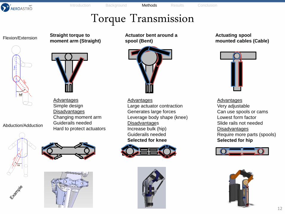
Torque Transmission
12
Advantages
Simple design
Disadvantages
Changing moment arm
Guiderails needed
Hard to protect actuators
Advantages
Large actuator contraction
Generates large forces
Leverage body shape (knee)
Disadvantages
Increase bulk (hip)
Guiderails needed
Selected for knee
Advantages
Very adjustable
Can use spools or cams
Lowest form factor
Slide rails not needed
Disadvantages
Require more parts (spools)
Selected for hip
Straight torque to
moment arm (Straight)
Actuator bent around a
spool (Bent)
Actuating spool
mounted cables (Cable)Flexion/Extension
Abduction/Adduction
Introduction Background Methods Results Conclusion
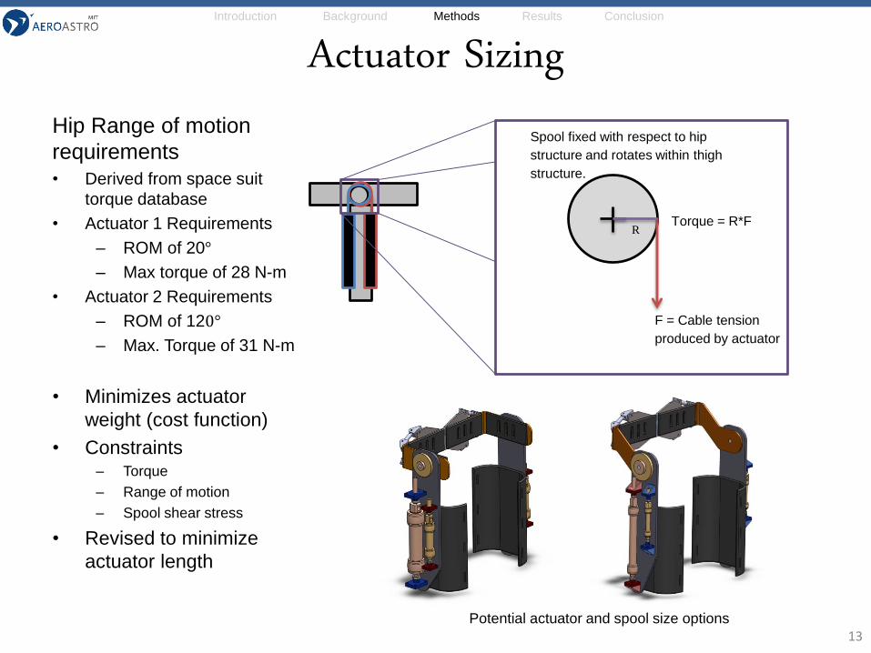
Actuator Sizing
13
Spool fixed with respect to hip
structure and rotates within thigh
structure.
F = Cable tension
produced by actuator
R Torque = R*F
Hip Range of motion
requirements• Derived from space suit
torque database
• Actuator 1 Requirements
– ROM of 20°
– Max torque of 28 N-m
• Actuator 2 Requirements
– ROM of 120°
– Max. Torque of 31 N-m
• Minimizes actuator
weight (cost function)
• Constraints– Torque
– Range of motion
– Spool shear stress
• Revised to minimize
actuator length
Potential actuator and spool size options
Introduction Background Methods Results Conclusion
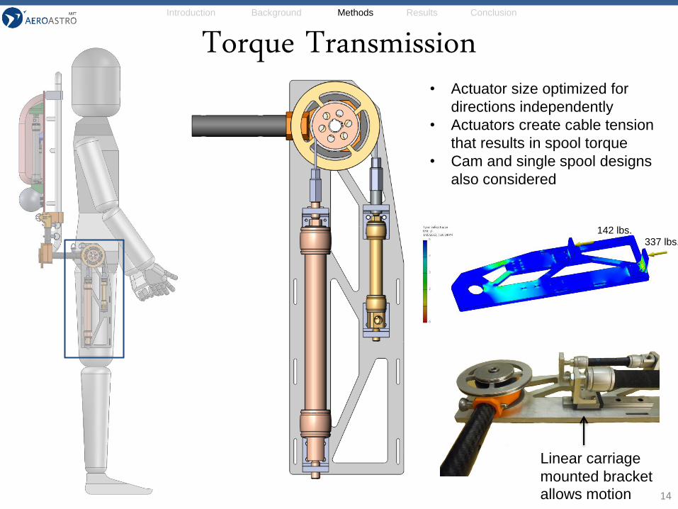
14
• Actuator size optimized for
directions independently
• Actuators create cable tension
that results in spool torque
• Cam and single spool designs
also considered
Torque Transmission
Linear carriage
mounted bracket
allows motion
142 lbs.337 lbs.
Introduction Background Methods Results Conclusion
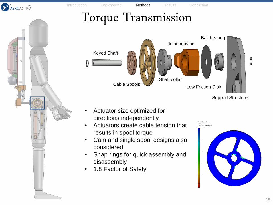
15
• Actuator size optimized for
directions independently
• Actuators create cable tension that
results in spool torque
• Cam and single spool designs also
considered
• Snap rings for quick assembly and
disassembly
• 1.8 Factor of Safety
Torque Transmission
Support Structure
Low Friction Disk
Ball bearing
Shaft collar
Joint housing
Cable Spools
Keyed Shaft
Introduction Background Methods Results Conclusion
16
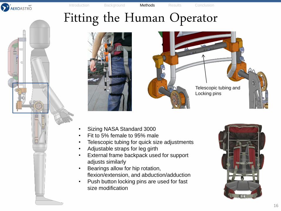
Fitting the Human Operator
• Sizing NASA Standard 3000
• Fit to 5% female to 95% male
• Telescopic tubing for quick size adjustments
• Adjustable straps for leg girth
• External frame backpack used for support
adjusts similarly
• Bearings allow for hip rotation,
flexion/extension, and abduction/adduction
• Push button locking pins are used for fast
size modification
Telescopic tubing and
Locking pins
Introduction Background Methods Results Conclusion
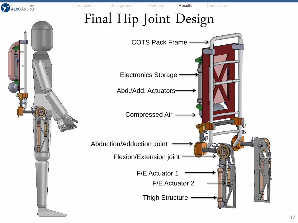
17
Final Hip Joint Design
Abduction/Adduction Joint
Flexion/Extension joint
F/E Actuator 1
F/E Actuator 2
COTS Pack Frame
Thigh Structure
Electronics Storage
Abd./Add. Actuators
Compressed Air
Introduction Background Methods Results Conclusion
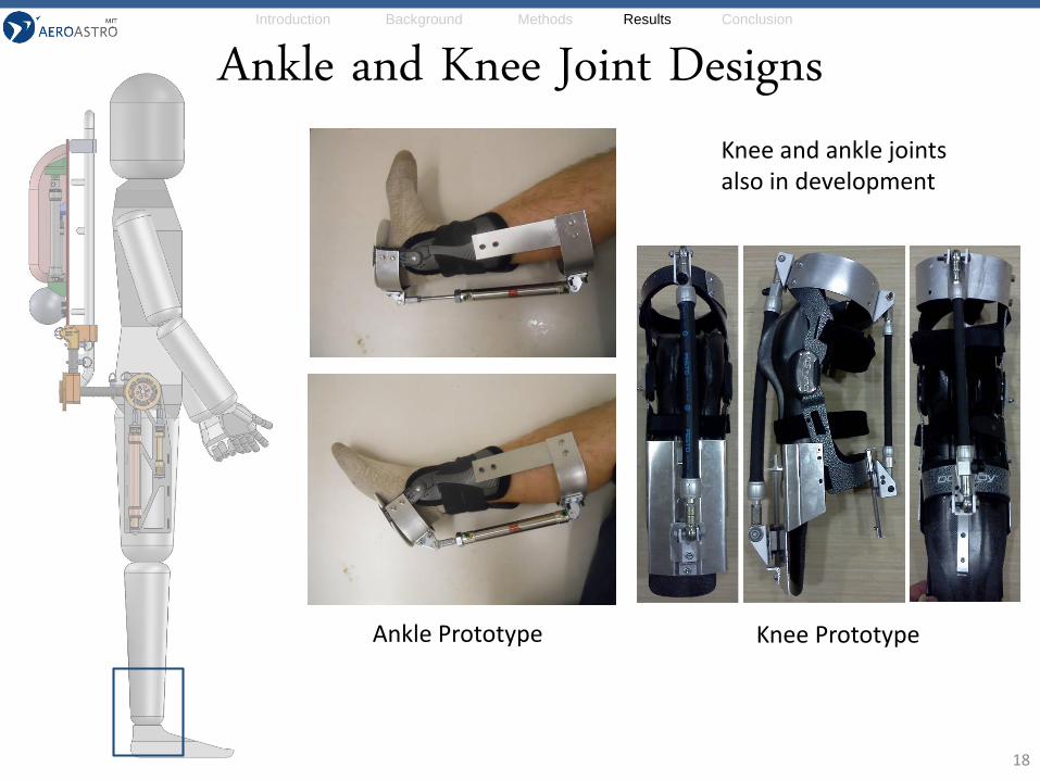
18
Ankle and Knee Joint Designs
Ankle Prototype Knee Prototype
Knee and ankle joints also in development
Introduction Background Methods Results Conclusion
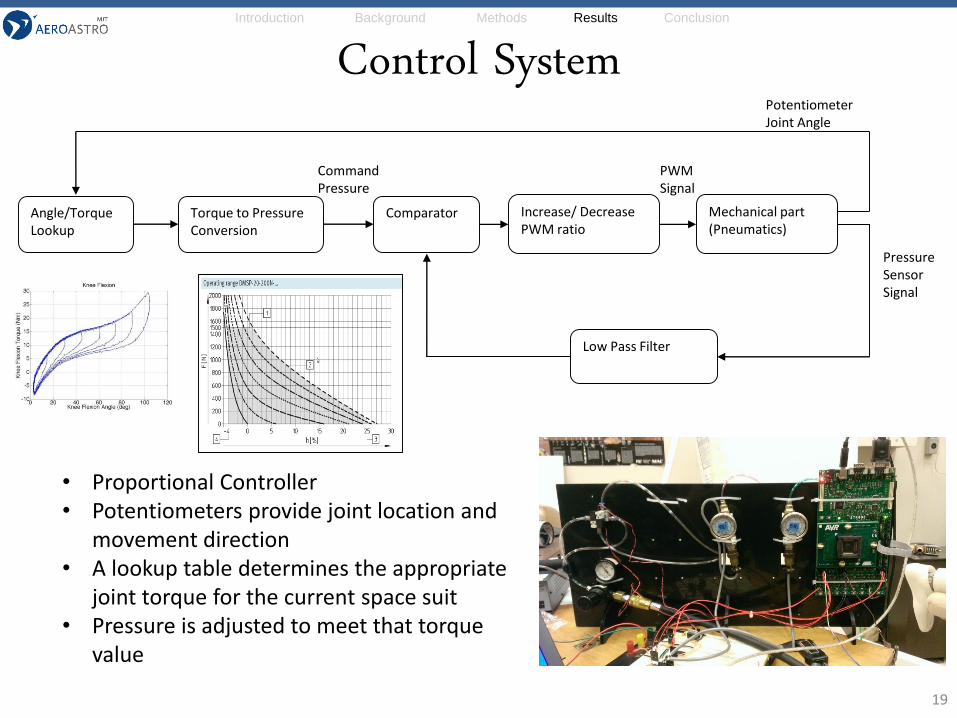
Control System
19
• Proportional Controller• Potentiometers provide joint location and
movement direction• A lookup table determines the appropriate
joint torque for the current space suit• Pressure is adjusted to meet that torque
value
Mechanical part (Pneumatics)
Low Pass Filter
Comparator Increase/ Decrease PWM ratio
Command Pressure
PotentiometerJoint Angle
Pressure Sensor Signal
Angle/Torque Lookup
Torque to Pressure Conversion
PWM Signal
Introduction Background Methods Results Conclusion
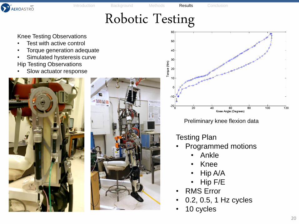
Robotic Testing
20
Preliminary knee flexion data
Knee Testing Observations
• Test with active control
• Torque generation adequate
• Simulated hysteresis curve
Hip Testing Observations
• Slow actuator response
Testing Plan
• Programmed motions
• Ankle
• Knee
• Hip A/A
• Hip F/E
• RMS Error
• 0.2, 0.5, 1 Hz cycles
• 10 cycles
Introduction Background Methods Results Conclusion
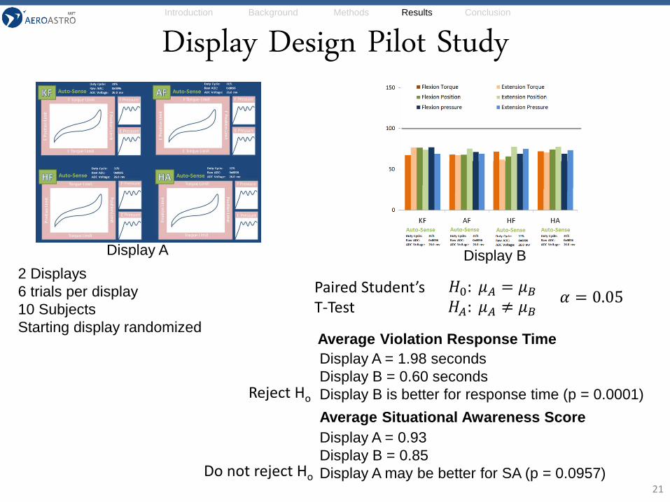
Display A = 1.98 seconds
Display B = 0.60 seconds
Display B is better for response time (p = 0.0001)
Display Design Pilot Study
21
Paired Student’s T-Test
𝐻0: 𝜇𝐴 = 𝜇𝐵𝐻𝐴: 𝜇𝐴 ≠ 𝜇𝐵
𝛼 = 0.05
Average Violation Response Time
Average Situational Awareness Score
2 Displays
6 trials per display
10 Subjects
Starting display randomized
Display A = 0.93
Display B = 0.85
Display A may be better for SA (p = 0.0957)
Display A Display B
Do not reject Ho
Reject Ho
Introduction Background Methods Results Conclusion
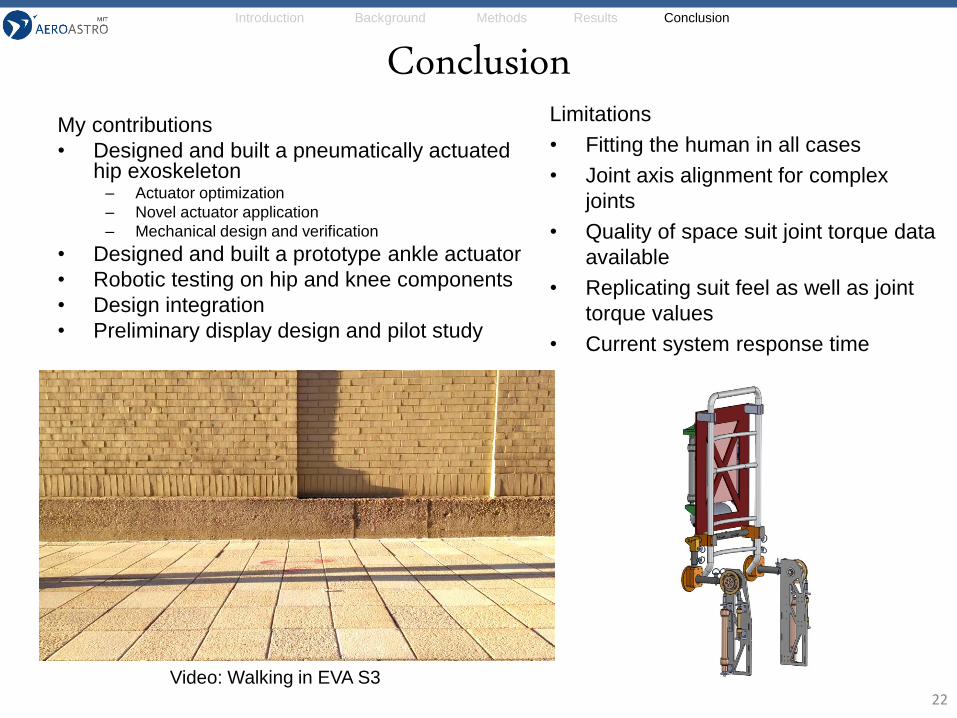
ConclusionMy contributions
• Designed and built a pneumatically actuated hip exoskeleton– Actuator optimization
– Novel actuator application
– Mechanical design and verification
• Designed and built a prototype ankle actuator
• Robotic testing on hip and knee components
• Design integration
• Preliminary display design and pilot study
22
Limitations
• Fitting the human in all cases
• Joint axis alignment for complex
joints
• Quality of space suit joint torque data
available
• Replicating suit feel as well as joint
torque values
• Current system response time
Video: Walking in EVA S3
Introduction Background Methods Results Conclusion
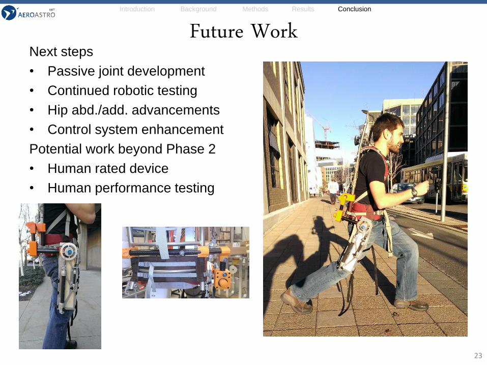
Future WorkNext steps
• Passive joint development
• Continued robotic testing
• Hip abd./add. advancements
• Control system enhancement
Potential work beyond Phase 2
• Human rated device
• Human performance testing
23
Introduction Background Methods Results Conclusion
References• Banala, S. K., K. Seok Hun, S. K. Agrawal and J. P. Scholz (2009). "Robot Assisted Gait Training With Active Leg
Exoskeleton (ALEX)." Neural Systems and Rehabilitation Engineering, IEEE Transactions on 17(1): 2-8.
• Bergamasco, M., B. Allotta, L. Bosio, L. Ferretti, G. Parrini, G. M. Prisco, F. Salsedo and G. Sartini (1994). An arm exoskeleton system for teleoperation and virtual environments applications. Robotics and Automation, 1994. Proceedings., 1994 IEEE International Conference on.
• Beyl, P., M. Van Damme, R. Van Ham and D. Lefeber (2008). Design and control concepts of an exoskeleton for gait rehabilitation. Biomedical Robotics and Biomechatronics, 2008. BioRob 2008. 2nd IEEE RAS & EMBS International Conference on.
• Brackbill, E. A., M. Ying, S. K. Agrawal, M. Annapragada and V. N. Dubey (2009). Dynamics and control of a 4-dof wearable cable-driven upper arm exoskeleton. Robotics and Automation, 2009. ICRA '09. IEEE International Conference on.
• Carignan, C., M. Liszka and S. Roderick (2005). Design of an arm exoskeleton with scapula motion for shoulder rehabilitation. Advanced Robotics, 2005. ICAR '05. Proceedings., 12th International Conference on.
• Carr, C. E. and D. J. Newman (2007). "Space Suit Bioenergetics: Cost of Transport During Walking and Running." Aviation, Space, and Environmental Medicine 78(12): 1093-1102.
• Cherry, M. S., S. Kota and D. P. Ferris (2009). An elastic exoskeleton for assisting human running. Proc. of IDETC/CIE 2009, ASME 2009 Int. Design Engineering Technical Conferences & Computers and Information in Engineering Conf.
• Crocher, V., N. Jarrasse, A. Sahbani, A. Roby-Brami and G. Morel (2011). Changing human upper-limb synergies with an exoskeleton using viscous fields. Robotics and Automation (ICRA), 2011 IEEE International Conference on.
• Dollar, A. M. and H. Herr (2008). Design of a quasi-passive knee exoskeleton to assist running. Intelligent Robots and Systems, 2008. IROS 2008. IEEE/RSJ International Conference on.
• Duda, J. E., D. J. Newman, J. Hoffman, J. Peverill and G. P. Perusek (2011). The Use of Artificial Muscles in Space Suit Simulation for Partial Gravity Experimentation and Training.
• Gordon, K. E. and D. P. Ferris (2007). "Learning to walk with a robotic ankle exoskeleton." J Biomech 40(12): 2636-2644.
• Hall, K. L., C. A. Phillips, D. B. Reynolds, S. R. Mohler and A. T. Neidhard-Doll (2012). "Pneumatic Muscle Actuator (PMA) Task-Specific Resistance for Potential Use in Microgravity Exercise." Aviation, Space, and Environmental Medicine 83(7): 696-701.
• Heng, C., L. Zhengyang, Z. Jun, W. Yu and W. Wei (2009). Design frame of a leg exoskeleton for load-carrying augmentation. Robotics and Biomimetics (ROBIO), 2009 IEEE International Conference on.
24
Introduction Background Methods Results Conclusion
References• Holschuh, B., E. Obropta, L. Buechley and D. Newman "Materials and Textile Architecture Analyses for Mechanical
Counter-Pressure Space Suits using Active Materials."
• Ivanova, G., S. Bulavintsev, R. Jee-Hwan and J. Poduraev (2011). Development of an Exoskeleton System for Elderly and Disabled People. Information Science and Applications (ICISA), 2011 International Conference on.
• Kazerooni, H., J. L. Racine, H. Lihua and R. Steger (2005). On the Control of the Berkeley Lower Extremity Exoskeleton (BLEEX). Robotics and Automation, 2005. ICRA 2005. Proceedings of the 2005 IEEE International Conference on.
• Kazerooni, H. and R. Steger (2006). "The Berkeley Lower Extremity Exoskeleton." Journal of Dynamic Systems, Measurement, and Control 128(1): 14.
• Kousidou, S., N. Tsagarakis, D. G. Caldwell and C. Smith (2006). Assistive Exoskeleton for Task Based Physiotherapy in 3-Dimensional Space. Biomedical Robotics and Biomechatronics, 2006. BioRob 2006. The First IEEE/RAS-EMBS International Conference on.
• Lewis, C. L. and D. P. Ferris (2011). "Invariant hip moment pattern while walking with a robotic hip exoskeleton." J Biomech 44(5): 789-793.
• Low, K. H., X. Liu, C. H. Goh and H. Yu (2006). "Locomotive Control of a Wearable Lower Exoskeleton for Walking Enhancement." Journal of Vibration and Control 12(12): 1311-1336.
• Mao, Y. and S. K. Agrawal (2011). A cable driven upper arm exoskeleton for upper extremity rehabilitation. Robotics and Automation (ICRA), 2011 IEEE International Conference on, IEEE.
• Martin, L. (2008). HULC Exoskeletons Augment Strength and Endurance.
• NASA. (2013). "Active Response Gravity Offload System." Retrieved June 25, 2013, from http://www.nasa.gov/centers/johnson/engineering/integrated_environments/active_response_gravity/
• Perusek, G. P., J. K. DeWitt, P. R. Cavanagh, C. M. Grodsinsky and K. M. Gilkey (2007). "Zero-Gravity Locomotion Simulators: New Ground-Based Analogs for Microgravity Exercise Simulation."
• Schmidt, P. B., D. J. Newman and E. Hodgson (2001). Modeling Space Suit Mobility: Applications to Design and Operations. 31st International Conference on Environmental Systems, SAE International.
• Thomas, K. S. and H. J. McMann (2006). US Spacesuits, Springer.
• van Dijk, W., H. van der Kooij and E. Hekman (2011). A passive exoskeleton with artificial tendons: Design and experimental evaluation. Rehabilitation Robotics (ICORR), 2011 IEEE International Conference on.
25
Introduction Background Methods Results Conclusion
Backup Slides
26
Introduction Background Methods Results Conclusion
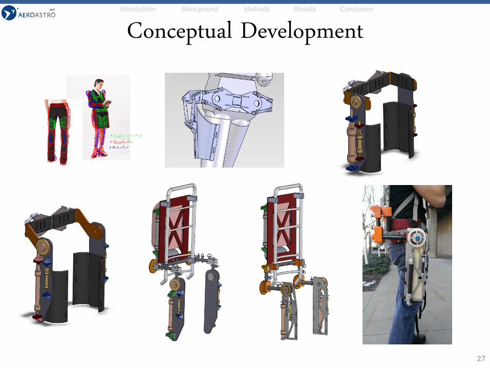
Conceptual Development
27
Introduction Background Methods Results Conclusion
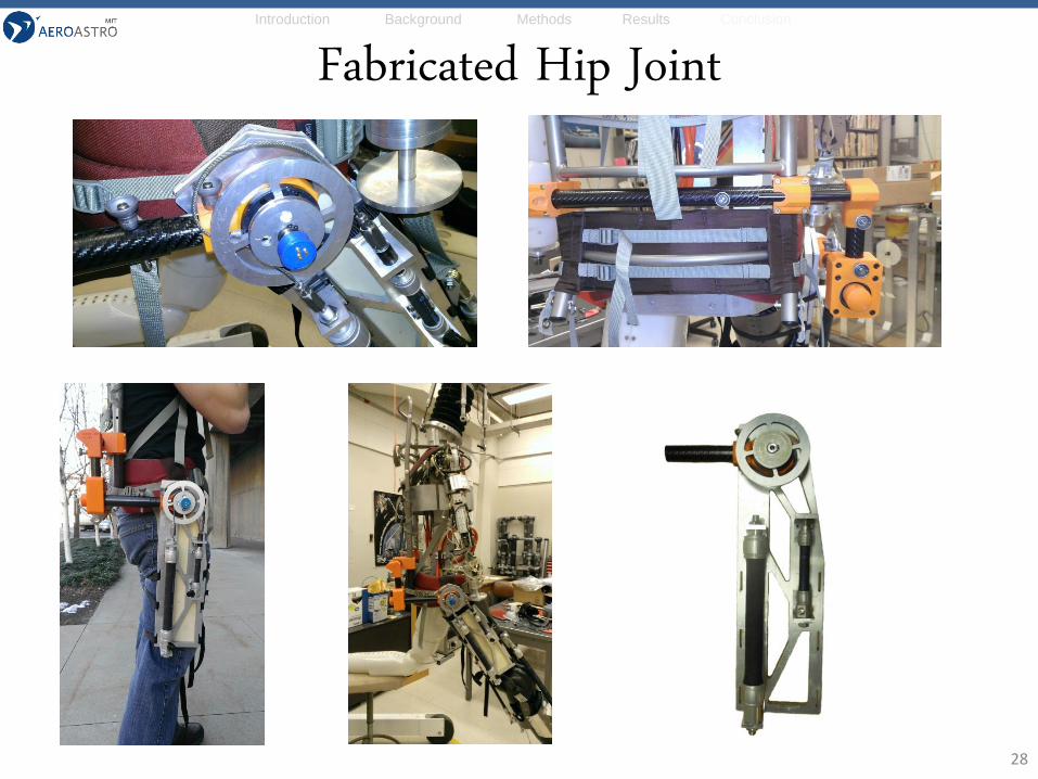
Fabricated Hip Joint
28
Introduction Background Methods Results Conclusion
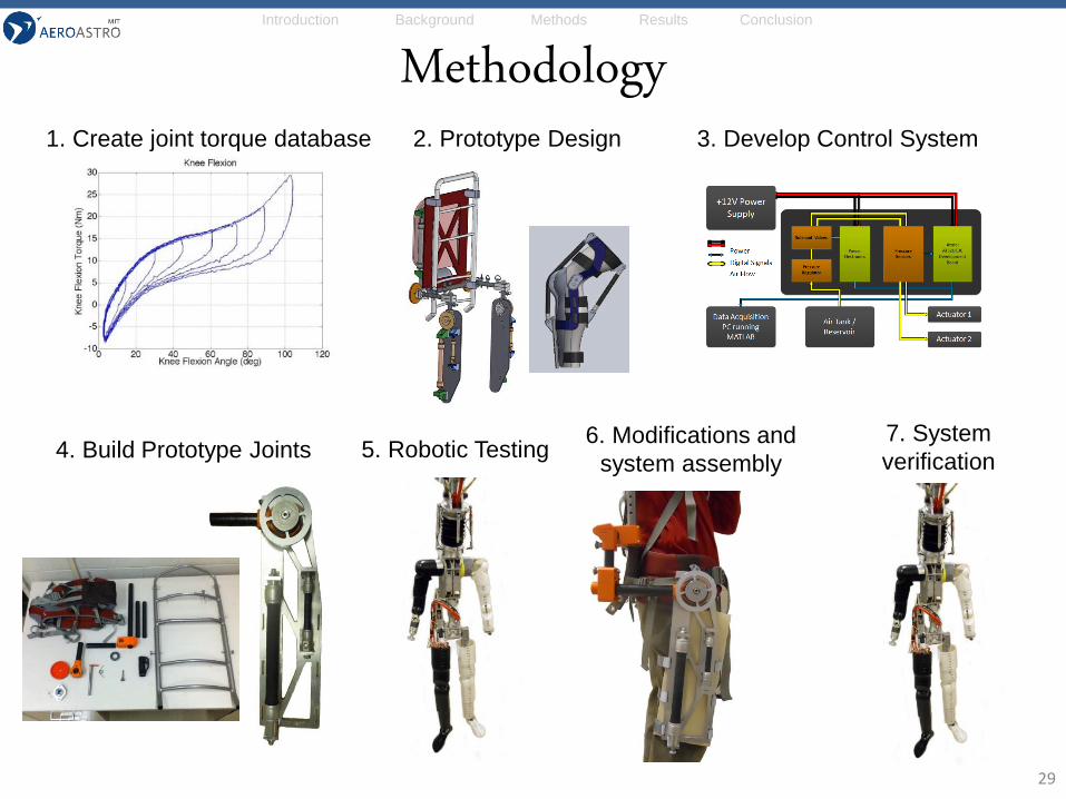
Methodology1. Create joint torque database 2. Prototype Design 3. Develop Control System
4. Build Prototype Joints 5. Robotic Testing6. Modifications and
system assembly
7. System
verification
29