Embed Size (px)
Citation preview
Engineerha Drawing* Syllabus
CARIBBEAN EXAMINATIONS COUNCIL
Caribbean Advanced Proficiency Examination
Geometrical and Mechanical Engineering Drawing
Syllabus Effective for examinations from MayJJune 2006
Correspondence related to the syllabus should be addressed to:
The Pro-Registrar Caribbean Examinations Council
Caenwood Centre 37 Arnold Road, Kingston 5, Jamaica, W.I.
Telephone: (876) 920-67 14 ' Facsimile Number: (876) 967-4972
E-mail address: [email protected] Website: www.cxc.org
Copyright @ 2005, by Caribbean Examinations Council The Garrison, St. Michael 20, Barbados
* I CXCA22/Lr2,OS
This 2-Unit syllabus CXC A22IU2105 replaces the l-Unit syllabus CXC A22lUllO2 issued in 2002.
First Issued 1999 Revised 2002 Revised 2005
Please check the website, www.cxc.org for updates on CXC's syllabuses.
RATIONALE .......................................................................................................................... 1
. AIMS ....................................... ................................... ........................................................... 1 2
SKILLS AND ABILITIES TO BE ASSESSED ........................................................................ 2
PRE-REQUISITES OF THE SYLLABUS ............................................................................... 2
STRUCTURE OF THE SYLLABUS ...................................................................................... 3
UNIT 1 : GEOMETRICAL AND ENGINEERING DRAWING
MODULE 1 : PLANE GEOMETRY ................................................................... 4 . 8
MODULE 2: SOLID GEOMETRY ...................................................................... 9 . 1 1
MODULE 3: ENGINEERING DRAW7NG ..................................................... 1 2 . 14
UNIT 2: MECHANZCAL ENGINEERING DRA W G AND DESIGN
MODULE 1 : MECHANICS OF MACHINES ........................................................ 15 . 18
MODULE 2: ENGINEERING MATERIALS AND PROCESSES .......................... 19 . 22
MODULE 3: ENGINEERING DESIGN ELEMENTS ............................................ 23 . 25
OUTLZNE OF ASSESSMENT ........................................................................................ 2 6 . 40
.................................................................. REGULATIONS FOR PRIVATE CANDIDATES 40
REGULATZONS FOR RESIT CANDIDATES ....................................................................... 4 0 - 4 1
ASSESSMENT GRID ............................................................................................................. 41
REFERENCE MATERIAL ..................................................................................................... 41
MINIMUM EQUIPMENT LIST ............................................................................................ 42
-
he Caribbean Advanced Proficiency Examinations (CAPE) are designed to provide certification of the academic, vocational and technical achievement of students in the Caribbean who, having completed a minimum of five years of secondary education, wish to further their studies. The examinations address
the skills and knowledge acquired by students under a flexible and articulated system where subjects are organised in l-Unit or 2-Unit courses with each Unit containing three Modules.
Subjects examined under CAPE may be studied concurrently or singly, or may be combined with subjects examined by other examination boards or institutions.
The Caribbean Examinations Council offers three types of certification. The first is the award of a certificate showing each CAPE Unit completed. The second is the CAPE diploma, awarded to candidates who have satisfactorily completed at least six Units, including Caribbean Studies. The third is the CAPE Associate Degree, awarded for the satisfactory completion of a prescribed cluster of seven CAPE Units including Caribbean Studies and Communication Studies. For the CAPE diploma and the CAPE Associate Degree, candidates must complete the cluster of required Units within a maximum period of five years.
Geomatrlcal and Machanlcal Englnaerlng Drawlng Syllabus
eometrical and Mechanical Engineering Drawing (GMED) is the universal means of communication for engineers, technicians and craftsmen. This type of international communication is facilitated by
the use of standards ~ublished by the International Organization for Standardization (ISO) for Engineering Drawing.
The course of study for GMED comprises both practical and theoretical activities that respond to the interests, skills and disposition of students within a wide range of abilities. This subject stimulates an interest in drafting and engineering as career options for students. GMED incorporates the language and logic that structurally link a wide range of occupations and is, therefore, important in creating and developing the infrastructure necessary for socio-economic development of the Caribbean region.
The course outlined in this syllabus would enhance the capabilities and skills of students and promotes their development as rational, ethical and responsible members of society. Unit 1 focuses on the preparation of engineering drawings, while Unit 2 focuses on the design and drawing of engineering components. A student who completes this syllabus would be competent in the use of the latest developments in drawing technology, including Computer-Aided Drafting (CAD). In addition, the student would become proficient in the application of the British Standards (BS 8888), IS0 Standards, Caribbean Uniform Building Codes (CUBiC) and local codes.
4 Alms The syllabus aims to:
1. develop skills in the reading, interpretation and production of Mechanical Engineering drawings and diagrammatic illustrations conforming to BS and IS0 Standards, CUBiC and local codes;
2. develop skills in the preparation of working and assembly drawings conforming to BS and IS0 Standards, CUBiC and local codes;
3. provide knowledge of materials for production of engineering components;
I ,.22m2,05 1
4. provide knowledge of the different methods of production of engineering components;
5. develop skills in applying the principles of Geometrical and Mechanical Engineering Drawing in solving engineering problems;
develop skills in applying and drawing principles to facilitate product development and
develop skills to use Computer-Aided Drafting (CAD) software to produce engineering drawings;
develop an interest in Mechanical Engineering as a career and as an intellectual discipline;
develop an appreciation of the pivotal role of Mechanical Engineering drawing in the socio- economic development of individual territories and the Caribbean region as a whole.
+ SKILLS AND ABILITIES TO BE ASSESSED The skills and abilities which students are expected to develop on completion of the syllabus have been grouped under three headings:
(i) Knowledge; (ii) Application; and (iii) Drawing Skills.
The ability to identify, recall and grasp the meaning of basic facts, concepts and
The ability to use facts, concepts, principles and procedures in unfamiliar situations; transform data accurately and appropriately; use common characteristics as a basis for classification; use formulae accurately for computations.
The ability to produce neatly organized, clean and accurate drawings according to specification.
+ PRE-REIUISITES OF RE SYUABUS It is expected that persons with a good grasp of the Mechanical Engineering Drawing Option of the CSEC Technical Drawing syllabus or the equivalent should be able to successfully pursue this course.
+ SlRUrnRE OF THE SYuAms The syllabus is divided into two Units. Each Unit consists of three Modules. The Units are independent of each other. Together they provide a comprehensive post-secondary course in the field of Engineering .
Communication.
Unit 1 : Geometrical and Enginem'ng Drawing contains three Modules of approximately 50 hours each. The total time for the syllabus ii approximately 150 hours.
Unit 2: Mechanical Engineering Drawing and Design contains three Modules of approximately 50 hours each. The total time for the syllabus is approximately 150 hours.
Mechanics of Machines Engineering Materials and Processes Engineering Design Elements
+ UNIT 1: QEOHETRICN I D EW6lNEERlNQ DRAWIN6 MODULE 1: PLANE GEOMETRY
GENERAL OBJECTIVES
On completion of this Module, students should:
1, develop the ability to produce drawings of a two-dimensional nature;
2. develop basic Computer-Aided Drafting (CAD) skills.
SPECIFIC OBJECTIVES
Students should be able to:
1. define standard engineering curves;
2. construct standard engineering curves;
3. determine centroids of plane figures by graphical methods;
4. use graphical methods of integration of areas and first and second moment of areas;
5. develop displacement diagrams for edge, face and cylindrical Cams;
6. develop Cam profiles;
7. use Computer-Aided Drafting software to produce drawings.
CONTENT
1. Conic Sections and Loci
(i) Standard engineering curves: ellipse, parabola, hyperbola, Archimedean spiral and involute.
(ii) Construction of ellipse, parabola and hyperbola using true methods.
(iii) Construction of Archimedean spiral, involute and cycloid.
(iv) Construction of tangents to these curves.
MODULE 1: PLANE GEOMETRY (cont'd)
Graphical methods,
(a) integration of area;
(b) first and second moments.
(i) Construction of Cam profiles and displacement diagrams to produce:
(a) dwell;
(b) uniform velocity;
(c) uniform acceleration or retardation;
(d) simple harmonic motion.
(ii) Construction of Cam profiles and displacement diagrams with various types of followers,
(a) knife-edge;
(b) roller;
(d) spherical.
(iii) Construction of Cam profiles and displacement diagrams with different follower paths:
(a) straight line;
(b) circular arc;
(c) on-centre;
(d) off-centre.
UNIT 1 MODULE 1: PLANE GEOMETRY (cont'd)
4. Computer-Aided Drafting (CAD)
(i) Use of Cartesian, Polar and Absolute co-ordinates.
(ii) CAD features:
(a) menus;
(b) toolbars (draw, modify, dimension);
(c) parameters.
(iii) toolbars:
(a) draw - line;
(b) construction line;
(d) rectangle;
(e) arc;
(0 circle;
(g) donut;
(h) spline;
(i) eclipse;
Q) block;
(k) hatch;
(1) boundary. .
(iv) modify:
(a) mirror;
(b) array (rectangle, polar) ;
UNIT 1 MODULE 1: PLANE GEOMETRY (cont'd)
(c) COPY;
(d) rotate;
(e) scale;
(f) stretch.
(v) dimension:
(a) linear;
(b) aligned;
(C) ordinate;
(d) radius;
(e) diameter;
(0 angular;
(g) baseline;
(h) continue;
(i) leader;
(j) tolerance;
(k) centermark;
(1) dimension text edit;
(m) dimension style.
(vi) Use of CAD software to produce plane geometry drawings.

UNIT 1 MODULE 1: PLANE GEOMETRY (cont'd)
Suggested Teaching and Learning Activities
Teachers are encouraged to engage students in activities such as those listed below as they seek to achieve the objectives of this Module.
1. Have students solve problems pertaining to the Content on Plane Geometry in the recommended texts.
2. Use real life examples to promote class discussion and illustrate the use and purpose of Plane Geometry in Mechanical Engineering.
3. Explain the fundamentals of Mechanical Engineering science with emphasis on definitions and the graphical approach.
4. Place emphasis on freehand sketching and different drawing methods.
5. Have students perform relevant calculations where required.
6. Have students use CAD software to produce Plane Geometry drawings.
RESOURCE
Hewitt, D.E. Engneenng Dra wing and Desip for Mechanical Technicians, London: The Macmillian Press Limited, 1999.
MODULE 2: SOLID GEOMETRY
GENERAL OBJECTIVES
On completion of this Module, students should:
1. develop the ability to produce three dimensional drawings;
develop Computer-Aided Drafting (CAD) skills.
SPECIFIC OBJECTIVES
Students should be able to:
1. represent solids in pictorial projections;
2. apply the isometric scale in constructing drawings in isometric projection;
4. project solids in orthographic projection;
5 . project sections of solids cut by inclined planes;
draw true shapes of sections;
7. project auxiliary views;
draw lines of intersection between solids;
9. develop surfaces of right or skewed objects;
10. develop surfaces composed of multiple geometric shapes;
1 1. arrange the development of surfaces to use material optimally;
12. construct helix for appropriate applications;
13. produce drawings using CAD software.

MODULE 2: SOLID GEOMETRY (cont'd)
Pictorial Projections
(i) Projection of solids in:
(a) oblique;
(b) planometric;
(c) isometric;
(d) two-point angular.
(ii) The application of the isometric scale to the construction of drawings in isometric
(iii) The construction of circles and curves in pictorial drawings.
2. Orthographic Projections
(i) First angle projection.
(ii) Third angle projection.
3. Auxiliary Views
(i) The projection of sections of solids cut by inclined planes.
(U) True shapes of sections.
(iii) First and second auxiliary views.
Intersection of Solicls
Intersection and interpenetration of solids.
UNIT 1 MODULE 2: SOLID GEOMETRY (cont'd)
5. Surface Development
(i) Surfaces of right or skewed three-dimensional objects.
(ii) Surfaces composed of multiple geometric shapes.
(iii) Transition pieces (square-to-round, round-to-round) .
(iv) Economical use of materials.
6. Helix
(i) Application of helix to screw threads and springs.
(ii) Construction of helix on cylindrical and conical forms.
7. CAD
Use of CAD software to produce solid geometry drawings.
Suggested Teaching and Learning Activities
Teachers are encouraged to engage students in activities such as those listed below as they seek to achieve the objectives of this Module.
1. Have students solve problems pertaining to the Content on Solid Geometry in the recommended texts.
2. Use real life examples to promote class discussions and illustrate the use and purpose of Solid Geometry in Mechanical Engineering.
3. Place emphasis on definitions, freehand sketching and different drawing methods.
4. Have students perform relevant calculations where required,
5. Have students use CAD software to produce Solid Geometry drawings.
RESOURCE
Hewitt, D.E. Engineering Drawing and Des ip for Mechanical Technicians, London: The Macmillian Press Limited, 1999.
MODULE 3: ENGINEERING DRAWING
GENERAL OBJEC'TIVES
On completion of this Module, students should:
develop the ability to prepare machine drawings;
develop the ability to produce drawings, freehand sketches and designs of machine components for manufacture.
SPECIFIC OBJECTIVES
Students should be able to:
1. prepare drawings with sectional views;
2. produce working and assembly drawings;
3. produce and dimension drawings of engineering components for manufacturing;
4. prepare detailed freehand sketches of machine parts and components;
5. synthesize solutions to simple engineering problems;
6. produce drawings using CAD software.
1 . Assembly Drawings
(i) Assembly drawings of machine parts and components.
(ii) Detailed drawings of components from: assembly drawings, freehand sketches and actual machine parts.
Working Drawings
(i) Working drawings of machine parts and components.
(ii) Use of welding and machine graphical symbols.
MODULE 3: ENGINEERING DRAWING (cont'd)
3. Detailed Drawings
(i) Dimensional drawings:
(a) manufacturing;
(b) general;
(c) geometric and positional tolerance: finishes, limits and fits (BS 4500).
(ii) Balloon referencing and part listings:
(a) cross-reference;
(b) item list and materials specification.
4. Freehand Sketching
Orthographic and pictorial views of machine parts and components.
Synthesize designs using components selected from the suggested list below.
(i) accessories: gauges, small tools and clamping devices;
(ii) mechanisms: slide crank and pin, rack and pinion, ratchet;
(iii) fasteners: bolts and nuts, screws, studs, keys, pins, rivets and locking devices;
(iv) Hydraulic Systems:
(a) pumps: centrifugal and reciprocating;
(b) valves: non-return, isolating, expansion, safety, gate and globe;
(c) piping and joints: flanged and hydraulic;
(d) seals: dynamic and static.
MODULE 3: ENGINEERING DRAWING (cont'd)
(V) Machine tools:
Parts of the following machines: drilling; grinding; lathe; milling and shaping.
Use of CAD software to produce engineering drawings.
Suggested Teaching and Learning Activities
Teachers are encouraged to engage students in activities such as those listed below as they seek to achieve the objectives of this Module.
1. Use articles from current periodicals on relevant Mechanical Engineering topics to assist students in adequately covering the design sections of the Module.
2. Have students complete several working and assembly drawings of machine parts and components.
3. Place emphasis on the importance of freehand sketching to enable students to become familiar with the complexity in the theory and construction of various machine parts and components.
4. Visit a Mechanical Engineering Drawing Office to familiarize students with the different conventional representation on drawings and the use and importance of drawing standards.
5. Visit machine and mechanical engineering workshops to familiarize students with the operations.
6. Arrange lectures by experienced engineers on the design and preparation of working drawings of engineering components in order to enhance students' understanding and appreciation of the content in the Module.
Ewneering Drawing and Design for Mechanical Technicians, London: The Macmillian Press Limited. 1999.
+ UNIT 2 NEGIIIIIGM 8161NEER11 BRAWIN6 AWB BB161 MODULE 1: MECHANICS OF MACHINES
GENERAL OBJECTIVES
On completion of this Module, students should:
1. understand how forces in structures are graphically determined;
develop skills to produce accurate drawings of gear tooth profiles;
3. understand how true lengths and angles of skew lines are determined;
develop skills to locate planes in space;
5. acquire knowledge of IS0 conventional systems, British Standards (BS 8888), Caribbean Uniform Building Codes (CUBiC) and local codes.
SPECIFIC OBJECTIVES
Students should be able to:
determine forces by graphical methods;
2. construct S hearing force and bending moments diagrams;
determine forces in beams;
4. calculate the various parameters of the involute spur gears;
5. construct involute gear tooth profiles;
6. use IS0 conventional systems and British Standards (BS 8888);
determine true angles;
locate lines and planes in space;
draw planes inclined to planes of reference;
10. determine the perpendiculars from given oblique planes;
1 1, determine the shortest distance between skew lines;
UNIT 2 MODULE 1 : MECHANICS OF MACHINES (cont'd)
12. produce drawings using Computer-Aided Drafting (CAD) software.
CONTENT
1. Systems of Forces by Graphical Methods
(i) Triangle, parallelogram and polygon of forces to find resultant equilibrium; resolution of forces in members of simple framework.
(ii) Space and polar diagrams and funicular (link) polygons to find the position of resultant or equilibrium.
(iii) Shearing force and bending moment diagrams.
2. Gears
(i) Involute Spur Gears - definition of terms:
(a) pitch circle diameter;
(b) pitch point;
pressure angle;
addendum;
dedendum;
clearance;
circular itch;
circular tooth thickness;
number of teeth;
diametrical pitch;
module;
base circle diameter.
UNIT 2 MODULE 1: MECHANICS OF MACHINES (cont'd)
(ii) Calculation of parameters necessary for construction of gear tooth profiles.
(iii) Construction of gear tooth profiles by involute and approximate methods.
(iv) Use of IS0 conventional systems and British Standards (BS 8888).
3. Skew Lines
(i) True angles between intersecting lines.
(ii) True angles between intersecting planes.
(iii) True angles between lines and planes.
(iv) Traces of lines on planes.
(v) Traces of planes on planes.
(vi) Traces of perpendicular planes and their inclination to the planes of reference.
(vii) Traces of oblique planes and their inclination to the planes of reference.
(viii) Oblique plane and its inclination to the planes of reference.
4. CAD
Use of CAD software to produce mechanics of machine drawings.
Suggested Teaching and Learning Activities
Teachers are encouraged to engage students in activities such as those listed below as they seek to achieve the objectives of this Module.
1. Use real life examples of components to illustrate the techniques contained in the Module.
2 . Visit a Mechanical Engineering Drawing Office to familiarize students with the different conventional representation on drawings and the use and importance of drawing standards.
3. Have students research and make presentations on topics contained in the Module.
UNIT 2 MODULE 1: MECHANICS OF MACHINES (cont'd)
4. Have students use CADschare to produce drawings on Mechanics of Machines.
RESOURCE
Hewitt, D.E. Engineeting Drawing and Des@ for Mkchanical Technicians, London: The Macmillian Press Limited, 1999.

MODULE 2: ENGINEERING MATERIALS AND PROCESSES
GENERAL OBJECTIVES
On completion of this Module, students should:
understand the different methods of producing engineering components;
2. acquire knowledge of materials for the production of engineering components;
develop the ability to identify appropriate bearings for various applications; .
4. know appropriate lubricants and lubrication method for various applications;
5. develop the ability to identify seals for various applications.
SPECIFIC OBJECTIVES
Students should be able to:
describe the appropriate manufacturing processes for the production of engineering components;
2. select appropriate materials for the production of engineering components;
solve problems requiring knowledge of the application of bearings;
solve problems requiring knowledge of the application of lubricants;
solve problems requiring knowledge of the application of seals.
(i) Metals:
(a) ferrous - wrought iron, cast iron, carbon steel, stainless steel;
(b) non-ferrous - copper, aluminium, brass and other alloys.
UNIT 2 MODULE 2: ENGINEERING MATERIALS AND PROCESSES (cont'd)
(ii) Plastics - manufactured material:
(a) thermo-plastic - polyvinyl chloride (PVC), polytetrafluroethylene (fluorocarbons), polyethylene, polystyrene, p~l~propylene, polyamides (Nylon), polymethylmethacrylate (Perspex) ;
(b) thermo-setting - epoxy-resin (bakelite, melamine, araldite), laminates (tufnol, formica).
(iii) Rubber:
(a) characteristics (organic, silicone, synthetic) ;
(b) uses and applications.
2. Manufacturing Processes
(i) Machining Tool Operations - turning, shaping, drilling, milling and grinding.
(ii) Casting - sand, die, investment.
(iii) Forging - drop, hand (upsetting, drawing down, swaging, bending).
(iv) Fabrication:
(a) welding - shielded metal arc welding (SMAW), oxyfuel gas welding (OFW), gas tungsten-arc (GTAW) , oxy-gas (acetylene) ;
(b) welding symbols and their application;
(c) riveting - cold, hot, pop;
(d) steel metal work - grooved seam, knock-up, pandown, flanging, rolling and bending.
(V) Safety in Manufacturing:
(a) safety equipment and material;
(b) safety procedures and processes in manufacturing;
(c) safety design in manufacturing.
MODULE 2: ENGINEERING MATERIALS AND PROCESSES (cont'd)
(i) Roller- cylindrical (radial, thrust), tapered, spherical, needle.
(ii) Ball - radial, thrust, angular contact, self aligning, singleldouble row.
(iii) Journal - pillow block, self lubricating.
(iv) Typical applications.
(i) Bush - drill, sleeve (limits and fits).
(ii) Typical applications.
(i) Types of lubricants - liquid, solid and gas.
(ii) Methods of applications - liquid (splash, pressurised); solid; gas (mist, air).
(i) Static - gasket, o-ring.
(ii) Dynamic - labyrinth, split ring, 'U', garter spring, o-ring.
Use of CAD software to produce drawings.
Suggested teach in^ and Learning Activities
Teachers are encouraged to engage students in activities such as those listed below as they seek to achieve the objectives of this Module.
Use real life examples of components made from the manufacturing processes and materials in
Enpneenng Drawing and Desip for Mechanical T~hnicians, London: The MacmiIlian Press Limited, 1999.
7
MODULE 2: ENGINEERING MATERIALS AND PROCESSES (cont'd)
2. Have students visit machine and mechanical engineering workshops to familiarize them with the . various machine-tools, equipment and sub-assembly components being repaired.
Have students visit engineering pIants1factories to observe the manufacture of components/products using the various processes and materials in the Module.
4. Have students research and make presentations on topics contained in the Module.
UNIT 2 MODULE 3: ENGINEERING DESIGN ELEMENTS
GENERAL OBJECTIVES
On completion of this Module, students should:
1. develop skills to synthesize or modify designs using creativity, technical information and scientific principles;
2. develop skills to prepare freehand sketches and drawings of machine components suitable for different manufacturing processes.
SPECIFIC OBJECTIVES
Students should be able to:
1. solve problems requiring knowledge of various elements of power transmission;
2. prepare freehand sketches and drawings of machine components;
3. explain the design process;
4. produce or modify designs of machine parts and components.
CONTENT
1. Transmission of Motion and Pourer
(i) Couplings - rigid, flanged, fluid, Oldham and universal point.
(ii) Clutches - single plate, multi-plate and centrifugal.
(iii) Gears - spur, helical, bevel and worm.
(iv) Belt drives - vee, flat and toothed (tensioning of belts, fixed and movable shafts).
(V) Brakes - single shoe, double shoe and internal drum.
(vi) Chain drives - roller and inverted tooth/silent (tensioning of chain).
MODULE 3: ENGINEERING DESIGN ELEMENTS (cont'd)
2. Design details
Design for casting, forging, machining and fabrication.
3. Design pngnciples
(i) Elements: materials specification, manufacturing processes, size and shape.
(ii) Aesthetics and ergonomics (ergonomic control loop).
4. Design process
(i) recognition of need;
(ii) definition of problem;
(iii) synthesis;
(iv) analysis and optimisation;
(v) evaluation;
(vi) presentation.
Use of CAD software to design and produce engineering drawings.
Suggested Teaching and Learning Activities
Teachers are encouraged to engage students in activities such as those listed below as they seek to achieve the objectives of this Module.
Use articles from current periodical on relevant Mechanical ~ n ~ i n e e r i n ~ . t o ~ i c s to assist students in adequately covering the content in the Module.
MODULE 3: ENGINEERING DESIGN ELEMENTS (cont'd)
2. Have students complete a number of working and assembly drawings of various engineering components.
3. Place emphasis on the importance of freehand sketching to enable students to become familiar with the differences in the theory and construction of various devices.
4. Have students visit a Mechanical Engineering Drawing Office to familiarize them with the different conventional representation on drawings and .the use and importance of drawing
5. Arrange lectures by experienced engineers with respect to the production of working drawings and detailed designs in order to enhance students' understanding and appreciation of the content in the Module.
Have students use CAD software to design and draw machine parts and components.
Hawkes, B and Abinett, R. The Engneenng Desip Process, Essex , United Kingdom: Longman Group Limited, 2000.
Engneenng Drawng and Desip for Mechanical Technicians, London: The Macmillian Press Limited, 1999.

Each Unit of the syllabus will be independently assessed and graded separately. The same scheme of assessment will be applied to each Module in each Unit..,Candidates have the option of submitting their . . responses to Paper 01 and Paper 02 using either the traditional drawing method (drawing board and tee square) or Computer-Aided Drafting (CAD) software.
EXTERNAL ASSESSMENT (80%)
Written Papers
Paper 01 Nine compulsory tasks consisting of three questions from 30% (2 hours) each Module in the Unit.
Paper 02 Nine essay or extended response questions (inclusive of 50% (3 hours) drawings) arranged in three sections corresponding to the
three Modules of the Unit. Each section consists of three questions. Candidates will be required to answer two questions from each section.
INTERNAL ASSESSMENT (20%)
Paper 03/1 - Portfolios
Unit 1
The Internal Assessment requires that candidates compile a Drawing Portfolio comprising six assignments, two from each Module. In Assignment 5, a maximum of six marks are allocated for communicating information in a logical way using correct grammar.
Unit 2
The Internal Assessment requires that candidates design or redesign a machine component. All freehand sketches, pictorial and working drawings, specifications and calculations for the design must be included in a Design Portfolio. Candidates will be awarded a total of six marks for communicating information in a logical way using correct grammar.
MODERATION OF INTERNAL ASSESSMENT
Each year an Internal Assessment Record Sheet will be sent to schools submitting students for the examination.
All Internal Assessment Record Sheets and sample of assignments are to be submitted to the Local Registrar in time to reach CXC by May 3 1 of the year of the examination. A sample of assignments will be

requested by CXC for moderation purposes. These assignments will be re-assessed by CXC Examiners to inform the moderation of scores submitted by the given teacher. Teachers' marks may be adjusted as a result of moderation. An Examiner's feedback report will be sent to each teacher.
Copies of the students' assignment that are not included in the sample submitted to CXC must be retained by the school until three months after publication by CXC of the examination results.
ASSESSMENT DETAILS
Each Unit will be assessed as follows:
External Assessment by Written Papers - (80% of Total Assessment)
Paper 01 (2 hours - 30% of Total Assessment)
1. Comjmsition of the Paper
This paper consists of nine compulsory short-response questions, three from each Module.
Questions may differ in difficulty and may require knowledge of several topics in the Module
Mark Allocation
This paper is worth 90 marks and contributes 30% towards the final assessment. Each Module is worth 30 marks and contributes 10% towards the final assessment.
3. Award of Marks
Full marks will be awarded for correct answers supported by relevant working or demonstration of
No marks will be awarded to a correct answer which is unsupported by any details of the method used (for example: calculations, construction or line-work). Candidates are, therefore, advised to show all - their working.
4. Use of Cakulatms
Candidates may use silent, non-programmable calculators.
Paper 02 (3 hours - 50% of Total Assessment)
1. Composition of Paper
This paper is divided into three sections, each representing one of the three Modules of the Unit. Each section contains three questions. The candidate is required to answer two questions from each section.
All questions are equally weighted and may require knowledge of more than one topic in the Module from which they are taken. Only a sample of the topics in any Module will be assessed and these may not receive equal emphasis.
2. Mark Allocation
This paper is worth 150 marks and contributes 50% towards the final assessment. Each Module is worth 50 marks and contributes approximately 16.7% towards the final assessment.
3. Award of Marks
Full marks will be awarded for correct answers supported by relevant working or demonstration of the process.
No marks will be awarded to a correct answer which is unsupported by any details of the method used (for example: calculations, construction or line-work). Candidates are, therefore, advised to show 4 their working.
Candidates may use silent, non-programmable calculators.
INTERNAL ASSESSMENT (20% of Total Assessment)
Internal Assessment is an integral part of student assessment in the course covered by this syllabus. It is intended to assist students in acquiring certain knowledge, skills and attitudes that are associated with the subject. The activities for the Internal Assessment are linked to the syllabus and should form part of the learning activities to enable the student to achieve the objectives of the' syllabus.
During the course of study for the subject, students obtain marks for the competence they develop and demonstrate in undertaking their Internal Assessment assignments. These marks contribute to the final marks and grades that are awarded to students for their performance in the examination.
The guidelines provided in this syllabus for selecting appropriate tasks are intended to assist teachers and students in selecting assignments that are valid for the purpose of Internal Assessment. The guidelines provided for the assessment of the assignments are intended to assist teachers in awarding marks that are reliable estimates of the achievement of students in the Internal Assessment component of the course. In order to ensure that the scores awarded by teachers are in line with the Caribbean Examinations Council's
standards, the Council undertakes the moderation of a sample of the Internal Assessment assignments marked by each teacher. Internal Assessment provides an opportunity to individualise a part of the cumculum to meet the needs of students. It facilitates feedback to the student at various stages of the experience. This helps to build the self-confidence of students as they proceed with their studies. Internal Assessment also facilitates the development of the critical skills and abilities emphasised by this CAPE .
subject and enhances the validity of the examination on which candidate performance is reported. Internal Assessment, therefore, makes a significant and unique contribution to both the development of relevant skills and the testing and rewarding of students for the development of those skills.
The Caribbean Examinations Council seeks to ensure that the Internal Assessment scores are valid and reliable estimates of accomplishment. The guidelines provided in this syllabus are intended to assist in doing so.
The Internal Assessment will consist of a Portfolio for each Unit consisting of assignments taken from the Module(s) outlined in the syllabus.
Paper 0311 - Drawing Portfolio (20% of the Total Assessment)
Composition
The Drawing Portfolio must consist of six assignments. Two assignments must be set on each Module. At least one assignment from each Module must be CAb-based. A complete record of freehand sketches and final drawing solutions must be submitted in the Drawing Portfolio. The assignments in each Portfolio will be assessed by the teacher and a sample of the Portfolios will be reassessed by a moderator appointed by CXC.
Mark Allocation
Each assignment is worth 10 marks. However, for the purposes of assessment by the classroom teacher, each assignment should be marked out of 20 as shown in the criteria and mark schemes for Internal Assessment assignments outlined on pages 30-34 of the syllabus.
The mark recorded for each Module will be the average of the TWO Module assignments. The Internal Assessment for each Module is compdmy and failure to submit all assignments will nomUy result in no marks being awarded for Internal Assessment. Assignments are set and assessed by the teacher, using the Internal Assessment Assignments, Criteria and Mark Schemes provided on pages 30-34 of the syllabus.
UNIT I
WTERNAL ASSESSMENT ASSIGNMENTS, CRITERIA AND MARK SCHEMES
Assignments
Each candidate is required to produce a Drawing Portfolio consisting of six original drawings. Examples of appropriate sources and topics on which these assignments may be based are given below.
For EACH assignment (1, 2, 3 and 6), the student will submit a completed drawing or set of drawings on A 2 (420 X 594 mm) paper by itself with border lines and title block.
Assignment 1
Candidates will be expected to produce drawings based on Specific Objectives 3 and 4 of Module 1.
Assignment 2
Candidates will be expected to produce ONE drawing based on Specific Objectives 5 and 6 of Module 1.
~ Assignment 3
l Candidates will be expected to produce ONE drawing based on Specific Objectives 8 to 11 of Module 2.
Candidates will be expected to produce ONE drawing using CAD software and based on Specific Objective 13 of Module 2.
Assignment 5
Candidates will be expected to produce drawings based Specific Objectives 4 and 5 of Module 3.
Assignment 6
Candidates will be expected to produce ONE drawing based Specific Objectives 1,3 and 4 of Module 3.
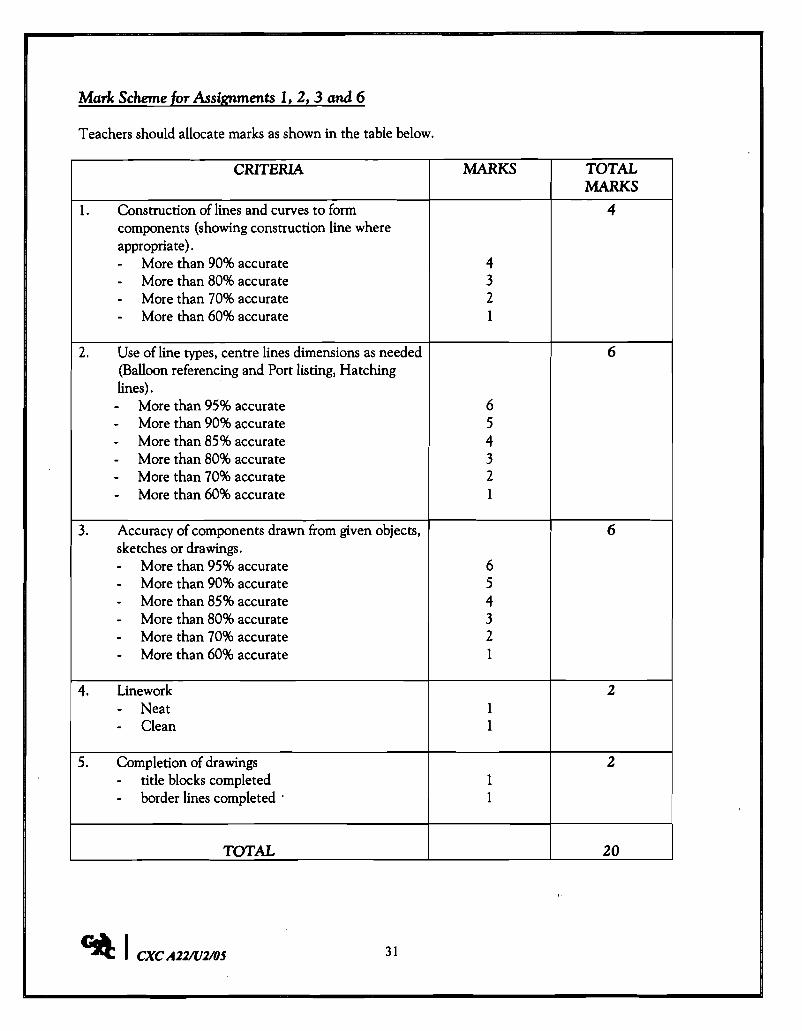
CRlTERLA MARKS TOTAL MARKS
1. Construction of lines and curves to form 4 components (showing construction line where appropriate). - More than 90% accurate 4 - More than 80% accurate 3 - More than 70% accurate 2 - More than 60% accurate 1
2. Use of line types, centre lines dimensions as needed 6 (Balloon referencing and Port listing, Hatching lines). - More than 95% accurate 6 - More than 90% accurate 5 - More than 85% accurate 4 - More than 80% accurate 3 - More than 70% accurate 2 - More than 60% accurate 1
3. Accuracy of components drawn from given objects, 6 sketches or drawings. - More than 95% accurate 6 - More than 90% accurate 5 - More than 85% accurate 4 - More than 80% accurate 3 - More than 70% accurate 2 - More than 60% accurate 1
4. Linework 2 - Neat 1 - Clean 1
5. Completion of drawings 2 - title blocks completed 1 - border lines completed . 1
TOTAL 20
Mark Scheme for Assignments 1,2,3 a d 6
Teachers should allocate marks as shown in the table below.
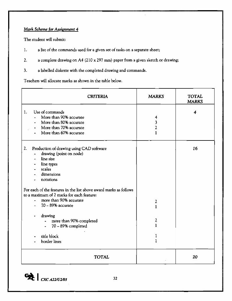
Mark Scheme for Assignment 4
The student will submit:
a list of the commands used for a given set of tasks on a separate sheet;
a complete drawing on A4 (2 10 X 297 mm) paper from a given sketch or drawing;
3. a labelled diskette with the completed drawing and commands.
Teachers will allocate marks as shown in the table below.
CRlTERlA MARKS TOTAL MARK;S
1. Use of commands 4 - More than 90% accurate 4 - More than 80% accurate 3 - More than 70% accurate 2 - More than 60% accurate 1
2. Production of drawing using CAD software 16 - drawing (point on node) - line size - line types - scales - dimensions - notations
For each of the features in the list above award marks as follows to a maximum of 2 marks for each feature:
- more than 90% accurate 2 - 70 - 89% accurate 1
- drawing - more than 90% completed 2 - 70 - 89% completed 1
- title block 1 - border lines 1
TOTAL 20
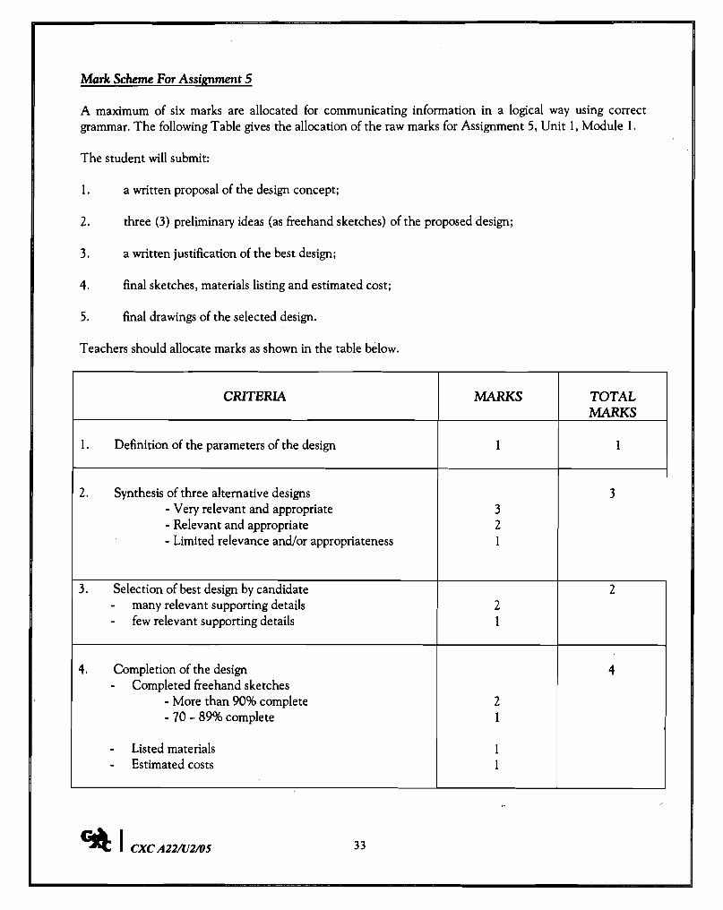
Mark Scheme For Assignment 5
A maximum of six marks are allocated for communicating information in a logical way using correct grammar. The following Table gives the allocation of the raw marks for Assignment 5, Unit 1, Module 1.
The student will submit:
a written proposal of the design concept;
three (3) preliminary ideas (as freehand sketches) of the proposed design;
3. a written justification of the best design;
final sketches, materials listing and estimated cost;
final drawings of the selected design.
Teachers should allocate marks as shown in the table below.
CRITERIA MARKS TOTAL MARKS
1. Definition of the parameters of the design 1 1
2. Synthesis of three alternative designs 3 - Very relevant and appropriate 3 - Relevant and appropriate 2 - Limited relevance andlor appropriateness 1
3. Selection of best design by candidate 2 - many relevant supporting details 2 - few relevant supporting details 1
4. Completion of the design 4 - Completed freehand sketches
- More than 90% complete 2 - 70 - 89% complete 1
- Listed materials 1 - Estimated costs 1
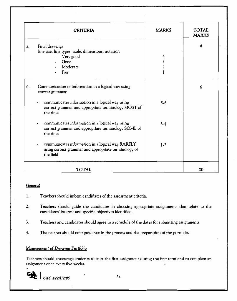
Teachers should inform candidates of the assessment criteria.
2. Teachers should guide the candidates in choosing appropriate assignments that relate to the candidates' interest and specific objectives identified.
3. Teachers and candidates should agree to a schedule of the dates for submitting assignments.
The teacher should offer guidance in the process and the preparation of the portfolio.
Management of Drawing Portfolio
Teachers should encourage students to start the first assignment during the first term and to complete an assignment once every five weeks.
CRITERIA MARKS TOTAL MARKS
5 . Final drawings 4 line size, line types, scale, dimensions, notation
- Very good 4 - Good 3 - Moderate 2 - Fair 1
6. Communication of information in a logical way using 6 correct grammar
- communicates information in a logical way using correct grammar and appropriate terminology MOST of the time
- communicates information in a logical way using correct grammar and appropriate terminology SOME of the time
- communicates information in a logical way RARELY 1-2 using correct grammar and appropriate terminology of the field
TOTAL 20
Paper 0311 - Desim Portfolio
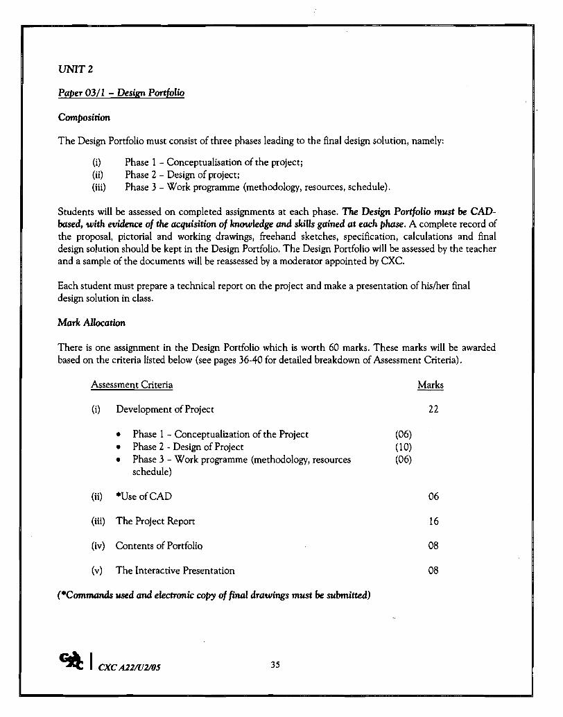
The Design Portfolio must consist of three phases leading to the final design solution, namely:
(i) Phase 1 - Conceptualisation of the project; (ii) Phase 2 - Design of project; (iii) Phase 3 - Work programme (methodology, resources, schedule).
Students will be assessed on completed assignments at each phase. The Design Portfolio must be CAD- based, with evidence of the acquisition of knowledge and skills gained at each phase. A complete record of the proposal, pictorial and working drawings, freehand sketches, specification, calculations and final design solution should be kept in the Design Portfolio. The Design Portfolio will be assessed by the teacher and a sample of the documents will be reassessed by a moderator appointed by CXC.
Each student must prepare a technical report on the project and make a presentation of hisher final design solution in class.
Mark Allocation
There is one assignment in the Design Portfolio which is worth 60 marks. These marks will be awarded based on the criteria listed below (see pages 36-40 for detailed breakdown of Assessment Criteria).
Assessment Criteria
(i) Development of Project
Phase 1 - Conceptualization of the Project Phase 2 - Design of Project Phase 3 - Work programme (methodology, resources
(ii) *Use of CAD
(iii) The Project Report
(iv) Contents of Portfolio
(v) The Interactive Presentation
(*Commands used and electronic copy of final drawings must be submitted)
Assessment Criteria bnge Total Marks Marks
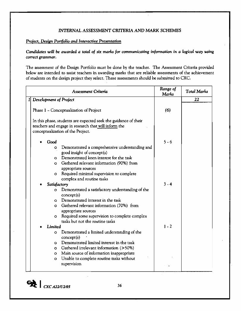
1 Development of Project 22
Phase 1 - Conceptualization of Project (6)
In this phase, students are expected seek the guidance of their teachers and engage in research that will inform the conceptualization of the Project.
Good 5 - 6 o Demonstrated a comprehensive understanding and
good insight of concept (S) o Demonstrated keen interest for the task o Gathered relevant information (90%) from
appropriate sources o Required minimal supervision to complete
complex and routine tasks Satisfactory 3 - 4
o Demonstrated a satisfactory understanding of the concept (S)
o Demonstrated interest in the task o Gathered relevant information (70%) from
appropriate sources o Required some supervision to complete complex
tasks but not the routine tasks Limited 1 - 2
o Demonstrated a limited understanding of the concept (S) a
o Demonstrated limited interest in the task o Gathered irrelevant information (>50%) o Main source of information inappropriate o Unable to complete routine tasks without
supervision
lNTERNAL ASSESSMENT CRITERIA AND MARK SCHEMES
Project, Design Portfolio and Interactive Presentation
Candidates will be awarded a total of six marks for communicating infonnution in a logical way wing correct grammar.
The assessment of the Design Portfolio must be done by the teacher. The Assessment Criteria provided below are intended to assist teachers in awarding marks that are reliable assessments of the achievement of students on the design project they select. These assessments should be submitted to CXC.
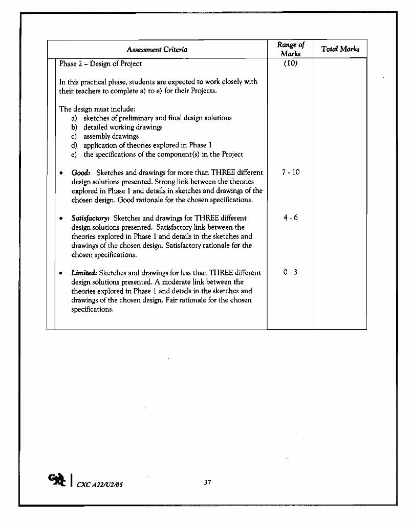
Assessment Criteria Range Total Marks Marks
Phase 2 - Design of Project (10)
In this practical phase, students are expected to work closely with their teachers to complete a) to e) for their Projects.
The design must include: a) sketches of preliminary and final design solutions b) detailed working drawings c) assembly drawings d) application of theories explored in Phase 1 e) the specifications of the component(s) in the Project
Good: Sketches and drawings for more than THREE different 7 - 10 design solutions presented. Strong link between the theories explored in Phase 1 and details in sketches and drawings of the chosen design. Good rationale for the chosen specifications.
Satisfactory: Sketches and drawings for THREE different 4 - 6 design solutions presented. Satisfactory link between the theories explored in Phase 1 and details in the sketches and drawings of the chosen design. Satisfactory rationale for the chosen specifications.
Limited: Sketches and drawings for less than THREE different 0 - 3 design solutions presented. A moderate link between the theories explored in Phase 1 and details in the sketches and drawings of the chosen design. Fair rationale for the chosen specifications.
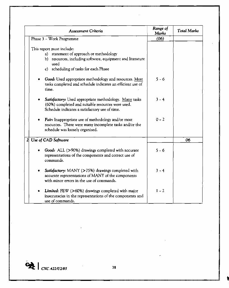
Assessment Criteria Range of Total Marks Marks Phase 3 - Work Programme (06)
This report must include: a) statement of approach or methodology b) resources, including software, equipment and literature
used c) scheduling of tasks for each Phase
Good: Used appropriate methodology and resources. Most 5 - 6 tasks completed and schedule indicates an efficient use of time.
Satisfactory: Used appropriate methodology. Many tasks 3 - 4 (60%) completed and suitable resources were used. Schedule indicates a satisfactory use of time.
Fair: Inappropriate use of methodology and/or most 0 - 2 resources. There were many incomplete tasks and/or the schedule was loosely organized.
2 Use of CAD Software 06
Good: ALL (>90%) drawings completed with accurate 5 - 6 representations of the components and correct use of commands.
Satisfactory: MANY (>75%) drawings completed with 3 - 4 accurate representations of MANY of the components with minor errors in the use of commands.
Limited: FEW (>60%) drawings completed with major 1 - 2 inaccuracies in the representations of the components and use of commands.
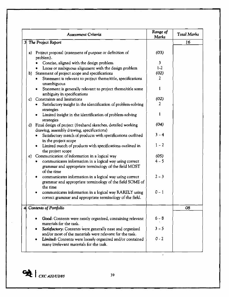
Assessment Criteria Range Total Marks Marks 3 The Project Report 16
a) Project proposal (statement of purpose or definition of (03) problem).
Concise, aligned with the design problem 3 Loose or ambiguous alignment with the design problem 1-2
b) Statement of project scope and specifications (02) Statement is relevant to project themeltitle, specifications 2 unambiguous Statement is generally relevant to project themeltitle some 1 ambiguity in specifications
c) Constraints and limitations (02) Satisfactory insight in the identification of problem-solving 2 strategies Limited insight in the identification of problem-solving 1 strategies
d) Final design of project (freehand sketches, detailed working (04) drawing, assembly drawing, specifications)
Satisfactory match of products with specifications outlined 3 - 4 in the project scope Limited match of products with specifications outlined in 1 - 2 the project scope
e) Communication of information in a logical way (05) communicates information in a logical way using correct 4 - 5 grammar and appropriate terminology of the field MOST of the time communicates information in a logical way using correct 2 - 3 grammar and appropriate terminology of the field SOME of the time communicates information in a logical way RARELY using 0 - 1 correct grammar and appropriate terminology of the field.
4 Contents of Portfolio 08
Good: Contents were neatly organized, containing relevant 6 - 8 materials for the task. Satisfactory: Contents were generally neat and organized 3 - 5 andlor most of the materials were relevant for the task. Limited: Contents were loosely organized andlor contained 0 - 2 many irrelevant materials for the task.
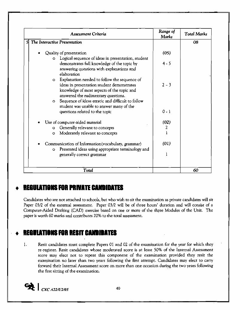
+ REGULATIONS FOR PRIVATE CANDIDATES
Candidates who are not attached to schools, but who wish to sit the examination as private candidates will sit Paper 03/2 of the external assessment. Paper 03/2 will be of three hours' duration and will consist of a Computer-Aided Drafting (CAD) exercise based on one or more of the three Modules of the Unit. The paper is worth 60 marks and contributes 20% to the total assessment.
+ REGULATIONS FOR RESIT CANDIDATES 1. Resit candidates must complete Papers 01 and 02 of the examination for the year for which they
re-register. Resit candidates whose moderated score is at least 50% of the Internal Assessment score may elect not to repeat this component of the examination provided they resit the examination no later than two years following the first attempt. Candidates may elect to carry forward their Internal Assessment score on more than one occasion during the two years following the first sitting of the examination.
I CXCA22AJ2l.05 40
Range of Assessment Criteria Marks Total Marks
5 The Interactive Presentation 08
Quality of presentation (05) o Logical sequence of ideas in presentation, student
demonstrates full knowledge of the topic by 4 - 5 answering questions with explanations and elaboration
o Explanation needed to follow the sequence of ideas in presentation student demonstrates 2 - 3 knowledge of most aspects of the topic and answered the rudimentary questions.
o Sequence of ideas erratic and difficult to follow student was unable to answer many of the questions related to the topic
Use of computer-aided material o Generally relevant to concepts o Moderately relevant to concepts
Communication of Information (vocabulary, grammar) o Presented ideas using appropriate terminology and
generally correct grammar
Total
0 - 1
(02) 2 1
(01)
1
60
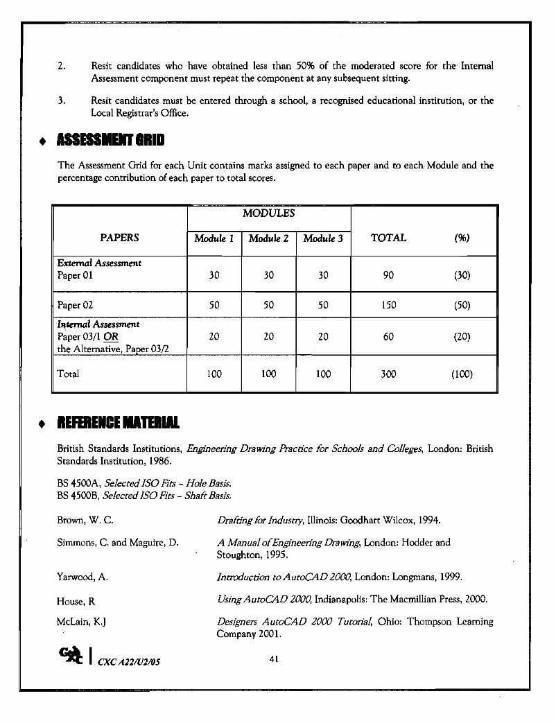
Resit candidates who have obtained less than 50% of the moderated score for the Internal Assessment component must repeat the component at any subsequent sitting.
3. Resit candidates must be entered through a school, a recognised educational institution, or the Local Registrar's Office.
+ ASSESSMENT BRlD The Assessment Grid for each Unit contains marks assigned to each paper and to each Module and the percentage contribution of each paper to total scores.
+ REFEREWCEHATERW British Standards Institutions, Enginee~g Drawng Racti'ce for Schools and Colleges, London: British Standards Institution, 1986.
BS 4500A, Selected I S 0 Firs - Hole Basis. BS 4500B, Selected I S 0 Firs - Shah Basis.
Drafting for Industry, Illinois: Goodhart Wilcox, 1994.
Simmons, C. and Maguire, D. A Manual ofEngineenng Drawng, London: Hodder and Stoughton, 1995.
Introduction to A utoCA D 2000, London: Longmans, 1999.
UsingAutoG4D 2000, Indianapolis: The Macmillian Press, 2000.
Desiflers A utoCA D 2000 TutoriaI, Ohio: Thompson Learning Company 200 1.
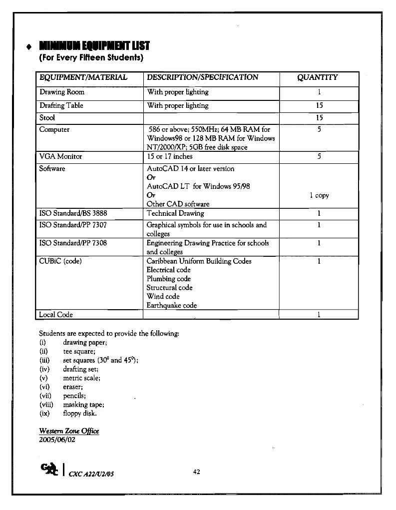
EQUIPMENTIMATERLAL DESCRIPTIONISPECIFICATION QUANTITY
Drawing Room With proper lighting 1
Drafting Table With proper lighting 15
Stool 15
Computer 586 or above; 550MHz; 64 MB RAM for 5 Windows98 or 128 MB RAM for Windows NTl2000KP; 5GB free disk space
VGA Monitor 15 or 17 inches 5
Software AutoCAD 14 or later version Or AutoCAD LT for Windows 95/98 Or 1 COPY Other CAD software
IS0 StandardiBS 3888 Technical Drawing 1
IS0 Standardpp 7307 Graphical symbols for use in schools and 1 colleges
IS0 Standardpp 7308 Engineering Drawing Practice for schools 1 and colleges
CUBiC (code) Caribbean Uniform Building Codes 1 Electrical code Plumbing code Structural code Wind code Earthquake code
Local Code 1
* mlNlmom EIUlPHEm LIST (For Every Fifteen Students)
Students are expected to provide the following: (i) drawing paper; (ii) tee square; (iii) set squares (30' and 45") ;
(viii) masking tape; (ix) floppy disk.
Westem Zone Office