Embed Size (px)
Citation preview
ENGINEERED PRODUCTIVITY SOLUTIONS
25% faster than with conventional machining
Turbocharger machining
2
Benefits for you: Significantreductioninmachiningprocessby25% Increaseinultra-precisemachining Toollifeincreasedbyseveraldegrees Fewertoolsrequired Integratedassistanceandmonitoringsystem Ahighdegreeofautomationdesigned
forseriesproduction Increaseinlong-termqualityofturbochargers
Requirements for turbocharger manufacturing:
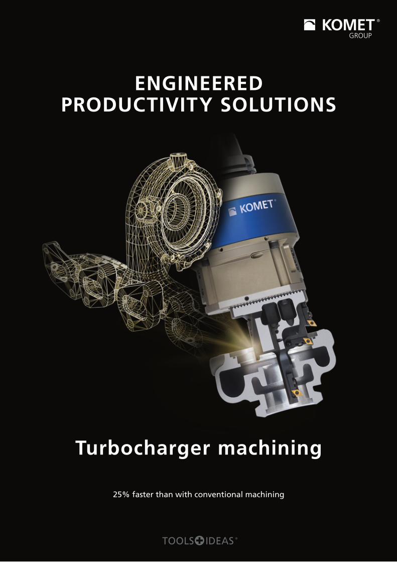
Relating to the material Extremelyhighrequirementsrelatingtothermomechanicalproperties,highheatresistance–useintemperaturesofupto1100°Cforpetrolengines
Useofhigh-alloy,high-temperature-resistantmaterialswithahighnickelandchromecontent
Extremelylowthermalconductivity(Heatisdirectedintothemachiningtool)
Strongtendencytowardsstrainhardening Highlyabrasivecastskin,edgezonehardness
upto450HV0.5 Austeniticmatrixwithchromiumcarbidesrequireshighcuttingforces,whichresultinarelativelyshorttoollife
Inshort,abrasiveanddifficulttocut
Relating to machining Highrequirementsrelatingtoformandpositiontolerances Automatedseriesproduction Reductionofcostsperpieceandthemachiningtime
Productivity PLUS! A highly efficient solution in turbocharger manufacturing from STAMA Maschinenfabrik GmbH and KOMET GROUP GmbH
ASUCCESSFULCOLLABORATIONTHETURNKEYSOLUTIONFORMACHININGNEWGENERATIONSOFTURBOCHARGERS
A time saving of up to 67%. Machining time reduced by up to 25%.
ThecombinationoftheSTAMAMT838TWINmilling-turningcentreandKOMET®machiningoptimisationwithaspecialKomTronic®U-axistoolissettingnewstandards.Atimesav-ing of up to 67% is achieved for V-belt machining alone.This is mainly the result of interpolation grooving andturning, which replaces the circular milling processwhich was originally used, and the result of the use ofKOMET®U-axissystems.The result: The time required for the entire machin-ing process for the component is reduced by 25%.Inadditiontodrasticallyreducedtoolcosts.
Turbochargerhousing

3
Machining strategy
Rotationallysymmetricalmachiningwithhighly asymmetric component
UseoffreelyprogrammableKOMETKomTronic®U-axissystemsenables any type of contour machining and turningonpartswhicharenotrotationallysymmetrical.Throughthecombineduseofcustomised snap-on toolsandoptimallyselected indexable inserts
Machiningcontoursinboresaswellasinternalandexternalmachiningresultsina significant reduction
in production times, better surface quality, and improved dimensional accuracy
Fewertoolsrequired Useof3D-printed special toolswithinnovativecoolantchannelsadaptedtotheprocess
The solution on the machine side
Double-spindleSTAMAmilling-turningcentre MT838TWINwithHSK-A100 Highlydynamicandstablecompletemachining
withmillingandturning Completefreedominthechoiceandsequenceofoptions
Productivity PLUS! KOMET® tool solutions
Examples of ultra-precise machining
INNOVATIVESOLUTIONSFORTURBOCHARGERMANUFACTURING
Pre-machining of V-belt outer diameter – KOMET® interpolation grooving and turning tool
Benefits for you:
Extremelystabletooldesign
Specialadaptationofthecuttingedgegeometry
tothemachiningprocesswithregardto
machiningtimeandstability
Internalcoolantsupply
directlytothetool's
cuttingedge
Finish machining of counter bearing conical hole – KOMET KomTronic® U-axis systems Withsteppedsnap-ontoolwithfourindexableinserts.
Benefits for you:
Completefinishmachiningwithasingletool
Enablesmaximumprecisiontobeachieved
99%useofstandardindexableinserts
Directcoolantsupplytotheindividualcuttingedges
Integratedpositionmeasuringsystem
Short,stabletooldesignthanks
tooptimalcompactconnection
Finish machining of V-belt outer diameter – KOMET KomTronic® U-axis systems With 3D-printed snap-on tool and indexable inserts in
special designs, with three cutting edges with ground
recessgeometryandflute.
Benefits for you:
Considerablyhighercuttingvalues
thanwithconventionalmachining
Integratedpositionmeasuringsystem
Short,stabletooldesignthanks
tooptimalcompactconnection
KOMET® arbor face-milling cutter for machining of turbo chargers Ø 50 – 125 mmWithdouble-sidedoctagonalindexableinsertswith
16usablecuttingedges.
Benefits for you:
Robustdesign,stableandsecurepositioninthebasicbody
Specialcuttingmaterialsuitableforthetoughest
thermomechanicalrequirements
Defined,stablecuttingedgeguidance
Maximumproductivity,processrelia-
bilityandcost-efficiencyguaranteed

4
1
2
Selected machining examples – Conventional machining vs. KOMET® strategy
OPTIMISATIONOFTHEMACHININGPROCESS
Now KOMET KomTronic® U-axis systems with direct position measuring system and 3D-printed snap-on tool
Advantages
Significantlyhighercuttingspeedscanbeachieved Considerablereductioninmachiningtimes Rapidamortisation
Now Complete manufacturing with KOMET® interpolation grooving and turning tool
Advantages
Timereductionofupto47% Circularmilling75sec–reductiontobelow40sec
withinterpolationgroovingandturning Highlevelofprocessreliability Reducesnumberoftoolsrequiredbyone,
eliminatingtheneedforchangeovertime
Previously Conventional finish machining with interpolation grooving and turning tool
Machiningprocessisheavilydependentonthemachineperformance(cuttingspeed,feedrate,etc.)
Previously Conventional roughing with two tools
Firststep: Pre-machiningwithspecialboringbarSecondstep: Pre-machiningwithspecialcircular millingcutter100
Process: Finish machining of V-belt outer diameter
Process: Pre-machining of V-belt outer diameter
FinishmachiningofV-belt FinishmachiningofV-belt
Pre-machiningofV-beltPre-machiningofV-beltsemi,circular
Pre-machiningofV-beltouterdiameter

5
2
2
3
3
3
1
1
Now KOMET KomTronic® U-axis systems with direct position measuring system and 3D-printed snap-on tool
Advantages
Significantlyhighercuttingspeedscanbeachieved Considerablereductioninmachiningtimes Rapidamortisation
Now KOMET KomTronic® U-axis systems with stepped snap-on tool and direct
position measuring system
Advantages
Completefinishmachining Increasedpositioningaccuracyandprocessreliability FreelyprogrammableU-axisenablesuseofstandardcuttingedgesforcomplicatedcontours.
Effect:Lowercuttingpressureandmachining ofthecontourlineinasingleoperation
Result:Lowermachiningforces,longertoollife andextremelylongshaperetentionasaresult
Previously Conventional counter bearing machining with up to four tools
Firststep: SemifinishlinerSecondstep:SemifinishbearingringThirdstep: SemifinishcounterbearingFourthstep:Semifinishliner
Process: Finish machining of counter bearing conical hole
FinishmachiningofV-beltwithKomTronic®U-axistoolHSK-A100Monospecialboringbar(adjustable)HSK-100Monospecialboringbar
HSK-A100Monospecialboringbar HSK-A100Monospecialboringbar
Watch now! www.kometgroup.com/turbocharger
YoucanalsofindallKOMET®videosonourYouTubechannel:www.youtube.com/kometgroup

6
0
10
20
30
40
50
60
TURBOCHARGERMANUFACTURING
Independent study by Reutlingen University, Prof. Dr.-Ing. Helmut Nebeling verifies the cost-effectiveness of the innovative turbocharger manufacturing process
Costs per part
Example: Reduction in time required for "V-belt" finishing
Cutting values achieved for "Trumpet"
U-axis enables efficient, quicker and more cost-effective machining of turbocharger housings
Interpolationmilling 174sec
U-axis 30sec
Vc 140m/min
f 0.12mm/rev
ap 0.3
Formtolerance <0.020mm
Rz <16m
Costsineuros
U-axisConventional
Labourcosts Toolcosts Machinerycosts
Conventional:Roughingandfinishing inthemillingprocess U-axis:RoughingandfinishingwithU-axis
Conventional U-axis
Machinerycosts 12.53 12.18
Toolcosts 19.87 0.40
Labourcosts 10.05 6.03
Totalcosts 51.44 18.61
21.53
12.18
6.03
19.87
10.05
0.40

7
KOMET GROUP GmbHKOMET GROUP GmbHKOMET GROUP GmbHKOMET GROUP GmbH WerkstueckWerkstueckWerkstueckWerkstueck Angebots-Nr.: 123456Angebots-Nr.: 123456Angebots-Nr.: 123456Angebots-Nr.: 123456
AufspannungAufspannungAufspannungAufspannung WerkstoffWerkstoffWerkstoffWerkstoff
Wer
kstü
ck-ID
Wer
kstü
ck-ID
Wer
kstü
ck-ID
Wer
kstü
ck-ID
Anza
hl W
kstü
.
Zusa
tzin
fo
Z-Ac
hse
Wks
tü.-
Abst
and
[mm
]
X-Ac
hse
Wks
tü.-
Abst
and
[mm
]
Y-Ac
hse
Wks
tü.-
Abst
and
[mm
]
Wer
ksto
ff-be
zeic
hnun
g
Wer
ksto
ffhau
pt-
grup
pe
Wer
ksto
ff-gr
uppe
Zugf
estig
keit
[N/m
m²]
Här
te [H
B]
Spez
if. S
chni
tt-kr
aft [
N/m
m²]
k c W
erks
toff-
expo
nent
Spez
if. V
orsc
hub-
kraf
t [N
/mm
²]
k f W
erks
toff-
expo
nent
RRRRmmmm kkkkc1.1c1.1c1.1c1.1 mmmmcccc kkkkf1.1f1.1f1.1f1.1 mmmmffff
1 1 X 12 NiCrSi 36 16 S 31 550 1706 0,26 733 0,443
www.cutview.comSeite: 1/1
18900002.xlsx02.05.2017
Materialdatabaseandcuttingvaluesdatabase withempiricalvalues Evaluation of:Calculationofservicelifeanalysis
fortools,CPP(costperpart)saving,amortisation, toolcomparisonsandplanning
ToolScopes record and document the machine's in-ternal data during the machining process, such asthe torque of a spindle or name of the current pro-gramme. ToolScope apps can use this data to mon-itor the process in real time or optimise the feed overrideduringtheprocess.ToolScopecanbeusedtodocumentmon-itoringresultsandautomaticallytransferthisdocumentationtothecustomerserverforarchiving.KOMET®offersaddi-tionalsoftwareforoptimisingdatastorage.
KOMET®BRINKHAUSTOOLSCOPEASSISTANCESYSTEMINUSEFORTURBOCHARGERMACHINING
Benefits for you: Reducedcycletimeforfacemilling Fingerprintingofprocessespriortothestart
ofseriesproduction Automatedaverageprocessmonitoring Reducedtoolcoststhankstowear-dependent
toolchange Automatedmonitoringofthemachinestatus Documentationofin-processmeasuredvalueswithautomatedconnectiontocustomerITsystems
Moreinformationcanbefoundatwww.thomann.com/en
Machiningprocessesforturbochargersplacenewdemandson processes and machines in terms of quality assurance.WiththeToolScopeassistancesystem,KOMET®fullysatis-fiesthesedemandsaswell.WithToolScope, theKOMETGROUP is theonly toolmanu-facturer tooffer a true Industry4.0 solution, even for smallandmedium-sizedcompanies.Turbochargermachiningproces-sesenablethefullpotentialofthissystemtocomeintoplay.
Intheearlyplanningstageforturbochargermachining,thebasisforthemachiningtimesandcostanalysisisformedus-ingtheCutView®planningtool.TheKOMETGROUPtoolequipment in conjunction with the STAMA MT 838 TWINmilling-turningcentreprovides thebasis for thismachiningexample.
With regard to this project, CutView® is characterised by the following features:
Quickandeasyoperationofmachiningprocesses, toolsandmachines Easeofuseandsmoothdataexchangebased
onMicrosoftExcel Determineshowlongaworkpiecerunsonamachine Timecalculationforadjustingthemachiningsequence Toolcalculationwithcostsinvolved Calculationoftorque,cuttingperformance,
feedpowerandprimaryprocessingtime
COSTBREAKDOWNUSINGCUTVIEW®PLANNINGSOFTWARE
1. Monitoringprocessesareclearlydisplayed.2. Cleardisplays(piececounterhere)facilitatetheunderstanding ofprocessesinthemachine.3. ToolScopedatacanbequicklyvisualised.KOMET®evenoffers Exceltemplatestohelpyoureachyourgoalfaster.
1
2
3

www.kometgroup.com
39901 81200-08/17 · © 2017 KOMET GROUP GmbH · We reserve the right to make modifications.
8. What workpiece diameters can be machined?Therangeofapplicationis0.5–500mm,takingintoconsid-erationtherelevantprojectionlengthandattachmentpoint.
9. What is the maximum possible number of different diameters or cutting edges?Anynumberofcuttingedgesarepossible.Thisisdependentonthetoollengthandtoolwidth(slide)of40or60mmre-spectively,andthecontrolsystem.
10. How is the tool system set?TheU-axisisalwayschangedinthecentralposition.Thisenablesthesnap-ontooltobemeasuredonadummyinthepresettingdevice.Inaddition,post-processmeasurementwithautomatedcuttingedgecorrectionispossibleviathetoolmanagement.
11. What are the maintenance and service intervals? Recommendedonceayear,oreverytwoyearsdependingonuse
12. How long is the expected service life? Withregularmaintenanceandcareandthereplacementofwearparts,aservicelifeof>6500operatinghoursisrealistic,correspondingtoapproximately10years.
13. How accurate is the system for double-spindle ma-chining?Bothsystemsshouldbeusedoffset(180°)dependingontheimbalance.Aswithasingle-spindlemachine,withthedouble-spindlemachinetheaccuraciesinpoint1areachievedwithexacttoolpresettingoraZ-axisthatcanbeadjusted/correctedseparately.
14. What is the maximum size that can be machined with HSK63 or HSK100? KomTronic®UAS-115:Uptodia.approx.250mmKomTronic®UAS-160:Uptodia.approx.500mmtakingintoconsiderationtherelevantprojectionlengthandattachmentpoint.
15. Are the U-axes more suitable for vertical machining than horizontal machining? U-axesareusedbothverticallyandhorizontally.Theadvantagesanddisadvantageshereshouldbeconsideredtobethesameasforamechanicaltool(centrifugalforces).
1. What levels of accuracy can be achieved with the KomTronic® U-axis? Diameter of 0.02 mm with no measuring system onthe slide, diameter of 0.005 mm with a measuringsystem. The measuring system can perform analysiswith a measuring accuracy of 0.0001 mm (accuracy isdependent on other machining factors, such as toolchangeerrors,wearonthecuttingedge,etc.)
2. How can the position of the inserts be corrected?Onthetoolviashortclampholdersorforeachcuttingedgedirectlyviathetoolmanagement.
3. Does the U-axis always need to be re-measured each time the inserts are changed?No, theU-axis or slide is always in the sameposition. Theinsertpositioncanbecorrecteddirectlyinthemachineviaanin-processmeasurement.
4. Does the KomTronic® U-axis need to be removed from the machine in order to measure the tool?No,thisisconvenientlycarriedoutbyintegratinganattachmentpointconnection(optional).
5. What is the maximum speed limit?Withthesingleslidebalancedinthecentralposition,themax-imumspeedis4000rpm,adjusteddependingonthestroke.At up to 8000 rpm over the entire axis stroke (see the"KomTronic®drawbartoolsformachiningcentres"brochure)
6. Can the KomTronic® U-axis also be used for roughing?Avarietyofmachiningprocessescanbeused(finishingandroughing).Theslidehasamaximumpowerof4000Nandapermissibletorqueof200Nm.However,thepossibleusagedatadependsontheoveralllengthofthetoolandtheU-axis.
7. How is the U-axis driven?The U-axis is driven via a servo motor. The slides for theUAS115/160 seriesaredrivenviaa roller threaddrivewithnoplay.
FAQ–questionsandanswersregardingKOMET®U-axistools