Embed Size (px)
Citation preview
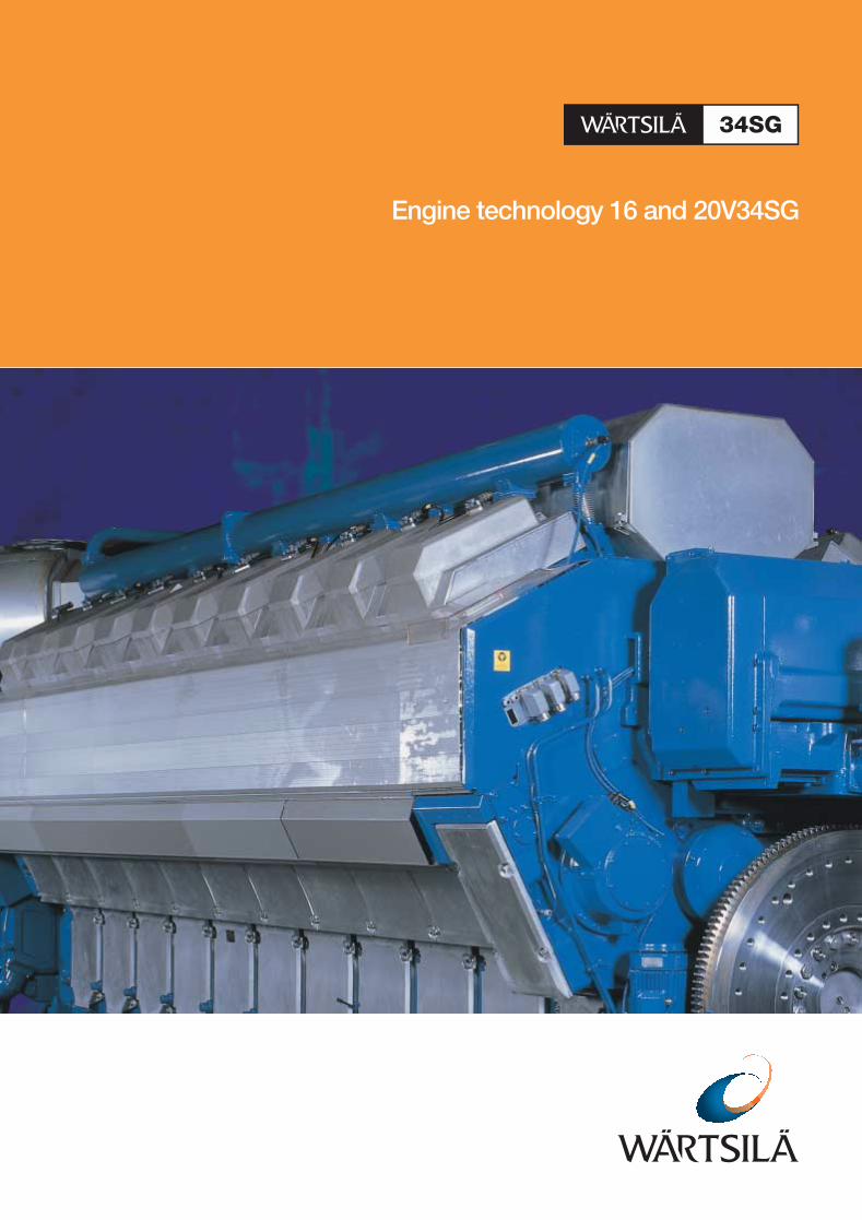
Engine technology 16 and 20V34SG
2
3
Engine technologyIntroduction . . . . . . . . . . . . . . . . . . . . . . . . . . . . . 4
Design philosophy . . . . . . . . . . . . . . . . . . . . . . . . 5
The lean-burn concept . . . . . . . . . . . . . . . . . . . . . 6
Low emissions . . . . . . . . . . . . . . . . . . . . . . . . . . . 6
Gas admission system . . . . . . . . . . . . . . . . . . . . . 7
Gas supply system . . . . . . . . . . . . . . . . . . . . . . . . 7
Prechamber . . . . . . . . . . . . . . . . . . . . . . . . . . . . . 8
Ignition system . . . . . . . . . . . . . . . . . . . . . . . . . . . 8
Air-fuel ratio . . . . . . . . . . . . . . . . . . . . . . . . . . . . . 8
Cooling system . . . . . . . . . . . . . . . . . . . . . . . . . . . 9
Lubricating oil system. . . . . . . . . . . . . . . . . . . . . . 9
Starting system. . . . . . . . . . . . . . . . . . . . . . . . . . 10
Piston . . . . . . . . . . . . . . . . . . . . . . . . . . . . . . . . . 10
Piston ring set . . . . . . . . . . . . . . . . . . . . . . . . . . . 10
Cylinder head . . . . . . . . . . . . . . . . . . . . . . . . . . . 10
Connecting rod and big-end bearings . . . . . . . . 11
Engine block . . . . . . . . . . . . . . . . . . . . . . . . . . . . 11
Crankshaft and bearings . . . . . . . . . . . . . . . . . . 12
Cylinder liner and anti-polishing ring . . . . . . . . . 12
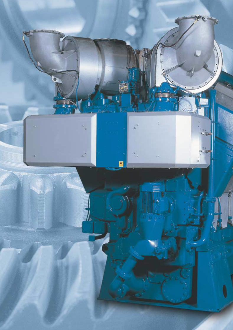
Turbocharging system . . . . . . . . . . . . . . . . . . . . 12
Multiduct. . . . . . . . . . . . . . . . . . . . . . . . . . . . . . . 13
Automation system. . . . . . . . . . . . . . . . . . . . . . . 13
Easy maintenance. . . . . . . . . . . . . . . . . . . . . . . . 14
Main technical data . . . . . . . . . . . . . . . . . . . . . . 15
In 1992, Wärtsilä started the development of lean-burn,
spark-ignited Otto gas engines. The first 34SG engine was
released in 1995 and now the product range of lean-burn
gas engines has been expanded by introducing the new
WÄRTSILÄ® 34SG. These engines take the power
output of the 34SG series up to 9 MW.
The Wärtsilä 34SG is a four-stroke, spark-ignited gas
engine that works according to the Otto process and the
lean-burn principle. The engine has ported gas admission
and a prechamber with a spark plug for ignition.
The engine runs at 720 or 750 rpm for 60 or 50 Hz
applications and produces 6950 to 9000 kW of
mechanical power, respectively. The efficiency of the
Wärtsilä 34SG is the highest of any spark-ignited gas
engines today. The natural gas fuelled, lean-burn,
medium-speed engine is a reliable, high-efficiency and
low-pollution power source for co-generation plants.
4
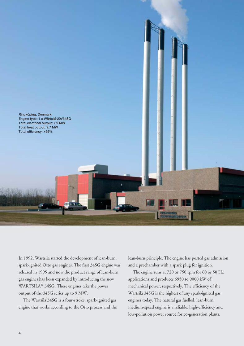
Ringköping, DenmarkEngine type: 1 x Wärtsilä 20V34SGTotal electrical output: 7.9 MWTotal heat output: 9.7 MWTotal efficiency: >95%.
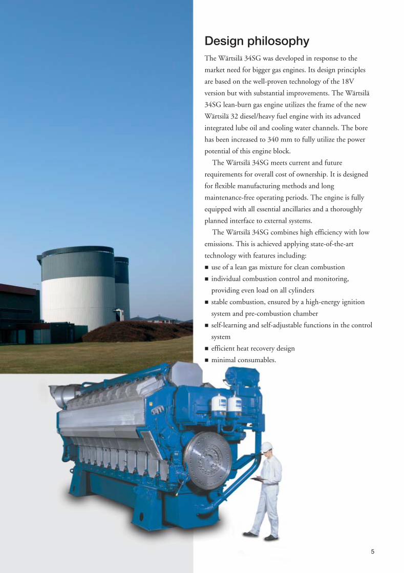
Design philosophyThe Wärtsilä 34SG was developed in response to the
market need for bigger gas engines. Its design principles
are based on the well-proven technology of the 18V
version but with substantial improvements. The Wärtsilä
34SG lean-burn gas engine utilizes the frame of the new
Wärtsilä 32 diesel/heavy fuel engine with its advanced
integrated lube oil and cooling water channels. The bore
has been increased to 340 mm to fully utilize the power
potential of this engine block.
The Wärtsilä 34SG meets current and future
requirements for overall cost of ownership. It is designed
for flexible manufacturing methods and long
maintenance-free operating periods. The engine is fully
equipped with all essential ancillaries and a thoroughly
planned interface to external systems.
The Wärtsilä 34SG combines high efficiency with low
emissions. This is achieved applying state-of-the-art
technology with features including:
� use of a lean gas mixture for clean combustion
� individual combustion control and monitoring,
providing even load on all cylinders
� stable combustion, ensured by a high-energy ignition
system and pre-combustion chamber
� self-learning and self-adjustable functions in the control
system
� efficient heat recovery design
� minimal consumables.
5
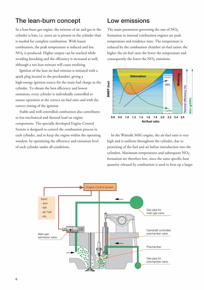
The lean-burn conceptIn a lean-burn gas engine, the mixture of air and gas in the
cylinder is lean, i.e. more air is present in the cylinder than
is needed for complete combustion. With leaner
combustion, the peak temperature is reduced and less
NOX is produced. Higher output can be reached while
avoiding knocking and the efficiency is increased as well,
although a too lean mixture will cause misfiring.
Ignition of the lean air-fuel mixture is initiated with a
spark plug located in the prechamber, giving a
high-energy ignition source for the main fuel charge in the
cylinder. To obtain the best efficiency and lowest
emissions, every cylinder is individually controlled to
ensure operation at the correct air-fuel ratio and with the
correct timing of the ignition.
Stable and well-controlled combustion also contributes
to less mechanical and thermal load on engine
components. The specially developed Engine Control
System is designed to control the combustion process in
each cylinder, and to keep the engine within the operating
window, by optimizing the efficiency and emissions level
of each cylinder under all conditions.
Low emissionsThe main parameters governing the rate of NOX
formation in internal combustion engines are peak
temperature and residence time. The temperature is
reduced by the combustion chamber air-fuel ratios: the
higher the air-fuel ratio the lower the temperature and
consequently the lower the NOX emissions.
In the Wärtsilä 34SG engine, the air-fuel ratio is very
high and is uniform throughout the cylinder, due to
premixing of the fuel and air before introduction into the
cylinders. Maximum temperatures and subsequent NOX
formation are therefore low, since the same specific heat
quantity released by combustion is used to heat up a larger
6
Input:
- rpm
- kW
- air/ fuel
- etc.
Main gasadmission valve
Camshaft controlledprechamber valve
Prechamber
Gas pipe forprechamber valve
Gas pipe formain gas valve
Engine Control SystemT
he
rma
le
ffic
ien
cy
(%)
NO
x(g
/kW
h)
Air/fuel ratio
0.6 0.8 1.0 1.2 1.4 1.6 1.8 2.0 2.2
Detonation
BM
EP
(ba
r)
2.62.4
Mis
firi
ngOperating
window
45%
< 1 g/kWh
mass of air. Benefiting from this unique feature of the
lean-burn principle, the NOX emissions from the Wärtsilä
34SG are extremely low, and comply with the most
stringent existing NOX legislation.
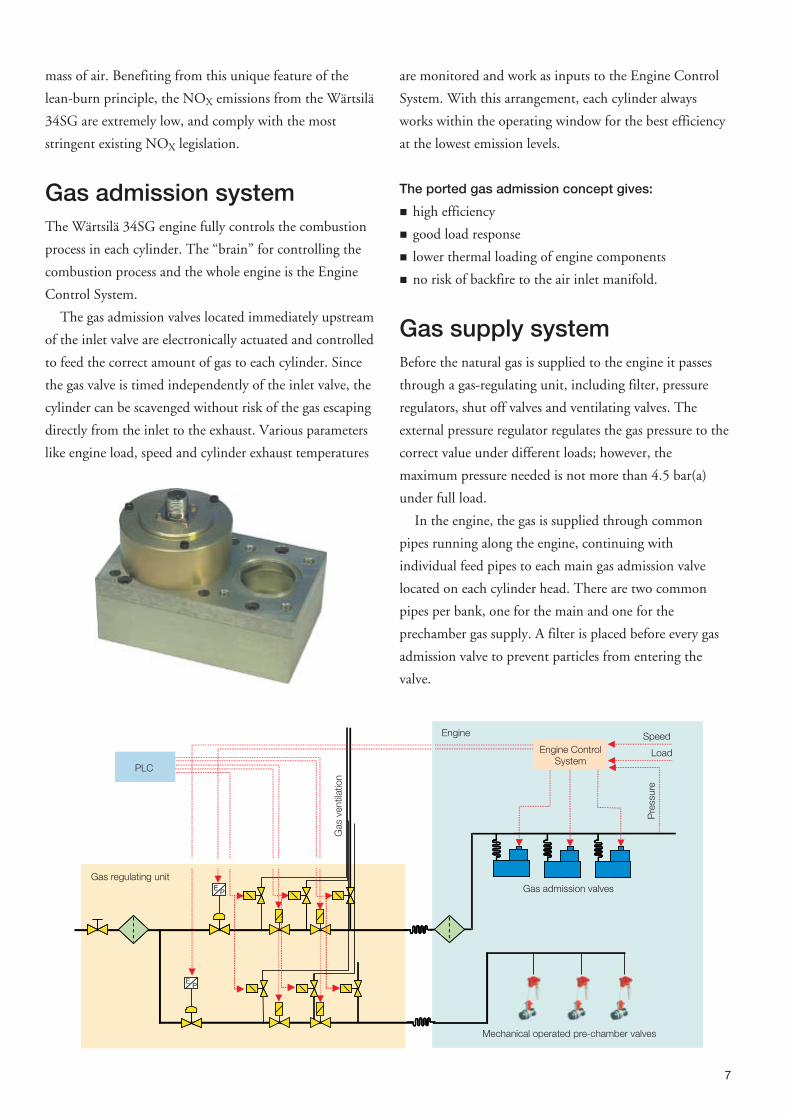
Gas admission systemThe Wärtsilä 34SG engine fully controls the combustion
process in each cylinder. The “brain” for controlling the
combustion process and the whole engine is the Engine
Control System.
The gas admission valves located immediately upstream
of the inlet valve are electronically actuated and controlled
to feed the correct amount of gas to each cylinder. Since
the gas valve is timed independently of the inlet valve, the
cylinder can be scavenged without risk of the gas escaping
directly from the inlet to the exhaust. Various parameters
like engine load, speed and cylinder exhaust temperatures
are monitored and work as inputs to the Engine Control
System. With this arrangement, each cylinder always
works within the operating window for the best efficiency
at the lowest emission levels.
The ported gas admission concept gives:
� high efficiency
� good load response
� lower thermal loading of engine components
� no risk of backfire to the air inlet manifold.
Gas supply systemBefore the natural gas is supplied to the engine it passes
through a gas-regulating unit, including filter, pressure
regulators, shut off valves and ventilating valves. The
external pressure regulator regulates the gas pressure to the
correct value under different loads; however, the
maximum pressure needed is not more than 4.5 bar(a)
under full load.
In the engine, the gas is supplied through common
pipes running along the engine, continuing with
individual feed pipes to each main gas admission valve
located on each cylinder head. There are two common
pipes per bank, one for the main and one for the
prechamber gas supply. A filter is placed before every gas
admission valve to prevent particles from entering the
valve.
7
Gas admission valves
Load
Speed
PLC
Engine
Mechanical operated pre-chamber valves
Gas regulating unitE P
EP
Pre
ssur
e
Gas
vent
ilatio
n
Engine ControlSystem
PrechamberThe prechamber is the ignition source for the main
fuel charge and is one of the essential components of
a lean-burn spark-ignited gas engine.
The prechamber should be as small as possible to
give low NOX values, but big enough to give rapid
and reliable combustion. Some of the design
parameters considered are:
� shape and size
� mixing of air and fuel
� gas velocities and turbulence at the spark plug
� cooling of the prechamber and the spark plug
� choice of material.
The prechamber of the Wärtsilä 34SG is already
optimized at the design stage using advanced
three-dimensional, computerized fluid dynamics. In
practice, the results can be seen as:
� reliable and powerful ignition
� high combustion efficiency and stability
� extended spark plug life
� very low NOX levels.
Gas is admitted to the prechamber through a mechanical,
camshaft-driven valve. This solution has proved to be
extremely reliable and gives an excellent mixture into the
prechamber.
Ignition systemThe Wärtsilä 34SG ignition system is tailor-made
for the engine type and integrated in the Engine
Control System. The ignition module
communicates with the main control module,
which determines the global ignition timing. The
ignition module controls the cylinder-specific
ignition timing based on the combustion quality.
The cylinder-specific control ensures the
optimum combustion in every cylinder with
respect to reliability and efficiency.
The ignition coil is located in the cylinder
cover and is integrated in the spark plug
extension. The coil-on-plug design ensures a
reliable solution with a minimum of joints
between the spark plug and the ignition coil. The
spark plug has been especially developed for long
lifetime and to withstand the high cylinder
pressure and temperature related to the high engine
output.
Air-fuel ratioTo always ensure correct performance of the engine, it
is essential to have the correct air-fuel ratio under all types
of conditions. The Wärtsilä 34SG uses an exhaust gas
wastegate valve to adjust the air-fuel ratio. Part of the
exhaust gases bypasses the turbocharger through the
waste-gate valve. This valve adjusts the air-fuel ratio to the
correct value regardless of varying site conditions under
any load.
8
Prechambervalve push rod
Prechambervalve cam
Rocker arm
Valve integratedin prechamber
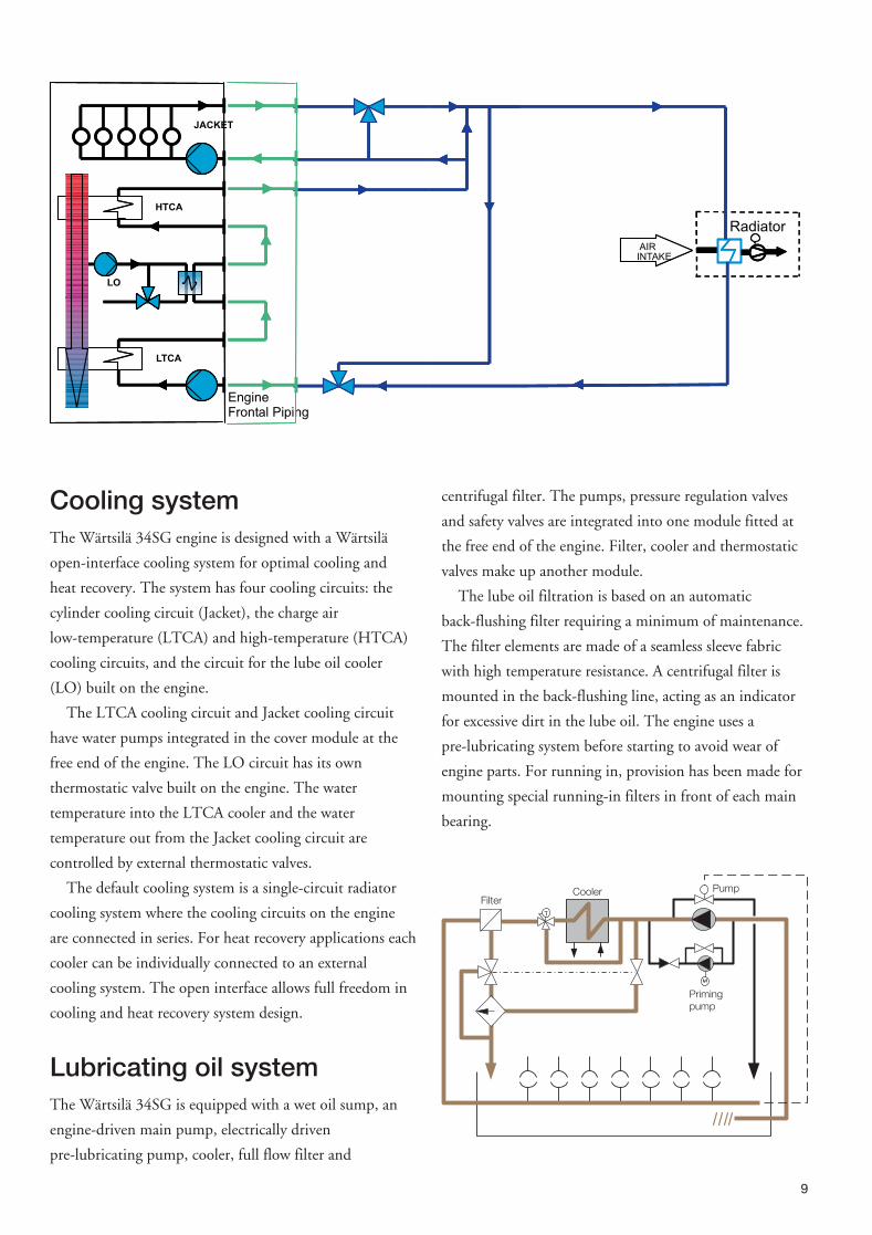
Cooling systemThe Wärtsilä 34SG engine is designed with a Wärtsilä
open-interface cooling system for optimal cooling and
heat recovery. The system has four cooling circuits: the
cylinder cooling circuit (Jacket), the charge air
low-temperature (LTCA) and high-temperature (HTCA)
cooling circuits, and the circuit for the lube oil cooler
(LO) built on the engine.
The LTCA cooling circuit and Jacket cooling circuit
have water pumps integrated in the cover module at the
free end of the engine. The LO circuit has its own
thermostatic valve built on the engine. The water
temperature into the LTCA cooler and the water
temperature out from the Jacket cooling circuit are
controlled by external thermostatic valves.
The default cooling system is a single-circuit radiator
cooling system where the cooling circuits on the engine
are connected in series. For heat recovery applications each
cooler can be individually connected to an external
cooling system. The open interface allows full freedom in
cooling and heat recovery system design.
Lubricating oil systemThe Wärtsilä 34SG is equipped with a wet oil sump, an
engine-driven main pump, electrically driven
pre-lubricating pump, cooler, full flow filter and
centrifugal filter. The pumps, pressure regulation valves
and safety valves are integrated into one module fitted at
the free end of the engine. Filter, cooler and thermostatic
valves make up another module.
The lube oil filtration is based on an automatic
back-flushing filter requiring a minimum of maintenance.
The filter elements are made of a seamless sleeve fabric
with high temperature resistance. A centrifugal filter is
mounted in the back-flushing line, acting as an indicator
for excessive dirt in the lube oil. The engine uses a
pre-lubricating system before starting to avoid wear of
engine parts. For running in, provision has been made for
mounting special running-in filters in front of each main
bearing.
9
JACKET
HTCA
LTCA
LO
AIRINTAKEAIRINTAKE
EngineFrontal Piping
Radiator
FilterCooler Pump
Primingpump
Starting systemThe Wärtsilä 34SG engine is provided with pneumatic
starting valves in the cylinder heads of one bank. The
valves are operated by air from a distributor at the end of
the camshaft. A starting limiter valve prevents the engine
from starting if the turning gear is engaged.
PistonPistons are of the low-friction, composite type with forged
steel top and aluminium skirt. The design itself is tailored
for an engine of this size and includes a number of
innovative approaches. Long lifetime is obtained through
the use of Wärtsilä’s patented skirt-lubrication system, a
piston crown cooled by “cocktail-shaker” cooling,
induction hardened piston ring grooves and the
low-friction piston ring.
Piston ring setThe two compression rings and the oil control ring are
located in the piston crown. This three-ring concept has
proved its efficiency in all Wärtsilä engines. In a
three-pack, every ring is dimensioned and profiled for the
task it must perform. Most of the frictional loss in a
reciprocating combustion engine originates from the
piston rings. A three-ring pack is thus optimal with respect
to both function and efficiency.
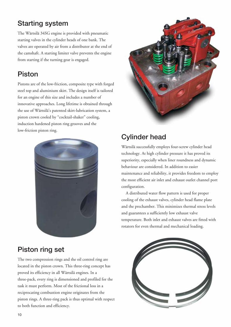
Cylinder headWärtsilä successfully employs four-screw cylinder head
technology. At high cylinder pressure it has proved its
superiority, especially when liner roundness and dynamic
behaviour are considered. In addition to easier
maintenance and reliability, it provides freedom to employ
the most efficient air inlet and exhaust outlet channel port
configuration.
A distributed water flow pattern is used for proper
cooling of the exhaust valves, cylinder head flame plate
and the prechamber. This minimizes thermal stress levels
and guarantees a sufficiently low exhaust valve
temperature. Both inlet and exhaust valves are fitted with
rotators for even thermal and mechanical loading.
10
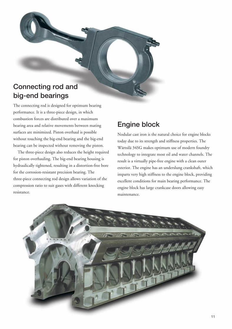
Connecting rod andbig-end bearingsThe connecting rod is designed for optimum bearing
performance. It is a three-piece design, in which
combustion forces are distributed over a maximum
bearing area and relative movements between mating
surfaces are minimized. Piston overhaul is possible
without touching the big-end bearing and the big-end
bearing can be inspected without removing the piston.
The three-piece design also reduces the height required
for piston overhauling. The big-end bearing housing is
hydraulically tightened, resulting in a distortion-free bore
for the corrosion-resistant precision bearing. The
three-piece connecting rod design allows variation of the
compression ratio to suit gases with different knocking
resistance.
Engine blockNodular cast iron is the natural choice for engine blocks
today due to its strength and stiffness properties. The
Wärtsilä 34SG makes optimum use of modern foundry
technology to integrate most oil and water channels. The
result is a virtually pipe-free engine with a clean outer
exterior. The engine has an underslung crankshaft, which
imparts very high stiffness to the engine block, providing
excellent conditions for main bearing performance. The
engine block has large crankcase doors allowing easy
maintenance.
11
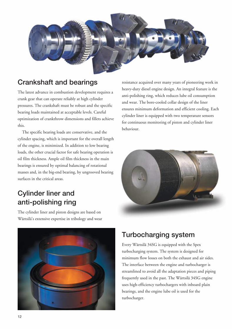
Crankshaft and bearingsThe latest advance in combustion development requires a
crank gear that can operate reliably at high cylinder
pressures. The crankshaft must be robust and the specific
bearing loads maintained at acceptable levels. Careful
optimization of crankthrow dimensions and fillets achieve
this.
The specific bearing loads are conservative, and the
cylinder spacing, which is important for the overall length
of the engine, is minimized. In addition to low bearing
loads, the other crucial factor for safe bearing operation is
oil film thickness. Ample oil film thickness in the main
bearings is ensured by optimal balancing of rotational
masses and, in the big-end bearing, by ungrooved bearing
surfaces in the critical areas.
Cylinder liner andanti-polishing ringThe cylinder liner and piston designs are based on
Wärtsilä’s extensive expertise in tribology and wear
resistance acquired over many years of pioneering work in
heavy-duty diesel engine design. An integral feature is the
anti-polishing ring, which reduces lube oil consumption
and wear. The bore-cooled collar design of the liner
ensures minimum deformation and efficient cooling. Each
cylinder liner is equipped with two temperature sensors
for continuous monitoring of piston and cylinder liner
behaviour.
Turbocharging systemEvery Wärtsilä 34SG is equipped with the Spex
turbocharging system. The system is designed for
minimum flow losses on both the exhaust and air sides.
The interface between the engine and turbocharger is
streamlined to avoid all the adaptation pieces and piping
frequently used in the past. The Wärtsilä 34SG engine
uses high-efficiency turbochargers with inboard plain
bearings, and the engine lube oil is used for the
turbocharger.
12

MultiductThe multiduct replaces a number of individual
components in traditional engine designs. These include:
� air transfer from the air receiver to the cylinder head
� exhaust transfer to the exhaust system
� cooling water outlet after the cylinder head
� cooling water return channel from the engine
� gas fuel mixing into the combustion air.
Additional functions are:
� introduction of an initial swirl to the inlet air for
optimal part-load combustion
� insulation / cooling of the exhaust transfer duct
� support for the exhaust system and its insulation.
Automation systemThe Engine Control System is an engine-mounted
distributed system. The various electronic modules are
dedicated to different functions and communicate with
each other via a CAN databus. All parameters handled by
the Engine Control System are transferred to the operator
interface and the plant control system. Its features are:
� easy maintenance and high reliability due to rugged
engine-dedicated connectors, CIB´s (cabling interface
boxes) and high quality cables
� less cabling on and around the engine
� easy interfacing with external system via a databus
� digitized signals giving immunity from electromagnetic
disturbance
� built-in diagnosis for easy troubleshooting.
Main control module
The main control module, the core of the Engine Control
System, reads the information sent by all the other
modules. Using this information it determines reference
values for the main gas admission to control the engine’s
speed and load.
The main control module also uses the information
sent from the different distributed modules to control the
global air-fuel ratio and global ignition timing in order to
obtain the best performance and reliable operation in
different site conditions, such as varying ambient
temperature and methane number.
The main control module automatically controls the
start and stop sequences of the engine and the engine
safety. It also communicates with the plant control system
(PLC).
Cylinder control module
Each cylinder control module monitors and controls three
cylinders. The cylinder control module controls the
cylinder-specific air-fuel ratio by adjusting the gas
admission individually for all cylinders. This ensures
optimal combustion in all cylinders.
The cylinder control module also measures the knock
intensity i.e. uncontrolled combustion in all cylinders.
Information on knock intensity is used to adjust the
cylinder-specific ignition timing by the cylinder control
module. Light knocking leads to automatic adjustment of
the ignition timing and air-fuel ratio. Heavy knocking
leads to load reduction and ultimately to shut-down of the
engine if heavy knocking does not disappear.
13
The cylinder control module also monitors the exhaust gas andcylinder liner temperatures of all cylinders.
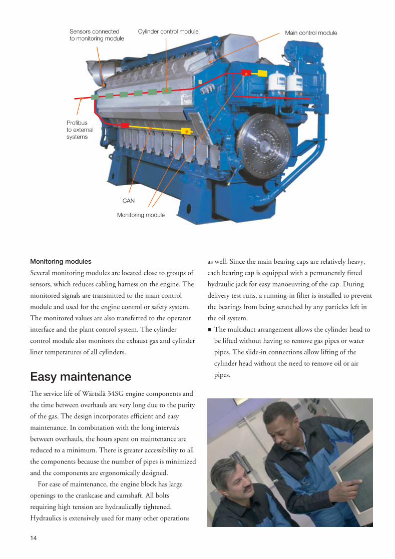
Monitoring modules
Several monitoring modules are located close to groups of
sensors, which reduces cabling harness on the engine. The
monitored signals are transmitted to the main control
module and used for the engine control or safety system.
The monitored values are also transferred to the operator
interface and the plant control system. The cylinder
control module also monitors the exhaust gas and cylinder
liner temperatures of all cylinders.
Easy maintenanceThe service life of Wärtsilä 34SG engine components and
the time between overhauls are very long due to the purity
of the gas. The design incorporates efficient and easy
maintenance. In combination with the long intervals
between overhauls, the hours spent on maintenance are
reduced to a minimum. There is greater accessibility to all
the components because the number of pipes is minimized
and the components are ergonomically designed.
For ease of maintenance, the engine block has large
openings to the crankcase and camshaft. All bolts
requiring high tension are hydraulically tightened.
Hydraulics is extensively used for many other operations
as well. Since the main bearing caps are relatively heavy,
each bearing cap is equipped with a permanently fitted
hydraulic jack for easy manoeuvring of the cap. During
delivery test runs, a running-in filter is installed to prevent
the bearings from being scratched by any particles left in
the oil system.
� The multiduct arrangement allows the cylinder head to
be lifted without having to remove gas pipes or water
pipes. The slide-in connections allow lifting of the
cylinder head without the need to remove oil or air
pipes.
14
Sensors connectedto monitoring module
Monitoring module
Cylinder control module
CAN
Main control module
Profibusto externalsystems
� The water pumps are easy to replace thanks to the
cassette design principle and water channel arrangement
in the pump cover at the free end of the engine.
� A rigid and tight but easily removable insulating box
surrounds the exhaust system.
� Easy access to the piping system is obtained by
removing the insulating panels.
� The camshaft is built of identical cylinder segments
bolted to intermediate bearing pieces.
� A wide range of special tools and measuring equipment
specifically designed to facilitate service work are also
available.
� Access to and maintenance of the spark plug and
prechamber gas valve in the prechamber is easy. The
prechamber does not need to be removed. For spark
plug replacement, the valve cover does not need to be
removed.
� Use of electrically controlled gas admission valves means
few mechanical parts and less need for periodic
adjustments.
� The three-piece connecting rod allows inspection of the
big-end bearing without removal of the piston, and
piston overhaul without dismantling the big-end
bearing.
15
A
B
C
D
E
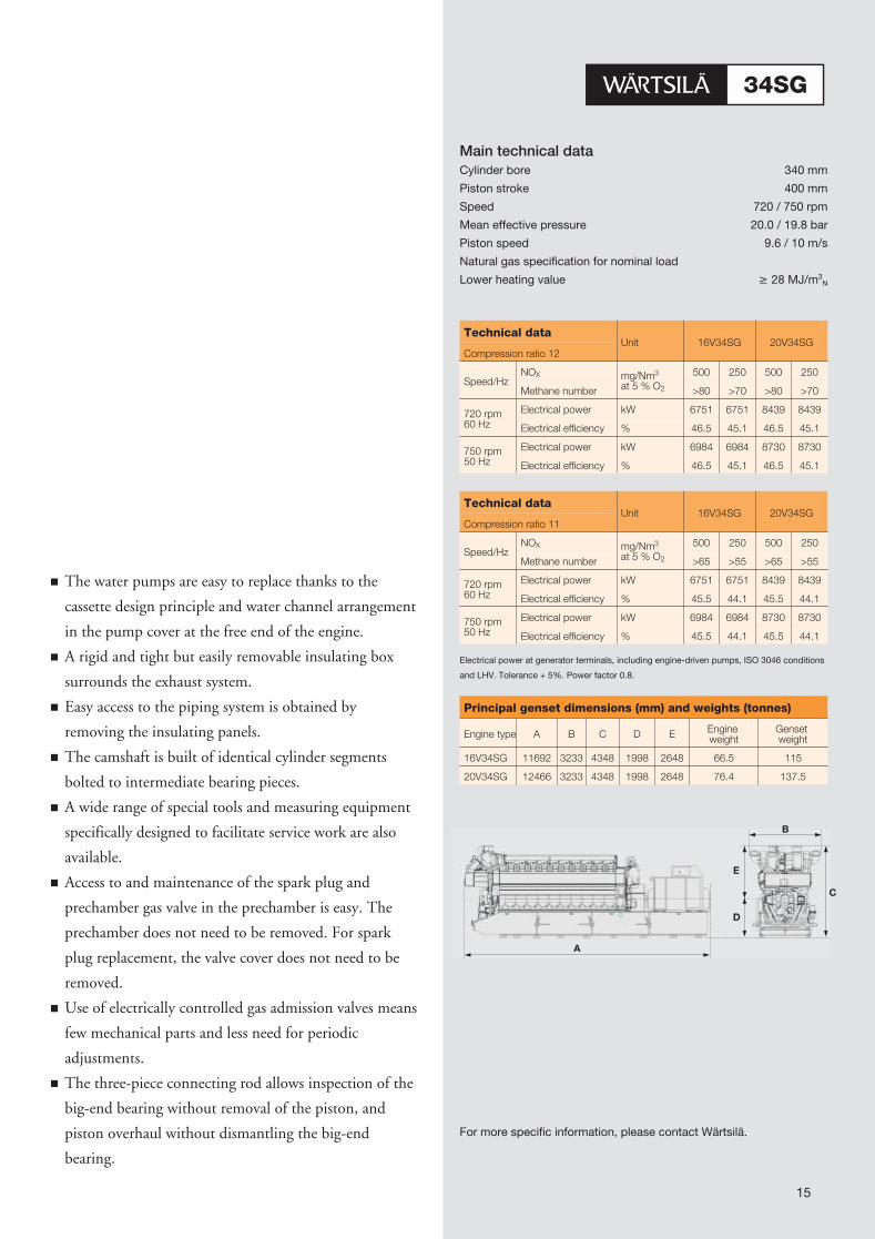
Main technical dataCylinder bore 340 mm
Piston stroke 400 mm
Speed 720 / 750 rpm
Mean effective pressure 20.0 / 19.8 bar
Piston speed 9.6 / 10 m/s
Natural gas specification for nominal load
Lower heating value � 28 MJ/m3N
Technical dataUnit 16V34SG 20V34SG
Compression ratio 12
Speed/HzNOX mg/Nm3
at 5 % O2
500 250 500 250
Methane number >80 >70 >80 >70
720 rpm60 Hz
Electrical power kW 6751 6751 8439 8439
Electrical efficiency % 46.5 45.1 46.5 45.1
750 rpm50 Hz
Electrical power kW 6984 6984 8730 8730
Electrical efficiency % 46.5 45.1 46.5 45.1
Technical dataUnit 16V34SG 20V34SG
Compression ratio 11
Speed/HzNOX mg/Nm3
at 5 % O2
500 250 500 250
Methane number >65 >55 >65 >55
720 rpm60 Hz
Electrical power kW 6751 6751 8439 8439
Electrical efficiency % 45.5 44.1 45.5 44.1
750 rpm50 Hz
Electrical power kW 6984 6984 8730 8730
Electrical efficiency % 45.5 44.1 45.5 44.1
Electrical power at generator terminals, including engine-driven pumps, ISO 3046 conditions
and LHV. Tolerance + 5%. Power factor 0.8.
Principal genset dimensions (mm) and weights (tonnes)
Engine type A B C D E Engineweight
Gensetweight
16V34SG 11692 3233 4348 1998 2648 66.5 115
20V34SG 12466 3233 4348 1998 2648 76.4 137.5
For more specific information, please contact Wärtsilä.
06.2
005
/B
ock´
sof
fice
/W
aasa
Gra
phi
cs
Wärtsilä Finland OyP.O.Box 252,FIN-65101 Vaasa, Finland
Tel: +358 10 709 0000Fax: +358 6 356 9133
Wärtsilä is a leading provider of power plants, operation and lifetime
care services in decentralized power generation.
Wärtsilä is The Ship Power Supplier for builders, owners and operators
of vessels and offshore installations. Our own global service network
takes complete care of customers’ ship machinery at every lifecycle
stage.
For more information visit www.wartsila.com
WÄRTSILÄ® is a registered trademark. Copyright © 2005 Wärtsilä Corporation.