Embed Size (px)
Citation preview
FLIGHT SYSTEMS®
ENGINE SAVER®
TEST SETMODEL 9550
MANUAL
REV 5/10 - Printed in USA
505 Fishing Creek Road Lewisberry, PA 17339 USAPhone: 717-932-9900 Fax: 717-932-9925 www.
flightsystems.com
® ENGINE SAVER and FLIGHT SYSTEMS are Registered Trade Marks of Flight Systems, Inc.
CONTENTS
1.0 Introduction 1
2.0 Description 2
2.1 General 2
2.2 Pulse Frequency Generation/Measurement 2
2.3 Engine RPM Measurement 2
2.4 DC Analog Outputs Measurement 2
2.5 Temperature Measurement 3
2.6 Simulation of Pressure Input 3
2.7 How to connect the Engine Saver to the Model 9550 Test Set (Photo Illustration) 4
3.0 Test procedure for – Model 550 Level 7 & 8 Engine Saver – Industrial & 5 Marine versions.
4.0 Repair Service and Calibration of the 9550 Test Set 11
5.0 Flight Systems Contact Information 11
6.0 New Product Warranty 13
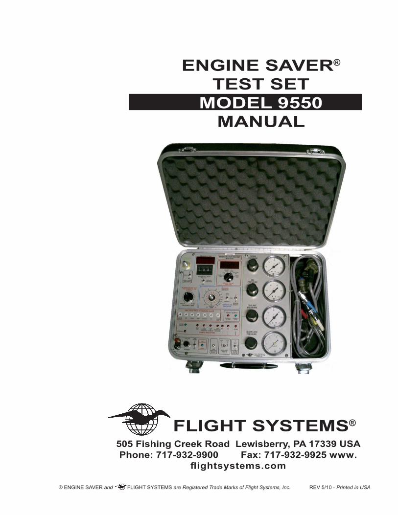
1.0 INTRODUCTIONThe Model 9550 Engine Saver Test Set was designed to provide the equipment OEM and fleet user with a con-venient means of testing, calibrating and troubleshooting the Engine Saver and other related engine protection products, components and accessories. The Model 9550 Test Set is compact and self-contained in an attractive and serviceable aluminum or fiberglass attaché case that weighs less than 20 pounds. All of the electronic and pneumatic components, as well as the hoses and electrical cable necessary for testing the 550 Engine Saver, are included. The only additional requirements are an air supply of 80 to 150 PSI, a source of 24 volts DC power at 1 amp, and a portable volt-ohmmeter.The present revision of this manual incorporates updated information reflecting the advances in the 550 Engine Saver through the many years it has been in reliable service to the industry. Thus, in order to stay up-to-date as possible and at the same time to keep this manual down to reasonable size, the emphasis here is on the current Level 8 in its original design, and in its Marine version.However, Flight Systems continues to provide Model 550 upgrade and test capability for earlier models of the Model 550 Level 7 Engine Saver by means of dual testing capability to test the 65 Coolant Temperature Sen-sor (P/N 57-5500-65) used with the PC board part numbers 57-5500-49A and B, and the 76 Coolant Tempera-ture Sensor (P/N 57-5500-76) used only for the 57-5500-49C Engine Saver PC board.
1
2.0 DESCRIPTION AND THEORY OF OPERATION
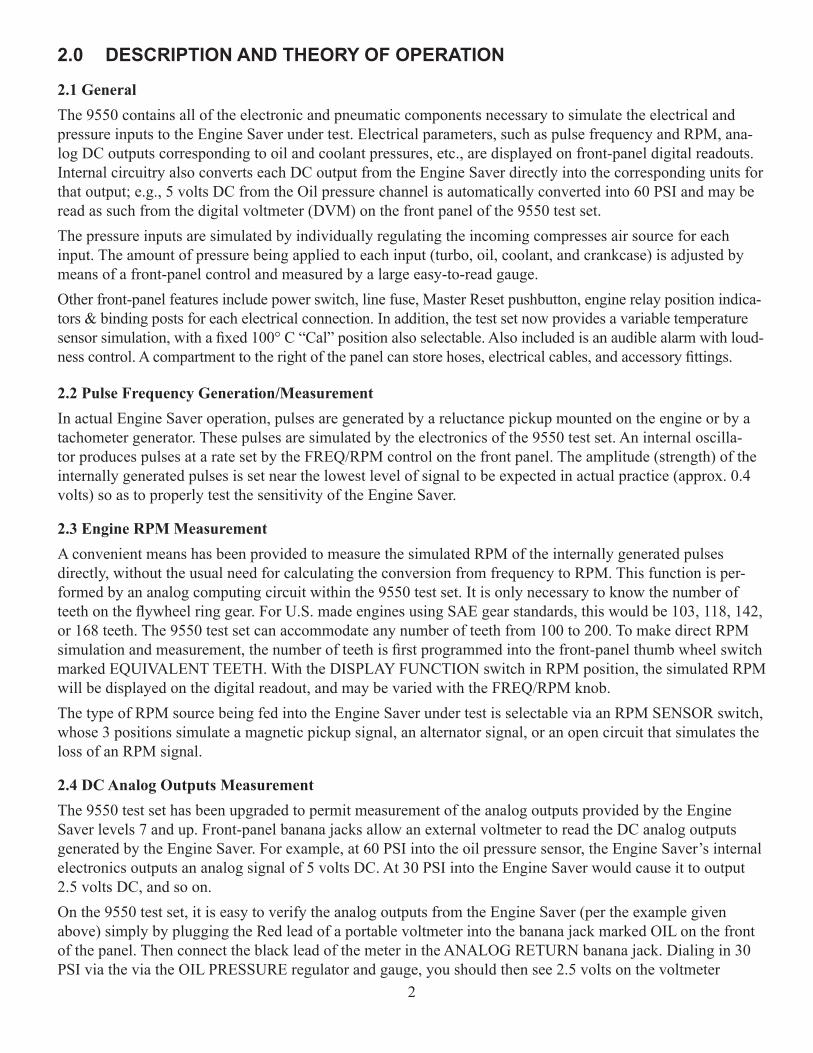
2.1 GeneralThe 9550 contains all of the electronic and pneumatic components necessary to simulate the electrical and pressure inputs to the Engine Saver under test. Electrical parameters, such as pulse frequency and RPM, ana-log DC outputs corresponding to oil and coolant pressures, etc., are displayed on front-panel digital readouts. Internal circuitry also converts each DC output from the Engine Saver directly into the corresponding units for that output; e.g., 5 volts DC from the Oil pressure channel is automatically converted into 60 PSI and may be read as such from the digital voltmeter (DVM) on the front panel of the 9550 test set.The pressure inputs are simulated by individually regulating the incoming compresses air source for each input. The amount of pressure being applied to each input (turbo, oil, coolant, and crankcase) is adjusted by means of a front-panel control and measured by a large easy-to-read gauge.Other front-panel features include power switch, line fuse, Master Reset pushbutton, engine relay position indica-tors & binding posts for each electrical connection. In addition, the test set now provides a variable temperature sensor simulation, with a fixed 100° C “Cal” position also selectable. Also included is an audible alarm with loud-ness control. A compartment to the right of the panel can store hoses, electrical cables, and accessory fittings.
2.2 Pulse Frequency Generation/MeasurementIn actual Engine Saver operation, pulses are generated by a reluctance pickup mounted on the engine or by a tachometer generator. These pulses are simulated by the electronics of the 9550 test set. An internal oscilla-tor produces pulses at a rate set by the FREQ/RPM control on the front panel. The amplitude (strength) of the internally generated pulses is set near the lowest level of signal to be expected in actual practice (approx. 0.4 volts) so as to properly test the sensitivity of the Engine Saver.
2.3 Engine RPM MeasurementA convenient means has been provided to measure the simulated RPM of the internally generated pulses directly, without the usual need for calculating the conversion from frequency to RPM. This function is per-formed by an analog computing circuit within the 9550 test set. It is only necessary to know the number of teeth on the flywheel ring gear. For U.S. made engines using SAE gear standards, this would be 103, 118, 142, or 168 teeth. The 9550 test set can accommodate any number of teeth from 100 to 200. To make direct RPM simulation and measurement, the number of teeth is first programmed into the front-panel thumb wheel switch marked EQUIVALENT TEETH. With the DISPLAY FUNCTION switch in RPM position, the simulated RPM will be displayed on the digital readout, and may be varied with the FREQ/RPM knob.The type of RPM source being fed into the Engine Saver under test is selectable via an RPM SENSOR switch, whose 3 positions simulate a magnetic pickup signal, an alternator signal, or an open circuit that simulates the loss of an RPM signal.
2.4 DC Analog Outputs MeasurementThe 9550 test set has been upgraded to permit measurement of the analog outputs provided by the Engine Saver levels 7 and up. Front-panel banana jacks allow an external voltmeter to read the DC analog outputs generated by the Engine Saver. For example, at 60 PSI into the oil pressure sensor, the Engine Saver’s internal electronics outputs an analog signal of 5 volts DC. At 30 PSI into the Engine Saver would cause it to output 2.5 volts DC, and so on.On the 9550 test set, it is easy to verify the analog outputs from the Engine Saver (per the example given above) simply by plugging the Red lead of a portable voltmeter into the banana jack marked OIL on the front of the panel. Then connect the black lead of the meter in the ANALOG RETURN banana jack. Dialing in 30 PSI via the via the OIL PRESSURE regulator and gauge, you should then see 2.5 volts on the voltmeter
2
In addition, the Model 9550 automatically converts the same 2.5 volts into PSI units that can be read directly off the front-panel DVM. Turning the DVM SELECT rotary switch to ANALOG OIL gives a reading of 30 PSI on the DVM display, in this case. The DC voltage for the 6 other parameters are converted to real-world values as well (Turbo and crankcase analog voltages are only present on the Marine version of the Model 550.)Note: RPM Readings on the DVM are RPM x 100, which means that 1800 RPM would appear as 180 on the DVM.
2.5 Temperature MeasurementThe 9550 test set provides for the testing of the Engine Saver’s Temp channel via a front-panel adjustment, simulating a temperature sensor, over a range of 50 to 180° C. I addition, the user may flip a switch to select a fixed 100° C reference in order to check the calibration of the variable temperature knob. A third switch simu-lates an open-circuit condition, which could be caused by an open wire or a bad sensor in the field.Also on the 9550 test set, you will find a selector switch that gives you the option to test the 65 (P/N 57-5500-65) or the 76 (P/N 57-CU66-76) Coolant Temperature sensors. The 65 sensor is used for the 57-5500-49A and B and the 76 sensor is used for the 57-500-49C Engine Saver boards (Note: The 49A and B designated AT-212 use the 76 sensor, but these are very rare.) If you install an Engine Saver board in a unit that is using the wrong sensor, you will experience an immediate trip on Coolant Temperature. The 49C has its identification stamped on the board face plate for your convenience.
2.6 Simulation of Pressure InputsA source of compressed air between 80 and 150 PSI is connected to the test set at the inlet marked AIR SUP-PLY. The incoming air is reduced by four separate regulators. Each regulator can be set by means of a control knob on the front panel of the test set. A gauge on the panel measures the air pressure applied to each input of the unit being tested. For the oil and coolant pressures, a range of 0 to 60 is available. Turbo pressure is variable from 0 to 30 PSI. The crankcase pressure input is limited to a maximum of 15 inches of water, in order to protect the test set gauge and transducer on Marine Engine Savers. If you find that the stock switch (10” H2O) is not suited for you application, we do stock 8 and 15” H2O switches. A flexible hose with quick-connect type coupler connects the test set to each of the 4 pressure inputs of the Engine Saver.The 9550 test set is designed to test not only the Model 550 level 7 and 8 Engine Savers, but also the pressure switches that are used with the Model 995 Engine Monitor, a special adapter is required, Flight Systems P/N 57-5500-10.
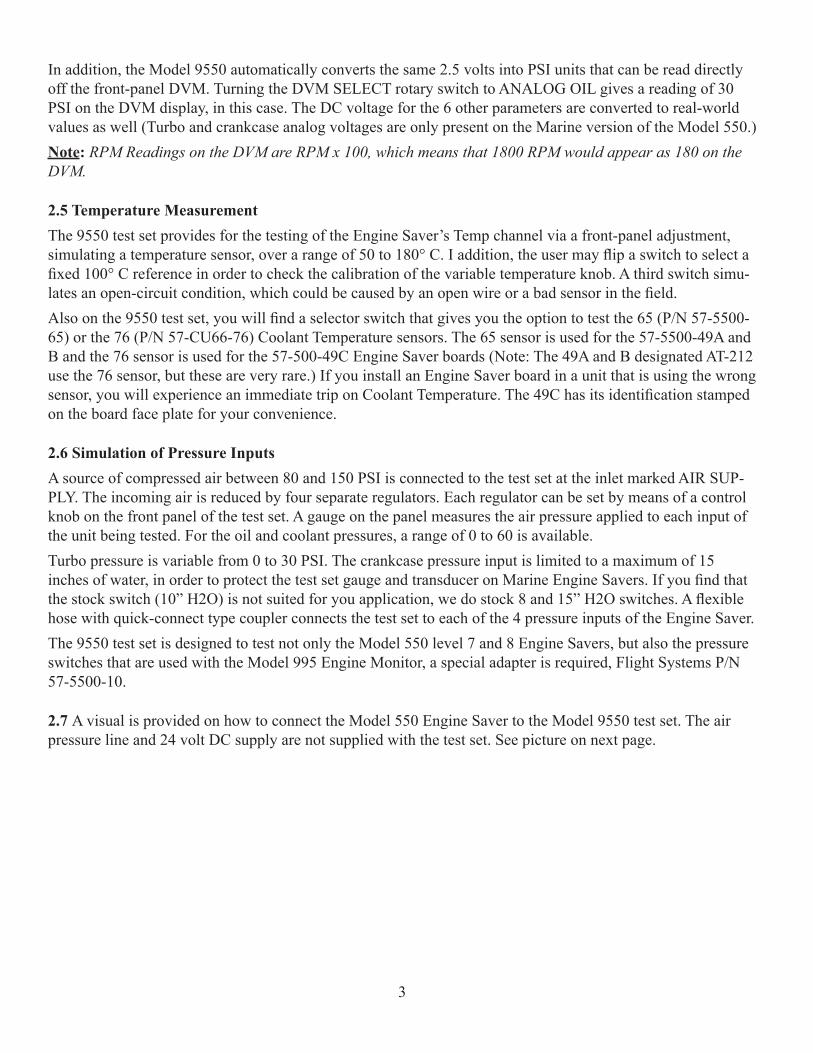
2.7 A visual is provided on how to connect the Model 550 Engine Saver to the Model 9550 test set. The air pressure line and 24 volt DC supply are not supplied with the test set. See picture on next page.
3
4
3.0 TEST PROCEDUREThe Model 9550 test set will test any level 7 and 8 Engine Saver, as well as the Model 565 Engine Controller with the appropriate harness adaptors. Equipment required that is not supplied:- Regulated 80 PSI air supply- 24 Volt DC power supply- Volt-Ohmmeter- Potentiometer adjustment tool or 1/8” slotted screw driverFactory preset trip settings:All new units are preset at the factory; repairs are only set to factory presets when the unit is completely re-built. A list of factory presets is either taped to the lid of the Model 550 or there is a label on the anti-static bag for the Engine Saver board.We suggest that you periodically calibrate your 9550 test set with a new Level 8 Model 550 due to the fact that transporting the test set can misalign the adjustments.Note: The markings around the adjustments on the Engine Saver board are for reference only and should not be used for calibration.
Prepare Test Set for Testing• Set pressure gauges to zero, turn counter clockwise.• Set temperature sensor to 65 (49A or B) or 76 (49C.)• Connect regulated air supply to the test set.• Set RPM sensor to MAG.• Set Analog display function to RPM.• Set Equivalent Teeth dials (See page 13 of the Engine Saver manual for more details)• Set FREQ/RPM knob to zero.• Set the Temperature switch VARIABLE.• Set variable temperature to 80°C.• Set display function to RPM.• Set AUXILIARY INPUT switch to off (center)• Set ALARM switch to low.
1. Thread Quick Connect adapters into the pressure ports on the back of the Engine Saver.2. Connect Main, Accessory, and Auxiliary test set cables to the Engine Saver.3. Connect only the Turbo and Crankcase pressure lines.4. Set Coolant Pressure gauge to 30 PSI.5. Set Oil Pressure gauge to 50 PSI.6. Turn on the main power switch of the test set; the RELAY OUTPUT should have the NORMALLY CLOSED red LED lit.
5
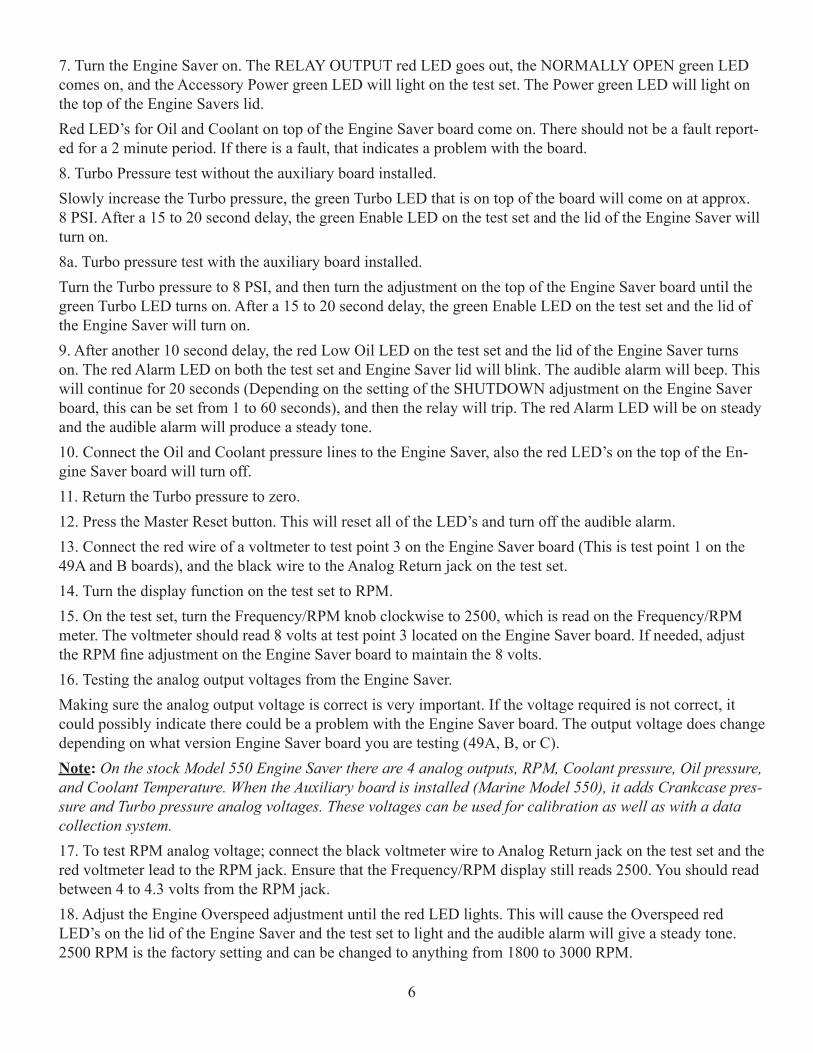
7. Turn the Engine Saver on. The RELAY OUTPUT red LED goes out, the NORMALLY OPEN green LED comes on, and the Accessory Power green LED will light on the test set. The Power green LED will light on the top of the Engine Savers lid.Red LED’s for Oil and Coolant on top of the Engine Saver board come on. There should not be a fault report-ed for a 2 minute period. If there is a fault, that indicates a problem with the board.8. Turbo Pressure test without the auxiliary board installed.Slowly increase the Turbo pressure, the green Turbo LED that is on top of the board will come on at approx. 8 PSI. After a 15 to 20 second delay, the green Enable LED on the test set and the lid of the Engine Saver will turn on.8a. Turbo pressure test with the auxiliary board installed. Turn the Turbo pressure to 8 PSI, and then turn the adjustment on the top of the Engine Saver board until the green Turbo LED turns on. After a 15 to 20 second delay, the green Enable LED on the test set and the lid of the Engine Saver will turn on.9. After another 10 second delay, the red Low Oil LED on the test set and the lid of the Engine Saver turns on. The red Alarm LED on both the test set and Engine Saver lid will blink. The audible alarm will beep. This will continue for 20 seconds (Depending on the setting of the SHUTDOWN adjustment on the Engine Saver board, this can be set from 1 to 60 seconds), and then the relay will trip. The red Alarm LED will be on steady and the audible alarm will produce a steady tone. 10. Connect the Oil and Coolant pressure lines to the Engine Saver, also the red LED’s on the top of the En-gine Saver board will turn off.11. Return the Turbo pressure to zero.12. Press the Master Reset button. This will reset all of the LED’s and turn off the audible alarm.13. Connect the red wire of a voltmeter to test point 3 on the Engine Saver board (This is test point 1 on the 49A and B boards), and the black wire to the Analog Return jack on the test set.14. Turn the display function on the test set to RPM.15. On the test set, turn the Frequency/RPM knob clockwise to 2500, which is read on the Frequency/RPM meter. The voltmeter should read 8 volts at test point 3 located on the Engine Saver board. If needed, adjust the RPM fine adjustment on the Engine Saver board to maintain the 8 volts.16. Testing the analog output voltages from the Engine Saver.Making sure the analog output voltage is correct is very important. If the voltage required is not correct, it could possibly indicate there could be a problem with the Engine Saver board. The output voltage does change depending on what version Engine Saver board you are testing (49A, B, or C). Note: On the stock Model 550 Engine Saver there are 4 analog outputs, RPM, Coolant pressure, Oil pressure, and Coolant Temperature. When the Auxiliary board is installed (Marine Model 550), it adds Crankcase pres-sure and Turbo pressure analog voltages. These voltages can be used for calibration as well as with a data collection system.17. To test RPM analog voltage; connect the black voltmeter wire to Analog Return jack on the test set and the red voltmeter lead to the RPM jack. Ensure that the Frequency/RPM display still reads 2500. You should read between 4 to 4.3 volts from the RPM jack.18. Adjust the Engine Overspeed adjustment until the red LED lights. This will cause the Overspeed red LED’s on the lid of the Engine Saver and the test set to light and the audible alarm will give a steady tone. 2500 RPM is the factory setting and can be changed to anything from 1800 to 3000 RPM.
6
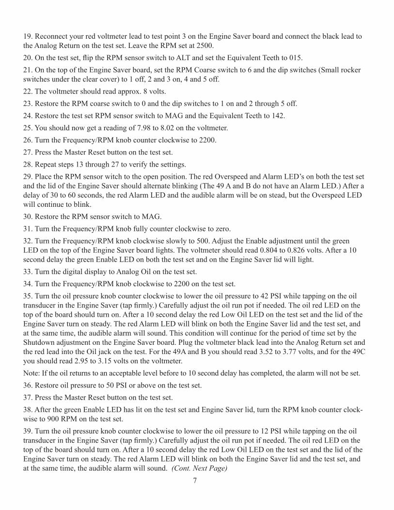
19. Reconnect your red voltmeter lead to test point 3 on the Engine Saver board and connect the black lead to the Analog Return on the test set. Leave the RPM set at 2500.20. On the test set, flip the RPM sensor switch to ALT and set the Equivalent Teeth to 015.21. On the top of the Engine Saver board, set the RPM Coarse switch to 6 and the dip switches (Small rocker switches under the clear cover) to 1 off, 2 and 3 on, 4 and 5 off.22. The voltmeter should read approx. 8 volts.23. Restore the RPM coarse switch to 0 and the dip switches to 1 on and 2 through 5 off.24. Restore the test set RPM sensor switch to MAG and the Equivalent Teeth to 142.25. You should now get a reading of 7.98 to 8.02 on the voltmeter.26. Turn the Frequency/RPM knob counter clockwise to 2200.27. Press the Master Reset button on the test set.28. Repeat steps 13 through 27 to verify the settings.29. Place the RPM sensor witch to the open position. The red Overspeed and Alarm LED’s on both the test set and the lid of the Engine Saver should alternate blinking (The 49 A and B do not have an Alarm LED.) After a delay of 30 to 60 seconds, the red Alarm LED and the audible alarm will be on stead, but the Overspeed LED will continue to blink.30. Restore the RPM sensor switch to MAG.31. Turn the Frequency/RPM knob fully counter clockwise to zero.32. Turn the Frequency/RPM knob clockwise slowly to 500. Adjust the Enable adjustment until the green LED on the top of the Engine Saver board lights. The voltmeter should read 0.804 to 0.826 volts. After a 10 second delay the green Enable LED on both the test set and on the Engine Saver lid will light.33. Turn the digital display to Analog Oil on the test set.34. Turn the Frequency/RPM knob clockwise to 2200 on the test set.35. Turn the oil pressure knob counter clockwise to lower the oil pressure to 42 PSI while tapping on the oil transducer in the Engine Saver (tap firmly.) Carefully adjust the oil run pot if needed. The oil red LED on the top of the board should turn on. After a 10 second delay the red Low Oil LED on the test set and the lid of the Engine Saver turn on steady. The red Alarm LED will blink on both the Engine Saver lid and the test set, and at the same time, the audible alarm will sound. This condition will continue for the period of time set by the Shutdown adjustment on the Engine Saver board. Plug the voltmeter black lead into the Analog Return set and the red lead into the Oil jack on the test. For the 49A and B you should read 3.52 to 3.77 volts, and for the 49C you should read 2.95 to 3.15 volts on the voltmeter.Note: If the oil returns to an acceptable level before to 10 second delay has completed, the alarm will not be set.36. Restore oil pressure to 50 PSI or above on the test set.37. Press the Master Reset button on the test set.38. After the green Enable LED has lit on the test set and Engine Saver lid, turn the RPM knob counter clock-wise to 900 RPM on the test set.39. Turn the oil pressure knob counter clockwise to lower the oil pressure to 12 PSI while tapping on the oil transducer in the Engine Saver (tap firmly.) Carefully adjust the oil run pot if needed. The oil red LED on the top of the board should turn on. After a 10 second delay the red Low Oil LED on the test set and the lid of the Engine Saver turn on steady. The red Alarm LED will blink on both the Engine Saver lid and the test set, and at the same time, the audible alarm will sound. (Cont. Next Page)
7
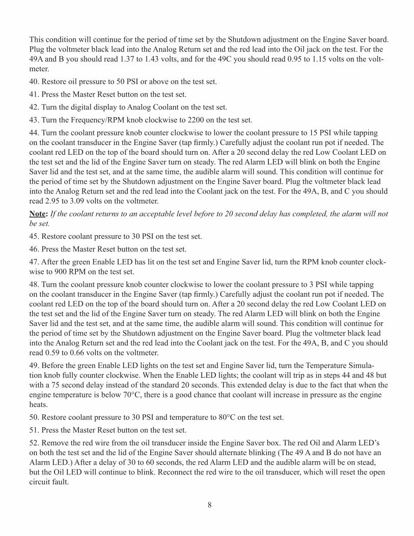
This condition will continue for the period of time set by the Shutdown adjustment on the Engine Saver board. Plug the voltmeter black lead into the Analog Return set and the red lead into the Oil jack on the test. For the 49A and B you should read 1.37 to 1.43 volts, and for the 49C you should read 0.95 to 1.15 volts on the volt-meter.40. Restore oil pressure to 50 PSI or above on the test set.41. Press the Master Reset button on the test set.42. Turn the digital display to Analog Coolant on the test set.43. Turn the Frequency/RPM knob clockwise to 2200 on the test set.44. Turn the coolant pressure knob counter clockwise to lower the coolant pressure to 15 PSI while tapping on the coolant transducer in the Engine Saver (tap firmly.) Carefully adjust the coolant run pot if needed. The coolant red LED on the top of the board should turn on. After a 20 second delay the red Low Coolant LED on the test set and the lid of the Engine Saver turn on steady. The red Alarm LED will blink on both the Engine Saver lid and the test set, and at the same time, the audible alarm will sound. This condition will continue for the period of time set by the Shutdown adjustment on the Engine Saver board. Plug the voltmeter black lead into the Analog Return set and the red lead into the Coolant jack on the test. For the 49A, B, and C you should read 2.95 to 3.09 volts on the voltmeter.Note: If the coolant returns to an acceptable level before to 20 second delay has completed, the alarm will not be set.45. Restore coolant pressure to 30 PSI on the test set.46. Press the Master Reset button on the test set.47. After the green Enable LED has lit on the test set and Engine Saver lid, turn the RPM knob counter clock-wise to 900 RPM on the test set.48. Turn the coolant pressure knob counter clockwise to lower the coolant pressure to 3 PSI while tapping on the coolant transducer in the Engine Saver (tap firmly.) Carefully adjust the coolant run pot if needed. The coolant red LED on the top of the board should turn on. After a 20 second delay the red Low Coolant LED on the test set and the lid of the Engine Saver turn on steady. The red Alarm LED will blink on both the Engine Saver lid and the test set, and at the same time, the audible alarm will sound. This condition will continue for the period of time set by the Shutdown adjustment on the Engine Saver board. Plug the voltmeter black lead into the Analog Return set and the red lead into the Coolant jack on the test. For the 49A, B, and C you should read 0.59 to 0.66 volts on the voltmeter.49. Before the green Enable LED lights on the test set and Engine Saver lid, turn the Temperature Simula-tion knob fully counter clockwise. When the Enable LED lights; the coolant will trip as in steps 44 and 48 but with a 75 second delay instead of the standard 20 seconds. This extended delay is due to the fact that when the engine temperature is below 70°C, there is a good chance that coolant will increase in pressure as the engine heats. 50. Restore coolant pressure to 30 PSI and temperature to 80°C on the test set.51. Press the Master Reset button on the test set. 52. Remove the red wire from the oil transducer inside the Engine Saver box. The red Oil and Alarm LED’s on both the test set and the lid of the Engine Saver should alternate blinking (The 49 A and B do not have an Alarm LED.) After a delay of 30 to 60 seconds, the red Alarm LED and the audible alarm will be on stead, but the Oil LED will continue to blink. Reconnect the red wire to the oil transducer, which will reset the open circuit fault.
8
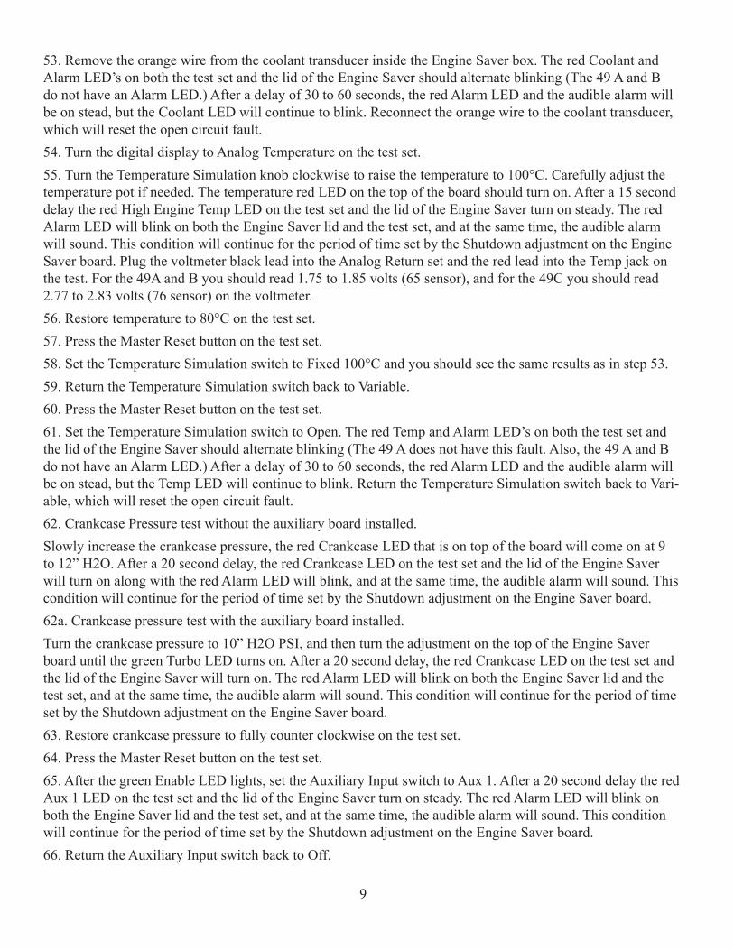
53. Remove the orange wire from the coolant transducer inside the Engine Saver box. The red Coolant and Alarm LED’s on both the test set and the lid of the Engine Saver should alternate blinking (The 49 A and B do not have an Alarm LED.) After a delay of 30 to 60 seconds, the red Alarm LED and the audible alarm will be on stead, but the Coolant LED will continue to blink. Reconnect the orange wire to the coolant transducer, which will reset the open circuit fault.54. Turn the digital display to Analog Temperature on the test set.55. Turn the Temperature Simulation knob clockwise to raise the temperature to 100°C. Carefully adjust the temperature pot if needed. The temperature red LED on the top of the board should turn on. After a 15 second delay the red High Engine Temp LED on the test set and the lid of the Engine Saver turn on steady. The red Alarm LED will blink on both the Engine Saver lid and the test set, and at the same time, the audible alarm will sound. This condition will continue for the period of time set by the Shutdown adjustment on the Engine Saver board. Plug the voltmeter black lead into the Analog Return set and the red lead into the Temp jack on the test. For the 49A and B you should read 1.75 to 1.85 volts (65 sensor), and for the 49C you should read 2.77 to 2.83 volts (76 sensor) on the voltmeter. 56. Restore temperature to 80°C on the test set.57. Press the Master Reset button on the test set.58. Set the Temperature Simulation switch to Fixed 100°C and you should see the same results as in step 53.59. Return the Temperature Simulation switch back to Variable.60. Press the Master Reset button on the test set. 61. Set the Temperature Simulation switch to Open. The red Temp and Alarm LED’s on both the test set and the lid of the Engine Saver should alternate blinking (The 49 A does not have this fault. Also, the 49 A and B do not have an Alarm LED.) After a delay of 30 to 60 seconds, the red Alarm LED and the audible alarm will be on stead, but the Temp LED will continue to blink. Return the Temperature Simulation switch back to Vari-able, which will reset the open circuit fault.62. Crankcase Pressure test without the auxiliary board installed. Slowly increase the crankcase pressure, the red Crankcase LED that is on top of the board will come on at 9 to 12” H2O. After a 20 second delay, the red Crankcase LED on the test set and the lid of the Engine Saver will turn on along with the red Alarm LED will blink, and at the same time, the audible alarm will sound. This condition will continue for the period of time set by the Shutdown adjustment on the Engine Saver board.62a. Crankcase pressure test with the auxiliary board installed.Turn the crankcase pressure to 10” H2O PSI, and then turn the adjustment on the top of the Engine Saver board until the green Turbo LED turns on. After a 20 second delay, the red Crankcase LED on the test set and the lid of the Engine Saver will turn on. The red Alarm LED will blink on both the Engine Saver lid and the test set, and at the same time, the audible alarm will sound. This condition will continue for the period of time set by the Shutdown adjustment on the Engine Saver board.63. Restore crankcase pressure to fully counter clockwise on the test set.64. Press the Master Reset button on the test set.65. After the green Enable LED lights, set the Auxiliary Input switch to Aux 1. After a 20 second delay the red Aux 1 LED on the test set and the lid of the Engine Saver turn on steady. The red Alarm LED will blink on both the Engine Saver lid and the test set, and at the same time, the audible alarm will sound. This condition will continue for the period of time set by the Shutdown adjustment on the Engine Saver board.66. Return the Auxiliary Input switch back to Off.
9
67. Press the Master Reset button on the test set.68. After the green Enable LED lights, set the Auxiliary Input switch to Aux 2. After a 20 second delay the red Aux 2 LED on the test set and the lid of the Engine Saver turn on steady. The red Alarm LED will blink on both the Engine Saver lid and the test set, and at the same time, the audible alarm will sound. This condition will continue for the period of time set by the Shutdown adjustment on the Engine Saver board.69. Return the Auxiliary Input switch back to Off.70. Press the Master Reset button on the test set.71. Turn of test set.72. Disconnect all pressure hoses.73. Unthread Quick Connect adapters from the pressure ports on the back of the Engine Saver.74. Disconnect Main, Accessory, and Auxiliary test set cables from the Engine Saver.End of Test
10
DESIGNED, MANUFACTURED AND SERVICED BY
FLIGHT SYSTEMS, INC. 505 Fishing Creek Road Dock 16 Lewisberry, PA 17339 USA
Tel: 717-932-9900 Sales: Anthony Misiti [email protected] (US Toll-Free: 800 403 3728) Spare Parts: Josh Leeds [email protected] Fax: 717-932-9925 Tech. Support: Steve Wida [email protected] (US Toll-Free: 800-333-9912) Bob Hinkleman [email protected] 8-5 ET, M-F www.flightsystems.com Management: Bob Shaffner [email protected]
4.0 REPAIR SERVICE / PARTS/TECHNICAL SUPPORT The Engine Saver Test Set is fully rebuildable. Service, Parts and Technical Support can be obtained throughout the world. Applications assistance is likewise available through the locations listed below and on the following page.
5.0 SALES AND SERVICE LOCATIONS
EASTERN CANADADaniel DiCesar3535 Breard Street Brossard, QC J4Z 2E3 Canada Tel: 450-656-0344Email: [email protected]
FACTORY REPRESENTATIVES
• SEE FOLLOWING PAGE FOR US, CANADIAN & INTERNATIONAL INSTALLING DISTRIBUTORS
GERMANYKlaus-Josef RossfeldtFriedensstr. 11 D-58239 Schwerte GermanyTel: + 49 (0) 2304 14436Alt: + 49 174 490 4899Email: [email protected]
NORTHWEST USAHarold Bailey, Pirate Energy 14703 Oceanview Drive #I-1 Harbor, OR 97415 Tel 541 251 1323 Fax 888 449 0667Email: [email protected]
ONTARIO, CANADAGary Logan Emergency Energy Products Ltd. 99 West Drive, Unit C Brampton, Ontario L6T 2J6 Canada Phone: l 877 354 5102 Fax: 905 274 7281 Email: [email protected]
11
CANADA
Western Canada:Cummins British Columbia18452 96th Avenue Surrey. British Columbia V3T 4W2, Canada Tel: 604-882-5000 Fax: 604-882-5080 Contact: Phil Dunn
Eastern Canada:Cummins Eastern Canada7200 Trans Canada Hwy Pt. Claire, Quebec H9R 1C2, Canada Tel: 514-695-8410 Fax: 514-695-9012 Contact: Lucien Fredette
Central Canada:Cummins Alberta14755 - 121A Avenue Edmonton, Alta T5L 2T2, Canada Tel: 403-455-2151Fax: 403-454-9512 Contact: Colin Carmichael
UNITED STATES
Northeastern USA:Rhode Island Engine Co. Inc.79 State St. / PO Box 543 Narragansett, RI 02882-0543 Tel: 401-789-1021Fax: 401-789-1066 Contact: David AllardWebsite: www.RIEngine.com
Southwestern USA:Cummins Southwest2339 N. Black Canyon Hwy P.O. Box 6688 Phoenix, AZ 85009 Tel: 602-252-8021Fax: 602-253-6725 Contact: Steve Ryberg
West Coast USA:Cummins Intermountain5370 East Idaho Street Elko, NV 89801 Tel: 702-738-6405 Contact: Tom Bland
INSTALLING DISTRIBUTORS FOR FLIGHT SYSTEMS
MARINE & INDUSTRIAL CONTROLS
INTERNATIONAL
If no distributor listed for a particular region or country, contact Flight Systems Inc. (On preceding page)
West/Central Africa, Incl. DR, Congo, Zambia:Pinnacle EngineeringHouse Number I/S 47 Site 18, Community OneTema, Ghana AfricaTel: 233 223 11225Contact: Bridge Adams Eshun [email protected]
Australia:Norman G. Clark (A/Asia) Pty. LTDP.O. Box 281 West Heidelberg, Victoria 3081 Australia Tel: (01161) 3 9457 5833 Fax: (01161) 3 9457 5781 Contact: Rob Clark Website: www.ngclark.com.au
Thailand:Daven Co. LTD 126/43 Soi Wat Ku Chang Wattana Rd Pakkred Notaburi 11120 Thailand Tel: 66 2 964 0878 Fax: 66 2 964 0879 Contact: Pote Pasoog [email protected]
12
The MODEL 9550 ENGINE SAVER® TEST SET is warranted to be free from defects in materials and workmanship for a period of two years from the date of shipment, or the date it is first put into service, if the latter is documented.
FLIGHT SYSTEMS’ liability is limited to the repair of replacement of defective product within the warranty period, and does not cover installation or removal costs incurred or possible damage to other equipment (including engines or parts thereof) as a result of a malfunction of the ENGINE SAVER TEST SET.
If, in the opinion of FLIGHT SYSTEMS (or its authorized agent) the malfunction of the ENGINE SAVER TEST SET was caused by abuse, misuse or improper installation, the warranty claim will be disallowed and established repair rates shall apply.
Units should be shipped, freight charges prepaid, directly to FLIGHT SYSTEMS, 505 Fishing Creek Rd, Lewisberry, PA 17339 USA Attn: M & I Repair Dock 16, or any of the authorized agents listed in this publication (see preceding pages).
13
6.0 NEW PRODUCT WARRANTY