Embed Size (px)
Citation preview
Engine Monitoring and Performance ControlDevelopment at MTU Aero Engines
Wolfgang Horn, André Kando, Jürgen Mathes
3rd NASA GRC Propulsion Controls and Diagnostics Workshop
Cleveland, February 29 2012
29 February 2012 Wolfgang Horn Engine Monitoring and Performance Control Development at MTU Aero Engines 2
Agenda
• Introduction
• Active Systems
• Model-Based Control
• Commercial Engine Condition Monitoring
29 February 2012 Wolfgang Horn Engine Monitoring and Performance Control Development at MTU Aero Engines 3Introduct ion
• Introduction
• Active Systems
• Model-Based Control
• Commercial Engine Condition Monitoring
Chapter Break
29 February 2012 Wolfgang Horn Engine Monitoring and Performance Control Development at MTU Aero Engines 4
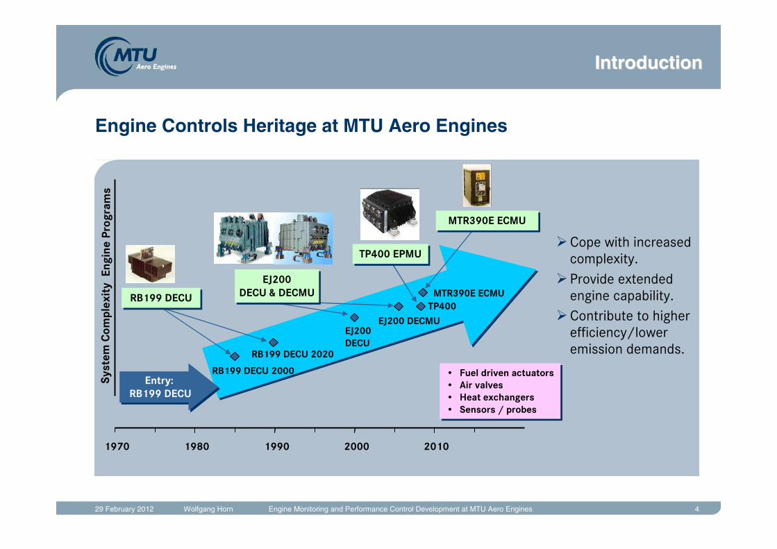
Engine Controls Heritage at MTU Aero Engines
1970 1980 1990 2000 2010
RB199 DECU 2000
EJ200 DECMU
Syst
em C
o mpl
exit
y E
n gin
e Pr
o gra
ms
TP400
Entry: RB199 DECU
Entry: RB199 DECU
RB199 DECU 2020
EJ200 DECU
MTR390E ECMURB199 DECURB199 DECU
EJ200 DECU & DECMU
EJ200 DECU & DECMU
TP400 EPMUTP400 EPMU
MTR390E ECMUMTR390E ECMU
• Fuel driven actuators• Air valves• Heat exchangers• Sensors / probes
• Fuel driven actuators• Air valves• Heat exchangers• Sensors / probes
�Cope with increased complexity.
�Provide extended engine capability.
�Contribute to higher efficiency/lower emission demands.
IntroductionIntroduction
29 February 2012 Wolfgang Horn Engine Monitoring and Performance Control Development at MTU Aero Engines 5
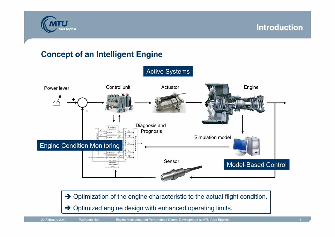
Concept of an Intelligent Engine
+
-
Filter 1
Filter 2
Filter i
Filter m
Filter m+1
...... Fe
hler
erke
nnun
g
y
u
y1
y2
yi
ym
1y
2y
iy
my
1ˆ +my
ℜ1
ℜ2
ℜi
ℜm
ℜm+1
HypotheseSensorfehler
HypotheseAktuator-/
Komponenten-fehler
gew
icht
ete
Sum
me
Res
idue
n
Sign
alau
fber
eitu
ng
� Optimization of the engine characteristic to the actual flight condition.
� Optimized engine design with enhanced operating limits.
� Optimization of the engine characteristic to the actual flight condition.
� Optimized engine design with enhanced operating limits.
Power lever Control unit Actuator Engine
Simulation model
Diagnosis and Prognosis
Sensor
Active Systems
Model-Based Control
Engine Condition Monitoring
IntroductionIntroduction
29 February 2012 Wolfgang Horn Engine Monitoring and Performance Control Development at MTU Aero Engines 6Active Systems
• Introduction
• Active Systems
• Model-Based Control
• Commercial Engine Condition Monitoring
Chapter Break
29 February 2012 Wolfgang Horn Engine Monitoring and Performance Control Development at MTU Aero Engines 7
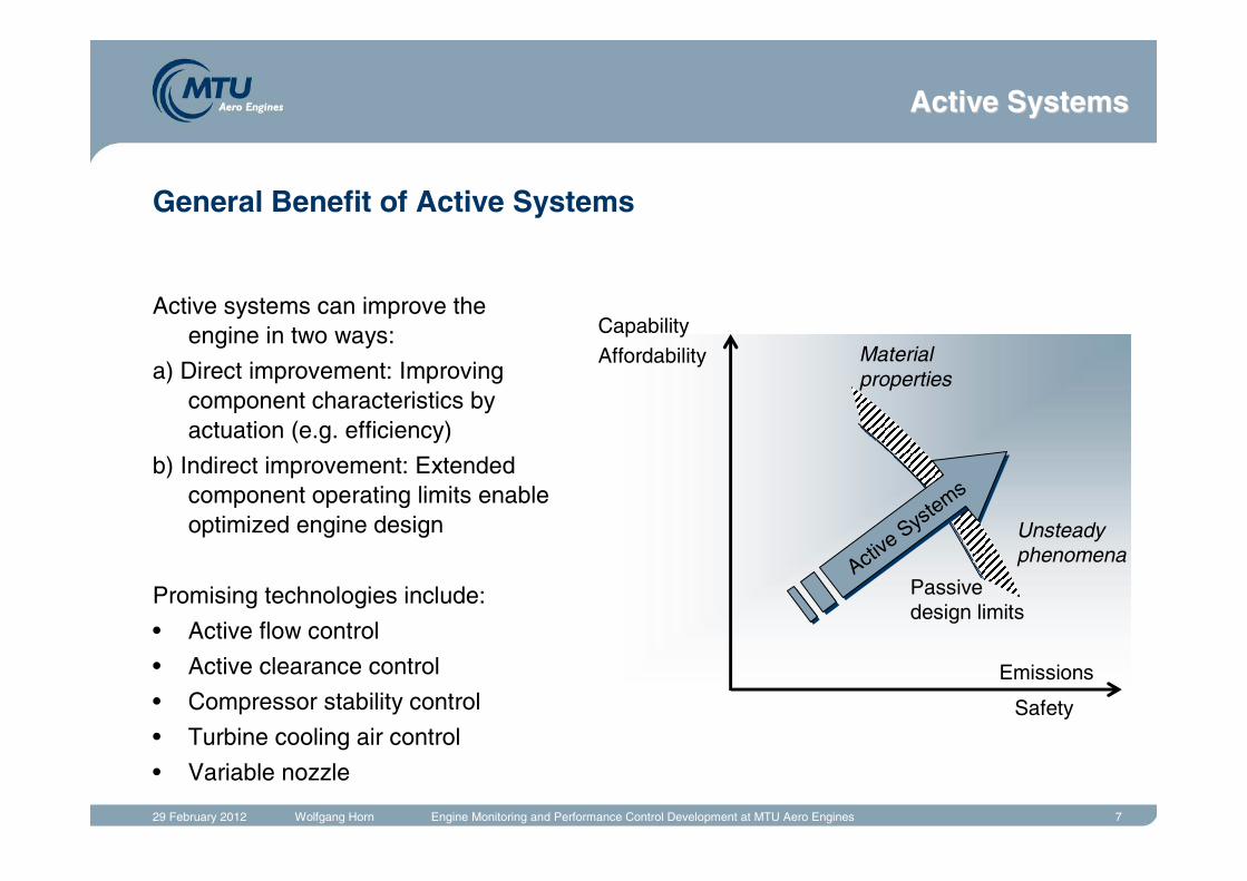
General Benefit of Active Systems
Active systems can improve the engine in two ways:
a) Direct improvement: Improving component characteristics by actuation (e.g. efficiency)
b) Indirect improvement: Extended component operating limits enable optimized engine design
Promising technologies include:
• Active flow control
• Active clearance control
• Compressor stability control
• Turbine cooling air control
• Variable nozzle
CapabilityAffordability
Emissions
Safety
Active
Systems
Active
Systems
Passive design limits
Material properties
Unsteadyphenomena
Active SystemsActive Systems
29 February 2012 Wolfgang Horn Engine Monitoring and Performance Control Development at MTU Aero Engines 8
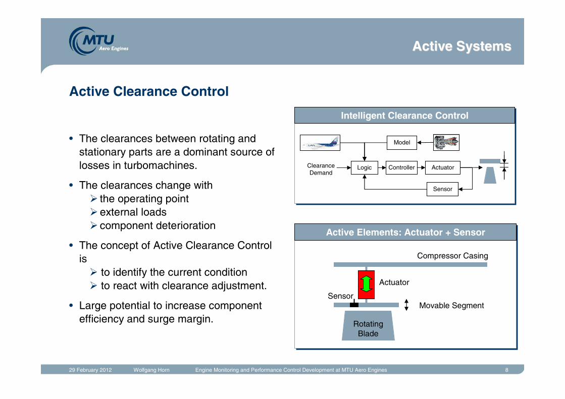
Active Clearance Control
• The clearances between rotating and stationary parts are a dominant source of losses in turbomachines.
• The clearances change with� the operating point�external loads� component deterioration
• The concept of Active Clearance Control is� to identify the current condition� to react with clearance adjustment.
• Large potential to increase component efficiency and surge margin.
Intelligent Clearance Control
Logic Controller Actuator
Sensor
Model
Clearance Demand
Actuator
Compressor Casing
Movable Segment
RotatingBlade
Sensor
Active Elements: Actuator + Sensor
Active SystemsActive Systems
29 February 2012 Wolfgang Horn Engine Monitoring and Performance Control Development at MTU Aero Engines 9
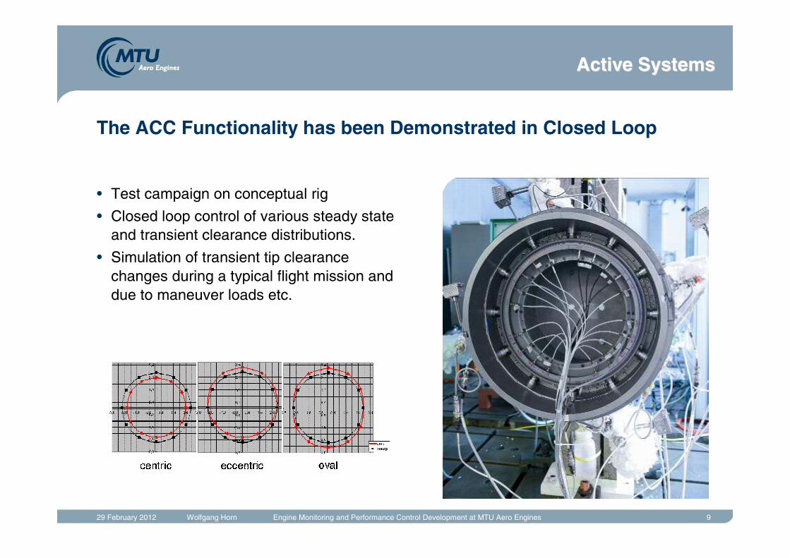
The ACC Functionality has been Demonstrated in Closed Loop
• Test campaign on conceptual rig
• Closed loop control of various steady state and transient clearance distributions.
• Simulation of transient tip clearance changes during a typical flight mission and due to maneuver loads etc.
Active SystemsActive Systems
29 February 2012 Wolfgang Horn Engine Monitoring and Performance Control Development at MTU Aero Engines 10
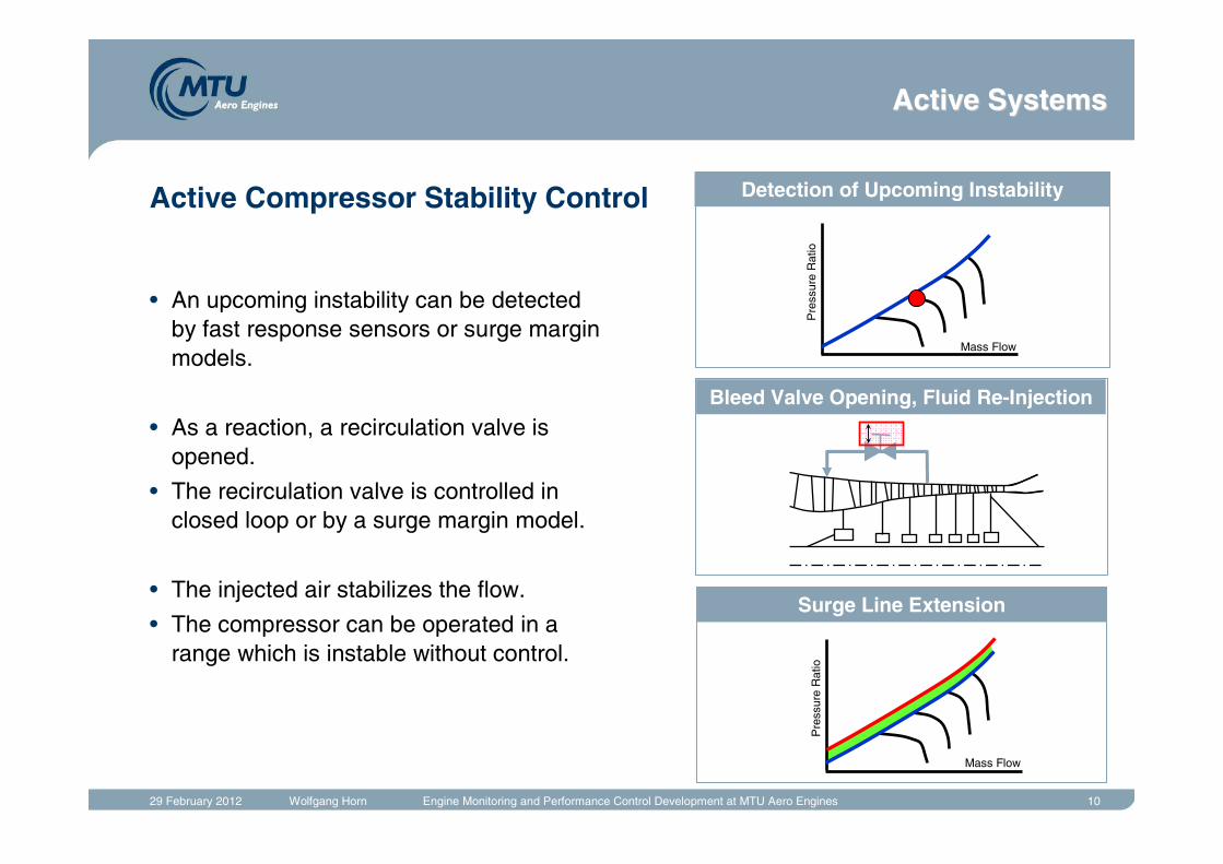
Active Compressor Stability Control
• An upcoming instability can be detected by fast response sensors or surge margin models.
• As a reaction, a recirculation valve is opened.
• The recirculation valve is controlled in closed loop or by a surge margin model.
• The injected air stabilizes the flow.
• The compressor can be operated in a range which is instable without control.
Detection of Upcoming Instability
Bleed Valve Opening, Fluid Re-Injection
Surge Line Extension
Pre
ssur
e R
atio
Mass Flow
Pre
ssur
e R
atio
Mass Flow
Active SystemsActive Systems
29 February 2012 Wolfgang Horn Engine Monitoring and Performance Control Development at MTU Aero Engines 11
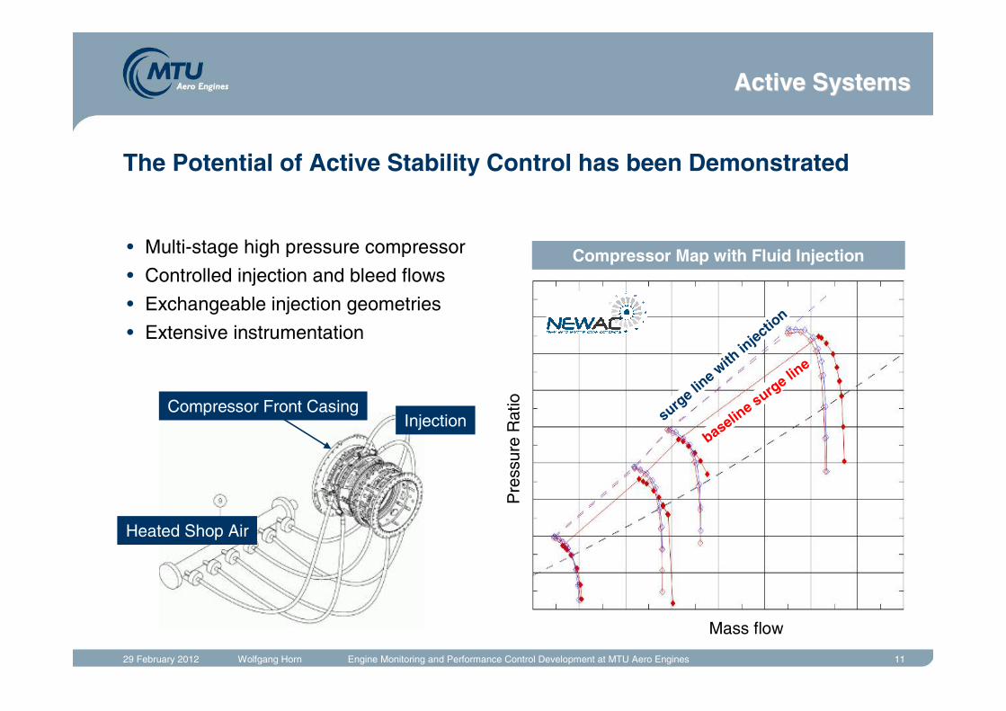
The Potential of Active Stability Control has been Demonstrated
Mass flow
Pre
ssur
e R
atio
surge lin
e with
injectio
n
baseline surg
e line
Heated Shop Air
InjectionCompressor Front Casing
• Multi-stage high pressure compressor
• Controlled injection and bleed flows
• Exchangeable injection geometries
• Extensive instrumentation
Compressor Map with Fluid Injection
Active SystemsActive Systems
29 February 2012 Wolfgang Horn Engine Monitoring and Performance Control Development at MTU Aero Engines 12
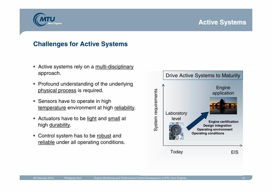
Challenges for Active Systems
• Active systems rely on a multi-disciplinaryapproach.
• Profound understanding of the underlying physical process is required.
• Sensors have to operate in hightemperature environment at high reliability.
• Actuators have to be light and small at high durability.
• Control system has to be robust and reliable under all operating conditions.
Sys
tem
req
uire
men
ts
Laboratorylevel
Engine application
Engine certificationDesign integration
Operating environmentOperating conditions
Today EIS
Drive Active Systems to Maturity
Active SystemsActive Systems
29 February 2012 Wolfgang Horn Engine Monitoring and Performance Control Development at MTU Aero Engines 13Model-Based Control
• Introduction
• Active Systems
• Model-Based Control
• Commercial Engine Condition Monitoring
Chapter Break
Active SystemsActive Systems
29 February 2012 Wolfgang Horn Engine Monitoring and Performance Control Development at MTU Aero Engines 14
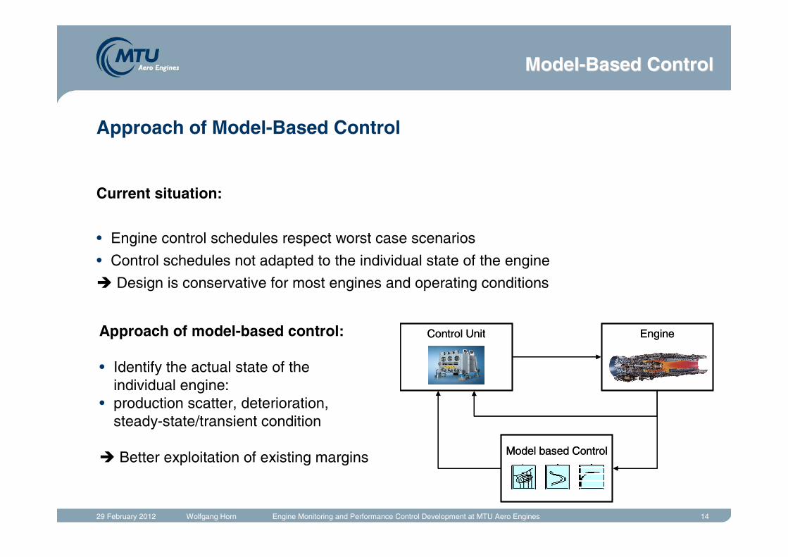
Approach of Model-Based Control
Current situation:
• Engine control schedules respect worst case scenarios
• Control schedules not adapted to the individual state of the engine
� Design is conservative for most engines and operating conditions
EngineControl Unit
Model based Control
EngineControl Unit
Model based Control
Approach of model-based control:
• Identify the actual state of the individual engine:
• production scatter, deterioration, steady-state/transient condition
� Better exploitation of existing margins
ModelModel--Based ControlBased Control
29 February 2012 Wolfgang Horn Engine Monitoring and Performance Control Development at MTU Aero Engines 15
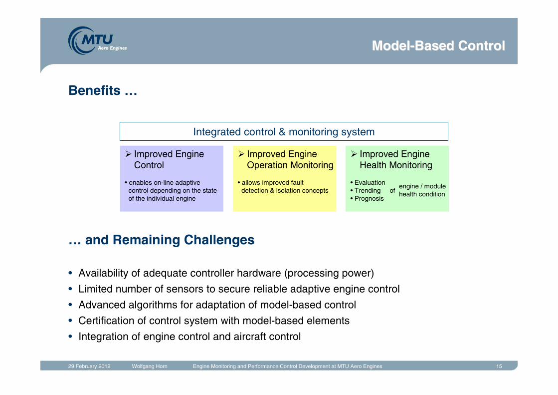
Benefits …
… and Remaining Challenges
• Availability of adequate controller hardware (processing power)
• Limited number of sensors to secure reliable adaptive engine control
• Advanced algorithms for adaptation of model-based control
• Certification of control system with model-based elements
• Integration of engine control and aircraft control
� Improved Engine Control
• enables on-line adaptivecontrol depending on the stateof the individual engine
� Improved Engine Operation Monitoring
• allows improved faultdetection & isolation concepts
� Improved EngineHealth Monitoring
• Evaluation• Trending of • Prognosis
engine / modulehealth condition
Integrated control & monitoring system
ModelModel--Based ControlBased Control
29 February 2012 Wolfgang Horn Engine Monitoring and Performance Control Development at MTU Aero Engines 16Commercial Engine Condition Monitoring
• Introduction
• Active Systems
• Model-Based Control
• Commercial Engine Condition Monitoring
Chapter Break
29 February 2012 Wolfgang Horn Engine Monitoring and Performance Control Development at MTU Aero Engines 17
Sho
p M
aint
enan
ce(O
ff-W
ing)
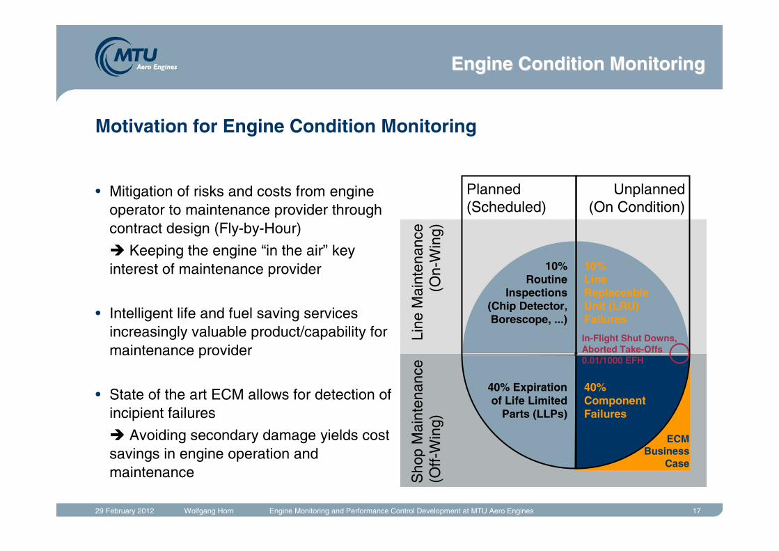
ECMBusiness
Case
• Mitigation of risks and costs from engine operator to maintenance provider through contract design (Fly-by-Hour)
� Keeping the engine “in the air” key interest of maintenance provider
• Intelligent life and fuel saving services increasingly valuable product/capability for maintenance provider
• State of the art ECM allows for detection of incipient failures
� Avoiding secondary damage yields cost savings in engine operation and maintenance
Motivation for Engine Condition Monitoring
Line
Mai
nten
ance
(On-
Win
g)
Planned(Scheduled)
Unplanned(On Condition)
10%Routine
Inspections(Chip Detector,Borescope, ...)
10%LineReplaceableUnit (LRU)Failures
40% Expirationof Life Limited
Parts (LLPs)
40%ComponentFailures
In-Flight Shut Downs,Aborted Take-Offs0.01/1000 EFH
Engine Condition MonitoringEngine Condition Monitoring
29 February 2012 Wolfgang Horn Engine Monitoring and Performance Control Development at MTU Aero Engines 18
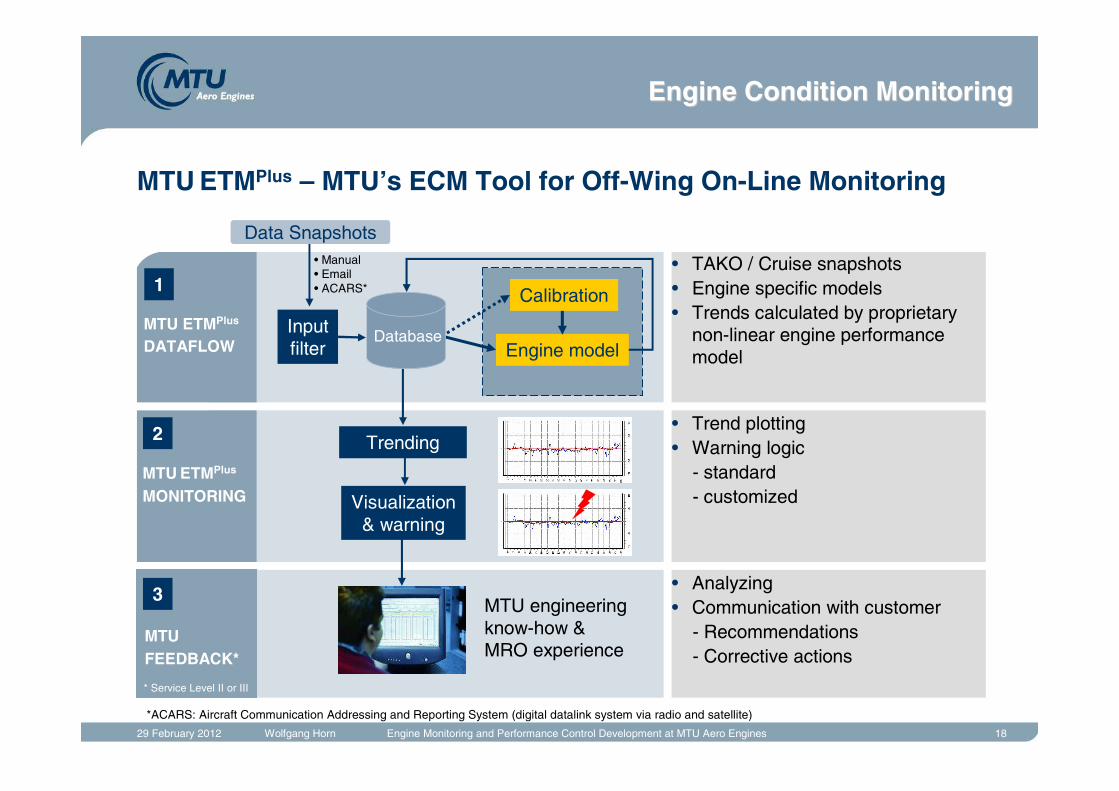
MTU ETMPlus – MTU’s ECM Tool for Off-Wing On-Line Monitoring
• Manual• Email• ACARS*
Inputfilter
Calibration
Engine model
Trending
Visualization & warning
Data Snapshots
1
2
3
MTU ETMPlus
DATAFLOW
MTU ETMPlus
MONITORING
MTU engineeringknow-how &MRO experience
Database
MTUFEEDBACK*
* Service Level II or III
*ACARS: Aircraft Communication Addressing and Reporting System (digital datalink system via radio and satellite)
• TAKO / Cruise snapshots• Engine specific models• Trends calculated by proprietary
non-linear engine performance model
• Analyzing• Communication with customer
- Recommendations- Corrective actions
• Trend plotting• Warning logic
- standard- customized
Engine Condition MonitoringEngine Condition Monitoring
29 February 2012 Wolfgang Horn Engine Monitoring and Performance Control Development at MTU Aero Engines 19
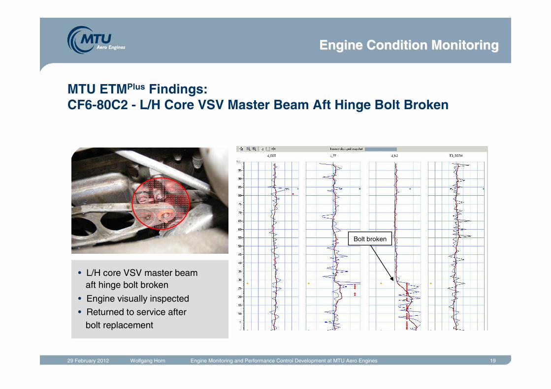
MTU ETMPlus Findings:CF6-80C2 - L/H Core VSV Master Beam Aft Hinge Bolt Broken
• L/H core VSV master beam aft hinge bolt broken
• Engine visually inspected
• Returned to service after bolt replacement
Bolt broken
Engine Condition MonitoringEngine Condition Monitoring
29 February 2012 Wolfgang Horn Engine Monitoring and Performance Control Development at MTU Aero Engines 20
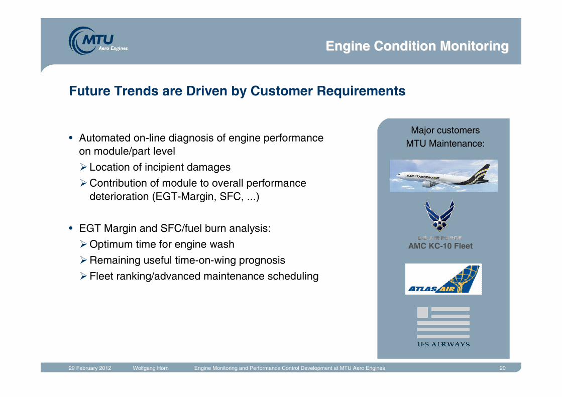
Future Trends are Driven by Customer Requirements
• Automated on-line diagnosis of engine performance on module/part level
�Location of incipient damages
�Contribution of module to overall performance deterioration (EGT-Margin, SFC, ...)
• EGT Margin and SFC/fuel burn analysis:
�Optimum time for engine wash
�Remaining useful time-on-wing prognosis
�Fleet ranking/advanced maintenance scheduling
Major customers MTU Maintenance:
AMC KC-10 Fleet
Engine Condition MonitoringEngine Condition Monitoring
29 February 2012 Wolfgang Horn Engine Monitoring and Performance Control Development at MTU Aero Engines 21
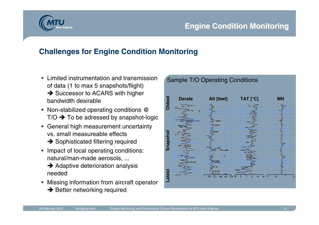
Challenges for Engine Condition Monitoring
• Limited instrumentation and transmission of data (1 to max 5 snapshots/flight)� Successor to ACARS with higher bandwidth desirable
• Non-stabilized operating conditions @ T/O � To be adressed by snapshot-logic
• General high measurement uncertainty vs. small measureable effects � Sophisticated filtering required
• Impact of local operating conditions: natural/man-made aerosols, ...� Adaptive deterioration analysis needed
• Missing information from aircraft operator � Better networking required
Sample T/O Operating Conditions
Derate Alt [feet] TAT [°C] MN
Lat
est
Old
est
Sn
apsh
ot
Engine Condition MonitoringEngine Condition Monitoring
29 February 2012 Wolfgang Horn Engine Monitoring and Performance Control Development at MTU Aero Engines 22
Conclusion
• Enhanced engine performance controls and diagnostics offer the opportunity to
� improve engine operation
� improve engine design
� improve maintenance action.
• Diagnostic algorithms still have development potential with benefits for manufacturers and customers.
• Technologies for active systems and model-based control have been identified and developed on a laboratory level.
• Technology enhancements for the transition to certifiable engines will be required.