Embed Size (px)
Citation preview

Engine MechanicalService Manual
5.7L

This Page WasIntentionally Left
Blank

Engine Engine Mechanical - 5.7L 6-1
2001 Marine/Industrial
Engine Mechanical - 5.7LSpecifications
Fastener Tightening Specifications
Specification
Application Metric English
Accelerator Control Cable Bracket Bolt and Nut 12 N•m 106 lb in
Belt Idler Pulley Bolt 50 N•m 37 lb ft
Camshaft Retainer Bolt 12 N•m 106 lb in
Camshaft Sprocket Bolt 25 N•m 18 lb ft
Connecting Rod Nut
First Pass 27 N•m 20 lb ft
Final Pass 55 degrees
Crankshaft Balancer Bolt 95 N•m 70 lb ft
Crankshaft Bearing Cap Bolt and Stud (Preferred Method)
First Pass (Two Bolt Type Bearing Cap) 20 N•m 15 lb ft
Final Pass (Two Bolt Type Bearing Cap) 73 degrees
First Pass (Four Bolt Type Bearing Cap) 20 N•m 15 lb ft
Final Pass Outboard Bolt (Four Bolt Type Bearing Cap) 43 degrees
Final Pass Inboard Bolt and Stud (Four Bolt Type Bearing Cap) 73 degrees
Crankshaft Bearing Cap Bolt and Stud (Optional Strategy)
Two Bolt Type Bearing Cap 105 N•m 77 lb ft
Inboard Bolt and Stud (Four Bolt Type Bearing Cap) 105 N•m 77 lb ft
Outboard Bolt (Four Bolt Type Bearing Cap) 90 N•m 66 lb ft
Crankshaft Oil Deflector Nut 40 N•m 30 lb ft
Crankshaft Position Sensor Bolt 9 N.m 80 lb in
Crankshaft Pulley Bolt 58 N.m 43 lb ft
Crankshaft Rear Oil Seal Housing Nut and Bolt 12 N.m 106 lb ft
Crankshaft Rear Oil Seal Housing Retainer Stud 6 N•m 53 lb in
Cylinder Head Bolt (Preferred Method)
All Bolts First Pass in Sequence 30 N•m 22 lb ft
Long Bolts Final Pass in Sequence 75 degrees
Medium Bolts Final Pass in Sequence 65 degrees
Short Bolts Final Pass in Sequence 55 degrees
Cylinder Head Bolt (Optional On-Vehicle Stategy)
First Pass in Sequence 35 N.m 26 lb ft
Second Pass in Sequence 60 N.m 44 lb ft
Final Pass in Sequence 90 N.m 66 lb ft
Cylinder Head Core Hole Plug 20 N•m 15 lb ft
Distributor Cap Bolt 2.4 N•m 21 lb in
Distributor Clamp Bolt 25 N•m 18 lb ft
Drive Belt Tensioner Bolt 50 N•m 37 lb ft
EGR Valve Bolt
First Pass 10 N•m 89 lb in
Final Pass 30 N•m 22 lb ft

6-2 Engine Mechanical - 5.7L Engine
2001 Marine/Industrial
Fastener Tightening Specifications (cont’d)
Specification
Application Metric English
EGR Valve Pipe Nut at Intake Manifold 25 N•m 18 lb ft
EGR Valve Pipe Nut at Exhaust Manifold 30 N•m 22 lb ft
EGR Valve Pipe Clamp Bracket Bolt 25 N•m 18 lb ft
Engine Block Coolant Drain Hole Plug 20 N•m 15 lb ft
Engine Block Oil Gallery Plug 20 N•m 15 lb ft
Engine Coolant Temperature (ECT) Sensor 20 N•m 15 lb ft
Engine Flywheel Bolt 100 N•m 74 lb ft
Engine Front Cover Bolt 12 N•m 106 lb in
Engine Lift Bracket Bolt (Special Tool J 41427) 15 N•m 11 lb ft
Engine Lift Front Bracket Stud 35 N•m 26 lb ft
Engine Mount Bolt (Through-bolt) to Engine Mount Bracket 95 N•m 70 lb ft
Engine Mount Bolt to Engine Mount Frame Bracket 58 N•m 43 lb ft
Engine Mount Bracket Bolt to Engine 54 N•m 40 lb ft
Engine Mount Bracket Bolt to Frame 45 N•m 33 lb ft
Engine Mount Heat Shield to Engine Mount Bracket 6 N•m 53 lb in
Engine Mount Nut (Through-Bolt) 68 N•m 50 lb ft
Engine Oil Pressure Gauge Sensor 30 N•m 22 lb ft
Engine Oil Pressure Gauge Sensor Fitting (Plus Required Angle) 15 N•m 11 lb ft
Engine Wiring Harness Bracket Nut 12 N•m 106 lb in
Evaporitive Emission (EVAP) Canister Purge Solenoid Valve Stud 10 N•m 89 lb in
Exhaust Manifold Bolt
First Pass 15 N•m 11 lb ft
Final Pass 30 N•m 22 lb ft
Fan and Water Pump Pulley Bolt 25 N•m 18 lb ft
Fuel Pipe Bracket Bolt 6 N•m 53 lb in
Fuel Pipe Retainer Nut 3 N•m 27 lb in
Generator and Drive Belt Tensioner Bracket Bolt and Nut to Engine 41 N•m 30 lb ft
Generator and Drive Belt Tensioner Bracket Stud to Engine 20 N•m 15 lb ft
Ignition Coil Stud 12 N•m 106 lb in
Knock Sensor 20 N•m 15 lb ft
Lower Intake Manifold Bolt
First Pass in Sequence 3 N•m 27 lb in
Second Pass in Sequence 12 N•m 106 lb in
Final Pass in Sequence 15 N•m 11 lb ft
Oil Filter Adapter Bolt 25 N•m 18 lb ft
Oil Filter Fitting 35 N•m 26 lb ft
Oil Level Indicator Tube Bolt 25 N•m 18 lb ft
Oil Pan Drain Plug 25 N•m 18 lb ft
Oil Pan Stud (Front) 6 N•m 53 lb in
Oil Pan Stud Nut 25 N•m 18 lb ft
Oil Pan Bolt or Stud 12 N•m 106 lb in
Oil Pump Bolt to Rear Crankshaft Bearing Cap
Engine Engine Mechanical - 5.7L 6-3
2001 Marine/Industrial
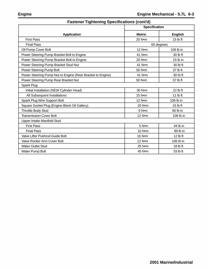
Fastener Tightening Specifications (cont’d) Specification
Application Metric English
First Pass 20 N•m 15 lb ft
Final Pass 65 degrees
Oil Pump Cover Bolt 12 N•m 106 lb in
Power Steering Pump Bracket Bolt to Engine 41 N•m 30 lb ft
Power Steering Pump Bracket Bolt to Engine 20 N•m 15 lb in
Power Steering Pump Bracket Stud Nut 41 N•m 30 lb ft
Power Steering Pump Bolt 50 N•m 37 lb ft
Power Steering Pump Nut to Engine (Rear Bracket to Engine) 41 N•m 30 lb ft
Power Steering Pump Rear Bracket Nut 50 N•m 37 lb ft
Spark Plug
Initial Installation (NEW Cylinder Head) 30 N•m 22 lb ft
All Subsequent Installations 15 N•m 11 lb ft
Spark Plug Wire Support Bolt 12 N•m 106 lb in
Square Socket Plug (Engine Block Oil Gallery) 20 N•m 15 lb ft
Throttle Body Stud 9 N•m 80 lb in
Transmission Cover Bolt 12 N•m 106 lb in
Upper Intake Manifold Stud
First Pass 5 N•m 44 lb in
Final Pass 10 N•m 89 lb in
Valve Lifter Pushrod Guide Bolt 16 N•m 12 lb ft
Valve Rocker Arm Cover Bolt 12 N•m 106 lb in
Water Outlet Stud 25 N•m 18 lb ft
Water Pump Bolt 45 N•m 33 lb ft

6-4 Engine Mechanical - 5.7L Engine
2001 Marine/Industrial
Engine Mechanical Specifications
Specification Application Metric English
General Data
Engine Type V8
Displacement 5.7L 350 CID
RPO (VIN Code) L31 (R)
Bore 101.63 mm 4.0012 in
Stroke 88.39 mm 3.480 in
Compression Ratio 9.4:1
Firing Order 1-8-4-3-6-5-7-2
Spark Plug Gap 1.52 mm 0.060 in
42 kPa at 6.0 psig at1,000 engine rpm 1,000 engine rpm
Oil Pressure (Minimum) at Normal Operating Temperature 125 kPa at 18.0 psig at2,000 engine rpm 2,000 engine rpm
166 kPa at 24.0 psig at4,000 engine rpm 4,000 engine rpm
Camshaft
End Play 0.05-0.30 mm 0.002-0.012 in
Journal Diameter 47.440-47.490 mm 1.8677-1.8696 in
Journal Diameter Out-of-Round 0.025 mm (Maximum) 0.0010 in (Maximum)
Lobe Lift (Exhaust) 7.20-7.30 mm 0.283-0.287 in
Lobe Lift (Intake) 6.97-7.07 mm 0.274-0.278 in
Runout 0.065 mm (Maximum) 0.0026 in (Maximum)
Connecting Rod
Connecting Rod Bearing Clearance (Production) 0.033-0.078 mm 0.0013-0.0031 in
Connecting Rod Bearing Clearance (Service) 0.025-0.063 mm 0.0010-0.0025 in
Connecting Rod Side Clearance 0.15-0.68 mm 0.006-0.027 in
Connecting Rod Journal Diameter 53.304-53.334 mm 2.0986-2.0998 in
Connecting Rod Journal Taper (Production) 0.007 mm (Maximum) 0.0003 in (Maximum)
Connecting Rod Journal Taper (Service) 0.025 mm (Maximum) 0.0010 in (Maximum)
Connecting Rod Journal Out-of-Round (Production) 0.007 mm (Maximum) 0.0003 in (Maximum)
Connecting Rod Journal Out-of-Round (Service) 0.025 mm (Maximum) 0.0010 in (Maximum)
Crankshaft
Crankshaft Bearing Clearance (Journal #1-Production) 0.018-0.053 mm 0.0007-0.0021 in
Crankshaft Bearing Clearance (Journal #2, #3 and #4-Production) 0.030-0.068mm 0.0012-0.0027 in
Crankshaft Bearing Clearance (Journal #5-Production) 0.020-0.060 mm 0.0008-0.0024 in
Crankshaft Bearing Clearance (Journal #1-Service) 0.025-0.051 mm 0.0010-0.0020 in
Crankshaft Bearing Clearance (Journal #2, #3 and #4-Service) 0.025-0.064 mm 0.0010-0.025 in
Crankshaft Bearing Clearance (Journal #5-Service) 0.038-0.063 mm 0.0015-0.0025 in
Crankshaft End Play 0.050-0.20 mm 0.002-0.008 in
Crankshaft Journal Diameter (Journal #1) 62.189-62.212 mm 2.4484-2.4493 in
Crankshaft Journal Diameter (Journal #2 and #3) 62.181-62.207 mm 2.4481-2.4491 in
Crankshaft Journal Diameter (Journal #5) 62.185-62.207 mm 2.4482-2.4491 in
Crankshaft Journal Out-of-Round (Production) 0.005 mm (Maximum) 0.0002 in (Maximum)
Crankshaft Journal Out-of-Round (Service) 0.025 mm (Maximum) 0.0010 in (Maximum)
Crankshaft Journal Taper (Production) 0.005 mm (Maximum) 0.0002 in (Maximum)
Crankshaft Journal Taper (Service) 0.025 mm (Maximum) 0.0010 in (Maximum)
Crankshaft Runout at Rear Flange 0.038mm (Maximum) 0.0015 in (Maximum)
Cylinder Bore
Diameter 101.618-101.643 mm 4.0007-4.0017 in
Out-of-Round (Production) 0.025 mm (Maximum) 0.0010 in (Maximum)
Out-of-Round (Service) 0.05 mm (Maximum) 0.002 in (Maximum)
Taper (Production-Relief Side) 0.025 mm (Maximum) 0.0010 in (Maximum)

Engine Engine Mechanical - 5.7L 6-5
2001 Marine/Industrial
Taper (Production-Thrust Side) 0.012 mm (Maximum) 0.0005 in (Maximum)
Taper (Service Limit) 0.025 mm (Maximum) 0.0010 in (Maximum)
Cylinder Head
Surface Flatness (Engine Block Deck) 0.10 mm (Maximum) 0.004 in (Maximum)
Surface Flatness (Exhaust Manifold Deck) 0.05 mm (Maximum) 0.002 in (Maximum)
Surface Flatness (Intake Manifold Deck) 0.10 mm (Maximum) 0.004 in (Maximum)
Exhaust Manifold
Surface Flatness (Flange to Flange) 0.25 mm (Maximum) 0.010 in (Maximum)
Surface Flatness (Individual Flange) 0.05 mm (Maximum) 0.002 in (Maximum)
Piston
Piston Bore Clearance (Production) 0.018-0.053 mm 0.0007-0.002 in
Piston Bore Clearance (Service) 0.018-0.053 mm 0.0007-0.002 in
Piston Pin
Clearance in Piston (Production) 0.013-0.023 mm 0.0005-0.0009 in
Clearance in Piston (Service) 0.013-0.025 mm 0.0005-0.0010 in
Diameter 23.545-23.548 mm 0.9270-0.9271 in
Fit in Connecting Rod 0.021-0.040 mm 0.0008-0.0016 in(Interference) (Interference)
Piston Rings (End Gap Measured in Cylinder Bore)
Piston Compression Ring Gap (Production-Top Groove) 0.25-0.40 mm 0.098-0.015 in
Piston Compression Ring Gap (Production- 2nd Groove) 0.46-0.66 mm 0.018-0.025 in
Piston Compression Ring Gap (Service -Top Groove) 0.25-0.50 mm 0.009-0.019 in
Piston Compression Ring Gap (Service - 2nd Groove) 0.46-0.80 mm 0.018-0.031 in
Piston Compression Ring Groove Clearance (Production-Top Groove) 0.030-0.070 mm 0.0012-0.0027 in
Piston Compression Ring Groove Clearance (Production- 2nd Groove) 0.040-0.080 mm 0.0015-0.003 in
Piston Compression Ring Groove Clearance (Service-Top Groove) 0.030-0.090 mm 0.0012-0.0035 in
Piston Compression Ring Groove Clearance (Service-2nd Groove) 0.040-0.100 mm 0.0015-0.0040 in
Piston Oil Ring Gap (Production) 0.25-0.76 mm 0.009-0.029 in
Piston Oil Ring Gap (Service) 0.25-0.90 mm 0.009-0.035 in
Piston Oil Ring Groove Clearance (Production) 0.046-0.096 mm 0.0018-0.0037 in
Piston Oil Ring Groove Clearance (Service) 0.046-0.100 mm 0.0018-0.0039 in
Valve System
Valve Face Angle 45 Degrees
Valve Head Edge Margin 0.79 mm (Minimum) 0.031 in (Minimum)
Valve Lash Rotate the Valve Rocker Arm Nut Clockwise360 degrees (1 Turn) from Zero Lash
Valve Lifter Hydraulic Roller
Valve Rocker Arm Ratio 1.5:1
Valve Seat Angle 46 Degrees
Valve Seat Runout 0.05 mm (Maximum) 0.002 in (Maximum)
Valve Seat Width (Exhaust-Heavy Duty) 1.50-2.56 mm 0.059-0.101 in
Valve Seat Width (Exhaust-Light Duty) 1.65-2.49 mm 0.065-0.098 in
Valve Seat Width (Intake) 1.02-1.65 mm 0.040-0.065 in
Valve Spring Free Length 51.3 mm 2.02 in
Valve Spring Installed Height (Exhaust) 42.92-43.43 mm 1.67-1.70 in
Valve Spring Installed Height (Intake) 42.92-43.43 mm 1.67-1.70 in
Valve Spring Pressure (Closed) 338-374 N at 43.2 mm 76-84 lb at 1.70 in
Valve Spring Pressure (Open) 832-903 N at 32.3 mm 187-203 lb at 1.27 in
Valve Stem Clearance (Exhaust-Production) 0.025-0.069 mm 0.0010-0.0027 in
Valve Stem Clearance (Intake-Production) 0.025-0.069 mm 0.0010-0.0027 in
Valve Stem Clearance (Exhaust-Service) 0.025-0.094 mm 0.0010-0.0037 in
Valve Stem Clearance (Intake-Service) 0.025-0.094 mm 0.0010-0.0037 in
Valve Stem Diameter 8.661-8.679 mm 0.3410-0.3416 in
Valve Stem Oil Seal Installed Height (Measured from the Top of the 1-2 mm 0.03937-0.07874 inLarge Valve Guide Bevel to the Bottom of the Valve Stem Oil Seal)
Engine Mechanical Specifications (cont’d)

6-6 Engine Mechanical - 5.7L Engine
2001 Marine/Industrial
GM SPO Group Numbers Application GM SPO Group Number
Accelerator Control Cable Bracket 3.454
Belt Idler Pulley (Grooved) 1.062
Belt Idler Pulley (Smooth) 1.062
Camshaft Bearing 0.539
Camshaft Retainer 0.529
Camshaft Sprocket 0.736
Camshaft Sprocket Locator Pin 0.738
Camshaft Timing Chain 0.724
Clutch Pilot Bearing 0.649
Connecting Rod 0.603
Connecting Rod Bearing Kit 0.616
Crankshaft Balancer 0.659
Crankshaft Bearing Kit 0.096
Crankshaft Front Oil Seal 0.213
Crankshaft Oil Deflector 1.430
Crankshaft Rear Oil Seal 0.137
Crankshaft Rear Oil Seal Housing 0.137
Crankshaft Rear Oil Seal Housing Retainer Stud 0.137
Crankshaft Rear Oil Seal Housing Gasket 0.137
Crankshaft Rear Oil Seal Retainer Stud 0.137
Crankshaft Position Sensor 2.383
Crankshaft Position Sensor Reluctor Ring 2.383
Crankshaft Position Sensor Seal (O-ring) 2.383
Crankshaft Pulley 0.659
Crankshaft Sprocket 0.728
Cylinder Head 0.269
Cylinder Head Gasket 0.289
Distributor 2.361
Distributor Cap 2.367
Distributor Clamp 2.363
Distributor Gasket 2.363
Dowel Pin (Cylinder Head Locator) 8.939
Dowel Straight Pin (Transmission Locator) 8.939
Drive Belt Tensioner 1.060
EGR Valve 3.670
EGR Valve Gasket 3.680
EGR Valve Pipe 3.675
EGR Valve Pipe Fitting 3.680
Evaporative Emission Canister Purge Solenoid Valve 3.130
Evaporative Emission Canister Purge Solenoid Valve Harness 3.145
Engine Block N.S.
Engine Block Core Hole Plug 0.034
Engine Block Oil Gallery Plug 1.531
Engine Camshaft 0.519
Engine Coolant Heater 1.152
Engine Coolant Temperature Sensor 1.150
Engine Coolant Temperature Gauge Sensor 1.150
Engine Coolant Thermostat 1.246
Engine Coolant Thermostat Seal (O-ring) 1.252
Engine Crankshaft 0.646
Engine Flywheel 0.666
Engine Front Cover 0.206
Engine Mount 0.029

Engine Engine Mechanical - 5.7L 6-7
2001 Marine/Industrial
GM SPO Group Numbers (cont’d) Application GM SPO Group Number
Engine Mount Bracket 0.029
Engine Mount Bracket Spacer 0.029
Engine Oil Pressure Gauge Sensor 1.800
Engine Oil Pressure Gauge Sensor Fitting 1.800
Engine Piston Kit (Piston and Pin) 0.629
Engine Wiring Harness Bracket 2.559
Exhaust Manifold 3.601
Exhaust Manifold Gasket 3.270
Exhaust Valve 0.297
Expansion Cup Plug (Camshaft Rear Bearing Hole) 8.970
Fan & Water Pump & A/C Compressor & Generator & Power Steering Pump Belt 1.066
Fan & Water Pump & Generator & Power Steering Pump Belt 1.066
Fan & Water Pump Pulley 1.062
Flywheel Locator Pin 0.669
Front Groove Pin (Crankshaft Balancer Weight) 8.940
Fuel Pipe (Included in Fuel Injection Feed and Return Pipe Kit Only) 3.163
Fuel Pipe Retainer Bracket (Included in Fuel Injection Feed and Return Pipe Kit Only) 3.163
Fuel Injector (O-ring) Seal Kit 3.331
Fuel Meter Body 3.374
Generator & Drive Belt Tensioner Bracket 1.060
Ignition Coil 2.170
Ignition Coil Wire Harness 2.240
Intake Valve 0.296
Knock Sensor 2.383
Lower Intake Manifold (Included in Lower Intake Manifold Kit Only) 3.265
Lower Intake Manifold Gasket Kit 3.270
MAP Sensor 3.682
MAP Sensor Seal 3.682
Oil Fill Cap 1.758
Oil Filter 1.836
Oil Filter Adapter 1.840
Oil Filter Adapter Gasket 1.840
Oil Filter Adapter Seal (O-ring) 1.844
Oil Filter Bypass Valve 1.837
Oil Filter Fitting 1.855
Oil Level Indicator 1.516
Oil Level Indicator Tube 1.516
Oil Pan Drain Plug 1.453
Oil Pan Drain Plug Seal (O-ring) 1.456
Oil Pan Gasket 1.429
Oil Pan Kit with Gasket 1.426
Oil Pan Reinforcement 1.426
Oil Pump 1.652
Oil Pump Cover 1.723
Oil Pump Drive Shaft 1.639
Oil Pump Drive Shaft Retainer 1.639
Oil Pump Pressure Relief Valve 1.609
Oil Pump Pressure Relief Valve Spring 1.609
Oil Pump Pressure Relief Valve Spring Bore Plug 1.609
Oil Pump Pressure Relief Valve Spring Straight Pin 1.609
Oil Pump Screen 1.656
PCV Tube 1.762
PCV Valve 1.745

6-8 Engine Mechanical - 5.7L Engine
2001 Marine/Industrial
Application GM SPO Group Number
PCV Valve Cover 1.745
PCV Valve Elbow 1.762
PCV Valve Grommet 1.745
PCV Valve Hose 1.762
Pin (Oil Pump Locator) 1.723
Piston (with Pin) 0.629
Piston Ring Kit 0.643
Power Steering Pump Bracket 6.606
Secondary Air Injection (AIR) Check Valve 3.670
Secondary Air Injection (AIR) Check Valve Gasket 3.680
Secondary Air Injection (AIR) Check Valve (Crossover) Pipe 3.675
Secondary Air Injection (AIR) Pipe 3.675
Spark Plug 2.270
Spark Plug Wire 2.240
Spark Plug Wire Retainer 2.251
Spark Plug Wire Shield 2.251
Spark Plug Wire Support 2.251
Spring Type S Pin (Crankshaft Rear Oil Seal Housing Locator) 8.940
Square Socket Plug (Engine Block Oil Gallery) 8.971
Throttle Body 3.335
Throttle Body to Upper Manifold Gasket (Included in Service Kits Only) N.S.
Upper Intake Manifold (Included in Upper Intake Manifold Kit Only) 3.625
Upper Intake Manifold to Lower Intake Manifold Gasket (Included in Intake Manifold Seal Kit) 3.270
Valve Lifter 0.459
Valve Lifter Guide 0.439
Valve Lifter Guide Retainer 0.439
Valve Pushrod 0.426
Valve Rocker Arm (Included in the Valve Rocker Arm Kit only) N.S.
Valve Rocker Arm Ball (Included in the Valve Rocker Arm Kit only) N.S.
Valve Rocker Arm Ball Stud 0.429
Valve Rocker Arm Cover 0.386
Valve Rocker Arm Cover Gasket 0.423
Valve Rocker Arm Kit (Includes the Valve Rocker Arm, the Valve Rocker Arm Ball and the ValveRocker Arm Nut) 0.333
Valve Rocker Arm Nut 0.429
Valve Spring 0.303
Valve Spring Cap 0.309
Valve Stem Key 0.310
Valve Stem Oil Seals 0.308
Water Outlet 1.153
Water Pump Gasket 1.079
Water Pump Inlet Hose 1.097
Water Pump Kit (Includes the Water Pump Gaskets) 1.069
Woodruff Key (Crankshaft Balancer) 8.960
GM SPO Group Numbers (cont’d)

Engine Engine Mechanical - 5.7L 6-9
2001 Marine/Industrial
Application Type of Material GM Part Number
Camshaft Retainer Bolt Threadlock 12345382
Crankshaft Balancer Keyway Adhesive 12346141
Cylinder Head Bolt Sealant 12346004
Engine Block to the Crankshaft Rear Oil Seal HousingJunction at the Oil Pan Sealing Surfaces Adhesive 12346141
Engine Block to the Engine Front Cover Junction at the OilPan Sealing Surfaces Adhesive 12346141
Engine Block at the Lower Intake Manifold Sealing Surfaces Adhesive 12346141
Engine Block Coolant Drain Hole Plug Sealant 12346004
Engine Block Core Hole Plug Threadlock 12345382
Engine Block Oil Gallery Plug Sealant 12346004
Engine Coolant Temperature (ECT) Sensor Sealant 12346004
Engine Coolant Temperature (ECT) Gauge Sensor Sealant 12346004
Engine Oil SAE 5W-30 Oil 12345610
Engine Oil Pressure Gauge Sensor Sealant 12346004
Engine Oil Pressure Gauge Sensor Fitting Sealant 12346004
Engine Oil Supplement Lubricant 1052367
Evaporative Emission (EVAP) Canister Purge Solenoid Valve Stud Threadlock 12345382
Exhaust Manifold Bolt Threadlock 12345382
Expansion Cup Plug (Camshaft Rear Bearing Hole) Sealant 12346004
Expansion Cup Plug (Engine Block Core Hole) Sealant 12346004
Fuel Pipe Bolt Threadlock 12345382
Knock Sensor Sealant 12346004
Lower Intake Manifold Bolt Threadlock 12345382
Oil Level Indicator Tube Sealant 12346004
Oil Pump Screen Tube Sealant 12346004
Throttle Body Stud Threadlock 12345382
Upper Intake Manifold Stud Threadlock 12345382
Valve Rocker Arm Ball Stud Lubricant 1052271
Valve Train Component Prelube Lubricant 12345501
Water Pump Bolt Sealant 12346004
Sealers, Adhesives and Lubricants

6-10 Engine Mechanical - 5.7L Engine
2001 Marine/Industrial
Checks ActionEngine Performance diagnosis procedures are covered in Engine Controls and should be consulted for diagnosis of anyDrivability, Emissions or Malfunctioning Indicator Lamp (MIL) concerns.The following diagnosis covers common concerns and possible causes.When the proper diagnosis is made, the concern should be corrected by adjustment, repair or replacement as required.Refer to the appropriate section of the service manual for each specific procedure.This diagnostic table will assist in engine misfire diagnosis due to a mechanical concern such as a faulty engine camshaft,worn or damaged bearings or bent valve pushrod.Thsi table will not isolate a crossed fuel injector wire, faulty fuel injector or any other drivability component failure that maycause a misfire.The Powertrain On-Board Diagnostic System checks must be performed first.When using this table to make a Base Engine Misfire diagnosis, begin with the preliminary information below and thenproceed to the specific category.
Preliminary 1. Perform DTC P0300 before proceeding with Base Engine Misfire Diagnosis information. DTC P0300 will assist in determining which cylinder or cylinders are misfiring.2. Perform a visual inspection of the following: A loose or improperly isnstalled engine flywheel or crankshaft balancer Worn, damaged or misaligned accessory drive system components3. Listen to the engine for any abnormal internal engine noises.4. Inspect the engine for acceptable oil pressure.5. Verify if the engine has excessive oil consumption.6. Verify if the engine has excessive coolant consumption.7. Perform a compression test on the engine.
Intake Manifold Leaks An intake manifold that has a vacuum leak may cause a misfire. Inspect for the following:
Improperly installed or damaged vacuum hoses Faulty or improperly installed lower intake manifold and/or gaskets Cracked or damaged lower intake manifold Improperly installed MAP sensor The sealing grommet of the MAP sensor should not be torn or damaged Improperly installed throttle body or damaged gasket Warped intake manifold Warped or damaged cylinder head sealing surface
Coolant Consumption Coolant consumption may or may not cause the engine to overheat. Inspect for the following:
External coolant leaks Faulty cylinder head gasket Warped cylinder head Cracked cylinder head Damaged engine block
Oil Consumption Oil consumption may or may not cause the engine to misfire.1. Remove the spark plugs and inspect for an oil fouled spark plug.2. Perform a cylinder compression test.3. If the compression test indicates worn valves or valve guides, inspect the following: Worn, brittle or improperly installed valve stem oil seals Worn valve guides Worn valve stems Worn or burnt valves or valve seats4. If the compression test indicates worn or damaged piston rings, inspect the following: Broken or improperly seated piston rings Excessive piston ring end gap Excessive cylinder bore wear or taper Cylinder damage Piston damage
Diagnostic Information and Procedures
Base Engine Misfire Diagnosis

Engine Engine Mechanical - 5.7L 6-11
2001 Marine/Industrial
Base Engine Misfire Diagnosis (cont’d) Checks ActionAbnormal Internal Engine Noises 1. Start the engine and determine if the noise is timed to the engine camshaft speed or
the crankshaft speed.2. Using a timing light, two knocks per flash is the crankshaft speed and one knock per flash is the engine camshaft speed.3. If the noise is timed to the engine camshaft speed, inspect the following: Missing or loose valve train components Worn or loose valve rocker arms Worn or bent valve pushrods Faulty valve springs Bent or burnt valves Worn engine camshaft lobes Worn or damaged camshaft timing chain and/or sprockets
Important: A slight COLD knock or piston slapping noise could be considered normal if not present after the engine has reached normal operating temperatures. If the knock is timed to the crankshaft speed, inspect the following:
Worn crankshaft or connecting rod bearings Piston ro cylinder damage Worn piston or piston pin Faulty connecting rod Excessive carbon build-up on the top of the piston
No Abnormal Internal Engine Noise 1. Inspect for a worn or improperly installed camshaft timing chain and/or sprockets.2. Remove the valve rocker arm cover on the side of the engine with the cylinder that is misfiring.3. Inspect for the following: Loose valve rocker arm studs Bent valve push rods Faulty valve springs Faulty valve lifters (bleeding down) Worn or improperly seated valves Worn engine camshaft lobes
Engine Compression Test1. Disconnect the positive ignition coil wire plug from
ignition coil.
2. Disconnect the fuel injector electrical connector.
3. Remove all the spark plugs.
4. Block the throttle plate wide open.
5. Charge the battery if the battery is not fullycharged.
6. Start with the compression gauge at zero. Thencrank the engine through four compressionstrokes (four puffs).
7. Make the compression check the same for eachcylinder. Record the reading.The minimum compression in any one cylindershould not be less than 70 percent of the highestcylinder. No cylinder should read less than 690kPa (100 psi). For example, if the highestpressure in any one cylinder is 1035 kPa (150psi), the lowest allowable pressure for any othercylinder would be 725 kPa (105 psi).(1035 x 70% = 725) (150 x 70% = 105).
8. If some cylinders have low compression, injectapproximately 15 ml (one tablespoon) of engine
oil into the combustion chamber through the sparkplug
hole.
• Normal - Compression builds up quickly andevenly to the specified compression for eachcylinder.
• Piston Rings Leaking - Compression is low on thefirst stroke. Then compression builds up with thefollowing strokes but does not reach normal.Compression improves considerably when youadd oil.
• Valves Leaking - Compression is low on the firststroke. Compression usually does not build up onthe following strokes. Compression does notimprove much when you add oil.
• If two adjacent cylinders have lower than normalcompression, and injecting oil into the cylindersdoes not increase the compression, the causemay be a head gasket leaking between the twocylinders.
9. Install the removed parts.
10. Connect the disconnected components.

6-12 Engine Mechanical - 5.7L Engine
2001 Marine/Industrial
Symptoms CauseWhen diagnosing engine noisee complaints, use the following steps to isolate the source of the engine noise:
Determine the type of noiseFor example, is the noise a light rattle/tapping or a low rumble/knocking?The exact operating condition under which the noise existsNote factors such as ambient temperature, the amount of engine warm-up time, the engine temperature, the engineRPM and other specifics.At what rate the noise occurs, and at what location on the engineEngine noises are generally synchronized to either engine speed (crankshaft, engine flywheel, connecting rods,crankshaft balancer or pistons and related components) or one-half engine speed (valve train noise such as valverocker arms, valve lifters and camshaft timing chain). Determine the rate at which the noise is occurring.Compare the engine sounds to other engines, and make sure you are not trying to correct a normal condition.
Noise on Start-Up but Only Lasts a Improper oil viscosity. Install the recommended oil viscosity for the expectedFew seconds temperatures.
Worn or dirty valve lifters Excessive piston-to-cylinder bore clearance Excessive piston pin-to-bore clearance Excessive crankshaft bearing clearance
Knocks Cold and Continues for Loose or broken crankshaft balancer or accessory drive components1 to 2 Minutes Excessive piston-to-bore clearance
A cold piston knock which appears in 1.5 minutes should be considered acceptable. A cold engine knock usually disappears when the specific cylinders secondary ignition circuit is grounded out.
Intermittent Noise on Idle, Improper oil viscosity. Install the recommended oil viscosity for the expectedDisappearing When Engine Speed is temperatures.Increased Lower than specified oil pressure
Install an oil pressure gauge and measure the engine oil pressure. Dirty or worn valve lifter
Valve Train Noise (Rattle/Tapping) The following conditions may cause valve train noise: Lower than specified oil pressure Worn or faulty oil pump Loose oil pump-to-engine block bolt Loose valve rocker arm attachments Worn valve rocker arms and/or valve pushrods Broken valve spring Sticking valves Worn, dirty or faulty valve lifters Worn engine camshaft lobes Worn valve guides or valve stems Bent, broken or damaged timing chain sprocket teeth
Knocks Hot at The following conditions may cause a knocking noise:Idle (Rumble/Knocking) Malfunctioning accessory drive system components
Loose or broken crankshaft balancer Detonation or spark knock Check for proper operation of the cooling, knock and ignition control components. Refer to diagnostic information in Engine Controls Excessive connecting rod bearing clearance Excessive piston pin-to-bore clearance Bent connecting rod Excessive crankshaft bearing clearance Loose torque converter bolts (if equipped) Cracked or damaged engine flywheel Exhaust leak at the exhaust manifold Combustion chamber deposits
Exhaust System Noise and/or Exhaust system noise and/or leakage may be caused by the following conditions:Leakage Improperly installed or misaligned exhaust system components
A cracked or broken exhaust manifold Damaged or worn exhaust manifold gaskets and/or seals Burnt or rusted out exhaust system components Broken or loose exhaust clamps and/or brackets
Engine Noise Diagnosis

Engine Engine Mechanical - 5.7L 6-13
2001 Marine/Industrial
Valve Train Diagnosis
General Information Symptoms Cause
A light tapping noise at 1/2 engine speed, or any varying frequency, may indicate a valve train problem.Tapping noises will typically increase with increased engine speed.Before attempting to diagnose a valve train noise, check for the proper engine oil level and then allow the engine toobtain normal operating temperature.Following this procedure will bring all engine components to a normal state of expansion.Sit in the driver’s seat, then operate the engine at various speeds and listen for any abnormal engine noise.
Valve Train Noise Low engine oil pressure A worn or faulty oil pump A loose or plugged oil pump screen Loose valve rocker arm attachments (causing excessive valve lash) A worn or damaged valve rocker arm ball A worn valve rocker arm and/or valve pushrod A broken valve spring Sticking valves Valve lifters worn, dirty or faulty A broken valve lifter guide Engine camshaft lobes worn Worn valve guides or valve stems Bent valve pushrods Excessive free play in the camshaft timing chain Bent, broken or damaged camshaft sprocket teeth
DEFINITION: A light tapping noise at 1/2 engine speed, or any varying frequency.
1 Is there valve train noise? — Go to Step 2 System OK
Check for a high engine oil level. An engine with the
engine oil level above the FULL mark on the oil level
indicator allows the crankshaft counterweights to churn the
2 engine oil into foam. When the foamy engine oil is pumped
into the valve lifters, the valve lifters become noisy. A solid
column of engine oil ensures proper valve lifter operation.
Is the engine oil level too high? — Go to Step 3 Go to Step 4
3Drain the engine oil to the proper level.
Is the tapping noise gone? — System OK Go to Step 6
Check for a low engine oil level. An engine with the engineoil level below the ADD mark on the oil level indicator may
4 allow the oil pump to pump air at high engine RPM.Is the engine oil level below the ADD mark on the oil levelindicator? — Go to Step 5 Go to Step 6
5Add the engine oil as required.
Is the tapping noise gone? — System OK Go to Step 6
Check for the proper engine oil pressure. Refer to Engine
6Mechanical Specifications and Oil Pressure Diagnosis and 41.4 kPa
Testing. (6 psi)
Is the engine oil pressure within specifications? Go to Step 11 Go to Step 7
Diagnostic Table
Step Action Value(s) Yes No

6-14 Engine Mechanical - 5.7L Engine
2001 Marine/Industrial
Check the oil pump screen for damage or a loose fit to the
7 oil pump.
Is the oil pump screen loose or is the oil pump screen
damaged? — Go to Step 8 Go to Step 9
8Repair as required.
Is the tapping noise gone? — System OK Go to Step 9
Check for a damaged oil pump or loose bolts.
9 Refer to Oil Pump Clean and Inspect.
Is the oil pump damaged or are the bolts loose? — Go to Step 10 Go to Step 11
10Repair as required.Is the tapping noise gone? — System OK Go to Step 11
Remove and inspect the valve lifters, the valve rocker
arms and the valve pushrods. Refer to Valve Rocker Arm
11 and Pushrods Clean and Inspect and Valve Lifters and
Guides Clean and Inspect.
Are the components worn or damaged? — Go to Step 12 Go to Step 13
12Replace the components as required.
Is the tapping noise gone? — System OK Go to Step 13
Perform an engine camshaft lobe lift test. Refer to13 Camshaft and Bearings Clean and Inspect.
Is the engine camshaft lobes within specifications? — Go to Step 15 Go to Step 14
14Replace the engine camshaft and valve lifters.Is the tapping noise gone? — System OK Go to Step 15
Remove the engine front cover and inspect the camshaft
15timing chain and sprockets for excessive wear or damage.Refer toTiming Chain and Sprockets Clean and Inspect.Are the components worn or damaged? — Go to Step 17 Go to Step 16
16Replace the components as required.Is the tapping noise gone? — System OK Go to Step 17
Perform a complete disassembly of the engine and inspect17 all components.
Are the components worn or damaged? — Go to Step 18 System OK
Replace the components as required.18 Did you complete the worn or damaged component
replacement? — System OK —
Diagnostic Table (cont’d)
Step Action Value(s) Yes No
Engine Engine Mechanical - 5.7L 6-15
2001 Marine/Industrial
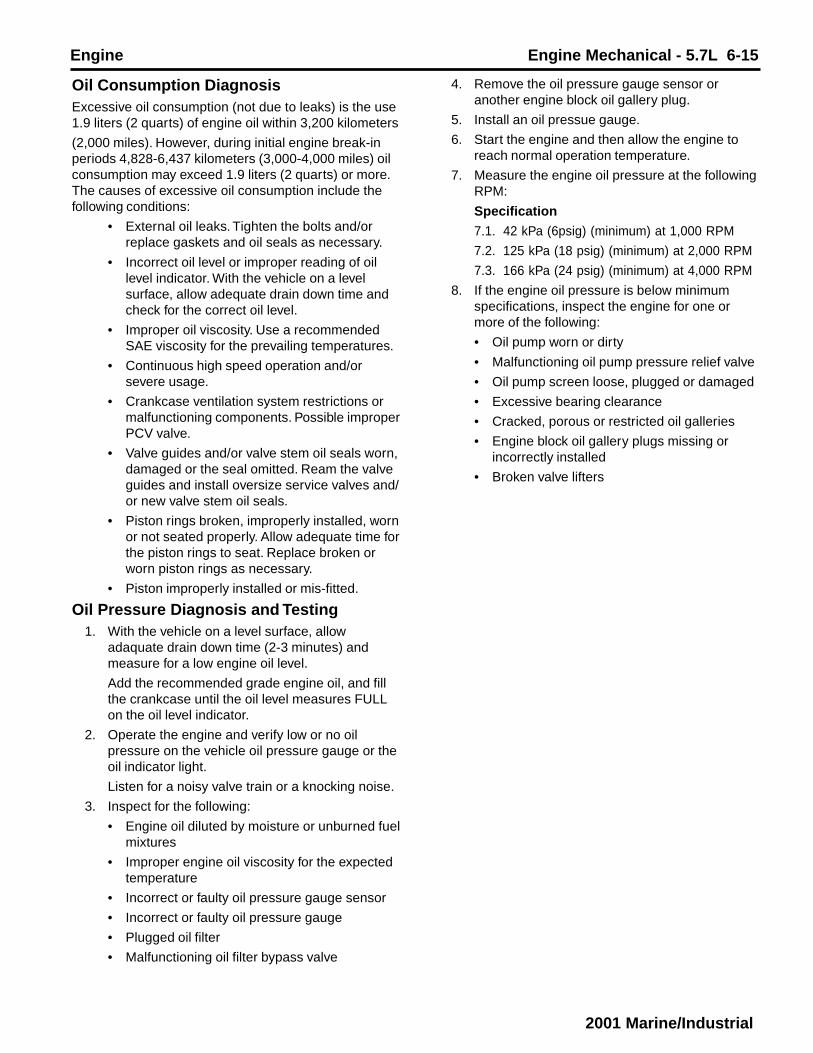
Oil Consumption DiagnosisExcessive oil consumption (not due to leaks) is the use1.9 liters (2 quarts) of engine oil within 3,200 kilometers
(2,000 miles). However, during initial engine break-inperiods 4,828-6,437 kilometers (3,000-4,000 miles) oilconsumption may exceed 1.9 liters (2 quarts) or more.The causes of excessive oil consumption include thefollowing conditions:
• External oil leaks. Tighten the bolts and/orreplace gaskets and oil seals as necessary.
• Incorrect oil level or improper reading of oillevel indicator. With the vehicle on a levelsurface, allow adequate drain down time andcheck for the correct oil level.
• Improper oil viscosity. Use a recommendedSAE viscosity for the prevailing temperatures.
• Continuous high speed operation and/orsevere usage.
• Crankcase ventilation system restrictions ormalfunctioning components. Possible improperPCV valve.
• Valve guides and/or valve stem oil seals worn,damaged or the seal omitted. Ream the valveguides and install oversize service valves and/or new valve stem oil seals.
• Piston rings broken, improperly installed, wornor not seated properly. Allow adequate time forthe piston rings to seat. Replace broken orworn piston rings as necessary.
• Piston improperly installed or mis-fitted.
Oil Pressure Diagnosis and Testing1. With the vehicle on a level surface, allow
adaquate drain down time (2-3 minutes) andmeasure for a low engine oil level.
Add the recommended grade engine oil, and fillthe crankcase until the oil level measures FULLon the oil level indicator.
2. Operate the engine and verify low or no oilpressure on the vehicle oil pressure gauge or theoil indicator light.
Listen for a noisy valve train or a knocking noise.
3. Inspect for the following:
• Engine oil diluted by moisture or unburned fuelmixtures
• Improper engine oil viscosity for the expectedtemperature
• Incorrect or faulty oil pressure gauge sensor
• Incorrect or faulty oil pressure gauge
• Plugged oil filter
• Malfunctioning oil filter bypass valve
4. Remove the oil pressure gauge sensor oranother engine block oil gallery plug.
5. Install an oil pressue gauge.
6. Start the engine and then allow the engine toreach normal operation temperature.
7. Measure the engine oil pressure at the followingRPM:
Specification
7.1. 42 kPa (6psig) (minimum) at 1,000 RPM
7.2. 125 kPa (18 psig) (minimum) at 2,000 RPM
7.3. 166 kPa (24 psig) (minimum) at 4,000 RPM
8. If the engine oil pressure is below minimumspecifications, inspect the engine for one ormore of the following:
• Oil pump worn or dirty
• Malfunctioning oil pump pressure relief valve
• Oil pump screen loose, plugged or damaged
• Excessive bearing clearance
• Cracked, porous or restricted oil galleries
• Engine block oil gallery plugs missing orincorrectly installed
• Broken valve lifters

6-16 Engine Mechanical - 5.7L Engine
2001 Marine/Industrial
Important: You can repair most fluid leaks by first visually locating the leak, repairing or replacing the component, or
by resealing the gasket surface. Once the leak is identified, determine the cause of the leak. Repair the cause of the
leak as ewll as the leak itself.
1. Operate the vehicle until it reaches normal operating
1temperature.
2. Park the vehicle on a level surface, over a large
sheet of paper or other clean surface.
3. Wait (15 minutes)
4. Check for drippings.
Are drippings present? — Go to Step 2 System OK
2Can you identify the type of fluid and the approximate
location of the leak? — Go to Step 10 Go to Step 3
1. Visually inspect the suspected area. Use a small
mirror to assist in looking at hard to see areas.
2. Check for leaks at the following locations:
3
• Sealing surfaces
• Fittings
• Cracked or damaged components
Can you identify the type of fluid and the approximate
location of the leak? — Go to Step 10 Go to Step 4
1. Completely clean the entire engine and surroundingcomponents.
2. Operate the vehicle for several kilometers (miles) atnormal operating temperature and at varying speeds.
3. Park the vehicle on a level surface, over a large4 sheet of paper or other clean surface.
4. Wait (15 minutes).5. Idetify the type of fluid and the approximate location
of the leak.Can you identify the type of fluid and the approximatelocation of the leak? — Go to Step 10 Go to Step 5
1. Visually inspect the suspected area. Use a small
mirror to assist in looking at hard to see areas.
2. Check for leaks at the following locations:
5
• Sealing surfaces
• Fittings
• Cracked or damaged components
Can you identify the type of fluid and the approximate
location of the leak? — Go to Step 10 Go to Step 6
1. Completely clean the entire engine and surroundingcomponents.
6 2. Apply an aerosol-type powder (baby powder, footpowder, etc.) to the suspected area.
Oil Leak Diagnosis
Step Action Value(s) Yes No
Engine Engine Mechanical - 5.7L 6-17
2001 Marine/Industrial
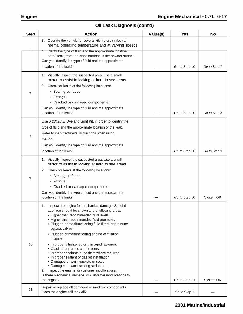
3. Operate the vehicle for several kilometers (miles) atnormal operating temperature and at varying speeds.
6 4. Idetify the type of fluid and the approximate locationof the leak, from the discolorations in the powder surface.
Can you identify the type of fluid and the approximate
location of the leak? — Go to Step 10 Go to Step 7
1. Visually inspect the suspected area. Use a smallmirror to assist in looking at hard to see areas.
2. Check for leaks at the following locations:
7
• Sealing surfaces
• Fittings
• Cracked or damaged components
Can you identify the type of fluid and the approximatelocation of the leak? — Go to Step 10 Go to Step 8
Use J 28428-E, Dye and Light Kit, in order to identify the
type of fluid and the approximate location of the leak.
8Refer to manufacturer’s instructions when using
the tool.
Can you identify the type of fluid and the approximate
location of the leak? — Go to Step 10 Go to Step 9
1. Visually inspect the suspected area. Use a smallmirror to assist in looking at hard to see areas.
2. Check for leaks at the following locations:
9
• Sealing surfaces
• Fittings
• Cracked or damaged components
Can you identify the type of fluid and the approximatelocation of the leak? — Go to Step 10 System OK
1. Inspect the engine for mechanical damage. Specialattention should be shown to the following areas:• Higher than recommended fluid levels• Higher than recommended fluid pressures• Plugged or maalfunctioning fluid filters or pressure bypass valves
• Plugged or malfunctioning engine ventilation system
10 • Improperly tightened or damaged fasteners• Cracked or porous components• Improper sealants or gaskets where required• Improper sealant or gasket installation• Damaged or worn gaskets or seals• Damaged or worn sealing surfaces
2. Inspect the engine for customer modifications.Is there mechanical damage, or custormer modifications tothe engine? — Go to Step 11 System OK
11Repair or replace all damaged or modified components.Does the engine still leak oil? — Go to Step 1 —
Oil Leak Diagnosis (cont’d)
Step Action Value(s) Yes No

6-18 Engine Mechanical - 5.7L Engine
2001 Marine/Industrial
Symptoms - Drive BeltImportant: Review the system operation in order tofamiliarize yourself with the system functions. Referto Drive Belt System Description.
Visual/Physical Inspection• Inspect for aftermarket devices which could
affect the operation of the drive belts.
• Inspect the easily accessible or visible systemcomponents for obvious damage or conditionswhich could cause the symptom.
• Inspect the drive belt for excessive wear,shredding or missing sections.
• Inspect the drive belt for contamination ofexcessive dirt, oil, coolant or other substancesthat may affect the drive belt operation.
Intermittent• Drive belt symptoms may be from intermittent
failure of an accessory drive component.
• Drive belt symptoms may occur from changes in load ofthe accessory drive components.
.• Ambient temperatures, moisture or engine operatingtemperature can affect the drive belt operation.
Symptoms ListRefer to a symptom diagnostic procedure from the following listin order to diagnose the symptom:
• Drive Belt Chirping Diagnosis
• Drive Belt Squeal Diagnosis
• Drive Belt Whine Diagnosis
• Drive Belt Rumbling Diagnosis
• Drive Belt Vibration Diagnosis
• Drive Belt Falls Off Diagnosis
• Drive Belt Excessive Wear Diagnosis
Drive Belt Chirping DiagnosisDiagnostic AidsThe symptom may be intermittent due to moisture onthe drive belt(s) or the pulleys. It may be necessary tospray a small amount of water on the drive belt(s) inorder to duplicate the customers concern. If sprayingwater on the drive belt(s) duplicates the symptom,cleaning the belt pulleys may be the probablesolution.
A loose or improper installation of a body component,a suspension component or other items of the vehiclemay cause the chirping noise.
Test DescriptionThe number(s) below refer to the step number(s) onthe diagnostic table.
2. The noise may not be engine related. This stepis to verify that the engine is making the noise.If the engine is not making the noise, do notproceed further with this table.
3. The noise may be an internal engine noise.
Removing the drive belt and operating theengine for a brief period will verify the noise isrelated to the drive belt. When removing thedrive belt(s), the water pump may not beoperating and the engine may overheat. AlsoDTCs may set when the engine is operatingwith the drive belt removed.
4. Inspect all drive belt pulleys for pilling. Pilling isthe small balls or pills or it can be strings in thedrive belt grooves from the accumulation ofrubber dust.
6. Misalignment of the pulleys may be caused from impropermounting of the accessory drive component, incorrectinstallation of the accessory drive component pulley orthe pulley bent inward or outward from a previous repair.Test for a misaligned pulley .using a straight edge in thepulley grooves across two or three pulleys. If a misalignedpulley is found, refer to that accessory drive componentfor the proper installation procedure for that pulley.
10. Inspecting of the fasteners can eliminate the possibilitythat a wrong bolt, nut, spacer or washer was installed.
12. Inspecting the pulleys for being bent should includeinspecting for a dent or other damage to the pulleys thatwould prevent the drive belt from not seating properly inall of the pulley grooves or on the smooth surface of apulley when the back side of the belt is used to drive thepulley.
14. Replacing the drive belt when it is not damaged or thereis not excessive pilling will only be a temporary repair.

Engine Engine Mechanical - 5.7L 6-19
2001 Marine/Industrial
Notice: Refer to Belt Dressing Notice in Cautions and Notices.
DEFINITION: The following items are indications of chirping:
• A high pitched noise that is heard once per revolution of the drive belt or a pulley.
• It usually occurs on cold damp mornings.
1Did you review the Drive Belt Symptom operation an d perform Go to Symptoms -
the necessary inspections? — Go to Step 2 Drive Belt
2Verify that there is a chirping noise. Go to
Does the engine make the chirping noise? — Go to Step 3 Diagnostic Aids
1. Remove the drive belt.
3 2. Operate the engine for no longer than 30 to 40 seconds. Go to Engine
Does the chirping noise still exist? — Noise Diagnosis Go to Step 4
4Inspect for severe pilling exceeding 1/3 of the belt groove depth.Does the belt grooves have pilling? — Go to Step 5 Go to Step 6
5Clean the drive belt pulleys with a suitable wire brush.
Did you complete the repair? — Go to Step 15 Go to Step 6
6Inspect for misalignment of the pulleys.Are any of the pulleys misaligned? — Go to Step 7 Go to Step 8
7Replace or repair any misaligned pulleys.Did you complete the repair? — Go to Step 15 Go to Step 8
8Inspect for bent or cracked brackets.Did you find any bent or cracked brackets? — Go to Step 9 Go to Step 10
9Replace any bent or cracked brackets.Did you complete the repair? — Go to Step 15 Go to Step 10
10Inspect for improper, loose or missing fastenersDid you find the condition? — Go to Step 11 Go to Step 12
Tighten any loose fasteners.
11Replace any improper or missing fasteners. Refer to Fastener
Tightening Specifications.
Did you complete the repair? — Go to Step 15 Go to Step 12
12Inspect for a bent pulley.Did you find the condition? — Go to Step 13 Go to Step 14
13Replace the bent pulley.Did you complete the repair? — Go to Step 15 Go to Step 14
14Replace the drive belt. Refer to Drive Belt Replacement. Go toDid you complete the repair? — Go to Step 15 Diagnostic Aids
15Operate the system in order to verify the repair.Did you correct the condition? — System OK Go to Step 3
Drive Belt Chirping Diagnosis
Step Action Value(s) Yes No

6-20 Engine Mechanical - 5.7L Engine
2001 Marine/Industrial
Drive Belt Squeal DiagnosisDiagnostic AidsA loose or improper installation of a body component,a suspension component or other items of the vehiclemay cause the chirping noise.
If the noise is intermittent, verify the accessory drivecomponents by varying their loads making sure theyare operated to their maximum capacity. Anovercharged A/C system, power steering system witha pinched hose or wrong fluid or a generator failingare suggested items to inspect.
Test DescriptionThe number(s) below refer to the step number(s) onthe diagnostic table.
2. The noise may not be engine related. This stepis to verify that the engine is making the noise.If the engine is not making the noise, do notproceed further with this table.
3. The noise may be an internal engine noise.
Removing the drive belt and operating theengine for a brief period will verify the noise isrelated to the drive belt. When removing thedrive belt(s), the water pump may not beoperating and the engine may overheat. AlsoDTCs may set when the engine is operatingwith the drive belt removed.
4. This test is to verify that an accessory drivecomponent does not have a seized bearing.With the belt removed, test the bearings in the
accessory drive components for turningsmoothly. Also test the accessory drivecomponents with the engine operating byvarying the load on the components to verifythat the components operate properly.
5. This test is to verify that the drive belt tensioneroperates properly. If the drive belt tensioner isnot operating properly, proper belt tension maynot be achieved to keep the drive belt fromslipping, which could cause a squeal noise.
6. This test is to verify that the drive belt(s) is nottoo long, which would prevent the drive belttensioner from working properly. Also, if anincorrect length drive belt was installed, it maynot be routed properly and may be turning anaccessory drive component in the wrongdirection.
7. Misalignment of the pulleys may be causedfrom improper mounting of the accessory drivecomponent, incorrect installation of theaccessory drive component pulley or the pulleybent inward or outward from a previous repair.Test for a misaligned pulley using a straightedge in the pulley grooves across two or threepulleys. If a misaligned pulley is found, refer tothat accessory drive component for the properinstallation procedure for that pulley.
8. This test is to verify that the pulleys are thecorrect diameter or width. Using a known goodvehicle compare the pulley sizes.
Notice: Refer to Belt Dressing Notice in Cautions and Notices.
DEFINITION: The following items are indications of drive belt squeal:
• A loud screeching noise that is caused by a slipping drive belt (this is unusual for a drive belt with multiple ribs)
• The noise occurs when a heavy load is applied to the drive belt, such as an air conditioning compressor engagement,
snapping the throttle or slipping on a seized pulley or a faulty accessory drive component.
1Did you review the Drive Belt Symptom operation an d perform Go to Symptoms -
the necessary inspections? — Go to Step 2 Drive Belt
2Verify that there is a squeal noise. Go to
Does the engine make the squeal noise? — Go to Step 3 Diagnostic Aids
1. Remove the drive belt(s).
3 2. Operate the engine for no longer than 30 to 40 seconds. Go to Engine
Does the chirping noise still exist? — Noise Diagnosis Go to Step 4
4Inspect for an accessory drive component seized bearing orfaulty accessory drive component.Did you find and correct the condition? — Go to Step 9 Go to Step 5
Drive Belt Squeal Diagnosis
Step Action Value(s) Yes No

Engine Engine Mechanical - 5.7L 6-21
2001 Marine/Industrial
Test the drive belt tensioner for proper operation. Refer to Drive
5 Belt Tensioner Diagnosis.
Did you find and correct the condition? — Go to Step 9 Go to Step 6
Inspect for the correct drive belt length. Refer to Drive Belt6 Replacement.
Did you find and correct the condition? — Go to Step 9 Go to Step 7
7Inspect for a misalignment of a pulley.Did you find and correct the condition? — Go to Step 9 Go to Step 8
8Inspect for the correct pulley size. Go toDid you find and correct the condition? — Go to Step 9 Diagnostic Aids
9Operate the system in order to verify the repair.Did you correct the condition? — System OK Go to Step 3
Drive Belt Squeal Diagnosis (cont’d)
Step Action Value(s) Yes No
Drive Belt Whine DiagnosisDiagnostic AidsThe drive belt(s) will not cause the whine noise.
If the whine noise is intermittent, verify the accessorydrive components by varying their loads making surethey are operated to their maximum capacity. Anovercharged A/C system, power steering system witha pinched hose or wrong fluid or a generator failingare suggested items to inspect.
Test DescriptionThe number(s) below refer to the step number(s) onthe diagnostic table.
3. This test is to verify that the noise is being
caused by the drive belt(s) or the accessory drivecomponents. When removing the drive belt(s), thewater pump may not be operating and the enginemay overheat. Also DTCs may set when theengine is operating with the drive belt(s)removed.
4. The inspection should include checking the drivebelt tensioner and the drive belt idler pulleybearings. The drive belt(s) may have to beinstalled and the accessory drive componentsoperated seperately by varying their loads. Referto the suspected accessory drive component forthe proper inspection and replacementprocedure.
Notice: Refer to Belt Dressing Notice in Cautions and Notices.
DEFINITION: A high pitched continuous noise that may be caused by an accessory drive component failed bearing.
1Did you review the Drive Belt Symptom operation and perform Go to Symptoms-the necessary inspections? — Go to Step 2 Drive Belt
2Verify that there is a whine noise. Go toDoes the engine make the whine noise? — Go to Step 3 Diagnostic Aids
1. Remove the drive belt(s).3 2. Operate the engine for no longer than 30 to 40 seconds. Go to Engine
Does the whine noise still exist? — Noise Diagnosis Go to Step 4
4Inspect for a failed accessory drive component bearing. Go toDid you find and repair the condition? — Go to Step 5 Diagnostic Aids
5Operate the system in order to verify the repair.Did you correct the condition? — System OK —
Drive Belt Whine Diagnosis
Step Action Value(s) Yes No

6-22 Engine Mechanical - 5.7L Engine
2001 Marine/Industrial
Drive Belt Rumbling DiagnosisDiagnostic AidsVibration from the engine operating may cause abody component or another part of the vehicle tomake rumbling noise.
The drive belt(s) may have a condition that can not beseen or felt. Sometimes replacing the drive belt maybe the only repair for the symptom.
If replacing the drive belt(s), completing thediagnostic table, and the noise is only heard when thedrive component with a failure. Varying the load onthe different accessory drive components may aid inidentifying which component is causing the rumblingnoise.
Test DescriptionThe number(s) below refer to the step number(s) onthe diagnostic table.
2. This test is to verify that the symptom is presentduring diagnosing. Other vehicle componentsmay cause a similar symptom.
3. This test is to verify that the drive belt(s) iscausing the rumbling noise. Rumbling noise maybe confused with an internal engine noise due tothe similarity in the description. Remove only onedrive belt at a time if the vehicle has multiple drivebelts. When removing the drive belt the waterpump may not be operating and the engine mayoverheat. Also, DTC’s may set when the engine isoperating with the drive belt removed.
4. Inspecting the drive belt(s) is to ensure that it isnot causing the noise. Small cracks across theribs of the drive belt will not cause the noise. Beltseparation is identified by the plys of the beltseparating and may be seen at the edge of thebelt, or felt as a lump in the belt.
5. Small amounts of pilling is a normal condition andacceptable. When the pilling is severe, the drivebelt does not have a smooth surface for properoperation.
Notice: Refer to Belt Dressing Notice in Cautions and Notices.
DEFINITION:
• A low pitch tapping, knocking or thumping noise heard at or just above idle.
• Heard once per revolution of the drive belt or a pulley.
• Rumbling may be caused from:
- Pilling, the accumulation of rubber dust that forms small balls (pills) or strings in the drive belt pulley groove
- The separation of the drive belt
- A damaged drive belt
1Did you review the Drive Belt Symptom operation and perform Go to Symptoms-the necessary inspections? — Go to Step 2 Drive Belt
2Verify that there is a rumbling noise. Go toDoes the engine make the rumbling noise? — Go to Step 3 Diagnostic Aids
1. Remove the drive belt(s).3 2. Operate the engine for no longer than 30 to 40 seconds. Go to Engine
Does the rumbling noise still exist? — Noise Diagnosis Go to Step 4
Inspect the drive belt(s) for damage, separation or sections of4 missing ribs.
Did you find and repair the condition? — Go to Step 7 Go to Step 5
Inspect for severe pilling of more than 1/3 of the drive belt5 pulley grooves.
Did you find severe pilling? — Go to Step 6 Go to Step 7
1. Clean the drive belt pulleys using a suitable wire brush.6 2. Reinstall the drive belt. Refer to Drive Belt Replacement.
Did you complete the repair? — Go to Step 8 Go to Step 7
Drive Belt Rumbling Diagnosis
Step Action Value(s) Yes No

Engine Engine Mechanical - 5.7L 6-23
2001 Marine/Industrial
7Install a new drive belt. Refer to Drive Belt Replacement.Did you complete the replacement? — Go to Step 8 —
8Operate the system in order to verify the repair. Go toDid you correct the condition? — System OK Diagnostic Aids
Drive Belt Rumbling Diagnosis (cont’d)
Step Action Value(s) Yes No
Drive Belt Vibration DiagnosisDiagnostic AidsThe accessory drive components can have an affecton engine vibration. Such as, but not limited to theA/C system overcharged, the power steering systemrestricted or the incorrect fluid or an extra load on thegenerator. To help identify an intermittent or animproper condition, vary the loads on the accessorydrive components.
Test DescriptionThe number(s) below refer to the step number(s) onthe diagnostic table.
2. This test is to verify that the symptom is presentduring diagnosing. Other vehicle componentsmay cause a similar symptom such as theexhaust system or the drivetrain.
3. This test is to verify that the drive belt(s) oraccessory drive components may be causingthe vibration. When removing the drive belt thewater pump may not be operating and theengine may overheat. Also, DTC’s may setwhen the engine is operating with the drive beltremoved.
4. The drive belt(s) may cause a vibration. While thedrive belt(s) is removed, inspect the condition ofthe belt.
6. Inspecting of the fasteners can eliminate thepossibility that a wrong bolt, nut, spacer orwasher was installed.
8. This step should only be performed if the fan isdriven by the drive belt. Inspect the enginecooling fan for bent, twisted, loose or crackedblades. Inspect the fan clutch for smoothness,ease of turning. Inspect for a bent fan shaft orbent mounting flange.
9. This step should only be performed if the waterpump is driven by the drive belt. Inspect the waterpump shaft for being bent. Also inpsect the waterpump bearings for smoothness and excessiveplay. Compare the water pump with a known goodwater pump.
10. Accessory drive component brackets that arebent, cracked or loose may put extra strain onthat accessory component causing it to vibrate.
Notice: Refer to Belt Dressing Notice in Cautions and Notices.
DEFINITION:
• The vibration is engine-speed related.
• The vibration may be sensitive to accessory load.
1Did you review the Drive Belt Symptom operation and perform Go to Symptoms-the necessary inspections? — Go to Step 2 Drive Belt
2Verify that the vibration is engine related. Go toDoes the engine make the vibration? — Go to Step 3 Diagnostic Aids
1. Remove the drive belt(s).3 2. Operate the engine for no longer than 30 to 40 seconds. Go to Engine
Does the rumbling noise still exist? — Related Vibration Go to Step 4
Inspect the drive belt(s) for wear, damage, debris build-up and4 missing drive belt ribs.
Did you find any of these conditions? — Go to Step 5 Go to Step 6
Drive Belt Vibration Diagnosis
Step Action Value(s) Yes No

6-24 Engine Mechanical - 5.7L Engine
2001 Marine/Industrial
5Install a new drive belt. Refer to Drive Belt Replacement.Did you complete the replacement? — Go to Step 11 —
6Inspect for improper, loose or missing fasteners.Did you find any of these conditions? — Go to Step 7 Go to Step 8
Tighten any loose fasteners.
7Replace improper or missing fasteners. Refer to FastenerTightening Specifications.Did you complete the repair? — Go to Step 11 —
Inspect for damaged fan blades or bent fan clutch shaft, if the
8fan is belt driven. Refer to Fan Clutch Replacement in EngineCooling.Did you find and correct the condition? — Go to Step 11 Go to Step 9
Inspect for bent water pump shaft, if the water pump is belt
9driven. Refer to Water Pump Replacement (4.3L Engine)in Engine Cooling.Did you find and correct the condition? — Go to Step 11 Go to Step 10
10Inspect for bent or cracked brackets. Go toDid you find and correct the condition? — Go to Step 11 Diagnostic Aids
11Operate the system in order to verify the repair.Did you correct the condition? — System OK Go to Step 3
Drive Belt Vibration Diagnosis (cont’d)
Step Action Value(s) Yes No
Drive Belt Falls Off DiagnosisDiagnostic AidsIf the drive belt(s) repeatedly falls off the drive beltpulleys, this is because of pulley misalignment.
An extra load that is quickly applied and released byan accessory drive component may cause the drivebelt to fall off the pulleys. Verify the accessory drivecomponents operate properly.
If the drive belt(s) is the incorrect length, the drive belttensioner may not keep the proper tension on thedrive belt.
Test DescriptionThe number(s) below refer to the step number(s) onthe diagnostic table.
2. This inspection is to verify the condition of thedrive belt. Damage may of occured to the drivebelt when the drive belt fell off. The drive beltmay of been damaged, which caused the drivebelt to fall off. Inspect the belt for cuts, tears,sections of ribs missing or damaged belt plys.
4. Misalignment of the pulleys may be causedfrom improper mounting of the accessory drive
component, incorrect installation of the accessorydrive component pulley or the pulley bent inwardor outward from a previous repair. Test for amisaligned pulley using a straight edge in thepulley grooves across two or three pulleys. If amisaligned pulley is found, refer to that accessorydrive component for the proper installationprocedure of that pulley.
5. Inspecting the pulleys for being bent shouldinclude inspecting for a dent or other damage tothe pulleys that would prevent the drive belt fromnot seating properly in all of the pulley grooves oron the smooth surface of a pulley when the backside of the belt is used to drive the pulley.
6. Accessory drive component brackets that arebent or cracked will let the drive belt fall off.
7. Inspecting of the fasteners can eliminate thepossibility that a wrong bolt, nut, spacer orwasher was installed. Missing, loose or the wrongfasteners may cause pulley misalignment fromthe bracket moving under load. Over tightening ofthe fasteners may cause misalignment of theaccessory component bracket.

Engine Engine Mechanical - 5.7L 6-25
2001 Marine/Industrial
Notice: Refer to Belt Dressing Notice in Cautions and Notices.
DEFINITION: The drive belt falls off the pulleys or may not ride correctly on the pulleys.
1Did you review the Drive Belt Symptom operation and perform Go to Symptoms-the necessary inspections? — Go to Step 2 Drive Belt
2Inspect for a damaged drive belt.Did you find the condition? — Go to Step 3 Go to Step 4
Drive Belt Falls Off Diagnosis
Step Action Value(s) Yes No
7Inspect for improper, loose or missing fasteners.Did you find loose or missing fasteners? — Go to Step 8 Go to Step 9
Tighten any loose fasteners.
8Replace improper or missing fasteners. Refer to FastenerTightening Specifications.Does the drive belt continue to fall off? — Go to Step 9 System OK
Test the drive belt tensioner for operating correctly. Refer9 to Drive Belt Tensioner Diagnosis.
Does the drive belt tensioner operate correctly? — Go to Step 11 Go to Step 10
Replace the drive belt tensioner. Refer to Drive Belt Tensioner10 Replacement.
Does the drive belt continue to fall off? — Go to Step 11 System OK
Inspect for failed drive belt idler and drive belt tensioner pulley11 bearings. Go to
Did you find and repair the condition? — Go to Step 12 Diagnostic Aids
12Operate the system in order to verify the repair.Did you correct the condition? — System OK Go to Step 2
3Install a new drive belt. Refer to Drive Belt Replacement.Does the drive belt continue to fall off? — Go to Step 4 System OK
4Inspect for misalignment of the pulleys.Did you find and repair the condition? — Go to Step 12 Go to Step 5
5Inspect for a bent or dented pulley.Did you find and repair the condition? — Go to Step 12 Go to Step 6
6Inspect for a bent or cracked bracket.Did you find and repair the condition? — Go to Step 12 Go to Step 7
Drive Belt Excessive Wear DiagnosisDiagnostic AidsExcessive ewar on a drive belt(s) is usually caused byan incorrect installation or the wrong drive belt for theapplication.
Minor misalignment of the drive belt pulleys will notcause excessive wear, but will probably cause thedrive belt(s) to make a noise or to fall off.
Excessive misalignment of the drive belt pulleys willcause excessive wear but may also make the drivebelt(s) fall off.
Test DescriptionThe number(s) below refer to the step number(s) onthe diagnostic table.
2. This inspection is to verify the drive belt(s) is correctlyinstalled on all of the drive belt pulleys. Wear on the drivebelt(s) may be caused by mis-positioning the drive belt(s)by one groove on a pulley.
3. The installation of a drive belt that is two wide or twonarrow will cause wear on the drive belt. The drive beltribs should match all of the grooves on all of the pulleys.
4. This inspection is to verify the drive belt(s) is notcontacting any parts of the engine or body while theengine is operating. There should be sufficient clearancewhen the drive belt accessory drive components loadvaries. The drive belt(s) should not come in contact withan engine or a body component when snapping thethrottle.

6-26 Engine Mechanical - 5.7L Engine
2001 Marine/Industrial
Notice: Refer to Belt Dressing Notice in Cautions and Notices.
DEFINITION: Wear at the outside ribs of the drive belt due to an incorrectly installed drive belt.
1Did you review the Drive Belt Symptom operation and perform Go to Symptoms-the necessary inspections? — Go to Step 2 Drive Belt
Inspect the drive belt(s) for the proper installation. Refer to2 Drive Belt Replacement.
Did you find the condition? — Go to Step 5 Go to Step 3
Drive Belt Excessive Wear Diagnosis
Step Action Value(s) Yes No
3Inspect for the proper drive belt.Did you find this condition? — Go to Step 5 Go to Step 4
Inspect for the drive belt rubbing against a bracket, hose or4 wiring harness. Go to
Did you find and repair the condition? — Go to Step 6 Diagnostic Aids
5Replace the drive belt. Refer to Drive Belt Replacement.Did you complete the replacement? — Go to Step 6 —
6Operate the system in order to verify the repair.Does the drive belt continue to fall off? — System OK —
Drive Belt Tensioner DiagnosisInspection ProcedureNotice: Allowing the drive belt tensioner to snap intothe free position may result in damage to thetensioner.
1. Remove the drive belt. Refer to Drive BeltReplacement.
2. Position a hex-head socket on the drive belttensioner pulley bolt head.
3. Move the drive belt tensioner through it’s fulltravel.
• The movement should feel smooth
• There should be no binding
• The tensioner should return freely
4. If any binding is observed, replace the drive belttensioner. Refer to Drive Belt TensionerReplacement.
5. Install the drive belt. Refer to Drive BeltReplacement.
Important: Movement of the drive belt tensioner whilethe engine is operating is a normal operating condition.Do not replace the drive belt tensioner for this normalcondition.

Engine Engine Mechanical - 5.7L 6-27
2001 Marine/Industrial

6-28 Engine Mechanical - 5.7L Engine
2001 Marine/Industrial
Component LocatorDissassembled Views
Intake Manifolds and Components
66997Legend
(1) Fuel Pipe Retainer Bracket
(2) Fuel Pipe Retainer Bracket Nuts
(3) Fuel Pipe
(4) Fuel Pipe Attachment Screw
(5) Fuel Seal Retainer
(6) Fuel Seal (Yellow O-ring)
(7) Spacer Ring (Flat Washer)
(8) Fuel Seal (Black O-ring)
(9) Upper Manifold
(10) Upper Intake Manifold to Lower Intake ManifoldGasket
(11) Fuel Meter Body Seal
(12) Fuel Meter Body
(13) Distributor Assembly
(14) Hex Bolt (Distributor Clamp)
(15) Distributor Clamp
(16) Lower Intake Manifold
(17) Lower Intake Manifold Gasket
(18) EGR Valve Gasket
(19) EGR Valve
(20) EGR Valve Bolt
(21) Engine Coolant Sensor
(22) Engine Coolant Thermostat
(23) Water Outlet
(24) Water Outlet Stud
(25) Upper Intake Manifold Stud
(26) Throttle Body Gasket
(27) Throttle Body
(28) Throttle Body Attaching Stud

Engine Engine Mechanical - 5.7L 6-29
2001 Marine/Industrial
Front of Engine
182828Legend
(1) Engine Front Cover
(2) Camshaft Timing Chain
(3) Camshaft Sprocket
(4) Camshaft Sprocket Bolt
(5) Valve Lifter Guide Retainer Bolt
(6) Valve Lifter Guide Retainer
(7) Valve Lifter Guide
(8) Valve Lifter
(9) Engine Block
(10) Engine Camshaft
(11) Camshaft Sprocket Locator Pin
(12) Camshaft Retainer
(13) Camshaft Retainer Bolt
(14) Water Pump Gasket
(15) Water Pump
(16) Water Pump Bolt
(17) Water Pump Inlet Hose Clamp
(18) Water Pump Inlet Hose
(19) Engine Block Oil Gallery Plug
(20) Camshaft Bearings
(21) Crankshaft Position Sensor
(22) Crankshaft Position Sensor Bolt
(23) Front Groove Pin (Crankshaft Balancer)
(24) Crankshaft Balancer Bolt
(25) Crankshaft Balancer Bolt Washer
(26) Crankshaft Balancer
(27) Crankshaft Front Oil Seal

6-30 Engine Mechanical - 5.7L Engine
2001 Marine/Industrial
Cylinder Head and Exhaust Manifold Area
182825Legend
(1) Valve Rocker Arm Cover Bolt
(2) Valve Rocker Arm Cover Bolt Washer
(3) Valve Rocker Arm Cover
(4) Valve Rocker Arm Cover Gasket
(5) Valve Stem Keys
(6) Valve Spring Cap
(7) Valve Spring
(8) Valve Stem Oil Seal
(9) Valve
(10) Cylinder Head Bolt (Long)
(11) EGR Valve Pipe
(12) EGR Valve Pipe Clamp
(13) EGR Valve Pipe Clamp Bracket Bolt
(14) Cylinder Head Bolt (Medium)
(15) Cylinder Head Bolt (Short)
(16) Spark Plug Wire Support Bracket
(17) Spark Plug Wire Support Bracket Bolt
(18) EGR Valve Pipe Fitting
(19) Exhaust Manifold Bolts
(20) Engine Coolant Temperature (ECT) GaugeSensor
(21) Spark Plug Wire Shields
(22) Exhaust Manifold
(23) Exhaust Manifold Gasket
(24) Cylinder Head Gasket
(25) Valve Pushrod
(26) Valve Rocker Arm
(27) Valve Rocker Arm Ball
(28) Valve Rocker Arm Nut

Engine Engine Mechanical - 5.7L 6-31
2001 Marine/Industrial
Legend
(1) Piston Ring Kit
(2) Piston
(3) Connecting Rod
(4) Connecting Rod Bolt
(5) Connecting Rod Bearings
(6) Connecting Rod Cap
(7) Hex Nut (Connecting Rod)
(8) Engine Oil Pressure Gauge Sensor Fitting
(9) Engine Oil Pressure Gauge Sensor
(10) Engine Block
(11) Expansion Cup Plug (Camshaft Rear BearingHole)
(12) Dowel Straight Pin (Transmission Locator)
(13) Engine Block Coolant Drain Hole Plug
(14) Engine Block Core Hole Plug
(15) Crankshaft Rear Oil Seal Housing Bolt
Cylinder Block and Components
317429
(16) Crankshaft Rear Oil Seal
(17) Engine Flywheel (Automatic Transmission)
(18) Flywheel Bolt
(19) Engine Flywheel (Manual Transmission)
(20) Crankshaft Rear Oil Seal Housing Nut
(21) Crankshaft Rear Oil Seal Housing Stud
(22) Crankshaft Rear Oil Seal Housing
(23) Crankshaft Rear Oil Seal Housing Gasket
(24) Crankshaft Rear Oil Seal Housing
(25) Crankshaft
(26) Crankshaft Bearing (Rear Thrust Bearing)
(27) Crankshaft Bearing Cap (Rear)
(28) Crankshaft Bearing Cap
(29) Crankshaft Bearing Cap Stud
(30) Crankshaft Bearing Cap Bolt
(31) Crankshaft Bearings

6-32 Engine Mechanical - 5.7L Engine
2001 Marine/Industrial
(32) Crankshaft Sprocket
(33) Crankshaft Position Sensor Reluctor Ring
(34) Woodruff Keys (Crankshaft Balancer)
(35) Crankshaft Bearing
(36) Crankshaft Bearing (Rear Thrust Bearing)
(37) Flywheel Locator Pin
(38) Spring Type S Pin (Crankshaft Rear Oil Seal HousingLocator)
(39) Oil Level Indicator Tube
(40) Oil Level Indicator Tube Bolt
(41) Oil Level Indicator
(42) Piston Pin

Engine Engine Mechanical - 5.7L 6-33
2001 Marine/Industrial
Legend
(1) Engine Block
(2) Oil Pump Driveshaft
(3) Oil Pump Driveshaft Retainer
(4) Pin (Oil Pump Locator)
(5) Oil Pump
(6) Oil Pan Gasket
(7) Oil Pan
(8) Oil Pan Drain Plug Seal (O-ring)
182829
(9) Oil Pan Drain Plug
(10) Oil Pan Nut
(11) Oil Pan Bolt
(12) Oil Pan Reinforcement
(13) Crankshaft Oil Deflector Bolt
(14) Crankshaft Oil Deflector Nut
(15) Crankshaft Oil Deflector

6-34 Engine Mechanical - 5.7L Engine
2001 Marine/Industrial
Draining Fluids and Oil Filter Removal1. Remove the oil pan drain plug and allow the engine oil to
drain into a suitable container.
2. Remove the oil filter and discard.
3. Remove the engine block coolant drain hole plug and allowthe coolant to drain into a suitable container.
316798
316766
182850

Engine Engine Mechanical - 5.7L 6-35
2001 Marine/Industrial
4. Remove the knock sensor and allow the coolant to drain intoa suitable container.
Engine Flywheel Removal1. Remove the engine flywheel bolts.
2. Remove the engine flywheel.
Exhaust Manifold Removal (Left)Notice: Twist the spark plug boot one-half turn in order to releasethe boot. Pull on the spark plug boot only. Do not pull on the sparkplug wire or the wire could be damaged.
1. Remove the spark plug wires from the spark plugs.
1.1. Rotate the spark plug wire boot one-half turn.
1.2. Pull outward on the spark plug wire boot to release from the spark plug.
2. Remove the bolts and the spark plug wire supports.
317185
522146
182837

6-36 Engine Mechanical - 5.7L Engine
2001 Marine/Industrial
3. Remove the exhaust manifold bolts.
4. Remove the spark plug wire shields.
5. Remove the exhaust manifold.
6. Remove and discard the exhaust manifold gasket.
Exhaust Manifold Removal (Right)Notice: Twist the spark plug boot one-half turn in order to releasethe boot. Pull on the spark plug boot only. Do not pull on the sparkplug wire or the wire could be damaged.
1. Remove the spark plug wires from the spark plugs.
1.1. Rotate the spark plug wire boot one-half turn.
1.2. Pull outward on the spark plug wire boot to release from the spark plug.
2. Remove the bolts and the spark plug wire supports.
3. Remove the exhaust manifold bolts.
4. Remove the spark plug wire shields.
5. Remove the exhaust manifold.
6. Remove and discard the exhaust manifold gasket.
317179
69032
64925

Engine Engine Mechanical - 5.7L 6-37
2001 Marine/Industrial
Oil Level Indicator and Tube Removal1. Remove the oil level indicator tube bolt.
2. Remove the oil level indicator tube from the engine block.
Water Pump RemovalTools Required
J 41240 Fan Clutch Remover and Installer
1. Remove the bolts and the fan and water pump pulley usingthe J 41240.
500691
317191
2. Remove the clamps and the water pump inlet hose.
182853

6-38 Engine Mechanical - 5.7L Engine
2001 Marine/Industrial
This page
was
intentionally
left blank

Engine Engine Mechanical - 5.7L 6-39
2001 Marine/Industrial
69011
173172
188055
Crankshaft Balancer RemovalTools Required
J 23523-F Balancer Remover and Installer
1. Remove the crankshaft balancer bolt and washer.
3. Remove the water pump bolts.
4. Remove the water pump.
5. Remove the water pump gaskets.
6. Discard the water pump gaskets.
2. Remove the bolts and the crankshaft pulley.

6-40 Engine Mechanical - 5.7L Engine
2001 Marine/Industrial
66878
182849
39119
Notice: Refer to Fastener Notice in Cautions and Notices.
3. Use the J23523-F in order to remove the crankshaftbalancer.
3.1. Install the J 23523-F plate and bolts onto the crankshaft balancer.
Tighten
Tighten the bolts to 25 N•m (18 lb ft).
3.2. Install the J 23523-F forcing screw into the plate.
3.3. Rotate the J 23523-F forcing screw clockwise in order to remove the crankshaft balancer.
4. Remove the J 23523-F from the crankshaft balancer.
5. Note the position of any front groove pins (crankshaftbalancer weights) (if applicable).
Valve Rocker Arm Cover Removal (Left)1. Remove the valve rocker arm cover bolts and washers.
2. Remove the valve rocker arm cover.
3. Remove the valve rocker arm cover gasket.
4. Discard the valve rocker arm cover gasket.

Engine Engine Mechanical - 5.7L 6-41
2001 Marine/Industrial
182833
341359
69303
Valve Rocker Arm Cover Removal (Right)1. Remove the valve rocker arm cover bolts and washers.
2. Remove the valve rocker arm cover.
3. Remove the valve rocker arm cover gasket.
4. Discard the valve rocker arm cover gasket.
Distributor Removal1. Remove the ignition coil wire harness from the ignition coil
and distributor cap.
2. Remove the distributor clamp bolt.
3. Remove the distributor and the distributor clamp.

6-42 Engine Mechanical - 5.7L Engine
2001 Marine/Industrial
523516
317211
66456
4. Remove the distributor gasket and discard.
Intake Manifold Removal1. Remove the evaporative emission canister purge solenoid
valve harness.
1.1. Push the quick disconnect clip and hold in place.
1.2. Pull outward on the harness elbow.
2. Remove the lower intake manifold bolts.
Important: The intake manifold may be removed as an assembly.Do not remove the specific intake manifold components unlesscomponent service is required.
Do not allow dirt or debris to enter the fuel system. Ensure that theends of the fuel system are properly sealed.
Do not disassemble the fuel injection unit, unless service isrequired.
3. Remove the intake manifold assembly.
4. Remove and discard the lower intake manifold gaskets.
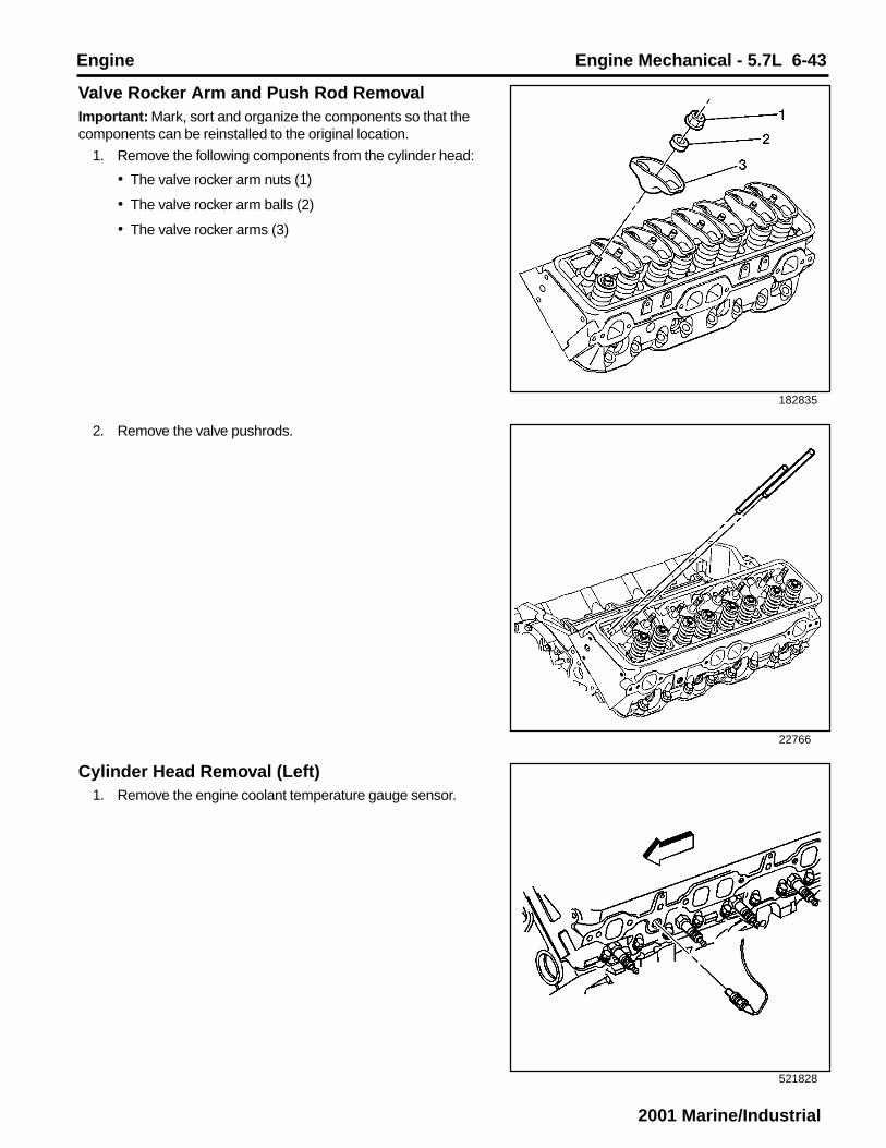
Engine Engine Mechanical - 5.7L 6-43
2001 Marine/Industrial
182835
22766
521828
Valve Rocker Arm and Push Rod RemovalImportant: Mark, sort and organize the components so that thecomponents can be reinstalled to the original location.
1. Remove the following components from the cylinder head:
• The valve rocker arm nuts (1)
• The valve rocker arm balls (2)
• The valve rocker arms (3)
2. Remove the valve pushrods.
Cylinder Head Removal (Left)1. Remove the engine coolant temperature gauge sensor.

6-44 Engine Mechanical - 5.7L Engine
2001 Marine/Industrial
317307
317217
317227
2. Remove and discard the spark plugs.
3. Remove the cylinder head bolts.
Notice: After removal, place the cylinder head on two wood blocksto prevent damage.
4. Remove the cylinder head.

Engine Engine Mechanical - 5.7L 6-45
2001 Marine/Industrial
317233
182846
317307
6. Remove the dowel pin (cylinder head locator)(if required).
Cylinder Head Removal (Right)1. Remove and discard the spark plugs.
5. Remove and discard the cylinder head gasket.

6-46 Engine Mechanical - 5.7L Engine
2001 Marine/Industrial
2. Remove the cylinder head bolts.
Notice: After removal, place the cylinder head on two wood blocksto prevent damage.
3. Remove the cylinder head.
4. Remove and discard the cylinder head gasket.
317239
317246
317255

Engine Engine Mechanical - 5.7L 6-47
2001 Marine/Industrial
182846
11508
11509
5. Remove the dowel pin (cylinder head locator)(if required).
Valve Lifter RemovalTools Required
J 3049-A Valve Lifter Remover
1. Remove the bolts and valve lifter guide retainer.
Important: Place the valve lifters in the rack in the upright positionin order to maintain the oil inside the valve lifter.
2. Remove the valve lifter guides and valve lifters.
Place the components in a rack so that the components canbe reinstalled to the original location.

6-48 Engine Mechanical - 5.7L Engine
2001 Marine/Industrial
31350
Important: Some valve lifters may be stuck in the valve lifter boresbecause of gum or varnish deposits and may require the use ofJ 3049-A for removal.
3. Use the J 3049-A in order to remove the stuck valve lifters.
39122
Oil Filter Adapter Removal1. Remove the oil filter adapter bolts and washers (if
applicable).
2. Remove the oil filter adapter.
3. Remove the oil filter adapter seal (O-ring) and the oil filteradapter gasket (if applicable).
4. Discard the oil filter adapter seal (O-ring) and the oil filteradapter gasket (if applicable).

Engine Engine Mechanical - 5.7L 6-49
2001 Marine/Industrial
182851
521817
11438
Oil Pan Removal1. Remove the oil pan bolts and nuts.
2. Remove the oil pan reinforcements.
3. Remove the oil pan.
4. Remove and discard the oil pan gasket.
5. Remove the oil pan studs.
Oil Pump, Pump Screen and Deflector Removal1. Remove the nuts (6) and the crankshaft oil deflector (2).
2. Remove the oil pump bolt (1).
3. Remove the oil pump (3), the oil pump driveshaft (5) and theoil pump driveshaft retainer (4).
4. Separate the oil pump (3), the oil pump driveshaft (5) andthe oil pump driveshaft retainer (4).
Important: Always install a NEW oil pump driveshaft retainerduring assembly.
5. Discard the oil pump driveshaft retainer.

6-50 Engine Mechanical - 5.7L Engine
2001 Marine/Industrial
182852
11485
387759
6. Inspect the pins (oil pump locator) for damage, replace thepins if required.
Important: Always install a NEW crankshaft position sensor seal(O-ring) during assembly.
3. Remove the crankshaft position sensor seal (O-ring).
4. Discard the crankshaft position sensor seal (O-ring).
Engine Front Cover Removal1. Remove the crankshaft position sensor bolt.
2. Remove the crankshaft position sensor.

Engine Engine Mechanical - 5.7L 6-51
2001 Marine/Industrial
69010
5. Remove the engine front cover bolts.
6. Remove the engine front cover and gasket.
Important: DO NOT reuse the composite engine front cover andgasket. Always install a NEW engine front cover and gasket.
7. Discard the engine front cover and gasket.
Timing Chain and Sprockets RemovalTools Required
J 5825-A Crankshaft Gear Remover
1. Remove the crankshaft position sensor reluctor ring.
69450

6-52 Engine Mechanical - 5.7L Engine
2001 Marine/Industrial
341357
2. Check the camshaft timing chain free play.
2.1. Rotate the camshaft sprocket (1) counterclockwise until all slack is removed from the camshaft timing
chain (2).
2.2. Measure the free play on the slack side (3) of the camshaft timing chain.
If the camshaft timing chain can be moved side to side in excess of 11 mm (0.43 in), replacement of the camshaft timing chain and the sprockets is recommended during assembly.
3. Remove the camshaft sprocket bolts.
4. Remove the camshaft sprocket.
5. Remove the camshaft timing chain.
500645
11506
Caution: Refer to Safety Glasses Caution in Cautions andNotices.
6. Remove the crankshaft sprocket using the J 5825-A.

Engine Engine Mechanical - 5.7L 6-53
2001 Marine/Industrial
182847
182836
69013
Camshaft Removal1. Remove the bolts and the camshaft retainer.
Notice: All camshaft journals are the same diameter, so care mustbe used in removing or installing the camshaft to avoid damage tothe camshaft bearings.
2. Remove the engine camshaft.
2.1. Install the three 5/16-18 x 4.0 inch bolts in the engine camshaft front bolt holes.
2.2. Using the bolts as a handle, carefully rotate and pull the engine camshaft out of the camshaft bearings.
2.3. Remove the bolts from the front of the engine camshaft.
7. Remove the woodruff keys (crankshaft balancer)(ifrequired).

6-54 Engine Mechanical - 5.7L Engine
2001 Marine/Industrial
11497
480549
Piston, Connecting Rod, and Bearing RemovalTools Required
J 5239 Conneting Rod Bolt Guide Set
J 24270 Cylinder Bore Ridge Reamer
Caution: Wear safety glasses in order to avoid eye damage.1. Remove the ring ridge.
1.1. Turn the crankshaft until the piston is at the bottom of the stroke.
1.2. Place a cloth on top of the piston.
1.3. Use the J 24270 to remove all of the cylinder ring ridge.
1.4. Turn the crankshaft so the piston is at the top of the stroke.
1.5. Remove the cloth.
1.6. Remove the cutting debris.
Important: Place matchmarks or numbers on the connecting rodsand the connecting rod caps.
2. Remove the connecting rod nuts.
3. Remove the connecting rod cap.

Engine Engine Mechanical - 5.7L 6-55
2001 Marine/Industrial
31373
188017
31379
4. Use the J 5239 in order to protect the crankshaft journalsand remove the connecting rod and the piston out of the topof the engine block.
Important: Always assemble the connecting rod caps to thematching connecting rods.
5. Remove the connecting rod bearings.
5.1. Keep the connecting rod bearings with the original connecting rod and connecting rod cap.
5.2. Wipe the oil from the connecting rod bearings.
5.3. Wipe the oil from the crankpins.
Crankshaft Rear Oil Seal and Housing Removal1. Remove the crankshaft rear oil seal from the crankshaft rear
oil seal housing.
Insert a suitable tool into the access notches and thencarefully pry the crankshaft rear oil seal from the crankshaftrear oil seal housing.
2. Discard the crankshaft rear oil seal.
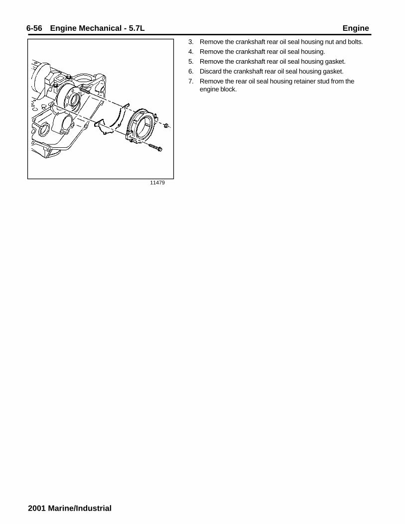
6-56 Engine Mechanical - 5.7L Engine
2001 Marine/Industrial
11479
3. Remove the crankshaft rear oil seal housing nut and bolts.
4. Remove the crankshaft rear oil seal housing.
5. Remove the crankshaft rear oil seal housing gasket.
6. Discard the crankshaft rear oil seal housing gasket.
7. Remove the rear oil seal housing retainer stud from theengine block.

Engine Engine Mechanical - 5.7L 6-57
2001 Marine/Industrial
317268
317351
317295
Crankshaft and Bearings Removal1. Mark or identify the crankshaft bearing cap locations,
direction and positions for assembly.
2. Remove the crankshaft bearing cap bolts.
3. Remove the crankshaft bearing caps.
4. Remove the crankshaft.
5. Remove the crankshaft bearings from the crankshaftbearing caps.

6-58 Engine Mechanical - 5.7L Engine
2001 Marine/Industrial
317292
182855
521820
6. Remove the crankshaft bearings from the engine block.
Engine Block Plug RemovalTools Required
J 41712 Oil Pressure Switch Socket
Caution: Refer to Safety Glasses Caution in Cautions andNotices.
1. Remove the transmission locator pins (if required).
2. Remove the S type pin (crankshaft rear oil seal housing)(ifrequired).

Engine Engine Mechanical - 5.7L 6-59
2001 Marine/Industrial
182854
333649
333652
3. Remove the expansion cup plug (camshaft rear bearinghole).
4. Remove the engine oil pressure gauge sensor using the J41712.
5. Remove the engine oil pressure sensor gauge fitting.

6-60 Engine Mechanical - 5.7L Engine
2001 Marine/Industrial
69847
182841
182838
6. Remove the square socket plugs (engine block oil gallery)from the rear of the engine block.
7. Remove the left side rear and left rear top engine block oilgallery plugs.
8. Remove the engine block oil gallery plugs (front) from theengine block and discard.
Insert a 3/8 x 26 in. rod into the rear oil gallery holes in orderto drive out the front engine block oil gallery plugs.

Engine Engine Mechanical - 5.7L 6-61
2001 Marine/Industrial
500648
9. Remove the engine block core hole plugs.
9.1. Use a suitable tool in order to drive the engine block core hole plugs into the coolant jacket.
9.2. Use a suitable tool in order to pull the engine block core hole plugs from the coolant jacket.
9.3. Discard the engine block core hole plugs.

6-62 Engine Mechanical - 5.7L Engine
2001 Marine/Industrial
317297
Engine Block Clean and InspectTools Required
J 8087 Cylinder Bore Gauge
Caution: Refer to Safety Glasses Caution in Cautions andNotices.
1. Clean all the remaining sealing or gasket material from thesealing surfaces.
2. Clean the engine block with cleaning solvent.
3. Flush the engine block with clean water or steam.
4. Clean the cylinder bores.
5. Clean the oil galleries and the oil passages.
6. Clean the scale and the deposits from the coolantpassages.
Notice: Clean all debris, dirt and coolant from the engine blockcylinder head bolt holes. Failure to remove all foreign material mayresult in damaged threads, improperly tightened fasteners ordamage to the components.
7. Clean the engine block cylinder head bolt holes.
8. After cleaning the engine block, spray or wipe the cylinderbores and the machined surfaces with clean engine oil.
9. Inspect the following areas:
• Coolant jackets (3) for cracks
• Cylinder bores (1) for scratches or gouging
• Valve lifter bores (2) for excessive scoring or wear
• Threaded holes (4) for damage
• Crankshaft bearing webs (5) for cracks
• Crankshaft bearing caps (6) and the crankshaft bearingbores (7) for damage
- The crankshaft bearing bores should be round and uniform when measuring the inside diameter (ID).
- The surface where the crankshaft bearings contact the crankshaft bearing bore should be smooth.
- If a crankshaft bearing cap is damaged and requires replacement, replace the crankshaft bearing cap first, then rebore the engine block crankshaft bearing bores and check for proper alignment. Finally, check the crankshaft fro the proper clearances.
• Engine block core hole plug bores (8) for damage
• Engine block (9) fro cracks or damage
• Engine mount bosses (10) for damage

Engine Engine Mechanical - 5.7L 6-63
2001 Marine/Industrial
4972
186747
10. Measure the cylinder bores for taper and out-of-round.
10.1. Depress the plunger on the J 8087 7 mm (0.275 in) or until the J 8087 enters the cylinder bore.
10.2. Center the J 8087 in the cylinder bore and turn the indicator dial to 0.
10.3. Move the J 8087 up and down the cylinder bore to determine the cylinder bore taper. Refer to Engine Mechanical Specifications.
10.4. Turn the J 8087 to different points around the cylinder bore to determine the cylinder bore out-of-round condition. Refer to Engine Mechanical Specifications.
Cylinder Boring and HoningHoning Procedure
Caution: Refer to Safety Glasses Caution in Cautions andNotices.
1. When honing the cylinder bores, follow the manufacturer’srecommendations for equipment use, cleaning andlubrication.
• Use only clean sharp stones of the proper grade for theamount of material to be removed.
• Dull, dirty stones cut unevenly and generate excessiveheat.
• DO NOT hone to a final grade with a coarse or medium-grade stone.
• Leave sufficient metal so that all the stone marks will beremove with the fine grade stones.
• Perform the final honing with a fine-grade stone and honethe cylinder bore in a cross-hatch pattern at 45-65degrees to obtain the proper clearance.
2. During the honing operation, thoroughly check the cylinderbore.
• Repeatedly check the cylinder bore fit with the selectedpiston.
• All measurements of the piston or cylinder bore shouldbe made with the components at normal roomtemperature.
3. When honing to eliminate taper in the cylinder bore, use fullstrokes the complete length of the cylinder bore.
4. Repeatedly check the measurement at the top, the middleand the bottom of the cylinder bore.
• The finish marks should be clean but not sharp.
• The finish marks should be free from imbedded particlesor torn or folded material.
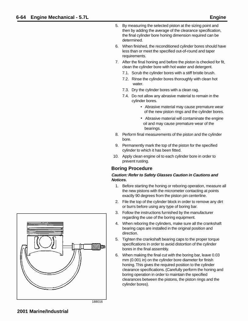
6-64 Engine Mechanical - 5.7L Engine
2001 Marine/Industrial
188016
5. By measuring the selected piston at the sizing point andthen by adding the average of the clearance specification,the final cylinder bore honing dimension required can bedetermined.
6. When finished, the reconditioned cylinder bores should haveless than or meet the specified out-of-round and taperrequirements.
7. After the final honing and before the piston is checked for fit,clean the cylinder bore with hot water and detergent.
7.1. Scrub the cylinder bores with a stiff bristle brush.
7.2. Rinse the cylinder bores thoroughly with clean hot water.
7.3. Dry the cylinder bores with a clean rag.
7.4. Do not allow any abrasive material to remain in the cylinder bores.
• Abrasive material may cause premature wear of the new piston rings and the cylinder bores.
• Abrasive material will contaminate the engine oil and may cause premature wear of the bearings.
8. Perform final measurements of the piston and the cylinderbore.
9. Permanently mark the top of the piston for the specifiedcylinder to which it has been fitted.
10. Apply clean engine oil to each cylinder bore in order toprevent rusting.
Boring ProcedureCaution: Refer to Safety Glasses Caution in Cautions andNotices.
1. Before starting the honing or reboring operation, measure allthe new pistons with the micrometer contacting at pointsexactly 90 degrees from the piston pin centerline.
2. File the top of the cylinder block in order to remove any dirtor burrs before using any type of boring bar.
3. Follow the instructions furnished by the manufacturerregarding the use of the boring equipment.
4. When reboring the cylinders, make sure all the crankshaftbearing caps are installed in the original position anddirection.
5. Tighten the crankshaft bearing caps to the proper torquespecifications in order to avoid distortion of the cylinderbores in the final assembly.
6. When making the final cut with the boring bar, leave 0.03mm (0.001 in) on the cylinder bore diameter for finishhoning. This gives the required position to the cylinderclearance specifications. (Carefully perform the honing andboring operation in order to maintain the specifiedclearances between the pistons, the piston rings and thecylinder bores).

Engine Engine Mechanical - 5.7L 6-65
2001 Marine/Industrial
4967
4965
34671
Piston and Connecting Rod DisassembleTools Required
J 24086-C Piston Pin Remover/Installer
Caution: Refer to Safety Glasses Caution in Cautions andNotices.
1. Remove the piston rings from the pistons.
2. Press the piston pin from the connecting rod using theJ 24086-C.
The piston pin has an interference fit into the connecting rod,and is full floating in the piston.
3. Mark, seperate and organize the parts for assembly.

6-66 Engine Mechanical - 5.7L Engine
2001 Marine/Industrial
34671
4977
156168
Piston, Connecting Rod and Bearings Clean andInspectImportant: Measurement of all components should be taken withthe components at room temperature.
Do not use a wire brush in order to clean any part of the piston.
Caution: Refer to Safety Glasses Caution in Cautions andNotices.
1. Clean the piston and connecting rod in solvent.
2. Dry the components with compressed air.
3. Clean the piston ring grooves with a suitable ring groovecleaning tool.
4. Clean the piston oil lubrication holes and slots.
5. Inspect the piston for the following:
• Eroded areas (1) on the top of the piston
• Scuffed or damaged skirt (2)
• Damage to the pin bore (3)
• Cracks in the piston ring lands, the piston skirt or the pin bosses
• Piston ring grooves for nicks, burrs or other warpage which may cause the piston ring to bind
6. Inspect the piston pin for scoring, wear or other damage

Engine Engine Mechanical - 5.7L 6-67
2001 Marine/Industrial
4969
22934
4976
7. Measure the piston ring-to-piston ring groove sideclearance.
7.1. Insert the edge of the piston ring into the piston ring groove.
7.2. Roll the piston ring completely around the piston.
• If binding is caused by a distorted piston ring groove, MINOR imperfections may be removed with a fine file.
• If binding is caused by a distorted piston ring, replace the piston ring.
8. Measure the piston ring side clearance with a feeler gauge.
• If the side clearance is too small, try another piston ringset.
• If the proper piston ring-to-piston ring groove clearancecannot be achieved, replace the piston and pin assembly.
9. To determine the proper piston ring side clearance, refer toEngine Mechanical Specifications.
10. To determine piston pin-to-bore clearance, use amicrometer and measure the piston pin.

6-68 Engine Mechanical - 5.7L Engine
2001 Marine/Industrial
4975
188016
156167
11. To determine piston pin-to-bore clearance, use an insidemicrometer and measure the piston pin bore.
12. To determine the piston pin-to-bore clearance, subtract thepiston pin diameter from the piston pin bore diameter. Referto Engine Mechanical Specifications.
13. Measure the piston with a micrometer at a right angle to thepiston pin bore, measure the piston at 11 mm (0.433 in)from the bottom of the skirt. Refer to Engine MechanicalSpecifications.
If the piston is not within specifications, replace the pistonand pin as an assembly.
14. Inspect the connecting rod for an out-of-round bearing bore.Refer to Engine Mechanical Specifications.

Engine Engine Mechanical - 5.7L 6-69
2001 Marine/Industrial
156169
4968
4972
15. Inspect the connecting rod for twisting.
16. Inspect the connecting rod for damage to the bearing capand bolt threads.
17. Measure the piston compression ring end gap.
Important: Fit each compression ring to the cylinder in which it willbe used.
18. Place the compression ring into the cylinder bore.
18.1. Push the compression ring into the cylinder bore to approximately 6.5 mm (0.25 in) above the ring travel. The ring must be square to the cylinder wall.
18.2. Use a feeler gauge in order to measure the end gap.
Select another size ring set if the end gap exceeds specifications. Refer to Engine Mechanical Specifications.
Piston SelectionTools Required
J 8087 Cylinder Bore Gauge
Important: Measurements of all components should be taken withthe comonents at normal room temperature.
For proper piston fit, the engine block cylinder bores should nothave excessive wear or taper.
A used piston and piston pin set may be reinstalled if, aftercleaning and inspection, the piston and piston pin are withinspecifications.
1. Use the J 8087 in order to measure the cylinder borediameter. Measure at a point 64 mm (2.5 in) from the top ofthe cylinder bore and 90 degrees to the crankshaftcenterline.

6-70 Engine Mechanical - 5.7L Engine
2001 Marine/Industrial
4974
188016
4965
2. Measure the J 8087 with a micrometer and record thereading.
3. With a micrometer or caliper at a right angle to the piston pinbore, meausre the piston 11 mm (0.433 in) from the bottomof the skirt.
4. Subtract the piston diameter from the cylinder bore diameterin order to determine piston-to-bore clearance.
Specification
Piston-to-bore clearance 0.018-0.068 mm (0.0007-0.0026in).
5. If the proper clearance cannot be obtained, then selectanother piston and measure the clearances.
If the proper fit cannot be obtained, the cylinder bore mayrequire honing or boring.
6. When the piston-to-cylinder bore clearance is withinspecifications, permanently mark the top of the piston forinstallation into the proper cylinder.
Piston and Connecting Rod AssembleTools Required
J 24086-C Piston Pin Remover/Installer
Caution: Avoid contact with HOT components. Wear safetlyglasses and protective gloves to avoid personal injury.Notice: Applying excessive heat to the connecting rod maydamage or distort the rod. Rod temperature SHOULD NOTexceed 315°C (600°F). At this temperature, the end of theconnecting rod will turn a straw color upon visual inspection.
Notice: After the J 24086-C installer hub bottoms on the supportassembly, DO NOT exceed 35,000 kPa (5,000 psi) or the tool maybe damaged.

Engine Engine Mechanical - 5.7L 6-71
2001 Marine/Industrial
490763
Important: When assembling the piston and connecting rod, themark on the top of the piston must point to the front of the engineblock. The left bank connecting rods should have the flange facetoward the front of the engine block. The right bank connectingrods should have the flange face toward the rear of the engineblock.
The piston pin has an interference fit into the connecting rod and isfull floating in the piston.
1. Install the piston pin and connecting rod assembly.
1.1. Lubricate the piston pin bores with clean engine oil.
1.2. Use a torch and apply MILD heat to the piston pin end of the connecting rod.
1.3. Use the J 24086-C in order to press the piston pin into the piston and connecting rod assembly.
1.4. Inspect for the proper installation of the piston and piston pin. The piston must move freely on the piston pin with no binding or interference.
Notice: Use a piston ring expander to install the piston rings. Therings may be damaged if expanded more than necessary.
2. Install the piston rings onto the piston.
2.1. Install the oil control piston ring spacer.
2.2. Install the lower oil control piston ring.
2.3. Install the upper oil control piston ring.
2.4. Install the lower compression piston ring.
The mark on the side of the piston ring should face the top of the piston.
2.5. Install the upper compression piston ring.
The mark on the side of the piston ring should face the top of the piston.

6-72 Engine Mechanical - 5.7L Engine
2001 Marine/Industrial
4967
59918
3. Space the compression piston ring end gaps 120 degreesapart.
4. Space the oil control piston ring end gaps a minimum of 90degrees apart.
Crankshaft and Bearings Clean and InspectTools Required
J 7872 Magnetic Base Dial Indicator
J 36660 Electronic Torque Angle Meter
J 43690 Rod Bearing Clearance Checking Tool
Caution: Refer to Safety Glasses Caution in Cautions andNotices.Important: Use care when handling the crankshaft. Avoid damageto the crankshaft bearing surfaces.
1. Clean the crankshaft in cleaning solvent. Remove all sludgeor restrictions from the oil passages.
2. Dry the crankshaft with compressed air.
334386
3. Clean the crankshaft bearings in cleaning solvent. Wipe thecrankshaft bearings clean with a soft cloth, do not scratchthe crankshaft bearing surfaces.
4. Dry the crankshaft and crankshaft bearings withcompressed air.
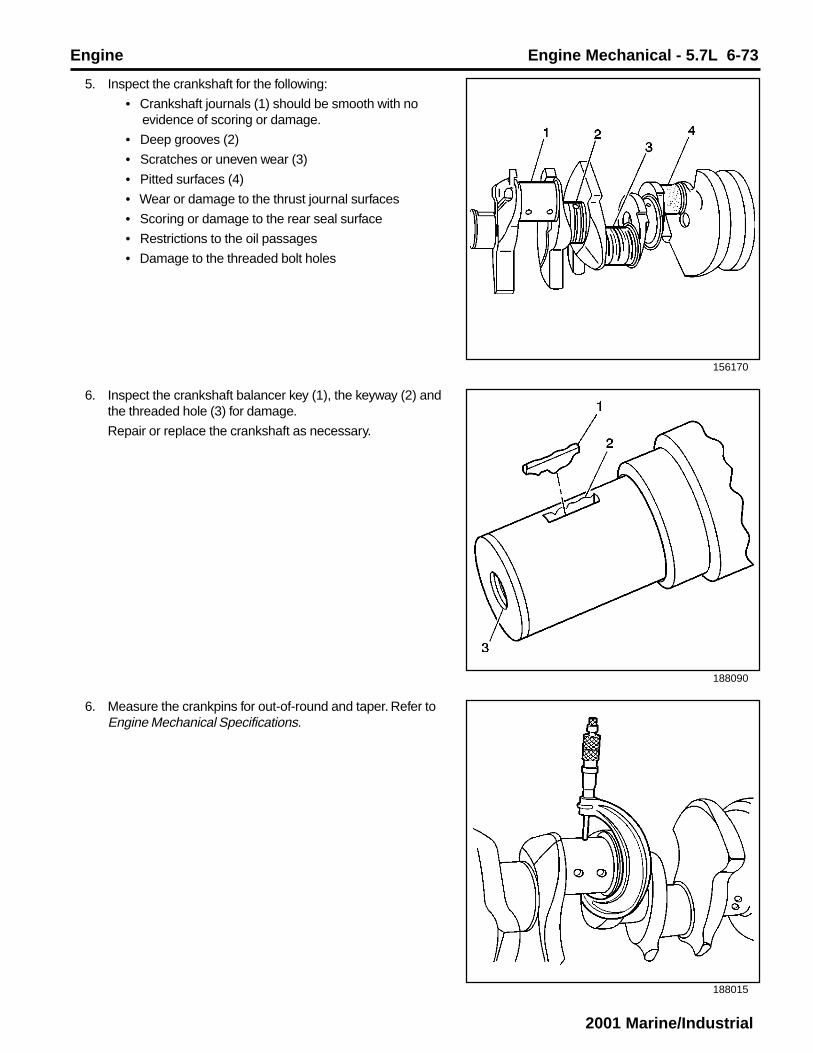
Engine Engine Mechanical - 5.7L 6-73
2001 Marine/Industrial
156170
188090
188015
5. Inspect the crankshaft for the following:
• Crankshaft journals (1) should be smooth with no evidence of scoring or damage.
• Deep grooves (2)
• Scratches or uneven wear (3)
• Pitted surfaces (4)
• Wear or damage to the thrust journal surfaces
• Scoring or damage to the rear seal surface
• Restrictions to the oil passages
• Damage to the threaded bolt holes
6. Measure the crankpins for out-of-round and taper. Refer toEngine Mechanical Specifications.
6. Inspect the crankshaft balancer key (1), the keyway (2) andthe threaded hole (3) for damage.
Repair or replace the crankshaft as necessary.

6-74 Engine Mechanical - 5.7L Engine
2001 Marine/Industrial
35210
188467
8. Use a suitable support to support the crankshaft on the frontand rear journals.
9. Use the J 7872 in order to measure the crankshaft journalrunout.
The crankshaft runout should not exceed 0.038 mm (0.0015in).
10. Measure the crankshaft end play.
Important: In order to properly measure the crankshaft end play,the crankshaft, the crankshaft bearings and the crankshaft bearingcaps, the crankshaft bearing cap bolts must be installed into theengine block and the bolts tightened to specifications.
Firmly thrust the crankshaft first rearward, then forward. This willalign the crankshaft rear bearings and the crankshaft thrustsurfaces.
10.1. With the crankshaft pushed forward, insert a feeler gauge between the crankshaft and the crankshaft bearing surface and then measure the clearance. Refer to Engine Mechanical Specifications.
10.2. If the correct end play cannot be obtained, verify that the correct size crankshaft bearing has been installed. Refer to Engine Mechanical Specifications.
10.3. Inspect the crankshaft for binding. Turn the crankshaft to check for binding. If the crankshaft does not turn freely, then loosen the crankshaft bearing cap bolts, one bearing cap at a time, until the tight crankshaft bearing is located.
Burrs on the crankshaft bearing cap, foreign matter between the crankshaft bearing and the engine block or crankshaft bearing cap or a faulty crankshaft bearing could cause a lack of clearance at the crankshaft bearing.

Engine Engine Mechanical - 5.7L 6-75
2001 Marine/Industrial
52051
52053
52056
11. Inspect the crankshaft bearings for craters or pockets.Flattened sections on the crankshaft bearing halves alsoindicate fatigue.
12. Inspect the crankshaft bearings for excessive scoring ordiscoloration.
13. Inspect the crankshaft bearings for dirt or debris imbeddedinto the crankshaft bearing material.
14. Inspect the crankshaft bearings for improper seatingindicated by bright, polished sections of the crankshaftbearings.
• If the lower half of the crankshaft bearing is worn or damaged, both the upper and lower halves of the crankshaft bearing should be replaced.
• Generally, if the lower half of the crankshaft bearing issuitable for use, the upper half of the crankshaft bearingshould also be suitable for use.

6-76 Engine Mechanical - 5.7L Engine
2001 Marine/Industrial
188015
317292
Bearing Clearance Measuring ProceduresThe crankshaft bearings are of the precision insert type and do notuse shims for adjustment. If the clearances are excessive, thennew upper and lower crankshaft bearings will be required. Theservice crankshaft bearings are available in the standard size andan undersize.
The selective fitting of the crankshaft bearings are necessary inproduction in order to obtain close tolerances. For this reason, inone journal bore you may use one-half of a standard crankshaftbearing with one-half of an undersize crankshaft bearing.
Important: Do not use the plastic gauge method to measureconnecting rod bearing clearances. The plastic gauge method formeasuring connecting rod bearing clearances will result inunreliable measurements. Use only the micrometer method tocorrectly determine the connecting rod bearing clearances.
In order to determine the correct replacement crankshaft bearingsize, the crankshaft bearing clearance must be measuredaccurately. Either the micrometer or plastic gauge method may beused; however, the micrometer method gives more reliable resultsand is preferred.
Micrometer Method for Crankshaft Bearings
1. Measure the crankshaft journal diameter with a micrometerin several places, approximately 90 degrees apart, and thenaverage the measurements.
2. Determine the taper and the out-of-round of the crankshaftjournal. Refer to Engine Mechanical Specifications.
3. Install the crankshaft bearings into the engine block.

Engine Engine Mechanical - 5.7L 6-77
2001 Marine/Industrial
317295
353070
4. Install the crankshaft bearings into the crankshaft bearingcaps.
5. Install the crankshaft bearing caps in the original positionsand with the arrow on the crankshaft bearing caps in thedirection of the front of the engine block.
Notice: Refer to Fastener Notice in Cautions and Notices.
6. Install the crankshaft bearing cap bolts.
Tighten
6.1. Tighten the crankshaft bearing cap bolts and the crankshaft bearing cap studs on the first pass to 20 N•m (15 lb ft).
6.2. Tighten the crankshaft bearing cap bolts and the crankshaft bearing cap studs (two bolt caps) on the final pass an additional 73 degrees using the J 36660.
6.3. Tighten the crankshaft bearing cap outboard bolts and the crankshaft bearing cap outboard studs (four bolt caps) on the final pass an additional 43 degrees using the J 36660.
6.4. Tighten the crankshaft bearing cap inboard bolts and the crankshaft bearing cap inboard studs (four bolt caps) on the final pass an additional 73 degrees using
the J 36660.
7. Measure the crankshaft bearing inside diameter (ID) at thetop and the bottom using an inside micrometer.
8. In order to determine the crankshaft bearing clearance,subtract the journal diameter from the crankshaft bearing ID.
9. Compare the crankshaft bearing clearance to thespecifications. Refer to Engine Mechanical Specifications.
10. If the crankshaft bearing clearances exceeds specifications,install the new crankshaft bearings as follows:
10.1. Measure the crankshaft bearing inside diameter (ID) at the top and the bottom using an inside micrometer.
10.2. Compare the crankshaft bearing clearance to the specifications. Refer to Engine Mechanical Specifications.
11. Replace or repair the crankshaft if the proper clearancescannot be obtained.

6-78 Engine Mechanical - 5.7L Engine
2001 Marine/Industrial
188015
Micrometer Method for Connecting Rod Bearings
Notice: Do not shim, scrape or file bearing inserts. Do not touchthe bearing surface of the insert with bare fingers. Skin oil andacids will etch the bearing surface.
1. Measure the crankpin diameter with a micrometer in severalplaces, approximately 90 degrees apart, and then averagethe measurements.
2. Determine the taper and the out-of-round. Refer to EngineMechanical Specifications.
3. Install the connecting rod bearings into the connecting rodcap and the connecting rod.
Notice: Refer to Fastener Notice in Cautions and Notices.
4. Install the connecting rod caps and the nuts.
Tighten
4.1. Tighten the connecting rod nuts on the first pass, evenly to 27 N•m (20 lb ft).
4.2. Tighten the connecting rod nuts on the final pass an additional 55 degrees using the J 36660.
5. Measure the connecting rod bearing inside diameter (ID) atthe top and the bottom using an inside micrometer.
6. Compare the connecting rod bearing clearance to thespecifications. Refer to Engine Mechanical Specifications.
7. If the connecting rod bearing clearance is withinspecifications, the connecting rod bearing is satisfactory.
• Replace the connecting rod bearing if the clearance is not within specifications.
• Always replace both the upper and the lower connectingrod bearings as an assembly.
8. A standard or undersize connecting rod bearingcombination may result in the proper clearance.
If the proper connecting rod bearing clearance cannot beachieved using the standard or the undersize connecting rodbearings, it will be necessary to replace or repair thecrankshaft.

Engine Engine Mechanical - 5.7L 6-79
2001 Marine/Industrial
317292
317351
500655
Plastic Gauge Method for Crankshaft Bearings
1. Install the crankshaft bearings into the engine block.
2. Install the crankshaft.
3. Install the gauging plastic the full width of the journal.

6-80 Engine Mechanical - 5.7L Engine
2001 Marine/Industrial
317295
317268
4. Install the crankshaft bearings into the crankshaft bearingcaps.
5. Install the crankshaft bearing caps in the original positionsand with the arrow on the crankshaft bearing caps in thedirection of the front of the engine block.
Notice: Refer to Fastener Notice in Cautions and Notices.
6. Install the crankshaft bearing cap bolts and the crankshaftbearing cap studs.
Tighten
6.1. Tighten the crankshaft bearing cap bolts and the crankshaft bearing cap studs on the first pass to 20 N•m (15 lb ft).
6.2. Tighten the crankshaft bearing cap bolts and the crankshaft bearing cap studs (two bolt caps) on the final pass an additional 73 degrees using the J 36660.
6.3. Tighten the crankshaft bearing cap outboard bolts and the crankshaft bearing cap outboard studs (four bolt caps) on the final pass an additional 43 degrees using the J 36660.
6.4. Tighten the crankshaft bearing cap inboard bolts and the crankshaft bearing cap inboard studs (four bolt caps) on the final pass an additional 73 degrees using
the J 36660.
7. Remove the crankshaft bearing cap bolts.
8. Remove the crankshaft bearing caps. The gauging plasticmay adhere to either the crankshaft bearing journal or thecrankshaft bearing surface.
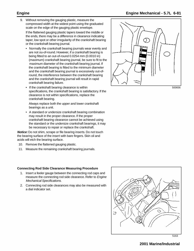
Engine Engine Mechanical - 5.7L 6-81
2001 Marine/Industrial
5163
9. Without removing the gauging plastic, measure thecompressed width at the widest point using the graduatedscale on the edge of the gauging plastic envelope.
If the flattened gauging plastic tapers toward the middle orthe ends, there may be a difference in clearance indicatingtaper, low spot or other irregularity of the crankshaft bearingor the crankshaft bearing journal.
• Normally the crankshaft bearing journals wear evenly and are not ou-of-round. However, if a crankshaft bearing is being fitted to an out-of-round 0.0254 mm (0.0010 in) (maximum) crankshaft bearing journal, be sure to fit to the
maximum diameter of the crankshaft bearing journal. If the crankshaft bearing is fitted to the minimum diameter and the crankshaft bearing journal is excessively out-of- round, the interference between the crankshaft bearing and the crankshaft bearing journal will result in rapid crankshaft bearing failure.
• If the crankshaft bearing clearance is within specifications, the crankshaft bearing is satisfactory. If the clearance is not within specifications, replace the crankshaft bearing.
Always replace both the upper and lower crankshaft bearings as a unit.
• A standard or undersize crankshaft bearing combination may result in the proper clearance. If the proper crankshaft bearing clearance cannot be achieved using the standard or the undersize crankshaft bearings, it may be necessary to repair or replace the crankshaft.
Notice: Do not shim, scrape or file bearing inserts. Do not touchthe bearing surface of the insert with bare fingers. Skin oil andacids will etch the bearing surface.
10. Remove the flattened gauging plastic.
11. Measure the remaining crankshaft bearing journals.
Connecting Rod Side Clearance Measuring Procedure
1. Insert a feeler gauge between the connecting rod caps andmeasure the connecting rod side clearance. Refer to EngineMechanical Specifications.
2. Connecting rod side clearances may also be measured witha dial indicator set.
500656

6-82 Engine Mechanical - 5.7L Engine
2001 Marine/Industrial
334038
69012
Crankshaft Balancer Clean and InspectCaution: Refer to Safety Glasses Caution in Cautions andNotices.
1. Clean the crankshaft balancer in cleaning solvent.
2. Dry the crankshaft balancer with compressed air.
3. Inspect the crankshaft balancer for the following:
• Worn or damaged bolt hole threads (1)
• Worn, chunking or deteriorated rubber (2) between thehub and outer ring
• Loose or improperly installed balance weights (3)
A properly installed front groove pin should be installed until flush or below flush with the face of the crankshaft balancer.
• Worn or damaged keyway (4)
Important: A crankshaft front oil sealing surface with excessivescoring, grooves, rust or other damage must be replaced.
• Worn, grooved or damaged crankshaft front oil sealing surface
Minor imperfections on the crankshaft balancer crankshaft front oil seal surface may be removed with a polishing compound or fine grade emery cloth.
Engine Flywheel Clean and InspectCaution: Refer to Safety Glasses Caution in Cautions andNotices.
1. Clean the engine flywheel (1) or (2) in cleaning solvent.
2. Dry the engine flywheel with compressed air.

Engine Engine Mechanical - 5.7L 6-83
2001 Marine/Industrial
381965
64126
188086
3. Inspect the engine flywheel (automatic transmission) (ifequipped) for the following:
• Stress cracks around the engine flywheel-to-torque converter bolt hole locations (1)
• Missing balance weights
• Stress cracks around the engine flywheel-to-crankshaft bolt hole locations (2) or (3)
Important: Do not attempt to repair the welded areas (if present)that retain the ring gear to the engine flywheel plate. Always installa NEW engine flywheel.
• Welded areas that retain the ring gear onto the engine flywheel for cracking (4) (if present)
• Damaged ring gear teeth (5)
4. Inspect the engine flywheel (manual transmission) (ifequipped) for loose or improperly installed flywheel weights(if applicable).
A properly installed flywheel weight should be installed untilflush or below flush with the face of the engine flywheel.
5. Inspect the engine flywheel (manual transmission) (ifequipped) for the following:
• Pitted friction surface (1)
• Scoring or grooves (2)
• Rust or other surface damage (3)
• Damaged ring gear teeth (4)
• Loose or improperly positioned ring gear
The ring gear has an interference fit onto the engine flywheel and the ring gear should be positioned completely flat against the flange of the engine flywheel.
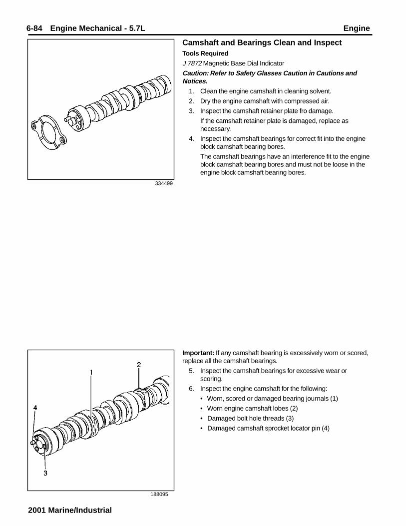
6-84 Engine Mechanical - 5.7L Engine
2001 Marine/Industrial
334499
188095
Camshaft and Bearings Clean and InspectTools Required
J 7872 Magnetic Base Dial Indicator
Caution: Refer to Safety Glasses Caution in Cautions andNotices.
1. Clean the engine camshaft in cleaning solvent.
2. Dry the engine camshaft with compressed air.
3. Inspect the camshaft retainer plate fro damage.
If the camshaft retainer plate is damaged, replace asnecessary.
4. Inspect the camshaft bearings for correct fit into the engineblock camshaft bearing bores.
The camshaft bearings have an interference fit to the engineblock camshaft bearing bores and must not be loose in theengine block camshaft bearing bores.
Important: If any camshaft bearing is excessively worn or scored,replace all the camshaft bearings.
5. Inspect the camshaft bearings for excessive wear orscoring.
6. Inspect the engine camshaft for the following:
• Worn, scored or damaged bearing journals (1)
• Worn engine camshaft lobes (2)
• Damaged bolt hole threads (3)
• Damaged camshaft sprocket locator pin (4)

Engine Engine Mechanical - 5.7L 6-85
2001 Marine/Industrial
188014
188012
66100
7. Measure the engine camshaft journals with a micrometer.
If the camshaft journals are more than 0.025 mm (0.0010 in)out-of-round, then replace the engine camshaft.
8. Measure for a bent engine camshaft or excessive enginecamshaft runout using the J 7872.
8.1. Mount the engine camshaft in a suitable stand between centers.
8.2. Use the J 7872 in order to check the intermediate engine camshaft journals.
If the runout exceeds 0.065 mm (0.0026 in), the engine camshaft is bent and must be replaced.
9. Measure the engine camshaft lobe lift using the J 7872.
9.1. Place the engine camshaft on the V-blocks.
9.2. Use the J 7872 in order to measure the engine camshaft lobe lift.
10. Replace the engine camshaft if the engine camshaft lobe liftis not within specifications. Refer to Engine MechanicalSpecifications.
Camshaft Bearing RemovalTools Required
J 33049 Camshaft Bearing Service Kit
1. Select the cone (1), the handle (10), the expanding driver (4-8), the washer (2 or 3) and the expander assembly (15) fromthe J 33049.
2. Assemble the J 33049.
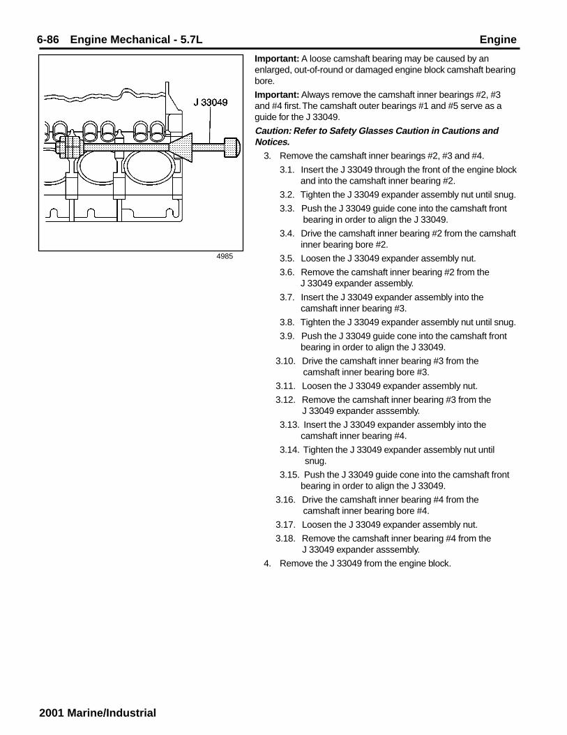
6-86 Engine Mechanical - 5.7L Engine
2001 Marine/Industrial
4985
Important: A loose camshaft bearing may be caused by anenlarged, out-of-round or damaged engine block camshaft bearingbore.
Important: Always remove the camshaft inner bearings #2, #3and #4 first. The camshaft outer bearings #1 and #5 serve as aguide for the J 33049.
Caution: Refer to Safety Glasses Caution in Cautions andNotices.
3. Remove the camshaft inner bearings #2, #3 and #4.
3.1. Insert the J 33049 through the front of the engine block and into the camshaft inner bearing #2.
3.2. Tighten the J 33049 expander assembly nut until snug.
3.3. Push the J 33049 guide cone into the camshaft front bearing in order to align the J 33049.
3.4. Drive the camshaft inner bearing #2 from the camshaft inner bearing bore #2.
3.5. Loosen the J 33049 expander assembly nut.
3.6. Remove the camshaft inner bearing #2 from the J 33049 expander assembly.
3.7. Insert the J 33049 expander assembly into the camshaft inner bearing #3.
3.8. Tighten the J 33049 expander assembly nut until snug.
3.9. Push the J 33049 guide cone into the camshaft front bearing in order to align the J 33049.
3.10. Drive the camshaft inner bearing #3 from the camshaft inner bearing bore #3.
3.11. Loosen the J 33049 expander assembly nut.
3.12. Remove the camshaft inner bearing #3 from the J 33049 expander asssembly.
3.13. Insert the J 33049 expander assembly into the camshaft inner bearing #4.
3.14. Tighten the J 33049 expander assembly nut until snug.
3.15. Push the J 33049 guide cone into the camshaft front bearing in order to align the J 33049.
3.16. Drive the camshaft inner bearing #4 from the camshaft inner bearing bore #4.
3.17. Loosen the J 33049 expander assembly nut.
3.18. Remove the camshaft inner bearing #4 from the J 33049 expander asssembly.
4. Remove the J 33049 from the engine block.

Engine Engine Mechanical - 5.7L 6-87
2001 Marine/Industrial
63219
66100
5. Remove the camshaft outer bearings #1 and #5.
5.1. Insert the J 33049 into the camshaft outer bearing #1.
5.2. Tighten the J 33049 expander assembly nut until snug.
5.3. Drive the camshaft outer bearing #1 from the camshaft outer bearing bore #1.
5.4. Loosen the J 33049 expander assembly nut.
5.5. Remove the camshaft outer bearing #1 from the J 33049 expander assembly.
5.6. Remove the J 33049 from the engine block.
5.7. Insert the J 33049 expander assembly into the camshaft outer bearing #5.
5.8. Tighten the J 33049 expander assembly nut until snug.
5.9. Drive the camshaft outer bearing #5 from the camshaft outer bearing bore #5.
5.10. Loosen the J 33049 expander assembly nut.
5.11. Remove the camshaft outer bearing #5 from the J 33049 expander asssembly.
6. Remove the J 33049 from the engine block.
7. Discard the camshaft bearings.
Camshaft Bearing InstallationTools Required
J 33049 Camshaft Bearing Service Kit
Important: Always install the camshaft outer bearings #1 and #5first. The camshaft outer bearings serve as a guide for the J 33049and help center the camshaft inner bearings during the installationprocess.
Look to ensure that the camshaft bearing lubrication hole or holesalign with the oil gallery hole or holes in the engine block. On someengines, the oil gallery holes may be difficult to see. Verify that thecamshaft bearing lubrication holes and the oil gallery holes arealigned.
1. Select the handle (10), the expanding driver (4-8), thewasher (2 or 3) and the expander assembly (15) from theJ 33049.
2. Assemble the J 33049.

6-88 Engine Mechanical - 5.7L Engine
2001 Marine/Industrial
63219
Caution: Refer to Safety Glasses Caution in Cautions andNotices.Important: The camshaft bearing lubrication holes must align withthe oil gallery holes in the engine block.
After installation of the camshaft bearings, always inspect thecamshaft bearing lubrication holes for proper alignment with the oilgallery holes.
An improperly aligned camshaft bearing lubrication hole and oilgallery hole will restrict oil flow to the camshaft bearing and thecamshaft journal.
3. Install the NEW camshaft outer bearings #5 and #1.
3.1. Install the NEW camshaft outer bearing #4 onto the J33049 expander assembly.
3.2. Tighten the J 33049 expander assembly nut until snug.
3.3. Align the camshaft outer bearing #5 lubrication hole with the oil gallery hole in the camshaft outer bearing bore #5 at the rear of the engine block.
3.4. Drive the camshaft outer bearing #5 into the camshaft outer bearing bore #5 at the rear of the engine block.
3.5. Loosen the J 33049 expander assembly nut.
3.6. Remove the camshaft outer bearing #5 from the J33049 expander assembly.
3.7. Install the NEW camshaft outer bearing #1 onto the J33049 expander assembly.
3.8. Tighten the J 33049 expander assembly nut until snug.
3.9. Align the camshaft outer bearing #1 lubrication hole with the oil gallery hole in the camshaft outer bearing bore #1 at the front of the engine block
3.10. Drive the camshaft outer bearing #1 into the camshaft outer bearing bore #1 at the front of the engine block.
3.11. Loosen the J 33049 expander assembly nut.
3.12. Carefully slide the J 33049 into the engine block until the J 33049 expander assembly is positioned between the camshaft inner bearing bore #3 and the
camshaft inner bearing bore #4.

Engine Engine Mechanical - 5.7L 6-89
2001 Marine/Industrial
4985
Important: The camshaft bearing lubrication holes must align withthe oil gallery holes in the engine block.
After installation of the camshaft bearings, always inspect thecamshaft bearing lubrication holes for proper alignment with the oilgallery holes.
An improperly aligned camshaft bearing lubrication hole and oilgallery hole will restrict oil flow to the camshaft bearing and thecamshaft journal.
4. Install the NEW camshaft inner bearings #4, #3 and #2.
4.1. Install the NEW camshaft inner bearing #4 onto the J33049 expander assembly.
4.2. Tighten the J 33049 expander assembly nut until snug.
4.3. Align the camshaft inner bearing #4 lubrication hole with the oil gallery hole in the camshaft inner bearing bore #4 of the engine block.
4.4. Push the J 33049 guide cone into the camshaft front bearing bore #1 in order to align the J 33049.
4.5. Drive the camshaft inner bearing #4 into the camshaft inner bearing bore #4.
4.6. Loosen the J 33049 expander assembly nut.
4.7. Carefully slide the J 33049 until the J 33049 expander assembly is positioned between the camshaft inner bearing bore #3 and the camshaft inner bearing bore #2.
4.8. Install the NEW camshaft inner bearing #3 onto the J33049 expander assembly.
4.9. Tighten the J 33049 expander assembly nut until snug.
4.10. Align the camshaft inner bearing #3 lubrication hole with the oil gallery hole in the camshaft inner bearing
bore #3 of the engine block.
4.11. Push the J 33049 guide cone into the camshaft front bearing bore #1 in order to align the J 33049.
4.12. Drive the camshaft inner bearing #3 into the camshaft inner bearing bore #3.
4.13. Loosen the J 33049 expander assembly nut.
4.14. Carefully slide the J 33049 until the J 33049 expander assembly is positioned between the camshaft inner bearing bore #2 and the camshaft outer bearing bore #1.
4.15. Install the NEW camshaft inner bearing #2 onto the J33049 expander assembly.
4.16. Tighten the J 33049 expander assembly nut until snug.
4.17. Align the camshaft inner bearing #2 lubrication hole with the oil gallery hole in the camshaft inner bearing
bore #2 of the engine block.
4.18. Push the J 33049 guide cone into the camshaft front bearing bore #1 in order to align the J 33049.
4.19. Drive the camshaft inner bearing #2 into the camshaft inner bearing bore #2.
4.20. Loosen the J 33049 expander assembly nut.

6-90 Engine Mechanical - 5.7L Engine
2001 Marine/Industrial
11503
188097
Timing Chain and Sprockets Clean and InspectCaution: Refer to Safety Glasses Caution in Cautions andNotices.
1. Clean the components with cleaning solvent.
2. Dry the components with compressed air.
3. Inspect the camshaft timing chain for binding or wear.
4. Inspect the camshaft sprocket and the crankshaft sprocketfor the following:
• Broken teeth (1)
• Damaged teeth (2)
• Chipped teeth (3)
• Worn teeth
• Uneven wear on the edge of the teeth
• Worn valleys between the sprocket teeth
• Crankshaft sprocket keyway for wear
• Woodruff key (crankshaft sprocket) for wear or damage
5. Carefully remove the J 33049 from the engine block.

Engine Engine Mechanical - 5.7L 6-91
2001 Marine/Industrial
182835
488857
Valve Rocker Arm and Push Rods Clean andInspectImportant: Parts that are to be reused must be marked, sortedand organized for assembly.
1. Mark, sort and organize the components for assembly.
Caution: Refer to Safety Glasses Caution in Cautions andNotices.
2. Clean the components with cleaning solvent.
3. Dry the components with compressed air.
4. Inspect the valve rocker arm components for the following:
• Wear or scoring of the valve rocker arm (3) ball area
• Valve rocker arm (3) pushrod sockets and valve stemcontact surfaces
The contact surfaces should be smooth with no scoring orexcessive wear.
• Valve rocker arm ball (2) for wear or scoring
The contact surfaces should be smooth with no scoring orexcessive wear.
5. Inspect the valve push rods for the following:
• Restriction of the oil passage (1)
• Wear or scoring of the end contact surfaces (2). The end contact surfaces must be smooth with no scoring or excessive wear.
• Shaft for bends (3).
Roll the valve pushrod on a flat surface to determineif the valve pushrod is bent.

6-92 Engine Mechanical - 5.7L Engine
2001 Marine/Industrial
178485
521834
Valve Lifters and Guides Clean and InspectImportant: Components that are to be reused must be marked,sorted and organized for assembly.
1. Mark, sort and organize the components for assembly.
Caution: Refer to Safety Glasses Caution in Cautions andNotices.
2. Clean the components with cleaning solvent.
3. Dry the components with compressed air.
4. Inspect the valve lifter for the following:
• Broken or damaged clip (1)
• Worn valve pushrod socket (2)
• Wear or scuffing (3)
If the valve lifter shows wear or scuffing, inspect theengine block valve lifter bores for wear or damage
• Worn roller (4)
• Loose or damaged pin (5)
• Plugged oil hole (6)
5. Inspect the valve lifter guides (1) for the following:
• Excessive wear (1)
• Cracks or damage
6. Inspect the valve lifter guide retainer for the following:
• Wear, damage or stress cracking in the leg areas (2)
• Wear or damage in the bolt holes (3)
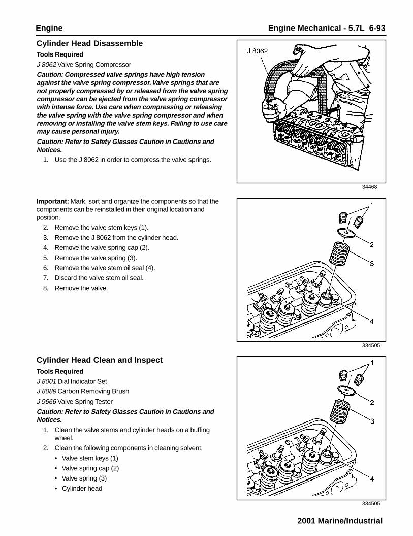
Engine Engine Mechanical - 5.7L 6-93
2001 Marine/Industrial
34468
334505
334505
Cylinder Head DisassembleTools Required
J 8062 Valve Spring Compressor
Caution: Compressed valve springs have high tensionagainst the valve spring compressor. Valve springs that arenot properly compressed by or released from the valve springcompressor can be ejected from the valve spring compressorwith intense force. Use care when compressing or releasingthe valve spring with the valve spring compressor and whenremoving or installing the valve stem keys. Failing to use caremay cause personal injury.Caution: Refer to Safety Glasses Caution in Cautions andNotices.
1. Use the J 8062 in order to compress the valve springs.
Important: Mark, sort and organize the components so that thecomponents can be reinstalled in their original location andposition.
2. Remove the valve stem keys (1).
3. Remove the J 8062 from the cylinder head.
4. Remove the valve spring cap (2).
5. Remove the valve spring (3).
6. Remove the valve stem oil seal (4).
7. Discard the valve stem oil seal.
8. Remove the valve.
Cylinder Head Clean and InspectTools Required
J 8001 Dial Indicator Set
J 8089 Carbon Removing Brush
J 9666 Valve Spring Tester
Caution: Refer to Safety Glasses Caution in Cautions andNotices.
1. Clean the valve stems and cylinder heads on a buffingwheel.
2. Clean the following components in cleaning solvent:
• Valve stem keys (1)
• Valve spring cap (2)
• Valve spring (3)
• Cylinder head

6-94 Engine Mechanical - 5.7L Engine
2001 Marine/Industrial
4957
64318
3. Dry the components with compressed air.
4. Use the J 8089 to clean the carbon from the cylinder headcombustion chambers.
Be careful not to scuff the combustion chambers.
5. Inspect the cylinder head for the following:
• Damage to the gasket surfaces
• Damage to the threaded bolt holes
• Burnt or eroded areas in the combustion chambers
• Cracks in the exhaust ports and combustion chambers
• External cracks in the water chambers
• Restrictions in the intake or exhaust passages
• Restrictions in the cooling system passages
• Rusted, damaged or leaking core plugs
6. Measure the cylinder head for warpage with a straight edgeand feeler gauge
• A cylinder head block deck with warpage in excess of 0.10 mm (0.004 in) within a 152.4 mm (6.0 in) area must be repaired or replaced.
• A cylinder head exhaust manifold deck with warpage in excess of 0.05 mm (0.002 in) must be repaired or
replaced.
• A cylinder head intake manifold deck with warpage in excess of 0.10 mm (0.004 in) must be repaired or
replaced.

Engine Engine Mechanical - 5.7L 6-95
2001 Marine/Industrial
4960
40075
156172
7. Use the J 9666 in order to measure the valve spring.
Replace the valve spring if the valve spring tension is lessthan 338 N (76 lb) at 43.2 mm (1.70 in).
8. Inspect the valve springs for squareness.
9. Valve stems (1) with excessive valve guide (2) clearancemust be repaired or the cylinder head replaced.

6-96 Engine Mechanical - 5.7L Engine
2001 Marine/Industrial
35214
35214
10. Measure the valve stem-to-guide clearance.
Excessive valve stem-to-guide clearance may cause anexcessive oil consumption and may also cause a valve tobreak. Insufficient clearance will result in noisy and stickyfunctioning of the valve and will disturb the engine assemblysmoothness.
10.1. Clamp the J 8001 on the exhaust port side of the cylinder head.
10.2. Position the dial indicator so that the movement of the valve stem from side to side (crosswise to the cylinder head) will cause a direct movement of the dial indicator stem.
The dial indicator stem must contract the side of the valve stem just above the valve guide.
10.3. Drop the valve head about 1.6 mm (0.063 in) off the valve seat.
10.4. Use light pressure and move the valve stem from side to side in order to obtain a valve stem-to-guide clearance reading. Refer to Engine Mechanical Specifications.
Valve Guide Reaming/Valve and Seat GrindingTools Required
J 5830-02 Valve Guide Reamer Set
J 8001 Dial Indicator Set
1. Measure the valve stem-to-guide clearance. Refer toCylinder Head Clean and Inspect.

Engine Engine Mechanical - 5.7L 6-97
2001 Marine/Industrial
156172
480556
156174
2. Improper valve stem (1) to valve guide (2) clearance maycause excessive oil consumption.
Caution: Refer to Safety Glasses Caution in Cautions andNotices.Important: Exhaust valves with excessive valve stem-to-guideclearance must be replaced with the available service valve thathas an 0.0774 mm (0.0305 in) oversize valve stem. The intakevalves are NOT available with oversize valve stems. Replace thecylinder head if after using a NEW intake valve in order to measurethe valve stem-to-guide clearance, the valve stem-to-guideclearance is not within specifications.
3. Use the J 5830-3 in order to ream the exhaust valve guide inorder to achieve the correct valve stem-to-guide clearance.
4. Always recondition the exhaust valve seat after reaming theexhaust valve guide bores and installing new exhaustvalves.
5. Inspect the valves for the following:
• Burnt or damaged areas (1)
• Undersize margain (2)
• Bent stem (3)
• Scoring or other damage to the stem (4)
• Worn key groove (5)
• Worn stem tip (6)
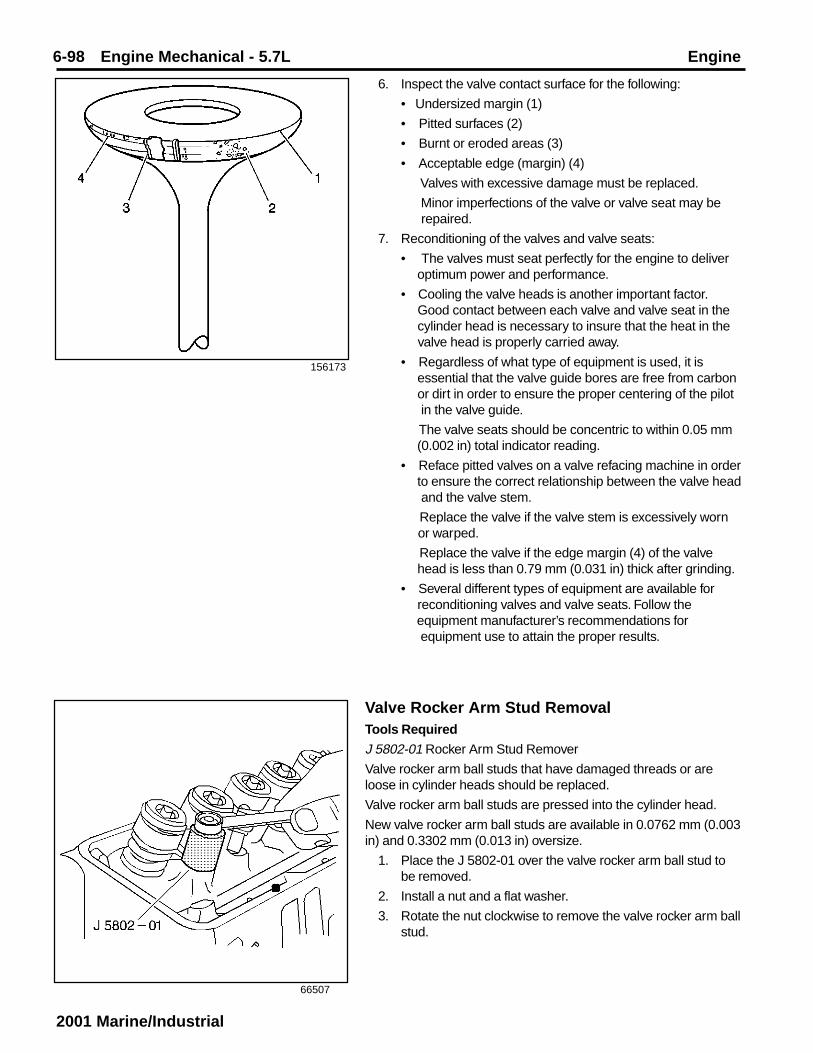
6-98 Engine Mechanical - 5.7L Engine
2001 Marine/Industrial
156173
6. Inspect the valve contact surface for the following:
• Undersized margin (1)
• Pitted surfaces (2)
• Burnt or eroded areas (3)
• Acceptable edge (margin) (4)
Valves with excessive damage must be replaced.
Minor imperfections of the valve or valve seat may be repaired.
7. Reconditioning of the valves and valve seats:
• The valves must seat perfectly for the engine to deliver optimum power and performance.
• Cooling the valve heads is another important factor. Good contact between each valve and valve seat in the cylinder head is necessary to insure that the heat in the valve head is properly carried away.
• Regardless of what type of equipment is used, it is essential that the valve guide bores are free from carbon or dirt in order to ensure the proper centering of the pilot in the valve guide.
The valve seats should be concentric to within 0.05 mm (0.002 in) total indicator reading.
• Reface pitted valves on a valve refacing machine in order to ensure the correct relationship between the valve head and the valve stem.
Replace the valve if the valve stem is excessively worn or warped.
Replace the valve if the edge margin (4) of the valve head is less than 0.79 mm (0.031 in) thick after grinding.
• Several different types of equipment are available for reconditioning valves and valve seats. Follow the equipment manufacturer’s recommendations for equipment use to attain the proper results.
66507
Valve Rocker Arm Stud RemovalTools Required
J 5802-01 Rocker Arm Stud Remover
Valve rocker arm ball studs that have damaged threads or areloose in cylinder heads should be replaced.
Valve rocker arm ball studs are pressed into the cylinder head.
New valve rocker arm ball studs are available in 0.0762 mm (0.003in) and 0.3302 mm (0.013 in) oversize.
1. Place the J 5802-01 over the valve rocker arm ball stud tobe removed.
2. Install a nut and a flat washer.
3. Rotate the nut clockwise to remove the valve rocker arm ballstud.

Engine Engine Mechanical - 5.7L 6-99
2001 Marine/Industrial
Valve Rocker Arm Stud InstallationTools Required
J 5715 Reamer (0.0762 mm (0.003 in)
J 6036 Reamer (0.03302 mm (0.013 in)
J 6880 Rocker Arm Stud Installer
Caution: Refer to Safety Glasses Caution in Cautions andNotices.Important: Valve rocker arm ball studs that have damagedthreads or are loose in cylinder heads should be replaced. Newvalve rocker arm ball studs are available in 0.0762 mm (0.003 in)and 0.03302 mm (0.013 in) oversize.
1. Ream the hole to the proper size for the replacementoversize valve rocker arm ball stud.
Use J 5715 for 0.0762 mm (0.003 in) oversize valve rockerarm ball studs, or J 6036 for 0.03302 mm (0.013 in) oversizevalve rocker arm ball studs.
66509
66504
2. Apply lubricant GM P/N 1052271 or equivalent to the lowerend (press-fit end) of the valve rocker arm ball stud.
3. Use the J 6880 and a hammer to install the valve rocker armball stud into place.
The valve rocker arm ball stud is installed to proper depthwhen the J 6880 bottoms onto the cylinder head.
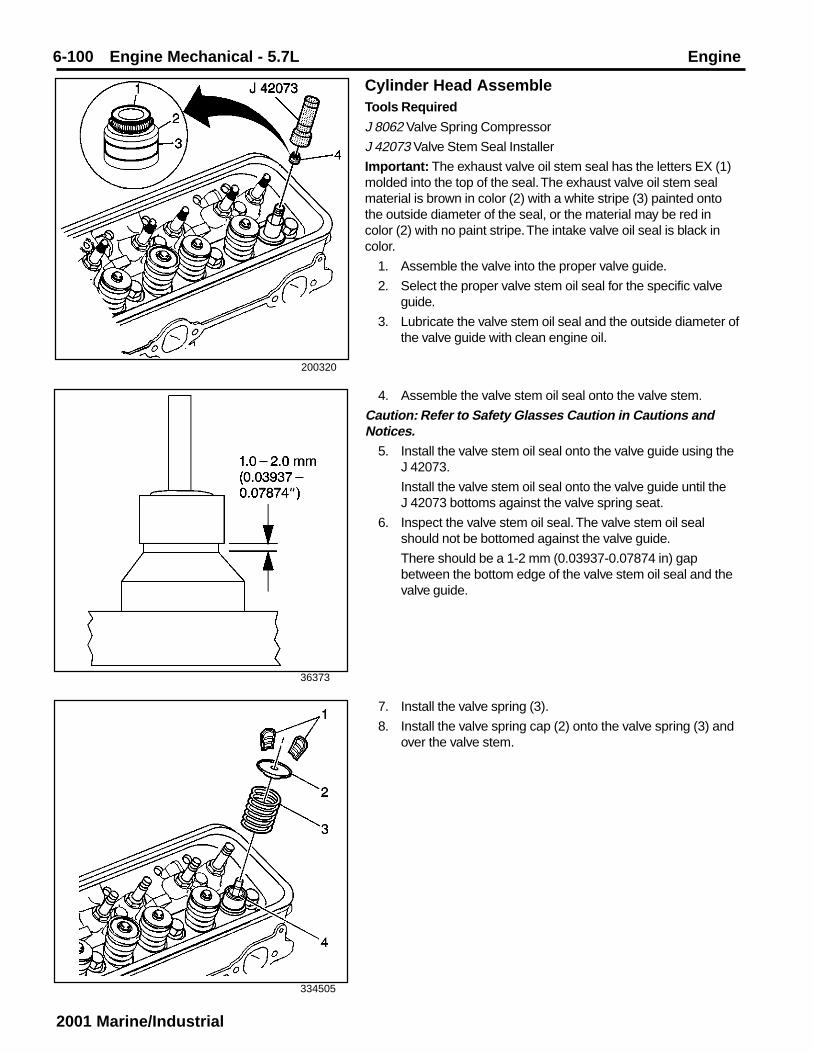
6-100 Engine Mechanical - 5.7L Engine
2001 Marine/Industrial
200320
36373
334505
Cylinder Head AssembleTools Required
J 8062 Valve Spring Compressor
J 42073 Valve Stem Seal Installer
Important: The exhaust valve oil stem seal has the letters EX (1)molded into the top of the seal. The exhaust valve oil stem sealmaterial is brown in color (2) with a white stripe (3) painted ontothe outside diameter of the seal, or the material may be red incolor (2) with no paint stripe. The intake valve oil seal is black incolor.
1. Assemble the valve into the proper valve guide.
2. Select the proper valve stem oil seal for the specific valveguide.
3. Lubricate the valve stem oil seal and the outside diameter ofthe valve guide with clean engine oil.
4. Assemble the valve stem oil seal onto the valve stem.
Caution: Refer to Safety Glasses Caution in Cautions andNotices.
5. Install the valve stem oil seal onto the valve guide using theJ 42073.
Install the valve stem oil seal onto the valve guide until theJ 42073 bottoms against the valve spring seat.
6. Inspect the valve stem oil seal. The valve stem oil sealshould not be bottomed against the valve guide.
There should be a 1-2 mm (0.03937-0.07874 in) gapbetween the bottom edge of the valve stem oil seal and thevalve guide.
7. Install the valve spring (3).
8. Install the valve spring cap (2) onto the valve spring (3) andover the valve stem.

Engine Engine Mechanical - 5.7L 6-101
2001 Marine/Industrial

6-102 Engine Mechanical - 5.7L Engine
2001 Marine/Industrial
34468
5274
Caution: Compressed valve springs have high tensionagainst the valve spring compressor. Valve springs that arenot properly compressed by or released from the valve springcompressor can be ejected from the valve spring compressorwith intense force. Use care when compressing or releasingthe valve spring with the valve spring compressor and whenremoving or installing the valve stem keys. Failing to use caremay cause personal injury.Caution: Refer to Safety Glasses Caution in Cautions andNotices.
9. Use the J 8062 in order to compress the valve springs.
10. Install the valve stem keys.
10.1 Use grease in order to hold the valve stem keys in place while disconnecting the J 8062.
10.2. Ensure that the valve stem keys seat properly in the upper groove of the valve stem.
10.3. Tap the end of the valve stem with a plastic-faced in order to seat the valve stem keys, if necessary.
Oil Pump Disassemble1. Remove the oil pump driveshaft and oil pump driveshaft
retainer.

Engine Engine Mechanical - 5.7L 6-103
2001 Marine/Industrial
5275
5276
5277
2. Remove the oil pump screen (if necessary).
• The oil pump screen has a press fit into the oil pump cover.
• DO NOT remove the oil pump screen from the pipe. The pipe and oil pump screen are serviced as a complete assembly.
3. Remove the oil pump cover bolts.
4. Remove the oil pump cover.

6-104 Engine Mechanical - 5.7L Engine
2001 Marine/Industrial
5278
30401
186750
Oil Pump Clean and InspectCaution: Refer to Safety Glasses Caution in Cautions andNotices.
1. Clean the oil pump components in cleaning solvent.
2. Dry the components with compressed air.
3. Inspect the oil pump for the following conditions:
• Scoring on the top of the gears (1)
• Damaged gears (2) for the following:
– Chipping
– Gailing
– Wear
• Scoring, damage or casting imperfections to the body (3)
• Damaged or scored gear shaft (4)
• Damaged or scored gear shaft (5)
5. Remove the oil pump drive gear and the oil pump drivengear.
6. Matchmark the gear teeth for assembly.
Caution: Refer to Safety Glasses Caution in Cautions andNotices.
7. Remove the following items:
7.1. The oil pump pressure relief valve spring straight pin
7.2. The oil pump pressure relief spring
7.3. The oil pump pressure relief valve

Engine Engine Mechanical - 5.7L 6-105
2001 Marine/Industrial
30401
5278
• Damaged bolt hole threads
• Worn oil pump driveshaft bore
• Damaged or sticking oil pump pressure relief valve (minor imperfections may be removed with a fine oil stone)
• Collapsed or broken oil pump pressure relief valve spring
4. If the oil pump is to be reused, install a NEW oil pumppressure relief valve spring.
5. During oil pump installation, install a NEW oil pumpdriveshaft retainer.
Oil Pump AssembleTools Required
J 21882 Oil Suction Pipe Installer
1. Apply clean engine oil GM P/N 12345610 or equivalent tothe oil pump pressure relief valve, oil pump pressure reliefvalve spring and oil pump body.
Caution: Refer to Safety Glasses Caution in Cautions andNotices.Important: Replace the oil pump pressure relief valve spring whenyou reuse the oil pump.
2. Install the following items:
2.1. The oil pump pressure relief valve
2.2. The oil pump pressure relief valve spring
2.3. The oil pump pressure relief valve spring straight pin
3. Apply clean engine oil GM P/N 12345610 or equivalent tothe oil pump drive gear, the oil pump driven gear and the oilpump body internal surfaces.
4. Install the oil pump drive gear and the oil pump driven gearinto the oil pump body.
4.1. Align the matchmarks on the oil pump drive and driven gears.
4.2. Install the smooth side of the oil pump drive and driven gears toward the oil pump cover.

6-106 Engine Mechanical - 5.7L Engine
2001 Marine/Industrial
5277
5276
5280
Notice: Refer to Fastener Notice in Cautions and Notices.
5. Install the oil pump cover bolts.
Tighten
Tighten the bolts to 12 N•m (106 lb in).
6. Inspect the oil pump for smoothness of operation by turningthe oil pump driveshaft by hand.
4. Install the oil pump cover.
7. Install the oil pump screen.
7.1. If removed, replace the oil pump screen.
The oil pump screen must have a good press fit into the oil pump body.
7.2. Mount the oil pump in a soft jawed vise.
7.3. Apply sealant GM P/N 12346004 or equivalent to the end of the oil pump screen pipe.
7.4. Use the J 21882 and a soft-faced hammer in order to tap the oil pump screen into the pump body.
The oil pump screen must align parallel with the bottom of the oil pan when the oil pan is installed.

Engine Engine Mechanical - 5.7L 6-107
2001 Marine/Industrial
5274
333657
Important: Install a NEW oil pump driveshaft retainer duringassembly.
8. Install the oil pump driveshaft and the NEW oil pumpdriveshaft retainer.
Valve Rocker Arm Cover Clean and InspectCaution: Refer to Safety Glasses Caution in Cautions andNotices.
1. Clean the valve rocker arm cover in cleaning solvent.
2. Dry the valve rocker arm cover with compressed air.
3. Inspect the valve rocker arm cover for the following:
• Damage to the PCV valve grommet (1)
• Dents or damage to the exterior of the valve rocker armcover (2)
A dented or damaged valve rocker arm cover mayinterfere with the valve rocker arms.
• Gouges or damage to the sealing surface (3)
• Damage to the bolt holes (4)
• Restrictions to the ventilation system passages

6-108 Engine Mechanical - 5.7L Engine
2001 Marine/Industrial
Oil Pan Clean and InspectCaution: Refer to Safety Glasses Caution in Cautions andNotices.
1. Clean the oil pan and the oil pan baffle in cleaning solvent.
2. Dry the oil pan and the oil pan baffle with compressed air.
3. Inspect the oil pan for the following:
• Gouges or damage to the oil pan sealing surfaces (1)
• The oil pan drain plug hole for damaged threads (2)
• Damaged oil pan drain plug threads (3)
• Damage to the oil pan reinforcements (4)
• Damage to the oil pan baffle
• Dents or damage to the exterior of the oil pan
An oil pan that is dented may interfere with the properposition of the oil pump screen, or may not distribute oilproperly in the oil pan sump area.
521835
500661
500667
Intake Manifold Disassemble1. Remove the bolt, the nut and the accelerator control cable
bracket.
2. Remove the throttle body attaching studs.
3. Remove the throttle body.
4. Remove the throttle body upper intake manifold gasket.
5. Discard the throttle body to upper intake manifold gasket.

Engine Engine Mechanical - 5.7L 6-109
2001 Marine/Industrial
500671
480563
480565
6. Remove the water outlet studs.
7. Remove the water outlet.
8. Remove the engine coolant thermostat.
Important: Note the position and direction of the exhaust gasrecirculation (EGR) valve before remova. It is possible toimproperly install the EGR valve 180 degrees from the originalposition.
9. Remove the exhaust gas recirculation (EGR) valve bolts.
Notice: The Linear EGR valve is an electrical component. DONOT soak in any liquid cleaner or solvent because damage mayresult.
10. Remove the EGR valve and EGR valve gasket from thelower intake manifold.
11. Discard the EGR valve gasket.

6-110 Engine Mechanical - 5.7L Engine
2001 Marine/Industrial
10932
500674
500677
12. Remove the engine coolant temperature (ECT) sensor fromthe lower intake manifold.
13. Remove the studs and the ignition coil.
14. Remove the manifold absolute pressure (MAP) sensor fromthe upper intake manifold.
15. Remove the MAP sensor seal from the MAP sensor.
16. Discard the MAP sensor seal.

Engine Engine Mechanical - 5.7L 6-111
2001 Marine/Industrial

6-112 Engine Mechanical - 5.7L Engine
2001 Marine/Industrial
500679
500680
17. Remove the fuel pipe bolt (4).
18. Remove the nuts (2) and the fuel pipe retainer (1).
19. Remove the fuel pipe (3).
20. Remove and discard the fuel seal retainers (5).
21. Remove and discard the fuel seals (6) (yellow O-rings).
22. Remove and discard the spacer rings (7) (flat washers).
23. Remove and discard the fuel seals (8) (black O-rings).
24. Remove the studs and the evaporative emission (EVAP)canister purge solenoid valve.
25. Remove the nut and the engine wiring harness bracket.

Engine Engine Mechanical - 5.7L 6-113
2001 Marine/Industrial
500682
26. Remove the upper intake manifold studs (1).
27. Remove the upper intake manifold (2).
28. Remove the upper intake manifold to lower intake manifoldgasket (3).
29. Discard the upper intake manifold to lower intake manifoldgasket (3).
30. Remove the fuel meter body seal (4) and discard.
31. Remove the 8 poppet nozzles from the lower intakemanifold bores.
32. Remove the fuel meter body (5) from the lower intakemanifold (6).
Intake Manifold Clean and InspectCaution: Refer to Safety Glasses Caution in Cautions andNotices.
1. Clean the upper intake manifold in cleaning solvent.
2. Dry the upper intake manifold with compressed air.
500681

6-114 Engine Mechanical - 5.7L Engine
2001 Marine/Industrial
500685
500686
500684
6. Inspect the lower intake manifold for the following:
• Damage to the gasket sealing surfaces (1), (2) and (3)
• Restricted exhaust gas recirculation (EGR) system passages
• Restricted cooling system passages (5)
• Cracks or damage
• Damage to the threaded bolt holes
5. Inspect the upper intake manifold for the following:
• Cracks or other damage to the exterior (1)
• Cracking or damage in the gasket grooves (2) and (3)
• Damage to the throttle body mounting surface (4)
• Loose or damaged bolt hole thread inserts (5)
3. Clean the lower intake manifold in cleaning solvent.
4. Dry the lower intake manifold with compressed air.

Engine Engine Mechanical - 5.7L 6-115
2001 Marine/Industrial
500681
500680
9. If reusing the fasteners, apply threadlock GM P/N 12345382or equivalent to the threads of the evaporative emission(EVAP) canister purge solenoid valve studs.
10. Install the EVAP canister purge solenoid valve and studs.
Tighten
Tighten the EVAP canister purge solenoid valve studs to 10N•m (89 lb in).
11. Install the engine wiring harness bracket and nut.
Tighten
Tighten the engine wiring harness bracket nut to 12 N•m(106 lb in).
Intake Manifold Assemble1. Install the fuel meter body (5) into the lower intake manifold
(6).
2. Install the 8 poppet nozzles into the lower intake manifold(6).
3. Inspect the poppet nozzles in order to ensure that thepoppet nozzles are firmly seated and locked in the lowerintake manifold bores.
4. Install a NEW fuel meter body seal (4) into the groove on thefuel meter body (5).
5. Install the NEW upper intake manifold to lower intakemanifold gasket (3) into the groove of the upper intakemanifold (2).
6. Install the upper intake manifold (2) onto the lower intakemanifold (6).
Notice: Refer to Fastener Notice in Cautions and Notices.
7. If reusing the fasteners, apply threadlock GM P/N 12345382or equivalent to the threads of the upper intake manifoldattaching studs (1).
8. Install the upper intake manifold attaching studs (1).
Tighten
8.1. Tighten the upper intake manifold attaching studs on the first pass to 5 N•m (44 lb in).
8.2. Tighten the upper intake manifold attaching studs on the final pass to 10 N•m (89 lb in).

6-116 Engine Mechanical - 5.7L Engine
2001 Marine/Industrial
500679
500677
12. Install the NEW fuel seals (8) (black O-rings) into the fuelmeter body.
13. Install the NEW spacer rings (7) (flat washers) into the fuelmeter body.
14. Install the NEW fuel seals (6) (yellow O-rings) into the fuelmeter body.
15. Install the NEW fuel seal retainers (5) into the fuel meterbody.
16. Install the fuel pipe (3) into the fuel meter body.
17. Install the fuel pipe retainer (1) and the nuts (2).
18. If reusing the fastener, apply threadlock GM P/N 12345382or equivalent to the threads of the fuel pipe bolt (4).
19. Install the fuel pipe bolt (4).
Tighten
19.1. Tighten the fuel pipe retainer nuts (2) to 3 N•m (27 lb in).
19.2. Tighten the fuel pipe bolt (4) to 6 N•m (53 lb in).20. Install a NEW manifold absolute pressure (MAP) sensor
seal onto the MAP sensor.
21. Apply a small amount (1 drop) of clean engine oil to theMAP sensor seal.
22. Install the MAP sensor into the upper intake manifold.

Engine Engine Mechanical - 5.7L 6-117
2001 Marine/Industrial
500674
10932
480565
23. Install the ignition coil and studs.
Tighten
Tighten the ignition coil studs to 12 N•m (106 lb in).
24. If reusing the engine coolant temperature (ECT) sensor,apply sealant GM P/N 12346004 or equivalent to thethreads of the ECT sensor.
25. Install the ECT sensor into the front of the lower intakemanifold.
Tighten
Tighten the ECT sensor to 20 N•m (15 lb ft).
Important: The exhaust gas recirculation (EGR) valve must beinstalled in the original orientation.
26. Install the NEW EGR valve gasket and the EGR valve.

6-118 Engine Mechanical - 5.7L Engine
2001 Marine/Industrial
27. Install the EGR valve bolts.
Tighten
27.1. Tighten the EGR valve bolts on the first pass to 10 N•m (88 lb in).
27.2. Tighten the EGR valve bolts on the final pass to 30 N•m (22 lb ft).
480563
500667
500671
28. Install the engine coolant thermostat.
29. Install the water outlet.
30. Install the water outlet studs.
Tighten
Tighten the water outlet studs to 25 N•m (18 lb ft).
31. Install a NEW throttle body gasket into the groove in theupper intake manifold.
32. Install the throttle body onto the upper intake manifold.
33. If reusing the fasteners, apply threadlock GM P/N 12345382or equivalent to the threads of the throttle body attachingstuds.
34. Install the throttle body attaching studs.
Tighten
Tighten the throttle body attaching studs to 9 N.m (80 lb in).

Engine Engine Mechanical - 5.7L 6-119
2001 Marine/Industrial
500661
521830
35. Install the accelerator control cable bracket, the bolt and thenut.
Tighten
Tighten the accelerator control cable bracket bolt and nut to12 N•m (106 lb in).
Exhaust Manifold Clean and InspectCaution: Refer to Safety Glasses Caution in Cautions andNotices.
1. Clean the exhaust manifolds in cleaning solvent.
2. Dry the components with compressed air.
3. Inspect the exhaust manifolds for the following:
• Damage to the gasket sealing surfaces (1)
• Damage to the exhaust gas recirculation (EGR) pipe fitting (2) (left manifold).
• Damage to the take down bolt hole threads (3)
• Restrictions within exhaust passages
• Broken or damaged exhaust manifold heat shields (4) (if applicable)
• Damaged or cracked exhaust manifold

6-120 Engine Mechanical - 5.7L Engine
2001 Marine/Industrial
66607
480571
4. Measure the alignment or surface flatness of the exhaustmanifold flanges using a straight edge and a feeler gauge.Refer to Engine Mechanical Specifications.
If the surface flatness is not within the specifications, theexhaust manifold is warped and must be replaced.
Water Pump Clean and InspectCaution: Refer to Safety Glasses Caution in Cautions andNotices.
1. Remove all the old gasket material from the water pumpsealing surfaces.
2. Clean all the dirt and any debris from the water pump.
3. Inspect the water pump for the following:
• Leakage or damage to the housing cover or gasket (1)
• Excessive scratches or gouging to the gasket sealing surfaces (2)
• Leakage from the water pump vent hole (3)
A stain around the vent hole is acceptable. If leakage occurred (dripping) with the engine operating and the cooling system pressurized, then replace the water pump.
• Damaged bolt hole threads (4)
• Excessive side-to-side movement of the water pump shaft (5)
• Leakage around the water inlet pipe (6)
• Leakage around the heater hose pipe (7)
• Restrictions within the internal coolant passages

Engine Engine Mechanical - 5.7L 6-121
2001 Marine/Industrial
4962
4963
Thread RepairGeneral purpose thread repair kits are available commercially.
Caution: Refer to Safety Glasses Caution in Cautions andNotices.Important: Refer to the thread repair kit manufacturer’sinstructions regarding the size of the drill and which tap to use.
Always avoid any buildup of chips. Back out the tap every few turnsand remove the chips.
Determine the size, the pitch and the depth of the damagedthread.
1. Adjust the stop collars on the cutting tool as needed. Tap thestop collars to the required depths.
2. Drill out the damaged thread.
3. Remove the chips.
4. Apply clean engine oil to the top thread.
5. Use the tap in order to cut new thread.
6. Clean the thread.
7. Screw the thread insert onto the mandrel of the thread insertinstaller. Engage the tang of the thread insert onto the end ofthe mandrel.
Important: The thread insert should be flush to 1 turn below thesurface.
8. Lubricate the thread insert with clean engine oil (exceptwhen installing in aluminum) and install the thread insert.
9. If the tang of the thread insert does not break off whenbacking out the thread insert installer, break off the tangusing a drift punch.

6-122 Engine Mechanical - 5.7L Engine
2001 Marine/Industrial
Service Prior to Assembly • Dirt will cause premature wear of the rebuilt
engine. Clean all the components.
• Use the proper tools to measure the componentswhen checking for excessive wear. Componentsnot within the manufacturer’s specification mustbe repaired or replaced.
• When the components are re-installed into an engine,return the components to the original location,position and direction.
• During assembly, lubricate all the moving parts withclean engine oil (unless otherwise specified). Theengine oil will provide the initial lubrication when theengine is first started.
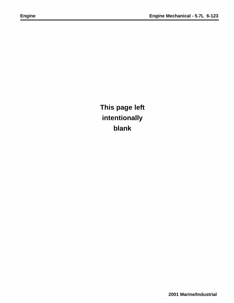
Engine Engine Mechanical - 5.7L 6-123
2001 Marine/Industrial
This page left
intentionally
blank

6-124 Engine Mechanical - 5.7L Engine
2001 Marine/Industrial
182855
521836
182854
Engine Block Plug InstallationTools Required
J 41712 Oil Pressure Switch Socket
Caution: Refer to Safety Glasses Caution in Cautions andNotices.
1. Install the transmission locator pins (if required).
A properly installed transmission locator pin will protrude12.7 mm (0.5 in) from the rear face of the engine block.
2. Apply sealant GM P/N 12346004 or equivalent to theoutside diameter of the NEW expansion cup plug (camshaftrear bearing hole).
3. Install the NEW expansion cup plug (camshaft rear bearinghole).
A properly installed expansion cup plug will be installed 8.8mm (0.348 in) into the rear of the engine block.
4. Install the S type pin (crankshaft rear oil seal housinglocator).

Engine Engine Mechanical - 5.7L 6-125
2001 Marine/Industrial
182841
69847
182838
Notice: Refer to Fastener Notice in Cautions and Notices.
5. Apply sealant GM P/N 12346004 or equivalent to thethreads of the left side rear and left rear top engine oilgallery plugs.
6. Install the left side rear and left rear top engine oil galleryplugs.
Tighten
Tighten the left side rear and left rear top oil gallery plugs to20 N.m (15 lb ft).
7. Apply sealant GM P/N 12346004 or equivalent to thethreads of the square socket plugs (engine block oil gallery).
8. Install the square socket plugs.
Tighten
Tighten the square socket plugs to 20 N.m (15 lb ft).
9. Apply sealant GM P/N 12346004 or equivalent to theoutside diameter of the NEW engine block oil gallery plugs.
10. Install the NEW engine block oil gallery plugs.
A properly installed engine block oil gallery plug must beinstalled below flush with the front face of the engine block.

6-126 Engine Mechanical - 5.7L Engine
2001 Marine/Industrial
500653
333659
316798
11. Apply threadlock GM P/N 12345382 or equivalent to thethreads of the outside diameter of the NEW engine blockcore hole plugs.
12. Install the NEW engine block core hole plugs.
A properly installed engine block core hole plug must beinstalled flush with the bottom of the chamfer (1) of theengine block core hole.
13. Apply sealant GM P/N 12346004 or equivalent to thethreads of the engine block coolant drain hole plug.
14. Install the engine block coolant drain hole plug.
Tighten
Tighten the engine block coolant drain hole plug to 20 N.m(15 lb ft).
15. Apply sealant GM P/N 12346004 or equivalent to thethreads of the engine oil pressure sensor fitting.
Important: Do not loosen the oil pressure sensor fitting after theinitial torque has been obtained.
16. Install the engine oil pressure sensor fitting.
Tighten
Tighten the engine oil pressure sensor fitting to 15 N.m (11lb ft).
Important: Do not rotate the engine oil pressure sensor fittingmore than 359 degrees after the initial torque has been obtained.
17. Rotate the engine oil pressure sensor fitting clockwise to theproper position (1), 50 degrees from the centerline (2).

Engine Engine Mechanical - 5.7L 6-127
2001 Marine/Industrial
333649
182837
18. Apply sealant GM P/N 12346004 or equivalent to thethreads of the engine oil pressure gauge sensor.
19. Install the engine oil pressure gauge sensor using the J41712.
Tighten
Tighten the engine oil pressure gauge sensor to 30 N.m (22lb ft).
20. Apply sealant GM P/N 12346004 or equivalent to thethreads of the knock sensor.
21. Install the knock sensor.
Tighten
Tighten the knock sensor to 19 N•m (14 lb ft).

6-128 Engine Mechanical - 5.7L Engine
2001 Marine/Industrial
317292
317351
Crankshaft and Bearings InstallationTools Required
J 36660 Electronic Torque Angle Meter
1. Install the crankshaft bearings into the engine block.
2. Apply clean engine oil to the crankshaft bearings.
3. Apply clean engine oil to the crankshaft bearing journals.
4. Install the crankshaft.

Engine Engine Mechanical - 5.7L 6-129
2001 Marine/Industrial
317295
317268
7. Install the crankshaft bearing caps in the original positionand with the arrow on the crankshaft bearing caps in thedirection of the front of the engine block.
Notice: Refer to Fastener Notice in Cautions and Notices.
8. Install the crankshaft bearing cap bolts and the crankshaftbearing cap studs.
9. Thrust the crankshaft rearward in order to set and align thecrankshaft thrust bearings and the crankshaft bearing caps.
10. Thrust the crankshaft forward in order to align the rear facesof the crankshaft thrust bearings.
11. Look to ensure that the crankshaft bearing caps are fullyseated in the engine block crankshaft bearing cap channeland that the crankshaft bearing caps are centered on theengine block bulkheads.
11. Tighten the crankshaft bearing cap bolts and the crankshaftbearing cap studs.
Tighten
11.1. Tighten the crankshaft bearing cap bolts and the crankshaft bearing cap studs on the first pass to 20 N•m (15 lb ft).
11.2. Tighten the crankshaft bearing cap bolts and the crankshaft bearing cap studs (two bolt caps) on the final pass to 73 degrees using the J 36660.
11.3. Tighten the bearing cap outboard bolts (four bolt caps) on the final pass to 43 degrees using the J 36660.
11.4. Tighten the bearing cap inboard bolts and the bearing cap inboard studs (four bolt caps) on the final pass to 73 degrees using J 36660.
5. Install the crankshaft bearings into the crankshaft bearingcaps.
6. Apply clean engine oil to the crankshaft bearings.

6-130 Engine Mechanical - 5.7L Engine
2001 Marine/Industrial
188467
11479
12. Measure the crankshaft end play.
12.1. Firmly thrust the crankshaft rearward, and then forward.
This will align the crankshaft rear bearing thrust surfaces.
12.2. With the crankshaft pushed forward, insert a feeler gauge between the crankshaft and the crankshaft rear bearing thrust surface to measure the clearance.
Specification
Crankshaft end play 0.05-0.20 mm (0.002-0.008 in)
13. Rotate the crankshaft in order to check for binding.
A bent crankshaft or lack of proper crankshaft bearingclearance may cause binding.
14. If the crankshaft does not turn freely, loosen the crankshaftbearing cap bolts on 1 crankshaft bearing cap at a time inorder to determine the location of the binding.
A lack of proper crankshaft bearing clearance may becaused by the following:
• Burrs on the crankshaft bearing cap
• Foreign material between the crankshaft bearing and the engine block
• Foreign material between the crankshaft bearing and the crankshaft bearing cap
• Damaged crankshaft bearing
• Improper size crankshaft bearing
Crankshaft Rear Oil Seal and Housing InstallationTools Required
J 35621-B Rear Main Seal Installer
Notice: Refer to Fastener Notices in Cautions and Notices.
1. Install the crankshaft rear oil seal housing retainer stud.
Tighten
Tighten the crankshaft rear oil seal housing retainer stud to6 N•m (53 lb in).

Engine Engine Mechanical - 5.7L 6-131
2001 Marine/Industrial
11479
334550
Important: Always use a NEW crankshaft rear oil seal housinggasket when installing the crankshaft rear oil seal housing.
2. Install the NEW crankshaft rear oil seal housing gasket andthe crankshaft rear oil seal housing onto the crankshaft rearoil seal housing retainer stud.
3. Install the crankshaft rear oil seal housing nut and bolts.
Tighten
Tighten the crankshaft rear oil seal housing nut and bolts to12 N•m (106 lb in).
4. Apply a small amount (2 to 3 drops) of clean engine oil GMP/N 1234610 or equivalent to the bore of the crankshaft rearoil seal housing.
5. Inspect the outside diameter of the engine flywheel pilotflange for imperfections or rust.
Minor imperfections and/or rust may be removed with a finegrade emery cloth.
6. Apply a small amount (2 to 3 drops) of clean engine oil GMP/N 1234610 or equivalent to the outside diameter of theengine flywheel pilot flange.
7. Apply a small amount (1 drop) of clean engine oil GM P/N1234610 or equivalent to the outside diameter of theflywheel locator pin.
8. Apply a small amount (2 to 3 drops) of clean engine oil GMP/N 1234610 or equivalent to the crankshaft seal surface.
9. Inspect the J 35621-B flange for imperfections that maydamage the crankshaft rear oil seal.
Minor imperfections may be removed with a fine gradeemery cloth.
Important: DO NOT allow oil or any other lubricants to contact theseal lip of the crankshaft rear oil seal.
10. Remove the installation guide from the NEW crankshaft rearoil seal.
11. Apply a small amount (2 to 3 drops) of clean engine oil GMP/N 1234610 or equivalent to the outside diameter of theNEW crankshaft rear oil seal.
12. Install the NEW crankshaft rear oil seal onto the J 35621-B.

6-132 Engine Mechanical - 5.7L Engine
2001 Marine/Industrial
387765
13. Install the J 35621-B onto the rear of the crankshaft andhand tighten the tool bolts until snug.
Notice: Proper alignment of the crankshft rear oil seal is critical.Install the crankshaft rear oil seal near to flush and square to thecrankshaft rear oil seal housing. Failing to do so may cause thecrankshaft rear oil seal or the crankshaft rear oil seal installlationtool to fail.
Important: A properly installed crankshaft rear oil seal will be nearto flush and square to the crankshaft rear oil seal housing.
14. Install the crankshaft rear oil seal onto the crankshaft andinto the crankshaft rear oil seal housing.
14.1. Turn the J 35621-B wing nut clockwise until the crankshaft rear oil seal is installed near to flush and square to the crankshaft rear oil seal housing.
Increased resistance will be felt when the crankshaft rear oil seal has reached the bottom of the crankshaft rear oil seal housing bore.
14.2. Turn the J 35621-B wing nut counterclockwise to release the J 35621-B from the crankshaft rear oil seal.
15. Remove the J 35621-B from the crankshaft.
16. Wipe off any excess engine oil with a clean rag.
Piston, Connecting Rod and Bearing InstallationTools Required
J 5239 Connecting Rod Bolt Guide Set
J 8037 Ring Compressor
J 36660 Electronic Torque Angle Meter
1. Apply clean engine oil to the following components:
• The piston
• The piston rings
• The cylinder bore
• The bearing surfaces
2. Install the J 5239 onto the connecting rod bolts.
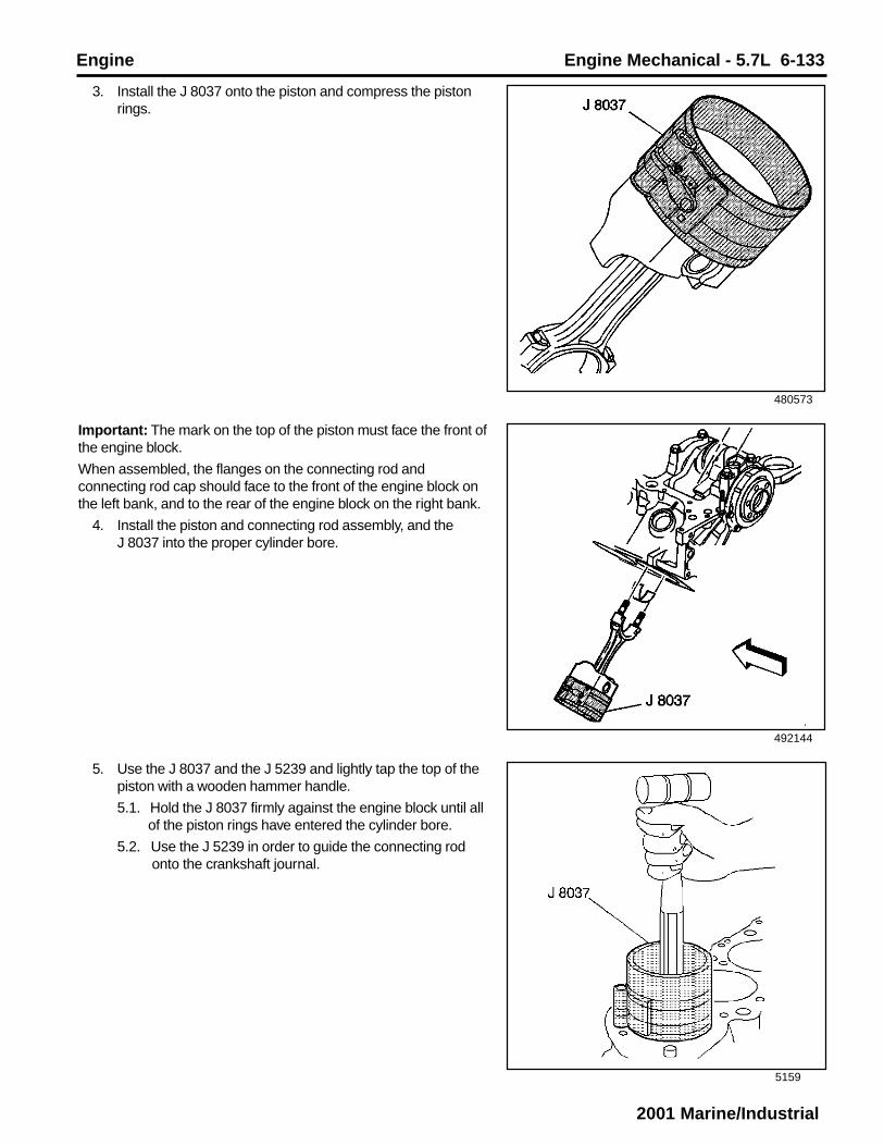
Engine Engine Mechanical - 5.7L 6-133
2001 Marine/Industrial
480573
492144
5159
3. Install the J 8037 onto the piston and compress the pistonrings.
Important: The mark on the top of the piston must face the front ofthe engine block.
When assembled, the flanges on the connecting rod andconnecting rod cap should face to the front of the engine block onthe left bank, and to the rear of the engine block on the right bank.
4. Install the piston and connecting rod assembly, and theJ 8037 into the proper cylinder bore.
5. Use the J 8037 and the J 5239 and lightly tap the top of thepiston with a wooden hammer handle.
5.1. Hold the J 8037 firmly against the engine block until all of the piston rings have entered the cylinder bore.
5.2. Use the J 5239 in order to guide the connecting rod onto the crankshaft journal.

6-134 Engine Mechanical - 5.7L Engine
2001 Marine/Industrial
31373
5163
480549
6. Remove the J 5239.
Notice: Refer to Fastener Notice in Cautions and Notices.
7. Install the connecting rod caps, bearings and nuts.
Tighten
7.1. Tighten the nuts evenly on the first pass to 27 N•m (20 lb ft).
7.2. Use the J 36660 in order to tighten the nuts on the final pass to 70 degrees.
8. After the piston and connecting rod assemblies have beeninstalled, then lightly tap each connecting rod assembly(parallel to the crankpin) in order to ensure that theconnecting rods have side clearance.
9. Use a feeler gauge or a dial indicator to measure theconnecting rod side clearance between the connecting rodcaps. The connecting rod side clearance should be 0.15-0.68 mm (0.006-0.027 in).

Engine Engine Mechanical - 5.7L 6-135
2001 Marine/Industrial
69013
182836
Camshaft Installation1. Apply clean engine oil GM P/N 12345610 or equivalent, or
engine oil supplement GM P/N 1052367 or equivalent to thefollowing components:
• The engine camshaft lobes
• The camshaft bearing journals
• The camshaft bearings
2. Install three 5/16-18 x 4.0 in. bolts into the engine camshaftfront bolt holes.
Notice: All camshaft journals are the same diameter, so care mustbe used in removing or installing the camshaft to avoid damage tothe camshaft bearings.
3. Use the bolts as a handle in order to install the enginecamshaft.
4. Remove the 3 bolts from the front of the engine camshaft.
Notice: Refer to Fastener Notice in Cautions and Notices.
5. If reusing the fasteners, apply threadlock GM P/N 12345382or equivalent to the threads of the camshaft retainer bolts.
6. Install the camshaft retainer and bolts.
Tighten the camshaft retainer bolts to 12 N•m (106 lb in).

6-136 Engine Mechanical - 5.7L Engine
2001 Marine/Industrial
182847
32066
Timing Chain and Sprockets InstallationTools Required
J 5590 Installer
1. Install the woodruff keys (crankshaft balancer) into thecrankshaft keyway.
2. Align the keyway of the crankshaft sprocket with thewoodruff key (crankshaft balancer).
Caution: Refer to Safety Glasses Caution in Cautions andNotices.
3. Use the J 5590 in order to install the crankshaft sprocket.
4. Rotate the crankshaft until the crankshaft sprocketalignment mark is in the 12 o’clock position.

Engine Engine Mechanical - 5.7L 6-137
2001 Marine/Industrial
500645
11503
5. Install the camshaft sprocket and the camshaft timing chain.
Install the camshaft sprocket with the alignment mark in the6 o’clock position.
Important: Do not use a hammer to install the camshaft sprocketonto the camshaft. To do so may dislodge the expansion cup plug(camshaft rear bearing hole) and/or damage the camshaft.
6. Rotate the camshaft until the camshaft and crankshaftsprocket alignment marks are in the proper position.
Notice: Refer to Fastener Notice in Cautions and Notices.
7. Install the camshaft sprocket bolts.
Tighten
Tighten the camshaft sprocket bolts to 25 N.m (18 lb ft).

6-138 Engine Mechanical - 5.7L Engine
2001 Marine/Industrial
521825
69010
Important: Align the keyway on the crankshaft position sensorreluctor ring with the woodruff key (crankshaft balancer) in thecrankshaft, and install the crankshaft position sensor reluctor ringonto the crankshaft until completely seated against the crankshaftsprocket.
8. Install the crankshaft position sensor reluctor ring.
8.1. Align the keyway on the crankshaft position sensor reluctor ring with the woodruff key (crankshaft balancer) in the crankshaft.
8.2. Use the J 5590 in order to push the crankshaft position sensor reluctor ring onto the crankshaft until completely seated against the crankhshaft sproket.
Engine Front Cover InstallationImportant: Once the composite engine front cover is removed,DO NOT reinstall the engine front cover. Always install a NEWengine front cover.
1. Install the NEW engine front cover.
Notice: Refer to Fasteners Notice in Cautions and Notices.
2. Install the engine front cover bolts.
Tighten
Tighten the engine front cover bolts to 12 N•m (106 lb in).

Engine Engine Mechanical - 5.7L 6-139
2001 Marine/Industrial
387759
11485
182852
Important: DONOT reuse the original crankshaft position sensorseal (o-ring). When installing the crankshaft position sensor, besure the crankshaft position sensor is fully seated and heldstationary in the engine front cover crankshaft position sensorbore. A crankshaft position sensor that is not completely seatedwill cock in the engine front cover and may result in erratic engineoperation.
3. Lubricate the NEW crankshaft position sensor seal (O-ring)with clean engine oil.
4. Install the NEW crankshaft position sensor seal (O-ring)onto the crankshaft position sensor.
Oil Pump, Pump Screen and Deflector InstallationTools Required
J 36660 Electronic Torque Angle Meter
1. Inspect for properly installed pins (oil pump locator).
5. Install the crankshaft position sensor until fully seated intothe engine front cover.
6. Install the crankshaft position sensor bolt.
Tighten
Tighten the crankshaft position bolt to 9 N•m (80 lb in).

6-140 Engine Mechanical - 5.7L Engine
2001 Marine/Industrial
11438
317310
Important: DO not reuse the oil pump driveshaft retainer (4).
During assembly, install a NEW oil pump driveshaft retainer.
2. Assemble the oil pump (3), the oil pump driveshaft (5) and aNEW oil pump driveshaft retainer (4).
3. Install the oil pump (3).
Position the oil pump onto the pins.
4. Install the crankshaft oil deflector (2) and the nuts (6).
5. Install the bolt (1) attaching the oil pump to the rearcrankshaft bearing cap.
Tighten
• Tighten the oil pump bolt on the first pass to 20 N.m (15 lbft).
• Tighten the oil pump bolt on the final pass to 65 degreesusing the J 36660.
• Tighten the crankshaft oil deflector nuts to 40 N.m (30 lbft).
2. Apply a 5 mm (0.197 in) wide and 25 mm (1.0 in) long beadof adhesive GM P/N 12346141 or equivalent to both theright and left sides of the engine front cover to engine blockjunction at the oil pan sealing surfaces.
521817
Oil Pan InstallationNotice: Refer to Fastener Notice in Cautions and Notices.
1. Install the oil pan studs into the engine block.
Tighten
Tighten the oil pan studs to 6 N.m (53 lb in).

Engine Engine Mechanical - 5.7L 6-141
2001 Marine/Industrial
317313
182851
3. Apply a 5 mm (0.197 in) wide and 25 mm (1.0 in) long beadof adhesive GM P/N 12346141 or equivalent to both theright and left sides of the crankshaft rear oil seal housing toengine block junction at the oil pan sealing surfaces.
Important: Always install a NEW oil pan gasket.
The oil pan gasket and oil pan must be installed and the fastenerstightened while the adhesive is still wet to the touch.
4. Install the NEW oil pan gasket.
5. Install the oil pan.
Press the oil pan gasket into the grooves of the engine frontcover and crankshaft rear oil seal housing.
6. Install the oil pan reinforcements.
7. Install the nuts and the bolts.
Tighten
7.1. Tighten the oil pan bolts to 12 N.m (106 lb in).
7.2. Tighten the oil pan nuts to 25 N.m (18 lb ft).

6-142 Engine Mechanical - 5.7L Engine
2001 Marine/Industrial
182850
8. Install a NEW oil pan drain plug seal (O-ring) onto the oilpan drain plug.
9. Install the oil pan drain plug into the oil pan.
Tighten
Tighten the oil pan drain plug to 25 N•m (18 lb ft).
39122
Oil Filter Adapter Installation1. Apply clean engine oil GM P/N 12345610 or equivalent to
the NEW oil filter adapter seal (O-ring) (if applicable).
2. Install the NEW oil filter adapter seal into the groove in theoil filter adapter (if applicable).
3. Install the NEW oil filter adapter gasket (if applicable) andthe oil filter adapter.
Notice: Refer to Fastener Notice in Cautions and Notices.
4. Install the oil filter adapter flat washers (if applicable) and theoil filter adapter bolts.
Tighten
Tighten the oil filter adapter bolts to 25 N.m (18 lb ft).

Engine Engine Mechanical - 5.7L 6-143
2001 Marine/Industrial
182849
182832
Crankshaft Balancer InstallationTools Required
J 23523-F Balancer Remover and Installer
1. Look to ensure that the front groove pin (crankshaftbalancer) is installed in the proper location (if applicable).
Notice: The inertial weight section of the crankshaft balancer isassembled to the hub with a rubber type material. The correctinstallation procedures (with the proper tool) must be followed ormovement of the inertial weight section of the hub will destroy thetuning of the crankshaft balancer.
2. Apply a small amount of adhesive GM P/N 12346141 orequivalent onto the crankshaft balancer keyway in order toseal the crankshaft balancer keyway and crankshaft joint.
3. Align the keyway of the crankshaft balancer with thewoodruff key (crankshaft balancer).
4. Install the crankshaft balancer onto the end of thecrankshaft.

6-144 Engine Mechanical - 5.7L Engine
2001 Marine/Industrial
4065
342203
188055
Notice: Refer to Fastener Notice in Cautions and Notices.
7. Install the crankshaft pulley and bolts.
Tighten
Tighten the crankshaft pulley bolts to 58 N•m (43 lb ft).
5. Use the J 23523-F in order to press the crankshaft balanceronto the crankshaft.
5.1. Install the J 23523-F plate and bolts onto the front of the crankshaft balancer.
Tighten
Tighten the J 23523-F plate bolts to 25 N•m (18 lb ft).
5.2. Install the J 23523-F screw into the end for the crankshaft.
5.3. Install the J 23523-F bearing, the washer and the nut onto the J 23523-F screw.
5.4. Rotate the J 23523-F nut clockwise until the crankshaft balancer hub is completely seated against the
crankshaft position sensor reluctor ring.
6. Remove the J 23523-F.
8. Ensure that the crown of the crankshaft balancer washer (2)is faced away from the engine.

Engine Engine Mechanical - 5.7L 6-145
2001 Marine/Industrial
173172
11509
11508
9. Install the crankshaft balancer washer and the bolt.
Tighten
Tighten the crankshaft balancer bolt to 95 N•m (70 lb ft).
Valve Lifter Installation1. Apply lubricant GM P/N 12345501 or equivalent to the valve
lifter rollers.
Important: If reusing the valve lifters, install the valve lifters in theoriginal positions.
2. Install the valve lifters.
Notice: Refer to Fastener Notice in Cautions and Notices.
3. Install the valve lifter guides.
4. Install the valve lifter guide retainer.
5. Install the valve lifter guide retainer bolts.
Tighten
Tighten the valve lifter guide retainer bolts to 25 N•m (18 lbft).

6-146 Engine Mechanical - 5.7L Engine
2001 Marine/Industrial
182846
317227
317233
Cylinder Head Installation (Left)Tools Required
J 36660 Electronic Torque Angle Meter
1. Clean the cylinder head gasket surfaces on the engineblock.
2. Inspect the dowel pins (cylinder head locators) for properinstallation.
3. Clean the cylinder head gasket surfaces on the cylinderhead.
Important: Do not use any type of sealer on the cylinder headgasket (unless specified).
4. Install the NEW cylinder head gasket in position over thedowel pins (cylinder head locators).
The cylinder head gasket is not directional and may beinstalled using either side facing the engine block.
5. Install the cylinder head onto the engine block.
Guide the cylinder head carefully into place over the dowelpins and the cylinder head gasket.

Engine Engine Mechanical - 5.7L 6-147
2001 Marine/Industrial
317217
500687
6. Apply sealant GM P/N 12346004 or equivalent to thethreads of the cylinder head bolts.
Notice: Refer to Fastener Notice in Cautions and Notices.
7. Install the cylinder head bolts.
8. Tighten the cylinder head bolts in sequence on the firstpass.
Tighten
Tighten the bolts in sequence on the first pass to 30 N•m(22 lb ft).
9. Use the J 36660 in order to tighten the cylinder head bolts insequence on the final pass.
Tighten
• Tighten the long bolts (1, 2, 5, 6, 9, 10 and 13) on the final pass in sequence to 75 degrees.
• Tighten the medium bolts (14 and 17) on the final pass in sequence to 65 degrees.
• Tighten the short bolts (3, 4, 7, 8. 11. 12. 15 and 16) on the final pass in sequence to 55 degrees.

6-148 Engine Mechanical - 5.7L Engine
2001 Marine/Industrial
317307
521828
10. Measure the NEW spark plugs for the proper gap.
Adjust the spark plug gap if necessary.
Specification
Spark plug gap to 1.52 mm (0.060 in)
11. Install the spark plugs.
Tighten
• Tighten the spark plugs for a USED cylinder head to 15 N•m (11 lb ft)
• Tighten the spark plugs for the initial installation of a NEW cylinder head to 30 N•m (22 lb ft).
12. If reusing the engine coolant temperature gauge sensor (ifapplicable), apply sealant GM P/N 12346004 or equivalentto the threads of the engine coolant temperature gaugesensor.
13. Install the engine coolant temperature gauge sensor (ifapplicable).
Tighten
Tighten the engine coolant temperature gauge sensor to 20N•m (15 lb ft).

Engine Engine Mechanical - 5.7L 6-149
2001 Marine/Industrial
182846
317255
317246
Cylinder Head Installation (Right)Tools Required
J 36660 Electronic Torque Angle Meter
1. Clean the cylinder head gasket surfaces on the engineblock.
2. Inspect the dowel pins (cylinder head locators) for properinstallation.
3. Clean the cylinder head gasket surfaces on the cylinderhead.
Important: Do not use any type of sealer on the cylinder headgasket (unless specified).
4. Install the NEW cylinder head gasket in position over thedowel pins (cylinder head locators).
The cylinder head gasket is not directional and may beinstalled using either side facing the engine block.
5. Install the cylinder head onto the engine block.
Guide the cylinder head carefully into place over the dowelpins and the cylinder head gasket.
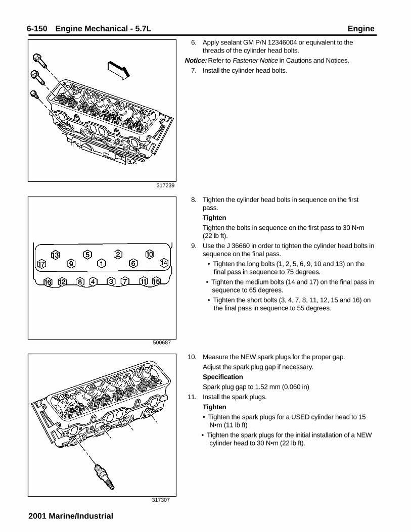
6-150 Engine Mechanical - 5.7L Engine
2001 Marine/Industrial
317239
317307
500687
6. Apply sealant GM P/N 12346004 or equivalent to thethreads of the cylinder head bolts.
Notice: Refer to Fastener Notice in Cautions and Notices.
7. Install the cylinder head bolts.
8. Tighten the cylinder head bolts in sequence on the firstpass.
Tighten
Tighten the bolts in sequence on the first pass to 30 N•m(22 lb ft).
9. Use the J 36660 in order to tighten the cylinder head bolts insequence on the final pass.
• Tighten the long bolts (1, 2, 5, 6, 9, 10 and 13) on the final pass in sequence to 75 degrees.
• Tighten the medium bolts (14 and 17) on the final pass in sequence to 65 degrees.
• Tighten the short bolts (3, 4, 7, 8, 11, 12, 15 and 16) on the final pass in sequence to 55 degrees.
10. Measure the NEW spark plugs for the proper gap.
Adjust the spark plug gap if necessary.
Specification
Spark plug gap to 1.52 mm (0.060 in)
11. Install the spark plugs.
Tighten
• Tighten the spark plugs for a USED cylinder head to 15 N•m (11 lb ft)
• Tighten the spark plugs for the initial installation of a NEW cylinder head to 30 N•m (22 lb ft).

Engine Engine Mechanical - 5.7L 6-151
2001 Marine/Industrial
22766
182835
Valve Rocker Arm and Push Rod InstallationImportant: Be sure to keep parts in order. Parts must bereinstalled into the original location and position.
1. Apply prelube GM P/N 12345501 or equivalent to the valverocker arm and the valve rocker arm ball surfaces.
Important: Be sure that the valve pushrods seat in the valve liftersockets.
2. Install the valve pushrods.
3. Install the following components:
1.1. The valve rocker arm nuts (1)
1.2. The valve rocker arm balls (2)
1.3. The valve rocker arms (3)
195336
Valve Lash Adjustment1. Turn the valve rocker arm nuts clockwise until all of the valve
lash is removed.
2. Turn the crankshaft clockwise until the alignment mark onthe crankshaft balancer is aligned with the notch in theengine front cover tab.
3. Look at number 1 cylinder valves as the crankshaft balanceralignment mark approaches the notch in the engine frontcover tab. If a valve moves as the alignment mark movesinto position, the engine is in the number 6 firing position. Ifthis happens, turn the crankshaft clockwise one revolution inorder to reach the number 1 cylinder firing position.

6-152 Engine Mechanical - 5.7L Engine
2001 Marine/Industrial
4. With the engine in the number 1 cylinder firing position,adjust the exhaust valves for cylinders number 1, 3, 4 and 8and the intake valves for cylinders number 1, 2, 5 and 7.
4.1. Turn the valve rocker arm nut counter clockwise until the valve lash is felt in the valve pushrod.
4.2. Turn the valve rocker arm nut clockwise until all the valve lash is removed (zero valve lash).
Zero valve lash can be felt by moving the valve pushrod up and down between your thumb and
forefinger until there is no more up and down movement of the valve pushrod.
4.3. When all the valve lash is removed, then turn the valve rocker arm nut clockwise 1 additional turn (360
degrees).
22759
22759
195336
5. Turn the crankshaft clockwise 1 revolution until thealignment mark on the crankshaft balancer is aligned withthe notch in the engine front cover tab.
6. With the engine in the number 6 cylinder firing position,adjust the exhaust valves for cylinders number 2, 5, 6 and 7and the intake valves for cylinders number 3, 4, 6 and 8.
6.1. Turn the valve rocker arm nut counter clockwise until the valve lash is felt in the valve pushrod.
6.2. Turn the valve rocker arm nut clockwise until all the valve lash is removed (zero valve lash).
Zero valve lash can be felt by moving the valve pushrod up and down between your thumb and
forefinger until there is no more up and down movement of the valve pushrod.
6.3. When all the valve lash is removed, then turn the valve rocker arm nut clockwise 1 additional turn (360
degrees).

Engine Engine Mechanical - 5.7L 6-153
2001 Marine/Industrial
38512
26744
26743
Intake Manifold InstallationNotice: Applying excessive amounts of sealant may prohibit theintake manifold gaskets from sealing properly.
1. Apply a 4.0 mm (0.157 in) patch of adhesive GM P/N12346141 or equivalent to the cylinder head side of thelower intake manifold gasket at each end.
Important: The lower intake manifold gasket must be installedwhile the adhesive is still wet to the touch.
2. Install the lower intake manifold gasket onto the cylinderhead.
Use the gasket locator pins in order to properly seat thelower intake manifold gasket on the cylinder head.
Notice: Care must be used to apply the correct amount of sealantonto the gaskets. Applying excessive amounts of sealant mayprohibit the intake manifold gaskets from sealing properly.
Important: The lower intake manifold must be installed and thefasteners tightened while the adhesive is still wet to the touch.
3. Apply a 5.0 mm (0.197 in) bead of adhesive GM P/N12346141 or equivalent to the front top of the engine block.
Extend the adhesive bead 13 mm (0.50 in) onto each lowerintake manifold gasket.
4. Apply a 5.0 mm (0.197 in) bead of adhesive GM P/N12346141 or equivalent to the rear top of the engine block.
Extend the adhesive bead 13 mm (0.50 in) onto each lowerintake manifold gasket.

6-154 Engine Mechanical - 5.7L Engine
2001 Marine/Industrial
66456
317211
500689
5. Install the lower intake manifold onto the engine block.
Notice: Refer to Fastener Notice in Cautions and Notices.
6. If reusing the fasteners, apply threadlock GM P/N 12345382or equivalent to the threads of the lower intake manifoldbolts.
7. Install the lower intake manifold bolts.
Notice: Proper lower intake manifold fastener tightening sequenceand torque is critical. Always follow the tightening sequence, andtorque the intake manifold bolts using the 3 step method. Failing todo so may distort the crankshaft bearing bore alignment andcause damage to the crankshaft bearings.
8. Tighten the lower intake manifold bolts.
Tighten
8.1. Tighten the bolts in sequence (1-8) on the first pass to 3 N•m (27 lb in).
8.2. Tighten the bolts in sequence (1-8) on the first pass to 12 N•m (106 lb in).
8.3. Tighten the bolts in sequence (1-8) on the first pass to 15 N•m (11 lb ft).
9. Connect the evaporative emission (EVAP) canister solenoidvalve harness.
9.1. Push the elbow inward until the quick connect snaps into place.
9.2. Pull the elbow outward in order to ensure proper connection.

Engine Engine Mechanical - 5.7L 6-155
2001 Marine/Industrial
195336
500690
523516
Distributor Installation1. Bring cylinder number one piston to Top Dead Center (TDC)
of the compression stroke.
2. Remove the distributor cap bolts and discard.
3. Remove the distributor cap.
4. Install a NEW distributor gasket onto the distributor.

6-156 Engine Mechanical - 5.7L Engine
2001 Marine/Industrial
492137
523746
4. Align the indent hole on the driven gear with the paint markon the distributor housing.
5. Ensure that the distributor rotor segment points to the caphold area.
6. Align the slotted tang in the oil pump driveshaft with thedistributor driveshaft.
Rotate the oil pump driveshaft with a screwdriver ifnecessary.
7. Align the flat (1) in the distributor housing toward the front ofthe engine.
8. Install the distributor and distributor clamp.

Engine Engine Mechanical - 5.7L 6-157
2001 Marine/Industrial
68505
366609
500690
9. Once the distributor is fully seated, align the distributor rotorsegment with the number 8 pointer that is cast into thedistributor base.
10. If the distributor rotor segment does not come within a fewdegrees of the number 8 pointer (1), the gear mesh betweenthe distributor and camshaft may be off a tooth or more.Repeat the procedure again in order to achieve properalignment.
Notice: Refer to Fastener Notice in Cautions and Notices.
11. Install the distributor clamp bolt.
Tighten
Tighten the distributor clamp bolt to 25 N.m (18 lb ft).
12. Install the distributor cap onto the distributor.
13. Install the NEW distributor cap bolts.
Do not overtighten the NEW distributor cap bolts.
Tighten
Tighten the distributor cap bolts to 2.4 N.m (21 lb in).

6-158 Engine Mechanical - 5.7L Engine
2001 Marine/Industrial
341359
182833
39119
14. Install the ignition coil wire harness.
Valve Rocker Arm Cover Installation (Left)Important: Always install a NEW valve rocker arm cover gasket.
1. Install the NEW valve rocker arm cover gasket.
2. Install the valve rocker arm cover.
Notice: Refer to Fastener Notice in Cautions and Notices.
3. Install the valve rocker arm cover washers and bolts.
Tighten
Tighten the bolts to 12 N.m (106 lb in).
Valve Rocker Arm Cover Installation (Right)Important: Always install a NEW valve rocker arm cover gasket.
1. Install the NEW valve rocker arm cover gasket.
2. Install the valve rocker arm cover.
Notice: Refer to Fastener Notice in Cautions and Notices.
3. Install the valve rocker arm cover washers and bolts.
Tighten
Tighten the bolts to 12 N.m (106 lb in).

Engine Engine Mechanical - 5.7L 6-159
2001 Marine/Industrial
69011
182853
317191
Water Pump InstallationTools Required
J 41240 Fan Clutch Remover and Installer
1. If reusing the fasteners, apply sealant GM P/N 12346004 orequivalent to the threads of the water pump bolts.
2. Install the water pump and the NEW water pump gaskets.
Notice: Refer to Fastener Notice in Cautions and Notices.
3. Install the water pump bolts.
Tighten
Tighten the water pump bolts to 45 N.m (33 lb ft).
Important: After final assembly, the water pump inlet hose clamptangs (water pump end) must point forward and the upper tangshould be level with the outside diameter of the water pump inlethose.
4. Install the water pump inlet hose and the water pump inlethose clamps.
5. Install the fan and water pump pulley and bolts using theJ 41240.
Tighten
Tighten the fan and water pump pulley bolts to 25 N.m (18 lbft).

6-160 Engine Mechanical - 5.7L Engine
2001 Marine/Industrial
64925
317185
Exhaust Manifold Installation (Left)1. Install the NEW exhaust manifold gasket.
2. Install the exhaust manifold.
3. Install the spark plug wire shields.
4. Apply threadlock GM P/N 12345493 or equivalent to thethreads of the exhaust manifold bolts.
Notice: Refer to Fastener Notice in Cautions and Notices.
5. Install the exhaust manifold bolts and stud.
Tighten
5.1. Tighten the exhaust manifold bolts on the first pass to 15 N•m (11 lb ft).
5.2. Tighten the exhaust manifold bolts on the final pass to 30 N•m (22 lb ft).
6. Install the spark plug wire supports and bolts.
Tighten
Tighten the bolts to 12 N.m (106 lb in).
7. Install the spark plug wires onto the spark plugs.
500691
Oil Level Indicator and Tube Installation1. Apply sealant GM P/N 12346004 or equivalent around the
oil level indicator tube 13 mm (0.50 in) below the tube bead.
2. Install the oil level indicator tube into the engine block.Rotate the oil level indicator tube into position.
Notice: Refer to Fastener Notice in Cautions and Notices.
3. Install the oil level indicator tube bolt.
Tighten
Tighten the oil level indicator tube bolt to 25 N•m (18 lb ft).
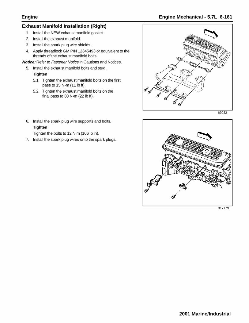
Engine Engine Mechanical - 5.7L 6-161
2001 Marine/Industrial
69032
317179
Exhaust Manifold Installation (Right)1. Install the NEW exhaust manifold gasket.
2. Install the exhaust manifold.
3. Install the spark plug wire shields.
4. Apply threadlock GM P/N 12345493 or equivalent to thethreads of the exhaust manifold bolts.
Notice: Refer to Fastener Notice in Cautions and Notices.
5. Install the exhaust manifold bolts and stud.
Tighten
5.1. Tighten the exhaust manifold bolts on the first pass to 15 N•m (11 lb ft).
5.2. Tighten the exhaust manifold bolts on the final pass to 30 N•m (22 lb ft).
6. Install the spark plug wire supports and bolts.
Tighten
Tighten the bolts to 12 N.m (106 lb in).
7. Install the spark plug wires onto the spark plugs.

6-162 Engine Mechanical - 5.7L Engine
2001 Marine/Industrial
522146
63174
Engine Flywheel Installation1. Install the engine flywheel to the crankshaft.
2. Align the engine flywheel locator hole to the pin.
Notice: Refer to Fastener Notice in Cautions and Notices.
3. Install the engine flywheel bolts.
Tighten
Tighten the engine flywheel bolts in sequence (1-6) to100 N•m (74 lb ft).

Engine Engine Mechanical - 5.7L 6-163
2001 Marine/Industrial
Engine Set-Up and TestingAfter overhaul, the engine must be tested before it isinstalled in the vehicle. If a suitable test stand is notavailable, the following procedures can be used after theengine is installed in the vehicle.
1. Fill the crankcase with the proper quantity andgrade of engine oil.
2. Add engine oil supplement GM P/N 1052367 orequivalent to the engine oil.
Notice: DO NOT use cooling system seal tabs (or similarcompounds) unless otherwise instructed. The use ofcooling system seal tabs (or similar compounds) mayrestrict coolant flow through the passages of the coolingsystem or the engine components. Restricted coolantflow may cause engine overheating and/or damage to thecooling system or the engine components/assembly.
3. Fill the cooling system with the proper quantity andgrade of coolant.
4. With the ignition OFF or disconnected, crank theengine several times. Listen for any unusual noisesor evidence that any of the parts are binding.
5. Start the engine and listen for unusual noises.
6. Check the vehicle oil pressure gauge or light andconfirm that the engine has acceptable oilpressure.
If necessary, install an oil pressure gauge andmeasure the engine oil pressure.
7. Operate the engine at about 1,000 RPM until theengine has reached normal operating temperature.
8. Listen for improperly adjusted or sticking valves,sticking valve lifters or other unusual noises.
9. Inspect for oil and/or coolant leaks while the engineis operating.
10. Verify that the distributor is properly positioned.
11. Perform a final inspection for the proper engine oiland coolant levels.

6-164 Engine Mechanical - 5.7L Engine
2001 Marine/Industrial
Engine Block
The cast iron engine block has eight cylinders arrangedin a V shape with four cylinders in each bank. The engineblock is a one piece casting with the cylinders encircledby coolant jackets.
Cylinder Head
The cast iron cylinder heads have one intake and oneexhaust valve for each cylinder. A spark plug is locatedbetween the valves in the side of the cylinder head. Thevalve guides and seats are integral to the cylinder head.The 5.7L heavy duty applications have pressed inexhaust valve seats.
Camshaft
The steel camshaft is supported by five bearings pressedinto the engine block. The camshaft timing chain sprocketmounted to the front of the camshaft is driven by thecrankshaft sprocket through a camshaft timing chain.
Motion from the engine camshaft is transmitted to thevalves by hydraulic roller valve lifters, valve pushrods andball--pivot type valve rocker arms.
Crankshaft
The cast nodular iron crankshaft is supported by fivecrankshaft bearings. The crankshaft bearings are retainedby the crankshaft bearing caps, which are machined with
Description and OperationEngine Component Description
182830

Engine Engine Mechanical - 5.7L 6-165
2001 Marine/Industrial
the engine block for proper alignment and clearances. Lightduty 5.7L engines have two bolts per crankshaft bearingcap. the heavy duty 5.7L engines have four bolts percrankshaft bearing cap, on bearing caps 2, 3, and 4. Thenumber five crankshaft bearing at the rear of the engine isthe end thrust bearing. The four connecting rod journals(two connecting rods per journal) are spaced 90 degreesapart. The crankshaft position sensor reluctor ring has fourlugs used for crankshaft timing and is constructed ofpowdered metal. The crankshaft position sensor reluctorring has a slight interference fit onto the crankshaft and aninternal keyway for correct positioning.
Piston and Connecting Rod Assemblies
The cast aluminum pistons use two compression rings andone oil control assembly. The piston is a low friction,lightweight design with a flat top and barrel shaped skirt.The piston pins are chromium steel. The piston pins have afloating fit in the piston and are retained by a press fit in theconnecting rod. The connecting rods are made out of eitherforged powdered metal or forged steel. The connectingrods are machined with the rod cap installed for properclearances and alignments.
Valve Train
The valve train is a ball pivot type. Motion is transmittedfrom the camshaft through the hydraulic roller valve liftersand tubular valve pushrods to the valve rocker arms. Thevalve rocker arm pivots on a ball in order to open the valve.The hydraulic roller valve lifters keep all parts of the valvetrain in constant contact. The valve rocker arm ball isretained on the valve rocker arm ball stud with a lockingnut. The valve rocker arm ball studs are pressed into thecylinder head.
Intake Manifold
The intake manifold is a two-piece design. The upperportion is made from a composite material and the lowerportion is cast aluminum. The throttle body attaches to theupper manifold. The lower manifold has an exhaust gasrecirculation (EGR) port cast into the manifold for mixture.The (EGR) valve bolts into the lower intake manifold. TheCentral Sequential Multiport Fuel Injection system usesmultiple fuel injectors to meter and distribute fuel to eachengine cylinder. The Central (SFI) is retained by a bracketbolted to the lower intake manifold. The fuel meter bodyalso houses the pressure regulator. Metal inlet and outletfuel lines and nylon delivery tubes connect to the Central(SFI) unit. The delivery tubes independently distribute fuelto each cylinder through nozzles located at the portentrance of each manifold runner where the fuel isatomized.
Drive Belt System DescriptionThe drive belt system consists of the followingcomponents:
• The drive belt
• The drive belt tensioner
• The drive belt idler pulley
• The crankshaft balancer pulley
• The accessory drive component mounting brackets
• The accessory drive components
– The power steering pump, if belt driven
– The generator
– The A/C compressor, if equipped
– The engine cooling fan, if belt driven
– The water pump, if belt driven
– The vacuum pump, if belt driven
– The air compressor, if belt driven
The drive belt system may use one belt or two belts.The drive belt is thin so that it can bend backwards andhas several ribs to match the grooves in the pulleys.There also may be a V-belt style belt used to drivecertain accessory drive components. The drive belts aremade of different types of rubbers (chloroprene orEPDM) and have different layers or plys containingeither fiber cloth or cords for reinforcement.
Both sides of the drive belt may be used to drive thedifferent accessory drive components. When the backside of the drive belt is used to drive a pulley, the pulleyis smooth.
The drive belt is pulled by the crankshaft balancer pulleyacross the accessory drive component puleys. Thespring loaded drive belt tensioner keeps constanttension on the drive belt to prevent the drive belt fromslipping. The drive belt tensioner arm will move whenloads are applied to the drive belt by the accessorydrive components and the crankshaft.
The drive belt system may have an idler pulley, which isused to add wrap to the adjacent pulleys. Somesystems use an idler pulley in place of an accessorydrive component when the vehicle is not equipped withthe accessory.
New Product InformationThe purpose of New Product Information is to highlightor indicate important product changes from the previousmodel year.
Changes may include one or more of the followingitems:
• Torque values and/or fastener tighteningstrategies
• Changed engine specifications
• New sealants and/or adhesives
• Disassembly and assembly procedure revisions
• Engine mechanical diagnostic procedurerevisions
• New special tools required
• A component comparison from the previous year

6-166 Engine Mechanical - 5.7L Engine
2001 Marine/Industrial
67757
Torque Values and/or Fastener TighteningStrategies
• Cylinder head bolts, the crankshaft bearing capbolts and the connecting rod bolts apply a torqueangle strategy.
In an on-vehicle situation where a torque anglemeter may not fit into the vehicle packaging, athree step tightening process may be followedusing a torque wrench.
• Certain fasteners should not be reused. Bolts,studs or other fasteners that must be replaced willbe called out in the specific service procedures.
Changed Engine Specifications
Engine mechanical specifications remain the same asthe 1999 products.
New Sealants and/or Adhesives
No new sealants or adhesives have been added.
Disassembly and Assembly Procedure Revisionsand Additions
No revisions or additions.
Engine Mechanical Diagnostic Procedure Revisions
• Valve Train diagnostic information is now providedin table form.
Potential or probable causes are supplied for eachspecific concern.
• Engine Noise diagnostic information is nowprovided in table form.
Potential or probable causes are supplied for eachspecific concern.
New Special Tools Required
No new special tools are required.
Engine IdentificationThe Vehicle Identification Number (VIN) is located on theleft side rear of the engine block (near the transmissionbellhousing) and typically is a nine digit number stampedonto the engine at the vehicle assembly plant.
• The first digit identifies the division.
• The second digit identifies the model year.
• The third digit identifies the assembly plant.
• The fourth through ninth digits are the last sixdigits of the Vehicle Identification Number (VIN).
LubricationRight Side View

Engine Engine Mechanical - 5.7L 6-167
2001 Marine/Industrial
67753
Front View
The gear-type oil pump is driven through an extensiondriveshaft. The extension driveshaft is driven by thedistributor which is gear driven by the camshaft. The oil isdrawn from the oil pan through a pickup screen and tube.Pressurized oil is delivered through internal passages inorder to lubricate the camshaft and the crankshaft bearingsand to provide lash control in the hydraulic valve lifters. Oilis metered from the valve lifters through the valve pushrodsin order to lubricate the valve rocker arms and valve rockerarm ball pivots. Oil returning to the oil pan from the cylinderheads and the camshaft front bearing, lubricates thecamshaft timing chain and the crankshaft and the camshaftsprockets.
Cleanliness and Care• Throughout this section, it should be understood
that proper cleaning and protection of machinedsurfaces and friction areas is part of the repairprocedure. This is considered standard shoppractice even if not specifically stated.
• When any internal engine parts are serviced, careand cleanliness is important.
• When components are removed for service, thecomponents should be marked, organized or retainedin a specific order for re-assembly.
• At the time of installation, the components should beinstalled in the same location and with the samemating surface as when removed.
• An automobile engine is a combination of manymachined, honed, polished and lapped surfaces withtolerances that are measured in millimeters orthousandths of an inch. The surfaces should beprotected to avoid component damage.
• Apply a liberal amount of clean engine oil to frictionareas during assembly.
• Proper lubrication will protect and lubricate frictionareas during initial operation.retained in a specificorder for re-assembly.

6-168 Engine Mechanical - 5.7L Engine
2001 Marine/Industrial
Replacing Engine GasketsGasket Reuse and Applying Sealant
• Do not reuse any gasket unless specified.
• Gaskets that can be reused will be identified in theservice procedure.
• Do not apply sealant to any gasket or sealingsurface unless specified in the service procedure.
Seperating Components
• Use a rubber mallet in order to seperate thecomponents.
• Bump the part sideways in order to loosen thecomponents.
• Bumping of the component should be done atbends or reinforced areas of the component toprevent distortion of the components.
Cleaning Gasket Surfaces
• Use care to avoid gouging or scraping the sealingsurfaces.
• Use a plastic or wood scraper in order to removeall the sealant from the components.
Do not use any other method or technique toremove the sealant or the gasket material from apart.
• Do not use abrasive pads, sand paper or powertools to clean the gasket surfaces.
– These methods of cleaning can cause damage to the component sealing surfaces.
– Abrasive pads also produce a fine grit that the oil filter cannot remove from the engine oil.
This fine grit is abrasive and can cause internal engine damage.
Assembling Components
• Assemble components using only the sealant (orequivalent) that is specified in the serviceprocedure.
• Sealing surfaces must be clean and free of debrisor oil.
• Specific components such as crankshaft oil sealsor valve stem oil seals may require lubricationduring assembly.
• Components requiring lubrication will be identifiedin the service procedure.
• Apply only the amount of sealant specified in theservice procedure to a component.
• Do not allow the sealant to enter into any blindthreaded holes, as the sealant may prevent thefastener from clamping properly or causecomponent damage when tightened.
• Tighten fasteners to the proper specifications. DONOT overtighten the fasteners.
Use of RTV and Anaerobic SealerSealant Types
Important: The correct sealant and amount of sealant mustbe used in the proper location to prevent oil leaks, coolantleaks or the loosening of the fasteners. DO NOT interchangethe sealants. Use only the sealant (or equivalent) asspecified in the service procedure.
The following 2 major types of sealant are commonly used inengines:
• Aerobic sealant [Room Temperature Vulcanizing(RTV)]
• Anaerobic sealant, which include the following:
– Gasket eliminator
– Pipe
– Threadlock
Aerobic Type Room Temperature Vulcanizing (RTV)Sealant
Aerobic type Room Temperature Vulcanizing (RTV) sealantcures when exposed to air. This type of sealant is usedwhere 2 components (such as the intake manifold and theengine block) are assembled together.
Use the following information when using RTV sealant:
• Do not use RTV sealant in areas where extremetemperatures are expected. These areas include:
– The exhaust manifold
– The head gasket
– Any other surfaces where a different type of sealant is specified in the service procedure
• Always follow all the safety recommendations and thedirections that are on the RTV sealant container.
• Use a plastic or wood scraper in order to remove allthe RTV sealant from the components.
Important: Do not allow the RTV sealant to enter any blindthreaded holes, as it may prevent the fasteners fromclamping properly or cause damage when the fastener istightened.
The surfaces to be sealed must be clean and dry.
• Use a RTV sealant bead size as specified in theservice procedure.
• Apply the RTV sealant bead to the inside of any bolthole areas.
• Assemble the components while the RTV sealant isstill wet to the touch (within 3 minutes). Do not wait forthe RTV sealant to skin over.
• Tighten the fasteners in sequence (if specified) and tothe proper torque specifications. DO NOT overtighten

Engine Engine Mechanical - 5.7L 6-169
2001 Marine/Industrial
the fasteners.
Anaerobic Type Gasket Eliminator Sealant
Anaerobic type gasket eliminator sealant cures in theabsence of air. This type of sealant is used where 2 rigidparts (such as castings) are assembled together. When2 rigid parts are disassembled and no sealant or gasketis readily noticeable, then the 2 parts were probablyassembled using an anaerobic type gasket eliminatorsealant.
Use the following information when using gasketeliminator sealant:
• Always follow all the safety recommendations anddirections that are on the gasket eliminator sealantcontainer.
• Apply a continuous bead of gasket eliminatorsealant to one flange.
The surfaces to be sealed must be clean and dry.
Important: Do not allow the gasket eliminator sealant toenter any blind threaded holes, as the gasket eliminatorsealant may prevent the fasteners from clampingproperly, seating properly or cause damage when thefastener is tightened.
Apply the gasket eliminator sealant evenly to get auniform thickness of the gasket eliminator sealant on thesealing surface.
Important: Gasket eliminator sealed joint fasteners thatare partially torqued and the gasket eliminator sealantallowed to cure more than 5 minutes, may result inincorrect shimming and sealing of the joint.
• Tighten the fasteners in sequence (if specified)and to the proper torque specifications. DO NOTovertighten the fasteners.
• After properly tightening the fasteners, remove theexcess gasket eliminator sealant from the outsideof the joint.
Anaerobic Type Threadlock Sealant
Anaerobic type threadlock sealant cures in the absenceof air. This type of sealant is used for threadlocking andsealing of bolts, fittings, nuts and studs. This type ofsealant cures only when confined between 2 close fittingmetal surfaces.
Use the following information when using threadlocksealant:
• Always follow all safety recommendations anddirections that are on the threadlock sealantcontainer.
• The threaded surfaces must be clean and dry.
• Apply the threadlock sealant as specified on thethreadlock sealant container.
Important: Fasteners that are partially torqued and thenthe threadlock sealant allowed to cure more than fiveminutes, may result in incorrect clamp load of assembled
components.
Tighten the fastener in sequence (if specified) and to theproper torque specification. DO NOT overtighten thefasteners.
Anaerobic Type Pipe Sealant
Anaerobic type pipe sealant cures in the absence of air andremains pliable when cured. This type of sealant is usedwhere 2 parts are assembled together and require a leakproof joint.
Use the following information when using pipe sealant:
• Do not use pipe sealant in areas where extremetemperatures are expected. These areas include:
– The exhaust manifold
– The head gasket
– Surfaces where a different sealant is specified
• Always follow all the safety recommendations anddirections that are on the pipe sealant container.
• Ther surfaces to be sealed must be clean and dry.
• Use a pipe sealant bead of the size or quantity asspecified in the service procedure.
Important: Do not allow the pipe sealant to enter any of theblind threaded holes, as the pipe sealant may prevent thefastener from clamping properly, or cause componentdamage when the fastener is tightened.
• Apply the pipe sealant bead to the inside of any bolthole areas.
• Apply a continuous bead of pipe sealant to 1 sealingsurface.
• Tighten the fasteners in sequence (if specified) andto the proper torque specifications. DO NOTovertighten the fasteners.
Seperating PartsImportant: Many internal engine components will developspecific wear patterns on their friction surfaces.
When disassembling the engine, internal componentsMUST be seperated, marked and organized in a way toensure reinstallation to the original location and position.
Mark or identify the following components:
• Piston to the specific cylinder bore
• Piston rings to the specific cylinder bore
• Connecting rod to the crankshaft journal
• Connecting rod to connecting rod cap
• Crankshaft bearings and connecting rod bearings
• Engine camshaft and valve lifters
• Valve lifters, valve rocker arms and valve rocker armsupports
• Valve to the valve guide

6-170 Engine Mechanical - 5.7L Engine
2001 Marine/Industrial
• Valve spring to cylinder head location
• Engine block bearing cap location and direction
• Oil pump drive and driven gears
Tools and EquipmentSpecial tools are listed and illustrated throughout thissection with a complete listing at the end of the section.The tools (or equivalents) are specially designed to quicklyand safely accomplish the operations for which the toolsare intended. The use of special tools will also minimizepossible damage to engine components. Some precisionmeasuring tools are required for inspection of certaincritical components. Torque wrenches and a torque anglemeter are necessary for the proper tightening of variousfasteners.
To properly service the engine assembly, the followingitems should be readily available:
• Approved eye protection and safety gloves
• A clean, well-lit, work area
• A suitable parts cleaning tank
• A compressed air supply
• Trays or storage containers to keep parts andfasteners organized
• An adequate set of hand tools
• Approved engine repair stand
• An approved engine lifting device that willadequately support the weight of the components

Engine Engine Mechanical - 5.7L 6-171
2001 Marine/Industrial
This page left
intentionally
blank
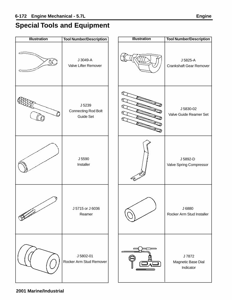
6-172 Engine Mechanical - 5.7L Engine
2001 Marine/Industrial
Illustration Tool Number/Description Illustration Tool Number/Description
Special Tools and Equipment
J 3049-A
Valve Lifter Remover
J 5239
Connecting Rod Bolt
Guide Set
J 5825-A
Crankshaft Gear Remover
J 5830-02
Valve Guide Reamer Set
J 5590
InstallerJ 5892-D
Valve Spring Compressor
J 5715 or J 6036
Reamer
J 6880
Rocker Arm Stud Installer
J 5802-01
Rocker Arm Stud RemoverJ 7872
Magnetic Base Dial
Indicator
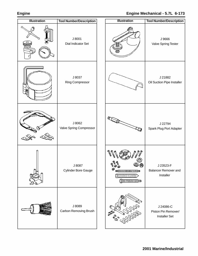
Engine Engine Mechanical - 5.7L 6-173
2001 Marine/Industrial
Illustration Tool Number/Description Illustration Tool Number/Description
J 8001
Dial Indicator Set
J 8037
Ring Compressor
J 9666
Valve Spring Tester
J 21882
Oil Suction Pipe Installer
J 8062
Valve Spring CompressorJ 22794
Spark Plug Port Adapter
J 8087
Cylinder Bore Gauge
J 23523-F
Balancer Remover and
Installer
J 8089
Carbon Removing BrushJ 24086-C
Piston Pin Remover/
Installer Set

6-174 Engine Mechanical - 5.7L Engine
2001 Marine/Industrial
Illustration Tool Number/Description Illustration Tool Number/Description
J 24270
Cylinder Bore Ridge
Reamer
J 28428-E
High Intensity Black
Light Kit
J 36660
Electronic Torque
Angle Meter
J 38606
Valve Spring Compressor
J 33049
Camshaft Bearing Service
Set
J 41240
Fan Clutch Remover
and Installer
J 35468
Cover Aligner/Seal Installer
J 41427
Engine Lift Brackets
J 35621-B
Rear Main Seal InstallerJ 41712
Oil Pressure Switch
Socket

Engine Engine Mechanical - 5.7L 6-175
2001 Marine/Industrial
Illustration Tool Number/Description
J 42073
Valve Stem Seal Installer
J 43276
Clutch Pilot Bearing
Remover