Embed Size (px)
Citation preview
© 2017 Avco Corporation. All Rights Reserved.
Engine Maintenance Manual (Principal Manual) LIO-360-B1G6 Engine
September 2017
Part No. MM-LIO-360-B1G6
LIO-360-B1G6 Engine
Maintenance Manual Lycoming Part Number: MM-LIO-360-B1G6
Contact Us:
Mailing Address:
Lycoming Engines 652 Oliver Street Williamsport, PA 17701 USA
Phone:
Factory
U.S. and Canada Toll Free:
Direct:
+1 (800) 258-3279
+1 (570) 323-6181
Technical Support Hotline
• +1 (877) 839-7878 (Toll Free)
• +1 (570) 327-7222
Lycoming’s regular business hours are Monday through Friday from 8:00AM through 5:00PM Eastern Time (-5 GMT).
Visit us Online: www.Lycoming.com
LIO-360-B1G6 Engine Maintenance Manual
© 2017 Avco Corporation. All Rights Reserved Record of Revisions September 2017 Page i
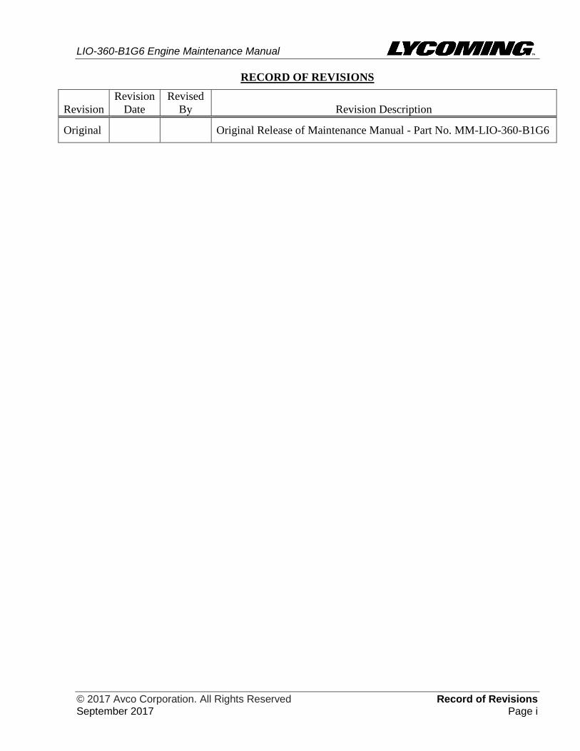
RECORD OF REVISIONS
Revision
Revision
Date
Revised
By Revision Description
Original
Original Release of Maintenance Manual - Part No. MM-LIO-360-B1G6

LIO-360-B1G6 Engine Maintenance Manual
Record of Revisions © 2017 Avco Corporation. All Rights Reserved Page ii September 2017
This page intentionally left blank.
LIO-360-B1G6 Engine Maintenance Manual
© 2017 Avco Corporation. All Rights Reserved Service Document List September 2017 Page iii
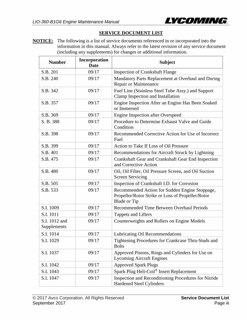
SERVICE DOCUMENT LIST
NOTICE: The following is a list of service documents referenced in or incorporated into the
information in this manual. Always refer to the latest revision of any service document
(including any supplements) for changes or additional information.
Number Incorporation
Date Subject
S.B. 201 09/17 Inspection of Crankshaft Flange
S.B. 240 09/17 Mandatory Parts Replacement at Overhaul and During
Repair or Maintenance
S.B. 342 09/17 Fuel Line (Stainless Steel Tube Assy.) and Support
Clamp Inspection and Installation
S.B. 357 09/17 Engine Inspection After an Engine Has Been Soaked
or Immersed
S.B. 369 09/17 Engine Inspection after Overspeed
S. B. 388 09/17 Procedure to Determine Exhaust Valve and Guide
Condition
S.B. 398 09/17 Recommended Corrective Action for Use of Incorrect
Fuel
S.B. 399 09/17 Action to Take If Loss of Oil Pressure
S.B. 401 09/17 Recommendations for Aircraft Struck by Lightning
S.B. 475 09/17 Crankshaft Gear and Crankshaft Gear End Inspection
and Corrective Action
S.B. 480 09/17 Oil, Oil Filter, Oil Pressure Screen, and Oil Suction
Screen Servicing
S.B. 505 09/17 Inspection of Crankshaft I.D. for Corrosion
S.B. 533 09/17 Recommended Action for Sudden Engine Stoppage,
Propeller/Rotor Strike or Loss of Propeller/Rotor
Blade or Tip
S.I. 1009 09/17 Recommended Time Between Overhaul Periods
S.I. 1011 09/17 Tappets and Lifters
S.I. 1012 and
Supplements
09/17 Counterweights and Rollers on Engine Models
S.I. 1014 09/17 Lubricating Oil Recommendations
S.I. 1029 09/17 Tightening Procedures for Crankcase Thru-Studs and
Bolts
S.I. 1037 09/17 Approved Pistons, Rings and Cylinders for Use on
Lycoming Aircraft Engines
S.I. 1042 09/17 Approved Spark Plugs
S.I. 1043 09/17 Spark Plug Heli-Coil® Insert Replacement
S.I. 1047 09/17 Inspection and Reconditioning Procedures for Nitride
Hardened Steel Cylinders
LIO-360-B1G6 Engine Maintenance Manual
Service Document List © 2017 Avco Corporation. All Rights Reserved Page iv September 2017
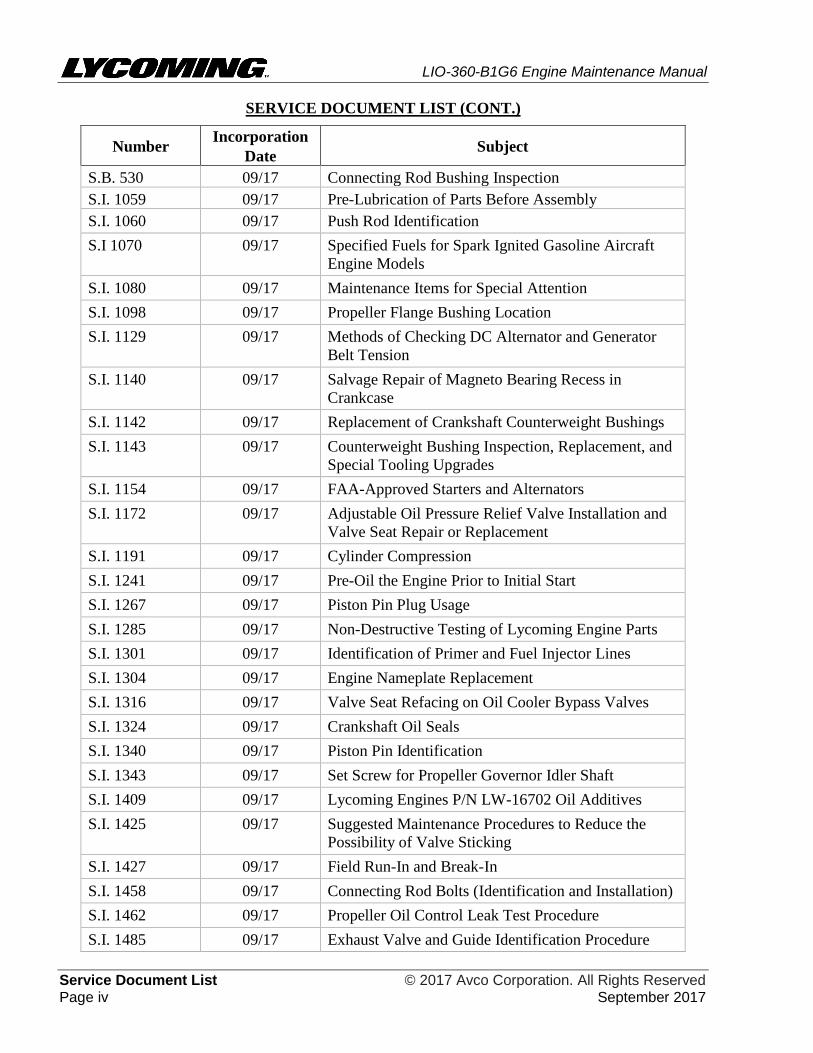
SERVICE DOCUMENT LIST (CONT.)
Number Incorporation
Date Subject
S.B. 530 09/17 Connecting Rod Bushing Inspection
S.I. 1059 09/17 Pre-Lubrication of Parts Before Assembly
S.I. 1060 09/17 Push Rod Identification
S.I 1070 09/17 Specified Fuels for Spark Ignited Gasoline Aircraft
Engine Models
S.I. 1080 09/17 Maintenance Items for Special Attention
S.I. 1098 09/17 Propeller Flange Bushing Location
S.I. 1129 09/17 Methods of Checking DC Alternator and Generator
Belt Tension
S.I. 1140 09/17 Salvage Repair of Magneto Bearing Recess in
Crankcase
S.I. 1142 09/17 Replacement of Crankshaft Counterweight Bushings
S.I. 1143 09/17 Counterweight Bushing Inspection, Replacement, and
Special Tooling Upgrades
S.I. 1154 09/17 FAA-Approved Starters and Alternators
S.I. 1172 09/17 Adjustable Oil Pressure Relief Valve Installation and
Valve Seat Repair or Replacement
S.I. 1191 09/17 Cylinder Compression
S.I. 1241 09/17 Pre-Oil the Engine Prior to Initial Start
S.I. 1267 09/17 Piston Pin Plug Usage
S.I. 1285 09/17 Non-Destructive Testing of Lycoming Engine Parts
S.I. 1301 09/17 Identification of Primer and Fuel Injector Lines
S.I. 1304 09/17 Engine Nameplate Replacement
S.I. 1316 09/17 Valve Seat Refacing on Oil Cooler Bypass Valves
S.I. 1324 09/17 Crankshaft Oil Seals
S.I. 1340 09/17 Piston Pin Identification
S.I. 1343 09/17 Set Screw for Propeller Governor Idler Shaft
S.I. 1409 09/17 Lycoming Engines P/N LW-16702 Oil Additives
S.I. 1425 09/17 Suggested Maintenance Procedures to Reduce the
Possibility of Valve Sticking
S.I. 1427 09/17 Field Run-In and Break-In
S.I. 1458 09/17 Connecting Rod Bolts (Identification and Installation)
S.I. 1462 09/17 Propeller Oil Control Leak Test Procedure
S.I. 1485 09/17 Exhaust Valve and Guide Identification Procedure
LIO-360-B1G6 Engine Maintenance Manual
© 2017 Avco Corporation. All Rights Reserved Service Document List September 2017 Page v
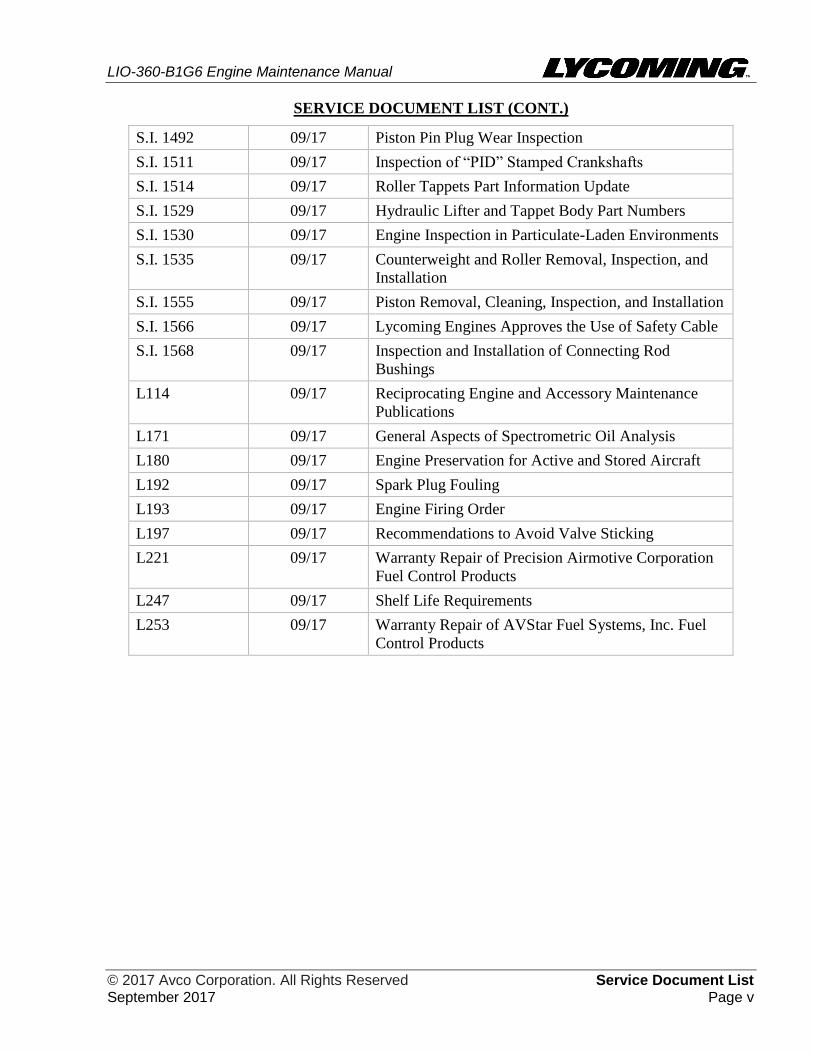
SERVICE DOCUMENT LIST (CONT.)
S.I. 1492 09/17 Piston Pin Plug Wear Inspection
S.I. 1511 09/17 Inspection of “PID” Stamped Crankshafts
S.I. 1514 09/17 Roller Tappets Part Information Update
S.I. 1529 09/17 Hydraulic Lifter and Tappet Body Part Numbers
S.I. 1530 09/17 Engine Inspection in Particulate-Laden Environments
S.I. 1535 09/17 Counterweight and Roller Removal, Inspection, and
Installation
S.I. 1555 09/17 Piston Removal, Cleaning, Inspection, and Installation
S.I. 1566 09/17 Lycoming Engines Approves the Use of Safety Cable
S.I. 1568 09/17 Inspection and Installation of Connecting Rod
Bushings
L114 09/17 Reciprocating Engine and Accessory Maintenance
Publications
L171 09/17 General Aspects of Spectrometric Oil Analysis
L180 09/17 Engine Preservation for Active and Stored Aircraft
L192 09/17 Spark Plug Fouling
L193 09/17 Engine Firing Order
L197 09/17 Recommendations to Avoid Valve Sticking
L221 09/17 Warranty Repair of Precision Airmotive Corporation
Fuel Control Products
L247 09/17 Shelf Life Requirements
L253 09/17 Warranty Repair of AVStar Fuel Systems, Inc. Fuel
Control Products

LIO-360-B1G6 Engine Maintenance Manual
Service Document List © 2017 Avco Corporation. All Rights Reserved Page vi September 2017
This page intentionally left blank.
LIO-360-B1G6 Engine Maintenance Manual
© 2017 Avco Corporation. All Rights Reserved Table of Contents September 2017 Page vii
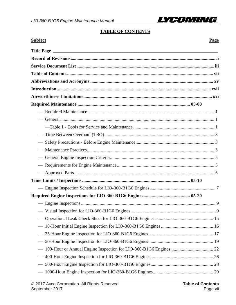
TABLE OF CONTENTS
Subject Page
Title Page _______________________________________________________________________
Record of Revisions .............................................................................................................................. i
Service Document List ....................................................................................................................... iii
Table of Contents .............................................................................................................................. vii
Abbreviations and Acronyms .......................................................................................................... xv
Introduction ..................................................................................................................................... xvii
Airworthiness Limitations ............................................................................................................... xxi
Required Maintenance ................................................................................................. 05-00
— Required Maintenance ............................................................................................................. 1
— General ..................................................................................................................................... 1
—Table 1 - Tools for Service and Maintenance ...................................................................... 1
— Time Between Overhaul (TBO) ............................................................................................... 3
— Safety Precautions - Before Engine Maintenance .................................................................... 3
— Maintenance Practices .............................................................................................................. 3
— General Engine Inspection Criteria .......................................................................................... 5
— Requirements for Engine Maintenance .................................................................................... 5
— Approved Parts ......................................................................................................................... 5
Time Limits / Inspections ............................................................................................. 05-10
— Engine Inspection Schedule for LIO-360-B1G6 Engines ........................................................ 7
Required Engine Inspections for LIO-360-B1G6 Engines ........................................ 05-20
— Engine Inspections .................................................................................................................... 9
— Visual Inspection for LIO-360-B1G6 Engines ......................................................................... 9
— Operational Leak Check Sheet for LIO-360-B1G6 Engines .................................................. 15
— 10-Hour Initial Engine Inspection for LIO-360-B1G6 Engines ............................................. 16
— 25-Hour Engine Inspection for LIO-360-B1G6 Engines ........................................................ 17
— 50-Hour Engine Inspection for LIO-360-B1G6 Engines ........................................................ 19
— 100-Hour or Annual Engine Inspection for LIO-360-B1G6 Engines ..................................... 22
— 400-Hour Engine Inspection for LIO-360-B1G6 Engines ...................................................... 26
— 500-Hour Engine Inspection for LIO-360-B1G6 Engines ...................................................... 28
— 1000-Hour Engine Inspection for LIO-360-B1G6 Engines .................................................... 29
LIO-360-B1G6 Engine Maintenance Manual
Table of Contents © 2017 Avco Corporation. All Rights Reserved Page viii September 2017
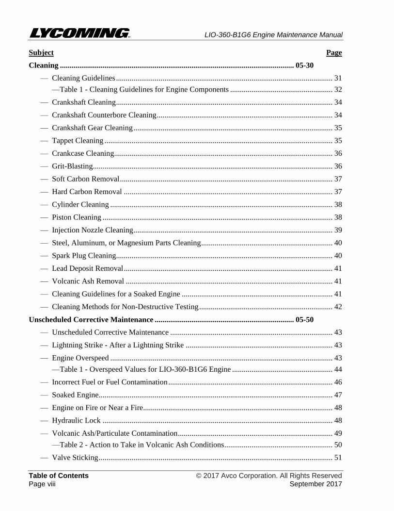
Subject Page
Cleaning ......................................................................................................................... 05-30
— Cleaning Guidelines ................................................................................................................ 31
—Table 1 - Cleaning Guidelines for Engine Components ..................................................... 32
— Crankshaft Cleaning ................................................................................................................ 34
— Crankshaft Counterbore Cleaning ........................................................................................... 34
— Crankshaft Gear Cleaning ....................................................................................................... 35
— Tappet Cleaning ...................................................................................................................... 35
— Crankcase Cleaning................................................................................................................. 36
— Grit-Blasting............................................................................................................................ 36
— Soft Carbon Removal .............................................................................................................. 37
— Hard Carbon Removal ............................................................................................................ 37
— Cylinder Cleaning ................................................................................................................... 38
— Piston Cleaning ....................................................................................................................... 38
— Injection Nozzle Cleaning ....................................................................................................... 39
— Steel, Aluminum, or Magnesium Parts Cleaning .................................................................... 40
— Spark Plug Cleaning................................................................................................................ 40
— Lead Deposit Removal ............................................................................................................ 41
— Volcanic Ash Removal ........................................................................................................... 41
— Cleaning Guidelines for a Soaked Engine .............................................................................. 41
— Cleaning Methods for Non-Destructive Testing ..................................................................... 42
Unscheduled Corrective Maintenance ........................................................................ 05-50
— Unscheduled Corrective Maintenance .................................................................................... 43
— Lightning Strike - After a Lightning Strike ............................................................................ 43
— Engine Overspeed ................................................................................................................... 43
—Table 1 - Overspeed Values for LIO-360-B1G6 Engine .................................................... 44
— Incorrect Fuel or Fuel Contamination ..................................................................................... 46
— Soaked Engine......................................................................................................................... 47
— Engine on Fire or Near a Fire .................................................................................................. 48
— Hydraulic Lock ....................................................................................................................... 48
— Volcanic Ash/Particulate Contamination ................................................................................ 49
—Table 2 - Action to Take in Volcanic Ash Conditions ........................................................ 50
— Valve Sticking ......................................................................................................................... 51
LIO-360-B1G6 Engine Maintenance Manual
© 2017 Avco Corporation. All Rights Reserved Table of Contents September 2017 Page ix
Subject Page
Unscheduled Corrective Maintenance (Cont.) ........................................................... 05-50
— Oil Starvation/Sudden Loss of Oil Pressure ........................................................................... 51
— Propeller Strike, Sudden Engine Stoppage or Loss of a Propeller Blade Tip ......................... 52
—Engine Inspection Checklist After Propeller Strike for LIO-360-B1G6 Engine ................ 54
— Non-Destructive Testing
(Magnetic Particle Inspection and Fluorescent Penetrant Inspection.) ................................... 59
Servicing - Replenishing ............................................................................................... 12-10
— Refueling ................................................................................................................................. 61
— Oil Level Check ...................................................................................................................... 61
— Oil Consumption ..................................................................................................................... 62
— Oil Type and Viscosity ........................................................................................................... 62
— Add Oil to the Engine ............................................................................................................. 62
— Oil Leak Check ....................................................................................................................... 63
— Oil Servicing Schedule............................................................................................................ 63
— Oil Change Procedure ............................................................................................................. 63
— Engine Pre-Oil Procedure ....................................................................................................... 65
— Oil Suction Screen Removal/Inspection/Cleaning/Installation ............................................... 66
— Oil Filter Replacement ............................................................................................................ 67
— Oil Filter Inspection ................................................................................................................ 68
— Engine Wear and Oil Analysis ................................................................................................ 68
Fault Isolation ................................................................................................................ 12-30
— Recommended Approach to Fault Isolation ............................................................................ 69
— Fault Isolation Guide ............................................................................................................... 69
Engine Removal and Return to Service ...................................................................... 72-00
— Engine Removal Prerequisites ................................................................................................ 83
— Engine Removal Procedure ..................................................................................................... 83
— Engine Installation Preparation Requirements ........................................................................ 85
— Operational Ground Check ..................................................................................................... 85
— Idle Speed and Mixture Adjustment ....................................................................................... 86
— Engine Mounting Bracket Inspection ..................................................................................... 87
— Return to Service Procedure ................................................................................................... 87
Engine Disassembly....................................................................................................... 72-05
— Sequence of Engine Disassembly Procedures ........................................................................ 89
LIO-360-B1G6 Engine Maintenance Manual
Table of Contents © 2017 Avco Corporation. All Rights Reserved Page x September 2017
Subject Page
Engine Assembly ........................................................................................................... 72-10
— Sequence of Engine Assembly Procedures ............................................................................. 95
— General Assembly Practices.................................................................................................. 101
—Corrosion Prevention ........................................................................................................ 101
—Painting the Engine and Engine Components ................................................................... 101
—Limits and Clearances ....................................................................................................... 104
—Inspections ........................................................................................................................ 104
— Engine Assembly Checklist .................................................................................................. 105
Propeller Flange Bushing Replacement ...................................................................... 72-15
— Propeller Flange Bushing Removal ...................................................................................... 111
— Propeller Flange Bushing Installation ................................................................................... 111
Crankcase Maintenance ............................................................................................... 72-20
— Exterior Crankcase Inspection .............................................................................................. 113
— Connecting Rod Removal ..................................................................................................... 113
— Crankcase Disassembly......................................................................................................... 114
— Tappet, Main Bearing, and O-Ring Removal .................................................................. 116
— Propeller Governor Drive Removal/Disassembly............................................................ 117
— Oil Plug Removal ............................................................................................................. 118
— Crankshaft Idler Gear Shaft Removal .............................................................................. 118
— NPT Plug Removal .......................................................................................................... 119
— Crankshaft Disassembly ........................................................................................................ 119
— Counterweight Removal ....................................................................................................... 120
— Interior Crankcase Inspection ............................................................................................... 122
— Crankcase Dimensional Inspection ....................................................................................... 123
— Crankshaft Dimensional Inspection Checklist for LIO-360-B1G6 Engines ................... 124
— Crankshaft Inspection ........................................................................................................... 125
— Crankshaft Inspection Checklist for LIO-360-B1G6 Engines ......................................... 125
— Alignment Dowel Inspection ................................................................................................ 134
— Crankshaft Bearing Surface Inspection ................................................................................. 134
— Bearing Shell Surface Inspection .......................................................................................... 135
— Gear Inspection ..................................................................................................................... 135
— Screwed Fitting Inspection.................................................................................................... 135
— Camshaft Disassembly and Inspection ................................................................................. 136
— Connecting Rod Inspection ................................................................................................... 137
— Connecting Rod Bushing Replacement ................................................................................ 140
LIO-360-B1G6 Engine Maintenance Manual
© 2017 Avco Corporation. All Rights Reserved Table of Contents September 2017 Page xi
Subject Page
Crankcase Maintenance (Cont.) .................................................................................. 72-20
— Connecting Rod Parallelism / Squareness Check ................................................................. 141
— Tappet Inspection .................................................................................................................. 142
— Crankshaft Assembly ............................................................................................................ 142
— Alignment Dowel Replacement ....................................................................................... 142
— Crankshaft Gear Installation ............................................................................................ 143
— Expansion Plug Installation ............................................................................................. 145
— Solid-Ring Crankshaft Oil Seal Installation..................................................................... 146
— Connecting Rod Installation............................................................................................. 148
— Counterweight Installation ............................................................................................... 150
— NPT Plug Installation (if removed) ....................................................................................... 151
— Crankshaft Idler Gear Shaft Installation ............................................................................... 152
— Oil Plug Installation (if removed) ......................................................................................... 152
— Tappet Assembly Installation................................................................................................ 153
— Crankshaft Bearing and O-Ring Installation ......................................................................... 154
— Propeller Governor Drive Installation ................................................................................... 154
— Camshaft Assembly and Installation..................................................................................... 157
— Crankshaft Installation .......................................................................................................... 159
— Crankcase Assembly ............................................................................................................. 160
— Crankshaft Oil Seal Installation ............................................................................................ 165
— Crankshaft Idler Gear Installation ......................................................................................... 167
— Crankshaft End Play Clearance Check ................................................................................. 167
— Propeller Oil Control Leak Test ............................................................................................ 168
— Propeller Governor Removal ................................................................................................ 170
— Propeller Governor Installation ............................................................................................. 170
— Crankshaft-to-Camshaft Timing Check ................................................................................ 170
Accessory Housing Maintenance ................................................................................. 72-25
— Accessory Housing Removal ................................................................................................ 171
— Oil Pump Removal ................................................................................................................ 172
— Oil Pump Installation ............................................................................................................ 172
— Fuel Pump Plunger Removal ................................................................................................ 173
— Fuel Pump Plunger Inspection .............................................................................................. 173
— Fuel Pump Plunger Installation ............................................................................................. 173
— Accessory Housing Installation ............................................................................................ 173
LIO-360-B1G6 Engine Maintenance Manual
Table of Contents © 2017 Avco Corporation. All Rights Reserved Page xii September 2017
Subject Page
Cylinder Maintenance .................................................................................................. 72-30
— General .................................................................................................................................. 175
— Visual Cylinder Inspection.................................................................................................... 175
— Cylinder Compression Check ............................................................................................... 176
— Table 2 - Summary of Cylinder Compression Check Results and Corrective Action ..... 180
— Intercylinder Baffle Inspection ............................................................................................. 181
— Cylinder Borescope Inspection ............................................................................................. 182
— Table 3 - Borescope Inspection Steps, Results and Corrective Action ............................ 183
— Exhaust Valve and Guide Inspection .................................................................................... 183
— Cylinder Removal ................................................................................................................. 189
— Piston Removal ..................................................................................................................... 192
— Cylinder Assembly Inspection .............................................................................................. 193
— Piston Inspection ................................................................................................................... 198
— Piston Ring Replacement ...................................................................................................... 202
— Piston Installation .................................................................................................................. 203
— Intake Valve Replacement .................................................................................................... 204
— Exhaust Valve Replacement ................................................................................................. 204
— Cylinder Installation .............................................................................................................. 205
— Shroud Tube Installation .................................................................................................. 208
— Push Rod Installation ....................................................................................................... 209
— Intercylinder Baffle Installation ....................................................................................... 211
— Oil Drain Tube Installation .............................................................................................. 211
— Corrective Action for Valve Sticking ................................................................................... 212
— Intake and Exhaust Valve Guide Replacement ..................................................................... 213
— Intake and Exhaust Valve Seat Replacement ........................................................................ 213
— Barrel Glaze and Varnish Removal from Interior Cylinder Barrel ....................................... 214
— Heli-Coil® Replacement ........................................................................................................ 214
Lubrication System Maintenance ................................................................................ 72-50
— Oil Pressure Adjustment ....................................................................................................... 219
— Oil System Inspection ........................................................................................................... 219
— Oil Line Inspection................................................................................................................ 219
— Oil Line Replacement ........................................................................................................... 220
— Oil Level Gage Tube and Assembly Removal ...................................................................... 220
— Oil Level Gage Tube and Assembly Installation .................................................................. 220
LIO-360-B1G6 Engine Maintenance Manual
© 2017 Avco Corporation. All Rights Reserved Table of Contents September 2017 Page xiii
Subject Page
Lubrication System Maintenance (Cont.) ................................................................... 72-50
— Oil Pressure Relief Valve Removal ...................................................................................... 221
— Oil Pressure Relief Valve Inspection .................................................................................... 221
— Oil Pressure Relief Vale Installation ..................................................................................... 221
— Thermostatic Oil Cooler Bypass Valve Removal ................................................................. 222
— Thermostatic Oil Cooler Bypass Valve Cleaning ................................................................. 222
— Thermostatic Oil Cooler Bypass Valve Installation ............................................................. 222
— Oil Filter Base Removal ........................................................................................................ 222
— Oil Filter Base Installation .................................................................................................... 223
— Oil Sump Removal ................................................................................................................ 223
— Oil Sump Installation ............................................................................................................ 224
Accessory Drives ........................................................................................................... 72-60
— Accessory Drive Inspection .................................................................................................. 227
— Vacuum Pump Replacement (if installed) ............................................................................ 227
— Vacuum Pump Driven Gear Replacement (if installed) ....................................................... 227
Electrical System Maintenance .................................................................................... 72-70
— Wiring Inspection .................................................................................................................. 229
— Alternator Belt Inspection ..................................................................................................... 229
— Alternator Belt Tension Check/Adjustment .......................................................................... 229
— Alternator and Bracket Removal ........................................................................................... 232
— Alternator and Bracket Installation ....................................................................................... 233
— Alternator Belt Replacement ................................................................................................. 233
— Starter Replacement .............................................................................................................. 234
— Starter Ring Gear Support Replacement ............................................................................... 235
— Starter Ring Gear Inspection ................................................................................................. 236
— Starter Ring Gear Replacement ............................................................................................. 236
Induction System Maintenance.................................................................................... 72-80
— Induction System Inspection ................................................................................................. 237
— Intake Pipe Replacement ....................................................................................................... 237
Engine Fuel and Control - Distribution ...................................................................... 73-10
— Fuel System Inspection ......................................................................................................... 239
— Fuel Line Inspection.............................................................................................................. 240
—Table 1 - Corrective Action for Fuel Lines ....................................................................... 242
— Fuel Injector Leak Check ...................................................................................................... 243
LIO-360-B1G6 Engine Maintenance Manual
Table of Contents © 2017 Avco Corporation. All Rights Reserved Page xiv September 2017
Subject Page
Engine Fuel and Control - Distribution (Cont.) ......................................................... 72-50
— Fuel System Inspection Checklist for LIO-360-B1G6 Engines ............................................ 243
— Fuel Line Replacement ......................................................................................................... 246
— Fuel Injector Replacement .................................................................................................... 248
— Injection Nozzle Replacement .............................................................................................. 249
— Injection Nozzle Fuel Flow Check........................................................................................ 250
— Fuel Manifold Replacement .................................................................................................. 251
— Fuel Pump Replacement ....................................................................................................... 253
Spark Plug Maintenance .............................................................................................. 74-20
— Spark Plugs ........................................................................................................................... 255
— Spark Plug Removal.............................................................................................................. 255
— Ignition Lead Inspection ....................................................................................................... 256
— Spark Plug Inspection ........................................................................................................... 256
— Spark Plug Fouling................................................................................................................ 257
— Spark Plug Port Seal Inspection ............................................................................................ 258
— Spark Plug Cleaning.............................................................................................................. 258
— Spark Plug Gap Setting ......................................................................................................... 258
— Spark Plug Rotation .............................................................................................................. 258
— Spark Plug Installation .......................................................................................................... 259
— Ignition Harness Removal ..................................................................................................... 260
— Ignition Harness Inspection .................................................................................................. 260
— Ignition Harness Installation ................................................................................................. 261
Magneto Maintenance .................................................................................................. 74-30
— Magneto Inspection................................................................................................................ 263
— Magneto-to-Engine Timing Check ........................................................................................ 263
— Magneto-to-Engine Timing Adjustment Procedure .............................................................. 265
— Magneto Replacement Procedure .......................................................................................... 265
Magneto Maintenance .................................................................................................. 78-00
— Exhaust System Inspection .................................................................................................... 269
Appendix A ______________________________________________________________________
— Stud Replacement ................................................................................................................. 271
— Hydraulic Pump Adapter Assembly Removal ...................................................................... 272
— Hydraulic Pump Adapter Assembly Installation .................................................................. 272
— Hydraulic Pump Replacement .............................................................................................. 273
LIO-360-B1G6 Engine Maintenance Manual
© 2017 Avco Corporation. All Rights Reserved Abbreviations and Acronyms September 2017 Page xv
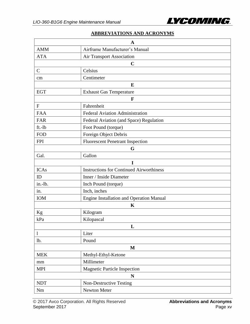
ABBREVIATIONS AND ACRONYMS
A
AMM Airframe Manufacturer’s Manual
ATA Air Transport Association
C
C Celsius
cm Centimeter
E
EGT Exhaust Gas Temperature
F
F Fahrenheit
FAA Federal Aviation Administration
FAR Federal Aviation (and Space) Regulation
ft.-lb Foot Pound (torque)
FOD Foreign Object Debris
FPI Fluorescent Penetrant Inspection
G
Gal. Gallon
I
ICAs Instructions for Continued Airworthiness
ID Inner / Inside Diameter
in.-lb. Inch Pound (torque)
in. Inch, inches
IOM Engine Installation and Operation Manual
K
Kg Kilogram
kPa Kilopascal
L
l Liter
lb. Pound
M
MEK Methyl-Ethyl-Ketone
mm Millimeter
MPI Magnetic Particle Inspection
N
NDT Non-Destructive Testing
Nm Newton Meter
LIO-360-B1G6 Engine Maintenance Manual
Abbreviations and Acronyms © 2017 Avco Corporation. All Rights Reserved Page xvi September 2017
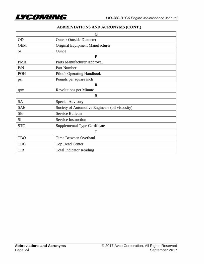
ABBREVIATIONS AND ACRONYMS (CONT.)
O
OD Outer / Outside Diameter
OEM Original Equipment Manufacturer
oz Ounce
P
PMA Parts Manufacturer Approval
P/N Part Number
POH Pilot’s Operating Handbook
psi Pounds per square inch
R
rpm Revolutions per Minute
S
SA Special Advisory
SAE Society of Automotive Engineers (oil viscosity)
SB Service Bulletin
SI Service Instruction
STC Supplemental Type Certificate
T
TBO Time Between Overhaul
TDC Top Dead Center
TIR Total Indicator Reading
LIO-360-B1G6 Engine Maintenance Manual
© 2017 Avco Corporation. All Rights Reserved Introduction September 2017 Page xvii
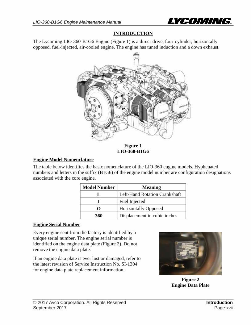
INTRODUCTION
The Lycoming LIO-360-B1G6 Engine (Figure 1) is a direct-drive, four-cylinder, horizontally
opposed, fuel-injected, air-cooled engine. The engine has tuned induction and a down exhaust.
Figure 1
LIO-360-B1G6
Engine Model Nomenclature
The table below identifies the basic nomenclature of the LIO-360 engine models. Hyphenated
numbers and letters in the suffix (B1G6) of the engine model number are configuration designations
associated with the core engine.
Model Number Meaning
L Left-Hand Rotation Crankshaft
I Fuel Injected
O Horizontally Opposed
360 Displacement in cubic inches
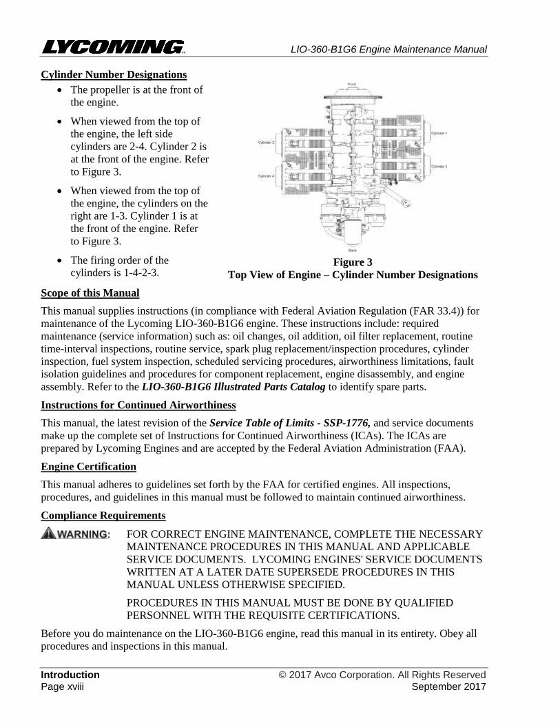
Engine Serial Number
Every engine sent from the factory is identified by a
unique serial number. The engine serial number is
identified on the engine data plate (Figure 2). Do not
remove the engine data plate.
If an engine data plate is ever lost or damaged, refer to
the latest revision of Service Instruction No. SI-1304
for engine data plate replacement information.
Figure 2
Engine Data Plate
LIO-360-B1G6 Engine Maintenance Manual
Introduction © 2017 Avco Corporation. All Rights Reserved Page xviii September 2017
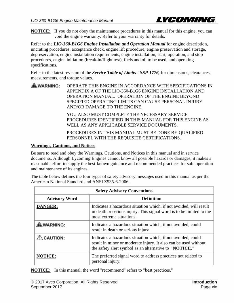
Cylinder Number Designations
• The propeller is at the front of
the engine.
• When viewed from the top of
the engine, the left side
cylinders are 2-4. Cylinder 2 is
at the front of the engine. Refer
to Figure 3.
• When viewed from the top of
the engine, the cylinders on the
right are 1-3. Cylinder 1 is at
the front of the engine. Refer
to Figure 3.
• The firing order of the
cylinders is 1-4-2-3.
Figure 3
Top View of Engine – Cylinder Number Designations
Scope of this Manual
This manual supplies instructions (in compliance with Federal Aviation Regulation (FAR 33.4)) for
maintenance of the Lycoming LIO-360-B1G6 engine. These instructions include: required
maintenance (service information) such as: oil changes, oil addition, oil filter replacement, routine
time-interval inspections, routine service, spark plug replacement/inspection procedures, cylinder
inspection, fuel system inspection, scheduled servicing procedures, airworthiness limitations, fault
isolation guidelines and procedures for component replacement, engine disassembly, and engine
assembly. Refer to the LIO-360-B1G6 Illustrated Parts Catalog to identify spare parts.
Instructions for Continued Airworthiness
This manual, the latest revision of the Service Table of Limits - SSP-1776, and service documents
make up the complete set of Instructions for Continued Airworthiness (ICAs). The ICAs are
prepared by Lycoming Engines and are accepted by the Federal Aviation Administration (FAA).
Engine Certification
This manual adheres to guidelines set forth by the FAA for certified engines. All inspections,
procedures, and guidelines in this manual must be followed to maintain continued airworthiness.
Compliance Requirements
FOR CORRECT ENGINE MAINTENANCE, COMPLETE THE NECESSARY
MAINTENANCE PROCEDURES IN THIS MANUAL AND APPLICABLE
SERVICE DOCUMENTS. LYCOMING ENGINES' SERVICE DOCUMENTS
WRITTEN AT A LATER DATE SUPERSEDE PROCEDURES IN THIS
MANUAL UNLESS OTHERWISE SPECIFIED.
PROCEDURES IN THIS MANUAL MUST BE DONE BY QUALIFIED
PERSONNEL WITH THE REQUISITE CERTIFICATIONS.
Before you do maintenance on the LIO-360-B1G6 engine, read this manual in its entirety. Obey all
procedures and inspections in this manual.
LIO-360-B1G6 Engine Maintenance Manual
© 2017 Avco Corporation. All Rights Reserved Introduction September 2017 Page xix
NOTICE: If you do not obey the maintenance procedures in this manual for this engine, you can
void the engine warranty. Refer to your warranty for details.
Refer to the LIO-360-B1G6 Engine Installation and Operation Manual for engine description,
uncrating procedures, acceptance check, engine lift procedure, engine preservation and storage,
depreservation, engine installation requirements, engine installation, start, operation, and stop
procedures, engine initiation (break-in/flight test), fuels and oil to be used, and operating
specifications.
Refer to the latest revision of the Service Table of Limits - SSP-1776, for dimensions, clearances,
measurements, and torque values.
OPERATE THIS ENGINE IN ACCORDANCE WITH SPECIFICATIONS IN
APPENDIX A OF THE LIO-360-B1G6 ENGINE INSTALLATION AND
OPERATION MANUAL. OPERATION OF THE ENGINE BEYOND
SPECIFIED OPERATING LIMITS CAN CAUSE PERSONAL INJURY
AND/OR DAMAGE TO THE ENGINE.
YOU ALSO MUST COMPLETE THE NECESSARY SERVICE
PROCEDURES IDENTIFIED IN THIS MANUAL FOR THIS ENGINE AS
WELL AS ANY APPLICABLE SERVICE DOCUMENTS.
PROCEDURES IN THIS MANUAL MUST BE DONE BY QUALIFIED
PERSONNEL WITH THE REQUISITE CERTIFICATIONS.
Warnings, Cautions, and Notices
Be sure to read and obey the Warnings, Cautions, and Notices in this manual and in service
documents. Although Lycoming Engines cannot know all possible hazards or damages, it makes a
reasonable effort to supply the best-known guidance and recommended practices for safe operation
and maintenance of its engines.
The table below defines the four types of safety advisory messages used in this manual as per the
American National Standard and ANSI Z535-6-2006.
Safety Advisory Conventions
Advisory Word Definition
DANGER: Indicates a hazardous situation which, if not avoided, will result
in death or serious injury. This signal word is to be limited to the
most extreme situations.
Indicates a hazardous situation which, if not avoided, could
result in death or serious injury.
Indicates a hazardous situation which, if not avoided, could
result in minor or moderate injury. It also can be used without
the safety alert symbol as an alternative to "NOTICE."
NOTICE: The preferred signal word to address practices not related to
personal injury.
NOTICE: In this manual, the word "recommend" refers to "best practices."
LIO-360-B1G6 Engine Maintenance Manual
Introduction © 2017 Avco Corporation. All Rights Reserved Page xx September 2017
Service Bulletins, Service Instructions, and Service Letters
As advancements in technological applications on this engine continue, Lycoming will make future
revisions to this manual. However, if more timely distribution is necessary, Lycoming supplies up-
to-date Service Bulletins (SBs), Service Instructions (SIs) and Service Letters (which are abbreviated
with a capital “L” followed by the number, example L180). Special Advisories (SAs) are supplied as
necessary.
For additional publication information, look on Lycoming’s website (Lycoming.com) or speak to
Lycoming Engines by telephone: U.S. and Canada toll free: +1(800) 258-3279; or Direct: +1 (570)
323-6181.
Applicable information from Lycoming Engines' Service Bulletins, Service Instructions, and Service
Letters are included in this manual at the time of publication. Any new service information will be
included in the next update of the manual.
Reminder: Unless otherwise specified, Lycoming Engines' service documents (which have a later
date than this manual) override procedures in this manual.
For reference, the Service Document List at the front of this manual shows the service documents
referenced or included in this manual.
List of Publications
Refer to the latest revision of Service Letter No. L114 for a list of Lycoming Engines' publications.
Environmental Compliance
Lycoming Engines recommends that engine owners and engine service personnel be in compliance
with all federal, state, and local environmental regulations when solvents, paint, fuel, oil, chemicals,
or other consumables are used in engine service.
Simplified Technical English
The text in this manual is written in the form of Simplified Technical English in compliance with
FAA requirements and to make translation into other languages easier.
Format
Chapters in this manual are identified in Air Transport Association (ATA) format.
Figures
Figures in this manual are for illustration purposes only. Figures always start as Figure 1 in each
chapter.
Copyright
This publication is a copyrighted work. All rights reserved by Lycoming Engines. Content in this
manual cannot be changed or released as a reprint, electronic media output, or web communiqué
without written permission from Lycoming Engines.
Feedback
To supply comments, suggestions, or corrections to this manual, either call Lycoming Engines
Customer Service at the phone number in the front of this manual or use the Lycoming.com website.
LIO-360-B1G6 Engine Maintenance Manual
© 2017 Avco Corporation. All Rights Reserved Airworthiness Limitations September 2017 Page xxi
AIRWORTHINESS LIMITATIONS
1. General
This Airworthiness Limitations chapter sets forth each mandatory replacement time,
inspection interval, and related procedure required for type certification. The
Airworthiness Limitations section is FAA approved and specifies maintenance required
under 14 CFR §§ 43.16 and 91.403 of the Federal Aviation Regulations (FAR) unless an
alternative program has been FAA-approved.
2. Mandatory Inspection - Fuel Injector Lines
At every 100 hours of operation and after any maintenance has been done on the engine
where the fuel injector lines have been disconnected, moved or loosened, examine the
fuel lines per the "Fuel Line Inspection" procedure in Chapter 73-10.
3. Mandatory Inspection
At every 500 hours of operation, examine the magnetos in accordance with the applicable
magneto manufacturer's instructions.
4. Mandatory Inspection - Exhaust Valve and Guide
At every 1000 hours of operation for LIO-360-B1G6 engines, examine the exhaust valve
and guide conditions. Refer to the section "Exhaust Valve and Guide Inspection" in
Chapter 72-30.

LIO-360-B1G6 Engine Maintenance Manual
Airworthiness Limitations © 2017 Avco Corporation. All Rights Reserved Page xxii September 2017
This page intentionally left blank.
LIO-360-B1G6 Engine Maintenance Manual
© 2017 Avco Corporation. All Rights Reserved 05-00 September 2017 Page 1
05-00 - REQUIRED MAINTENANCE
1. Required Maintenance
Required maintenance on these engines includes: oil changes, oil addition, oil filter replacement,
routine time-interval inspections, routine service, spark plug replacement/inspection procedures,
cylinder inspection, fuel system inspection and other procedures identified in the checklists in
Chapter 05-20 of this manual.
2. General
In addition to instructions for required service and maintenance of the Lycoming LIO-360-B1G6
engine, this manual also includes airworthiness limitations, fault isolation guidelines and
procedures for component replacement, engine disassembly, and engine assembly. Refer to the
LIO-360-B1G6 Illustrated Parts Catalog to identify spare parts.
A. Refer to the latest revision of the Service Table of Limits - SSP-1776, for dimensions,
clearances, measurements, and torque values.
B. Engine description, uncrating procedures, acceptance check, engine lift procedure, engine
preservation and storage, depreservation, engine installation requirements, engine
installation, engine start, operation, and stop procedures, engine initiation (break-in/flight
test), fuels and oil to be used, and operating specifications are included in the LIO-360-B1G6
Engine Installation and Operation Manual.
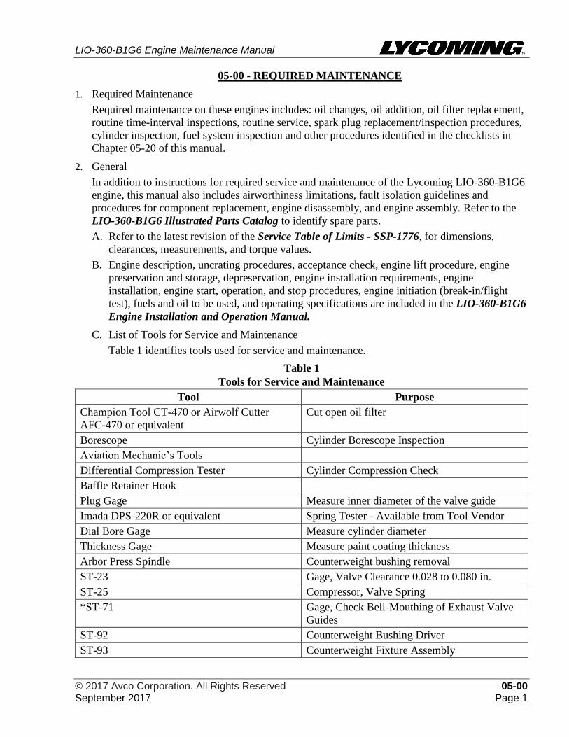
C. List of Tools for Service and Maintenance
Table 1 identifies tools used for service and maintenance.
Table 1
Tools for Service and Maintenance
Tool Purpose
Champion Tool CT-470 or Airwolf Cutter
AFC-470 or equivalent
Cut open oil filter
Borescope Cylinder Borescope Inspection
Aviation Mechanic’s Tools
Differential Compression Tester Cylinder Compression Check
Baffle Retainer Hook
Plug Gage Measure inner diameter of the valve guide
Imada DPS-220R or equivalent Spring Tester - Available from Tool Vendor
Dial Bore Gage Measure cylinder diameter
Thickness Gage Measure paint coating thickness
Arbor Press Spindle Counterweight bushing removal
ST-23 Gage, Valve Clearance 0.028 to 0.080 in.
ST-25 Compressor, Valve Spring
*ST-71 Gage, Check Bell-Mouthing of Exhaust Valve
Guides
ST-92 Counterweight Bushing Driver
ST-93 Counterweight Fixture Assembly
LIO-360-B1G6 Engine Maintenance Manual
05-00 © 2017 Avco Corporation. All Rights Reserved Page 2 September 2017
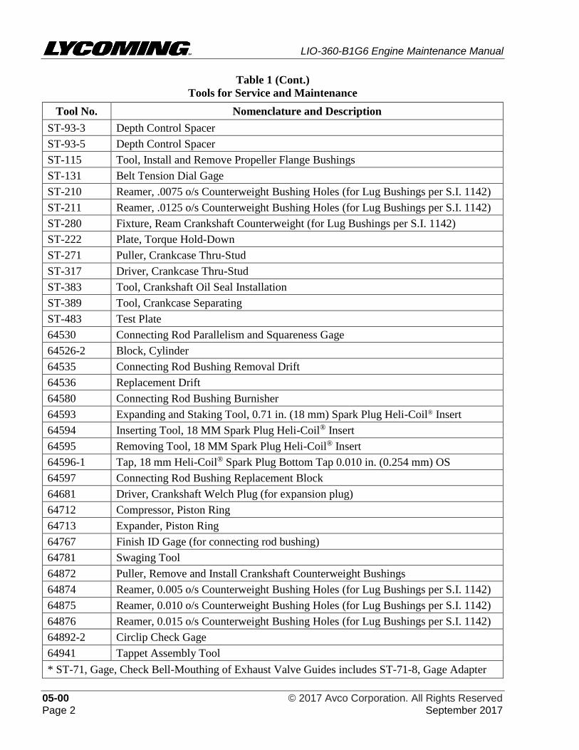
Table 1 (Cont.)
Tools for Service and Maintenance
Tool No. Nomenclature and Description
ST-93-3 Depth Control Spacer
ST-93-5 Depth Control Spacer
ST-115 Tool, Install and Remove Propeller Flange Bushings
ST-131 Belt Tension Dial Gage
ST-210 Reamer, .0075 o/s Counterweight Bushing Holes (for Lug Bushings per S.I. 1142)
ST-211 Reamer, .0125 o/s Counterweight Bushing Holes (for Lug Bushings per S.I. 1142)
ST-280 Fixture, Ream Crankshaft Counterweight (for Lug Bushings per S.I. 1142)
ST-222 Plate, Torque Hold-Down
ST-271 Puller, Crankcase Thru-Stud
ST-317 Driver, Crankcase Thru-Stud
ST-383 Tool, Crankshaft Oil Seal Installation
ST-389 Tool, Crankcase Separating
ST-483 Test Plate
64530 Connecting Rod Parallelism and Squareness Gage
64526-2 Block, Cylinder
64535 Connecting Rod Bushing Removal Drift
64536 Replacement Drift
64580 Connecting Rod Bushing Burnisher
64593 Expanding and Staking Tool, 0.71 in. (18 mm) Spark Plug Heli-Coil® Insert
64594 Inserting Tool, 18 MM Spark Plug Heli-Coil® Insert
64595 Removing Tool, 18 MM Spark Plug Heli-Coil® Insert
64596-1 Tap, 18 mm Heli-Coil® Spark Plug Bottom Tap 0.010 in. (0.254 mm) OS
64597 Connecting Rod Bushing Replacement Block
64681 Driver, Crankshaft Welch Plug (for expansion plug)
64712 Compressor, Piston Ring
64713 Expander, Piston Ring
64767 Finish ID Gage (for connecting rod bushing)
64781 Swaging Tool
64872 Puller, Remove and Install Crankshaft Counterweight Bushings
64874 Reamer, 0.005 o/s Counterweight Bushing Holes (for Lug Bushings per S.I. 1142)
64875 Reamer, 0.010 o/s Counterweight Bushing Holes (for Lug Bushings per S.I. 1142)
64876 Reamer, 0.015 o/s Counterweight Bushing Holes (for Lug Bushings per S.I. 1142)
64892-2 Circlip Check Gage
64941 Tappet Assembly Tool
* ST-71, Gage, Check Bell-Mouthing of Exhaust Valve Guides includes ST-71-8, Gage Adapter
LIO-360-B1G6 Engine Maintenance Manual
© 2017 Avco Corporation. All Rights Reserved 05-00 September 2017 Page 3
3. Time Between Overhaul (TBO)
Refer to the latest revision of Service Instruction No. SI-1009 for any changes or special
circumstances for the recommended TBO.
Lycoming Engines recommends engines be sent to the factory for overhaul.
4. Safety Precautions - Before Engine Maintenance
BEFORE THE START OF ANY SERVICE OR MAINTENANCE ON AN
INSTALLED ENGINE OR AN ENGINE ON A TEST STAND CONNECTED
TO POWER, ENSURE THE IGNITION SWITCH IS TURNED OFF AND
DISABLED. DISCONNECT ALL POWER TO THE ENGINE TO PREVENT
ACCIDENTAL ENGINE START-UP. FAILURE TO DISABLE POWER
COULD CAUSE ACCIDENTAL ENGINE START-UP, INJURY, OR DEATH.
ENSURE ALL OBJECTS/PERSONNEL ARE CLEAR OF THE
PROPELLER’S ROTATIONAL ARC. IF POWER IS ON, A LOOSE OR
BROKEN WIRE CAN CAUSE THE ENGINE TO START AND THE
PROPELLER TO TURN WHICH CAN LEAD TO DEATH OR SERIOUS
INJURY OR A PROPELLER STRIKE.
IF IT IS NECESSARY TO COMPLETE OPERATIONAL TESTS ON THE
ENGINE WITH POWER ON, KEEP ALL PERSONNEL AWAY FROM THE
ROTATIONAL RADIUS OF THE PROPELLER TO PREVENT INJURY OR
DEATH ON ENGINE START-UP.
A. Disconnect the battery.
B. Remove access panel(s), cowling(s) and/or baffles for access to areas.
5. Maintenance Practices
A. Obey all safety precautions.
B. Do not reuse a gasket, O-ring, or seal. Install a new gasket, O-ring, or seal during component
installation where a gasket, O-ring, or seal was removed.
C. If maintenance is done that could cause contamination of the internal components of the
engine, complete the “Oil Change Procedure” in Chapter 12-10.
D. Remove all traces of dirt, dust, debris and accumulated matter from parts. All parts must be
clean before they are installed on the engine. For specific cleaning guidelines, refer to
Chapter 05-30.
E. If adhesive tape has been applied to any part, remove the tape and all residue. Clean the part
completely.
F. Hardware
(1) All cotter pins that are removed must be discarded and not reused. Install a new cotter pin
where a cotter pin was removed.
(2) All safety wire and cotter pins must be made of corrosion-resistant steel and installed as a
snug fit in holes in studs and bolts for correct locking.
(3) If safety wire or safety cable was removed during component removal, be sure to install
new safety wire or safety cable during component installation.
LIO-360-B1G6 Engine Maintenance Manual
05-00 © 2017 Avco Corporation. All Rights Reserved Page 4 September 2017
(4) All safety cable installed on the engine must meet or exceed specifications in the latest
revision of AS3510. Safety cable must be installed per the safety cable manufacturer’s
instructions and in accordance with specifications in the latest revisions of AS4536 and
AS567 and the latest revision of Service Instruction No. SI-1566.
(5) The cotter pin head must install as a snug fit into the castellation of the nut. Unless
otherwise specified, bend one end of the cotter pin back over the stud or bolt and the
other end flat against the nut.
(6) Torque a castellated or slotted nut to the value specified in this manual or the latest
revision of the Service Table of Limits - SSP-1776, if necessary, turn the nut up to one
additional hex to align the slot in the nut with the hole in the bolt.
(7) If a lockplate is required when installing a bolt, torque the nut to the value specified in
this manual or the latest revision of the Service Table of Limits - SSP-1776, if necessary,
turn the nut up to one additional hex to align the flat on the nut with the tab on the
lockplate. Lockplate tabs must not be bent up on the corner of the nut.
(8) Any damaged or unserviceable hardware, fasteners, studs, screws, bolts, nuts, washers,
and clamps must be replaced with new parts.
(9) Unless otherwise directed, lock washers and lock nuts must be replaced with new lock
washers and lock nuts.
(10) Although the latest revision of Service Bulletin No. SB-240 identifies parts which must
be replaced after they are removed, in the case where other parts are removed, it is
recommended practice, prior to installation, to examine each part for damage or wear
and replace the part as needed in accordance with accepted practices and standards to
ensure that serviceable parts are installed on the engine.
G. Unless otherwise specified in this manual, refer to the latest revision of the Service Table of
Limits - SSP-1776 for:
• Standard torque values for fittings, plugs, and hardware fasteners
• Special torque requirements for fittings, valves, clamps, couplings, plugs, and other
hardware fasteners in various locations on the engine
• Dimensions
• Clearances
• Measurements
H. Specific engine parts must be lubricated during engine assembly. Many premature part
failures have been caused by incorrect pre-lubrication during engine assembly. If parts are
not correctly lubricated, or if an unapproved lubricant is used, engine parts could become
scored before the engine oil has lubricated the engine during the first cycle of operation. This
scoring can cause premature part failure, or, in some cases, engine failure. As preventive
action, during engine assembly and individual engine component replacement, apply the
approved lubricant for specified components identified in the latest revision of Service
Instruction No. SI-1059.
I. Complete the Operational Ground Check prior to and after each inspection, after
maintenance, and after engine assembly. Refer to Chapter 72-00.
LIO-360-B1G6 Engine Maintenance Manual
© 2017 Avco Corporation. All Rights Reserved 05-00 September 2017 Page 5
6. General Engine Inspection Criteria
During visual inspection:
• Replace the crankcase, oil sump, or accessory housing if there is any raised metal on surfaces
• Replace the crankcase, oil sump, or accessory housing if there is any scratch, ding, dent, or
pit, that exceeds 0.050 in. (1.27 mm) depth
• Replace the crankcase if the dowels do not fully seat into the crankcase holes
• Replace any bent, damaged, or stripped studs, refer to Appendix A
7. Requirements for Engine Maintenance
A. These engines must be maintained using Lycoming Engines’ approved methods and
procedures.
B. Refer to the latest revision of Service Bulletin No. SB-240 for a list of parts that must be
replaced whenever they are removed.
8. Approved Parts
LYCOMING DOES NOT GIVE APPROVAL FOR USE OF PARTS
MANUFACTURER APPROVAL (PMA) PARTS ON ITS ENGINES.
LYCOMING INSTALLATION INSTRUCTIONS DO NOT APPLY TO PMA
PARTS. EQUIPMENT FAILURE COULD OCCUR IF LYCOMING
INSTRUCTIONS ARE USED TO INSTALL PMA PARTS. DAMAGES
RELATED TO THE INSTALLATION OF PMA PARTS COULD VOID THE
WARRANTY.
Lycoming Engines recommends these engines be assembled, maintained, and overhauled using
only genuine Lycoming parts. (PMA parts have not been approved for use by Lycoming
Engines.)
Refer to the LIO-360-B1G6 Illustrated Parts Catalog for genuine Lycoming parts.
Before installing a component, complete a check of the shelf-life of the part as per the latest
revision of Service Letter No. L247.

LIO-360-B1G6 Engine Maintenance Manual
05-00 © 2017 Avco Corporation. All Rights Reserved Page 6 September 2017
This page intentionally left blank.
LIO-360-B1G6 Engine Maintenance Manual
© 2017 Avco Corporation. All Rights Reserved 05-10 September 2017 Page 7
05-10 - TIME LIMITS / INSPECTIONS
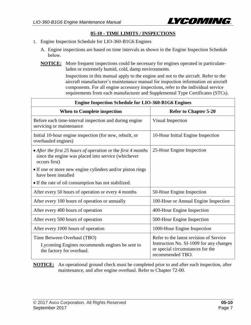
1. Engine Inspection Schedule for LIO-360-B1G6 Engines
A. Engine inspections are based on time intervals as shown in the Engine Inspection Schedule
below.
NOTICE: More frequent inspections could be necessary for engines operated in particulate-
laden or extremely humid, cold, damp environments.
Inspections in this manual apply to the engine and not to the aircraft. Refer to the
aircraft manufacturer’s maintenance manual for inspection information on aircraft
components. For all engine accessory inspections, refer to the individual service
requirements from each manufacturer and Supplemental Type Certificates (STCs).
Engine Inspection Schedule for LIO-360-B1G6 Engines
When to Complete inspection Refer to Chapter 5-20
Before each time-interval inspection and during engine
servicing or maintenance
Visual Inspection
Initial 10-hour engine inspection (for new, rebuilt, or
overhauled engines)
10-Hour Initial Engine Inspection
• After the first 25 hours of operation or the first 4 months
since the engine was placed into service (whichever
occurs first)
• If one or more new engine cylinders and/or piston rings
have been installed
• If the rate of oil consumption has not stabilized.
25-Hour Engine Inspection
After every 50 hours of operation or every 4 months 50-Hour Engine Inspection
After every 100 hours of operation or annually 100-Hour or Annual Engine Inspection
After every 400 hours of operation 400-Hour Engine Inspection
After every 500 hours of operation 500-Hour Engine Inspection
After every 1000 hours of operation 1000-Hour Engine Inspection
Time Between Overhaul (TBO)
Lycoming Engines recommends engines be sent to
the factory for overhaul.
Refer to the latest revision of Service
Instruction No. SI-1009 for any changes
or special circumstances for the
recommended TBO.
NOTICE: An operational ground check must be completed prior to and after each inspection, after
maintenance, and after engine overhaul. Refer to Chapter 72-00.

LIO-360-B1G6 Engine Maintenance Manual
05-10 © 2017 Avco Corporation. All Rights Reserved Page 8 September 2017
This page intentionally left blank.
LIO-360-B1G6 Engine Maintenance Manual
© 2017 Avco Corporation. All Rights Reserved 05-20 September 2017 Page 9
05-20 - REQUIRED ENGINE INSPECTIONS FOR LIO-360-B1G6 ENGINES
1. Engine Inspections
A. As shown in the Engine Inspection Schedule in Chapter 05-10, the scope of engine
inspections includes visual observations during engine servicing or maintenance as well as
inspections based on progressive time intervals after the engine is put into service.
B. All engine inspections are mandatory and must be completed no later than 10 hours after the
specified time interval for the inspection. Refer to FAR 91-409 for additional requirements.
NOTICE: More frequent inspections could be necessary for engines operated in particulate-
laden or extremely humid, cold, damp environments.
Obey and follow inspection checklists and instructions in this chapter in addition to
maintenance guidelines from the aircraft manufacturer or component manufacturers
that have a Supplemental Type Certificate (STC).
2. Visual Inspection for LIO-360-B1G6 Engines
A. Complete the Visual Inspection, with the engine installed in the aircraft, before the initial 10-
hour inspection and each routine 25, 50, 100, 400, 500, and 1000-hour inspection and every
time before you service, maintain, clean, or disassemble the engine.
BEFORE ANY ENGINE INSPECTION OR SERVICE PROCEDURE,
MAKE SURE THE IGNITION SWITCH IS SET TO OFF AND THAT ALL
POWER TO THE ENGINE IS DISCONNECTED. ENSURE ALL
OBJECTS/PERSONNEL ARE CLEAR OF THE PROPELLER’S
ROTATIONAL ARC. IF POWER IS ON, A LOOSE OR BROKEN WIRE
CAN CAUSE THE ENGINE TO START AND THE PROPELLER TO TURN
WHICH CAN LEAD TO DEATH OR SERIOUS INJURY OR A
PROPELLER STRIKE.
B. Visual Inspection
(1) Set all ignition and electrical switches to the OFF position.
(2) Per the aircraft manufacturer’s instructions, remove the engine cowling from the
aircraft for access to the engine and its compartment.
IF VOLCANIC ASH IS SUSPECTED ON THE ENGINE, DO NOT TOUCH
IT WITH BARE HANDS OR GET IT IN YOUR EYES. WEAR
PERSONAL PROTECTIVE EQUIPMENT. DO NOT USE WATER TO
RINSE IT OFF. THE VOLCANIC ASH CAN CONTAIN ACIDIC
COMPOUNDS WHICH MUST NOT BE INHALED OR TOUCHED SINCE
IT CAN CAUSE INJURY. REFER TO THE "VOLCANIC ASH
REMOVAL" PROCEDURE IN CHAPTER 05-30.
(3) Copy and complete the Visual Inspection Checklist in this chapter for LIO-360-B1G6
engines each time this inspection is done as a record of engine service. Record the
engine hours.
LIO-360-B1G6 Engine Maintenance Manual
05-20 © 2017 Avco Corporation. All Rights Reserved Page 10 September 2017
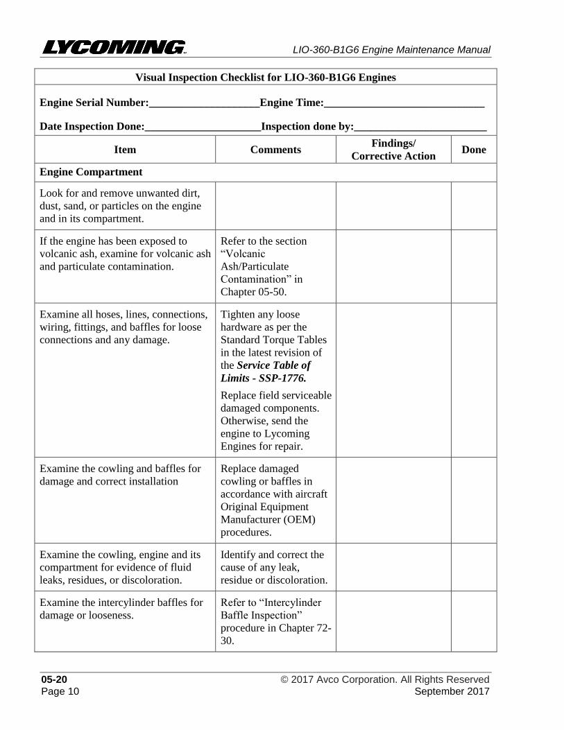
Visual Inspection Checklist for LIO-360-B1G6 Engines
Engine Serial Number:____________________Engine Time:_____________________________
Date Inspection Done:_____________________Inspection done by:________________________
Item Comments Findings/
Corrective Action Done
Engine Compartment
Look for and remove unwanted dirt,
dust, sand, or particles on the engine
and in its compartment.
If the engine has been exposed to
volcanic ash, examine for volcanic ash
and particulate contamination.
Refer to the section
“Volcanic
Ash/Particulate
Contamination” in
Chapter 05-50.
Examine all hoses, lines, connections,
wiring, fittings, and baffles for loose
connections and any damage.
Tighten any loose
hardware as per the
Standard Torque Tables
in the latest revision of
the Service Table of
Limits - SSP-1776.
Replace field serviceable
damaged components.
Otherwise, send the
engine to Lycoming
Engines for repair.
Examine the cowling and baffles for
damage and correct installation
Replace damaged
cowling or baffles in
accordance with aircraft
Original Equipment
Manufacturer (OEM)
procedures.
Examine the cowling, engine and its
compartment for evidence of fluid
leaks, residues, or discoloration.
Identify and correct the
cause of any leak,
residue or discoloration.
Examine the intercylinder baffles for
damage or looseness.
Refer to “Intercylinder
Baffle Inspection”
procedure in Chapter 72-
30.
LIO-360-B1G6 Engine Maintenance Manual
© 2017 Avco Corporation. All Rights Reserved 05-20 September 2017 Page 11
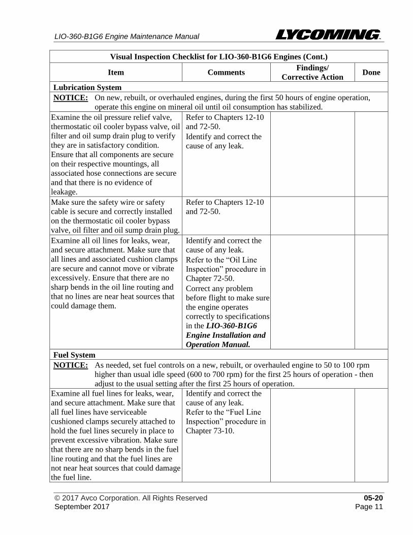
Visual Inspection Checklist for LIO-360-B1G6 Engines (Cont.)
Item Comments Findings/
Corrective Action Done
Lubrication System
NOTICE: On new, rebuilt, or overhauled engines, during the first 50 hours of engine operation,
operate this engine on mineral oil until oil consumption has stabilized.
Examine the oil pressure relief valve,
thermostatic oil cooler bypass valve, oil
filter and oil sump drain plug to verify
they are in satisfactory condition.
Ensure that all components are secure
on their respective mountings, all
associated hose connections are secure
and that there is no evidence of
leakage.
Refer to Chapters 12-10
and 72-50.
Identify and correct the
cause of any leak.
Make sure the safety wire or safety
cable is secure and correctly installed
on the thermostatic oil cooler bypass
valve, oil filter and oil sump drain plug.
Refer to Chapters 12-10
and 72-50.
Examine all oil lines for leaks, wear,
and secure attachment. Make sure that
all lines and associated cushion clamps
are secure and cannot move or vibrate
excessively. Ensure that there are no
sharp bends in the oil line routing and
that no lines are near heat sources that
could damage them.
Identify and correct the
cause of any leak.
Refer to the “Oil Line
Inspection” procedure in
Chapter 72-50.
Correct any problem
before flight to make sure
the engine operates
correctly to specifications
in the LIO-360-B1G6
Engine Installation and
Operation Manual.
Fuel System
NOTICE: As needed, set fuel controls on a new, rebuilt, or overhauled engine to 50 to 100 rpm
higher than usual idle speed (600 to 700 rpm) for the first 25 hours of operation - then
adjust to the usual setting after the first 25 hours of operation.
Examine all fuel lines for leaks, wear,
and secure attachment. Make sure that
all fuel lines have serviceable
cushioned clamps securely attached to
hold the fuel lines securely in place to
prevent excessive vibration. Make sure
that there are no sharp bends in the fuel
line routing and that the fuel lines are
not near heat sources that could damage
the fuel line.
Identify and correct the
cause of any leak.
Refer to the “Fuel Line
Inspection” procedure in
Chapter 73-10.
LIO-360-B1G6 Engine Maintenance Manual
05-20 © 2017 Avco Corporation. All Rights Reserved Page 12 September 2017
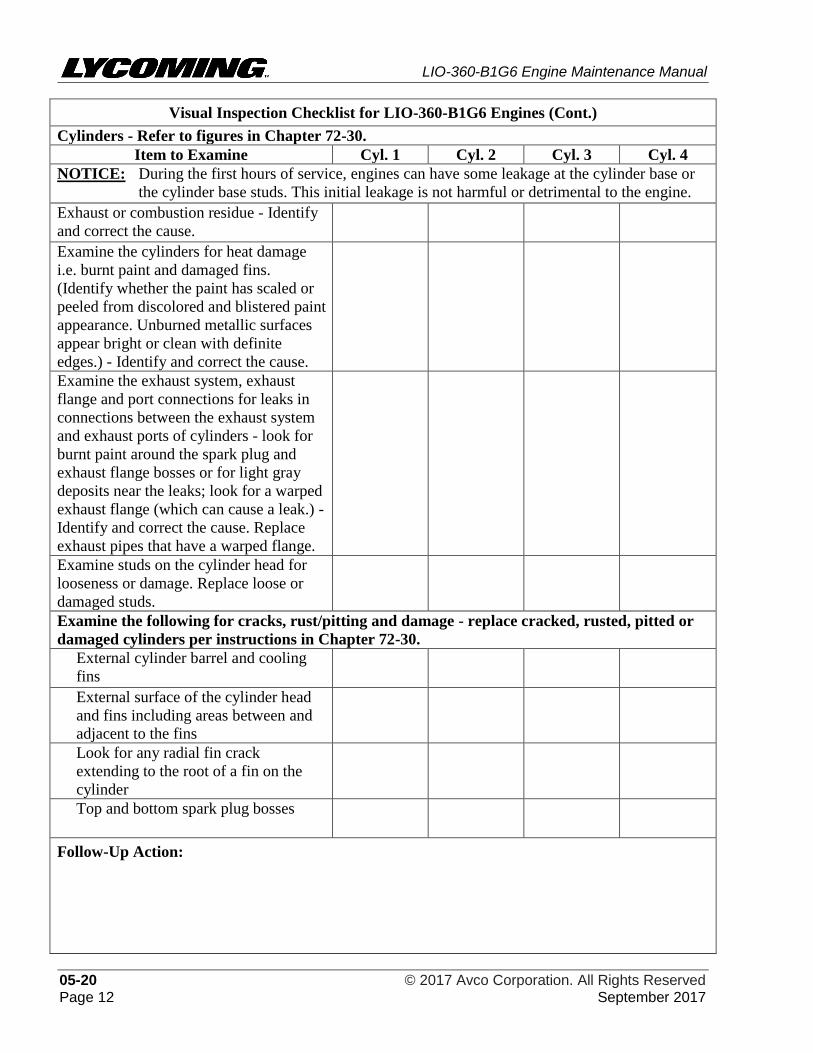
Visual Inspection Checklist for LIO-360-B1G6 Engines (Cont.)
Cylinders - Refer to figures in Chapter 72-30.
Item to Examine Cyl. 1 Cyl. 2 Cyl. 3 Cyl. 4
NOTICE: During the first hours of service, engines can have some leakage at the cylinder base or
the cylinder base studs. This initial leakage is not harmful or detrimental to the engine.
Exhaust or combustion residue - Identify
and correct the cause.
Examine the cylinders for heat damage
i.e. burnt paint and damaged fins.
(Identify whether the paint has scaled or
peeled from discolored and blistered paint
appearance. Unburned metallic surfaces
appear bright or clean with definite
edges.) - Identify and correct the cause.
Examine the exhaust system, exhaust
flange and port connections for leaks in
connections between the exhaust system
and exhaust ports of cylinders - look for
burnt paint around the spark plug and
exhaust flange bosses or for light gray
deposits near the leaks; look for a warped
exhaust flange (which can cause a leak.) -
Identify and correct the cause. Replace
exhaust pipes that have a warped flange.
Examine studs on the cylinder head for
looseness or damage. Replace loose or
damaged studs.
Examine the following for cracks, rust/pitting and damage - replace cracked, rusted, pitted or
damaged cylinders per instructions in Chapter 72-30.
External cylinder barrel and cooling
fins
External surface of the cylinder head
and fins including areas between and
adjacent to the fins
Look for any radial fin crack
extending to the root of a fin on the
cylinder
Top and bottom spark plug bosses
Follow-Up Action:
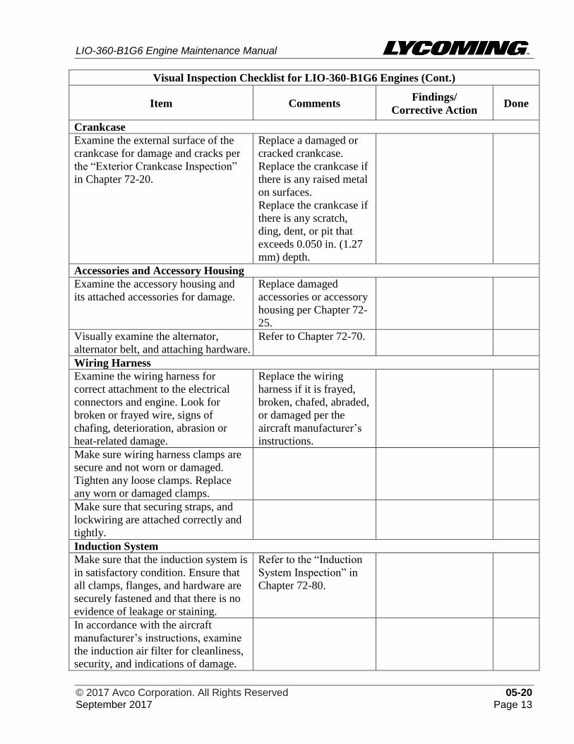
LIO-360-B1G6 Engine Maintenance Manual
© 2017 Avco Corporation. All Rights Reserved 05-20 September 2017 Page 13
Visual Inspection Checklist for LIO-360-B1G6 Engines (Cont.)
Item Comments Findings/
Corrective Action Done
Crankcase
Examine the external surface of the
crankcase for damage and cracks per
the “Exterior Crankcase Inspection”
in Chapter 72-20.
Replace a damaged or
cracked crankcase.
Replace the crankcase if
there is any raised metal
on surfaces.
Replace the crankcase if
there is any scratch,
ding, dent, or pit that
exceeds 0.050 in. (1.27
mm) depth.
Accessories and Accessory Housing
Examine the accessory housing and
its attached accessories for damage.
Replace damaged
accessories or accessory
housing per Chapter 72-
25.
Visually examine the alternator,
alternator belt, and attaching hardware.
Refer to Chapter 72-70.
Wiring Harness
Examine the wiring harness for
correct attachment to the electrical
connectors and engine. Look for
broken or frayed wire, signs of
chafing, deterioration, abrasion or
heat-related damage.
Replace the wiring
harness if it is frayed,
broken, chafed, abraded,
or damaged per the
aircraft manufacturer’s
instructions.
Make sure wiring harness clamps are
secure and not worn or damaged.
Tighten any loose clamps. Replace
any worn or damaged clamps.
Make sure that securing straps, and
lockwiring are attached correctly and
tightly.
Induction System
Make sure that the induction system is
in satisfactory condition. Ensure that
all clamps, flanges, and hardware are
securely fastened and that there is no
evidence of leakage or staining.
Refer to the “Induction
System Inspection” in
Chapter 72-80.
In accordance with the aircraft
manufacturer’s instructions, examine
the induction air filter for cleanliness,
security, and indications of damage.
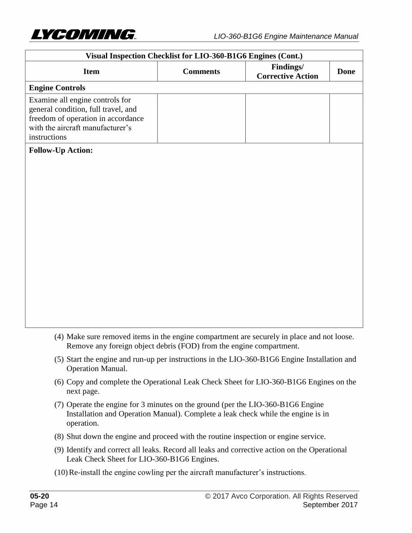
LIO-360-B1G6 Engine Maintenance Manual
05-20 © 2017 Avco Corporation. All Rights Reserved Page 14 September 2017
Visual Inspection Checklist for LIO-360-B1G6 Engines (Cont.)
Item Comments Findings/
Corrective Action Done
Engine Controls
Examine all engine controls for
general condition, full travel, and
freedom of operation in accordance
with the aircraft manufacturer’s
instructions
Follow-Up Action:
(4) Make sure removed items in the engine compartment are securely in place and not loose.
Remove any foreign object debris (FOD) from the engine compartment.
(5) Start the engine and run-up per instructions in the LIO-360-B1G6 Engine Installation and
Operation Manual.
(6) Copy and complete the Operational Leak Check Sheet for LIO-360-B1G6 Engines on the
next page.
(7) Operate the engine for 3 minutes on the ground (per the LIO-360-B1G6 Engine
Installation and Operation Manual). Complete a leak check while the engine is in
operation.
(8) Shut down the engine and proceed with the routine inspection or engine service.
(9) Identify and correct all leaks. Record all leaks and corrective action on the Operational
Leak Check Sheet for LIO-360-B1G6 Engines.
(10) Re-install the engine cowling per the aircraft manufacturer’s instructions.
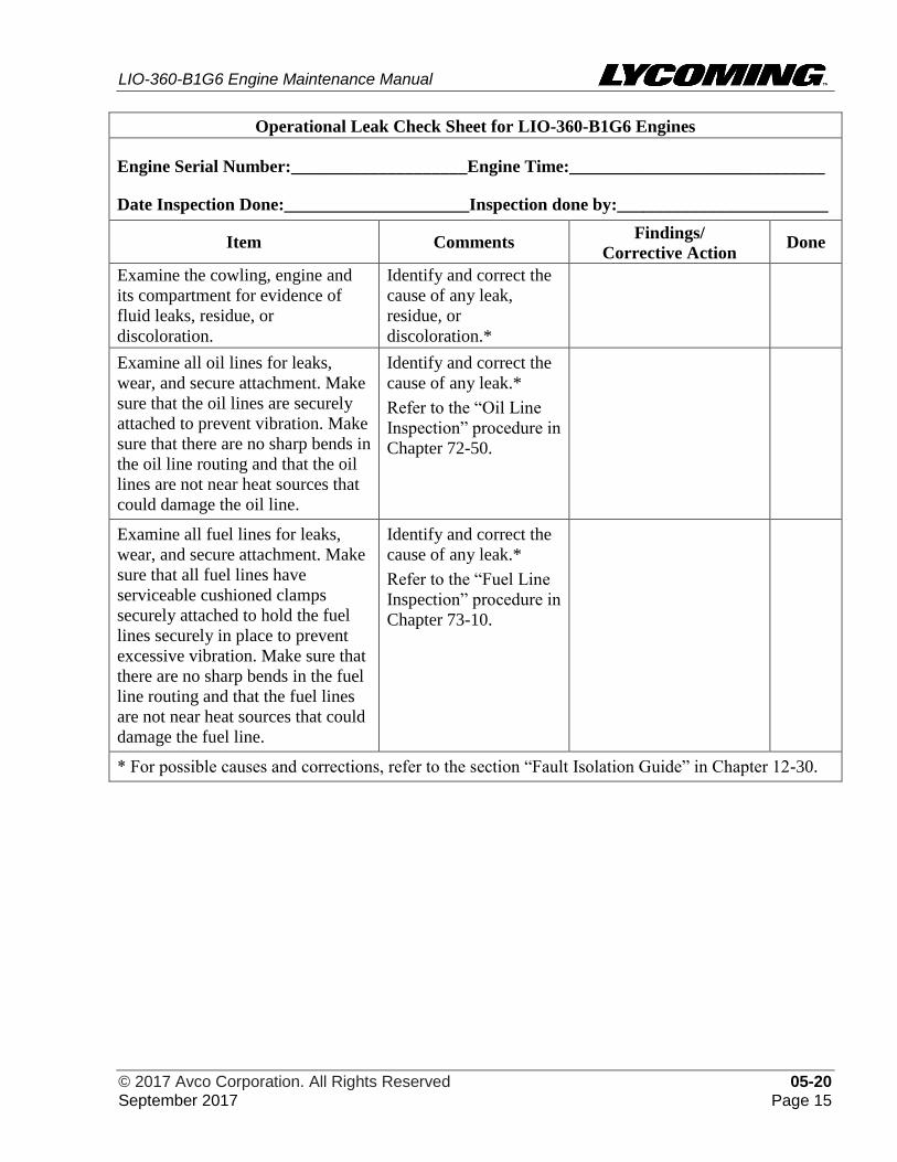
LIO-360-B1G6 Engine Maintenance Manual
© 2017 Avco Corporation. All Rights Reserved 05-20 September 2017 Page 15
Operational Leak Check Sheet for LIO-360-B1G6 Engines
Engine Serial Number:____________________Engine Time:_____________________________
Date Inspection Done:_____________________Inspection done by:________________________
Item Comments Findings/
Corrective Action Done
Examine the cowling, engine and
its compartment for evidence of
fluid leaks, residue, or
discoloration.
Identify and correct the
cause of any leak,
residue, or
discoloration.*
Examine all oil lines for leaks,
wear, and secure attachment. Make
sure that the oil lines are securely
attached to prevent vibration. Make
sure that there are no sharp bends in
the oil line routing and that the oil
lines are not near heat sources that
could damage the oil line.
Identify and correct the
cause of any leak.*
Refer to the “Oil Line
Inspection” procedure in
Chapter 72-50.
Examine all fuel lines for leaks,
wear, and secure attachment. Make
sure that all fuel lines have
serviceable cushioned clamps
securely attached to hold the fuel
lines securely in place to prevent
excessive vibration. Make sure that
there are no sharp bends in the fuel
line routing and that the fuel lines
are not near heat sources that could
damage the fuel line.
Identify and correct the
cause of any leak.*
Refer to the “Fuel Line
Inspection” procedure in
Chapter 73-10.
* For possible causes and corrections, refer to the section “Fault Isolation Guide” in Chapter 12-30.
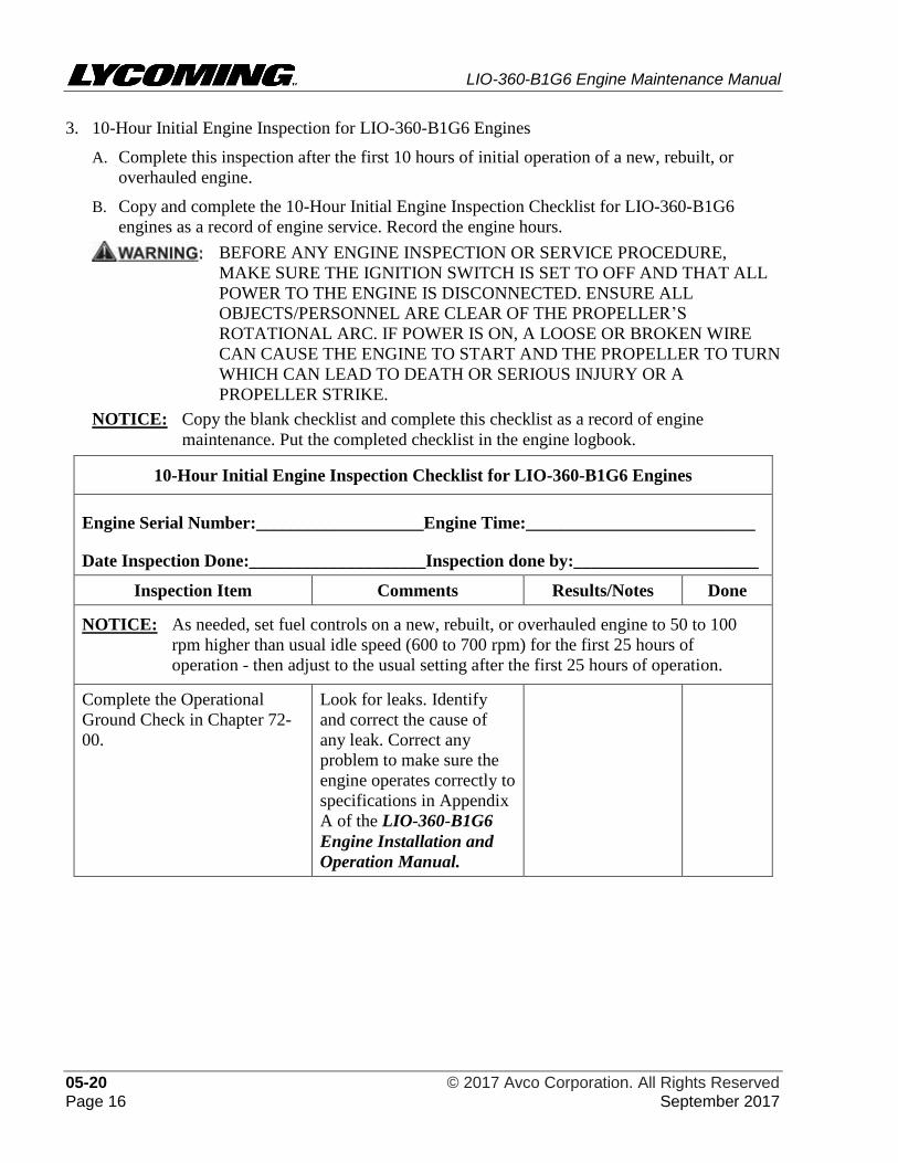
LIO-360-B1G6 Engine Maintenance Manual
05-20 © 2017 Avco Corporation. All Rights Reserved Page 16 September 2017
3. 10-Hour Initial Engine Inspection for LIO-360-B1G6 Engines
A. Complete this inspection after the first 10 hours of initial operation of a new, rebuilt, or
overhauled engine.
B. Copy and complete the 10-Hour Initial Engine Inspection Checklist for LIO-360-B1G6
engines as a record of engine service. Record the engine hours.
BEFORE ANY ENGINE INSPECTION OR SERVICE PROCEDURE,
MAKE SURE THE IGNITION SWITCH IS SET TO OFF AND THAT ALL
POWER TO THE ENGINE IS DISCONNECTED. ENSURE ALL
OBJECTS/PERSONNEL ARE CLEAR OF THE PROPELLER’S
ROTATIONAL ARC. IF POWER IS ON, A LOOSE OR BROKEN WIRE
CAN CAUSE THE ENGINE TO START AND THE PROPELLER TO TURN
WHICH CAN LEAD TO DEATH OR SERIOUS INJURY OR A
PROPELLER STRIKE.
NOTICE: Copy the blank checklist and complete this checklist as a record of engine
maintenance. Put the completed checklist in the engine logbook.
10-Hour Initial Engine Inspection Checklist for LIO-360-B1G6 Engines
Engine Serial Number:___________________Engine Time:__________________________
Date Inspection Done:____________________Inspection done by:_____________________
Inspection Item Comments Results/Notes Done
NOTICE: As needed, set fuel controls on a new, rebuilt, or overhauled engine to 50 to 100
rpm higher than usual idle speed (600 to 700 rpm) for the first 25 hours of
operation - then adjust to the usual setting after the first 25 hours of operation.
Complete the Operational
Ground Check in Chapter 72-
00.
Look for leaks. Identify
and correct the cause of
any leak. Correct any
problem to make sure the
engine operates correctly to
specifications in Appendix
A of the LIO-360-B1G6
Engine Installation and
Operation Manual.
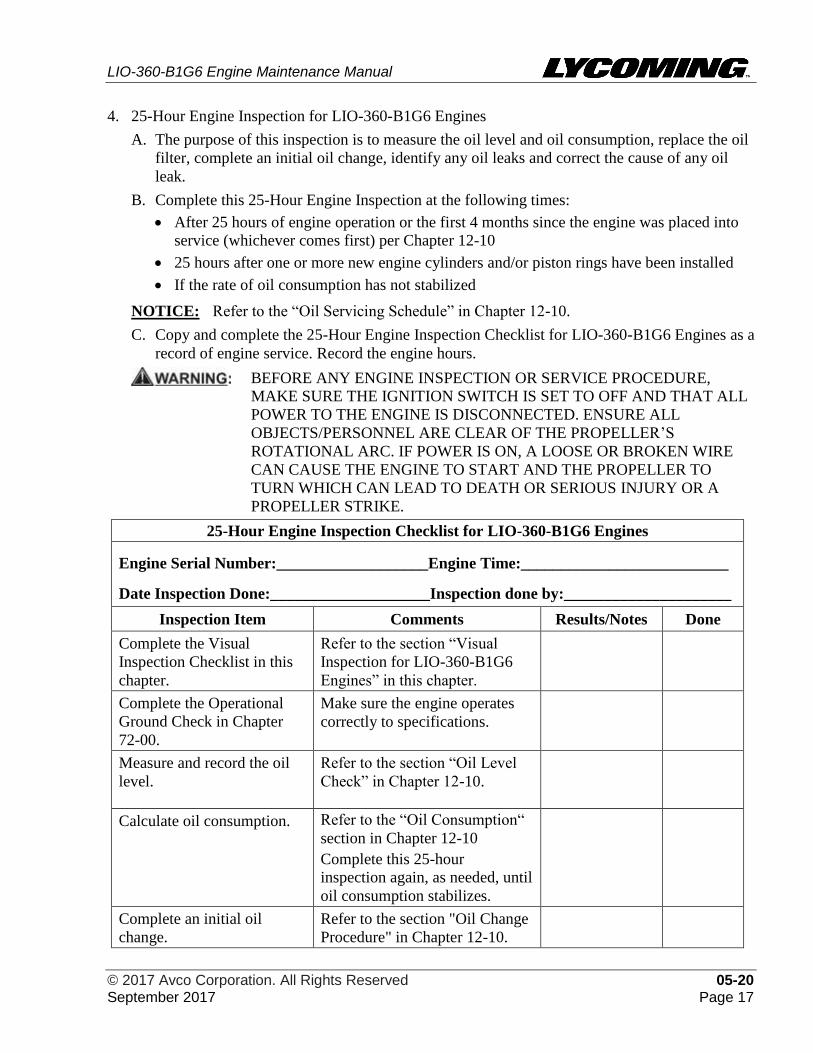
LIO-360-B1G6 Engine Maintenance Manual
© 2017 Avco Corporation. All Rights Reserved 05-20 September 2017 Page 17
4. 25-Hour Engine Inspection for LIO-360-B1G6 Engines
A. The purpose of this inspection is to measure the oil level and oil consumption, replace the oil
filter, complete an initial oil change, identify any oil leaks and correct the cause of any oil
leak.
B. Complete this 25-Hour Engine Inspection at the following times:
• After 25 hours of engine operation or the first 4 months since the engine was placed into
service (whichever comes first) per Chapter 12-10
• 25 hours after one or more new engine cylinders and/or piston rings have been installed
• If the rate of oil consumption has not stabilized
NOTICE: Refer to the “Oil Servicing Schedule” in Chapter 12-10.
C. Copy and complete the 25-Hour Engine Inspection Checklist for LIO-360-B1G6 Engines as a
record of engine service. Record the engine hours.
BEFORE ANY ENGINE INSPECTION OR SERVICE PROCEDURE,
MAKE SURE THE IGNITION SWITCH IS SET TO OFF AND THAT ALL
POWER TO THE ENGINE IS DISCONNECTED. ENSURE ALL
OBJECTS/PERSONNEL ARE CLEAR OF THE PROPELLER’S
ROTATIONAL ARC. IF POWER IS ON, A LOOSE OR BROKEN WIRE
CAN CAUSE THE ENGINE TO START AND THE PROPELLER TO
TURN WHICH CAN LEAD TO DEATH OR SERIOUS INJURY OR A
PROPELLER STRIKE.
25-Hour Engine Inspection Checklist for LIO-360-B1G6 Engines
Engine Serial Number:___________________Engine Time:__________________________
Date Inspection Done:____________________Inspection done by:_____________________
Inspection Item Comments Results/Notes Done
Complete the Visual
Inspection Checklist in this
chapter.
Refer to the section “Visual
Inspection for LIO-360-B1G6
Engines” in this chapter.
Complete the Operational
Ground Check in Chapter
72-00.
Make sure the engine operates
correctly to specifications.
Measure and record the oil
level.
Refer to the section “Oil Level
Check” in Chapter 12-10.
Calculate oil consumption. Refer to the “Oil Consumption“
section in Chapter 12-10
Complete this 25-hour
inspection again, as needed, until
oil consumption stabilizes.
Complete an initial oil
change.
Refer to the section "Oil Change
Procedure" in Chapter 12-10.
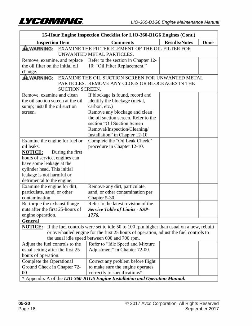
LIO-360-B1G6 Engine Maintenance Manual
05-20 © 2017 Avco Corporation. All Rights Reserved Page 18 September 2017
25-Hour Engine Inspection Checklist for LIO-360-B1G6 Engines (Cont.)
Inspection Item Comments Results/Notes Done
EXAMINE THE FILTER ELEMENT OF THE OIL FILTER FOR
UNWANTED METAL PARTICLES.
Remove, examine, and replace
the oil filter on the initial oil
change.
Refer to the section in Chapter 12-
10: “Oil Filter Replacement.”
EXAMINE THE OIL SUCTION SCREEN FOR UNWANTED METAL
PARTICLES. REMOVE ANY CLOGS OR BLOCKAGES IN THE
SUCTION SCREEN.
Remove, examine and clean
the oil suction screen at the oil
sump; install the oil suction
screen.
If blockage is found, record and
identify the blockage (metal,
carbon, etc.)
Remove any blockage and clean
the oil suction screen. Refer to the
section “Oil Suction Screen
Removal/Inspection/Cleaning/
Installation” in Chapter 12-10.
Examine the engine for fuel or
oil leaks.
NOTICE: During the first
hours of service, engines can
have some leakage at the
cylinder head. This initial
leakage is not harmful or
detrimental to the engine.
Complete the “Oil Leak Check”
procedure in Chapter 12-10.
Examine the engine for dirt,
particulate, sand, or other
contamination.
Remove any dirt, particulate,
sand, or other contamination per
Chapter 5-30.
Re-torque the exhaust flange
nuts after the first 25-hours of
engine operation.
Refer to the latest revision of the
Service Table of Limits - SSP-
1776.
General
NOTICE: If the fuel controls were set to idle 50 to 100 rpm higher than usual on a new, rebuilt
or overhauled engine for the first 25 hours of operation, adjust the fuel controls to
the usual idle speed between 600 and 700 rpm.
Adjust the fuel controls to the
usual setting after the first 25
hours of operation.
Refer to “Idle Speed and Mixture
Adjustment” in Chapter 72-00.
Complete the Operational
Ground Check in Chapter 72-
00.
Correct any problem before flight
to make sure the engine operates
correctly to specifications*.
* Appendix A of the LIO-360-B1G6 Engine Installation and Operation Manual.
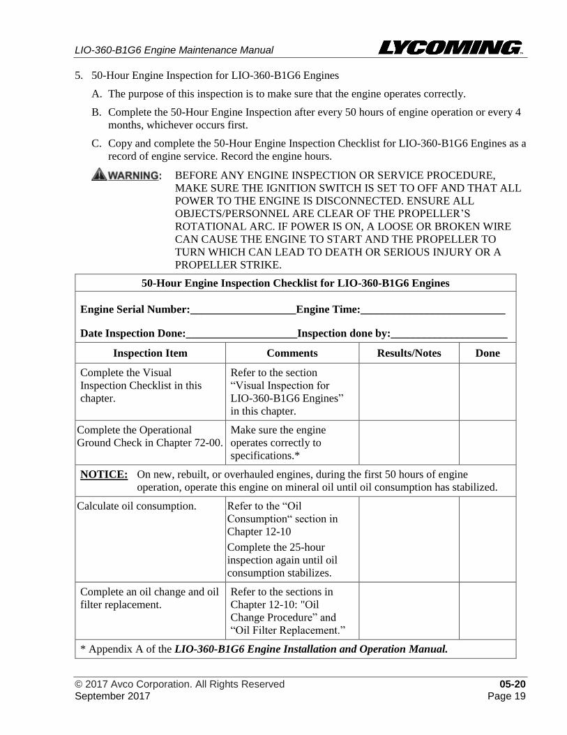
LIO-360-B1G6 Engine Maintenance Manual
© 2017 Avco Corporation. All Rights Reserved 05-20 September 2017 Page 19
5. 50-Hour Engine Inspection for LIO-360-B1G6 Engines
A. The purpose of this inspection is to make sure that the engine operates correctly.
B. Complete the 50-Hour Engine Inspection after every 50 hours of engine operation or every 4
months, whichever occurs first.
C. Copy and complete the 50-Hour Engine Inspection Checklist for LIO-360-B1G6 Engines as a
record of engine service. Record the engine hours.
BEFORE ANY ENGINE INSPECTION OR SERVICE PROCEDURE,
MAKE SURE THE IGNITION SWITCH IS SET TO OFF AND THAT ALL
POWER TO THE ENGINE IS DISCONNECTED. ENSURE ALL
OBJECTS/PERSONNEL ARE CLEAR OF THE PROPELLER’S
ROTATIONAL ARC. IF POWER IS ON, A LOOSE OR BROKEN WIRE
CAN CAUSE THE ENGINE TO START AND THE PROPELLER TO
TURN WHICH CAN LEAD TO DEATH OR SERIOUS INJURY OR A
PROPELLER STRIKE.
50-Hour Engine Inspection Checklist for LIO-360-B1G6 Engines
Engine Serial Number:___________________Engine Time:__________________________
Date Inspection Done:____________________Inspection done by:_____________________
Inspection Item Comments Results/Notes Done
Complete the Visual
Inspection Checklist in this
chapter.
Refer to the section
“Visual Inspection for
LIO-360-B1G6 Engines”
in this chapter.
Complete the Operational
Ground Check in Chapter 72-00.
Make sure the engine
operates correctly to
specifications.*
NOTICE: On new, rebuilt, or overhauled engines, during the first 50 hours of engine
operation, operate this engine on mineral oil until oil consumption has stabilized.
Calculate oil consumption. Refer to the “Oil
Consumption“ section in
Chapter 12-10
Complete the 25-hour
inspection again until oil
consumption stabilizes.
Complete an oil change and oil
filter replacement.
Refer to the sections in
Chapter 12-10: "Oil
Change Procedure” and
“Oil Filter Replacement.”
* Appendix A of the LIO-360-B1G6 Engine Installation and Operation Manual.
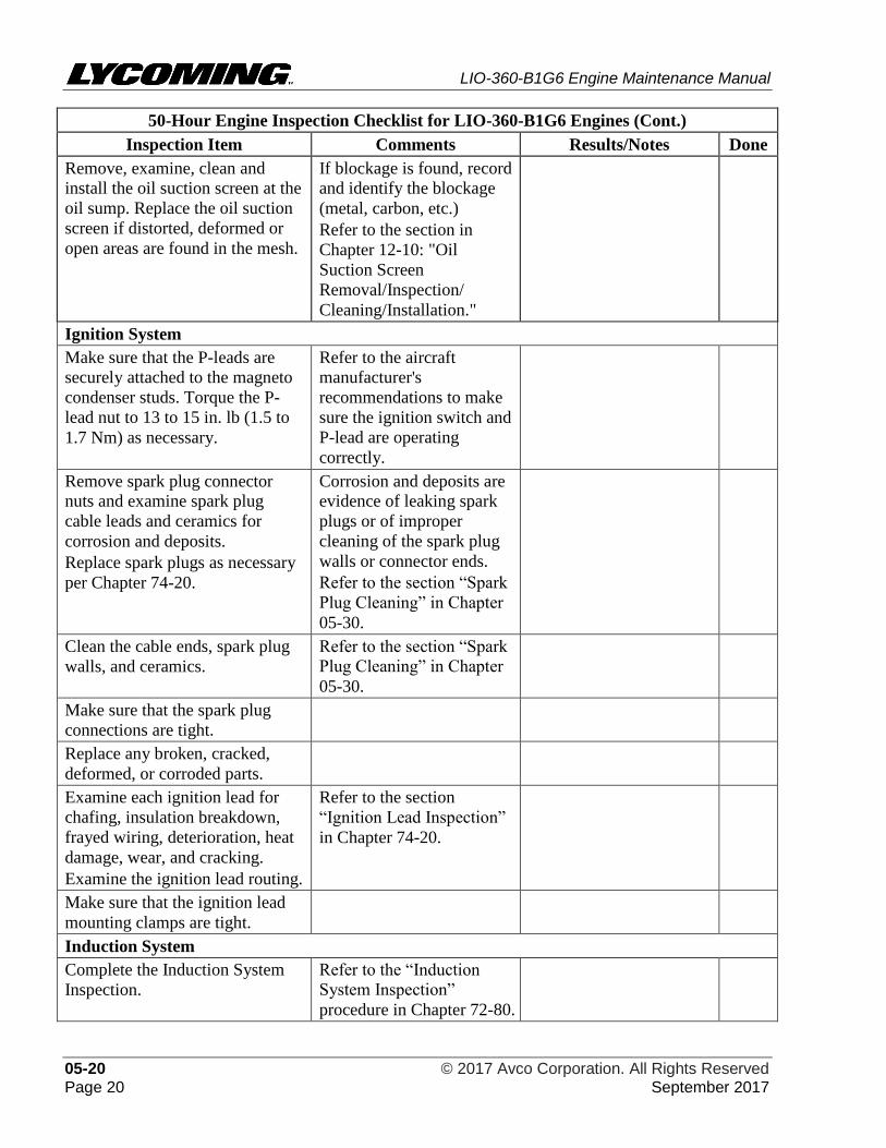
LIO-360-B1G6 Engine Maintenance Manual
05-20 © 2017 Avco Corporation. All Rights Reserved Page 20 September 2017
50-Hour Engine Inspection Checklist for LIO-360-B1G6 Engines (Cont.)
Inspection Item Comments Results/Notes Done
Remove, examine, clean and
install the oil suction screen at the
oil sump. Replace the oil suction
screen if distorted, deformed or
open areas are found in the mesh.
If blockage is found, record
and identify the blockage
(metal, carbon, etc.)
Refer to the section in
Chapter 12-10: "Oil
Suction Screen
Removal/Inspection/
Cleaning/Installation."
Ignition System
Make sure that the P-leads are
securely attached to the magneto
condenser studs. Torque the P-
lead nut to 13 to 15 in. lb (1.5 to
1.7 Nm) as necessary.
Refer to the aircraft
manufacturer's
recommendations to make
sure the ignition switch and
P-lead are operating
correctly.
Remove spark plug connector
nuts and examine spark plug
cable leads and ceramics for
corrosion and deposits.
Replace spark plugs as necessary
per Chapter 74-20.
Corrosion and deposits are
evidence of leaking spark
plugs or of improper
cleaning of the spark plug
walls or connector ends.
Refer to the section “Spark
Plug Cleaning” in Chapter
05-30.
Clean the cable ends, spark plug
walls, and ceramics.
Refer to the section “Spark
Plug Cleaning” in Chapter
05-30.
Make sure that the spark plug
connections are tight.
Replace any broken, cracked,
deformed, or corroded parts.
Examine each ignition lead for
chafing, insulation breakdown,
frayed wiring, deterioration, heat
damage, wear, and cracking.
Examine the ignition lead routing.
Refer to the section
“Ignition Lead Inspection”
in Chapter 74-20.
Make sure that the ignition lead
mounting clamps are tight.
Induction System
Complete the Induction System
Inspection.
Refer to the “Induction
System Inspection”
procedure in Chapter 72-80.
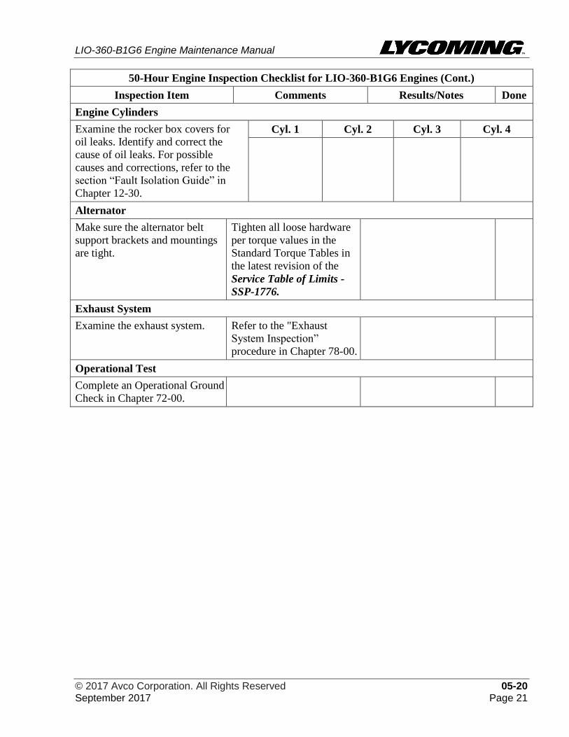
LIO-360-B1G6 Engine Maintenance Manual
© 2017 Avco Corporation. All Rights Reserved 05-20 September 2017 Page 21
50-Hour Engine Inspection Checklist for LIO-360-B1G6 Engines (Cont.)
Inspection Item Comments Results/Notes Done
Engine Cylinders
Examine the rocker box covers for
oil leaks. Identify and correct the
cause of oil leaks. For possible
causes and corrections, refer to the
section “Fault Isolation Guide” in
Chapter 12-30.
Cyl. 1 Cyl. 2 Cyl. 3 Cyl. 4
Alternator
Make sure the alternator belt
support brackets and mountings
are tight.
Tighten all loose hardware
per torque values in the
Standard Torque Tables in
the latest revision of the
Service Table of Limits -
SSP-1776.
Exhaust System
Examine the exhaust system. Refer to the "Exhaust
System Inspection”
procedure in Chapter 78-00.
Operational Test
Complete an Operational Ground
Check in Chapter 72-00.
LIO-360-B1G6 Engine Maintenance Manual
05-20 © 2017 Avco Corporation. All Rights Reserved Page 22 September 2017
6. 100-Hour or Annual Engine Inspection for LIO-360-B1G6 Engines
NOTICE: Refer to the aircraft manufacturer’s recommendation as to whether this inspection is to
be completed every 100 hours of engine operation or annually.
A. The purpose of this inspection is to examine the ignition, magnetos, electrical systems, the
engine cylinders, and the exhaust system.
B. Complete the 100-Hour Engine Inspection after the first 100 hours of operation since the
engine has been in service and then after every 100 hours of operation or during each annual
aircraft inspection (whichever occurs first).
C. Copy and complete the 100-Hour or Annual Engine Inspection Checklist for LIO-360-B1G6
Engines as a record of engine service. Record the engine hours.
BEFORE ANY ENGINE INSPECTION OR SERVICE PROCEDURE,
MAKE SURE THE IGNITION SWITCH IS SET TO OFF AND THAT ALL
POWER TO THE ENGINE IS DISCONNECTED. ENSURE ALL
OBJECTS/PERSONNEL ARE CLEAR OF THE PROPELLER’S
ROTATIONAL ARC. IF POWER IS ON, A LOOSE OR BROKEN WIRE
CAN CAUSE THE ENGINE TO START AND THE PROPELLER TO
TURN WHICH CAN LEAD TO DEATH OR SERIOUS INJURY OR A
PROPELLER STRIKE.
100-Hour or Annual Engine Inspection Checklist for LIO-360-B1G6 Engines
Engine Serial Number:___________________Engine Time:__________________________
Date Inspection Done:____________________Inspection done by:_____________________
NOTICE: Complete the Operational Ground Check prior to and after each inspection, after
maintenance, and after engine assembly. Refer to Chapter 72-00.
Inspection Item Comments Results/Notes Done
Complete the 50-Hour Engine
Inspection Checklist.
Refer to the section “50-
Hour Engine Inspection for
LIO-360-B1G6 Engines” in
this chapter.
Ignition System
IF THE P-LEAD IS DISCONNECTED, THE MAGNETO WILL BE ON
AND WILL ACTIVATE THE SPARK PLUG IF THE PROPELLER IS
TURNED. TO PREVENT INJURY, MAKE SURE THAT THE P-LEAD IS
SECURELY ATTACHED TO THE CONDENSER STUD.
Make sure that the magneto-to-
engine timing is correct.
Adjust the timing as necessary.
Refer to the "Magneto-to-
Engine Timing Check" in
Chapter 74-30.
The correct advance timing is
stamped on the engine data
plate.
Complete a visual inspection
of the magneto wiring
conditions and connections,
vent holes, and P-lead
attachment.
LIO-360-B1G6 Engine Maintenance Manual
© 2017 Avco Corporation. All Rights Reserved 05-20 September 2017 Page 23
100-Hour or Annual Engine Inspection Checklist for LIO-360-B1G6 Engines (Cont.)
Inspection Item Comments Results/Notes Done
Ignition System (Cont.)
Clean the magneto vents to make
sure that there is no obstruction.
Make sure the magneto clamps
securely attach the magneto to the
engine.
If a retard magneto is installed,
make sure that the switch wire on
the retard (left) breaker connects
the retard contact points to the
ignition vibrator.
NEVER INSTALL A SPARK PLUG THAT HAS BEEN DROPPED.
Remove, examine, rotate, clean,
and re-gap acceptable spark
plugs. Replace worn spark plugs.
Refer to Chapters 05-30 and
74-20.
Examine the continuity of the
engine ground straps.
Refer to the aircraft
manufacturer’s instructions.
Electrical System
Complete the wiring inspection. Refer to the section “Wiring
Inspection” in Chapter 72-70.
Examine the alternator belt(s). Refer to the section
"Alternator Belt Inspection"
in Chapter 72-70.
Complete a check of the
alternator belt tension.
Refer to the section
"Alternator Belt Tension
Check/Adjustment" in
Chapter 72-70.
Examine the alternator attaching
hardware for damage. Make sure
that safety wire/cable and cotter
pins are installed and tight.
LIO-360-B1G6 Engine Maintenance Manual
05-20 © 2017 Avco Corporation. All Rights Reserved Page 24 September 2017
100-Hour or Annual Engine Inspection Checklist for LIO-360-B1G6 Engines (Cont.)
Inspection Item Comments Results/Notes Done
Fuel System
Complete the Fuel System
Inspection.
Refer to the section "Fuel
System Inspection” procedure in
Chapter 73-10.
DO NOT ATTEMPT TO REPAIR A DAMAGED FUEL LINE. REPLACE
ANY FUEL LINE THAT IS CRACKED, DENTED, OR KINKED; CRACKS
CAN DEVELOP AT THE SIDE OF SHARP BENDS OR KINKS.
Examine fuel injector lines for
correct routing, damage, leaks,
dents, pits, nicks, kinks, stains
caused by fuel leaks, cracks,
brittleness, or chafing.
Refer to the "Fuel Line
Inspection” section in Chapter 73-
10.
Fuel Line 1
Fuel Line 2
Fuel Line 3
Fuel Line 4
Make sure fuel lines are held
securely in place using clamps
with cushions.
If no clamps are attached to the
fuel line that was in service,
replace the fuel line per
instructions in Chapter 73-10.
If cushions on clamps are
deteriorated or missing, replace
the clamps and fuel line.
If the clamps are loose, replace
the fuel line.
NOTICE: Plastic tie straps are
not an acceptable substitute for
clamps.
Examine the fuel injectors for
leaks and correct installation.
Refer to the section “Fuel Injector
Leak Check” in Chapter 73-10.
Examine the fuel injector nozzle
line attachments for secure
connection.
Tighten any loose connections per
torque values in the latest revision
of the Service Table of Limits -
SSP-1776
Examine each fuel injector line
between the fuel manifold and the
nozzles for any evidence of
physical damage and for stains
caused by fuel leakage.
Replace damaged or worn fuel
injector lines.*
Examine solder joints at the end
of fuel injector lines for cracks.
Replace cracked fuel injector
lines.*
Examine the flexible fuel lines. Replace any fuel lines that have
become hard.*
Examine gaskets, and seals for
deterioration or leakage.
Replace any gaskets, or seals that
are worn, damaged, or leaking.
* Refer to the “Fuel Line Replacement” procedure in Chapter 73-10.
LIO-360-B1G6 Engine Maintenance Manual
© 2017 Avco Corporation. All Rights Reserved 05-20 September 2017 Page 25
100-Hour or Annual Engine Inspection Checklist for LIO-360-B1G6 Engines (Cont.)
Inspection Item Comments Results/Notes Done
Crankcase
Complete the crankcase
inspection.
Refer to the “Exterior
Crankcase Inspection”
procedure in Chapter 72-20.
Engine Accessories
Complete the accessory drive
inspection.
Refer to the “Accessory Drive
Inspection” procedure in
Chapter 72-60.
Engine Mounts
Complete the engine mounting
bracket inspection.
Refer to the “Engine
Mounting Bracket Inspection”
procedure in Chapter 72-00.
Cylinders
Complete the “Visual Cylinder Inspection” procedure in Chapter 72-30. Record the results for each
cylinder.
Cylinder 1
Cylinder 2
Cylinder 3
Cylinder 4
Cylinder Compression Check
Complete the “Cylinder Compression Check Procedure” in Chapter 72-30. Record the results for
each cylinder.
Cylinder 1
Cylinder 2
Cylinder 3
Cylinder 4
Operational Test
Complete an Operational Ground
Check in Chapter 72-00.
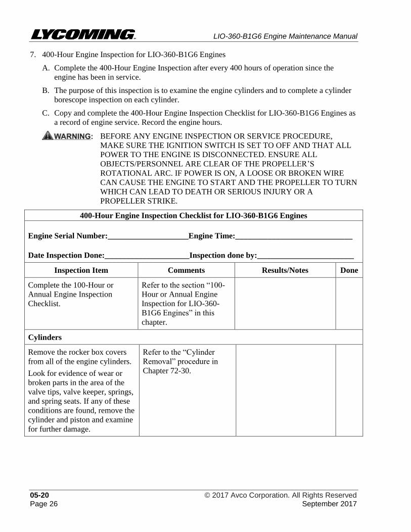
LIO-360-B1G6 Engine Maintenance Manual
05-20 © 2017 Avco Corporation. All Rights Reserved Page 26 September 2017
7. 400-Hour Engine Inspection for LIO-360-B1G6 Engines
A. Complete the 400-Hour Engine Inspection after every 400 hours of operation since the
engine has been in service.
B. The purpose of this inspection is to examine the engine cylinders and to complete a cylinder
borescope inspection on each cylinder.
C. Copy and complete the 400-Hour Engine Inspection Checklist for LIO-360-B1G6 Engines as
a record of engine service. Record the engine hours.
BEFORE ANY ENGINE INSPECTION OR SERVICE PROCEDURE,
MAKE SURE THE IGNITION SWITCH IS SET TO OFF AND THAT ALL
POWER TO THE ENGINE IS DISCONNECTED. ENSURE ALL
OBJECTS/PERSONNEL ARE CLEAR OF THE PROPELLER’S
ROTATIONAL ARC. IF POWER IS ON, A LOOSE OR BROKEN WIRE
CAN CAUSE THE ENGINE TO START AND THE PROPELLER TO TURN
WHICH CAN LEAD TO DEATH OR SERIOUS INJURY OR A
PROPELLER STRIKE.
400-Hour Engine Inspection Checklist for LIO-360-B1G6 Engines
Engine Serial Number:____________________Engine Time:_____________________________
Date Inspection Done:_____________________Inspection done by:________________________
Inspection Item Comments Results/Notes Done
Complete the 100-Hour or
Annual Engine Inspection
Checklist.
Refer to the section “100-
Hour or Annual Engine
Inspection for LIO-360-
B1G6 Engines” in this
chapter.
Cylinders
Remove the rocker box covers
from all of the engine cylinders.
Look for evidence of wear or
broken parts in the area of the
valve tips, valve keeper, springs,
and spring seats. If any of these
conditions are found, remove the
cylinder and piston and examine
for further damage.
Refer to the “Cylinder
Removal” procedure in
Chapter 72-30.
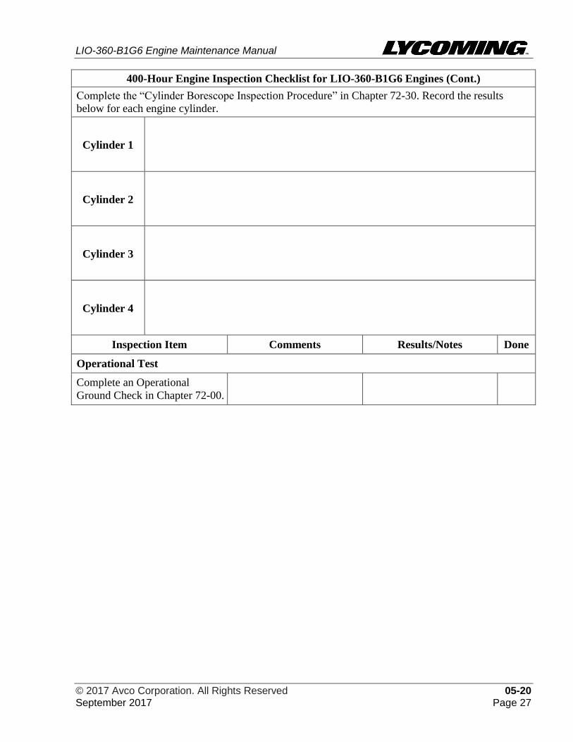
LIO-360-B1G6 Engine Maintenance Manual
© 2017 Avco Corporation. All Rights Reserved 05-20 September 2017 Page 27
400-Hour Engine Inspection Checklist for LIO-360-B1G6 Engines (Cont.)
Complete the “Cylinder Borescope Inspection Procedure” in Chapter 72-30. Record the results
below for each engine cylinder.
Cylinder 1
Cylinder 2
Cylinder 3
Cylinder 4
Inspection Item Comments Results/Notes Done
Operational Test
Complete an Operational
Ground Check in Chapter 72-00.
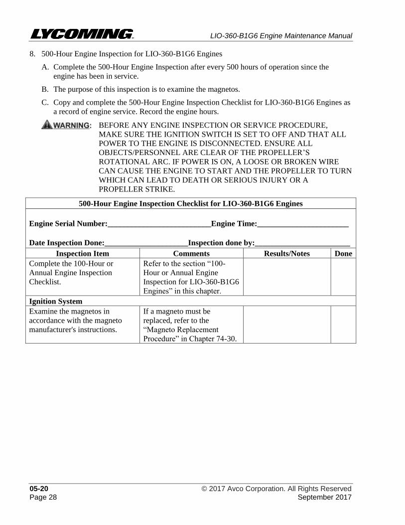
LIO-360-B1G6 Engine Maintenance Manual
05-20 © 2017 Avco Corporation. All Rights Reserved Page 28 September 2017
8. 500-Hour Engine Inspection for LIO-360-B1G6 Engines
A. Complete the 500-Hour Engine Inspection after every 500 hours of operation since the
engine has been in service.
B. The purpose of this inspection is to examine the magnetos.
C. Copy and complete the 500-Hour Engine Inspection Checklist for LIO-360-B1G6 Engines as
a record of engine service. Record the engine hours.
BEFORE ANY ENGINE INSPECTION OR SERVICE PROCEDURE,
MAKE SURE THE IGNITION SWITCH IS SET TO OFF AND THAT ALL
POWER TO THE ENGINE IS DISCONNECTED. ENSURE ALL
OBJECTS/PERSONNEL ARE CLEAR OF THE PROPELLER’S
ROTATIONAL ARC. IF POWER IS ON, A LOOSE OR BROKEN WIRE
CAN CAUSE THE ENGINE TO START AND THE PROPELLER TO TURN
WHICH CAN LEAD TO DEATH OR SERIOUS INJURY OR A
PROPELLER STRIKE.
500-Hour Engine Inspection Checklist for LIO-360-B1G6 Engines
Engine Serial Number:__________________________Engine Time:_______________________
Date Inspection Done:_____________________Inspection done by:________________________
Inspection Item Comments Results/Notes Done
Complete the 100-Hour or
Annual Engine Inspection
Checklist.
Refer to the section “100-
Hour or Annual Engine
Inspection for LIO-360-B1G6
Engines” in this chapter.
Ignition System
Examine the magnetos in
accordance with the magneto
manufacturer's instructions.
If a magneto must be
replaced, refer to the
“Magneto Replacement
Procedure” in Chapter 74-30.
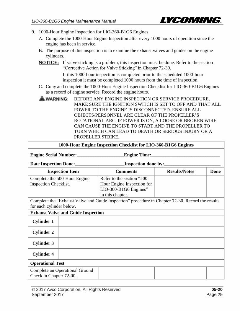
LIO-360-B1G6 Engine Maintenance Manual
© 2017 Avco Corporation. All Rights Reserved 05-20 September 2017 Page 29
9. 1000-Hour Engine Inspection for LIO-360-B1G6 Engines
A. Complete the 1000-Hour Engine Inspection after every 1000 hours of operation since the
engine has been in service.
B. The purpose of this inspection is to examine the exhaust valves and guides on the engine
cylinders.
NOTICE: If valve sticking is a problem, this inspection must be done. Refer to the section
“Corrective Action for Valve Sticking” in Chapter 72-30.
If this 1000-hour inspection is completed prior to the scheduled 1000-hour
inspection it must be completed 1000 hours from the time of inspection.
C. Copy and complete the 1000-Hour Engine Inspection Checklist for LIO-360-B1G6 Engines
as a record of engine service. Record the engine hours.
BEFORE ANY ENGINE INSPECTION OR SERVICE PROCEDURE,
MAKE SURE THE IGNITION SWITCH IS SET TO OFF AND THAT ALL
POWER TO THE ENGINE IS DISCONNECTED. ENSURE ALL
OBJECTS/PERSONNEL ARE CLEAR OF THE PROPELLER’S
ROTATIONAL ARC. IF POWER IS ON, A LOOSE OR BROKEN WIRE
CAN CAUSE THE ENGINE TO START AND THE PROPELLER TO
TURN WHICH CAN LEAD TO DEATH OR SERIOUS INJURY OR A
PROPELLER STRIKE.
1000-Hour Engine Inspection Checklist for LIO-360-B1G6 Engines
Engine Serial Number:____________________Engine Time:_____________________________
Date Inspection Done:_____________________Inspection done by:________________________
Inspection Item Comments Results/Notes Done
Complete the 500-Hour Engine
Inspection Checklist.
Refer to the section “500-
Hour Engine Inspection for
LIO-360-B1G6 Engines”
in this chapter.
Complete the “Exhaust Valve and Guide Inspection” procedure in Chapter 72-30. Record the results
for each cylinder below.
Exhaust Valve and Guide Inspection
Cylinder 1
Cylinder 2
Cylinder 3
Cylinder 4
Operational Test
Complete an Operational Ground
Check in Chapter 72-00.

LIO-360-B1G6 Engine Maintenance Manual
05-20 © 2017 Avco Corporation. All Rights Reserved Page 30 September 2017
This page intentionally left blank.
LIO-360-B1G6 Engine Maintenance Manual
© 2017 Avco Corporation. All Rights Reserved 05-30 September 2017 Page 31
05-30 - CLEANING
1. Cleaning Guidelines
NOTICE: The goal to keep the engine and nacelle clean is to prevent contamination from foreign
object debris (FOD) which can adversely affect engine operation.
A. Refer to Table 1 for cleaning guidelines for engine components.
IF VOLCANIC ASH IS SUSPECTED ON THE ENGINE, DO NOT INHALE
IT OR TOUCH IT WITH BARE HANDS OR GET IT IN YOUR EYES.
WEAR PERSONAL PROTECTIVE EQUIPMENT. DO NOT USE WATER
TO RINSE IT OFF. THE VOLCANIC ASH CAN CONTAIN ACIDIC
COMPOUNDS WHICH MUST NOT BE INHALED OR TOUCHED SINCE
IT CAN CAUSE INJURY. REFER TO THE SECTION "VOLCANIC ASH
REMOVAL" IN THIS CHAPTER.
NOTICE: Except for parts contaminated with suspect volcanic ash, before cleaning engine
parts, complete a visual inspection (per Chapter 05-20 of engine parts to identify any
stains and residues and sources thereof.
B. After the initial visual inspection (in Chapter 05-20), clean engine parts thoroughly per
instructions in this chapter.
DO NOT USE ALKALINE (CAUSTIC) CLEANING SOLUTIONS SUCH AS
DETERGENTS ON ENGINE PARTS. ALKALINE SOLUTIONS REMOVE
THE FINISH ON ALUMINUM PARTS AND MAGNESIUM PARTS.
ALKALINE COMPOUNDS CAN GET INTO THE PORES OF THE METAL
WHICH CAN CAUSE OIL FOAMING WHEN THE PART IS PUT BACK
INTO SERVICE.
OBEY STANDARD SAFETY PRACTICES REGARDING THE HANDLING
OF CLEANING MATERIALS AND THE USE OF PERSONAL
PROTECTIVE EQUIPMENT.
NOTICE: If you are not sure of the correct cleaning agent or whether the component contains
aluminum or magnesium, contact Technical Support at Lycoming Engines at the
phone numbers in the front of the manual.
C. There are two processes for cleaning: degreasing and decarbonizing.
(1) Degreasing removes dirt and sludge (soft carbon). Soak the component or part in mineral
spirits or other degreaser. Refer to the “Soft Carbon Removal” procedure in this chapter.
DO NOT USE ANY HEATED DECARBONIZING SOLVENT ON
ALUMINUM OR MAGNESIUM PARTS. THE DECARBONIZING
SOLVENT CAN DAMAGE OR CORRODE MAGNESIUM AND
ALUMINUM PARTS.
(2) Decarbonzing removes hard carbon with an initial soak of the part in a warm or heated
decarbonizing solution. After the soak, use a (non-wire) bristle brush, wooden scraper, or
grit-blasting (with non-abrasive media as per the “Grit-Blast Procedure” in this chapter)
to physically remove the hard carbon. Refer to the “Hard Carbon Removal” procedure in
this chapter.
NOTICE: Since decarbonizing can remove most of the enamel from exterior surfaces,
remove any remaining enamel by grit-blasting.
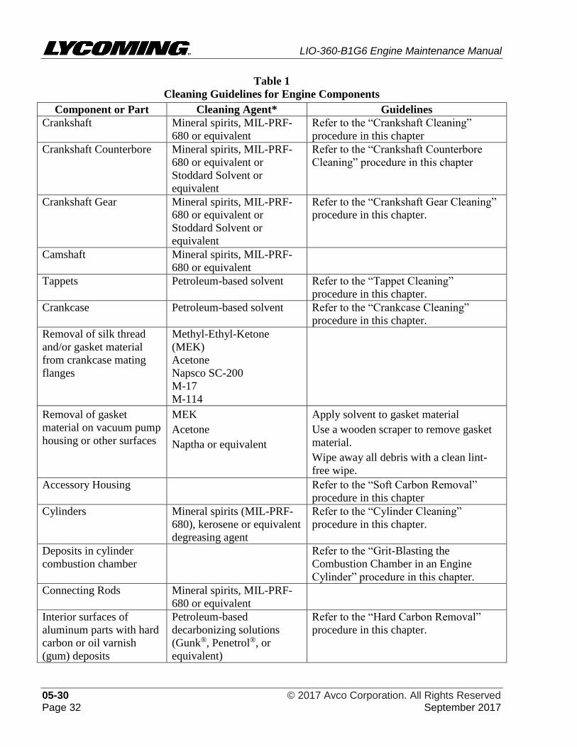
LIO-360-B1G6 Engine Maintenance Manual
05-30 © 2017 Avco Corporation. All Rights Reserved Page 32 September 2017
Table 1
Cleaning Guidelines for Engine Components
Component or Part Cleaning Agent* Guidelines
Crankshaft Mineral spirits, MIL-PRF-
680 or equivalent
Refer to the “Crankshaft Cleaning”
procedure in this chapter
Crankshaft Counterbore Mineral spirits, MIL-PRF-
680 or equivalent or
Stoddard Solvent or
equivalent
Refer to the “Crankshaft Counterbore
Cleaning” procedure in this chapter
Crankshaft Gear Mineral spirits, MIL-PRF-
680 or equivalent or
Stoddard Solvent or
equivalent
Refer to the “Crankshaft Gear Cleaning”
procedure in this chapter.
Camshaft Mineral spirits, MIL-PRF-
680 or equivalent
Tappets Petroleum-based solvent Refer to the “Tappet Cleaning”
procedure in this chapter.
Crankcase Petroleum-based solvent Refer to the “Crankcase Cleaning”
procedure in this chapter.
Removal of silk thread
and/or gasket material
from crankcase mating
flanges
Methyl-Ethyl-Ketone
(MEK)
Acetone
Napsco SC-200
M-17
M-114
Removal of gasket
material on vacuum pump
housing or other surfaces
MEK
Acetone
Naptha or equivalent
Apply solvent to gasket material
Use a wooden scraper to remove gasket
material.
Wipe away all debris with a clean lint-
free wipe.
Accessory Housing Refer to the “Soft Carbon Removal”
procedure in this chapter
Cylinders Mineral spirits (MIL-PRF-
680), kerosene or equivalent
degreasing agent
Refer to the “Cylinder Cleaning”
procedure in this chapter.
Deposits in cylinder
combustion chamber
Refer to the “Grit-Blasting the
Combustion Chamber in an Engine
Cylinder” procedure in this chapter.
Connecting Rods Mineral spirits, MIL-PRF-
680 or equivalent
Interior surfaces of
aluminum parts with hard
carbon or oil varnish
(gum) deposits
Petroleum-based
decarbonizing solutions
(Gunk®, Penetrol®, or
equivalent)
Refer to the “Hard Carbon Removal”
procedure in this chapter.
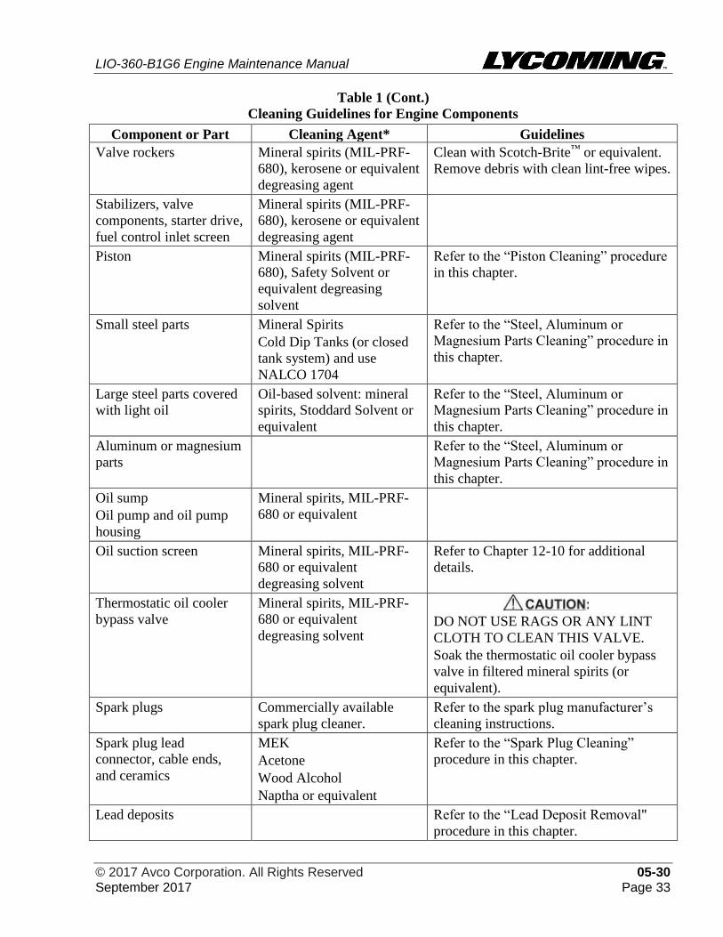
LIO-360-B1G6 Engine Maintenance Manual
© 2017 Avco Corporation. All Rights Reserved 05-30 September 2017 Page 33
Table 1 (Cont.)
Cleaning Guidelines for Engine Components
Component or Part Cleaning Agent* Guidelines
Valve rockers Mineral spirits (MIL-PRF-
680), kerosene or equivalent
degreasing agent
Clean with Scotch-Brite™ or equivalent.
Remove debris with clean lint-free wipes.
Stabilizers, valve
components, starter drive,
fuel control inlet screen
Mineral spirits (MIL-PRF-
680), kerosene or equivalent
degreasing agent
Piston Mineral spirits (MIL-PRF-
680), Safety Solvent or
equivalent degreasing
solvent
Refer to the “Piston Cleaning” procedure
in this chapter.
Small steel parts Mineral Spirits
Cold Dip Tanks (or closed
tank system) and use
NALCO 1704
Refer to the “Steel, Aluminum or
Magnesium Parts Cleaning” procedure in
this chapter.
Large steel parts covered
with light oil
Oil-based solvent: mineral
spirits, Stoddard Solvent or
equivalent
Refer to the “Steel, Aluminum or
Magnesium Parts Cleaning” procedure in
this chapter.
Aluminum or magnesium
parts
Refer to the “Steel, Aluminum or
Magnesium Parts Cleaning” procedure in
this chapter.
Oil sump
Oil pump and oil pump
housing
Mineral spirits, MIL-PRF-
680 or equivalent
Oil suction screen Mineral spirits, MIL-PRF-
680 or equivalent
degreasing solvent
Refer to Chapter 12-10 for additional
details.
Thermostatic oil cooler
bypass valve
Mineral spirits, MIL-PRF-
680 or equivalent
degreasing solvent
DO NOT USE RAGS OR ANY LINT
CLOTH TO CLEAN THIS VALVE.
Soak the thermostatic oil cooler bypass
valve in filtered mineral spirits (or
equivalent).
Spark plugs Commercially available
spark plug cleaner.
Refer to the spark plug manufacturer’s
cleaning instructions.
Spark plug lead
connector, cable ends,
and ceramics
MEK
Acetone
Wood Alcohol
Naptha or equivalent
Refer to the “Spark Plug Cleaning”
procedure in this chapter.
Lead deposits Refer to the “Lead Deposit Removal"
procedure in this chapter.
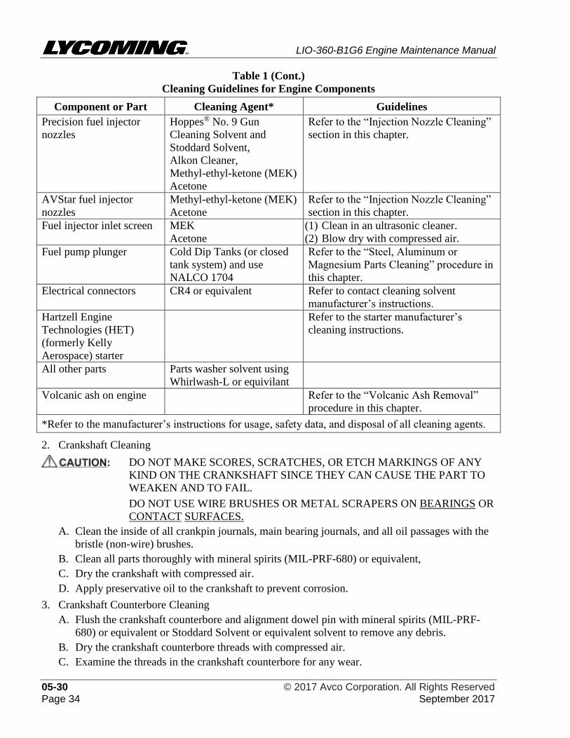
LIO-360-B1G6 Engine Maintenance Manual
05-30 © 2017 Avco Corporation. All Rights Reserved Page 34 September 2017
Table 1 (Cont.)
Cleaning Guidelines for Engine Components
Component or Part Cleaning Agent* Guidelines
Precision fuel injector
nozzles
Hoppes® No. 9 Gun
Cleaning Solvent and
Stoddard Solvent,
Alkon Cleaner,
Methyl-ethyl-ketone (MEK)
Acetone
Refer to the “Injection Nozzle Cleaning”
section in this chapter.
AVStar fuel injector
nozzles
Methyl-ethyl-ketone (MEK)
Acetone
Refer to the “Injection Nozzle Cleaning”
section in this chapter.
Fuel injector inlet screen MEK
Acetone
(1) Clean in an ultrasonic cleaner.
(2) Blow dry with compressed air.
Fuel pump plunger Cold Dip Tanks (or closed
tank system) and use
NALCO 1704
Refer to the “Steel, Aluminum or
Magnesium Parts Cleaning” procedure in
this chapter.
Electrical connectors CR4 or equivalent Refer to contact cleaning solvent
manufacturer’s instructions.
Hartzell Engine
Technologies (HET)
(formerly Kelly
Aerospace) starter
Refer to the starter manufacturer’s
cleaning instructions.
All other parts Parts washer solvent using
Whirlwash-L or equivilant
Volcanic ash on engine Refer to the “Volcanic Ash Removal”
procedure in this chapter.
*Refer to the manufacturer’s instructions for usage, safety data, and disposal of all cleaning agents.
2. Crankshaft Cleaning
DO NOT MAKE SCORES, SCRATCHES, OR ETCH MARKINGS OF ANY
KIND ON THE CRANKSHAFT SINCE THEY CAN CAUSE THE PART TO
WEAKEN AND TO FAIL.
DO NOT USE WIRE BRUSHES OR METAL SCRAPERS ON BEARINGS OR
CONTACT SURFACES.
A. Clean the inside of all crankpin journals, main bearing journals, and all oil passages with the
bristle (non-wire) brushes.
B. Clean all parts thoroughly with mineral spirits (MIL-PRF-680) or equivalent,
C. Dry the crankshaft with compressed air.
D. Apply preservative oil to the crankshaft to prevent corrosion.
3. Crankshaft Counterbore Cleaning
A. Flush the crankshaft counterbore and alignment dowel pin with mineral spirits (MIL-PRF-
680) or equivalent or Stoddard Solvent or equivalent solvent to remove any debris.
B. Dry the crankshaft counterbore threads with compressed air.
C. Examine the threads in the crankshaft counterbore for any wear.
LIO-360-B1G6 Engine Maintenance Manual
© 2017 Avco Corporation. All Rights Reserved 05-30 September 2017 Page 35
D. Make sure the tapped hole is clean and the threads are not stripped, galled, or damaged. If the
threads are stripped, galled, or damaged, discard the crankshaft and replace it with a new
crankshaft.
E. Clean the threads of the recessed counterbore on the crankshaft as follows:
(1) Use the correct sized undamaged bottoming tap for a 5/16-24 thread size. Do not use an
oversized tap.
TO PREVENT MAKING THE THREADS IN THE CRANKSHAFT
COUNTERBORE TOO LARGE, USE THE CORRECTLY SIZED TAP.
IF THE INCORRECT TAP IS USED, THE BORE CAN BE MADE
TOO LARGE TO CORRECTLY ENGAGE THE THREADS ON THE
CRANSKHAFT GEAR BOLT WHEN THE CRANKSHAFT GEAR IS
INSTALLED ON THE CRANKSHAFT. IF THE BOLT THREADS
ARE TOO LARGE, DISCARD THE CRANKSHAFT AND REPLACE
IT WITH A NEW CRANKSHAFT.
(2) Install the tap into the recessed counterbore on the crankshaft.
(3) Turn the tap as necessary to clean the threads.
(4) Remove the tap.
(5) Flush the crankshaft counterbore and alignment dowel pin with mineral spirits (MIL-
PRF-680) or equivalent or Stoddard Solvent, or equivalent solvent to remove any debris.
(6) Dry the crankshaft counterbore threads with compressed air.
(7) Examine the threads in the crankshaft counterbore for any wear.
(8) Make sure the tapped hole is clean and the threads are not stripped, galled, or damaged. If
the threads are stripped, galled, or damaged, send the crankshaft to Lycoming Engines
(through an authorized Lycoming distributor) with paperwork that identifies the type of
damage. Do not try to repair the threads in the field.
4. Crankshaft Gear Cleaning
A. Soak the crankshaft gear in mineral spirits (MIL-PRF-680) or equivalent or Stoddard
Solvent, or equivalent solvent.
B. Remove all dirt and debris from the crankshaft gear with a lint-free wipe.
C. Dry with compressed air.
5. Tappet Cleaning
A. Clean the tappets using the cleaning procedure in the next steps. Refer to the latest revision of
Service Instructions SI-1011 and SI-1514 for details about tappets.
NOTICE: During disassembly and cleaning, keep the tappet parts together.
B. Put tappets in a special cleaning basket that has separate compartments to keep the parts for
each tappet as a set, identified but segregated from other tappets.
C. Put the cleaning basket with the tappets immersed in a petroleum-based solvent.
D. Flush with petroleum-based solvent and blow dry with compressed air.
NOTICE: If the cleaned tappets are acceptable per the “Tappet Inspection” in Chapter 72-20,
they can be re-installed.
E. Apply a light coat of engine oil to the lifter parts before tappet assembly.
LIO-360-B1G6 Engine Maintenance Manual
05-30 © 2017 Avco Corporation. All Rights Reserved Page 36 September 2017
6. Crankcase Cleaning
A. Grit-blast the crankcase (as necessary) to remove all coatings on the crankcase and engine
mount bosses. Refer to the sections “Grit-Blasting,” “Grit-Blast Media,” and “Grit Blast
Procedure” in this chapter. Make sure there is no dirt, debris, sludge, paint, or any other
substance that could prevent reliable fluorescent penetrant inspection (FPI) or subsequent oil
flow.
B. Remove all plugs from oil passages in the crankcase.
NOTICE: Clean the crankcase after all grit-blasting is complete.
C. Use a stiff bristle fiber (not wire) brush and clean petroleum solvent to clean and flush the oil
passages.
D. Use compressed air to clean and dry the oil passages.
E. Prior to installation of a new crankshaft oil seal, clean the crankcase bore, use a clean
disposable lint-free cloth and any of the following cleaning solvents to remove oil, sealant,
and debris from the crankcase, especially the crankcase bore which has the groove for the
crankshaft oil seal:
• Methyl-Ethyl-Ketone (MEK) • M-17
• Acetone • M-114.
• Napasco SC-200 • Ethyl alcohol
ONLY APPLY MEK SOLVENT TO THE CRANKCASE, INCLUDING THE
CRANKCASE BORE AND GROOVE FOR THE CRANKSHAFT OIL SEAL.
DO NOT APPLY MEK SOLVENT TO THE CRANKSHAFT OIL SEAL
SINCE MEK CAN CAUSE THE SEAL TO DETERIORATE. BE SURE
THAT ALL TRACES OF CLEANING SOLVENT, OIL AND SEALANT ARE
REMOVED PRIOR TO INSTALLATION OF A NEW CRANKSHAFT OIL
SEAL.
7. Grit-Blasting
Do not grit-blast the following:
• Piston ring grooves and • Bearing surfaces
piston skirts • Bushings
• Valve stems • Gears
• Valve guides • Any machined surface
A. Grit-Blast Media
DO NOT USE SAND OR METALLICALLY ABRASIVE MATERIALS TO
GRIT-BLAST.
During grit-blasting for general cleaning, use mildly abrasive blast media such as 17-grit
walnut shells or equivalent.
For Non-Destructive Testing (NDT), do not use 17-grit walnut shells, use a fine abrasive of
150-grit or finer.
B. Grit-Blast Procedure
ALWAYS REMOVE ANY COMPONENT OR PART FROM THE ENGINE
BEFORE GRIT-BLASTING THE COMPONENT OR PART.
(1) To grit-blast the engine cylinders, refer to the section "Grit-Blasting the Combustion
Chamber in an Engine Cylinder" in this chapter.
LIO-360-B1G6 Engine Maintenance Manual
© 2017 Avco Corporation. All Rights Reserved 05-30 September 2017 Page 37
(2) Hold the grit-blast gun (filled with the correct grit-blast media), a few inches away, but
pointed toward the surface to be grit-blasted. Operate the grit-blast gun as per the
manufacturer’s instructions.
(3) Unless otherwise specified in the manufacturer’s instructions, use approximately 35 to 45
psi (241 to 310 kPa) of air pressure during grit-blasting.
(4) Use compressed air and the vacuum cleaner to remove any debris and residue.
(5) After all cleaning is complete:
(a) Rinse the part in a petroleum solvent.
(b) Dry the part with an air blast to remove all loose particles.
(c) Apply a coating of preservative oil to the entire part.
(d) Put cleaned oil and fuel system components in a clean sealed container until ready for
assembly.
(e) Install clean plastic caps or covers over each open end of a cleaned hollow tube, hose
or line to prevent debris from entering these areas.
(f) Put remaining cleaned parts on clean bench surfaces where there is no particulate,
dirt, grit, or other unwanted materials.
8. Soft Carbon Removal
A. Unless otherwise directed, put the component in a bath tank fully immersed in mineral spirits
or equivalent for 10 minutes.
B. Remove the component from the bath tank.
C. Remove any remaining soft carbon (dirt or sludge) from the component with a lint-free wipe.
D. Apply a spray coating of preservative oil on the component to prevent corrosion.
E. If the component is not to be installed immediately, put the component in a sealed plastic bag
until installation.
9. Hard Carbon Removal
DO NOT PUT STEEL AND MAGNESIUM PARTS INTO THE SAME
DECARBONIZING SOLUTION, BECAUSE IT CAN CAUSE CORROSION OF
THE MAGNESIUM PARTS.
DO NOT USE ANY HEATED DECARBONIZING SOLVENT ON ALUMINUM
OR MAGNESIUM PARTS. THE DECARBONIZING SOLVENT CAN
DAMAGE OR CORRODE MAGNESIUM AND ALUMINUM PARTS.
NOTICE: If you are not sure if the component is steel or contains magnesium, contact Technical
Support at Lycoming Engines at the phone numbers in the front of the manual.
DO NOT USE WIRE BRUSHES OR METAL SCRAPERS ON BEARINGS OR
CONTACT SURFACES.
NOTICE: Hard carbon can remain on interior surfaces of cylinders and combustion chambers after
using a degreasing solvent to clean a part.
A. Put the component with the hard carbon fully immersed into a warm petroleum-based
decarbonizing solution (examples: Gunk®, Penetrol®, or equivalent) in a heated bath tank or
Paint and Ink Remover in an ultrasonic cleaner.
B. Soak for 10 minutes (to loosen the hard carbon).
LIO-360-B1G6 Engine Maintenance Manual
05-30 © 2017 Avco Corporation. All Rights Reserved Page 38 September 2017
C. Remove the component from the bath tank.
D. Use a (non-wire) bristle brush, wooden scraper, or grit-blasting (with 17-grit walnut shells or
equivalent as per the section “Grit-Blast Media” in this chapter) to physically remove the
hard carbon.
E. Remove any remaining hard carbon from the component with a lint-free wipe.
F. Apply a spray coating of preservative oil on the component to prevent corrosion.
G. If the component is not to be installed immediately, put the component in a sealed plastic bag
until installation.
10. Cylinder Cleaning
A. Clean the internal barrel of the cylinder by flushing it with a hydrocarbon-based solvent
(mineral spirits MIL-PRF-680 or equivalent) under air pressure. Use a soft bristle brush in
conjunction with flushing to remove abrasive build-up from areas that are otherwise difficult
to reach.
B. Make a hooked tool from soft wire and rub the tool back and forth in the recess to loosen any
built-up abrasive. Complete this task each time the cylinder is flushed. There must not be any
abraded material in this area.
C. Remove all oil accumulation from the external sides of the cylinders by washing with mineral
spirits (MIL-PRF-680), kerosene, or equivalent degreasing solvent.
D. Thoroughly dry the cylinder with compressed air.
E. Clean the cylinder head fin areas thoroughly with mineral spirits (MIL-PRF-680), kerosene
or equivalent, to remove all traces of grease, dirt, or other foreign matter, and air dry with
compressed air.
F. Grit-Blasting the Combustion Chamber in an Engine Cylinder:
(1) Remove the intake and exhaust valves from the cylinder to be cleaned. Refer to Chapter
72-30.
(2) Remove the spark plugs from the cylinder. Refer to the section “Spark Plug Removal” in
Chapter 74-20.
(3) Complete the "Grit-Blast Procedure” in this chapter.
(4) Record the cleaning for future reference to identify trends and engine operating time for
lead build up to occur.
G. Wipe the cylinder with a clean, white cloth dipped in SAE 10 engine oil. Examine the cloth
under a light for evidence of any abrasive residue remaining in the cylinder. If any residual
abrasive is found, repeat the earlier steps in this procedure until there is no abrasive residue.
11. Piston Cleaning
DO NOT USE A STEEL BUFFING BRUSH TO CLEAN THE RING LANDS
AND SKIRT OF A PISTON. DO NOT GRIT-BLAST PISTON GROOVES.
THESE METHODS CAN STRETCH THE SIDES OF THE PISTON RING
GROOVES AND ROUND OFF THE OUTER CORNER OF THE PISTON
RING LANDS, WHICH AFFECTS THE PISTON CONFIGURATION.
A. Remove all oil or preservative oil accumulation from the piston by a soak or wash in a clean
bath of mineral spirits, Safety Solvent, or equivalent degreasing solvent in compliance with
MIL-PRF-680 specifications.
B. Remove any remaining deposits with a wooden scraper.
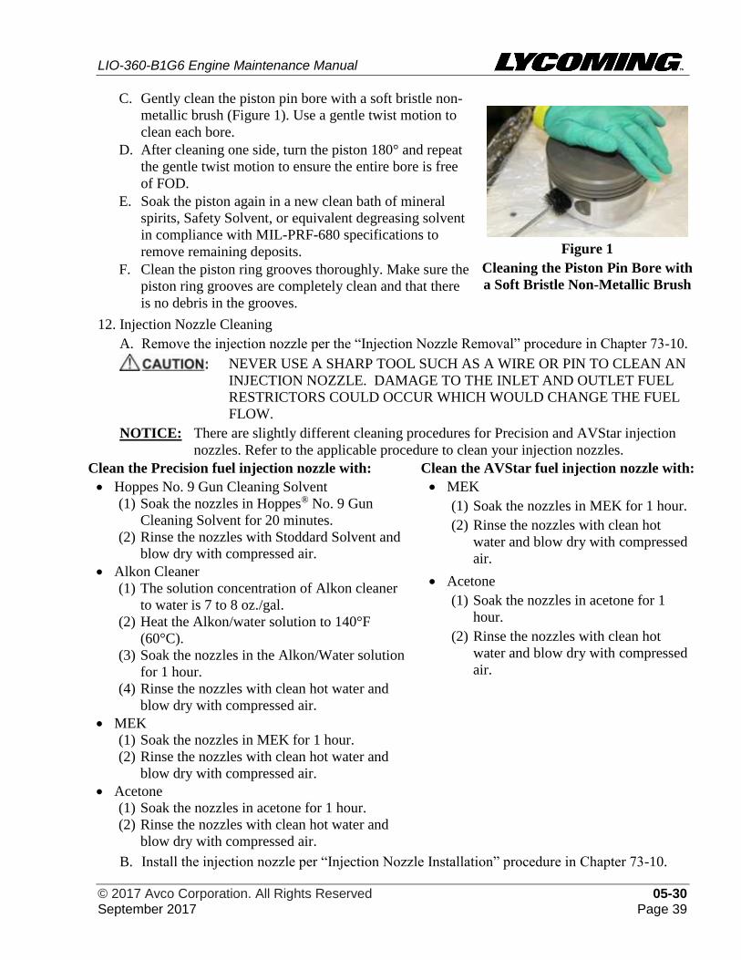
LIO-360-B1G6 Engine Maintenance Manual
© 2017 Avco Corporation. All Rights Reserved 05-30 September 2017 Page 39
C. Gently clean the piston pin bore with a soft bristle non-
metallic brush (Figure 1). Use a gentle twist motion to
clean each bore.
D. After cleaning one side, turn the piston 180° and repeat
the gentle twist motion to ensure the entire bore is free
of FOD.
E. Soak the piston again in a new clean bath of mineral
spirits, Safety Solvent, or equivalent degreasing solvent
in compliance with MIL-PRF-680 specifications to
remove remaining deposits.
F. Clean the piston ring grooves thoroughly. Make sure the
piston ring grooves are completely clean and that there
is no debris in the grooves.
Figure 1
Cleaning the Piston Pin Bore with
a Soft Bristle Non-Metallic Brush
12. Injection Nozzle Cleaning
A. Remove the injection nozzle per the “Injection Nozzle Removal” procedure in Chapter 73-10.
NEVER USE A SHARP TOOL SUCH AS A WIRE OR PIN TO CLEAN AN
INJECTION NOZZLE. DAMAGE TO THE INLET AND OUTLET FUEL
RESTRICTORS COULD OCCUR WHICH WOULD CHANGE THE FUEL
FLOW.
NOTICE: There are slightly different cleaning procedures for Precision and AVStar injection
nozzles. Refer to the applicable procedure to clean your injection nozzles.
Clean the Precision fuel injection nozzle with: Clean the AVStar fuel injection nozzle with:
• Hoppes No. 9 Gun Cleaning Solvent
(1) Soak the nozzles in Hoppes® No. 9 Gun
Cleaning Solvent for 20 minutes.
(2) Rinse the nozzles with Stoddard Solvent and
blow dry with compressed air.
• Alkon Cleaner
(1) The solution concentration of Alkon cleaner
to water is 7 to 8 oz./gal.
(2) Heat the Alkon/water solution to 140°F
(60°C).
(3) Soak the nozzles in the Alkon/Water solution
for 1 hour.
(4) Rinse the nozzles with clean hot water and
blow dry with compressed air.
• MEK
(1) Soak the nozzles in MEK for 1 hour.
(2) Rinse the nozzles with clean hot water and
blow dry with compressed air.
• Acetone
(1) Soak the nozzles in acetone for 1 hour.
(2) Rinse the nozzles with clean hot water and
blow dry with compressed air.
• MEK
(1) Soak the nozzles in MEK for 1 hour.
(2) Rinse the nozzles with clean hot
water and blow dry with compressed
air.
• Acetone
(1) Soak the nozzles in acetone for 1
hour.
(2) Rinse the nozzles with clean hot
water and blow dry with compressed
air.
B. Install the injection nozzle per “Injection Nozzle Installation” procedure in Chapter 73-10.
LIO-360-B1G6 Engine Maintenance Manual
05-30 © 2017 Avco Corporation. All Rights Reserved Page 40 September 2017
13. Steel, Aluminum, or Magnesium Parts Cleaning
DO NOT PUT STEEL AND MAGNESIUM PARTS INTO THE SAME
DECARBONIZING SOLUTION, BECAUSE IT CAN CAUSE CORROSION
OF THE MAGNESIUM PARTS.
DO NOT USE ANY HEATED DECARBONIZING SOLVENT ON
ALUMINUM OR MAGNESIUM PARTS. THE DECARBONIZING
SOLVENT CAN DAMAGE OR CORRODE MAGNESIUM AND
ALUMINUM PARTS.
ONLY USE PETROLEUM-BASED DECARBONIZING SOLUTIONS ON
ALUMINUM PARTS.
DO NOT USE CHLORINATED SOLVENTS (SUCH AS
TRICHLOROETHANE, TRICHLOROETHYLENE, “PERC”-DEGREASER,
ETC), TO PREVENT HYDROGEN EMBRITTLEMENT WHICH CAN
WEAKEN A METAL PART AND CAUSE IT TO FAIL.
DO NOT USE WATER-MIXED SOLVENTS THAT CONTAIN CAUSTIC
COMPOUNDS AND/OR SOAP, BECAUSE THEY CAN CAUSE DAMAGE
TO ALUMINUM AND MAGNESIUM PARTS. WHEN THE ENGINE IS
RETURNED TO SERVICE, THESE MATERIALS CAN ENTER THE PORES
OF THE METAL AND CAUSE OIL FOAMING.
NOTICE: If you are not sure if the component is steel or contains magnesium or aluminum,
contact Technical Support at Lycoming Engines at the phone numbers in the front of
this manual.
A. Put the component fully immersed in mineral spirits or equivalent in a bath tank.
NOTICE: For small steel parts, cold dip tanks or a closed tank system can be used with
NALCO 1704.
B. Remove the component from the bath tank.
C. Remove any remaining soft carbon (dirt or sludge) from the component with a lint-free wipe.
D. Apply a spray coating of preservative oil on the component to prevent corrosion.
E. If the component is not be installed immediately, put the component in a sealed plastic bag to
prevent the oil from drying out.
14. Spark Plug Cleaning
A. Remove the spark plug as per the “Spark Plug Removal” procedure in Chapter 74-20.
B. Refer to the spark plug manufacturer’s cleaning instructions.
C. Clean the ignition lead, cable ends, spark plug walls, and ceramic of the spark plugs (new or
reused) as per the spark plug manufacturer’s instructions.
D. Wipe the spark plug lead connector clean using a lint-free cloth moistened with Methyl-
Ethyl-Ketone (MEK), acetone, wood alcohol, naptha, or equivalent.
E. Remove all cleaning residue from the spark plug lead connector.
F. Install the spark plug as per the “Spark Plug Installation” procedure in Chapter 74-20.
LIO-360-B1G6 Engine Maintenance Manual
© 2017 Avco Corporation. All Rights Reserved 05-30 September 2017 Page 41
15. Lead Deposit Removal
A. Grit-blast (the component with lead deposits) with 17 grit walnut shells or equivalent at 35 to
45 psi (241 to 310 kPa). Refer to the section “Grit-Blast Media” and “Grit-Blast Procedure”
in this chapter.
B. Remove all debris from the component to prevent problems caused by foreign object debris.
16. Volcanic Ash Removal
IF VOLCANIC ASH IS SUSPECTED ON THE ENGINE, DO NOT INHALE IT
OR TOUCH IT WITH BARE HANDS OR GET IT IN YOUR EYES. WEAR
PERSONAL PROTECTIVE EQUIPMENT. DO NOT USE WATER TO RINSE
IT OFF. THE VOLCANIC ASH CAN CONTAIN ACIDIC COMPOUNDS
WHICH MUST NOT BE INHALED OR TOUCHED SINCE IT CAN CAUSE
INJURY.
A. Engine exterior and components NOT contaminated with volcanic ash:
(1) Remove grease, oil, dirt, and soft carbon deposits from the parts.
(2) Spray or brush the components with a hydrocarbon-base solvent.
B. To remove volcanic ash:
(1) Wear personal protective equipment (gloves, respiratory, and eye protection).
(2) Per the aircraft manufacturer’s instructions, thoroughly remove the ash or particulate
from the aircraft by hand brushing or air/vacuuming. Make sure that all ash is removed
from the engine and cowling.
C. Examine the induction filters, induction system, and engine baffles for blockage or damage.
D. Refer to the section “Volcanic Ash/Particulate Contamination” in Chapter 05-50 for further
details.
E. Refer to the aircraft manufacturer’s instructions for additional information
17. Cleaning Guidelines for a Soaked Engine
A. Clean the engine, especially all recessed areas where debris and silt can get trapped.
B. When cleaning parts removed from an engine that was soaked, especially ferrous (iron)
metals, do not use hot acidic cleaning agents or electrolytic cleaning methods (such as
cathodic cleaning) since they can cause hydrogen embrittlement. This embrittlement can
cause a metallic part to weaken and fail.
C. Additionally, acids can generally attack the metals and cause pitting or other corrosion
damage.
D. Be sure to remove all cleaning agents.
E. Rinse the part thoroughly.
F. Dry the part.
G. There must not be any cleaning agent residue on the metal surfaces. Any chemical that could
either corrode the metal or create hydrogen gas which can cause hydrogen embrittlement
during service.
H. Paint strippers are usually organic solvents like MEK or acetone or toluene, etc. and typically
will not cause any damage to metals.
I. Except for chlorinated solvents (such as trichloroethane, trichloroethylene, “perc”-degreaser,
etc), just about any other type of solvent can be used on steel or aluminum parts. Chlorinated
solvents can react with moisture and produce some hydrochloric acid which could harm the
metal.
LIO-360-B1G6 Engine Maintenance Manual
05-30 © 2017 Avco Corporation. All Rights Reserved Page 42 September 2017
18. Cleaning Method for Non-Destructive Testing
A. Remove all traces of:
• Paint • Corrosion
• Gasket materials • Smeared metal
• Oil • Plating
• Grease • Chemical residues
• Dirt
B. Use any of the following cleaning methods as long as it is not harmful to the component or its
intended function:
• Vapor degreasing
• Solvent degreasing
• Ultrasonic cleaning
• Chemical cleaning
• Aqueous-based cleaning
• Mechanical cleaning (such as grit-blasting)
NOTICE: If grit-blasting is to be used in preparation for non-destructive testing without a
subsequent etching process, make sure the grit blasting does not peen the surface.
Do not use 17-grit walnut shells, use a fine abrasive of 150-grit or finer.
LIO-360-B1G6 Engine Maintenance Manual
© 2017 Avco Corporation. All Rights Reserved 12-30 September 2017 Page 43
05-50 - UNSCHEDULED MAINTENANCE
1. Unscheduled corrective maintenance is necessary when any of the following conditions occur:
• Lightning strike
• Engine overspeed
• Incorrect fuel or fuel
contamination
• Soaked engine
• Engine on fire or near fire
• Hydraulic lock
• Volcanic ash/particulate
contamination
• Valve sticking
• Oil starvation/sudden loss of oil pressure
• Propeller strike, sudden engine stoppage or
loss of propeller blade tip
A. Lightning Strike - After a lightning strike:
After a lightning strike, if there is external evidence of electrical damage to the engine or
propeller or evidence of magnetism of the engine or propeller, before the next flight,
complete a visual inspection of the engine and propeller for electrical arc damage (in
accordance with the airframe and propeller manufacturer’s recommended
procedures/guidance).
If there is evidence of arc damage and the engine is not past its Time Between Overhaul
(TBO) per the latest revision of Service Instruction No. SI-1009, send the engine either to
Lycoming Engines or an approved repair facility for an internal inspection and evaluation on
whether an engine repair or overhaul is necessary.
OR
Complete the following in the field in accordance with this manual:
(1) Remove, disassemble, and clean the engine (per Chapters 72-00, 72-05, and 05-30).
(2) Complete an inspection of the engine and its components per chapters in this manual
and the latest revision of Service Bulletin No. SB-401.
(3) Examine the engine compartment in the aircraft, the engine, external surfaces, internal
parts for discoloration, cracks, and other indications of arcing and heat damage.
NOTICE: Refer to the latest revision of Service Bulletin No. 240 which identifies
certain parts that must be replaced on engine reassembly. Do not re-install
any part if it is discolored, cracked, or damaged. Replace the part with a
serviceable part.
(4) Assemble the engine (per Chapter 72-10) and complete an Operational Ground Check
(per Chapter 72-00).
(5) Record the incidence of a lightning strike, inspection outcome, and any corrective
action in the engine logbook.
B. Engine Overspeed
DO NOT OPERATE THE ENGINE CONTINUOUSLY AT AN
OVERSPEED RATE BECAUSE PARTS CAN WEAR OUT AND
EVENTUALLY CAUSE ENGINE FAILURE.
(1) In engine overspeed, the engine operates above its rated (speed) revolutions per minute
(rpm). Momentary overspeed is an increase of no more than 10% of rated engine rpm for
a period not exceeding 3 seconds. No action is required for a momentary overspeed.
NOTICE: Refer to the engine specifications in Appendix A of the LIO-360-B1G6 Engine
Installation and Operation Manual for rated engine speed.
All incidents of engine overspeed must be recorded in the engine logbook along
with any corrective action identified herein.
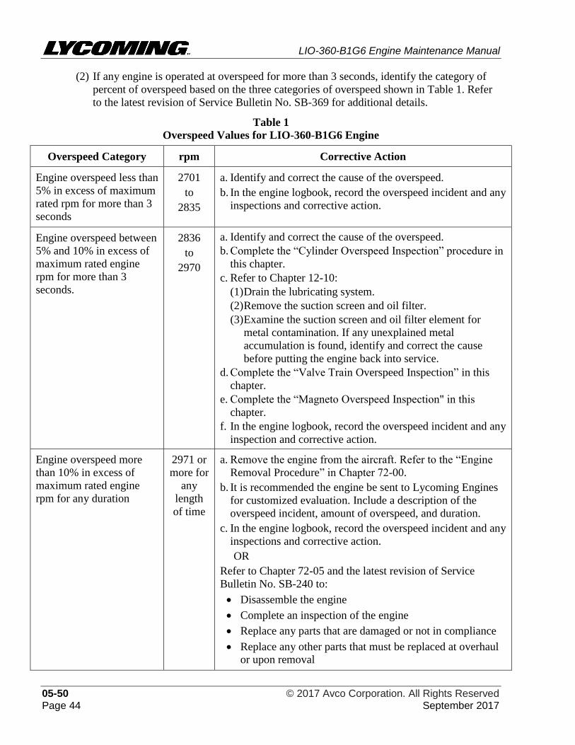
LIO-360-B1G6 Engine Maintenance Manual
05-50 © 2017 Avco Corporation. All Rights Reserved Page 44 September 2017
(2) If any engine is operated at overspeed for more than 3 seconds, identify the category of
percent of overspeed based on the three categories of overspeed shown in Table 1. Refer
to the latest revision of Service Bulletin No. SB-369 for additional details.
Table 1
Overspeed Values for LIO-360-B1G6 Engine
Overspeed Category rpm Corrective Action
Engine overspeed less than
5% in excess of maximum
rated rpm for more than 3
seconds
2701
to
2835
a. Identify and correct the cause of the overspeed.
b. In the engine logbook, record the overspeed incident and any
inspections and corrective action.
Engine overspeed between
5% and 10% in excess of
maximum rated engine
rpm for more than 3
seconds.
2836
to
2970
a. Identify and correct the cause of the overspeed.
b. Complete the “Cylinder Overspeed Inspection” procedure in
this chapter.
c. Refer to Chapter 12-10:
(1) Drain the lubricating system.
(2) Remove the suction screen and oil filter.
(3) Examine the suction screen and oil filter element for
metal contamination. If any unexplained metal
accumulation is found, identify and correct the cause
before putting the engine back into service.
d. Complete the “Valve Train Overspeed Inspection” in this
chapter.
e. Complete the “Magneto Overspeed Inspection" in this
chapter.
f. In the engine logbook, record the overspeed incident and any
inspection and corrective action.
Engine overspeed more
than 10% in excess of
maximum rated engine
rpm for any duration
2971 or
more for
any
length
of time
a. Remove the engine from the aircraft. Refer to the “Engine
Removal Procedure” in Chapter 72-00.
b. It is recommended the engine be sent to Lycoming Engines
for customized evaluation. Include a description of the
overspeed incident, amount of overspeed, and duration.
c. In the engine logbook, record the overspeed incident and any
inspections and corrective action.
OR
Refer to Chapter 72-05 and the latest revision of Service
Bulletin No. SB-240 to:
• Disassemble the engine
• Complete an inspection of the engine
• Replace any parts that are damaged or not in compliance
• Replace any other parts that must be replaced at overhaul
or upon removal
LIO-360-B1G6 Engine Maintenance Manual
© 2017 Avco Corporation. All Rights Reserved 05-50 September 2017 Page 45
(3) Cylinder Overspeed Inspection
(a) Complete the cylinder compression check on all cylinders as a check for the sealing
quality of the rings and valves. Refer to the section “Cylinder Compression Check
Procedure” in Chapter 72-30.
(b) Use a borescope or equivalent instrument to examine the walls of each cylinder for
scoring which could be caused by a stuck or broken piston ring. Refer to the
“Cylinder Borescope Inspection Procedure” in Chapter 72-30.
(4) Magneto Overspeed Inspection
(a) Remove the magnetos per the “Magneto Removal” procedure in Chapter 74-30.
Examine the magnetos for damage; replace parts as necessary per the magneto
manufacturer’s instructions.
(b) Examine the magneto drive gears for looseness which is an indication that the
supporting idler shafts are loose due to failure of safety attachments.
(c) Test the magnetos in accordance with the magneto manufacturer’s instructions.
(d) Replace a magneto if it is damaged.
(e) If applicable, examine the magneto bearing recess in the crankcase for excessive
wear. Repair as necessary in accordance with the latest revision of Service Instruction
No. 1140.
(5) Valve Train Overspeed Inspection
(a) Either repeated moments or short periods of operation in the overspeed region
increase the rate of wear at an accelerated rate in the parts that make up the valve train
and consequently decrease engine reliability. In addition to the checks completed on
the engine during a 100-hour maintenance inspection, complete the following steps to
examine the valve train before putting the engine back into service.
(b) Use a borescope or equivalent illuminated magnifying optical device to examine the
condition of the intake and exhaust valve faces and seat faces. If there is evidence of
excessive wear, pounding, or grooving, replace the valve and seat (valve seats can
only be replaced by an authorized vendor).
(c) Refer to the section "Exhaust Valve and Guide Inspection" in Chapter 72-30 and the
latest revision of Service Bulletin No. SB-388 to determine exhaust valve condition
and stem-to-valve guide clearance condition.
(d) Examine the external condition of valve keys, rockers, and exhaust valve guides for
damage (per Chapter 72-30). Examine valve springs for coil strikes or severe
bottoming of the coils. If damage to the valve springs is evident, remove them and
complete the check of the compression load. Replace any valve spring that is not
within limits as specified in the Special Torque Requirements Tables in Section V in
Part 1 of the latest revision of the Service Table of Limits - SSP-1776.
(e) Turn the crankshaft by hand to see if the valve lift is uniform or equal for all
cylinders. See if valve rockers lift freely when the valves are closed. Unequal valve
lift is an indication of bent push rods. Tight rockers, when valves are closed, are an
indication of a tuliped valve or a damaged valve lifter. Refer to Chapter 72-30 and
correct any suspected damage before putting the engine back into service.
LIO-360-B1G6 Engine Maintenance Manual
05-50 © 2017 Avco Corporation. All Rights Reserved Page 46 September 2017
C. Incorrect Fuel or Fuel Contamination
(1) Refer to the latest revision of Service Instruction No. SI-1070 for approved fuels, octane
ratings, and the use of a higher grade fuel for this engine. Do not use any fuel that has a
lower octane rating than the fuel specified for your engine.
ONLY USE APPROVED FUELS. DO NOT OPERATE THE ENGINE
WITH JET FUEL OR A LOWER OCTANE OR INCORRECT GRADE OF
FUEL. UNUSUAL DETONATION CAN OCCUR AND INCREASE
ENGINE TEMPERATURE AND PRESSURE WHICH CAN DAMAGE
THE ENGINE
(2) Actual damage to the engine from incorrect fuel could be in a range from unnoticeable to
severe damage or failure. Primary damage to the engine caused by incorrect fuel occurs
in the combustion chambers. Tuliped intake valves and burnt pistons from excessive
cylinder head and oil temperatures are evidence of primary damage. If detonation has
been severe enough, further damage will occur to crank pins, main bearings, and valve
train components. The extent of damage can vary accordingly based on the duration of
operation, engine power level and the type of fuel used.
(3) Any mixture of unapproved fuels and additive materials that change the octane rating
from the latest revision of Service Instruction No. SI-1070 could be harmful to the
engine.
(4) Because of many variables, it is impossible to be sure of the airworthiness of an engine
that has been operated with incorrect fuel - except by detailed inspection of the engine by
qualified personnel. Therefore, if the engine has been operated with incorrect fuel,
regardless of the power setting or time of operation, as per the latest revision of Service
Bulletin No. SB-398:
(a) Do not continue flight and engine operation with incorrect fuel.
(b) Drain the aircraft fuel system until all fuel tanks are empty in accordance with the
aircraft manufacturer’s installation.
(c) If the aircraft manufacturer has a procedure for cleaning and/or purging the aircraft
fuel system after the use of incorrect fuel, follow the aircraft manufacturer’s
procedure. If there is no aircraft cleaning and/or purging procedure, service the
aircraft fuel tanks in accordance with the aircraft manufacturer’s instructions.
(d) Remove the engine in accordance with the “Engine Removal Procedure” in Chapter
72-00.
(e) It is recommended the engine be sent to Lycoming Engines for evaluation.
OR
Complete the following in the field in accordance with this manual:
1 Remove, disassemble, and clean the engine per Chapters 72-00, 72-05, and 05-30.
2 Complete an inspection of engine components per chapters in this manual.
LIO-360-B1G6 Engine Maintenance Manual
© 2017 Avco Corporation. All Rights Reserved 05-50 September 2017 Page 47
3 During inspection of engine components, carefully look for signs of detonation
such as tuliped intake valves, burnt pistons, and damage to: crank pins, main
bearings, and drive train components, and other conditions that can cause engine
failure.
NOTICE: Refer to the latest revision of Service Bulletin No. SB-240 which
identifies certain parts that must be replaced on engine reassembly.
4 Assemble the engine per Chapter 72-10 and complete an Operational Ground
Check per Chapter 72-00.
D. Soaked Engine
WHEN AN ENGINE HAS BEEN SOAKED IN WATER, MOISTURE AND
UNWANTED MATERIALS CAN CAUSE DAMAGE TO ALL SYSTEMS
OF THE ENGINE. DO NOT INSTALL OR OPERATE AN ENGINE
THAT HAS BEEN SOAKED OR IMMERSED IN WATER OR OTHER
FLUID UNTIL IT HAS BEEN DISASSEMBLED, CLEANED,
EXAMINED AS NEEDED, ASSEMBLED, AND OPERATIONALLY
TESTED TO ENSURE THE ENGINE CAN BE SAFELY PUT BACK
INTO SERVICE.
NOTICE: The composition of the substance that the engine has been exposed to can affect
the type and extent of the damage.
It is recommended the engine be sent to Lycoming Engines for evaluation. Include a
description of the liquid in which the engine was soaked.
OR
NOTICE: The following inspection only applies to an engine soaked in water.
If the engine is soaked in a substance other than water, contact Lycoming
Engines Technical Support.
Complete the following in the field in accordance with this manual.
(1) Refer to the latest revision of Service Bulletin No. SB-357 for additional details.
(2) Remove and disassemble the engine (per Chapters 72-00 and 72-05).
(3) Clean the engine, especially all recessed areas where debris or silt can get trapped.
Remove all debris and silt per the section “Cleaning Guidelines for a Soaked Engine” in
Chapter 05-30.
(4) Complete an inspection of engine components per chapters in this manual.
(a) Examine components for visible corrosion or rust (or evidence thereof) per Chapters
72-20 and 72-30. Where possible, remove any rust or corrosion
(b) Look for pitting on the cylinder and piston. If pitting is found, replace the component.
Do not re-install a pitted cylinder or pitted piston.
(c) Visually examine components for embedded silt or debris contamination on bearing
surfaces, pistons, mounting flanges, or on any porous surfaces. Remove all silt and
debris from the component. If the embedded silt or debris cannot be removed, replace
the component.
LIO-360-B1G6 Engine Maintenance Manual
05-50 © 2017 Avco Corporation. All Rights Reserved Page 48 September 2017
(5) Replace parts per the latest revision of Service Bulletin No. SB-240 which identifies parts
that must be replaced during engine assembly.
(6) Make sure all oil passages, bored holes, oil and fuel hoses are clean and unobstructed and
have no debris.
(7) Once the engine is cleaned and reassembled, make sure it is in conformance with all
required fits and clearances (per the latest revision of the Service Table of Limits - SSP-
1776).
(8) Assemble the engine per Chapter 72-10.
(9) Refer to the Airframe Maintenance Manual and make sure all airframe interface fuel and
oil lines, intake, and exhaust, and the oil cooler are clean and have no debris or silt to
prevent re-contamination of the engine after the engine is installed in the airframe and re-
connected to airframe interface components.
(10) Record and complete the “Oil Change Procedure” per Chapter 12-10.
(11) Install the engine in the airframe per instructions in the LIO-360-B1G6 Engine
Installation and Operation Manual.
(12) Complete an Operational Ground Check per Chapter 72-00 to make sure the engine is
operating correctly before returning the engine to service.
E. Engine on Fire or Near a Fire
Replace any components exposed to heat from a fire.
It is recommended the engine be sent to Lycoming Engines for evaluation. Include a
description that the engine was in or near a fire or external heat.
OR
Complete the following in the field in accordance with this manual:
(1) Remove, disassemble, and clean the engine (per Chapters 72-00, 72-05, and 05-30)
(2) Complete an inspection of engine components per chapters in this manual.
NOTICE: Refer to the latest revision of Service Bulletin No. SB-240 which identifies
certain parts that must be replaced on engine reassembly.
(3) Assemble the engine per Chapter 72-10 and complete an Operational Ground Check per
Chapter 72-00.
F. Hydraulic Lock
DO NOT OPERATE THE ENGINE IF HYDRAULIC LOCK IS
SUSPECTED. HYDRAULIC LOCK CAN CAUSE DAMAGE TO THE
ENGINE.
Hydraulic lock is caused by liquid accumulation in either the Induction System or the
cylinder assembly.
(1) The liquid prevents movement of the piston during the compression stroke.
(2) Damage to the engine occurs when the other cylinders fire, which forces the piston in the
liquid-filled cylinder through the compression stroke.
LIO-360-B1G6 Engine Maintenance Manual
© 2017 Avco Corporation. All Rights Reserved 05-50 September 2017 Page 49
(3) Damage to an engine from hydraulic lock can be extensive due to the high forces. These
forces can damage connecting rods, pistons, cylinder assemblies, piston pins, the
crankcase, and the crankshaft.
(4) Hydraulic lock can occur as a result of any of the following:
• Incorrect operation of the fuel drain valve adapter assembly.
• Incorrect starting procedures.
• Failure to remove preservative oil from an engine that had been in storage.
(5) It is recommended the engine be sent to Lycoming Engines for evaluation. Include a
description and details of the hydraulic lock.
OR
Examine the engine for hydraulic lock in the field as follows:
(a) Remove all cylinders as per the “Cylinder Removal” procedure in Chapter 72-30.
(b) Refer to Chapter 72-20 to remove and examine the connecting rods.
(c) If all connecting rods are in compliance with the specified criteria in the latest
revision of the Service Table of Limits - SSP-1776, install the connecting rods.
(d) If any connecting rod is not in compliance with acceptance criteria, disassemble the
engine to examine the crankcase and crankshaft as per Chapters 72-05 and 72-20.
G. Volcanic Ash/Particulate Contamination
IF VOLCANIC ASH IS SUSPECTED ON THE ENGINE, DO NOT
INHALE IT OR TOUCH IT WITH BARE HANDS OR GET IT IN YOUR
EYES. WEAR PERSONAL PROTECTIVE EQUIPMENT. DO NOT USE
WATER TO RINSE IT OFF. THE VOLCANIC ASH CAN CONTAIN
ACIDIC COMPOUNDS WHICH MUST NOT BE INHALED OR
TOUCHED SINCE IT CAN CAUSE INJURY.
(1) Given the dynamic conditions of volcanic ash, Lycoming recommends that engines not
be operated in areas where volcanic ash is seen in the air or on the ground. Ash on the
ground and runways can inadvertently get into the engine compartment and cause engine
damage during landing or take-off.
(2) If volcanic ash or particulates get into the engine oil, engine malfunction and/or failure
can occur from abrasive wear.
(3) In volcanic ash fall-out or high sand or dust areas, after the engine cools, install inlet and
exhaust covers to prevent entry of airborne volcanic ash into the engine.
(4) In the event that the engine has been in particulate-laden atmospheres, especially volcanic
ash clouds or with ash on the ground, complete the standard actions in Table 2. Refer to
Service Instruction No. SI-1530 for additional details.
LIO-360-B1G6 Engine Maintenance Manual
05-50 © 2017 Avco Corporation. All Rights Reserved Page 50 September 2017
Table 2
Action to Take in Volcanic Ash Conditions
Maintenance after flight… Maintenance after 10 hours of operation or the
next flight…
Wear personal protective equipment (gloves,
respiratory, and eye protection). Per the aircraft
manufacturer’s instructions, thoroughly remove the
ash or particulate from the aircraft by hand brushing or
air/vacuuming. Make sure that all ash is removed from
the engine and cowling.
Wear personal protective equipment. Examine the
external engine and cowling for any particulate or
ash residue. Remove any particulate or ash residue
per the aircraft manufacturer’s instructions.
Complete the post-flight inspection. Particularly,
examine the induction filters, induction system, and
engine baffles for blockage or damage.
Complete the pre-flight inspection per the Pilot’s
Operating Handbook (POH).
Immediately, complete an oil change and replace the
oil filter. Collect an oil sample and have a
spectrographic analysis done on the oil sample.
Compare this analysis with past oil analyses to
determine engine wear or contamination. Refer to
Chapter 12-10.
Change the oil and replace the oil filter. Collect an
oil sample for spectrographic analysis. Compare the
results against the last oil sample to identify engine
wear or effects of contamination. As a precaution,
complete another oil change and analysis of another
oil sample again. Refer to Chapter 12-10.
Replace the intake air filter, as per the aircraft
manufacturer’s instructions to remove any internal
contamination that can cause premature wear because
of the highly abrasive effects from most solid particles.
Replace the intake air filter as a precaution to be
sure there are no effects from particulate
contamination. Replace the intake air filter again
after the next flight.
Examine the external condition of the engine, all
accessories, external fuel and oil cooling air baffles, oil
hoses, and all other components for corrosion or
scoring. Identify any possible damage caused by the
high speed impact from solid particles and corrosive
effects caused by the chemical composition of volcanic
ash.
Examine the external condition of the engine, all
accessories, external fuel and oil cooling air baffles,
oil hoses, and all other components for corrosion or
scoring. Identify any possible damage caused by
high speed impact from solid particles and corrosive
effects caused by the chemical composition of the
volcanic ash.
Drain all other fuel/fluids from the engine and replace
with clean fluids. Replace the disposable airframe fuel
filter or remove and clean the fuel inlet screen, as per
the aircraft manufacturer’s instructions.
Remove and examine the airframe fuel filter or fuel
inlet screen to identify any remnants of
contamination. Replace the airframe fuel filter or
clean the fuel inlet screen if contamination is found.
Examine seals for damage and leaks. Replace damaged
or leaky seals.
Monitor oil temperature and pressure for indications
of engine problems during flight.
DO NOT USE HIGH PRESSURE AIR SPRAY ON
THE WIRING HARNESS.
Clean the engine, except the wiring harness, with a
high pressure air spray. Be sure to clean the cooling
fins on the cylinders.
LIO-360-B1G6 Engine Maintenance Manual
© 2017 Avco Corporation. All Rights Reserved 05-50 September 2017 Page 51
H. Valve Sticking
(1) The primary causes of intake or exhaust valve sticking are:
(a) Accumulated contaminants in the oil and oil filter can collect on valve stems and/or
guides to prevent valve movement and cause intermittent engine hesitation or “miss.”
If the contamination deposits are not removed, the valve becomes stuck and causes
engine damage.
(b) Conditions that can increase oil contamination and valve sticking include:
• High ambient temperature
• Slow flight with reduced cooling
• High lead content in fuel
• Oil changes and oil filter replacement not done as frequently as necessary. Refer to
the “Oil Servicing Schedule” in Chapter 12-10.
• Induction system not sealed - unfiltered air enters engine
• Cooling air baffles and/or baffle strip deterioration
• Sudden cool down of the engine that can occur with a rapid descent with reduced
power or engine shutdown without sufficient engine cooling.
NOTICE: If valve sticking is a problem, refer to the latest revisions of Service Letter No.
L197 and Service Instruction No. SI-1425 and complete the 1000-hour inspection
in Chapter 05-20. Refer to the section “Corrective Action for Valve Sticking” in
Chapter 72-30.
If the 1000-hour inspection is completed before 1000 hours of operation because
of valve sticking, complete the scheduled 1000-hour inspection after the next
1000 hours of engine operation from the time of this inspection unless valve
sticking occurs again.
I. Oil Starvation/Sudden Loss of Oil Pressure
(1) To operate correctly at various attitudes, the engine must be supplied with a sufficient
quantity of lubricating oil. Unless there is an adequate quantity of lubricating oil at all
times during flight, loss of oil pressure can occur.
NOTICE: Refer to Appendix A of the LIO-360-B1G6 Engine Installation and Operation
Manual for the minimum oil quantity.
(2) Very often a sudden loss of oil pressure is quickly followed by a sudden rise in oil
temperature.
(3) As a preventive measure, before every take-off, complete a check of the engine oil level
as per instructions in "Oil Level Check" in Chapter 12-10. Make sure the oil level is
above the minimum specified level.
LIO-360-B1G6 Engine Maintenance Manual
05-50 © 2017 Avco Corporation. All Rights Reserved Page 52 September 2017
NOTICE: Circumstances which cause loss of oil pressure can be different which makes
prediction of the extent of damage to the engine or future engine reliability
difficult. In case of oil pressure loss or engine operation with oil below the
minimum operating level, the most conservative action is to remove the engine,
(Chapter 72-00), disassemble the engine (Chapter 72-05), and completely
examine all engine components per chapters herein. Any decision to operate an
engine that had loss of oil pressure without an inspection must be the
responsibility of the agency putting the aircraft back into service.
(4) Any time oil pressure falls below the minimum level, refer to the latest revision of
Service Bulletin No. SB-399, identify the root cause as per the following protocol of
progressive steps:
(a) Complete the “Oil Level Check” in the oil sump (per Chapter 12-10). If no oil is
visible on the oil level gage (dipstick), drain the oil to measure the oil quantity.
(b) If the oil level is sufficient, complete the check of the oil pressure indication system
accuracy. If the oil pressure gage is not operating correctly, replace it.
(c) Examine oil line connections for leaks. Tighten any loose connections per the torque
values in the latest revision of the Service Table of Limits - SSP-1776 and look for
leaks. Replace leaking oil lines per Chapter 72-50.
(d) Per Chapter 12-10, complete the “Oil Suction Screen Removal/Inspection/
Cleaning/Installation” at the oil sump and the “Oil Filter Inspection.” Look for
blockage or metal deposits. If metal or blockage is found, remove the material and
identify the origin of material and correct the root cause.
(e) Examine the oil pump for malfunction. Replace the oil pump if it is not operating
correctly. Refer to Chapter 72-25.
(f) If the oil pressure indication system is operating correctly and there has been
confirmation that oil pressure loss/oil starvation has occurred, remove the engine
(Chapter 72-00) and send to Lycoming Engines or disassemble the engine for
evaluation (Chapter 72-05).
J. Propeller Strike, Sudden Engine Stoppage or Loss of a Propeller Blade Tip
(1) This section includes recommendations for aircraft engines that have had propeller/rotor
damage as well as any of the following.
• Separation of the propeller/rotor blade from the hub
• Loss of a propeller or rotor blade tip
• Sudden stoppage
• Any incident, whether or not the engine is operating, where repair of the propeller is
necessary
LIO-360-B1G6 Engine Maintenance Manual
© 2017 Avco Corporation. All Rights Reserved 05-50 September 2017 Page 53
• Any incident during engine operation where the propeller has impact on a solid object
which causes a decrease in rpm and where a structural repair of the propeller is
necessary. This incident includes propeller strikes against the ground. Although the
propeller can continue to turn, damage to the engine can occur, possibly with
progression to engine failure.
• Sudden rpm drop on impact to water, tall grass, or similar yielding medium where
propeller damage does not usually occur.
(2) A propeller strike can occur at taxi speeds and during touch-and-go operations with
propeller tip ground contact. In addition, propeller strikes also include situations where an
aircraft is stationary and a landing gear collapse occurs causing one or more blades to be
bent, or where a hangar door (or other object) hits the propeller blade. These instances are
cases of sudden engine stoppage because of potentially severe side loading on the
crankshaft propeller flange, front bearing, and seal.
(3) Recommended Corrective Action for Propeller Strikes
BASED UPON THE ACCUMULATED ENGINEERING, TECHNICAL
AND HISTORICAL DATA AVAILABLE, LYCOMING ENGINES
PROHIBITS STRAIGHTENING OR GRINDING OF BENT
CRANKSHAFT PROPELLER FLANGES TO RESTORE MAXIMUM
RUN-OUT SPECIFICATION AS NOTED IN THE LATEST REVISION
OF THE SERVICE TABLE OF LIMITS - SSP-1776. IF THE
CRANKSHAFT PROPELLER FLANGE IS BENT, REPLACE THE
CRANKSHAFT. DO NOT TRY TO STRAIGHTEN OR GRIND
THE CRANKSHAFT PROPELLER FLANGE. REFER TO THE
LATEST REVISION OF SERVICE BULLETIN NO. 201.
DAMAGE TO A PROPELLER IS SERIOUS AND CAN CAUSE THE
ENGINE TO BE UNAIRWORTHY.
(a) Circumstances of a propeller strike cannot always be used as predictors of the extent
of engine damage or its future reliability. There can be varying degrees of damage to
an engine and propeller from a propeller strike. The initial damage can be hidden but
could become progressively worse with time and wear.
(b) Given these possibilities and the fact that there is no identified clear, quantifiable
threshold limit or gradient standard to reliably measure the extent of damage to an
engine, Lycoming Engines can only recommend BEFORE FURTHER FLIGHT, that
you complete the tasks in the sequential order shown in the Engine Inspection
Checklist After Propeller Strike for LIO-360-B1G6 Engines (in this chapter) as
corrective action for a propeller strike. Make a copy of the checklist and complete it.
NOTICE: The agency that returns the aircraft to service is responsible for the decision
to operate an engine that had a propeller strike. Lycoming Engines does not
take responsibility for the decision to return the engine to service after a
propeller strike. Refer to the latest revision of Service Bulletin No. SB-533.
LIO-360-B1G6 Engine Maintenance Manual
05-50 © 2017 Avco Corporation. All Rights Reserved Page 54 September 2017
Engine Inspection Checklist After Propeller Strike for LIO-360-B1G6 Engines
Engine Serial Number:
Date Inspection Started: Date Inspection Completed:
Sequential Task Additional Information Corrective Action
Done/Comments
1. Examine the propeller for extent of
damage; record condition of
propeller.
Condition of Propeller/Corrective
Action:
Propeller satisfactory
Repair propeller in accordance
with propeller manufacturer's
instructions
Replace propeller in accordance
with the airframe manufacturer's
instructions.
2. Remove the propeller. As per airframe and propeller
manufacturer’s instructions.
3. Remove the engine. Refer to Chapter 72-00
CRANKCASE P/N: MATCH NO:
4. Disassemble the engine - remove
the crankshaft, camshaft,
connecting rods, crankshaft gear,
and internal steel parts.
Refer to Chapter 72-05
5. Complete grit-blast cleaning* of
the crankcase with 17-grit walnut
shells or equivalent at 35 to 45 psi
(241 to 310 kPa); remove all
coatings on the crankcase and
engine mount bosses.
Make sure there is no dirt, debris,
sludge, paint, or any other
substance that could prevent
reliable Fluorescent Penetrant
Inspection (FPI) or subsequent oil
flow.
6. Complete grit-blast cleaning* of
the oil sump and engine mount
bosses with 17-grit walnut shells or
equivalent at 35 to 45 psi (241 to
310 kPa)
Make sure there is no dirt, debris,
sludge, paint, or any other substance
that could prevent reliable FPI or
subsequent oil flow.
7. Complete grit-blast cleaning* of
the engine mount brackets (if used)
with 17-grit walnut shells or
equivalent at 35 to 45 psi (241 to
310 kPa).
Make sure there is no dirt, debris,
sludge, paint, or any other
substance that could prevent
reliable FPI or subsequent oil flow.
* Refer to the “Grit-Blast Procedure” in Chapter 05-30.
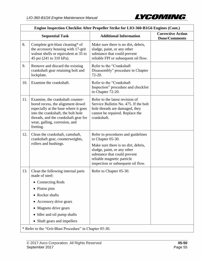
LIO-360-B1G6 Engine Maintenance Manual
© 2017 Avco Corporation. All Rights Reserved 05-50 September 2017 Page 55
Engine Inspection Checklist After Propeller Strike for LIO-360-B1G6 Engines (Cont.)
Sequential Task Additional Information Corrective Action
Done/Comments
8. Complete grit-blast cleaning* of
the accessory housing with 17-grit
walnut shells or equivalent at 35 to
45 psi (241 to 310 kPa).
Make sure there is no dirt, debris,
sludge, paint, or any other
substance that could prevent
reliable FPI or subsequent oil flow.
9. Remove and discard the existing
crankshaft gear retaining bolt and
lockplate.
Refer to the “Crankshaft
Disassembly” procedure in Chapter
72-20.
10. Examine the crankshaft. Refer to the “Crankshaft
Inspection” procedure and checklist
in Chapter 72-20.
11. Examine, the crankshaft counter-
bored recess, the alignment dowel
especially at the base where it goes
into the crankshaft, the bolt hole
threads, and the crankshaft gear for
wear, galling, corrosion, and
fretting.
Refer to the latest revision of
Service Bulletin No. 475. If the bolt
hole threads are damaged, they
cannot be repaired. Replace the
crankshaft.
12. Clean the crankshaft, camshaft,
crankshaft gear, counterweights,
rollers and bushings.
Refer to procedures and guidelines
in Chapter 05-30.
Make sure there is no dirt, debris,
sludge, paint, or any other
substance that could prevent
reliable magnetic particle
inspection or subsequent oil flow.
13. Clean the following internal parts
made of steel:
• Connecting Rods
• Piston pins
• Rocker shafts
• Accessory drive gears
• Magneto drive gears
• Idler and oil pump shafts
• Shaft gears and impellers
Refer to Chapter 05-30.
* Refer to the “Grit-Blast Procedure” in Chapter 05-30.
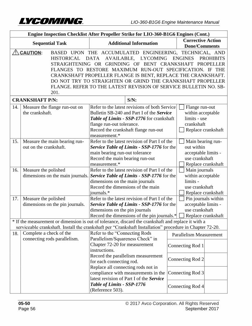
LIO-360-B1G6 Engine Maintenance Manual
05-50 © 2017 Avco Corporation. All Rights Reserved Page 56 September 2017
Engine Inspection Checklist After Propeller Strike for LIO-360-B1G6 Engines (Cont.)
Sequential Task Additional Information Corrective Action
Done/Comments
BASED UPON THE ACCUMULATED ENGINEERING, TECHNICAL, AND
HISTORICAL DATA AVAILABLE, LYCOMING ENGINES PROHIBITS
STRAIGHTENING OR GRINDING OF BENT CRANKSHAFT PROPELLER
FLANGES TO RESTORE MAXIMUM RUN-OUT SPECIFICATION. IF THE
CRANKSHAFT PROPELLER FLANGE IS BENT, REPLACE THE CRANKSHAFT.
DO NOT TRY TO STRAIGHTEN OR GRIND THE CRANKSHAFT PROPELLER
FLANGE. REFER TO THE LATEST REVISION OF SERVICE BULLETIN NO. SB-
201.
CRANKSHAFT P/N: S/N:
14. Measure the flange run-out on
the crankshaft.
Refer to the latest revisions of both Service
Bulletin SB-240 and Part I of the Service
Table of Limits - SSP-1776 for crankshaft
flange run-out tolerance.
Record the crankshaft flange run-out
measurement.*
Flange run-out
within acceptable
limits - use
crankshaft
Replace crankshaft
15. Measure the main bearing run-
out on the crankshaft.
Refer to the latest revision of Part I of the
Service Table of Limits - SSP-1776 for the
main bearing run-out tolerance
Record the main bearing run-out
measurement.*
Main bearing run-
out within
acceptable limits -
use crankshaft
Replace crankshaft
16. Measure the polished
dimensions on the main journals.
Refer to the latest revision of Part I of the
Service Table of Limits - SSP-1776 for the
dimensions on the main journals
Record the dimensions of the main
journals.*
Main journals
within acceptable
limits -
use crankshaft
Replace crankshaft
17. Measure the polished
dimensions on the pin journals.
Refer to the latest revision of Part I of the
Service Table of Limits - SSP-1776 for the
dimensions on the pin journals
Record the dimensions of the pin journals.*
Pin journals within
acceptable limits -
use crankshaft
Replace crankshaft
* If the measurement or dimension is out of tolerance, discard the crankshaft and replace it with a
serviceable crankshaft. Install the crankshaft per “Crankshaft Installation” procedure in Chapter 72-20.
18. Complete a check of the
connecting rods parallelism.
Refer to the “Connecting Rods
Parallelism/Squareness Check” in
Chapter 72-20 for measurement
instructions.
Record the parallelism measurement
for each connecting rod.
Replace all connecting rods not in
compliance with measurements in the
latest revision of Part I of the Service
Table of Limits - SSP-1776
(Reference 503).
Parallelism Measurement
Connecting Rod 1
Connecting Rod 2
Connecting Rod 3
Connecting Rod 4
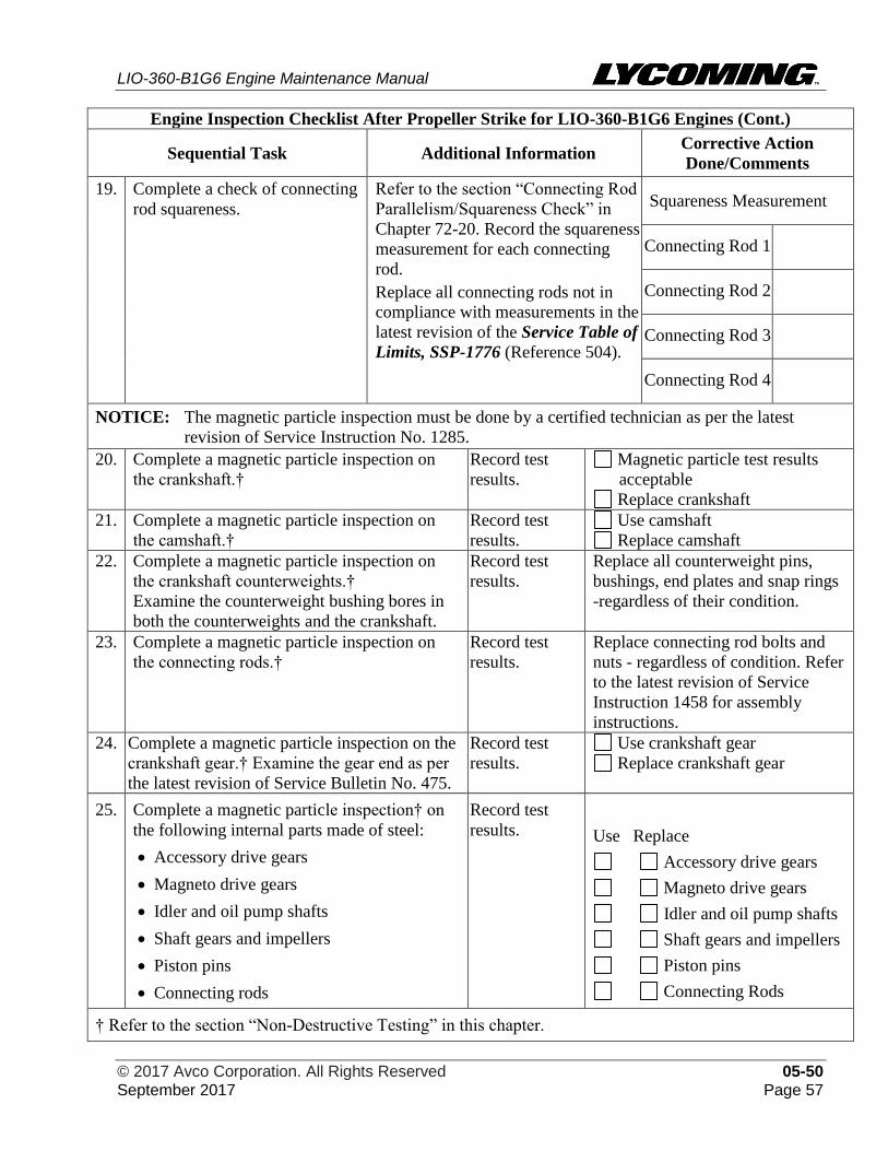
LIO-360-B1G6 Engine Maintenance Manual
© 2017 Avco Corporation. All Rights Reserved 05-50 September 2017 Page 57
Engine Inspection Checklist After Propeller Strike for LIO-360-B1G6 Engines (Cont.)
Sequential Task Additional Information Corrective Action
Done/Comments
19. Complete a check of connecting
rod squareness.
Refer to the section “Connecting Rod
Parallelism/Squareness Check” in
Chapter 72-20. Record the squareness
measurement for each connecting
rod.
Replace all connecting rods not in
compliance with measurements in the
latest revision of the Service Table of
Limits, SSP-1776 (Reference 504).
Squareness Measurement
Connecting Rod 1
Connecting Rod 2
Connecting Rod 3
Connecting Rod 4
NOTICE: The magnetic particle inspection must be done by a certified technician as per the latest
revision of Service Instruction No. 1285.
20. Complete a magnetic particle inspection on
the crankshaft.†
Record test
results.
Magnetic particle test results
acceptable
Replace crankshaft
21. Complete a magnetic particle inspection on
the camshaft.†
Record test
results.
Use camshaft
Replace camshaft
22. Complete a magnetic particle inspection on
the crankshaft counterweights.†
Examine the counterweight bushing bores in
both the counterweights and the crankshaft.
Record test
results.
Replace all counterweight pins,
bushings, end plates and snap rings
-regardless of their condition.
23. Complete a magnetic particle inspection on
the connecting rods.†
Record test
results.
Replace connecting rod bolts and
nuts - regardless of condition. Refer
to the latest revision of Service
Instruction 1458 for assembly
instructions.
24. Complete a magnetic particle inspection on the
crankshaft gear.† Examine the gear end as per
the latest revision of Service Bulletin No. 475.
Record test
results.
Use crankshaft gear
Replace crankshaft gear
25. Complete a magnetic particle inspection† on
the following internal parts made of steel:
• Accessory drive gears
• Magneto drive gears
• Idler and oil pump shafts
• Shaft gears and impellers
• Piston pins
• Connecting rods
Record test
results. Use Replace
Accessory drive gears
Magneto drive gears
Idler and oil pump shafts
Shaft gears and impellers
Piston pins
Connecting Rods
† Refer to the section “Non-Destructive Testing” in this chapter.
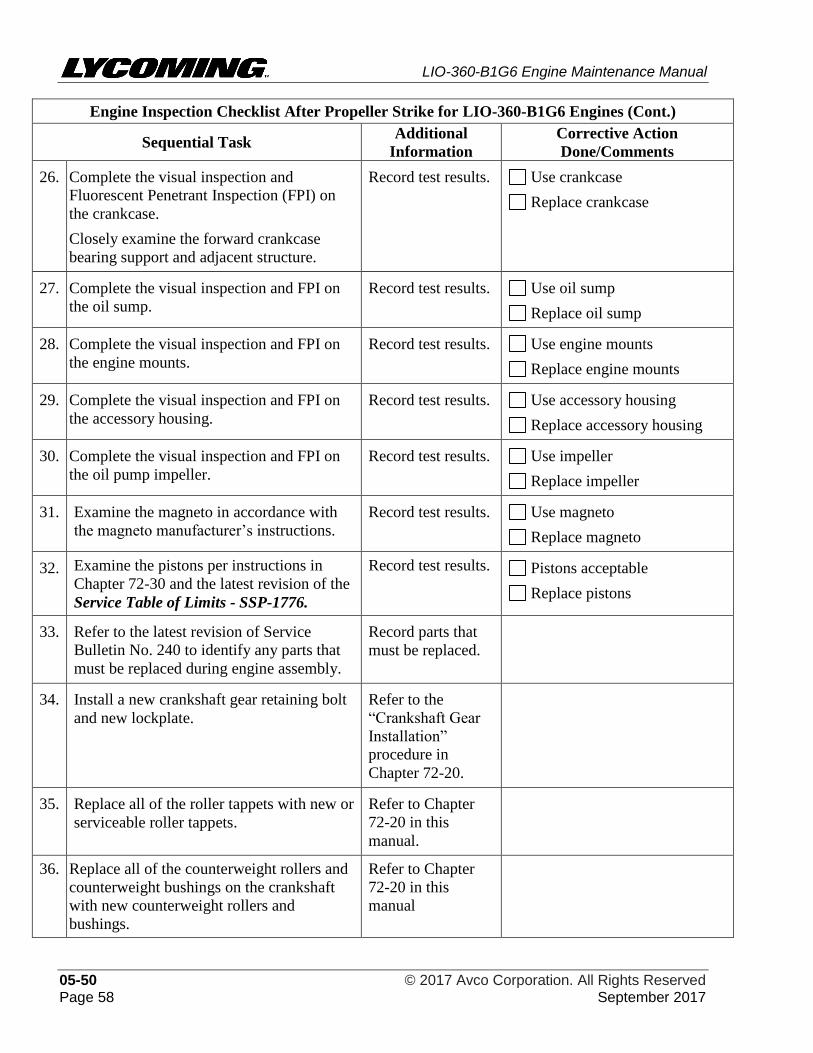
LIO-360-B1G6 Engine Maintenance Manual
05-50 © 2017 Avco Corporation. All Rights Reserved Page 58 September 2017
Engine Inspection Checklist After Propeller Strike for LIO-360-B1G6 Engines (Cont.)
Sequential Task Additional
Information
Corrective Action
Done/Comments
26. Complete the visual inspection and
Fluorescent Penetrant Inspection (FPI) on
the crankcase.
Closely examine the forward crankcase
bearing support and adjacent structure.
Record test results. Use crankcase
Replace crankcase
27. Complete the visual inspection and FPI on
the oil sump.
Record test results. Use oil sump
Replace oil sump
28. Complete the visual inspection and FPI on
the engine mounts.
Record test results. Use engine mounts
Replace engine mounts
29. Complete the visual inspection and FPI on
the accessory housing.
Record test results. Use accessory housing
Replace accessory housing
30. Complete the visual inspection and FPI on
the oil pump impeller.
Record test results. Use impeller
Replace impeller
31. Examine the magneto in accordance with
the magneto manufacturer’s instructions.
Record test results. Use magneto
Replace magneto
32. Examine the pistons per instructions in
Chapter 72-30 and the latest revision of the
Service Table of Limits - SSP-1776.
Record test results. Pistons acceptable
Replace pistons
33. Refer to the latest revision of Service
Bulletin No. 240 to identify any parts that
must be replaced during engine assembly.
Record parts that
must be replaced.
34. Install a new crankshaft gear retaining bolt
and new lockplate.
Refer to the
“Crankshaft Gear
Installation”
procedure in
Chapter 72-20.
35. Replace all of the roller tappets with new or
serviceable roller tappets.
Refer to Chapter
72-20 in this
manual.
36. Replace all of the counterweight rollers and
counterweight bushings on the crankshaft
with new counterweight rollers and
bushings.
Refer to Chapter
72-20 in this
manual
LIO-360-B1G6 Engine Maintenance Manual
© 2017 Avco Corporation. All Rights Reserved 05-50 September 2017 Page 59
Engine Inspection Checklist After Propeller Strike for LIO-360-B1G6 Engines (Cont.)
Sequential Task Additional
Information
Corrective Action
Done/Comments
37. Review the documents of all engine-
mounted accessories including the propeller
governor (if installed), etc. for continued
airworthiness instruction.
38. Assemble and install the engine. Install the
propeller and test the engine. Complete an
Operational Ground Check of the engine.
In accordance with
instructions in
Chapters 72-00 and
72-10.
39. Complete “Field Run-In” (if applicable)
and “Engine Initiation”.
Refer to the “Field
Run-In” or “Engine
Initiation” chapters
in the LIO-360-
B1G6 Engine
Installation and
Operation Manual.
40. Record maintenance findings and any
corrective action.
UNAIRWORTHY PARTS:
ADDITIONAL WORK/INSPECTIONS NECESSARY:
OUTCOME OF INSPECTION- SUMMARY NOTES:
2. Non-Destructive Testing (Magnetic Particle Inspection and Fluorescent Penetrant Inspection.)
Refer to the latest revision of Service Instruction No. SI-1285 for additional details.
A. Non-destructive testing (NDT) that can be done on engine components includes Magnetic
Particle Inspection (MPI) and Fluorescent Penetrant Inspection (FPI). The purpose of the
NDT is to identify the presence or potential of structural failures in an engine component.
The MPI is used for detection of discontinuities on the surface and/or sub-surface of
ferroelectric materials such as iron, nickel, cobalt, and some of their alloys.
The FPI is used to identify casting, forging and welding surface defects such as hairline
cracks, surface porosity, leaks in new products, and fatigue cracks on in-service components.
LIO-360-B1G6 Engine Maintenance Manual
05-50 © 2017 Avco Corporation. All Rights Reserved Page 60 September 2017
B. Penetrant Materials Used for NDT
Do not use visible dye for MPIs or FPIs because visible dye penetrant materials have an
adverse effect on future penetrant inspections which can cause indications to be tightly
closed and therefore missed during future inspections.
C. Requirements for NDT Personnel
Personnel who complete the Magnetic Particle and Fluorescent Penetrant Inspections on
Lycoming engine components must be certified to a written procedure in accordance with
NAS-410, Certification and Qualification of NDT personnel. Also, personnel who make the
"accept" or "reject" decisions during the inspections must be certified to at least Level II in
accordance with NAS-410.
D. NDT Inspection Procedure Requirements and Guidelines
There must be written procedures for the Magnetic Particle Inspection and the Fluorescent
Penetrant Inspection that have been approved by someone who is certified to Level III in
accordance with NAS-410.
E. Before NDT, clean the components per the “Cleaning Method for Non-Destructive Testing”
in Chapter 05-30.
F. Inspection Guidelines
(1) The inspections must be done per established acceptance criteria to ensure component
conformance.
(2) A 3 power to 10 power magnifying glass must be used to evaluate indications.
(3) If a Magnetic Particle Inspection is difficult to do on an odd-shaped part, the Fluorescent
Penetrant Inspection can be used if the acceptance criteria are concerned about surface
indications only.
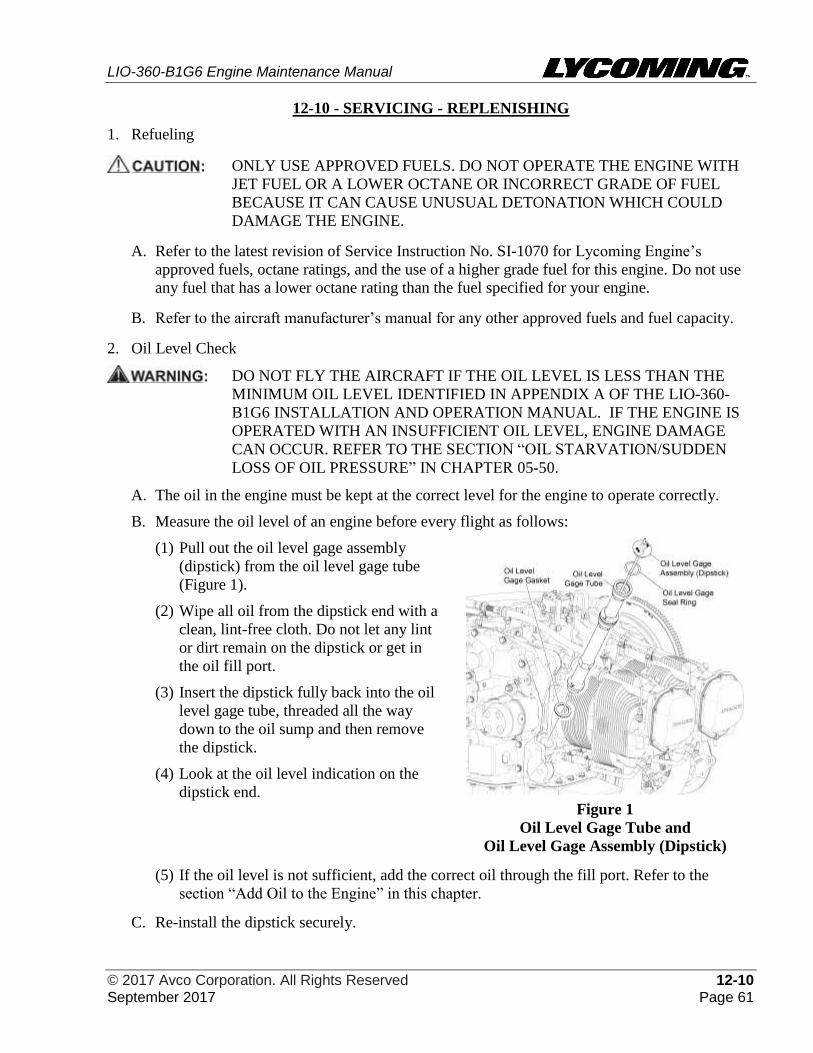
LIO-360-B1G6 Engine Maintenance Manual
© 2017 Avco Corporation. All Rights Reserved 12-10 September 2017 Page 61
12-10 - SERVICING - REPLENISHING
1. Refueling
ONLY USE APPROVED FUELS. DO NOT OPERATE THE ENGINE WITH
JET FUEL OR A LOWER OCTANE OR INCORRECT GRADE OF FUEL
BECAUSE IT CAN CAUSE UNUSUAL DETONATION WHICH COULD
DAMAGE THE ENGINE.
A. Refer to the latest revision of Service Instruction No. SI-1070 for Lycoming Engine’s
approved fuels, octane ratings, and the use of a higher grade fuel for this engine. Do not use
any fuel that has a lower octane rating than the fuel specified for your engine.
B. Refer to the aircraft manufacturer’s manual for any other approved fuels and fuel capacity.
2. Oil Level Check
DO NOT FLY THE AIRCRAFT IF THE OIL LEVEL IS LESS THAN THE
MINIMUM OIL LEVEL IDENTIFIED IN APPENDIX A OF THE LIO-360-
B1G6 INSTALLATION AND OPERATION MANUAL. IF THE ENGINE IS
OPERATED WITH AN INSUFFICIENT OIL LEVEL, ENGINE DAMAGE
CAN OCCUR. REFER TO THE SECTION “OIL STARVATION/SUDDEN
LOSS OF OIL PRESSURE” IN CHAPTER 05-50.
A. The oil in the engine must be kept at the correct level for the engine to operate correctly.
B. Measure the oil level of an engine before every flight as follows:
(1) Pull out the oil level gage assembly
(dipstick) from the oil level gage tube
(Figure 1).
(2) Wipe all oil from the dipstick end with a
clean, lint-free cloth. Do not let any lint
or dirt remain on the dipstick or get in
the oil fill port.
(3) Insert the dipstick fully back into the oil
level gage tube, threaded all the way
down to the oil sump and then remove
the dipstick.
(4) Look at the oil level indication on the
dipstick end.
Figure 1
Oil Level Gage Tube and
Oil Level Gage Assembly (Dipstick)
(5) If the oil level is not sufficient, add the correct oil through the fill port. Refer to the
section “Add Oil to the Engine” in this chapter.
C. Re-install the dipstick securely.
LIO-360-B1G6 Engine Maintenance Manual
12-10 © 2017 Avco Corporation. All Rights Reserved Page 62 September 2017
3. Oil Consumption
NOTICE: To ensure accurate calculation of oil consumption, each time oil is added to the engine,
record the amount of oil added in the engine logbook.
A. Use the following formula to calculate the maximum allowable oil consumption limits for
this engine and record the value in the engine logbook. Compare this oil consumption value
to past oil consumption values.
0.006 x BHP x 4 ÷ 7.4 = Qt./Hr.
ONCE BREAK-IN IS COMPLETE, IF OIL CONSUMPTION IS MORE
THAN THE CONSUMPTION RATES IN APPENDIX A OF THE LIO-360-
B1G6 ENGINE INSTALLATION AND OPERATION MANUAL, THE
AIRCRAFT IS NOT TO BE IN FLIGHT. EXCESSIVE OIL
CONSUMPTION IS AN INDICATION OF A PROBLEM, SUCH AS OIL
LEAKS OR CYLINDER MALFUNCTION.
B. If engine oil servicing is consistently frequent or oil consumption has increased or is
excessive:
(1) Complete the “Cylinder Borescope Inspection Procedure” in Chapter 72-30.
(2) Refer to Chapter 12-30 for corrective action to identify and correct the cause of the
excessive oil consumption before further flight.
4. Oil Type and Viscosity
A. The oils to be used in the LIO-360-B1G6 engines are identified in Appendix A of the LIO-
360-B1G6 Engine Installation and Operation Manual.
B. Refer to the latest revision of Service Instruction No. SI-1014 for additional details.
5. Add Oil to the Engine
NOTICE: Each time oil is added to the engine, record the quantity of oil added in the engine
logbook to calculate oil consumption.
A. Oil Additives
Refer to the latest revision of Service Instruction No. SI 1409 for quantity and instructions to add
the oil additive.
NOTICE: The approved oil, oil sump capacity, and the minimum quantity for engine operation
are identified in the latest revision of Service Instruction No. SI-1014 and Appendix
A of the LIO-360-B1G6 Engine Installation and Operation Manual.
On new, rebuilt, or overhauled engines, during the first 50 hours of engine
operation, operate these engines with mineral oil until oil consumption has
stabilized. Afterwards, complete the “Oil Change Procedure” in this chapter.
B. To add oil to the LIO-360-B1G6 engine:
(1) Pull out the oil level gage assembly (dipstick) (Figure 1) from the oil level gage tube.
(2) Add either new clean mineral oil (if within the first 50 hours of operation of a new,
rebuilt, or overhauled engine) or specified oil of the correct quantity and viscosity for the
ambient temperature (identified in Appendix A in the LIO-360-B1G6 Engine
Installation and Operation Manual or the latest revision of Service Instruction No. SI-
1014) to the oil sump through the oil level gage tube.
LIO-360-B1G6 Engine Maintenance Manual
© 2017 Avco Corporation. All Rights Reserved 12-10 September 2017 Page 63
(3) Measure the oil level per the “Oil Level Check” procedure in this chapter. Add more oil if
necessary until the oil level in the engine is sufficient.
(4) In the engine logbook, record the amount of oil added to calculate oil consumption.
(5) Install the oil level gage assembly (dipstick) into the oil level gage tube securely.
6. Oil Leak Check
A. Examine the following for oil leaks:
• Oil sump drain plug
• Oil Suction screen plug (LIO-360-B1G6 Engines)
• Oil filter
• Oil hoses connected to the oil cooler
B. If leaks are found, identify and correct the cause. Complete the Operational Leak Check
Sheet in Chapter 05-20.
C. After the cause of the oil leak is corrected, measure the oil level. Refer to “Oil Level Check”
procedure in this chapter. Add oil as necessary per the procedure “Add Oil to the Engine” in
this chapter.
7. Oil Servicing Schedule
The recommended schedule for oil changes, oil suction screen cleaning and oil filter replacement
are shown in Table 1.
Table 1
Oil Servicing Schedule
Task Frequency
Initial oil change and oil filter replacement of any
new, rebuilt, or overhauled engine, or engine
returned to service after storage
After the first 25 hours of operation after initial
start-up or every 4 months (whichever occurs
first*)
Repeat as necessary until oil consumption
stabilizes.**
Routine oil change and oil filter replacement (after
initial 25-hour oil change and oil filter replacement)
&
Oil suction screen cleaning/inspection
After every 50 hours of engine operation or every
4 months (whichever occurs first*)
After replacement of any engine cylinder
* Oil change intervals must not exceed 4 months regardless of operating hours and especially if the
aircraft has not been flown for at least 25 hours in a 4-month period. More frequent oil changes are
recommended if the engine has been exposed to volcanic ash, particulate, sand, dust, debris, or extreme
weather conditions.
** If oil consumption does not stabilize, identify and correct the cause and repeat this procedure.
8. Oil Change Procedure
NOTICE: Refer to Table 1 for the oil servicing schedule for your engine.
An anti-scuffing oil additive can be added to the oil sump during an oil change. Refer to
the “Oil Additives” section in this chapter.
On new, rebuilt, or overhauled engines, during the first 50 hours of engine operation,
operate this engine on mineral oil until oil consumption has stabilized.
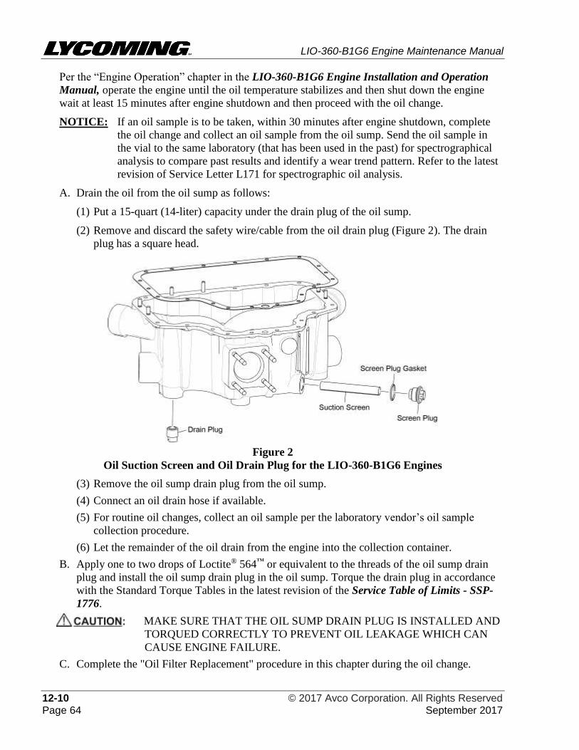
LIO-360-B1G6 Engine Maintenance Manual
12-10 © 2017 Avco Corporation. All Rights Reserved Page 64 September 2017
Per the “Engine Operation” chapter in the LIO-360-B1G6 Engine Installation and Operation
Manual, operate the engine until the oil temperature stabilizes and then shut down the engine
wait at least 15 minutes after engine shutdown and then proceed with the oil change.
NOTICE: If an oil sample is to be taken, within 30 minutes after engine shutdown, complete
the oil change and collect an oil sample from the oil sump. Send the oil sample in
the vial to the same laboratory (that has been used in the past) for spectrographical
analysis to compare past results and identify a wear trend pattern. Refer to the latest
revision of Service Letter L171 for spectrographic oil analysis.
A. Drain the oil from the oil sump as follows:
(1) Put a 15-quart (14-liter) capacity under the drain plug of the oil sump.
(2) Remove and discard the safety wire/cable from the oil drain plug (Figure 2). The drain
plug has a square head.
Figure 2
Oil Suction Screen and Oil Drain Plug for the LIO-360-B1G6 Engines
(3) Remove the oil sump drain plug from the oil sump.
(4) Connect an oil drain hose if available.
(5) For routine oil changes, collect an oil sample per the laboratory vendor’s oil sample
collection procedure.
(6) Let the remainder of the oil drain from the engine into the collection container.
B. Apply one to two drops of Loctite® 564™ or equivalent to the threads of the oil sump drain
plug and install the oil sump drain plug in the oil sump. Torque the drain plug in accordance
with the Standard Torque Tables in the latest revision of the Service Table of Limits - SSP-
1776.
MAKE SURE THAT THE OIL SUMP DRAIN PLUG IS INSTALLED AND
TORQUED CORRECTLY TO PREVENT OIL LEAKAGE WHICH CAN
CAUSE ENGINE FAILURE.
C. Complete the "Oil Filter Replacement" procedure in this chapter during the oil change.
LIO-360-B1G6 Engine Maintenance Manual
© 2017 Avco Corporation. All Rights Reserved 12-10 September 2017 Page 65
D. Complete the "Oil Suction Screen Removal/Inspection/Cleaning/Installation" procedure in
this chapter.
E. Add oil of the correct viscosity for ambient temperature to the engine. Refer to the "Add Oil
to the Engine" procedure in this chapter.
F. If an oil line has been disconnected or if the oil cooler was drained or replaced or after any
prolonged period of engine inactivity, complete the "Engine Pre-Oil Procedure" in this
chapter.
G. Complete the “Oil Level Check” procedure in this chapter.
H. Safety cable/wire the oil sump drain plug(s), suction screen plug (Figure 2), and oil filter (if
applicable) in accordance with the standard practices per the latest revision of AC43.13-1B or
the latest revision of Service Instruction No. SI-1566.
I. Dispose of the oil in the collection container in accordance with environmental safety laws.
J. Wipe away any oil spilled on the engine.
K. After all service is complete, operate the engine and look for oil leaks. Identify and correct
the cause of any oil leak.
9. Engine Pre-Oil Procedure
Refer to the latest revision of Service Instruction No. SI-1241 for additional details.
Complete the engine pre-oil procedure on the engine at the following times:
• Before the initial start of an engine after engine installation
• After oil cooler replacement or draining
• After disconnecting any oil lines from the oil cooler circuit.
• After any prolonged period of inactivity requiring a preservation procedure per the latest
revision of Service Letter No. L180
To complete the pre-oil procedure:
A. If not already done, fill the oil sump with clean engine oil to the correct level per the “Add
Oil to the Engine” procedure in this chapter.
B. Make sure that the Ignition switch, Auxiliary Fuel Pump switch, and Fuel Selector are all in
the OFF position. Move the Mixture Control to the IDLE/CUTOFF position.
C. Fill the oil cooler with engine oil per the airframe manufacturer’s instructions.
D. Per the “Spark Plug Removal” procedure in Chapter 74-20, disconnect the ignition leads
from all spark plugs and remove one spark plug from each cylinder of the engine. Remove
and discard the spark plug gasket.
E. Move the throttle control to the FULL OPEN position.
DO NOT ENERGIZE THE STARTER FOR PERIODS OVER 10 TO 15
SECONDS. LET THE STARTER COOL FOR 30 SECONDS AFTER EACH
ENERGIZATION. IF THE STARTER FAILS TO ENERGIZE AFTER
TWO ATTEMPTS, IDENTIFY AND CORRECT THE CAUSE PER THE
AIRFRAME MANUFACTURER’S MAINTENANCE MANUAL.
LIO-360-B1G6 Engine Maintenance Manual
12-10 © 2017 Avco Corporation. All Rights Reserved Page 66 September 2017
F. Pre-oil start cycle: Energize the starter for 10 to 15 seconds and look for evidence of oil
pressure of at least 20 psi (138 kPa) within 10 to 15 seconds.
If there is no oil pressure within 10 to 15 seconds, stop energizing the starter. Wait at least 30
seconds and repeat the pre-oil start cycle.
Up to six consecutive pre-oil start cycles can be done. Afterwards let the starter cool for 30
minutes. If stable oil pressure is not achieved, stop pre-oiling and contact Lycoming Engines.
NOTICE: Unstable oil pressure or oil pressure less than 20 psi (138 kPa) could be an
indication of obstructed or interrupted oil flow or air in the oil lines.
G. If oil pressure of at least 20 psi (138 kPa) was sustained in the previous step, repeat the pre-
oil start cycle to make sure oil pressure holds stable and that there is no sudden drop in oil
pressure. If oil pressure is not stable or drops suddenly, stop pre-oiling, identify and correct
the cause.
NOTICE: Install a new spark plug gasket whether a new or acceptable re-used spark plug is to
be installed.
H. Once the minimum oil pressure of 20 psi (138 kPa) is shown on the oil pressure gage, re-
install the spark plugs each with a new gasket as per the “Spark Plug Installation” procedure
in Chapter 74-20.
I. Reconnect the ignition leads to all spark plugs.
J. Within the next 3 hours start and operate the engine for 3 minutes at approximately 1000
rpm. Refer to either the “Engine Initiation” chapter or the "Engine Operation" chapter in the
LIO-360-B1G6 Engine Installation and Operation Manual.
10. Oil Suction Screen Removal/Inspection/Cleaning/Installation
NOTICE: On the LIO-360-B1G6 (Figure 2) engines there is an oil suction screen in the oil sump.
Clean the oil suction screen and replace the oil filter after every 50 hours of engine
operation, with each oil change (unless more frequent oil changes are necessary).
A. Remove and discard the safety/cable wire/cable from the suction screen plug and oil drain
plug on the oil sump (Figure 2).
B. Put a suitable collection container with a minimum 15-quart (14-liter) capacity under the
drain plug of the oil sump.
C. Remove the oil drain plug and drain the oil from the engine.
D. Remove the screen plug and oil suction screen from the oil sump.
E. Remove and discard the gasket from the screen plug.
F. Before cleaning the oil suction screen:
(1) Examine the oil suction screen for distortion, deformation or openings in the mesh and/or
metallic particles, shavings, or flakes (which can be an indication of possible excessive
internal wear on the engine).
(2) Examine any material trapped in the oil suction screen. Examine the condition of the oil
and particles on the oil suction screen. Look for shining, metallic residue.
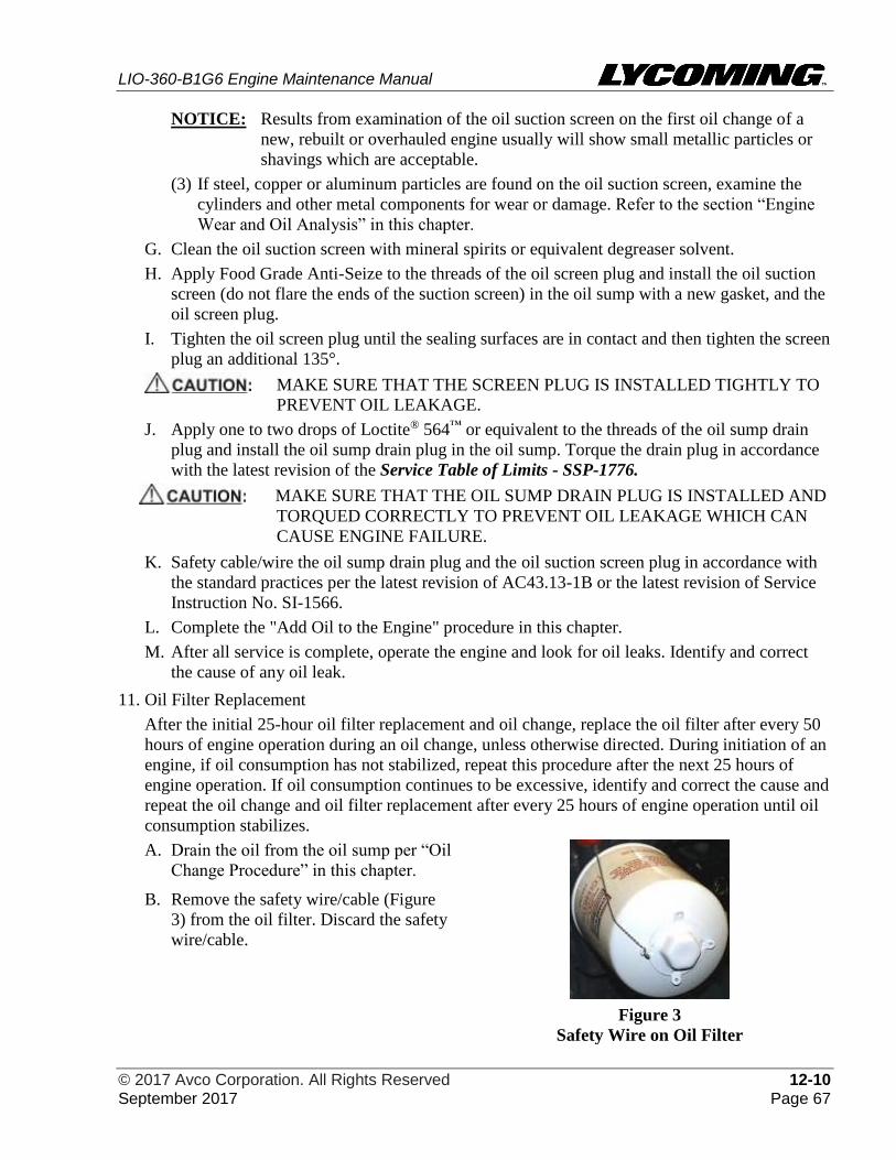
LIO-360-B1G6 Engine Maintenance Manual
© 2017 Avco Corporation. All Rights Reserved 12-10 September 2017 Page 67
NOTICE: Results from examination of the oil suction screen on the first oil change of a
new, rebuilt or overhauled engine usually will show small metallic particles or
shavings which are acceptable.
(3) If steel, copper or aluminum particles are found on the oil suction screen, examine the
cylinders and other metal components for wear or damage. Refer to the section “Engine
Wear and Oil Analysis” in this chapter.
G. Clean the oil suction screen with mineral spirits or equivalent degreaser solvent.
H. Apply Food Grade Anti-Seize to the threads of the oil screen plug and install the oil suction
screen (do not flare the ends of the suction screen) in the oil sump with a new gasket, and the
oil screen plug.
I. Tighten the oil screen plug until the sealing surfaces are in contact and then tighten the screen
plug an additional 135°.
MAKE SURE THAT THE SCREEN PLUG IS INSTALLED TIGHTLY TO
PREVENT OIL LEAKAGE.
J. Apply one to two drops of Loctite® 564™ or equivalent to the threads of the oil sump drain
plug and install the oil sump drain plug in the oil sump. Torque the drain plug in accordance
with the latest revision of the Service Table of Limits - SSP-1776.
MAKE SURE THAT THE OIL SUMP DRAIN PLUG IS INSTALLED AND
TORQUED CORRECTLY TO PREVENT OIL LEAKAGE WHICH CAN
CAUSE ENGINE FAILURE.
K. Safety cable/wire the oil sump drain plug and the oil suction screen plug in accordance with
the standard practices per the latest revision of AC43.13-1B or the latest revision of Service
Instruction No. SI-1566.
L. Complete the "Add Oil to the Engine" procedure in this chapter.
M. After all service is complete, operate the engine and look for oil leaks. Identify and correct
the cause of any oil leak.
11. Oil Filter Replacement
After the initial 25-hour oil filter replacement and oil change, replace the oil filter after every 50
hours of engine operation during an oil change, unless otherwise directed. During initiation of an
engine, if oil consumption has not stabilized, repeat this procedure after the next 25 hours of
engine operation. If oil consumption continues to be excessive, identify and correct the cause and
repeat the oil change and oil filter replacement after every 25 hours of engine operation until oil
consumption stabilizes.
A. Drain the oil from the oil sump per “Oil
Change Procedure” in this chapter.
B. Remove the safety wire/cable (Figure
3) from the oil filter. Discard the safety
wire/cable.
Figure 3
Safety Wire on Oil Filter
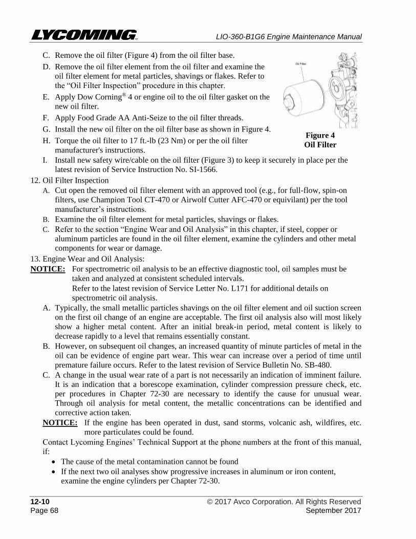
LIO-360-B1G6 Engine Maintenance Manual
12-10 © 2017 Avco Corporation. All Rights Reserved Page 68 September 2017
C. Remove the oil filter (Figure 4) from the oil filter base.
D. Remove the oil filter element from the oil filter and examine the
oil filter element for metal particles, shavings or flakes. Refer to
the “Oil Filter Inspection” procedure in this chapter.
E. Apply Dow Corning® 4 or engine oil to the oil filter gasket on the
new oil filter.
F. Apply Food Grade AA Anti-Seize to the oil filter threads.
G. Install the new oil filter on the oil filter base as shown in Figure 4.
H. Torque the oil filter to 17 ft.-lb (23 Nm) or per the oil filter
manufacturer's instructions.
Figure 4
Oil Filter
I. Install new safety wire/cable on the oil filter (Figure 3) to keep it securely in place per the
latest revision of Service Instruction No. SI-1566.
12. Oil Filter Inspection
A. Cut open the removed oil filter element with an approved tool (e.g., for full-flow, spin-on
filters, use Champion Tool CT-470 or Airwolf Cutter AFC-470 or equivilant) per the tool
manufacturer’s instructions.
B. Examine the oil filter element for metal particles, shavings or flakes.
C. Refer to the section “Engine Wear and Oil Analysis” in this chapter, if steel, copper or
aluminum particles are found in the oil filter element, examine the cylinders and other metal
components for wear or damage.
13. Engine Wear and Oil Analysis:
NOTICE: For spectrometric oil analysis to be an effective diagnostic tool, oil samples must be
taken and analyzed at consistent scheduled intervals.
Refer to the latest revision of Service Letter No. L171 for additional details on
spectrometric oil analysis.
A. Typically, the small metallic particles shavings on the oil filter element and oil suction screen
on the first oil change of an engine are acceptable. The first oil analysis also will most likely
show a higher metal content. After an initial break-in period, metal content is likely to
decrease rapidly to a level that remains essentially constant.
B. However, on subsequent oil changes, an increased quantity of minute particles of metal in the
oil can be evidence of engine part wear. This wear can increase over a period of time until
premature failure occurs. Refer to the latest revision of Service Bulletin No. SB-480.
C. A change in the usual wear rate of a part is not necessarily an indication of imminent failure.
It is an indication that a borescope examination, cylinder compression pressure check, etc.
per procedures in Chapter 72-30 are necessary to identify the cause for unusual wear.
Through oil analysis for metal content, the metallic concentrations can be identified and
corrective action taken.
NOTICE: If the engine has been operated in dust, sand storms, volcanic ash, wildfires, etc.
more particulates could be found.
Contact Lycoming Engines’ Technical Support at the phone numbers at the front of this manual,
if:
• The cause of the metal contamination cannot be found
• If the next two oil analyses show progressive increases in aluminum or iron content,
examine the engine cylinders per Chapter 72-30.
LIO-360-B1G6 Engine Maintenance Manual
© 2017 Avco Corporation. All Rights Reserved 12-30 September 2017 Page 69
12-30 - FAULT ISOLATION
1. Recommended Approach to Fault Isolation
A. Refer to the Fault Isolation Guide in Table 1.
B. Visually examine the engine for indications of obvious problems, such as intake and exhaust
valve leaks, physical damage to ignition wires and ignition harness, blocked breathers, fuel
and oil stains, etc.
C. Review maintenance logs to identify any trends or possible causes.
D. Discuss any operational problems with the pilot to identify background, details or incidents
of unusual operation.
E. Record all findings and corrective action.
2. Fault Isolation Guide
A. The Fault Isolation Guide in Table 1 shows the more common and recurring problems,
causes, and corrective actions. Continue from the simplest to the most complex possible
causes.
B. The "Ref." column in Tables 1 contains references to the following:
(1) A numeric entry such as "72-00" refers to a chapter in this manual.
(2) SI refers to the latest revision of a Lycoming Service Instruction.
(3) IOM refers to the LIO-360-B1G6 Engine Installation and Operation Manual.
(4) AMM refers to the Airframe Manufacturer’s Manual.
(5) POH refer to the Pilot’s Operating Handbook.
Table 1
Fault Isolation Guide
Problem Cause Corrective Action Ref.
Engine will not start
or starts with
difficulty
Discharged battery Replace with a charged battery. AMM
Incorrect starting
procedure
Obey starting procedures or the Pilot’s
Operating Handbook.
IOM
POH
Throttle valve open too
far
Set the throttle control approximately
1/4 (of the length of throttle control
travel) open for about 800 rpm.
AMM
Faulty starter Complete the “Starter Replacement”
procedure. 72-70
No fuel or low fuel level Complete a check of the fuel supply.
Service as required. AMM
LIO-360-B1G6 Engine Maintenance Manual
12-30 © 2017 Avco Corporation. All Rights Reserved Page 70 September 2017
Table 1 (Cont.)
Fault Isolation Guide
Problem Cause Corrective Action Ref.
Engine will not start
or starts with
difficulty (Cont.)
No fuel flow
Blockage in fuel line
1. Disconnect the fuel line.
2. Complete a check of the fuel flow.
3. Examine for evidence of leaks and
correct as required.
4. Clean the filters, strainers, lines, or
fuel valves.
73-10
Fault in the ignition
system
1. Visually examine the harness for
physical damage.
2. Examine ignition leads for continuity
using a high-tension lead tester.
3. Replace worn or damaged
components as necessary.
4. Complete the following procedures:
• Spark Plug Removal
• Ignition Lead Inspection
• Ignition Harness Inspection
• Spark Plug Inspection
74-20
• Spark Plug Cleaning 05-30
• Spark Plug Gap Setting
• Spark Plug Rotation
• Spark Plug Installation
74-20
Damaged or worn
ignition lead
Replace the ignition harness:
Ignition Harness Removal
Ignition Harness Installation
74-20
Magneto incorrectly
timed to engine.
Complete the “Magneto-to-Engine
Timing Check Adjustment Procedure.” 74-30
Magneto internal timing
not adjusted correctly or
"E" gap drifting because
of point or follower wear.
Replace magneto with a serviceable
unit as per the “Magneto Replacement
Procedure.” 74-30
Water in fuel system Drain the fuel lines. AMM
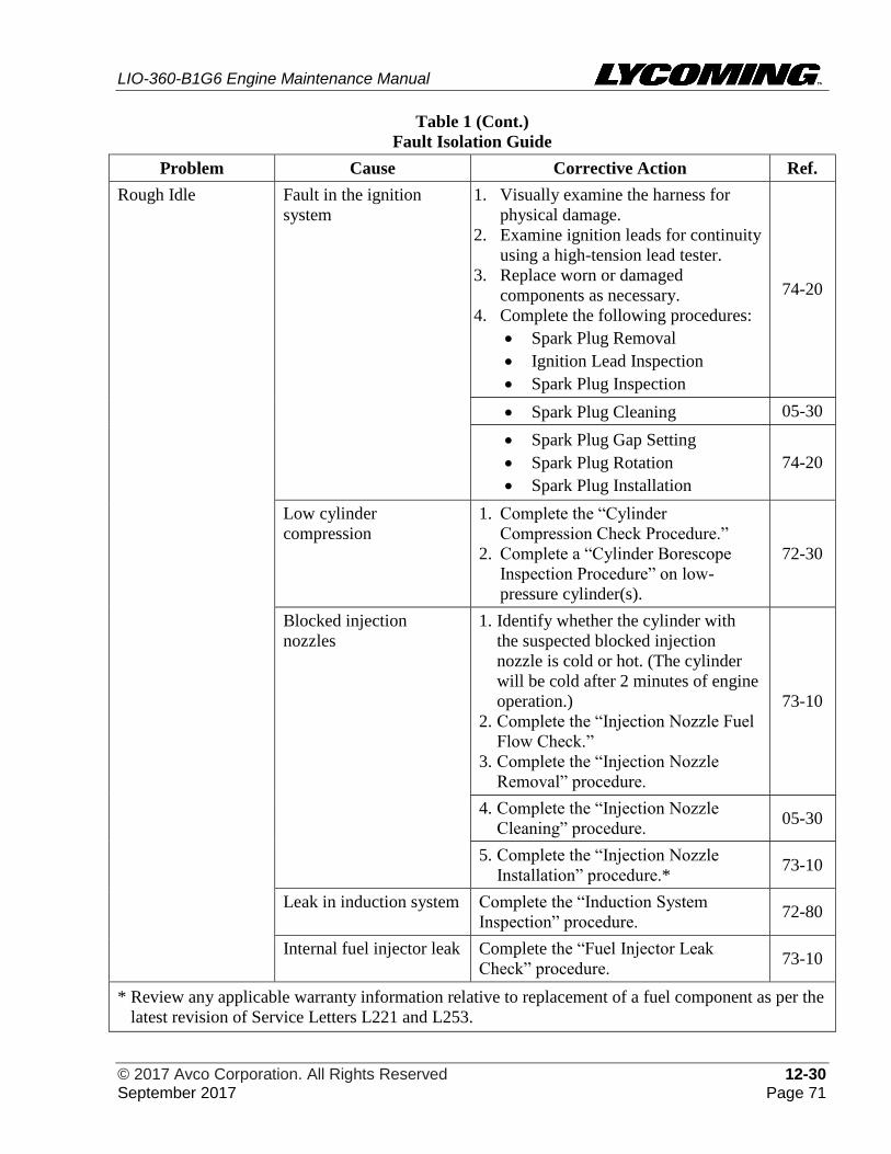
LIO-360-B1G6 Engine Maintenance Manual
© 2017 Avco Corporation. All Rights Reserved 12-30 September 2017 Page 71
Table 1 (Cont.)
Fault Isolation Guide
Problem Cause Corrective Action Ref.
Rough Idle Fault in the ignition
system
1. Visually examine the harness for
physical damage.
2. Examine ignition leads for continuity
using a high-tension lead tester.
3. Replace worn or damaged
components as necessary.
4. Complete the following procedures:
• Spark Plug Removal
• Ignition Lead Inspection
• Spark Plug Inspection
74-20
• Spark Plug Cleaning 05-30
• Spark Plug Gap Setting
• Spark Plug Rotation
• Spark Plug Installation
74-20
Low cylinder
compression
1. Complete the “Cylinder
Compression Check Procedure.”
2. Complete a “Cylinder Borescope
Inspection Procedure” on low-
pressure cylinder(s).
72-30
Blocked injection
nozzles
1. Identify whether the cylinder with
the suspected blocked injection
nozzle is cold or hot. (The cylinder
will be cold after 2 minutes of engine
operation.)
2. Complete the “Injection Nozzle Fuel
Flow Check.”
3. Complete the “Injection Nozzle
Removal” procedure.
73-10
4. Complete the “Injection Nozzle
Cleaning” procedure. 05-30
5. Complete the “Injection Nozzle
Installation” procedure.* 73-10
Leak in induction system Complete the “Induction System
Inspection” procedure. 72-80
Internal fuel injector leak Complete the “Fuel Injector Leak
Check” procedure. 73-10
* Review any applicable warranty information relative to replacement of a fuel component as per the
latest revision of Service Letters L221 and L253.
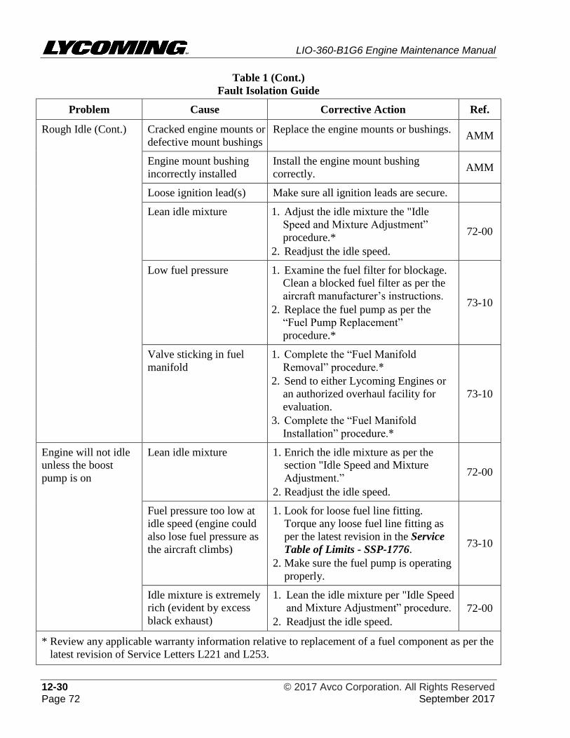
LIO-360-B1G6 Engine Maintenance Manual
12-30 © 2017 Avco Corporation. All Rights Reserved Page 72 September 2017
Table 1 (Cont.)
Fault Isolation Guide
Problem Cause Corrective Action Ref.
Rough Idle (Cont.) Cracked engine mounts or
defective mount bushings
Replace the engine mounts or bushings. AMM
Engine mount bushing
incorrectly installed
Install the engine mount bushing
correctly. AMM
Loose ignition lead(s) Make sure all ignition leads are secure.
Lean idle mixture 1. Adjust the idle mixture the "Idle
Speed and Mixture Adjustment”
procedure.*
2. Readjust the idle speed.
72-00
Low fuel pressure 1. Examine the fuel filter for blockage.
Clean a blocked fuel filter as per the
aircraft manufacturer’s instructions.
2. Replace the fuel pump as per the
“Fuel Pump Replacement”
procedure.*
73-10
Valve sticking in fuel
manifold
1. Complete the “Fuel Manifold
Removal” procedure.*
2. Send to either Lycoming Engines or
an authorized overhaul facility for
evaluation.
3. Complete the “Fuel Manifold
Installation” procedure.*
73-10
Engine will not idle
unless the boost
pump is on
Lean idle mixture 1. Enrich the idle mixture as per the
section "Idle Speed and Mixture
Adjustment.”
2. Readjust the idle speed.
72-00
Fuel pressure too low at
idle speed (engine could
also lose fuel pressure as
the aircraft climbs)
1. Look for loose fuel line fitting.
Torque any loose fuel line fitting as
per the latest revision in the Service
Table of Limits - SSP-1776.
2. Make sure the fuel pump is operating
properly.
73-10
Idle mixture is extremely
rich (evident by excess
black exhaust)
1. Lean the idle mixture per "Idle Speed
and Mixture Adjustment” procedure.
2. Readjust the idle speed.
72-00
* Review any applicable warranty information relative to replacement of a fuel component as per the
latest revision of Service Letters L221 and L253.
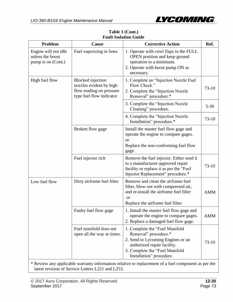
LIO-360-B1G6 Engine Maintenance Manual
© 2017 Avco Corporation. All Rights Reserved 12-30 September 2017 Page 73
Table 1 (Cont.)
Fault Isolation Guide
Problem Cause Corrective Action Ref.
Engine will not idle
unless the boost
pump is on (Cont.)
Fuel vaporizing in lines 1. Operate with cowl flaps in the FULL
OPEN position and keep ground
operation to a minimum.
2. Operate with boost pump ON as
necessary.
High fuel flow Blocked injection
nozzles evident by high
flow reading on pressure
type fuel flow indicator
1. Complete an “Injection Nozzle Fuel
Flow Check.”
2. Complete the “Injection Nozzle
Removal” procedure.*
73-10
3. Complete the “Injection Nozzle
Cleaning” procedure. 5-30
4. Complete the “Injection Nozzle
Installation” procedure.* 73-10
Broken flow gage Install the master fuel flow gage and
operate the engine to compare gages.
or
Replace the non-conforming fuel flow
gage.
Fuel injector rich Remove the fuel injector. Either send it
to a manufacturer-approved repair
facility or replace it as per the “Fuel
Injector Replacement” procedure.*
73-10
Low fuel flow Dirty airframe fuel filter Remove and clean the airframe fuel
filter, blow out with compressed air,
and re-install the airframe fuel filter
or
Replace the airframe fuel filter.
AMM
Faulty fuel flow gage 1. Install the master fuel flow gage and
operate the engine to compare gages.
2. Replace a damaged fuel flow gage.
AMM
Fuel manifold does not
open all the way at times.
1. Complete the “Fuel Manifold
Removal” procedure.*
2. Send to Lycoming Engines or an
authorized repair facility.
3. Complete the “Fuel Manifold
Installation” procedure.
73-10
* Review any applicable warranty information relative to replacement of a fuel component as per the
latest revision of Service Letters L221 and L253.
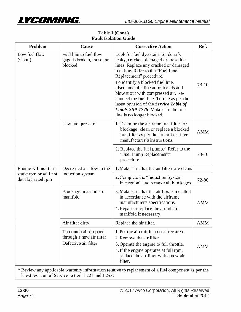
LIO-360-B1G6 Engine Maintenance Manual
12-30 © 2017 Avco Corporation. All Rights Reserved Page 74 September 2017
Table 1 (Cont.)
Fault Isolation Guide
Problem Cause Corrective Action Ref.
Low fuel flow
(Cont.)
Fuel line to fuel flow
gage is broken, loose, or
blocked
Look for fuel dye stains to identify
leaky, cracked, damaged or loose fuel
lines. Replace any cracked or damaged
fuel line. Refer to the “Fuel Line
Replacement” procedure.
To identify a blocked fuel line,
disconnect the line at both ends and
blow it out with compressed air. Re-
connect the fuel line. Torque as per the
latest revision of the Service Table of
Limits SSP-1776. Make sure the fuel
line is no longer blocked.
73-10
Low fuel pressure 1. Examine the airframe fuel filter for
blockage; clean or replace a blocked
fuel filter as per the aircraft or filter
manufacturer’s instructions.
AMM
2. Replace the fuel pump.* Refer to the
“Fuel Pump Replacement”
procedure.
73-10
Engine will not turn
static rpm or will not
develop rated rpm
Decreased air flow in the
induction system
1. Make sure that the air filters are clean.
2. Complete the “Induction System
Inspection” and remove all blockages. 72-80
Blockage in air inlet or
manifold
3. Make sure that the air box is installed
in accordance with the airframe
manufacturer's specifications.
4. Repair or replace the air inlet or
manifold if necessary.
AMM
Air filter dirty Replace the air filter. AMM
Too much air dropped
through a new air filter
Defective air filter
1. Put the aircraft in a dust-free area.
2. Remove the air filter.
3. Operate the engine to full throttle.
4. If the engine operates at full rpm,
replace the air filter with a new air
filter.
AMM
* Review any applicable warranty information relative to replacement of a fuel component as per the
latest revision of Service Letters L221 and L253.
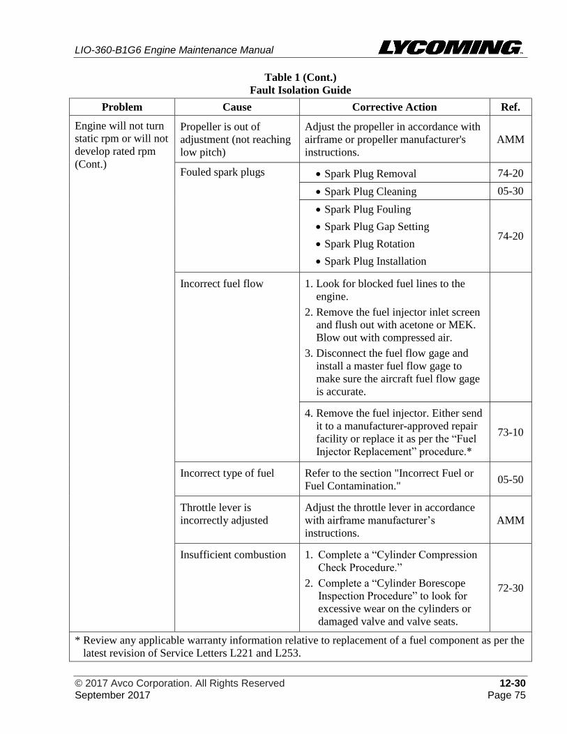
LIO-360-B1G6 Engine Maintenance Manual
© 2017 Avco Corporation. All Rights Reserved 12-30 September 2017 Page 75
Table 1 (Cont.)
Fault Isolation Guide
Problem Cause Corrective Action Ref.
Engine will not turn
static rpm or will not
develop rated rpm
(Cont.)
Propeller is out of
adjustment (not reaching
low pitch)
Adjust the propeller in accordance with
airframe or propeller manufacturer's
instructions.
AMM
Fouled spark plugs • Spark Plug Removal 74-20
• Spark Plug Cleaning 05-30
• Spark Plug Fouling
• Spark Plug Gap Setting
• Spark Plug Rotation
• Spark Plug Installation
74-20
Incorrect fuel flow 1. Look for blocked fuel lines to the
engine.
2. Remove the fuel injector inlet screen
and flush out with acetone or MEK.
Blow out with compressed air.
3. Disconnect the fuel flow gage and
install a master fuel flow gage to
make sure the aircraft fuel flow gage
is accurate.
4. Remove the fuel injector. Either send
it to a manufacturer-approved repair
facility or replace it as per the “Fuel
Injector Replacement” procedure.*
73-10
Incorrect type of fuel Refer to the section "Incorrect Fuel or
Fuel Contamination." 05-50
Throttle lever is
incorrectly adjusted
Adjust the throttle lever in accordance
with airframe manufacturer’s
instructions.
AMM
Insufficient combustion 1. Complete a “Cylinder Compression
Check Procedure.”
2. Complete a “Cylinder Borescope
Inspection Procedure” to look for
excessive wear on the cylinders or
damaged valve and valve seats.
72-30
* Review any applicable warranty information relative to replacement of a fuel component as per the
latest revision of Service Letters L221 and L253.
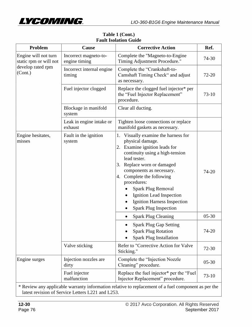
LIO-360-B1G6 Engine Maintenance Manual
12-30 © 2017 Avco Corporation. All Rights Reserved Page 76 September 2017
Table 1 (Cont.)
Fault Isolation Guide
Problem Cause Corrective Action Ref.
Engine will not turn
static rpm or will not
develop rated rpm
(Cont.)
Incorrect magneto-to-
engine timing
Complete the "Magneto-to-Engine
Timing Adjustment Procedure." 74-30
Incorrect internal engine
timing
Complete the “Crankshaft-to-
Camshaft Timing Check“ and adjust
as necessary.
72-20
Fuel injector clogged Replace the clogged fuel injector* per
the “Fuel Injector Replacement”
procedure.
73-10
Blockage in manifold
system
Clear all ducting.
Leak in engine intake or
exhaust
Tighten loose connections or replace
manifold gaskets as necessary.
Engine hesitates,
misses
Fault in the ignition
system
1. Visually examine the harness for
physical damage.
2. Examine ignition leads for
continuity using a high-tension
lead tester.
3. Replace worn or damaged
components as necessary.
4. Complete the following
procedures:
• Spark Plug Removal
• Ignition Lead Inspection
• Ignition Harness Inspection
• Spark Plug Inspection
74-20
• Spark Plug Cleaning 05-30
• Spark Plug Gap Setting
• Spark Plug Rotation
• Spark Plug Installation
74-20
Valve sticking Refer to "Corrective Action for Valve
Sticking." 72-30
Engine surges Injection nozzles are
dirty
Complete the “Injection Nozzle
Cleaning” procedure. 05-30
Fuel injector
malfunction
Replace the fuel injector* per the “Fuel
Injector Replacement” procedure. 73-10
* Review any applicable warranty information relative to replacement of a fuel component as per the
latest revision of Service Letters L221 and L253.
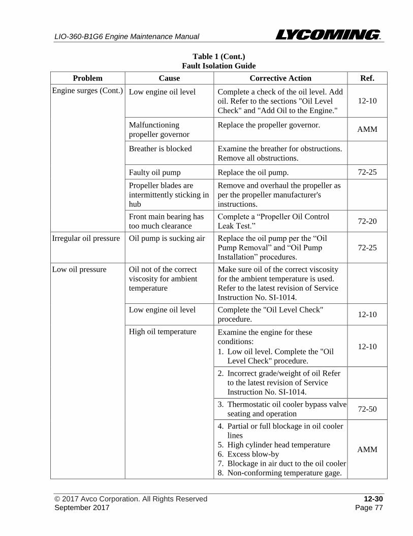
LIO-360-B1G6 Engine Maintenance Manual
© 2017 Avco Corporation. All Rights Reserved 12-30 September 2017 Page 77
Table 1 (Cont.)
Fault Isolation Guide
Problem Cause Corrective Action Ref.
Engine surges (Cont.) Low engine oil level Complete a check of the oil level. Add
oil. Refer to the sections "Oil Level
Check" and "Add Oil to the Engine."
12-10
Malfunctioning
propeller governor
Replace the propeller governor. AMM
Breather is blocked Examine the breather for obstructions.
Remove all obstructions.
Faulty oil pump Replace the oil pump. 72-25
Propeller blades are
intermittently sticking in
hub
Remove and overhaul the propeller as
per the propeller manufacturer's
instructions.
Front main bearing has
too much clearance
Complete a “Propeller Oil Control
Leak Test.” 72-20
Irregular oil pressure Oil pump is sucking air Replace the oil pump per the “Oil
Pump Removal” and “Oil Pump
Installation” procedures.
72-25
Low oil pressure Oil not of the correct
viscosity for ambient
temperature
Make sure oil of the correct viscosity
for the ambient temperature is used.
Refer to the latest revision of Service
Instruction No. SI-1014.
Low engine oil level Complete the "Oil Level Check"
procedure. 12-10
High oil temperature Examine the engine for these
conditions:
1. Low oil level. Complete the "Oil
Level Check" procedure.
12-10
2. Incorrect grade/weight of oil Refer
to the latest revision of Service
Instruction No. SI-1014.
3. Thermostatic oil cooler bypass valve
seating and operation 72-50
4. Partial or full blockage in oil cooler
lines
5. High cylinder head temperature
6. Excess blow-by
7. Blockage in air duct to the oil cooler
8. Non-conforming temperature gage.
AMM
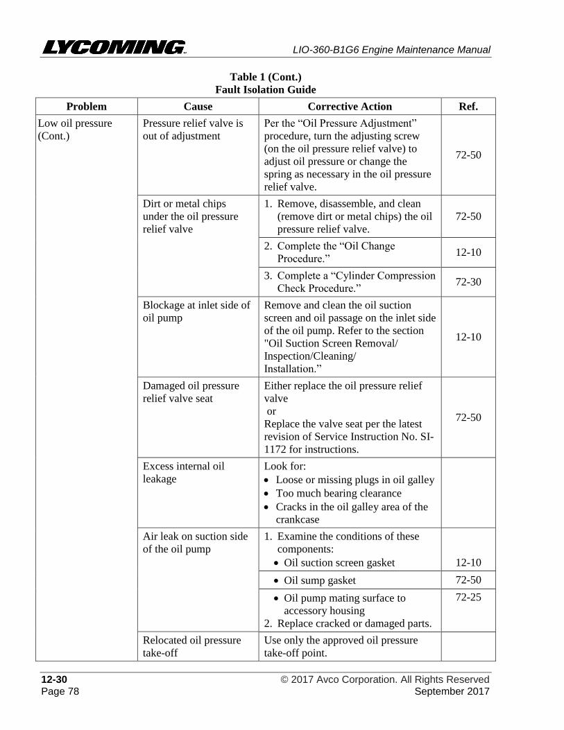
LIO-360-B1G6 Engine Maintenance Manual
12-30 © 2017 Avco Corporation. All Rights Reserved Page 78 September 2017
Table 1 (Cont.)
Fault Isolation Guide
Problem Cause Corrective Action Ref.
Low oil pressure
(Cont.)
Pressure relief valve is
out of adjustment
Per the “Oil Pressure Adjustment”
procedure, turn the adjusting screw
(on the oil pressure relief valve) to
adjust oil pressure or change the
spring as necessary in the oil pressure
relief valve.
72-50
Dirt or metal chips
under the oil pressure
relief valve
1. Remove, disassemble, and clean
(remove dirt or metal chips) the oil
pressure relief valve.
72-50
2. Complete the “Oil Change
Procedure.” 12-10
3. Complete a “Cylinder Compression
Check Procedure.” 72-30
Blockage at inlet side of
oil pump
Remove and clean the oil suction
screen and oil passage on the inlet side
of the oil pump. Refer to the section
"Oil Suction Screen Removal/
Inspection/Cleaning/
Installation.”
12-10
Damaged oil pressure
relief valve seat
Either replace the oil pressure relief
valve
or
Replace the valve seat per the latest
revision of Service Instruction No. SI-
1172 for instructions.
72-50
Excess internal oil
leakage
Look for:
• Loose or missing plugs in oil galley
• Too much bearing clearance
• Cracks in the oil galley area of the
crankcase
Air leak on suction side
of the oil pump
1. Examine the conditions of these
components:
• Oil suction screen gasket 12-10
• Oil sump gasket 72-50
• Oil pump mating surface to
accessory housing
2. Replace cracked or damaged parts.
72-25
Relocated oil pressure
take-off
Use only the approved oil pressure
take-off point.
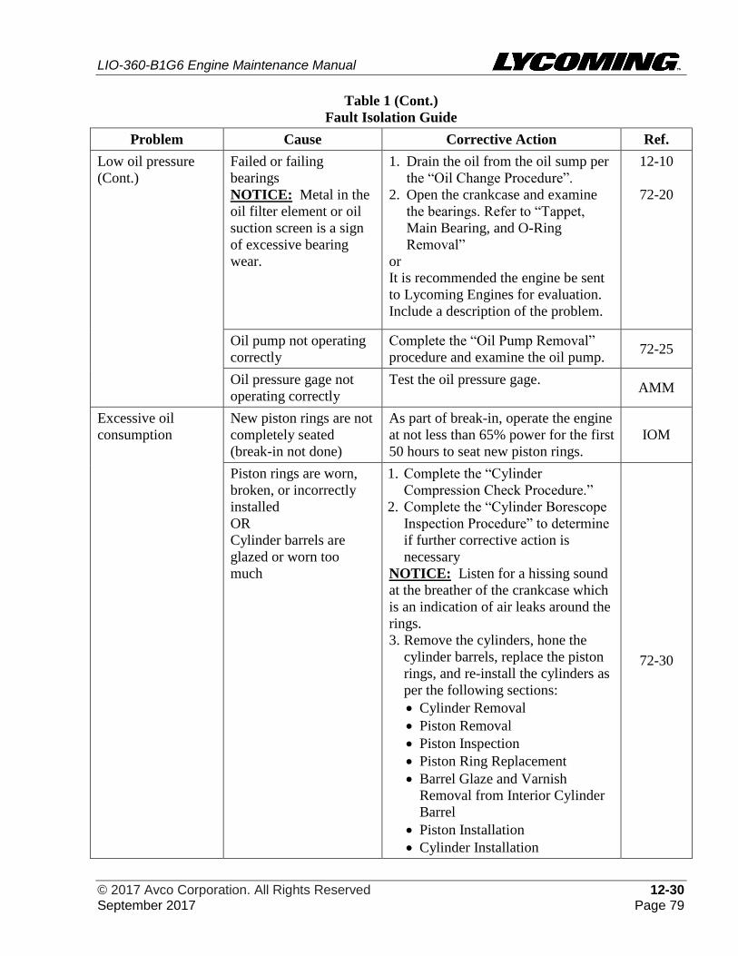
LIO-360-B1G6 Engine Maintenance Manual
© 2017 Avco Corporation. All Rights Reserved 12-30 September 2017 Page 79
Table 1 (Cont.)
Fault Isolation Guide
Problem Cause Corrective Action Ref.
Low oil pressure
(Cont.)
Failed or failing
bearings
NOTICE: Metal in the
oil filter element or oil
suction screen is a sign
of excessive bearing
wear.
1. Drain the oil from the oil sump per
the “Oil Change Procedure”.
2. Open the crankcase and examine
the bearings. Refer to “Tappet,
Main Bearing, and O-Ring
Removal”
or
It is recommended the engine be sent
to Lycoming Engines for evaluation.
Include a description of the problem.
12-10
72-20
Oil pump not operating
correctly
Complete the “Oil Pump Removal”
procedure and examine the oil pump. 72-25
Oil pressure gage not
operating correctly
Test the oil pressure gage. AMM
Excessive oil
consumption
New piston rings are not
completely seated
(break-in not done)
As part of break-in, operate the engine
at not less than 65% power for the first
50 hours to seat new piston rings.
IOM
Piston rings are worn,
broken, or incorrectly
installed
OR
Cylinder barrels are
glazed or worn too
much
1. Complete the “Cylinder
Compression Check Procedure.”
2. Complete the “Cylinder Borescope
Inspection Procedure” to determine
if further corrective action is
necessary
NOTICE: Listen for a hissing sound
at the breather of the crankcase which
is an indication of air leaks around the
rings.
3. Remove the cylinders, hone the
cylinder barrels, replace the piston
rings, and re-install the cylinders as
per the following sections:
• Cylinder Removal
• Piston Removal
• Piston Inspection
• Piston Ring Replacement
• Barrel Glaze and Varnish
Removal from Interior Cylinder
Barrel
• Piston Installation
• Cylinder Installation
72-30
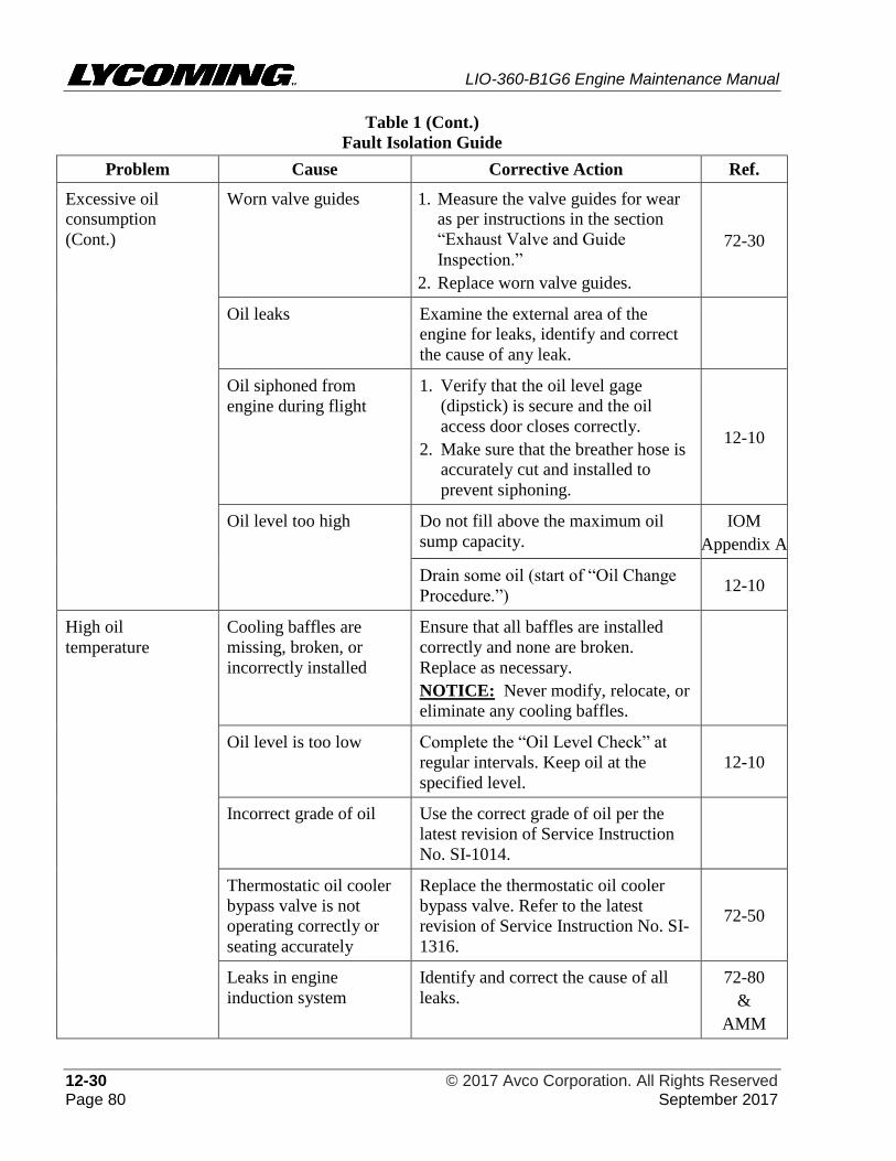
LIO-360-B1G6 Engine Maintenance Manual
12-30 © 2017 Avco Corporation. All Rights Reserved Page 80 September 2017
Table 1 (Cont.)
Fault Isolation Guide
Problem Cause Corrective Action Ref.
Excessive oil
consumption
(Cont.)
Worn valve guides 1. Measure the valve guides for wear
as per instructions in the section
“Exhaust Valve and Guide
Inspection.”
2. Replace worn valve guides.
72-30
Oil leaks Examine the external area of the
engine for leaks, identify and correct
the cause of any leak.
Oil siphoned from
engine during flight
1. Verify that the oil level gage
(dipstick) is secure and the oil
access door closes correctly.
2. Make sure that the breather hose is
accurately cut and installed to
prevent siphoning.
12-10
Oil level too high Do not fill above the maximum oil
sump capacity.
IOM
Appendix A
Drain some oil (start of “Oil Change
Procedure.”) 12-10
High oil
temperature
Cooling baffles are
missing, broken, or
incorrectly installed
Ensure that all baffles are installed
correctly and none are broken.
Replace as necessary.
NOTICE: Never modify, relocate, or
eliminate any cooling baffles.
Oil level is too low Complete the “Oil Level Check” at
regular intervals. Keep oil at the
specified level.
12-10
Incorrect grade of oil Use the correct grade of oil per the
latest revision of Service Instruction
No. SI-1014.
Thermostatic oil cooler
bypass valve is not
operating correctly or
seating accurately
Replace the thermostatic oil cooler
bypass valve. Refer to the latest
revision of Service Instruction No. SI-
1316.
72-50
Leaks in engine
induction system
Identify and correct the cause of all
leaks.
72-80
&
AMM
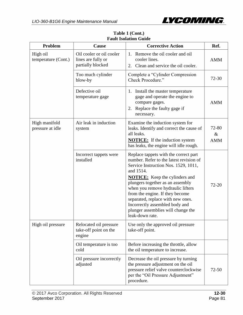
LIO-360-B1G6 Engine Maintenance Manual
© 2017 Avco Corporation. All Rights Reserved 12-30 September 2017 Page 81
Table 1 (Cont.)
Fault Isolation Guide
Problem Cause Corrective Action Ref.
High oil
temperature (Cont.)
Oil cooler or oil cooler
lines are fully or
partially blocked
1. Remove the oil cooler and oil
cooler lines.
2. Clean and service the oil cooler.
AMM
Too much cylinder
blow-by
Complete a “Cylinder Compression
Check Procedure.” 72-30
Defective oil
temperature gage
1. Install the master temperature
gage and operate the engine to
compare gages.
2. Replace the faulty gage if
necessary.
AMM
High manifold
pressure at idle
Air leak in induction
system
Examine the induction system for
leaks. Identify and correct the cause of
all leaks.
NOTICE: If the induction system
has leaks, the engine will idle rough.
72-80
&
AMM
Incorrect tappets were
installed
Replace tappets with the correct part
number. Refer to the latest revision of
Service Instruction Nos. 1529, 1011,
and 1514.
NOTICE: Keep the cylinders and
plungers together as an assembly
when you remove hydraulic lifters
from the engine. If they become
separated, replace with new ones.
Incorrectly assembled body and
plunger assemblies will change the
leak-down rate.
72-20
High oil pressure Relocated oil pressure
take-off point on the
engine
Use only the approved oil pressure
take-off point.
Oil temperature is too
cold
Before increasing the throttle, allow
the oil temperature to increase.
Oil pressure incorrectly
adjusted
Decrease the oil pressure by turning
the pressure adjustment on the oil
pressure relief valve counterclockwise
per the “Oil Pressure Adjustment”
procedure.
72-50
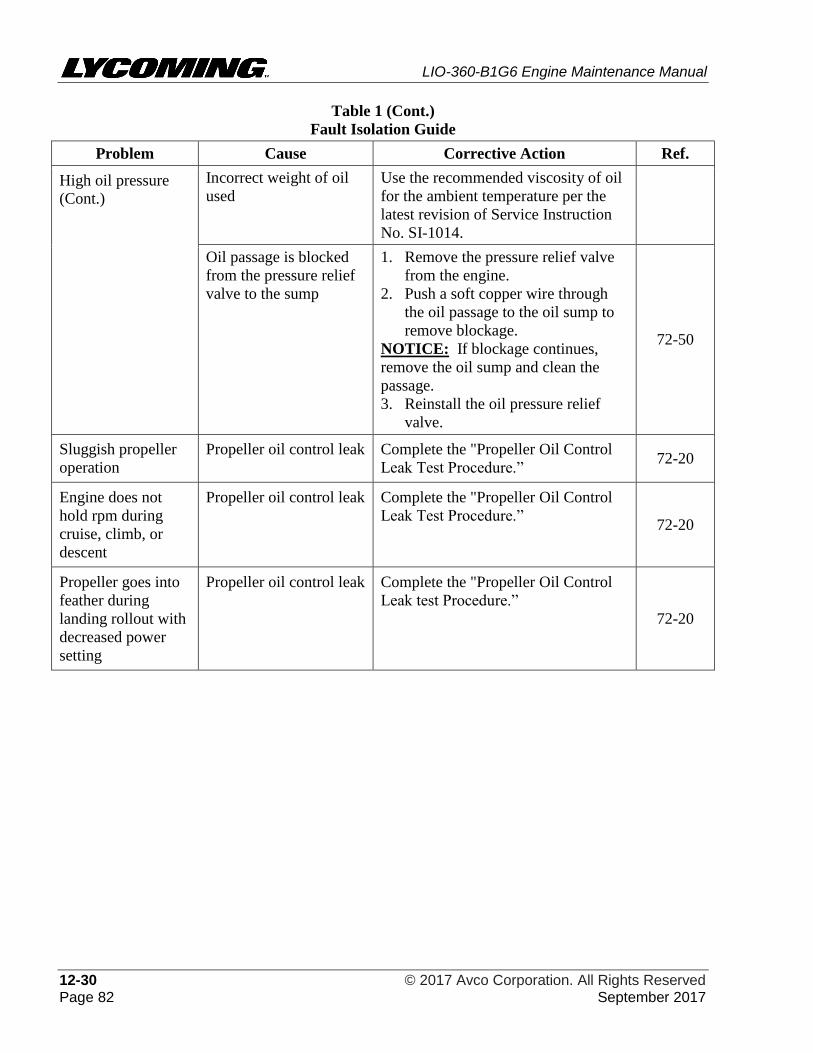
LIO-360-B1G6 Engine Maintenance Manual
12-30 © 2017 Avco Corporation. All Rights Reserved Page 82 September 2017
Table 1 (Cont.)
Fault Isolation Guide
Problem Cause Corrective Action Ref.
High oil pressure
(Cont.)
Incorrect weight of oil
used
Use the recommended viscosity of oil
for the ambient temperature per the
latest revision of Service Instruction
No. SI-1014.
Oil passage is blocked
from the pressure relief
valve to the sump
1. Remove the pressure relief valve
from the engine.
2. Push a soft copper wire through
the oil passage to the oil sump to
remove blockage.
NOTICE: If blockage continues,
remove the oil sump and clean the
passage.
3. Reinstall the oil pressure relief
valve.
72-50
Sluggish propeller
operation
Propeller oil control leak Complete the "Propeller Oil Control
Leak Test Procedure.” 72-20
Engine does not
hold rpm during
cruise, climb, or
descent
Propeller oil control leak Complete the "Propeller Oil Control
Leak Test Procedure.” 72-20
Propeller goes into
feather during
landing rollout with
decreased power
setting
Propeller oil control leak Complete the "Propeller Oil Control
Leak test Procedure.”
72-20
LIO-360-B1G6 Engine Maintenance Manual
© 2017 Avco Corporation. All Rights Reserved 72-00 September 2017 Page 83
72-00 - ENGINE REMOVAL AND RETURN TO SERVICE,
1. Engine Removal Prerequisites
DURING ALL MAINTENANCE PROCEDURES AND INSPECTIONS,
ENSURE THAT THE ENGINE IGNITION SWITCH IS IN THE OFF
POSITION, ALL POWER TO THE AIRCRAFT IS DISCONNECTED, AND
ALL PERSONNEL ARE CLEAR OF THE PROPELLER’S ROTATIONAL
ARC.
A. Before engine removal from the aircraft:
(1) Make sure that all electrical switches, circuit breakers, Ignition Switch, and the Fuel
Selector Valve are in the OFF position.
(2) In accordance with the aircraft manufacturer’s instructions, remove all cowling, baffling
and nacelle access panels to enable engine removal.
(3) Disconnect the ground terminal of the battery.
(4) Disconnect the positive terminal of the battery.
(5) Disconnect and examine the leads and wiring for damage or frayed wiring.
(6) Remove the propeller in accordance with the aircraft manufacturer’s instructions and/or
propeller manufacturer’s instructions.
(7) Drain oil from the engine. Refer to the “Oil Change Procedure” in Chapter 12-10.
(8) Remove accessories.
(9) If the engine is to be stored, complete the engine preservation procedure before engine
removal. Refer to instructions in the LIO-360-B1G6 Engine Installation and Operation
Manual.
2. Engine Removal Procedure
A. Remove the engine as follows:
(1) Complete the prerequisites in the section “Engine Removal Prerequisites” in this chapter.
(2) During removal of tubes or engine parts, look for indications of scoring, burning or other
unacceptable conditions.
(3) Disconnect all connecting control cables.
(4) Disconnect any relays, gages, or other indicating devices as per the aircraft
manufacturer's procedure.
USE CARE TO PREVENT DUST, DIRT, SAFETY WIRE, NUTS, SAFETY
CABLE, WASHERS OR OTHER FOREIGN MATTER FROM ENTERING
THE ENGINE. DURING ENGINE REMOVAL, IF ITEMS
ACCIDENTALLY FALL INTO THE ENGINE, STOP WORK, FIND AND
REMOVE ALL OF THE DROPPED ARTICLES. USE CORRECT PLUGS,
CAPS, AND OTHER COVERINGS TO COVER EXPOSED OPENINGS.
INSTALL DUST CAPS OVER, NOT IN, TUBE ENDS.
DO NOT PUT TAPE OR PLUGS INSIDE OPEN LINES OR FITTINGS.
(5) Apply a cap over oil and fuel lines and connections to prevent spillage and debris from
entering the engine.
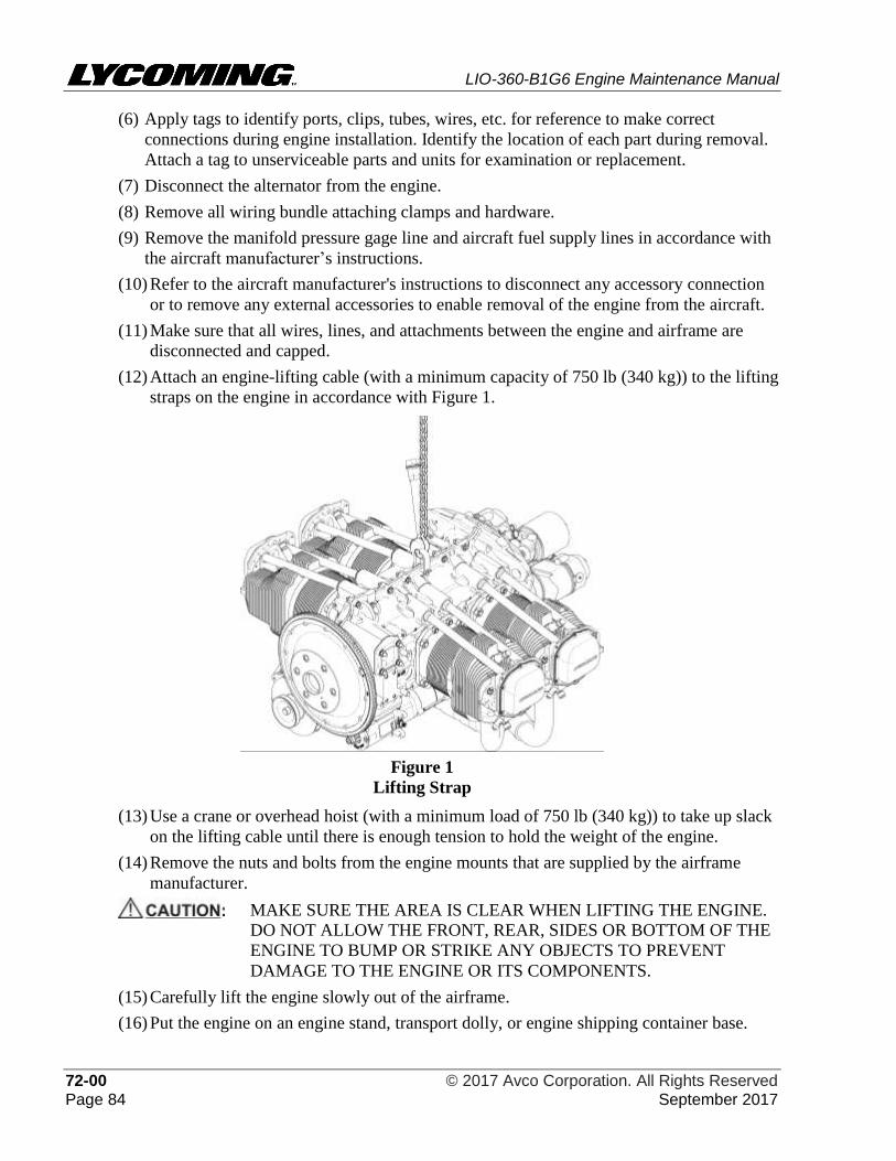
LIO-360-B1G6 Engine Maintenance Manual
72-00 © 2017 Avco Corporation. All Rights Reserved Page 84 September 2017
(6) Apply tags to identify ports, clips, tubes, wires, etc. for reference to make correct
connections during engine installation. Identify the location of each part during removal.
Attach a tag to unserviceable parts and units for examination or replacement.
(7) Disconnect the alternator from the engine.
(8) Remove all wiring bundle attaching clamps and hardware.
(9) Remove the manifold pressure gage line and aircraft fuel supply lines in accordance with
the aircraft manufacturer’s instructions.
(10) Refer to the aircraft manufacturer's instructions to disconnect any accessory connection
or to remove any external accessories to enable removal of the engine from the aircraft.
(11) Make sure that all wires, lines, and attachments between the engine and airframe are
disconnected and capped.
(12) Attach an engine-lifting cable (with a minimum capacity of 750 lb (340 kg)) to the lifting
straps on the engine in accordance with Figure 1.
Figure 1
Lifting Strap
(13) Use a crane or overhead hoist (with a minimum load of 750 lb (340 kg)) to take up slack
on the lifting cable until there is enough tension to hold the weight of the engine.
(14) Remove the nuts and bolts from the engine mounts that are supplied by the airframe
manufacturer.
MAKE SURE THE AREA IS CLEAR WHEN LIFTING THE ENGINE.
DO NOT ALLOW THE FRONT, REAR, SIDES OR BOTTOM OF THE
ENGINE TO BUMP OR STRIKE ANY OBJECTS TO PREVENT
DAMAGE TO THE ENGINE OR ITS COMPONENTS.
(15) Carefully lift the engine slowly out of the airframe.
(16) Put the engine on an engine stand, transport dolly, or engine shipping container base.
LIO-360-B1G6 Engine Maintenance Manual
© 2017 Avco Corporation. All Rights Reserved 72-00 September 2017 Page 85
3. Engine Installation Preparation Requirements
To prevent delays on engine re-installation, have the following materials and new spare parts
identified in Table 1 available (Refer to the LIO-360-B1G6 Illustrated Parts Catalog). Follow
the procedures in Table 1 to prepare the engine for installation (if the engine was not in storage).
If the engine was in storage, refer to the LIO-360-B1G6 Engine Installation and Operation
Manual for instructions to prepare an engine that has been in storage.
Table 1
Materials and Procedures to Prepare a Serviced Engine for Installation
New gaskets, seals, O-rings, and packing (Make
sure the new parts are not brittle, torn, cut, or
cracked and do not have flashings,
deterioration/wear or deformities.)*
Always install new gaskets, seals, O-rings, or
packing.
New safety wire/cable, lock nuts, lock washers,
tab washers, and cotter pins
New replacement part for any part that had to be
discarded*
Oil per specifications in Appendix A of the LIO-
360-B1G6 Engine Installation and Operation
Manual
“Add Oil to the Engine” in Chapter 12-10.
Cleaning solvents and lint-free wipes (identified
in Chapter 05-30)
Cleaning procedures in Chapter 05-30
*Refer to the latest revision of Service Bulletin No. SB-240 to identify parts that had been
removed and must be replaced. Before installing a component, complete a check of the shelf-life
of the part as per the latest revision of Service Letter No. L247
After all inspections and maintenance tasks are complete, prepare, and install the engine per the
LIO-360-B1G6 Engine Installation and Operation Manual.
During engine re-installation:
A. Refer to and follow the "Maintenance Practices" in Chapter 05-00.
B. Replace any gaskets, seals or packing that were removed with new parts.
C. Replace any part that was damaged or that could not be repaired with a new part.
D. Install external accessories as per the aircraft manufacturer's instructions.
E. Examine the engine mounts to make sure they are not damaged or bent.
4. Operational Ground Check
NOTICE: The purpose of this check is to make sure the installed engine operates in the aircraft
according to specifications in Appendix A of the LIO-360-B1G6 Engine
Installation and Operation Manual.
A. Per the component manufacturer's instructions, calibrate the cylinder head temperature gage,
oil temperature gage, oil pressure gage, manifold pressure gage, and tachometer prior to
testing.
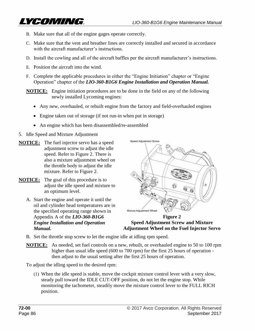
LIO-360-B1G6 Engine Maintenance Manual
72-00 © 2017 Avco Corporation. All Rights Reserved Page 86 September 2017
B. Make sure that all of the engine gages operate correctly.
C. Make sure that the vent and breather lines are correctly installed and secured in accordance
with the aircraft manufacturer’s instructions.
D. Install the cowling and all of the aircraft baffles per the aircraft manufacturer’s instructions.
E. Position the aircraft into the wind.
F. Complete the applicable procedures in either the “Engine Initiation” chapter or “Engine
Operation” chapter of the LIO-360-B1G6 Engine Installation and Operation Manual.
NOTICE: Engine initiation procedures are to be done in the field on any of the following
newly installed Lycoming engines:
• Any new, overhauled, or rebuilt engine from the factory and field-overhauled engines
• Engine taken out of storage (if not run-in when put in storage)
• An engine which has been disassembled/re-assembled
5. Idle Speed and Mixture Adjustment
NOTICE: The fuel injector servo has a speed
adjustment screw to adjust the idle
speed. Refer to Figure 2. There is
also a mixture adjustment wheel on
the throttle body to adjust the idle
mixture. Refer to Figure 2.
NOTICE: The goal of this procedure is to
adjust the idle speed and mixture to
an optimum level.
A. Start the engine and operate it until the
oil and cylinder head temperatures are in
the specified operating range shown in
Appendix A of the LIO-360-B1G6
Engine Installation and Operation
Manual.
Figure 2
Speed Adjustment Screw and Mixture
Adjustment Wheel on the Fuel Injector Servo
B. Set the throttle stop screw to let the engine idle at idling rpm speed.
NOTICE: As needed, set fuel controls on a new, rebuilt, or overhauled engine to 50 to 100 rpm
higher than usual idle speed (600 to 700 rpm) for the first 25 hours of operation -
then adjust to the usual setting after the first 25 hours of operation.
To adjust the idling speed to the desired rpm:
(1) When the idle speed is stable, move the cockpit mixture control lever with a very slow,
steady pull toward the IDLE CUT-OFF position, do not let the engine stop. While
monitoring the tachometer, steadily move the mixture control lever to the FULL RICH
position.
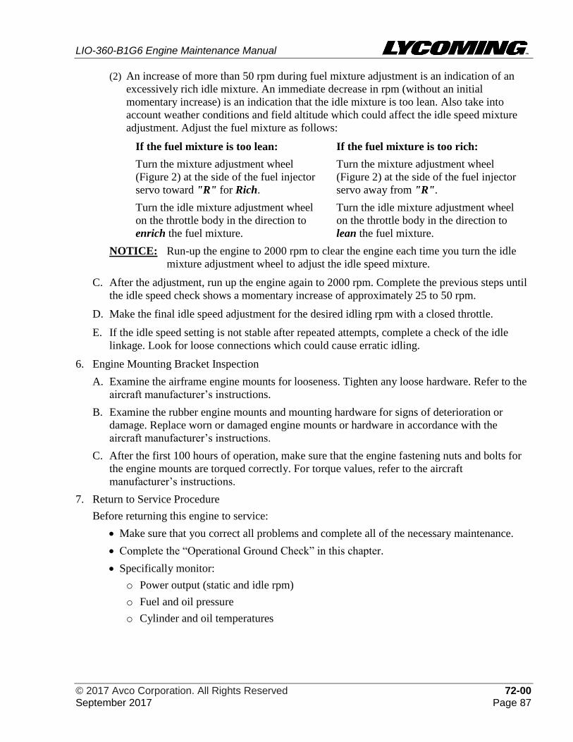
LIO-360-B1G6 Engine Maintenance Manual
© 2017 Avco Corporation. All Rights Reserved 72-00 September 2017 Page 87
(2) An increase of more than 50 rpm during fuel mixture adjustment is an indication of an
excessively rich idle mixture. An immediate decrease in rpm (without an initial
momentary increase) is an indication that the idle mixture is too lean. Also take into
account weather conditions and field altitude which could affect the idle speed mixture
adjustment. Adjust the fuel mixture as follows:
If the fuel mixture is too lean: If the fuel mixture is too rich:
Turn the mixture adjustment wheel
(Figure 2) at the side of the fuel injector
servo toward "R" for Rich.
Turn the mixture adjustment wheel
(Figure 2) at the side of the fuel injector
servo away from "R".
Turn the idle mixture adjustment wheel
on the throttle body in the direction to
enrich the fuel mixture.
Turn the idle mixture adjustment wheel
on the throttle body in the direction to
lean the fuel mixture.
NOTICE: Run-up the engine to 2000 rpm to clear the engine each time you turn the idle
mixture adjustment wheel to adjust the idle speed mixture.
C. After the adjustment, run up the engine again to 2000 rpm. Complete the previous steps until
the idle speed check shows a momentary increase of approximately 25 to 50 rpm.
D. Make the final idle speed adjustment for the desired idling rpm with a closed throttle.
E. If the idle speed setting is not stable after repeated attempts, complete a check of the idle
linkage. Look for loose connections which could cause erratic idling.
6. Engine Mounting Bracket Inspection
A. Examine the airframe engine mounts for looseness. Tighten any loose hardware. Refer to the
aircraft manufacturer’s instructions.
B. Examine the rubber engine mounts and mounting hardware for signs of deterioration or
damage. Replace worn or damaged engine mounts or hardware in accordance with the
aircraft manufacturer’s instructions.
C. After the first 100 hours of operation, make sure that the engine fastening nuts and bolts for
the engine mounts are torqued correctly. For torque values, refer to the aircraft
manufacturer’s instructions.
7. Return to Service Procedure
Before returning this engine to service:
• Make sure that you correct all problems and complete all of the necessary maintenance.
• Complete the “Operational Ground Check” in this chapter.
• Specifically monitor:
o Power output (static and idle rpm)
o Fuel and oil pressure
o Cylinder and oil temperatures

LIO-360-B1G6 Engine Maintenance Manual
72-00 © 2017 Avco Corporation. All Rights Reserved Page 88 September 2017
This page intentionally left blank.
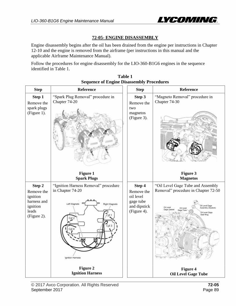
LIO-360-B1G6 Engine Maintenance Manual
© 2017 Avco Corporation. All Rights Reserved 72-05 September 2017 Page 89
72-05- ENGINE DISASSEMBLY
Engine disassembly begins after the oil has been drained from the engine per instructions in Chapter
12-10 and the engine is removed from the airframe (per instructions in this manual and the
applicable Airframe Maintenance Manual).
Follow the procedures for engine disassembly for the LIO-360-B1G6 engines in the sequence
identified in Table 1.
Table 1
Sequence of Engine Disassembly Procedures
Step Reference Step Reference
Step 1 “Spark Plug Removal” procedure in
Chapter 74-20
Step 3 “Magneto Removal” procedure in
Chapter 74-30
Figure 3
Magnetos
Remove the
spark plugs
(Figure 1).
Remove the
two
magnetos
(Figure 3).
Figure 1
Spark Plugs
Step 2
Remove the
ignition
harness and
ignition
leads
(Figure 2).
“Ignition Harness Removal” procedure
in Chapter 74-20
Step 4
Remove the
oil level
gage tube
and dipstick
(Figure 4).
“Oil Level Gage Tube and Assembly
Removal” procedure in Chapter 72-50
Figure 4
Oil Level Gage Tube
Figure 2
Ignition Harness
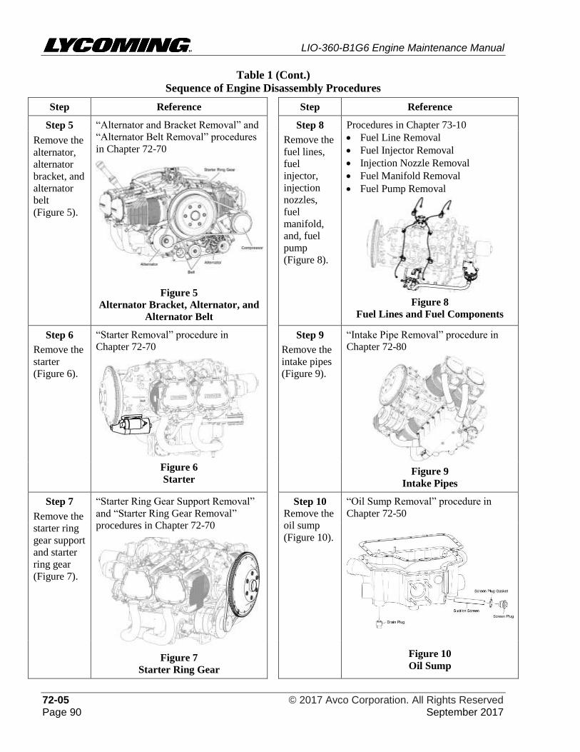
LIO-360-B1G6 Engine Maintenance Manual
72-05 © 2017 Avco Corporation. All Rights Reserved Page 90 September 2017
Table 1 (Cont.)
Sequence of Engine Disassembly Procedures
Step Reference Step Reference
Step 5 “Alternator and Bracket Removal” and
“Alternator Belt Removal” procedures
in Chapter 72-70
Figure 5
Alternator Bracket, Alternator, and
Alternator Belt
Step 8
Remove the
fuel lines,
fuel
injector,
injection
nozzles,
fuel
manifold,
and, fuel
pump
(Figure 8).
Procedures in Chapter 73-10
• Fuel Line Removal
• Fuel Injector Removal
• Injection Nozzle Removal
• Fuel Manifold Removal
• Fuel Pump Removal
Figure 8
Fuel Lines and Fuel Components
Remove the
alternator,
alternator
bracket, and
alternator
belt
(Figure 5).
Step 6
Remove the
starter
(Figure 6).
“Starter Removal” procedure in
Chapter 72-70
Figure 6
Starter
Step 9
Remove the
intake pipes
(Figure 9).
“Intake Pipe Removal” procedure in
Chapter 72-80
Figure 9
Intake Pipes
Step 7
Remove the
starter ring
gear support
and starter
ring gear
(Figure 7).
“Starter Ring Gear Support Removal”
and “Starter Ring Gear Removal”
procedures in Chapter 72-70
Figure 7
Starter Ring Gear
Step 10
Remove the
oil sump
(Figure 10).
“Oil Sump Removal” procedure in
Chapter 72-50
Figure 10
Oil Sump
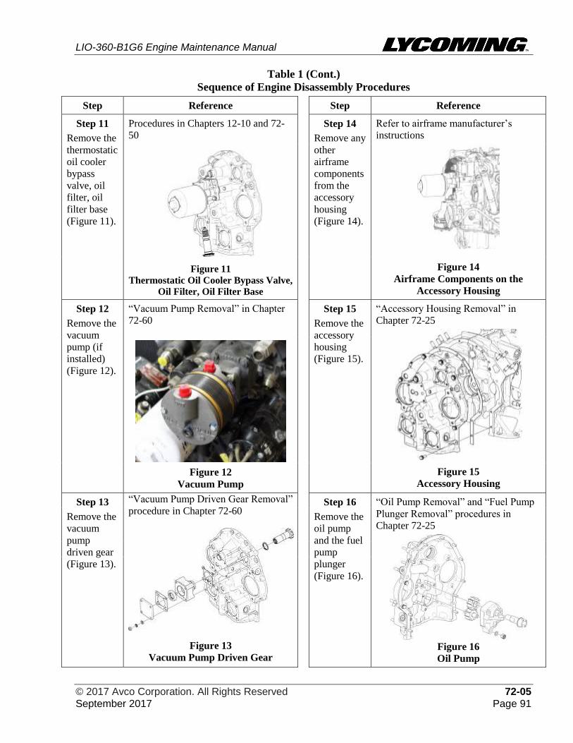
LIO-360-B1G6 Engine Maintenance Manual
© 2017 Avco Corporation. All Rights Reserved 72-05 September 2017 Page 91
Table 1 (Cont.)
Sequence of Engine Disassembly Procedures
Step Reference Step Reference
Step 11
Remove the
thermostatic
oil cooler
bypass
valve, oil
filter, oil
filter base
(Figure 11).
Procedures in Chapters 12-10 and 72-
50
Step 14
Remove any
other
airframe
components
from the
accessory
housing
(Figure 14).
Refer to airframe manufacturer’s
instructions
Figure 14
Airframe Components on the
Accessory Housing
Figure 11
Thermostatic Oil Cooler Bypass Valve,
Oil Filter, Oil Filter Base
Step 12
Remove the
vacuum
pump (if
installed)
(Figure 12).
“Vacuum Pump Removal” in Chapter
72-60 Step 15
Remove the
accessory
housing
(Figure 15).
“Accessory Housing Removal” in
Chapter 72-25
Figure 15
Accessory Housing
Figure 12
Vacuum Pump
Step 13
Remove the
vacuum
pump
driven gear
(Figure 13).
“Vacuum Pump Driven Gear Removal”
procedure in Chapter 72-60
Figure 13
Vacuum Pump Driven Gear
Step 16
Remove the
oil pump
and the fuel
pump
plunger
(Figure 16).
“Oil Pump Removal” and “Fuel Pump
Plunger Removal” procedures in
Chapter 72-25
Figure 16
Oil Pump
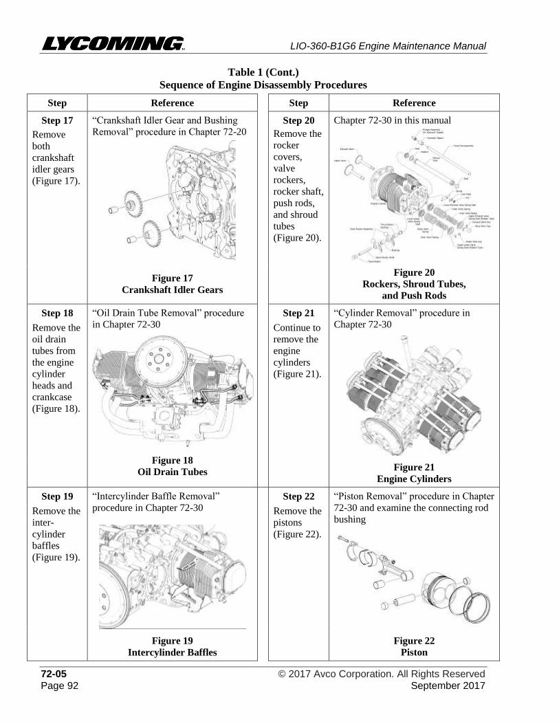
LIO-360-B1G6 Engine Maintenance Manual
72-05 © 2017 Avco Corporation. All Rights Reserved Page 92 September 2017
Table 1 (Cont.)
Sequence of Engine Disassembly Procedures
Step Reference Step Reference
Step 17 “Crankshaft Idler Gear and Bushing
Removal” procedure in Chapter 72-20
Step 20 Chapter 72-30 in this manual
Remove
both
crankshaft
idler gears
(Figure 17).
Remove the
rocker
covers,
valve
rockers,
rocker shaft,
push rods,
and shroud
tubes
(Figure 20).
Figure 17
Crankshaft Idler Gears
Figure 20
Rockers, Shroud Tubes,
and Push Rods
Step 18 “Oil Drain Tube Removal” procedure
in Chapter 72-30
Figure 18
Oil Drain Tubes
Step 21 “Cylinder Removal” procedure in
Chapter 72-30
Figure 21
Engine Cylinders
Remove the
oil drain
tubes from
the engine
cylinder
heads and
crankcase
(Figure 18).
Continue to
remove the
engine
cylinders
(Figure 21).
Step 19 “Intercylinder Baffle Removal”
procedure in Chapter 72-30
Figure 19
Intercylinder Baffles
Step 22 “Piston Removal” procedure in Chapter
72-30 and examine the connecting rod
bushing
Figure 22
Piston
Remove the
inter-
cylinder
baffles
(Figure 19).
Remove the
pistons
(Figure 22).
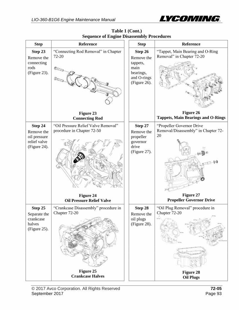
LIO-360-B1G6 Engine Maintenance Manual
© 2017 Avco Corporation. All Rights Reserved 72-05 September 2017 Page 93
Table 1 (Cont.)
Sequence of Engine Disassembly Procedures
Step Reference Step Reference
Step 23 “Connecting Rod Removal” in Chapter
72-20
Step 26 “Tappet, Main Bearing and O-Ring
Removal” in Chapter 72-20
Figure 26
Tappets, Main Bearings and O-Rings
Remove the
connecting
rods
(Figure 23).
Remove the
tappets,
main
bearings,
and O-rings
(Figure 26).
Figure 23
Connecting Rod
Step 24
Remove the
oil pressure
relief valve
(Figure 24).
“Oil Pressure Relief Valve Removal”
procedure in Chapter 72-50
Step 27
Remove the
propeller
governor
drive
(Figure 27).
“Propeller Governor Drive
Removal/Disassembly” in Chapter 72-
20
Figure 27
Propeller Governor Drive
Figure 24
Oil Pressure Relief Valve
Step 25
Separate the
crankcase
halves
(Figure 25).
“Crankcase Disassembly” procedure in
Chapter 72-20
Figure 25
Crankcase Halves
Step 28
Remove the
oil plugs
(Figure 28).
“Oil Plug Removal” procedure in
Chapter 72-20
Figure 28
Oil Plugs
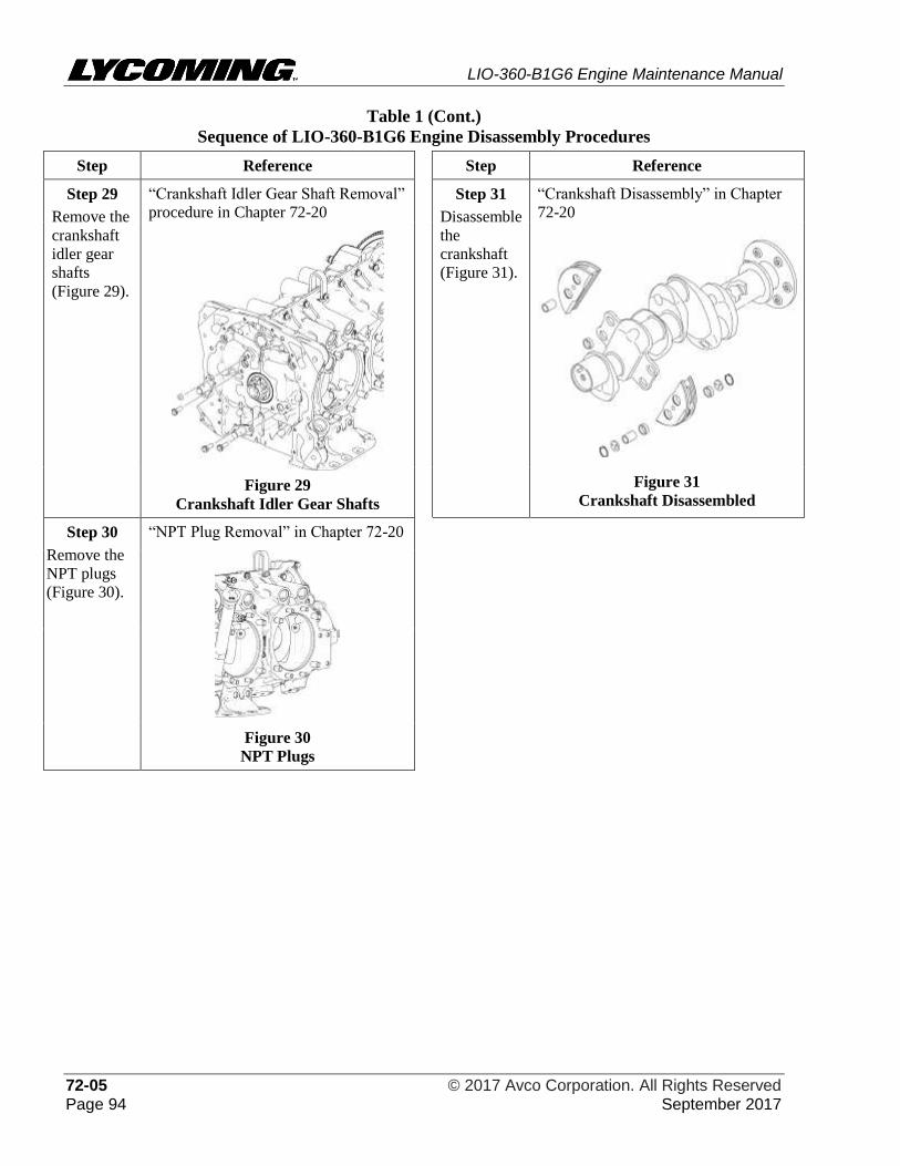
LIO-360-B1G6 Engine Maintenance Manual
72-05 © 2017 Avco Corporation. All Rights Reserved Page 94 September 2017
Table 1 (Cont.)
Sequence of LIO-360-B1G6 Engine Disassembly Procedures
Step Reference Step Reference
Step 29
Remove the
crankshaft
idler gear
shafts
(Figure 29).
“Crankshaft Idler Gear Shaft Removal”
procedure in Chapter 72-20
Figure 29
Crankshaft Idler Gear Shafts
Step 31
Disassemble
the
crankshaft
(Figure 31).
“Crankshaft Disassembly” in Chapter
72-20
Figure 31
Crankshaft Disassembled
Step 30
Remove the
NPT plugs
(Figure 30).
“NPT Plug Removal” in Chapter 72-20
Figure 30
NPT Plugs
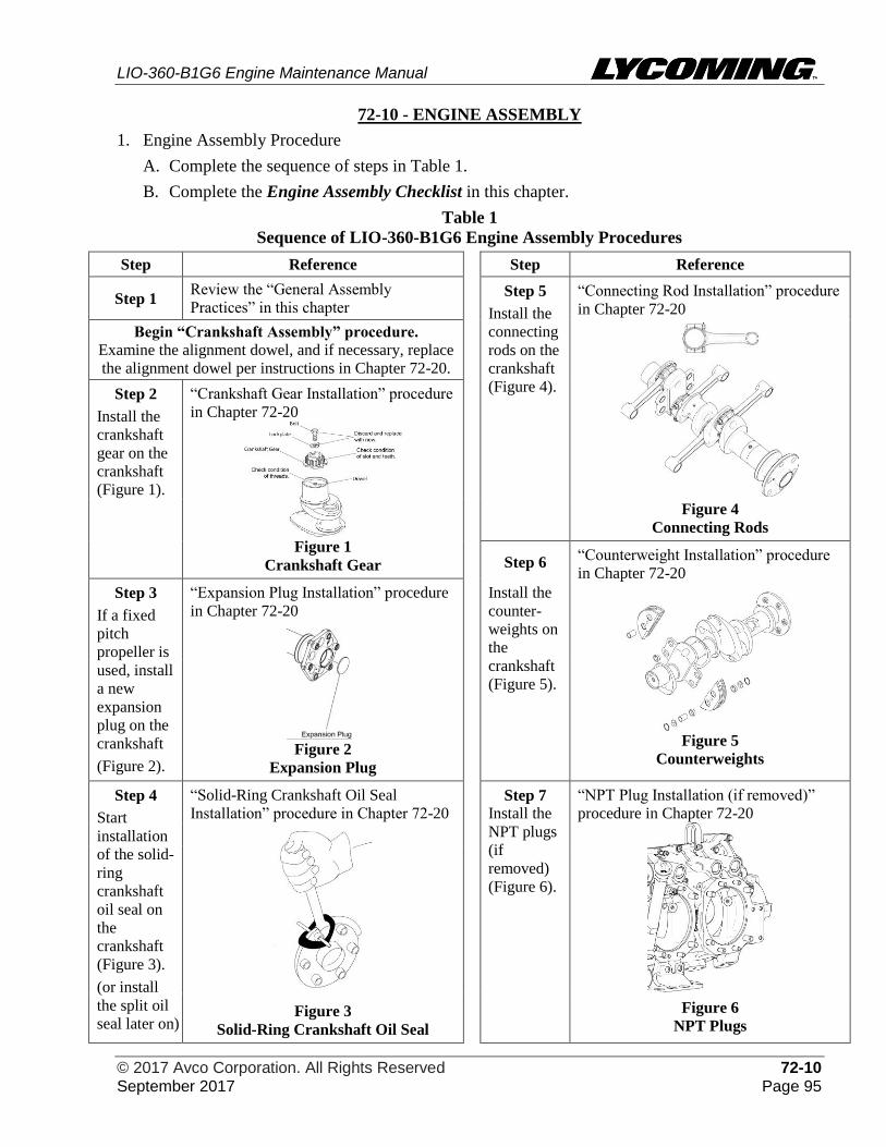
LIO-360-B1G6 Engine Maintenance Manual
© 2017 Avco Corporation. All Rights Reserved 72-10 September 2017 Page 95
72-10 - ENGINE ASSEMBLY
1. Engine Assembly Procedure
A. Complete the sequence of steps in Table 1.
B. Complete the Engine Assembly Checklist in this chapter.
Table 1
Sequence of LIO-360-B1G6 Engine Assembly Procedures
Step Reference Step Reference
Step 1 Review the “General Assembly
Practices” in this chapter Step 5
Install the
connecting
rods on the
crankshaft
(Figure 4).
“Connecting Rod Installation” procedure
in Chapter 72-20
Begin “Crankshaft Assembly” procedure.
Examine the alignment dowel, and if necessary, replace
the alignment dowel per instructions in Chapter 72-20.
Step 2
Install the
crankshaft
gear on the
crankshaft
(Figure 1).
“Crankshaft Gear Installation” procedure
in Chapter 72-20
Figure 1
Crankshaft Gear
Figure 4
Connecting Rods
Step 6 “Counterweight Installation” procedure
in Chapter 72-20
Figure 5
Counterweights
Step 3
If a fixed
pitch
propeller is
used, install
a new
expansion
plug on the
crankshaft
(Figure 2).
“Expansion Plug Installation” procedure
in Chapter 72-20
Figure 2
Expansion Plug
Install the
counter-
weights on
the
crankshaft
(Figure 5).
Step 4
Start
installation
of the solid-
ring
crankshaft
oil seal on
the
crankshaft
(Figure 3).
(or install
the split oil
seal later on)
“Solid-Ring Crankshaft Oil Seal
Installation” procedure in Chapter 72-20
Figure 3
Solid-Ring Crankshaft Oil Seal
Step 7 Install the
NPT plugs
(if
removed)
(Figure 6).
“NPT Plug Installation (if removed)”
procedure in Chapter 72-20
Figure 6
NPT Plugs
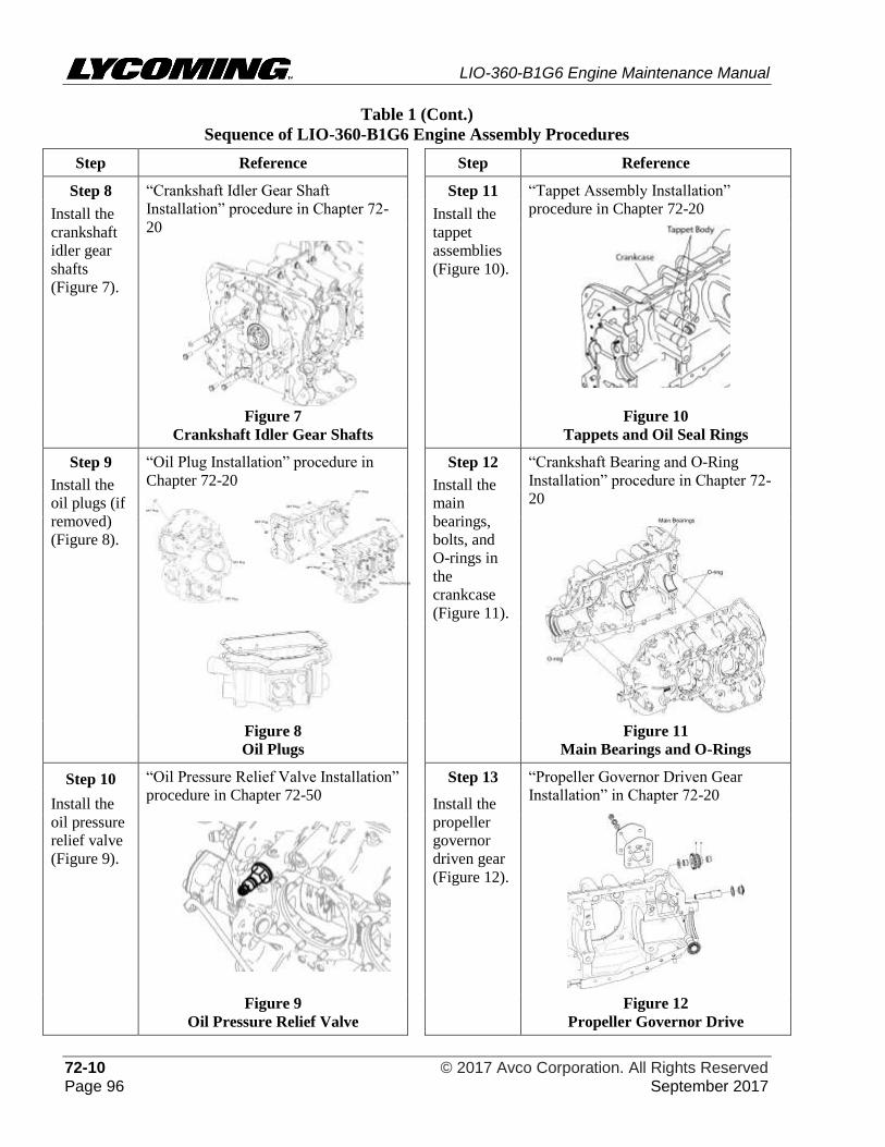
LIO-360-B1G6 Engine Maintenance Manual
72-10 © 2017 Avco Corporation. All Rights Reserved Page 96 September 2017
Table 1 (Cont.)
Sequence of LIO-360-B1G6 Engine Assembly Procedures
Step Reference Step Reference
Step 8 “Crankshaft Idler Gear Shaft
Installation” procedure in Chapter 72-
20
Step 11 “Tappet Assembly Installation”
procedure in Chapter 72-20 Install the
crankshaft
idler gear
shafts
(Figure 7).
Install the
tappet
assemblies
(Figure 10).
Figure 7
Crankshaft Idler Gear Shafts
Figure 10
Tappets and Oil Seal Rings
Step 9
Install the
oil plugs (if
removed)
(Figure 8).
“Oil Plug Installation” procedure in
Chapter 72-20 Step 12
Install the
main
bearings,
bolts, and
O-rings in
the
crankcase
(Figure 11).
“Crankshaft Bearing and O-Ring
Installation” procedure in Chapter 72-
20
Figure 8
Oil Plugs
Figure 11
Main Bearings and O-Rings
Step 10 “Oil Pressure Relief Valve Installation”
procedure in Chapter 72-50 Step 13 “Propeller Governor Driven Gear
Installation” in Chapter 72-20 Install the
oil pressure
relief valve
(Figure 9).
Install the
propeller
governor
driven gear
(Figure 12).
Figure 9
Oil Pressure Relief Valve
Figure 12
Propeller Governor Drive
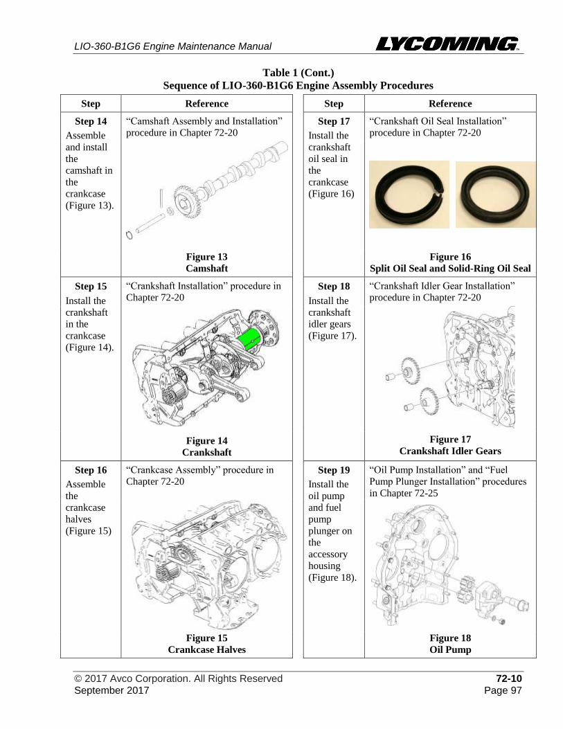
LIO-360-B1G6 Engine Maintenance Manual
© 2017 Avco Corporation. All Rights Reserved 72-10 September 2017 Page 97
Table 1 (Cont.)
Sequence of LIO-360-B1G6 Engine Assembly Procedures
Step Reference Step Reference
Step 14
Assemble
and install
the
camshaft in
the
crankcase
(Figure 13).
“Camshaft Assembly and Installation”
procedure in Chapter 72-20
Step 17
Install the
crankshaft
oil seal in
the
crankcase
(Figure 16)
“Crankshaft Oil Seal Installation”
procedure in Chapter 72-20
Figure 13
Camshaft
Figure 16
Split Oil Seal and Solid-Ring Oil Seal
Step 15 “Crankshaft Installation” procedure in
Chapter 72-20
Step 18 “Crankshaft Idler Gear Installation”
procedure in Chapter 72-20
Install the
crankshaft
in the
crankcase
(Figure 14).
Install the
crankshaft
idler gears
(Figure 17).
Figure 14
Crankshaft
Figure 17
Crankshaft Idler Gears
Step 16
Assemble
the
crankcase
halves
(Figure 15)
“Crankcase Assembly” procedure in
Chapter 72-20
Step 19
Install the
oil pump
and fuel
pump
plunger on
the
accessory
housing
(Figure 18).
“Oil Pump Installation” and “Fuel
Pump Plunger Installation” procedures
in Chapter 72-25
Figure 15
Crankcase Halves
Figure 18
Oil Pump
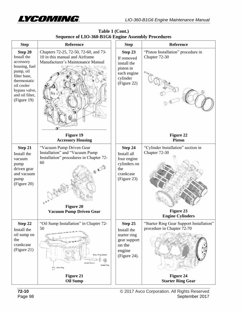
LIO-360-B1G6 Engine Maintenance Manual
72-10 © 2017 Avco Corporation. All Rights Reserved Page 98 September 2017
Table 1 (Cont.)
Sequence of LIO-360-B1G6 Engine Assembly Procedures
Step Reference Step Reference
Step 20 Install the
accessory
housing, fuel
pump, oil
filter base,
thermostatic
oil cooler
bypass valve,
and oil filter,
(Figure 19)
Chapters 72-25, 72-50, 72-60, and 73-
10 in this manual and Airframe
Manufacturer’s Maintenance Manual
Step 23
If removed
install the
piston in
each engine
cylinder
(Figure 22)
“Piston Installation” procedure in
Chapter 72-30
Figure 19
Accessory Housing
Figure 22
Piston
Step 21
Install the
vacuum
pump
driven gear
and vacuum
pump
(Figure 20)
“Vacuum Pump Driven Gear
Installation” and “Vacuum Pump
Installation” procedures in Chapter 72-
60
Figure 20
Vacuum Pump Driven Gear
Step 24
Install all
four engine
cylinders on
the
crankcase
(Figure 23)
“Cylinder Installation” section in
Chapter 72-30
Figure 23
Engine Cylinders
Step 22
Install the
oil sump on
the
crankcase
(Figure 21)
“Oil Sump Installation” in Chapter 72-
50
Step 25 “Starter Ring Gear Support Installation”
procedure in Chapter 72-70
Install the
starter ring
gear support
on the
engine (Figure 24).
Figure 21
Oil Sump
Figure 24
Starter Ring Gear
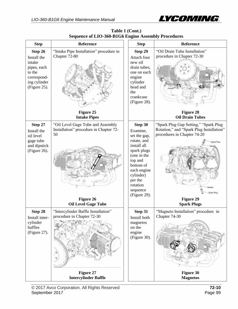
LIO-360-B1G6 Engine Maintenance Manual
© 2017 Avco Corporation. All Rights Reserved 72-10 September 2017 Page 99
Table 1 (Cont.)
Sequence of LIO-360-B1G6 Engine Assembly Procedures
Step Reference Step Reference
Step 26 “Intake Pipe Installation” procedure in
Chapter 72-80
Step 29 “Oil Drain Tube Installation”
procedure in Chapter 72-30
Install the
intake
pipes, each
to the
correspond-
ing cylinder
(Figure 25).
Attach four
new oil
drain tubes,
one on each
engine
cylinder
head and
the
crankcase
(Figure 28).
Figure 25
Intake Pipes
Figure 28
Oil Drain Tubes
Step 27 “Oil Level Gage Tube and Assembly
Installation” procedure in Chapter 72-
50
Step 30
Examine,
set the gap,
rotate, and
install all
spark plugs
(one in the
top and
bottom of
each engine
cylinder)
per the
rotation
sequence
(Figure 29).
“Spark Plug Gap Setting,” “Spark Plug
Rotation,” and “Spark Plug Installation”
procedures in Chapter 74-20
Install the
oil level
gage tube
and dipstick
(Figure 26).
Figure 26
Oil Level Gage Tube
Figure 29
Spark Plugs
Step 28
Install inter-
cylinder
baffles
(Figure 27).
“Intercylinder Baffle Installation”
procedure in Chapter 72-30
Step 31
Install both
magnetos
on the
engine
(Figure 30).
“Magneto Installation” procedure in
Chapter 74-30
Figure 27
Intercylinder Baffle
Figure 30
Magnetos
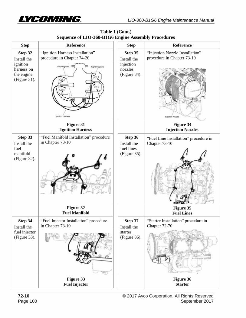
LIO-360-B1G6 Engine Maintenance Manual
72-10 © 2017 Avco Corporation. All Rights Reserved Page 100 September 2017
Table 1 (Cont.)
Sequence of LIO-360-B1G6 Engine Assembly Procedures
Step Reference Step Reference
Step 32
Install the
ignition
harness on
the engine
(Figure 31).
“Ignition Harness Installation”
procedure in Chapter 74-20
Step 35
Install the
injection
nozzles
(Figure 34).
“Injection Nozzle Installation”
procedure in Chapter 73-10
Figure 31
Ignition Harness
Figure 34
Injection Nozzles
Step 33
Install the
fuel
manifold
(Figure 32).
“Fuel Manifold Installation” procedure
in Chapter 73-10
Figure 32
Fuel Manifold
Step 36
Install the
fuel lines
(Figure 35).
“Fuel Line Installation” procedure in
Chapter 73-10
Figure 35
Fuel Lines
Step 34
Install the
fuel injector
(Figure 33).
“Fuel Injector Installation” procedure
in Chapter 73-10
Step 37
Install the
starter
(Figure 36).
“Starter Installation” procedure in
Chapter 72-70
Figure 33
Fuel Injector
Figure 36
Starter
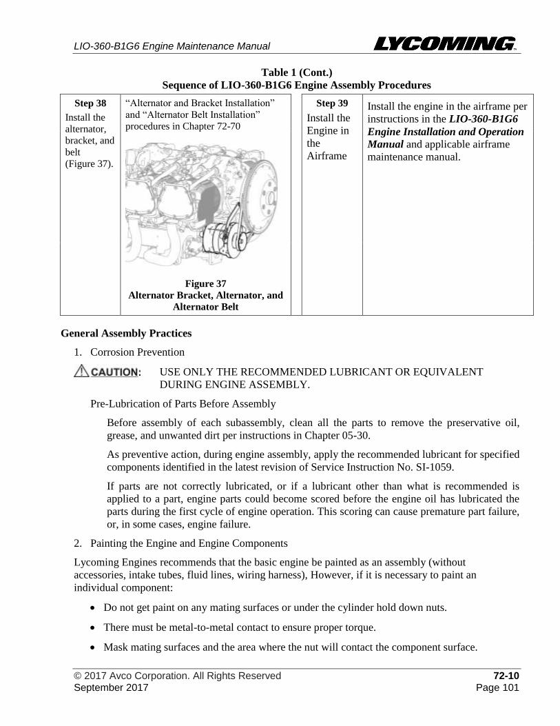
LIO-360-B1G6 Engine Maintenance Manual
© 2017 Avco Corporation. All Rights Reserved 72-10 September 2017 Page 101
Table 1 (Cont.)
Sequence of LIO-360-B1G6 Engine Assembly Procedures
Step 38
Install the
alternator,
bracket, and
belt
(Figure 37).
“Alternator and Bracket Installation”
and “Alternator Belt Installation”
procedures in Chapter 72-70
Figure 37
Alternator Bracket, Alternator, and
Alternator Belt
Step 39
Install the
Engine in
the
Airframe
Install the engine in the airframe per
instructions in the LIO-360-B1G6
Engine Installation and Operation
Manual and applicable airframe
maintenance manual.
General Assembly Practices
1. Corrosion Prevention
USE ONLY THE RECOMMENDED LUBRICANT OR EQUIVALENT
DURING ENGINE ASSEMBLY.
Pre-Lubrication of Parts Before Assembly
Before assembly of each subassembly, clean all the parts to remove the preservative oil,
grease, and unwanted dirt per instructions in Chapter 05-30.
As preventive action, during engine assembly, apply the recommended lubricant for specified
components identified in the latest revision of Service Instruction No. SI-1059.
If parts are not correctly lubricated, or if a lubricant other than what is recommended is
applied to a part, engine parts could become scored before the engine oil has lubricated the
parts during the first cycle of engine operation. This scoring can cause premature part failure,
or, in some cases, engine failure.
2. Painting the Engine and Engine Components
Lycoming Engines recommends that the basic engine be painted as an assembly (without
accessories, intake tubes, fluid lines, wiring harness), However, if it is necessary to paint an
individual component:
• Do not get paint on any mating surfaces or under the cylinder hold down nuts.
• There must be metal-to-metal contact to ensure proper torque.
• Mask mating surfaces and the area where the nut will contact the component surface.
LIO-360-B1G6 Engine Maintenance Manual
72-10 © 2017 Avco Corporation. All Rights Reserved Page 102 September 2017
Table 2 includes paint stripping and painting guidelines for components.
All paint is to be sprayed; however, if it is necessary to use a brush, use care to prevent an
accumulation of pockets of paint. Refer to the paint manufacturer’s instructions for drying and
curing times.
Parts requiring use of paint for protection or appearance are to be painted in accordance with the
recommendations using the following approved materials:
• Thinner - Toluene or equivalent (AMS3180 or equivalent Federal Spec. TT-T-548).
• Primer - Zinc chromate (AMS3110 or equivalent MIL-P-8585).
• Enamel - Phthalate resin type (AMS3125C or equivalent MIL E-7729).
NOTICE: All machined bosses are to be masked before painting. Do not paint areas under
hold- down nuts where torque is required.
Table 2
Paint Stripping and Painting Guidelines for Components
Aluminum and Steel
Parts
NOTICE: It is not necessary to apply the primer coat if paint has not
been removed from the part.
(1) Clean and degrease the parts with mineral spirits or equivalent.
(2) Apply one coat of zinc chromate primer, thinned with two parts
toluene.
(3) Air dry.
(4) Apply one coat of enamel and bake at 250° to 300° F (121° to 149° C),
for 1/2-hour.
Magnesium Parts
(1) Clean all traces of oil and grease from the part using a neutral, non-
corrosive, degreasing medium followed by a rinse.
(2) Immerse the part for 45 minutes in a hot dichromate solution (3/4 lb.
(0.34 kg) of sodium dichromate to 1 gallon (3.8 liters) of water at 180°
to 200°F (82° to 93°C) (as required).
(3) Wash the part thoroughly in cold running water, dipped in hot water,
and dried in an air blast.
(4) Immediately paint the part with a primer coat and engine enamel, the
same as aluminum parts.
Shroud Tubes
(1) Clean and degrease the shroud tube with mineral spirits or equivalent.
(2) Dip the shroud tube in zinc chromate primer, thinned to spraying
consistency.
(3) Let the primer coat dry.
(4) Paint the outside of the shroud tube with engine enamel.
LIO-360-B1G6 Engine Maintenance Manual
© 2017 Avco Corporation. All Rights Reserved 72-10 September 2017 Page 103
Table 2 (Cont.)
Paint Stripping and Painting Guidelines for Components
Cylinders NOTICE: Paint the cylinder with a Phthalate resin type enamel
(AMS3125C or equivalent MIL-E-7729) properly thinned
with Toluene or equivalent (AMS3180 or equivalent
Federal Spec. TT-T-548).
(1) Remove all old paint from the cylinder.
Paint strippers are usually organic solvents like MEK or acetone or
toluene, etc. and typically will not cause any damage to metals. A vapor
degreaser is best suited for this purpose.
NOTICE: Masking tape, corks, plugs, metal covers, etc. are
acceptable for masking purposes.
(2) Mask off the following parts of the cylinder:
• Rocker box section, including the rocker box flange
• Both valve ports and flanges
• Thermocouple hole
• Spark plug holes
• Push rod shroud tube holes
• All other exposed threaded surfaces in which paint could
accumulate
(3) Cover the flange area to prevent paint being applied where the
cylinder hold-down nuts contact the cylinder flange.
NOTICE: In the next step, maximum thickness of the paint on the
cylinder flange must be 0.0005 in. (0.0127 mm). Measure
the thickness of the paint with a thickness gage or
equivalent. If a thickness gage is not available, use a
micrometer to measure the thickness of the flange before
and after painting. If the paint is over 0.0005 in. (0.0127
mm) thick, remove the paint and repaint the cylinder flange.
(4) Apply a very light sprayed coat of zinc chromate primer to a
maximum thickness of (0.0005 in. (0.0127 mm) on the cylinder
flange. If the correct amount of paint has been applied, the color of
the paint will be green with a yellowish tint and the metal will show
through. If the paint is too thick, the color will be zinc chromate
yellow.
(5) Use a cloth dipped in paint thinner to remove paint from all surfaces
where it could have accidentally accumulated.
(6) Air-dry the cylinder or bake the cylinder in an oven until
completely dry. Refer to the paint manufacturer’s instructions for
drying time and oven temperature.
(7) Refer to Chapter 74-20 and paint the cylinder fin area appropriately
for spark plug identification.
LIO-360-B1G6 Engine Maintenance Manual
72-10 © 2017 Avco Corporation. All Rights Reserved Page 104 September 2017
3. Limits and Clearances
Refer to the latest revision of the Service Table of Limits - SSP-1776, for the following.
• Backlash and end clearance of gears
• Clearance between mating machined parts
• Clearance between moving parts that touch
• Torque limits for various nuts, screws, and fasteners.
4. Inspections
NOTICE: Inspections in this section refer to reusable items that do not require replacement in
accordance with the latest revision of Service Bulletin No. SB-240. Be sure to record
part replacement or any corrective action in the engine logbook.
A. Bearing Shell Surface Inspection
(1) Examine all bearing saddle surfaces for damage, scoring, galling, and wear. If any of
these conditions are found, identify and correct the cause.
(2) Make sure that the clearance of each bearing agrees with the specification in the latest
revision of the Service Table of Limits - SSP-1776.
(3) If a bearing is not in the specified limits in the latest revision of the Service Table of
Limit - SSP-1776, discard it and replace it with a new one.
(4) Examine all journal surfaces for galling, scores, misalignment, and out-of-round
condition. Replace a scored, galled, misaligned, or out-of-round component.
(5) Examine the shafts and pins for straightness.
B. Gear Inspection
(1) Examine the involutes of the gear teeth for pitting and excessive wear.
(2) If pit marks are found, discard the gear and replace it with a new one.
(3) Examine the bearing surfaces of all gears for deep scratches.
(4) Remove minor abrasions with a fine abrasive cloth.
C. Screwed Fitting Inspection
(1) Examine the condition of the threads on screwed fittings (threaded fastenings or plugs).
(2) Remove small nicks and burrs with a small file, fine abrasive cloth, or stone.
(3) If the part cannot be repaired by polishing it, discard it and replace it with a new one.
(4) If the part has too much distortion, galling, or mutilation (caused by over-tightening or
use of an incorrect tool) replace it.
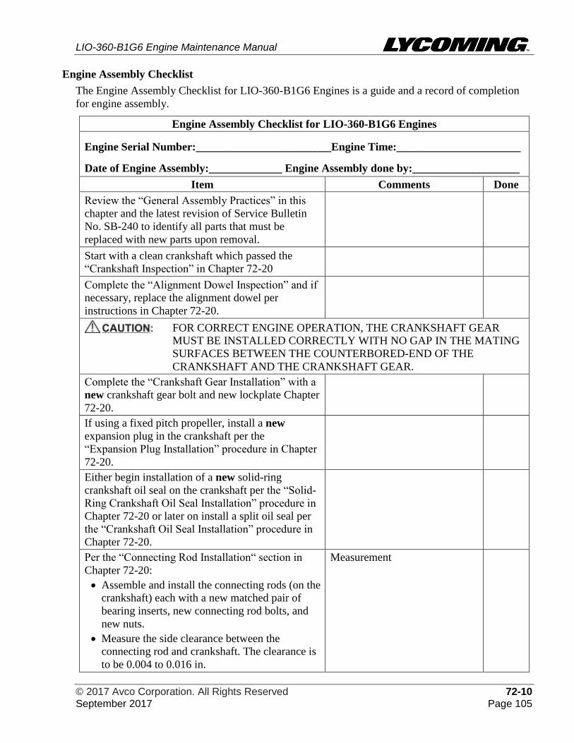
LIO-360-B1G6 Engine Maintenance Manual
© 2017 Avco Corporation. All Rights Reserved 72-10 September 2017 Page 105
Engine Assembly Checklist
The Engine Assembly Checklist for LIO-360-B1G6 Engines is a guide and a record of completion
for engine assembly.
Engine Assembly Checklist for LIO-360-B1G6 Engines
Engine Serial Number:________________________Engine Time:______________________
Date of Engine Assembly:_____________ Engine Assembly done by:___________________
Item Comments Done
Review the “General Assembly Practices” in this
chapter and the latest revision of Service Bulletin
No. SB-240 to identify all parts that must be
replaced with new parts upon removal.
Start with a clean crankshaft which passed the
“Crankshaft Inspection” in Chapter 72-20
Complete the “Alignment Dowel Inspection” and if
necessary, replace the alignment dowel per
instructions in Chapter 72-20.
FOR CORRECT ENGINE OPERATION, THE CRANKSHAFT GEAR
MUST BE INSTALLED CORRECTLY WITH NO GAP IN THE MATING
SURFACES BETWEEN THE COUNTERBORED-END OF THE
CRANKSHAFT AND THE CRANKSHAFT GEAR.
Complete the “Crankshaft Gear Installation” with a
new crankshaft gear bolt and new lockplate Chapter
72-20.
If using a fixed pitch propeller, install a new
expansion plug in the crankshaft per the
“Expansion Plug Installation” procedure in Chapter
72-20.
Either begin installation of a new solid-ring
crankshaft oil seal on the crankshaft per the “Solid-
Ring Crankshaft Oil Seal Installation” procedure in
Chapter 72-20 or later on install a split oil seal per
the “Crankshaft Oil Seal Installation” procedure in
Chapter 72-20.
Per the “Connecting Rod Installation“ section in
Chapter 72-20:
• Assemble and install the connecting rods (on the
crankshaft) each with a new matched pair of
bearing inserts, new connecting rod bolts, and
new nuts.
• Measure the side clearance between the
connecting rod and crankshaft. The clearance is
to be 0.004 to 0.016 in.
Measurement
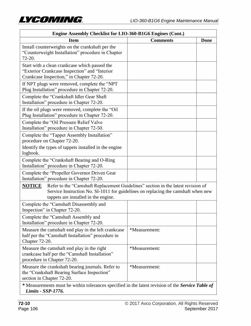
LIO-360-B1G6 Engine Maintenance Manual
72-10 © 2017 Avco Corporation. All Rights Reserved Page 106 September 2017
Engine Assembly Checklist for LIO-360-B1G6 Engines (Cont.)
Item Comments Done
Install counterweights on the crankshaft per the
“Counterweight Installation” procedure in Chapter
72-20.
Start with a clean crankcase which passed the
“Exterior Crankcase Inspection” and “Interior
Crankcase Inspection,” in Chapter 72-20.
If NPT plugs were removed, complete the “NPT
Plug Installation” procedure in Chapter 72-20.
Complete the “Crankshaft Idler Gear Shaft
Installation” procedure in Chapter 72-20.
If the oil plugs were removed, complete the “Oil
Plug Installation” procedure in Chapter 72-20.
Complete the “Oil Pressure Relief Valve
Installation” procedure in Chapter 72-50.
Complete the “Tappet Assembly Installation”
procedure on Chapter 72-20.
Identify the types of tappets installed in the engine
logbook.
Complete the “Crankshaft Bearing and O-Ring
Installation” procedure in Chapter 72-20.
Complete the “Propeller Governor Driven Gear
Installation” procedure in Chapter 72-20.
NOTICE Refer to the “Camshaft Replacement Guidelines” section in the latest revision of
Service Instruction No. SI-1011 for guidelines on replacing the camshaft when new
tappets are installed in the engine.
Complete the “Camshaft Disassembly and
Inspection” in Chapter 72-20.
Complete the “Camshaft Assembly and
Installation” procedure in Chapter 72-20.
Measure the camshaft end play in the left crankcase
half per the “Camshaft Installation” procedure in
Chapter 72-20.
*Measurement:
Measure the camshaft end play in the right
crankcase half per the “Camshaft Installation”
procedure in Chapter 72-20.
*Measurement:
Measure the crankshaft bearing journals. Refer to
the “Crankshaft Bearing Surface Inspection”
section in Chapter 72-20.
*Measurement:
* Measurements must be within tolerances specified in the latest revision of the Service Table of
Limits - SSP-1776.
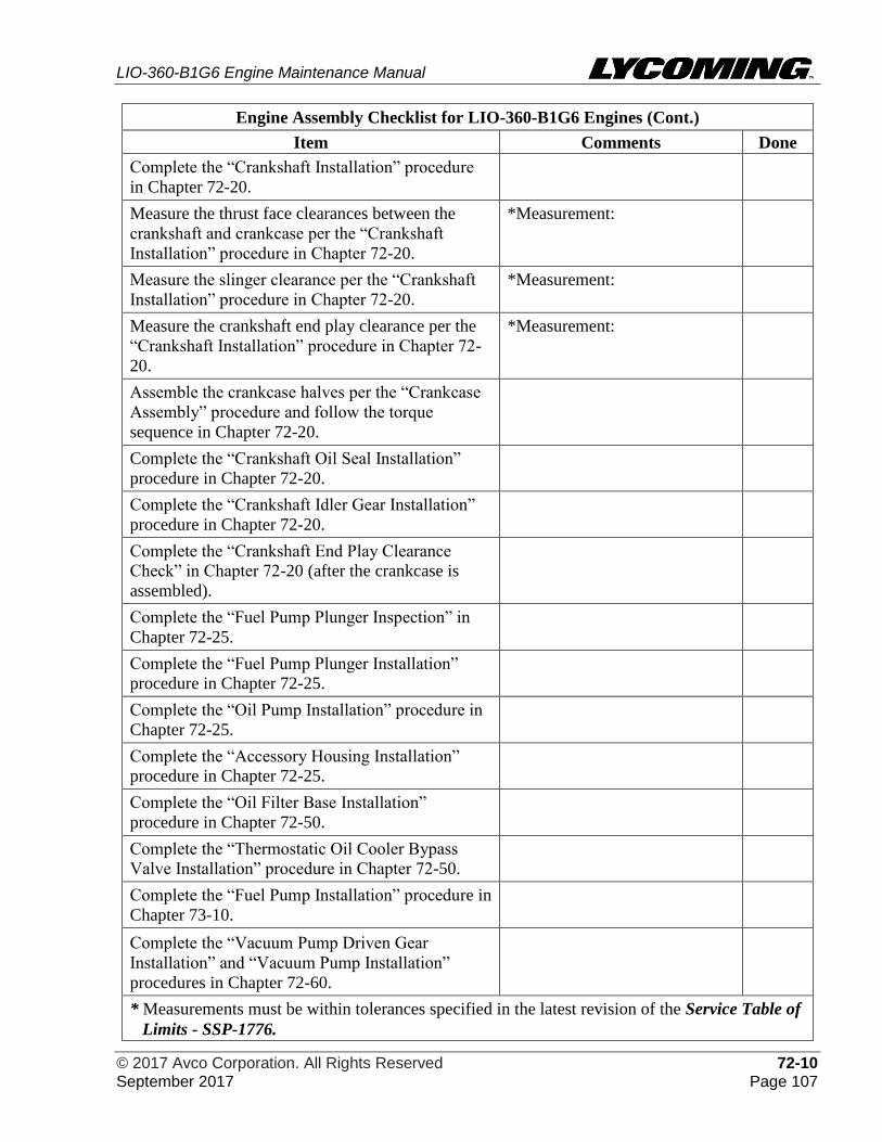
LIO-360-B1G6 Engine Maintenance Manual
© 2017 Avco Corporation. All Rights Reserved 72-10 September 2017 Page 107
Engine Assembly Checklist for LIO-360-B1G6 Engines (Cont.)
Item Comments Done
Complete the “Crankshaft Installation” procedure
in Chapter 72-20.
Measure the thrust face clearances between the
crankshaft and crankcase per the “Crankshaft
Installation” procedure in Chapter 72-20.
*Measurement:
Measure the slinger clearance per the “Crankshaft
Installation” procedure in Chapter 72-20.
*Measurement:
Measure the crankshaft end play clearance per the
“Crankshaft Installation” procedure in Chapter 72-
20.
*Measurement:
Assemble the crankcase halves per the “Crankcase
Assembly” procedure and follow the torque
sequence in Chapter 72-20.
Complete the “Crankshaft Oil Seal Installation”
procedure in Chapter 72-20.
Complete the “Crankshaft Idler Gear Installation”
procedure in Chapter 72-20.
Complete the “Crankshaft End Play Clearance
Check” in Chapter 72-20 (after the crankcase is
assembled).
Complete the “Fuel Pump Plunger Inspection” in
Chapter 72-25.
Complete the “Fuel Pump Plunger Installation”
procedure in Chapter 72-25.
Complete the “Oil Pump Installation” procedure in
Chapter 72-25.
Complete the “Accessory Housing Installation”
procedure in Chapter 72-25.
Complete the “Oil Filter Base Installation”
procedure in Chapter 72-50.
Complete the “Thermostatic Oil Cooler Bypass
Valve Installation” procedure in Chapter 72-50.
Complete the “Fuel Pump Installation” procedure in
Chapter 73-10.
Complete the “Vacuum Pump Driven Gear
Installation” and “Vacuum Pump Installation”
procedures in Chapter 72-60.
* Measurements must be within tolerances specified in the latest revision of the Service Table of
Limits - SSP-1776.
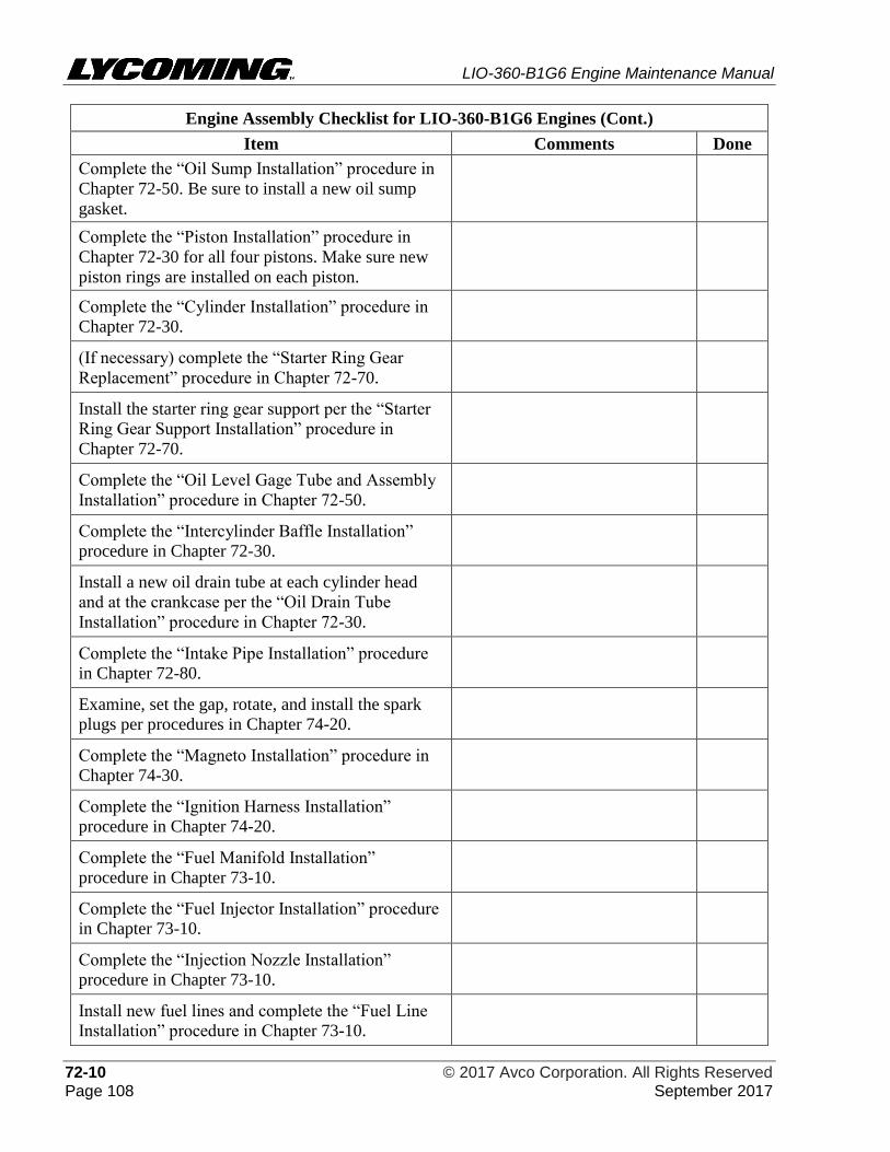
LIO-360-B1G6 Engine Maintenance Manual
72-10 © 2017 Avco Corporation. All Rights Reserved Page 108 September 2017
Engine Assembly Checklist for LIO-360-B1G6 Engines (Cont.)
Item Comments Done
Complete the “Oil Sump Installation” procedure in
Chapter 72-50. Be sure to install a new oil sump
gasket.
Complete the “Piston Installation” procedure in
Chapter 72-30 for all four pistons. Make sure new
piston rings are installed on each piston.
Complete the “Cylinder Installation” procedure in
Chapter 72-30.
(If necessary) complete the “Starter Ring Gear
Replacement” procedure in Chapter 72-70.
Install the starter ring gear support per the “Starter
Ring Gear Support Installation” procedure in
Chapter 72-70.
Complete the “Oil Level Gage Tube and Assembly
Installation” procedure in Chapter 72-50.
Complete the “Intercylinder Baffle Installation”
procedure in Chapter 72-30.
Install a new oil drain tube at each cylinder head
and at the crankcase per the “Oil Drain Tube
Installation” procedure in Chapter 72-30.
Complete the “Intake Pipe Installation” procedure
in Chapter 72-80.
Examine, set the gap, rotate, and install the spark
plugs per procedures in Chapter 74-20.
Complete the “Magneto Installation” procedure in
Chapter 74-30.
Complete the “Ignition Harness Installation”
procedure in Chapter 74-20.
Complete the “Fuel Manifold Installation”
procedure in Chapter 73-10.
Complete the “Fuel Injector Installation” procedure
in Chapter 73-10.
Complete the “Injection Nozzle Installation”
procedure in Chapter 73-10.
Install new fuel lines and complete the “Fuel Line
Installation” procedure in Chapter 73-10.
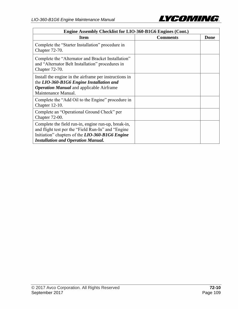
LIO-360-B1G6 Engine Maintenance Manual
© 2017 Avco Corporation. All Rights Reserved 72-10 September 2017 Page 109
Engine Assembly Checklist for LIO-360-B1G6 Engines (Cont.)
Item Comments Done
Complete the “Starter Installation” procedure in
Chapter 72-70.
Complete the “Alternator and Bracket Installation”
and “Alternator Belt Installation” procedures in
Chapter 72-70.
Install the engine in the airframe per instructions in
the LIO-360-B1G6 Engine Installation and
Operation Manual and applicable Airframe
Maintenance Manual.
Complete the “Add Oil to the Engine” procedure in
Chapter 12-10.
Complete an “Operational Ground Check” per
Chapter 72-00.
Complete the field run-in, engine run-up, break-in,
and flight test per the “Field Run-In” and “Engine
Initiation” chapters of the LIO-360-B1G6 Engine
Installation and Operation Manual.

LIO-360-B1G6 Engine Maintenance Manual
72-10 © 2017 Avco Corporation. All Rights Reserved Page 110 September 2017
This page intentionally left blank.
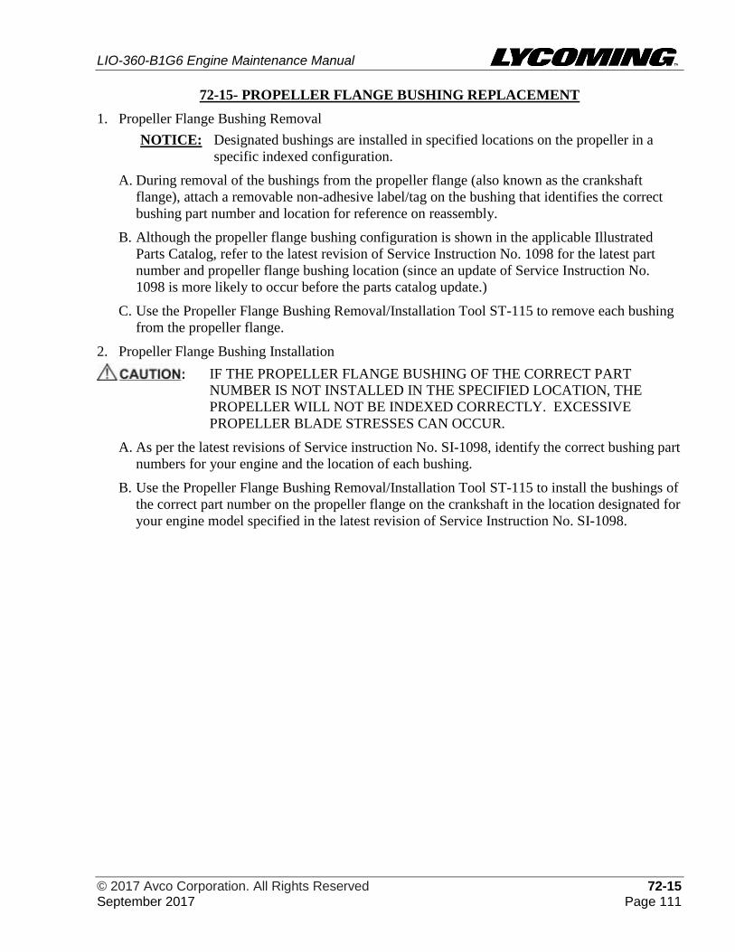
LIO-360-B1G6 Engine Maintenance Manual
© 2017 Avco Corporation. All Rights Reserved 72-15 September 2017 Page 111
72-15- PROPELLER FLANGE BUSHING REPLACEMENT
1. Propeller Flange Bushing Removal
NOTICE: Designated bushings are installed in specified locations on the propeller in a
specific indexed configuration.
A. During removal of the bushings from the propeller flange (also known as the crankshaft
flange), attach a removable non-adhesive label/tag on the bushing that identifies the correct
bushing part number and location for reference on reassembly.
B. Although the propeller flange bushing configuration is shown in the applicable Illustrated
Parts Catalog, refer to the latest revision of Service Instruction No. 1098 for the latest part
number and propeller flange bushing location (since an update of Service Instruction No.
1098 is more likely to occur before the parts catalog update.)
C. Use the Propeller Flange Bushing Removal/Installation Tool ST-115 to remove each bushing
from the propeller flange.
2. Propeller Flange Bushing Installation
IF THE PROPELLER FLANGE BUSHING OF THE CORRECT PART
NUMBER IS NOT INSTALLED IN THE SPECIFIED LOCATION, THE
PROPELLER WILL NOT BE INDEXED CORRECTLY. EXCESSIVE
PROPELLER BLADE STRESSES CAN OCCUR.
A. As per the latest revisions of Service instruction No. SI-1098, identify the correct bushing part
numbers for your engine and the location of each bushing.
B. Use the Propeller Flange Bushing Removal/Installation Tool ST-115 to install the bushings of
the correct part number on the propeller flange on the crankshaft in the location designated for
your engine model specified in the latest revision of Service Instruction No. SI-1098.

LIO-360-B1G6 Engine Maintenance Manual
72-15 © 2017 Avco Corporation. All Rights Reserved Page 112 September 2017
This page intentionally left blank.
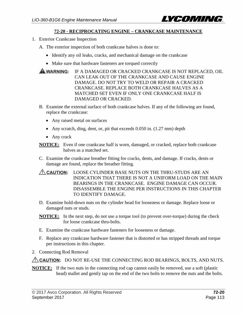
LIO-360-B1G6 Engine Maintenance Manual
© 2017 Avco Corporation. All Rights Reserved 72-20 September 2017 Page 113
72-20 - RECIPROCATING ENGINE – CRANKCASE MAINTENANCE
1. Exterior Crankcase Inspection
A. The exterior inspection of both crankcase halves is done to:
• Identify any oil leaks, cracks, and mechanical damage on the crankcase
• Make sure that hardware fasteners are torqued correctly
IF A DAMAGED OR CRACKED CRANKCASE IS NOT REPLACED, OIL
CAN LEAK OUT OF THE CRANKCASE AND CAUSE ENGINE
DAMAGE. DO NOT TRY TO WELD OR REPAIR A CRACKED
CRANKCASE. REPLACE BOTH CRANKCASE HALVES AS A
MATCHED SET EVEN IF ONLY ONE CRANKCASE HALF IS
DAMAGED OR CRACKED.
B. Examine the external surface of both crankcase halves. If any of the following are found,
replace the crankcase:
• Any raised metal on surfaces
• Any scratch, ding, dent, or, pit that exceeds 0.050 in. (1.27 mm) depth
• Any crack
NOTICE: Even if one crankcase half is worn, damaged, or cracked, replace both crankcase
halves as a matched set.
C. Examine the crankcase breather fitting for cracks, dents, and damage. If cracks, dents or
damage are found, replace the breather fitting.
LOOSE CYLINDER BASE NUTS ON THE THRU-STUDS ARE AN
INDICATION THAT THERE IS NOT A UNIFORM LOAD ON THE MAIN
BEARINGS IN THE CRANKCASE. ENGINE DAMAGE CAN OCCUR.
DISASSEMBLE THE ENGINE PER INSTRUCTIONS IN THIS CHAPTER
TO IDENTIFY DAMAGE.
D. Examine hold-down nuts on the cylinder head for looseness or damage. Replace loose or
damaged nuts or studs.
NOTICE: In the next step, do not use a torque tool (to prevent over-torque) during the check
for loose crankcase thru-bolts.
E. Examine the crankcase hardware fasteners for looseness or damage.
F. Replace any crankcase hardware fastener that is distorted or has stripped threads and torque
per instructions in this chapter.
2. Connecting Rod Removal
DO NOT RE-USE THE CONNECTING ROD BEARINGS, BOLTS, AND NUTS.
NOTICE: If the two nuts in the connecting rod cap cannot easily be removed, use a soft (plastic
head) mallet and gently tap on the end of the two bolts to remove the nuts and the bolts.
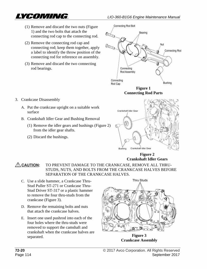
LIO-360-B1G6 Engine Maintenance Manual
72-20 © 2017 Avco Corporation. All Rights Reserved Page 114 September 2017
(1) Remove and discard the two nuts (Figure
1) and the two bolts that attach the
connecting rod cap to the connecting rod.
(2) Remove the connecting rod cap and
connecting rod; keep them together, apply
a label to identify the throw position of the
connecting rod for reference on assembly.
(3) Remove and discard the two connecting
rod bearings.
Figure 1
Connecting Rod Parts
3. Crankcase Disassembly
A. Put the crankcase upright on a suitable work
surface
B. Crankshaft Idler Gear and Bushing Removal
(1) Remove the idler gears and bushings (Figure 2)
from the idler gear shafts.
(2) Discard the bushings.
Figure 2
Crankshaft Idler Gears
TO PREVENT DAMAGE TO THE CRANKCASE, REMOVE ALL THRU-
STUDS, NUTS, AND BOLTS FROM THE CRANKCASE HALVES BEFORE
SEPARATION OF THE CRANKCASE HALVES.
C. Use a slide hammer, a Crankcase Thru-
Stud Puller ST-271 or Crankcase Thru-
Stud Driver ST-317 or a plastic hammer
to remove the four thru-studs from the
crankcase (Figure 3).
D. Remove the remaining bolts and nuts
that attach the crankcase halves.
E. Insert one used pushrod into each of the
four holes where the thru-studs were
removed to support the camshaft and
crankshaft when the crankcase halves are
separated.
Figure 3
Crankcase Assembly
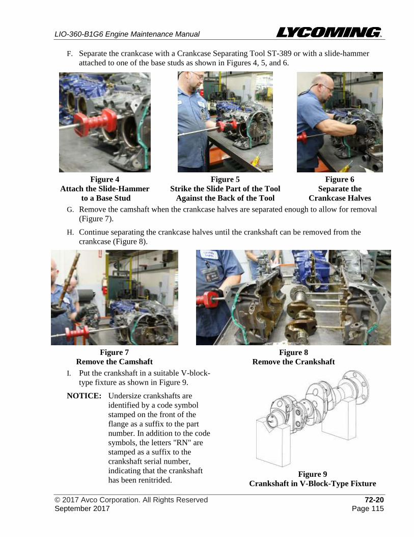
LIO-360-B1G6 Engine Maintenance Manual
© 2017 Avco Corporation. All Rights Reserved 72-20 September 2017 Page 115
F. Separate the crankcase with a Crankcase Separating Tool ST-389 or with a slide-hammer
attached to one of the base studs as shown in Figures 4, 5, and 6.
Figure 4
Attach the Slide-Hammer
to a Base Stud
Figure 5
Strike the Slide Part of the Tool
Against the Back of the Tool
Figure 6
Separate the
Crankcase Halves
G. Remove the camshaft when the crankcase halves are separated enough to allow for removal
(Figure 7).
H. Continue separating the crankcase halves until the crankshaft can be removed from the
crankcase (Figure 8).
Figure 7
Remove the Camshaft
Figure 8
Remove the Crankshaft
I. Put the crankshaft in a suitable V-block-
type fixture as shown in Figure 9.
NOTICE: Undersize crankshafts are
identified by a code symbol
stamped on the front of the
flange as a suffix to the part
number. In addition to the code
symbols, the letters "RN" are
stamped as a suffix to the
crankshaft serial number,
indicating that the crankshaft
has been renitrided.
Figure 9
Crankshaft in V-Block-Type Fixture
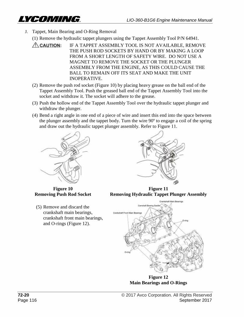
LIO-360-B1G6 Engine Maintenance Manual
72-20 © 2017 Avco Corporation. All Rights Reserved Page 116 September 2017
J. Tappet, Main Bearing and O-Ring Removal
(1) Remove the hydraulic tappet plungers using the Tappet Assembly Tool P/N 64941.
IF A TAPPET ASSEMBLY TOOL IS NOT AVAILABLE, REMOVE
THE PUSH ROD SOCKETS BY HAND OR BY MAKING A LOOP
FROM A SHORT LENGTH OF SAFETY WIRE. DO NOT USE A
MAGNET TO REMOVE THE SOCKET OR THE PLUNGER
ASSEMBLY FROM THE ENGINE, AS THIS COULD CAUSE THE
BALL TO REMAIN OFF ITS SEAT AND MAKE THE UNIT
INOPERATIVE.
(2) Remove the push rod socket (Figure 10) by placing heavy grease on the ball end of the
Tappet Assembly Tool. Push the greased ball end of the Tappet Assembly Tool into the
socket and withdraw it. The socket will adhere to the grease.
(3) Push the hollow end of the Tappet Assembly Tool over the hydraulic tappet plunger and
withdraw the plunger.
(4) Bend a right angle in one end of a piece of wire and insert this end into the space between
the plunger assembly and the tappet body. Turn the wire 90º to engage a coil of the spring
and draw out the hydraulic tappet plunger assembly. Refer to Figure 11.
Figure 10
Removing Push Rod Socket
Figure 11
Removing Hydraulic Tappet Plunger Assembly
(5) Remove and discard the
crankshaft main bearings,
crankshaft front main bearings,
and O-rings (Figure 12).
Figure 12
Main Bearings and O-Rings
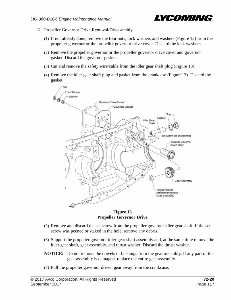
LIO-360-B1G6 Engine Maintenance Manual
© 2017 Avco Corporation. All Rights Reserved 72-20 September 2017 Page 117
K. Propeller Governor Drive Removal/Disassembly
(1) If not already done, remove the four nuts, lock washers and washers (Figure 13) from the
propeller governor or the propeller governor drive cover. Discard the lock washers.
(2) Remove the propeller governor or the propeller governor drive cover and governor
gasket. Discard the governor gasket.
(3) Cut and remove the safety wire/cable from the idler gear shaft plug (Figure 13).
(4) Remove the idler gear shaft plug and gasket from the crankcase (Figure 13). Discard the
gasket.
Figure 13
Propeller Governor Drive
(5) Remove and discard the set screw from the propeller governor idler gear shaft. If the set
screw was peened or staked in the hole, remove any debris.
(6) Support the propeller governor idler gear shaft assembly and, at the same time remove the
idler gear shaft, gear assembly, and thrust washer. Discard the thrust washer.
NOTICE: Do not remove the dowels or bushings from the gear assembly. If any part of the
gear assembly is damaged, replace the entire gear assembly.
(7) Pull the propeller governor driven gear away from the crankcase.
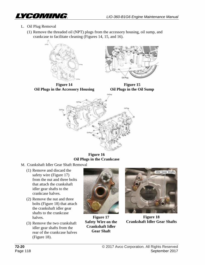
LIO-360-B1G6 Engine Maintenance Manual
72-20 © 2017 Avco Corporation. All Rights Reserved Page 118 September 2017
L. Oil Plug Removal
(1) Remove the threaded oil (NPT) plugs from the accessory housing, oil sump, and
crankcase to facilitate cleaning (Figures 14, 15, and 16).
Figure 14
Oil Plugs in the Accessory Housing
Figure 15
Oil Plugs in the Oil Sump
Figure 16
Oil Plugs in the Crankcase
M. Crankshaft Idler Gear Shaft Removal
(1) Remove and discard the
safety wire (Figure 17)
from the nut and three bolts
that attach the crankshaft
idler gear shafts to the
crankcase halves.
(2) Remove the nut and three
bolts (Figure 18) that attach
the crankshaft idler gear
shafts to the crankcase
halves.
(3) Remove the two crankshaft
idler gear shafts from the
rear of the crankcase halves
(Figure 18).
Figure 17
Safety Wire on the
Crankshaft Idler
Gear Shaft
Figure 18
Crankshaft Idler Gear Shafts
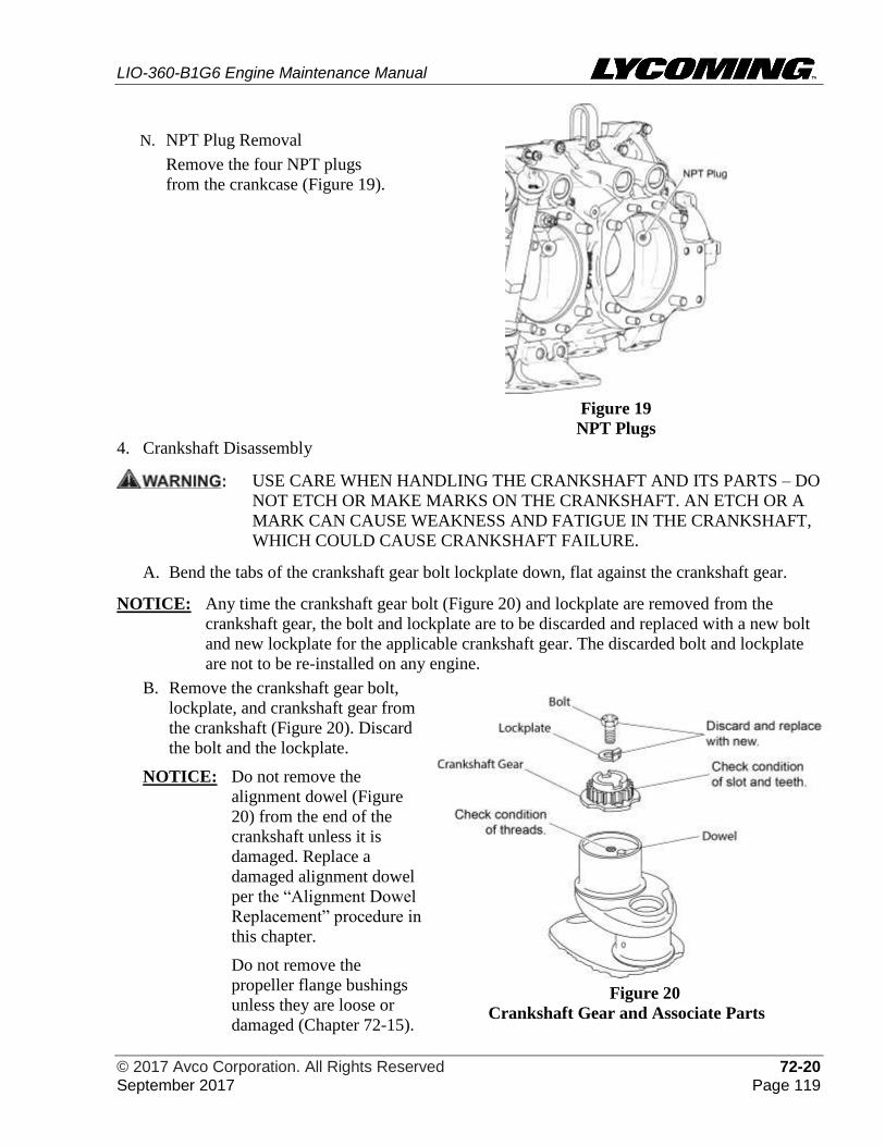
LIO-360-B1G6 Engine Maintenance Manual
© 2017 Avco Corporation. All Rights Reserved 72-20 September 2017 Page 119
N. NPT Plug Removal
Remove the four NPT plugs
from the crankcase (Figure 19).
Figure 19
NPT Plugs 4. Crankshaft Disassembly
USE CARE WHEN HANDLING THE CRANKSHAFT AND ITS PARTS – DO
NOT ETCH OR MAKE MARKS ON THE CRANKSHAFT. AN ETCH OR A
MARK CAN CAUSE WEAKNESS AND FATIGUE IN THE CRANKSHAFT,
WHICH COULD CAUSE CRANKSHAFT FAILURE.
A. Bend the tabs of the crankshaft gear bolt lockplate down, flat against the crankshaft gear.
NOTICE: Any time the crankshaft gear bolt (Figure 20) and lockplate are removed from the
crankshaft gear, the bolt and lockplate are to be discarded and replaced with a new bolt
and new lockplate for the applicable crankshaft gear. The discarded bolt and lockplate
are not to be re-installed on any engine.
B. Remove the crankshaft gear bolt,
lockplate, and crankshaft gear from
the crankshaft (Figure 20). Discard
the bolt and the lockplate.
NOTICE: Do not remove the
alignment dowel (Figure
20) from the end of the
crankshaft unless it is
damaged. Replace a
damaged alignment dowel
per the “Alignment Dowel
Replacement” procedure in
this chapter.
Do not remove the
propeller flange bushings
unless they are loose or
damaged (Chapter 72-15).
Figure 20
Crankshaft Gear and Associate Parts
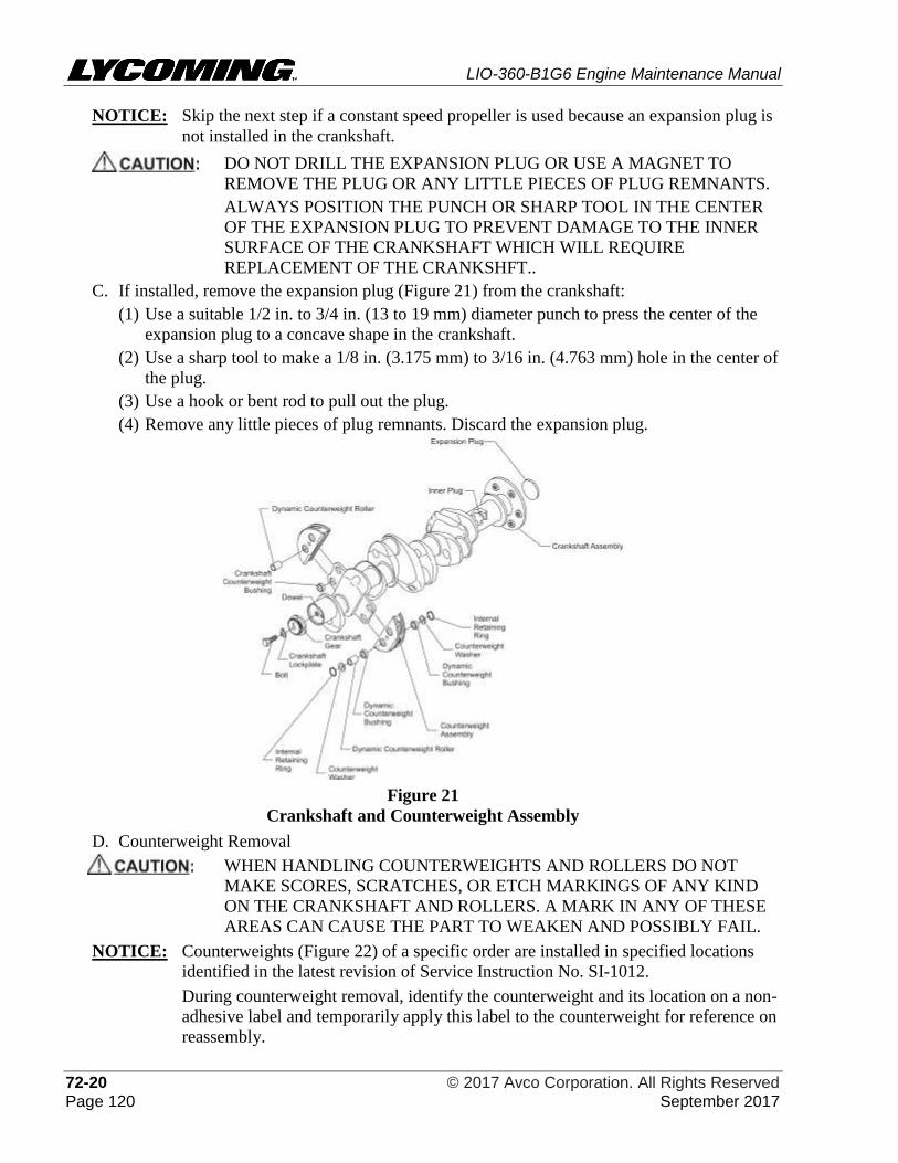
LIO-360-B1G6 Engine Maintenance Manual
72-20 © 2017 Avco Corporation. All Rights Reserved Page 120 September 2017
NOTICE: Skip the next step if a constant speed propeller is used because an expansion plug is
not installed in the crankshaft.
DO NOT DRILL THE EXPANSION PLUG OR USE A MAGNET TO
REMOVE THE PLUG OR ANY LITTLE PIECES OF PLUG REMNANTS.
ALWAYS POSITION THE PUNCH OR SHARP TOOL IN THE CENTER
OF THE EXPANSION PLUG TO PREVENT DAMAGE TO THE INNER
SURFACE OF THE CRANKSHAFT WHICH WILL REQUIRE
REPLACEMENT OF THE CRANKSHFT..
C. If installed, remove the expansion plug (Figure 21) from the crankshaft:
(1) Use a suitable 1/2 in. to 3/4 in. (13 to 19 mm) diameter punch to press the center of the
expansion plug to a concave shape in the crankshaft.
(2) Use a sharp tool to make a 1/8 in. (3.175 mm) to 3/16 in. (4.763 mm) hole in the center of
the plug.
(3) Use a hook or bent rod to pull out the plug.
(4) Remove any little pieces of plug remnants. Discard the expansion plug.
Figure 21
Crankshaft and Counterweight Assembly
D. Counterweight Removal
WHEN HANDLING COUNTERWEIGHTS AND ROLLERS DO NOT
MAKE SCORES, SCRATCHES, OR ETCH MARKINGS OF ANY KIND
ON THE CRANKSHAFT AND ROLLERS. A MARK IN ANY OF THESE
AREAS CAN CAUSE THE PART TO WEAKEN AND POSSIBLY FAIL.
NOTICE: Counterweights (Figure 22) of a specific order are installed in specified locations
identified in the latest revision of Service Instruction No. SI-1012.
During counterweight removal, identify the counterweight and its location on a non-
adhesive label and temporarily apply this label to the counterweight for reference on
reassembly.
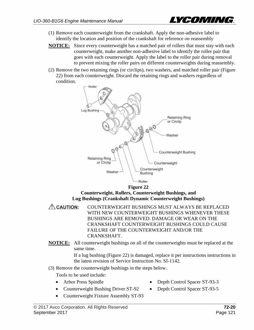
LIO-360-B1G6 Engine Maintenance Manual
© 2017 Avco Corporation. All Rights Reserved 72-20 September 2017 Page 121
(1) Remove each counterweight from the crankshaft. Apply the non-adhesive label to
identify the location and position of the crankshaft for reference on reassembly
NOTICE: Since every counterweight has a matched pair of rollers that must stay with each
counterweight, make another non-adhesive label to identify the roller pair that
goes with each counterweight. Apply the label to the roller pair during removal
to prevent mixing the roller pairs on different counterweights during reassembly.
(2) Remove the two retaining rings (or circlips), two washers, and matched roller pair (Figure
22) from each counterweight. Discard the retaining rings and washers regardless of
condition.
Figure 22
Counterweight, Rollers, Counterweight Bushings, and
Lug Bushings (Crankshaft Dynamic Counterweight Bushings)
COUNTERWEIGHT BUSHINGS MUST ALWAYS BE REPLACED
WITH NEW COUNTERWEIGHT BUSHINGS WHENEVER THESE
BUSHINGS ARE REMOVED. DAMAGE OR WEAR ON THE
CRANKSHAFT COUNTERWEIGHT BUSHINGS COULD CAUSE
FAILURE OF THE COUNTERWEIGHT AND/OR THE
CRANKSHAFT.
NOTICE: All counterweight bushings on all of the counterweights must be replaced at the
same time.
If a lug bushing (Figure 22) is damaged, replace it per instructions instructions in
the latest revision of Service Instruction No. SI-1142.
(3) Remove the counterweight bushings in the steps below.
Tools to be used include:
• Arbor Press Spindle • Depth Control Spacer ST-93-3
• Counterweight Bushing Driver ST-92 • Depth Control Spacer ST-93-5
• Counterweight Fixture Assembly ST-93
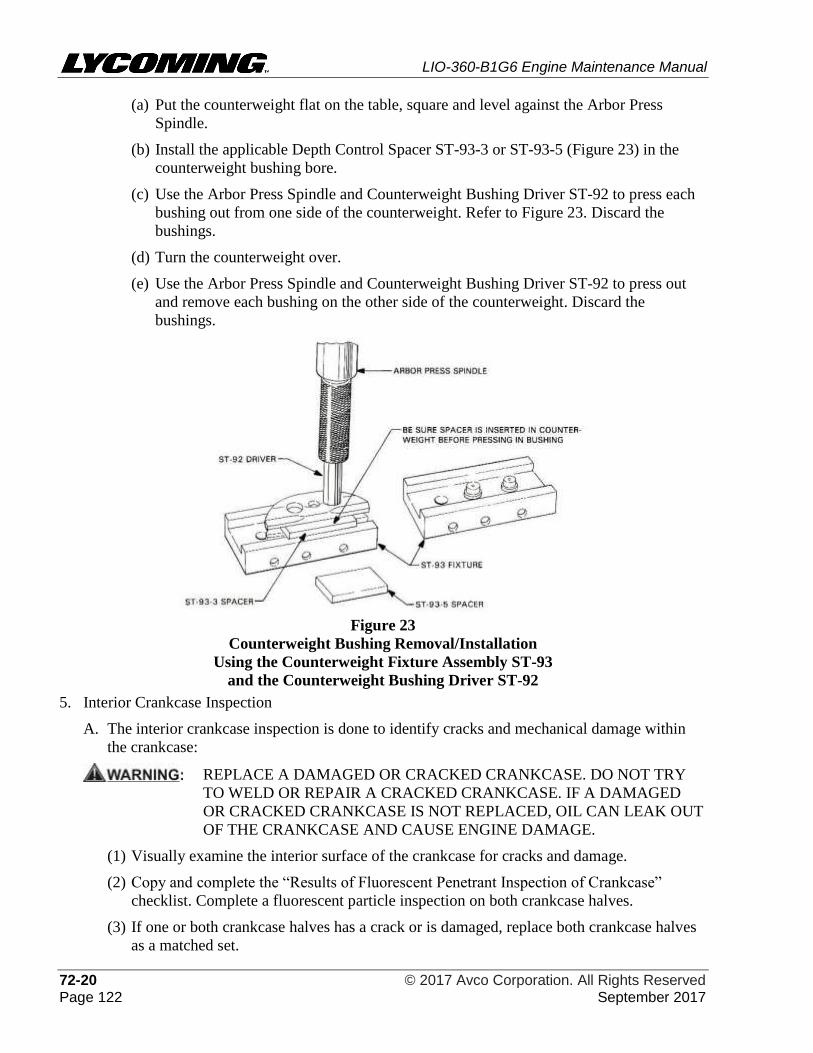
LIO-360-B1G6 Engine Maintenance Manual
72-20 © 2017 Avco Corporation. All Rights Reserved Page 122 September 2017
(a) Put the counterweight flat on the table, square and level against the Arbor Press
Spindle.
(b) Install the applicable Depth Control Spacer ST-93-3 or ST-93-5 (Figure 23) in the
counterweight bushing bore.
(c) Use the Arbor Press Spindle and Counterweight Bushing Driver ST-92 to press each
bushing out from one side of the counterweight. Refer to Figure 23. Discard the
bushings.
(d) Turn the counterweight over.
(e) Use the Arbor Press Spindle and Counterweight Bushing Driver ST-92 to press out
and remove each bushing on the other side of the counterweight. Discard the
bushings.
Figure 23
Counterweight Bushing Removal/Installation
Using the Counterweight Fixture Assembly ST-93
and the Counterweight Bushing Driver ST-92
5. Interior Crankcase Inspection
A. The interior crankcase inspection is done to identify cracks and mechanical damage within
the crankcase:
REPLACE A DAMAGED OR CRACKED CRANKCASE. DO NOT TRY
TO WELD OR REPAIR A CRACKED CRANKCASE. IF A DAMAGED
OR CRACKED CRANKCASE IS NOT REPLACED, OIL CAN LEAK OUT
OF THE CRANKCASE AND CAUSE ENGINE DAMAGE.
(1) Visually examine the interior surface of the crankcase for cracks and damage.
(2) Copy and complete the “Results of Fluorescent Penetrant Inspection of Crankcase”
checklist. Complete a fluorescent particle inspection on both crankcase halves.
(3) If one or both crankcase halves has a crack or is damaged, replace both crankcase halves
as a matched set.
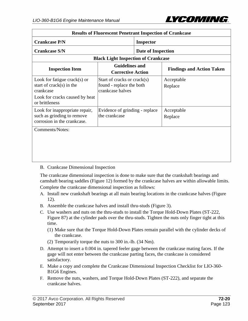
LIO-360-B1G6 Engine Maintenance Manual
© 2017 Avco Corporation. All Rights Reserved 72-20 September 2017 Page 123
Results of Fluorescent Penetrant Inspection of Crankcase
Crankcase P/N Inspector
Crankcase S/N Date of Inspection
Black Light Inspection of Crankcase
Inspection Item Guidelines and
Corrective Action Findings and Action Taken
Look for fatigue crack(s) or
start of crack(s) in the
crankcase
Look for cracks caused by heat
or brittleness
Start of cracks or crack(s)
found - replace the both
crankcase halves
Acceptable
Replace
Look for inappropriate repair,
such as grinding to remove
corrosion in the crankcase.
Evidence of grinding - replace
the crankcase
Acceptable
Replace
Comments/Notes:
B. Crankcase Dimensional Inspection
The crankcase dimensional inspection is done to make sure that the crankshaft bearings and
camshaft bearing saddles (Figure 12) formed by the crankcase halves are within allowable limits.
Complete the crankcase dimensional inspection as follows:
A. Install new crankshaft bearings at all main bearing locations in the crankcase halves (Figure
12).
B. Assemble the crankcase halves and install thru-studs (Figure 3).
C. Use washers and nuts on the thru-studs to install the Torque Hold-Down Plates (ST-222,
Figure 87) at the cylinder pads over the thru-studs. Tighten the nuts only finger tight at this
time.
(1) Make sure that the Torque Hold-Down Plates remain parallel with the cylinder decks of
the crankcase.
(2) Temporarily torque the nuts to 300 in.-lb. (34 Nm).
D. Attempt to insert a 0.004 in. tapered feeler gage between the crankcase mating faces. If the
gage will not enter between the crankcase parting faces, the crankcase is considered
satisfactory.
E. Make a copy and complete the Crankcase Dimensional Inspection Checklist for LIO-360-
B1G6 Engines.
F. Remove the nuts, washers, and Torque Hold-Down Plates (ST-222), and separate the
crankcase halves.
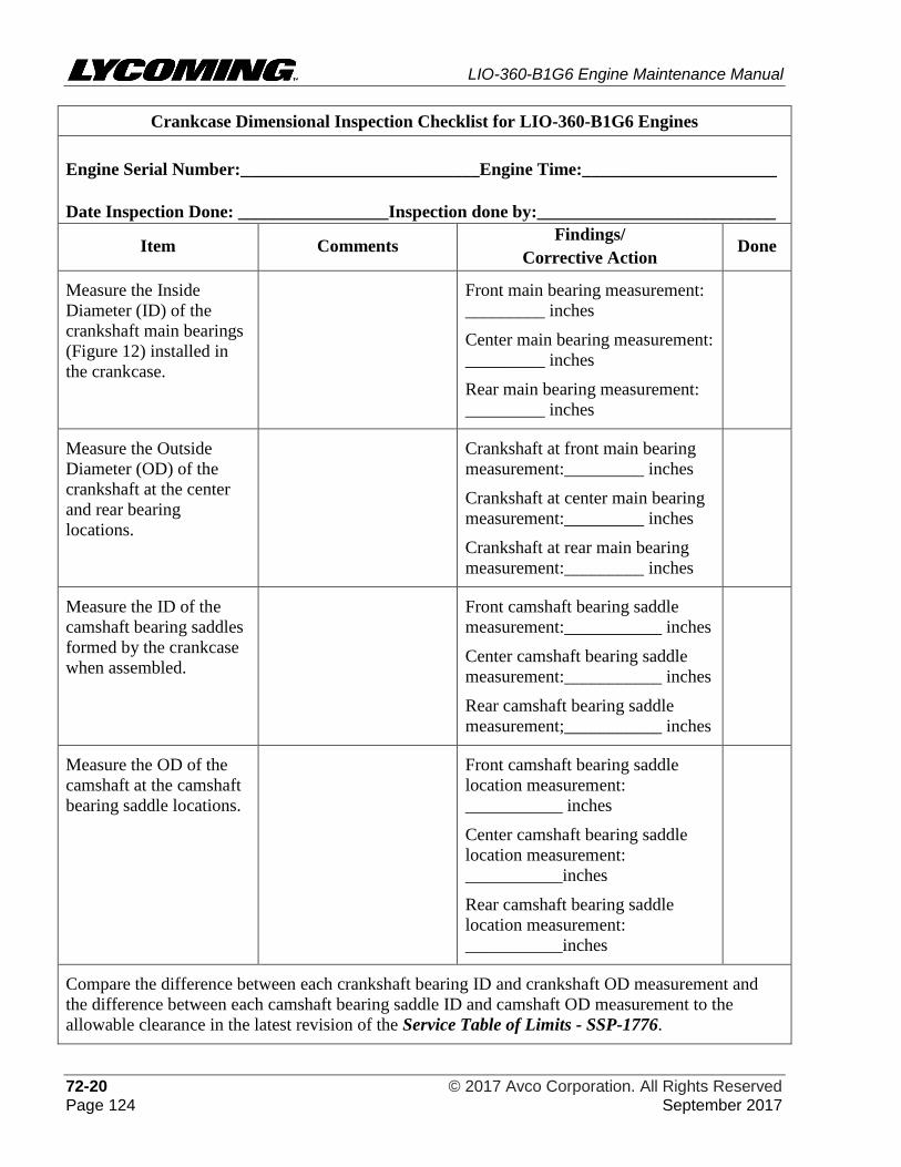
LIO-360-B1G6 Engine Maintenance Manual
72-20 © 2017 Avco Corporation. All Rights Reserved Page 124 September 2017
Crankcase Dimensional Inspection Checklist for LIO-360-B1G6 Engines
Engine Serial Number:___________________________Engine Time:______________________
Date Inspection Done: _________________Inspection done by:___________________________
Item Comments Findings/
Corrective Action Done
Measure the Inside
Diameter (ID) of the
crankshaft main bearings
(Figure 12) installed in
the crankcase.
Front main bearing measurement:
_________ inches
Center main bearing measurement:
_________ inches
Rear main bearing measurement:
_________ inches
Measure the Outside
Diameter (OD) of the
crankshaft at the center
and rear bearing
locations.
Crankshaft at front main bearing
measurement:_________ inches
Crankshaft at center main bearing
measurement:_________ inches
Crankshaft at rear main bearing
measurement:_________ inches
Measure the ID of the
camshaft bearing saddles
formed by the crankcase
when assembled.
Front camshaft bearing saddle
measurement:___________ inches
Center camshaft bearing saddle
measurement:___________ inches
Rear camshaft bearing saddle
measurement;___________ inches
Measure the OD of the
camshaft at the camshaft
bearing saddle locations.
Front camshaft bearing saddle
location measurement:
___________ inches
Center camshaft bearing saddle
location measurement:
___________inches
Rear camshaft bearing saddle
location measurement:
___________inches
Compare the difference between each crankshaft bearing ID and crankshaft OD measurement and
the difference between each camshaft bearing saddle ID and camshaft OD measurement to the
allowable clearance in the latest revision of the Service Table of Limits - SSP-1776.
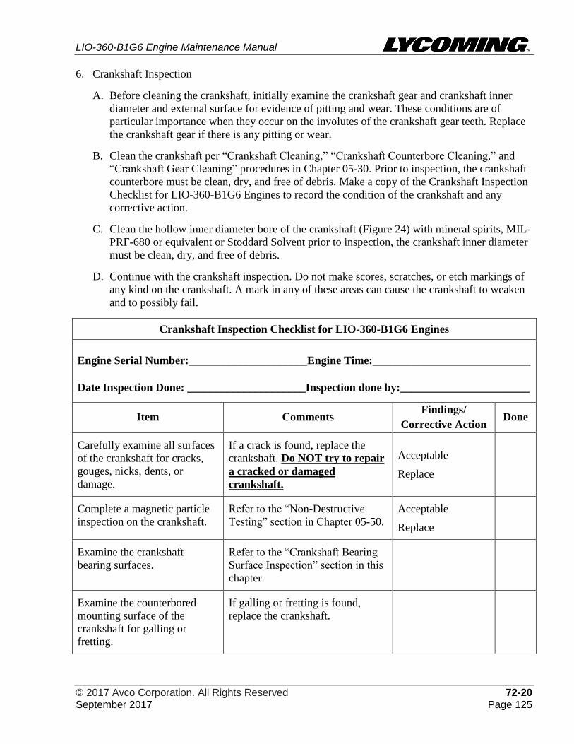
LIO-360-B1G6 Engine Maintenance Manual
© 2017 Avco Corporation. All Rights Reserved 72-20 September 2017 Page 125
6. Crankshaft Inspection
A. Before cleaning the crankshaft, initially examine the crankshaft gear and crankshaft inner
diameter and external surface for evidence of pitting and wear. These conditions are of
particular importance when they occur on the involutes of the crankshaft gear teeth. Replace
the crankshaft gear if there is any pitting or wear.
B. Clean the crankshaft per “Crankshaft Cleaning,” “Crankshaft Counterbore Cleaning,” and
“Crankshaft Gear Cleaning” procedures in Chapter 05-30. Prior to inspection, the crankshaft
counterbore must be clean, dry, and free of debris. Make a copy of the Crankshaft Inspection
Checklist for LIO-360-B1G6 Engines to record the condition of the crankshaft and any
corrective action.
C. Clean the hollow inner diameter bore of the crankshaft (Figure 24) with mineral spirits, MIL-
PRF-680 or equivalent or Stoddard Solvent prior to inspection, the crankshaft inner diameter
must be clean, dry, and free of debris.
D. Continue with the crankshaft inspection. Do not make scores, scratches, or etch markings of
any kind on the crankshaft. A mark in any of these areas can cause the crankshaft to weaken
and to possibly fail.
Crankshaft Inspection Checklist for LIO-360-B1G6 Engines
Engine Serial Number:_____________________Engine Time:____________________________
Date Inspection Done: _____________________Inspection done by:_______________________
Item Comments Findings/
Corrective Action Done
Carefully examine all surfaces
of the crankshaft for cracks,
gouges, nicks, dents, or
damage.
If a crack is found, replace the
crankshaft. Do NOT try to repair
a cracked or damaged
crankshaft.
Acceptable
Replace
Complete a magnetic particle
inspection on the crankshaft.
Refer to the “Non-Destructive
Testing” section in Chapter 05-50.
Acceptable
Replace
Examine the crankshaft
bearing surfaces.
Refer to the “Crankshaft Bearing
Surface Inspection” section in this
chapter.
Examine the counterbored
mounting surface of the
crankshaft for galling or
fretting.
If galling or fretting is found,
replace the crankshaft.
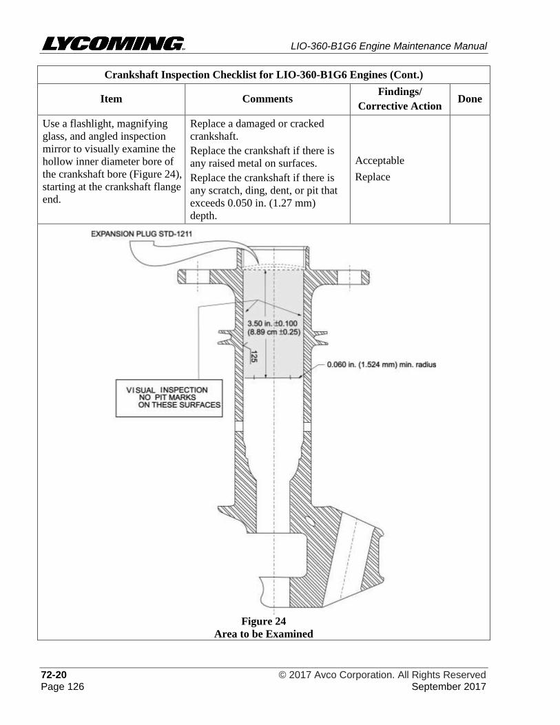
LIO-360-B1G6 Engine Maintenance Manual
72-20 © 2017 Avco Corporation. All Rights Reserved Page 126 September 2017
Crankshaft Inspection Checklist for LIO-360-B1G6 Engines (Cont.)
Item Comments Findings/
Corrective Action Done
Use a flashlight, magnifying
glass, and angled inspection
mirror to visually examine the
hollow inner diameter bore of
the crankshaft bore (Figure 24),
starting at the crankshaft flange
end.
Replace a damaged or cracked
crankshaft.
Replace the crankshaft if there is
any raised metal on surfaces.
Replace the crankshaft if there is
any scratch, ding, dent, or pit that
exceeds 0.050 in. (1.27 mm)
depth.
Acceptable
Replace
Figure 24
Area to be Examined
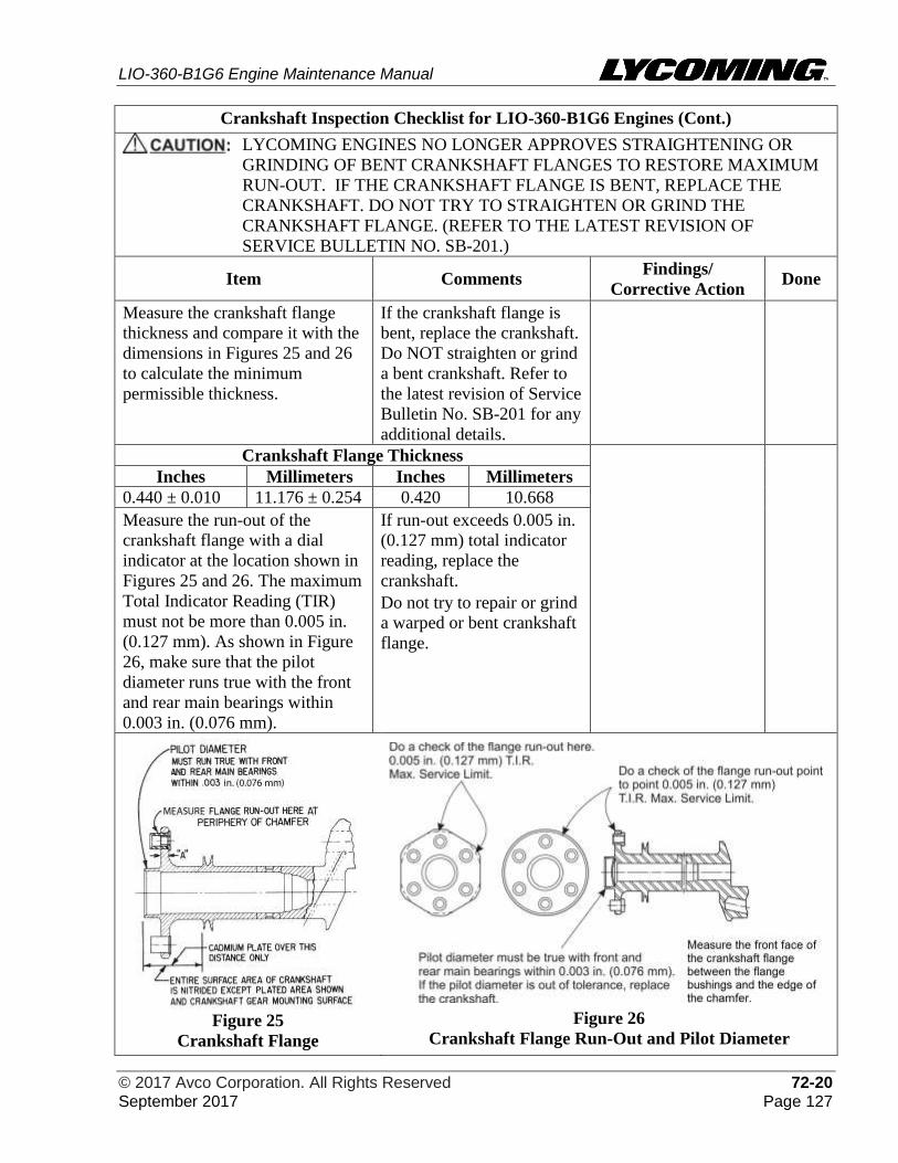
LIO-360-B1G6 Engine Maintenance Manual
© 2017 Avco Corporation. All Rights Reserved 72-20 September 2017 Page 127
Crankshaft Inspection Checklist for LIO-360-B1G6 Engines (Cont.)
LYCOMING ENGINES NO LONGER APPROVES STRAIGHTENING OR
GRINDING OF BENT CRANKSHAFT FLANGES TO RESTORE MAXIMUM
RUN-OUT. IF THE CRANKSHAFT FLANGE IS BENT, REPLACE THE
CRANKSHAFT. DO NOT TRY TO STRAIGHTEN OR GRIND THE
CRANKSHAFT FLANGE. (REFER TO THE LATEST REVISION OF
SERVICE BULLETIN NO. SB-201.)
Item Comments Findings/
Corrective Action Done
Measure the crankshaft flange
thickness and compare it with the
dimensions in Figures 25 and 26
to calculate the minimum
permissible thickness.
If the crankshaft flange is
bent, replace the crankshaft.
Do NOT straighten or grind
a bent crankshaft. Refer to
the latest revision of Service
Bulletin No. SB-201 for any
additional details.
Crankshaft Flange Thickness
Inches Millimeters Inches Millimeters
0.440 ± 0.010 11.176 ± 0.254 0.420 10.668
Measure the run-out of the
crankshaft flange with a dial
indicator at the location shown in
Figures 25 and 26. The maximum
Total Indicator Reading (TIR)
must not be more than 0.005 in.
(0.127 mm). As shown in Figure
26, make sure that the pilot
diameter runs true with the front
and rear main bearings within
0.003 in. (0.076 mm).
If run-out exceeds 0.005 in.
(0.127 mm) total indicator
reading, replace the
crankshaft.
Do not try to repair or grind
a warped or bent crankshaft
flange.
Figure 25
Crankshaft Flange
Figure 26
Crankshaft Flange Run-Out and Pilot Diameter
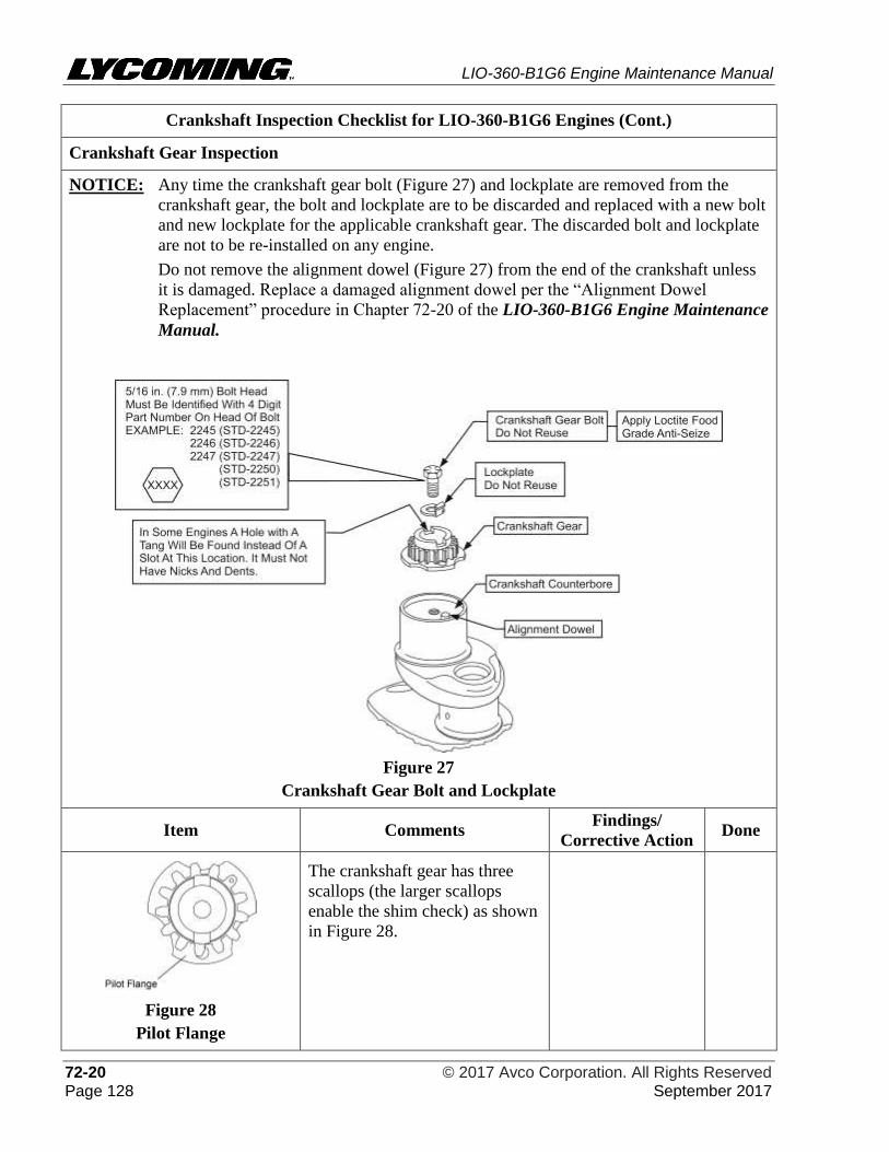
LIO-360-B1G6 Engine Maintenance Manual
72-20 © 2017 Avco Corporation. All Rights Reserved Page 128 September 2017
Crankshaft Inspection Checklist for LIO-360-B1G6 Engines (Cont.)
Crankshaft Gear Inspection
NOTICE: Any time the crankshaft gear bolt (Figure 27) and lockplate are removed from the
crankshaft gear, the bolt and lockplate are to be discarded and replaced with a new bolt
and new lockplate for the applicable crankshaft gear. The discarded bolt and lockplate
are not to be re-installed on any engine.
Do not remove the alignment dowel (Figure 27) from the end of the crankshaft unless
it is damaged. Replace a damaged alignment dowel per the “Alignment Dowel
Replacement” procedure in Chapter 72-20 of the LIO-360-B1G6 Engine Maintenance
Manual.
Figure 27
Crankshaft Gear Bolt and Lockplate
Item Comments Findings/
Corrective Action Done
Figure 28
Pilot Flange
The crankshaft gear has three
scallops (the larger scallops
enable the shim check) as shown
in Figure 28.
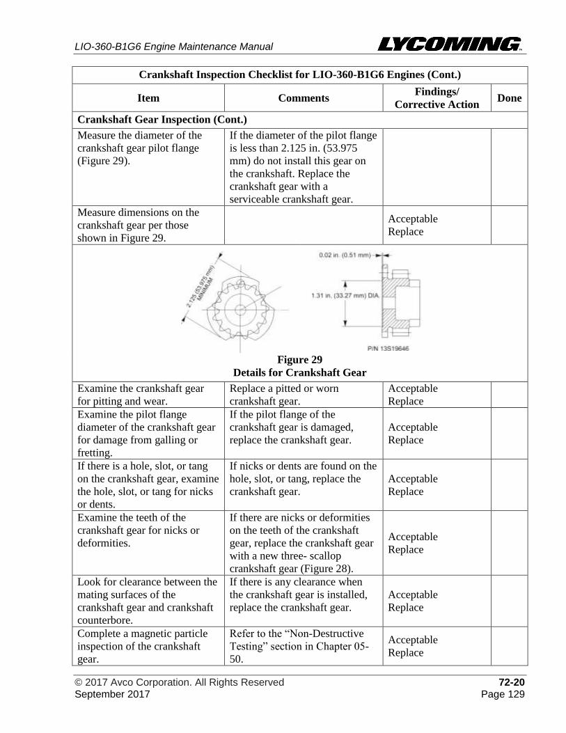
LIO-360-B1G6 Engine Maintenance Manual
© 2017 Avco Corporation. All Rights Reserved 72-20 September 2017 Page 129
Crankshaft Inspection Checklist for LIO-360-B1G6 Engines (Cont.)
Item Comments Findings/
Corrective Action Done
Crankshaft Gear Inspection (Cont.)
Measure the diameter of the
crankshaft gear pilot flange
(Figure 29).
If the diameter of the pilot flange
is less than 2.125 in. (53.975
mm) do not install this gear on
the crankshaft. Replace the
crankshaft gear with a
serviceable crankshaft gear.
Measure dimensions on the
crankshaft gear per those
shown in Figure 29.
Acceptable
Replace
Figure 29
Details for Crankshaft Gear
Examine the crankshaft gear
for pitting and wear.
Replace a pitted or worn
crankshaft gear.
Acceptable
Replace
Examine the pilot flange
diameter of the crankshaft gear
for damage from galling or
fretting.
If the pilot flange of the
crankshaft gear is damaged,
replace the crankshaft gear.
Acceptable
Replace
If there is a hole, slot, or tang
on the crankshaft gear, examine
the hole, slot, or tang for nicks
or dents.
If nicks or dents are found on the
hole, slot, or tang, replace the
crankshaft gear.
Acceptable
Replace
Examine the teeth of the
crankshaft gear for nicks or
deformities.
If there are nicks or deformities
on the teeth of the crankshaft
gear, replace the crankshaft gear
with a new three- scallop
crankshaft gear (Figure 28).
Acceptable
Replace
Look for clearance between the
mating surfaces of the
crankshaft gear and crankshaft
counterbore.
If there is any clearance when
the crankshaft gear is installed,
replace the crankshaft gear.
Acceptable
Replace
Complete a magnetic particle
inspection of the crankshaft
gear.
Refer to the “Non-Destructive
Testing” section in Chapter 05-
50.
Acceptable
Replace
LIO-360-B1G6 Engine Maintenance Manual
72-20 © 2017 Avco Corporation. All Rights Reserved Page 130 September 2017
Crankshaft Inspection Checklist for LIO-360-B1G6 Engines (Cont.)
Item Comments Findings/
Corrective Action Done
Criteria for Crankshaft Gear Replacement
Lycoming Engines no longer approves rework or repair of an unacceptable crankshaft gear.
Replace the crankshaft gear with a serviceable crankshaft gear if any of the following are found
during the crankshaft gear identification and inspection.
• If the pilot flange diameter is less than 2.125 in. (53.975 mm) or is not in compliance with
dimensions shown in Figure 29
• If the crankshaft gear does not have the larger scallops as shown in Figure 28
• Damaged counterbore face of the crankshaft gear
• If the crankshaft gear has a hole, slot, or tang and there are any nicks or dents on the hole,
slot, or tang; nicks or deformities on the slot and teeth of the crankshaft gear
• Pitting, galling, fretting, or wear
• Crankshaft gear that fails magnetic particle inspection
• Clearance between the mating surfaces of the installed crankshaft gear and crankshaft
counterbore (There must not be any clearance when the crankshaft gear is installed.)
Crankshaft Counterbore Inspection
LYCOMING ENGINES NO LONGER ALLOWS REWORK OF THE
COUNTERBORE. DO NOT TRY TO REPAIR THE CRANKSHAFT
COUNTERBORE THREADS IN THE FIELD. IF THIS TYPE OF REPAIR IS
NECESSARY, IT IS RECOMMENDED THE CRANKSHAFT BE SENT TO THE
FACTORY (THROUGH AN AUTHORIZED LYCOMING DISTRIBUTOR)
WITH PAPERWORK THAT IDENTIFIES THE NECESSARY REPAIR.
NOTICE: Prior to inspection, the crankshaft counterbore must be clean, dry, and free of debris.
Refer to the “Crankshaft Counterbore Cleaning” procedure in Chapter 05-30.
Make sure the threads in the
counterbored end of the
crankshaft are intact and not
galled, stripped, or damaged.
If the threads are galled, stripped
or damaged, it is recommended
the crankshaft be sent to
Lycoming Engines (through an
authorized Lycoming distributor)
with paperwork that identifies the
type of damage. Do not try to
repair the threads in the field.
Measure the Inside Diameter
(ID) of the crankshaft
counterbore at the rear of the
crankshaft to make sure there is a
correct fit between the ID of the
crankshaft and the Outside
Diameter (OD) of the crankshaft
gear pilot flange. The crankshaft
counterbore diameter at the rear
of the crankshaft must not be
more than 2.126 in. (54.000 mm)
when measured at any location.
If the diameter is oversized,
replace the crankshaft.
Lycoming Engines no longer
approves rework or repair of an
unacceptable crankshaft
counterbore diameter.
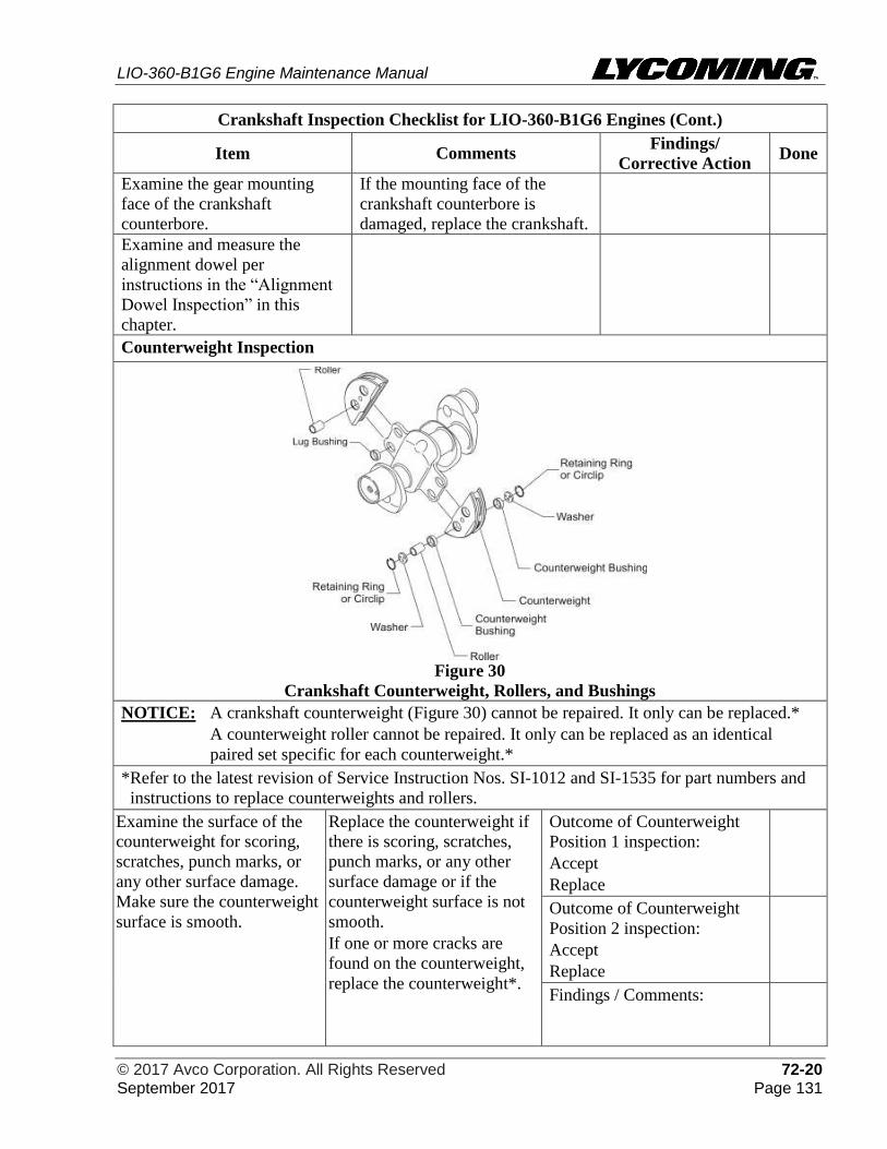
LIO-360-B1G6 Engine Maintenance Manual
© 2017 Avco Corporation. All Rights Reserved 72-20 September 2017 Page 131
Crankshaft Inspection Checklist for LIO-360-B1G6 Engines (Cont.)
Item Comments Findings/
Corrective Action Done
Examine the gear mounting
face of the crankshaft
counterbore.
If the mounting face of the
crankshaft counterbore is
damaged, replace the crankshaft.
Examine and measure the
alignment dowel per
instructions in the “Alignment
Dowel Inspection” in this
chapter.
Counterweight Inspection
Figure 30
Crankshaft Counterweight, Rollers, and Bushings
NOTICE: A crankshaft counterweight (Figure 30) cannot be repaired. It only can be replaced.*
A counterweight roller cannot be repaired. It only can be replaced as an identical
paired set specific for each counterweight.*
*Refer to the latest revision of Service Instruction Nos. SI-1012 and SI-1535 for part numbers and
instructions to replace counterweights and rollers.
Examine the surface of the
counterweight for scoring,
scratches, punch marks, or
any other surface damage.
Make sure the counterweight
surface is smooth.
Replace the counterweight if
there is scoring, scratches,
punch marks, or any other
surface damage or if the
counterweight surface is not
smooth.
If one or more cracks are
found on the counterweight,
replace the counterweight*.
Outcome of Counterweight
Position 1 inspection:
Accept
Replace
Outcome of Counterweight
Position 2 inspection:
Accept
Replace
Findings / Comments:
LIO-360-B1G6 Engine Maintenance Manual
72-20 © 2017 Avco Corporation. All Rights Reserved Page 132 September 2017
Crankshaft Inspection Checklist for LIO-360-B1G6 Engines (Cont.)
Item Comments Findings/
Corrective Action Done
Counterweight Inspection (Cont.)
Examine the lug bushings for
roundness and for any
scratches, etching, galling or
any other surface damage.
Replace any lug bushing that
is out-of-round, scratched,
etched, galled, or has surface
damage. Refer to the latest
revision of Service
Instruction No. SI-1142
Complete Non-Destructive
Test (magnetic particle
inspection) on the
counterweights.
Refer to Chapter 05-50. Findings / Comments:
Examine the bushing bore on
the counterweight for
roundness and for any
scratches, etching, galling or
any other surface damage.
Measure the bushing bore
diameter on the
counterweight.
Replace the counterweight if
the bushing bore on the
counterweight is not round,
not smooth, is out of
tolerance, or has surface
damage.*
Outcome of Bushing Bore
Inspection for Counterweight
Position 1
Accept Replace
Outcome of Bushing Bore
Inspection for Counterweight
Position 2
Accept Replace
(a) The bushing bore on the counterweight must be between
0.9369 and 0.9377 in. (23.7973 and 23.8176 mm).
Bushing Bore Diameter
Counterweight Position 1:
Bushing Bore Diameter
Counterweight Position 2:
NOTICE: If the bushing bore on the counterweight is not within the specified tolerances, replace
the counterweight. Some counterweights must be replaced as a matched set.*
DO NOT INCREASE THE DIAMETER OF THE BUSHING BORE ON A
COUNTERWEIGHT. THIS ENLARGEMENT CAN CAUSE ENGINE
DAMAGE BECAUSE IT WILL DECREASE THE SNAP RING GROOVE
DEPTH IN THE BUSHING BORE ON THE COUNTERWEIGHT.
*Refer to the latest revision of Service Instruction Nos. SI-1012 and SI-1535 for part numbers and
instructions to replace counterweights and rollers.
Examine the surface of the
rollers for scoring,
scratches, punch marks, or
any other surface damage.
Make sure the roller surface
is smooth.
If the roller surface is not
smooth or has scoring,
scratches, punch marks, or
any other surface damage is
on one or both rollers in a
pair, replace the rollers as a
matched pair.
Outcome of Roller Pair
Inspection for Counterweight
Position 1
Accept Replace
Outcome of Roller Pair
Inspection for Counterweight
Position 2
Accept Replace
LIO-360-B1G6 Engine Maintenance Manual
© 2017 Avco Corporation. All Rights Reserved 72-20 September 2017 Page 133
Crankshaft Inspection Checklist for LIO-360-B1G6 Engines (Cont.)
Item Comments Findings/
Corrective Action Done
Counterweight Inspection (Cont.)
Complete Non-Destructive
Testing on rollers. Refer to
Chapter 05-50.
If one or more cracks are
found on a roller, replace
the rollers as a matched
pair.*
Findings / Comments:
Measure the roller
dimensions per the latest
revision of Service
Instruction No. SI-1535.
If the roller is out of
tolerance, replace the rollers
as a matched pair.*
Findings / Comments:
*Refer to the latest revision of Service Instruction Nos. SI-1012 and SI-1535 for part numbers and
instructions to replace counterweights and rollers.
Rejection Criteria for a Crankshaft
A crankshaft must be replaced under any of the following conditions:
• If a crack or damage is found
• If corrosion is found or there is evidence of grinding to remove corrosion
• Crack(s) or pitting with crack(s) in the crankshaft inner bore
• Warped or bent crankshaft flange (Do not try to repair or grind a warped or bent crankshaft
flange)
• If the mounting surface of the crankshaft counterbore is galled, fretted or damaged
• Oversized inside diameter of crankshaft
• If a bearing surface is scored, galled, or worn and polishing to either 0.003 in. or 0.006 in.
undersize does not remove the condition
• If the undersize is greater than 0.006 in.
• Raised metal on inner diameter bore of crankshaft surface.
• Scratch, ding, dent, or pit that exceeds 0.050 in. (1.27 mm) depth on crankshaft inner
diameter bore
• If run-out exceeds 0.005 in. (0.127 mm) total indicator reading
Findings/Comments:
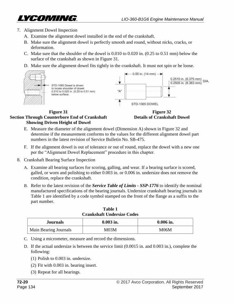
LIO-360-B1G6 Engine Maintenance Manual
72-20 © 2017 Avco Corporation. All Rights Reserved Page 134 September 2017
7. Alignment Dowel Inspection
A. Examine the alignment dowel installed in the end of the crankshaft.
B. Make sure the alignment dowel is perfectly smooth and round, without nicks, cracks, or
deformation.
C. Make sure that the shoulder of the dowel is 0.010 to 0.020 in. (0.25 to 0.51 mm) below the
surface of the crankshaft as shown in Figure 31.
D. Make sure the alignment dowel fits tightly in the crankshaft. It must not spin or be loose.
Figure 31
Section Through Counterbore End of Crankshaft
Showing Driven Height of Dowel
Figure 32
Details of Crankshaft Dowel
E. Measure the diameter of the alignment dowel (Dimension A) shown in Figure 32 and
determine if the measurement conforms to the values for the different alignment dowel part
numbers in the latest revision of Service Bulletin No. SB-475.
F. If the alignment dowel is out of tolerance or out of round, replace the dowel with a new one
per the “Alignment Dowel Replacement” procedure in this chapter.
8. Crankshaft Bearing Surface Inspection
A. Examine all bearing surfaces for scoring, galling, and wear. If a bearing surface is scored,
galled, or worn and polishing to either 0.003 in. or 0.006 in. undersize does not remove the
condition, replace the crankshaft.
B. Refer to the latest revision of the Service Table of Limits - SSP-1776 to identify the nominal
manufactured specifications of the bearing journals. Undersize crankshaft bearing journals in
Table 1 are identified by a code symbol stamped on the front of the flange as a suffix to the
part number.
Table 1
Crankshaft Undersize Codes
Journals 0.003 in. 0.006 in.
Main Bearing Journals M03M M06M
C. Using a micrometer, measure and record the dimensions.
D. If the actual undersize is between the service limit (0.0015 in. and 0.003 in.), complete the
following:
(1) Polish to 0.003 in. undersize.
(2) Fit with 0.003 in. bearing insert.
(3) Repeat for all bearings.
LIO-360-B1G6 Engine Maintenance Manual
© 2017 Avco Corporation. All Rights Reserved 72-20 September 2017 Page 135
DURING POLISHING, DO NOT ALLOW THE LATHE SPEED TO
EXCEED 150 RPM.
NOTICE: Polishing undersize is preferable to grinding undersize because crankshafts that
are polished do not require re-nitriding.
If one bearing journal is polished to 0.003 in. or 0.006 in. undersize, all
corresponding journals must be polished to the same size.
If a bearing surface is scored, galled, or worn and polishing to either 0.003 in. or
0.006 in. undersize does not remove the condition, replace the crankshaft.
E. If, after the bearing journal is polished to 0.003 in., the bearing journal requires more
polishing complete the following:
(1) Polish to 0.006 in. undersize.
(2) Fit with 0.006 in. bearing insert.
(3) Repeat for all like bearings.
F. If the actual undersize is greater than 0.006 in., replace the crankshaft.
9. Bearing Shell Surface Inspection
NOTICE: Inspections in this section refer to reusable items that do not require replacement in
accordance with the latest revision of Service Bulletin No. SB-240. Be sure to record
any part replacement or corrective action in the engine logbook.
A. Examine all bearing saddle surfaces for scoring, galling, and wear. If any of these conditions
are found, identify and correct the cause.
B. Make sure that the clearance of each bearing agrees with the specification in the latest
revision of the Service Table of Limits - SSP-1776.
C. If a bearing is not in the specified limits in the latest revision of the Service Table of Limit -
SSP-1776, discard it and replace it with a new one.
D. Examine all journal surfaces for galling, scores, misalignment, and out-of-round condition.
Replace a scored, galled, misaligned, or out-of-round component.
E. Examine the shafts and pins for straightness.
10. Gear Inspection
A. Examine the involutes of the gear teeth for pitting and excessive wear.
B. If pit marks are found, discard the gear and replace it with a new one.
C. Examine the bearing surfaces of all gears for deep scratches.
D. Remove minor abrasions with a fine abrasive cloth.
11. Screwed Fitting Inspection
A. Examine the condition of the threads on screwed fittings (threaded fastenings or plugs).
B. Remove small nicks and burrs with a small file, fine abrasive cloth, or stone.
C. If the part cannot be repaired by polishing it, discard it and replace it with a new one.
D. If the part has too much distortion, galling, or mutilation (caused by over-tightening or use of
an incorrect tool) replace it with a new part. Do not re-use a non-conforming part.
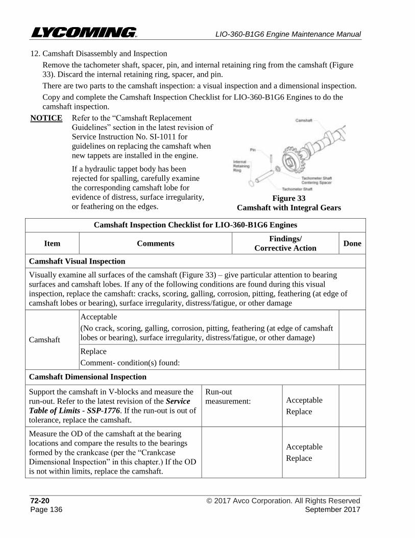
LIO-360-B1G6 Engine Maintenance Manual
72-20 © 2017 Avco Corporation. All Rights Reserved Page 136 September 2017
12. Camshaft Disassembly and Inspection
Remove the tachometer shaft, spacer, pin, and internal retaining ring from the camshaft (Figure
33). Discard the internal retaining ring, spacer, and pin.
There are two parts to the camshaft inspection: a visual inspection and a dimensional inspection.
Copy and complete the Camshaft Inspection Checklist for LIO-360-B1G6 Engines to do the
camshaft inspection.
NOTICE Refer to the “Camshaft Replacement
Guidelines” section in the latest revision of
Service Instruction No. SI-1011 for
guidelines on replacing the camshaft when
new tappets are installed in the engine.
If a hydraulic tappet body has been
rejected for spalling, carefully examine
the corresponding camshaft lobe for
evidence of distress, surface irregularity,
or feathering on the edges.
Figure 33
Camshaft with Integral Gears
Camshaft Inspection Checklist for LIO-360-B1G6 Engines
Item Comments Findings/
Corrective Action Done
Camshaft Visual Inspection
Visually examine all surfaces of the camshaft (Figure 33) – give particular attention to bearing
surfaces and camshaft lobes. If any of the following conditions are found during this visual
inspection, replace the camshaft: cracks, scoring, galling, corrosion, pitting, feathering (at edge of
camshaft lobes or bearing), surface irregularity, distress/fatigue, or other damage
Camshaft
Acceptable
(No crack, scoring, galling, corrosion, pitting, feathering (at edge of camshaft
lobes or bearing), surface irregularity, distress/fatigue, or other damage)
Replace
Comment- condition(s) found:
Camshaft Dimensional Inspection
Support the camshaft in V-blocks and measure the
run-out. Refer to the latest revision of the Service
Table of Limits - SSP-1776. If the run-out is out of
tolerance, replace the camshaft.
Run-out
measurement: Acceptable
Replace
Measure the OD of the camshaft at the bearing
locations and compare the results to the bearings
formed by the crankcase (per the “Crankcase
Dimensional Inspection” in this chapter.) If the OD
is not within limits, replace the camshaft.
Acceptable
Replace
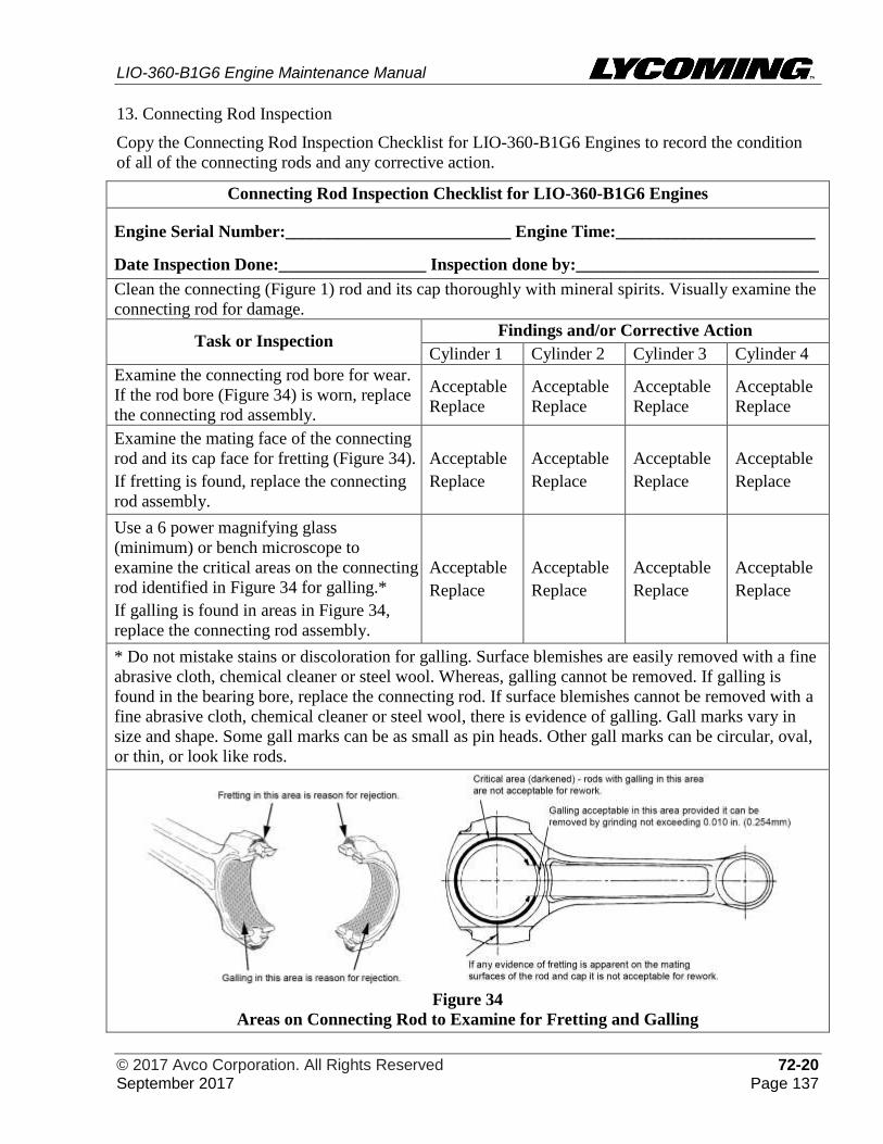
LIO-360-B1G6 Engine Maintenance Manual
© 2017 Avco Corporation. All Rights Reserved 72-20 September 2017 Page 137
13. Connecting Rod Inspection
Copy the Connecting Rod Inspection Checklist for LIO-360-B1G6 Engines to record the condition
of all of the connecting rods and any corrective action.
Connecting Rod Inspection Checklist for LIO-360-B1G6 Engines
Engine Serial Number:__________________________ Engine Time:_______________________
Date Inspection Done:_________________ Inspection done by:____________________________
Clean the connecting (Figure 1) rod and its cap thoroughly with mineral spirits. Visually examine the
connecting rod for damage.
Task or Inspection Findings and/or Corrective Action
Cylinder 1 Cylinder 2 Cylinder 3 Cylinder 4
Examine the connecting rod bore for wear.
If the rod bore (Figure 34) is worn, replace
the connecting rod assembly.
Acceptable
Replace
Acceptable
Replace
Acceptable
Replace
Acceptable
Replace
Examine the mating face of the connecting
rod and its cap face for fretting (Figure 34).
If fretting is found, replace the connecting
rod assembly.
Acceptable
Replace
Acceptable
Replace
Acceptable
Replace
Acceptable
Replace
Use a 6 power magnifying glass
(minimum) or bench microscope to
examine the critical areas on the connecting
rod identified in Figure 34 for galling.*
If galling is found in areas in Figure 34,
replace the connecting rod assembly.
Acceptable
Replace
Acceptable
Replace
Acceptable
Replace
Acceptable
Replace
* Do not mistake stains or discoloration for galling. Surface blemishes are easily removed with a fine
abrasive cloth, chemical cleaner or steel wool. Whereas, galling cannot be removed. If galling is
found in the bearing bore, replace the connecting rod. If surface blemishes cannot be removed with a
fine abrasive cloth, chemical cleaner or steel wool, there is evidence of galling. Gall marks vary in
size and shape. Some gall marks can be as small as pin heads. Other gall marks can be circular, oval,
or thin, or look like rods.
Figure 34
Areas on Connecting Rod to Examine for Fretting and Galling
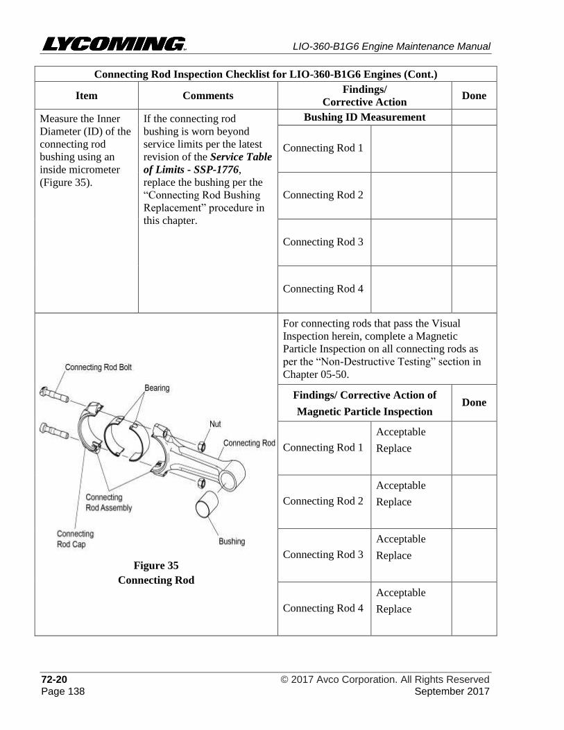
LIO-360-B1G6 Engine Maintenance Manual
72-20 © 2017 Avco Corporation. All Rights Reserved Page 138 September 2017
Connecting Rod Inspection Checklist for LIO-360-B1G6 Engines (Cont.)
Item Comments Findings/
Corrective Action Done
Measure the Inner
Diameter (ID) of the
connecting rod
bushing using an
inside micrometer
(Figure 35).
If the connecting rod
bushing is worn beyond
service limits per the latest
revision of the Service Table
of Limits - SSP-1776,
replace the bushing per the
“Connecting Rod Bushing
Replacement” procedure in
this chapter.
Bushing ID Measurement
Connecting Rod 1
Connecting Rod 2
Connecting Rod 3
Connecting Rod 4
Figure 35
Connecting Rod
For connecting rods that pass the Visual
Inspection herein, complete a Magnetic
Particle Inspection on all connecting rods as
per the “Non-Destructive Testing” section in
Chapter 05-50.
Findings/ Corrective Action of
Magnetic Particle Inspection Done
Connecting Rod 1
Acceptable
Replace
Connecting Rod 2
Acceptable
Replace
Connecting Rod 3
Acceptable
Replace
Connecting Rod 4
Acceptable
Replace
LIO-360-B1G6 Engine Maintenance Manual
© 2017 Avco Corporation. All Rights Reserved 72-20 September 2017 Page 139
Connecting Rod Inspection Checklist for LIO-360-B1G6 Engines (Cont.)
Complete the “Connecting Rods -
Parallelism/ Squareness Check” in this
chapter.
For the parallelism check, measure the
distance between arbors (Figure 39). For
exact parallelism or alignment, the distances
measured on both sides are to be the same.
For the squareness check, use a feeler gage
to measure the clearance at the four check
points where the arbors rest on the parallel
blocks (Figure 40). Compare the clearance
between each arbor and the parallel blocks
against the values in the latest revision of the
Service Table of Limits - SSP-1776. If out
of tolerance, replace the connecting rods and
examine the crankshaft to make sure the
crankshaft is not damaged.
Connecting
Rod
Parallelism
Measurement
Squareness
Measurement Outcome
Connecting
Rod 1
Acceptable
Replace
Connecting
Rod 2
Acceptable
Replace
Connecting
Rod 3
Acceptable
Replace
Connecting
Rod 4
Acceptable
Replace
Connecting Rod Bearing and Crankshaft Clearance
To complete this inspection:
NOTICE: For this inspection the connecting rods, bearings, connecting rod bolts, and nuts (Figure
35) are assembled, but not installed on the crankshaft.
1. Assemble and torque each connecting rod with acceptable bearings per instructions in the
“Connecting Rod Installation” section in this chapter.
2. Measure the inside diameter of the bearing in each connecting rod and record the
measurement below.
3. Measure the crankshaft diameter at the crankpin journal for each connecting rod and record
the measurement below.
4. Subtract the crankshaft diameter at the crankpin journal from the inside diameter of the
bearings for each connecting rod to calculate the connecting rod bearing and crankshaft
clearance. Record the measurement below.
5. Compare the connecting rod bearing and crankshaft clearance to the acceptable clearance
measurement in the latest revision of the Service Table of Limits - SSP-1776.
6. Remove and discard the connecting rod bolts and nuts from the connecting rod assembly.
7. If the connecting rod bearing and crankshaft clearance is within limits, the connecting rod
bearings are acceptable.
8. If the connecting rod bearing and crankshaft clearance is not within limits, replace the
connecting rod bearings with oversize bearings to bring the clearance within acceptable limits.
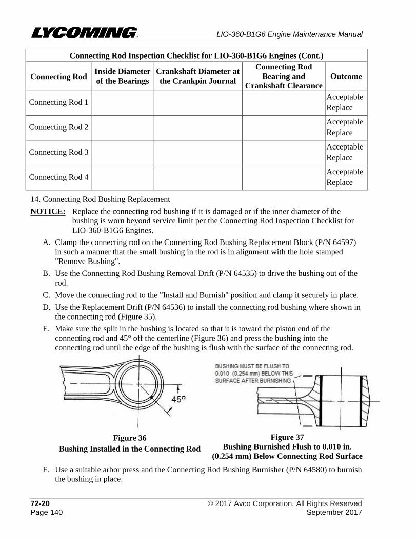
LIO-360-B1G6 Engine Maintenance Manual
72-20 © 2017 Avco Corporation. All Rights Reserved Page 140 September 2017
Connecting Rod Inspection Checklist for LIO-360-B1G6 Engines (Cont.)
Connecting Rod Inside Diameter
of the Bearings
Crankshaft Diameter at
the Crankpin Journal
Connecting Rod
Bearing and
Crankshaft Clearance
Outcome
Connecting Rod 1 Acceptable
Replace
Connecting Rod 2 Acceptable
Replace
Connecting Rod 3 Acceptable
Replace
Connecting Rod 4 Acceptable
Replace
14. Connecting Rod Bushing Replacement
NOTICE: Replace the connecting rod bushing if it is damaged or if the inner diameter of the
bushing is worn beyond service limit per the Connecting Rod Inspection Checklist for
LIO-360-B1G6 Engines.
A. Clamp the connecting rod on the Connecting Rod Bushing Replacement Block (P/N 64597)
in such a manner that the small bushing in the rod is in alignment with the hole stamped
"Remove Bushing".
B. Use the Connecting Rod Bushing Removal Drift (P/N 64535) to drive the bushing out of the
rod.
C. Move the connecting rod to the "Install and Burnish" position and clamp it securely in place.
D. Use the Replacement Drift (P/N 64536) to install the connecting rod bushing where shown in
the connecting rod (Figure 35).
E. Make sure the split in the bushing is located so that it is toward the piston end of the
connecting rod and 45° off the centerline (Figure 36) and press the bushing into the
connecting rod until the edge of the bushing is flush with the surface of the connecting rod.
Figure 36
Bushing Installed in the Connecting Rod
Figure 37
Bushing Burnished Flush to 0.010 in.
(0.254 mm) Below Connecting Rod Surface
F. Use a suitable arbor press and the Connecting Rod Bushing Burnisher (P/N 64580) to burnish
the bushing in place.
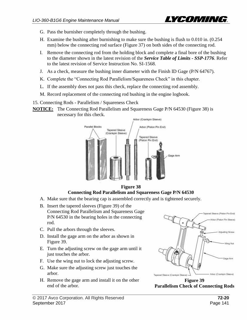
LIO-360-B1G6 Engine Maintenance Manual
© 2017 Avco Corporation. All Rights Reserved 72-20 September 2017 Page 141
G. Pass the burnisher completely through the bushing.
H. Examine the bushing after burnishing to make sure the bushing is flush to 0.010 in. (0.254
mm) below the connecting rod surface (Figure 37) on both sides of the connecting rod.
I. Remove the connecting rod from the holding block and complete a final bore of the bushing
to the diameter shown in the latest revision of the Service Table of Limits - SSP-1776. Refer
to the latest revision of Service Instruction No. SI-1568.
J. As a check, measure the bushing inner diameter with the Finish ID Gage (P/N 64767).
K. Complete the “Connecting Rod Parallelism/Squareness Check” in this chapter.
L. If the assembly does not pass this check, replace the connecting rod assembly.
M. Record replacement of the connecting rod bushing in the engine logbook.
15. Connecting Rods - Parallelism / Squareness Check
NOTICE: The Connecting Rod Parallelism and Squareness Gage P/N 64530 (Figure 38) is
necessary for this check.
Figure 38
Connecting Rod Parallelism and Squareness Gage P/N 64530
A. Make sure that the bearing cap is assembled correctly and is tightened securely.
B. Insert the tapered sleeves (Figure 39) of the
Connecting Rod Parallelism and Squareness Gage
P/N 64530 in the bearing holes in the connecting
rod.
C. Pull the arbors through the sleeves.
D. Install the gage arm on the arbor as shown in
Figure 39.
E. Turn the adjusting screw on the gage arm until it
just touches the arbor.
F. Use the wing nut to lock the adjusting screw.
G. Make sure the adjusting screw just touches the
arbor.
H. Remove the gage arm and install it on the other
end of the arbor.
Figure 39
Parallelism Check of Connecting Rods
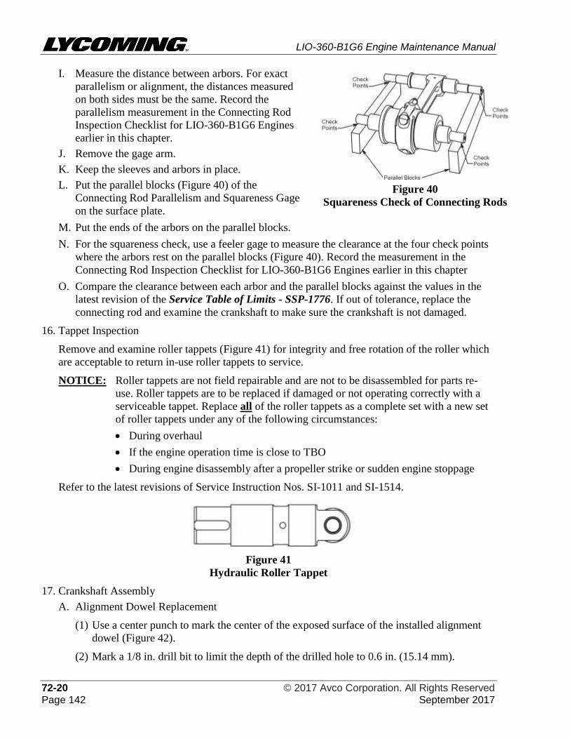
LIO-360-B1G6 Engine Maintenance Manual
72-20 © 2017 Avco Corporation. All Rights Reserved Page 142 September 2017
I. Measure the distance between arbors. For exact
parallelism or alignment, the distances measured
on both sides must be the same. Record the
parallelism measurement in the Connecting Rod
Inspection Checklist for LIO-360-B1G6 Engines
earlier in this chapter.
J. Remove the gage arm.
K. Keep the sleeves and arbors in place.
L. Put the parallel blocks (Figure 40) of the
Connecting Rod Parallelism and Squareness Gage
on the surface plate.
Figure 40
Squareness Check of Connecting Rods
M. Put the ends of the arbors on the parallel blocks.
N. For the squareness check, use a feeler gage to measure the clearance at the four check points
where the arbors rest on the parallel blocks (Figure 40). Record the measurement in the
Connecting Rod Inspection Checklist for LIO-360-B1G6 Engines earlier in this chapter
O. Compare the clearance between each arbor and the parallel blocks against the values in the
latest revision of the Service Table of Limits - SSP-1776. If out of tolerance, replace the
connecting rod and examine the crankshaft to make sure the crankshaft is not damaged.
16. Tappet Inspection
Remove and examine roller tappets (Figure 41) for integrity and free rotation of the roller which
are acceptable to return in-use roller tappets to service.
NOTICE: Roller tappets are not field repairable and are not to be disassembled for parts re-
use. Roller tappets are to be replaced if damaged or not operating correctly with a
serviceable tappet. Replace all of the roller tappets as a complete set with a new set
of roller tappets under any of the following circumstances:
• During overhaul
• If the engine operation time is close to TBO
• During engine disassembly after a propeller strike or sudden engine stoppage
Refer to the latest revisions of Service Instruction Nos. SI-1011 and SI-1514.
Figure 41
Hydraulic Roller Tappet
17. Crankshaft Assembly
A. Alignment Dowel Replacement
(1) Use a center punch to mark the center of the exposed surface of the installed alignment
dowel (Figure 42).
(2) Mark a 1/8 in. drill bit to limit the depth of the drilled hole to 0.6 in. (15.14 mm).
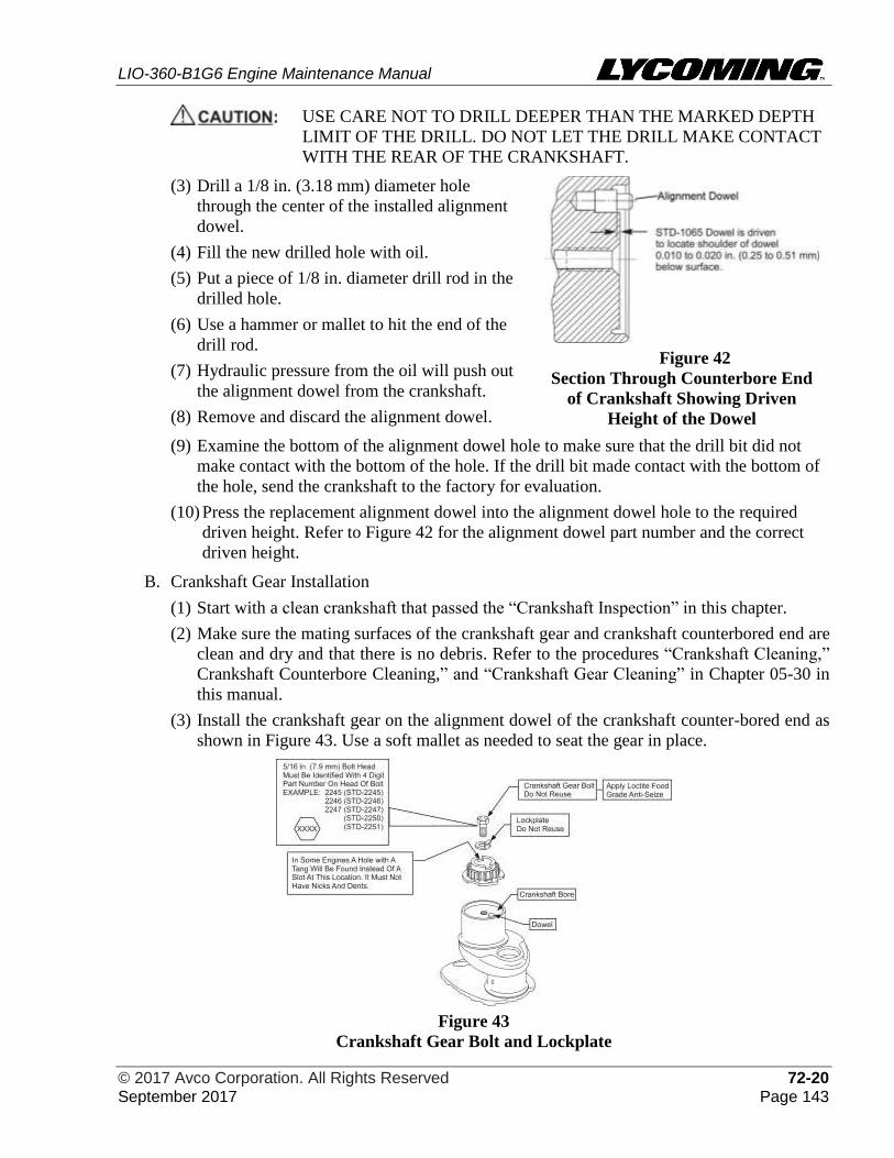
LIO-360-B1G6 Engine Maintenance Manual
© 2017 Avco Corporation. All Rights Reserved 72-20 September 2017 Page 143
USE CARE NOT TO DRILL DEEPER THAN THE MARKED DEPTH
LIMIT OF THE DRILL. DO NOT LET THE DRILL MAKE CONTACT
WITH THE REAR OF THE CRANKSHAFT.
(3) Drill a 1/8 in. (3.18 mm) diameter hole
through the center of the installed alignment
dowel.
(4) Fill the new drilled hole with oil.
(5) Put a piece of 1/8 in. diameter drill rod in the
drilled hole.
(6) Use a hammer or mallet to hit the end of the
drill rod.
(7) Hydraulic pressure from the oil will push out
the alignment dowel from the crankshaft.
(8) Remove and discard the alignment dowel.
Figure 42
Section Through Counterbore End
of Crankshaft Showing Driven
Height of the Dowel
(9) Examine the bottom of the alignment dowel hole to make sure that the drill bit did not
make contact with the bottom of the hole. If the drill bit made contact with the bottom of
the hole, send the crankshaft to the factory for evaluation.
(10) Press the replacement alignment dowel into the alignment dowel hole to the required
driven height. Refer to Figure 42 for the alignment dowel part number and the correct
driven height.
B. Crankshaft Gear Installation
(1) Start with a clean crankshaft that passed the “Crankshaft Inspection” in this chapter.
(2) Make sure the mating surfaces of the crankshaft gear and crankshaft counterbored end are
clean and dry and that there is no debris. Refer to the procedures “Crankshaft Cleaning,”
Crankshaft Counterbore Cleaning,” and “Crankshaft Gear Cleaning” in Chapter 05-30 in
this manual.
(3) Install the crankshaft gear on the alignment dowel of the crankshaft counter-bored end as
shown in Figure 43. Use a soft mallet as needed to seat the gear in place.
Figure 43
Crankshaft Gear Bolt and Lockplate
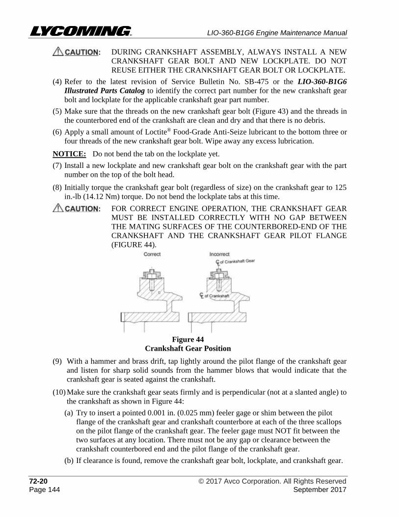
LIO-360-B1G6 Engine Maintenance Manual
72-20 © 2017 Avco Corporation. All Rights Reserved Page 144 September 2017
DURING CRANKSHAFT ASSEMBLY, ALWAYS INSTALL A NEW
CRANKSHAFT GEAR BOLT AND NEW LOCKPLATE. DO NOT
REUSE EITHER THE CRANKSHAFT GEAR BOLT OR LOCKPLATE.
(4) Refer to the latest revision of Service Bulletin No. SB-475 or the LIO-360-B1G6
Illustrated Parts Catalog to identify the correct part number for the new crankshaft gear
bolt and lockplate for the applicable crankshaft gear part number.
(5) Make sure that the threads on the new crankshaft gear bolt (Figure 43) and the threads in
the counterbored end of the crankshaft are clean and dry and that there is no debris.
(6) Apply a small amount of Loctite® Food-Grade Anti-Seize lubricant to the bottom three or
four threads of the new crankshaft gear bolt. Wipe away any excess lubrication.
NOTICE: Do not bend the tab on the lockplate yet.
(7) Install a new lockplate and new crankshaft gear bolt on the crankshaft gear with the part
number on the top of the bolt head.
(8) Initially torque the crankshaft gear bolt (regardless of size) on the crankshaft gear to 125
in.-lb (14.12 Nm) torque. Do not bend the lockplate tabs at this time.
FOR CORRECT ENGINE OPERATION, THE CRANKSHAFT GEAR
MUST BE INSTALLED CORRECTLY WITH NO GAP BETWEEN
THE MATING SURFACES OF THE COUNTERBORED-END OF THE
CRANKSHAFT AND THE CRANKSHAFT GEAR PILOT FLANGE
(FIGURE 44).
Figure 44
Crankshaft Gear Position
(9) With a hammer and brass drift, tap lightly around the pilot flange of the crankshaft gear
and listen for sharp solid sounds from the hammer blows that would indicate that the
crankshaft gear is seated against the crankshaft.
(10) Make sure the crankshaft gear seats firmly and is perpendicular (not at a slanted angle) to
the crankshaft as shown in Figure 44:
(a) Try to insert a pointed 0.001 in. (0.025 mm) feeler gage or shim between the pilot
flange of the crankshaft gear and crankshaft counterbore at each of the three scallops
on the pilot flange of the crankshaft gear. The feeler gage must NOT fit between the
two surfaces at any location. There must not be any gap or clearance between the
crankshaft counterbored end and the pilot flange of the crankshaft gear.
(b) If clearance is found, remove the crankshaft gear bolt, lockplate, and crankshaft gear.
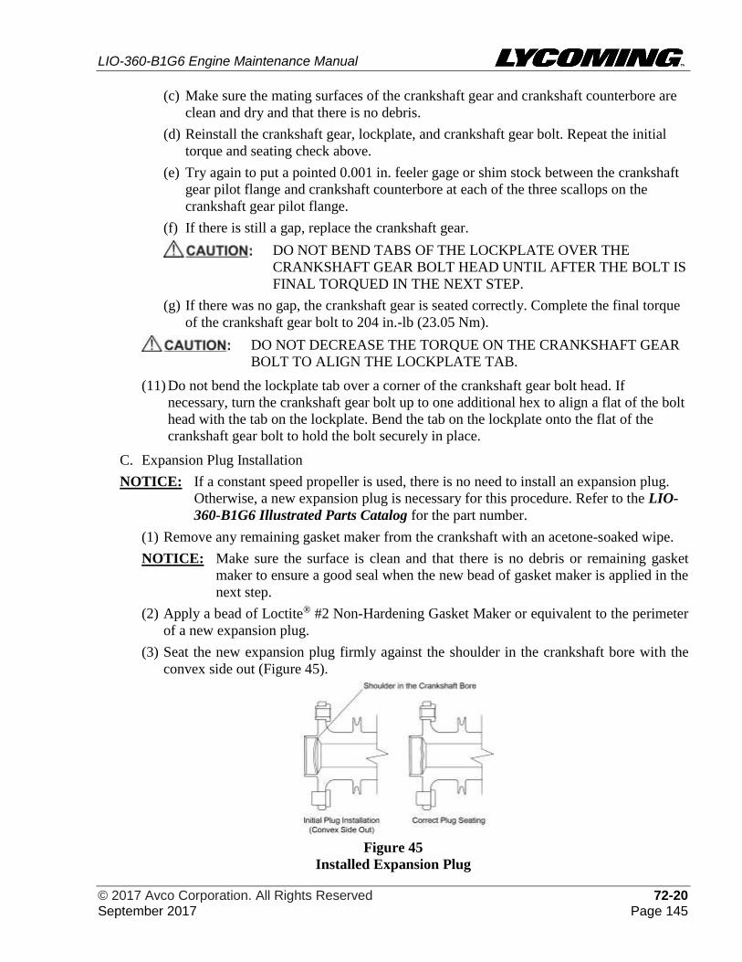
LIO-360-B1G6 Engine Maintenance Manual
© 2017 Avco Corporation. All Rights Reserved 72-20 September 2017 Page 145
(c) Make sure the mating surfaces of the crankshaft gear and crankshaft counterbore are
clean and dry and that there is no debris.
(d) Reinstall the crankshaft gear, lockplate, and crankshaft gear bolt. Repeat the initial
torque and seating check above.
(e) Try again to put a pointed 0.001 in. feeler gage or shim stock between the crankshaft
gear pilot flange and crankshaft counterbore at each of the three scallops on the
crankshaft gear pilot flange.
(f) If there is still a gap, replace the crankshaft gear.
DO NOT BEND TABS OF THE LOCKPLATE OVER THE
CRANKSHAFT GEAR BOLT HEAD UNTIL AFTER THE BOLT IS
FINAL TORQUED IN THE NEXT STEP.
(g) If there was no gap, the crankshaft gear is seated correctly. Complete the final torque
of the crankshaft gear bolt to 204 in.-lb (23.05 Nm).
DO NOT DECREASE THE TORQUE ON THE CRANKSHAFT GEAR
BOLT TO ALIGN THE LOCKPLATE TAB.
(11) Do not bend the lockplate tab over a corner of the crankshaft gear bolt head. If
necessary, turn the crankshaft gear bolt up to one additional hex to align a flat of the bolt
head with the tab on the lockplate. Bend the tab on the lockplate onto the flat of the
crankshaft gear bolt to hold the bolt securely in place.
C. Expansion Plug Installation
NOTICE: If a constant speed propeller is used, there is no need to install an expansion plug.
Otherwise, a new expansion plug is necessary for this procedure. Refer to the LIO-
360-B1G6 Illustrated Parts Catalog for the part number.
(1) Remove any remaining gasket maker from the crankshaft with an acetone-soaked wipe.
NOTICE: Make sure the surface is clean and that there is no debris or remaining gasket
maker to ensure a good seal when the new bead of gasket maker is applied in the
next step.
(2) Apply a bead of Loctite® #2 Non-Hardening Gasket Maker or equivalent to the perimeter
of a new expansion plug.
(3) Seat the new expansion plug firmly against the shoulder in the crankshaft bore with the
convex side out (Figure 45).
Figure 45
Installed Expansion Plug
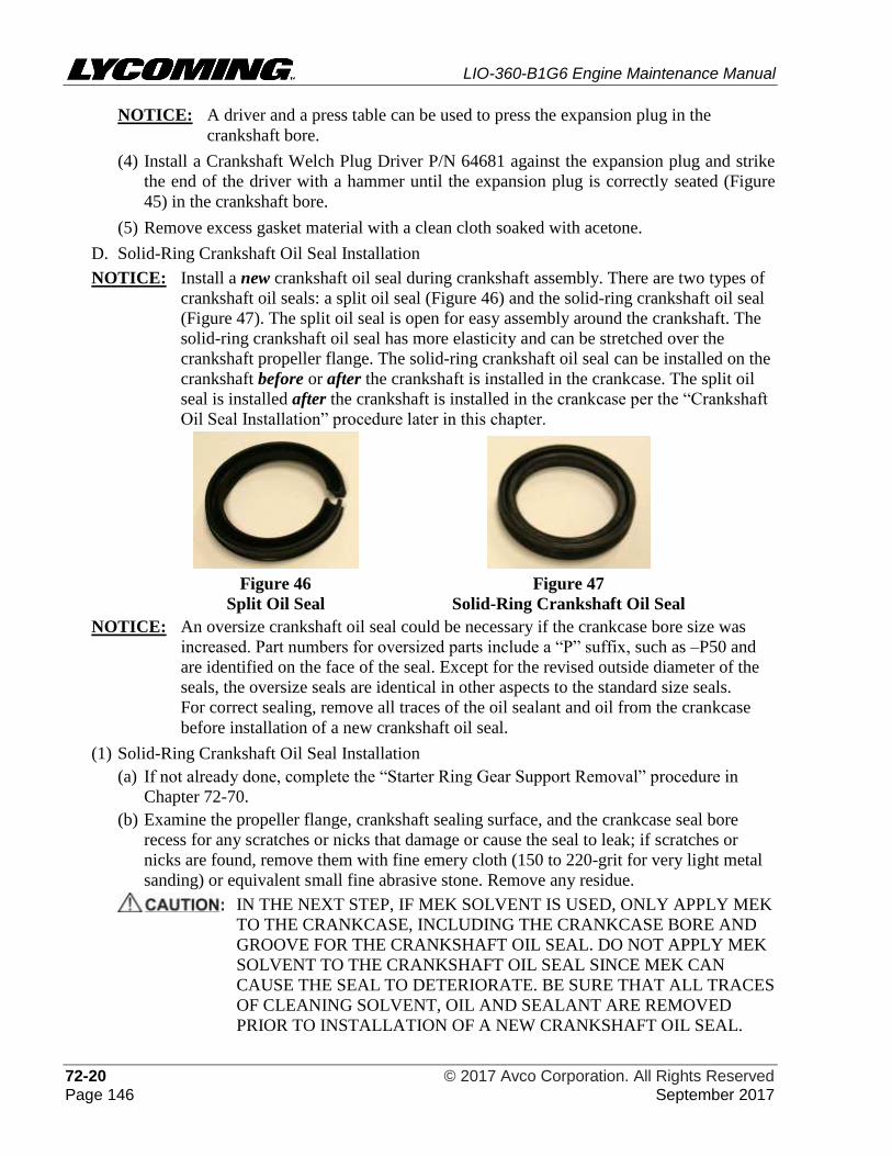
LIO-360-B1G6 Engine Maintenance Manual
72-20 © 2017 Avco Corporation. All Rights Reserved Page 146 September 2017
NOTICE: A driver and a press table can be used to press the expansion plug in the
crankshaft bore.
(4) Install a Crankshaft Welch Plug Driver P/N 64681 against the expansion plug and strike
the end of the driver with a hammer until the expansion plug is correctly seated (Figure
45) in the crankshaft bore.
(5) Remove excess gasket material with a clean cloth soaked with acetone.
D. Solid-Ring Crankshaft Oil Seal Installation
NOTICE: Install a new crankshaft oil seal during crankshaft assembly. There are two types of
crankshaft oil seals: a split oil seal (Figure 46) and the solid-ring crankshaft oil seal
(Figure 47). The split oil seal is open for easy assembly around the crankshaft. The
solid-ring crankshaft oil seal has more elasticity and can be stretched over the
crankshaft propeller flange. The solid-ring crankshaft oil seal can be installed on the
crankshaft before or after the crankshaft is installed in the crankcase. The split oil
seal is installed after the crankshaft is installed in the crankcase per the “Crankshaft
Oil Seal Installation” procedure later in this chapter.
Figure 46
Split Oil Seal
Figure 47
Solid-Ring Crankshaft Oil Seal
NOTICE: An oversize crankshaft oil seal could be necessary if the crankcase bore size was
increased. Part numbers for oversized parts include a “P” suffix, such as –P50 and
are identified on the face of the seal. Except for the revised outside diameter of the
seals, the oversize seals are identical in other aspects to the standard size seals.
For correct sealing, remove all traces of the oil sealant and oil from the crankcase
before installation of a new crankshaft oil seal.
(1) Solid-Ring Crankshaft Oil Seal Installation
(a) If not already done, complete the “Starter Ring Gear Support Removal” procedure in
Chapter 72-70.
(b) Examine the propeller flange, crankshaft sealing surface, and the crankcase seal bore
recess for any scratches or nicks that damage or cause the seal to leak; if scratches or
nicks are found, remove them with fine emery cloth (150 to 220-grit for very light metal
sanding) or equivalent small fine abrasive stone. Remove any residue.
IN THE NEXT STEP, IF MEK SOLVENT IS USED, ONLY APPLY MEK
TO THE CRANKCASE, INCLUDING THE CRANKCASE BORE AND
GROOVE FOR THE CRANKSHAFT OIL SEAL. DO NOT APPLY MEK
SOLVENT TO THE CRANKSHAFT OIL SEAL SINCE MEK CAN
CAUSE THE SEAL TO DETERIORATE. BE SURE THAT ALL TRACES
OF CLEANING SOLVENT, OIL AND SEALANT ARE REMOVED
PRIOR TO INSTALLATION OF A NEW CRANKSHAFT OIL SEAL.
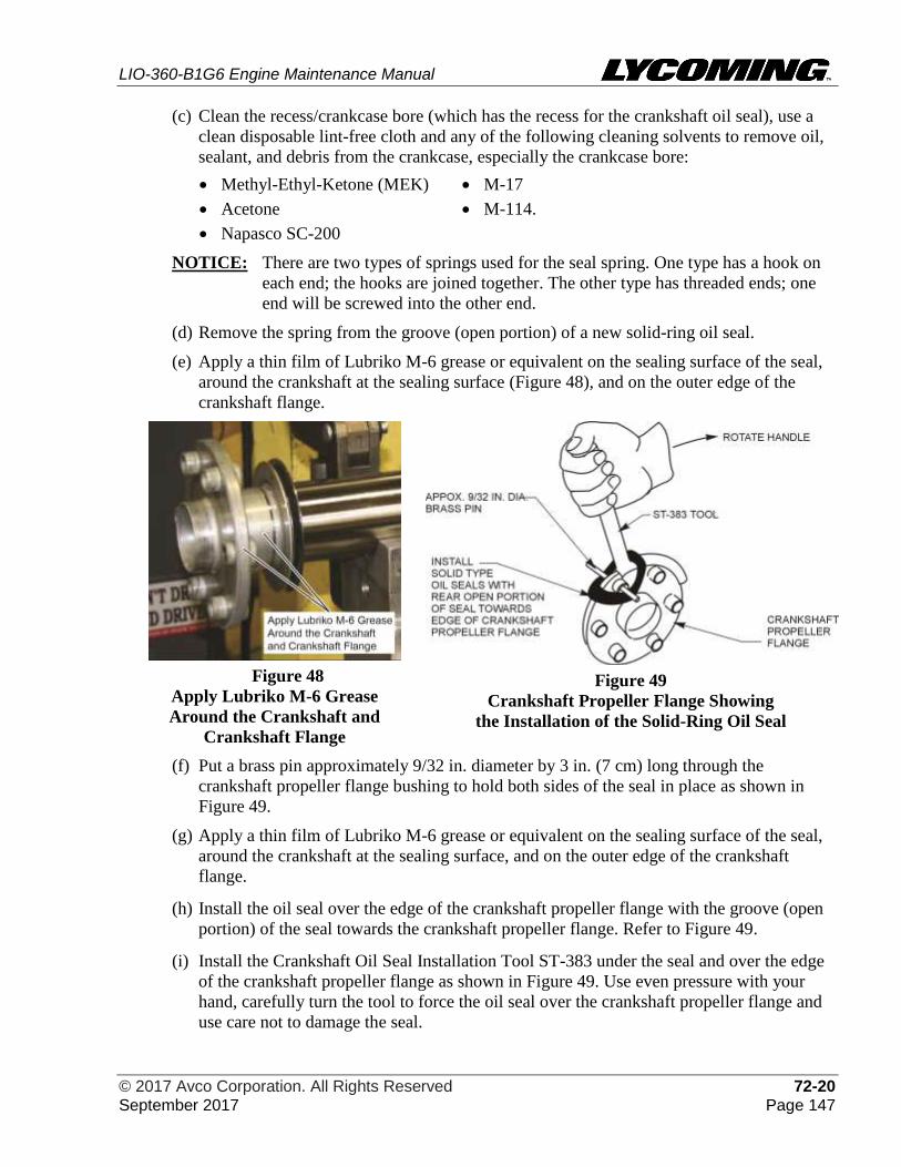
LIO-360-B1G6 Engine Maintenance Manual
© 2017 Avco Corporation. All Rights Reserved 72-20 September 2017 Page 147
(c) Clean the recess/crankcase bore (which has the recess for the crankshaft oil seal), use a
clean disposable lint-free cloth and any of the following cleaning solvents to remove oil,
sealant, and debris from the crankcase, especially the crankcase bore:
• Methyl-Ethyl-Ketone (MEK) • M-17
• Acetone • M-114.
• Napasco SC-200
NOTICE: There are two types of springs used for the seal spring. One type has a hook on
each end; the hooks are joined together. The other type has threaded ends; one
end will be screwed into the other end.
(d) Remove the spring from the groove (open portion) of a new solid-ring oil seal.
(e) Apply a thin film of Lubriko M-6 grease or equivalent on the sealing surface of the seal,
around the crankshaft at the sealing surface (Figure 48), and on the outer edge of the
crankshaft flange.
Figure 49
Crankshaft Propeller Flange Showing
the Installation of the Solid-Ring Oil Seal
Figure 48
Apply Lubriko M-6 Grease
Around the Crankshaft and
Crankshaft Flange
(f) Put a brass pin approximately 9/32 in. diameter by 3 in. (7 cm) long through the
crankshaft propeller flange bushing to hold both sides of the seal in place as shown in
Figure 49.
(g) Apply a thin film of Lubriko M-6 grease or equivalent on the sealing surface of the seal,
around the crankshaft at the sealing surface, and on the outer edge of the crankshaft
flange.
(h) Install the oil seal over the edge of the crankshaft propeller flange with the groove (open
portion) of the seal towards the crankshaft propeller flange. Refer to Figure 49.
(i) Install the Crankshaft Oil Seal Installation Tool ST-383 under the seal and over the edge
of the crankshaft propeller flange as shown in Figure 49. Use even pressure with your
hand, carefully turn the tool to force the oil seal over the crankshaft propeller flange and
use care not to damage the seal.
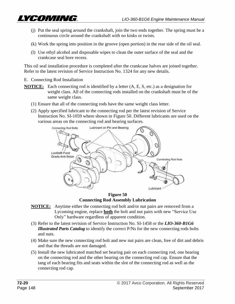
LIO-360-B1G6 Engine Maintenance Manual
72-20 © 2017 Avco Corporation. All Rights Reserved Page 148 September 2017
(j) Put the seal spring around the crankshaft, join the two ends together. The spring must be a
continuous circle around the crankshaft with no kinks or twists.
(k) Work the spring into position in the groove (open portion) in the rear side of the oil seal.
(l) Use ethyl alcohol and disposable wipes to clean the outer surface of the seal and the
crankcase seal bore recess.
This oil seal installation procedure is completed after the crankcase halves are joined together.
Refer to the latest revision of Service Instruction No. 1324 for any new details.
E. Connecting Rod Installation
NOTICE: Each connecting rod is identified by a letter (A, E, S, etc.) as a designation for
weight class. All of the connecting rods installed on the crankshaft must be of the
same weight class.
(1) Ensure that all of the connecting rods have the same weight class letter.
(2) Apply specified lubricant to the connecting rod per the latest revision of Service
Instruction No. SI-1059 where shown in Figure 50. Different lubricants are used on the
various areas on the connecting rod and bearing surfaces.
Figure 50
Connecting Rod Assembly Lubrication
NOTICE: Anytime either the connecting rod bolt and/or nut pairs are removed from a
Lycoming engine, replace both the bolt and nut pairs with new “Service Use
Only” hardware regardless of apparent condition.
(3) Refer to the latest revision of Service Instruction No. SI-1458 or the LIO-360-B1G6
Illustrated Parts Catalog to identify the correct P/Ns for the new connecting rods bolts
and nuts.
(4) Make sure the new connecting rod bolt and new nut pairs are clean, free of dirt and debris
and that the threads are not damaged.
(5) Install the new lubricated matched set bearing pair on each connecting rod, one bearing
on the connecting rod and the other bearing on the connecting rod cap. Ensure that the
tang of each bearing fits and seats within the slot of the connecting rod as well as the
connecting rod cap.
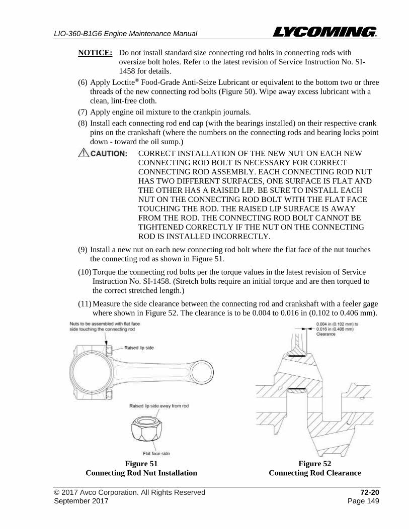
LIO-360-B1G6 Engine Maintenance Manual
© 2017 Avco Corporation. All Rights Reserved 72-20 September 2017 Page 149
NOTICE: Do not install standard size connecting rod bolts in connecting rods with
oversize bolt holes. Refer to the latest revision of Service Instruction No. SI-
1458 for details.
(6) Apply Loctite® Food-Grade Anti-Seize Lubricant or equivalent to the bottom two or three
threads of the new connecting rod bolts (Figure 50). Wipe away excess lubricant with a
clean, lint-free cloth.
(7) Apply engine oil mixture to the crankpin journals.
(8) Install each connecting rod end cap (with the bearings installed) on their respective crank
pins on the crankshaft (where the numbers on the connecting rods and bearing locks point
down - toward the oil sump.)
CORRECT INSTALLATION OF THE NEW NUT ON EACH NEW
CONNECTING ROD BOLT IS NECESSARY FOR CORRECT
CONNECTING ROD ASSEMBLY. EACH CONNECTING ROD NUT
HAS TWO DIFFERENT SURFACES, ONE SURFACE IS FLAT AND
THE OTHER HAS A RAISED LIP. BE SURE TO INSTALL EACH
NUT ON THE CONNECTING ROD BOLT WITH THE FLAT FACE
TOUCHING THE ROD. THE RAISED LIP SURFACE IS AWAY
FROM THE ROD. THE CONNECTING ROD BOLT CANNOT BE
TIGHTENED CORRECTLY IF THE NUT ON THE CONNECTING
ROD IS INSTALLED INCORRECTLY.
(9) Install a new nut on each new connecting rod bolt where the flat face of the nut touches
the connecting rod as shown in Figure 51.
(10) Torque the connecting rod bolts per the torque values in the latest revision of Service
Instruction No. SI-1458. (Stretch bolts require an initial torque and are then torqued to
the correct stretched length.)
(11) Measure the side clearance between the connecting rod and crankshaft with a feeler gage
where shown in Figure 52. The clearance is to be 0.004 to 0.016 in (0.102 to 0.406 mm).
Figure 51
Connecting Rod Nut Installation
Figure 52
Connecting Rod Clearance
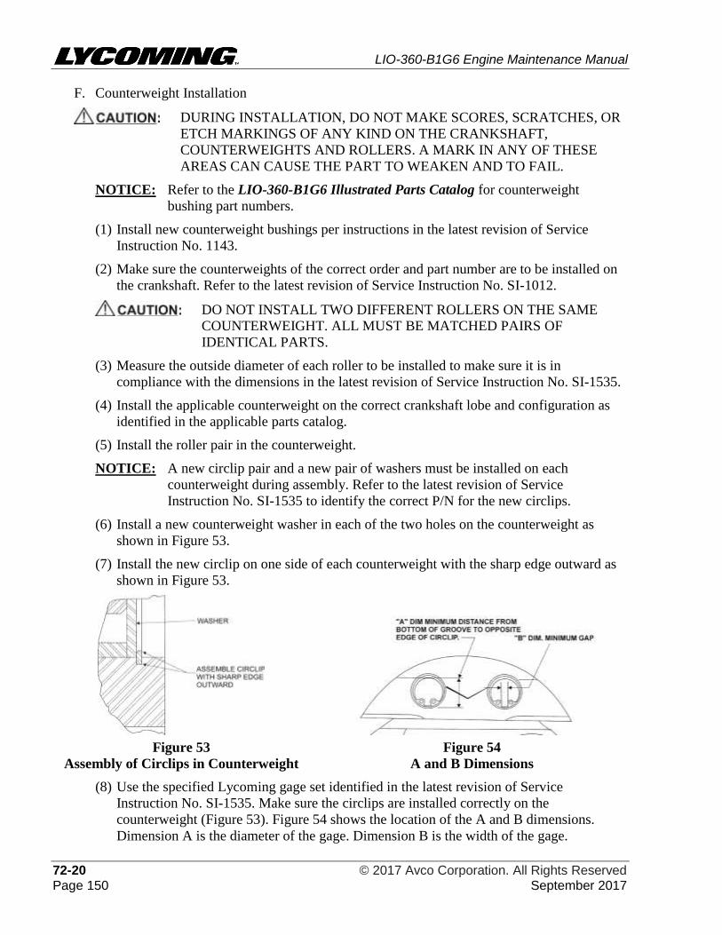
LIO-360-B1G6 Engine Maintenance Manual
72-20 © 2017 Avco Corporation. All Rights Reserved Page 150 September 2017
F. Counterweight Installation
DURING INSTALLATION, DO NOT MAKE SCORES, SCRATCHES, OR
ETCH MARKINGS OF ANY KIND ON THE CRANKSHAFT,
COUNTERWEIGHTS AND ROLLERS. A MARK IN ANY OF THESE
AREAS CAN CAUSE THE PART TO WEAKEN AND TO FAIL.
NOTICE: Refer to the LIO-360-B1G6 Illustrated Parts Catalog for counterweight
bushing part numbers.
(1) Install new counterweight bushings per instructions in the latest revision of Service
Instruction No. 1143.
(2) Make sure the counterweights of the correct order and part number are to be installed on
the crankshaft. Refer to the latest revision of Service Instruction No. SI-1012.
DO NOT INSTALL TWO DIFFERENT ROLLERS ON THE SAME
COUNTERWEIGHT. ALL MUST BE MATCHED PAIRS OF
IDENTICAL PARTS.
(3) Measure the outside diameter of each roller to be installed to make sure it is in
compliance with the dimensions in the latest revision of Service Instruction No. SI-1535.
(4) Install the applicable counterweight on the correct crankshaft lobe and configuration as
identified in the applicable parts catalog.
(5) Install the roller pair in the counterweight.
NOTICE: A new circlip pair and a new pair of washers must be installed on each
counterweight during assembly. Refer to the latest revision of Service
Instruction No. SI-1535 to identify the correct P/N for the new circlips.
(6) Install a new counterweight washer in each of the two holes on the counterweight as
shown in Figure 53.
(7) Install the new circlip on one side of each counterweight with the sharp edge outward as
shown in Figure 53.
Figure 53
Assembly of Circlips in Counterweight
Figure 54
A and B Dimensions
(8) Use the specified Lycoming gage set identified in the latest revision of Service
Instruction No. SI-1535. Make sure the circlips are installed correctly on the
counterweight (Figure 53). Figure 54 shows the location of the A and B dimensions.
Dimension A is the diameter of the gage. Dimension B is the width of the gage.
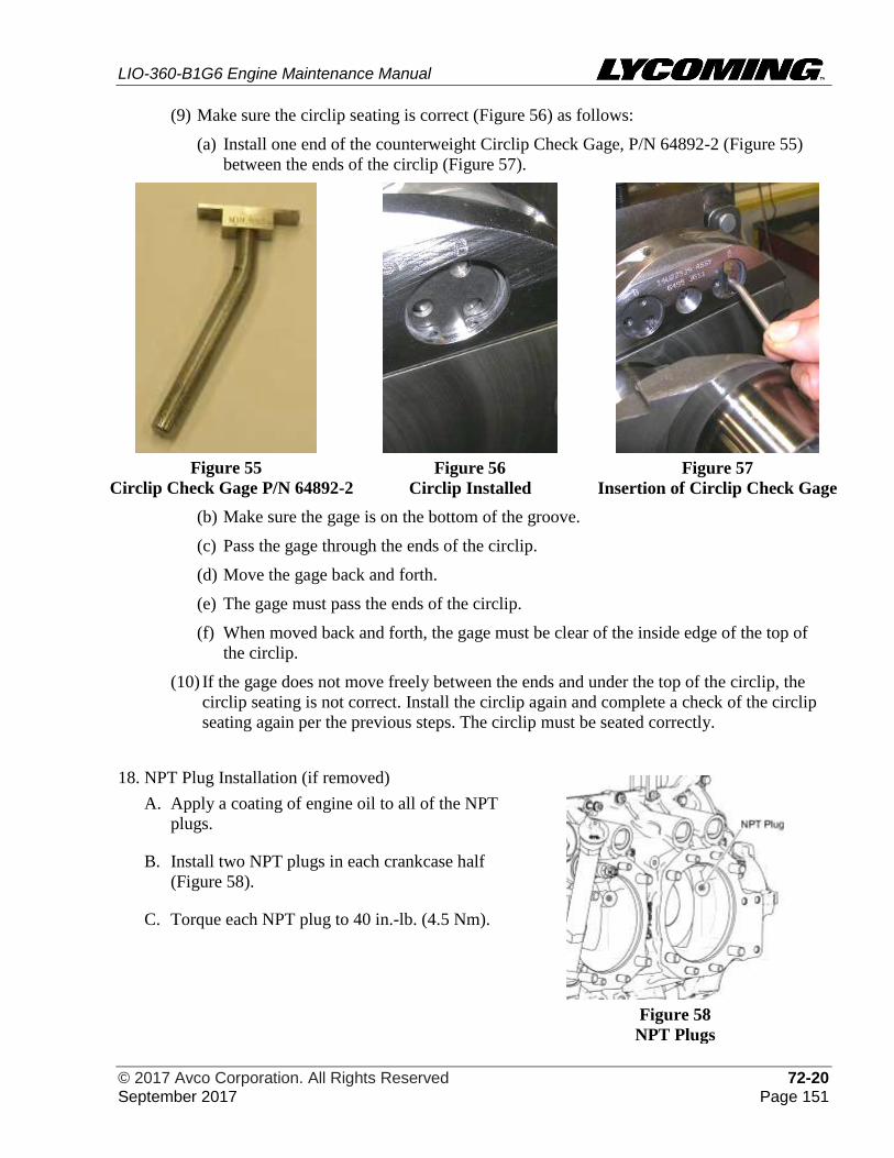
LIO-360-B1G6 Engine Maintenance Manual
© 2017 Avco Corporation. All Rights Reserved 72-20 September 2017 Page 151
(9) Make sure the circlip seating is correct (Figure 56) as follows:
(a) Install one end of the counterweight Circlip Check Gage, P/N 64892-2 (Figure 55)
between the ends of the circlip (Figure 57).
Figure 55
Circlip Check Gage P/N 64892-2
Figure 56
Circlip Installed
Figure 57
Insertion of Circlip Check Gage
(b) Make sure the gage is on the bottom of the groove.
(c) Pass the gage through the ends of the circlip.
(d) Move the gage back and forth.
(e) The gage must pass the ends of the circlip.
(f) When moved back and forth, the gage must be clear of the inside edge of the top of
the circlip.
(10) If the gage does not move freely between the ends and under the top of the circlip, the
circlip seating is not correct. Install the circlip again and complete a check of the circlip
seating again per the previous steps. The circlip must be seated correctly.
18. NPT Plug Installation (if removed)
Figure 58
NPT Plugs
A. Apply a coating of engine oil to all of the NPT
plugs.
B. Install two NPT plugs in each crankcase half
(Figure 58).
C. Torque each NPT plug to 40 in.-lb. (4.5 Nm).
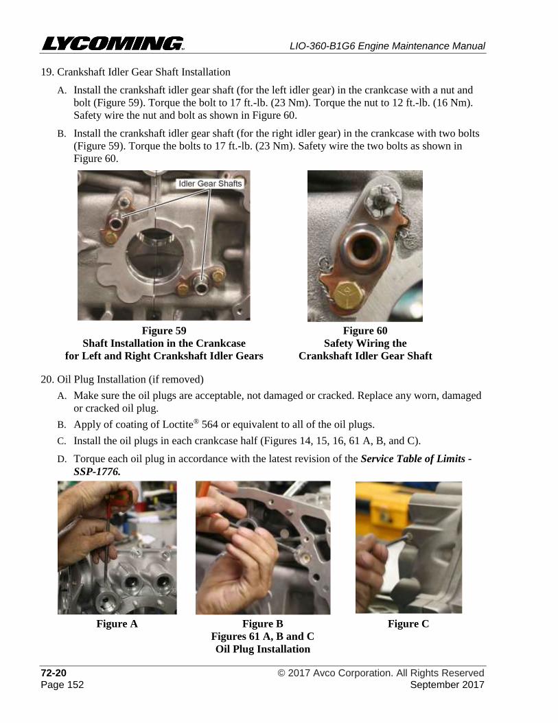
LIO-360-B1G6 Engine Maintenance Manual
72-20 © 2017 Avco Corporation. All Rights Reserved Page 152 September 2017
19. Crankshaft Idler Gear Shaft Installation
A. Install the crankshaft idler gear shaft (for the left idler gear) in the crankcase with a nut and
bolt (Figure 59). Torque the bolt to 17 ft.-lb. (23 Nm). Torque the nut to 12 ft.-lb. (16 Nm).
Safety wire the nut and bolt as shown in Figure 60.
B. Install the crankshaft idler gear shaft (for the right idler gear) in the crankcase with two bolts
(Figure 59). Torque the bolts to 17 ft.-lb. (23 Nm). Safety wire the two bolts as shown in
Figure 60.
Figure 59
Shaft Installation in the Crankcase
for Left and Right Crankshaft Idler Gears
Figure 60
Safety Wiring the
Crankshaft Idler Gear Shaft
20. Oil Plug Installation (if removed)
A. Make sure the oil plugs are acceptable, not damaged or cracked. Replace any worn, damaged
or cracked oil plug.
B. Apply of coating of Loctite® 564 or equivalent to all of the oil plugs.
C. Install the oil plugs in each crankcase half (Figures 14, 15, 16, 61 A, B, and C).
D. Torque each oil plug in accordance with the latest revision of the Service Table of Limits -
SSP-1776.
Figure A Figure B Figure C
Figures 61 A, B and C
Oil Plug Installation
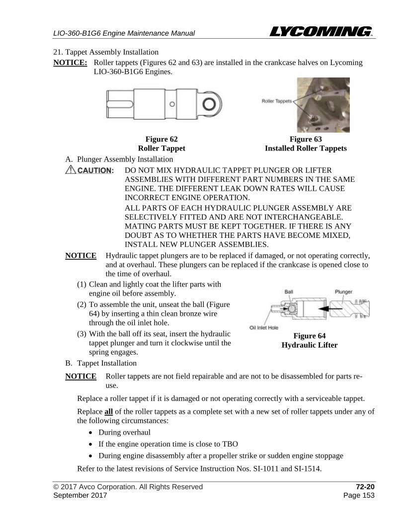
LIO-360-B1G6 Engine Maintenance Manual
© 2017 Avco Corporation. All Rights Reserved 72-20 September 2017 Page 153
21. Tappet Assembly Installation
NOTICE: Roller tappets (Figures 62 and 63) are installed in the crankcase halves on Lycoming
LIO-360-B1G6 Engines.
Figure 62
Roller Tappet
Figure 63
Installed Roller Tappets
A. Plunger Assembly Installation
DO NOT MIX HYDRAULIC TAPPET PLUNGER OR LIFTER
ASSEMBLIES WITH DIFFERENT PART NUMBERS IN THE SAME
ENGINE. THE DIFFERENT LEAK DOWN RATES WILL CAUSE
INCORRECT ENGINE OPERATION.
ALL PARTS OF EACH HYDRAULIC PLUNGER ASSEMBLY ARE
SELECTIVELY FITTED AND ARE NOT INTERCHANGEABLE.
MATING PARTS MUST BE KEPT TOGETHER. IF THERE IS ANY
DOUBT AS TO WHETHER THE PARTS HAVE BECOME MIXED,
INSTALL NEW PLUNGER ASSEMBLIES.
NOTICE Hydraulic tappet plungers are to be replaced if damaged, or not operating correctly,
and at overhaul. These plungers can be replaced if the crankcase is opened close to
the time of overhaul.
(1) Clean and lightly coat the lifter parts with
engine oil before assembly.
(2) To assemble the unit, unseat the ball (Figure
64) by inserting a thin clean bronze wire
through the oil inlet hole.
(3) With the ball off its seat, insert the hydraulic
tappet plunger and turn it clockwise until the
spring engages.
Figure 64
Hydraulic Lifter
B. Tappet Installation
NOTICE Roller tappets are not field repairable and are not to be disassembled for parts re-
use.
Replace a roller tappet if it is damaged or not operating correctly with a serviceable tappet.
Replace all of the roller tappets as a complete set with a new set of roller tappets under any of
the following circumstances:
• During overhaul
• If the engine operation time is close to TBO
• During engine disassembly after a propeller strike or sudden engine stoppage
Refer to the latest revisions of Service Instruction Nos. SI-1011 and SI-1514.
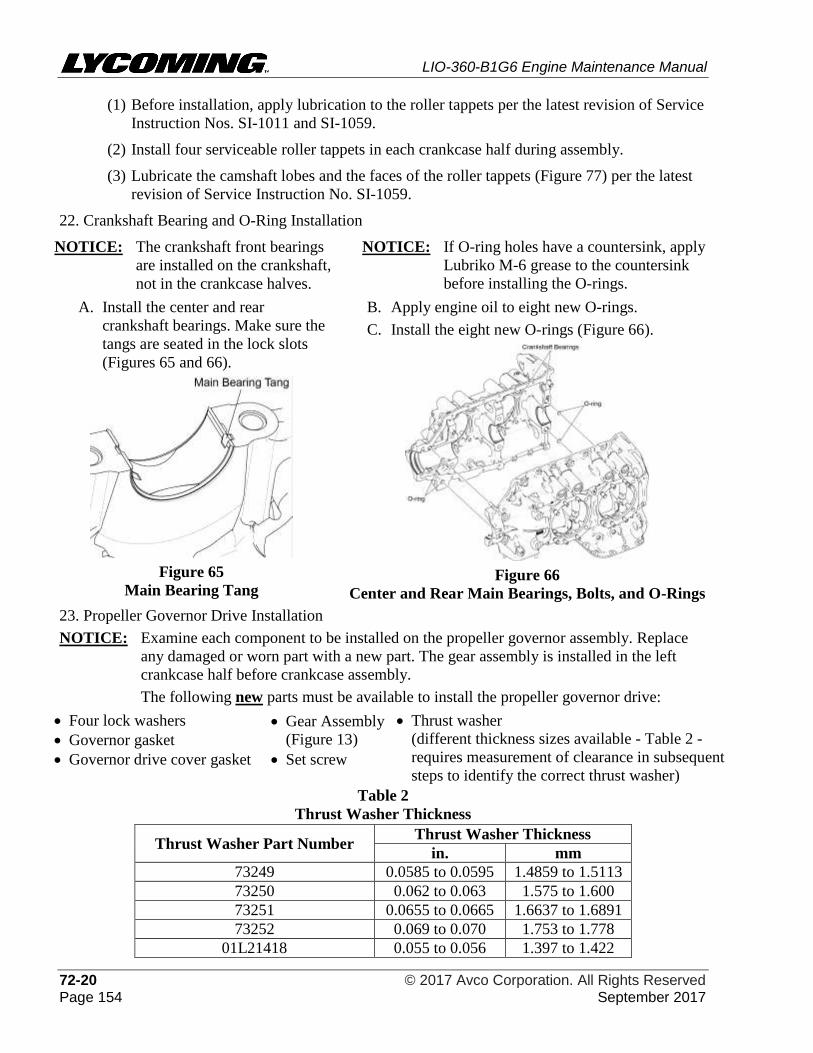
LIO-360-B1G6 Engine Maintenance Manual
72-20 © 2017 Avco Corporation. All Rights Reserved Page 154 September 2017
(1) Before installation, apply lubrication to the roller tappets per the latest revision of Service
Instruction Nos. SI-1011 and SI-1059.
(2) Install four serviceable roller tappets in each crankcase half during assembly.
(3) Lubricate the camshaft lobes and the faces of the roller tappets (Figure 77) per the latest
revision of Service Instruction No. SI-1059.
22. Crankshaft Bearing and O-Ring Installation
NOTICE: The crankshaft front bearings
are installed on the crankshaft,
not in the crankcase halves.
NOTICE: If O-ring holes have a countersink, apply
Lubriko M-6 grease to the countersink
before installing the O-rings.
A. Install the center and rear
crankshaft bearings. Make sure the
tangs are seated in the lock slots
(Figures 65 and 66).
Figure 65
Main Bearing Tang
B. Apply engine oil to eight new O-rings.
C. Install the eight new O-rings (Figure 66).
Figure 66
Center and Rear Main Bearings, Bolts, and O-Rings
23. Propeller Governor Drive Installation
NOTICE: Examine each component to be installed on the propeller governor assembly. Replace
any damaged or worn part with a new part. The gear assembly is installed in the left
crankcase half before crankcase assembly.
The following new parts must be available to install the propeller governor drive:
• Four lock washers • Gear Assembly
(Figure 13)
• Thrust washer
(different thickness sizes available - Table 2 -
requires measurement of clearance in subsequent
steps to identify the correct thrust washer)
• Governor gasket
• Governor drive cover gasket • Set screw
Table 2
Thrust Washer Thickness
Thrust Washer Part Number Thrust Washer Thickness
in. mm
73249 0.0585 to 0.0595 1.4859 to 1.5113
73250 0.062 to 0.063 1.575 to 1.600
73251 0.0655 to 0.0665 1.6637 to 1.6891
73252 0.069 to 0.070 1.753 to 1.778
01L21418 0.055 to 0.056 1.397 to 1.422
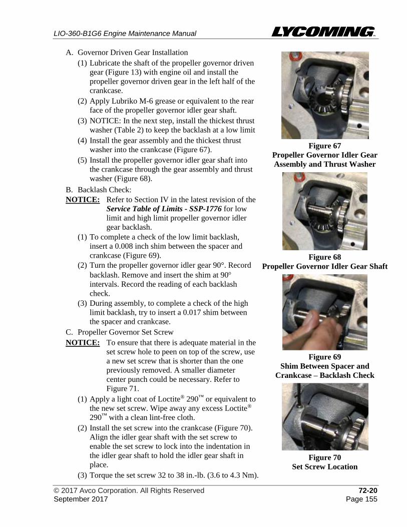
LIO-360-B1G6 Engine Maintenance Manual
© 2017 Avco Corporation. All Rights Reserved 72-20 September 2017 Page 155
A. Governor Driven Gear Installation
(1) Lubricate the shaft of the propeller governor driven
gear (Figure 13) with engine oil and install the
propeller governor driven gear in the left half of the
crankcase.
(2) Apply Lubriko M-6 grease or equivalent to the rear
face of the propeller governor idler gear shaft.
(3) NOTICE: In the next step, install the thickest thrust
washer (Table 2) to keep the backlash at a low limit
(4) Install the gear assembly and the thickest thrust
washer into the crankcase (Figure 67).
(5) Install the propeller governor idler gear shaft into
the crankcase through the gear assembly and thrust
washer (Figure 68).
B. Backlash Check:
NOTICE: Refer to Section IV in the latest revision of the
Service Table of Limits - SSP-1776 for low
limit and high limit propeller governor idler
gear backlash.
(1) To complete a check of the low limit backlash,
insert a 0.008 inch shim between the spacer and
crankcase (Figure 69).
(2) Turn the propeller governor idler gear 90°. Record
backlash. Remove and insert the shim at 90
intervals. Record the reading of each backlash
check.
(3) During assembly, to complete a check of the high
limit backlash, try to insert a 0.017 shim between
the spacer and crankcase.
C. Propeller Governor Set Screw
NOTICE: To ensure that there is adequate material in the
set screw hole to peen on top of the screw, use
a new set screw that is shorter than the one
previously removed. A smaller diameter
center punch could be necessary. Refer to
Figure 71.
(1) Apply a light coat of Loctite® 290™ or equivalent to
the new set screw. Wipe away any excess Loctite®
290™ with a clean lint-free cloth.
(2) Install the set screw into the crankcase (Figure 70).
Align the idler gear shaft with the set screw to
enable the set screw to lock into the indentation in
the idler gear shaft to hold the idler gear shaft in
place.
(3) Torque the set screw 32 to 38 in.-lb. (3.6 to 4.3 Nm).
Figure 67
Propeller Governor Idler Gear
Assembly and Thrust Washer
Figure 68
Propeller Governor Idler Gear Shaft
Figure 69
Shim Between Spacer and
Crankcase – Backlash Check
Figure 70
Set Screw Location
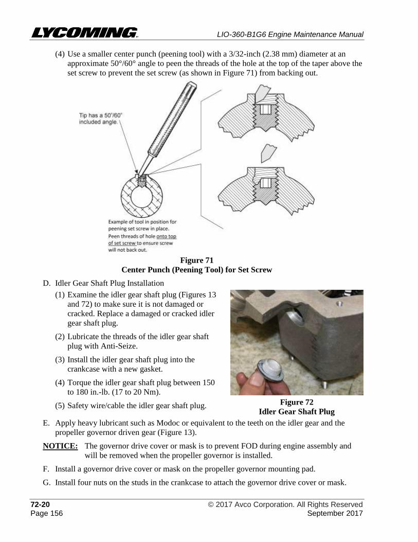
LIO-360-B1G6 Engine Maintenance Manual
72-20 © 2017 Avco Corporation. All Rights Reserved Page 156 September 2017
(4) Use a smaller center punch (peening tool) with a 3/32-inch (2.38 mm) diameter at an
approximate 50°/60° angle to peen the threads of the hole at the top of the taper above the
set screw to prevent the set screw (as shown in Figure 71) from backing out.
Figure 71
Center Punch (Peening Tool) for Set Screw
D. Idler Gear Shaft Plug Installation
(1) Examine the idler gear shaft plug (Figures 13
and 72) to make sure it is not damaged or
cracked. Replace a damaged or cracked idler
gear shaft plug.
(2) Lubricate the threads of the idler gear shaft
plug with Anti-Seize.
(3) Install the idler gear shaft plug into the
crankcase with a new gasket.
(4) Torque the idler gear shaft plug between 150
to 180 in.-lb. (17 to 20 Nm).
(5) Safety wire/cable the idler gear shaft plug.
Figure 72
Idler Gear Shaft Plug
E. Apply heavy lubricant such as Modoc or equivalent to the teeth on the idler gear and the
propeller governor driven gear (Figure 13).
NOTICE: The governor drive cover or mask is to prevent FOD during engine assembly and
will be removed when the propeller governor is installed.
F. Install a governor drive cover or mask on the propeller governor mounting pad.
G. Install four nuts on the studs in the crankcase to attach the governor drive cover or mask.
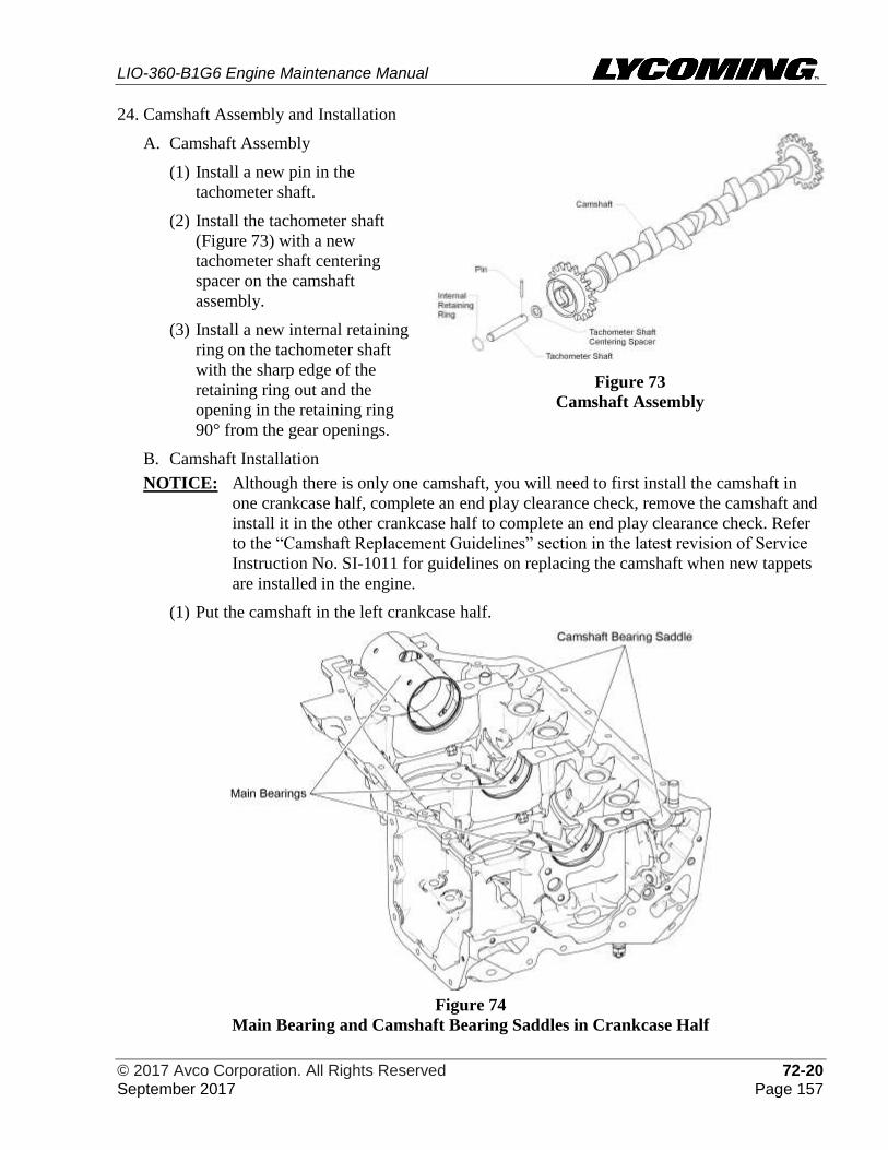
LIO-360-B1G6 Engine Maintenance Manual
© 2017 Avco Corporation. All Rights Reserved 72-20 September 2017 Page 157
24. Camshaft Assembly and Installation
A. Camshaft Assembly
(1) Install a new pin in the
tachometer shaft.
(2) Install the tachometer shaft
(Figure 73) with a new
tachometer shaft centering
spacer on the camshaft
assembly.
(3) Install a new internal retaining
ring on the tachometer shaft
with the sharp edge of the
retaining ring out and the
opening in the retaining ring
90° from the gear openings.
Figure 73
Camshaft Assembly
B. Camshaft Installation
NOTICE: Although there is only one camshaft, you will need to first install the camshaft in
one crankcase half, complete an end play clearance check, remove the camshaft and
install it in the other crankcase half to complete an end play clearance check. Refer
to the “Camshaft Replacement Guidelines” section in the latest revision of Service
Instruction No. SI-1011 for guidelines on replacing the camshaft when new tappets
are installed in the engine.
(1) Put the camshaft in the left crankcase half.
Figure 74
Main Bearing and Camshaft Bearing Saddles in Crankcase Half
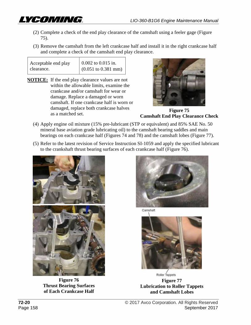
LIO-360-B1G6 Engine Maintenance Manual
72-20 © 2017 Avco Corporation. All Rights Reserved Page 158 September 2017
(2) Complete a check of the end play clearance of the camshaft using a feeler gage (Figure
75).
(3) Remove the camshaft from the left crankcase half and install it in the right crankcase half
and complete a check of the camshaft end play clearance.
Acceptable end play
clearance.
0.002 to 0.015 in.
(0.051 to 0.381 mm)
Figure 75
Camshaft End Play Clearance Check
NOTICE: If the end play clearance values are not
within the allowable limits, examine the
crankcase and/or camshaft for wear or
damage. Replace a damaged or worn
camshaft. If one crankcase half is worn or
damaged, replace both crankcase halves
as a matched set.
(4) Apply engine oil mixture (15% pre-lubricant (STP or equivalent) and 85% SAE No. 50
mineral base aviation grade lubricating oil) to the camshaft bearing saddles and main
bearings on each crankcase half (Figures 74 and 78) and the camshaft lobes (Figure 77).
(5) Refer to the latest revision of Service Instruction SI-1059 and apply the specified lubricant
to the crankshaft thrust bearing surfaces of each crankcase half (Figure 76).
Figure 76
Thrust Bearing Surfaces
of Each Crankcase Half
Figure 77
Lubrication to Roller Tappets
and Camshaft Lobes
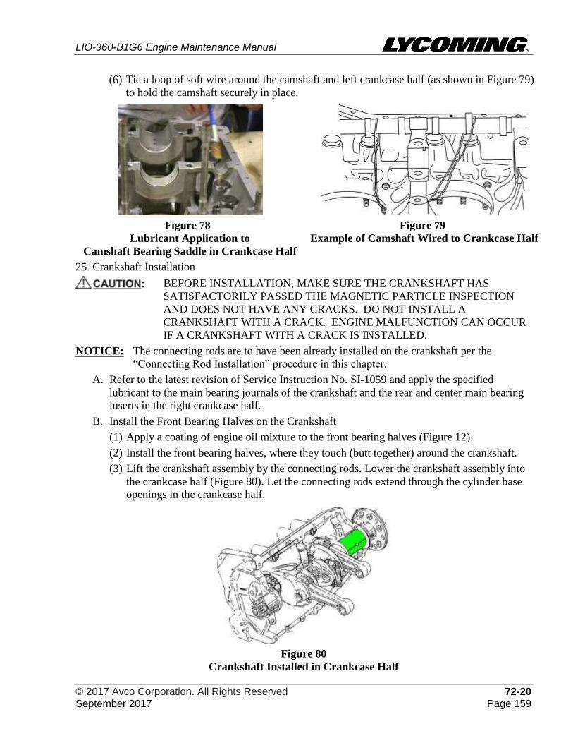
LIO-360-B1G6 Engine Maintenance Manual
© 2017 Avco Corporation. All Rights Reserved 72-20 September 2017 Page 159
(6) Tie a loop of soft wire around the camshaft and left crankcase half (as shown in Figure 79)
to hold the camshaft securely in place.
Figure 78
Lubricant Application to
Camshaft Bearing Saddle in Crankcase Half
Figure 79
Example of Camshaft Wired to Crankcase Half
25. Crankshaft Installation
BEFORE INSTALLATION, MAKE SURE THE CRANKSHAFT HAS
SATISFACTORILY PASSED THE MAGNETIC PARTICLE INSPECTION
AND DOES NOT HAVE ANY CRACKS. DO NOT INSTALL A
CRANKSHAFT WITH A CRACK. ENGINE MALFUNCTION CAN OCCUR
IF A CRANKSHAFT WITH A CRACK IS INSTALLED.
NOTICE: The connecting rods are to have been already installed on the crankshaft per the
“Connecting Rod Installation” procedure in this chapter.
A. Refer to the latest revision of Service Instruction No. SI-1059 and apply the specified
lubricant to the main bearing journals of the crankshaft and the rear and center main bearing
inserts in the right crankcase half.
B. Install the Front Bearing Halves on the Crankshaft
(1) Apply a coating of engine oil mixture to the front bearing halves (Figure 12).
(2) Install the front bearing halves, where they touch (butt together) around the crankshaft.
(3) Lift the crankshaft assembly by the connecting rods. Lower the crankshaft assembly into
the crankcase half (Figure 80). Let the connecting rods extend through the cylinder base
openings in the crankcase half.
Figure 80
Crankshaft Installed in Crankcase Half
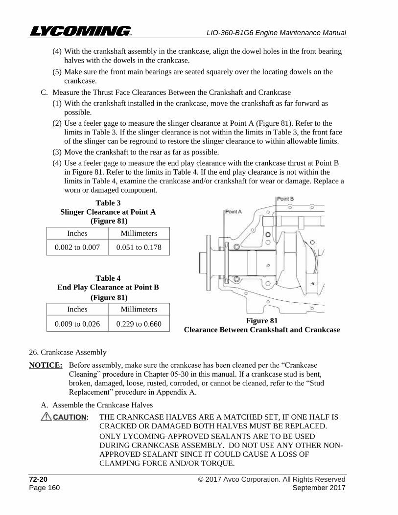
LIO-360-B1G6 Engine Maintenance Manual
72-20 © 2017 Avco Corporation. All Rights Reserved Page 160 September 2017
(4) With the crankshaft assembly in the crankcase, align the dowel holes in the front bearing
halves with the dowels in the crankcase.
(5) Make sure the front main bearings are seated squarely over the locating dowels on the
crankcase.
C. Measure the Thrust Face Clearances Between the Crankshaft and Crankcase
(1) With the crankshaft installed in the crankcase, move the crankshaft as far forward as
possible.
(2) Use a feeler gage to measure the slinger clearance at Point A (Figure 81). Refer to the
limits in Table 3. If the slinger clearance is not within the limits in Table 3, the front face
of the slinger can be reground to restore the slinger clearance to within allowable limits.
(3) Move the crankshaft to the rear as far as possible.
(4) Use a feeler gage to measure the end play clearance with the crankcase thrust at Point B
in Figure 81. Refer to the limits in Table 4. If the end play clearance is not within the
limits in Table 4, examine the crankcase and/or crankshaft for wear or damage. Replace a
worn or damaged component.
Table 3
Slinger Clearance at Point A
(Figure 81)
Figure 81
Clearance Between Crankshaft and Crankcase
Inches Millimeters
0.002 to 0.007 0.051 to 0.178
Table 4
End Play Clearance at Point B
(Figure 81)
Inches Millimeters
0.009 to 0.026 0.229 to 0.660
26. Crankcase Assembly
NOTICE: Before assembly, make sure the crankcase has been cleaned per the “Crankcase
Cleaning” procedure in Chapter 05-30 in this manual. If a crankcase stud is bent,
broken, damaged, loose, rusted, corroded, or cannot be cleaned, refer to the “Stud
Replacement” procedure in Appendix A.
A. Assemble the Crankcase Halves
THE CRANKCASE HALVES ARE A MATCHED SET, IF ONE HALF IS
CRACKED OR DAMAGED BOTH HALVES MUST BE REPLACED.
ONLY LYCOMING-APPROVED SEALANTS ARE TO BE USED
DURING CRANKCASE ASSEMBLY. DO NOT USE ANY OTHER NON-
APPROVED SEALANT SINCE IT COULD CAUSE A LOSS OF
CLAMPING FORCE AND/OR TORQUE.
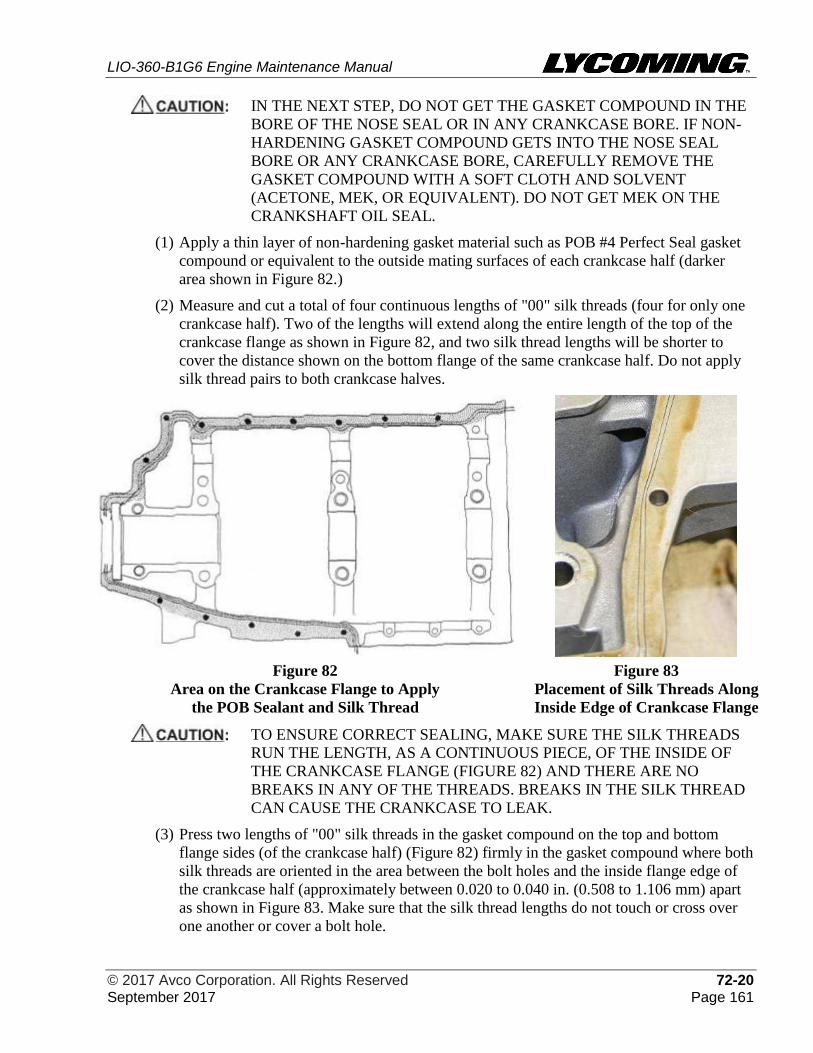
LIO-360-B1G6 Engine Maintenance Manual
© 2017 Avco Corporation. All Rights Reserved 72-20 September 2017 Page 161
IN THE NEXT STEP, DO NOT GET THE GASKET COMPOUND IN THE
BORE OF THE NOSE SEAL OR IN ANY CRANKCASE BORE. IF NON-
HARDENING GASKET COMPOUND GETS INTO THE NOSE SEAL
BORE OR ANY CRANKCASE BORE, CAREFULLY REMOVE THE
GASKET COMPOUND WITH A SOFT CLOTH AND SOLVENT
(ACETONE, MEK, OR EQUIVALENT). DO NOT GET MEK ON THE
CRANKSHAFT OIL SEAL.
(1) Apply a thin layer of non-hardening gasket material such as POB #4 Perfect Seal gasket
compound or equivalent to the outside mating surfaces of each crankcase half (darker
area shown in Figure 82.)
(2) Measure and cut a total of four continuous lengths of "00" silk threads (four for only one
crankcase half). Two of the lengths will extend along the entire length of the top of the
crankcase flange as shown in Figure 82, and two silk thread lengths will be shorter to
cover the distance shown on the bottom flange of the same crankcase half. Do not apply
silk thread pairs to both crankcase halves.
Figure 82
Area on the Crankcase Flange to Apply
the POB Sealant and Silk Thread
Figure 83
Placement of Silk Threads Along
Inside Edge of Crankcase Flange
TO ENSURE CORRECT SEALING, MAKE SURE THE SILK THREADS
RUN THE LENGTH, AS A CONTINUOUS PIECE, OF THE INSIDE OF
THE CRANKCASE FLANGE (FIGURE 82) AND THERE ARE NO
BREAKS IN ANY OF THE THREADS. BREAKS IN THE SILK THREAD
CAN CAUSE THE CRANKCASE TO LEAK.
(3) Press two lengths of "00" silk threads in the gasket compound on the top and bottom
flange sides (of the crankcase half) (Figure 82) firmly in the gasket compound where both
silk threads are oriented in the area between the bolt holes and the inside flange edge of
the crankcase half (approximately between 0.020 to 0.040 in. (0.508 to 1.106 mm) apart
as shown in Figure 83. Make sure that the silk thread lengths do not touch or cross over
one another or cover a bolt hole.
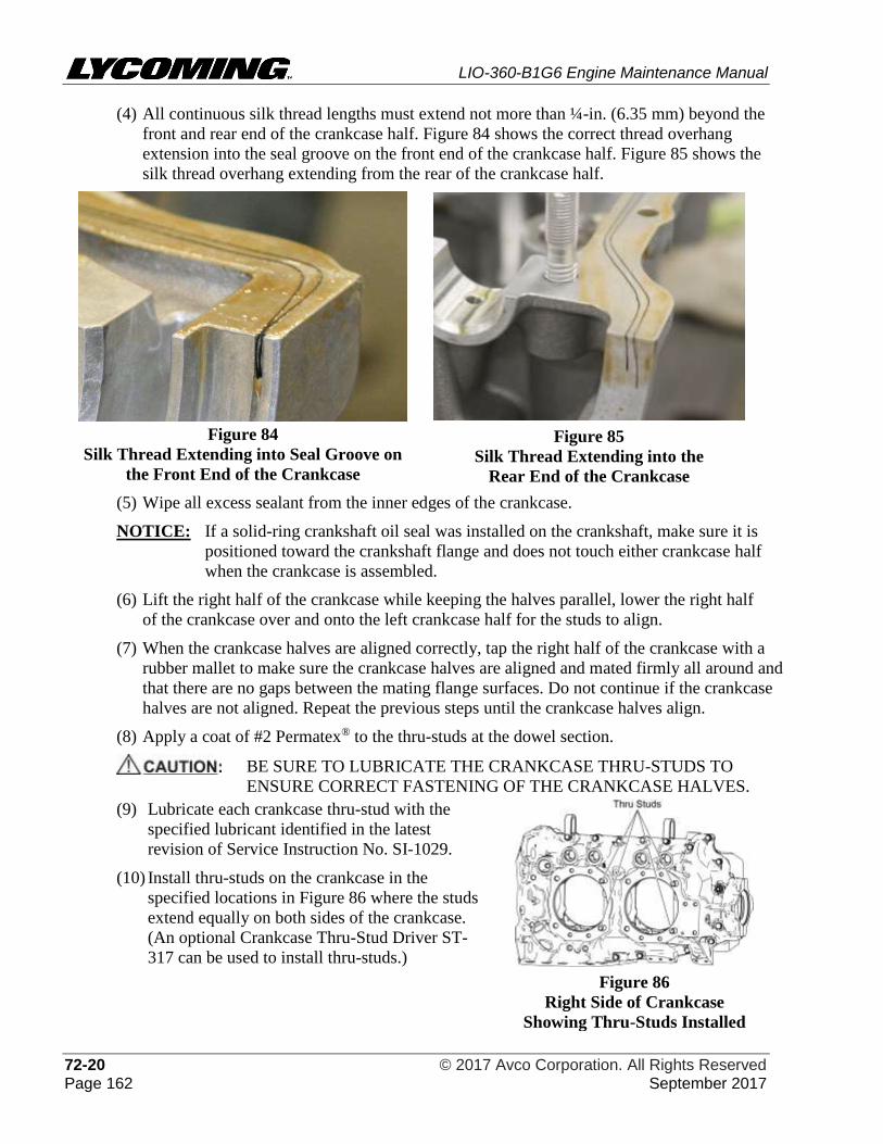
LIO-360-B1G6 Engine Maintenance Manual
72-20 © 2017 Avco Corporation. All Rights Reserved Page 162 September 2017
(4) All continuous silk thread lengths must extend not more than ¼-in. (6.35 mm) beyond the
front and rear end of the crankcase half. Figure 84 shows the correct thread overhang
extension into the seal groove on the front end of the crankcase half. Figure 85 shows the
silk thread overhang extending from the rear of the crankcase half.
Figure 84
Silk Thread Extending into Seal Groove on
the Front End of the Crankcase
Figure 85
Silk Thread Extending into the
Rear End of the Crankcase
(5) Wipe all excess sealant from the inner edges of the crankcase.
NOTICE: If a solid-ring crankshaft oil seal was installed on the crankshaft, make sure it is
positioned toward the crankshaft flange and does not touch either crankcase half
when the crankcase is assembled.
(6) Lift the right half of the crankcase while keeping the halves parallel, lower the right half
of the crankcase over and onto the left crankcase half for the studs to align.
(7) When the crankcase halves are aligned correctly, tap the right half of the crankcase with a
rubber mallet to make sure the crankcase halves are aligned and mated firmly all around and
that there are no gaps between the mating flange surfaces. Do not continue if the crankcase
halves are not aligned. Repeat the previous steps until the crankcase halves align.
(8) Apply a coat of #2 Permatex® to the thru-studs at the dowel section.
BE SURE TO LUBRICATE THE CRANKCASE THRU-STUDS TO
ENSURE CORRECT FASTENING OF THE CRANKCASE HALVES.
(9) Lubricate each crankcase thru-stud with the
specified lubricant identified in the latest
revision of Service Instruction No. SI-1029.
(10) Install thru-studs on the crankcase in the
specified locations in Figure 86 where the studs
extend equally on both sides of the crankcase.
(An optional Crankcase Thru-Stud Driver ST-
317 can be used to install thru-studs.)
Figure 86
Right Side of Crankcase
Showing Thru-Studs Installed
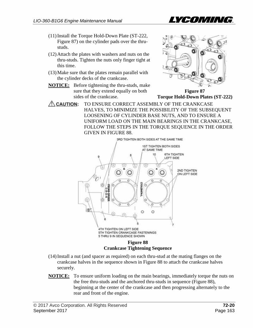
LIO-360-B1G6 Engine Maintenance Manual
© 2017 Avco Corporation. All Rights Reserved 72-20 September 2017 Page 163
(11) Install the Torque Hold-Down Plate (ST-222,
Figure 87) on the cylinder pads over the thru-
studs.
(12) Attach the plates with washers and nuts on the
thru-studs. Tighten the nuts only finger tight at
this time.
(13) Make sure that the plates remain parallel with
the cylinder decks of the crankcase.
NOTICE: Before tightening the thru-studs, make
sure that they extend equally on both
sides of the crankcase.
Figure 87
Torque Hold-Down Plates (ST-222)
TO ENSURE CORRECT ASSEMBLY OF THE CRANKCASE
HALVES, TO MINIMIZE THE POSSIBILITY OF THE SUBSEQUENT
LOOSENING OF CYLINDER BASE NUTS, AND TO ENSURE A
UNIFORM LOAD ON THE MAIN BEARINGS IN THE CRANKCASE,
FOLLOW THE STEPS IN THE TORQUE SEQUENCE IN THE ORDER
GIVEN IN FIGURE 88.
Figure 88
Crankcase Tightening Sequence
(14) Install a nut (and spacer as required) on each thru-stud at the mating flanges on the
crankcase halves in the sequence shown in Figure 88 to attach the crankcase halves
securely.
NOTICE: To ensure uniform loading on the main bearings, immediately torque the nuts on
the free thru-studs and the anchored thru-studs in sequence (Figure 88),
beginning at the center of the crankcase and then progressing alternately to the
rear and front of the engine.
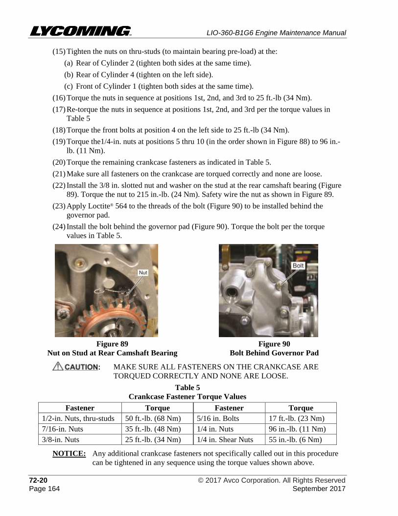
LIO-360-B1G6 Engine Maintenance Manual
72-20 © 2017 Avco Corporation. All Rights Reserved Page 164 September 2017
(15) Tighten the nuts on thru-studs (to maintain bearing pre-load) at the:
(a) Rear of Cylinder 2 (tighten both sides at the same time).
(b) Rear of Cylinder 4 (tighten on the left side).
(c) Front of Cylinder 1 (tighten both sides at the same time).
(16) Torque the nuts in sequence at positions 1st, 2nd, and 3rd to 25 ft.-lb (34 Nm).
(17) Re-torque the nuts in sequence at positions 1st, 2nd, and 3rd per the torque values in
Table 5
(18) Torque the front bolts at position 4 on the left side to 25 ft.-lb (34 Nm).
(19) Torque the1/4-in. nuts at positions 5 thru 10 (in the order shown in Figure 88) to 96 in.-
lb. (11 Nm).
(20) Torque the remaining crankcase fasteners as indicated in Table 5.
(21) Make sure all fasteners on the crankcase are torqued correctly and none are loose.
(22) Install the 3/8 in. slotted nut and washer on the stud at the rear camshaft bearing (Figure
89). Torque the nut to 215 in.-lb. (24 Nm). Safety wire the nut as shown in Figure 89.
(23) Apply Loctite® 564 to the threads of the bolt (Figure 90) to be installed behind the
governor pad.
(24) Install the bolt behind the governor pad (Figure 90). Torque the bolt per the torque
values in Table 5.
Figure 89
Nut on Stud at Rear Camshaft Bearing
Figure 90
Bolt Behind Governor Pad
MAKE SURE ALL FASTENERS ON THE CRANKCASE ARE
TORQUED CORRECTLY AND NONE ARE LOOSE.
Table 5
Crankcase Fastener Torque Values
Fastener Torque Fastener Torque
1/2-in. Nuts, thru-studs 50 ft.-lb. (68 Nm) 5/16 in. Bolts 17 ft.-lb. (23 Nm)
7/16-in. Nuts 35 ft.-lb. (48 Nm) 1/4 in. Nuts 96 in.-lb. (11 Nm)
3/8-in. Nuts 25 ft.-lb. (34 Nm) 1/4 in. Shear Nuts 55 in.-lb. (6 Nm)
NOTICE: Any additional crankcase fasteners not specifically called out in this procedure
can be tightened in any sequence using the torque values shown above.
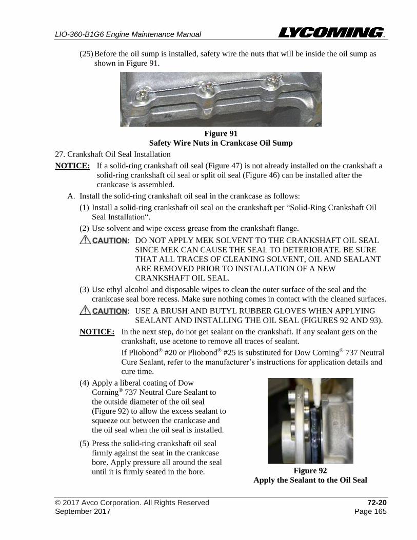
LIO-360-B1G6 Engine Maintenance Manual
© 2017 Avco Corporation. All Rights Reserved 72-20 September 2017 Page 165
(25) Before the oil sump is installed, safety wire the nuts that will be inside the oil sump as
shown in Figure 91.
Figure 91
Safety Wire Nuts in Crankcase Oil Sump
27. Crankshaft Oil Seal Installation
NOTICE: If a solid-ring crankshaft oil seal (Figure 47) is not already installed on the crankshaft a
solid-ring crankshaft oil seal or split oil seal (Figure 46) can be installed after the
crankcase is assembled.
A. Install the solid-ring crankshaft oil seal in the crankcase as follows:
(1) Install a solid-ring crankshaft oil seal on the crankshaft per “Solid-Ring Crankshaft Oil
Seal Installation“.
(2) Use solvent and wipe excess grease from the crankshaft flange.
DO NOT APPLY MEK SOLVENT TO THE CRANKSHAFT OIL SEAL
SINCE MEK CAN CAUSE THE SEAL TO DETERIORATE. BE SURE
THAT ALL TRACES OF CLEANING SOLVENT, OIL AND SEALANT
ARE REMOVED PRIOR TO INSTALLATION OF A NEW
CRANKSHAFT OIL SEAL.
(3) Use ethyl alcohol and disposable wipes to clean the outer surface of the seal and the
crankcase seal bore recess. Make sure nothing comes in contact with the cleaned surfaces.
USE A BRUSH AND BUTYL RUBBER GLOVES WHEN APPLYING
SEALANT AND INSTALLING THE OIL SEAL (FIGURES 92 AND 93).
NOTICE: In the next step, do not get sealant on the crankshaft. If any sealant gets on the
crankshaft, use acetone to remove all traces of sealant.
If Pliobond® #20 or Pliobond® #25 is substituted for Dow Corning® 737 Neutral
Cure Sealant, refer to the manufacturer’s instructions for application details and
cure time.
(4) Apply a liberal coating of Dow
Corning® 737 Neutral Cure Sealant to
the outside diameter of the oil seal
(Figure 92) to allow the excess sealant to
squeeze out between the crankcase and
the oil seal when the oil seal is installed.
(5) Press the solid-ring crankshaft oil seal
firmly against the seat in the crankcase
bore. Apply pressure all around the seal
until it is firmly seated in the bore.
Figure 92
Apply the Sealant to the Oil Seal
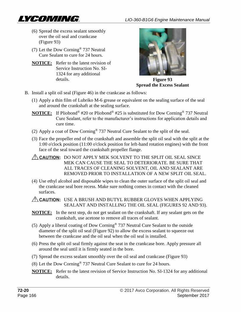
LIO-360-B1G6 Engine Maintenance Manual
72-20 © 2017 Avco Corporation. All Rights Reserved Page 166 September 2017
(6) Spread the excess sealant smoothly
over the oil seal and crankcase
(Figure 93)
(7) Let the Dow Corning® 737 Neutral
Cure Sealant to cure for 24 hours.
NOTICE: Refer to the latest revision of
Service Instruction No. SI-
1324 for any additional
details.
Figure 93
Spread the Excess Sealant
B. Install a split oil seal (Figure 46) in the crankcase as follows:
(1) Apply a thin film of Lubriko M-6 grease or equivalent on the sealing surface of the seal
and around the crankshaft at the sealing surface.
NOTICE: If Pliobond® #20 or Pliobond® #25 is substituted for Dow Corning® 737 Neutral
Cure Sealant, refer to the manufacturer’s instructions for application details and
cure time.
(2) Apply a coat of Dow Corning® 737 Neutral Cure Sealant to the split of the seal.
(3) Face the propeller end of the crankshaft and assemble the split oil seal with the split at the
1:00 o'clock position (11:00 o'clock position for left-hand rotation engines) with the front
face of the seal toward the crankshaft propeller flange.
DO NOT APPLY MEK SOLVENT TO THE SPLIT OIL SEAL SINCE
MEK CAN CAUSE THE SEAL TO DETERIORATE. BE SURE THAT
ALL TRACES OF CLEANING SOLVENT, OIL AND SEALANT ARE
REMOVED PRIOR TO INSTALLATION OF A NEW SPLIT OIL SEAL.
(4) Use ethyl alcohol and disposable wipes to clean the outer surface of the split oil seal and
the crankcase seal bore recess. Make sure nothing comes in contact with the cleaned
surfaces.
USE A BRUSH AND BUTYL RUBBER GLOVES WHEN APPLYING
SEALANT AND INSTALLING THE OIL SEAL (FIGURES 92 AND 93).
NOTICE: In the next step, do not get sealant on the crankshaft. If any sealant gets on the
crankshaft, use acetone to remove all traces of sealant.
(5) Apply a liberal coating of Dow Corning® 737 Neutral Cure Sealant to the outside
diameter of the split oil seal (Figure 92) to allow the excess sealant to squeeze out
between the crankcase and the oil seal when the oil seal is installed.
(6) Press the split oil seal firmly against the seat in the crankcase bore. Apply pressure all
around the seal until it is firmly seated in the bore.
(7) Spread the excess sealant smoothly over the oil seal and crankcase (Figure 93)
(8) Let the Dow Corning® 737 Neutral Cure Sealant to cure for 24 hours.
NOTICE: Refer to the latest revision of Service Instruction No. SI-1324 for any additional
details.
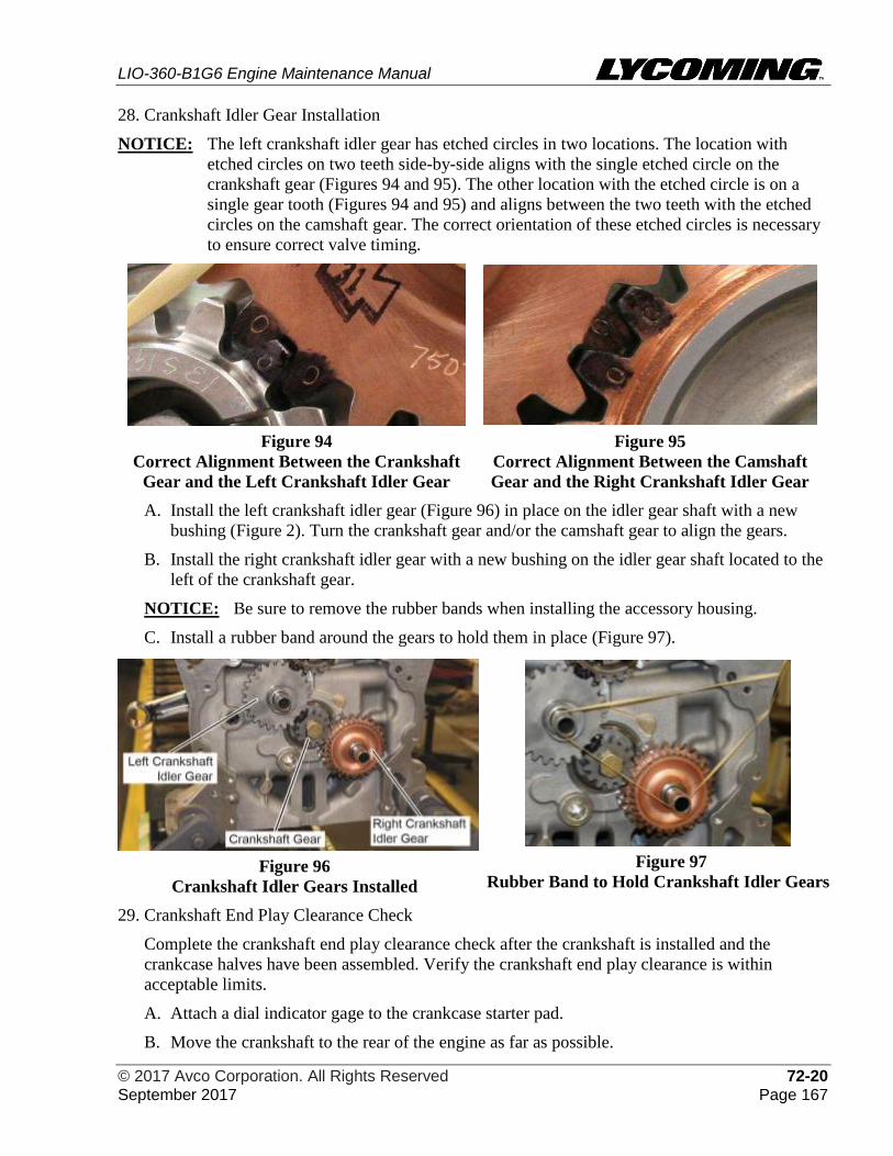
LIO-360-B1G6 Engine Maintenance Manual
© 2017 Avco Corporation. All Rights Reserved 72-20 September 2017 Page 167
28. Crankshaft Idler Gear Installation
NOTICE: The left crankshaft idler gear has etched circles in two locations. The location with
etched circles on two teeth side-by-side aligns with the single etched circle on the
crankshaft gear (Figures 94 and 95). The other location with the etched circle is on a
single gear tooth (Figures 94 and 95) and aligns between the two teeth with the etched
circles on the camshaft gear. The correct orientation of these etched circles is necessary
to ensure correct valve timing.
Figure 94
Correct Alignment Between the Crankshaft
Gear and the Left Crankshaft Idler Gear
Figure 95
Correct Alignment Between the Camshaft
Gear and the Right Crankshaft Idler Gear
A. Install the left crankshaft idler gear (Figure 96) in place on the idler gear shaft with a new
bushing (Figure 2). Turn the crankshaft gear and/or the camshaft gear to align the gears.
B. Install the right crankshaft idler gear with a new bushing on the idler gear shaft located to the
left of the crankshaft gear.
NOTICE: Be sure to remove the rubber bands when installing the accessory housing.
C. Install a rubber band around the gears to hold them in place (Figure 97).
Figure 96
Crankshaft Idler Gears Installed
Figure 97
Rubber Band to Hold Crankshaft Idler Gears
29. Crankshaft End Play Clearance Check
Complete the crankshaft end play clearance check after the crankshaft is installed and the
crankcase halves have been assembled. Verify the crankshaft end play clearance is within
acceptable limits.
A. Attach a dial indicator gage to the crankcase starter pad.
B. Move the crankshaft to the rear of the engine as far as possible.
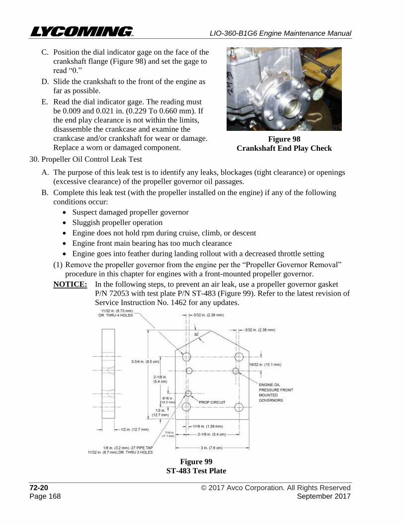
LIO-360-B1G6 Engine Maintenance Manual
72-20 © 2017 Avco Corporation. All Rights Reserved Page 168 September 2017
C. Position the dial indicator gage on the face of the
crankshaft flange (Figure 98) and set the gage to
read “0.”
D. Slide the crankshaft to the front of the engine as
far as possible.
E. Read the dial indicator gage. The reading must
be 0.009 and 0.021 in. (0.229 To 0.660 mm). If
the end play clearance is not within the limits,
disassemble the crankcase and examine the
crankcase and/or crankshaft for wear or damage.
Replace a worn or damaged component.
Figure 98
Crankshaft End Play Check
30. Propeller Oil Control Leak Test
A. The purpose of this leak test is to identify any leaks, blockages (tight clearance) or openings
(excessive clearance) of the propeller governor oil passages.
B. Complete this leak test (with the propeller installed on the engine) if any of the following
conditions occur:
• Suspect damaged propeller governor
• Sluggish propeller operation
• Engine does not hold rpm during cruise, climb, or descent
• Engine front main bearing has too much clearance
• Engine goes into feather during landing rollout with a decreased throttle setting
(1) Remove the propeller governor from the engine per the “Propeller Governor Removal”
procedure in this chapter for engines with a front-mounted propeller governor.
NOTICE: In the following steps, to prevent an air leak, use a propeller governor gasket
P/N 72053 with test plate P/N ST-483 (Figure 99). Refer to the latest revision of
Service Instruction No. 1462 for any updates.
Figure 99
ST-483 Test Plate
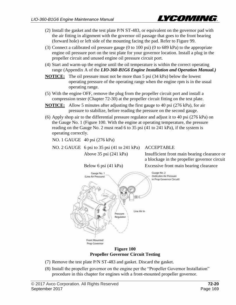
LIO-360-B1G6 Engine Maintenance Manual
© 2017 Avco Corporation. All Rights Reserved 72-20 September 2017 Page 169
(2) Install the gasket and the test plate P/N ST-483, or equivalent on the governor pad with
the air fitting in alignment with the governor oil passage that goes to the front bearing
(forward hole) or left side of the mounting facing the pad. Refer to Figure 99.
(3) Connect a calibrated oil pressure gauge (0 to 100 psi) (0 to 689 kPa) to the appropriate
engine oil pressure port on the test plate for your governor location. Install a plug in the
propeller circuit and unused engine oil pressure circuit port.
(4) Start and warm-up the engine until the oil temperature is within the correct operating
range (Appendix A of the LIO-360-B1G6 Engine Installation and Operation Manual.)
NOTICE: The oil pressure must not be more than 5 psi (34 kPa) below the lowest
operating pressure of the operating range when the engine rpm is in the usual
operating range.
(5) With the engine OFF, remove the plug from the propeller circuit port and install a
compression tester (Chapter 72-30) at the propeller circuit fitting on the test plate.
NOTICE: Allow 5 minutes after adjusting the first gauge to 40 psi (276 kPa), for air
pressure to stabilize, before reading the pressure on the second gauge.
(6) Apply shop air to the differential pressure regulator and adjust it to 40 psi (276 kPa) on
the Gauge No. 1 (Figure 100. With the engine at operating temperature, the pressure
reading on the Gauge No. 2 must read 6 to 35 psi (41 to 241 kPa), if the system is
operating correctly.
NO. 1 GAUGE 40 psi (276 kPa)
NO. 2 GAUGE 6 psi to 35 psi (41 to 241 kPa) ACCEPTABLE
Above 35 psi (241 kPa) Insufficient front main bearing clearance or
a blockage in the propeller governor circuit
Below 6 psi (41 kPa) Excessive front main bearing clearance
Figure 100
Propeller Governor Circuit Testing
(7) Remove the test plate P/N ST-483 and gasket. Discard the gasket.
(8) Install the propeller governor on the engine per the “Propeller Governor Installation”
procedure in this chapter for engines with a front-mounted propeller governor.
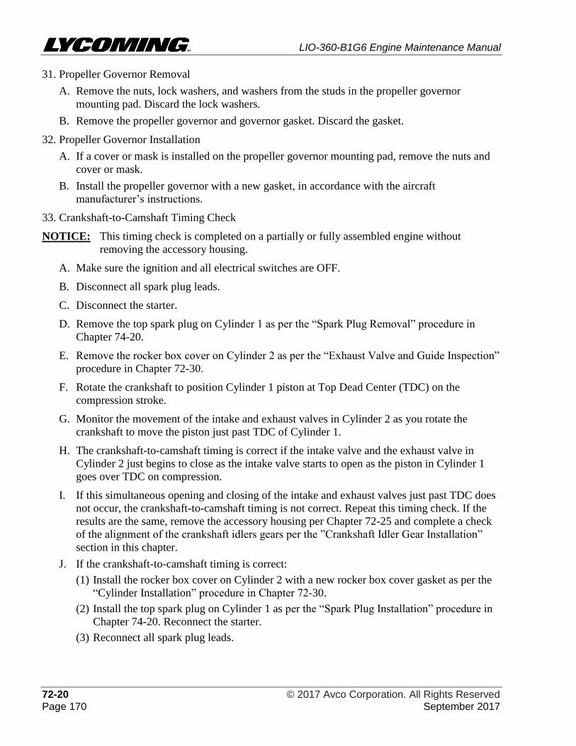
LIO-360-B1G6 Engine Maintenance Manual
72-20 © 2017 Avco Corporation. All Rights Reserved Page 170 September 2017
31. Propeller Governor Removal
A. Remove the nuts, lock washers, and washers from the studs in the propeller governor
mounting pad. Discard the lock washers.
B. Remove the propeller governor and governor gasket. Discard the gasket.
32. Propeller Governor Installation
A. If a cover or mask is installed on the propeller governor mounting pad, remove the nuts and
cover or mask.
B. Install the propeller governor with a new gasket, in accordance with the aircraft
manufacturer’s instructions.
33. Crankshaft-to-Camshaft Timing Check
NOTICE: This timing check is completed on a partially or fully assembled engine without
removing the accessory housing.
A. Make sure the ignition and all electrical switches are OFF.
B. Disconnect all spark plug leads.
C. Disconnect the starter.
D. Remove the top spark plug on Cylinder 1 as per the “Spark Plug Removal” procedure in
Chapter 74-20.
E. Remove the rocker box cover on Cylinder 2 as per the “Exhaust Valve and Guide Inspection”
procedure in Chapter 72-30.
F. Rotate the crankshaft to position Cylinder 1 piston at Top Dead Center (TDC) on the
compression stroke.
G. Monitor the movement of the intake and exhaust valves in Cylinder 2 as you rotate the
crankshaft to move the piston just past TDC of Cylinder 1.
H. The crankshaft-to-camshaft timing is correct if the intake valve and the exhaust valve in
Cylinder 2 just begins to close as the intake valve starts to open as the piston in Cylinder 1
goes over TDC on compression.
I. If this simultaneous opening and closing of the intake and exhaust valves just past TDC does
not occur, the crankshaft-to-camshaft timing is not correct. Repeat this timing check. If the
results are the same, remove the accessory housing per Chapter 72-25 and complete a check
of the alignment of the crankshaft idlers gears per the ”Crankshaft Idler Gear Installation”
section in this chapter.
J. If the crankshaft-to-camshaft timing is correct:
(1) Install the rocker box cover on Cylinder 2 with a new rocker box cover gasket as per the
“Cylinder Installation” procedure in Chapter 72-30.
(2) Install the top spark plug on Cylinder 1 as per the “Spark Plug Installation” procedure in
Chapter 74-20. Reconnect the starter.
(3) Reconnect all spark plug leads.
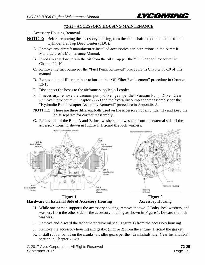
LIO-360-B1G6 Engine Maintenance Manual
© 2017 Avco Corporation. All Rights Reserved 72-25 September 2017 Page 171
72-25 - ACCESSORY HOUSING MAINTENANCE
1. Accessory Housing Removal
NOTICE: Before removing the accessory housing, turn the crankshaft to position the piston in
Cylinder 1 at Top Dead Center (TDC).
A. Remove any aircraft manufacturer-installed accessories per instructions in the Aircraft
Manufacturer’s Maintenance Manual.
B. If not already done, drain the oil from the oil sump per the “Oil Change Procedure” in
Chapter 12-10.
C. Remove the fuel pump per the “Fuel Pump Removal” procedure in Chapter 73-10 of this
manual.
D. Remove the oil filter per instructions in the “Oil Filter Replacement” procedure in Chapter
12-10.
E. Disconnect the hoses to the airframe-supplied oil cooler.
F. If necessary, remove the vacuum pump driven gear per the “Vacuum Pump Driven Gear
Removal” procedure in Chapter 72-60 and the hydraulic pump adapter assembly per the
“Hydraulic Pump Adapter Assembly Removal” procedure in Appendix A.
NOTICE: There are three different bolts used on the accessory housing. Identify and keep the
bolts separate for correct reassembly.
G. Remove all of the Bolts A and B, lock washers, and washers from the external side of the
accessory housing shown in Figure 1. Discard the lock washers.
Figure 1
Hardware on External Side of Accessory Housing
Figure 2
Accessory Housing
H. While one person supports the accessory housing, remove the two C Bolts, lock washers, and
washers from the other side of the accessory housing as shown in Figure 1. Discard the lock
washers.
I. Remove and discard the tachometer drive oil seal (Figure 1) from the accessory housing.
J. Remove the accessory housing and gasket (Figure 2) from the engine. Discard the gasket.
K. Install rubber bands on the crankshaft idler gears per the “Crankshaft Idler Gear Installation”
section in Chapter 72-20.
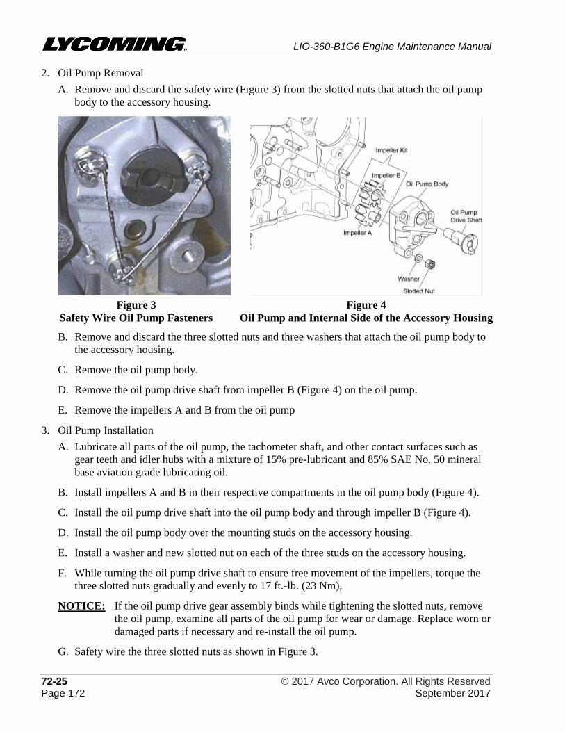
LIO-360-B1G6 Engine Maintenance Manual
72-25 © 2017 Avco Corporation. All Rights Reserved Page 172 September 2017
2. Oil Pump Removal
A. Remove and discard the safety wire (Figure 3) from the slotted nuts that attach the oil pump
body to the accessory housing.
Figure 3
Safety Wire Oil Pump Fasteners
Figure 4
Oil Pump and Internal Side of the Accessory Housing
B. Remove and discard the three slotted nuts and three washers that attach the oil pump body to
the accessory housing.
C. Remove the oil pump body.
D. Remove the oil pump drive shaft from impeller B (Figure 4) on the oil pump.
E. Remove the impellers A and B from the oil pump
3. Oil Pump Installation
A. Lubricate all parts of the oil pump, the tachometer shaft, and other contact surfaces such as
gear teeth and idler hubs with a mixture of 15% pre-lubricant and 85% SAE No. 50 mineral
base aviation grade lubricating oil.
B. Install impellers A and B in their respective compartments in the oil pump body (Figure 4).
C. Install the oil pump drive shaft into the oil pump body and through impeller B (Figure 4).
D. Install the oil pump body over the mounting studs on the accessory housing.
E. Install a washer and new slotted nut on each of the three studs on the accessory housing.
F. While turning the oil pump drive shaft to ensure free movement of the impellers, torque the
three slotted nuts gradually and evenly to 17 ft.-lb. (23 Nm),
NOTICE: If the oil pump drive gear assembly binds while tightening the slotted nuts, remove
the oil pump, examine all parts of the oil pump for wear or damage. Replace worn or
damaged parts if necessary and re-install the oil pump.
G. Safety wire the three slotted nuts as shown in Figure 3.
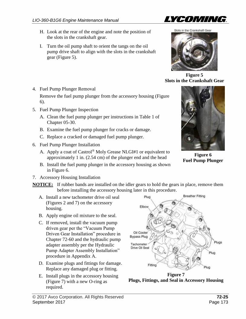
LIO-360-B1G6 Engine Maintenance Manual
© 2017 Avco Corporation. All Rights Reserved 72-25 September 2017 Page 173
H. Look at the rear of the engine and note the position of
the slots in the crankshaft gear.
I. Turn the oil pump shaft to orient the tangs on the oil
pump drive shaft to align with the slots in the crankshaft
gear (Figure 5).
Figure 5
Slots in the Crankshaft Gear
4. Fuel Pump Plunger Removal
Remove the fuel pump plunger from the accessory housing (Figure
6).
5. Fuel Pump Plunger Inspection
A. Clean the fuel pump plunger per instructions in Table 1 of
Chapter 05-30.
B. Examine the fuel pump plunger for cracks or damage.
C. Replace a cracked or damaged fuel pump plunger.
6. Fuel Pump Plunger Installation
A. Apply a coat of Castrol® Moly Grease NLGI#1 or equivalent to
approximately 1 in. (2.54 cm) of the plunger end and the head
B. Install the fuel pump plunger in the accessory housing as shown
in Figure 6.
Figure 6
Fuel Pump Plunger
7. Accessory Housing Installation
NOTICE: If rubber bands are installed on the idler gears to hold the gears in place, remove them
before installing the accessory housing later in this procedure.
A. Install a new tachometer drive oil seal
(Figures 2 and 7) on the accessory
housing.
B. Apply engine oil mixture to the seal.
C. If removed, install the vacuum pump
driven gear per the “Vacuum Pump
Driven Gear Installation” procedure in
Chapter 72-60 and the hydraulic pump
adapter assembly per the Hydraulic
Pump Adapter Assembly Installation”
procedure in Appendix A.
D. Examine plugs and fittings for damage.
Replace any damaged plug or fitting.
E. Install plugs in the accessory housing
(Figure 7) with a new O-ring as
required.
Figure 7
Plugs, Fittings, and Seal in Accessory Housing
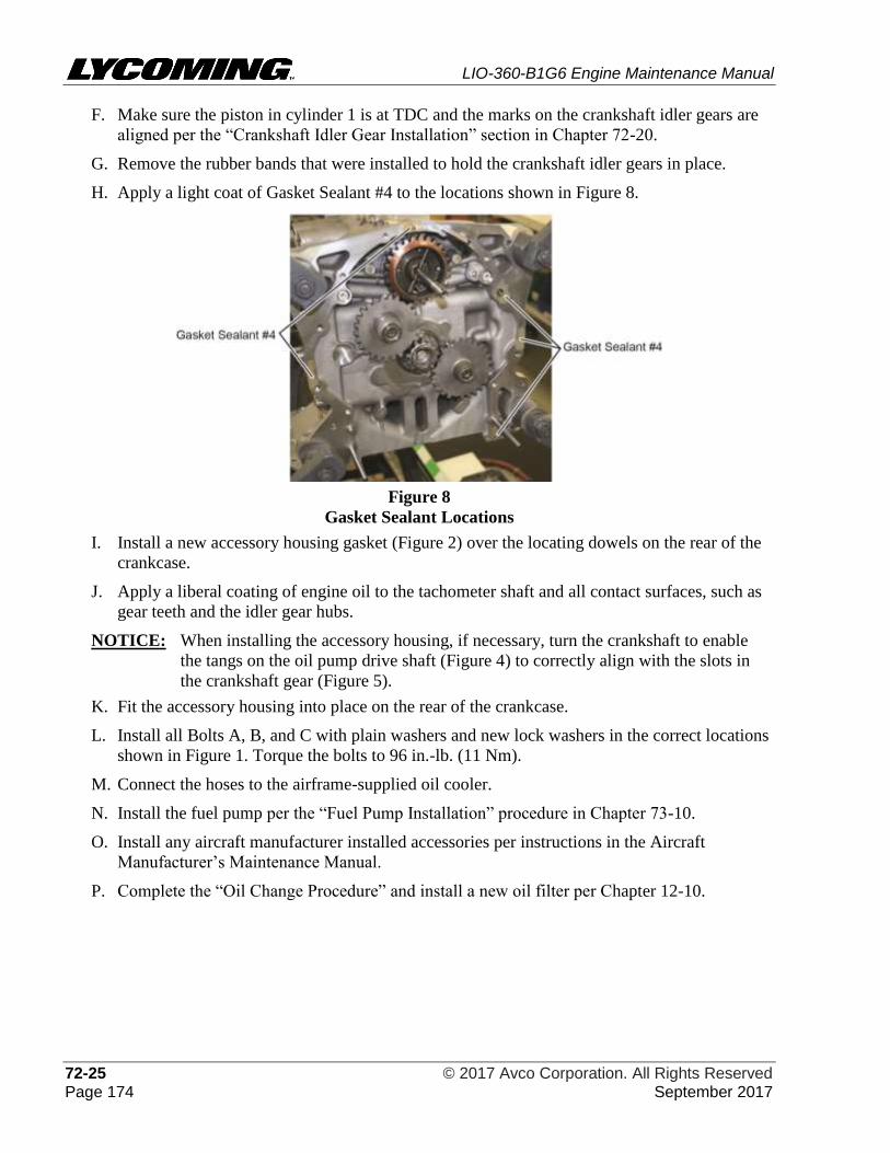
LIO-360-B1G6 Engine Maintenance Manual
72-25 © 2017 Avco Corporation. All Rights Reserved Page 174 September 2017
F. Make sure the piston in cylinder 1 is at TDC and the marks on the crankshaft idler gears are
aligned per the “Crankshaft Idler Gear Installation” section in Chapter 72-20.
G. Remove the rubber bands that were installed to hold the crankshaft idler gears in place.
H. Apply a light coat of Gasket Sealant #4 to the locations shown in Figure 8.
Figure 8
Gasket Sealant Locations
I. Install a new accessory housing gasket (Figure 2) over the locating dowels on the rear of the
crankcase.
J. Apply a liberal coating of engine oil to the tachometer shaft and all contact surfaces, such as
gear teeth and the idler gear hubs.
NOTICE: When installing the accessory housing, if necessary, turn the crankshaft to enable
the tangs on the oil pump drive shaft (Figure 4) to correctly align with the slots in
the crankshaft gear (Figure 5).
K. Fit the accessory housing into place on the rear of the crankcase.
L. Install all Bolts A, B, and C with plain washers and new lock washers in the correct locations
shown in Figure 1. Torque the bolts to 96 in.-lb. (11 Nm).
M. Connect the hoses to the airframe-supplied oil cooler.
N. Install the fuel pump per the “Fuel Pump Installation” procedure in Chapter 73-10.
O. Install any aircraft manufacturer installed accessories per instructions in the Aircraft
Manufacturer’s Maintenance Manual.
P. Complete the “Oil Change Procedure” and install a new oil filter per Chapter 12-10.
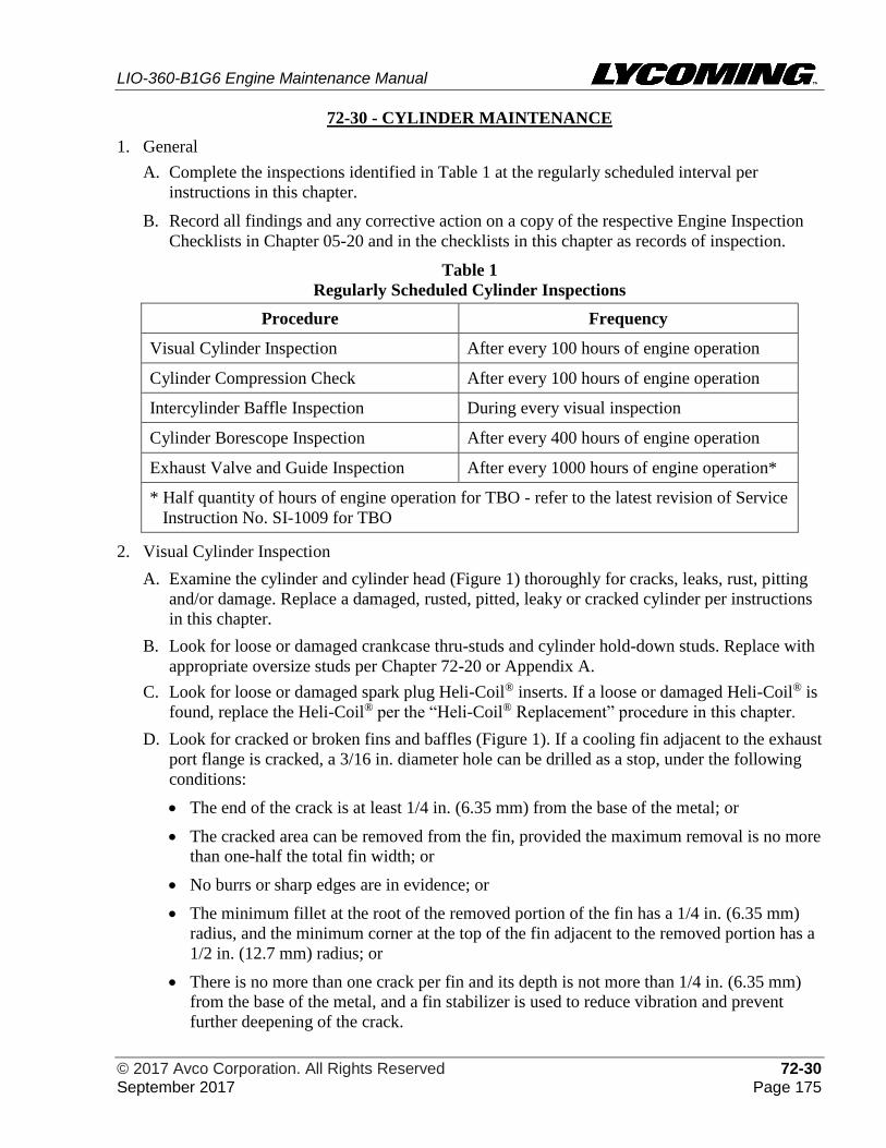
LIO-360-B1G6 Engine Maintenance Manual
© 2017 Avco Corporation. All Rights Reserved 72-30 September 2017 Page 175
72-30 - CYLINDER MAINTENANCE
1. General
A. Complete the inspections identified in Table 1 at the regularly scheduled interval per
instructions in this chapter.
B. Record all findings and any corrective action on a copy of the respective Engine Inspection
Checklists in Chapter 05-20 and in the checklists in this chapter as records of inspection.
Table 1
Regularly Scheduled Cylinder Inspections
Procedure Frequency
Visual Cylinder Inspection After every 100 hours of engine operation
Cylinder Compression Check After every 100 hours of engine operation
Intercylinder Baffle Inspection During every visual inspection
Cylinder Borescope Inspection After every 400 hours of engine operation
Exhaust Valve and Guide Inspection After every 1000 hours of engine operation*
* Half quantity of hours of engine operation for TBO - refer to the latest revision of Service
Instruction No. SI-1009 for TBO
2. Visual Cylinder Inspection
A. Examine the cylinder and cylinder head (Figure 1) thoroughly for cracks, leaks, rust, pitting
and/or damage. Replace a damaged, rusted, pitted, leaky or cracked cylinder per instructions
in this chapter.
B. Look for loose or damaged crankcase thru-studs and cylinder hold-down studs. Replace with
appropriate oversize studs per Chapter 72-20 or Appendix A.
C. Look for loose or damaged spark plug Heli-Coil® inserts. If a loose or damaged Heli-Coil® is
found, replace the Heli-Coil® per the “Heli-Coil® Replacement” procedure in this chapter.
D. Look for cracked or broken fins and baffles (Figure 1). If a cooling fin adjacent to the exhaust
port flange is cracked, a 3/16 in. diameter hole can be drilled as a stop, under the following
conditions:
• The end of the crack is at least 1/4 in. (6.35 mm) from the base of the metal; or
• The cracked area can be removed from the fin, provided the maximum removal is no more
than one-half the total fin width; or
• No burrs or sharp edges are in evidence; or
• The minimum fillet at the root of the removed portion of the fin has a 1/4 in. (6.35 mm)
radius, and the minimum corner at the top of the fin adjacent to the removed portion has a
1/2 in. (12.7 mm) radius; or
• There is no more than one crack per fin and its depth is not more than 1/4 in. (6.35 mm)
from the base of the metal, and a fin stabilizer is used to reduce vibration and prevent
further deepening of the crack.
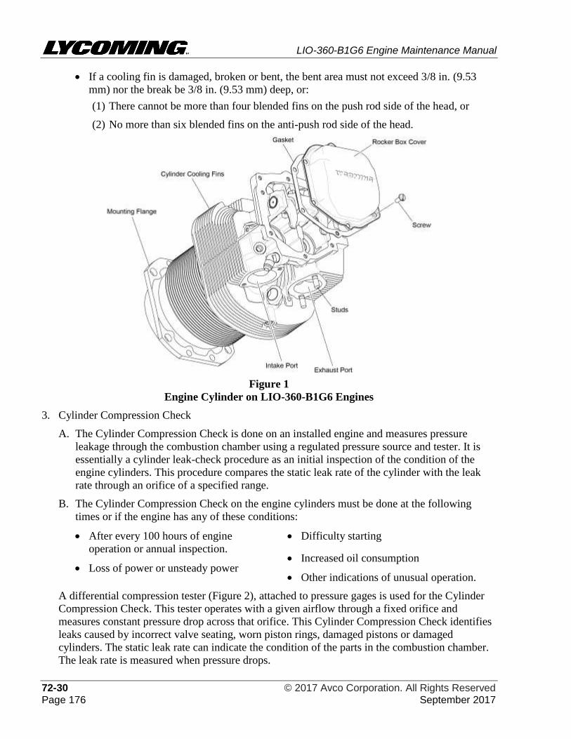
LIO-360-B1G6 Engine Maintenance Manual
72-30 © 2017 Avco Corporation. All Rights Reserved Page 176 September 2017
• If a cooling fin is damaged, broken or bent, the bent area must not exceed 3/8 in. (9.53
mm) nor the break be 3/8 in. (9.53 mm) deep, or:
(1) There cannot be more than four blended fins on the push rod side of the head, or
(2) No more than six blended fins on the anti-push rod side of the head.
Figure 1
Engine Cylinder on LIO-360-B1G6 Engines
3. Cylinder Compression Check
A. The Cylinder Compression Check is done on an installed engine and measures pressure
leakage through the combustion chamber using a regulated pressure source and tester. It is
essentially a cylinder leak-check procedure as an initial inspection of the condition of the
engine cylinders. This procedure compares the static leak rate of the cylinder with the leak
rate through an orifice of a specified range.
B. The Cylinder Compression Check on the engine cylinders must be done at the following
times or if the engine has any of these conditions:
• After every 100 hours of engine
operation or annual inspection.
• Loss of power or unsteady power
• Difficulty starting
• Increased oil consumption
• Other indications of unusual operation.
A differential compression tester (Figure 2), attached to pressure gages is used for the Cylinder
Compression Check. This tester operates with a given airflow through a fixed orifice and
measures constant pressure drop across that orifice. This Cylinder Compression Check identifies
leaks caused by incorrect valve seating, worn piston rings, damaged pistons or damaged
cylinders. The static leak rate can indicate the condition of the parts in the combustion chamber.
The leak rate is measured when pressure drops.
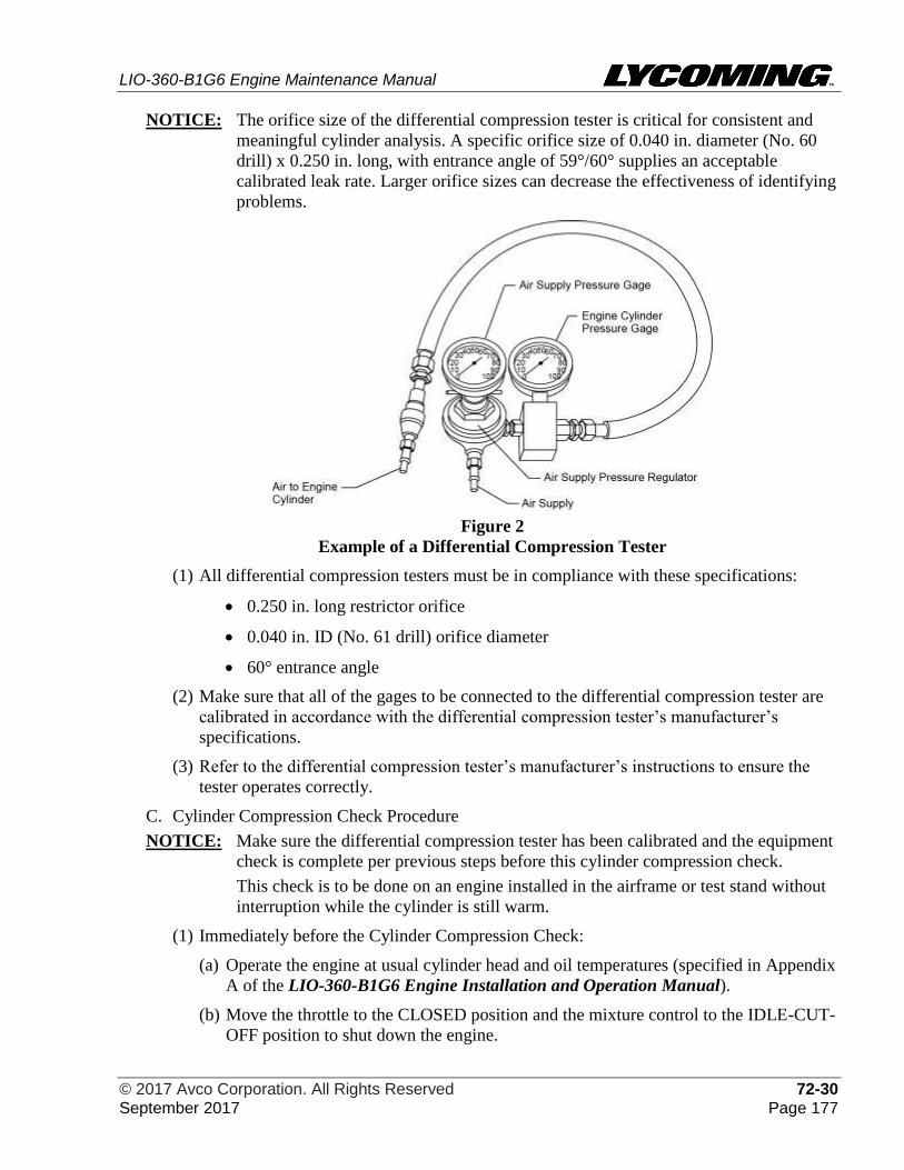
LIO-360-B1G6 Engine Maintenance Manual
© 2017 Avco Corporation. All Rights Reserved 72-30 September 2017 Page 177
NOTICE: The orifice size of the differential compression tester is critical for consistent and
meaningful cylinder analysis. A specific orifice size of 0.040 in. diameter (No. 60
drill) x 0.250 in. long, with entrance angle of 59°/60° supplies an acceptable
calibrated leak rate. Larger orifice sizes can decrease the effectiveness of identifying
problems.
Figure 2
Example of a Differential Compression Tester
(1) All differential compression testers must be in compliance with these specifications:
• 0.250 in. long restrictor orifice
• 0.040 in. ID (No. 61 drill) orifice diameter
• 60° entrance angle
(2) Make sure that all of the gages to be connected to the differential compression tester are
calibrated in accordance with the differential compression tester’s manufacturer’s
specifications.
(3) Refer to the differential compression tester’s manufacturer’s instructions to ensure the
tester operates correctly.
C. Cylinder Compression Check Procedure
NOTICE: Make sure the differential compression tester has been calibrated and the equipment
check is complete per previous steps before this cylinder compression check.
This check is to be done on an engine installed in the airframe or test stand without
interruption while the cylinder is still warm.
(1) Immediately before the Cylinder Compression Check:
(a) Operate the engine at usual cylinder head and oil temperatures (specified in Appendix
A of the LIO-360-B1G6 Engine Installation and Operation Manual).
(b) Move the throttle to the CLOSED position and the mixture control to the IDLE-CUT-
OFF position to shut down the engine.
LIO-360-B1G6 Engine Maintenance Manual
72-30 © 2017 Avco Corporation. All Rights Reserved Page 178 September 2017
(c) Move the Ignition switch to the OFF position.
(d) Make sure that the aircraft master switch and fuel supply switches are all in the OFF
position.
(e) After the engine is shut down, complete the Cylinder Compression Check
immediately to get an accurate measurement.
(f) Set the aircraft brakes and install the wheel chocks.
TAKE ALL NECESSARY PRECAUTIONS AGAINST
ACCIDENTAL ROTATION OF THE CRANKSHAFT/PROPELLER
TO PREVENT INJURY.
(2) Disable power to the engine.
IGNTION LEADS AND SPARK PLUGS ARE VERY HOT. IN THE
NEXT STEP, WEAR PERSONAL PROTECTIVE GEAR TO PREVENT
BURNS.
(3) Disconnect all of the spark plugs leads per the “Spark Plug Removal” procedure in
Chapter 74-20.
(4) Remove a spark plug from each cylinder. Discard the spark plug gasket.
USE GLOVES OR RAGS TO PROTECT HANDS WHILE HOLDING
THE PROPELLER BLADE.
(5) Turn the crankshaft by hand in the direction of propeller rotation to put the piston in a
position as close to Top Dead Center (TDC) on the compression stroke as possible.
(6) Install the threaded end of an adapter with a coupling end in the spark plug hole of the
cylinder to be tested.
(7) Make sure that the air valve on the differential compression tester is in the CLOSED
position.
(8) Connect the differential compression tester to a clean source of compressed air.
BEFORE CONNECTION OF THE COMPRESSION TESTER, MAKE
SURE THAT THE AIR SUPPLY REGULATOR DOES NOT SHOW
MORE THAN 80 PSI (552 KPA) OF AIR PRESSURE. EXCESSIVE
AIR PRESSURE CAN CAUSE THE PROPELLER TO TURN. KEEP
CLEAR OF THE ROTATIONAL RADIUS OF THE PROPELLER.
NOTICE: Operate the differential compression tester per the manufacturer’s instructions.
(9) Adjust the regulator of the compression tester to 0 psi (0 kPa) on the regulated pressure
gage.
(10) Connect the differential compression tester to the adapter in the spark plug hole of the
cylinder to be tested.
(11) One mechanic holds the propeller firmly in place, to prevent crankshaft rotation, while
the other mechanic opens the cylinder pressure valve in the next step.
LIO-360-B1G6 Engine Maintenance Manual
© 2017 Avco Corporation. All Rights Reserved 72-30 September 2017 Page 179
IN THE NEXT STEP, HOLD THE PROPELLER FIRMLY WHEN
OPENING THE AIR VALVE ON THE DIFFERENTIAL
COMPRESSION TESTER. PENT-UP AIR PRESSURE IN THE
CYLINDER COULD CAUSE THE CRANKSHAFT TO TURN.
(12) Slowly open the air valve on the differential compression tester and increase the pressure
to the cylinder to 15 to 20 psi (103 to 138 kPa).
(13) Listen for escaping air. If escaping air is heard, refer to Table 2 to identify and correct
the cause.
(14) Continue to turn the propeller in the usual direction of rotation against the 15 to 20 psi
(103 to 138 kPa) pressure until the piston reaches TDC evident by a sudden decrease in
the force necessary to turn the propeller.
NOTICE: If you turn the propeller past TDC, back up the rotation at least one revolution
and repeat the previous step to prevent backlash and to keep the piston rings in
position.
(15) With the piston at TDC, one mechanic holds the propeller securely while the other
mechanic opens the air valve slowly and completely. Gradually increase the air supply
pressure up to 80 psi (552 kPa). As the pressure increases, the other mechanic must
move the propeller back and forth slightly with a rocking motion to make sure that the
piston rings are seated.
(16) Record the pressure reading on the engine cylinder pressure gage. The difference
between the engine cylinder pressure gage reading and the pressure shown on the air
supply pressure gage reading is the amount of leakage through the cylinder.
(17) The minimum approved engine cylinder pressure reading is 60 psi (414 kPa). Maximum
approved leakage is 25% (20 psi (138 kPa) of the 80 psi (552 kPa) regulated pressure).
(18) Close the air valve and disconnect the differential compression tester from the engine
cylinder and connect it to the spark plug hole of the next engine cylinder to be tested.
NOTICE: Pressure readings for all of the engine cylinders are to be nearly equal. Refer to
Table 2.
(19) Complete the previous steps for each of the remaining engine cylinders.
(20) Refer to Table 2 for a summary of the Cylinder Compression Check results and
corrective action. Corrrective action in Table 2 applies to procedures in this chapter.
D. Review and analyze the results. Take any necessary corrective action.
E. Record the results of the Cylinder Compression Check for each cylinder on the 100-Hour or
Annual Engine Inspection Checklist (in Chapter 05-20).
F. After all service is complete, examine and install the spark plugs with a new gasket and
connect the ignition leads to the spark plugs per the following procedures in Chapter 74-20.
• Spark Plug Inspection • Spark Plug Rotation
• Ignition Lead Inspection • Spark Plug Installation
• Spark Plug Gap Setting • Ignition Harness Installation
LIO-360-B1G6 Engine Maintenance Manual
72-30 © 2017 Avco Corporation. All Rights Reserved Page 180 September 2017
Table 2
Summary of Cylinder Compression Check Results and Corrective Action
Results Indication Corrective Action
Differential pressure of 70 psi (483
kPa) or more for an engine cylinder
Satisfactory No corrective action necessary.
Differential pressure of 60 to 69 psi
(414 to 441 kPa) for an engine
cylinder
Wear has
occurred
Complete the Cylinder Compression
Check again after the next 100-hour
engine operating interval - record results.
Monitor the differential pressure.
Differential pressure of less than 60
psi (414 kPa) for an engine cylinder
Cylinder worn or
not in
conformance
Either manually turn the crankshaft three
times or start the engine and operate for 3
minutes, stop the engine, and repeat the
Cylinder Compression Check.
If the results of the second Cylinder
Compression Check are too low, listen for
airflow at the exhaust and intake ports.
Identify all of the causes and complete the
necessary corrective action.
Difference of 5 psi (34 kPa) or less)
between engine cylinders (Pressure
readings for all engine cylinders must
be nearly equal.)
Satisfactory No corrective action necessary.
Difference of 6 to 15 psi (41 to 103
kPa) between engine cylinders.
Repeat the Cylinder Compression Check
after the next 10 hours of engine
operation. A valve can reseat itself and
show satisfactory compression again. If
the difference remains between 6 to 15 psi
(41 to 103 kPa) after the second Cylinder
Compression Check, identify all of the
causes and complete the necessary
corrective action.
Difference of more than 15 psi (104
kPa) between engine cylinders
Start and operate the engine for 3 minutes,
stop the engine, and repeat the Cylinder
Compression Check.
If the difference between engine cylinders
is still more than 15 psi (104 kPa), replace
all of the engine cylinders.
Air escaping at spark plug spot face Fluorescent
Penetrant
Inspection of
area shows
cracks
Replace the cylinder with a cylinder kit.
Leak check at the spark plug port
seals (using a soap solution) shows
bubbling around spark plug port seal.
Heli-Coil® insert
requires
replacement.
Complete the “Heli-Coil® Replacement”
procedure in this chapter.
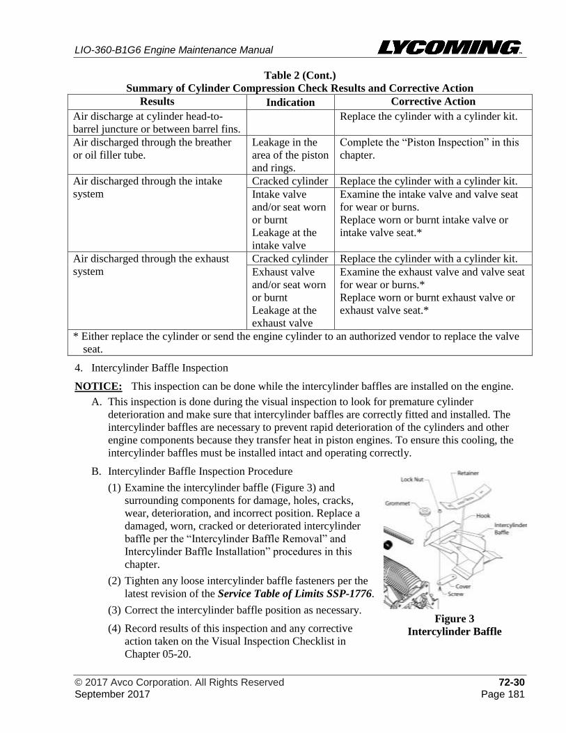
LIO-360-B1G6 Engine Maintenance Manual
© 2017 Avco Corporation. All Rights Reserved 72-30 September 2017 Page 181
Table 2 (Cont.)
Summary of Cylinder Compression Check Results and Corrective Action
Results Indication Corrective Action
Air discharge at cylinder head-to-
barrel juncture or between barrel fins.
Replace the cylinder with a cylinder kit.
Air discharged through the breather
or oil filler tube.
Leakage in the
area of the piston
and rings.
Complete the “Piston Inspection” in this
chapter.
Air discharged through the intake
system
Cracked cylinder Replace the cylinder with a cylinder kit.
Intake valve
and/or seat worn
or burnt
Leakage at the
intake valve
Examine the intake valve and valve seat
for wear or burns.
Replace worn or burnt intake valve or
intake valve seat.*
Air discharged through the exhaust
system
Cracked cylinder Replace the cylinder with a cylinder kit.
Exhaust valve
and/or seat worn
or burnt
Leakage at the
exhaust valve
Examine the exhaust valve and valve seat
for wear or burns.*
Replace worn or burnt exhaust valve or
exhaust valve seat.*
* Either replace the cylinder or send the engine cylinder to an authorized vendor to replace the valve
seat.
4. Intercylinder Baffle Inspection
NOTICE: This inspection can be done while the intercylinder baffles are installed on the engine.
A. This inspection is done during the visual inspection to look for premature cylinder
deterioration and make sure that intercylinder baffles are correctly fitted and installed. The
intercylinder baffles are necessary to prevent rapid deterioration of the cylinders and other
engine components because they transfer heat in piston engines. To ensure this cooling, the
intercylinder baffles must be installed intact and operating correctly.
B. Intercylinder Baffle Inspection Procedure
(1) Examine the intercylinder baffle (Figure 3) and
surrounding components for damage, holes, cracks,
wear, deterioration, and incorrect position. Replace a
damaged, worn, cracked or deteriorated intercylinder
baffle per the “Intercylinder Baffle Removal” and
Intercylinder Baffle Installation” procedures in this
chapter.
(2) Tighten any loose intercylinder baffle fasteners per the
latest revision of the Service Table of Limits SSP-1776.
(3) Correct the intercylinder baffle position as necessary.
(4) Record results of this inspection and any corrective
action taken on the Visual Inspection Checklist in
Chapter 05-20.
Figure 3
Intercylinder Baffle
LIO-360-B1G6 Engine Maintenance Manual
72-30 © 2017 Avco Corporation. All Rights Reserved Page 182 September 2017
5. Cylinder Borescope Inspection
DURING A CYLINDER BORESCOPE INSPECTION, MAKE SURE THAT
THE IGNITION SWITCH IS TURNED OFF AND THAT POWER TO THE
ENGINE IS DISCONNECTED.
AS A PRECAUTION, DO NOT STAND OR ALLOW ANYONE TO STAND
WITHIN THE ROTATIONAL ARC RADIUS OF THE PROPELLER. MAKE
SURE THE ENGINE IS COOL.
A. The cylinder borescope inspection is done to examine the inner walls of the engine cylinders
for rust, deposits and unusual wear patterns of the combustion chamber, valve, piston top,
and the cylinder barrel without removing the engine cylinder.
B. When to complete the Cylinder Borescope Inspection:
(1) Repeatedly high oil consumption is excessive
(2) 400-hour inspection
(3) After an engine overspeed
(4) Low cylinder compression
(5) If valve sticking is suspected (refer to the “Corrective Action for Valve Sticking” section
in this chapter)
(6) Worn piston rings or worn cylinder barrel
(7) Insufficient combustion
C. Cylinder Borescope Inspection Procedure
(1) Remove a top spark plug from each cylinder per the “Spark Plug Removal” procedure in
Chapter 74-20.
(2) Put the piston at bottom dead center on the power stroke.
(3) Install the borescope through the vacant top spark plug hole on the engine cylinder and
examine the combustion chamber, the top of the piston, the internal surfaces of each
cylinder, including the exhaust valve and exhaust valve seat. Complete inspection steps in
Table 3.
(4) Remove the borescope from the cylinder.
(5) Put the piston at bottom dead center at the end of the intake stroke.
(6) Install the borescope through the vacant spark plug hole and examine the intake valve and
intake valve seat. Complete inspection steps in Table 3. Unless otherwise shown,
corrective action in Table 3 applies to procedures in this chapter.
(7) Reinstall the spark plug in the cylinder per the “Spark Plug Installation” procedure in
Chapter 74-20.
(8) Record all results and corrective action in the 400-Hour Engine Inspection Checklist in
Chapter 05-20 or the engine logbook.
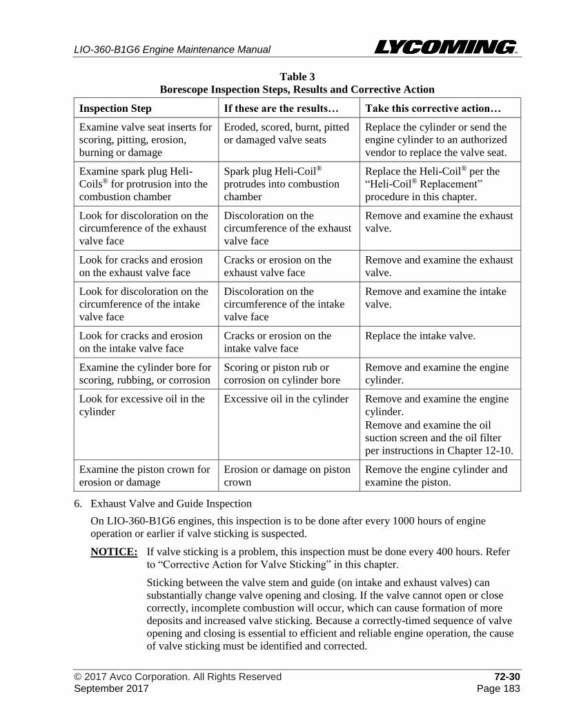
LIO-360-B1G6 Engine Maintenance Manual
© 2017 Avco Corporation. All Rights Reserved 72-30 September 2017 Page 183
Table 3
Borescope Inspection Steps, Results and Corrective Action
Inspection Step If these are the results… Take this corrective action…
Examine valve seat inserts for
scoring, pitting, erosion,
burning or damage
Eroded, scored, burnt, pitted
or damaged valve seats
Replace the cylinder or send the
engine cylinder to an authorized
vendor to replace the valve seat.
Examine spark plug Heli-
Coils® for protrusion into the
combustion chamber
Spark plug Heli-Coil®
protrudes into combustion
chamber
Replace the Heli-Coil® per the
“Heli-Coil® Replacement”
procedure in this chapter.
Look for discoloration on the
circumference of the exhaust
valve face
Discoloration on the
circumference of the exhaust
valve face
Remove and examine the exhaust
valve.
Look for cracks and erosion
on the exhaust valve face
Cracks or erosion on the
exhaust valve face
Remove and examine the exhaust
valve.
Look for discoloration on the
circumference of the intake
valve face
Discoloration on the
circumference of the intake
valve face
Remove and examine the intake
valve.
Look for cracks and erosion
on the intake valve face
Cracks or erosion on the
intake valve face
Replace the intake valve.
Examine the cylinder bore for
scoring, rubbing, or corrosion
Scoring or piston rub or
corrosion on cylinder bore
Remove and examine the engine
cylinder.
Look for excessive oil in the
cylinder
Excessive oil in the cylinder Remove and examine the engine
cylinder.
Remove and examine the oil
suction screen and the oil filter
per instructions in Chapter 12-10.
Examine the piston crown for
erosion or damage
Erosion or damage on piston
crown
Remove the engine cylinder and
examine the piston.
6. Exhaust Valve and Guide Inspection
On LIO-360-B1G6 engines, this inspection is to be done after every 1000 hours of engine
operation or earlier if valve sticking is suspected.
NOTICE: If valve sticking is a problem, this inspection must be done every 400 hours. Refer
to “Corrective Action for Valve Sticking” in this chapter.
Sticking between the valve stem and guide (on intake and exhaust valves) can
substantially change valve opening and closing. If the valve cannot open or close
correctly, incomplete combustion will occur, which can cause formation of more
deposits and increased valve sticking. Because a correctly-timed sequence of valve
opening and closing is essential to efficient and reliable engine operation, the cause
of valve sticking must be identified and corrected.
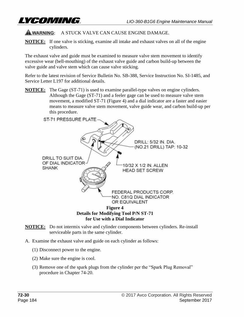
LIO-360-B1G6 Engine Maintenance Manual
72-30 © 2017 Avco Corporation. All Rights Reserved Page 184 September 2017
A STUCK VALVE CAN CAUSE ENGINE DAMAGE.
NOTICE: If one valve is sticking, examine all intake and exhaust valves on all of the engine
cylinders.
The exhaust valve and guide must be examined to measure valve stem movement to identify
excessive wear (bell-mouthing) of the exhaust valve guide and carbon build-up between the
valve guide and valve stem which can cause valve sticking.
Refer to the latest revision of Service Bulletin No. SB-388, Service Instruction No. SI-1485, and
Service Letter L197 for additional details.
NOTICE: The Gage (ST-71) is used to examine parallel-type valves on engine cylinders.
Although the Gage (ST-71) and a feeler gage can be used to measure valve stem
movement, a modified ST-71 (Figure 4) and a dial indicator are a faster and easier
means to measure valve stem movement, valve guide wear, and carbon build-up per
this procedure.
Figure 4
Details for Modifying Tool P/N ST-71
for Use with a Dial Indicator
NOTICE: Do not intermix valve and cylinder components between cylinders. Re-install
serviceable parts in the same cylinder.
A. Examine the exhaust valve and guide on each cylinder as follows:
(1) Disconnect power to the engine.
(2) Make sure the engine is cool.
(3) Remove one of the spark plugs from the cylinder per the “Spark Plug Removal”
procedure in Chapter 74-20.
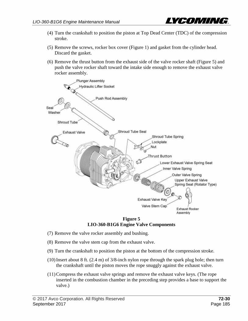
LIO-360-B1G6 Engine Maintenance Manual
© 2017 Avco Corporation. All Rights Reserved 72-30 September 2017 Page 185
(4) Turn the crankshaft to position the piston at Top Dead Center (TDC) of the compression
stroke.
(5) Remove the screws, rocker box cover (Figure 1) and gasket from the cylinder head.
Discard the gasket.
(6) Remove the thrust button from the exhaust side of the valve rocker shaft (Figure 5) and
push the valve rocker shaft toward the intake side enough to remove the exhaust valve
rocker assembly.
Figure 5
LIO-360-B1G6 Engine Valve Components
(7) Remove the valve rocker assembly and bushing.
(8) Remove the valve stem cap from the exhaust valve.
(9) Turn the crankshaft to position the piston at the bottom of the compression stroke.
(10) Insert about 8 ft. (2.4 m) of 3/8-inch nylon rope through the spark plug hole; then turn
the crankshaft until the piston moves the rope snuggly against the exhaust valve.
(11) Compress the exhaust valve springs and remove the exhaust valve keys. (The rope
inserted in the combustion chamber in the preceding step provides a base to support the
valve.)
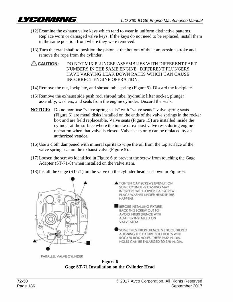
LIO-360-B1G6 Engine Maintenance Manual
72-30 © 2017 Avco Corporation. All Rights Reserved Page 186 September 2017
(12) Examine the exhaust valve keys which tend to wear in uniform distinctive patterns.
Replace worn or damaged valve keys. If the keys do not need to be replaced, install them
in the same position from where they were removed.
(13) Turn the crankshaft to position the piston at the bottom of the compression stroke and
remove the rope from the cylinder.
DO NOT MIX PLUNGER ASSEMBLIES WITH DIFFERENT PART
NUMBERS IN THE SAME ENGINE. DIFFERENT PLUNGERS
HAVE VARYING LEAK DOWN RATES WHICH CAN CAUSE
INCORRECT ENGINE OPERATION.
(14) Remove the nut, lockplate, and shroud tube spring (Figure 5). Discard the lockplate.
(15) Remove the exhaust side push rod, shroud tube, hydraulic lifter socket, plunger
assembly, washers, and seals from the engine cylinder. Discard the seals.
NOTICE: Do not confuse “valve spring seats” with “valve seats,” valve spring seats
(Figure 5) are metal disks installed on the ends of the valve springs in the rocker
box and are field replaceable. Valve seats (Figure 15) are installed inside the
cylinder at the surface where the intake or exhaust valve rests during engine
operation when that valve is closed. Valve seats only can be replaced by an
authorized vendor.
(16) Use a cloth dampened with mineral spirits to wipe the oil from the top surface of the
valve spring seat on the exhaust valve (Figure 5).
(17) Loosen the screws identified in Figure 6 to prevent the screw from touching the Gage
Adapter (ST-71-8) when installed on the valve stem.
(18) Install the Gage (ST-71) on the valve on the cylinder head as shown in Figure 6.
Figure 6
Gage ST-71 Installation on the Cylinder Head
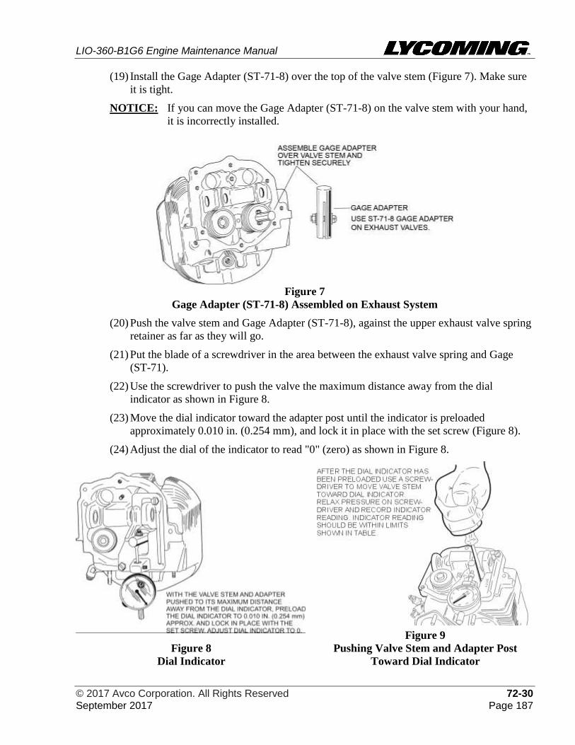
LIO-360-B1G6 Engine Maintenance Manual
© 2017 Avco Corporation. All Rights Reserved 72-30 September 2017 Page 187
(19) Install the Gage Adapter (ST-71-8) over the top of the valve stem (Figure 7). Make sure
it is tight.
NOTICE: If you can move the Gage Adapter (ST-71-8) on the valve stem with your hand,
it is incorrectly installed.
Figure 7
Gage Adapter (ST-71-8) Assembled on Exhaust System
(20) Push the valve stem and Gage Adapter (ST-71-8), against the upper exhaust valve spring
retainer as far as they will go.
(21) Put the blade of a screwdriver in the area between the exhaust valve spring and Gage
(ST-71).
(22) Use the screwdriver to push the valve the maximum distance away from the dial
indicator as shown in Figure 8.
(23) Move the dial indicator toward the adapter post until the indicator is preloaded
approximately 0.010 in. (0.254 mm), and lock it in place with the set screw (Figure 8).
(24) Adjust the dial of the indicator to read "0" (zero) as shown in Figure 8.
Figure 8
Dial Indicator
Figure 9
Pushing Valve Stem and Adapter Post
Toward Dial Indicator
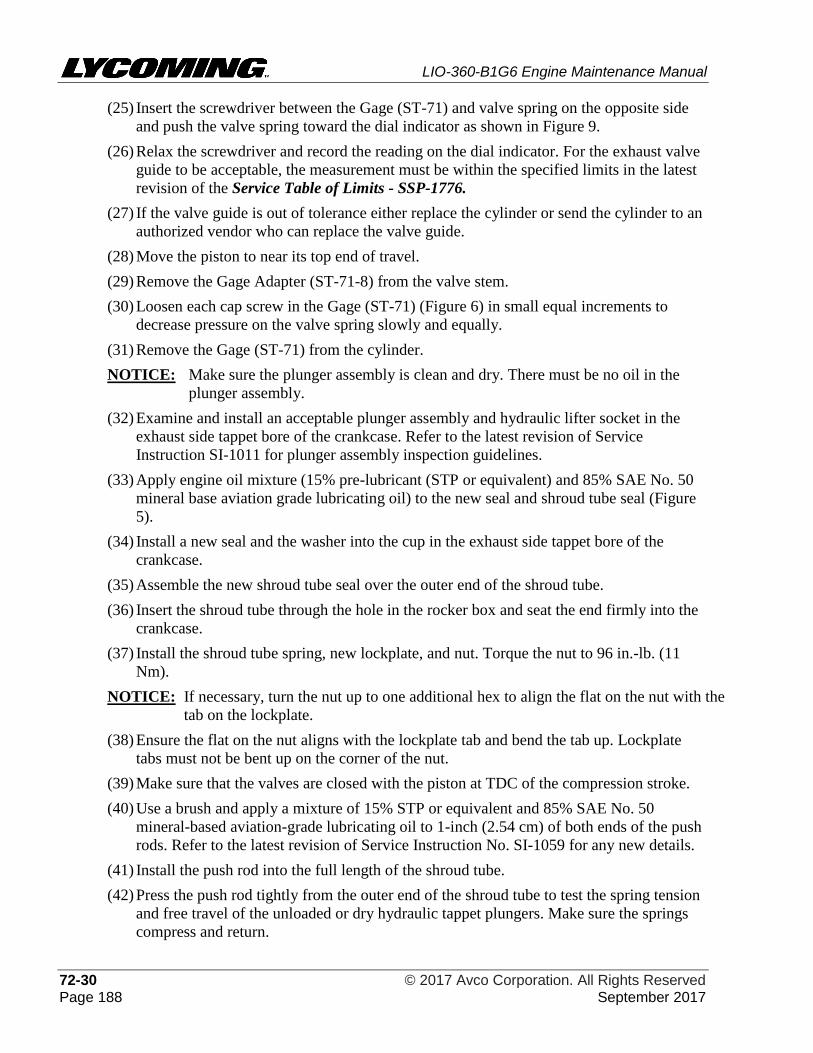
LIO-360-B1G6 Engine Maintenance Manual
72-30 © 2017 Avco Corporation. All Rights Reserved Page 188 September 2017
(25) Insert the screwdriver between the Gage (ST-71) and valve spring on the opposite side
and push the valve spring toward the dial indicator as shown in Figure 9.
(26) Relax the screwdriver and record the reading on the dial indicator. For the exhaust valve
guide to be acceptable, the measurement must be within the specified limits in the latest
revision of the Service Table of Limits - SSP-1776.
(27) If the valve guide is out of tolerance either replace the cylinder or send the cylinder to an
authorized vendor who can replace the valve guide.
(28) Move the piston to near its top end of travel.
(29) Remove the Gage Adapter (ST-71-8) from the valve stem.
(30) Loosen each cap screw in the Gage (ST-71) (Figure 6) in small equal increments to
decrease pressure on the valve spring slowly and equally.
(31) Remove the Gage (ST-71) from the cylinder.
NOTICE: Make sure the plunger assembly is clean and dry. There must be no oil in the
plunger assembly.
(32) Examine and install an acceptable plunger assembly and hydraulic lifter socket in the
exhaust side tappet bore of the crankcase. Refer to the latest revision of Service
Instruction SI-1011 for plunger assembly inspection guidelines.
(33) Apply engine oil mixture (15% pre-lubricant (STP or equivalent) and 85% SAE No. 50
mineral base aviation grade lubricating oil) to the new seal and shroud tube seal (Figure
5).
(34) Install a new seal and the washer into the cup in the exhaust side tappet bore of the
crankcase.
(35) Assemble the new shroud tube seal over the outer end of the shroud tube.
(36) Insert the shroud tube through the hole in the rocker box and seat the end firmly into the
crankcase.
(37) Install the shroud tube spring, new lockplate, and nut. Torque the nut to 96 in.-lb. (11
Nm).
NOTICE: If necessary, turn the nut up to one additional hex to align the flat on the nut with the
tab on the lockplate.
(38) Ensure the flat on the nut aligns with the lockplate tab and bend the tab up. Lockplate
tabs must not be bent up on the corner of the nut.
(39) Make sure that the valves are closed with the piston at TDC of the compression stroke.
(40) Use a brush and apply a mixture of 15% STP or equivalent and 85% SAE No. 50
mineral-based aviation-grade lubricating oil to 1-inch (2.54 cm) of both ends of the push
rods. Refer to the latest revision of Service Instruction No. SI-1059 for any new details.
(41) Install the push rod into the full length of the shroud tube.
(42) Press the push rod tightly from the outer end of the shroud tube to test the spring tension
and free travel of the unloaded or dry hydraulic tappet plungers. Make sure the springs
compress and return.
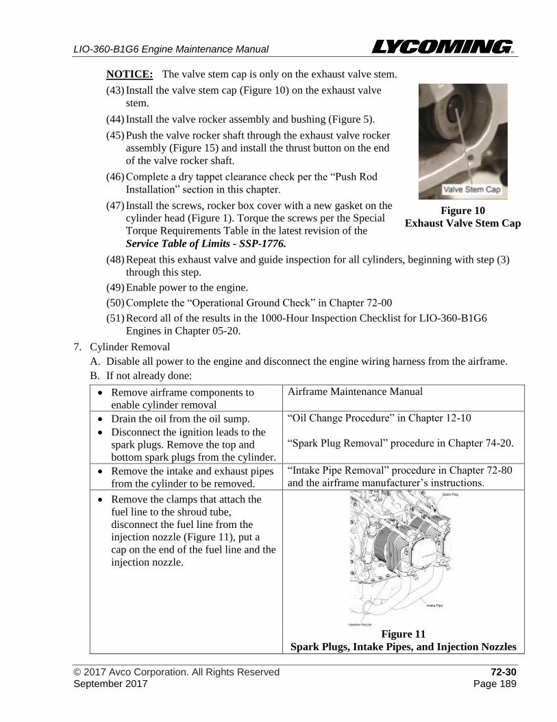
LIO-360-B1G6 Engine Maintenance Manual
© 2017 Avco Corporation. All Rights Reserved 72-30 September 2017 Page 189
NOTICE: The valve stem cap is only on the exhaust valve stem.
(43) Install the valve stem cap (Figure 10) on the exhaust valve
stem.
(44) Install the valve rocker assembly and bushing (Figure 5).
(45) Push the valve rocker shaft through the exhaust valve rocker
assembly (Figure 15) and install the thrust button on the end
of the valve rocker shaft.
(46) Complete a dry tappet clearance check per the “Push Rod
Installation” section in this chapter.
(47) Install the screws, rocker box cover with a new gasket on the
cylinder head (Figure 1). Torque the screws per the Special
Torque Requirements Table in the latest revision of the
Service Table of Limits - SSP-1776.
Figure 10
Exhaust Valve Stem Cap
(48) Repeat this exhaust valve and guide inspection for all cylinders, beginning with step (3)
through this step.
(49) Enable power to the engine.
(50) Complete the “Operational Ground Check” in Chapter 72-00
(51) Record all of the results in the 1000-Hour Inspection Checklist for LIO-360-B1G6
Engines in Chapter 05-20.
7. Cylinder Removal
A. Disable all power to the engine and disconnect the engine wiring harness from the airframe.
B. If not already done:
• Remove airframe components to
enable cylinder removal
Airframe Maintenance Manual
• Drain the oil from the oil sump.
• Disconnect the ignition leads to the
spark plugs. Remove the top and
bottom spark plugs from the cylinder.
“Oil Change Procedure” in Chapter 12-10
“Spark Plug Removal” procedure in Chapter 74-20.
• Remove the intake and exhaust pipes
from the cylinder to be removed.
“Intake Pipe Removal” procedure in Chapter 72-80
and the airframe manufacturer’s instructions.
• Remove the clamps that attach the
fuel line to the shroud tube,
disconnect the fuel line from the
injection nozzle (Figure 11), put a
cap on the end of the fuel line and the
injection nozzle.
Figure 11
Spark Plugs, Intake Pipes, and Injection Nozzles
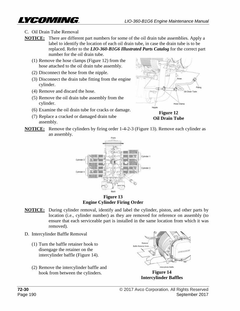
LIO-360-B1G6 Engine Maintenance Manual
72-30 © 2017 Avco Corporation. All Rights Reserved Page 190 September 2017
C. Oil Drain Tube Removal
NOTICE: There are different part numbers for some of the oil drain tube assemblies. Apply a
label to identify the location of each oil drain tube, in case the drain tube is to be
replaced. Refer to the LIO-360-B1G6 Illustrated Parts Catalog for the correct part
number for the oil drain tube.
(1) Remove the hose clamps (Figure 12) from the
hose attached to the oil drain tube assembly.
(2) Disconnect the hose from the nipple.
(3) Disconnect the drain tube fitting from the engine
cylinder.
(4) Remove and discard the hose.
(5) Remove the oil drain tube assembly from the
cylinder.
(6) Examine the oil drain tube for cracks or damage.
(7) Replace a cracked or damaged drain tube
assembly.
Figure 12
Oil Drain Tube
NOTICE: Remove the cylinders by firing order 1-4-2-3 (Figure 13). Remove each cylinder as
an assembly.
Figure 13
Engine Cylinder Firing Order
NOTICE: During cylinder removal, identify and label the cylinder, piston, and other parts by
location (i.e., cylinder number) as they are removed for reference on assembly (to
ensure that each serviceable part is installed in the same location from which it was
removed).
D. Intercylinder Baffle Removal
(1) Turn the baffle retainer hook to
disengage the retainer on the
intercylinder baffle (Figure 14).
(2) Remove the intercylinder baffle and
hook from between the cylinders.
Figure 14
Intercylinder Baffles
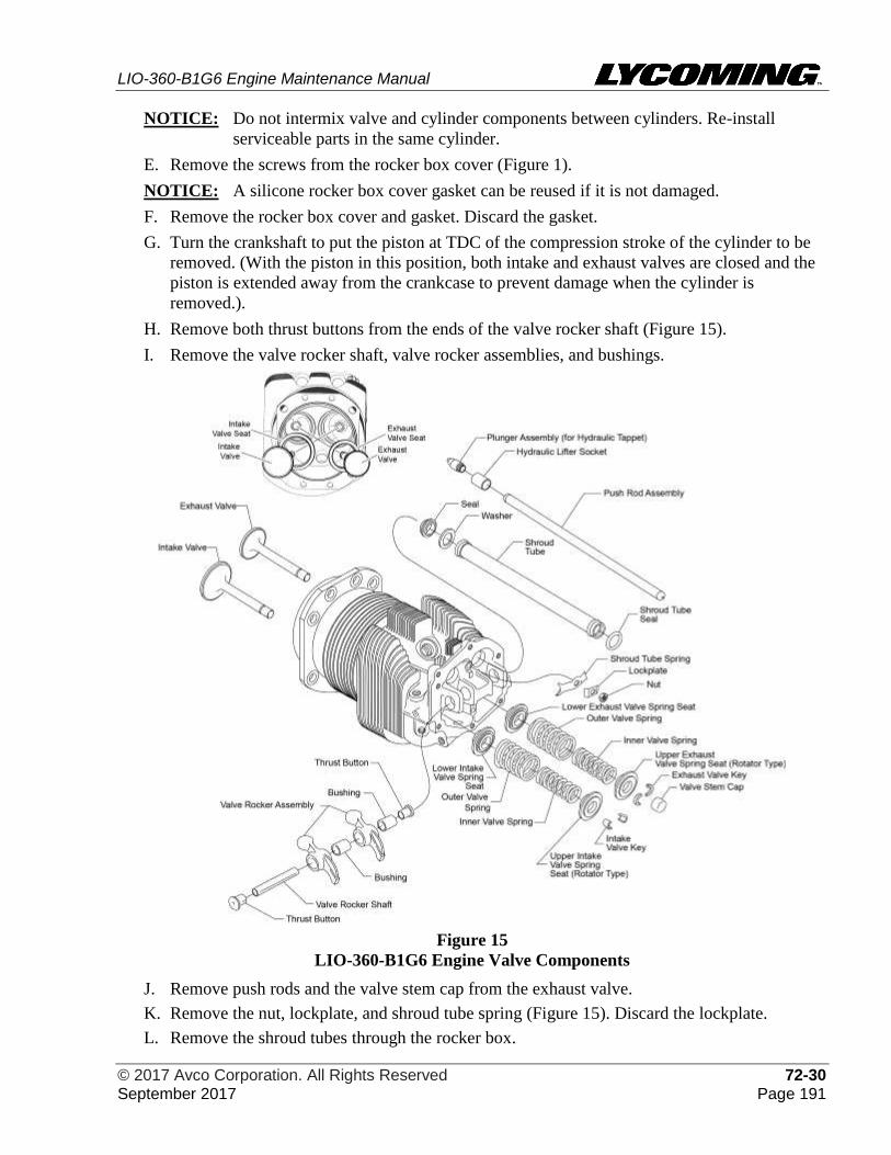
LIO-360-B1G6 Engine Maintenance Manual
© 2017 Avco Corporation. All Rights Reserved 72-30 September 2017 Page 191
NOTICE: Do not intermix valve and cylinder components between cylinders. Re-install
serviceable parts in the same cylinder.
E. Remove the screws from the rocker box cover (Figure 1).
NOTICE: A silicone rocker box cover gasket can be reused if it is not damaged.
F. Remove the rocker box cover and gasket. Discard the gasket.
G. Turn the crankshaft to put the piston at TDC of the compression stroke of the cylinder to be
removed. (With the piston in this position, both intake and exhaust valves are closed and the
piston is extended away from the crankcase to prevent damage when the cylinder is
removed.).
H. Remove both thrust buttons from the ends of the valve rocker shaft (Figure 15).
I. Remove the valve rocker shaft, valve rocker assemblies, and bushings.
Figure 15
LIO-360-B1G6 Engine Valve Components
J. Remove push rods and the valve stem cap from the exhaust valve.
K. Remove the nut, lockplate, and shroud tube spring (Figure 15). Discard the lockplate.
L. Remove the shroud tubes through the rocker box.
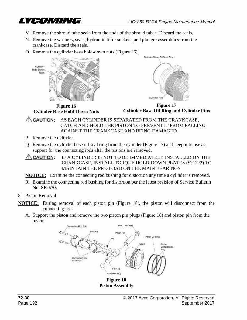
LIO-360-B1G6 Engine Maintenance Manual
72-30 © 2017 Avco Corporation. All Rights Reserved Page 192 September 2017
M. Remove the shroud tube seals from the ends of the shroud tubes. Discard the seals.
N. Remove the washers, seals, hydraulic lifter sockets, and plunger assemblies from the
crankcase. Discard the seals.
O. Remove the cylinder base hold-down nuts (Figure 16).
Figure 16
Cylinder Base Hold-Down Nuts
Figure 17
Cylinder Base Oil Ring and Cylinder Fins
AS EACH CYLINDER IS SEPARATED FROM THE CRANKCASE,
CATCH AND HOLD THE PISTON TO PREVENT IT FROM FALLING
AGAINST THE CRANKCASE AND BEING DAMAGED.
P. Remove the cylinder.
Q. Remove the cylinder base oil seal ring from the cylinder (Figure 17) and keep it to use as
support for the connecting rods after the pistons are removed.
IF A CYLINDER IS NOT TO BE IMMEDIATELY INSTALLED ON THE
CRANKCASE, INSTALL TORQUE HOLD-DOWN PLATES (ST-222) TO
MAINTAIN THE PRE-LOAD ON THE MAIN BEARINGS.
NOTICE: Examine the connecting rod bushing for distortion any time a cylinder is removed.
R. Examine the connecting rod bushing for distortion per the latest revision of Service Bulletin
No. SB-630.
8. Piston Removal
NOTICE: During removal of each piston pin (Figure 18), the piston will disconnect from the
connecting rod.
A. Support the piston and remove the two piston pin plugs (Figure 18) and piston pin from the
piston.
Figure 18
Piston Assembly
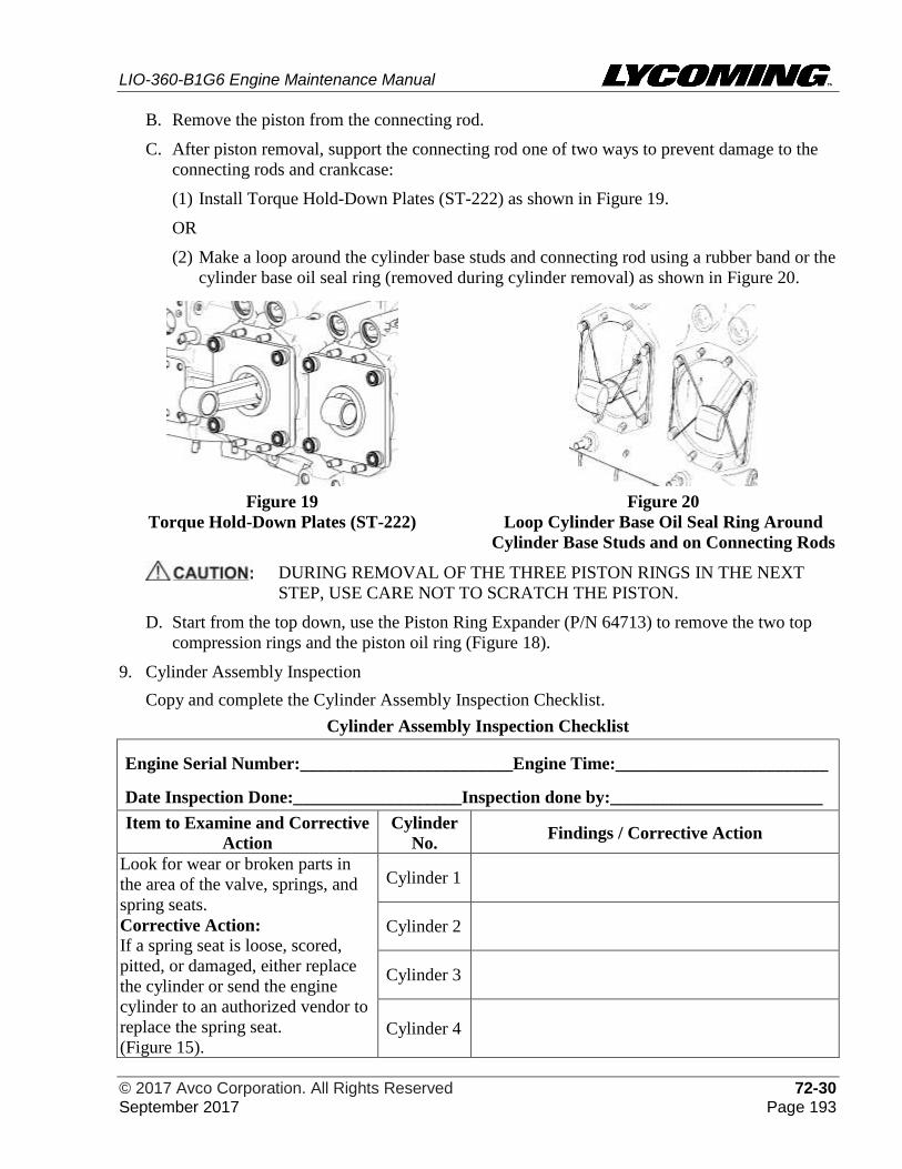
LIO-360-B1G6 Engine Maintenance Manual
© 2017 Avco Corporation. All Rights Reserved 72-30 September 2017 Page 193
B. Remove the piston from the connecting rod.
C. After piston removal, support the connecting rod one of two ways to prevent damage to the
connecting rods and crankcase:
(1) Install Torque Hold-Down Plates (ST-222) as shown in Figure 19.
OR
(2) Make a loop around the cylinder base studs and connecting rod using a rubber band or the
cylinder base oil seal ring (removed during cylinder removal) as shown in Figure 20.
Figure 19
Torque Hold-Down Plates (ST-222) Figure 20
Loop Cylinder Base Oil Seal Ring Around
Cylinder Base Studs and on Connecting Rods
DURING REMOVAL OF THE THREE PISTON RINGS IN THE NEXT
STEP, USE CARE NOT TO SCRATCH THE PISTON.
D. Start from the top down, use the Piston Ring Expander (P/N 64713) to remove the two top
compression rings and the piston oil ring (Figure 18).
9. Cylinder Assembly Inspection
Copy and complete the Cylinder Assembly Inspection Checklist.
Cylinder Assembly Inspection Checklist
Engine Serial Number:________________________Engine Time:________________________
Date Inspection Done:___________________Inspection done by:________________________
Item to Examine and Corrective
Action
Cylinder
No. Findings / Corrective Action
Look for wear or broken parts in
the area of the valve, springs, and
spring seats.
Corrective Action:
If a spring seat is loose, scored,
pitted, or damaged, either replace
the cylinder or send the engine
cylinder to an authorized vendor to
replace the spring seat.
(Figure 15).
Cylinder 1
Cylinder 2
Cylinder 3
Cylinder 4
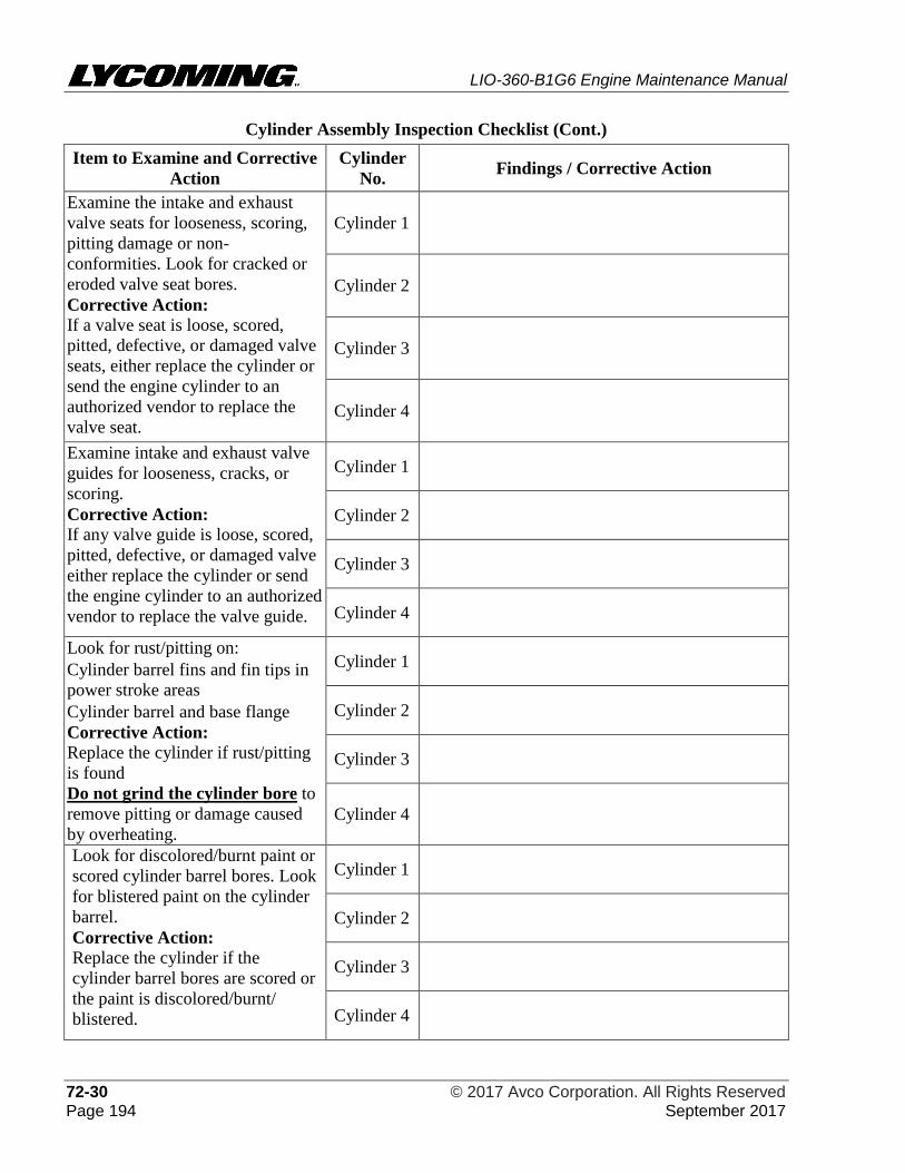
LIO-360-B1G6 Engine Maintenance Manual
72-30 © 2017 Avco Corporation. All Rights Reserved Page 194 September 2017
Cylinder Assembly Inspection Checklist (Cont.)
Item to Examine and Corrective
Action
Cylinder
No. Findings / Corrective Action
Examine the intake and exhaust
valve seats for looseness, scoring,
pitting damage or non-
conformities. Look for cracked or
eroded valve seat bores.
Corrective Action:
If a valve seat is loose, scored,
pitted, defective, or damaged valve
seats, either replace the cylinder or
send the engine cylinder to an
authorized vendor to replace the
valve seat.
Cylinder 1
Cylinder 2
Cylinder 3
Cylinder 4
Examine intake and exhaust valve
guides for looseness, cracks, or
scoring.
Corrective Action:
If any valve guide is loose, scored,
pitted, defective, or damaged valve
either replace the cylinder or send
the engine cylinder to an authorized
vendor to replace the valve guide.
Cylinder 1
Cylinder 2
Cylinder 3
Cylinder 4
Look for rust/pitting on:
• Cylinder barrel fins and fin tips in
power stroke areas
• Cylinder barrel and base flange
Corrective Action:
Replace the cylinder if rust/pitting
is found
Do not grind the cylinder bore to
remove pitting or damage caused
by overheating.
Cylinder 1
Cylinder 2
Cylinder 3
Cylinder 4
Look for discolored/burnt paint or
scored cylinder barrel bores. Look
for blistered paint on the cylinder
barrel.
Corrective Action:
Replace the cylinder if the
cylinder barrel bores are scored or
the paint is discolored/burnt/
blistered.
Cylinder 1
Cylinder 2
Cylinder 3
Cylinder 4

LIO-360-B1G6 Engine Maintenance Manual
© 2017 Avco Corporation. All Rights Reserved 72-30 September 2017 Page 195
Cylinder Assembly Inspection Checklist (Cont.)
Item to Examine and Corrective
Action
Cylinder
No. Findings / Corrective Action
Examine the threads in all
threaded holes in the cylinder for
debris or damage.
Corrective Action:
Use the correct size bottoming tap
to clean the threads.
If thread damage cannot be
corrected with the tap, replace the
cylinder.
Cylinder 1
Cylinder 2
Cylinder 3
Cylinder 4
Examine the intake and exhaust
ports for damage, warping, nicks,
scoring, or dents.
Corrective Action:
Replace the cylinder if the intake
or exhaust port is damaged,
warped, nicked, scored, or dented.
Do not grind or repair the
intake or exhaust port to correct
damage, warping, nicks, scoring,
or dents
Cylinder 1
Cylinder 2
Cylinder 3
Cylinder 4
Look for any radial fin crack
extending to the root of a fin.
Corrective Action:
Replace the cylinder if there is a
radial fin crack extending to the
root of the fin.
Cylinder 1
Cylinder 2
Cylinder 3
Cylinder 4
Look for broken, bent or
straightened, or pitted cylinder
head fins. Refer to the “Visual
Cylinder Inspection” in this
chapter.
Corrective Action:
Replace any cylinder that has
unacceptable cylinder head fins.
Cylinder 1
Cylinder 2
Cylinder 3
Cylinder 4
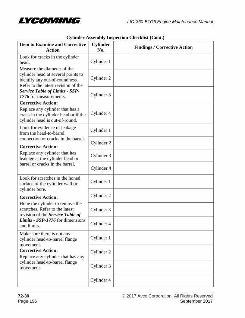
LIO-360-B1G6 Engine Maintenance Manual
72-30 © 2017 Avco Corporation. All Rights Reserved Page 196 September 2017
Cylinder Assembly Inspection Checklist (Cont.)
Item to Examine and Corrective
Action
Cylinder
No. Findings / Corrective Action
Look for cracks in the cylinder
head.
Measure the diameter of the
cylinder head at several points to
identify any out-of-roundness.
Refer to the latest revision of the
Service Table of Limits - SSP-
1776 for measurements.
Corrective Action:
Replace any cylinder that has a
crack in the cylinder head or if the
cylinder head is out-of-round.
Cylinder 1
Cylinder 2
Cylinder 3
Cylinder 4
Look for evidence of leakage
from the head-to-barrel
connection or cracks in the barrel.
Corrective Action:
Replace any cylinder that has
leakage at the cylinder head or
barrel or cracks in the barrel.
Cylinder 1
Cylinder 2
Cylinder 3
Cylinder 4
Look for scratches in the honed
surface of the cylinder wall or
cylinder bore.
Corrective Action:
Hone the cylinder to remove the
scratches. Refer to the latest
revision of the Service Table of
Limits - SSP-1776 for dimensions
and limits.
Cylinder 1
Cylinder 2
Cylinder 3
Cylinder 4
Make sure there is not any
cylinder head-to-barrel flange
movement.
Corrective Action:
Replace any cylinder that has any
cylinder head-to-barrel flange
movement.
Cylinder 1
Cylinder 2
Cylinder 3
Cylinder 4
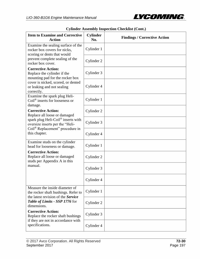
LIO-360-B1G6 Engine Maintenance Manual
© 2017 Avco Corporation. All Rights Reserved 72-30 September 2017 Page 197
Cylinder Assembly Inspection Checklist (Cont.)
Item to Examine and Corrective
Action
Cylinder
No. Findings / Corrective Action
Examine the sealing surface of the
rocker box covers for nicks,
scoring or dents that would
prevent complete sealing of the
rocker box cover.
Corrective Action:
Replace the cylinder if the
mounting pad for the rocker box
cover is nicked, scored, or dented
or leaking and not sealing
correctly.
Cylinder 1
Cylinder 2
Cylinder 3
Cylinder 4
Examine the spark plug Heli-
Coil® inserts for looseness or
damage.
Corrective Action:
Replace all loose or damaged
spark plug Heli-Coil® inserts with
oversize inserts per the “Heli-
Coil® Replacement” procedure in
this chapter.
Cylinder 1
Cylinder 2
Cylinder 3
Cylinder 4
Examine studs on the cylinder
head for looseness or damage.
Corrective Action:
Replace all loose or damaged
studs per Appendix A in this
manual.
Cylinder 1
Cylinder 2
Cylinder 3
Cylinder 4
Measure the inside diameter of
the rocker shaft bushings. Refer to
the latest revision of the Service
Table of Limits - SSP 1776 for
dimensions.
Corrective Action:
Replace the rocker shaft bushings
if they are not in accordance with
specifications.
Cylinder 1
Cylinder 2
Cylinder 3
Cylinder 4
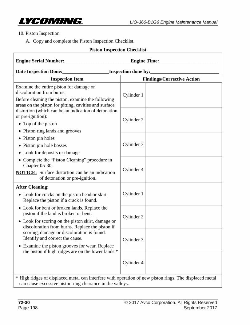
LIO-360-B1G6 Engine Maintenance Manual
72-30 © 2017 Avco Corporation. All Rights Reserved Page 198 September 2017
10. Piston Inspection
A. Copy and complete the Piston Inspection Checklist.
Piston Inspection Checklist
Engine Serial Number:___________________________Engine Time:________________________
Date Inspection Done:___________________Inspection done by:____________________________
Inspection Item Findings/Corrective Action
Examine the entire piston for damage or
discoloration from burns.
Before cleaning the piston, examine the following
areas on the piston for pitting, cavities and surface
distortion (which can be an indication of detonation
or pre-ignition):
• Top of the piston
• Piston ring lands and grooves
• Piston pin holes
• Piston pin hole bosses
• Look for deposits or damage
• Complete the “Piston Cleaning” procedure in
Chapter 05-30.
NOTICE: Surface distortion can be an indication
of detonation or pre-ignition.
Cylinder 1
Cylinder 2
Cylinder 3
Cylinder 4
After Cleaning:
• Look for cracks on the piston head or skirt.
Replace the piston if a crack is found.
• Look for bent or broken lands. Replace the
piston if the land is broken or bent.
• Look for scoring on the piston skirt, damage or
discoloration from burns. Replace the piston if
scoring, damage or discoloration is found.
Identify and correct the cause.
• Examine the piston grooves for wear. Replace
the piston if high ridges are on the lower lands.*
Cylinder 1
Cylinder 2
Cylinder 3
Cylinder 4
* High ridges of displaced metal can interfere with operation of new piston rings. The displaced metal
can cause excessive piston ring clearance in the valleys.
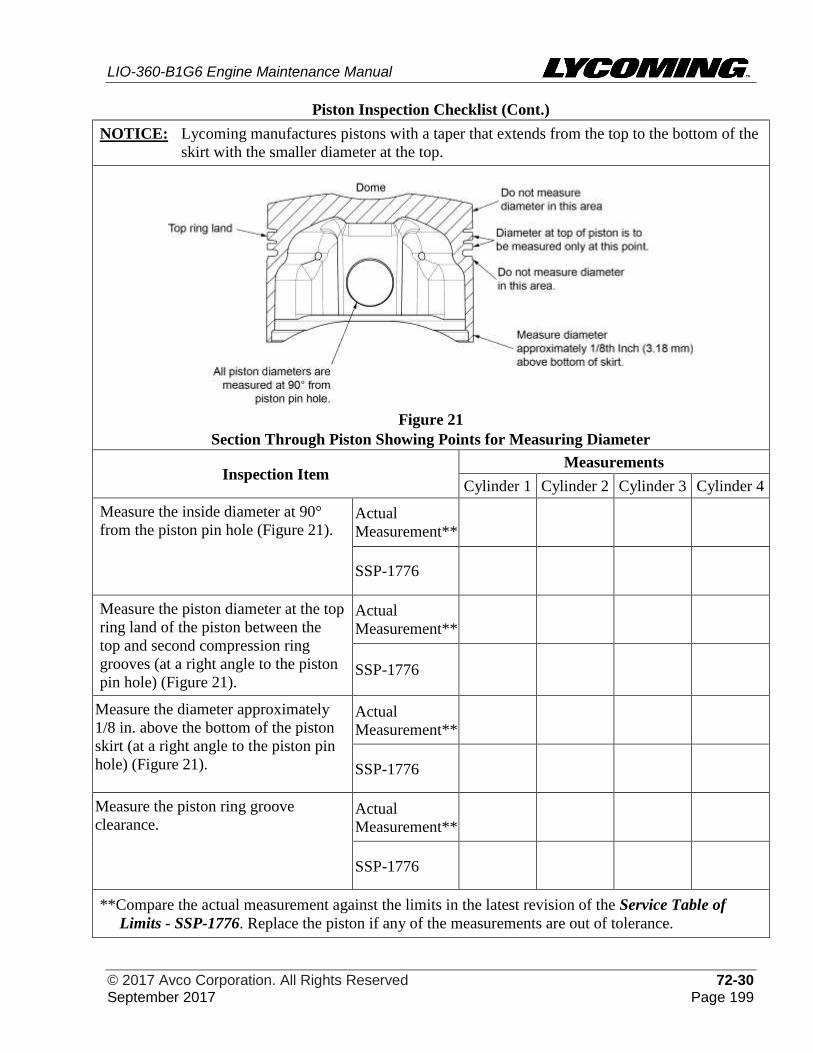
LIO-360-B1G6 Engine Maintenance Manual
© 2017 Avco Corporation. All Rights Reserved 72-30 September 2017 Page 199
Piston Inspection Checklist (Cont.)
NOTICE: Lycoming manufactures pistons with a taper that extends from the top to the bottom of the
skirt with the smaller diameter at the top.
Figure 21
Section Through Piston Showing Points for Measuring Diameter
Inspection Item Measurements
Cylinder 1 Cylinder 2 Cylinder 3 Cylinder 4
Measure the inside diameter at 90°
from the piston pin hole (Figure 21). Actual
Measurement**
SSP-1776
Measure the piston diameter at the top
ring land of the piston between the
top and second compression ring
grooves (at a right angle to the piston
pin hole) (Figure 21).
Actual
Measurement**
SSP-1776
Measure the diameter approximately
1/8 in. above the bottom of the piston
skirt (at a right angle to the piston pin
hole) (Figure 21).
Actual
Measurement**
SSP-1776
Measure the piston ring groove
clearance. Actual
Measurement**
SSP-1776
**Compare the actual measurement against the limits in the latest revision of the Service Table of
Limits - SSP-1776. Replace the piston if any of the measurements are out of tolerance.
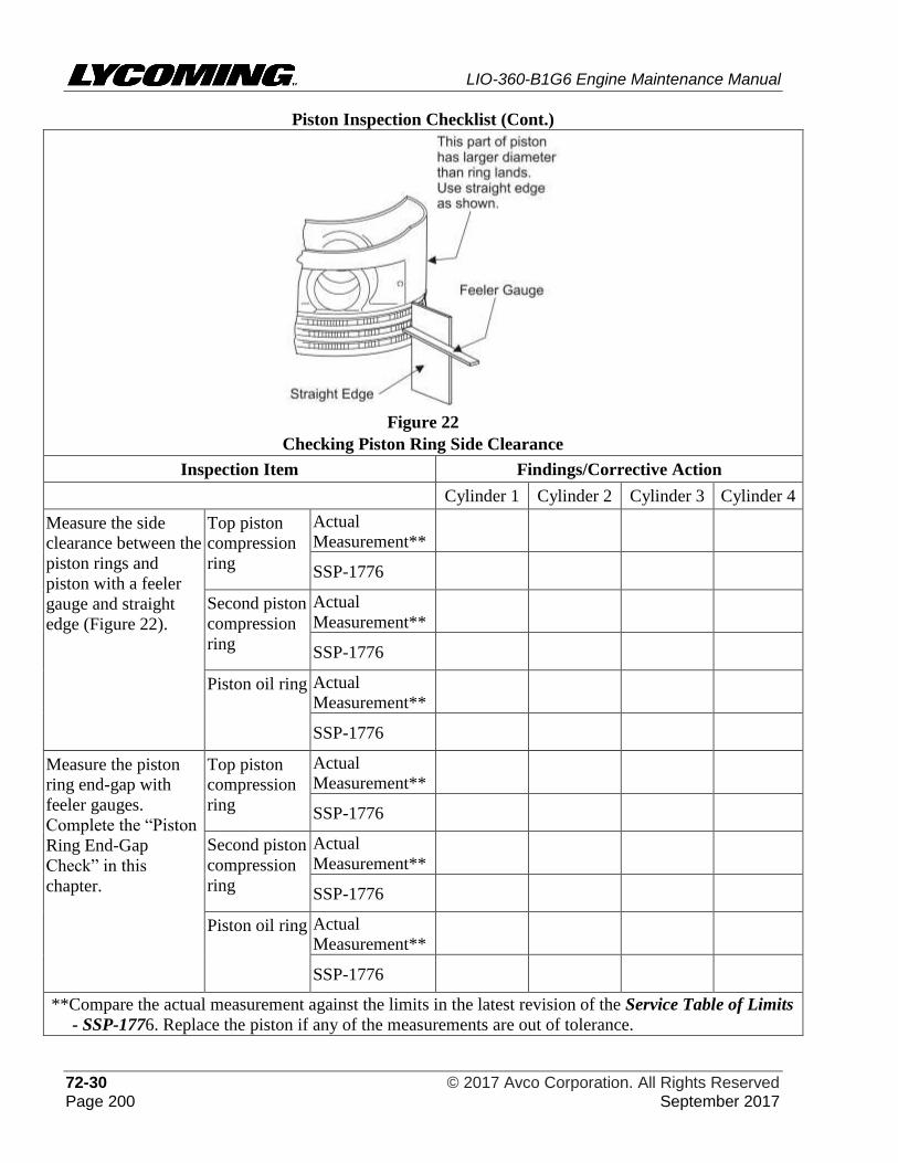
LIO-360-B1G6 Engine Maintenance Manual
72-30 © 2017 Avco Corporation. All Rights Reserved Page 200 September 2017
Piston Inspection Checklist (Cont.)
Figure 22
Checking Piston Ring Side Clearance
Inspection Item Findings/Corrective Action
Cylinder 1 Cylinder 2 Cylinder 3 Cylinder 4
Measure the side
clearance between the
piston rings and
piston with a feeler
gauge and straight
edge (Figure 22).
Top piston
compression
ring
Actual
Measurement**
SSP-1776
Second piston
compression
ring
Actual
Measurement**
SSP-1776
Piston oil ring Actual
Measurement**
SSP-1776
Measure the piston
ring end-gap with
feeler gauges.
Complete the “Piston
Ring End-Gap
Check” in this
chapter.
Top piston
compression
ring
Actual
Measurement**
SSP-1776
Second piston
compression
ring
Actual
Measurement**
SSP-1776
Piston oil ring Actual
Measurement**
SSP-1776
**Compare the actual measurement against the limits in the latest revision of the Service Table of Limits
- SSP-1776. Replace the piston if any of the measurements are out of tolerance.
LIO-360-B1G6 Engine Maintenance Manual
© 2017 Avco Corporation. All Rights Reserved 72-30 September 2017 Page 201
Piston Inspection Checklist (Cont.)
Comments:
If inspection of the piston shows the original ground surface of the piston skirt to be undamaged, the
piston is acceptable and can be re-installed.
If any of the following conditions are found on the piston, replace the piston.
• Damage or pitting, caveties, surface distortion, scoring, or discoloration
• Cracked, bent, or broken lands, scored skirts or any out-of-tolerance dimensional limits
• Piston grooves worn to the extent that high ridges are on the lower lands
• Excessive side clearance of piston rings in grooves
NOTICE: Refer to the LIO-360-B1G6 Illustrated Parts Catalog to identify a replacement piston and
associated rings.
B. Piston Ring End Gap Check:
DURING THE PISTON RING END-GAP CHECK, USE CARE NOT TO
SCRATCH OR SCORE THE PISTON OR CYLINDER BORE.
(1) Lubricate the piston ring, piston, and cylinder bore with a light coating of a mixture of
15% pre-lubricant (STP or equivalent) and 85% SAE 50 mineral-base aviation-grade
lubricating oil (unless otherwise directed per the latest revision of Service Instruction No.
SI-1059).
(2) Put one of the piston rings in the cylinder in which it will be used.
(3) To square the piston ring in the cylinder bore, install the piston in the cylinder (per the
“Piston Installation” procedure in this chapter) and use a soft mallet to tap the dome end
of the piston on the inside, until the bottom of the piston skirt is flush with the end of the
cylinder barrel. Remove the piston from the cylinder per the “Piston Removal” procedure
in this chapter.
(4) Measure the piston ring end-gap with feeler gauges. Record the measurement in the
Piston Inspection Checklist. Compare the measurement with the ring end gap
measurement in the latest revision of the Service Table of Limits - SSP-1776.
(5) If necessary to increase the end-gap, carefully file the ends of the piston ring.
(6) Repeat this check for each piston ring to be used in each cylinder.
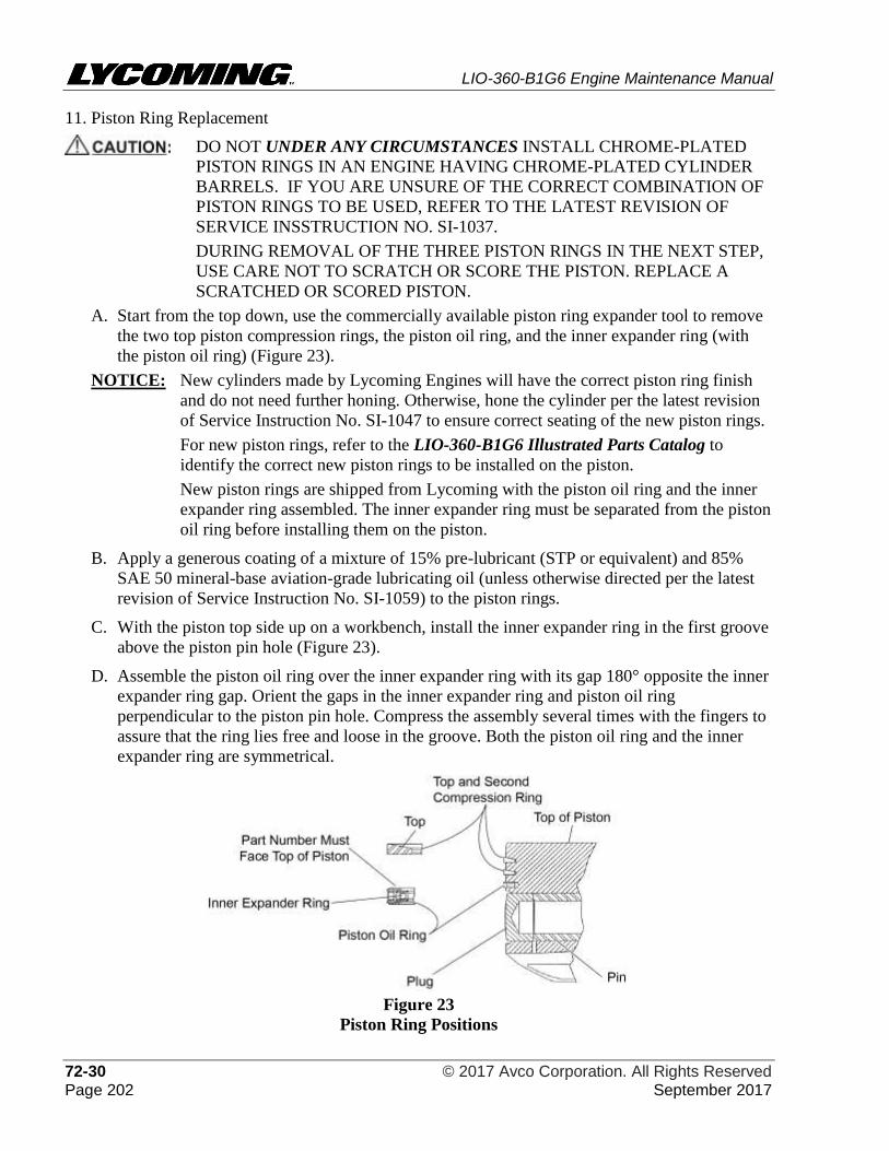
LIO-360-B1G6 Engine Maintenance Manual
72-30 © 2017 Avco Corporation. All Rights Reserved Page 202 September 2017
11. Piston Ring Replacement
DO NOT UNDER ANY CIRCUMSTANCES INSTALL CHROME-PLATED
PISTON RINGS IN AN ENGINE HAVING CHROME-PLATED CYLINDER
BARRELS. IF YOU ARE UNSURE OF THE CORRECT COMBINATION OF
PISTON RINGS TO BE USED, REFER TO THE LATEST REVISION OF
SERVICE INSSTRUCTION NO. SI-1037.
DURING REMOVAL OF THE THREE PISTON RINGS IN THE NEXT STEP,
USE CARE NOT TO SCRATCH OR SCORE THE PISTON. REPLACE A
SCRATCHED OR SCORED PISTON.
A. Start from the top down, use the commercially available piston ring expander tool to remove
the two top piston compression rings, the piston oil ring, and the inner expander ring (with
the piston oil ring) (Figure 23).
NOTICE: New cylinders made by Lycoming Engines will have the correct piston ring finish
and do not need further honing. Otherwise, hone the cylinder per the latest revision
of Service Instruction No. SI-1047 to ensure correct seating of the new piston rings.
For new piston rings, refer to the LIO-360-B1G6 Illustrated Parts Catalog to
identify the correct new piston rings to be installed on the piston.
New piston rings are shipped from Lycoming with the piston oil ring and the inner
expander ring assembled. The inner expander ring must be separated from the piston
oil ring before installing them on the piston.
B. Apply a generous coating of a mixture of 15% pre-lubricant (STP or equivalent) and 85%
SAE 50 mineral-base aviation-grade lubricating oil (unless otherwise directed per the latest
revision of Service Instruction No. SI-1059) to the piston rings.
C. With the piston top side up on a workbench, install the inner expander ring in the first groove
above the piston pin hole (Figure 23).
D. Assemble the piston oil ring over the inner expander ring with its gap 180° opposite the inner
expander ring gap. Orient the gaps in the inner expander ring and piston oil ring
perpendicular to the piston pin hole. Compress the assembly several times with the fingers to
assure that the ring lies free and loose in the groove. Both the piston oil ring and the inner
expander ring are symmetrical.
Figure 23
Piston Ring Positions
LIO-360-B1G6 Engine Maintenance Manual
© 2017 Avco Corporation. All Rights Reserved 72-30 September 2017 Page 203
E. Install the two top compression rings (Figure 23) with the word "Top" toward the top of the
piston in the remaining top grooves. Orient the gaps in the two compression rings 180° from
each other parallel with the piston pin hole.
F. Compress each of the two top compression piston rings several times with your fingers to
make sure the rings are situated freely and loosely in the groove.
G. To ensure correct installation, measure the side clearance of the rings in the grooves with a
feeler gage and a straight edge (Figure 22). If the actual measurement is greater than the
maximum allowable side clearance, per the latest revision of the Service Table of Limits -
SSP-1776, replace the piston.
NOTICE: Engine break-in must be completed to seat newly installed piston rings. Refer to the
latest revision of Service Instruction No. SI-1427 and the “Engine Initiation” chapter
of the LIO-360-B1G6 Engine Installation and Operation Manual.
12. Piston Installation
A. Clean the pistons as per instructions in the “Piston Cleaning” procedure in Chapter 5-30.
B. Apply lubricant specified in the latest revision of Service Instruction No. SI-1059 to the
inside diameter of the connecting rod bushing, the outer diameter of the piston pin, and the
inside diameter of the piston pin hole.
DO NOT ATTEMPT TO TURN THE CRANKSHAFT UNLESS THE
CONNECTING RODS ARE SUPPORTED.
C. Turn the crankshaft so that when the Number 1 piston is inserted, it will be at TDC of its
firing stroke, with both tappets on the base circle of the camshaft lobes.
D. Remove the Torque Hold-Down Plates (ST-222), rubber bands, or cylinder base oil seal rings
from the crankcase.
E. Install the piston on the connecting rod where the number stamped on the bottom of the
piston head is upright and readable (not upside-down.)
F. Insert the piston pin into the piston and through the connecting rod (Figure 18) to ensure the
entire length of the piston pin is lubricated, move the piston pin back and forth until it is
centered.
NOTICE: If the original piston pin is tighter than a palm push fit, look for burrs or slight carbon
in the pin bore of the piston. Remove any burrs with a stone. Remove carbon
deposits as per instructions in Chapter 05-30. If a new piston or piston pin is
installed, use a pin that will give a palm push fit at 60º to 70ºF (15º to 20ºC).
G. Insert a piston pin plug at each end of the piston pin.
H. Complete a check of the clearance between the piston and each piston pin plug. Refer to the
latest revision of the Service Table of Limits - SSP-1776 for acceptable clearance limits.
I. Install the piston rings on the piston per the “Piston Ring Replacement” procedure.
J. Apply a generous coating of a mixture of 15% pre-lubricant (STP or equivalent) and 85%
SAE 50 mineral-base aviation-grade lubricating oil (unless otherwise directed per the latest
revision of Service Instruction No. SI-1059) to the piston rings, working the mixture into the
ring grooves.
K. Apply lubricant specified in the latest revision of Service Instruction No. SI-1059 to the
piston pin plug faces.
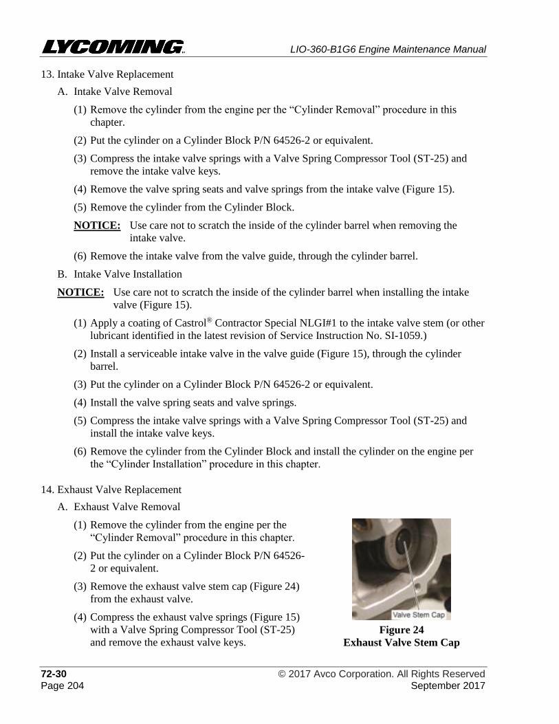
LIO-360-B1G6 Engine Maintenance Manual
72-30 © 2017 Avco Corporation. All Rights Reserved Page 204 September 2017
13. Intake Valve Replacement
A. Intake Valve Removal
(1) Remove the cylinder from the engine per the “Cylinder Removal” procedure in this
chapter.
(2) Put the cylinder on a Cylinder Block P/N 64526-2 or equivalent.
(3) Compress the intake valve springs with a Valve Spring Compressor Tool (ST-25) and
remove the intake valve keys.
(4) Remove the valve spring seats and valve springs from the intake valve (Figure 15).
(5) Remove the cylinder from the Cylinder Block.
NOTICE: Use care not to scratch the inside of the cylinder barrel when removing the
intake valve.
(6) Remove the intake valve from the valve guide, through the cylinder barrel.
B. Intake Valve Installation
NOTICE: Use care not to scratch the inside of the cylinder barrel when installing the intake
valve (Figure 15).
(1) Apply a coating of Castrol® Contractor Special NLGI#1 to the intake valve stem (or other
lubricant identified in the latest revision of Service Instruction No. SI-1059.)
(2) Install a serviceable intake valve in the valve guide (Figure 15), through the cylinder
barrel.
(3) Put the cylinder on a Cylinder Block P/N 64526-2 or equivalent.
(4) Install the valve spring seats and valve springs.
(5) Compress the intake valve springs with a Valve Spring Compressor Tool (ST-25) and
install the intake valve keys.
(6) Remove the cylinder from the Cylinder Block and install the cylinder on the engine per
the “Cylinder Installation” procedure in this chapter.
14. Exhaust Valve Replacement
A. Exhaust Valve Removal
(1) Remove the cylinder from the engine per the
“Cylinder Removal” procedure in this chapter.
(2) Put the cylinder on a Cylinder Block P/N 64526-
2 or equivalent.
(3) Remove the exhaust valve stem cap (Figure 24)
from the exhaust valve.
(4) Compress the exhaust valve springs (Figure 15)
with a Valve Spring Compressor Tool (ST-25)
and remove the exhaust valve keys.
Figure 24
Exhaust Valve Stem Cap
LIO-360-B1G6 Engine Maintenance Manual
© 2017 Avco Corporation. All Rights Reserved 72-30 September 2017 Page 205
(5) Remove the valve spring seats and valve springs from the exhaust valve.
(6) Remove the cylinder from the Cylinder Block.
NOTICE: Use care not to scratch the inside of the cylinder barrel when removing the
exhaust valve.
(7) Remove the exhaust valve from the valve guide, through the cylinder barrel.
B. Exhaust Valve Installation
NOTICE: Use care not to scratch the inside of the cylinder barrel when installing the exhaust
valve.
(1) Apply a coating of Castrol® Contractor Special NLGI#1 to the exhaust valve stem (or
other lubricant identified in the latest revision of Service Instruction No. SI-1059.)
(2) Install a serviceable exhaust valve in the valve guide (Figure 15), through the cylinder
barrel.
(3) Put the cylinder on a Cylinder Block P/N 64526-2 or equivalent.
(4) Install the valve spring seats and valve springs.
(5) Use a Valve Spring Compressor Tool (ST-25) to compress the exhaust valve springs and
install the exhaust valve keys.
(6) Install the exhaust valve stem cap (Figure 24) on the exhaust valve.
(7) Remove the cylinder from the Cylinder Block and install the cylinder on the engine per
the “Cylinder Installation” procedure in this chapter.
15. Cylinder Installation
NOTICE: Use a cylinder kit when installing a new cylinder. Make sure you are installing the
correct cylinder in the designated position on the engine.
If all cylinders are to be installed, install them by their firing order 1 - 4 - 2 - 3.
INSTALL ONLY THE NEW CYLINDER BASE OIL SEAL RING (FIGURE
17) AROUND THE CYLINDER BASE. DO NOT USE ANY ADDITIONAL
SEALANT OR GASKET MATERIAL WHICH COULD DETERIORATE AND
CAUSE A REDUCED TORQUE ON THE CYLINDER BASE STUDS.
NOTICE: Do not re-install the cylinder base oil seal ring which had been removed during cylinder
removal (and re-used as a support for connecting rods). Use a new cylinder base oil seal
ring.
A. Install a new cylinder base oil seal ring around the cylinder base for each engine cylinder.
B. Apply a light coat of engine oil mixture to the cylinder base oil seal ring.
C. Lubricate the inside diameter of the cylinder barrel with engine oil mixture (15% pre-
lubricant (STP or equivalent) and 85% SAE No. 50 mineral base aviation grade lubricating
oil) to the depth of the piston rings, approximately 2 in. (5 cm).
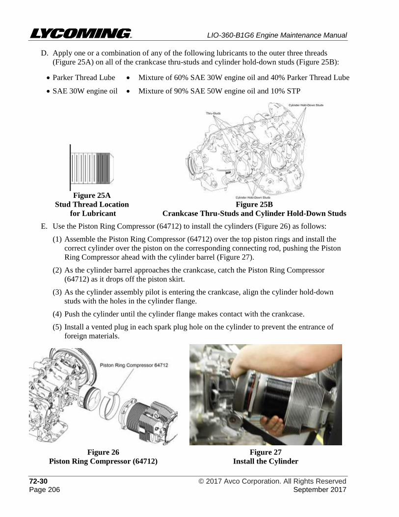
LIO-360-B1G6 Engine Maintenance Manual
72-30 © 2017 Avco Corporation. All Rights Reserved Page 206 September 2017
D. Apply one or a combination of any of the following lubricants to the outer three threads
(Figure 25A) on all of the crankcase thru-studs and cylinder hold-down studs (Figure 25B):
• Parker Thread Lube • Mixture of 60% SAE 30W engine oil and 40% Parker Thread Lube
• SAE 30W engine oil • Mixture of 90% SAE 50W engine oil and 10% STP
Figure 25A
Stud Thread Location
for Lubricant
Figure 25B
Crankcase Thru-Studs and Cylinder Hold-Down Studs
E. Use the Piston Ring Compressor (64712) to install the cylinders (Figure 26) as follows:
(1) Assemble the Piston Ring Compressor (64712) over the top piston rings and install the
correct cylinder over the piston on the corresponding connecting rod, pushing the Piston
Ring Compressor ahead with the cylinder barrel (Figure 27).
(2) As the cylinder barrel approaches the crankcase, catch the Piston Ring Compressor
(64712) as it drops off the piston skirt.
(3) As the cylinder assembly pilot is entering the crankcase, align the cylinder hold-down
studs with the holes in the cylinder flange.
(4) Push the cylinder until the cylinder flange makes contact with the crankcase.
(5) Install a vented plug in each spark plug hole on the cylinder to prevent the entrance of
foreign materials.
Figure 26
Piston Ring Compressor (64712)
Figure 27
Install the Cylinder
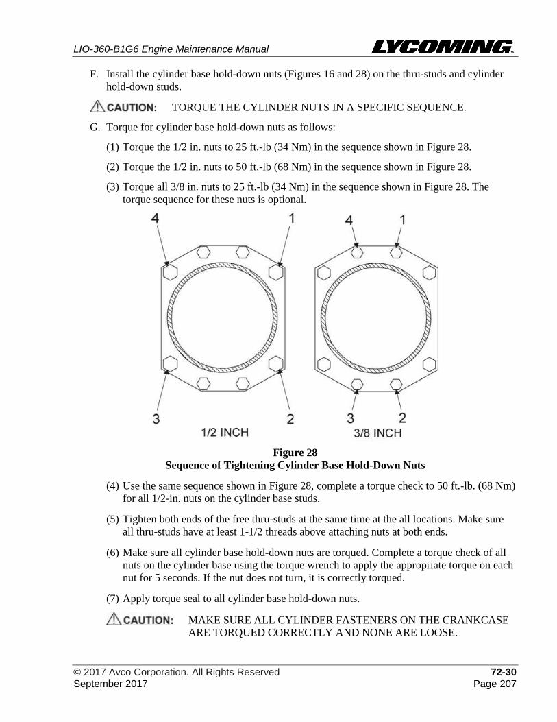
LIO-360-B1G6 Engine Maintenance Manual
© 2017 Avco Corporation. All Rights Reserved 72-30 September 2017 Page 207
F. Install the cylinder base hold-down nuts (Figures 16 and 28) on the thru-studs and cylinder
hold-down studs.
TORQUE THE CYLINDER NUTS IN A SPECIFIC SEQUENCE.
G. Torque for cylinder base hold-down nuts as follows:
(1) Torque the 1/2 in. nuts to 25 ft.-lb (34 Nm) in the sequence shown in Figure 28.
(2) Torque the 1/2 in. nuts to 50 ft.-lb (68 Nm) in the sequence shown in Figure 28.
(3) Torque all 3/8 in. nuts to 25 ft.-lb (34 Nm) in the sequence shown in Figure 28. The
torque sequence for these nuts is optional.
Figure 28
Sequence of Tightening Cylinder Base Hold-Down Nuts
(4) Use the same sequence shown in Figure 28, complete a torque check to 50 ft.-lb. (68 Nm)
for all 1/2-in. nuts on the cylinder base studs.
(5) Tighten both ends of the free thru-studs at the same time at the all locations. Make sure
all thru-studs have at least 1-1/2 threads above attaching nuts at both ends.
(6) Make sure all cylinder base hold-down nuts are torqued. Complete a torque check of all
nuts on the cylinder base using the torque wrench to apply the appropriate torque on each
nut for 5 seconds. If the nut does not turn, it is correctly torqued.
(7) Apply torque seal to all cylinder base hold-down nuts.
MAKE SURE ALL CYLINDER FASTENERS ON THE CRANKCASE
ARE TORQUED CORRECTLY AND NONE ARE LOOSE.
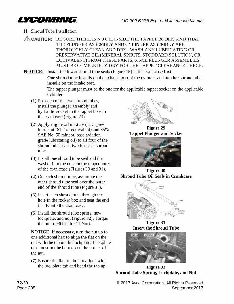
LIO-360-B1G6 Engine Maintenance Manual
72-30 © 2017 Avco Corporation. All Rights Reserved Page 208 September 2017
H. Shroud Tube Installation
BE SURE THERE IS NO OIL INSIDE THE TAPPET BODIES AND THAT
THE PLUNGER ASSEMBLY AND CYLINDER ASSEMBLY ARE
THOROUGHLY CLEAN AND DRY. WASH ANY LUBRICATING OR
PRESERVATIVE OIL (MINERAL SPIRITS, STODDARD SOLUTION, OR
EQUIVALENT) FROM THESE PARTS, SINCE PLUNGER ASSEMBLIES
MUST BE COMPLETELY DRY FOR THE TAPPET CLEARANCE CHECK.
NOTICE: Install the lower shroud tube seals (Figure 15) in the crankcase first.
One shroud tube installs on the exhaust port of the cylinder and another shroud tube
installs on the intake port.
The tappet plunger must be the one for the applicable tappet socket on the applicable
cylinder.
(1) For each of the two shroud tubes,
install the plunger assembly and
hydraulic socket in the tappet bore in
the crankcase (Figure 29).
(2) Apply engine oil mixture (15% pre-
lubricant (STP or equivalent) and 85%
SAE No. 50 mineral base aviation
grade lubricating oil) to all four of the
shroud tube seals, two for each shroud
tube.
(3) Install one shroud tube seal and the
washer into the cups in the tappet bores
of the crankcase (Figures 30 and 31).
(4) On each shroud tube, assemble the
other shroud tube seal over the outer
end of the shroud tube (Figure 31).
(5) Insert each shroud tube through the
hole in the rocker box and seat the end
firmly into the crankcase.
(6) Install the shroud tube spring, new
lockplate, and nut (Figure 32). Torque
the nut to 96 in.-lb. (11 Nm).
NOTICE: If necessary, turn the nut up to
one additional hex to align the flat on the
nut with the tab on the lockplate. Lockplate
tabs must not be bent up on the corner of
the nut.
(7) Ensure the flat on the nut aligns with
the lockplate tab and bend the tab up.
Figure 29
Tappet Plunger and Socket
Figure 30
Shroud Tube Oil Seals in Crankcase
Figure 31
Insert the Shroud Tube
Figure 32
Shroud Tube Spring, Lockplate, and Nut
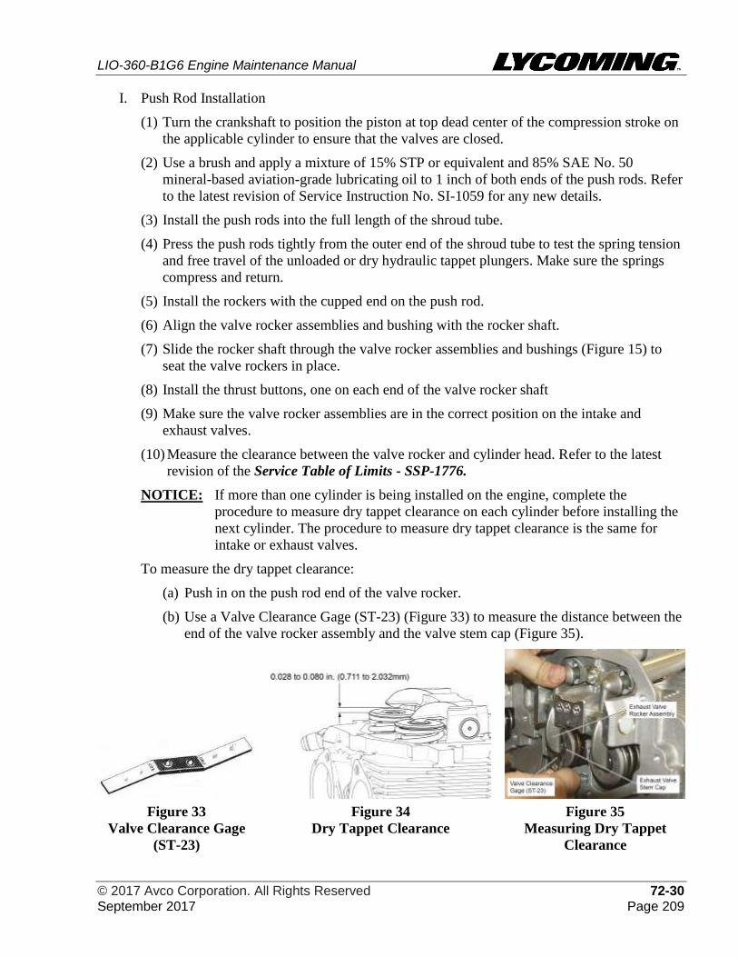
LIO-360-B1G6 Engine Maintenance Manual
© 2017 Avco Corporation. All Rights Reserved 72-30 September 2017 Page 209
I. Push Rod Installation
(1) Turn the crankshaft to position the piston at top dead center of the compression stroke on
the applicable cylinder to ensure that the valves are closed.
(2) Use a brush and apply a mixture of 15% STP or equivalent and 85% SAE No. 50
mineral-based aviation-grade lubricating oil to 1 inch of both ends of the push rods. Refer
to the latest revision of Service Instruction No. SI-1059 for any new details.
(3) Install the push rods into the full length of the shroud tube.
(4) Press the push rods tightly from the outer end of the shroud tube to test the spring tension
and free travel of the unloaded or dry hydraulic tappet plungers. Make sure the springs
compress and return.
(5) Install the rockers with the cupped end on the push rod.
(6) Align the valve rocker assemblies and bushing with the rocker shaft.
(7) Slide the rocker shaft through the valve rocker assemblies and bushings (Figure 15) to
seat the valve rockers in place.
(8) Install the thrust buttons, one on each end of the valve rocker shaft
(9) Make sure the valve rocker assemblies are in the correct position on the intake and
exhaust valves.
(10) Measure the clearance between the valve rocker and cylinder head. Refer to the latest
revision of the Service Table of Limits - SSP-1776.
NOTICE: If more than one cylinder is being installed on the engine, complete the
procedure to measure dry tappet clearance on each cylinder before installing the
next cylinder. The procedure to measure dry tappet clearance is the same for
intake or exhaust valves.
To measure the dry tappet clearance:
(a) Push in on the push rod end of the valve rocker.
(b) Use a Valve Clearance Gage (ST-23) (Figure 33) to measure the distance between the
end of the valve rocker assembly and the valve stem cap (Figure 35).
Figure 33
Valve Clearance Gage
(ST-23)
Figure 34
Dry Tappet Clearance
Figure 35
Measuring Dry Tappet
Clearance
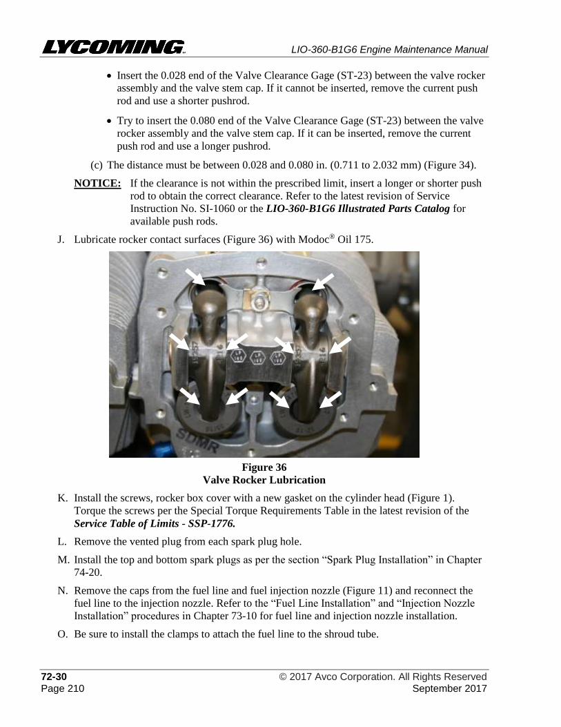
LIO-360-B1G6 Engine Maintenance Manual
72-30 © 2017 Avco Corporation. All Rights Reserved Page 210 September 2017
• Insert the 0.028 end of the Valve Clearance Gage (ST-23) between the valve rocker
assembly and the valve stem cap. If it cannot be inserted, remove the current push
rod and use a shorter pushrod.
• Try to insert the 0.080 end of the Valve Clearance Gage (ST-23) between the valve
rocker assembly and the valve stem cap. If it can be inserted, remove the current
push rod and use a longer pushrod.
(c) The distance must be between 0.028 and 0.080 in. (0.711 to 2.032 mm) (Figure 34).
NOTICE: If the clearance is not within the prescribed limit, insert a longer or shorter push
rod to obtain the correct clearance. Refer to the latest revision of Service
Instruction No. SI-1060 or the LIO-360-B1G6 Illustrated Parts Catalog for
available push rods.
J. Lubricate rocker contact surfaces (Figure 36) with Modoc® Oil 175.
Figure 36
Valve Rocker Lubrication
K. Install the screws, rocker box cover with a new gasket on the cylinder head (Figure 1).
Torque the screws per the Special Torque Requirements Table in the latest revision of the
Service Table of Limits - SSP-1776.
L. Remove the vented plug from each spark plug hole.
M. Install the top and bottom spark plugs as per the section “Spark Plug Installation” in Chapter
74-20.
N. Remove the caps from the fuel line and fuel injection nozzle (Figure 11) and reconnect the
fuel line to the injection nozzle. Refer to the “Fuel Line Installation” and “Injection Nozzle
Installation” procedures in Chapter 73-10 for fuel line and injection nozzle installation.
O. Be sure to install the clamps to attach the fuel line to the shroud tube.
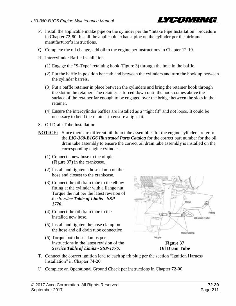
LIO-360-B1G6 Engine Maintenance Manual
© 2017 Avco Corporation. All Rights Reserved 72-30 September 2017 Page 211
P. Install the applicable intake pipe on the cylinder per the “Intake Pipe Installation” procedure
in Chapter 72-80. Install the applicable exhaust pipe on the cylinder per the airframe
manufacturer’s instructions.
Q. Complete the oil change, add oil to the engine per instructions in Chapter 12-10.
R. Intercylinder Baffle Installation
(1) Engage the "S-Type" retaining hook (Figure 3) through the hole in the baffle.
(2) Put the baffle in position beneath and between the cylinders and turn the hook up between
the cylinder barrels.
(3) Put a baffle retainer in place between the cylinders and bring the retainer hook through
the slot in the retainer. The retainer is forced down until the hook comes above the
surface of the retainer far enough to be engaged over the bridge between the slots in the
retainer.
(4) Ensure the intercylinder baffles are installed as a “tight fit” and not loose. It could be
necessary to bend the retainer to ensure a tight fit.
S. Oil Drain Tube Installation
NOTICE: Since there are different oil drain tube assemblies for the engine cylinders, refer to
the LIO-360-B1G6 Illustrated Parts Catalog for the correct part number for the oil
drain tube assembly to ensure the correct oil drain tube assembly is installed on the
corresponding engine cylinder.
(1) Connect a new hose to the nipple
(Figure 37) in the crankcase.
(2) Install and tighten a hose clamp on the
hose end closest to the crankcase.
(3) Connect the oil drain tube to the elbow
fitting at the cylinder with a flange nut.
Torque the nut per the latest revision of
the Service Table of Limits - SSP-
1776.
(4) Connect the oil drain tube to the
installed new hose.
(5) Install and tighten the hose clamp on
the hose and oil drain tube connection.
(6) Torque both hose clamps per
instructions in the latest revision of the
Service Table of Limits - SSP-1776.
Figure 37
Oil Drain Tube
T. Connect the correct ignition lead to each spark plug per the section “Ignition Harness
Installation” in Chapter 74-20.
U. Complete an Operational Ground Check per instructions in Chapter 72-00.
LIO-360-B1G6 Engine Maintenance Manual
72-30 © 2017 Avco Corporation. All Rights Reserved Page 212 September 2017
16. Corrective Action for Valve Sticking
NOTICE: If valve sticking is a problem, complete the 1000-hour Engine Inspection Checklist in
Chapter 05-20 (regardless of the number of engine operating hours) (Figure 15). After
correcting the cause of valve sticking, complete the 1000-hour inspection after the next
1000 hours of engine operation, unless valve sticking occurs again.
Sticking between the valve stem and guide (on intake and exhaust valves) can
substantially change valve opening and closing. If the valve cannot open or close
correctly, incomplete combustion will occur, which can cause formation of more
deposits and increased valve sticking. Because a correctly-timed sequence of valve
opening and closing is essential to efficient and reliable engine operation, the cause of
valve sticking must be identified and corrected.
A STUCK VALVE CAN CAUSE ENGINE FAILURE.
NOTICE: If one valve is sticking, examine all other valves on all of the engine cylinders as a
precaution.
A. Per Chapter 12-10 complete an oil and filter change and have an analysis done on the
metallic solids in the oil filter to identify the contamination and find the source to correct the
problem. Refer to the latest revision of Service Bulletin No. SB-480.
B. If the source of the oil contamination cannot be found or corrected, complete the following
procedures in Chapter 12-10:
(1) Replace the oil filter (more often) after every 25 hours of operation (instead of after every
50 hours of engine operation.)
(2) Complete an oil change after every 25 hours of operation (instead of after every 50 hours
of engine operation.)
C. Complete an air filter change at more frequent intervals.
D. Examine the cooling air baffles and baffle strips for contamination. Remove any
contamination.
E. Identify with a tag and remove the top spark plugs from the engine cylinders per the “Spark
Plug Removal” procedure in Chapter 74-20.
F. Identify the location of each cylinder and valve train component for reference on assembly
and remove the cylinder and valve train components per the “Cylinder Removal” section in
this chapter.
G. Remove the intake and exhaust valves per the “Intake Valve Removal” and “Exhaust Valve
Removal” sections in this chapter.
H. Examine the valve stem keys/caps (Figure 15) for wear. Look for any distinct, uniform
patterns. Replace worn valve stem keys or caps.
NOTICE: Refer to the latest revision of the Service Table of Limits - SSP-1776 for valve
guide dimensions to use the correct reamer.
Use reamer tools to remove hardened carbon from the valve guides.
I. Apply ordinary cup grease on the flutes of the reamer to remove the deposits on the reamer.
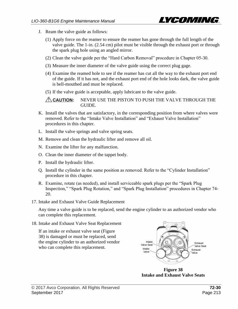
LIO-360-B1G6 Engine Maintenance Manual
© 2017 Avco Corporation. All Rights Reserved 72-30 September 2017 Page 213
J. Ream the valve guide as follows:
(1) Apply force on the reamer to ensure the reamer has gone through the full length of the
valve guide. The 1-in. (2.54 cm) pilot must be visible through the exhaust port or through
the spark plug hole using an angled mirror.
(2) Clean the valve guide per the “Hard Carbon Removal” procedure in Chapter 05-30.
(3) Measure the inner diameter of the valve guide using the correct plug gage.
(4) Examine the reamed hole to see if the reamer has cut all the way to the exhaust port end
of the guide. If it has not, and the exhaust port end of the hole looks dark, the valve guide
is bell-mouthed and must be replaced.
(5) If the valve guide is acceptable, apply lubricant to the valve guide.
NEVER USE THE PISTON TO PUSH THE VALVE THROUGH THE
GUIDE.
K. Install the valves that are satisfactory, in the corresponding position from where valves were
removed. Refer to the “Intake Valve Installation” and “Exhaust Valve Installation”
procedures in this chapter.
L. Install the valve springs and valve spring seats.
M. Remove and clean the hydraulic lifter and remove all oil.
N. Examine the lifter for any malfunction.
O. Clean the inner diameter of the tappet body.
P. Install the hydraulic lifter.
Q. Install the cylinder in the same position as removed. Refer to the “Cylinder Installation”
procedure in this chapter.
R. Examine, rotate (as needed), and install serviceable spark plugs per the “Spark Plug
Inspection,” “Spark Plug Rotation,” and “Spark Plug Installation” procedures in Chapter 74-
20.
17. Intake and Exhaust Valve Guide Replacement
Any time a valve guide is to be replaced, send the engine cylinder to an authorized vendor who
can complete this replacement.
18. Intake and Exhaust Valve Seat Replacement
If an intake or exhaust valve seat (Figure
38) is damaged or must be replaced, send
the engine cylinder to an authorized vendor
who can complete this replacement.
Figure 38
Intake and Exhaust Valve Seats
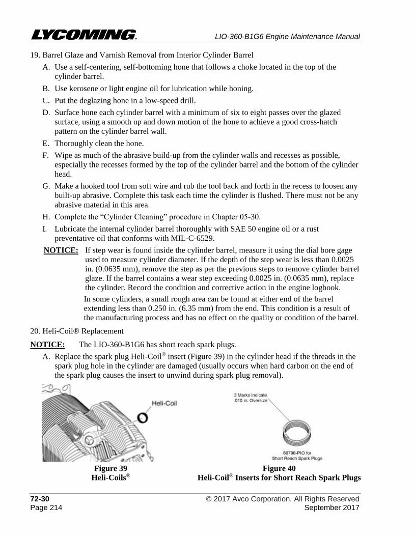
LIO-360-B1G6 Engine Maintenance Manual
72-30 © 2017 Avco Corporation. All Rights Reserved Page 214 September 2017
19. Barrel Glaze and Varnish Removal from Interior Cylinder Barrel
A. Use a self-centering, self-bottoming hone that follows a choke located in the top of the
cylinder barrel.
B. Use kerosene or light engine oil for lubrication while honing.
C. Put the deglazing hone in a low-speed drill.
D. Surface hone each cylinder barrel with a minimum of six to eight passes over the glazed
surface, using a smooth up and down motion of the hone to achieve a good cross-hatch
pattern on the cylinder barrel wall.
E. Thoroughly clean the hone.
F. Wipe as much of the abrasive build-up from the cylinder walls and recesses as possible,
especially the recesses formed by the top of the cylinder barrel and the bottom of the cylinder
head.
G. Make a hooked tool from soft wire and rub the tool back and forth in the recess to loosen any
built-up abrasive. Complete this task each time the cylinder is flushed. There must not be any
abrasive material in this area.
H. Complete the “Cylinder Cleaning” procedure in Chapter 05-30.
I. Lubricate the internal cylinder barrel thoroughly with SAE 50 engine oil or a rust
preventative oil that conforms with MIL-C-6529.
NOTICE: If step wear is found inside the cylinder barrel, measure it using the dial bore gage
used to measure cylinder diameter. If the depth of the step wear is less than 0.0025
in. (0.0635 mm), remove the step as per the previous steps to remove cylinder barrel
glaze. If the barrel contains a wear step exceeding 0.0025 in. (0.0635 mm), replace
the cylinder. Record the condition and corrective action in the engine logbook.
In some cylinders, a small rough area can be found at either end of the barrel
extending less than 0.250 in. (6.35 mm) from the end. This condition is a result of
the manufacturing process and has no effect on the quality or condition of the barrel.
20. Heli-Coil® Replacement
NOTICE: The LIO-360-B1G6 has short reach spark plugs.
A. Replace the spark plug Heli-Coil® insert (Figure 39) in the cylinder head if the threads in the
spark plug hole in the cylinder are damaged (usually occurs when hard carbon on the end of
the spark plug causes the insert to unwind during spark plug removal).
Figure 39
Heli-Coils® Figure 40
Heli-Coil® Inserts for Short Reach Spark Plugs
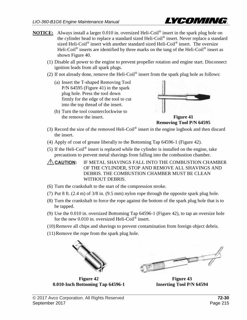
LIO-360-B1G6 Engine Maintenance Manual
© 2017 Avco Corporation. All Rights Reserved 72-30 September 2017 Page 215
NOTICE: Always install a larger 0.010 in. oversized Heli-Coil® insert in the spark plug hole on
the cylinder head to replace a standard sized Heli-Coil® insert. Never replace a standard
sized Heli-Coil® insert with another standard sized Heli-Coil® insert. The oversize
Heli-Coil® inserts are identified by three marks on the tang of the Heli-Coil® insert as
shown Figure 40.
(1) Disable all power to the engine to prevent propeller rotation and engine start. Disconnect
ignition leads from all spark plugs.
(2) If not already done, remove the Heli-Coil® insert from the spark plug hole as follows:
(a) Insert the T-shaped Removing Tool
P/N 64595 (Figure 41) in the spark
plug hole. Press the tool down
firmly for the edge of the tool to cut
into the top thread of the insert.
(b) Turn the tool counterclockwise to
the remove the insert.
Figure 41
Removing Tool P/N 64595
(3) Record the size of the removed Heli-Coil® insert in the engine logbook and then discard
the insert.
(4) Apply of coat of grease liberally to the Bottoming Tap 64596-1 (Figure 42).
(5) If the Heli-Coil® insert is replaced while the cylinder is installed on the engine, take
precautions to prevent metal shavings from falling into the combustion chamber.
IF METAL SHAVINGS FALL INTO THE COMBUSTION CHAMBER
OF THE CYLINDER, STOP AND REMOVE ALL SHAVINGS AND
DEBRIS. THE COMBUSTION CHAMBER MUST BE CLEAN
WITHOUT DEBRIS.
(6) Turn the crankshaft to the start of the compression stroke.
(7) Put 8 ft. (2.4 m) of 3/8 in. (9.5 mm) nylon rope through the opposite spark plug hole.
(8) Turn the crankshaft to force the rope against the bottom of the spark plug hole that is to
be tapped.
(9) Use the 0.010 in. oversized Bottoming Tap 64596-1 (Figure 42), to tap an oversize hole
for the new 0.010 in. oversized Heli-Coil® insert.
(10) Remove all chips and shavings to prevent contamination from foreign object debris.
(11) Remove the rope from the spark plug hole.
Figure 42
0.010-Inch Bottoming Tap 64596-1
Figure 43
Inserting Tool P/N 64594
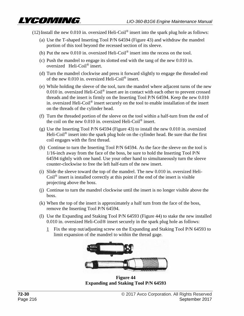
LIO-360-B1G6 Engine Maintenance Manual
72-30 © 2017 Avco Corporation. All Rights Reserved Page 216 September 2017
(12) Install the new 0.010 in. oversized Heli-Coil® insert into the spark plug hole as follows:
(a) Use the T-shaped Inserting Tool P/N 64594 (Figure 43) and withdraw the mandrel
portion of this tool beyond the recessed section of its sleeve.
(b) Put the new 0.010 in. oversized Heli-Coil® insert into the recess on the tool.
(c) Push the mandrel to engage its slotted end with the tang of the new 0.010 in.
oversized Heli-Coil® insert.
(d) Turn the mandrel clockwise and press it forward slightly to engage the threaded end
of the new 0.010 in. oversized Heli-Coil® insert.
(e) While holding the sleeve of the tool, turn the mandrel where adjacent turns of the new
0.010 in. oversized Heli-Coil® insert are in contact with each other to prevent crossed
threads and the insert is firmly on the Inserting Tool P/N 64594. Keep the new 0.010
in. oversized Heli-Coil® insert securely on the tool to enable installation of the insert
on the threads of the cylinder head.
(f) Turn the threaded portion of the sleeve on the tool within a half-turn from the end of
the coil on the new 0.010 in. oversized Heli-Coil® insert.
(g) Use the Inserting Tool P/N 64594 (Figure 43) to install the new 0.010 in. oversized
Heli-Coil® insert into the spark plug hole on the cylinder head. Be sure that the first
coil engages with the first thread.
(h) Continue to turn the Inserting Tool P/N 64594. As the face the sleeve on the tool is
1/16-inch away from the face of the boss, be sure to hold the Inserting Tool P/N
64594 tightly with one hand. Use your other hand to simultaneously turn the sleeve
counter-clockwise to free the left half-turn of the new insert.
(i) Slide the sleeve toward the top of the mandrel. The new 0.010 in. oversized Heli-
Coil® insert is installed correctly at this point if the end of the insert is visible
projecting above the boss.
(j) Continue to turn the mandrel clockwise until the insert is no longer visible above the
boss.
(k) When the top of the insert is approximately a half turn from the face of the boss,
remove the Inserting Tool P/N 64594.
(l) Use the Expanding and Staking Tool P/N 64593 (Figure 44) to stake the new installed
0.010 in. oversized Heli-Coil® insert securely in the spark plug hole as follows:
1 Fix the stop nut/adjusting screw on the Expanding and Staking Tool P/N 64593 to
limit expansion of the mandrel to within the thread gage.
Figure 44
Expanding and Staking Tool P/N 64593
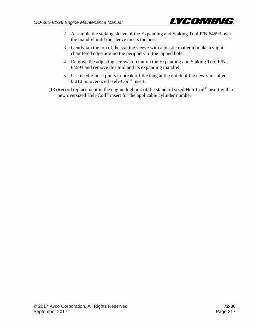
LIO-360-B1G6 Engine Maintenance Manual
© 2017 Avco Corporation. All Rights Reserved 72-30 September 2017 Page 217
2 Assemble the staking sleeve of the Expanding and Staking Tool P/N 64593 over
the mandrel until the sleeve meets the boss.
3 Gently tap the top of the staking sleeve with a plastic mallet to make a slight
chamfered edge around the periphery of the tapped hole.
4 Remove the adjusting screw/stop nut on the Expanding and Staking Tool P/N
64593 and remove this tool and its expanding mandrel
5 Use needle-nose pliers to break off the tang at the notch of the newly installed
0.010 in. oversized Heli-Coil® insert.
(13) Record replacement in the engine logbook of the standard sized Heli-Coil® insert with a
new oversized Heli-Coil® insert for the applicable cylinder number.

LIO-360-B1G6 Engine Maintenance Manual
72-30 © 2017 Avco Corporation. All Rights Reserved Page 218 September 2017
This page intentionally left blank.
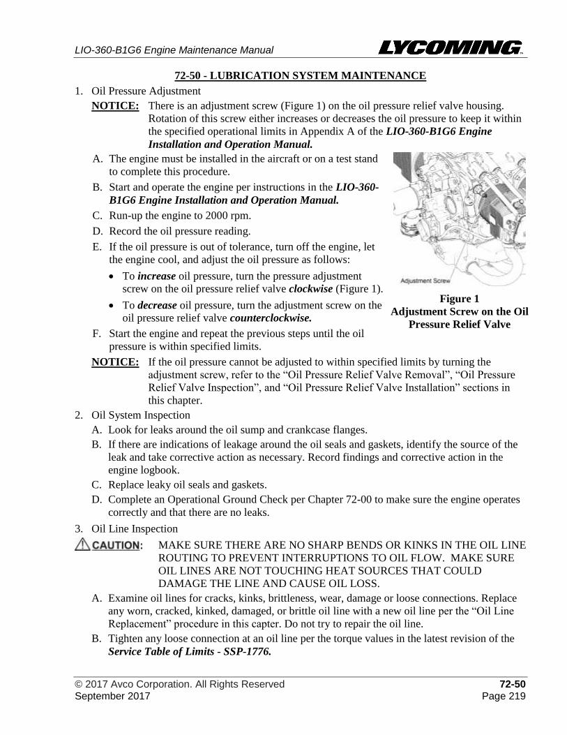
LIO-360-B1G6 Engine Maintenance Manual
© 2017 Avco Corporation. All Rights Reserved 72-50 September 2017 Page 219
72-50 - LUBRICATION SYSTEM MAINTENANCE
1. Oil Pressure Adjustment
NOTICE: There is an adjustment screw (Figure 1) on the oil pressure relief valve housing.
Rotation of this screw either increases or decreases the oil pressure to keep it within
the specified operational limits in Appendix A of the LIO-360-B1G6 Engine
Installation and Operation Manual.
A. The engine must be installed in the aircraft or on a test stand
to complete this procedure.
B. Start and operate the engine per instructions in the LIO-360-
B1G6 Engine Installation and Operation Manual.
C. Run-up the engine to 2000 rpm.
D. Record the oil pressure reading.
E. If the oil pressure is out of tolerance, turn off the engine, let
the engine cool, and adjust the oil pressure as follows:
• To increase oil pressure, turn the pressure adjustment
screw on the oil pressure relief valve clockwise (Figure 1).
• To decrease oil pressure, turn the adjustment screw on the
oil pressure relief valve counterclockwise.
F. Start the engine and repeat the previous steps until the oil
pressure is within specified limits.
Figure 1
Adjustment Screw on the Oil
Pressure Relief Valve
NOTICE: If the oil pressure cannot be adjusted to within specified limits by turning the
adjustment screw, refer to the “Oil Pressure Relief Valve Removal”, “Oil Pressure
Relief Valve Inspection”, and “Oil Pressure Relief Valve Installation” sections in
this chapter.
2. Oil System Inspection
A. Look for leaks around the oil sump and crankcase flanges.
B. If there are indications of leakage around the oil seals and gaskets, identify the source of the
leak and take corrective action as necessary. Record findings and corrective action in the
engine logbook.
C. Replace leaky oil seals and gaskets.
D. Complete an Operational Ground Check per Chapter 72-00 to make sure the engine operates
correctly and that there are no leaks.
3. Oil Line Inspection
MAKE SURE THERE ARE NO SHARP BENDS OR KINKS IN THE OIL LINE
ROUTING TO PREVENT INTERRUPTIONS TO OIL FLOW. MAKE SURE
OIL LINES ARE NOT TOUCHING HEAT SOURCES THAT COULD
DAMAGE THE LINE AND CAUSE OIL LOSS.
A. Examine oil lines for cracks, kinks, brittleness, wear, damage or loose connections. Replace
any worn, cracked, kinked, damaged, or brittle oil line with a new oil line per the “Oil Line
Replacement” procedure in this capter. Do not try to repair the oil line.
B. Tighten any loose connection at an oil line per the torque values in the latest revision of the
Service Table of Limits - SSP-1776.
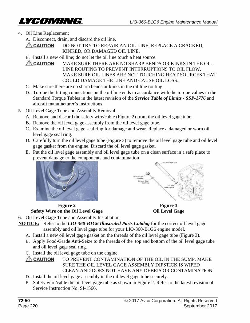
LIO-360-B1G6 Engine Maintenance Manual
72-50 © 2017 Avco Corporation. All Rights Reserved Page 220 September 2017
4. Oil Line Replacement
A. Disconnect, drain, and discard the oil line.
DO NOT TRY TO REPAIR AN OIL LINE, REPLACE A CRACKED,
KINKED, OR DAMAGED OIL LINE.
B. Install a new oil line; do not let the oil line touch a heat source.
MAKE SURE THERE ARE NO SHARP BENDS OR KINKS IN THE OIL
LINE ROUTING TO PREVENT INTERRUPTIONS TO OIL FLOW.
MAKE SURE OIL LINES ARE NOT TOUCHING HEAT SOURCES THAT
COULD DAMAGE THE LINE AND CAUSE OIL LOSS.
C. Make sure there are no sharp bends or kinks in the oil line routing
D. Torque the fitting connections on the oil line ends in accordance with the torque values in the
Standard Torque Tables in the latest revision of the Service Table of Limits - SSP-1776 and
aircraft manufacturer’s instructions.
5. Oil Level Gage Tube and Assembly Removal
A. Remove and discard the safety wire/cable (Figure 2) from the oil level gage tube.
B. Remove the oil level gage assembly from the oil level gage tube.
C. Examine the oil level gage seal ring for damage and wear. Replace a damaged or worn oil
level gage seal ring.
D. Carefully turn the oil level gage tube (Figure 3) to remove the oil level gage tube and oil level
gage gasket from the engine. Discard the oil level gage gasket.
E. Put the oil level gage assembly and oil level gage tube on a clean surface in a safe place to
prevent damage to the components and contamination.
Figure 2
Safety Wire on the Oil Level Gage
Figure 3
Oil Level Gage
6. Oil Level Gage Tube and Assembly Installation
NOTICE: Refer to the LIO-360-B1G6 Illustrated Parts Catalog for the correct oil level gage
assembly and oil level gage tube for your LIO-360-B1G6 engine model.
A. Install a new oil level gage gasket on the threads of the oil level gage tube (Figure 3).
B. Apply Food-Grade Anti-Seize to the threads of the top and bottom of the oil level gage tube
and oil level gage seal ring.
C. Install the oil level gage tube on the engine.
TO PREVENT CONTAMINATION OF THE OIL IN THE SUMP, MAKE
SURE THE OIL LEVEL GAGE ASSEMBLY DIPSTICK IS WIPED
CLEAN AND DOES NOT HAVE ANY DEBRIS OR CONTAMINATION.
D. Install the oil level gage assembly in the oil level gage tube securely.
E. Safety wire/cable the oil level gage tube as shown in Figure 2. Refer to the latest revision of
Service Instruction No. SI-1566.
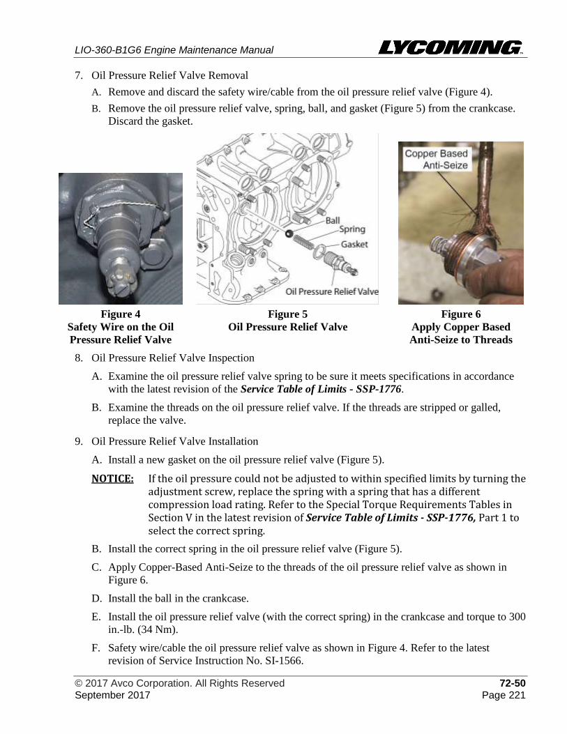
LIO-360-B1G6 Engine Maintenance Manual
© 2017 Avco Corporation. All Rights Reserved 72-50 September 2017 Page 221
7. Oil Pressure Relief Valve Removal
A. Remove and discard the safety wire/cable from the oil pressure relief valve (Figure 4).
B. Remove the oil pressure relief valve, spring, ball, and gasket (Figure 5) from the crankcase.
Discard the gasket.
Figure 4
Safety Wire on the Oil
Pressure Relief Valve
Figure 5
Oil Pressure Relief Valve
Figure 6
Apply Copper Based
Anti-Seize to Threads
8. Oil Pressure Relief Valve Inspection
A. Examine the oil pressure relief valve spring to be sure it meets specifications in accordance
with the latest revision of the Service Table of Limits - SSP-1776.
B. Examine the threads on the oil pressure relief valve. If the threads are stripped or galled,
replace the valve.
9. Oil Pressure Relief Valve Installation
A. Install a new gasket on the oil pressure relief valve (Figure 5).
NOTICE: If the oil pressure could not be adjusted to within specified limits by turning the adjustment screw, replace the spring with a spring that has a different compression load rating. Refer to the Special Torque Requirements Tables in Section V in the latest revision of Service Table of Limits - SSP-1776, Part 1 to select the correct spring.
B. Install the correct spring in the oil pressure relief valve (Figure 5).
C. Apply Copper-Based Anti-Seize to the threads of the oil pressure relief valve as shown in
Figure 6.
D. Install the ball in the crankcase.
E. Install the oil pressure relief valve (with the correct spring) in the crankcase and torque to 300
in.-lb. (34 Nm).
F. Safety wire/cable the oil pressure relief valve as shown in Figure 4. Refer to the latest
revision of Service Instruction No. SI-1566.
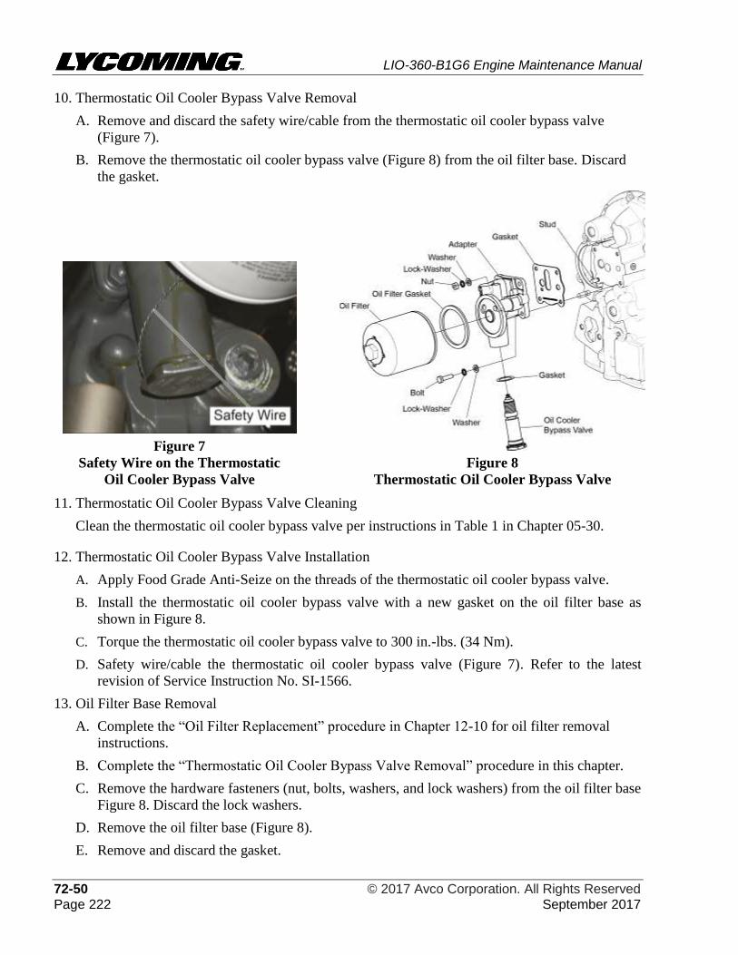
LIO-360-B1G6 Engine Maintenance Manual
72-50 © 2017 Avco Corporation. All Rights Reserved Page 222 September 2017
10. Thermostatic Oil Cooler Bypass Valve Removal
A. Remove and discard the safety wire/cable from the thermostatic oil cooler bypass valve
(Figure 7).
B. Remove the thermostatic oil cooler bypass valve (Figure 8) from the oil filter base. Discard
the gasket.
Figure 7
Safety Wire on the Thermostatic
Oil Cooler Bypass Valve
Figure 8
Thermostatic Oil Cooler Bypass Valve
11. Thermostatic Oil Cooler Bypass Valve Cleaning
Clean the thermostatic oil cooler bypass valve per instructions in Table 1 in Chapter 05-30.
12. Thermostatic Oil Cooler Bypass Valve Installation
A. Apply Food Grade Anti-Seize on the threads of the thermostatic oil cooler bypass valve.
B. Install the thermostatic oil cooler bypass valve with a new gasket on the oil filter base as
shown in Figure 8.
C. Torque the thermostatic oil cooler bypass valve to 300 in.-lbs. (34 Nm).
D. Safety wire/cable the thermostatic oil cooler bypass valve (Figure 7). Refer to the latest
revision of Service Instruction No. SI-1566.
13. Oil Filter Base Removal
A. Complete the “Oil Filter Replacement” procedure in Chapter 12-10 for oil filter removal
instructions.
B. Complete the “Thermostatic Oil Cooler Bypass Valve Removal” procedure in this chapter.
C. Remove the hardware fasteners (nut, bolts, washers, and lock washers) from the oil filter base
Figure 8. Discard the lock washers.
D. Remove the oil filter base (Figure 8).
E. Remove and discard the gasket.
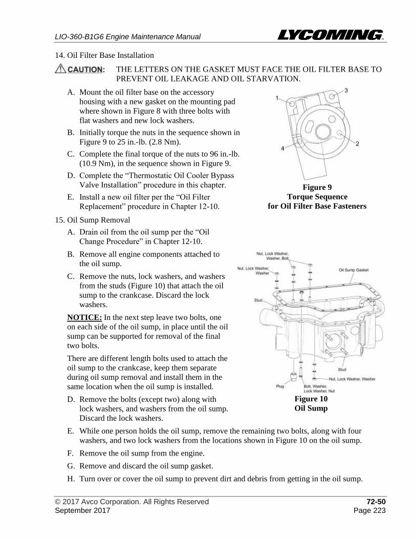
LIO-360-B1G6 Engine Maintenance Manual
© 2017 Avco Corporation. All Rights Reserved 72-50 September 2017 Page 223
14. Oil Filter Base Installation
THE LETTERS ON THE GASKET MUST FACE THE OIL FILTER BASE TO
PREVENT OIL LEAKAGE AND OIL STARVATION.
A. Mount the oil filter base on the accessory
housing with a new gasket on the mounting pad
where shown in Figure 8 with three bolts with
flat washers and new lock washers.
B. Initially torque the nuts in the sequence shown in
Figure 9 to 25 in.-lb. (2.8 Nm).
C. Complete the final torque of the nuts to 96 in.-lb.
(10.9 Nm), in the sequence shown in Figure 9.
D. Complete the “Thermostatic Oil Cooler Bypass
Valve Installation” procedure in this chapter.
E. Install a new oil filter per the “Oil Filter
Replacement” procedure in Chapter 12-10.
Figure 9
Torque Sequence
for Oil Filter Base Fasteners
15. Oil Sump Removal
A. Drain oil from the oil sump per the “Oil
Change Procedure” in Chapter 12-10.
B. Remove all engine components attached to
the oil sump.
C. Remove the nuts, lock washers, and washers
from the studs (Figure 10) that attach the oil
sump to the crankcase. Discard the lock
washers.
NOTICE: In the next step leave two bolts, one
on each side of the oil sump, in place until the oil
sump can be supported for removal of the final
two bolts.
There are different length bolts used to attach the
oil sump to the crankcase, keep them separate
during oil sump removal and install them in the
same location when the oil sump is installed.
D. Remove the bolts (except two) along with
lock washers, and washers from the oil sump.
Discard the lock washers.
Figure 10
Oil Sump
E. While one person holds the oil sump, remove the remaining two bolts, along with four
washers, and two lock washers from the locations shown in Figure 10 on the oil sump.
F. Remove the oil sump from the engine.
G. Remove and discard the oil sump gasket.
H. Turn over or cover the oil sump to prevent dirt and debris from getting in the oil sump.
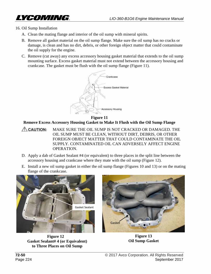
LIO-360-B1G6 Engine Maintenance Manual
72-50 © 2017 Avco Corporation. All Rights Reserved Page 224 September 2017
16. Oil Sump Installation
A. Clean the mating flange and interior of the oil sump with mineral spirits.
B. Remove all gasket material on the oil sump flange. Make sure the oil sump has no cracks or
damage, is clean and has no dirt, debris, or other foreign object matter that could contaminate
the oil supply for the engine.
C. Remove (cut away) any excess accessory housing gasket material that extends to the oil sump
mounting surface. Excess gasket material must not extend between the accessory housing and
crankcase. The gasket must be flush with the oil sump flange (Figure 11).
Figure 11
Remove Excess Accessory Housing Gasket to Make It Flush with the Oil Sump Flange
MAKE SURE THE OIL SUMP IS NOT CRACKED OR DAMAGED. THE
OIL SUMP MUST BE CLEAN, WITHOUT DIRT, DEBRIS, OR OTHER
FOREIGN OBJECT MATTER THAT COULD CONTAMINATE THE OIL
SUPPLY. CONTAMINATED OIL CAN ADVERSELY AFFECT ENGINE
OPERATION.
D. Apply a dab of Gasket Sealant #4 (or equivalent) to three places in the split line between the
accessory housing and crankcase where they mate with the oil sump (Figure 12).
E. Install a new oil sump gasket in either the oil sump flange (Figures 10 and 13) or on the mating
flange of the crankcase.
Figure 12
Gasket Sealant# 4 (or Equivalent)
to Three Places on Oil Sump
Figure 13
Oil Sump Gasket
Gasket Sealant
Gasket
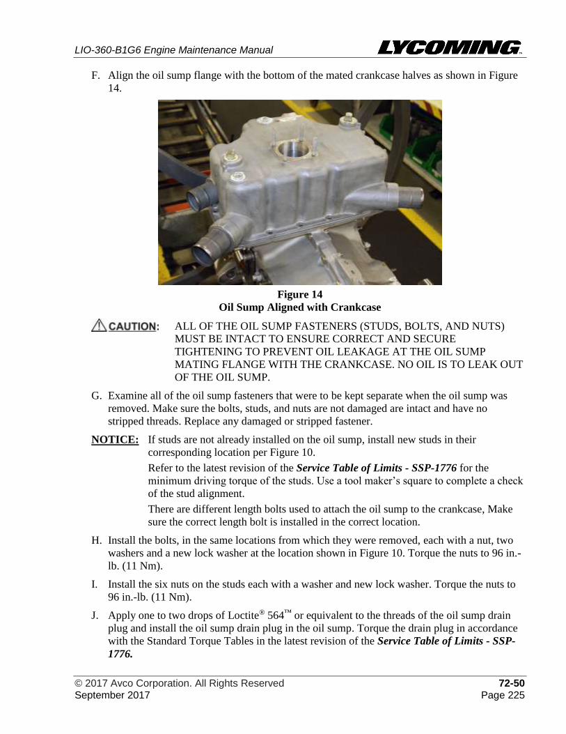
LIO-360-B1G6 Engine Maintenance Manual
© 2017 Avco Corporation. All Rights Reserved 72-50 September 2017 Page 225
F. Align the oil sump flange with the bottom of the mated crankcase halves as shown in Figure
14.
Figure 14
Oil Sump Aligned with Crankcase
ALL OF THE OIL SUMP FASTENERS (STUDS, BOLTS, AND NUTS)
MUST BE INTACT TO ENSURE CORRECT AND SECURE
TIGHTENING TO PREVENT OIL LEAKAGE AT THE OIL SUMP
MATING FLANGE WITH THE CRANKCASE. NO OIL IS TO LEAK OUT
OF THE OIL SUMP.
G. Examine all of the oil sump fasteners that were to be kept separate when the oil sump was
removed. Make sure the bolts, studs, and nuts are not damaged are intact and have no
stripped threads. Replace any damaged or stripped fastener.
NOTICE: If studs are not already installed on the oil sump, install new studs in their
corresponding location per Figure 10.
Refer to the latest revision of the Service Table of Limits - SSP-1776 for the
minimum driving torque of the studs. Use a tool maker’s square to complete a check
of the stud alignment.
There are different length bolts used to attach the oil sump to the crankcase, Make
sure the correct length bolt is installed in the correct location.
H. Install the bolts, in the same locations from which they were removed, each with a nut, two
washers and a new lock washer at the location shown in Figure 10. Torque the nuts to 96 in.-
lb. (11 Nm).
I. Install the six nuts on the studs each with a washer and new lock washer. Torque the nuts to
96 in.-lb. (11 Nm).
J. Apply one to two drops of Loctite® 564™ or equivalent to the threads of the oil sump drain
plug and install the oil sump drain plug in the oil sump. Torque the drain plug in accordance
with the Standard Torque Tables in the latest revision of the Service Table of Limits - SSP-
1776.
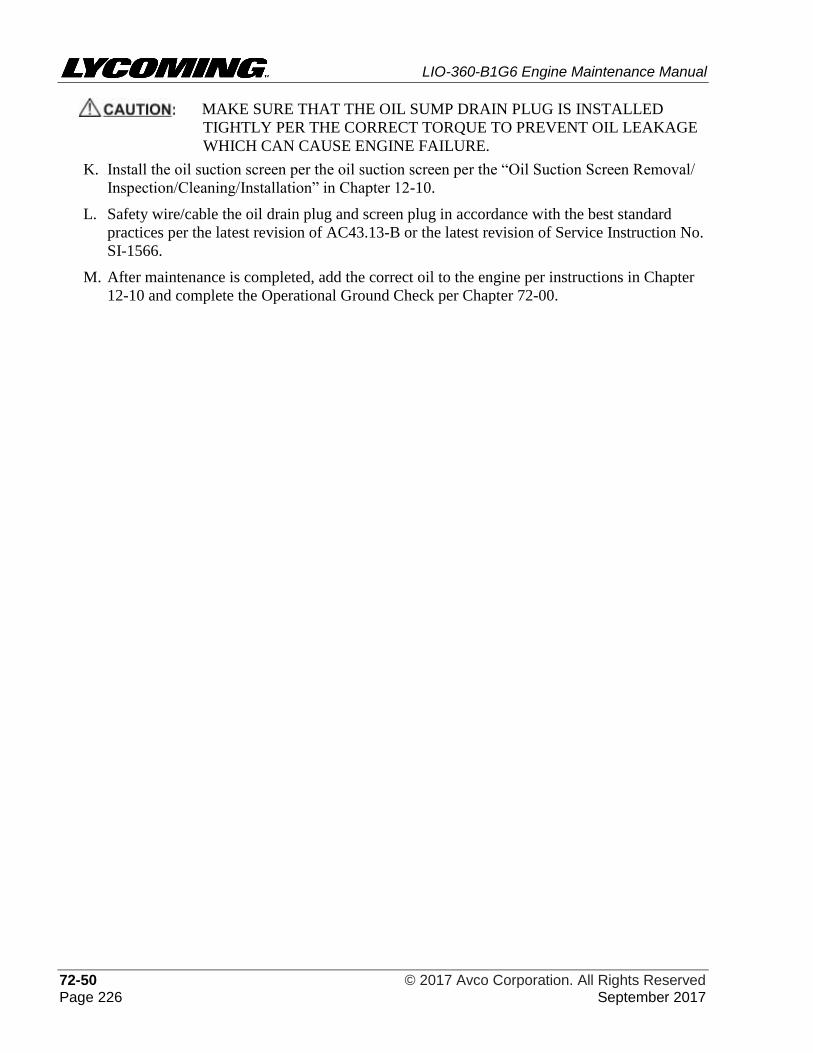
LIO-360-B1G6 Engine Maintenance Manual
72-50 © 2017 Avco Corporation. All Rights Reserved Page 226 September 2017
MAKE SURE THAT THE OIL SUMP DRAIN PLUG IS INSTALLED
TIGHTLY PER THE CORRECT TORQUE TO PREVENT OIL LEAKAGE
WHICH CAN CAUSE ENGINE FAILURE.
K. Install the oil suction screen per the oil suction screen per the “Oil Suction Screen Removal/
Inspection/Cleaning/Installation” in Chapter 12-10.
L. Safety wire/cable the oil drain plug and screen plug in accordance with the best standard
practices per the latest revision of AC43.13-B or the latest revision of Service Instruction No.
SI-1566.
M. After maintenance is completed, add the correct oil to the engine per instructions in Chapter
12-10 and complete the Operational Ground Check per Chapter 72-00.
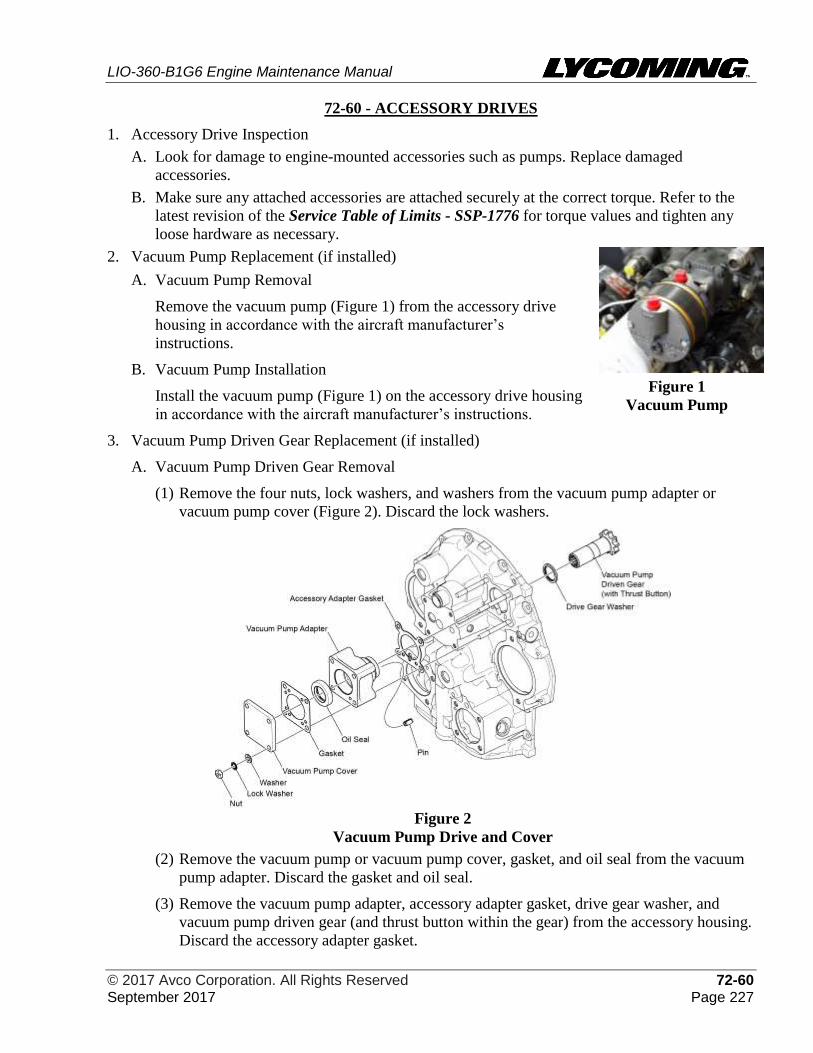
LIO-360-B1G6 Engine Maintenance Manual
© 2017 Avco Corporation. All Rights Reserved 72-60 September 2017 Page 227
72-60 - ACCESSORY DRIVES
1. Accessory Drive Inspection
A. Look for damage to engine-mounted accessories such as pumps. Replace damaged
accessories.
B. Make sure any attached accessories are attached securely at the correct torque. Refer to the
latest revision of the Service Table of Limits - SSP-1776 for torque values and tighten any
loose hardware as necessary.
2. Vacuum Pump Replacement (if installed)
Figure 1
Vacuum Pump
A. Vacuum Pump Removal
Remove the vacuum pump (Figure 1) from the accessory drive
housing in accordance with the aircraft manufacturer’s
instructions.
B. Vacuum Pump Installation
Install the vacuum pump (Figure 1) on the accessory drive housing
in accordance with the aircraft manufacturer’s instructions.
3. Vacuum Pump Driven Gear Replacement (if installed)
A. Vacuum Pump Driven Gear Removal
(1) Remove the four nuts, lock washers, and washers from the vacuum pump adapter or
vacuum pump cover (Figure 2). Discard the lock washers.
Figure 2
Vacuum Pump Drive and Cover
(2) Remove the vacuum pump or vacuum pump cover, gasket, and oil seal from the vacuum
pump adapter. Discard the gasket and oil seal.
(3) Remove the vacuum pump adapter, accessory adapter gasket, drive gear washer, and
vacuum pump driven gear (and thrust button within the gear) from the accessory housing.
Discard the accessory adapter gasket.
LIO-360-B1G6 Engine Maintenance Manual
72-60 © 2017 Avco Corporation. All Rights Reserved Page 228 September 2017
(4) Remove the vacuum pump driven gear (and thrust button within the gear) from the
vacuum pump adapter.
(5) Remove and discard the pin from the vacuum pump adapter.
(6) Remove any remaining gasket material from the vacuum pump or vacuum pump cover,
vacuum pump adapter, and accessory housing mounting surface per instructions in the
table in Chapter 05-30.
B. Vacuum Pump Driven Gear Installation
(1) Apply engine oil mixture to the vacuum pump driven gear.
(2) Install a new pin in the vacuum pump adapter.
(3) Install the vacuum pump driven gear (with the thrust button already installed inside the
geared end) and drive gear washer in the vacuum pump adapter (Figure 2).
(4) Install a new accessory adapter gasket on the vacuum pump adapter in the correct
orientation as shown in Figure 2.
(5) Install the vacuum pump adapter with a new oil seal on the accessory housing as shown
in Figure 2.
(6) Install the vacuum pump or vacuum pump cover with a new gasket on the vacuum pump
adapter with four nuts, four new lock washers and four washers. Torque the nuts to 96 to
108 in.-lb (11 to 12 Nm).
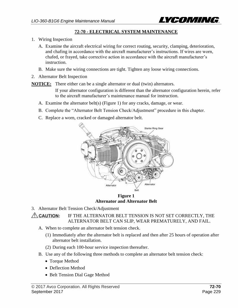
LIO-360-B1G6 Engine Maintenance Manual
© 2017 Avco Corporation. All Rights Reserved 72-70 September 2017 Page 229
72-70 - ELECTRICAL SYSTEM MAINTENANCE
1. Wiring Inspection
A. Examine the aircraft electrical wiring for correct routing, security, clamping, deterioration,
and chafing in accordance with the aircraft manufacturer’s instructions. If wires are worn,
chafed, or frayed, take corrective action in accordance with the aircraft manufacturer’s
instruction.
B. Make sure the wiring connections are tight. Tighten any loose wiring connections.
2. Alternator Belt Inspection
NOTICE: There either can be a single alternator or dual (twin) alternators.
If your alternator configuration is different than the alternator configuration herein, refer
to the aircraft manufacturer’s maintenance manual for instruction.
A. Examine the alternator belt(s) (Figure 1) for any cracks, damage, or wear.
B. Complete the “Alternator Belt Tension Check/Adjustment” procedure in this chapter.
C. Replace a worn, cracked or damaged alternator belt.
Figure 1
Alternator and Alternator Belt
3. Alternator Belt Tension Check/Adjustment
IF THE ALTERNATOR BELT TENSION IS NOT SET CORRECTLY, THE
ALTERNATOR BELT CAN SLIP, WEAR PREMATURELY, AND FAIL.
A. When to complete an alternator belt tension check.
(1) Immediately after the alternator belt is replaced and then after 25 hours of operation after
alternator belt installation.
(2) During each 100-hour service inspection thereafter.
B. Use any of the following three methods to complete an alternator belt tension check:
• Torque Method
• Deflection Method
• Belt Tension Dial Gage Method
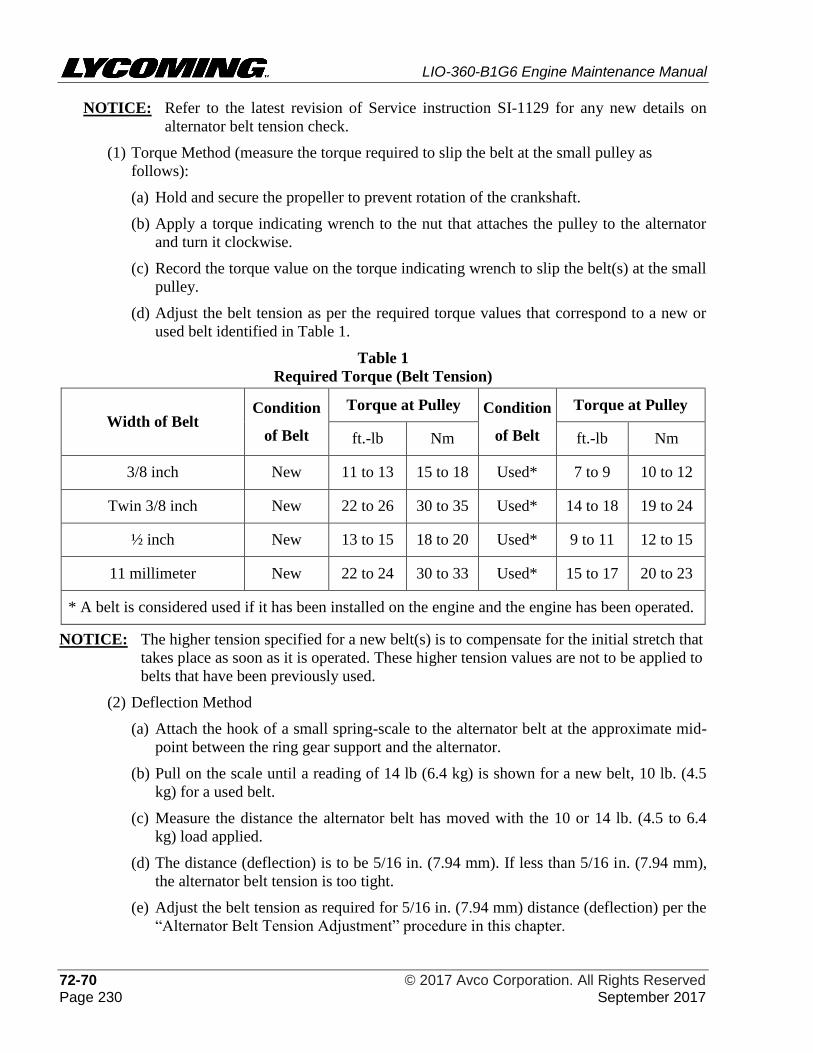
LIO-360-B1G6 Engine Maintenance Manual
72-70 © 2017 Avco Corporation. All Rights Reserved Page 230 September 2017
NOTICE: Refer to the latest revision of Service instruction SI-1129 for any new details on
alternator belt tension check.
(1) Torque Method (measure the torque required to slip the belt at the small pulley as
follows):
(a) Hold and secure the propeller to prevent rotation of the crankshaft.
(b) Apply a torque indicating wrench to the nut that attaches the pulley to the alternator
and turn it clockwise.
(c) Record the torque value on the torque indicating wrench to slip the belt(s) at the small
pulley.
(d) Adjust the belt tension as per the required torque values that correspond to a new or
used belt identified in Table 1.
Table 1
Required Torque (Belt Tension)
Width of Belt Condition
of Belt
Torque at Pulley Condition
of Belt
Torque at Pulley
ft.-lb Nm ft.-lb Nm
3/8 inch New 11 to 13 15 to 18 Used* 7 to 9 10 to 12
Twin 3/8 inch New 22 to 26 30 to 35 Used* 14 to 18 19 to 24
½ inch New 13 to 15 18 to 20 Used* 9 to 11 12 to 15
11 millimeter New 22 to 24 30 to 33 Used* 15 to 17 20 to 23
* A belt is considered used if it has been installed on the engine and the engine has been operated.
NOTICE: The higher tension specified for a new belt(s) is to compensate for the initial stretch that
takes place as soon as it is operated. These higher tension values are not to be applied to
belts that have been previously used.
(2) Deflection Method
(a) Attach the hook of a small spring-scale to the alternator belt at the approximate mid-
point between the ring gear support and the alternator.
(b) Pull on the scale until a reading of 14 lb (6.4 kg) is shown for a new belt, 10 lb. (4.5
kg) for a used belt.
(c) Measure the distance the alternator belt has moved with the 10 or 14 lb. (4.5 to 6.4
kg) load applied.
(d) The distance (deflection) is to be 5/16 in. (7.94 mm). If less than 5/16 in. (7.94 mm),
the alternator belt tension is too tight.
(e) Adjust the belt tension as required for 5/16 in. (7.94 mm) distance (deflection) per the
“Alternator Belt Tension Adjustment” procedure in this chapter.
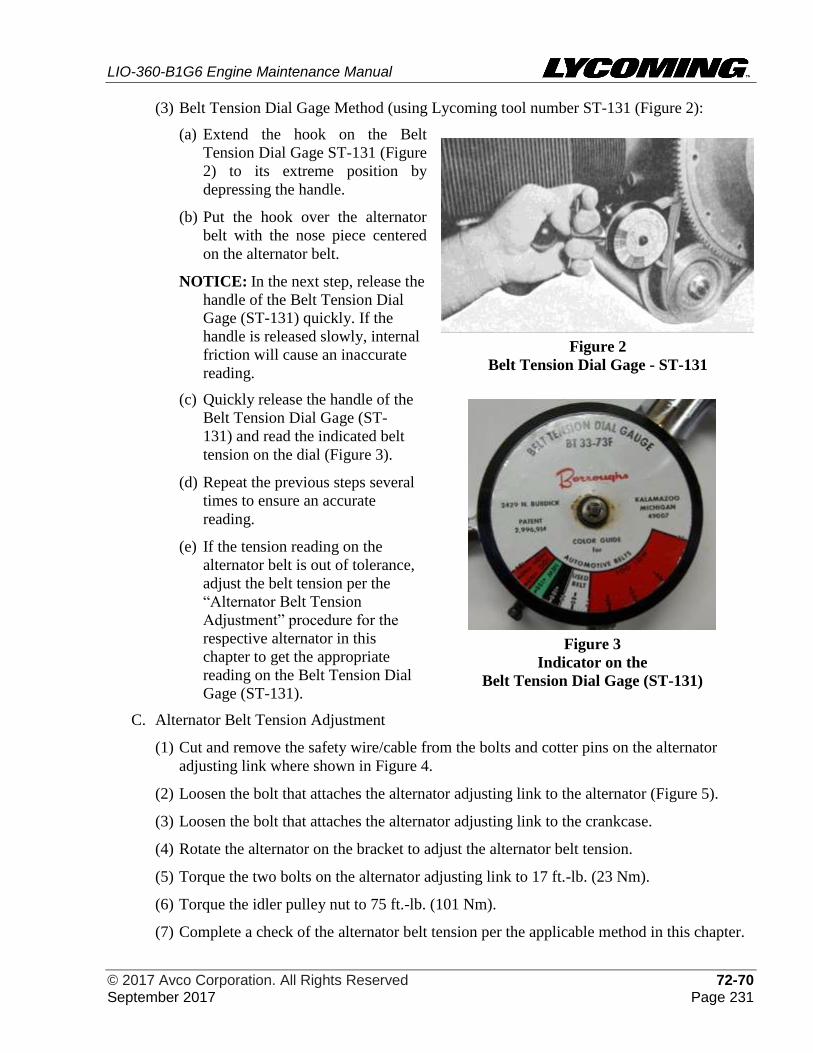
LIO-360-B1G6 Engine Maintenance Manual
© 2017 Avco Corporation. All Rights Reserved 72-70 September 2017 Page 231
(3) Belt Tension Dial Gage Method (using Lycoming tool number ST-131 (Figure 2):
(a) Extend the hook on the Belt
Tension Dial Gage ST-131 (Figure
2) to its extreme position by
depressing the handle.
(b) Put the hook over the alternator
belt with the nose piece centered
on the alternator belt.
NOTICE: In the next step, release the
handle of the Belt Tension Dial
Gage (ST-131) quickly. If the
handle is released slowly, internal
friction will cause an inaccurate
reading.
Figure 2
Belt Tension Dial Gage - ST-131
(c) Quickly release the handle of the
Belt Tension Dial Gage (ST-
131) and read the indicated belt
tension on the dial (Figure 3).
(d) Repeat the previous steps several
times to ensure an accurate
reading.
(e) If the tension reading on the
alternator belt is out of tolerance,
adjust the belt tension per the
“Alternator Belt Tension
Adjustment” procedure for the
respective alternator in this
chapter to get the appropriate
reading on the Belt Tension Dial
Gage (ST-131).
Figure 3
Indicator on the
Belt Tension Dial Gage (ST-131)
C. Alternator Belt Tension Adjustment
(1) Cut and remove the safety wire/cable from the bolts and cotter pins on the alternator
adjusting link where shown in Figure 4.
(2) Loosen the bolt that attaches the alternator adjusting link to the alternator (Figure 5).
(3) Loosen the bolt that attaches the alternator adjusting link to the crankcase.
(4) Rotate the alternator on the bracket to adjust the alternator belt tension.
(5) Torque the two bolts on the alternator adjusting link to 17 ft.-lb. (23 Nm).
(6) Torque the idler pulley nut to 75 ft.-lb. (101 Nm).
(7) Complete a check of the alternator belt tension per the applicable method in this chapter.
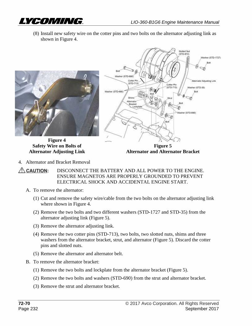
LIO-360-B1G6 Engine Maintenance Manual
72-70 © 2017 Avco Corporation. All Rights Reserved Page 232 September 2017
(8) Install new safety wire on the cotter pins and two bolts on the alternator adjusting link as
shown in Figure 4.
Figure 4
Safety Wire on Bolts of
Alternator Adjusting Link
Figure 5
Alternator and Alternator Bracket
4. Alternator and Bracket Removal
DISCONNECT THE BATTERY AND ALL POWER TO THE ENGINE.
ENSURE MAGNETOS ARE PROPERLY GROUNDED TO PREVENT
ELECTRICAL SHOCK AND ACCIDENTAL ENGINE START.
A. To remove the alternator:
(1) Cut and remove the safety wire/cable from the two bolts on the alternator adjusting link
where shown in Figure 4.
(2) Remove the two bolts and two different washers (STD-1727 and STD-35) from the
alternator adjusting link (Figure 5).
(3) Remove the alternator adjusting link.
(4) Remove the two cotter pins (STD-713), two bolts, two slotted nuts, shims and three
washers from the alternator bracket, strut, and alternator (Figure 5). Discard the cotter
pins and slotted nuts.
(5) Remove the alternator and alternator belt.
B. To remove the alternator bracket:
(1) Remove the two bolts and lockplate from the alternator bracket (Figure 5).
(2) Remove the two bolts and washers (STD-690) from the strut and alternator bracket.
(3) Remove the strut and alternator bracket.
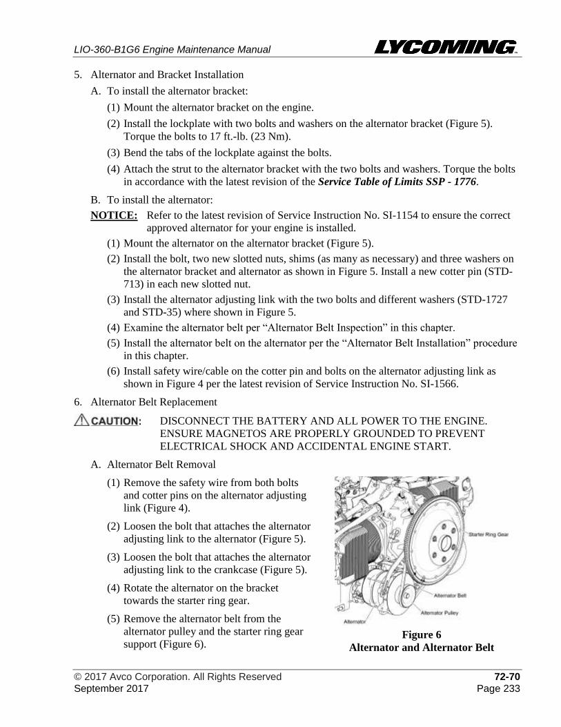
LIO-360-B1G6 Engine Maintenance Manual
© 2017 Avco Corporation. All Rights Reserved 72-70 September 2017 Page 233
5. Alternator and Bracket Installation
A. To install the alternator bracket:
(1) Mount the alternator bracket on the engine.
(2) Install the lockplate with two bolts and washers on the alternator bracket (Figure 5).
Torque the bolts to 17 ft.-lb. (23 Nm).
(3) Bend the tabs of the lockplate against the bolts.
(4) Attach the strut to the alternator bracket with the two bolts and washers. Torque the bolts
in accordance with the latest revision of the Service Table of Limits SSP - 1776.
B. To install the alternator:
NOTICE: Refer to the latest revision of Service Instruction No. SI-1154 to ensure the correct
approved alternator for your engine is installed.
(1) Mount the alternator on the alternator bracket (Figure 5).
(2) Install the bolt, two new slotted nuts, shims (as many as necessary) and three washers on
the alternator bracket and alternator as shown in Figure 5. Install a new cotter pin (STD-
713) in each new slotted nut.
(3) Install the alternator adjusting link with the two bolts and different washers (STD-1727
and STD-35) where shown in Figure 5.
(4) Examine the alternator belt per “Alternator Belt Inspection” in this chapter.
(5) Install the alternator belt on the alternator per the “Alternator Belt Installation” procedure
in this chapter.
(6) Install safety wire/cable on the cotter pin and bolts on the alternator adjusting link as
shown in Figure 4 per the latest revision of Service Instruction No. SI-1566.
6. Alternator Belt Replacement
DISCONNECT THE BATTERY AND ALL POWER TO THE ENGINE.
ENSURE MAGNETOS ARE PROPERLY GROUNDED TO PREVENT
ELECTRICAL SHOCK AND ACCIDENTAL ENGINE START.
A. Alternator Belt Removal
(1) Remove the safety wire from both bolts
and cotter pins on the alternator adjusting
link (Figure 4).
(2) Loosen the bolt that attaches the alternator
adjusting link to the alternator (Figure 5).
(3) Loosen the bolt that attaches the alternator
adjusting link to the crankcase (Figure 5).
(4) Rotate the alternator on the bracket
towards the starter ring gear.
(5) Remove the alternator belt from the
alternator pulley and the starter ring gear
support (Figure 6).
Figure 6
Alternator and Alternator Belt
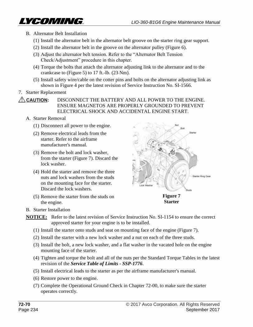
LIO-360-B1G6 Engine Maintenance Manual
72-70 © 2017 Avco Corporation. All Rights Reserved Page 234 September 2017
B. Alternator Belt Installation
(1) Install the alternator belt in the alternator belt groove on the starter ring gear support.
(2) Install the alternator belt in the groove on the alternator pulley (Figure 6).
(3) Adjust the alternator belt tension. Refer to the “Alternator Belt Tension
Check/Adjustment” procedure in this chapter.
(4) Torque the bolts that attach the alternator adjusting link to the alternator and to the
crankcase to (Figure 5) to 17 ft.-lb. (23 Nm).
(5) Install safety wire/cable on the cotter pins and bolts on the alternator adjusting link as
shown in Figure 4 per the latest revision of Service Instruction No. SI-1566.
7. Starter Replacement
DISCONNECT THE BATTERY AND ALL POWER TO THE ENGINE.
ENSURE MAGNETOS ARE PROPERLY GROUNDED TO PREVENT
ELECTRICAL SHOCK AND ACCIDENTAL ENGINE START.
A. Starter Removal
(1) Disconnect all power to the engine.
(2) Remove electrical leads from the
starter. Refer to the airframe
manufacturer's manual.
(3) Remove the bolt and lock washer,
from the starter (Figure 7). Discard the
lock washer.
(4) Hold the starter and remove the three
nuts and lock washers from the studs
on the mounting face for the starter.
Discard the lock washers.
(5) Remove the starter from the studs on
the engine.
Figure 7
Starter
B. Starter Installation
NOTICE: Refer to the latest revision of Service Instruction No. SI-1154 to ensure the correct
approved starter for your engine is to be installed.
(1) Install the starter onto studs and seat on mounting face of the engine (Figure 7).
(2) Install the starter with a new lock washer and a nut on each of the three studs.
(3) Install the bolt, a new lock washer, and a flat washer in the vacated hole on the engine
mounting face of the starter.
(4) Tighten and torque the bolt and all of the nuts per the Standard Torque Tables in the latest
revision of the Service Table of Limits - SSP-1776.
(5) Install electrical leads to the starter as per the airframe manufacturer's manual.
(6) Restore power to the engine.
(7) Complete the Operational Ground Check in Chapter 72-00, to make sure the starter
operates correctly.
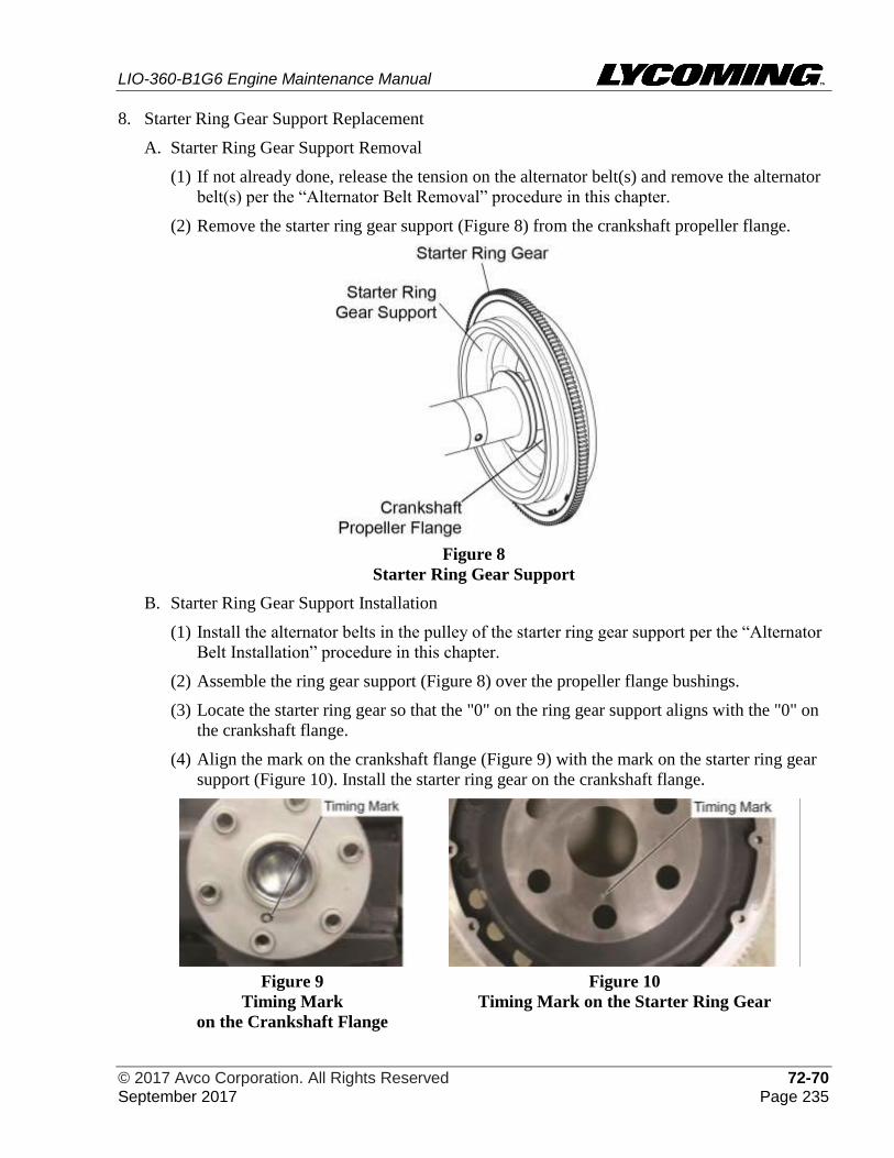
LIO-360-B1G6 Engine Maintenance Manual
© 2017 Avco Corporation. All Rights Reserved 72-70 September 2017 Page 235
8. Starter Ring Gear Support Replacement
A. Starter Ring Gear Support Removal
(1) If not already done, release the tension on the alternator belt(s) and remove the alternator
belt(s) per the “Alternator Belt Removal” procedure in this chapter.
(2) Remove the starter ring gear support (Figure 8) from the crankshaft propeller flange.
Figure 8
Starter Ring Gear Support
B. Starter Ring Gear Support Installation
(1) Install the alternator belts in the pulley of the starter ring gear support per the “Alternator
Belt Installation” procedure in this chapter.
(2) Assemble the ring gear support (Figure 8) over the propeller flange bushings.
(3) Locate the starter ring gear so that the "0" on the ring gear support aligns with the "0" on
the crankshaft flange.
(4) Align the mark on the crankshaft flange (Figure 9) with the mark on the starter ring gear
support (Figure 10). Install the starter ring gear on the crankshaft flange.
Figure 9
Timing Mark
on the Crankshaft Flange
Figure 10
Timing Mark on the Starter Ring Gear
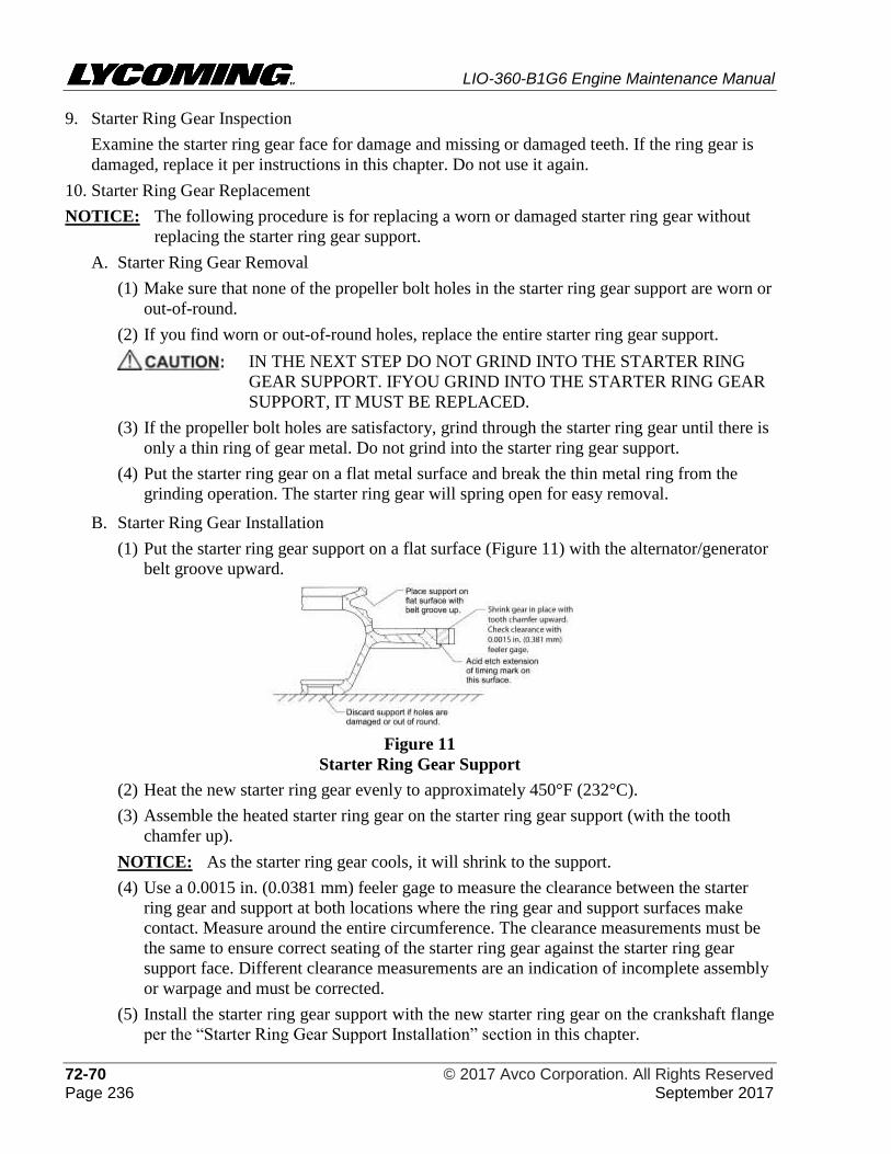
LIO-360-B1G6 Engine Maintenance Manual
72-70 © 2017 Avco Corporation. All Rights Reserved Page 236 September 2017
9. Starter Ring Gear Inspection
Examine the starter ring gear face for damage and missing or damaged teeth. If the ring gear is
damaged, replace it per instructions in this chapter. Do not use it again.
10. Starter Ring Gear Replacement
NOTICE: The following procedure is for replacing a worn or damaged starter ring gear without
replacing the starter ring gear support.
A. Starter Ring Gear Removal
(1) Make sure that none of the propeller bolt holes in the starter ring gear support are worn or
out-of-round.
(2) If you find worn or out-of-round holes, replace the entire starter ring gear support.
IN THE NEXT STEP DO NOT GRIND INTO THE STARTER RING
GEAR SUPPORT. IFYOU GRIND INTO THE STARTER RING GEAR
SUPPORT, IT MUST BE REPLACED.
(3) If the propeller bolt holes are satisfactory, grind through the starter ring gear until there is
only a thin ring of gear metal. Do not grind into the starter ring gear support.
(4) Put the starter ring gear on a flat metal surface and break the thin metal ring from the
grinding operation. The starter ring gear will spring open for easy removal.
B. Starter Ring Gear Installation
(1) Put the starter ring gear support on a flat surface (Figure 11) with the alternator/generator
belt groove upward.
Figure 11
Starter Ring Gear Support
(2) Heat the new starter ring gear evenly to approximately 450°F (232°C).
(3) Assemble the heated starter ring gear on the starter ring gear support (with the tooth
chamfer up).
NOTICE: As the starter ring gear cools, it will shrink to the support.
(4) Use a 0.0015 in. (0.0381 mm) feeler gage to measure the clearance between the starter
ring gear and support at both locations where the ring gear and support surfaces make
contact. Measure around the entire circumference. The clearance measurements must be
the same to ensure correct seating of the starter ring gear against the starter ring gear
support face. Different clearance measurements are an indication of incomplete assembly
or warpage and must be corrected.
(5) Install the starter ring gear support with the new starter ring gear on the crankshaft flange
per the “Starter Ring Gear Support Installation” section in this chapter.
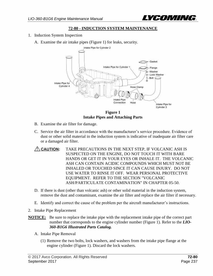
LIO-360-B1G6 Engine Maintenance Manual
© 2017 Avco Corporation. All Rights Reserved 72-80 September 2017 Page 237
72-80 - INDUCTION SYSTEM MAINTENANCE
1. Induction System Inspection
A. Examine the air intake pipes (Figure 1) for leaks, security.
Figure 1
Intake Pipes and Attaching Parts
B. Examine the air filter for damage.
C. Service the air filter in accordance with the manufacturer’s service procedure. Evidence of
dust or other solid material in the induction system is indicative of inadequate air filter care
or a damaged air filter.
TAKE PRECAUTIONS IN THE NEXT STEP, IF VOLCANIC ASH IS
SUSPECTED ON THE ENGINE, DO NOT TOUCH IT WITH BARE
HANDS OR GET IT IN YOUR EYES OR INHALE IT. THE VOLCANIC
ASH CAN CONTAIN ACIDIC COMPOUNDS WHICH MUST NOT BE
INHALED OR TOUCHED SINCE IT CAN CAUSE INJURY. DO NOT
USE WATER TO RINSE IT OFF. WEAR PERSONAL PROTECTIVE
EQUIPMENT. REFER TO THE SECTION "VOLCANIC
ASH/PARTICULATE CONTAMINATION" IN CHAPTER 05-50.
D. If there is dust (other than volcanic ash) or other solid material in the induction system,
remove the dust and contaminant, examine the air filter and replace the air filter if necessary.
E. Identify and correct the cause of the problem per the aircraft manufacturer’s instructions.
2. Intake Pipe Replacement
NOTICE: Be sure to replace the intake pipe with the replacement intake pipe of the correct part
number that corresponds to the engine cylinder number (Figure 1). Refer to the LIO-
360-B1G6 Illustrated Parts Catalog.
A. Intake Pipe Removal
(1) Remove the two bolts, lock washers, and washers from the intake pipe flange at the
engine cylinder (Figure 1). Discard the lock washers.
LIO-360-B1G6 Engine Maintenance Manual
72-80 © 2017 Avco Corporation. All Rights Reserved Page 238 September 2017
(2) If the intake pipe is not to be replaced, attach a label to the intake pipe that identifies the
corresponding engine cylinder number for reference on assembly.
(3) Remove the two hose clamps, hose, and intake pipe from the intake pipe connection.
(4) Remove and discard the gasket from the intake pipe.
(5) Examine the intake pipe connection for damage or loose fit in the sump.
(6) If the intake pipe connection is damaged, replace a damaged intake pipe connection with
a new oversized intake pipe connection as follows:
USE CARE NOT TO DAMAGE THE OIL SUMP WHEN REMOVING
A LOOSE OR DAMAGED INTAKE PIPE CONNECTION.
(a) Remove and discard the damaged intake pipe connection from the oil sump by
collapsing it with a chisel or punch.
(b) Clean the port in the oil sump and the new intake pipe connection per instructions in
Chapter 05-30.
(c) Apply a coating of Loctite® 620 to the joint area.
(d) Place a new intake pipe connection on the end of the Swaging Tool P/N 64781 and
tighten the screw until the rollers have expanded sufficiently to hold the connection
on the tool.
(e) Fully insert the intake pipe connection into the port in the oil sump, making sure that
the connection seated on the machined shoulder provided.
(f) Begin to turn the Swaging Tool, stopping every couple of turns to expand the rollers
by tightening the screw one or two full turns.
(g) When the groove in the connection is fully swaged in the groove in the oil sump,
(evident by the increased resistance of the screw), collapse the rollers and withdraw
the Swaging Tool.
B. Intake Pipe Installation
NOTICE: Make sure the intake pipe of the correct part number is installed for the respective
engine cylinder. Refer to the LIO-360-B1G6 Illustrated Parts Catalog.
(1) Install the hose (Figure 1) and two hose clamps on the intake pipe connection and the
intake pipe. Do not torque the hose clamps.
(2) Center the intake pipe to the center of the correct intake pipe flange on the engine
cylinder.
(3) Torque the two hose clamps on the intake pipe connection and the intake pipe per
instruction in the latest revision of the Service Table of Limits - SSP-1776.
(4) Attach the intake pipe to the engine cylinder flange with a new gasket, two bolts, two new
lock washers, and two washers. Torque the two bolts to 96 to 108 in.-lb. (11 to 12 Nm).
LIO-360-B1G6 Engine Maintenance Manual
© 2017 Avco Corporation. All Rights Reserved 73-10 September 2017 Page 239
73-10 - ENGINE FUEL AND CONTROL – DISTRIBUTION MAINTENANCE
1. Fuel System Inspection
DO NOT SMOKE OR HAVE AN OPEN FIRE/FLAME OR USE ANY
DEVICES THAT CAN MAKE SPARKS DURING THIS INSPECTION.
SMOKING, FLAMES, OR SPARKS CAN IGNITE THE FUEL WHICH CAN
CAUSE SERIOUS INJURY OR DEATH.
TO ENSURE CORRECT ENGINE OPERATION AND FLIGHT SAFETY,
THERE MUST NOT BE ANY FUEL LEAK AND ALL FUEL LINES MUST BE
SECURED WITH CLAMPS (PER THE “FUEL LINE INSPECTION”
PROCEDURE IN THIS CHAPTER). IDENTIFY AND CORRECT THE CAUSE
OF ANY FUEL LEAK.
NOTICE: This inspection is to be done every 100 hours.
A. Make a copy of the Fuel System Inspection Checklist for LIO-360-B1G6 Engines in this
chapter and complete this checklist for this inspection.
NOTICE: Figure 1 is a general conceptual reference figure of fuel system components. Some
of the LIO-360-B1G6Engines contain fuel system components made up of different
configurations and part numbers. Refer to the applicable latest edition of the LIO-
360-B1G6 Illustrated Parts Catalog for part number details.
B. Examine the fuel pump for secure attachment and damage. Replace a damaged or
malfunctioning fuel pump. Tighten any loose fasteners per the “Fuel Pump Replacement”
procedure in this chapter.
C. Examine the fuel manifold (Figure 1) for damage, leaks, and loose fittings or connections.
Tighten any loose fittings or connection. Replace a damaged fuel manifold per the “Fuel
Manifold Replacement” procedure in this chapter.
D. Examine the fuel injector for damage, leaks, and loose fittings or connections. Tighten any
loose fittings or connection per the “Fuel Injector Installation” procedure in this chapter.
Replace a damaged fuel injector per the “Fuel Injector Replacement” section in this chapter.
E. Examine each injection nozzle (Figure 1) for damage or wear; replace a damaged or worn
injection nozzle per the “Injection Nozzle Replacement” procedure in this chapter.
F. Examine fuel line fittings for damage or leaks. Make sure all fuel line fittings and
connections are secure and correctly installed/torqued per the “Fuel Line Installation”
procedure in this chapter. If tightening does not correct a fuel leak, replace the fitting.
G. Complete the “Fuel Line Inspection” procedure in this chapter.
H. Make sure the mixture control and throttle linkage have full travel, freedom of movement.
I. Lubricate the linkage per the aircraft manufacturer's instruction.
J. Operate the engine and look for leaks. Identify and correct the cause of any leak or
malfunction. If leaks or malfunctions were found and corrected, operate the engine again to
make sure it is operating correctly and there is no leak anywhere.
K. Do not return the engine to service unless the engine is operating correctly and does not have
any leaks.
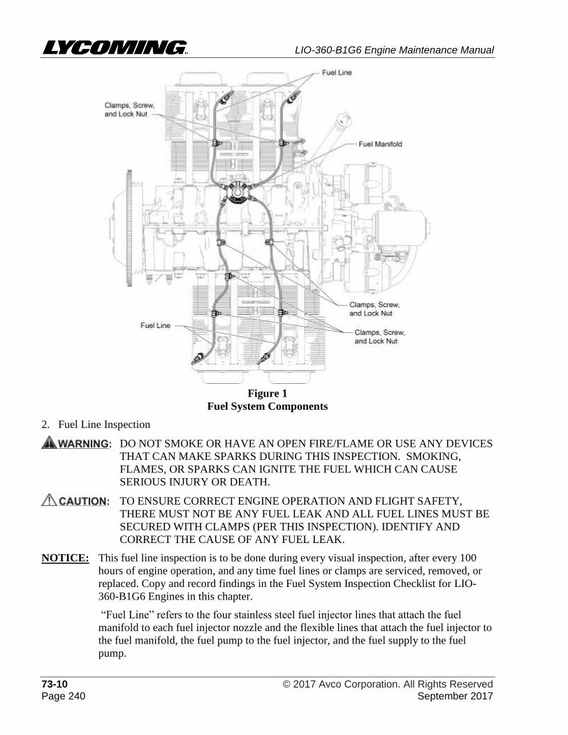
LIO-360-B1G6 Engine Maintenance Manual
73-10 © 2017 Avco Corporation. All Rights Reserved Page 240 September 2017
Figure 1
Fuel System Components
2. Fuel Line Inspection
DO NOT SMOKE OR HAVE AN OPEN FIRE/FLAME OR USE ANY DEVICES
THAT CAN MAKE SPARKS DURING THIS INSPECTION. SMOKING,
FLAMES, OR SPARKS CAN IGNITE THE FUEL WHICH CAN CAUSE
SERIOUS INJURY OR DEATH.
TO ENSURE CORRECT ENGINE OPERATION AND FLIGHT SAFETY,
THERE MUST NOT BE ANY FUEL LEAK AND ALL FUEL LINES MUST BE
SECURED WITH CLAMPS (PER THIS INSPECTION). IDENTIFY AND
CORRECT THE CAUSE OF ANY FUEL LEAK.
NOTICE: This fuel line inspection is to be done during every visual inspection, after every 100
hours of engine operation, and any time fuel lines or clamps are serviced, removed, or
replaced. Copy and record findings in the Fuel System Inspection Checklist for LIO-
360-B1G6 Engines in this chapter.
“Fuel Line” refers to the four stainless steel fuel injector lines that attach the fuel
manifold to each fuel injector nozzle and the flexible lines that attach the fuel injector to
the fuel manifold, the fuel pump to the fuel injector, and the fuel supply to the fuel
pump.
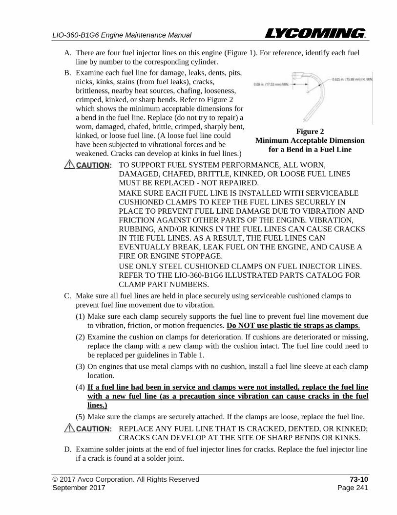
LIO-360-B1G6 Engine Maintenance Manual
© 2017 Avco Corporation. All Rights Reserved 73-10 September 2017 Page 241
A. There are four fuel injector lines on this engine (Figure 1). For reference, identify each fuel
line by number to the corresponding cylinder.
B. Examine each fuel line for damage, leaks, dents, pits,
nicks, kinks, stains (from fuel leaks), cracks,
brittleness, nearby heat sources, chafing, looseness,
crimped, kinked, or sharp bends. Refer to Figure 2
which shows the minimum acceptable dimensions for
a bend in the fuel line. Replace (do not try to repair) a
worn, damaged, chafed, brittle, crimped, sharply bent,
kinked, or loose fuel line. (A loose fuel line could
have been subjected to vibrational forces and be
weakened. Cracks can develop at kinks in fuel lines.)
Figure 2
Minimum Acceptable Dimension
for a Bend in a Fuel Line
TO SUPPORT FUEL SYSTEM PERFORMANCE, ALL WORN,
DAMAGED, CHAFED, BRITTLE, KINKED, OR LOOSE FUEL LINES
MUST BE REPLACED - NOT REPAIRED.
MAKE SURE EACH FUEL LINE IS INSTALLED WITH SERVICEABLE
CUSHIONED CLAMPS TO KEEP THE FUEL LINES SECURELY IN
PLACE TO PREVENT FUEL LINE DAMAGE DUE TO VIBRATION AND
FRICTION AGAINST OTHER PARTS OF THE ENGINE. VIBRATION,
RUBBING, AND/OR KINKS IN THE FUEL LINES CAN CAUSE CRACKS
IN THE FUEL LINES. AS A RESULT, THE FUEL LINES CAN
EVENTUALLY BREAK, LEAK FUEL ON THE ENGINE, AND CAUSE A
FIRE OR ENGINE STOPPAGE.
USE ONLY STEEL CUSHIONED CLAMPS ON FUEL INJECTOR LINES.
REFER TO THE LIO-360-B1G6 ILLUSTRATED PARTS CATALOG FOR
CLAMP PART NUMBERS.
C. Make sure all fuel lines are held in place securely using serviceable cushioned clamps to
prevent fuel line movement due to vibration.
(1) Make sure each clamp securely supports the fuel line to prevent fuel line movement due
to vibration, friction, or motion frequencies. Do NOT use plastic tie straps as clamps.
(2) Examine the cushion on clamps for deterioration. If cushions are deteriorated or missing,
replace the clamp with a new clamp with the cushion intact. The fuel line could need to
be replaced per guidelines in Table 1.
(3) On engines that use metal clamps with no cushion, install a fuel line sleeve at each clamp
location.
(4) If a fuel line had been in service and clamps were not installed, replace the fuel line
with a new fuel line (as a precaution since vibration can cause cracks in the fuel
lines.)
(5) Make sure the clamps are securely attached. If the clamps are loose, replace the fuel line.
REPLACE ANY FUEL LINE THAT IS CRACKED, DENTED, OR KINKED;
CRACKS CAN DEVELOP AT THE SITE OF SHARP BENDS OR KINKS.
D. Examine solder joints at the end of fuel injector lines for cracks. Replace the fuel injector line
if a crack is found at a solder joint.
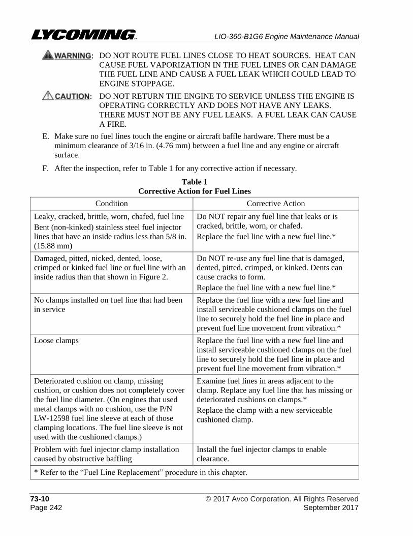
LIO-360-B1G6 Engine Maintenance Manual
73-10 © 2017 Avco Corporation. All Rights Reserved Page 242 September 2017
DO NOT ROUTE FUEL LINES CLOSE TO HEAT SOURCES. HEAT CAN
CAUSE FUEL VAPORIZATION IN THE FUEL LINES OR CAN DAMAGE
THE FUEL LINE AND CAUSE A FUEL LEAK WHICH COULD LEAD TO
ENGINE STOPPAGE.
DO NOT RETURN THE ENGINE TO SERVICE UNLESS THE ENGINE IS
OPERATING CORRECTLY AND DOES NOT HAVE ANY LEAKS.
THERE MUST NOT BE ANY FUEL LEAKS. A FUEL LEAK CAN CAUSE
A FIRE.
E. Make sure no fuel lines touch the engine or aircraft baffle hardware. There must be a
minimum clearance of 3/16 in. (4.76 mm) between a fuel line and any engine or aircraft
surface.
F. After the inspection, refer to Table 1 for any corrective action if necessary.
Table 1
Corrective Action for Fuel Lines
Condition Corrective Action
Leaky, cracked, brittle, worn, chafed, fuel line
Bent (non-kinked) stainless steel fuel injector
lines that have an inside radius less than 5/8 in.
(15.88 mm)
Do NOT repair any fuel line that leaks or is
cracked, brittle, worn, or chafed.
Replace the fuel line with a new fuel line.*
Damaged, pitted, nicked, dented, loose,
crimped or kinked fuel line or fuel line with an
inside radius than that shown in Figure 2.
Do NOT re-use any fuel line that is damaged,
dented, pitted, crimped, or kinked. Dents can
cause cracks to form.
Replace the fuel line with a new fuel line.*
No clamps installed on fuel line that had been
in service
Replace the fuel line with a new fuel line and
install serviceable cushioned clamps on the fuel
line to securely hold the fuel line in place and
prevent fuel line movement from vibration.*
Loose clamps Replace the fuel line with a new fuel line and
install serviceable cushioned clamps on the fuel
line to securely hold the fuel line in place and
prevent fuel line movement from vibration.*
Deteriorated cushion on clamp, missing
cushion, or cushion does not completely cover
the fuel line diameter. (On engines that used
metal clamps with no cushion, use the P/N
LW-12598 fuel line sleeve at each of those
clamping locations. The fuel line sleeve is not
used with the cushioned clamps.)
Examine fuel lines in areas adjacent to the
clamp. Replace any fuel line that has missing or
deteriorated cushions on clamps.*
Replace the clamp with a new serviceable
cushioned clamp.
Problem with fuel injector clamp installation
caused by obstructive baffling
Install the fuel injector clamps to enable
clearance.
* Refer to the “Fuel Line Replacement” procedure in this chapter.
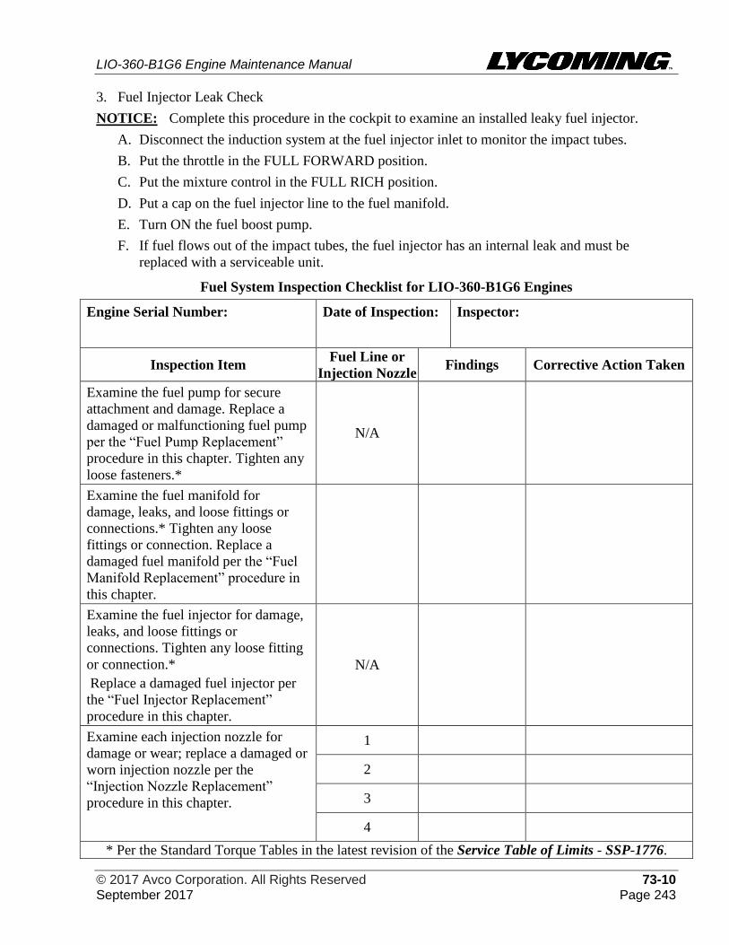
LIO-360-B1G6 Engine Maintenance Manual
© 2017 Avco Corporation. All Rights Reserved 73-10 September 2017 Page 243
3. Fuel Injector Leak Check
NOTICE: Complete this procedure in the cockpit to examine an installed leaky fuel injector.
A. Disconnect the induction system at the fuel injector inlet to monitor the impact tubes.
B. Put the throttle in the FULL FORWARD position.
C. Put the mixture control in the FULL RICH position.
D. Put a cap on the fuel injector line to the fuel manifold.
E. Turn ON the fuel boost pump.
F. If fuel flows out of the impact tubes, the fuel injector has an internal leak and must be
replaced with a serviceable unit.
Fuel System Inspection Checklist for LIO-360-B1G6 Engines
Engine Serial Number: Date of Inspection: Inspector:
Inspection Item Fuel Line or
Injection Nozzle Findings Corrective Action Taken
Examine the fuel pump for secure
attachment and damage. Replace a
damaged or malfunctioning fuel pump
per the “Fuel Pump Replacement”
procedure in this chapter. Tighten any
loose fasteners.*
N/A
Examine the fuel manifold for
damage, leaks, and loose fittings or
connections.* Tighten any loose
fittings or connection. Replace a
damaged fuel manifold per the “Fuel
Manifold Replacement” procedure in
this chapter.
Examine the fuel injector for damage,
leaks, and loose fittings or
connections. Tighten any loose fitting
or connection.*
Replace a damaged fuel injector per
the “Fuel Injector Replacement”
procedure in this chapter.
N/A
Examine each injection nozzle for
damage or wear; replace a damaged or
worn injection nozzle per the
“Injection Nozzle Replacement”
procedure in this chapter.
1
2
3
4
* Per the Standard Torque Tables in the latest revision of the Service Table of Limits - SSP-1776.
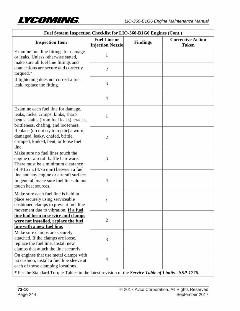
LIO-360-B1G6 Engine Maintenance Manual
73-10 © 2017 Avco Corporation. All Rights Reserved Page 244 September 2017
Fuel System Inspection Checklist for LIO-360-B1G6 Engines (Cont.)
Inspection Item Fuel Line or
Injection Nozzle Findings
Corrective Action
Taken
Examine fuel line fittings for damage
or leaks. Unless otherwise stated,
make sure all fuel line fittings and
connections are secure and correctly
torqued.*
If tightening does not correct a fuel
leak, replace the fitting.
1
2
3
4
Examine each fuel line for damage,
leaks, nicks, crimps, kinks, sharp
bends, stains (from fuel leaks), cracks,
brittleness, chafing, and looseness.
Replace (do not try to repair) a worn,
damaged, leaky, chafed, brittle,
crimped, kinked, bent, or loose fuel
line.
Make sure no fuel lines touch the
engine or aircraft baffle hardware.
There must be a minimum clearance
of 3/16 in. (4.76 mm) between a fuel
line and any engine or aircraft surface.
In general, make sure fuel lines do not
touch heat sources.
1
2
3
4
Make sure each fuel line is held in
place securely using serviceable
cushioned clamps to prevent fuel line
movement due to vibration. If a fuel
line had been in service and clamps
were not installed, replace the fuel
line with a new fuel line.
Make sure clamps are securely
attached. If the clamps are loose,
replace the fuel line. Install new
clamps that attach the line securely.
On engines that use metal clamps with
no cushion, install a fuel line sleeve at
each of those clamping locations.
1
2
3
4
* Per the Standard Torque Tables in the latest revision of the Service Table of Limits - SSP-1776.
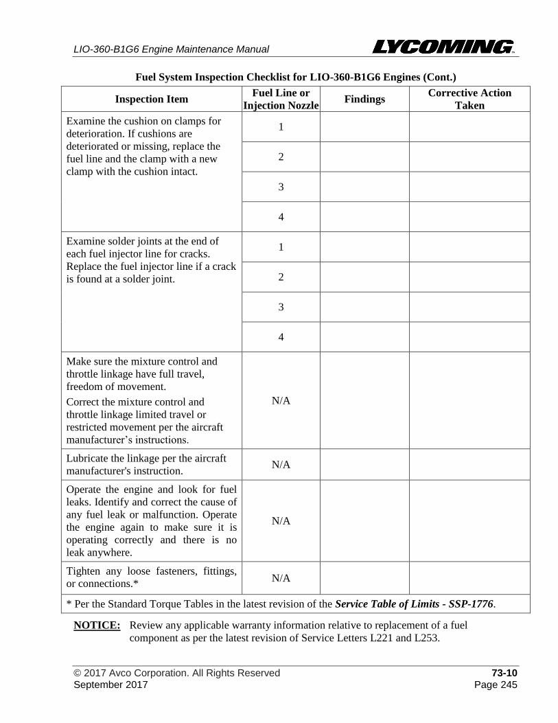
LIO-360-B1G6 Engine Maintenance Manual
© 2017 Avco Corporation. All Rights Reserved 73-10 September 2017 Page 245
Fuel System Inspection Checklist for LIO-360-B1G6 Engines (Cont.)
Inspection Item Fuel Line or
Injection Nozzle Findings
Corrective Action
Taken
Examine the cushion on clamps for
deterioration. If cushions are
deteriorated or missing, replace the
fuel line and the clamp with a new
clamp with the cushion intact.
1
2
3
4
Examine solder joints at the end of
each fuel injector line for cracks.
Replace the fuel injector line if a crack
is found at a solder joint.
1
2
3
4
Make sure the mixture control and
throttle linkage have full travel,
freedom of movement.
Correct the mixture control and
throttle linkage limited travel or
restricted movement per the aircraft
manufacturer’s instructions.
N/A
Lubricate the linkage per the aircraft
manufacturer's instruction. N/A
Operate the engine and look for fuel
leaks. Identify and correct the cause of
any fuel leak or malfunction. Operate
the engine again to make sure it is
operating correctly and there is no
leak anywhere.
N/A
Tighten any loose fasteners, fittings,
or connections.* N/A
* Per the Standard Torque Tables in the latest revision of the Service Table of Limits - SSP-1776.
NOTICE: Review any applicable warranty information relative to replacement of a fuel
component as per the latest revision of Service Letters L221 and L253.
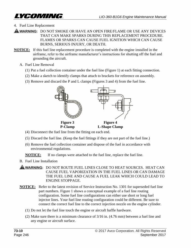
LIO-360-B1G6 Engine Maintenance Manual
73-10 © 2017 Avco Corporation. All Rights Reserved Page 246 September 2017
4. Fuel Line Replacement
DO NOT SMOKE OR HAVE AN OPEN FIRE/FLAME OR USE ANY DEVICES
THAT CAN MAKE SPARKS DURING THIS REPLACEMENT PROCEDURE.
FLAMES OR SPARKS CAN CAUSE FUEL IGNITION WHICH CAN CAUSE
BURNS, SERIOUS INJURY, OR DEATH.
NOTICE: If this fuel line replacement procedure is completed with the engine installed in the
airframe, refer to the airframe manufacturer’s instructions for shutting off the fuel and
grounding the aircraft.
A. Fuel Line Removal
(1) Put a fuel collection container under the fuel line (Figure 1) at each fitting connection.
(2) Make a sketch to identify clamps that attach to brackets for reference on assembly.
(3) Remove and discard the P and L clamps (Figures 3 and 4) from the fuel line.
Figure 3
P-Clamp
Figure 4
L-Shape Clamp
(4) Disconnect the fuel line from the fitting on each end.
(5) Discard the fuel line. (Keep the fuel fittings if they are not part of the fuel line.)
(6) Remove the fuel collection container and dispose of the fuel in accordance with
environmental regulations.
NOTICE: If no clamps were attached to the fuel line, replace the fuel line.
B. Fuel Line Installation
DO NOT ROUTE FUEL LINES CLOSE TO HEAT SOURCES. HEAT CAN
CAUSE FUEL VAPORIZATION IN THE FUEL LINES OR CAN DAMAGE
THE FUEL LINE AND CAUSE A FUEL LEAK WHICH COULD LEAD TO
ENGINE STOPPAGE.
NOTICE: Refer to the latest revision of Service Instruction No. 1301 for superseded fuel line
part numbers. Figure 1 shows a conceptual example of a fuel line routing
configuration. Some fuel line configurations can either use short or long fuel
injector lines. Your fuel line routing configuration could be different. Be sure to
connect the correct fuel line to the correct injection nozzle on the engine cylinder.
(1) Do not let the fuel line touch the engine or aircraft baffle hardware.
(2) Make sure there is a minimum clearance of 3/16 in. (4.76 mm) between a fuel line and
any engine or aircraft surface.
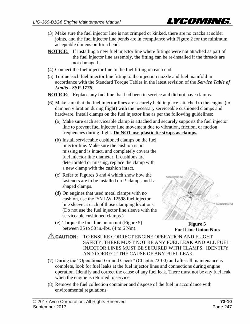
LIO-360-B1G6 Engine Maintenance Manual
© 2017 Avco Corporation. All Rights Reserved 73-10 September 2017 Page 247
(3) Make sure the fuel injector line is not crimped or kinked, there are no cracks at solder
joints, and the fuel injector line bends are in compliance with Figure 2 for the minimum
acceptable dimension for a bend.
NOTICE: If installing a new fuel injector line where fittings were not attached as part of
the fuel injector line assembly, the fitting can be re-installed if the threads are
not damaged.
(4) Connect the fuel injector line to the fuel fitting on each end.
(5) Torque each fuel injector line fitting to the injection nozzle and fuel manifold in
accordance with the Standard Torque Tables in the latest revision of the Service Table of
Limits - SSP-1776.
NOTICE: Replace any fuel line that had been in service and did not have clamps.
(6) Make sure that the fuel injector lines are securely held in place, attached to the engine (to
dampen vibration during flight) with the necessary serviceable cushioned clamps and
hardware. Install clamps on the fuel injector line as per the following guidelines:
(a) Make sure each serviceable clamp is attached and securely supports the fuel injector
line to prevent fuel injector line movement due to vibration, friction, or motion
frequencies during flight. Do NOT use plastic tie straps as clamps.
(b) Install serviceable cushioned clamps on the fuel
injector line. Make sure the cushion is not
missing and is intact, and completely covers the
fuel injector line diameter. If cushions are
deteriorated or missing, replace the clamp with
a new clamp with the cushion intact.
(c) Refer to Figures 3 and 4 which show how the
fasteners are to be installed on P-clamps and L-
shaped clamps.
(d) On engines that used metal clamps with no
cushion, use the P/N LW-12598 fuel injector
line sleeve at each of those clamping locations.
(Do not use the fuel injector line sleeve with the
serviceable cushioned clamps.)
(e) Torque the fuel line union nut (Figure 5)
between 35 to 50 in.-lbs. (4 to 6 Nm).
Figure 5
Fuel Line Union Nuts
TO ENSURE CORRECT ENGINE OPERATION AND FLIGHT
SAFETY, THERE MUST NOT BE ANY FUEL LEAK AND ALL FUEL
INJECTOR LINES MUST BE SECURED WITH CLAMPS. IDENTIFY
AND CORRECT THE CAUSE OF ANY FUEL LEAK.
(7) During the “Operational Ground Check” (Chapter 72-00) and after all maintenance is
complete, look for fuel leaks at the fuel injector lines and connections during engine
operation. Identify and correct the cause of any fuel leak. There must not be any fuel leak
when the engine is returned to service.
(8) Remove the fuel collection container and dispose of the fuel in accordance with
environmental regulations.
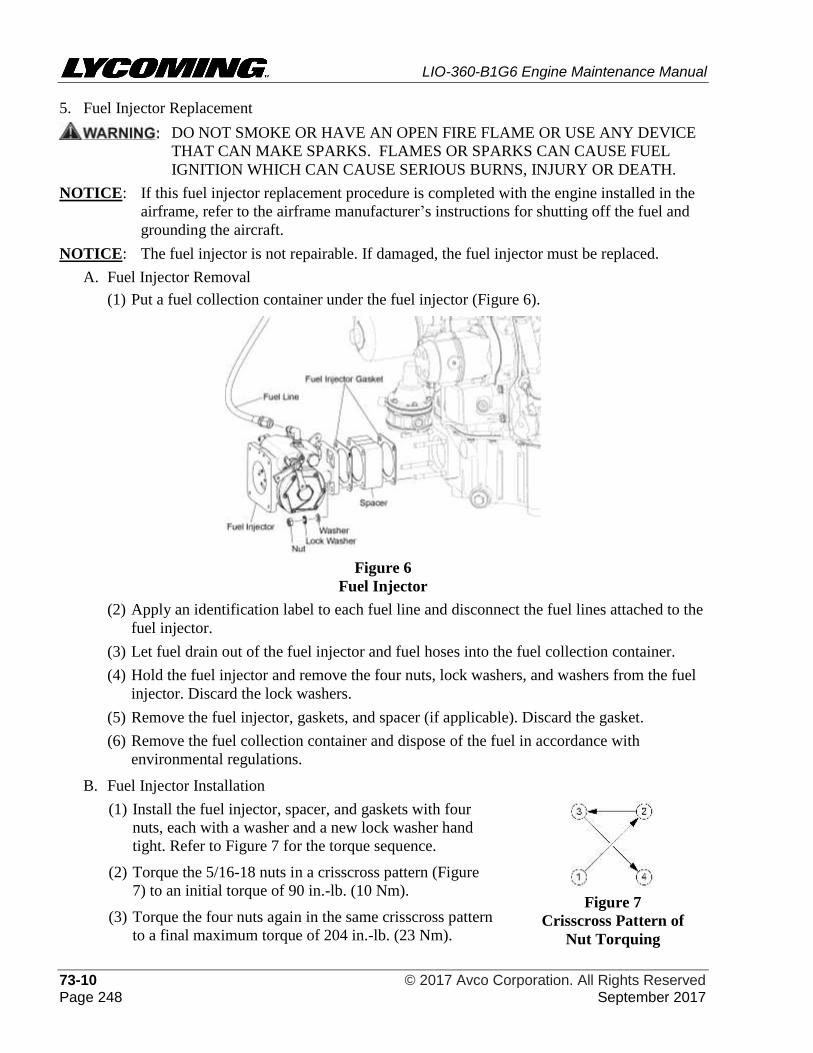
LIO-360-B1G6 Engine Maintenance Manual
73-10 © 2017 Avco Corporation. All Rights Reserved Page 248 September 2017
5. Fuel Injector Replacement
DO NOT SMOKE OR HAVE AN OPEN FIRE FLAME OR USE ANY DEVICE
THAT CAN MAKE SPARKS. FLAMES OR SPARKS CAN CAUSE FUEL
IGNITION WHICH CAN CAUSE SERIOUS BURNS, INJURY OR DEATH.
NOTICE: If this fuel injector replacement procedure is completed with the engine installed in the
airframe, refer to the airframe manufacturer’s instructions for shutting off the fuel and
grounding the aircraft.
NOTICE: The fuel injector is not repairable. If damaged, the fuel injector must be replaced.
A. Fuel Injector Removal
(1) Put a fuel collection container under the fuel injector (Figure 6).
Figure 6
Fuel Injector
(2) Apply an identification label to each fuel line and disconnect the fuel lines attached to the
fuel injector.
(3) Let fuel drain out of the fuel injector and fuel hoses into the fuel collection container.
(4) Hold the fuel injector and remove the four nuts, lock washers, and washers from the fuel
injector. Discard the lock washers.
(5) Remove the fuel injector, gaskets, and spacer (if applicable). Discard the gasket.
(6) Remove the fuel collection container and dispose of the fuel in accordance with
environmental regulations.
B. Fuel Injector Installation
(1) Install the fuel injector, spacer, and gaskets with four
nuts, each with a washer and a new lock washer hand
tight. Refer to Figure 7 for the torque sequence.
(2) Torque the 5/16-18 nuts in a crisscross pattern (Figure
7) to an initial torque of 90 in.-lb. (10 Nm).
(3) Torque the four nuts again in the same crisscross pattern
to a final maximum torque of 204 in.-lb. (23 Nm).
Figure 7
Crisscross Pattern of
Nut Torquing
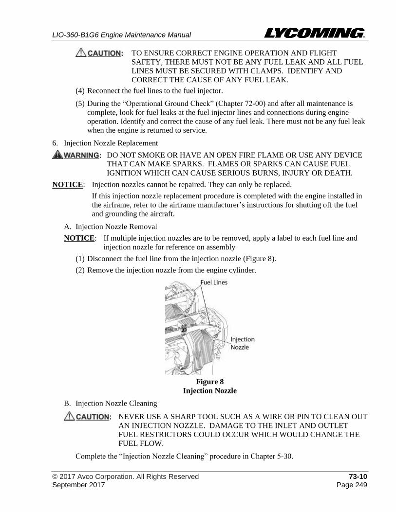
LIO-360-B1G6 Engine Maintenance Manual
© 2017 Avco Corporation. All Rights Reserved 73-10 September 2017 Page 249
TO ENSURE CORRECT ENGINE OPERATION AND FLIGHT
SAFETY, THERE MUST NOT BE ANY FUEL LEAK AND ALL FUEL
LINES MUST BE SECURED WITH CLAMPS. IDENTIFY AND
CORRECT THE CAUSE OF ANY FUEL LEAK.
(4) Reconnect the fuel lines to the fuel injector.
(5) During the “Operational Ground Check” (Chapter 72-00) and after all maintenance is
complete, look for fuel leaks at the fuel injector lines and connections during engine
operation. Identify and correct the cause of any fuel leak. There must not be any fuel leak
when the engine is returned to service.
6. Injection Nozzle Replacement
DO NOT SMOKE OR HAVE AN OPEN FIRE FLAME OR USE ANY DEVICE
THAT CAN MAKE SPARKS. FLAMES OR SPARKS CAN CAUSE FUEL
IGNITION WHICH CAN CAUSE SERIOUS BURNS, INJURY OR DEATH.
NOTICE: Injection nozzles cannot be repaired. They can only be replaced.
If this injection nozzle replacement procedure is completed with the engine installed in
the airframe, refer to the airframe manufacturer’s instructions for shutting off the fuel
and grounding the aircraft.
A. Injection Nozzle Removal
NOTICE: If multiple injection nozzles are to be removed, apply a label to each fuel line and
injection nozzle for reference on assembly
(1) Disconnect the fuel line from the injection nozzle (Figure 8).
(2) Remove the injection nozzle from the engine cylinder.
Figure 8
Injection Nozzle
B. Injection Nozzle Cleaning
NEVER USE A SHARP TOOL SUCH AS A WIRE OR PIN TO CLEAN OUT
AN INJECTION NOZZLE. DAMAGE TO THE INLET AND OUTLET
FUEL RESTRICTORS COULD OCCUR WHICH WOULD CHANGE THE
FUEL FLOW.
Complete the “Injection Nozzle Cleaning” procedure in Chapter 5-30.
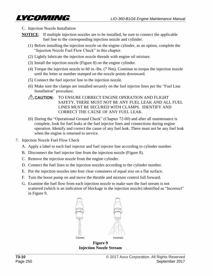
LIO-360-B1G6 Engine Maintenance Manual
73-10 © 2017 Avco Corporation. All Rights Reserved Page 250 September 2017
C. Injection Nozzle Installation
NOTICE: If multiple injection nozzles are to be installed, be sure to connect the applicable
fuel line to the corresponding injection nozzle and cylinder.
(1) Before installing the injection nozzle on the engine cylinder, as an option, complete the
“Injection Nozzle Fuel Flow Check” in this chapter.
(2) Lightly lubricate the injection nozzle threads with engine oil mixture.
(3) Install the injection nozzle (Figure 8) on the engine cylinder.
(4) Torque the injection nozzle to 60 in.-lbs. (7 Nm). Continue to torque the injection nozzle
until the letter or number stamped on the nozzle points downward.
(5) Connect the fuel injector line to the injection nozzle.
(6) Make sure the clamps are installed securely on the fuel injector lines per the “Fuel Line
Installation” procedure.
TO ENSURE CORRECT ENGINE OPERATION AND FLIGHT
SAFETY, THERE MUST NOT BE ANY FUEL LEAK AND ALL FUEL
LINES MUST BE SECURED WITH CLAMPS. IDENTIFY AND
CORRECT THE CAUSE OF ANY FUEL LEAK.
(6) During the “Operational Ground Check” (Chapter 72-00) and after all maintenance is
complete, look for fuel leaks at the fuel injector lines and connections during engine
operation. Identify and correct the cause of any fuel leak. There must not be any fuel leak
when the engine is returned to service.
7. Injection Nozzle Fuel Flow Check
A. Apply a label to each fuel injector and fuel injector line according to cylinder number.
B. Disconnect the fuel injector line from the injection nozzle (Figure 8).
C. Remove the injection nozzle from the engine cylinder.
D. Connect the fuel lines to the injection nozzles according to the cylinder number.
E. Put the injection nozzles into four clear containers of equal size on a flat surface.
F. Turn the boost pump on and move the throttle and mixture control full forward.
G. Examine the fuel flow from each injection nozzle to make sure the fuel stream is not
scattered (which is an indication of blockage in the injection nozzle) identified as “Incorrect”
in Figure 9.
Figure 9
Injection Nozzle Stream
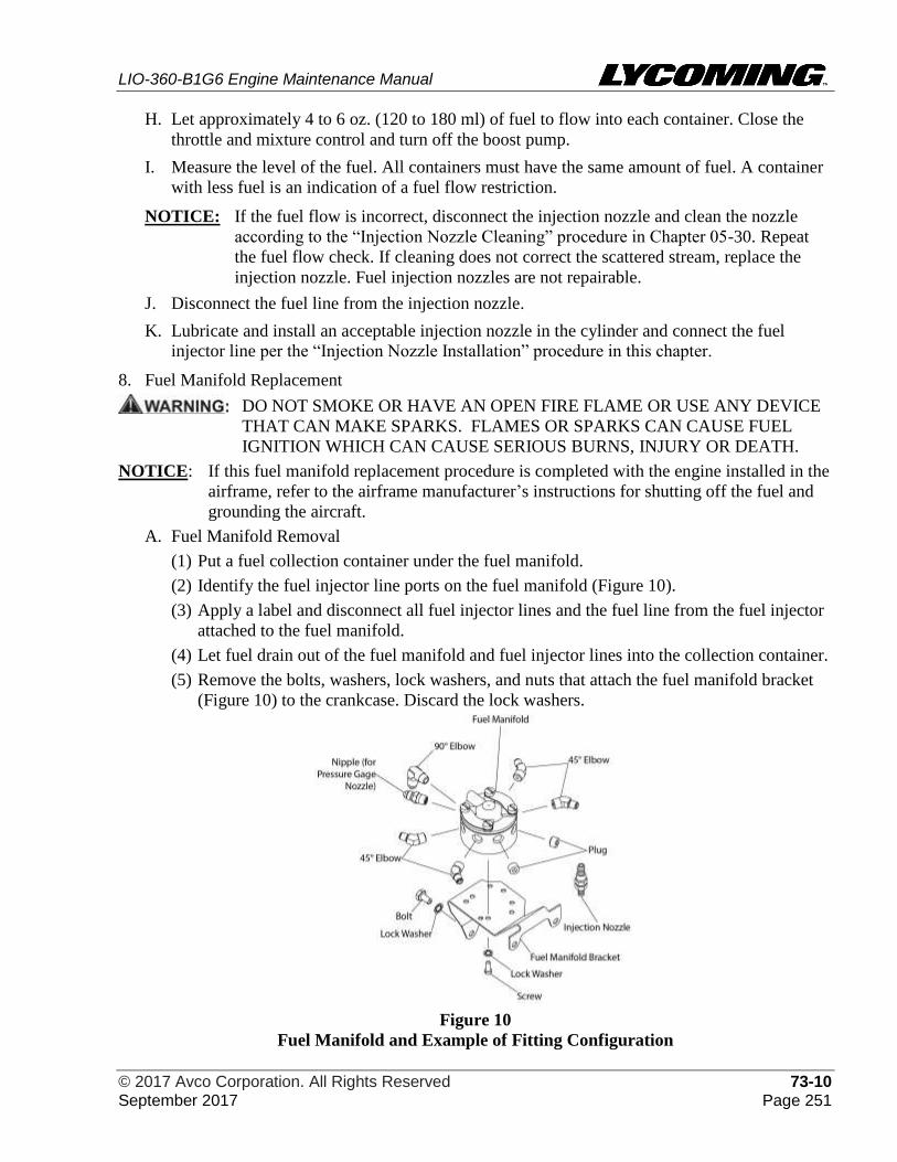
LIO-360-B1G6 Engine Maintenance Manual
© 2017 Avco Corporation. All Rights Reserved 73-10 September 2017 Page 251
H. Let approximately 4 to 6 oz. (120 to 180 ml) of fuel to flow into each container. Close the
throttle and mixture control and turn off the boost pump.
I. Measure the level of the fuel. All containers must have the same amount of fuel. A container
with less fuel is an indication of a fuel flow restriction.
NOTICE: If the fuel flow is incorrect, disconnect the injection nozzle and clean the nozzle
according to the “Injection Nozzle Cleaning” procedure in Chapter 05-30. Repeat
the fuel flow check. If cleaning does not correct the scattered stream, replace the
injection nozzle. Fuel injection nozzles are not repairable.
J. Disconnect the fuel line from the injection nozzle.
K. Lubricate and install an acceptable injection nozzle in the cylinder and connect the fuel
injector line per the “Injection Nozzle Installation” procedure in this chapter.
8. Fuel Manifold Replacement
DO NOT SMOKE OR HAVE AN OPEN FIRE FLAME OR USE ANY DEVICE
THAT CAN MAKE SPARKS. FLAMES OR SPARKS CAN CAUSE FUEL
IGNITION WHICH CAN CAUSE SERIOUS BURNS, INJURY OR DEATH.
NOTICE: If this fuel manifold replacement procedure is completed with the engine installed in the
airframe, refer to the airframe manufacturer’s instructions for shutting off the fuel and
grounding the aircraft.
A. Fuel Manifold Removal
(1) Put a fuel collection container under the fuel manifold.
(2) Identify the fuel injector line ports on the fuel manifold (Figure 10).
(3) Apply a label and disconnect all fuel injector lines and the fuel line from the fuel injector
attached to the fuel manifold.
(4) Let fuel drain out of the fuel manifold and fuel injector lines into the collection container.
(5) Remove the bolts, washers, lock washers, and nuts that attach the fuel manifold bracket
(Figure 10) to the crankcase. Discard the lock washers.
Figure 10
Fuel Manifold and Example of Fitting Configuration
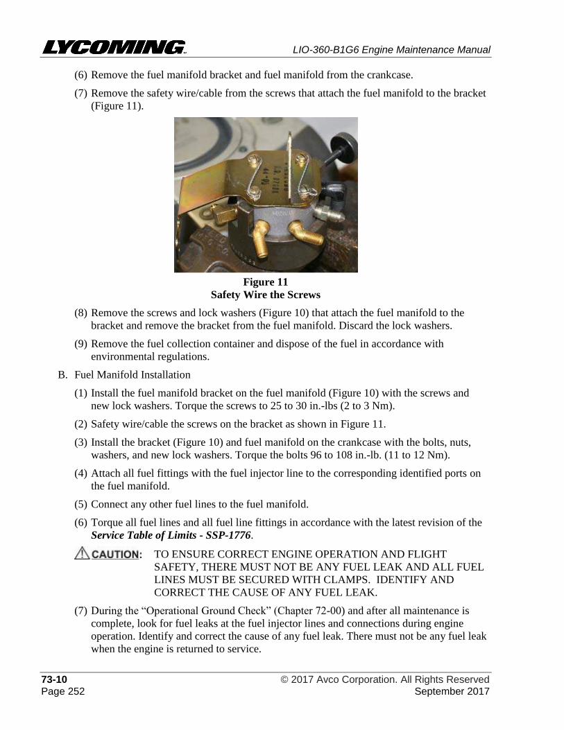
LIO-360-B1G6 Engine Maintenance Manual
73-10 © 2017 Avco Corporation. All Rights Reserved Page 252 September 2017
(6) Remove the fuel manifold bracket and fuel manifold from the crankcase.
(7) Remove the safety wire/cable from the screws that attach the fuel manifold to the bracket
(Figure 11).
Figure 11
Safety Wire the Screws
(8) Remove the screws and lock washers (Figure 10) that attach the fuel manifold to the
bracket and remove the bracket from the fuel manifold. Discard the lock washers.
(9) Remove the fuel collection container and dispose of the fuel in accordance with
environmental regulations.
B. Fuel Manifold Installation
(1) Install the fuel manifold bracket on the fuel manifold (Figure 10) with the screws and
new lock washers. Torque the screws to 25 to 30 in.-lbs (2 to 3 Nm).
(2) Safety wire/cable the screws on the bracket as shown in Figure 11.
(3) Install the bracket (Figure 10) and fuel manifold on the crankcase with the bolts, nuts,
washers, and new lock washers. Torque the bolts 96 to 108 in.-lb. (11 to 12 Nm).
(4) Attach all fuel fittings with the fuel injector line to the corresponding identified ports on
the fuel manifold.
(5) Connect any other fuel lines to the fuel manifold.
(6) Torque all fuel lines and all fuel line fittings in accordance with the latest revision of the
Service Table of Limits - SSP-1776.
TO ENSURE CORRECT ENGINE OPERATION AND FLIGHT
SAFETY, THERE MUST NOT BE ANY FUEL LEAK AND ALL FUEL
LINES MUST BE SECURED WITH CLAMPS. IDENTIFY AND
CORRECT THE CAUSE OF ANY FUEL LEAK.
(7) During the “Operational Ground Check” (Chapter 72-00) and after all maintenance is
complete, look for fuel leaks at the fuel injector lines and connections during engine
operation. Identify and correct the cause of any fuel leak. There must not be any fuel leak
when the engine is returned to service.
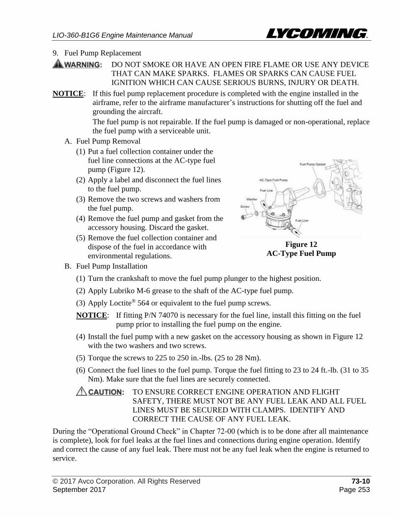
LIO-360-B1G6 Engine Maintenance Manual
© 2017 Avco Corporation. All Rights Reserved 73-10 September 2017 Page 253
9. Fuel Pump Replacement
DO NOT SMOKE OR HAVE AN OPEN FIRE FLAME OR USE ANY DEVICE
THAT CAN MAKE SPARKS. FLAMES OR SPARKS CAN CAUSE FUEL
IGNITION WHICH CAN CAUSE SERIOUS BURNS, INJURY OR DEATH.
NOTICE: If this fuel pump replacement procedure is completed with the engine installed in the
airframe, refer to the airframe manufacturer’s instructions for shutting off the fuel and
grounding the aircraft.
The fuel pump is not repairable. If the fuel pump is damaged or non-operational, replace
the fuel pump with a serviceable unit.
A. Fuel Pump Removal
(1) Put a fuel collection container under the
fuel line connections at the AC-type fuel
pump (Figure 12).
(2) Apply a label and disconnect the fuel lines
to the fuel pump.
(3) Remove the two screws and washers from
the fuel pump.
(4) Remove the fuel pump and gasket from the
accessory housing. Discard the gasket.
(5) Remove the fuel collection container and
dispose of the fuel in accordance with
environmental regulations.
Figure 12
AC-Type Fuel Pump
B. Fuel Pump Installation
(1) Turn the crankshaft to move the fuel pump plunger to the highest position.
(2) Apply Lubriko M-6 grease to the shaft of the AC-type fuel pump.
(3) Apply Loctite® 564 or equivalent to the fuel pump screws.
NOTICE: If fitting P/N 74070 is necessary for the fuel line, install this fitting on the fuel
pump prior to installing the fuel pump on the engine.
(4) Install the fuel pump with a new gasket on the accessory housing as shown in Figure 12
with the two washers and two screws.
(5) Torque the screws to 225 to 250 in.-lbs. (25 to 28 Nm).
(6) Connect the fuel lines to the fuel pump. Torque the fuel fitting to 23 to 24 ft.-lb. (31 to 35
Nm). Make sure that the fuel lines are securely connected.
TO ENSURE CORRECT ENGINE OPERATION AND FLIGHT
SAFETY, THERE MUST NOT BE ANY FUEL LEAK AND ALL FUEL
LINES MUST BE SECURED WITH CLAMPS. IDENTIFY AND
CORRECT THE CAUSE OF ANY FUEL LEAK.
During the “Operational Ground Check” in Chapter 72-00 (which is to be done after all maintenance
is complete), look for fuel leaks at the fuel lines and connections during engine operation. Identify
and correct the cause of any fuel leak. There must not be any fuel leak when the engine is returned to
service.

LIO-360-B1G6 Engine Maintenance Manual
73-10 © 2017 Avco Corporation. All Rights Reserved Page 254 September 2017
This page intentionally left blank.
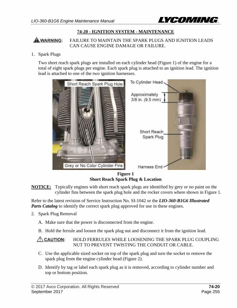
LIO-360-B1G6 Engine Maintenance Manual
© 2017 Avco Corporation. All Rights Reserved 74-20 September 2017 Page 255
74-20 - IGNITION SYSTEM - MAINTENANCE
FAILURE TO MAINTAIN THE SPARK PLUGS AND IGNITION LEADS
CAN CAUSE ENGINE DAMAGE OR FAILURE.
1. Spark Plugs
Two short reach spark plugs are installed on each cylinder head (Figure 1) of the engine for a
total of eight spark plugs per engine. Each spark plug is attached to an ignition lead. The ignition
lead is attached to one of the two ignition harnesses.
Figure 1
Short Reach Spark Plug & Location
NOTICE: Typically engines with short reach spark plugs are identified by grey or no paint on the
cylinder fins between the spark plug hole and the rocker covers where shown in Figure 1.
Refer to the latest revision of Service Instruction No. SI-1042 or the LIO-360-B1G6 Illustrated
Parts Catalog to identify the correct spark plug approved for use in these engines.
2. Spark Plug Removal
A. Make sure that the power is disconnected from the engine.
B. Hold the ferrule and loosen the spark plug nut and disconnect it from the ignition lead.
HOLD FERRULES WHILE LOOSENING THE SPARK PLUG COUPLING
NUT TO PREVENT TWISTING THE CONDUIT OR CABLE.
C. Use the applicable sized socket on top of the spark plug and turn the socket to remove the
spark plug from the engine cylinder head (Figure 2).
D. Identify by tag or label each spark plug as it is removed, according to cylinder number and
top or bottom position.
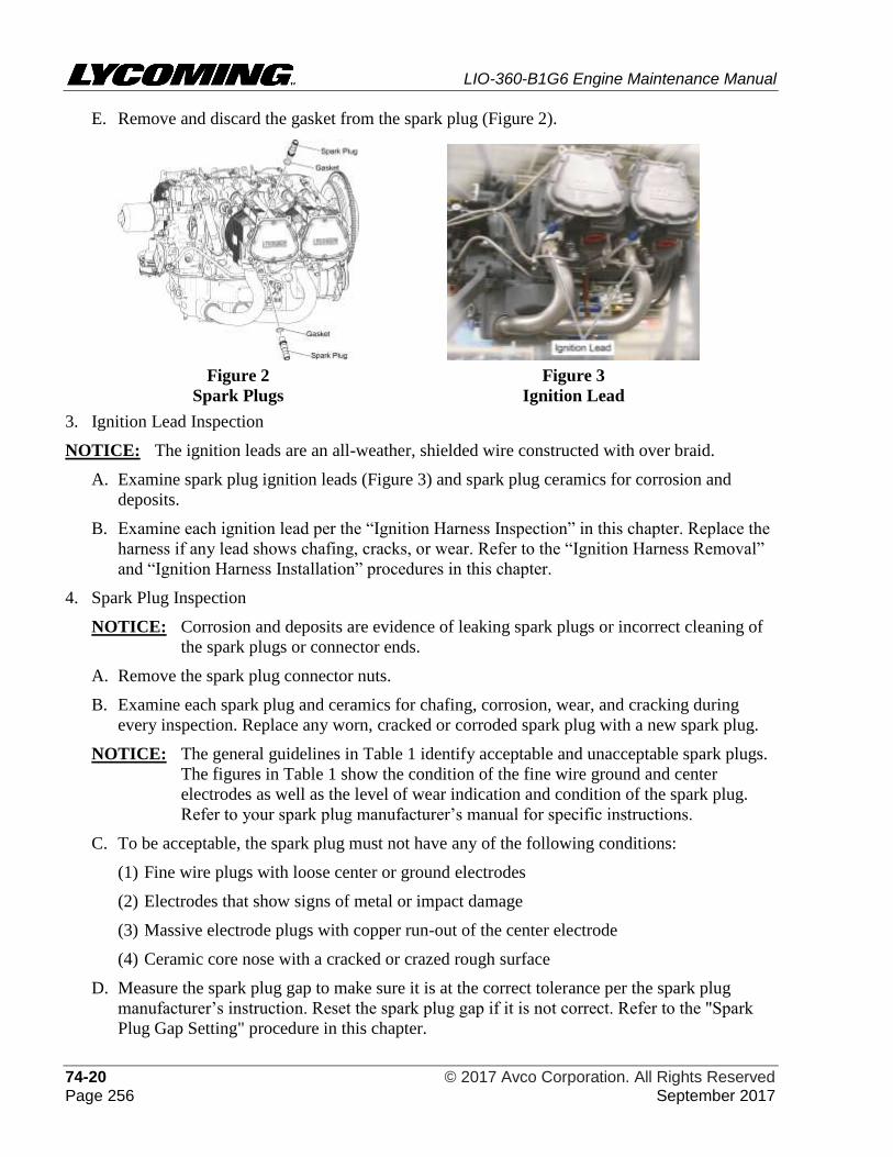
LIO-360-B1G6 Engine Maintenance Manual
74-20 © 2017 Avco Corporation. All Rights Reserved Page 256 September 2017
E. Remove and discard the gasket from the spark plug (Figure 2).
Figure 2
Spark Plugs
Figure 3
Ignition Lead
3. Ignition Lead Inspection
NOTICE: The ignition leads are an all-weather, shielded wire constructed with over braid.
A. Examine spark plug ignition leads (Figure 3) and spark plug ceramics for corrosion and
deposits.
B. Examine each ignition lead per the “Ignition Harness Inspection” in this chapter. Replace the
harness if any lead shows chafing, cracks, or wear. Refer to the “Ignition Harness Removal”
and “Ignition Harness Installation” procedures in this chapter.
4. Spark Plug Inspection
NOTICE: Corrosion and deposits are evidence of leaking spark plugs or incorrect cleaning of
the spark plugs or connector ends.
A. Remove the spark plug connector nuts.
B. Examine each spark plug and ceramics for chafing, corrosion, wear, and cracking during
every inspection. Replace any worn, cracked or corroded spark plug with a new spark plug.
NOTICE: The general guidelines in Table 1 identify acceptable and unacceptable spark plugs.
The figures in Table 1 show the condition of the fine wire ground and center
electrodes as well as the level of wear indication and condition of the spark plug.
Refer to your spark plug manufacturer’s manual for specific instructions.
C. To be acceptable, the spark plug must not have any of the following conditions:
(1) Fine wire plugs with loose center or ground electrodes
(2) Electrodes that show signs of metal or impact damage
(3) Massive electrode plugs with copper run-out of the center electrode
(4) Ceramic core nose with a cracked or crazed rough surface
D. Measure the spark plug gap to make sure it is at the correct tolerance per the spark plug
manufacturer’s instruction. Reset the spark plug gap if it is not correct. Refer to the "Spark
Plug Gap Setting" procedure in this chapter.
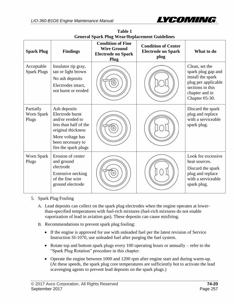
LIO-360-B1G6 Engine Maintenance Manual
© 2017 Avco Corporation. All Rights Reserved 74-20 September 2017 Page 257
Table 1
General Spark Plug Wear/Replacement Guidelines
Spark Plug Findings
Condition of Fine
Wire Ground
Electrode on Spark
Plug
Condition of Center
Electrode on Spark
plug
What to do
Acceptable
Spark Plugs
Insulator tip gray,
tan or light brown
No ash deposits
Electrodes intact,
not burnt or eroded
Clean, set the
spark plug gap and
install the spark
plug per applicable
sections in this
chapter and in
Chapter 05-30.
Partially
Worn Spark
Plugs
Ash deposits
Electrode burnt
and/or eroded to
less than half of the
original thickness
More voltage has
been necessary to
fire the spark plugs
Discard the spark
plug and replace
with a serviceable
spark plug.
Worn Spark
Plugs
Erosion of center
and ground
electrode
Extensive necking
of the fine wire
ground electrode
Look for excessive
heat sources.
Discard the spark
plug and replace
with a serviceable
spark plug.
5. Spark Plug Fouling
A. Lead deposits can collect on the spark plug electrodes when the engine operates at lower-
than-specified temperatures with fuel-rich mixtures (fuel-rich mixtures do not enable
vaporization of lead in aviation gas). These deposits can cause misfiring.
B. Recommendations to prevent spark plug fouling:
• If the engine is approved for use with unleaded fuel per the latest revision of Service
Instruction SI-1070, use unleaded fuel after purging the fuel system.
• Rotate top and bottom spark plugs every 100 operating hours or annually – refer to the
“Spark Plug Rotation” procedure in this chapter.
• Operate the engine between 1000 and 1200 rpm after engine start and during warm-up.
(At these speeds, the spark plug core temperatures are sufficiently hot to activate the lead
scavenging agents to prevent lead deposits on the spark plugs.)
LIO-360-B1G6 Engine Maintenance Manual
74-20 © 2017 Avco Corporation. All Rights Reserved Page 258 September 2017
• Operate the engine at the specified operating temperature to prevent low temperature
operation.
• Use oil cooler baffles to keep the oil temperature from decreasing during winter flight.
• Do not stop the engine immediately after landing to prevent rapid engine cooling.
• Before engine shutdown, operate the engine between 1000 and 1200 rpm until operating
temperatures are stable. Then increase engine speed to 1800 rpm for 15 to 20 seconds.
Then decrease engine speed between 1000 and 1200 rpm before engine shutdown.
6. Spark Plug Port Seal Inspection
NOTICE: This inspection is usually done to complete the check of the Heli-Coil® spark plug insert
in the cylinder head.
A. Apply a soap solution to the seating area of the cylinder head.
B. Look for bubbles. If bubbles are seen, replace the Heli-Coils®. Replace all loose or damaged
spark plug Heli-Coil® inserts with oversize inserts per the “Heli-Coil® Replacement”
procedure in Chapter 72-30.
C. Examine the spark plugs (if not already done). Refer to the section “Spark Plug Inspection”
procedure in this chapter.
D. Examine the surface of the cylinder (covered with soap solution) for cracks. Refer to the
“Visual Cylinder Inspection” procedure in Chapter 72-30.
7. Spark Plug Cleaning
Complete the “Spark Plug Cleaning” procedure in Chapter 05-30.
8. Spark Plug Gap Setting
A. Make sure the “Spark Plug Cleaning” procedure in Chapter 05-30 was completed and that the
inside of the spark plug barrel is clean and dry and does not have any residue from cleaning.
B. Refer to the latest revision of Service Instruction No. 1042 or the LIO-360-B1G6 Illustrated
Parts Catalog to identify the correct spark plug for this engine.
C. Before spark plug installation, set the spark plug gap in accordance with the spark plug
manufacturer’s instructions.
D. Reset and test the spark plugs in accordance with the spark plug manufacturer’s instructions.
9. Spark Plug Rotation
NOTICE: As part of routine service, rotate spark plugs in different locations per Table 2 every 100
hours of engine operation or annually (whichever occurs first) or when there is evidence
of spark plug fouling.
A. Remove all of the spark plugs. Refer to the “Spark Plug Removal” procedure in this chapter.
B. Examine each spark plug and ignition lead. Refer to the “Spark Plug Inspection” and
“Ignition Lead Inspection” procedures in this chapter.
C. Complete the “Spark Plug Cleaning” procedure in Chapter 05-30.
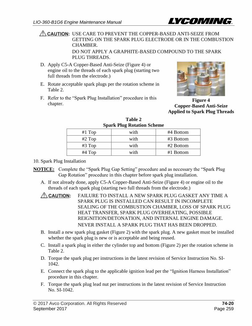
LIO-360-B1G6 Engine Maintenance Manual
© 2017 Avco Corporation. All Rights Reserved 74-20 September 2017 Page 259
USE CARE TO PREVENT THE COPPER-BASED ANTI-SEIZE FROM
GETTING ON THE SPARK PLUG ELECTRODE OR IN THE COMBUSTION
CHAMBER.
DO NOT APPLY A GRAPHITE-BASED COMPOUND TO THE SPARK
PLUG THREADS.
D. Apply C5-A Copper-Based Anti-Seize (Figure 4) or
engine oil to the threads of each spark plug (starting two
full threads from the electrode.)
E. Rotate acceptable spark plugs per the rotation scheme in
Table 2.
F. Refer to the “Spark Plug Installation” procedure in this
chapter.
Figure 4
Copper-Based Anti-Seize
Applied to Spark Plug Threads
Table 2
Spark Plug Rotation Scheme
#1 Top with #4 Bottom
#2 Top with #3 Bottom
#3 Top with #2 Bottom
#4 Top with #1 Bottom
10. Spark Plug Installation
NOTICE: Complete the “Spark Plug Gap Setting” procedure and as necessary the “Spark Plug
Gap Rotation” procedure in this chapter before spark plug installation.
A. If not already done, apply C5-A Copper-Based Anti-Seize (Figure 4) or engine oil to the
threads of each spark plug (starting two full threads from the electrode.)
FAILURE TO INSTALL A NEW SPARK PLUG GASKET ANY TIME A
SPARK PLUG IS INSTALLED CAN RESULT IN INCOMPLETE
SEALING OF THE COMBUSTION CHAMBER, LOSS OF SPARK PLUG
HEAT TRANSFER, SPARK PLUG OVERHEATING, POSSIBLE
REIGNITION/DETONATION, AND INTERNAL ENGINE DAMAGE.
NEVER INSTALL A SPARK PLUG THAT HAS BEEN DROPPED.
B. Install a new spark plug gasket (Figure 2) with the spark plug. A new gasket must be installed
whether the spark plug is new or is acceptable and being reused.
C. Install a spark plug in either the cylinder top and bottom (Figure 2) per the rotation scheme in
Table 2.
D. Torque the spark plug per instructions in the latest revision of Service Instruction No. SI-
1042.
E. Connect the spark plug to the applicable ignition lead per the “Ignition Harness Installation”
procedure in this chapter.
F. Torque the spark plug lead nut per instructions in the latest revision of Service Instruction
No. SI-1042.
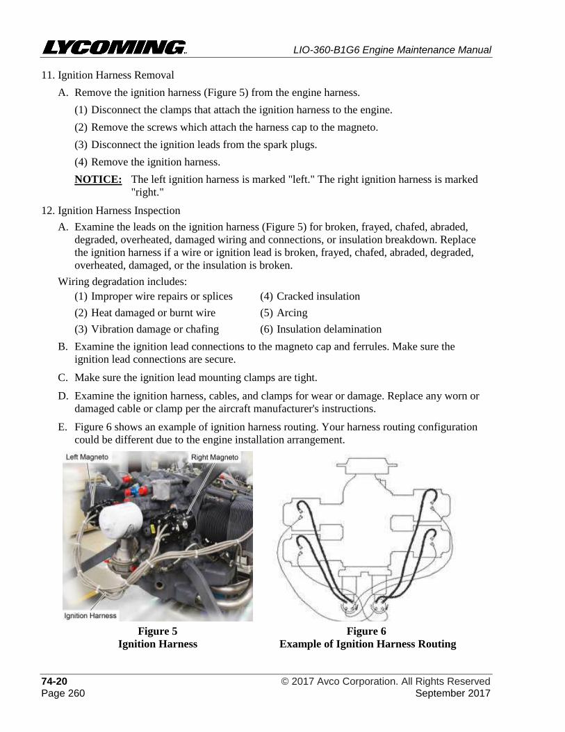
LIO-360-B1G6 Engine Maintenance Manual
74-20 © 2017 Avco Corporation. All Rights Reserved Page 260 September 2017
11. Ignition Harness Removal
A. Remove the ignition harness (Figure 5) from the engine harness.
(1) Disconnect the clamps that attach the ignition harness to the engine.
(2) Remove the screws which attach the harness cap to the magneto.
(3) Disconnect the ignition leads from the spark plugs.
(4) Remove the ignition harness.
NOTICE: The left ignition harness is marked "left." The right ignition harness is marked
"right."
12. Ignition Harness Inspection
A. Examine the leads on the ignition harness (Figure 5) for broken, frayed, chafed, abraded,
degraded, overheated, damaged wiring and connections, or insulation breakdown. Replace
the ignition harness if a wire or ignition lead is broken, frayed, chafed, abraded, degraded,
overheated, damaged, or the insulation is broken.
Wiring degradation includes:
(1) Improper wire repairs or splices (4) Cracked insulation
(2) Heat damaged or burnt wire (5) Arcing
(3) Vibration damage or chafing (6) Insulation delamination
B. Examine the ignition lead connections to the magneto cap and ferrules. Make sure the
ignition lead connections are secure.
C. Make sure the ignition lead mounting clamps are tight.
D. Examine the ignition harness, cables, and clamps for wear or damage. Replace any worn or
damaged cable or clamp per the aircraft manufacturer's instructions.
E. Figure 6 shows an example of ignition harness routing. Your harness routing configuration
could be different due to the engine installation arrangement.
Figure 5
Ignition Harness
Figure 6
Example of Ignition Harness Routing
LIO-360-B1G6 Engine Maintenance Manual
© 2017 Avco Corporation. All Rights Reserved 74-20 September 2017 Page 261
13. Ignition Harness Installation
A. Attach the left ignition harness to the magneto labled “Left” (Figure 5).
B. Attach the right ignition harness to the magneto labled “Right”.
NOTICE: Each spark plug ignition lead nut is marked with a letter and number identifying the
spark plug position on each respective cylinder. A spark plug nut marked "T1"
identifies the top spark plug on cylinder #1 to which that ignition lead is to be
connected. A spark plug nut marked "B4" identifies the bottom spark plug on
cylinder #4 to which that ignition lead is to be connected.
C. Route and connect the ignition leads to the spark plugs:
(1) Route the ignition leads to the appropriate spark plug position as indicated by the alpha-
numeric markings on each spark plug nut.
(2) When the spark plug nut thread makes contact with the spark plug threads, push the
ferrule against the spark plug while turning the spark plug nut clockwise.
(3) Continue turning the spark plug nut until it seats and is finger-tight.
NOTICE: In the next step, a hex ferrule will protrude above the spark plug mounting nut.
Hold this hex ferrule with a 7/16 in. wrench while tightening the spark plug nuts
to prevent twisting of the ignition lead.
(4) Torque the spark plug lead nut per instructions in the latest revision of Service Instruction
No. SI-1042.
D. Position the ignition leads (Figures 5 and 6) to prevent chafing by baffles or engine parts.
There must not be any kinks or sharp bends in the ignition lead wire routing.

LIO-360-B1G6 Engine Maintenance Manual
74-20 © 2017 Avco Corporation. All Rights Reserved Page 262 September 2017
This page intentionally left blank.
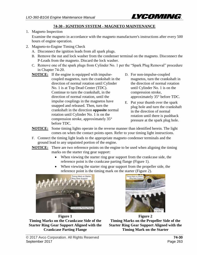
LIO-360-B1G6 Engine Maintenance Manual
© 2017 Avco Corporation. All Rights Reserved 74-30 September 2017 Page 263
74-30 - IGNITION SYSTEM - MAGNETO MAINTENANCE
1. Magneto Inspection
Examine the magneto in accordance with the magneto manufacturer's instructions after every 500
hours of engine operation.
2. Magneto-to-Engine Timing Check
A. Disconnect the ignition leads from all spark plugs.
B. Remove the nut and lock washer from the condenser terminal on the magneto. Disconnect the
P-Leads from the magneto. Discard the lock washer.
C. Remove one of the spark plugs from Cylinder No. 1 per the “Spark Plug Removal” procedure
in Chapter 74-20.
NOTICE: If the engine is equipped with impulse-
coupled magnetos, turn the crankshaft in the
direction of normal rotation until Cylinder
No. 1 is at Top Dead Center (TDC).
Continue to turn the crankshaft, in the
direction of normal rotation, until the
impulse couplings in the magnetos have
snapped and released. Then, turn the
crankshaft in the direction opposite normal
rotation until Cylinder No. 1 is on the
compression stroke, approximately 35°
before TDC.
D. For non-impulse-coupled
magnetos, turn the crankshaft in
the direction of normal rotation
until Cylinder No. 1 is on the
compression stroke,
approximately 35° before TDC.
E. Put your thumb over the spark
plug hole and turn the crankshaft
in the direction of normal
rotation until there is pushback
pressure at the spark plug hole.
NOTICE: Some timing lights operate in the reverse manner than identified herein. The light
comes on when the contact points open. Refer to your timing light instructions.
F. Connect the timing light leads to the appropriate magneto condenser terminals and the
ground lead to any unpainted portion of the engine.
NOTICE: There are two reference points on the engine to be used when aligning the timing
marks on the starter ring gear support:
• When viewing the starter ring gear support from the crankcase side, the
reference point is the crankcase parting flange (Figure 1).
• When viewing the starter ring gear support from the propeller side, the
reference point is the timing mark on the starter (Figure 2).
Figure 1
Timing Marks on the Crankcase Side of the
Starter Ring Gear Support Aligned with the
Crankcase Parting Flange
Figure 2
Timing Marks on the Propeller Side of the
Starter Ring Gear Support Aligned with the
Timing Mark on the Starter
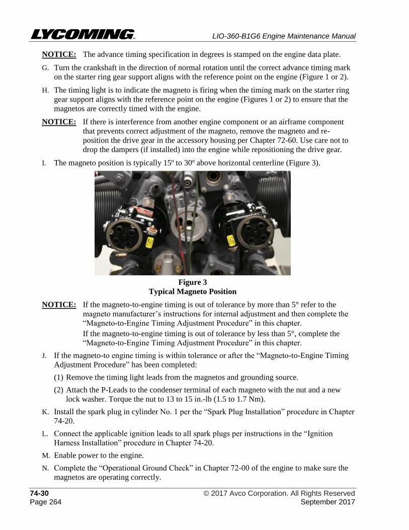
LIO-360-B1G6 Engine Maintenance Manual
74-30 © 2017 Avco Corporation. All Rights Reserved Page 264 September 2017
NOTICE: The advance timing specification in degrees is stamped on the engine data plate.
G. Turn the crankshaft in the direction of normal rotation until the correct advance timing mark
on the starter ring gear support aligns with the reference point on the engine (Figure 1 or 2).
H. The timing light is to indicate the magneto is firing when the timing mark on the starter ring
gear support aligns with the reference point on the engine (Figures 1 or 2) to ensure that the
magnetos are correctly timed with the engine.
NOTICE: If there is interference from another engine component or an airframe component
that prevents correct adjustment of the magneto, remove the magneto and re-
position the drive gear in the accessory housing per Chapter 72-60. Use care not to
drop the dampers (if installed) into the engine while repositioning the drive gear.
I. The magneto position is typically 15º to 30º above horizontal centerline (Figure 3).
Figure 3
Typical Magneto Position
NOTICE: If the magneto-to-engine timing is out of tolerance by more than 5° refer to the
magneto manufacturer’s instructions for internal adjustment and then complete the
“Magneto-to-Engine Timing Adjustment Procedure” in this chapter.
If the magneto-to-engine timing is out of tolerance by less than 5°, complete the
“Magneto-to-Engine Timing Adjustment Procedure” in this chapter.
J. If the magneto-to engine timing is within tolerance or after the “Magneto-to-Engine Timing
Adjustment Procedure” has been completed:
(1) Remove the timing light leads from the magnetos and grounding source.
(2) Attach the P-Leads to the condenser terminal of each magneto with the nut and a new
lock washer. Torque the nut to 13 to 15 in.-lb (1.5 to 1.7 Nm).
K. Install the spark plug in cylinder No. 1 per the “Spark Plug Installation” procedure in Chapter
74-20.
L. Connect the applicable ignition leads to all spark plugs per instructions in the “Ignition
Harness Installation” procedure in Chapter 74-20.
M. Enable power to the engine.
N. Complete the “Operational Ground Check” in Chapter 72-00 of the engine to make sure the
magnetos are operating correctly.
LIO-360-B1G6 Engine Maintenance Manual
© 2017 Avco Corporation. All Rights Reserved 74-30 September 2017 Page 265
3. Magneto-to-Engine Timing Adjustment Procedure
A. Turn the crankshaft in the direction of normal rotation until the correct advance timing mark
on the starter ring gear support aligns with the reference point on the engine (Figure 1 or 2).
B. Loosen the hold-down nuts on the clamps of the magneto that is not timed with the engine.
C. Manually and slowly turn the magneto in its mounting flange in the direction opposite its
normal rotation until the timing light indicates the magneto is not firing.
D. Turn the magneto in the direction of normal rotation until the timing light indicates the
magneto is firing.
E. Torque the hold-down nuts on the magneto clamps 48 in.-lb. (5 Nm) increments, alternating
between the two nuts until both nuts are torqued to 15 to 18 ft.-lb. (20 to 24 Nm).
F. Apply torque seal to the torqued hold-down nuts on the magneto clamps.
G. Complete the previous steps on the other magneto to ensure that both timing lights indicate
the magnetos are firing when the timing mark on the starter ring gear support aligns with the
reference point on the engine (Figure 1 or 2).
H. Turn the crankshaft a few degrees in the direction opposite normal rotation. The timing lights
are to indicate the magnetos are not firing.
I. Slowly turn the crankshaft in the direction of normal rotation until the correct advance timing
mark on the starter ring gear support (Figure 1) aligns with the reference point on the engine
(Figure 1 or 2). Both lights on the timing light are to indicate the magnetos are firing.
J. Adjust the magneto-to-engine timing until repeat checks by the “Magneto-to-Engine Timing
Check” in this chapter are within tolerance.
4. Magneto Replacement Procedure
BEFORE THIS PROCEDURE, MAKE SURE ALL POWER IS DISABLED TO
THE ENGINE TO PREVENT ELECTRICAL SHOCK AND INJUIRY.
NOTICE: Magneto configurations are different between magneto suppliers. This procedure
applies to Slick magnetos only. Refer to the manufacturer’s instructions for other types
of magnetos.
A. Magneto Removal
(1) Disconnect the harness (Figure 4) from the magneto to be removed.
(2) Hold the magneto and remove the nuts, lock washers, washers, clamps, cotter pin, gear
nut, and magneto gear from the magneto. Discard the lock washers.
(3) Remove the magneto.
(4) Remove and discard the gasket.
B. Magneto Installation
A new or serviceable magneto, new magneto gasket, and two new lock washers are necessary
to install the magneto. Refer to the applicable parts catalog.
(1) Apply a light coat of C5-A Copper-Based Anti-Seize compound to the tapered section of
the magneto driveshaft (Figure 5).
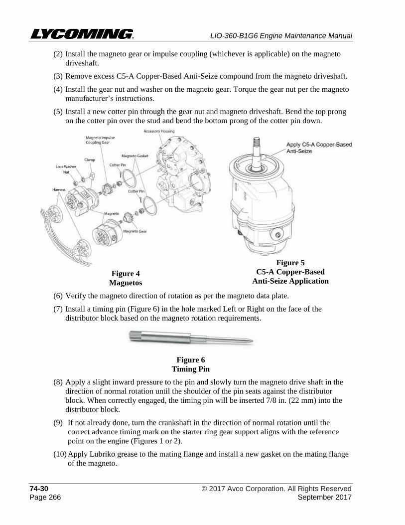
LIO-360-B1G6 Engine Maintenance Manual
74-30 © 2017 Avco Corporation. All Rights Reserved Page 266 September 2017
(2) Install the magneto gear or impulse coupling (whichever is applicable) on the magneto
driveshaft.
(3) Remove excess C5-A Copper-Based Anti-Seize compound from the magneto driveshaft.
(4) Install the gear nut and washer on the magneto gear. Torque the gear nut per the magneto
manufacturer’s instructions.
(5) Install a new cotter pin through the gear nut and magneto driveshaft. Bend the top prong
on the cotter pin over the stud and bend the bottom prong of the cotter pin down.
Figure 4
Magnetos
Figure 5
C5-A Copper-Based
Anti-Seize Application
(6) Verify the magneto direction of rotation as per the magneto data plate.
(7) Install a timing pin (Figure 6) in the hole marked Left or Right on the face of the
distributor block based on the magneto rotation requirements.
Figure 6
Timing Pin
(8) Apply a slight inward pressure to the pin and slowly turn the magneto drive shaft in the
direction of normal rotation until the shoulder of the pin seats against the distributor
block. When correctly engaged, the timing pin will be inserted 7/8 in. (22 mm) into the
distributor block.
(9) If not already done, turn the crankshaft in the direction of normal rotation until the
correct advance timing mark on the starter ring gear support aligns with the reference
point on the engine (Figures 1 or 2).
(10) Apply Lubriko grease to the mating flange and install a new gasket on the mating flange
of the magneto.
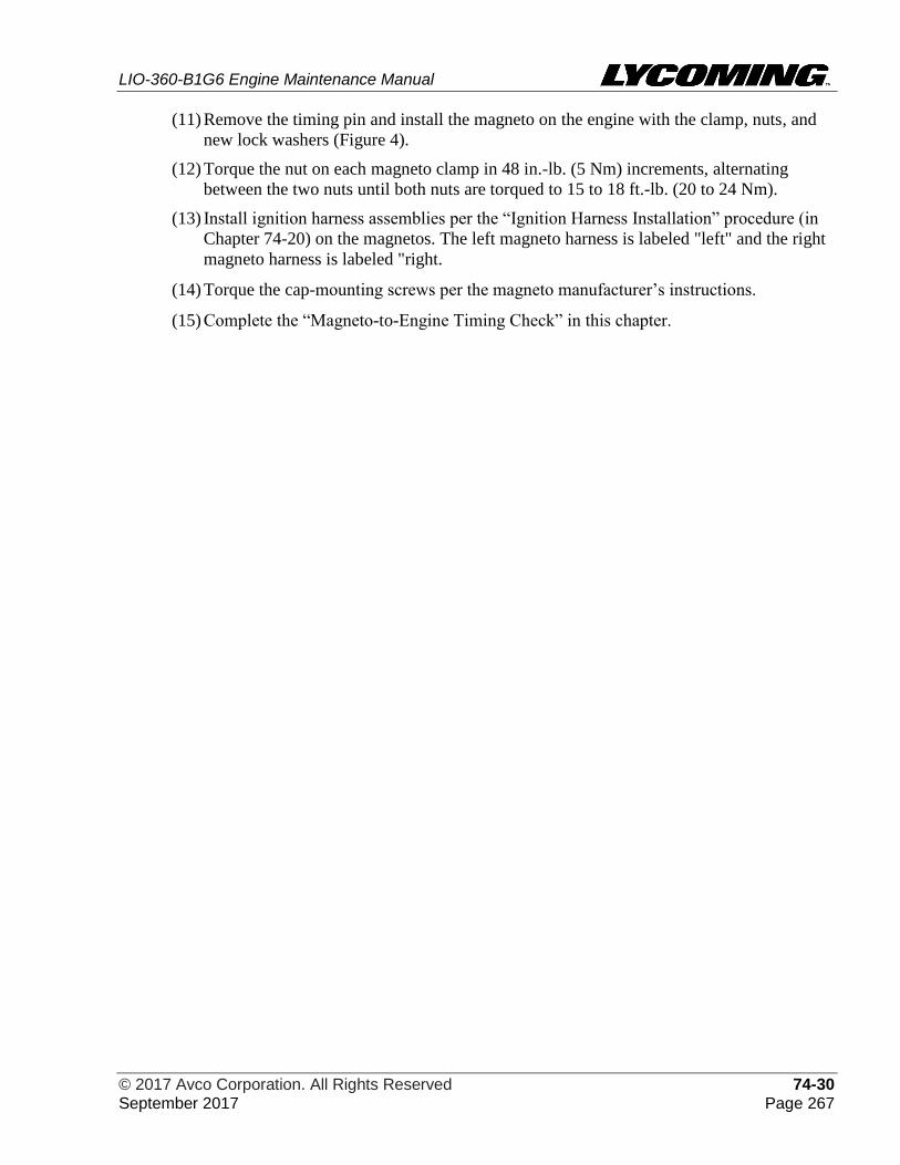
LIO-360-B1G6 Engine Maintenance Manual
© 2017 Avco Corporation. All Rights Reserved 74-30 September 2017 Page 267
(11) Remove the timing pin and install the magneto on the engine with the clamp, nuts, and
new lock washers (Figure 4).
(12) Torque the nut on each magneto clamp in 48 in.-lb. (5 Nm) increments, alternating
between the two nuts until both nuts are torqued to 15 to 18 ft.-lb. (20 to 24 Nm).
(13) Install ignition harness assemblies per the “Ignition Harness Installation” procedure (in
Chapter 74-20) on the magnetos. The left magneto harness is labeled "left" and the right
magneto harness is labeled "right.
(14) Torque the cap-mounting screws per the magneto manufacturer’s instructions.
(15) Complete the “Magneto-to-Engine Timing Check” in this chapter.

LIO-360-B1G6 Engine Maintenance Manual
74-30 © 2017 Avco Corporation. All Rights Reserved Page 268 September 2017
This page intentionally left blank.
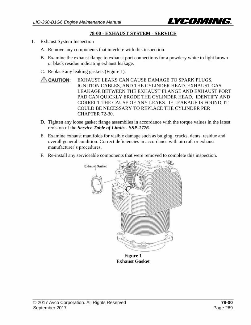
LIO-360-B1G6 Engine Maintenance Manual
© 2017 Avco Corporation. All Rights Reserved 78-00 September 2017 Page 269
78-00 - EXHAUST SYSTEM - SERVICE
1. Exhaust System Inspection
A. Remove any components that interfere with this inspection.
B. Examine the exhaust flange to exhaust port connections for a powdery white to light brown
or black residue indicating exhaust leakage.
C. Replace any leaking gaskets (Figure 1).
EXHAUST LEAKS CAN CAUSE DAMAGE TO SPARK PLUGS,
IGNITION CABLES, AND THE CYLINDER HEAD. EXHAUST GAS
LEAKAGE BETWEEN THE EXHAUST FLANGE AND EXHAUST PORT
PAD CAN QUICKLY ERODE THE CYLINDER HEAD. IDENTIFY AND
CORRECT THE CAUSE OF ANY LEAKS. IF LEAKAGE IS FOUND, IT
COULD BE NECESSARY TO REPLACE THE CYLINDER PER
CHAPTER 72-30.
D. Tighten any loose gasket flange assemblies in accordance with the torque values in the latest
revision of the Service Table of Limits - SSP-1776.
E. Examine exhaust manifolds for visible damage such as bulging, cracks, dents, residue and
overall general condition. Correct deficiencies in accordance with aircraft or exhaust
manufacturer’s procedures.
F. Re-install any serviceable components that were removed to complete this inspection.
Figure 1
Exhaust Gasket
LIO-360-B1G6 Engine Maintenance
Manual
78-00 © 2017 Avco Corporation. All Rights Reserved Page 270 September 2017
This page intentionally left blank.
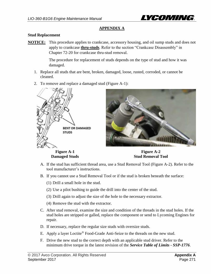
LIO-360-B1G6 Engine Maintenance Manual
© 2017 Avco Corporation. All Rights Reserved Appendix A September 2017 Page 271
APPENDIX A
Stud Replacement
NOTICE: This procedure applies to crankcase, accessory housing, and oil sump studs and does not
apply to crankcase thru-studs. Refer to the section “Crankcase Disassembly” in
Chapter 72-20 for crankcase thru-stud removal.
The procedure for replacement of studs depends on the type of stud and how it was
damaged.
1. Replace all studs that are bent, broken, damaged, loose, rusted, corroded, or cannot be
cleaned.
2. To remove and replace a damaged stud (Figure A-1):
Figure A-1
Damaged Studs
Figure A-2
Stud Removal Tool
A. If the stud has sufficient thread area, use a Stud Removal Tool (Figure A-2). Refer to the
tool manufacturer’s instructions.
B. If you cannot use a Stud Removal Tool or if the stud is broken beneath the surface:
(1) Drill a small hole in the stud.
(2) Use a pilot bushing to guide the drill into the center of the stud.
(3) Drill again to adjust the size of the hole to the necessary extractor.
(4) Remove the stud with the extractor.
C. After stud removal, examine the size and condition of the threads in the stud holes. If the
stud holes are stripped or galled, replace the component or send to Lycoming Engines for
repair.
D. If necessary, replace the regular size studs with oversize studs.
E. Apply a layer Loctite® Food-Grade Anti-Seize to the threads on the new stud.
F. Drive the new stud to the correct depth with an applicable stud driver. Refer to the
minimum drive torque in the latest revision of the Service Table of Limits - SSP-1776.
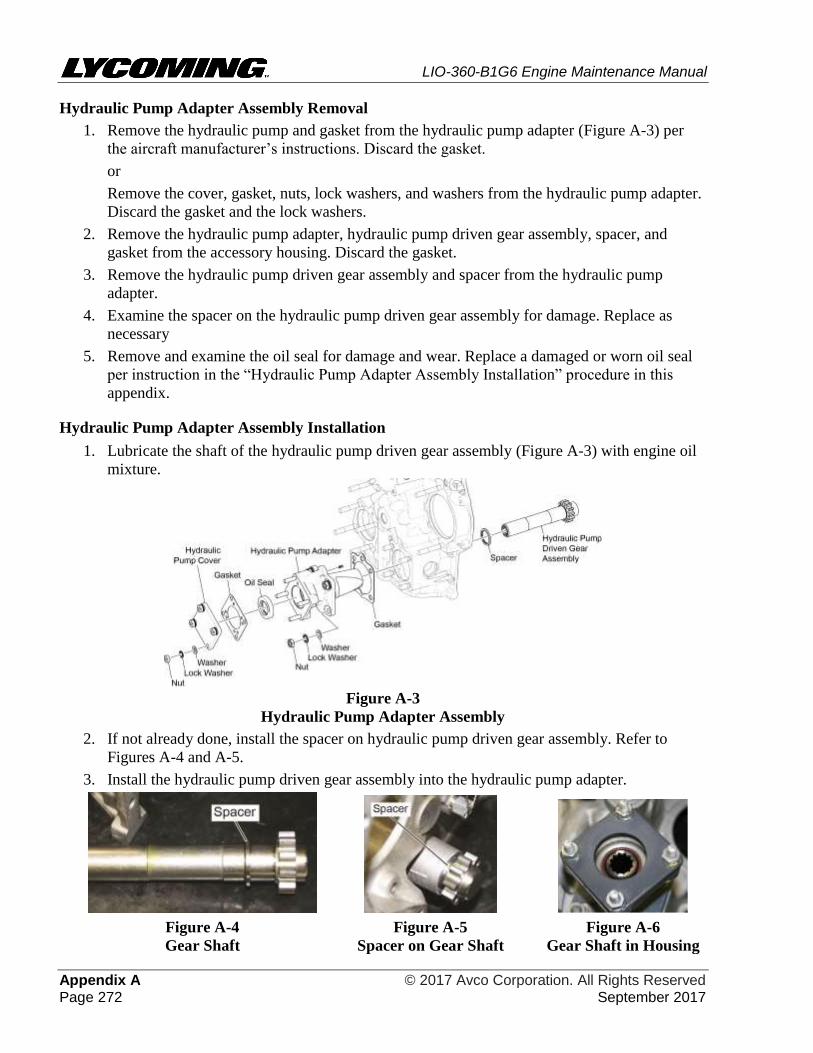
LIO-360-B1G6 Engine Maintenance Manual
Appendix A © 2017 Avco Corporation. All Rights Reserved Page 272 September 2017
Hydraulic Pump Adapter Assembly Removal
1. Remove the hydraulic pump and gasket from the hydraulic pump adapter (Figure A-3) per
the aircraft manufacturer’s instructions. Discard the gasket.
or
Remove the cover, gasket, nuts, lock washers, and washers from the hydraulic pump adapter.
Discard the gasket and the lock washers.
2. Remove the hydraulic pump adapter, hydraulic pump driven gear assembly, spacer, and
gasket from the accessory housing. Discard the gasket.
3. Remove the hydraulic pump driven gear assembly and spacer from the hydraulic pump
adapter.
4. Examine the spacer on the hydraulic pump driven gear assembly for damage. Replace as
necessary
5. Remove and examine the oil seal for damage and wear. Replace a damaged or worn oil seal
per instruction in the “Hydraulic Pump Adapter Assembly Installation” procedure in this
appendix.
Hydraulic Pump Adapter Assembly Installation
1. Lubricate the shaft of the hydraulic pump driven gear assembly (Figure A-3) with engine oil
mixture.
Figure A-3
Hydraulic Pump Adapter Assembly
2. If not already done, install the spacer on hydraulic pump driven gear assembly. Refer to
Figures A-4 and A-5.
3. Install the hydraulic pump driven gear assembly into the hydraulic pump adapter.
Figure A-4
Gear Shaft
Figure A-5
Spacer on Gear Shaft
Figure A-6
Gear Shaft in Housing
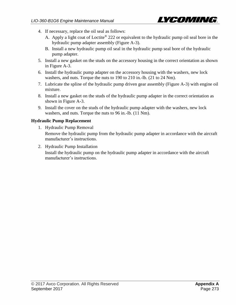
LIO-360-B1G6 Engine Maintenance Manual
© 2017 Avco Corporation. All Rights Reserved Appendix A September 2017 Page 273
4. If necessary, replace the oil seal as follows:
A. Apply a light coat of Loctite® 222 or equivalent to the hydraulic pump oil seal bore in the
hydraulic pump adapter assembly (Figure A-3).
B. Install a new hydraulic pump oil seal in the hydraulic pump seal bore of the hydraulic
pump adapter.
5. Install a new gasket on the studs on the accessory housing in the correct orientation as shown
in Figure A-3.
6. Install the hydraulic pump adapter on the accessory housing with the washers, new lock
washers, and nuts. Torque the nuts to 190 to 210 in.-lb. (21 to 24 Nm).
7. Lubricate the spline of the hydraulic pump driven gear assembly (Figure A-3) with engine oil
mixture.
8. Install a new gasket on the studs of the hydraulic pump adapter in the correct orientation as
shown in Figure A-3.
9. Install the cover on the studs of the hydraulic pump adapter with the washers, new lock
washers, and nuts. Torque the nuts to 96 in.-lb. (11 Nm).
Hydraulic Pump Replacement
1. Hydraulic Pump Removal
Remove the hydraulic pump from the hydraulic pump adapter in accordance with the aircraft
manufacturer’s instructions.
2. Hydraulic Pump Installation
Install the hydraulic pump on the hydraulic pump adapter in accordance with the aircraft
manufacturer’s instructions.

LIO-360-B1G6 Engine Maintenance Manual
Appendix A © 2017 Avco Corporation. All Rights Reserved Page 274 September 2017
This page intentionally left blank.