Embed Size (px)
Citation preview
Engine induced vibrations
Wijckmans, Maurice
Published: 01/01/1994
Document VersionPublisher’s PDF, also known as Version of Record (includes final page, issue and volume numbers)
Please check the document version of this publication:
• A submitted manuscript is the author's version of the article upon submission and before peer-review. There can be important differencesbetween the submitted version and the official published version of record. People interested in the research are advised to contact theauthor for the final version of the publication, or visit the DOI to the publisher's website.• The final author version and the galley proof are versions of the publication after peer review.• The final published version features the final layout of the paper including the volume, issue and page numbers.
Link to publication
Citation for published version (APA):Wijckmans, M. (1994). Engine induced vibrations. (DCT rapporten; Vol. 1994.135). Eindhoven: TechnischeUniversiteit Eindhoven.
General rightsCopyright and moral rights for the publications made accessible in the public portal are retained by the authors and/or other copyright ownersand it is a condition of accessing publications that users recognise and abide by the legal requirements associated with these rights.
• Users may download and print one copy of any publication from the public portal for the purpose of private study or research. • You may not further distribute the material or use it for any profit-making activity or commercial gain • You may freely distribute the URL identifying the publication in the public portal ?
Take down policyIf you believe that this document breaches copyright please contact us providing details, and we will remove access to the work immediatelyand investigate your claim.
Download date: 22. Jun. 2018
Engine induced vibrations
by
Maurice Wijckmans
Coaches: Inge Johansson and Stefan Edlund,Vehicle Dynamics and Chassis Development,Volvo Truck Corporation, Sweden.
Report nr. TUE: WFW 94-135october 1994
Eindhoven University of TechnologyDepartment of Mechanical EngineeringDivision of Fundamental Mechanics
ABSTRACT
Existing Finite Element models of chassis, cab, engine and gearbox have been merged into acomplete full vehicle model by use of a superelement technique in CSA/Nastran version 93C.The superelement technique is used to reduce the degrees of freedom. Additional informationabout the internal nodes is achieved with component mode synthesis. To examine the engineinduced vibrations and its transmission paths, a frequency response analyses is performed withloads for the different engine orders. The developed full vehicle model is a good tool to cxamine the transmission paths and to do fast parameter studies.
Engine induced vibrations July 14, 1994
CONTENTS
1. Introduction .4
2. Models of substructures 42.1 Frame 42.2 Engine 52.3 Cab 62.4 Residual 6
3. Reducing the degrees of freedom 6
4. Model assumptions 8
5. Loadcases 9
6. Analyses 96.1 Exemplification of transmission paths for third engine order 10
7. Conclusions 11
8. References 12
Engine induced vibrations July 14, 1994 3
1. Introduction
For front end dynamics ([1]), caused by excitation from wheel run-out and unbalance as well asfrom brake excitation and vertical road input, finite element models of frame and chassis havealready been used to examine the dynamic behavior of the truck. For low frequencies, the caband engine were modelled as rigid bodies. For higher frequencies, like engine induced vibrations, it was desirable to have finite element models of the cab and the engine in particular.First the different finite element models used in this project will be described. The models ofthe cab, frame and engine were developed with respect to stress analyses. The models aretherefore much too detailed for efficient analysis of vehicle dynamics. In these studies we areonly interested in the mass- and stiffness-distribution within a certain frequency range. And notin the stress concentration in the different parts of the models. This goes in particular for thecab and the frame. For the engine some more details are requested, because the engine isexcited by dynamic loads in the cylinders and the bearings. The response of the engine itself isused to excite the rest of the truck.The superelement technique is used to reduce the number of degrees of freedom and thus todecrease the calculation time. Some background theory about reducing the degrees of freedomwill be explained in chapter three. Next the model assumptions are discussed, while in chapterfive the loadcase is introduced. These loadcase is used to examine the engine induced vibrations and the transmission paths.
2. Models of substructures
The full model consists of 24.157 elements and 23.039 nodes. The most common elementsused in the several models are quadrilateral elements. Two types of these elements are used:
• Quad4: An isoparametric quadrilateral element with 4 nodes, which has membrane, bendingand coupled membrane-bending stiffness. So there is stiffness in all 3 displacements and inthe two out off plane rotations.
• Tria3: Same type as the Quad4, but with only 3 nodes per element.
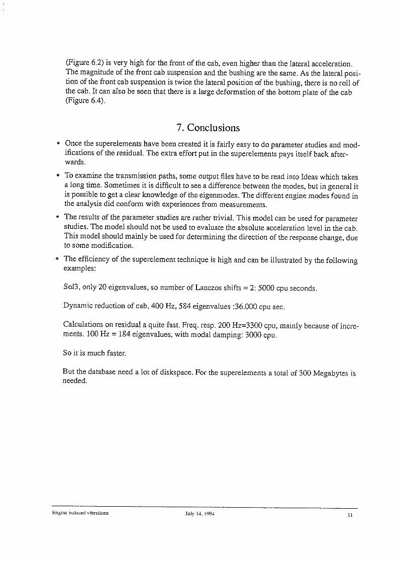
The models also consist of isoparametric solid hexahedron elements with 8 up to 20 nodes.Because the truck is in general symmetric, only one half of the complete vehicle is modelled.The engine, with six cylinders in row causes anti-symmetric loadcases, which are merelyresponsible for the high frequent vibrations in the cab. Therefore anti-symmetric boundaryconditions are used in the plane of symmetry, which is the xz-plane. The direction of the globalcoordinate system can be seen in Figure 2.1.
2.1 Frame
The frame is built up by two siderails connected to each other by five cross-members and consists of the following elements and nodes:
3898 Quad438 Tria3164 rigid bars
Engine induced vibrations July 14, 1994 4
4464 interior nodes15 exterior nodes
After a dynamic reduction, between 0.0 and 400.0 Hz, 32 generalizedcoordinates have been generated. When all exterior nodes are constrained (fixed eigenmodes), the frame has its lowest eigenfrequency at80.1 Hz.
2.2 Engine
The engine is a 6 cylinder engine used in the new FH-series. It is a detailed model including the6 cylinders, 7 bearings, gearbox, fan and even the dip-stick. However, the piston and piston rodhave not been modelled. The model contains the following elements and nodes:
4431 Quad4832 Tria3334 Beams48 Hexa49 Conm2, to specify rigid mass.412 rigid bars5033 interior nodes21 exterior nodes. 12 nodes for specifying the dynamic loads in the cylinders, 7 nodes for specifying the dynamic reaction forces in the bearings. 2 exterior points which connect the engine with the engine mounts.There are two engine mounts, each modelled by 3 linear translationalsprings and 3 linear translational viscous dampers. The front engine suspension is between exterior node 357201 and node 2500. The rearengine suspension is situated between exterior node 357101 and node3901.After a dynamic reduction 29 generalized coordinates have been generated.
To merge the engine into the full model, the engine had to be rotated with an angle of fourdegrees around the y-axis. After this was done, it occurred that there is an offset between therear engine mount and the frame:
xoffset = 1.36 [mm]yoffset 85.15 [mm]z~set = 2.64 [mm]
The offset in lateral direction is unacceptable large. This is corrected by defining a rigid barbetween node 3901 and 357101, which is stiff connected to node 357101 in all 6 directions.This can be done because node 357101 itself is stiff connected to the engine by rigid bars.
For low frequencies the engine moves as a rigid body. Therefore it is important that themechanical properties of the engine are comparable with the measured values. The mass andthe moments of inertia have been calculated by means of Nastran. It turned out that themechanical properties of the FE-model are comparable with the measured values.
Engine induced vibrations July 14, 1994 5
2.3 Cab
A model of the L2H1 cab is used and contains the following elements:
12392 Quad4878 Tria311 Beams348 Hexa122 Conm2144 RBE213356 interior points3 exterior points.
The bushing in front of the cab is modelled by three linear translationalsprings and three linear viscous dampers between exterior node 420.003and 96.0 11. The bushing is mainly for lateral and longitudinal forces.The front cab suspension is only for vertical displacements. This is modelled by a linear spring and a linear viscous damper in vertical direction,acting between exterior node 420.001 and node 2501. The rear cab suspension is modelled by a vertical linear spring, a vertical linear viscousdamper and a lateral linear viscous damper between exterior node420.002 and node 4901.The roll bar in front of the cab is modelled by beam elements betweennode 96.011, node 96003 (= node 2500, only rotational freedom in 5direction) and node 96012.A dynamic reduction generates 584 generalized coordinates.
To avoid modelling the plastics of the interior of the cab the specified density of the material ishigher, than the density of steel, to take into account these additional masses of the plastics.
2.4 Residual
The residual contains the tyre models, steering gear, trailer, leaf suspensions between frameand axles and the suspensions mentioned above. This is done to make it easier to calculate different designs of the suspensions.
3. Reducing the degrees of freedom
Superelement analysis is used to reduce the number of degrees of freedom of a large structure.The structure is divided in substructures called superelements. Each superelement is connectedto the residual in the exterior nodes. First the general form of this reduction will be described.The equations of motion for any superelement with flQ degrees of freedom is as follow:
MGG~J+DQQU+KGG~U ~(t) (1)
In here is:U : global degrees of freedom of a superelement, size ~G ~
Engine induced vibrations July 14, 1994 6
MGG : global mass matrix.KGG : global stiffness matrix.BGG : global dampings matrix.~‘ (t) : exterior forces.
Reduction of the fl~ degrees of freedom is possible by describing the global degrees of freedom ~I as a linear combination of ~A generalized coordinates p, whereas ~A <I1Q.
U = Txp=~T = transformationrnarrix(nQxnA) (2)
Substituting (3) in (2) gives:
MAAJi+~AAP+KAAP = E’AA(t) (3)
with:MAA = T_MGG_T : reduced mass matrix.KAA = _T’KGGT : reduced stiffness matrix._BAA = _T_BQQ_T : reduced dampings matrixfAA (t) = T’F (t) : reduces forces
The degrees of freedom of a superelement are now reduced to the analyses set, which containsa total number of degrees of freedom that is equal to the number of generalized coordinates.The transformation matrix can be developed in several ways.
In static analyses all superelements are reduced to the exterior nodes. The stiffness of a super-element can be described completely in those nodes. There is no loss of accuracy. But this isnot accurate enough for dynamic analyses, because the number of boundary points is notenough to represent the eigenmodes. For dynamic analyses it is important that the reducedstructure has a sufficient accurate dynamic behavior similar to the full model within a specifiedfrequency range. A suitable method is the Component Mode Synthesis technique. CSA/Nastran uses the Craig-B ampton method. This method involves an eigenvalue extraction of eachSuperelement and assumes all exterior points to be fixed in all directions. For each extractedeigenvalue one generalized coordinate is added to the reduced set of degrees of freedoms.These generalized coordinates represent the eigenmodes of the superelement. Tn [2] it isexplained how the transformationmatrix T looks like for the Craig-B ampton method.
Because this method is an approximation, the problem is how many eigenmodes must be takeninto account for Component Mode Synthesis in order to have a sufficient accurate dynamicbehavior. As a rule of thumb, for each Superelement, all eigenvalues up to twice the highestfrequency of interest for the complete structure, should be extracted. For the dynamic reductionall eigenmodes between 0 and 400 Hz have been taken into account. This made it possible toreduce the number of degrees of freedoms from 140.000 to nearly 2000.
The stiffness matrix of the residual is made by assembling all the reduced matrices of thesuperelements. The stiffness matrix of the residual is in general not sparse anymore, so CSA/Nastran will not use the sparse solver. For static problems the program uses the Choleskydecomposition which is much slower. Therefore it is important to have only a few grid pointsin the residual.
Engine induced vibrations July 14, 1994 7
Remarks:
• Since the superelement technique is based on superposition, it is important that all theSuperelements have linear conditions.
• In many cases it is enough to specify the exterior nodes only in the connection points of twosubstructures. Unless dynamic forces are acting on some nodes in a superelement. Thenthese nodes must be exterior nodes, so they are belonging to the residual. The reason for thisis that when doing a reduction of a superelement, not only the mass and stiffness matrixesare reduced, but also the loadvector. They must all be independent of the frequency, which isnot the case for dynamic forces. Only static forces may act on the interior nodes of a super-element.
• A further reduction of the full model can be achieved by solving the real eigenmodes andusing only modal data in the frequency range of interest for analyses of the frequencyresponse.
4. Model assumptions
• The model is linear, thus only small deformations allowed
• As a truck is in general symmetric, only one half of the truck has been modelled.
• Only anti-symmetric loadcases, thus anti-symmetric boundary conditions are adapted onnodes in the plane of symmetry.
• For the dynamic reduction of every superelement all eigenmodes between 0.0 and 400.0 Hzhave been taken into account. Therefore this model is only valid for frequencies up to 200.0Hz.
• The geometry of the nodes applies to the loaded truck condition. The springs are in fact in acompressed state. If the mass of the truck is changed (unloaded), then in reality the geometry changes, but here the same geometry is considered.
• Only a vertical tyre model, modelled by a vertical spring for every wheel. No longitudinaland lateral tyre model, because these models are only important for low frequencies up to10.0 Hz.
• No centrifugal and gyroscopic forces.
• Forces in the engine are calculated by using the pressure in the cylinder necessary to meetthe euro2-legislation.
5. Loadcase
The dynamic response of the model is studied for different engine orders. The dynamic loads inthe cylinders and the bearings have been calculated by the engine department. Because mainly
Engine induced vibrations July 14. 1994 8
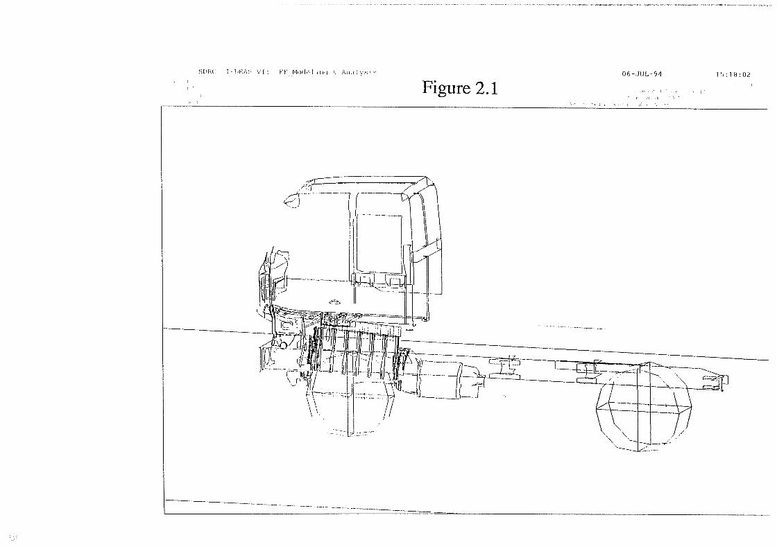
the torque in the engine is responsible for the excitation of the cab, only the anti-symmetricloadcase is used, which means that there are only forces acting in lateral direction.The dynamic loads are applied on one node in every bearing and on two nodes in every cylinder. In Figure 5.1 the magnitude of the forces for the third order can be seen. The magnitudeand phase of the forces in each cylinder are the same.
6. Analyses
Since the superelement technique is an approximation, a real eigenvalue analyses has beenused to compare the results of the model with and without a dynamic reduction. Only the firsttwenty eigenfrequencies have been calculated and they are exactly the same. The eigenmode at4.2 Hz. however showed some differences:
Exterior nodes: difference less than 0.01 %Interior nodes: frame: 0.01%engine max 0.4 %
cab max2.0%
Off course the approximation will become worse when the frequency is close to 200.0 Herz.This model is however used to determine the direction in which the response alters due to different modifications of the structure.
During vibration measurements in the cab, the measurements showed an increasing acceleration level when the engine rotation is decreased towards 8.0 rotations per second. Due to cutout of the engine the peak has never been measured. This peak is expected to be in the range of15.0 to 20.0 Hz. For this model the first eigenmodes however occurred around 11.5 Hz. Thestatic stiffness of the engine mounts was not high enough. To get the first eigenmode, where theengine is rolling as a rigid body, in a realistic frequency range, the stiffness and damping valuesof the engine mounts have been increased to include dynamic stiffening effects found in rubbercomponents.
The response of the nodes in the cab shows a lot of undamped eigenfrequencies, because thereis no structural damping in the models. For nodes in the engine there is little distortion. But forthe cab suspension the response is pretty distort due to a lot of undamped eigenfrequencies ofthe frame and the cab. The magnitude of this peaks obtained by a frequency response analysesare very sensitive to the size of each frequency increment. When parameter studies are done,some peaks could shift in the frequency. Peaks might disappear or new peaks might occur if theresolution in frequency is low.One way to overcome this is to use very small frequency increments, which will result in a verylarge computation time. Another way to avoid this problem is by adding some material damping to the model. The peaks will decrease and become wider. Which means that the peaks areless sensitive to the size of the frequency increments. It also gives a clearer view about the mostimportant eigenfrequencies.
Engine induced vibrations July 14. 1994 9
In this model no well defined material damping mechanism exists. But with modal damping itis possible to include damping after the eigenvectors have been used to transform the equationsof motion to the uncoupled single degree of freedom form. The uncoupled equations of motionfor a single degree of freedom are:
m1ii~ + b~ii1 + = (4)
Which can be written in non dimensional form as
= (5)
where ~ is the damping factor
C = c/c0,c0 = 2,fl~ (6)
and c0 is the critical damping value. With damping the resonant frequency becomes
13 = ~Ji_~2 (7)
When a damping value of 2.0 % of the critical value is used, thus the damping factor ~ = 0.02,the presence of damping will not significantly alter the resonant frequency from the undampedvalue. But the response in the resonant frequency is entirely controlled by the damping. Therest of the response will not be affected by the damping. In Figure 6.1 it can be seen that addingmodal damping gives a clearer view of the response.
This model is used as reference. For further analyses the following things have been done:
6.1 Exemplification of transmission paths for third engine order
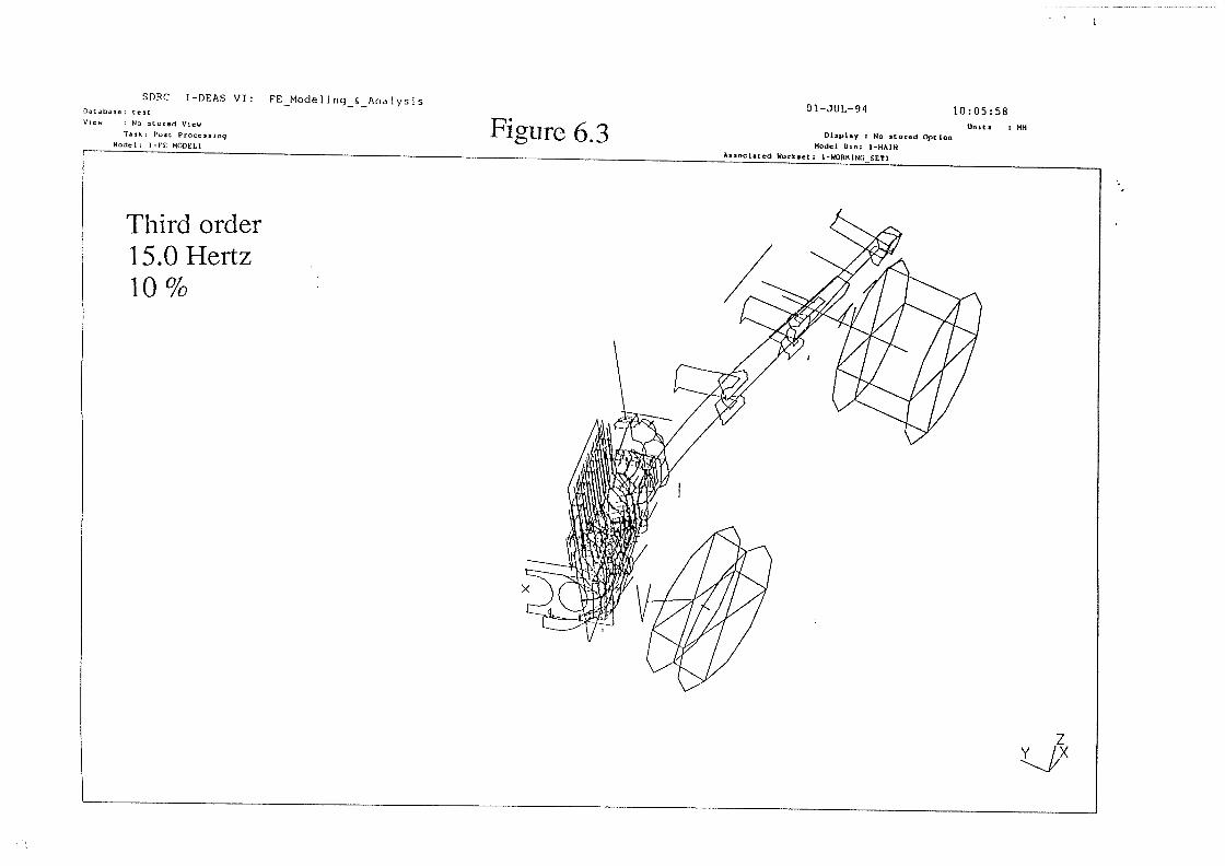
Figure 6.2 shows the response of the cab in vertical direction. Out of the response of the cabsome important eigenmodes can be extracted. That are 15.0, 32.0, 38.0, 43.5 and 58.0 Hz.
Eigenmode at 15.0 Herz:
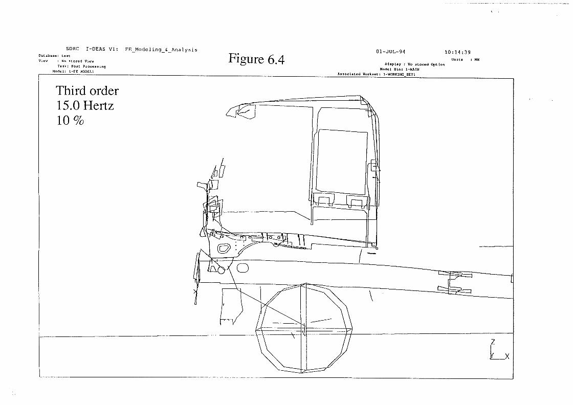
For this mode the engine is rolling as a rigid body. There is no deformation of the engine orthe gearbox. There is also no deformation in the crossmember to which the front enginemount is attached. This crossmember follows the lower side of the engine with a certainphase delay. The crossmember itself excites the longitudinal beam of the frame, which leadsto a torsion of this beam. The frame is in phase with the engine. From the front view theframe is swinging clockwise around some longitudinal axis (Figure 6.3). The frame is verysoft.It can be seen that most of the deformation of the cab appear in the front of the cab due tothe bushing. The bushing is in phase with the engine and frame and moves also clockwise.Because there is no lateral spring in the rear cab suspension, most of the vibrations is transmitted through the bushing. Due to this the front cab is moving relative to the rear of the cab.This results in a twisting of the cab (Figure 6.4). For this frequency the vertical acceleration
Engine induced vibrations July 14, 1994 10
(Figure 6.2) is very high for the front of the cab, even higher than the lateral acceleration.The magnitude of the front cab suspension and the bushing are the same. As the lateral position of the front cab suspension is twice the lateral position of the bushing, there is no roll ofthe cab. It can also be seen that there is a large deformation of the bottom plate of the cab(Figure 6.4).
7. Conclusionso Once the superelements have been created it is fairly easy to do parameter studies and mod
ifications of the residual. The extra effort put in the superelements pays itself back afterwards.
• To examine the transmission paths, some output files have to be read into Ideas which takesa long time. Sometimes it is difficult to see a difference between the modes, but in general itis possible to get a clear knowledge of the eigenmodes. The different engine modes found inthe analysis did conform with experiences from measurements.
o The results of the parameter studies are rather trivial. This model can be used for parameterstudies. The model should not be used to evaluate the absolute acceleration level in the cab.This model should mainly be used for determining the direction of the response change, dueto some modification.
• The efficiency of the superelement technique is high and can be illustrated by the followingexamples:
So13, only 20 eigenvalues, so number of Lanczos shifts 2: 5000 cpu seconds.
Dynamic reduction of cab, 400 Hz, 584 eigenvalues :36.000 cpu sec.
Calculations on residual a quite fast. Freq. resp. 200 Hz=3300 cpu, mainly because of increments. 100 Hz = 184 eigenvalues, with modal damping: 3000 cpu.
So it is much faster.
But the database need a lot of diskspace. For the superelements a total of 300 Megabytes isneeded.
Engine induced vibrations July 14, 1994 11

8. References
1. Johansson I. and Edlund S. ‘Optimization of vehicle dynamics in trucks by use of fullvehicle FE-models’.
2. Kraker A. de ‘Numeriek-experimentele analyse van dynamische systemen’.
Engine induced vibrations July 14, 1994 12
I-iEA~ \I: VK ~ 06—JUL—94 l:10:02
Figure 2.1
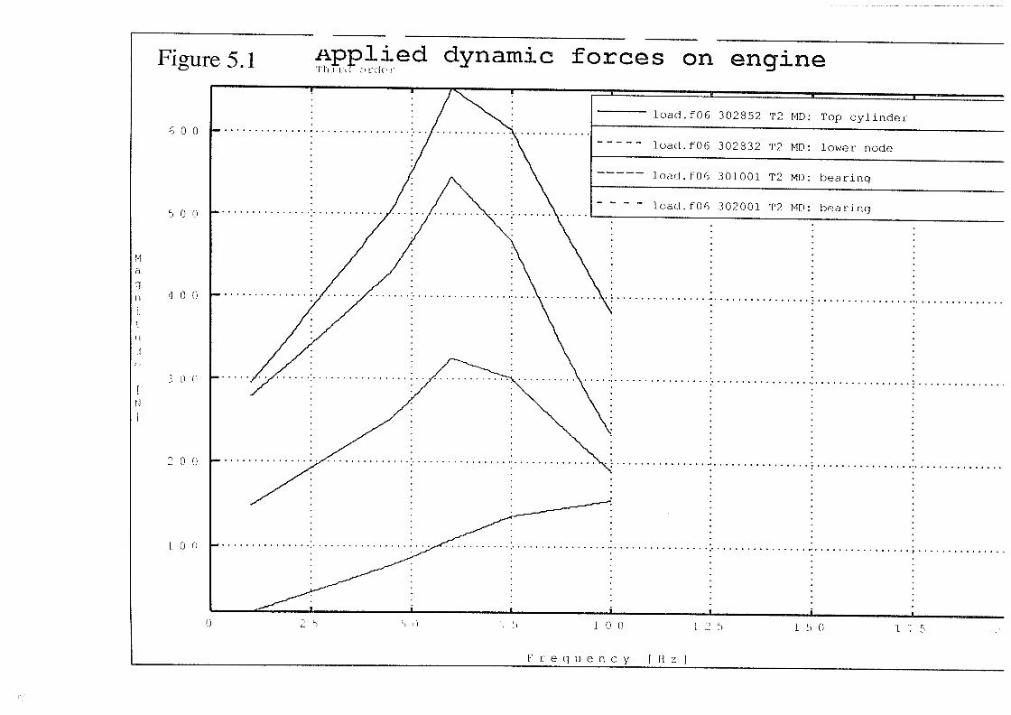
Figure 5.1
600
Applied dynamic forces on engine
5 0 0
400
51d
1.
0 0
200
0 2 5 I 0 (1 2 5 1 5 (1 175
1~ r e q U e n C y I II Z I
‘1
ii
II
Ii,
Figure 6.1 Modal damping[ ~ . ~.I
— JNo rnoda~ clarnpinq, 420003 T2 MA
2.0 %, 420003 T2 MA
- ~ ~j
I I’
•1 ~) ‘I ()
F 0 q ii e n c y I II
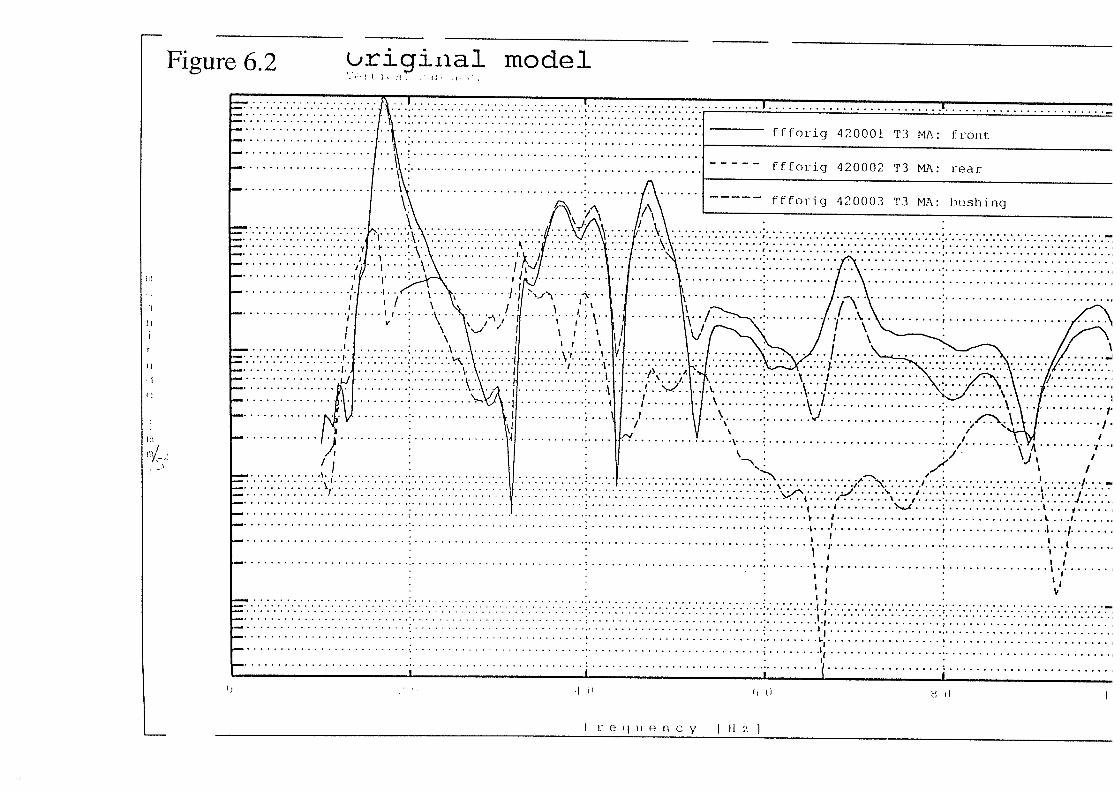
Figure 6.2 ~ model—
— ffforig 120001 T3 MA: front
ffforig 420002 T.3 MA: reai
I \ : ffiorig 420003 T3 MA: hushingI \\ A ________________________________—I /
- ~ ..~ -
:::::::..:::..:..:. 4.I....~.\ kJ”~ .~— jII.’~.~— j..~.....\.\ LI~.II— \.\ I 1~~~J/— 11
— . . . ).~ ~ . . . -~if. ~ i I.’
- ..~I V.’
~~ ~ . :~.•:•:/•:•:•:.:.:.:....•..:.:: :.:.:.:.:/~:.:.~
\ I /
— I ~ i...1
— ~
—
I I— I
I I,— I •~ I.,
— I1 —
—
() 1
I e q ii e n c y II
SDRC 1—DEAS VI: FEModeHng& Analysis01—JUL—94 10:05:58Database: test
View : No stored View
Task; Poet. Processing
Model: I-it MODtLIFigure 6.3 Display : No stored Option
Model Ii,n: I-MAINAssociated Work,et; I-WORKING SEll
Units UN
Third order15.0 Hertz10%
7
Database: testView : No stored View
Task: Post Processing
01—JUL—94 10:14:39
Display : No stored Option
Model Bin: 1-MAIN
Units : MM
SDRC 1-DEAS VI: FEModelinq&Analysis
Figure 6.4