Embed Size (px)
Citation preview

Engine Driven Products

Core Values1. We respect each other, our community and
the environment.
2. We are ethical and honest in all of our business dealings.
3. We are diligent in protecting the safety of our people.
4. We are disciplined and personally account-able for our decisions, actions attitude and results.
5. We have an entrepreneur’s mindset, driving innovation and striving for excellence in all we do.
6. We openly communicate among all levels of the company.
7. We believe in working as a team toward common objectives with a can-do attitude.
2
4
8
9
10
Page 11
Page 12
Page 16
6
3

1
Mechanical PilotlessTM Power Take-Off
PilotlessTM Over-The-Shaft Power Take-Off
Automotive-Style Spring Loaded Power Take-Off
Mechanical Power Take-Off
Type 2 Air/Hydraulic Power Take-Off
Type 1 Air/Hydraulic Power Take-Off
PythonTM Hydraulic Clutch Control
Hydraulic Power Unit
PTO Product Selection Guide
Pump Drive Selection Guide
WPT Power is constantly striving to improve and develop the product range. For this reason, WPT Power reserves the right to make changes in any product information without prior notice. Every effort has been made to ensure that the dimensions, performance, specifications, etc. are correct at the time of printing. For more information, please contact your authorized WPT Power distributor or visit: WPTpower.com.
2
4
8
9
10
Page 11
Page 12
Page 16
6
Contents
3
2
1 Support plate for 311, 214, 314 is required for sideload applications and recommended for inline applications.
Industrial engine applications are more demanding than ever. Customers need a solution rugged enough to meet those demands and WPT Power has engineered that solution with the WPT PilotlessTM Mechanical Power Take-Off. This design eliminates the pilot bearing and increases side load capacity over previous generations of PTO products. The WPT PilotlessTM Mechanical Power Take-Off will optimize your cost by reducing inventory, increasing uptime and engine life, and simplify installation time. • Dual spherical roller main bearing design.
• Time savings for assembly since no pilot bearing alignment required.
• Most sizes fit within envelope of previous design.
• No direct loading to engine crankshaft increases life of engine main bearings.
• No installation related engine thrust bearing damage.
• 100% equipped with ball-bearing engagement collars.
• Increased side load capacity.
A
D
B
Customer-suppliedsupport bracket1
C
ModelSAE
HousingsA
Output ShaftC D
Weightlb (kg)
# ofTeethB Dia Keyway
WPL 106 5, 4 8 7/16 (214.6) 2 1/8 (55.4) 1.438 (36.53) 3/8 x 3/16 2 7/16 (62.7) 4 7/16 (112.8) 72 (33) 42
WPL 107 5, 4 8 7/16 (214.6) 2 1/8 (55.4) 1.438 (36.53) 3/8 x 3/16 2 7/16 (62.7) 4 7/16 (112.8) 75 (134) 47
WPL 108 4 8 3/8 (213.4) 4 5/8 (118.4) 1.750 (44.45) 1/2 x 1/4 3 (76.7) 4 13/16 (122.9) 88 (40) 51
WPL 110 4, 3 9 3/4 (248.4) 3 15/16 (100.1) 2.250 (57.15) 5/8 x 5/16 3 1/2 (89.4) 5 3/4 (146.1) 125 (57) 63
WPL 111 3 11 7/16 (291.7) 4 1/16 (102.6) 2.250 (57.15) 5/8 x 5/16 11 1/8 (282.7) 5 3/4 (146.1) 162 (73) 72
WPL 211 3, 2 12 9/16 (320.0) 3 5/8 (92.5) 2.500 (63.50) 5/8 x 5/16 4 1/4 (108.0) 6 3/4 (171.5) 218 (99) 72
WPL 3111 3, 2 15 3/4 (400.8) 8 (204.0) 3.500 (88.90) 7/8 x 7/16 3 11/16 (94.2) 7 3/4 (196.9) 343 (156) 72
WPL 114 1 13 5/8 (346.2) 5 1/8 (130.6) 3.000 (76.20) 3/4 x 3/8 3 3/4 (95.2) 6 3/4 (171.5) 275 (125) 59
WPL 2141 1, 0 16 3/16 (411.5) 7 1/2 (191.8) 3.500 (88.90) 7/8 x 7/16 4 5/16 (110.2) 7 3/4 (196.9) 407 (185) 59
WPL 3141 1, 0 17 1/16 (433.1) 7 1/2 (190.5) 3.938 (100.01) 1 x 1/2 3 7/8 (99.6) 8 1/4 (209.6) 470 (213) 59
2
PilotlessTM
Mechanical Power Take-Off

3
Customer-suppliedsupport bracket1
A
D
B
C
ModelSAE
HousingsA
Output ShaftC D
Weightlb (kg)
# ofTeethB Dia Keyway
OTS-PL 211 3, 2 12 9/16 (320.0) 4 1/16 (102.6) 2.500 (63.50) 5/8 x 5/16 4 1/4 (108.0) 6 3/4 (171.5) 218 (99) 72
OTS-PL 3111 3, 2 15 3/4 (400.8) 8 (204.0) 3.500 (88.90) 7/8 x 7/16 3 11/16 (94.2) 7 3/4 (196.9) 343 (156) 72
OTS-PL 2141 1, 0 16 3/16 (411.5) 7 1/2 (191.8) 3.500 (88.90) 7/8 x 7/16 4 5/16 (110.2) 7 3/4 (196.9) 407 (185) 59
OTS-PL 3141 1, 0 17 1/16 (433.1) 7 1/2 (190.5) 3.938 (100.01) 1 x 1/2 3 7/8 (99.6) 8 1/4 (209.6) 470 (213) 59
WPT Power’s PilotlessTM Over-the-Shaft (OTS) Power Take-Off is engineered to meet the most demanding diesel engine applications. This design eliminates the pilot bearing while increasing side load capacity over competitive units. The OTS PTO is suitable for pneumatic or hydraulic actuation from the side of the housing and can be utilized for in-line or side load applications. The WPT PilotlessTM OTS Power Take-Off will increase uptime, engine life, and simplify installation time.
• Dual spherical roller main bearing design, increases side load capacity.
• Self-Adjusting clutch.
• No direct loading to engine crankshaft which increases life of engine main bearings.
• Time savings for assembly since no pilot bearing alignment required.
• For in-line or side load applications.
• Hydraulic or pneumatic actuation.
• Compatible with the Hydraulic Power Unit.
3
PilotlessTM
Over-the-Shaft Power Take-Off
1 Support plate for 311, 214, 314 is required for sideload applications and recommended for inline applications.

4
A B C
Loaded with features and virtually maintenance free, the automotive-style PTO is used with flat-faced flywheels in marine, industrial, construction, brush chipper and irrigation applications.
• The troublesome pilot bearing has been eliminated to reduce failures and downtime.
• Torsionally-dampened automotive-style spring-loaded clutch.
• Quick and easy external adjustments.
• The angular contact throwout bearing reduces heat buildup during long idle times.
WTD-13-130/133
D
90o
30o
4
Automotive-Style
W15-WG-200
W15-WG-200
Model SAEHousings A B
Output Shaft D HoleWeightlb (kg)
C Dia KeywayBolt
CircleQty Dia
WTD-13-130WTD-13-133 3
2.56(65.1)
9 1/8(231.8)
2 15/16(74.6)
1.750(44.45)
3/8 x 3/16 14.13
(358.8)8
3/8(9.5)
149(68)
W15-WG-200 12.53(79.1)
13 3/16 (335.3)
4 1/4 (108.0)
2.500 (63.50)
5/8 x 5/1616.63 (422.3)
81/2(12)
190(87)
WTD-13-130/133
D
90o
30o

5
GM-Style
• GM®-style bellhousing mounts directly to 4.3, 5.7, 6.2, 7.4 & 8.1 liter engines.
• Solid ductile iron bellhousing is built for heavy-duty applications, keeping out weather and other contaminants.
• Heavy-duty adjustment ball screw with jam nut makes adjustments easy.
• Inline or sideload applications.
• Heavy-duty, precision components are made of steel and ductile iron.
Model A BOutput Shaft D Hole
Weightlb (kg)
C Dia KeywayBolt
CircleQty Dia
GM® Style1.69(42.9)
14 7/16(366.7)
4 7/16(112.7)
1.750(44.45)
3/8 x 3/1612.63
(320.7)6
3/8(9.5)
160(73)
GM® Style HD1.69(42.9)
14 7/16(366.7)
4 7/16(112.7)
2.250(57.15)
1/2 x 1/412.63
(320.7)6
3/8(9.5)
160(73)
A
B C
D
5
GM® is a registered trademark of the General Motors Company
GM®-Style

6
ModelSAE
HousingsA
Output ShaftC D
Weightlb (kg)
# ofTeeth
B Dia Keyway
C1061
C1071 5, 47 1/8
(181.0)3 1/2(88.9)
1.438(36.53)
3/8 x 3/162 1/8(54.0)
4 5/8(117.5)
65(30)
42
C108 5, 4, 37 1/8
(181.0)6
(152.4)1.750
(44.45)1/2 x 1/4
2 1/4(57.2)
5(127.0)
82(37)
51
C110 4, 38 5/8
(219.1)5 1/2
(139.7)2.250(57.15)
5/8 x 5/163 3/4(95.3)
5 5/8(142.9)
117(53)
63
SP111 3, 2, 19 1/4
(235.0)6 1/2
(165.1)2.250(57.15)
5/8 x 5/163 3/4(95.3)
5 3/4(146.1)
143(65)
72
SP211 3, 2, 19 5/8
(244.5)6 1/2
(165.1)2.500(63.50)
5/8 x 5/163
(76.2)6 1/4
(158.8)157(71)
72
SP3112 3, 213 7/8(352.4)
10(254.0)
3.500 (88.90)
7/8 x 7/163 3/8(85.7)
7 1/2(190.5)
233(106)
72
SP114 112 1/8(308.0)
8 1/2(215.9)
3.000 (76.20)
3/4 x 3/83 3/4(95.3)
6 5/8(168.3)
263(119)
59
SP2142 1, 013 3/4(349.3)
10(254.0)
3.500 (88.90)
7/8 x 7/163 3/8(85.7)
7 1/2(190.5)
332(151)
59
SP3142 1, 014 1/2(368.3)
10(254.0)
3.938 (100.01)
1 x 1/23 3/8(85.7)
7 1/2(190.5)
413(187)
59
IBF3142 1, 016 3/4(425.5)
10(254.0)
3.938 (100.01)
1 x 1/23 5/8(92.1)
12 1/2(317.5)
595(270)
59
SP3182 018 1/4(463.6)
10(254.0)
4.500 (114.30)
1 x 1/22 5/8(66.7)
10(254.0)
897(407)
75
The WPT® Mechanical Power Take-Off consists of a lever-actuated clutch with a shaft and bearings mounted in a rigid cast housing. The Mechanical PTO is designed for inline and sideload applications on all internal combustion engines with standard SAE industrial flywheel/flywheel housing dimensions.
A
D
B
C
Customer-suppliedsupport bracket2
1 Double main bearings
2 Support plate for 311, 214, 314 is required for sideload applications and recommended for inline applications. Support plate for 318 is required for both sideload and inline applications.
• Sealed-for-life pilot bearings eliminate lubrication problems.
• Ball bearing throwout collars are optional on 10”, 11 ½”, 14” and 18”. Standard on the 311 PTO.
• All drive rings are ductile (nodular) iron or steel.
6
Mechanical Power Take-Off

77
OEM ClutchPacks
WPT provides many clutch pack options for OEM gearbox applications.
• Mechanical Clutch Pack sizes ranging from SAE 6 to SAE 18 inch flywheels.
• Bellhousings from SAE #5 to SAE #0.
• Pneumatic and hydraulic clutch sizes ranging from SAE 10 to SAE 21 inch flywheels.
• Bell housing from SAE #3 to SAE #00.

8
A
B C
D
Customer-suppliedsupport bracket (Required)
If you are looking for an innovative, high capacity power take-off, look no further than the WPT® Type 2.
With its versatile design, dry clutch and top-of-the-line spherical roller bearings, the Type 2 PTO has been field-proven in many sideload applications.
The benefits of the WPT Type 2 include the potential for remote engagement, self-adjusting clutch, with air or hydraulic actuation. Heavy-duty gear tooth friction discs are standard on 14” and 18” models. Bearings are lubricated with either grease or oil.
Customers needing maximum capacity in a small package will find the Type 2 an outstanding PTO for their applications.
Model SAEHousings A B
Output ShaftD
C Dia Keyway
211/311 3, 217 5/16 (439.6)
11 3/16(284.2)
3 3/8(85.7)
2.750(69.85)
5/8 x 5/167 3/16(182.6)
214/314H 1, 031 9/16(801.7)
21 1/16(535.0)
7 1/4(184.2)
3.625(92.08)
7/8 x 7/168 1/2
(215.9)
214Compact
2, 120 7/16 (518.6)
20 7/16 (518.6)
5 1/2 (140.0)
2.756 (70.00)
20 mm x 6 mm9
(228.6)
314HCompact
2, 15 11/16 (144.0)
3.542 (90.00)
25 mm x 10.7 mm9
(228.6)
218 031 7/8 (810.3)
20 15/16 (531.5)
7 1/4(184.2)
3.625(92.08)
7/8 x 7/168 1/2
(215.9)
318 033 7/16 (849.3)
22 7/16 (569.2)
7 1/4(184.2)
3.625(92.08)
7/8 x 7/168 1/2
(215.9)
Type 2Power Take-Off
8 Flange output shafts available. Contact WPT Applications Engineering for assistance.

9
The Type 1 PTO is one of the most rugged, highest capacity products available on the market today. With the sheave mounted between the bearings, these power take-offs are designed to attain the maximum potential of their massive spherical roller bearings.
Some benefits of the WPT® Type 1 include: Potential for remote engagement, self-adjusting clutch, air or hydraulic actuation, heavy-duty gear tooth friction discs and easy drive belt removal.
Gen II Type 1 PTO’s make it possible to house mechanical, hydraulic or pneumatic clutch pack. In addition, the sheave housing is designed with internal and external pilots, vastly improving the quality and ease of field repairs while increasing uptime.
Model SAEHousings A
Output ShaftC
Sheave (Customer Supplied)
B Dia Keyway Max Dia Max Width1
314H(GEN II)
1, 029 1/2(749.3)
9 1/2(241.3)
3.938(100.00)
1 x 1/223 7/8(606.4)
17(431.8)
12 7/8(327.0)
SP314(GEN II)
1, 028 5/16(718.6)
9 1/2(241.3)
3.938(100.00)
1 x 1/223 7/8(606.4)
17(431.8)
12 7/8(327.0)
318 038 3/4(984.3)
13 5/16(338.1)
4.500(114.30)
1 x 1/2 31 1/2(800.1)
18(457.2)
15 5/16(388.9)
318/ExtVersion
044 3/4
(1136.7)19 5/16(490.5)
4.500(114.30)
1 x 1/2 37 1/2(952.5)
18(457.2)
21 3/8(542.9)
321 0044 5/8
(1133.5)19 15/16(506.4)
4.750(120.65)
1 1/4 x 5/8 39 3/4
(1009.7)23
(584.2)22
(558.8)
321/ShortVersion
0035 5/8(904.9)
11(279.4)
4.750(120.65)
1 1/4 x 5/8 30 3/4(781.1)
23(584.2)
13(330.2)
321/ExtVersion
0047 5/8
(1209.7)23
(584.2)4.750
(120.65)1 1/4 x 5/8
42 3/4(1085.9)
23(584.2)
25(635.0)
1 Maximum sheave width varies with sheave diameter. Tabulated value is at the maximum sheave diameter.
A
C
Customer-suppliedsupport bracket (Required)
B
Type 1 Power Take-Off
9
A
C
B
Customer-suppliedsupport bracket (Required)
SP314 (GEN II)
Flange output shafts available. Contact WPT Applications Engineering for assistance.

10
• Eliminates operator-related engagement abuse.
• Maximizes the clutch’s wear component life.
• Optimizes clutch engagement for smooth operation.
• Can be easily integrated into OEM control systems.
• Designed & tested to operate in cold weather conditions.
• Self contained unit. No need for machine hydraulics.
• Compatible with SAE J1939 engine connections.
• Available in 12 or 24 volt.
WPT Power’s patented PythonTM Hydraulic Clutch Control is the perfect product for any equipment with an engine that struggles during machine startup. With the push of a button, our PythonTM will smoothly engage any WPT Type 1 and Type 2 Power Take-Off to accelerate the most demanding loads. It eliminates the need for bump starting heavy loads which can stall or damage the engine. This product was designed and tested alongside seasoned experts in the Off-Highway Equipment industry, and was specially engineered for applications with high inertia loads. WPT Power’s patented PythonTM is perfect for the OEM as well as the end user.
PythonTM
HydraulicClutch Control
10
7 5/8 (194)
10 1/8(257)
U.S. PATENT 9,026,331,OTHER PATENTS PENDING
11
HydraulicPower Unit
11
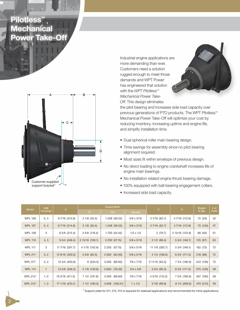
• Large 0.8 gal (3L) tank
• Lockout/Tagout is easy with removable key
• Thermal Overload Protection as standard
WPT’s Power’s self-contained Hydraulic Power Unit (HPU) is the ideal hydraulic power source to operate any WPT Hydraulic Power Take-Off. Availabe in 12VDC or 24VDC, the WPT HPU is designed to simplify installation and minimize maintenance. All WPT Hydraulic Power Packs are factory set to the pressure requirements of your PTO application.
16 5/16 (414)
15(384)

12
Part NumberFrom SAE
Engine HousingTo SAE
Bellhousing
WTD-00-000 2 4
WTD-00-001 1 2
WTD-00-002 1/2 1
WTD-00-003 0 1
WTD-00-004 00 0
WPT PTOs meet the mounting requirements of SAE J617 and SAE J620.
Dual or double-drilled flywheels may interfere with PTO. Contact WPT Applications Engineering for assistance on higher capacity or speed rating questions.
WPT SAE Housing Adapters Available
SAEHousing
AB
Pilot
C
BoltCircle
Qty DiaHole to
Hole
612 1/8(307.8)
10.500(266.70)
11.25(285.8)
813/32(10.3)
4 1/4(109.4)
514
(355.6)12.375(314.32)
13.13(333.4)
813/32(10.3)
5(127.6)
415 7/8(403.4)
14.250(361.95)
15.00(381.0)
1213/32(10.3)
3 7/8(98.6)
317 3/4(450.8)
16.125(409.58)
16.88(428.6)
1213/32(10.3)
4 5/16(110.9)
219 1/4(489.0)
17.625(447.68)
18.38(466.7)
1213/32(10.3)
4 3/4(120.8)
121 3/4(552.4)
20.125(511.18)
20.88(530.2)
1215/32(11.9)
5 3/8(137.2)
1/225 1/2(647.7)
23.000(584.20)
24.38(619.1)
1217/32(11.5)
6 1/4(160.2)
028
(711.2)25.500(647.70)
26.75(679.5)
1617/32(11.5)
5 3/16(132.6)
0034 3/4(882.6)
31.000(787.40)
33.50(850.9)
1617/32(11.5)
6 1/2(166.0)
Housing Flywheel
WPTClutchSize
DPilot
E(mm)
FG
BoltCircle
Qty DiaHole to
Hole
6”8.500
(215.90)52
1 3/16(30.2)
7.88(200.0)
621/64(8.3)
3 15/16(100.0)
7”9.500
(241.30)52
1 3/16(30.2)
8.75(222.3)
821/64(8.3)
3 5/16(85.1)
8”10.375
(263.52)62
2 7/16(62.0)
9.63(244.5)
613/32(10.3)
4 3/4(122.2)
10”12.375(314.32)
62 72
2 1/8(53.8)
11.63(295.3)
813/32(10.3)
4 7/16(113.0)
11”13.875
(352.42)
62 7280
1 9/16(39.6)
13.13(333.4)
813/32(10.3)
5(127.6)
14”18.375
(466.72)
72 80100
1(25.4)
17.25(438.2)
817/32(13.5)
6 9/16(167.7)
18”22.500(571.50)
100120
5/8(15.7)
21.38(542.9)
621/32(16.7)
10 11/16(271.5)
21”26.500(673.10)
-0(0)
25.25(641.4)
1221/32(16.7)
6 1/2(166.0)
F
BDE A
Bellhousing
C
EngineHousing
Flywheel
Drive Ring
GHole to
Hole
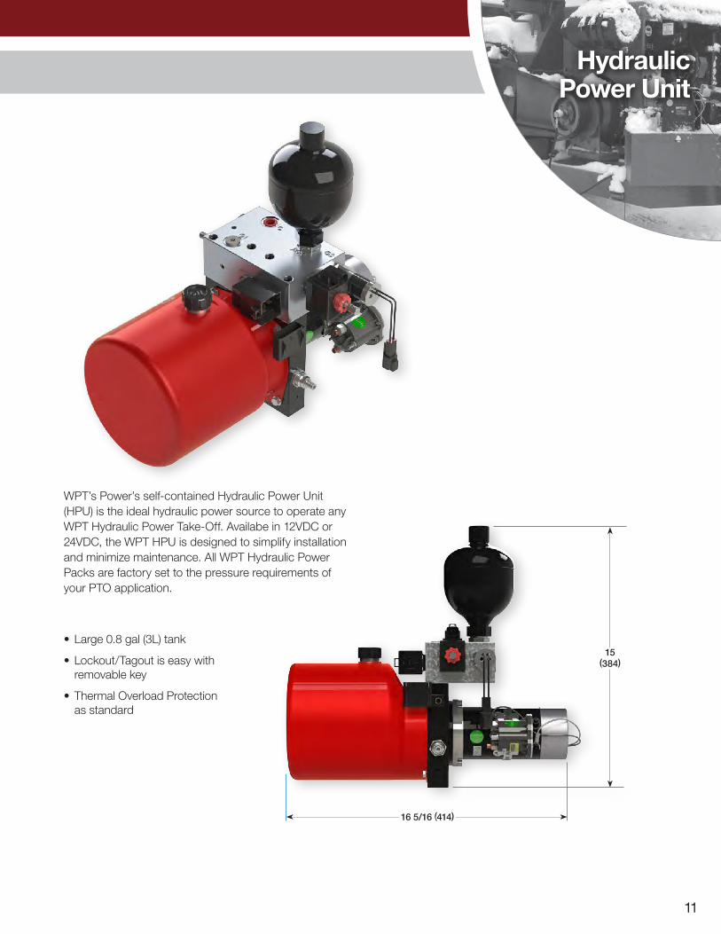
Step One
Step Two
Step Three
Step Four
PTO ProductSelectionGuide
13
Duty ServiceClassification
TypicalApplications
Single Cylinder Engine Multi-Cylinder Engine
Up to 10Hours/Day
Over 10Hours/Day
Up to 10Hours/Day
Over 10Hours/Day
Uniform Light loads with minimal slipCentrifugal blowers, compressors, fans,
rotary pumps1.5 1.75 1.25 1.5
ModerateMedium loads with maximum 3 second slip at engagement
Cone crushers, wood chippers, mine fans,
reciprocating pumps, road milling machines and planers
2 2.25 1.75 2
SevereHeavy loads requiring bump
start sequence forengagement
Jaw crushers, tub grinders, dredge/mud pumps,
hammer mills, reciprocating compressors, waste recyclers
2.25 2.5 2 2.25
Application Service Factor Selection Guide Service Factor (SF)
Step One
hp x SFr/min
= lbf·ft
=
kW x SFr/min
= N·m
=
T = Engine Torque [lbf·ft (N·m)] x SF
Step Two
Step Three
Step Four
Sideload
hp x F x SFr/min x D (in)L =
L = Actual Applied sideloadD = Sheave or Sprocket DiameterF = Load Factor 1.0 for Chain Drive or Gear Belt 1.5 for Timing Belts 2.2 for All V-belts
x 126,000
kW x F x SFr/min x D (mm)L = x 1,947,000
See Pages 14 and 15 for PTO Maximum Input Torque, r/min and Sideload ratings.
T
T
= lbf
= kgf
MaximumInput
Torque
For in-line applications skip to Step Four.
Multiply By To Obtain
lbf·ft 1.356 N·m
hp 0.746 kW
lbf 0.454 kgf
kg 9.807 N
Conversionsx 5,252
x 9,549
PTO ProductSelection
Guide
Additional Notes:Power Take-Off calculations are for reference only. For full warranty consideration, a data sheet must be turned into WPT Power and complete review performed by WPT Power Applications Engineering.

14
A
C
“X” Distance Inches (mm) · Allowable Sideload1 lbf (kgf) Maximum Input Torque1
lbf·ft (N·m)
Maximum Speed1
r/minModel r/min “X” Sideload “X” Sideload
WTD-13-130 20003000
10(254)
1,000 (500) 900 (400)
13 (330)
700 (300)600 (300)
412(560)
35003000
WTD-13-13320003000
10(254)
2,600 (1200)2,300 (1000)
13(330)
1,700 (800)1,500 (700)
412(560)
3000
W15-WG-20020003000
10(254)
1,000 (500) 900 (400)
13 (330)
500 (200)400 (200)
1650(2200)
2100
GM® Style 20003000
15 (381)
1,000 (500) 900 (400)
18 (457)
700 (300)600 (300)
386(523)
3400
GM® Style HD20003000
15 (381)
2,900 (1300)2,900 (1300)
18 (457)
2,000 (900)2,000 (900)
386(523)
3400
Model
“X” Distance Inches (mm)Allowable Sideload1 lbf (kgf) Maximum Input Torque
lbf·ft (N·m)at 100 lbf/in2 [7 bar]
Maximum Input Torque1 lbf·ft (N·m)
at 200 lbf/in2 [14 bar]
MaximumSpeed1
r/minr/min “X” Sideload
OTS-PL 211210023002500
14 (356)
4,7504,6304,510
(2160)(2100)(2050)
810 (1100) 1770 (2400) 2500
OTS-PL 311210023002500
19 (483)
3,6703,5703,480
(1660)(1620)(1580)
1250 (1700) 2580 (3500) 2500
OTS-PL 214180021002300
20(508)
3,8903,7203,620
(1770)(1690)(1640)
740 (1000) 1860 (2525) 2300
OTS-PL 314 180021002300
22(559)
4,0403,8503,750
(1830)(1750)(1700)
1360 (1500) 2780 (3770) 2300
PilotlessTM/OTS/Automotive Performance Ratings
X
of Load
“X” Distance Inches (mm) · Allowable Sideload1 lbf (kgf) Maximum Input Torque1
lbf·ft (N·m)
MaximumSpeed1
r/minModel r/min “X” Sideload “X” Sideload
WPL 106180025003500
10 (254)
1,6101,6101,540
(730)(730)(700)
11 (279)
1,3601,3601,290
(610)(610)(590)
171(232)
3500
WPL 107180025003200
10 (254)
1,6101,6101,580
(730)(730)(720)
11 (279)
1,3601,3601,330
(610)(610)(600)
191(259)
3200
WPL 108210024003100
11 (279)
1,9001,9001,710
(860)(860)(780)
13 (330)
1,2501,2501,130
(570)(560)(510)
248(336)
3100
WPL 110210023002500
12 (305)
2,3702,3102,250
(1070)(1050)(1020)
14 (356)
1,8101,7801,740
(820)(810)(790)
354(481)
2800
WPL 111210023002500
13 (330)
3,1003,0202,940
(1410)(1370)(1340)
15 (381)
2,4102,3502,290
(1090)(1060)(1040)
487(660)
2500
WPL 211210023002500
14 (356)
4,7504,6304,510
(2160)(2100)(2050)
16 (406)
3,6903,5903,500
(1670)(1630)(1590)
974(1321)
2500
WPL 311210023002500
19 (483)
3,6703,5703,480
(1660)(1620)(1580)
23 (584)
2,5002,4302,370
(1130)(1100)(1080)
1746(2367)
2500
WPL 114180021002300
16 (406)
3,1503,0002,920
(1430)(1360)(1330)
18 (457)
2,4902,3802,310
(1130)(1080)(1050)
862(1169)
2300
WPL 214180021002300
20 (508)
3,8903,7203,620
(1770)(1690)(1640)
24 (610)
2,7602,6402,570
(1250)(1200)(1160)
1724(2337)
2300
WPL 314 180021002300
22 (559)
4,0403,8503,750
(1830)(1750)(1700)
24 (610)
3,4203,2703,180
(1550)(1480)(1440)
2586(3506)
2300
PilotlessTM MechanicalA
B
X
of Load
X
C
of Load
Automotive
PilotlessTM Over-the-ShaftB
1 Contact WPT Applications Engineering for assistance on higher capacity or speed rating questions.

15
X
E
of Load
“X” Distance Inches (mm) · Allowable Sideload1 lbf (kgf) Maximum Input Torque1
lbf·ft (N·m)
MaximumSpeed1
r/minModel r/min “X” Sideload “X” Sideload
C106 C107
18003500
8 (203)
600500
(300)(200)
9 (229)
500400
(200)(200)
171 (232)191 (259)
35003200
(Double Main Bearings) C106 C107
18003200
9 (229)
1,000800
(400)(400)
10 (254)
800600
(400)(300)
171 (232)191 (259)
35003200
C10818003100
10 (254)
1,3001,100
(600)(500)
12 (305)
900800
(400)(400)
248(336)
3100
C110 18002800
12 (305)
2,0001,700
(900)(800)
14 (356)
1,4001,200
(600)(600)
354(481)
2800
SP11118002500
12 (305)
2,1001,900
(1000)(900)
14 (356)
1,5001,300
(700)(600)
487(660)
2500
SP211 18002500
13 (330)
2,1001,900
(900)(800)
15 (381)
1,5001,300
(700)(600)
974(1321)
2500
SP31118002300
18 (457)
2,0001,900
(900)(900)
22 (559)
1,3001,200
(300)(500)
1746(2367)
2300
SP114 18002300
16 (406)
2,0002,200
(900)(1000)
22 (508)
1,2001,400
(500)(600)
862(1169)
2300
SP21418002300
18 (457)
2,9002,300
(1300)(1000)
20 (559)
1,2001,400
(500)(700)
1724(2337)
2300
SP314(80 mm PB)
18002300
19 (483)
2,7002,500
(1200)(1100)
23 (584)
1,7001,500
(800)(700)
2586(3506)
2300
SP314 (100mm PB)
18002800
19 (483)
3,8003,800
(1700)(1700)
23 (584)
2,5002,400
(1100)(1100)
2586(3506)
2300
IBF314 18002300
22 (559)
5,5006,000
(2500)(2700)
27 (686)
4,6005,000
(2100)(2300)
2586(3506)
2300
SP31818002100
23 (584)
6,0206,340
(2730)(2880)
27 (686)
3,9104,110
(1770)(1860)
6465(8765)
2100
“X” Distance Inches (mm) · Allowable Sideload1 lbf (kgf) Maximum Input Torque1
lbf·ft (N·m)
MaximumSpeed1
r/minModel RPM “X” Sideload “X” Sideload
314H (GEN II)SP314 (GEN II)
18002300
17(432)
15,10014,100
(6900)(6400)
19(483)
12,40011,500
(5600)(5200)
3,800 (5100) 2300
31818002100
22 (559)
28,30027,000
(12800)(12300)
26(660)
21,70019,800
(9900)(9000)
7,100 (9600) 2100
32112001800
28(711)
31,70028,800
(14400)(13100)
32(813)
24,40022,200
(11100)(10100)
13,500 (18300) 1800
“X” Distance Inches (mm) · Allowable Sideload1 lbf (kgf) Maximum Input Torque1
lbf·ft (N·m)
MaximumSpeed1
r/minModel r/min “X” Sideload “X” Sideload
21121002500
12 (305)
3,5003,300
(1600)(1500)
15 (381)
2,4002,300
(1100)(1000)
1,300 (1800) 2500
31121002500
12 (305)
3,5003,300
(1600)(1500)
15 (381)
2,4002,300
(1100)(1000)
1,900 (2600) 2500
214HCompact
18002300
16 (406)
5,3005,300
(2400)(2400)
19 (483)
3,8003,500
(1700)(1600)
2,500 (3400) 2300
214H18002300
23 (584)
8,0007,600
(3600)(3500)
29 (737)
5,5005,300
(2500)(2400)
2,500 (3400) 2300
314HCompact
18002300
16 (406)
5,3005,300
(2400)(2400)
19 (483)
3,8003,500
(1700)(1600)
3,800 (5100) 2300
314H18002300
23 (584)
8,0007,600
(3600)(3500)
29 (737)
5,5005,300
(2500)(2400)
3,800 (5100) 2300
21818002300
23 (584)
8,0007,600
(3600)(3500)
29 (737)
5,5005,300
(2500)(2400)
4,700 (6400) 2100
31818002300
23 (584)
8,0007,600
(3600)(3500)
29 (737)
5,5005,300
(2500)(2400)
7,100 (9600) 2100
318 Heavy Duty
18002100
17 (432)
16,60015,800
(7500)(7200)
20 (508)
12,00011,500
(5400)(5200)
7,100 (9600) 2100
Mechanical
Type 2
Type 1E
F
D
X
D
X
F
of Load
of Load
Mechanical/Type 1/Type 2 Performance Ratings
1 Contact WPT Applications Engineering for assistance on higher capacity or speed rating questions.
16
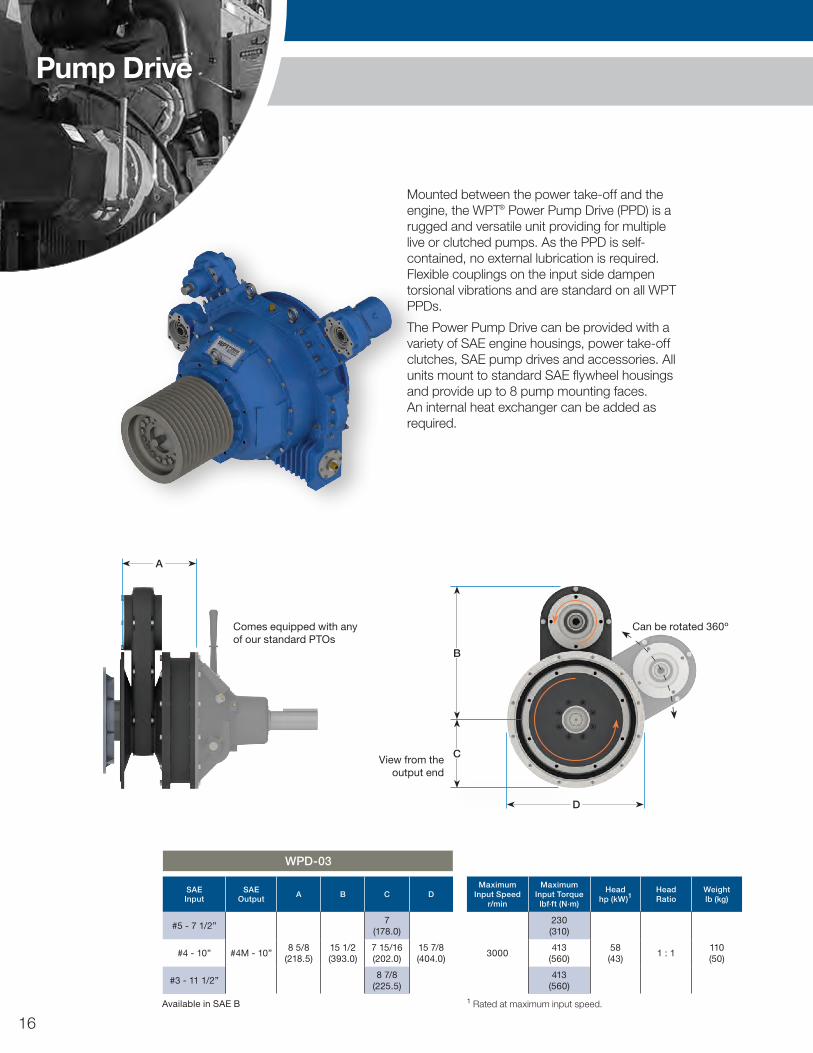
Mounted between the power take-off and the engine, the WPT® Power Pump Drive (PPD) is a rugged and versatile unit providing for multiple live or clutched pumps. As the PPD is self-contained, no external lubrication is required. Flexible couplings on the input side dampen torsional vibrations and are standard on all WPT PPDs.
The Power Pump Drive can be provided with a variety of SAE engine housings, power take-off clutches, SAE pump drives and accessories. All units mount to standard SAE flywheel housings and provide up to 8 pump mounting faces. An internal heat exchanger can be added as required.
SAEInput
SAEOutput A B C D
Maximum Input Speed
r/min
Maximum Input Torque
lbf·ft (N·m)
Headhp (kW)1
HeadRatio
Weightlb (kg)
#5 - 7 1/2”
#4M - 10”8 5/8
(218.5)15 1/2(393.0)
7(178.0)
15 7/8(404.0)
3000
230(310)
58(43)
1 : 1110(50)
#4 - 10”7 15/16(202.0)
413(560)
#3 - 11 1/2”8 7/8
(225.5)413
(560)
WPD-03
1 Rated at maximum input speed.
A
Comes equipped with any of our standard PTOs
Available in SAE B
View from the output end
D
B
C
Can be rotated 360o
Pump Drive

17
D
B
C
Can be rotated 360o
SAEInput
SAEOutput A B C D
MaximumInput Speed
r/min
MaximumInput Torque
lbf·ft (N·m)
TotalHead
hp (kW)1
SingleHead
hp (kW)1HeadRatio
Weightlb (kg)
#3, #2 - 11 1/2”#3M - 11 1/2”
10 1/8(257.0) 16 5/8
(422.0)12 13/16(325.0)
24 7/16(620.0)
26001475
(2000)235(175)
160(120)
1 : 1430(195)
#1 - 14” 11 1/8(282.0)
WPD-00
1 Rated at maximum input speed.
A
Comes equipped with any of our standard PTOs
D
B
CView from the
output end
Available in SAE B, B-B, C, D, E (spline only)
Pump Drive
SAEInput
SAEOutput A B C D
MaximumInput Speed
r/min
MaximumInput Torque
lbf·ft (N·m)
Headhp (kW)1
HeadRatio
Weightlb (kg)
#3 - 11 1/2” #3M - 11 1/2” 9 1/4(235.0)
19(483.9)
8 7/8(225.5)
17 3/4(450.9)
25001475
(2000)210(157)
1 : 1260(117)
WPD-03 HD
1 Rated at maximum input speed. Available in SAE B, B-B, C, D, E (spline only)
View from the output end
A
18
Pump Drive
D
A
B
C
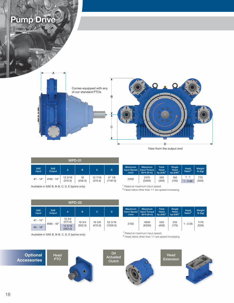
Comes equipped with any of our standard PTOs
View from the output end
SAEInput
SAEOutput A B C D
Maximum Input Speed
r/min
MaximumInput Torque
lbf·ft (N·m)
TotalHead
hp (kW)1
SingleHead
hp (kW)1Head Ratio2
Weightlb (kg)
#1 - 14”#0M - 18”
14 3/4(374.0) 19 3/4
(502.0)16 3/8(415.0)
52 3/16(1326.0)
21004650
(6300)535(400)
235(175)
1 : 0.951170(530)
#0 - 18” 14 5/16(363.0)
WPD-02
1 Rated at maximum input speed.2 Head ratios other than 1:1 are speed increasing
Available in SAE B, B-B, C, D, E (spline only)
SAEInput
SAEOutput A B C D
Maximum Input Speed
r/min
MaximumInput Torque
lbf·ft (N·m)
TotalHead
hp (kW)1
SingleHead
hp (kW)1Head Ratio2
Weightlb (kg)
#1 - 14” #1M - 14”12 3/16(310.0)
18(456.5)
12 7/16(315.0)
47 1/8(1197.0)
22002470
(3350)400(300)
160(120)
1 : 1 770(350)1 : 0.88
WPD-01
1 Rated at maximum input speed.2 Head ratios other than 1:1 are speed increasing
Available in SAE B, B-B, C, D, E (spline only)
Oil Actuated
Clutch
HeadExtension
OptionalAccessories
Step Two
Step One
Step Three
Step Four
HeadPTO
Step Five
19
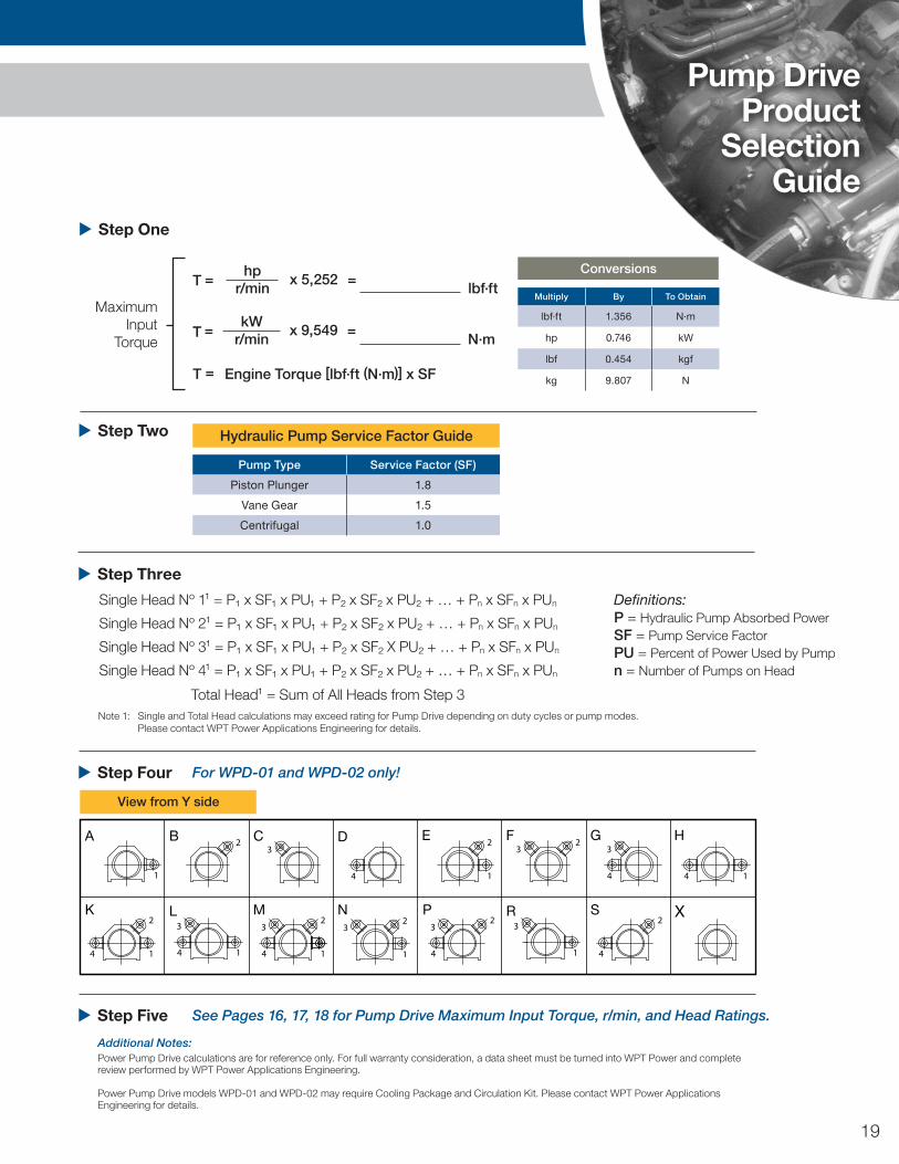
Pump Type Service Factor (SF)
Piston Plunger 1.8
Vane Gear 1.5
Centrifugal 1.0
Hydraulic Pump Service Factor Guide Step Two
hpr/min
= lbf·ft
=
kWr/min
= N·m
=
T = Engine Torque [lbf·ft (N·m)] x SF
Step One
Step Three
Step Four
Single Head No 11 = P1 x SF1 x PU1 + P2 x SF2 x PU2 + … + Pn x SFn x PUn
Single Head No 21 = P1 x SF1 x PU1 + P2 x SF2 x PU2 + … + Pn x SFn x PUn
Single Head No 31 = P1 x SF1 x PU1 + P2 x SF2 X PU2 + … + Pn x SFn x PUn
Single Head No 41 = P1 x SF1 x PU1 + P2 x SF2 x PU2 + … + Pn x SFn x PUn
For WPD-01 and WPD-02 only!
T
T
MaximumInput
Torque
x 5,252
x 9,549
Definitions: P = Hydraulic Pump Absorbed Power SF = Pump Service Factor PU = Percent of Power Used by Pump n = Number of Pumps on Head
Total Head1 = Sum of All Heads from Step 3Note 1: Single and Total Head calculations may exceed rating for Pump Drive depending on duty cycles or pump modes. Please contact WPT Power Applications Engineering for details.
Pump DriveProduct
SelectionGuide
A B C D E F G
XM3
2
14
P3
2
4
N3
2
1
L3
14
2
11
23
23 3
44
H
14
K2
14
R3
1
S2
4
View from Y side
Step Five See Pages 16, 17, 18 for Pump Drive Maximum Input Torque, r/min, and Head Ratings.
Additional Notes:Power Pump Drive calculations are for reference only. For full warranty consideration, a data sheet must be turned into WPT Power and complete review performed by WPT Power Applications Engineering.
Power Pump Drive models WPD-01 and WPD-02 may require Cooling Package and Circulation Kit. Please contact WPT Power Applications Engineering for details.
Multiply By To Obtain
lbf·ft 1.356 N·m
hp 0.746 kW
lbf 0.454 kgf
kg 9.807 N
Conversions

20
Custom Units
WTD-11-23J
WRB-11-130
W15-CG-325
W10-CG-101
Designed for very high tension and torque applications, this heavy-duty PTO will carry close to 3 times the belt tension of comparably sized PTOs.
The WPT Rubber Block Drive PTO is the perfect solution for customers needing a simple means of driving their equipment, with the least possible amount of design complexity. It is rated for both side-load and inline applications, and is a drop-in replacement for pilot bearing mechanical PTO’s.
Designed for proper sheave location while still having the capacity for very high belt tension.
The WPT Hydro-Mechanical PTO was designed for side-load applications, where a customer needs hydraulic engagement in a mechanical PTO sized package. This PTO requires no adjustment for the life of the product. It also replaces competitive thrust-bearing design PTO’s requiring precision pressure control, by using a high-reliability low-maintenance clutch, pressure insensitive actuator, and rotating union.

21
ApplicationPhotos
Self Contained Loader Mount Snow Blower
WPT 14” Mechanical Power Take-Off or 14” Power Grip PO Pneumatic Clutch.
Track Mounted Brush Chipper
WPT Single Head Pump Drive with 10” PilotlessTM Mechanical Power Take-Off.
Trailer Mounted Water Blaster
WPT 11” Mechanical Power Take-Off.
Portable Horizontal Impact Plant
WPT 314 Hydraulic Power Take-Off with patented PythonTM Hydraulic Clutch Control System.

WPT Power Corporation1600 Fisher RoadWichita Falls, Texas 76305U.S.A.
P.O. Box 8148Wichita Falls, Texas 76307
+1 940-761-1971 PhoneWPTpower.com
WPT Power (Shanghai) Ltd.No. 3-4 Building669 MinTa RoadSongjiang, Shanghai, PRC201617
+86-21-57847560 PhoneWPTpower.com.cn
Distributed by:
Global resource network
Our extensive network of knowledgeable distributors ensures that your product needswill be met quickly and with minimum downtime – when and wherever you are, worldwide.
WLB-00-001 F