Embed Size (px)
Citation preview

ENG3640 Review and Exam Question 1
ENG3640 Microcomputer Interfacing Review & Final Exam Structure

ENG3640 Review and Exam Question 2
Topics
Programming I/O Interfacing Interfacing Devices Data Acquisition Systems Timing Generation Serial Communication Busses Transmission Lines Memory Interfacing

ENG3640 Review and Exam Question 3
Course Objectives
Achieves the following goals:1. Learn about Microcontroller architecture2. Understand Software Development 3. Program in assembly language4. Interrupts, DMA, Polling5. Learn Basic I/O techniques (Parallel, Serial)6. Learn Serial communication Systems7. Understand functionality of busses8. Understand Data Acquisition Systems9. Learn about Memory Technology and Interfacing

ENG3640 Review and Exam Question 4
Q1. Software Development
Problem Statement
DesignStage
EffectiveData Structure
Modular Design
(Procedures)
Implementation
Instruction Set
AddressingModes
AssemblyFormatTesting
Directives

ENG3640 Review and Exam Question 5
Analysis

ENG3640 Review and Exam Question 6
Software Development

ENG3640 Review and Exam Question 7
Program Development
ENG3640 Review and Exam Question 8
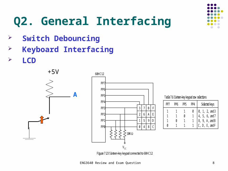
Q2. General Interfacing Switch Debouncing Keyboard Interfacing LCD
+5V
APP7 PP6 PP5 PP4 Selected keys
1110
1101
1011
0111
0,4,8,C,
1,5,9,D,
2,6,A,E,
and 3and 7and Band F
Table 7.6 Sixteen-key keypad row selections
A
B
C
D
E
F
0
1
2
3
4
5
6
7
8
9
10K
VCC
PP7
PP6
PP5
PP4
PP3
PP2
PP1
PP0
68HC12
Figure 7.23 Sixteen-key keypad connected to 68HC12

ENG3640 Review and Exam Question 99
Hardware Debouncing: Schmitt Trigger
A Schmitt trigger is a special circuit that uses feedback internally to shift the switching threshold depending on whether the input is changing from low to high or high to low.
The difference between V T+ and V T- is called hysteresis. A 74LS14 Schmitt Trigger inverter can be used to debounce a
switch.
VIN
VOUT
2.1 2.9 5.0
V T+
V T-
5.0
Example: 74LS14

ENG3640 Review and Exam Question 1010
Liquid Crystal Displays: Operation
An LCD display requires an alternating excitation wave applied to selected electrodes to change selected areas.
A constant (DC) excitation signal will polarize and destroy the crystal.
60 Hz Oscillator
Control
BP
FP
XOR
VLCD
Front Plane
Liquid Crystal Material
Back Plane

ENG3640 Review and Exam Question 11
I/O Interfacing
ENG3640 Review and Exam Question 12
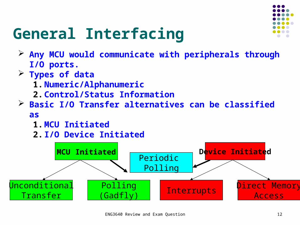
General Interfacing Any MCU would communicate with peripherals through I/O
ports. Types of data
1. Numeric/Alphanumeric2. Control/Status Information
Basic I/O Transfer alternatives can be classified as 1. MCU Initiated2. I/O Device Initiated
MCU Initiated Device Initiated
UnconditionalTransfer
Polling(Gadfly)
InterruptsDirect Memory
Access
Periodic Polling
ENG3640 Review and Exam Question 13
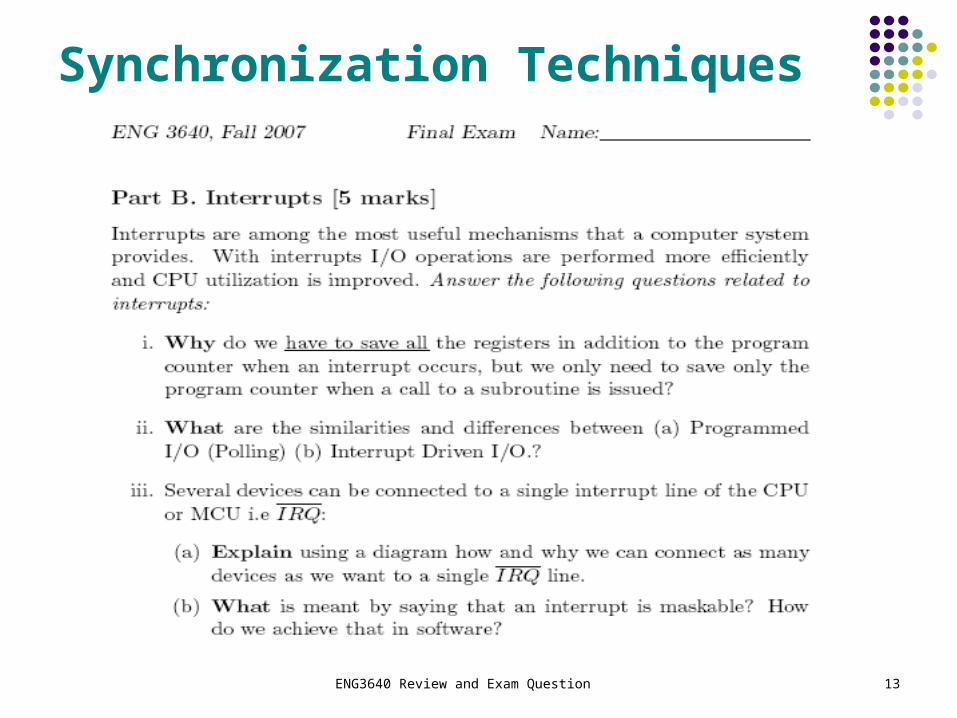
Synchronization Techniques

ENG3640 Review and Exam Question 14
Q3. Timer Module
Input Capture: “captures the time at which an external event occurs”. Can be used to:
1. Generate interrupts and
2. Measure period or pulse width Output Compare: “can generate a periodic
pulse with a programmable polarity, duration, and frequency”. Can be used to:
1. Create periodic interrupts,
2. Generate: Pulses, Square waves
3. Measure frequency

ENG3640 Review and Exam Question 15
General Understanding of TIM

ENG3640 Review and Exam Question 16
Q4. DAQ
Real
World
Measurand
Transducer
(sensors)
Analog
Mux
Signal
Conditioning
Sample and
Hold Circuit
A/D
ConvMCUD/A
ConvActuator

ENG3640 Review and Exam Question 17
Analysis or Design of Signal Conditioning

ENG3640 Review and Exam Question 18
Data Acquisition Systems

ENG3640 Review and Exam Question 19
Q5. DACs or ADCs
A/D converters are classified according to several characteristics
Resolution (number of bits) typically 8 bits to 24 bits Speed (number of samples per second) – several
samples/sec to several billion samples/sec Accuracy – how much error there is in the conversion
Classification1. Staircase ADC2. Tracking ADC3. Successive Approximation Converters4. Flash A/D Converters5. Integrating A/D Converters

ENG3640 Review and Exam Question 20
Important Circuits in DAS

ENG3640 Review and Exam Question 21
Q6. Serial and Parallel Communications
Transmitter Receiver
CLK

ENG3640 Review and Exam Question 22
Understanding of the Technology

ENG3640 Review and Exam Question 23
Serial Communication Systems

ENG3640 Review and Exam Question 24
Bus Protocols
Protocol refers to the set of rules agreed upon by both the bus master and bus slave Synchronous bus transfers occur in relation to successive edges
of a clock Asynchronous bus transfers bear no particular timing relationship Semi synchronous bus Operations/control initiate asynchronously,
but data transfer occurs synchronously
CPU Device 1 Device 2 Device 3
Bus

ENG3640 Review and Exam Question
25ENG3640 Fall 2009 25
Transmission Line Models
When can the R and G terms be ignored in the ZWhen can the R and G terms be ignored in the Z00?? As ww increases, the impact of R and G decreases. When the frequency increases above 100 kHz, the terms
multiplied by ww start to dominate.

ENG3640 Review and Exam Question 26
Reflections on the Bus To reduce reflections, the ends of a transmission line
should be terminated by connecting a resistor equal to Z0 across the line
Connecting a resistor between the bus and VCC will pullup the lower logic level and reduce noise immunity
Classic Solution: connect two resistors to the bus one to the ground and one to VCC R1//R2 = Z0
RT
VT
RT = R1//R2 = Z0
Bus

ENG3640 Review and Exam Question 27
Lattice Diagram Analysis – Key Concepts
Diagram shows the boundaries (x =0 and x=l) and the reflection coefficients
Time (in T) axis shown vertically
Calculate voltage amplitude for each successive reflected wave
Total voltage at any point is the sum of all the waves that have reached that point
Vs
Rs
ZoV(source) V(load)
TD = N ps0
Vs
RtThe lattice diagram is a tool/technique to simplify the accounting of reflections and waveforms
Time V(source) V(load)
a
source load
bA
cA’
B’
dB
e
0
N ps
2N ps
3N ps
4N ps
5N ps
ENG3640 Review and Exam Question 28ENG3640 Fall 2009 28
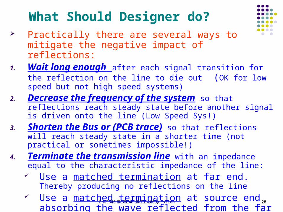
What Should Designer do? Practically there are several ways to mitigate the negative
impact of reflections:1. Wait long enough after each signal transition for the reflection on
the line to die out (OK for low speed but not high speed systems)
2. Decrease the frequency of the system so that reflections reach steady state before another signal is driven onto the line (Low Speed Sys!)
3. Shorten the Bus or (PCB trace) so that reflections will reach steady state in a shorter time (not practical or sometimes impossible!)
4. Terminate the transmission line with an impedance equal to the characteristic impedance of the line:
Use a matched termination at far end. Thereby producing no reflections on the line
Use a matched termination at source end absorbing the wave reflected from the far end.

ENG3640 Review and Exam Question 29
Why, How to solve Reflections

ENG3640 Review and Exam Question 30
Q7. Memory

ENG3640 Review and Exam Question 31
Understanding the Principle of Operation
ENG3640 Review and Exam Question 32
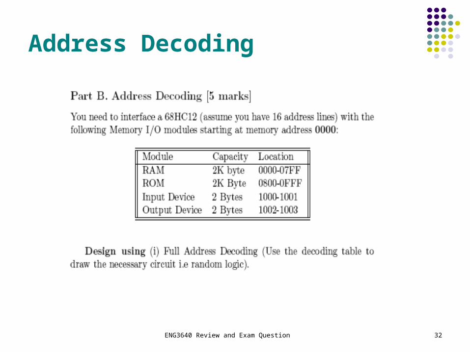
Address Decoding

ENG3640 Review and Exam Question 33

ENG3640 Review and Exam Question 34


![Poster evaluation question1[1]](https://img.pdfslide.us/doc/110x75/54826da9b4af9f820d8b4788/poster-evaluation-question11.jpg)