Embed Size (px)
Citation preview

Broadcast Microwave Services, Inc.12367 Crosthwaite Circle - Poway, California 92064 - U.S.A.
Tel: +1-858-391-3050, Toll Free (U.S.): 800-669-9667Fax: +1-858-391-3049, Website: www.bms-inc.com
E-mail: [email protected]
Page 1 ENG Truck Systems Digital and Analog
Microwave Equipment for ENG truck systems must be rugged, compact, reliable, easy to operate, and offer the performance and agility required to deliver the story. Truck systems built by BMS are designed expressly for the demanding environment of field ENG use.
Truck system packages purchased from BMS include all mating connectors for your installation or may be supplied directly to your truck system integrator.
BMS now offers the most powerful digital ENG truck system comprised of a BMS Truck-Coder II and BPA-10CC 10 Watt power amplifier.
The Truck-Coder II is a compact rack mountable device dedicated to set up wireless digital transmission of audio, video, and data signals. This easy to operate system includes 4:2:0/4:2:2 MPEG-2 encoding, COFDM digital modulation, and RF amplification. The Truck-Coder II features pre-defined or user selected operating modes designed to achieve the best trade off between robust transmission, video quality, and end to end delay. This system is ideal for fixed, portable, and mobile applications for non-line-of-sight operation.
The backbone of the analog ENG truck system is the high power BMT75 Series Transmitter. It offers a ver-satile transmit package for all vehicle applications while being cost and space efficient. This transmit-ter is mounted at the antenna to minimize RF loss. Inside the truck, BMS’ TCP-100 control panel offers a compact, (1 RU), intuitive interface. This control panel can control dual transmitters mounted at the antenna providing redundant systems or simultane-ous dual band operation.
Digital ENG Truck System
Analog ENG Truck System
Video, audio, DC power, and pedestal controls are fed through at 0.5” maximum diameter cable bundle from the TCP-100 to the mast-mounted transmitter. This leaves room for additional cables within the Nycoil™ sheath to control operational mast-mounted equipment such as POV camera, off-air antenna, etc. using a .75” to 1.25” diameter Nycoil™.
Transmitters operate from 11-32 VDC and require 2.5-7.5 amperes, (voltage dependent), per transmitter. BMS recommends operation at 24-28 VDC to avoid voltage dropping below 12 VD at the top of the mast. A BVC-12-28-5A Voltage Converter can be supplied for 12 VDC operation, or a TPS100-28-6A rack mount power supply for AC operation.
Broadcast Microwave Services, Inc.12367 Crosthwaite Circle - Poway, California 92064 - U.S.A.
Tel: +1-858-391-3050, Toll Free (U.S.): 800-669-9667Fax: +1-858-391-3049, Website: www.bms-inc.com
E-mail: [email protected]
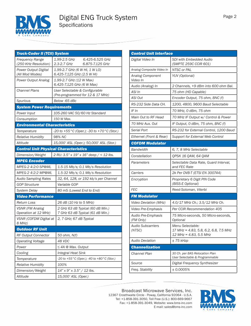
Page 2 Digital ENG Truck SystemSpecifications
Control Unit InterfaceDigital Video In SDI with Embedded Audio
(SMPTE 259C CCIR 601)Analog Composite Video In NTSC or PALAnalog Component Video In
YUV (Optional)
Audio (Analog) In 2 Channels, +9 dBm into 600 ohm Bal.ASI In 75 ohm (HD Capable)ASI Out Encoder Output, 75 ohm, BNC (f)
RS-232 Side Data CH. 1200, 4800, 9600 Baud Selectable
IF In 70 MHz, 0 dBm, 75 ohm
Main Out to RF Head 70 MHz IF Output w/ Control & Power
70 MHz Aux. Out IF Output, 0 dBm, 75 ohm, BNC (f)
Serial Port RS-232 for External Control, 1200 Baud
Ethernet (Front & Rear) Support for External Web Control
COFDM ModulatorBandwidth 6, 7, 8 MHz Selectable
Constellation QPSK 16 QAM, 64 QAM
Parameters Selectable Data Rate, Guard Interval, and FEC Rate
Carriers 2k Per DVB-T (ETSI EN 300744)
Encryption Proprietary 6 Digit PIN Code (BISS-E Optional)
FEC Reed-Soloman, Viterbi
FM ModulatorVideo Deviation (MHz) 4.0/17 MHz Ch.; 3.5/12 MHz Ch.
Video Pre-Emphasis Per CCIR Recommendation 405
Audio Pre-Emphasis(FM Only)
75 Micro-seconds, 50 Micro-seconds, Optional
Audio Subcarriers (NTSC)
Menu Selectable:17 MHz = 4.83, 5.8, 6.2, 6.8, 7.5 MHz12 MHz = 4.83, 5.5 MHz
Audio Deviation ± 75 kHzp
ChannelizationChannel Plan 30 Ch. per BAS Relocation Plan
User Selectable & Programmable
Source Digital Frequency Synthesizer
Freq. Stability ± 0.0005%
Truck-Coder II (TCII) SystemFrequency Range(250 KHz Resolution)
1.99-2.5 GHz 6.425-6.525 GHz2.3-2.7 GHz 6.875-7.125 GHz
Power Output Digital (All Mod Modes)
1.99-2.7 GHz (6 W HI, 1 W LO)6.425-7.125 GHz (2.5 W HI)
Power Output Analog 1.99-2.7 GHz (12 W Max)6.425-7.125 GHz (6 W Max)
Channel Plans User Selectable & Configurable (Pre-programmed for 12 & 17 MHz)
Spurious Below -65 dBc
System Power RequirementsPower Input 105-260 VAC 50/60 Hz StandardConsumption 150 W Max.
Environmental CharacteristicsTemperature -20 to +55°C (Oper.); -30 to +70°C (Stor.)Relative Humidity 98% NCAltitude 15,000’ ASL (Oper.); 50,000’ ASL (Stor.)
Control Unit Physical CharacteristicsDimension/Weight 2 RU: 3.5” x 19” x 16” deep / < 12 lbs.
MPEG EncoderMPEG-2 4:2:0 SP@ML 1.5-15 Mb/s; 0.1 Mb/s ResolutionMPEG-2 4:2:2 MP@ML 1.5-32 Mb/s; 0.1 Mb/s ResolutionAudio Sampling Rates 32, 64, 128, or 192 kb/s per ChannelGOP Structure Variable GOPSystem Delay 80 mS (Lowest End to End)
Video PerformanceReturn Loss 26 dB (10 Hz to 5 MHz)VSNR (FM Analog Operation at 12 MHz)
2 GHz 63 dB Typical (60 dB Min.)7 GHz 63 dB Typical (61 dB Min.)
VSNR (COFDM Digital at 8 MHz)
2, 7 GHz; 67 dB Typical
Outdoor RF UnitRF Output Connector 50 ohm, N(f)Operating Voltage 48 VDCPower ≤ 4A @ Max. OutputCooling Integral Heat SinkTemperature -20 to +55°C (Oper.); -40 to +80°C (Stor.)
Relative Humidity 100%Dimension/Weight 14” x 9” x 3.5” / 12 lbs.Altitude 15,000’ ASL (Oper.)

Broadcast Microwave Services, Inc.12367 Crosthwaite Circle - Poway, California 92064 - U.S.A.
Tel: +1-858-391-3050, Toll Free (U.S.): 800-669-9667Fax: +1-858-391-3049, Website: www.bms-inc.com
E-mail: [email protected]
Page 3
Technical Characteristics BPA-10CC Outline DrawingsFrequency 1.99-2.5 GHzPower 10W Average COFDMInput Voltage 28 VDC, 8 Amps at 10W with FansGain 52 dB (-13 dBm input for Po=10W) (Can Be Factory Set
From 40 to 55 dB)Gain Flatness ± 1 dB Over 500 MHzGain vs. Temp ± 1 dB Over Temperature Operating Temperature -20° to +50°CStorage Temperature -40° to +90°CDimensions ~9.5” x 5” x 4” (Includes Heatsink & Fan)
(~24 x 12.7 x 10 cm)Weight ~8 lbs (includes Heatsink & Fan)
(~3.6 kg)RF Input Type “N”RF Output Type “N” Isolator ProtectedShock Mount Pate 9.85” x 7.50”, Drilled for Easy Installation
(25.019 x 19.05 cm)
BMS offers a family of antennas to suit your requirements which are available in single polarity, dual polarity, 4-polarity, and dual band operation. The most popular are the BMA-20/30 Offset Feed Antenna and the BMA-2/4 Truncated Parabolic Antenna.
In choosing the right antenna, characteristics must be considered regarding gain and beamwidth versus size/weight and aerody-namic loading. Higher gain is desirable to maximize distance. However, with higher gain comes larger size. Beamwidth is impor-tant in determining required aiming accuracy. Beamwidths narrow with larger size antennas and higher frequencies. Low-profile stowage for transport must also be considered. All BMS antenna mounts allow stowage at 90 degrees.
Options include SMPTE color bar generator with 16 character ID, dual audio tone generators and a video detector that will re-motely turn the transmitter on when video is present.
Antenna Transmitter Frequency Az HPBW EL HPBW Gain AccessoriesBMA-15/30 BMT75-9P
Fixed 6W2.0-2.5 GHZ7.0 GHz
14°4°
28°8°
19 dBi24 dBi
•TPS-100-28-6A (AC to 28 VDc Converter)•HS-75 Heatsink•Custom Nycoil™ Assemblies
BMA-20/30 Offset
BMT75-7P3/12W Hi/Low
2.0-2.5 GHz7.0 GHz
15°4°
24°7°
20 dBi30 dBi
•BVC-12-28-5A (12 to 28 VDC Converter)
BMA-2/4 BMT75-5P3/12 W Hi/Low
2.0-2.5 GHz7.0 GHz
9°2.5°
19°5°
23 dBi34 dBi
•TCP-100 (Custom Control Panel)•Nose Guard to Protect Feed•Options: Color Bar Generator, Dual Audio Tone Generator, Auto-Tx with Video Detect
Antenna Selection (Analog)
ENG Truck SystemDigital (cont.) & Analog Specifications

Broadcast Microwave Services, Inc.12367 Crosthwaite Circle - Poway, California 92064 - U.S.A.
Tel: +1-858-391-3050, Toll Free (U.S.): 800-669-9667Fax: +1-858-391-3049, Website: www.bms-inc.com
E-mail: [email protected]
All Data Subject to Change Without Notice
Page 4
RF Characteristics - For Frequency Range and Number of Channels See Ordering In-formationFreq, Stability - Standard ± 0.002%
Freq. Stability - Optional ± 0.001%
RF Output Power See Ordering Information
RF Output Impedance 50Ω, SMA Connector
RF Output Protection Open/Short/Indefinitely
Spurious Output -53 dBc Max
Subcarrier CharacteristicsSubcarrier Frequencies 4.83 to 8.59 MHz, Fac-
tory SetSubcarrier Injection Level -25 dBc to -30 dBcSignal to Noise 65 dBHarmonic Distortion 1% MaxModulation Type FMModulation Response - Standard
50 Hz to 15 kHz
Modulation Response - Standard, Pre-emphasis
75 µsec
Modulation Response - Standard, Sub. Deviation
75 kHzp
Modulation Response - Optional
50 Hz to 50 kHz
Modulation Response - Optional, Pre-emphasis
50 µsec, None
Modulation Response - Optional - Sub. Deviation
100 kHzp, 125 kHzp
Modulation CharacteristicsModulation Types FMModulation Response - Standard
NTSC, 525 Lines
Modulation Response - Optional
PAL, SECAM, or FLAT
Pre-emphasis - Standard CCIR 405, 525 Lines Pre-emphasis - Optional 625 Lines or NoneModulation Sensitivity ± 4 MHz/1 VPP @ Cross-
over FrequencyModulation Input Impedance 75Ω UnbalancedBaseband Input 1 Vpp
Package size and connectors may vary.
FCC Identifier: CNV75K-BMT75-5P, -7P, -9P•Part 21.801 (b) - Common Carrier•Part 74 - Auxiliary Broadcast Services•Part 78 - CARS ServicesAvailable Accessories:•TCB-100 Control Box for Remote Channel Select•TCP-100 Truck Control Panel•HS-75 Heatsink for all Series 75 Models•HSF-75 Heatsink/Fan for all Series 75 Models•HCP-50/HCP-100 Helicopter Control Panels for Remote Channel Select
4/21/2006
Analog ENG Truck SystemSpecifications
Ordering Info BMT75-5P BMT75-7P BMT75-9P
Freq. Range 1.9-2.11 GHz 1.99-2.5 GHz 6.4-7.2 GHz
No. Channels 21 30 (64 Int’l) 42
RF Power Out 12/3W 12/3W 6W
BMT75 Series Transmitter Specifications


![]d - nwg-inc.com](https://img.pdfslide.us/doc/110x75/624facf12752cd191f0126be/d-nwg-inccom.jpg)