Embed Size (px)
Citation preview

DesiccantDehumidifiers
SATS
The
Nat
ural
Alte
rnat
ive
EngineeringManual
DESICAiR®
300 to 600 Scfm
Dry Desiccant DehumidificationSystems For Humidity Control

Founded in 1947, STULZ acquired Air TechnologySystems (ATS) in March 2001, naming the newcompany Stulz Air Technology Systems, Inc. (SATS).SATS is dedicated to providing innovative solutions forcritical temperature and humidity control needs. SATSdesigns and manufactures specialized environmentalcontrol equipment for commercial, industrial andcustom military applications. SATS serves a diversemarketplace - including telecommunications, informa-tion technology, medical, financial, educational, indus-trial process and government contracts - utilizingworld-class "island" manufacturing processes in amodern, 150,000 ft2 facility. The addition of SATS tothe STULZ family of companies solidifies STULZ as aglobal leader in the precision air conditioning market-place. SATS combines a global network of sales andservice companies with an extensive factory engineer-ing staff and highly flexible manufacturing resourcesdedicated to providing world-class quality, innovationand customer service.
ISO-9001 Quality RegisteredSATS operates in an ISO-9001:2000 Registered QualityManagement System. Each employee of SATS iscommitted to satisfying our customer expectations withthe highest level of consistent, measurable andcontinuous quality improvement.
SATS DESICAiR®- DRY DESICCANTDEHUMIDIFICATIONSATS DESICAIR® dehumidifiers utilize a unique dryand stable desiccant. The desiccant is a customizedform of silica gel which is synthesized and permanentlyencapsulated in the rotor ’s molecular matrix.DESICAIR® dehumidifiers provide precise humidityand/or temperature control of either a room or a pro-cess air stream such as may be required for pharma-ceutical air preparation, tabletting, panning, etc; airconveying of hygroscopic products; preparation, hard-ening and packaging of confectionery, chocolate,candy; plastic molding operations; electronics manu-facturing, warehousing; archival storage of documents,films, artifacts or works of art; seed storage; invest-ment casting operations; stand by readiness of mili-tary hardware; battery manufacturing; general manu-facturing and many other applications.
DESICAiR® dehumidifiers are available in sizesfrom 50 to 15,000 scfm and with moisture removalcapacities exceeding 500 Ibs per hour.
Stulz Air Technology Systems, Inc. (SATS)
DESICAiR® Series DEZ 1000 and Series DES 2000dehumidifiers provide dry air for humidity controlwith many standard options.
DESICAiR® DHP Series systems combinedesiccant dehumidification with cooling,heating, humidifying, filtration and many othercustom features such as double wallconstruction. This series facilitates singlesource, stand alone environmental control.
Product ReliabilityEach desiccant rotor is precision manufactured forlong life and low maintenance requirements anddriven by a positive grip cog type drive belt. EachDESICAiR® dehumidifier must pass stringentquality assurance testing before leaving ourfactory. SATS offers the industry’s only 5 year rotorprotection warranty as a standard!
Typical applications include:PROCESSES
Plastic Injection MoldingPharmecutical Tabletting / CapsulingElectronics ManufacturingCandy ProductionPackaging Operations
ENVIRONMENTALWarehouse & Storage FacilitiesMuseumsDocument ArchivesMilitary Equipment PreservationLaboratories & Clean RoomsPneumatic Conveying (Grain Elevators)Water Remediation
PERFECT FOR FLOOD DAMAGE RESTORATION!
1-1

Table of Contents
SECTION - 1
Introduction to SATS ........................................1-1Table of Contents .............................................1-2
SECTION - 2
DESICAiR® SYSTEMS:How it Works ....................................................2-1DEZ Dehumidifier Advantages ......................2-2/5Model Nomenclature & Specifications ..............2-6Layouts/Configurations ....................................2-7Standard/Optional Freatures ......................... 2-8/9
SECTION - 3
GUIDE SPECIFICATIONS:Standard Features .........................................3-1/6Optional Features .......................................... 3-7/9
SECTION - 4
PERFORMANCE/ CAPACITYSPECIFICATIONS:
Moisture Removal Graphs ............................4-1/3Dimensional Drawing DEZ-300-40-E ...............4-4Dimensional Drawing DEZ-450/600-40-E ........4-5
SECTION - 5
ADDITIONAL INFORMATION:
Duct Mounted Accessories ...............................5-1
1-2
DESICAiR® FAMILY OF PRODUCTS
DH100 Series
DRY 500 Series
DEZ 1000 Series
DES 2000 Series
DHS Series
DHP Series

2-1
Desiccant Dehumidification - How It Works
How it Works ...Humid (process) air (1) is drawn into thedehumidifier through a filter (2) and a speciallydesigned plenum (3). The air passes through therotor (4) where moisture is adsorbed by thedesiccant. As moisture is adsorbed by thedesiccant, heat is given off to the air stream. Thisheat gain causes the dry bulb temperature of the airstream to increase. The dehumidified air passesthrough a second plenum (5) and is discharged bythe process blower (6) through the outlet (15).
Simultaneously, the reactivation air (7) is drawnthrough a filter (8) and is heated (9) and enters aseparate segment of the rotor (4) through theplenum (5). This heat reduces the relative humidityof the reactivation air, increasing its moistureholding capacity. The heated reactivation airremoves the previously adsorbed moisture as avapor from the desiccant in the rotor. Thereactivation air passes through a plenum (3) and isdischarged by the reactivation blower (10) throughthe outlet (16).
The plenums (3,5) are constructed with internalpartitions to keep the process and reactivation airstreams from mixing.
While the dehumidifier is operating, the rotor iscontinuously turned by the drive motor and belt(11). The moisture adsorbed from the process airstream is carried to the reactivation zone wherethe moisture is transferred to the reactivation airstream.
The air streams pass concurrently through the rotorin counterflow. Counterflow is the most efficientpattern for thermal and mass transfer. The processand reactivation air streams follow separate andisolated paths through the dehumidifier. They areprevented from mixing by four significant designfeatures:
Internal ducting (12)A partition in both plenums (3,5)Solid rotor flute construction (4)Unique one piece face seals (13).
The face seals (13) are of one piece constructionand mounted to seal plates (14). The seals provideboth the periphery and process to reactivation airseal.
DESICAiR® Series 1000Desiccant Dehumidifier
(1) HUMID PROCESSAIR INLET
(2) FILTER(16) REACTIVATION AIR OUTLET
(3) TOP PLENUMWITH INTERNALPARTITION
(4) SILICA-GELDESICCANTROTOR
(11) ROTOR DRIVEMOTOR AND BELT
(12) TYPICAL INTERNALDUCTING
(5) BOTTOM PLENUMWITH INTERNALPARTITION
(10) REACTIVATIONBLOWER
(15) DRY PROCESSAIR OUTLET
(6) PROCESS BLOWER
(14) SEAL PLATES
(13) FACE SEALS
(9) REACTIVATION AIRHEATER
(7) REACTIVATIONAIR INLET
(8) FILTER

2-2
SERIES 1000 Dehumidifiers
The Series 1000 models are industrial duty dry desiccant dehumidifiers. They dehumidify aspace or process application to a humidity level chosen by the user without lowering theair temperature. Using desiccant air drying technology, humidity can be reduced tolevels below that which is achievable with a refrigeration based dehumidificationsystem.
The Series 1000 dehumidifiers even allow cold air streams to be dehumidified withoutfurther reducing the air temperature, so freezing and/or frosting of components isprevented. Air to be dehumidified is drawn into the unit, filtered, dehumidified andthen supplied to the space or process to be conditioned.
Each dehumidifier is complete with all the necessary blowers, controls, filters anddrive components to assure the safe and automatic operation of the dehumidifier.Single point electrical power connection is provided.
SERIES 1000 Systems Offer Outstanding Advantages
FlexibilityA range of options to meet your needs.
• Round or Square Duct Connections• Cabinet Stands• Status Indicator Lamps• Remote Unit Starting/Monitoring
Versatility• Space or Process Conditioning• Portable Units Available
Range of SizesA range of flow capacities to meet your space orprocess conditioning requirements from 300, 450 or600 scfm.
Non-Proprietary PartsAll Series 1000 systems incorporate non-proprietarycomponents where possible. Most major HVAC,refrigeration or electrical distributors stock an exactmodel cross reference or an alternate to most factoryprovided components.
Code Conformance
• Control enclosures are certified to UL508A Stan-dards.
• Unit may be Nationally Recognized TestingLaboratories (NRTL) certified to UL1995 Stan-dards.
Comprehensive WarrantyAll parts are warranted for 2 years from date ofinstallation.Note: Certain terms and conditions apply.
5-Year Rotor Warranty - The desiccant rotor isprotected with an exclusive SATS DESICAiR® warran-ty for five (5) years against softening or collapse dueto exposure to humid air.
Solid State ControlsPrecision humidity management with unrivaled, userfriendly controls that offer a wide range of functionsand features.
Desiccant RotorThe rotary style desiccant rotor utilized in Series 1000systems is manufactured using a unique, media(substrate) formulated for maximum performance withminimal maintenance.
The desiccant rotor consists of a corregated hightemperature fiber media impregnated with a non-
migrating, water selective, synthesized silica geldesiccant. The desiccant permanently encapsulatesthe media matrix in such a way as to render the entiresurface area of the rotor active as a desiccant. Theadvanced silica gel desiccant is non-corrosive andnon-toxic. The rotor is equipped with a non-slip,cogged gear, belt-drive system.
Rotor Pressure DropDifferential pressure indicating gauges are provided toindicate the pressure drops accross the rotor for airbalancing.
Separate gauges are provided for process and reacti-vation air streams. The gauges are factory mounted onthe cabinet and visible without requiring the removal ofany panels or access covers.
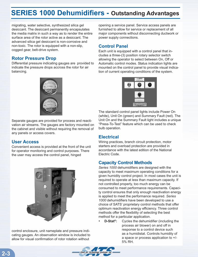
User AccessConvenient access is provided at the front of the unitfor operator monitoring and control purposes. Therethe user may access the control panel, hinged
control enclosure, unit nameplate and pressure indi-cating gauges. An observation window is included toallow for visual confirmation of rotor rotation without
opening a service panel. Service access panels arefurnished to allow for service or replacement of allmajor components without disconnecting ductwork orpower supply connections.
Control PanelEach unit is equipped with a control panel that in-cludes a three-(3) position rotary selector switchallowing the operator to select between On, Off orAutomatic control modes. Status indication lights aremounted on the control panel to provide visual indica-tion of current operating conditions of the system.
The standard control panel lights include Power On(white), Unit On (green) and Summary Fault (red). TheUnit On and the Summary Fault light includes a unique“Press-To-Test” feature which can be used to checkbulb operation.
ElectricalWiring practices, branch circuit protection, motorstarters and overload protection are provided inaccordance with the latest edition of the NationalElectric Code.
Capacity Control MethodsSeries 1000 dehumidifiers are designed with thecapacity to meet maximum operating conditions for agiven humidity control project. In most cases the unit isrequired to operate at less than maximum capacity. Ifnot controlled properly, too much energy can beconsumed to meet performance requirements. Capaci-ty control ensures that only enough reactivation energyis applied to meet the performance required. Series1000 dehumidifiers have been developed to use achoice of SATS’ proprietary control methods that offeroptimum reactivation energy efficiency. Three controlmethods offer the flexibility of selecting the bestmethod for a particular application.• D-Stat®: Cycles the dehumidifier (including the
process air blower) on and off inresponse to a control device suchas a humidistat. Controls humidity ofa space or process application to +/-5% RH.
SERIES 1000 Dehumidifiers - Outstanding Advantages
2-3

SERIES 1000 Dehumidifiers - Outstanding Advantages
2-4
• D-Stat II®: Functions the same as the D-Stat®
control method except the processblower runs continuously. This methodallows the process air to move forventilation or sensible cooling andpromotes uniform humidity through-out the conditioned space.
• H-Trac®: Proportionally controls reactivationenergy to maintain a constant relativehumidity while the process blowerruns continuously. Recommended fortight humidity control to +/-2% RH orfor setpoints below 30% RH.
Controller OptionsSATS offers a wide selection of solid state systemcontrollers for use with NRTL or non-NRTL labeleddehumidifiers. The controller provides basic reactiva-tion energy management and may be selected toinclude features such as remote on/off control, moni-toring of operating parameters and self diagnosticscapability.
Dry-Tech Controller:
(For Non-NRTL labeled dehumidifiers)Dry-Tech controllers provide the most cost effectivesolution for dehumidification control. They are de-signed exclusively for use with Series 1000 dehumidifi-ers utilizing the D-Stat® or D-Stat II® capacity controlmethod. The microprocessor based Dry-Tech control-ler offers the industry’s most sought after featuressuch as remote start/stop control, colored statusindicator LED’s and a summary fault dry contact statusrelay.
Dry-Tech ControllerDry-Tech printed circuit boards are manufacturedusing highly reliable manufacturing techniques and are
proven in thousands of applications to be extremelyrugged and the best suited for the rigorous require-ments of industrial dehumidification controls. Dry-Techcontrollers are mounted in a protective enclosurewhich is factory installed inside the dehumidifiercabinet behind an access panel. The enclosure isfurnished with a clear plexiglass window to convenient-ly view the status indicator LED’s, mounted on the Dry-Tech board.
Dry-Tech LED IndicatorsThe LED’s give visual indication of key operatingparameters for the system and provide self diagnosticalerts when service is needed.
Status LED’s:• Process Blower On .........................Green• Reactivation Blower On ..................Green• Reactivation Heater On ..................Green• Software Running ...........................Green• Summary Fault ................................Green
Service/Troubleshooting LED’s:• D-Stat Input .....................................Red• Remote Start On .............................Red• Process Air Proving Fault ...............Red• Reactivation Air Proving Fault ........Red• Rotor Rotation Fault ........................Red• Dirty Process Air Filter (opt) ...........Red• Dirty Reactivation Air Filter (opt) .....Red• High Reactivation Temp ..................Red• Low Reactivation Temp ...................Red
Summary Fault Contact:A summary fault dry contact relay is provided with Dry-Tech controllers for remote monitoring of key operatingconditions. The summary fault relay actuates (and the*summary fault LED illuminates) in conjunction withthe assigned troubleshooting LED’s listed above.Customer interface terminal positions for the summaryfault contact are located inside the control enclosure.
*In addition to the summary fault LED on the Dry-Techboard, a summary fault indicator light is provided onthe control panel as a standard feature when Dry-Techcontrollers are utilized.
The summary fault contact energizes if there is anoverheat fault, low reactivation temperature fault, rotorrotation fault or if there is insufficient process orreactivation airflow. The summary fault contact alsoenergizes upon detection of a dirty filter if optional,dirty filter status monitoring is selected.

SERIES 1000 Dehumidifiers - Outstanding Advantages
2-5
Optional Dirty Filter Monitoring:Optional air proving switches may be provided in theunit to monitor the condition of the air filters. WhenDry-Tech controllers are utilized, this option enablesthe summary fault alarm, (contact and lights) toannunciate upon detection of a dirty filter. The LED’son the Dry-Tech board are then used to determinewhich filter needs to be serviced.
Optional Controllers
(For NRTL labeled dehumidifiers)Series 1000 dehumidifiers are designed to use manyof the industry’s standard controllers. A choice ofcontrollers are available for NRTL rated dehumidifiersthat utilize our proprietary, capacity control methods tomanage reactivation energy. Controllers for NRTLlabeled units are selected based on the specifiedrequirements of your project and the capacity controlmethod needed.
Controllers for use with NRTL labeled units
NOTE: With NRTL labeled dehumidifiers, the summa-ry fault indicator light on the control panel is replacedwith a high reactivation temperature fault indicatorlight. The high reactivation temperature fault indicatorlight illuminates when an overheat condition occurs.
Remote Monitoring/Control FeaturesAll DESICAiR Series 1000 dehumidifiers are providedwith customer interface terminal positions as a stan-dard feature inside the control enclosure for remotemonitoring and control purposes.
Remote Start/Stop:Terminal positions are provided to connect a remote,start/stop control device. This may be used to startand stop the unit when the mode selector switch is inthe “Auto” position.
Process Blower Interlock:A dry contact relay is provided that closes when theprocess blower is turned on. It can be used to indicateoperating status or to start and stop auxilliary equip-ment such as a circulating fan.
Optional Summary Fault DetectionPackage
(For NRTL labeled dehumidifiers)In lieu of the fault detection features offered with Dry-Tech controllers, an optional summary fault detectionpackage is offered for dehumidifiers that are NRTLlabeled. The summary fault detection package con-sists of a summary fault dry contact relay and addi-tional “press-to-test” fault status indicator lights. Theadditional indicator lights are mounted on the unitcontrol panel with the high reactivation temperaturefault light.
Summary Fault Dry Contact Relay:A dry contact relay provides indication of a summaryfault condition. The relay contacts are configurable tooperate as normally open or as normally closed. Therelay energizes in conjunction with the illumination ofa control panel fault indicator light if a monitored faultcondition occurs.
Fault Lights:Additional fault status indicator lights are provided onthe dehumidifier control panel when the optionalsummary fault detection package is selected. Theillumination of a fault light will occur together with theactuation of the summary fault relay contact.Rotor Rotation Fault Light:This illuminates red if the rotor has not made a com-plete revolution within a specified period of time.Motor Fault Light:This illuminates red if there is a fault with the processblower motor or the reactivation blower motor.
Optional Dry Status ContactsDry status contacts may be individually selected asoptions for remote monitoring purposes. Customerinterface terminal positions for the dry contacts areprovided inside the control enclosure.
Process Air Proving Contact:This contact energizes when the process air provingswitch detects sufficient airflow.
Reactivation Air Proving Contact:This contact energizes when the reactivation airproving switch detects sufficient airflow.
Dirty Filter Indication Contact:This contact energizes when the differential pressureacross the process or the reactivation air filterindicates that the filter should be changed.

2-6
NOMINAL PERFORMANCE RATINGS
Process Air Reactivation Air Heater*Scfm E.S.P. Scfm E.S.P. Kw
DEZ-300-40-E 300 0.6 w.c. 100 0.4 w.c. 6 KwDEZ-450-40-E 450 2.0 w.c. 150 0.8 w.c. 9 KwDEZ-600-40-E 600 1.5 w.c. 200 0.3 w.c. 12 Kw*Note: Heaters are shown at their maximum rating. The heaters may notoperate at their maximum capacity under normal operating conditions. Pleasecontact the factory for actual heater power consumption specific to an applica-tion.
DEZ-300-40-E 9.6 FLA 18.8 FLA 20.8 FLA 29.8 FLA 33.0 FLADEZ-450-40-E 14.4 FLA 28.8 FLA 31.9 FLA 50.8 FLA 56.2 FLADEZ-600-40-E 18.2 FLA 36.4 FLA 40.2 FLA 63.8 FLA 70.6 FLA
ELECTRICAL DATAPOWER SUPPLY 460/3/60 230/3/60 208/3/60 230/1/60 208/1/60
SERIES 1000 MODEL NUMBERING SYSTEM
DEZ - XXX - 40 - EElectric Reactivation Heater40cm Rotor DiameterNominal Scfm:
-300-450-600
DEZ Standard Dehumidier
Model Nomenclature and Specifications
SERIES 1000 Dehumidifiers - Nomenclature

Layouts/Configurations
2-7

Selected Standard Features - “DEZ” Series 1000
2-8
SELECTED STANDARD FEATURES:
“DEZ” Model DEZ-300 DEZ-450 DEZ-600
Reactivation• Electric with Solid State Control Standard Standard Standard
Cabinet Construction - 0.125” Thick All Aluminum Construction
• Outdoor Rated (Nema 4 control enclosure) Standard Standard Standard• 1/2” Insulation for 55°F inlet temperature Optional Optional Optional• 1” Insulation for 45°F inlet temperature Optional Optional Optional• 100% Front Access to Internal Components Standard N/A N/A• Cabinet Stands - Raises Unit 10 1/2” Above Floor Optional Optional Optional• Lifting Eyes - Aids In Moving/Positioning Unit Optional Optional Optional• Mobile Casters - For Portable Units Optional Optional Optional
• Paint - Industial/Marine, Hi-Gloss, Siloxane Epoxy Standard Standard Standard
Filtration- Meets ASHRAE Standard 52.1-1992
• Process Inlet 30% Pleated Standard Standard Standard
• Reactivation Inlet 30% Pleated Standard Standard Standard
Gauges• Rotor Differential Pressure Indicating Gauges Standard Standard Standard
• Run Time Hour Meter Standard Standard Standard
Inlet/ Outlet Configurations
Process Inlet• Flanged Standard Standard Standard• Round with Flex Duct Bead Optional Optional Optional• Round for Rigid Duct Optional Optional Optional• Louvered for Outdoor Installations Optional Optional Optional
Process Outlet• Flanged Standard Standard Standard• Round with Flex Duct Bead Optional Optional Optional• Round for Rigid Duct Optional Optional Optional
Reactivation Inlet• Flanged Standard Standard Standard• Round with Flex Duct Bead Optional Optional Optional• Round for Rigid Duct Optional Optional Optional• Louvered for Outdoor Installations Optional Optional Optional
Reactivation Outlet• Flanged Standard Standard Standard• Round with Flex Duct Bead Optional Optional Optional• Round for Rigid Duct Optional Optional Optional• Weather Hood for Outdoor Installations Optional Optional Optional
Air Dampers• Reactivation (Internal) Standard Standard Standard• Reactivation (External with Locking Handle) Optional Optional Optional• Process (External with Locking Handle) Optional Optional Optional

2-9
Selected Standard Features (cont’d)
SELECTED STANDARD FEATURES:
“DEZ” Model DEZ-300 DEZ-450 DEZ-600
Power• 460/3/60 Standard Standard Standard• 230/3/60 Optional Optional Optional• 208/3/60 Optional Optional Optional• 230/1/60 Optional Optional Optional• 208/1/60 Optional Optional Optional
Disconnects• None Standard Standard Standard• Rotary, Non-fused Optional Optional Optional
Safety• Thermal Overheat Protection Standard Standard Standard• Process & Reactivation Air Proving Standard Standard Standard• Emergency Stop Optional Optional Optional• Voltage/Phase Monitor Optional Optional Optional
Capacity Control Method• D-Stat (w/ Non-NRTL Rated Unit) Standard Standard Standard• D-Stat (w/ NRTL Rated Unit) Optional Optional Optional• D-Stat II (w/ Non-NRTL Rated Unit) Optional Optional Optional• D-Stat II (w/ NRTL Rated Unit) Optional Optional Optional• H-Trac (w/ NRTL Rated Unit) Optional Optional Optional
Control Sensor Provision• None - Customer Provided Standard Standard Standard• Field Mounted - Duct Optional Optional Optional• Field Mounted - Wall Optional Optional Optional
Status Monitoring
Indicator Lights• Power On (White) Standard Standard Standard• Unit On (Green) Standard Standard Standard• *Summary Fault (Red) Standard Standard Standard
(*The Summary Fault light is replaced with a High Reactivation Temperature Fault light on NRTL labeled units.)
• **Summary Fault Detection Package Optional Optional Optional(**For use with NRTL labeled units)
Includes: >Summary Fault Dry Contact<>Rotor Rotation Fault Light (Red)<>Motor Fault Light (Red)<
Customer Interface Terminals• Remote Start/ Stop Standard Standard Standard• Process Blower Interlock Dry Contact Standard Standard Standard• ***Dirty Filter Dry Contact Optional Optional Optional• Process Air Proving Dry Contact Optional Optional Optional• Reactivation Air Proving Dry Contact Optional Optional Optional
(*** Optional dirty filter notification provided via a Summary Fault Alarm Contact when Dry-Tech controllers are utilized)

3-1
Guide Specifications - Standard Features
The advanced silica gel desiccantshall remove water vapor from thepassing airstream at the ratespecified in the schedule. Nominalface velocity shall not exceed 800fpm. The advanced silica gel shallbe bonded to the substrate in sucha way that the entire rotor surfaceshall be active as a desiccant. Thedesiccant shall be bonded to thesubstrate and not loose within therotor. The rotor shall be an extend-ed surface contactor with a pluralityof parallel flutes and have laminarair flow characteristics.
The rotor shall be fabricated toinclude mechanical support of themedia and shall have an externalsheet metal wrapper to encase themedia. The rotor shall allowoptimal airflow to minimize airflowpressure drop. Neither granularnor impregnated desiccants shallbe acceptable. Dehumidifiersrequiring either “topping off” or re-impregnation shall not be accept-able.
The desiccant rotor shall not beadversely affected by exposure toair even at 100% relative humidityor to prolonged storage or intermit-tent use in humid atmospheres forup to ten years. The desiccantdehumidification rotor shall becapable of sustained operation witheither the process or the reactiva-tion blower operating withoutreactivation heat applied.
All system componets except thedesiccant rotor shall have provi-sional warranty coverage for aperiod of 2 years after installation.The rotor shall be warranted for aperiod of 5 years against softeningor collapse due to exposure tohumid air.
The dehumidification systemmanufacturer shall be an ISO-9001 registered company. Thesystem shall be a model DEZ-________ DESICAiR Series 1000as manufactured by Stulz AIrTechnology Systems, Inc. (SATS)in Frederick, Maryland, USA.
DesiccantDehumidificationThe dehumidifier shall be of thenon-cycling type with dry non-granular, non-deliquescent, non-corrosive, non-toxic silica geldesiccant. The unit shall providefor continuous dehumidificationwith concurrent reactivation of thedesiccant. The blower arrange-ment shall provide counter flow ofthe process and reactivation airstreams.
The dehumidification process shallbe by adsorption. Absorption typedesiccants such as lithium chlorideor other salt type sorption materi-als which require a change in statefor the dehumidification processshall not be acceptable.
Desiccant RotorThe desiccant rotor shall consist ofa high temperature, corregated,synthetic fiber substrate mediawith an advanced silica gel desic-cant uniformly and permanentlyencapsulated in the matrix struc-ture of the media. The advancedsilica gel desiccant shall haveuniform macro-pore openings.
General DescriptionThe dehumidification system shallbe a desiccant dehumidifier de-signed to provide precision humidi-ty control to a space or processapplication. The dehumidifier andoptions selected shall be factoryassembled, tested and shippedcomplete with all components asdescribed here-in to maintain thespecified humidity level within theintended space or to maintain thedischarge outlet within the designload limits of this project. Thedehumidifier shall include anadvanced silica gel desiccant rotor,process air blower, reactivation airblower, reactivation heater, positivedrive rotor drive system and allnecessary controls for continuousand safe unattended operation.
The system cabinet shall bedesigned for outdoor installationand year round service. Thesystem shall require only connec-tion of ductwork, utilities, remotesensors and/or control signals.
At a process air flow rate of ______SCFM, the system shall provide___ lb/hr (___ Gr/lb) moistureremoval at an entering air tempera-ture condition of ___ °F DB / ___ °FWB, ___°F Dew Point (___ % RH).
GENERAL GUIDESPECIFICATIONS
QUALITY ASSURANCE(ISO 9001 Registered)
SATS operates in an ISO9001:2000 Registered QualityManagement System. EachSATS employee is committed tosatisfying his or her customerexpectations with the highestlevel of consistent, measurableand continuous qualityimprovment.

3-2
Guide Specifications - Standard Features
Rotor Pressure DropGauges:Pressure indication gauges shall beprovided to indicate the staticpressure drops across the rotor.Separate gauges and static pres-sure tips shall be installed forprocess and reactivation airstreams.
The gauges shall be externallymounted on the cabinet and visiblewithout requiring the removal of anypanels or access covers. Thegauges shall be suitable for eitherindoor or outdoor service and have4-1/2" face and analog dial. Thescale shall be selected such thatthe design pressure indication iswithin the mid-range of the gauge.The gauges shall be Dwyer Magne-helic gauges or approved equal.
Rotor Air SealsThe process and reactivationsections of the desiccant rotor shallbe provided with air seals toprevent cross leakage from oneairstream to another. A seal shallbe installed against a flange on theperiphery of the rotor to prevent airfrom by passing the rotor. Theseals shall provide positive sealingacross the sections.The seals and rotor constructionshall provide for independentadjustment and regulation of theprocess and reactivation air flowwithout concern for the air pressuredifference between the sections.
Seals shall provide minimumleakage up to 8” wc pressuredifferential. Trailing type wiperseals, balloon or bulb type sealsshall not be used.
Blowers/MotorsA process air blower and a reacti-vation air blower shall be providedas standard and sized for the airrequirements of each model. Theblowers shall be centrifugal typewith a welded housing unlessspecified otherwise. The blowersshall be direct drive, forward curvedtypes unless otherwise specified.The blowers shall be mountedinside the dehumidifier cabinet toprevent moisture from infiltratinginto the dehumidification system.
The blower motors shall includeshort circuit and thermal overloadprotection.
Process Blower Motor:The process blower/motor assem-bly shall be sized to provide______ CFM @ ______ inchesstatic pressure.
The rotor shall be able to becleaned with either warm water ordetergent wash without damage orloss of desiccant. The desiccantshall retain a minimum of 95% of itsworking capacity after ten washingsper the manufacturers instructions.
Rotor DriveThe desiccant rotor shall be beltdriven from a fractional horsepower gear motor. The rotor drivesystem shall consist of all thenecessary components for continu-ous, slip free operation. The rotordrive system shall be housed withinthe cassette section of the dehu-midifier and not be exposed toambient conditions.
The drive system shall include agearmotor and a reinforced flex gripcog type drive belt. Matching cogsshall be permanently mounted onthe rotor to ensure slip free rota-tion. An adjustable belt tensionershall be provided.The rotor shall be horizontallymounted with a center shaft em-ploying a ball bearing support tominimize driving friction. Rotationshall be continuous. The rotationalspeed shall be selected for themaximum dehumidification effec-tiveness per the manufacturersperformance data and to preventwave front breakthrough at designconditions.

3-3
Guide Specifications - Standard Features
smooth and painted. The cabinetseams shall be sealed to attain unitair leakage of less than 1% ofdesign airflow rate measured at 8”wc negative static pressure. Thecabinet shall be painted with anindustrial quality high gloss selfpriming enamel protective coatingwith an adhesive strength of 2700psi (on steel using ASTM D4541).The coating shall have a uniformdry film thickness of 3 - 7 mils percoat. The coating shall have aUSDA qualification for incidentalfood contact.
Access panels with full perimeterstyle gaskets shall be provided onat least one side of the cabinet toallow for service and replacementof all major internal components.Captive fasteners shall be providedon all service/access panels. Aplexiglass observation window shallbe provided to allow for visualconfirmation of rotor rotation wthoutopening the service panel.
The dehumidifier shall be equippedwith mounting angles that supportthe full operating weight of the unitand allow for leveling at installation.
Optional Cabinet Insulation:Internal cabinet insulation shall beavailable as a factory installedoption in the process air inlet ductand inlet plenum. This option shallbe available for applications wherethe inlet air temperature is belowthe ambient air dew point tempera-ture. This option shall preventcondensation from forming in thecabinet. This option shall impedeheat gain to a low temperaturespace should the dehumidifier belocated within the controlled space.
The insulation shall be flexible,elastomeric thermal insulation ratedfor use in applications from -40°F to+180°F. It shall be ASTM C 177
and circuit protection shall not begreater than 60 amps in accor-dance with the National ElectricCode and UL Standard 1995.Heater wire running from the heatercontactor to the heater terminal boxshall be rated for 200°C service. Ahigh temperature limit switchrequiring a manual reset shall bewired between the contactor andheater and the sensor shall beinstalled between the heater andthe rotor. The overheat device shallbe factory set. A red fault indicatorlight located on the control panelshall illuminate in the event of anoverheat occurance.
Solid state automatic modulation ofthe heater by a “Zero Firing” SolidState Relay (SSR) and solid statelogic system shall be included asstandard. This feature shall preventoverheating, provide energy con-servation and extend the operatinglife of the heater element by elimi-nating wide temperature variationsinherent in on/off heater cycling.The control setting shall be factorypre-set to maintain a 120°F (+/-3°F) reactivation leaving tempera-ture. The solid state power controlshall be connected in-line with theelectric resistance heater and shallprovide proportional temperaturecontrol of the heater. The controllershall ensure that a minimumamount of energy is consumedwhile providing for continuousdehumidification. A cool downpurge shall be incorporated tooperate the reactivation blower fora minimum of 5 minutes wheneverthe heater is de-energized by thecontrols.
Cabinet ConstructionThe dehumidifier cabinet shall beconstructed of 0.125” thick, 5052grade aluminum for corrosionprotection. The cabinet shall be offormed sections, welded, ground
Reactivation Blower Motor:The reactivation heater blower/motor assembly shall be sized toprovide ______ CFM @ ______inches static pressure.
Reactivation HeaterThe reactivation heater shall be ofsufficient capacity to ensure thecomplete and continuous reactiva-tion of the desiccant during sum-mer or winter operation of thedehumidifier. The heater shall beselected to satisfy the summer andwinter performance requirementsper the equipment schedule andshall be completely factory assem-bled.
The reactivation heater shall be anopen nichrome wire elementelectric resistance type heater. Theheater wire elements shall besupported by ceramic insulatorsand 304 stainless steel framing.The heater shall be mounted in aseparate insulated plenum box forsafety and energy conservation.Insulation shall be 1 inch thick, hightemperature type.
The reactivation heater shall beprotected by controls to safelyoperate the unit. The heater con-tactor shall be equipped with fusedoverload protection. Multipleheaters shall be staged not toexceed 48 amps per branch circuit

Optional Cabinet Stands:
Cabinet stands shall be provided asa field installed option to elevatethe dehumidifier cabinet a minimumof 10 1/2 inches above the floor.Four stands shall be provided withfasteners for attaching them to theunderside of the cabinet at each ofthe four corners. The stands shallhave holes pre-drilled in them thatmate with holes that are pre-drilledin the base of the dehumidifiercabinet.
DampersAir flow regulating dampers shallbe required for the process airstream and for the reactivation airstream. The dampers shall allowfor the proper setting of the re-quired airflow through the dehumid-ifier. Proper flow shall be deter-mined by setting the static pressuredrops across the desiccant rotor toa pre-determined value as shownon static pressure gauges. ATechnical Data Sheet which in-cludes the specified pressure dropsfor each air stream shall be includ-
performance tested at 75°F meantemperature to 0.27 Btu*in/hr*ft²*°Fand ASTM E 84-75 tested forflame-spread rating of 25 or less.The insulation shall have an ex-panded closed cell structure andfeature a low transmittance vaporbarrier skin on one side to retardthe flow of moisture vapor. Theinsulation shall be cut to size fromsheets and affixed to the interiorwall panels of the process enteringair plenum and the process enter-ing air duct with an approvedflexible adhesive that exceeds theoperating temperature range of thedehumidifier unit.
Select one of the following cabinetinsulation options:For Inlet Temps Below 55°F:For applications where inlet airtemperatures are less than 55°F,the process inlet area shall beinternally insulated with 1/2" thick,closed cell foam insulation.
For Inlet Temps Below 45°F:For applications where inlet airtemperatures are less than 45°F,the process inlet area shall beinternally insulated with 1" thick,closed cell foam insulation.
Optional Mobile Casters:Front swivel casters and rearrubber tire wheels shall be providedas a factory installed option. A pushbar shall be mounted to allow foreasy re-positioning of the unit. Theelectrical enclosure shall be mount-ed on the push bar side of the unitto protect the controls and indicatorlights from damage and to allow formaneuvering of the unit throughnarrow passages.
Guide Specifications - Standard Features
3-4
ed with the Installation Operation &Maintenance manual furnished witheach unit.
A reactivation air flow balancingdamper shall be factory installedinside the dehumidifier cabinet.The reactivation balancing dampershall be a sliding gate type andshall include a positive lockingmechanism. A process air balanc-ing damper shall be installed by thecontractor in the discharge duct-work.
Optional Process Damper:
As an option, a process air balanc-ing damper shall be factory in-stalled in the process air dischargeopening. The damper shall bemounted on an aluminum shaft witha bronze bushing. An externaladjustment arm with a positivelocking mechanism shall be provid-ed.
Isolated Air StreamsProcess and reactivation airstreams shall be internally isolatedfrom contact with blower motors,electrical devices, controls and therotor drive system to preventcontamination. The isolation shall
Above unit shown with optional features

Guide Specifications - Standard Features
be accomplished by internallyducting the air paths. The processair shall only contact the filter,ducting, desiccant rotor and blowerwheel.
The reactivation air shall onlycontact the filter, heater, desiccantrotor and blower wheel. The pro-cess and reactivation air streamsshall be isolated from each other bymeans of positive one piece seals.
Air ConnectionsIndoor Air Connections:Flanged:Air inlet and outlet connectionsshall be square or rectangular withturned in interface flanges. Flangesare blank for match drilling in thefield by the installing contractor.
Round, Beaded:As an option, round connectionswith circumferance bead shall befactory installed for flexible ducts.
Round, No Bead:As an option round, non-beadedconnections shall be available forhard ducts.
Outdoor Air Connections:Process Inlet Louvers:As an option, the process inlet shallbe louvered and include a safety/bird screen for use on systemsinstalled in outdoor locations.
Reactivation Inlet Louvers:As an option, the reactivation inletshall be louvered and include asafety/bird screen for use onsystems installed in outdoor loca-tions.
Reactivation Outlet Hood:As an option, the reactivation airoutlet shall be equipped with aweather hood and include a safety/bird screen for use on systemsinstalled in outdoor locations.
FiltersThe process and reactivation airinlets shall be furnished withdisposable, pleated filters listed byUL as Class (1)(2). The filters shallbe rated at an average of 25-30%efficiency per ASHRAE Std 52.1-1992.
The cabinet shall be designed withholding trays that allow the filters tobe slid into proper position easilyand quickly. Filter access coversshall be equipped with a compress-ible gasket that forms an air tightseal against the filter to preventleakage when it is secured in place.
A “dirty filter” alarm contact shallbe available as a factory installedoption. (See page 3-9)
Electrical SystemWiring practices, branch circuitprotection, motor starters, andoverload protection shall be inaccordance with the NationalElectric Code. Branch circuitprotection shall be provided formotor and control circuits. Branchfused circuit protection shall beprovided as required for electricresistance heater circuits and SSR/SCR devices in accordance withthe National Electric Code and ULStandard 1995. IEC style motorstarters with auxiliary contacts shallbe utilized.
All fuses, starters, contactors, etc.shall be panel mounted for easyaccess in a NEMA 4, UL listed
3-5

electrical control enclosure. Aground lug connection shall beprovided in the electrical enclosureand the enclosure shall beequipped with a hinged mountedcover. Wires shall be numbered atboth ends for easy identification.Wire numbers shall correspondwith numbers appearing on anelectrical drawing to be providedwith the unit. The wire harnessshall be neatly arranged and tiewrapped.
Optional Rotary DisconnectSwitch
A rotary type non fused disconnectshall be provided as a factoryinstalled option. This device shallinterrupt the power supply to thedehumidifier to allow for safeservice and maintenance activity.
Optional Fused Knife DisconnectSwitch
A knife style fused disconnectswitch shall be provided as anoption for field installation. Thisdevice shall interrupt the power
supply to the dehumidifier to allowfor safe service and maintenanceactivity. Replaceable fuses shall befurnished for system overcurrentand ground fault protection.
Optional Non-Fused Knife Dis-connect SwitchA knife style non-fused disconnectswitch shall be provided as anoption for field installation. Thisdevice shall interrupt the powersupply to the dehumidifier to allowfor safe service and maintenanceactivity.
Power SupplyThe power service provided bythe owner shall be (specify one ofthe following):
460/3/60230/3/60208/3/60230/1/60208/1/60
Control PanelA selector switch shall be mountedon the electrical enclosure door forOFF-ON-AUTO control.
In the “OFF” mode, the dehumidifi-er control circuit shall be energizedwith the blower motors, heater,rotor drive motor de-energized. Inthe “ON” mode, all componentsshall be energized and operatecontinuously.
3-6
Guide Specifications - Standard Features
In the “AUTO” mode, thedehumidifier shall be responsiveto a control signal provided by ahumidistat or other control device.Terminal board connections forcontrol wiring shall be factoryinstalled and clearly marked.
Status Indicator LightsStatus indication lights shall beprovided on the control panel. Thestatus indicator lights shall indicatePower On (white), Unit On (green)and Summary Fault (red) asstandard. Additional red fault statusindicator lights shall be offered asselected options. With the excep-tion of the white, Power On light,the status indicator lights shallinclude a “Press-To-Test” feature tocheck bulb operation.
Summary Fault Light:A Summary Fault light shall beprovided when Dry-Tech controllersare utilized. The Summary Faultlight shall illuminate red indicating ageneral fault if any one of thefollowing conditions occur:
High Reactivation TemperatureLow Reactivation TemperatureRotor Rotation FaultMotor FaultProcess Air Proving FaultReactivation Air Proving Fault
High Reactivation TemperatureFault Light:A high reactivation temperaturefault light shall be provided in lieuof a summary fault light for NRTLlabeled units. This illuminates red ifthe reactivation air temperatureentering the rotor is above 340°F orif the air temperature leaving therotor is above 180°F.

3-7
Guide Specifications - Optional Features
Automatic ControlMethodsEnergy conservation shall beachieved by matching the reactiva-tion heater output to the requiredmoisture removal rate. The dehu-midifier shall use a control methodthat offers optimum reactivationenergy efficiency. The capacitycontrol method shall maintain adesign control criteria or spacecondition setpoint for relativehumidity. Face and bypass damp-ers shall not be used for capacitymodulation.
Select one of the following controlmethods:D-Stat®: The dehumidifier shallcycle on and off (including processblower) in response to a controlclosure signal from a duct or wallmounted humidistat. The dehumidi-fier control shall compare theconditioned space humidity to thehumidity setpoint. When the mea-sured humidity exceeds setpoint,the dehumidifier cycles on. Thedehumidifier cycles off when themeasured humidity is below set-point.
D-Stat II®: The process blowershall remain operating while thereactivation heater and blower arecycled off in response to D-Stat®
control. This control method shallprovide on/off humidity controlwhile allowing the air to continuous-ly move for sensible cooling orventilation and to promote uniformhumidity throughout the conditionedspace.
H-Trac®: Recommended for tighthumidity control or to controlsetpoints below 30% RH. Thereactivation heater shall be auto-matically regulated to provide aconstant relative humidity of eitherthe process air or space condition.
The reactivation heater shallrespond to a proportional signalfrom the dehumidifier control tomodulate the capacity. The processand reactivation air blowers operatecontinuously while the controllerproportionally regulates the reacti-vation heater to maintain thesetpoint value.
Control Sensors:Select one of the following controlsensors:Duct Mounted Humidistat:(Shipped loose)A humidistat shall be provided asan option for field installation in theprocess air inlet duct when the D-Stat II® control scheme is selected.The humidistat shall be equippedwith a mechanically operated drycontact to open or close for cyclingthe dehumidifier as required. Thehumidistat shall include clearlymarked terminals for connection ofa control interconnect cable.
Operating Conditions:Sensor control range: 30 to 90% RHAmbient range: 40 to 125°FSwitching Differential: 5% RH
Wall Mounted Humidistat:A wall mounted humidistat shall beprovided as a field installed optionwhen the D-Stat® or D-Stat II®
control scheme is selected. Thehumidistat shall be equipped with amechanically operated dry contactto open or close for cycling thedehumidifier as required. The wallmounted humidistat shall beadjustable and shall include clearly
marked terminals for connection ofa control interconnect cable.
Operating Conditions:Sensor control range: 30 to 90% RHAmbient range: 40 to 125°FSwitching Differential: 5% RH
Duct Mounted RH Sensor/Trans-mitter:(Shipped loose)A relative humidity sensor/transmit-ter shall be provided as an optionfor field installation in the condi-tioned air inlet or outlet ducts whenthe H-Trac® control scheme isselected. The sensor/transmittershall be loop powered from thedehumidifier unit. The humiditysensor/transmitter shall includeclearly marked terminals for con-nection of a control interconnectcable
Operating Conditions:Sensor control range: 5 to 95% RHAmbient range: -40 to 120°FControl range: +/-2% RH
Wall Mounted RH Sensor/Trans-mitter:A wall mounted relative humiditysensor/transmitter shall be provid-ed as a field installed option whenthe H-Trac® control scheme is

selected. The sensor/transmittershall be loop powered from thedehumidifier unit. The wall mountedRH sensor/transmitter shall includeclearly marked terminals for con-nection of a control interconnectcable.
Operating Conditions:Sensor control range: 5 to 95% RHAmbient range: -40 to 120°FControl range: +/-2% RH
Customer InterfaceTerminalsA customer interface terminal blockshall be factory installed in thecontrol enclosure. The terminalblock shall have clearly markedpositions for all field installedcontrol wire connections. Theterminal block labels shall crossreference to labeling on anelectrical drawing supplied by themanufacturer. Terminal positionsfor customer interface wiring shallbe available for all remote controlinterface and status monitoringoptions.
Process Blower InterlockContact:A dry contact switch shall beprovided to indicate the processblower operation. The dry contactcloses when the process blower isturned on. It can be used to indi-cate unit operating status or to startand stop auxiliary equipmentsuch as a circulating fan.
Remote Start/Stop Contact:An operating circuit shall beprovided with interface terminalpositions to connect a customerfurnished switching control device.
It shall be used to start and stopthe unit when the unit selectorswitch is in the Auto position.
Solid State ControllersA user friendly solid state control-ler shall be provided that offersprecision humidity management.The controller shall be protected ina weather resistant enclosurewhich is factory installed on thedehumidifier cabinet. It shall becapable of operating the capacitycontrol method as specified. Thecontroller shall offer the functionsand features based on the speci-fied requirements of the project.
Select one of the following types ofcontrollers based on theconformance rating required by theproject:
Controller for Non-NRTL LabeledDehumidifiers:A Dry-Tech controller shall beprovided. The controller shall befactory configured to utilize one ofthe following control methods toregulate the system capacity:
D-Stat®
D-Stat II®
The controller shall be cabable ofmonitoring and annunciatingsystem status and fault conditionsas listed below:
• Process Blower On• Reactivation Blower On• Reactivation Heater On• Software Running• Summary Fault• D-Stat Control Sensor Signal• Remote Start On• Process Air Proving Fault• Reactivation Air Proving Fault• Rotor Rotation Fault• Dirty Process Air Filter (optional)• Dirty React. Air filter (optional)• High Reactivation Temperature• Low Reactivation Temperature
Controller for NRTL LabeledDehumidifiers:A controller shall be provided forunits requiring NRTL labeling. Thecontroller shall be factory config-ured to utilize one of the followingcontrol methods to regulate thesystem capacity:
D-Stat®
D-Stat II®
H-Trac®
Summary FaultDetection Package(For NRTL labeled dehumidifiers)An optional summary fault detec-tion package shall be offered fordehumidifiers requiring NRTLlabeling. The summary fault detec-tion package shall consist of asummary fault dry contact relay andextra fault status indicator lightsmounted on the control panel inaddition to the high reactivationtemperature fault light.
Summary Fault Dry ContactRelay:A dry contact relay shall be provid-ed with customer interface termi-nals for indicating a summary faultcondition. The relay contacts shallbe configurable to operate asnormally open or as normallyclosed. The relay contacts shallactuate in conjunction with theillumination of a control panel faultindicator light if a monitored faultcondition occurs. Monitored faultconditions shall include overheatfault, rotor rotation fault, a fault withthe process blower motor or thereactivation blower motor.Note: A summary fault contact isprovided as standard with Dry-Techcontrollers.
3-8
Guide Specifications - Optional Features

Fault Lights:Additional fault status indicatorlights shall be provided on thedehumidifier control panel whenthe Summary Fault DetectionPackage is selected. Theillumination of a fault light shalloccur in conjunction with theactuation of the summary faultrelay contact.
Rotor Rotation Fault Light:Illuminates red if the rotor has notmade a complete revolution withina specified period of time.
Motor Fault Light:Illuminates red if there is a faultwith the process blower motor orreactivation blower motor.
Status MonitoringContactsOptional dry status switch contactsshall be offered for remotemonitoring of key operatingconditions. The status contactsshall actuate in conjunction withassigned status indicator lights orLED’s as applicable. Customerinterface terminal positions for thedry contacts shall be located insidethe control enclosure.
Process Air Proving Contact:A dry contact, air proving switchshall be provided to indicate aprocess airflow fault condition. Thedry contact shall close when theprocess air proving switch hasdetected sufficient airflow. The drycontact shall return to its normal(open) position if a loss of processairflow is detected.
Reactivation Air ProvingContact:A dry contact, air proving switchshall be provided to indicate areactivation airflow fault condition.The dry contact shall close when
3-9
the reactivation air proving switchhas detected sufficient airflow. Thedry contact shall return to itsnormal (open) position if a loss ofreactivation airflow is detected.
Dirty Filter Indication Contact:A dry contact relay shall be provid-ed to indicate a dirty filter condition.The dry contact shall close whenthe differential pressure across theprocess or reactivation air filter hasreached a predetermined valueindicating that the filter should bechanged.
Safety FeaturesEmergency Stop Switch:
An emergency stop switch shall beprovided on the door of the controlenclosure. The emergency stopswitch shall disconnect controlpower from the unit contactorscausing them to open to cease unitoperation. The emergency stopswitch shall be operated by meansof a red colored, push buttonactuator. The emergency stopswitch must be manually reset toenable the dehumidifier to resumenormal operation.Voltage Sensor:(Single Phase)A voltage sensor shall be providedto protect the unit motors whensingle phase operation is selected.The voltage sensor shall interruptcontrol power in the event of lowsupply line voltage. The voltagesensor shall automatically resetwhen the fault condition is correct-ed.
Guide Specifications - Optional Features
Phase/Voltage Monitor:(Three Phase)A phase monitor shall be providedto protect the unit motors whenthree phase power is selected. Thephase monitor will interrupt controlpower in the event of an incorrectphase sequence, loss of a phase ora voltage unbalance. The phase/voltage sensor shall automaticallyreset when the fault condition iscorrected.
Product WarrantyStulz Air Technology System, Inc. (SATS),warrants to the original buyer of its productsthat the goods are free from defects inmaterial and workmanship. SATS obligationunder this warranty is to repair or replace, atits option, free of charge to the customer,any part or parts which are determined bySATS to be defective for a period of 24months from date of shipment when acompleted start-up form has been submittedto SATS within 90 days from shipment. Inthe event that a completed start-up form isnot received by SATS within 90 days fromshipment, the company’s obligation will befor a period of 12 months from date ofshipment. Parts replaced under -warrantyare warranted for a period of 90 days fromshipment or for the remainder of theStandard 1-year warranty period, whicheveris greater.SATS warranty does not cover failurescaused by improper installation, abuse,misuse, misapplication, improper or lack ofmaintenance, negligence, accident, normaldeterioration (including wear and tear), orthe use of improper parts or improper repair.Purchaser’s remedies are limited toreplacement or repair of non-conformingmaterials in accordance with the writtenwarranty. This warranty does not includecosts for transportation, costs for removalor reinstallation of equipment or labor forrepairs or replacement made in the field.If any sample was shown to the buyer,such sample was used merely to illustratethe general type and quality of the product,and not to represent that the equipmentwould necessarily conform to the sample.This is the only warranty given by theseller, and such warranty is only given tobuyers for commercial or industrialpurposes. This warranty is not enforceableuntil the invoice(s) is paid in full.

4-1
Grains Per Pound(GPP)
1. Find the correct “Process EnteringMoisture” (humidity) value in grainsper pound (GPP) on the x-axis of theMRC-GPP performance graph.
2. Move vertically in a straight line tointersect the curve (lower set) closestto the entering air temperature.Interpolate as required.
3. Move horizontally to the left andintersect the scale marked “ProcessLeaving Moisture”. The value at thispoint represents the moisture/humid-ity leaving the dehumidifier in grainsper pound.
Pounds Per Hour(PPH)
1. Find the correct “Process EnteringMoisture” (humidity) value in grainsper pound (GPP) on the x-axis of theMRC-PPH performance graph.
2. Move vertically in a straight line tointersect the curve (lower set) closestto the entering air temperature.Interpolate as required.
3. Move horizontally to the left andintersect the scale marked “MRC:PPH (Lbs/Hr)”. The value at this pointrepresents the moisture removalcapacity of the dehumidifier in poundsper hour (PPH).
Process Leaving Temperature1. Find the correct process “Process Entering Moisture” (humidity) value in grains per pound (GPP) on the x-axis
of either performance graph.2. Move vertically in a straight line to intersect the curve (upper set) closest to the entering air temperature.3. Move horizontally to the right and intersect the scale marked “Process Leaving Temp”. The value at this point
represents the air temperature leaving the dehumidifier in °F.Note:Process air leaving temperatures as shown are at maximum values at standard full rated heater output. The actual leavingtemperature will be lower whenever the heater output is below full rated output. The condition will occur during heatermodulation cycles due to partial loading of the dehumidifier.
Moisture Removal Capacity
Performance Curves - DEZ-300-40-E
Moisture Removal Capacity
DEZ-300-40-E
DEZ-300-40-E

4-2
Grains Per Pound(GPP)
1. Find the correct “Process EnteringMoisture” (humidity) value in grainsper pound (GPP) on the x-axis of theMRC-GPP performance graph.
2. Move vertically in a straight line tointersect the curve (lower set) closestto the entering air temperature.Interpolate as required.
3. Move horizontally to the left andintersect the scale marked “ProcessLeaving Moisture”. The value at thispoint represents the moisture/humid-ity leaving the dehumidifier in grainsper pound.
Pounds Per Hour(PPH)
1. Find the correct “Process EnteringMoisture” (humidity) value in grainsper pound (GPP) on the x-axis of theMRC-PPH performance graph.
2. Move vertically in a straight line tointersect the curve (lower set) closestto the entering air temperature.Interpolate as required.
3. Move horizontally to the left andintersect the scale marked “MRC:PPH (Lbs/Hr)”. The value at this pointrepresents the moisture removalcapacity of the dehumidifier in poundsper hour (PPH).
Process Leaving Temperature1. Find the correct process “Process Entering Moisture” (humidity) value in grains per pound (GPP) on the x-axis
of either performance graph.2. Move vertically in a straight line to intersect the curve (upper set) closest to the entering air temperature.3. Move horizontally to the right and intersect the scale marked “Process Leaving Temp”. The value at this point
represents the air temperature leaving the dehumidifier in °F.Note:Process air leaving temperatures as shown are at maximum values at standard full rated heater output. The actual leavingtemperature will be lower whenever the heater output is below full rated output. The condition will occur during heatermodulation cycles due to partial loading of the dehumidifier.
Moisture Removal Capacity
Moisture Removal Capacity
Performance Curves - DEZ-450-40-EDEZ-450-40-E
DEZ-450-40-E

4-3
Grains Per Pound(GPP)
1. Find the correct “Process EnteringMoisture” (humidity) value in grainsper pound (GPP) on the x-axis of theMRC-GPP performance graph.
2. Move vertically in a straight line tointersect the curve (lower set) closestto the entering air temperature.Interpolate as required.
3. Move horizontally to the left andintersect the scale marked “ProcessLeaving Moisture”. The value at thispoint represents the moisture/humid-ity leaving the dehumidifier in grainsper pound.
Pounds Per Hour(PPH)
1. Find the correct “Process EnteringMoisture” (humidity) value in grainsper pound (GPP) on the x-axis of theMRC-PPH performance graph.
2. Move vertically in a straight line tointersect the curve (lower set) closestto the entering air temperature.Interpolate as required.
3. Move horizontally to the left andintersect the scale marked “MRC:PPH (Lbs/Hr)”. The value at this pointrepresents the moisture removalcapacity of the dehumidifier in poundsper hour (PPH).
Process Leaving Temperature1. Find the correct process “Process Entering Moisture” (humidity) value in grains per pound (GPP) on the x-axis
of either performance graph.2. Move vertically in a straight line to intersect the curve (upper set) closest to the entering air temperature.3. Move horizontally to the right and intersect the scale marked “Process Leaving Temp”. The value at this point
represents the air temperature leaving the dehumidifier in °F.Note:Process air leaving temperatures as shown are at maximum values at standard full rated heater output. The actual leavingtemperature will be lower whenever the heater output is below full rated output. The condition will occur during heatermodulation cycles due to partial loading of the dehumidifier.
Moisture Removal Capacity
Performance Curves - DEZ-600-40-E
Moisture Removal Capacity
DEZ-600-40-E
DEZ-600-40-E

4-4
Dimensional Data - DEZ-300-40-E

4-5
Dimensional Data - DEZ-450/600-40-E

5-1
Duct Mounted AcessoriesSATS offers duct mounted accessories for further conditioning the process air. Some applications mayrequire control of temperature conditions as well as relative humidity levels. Duct mounted accessories arematched to the customer’s requirements for temperature conditioning the supply air and then integrated with
the dehumidification system. Duct mounted accessories may be controlled bythe DESICAiR® dehumidifier controller or by an external control system.
A Modular Auxiliary Removable Coil (MARC) unit can be furnished in thereturn air stream or the process air stream as needed for your application. AMARC cased coil unit holds cooling coils and/or heating coils for pre or postcooling/heating the process air. It replaces coil sections in existing air han-dlers and is well suited for applications in tight spaces or where modularconstruction is required.
MARC unit cabinets may be constructed with either 16 gauge galvanized steelor 304 stainless steel. Double wall construction is available as an option. Aconvenient access panel is provided for easy coil removal. The coils are
constructed using a variety of optional materials making them suitable for any application. Tubing is providedin copper, cupronickel, stainless steel, carbon steel or admiralty brass depending on the needs of the appli-cation. A stainless steel drain pan is included for the collection of condensation. Contact your SATSDESICAiR® sales representative for information on including this option with your dehumidification system.

Globally close to you.Stulz-ATS, located in Frederick, MD USA, is part of The STULZGroup with headquarters in Hamburg, Germany and produc-tion facilities world wide. Our network of manufacturer’s rep-resentatives and sales partners span the globe, providing in-novative solutions to your unique environmental control needs.
North American Headquarters:
Copyright 05/04 - Form L-04-D-101Specifications are subjectto change without notice
Worldwide:
German Headquarters:STULZ GmbH
Holsteiner Chaussee 283D-22457 Hamburg
Tel: +49(40)55 85 269Fax: +49(40)55 85 308
email: [email protected]
COSMOTEC do BRASIL INSTURIAL LTDA.Rodovia BR376 km 633 N° 2700, 83015-000 Sao Jose dos Pinhais, ParanaTel: +55(41)382 01 05 • Fax: +55(41)382 13 98 • email:[email protected]
COSMOTEC SPA - Member of the Stulz GroupVia Torricelli, 3, 37067 Valeggio sul Mincio, (VR)Tel: +39(045)633 16 00 • Fax: +39(045)633 16 35 • email:[email protected]
STULZ U. K. LTD.First Quarter, Blenheim Rd., Epsom, Surrey KY 19 9 QNTel: +44(1372)74 96 66 • Fax: +44(1372)73 94 44 •email: [email protected]
STULZ FRANCE S. A. R. L.107, Chemin de Ronde, 78290 Croissy-sur-SeineTel: +33(1)34 80 47 70 • Fax: +33(1)34 80 47 79 • email: [email protected]
STULZ ESPANA S.A.Paseo de Yeserias 33, 28005 MadridTel: +34(91)517 83 20 • Fax: +34(91)517 83 21 • email: [email protected]
STULZ ITALIA ENGINEERING S. R. L.Piazza Gramsci 2, 20154 MilanoTel: +39(02)34 23 52 • Fax: +39(02)33 14 734 • email: [email protected]
STULZ GROEP B. V.Industriecentrum Bovenkerk, Postbus 75, 1180 AB AmstelveenTel: +31(20)54 51 111 • Fax: +31(20)64 58 764 • email: [email protected]
Global Locations:
North American Headquarters:
Global Locations:
1572 Tilco Drive, Frederick, Maryland 21704, USA www.stulz-ats.comPhone: (301) 620-2033, Facsimile: (301) 662-5487, Email: [email protected]


![Cr2 apresentação institucional eng - dez-10 - 10-12 [compatibility mode]](https://img.pdfslide.us/doc/110x75/55a3df401a28ab6d6d8b4570/cr2-apresentacao-institucional-eng-dez-10-10-12-compatibility-mode.jpg)