Embed Size (px)
Citation preview
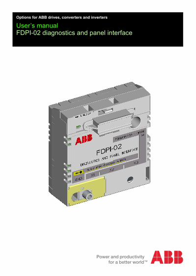
Options for ABB drives, converters and inverters
User’s manualFDPI-02 diagnostics and panel interface

Table of contents 3
Table of contents
1. FDPI-02 diagnostics and panel interfaceSafety . . . . . . . . . . . . . . . . . . . . . . . . . . . . . . . . . . . . . . . . . . . . . . 5Product overview . . . . . . . . . . . . . . . . . . . . . . . . . . . . . . . . . . . . . 5
Layout . . . . . . . . . . . . . . . . . . . . . . . . . . . . . . . . . . . . . . . . . . 6Mechanical installation . . . . . . . . . . . . . . . . . . . . . . . . . . . . . . . . . 9
Installing the FDPI-02 onto the control unit . . . . . . . . . . . . . . 9Installing an F-option module onto the installed FDPI-02 . . 11
Electrical installation . . . . . . . . . . . . . . . . . . . . . . . . . . . . . . . . . 13Connecting the FDPI-02 to the control unit . . . . . . . . . . . . . 13Connecting a control panel to the FDPI-02 . . . . . . . . . . . . . 14Chaining a control panel to several drives . . . . . . . . . . . . . . 16Connecting a PC to the FDPI-02 . . . . . . . . . . . . . . . . . . . . . 19
Connecting a PC through a control panel . . . . . . . . . . . 19Chaining a PC to several drives . . . . . . . . . . . . . . . . . . . . . 22
Chaining a PC connected through a control panel. . . . . 22Connecting chains to the PC’s USB port . . . . . . . . . . . . 22Chaining a PC connected to a commercial converter . . 23
Panel bus termination and chaining examples . . . . . . . . . . 25Example: Chaining a control panel . . . . . . . . . . . . . . . . 25Example: Chaining a PC through a control panel . . . . . 26Example: Connecting chains to the PC’s USB port . . . . 27Example: Chaining a PC through a commercial converter 28
Pin allocation . . . . . . . . . . . . . . . . . . . . . . . . . . . . . . . . . . . . . . . 29Technical data . . . . . . . . . . . . . . . . . . . . . . . . . . . . . . . . . . . . . . 30
RS-485 bus . . . . . . . . . . . . . . . . . . . . . . . . . . . . . . . . . . . . . 31Dimension drawing . . . . . . . . . . . . . . . . . . . . . . . . . . . . . . . . . . 32
Further informationProduct and service inquiries . . . . . . . . . . . . . . . . . . . . . . . . . . . 35Product training . . . . . . . . . . . . . . . . . . . . . . . . . . . . . . . . . . . . . 35Providing feedback on ABB Drives manuals . . . . . . . . . . . . . . . 35
4 Table of contents
Document library on the Internet . . . . . . . . . . . . . . . . . . . . . . . . 35
FDPI-02 diagnostics and panel interface 5
FDPI-02 diagnostics and panel interface
Safety
WARNING! Follow the safety instructions of the manuals delivered with the drive. Ignoring the safety instructions can cause injury or death.
Product overviewFDPI-02 diagnostics and panel interface is used for branching the RS-485 panel bus and chaining a control panel or PC tool to several drives.The interface unit provides a feed-through connection between a control unit and an F-type option module. It is compatible with the ZCU-xx and BCU-xx control units. The interface unit is installed in an option slot of the control unit. A small F-type option module can then be installed on top of the interface unit. The interface unit has one RJ-11 and two RJ-45 connectors. The RJ-11 connector is used for connecting the control unit. The RJ-45 connectors support a daisy chain bus for connecting a PC or a control panel (simultaneous control panel and PC communication is not allowed).Bus termination is required to prevent signal reflections from the bus cable ends. The interface unit has a bus termination switch for the panel/PC cable. If the unit is the first or the last unit of the bus, the termination switch must be in the TERMINATED position. If a control panel is connected to the bus end, it terminates the bus and only the other end must be terminated by termination switch S1. For a termination example, see section Panel bus termination and chaining examples on page 25.
6 FDPI-02 diagnostics and panel interface
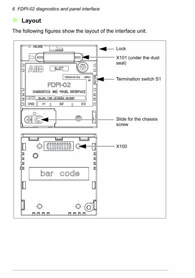
LayoutThe following figures show the layout of the interface unit.
Termination switch S1
X100
X101 (under the dust seal)
Slide for the chassis screw
Lock
FDPI-02 diagnostics and panel interface 7
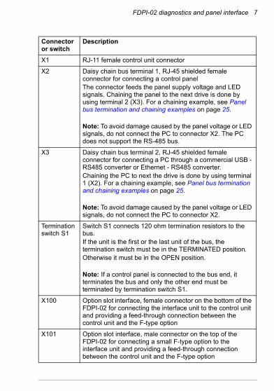
Connector or switch
Description
X1 RJ-11 female control unit connector
X2 Daisy chain bus terminal 1, RJ-45 shielded female connector for connecting a control panelThe connector feeds the panel supply voltage and LED signals. Chaining the panel to the next drive is done by using terminal 2 (X3). For a chaining example, see Panel bus termination and chaining examples on page 25.
Note: To avoid damage caused by the panel voltage or LED signals, do not connect the PC to connector X2. The PC does not support the RS-485 bus.
X3 Daisy chain bus terminal 2, RJ-45 shielded female connector for connecting a PC through a commercial USB - RS485 converter or Ethernet - RS485 converter.Chaining the PC to next the drive is done by using terminal 1 (X2). For a chaining example, see Panel bus termination and chaining examples on page 25.
Note: To avoid damage caused by the panel voltage or LED signals, do not connect the PC to connector X2.
Termination switch S1
Switch S1 connects 120 ohm termination resistors to the bus.If the unit is the first or the last unit of the bus, the termination switch must be in the TERMINATED position.Otherwise it must be in the OPEN position.
Note: If a control panel is connected to the bus end, it terminates the bus and only the other end must be terminated by termination switch S1.
X100 Option slot interface, female connector on the bottom of the FDPI-02 for connecting the interface unit to the control unit and providing a feed-through connection between the control unit and the F-type option
X101 Option slot interface, male connector on the top of the FDPI-02 for connecting a small F-type option to the interface unit and providing a feed-through connection between the control unit and the F-type option
8 FDPI-02 diagnostics and panel interface
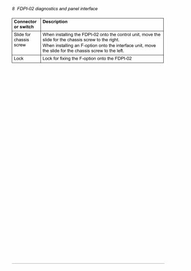
Slide for chassis screw
When installing the FDPI-02 onto the control unit, move the slide for the chassis screw to the right.When installing an F-option onto the interface unit, move the slide for the chassis screw to the left.
Lock Lock for fixing the F-option onto the FDPI-02
Connector or switch
Description
FDPI-02 diagnostics and panel interface 9
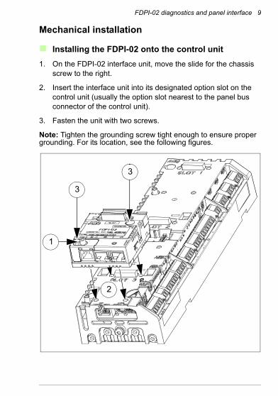
Mechanical installation
Installing the FDPI-02 onto the control unit1. On the FDPI-02 interface unit, move the slide for the chassis
screw to the right.
2. Insert the interface unit into its designated option slot on the control unit (usually the option slot nearest to the panel bus connector of the control unit).
3. Fasten the unit with two screws.
Note: Tighten the grounding screw tight enough to ensure proper grounding. For its location, see the following figures.
3
3
2
1
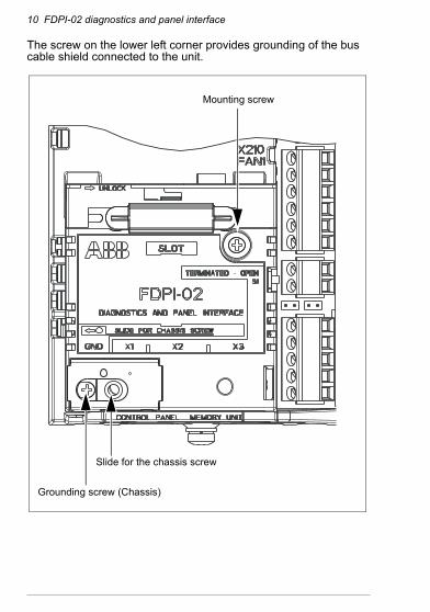
10 FDPI-02 diagnostics and panel interface
The screw on the lower left corner provides grounding of the bus cable shield connected to the unit.
Mounting screw
Grounding screw (Chassis)
Slide for the chassis screw
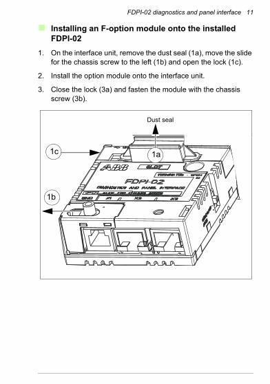
FDPI-02 diagnostics and panel interface 11
Installing an F-option module onto the installed FDPI-02
1. On the interface unit, remove the dust seal (1a), move the slide for the chassis screw to the left (1b) and open the lock (1c).
2. Install the option module onto the interface unit.
3. Close the lock (3a) and fasten the module with the chassis screw (3b).
1a
Dust seal
1b
1c

12 FDPI-02 diagnostics and panel interface
2
3a
3b
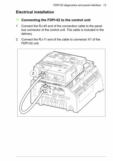
FDPI-02 diagnostics and panel interface 13
Electrical installation
Connecting the FDPI-02 to the control unit1. Connect the RJ-45 end of the connection cable to the panel
bus connector of the control unit. The cable is included in the delivery.
2. Connect the RJ-11 end of the cable to connector X1 of the FDPI-02 unit.
OPENTERMINATED 2
1
14 FDPI-02 diagnostics and panel interface
Connecting a control panel to the FDPI-02Notes: • The FDPI-02 cannot be used for connection to an Ethernet
network.• To avoid damage caused by the panel voltage or LED signals,
do not connect the PC to connector X2.
1. Connect a shielded CAT 5e or better Ethernet cable to the RJ-45 connector of the control panel. For more information on the cable, see RS-485 bus on page 31.
2. Connect the other end of the cable to connector X2 of the FDPI-02 unit.
3. Check that termination switch S1 of the FDPI-02 is in the OPEN position.
Note: When a control panel is connected to the bus end, it terminates the bus. Only the other end must be terminated by turning termination switch S1 to the TERMINATED position.For starting up the control panel, see ACS-AP-x Assistant control panels user’s manual [3AUA0000085685 (English)].
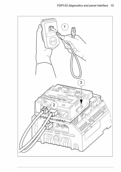
FDPI-02 diagnostics and panel interface 15
OPENTERMINATED
1
3
2
16 FDPI-02 diagnostics and panel interface
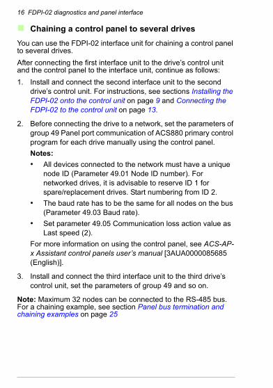
Chaining a control panel to several drivesYou can use the FDPI-02 interface unit for chaining a control panel to several drives. After connecting the first interface unit to the drive’s control unit and the control panel to the interface unit, continue as follows:1. Install and connect the second interface unit to the second
drive’s control unit. For instructions, see sections Installing the FDPI-02 onto the control unit on page 9 and Connecting the FDPI-02 to the control unit on page 13.
2. Before connecting the drive to a network, set the parameters of group 49 Panel port communication of ACS880 primary control program for each drive manually using the control panel. Notes: • All devices connected to the network must have a unique
node ID (Parameter 49.01 Node ID number). For networked drives, it is advisable to reserve ID 1 for spare/replacement drives. Start numbering from ID 2.
• The baud rate has to be the same for all nodes on the bus (Parameter 49.03 Baud rate).
• Set parameter 49.05 Communication loss action value as Last speed (2).
For more information on using the control panel, see ACS-AP-x Assistant control panels user’s manual [3AUA0000085685 (English)].
3. Install and connect the third interface unit to the third drive’s control unit, set the parameters of group 49 and so on.
Note: Maximum 32 nodes can be connected to the RS-485 bus. For a chaining example, see section Panel bus termination and chaining examples on page 25
FDPI-02 diagnostics and panel interface 17
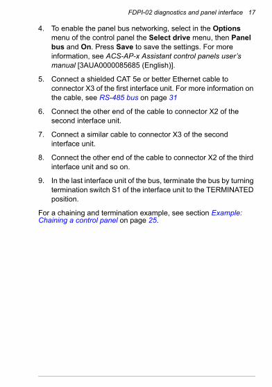
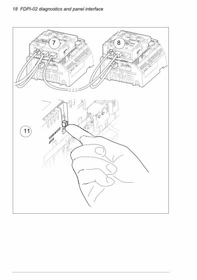
4. To enable the panel bus networking, select in the Options menu of the control panel the Select drive menu, then Panel bus and On. Press Save to save the settings. For more information, see ACS-AP-x Assistant control panels user’s manual [3AUA0000085685 (English)].
5. Connect a shielded CAT 5e or better Ethernet cable to connector X3 of the first interface unit. For more information on the cable, see RS-485 bus on page 31
6. Connect the other end of the cable to connector X2 of the second interface unit.
7. Connect a similar cable to connector X3 of the second interface unit.
8. Connect the other end of the cable to connector X2 of the third interface unit and so on.
9. In the last interface unit of the bus, terminate the bus by turning termination switch S1 of the interface unit to the TERMINATED position.
For a chaining and termination example, see section Example: Chaining a control panel on page 25.
18 FDPI-02 diagnostics and panel interface
OPENTERMINATED
7 8
11
FDPI-02 diagnostics and panel interface 19
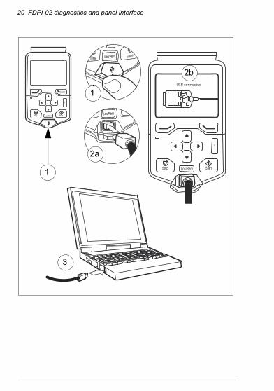
Connecting a PC to the FDPI-02You can connect a PC to the FDPI-02 unit either through a control panel or to a commercial USB - RS485 converter or Ethernet - RS485 converter.Notes: • Never connect the PC to connector X2 of FDPI-02. The panel
voltage or LED signals may cause damage to the PC.• Simultaneous control panel and PC communication is not
allowed.• The FDPI-02 cannot be used for connection to an Ethernet
network.
Connecting a PC through a control panel
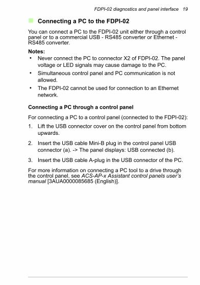
For connecting a PC to a control panel (connected to the FDPI-02):1. Lift the USB connector cover on the control panel from bottom
upwards.
2. Insert the USB cable Mini-B plug in the control panel USB connector (a). -> The panel displays: USB connected (b).
3. Insert the USB cable A-plug in the USB connector of the PC.
For more information on connecting a PC tool to a drive through the control panel, see ACS-AP-x Assistant control panels user’s manual [3AUA0000085685 (English)].
20 FDPI-02 diagnostics and panel interface
?
StartStop Loc/Rem
3
?
StartStop Loc/Rem
USB connected
1
1
2a
2b
FDPI-02 diagnostics and panel interface 21
Connecting a PC through a commercial converterNotes: • Never connect the PC to connector X2 of FDPI-02. The panel
voltage or LED signals may cause damage to the PC.• Simultaneous control panel and PC communication is not
allowed.• The FDPI-02 cannot be used for connection to an Ethernet
network.
For connecting a commercial USB - RS485 converter or Ethernet - RS485 converter to the FDPI-02:1. Connect a shielded CAT 5e or better Ethernet cable to the
connector of the converter. For information on the converter connectors, see the appropriate converter manual. For more information on the cable, see RS-485 bus on page 31.
2. Connect the other end of the cable to connector X3 of the FDPI-02 unit. For the X3 pin information, see section Pin allocation on page 29.
3. Check that termination switch S1 of the FDPI-02 is in the OPEN position.
For connecting the PC to the commercial USB - RS485 converter or Ethernet - RS485 converter, see the appropriate converter and PC manuals.
22 FDPI-02 diagnostics and panel interface
Chaining a PC to several drives
Chaining a PC connected through a control panel
The PC connected to the FDPI-02 interface unit through a control panel is chained to several drives the same way as the control panel. 1. Install and connect the interface units, set the parameters of
group 49 for the drives, enable the panel bus networking, connect the chain cables and terminate the bus. For the instructions, see section Chaining a control panel to several drives on page 16.
2. Connect the PC to the control panel. For the instructions, see section Connecting a PC through a control panel on page 19.
For a chaining example, see section Example: Chaining a PC through a control panel on page 26.
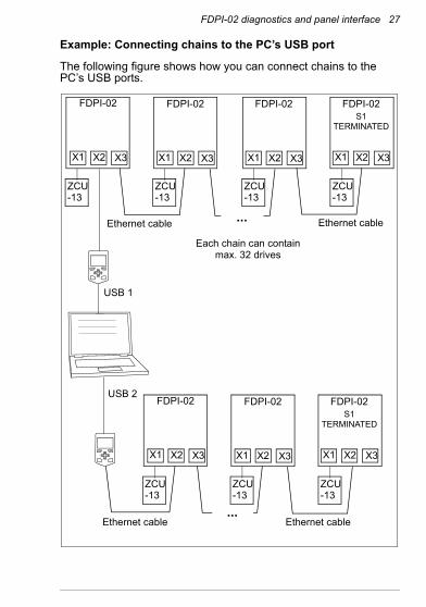
Connecting chains to the PC’s USB port
You can connect chained control panels to more than one USB ports of the same PC. The number of the chains is limited only by the number of the PC’s USB ports. Notes: • Each chain can contain maximum 32 drives.• Each chain must be terminated with the control panel on one
end and with termination switch S1 of FDPI-02 on the other end.
For the chaining instructions, see section Chaining a PC to several drives on page 22. For a chaining example, see Example: Connecting chains to the PC’s USB port on page 27.
FDPI-02 diagnostics and panel interface 23
Chaining a PC connected to a commercial converter
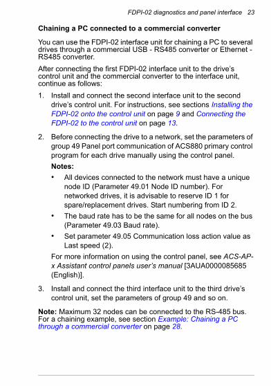
You can use the FDPI-02 interface unit for chaining a PC to several drives through a commercial USB - RS485 converter or Ethernet - RS485 converter. After connecting the first FDPI-02 interface unit to the drive’s control unit and the commercial converter to the interface unit, continue as follows:1. Install and connect the second interface unit to the second
drive’s control unit. For instructions, see sections Installing the FDPI-02 onto the control unit on page 9 and Connecting the FDPI-02 to the control unit on page 13.
2. Before connecting the drive to a network, set the parameters of group 49 Panel port communication of ACS880 primary control program for each drive manually using the control panel. Notes: • All devices connected to the network must have a unique
node ID (Parameter 49.01 Node ID number). For networked drives, it is advisable to reserve ID 1 for spare/replacement drives. Start numbering from ID 2.
• The baud rate has to be the same for all nodes on the bus (Parameter 49.03 Baud rate).
• Set parameter 49.05 Communication loss action value as Last speed (2).
For more information on using the control panel, see ACS-AP-x Assistant control panels user’s manual [3AUA0000085685 (English)].
3. Install and connect the third interface unit to the third drive’s control unit, set the parameters of group 49 and so on.
Note: Maximum 32 nodes can be connected to the RS-485 bus. For a chaining example, see section Example: Chaining a PC through a commercial converter on page 28.
24 FDPI-02 diagnostics and panel interface
4. To enable the panel bus networking, select in the Options menu of the control panel the Select drive menu, then Panel bus and On. Press Save to save the settings. For more information, see ACS-AP-x Assistant control panels user’s manual [3AUA0000085685 (English)].
5. Connect a shielded CAT 5e or better Ethernet cable to connector X2 of the first interface unit. For more information on the cable, see RS-485 bus on page 31
6. Connect the other end of the cable to connector X3 of the second interface unit.
7. Connect a similar cable to connector X2 of the second interface unit.
8. Connect the other end of the cable to connector X3 of the third interface unit and so on.
9. In the last interface unit of the bus, terminate the bus by turning termination switch S1 of the interface unit to the TERMINATED position.
For a chaining and termination example, see section Example: Chaining a PC through a commercial converter on page 28
FDPI-02 diagnostics and panel interface 25
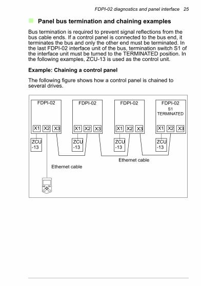
Panel bus termination and chaining examplesBus termination is required to prevent signal reflections from the bus cable ends. If a control panel is connected to the bus end, it terminates the bus and only the other end must be terminated. In the last FDPI-02 interface unit of the bus, termination switch S1 of the interface unit must be turned to the TERMINATED position. In the following examples, ZCU-13 is used as the control unit.
Example: Chaining a control panel
The following figure shows how a control panel is chained to several drives.
FDPI-02 FDPI-02 FDPI-02 S1
TERMINATED
FDPI-02
X1 X2 X3 X1 X2 X3X1 X2 X3X1 X2 X3
ZCU-13
ZCU-13
ZCU-13
ZCU-13
Ethernet cableEthernet cable
26 FDPI-02 diagnostics and panel interface
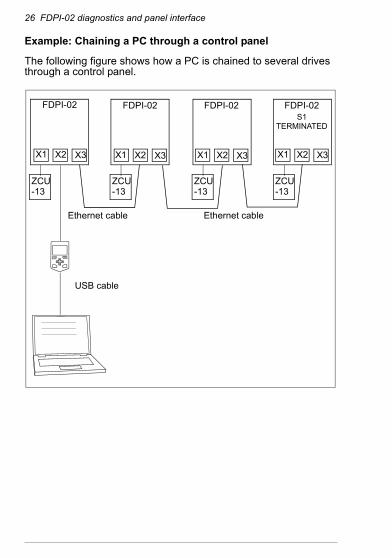
Example: Chaining a PC through a control panel
The following figure shows how a PC is chained to several drives through a control panel.
FDPI-02 FDPI-02 FDPI-02 S1
TERMINATED
FDPI-02
X1 X2 X3 X1 X2 X3X1 X2 X3X1 X2 X3
ZCU-13
ZCU-13
ZCU-13
ZCU-13
USB cable
Ethernet cableEthernet cable
FDPI-02 diagnostics and panel interface 27
Example: Connecting chains to the PC’s USB port
The following figure shows how you can connect chains to the PC’s USB ports.
FDPI-02 FDPI-02 FDPI-02 S1
TERMINATED
FDPI-02
X1 X2 X3 X1 X2 X3X1 X2 X3X1 X2 X3
ZCU-13
ZCU-13
ZCU-13
ZCU-13
USB 1
Ethernet cableEthernet cable
FDPI-02 FDPI-02 S1
TERMINATED
FDPI-02
X1 X2 X3 X1 X2 X3X1 X2 X3
ZCU-13
ZCU-13
ZCU-13
USB 2
Ethernet cable Ethernet cable
...
Each chain can contain max. 32 drives
...
28 FDPI-02 diagnostics and panel interface
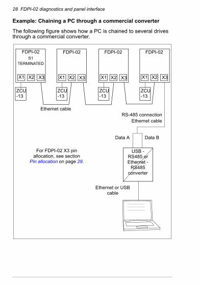
Example: Chaining a PC through a commercial converter
The following figure shows how a PC is chained to several drives through a commercial converter.
FDPI-02 S1
TERMINATED
FDPI-02 FDPI-02 FDPI-02
X1 X2 X3 X1 X2 X3X1 X2 X3X1 X2 X3
ZCU-13
ZCU-13
ZCU-13
ZCU-13
Ethernet cable
Data A Data B
Ethernet or USB cable
For FDPI-02 X3 pin allocation, see section
Pin allocation on page 29.
USB - RS485 or Ethernet -
RS485 converter
RS-485 connectionEthernet cable
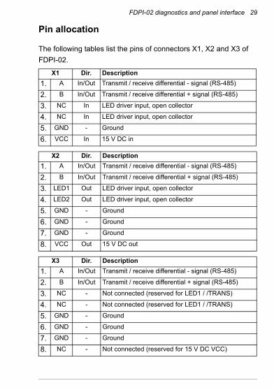
FDPI-02 diagnostics and panel interface 29
Pin allocation
The following tables list the pins of connectors X1, X2 and X3 of FDPI-02.
X1 Dir. Description1. A In/Out Transmit / receive differential - signal (RS-485)
2. B In/Out Transmit / receive differential + signal (RS-485)
3. NC In LED driver input, open collector
4. NC In LED driver input, open collector
5. GND - Ground
6. VCC In 15 V DC in
X2 Dir. Description1. A In/Out Transmit / receive differential - signal (RS-485)
2. B In/Out Transmit / receive differential + signal (RS-485)
3. LED1 Out LED driver input, open collector
4. LED2 Out LED driver input, open collector
5. GND - Ground
6. GND - Ground
7. GND - Ground
8. VCC Out 15 V DC out
X3 Dir. Description1. A In/Out Transmit / receive differential - signal (RS-485)
2. B In/Out Transmit / receive differential + signal (RS-485)
3. NC - Not connected (reserved for LED1 / /TRANS)
4. NC - Not connected (reserved for LED1 / /TRANS)
5. GND - Ground
6. GND - Ground
7. GND - Ground
8. NC - Not connected (reserved for 15 V DC VCC)
30 FDPI-02 diagnostics and panel interface
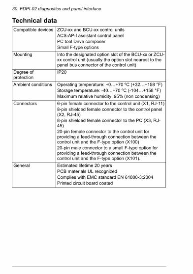
Technical dataCompatible devices ZCU-xx and BCU-xx control units
ACS-AP-I assistant control panelPC tool Drive composerSmall F-type options
Mounting Into the designated option slot of the BCU-xx or ZCU-xx control unit (usually the option slot nearest to the panel bus connector of the control unit)
Degree of protection
IP20
Ambient conditions Operating temperature: +0…+70 ºC (+32…+158 °F)Storage temperature: -40…+70 ºC (-104…+158 °F)Maximum relative humidity: 95% (non condensing)
Connectors 6-pin female connector to the control unit (X1, RJ-11)8-pin shielded female connector to the control panel (X2, RJ-45)8-pin shielded female connector to the PC (X3, RJ-45)20-pin female connector to the control unit for providing a feed-through connection between the control unit and the F-type option (X100)20-pin male connector to a small F-type option for providing a feed-through connection between the control unit and the F-type option (X101).
General Estimated lifetime 20 yearsPCB materials UL recognizedComplies with EMC standard EN 61800-3:2004Printed circuit board coated
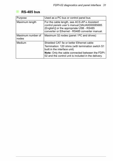
FDPI-02 diagnostics and panel interface 31
RS-485 busPurpose Used as a PC bus or control panel busMaximum length For the cable length, see ACS-AP-x Assistant
control panels user’s manual [3AUA0000085685 (English)] or the appropriate USB - RS485 converter or Ethernet - RS485 converter manual.
Maximum number of nodes
Maximum 32 nodes (panel / PC and drives)
Medium Shielded CAT 5e or better Ethernet cableTermination: 120 ohms (with termination switch S1 built in the interface unit)Note: Only the cable connected between the FDPI-02 and the control unit is included in the delivery.
32 FDPI-02 diagnostics and panel interface
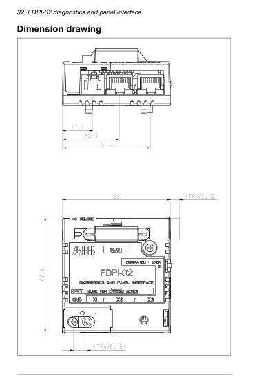
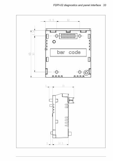
Dimension drawing
FDPI-02 diagnostics and panel interface 33

34 FDPI-02 diagnostics and panel interface
Further information
Product and service inquiriesAddress any inquiries about the product to your local ABB representative, quoting the type designation and serial number of the unit in question. A listing of ABB sales, support and service contacts can be found by navigating to www.abb.com/drives and selecting Sales, Support and Service network.
Product trainingFor information on ABB product training, navigate to www.abb.com/drives and select Training courses.
Providing feedback on ABB Drives manualsYour comments on our manuals are welcome. Go to www.abb.com/drives and select Document Library – Manuals feedback form (LV AC drives).
Document library on the InternetYou can find manuals and other product documents in PDF format on the Internet. Go to www.abb.com/drives and select Document Library. You can browse the library or enter selection criteria, for example a document code, in the search field.

Contact us
www.abb.com/drives www.abb.com/solar www.abb.com/windpowerwww.abb.com/drivespartners
3AU
A000
0113
618
Rev
A (E
N) 2
012-
05-3
1


![Application Programming Interface (API) Reference Guide · API commands ... Video Input Connector [n] ... Video Input Connector [n] Name . Video Input Connector [n] PresentationSelection](https://img.pdfslide.us/doc/110x75/5b74ccc67f8b9aa01f8c8f90/application-programming-interface-api-reference-guide-api-commands-video.jpg)


![USB Type-C™ Connector System Software Interface [UCSI] · PDF fileThe USB Type-C Connector System Software Interface (UCSI) describes the registers and data structures used to interface](https://img.pdfslide.us/doc/110x75/5aa941137f8b9a81188c8939/usb-type-c-connector-system-software-interface-ucsi-usb-type-c-connector-system.jpg)


![USB Type-C Connector System Software Interface Specification · Document Number: 336205-002 . USB Type-C™ Connector System Software Interface [UCSI] Requirements Specification](https://img.pdfslide.us/doc/110x75/5f68ce2b497d8b507b46b775/usb-type-c-connector-system-software-interface-specification-document-number-336205-002.jpg)