Embed Size (px)
DESCRIPTION
E+
Citation preview
EnergyPlus Testing with
ASHRAE 1052-RP Toolkit – Building
Fabric Analytical Tests
EnergyPlus Version 8.2.0
October 2014
Prepared for: U.S. Department of Energy Energy Efficiency and Renewable Energy Office of Building Technologies Washington, D.C. Prepared by: Robert H. Henninger and Michael J. Witte
115 S. Wilke Road, Suite 115 Arlington Heights, IL 60005 USA www.gard.com

This report was developed based upon funding from the Alliance for Sustainable Energy, LLC, Managing and Operating Contractor for the National Renewable Energy Laboratory for the U.S. Department of Energy. Any opinions, findings, and conclusions or recommendations expressed in this material are those of the author(s) and do not necessarily reflect those of the sponsor. Earlier work was supported by the Ernest Orlando Lawrence Berkeley National Laboratory, and by the National Energy Technology Laboratory and the National Renewable Energy Laboratory by subcontract through the University of Central Florida/Florida Solar Energy Center. This report was prepared as an account of work sponsored by an agency of the United States Government. Neither the United States Government nor any agency thereof, nor any of their employees, makes any warranty, express or implied, or assumes any legal liability or responsibility for the accuracy, completeness, or usefulness of any information, apparatus, product, or process disclosed, or represents that its use would not infringe privately owned rights. Reference herein to any specific commercial product, process, or services by trade name, trademark, manufacturer, or otherwise does not necessarily constitute or imply its endorsement, recommendation, or favoring by the United States Government or any agency thereof. The views and opinions of authors expressed herein do not necessarily state or reflect those of the United States Government or any agency thereof.
Table of Contents
Section Page
ASHRAE 1052-RP Analytical Tests iii October 2014
1 TEST OBJECTIVES AND OVERVIEW ......................................................................1
1.1 Test Type: Analytical ........................................................................................... 1
1.2 Test Suite: ASHRAE 1052-RP Toolkit ................................................................ 1
2 RESULTS AND DISCUSSION .......................................................................................5
2.1 Test SSConv – Steady State Convection ............................................................... 5
2.2 Test SSCond – Steady State Conduction .............................................................. 6
2.3 Test TC1 –Transient Conduction, Adiabatic Wall ................................................ 7
2.4 Test TC2 – Transient Conduction, Step Response ................................................ 8
2.4.1 Step-Up in External Temperature ........................................................... 8 2.4.2 Step-Down in External Temperature ...................................................... 9
2.5 Test TC3 – Transient Conduction, Sinusoidal Driving Temperature and Multi-Layer Wall .......................................................................................... 10
2.6 Test ExtSolRad – Exterior Solar Radiation, Opaque Surfaces ........................... 11
2.6.1 South Facing Surface ............................................................................ 11 2.6.2 East Facing Surface .............................................................................. 13
2.7 Test SolRadGlazing – Solar Radiation, Glazed Surfaces .................................... 15
2.7.1 South Facing Surface ............................................................................ 16 2.7.2 East Facing Surface .............................................................................. 17
2.8 Test SolRadShade – Solar Radiation, Window Shading ..................................... 19
2.8.1 South Facing Surface ............................................................................ 20
2.8.2 West Facing Surface ............................................................................. 21
2.9 Test WinReveal – Window Reveal ..................................................................... 24
2.10 Test IntSolarDist – Internal Solar Distribution ................................................... 26
2.11 Test Infiltration-1, Sensible Infiltration Load, Fixed Infiltration Rate ................ 29
2.12 Test Infiltration-2, Stack Effect ........................................................................... 29
2.13 Test ExtLWRad – External Long Wave Radiation ............................................. 31
2.14 Test IntLWRad – Interior Long Wave Radiation ................................................ 32
2.14.1 Test 1 –Ext. Surf. Emis. = 0.9, Oppos. Surf. Emis. = 0.1, Other Surf. Emis. = 0.3......................................................................... 32
2.14.2 Test 2 –Ext. Surf. Emis. = 0.9, All Other Surf. Emis. = 0.1 ................. 34 2.14.3 Test 3 –All Surf. Emis. = 0.9 ................................................................ 35
2.15 Test IntHeatGain – Internal Heat Gains, Convective and Radiative ................... 37
2.16 Test GrdCoup – Ground Coupling, Slab-on-Grade Floor ................................... 39
3 ENERGYPLUS PROBLEMS UNCOVERED WHILE USING ASHRAE
1052-RP TOOLKIT .......................................................................................................41
3.1 Inverted Coordinates for Shade Fins ................................................................... 41
3.2 Sunlit Areas of Surfaces ...................................................................................... 44
3.3 Solar Time Shift .................................................................................................. 45
Table of Contents
Section Page
ASHRAE 1052-RP Analytical Tests iv October 2014
3.4 Underestimating Peak Cooling Loads with Windows ........................................ 47
3.5 Summary of Pertinent Changes that Occurred Between Versions of EnergyPlus ........................................................................................................... 47
4 CONCLUSIONS .............................................................................................................51
5 REFERENCES ...............................................................................................................53
ASHRAE 1052-RP Analytical Tests 1 October 2014
1 TEST OBJECTIVES AND OVERVIEW
1.1 Test Type: Analytical
The ASHRAE 1052-RP Toolkit contains a set of simple analytical tests to test the accuracy of building fabric calculations in building energy analysis programs. Analytical tests compare a program’s results to mathematical solutions for simple cases. This is an excellent method to use for assessing the accuracy of results since there is only one solution for the case analyzed given the boundary conditions. Analytical testing accomplishes results on two different levels, both validation and debugging. Validation is accomplished when the results of the test program compare favorably with the analytical results. Debugging is accomplished when the results for certain cases do not compare favorably with the analytical results and then through systematic checking it is determined that the source of the difference is due to an input error, a modeling inconsistency or flaw in the program logic.
1.2 Test Suite: ASHRAE 1052-RP Toolkit
The tests described in ASHRAE’s report titled Development of an Analytical Verification Test
Suite for Whole Building Energy Simulation Programs – Building Fabric, dated April 2001, (Spitler 2001) were performed.
As stated in the report’s “Introduction to the Test Documentation”:
“A series of tests have been developed that are designed to help verify the ability of whole building energy simulation programs to model various aspects of heat transfer through the building fabric. These tests are each based on analytical solutions. …... These tests are for testing models relating to heat transfer through the building fabric, and not primary or secondary HVAC systems.”
“The objective in each test is usually to test the ability of a building energy analysis program to model a particular heat transfer phenomena. This is done by comparing the test program output with the analytical solution for a special test zone. The data to be compared may be a single load or flux, or hourly loads over one or more days of output. In order to make each test specific and help diagnose problems it is necessary to minimize the number of heat transfer paths (and hence number of models involved). This requires the use of test zones that are rather different in their construction and specification than normal building zones.”
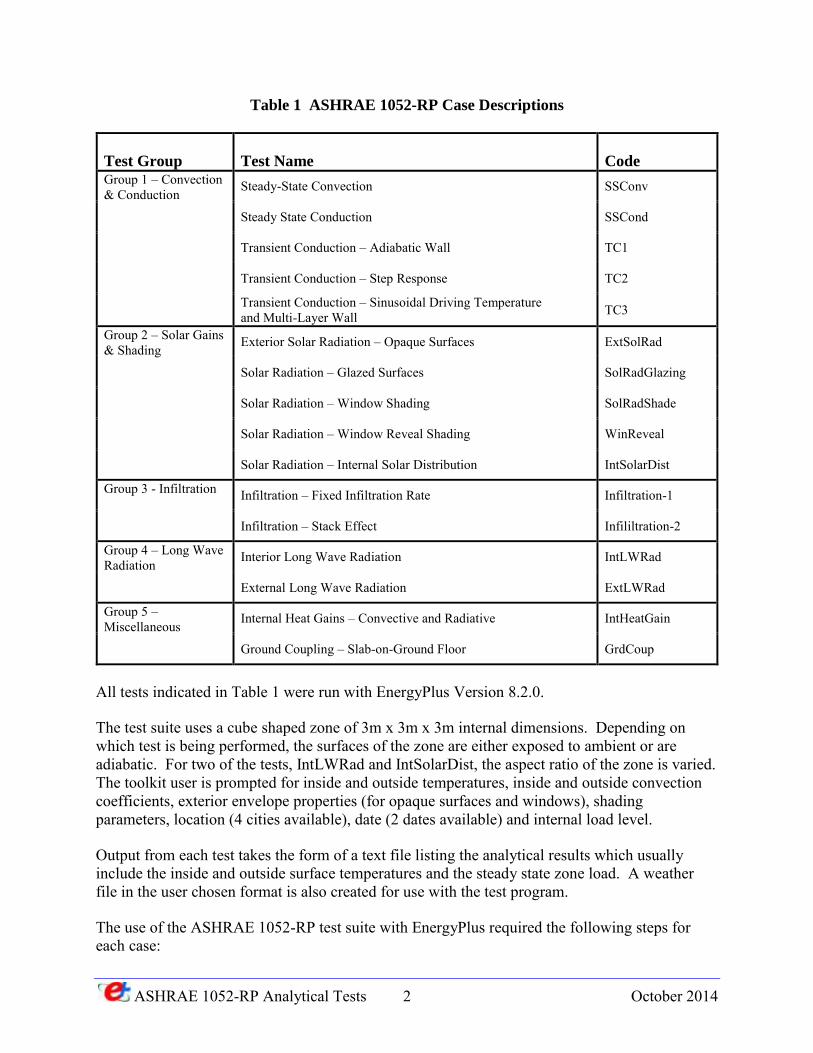
The ASHRAE 1052-RP test suite consists of 16 different tests which, as explained in the ASHRAE report, can be organized into groups relating to particular heat transfer phenomena as shown in Table 1 below.
ASHRAE 1052-RP Analytical Tests 2 October 2014
Table 1 ASHRAE 1052-RP Case Descriptions
Test Group Test Name Code Group 1 – Convection & Conduction Steady-State Convection SSConv
Steady State Conduction SSCond
Transient Conduction – Adiabatic Wall TC1
Transient Conduction – Step Response TC2
Transient Conduction – Sinusoidal Driving Temperature and Multi-Layer Wall TC3
Group 2 – Solar Gains & Shading Exterior Solar Radiation – Opaque Surfaces ExtSolRad
Solar Radiation – Glazed Surfaces SolRadGlazing
Solar Radiation – Window Shading SolRadShade
Solar Radiation – Window Reveal Shading WinReveal
Solar Radiation – Internal Solar Distribution IntSolarDist
Group 3 - Infiltration Infiltration – Fixed Infiltration Rate Infiltration-1
Infiltration – Stack Effect Infililtration-2
Group 4 – Long Wave Radiation Interior Long Wave Radiation IntLWRad
External Long Wave Radiation ExtLWRad
Group 5 – Miscellaneous Internal Heat Gains – Convective and Radiative IntHeatGain
Ground Coupling – Slab-on-Ground Floor GrdCoup
All tests indicated in Table 1 were run with EnergyPlus Version 8.2.0.
The test suite uses a cube shaped zone of 3m x 3m x 3m internal dimensions. Depending on which test is being performed, the surfaces of the zone are either exposed to ambient or are adiabatic. For two of the tests, IntLWRad and IntSolarDist, the aspect ratio of the zone is varied. The toolkit user is prompted for inside and outside temperatures, inside and outside convection coefficients, exterior envelope properties (for opaque surfaces and windows), shading parameters, location (4 cities available), date (2 dates available) and internal load level.
Output from each test takes the form of a text file listing the analytical results which usually include the inside and outside surface temperatures and the steady state zone load. A weather file in the user chosen format is also created for use with the test program.
The use of the ASHRAE 1052-RP test suite with EnergyPlus required the following steps for each case:
ASHRAE 1052-RP Analytical Tests 3 October 2014
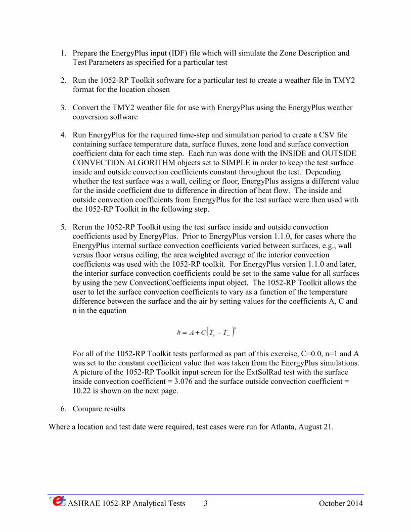
1. Prepare the EnergyPlus input (IDF) file which will simulate the Zone Description and Test Parameters as specified for a particular test
2. Run the 1052-RP Toolkit software for a particular test to create a weather file in TMY2 format for the location chosen
3. Convert the TMY2 weather file for use with EnergyPlus using the EnergyPlus weather conversion software
4. Run EnergyPlus for the required time-step and simulation period to create a CSV file containing surface temperature data, surface fluxes, zone load and surface convection coefficient data for each time step. Each run was done with the INSIDE and OUTSIDE CONVECTION ALGORITHM objects set to SIMPLE in order to keep the test surface inside and outside convection coefficients constant throughout the test. Depending whether the test surface was a wall, ceiling or floor, EnergyPlus assigns a different value for the inside coefficient due to difference in direction of heat flow. The inside and outside convection coefficients from EnergyPlus for the test surface were then used with the 1052-RP Toolkit in the following step.
5. Rerun the 1052-RP Toolkit using the test surface inside and outside convection coefficients used by EnergyPlus. Prior to EnergyPlus version 1.1.0, for cases where the EnergyPlus internal surface convection coefficients varied between surfaces, e.g., wall versus floor versus ceiling, the area weighted average of the interior convection coefficients was used with the 1052-RP toolkit. For EnergyPlus version 1.1.0 and later, the interior surface convection coefficients could be set to the same value for all surfaces by using the new ConvectionCoefficients input object. The 1052-RP Toolkit allows the user to let the surface convection coefficients to vary as a function of the temperature difference between the surface and the air by setting values for the coefficients A, C and n in the equation
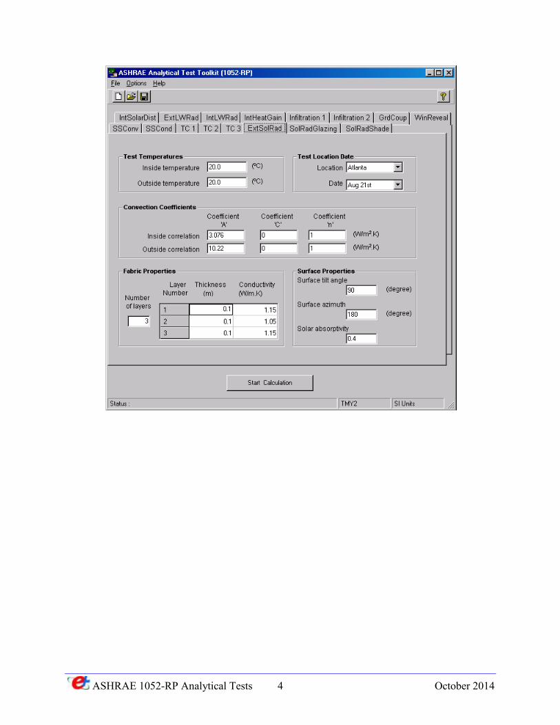
For all of the 1052-RP Toolkit tests performed as part of this exercise, C=0.0, n=1 and A was set to the constant coefficient value that was taken from the EnergyPlus simulations. A picture of the 1052-RP Toolkit input screen for the ExtSolRad test with the surface inside convection coefficient = 3.076 and the surface outside convection coefficient = 10.22 is shown on the next page.
6. Compare results
Where a location and test date were required, test cases were run for Atlanta, August 21.
ASHRAE 1052-RP Analytical Tests 4 October 2014
ASHRAE 1052-RP Analytical Tests 5 October 2014
2 RESULTS AND DISCUSSION
EnergyPlus results for each of the 16 ASHRAE 1052-RP analytical tests are presented here in this section in either spreadsheet format (for cases where only a single point comparison was required) or chart format (for cases where a time series comparison was required).
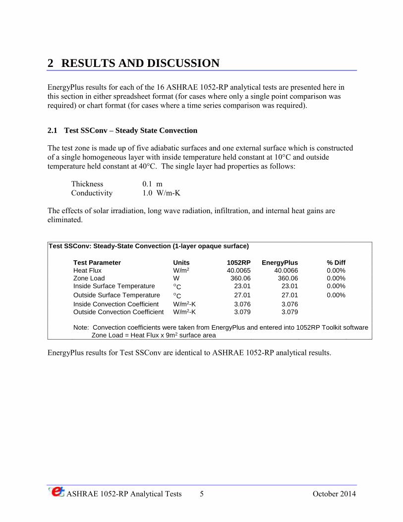
2.1 Test SSConv – Steady State Convection
The test zone is made up of five adiabatic surfaces and one external surface which is constructed of a single homogeneous layer with inside temperature held constant at 10°C and outside temperature held constant at 40°C. The single layer had properties as follows:
Thickness 0.1 m Conductivity 1.0 W/m-K
The effects of solar irradiation, long wave radiation, infiltration, and internal heat gains are eliminated.
Test SSConv: Steady-State Convection (1-layer opaque surface)
Test Parameter Units 1052RP EnergyPlus % Diff
Heat Flux W/m2 40.0065 40.0066 0.00%
Zone Load W 360.06 360.06 0.00%
Inside Surface Temperature °C 23.01 23.01 0.00%
Outside Surface Temperature °C 27.01 27.01 0.00%
Inside Convection Coefficient W/m2-K 3.076 3.076
Outside Convection Coefficient W/m2-K 3.079 3.079
Note: Convection coefficients were taken from EnergyPlus and entered into 1052RP Toolkit software
Zone Load = Heat Flux x 9m2 surface area
EnergyPlus results for Test SSConv are identical to ASHRAE 1052-RP analytical results.
ASHRAE 1052-RP Analytical Tests 6 October 2014
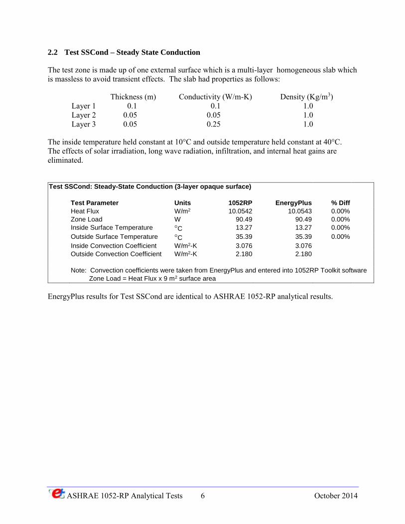
2.2 Test SSCond – Steady State Conduction
The test zone is made up of one external surface which is a multi-layer homogeneous slab which is massless to avoid transient effects. The slab had properties as follows:
Thickness (m) Conductivity (W/m-K) Density (Kg/m3) Layer 1 0.1 0.1 1.0 Layer 2 0.05 0.05 1.0 Layer 3 0.05 0.25 1.0
The inside temperature held constant at 10°C and outside temperature held constant at 40°C. The effects of solar irradiation, long wave radiation, infiltration, and internal heat gains are eliminated.
Test SSCond: Steady-State Conduction (3-layer opaque surface)
Test Parameter Units 1052RP EnergyPlus % Diff
Heat Flux W/m2 10.0542 10.0543 0.00%
Zone Load W 90.49 90.49 0.00%
Inside Surface Temperature °C 13.27 13.27 0.00%
Outside Surface Temperature °C 35.39 35.39 0.00%
Inside Convection Coefficient W/m2-K 3.076 3.076
Outside Convection Coefficient W/m2-K 2.180 2.180
Note: Convection coefficients were taken from EnergyPlus and entered into 1052RP Toolkit software
Zone Load = Heat Flux x 9 m2 surface area
EnergyPlus results for Test SSCond are identical to ASHRAE 1052-RP analytical results.
ASHRAE 1052-RP Analytical Tests 7 October 2014
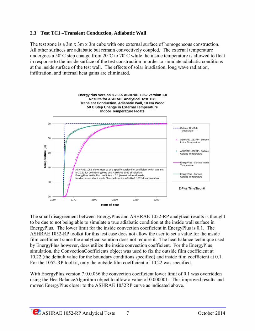
2.3 Test TC1 –Transient Conduction, Adiabatic Wall
The test zone is a 3m x 3m x 3m cube with one external surface of homogeneous construction. All other surfaces are adiabatic but remain convectively coupled. The external temperature undergoes a 50°C step change from 20°C to 70°C while the inside temperature is allowed to float in response to the inside surface of the test construction in order to simulate adiabatic conditions at the inside surface of the test wall. The effects of solar irradiation, long wave radiation, infiltration, and internal heat gains are eliminated.
The small disagreement between EnergyPlus and ASHRAE 1052-RP analytical results is thought to be due to not being able to simulate a true adiabatic condition at the inside wall surface in EnergyPlus. The lower limit for the inside convection coefficient in EnergyPlus is 0.1. The ASHRAE 1052-RP toolkit for this test case does not allow the user to set a value for the inside film coefficient since the analytical solution does not require it. The heat balance technique used by EnergyPlus however, does utilize the inside convection coefficient. For the EnergyPlus simulation, the ConvectionCoefficients object was used to fix the outside film coefficient at 10.22 (the default value for the boundary conditions specified) and inside film coefficient at 0.1. For the 1052-RP toolkit, only the outside film coefficient of 10.22 was specified.
With EnergyPlus version 7.0.0.036 the convection coefficient lower limit of 0.1 was overridden using the HeatBalanceAlgorithm object to allow a value of 0.000001. This improved results and moved EnergyPlus closer to the ASHRAE 1052RP curve as indicated above.
20
30
40
50
60
70
2150 2170 2190 2210 2230 2250
Te
mp
era
ture
(C
)
Hour of Year
EnergyPlus Version 8.2.0 & ASHRAE 1052 Version 1.0Results for ASHRAE Analytical Test TC1
Transient Conduction, Adiabatic Wall, 10 cm Wood50 C Step Change in External Temperature
Indoor Temperature Floats
Outdoor Dry BulbTemperature
ASHRAE 1052RP - SurfaceInside Temperature
ASHRAE 1052RP - SurfaceOutside Temperature
EnergyPlus - Surface InsideTemperature
EnergyPlus - SurfaceOutside Temperature
ASHRAE 1052 allows user to only specify outside film coefficient which was set to 10.22 for both EnergyPlus and ASHRAE 1052 simulations.EnergyPlus inside film coefficient = 0.1 (lowest value allowed).No discussion about inside film coefficient in ASHRAE 1052 documentation.
E-Plus TimeStep=6
ASHRAE 1052-RP Analytical Tests 8 October 2014
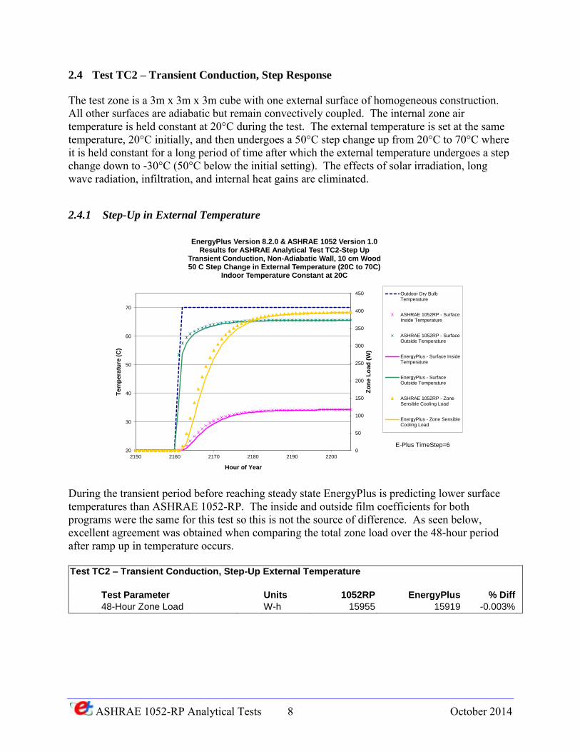
2.4 Test TC2 – Transient Conduction, Step Response
The test zone is a 3m x 3m x 3m cube with one external surface of homogeneous construction. All other surfaces are adiabatic but remain convectively coupled. The internal zone air temperature is held constant at 20°C during the test. The external temperature is set at the same temperature, 20°C initially, and then undergoes a 50°C step change up from 20°C to 70°C where it is held constant for a long period of time after which the external temperature undergoes a step change down to -30°C (50°C below the initial setting). The effects of solar irradiation, long wave radiation, infiltration, and internal heat gains are eliminated.
2.4.1 Step-Up in External Temperature
During the transient period before reaching steady state EnergyPlus is predicting lower surface temperatures than ASHRAE 1052-RP. The inside and outside film coefficients for both programs were the same for this test so this is not the source of difference. As seen below, excellent agreement was obtained when comparing the total zone load over the 48-hour period after ramp up in temperature occurs. Test TC2 – Transient Conduction, Step-Up External Temperature
Test Parameter Units 1052RP EnergyPlus % Diff
48-Hour Zone Load W-h 15955 15919 -0.003%
0
50
100
150
200
250
300
350
400
450
20
30
40
50
60
70
2150 2160 2170 2180 2190 2200
Zo
ne
Lo
ad
(W
)
Te
mp
era
ture
(C
)
Hour of Year
EnergyPlus Version 8.2.0 & ASHRAE 1052 Version 1.0Results for ASHRAE Analytical Test TC2-Step Up
Transient Conduction, Non-Adiabatic Wall, 10 cm Wood50 C Step Change in External Temperature (20C to 70C)
Indoor Temperature Constant at 20C
Outdoor Dry BulbTemperature
ASHRAE 1052RP - SurfaceInside Temperature
ASHRAE 1052RP - SurfaceOutside Temperature
EnergyPlus - Surface InsideTemperature
EnergyPlus - SurfaceOutside Temperature
ASHRAE 1052RP - ZoneSensible Cooling Load
EnergyPlus - Zone SensibleCooling Load
E-Plus TimeStep=6
ASHRAE 1052-RP Analytical Tests 9 October 2014
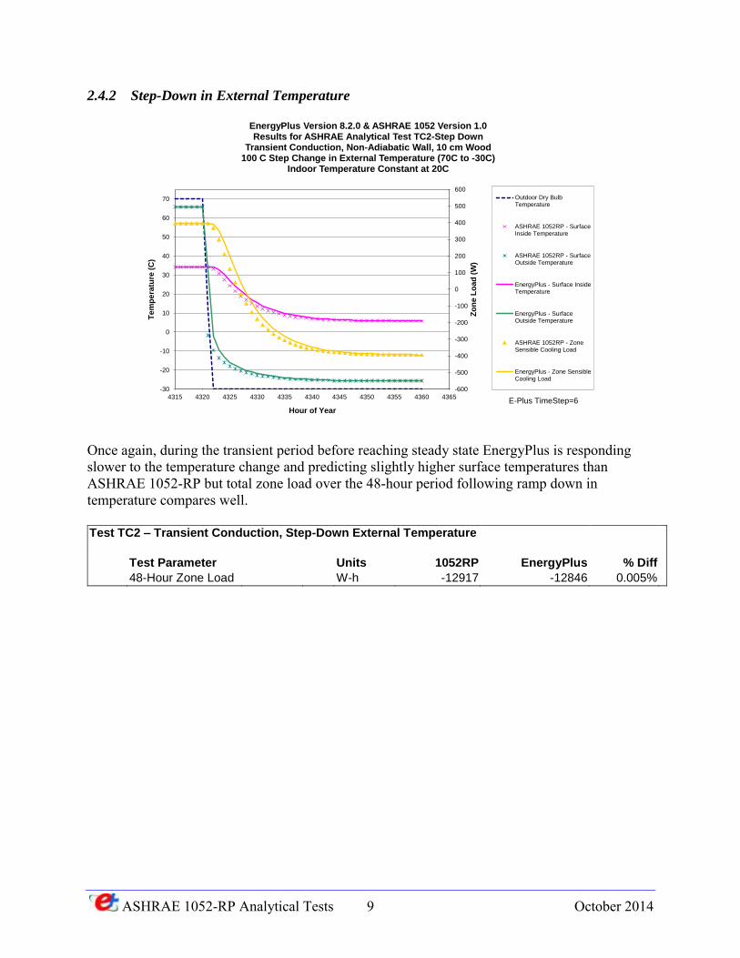
2.4.2 Step-Down in External Temperature
Once again, during the transient period before reaching steady state EnergyPlus is responding slower to the temperature change and predicting slightly higher surface temperatures than ASHRAE 1052-RP but total zone load over the 48-hour period following ramp down in temperature compares well. Test TC2 – Transient Conduction, Step-Down External Temperature
Test Parameter Units 1052RP EnergyPlus % Diff
48-Hour Zone Load W-h -12917 -12846 0.005%
-600
-500
-400
-300
-200
-100
0
100
200
300
400
500
600
-30
-20
-10
0
10
20
30
40
50
60
70
4315 4320 4325 4330 4335 4340 4345 4350 4355 4360 4365
Zo
ne
Lo
ad
(W
)
Te
mp
era
ture
(C
)
Hour of Year
EnergyPlus Version 8.2.0 & ASHRAE 1052 Version 1.0Results for ASHRAE Analytical Test TC2-Step Down
Transient Conduction, Non-Adiabatic Wall, 10 cm Wood100 C Step Change in External Temperature (70C to -30C)
Indoor Temperature Constant at 20C
Outdoor Dry BulbTemperature
ASHRAE 1052RP - SurfaceInside Temperature
ASHRAE 1052RP - SurfaceOutside Temperature
EnergyPlus - Surface InsideTemperature
EnergyPlus - SurfaceOutside Temperature
ASHRAE 1052RP - ZoneSensible Cooling Load
EnergyPlus - Zone SensibleCooling Load
E-Plus TimeStep=6
ASHRAE 1052-RP Analytical Tests 10 October 2014
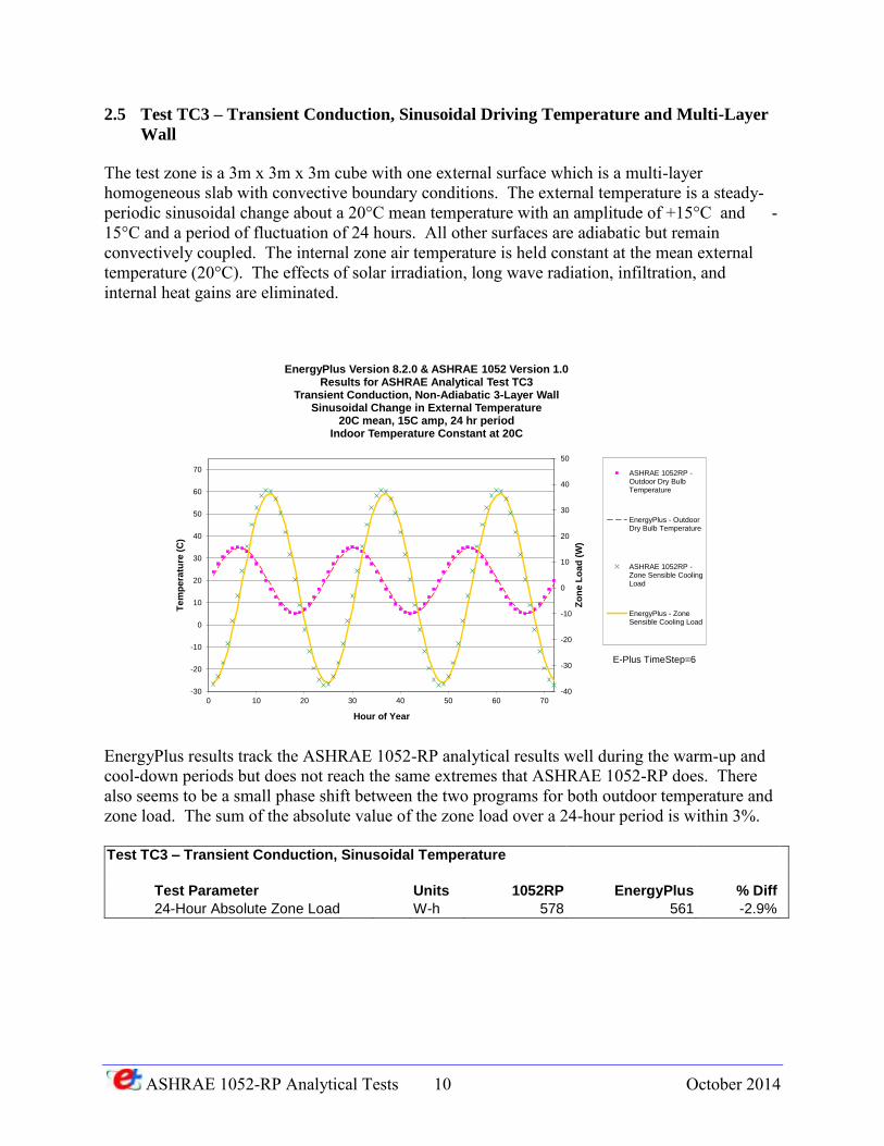
2.5 Test TC3 – Transient Conduction, Sinusoidal Driving Temperature and Multi-Layer
Wall
The test zone is a 3m x 3m x 3m cube with one external surface which is a multi-layer homogeneous slab with convective boundary conditions. The external temperature is a steady-periodic sinusoidal change about a 20°C mean temperature with an amplitude of +15°C and -15°C and a period of fluctuation of 24 hours. All other surfaces are adiabatic but remain convectively coupled. The internal zone air temperature is held constant at the mean external temperature (20°C). The effects of solar irradiation, long wave radiation, infiltration, and internal heat gains are eliminated.
EnergyPlus results track the ASHRAE 1052-RP analytical results well during the warm-up and cool-down periods but does not reach the same extremes that ASHRAE 1052-RP does. There also seems to be a small phase shift between the two programs for both outdoor temperature and zone load. The sum of the absolute value of the zone load over a 24-hour period is within 3%. Test TC3 – Transient Conduction, Sinusoidal Temperature
Test Parameter Units 1052RP EnergyPlus % Diff
24-Hour Absolute Zone Load W-h 578 561 -2.9%
-40
-30
-20
-10
0
10
20
30
40
50
-30
-20
-10
0
10
20
30
40
50
60
70
0 10 20 30 40 50 60 70
Zo
ne
Lo
ad
(W
)
Te
mp
era
ture
(C
)
Hour of Year
EnergyPlus Version 8.2.0 & ASHRAE 1052 Version 1.0Results for ASHRAE Analytical Test TC3
Transient Conduction, Non-Adiabatic 3-Layer WallSinusoidal Change in External Temperature
20C mean, 15C amp, 24 hr periodIndoor Temperature Constant at 20C
ASHRAE 1052RP -Outdoor Dry BulbTemperature
EnergyPlus - OutdoorDry Bulb Temperature
ASHRAE 1052RP -Zone Sensible CoolingLoad
EnergyPlus - ZoneSensible Cooling Load
E-Plus TimeStep=6
ASHRAE 1052-RP Analytical Tests 11 October 2014
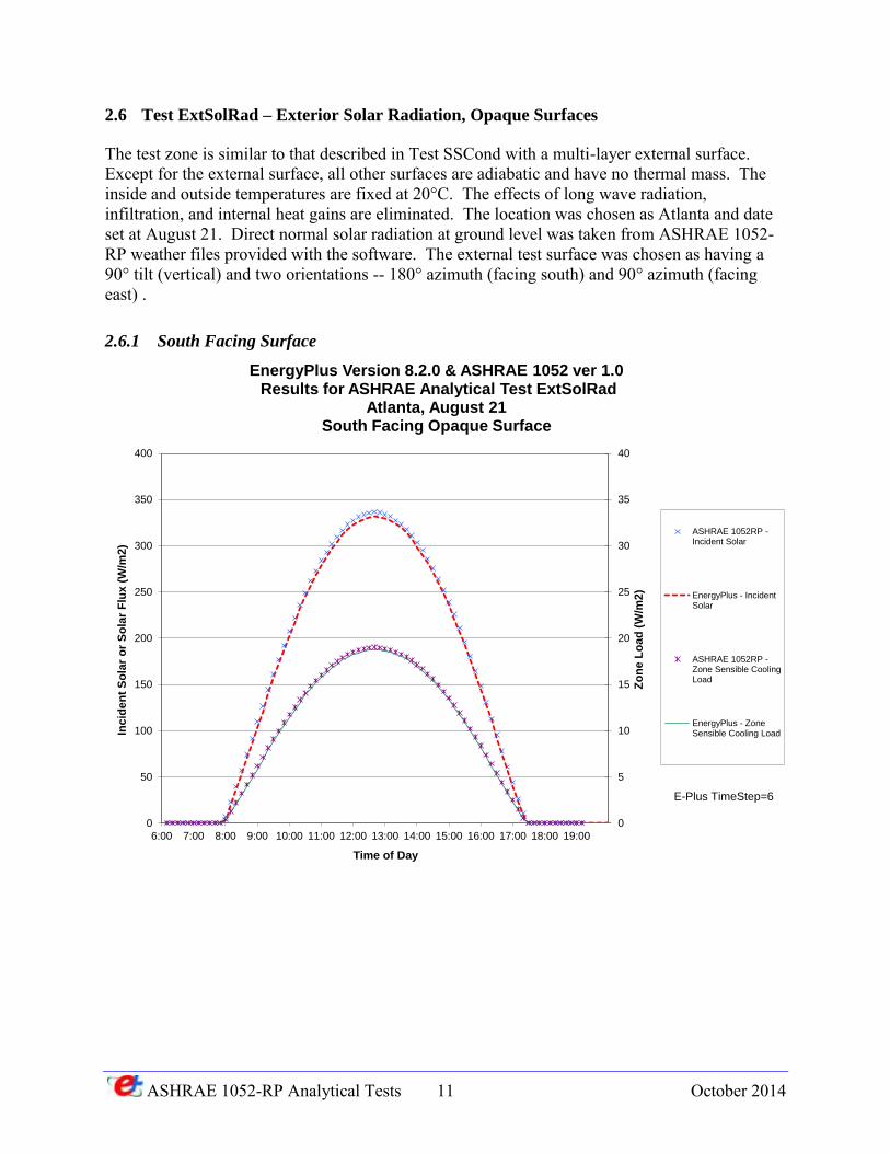
2.6 Test ExtSolRad – Exterior Solar Radiation, Opaque Surfaces
The test zone is similar to that described in Test SSCond with a multi-layer external surface. Except for the external surface, all other surfaces are adiabatic and have no thermal mass. The inside and outside temperatures are fixed at 20°C. The effects of long wave radiation, infiltration, and internal heat gains are eliminated. The location was chosen as Atlanta and date set at August 21. Direct normal solar radiation at ground level was taken from ASHRAE 1052-RP weather files provided with the software. The external test surface was chosen as having a 90° tilt (vertical) and two orientations -- 180° azimuth (facing south) and 90° azimuth (facing east) .
2.6.1 South Facing Surface
0
5
10
15
20
25
30
35
40
0
50
100
150
200
250
300
350
400
6:00 7:00 8:00 9:00 10:00 11:00 12:00 13:00 14:00 15:00 16:00 17:00 18:00 19:00
Zo
ne
Lo
ad
(W
/m2
)
Inc
ide
nt
So
lar
or
So
lar
Flu
x (
W/m
2)
Time of Day
EnergyPlus Version 8.2.0 & ASHRAE 1052 ver 1.0Results for ASHRAE Analytical Test ExtSolRad
Atlanta, August 21South Facing Opaque Surface
ASHRAE 1052RP -Incident Solar
EnergyPlus - IncidentSolar
ASHRAE 1052RP -Zone Sensible CoolingLoad
EnergyPlus - ZoneSensible Cooling Load
E-Plus TimeStep=6
ASHRAE 1052-RP Analytical Tests 12 October 2014
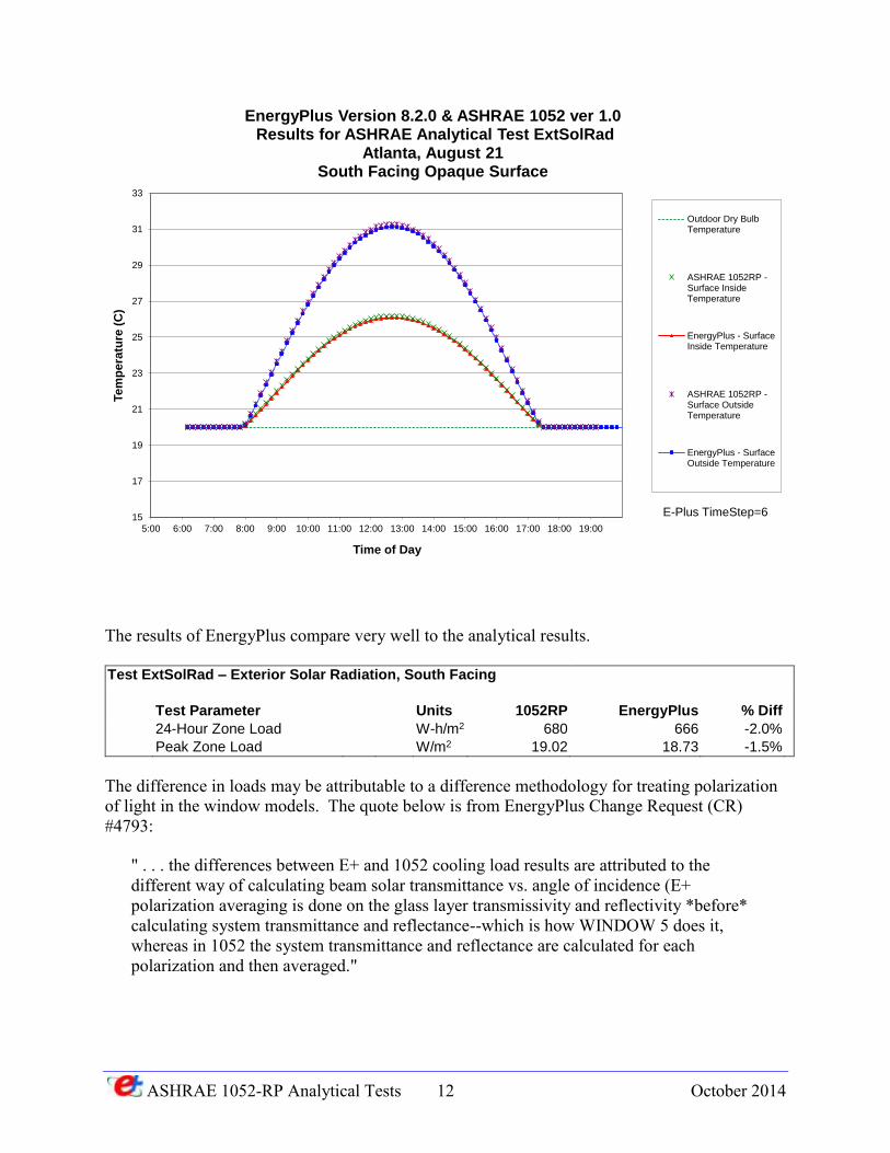
The results of EnergyPlus compare very well to the analytical results. Test ExtSolRad – Exterior Solar Radiation, South Facing
Test Parameter Units 1052RP EnergyPlus % Diff
24-Hour Zone Load W-h/m2 680 666 -2.0%
Peak Zone Load W/m2 19.02 18.73 -1.5%
The difference in loads may be attributable to a difference methodology for treating polarization of light in the window models. The quote below is from EnergyPlus Change Request (CR) #4793:
" . . . the differences between E+ and 1052 cooling load results are attributed to the different way of calculating beam solar transmittance vs. angle of incidence (E+ polarization averaging is done on the glass layer transmissivity and reflectivity *before* calculating system transmittance and reflectance--which is how WINDOW 5 does it, whereas in 1052 the system transmittance and reflectance are calculated for each polarization and then averaged."
15
17
19
21
23
25
27
29
31
33
5:00 6:00 7:00 8:00 9:00 10:00 11:00 12:00 13:00 14:00 15:00 16:00 17:00 18:00 19:00
Te
mp
era
ture
(C
)
Time of Day
EnergyPlus Version 8.2.0 & ASHRAE 1052 ver 1.0Results for ASHRAE Analytical Test ExtSolRad
Atlanta, August 21South Facing Opaque Surface
Outdoor Dry BulbTemperature
ASHRAE 1052RP -Surface InsideTemperature
EnergyPlus - SurfaceInside Temperature
ASHRAE 1052RP -Surface OutsideTemperature
EnergyPlus - SurfaceOutside Temperature
E-Plus TimeStep=6
ASHRAE 1052-RP Analytical Tests 13 October 2014
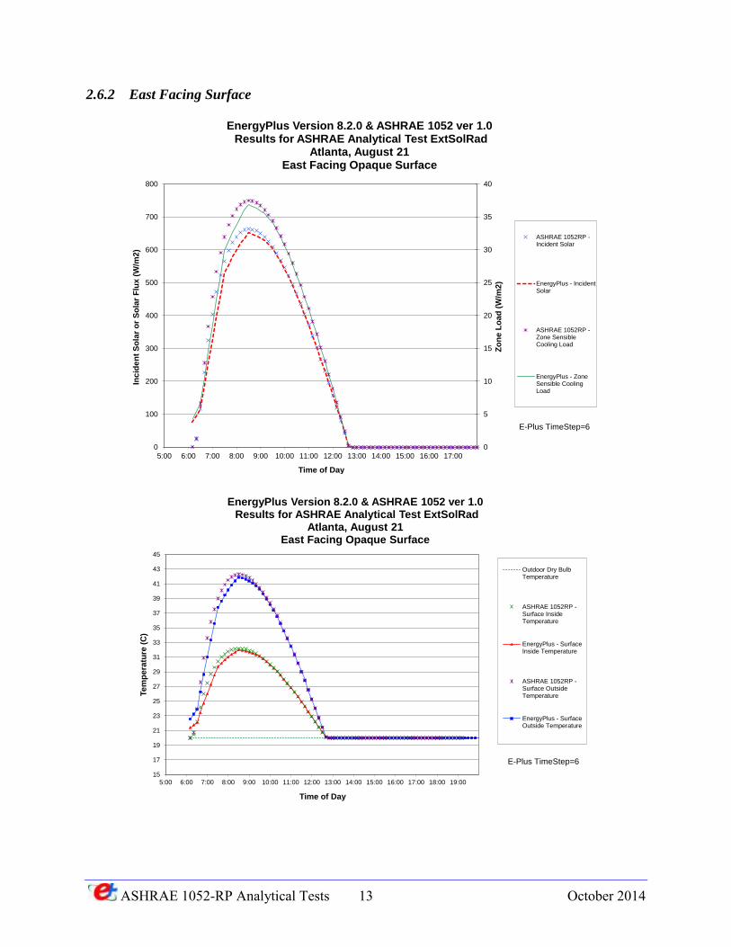
2.6.2 East Facing Surface
0
5
10
15
20
25
30
35
40
0
100
200
300
400
500
600
700
800
5:00 6:00 7:00 8:00 9:00 10:00 11:00 12:00 13:00 14:00 15:00 16:00 17:00
Zo
ne L
oad
(W
/m2
)
Inc
ide
nt
So
lar
or
So
lar
Flu
x (
W/m
2)
Time of Day
EnergyPlus Version 8.2.0 & ASHRAE 1052 ver 1.0Results for ASHRAE Analytical Test ExtSolRad
Atlanta, August 21East Facing Opaque Surface
ASHRAE 1052RP -Incident Solar
EnergyPlus - IncidentSolar
ASHRAE 1052RP -Zone SensibleCooling Load
EnergyPlus - ZoneSensible CoolingLoad
E-Plus TimeStep=6
15
17
19
21
23
25
27
29
31
33
35
37
39
41
43
45
5:00 6:00 7:00 8:00 9:00 10:00 11:00 12:00 13:00 14:00 15:00 16:00 17:00 18:00 19:00
Te
mp
era
ture
(C
)
Time of Day
EnergyPlus Version 8.2.0 & ASHRAE 1052 ver 1.0Results for ASHRAE Analytical Test ExtSolRad
Atlanta, August 21East Facing Opaque Surface
Outdoor Dry BulbTemperature
ASHRAE 1052RP -Surface InsideTemperature
EnergyPlus - SurfaceInside Temperature
ASHRAE 1052RP -Surface OutsideTemperature
EnergyPlus - SurfaceOutside Temperature
E-Plus TimeStep=6
ASHRAE 1052-RP Analytical Tests 14 October 2014
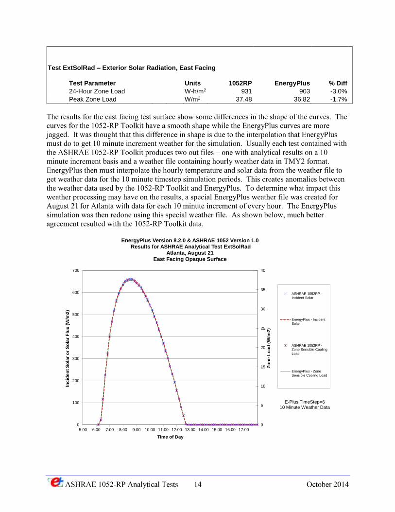
Test ExtSolRad – Exterior Solar Radiation, East Facing
Test Parameter Units 1052RP EnergyPlus % Diff
24-Hour Zone Load W-h/m2 931 903 -3.0%
Peak Zone Load W/m2 37.48 36.82 -1.7%
The results for the east facing test surface show some differences in the shape of the curves. The curves for the 1052-RP Toolkit have a smooth shape while the EnergyPlus curves are more jagged. It was thought that this difference in shape is due to the interpolation that EnergyPlus must do to get 10 minute increment weather for the simulation. Usually each test contained with the ASHRAE 1052-RP Toolkit produces two out files – one with analytical results on a 10 minute increment basis and a weather file containing hourly weather data in TMY2 format. EnergyPlus then must interpolate the hourly temperature and solar data from the weather file to get weather data for the 10 minute timestep simulation periods. This creates anomalies between the weather data used by the 1052-RP Toolkit and EnergyPlus. To determine what impact this weather processing may have on the results, a special EnergyPlus weather file was created for August 21 for Atlanta with data for each 10 minute increment of every hour. The EnergyPlus simulation was then redone using this special weather file. As shown below, much better agreement resulted with the 1052-RP Toolkit data.
0
5
10
15
20
25
30
35
40
0
100
200
300
400
500
600
700
5:00 6:00 7:00 8:00 9:00 10:00 11:00 12:00 13:00 14:00 15:00 16:00 17:00
Zo
ne
Lo
ad
(W
/m2
)
Inc
ide
nt
So
lar
or
So
lar
Flu
x (
W/m
2)
Time of Day
EnergyPlus Version 8.2.0 & ASHRAE 1052 Version 1.0Results for ASHRAE Analytical Test ExtSolRad
Atlanta, August 21East Facing Opaque Surface
ASHRAE 1052RP -Incident Solar
EnergyPlus - IncidentSolar
ASHRAE 1052RP -Zone Sensible CoolingLoad
EnergyPlus - ZoneSensible Cooling Load
E-Plus TimeStep=610 Minute Weather Data
ASHRAE 1052-RP Analytical Tests 15 October 2014
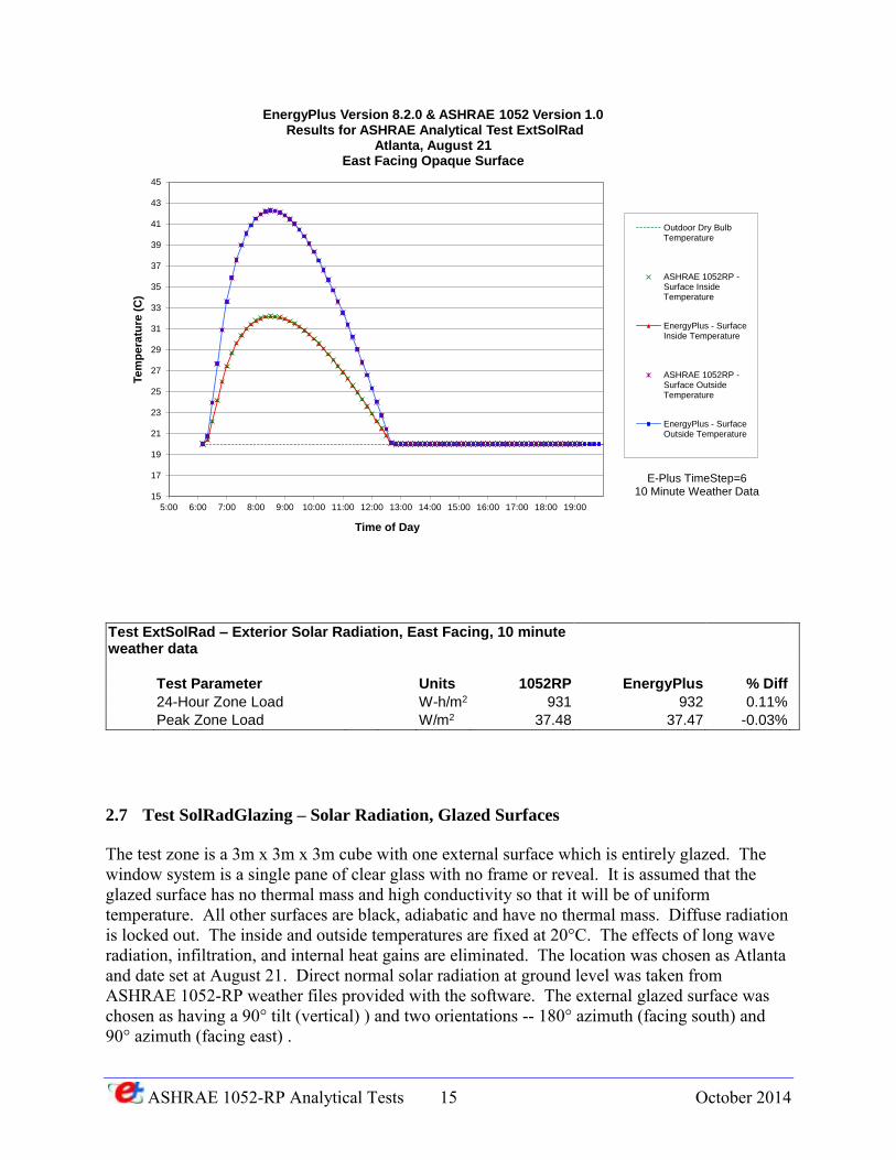
Test ExtSolRad – Exterior Solar Radiation, East Facing, 10 minute weather data
Test Parameter Units 1052RP EnergyPlus % Diff
24-Hour Zone Load W-h/m2 931 932 0.11%
Peak Zone Load W/m2 37.48 37.47 -0.03%
2.7 Test SolRadGlazing – Solar Radiation, Glazed Surfaces
The test zone is a 3m x 3m x 3m cube with one external surface which is entirely glazed. The window system is a single pane of clear glass with no frame or reveal. It is assumed that the glazed surface has no thermal mass and high conductivity so that it will be of uniform temperature. All other surfaces are black, adiabatic and have no thermal mass. Diffuse radiation is locked out. The inside and outside temperatures are fixed at 20°C. The effects of long wave radiation, infiltration, and internal heat gains are eliminated. The location was chosen as Atlanta and date set at August 21. Direct normal solar radiation at ground level was taken from ASHRAE 1052-RP weather files provided with the software. The external glazed surface was chosen as having a 90° tilt (vertical) ) and two orientations -- 180° azimuth (facing south) and 90° azimuth (facing east) .
15
17
19
21
23
25
27
29
31
33
35
37
39
41
43
45
5:00 6:00 7:00 8:00 9:00 10:00 11:00 12:00 13:00 14:00 15:00 16:00 17:00 18:00 19:00
Te
mp
era
ture
(C
)
Time of Day
EnergyPlus Version 8.2.0 & ASHRAE 1052 Version 1.0Results for ASHRAE Analytical Test ExtSolRad
Atlanta, August 21East Facing Opaque Surface
Outdoor Dry BulbTemperature
ASHRAE 1052RP -Surface InsideTemperature
EnergyPlus - SurfaceInside Temperature
ASHRAE 1052RP -Surface OutsideTemperature
EnergyPlus - SurfaceOutside Temperature
E-Plus TimeStep=610 Minute Weather Data
ASHRAE 1052-RP Analytical Tests 16 October 2014
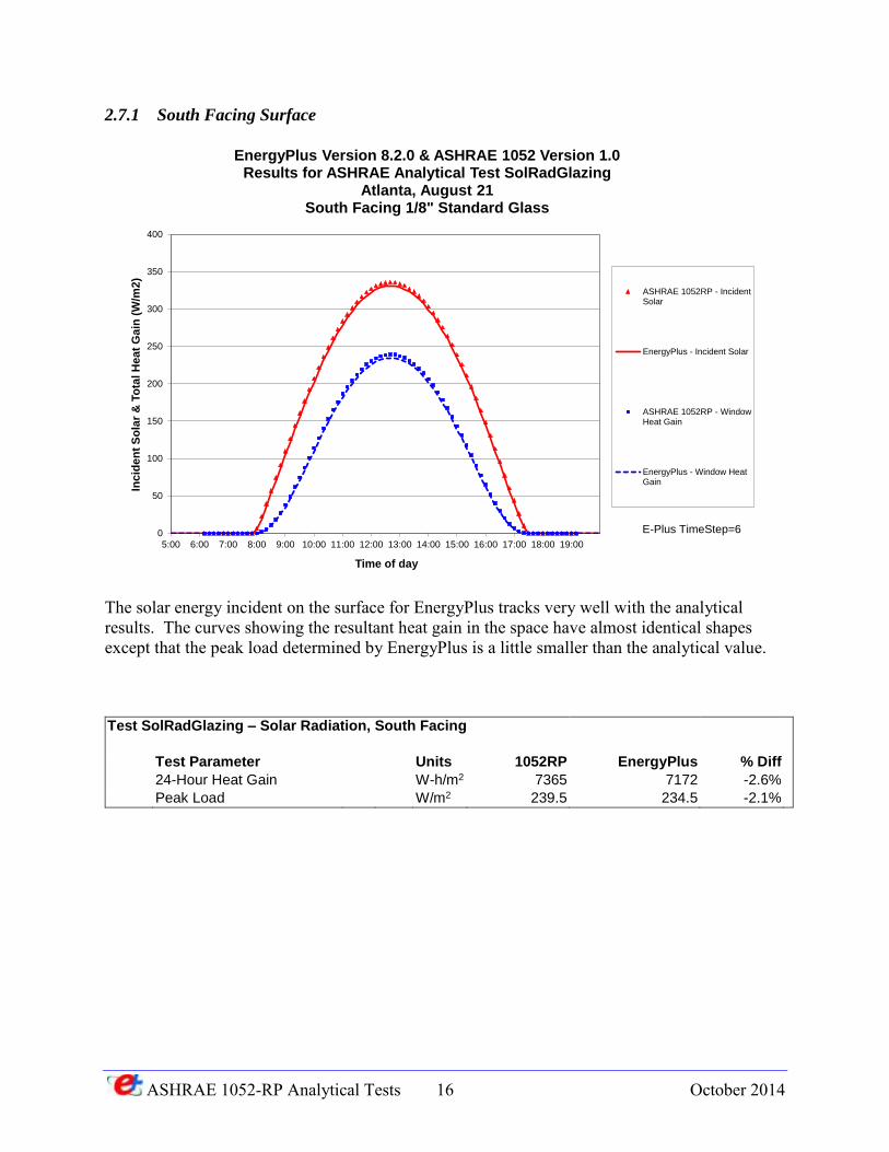
2.7.1 South Facing Surface
The solar energy incident on the surface for EnergyPlus tracks very well with the analytical results. The curves showing the resultant heat gain in the space have almost identical shapes except that the peak load determined by EnergyPlus is a little smaller than the analytical value.
Test SolRadGlazing – Solar Radiation, South Facing
Test Parameter Units 1052RP EnergyPlus % Diff
24-Hour Heat Gain W-h/m2 7365 7172 -2.6%
Peak Load W/m2 239.5 234.5 -2.1%
0
50
100
150
200
250
300
350
400
5:00 6:00 7:00 8:00 9:00 10:00 11:00 12:00 13:00 14:00 15:00 16:00 17:00 18:00 19:00
Inc
ide
nt
So
lar
& T
ota
l H
ea
t G
ain
(W
/m2
)
Time of day
EnergyPlus Version 8.2.0 & ASHRAE 1052 Version 1.0Results for ASHRAE Analytical Test SolRadGlazing
Atlanta, August 21South Facing 1/8" Standard Glass
ASHRAE 1052RP - IncidentSolar
EnergyPlus - Incident Solar
ASHRAE 1052RP - WindowHeat Gain
EnergyPlus - Window HeatGain
E-Plus TimeStep=6
ASHRAE 1052-RP Analytical Tests 17 October 2014
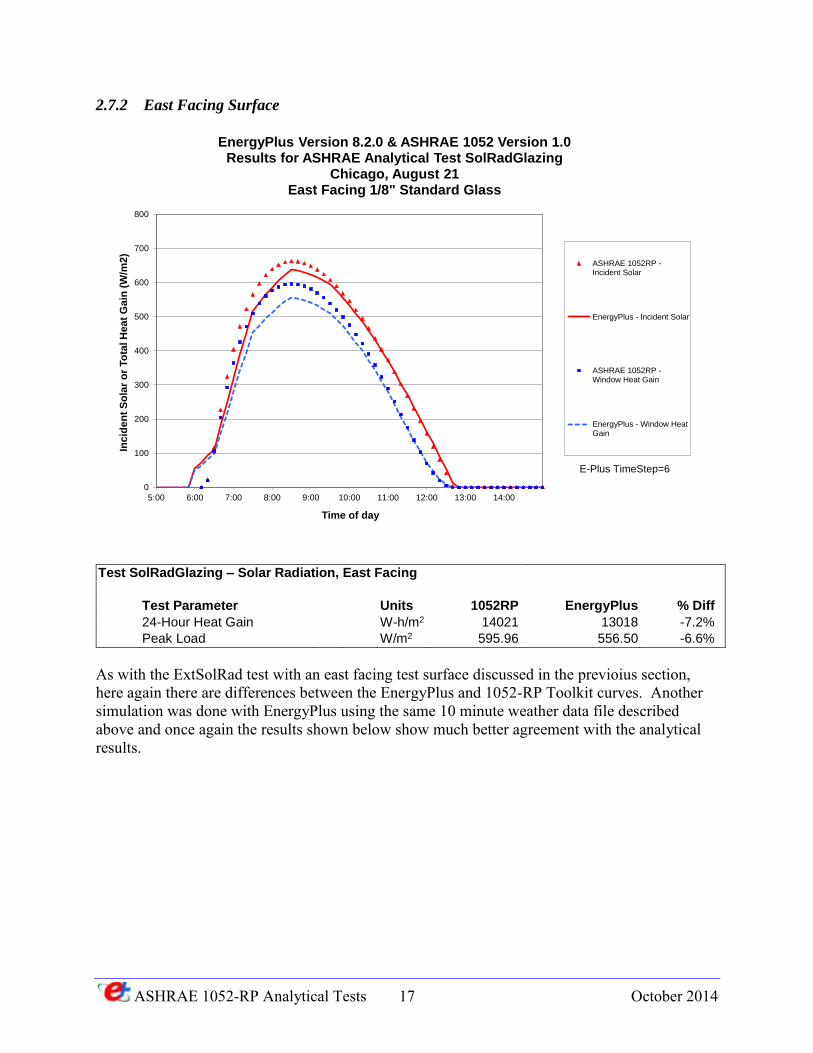
2.7.2 East Facing Surface
Test SolRadGlazing – Solar Radiation, East Facing
Test Parameter Units 1052RP EnergyPlus % Diff
24-Hour Heat Gain W-h/m2 14021 13018 -7.2%
Peak Load W/m2 595.96 556.50 -6.6%
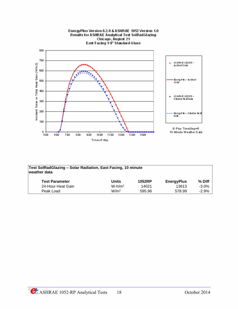
As with the ExtSolRad test with an east facing test surface discussed in the previoius section, here again there are differences between the EnergyPlus and 1052-RP Toolkit curves. Another simulation was done with EnergyPlus using the same 10 minute weather data file described above and once again the results shown below show much better agreement with the analytical results.
0
100
200
300
400
500
600
700
800
5:00 6:00 7:00 8:00 9:00 10:00 11:00 12:00 13:00 14:00
Inc
ide
nt
So
lar
or
To
tal H
ea
t G
ain
(W
/m2
)
Time of day
EnergyPlus Version 8.2.0 & ASHRAE 1052 Version 1.0Results for ASHRAE Analytical Test SolRadGlazing
Chicago, August 21East Facing 1/8" Standard Glass
ASHRAE 1052RP -Incident Solar
EnergyPlus - Incident Solar
ASHRAE 1052RP -Window Heat Gain
EnergyPlus - Window HeatGain
E-Plus TimeStep=6
ASHRAE 1052-RP Analytical Tests 18 October 2014
Test SolRadGlazing – Solar Radiation, East Facing, 10 minute weather data
Test Parameter Units 1052RP EnergyPlus % Diff
24-Hour Heat Gain W-h/m2 14021 13613 -3.0%
Peak Load W/m2 595.96 578.99 -2.9%
ASHRAE 1052-RP Analytical Tests 19 October 2014
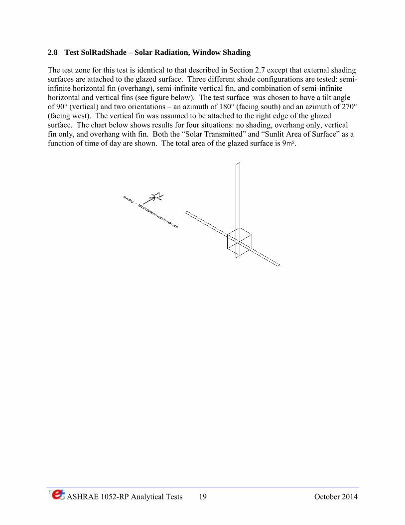
2.8 Test SolRadShade – Solar Radiation, Window Shading
The test zone for this test is identical to that described in Section 2.7 except that external shading surfaces are attached to the glazed surface. Three different shade configurations are tested: semi-infinite horizontal fin (overhang), semi-infinite vertical fin, and combination of semi-infinite horizontal and vertical fins (see figure below). The test surface was chosen to have a tilt angle of 90° (vertical) and two orientations – an azimuth of 180° (facing south) and an azimuth of 270° (facing west). The vertical fin was assumed to be attached to the right edge of the glazed surface. The chart below shows results for four situations: no shading, overhang only, vertical fin only, and overhang with fin. Both the “Solar Transmitted” and “Sunlit Area of Surface” as a function of time of day are shown. The total area of the glazed surface is 9m2.
ASHRAE 1052-RP Analytical Tests 20 October 2014
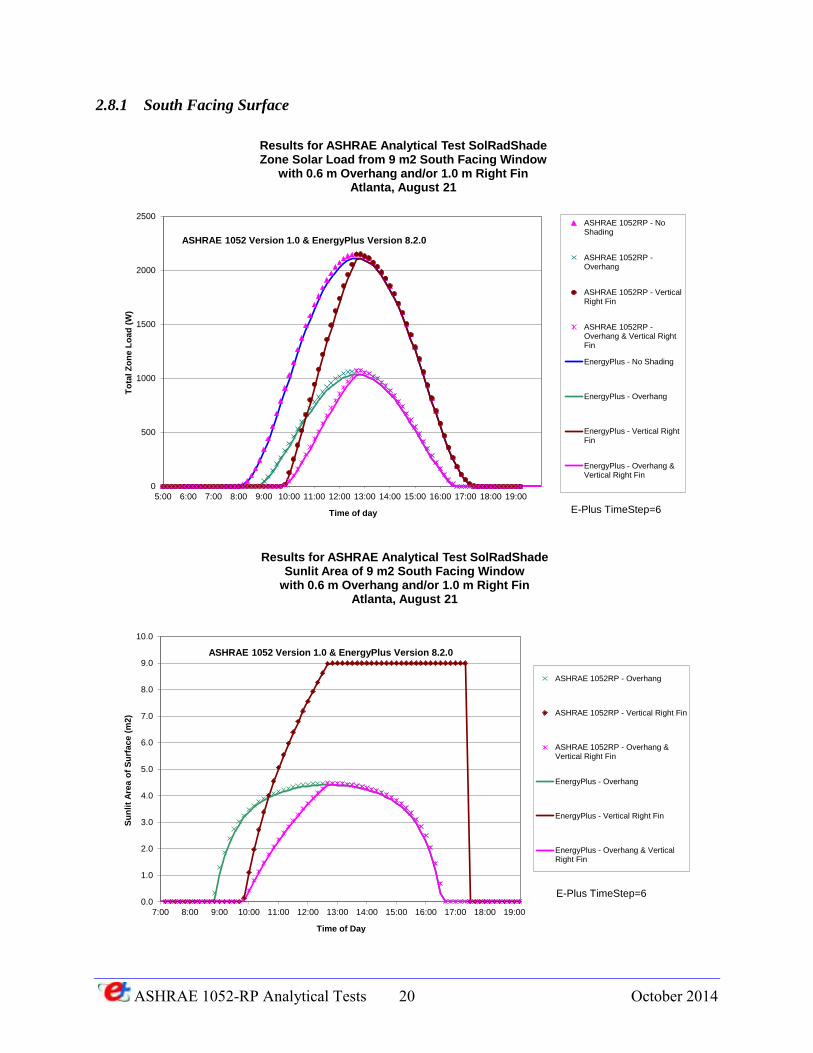
2.8.1 South Facing Surface
0
500
1000
1500
2000
2500
5:00 6:00 7:00 8:00 9:00 10:00 11:00 12:00 13:00 14:00 15:00 16:00 17:00 18:00 19:00
To
tal Z
on
e L
oad
(W
)
Time of day
Results for ASHRAE Analytical Test SolRadShadeZone Solar Load from 9 m2 South Facing Window
with 0.6 m Overhang and/or 1.0 m Right FinAtlanta, August 21
ASHRAE 1052RP - NoShading
ASHRAE 1052RP -Overhang
ASHRAE 1052RP - VerticalRight Fin
ASHRAE 1052RP -Overhang & Vertical RightFin
EnergyPlus - No Shading
EnergyPlus - Overhang
EnergyPlus - Vertical RightFin
EnergyPlus - Overhang &Vertical Right Fin
ASHRAE 1052 Version 1.0 & EnergyPlus Version 8.2.0
E-Plus TimeStep=6
0.0
1.0
2.0
3.0
4.0
5.0
6.0
7.0
8.0
9.0
10.0
7:00 8:00 9:00 10:00 11:00 12:00 13:00 14:00 15:00 16:00 17:00 18:00 19:00
Su
nlit
Are
a o
f S
urf
ace (
m2)
Time of Day
Results for ASHRAE Analytical Test SolRadShadeSunlit Area of 9 m2 South Facing Window
with 0.6 m Overhang and/or 1.0 m Right FinAtlanta, August 21
ASHRAE 1052RP - Overhang
ASHRAE 1052RP - Vertical Right Fin
ASHRAE 1052RP - Overhang &Vertical Right Fin
EnergyPlus - Overhang
EnergyPlus - Vertical Right Fin
EnergyPlus - Overhang & VerticalRight Fin
ASHRAE 1052 Version 1.0 & EnergyPlus Version 8.2.0
E-Plus TimeStep=6
ASHRAE 1052-RP Analytical Tests 21 October 2014
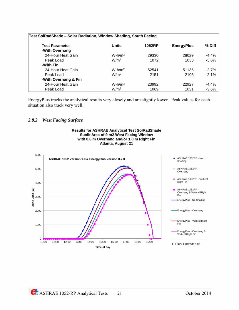
Test SolRadShade – Solar Radiation, Window Shading, South Facing
Test Parameter Units 1052RP EnergyPlus % Diff
-With Overhang
24-Hour Heat Gain W-h/m2 29330 28029 -4.4%
Peak Load W/m2 1072 1033 -3.6%
-With Fin
24-Hour Heat Gain W-h/m2 52541 51136 -2.7%
Peak Load W/m2 2151 2106 -2.1%
-With Overhang & Fin
24-Hour Heat Gain W-h/m2 23992 22927 -4.4%
Peak Load W/m2 1069 1031 -3.6%
EnergyPlus tracks the analytical results very closely and are slightly lower. Peak values for each situation also track very well.
2.8.2 West Facing Surface
0
1000
2000
3000
4000
5000
6000
10:00 11:00 12:00 13:00 14:00 15:00 16:00 17:00 18:00 19:00
Zo
ne
Lo
ad
(W
)
Time of day
Results for ASHRAE Analytical Test SolRadShadeSunlit Area of 9 m2 West Facing Window
with 0.6 m Overhang and/or 1.0 m Right FinAtlanta, August 21
ASHRAE 1052RP - NoShading
ASHRAE 1052RP -Overhang
ASHRAE 1052RP - VerticalRight Fin
ASHRAE 1052RP -Overhang & Vertical RightFin
EnergyPlus - No Shading
EnergyPlus - Overhang
EnergyPlus - Vertical RightFin
EnergyPlus - Overhang &Vertical Right Fin
ASHRAE 1052 Version 1.0 & EnergyPlus Version 8.2.0
E-Plus TimeStep=6
ASHRAE 1052-RP Analytical Tests 22 October 2014
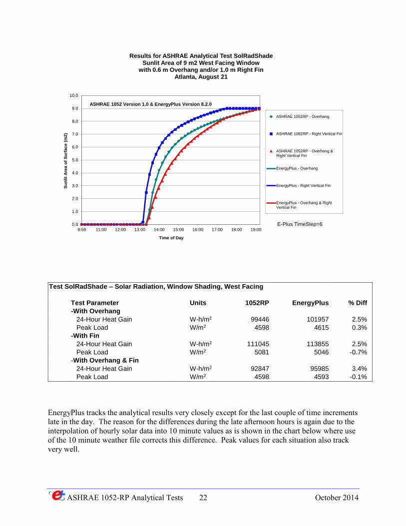
Test SolRadShade – Solar Radiation, Window Shading, West Facing
Test Parameter Units 1052RP EnergyPlus % Diff
-With Overhang
24-Hour Heat Gain W-h/m2 99446 101957 2.5%
Peak Load W/m2 4598 4615 0.3%
-With Fin
24-Hour Heat Gain W-h/m2 111045 113855 2.5%
Peak Load W/m2 5081 5046 -0.7%
-With Overhang & Fin
24-Hour Heat Gain W-h/m2 92847 95985 3.4%
Peak Load W/m2 4598 4593 -0.1%
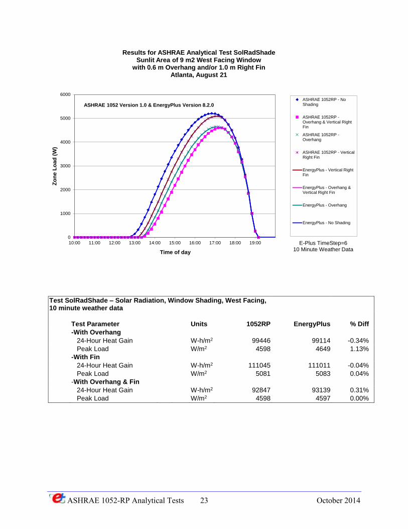
EnergyPlus tracks the analytical results very closely except for the last couple of time increments late in the day. The reason for the differences during the late afternoon hours is again due to the interpolation of hourly solar data into 10 minute values as is shown in the chart below where use of the 10 minute weather file corrects this difference. Peak values for each situation also track very well.
0.0
1.0
2.0
3.0
4.0
5.0
6.0
7.0
8.0
9.0
10.0
9:59 11:00 12:00 13:00 14:00 15:00 16:00 17:00 18:00 19:00
Su
nlit
Are
a o
f S
urf
ace (
m2)
Time of Day
Results for ASHRAE Analytical Test SolRadShadeSunlit Area of 9 m2 West Facing Window
with 0.6 m Overhang and/or 1.0 m Right FinAtlanta, August 21
ASHRAE 1052RP - Overhang
ASHRAE 1052RP - Right Vertical Fin
ASHRAE 1052RP - Overhang &Right Vertical Fin
EnergyPlus - Overhang
EnergyPlus - Right Vertical Fin
EnergyPlus - Overhang & RightVertical Fin
ASHRAE 1052 Version 1.0 & EnergyPlus Version 8.2.0
E-Plus TimeStep=6
ASHRAE 1052-RP Analytical Tests 23 October 2014
Test SolRadShade – Solar Radiation, Window Shading, West Facing, 10 minute weather data
Test Parameter Units 1052RP EnergyPlus % Diff
-With Overhang
24-Hour Heat Gain W-h/m2 99446 99114 -0.34%
Peak Load W/m2 4598 4649 1.13%
-With Fin
24-Hour Heat Gain W-h/m2 111045 111011 -0.04%
Peak Load W/m2 5081 5083 0.04%
-With Overhang & Fin
24-Hour Heat Gain W-h/m2 92847 93139 0.31%
Peak Load W/m2 4598 4597 0.00%
0
1000
2000
3000
4000
5000
6000
10:00 11:00 12:00 13:00 14:00 15:00 16:00 17:00 18:00 19:00
Zo
ne
Lo
ad
(W
)
Time of day
Results for ASHRAE Analytical Test SolRadShadeSunlit Area of 9 m2 West Facing Window
with 0.6 m Overhang and/or 1.0 m Right FinAtlanta, August 21
ASHRAE 1052RP - NoShading
ASHRAE 1052RP -Overhang & Vertical RightFin
ASHRAE 1052RP -Overhang
ASHRAE 1052RP - VerticalRight Fin
EnergyPlus - Vertical RightFin
EnergyPlus - Overhang &Vertical Right Fin
EnergyPlus - Overhang
EnergyPlus - No Shading
ASHRAE 1052 Version 1.0 & EnergyPlus Version 8.2.0
E-Plus TimeStep=610 Minute Weather Data
ASHRAE 1052-RP Analytical Tests 24 October 2014
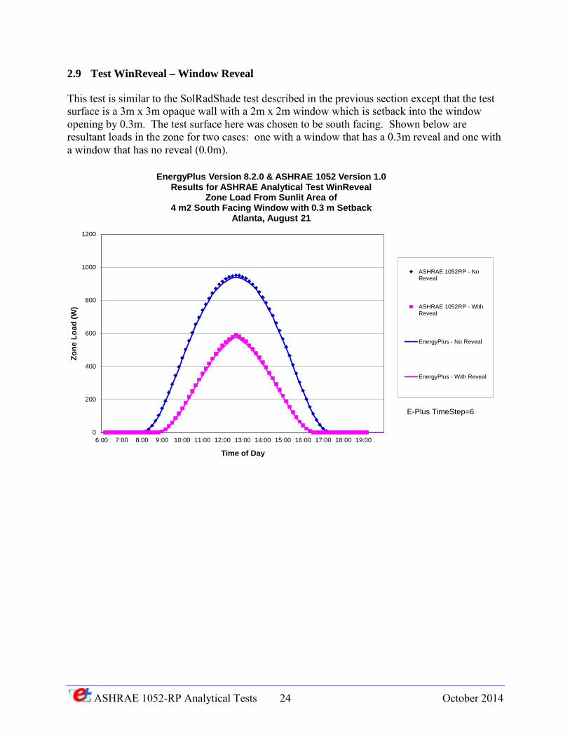
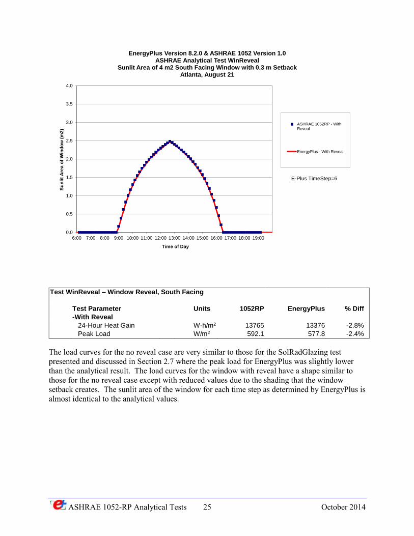
2.9 Test WinReveal – Window Reveal
This test is similar to the SolRadShade test described in the previous section except that the test surface is a 3m x 3m opaque wall with a 2m x 2m window which is setback into the window opening by 0.3m. The test surface here was chosen to be south facing. Shown below are resultant loads in the zone for two cases: one with a window that has a 0.3m reveal and one with a window that has no reveal (0.0m).
0
200
400
600
800
1000
1200
6:00 7:00 8:00 9:00 10:00 11:00 12:00 13:00 14:00 15:00 16:00 17:00 18:00 19:00
Zo
ne
Lo
ad
(W
)
Time of Day
EnergyPlus Version 8.2.0 & ASHRAE 1052 Version 1.0Results for ASHRAE Analytical Test WinReveal
Zone Load From Sunlit Area of 4 m2 South Facing Window with 0.3 m Setback
Atlanta, August 21
ASHRAE 1052RP - NoReveal
ASHRAE 1052RP - WithReveal
EnergyPlus - No Reveal
EnergyPlus - With Reveal
E-Plus TimeStep=6
ASHRAE 1052-RP Analytical Tests 25 October 2014
Test WinReveal – Window Reveal, South Facing
Test Parameter Units 1052RP EnergyPlus % Diff
-With Reveal
24-Hour Heat Gain W-h/m2 13765 13376 -2.8%
Peak Load W/m2 592.1 577.8 -2.4%
The load curves for the no reveal case are very similar to those for the SolRadGlazing test presented and discussed in Section 2.7 where the peak load for EnergyPlus was slightly lower than the analytical result. The load curves for the window with reveal have a shape similar to those for the no reveal case except with reduced values due to the shading that the window setback creates. The sunlit area of the window for each time step as determined by EnergyPlus is almost identical to the analytical values.
0.0
0.5
1.0
1.5
2.0
2.5
3.0
3.5
4.0
6:00 7:00 8:00 9:00 10:00 11:00 12:00 13:00 14:00 15:00 16:00 17:00 18:00 19:00
Su
nli
t A
rea
of
Win
do
w (
m2
)
Time of Day
EnergyPlus Version 8.2.0 & ASHRAE 1052 Version 1.0ASHRAE Analytical Test WinReveal
Sunlit Area of 4 m2 South Facing Window with 0.3 m SetbackAtlanta, August 21
ASHRAE 1052RP - WithReveal
EnergyPlus - With Reveal
E-Plus TimeStep=6

ASHRAE 1052-RP Analytical Tests 26 October 2014
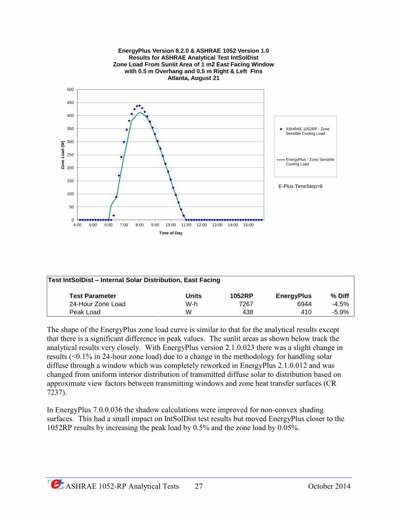
2.10 Test IntSolarDist – Internal Solar Distribution
The test zone is 3m wide x 0.5m deep x 3m high. One of the 3m x 3m surfaces is chosen as the test surface and has a 1m x 1m window centered in the surface. The window has a 0.5m overhang and 0.5m fins on either side. This configuration allows solar radiation to impinge only on the internal surface of the wall opposite the window (see figure below). The surface opposite the window is assumed massless and no internal redistribution of solar radiation occurs. All other surfaces are of heavyweight construction and are assumed adiabatic. The heavyweight surfaces test to see if the program is redistributing the solar gains which for this test it should not. The inside and outside temperatures are held constant at 20°C. The location and date were set for Atlanta, August 21. The test surface with the window was chosen as east facing.
ASHRAE 1052-RP Analytical Tests 27 October 2014
Test IntSolDist – Internal Solar Distribution, East Facing
Test Parameter Units 1052RP EnergyPlus % Diff
24-Hour Zone Load W-h 7267 6944 -4.5%
Peak Load W 438 410 -5.9%
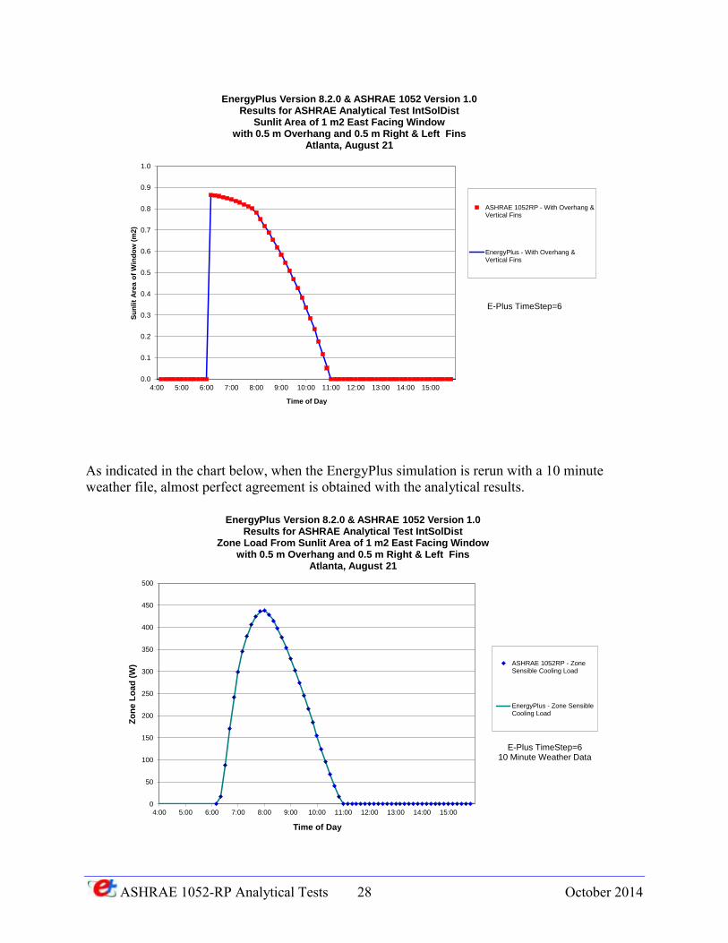
The shape of the EnergyPlus zone load curve is similar to that for the analytical results except that there is a significant difference in peak values. The sunlit areas as shown below track the analytical results very closely. With EnergyPlus version 2.1.0.023 there was a slight change in results (<0.1% in 24-hour zone load) due to a change in the methodology for handling solar diffuse through a window which was completely reworked in EnergyPlus 2.1.0.012 and was changed from uniform interior distribution of transmitted diffuse solar to distribution based on approximate view factors between transmitting windows and zone heat transfer surfaces (CR 7237).
In EnergyPlus 7.0.0.036 the shadow calculations were improved for non-convex shading surfaces. This had a small impact on IntSolDist test results but moved EnergyPlus closer to the 1052RP results by increasing the peak load by 0.5% and the zone load by 0.05%.
0
50
100
150
200
250
300
350
400
450
500
4:00 5:00 6:00 7:00 8:00 9:00 10:00 11:00 12:00 13:00 14:00 15:00
Zo
ne L
oa
d (
W)
Time of Day
EnergyPlus Version 8.2.0 & ASHRAE 1052 Version 1.0Results for ASHRAE Analytical Test IntSolDist
Zone Load From Sunlit Area of 1 m2 East Facing Windowwith 0.5 m Overhang and 0.5 m Right & Left Fins
Atlanta, August 21
ASHRAE 1052RP - ZoneSensible Cooling Load
EnergyPlus - Zone SensibleCooling Load
E-Plus TimeStep=6
ASHRAE 1052-RP Analytical Tests 28 October 2014
As indicated in the chart below, when the EnergyPlus simulation is rerun with a 10 minute weather file, almost perfect agreement is obtained with the analytical results.
0.0
0.1
0.2
0.3
0.4
0.5
0.6
0.7
0.8
0.9
1.0
4:00 5:00 6:00 7:00 8:00 9:00 10:00 11:00 12:00 13:00 14:00 15:00
Su
nli
t A
rea o
f W
ind
ow
(m
2)
Time of Day
EnergyPlus Version 8.2.0 & ASHRAE 1052 Version 1.0Results for ASHRAE Analytical Test IntSolDist
Sunlit Area of 1 m2 East Facing Windowwith 0.5 m Overhang and 0.5 m Right & Left Fins
Atlanta, August 21
ASHRAE 1052RP - With Overhang &Vertical Fins
EnergyPlus - With Overhang &Vertical Fins
E-Plus TimeStep=6
0
50
100
150
200
250
300
350
400
450
500
4:00 5:00 6:00 7:00 8:00 9:00 10:00 11:00 12:00 13:00 14:00 15:00
Zo
ne
Lo
ad
(W
)
Time of Day
EnergyPlus Version 8.2.0 & ASHRAE 1052 Version 1.0Results for ASHRAE Analytical Test IntSolDist
Zone Load From Sunlit Area of 1 m2 East Facing Windowwith 0.5 m Overhang and 0.5 m Right & Left Fins
Atlanta, August 21
ASHRAE 1052RP - ZoneSensible Cooling Load
EnergyPlus - Zone SensibleCooling Load
E-Plus TimeStep=610 Minute Weather Data
ASHRAE 1052-RP Analytical Tests 29 October 2014
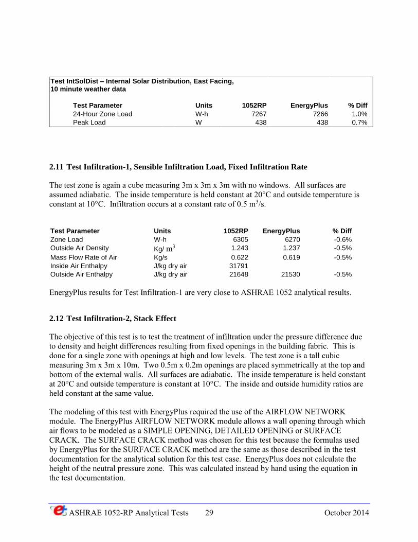
Test IntSolDist – Internal Solar Distribution, East Facing, 10 minute weather data
Test Parameter Units 1052RP EnergyPlus % Diff
24-Hour Zone Load W-h 7267 7266 1.0%
Peak Load W 438 438 0.7%
2.11 Test Infiltration-1, Sensible Infiltration Load, Fixed Infiltration Rate
The test zone is again a cube measuring 3m x 3m x 3m with no windows. All surfaces are assumed adiabatic. The inside temperature is held constant at 20°C and outside temperature is constant at 10°C. Infiltration occurs at a constant rate of 0.5 m3/s.
Test Parameter Units 1052RP EnergyPlus % Diff
Zone Load W-h 6305 6270 -0.6%
Outside Air Density Kg/ m3 1.243 1.237 -0.5%
Mass Flow Rate of Air Kg/s 0.622 0.619 -0.5%
Inside Air Enthalpy J/kg dry air 31791
Outside Air Enthalpy J/kg dry air 21648 21530 -0.5%
EnergyPlus results for Test Infiltration-1 are very close to ASHRAE 1052 analytical results.
2.12 Test Infiltration-2, Stack Effect
The objective of this test is to test the treatment of infiltration under the pressure difference due to density and height differences resulting from fixed openings in the building fabric. This is done for a single zone with openings at high and low levels. The test zone is a tall cubic measuring 3m x 3m x 10m. Two 0.5m x 0.2m openings are placed symmetrically at the top and bottom of the external walls. All surfaces are adiabatic. The inside temperature is held constant at 20°C and outside temperature is constant at 10°C. The inside and outside humidity ratios are held constant at the same value.
The modeling of this test with EnergyPlus required the use of the AIRFLOW NETWORK module. The EnergyPlus AIRFLOW NETWORK module allows a wall opening through which air flows to be modeled as a SIMPLE OPENING, DETAILED OPENING or SURFACE CRACK. The SURFACE CRACK method was chosen for this test because the formulas used by EnergyPlus for the SURFACE CRACK method are the same as those described in the test documentation for the analytical solution for this test case. EnergyPlus does not calculate the height of the neutral pressure zone. This was calculated instead by hand using the equation in the test documentation.

ASHRAE 1052-RP Analytical Tests 30 October 2014
Test Parameter Units 1052RP EnergyPlus % Diff
Zone Load W-h 0.1489 0.1506 1.12%
Mass Flow Rate of Air Kg/s 1510.3 1525.8 1.02%
Height of Neutral Pressure Zone
m 4.9345 4.9326 -0.04%
The EnergyPlus results for Test Infiltration-2 are very close to the ASHRAE 1052-RP analytical results
ASHRAE 1052-RP Analytical Tests 31 October 2014
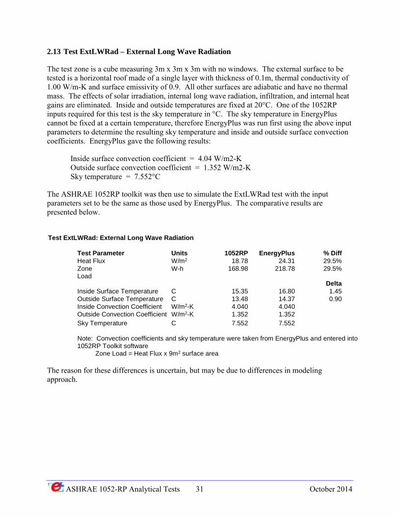
2.13 Test ExtLWRad – External Long Wave Radiation
The test zone is a cube measuring 3m x 3m x 3m with no windows. The external surface to be tested is a horizontal roof made of a single layer with thickness of 0.1m, thermal conductivity of 1.00 W/m-K and surface emissivity of 0.9. All other surfaces are adiabatic and have no thermal mass. The effects of solar irradiation, internal long wave radiation, infiltration, and internal heat gains are eliminated. Inside and outside temperatures are fixed at 20°C. One of the 1052RP inputs required for this test is the sky temperature in °C. The sky temperature in EnergyPlus cannot be fixed at a certain temperature, therefore EnergyPlus was run first using the above input parameters to determine the resulting sky temperature and inside and outside surface convection coefficients. EnergyPlus gave the following results:
Inside surface convection coefficient = 4.04 W/m2-K Outside surface convection coefficient = 1.352 W/m2-K Sky temperature = 7.552°C
The ASHRAE 1052RP toolkit was then use to simulate the ExtLWRad test with the input parameters set to be the same as those used by EnergyPlus. The comparative results are presented below.
Test ExtLWRad: External Long Wave Radiation
Test Parameter Units 1052RP EnergyPlus % Diff
Heat Flux W/m2 18.78 24.31 29.5%
Zone Load
W-h 168.98 218.78 29.5%
Delta
Inside Surface Temperature C 15.35 16.80 1.45
Outside Surface Temperature C 13.48 14.37 0.90
Inside Convection Coefficient W/m2-K 4.040 4.040
Outside Convection Coefficient W/m2-K 1.352 1.352
Sky Temperature C 7.552 7.552
Note: Convection coefficients and sky temperature were taken from EnergyPlus and entered into 1052RP Toolkit software
Zone Load = Heat Flux x 9m2 surface area
The reason for these differences is uncertain, but may be due to differences in modeling approach.
ASHRAE 1052-RP Analytical Tests 32 October 2014
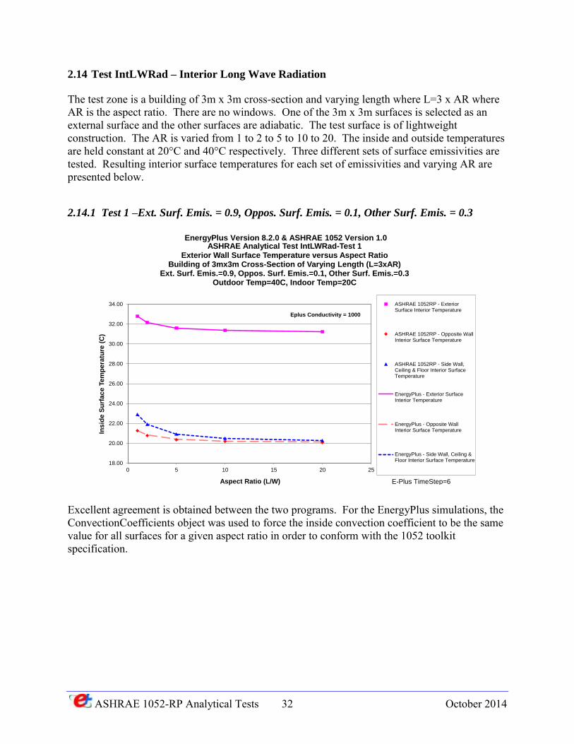
2.14 Test IntLWRad – Interior Long Wave Radiation
The test zone is a building of 3m x 3m cross-section and varying length where L=3 x AR where AR is the aspect ratio. There are no windows. One of the 3m x 3m surfaces is selected as an external surface and the other surfaces are adiabatic. The test surface is of lightweight construction. The AR is varied from 1 to 2 to 5 to 10 to 20. The inside and outside temperatures are held constant at 20°C and 40°C respectively. Three different sets of surface emissivities are tested. Resulting interior surface temperatures for each set of emissivities and varying AR are presented below.
2.14.1 Test 1 –Ext. Surf. Emis. = 0.9, Oppos. Surf. Emis. = 0.1, Other Surf. Emis. = 0.3
Excellent agreement is obtained between the two programs. For the EnergyPlus simulations, the ConvectionCoefficients object was used to force the inside convection coefficient to be the same value for all surfaces for a given aspect ratio in order to conform with the 1052 toolkit specification.
18.00
20.00
22.00
24.00
26.00
28.00
30.00
32.00
34.00
0 5 10 15 20 25
Ins
ide
Su
rfac
e T
em
pe
ratu
re (
C)
Aspect Ratio (L/W)
ASHRAE Analytical Test IntLWRad-Test 1Exterior Wall Surface Temperature versus Aspect Ratio
Building of 3mx3m Cross-Section of Varying Length (L=3xAR)Ext. Surf. Emis.=0.9, Oppos. Surf. Emis.=0.1, Other Surf. Emis.=0.3
Outdoor Temp=40C, Indoor Temp=20C
ASHRAE 1052RP - ExteriorSurface Interior Temperature
ASHRAE 1052RP - Opposite WallInterior Surface Temperature
ASHRAE 1052RP - Side Wall,Ceiling & Floor Interior SurfaceTemperature
EnergyPlus - Exterior SurfaceInterior Temperature
EnergyPlus - Opposite WallInterior Surface Temperature
EnergyPlus - Side Wall, Ceiling &Floor Interior Surface Temperature
EnergyPlus Version 8.2.0 & ASHRAE 1052 Version 1.0
Eplus Conductivity = 1000
E-Plus TimeStep=6
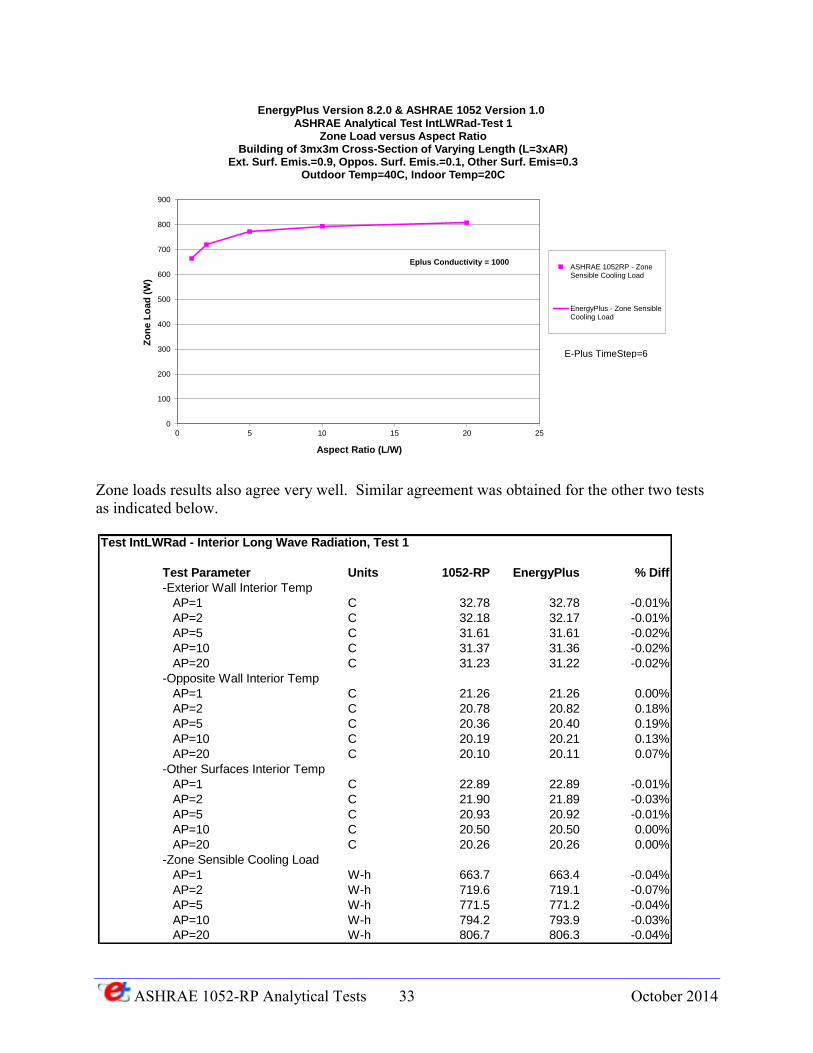
ASHRAE 1052-RP Analytical Tests 33 October 2014
Zone loads results also agree very well. Similar agreement was obtained for the other two tests as indicated below.
0
100
200
300
400
500
600
700
800
900
0 5 10 15 20 25
Zo
ne
Lo
ad
(W
)
Aspect Ratio (L/W)
ASHRAE Analytical Test IntLWRad-Test 1Zone Load versus Aspect Ratio
Building of 3mx3m Cross-Section of Varying Length (L=3xAR)Ext. Surf. Emis.=0.9, Oppos. Surf. Emis.=0.1, Other Surf. Emis=0.3
Outdoor Temp=40C, Indoor Temp=20C
ASHRAE 1052RP - ZoneSensible Cooling Load
EnergyPlus - Zone SensibleCooling Load
EnergyPlus Version 8.2.0 & ASHRAE 1052 Version 1.0
Eplus Conductivity = 1000
E-Plus TimeStep=6
Test IntLWRad - Interior Long Wave Radiation, Test 1
Test Parameter Units 1052-RP EnergyPlus % Diff
-Exterior Wall Interior Temp
AP=1 C 32.78 32.78 -0.01%
AP=2 C 32.18 32.17 -0.01%
AP=5 C 31.61 31.61 -0.02%
AP=10 C 31.37 31.36 -0.02%
AP=20 C 31.23 31.22 -0.02%
-Opposite Wall Interior Temp
AP=1 C 21.26 21.26 0.00%
AP=2 C 20.78 20.82 0.18%
AP=5 C 20.36 20.40 0.19%
AP=10 C 20.19 20.21 0.13%
AP=20 C 20.10 20.11 0.07%
-Other Surfaces Interior Temp
AP=1 C 22.89 22.89 -0.01%
AP=2 C 21.90 21.89 -0.03%
AP=5 C 20.93 20.92 -0.01%
AP=10 C 20.50 20.50 0.00%
AP=20 C 20.26 20.26 0.00%
-Zone Sensible Cooling Load
AP=1 W-h 663.7 663.4 -0.04%
AP=2 W-h 719.6 719.1 -0.07%
AP=5 W-h 771.5 771.2 -0.04%
AP=10 W-h 794.2 793.9 -0.03%
AP=20 W-h 806.7 806.3 -0.04%
ASHRAE 1052-RP Analytical Tests 34 October 2014
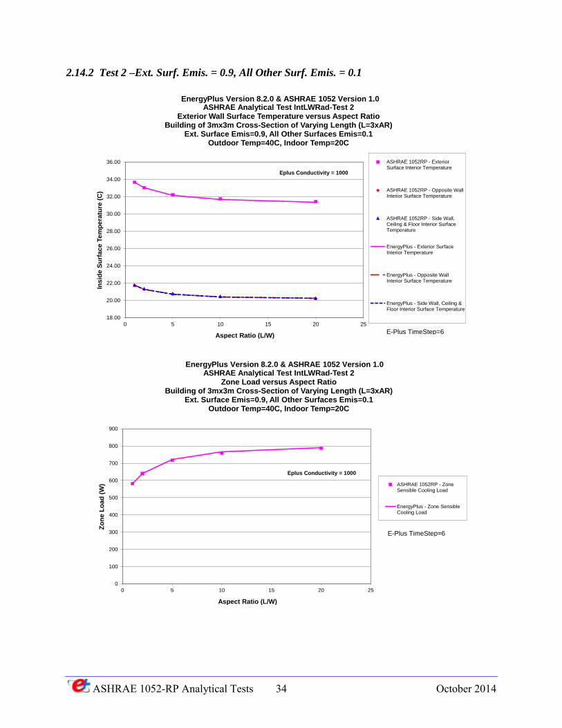
2.14.2 Test 2 –Ext. Surf. Emis. = 0.9, All Other Surf. Emis. = 0.1
18.00
20.00
22.00
24.00
26.00
28.00
30.00
32.00
34.00
36.00
0 5 10 15 20 25
Ins
ide
Su
rfa
ce
Te
mp
era
ture
(C
)
Aspect Ratio (L/W)
ASHRAE Analytical Test IntLWRad-Test 2Exterior Wall Surface Temperature versus Aspect Ratio
Building of 3mx3m Cross-Section of Varying Length (L=3xAR)Ext. Surface Emis=0.9, All Other Surfaces Emis=0.1
Outdoor Temp=40C, Indoor Temp=20C
ASHRAE 1052RP - ExteriorSurface Interior Temperature
ASHRAE 1052RP - Opposite WallInterior Surface Temperature
ASHRAE 1052RP - Side Wall,Ceiling & Floor Interior SurfaceTemperature
EnergyPlus - Exterior SurfaceInterior Temperature
EnergyPlus - Opposite WallInterior Surface Temperature
EnergyPlus - Side Wall, Ceiling &Floor Interior Surface Temperature
EnergyPlus Version 8.2.0 & ASHRAE 1052 Version 1.0
Eplus Conductivity = 1000
E-Plus TimeStep=6
0
100
200
300
400
500
600
700
800
900
0 5 10 15 20 25
Zo
ne
Lo
ad
(W
)
Aspect Ratio (L/W)
ASHRAE Analytical Test IntLWRad-Test 2Zone Load versus Aspect Ratio
Building of 3mx3m Cross-Section of Varying Length (L=3xAR)Ext. Surface Emis=0.9, All Other Surfaces Emis=0.1
Outdoor Temp=40C, Indoor Temp=20C
ASHRAE 1052RP - ZoneSensible Cooling Load
EnergyPlus - Zone SensibleCooling Load
EnergyPlus Version 8.2.0 & ASHRAE 1052 Version 1.0
Eplus Conductivity = 1000
E-Plus TimeStep=6
ASHRAE 1052-RP Analytical Tests 35 October 2014
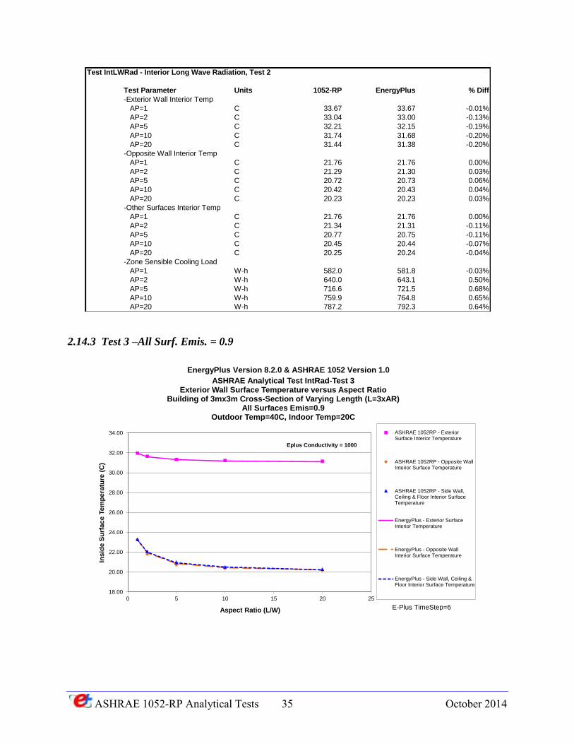
2.14.3 Test 3 –All Surf. Emis. = 0.9
Test IntLWRad - Interior Long Wave Radiation, Test 2
Test Parameter Units 1052-RP EnergyPlus % Diff
-Exterior Wall Interior Temp
AP=1 C 33.67 33.67 -0.01%
AP=2 C 33.04 33.00 -0.13%
AP=5 C 32.21 32.15 -0.19%
AP=10 C 31.74 31.68 -0.20%
AP=20 C 31.44 31.38 -0.20%
-Opposite Wall Interior Temp
AP=1 C 21.76 21.76 0.00%
AP=2 C 21.29 21.30 0.03%
AP=5 C 20.72 20.73 0.06%
AP=10 C 20.42 20.43 0.04%
AP=20 C 20.23 20.23 0.03%
-Other Surfaces Interior Temp
AP=1 C 21.76 21.76 0.00%
AP=2 C 21.34 21.31 -0.11%
AP=5 C 20.77 20.75 -0.11%
AP=10 C 20.45 20.44 -0.07%
AP=20 C 20.25 20.24 -0.04%
-Zone Sensible Cooling Load
AP=1 W-h 582.0 581.8 -0.03%
AP=2 W-h 640.0 643.1 0.50%
AP=5 W-h 716.6 721.5 0.68%
AP=10 W-h 759.9 764.8 0.65%
AP=20 W-h 787.2 792.3 0.64%
18.00
20.00
22.00
24.00
26.00
28.00
30.00
32.00
34.00
0 5 10 15 20 25
Ins
ide
Su
rfac
e T
em
pe
ratu
re (
C)
Aspect Ratio (L/W)
ASHRAE Analytical Test IntRad-Test 3Exterior Wall Surface Temperature versus Aspect Ratio
Building of 3mx3m Cross-Section of Varying Length (L=3xAR)All Surfaces Emis=0.9
Outdoor Temp=40C, Indoor Temp=20C
ASHRAE 1052RP - ExteriorSurface Interior Temperature
ASHRAE 1052RP - Opposite WallInterior Surface Temperature
ASHRAE 1052RP - Side Wall,Ceiling & Floor Interior SurfaceTemperature
EnergyPlus - Exterior SurfaceInterior Temperature
EnergyPlus - Opposite WallInterior Surface Temperature
EnergyPlus - Side Wall, Ceiling &Floor Interior Surface Temperature
EnergyPlus Version 8.2.0 & ASHRAE 1052 Version 1.0
Eplus Conductivity = 1000
E-Plus TimeStep=6
ASHRAE 1052-RP Analytical Tests 36 October 2014
0
100
200
300
400
500
600
700
800
900
1,000
0 5 10 15 20 25
Zo
ne
Lo
ad
(W
)
Aspect Ratio (L/W)
ASHRAE Analytical Test IntRad-Test 3Zone Load versus Aspect Ratio
Building of 3mx3m Cross-Section of Varying Length (L=3xAR)All Surfaces Emis=0.9
Outdoor Temp=40C, Indoor Temp=20C
ASHRAE 1052RP - ZoneSensible Cooling Load
EnergyPlus - Zone SensibleCooling Load
EnergyPlus Version 8.2.0 & ASHRAE 1052 Version 1.0
Eplus Conductivity = 1000
E-Plus TimeStep=6
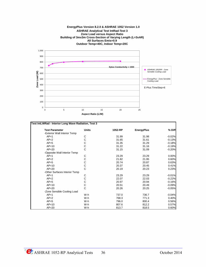
Test IntLWRad - Interior Long Wave Radiation, Test 3
Test Parameter Units 1052-RP EnergyPlus % Diff
-Exterior Wall Interior Temp
AP=1 C 31.99 31.98 -0.02%
AP=2 C 31.65 31.61 -0.13%
AP=5 C 31.35 31.29 -0.18%
AP=10 C 31.22 31.16 -0.19%
AP=20 C 31.15 31.09 -0.20%
-Opposite Wall Interior Temp
AP=1 C 23.29 23.29 0.00%
AP=2 C 21.82 21.95 0.60%
AP=5 C 20.74 20.87 0.63%
AP=10 C 20.37 20.45 0.41%
AP=20 C 20.19 20.23 0.23%
-Other Surfaces Interior Temp
AP=1 C 23.29 23.29 -0.01%
AP=2 C 22.07 22.03 -0.22%
AP=5 C 20.97 20.94 -0.16%
AP=10 C 20.51 20.49 -0.09%
AP=20 C 20.26 20.25 -0.05%
-Zone Sensible Cooling Load
AP=1 W-h 737.0 736.7 -0.04%
AP=2 W-h 768.3 771.3 0.40%
AP=5 W-h 796.0 800.4 0.56%
AP=10 W-h 807.6 812.2 0.57%
AP=20 W-h 813.7 818.5 0.60%
ASHRAE 1052-RP Analytical Tests 37 October 2014
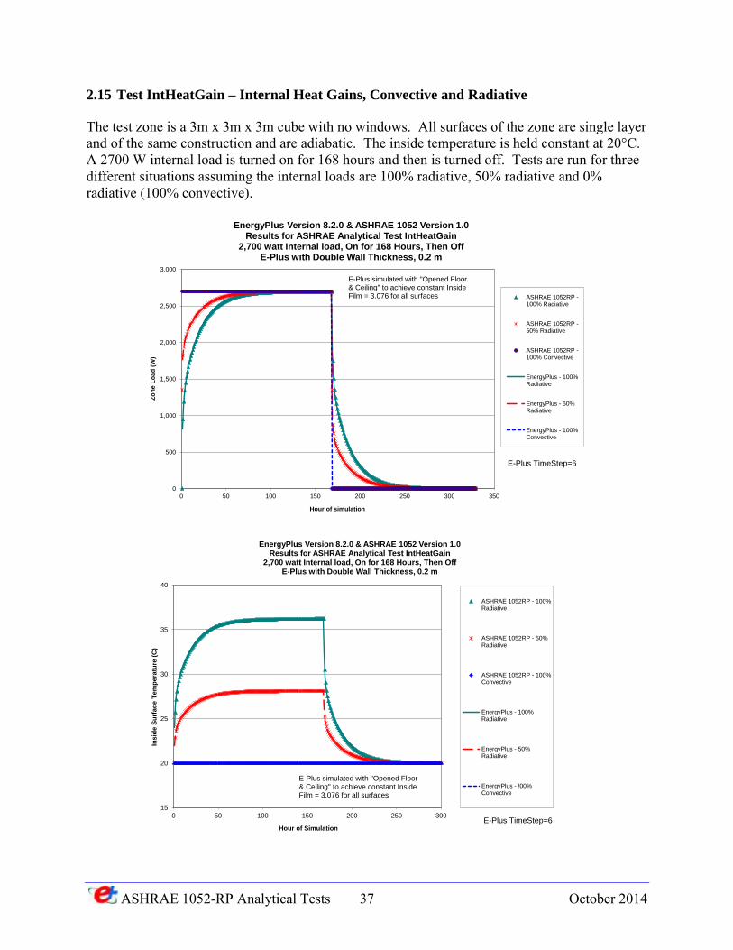
2.15 Test IntHeatGain – Internal Heat Gains, Convective and Radiative
The test zone is a 3m x 3m x 3m cube with no windows. All surfaces of the zone are single layer and of the same construction and are adiabatic. The inside temperature is held constant at 20°C. A 2700 W internal load is turned on for 168 hours and then is turned off. Tests are run for three different situations assuming the internal loads are 100% radiative, 50% radiative and 0% radiative (100% convective).
0
500
1,000
1,500
2,000
2,500
3,000
0 50 100 150 200 250 300 350
Zo
ne L
oad
(W
)
Hour of simulation
EnergyPlus Version 8.2.0 & ASHRAE 1052 Version 1.0Results for ASHRAE Analytical Test IntHeatGain
2,700 watt Internal load, On for 168 Hours, Then OffE-Plus with Double Wall Thickness, 0.2 m
ASHRAE 1052RP -100% Radiative
ASHRAE 1052RP -50% Radiative
ASHRAE 1052RP -100% Convective
EnergyPlus - 100%Radiative
EnergyPlus - 50%Radiative
EnergyPlus - 100%Convective
E-Plus TimeStep=6
E-Plus simulated with "Opened Floor& Ceiling" to achieve constant Inside Film = 3.076 for all surfaces
15
20
25
30
35
40
0 50 100 150 200 250 300
Insid
e S
urf
ace T
em
pera
ture
(C
)
Hour of Simulation
EnergyPlus Version 8.2.0 & ASHRAE 1052 Version 1.0Results for ASHRAE Analytical Test IntHeatGain
2,700 watt Internal load, On for 168 Hours, Then OffE-Plus with Double Wall Thickness, 0.2 m
ASHRAE 1052RP - 100%Radiative
ASHRAE 1052RP - 50%Radiative
ASHRAE 1052RP - 100%Convective
EnergyPlus - 100%Radiative
EnergyPlus - 50%Radiative
EnergyPlus - !00%Convective
E-Plus TimeStep=6
E-Plus simulated with "Opened Floor& Ceiling" to achieve constant Inside Film = 3.076 for all surfaces
ASHRAE 1052-RP Analytical Tests 38 October 2014
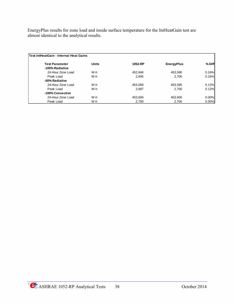
EnergyPlus results for zone load and inside surface temperature for the IntHeatGain test are almost identical to the analytical results.
Test IntHeatGain - Internal Heat Gains
Test Parameter Units 1052-RP EnergyPlus % Diff
-100% Radiative
24-Hour Zone Load W-h 452,846 453,590 0.16%
Peak Load W-h 2,695 2,700 0.16%
-50% Radiative
24-Hour Zone Load W-h 453,069 453,595 0.12%
Peak Load W-h 2,697 2,700 0.12%
-100% Convective
24-Hour Zone Load W-h 453,600 453,600 0.00%
Peak Load W-h 2,700 2,700 0.00%
ASHRAE 1052-RP Analytical Tests 39 October 2014
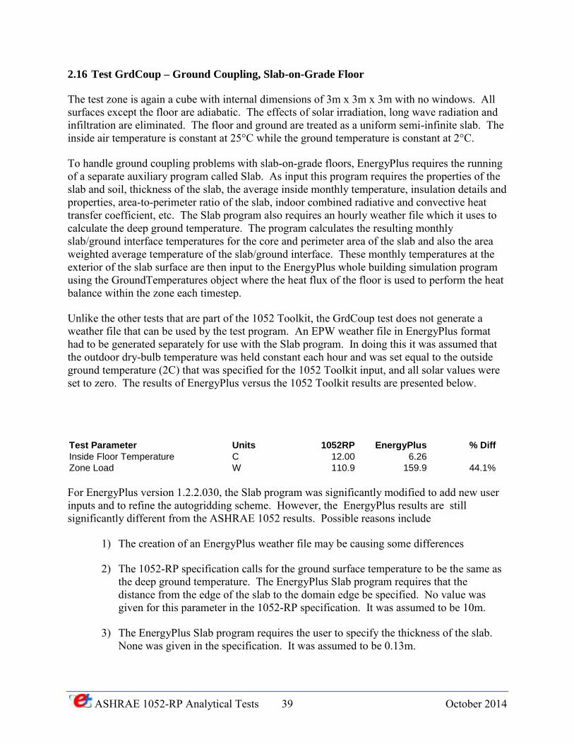
2.16 Test GrdCoup – Ground Coupling, Slab-on-Grade Floor
The test zone is again a cube with internal dimensions of 3m x 3m x 3m with no windows. All surfaces except the floor are adiabatic. The effects of solar irradiation, long wave radiation and infiltration are eliminated. The floor and ground are treated as a uniform semi-infinite slab. The inside air temperature is constant at 25°C while the ground temperature is constant at 2°C.
To handle ground coupling problems with slab-on-grade floors, EnergyPlus requires the running of a separate auxiliary program called Slab. As input this program requires the properties of the slab and soil, thickness of the slab, the average inside monthly temperature, insulation details and properties, area-to-perimeter ratio of the slab, indoor combined radiative and convective heat transfer coefficient, etc. The Slab program also requires an hourly weather file which it uses to calculate the deep ground temperature. The program calculates the resulting monthly slab/ground interface temperatures for the core and perimeter area of the slab and also the area weighted average temperature of the slab/ground interface. These monthly temperatures at the exterior of the slab surface are then input to the EnergyPlus whole building simulation program using the GroundTemperatures object where the heat flux of the floor is used to perform the heat balance within the zone each timestep.
Unlike the other tests that are part of the 1052 Toolkit, the GrdCoup test does not generate a weather file that can be used by the test program. An EPW weather file in EnergyPlus format had to be generated separately for use with the Slab program. In doing this it was assumed that the outdoor dry-bulb temperature was held constant each hour and was set equal to the outside ground temperature (2C) that was specified for the 1052 Toolkit input, and all solar values were set to zero. The results of EnergyPlus versus the 1052 Toolkit results are presented below.
Test Parameter Units 1052RP EnergyPlus % Diff
Inside Floor Temperature C 12.00 6.26
Zone Load W 110.9 159.9 44.1%
For EnergyPlus version 1.2.2.030, the Slab program was significantly modified to add new user inputs and to refine the autogridding scheme. However, the EnergyPlus results are still significantly different from the ASHRAE 1052 results. Possible reasons include
1) The creation of an EnergyPlus weather file may be causing some differences
2) The 1052-RP specification calls for the ground surface temperature to be the same as the deep ground temperature. The EnergyPlus Slab program requires that the distance from the edge of the slab to the domain edge be specified. No value was given for this parameter in the 1052-RP specification. It was assumed to be 10m.
3) The EnergyPlus Slab program requires the user to specify the thickness of the slab. None was given in the specification. It was assumed to be 0.13m.
ASHRAE 1052-RP Analytical Tests 40 October 2014
4) The EnergyPlus Slab program requires that the material properties of the slab and soil be specified. None were given in the specification except for the 1.0 W/m-K slab conductivity. It was assumed that the density of the slab and soil was 2200 kg/m**3 and the specific heat of the slab and soil was 670 J/kg-K.
5) The documentation for this test states that “The floor is rectangular and is bounded (but not penetrated) on each side by four equal width external walls. It is assumed that the effect of the walls is to change the ground/slab surface temperature linearly over their thickness. The walls have a finite conductance but its actual value is unimportant." This boundary condition is not simulated by the Slab program, which assumes that entire top surface of the slab is exposed to the zone air temperature, and that all of the ground is exposed to the outdoor conditions. The wall thickness in the toolkit was to 0.1mm to minimize the impact of this boundary condition.
Further investigation of these issues will be done as part of work on a more extensive ground coupling test suite.
ASHRAE 1052-RP Analytical Tests 41 October 2014
3 ENERGYPLUS PROBLEMS UNCOVERED WHILE
USING ASHRAE 1052-RP TOOLKIT
During the process of using the ASHRAE 1052-RP Toolkit to test early versions of EnergyPlus, several significant differences were identified when comparing the EnergyPlus results to that of the toolkit. Each of these is discussed further in this section with the eventual resolution of the problem.
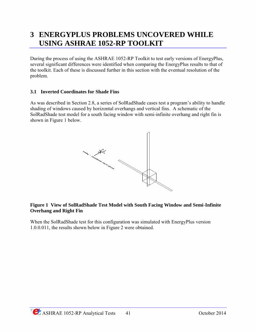
3.1 Inverted Coordinates for Shade Fins
As was described in Section 2.8, a series of SolRadShade cases test a program’s ability to handle shading of windows caused by horizontal overhangs and vertical fins. A schematic of the SolRadShade test model for a south facing window with semi-infinite overhang and right fin is shown in Figure 1 below.
Figure 1 View of SolRadShade Test Model with South Facing Window and Semi-Infinite
Overhang and Right Fin
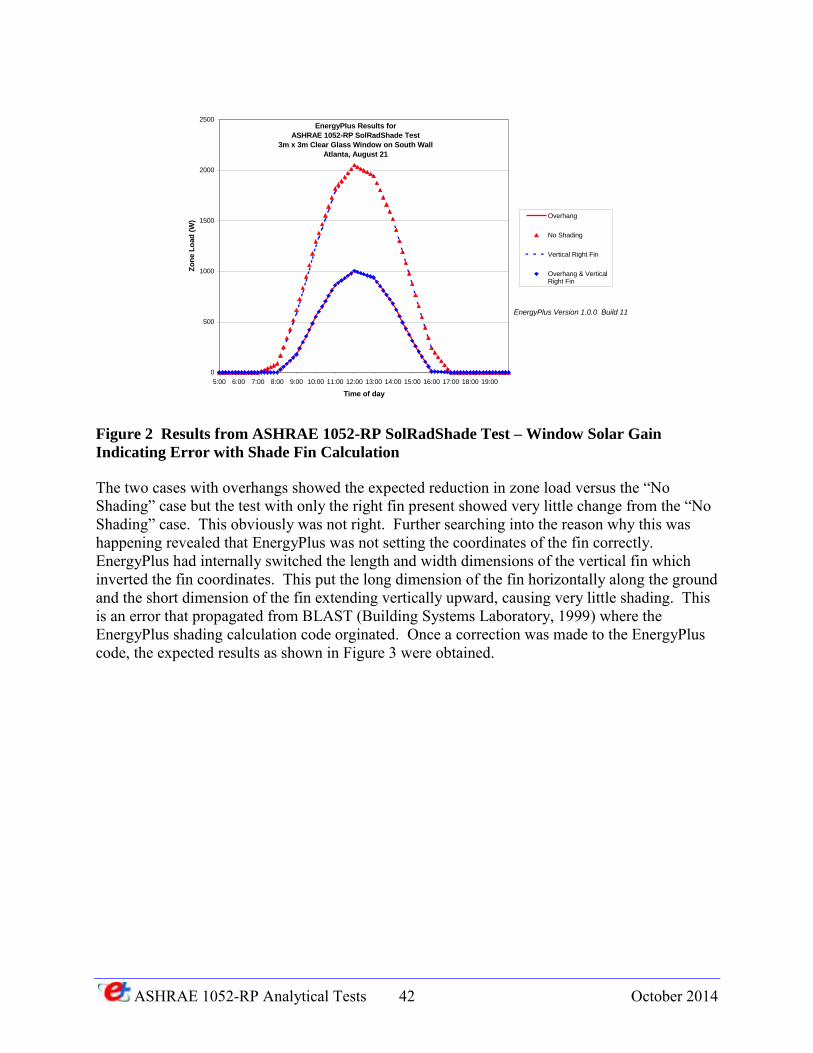
When the SolRadShade test for this configuration was simulated with EnergyPlus version 1.0.0.011, the results shown below in Figure 2 were obtained.
ASHRAE 1052-RP Analytical Tests 42 October 2014
Figure 2 Results from ASHRAE 1052-RP SolRadShade Test – Window Solar Gain
Indicating Error with Shade Fin Calculation
The two cases with overhangs showed the expected reduction in zone load versus the “No Shading” case but the test with only the right fin present showed very little change from the “No Shading” case. This obviously was not right. Further searching into the reason why this was happening revealed that EnergyPlus was not setting the coordinates of the fin correctly. EnergyPlus had internally switched the length and width dimensions of the vertical fin which inverted the fin coordinates. This put the long dimension of the fin horizontally along the ground and the short dimension of the fin extending vertically upward, causing very little shading. This is an error that propagated from BLAST (Building Systems Laboratory, 1999) where the EnergyPlus shading calculation code orginated. Once a correction was made to the EnergyPlus code, the expected results as shown in Figure 3 were obtained.
0
500
1000
1500
2000
2500
5:00 6:00 7:00 8:00 9:00 10:00 11:00 12:00 13:00 14:00 15:00 16:00 17:00 18:00 19:00
Time of day
Zo
ne L
oad
(W
)
Overhang
No Shading
Vertical Right Fin
Overhang & VerticalRight Fin
EnergyPlus Version 1.0.0 Build 11
EnergyPlus Results for
ASHRAE 1052-RP SolRadShade Test
3m x 3m Clear Glass Window on South Wall
Atlanta, August 21
ASHRAE 1052-RP Analytical Tests 43 October 2014
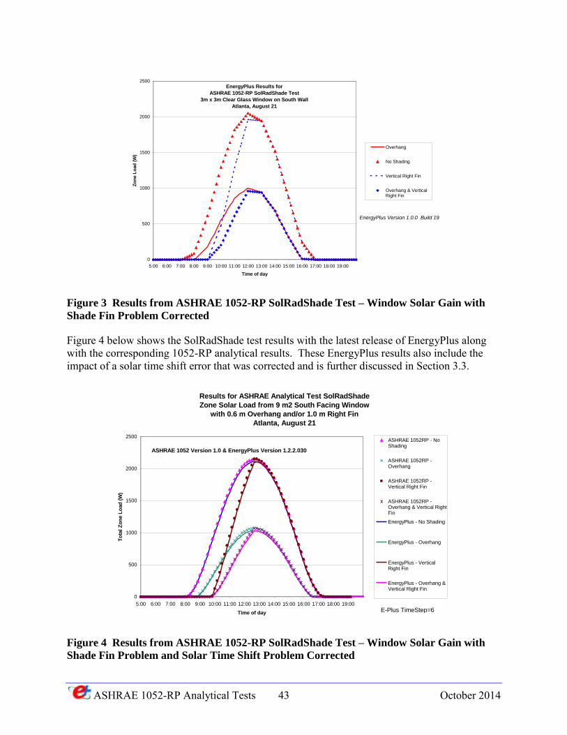
Figure 3 Results from ASHRAE 1052-RP SolRadShade Test – Window Solar Gain with
Shade Fin Problem Corrected
Figure 4 below shows the SolRadShade test results with the latest release of EnergyPlus along with the corresponding 1052-RP analytical results. These EnergyPlus results also include the impact of a solar time shift error that was corrected and is further discussed in Section 3.3.
Figure 4 Results from ASHRAE 1052-RP SolRadShade Test – Window Solar Gain with
Shade Fin Problem and Solar Time Shift Problem Corrected
0
500
1000
1500
2000
2500
5:00 6:00 7:00 8:00 9:00 10:00 11:00 12:00 13:00 14:00 15:00 16:00 17:00 18:00 19:00
Time of day
Zo
ne L
oad
(W
)
Overhang
No Shading
Vertical Right Fin
Overhang & VerticalRight Fin
EnergyPlus Version 1.0.0 Build 19
EnergyPlus Results for
ASHRAE 1052-RP SolRadShade Test
3m x 3m Clear Glass Window on South Wall
Atlanta, August 21
Results for ASHRAE Analytical Test SolRadShade
Zone Solar Load from 9 m2 South Facing Window
with 0.6 m Overhang and/or 1.0 m Right Fin
Atlanta, August 21
0
500
1000
1500
2000
2500
5:00 6:00 7:00 8:00 9:00 10:00 11:00 12:00 13:00 14:00 15:00 16:00 17:00 18:00 19:00
Time of day
To
tal
Zo
ne L
oad
(W
)
ASHRAE 1052RP - NoShading
ASHRAE 1052RP -Overhang
ASHRAE 1052RP -Vertical Right Fin
ASHRAE 1052RP -Overhang & Vertical RightFin
EnergyPlus - No Shading
EnergyPlus - Overhang
EnergyPlus - VerticalRight Fin
EnergyPlus - Overhang &Vertical Right Fin
ASHRAE 1052 Version 1.0 & EnergyPlus Version 1.2.2.030
E-Plus TimeStep=6
ASHRAE 1052-RP Analytical Tests 44 October 2014
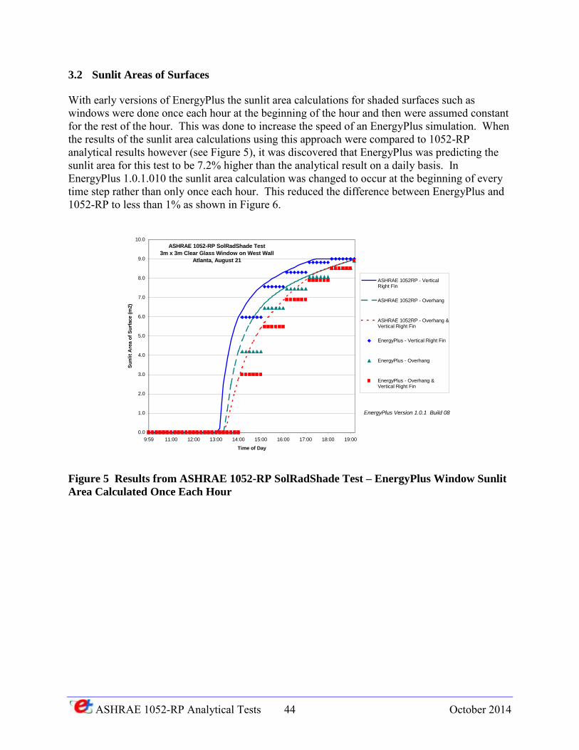
3.2 Sunlit Areas of Surfaces
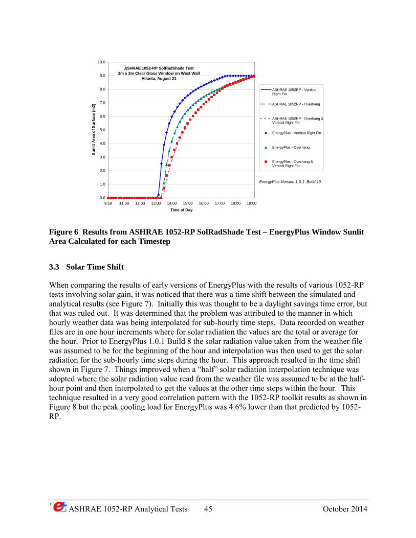
With early versions of EnergyPlus the sunlit area calculations for shaded surfaces such as windows were done once each hour at the beginning of the hour and then were assumed constant for the rest of the hour. This was done to increase the speed of an EnergyPlus simulation. When the results of the sunlit area calculations using this approach were compared to 1052-RP analytical results however (see Figure 5), it was discovered that EnergyPlus was predicting the sunlit area for this test to be 7.2% higher than the analytical result on a daily basis. In EnergyPlus 1.0.1.010 the sunlit area calculation was changed to occur at the beginning of every time step rather than only once each hour. This reduced the difference between EnergyPlus and 1052-RP to less than 1% as shown in Figure 6.
Figure 5 Results from ASHRAE 1052-RP SolRadShade Test – EnergyPlus Window Sunlit
Area Calculated Once Each Hour
0.0
1.0
2.0
3.0
4.0
5.0
6.0
7.0
8.0
9.0
10.0
9:59 11:00 12:00 13:00 14:00 15:00 16:00 17:00 18:00 19:00
Time of Day
Su
nli
t A
rea o
f S
urf
ace (
m2)
ASHRAE 1052RP - VerticalRight Fin
ASHRAE 1052RP - Overhang
ASHRAE 1052RP - Overhang &Vertical Right Fin
EnergyPlus - Vertical Right Fin
EnergyPlus - Overhang
EnergyPlus - Overhang &Vertical Right Fin
ASHRAE 1052-RP SolRadShade Test
3m x 3m Clear Glass Window on West Wall
Atlanta, August 21
EnergyPlus Version 1.0.1 Build 08
ASHRAE 1052-RP Analytical Tests 45 October 2014
Figure 6 Results from ASHRAE 1052-RP SolRadShade Test – EnergyPlus Window Sunlit
Area Calculated for each Timestep
3.3 Solar Time Shift
When comparing the results of early versions of EnergyPlus with the results of various 1052-RP tests involving solar gain, it was noticed that there was a time shift between the simulated and analytical results (see Figure 7). Initially this was thought to be a daylight savings time error, but that was ruled out. It was determined that the problem was attributed to the manner in which hourly weather data was being interpolated for sub-hourly time steps. Data recorded on weather files are in one hour increments where for solar radiation the values are the total or average for the hour. Prior to EnergyPlus 1.0.1 Build 8 the solar radiation value taken from the weather file was assumed to be for the beginning of the hour and interpolation was then used to get the solar radiation for the sub-hourly time steps during the hour. This approach resulted in the time shift shown in Figure 7. Things improved when a “half” solar radiation interpolation technique was adopted where the solar radiation value read from the weather file was assumed to be at the half-hour point and then interpolated to get the values at the other time steps within the hour. This technique resulted in a very good correlation pattern with the 1052-RP toolkit results as shown in Figure 8 but the peak cooling load for EnergyPlus was 4.6% lower than that predicted by 1052-RP.
0.0
1.0
2.0
3.0
4.0
5.0
6.0
7.0
8.0
9.0
10.0
9:59 11:00 12:00 13:00 14:00 15:00 16:00 17:00 18:00 19:00
Time of Day
Su
nli
t A
rea o
f S
urf
ace (
m2)
ASHRAE 1052RP - VerticalRight Fin
ASHRAE 1052RP - Overhang
ASHRAE 1052RP - Overhang &Vertical Right Fin
EnergyPlus - Vertical Right Fin
EnergyPlus - Overhang
EnergyPlus - Overhang &Vertical Right Fin
ASHRAE 1052-RP SolRadShade Test
3m x 3m Clear Glass Window on West Wall
Atlanta, August 21
EnergyPlus Version 1.0.1 Build 10
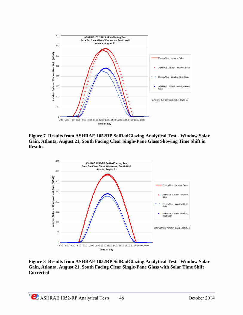
ASHRAE 1052-RP Analytical Tests 46 October 2014
Figure 7 Results from ASHRAE 1052RP SolRadGlazing Analytical Test - Window Solar
Gain, Atlanta, August 21, South Facing Clear Single-Pane Glass Showing Time Shift in
Results
Figure 8 Results from ASHRAE 1052RP SolRadGlazing Analytical Test - Window Solar
Gain, Atlanta, August 21, South Facing Clear Single-Pane Glass with Solar Time Shift
Corrected
0
50
100
150
200
250
300
350
400
5:00 6:00 7:00 8:00 9:00 10:00 11:00 12:00 13:00 14:00 15:00 16:00 17:00 18:00 19:00
Time of day
Incid
en
t S
ola
r o
r W
ind
ow
Heat
Gain
(W
/m2)
EnergyPlus - Incident Solar
ASHRAE 1052RP - Incident Solar
EnergyPlus - Window Heat Gain
ASHRAE 1052RP - Window HeatGain
ASHRAE 1052-RP SolRadGlazing Test
3m x 3m Clear Glass Window on South Wall
Atlanta, August 21
EnergyPlus Version 1.0.1 Build 04
0
50
100
150
200
250
300
350
400
5:00 6:00 7:00 8:00 9:00 10:00 11:00 12:00 13:00 14:00 15:00 16:00 17:00 18:00 19:00
Time of day
Inc
ide
nt
So
lar
or
Win
do
w H
ea
t G
ain
(W
/m2
)
EnergyPlus - Incident Solar
ASHRAE 1052RP - IncidentSolar
EnergyPlus - Window HeatGain
ASHRAE 1052RP WindowHeat Gain
ASHRAE 1052-RP SolRadGlazing Test
3m x 3m Clear Glass Window on South Wall
Atlanta, August 21
EnergyPlus Version 1.0.1 Build 10
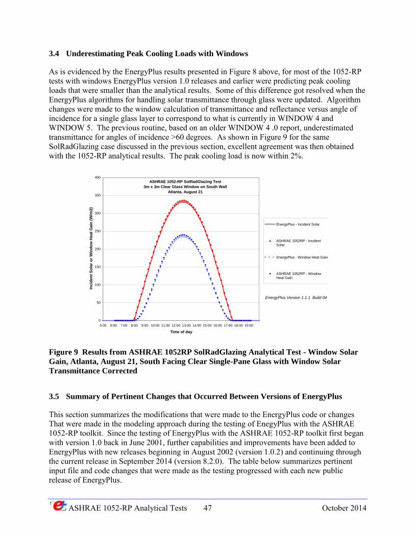
ASHRAE 1052-RP Analytical Tests 47 October 2014
3.4 Underestimating Peak Cooling Loads with Windows
As is evidenced by the EnergyPlus results presented in Figure 8 above, for most of the 1052-RP tests with windows EnergyPlus version 1.0 releases and earlier were predicting peak cooling loads that were smaller than the analytical results. Some of this difference got resolved when the EnergyPlus algorithms for handling solar transmittance through glass were updated. Algorithm changes were made to the window calculation of transmittance and reflectance versus angle of incidence for a single glass layer to correspond to what is currently in WINDOW 4 and WINDOW 5. The previous routine, based on an older WINDOW 4 .0 report, underestimated transmittance for angles of incidence >60 degrees. As shown in Figure 9 for the same SolRadGlazing case discussed in the previous section, excellent agreement was then obtained with the 1052-RP analytical results. The peak cooling load is now within 2%.
Figure 9 Results from ASHRAE 1052RP SolRadGlazing Analytical Test - Window Solar
Gain, Atlanta, August 21, South Facing Clear Single-Pane Glass with Window Solar
Transmittance Corrected
3.5 Summary of Pertinent Changes that Occurred Between Versions of EnergyPlus
This section summarizes the modifications that were made to the EnergyPlus code or changes That were made in the modeling approach during the testing of EnegyPlus with the ASHRAE 1052-RP toolkit. Since the testing of EnergyPlus with the ASHRAE 1052-RP toolkit first began with version 1.0 back in June 2001, further capabilities and improvements have been added to EnergyPlus with new releases beginning in August 2002 (version 1.0.2) and continuing through the current release in September 2014 (version 8.2.0). The table below summarizes pertinent input file and code changes that were made as the testing progressed with each new public release of EnergyPlus.
0
50
100
150
200
250
300
350
400
5:00 6:00 7:00 8:00 9:00 10:00 11:00 12:00 13:00 14:00 15:00 16:00 17:00 18:00 19:00
Time of day
Incid
en
t S
ola
r o
r W
ind
ow
Heat
Gain
(W
/m2)
EnergyPlus - Incident Solar
ASHRAE 1052RP - IncidentSolar
EnergyPlus - Window Heat Gain
ASHRAE 1052RP - WindowHeat Gain
ASHRAE 1052-RP SolRadGlazing Test
3m x 3m Clear Glass Window on South Wall
Atlanta, August 21
EnergyPlus Version 1.1.1 Build 04

ASHRAE 1052-RP Analytical Tests 48 October 2014
Summary of Pertinent EnergyPlus Changes that were Implemented Over
Course of 1052-RP Toolkit Testing
Version Input File Changes Code Changes
1.0.0.015 Fixed shade fin inverted coordinates problem 1.0.1.001 Change in weather processing file 1.0.1.008 Change in solar position calculation 1.0.1.010 Sunlit area calculation done for each timestep 1.0.1.037 Added ability to input monthly ground reflectance 1.1.1.004 Modify window calculation of transmittance and
reflectance versus angle of incidence for single glass layer
1.0.1.040 Set monthly ground reflectance to 0.20. Previously defaulted to 0.2 – 0.6 depending on month
1.0.1.026 Set SHADOW CALCULATIONS = 1; previously defaulted to 20
1.0.3.006 Changed weather interpolation to previous hour 1.0.3.015 Changed to “half” interpolation for solar radiation 1.1.0.003 Set surface inside convection coefficients to
constants for certain tests New ConvectionCoefficients input object added
1.1.1.004 Changed surface convection coefficient algorithms 1.2.0 More changes to exterior convection coefficient
algorithms 1.3.0.018 Included new SITE ATMOSPHERIC
VARIATION object which allows calculation of local outdoor air temperature and wind speed for each exterior surface. Air temperature gradient coefficient set to 0.0 to lockout air temperature variation.
1.3.018 Algorithm error corrected for calculating when sun comes up – sun rises 10 minutes earlier now
2.1.0.023 The methodology for handling solar diffuse through a window was completely reworked and was changed from uniform interior distribution of transmitted diffuse solar to distribution based on approximate view factors between transmitting windows and zone heat transfer surfaces. (CR7237)
3.0.0.028 The algorithm for variable system timestep was revised. Changes include uniform system timestep length across zone timestep and stricter management of history terms for zone air conditions.
7.0.0.036 Shadow calculations were improved for non-convex shading surfaces. Had small impact on IntSolDist test results
7.0.0.036 For Test Case TC1, used the HeatBalanceAlgorithm object to override the convection coefficient lower limit of 0.1 to allow the inside surface convection coefficient to be set
ASHRAE 1052-RP Analytical Tests 49 October 2014
to 0.000001 which brought results closer to the ASHRAE 1052RP curve
8.0.0.008 For all test cases using adiabatic massless surfaces where the specific heat for materials was set to 0.5 J/kg-K, the specific heat was reset to the new minimum value of 100 J/kg-K.
The minimum value of the specific heat used for material specification was changed from >0 J/kg-K to = >100 J/kg-K
8.0.0.008 Changed solar position calculations for 1hr timesteps to help match better with other sub-hourly timesteps.
8.2.0 The EnergyPlus source code was converted from FORTRAN to C++. This produced negligible differences in results
Beginning with EnergyPlus version 1.3.0.018 a new SITE ATMOSPHERIC VARIATION input object became available (beginning with EnergyPlus 3.0.0 the name of this object changed to Site:HeightVariation) to simulate changes in outside air temperature and wind speed that typically occur vertically across building surfaces versus the outdoor air temperature and wind speed that are obtained each hour from the weather file. Typically the meteorological wind speed is measured in an open field at 10m above the ground and meteorological air temperature is measured at 1.5m above ground level. To accommodate atmospheric variation EnergyPlus now automatically calculates the local outdoor air temperature and wind speed separately for each zone and surface exposed to the outdoor environment. The zone centroid or surface centroid are used to determine the height above ground. Only local outdoor air temperature and wind speed are currently calculated because they are important factors for the exterior convection calculation for surfaces and can also be factors in the zone infiltration and ventilation calculations. Since the ASHRAE 1052-RP analytical solutions assume that the temperature of the outside surfaces of the building are at the outdoor dry-bulb temperature read from the weather file, the SITE ATMOSPHERIC VARIATION temperature calculation feature was turned off by setting the air temperature gradient coefficient to 0.0. The wind effect variation was left turned on but had no effect on any of the tests because either the wind speed on the weather file was always 0.0 m/s or all exterior surfaces of the test zone were adiabatic (e.g. IntHeatGain test). The SITE ATMOSPHERIC VARIATION object inputs were set as shown below for all test cases. SITE ATMOSPHERIC VARIATION, 0.22, !- Wind Speed Profile Exponent 370, !- Wind Speed Profile Boundary Layer Thickness {m} 0.0; !- Air Temperature Gradient Coefficient {K/m} New output variables to report the surface exterior outdoor dry-bulb temperature and surface exterior wind speed allow the user to track hourly changes when the SITE ATMOSPHERIC VARIATION features are active.
The methodology for handling solar diffuse through a window was completely reworked in EnergyPlus 2.1.0.012 and was changed from uniform interior distribution of transmitted diffuse solar to distribution based on approximate view factors between transmitting windows and zone

ASHRAE 1052-RP Analytical Tests 50 October 2014
heat transfer surfaces. This change only affected the Test IntSolDist results. For all other tests the internal diffuse radiation was locked out.
In EnergyPlus 8.0.0.008, the minimum value for specific heat as input for Material objects was increased from >0 J/kg-K to = > 100 J/kg-K. This required changes in Material objects for some tests where the specific heat had been set to 0.5 J/kg-K to simulate the requirement for massless adiabatic surfaces. This change did not impact test results reported in spreadsheets. Also changed in EnergyPlus 8.0.0.008 was the solar position calculations for 1 hour timesteps to help match better with other sub-hourly timesteps. This change resulted in only very small changes in results for test cases IntHeatgain, SolRadShade and WinReveal.
ASHRAE 1052-RP Analytical Tests 51 October 2014
4 CONCLUSIONS
EnergyPlus Version 8.2.0 was used to model a series of analytical tests for building envelopes as specified in ASHRAE 1052-RP report titled Development of an Analytical Verification Test Suite
for Whole Building Energy Simulation Programs – Building Fabric. The ability of EnergyPlus to predict zone loads, surface heat fluxes and surface temperatures was tested using a test suite of 16 cases which tested various modes of heat transfer such as convection, conduction, radiation, solar gains and shading, infiltration, long wave radiation, and other miscellaneous tests. Comparison of results between EnergyPlus and the ASHRAE analytical solution for various test cases pointed to the following areas of significant difference:
Difference in window heat gains due to different approach to handling light polarization between EnergyPlus and the 1052 toolkit.
Differences for those tests where the 1052-RP hourly weather data had to be interpolated into subhourly data for 10 minute timesteps
Differences in treatment of external long wave radiation which may be due to differences in external long wave radiation models
Differences in treatment of ground-coupled heat transfer for slabs due to assumptions that had to be in order to use the EnergyPlus Slab program
Overall, the results of EnergyPlus compared very closely with the analytical results obtained from the ASHRAE 1052-RP Toolkit. The 1052-RP Toolkit proved to be very useful in detecting bugs and confirming that basic modeling algorithms were working properly.

ASHRAE 1052-RP Analytical Tests 52 October 2014
ASHRAE 1052-RP Analytical Tests 53 October 2014
5 REFERENCES
Building Systems Laboratory. 1999. BLAST 3.0 Users Manual. Urbana-Champaign: Building Systems Laboratory, Department of Mechanical and Industrial Engineering, University of Illinois.
EnergyPlus 2014. U.S. Department of Energy, Energy Efficiency and Renewable Energy, Office of Building Technologies. www.energyplus.gov
Spitler, J.D., Rees, S.J., and Dongyi, X., 2001. Development of an Analytical Verification Test Suite for Whole Building Energy Simulation Programs – Building Fabric, ASHRAE 1052-RP Final Report, April 2001.
Witte, M. J., Henninger, R.H., Glazer, J., and D. B. Crawley. 2001. "Testing and Validation of a New Building Energy Simulation Program," Proceedings of Building Simulation 2001, to be published in August 2001, Rio de Janeiro, Brazil, International Building Performance Simulation Association (IBPSA).