Embed Size (px)
Citation preview

2018-06-28
EnergyHub System Installation and user manual

Warning • Read the manual before installation • The EnergyHub may not be opened by unauthorized personnel. Contact Ferroamp for instructions.
• The electrical installation shall be performed by an authorized electrician in accordance with electrical standards and safety precautions
• The warranty is not applicable if the products has been modified. • Observe, the EnergyHub equalizes imbalance between the phase conductors and uses the systems neutral conductor. Large imbalance causes large currents in the neutral conductor.
• The DC contact shall not be connected when the EnergyHub is powered up.

Contents
1. Products ...................................................................................................................................... 5
2. Location of the EnergyHub ................................................................................................... 6
3. Current sensor installation .................................................................................................... 7
4. Connection to distribution board ....................................................................................... 11
5. Internet connection ................................................................................................................ 12
6. EnergyHub Connections....................................................................................................... 12
7. DC connection ........................................................................................................................ 13
8. Commissioning ........................................................................................................................ 14
9. Example of an EnergyHub system .................................................................................. 16
10. Schematic Wiring diagram .............................................................................................. 17
User manual ................................................................................................................................... 18
1. Activate ACE and solar production .................................................................................. 18
2. Change ACE limit .................................................................................................................. 19
3. Grid current and Load current ........................................................................................... 20
4. Activate ACE only ................................................................................................................. 21
5. Activate Solar production .................................................................................................... 22

Page 3 of 24
Introduction The EnergyHub is an inverter for the modular solar power systems, with new features. The EnergyHub does not only convert direct current from PV-panels to alternating current, but can also be used around the clock as an active electricity meter. Adaptive current Equalization (ACE) The patented ACE technology dynamically transfer energy between the phase conductors of a three-phase system, thereby limiting the supply phase currents to the main fuse rating, without limiting the load currents. This can reduce the required main fuse or increase the load currents, without increasing the main fuse.
Figure 1 - ACE technology transfers available current from L1 and L3 to L2 so the loads in the facility can be utilized without an interruption from the main fuse

Page 4 of 24
DC nanogrid The EnergyHub can be used with PV-panels and/or Energy Storage in order to utilize renewable, locally produced, energy. This is enabled through the optimizers as they work as DC/DC converters for solar power and Energy storages. The EnergyHub works as a bidirectional bridge between the DC nanogrid, created by the optimizers, and the AC grid inside the facility. With this system, batteries can be charged directly with solar power or with electricity form the AC grid, depending on the season and weather. Accordingly, the EnergyHub is used both as a rectifier and inverter.
Figure 2 - Overview of how a DC nanogrid could be configured
Page 5 of 24
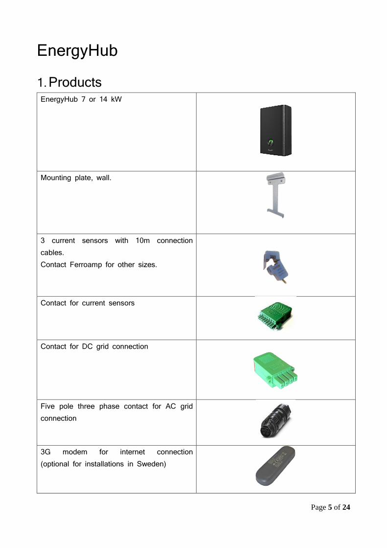
EnergyHub 1. Products EnergyHub 7 or 14 kW
Mounting plate, wall.
3 current sensors with 10m connection cables. Contact Ferroamp for other sizes.
Contact for current sensors
Contact for DC grid connection
Five pole three phase contact for AC grid connection
3G modem for internet connection (optional for installations in Sweden)

Page 6 of 24
2. Location of the EnergyHub • Make sure there is enough space around the
EnergyHub to enable a safe installation and steady airflow.
• Mount the EnergyHub indoors or in a suitable enclosure with sufficient ventilation.
• The wall and fasteners needs to be able to carry at least 25 Kg.
• Remember that the specified ambient temperature is 0-40°C.
• Relative humidity: 0-95%. • Mount the EnergyHub on the mounting plate and make
sure it is correctly placed on designated spot. Tighten with screws.

Page 7 of 24
3. Current sensor installation
In order to use the ACE functionality and analysis tools from the Ferroamp Portal, current sensors needs to be connected to the EnergyHub. There are 3 available current sensors. The size of the current transformer is decided by the current flowing through the cable and its physical size. < 100 A, ratio 2000
< 160 A, ratio 4000

Page 8 of 24
< 600 A, ratio 6000

Page 9 of 24
Install the current sensors on all three of the phase conductors. The sensors should be installed on the main feed cables. See wiring diagram in section 4 • The EnergyHub has an automatic calibration for each of the current sensors which
handles the direction of the current direction. • Adjust the length of the cable and connect it in accordance with the picture below. Only
6 wires are used, please note the order. •
Note: • It is important that the current sensors are completely closed around the
cable. • In order to ensure that the installation is correct measure the resistant
between the pairs; White – Red, Blue – Black, Green – Yellow. If one of the does not have contact with eachother something is wrong with the installation.

Page 10 of 24
Location of the current sensors In order to facilitate the collected data from the measurements it is important to install the current sensors on the correct distribution board. As an example, in order to produce a correct fuse analysis, the current sensors need to be installed so they measure all the current going through the main fuses.

Page 11 of 24
4. Connection to distribution board • Connect the EnergyHub with the delivered five pole three-phase contact. • A disconnect switch is recommended between the distribution board and the EnergyHub • The EnergyHub should be protected with fuses of B-characteristic, EnergyHub wall 14
kW needs B20 fuses. • The current in the neutral conductor can be 1.7 times higher than the rated current which
should be considered while dimensioning the cable for the EnergyHub. The connection cable for the EnergyHub needs to be able to handle the heat that may occur. E.g. for an EnergyHub with 20 A ACE the current in the neutral conductor can be 34 A
Figure 3 - Wiring diagram for the Energyhub and current sensors

Page 12 of 24
5. Internet connection The EnergyHub requires Internet connection in order to present data on the Ferroamp portal and receive software updates
6. EnergyHub Connections

Page 13 of 24
7. DC connection • Ensure that the EnergyHub is turned off. Do not connect the DC grid contact if the
EnergyHub is powered on. • Connect the cables to the 4-pole DC grid contact. Note that the Neutral (N) is not used
for the DC grid contact on the EnergyHub.

Page 14 of 24
8. Commissioning • Start the EnergyHub by turning on the disconnect switch on the AC side. • Wait 1 minute for the display to start.
• Press on the display until “Service menu enabled” shows to enter the setup menu. • When the finger is removed the “Start and Stop” view is shown. If it fails, please try
again without moving the finger. • Swipe right and left to change between different views. Go to CT ration.
• Confirm or choose desired ratio for the current sensors. The standard blue current sensor has a ratio of 2000.
• In order to change the ratio, press number and choose the new ration. • Press “Save” • Swipe to the view with the with button “Run CT configuration” • Start the calibration by pressing “Run CT Configuration”.

Page 15 of 24
• The configuration can take up to 5 minutes, when it is done the massage “Configuration
succeeded” is shown on the display. • If the message “configuration failed” is shown verify that the current transformers are
installed correctly • The Installation is done. • Press and hold until “Service menu disabled” is shown to go back to operational mode.

Page 16 of 24
9. Example of an EnergyHub system Equipment: • 2 units of SSO 6 kW • 1 unit of EnergyHub 14 kW • 3Gx1.5 mm2 cables, between the SSO and distribution board • 3Gx6 mm2 cable, between the distribution board and EnergyHub 14 kW • 4x10 A DC rated fuses • 1 disconnect switch rated for 20 A and 1000 VDC

Page 17 of 24
10. Schematic Wiring diagram

Page 18 of 24
User manual 1. Activate ACE and solar production
• Press and hold the display until “Service menu enabled” is shown.
• Choose ACE & PV from the drop-down menu.
• Press the number at the bottom in order to change the threshold for the current equalization.
• Press start • Verify that the system is running the correct settings in the table view

Page 19 of 24
2. Change ACE limit • Press and hold the display until “Service menu activated” is shown. • Press Stop.
• Press the number at the bottom in order to change the threshold for the current equalization.
• Press Start. • Verify the status in the table view • Press and hold the display to go back to operational mode.

Page 20 of 24
3. Grid current and Load current
• Grid current shows the current over the main fuse • Load current shows the current inside the facility • When ACE is activated, the transferred currents is shown by the arrows between the phases.

Page 21 of 24
4. Activate ACE only • Press and hold until “Service menu enabled” is shown. • Swipe to the ”Start and Stop” display. • Choose “ACE only” in the drop-down menu
• Choose the current limit that triggers the ACE function • Press Start • Verify the status at the table view • Press and hold the display to go back to operational mode.

Page 22 of 24
5. Activate Solar production • Press and hold until “Service menu enabled” is shown. • Swipe to the ”start and stop” display. • Choose “PV only” in the drop-down menu •
• • Press Start • Verify the status at the table view • Press and hold the display to go back to operational mode.

Page 23 of 24