Embed Size (px)
Citation preview

Energy Storage Materials 34 (2021) 629–639
Contents lists available at ScienceDirect
Energy Storage Materials
journal homepage: www.elsevier.com/locate/ensm
In situ formation of poly(butyl acrylate)-based non-flammable elastic
quasi-solid electrolyte for dendrite-free flexible lithium metal batteries
with long cycle life for wearable devices
Guodong Zhou
a , Xidong Lin
a , Jiapeng Liu
a , Jing Yu
a , Junxiong Wu
a , Ho Mei Law
a , Zheng Wang
a , Francesco Ciucci a , b , ∗
a Department of Mechanical and Aerospace Engineering, The Hong Kong University of Science and Technology, Clear Water Bay, Hong Kong, China b Department of Chemical and Biological Engineering, The Hong Kong University of Science and Technology, Clear Water Bay, Hong Kong, China
a r t i c l e i n f o
Keywords:
Non-flammable elastic quasi-solid electrolyte
In situ polymerization
Poly(butyl acrylate) flexible batteries
a b s t r a c t
With the rapid development of wearable devices, there is an increasing demand for ultra-safe flexible lithium-ion
batteries (LIBs) capable of delivering high energy density. Because it can provide the highest possible capacity of
3860 mAh g -1 , lithium metal has drawn tremendous research attention. However, Li is a highly reactive metal that
grows dendrites during the cycling of lithium-metal batteries (LMBs). To resolve the problem, we developed a new
non-flammable elastic quasi-solid electrolyte (QSE), which can be polymerized in situ and whose composition
is tailored to achieve high elasticity. Moreover, the incorporation of trimethyl phosphate (TMP) renders the
electrolyte non-flammable. Thanks to the solid electrolyte interphase (SEI) formed, the LMB with QSE displays
excellent cycling stability as it can be operated for 500 cycles, with a capacity retention of 94%. The corresponding
symmetric cell cycled stably for more than 500 h. Scanning electron microscopy (SEM) and density functional
theory (DFT) calculations reveal that fluoroethylene carbonate (FEC) is critical in forming the LiF-rich SEI that
enables long-term cycling stability. In brief, a non-flammable, elastic, and stable QSE is reported for the first time,
which is very promising in the application of the next-generation wearable devices.
1
i
t
s
i
p
n
c
h
g
D
b
i
b
l
P
t
T
p
t
c
t
l
l
cl
t
f
o
e
h
R
A
2
. Introduction
There is a tremendous demand for flexible batteries with the emerg-ng applications of wearable devices, such as smartwatches, electronicextiles, roll-up displays, wearable heaters, bio-electronic devices, andoft robots [1] . While lithium-ion batteries (LIBs) are commonly usedn consumer electronics and electric vehicles, they can be further im-roved in terms of flexibility, energy density, and safety. Among theegative electrodes, lithium metal (LM) has the lowest electrochemi-al potential (i.e. − 3.04 V vs. the standard hydrogen electrode) and theighest theoretical specific capacity (i.e. 3860 mAh g − 1 vs. 372 mAh
− 1 for graphite) [2] . However, due to the uneven plating and strip-
Abbreviation: AEA, adiabatic electron affinity; AIBN, azobisisobutyronitrile; AIP
MC, dimethyl carbonate; DEC, diethyl carbonate; DFT, density functional theory
onate; EIS, electrochemical impedance spectroscopy; EMC, ethyl methyl carbonate
nfrared spectroscopy; GCD, galvanostatic charge-discharge; HOMO, highest occup
is(fluorosulfonyl)imide; LiTFSI, lithium bis(trifluoromethylsulphonyl)imide; LM, lit
inear sweep voltammetry; LUMO, lowest unoccupied molecular orbital; MF, TMP/FE
EO, poly(ethylene oxide); PMMA, poly(methyl methacrylate); PVDF, poly(vinyliden
rolyte interphase; SEM, scanning electron microscopy; SSE, solid-state electrolyte; TB
GA, thermogravimetric analysis; TMP, trimethyl phosphate; TPP, triphenyl phospha∗ Corresponding author.
E-mail address: [email protected] (F. Ciucci).
ttps://doi.org/10.1016/j.ensm.2020.10.012
eceived 3 September 2020; Received in revised form 3 October 2020; Accepted 14
vailable online 16 October 2020
405-8297/© 2020 Elsevier B.V. All rights reserved.
ing of lithium during cycling, dendrites quickly form and penetratehe separator of lithium metal batteries (LMBs), causing internal shortircuits [3,4] . Furthermore, LM is highly active and reacts with the elec-rolyte to form a solid electrolyte interphase (SEI) [5] . The growth ofithium dendrites often cracks the SEI. Therefore, the newly exposedithium will continue to react with the electrolyte. This phenomenonauses the material to detach from its bulk, leading to inactive or “dead ”ithium [6] . As a consequence of this phenomenon, the anode utiliza-ion, cycling efficiency, and cycling life of LMBs are typically not satis-actory. Several strategies have been proposed to enhance the stabilityf LM, including the growth of an artificial SEI [7–15] and the use oflectrolytes with a high salt concentration [16–23] . For example, flu-
, adiabatic ionization potential; BA, butyl acrylate; CV, cyclic voltammetry;
; DSC, differential scanning calorimetry; EA, ethyl acetate; EC, ethylene car-
; EMF, EA/TMP/FEC; FEC, fluoroethylene carbonate; FTIR, fourier transform
ied molecular orbital; LFP, LiFePO 4 ; LIB, lithium-ion battery; LiFSI, lithium
hium metal; LMB, lithium-metal battery; LOE, liquid organic electrolyte; LSV,
C; PAN, polyacrylonitrile; PBA, poly(butyl acrylate); PC, propylene carbonate;
e fluoride); QSE, quasi-solid electrolyte; RT, room temperature; SEI, solid elec-
P, tributyl phosphate; TEP, triethyl phosphate; T g , glass transition temperature;
te; XPS, X-ray photoelectron spectroscopy.
October 2020

G. Zhou, X. Lin, J. Liu et al. Energy Storage Materials 34 (2021) 629–639
o
d
l
a
p
‘
b
g
l
c
b
r
t
s
c
t
a
p
f
c
v
t
t
o
s
t
w
c
T
i
i
f
s
h
R
p
t
l
s
p
b
T
H
b
w
fl
o
t
t
t
b
c
s
m
l
i
c
i
o
a
u
a
i
b
m
c
a
o
t
w
u
s
P
v
e
s
b(
p
s
c
s
0
m
t
a
D
f
p
w
w
u
a
t
s
2
m
b
b
o
w
(
t
Q
t
t
t
w
u
t
P
f
t
t
o
t
t
5
m
i
s
c
roethylene carbonate (FEC) has been adopted as a film-forming ad-itive to generate a lithium-ion conductive and electron insulating LiFayer on the LM surface [7,24] . The LiF-containing SEI typically shows uniform and compact morphology and leads to a significantly im-roved cycling stability. The Hu group [16] introduced a new class of
solvent-in-salt’ electrolytes with high concentrations (7 M) of lithiumis(trifluoromethylsulphonyl)imide (LiTFSI). Such high concentrationsreatly improved the cycling life of the batteries because of the de-ayed dendrite formation compared to the electrolytes with low con-entrations of LiTFSI (1 M). Qian et al. [17] . prepared a 4 M lithiumis(fluorosulfonyl)imide (LiFSI)/1,2-dimethoxyethane electrolyte. Theesulting Li | Li symmetric cell with the electrolyte could cycle morehan 6000 cycles at 10 mA cm
− 2 . As discussed above, the unsatisfactory performance of LM causes
afety concerns. Therefore, improving the safety of LMBs has become aritically important area of research. Conventional liquid organic elec-rolytes (LOEs), including dimethyl carbonate (DMC), diethyl carbon-te (DEC), ethyl methyl carbonate (EMC), ethylene carbonate (EC), andropylene carbonate (PC), are flammable and may trigger a catastrophicailure if the heat supplied is excessive, an internal short circuit oc-urs, or the battery is penetrated. Incorporating flame-retarding sol-ents, such as trimethyl phosphate (TMP), triethyl phosphate (TEP),ributyl phosphate (TBP), and triphenyl phosphate (TPP), into the elec-rolyte improves the safety of the battery [25–28] . Among the variousptions, TMP is particularly attractive because of its high dielectric con-tant ( ɛ r = 21.26), ability to dissolve lithium salts even at high concen-ration levels, low viscosity (2.32 mPa •s), and wide liquid temperatureindow ( − 46 – 197°C). However, TMP is unstable against LM and de-
omposes at a potential of 1.2 V vs. Li/Li + [29,30] . Moreover, usingMP does not fundamentally resolve the dendrite problem because TMP
s not able to form a stable SEI on LM [30] . A fundamentally different approach to improve the safety of batteries
s to employ a solid-state electrolyte (SSE). As is well known, the sur-ace of solids, either ceramic or polymer, is not perfectly flat. The poorolid-solid contact between SSE and electrodes can lead to excessivelyigh resistances and limit the utilization of active materials [31,32] .eplacing the SSE with a quasi-solid electrolyte (QSE) that contains aolymer skeleton and a solvent can solve this challenge. QSEs combinehe advantages of solids with those of liquids, including reduced or noeakage and better contact with electrodes [33–35] . Various polymers,uch as poly(ethylene oxide) (PEO), poly(vinylidene fluoride) (PVDF),olyacrylonitrile (PAN), and poly(methyl methacrylate) (PMMA) haveeen used to prepare QSEs [36,37] . For example, Chen et al. [38] . made aMP-based QSE with PMMA to reinforce the non-flammable electrolyte.owever, PMMA is a rigid-chain polymer material that is poorly solu-le in TMP, thus hindering its application in flexible electronics andearable devices. Furthermore, there have been no reports on non-ammable QSEs with outstanding elasticity, which is a necessary traitf high-performance wearable devices.
During the industrial production of batteries, electrodes and separa-ors are stacked or rolled together, and the liquid electrolyte is injectedo infiltrate the separators. The batteries are then sealed to completehe assembly before formation and degassing. In the case of QSE-basedatteries, there are two types of preparation methods. The first one isalled solution casting, which involves the dissolution of a polymer inolvents followed by casting and solvent evaporation [39] . The secondethod is polymerization, during which the polymer precursors, cross-
inker, and initiator are mixed into a solvent and form a QSE upon heat-ng [38,40,41] or UV treatment [42–47] . The complexity of these pro-esses prolongs the fabrication period and increases costs. Additionally,t is challenging to control the thickness of the QSEs. The combinationf these issues hinders the industrialization of QSE-based batteries. Anlternative to conventional procedures is to make QSE-based batteriessing in situ polymerization, the process of which is exactly the sames the traditional method except that the liquid precursor of the QSEs used instead of liquid electrolyte. Therefore, QSE-based batteries can
630
e prepared with the conventional process and equipment in this way,aking it possible to produce QSE-based batteries at large scale and low
ost. Furthermore, the thickness of the QSE can be easily controlled bydjusting the separator thickness.
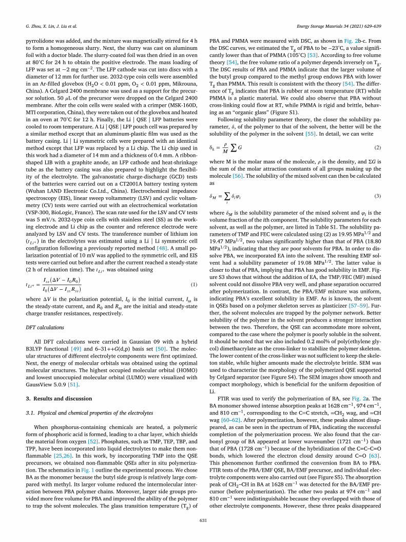
In this work, we developed a new non-flammable elastic QSE basedn poly(butyl acrylate) (PBA) and fabricated using in situ polymeriza-ion. The incorporation of TMP allowed the QSE to be non-flammable,hile FEC allowed the formation of a stable SEI on LM. Following sol-bility parameter theory, ethyl acetate (EA) was included to adjust theolubility of PBA in the mixed solvent. The large butyl side group ofBA provided more free volume compared with methyl. The more freeolume made it easier for the polymer chains to move and, therefore,ndowed the electrolyte with better flexibility and elasticity. The quasi-olid nature of the electrolyte enabled a spatially even current distri-ution, hampering the formation of dendrites. The LMB with LiFePO 4
LFP) cathode and PBA20 electrolyte displayed a specific discharge ca-acity of 166 mAh g − 1 at 0.2 C, and 153 mAh g − 1 at 1 C, as well astable operation at 0.5 C for 500 cycles with only a 6% of capacity de-ay over the whole testing period. The Li | PBA20 | Li symmetric cellhowed stable stripping/plating cycling for 500 h at 0.5 mA cm
− 2 and.5 mAh cm
− 2 . Density functional theory (DFT) was used to analyze theechanism of the stable cycling of the QSE-based batteries and revealed
he film-forming function of FEC in forming the stable LiF-rich SEI. Welso made a pouch cell with a capacity of 5.4 mAh with this method.ue to the elasticity of the electrolyte, the pouch cell could continue to
unction even if flexed and twisted. A ribbon-shaped battery was alsorepared to show the flexibility of the electrolyte, which could operatehen tied into a knot. The in situ polymerization method is compatibleith the current production line of LIBs due to the low-viscosity liq-id precursor, making it very easy to scale up. In this work, our batterynd QSE achieved non-flammability and elasticity and provided a prac-ical solution to the industrialization of QSE-based batteries with higherafety.
. Experimental section
Preparation of the QSEs. The QSEs were prepared by in situ poly-erization. Firstly, LiFSI was dissolved in EA/TMP/FEC (EMF) (4:3:3
y volume) mixed solvent to form a 5 M LiFSI/EMF solution. Then, theutyle acrylate (BA) monomer (20 wt.% – 50 wt.%, with 0.2 mol%f poly(ethylene glycol) dimethacrylate as cross-linker) was mixedith the solution to form the precursor solution. Azobisisobutyronitrile
AIBN) was dissolved in it as the thermal initiator. The precursor solu-ion was injected into a glass mold with a silicone spacer. Finally, theSE was obtained by heating the precursor at 70°C for 12 h. The ob-
ained QSEs were denoted as PBA20 – PBA50, where the number washe weight percentage of PBA in the QSEs (20 wt.% – 50 wt.%). All ofhe chemicals were purchased from Sigma-Aldrich.
Materials characterizations. Scanning electron microscopy (SEM)as performed on JEOL-6390. The LMs were rinsed with DMC and nat-rally dried in the glove box before the SEM measurement. Fourierransform infrared spectroscopy (FTIR) was performed on Bruker AL-HA Spectrometer. X-ray photoelectron spectroscopy (XPS) was per-ormed on an Axis Ultra DLD instrument. Differential scanning calorime-ry (DSC) tests were carried out on a differential scanning calorime-er (Q1000, TA). Thermogravimetric analysis (TGA) was carried outn a thermogravimetric analyzer (Q5000, TA). The uniaxial tensileests were conducted on a UTM-I2 universal testing machine followinghe ASTM D412 standard. The QSE samples were cut into the size of0 mm × 5 mm × 1 mm and tested with a crosshead speed of 50 mmin − 1 . At least five specimens were tested for each composition.
Electrochemical measurements. Unless specified, all electrochem-cal measurements were carried out in the 2032-type coin cells. LFP,uper P conductive carbon, and PVDF at the weight ratio of 8:1:1 werearefully ground with mortar and pestle for 20 min. After that, N-methyl
G. Zhou, X. Lin, J. Liu et al. Energy Storage Materials 34 (2021) 629–639
p
t
f
a
L
d
i
C
s
m
M
i
c
a
b
m
t
s
t
i
o
(
s
m
(
w
i
a
(
c
l
t
(
𝑡
w
t
c
D
B
u
N
m
a
G
3
3
f
t
T
fl
p
t
B
p
a
v
t
P
t
c
t
T
t
T
e
P
c
i
r
s
δ
w
t
m
a
𝛿
w
v
s
r
1
M
s
v
c
u
s
a
i
i
t
s
b
c
I
c
T
t
u
b
c
L
B
a
w
p
c
b
t
b
T
F
t
p
c
8
o
yrrolidone was added, and the mixture was magnetically stirred for 4 ho form a homogeneous slurry. Next, the slurry was cast on aluminumoil with a doctor blade. The slurry-coated foil was then dried in an ovent 80°C for 24 h to obtain the positive electrode. The mass loading ofFP was set at ~2 mg cm
− 2 . The LFP cathode was cut into discs with aiameter of 12 mm for further use. 2032-type coin cells were assembledn an Ar-filled glovebox (H 2 O < 0.01 ppm, O 2 < 0.01 ppm, Mikrouna,hina). A Celgard 2400 membrane was used as a support for the precur-or solution. 50 𝜇L of the precursor were dropped on the Celgard 2400embrane. After the coin cells were sealed with a crimper (MSK-160D,TI corporation, China), they were taken out of the glovebox and heated
n an oven at 70°C for 12 h. Finally, the Li | QSE | LFP batteries wereooled to room temperature. A Li | QSE | LFP pouch cell was prepared by similar method except that an aluminum-plastic film was used as theattery casing. Li | Li symmetric cells were prepared with an identicalethod except that LFP was replaced by a Li chip. The Li chip used in
his work had a diameter of 14 mm and a thickness of 0.4 mm. A ribbon-haped LIB with a graphite anode, an LFP cathode and heat-shrinkageube as the battery casing was also prepared to highlight the flexibil-ty of the electrolyte. The galvanostatic charge-discharge (GCD) testsf the batteries were carried out on a CT2001A battery testing systemWuhan LAND Electronic Co.Ltd., China). Electrochemical impedancepectroscopy (EIS), linear sweep voltammetry (LSV) and cyclic voltam-etry (CV) tests were carried out with an electrochemical workstation
VSP-300, BioLogic, France). The scan rate used for the LSV and CV testsas 5 mV/s. 2032-type coin cells with stainless steel (SS) as the work-
ng electrode and Li chip as the counter and reference electrode werenalyzed by LSV and CV tests. The transference number of lithium ion 𝑡 𝐿 𝑖 + ) in the electrolytes was estimated using a Li | Li symmetric cellonfiguration following a previously reported method [48] . A small po-arization potential of 10 mV was applied to the symmetric cell, and EISests were carried out before and after the current reached a steady-state2 h of relaxation time). The 𝑡 𝐿 𝑖 + was obtained using
𝐿 𝑖 + =
𝐼 𝑠𝑠 (Δ𝑉 − 𝐼 0 𝑅 0
)
𝐼 0 (Δ𝑉 − 𝐼 𝑠𝑠 𝑅 𝑠𝑠
) (1)
here ΔV is the polarization potential, I 0 is the initial current, I ss ishe steady-state current, and R 0 and R ss are the initial and steady-stateharge transfer resistances, respectively.
FT calculations
All DFT calculations were carried in Gaussian 09 with a hybrid3LYP functional [49] and 6–31 ++ G (d,p) basis set [50] . The molec-lar structures of different electrolyte components were first optimized.ext, the energy of molecular orbitals was obtained using the optimalolecular structures. The highest occupied molecular orbital (HOMO)
nd lowest unoccupied molecular orbital (LUMO) were visualized withaussView 5.0.9 [51] .
. Results and discussion
.1. Physical and chemical properties of the electrolytes
When phosphorus-containing chemicals are heated, a polymericorm of phosphoric acid is formed, leading to a char layer, which shieldshe material from oxygen [52] . Phosphates, such as TMP, TEP, TBP, andPP, have been incorporated into liquid electrolytes to make them non-ammable [25,26] . In this work, by incorporating TMP into the QSErecursors, we obtained non-flammable QSEs after in situ polymeriza-ion. The schematics in Fig. 1 outline the experimental process. We choseA as the monomer because the butyl side group is relatively large com-ared with methyl. Its larger volume reduced the intermolecular inter-ction between PBA polymer chains. Moreover, larger side groups pro-ided more free volume for PBA and improved the ability of the polymero trap the solvent molecules. The glass transition temperature (T g ) of
631
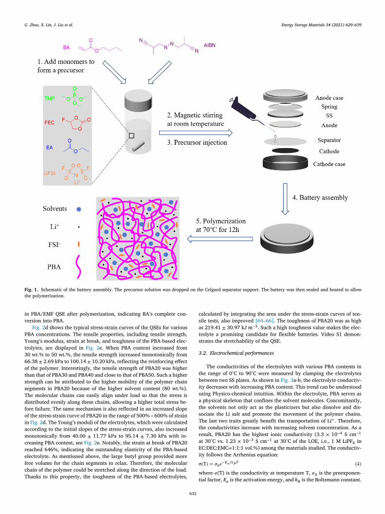
BA and PMMA were measured with DSC, as shown in Fig. 2 b-c. Fromhe DSC curves, we estimated the T g of PBA to be − 23°C, a value signifi-antly lower than that of PMMA (105°C) [53] . According to free volumeheory [54] , the free volume ratio of a polymer depends inversely on T g .he DSC results of PBA and PMMA indicate that the larger volume ofhe butyl group compared to the methyl group endows PBA with lower g than PMMA. This result is consistent with the theory [54] . The differ-nce of T g indicates that PBA is rubber at room temperature (RT) whileMMA is a plastic material. We could also observe that PBA withoutross-linking could flow at RT, while PMMA is rigid and brittle, behav-ng as an “organic glass ” (Figure S1).
Following solubility parameter theory, the closer the solubility pa-ameter, 𝛿, of the polymer to that of the solvent, the better will be theolubility of the polymer in the solvent [55] . In detail, we can write
𝑘 =
𝜌
𝑀
∑𝐺 (2)
here M is the molar mass of the molecule, 𝜌 is the density, and ΣG ishe sum of the molar attraction constants of all groups making up theolecule [56] . The solubility of the mixed solvent can then be calculated
s
𝑀
=
∑
𝑖
𝛿𝑖 𝜑 𝑖 (3)
here 𝛿M
is the solubility parameter of the mixed solvent and 𝜑 i is theolume fraction of the i th component. The solubility parameters for eacholvent, as well as the polymer, are listed in Table S1. The solubility pa-ameters of TMP and FEC were calculated using (2) as 19.95 MPa 1/2 and9.47 MPa 1/2 , two values significantly higher than that of PBA (18.80Pa 1/2 ), indicating that they are poor solvents for PBA. In order to dis-
olve PBA, we incorporated EA into the solvent. The resulting EMF sol-ent had a solubility parameter of 19.08 MPa 1/2 . The latter value isloser to that of PBA, implying that PBA has good solubility in EMF. Fig-re S3 shows that without the addition of EA, the TMP/FEC (MF) mixedolvent could not dissolve PBA very well, and phase separation occurredfter polymerization. In contrast, the PBA/EMF mixture was uniform,ndicating PBA’s excellent solubility in EMF. As is known, the solventn QSEs based on a polymer skeleton serves as plasticizer [57–59] . Fur-her, the solvent molecules are trapped by the polymer network. Betterolubility of the polymer in the solvent produces a stronger interactionetween the two. Therefore, the QSE can accommodate more solvent,ompared to the case where the polymer is poorly soluble in the solvent.t should be noted that we also included 0.2 mol% of poly(ethylene gly-ol) dimethacrylate as the cross-linker to stabilize the polymer skeleton.he lower content of the cross-linker was not sufficient to keep the skele-on stable, while higher amounts made the electrolyte brittle. SEM wassed to characterize the morphology of the polymerized QSE supportedy Celgard separator (see Figure S4). The SEM images show smooth andompact morphology, which is beneficial for the uniform deposition ofi.
FTIR was used to verify the polymerization of BA, see Fig. 2 a. TheA monomer showed intense absorption peaks at 1628 cm
− 1 , 974 cm
− 1 ,nd 810 cm
− 1 , corresponding to the C
= C stretch, = CH 2 wag, and = CHag [60–62] . After polymerization, however, these peaks almost disap-eared, as can be seen in the spectrum of PBA, indicating the successfulompletion of the polymerization process. We also found that the car-onyl group of BA appeared at lower wavenumber (1721 cm
− 1 ) thanhat of PBA (1728 cm
− 1 ) because of the hybridization of the C
= C
–C
= Oonds, which lowered the electron cloud density around C
= O [63] .his phenomenon further confirmed the conversion from BA to PBA.TIR tests of the PBA/EMF QSE, BA/EMF precursor, and individual elec-rolyte components were also carried out (see Figure S5). The absorptioneak of CH 2 –CH in BA at 1628 cm
− 1 was detected for the BA/EMF pre-ursor (before polymerization). The other two peaks at 974 cm
− 1 and10 cm
− 1 were indistinguishable because they overlapped with those ofther electrolyte components. However, these three peaks disappeared
G. Zhou, X. Lin, J. Liu et al. Energy Storage Materials 34 (2021) 629–639
Fig. 1. Schematic of the battery assembly. The precursor solution was dropped on the Celgard separator support. The battery was then sealed and heated to allow
the polymerization.
i
v
P
Y
t
3
6
o
t
s
s
T
d
f
o
i
a
m
c
r
e
f
c
T
c
s
a
t
s
3
t
b
i
u
a
t
s
T
t
ra
E
i
σ
w
n PBA/EMF QSE after polymerization, indicating BA’s complete con-ersion into PBA.
Fig. 2 d shows the typical stress-strain curves of the QSEs for variousBA concentrations. The tensile properties, including tensile strength,oung’s modulus, strain at break, and toughness of the PBA-based elec-rolytes, are displayed in Fig. 2 e. When PBA content increased from0 wt.% to 50 wt.%, the tensile strength increased monotonically from6.38 ± 2.69 kPa to 100.14 ± 10.20 kPa, reflecting the reinforcing effectf the polymer. Interestingly, the tensile strength of PBA20 was higherhan that of PBA30 and PBA40 and close to that of PBA50. Such a highertrength can be attributed to the higher mobility of the polymer chainegments in PBA20 because of the higher solvent content (80 wt.%).he molecular chains can easily align under load so that the stress isistributed evenly along these chains, allowing a higher total stress be-ore failure. The same mechanism is also reflected in an increased slopef the stress-strain curve of PBA20 in the range of 500% – 600% of strainn Fig. 2 d. The Young’s moduli of the electrolytes, which were calculatedccording to the initial slopes of the stress-strain curves, also increasedonotonically from 40.00 ± 11.77 kPa to 95.14 ± 7.30 kPa with in-
reasing PBA content, see Fig. 2 e. Notably, the strain at break of PBA20eached 646%, indicating the outstanding elasticity of the PBA-basedlectrolyte. As mentioned above, the large butyl group provided moreree volume for the chain segments to relax. Therefore, the molecularhain of the polymer could be stretched along the direction of the load.hanks to this property, the toughness of the PBA-based electrolytes,
t
632
alculated by integrating the area under the stress-strain curves of ten-ile tests, also improved [64–66] . The toughness of PBA20 was as highs 219.41 ± 30.97 kJ m
− 3 . Such a high toughness value makes the elec-rolyte a promising candidate for flexible batteries. Video S1 demon-trates the stretchability of the QSE.
.2. Electrochemical performances
The conductivities of the electrolytes with various PBA contents inhe range of 0°C to 90°C were measured by clamping the electrolytesetween two SS plates. As shown in Fig. 3 a-b, the electrolyte conductiv-ty decreases with increasing PBA content. This trend can be understoodsing Physico-chemical intuition. Within the electrolyte, PBA serves as physical skeleton that confines the solvent molecules. Concomitantly,he solvents not only act as the plasticizers but also dissolve and dis-ociate the Li salt and promote the movement of the polymer chains.he last two traits greatly benefit the transportation of Li + . Therefore,he conductivities increase with increasing solvent concentration. As aesult, PBA20 has the highest ionic conductivity (3.3 × 10 − 4 S cm
− 1
t 30°C vs. 1.23 × 10 − 3 S cm
− 1 at 30°C of the LOE, i.e., 1 M LiPF 6 inC:DEC:EMC = 1:1:1 vol.%) among the materials studied. The conductiv-ty follows the Arrhenius equation:
( T ) = 𝜎0 𝑒 − 𝐸 𝑎 ∕ 𝑘 𝐵 𝑇 (4)
here 𝜎(T) is the conductivity at temperature T, 𝜎0 is the preexponen-ial factor, E is the activation energy, and k is the Boltzmann constant.
a B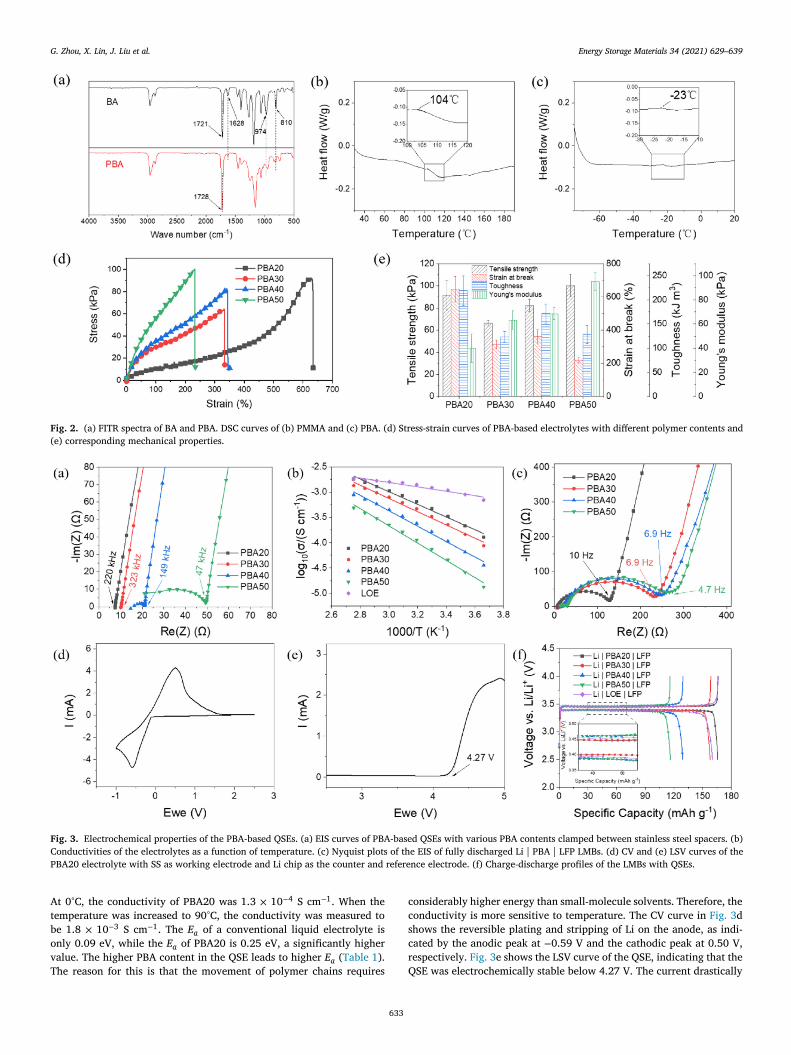
G. Zhou, X. Lin, J. Liu et al. Energy Storage Materials 34 (2021) 629–639
Fig. 2. (a) FITR spectra of BA and PBA. DSC curves of (b) PMMA and (c) PBA. (d) Stress-strain curves of PBA-based electrolytes with different polymer contents and
(e) corresponding mechanical properties.
Fig. 3. Electrochemical properties of the PBA-based QSEs. (a) EIS curves of PBA-based QSEs with various PBA contents clamped between stainless steel spacers. (b)
Conductivities of the electrolytes as a function of temperature. (c) Nyquist plots of the EIS of fully discharged Li | PBA | LFP LMBs. (d) CV and (e) LSV curves of the
PBA20 electrolyte with SS as working electrode and Li chip as the counter and reference electrode. (f) Charge-discharge profiles of the LMBs with QSEs.
A
t
b
o
v
T
c
c
s
c
r
Q
t 0°C, the conductivity of PBA20 was 1.3 × 10 − 4 S cm
− 1 . When theemperature was increased to 90°C, the conductivity was measured toe 1.8 × 10 − 3 S cm
− 1 . The E a of a conventional liquid electrolyte isnly 0.09 eV, while the E a of PBA20 is 0.25 eV, a significantly higheralue. The higher PBA content in the QSE leads to higher E a ( Table 1 ).he reason for this is that the movement of polymer chains requires
633
onsiderably higher energy than small-molecule solvents. Therefore, theonductivity is more sensitive to temperature. The CV curve in Fig. 3 dhows the reversible plating and stripping of Li on the anode, as indi-ated by the anodic peak at − 0.59 V and the cathodic peak at 0.50 V,espectively. Fig. 3 e shows the LSV curve of the QSE, indicating that theSE was electrochemically stable below 4.27 V. The current drastically
G. Zhou, X. Lin, J. Liu et al. Energy Storage Materials 34 (2021) 629–639
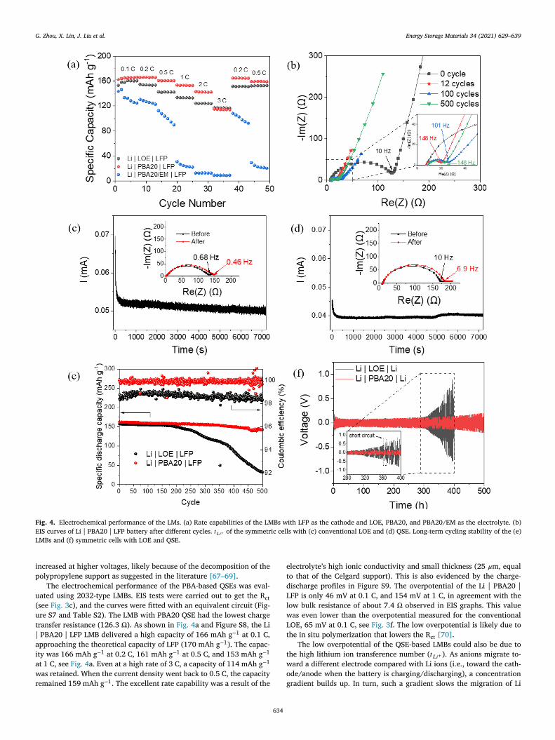
Fig. 4. Electrochemical performance of the LMs. (a) Rate capabilities of the LMBs with LFP as the cathode and LOE, PBA20, and PBA20/EM as the electrolyte. (b)
EIS curves of Li | PBA20 | LFP battery after different cycles. 𝑡 𝐿 𝑖 + of the symmetric cells with (c) conventional LOE and (d) QSE. Long-term cycling stability of the (e)
LMBs and (f) symmetric cells with LOE and QSE.
i
p
u(
u
t
|
a
ia
w
r
e
t
d
L
l
w
L
t
t
w
o
g
ncreased at higher voltages, likely because of the decomposition of theolypropylene support as suggested in the literature [67–69] .
The electrochemical performance of the PBA-based QSEs was eval-ated using 2032-type LMBs. EIS tests were carried out to get the R ct
see Fig. 3 c), and the curves were fitted with an equivalent circuit (Fig-re S7 and Table S2). The LMB with PBA20 QSE had the lowest chargeransfer resistance (126.3 Ω). As shown in Fig. 4 a and Figure S8, the Li PBA20 | LFP LMB delivered a high capacity of 166 mAh g − 1 at 0.1 C,pproaching the theoretical capacity of LFP (170 mAh g − 1 ). The capac-ty was 166 mAh g − 1 at 0.2 C, 161 mAh g − 1 at 0.5 C, and 153 mAh g − 1
t 1 C, see Fig. 4 a. Even at a high rate of 3 C, a capacity of 114 mAh g − 1
as retained. When the current density went back to 0.5 C, the capacityemained 159 mAh g − 1 . The excellent rate capability was a result of the
634
lectrolyte’s high ionic conductivity and small thickness (25 𝜇m, equalo that of the Celgard support). This is also evidenced by the charge-ischarge profiles in Figure S9. The overpotential of the Li | PBA20 |FP is only 46 mV at 0.1 C, and 154 mV at 1 C, in agreement with theow bulk resistance of about 7.4 Ω observed in EIS graphs. This valueas even lower than the overpotential measured for the conventionalOE, 65 mV at 0.1 C, see Fig. 3 f. The low overpotential is likely due tohe in situ polymerization that lowers the R ct [70] .
The low overpotential of the QSE-based LMBs could also be due tohe high lithium ion transference number ( 𝑡 𝐿 𝑖 + ). As anions migrate to-ard a different electrode compared with Li ions (i.e., toward the cath-de/anode when the battery is charging/discharging), a concentrationradient builds up. In turn, such a gradient slows the migration of Li

G. Zhou, X. Lin, J. Liu et al. Energy Storage Materials 34 (2021) 629–639
Fig. 5. Optical and SEM images of the LMs and
separators cycled with LOE (a, b, e, f) and QSEs
(c, d, g, h).
i
m
Q
w
e
f
[
c
c
o
c
s
i
d
b
t
r
m
e
m
t
w
c
t
o
c
c
b
o
b
t
i
w
a
w
d
o
t
t
t
t
s
w
d
w
Fig. 6. XPS Li 1 s spectra of the LMs cycled in LOE and PBA20 electrolytes.
p
a
w
s
t
t
e
a
o
T
o
t
M
s
m
3
D
ons and increases the overpotential. To verify the impact of 𝑡 𝐿 𝑖 + , weeasured the 𝑡 𝐿 𝑖 + of the symmetric cells with conventional LOE andSE, see Fig. 4 c-d. The result shows that the 𝑡 𝐿 𝑖 + in LOE was only 0.24,hile it reached 0.63 in the QSE, suggesting that concentration gradient
ffects are reduced. The high 𝑡 𝐿 𝑖 + of the QSE could be attributed to twoactors: 1) the polymer skeleton could limit the movement of anions;71] 2) the Li + cations were less solvated with high salt concentrationompared to low salt concentration, leading to higher Li + mobility [16] .
Interestingly, the specific capacities of the QSE-based batteries in-reased during the first a few cycles. The same phenomenon has beenbserved in other systems, including gel-like electrolytes [72–75] . Weonjecture that such an increase is due to the fact that interfacial re-istance between electrode and electrolyte decreased upon cycling. Tonvestigate this hypothesis, we carried out EIS tests of the LMB afterifferent cycles, and compared them with the newly prepared batteryefore cycling, as shown in Fig. 4 b. The R ct was reduced significantly af-er 12 cycles of operation and was virtually unchanged after that. Theseesults can be easily rationalized by noting that the molecular chainsove slowly during the cycling, enabling better contact between the
lectrolyte and the electrode, thus allowing better utilization of cathodeaterial.
Long-term cycling stability of the QSE-based LMBs was also charac-erized by GCD (results displayed in Fig. 4 e-f). As a reference, the LMBith conventional LOE showed a stable capacity within the first 170
ycles and started to decay after that. After 500 cycles, only 20% ofhe capacity was retained, along with an average coulombic efficiencyf 98.7%. In contrast, the QSE-based LMBs were able to remain stableycling for 500 cycles, with 94% of capacity retention and an averageoulombic efficiency higher than 99.9%. The capacity decay of PBA-ased QSE-based LMB was only 0.012% per cycle. Our work showedutstanding cycling performance compared to recent studies on QSE-ased LMBs (see Table S3). Li | Li symmetric cells were also preparedo assess the cycling stability of LM in different electrolytes, as shownn Fig. 6 f. A short circuit occurred after 238 h of plating and strippinghen LOE was adopted, while stable cycling for more than 500 h waschieved for QSE.
The electrochemical results imply that the LOE continuously reactedith the electrolyte, causing a low coulombic efficiency and a decreasedischarge capacity. The continuous reaction led to an uneven depositionf lithium on LM damaging the SEI and to the exposure of “fresh ” lithiumhat continuously reacted with the electrolyte. The polymer skeleton ofhe QSE facilitated the uniform plating and stripping of lithium as illus-rated in the schematics of Fig. 5 i-j [76–78] . To verify that, we observedhe morphologies of the LMs and separators both optically and by SEM,ee Fig. 5 . The LM surface with the LOE showed dark deposition spots,hich were also found on the separator. In addition, the separator wasry, implying that the LOE was consumed by the continuous reactionith LM. The SEM further allowed us to observe that dark spots were
o
635
orous and unevenly distributed, likely a mixture of reaction productsnd dead lithium. In contrast, the surface of LM cycled with the QSEas clean and free of black spots, and no deposition was found on the
eparator. SEM showed a clean and dense LM surface, suggesting thathe plating and stripping of Li occurrend uniformly for the battery withhe QSE.
XPS was carried out to characterize the LMs cycled in LOE and PBA20lectrolytes as shown in Fig. 6 . As can be seen, LiF formed on the LMfter cycling in PBA20 QSE. Combined with the SEM result above, webserved that the LiF-rich SEI created by FEC was compact and robust.he SEI formed in LOE also contained LiF due to the decompositionf LiPF 6 . However, it was very porous and could not prevent the con-inuous reaction between the LM and the carbonate-based electrolyte.oreover, organic component ROCOLi was also found in the SEI as a re-
ult of the decomposition of carbonates, which contributed to the porousorphology of the LM surface [79] .
.3. DFT calculations
In order to probe the mechanism of stable cycling for QSEs, we usedFT to analyze the components of QSE and LOE. The HOMO and LUMOf EA, TMP, FEC, FSI − , and PBA unit were calculated, as shown in Fig. 7 a

G. Zhou, X. Lin, J. Liu et al. Energy Storage Materials 34 (2021) 629–639
Fig. 7. DFT calculations of (a) the HOMO, LUMO, (b) AEA, and AIP of different QSE components.
Fig. 8. Demonstration of non-flammable and flexible batteries based on QSE. (a) Flammability test of the QSE. (b) Ribbon-shaped QSE-based battery could light an
LED light when tied into a knot. (c) The QSE-based pouch cell continued to work when folded, cut out and exposed to fire.
Table 1
Bulk resistance, thickness, conductivity, and activa-
tion energy of different electrolytes at room tempera-
ture.
R b Thickness Conductivity E a ( Ω) ( 𝜇m) (S cm
− 1 ) (eV)
PBA20 7.4 25 4.2 × 10 − 4 0.25
PBA30 10.1 25 3.1 × 10 − 4 0.26
PBA40 21.0 25 1.5 × 10 − 4 0.30
PBA50 49.4 25 6.3 × 10 − 5 0.34
LOE 2.68 25 1.2 × 10 − 3 0.09
a
s
t
f
l
T
L
t
Table 2
HOMO, LUMO, AEA, and AIP of different elec-
trolyte components.
HOMO LUMO AEA AIP
(eV) (eV) (eV) (eV)
EA − 7.62 − 0.30 − 0.52 + 9.85
TMP − 8.07 − 0.35 − 0.41 + 9.57
FEC − 8.90 − 0.65 − 0.28 + 10.95
FSI − − 4.26 + 3.09 − 2.42 + 5.66
H-BA-H − 7.59 − 0.30 − 0.44 + 9.52
EC − 8.39 − 0.61 − 0.29 + 10.55
DEC − 4.26 3.09 − 2.42 + 5.66
EMC − 8.08 − 0.25 − 0.51 + 10.22
PF6 − − 5.40 + 4.07 − 5.17 7.90
f
f
𝐴
𝐴
nd Table 2 . FEC was computed to have the lowest LUMO among alltudied compounds. This result implies that FEC is the most susceptibleo reduction at the anode [80–82] . The reduction of FEC leads to theormation a LiF-rich SEI which is Li + -conducting and electron-insulatingayer [7,24,83–85] . Therefore, using FEC prevents the reaction betweenMP and LM. In turn, this leads to the stable cycling of the QSE-basedMBs.
To further prove the effect of FEC, we calculated the adiabatic elec-ron affinity (AEA) and adiabatic ionization potential (AIP) of the dif-
636
erent electrolyte components, see Fig. 7 b. AEA and AIP are defined asollows: [86]
𝐸𝐴 = 𝐸 𝑀
− 𝐸 𝑀
− (5)
𝐼𝑃 = 𝐸 + − 𝐸 (6)
𝑀 𝑀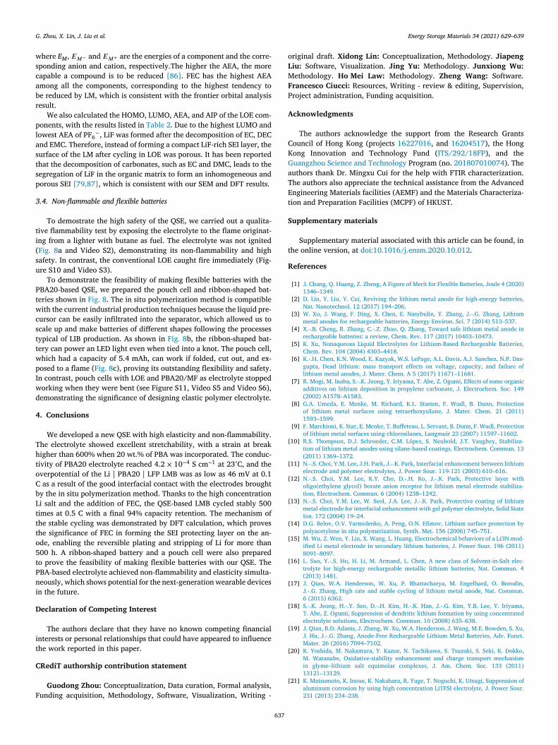
G. Zhou, X. Lin, J. Liu et al. Energy Storage Materials 34 (2021) 629–639
w
s
c
a
b
r
p
l
a
s
t
s
p
3
t
i
(
s
u
P
t
w
c
s
t
t
w
p
I
w
d
4
T
h
t
o
C
b
L
t
t
t
o
5
t
P
n
i
D
i
t
C
F
o
L
M
F
P
A
C
K
G
a
T
E
t
S
t
R
[
[
[
[
[
[
[
[
[
[
[
[
here E M
, 𝐸 𝑀
− and 𝐸 𝑀
+ are the energies of a component and the corre-ponding anion and cation, respectively.The higher the AEA, the moreapable a compound is to be reduced [86] . FEC has the highest AEAmong all the components, corresponding to the highest tendency toe reduced by LM, which is consistent with the frontier orbital analysisesult.
We also calculated the HOMO, LUMO, AEA, and AIP of the LOE com-onents, with the results listed in Table 2 . Due to the highest LUMO andowest AEA of PF 6
− , LiF was formed after the decomposition of EC, DECnd EMC. Therefore, instead of forming a compact LiF-rich SEI layer, theurface of the LM after cycling in LOE was porous. It has been reportedhat the decomposition of carbonates, such as EC and DMC, leads to theegregation of LiF in the organic matrix to form an inhomogeneous andorous SEI [79,87] , which is consistent with our SEM and DFT results.
.4. Non-flammable and flexible batteries
To demostrate the high safety of the QSE, we carried out a qualita-ive flammability test by exposing the electrolyte to the flame originat-ng from a lighter with butane as fuel. The electrolyte was not ignited Fig. 8 a and Video S2), demonstrating its non-flammability and highafety. In contrast, the conventional LOE caught fire immediately (Fig-re S10 and Video S3).
To demonstrate the feasibility of making flexible batteries with theBA20-based QSE, we prepared the pouch cell and ribbon-shaped bat-eries shown in Fig. 8 . The in situ polymerization method is compatibleith the current industrial production techniques because the liquid pre-
ursor can be easily infiltrated into the separator, which allowed us tocale up and make batteries of different shapes following the processesypical of LIB production. As shown in Fig. 8 b, the ribbon-shaped bat-ery can power an LED light even when tied into a knot. The pouch cell,hich had a capacity of 5.4 mAh, can work if folded, cut out, and ex-osed to a flame ( Fig. 8 c), proving its outstanding flexibility and safety.n contrast, pouch cells with LOE and PBA20/MF as electrolyte stoppedorking when they were bent (see Figure S11, Video S5 and Video S6),emonstrating the significance of designing elastic polymer electrolyte.
. Conclusions
We developed a new QSE with high elasticity and non-flammability.he electrolyte showed excellent stretchability, with a strain at breakigher than 600% when 20 wt.% of PBA was incorporated. The conduc-ivity of PBA20 electrolyte reached 4.2 × 10 − 4 S cm
− 1 at 23°C, and theverpotential of the Li | PBA20 | LFP LMB was as low as 46 mV at 0.1 as a result of the good interfacial contact with the electrodes broughty the in situ polymerization method. Thanks to the high concentrationi salt and the addition of FEC, the QSE-based LMB cycled stably 500imes at 0.5 C with a final 94% capacity retention. The mechanism ofhe stable cycling was demonstrated by DFT calculation, which proveshe significance of FEC in forming the SEI protecting layer on the an-de, enabling the reversible plating and stripping of Li for more than00 h. A ribbon-shaped battery and a pouch cell were also preparedo prove the feasibility of making flexible batteries with our QSE. TheBA-based electrolyte achieved non-flammability and elasticity simulta-eously, which shows potential for the next-generation wearable devicesn the future.
eclaration of Competing Interest
The authors declare that they have no known competing financialnterests or personal relationships that could have appeared to influencehe work reported in this paper.
RediT authorship contribution statement
Guodong Zhou: Conceptualization, Data curation, Formal analysis,unding acquisition, Methodology, Software, Visualization, Writing -
637
riginal draft. Xidong Lin: Conceptualization, Methodology. Jiapeng
iu: Software, Visualization. Jing Yu: Methodology. Junxiong Wu:
ethodology. Ho Mei Law: Methodology. Zheng Wang: Software.rancesco Ciucci: Resources, Writing - review & editing, Supervision,roject administration, Funding acquisition.
cknowledgments
The authors acknowledge the support from the Research Grantsouncil of Hong Kong (projects 16227016 , and 16204517 ), the Hongong Innovation and Technology Fund ( ITS/292/18FP ), and theuangzhou Science and Technology Program (no. 201807010074 ). Theuthors thank Dr. Mingxu Cui for the help with FTIR characterization.he authors also appreciate the technical assistance from the Advancedngineering Materials facilities (AEMF) and the Materials Characteriza-ion and Preparation Facilities (MCPF) of HKUST.
upplementary materials
Supplementary material associated with this article can be found, inhe online version, at doi:10.1016/j.ensm.2020.10.012 .
eferences
[1] J. Chang , Q. Huang , Z. Zheng , A Figure of Merit for Flexible Batteries, Joule 4 (2020)1346–1349 .
[2] D. Lin , Y. Liu , Y. Cui , Reviving the lithium metal anode for high-energy batteries,Nat. Nanotechnol. 12 (2017) 194–206 .
[3] W. Xu , J. Wang , F. Ding , X. Chen , E. Nasybulin , Y. Zhang , J.-.G. Zhang , Lithiummetal anodes for rechargeable batteries, Energy Environ. Sci. 7 (2014) 513–537 .
[4] X.-.B. Cheng , R. Zhang , C.-.Z. Zhao , Q. Zhang , Toward safe lithium metal anode inrechargeable batteries: a review, Chem. Rev. 117 (2017) 10403–10473 .
[5] K. Xu , Nonaqueous Liquid Electrolytes for Lithium-Based Rechargeable Batteries,Chem. Rev. 104 (2004) 4303–4418 .
[6] K.-.H. Chen , K.N. Wood , E. Kazyak , W.S. LePage , A.L. Davis , A.J. Sanchez , N.P. Das-gupta , Dead lithium: mass transport effects on voltage, capacity, and failure oflithium metal anodes, J. Mater. Chem. A 5 (2017) 11671–11681 .
[7] R. Mogi , M. Inaba , S.-.K. Jeong , Y. Iriyama , T. Abe , Z. Ogumi , Effects of some organicadditives on lithium deposition in propylene carbonate, J. Electrochem. Soc. 149(2002) A1578–A1583 .
[8] G.A. Umeda , E. Menke , M. Richard , K.L. Stamm , F. Wudl , B. Dunn , Protectionof lithium metal surfaces using tetraethoxysilane, J. Mater. Chem. 21 (2011)1593–1599 .
[9] F. Marchioni , K. Star , E. Menke , T. Buffeteau , L. Servant , B. Dunn , F. Wudl , Protectionof lithium metal surfaces using chlorosilanes, Langmuir 23 (2007) 11597–11602 .
10] R.S. Thompson , D.J. Schroeder , C.M. López , S. Neuhold , J.T. Vaughey , Stabiliza-tion of lithium metal anodes using silane-based coatings, Electrochem. Commun. 13(2011) 1369–1372 .
11] N.-.S. Choi , Y.M. Lee , J.H. Park , J.-.K. Park , Interfacial enhancement between lithiumelectrode and polymer electrolytes, J. Power Sour. 119-121 (2003) 610–616 .
12] N.-.S. Choi , Y.M. Lee , K.Y. Cho , D.-.H. Ko , J.-.K. Park , Protective layer witholigo(ethylene glycol) borate anion receptor for lithium metal electrode stabiliza-tion, Electrochem. Commun. 6 (2004) 1238–1242 .
13] N.-.S. Choi , Y.M. Lee , W. Seol , J.A. Lee , J.-.K. Park , Protective coating of lithiummetal electrode for interfacial enhancement with gel polymer electrolyte, Solid StateIon. 172 (2004) 19–24 .
14] D.G. Belov , O.V. Yarmolenko , A. Peng , O.N. Efimov , Lithium surface protection bypolyacetylene in situ polymerization, Synth. Met. 156 (2006) 745–751 .
15] M. Wu , Z. Wen , Y. Liu , X. Wang , L. Huang , Electrochemical behaviors of a Li3N mod-ified Li metal electrode in secondary lithium batteries, J. Power Sour. 196 (2011)8091–8097 .
16] L. Suo , Y.-.S. Hu , H. Li , M. Armand , L. Chen , A new class of Solvent-in-Salt elec-trolyte for high-energy rechargeable metallic lithium batteries, Nat. Commun. 4(2013) 1481 .
17] J. Qian , W.A. Henderson , W. Xu , P. Bhattacharya , M. Engelhard , O. Borodin ,J.-.G. Zhang , High rate and stable cycling of lithium metal anode, Nat. Commun.6 (2015) 6362 .
18] S.-.K. Jeong , H.-.Y. Seo , D.-.H. Kim , H.-.K. Han , J.-.G. Kim , Y.B. Lee , Y. Iriyama ,T. Abe , Z. Ogumi , Suppression of dendritic lithium formation by using concentratedelectrolyte solutions, Electrochem. Commun. 10 (2008) 635–638 .
19] J. Qian , B.D. Adams , J. Zheng , W. Xu , W.A. Henderson , J. Wang , M.E. Bowden , S. Xu ,J. Hu , J.-.G. Zhang , Anode-Free Rechargeable Lithium Metal Batteries, Adv. Funct.Mater. 26 (2016) 7094–7102 .
20] K. Yoshida , M. Nakamura , Y. Kazue , N. Tachikawa , S. Tsuzuki , S. Seki , K. Dokko ,M. Watanabe , Oxidative-stability enhancement and charge transport mechanismin glyme–lithium salt equimolar complexes, J. Am. Chem. Soc. 133 (2011)13121–13129 .
21] K. Matsumoto , K. Inoue , K. Nakahara , R. Yuge , T. Noguchi , K. Utsugi , Suppression ofaluminum corrosion by using high concentration LiTFSI electrolyte, J. Power Sour.231 (2013) 234–238 .

G. Zhou, X. Lin, J. Liu et al. Energy Storage Materials 34 (2021) 629–639
[
[
[
[
[
[
[
[
[
[
[
[
[
[
[
[
[
[
[
[
[
[
[
[
[
[
[
[
[
[
[
[
[
[
[
[
[
[
[
[
[
[
[
[
[
[
[
[
[
[
[
[
[
[
[
[
22] Y. Yamada , M. Yaegashi , T. Abe , A. Yamada , A superconcentrated ether electrolytefor fast-charging Li-ion batteries, Chem. Commun. 49 (2013) 11194–11196 .
23] Y. Yamada , K. Furukawa , K. Sodeyama , K. Kikuchi , M. Yaegashi , Y. Tateyama ,A. Yamada , Unusual stability of acetonitrile-based superconcentrated electrolytesfor fast-charging lithium-ion batteries, J. Am. Chem. Soc. 136 (2014) 5039–5046 .
24] X.-.Q. Zhang , X.-.B. Cheng , X. Chen , C. Yan , Q. Zhang , Fluoroethylene carbonateadditives to render uniform Li deposits in lithium metal batteries, Adv. Funct. Mater.27 (2017) 1605989 .
25] X. Wang , C. Yamada , H. Naito , G. Segami , K. Kibe , High-concentration trimethylphosphate-based nonflammable electrolytes with improved charge–discharge per-formance of a graphite anode for lithium-ion cells, J. Electrochem. Soc. 153 (2005)A135 .
26] J. Wu , J. Liu , Z. Lu , K. Lin , Y.-.Q. Lyu , B. Li , F. Ciucci , J.-.K. Kim , Non-flammableelectrolyte for dendrite-free sodium-sulfur battery, Energy Storage Mater. (2019) .
27] S. Takeuchi , S. Yano , T. Fukutsuka , K. Miyazaki , T. Abe , Electrochemical interca-lation/de-intercalation of lithium ions at graphite negative electrode in TMP-basedelectrolyte solution, J. Electrochem. Soc. 159 (2012) A2089–A2091 .
28] Q. Wang , B. Mao , S.I. Stoliarov , J. Sun , A review of lithium ion battery failure mech-anisms and fire prevention strategies, Prog. Energy Combust. Sci. 73 (2019) 95–131 .
29] X. Wang , E. Yasukawa , S. Kasuya , Nonflammable trimethyl phosphate solvent-con-taining electrolytes for Lithium-ion batteries: I. Fundamental properties, J. Elec-trochem. Soc. 148 (2001) A1058 .
30] X. Wang , E. Yasukawa , S. Kasuya , Nonflammable trimethyl phosphate solvent-con-taining electrolytes for Lithium-ion batteries: II. The use of an amorphous carbonanode, J. Electrochem. Soc. 148 (2001) A1066 .
31] K. Fu , Y. Gong , B. Liu , Y. Zhu , S. Xu , Y. Yao , W. Luo , C. Wang , S.D. Lacey , J. Dai ,Y. Chen , Y. Mo , E. Wachsman , L. Hu , Toward garnet electrolyte–based Li metalbatteries: an ultrathin, highly effective, artificial solid-state electrolyte/metallic Liinterface, Sci. Adv. 3 (2017) e1601659 .
32] Q. Zhao , X. Liu , S. Stalin , K. Khan , L.A. Archer , Solid-state polymer electrolytes within-built fast interfacial transport for secondary lithium batteries, Nature Energy 4(2019) 365–373 .
33] A. Arya , A.L. Sharma , Polymer electrolytes for lithium ion batteries: a critical study,Ionics 23 (2017) 497–540 .
34] Z. Xue , D. He , X. Xie , Poly(ethylene oxide)-based electrolytes for lithium-ion batter-ies, J. Mater. Chem. A 3 (2015) 19218–19253 .
35] M. Marcinek , J. Syzdek , M. Marczewski , M. Piszcz , L. Niedzicki , M. Kalita , A. Ple-wa-Marczewska , A. Bitner , P. Wieczorek , T. Trzeciak , M. Kasprzyk , P. Łęż ak ,Z. Zukowska , A. Zalewska , W. Wieczorek , Electrolytes for Li-ion transport – Review,Solid State Ion. 276 (2015) 107–126 .
36] F. Baskoro , H.Q. Wong , H.-.J. Yen , Strategic structural design of a gel polymer elec-trolyte toward a high efficiency Lithium-ion battery, ACS Appl. Energy Mater. 2(2019) 3937–3971 .
37] L. Long , S. Wang , M. Xiao , Y. Meng , Polymer electrolytes for lithium polymer bat-teries, J. Mater. Chem. A 4 (2016) 10038–10069 .
38] J. Chen , Z. Yang , G. Liu , C. Li , J. Yi , M. Fan , H. Tan , Z. Lu , C. Yang , Reinforcingconcentrated phosphate electrolytes with in-situ polymerized skeletons for robustquasi-solid lithium metal batteries, Energy Storage Mater. 25 (2020) 305–312 .
39] M. Zhu , J. Wu , Y. Wang , M. Song , L. Long , S.H. Siyal , X. Yang , G. Sui , Recent ad-vances in gel polymer electrolyte for high-performance lithium batteries, J. EnergyChem. 37 (2019) 126–142 .
40] D. Zhou , Y.B. He , R.L. Liu , M. Liu , H.D. Du , B.H. Li , Q. Cai , Q.H. Yang , F.Y. Kang , Insitu synthesis of a hierarchical all-solid-state electrolyte based on nitrile materialsfor high-performance Lithium-ion batteries, Adv. Energy Mater. 5 (2015) 1500353 .
41] X. Xu , K. Lin , D. Zhou , Q. Liu , X. Qin , S. Wang , S. He , F. Kang , B. Li , G. Wang ,Quasi-solid-state dual-ion sodium metal batteries for low-cost energy storage, Chem6 (2020) 902–918 .
42] M.-.K. Song , J.-.Y. Cho , B.W. Cho , H.-.W. Rhee , Characterization of UV-cured gelpolymer electrolytes for rechargeable lithium batteries, J. Power Sour. 110 (2002)209–215 .
43] B. Rupp , M. Schmuck , A. Balducci , M. Winter , W. Kern , Polymer electrolyte forlithium batteries based on photochemically crosslinked poly(ethylene oxide) andionic liquid, Eur. Polym. J. 44 (2008) 2986–2990 .
44] J.R. Nair , C. Gerbaldi , G. Meligrana , R. Bongiovanni , S. Bodoardo , N. Penazzi ,P. Reale , V. Gentili , UV-cured methacrylic membranes as novel gel–polymer elec-trolyte for Li-ion batteries, J. Power Sour. 178 (2008) 751–757 .
45] C. Gerbaldi , J.R. Nair , S. Ahmad , G. Meligrana , R. Bongiovanni , S. Bodoardo , N. Pe-nazzi , UV-cured polymer electrolytes encompassing hydrophobic room temperatureionic liquid for lithium batteries, J. Power Sour. 195 (2010) 1706–1713 .
46] C. Gerbaldi , J.R. Nair , G. Meligrana , R. Bongiovanni , S. Bodoardo , N. Penazzi ,UV-curable siloxane-acrylate gel-copolymer electrolytes for lithium-based batteryapplications, Electrochim. Acta 55 (2010) 1460–1467 .
47] J.-.H. Baik , S. Kim , D.G. Hong , J.-.C. Lee , Gel Polymer electrolytes based on poly-merizable Lithium salt and Poly(ethylene glycol) for Lithium battery applications,ACS Appl. Mater. Interf. 11 (2019) 29718–29724 .
48] S. Zugmann , M. Fleischmann , M. Amereller , R.M. Gschwind , H.D. Wiemhöfer ,H.J. Gores , Measurement of transference numbers for lithium ion electrolytesvia four different methods, a comparative study, Electrochim. Acta 56 (2011)3926–3933 .
49] A.D. Becke , Density-functional thermochemistry. III. The role of exact exchange, J.Chem. Phys. 98 (1993) 5648–5652 .
50] Frisch, M.J., Trucks, G.W., Schlegel, H.B., Scuseria, G.E., Robb, M.A., Cheeseman,J.R., Scalmani, G., Barone, V., Petersson, G.A., Nakatsuji, H., Li, X., Caricato, M.,Marenich, A.V., Bloino, J., Janesko, B.G., Gomperts, R., Mennucci, B., Hratchian,H.P., Ortiz, J.V., Izmaylov, A.F., Sonnenberg, J.L., Williams-Young, D., Ding, F., Lip-parini, F., Egidi, F., Goings, J., Peng, B., Petrone, A., Henderson, T., Ranasinghe,
638
D., Zakrzewski, V.G., Gao, J., Rega, N., Zheng, G., Liang, W., Hada, M., Ehara, M.,Toyota, K., Fukuda, R., Hasegawa, J., Ishida, M., Nakajima, T., Honda, Y., Kitao, O.,Nakai, H., Vreven, T., Throssell, K., Montgomery, J.A., Jr., Peralta, J.E., Ogliaro, F.,Bearpark, M.J., Heyd, J.J., Brothers, E.N., Kudin, K.N., Staroverov, V.N., Keith, T.A.,Kobayashi, R., Normand, J., Raghavachari, K., Rendell, A.P., Burant, J.C., Iyengar,S.S., Tomasi, J., Cossi, M., Millam, J.M., Klene, M., Adamo, C., Cammi, R., Ochter-ski, J.W., Martin, R.L., Morokuma, K., Farkas, O., Foresman, J.B., Fox, D.J.Gaussian,Inc., Wallingford CT, Gaussian 09, Revision D.01 (2016).
51] Dennington, R., Keith, T.A., Millam, J.M., Semichem Inc., Shawnee Mission, KS,GaussView, Version 5 (2016).
52] I.van der Veen , J. de Boer , Phosphorus flame retardants: properties, production, en-vironmental occurrence, toxicity and analysis, Chemosphere 88 (2012) 1119–1153 .
53] C.-.T. Lin , S.-.W. Kuo , C.-.F. Huang , F.-.C. Chang , Glass transition temperature en-hancement of PMMA through copolymerization with PMAAM and PTCM mediatedby hydrogen bonding, Polymer 51 (2010) 883–889 .
54] M.H. Cohen , D. Turnbull , Molecular Transport in Liquids and Glasses, J. Chem. Phys.31 (1959) 1164–1169 .
55] C.M. Hansen , in: The Three Dimensional Solubility Parameter, Danish Technical,Copenhagen, 1967, p. 14 .
56] A.F.M. Barton , CRC Handbook of Solubility Parameters and Other Cohesion Param-eters, CRC press, 1991 .
57] J.Y. Song , Y.Y. Wang , C.C. Wan , Review of gel-type polymer electrolytes for lithi-um-ion batteries, J. Power Sour. 77 (1999) 183–197 .
58] A. Manuel Stephan , Review on gel polymer electrolytes for lithium batteries, Eur.Polym. J. 42 (2006) 21–42 .
59] X. Judez , M. Martinez-Ibañez , A. Santiago , M. Armand , H. Zhang , C. Li , Quasi-solid-s-tate electrolytes for lithium sulfur batteries: advances and perspectives, J. PowerSour. 438 (2019) 226985 .
60] T. Nakano , S. Shimada , R. Saitoh , I. Noda , Transient 2D IR correlation spectroscopyof the photopolymerization of acrylic and epoxy monomers, Appl. Spectrosc. 47(1993) 1337–1342 .
61] M. Orgill , B.L. Baker , N.L. Owen , FTIR studies of conformational isomerism in acry-lates and acrylic acids, Spectrochimica Acta Part A 55 (1999) 1021–1024 .
62] S.J. Oh , S.C. Lee , S.Y. Park , Photopolymerization and photobleaching of n-butyl acry-late/fumed silica composites monitored by real time FTIR-ATR spectroscopy, Vib.Spectrosc. 42 (2006) 273–277 .
63] F. Bauer , U. Decker , S. Naumov , C. Riedel , Photoinitiator-free UV curing and mat-ting of acrylate-based nanocomposite coatings: Part 3, Prog. Org. Coat. 77 (2014)1085–1094 .
64] G. Zhou , H. Yao , Y. Zhou , W. Wang , M. Peng , Self-assembled complexes of grapheneoxide and oxidized vapor-grown carbon fiber for simultaneously enhancing thestrength and toughness of epoxy and multi-scale carbon fiber/epoxy composites,Carbon 137 (2018) 6–18 .
65] G. Zhou , W. Wang , M. Peng , Molecular-level dispersion of rigid-rod sulfonated aro-matic polyamides in epoxy resin for extraordinary improvement in both strengthand toughness, Polymer 163 (2019) 20–28 .
66] G. Zhou , W. Wang , M. Peng , Functionalized aramid nanofibers prepared by poly-merization induced self-assembly for simultaneously reinforcing and tougheningof epoxy and carbon fiber/epoxy multiscale composite, Compos. Sci. Technol. 168(2018) 312–319 .
67] S. Wu , H. Zheng , R. Tian , Z. Hei , H. Liu , H. Duan , In-situ preparation of gel poly-mer electrolyte with glass fiber membrane for lithium batteries, J. Power Sour. 472(2020) 228627 .
68] B. Weng , F. Xu , M. Alcoutlabi , Y. Mao , K. Lozano , Fibrous cellulose membrane massproduced via forcespinning R ○ for lithium-ion battery separators, Cellulose 22 (2015)1311–1320 .
69] M. Yanilmaz , M. Dirican , X. Zhang , Evaluation of electrospun SiO2/nylon 6,6nanofiber membranes as a thermally-stable separator for lithium-ion batteries, Elec-trochim. Acta 133 (2014) 501–508 .
70] Y. Cui , J. Chai , H. Du , Y. Duan , G. Xie , Z. Liu , G. Cui , Facile and Reliable in Situ Poly-merization of Poly(Ethyl Cyanoacrylate)-Based Polymer Electrolytes toward FlexibleLithium Batteries, ACS Appl. Mater. Interf. 9 (2017) 8737–8741 .
71] M. Liu , D. Zhou , Y.-.B. He , Y. Fu , X. Qin , C. Miao , H. Du , B. Li , Q.-.H. Yang , Z. Lin ,T.S. Zhao , F. Kang , Novel gel polymer electrolyte for high-performance lithium–sul-fur batteries, Nano Energy 22 (2016) 278–289 .
72] X. Li , S. Li , Z. Zhang , J. Huang , L. Yang , S.-i. Hirano , High-performance polymericionic liquid–silica hybrid ionogel electrolytes for lithium metal batteries, J. Mater.Chem. A 4 (2016) 13822–13829 .
73] J.-.H. Shin , W.A. Henderson , S. Passerini , PEO-based polymer electrolytes with ionicliquids and their use in Lithium metal-polymer electrolyte batteries, J. Electrochem.Soc. 152 (2005) A978–A983 .
74] J. Sunarso , Y. Shekibi , J. Efthimiadis , L. Jin , J.M. Pringle , A.F. Hollenkamp ,D.R. MacFarlane , M. Forsyth , P.C. Howlett , Optimising organic ionic plastic crystalelectrolyte for all solid-state and higher than ambient temperature lithium batteries,J. Solid State Electrochem 16 (2012) 1841–1848 .
75] B. Joos , T. Vranken , W. Marchal , M. Safari , M.K. Van Bael , A.T. Hardy , Eutectogels:a new class of solid composite electrolytes for Li/Li-ion batteries, Chem. Mater. 30(2018) 655–662 .
76] Z. Zou , Y. Li , Z. Lu , D. Wang , Y. Cui , B. Guo , Y. Li , X. Liang , J. Feng , H. Li , C.-.W. Nan ,M. Armand , L. Chen , K. Xu , S. Shi , Mobile ions in composite solids, Chem. Rev.(2020) .
77] Z. Lu , J. Yu , J. Wu , M.B. Effat , S.C.T. Kwok , Y. Lyu , M.M.F. Yuen , F. Ciucci , Enablingroom-temperature solid-state lithium-metal batteries with fluoroethylene carbon-ate-modified plastic crystal interlayers, Energy Storage Mater. 18 (2019) 311–319 .

G. Zhou, X. Lin, J. Liu et al. Energy Storage Materials 34 (2021) 629–639
[
[
[
[
[
[
[
[
[
[
78] J. Yi , J. Chen , Z. Yang , Y. Dai , W. Li , J. Cui , F. Ciucci , Z. Lu , C. Yang , Facile pattern-ing of laser-induced graphene with tailored Li nucleation kinetics for stable Lithi-um-metal batteries, Adv. Energy Mater. 9 (2019) 1901796 .
79] J. Chen , X. Fan , Q. Li , H. Yang , M.R. Khoshi , Y. Xu , S. Hwang , L. Chen , X. Ji , C. Yang ,H. He , C. Wang , E. Garfunkel , D. Su , O. Borodin , C. Wang , Electrolyte design forLiF-rich solid–electrolyte interfaces to enable high-performance microsized alloy an-odes for batteries, Nat. Energy 5 (2020) 386–397 .
80] L. Hu , Z. Zhang , K. Amine , Fluorinated electrolytes for Li-ion battery: an FEC-basedelectrolyte for high voltage LiNi0.5Mn1.5O4/graphite couple, Electrochem. Com-mun. 35 (2013) 76–79 .
81] C. Liu , Z.G. Neale , G. Cao , Understanding electrochemical potentials of cathode ma-terials in rechargeable batteries, Mater. Today 19 (2016) 109–123 .
82] H.B. Son , M.-.Y. Jeong , J.-.G. Han , K. Kim , K.H. Kim , K.-.M. Jeong , N.-.S. Choi , Ef-fect of reductive cyclic carbonate additives and linear carbonate co-solvents on fastchargeability of LiNi0.6Co0.2Mn0.2O2/graphite cells, J. Power Sources 400 (2018)147–156 .
639
83] T. Jaumann , J. Balach , M. Klose , S. Oswald , U. Langklotz , A. Michaelis , J. Eckert ,L. Giebeler , SEI-component formation on sub 5nm sized silicon nanoparticles inLi-ion batteries: the role of electrode preparation, FEC addition and binders, PCCP17 (2015) 24956–24967 .
84] M.D. Bhatt , C. O’Dwyer , Solid electrolyte interphases at Li-ion battery graphitic an-odes in propylene carbonate (PC)-based electrolytes containing FEC, LiBOB, andLiDFOB as additives, Chem. Phys. Lett. 618 (2015) 208–213 .
85] Y. Okuno , K. Ushirogata , K. Sodeyama , Y. Tateyama , Decomposition of the fluo-roethylene carbonate additive and the glue effect of lithium fluoride products forthe solid electrolyte interphase: an ab initio study, PCCP 18 (2016) 8643–8653 .
86] C.-.G. Zhan , J.A. Nichols , D.A. Dixon , Ionization potential, electron affinity, elec-tronegativity, hardness, and electron excitation energy: molecular properties fromdensity functional theory orbital energies, J. Phys. Chem. A 107 (2003) 4184–4195 .
87] J. Zheng , H. Zheng , R. Wang , L. Ben , W. Lu , L. Chen , L. Chen , H. Li , 3D visualizationof inhomogeneous multi-layered structure and Young’s modulus of the solid elec-trolyte interphase (SEI) on silicon anodes for lithium ion batteries, PCCP 16 (2014)13229–13238 .