Embed Size (px)
Citation preview

Electronic Supplementary Information
Energy Storage Characteristics of a New Rechargeable Solid Oxide
Iron-air Battery
Xuan Zhao, Nansheng Xu, Xue Li, Yunhui Gong, Kevin Huang*
Experimental
Preparation of Fe-FeO redox powders
The Fe-FeO redox powders were synthesized from a co-precipitation method
described in ref.1. Such prepared powders have a better redox reversibility and
thermal stability than those synthesized from conventional mechanical mixing
method.
Battery assembly
A simple planar button cell configuration was adopted for the battery test, the
schematic of which is shown in Figure S1. A commercially available NextCell
Electrolyte Supported Button Cell (Fuel Cell Materials, Ohio, USA) was used as the
RSOEC (Diameter: 20mm, effective area: 0.88cm2). Table S1 gives the composition
and thickness of the functional layers in the RSOEC. The energy storage redox
materials were packaged in form of granules underneath the ROSEC. Pt mesh and Pt
paste were used as current collectors for both air-electrode and fuel-electrode. A
Electronic Supplementary Material (ESI) for RSC AdvancesThis journal is © The Royal Society of Chemistry 2012

specially formulated glass-ceramic was used as the hermetic sealant for the battery
cell.
Fig. S1. A planar button cell configuration for testing rechargeable solid oxide
Iron-air battery
Table S1 Compositions and dimension of the commercial NextCells2
Component Composition Thickness (μm)
Anode Ni-YSZ/Ni-GDC(interlayer) 50
Electrolyte Hionic ZrO2-based 150(+/-15)
Cathode LSM/LSM-GDC(interlayer) 50
Testing procedure
The redox material Fe2O3-ZrO2 (5-10 wt%) granules were first reduced with a cover
Redox material
RSOEC
Pump
H2+H2O
Electronic Supplementary Material (ESI) for RSC AdvancesThis journal is © The Royal Society of Chemistry 2012

gas of 5%H2-N2. Before each electrical cycle, a pure H2 was used to finally reduce
Fe2O3 into metallic Fe. A small current was then applied to oxidize Fe into FeO so as
to create the Fe-FeO energy storage redox couple. The RSOEC’s EMF was closed
monitored during the initial electrochemical oxidation. As soon as EMF reached 0.97
volts, the electrochemical oxidation was stopped, and the system is ready for electrical
cycles. During electrical cycles, the reaction gas was circulated in a closed-loop to
homogenize the concentration. To prevent condensation, all pipelines were
heat-wrapped and kept at 110oC.
A Solartron 1260/1287 Electrochemical System was employed to measure the
electrical performance of the battery with software modules such as OCV (open
circuit voltage)-t, impedance spectroscopy, potential-dynamic, galvanic square waves
and galvanic cycles.
Other characterization
A field emission scanning electron microscope (FESEM, Zeiss Ultra) equipped with an
EDS capability was employed to observe microstructures and analyze the local
chemical compositions of the Fe-FeO redox materials as well as RSOEC. The phase
composition of the Fe-FeO redox material was also examined by powder X-ray
diffraction (PXRD) using an X-ray diffractometer (D/max-A, Rigaku, Japan) with
graphite-monochromatized CuK radiation (λ=1.5418 Å). The XRD scan was
Electronic Supplementary Material (ESI) for RSC AdvancesThis journal is © The Royal Society of Chemistry 2012
performed at a rate of 5o min-1 from 2θ= 10o to 90o, the spectrum of which was
analyzed with the JADE (MDI) software to identify phase compositions. The pore
characteristics of the porous Fe-containing redox unit including median pore diameter,
and porosity were analyzed by a mercury porosimeter (Autopore IV, Micromeritics) in
a pressure range of 0.5-30000 psi.
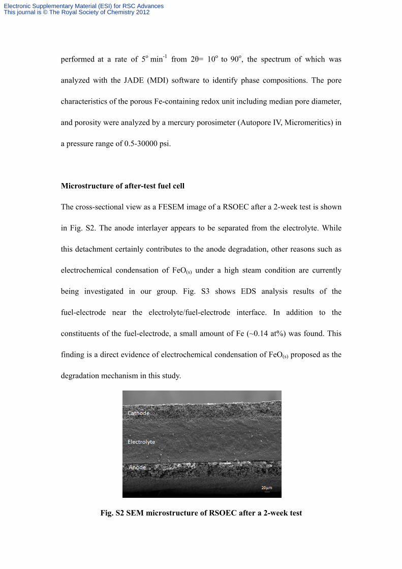
Microstructure of after-test fuel cell
The cross-sectional view as a FESEM image of a RSOEC after a 2-week test is shown
in Fig. S2. The anode interlayer appears to be separated from the electrolyte. While
this detachment certainly contributes to the anode degradation, other reasons such as
electrochemical condensation of FeO(s) under a high steam condition are currently
being investigated in our group. Fig. S3 shows EDS analysis results of the
fuel-electrode near the electrolyte/fuel-electrode interface. In addition to the
constituents of the fuel-electrode, a small amount of Fe (~0.14 at%) was found. This
finding is a direct evidence of electrochemical condensation of FeO(s) proposed as the
degradation mechanism in this study.
Fig. S2 SEM microstructure of RSOEC after a 2-week test
Electronic Supplementary Material (ESI) for RSC AdvancesThis journal is © The Royal Society of Chemistry 2012
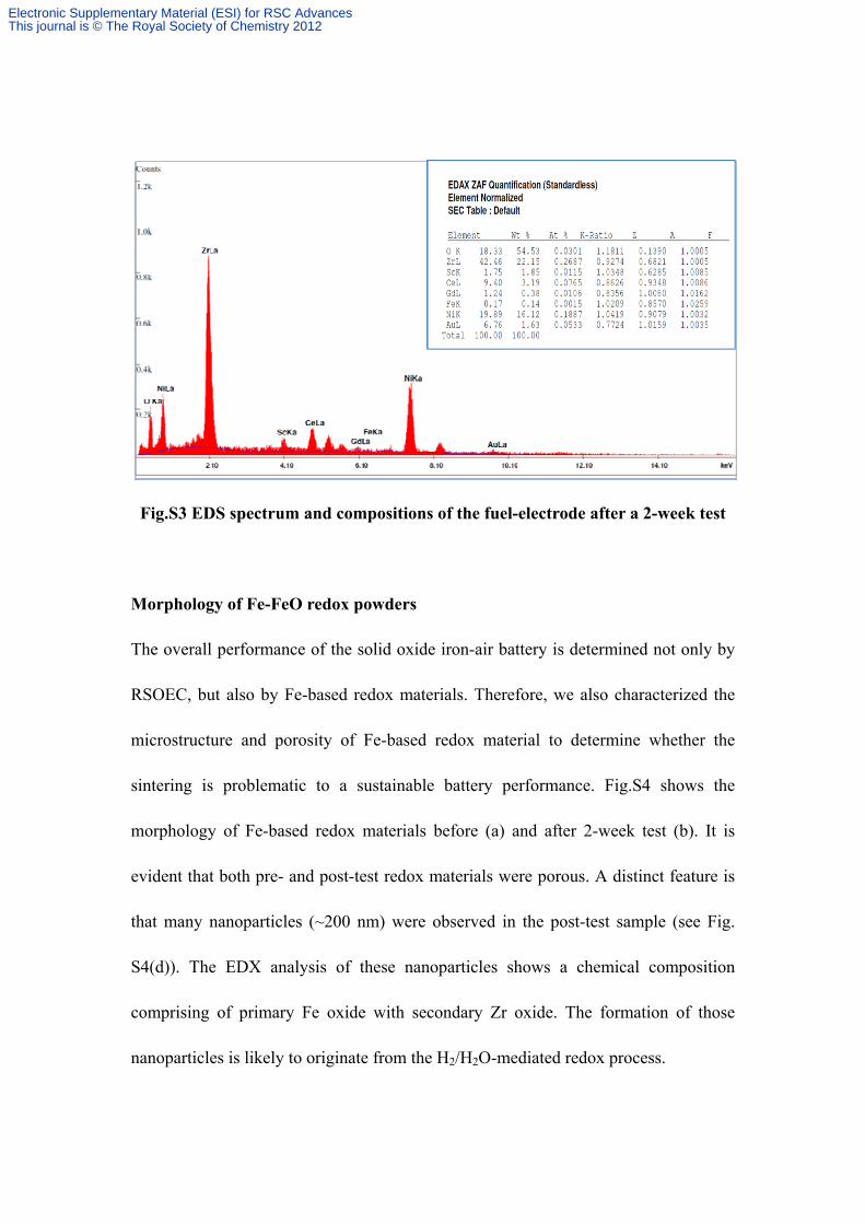
Fig.S3 EDS spectrum and compositions of the fuel-electrode after a 2-week test
Morphology of Fe-FeO redox powders
The overall performance of the solid oxide iron-air battery is determined not only by
RSOEC, but also by Fe-based redox materials. Therefore, we also characterized the
microstructure and porosity of Fe-based redox material to determine whether the
sintering is problematic to a sustainable battery performance. Fig.S4 shows the
morphology of Fe-based redox materials before (a) and after 2-week test (b). It is
evident that both pre- and post-test redox materials were porous. A distinct feature is
that many nanoparticles (~200 nm) were observed in the post-test sample (see Fig.
S4(d)). The EDX analysis of these nanoparticles shows a chemical composition
comprising of primary Fe oxide with secondary Zr oxide. The formation of those
nanoparticles is likely to originate from the H2/H2O-mediated redox process.
Electronic Supplementary Material (ESI) for RSC AdvancesThis journal is © The Royal Society of Chemistry 2012
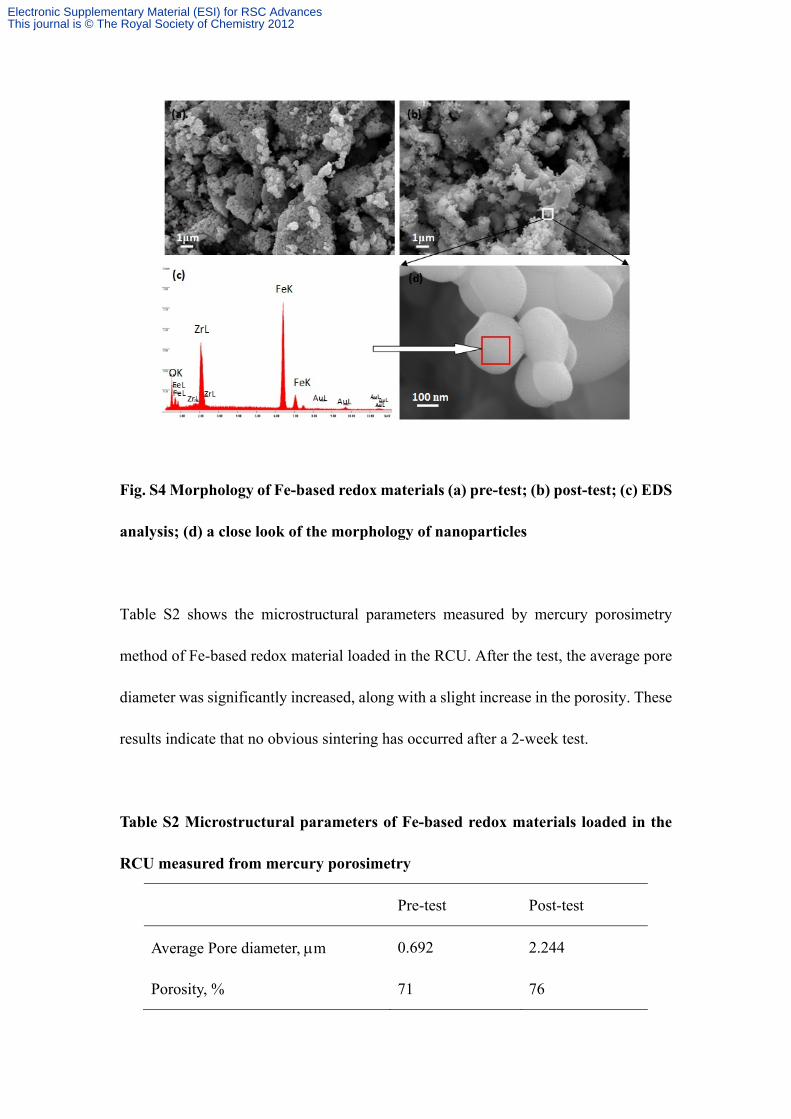
Fig. S4 Morphology of Fe-based redox materials (a) pre-test; (b) post-test; (c) EDS
analysis; (d) a close look of the morphology of nanoparticles
Table S2 shows the microstructural parameters measured by mercury porosimetry
method of Fe-based redox material loaded in the RCU. After the test, the average pore
diameter was significantly increased, along with a slight increase in the porosity. These
results indicate that no obvious sintering has occurred after a 2-week test.
Table S2 Microstructural parameters of Fe-based redox materials loaded in the
RCU measured from mercury porosimetry
Pre-test Post-test
Average Pore diameter, m 0.692 2.244
Porosity, % 71 76
Electronic Supplementary Material (ESI) for RSC AdvancesThis journal is © The Royal Society of Chemistry 2012

XRD examination of Fe-based redox materials
Fig. S5 shows the phase evolution before and after a 2-week test. Before test, Fig.S5(a)
shows contains two phases: Fe2O3 and ZrO2, present in the redox material. After the test,
Fig.5(b) shows that the redox materials protected in a 5%H2-N2 during shutdown only
consists of Fe and ZrO2. Based on these XRD results, it is safe to say that ZrO2 is a
stable and inactive support for the Fe-FeO redox system. The presence of ZrO2 helped
prevent the coarsening of Fe particles during this prolonged battery operation.
Fig. S5 XRD analysis of a Fe-based redox material (a) pre-test; (b) post-test.
Sample was protected in a 5%H2-N2 during shutdown.
References
1. Xu, N.; Li, X.; Zhao, X.; Goodenough, J. B.; Huang, K., Energy & Environmental
Science 2011, 4 (12), 4942-4946.
2. http://www.fuelcellmaterials.com/pdf/NextCell%2005-09.pdf.
3. Merte, L. R.; Peng, G.; Bechstein, R.; Rieboldt, F.; Farberow, C. A.; Grabow, L. C.;
(b) (a)
Electronic Supplementary Material (ESI) for RSC AdvancesThis journal is © The Royal Society of Chemistry 2012

Kudernatsch, W.; Wendt, S.; Lægsgaard, E.; Mavrikakis, M.; Besenbacher, F., Science
2012, 336 (6083), 889-893.
Electronic Supplementary Material (ESI) for RSC AdvancesThis journal is © The Royal Society of Chemistry 2012